robot vision guided laser solder cell product
TRANSCRIPT

Robot Vision Guided Laser Solder Cell Product Specification
Document Number: DS-0005 Model Number: PRO6TL
_____________________________________________________________________________
Page 1 of 13

Robot Vision Guided Laser Solder Cell Product Specification
Document Number: DS-0005 Model Number: PRO6TL
_____________________________________________________________________________
Page 2 of 13
Work-cell Overview
The soldering cell has been developed to provide autonomous non-contact soldering when used in an in-line conveyorized production line. Pallets are automatically transferred into and out of the cell using an edge-type roller chain conveyor.
A single four axis robot is used to selectively solder circuits using a non-contact diode laser fiber coupled heat source and a stepper-motor driven automatic solder wire feeder. Vision guidance along with a Cartesian robots is employed to position the focusing lens and solder feeder. Vision guidance is used to assure that the location of the product to be soldered is accurately known with minimal reliance on mechanical positioning repeatability of the product to be soldered.
All components are first quality, industrial duty, and the design meets NFPA 79 guidelines as well as applicable safety standards.
While more detail on the system is provided later, a brief overview of the system specifications is detailed below:
Overall Dimensions 76 ½” Wide X 59” Deep X 77 ½” Tall
Conveyor Height Adjustable from 35” to 37” (additional details below)
Conveyor Width Adjustable from 3” to 14” (additional details below)
Guarding Sheet metal safety enclosure interlocked per applicable safety standards
Work-cell / Robot Controller
An Adept AWC060 MV10 robot controller is used to control position of the two Cartesian robots, provide vision capability, and control the work-cell. The controller provides 28 tasks and abundant I/O for real-time work-cell control and allows unparalleled processing power and flexibility. Motion is highly coordinated and optimized for speed. An industrial flat panel touch-screen is used for operator interface to the controller.
Operator Interface The operator interface is provided via an industrial flat monitor . Simple to use GUI based process control menus allow real time modification of process parameters. Comprehensive help screens, operator messaging, and ease of use are major features of this platform.
Manual Teach Pendant
Industrial quality Adept teach pendant for manually moving the robot within the work space. The pendent displays robot coordinates, incorporates safety features to meet RIA safety standards, and allows the axis coordinates to be displayed and controlled in a variety of modes.
Industrial I/O Ruggedized Adept I/O technology and Bechoff DeviceNet IO are used to provide bulletproof optically isolated digital and analog I/O options for the work-cell. DeviceNet connectivity is supplied standard on the cell for ease of expansion.
Position/Process Table
CAD data for the circuit pad locations and reference fiducials is used to define soldering locations for the robots. Actual product orientation is vision generated before moving to locations on circuit defined by CAD data. Databases containing vision, setup, and process data are stored in the controller memory. Separate process parameters for each solder location are stored in memory also. Multiple process setups / part numbers can easily be selected via menu.
Datalogging A process log is recorded to the hard drive.
Program Language System programmed in Adept V+, Adept AIM, Visual Basic (PC front end only with optional Adept Windows, not included)
Vision Guidance The system is supplied with Adept’s fully integrated EVI vision/motion guidance and inspection system. Ease of use, flexibility, and high performance are the hallmarks of this system. System setup is GUI based and requires minimal training. Two vision cameras

Robot Vision Guided Laser Solder Cell Product Specification
Document Number: DS-0005 Model Number: PRO6TL
_____________________________________________________________________________
Page 3 of 13
and associated lighting are used to find the orientation of the product to be processed.
Motion Axes X axes: 400 mm Adept H Module Y axes: 350 mm Adept M Module Z axes: 130 mm Sz Module
Theta Axes: Adept Servo motor & bearing set XY Axes Repeatability: 0.0004”
XY Working Area X=11” Y=13.77” (Y axis is parallel to conveyor) Heat Source Spectra Physics 60 Watt Non-Contact Diode Laser System Beam Delivery: multi-fiber optic with focusing lens
Minimum Beam Diameter: 0.7 mm Maximum Beam Diameter: 2.4 mm
Adjustable Power Range: 1 ~ 60 Watts Power Adjustment: Controlled real time per process database
Intregra MP Diode Laser system (960nm) Diode Life: 12000 hours Power Consumption: 250W
Solder Process Monitor and Cameras
A miniature solder process camera is utilized on each of the two robots to provide a real-time, highly magnified view of the soldering process. The video image is displayed on an LCD video monitor to aid in process development.
Conveyor System Heavy duty, chain drive, edge roller conveyor Edge Rollers on 1.0” centers
Edge Roller affixed to Heavy Duty #40 Extended Pin Roller Chain Bodine Gear Motor Speed range: 1 ~ 20 FPM Edge Clearance: 0.25” Standard Conductive Chain & Bumper Guide Strips ESD Protection Conveyor Width: Adjustable 3” ~ 14” Conveyor Height: Adjustable 35” ~ 37”, Two Positions: One queue position, one work position
Auxiliary Connections
Auxiliary air and AC connections are provided included on front of machine. SMEMA interface connections for in-line conveyor operation are supplied standard.
General Software Information
The controller for the system includes dual AWC 060 processors, Adept Vision Guidance VXL, and utilizes AIM MotionWare, VisionWare, and V+ for the operating system.
The Adept system includes V+ (the basic operating system) and AIM (a windows like operating system). In addition, several utility programs are included. The software is briefly described below:
• V+ ~ Basic operating system for Adept robots. This is included with the machine and the machine always boots up in the V+ environment.
• AIM MotionWare ~ Adept’s version of windows. This database centered programming environment runs on top of V+ and uses V+ (basic-like) subroutines as the basis of it’s extremely high level language. The end user has the ability to make custom statements in AIM using V+ routines to implement high level functions.
• VisionWare ~ Adepts vision guidance package is seamlessly integrated with AIM MotionWare and is provided in the work-cell.

Robot Vision Guided Laser Solder Cell Product Specification
Document Number: DS-0005 Model Number: PRO6TL
_____________________________________________________________________________
Page 4 of 13
• Utilities ~ Adepts utilities disk is included in the directory C:\UTIL. Some of the most helpful programs are DISKCOPY, SPEC, etc. See the Adept utilities manual for more information.
• Machine Control Application ~ Most of the machine control is done in the AIM programming environment. AIM is basically a collection of V+ (basic like) routines used to create a higher level “language” of simple to use commands. Each AIM command has a corresponding V+ program used to perform the required tasks. While most functions are included with the base AIM package, some custom functions were implemented.
Process Overview
The soldering work-cell maintains precise control over all parameters during the solder process. The parameters are independent for each pin and can be edited in real time while the machine is running greatly reducing the solder parameter optimization process. When multiple circuits are processed, the same process and location data are used for all circuits in the array of circuits to be processed.
Hardware Description
Most of the major hardware components used in the work-cell are briefly described in the following sections.
Adept Cartesian Robots
Adept Cartesian robots are used to position the vision camera and soldering head at the each of the two heated work positions located inside the work-cell. This robot controller is used to control the motion axes as well as pneumatics and other peripherals in the system.
Each robot uses the following axes to comprise a Cartesian robot with a rotational theta axis.
Table 1 ~ Adept Cartesian Axes components
Axis Adept P/N Description Mechanical BOM Ref
X – Axis 90400-10040 H-Module-400mm #1
Y – Axis 90400-20035 M-Module-350mm #4
Z – Axis 90402-40013 Sz-Module-130mm #5
Theta – Axis Motor 100W Sigma Servo Motor
Servo motor with encoder #42
Note:
The theta axis is a custom designed axis that uses an Adept servo motor to control the rotation of the solder.
The controller for the system includes dual AWC 060 processors, Adept Vision Guidance VXL, and utilizes AIM MotionWare, VisionWare, and V+ for the operating system.
Robot Vision Guided Laser Solder Cell Product Specification
Document Number: DS-0005 Model Number: PRO6TL
_____________________________________________________________________________
Page 5 of 13
Figure 1 ~ Adept I/O interface board.
Figure 2 ~ Beckoff Device Net I/O system.
Figure 3 ~ Robot signal interface boxes.
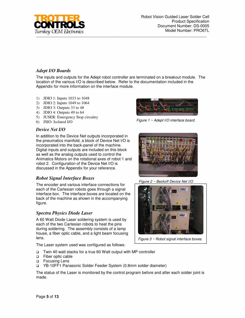
Adept I/O Boards
The inputs and outputs for the Adept robot controller are terminated on a breakout module. The location of the various I/O is described below. Refer to the documentation included in the Appendix for more information on the interface module.
1) JDIO 1: Inputs 1033 to 1048
2) JDIO 2: Inputs 1049 to 1064
3) JDIO 3: Outputs 33 to 48
4) JDIO 4: Outputs 49 to 64
5) JUSER: Emergency Stop circuitry
6) JSIO: Isolated I/O
Device Net I/O
In addition to the Device Net outputs incorporated in the pneumatics manifold, a block of Device Net I/O is incorporated into the back-panel of the machine. Digital inputs and outputs are included on this block as well as the analog outputs used to control the Animatics Motors on the rotational axes of robot 1 and robot 2. Configuration of the Device Net I/O is discussed in the Appendix for your reference.
Robot Signal Interface Boxes
The encoder and various interface connections for each of the Cartesian robots goes through a signal interface box. The interface boxes are located on the back of the machine as shown in the accompanying figure.
Spectra Physics Diode Laser
A 60 Watt Diode Laser soldering system is used by each of the two Cartesian robots to heat the pins during soldering. The assembly consists of a lamp house, a fiber optic cable, and a light beam focusing lens.
The Laser system used was configured as follows:
� Twin 40 watt stacks for a true 60 Watt output with MP controller � Fiber optic cable � Focusing Lens � YB-10FF1 Panasonic Solder Feeder System (0.8mm solder diameter)
The status of the Laser is monitored by the control program before and after each solder joint is made.

Robot Vision Guided Laser Solder Cell Product Specification
Document Number: DS-0005 Model Number: PRO6TL
_____________________________________________________________________________
Page 6 of 13
Figure 5 ~ Conveyor speed control potentiometer.
The Laser system communicates with directly via Adept digital I/0 to control the soldering power, shutter control functions, and monitor any error status.
Panasonic Wire Feeder(not included with TRW system)
A step motor actuated solder feeder mechanism is used to feed the solder to the pins being soldered for each of the robots end effectors. This consists of a wire feeder controller assembly and the actual wire feed mechanism.
The wire speed for the two wire feeders is communicated via serial to parallel converter modules connected to the two serial ports on the leftmost AWC processor. The feed solder control bit is controlled directly off of Adept I/O.
The status of the wire feeder is monitored by the control program before and after solder is fed. If an alarm condition exists, a message will be displayed to the operator.
Conveyor
The printed circuit boards are transferred into the machine using a roller chain edge type conveyor system. The speed of the conveyor is controlled via a potentiometer located inside the control cabinet on the back of the machine. The conveyor motor is turned off and on via a relay controlled from the Adepts digital I/O.
Figure 4 - Solder feeder controller and wire feed mechanism.
Robot Vision Guided Laser Solder Cell Product Specification
Document Number: DS-0005 Model Number: PRO6TL
_____________________________________________________________________________
Page 7 of 13
Stainless Heat
Shield
Fiber Optic
Pallet
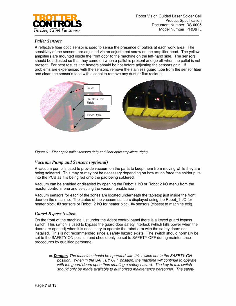
Pallet Sensors
A reflective fiber optic sensor is used to sense the presence of pallets at each work area. The sensitivity of the sensors are adjusted via an adjustment screw on the amplifier head. The yellow amplifiers are mounted inside the front door to the machine on the left-hand side. The sensors should be adjusted so that they come on when a pallet is present and go off when the pallet is not present. For best results, the heaters should be hot before adjusting the sensors gain. If problems are experienced with the sensors, remove the stainless guard tube from the sensor fiber and clean the sensor’s face with alcohol to remove any dust or flux residue.
Figure 6 ~ Fiber optic pallet sensors (left) and fiber optic amplifiers (right).
Vacuum Pump and Sensors (optional)
A vacuum pump is used to provide vacuum on the parts to keep them from moving while they are being soldered. This may or may not be necessary depending on how much force the solder puts into the PCB as it is being fed onto the pad being soldered.
Vacuum can be enabled or disabled by opening the Robot 1 I/O or Robot 2 I/O menu from the master control menu and selecting the vacuum enable icon.
Vacuum sensors for each of the zones are located underneath the tabletop just inside the front door on the machine. The status of the vacuum sensors displayed using the Robot_1 I/O for heater block #3 sensors or Robot_2 I/O for heater block #4 sensors (closest to machine exit).
Guard Bypass Switch
On the front of the machine just under the Adept control panel there is a keyed guard bypass switch. This switch is used to bypass the guard door safety interlock (which kills power when the doors are opened) when it is necessary to operate the robot arm with the safety doors not installed. This is not recommended since a safety hazard exists. The switch should normally be set to the SAFETY ON position and should only be set to SAFETY OFF during maintenance procedures by qualified personnel.
⇒⇒⇒⇒ Danger: The machine should be operated with this switch set to the SAFETY ON position. When in the SAFTEY OFF position, the machine will continue to operate with the guard doors open thus creating a safety hazard. The key to this switch should only be made available to authorized maintenance personnel. The safety

Robot Vision Guided Laser Solder Cell Product Specification
Document Number: DS-0005 Model Number: PRO6TL
_____________________________________________________________________________
Page 8 of 13
Figure 7 ~ Pressure regulator and gauges.
bypass (SAFETY OFF) mode is included only for maintenance or setup of the machine.
Temperature Controllers (optional)
The temperature of the heaters in each of four zones is controlled independently. An Omega temperature controller in conjunction with a thermocouple, solid state AC relay, and heaters (one setup per zone) are used to monitor and control the temperature of each zone. While power to the temperature controllers are on continuously to allow monitoring of the temperature, AC power to the heater control solid state relays is controlled by the Adept controller in conjunction with a power contactor.
Preheaters (optional)
Each of the optional heater blocks present within each zone has six cartridge style heaters and a thermocouple embedded within them. This provides advantages of quick zone heat up and uniform heating of the entire heater block.
Pneumatics
The system pressure is turned on and off using the electrically controlled soft start valve located on the front of the machine. When power is removed or and emergency stop is depressed, air pressure is automatically removed from the system by the soft start valve.
The system supply pressure to the machine is adjusted using the pressure regulator mounted on the left-hand front side of the machine. System pressure is indicated on the pressure gage.
The valves controlling the various pneumatic components are located on two manifolds (one for pressure and one for vacuum) the lower right hand side of the machine. The valves can be forced during maintenance if necessary by depressing the manual override button(s) located on the front of the valves (power must be off to the valve in order to force it). Communication with the valves is via the Device net port included on the Adept controllers CIP panel.
Figure 8 - Pneumatics manifolds.

Robot Vision Guided Laser Solder Cell Product Specification
Document Number: DS-0005 Model Number: PRO6TL
_____________________________________________________________________________
Page 9 of 13
Figure 10 ~ Upstream SMEMA and inlet air connection.
Figure 9 ~ Downstream SMEMA and pass through air connection.
Figure 11 ~ Auxiliary air and power connections.
SMEMA and Air Connections
The upstream and downstream SMEMA connections are located toward the back and lower part of the machine. The upstream connection is located on the entrance (left hand as view from the front of the machine) side of the machine while the downstream connection is located on the exit side of the machine.
The air inlet to the machine is on the entrance (left hand) side of the machine. The recommended inlet pressure for the machine is 80 to 120 psi. A pass through air connection is provided on the outlet of the machine to pass unregulated air to down stream equipment.
Auxiliary Air and Power Connections
Connections to provide filtered and regulated air as well as 120 VAC power are provided on the front of the machine for auxiliary functions required within the workspace. When using the AC receptacle keep in mind that it supplies a maximum of 10 amps at 120VAC.
Solder Monitor and Camera
A video monitor and camera are included on the system to allow the operator to view the solder joints as they are being made. This is an indispensable tool when used to set the machine up and view the solder process. The system is comprised of a camera, camera controller, and an LCD video monitor along with the brackets necessary

Robot Vision Guided Laser Solder Cell Product Specification
Document Number: DS-0005 Model Number: PRO6TL
_____________________________________________________________________________
Page 10 of 13
to carry the camera on the end effector. More information on this is provided in the setup section.
Documentation Supplied
Extensive documentation on the operation, maintenance, and construction of the work-cell is supplied. A summary of the supplied documentation is shown in table below Table 2.
Table 2- Supplied documentation.
Soldering Station Operators Manual
Soldering Station Drawings Notebook ~ Volume 1
Soldering Station Drawings Notebook ~ Volume 2
Spectra Physics Diode Laser Manual
Optional Wire Solder Feeder Instruction Manual
AIM Motion Ware Manual (CD only)
Aim Customizers Reference Guide (CD only)
V+ Operating System Users Guide (CD only)
V+ Language (CD only)
V+ Language Reference Guide (CD only)
V+ Language Reference Guide (CD only)
V+ Version 11.2 Release Notes (CD only)
Adept MV Controller Users Guide (CD only)
Adept Table Top Robot Users Guide (CD only)
Instructions for Adept Utilities Utility Programs (CD only)

Robot Vision Guided Laser Solder Cell Product Specification
Document Number: DS-0005 Model Number: PRO6TL
_____________________________________________________________________________
Page 11 of 13
The Adept supplied documentation “road map” for Adept controllers running AIM is supplied for your reference in the figure below.
Figure 12 - Adept documentation road map.

Robot Vision Guided Laser Solder Cell Product Specification
Document Number: DS-0005 Model Number: PRO6TL
_____________________________________________________________________________
Page 12 of 13
All of the mechanical and electrical drawings for the station are included in the drawings notebooks Volume 1 and Volume 2. Several assembly drawings are included in the Appendix section of this manual.
Please note that Adept related documentation is supplied in CD format. Hardcopies of the Adept supplied documentation can be supplied at an additional charge.
In addition to the documentation previously described, the operators manual contains a quick setup section detailing the following items regarding system commissioning and maintenance.
The steps required to set the machine up are summarized below along with references to the appropriate sections in the manual containing detailed information on each of the items.
- Set dip switches
- Set up Viewtronics monitor jumpers.
- Set temperature controls.
- Align heater blocks with conveyor
- Level heater blocks
- Set conveyor width
- Hook up SMEMA conveyor interface connections
- Adjust pallet stops
- Set theta axis angle
- Set up air knife and vacuum
- Set laser lens and focus
- Set solder feeder
- Teach pallet frame
- Calibrate cameras
- Adjust vision tools
- Enter circuit offsets for pallets
- Teach camera locations
- Enter pin CAD data and soldering data
- Edit protect database as required
- Adjust vision tools
- Save new code
Coordinate Systems
Each point in the robot work area is defined by a three-dimensional vector using a standard Cartesian coordinate system.
Multiple coordinate systems are used concurrently to eliminate tedious re-teaching of significant points and to allow the utilization of CAD data for soldering locations. The actual location of a pin is created by automatically by “adding” several coordinate translations together including the vision generated location of the circuit. The actual location for a given solder location is created using a vision generated frame for the reference fiducials, an alignment frame (ALIGN_FRAME) to translate from the fiducials found by vision to the origin of the circuit, and the actual CAD pad location data from the Pin.Db and Pn2.Db databases (this data taken from customer prints).

Robot Vision Guided Laser Solder Cell Product Specification
Document Number: DS-0005 Model Number: PRO6TL
_____________________________________________________________________________
Page 13 of 13