robot joint angle control based on self resonance
TRANSCRIPT

Robot Joint Angle Control Based on Self Resonance CancellationUsing Double Encoders
Akiyuki Hasegawa1, Hiroshi Fujimoto1 and Taro Takahashi2
Abstract— Research on the control using a load-side en-coder for two-mass system is getting more active due tothe widespread use of the load-side encoder. We previouslyproposed Self Resonance Cancellation, which is a positioncontrol method for two-mass system. SRC has steady-state errorand the vibration suppression performance is not improved.In the industry, Proportional-Proportional Integral control iscommonly used, however, P-PI has problems such that polescan’t be arranged arbitrarily and bad performance in thedisturbance suppression performance. In this paper, SRC andP-PI combined and complement each other’s faults and controlperformance is improved. In other words, poles can be arrangedarbitrarily, the vibration suppression performance and thedisturbance suppression performance is improved and thecontrol bandwidth become higher. Simulation and experimentalresults show the effectiveness of the proposed method.
I. INTRODUCTION
In the industry, there are many controlled objects thatcan be modeled into two-mass systems. Hence control oftwo-mass system is very important in engineering. Robotsjoints with gears or timing-belt are modeled into two-masssystem. Therefore, studies on position control of two-masssystem are important for robots control. Conventionally, two-mass system position control method using an observer hasbeen actively studied [1], [2]. However, observers are greatlyaffected by modeling error of the plants.
In recent years, the load-side encoder has been widelyused. It is because that the load-side positioning accuracyhas become more required and cost of the load-side encoderhas become lower. Therefore, studies on control methodsusing a load-side encoder has been active [3], [4], [5], [6].
We previously proposed Self Resonance Cancellation(SRC) which is a position control method for two-masssystem [7]. Although SRC has the advantage of simplifyingcontroller design, the vibration suppression performance isbad. In the industry, Proportional-Proportional Integral (P-PI) control is commonly used, because its simplicity andcomprehensibility are in great demand. However, P-PI hasproblems such that poles can’t be arranged arbitrarily andbad performance in the disturbance suppression. If we usestate feedback method, pole arranging arbitrarily is possible.However, parameters of robot joint are change according toposture fluctuation, thus state feedback is not appropriate forrobot joint angle control in terms of robustness.
1The University of Tokyo, 5-1-5 Kashiwanoha, Kashiwa, Chiba,277- 8561, Japan, [email protected],[email protected]
2Advanced Technology Engineering Department,Partner Robot Division,Toyota Motor Corporation 1-4-18, Koraku, Bunkyo-ku, Tokyo 112-8701,Japan taro [email protected]
Knee joint
Hip joint
Ankle joint
(a) Overview
Motor2
Motor1
Coupling
Timing belt
Gear
(b) Knee joint
Fig. 1: Experimental machine of leg robot
In this paper, SRC is combined with P-PI and theycomplement each other’s faults. In other words, the proposedmethod can arrange poles arbitrarily and has improved con-trol performances.
The purpose of this paper is to propose a method com-bining simplicity, comprehensibility, improved control per-formance for robot joint, which is modeled into two-masssystem. In section II, experimental setup and modeling isshown. In section III, the design and the principle of themethod proposed is described. In section IV, Simulationsresults and experiments results show the superiority of theproposed method.
II. EXPERIMENTAL SETUP AND MODELING
A. Leg Robot
Fig. 1a shows the experimental machine of a leg robot.The robot has a hip joint, a knee joint and an ankle joint.It is possible to measure the characteristics of only the leg,because the waist is fixed by the frame, The knee joint ofthe leg robot is shown in Fig. 1b.
As shown in the Fig. 1b, the leg robot joint consists oftwo motors and belts. This structure enables us to downsizemotors and to place motors freely, and joints which consistsof double motors and belt are proposed for humanoid robotin previous studies [8], [9]. The leg robot employs encodersnot only on the motor-side but also on the load-side, so thatcontrol methods using information on the load-side can beimplemented.
Fig. 2 is a schematic diagram of the joint which is shownin Fig. 1b. M1 and M2 denote the motors, L and l denotes the

Load
Motor1
Motor2
Coupling
L :
l :
M1 :M2 :
Gear
Fig. 2: Schematic diagram of single joint with double en-coders
load and the coupling, respectively. The frequency responseof the knee joint was measured. Fig. 3 shows the frequencyresponse from the motor1 input torque TM1 to the load-side angle θL. TABLE I shows modeling parameters. Themeasurement experiment were conducted using a frequencydomain identification method [10] and each joint of the robotlegs are in standing posture. Fig. 3 shows the joint has anti-resonances and resonances.
B. Two-mass Motor BenchRobots joints with gears or timing-belt are modeled into
two-mass system as shown in Fig. 4a and Fig. 4b. Weconducted experiments using two-mass motor bench to showclearly the performance of the control methods. Fig. 5 showsthe experimental machine of the two-mass motor bench.It has not only a motor-side motor but a load-side motor,therefore we can add the load-side disturbance or measurethe frequency response from the load-side.
Fig. 6 shows the frequency responses of the two-massmotor bench. TABLE II shows modeling parameters.
III. SRC-P-PIA. Self Resonance Cancellation [7]
Block diagram of SRC system is shown in Fig. 7. Here,JSRC = JM + JL. SRC calculates virtual angle θSRC fromthe motor-side angle θM and the load-side angle θL.
θSRC is denoted by (1), and θSRC is the center of gravityof the motor-side angle and the load-side angle.
100
101
102
-100
-50
0
100
101
102
-360
-270
-180
-90
0
Fig. 3: Frequency response of knee joint. From the motor1input torque TM1 to the load-side angle θL.
✓L
JL
DL
✓M
KJM
DMTM
TS
TS
(a) Model
+
+
+
�
�
K
TM
TL1
JLs2 +DLs
1
JMs2 +DMs
✓L
✓M
+
TS
(b) Block diagram
Fig. 4: Two-mass system
Motor-side Load-side
Fig. 5: Experimental machine of two-mass motor bench
θSRC =JM
JM + JLθM +
JLJM + JL
θL. (1)
The equation of motion on the motor-side and the load-side in the inertial system is denoted by (2), (3), thereforeθ̈SRC is denoted by (4).
JM θ̈M = TM −K(θM − θL), (2)
JLθ̈L = K(θM − θL), (3)
θ̈SRC =JM θ̈M
JM + JL+
JLθ̈LJM + JL
=TM
JM + JL. (4)
TABLE I: Parameter of leg robot knee joint
JM1 Motor1-side moment of inertia 8.31e-6 kgm2/s2
JM2 Motor2-side moment of inertia 8.31e-6 kgm2/s2
Jl Coupling moment of inertia 1e-6 kgm2/s2
JL Load-side moment of inertia 0.25 kgm2/s2
DM1 Motor1-side viscosity friction coefficient 2e-3 kgm/sDM2 Motor2-side viscosity friction coefficient 2e-3 kgm/sDl Coupling viscosity friction coefficient 2e-3 kgm/sDL Load-side viscosity friction coefficient 10 kgm/sK1 Belt1 torsional rigidity coefficient 120.5 kgm/s2
K2 Belt2 torsional rigidity coefficient 100.5 kgm/s2
KL Harmonic gear torsional rigidity coefficient 2.3e+4 kgm/s2
rp Gear ratio of belt 1.71rh Gear ratio of harmonic gear 50KT Torque constant 0.327 N /Arms
TABLE II: Parameter of two-mass motor bench
JM Motor-side moment of inertia 0.0019 kgm2/s2
JL Load-side moment of inertia 0.0057 kgm2/s2
DM Motor-side viscosity friction coefficient 0.0018 kgm/sDL Load-side viscosity friction coefficient 0.0826 kgm/sK Torsional rigidity coefficient 93.6137 kgm/s2
r Gear ratio 1

100
101
102
-100
-80
-60
-40
-20
0
100
101
102
-360
-270
-180
-90
0
Fig. 6: Frequency response of two-mass motor bench
The transfer function from the input torque TM to thecentroid angle θSRC is given by
θSRC
TM=
1
(JM + JL)s2
=1
JSRCs2, (5)
where JSRC = JM+JL. The transfer function from the inputtorque TM to the centroid angle θSRC has no resonance asshown in Fig. 8, therefore feedback of θSRC makes controlbandwidth higher. In addition to it, the design of the con-troller becomes very simple, because it is a rigid body modelwithout resonance. However, even if θSRC is controlled, theload-side angle θL deviates from the command value. Forexample, when θM and θL are vibrating, if the amplitudesis the inertia ratio and the frequencies are the same, θSRC isa constant value. Also, since θSRC neglects the resonance,therefore SRC is difficult to improve vibration suppressionperformance.
JL
DL
+ +
✓L
KTM JM
DM
JLJSRC
JMJSRC
✓M
✓SRC
TS
TS
Motor Load
Fig. 7: Block diagram of SRC system [7]
B. Proportional-Proportional Integral Control (Conven-tional)
Block diagram of P-PI is shown in Fig. 9. Inner-loop ofP-PI is motor-side angular velocity ωM control loop withPI controller and outer-loop of P-PI is the load-side angleθL control loop with P controller. The structure is simpleand the relationship between their gains and the controlperformance is clear. However, P-PI has disadvantages. First,P-PI can’t arrange poles arbitrarily, thus hand-tuning of
100
101
102
-80
-60
-40
-20
0
20
100
101
102
-400
-300
-200
-100
0
Fig. 8: Comparison of frequency characteristics of the trans-fer function from the input torque to the motor-side angleθMTM
, from the input torque to the load-side angleθLTM
and
from the input torque to the centroid angleθSRC
TM
+
�PI
+
�P
✓refL
!M
JL
DL
KTM JM
DM
Motor
Load
✓L
Fig. 9: Block diagram of the P-PI system for angle control
controller gain is needed. Second, the control bandwidth ofthe inner-loop is limited by the anti-resonance frequency.Third, bad performance in the disturbance suppression.
C. SRC-P-PI Control (Proposed)
Even if θSRC is feedbacked directly, the load-side angledoes not follow the command value. Several solutions havealready been proposed for this problem. Previous methodsolved the problem by eliminating the difference betweenthe load-side angle θL and the centroid angle θSRC [4], [5],[6].
In this paper, we propose a control method shown inthe block diagram of Fig. 10. In the method proposed, thedifference between the load-side angle θL and the centroidangle θSRC is not eliminated. Inner-loop of SRC-P-PI isthe centroid angular velocity ωSRC control loop with PIcontroller and outer-loop of SRC-P-PI is the load-side anglecontrol loop with P controller and all-pass-filter (APF). APFis used as a phase compensation filter.
While P-PI controls the motor-side angular velocity ωM ininner-loop, SRC-P-PI controls the centroid angular velocityωSRC in inner-loop. (5) showed that the transfer functionfrom the input torque TM to the centroid angle θSRC hasno resonance and anti-resonance. As a result, poles of inner-loop can be arranged arbitrarily by the PI controller, and itis possible to design inner-loop with high control bandwidthexceeding resonance and anti-resonance. However, SRC-P-PIneglects the resonance and anti-resonance in the inner-loop,therefore it is necessary to improve the vibration suppression

+
�PI
+
� P
JLs+DL
JSRCs+DSRC
JMs+DM
JSRCs+DSRC+
+!SRC !L
✓refL
!M
JL
DL
KTM JM
DM
Motor Load
✓L
�s+ !c
s+ !c
APF
Fig. 10: Block diagram of the SRC-P-PI system for anglecontrol
-10 -8 -6 -4 -2 0 2 4 6 8 10-10
-8
-6
-4
-2
0
2
4
6
8
10
Fig. 11: APF effect in the Nyquist diagram. APF rotate theNyquist diagram.
performance of the outer-loop. The outer-loop of SRC-P-PIhas APF as a phase compensator for vibration suppression.The effect of APF is shown in Fig. 11. APF rotate theNyquist diagram, therefore the system become stable.
In other words, SRC-P-PI enhances the disturbance sup-pression performance by making the control bandwidth ofthe inner-loop higher, and the outer-loop has vibration sup-pression performance. P-PI has 3 parameters required to betuned by hand, while SRC-P-PI has 2 parameters (outer Pgain and APF cutoff frequency) to be tuned by hand, that is,SRC-P-PI is easier to design than P-PI.
10-1
100
101
102
103
-20
-15
-10
-5
0
5
10-1
100
101
102
103
-100
-50
0
50
Fig. 12: Bode diagram of inner-loop. Two roll-offs at the highfrequencies are aligned in the same form for fair comparison.
-60 -50 -40 -30 -20 -10 0 10 20 30 40 50 60-60
-50
-40
-30
-20
-10
0
10
20
30
40
50
60
P-PI(conv)
SRC-P-PI(prop)
(a) Overview
-1.5 -1 -0.5 0 0.5 1 1.5-1.5
-1
-0.5
0
0.5
1
1.5
(b) Enlarged View
Fig. 13: Inner-loop phase margin. The phase margins arealigned for fair comparison.
-10 -8 -6 -4 -2 0 2 4 6 8 10-10
-8
-6
-4
-2
0
2
4
6
8
10
P-PI(conv)
SRC-P-PI(prop)
(a) Overview
-2 -1.5 -1 -0.5 0 0.5 1 1.5 2-2
-1.5
-1
-0.5
0
0.5
1
1.5
2
P-PI(conv)
SRC-P-PI(prop)
(b) Enlarged View
Fig. 14: Inner-loop phase margin. The phase margins arealigned for fair comparison.
In the proposed method the control system is designed asfollowing steps.
1) System IdentificationIdentify the motor-side inertia JM and viscosity fric-tion coefficient DM and those of load-side JL, DL.
2) Design SRC and inner loop controllerWe can make SRC with plant parametersJM , DM , JL, DL. The inner loop PI controllerare designed for the rigid body
1
(JM + JL)s. Poles
can be arranged arbitrarily.3) Design All Pass Filter
The cut off frequency ωc should be a little higher theresonance frequency. We can change the phase marginwith APF.
4) Tuning outer loop controllerThe outer loop P controller is tuned by hand.
IV. SIMULATIONA simulation is conducted using the parameters of the
motor bench shown in TABLE II. The resonance frequencyωp was around 40 Hz, and the simulation was done in acontinuous system. SRC-P-PI system shown in Fig. 10 iscompared with P-PI system shown in Fig. 9. Note that SRC-P-PI and P-PI control need two encoders.The purpose ofSRC-P-PI system is to obtain better performance with easiertuning parameters.
100
101
102
-100
-80
-60
-40
-20
0
100
101
102
-180
-90
0
90
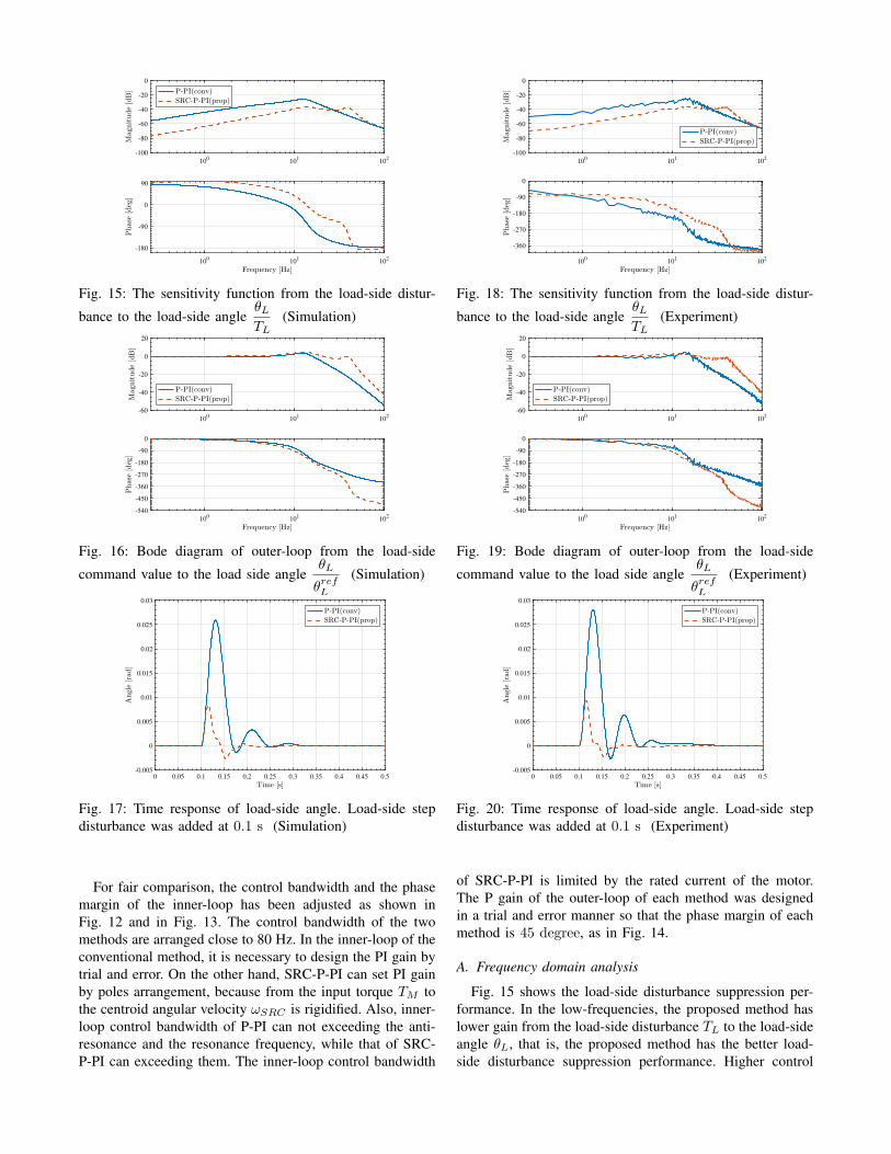
Fig. 15: The sensitivity function from the load-side distur-
bance to the load-side angleθLTL
(Simulation)
100
101
102
-60
-40
-20
0
20
100
101
102
-540
-450
-360
-270
-180
-90
0
Fig. 16: Bode diagram of outer-loop from the load-side
command value to the load side angleθL
θrefL
(Simulation)
0 0.05 0.1 0.15 0.2 0.25 0.3 0.35 0.4 0.45 0.5-0.005
0
0.005
0.01
0.015
0.02
0.025
0.03
Fig. 17: Time response of load-side angle. Load-side stepdisturbance was added at 0.1 s (Simulation)
For fair comparison, the control bandwidth and the phasemargin of the inner-loop has been adjusted as shown inFig. 12 and in Fig. 13. The control bandwidth of the twomethods are arranged close to 80 Hz. In the inner-loop of theconventional method, it is necessary to design the PI gain bytrial and error. On the other hand, SRC-P-PI can set PI gainby poles arrangement, because from the input torque TM tothe centroid angular velocity ωSRC is rigidified. Also, inner-loop control bandwidth of P-PI can not exceeding the anti-resonance and the resonance frequency, while that of SRC-P-PI can exceeding them. The inner-loop control bandwidth
100
101
102
-100
-80
-60
-40
-20
0
100
101
102
-360
-270
-180
-90
0
Fig. 18: The sensitivity function from the load-side distur-
bance to the load-side angleθLTL
(Experiment)
100
101
102
-60
-40
-20
0
20
100
101
102
-540
-450
-360
-270
-180
-90
0
Fig. 19: Bode diagram of outer-loop from the load-side
command value to the load side angleθL
θrefL
(Experiment)
0 0.05 0.1 0.15 0.2 0.25 0.3 0.35 0.4 0.45 0.5-0.005
0
0.005
0.01
0.015
0.02
0.025
0.03
Fig. 20: Time response of load-side angle. Load-side stepdisturbance was added at 0.1 s (Experiment)
of SRC-P-PI is limited by the rated current of the motor.The P gain of the outer-loop of each method was designedin a trial and error manner so that the phase margin of eachmethod is 45 degree, as in Fig. 14.
A. Frequency domain analysis
Fig. 15 shows the load-side disturbance suppression per-formance. In the low-frequencies, the proposed method haslower gain from the load-side disturbance TL to the load-sideangle θL, that is, the proposed method has the better load-side disturbance suppression performance. Higher control

TABLE III: Comparison of performance of SRC-P-PI andP-PI
Hand-tuning parameters Disturbance suppression Control bandwidthP-PI 3 (P, P and I gain) (standard) 16 Hz
SRC-P-PI 2 (P and ωc of APF) better 41 Hz
bandwidth of inner-loop which exceed the anti-resonanceand resonance frequency and feedback θSRC including infor-mation on the load-side improves the load-side disturbancesuppression performance.
We compared the closed-loop frequency characteristicsfrom the command value θrefL to the output θL in Fig. 16.The proposed method has higher control bandwidth than theconventional method.
TABLE III shows the comparison of performance of SRC-P-PI and P-PI. SRC-P-PI is better in both the disturbancesuppression performance and the control bandwidth despitethe small number of hand-tuning parameters. The controlbandwidth is defined at a frequency at which the gain is−3 dB.
B. Time Responses
Fig. 17 shows the simulation result of the load-side stepdisturbance response. The output is the load-side angleθL. The command value θrefL is 0.0 rad. The load-sidedisturbance force (0.5 N) is added at 0.1 s.
In terms of minimizing the maximum fluctuation of output,the proposed method is better than conventional method. Ifsettling time is defined as the time response curve to reachand stay within a range of ±0.001 rad, the settling time ofP-PI is 0.2330 s and that of SRC-P-PI is 0.1654 s. SRC-P-PIsettles in less time.
V. EXPERIMENT
A. Frequency domain analysis
We conducted experiments using the motor bench shownin Fig. 5. The experiments conditions are the same as thesimulations conditions. The controllers are discretized byTustin conversion whose sampling frequency is 2.5 kHz.The results of experiments are almost the same as the thoseof simulations.
Fig. 18 shows the load-side disturbance suppression per-formance. Since the motor-bench has load-side motor, it ispossible to input torque from the load-side. The measure-ment experiment were conducted using a frequency domainidentification method [10].
The proposed method has the better load-side disturbancesuppression performance. We compared the closed-loop fre-quency characteristics from the command value θrefL to theoutput θL in Fig. 19. The proposed method has higher controlbandwidth than the conventional method.
B. Time Responses
Fig. 20 shows the experiment result of the load-sidestep disturbance response. If settling time is defined as the
time response curve to reach and stay within a range of±0.001 rad, the settling time of P-PI is 0.2616 s and that ofSRC-P-PI is 0.1644 s. SRC-P-PI settles in less time.
VI. CONCLUSIONP-PI system is widely used in the industry as a method
using a load-side encoder to control the load-side angleof two-mass system. The proposed method has a similarstructure to P-PI control and controls the center-of-gravityangular velocity in the inner-loop. In the proposed method,poles of inner-loop can be arranged arbitrarily by the PIcontroller, and it is possible to design inner-loop with highcontrol bandwidth exceeding resonance and anti-resonance.As a results, the disturbance suppression performance andthe outer-loop control bandwidth of proposed method aresuperior to that of P-PI. Robots work in environments oftenreceiving external force, therefore the disturbance suppres-sion performance is important. In addition, the number ofhand-tuning parameters of the proposed method is one lessthan that of the P-PI control, that is, the proposed method iseasier to design controllers.
REFERENCES
[1] K. Yuki, T. Murakami, and K. Ohnishi, “Vibration control of a 2 massresonant system by the resonance ratio control,” IEEJ Transactions onIndustry Applications, vol. 113, no. 10, pp. 1162–1169, 1994.
[2] Y. Hori, “2-mass system control based on load-side acceleration con-trol and state feedback,” IEEJ Transactions on Industry Applications,vol. 112(5), pp. 499–500, 1992.
[3] E. Saito and S. Katsura, “Vibration control of two-mass resonantsystem based on wave compensator,” IEEJ Transactions on IndustryApplications, vol. 132, no. 4, pp. 2672–2677, 2011.
[4] M. Aoki, “Robust Resonance Suppression Control based on SelfResonance Cancellation Disturbance Observer and Application toHumanoid Robot,” in 2013 IEEE International Conference on Mecha-tronics (ICM), 2013, pp. 623–628.
[5] K. Sakata, H. Asaumi, K. Hirachi, K. Saiki, and H. Fujimoto, “SelfResonance Cancellation Techniques for a Two-Mass System andIts Application to a Large-Scale Stage,” IEEJ Journal of IndustryApplications, vol. 3, no. 6, pp. 455–462, 2014.
[6] S. Yamada, K. Inukai, and H. Fujimoto, “Proposal of Self ResonanceCancellation Control without Using Drive-Side Information,” in In-dustrial Electronics Society, IECON 2015 - 41st Annual Conferenceof the IEEE, 2015, pp. 783–788.
[7] K. Sakata, K. Saiki, and H. Fujimoto, “Self Resonance Cancellationusing Multiple Sensors for Ballscrew Driven Stage,” in 2011I EE-Japan Industry Application Society Conference (IEEJ JIASC 2011),no. 1, 2011, pp. 521–526.
[8] Y. Ito, S. Nozawa, J. Urata, T. Nakaoka, and K. Kobayashi, “Develop-ment and Verification of Life-Size Humanoid with High-Output Ac-tuation System,” in 2014 IEEE International Conference on Roboticsand Automation (ICRA), 2014, pp. 3433–3438.
[9] J. L. &. J.-H. O. Ill-Woo Park, Jung-Yup Kim, “Mechanical designof the humanoid robot platform, HUBO,” Advanced Robotics, vol. 21,no. 11, pp. 1305–1322, 2007.
[10] J. Pitelon, Rik Schoukens, System Identification: A Frequency DomainApproach, 2nd Editon. Wiley-IEEE Press, 2012.