robolux multiway multiport diaphragm valve, standard ... · robolux multiway multiport diaphragm...
TRANSCRIPT
2035 pneumatically operated
p. 1/12www.burkert.com
Robolux Multiway Multiport Diaphragm Valve, standard product range
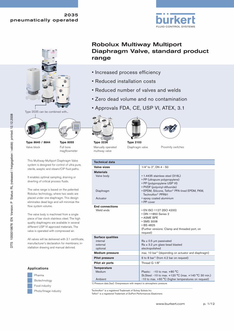
This Multiway-Multiport Diaphragm Valve
system is designed for control of ultra pure,
sterile, aseptic and steam/CIP fl uid paths.
It enables optimal sampling, draining or
diverting of critical process fl uids.
The valve range is based on the patented
Robolux technology, where two seats are
placed under one diaphragm. This design
eliminates dead legs and will minimize the
fl ow system volume.
The valve body is machined from a single
piece of bar stock stainless steel. The high
quality diaphragms are available in several
different USP VI approved materials. The
valve is operated with compressed air.
All valves will be delivered with 3.1 certifi cate,
manufacturer's declaration for membrans, in-
stallation drawing and manual delivred.
Technical data
Valve sizes 1/4” to 2”, DN 4 - 50
Materials
Valve body
Diaphragm
Actuator
• 1.4435 stainless steel (316L)
• PP (ultrapure polypropylene)
• PP (polypropylene USP VI)
• PVDF (polyvinyl-difluoride)
• EPDM, Silicone, Teflon® PFA-lined EPDM, FKM,
Technoflon® PFR91
• epoxy coated aluminium
• PP cover
End connections
Weld ends • EN ISO 1127 (ISO 4200)
• DIN 11850 Series 2
• ASME BPE
• SMS 3008
• BS 4825
(Further versions: Clamp and threaded port, on
request)
Surface qualities
internal
external
optional
Ra ≤ 0.5 μm passivated
Ra ≤ 3.2 μm glass bead blasted
electropolished
Medium pressure max. 10 bar1) (depending on actuator and diaphragm)
Pilot pressure 6 to 8 bar1) (from 4.2 bar on request)
Pilot air ports Thread G 1/8”
Temperature
Medium
Ambient
Plastic: -10 to max. +80 °C
St.Steel: -10 to max. +120 °C (max. +140 °C 30 min.)
-10 to max. +60 °C (higher temperatures on request)
Type 8640 / 8644
Valve block
Type 8055
Full bore
magfl owmeter
Type 3236
Manually operated
multiway valve
Type 2035 can be combined with...
Pharma
Biotechnology
Food industry
Photo/Image industry
Applications
Type 2103
Diaphragm valve Proximity switches
1) Pressure data [bar]: Overpressure with respect to atmospheric pressure
Technofl on® is a registered Trademark of Solvey Solexis Inc.
Tefl on® is a registered Trademark of DuPont Performances Elastomers
• Increased process efficiency
• Reduced installation costs
• Reduced number of valves and welds
• Zero dead volume and no contamination
• Approvals FDA, CE, USP VI, ATEX, 3.1
2035 pneumatically operated
p. 2/12
Further technical data
Kv value and CIP rate
Orifi ce DNPort connection
Valvesize
Actuatorsize
Actuator designation
Kv value water diaphragm EPDM, FKM
Kv value water Membran PFA
CIP rate (m/s] at 1 bar1)
[mm] [m3/h] [m3/h] EPDM, FKM PFA
10 3/8” 050 RV50 0.8 0.7 3.1 2.7
15 1/2” 050 RV50 2.5 2.0 5.5 4.4
20 3/4” 050 RV50 3.5 3.3 3.9 3.4
25 1” 070 RV70 10.0 9.0 6.6 6.0
40 1 1/2” 110 RV110 27.0 22.0 6.6 5.4
50 2” 110 RV110 35.0 27.0 5.1 4.0
Remark: All Kv values are measured on valves with port connection according ASME BPE.
1) Pressure data [bar]: Overpressure with respect to atmospheric pressure
Medium pressure
Actuator versions Body material Pilot pressure [bar]
EPDM, FKM, Silicone, PFR91 max. operating pressure [bar]
PFA / EPDMmax. operating pressure [bar]
RV50 stainless steel, PP 6 - 10 10 10
RV50 stainless steel, PP 4.2 - 10 8 8
RV70 stainless steel 6 - 10 10 8
RV70 stainless steel 4.2 - 10 8 6
RV70 PP 6 - 10 8 6
RV70 PP 4.2 - 10 6 –
RV110 stainless steel 6 - 10 8 8
RV110 stainless steel 4.2 - 10 6 6
2035 pneumatically operated
p. 3/12
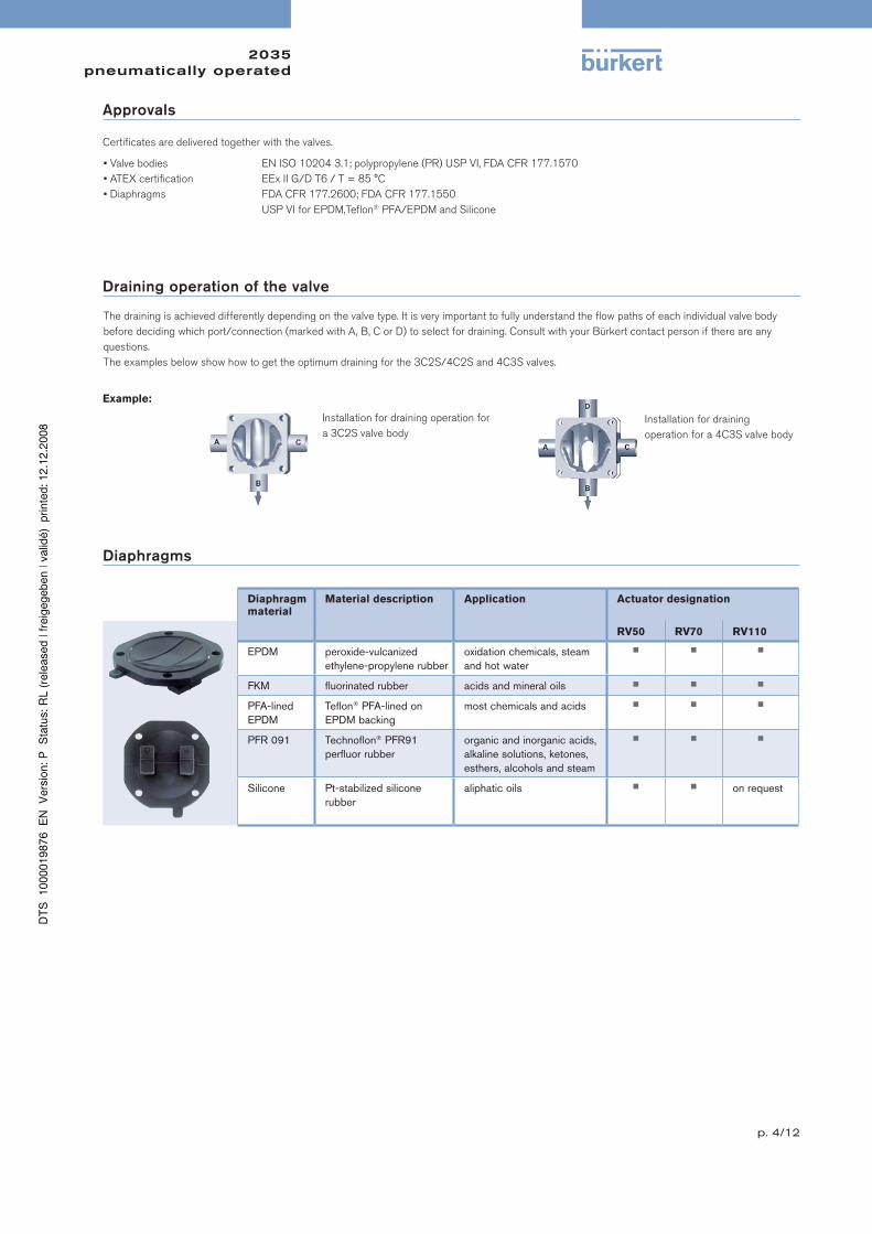
Valve symbols and flow patterns
3Connections 2Seats;
3C2S (formerly 3w3p)
4Connections 2Seats;
4C2S (formerly 3w4p)
3Connections 3Seats;
3C3S (formerly 4w3p)
4Connections 3Seats;
4C3S (formerly 4w4p)
4Connections 3Seats; 4C3S BD
(formerly 4w4p BD) filter valve
4Connections 4Seats
4C4S (formerly 6w4p)
4Connections 4Seats;
4C4S DFP (formerly 4w4p DFP)
4Connections 5Seats;
4C5S CHR (formerly 5w4p)
Chromatography valve
upper side lower side
upper side lower side upper side lower side upper side lower side
upper side upper sidelower side lower side
Seat U1
SeatU2
Seat U1
Seat U2
Seat U1
Seat L1
Seat U2
Seat L1
Seat L1
SeatU1
SeatU2
Seat U1
SeatU2
Seat U1
SeatU2
Seat L1
Seat L2
Seat U1
Seat U2
Seat L1
Seat L2
AC
B1
CA
B1 B2
Seat U1
Seat U2
Seat L1
Seat L2
2035 pneumatically operated
p. 4/12
Approvals
Certifi cates are delivered together with the valves.
• Valve bodies EN ISO 10204 3.1; polypropylene (PR) USP VI, FDA CFR 177.1570
• ATEX certifi cation EEx II G/D T6 / T = 85 °C
• Diaphragms FDA CFR 177.2600; FDA CFR 177.1550
USP VI for EPDM,Tefl on® PFA/EPDM and Silicone
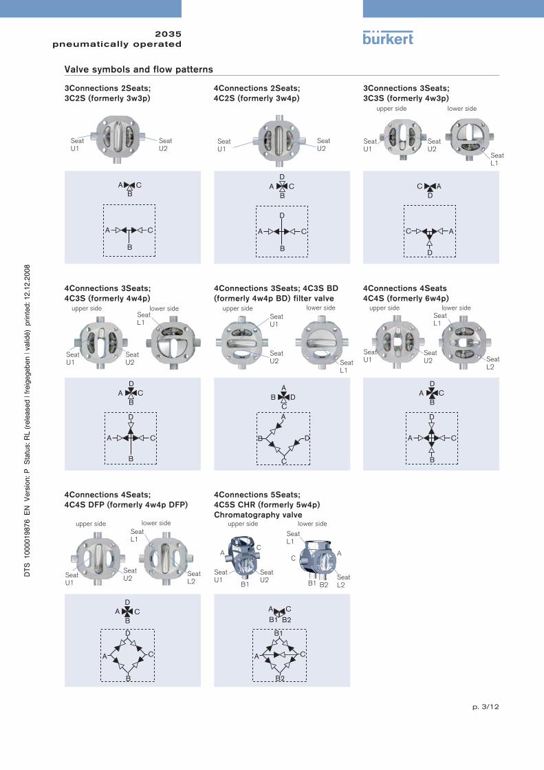
Draining operation of the valve
The draining is achieved differently depending on the valve type. It is very important to fully understand the fl ow paths of each individual valve body
before deciding which port/connection (marked with A, B, C or D) to select for draining. Consult with your Bürkert contact person if there are any
questions.
The examples below show how to get the optimum draining for the 3C2S/4C2S and 4C3S valves.
Example:
Installation for draining operation for
a 3C2S valve body
Installation for draining
operation for a 4C3S valve body
Diaphragms
Diaphragm material
Material description Application Actuator designation
RV50 RV70 RV110
EPDM peroxide-vulcanized
ethylene-propylene rubber
oxidation chemicals, steam
and hot water
■ ■ ■
FKM fl uorinated rubber acids and mineral oils ■ ■ ■
PFA-lined
EPDM
Tefl on® PFA-lined on
EPDM backing
most chemicals and acids ■ ■ ■
PFR 091 Technofl on® PFR91
perfl uor rubber
organic and inorganic acids,
alkaline solutions, ketones,
esthers, alcohols and steam
■ ■ ■
Silicone Pt-stabilized silicone
rubber
aliphatic oils ■ ■ on request
2035 pneumatically operated
p. 5/12
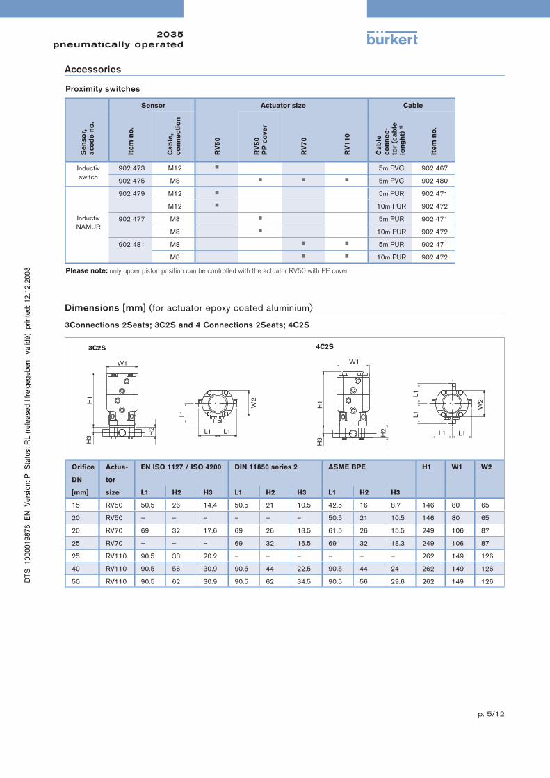
Dimensions [mm] (for actuator epoxy coated aluminium)
3Connections 2Seats; 3C2S and 4 Connections 2Seats; 4C2S
Orifi ce Actua- EN ISO 1127 / ISO 4200 DIN 11850 series 2 ASME BPE H1 W1 W2
DN tor
[mm] size L1 H2 H3 L1 H2 H3 L1 H2 H3
15 RV50 50.5 26 14.4 50.5 21 10.5 42.5 16 8.7 146 80 65
20 RV50 – – – – – – 50.5 21 10.5 146 80 65
20 RV70 69 32 17.6 69 26 13.5 61.5 26 15.5 249 106 87
25 RV70 – – – 69 32 16.5 69 32 18.3 249 106 87
25 RV110 90.5 38 20.2 – – – – – – 262 149 126
40 RV110 90.5 56 30.9 90.5 44 22.5 90.5 44 24 262 149 126
50 RV110 90.5 62 30.9 90.5 62 34.5 90.5 56 29.6 262 149 126
3C2S 4C2S
Accessories
Proximity switches
Sensor Actuator size Cable
Se
nso
r,
aco
de
no
.
Ite
m n
o.
Ca
ble
, co
nn
ecti
on
RV
50
RV
50
PP
co
ve
r
RV
70
RV
110
Ca
ble
co
nn
ec-
tor
(ca
ble
le
ng
ht)
1)
Ite
m n
o.
Inductiv
switch
902 473 M12 ■ 5m PVC 902 467
902 475 M8 ■ ■ ■ 5m PVC 902 480
Inductiv
NAMUR
902 479 M12 ■ 5m PUR 902 471
M12 ■ 10m PUR 902 472
902 477 M8 ■ 5m PUR 902 471
M8 ■ 10m PUR 902 472
902 481 M8 ■ ■ 5m PUR 902 471
M8 ■ ■ 10m PUR 902 472
Please note: only upper piston position can be controlled with the actuator RV50 with PP cover
2035 pneumatically operated
p. 6/12
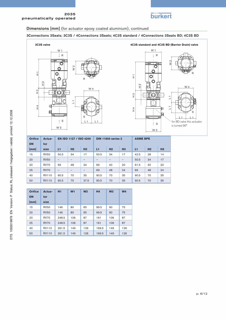
Dimensions [mm] (for actuator epoxy coated aluminium), continued
3Connections 3Seats; 3C3S / 4Connections 3Seats; 4C3S standard / 4Connections 3Seats BD; 4C3S BD
Orifi ce Actua- EN ISO 1127 / ISO 4200 DIN 11850 series 2 ASME BPE
DN tor
[mm] size L1 H2 H3 L1 H2 H3 L1 H2 H3
15 RV50 50.5 34 17 50.5 34 17 42.5 28 14
20 RV50 – – – – – – 50.5 34 17
20 RV70 69 48 24 69 40 20 61.5 40 20
25 RV70 – – – 69 48 24 69 48 24
40 RV110 90.5 70 35 90.5 70 35 90.5 70 35
50 RV110 90.5 75 37.5 90.5 70 35 90.5 70 35
Orifi ce Actua- H1 W1 W2 H4 W3 W4
DN tor
[mm] size
15 RV50 146 80 65 99.5 90 75
20 RV50 146 80 65 99.5 90 75
20 RV70 248.5 106 87 161 106 87
25 RV70 248.5 106 87 161 106 87
40 RV110 261.5 149 126 169.5 149 126
50 RV110 261.5 149 126 169.5 149 126
3C3S valve 4C3S standard and 4C3S BD (Barrier Drain) valve
for BD valve this actuator
is turned 90°
2035 pneumatically operated
p. 7/12
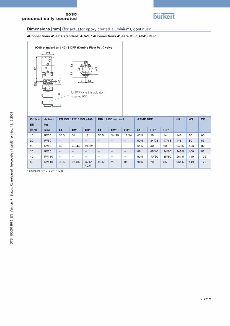
Dimensions [mm] (for actuator epoxy coated aluminium), continued
4Connections 4Seats standard; 4C4S / 4Connections 4Seats DFP; 4C4S DFP
Orifi ce Actua- EN ISO 1127 / ISO 4200 DIN 11850 series 2 ASME BPE H1 W1 W2
DN tor
[mm] size L1 H22) H32) L1 H22) H32) L1 H22) H32)
15 RV50 50.5 34 17 50.5 34/28 17/14 42.5 28 14 146 80 65
20 RV50 – – – – – – 50.5 34/28 17/14 146 80 65
20 RV70 69 48/44 24/22 – – – 61.5 40 20 248.5 106 87
25 RV70 – – – – – – 69 48/40 24/20 248.5 106 87
40 RV110 – – – – – – 90.5 70/60 35/30 261.5 149 126
50 RV110 90.5 75/85 37.5/
42.5
90.5 70 35 90.5 70 35 261.5 149 126
2) dimensions for 4C4S DFP / 4C4S
4C4S standard and 4C4S DFP (Double Flow Path) valve
for DFP valve this actuator
is turned 90°
2035 pneumatically operated
p. 8/12
Dimensions [mm] (for actuator epoxy coated aluminium), continued
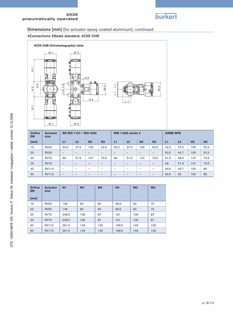
4C5S CHR (Chromatography) valve
4Connections 5Seats standard; 4C5S CHR
Orifi ceDN
Actuatorsize
EN ISO 1127 / ISO 4200 DIN 11850 series 2 ASME BPE
[mm] L1 L2 H2 H3 L1 L2 H2 H3 L1 L2 H2 H3
15 RV50 50.5 37.5 105 52.5 50.5 37.5 105 52.5 42.5 37.5 105 52.5
20 RV50 – – – – – – – – 50.5 40.7 105 52.5
20 RV70 69 51.5 147 73.5 69 51.5 147 73.5 61.5 48.4 147 73.5
25 RV70 – – – – – – – – 69 51.6 147 73.5
40 RV110 – – – – – – – – 90.5 45.7 160 80
50 RV110 – – – – – – – – 90.5 52 160 80
Orifi ceDN
Actuatorsize
H1 W1 W2 H4 W3 W4
[mm]
15 RV50 146 80 65 99.5 90 75
20 RV50 146 80 65 99.5 90 75
20 RV70 248.5 106 87 161 106 87
25 RV70 248.5 106 87 161 106 87
40 RV110 261.5 149 126 169.5 149 126
50 RV110 261.5 149 126 169.5 149 126
2035 pneumatically operated
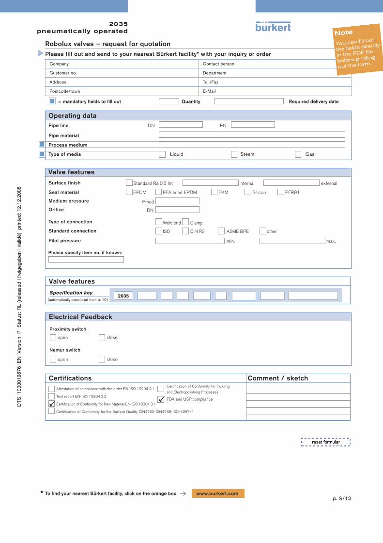
p. 9/12To fi nd your nearest Bürkert facility, click on the orange box www.burkert .com*
Attestation of compliance with the order EN-ISO 10204 2.1
Test report EN-ISO 10204 2.2
Certifi cation of Conformity for Raw Material EN-ISO 10204 3.1
Certifi cation of Conformity for the Surface Quality DIN4762-DIN4768-ISO/4287/1
Certifi cation of Conformity for Pickling
and Electropolishing Processes
FDA and USP compliance
= mandatory fi elds to fi ll out Quantity Required delivery date
Valve features
Company Contact person
Customer no. Department
Address Tel./Fax
Postcode/town E-Mail
Robolux valves – request for quotation
Please fill out and send to your nearest Bürkert facility* with your inquiry or order
Note
You can fill out
the fields directly
in the PDF file
before printing
out the form.
Certifications Comment / sketch
Specification key
(automatically transfered from p. 10)
Pipe line
Process medium
Type of media Liquid Steam Gas
DN PN
Surface finish
EPDM PFA lined EPDM FKM SiliconSeal material
Medium pressure Pmed
Orifice DN
Weld end Clamp Type of connection
ISO DIN R2 ASME BPE otherStandard connection
min. max.Pilot pressure
Pipe material
Please specify item no. if known:
Valve features
Operating data
Proximity switch
open close
Namur switch
Electrical Feedback
open close
PFR91
Standard Ra 0,5 Int internal external
2035
2035 pneumatically operated
p. 10/12
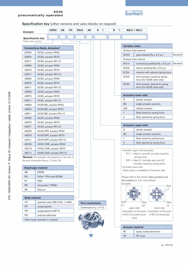
Specification key (other versions and valve blocks on request)
A
B
C
D
Connections-Seats, Actuators*
32R50 3C2S, actuator RV50
32R70 3C2S, actuator RV70
32R11 3C2S, actuator RV110
42R50 4C2S, actuator RV50
42R70 4C2S, actuator RV70
42R11 4C2S, actuator RV110
33R50 3C3S, actuator RV50
33R70 3C3S. actuator RV70
33R11 3C3S, actuator RV110
43R50 4C3S, actuator RV50
43R70 4C3S, actuator RV70
43R11 4C3S, actuator RV110
43B50 4C3S BD, actuator RV50
43B70 4C3S BD, actuator RV70
43B11 4C3S BD, actuator RV110
44R50 4C4S, actuator RV50
44R70 4C4S, actuator RV70
44R11 4C4S, actuator RV110
44D50 4C4S DFP, actuator RV50
44D70 4C4S DFP, actuator RV70
44D11 4C4S DFP, actuator RV110
45C50 4C5S CHR, actuator RV50
45C70 4C5S CHR, actuator RV70
45C11 4C5S CHR, actuator RV110
*Remark: The actuator size depends on the size of
the port connection (see p. 12 and 13)
Diaphragm material
AB EPDM
PN Tefl on® PFA-lined EPDM
FF FKM
PR Technofl on® PFR91
SK Silicone
Body material
VH stainless steel AISI 316L, 1.4435
PP polypropylene
PR polypropylene USP VI
PD polyvinyl difl uoride
Other body materials on request!
Variable codes
Surface fi nish external
NO22 glass-blasted Ra ≤ 3.2 μm
Surface fi nish internal
NO14 mechanical polished Ra ≤ 0.5 μm
NO25 electro polished Ra ≤ 0.5 μm
EC04 versions with reduced spring force
NC29 third actuator closed by spring
force (for 4C5S valve only)
NC30 third actuator opened by spring
force (for 4C5S valve only)
Actuators lower side*
D double actuator
SE single actuator excentric
000 without actuator
1 Seat closed by spring force
2 Seat opened by spring force
Actuators upper side*
D double actuator
SE single actuator excentric
1 Seat closed by spring force
2 Seat opened by spring force
Actuator material
AE epoxy coated aluminium
AP PP cover
• Actuator upper side (example)
D11 = Seat U1 and U2 normally closed by
spring action
D21 = Seat U1 normally open and U2
normally closed by spring action
• Actuator lower side
Same option is available for the lower side.
Please refer to the section Valve symbols and
fl ow patterns p. 3 for more details.
Example:
upper side
(orientation of the ports
A-B-C-D counter clock-
wise)
lower side
(orientation of the ports
A-B-C-D clockwise)
Seat
U2
Seat
U1
Seat
L2
Seat
L1
A
B
C
D
Port connections
Continued on p. 11/12
Specification key
Example
Please make a choice
Standard
Standard
32R50 AB VH SA42 AE NO22 + NO14D 1 D 1
2035 pneumatically operated
p. 11/12
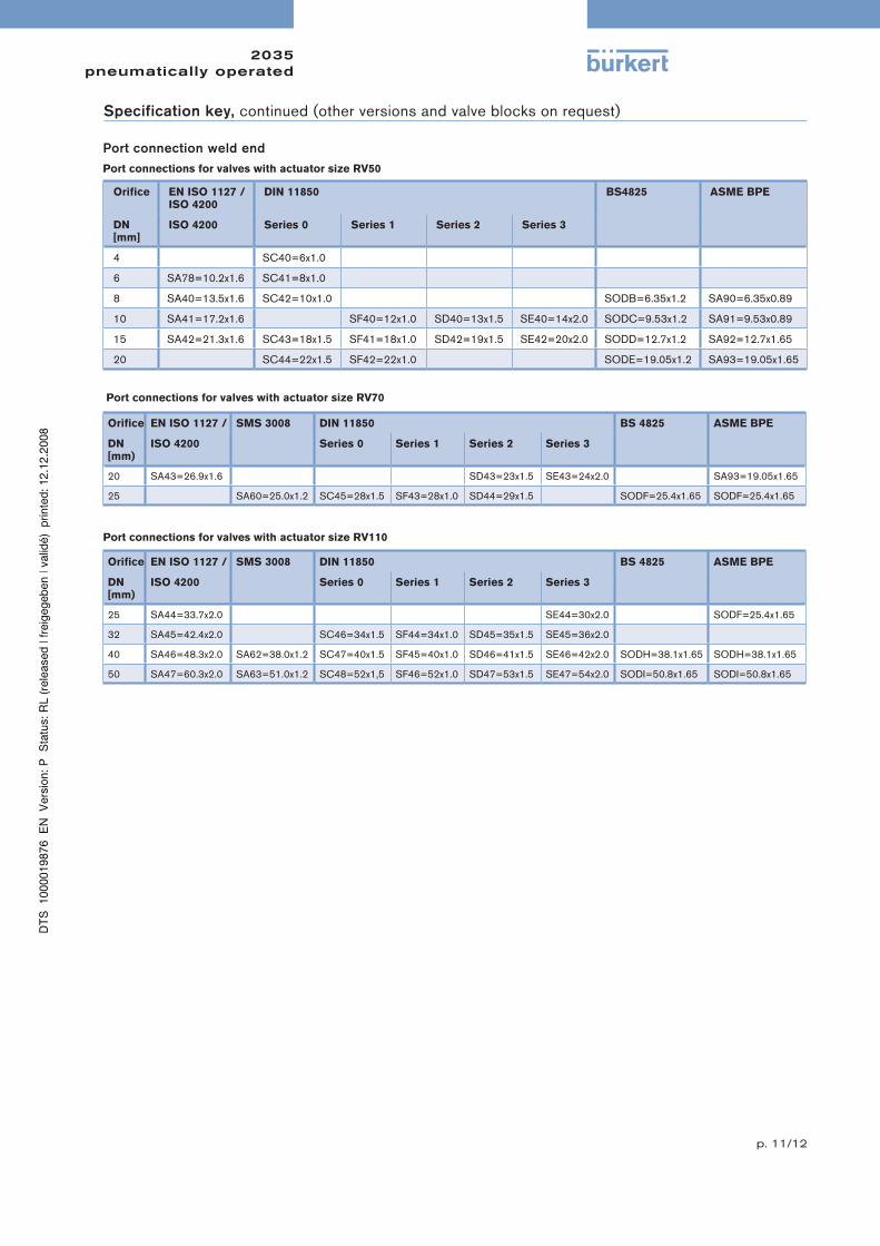
Specification key, continued (other versions and valve blocks on request)
Orifi ce EN ISO 1127 /ISO 4200
DIN 11850 BS4825 ASME BPE
DN [mm]
ISO 4200 Series 0 Series 1 Series 2 Series 3
4 SC40=6x1.0
6 SA78=10.2x1.6 SC41=8x1.0
8 SA40=13.5x1.6 SC42=10x1.0 SODB=6.35x1.2 SA90=6.35x0.89
10 SA41=17.2x1.6 SF40=12x1.0 SD40=13x1.5 SE40=14x2.0 SODC=9.53x1.2 SA91=9.53x0.89
15 SA42=21.3x1.6 SC43=18x1.5 SF41=18x1.0 SD42=19x1.5 SE42=20x2.0 SODD=12.7x1.2 SA92=12.7x1.65
20 SC44=22x1.5 SF42=22x1.0 SODE=19.05x1.2 SA93=19.05x1.65
Orifi ce EN ISO 1127 / SMS 3008 DIN 11850 BS 4825 ASME BPE
DN [mm)
ISO 4200 Series 0 Series 1 Series 2 Series 3
20 SA43=26.9x1.6 SD43=23x1.5 SE43=24x2.0 SA93=19.05x1.65
25 SA60=25.0x1.2 SC45=28x1.5 SF43=28x1.0 SD44=29x1.5 SODF=25.4x1.65 SODF=25.4x1.65
Orifi ce EN ISO 1127 / SMS 3008 DIN 11850 BS 4825 ASME BPE
DN [mm)
ISO 4200 Series 0 Series 1 Series 2 Series 3
25 SA44=33.7x2.0 SE44=30x2.0 SODF=25.4x1.65
32 SA45=42.4x2.0 SC46=34x1.5 SF44=34x1.0 SD45=35x1.5 SE45=36x2.0
40 SA46=48.3x2.0 SA62=38.0x1.2 SC47=40x1.5 SF45=40x1.0 SD46=41x1.5 SE46=42x2.0 SODH=38.1x1.65 SODH=38.1x1.65
50 SA47=60.3x2.0 SA63=51.0x1.2 SC48=52x1,5 SF46=52x1.0 SD47=53x1.5 SE47=54x2.0 SODI=50.8x1.65 SODI=50.8x1.65
Port connection weld end
Port connections for valves with actuator size RV50
Port connections for valves with actuator size RV70
Port connections for valves with actuator size RV110
2035 pneumatically operated
p. 12/12
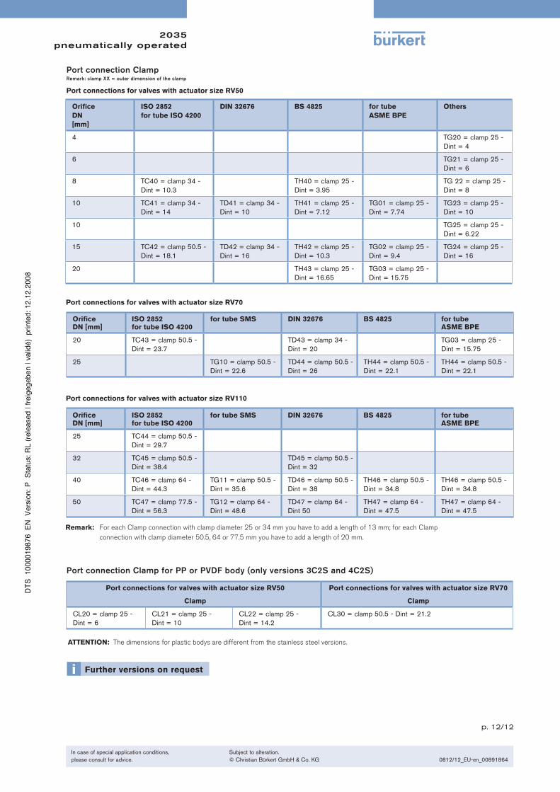
Orifi ceDN [mm]
ISO 2852for tube ISO 4200
for tube SMS DIN 32676 BS 4825 for tubeASME BPE
20 TC43 = clamp 50.5 -
Dint = 23.7
TD43 = clamp 34 -
Dint = 20
TG03 = clamp 25 -
Dint = 15.75
25 TG10 = clamp 50.5 -
Dint = 22.6
TD44 = clamp 50.5 -
Dint = 26
TH44 = clamp 50.5 -
Dint = 22.1
TH44 = clamp 50.5 -
Dint = 22.1
Orifi ceDN [mm]
ISO 2852for tube ISO 4200
for tube SMS DIN 32676 BS 4825 for tubeASME BPE
25 TC44 = clamp 50.5 -
Dint = 29.7
32 TC45 = clamp 50.5 -
Dint = 38.4
TD45 = clamp 50.5 -
Dint = 32
40 TC46 = clamp 64 -
Dint = 44.3
TG11 = clamp 50.5 -
Dint = 35.6
TD46 = clamp 50.5 -
Dint = 38
TH46 = clamp 50.5 -
Dint = 34.8
TH46 = clamp 50.5 -
Dint = 34.8
50 TC47 = clamp 77.5 -
Dint = 56.3
TG12 = clamp 64 -
Dint = 48.6
TD47 = clamp 64 -
Dint 50
TH47 = clamp 64 -
Dint = 47.5
TH47 = clamp 64 -
Dint = 47.5
Remark: For each Clamp connection with clamp diameter 25 or 34 mm you have to add a length of 13 mm; for each Clamp
connection with clamp diameter 50.5, 64 or 77.5 mm you have to add a length of 20 mm.
Port connection Clamp for PP or PVDF body (only versions 3C2S and 4C2S)
Port connections for valves with actuator size RV50 Port connections for valves with actuator size RV70
Clamp Clamp
CL20 = clamp 25 -
Dint = 6
CL21 = clamp 25 -
Dint = 10
CL22 = clamp 25 -
Dint = 14.2
CL30 = clamp 50.5 - Dint = 21.2
ATTENTION: The dimensions for plastic bodys are different from the stainless steel versions.
Port connection ClampRemark: clamp XX = outer dimension of the clamp
Port connections for valves with actuator size RV50
Orifi ce
DN
[mm]
ISO 2852
for tube ISO 4200
DIN 32676 BS 4825 for tube
ASME BPE
Others
4 TG20 = clamp 25 -
Dint = 4
6 TG21 = clamp 25 -
Dint = 6
8 TC40 = clamp 34 -
Dint = 10.3
TH40 = clamp 25 -
Dint = 3.95
TG 22 = clamp 25 -
Dint = 8
10 TC41 = clamp 34 -
Dint = 14
TD41 = clamp 34 -
Dint = 10
TH41 = clamp 25 -
Dint = 7.12
TG01 = clamp 25 -
Dint = 7.74
TG23 = clamp 25 -
Dint = 10
10 TG25 = clamp 25 -
Dint = 6.22
15 TC42 = clamp 50.5 -
Dint = 18.1
TD42 = clamp 34 -
Dint = 16
TH42 = clamp 25 -
Dint = 10.3
TG02 = clamp 25 -
Dint = 9.4
TG24 = clamp 25 -
Dint = 16
20 TH43 = clamp 25 -
Dint = 16.65
TG03 = clamp 25 -
Dint = 15.75
Port connections for valves with actuator size RV70
Port connections for valves with actuator size RV110
In case of special application conditions,
please consult for advice.
Subject to alteration.
© Christian Bürkert GmbH & Co. KG 0812/12_EU-en_00891864