robo circuit
TRANSCRIPT
INTRODUCTION
BASIC OF ROBOTICS.
STRUCTURE OF A ROBOT.
COMPONENTS & TOOLS. REQUIREMENTS.
RELAY LOGIC CKT..
HOW TO MAKE IT..??
HOW IT RUNS…???
APPLICATIONS.
----------------------------------------------------------------
1
BASIC OF ROBOTIC :-
Robot is a virtual or mechanical artificial agent. In practice, it is usually an electro-mechanical machine which is guided by computer or electronic programming, and is thus able to do tasks on its own. Another common characteristic is that by its appearance or movements, a robot often conveys a sense that it has intent or agency of its own. In easy words, A device that responds to sensory input.
COMPONENTS
DC MOTORS.
RADIO FREQUENCY CIRCUIT (Transmitter & Receiver).
DRIVER CKT. (Relay Logic)
STRUCTURE BASE.
BATTERIES (For RF ckt. & DC motors).
WHEELS.
MISCELLANIOUS PARTS(Wheels, Clamps, Wires, Screws etc…)
2
BLOCKDIAGRAM OF WHOLE STRUCTURE:
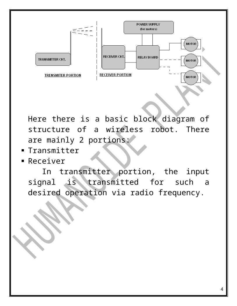
Here there is a basic block diagram of structure of a wireless robot. There are mainly 2 portions:
Transmitter Receiver
In transmitter portion, the input signal is transmitted for such a desired operation via radio frequency.
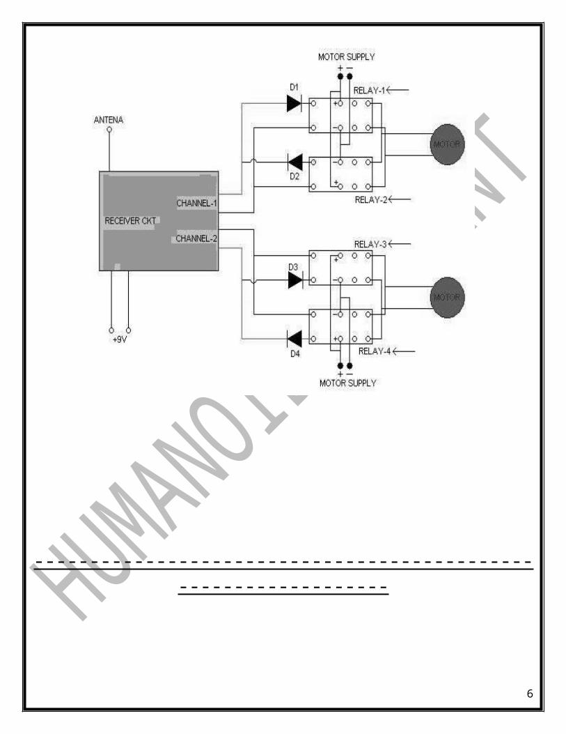
The receiver will receives that signals & identify the input signal for that operation & sends control signals to the driver ckt. Normally relay logic is used for this purpose. Devices (here a D.C. Motor) )to be controlled are connected with this driver ckt. External power is given to that device from driver ckt.
3
RELAY LOGIC CIRCUIT
----------------------------------------------------------------
4
HOW TO MAKE IT….???
All the stuffes we have, now time to connect & build heart of robot-Driver ckt.
First of all, relay board is necessary to make. As shown in figure, for controlling of 1 channel we should need 2 diodes, 2 relays, 1 motor, Power source for motor.Here we have taken a 12V DC motor.
Connect diodes with relay as shown figure. There are 2 relays are connected in parallel but different diode polarities are there.
Our aim is to run motor in both directions – forward and reverse. Means we have to supply the motor in 2 different polarities, for that the power supply is connected with both relays in different polarities.
Remember that the diodes & supply are connected with different polarities.
The input signal for relay is taken from RF ckt.
5
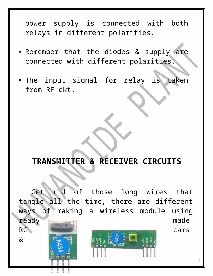
TRANSMITTER & RECEIVER CIRCUITS
Get rid of those long wires that tangle all the time, there are different ways of making a wireless module using ready made RC cars & putting relays near the output we can drive your 12v motors ,then there is IR remote control though not that much reliable & then there is DTMF thats their cell phone & GPRS communication, & the most simplest of them using RF modules, in consideration with all the above ways rf module is the most easiest & most cheapest (RS 550) nothing more. .
6
Transmitter(TX) & Receiver (RX) which u get in electronic shops. TX 01 ASK MODULE and RX 02 ASK MODULE are used here & shown above. Our
The two ICs HT12E & HT12D ar the encoder n decoders of 4 adress bit this is used as we need to drive 2 motors ,where each motor takes in 2 address bit (1 for forward rotation other for reverse ) so in all we need 4 address bits if we want to control more no. of motors we need to change encoder and decoders. At place of those switches we can either use push buttons are DPDT’s. Now near the receiving end we use a motor driver bcoz we get 5V as output but motors need 12v to drive them, so we should connect driver ckt as mentioned above.
7
HOW IT RUNS…???
When we input from our transmitter, Receiver will receives that signals & decode it & sends control signals to Relay Board.As per input, relay circuit will turn ON or turn OFF in directions that we want.
For example, if we input FORWARD from transmitter, receiver will receive it & send this signals to relay board. Here that relay which run a motor in forward direction will turn ON & vice-versa.
Here as our circuit, different power supplies are given to receiver & motors.
APPLICATION
For gaming purpose like racing, war, football, marine etc… In industries, most of process done by the robotic concept. In some places where PICK-N-PLACE is required like Stores. In biomedical field, Robotic Arms have proven to be blessings
for leg & limb amputees. In security purpose at any place, our home, public places, or
country boarders.
8
9