roadway elevation of rail - texas corrugators
TRANSCRIPT
StandardDivisionBridge
of this standard to other for
mats or for in
correct results or da
mages resultin
g fro
m its use.
kin
d is
made by Tx
DO
T for any purpose
whatsoever. Tx
DO
T assu
mes no responsibilit
y for the conversio
n
The use of this standard is governed by the "T
exas E
ngin
eerin
g Practic
e
Act".
No
warranty of any
DIS
CL
AI
ME
R:
FILE:
DA
TE:
DN: CK: DW: CK:FILE:
JOB
COUNTY
SECT
DIST
REVISIONS
TxDOT AES JTR AES
HIGHWAY
SHEET NO.
C TxDOT
CONT
rlstd037.dgn
July 2014
TRAFFIC RAIL
SHEET 1 OF 2
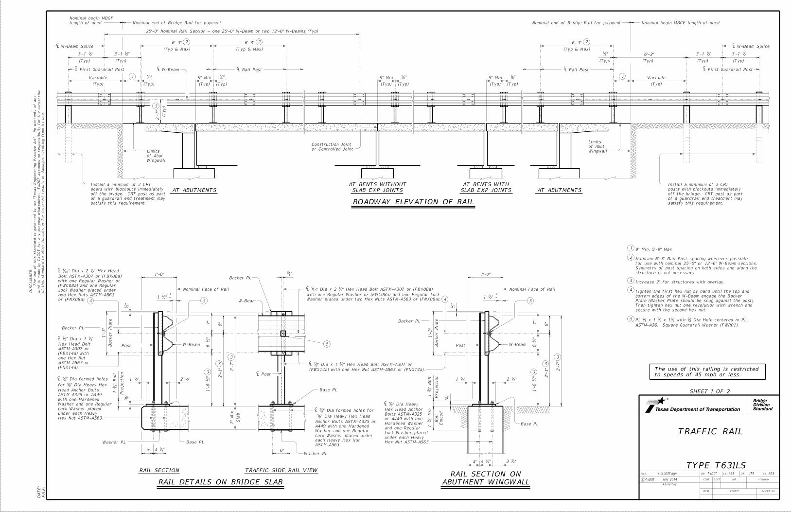
ROADWAY ELEVATION OF RAIL
Wingwall
of Abut
Limitsor Controlled Joint
Construction Joint
(Typ)
"85
9" Min
(Typ) (Typ)
"85
9" Min
(Typ) (Typ)
"85
"213'-1
C
(Typ)
L Rail Post
2'-
1"
(Typ)3
L W-BeamC
25'-0" Nominal Rail Section ~ one 25'-0" W-Beam or two 12'-6" W-Beams (Typ)
"213'-1
(Typ)
C
Variable
(Typ)
"213'-1
(Typ)
"213'-1
(Typ)
C
9" Min
(Typ) (Typ)
"85
(Typ)
Wingwall
of Abut
Limits
2
(Typ & Max)
C2
(Typ & Max)
CL W-Beam Splice
2
(Typ & Max)
CL Rail Post
Variable
"85
(Typ)
6'-3"
(Typ)
L W-Beam Splice
L First Guardrail Post L First Guardrail Post
1
2
3
5
"211
1'-0"
"212
" -211
+
Nominal Face of Rail
"2
1
Backer Plate
"8
5
7"
"2
16
"2
11'-
6
6"
2'-
1"
2'-
7"
Projectio
n
" B
olt
43
1
C
Sla
b
7"
Min
4
C
C
W-Beam
RAIL DETAILS ON BRIDGE SLAB
"85
C
C
5
5
W-Beam
C
RAIL SECTION TRAFFIC SIDE RAIL VIEW
3
3
3
(FNX14a).
ASTM-A563 or
one Hex Nut
(FBX14a) with
ASTM-A307 or
Hex Head Bolt
"41" Dia x 1 2
1L
Hex Nut ASTM-A563.
under each Heavy
Lock Washer placed
Washer and one Regular
with one Hardened
ASTM-A325 or A449
Head Anchor Bolts
" Dia Heavy Hex85for
" Dia formed holes87L
4" "414
1'-
3"
6"
"211
1'-0"
"212
" -211
+
Nominal Face of Rail
"2
1
Backer Plate
"8
5
7"
"2
16
"2
11'-
6
6"
2'-
1"
2'-
7"
Projectio
n
" B
olt
43
1
C
W-Beam
5
3
3
3
4" "414
1'-
3"
"433
" Min
41
7
Hex Nut ASTM-A563.
under each Heavy
Lock Washer placed
and one Regular
Hardened Washer
or A449 with one
Bolts ASTM-A325
Hex Head Anchor
" Dia Heavy85L
ABUTMENT WINGWALL
RAIL SECTION ON
(FBX14a) with one Hex Nut ASTM-A563 or (FNX14a).
" Hex Head Bolt ASTM-A307 or41" Dia x 1 2
1L
Washer placed under two Hex Nuts ASTM-A563 or (FNX08a).
with one Regular Washer or (FWC08a) and one Regular Lock
" Hex Head Bolt ASTM-A307 or (FBX08a)21" Dia x 2 16
5L
4
C
ASTM-A563.
each Heavy Hex Nut
Lock Washer placed under
Washer and one Regular
A449 with one Hardened
Anchor Bolts ASTM-A325 or
" Dia Heavy Hex Head85
" Dia formed holes for87L
or (FNX08a).
two Hex Nuts ASTM-A563
Lock Washer placed under
(FWC08a) and one Regular
with one Regular Washer or
Bolt ASTM-A307 or (FBX08a)
" Hex Head21" Dia x 2 16
5L
to speeds of 45 mph or less.
The use of this railing is restricted
6'-3" 6'-3" 6'-3"
Em
bed
Bolt
AT ABUTMENTS AT ABUTMENTS
Backer PL
Post
Washer PL Base PL
Washer PL
Base PL
L Post
Backer PL
Backer PL
Post
Base PL
TYPE T631LS
SLAB EXP JOINTS
AT BENTS WITHOUT
SLAB EXP JOINTS
AT BENTS WITH
satisfy this requirement.
of a guardrail end treatment may
off the bridge. CRT post as part
posts with blockouts immediately
Install a minimum of 2 CRT
satisfy this requirement.
of a guardrail end treatment may
off the bridge. CRT post as part
posts with blockouts immediately
Install a minimum of 2 CRT
1
ASTM-A36. Square Guardrail Washer (FWR01).
Dia Hole centered in PL,83 with 4
3 x 143 x 1 8
1PL
secure with the second hex nut.
Then tighten hex nut one revolution with wrench and
Plate (Backer Plate should be snug against the post).
bottom edges of the W-Beam engage the Backer
Tighten the first hex nut by hand until the top and
Increase 2" for structures with overlay.
structure is not necessary.
Symmetry of post spacing on both sides and along the
for use with nominal 25'-0" or 12'-6" W-Beam sections.
Maintain 6'-3" Rail Post spacing wherever possible
9" Min, 5'-9" Max
4
1
Nominal end of Bridge Rail for payment Nominal end of Bridge Rail for paymentlength of need
Nominal begin MBGF
Nominal begin MBGF length of need

StandardDivisionBridge
of this standard to other for
mats or for in
correct results or da
mages resultin
g fro
m its use.
kin
d is
made by Tx
DO
T for any purpose
whatsoever. Tx
DO
T assu
mes no responsibilit
y for the conversio
n
The use of this standard is governed by the "T
exas E
ngin
eerin
g Practic
e
Act".
No
warranty of any
DIS
CL
AI
ME
R:
FILE:
DA
TE:
DN: CK: DW: CK:FILE:
JOB
COUNTY
SECT
DIST
REVISIONS
TxDOT AES JTR AES
HIGHWAY
SHEET NO.
C TxDOT
CONT
rlstd037.dgn
July 2014
TRAFFIC RAIL
SHEET 2 OF 2
"2
16
21 2
1
"85
ELEVATION
Holes
" Dia85L C
"2
16
BACKER PLATE
8"
4" 4"
1"1" 6"
3"
"2
12
"2
12
8"
"2
12
"4
14
"4
11
Slotted Holes
" x 1"43L
C
C
Side
Traffic
ASTM-A992
L S3 x 5.7 41
8"
1"1" 6"
"4
14
"4
11
C
"4
11
"4
36
WASHER PLATE DETAIL
ASTM-A36
x 843 x 6 4
1PL
Holes
" Dia1611L
7"
"2
16
2'-
8"
3
"2
11'-
6
3
"8
5
"85
SECTION A-A
ASTM-A992
S3 x 5.7
only.
front flange
" Dia Hole83
only.
front flange
" Dia Hole169
" -
41
12
+21
21
2"
CL W-Beam Splice"2
13'-1
(Typ)
"213'-1
(Typ)
"213'-1
(Typ)" (Typ)4
14
(Typ)
CL W-Beam Splice
25'-0" or 12'-6"
Holes (Typ)
" Slotted21" x 2 4
3
8 Splice Holes (Typ)W-BEAM ELEVATION
Traffic Direction
W-BEAM SPLICE ELEVATION
"2112
2" 2"
"414
CL W-Beam Splice
Nut ASTM-A563 or (FBB01).
or with a double recessed Hex
Head Splice Bolts ASTM-A307
" Button41" Dia x 1 8
58 ~
3 Increase 2" for structures with overlay.
1"
1"
1'-
3"
"432
(Typ)
(Typ)
30°
" R21
" -
85
2
+
PLAN
POST ELEVATION
(11 Gage acceptable)
A1011 SS Gr 33
ASTM-A1011 CS or
x 8 x 1'-3"81Backer PL
GENERAL NOTES:
MATERIAL NOTES:
CONSTRUCTION NOTES:
ASTM-A529 Gr 55 or A572 Gr 50.
x 8 x 885Base PL
or A572 Gr 50.
ASTM-A529 Gr 55
x 8 x 885Base PL
TYPE T631LS
A
A
Average weight of railing with no overlay: 13 plf total.
with a new post and base plate unit.
are not permitted. Replace all impact-damaged posts
Repairs to impact-damaged post and base plate unit
walls, or on grade separations and interchanges.
joints providing more than 5" movement, on retaining
project above finished grade, on bridges with expansion
may not be installed on top of or behind curbs that
as it contains and redirects the errant vehicle. This rail
This rail is designed to deflect approximately 2' to 2'-6"
railing can be used for speeds of 45 mph and less.
full-scale crash test to meet MASH TL-2 criteria. This
This railing has been successfully evaluated by
furnished for quick reference.
Standardized Highway Barrier Hardware have been
Some part numbers from the "Task Force 13" Guide to
".213'-1
(Nominal) lengths. W-Beam must have slotted holes at
Contractor may furnish rail elements of 25'-0", or 12'-6"
Beam Guard Fence" except as modified in the plans. The
W-beam must meet the requirements of Item 540, "Metal
conform to A563 requirements.
lock washer placed under each heavy hex nut. Nuts must
or A449 bolts with one hardened washer and one regular
" Dia ASTM-A32585 Anchor bolts for base plate must be
Galvanize all steel components.
Shop drawings are not required for this rail.
" by grinding.161plate to approximately
Round or chamfer exposed edges of rail post and backer
drawings to the Engineer for approval.
and W-beam splices. Fabricator must submit erection
It is recommended to show a Rail Layout with rail posts
with this rail.
of rail. A metal beam guard fence transition is not used
Fully anchored guardrail must be attached to each end
" exist.161base plates if gaps larger than
adjacent roadway grade. Use epoxy mortar under post
approved by the Engineer. Post must be perpendicular to
Face of rail post must be plumb unless otherwise