roadster coyote fitment - factory five racing 4.6l engine mount set, ... engine prep p ford racing...
TRANSCRIPT

Factory Five Racing, Inc.
DO NOT DUPLICATE CONFIDENTIAL INFORMATION AND PROTECTED UNDER U.S. COPYRIGHT LAWS 2012 FACTORY FIVE RACING, INC. Company/instructions
Part Number: 15471 Revision: B Effective Date: 1/11/12 By: J. INGERSLEV Document Type (indicate): ° Bill of Material ° Drawing (may be attached) ° Specification • Assembly Instructions ° Operating Procedure ° Other
Roadster Coyote Engine Installation Instructions
Parts needed ...................................................................................................................................................................................... 2
Ford Racing Parts ...................................................................................................................................................................... 2 Ford Motor Co. Parts ................................................................................................................................................................. 2 Summit Racing .......................................................................................................................................................................... 2 Other vendors ............................................................................................................................................................................ 2
Supplies ............................................................................................................................................................................................. 4 Information ........................................................................................................................................................................................ 4 Accelerator Pedal .............................................................................................................................................................................. 5 Drivetrain ........................................................................................................................................................................................ 20
Engine prep ................................................................................................................................................................................. 20 Transmission Prep ....................................................................................................................................................................... 23
Engine/Transmission Installation .................................................................................................................................................... 25 Fuel System ..................................................................................................................................................................................... 25 Cooling system ................................................................................................................................................................................ 30 Vacuum ports and PCV vent ........................................................................................................................................................... 32
tough emmisions ......................................................................................................................................................................... 32
2
Relaxed Emissions ...................................................................................................................................................................... 35 Air Intake/Filter ............................................................................................................................................................................... 38
Mass Air Meter............................................................................................................................................................................ 38 Intake tube ................................................................................................................................................................................... 43
Wiring ............................................................................................................................................................................................. 46 Fuel Pump ................................................................................................................................................................................... 46 Neutral Safety switch .................................................................................................................................................................. 48 Radiator Cooling Fan .................................................................................................................................................................. 50 Power/start ................................................................................................................................................................................... 53 Tach ............................................................................................................................................................................................. 56 Alternator .................................................................................................................................................................................... 57 O2 Harness ................................................................................................................................................................................... 57 Starter Solenoid ........................................................................................................................................................................... 62 Computer mounting ..................................................................................................................................................................... 67 Black circuit Board box ............................................................................................................................................................... 73 Power Distribution ...................................................................................................................................................................... 78 OBD 2 Port .................................................................................................................................................................................. 79 General ........................................................................................................................................................................................ 81
Parts needed
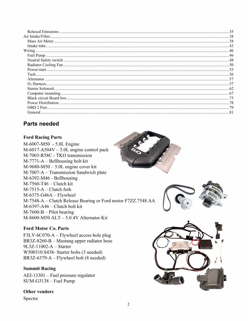
Ford Racing Parts M-6007-M50 - 5.0L Engine M-6017-A504V – 5.0L engine control pack M-7003-R58C - TKO transmission M-7771-A – Bellhousing bolt kit M-9680-M50 – 5.0L engine cover kit M-7007-A – Transmission Sandwich plate M-6392-M46 - Bellhousing M-7560-T46 – Clutch kit M-7515-A – Clutch fork M-6375-G46A – Flywheel M-7548-A – Clutch Release Bearing or Ford motor F7ZZ.7548.AA M-6397-A46 – Clutch bolt kit M-7600-B – Pilot bearing M-8600-M50 ALT – 5.0 4V Alternator Kit
Ford Motor Co. Parts F3LY-6C070-A – Flywheel access hole plug BR3Z-8260-B – Mustang upper radiator hose 9L3Z-11002-A – Starter W500310.S438- Starter bolts (3 needed) BR3Z-6379-A – Flywheel bolt (8 needed)
Summit Racing AEI-13301 – Fuel pressure regulator SUM-G3138 – Fuel Pump
Other vendors Spectre
3
Mass Air Sensor filter adapter – 9705 4” 90 ° intake tube – 9799 Oil Pan (Either vendor) Morosso –Coyote, specify 4.25” deep sump Canton – 15-794 Coyote specify 4.25” deep sump
These instructions assume that the customer has the following parts:
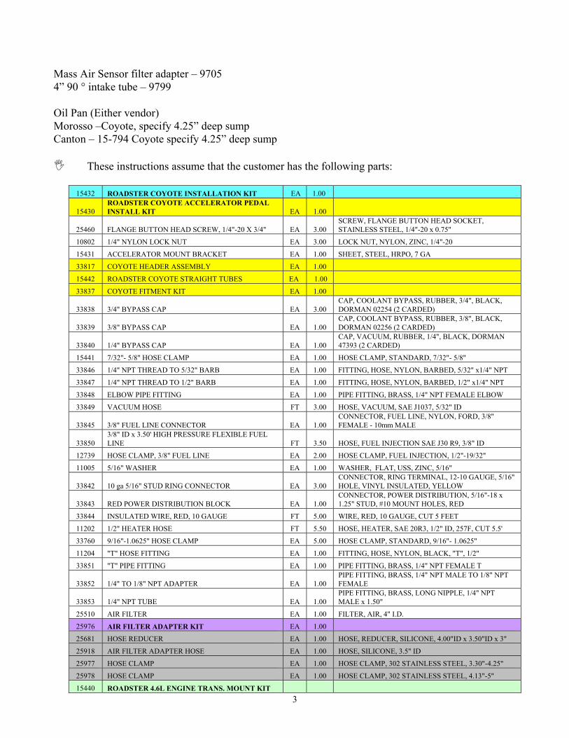
15432 ROADSTER COYOTE INSTALLATION KIT EA 1.00
15430 ROADSTER COYOTE ACCELERATOR PEDAL INSTALL KIT EA 1.00
25460 FLANGE BUTTON HEAD SCREW, 1/4"-20 X 3/4" EA 3.00 SCREW, FLANGE BUTTON HEAD SOCKET, STAINLESS STEEL, 1/4"-20 x 0.75"
10802 1/4" NYLON LOCK NUT EA 3.00 LOCK NUT, NYLON, ZINC, 1/4"-20
15431 ACCELERATOR MOUNT BRACKET EA 1.00 SHEET, STEEL, HRPO, 7 GA
33817 COYOTE HEADER ASSEMBLY EA 1.00
15442 ROADSTER COYOTE STRAIGHT TUBES EA 1.00
33837 COYOTE FITMENT KIT EA 1.00
33838 3/4" BYPASS CAP EA 3.00 CAP, COOLANT BYPASS, RUBBER, 3/4", BLACK, DORMAN 02254 (2 CARDED)
33839 3/8" BYPASS CAP EA 1.00 CAP, COOLANT BYPASS, RUBBER, 3/8", BLACK, DORMAN 02256 (2 CARDED)
33840 1/4" BYPASS CAP EA 1.00 CAP, VACUUM, RUBBER, 1/4", BLACK, DORMAN 47393 (2 CARDED)
15441 7/32"- 5/8" HOSE CLAMP EA 1.00 HOSE CLAMP, STANDARD, 7/32"- 5/8"
33846 1/4" NPT THREAD TO 5/32" BARB EA 1.00 FITTING, HOSE, NYLON, BARBED, 5/32" x1/4" NPT
33847 1/4" NPT THREAD TO 1/2" BARB EA 1.00 FITTING, HOSE, NYLON, BARBED, 1/2" x1/4" NPT
33848 ELBOW PIPE FITTING EA 1.00 PIPE FITTING, BRASS, 1/4" NPT FEMALE ELBOW
33849 VACUUM HOSE FT 3.00 HOSE, VACUUM, SAE J1037, 5/32" ID
33845 3/8" FUEL LINE CONNECTOR EA 1.00 CONNECTOR, FUEL LINE, NYLON, FORD, 3/8" FEMALE - 10mm MALE
33850 3/8" ID x 3.50' HIGH PRESSURE FLEXIBLE FUEL LINE FT 3.50 HOSE, FUEL INJECTION SAE J30 R9, 3/8" ID
12739 HOSE CLAMP, 3/8" FUEL LINE EA 2.00 HOSE CLAMP, FUEL INJECTION, 1/2"-19/32"
11005 5/16" WASHER EA 1.00 WASHER, FLAT, USS, ZINC, 5/16"
33842 10 ga 5/16" STUD RING CONNECTOR EA 3.00 CONNECTOR, RING TERMINAL, 12-10 GAUGE, 5/16" HOLE, VINYL INSULATED, YELLOW
33843 RED POWER DISTRIBUTION BLOCK EA 1.00 CONNECTOR, POWER DISTRIBUTION, 5/16"-18 x 1.25" STUD, #10 MOUNT HOLES, RED
33844 INSULATED WIRE, RED, 10 GAUGE FT 5.00 WIRE, RED, 10 GAUGE, CUT 5 FEET
11202 1/2" HEATER HOSE FT 5.50 HOSE, HEATER, SAE 20R3, 1/2" ID, 257F, CUT 5.5'
33760 9/16"-1.0625" HOSE CLAMP EA 5.00 HOSE CLAMP, STANDARD, 9/16"- 1.0625"
11204 "T" HOSE FITTING EA 1.00 FITTING, HOSE, NYLON, BLACK, "T", 1/2"
33851 "T" PIPE FITTING EA 1.00 PIPE FITTING, BRASS, 1/4" NPT FEMALE T
33852 1/4" TO 1/8" NPT ADAPTER EA 1.00 PIPE FITTING, BRASS, 1/4" NPT MALE TO 1/8" NPT FEMALE
33853 1/4" NPT TUBE EA 1.00 PIPE FITTING, BRASS, LONG NIPPLE, 1/4" NPT MALE x 1.50"
25510 AIR FILTER EA 1.00 FILTER, AIR, 4" I.D.
25976 AIR FILTER ADAPTER KIT EA 1.00
25681 HOSE REDUCER EA 1.00 HOSE, REDUCER, SILICONE, 4.00"ID x 3.50"ID x 3"
25918 AIR FILTER ADAPTER HOSE EA 1.00 HOSE, SILICONE, 3.5" ID
25977 HOSE CLAMP EA 1.00 HOSE CLAMP, 302 STAINLESS STEEL, 3.30"-4.25"
25978 HOSE CLAMP EA 1.00 HOSE CLAMP, 302 STAINLESS STEEL, 4.13"-5"
15440 ROADSTER 4.6L ENGINE TRANS. MOUNT KIT
4
15439 4.6L TKO TRANSMISSION MOUNT PLATE EA 1.00 SHEET, STEEL, HRPO, 7 GA
10833 1/2"-13 x 1.25" BOLT EA 2.00 SCREW, HEX HEAD CAP, GRADE 5, ZINC, 1/2"-13 x 1.25"
10834 1/2"-13 NYLON LOCK NUT EA 2.00 LOCK-NUT, NYLON , GRADE 5, ZINC, 1/2"-13
14222 4.6L POLYURETHANE ENGINE/TRANS. MOUNT KIT EA 1.00
14223 4.6L ENGINE MOUNT SET, BLACK SET 1.00 ENGINE MOUNT, 4.6L, POLYURETHANE, BLACK, w/ (2) M14x2.0 LOCKNUTS
13085 T-5/TREMEC TRANSMISSION MOUNT, BLACK EA 1.00 TRANSMISSION MOUNT, POLYURETHANE, BLACK
14059 SPACER EA 2.00 TUBE, ALUMINUM, ROUND, DOM, 0.750" OD x 0.120" WALL, 0, 0.43", 0
13976 1/2" WASHER EA 2.00 WASHER, FLAT, SAE, GRADE 2, ZINC, 1/2"
10833 1/2"-13 x 1.25" BOLT EA 2.00 SCREW, HEX HEAD CAP, GRADE 5, ZINC, 1/2"-13 x 1.25"
25831 M10 x 25MM BOLT EA 6.00 SCREW, HEX HEAD CAP , GRADE 8.8, ZINC, M10-1.5mm x 25mm
13977 3/8" WASHER EA 6.00 WASHER, FLAT, SAE, GRADE 2, ZINC, 3/8"
33862 EFI FUEL SYSTEM EA 1.00
33863 EFI REGULATOR AND FITTINGS EA 1.00
33864 EFI FUEL PRESSURE REGULATOR EA 1.00
REGULATOR, FUEL PRESSURE, 30-65 PSI, (3) 6AN O-RING PORTS, 1/8" NPT PORT, BLACK
ANODIZE/NICKEL PLATE
33865 6AN O-RING TO 6AN BARB FITTING EA 1.00 FITTING, HOSE, ALUMINUM, STRAIGHT, 6AN, O-RING TO 6AN PUSH-LOK BARB, BLACK
33866 6AN O-RING TO 4AN BARB FITTING EA 1.00 FITTING, HOSE, ALUMINUM, STRAIGHT, 6AN O-RING TO 4AN PUSH-LOK BARB, BLACK
33867 90 DEGREE 6AN O-RING TO 6AN BARB FITTING EA 1.00 FITTING, HOSE, ALUMINUM, 90 DEGREE, 6AN O-RING TO 6AN PUSH-LOK BARB, BLACK
33868 FUEL PRESSURE GAUGE EA 1.00 GAUGE, FUEL PRESSURE, WHITE, BLACK NEEDLE, 1.50", 0-100 PSI, 1/8" NPT
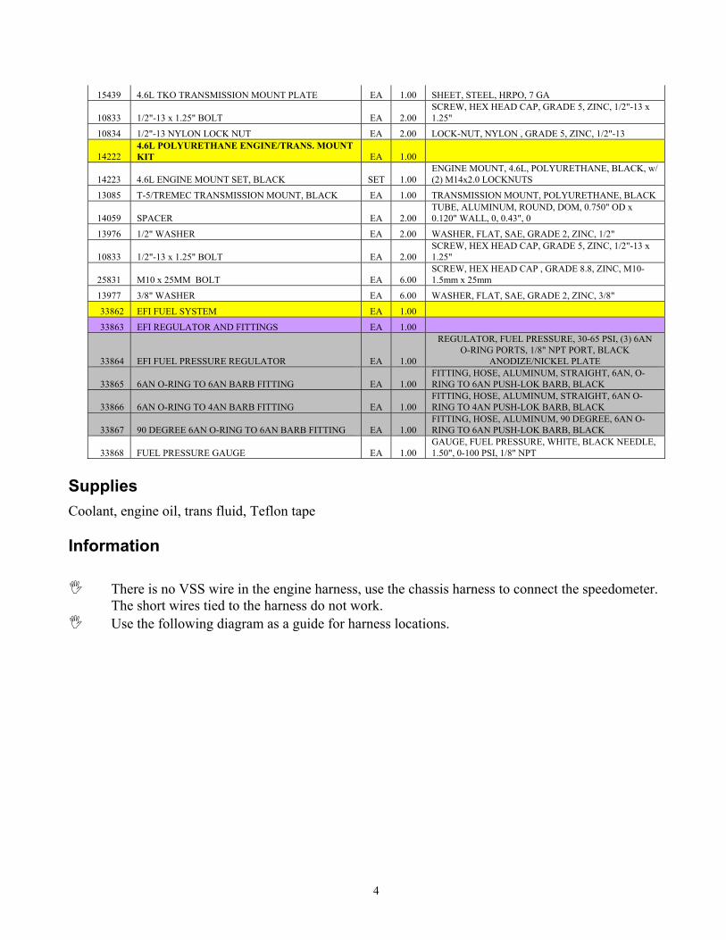
Supplies Coolant, engine oil, trans fluid, Teflon tape Information
There is no VSS wire in the engine harness, use the chassis harness to connect the speedometer. The short wires tied to the harness do not work.
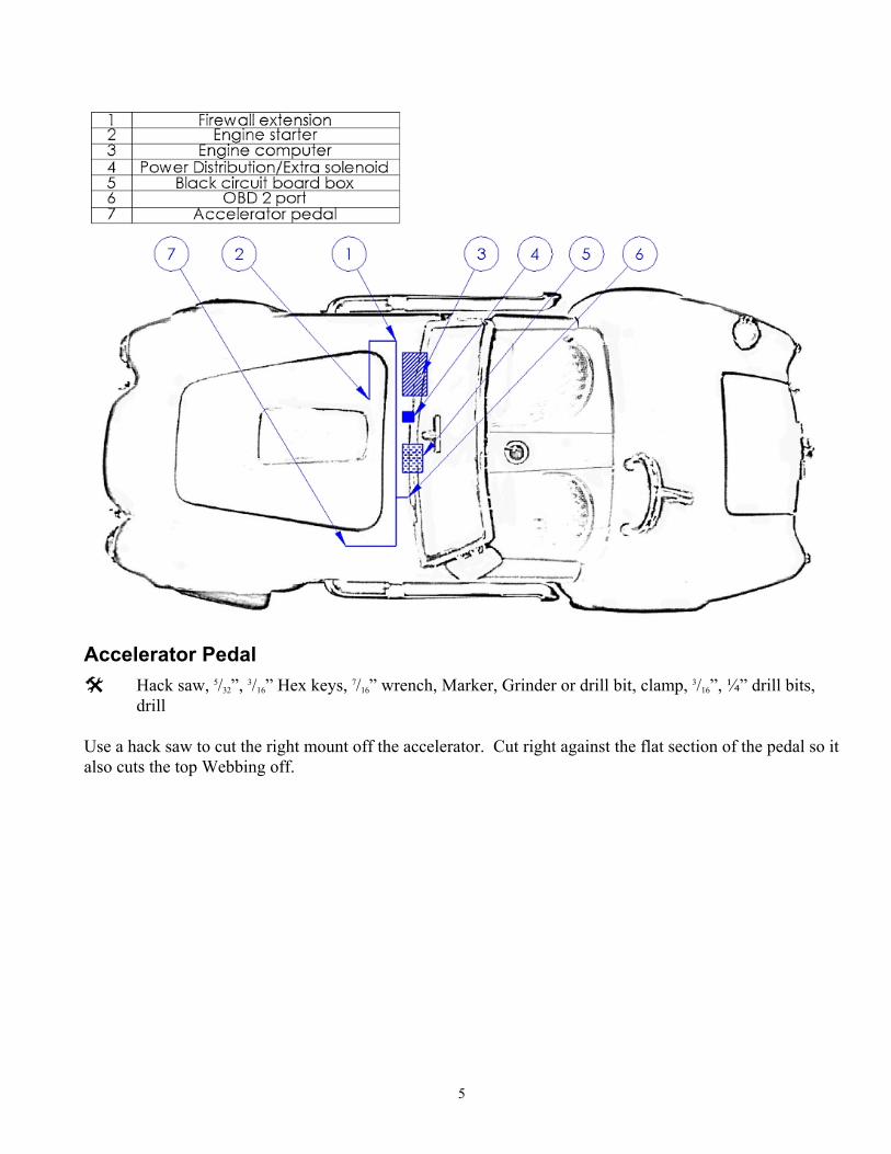
Use the following diagram as a guide for harness locations.
5
Accelerator Pedal
Hack saw, 5/32”, 3/16” Hex keys, 7/16” wrench, Marker, Grinder or drill bit, clamp, 3/16”, ¼” drill bits, drill
Use a hack saw to cut the right mount off the accelerator. Cut right against the flat section of the pedal so it also cuts the top Webbing off.
6
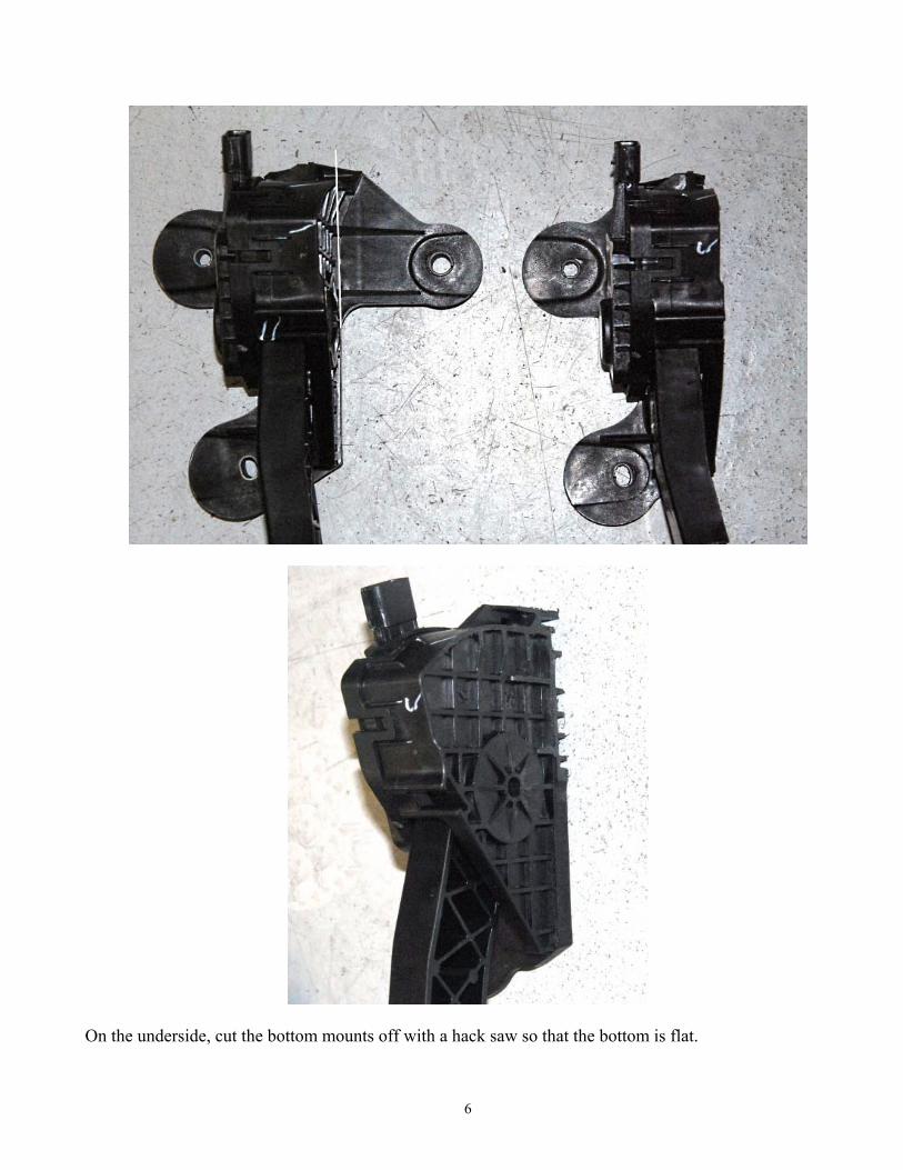
On the underside, cut the bottom mounts off with a hack saw so that the bottom is flat.
7
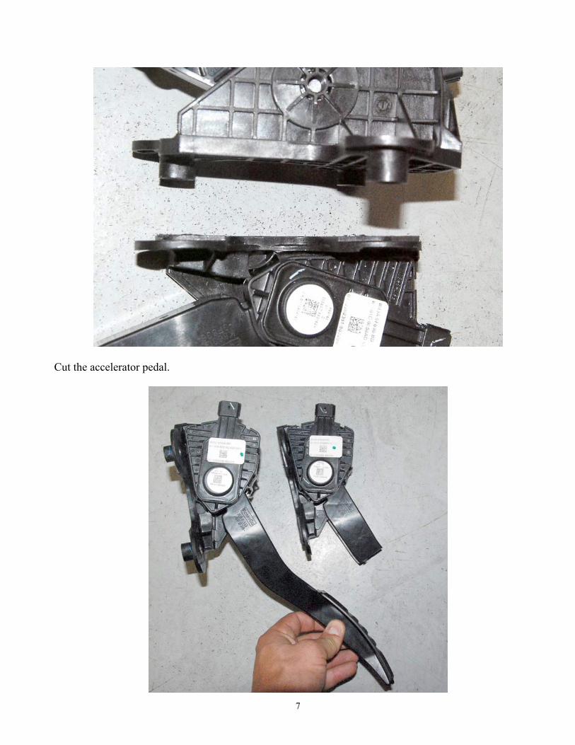
Cut the accelerator pedal.
8
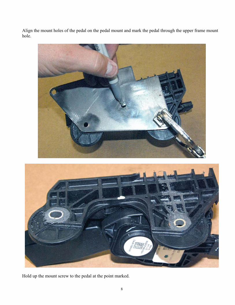
Align the mount holes of the pedal on the pedal mount and mark the pedal through the upper frame mount hole.
Hold up the mount screw to the pedal at the point marked.
9
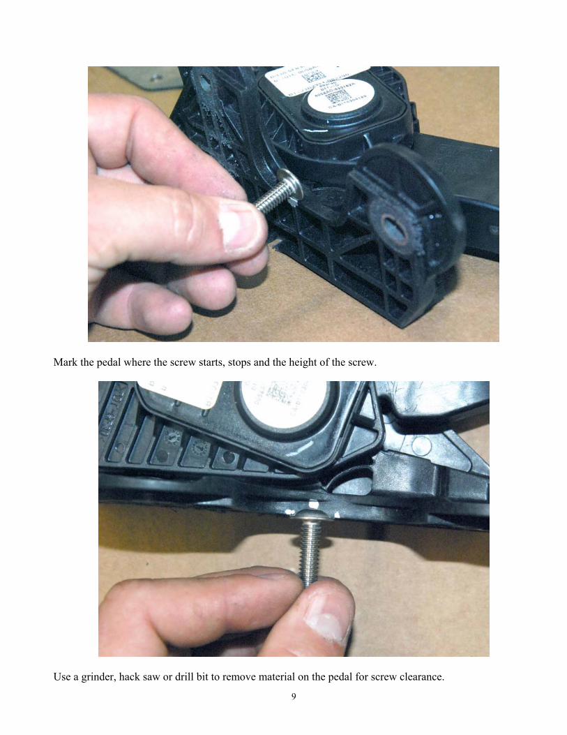
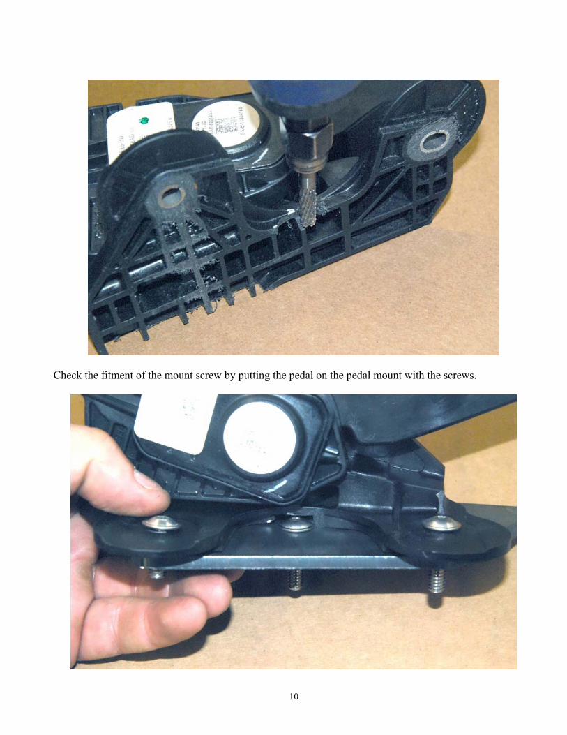
Mark the pedal where the screw starts, stops and the height of the screw.
Use a grinder, hack saw or drill bit to remove material on the pedal for screw clearance.
10
Check the fitment of the mount screw by putting the pedal on the pedal mount with the screws.
11
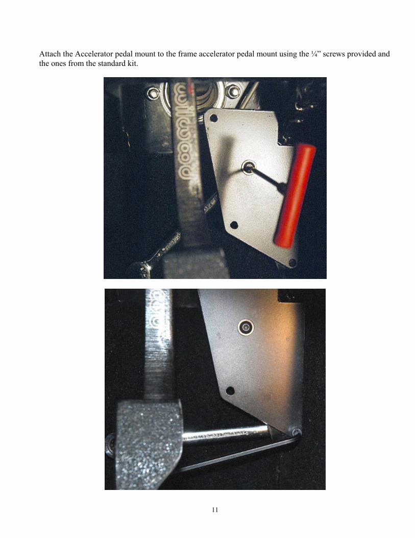
Attach the Accelerator pedal mount to the frame accelerator pedal mount using the ¼” screws provided and the ones from the standard kit.
12
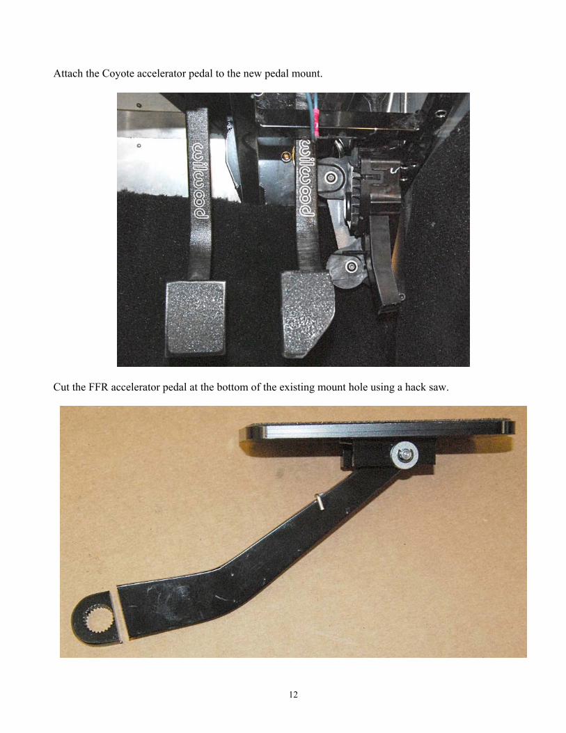
Attach the Coyote accelerator pedal to the new pedal mount.
Cut the FFR accelerator pedal at the bottom of the existing mount hole using a hack saw.
13
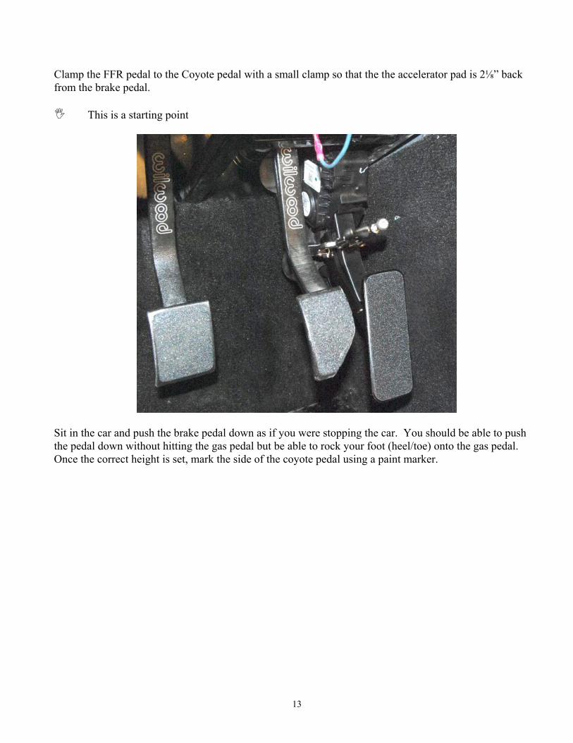
Clamp the FFR pedal to the Coyote pedal with a small clamp so that the the accelerator pad is 2⅛” back from the brake pedal.
This is a starting point
Sit in the car and push the brake pedal down as if you were stopping the car. You should be able to push the pedal down without hitting the gas pedal but be able to rock your foot (heel/toe) onto the gas pedal. Once the correct height is set, mark the side of the coyote pedal using a paint marker.
14
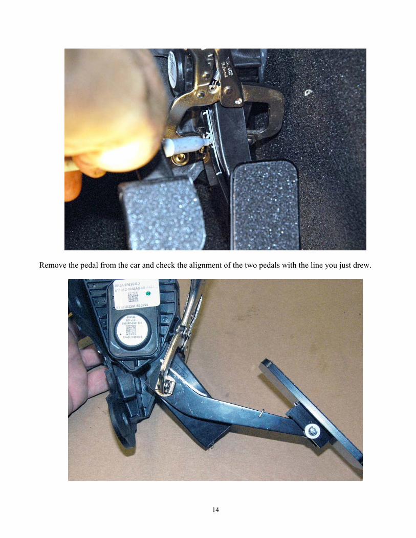
Remove the pedal from the car and check the alignment of the two pedals with the line you just drew.
15
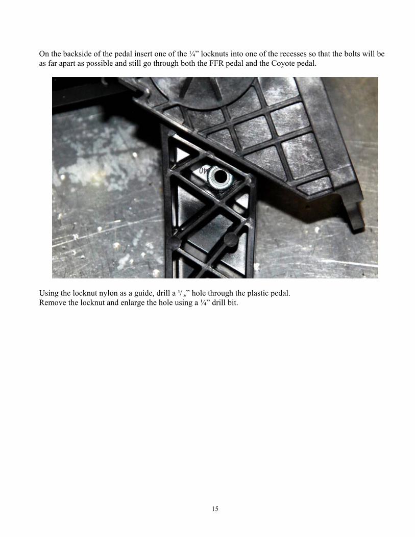
On the backside of the pedal insert one of the ¼” locknuts into one of the recesses so that the bolts will be as far apart as possible and still go through both the FFR pedal and the Coyote pedal.
Using the locknut nylon as a guide, drill a 3/16” hole through the plastic pedal. Remove the locknut and enlarge the hole using a ¼” drill bit.
16
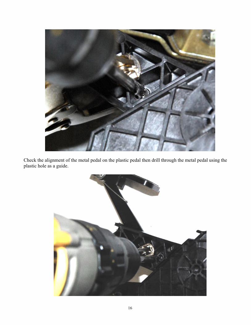
Check the alignment of the metal pedal on the plastic pedal then drill through the metal pedal using the plastic hole as a guide.
17
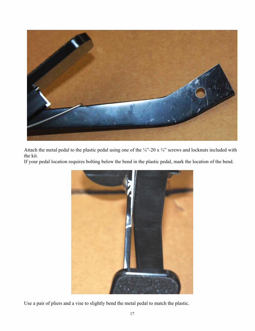
Attach the metal pedal to the plastic pedal using one of the ¼”-20 x ¾” screws and locknuts included with the kit. If your pedal location requires bolting below the bend in the plastic pedal, mark the location of the bend.
Use a pair of pliers and a vise to slightly bend the metal pedal to match the plastic.
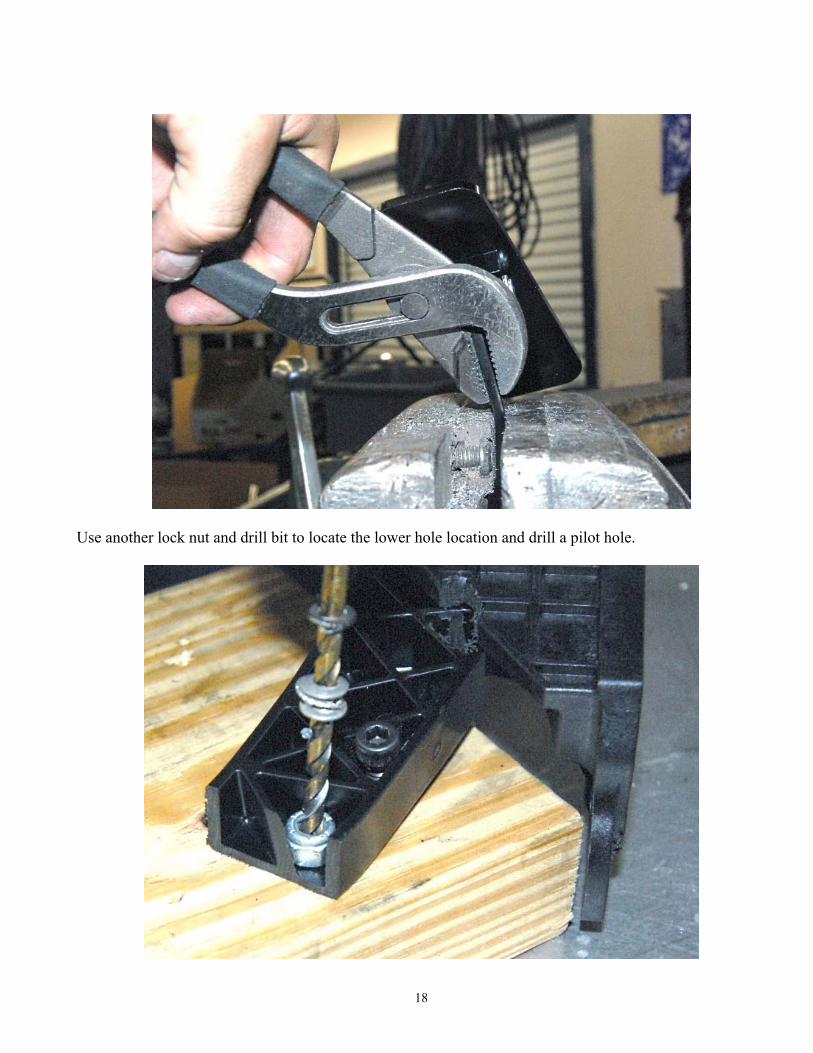
18
Use another lock nut and drill bit to locate the lower hole location and drill a pilot hole.
19
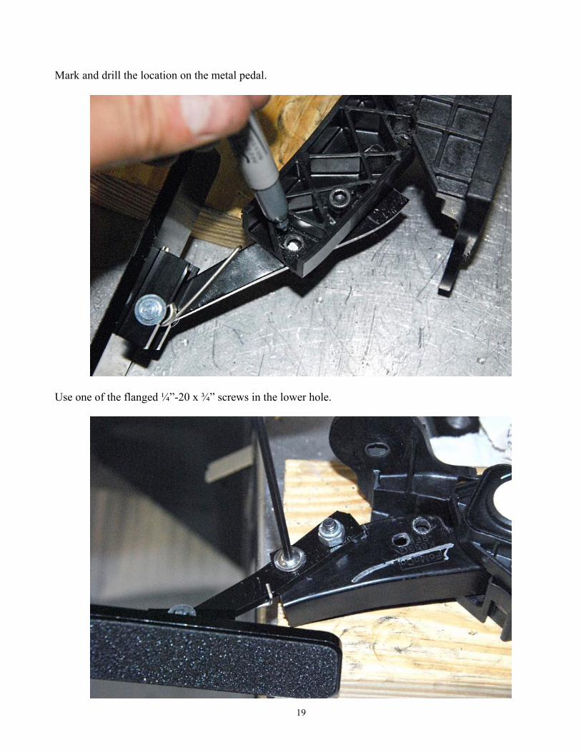
Mark and drill the location on the metal pedal.
Use one of the flanged ¼”-20 x ¾” screws in the lower hole.
20
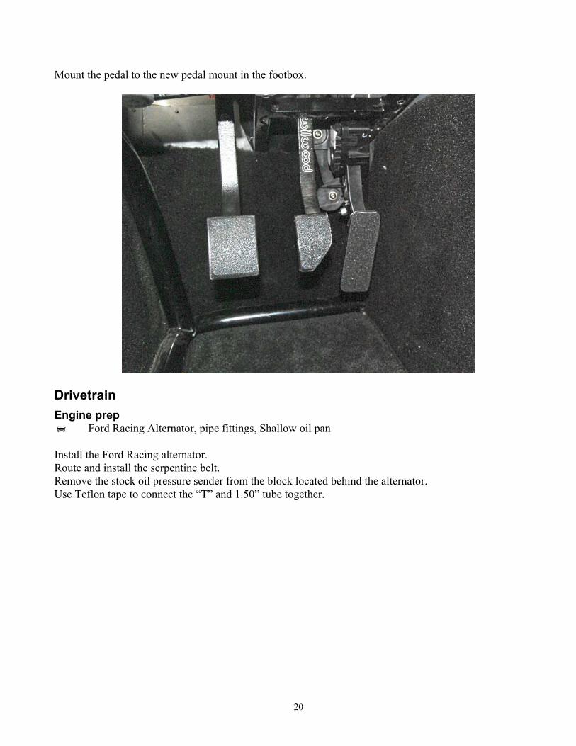
Mount the pedal to the new pedal mount in the footbox.
Drivetrain Engine prep
Ford Racing Alternator, pipe fittings, Shallow oil pan Install the Ford Racing alternator. Route and install the serpentine belt. Remove the stock oil pressure sender from the block located behind the alternator. Use Teflon tape to connect the “T” and 1.50” tube together.
21
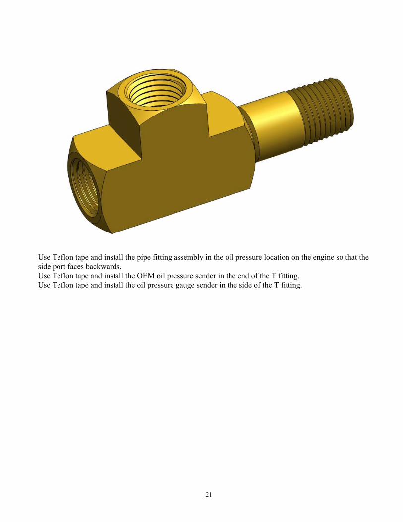
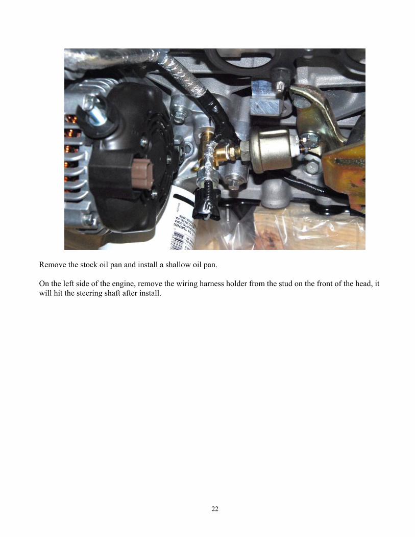
Use Teflon tape and install the pipe fitting assembly in the oil pressure location on the engine so that the side port faces backwards. Use Teflon tape and install the OEM oil pressure sender in the end of the T fitting. Use Teflon tape and install the oil pressure gauge sender in the side of the T fitting.
22
Remove the stock oil pan and install a shallow oil pan. On the left side of the engine, remove the wiring harness holder from the stud on the front of the head, it will hit the steering shaft after install.
23
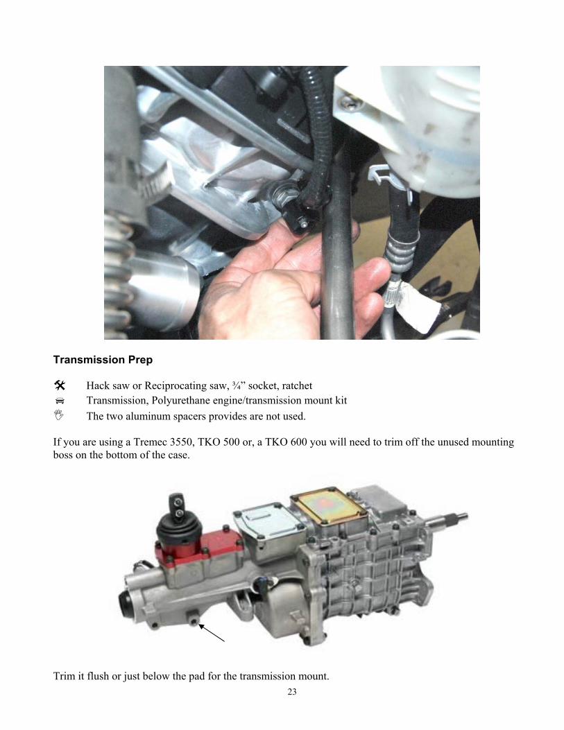
Transmission Prep
Hack saw or Reciprocating saw, ¾” socket, ratchet Transmission, Polyurethane engine/transmission mount kit The two aluminum spacers provides are not used.
If you are using a Tremec 3550, TKO 500 or, a TKO 600 you will need to trim off the unused mounting boss on the bottom of the case.
Trim it flush or just below the pad for the transmission mount.
24
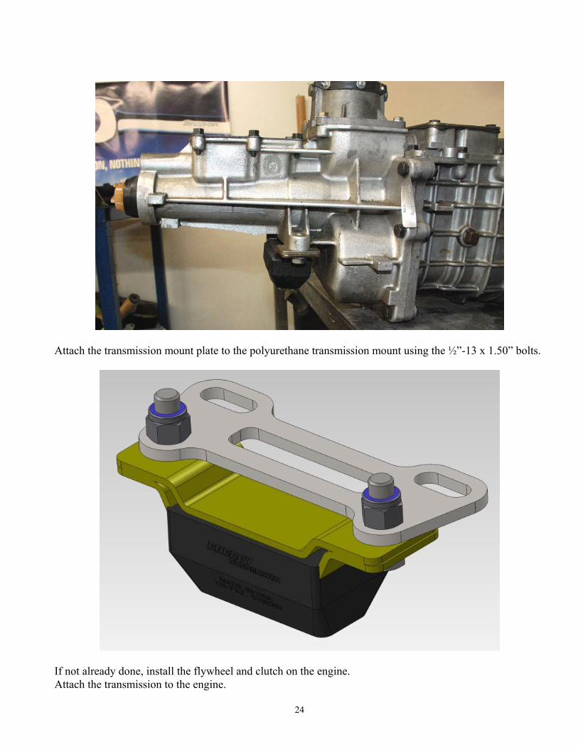
Attach the transmission mount plate to the polyurethane transmission mount using the ½”-13 x 1.50” bolts.
If not already done, install the flywheel and clutch on the engine. Attach the transmission to the engine.
25
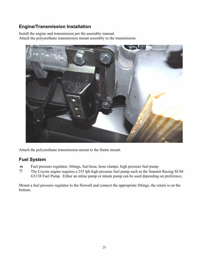
Engine/Transmission Installation Install the engine and transmission per the assembly manual. Attach the polyurethane transmission mount assembly to the transmission.
Attach the polyurethane transmission mount to the frame mount. Fuel System
Fuel pressure regulator, fittings, fuel hose, hose clamps, high pressure fuel pump The Coyote engine requires a 255 lph high pressure fuel pump such as the Summit Racing SUM-
G3138 Fuel Pump. Either an inline pump or intank pump can be used depending on preference. Mount a fuel pressure regulator to the firewall and connect the appropriate fittings, the return is on the bottom.

26
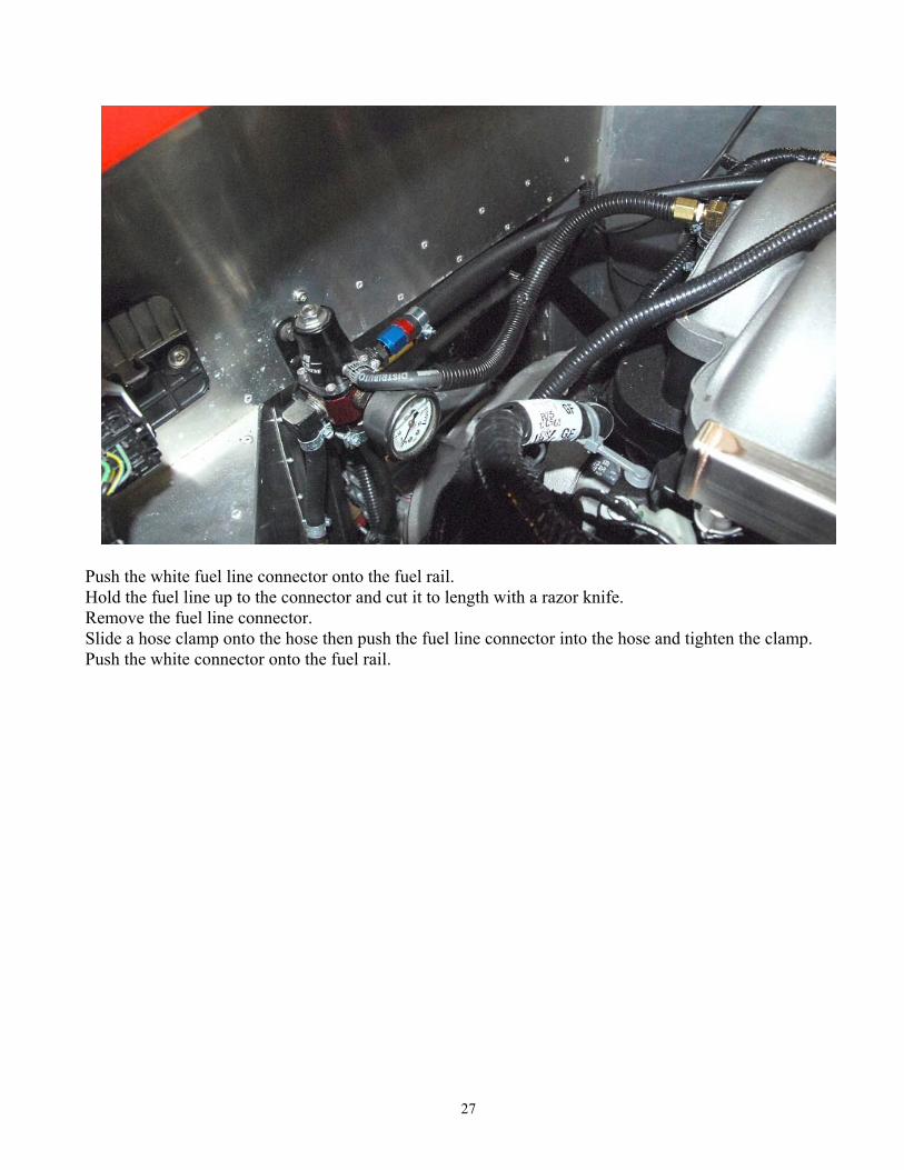
Push the ⅜” fuel line onto the right side of the regulator, attach a hose clamp and run it over to the engine fuel rail.
27
Push the white fuel line connector onto the fuel rail. Hold the fuel line up to the connector and cut it to length with a razor knife. Remove the fuel line connector. Slide a hose clamp onto the hose then push the fuel line connector into the hose and tighten the clamp. Push the white connector onto the fuel rail.
28
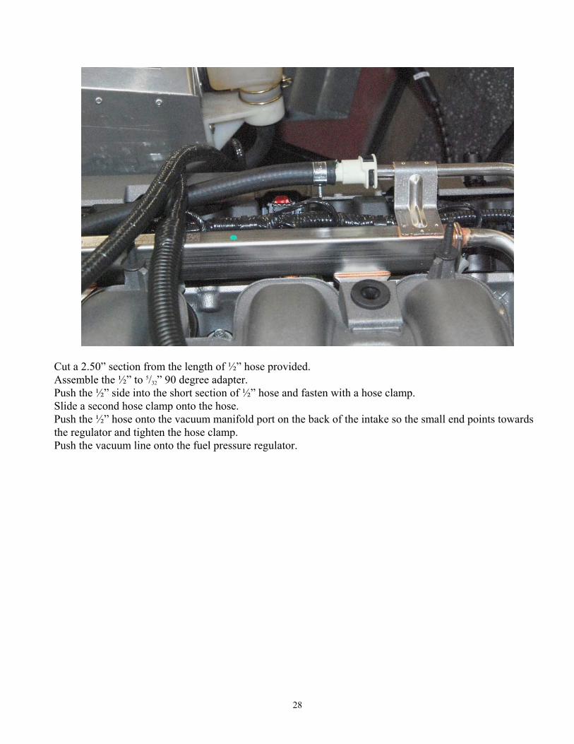
Cut a 2.50” section from the length of ½” hose provided. Assemble the ½” to 5/32” 90 degree adapter. Push the ½” side into the short section of ½” hose and fasten with a hose clamp. Slide a second hose clamp onto the hose. Push the ½” hose onto the vacuum manifold port on the back of the intake so the small end points towards the regulator and tighten the hose clamp. Push the vacuum line onto the fuel pressure regulator.
29
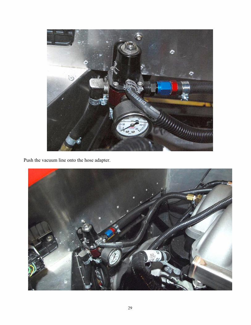
Push the vacuum line onto the hose adapter.
30
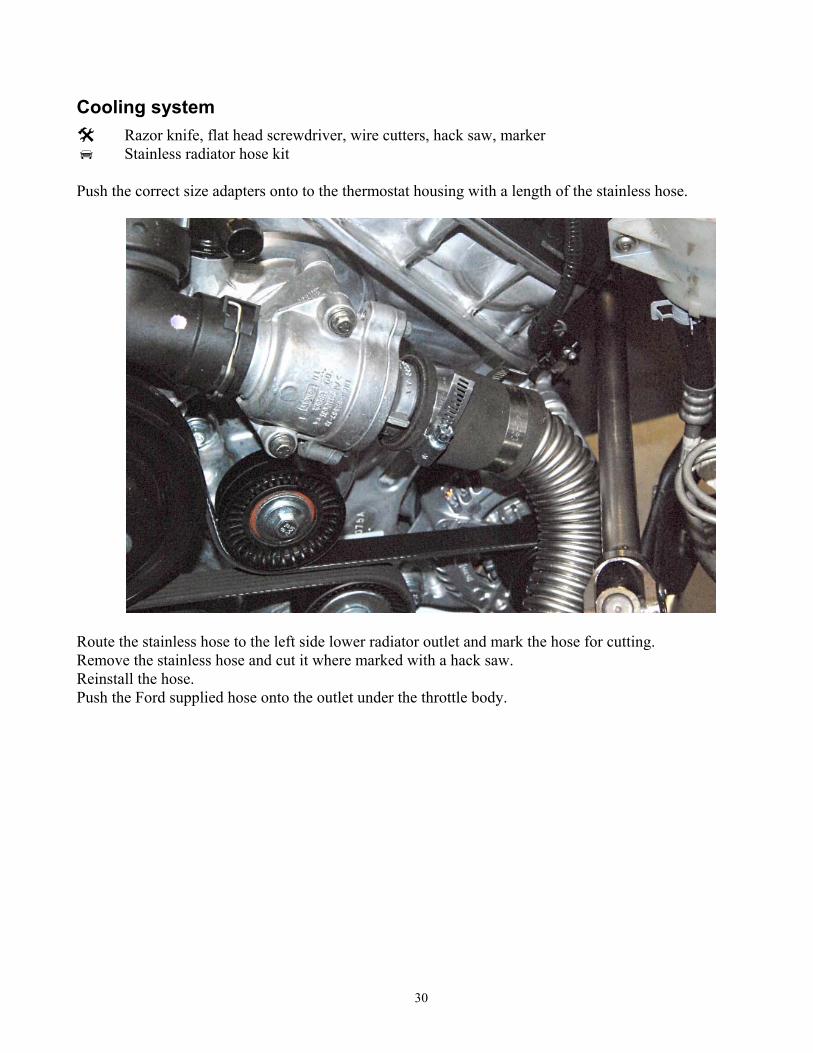
Cooling system Razor knife, flat head screwdriver, wire cutters, hack saw, marker Stainless radiator hose kit
Push the correct size adapters onto to the thermostat housing with a length of the stainless hose.
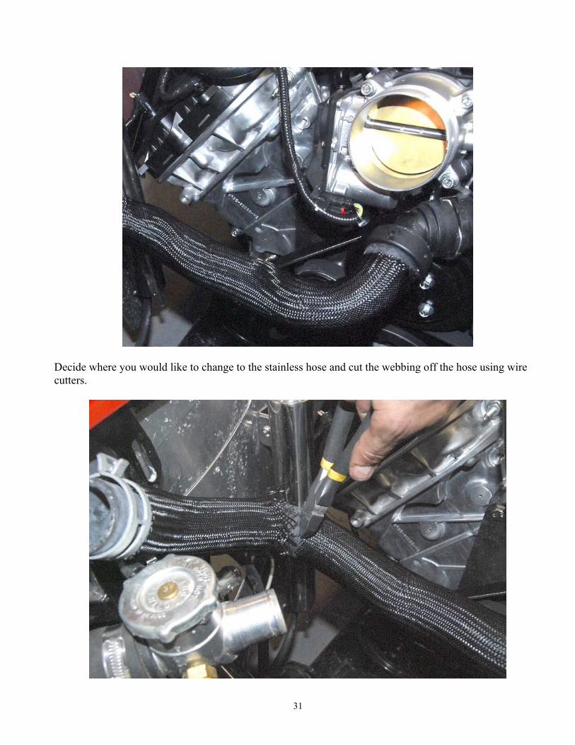
Route the stainless hose to the left side lower radiator outlet and mark the hose for cutting. Remove the stainless hose and cut it where marked with a hack saw. Reinstall the hose. Push the Ford supplied hose onto the outlet under the throttle body.
31
Decide where you would like to change to the stainless hose and cut the webbing off the hose using wire cutters.
32
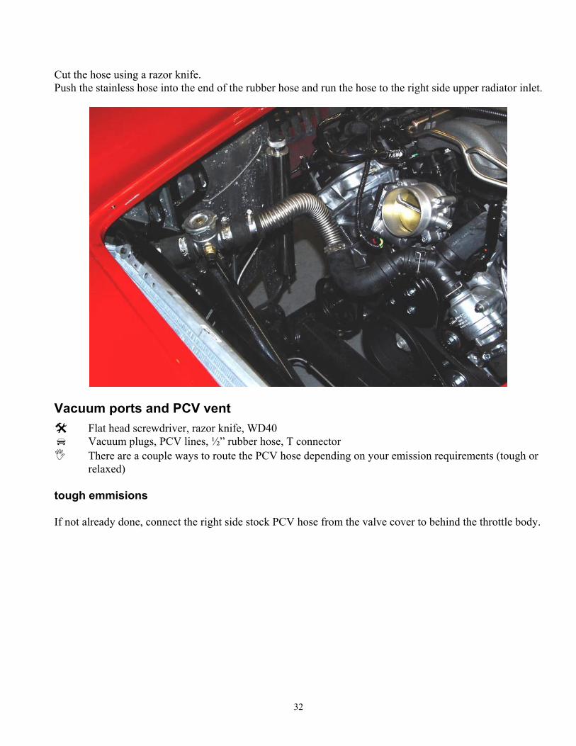
Cut the hose using a razor knife. Push the stainless hose into the end of the rubber hose and run the hose to the right side upper radiator inlet.
Vacuum ports and PCV vent
Flat head screwdriver, razor knife, WD40 Vacuum plugs, PCV lines, ½” rubber hose, T connector There are a couple ways to route the PCV hose depending on your emission requirements (tough or
relaxed) tough emmisions If not already done, connect the right side stock PCV hose from the valve cover to behind the throttle body.
33
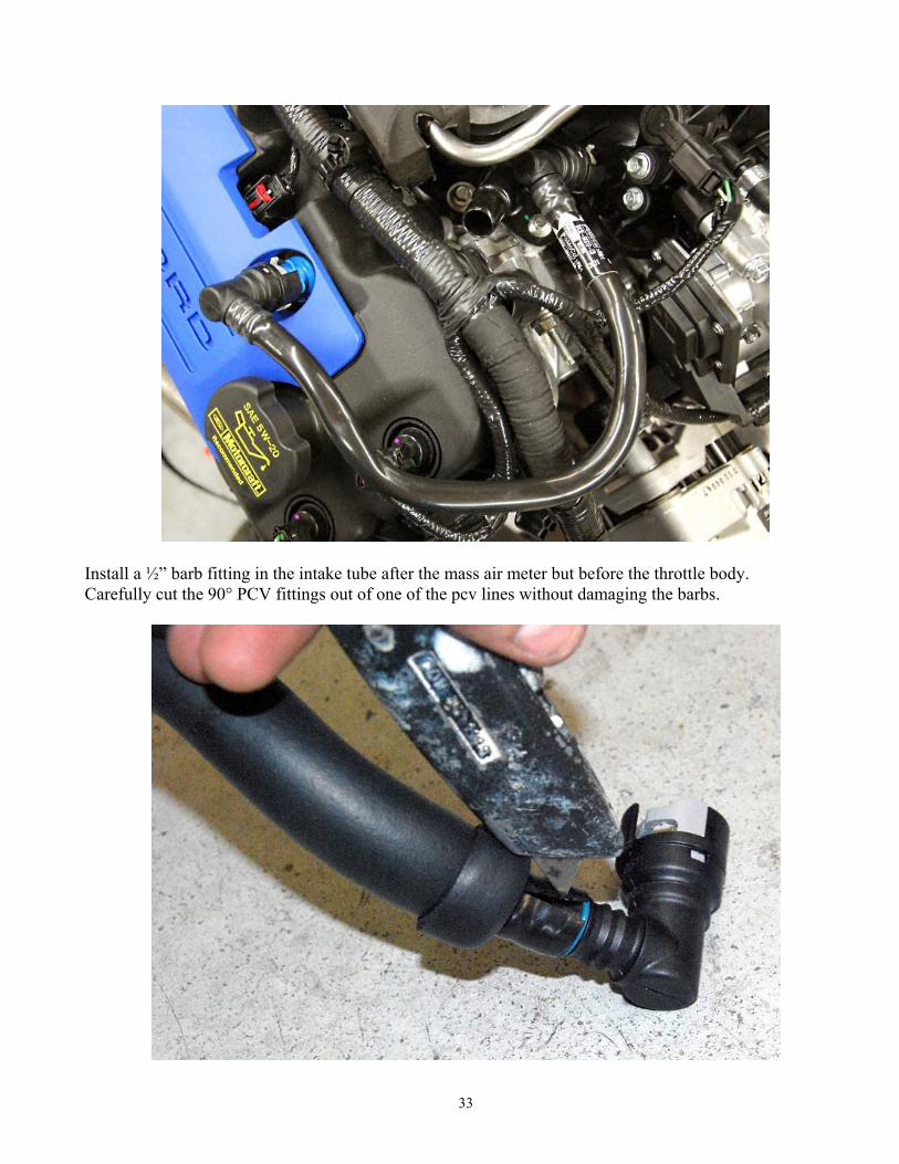
Install a ½” barb fitting in the intake tube after the mass air meter but before the throttle body. Carefully cut the 90° PCV fittings out of one of the pcv lines without damaging the barbs.
34
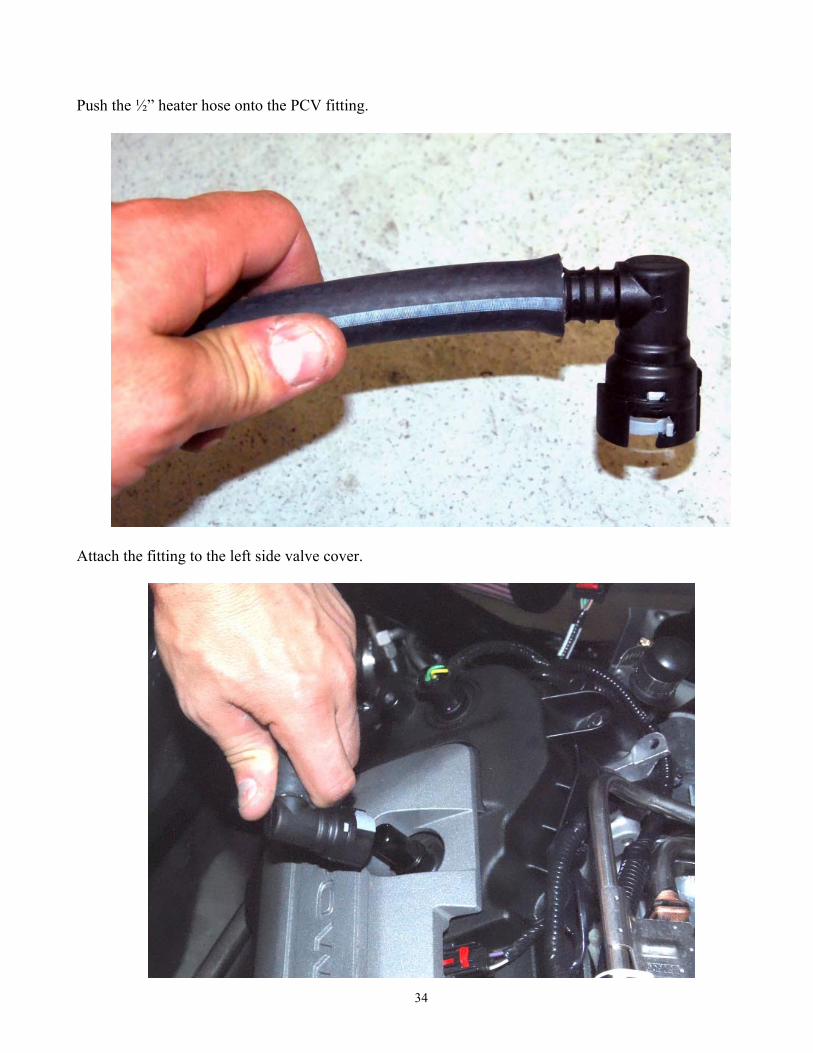
Push the ½” heater hose onto the PCV fitting.
Attach the fitting to the left side valve cover.
35
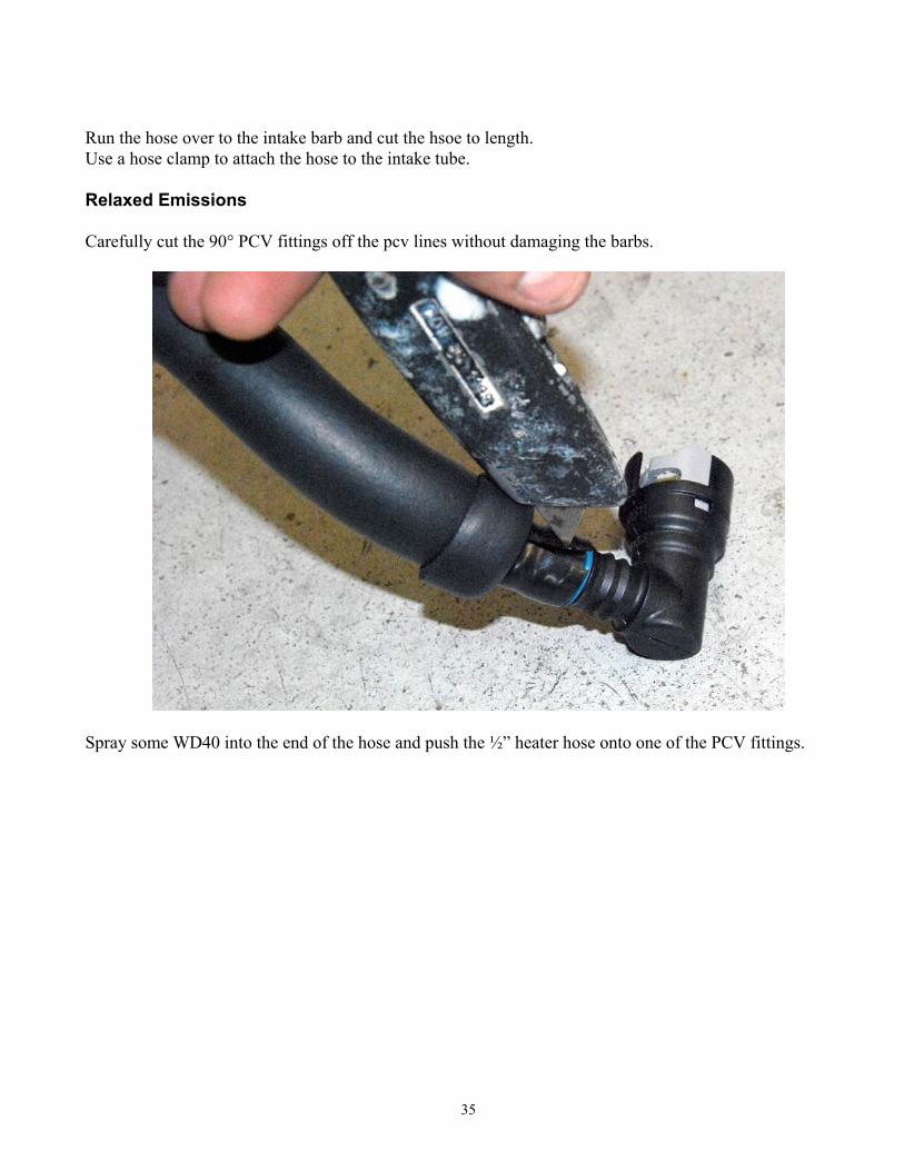
Run the hose over to the intake barb and cut the hsoe to length. Use a hose clamp to attach the hose to the intake tube. Relaxed Emissions Carefully cut the 90° PCV fittings off the pcv lines without damaging the barbs.
Spray some WD40 into the end of the hose and push the ½” heater hose onto one of the PCV fittings.
36
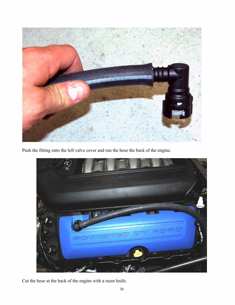
Push the fitting onto the left valve cover and run the hose the back of the engine.
Cut the hose at the back of the engine with a razor knife.
37
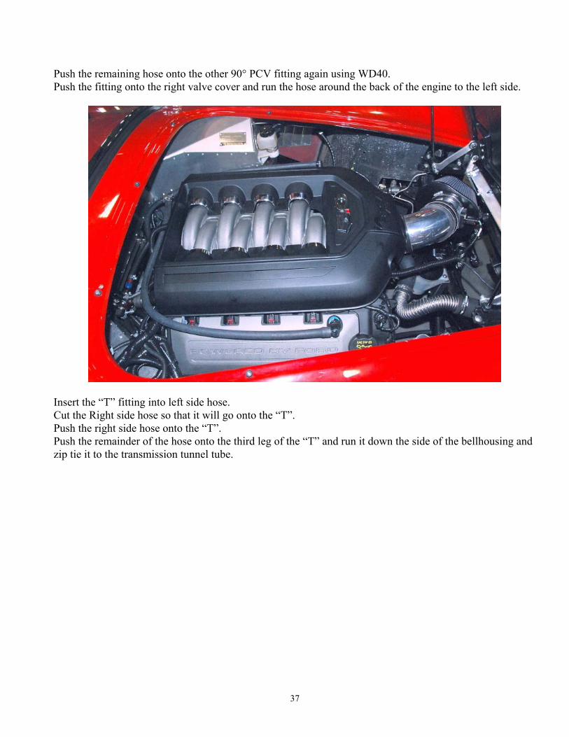
Push the remaining hose onto the other 90° PCV fitting again using WD40. Push the fitting onto the right valve cover and run the hose around the back of the engine to the left side.
Insert the “T” fitting into left side hose. Cut the Right side hose so that it will go onto the “T”. Push the right side hose onto the “T”. Push the remainder of the hose onto the third leg of the “T” and run it down the side of the bellhousing and zip tie it to the transmission tunnel tube.
38
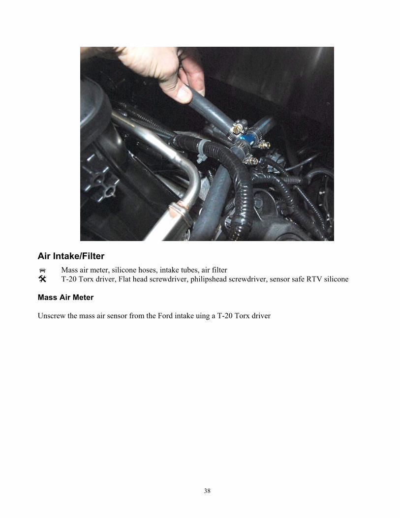
Air Intake/Filter
Mass air meter, silicone hoses, intake tubes, air filter T-20 Torx driver, Flat head screwdriver, philipshead screwdriver, sensor safe RTV silicone
Mass Air Meter Unscrew the mass air sensor from the Ford intake uing a T-20 Torx driver
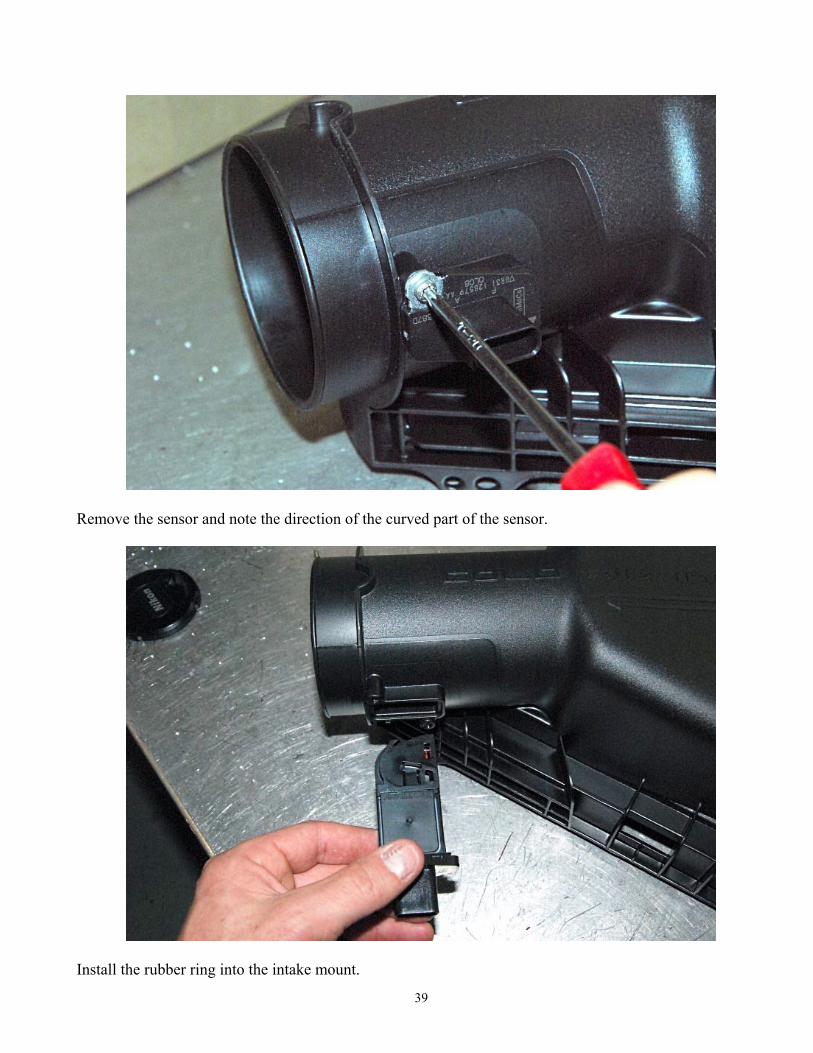
39
Remove the sensor and note the direction of the curved part of the sensor.
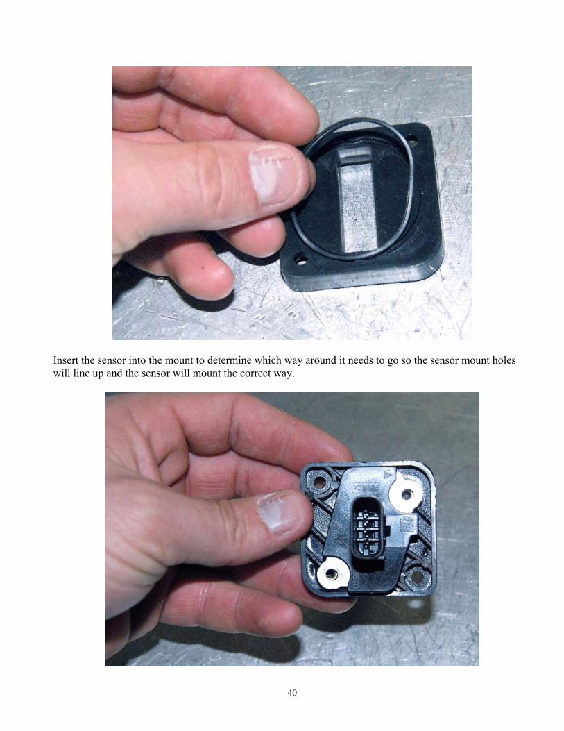
Install the rubber ring into the intake mount.
40
Insert the sensor into the mount to determine which way around it needs to go so the sensor mount holes will line up and the sensor will mount the correct way.
41
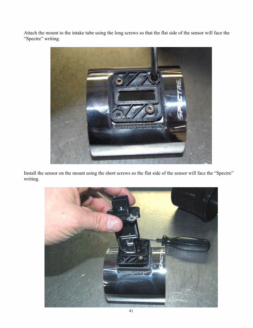
Attach the mount to the intake tube using the long screws so that the flat side of the sensor will face the “Spectre” writing.
Install the sensor on the mount using the short screws so the flat side of the sensor will face the “Spectre” writing.
42
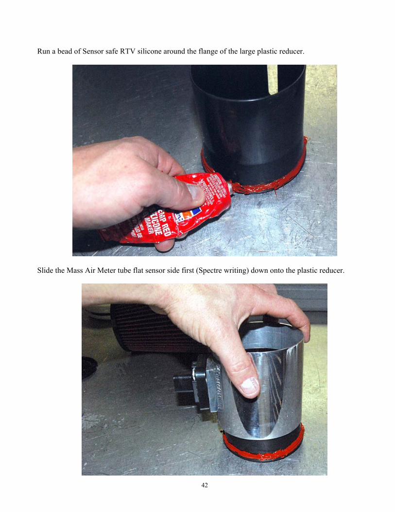
Run a bead of Sensor safe RTV silicone around the flange of the large plastic reducer.
Slide the Mass Air Meter tube flat sensor side first (Spectre writing) down onto the plastic reducer.
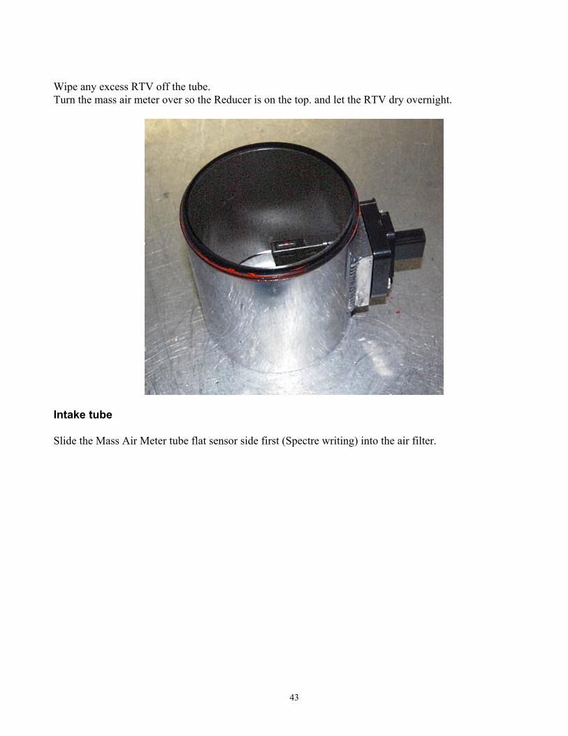
43
Wipe any excess RTV off the tube. Turn the mass air meter over so the Reducer is on the top. and let the RTV dry overnight.
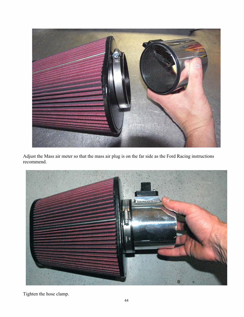
Intake tube Slide the Mass Air Meter tube flat sensor side first (Spectre writing) into the air filter.
44
Adjust the Mass air meter so that the mass air plug is on the far side as the Ford Racing instructions recommend.
Tighten the hose clamp.
45
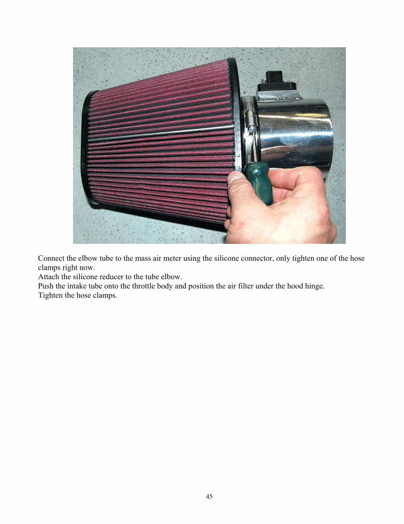
Connect the elbow tube to the mass air meter using the silicone connector, only tighten one of the hose clamps right now. Attach the silicone reducer to the tube elbow. Push the intake tube onto the throttle body and position the air filter under the hood hinge. Tighten the hose clamps.
46
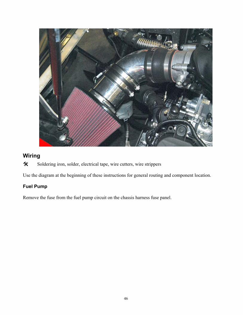
Wiring
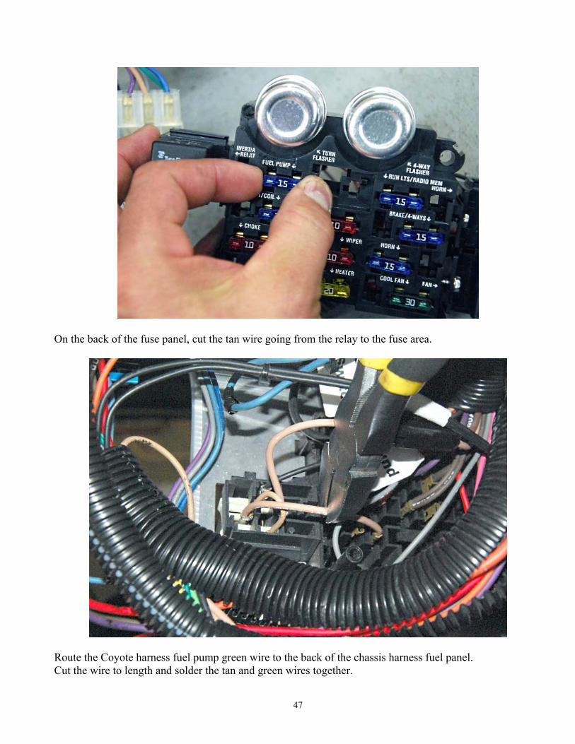
Soldering iron, solder, electrical tape, wire cutters, wire strippers Use the diagram at the beginning of these instructions for general routing and component location. Fuel Pump Remove the fuse from the fuel pump circuit on the chassis harness fuse panel.
47
On the back of the fuse panel, cut the tan wire going from the relay to the fuse area.
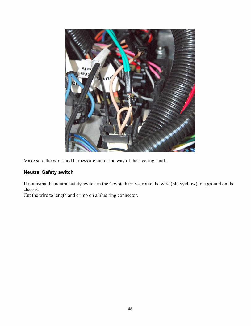
Route the Coyote harness fuel pump green wire to the back of the chassis harness fuel panel. Cut the wire to length and solder the tan and green wires together.
48
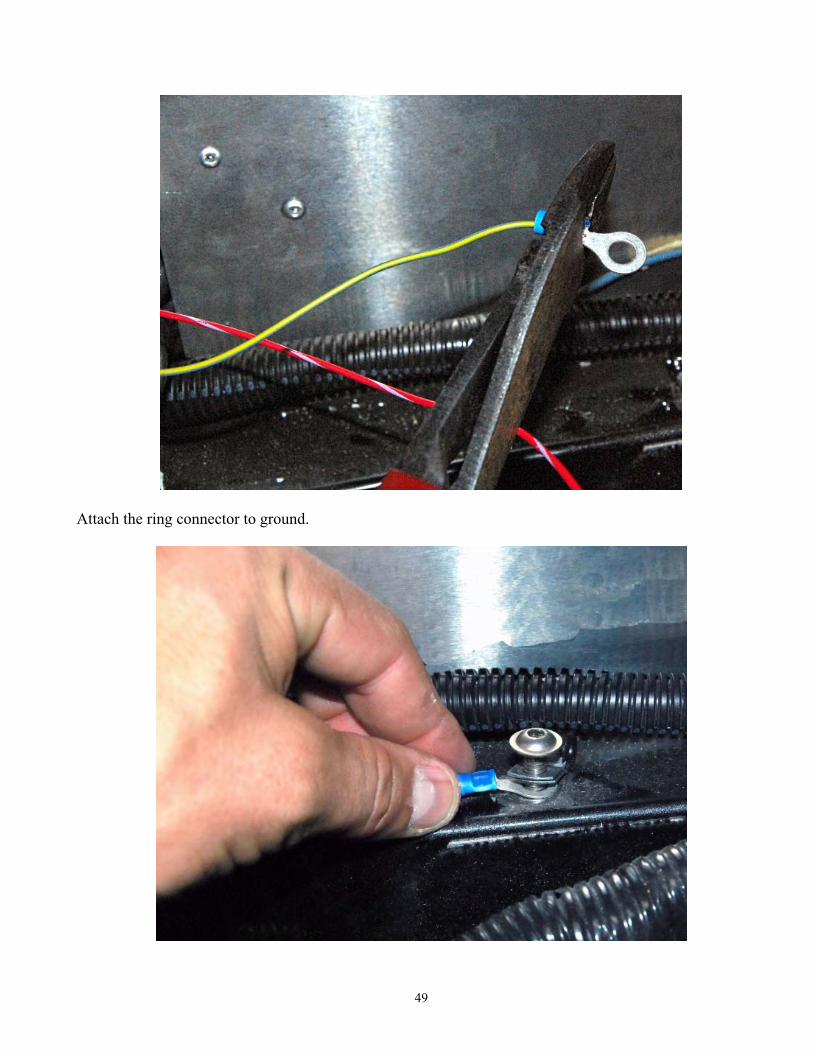
Make sure the wires and harness are out of the way of the steering shaft. Neutral Safety switch If not using the neutral safety switch in the Coyote harness, route the wire (blue/yellow) to a ground on the chassis. Cut the wire to length and crimp on a blue ring connector.
49
Attach the ring connector to ground.
50
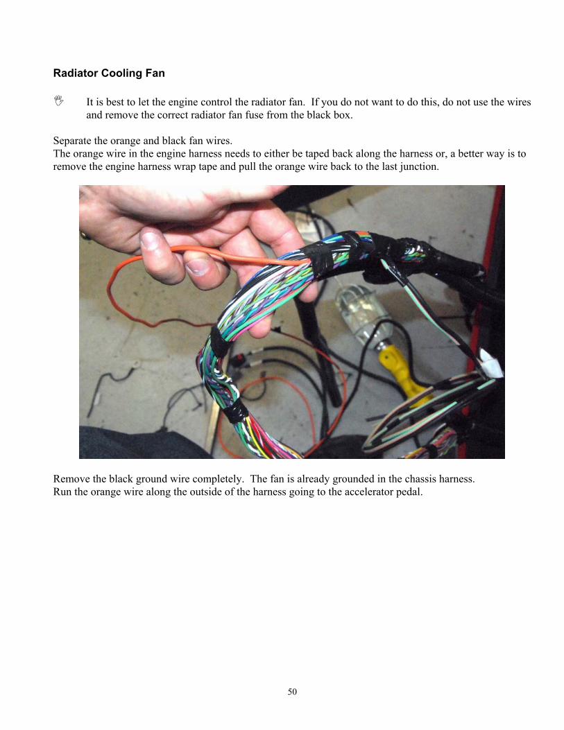
Radiator Cooling Fan
It is best to let the engine control the radiator fan. If you do not want to do this, do not use the wires and remove the correct radiator fan fuse from the black box.
Separate the orange and black fan wires. The orange wire in the engine harness needs to either be taped back along the harness or, a better way is to remove the engine harness wrap tape and pull the orange wire back to the last junction.
Remove the black ground wire completely. The fan is already grounded in the chassis harness. Run the orange wire along the outside of the harness going to the accelerator pedal.
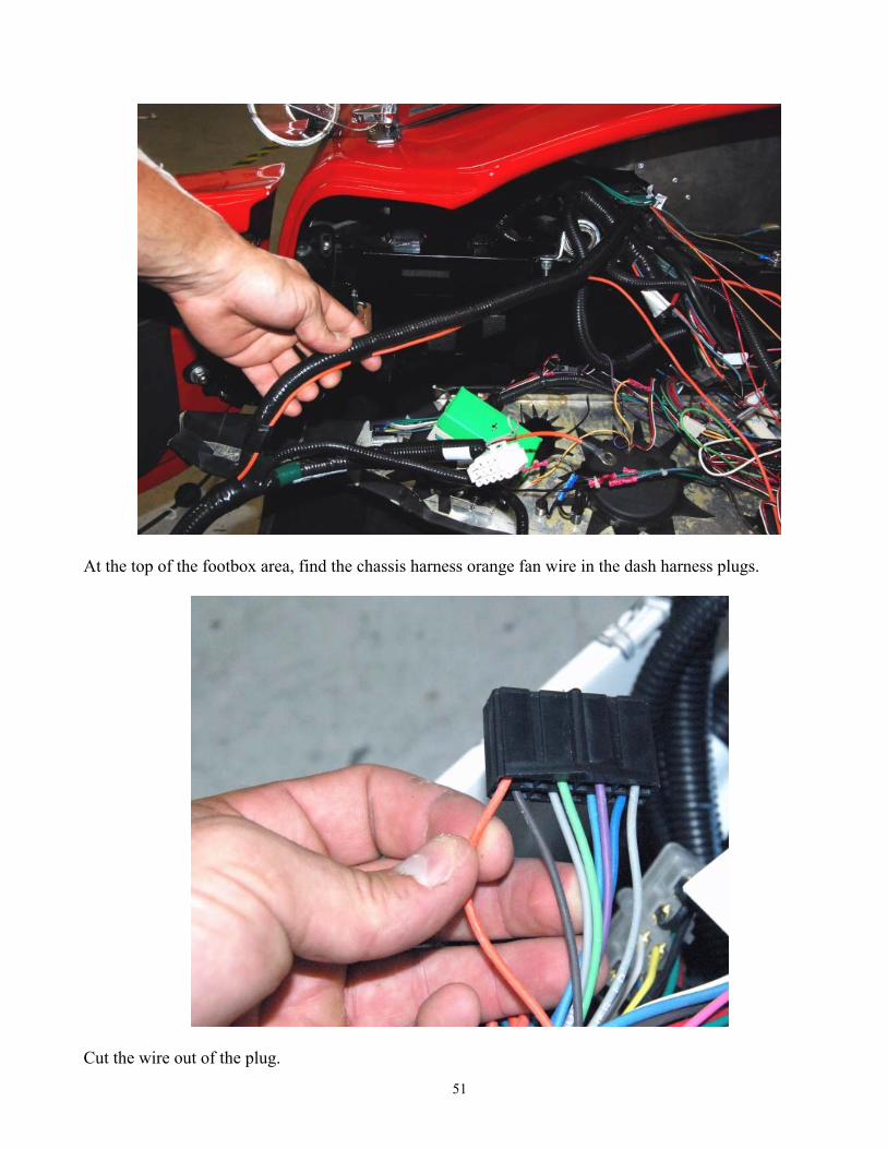
51
At the top of the footbox area, find the chassis harness orange fan wire in the dash harness plugs.
Cut the wire out of the plug.
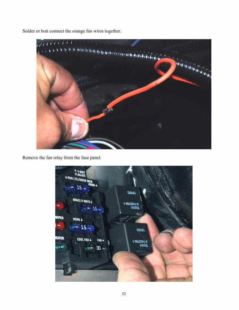
52
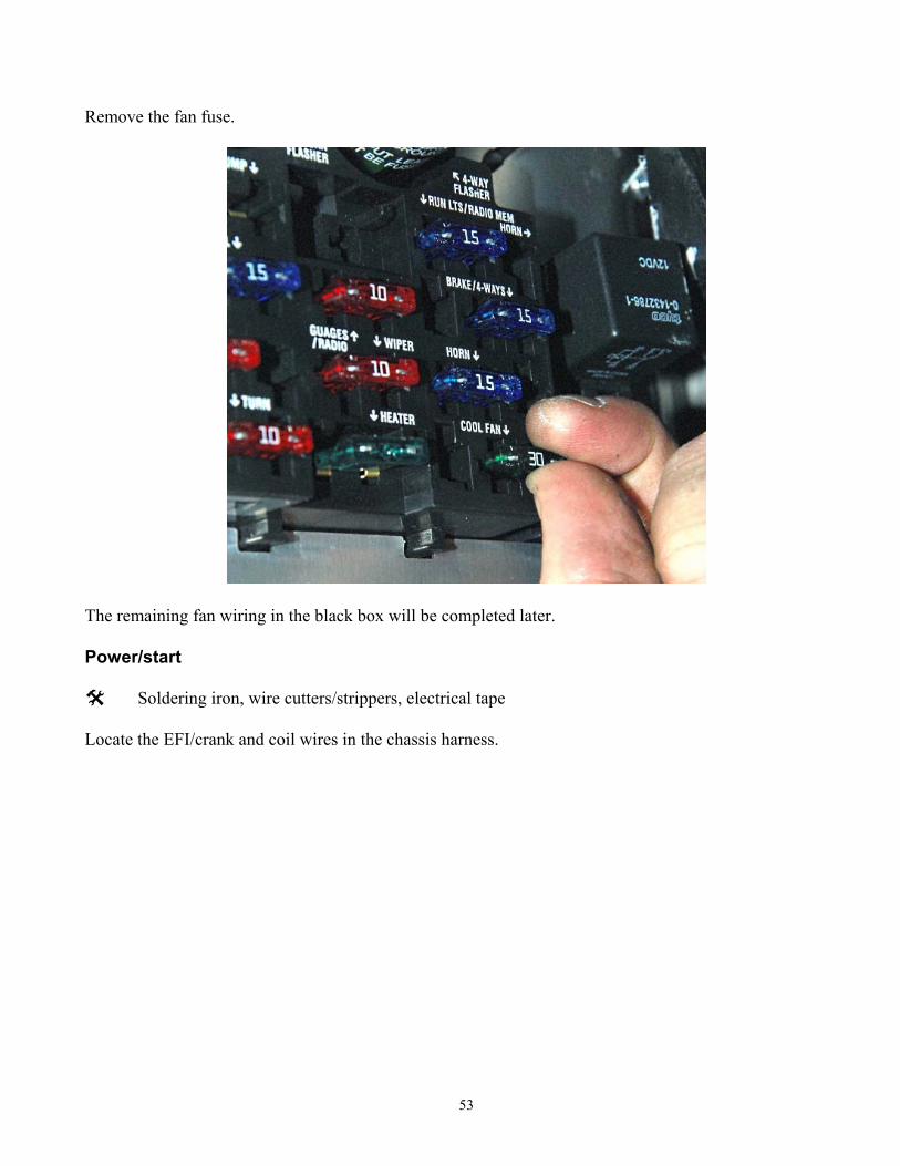
Solder or butt connect the orange fan wires together.
Remove the fan relay from the fuse panel.
53
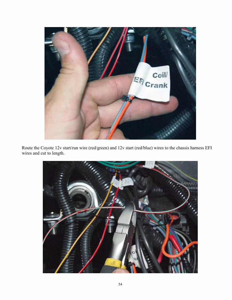
Remove the fan fuse.
The remaining fan wiring in the black box will be completed later. Power/start
Soldering iron, wire cutters/strippers, electrical tape Locate the EFI/crank and coil wires in the chassis harness.
54
Route the Coyote 12v start/run wire (red/green) and 12v start (red/blue) wires to the chassis harness EFI wires and cut to length.
55
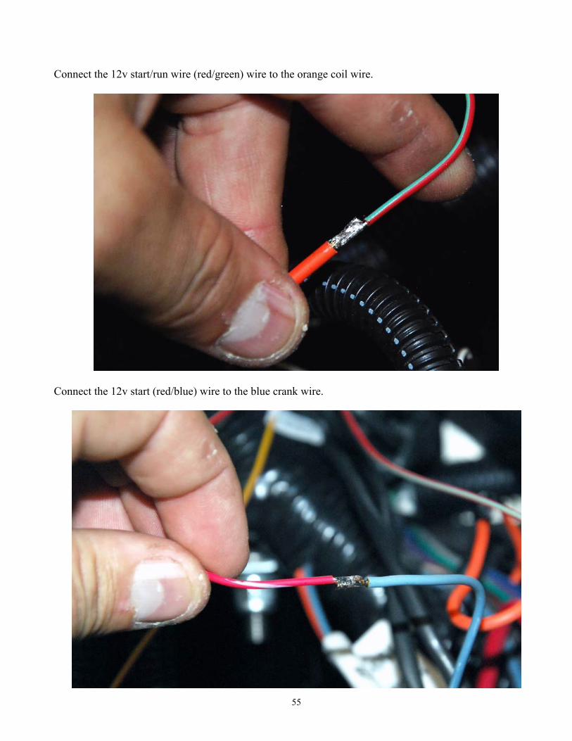
Connect the 12v start/run wire (red/green) wire to the orange coil wire.
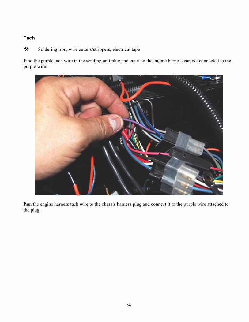
Connect the 12v start (red/blue) wire to the blue crank wire.
56
Tach
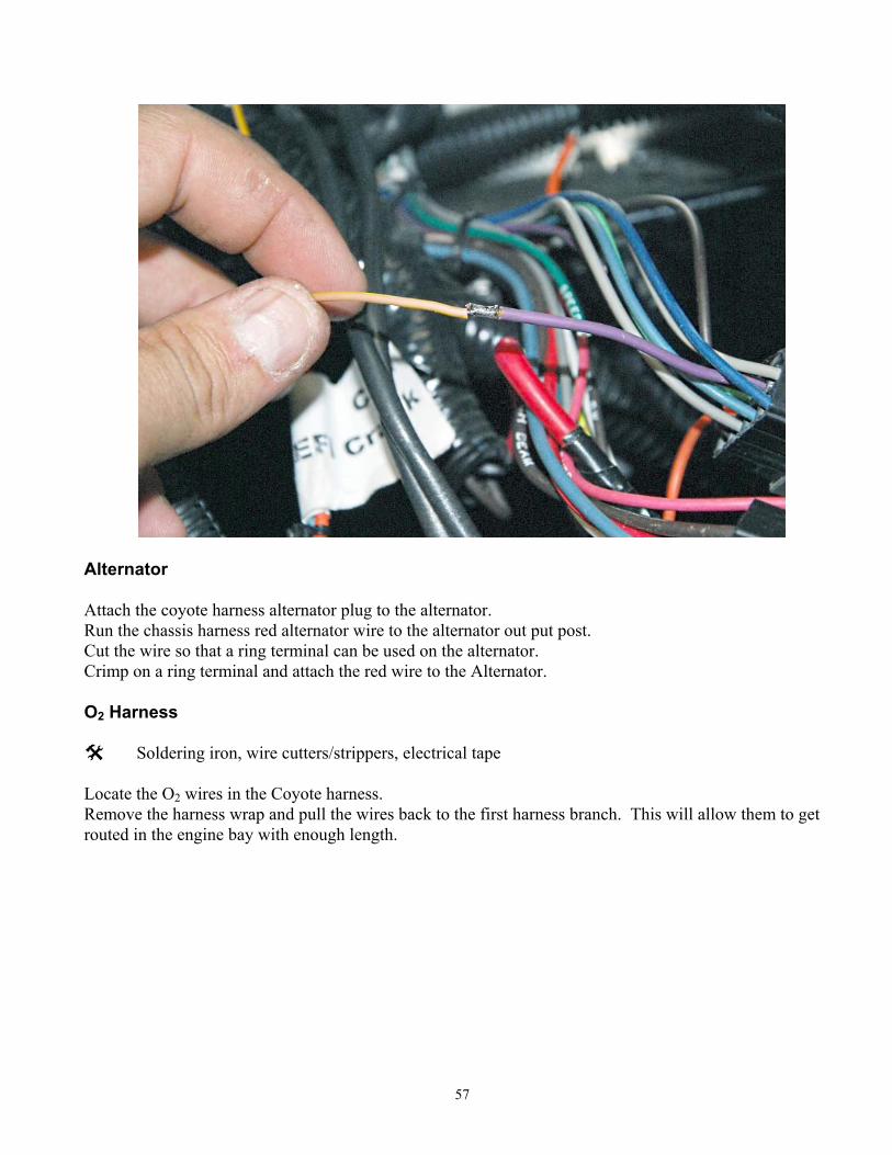
Soldering iron, wire cutters/strippers, electrical tape Find the purple tach wire in the sending unit plug and cut it so the engine harness can get connected to the purple wire.
Run the engine harness tach wire to the chassis harness plug and connect it to the purple wire attached to the plug.
57
Alternator Attach the coyote harness alternator plug to the alternator. Run the chassis harness red alternator wire to the alternator out put post. Cut the wire so that a ring terminal can be used on the alternator. Crimp on a ring terminal and attach the red wire to the Alternator. O2 Harness
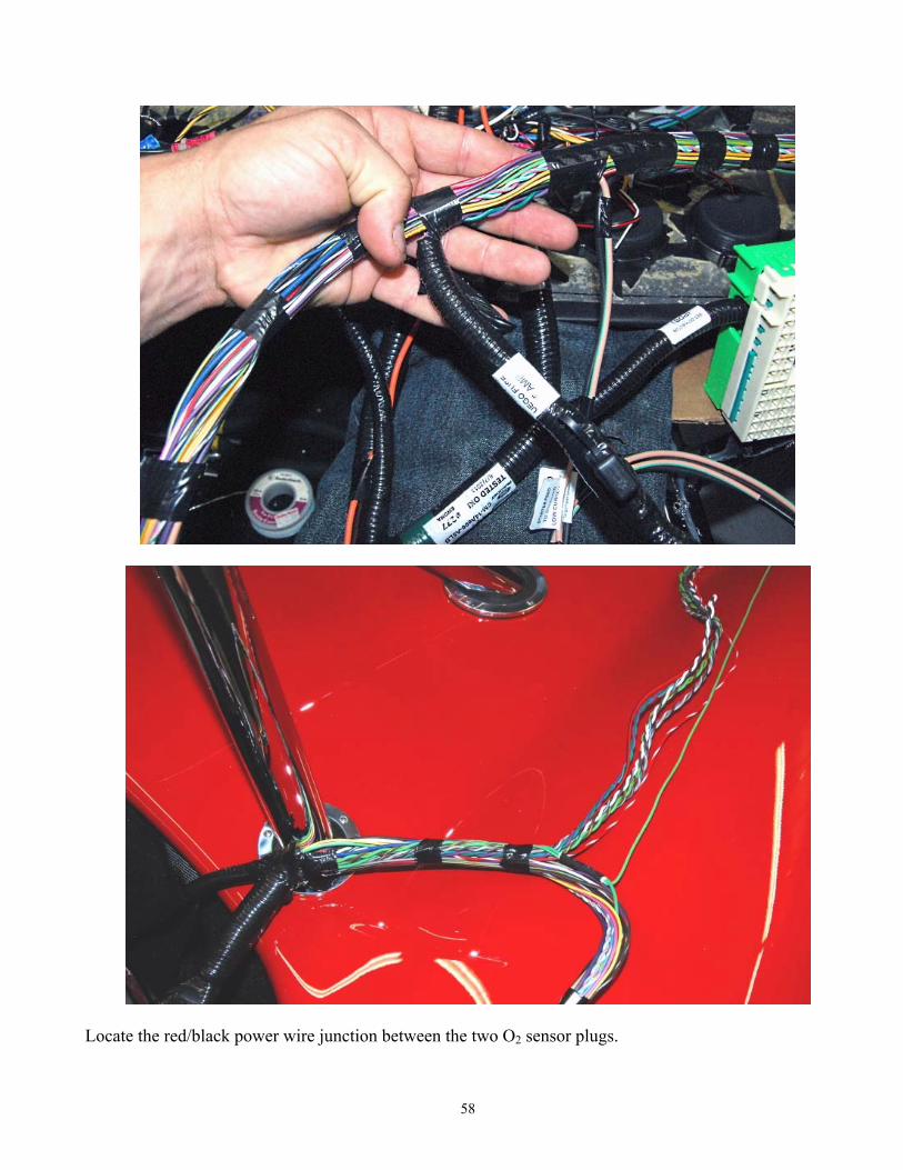
Soldering iron, wire cutters/strippers, electrical tape Locate the O2 wires in the Coyote harness. Remove the harness wrap and pull the wires back to the first harness branch. This will allow them to get routed in the engine bay with enough length.
58
Locate the red/black power wire junction between the two O2 sensor plugs.
59
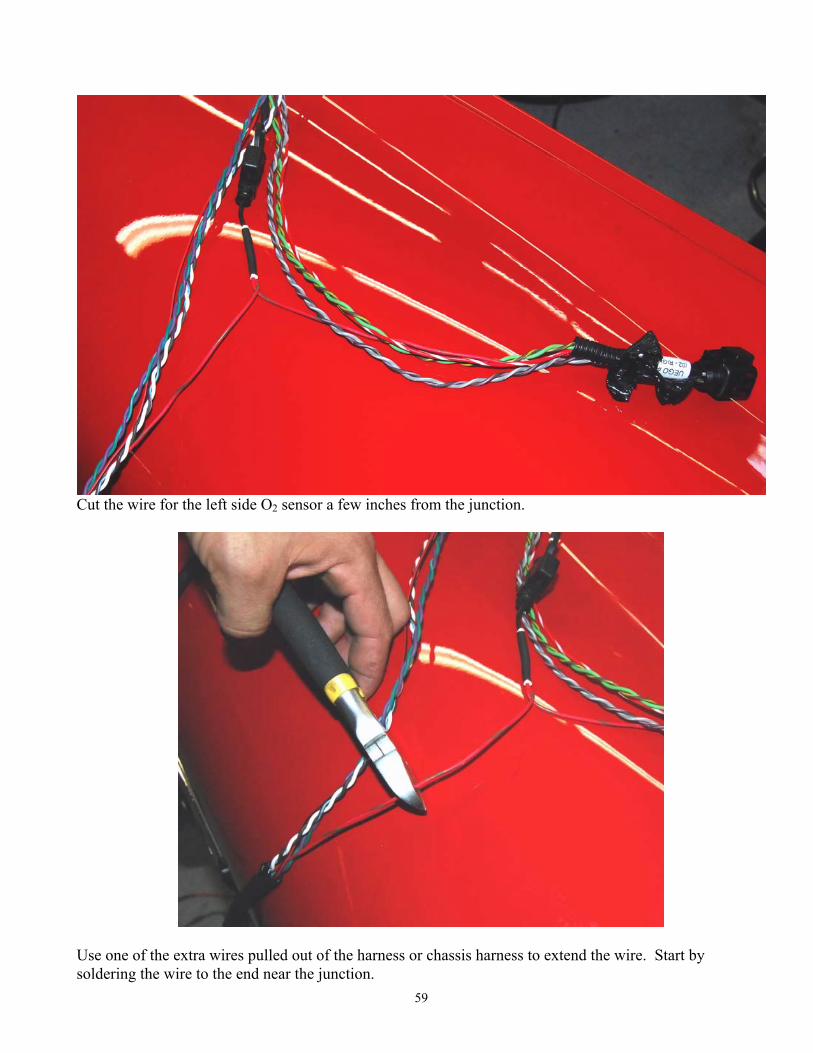
Cut the wire for the left side O2 sensor a few inches from the junction.
Use one of the extra wires pulled out of the harness or chassis harness to extend the wire. Start by soldering the wire to the end near the junction.
60
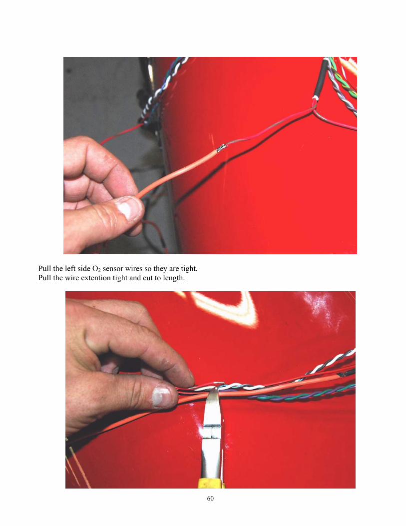
Pull the left side O2 sensor wires so they are tight. Pull the wire extention tight and cut to length.

61
Solder the other end of the extension wire to the O2 sensor wire.
Recover the harness with the original conduit.
62
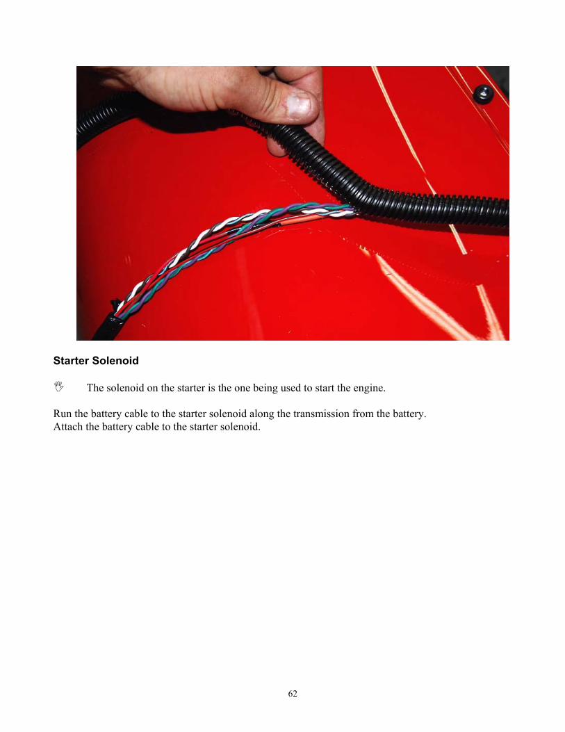
Starter Solenoid
The solenoid on the starter is the one being used to start the engine. Run the battery cable to the starter solenoid along the transmission from the battery. Attach the battery cable to the starter solenoid.
63
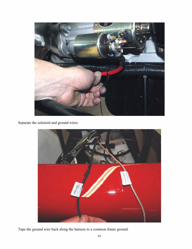
Separate the solenoid and ground wires.
Tape the ground wire back along the harness to a common frame ground.
64
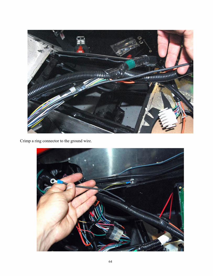
Crimp a ring connector to the ground wire.

65
Attach the ring connector to ground.
Attach the tan/green wire to the starting post on the solenoid.
66
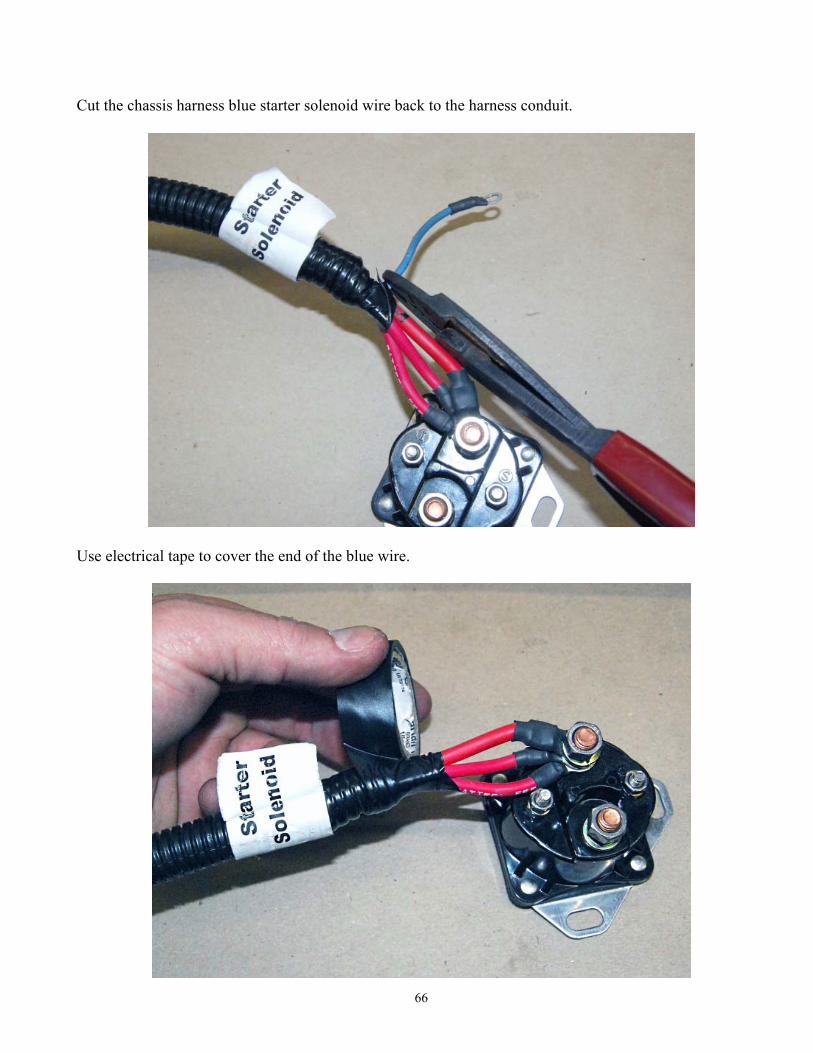
Cut the chassis harness blue starter solenoid wire back to the harness conduit.
Use electrical tape to cover the end of the blue wire.
67
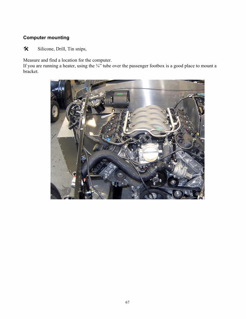
Computer mounting
Silicone, Drill, Tin snips, Measure and find a location for the computer. If you are running a heater, using the ¾” tube over the passenger footbox is a good place to mount a bracket.
68
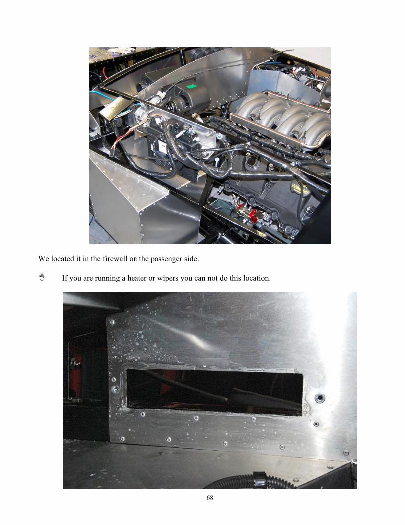
We located it in the firewall on the passenger side.
If you are running a heater or wipers you can not do this location.
69
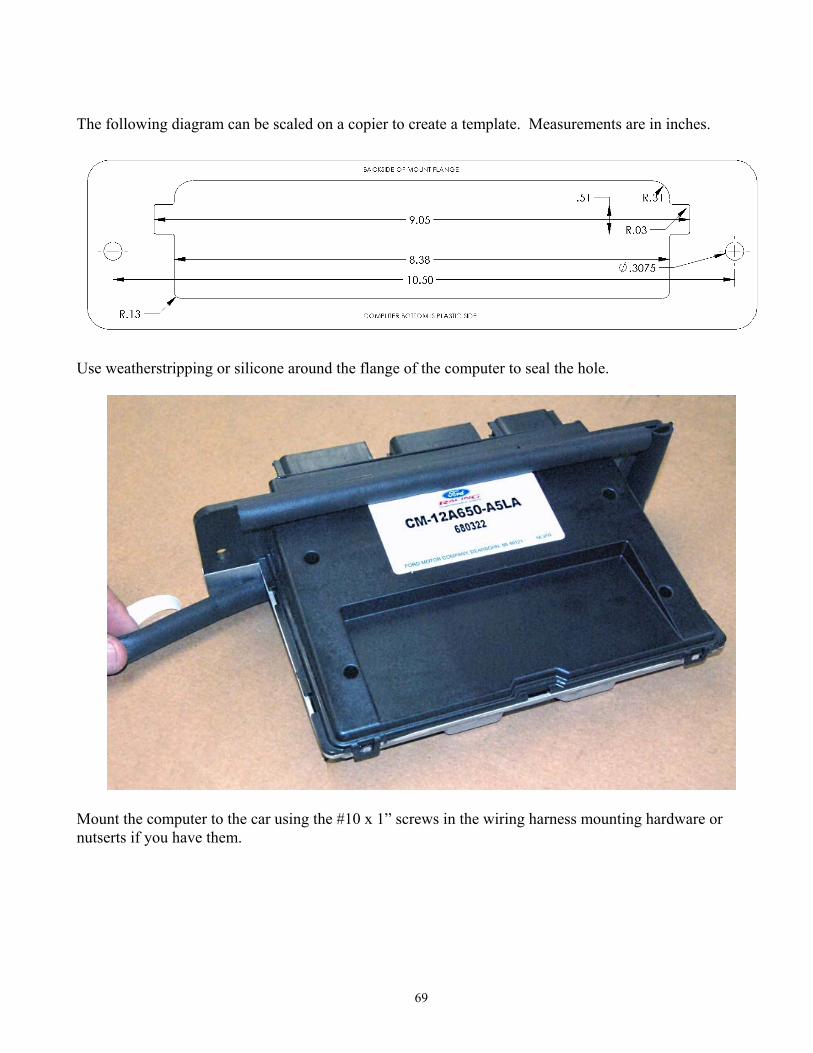
The following diagram can be scaled on a copier to create a template. Measurements are in inches.
Use weatherstripping or silicone around the flange of the computer to seal the hole.
Mount the computer to the car using the #10 x 1” screws in the wiring harness mounting hardware or nutserts if you have them.
70
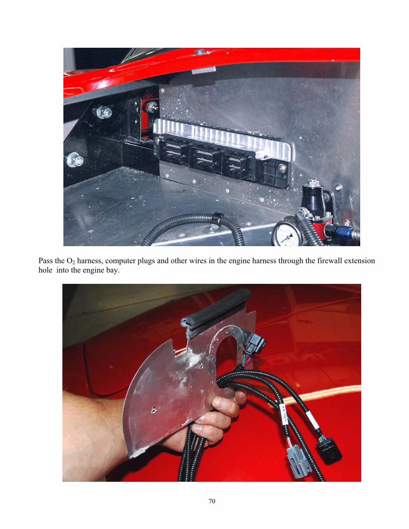
Pass the O2 harness, computer plugs and other wires in the engine harness through the firewall extension hole into the engine bay.
71
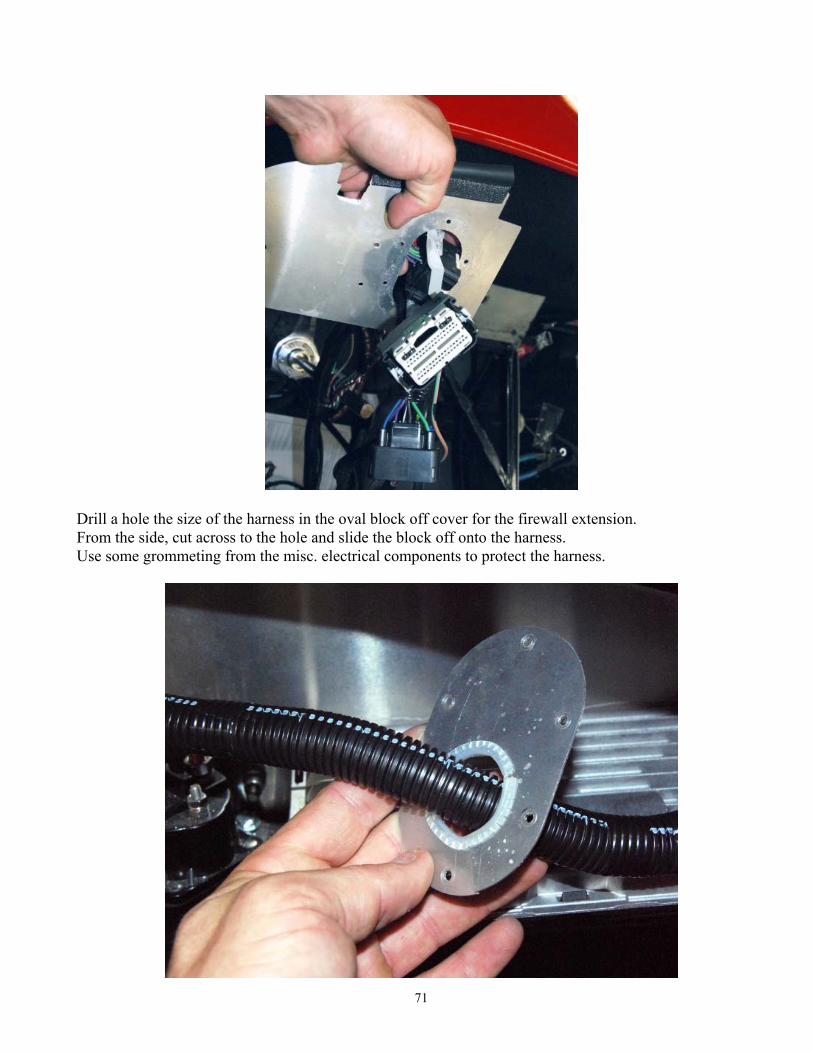
Drill a hole the size of the harness in the oval block off cover for the firewall extension. From the side, cut across to the hole and slide the block off onto the harness. Use some grommeting from the misc. electrical components to protect the harness.

72
Attach the firewall extension to the frame.
Silicone and rivet the block-off cover to the firewall extension.
73
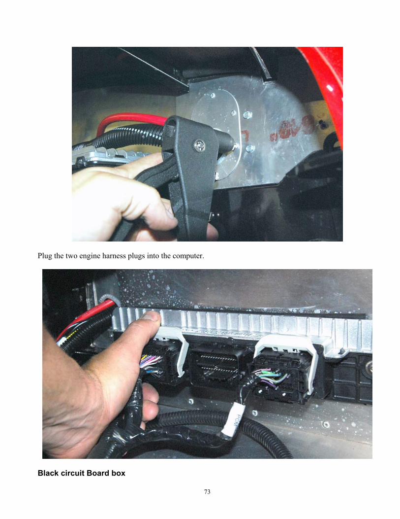
Plug the two engine harness plugs into the computer.
Black circuit Board box
74
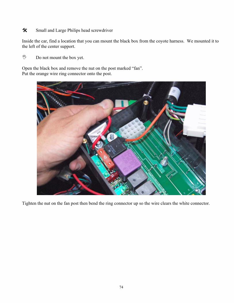
Small and Large Philips head screwdriver Inside the car, find a location that you can mount the black box from the coyote harness. We mounted it to the left of the center support.
Do not mount the box yet. Open the black box and remove the nut on the post marked “fan”. Put the orange wire ring connector onto the post.
Tighten the nut on the fan post then bend the ring connector up so the wire clears the white connector.
75
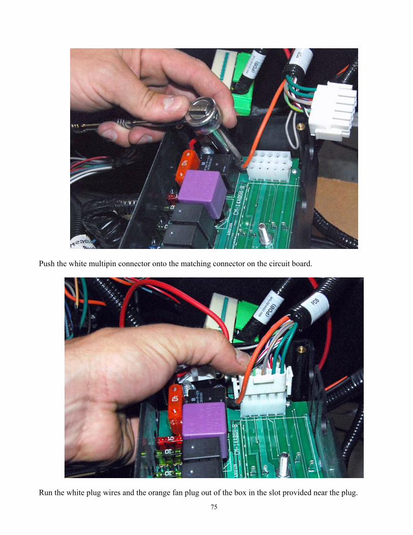
Push the white multipin connector onto the matching connector on the circuit board.
Run the white plug wires and the orange fan plug out of the box in the slot provided near the plug.
76
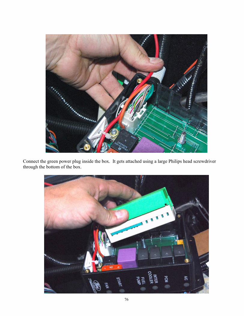
Connect the green power plug inside the box. It gets attached using a large Philips head screwdriver through the bottom of the box.
77
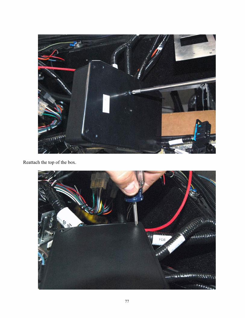
Reattach the top of the box.

78
Attach the box to the frame.
Power Distribution
Wire cutters/strippers, electrical tape, wire crimpers. We used an extra starter solenoid for power distribution in these instructions. A distribution post is
provided in the Coyote kit. The solenoid on the starter is the one being used to start the engine.
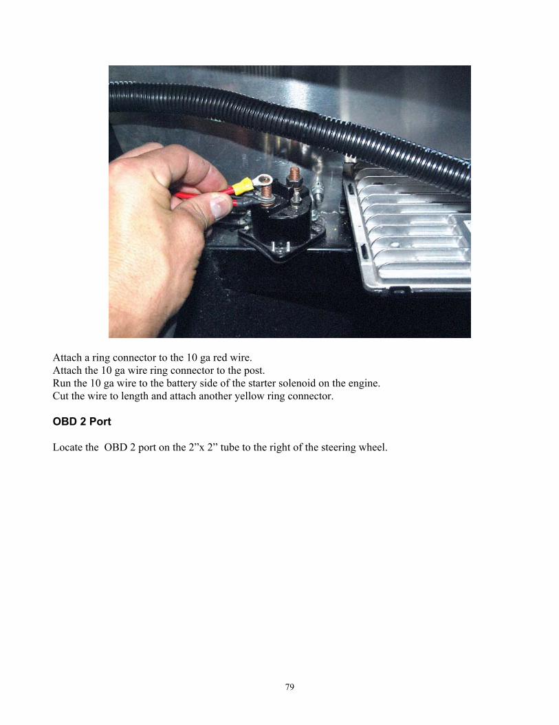
Locate and attach the power distribution post to the 2”x 2” tube. Shorten and attach the red wire from the black box to the power distribution post using one of the yellow ring connectors.
79
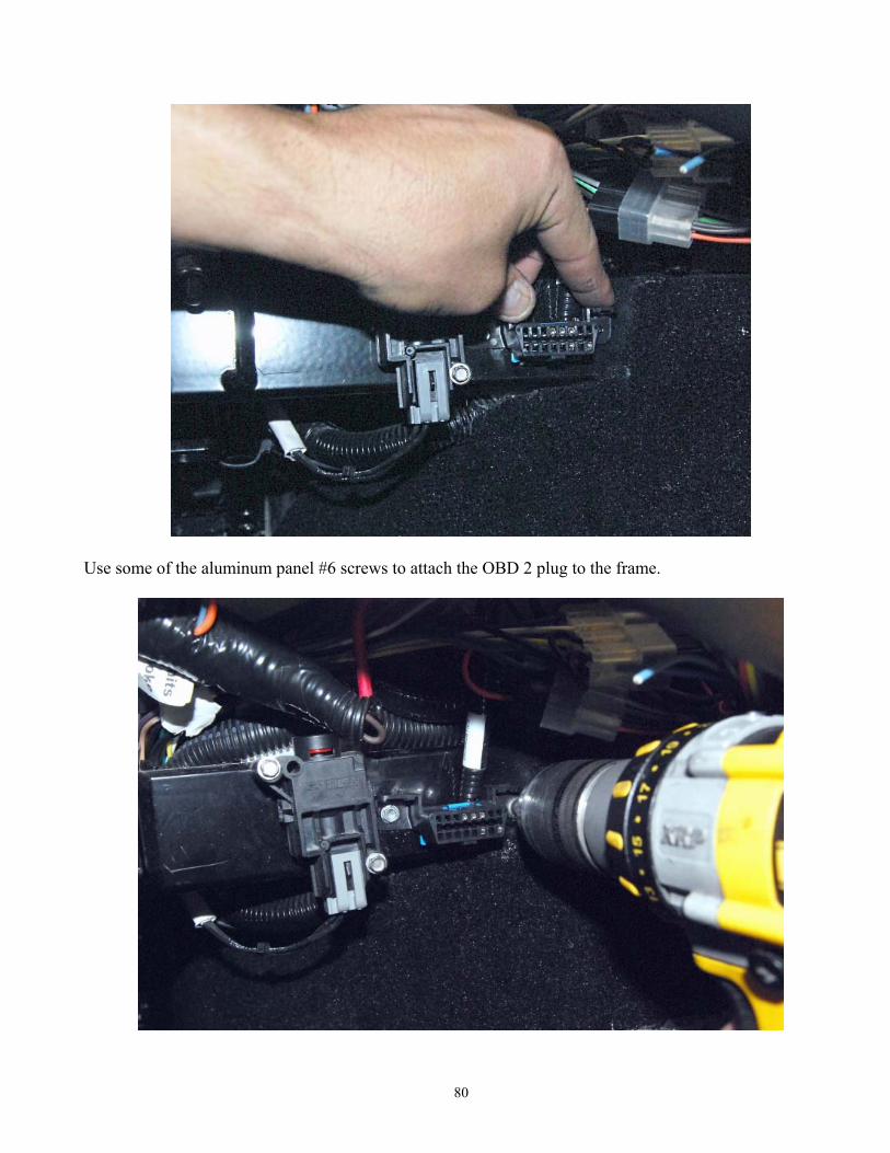
Attach a ring connector to the 10 ga red wire. Attach the 10 ga wire ring connector to the post. Run the 10 ga wire to the battery side of the starter solenoid on the engine. Cut the wire to length and attach another yellow ring connector. OBD 2 Port Locate the OBD 2 port on the 2”x 2” tube to the right of the steering wheel.
80
Use some of the aluminum panel #6 screws to attach the OBD 2 plug to the frame.
81
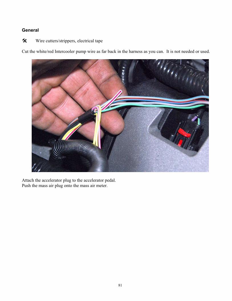
General
Wire cutters/strippers, electrical tape Cut the white/red Intercooler pump wire as far back in the harness as you can. It is not needed or used.
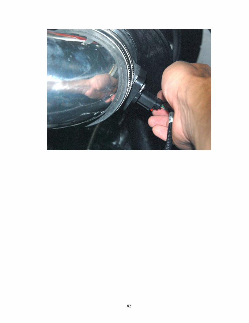
Attach the accelerator plug to the accelerator pedal. Push the mass air plug onto the mass air meter.
82