roads in japan - mlit.go.jp › road › road_e › pdf › road2014web.pdf · japan is a country...
TRANSCRIPT

ROADS IN JAPANRoad BureauMinistry of Land, Infrastructure, Transport and Tourism
http://www.mlit.go.jp/road/road_e/index_e.html

C O N T E N T S
Chapter 4 Road Administration in JapanType of Road ………………………………………………………………… 35
Chapter 1 Initiatives to Ensure Safety,Security and Comfort
Reducing Traffic Accidents ………………………………………………… 2Creating a Comfortable Living Environment ……………………………… 4Disaster Prevention ………………………………………………………… 6ITS (Intelligent Transport Systems) ……………………………………………… 8Deployment of Multiple Applications via Smartway ……………………… 10Environmental Measures …………………………………………………… 12
History of Roads in Japan …………………………………………………… 42Organization Chart …………………………………………………………… 48
52
70
Chapter 2 Improving Performance and ServiceAdministrative Management ……………………………………………… 14Road Development ………………………………………………………… 16Two-way Communication …………………………………………………… 23Asset Management ………………………………………………………… 24Efficient Operation of the Road Network…………………………………… 28
Chapter 3 Advanced Road Technologies
Road Structure Ordinance
Tunnels ………………………………………………………………………… 31
………………………………………
Statistics ……………………………………………………………………
Bridges ………………………………………………………………………… 32Pavement
Photographs provided by: East Nippon Expressway Co., Ltd., Metropolitan Expressway Co., Ltd., Hanshin Expressway., Ltd., and Honshu-Shikoku Bridge Expressway Co., Ltd., unless otherwise indicated.
……………………………………………………………………… 33
Chapter
1
Initiatives to Ensure Safety,Security and Comfort
Japan is a country with beautiful natural scenery, which changes from season to season, but also has steep land formations,weak geological features and is prone to eartquakes, storms, heavy snowfall and other natural disasters. Traffic accident fatalities and casualties are also rising with traffic-related deaths of about 5,000 and traffic-related casualties reaching 900,000, signifying
that one out of every 140 people is injured or dies in a traffic accident.Diverse measures are being implemented to prevent disastersand accidents; mitigate damages; enable quick restoration; improve the safety and security of road traffic; and create comfortable living environments.
1
2 3
Reducing Traffic Accidents
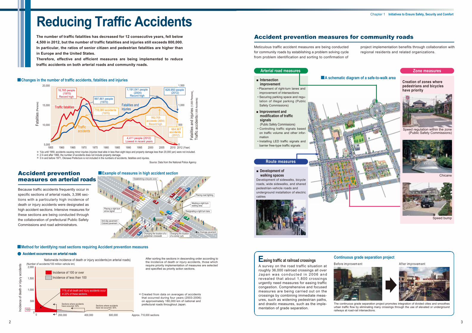
■Changes in the number of traffic accidents, fatalities and injuries
Source: Data from the National Police Agency
1Up until 1959, accidents causing minor injuries (injuries treat able in less than eight days and property damage less than 20,000 yen) were not included. 2 In and after 1966, the number of accidents does not include property damage. 3 In and before 1971, Okinawa Prefecture is not included in the numbers of accidents, fatalities and injuries.
Fata
lities
and
injur
ies (1
,000 P
erso
ns) ,
Traf
fic a
ccide
nts (1
,000 A
ccide
nts)
Accident prevention measures on arterial roads
Because traffic accidents frequently occur inspecific sections of arterial roads, 3,396 sec-tions with a particularly high incidence of
high accident sections. Intensive measures fordeath or injury accidents were designated as
these sections are being conducted throughthe collaboration of prefectural Public SafetyCommissions and road administrators.
Placing a right turnarrow signal
Establishing a bicycle zone
Designating a right turn lane
Changing the location of apedestrian crosswalk
Drainage pavement
Anti-slip pavementColored pavement
Placing road lighting
Marking a right turnwaiting area
Changing the locationof a corner curb
■Example of measures in high accident section
■Method for identifying road sections requiring Accident prevention measures
100
2,000
1,500
1,000
500
00
(Number of accidents/100 million vehicle km)
Incid
ence
of d
eath
or i
njury
acc
ident
s
Nationwide incidence of death or injury accidents (on arterial roads)
Sections where accidentshave not occurred: 50%
Sections where accidentshave occurred: 50%
Incidence of 100 or overIncidence of less than 100
After sorting the sections in descending order according tothe incidence of death or injury accidents, those whichrequire priority implementation of measures are selectedand specified as priority action sections.
●● Accident occurrence on arterial roadsAccident occurrence on arterial roads
Easing traffic at railroad crossingsA survey on the road traffic situation atroughly 36,000 railroad crossings all overJ a p a n w a s c o n d u c t e d i n 2 0 0 6 a n drevealed that about 1,800 crossingsurgently need measures for easing trafficcongestion. Comprehensive and focusedmeasures are being carried out on thecrossings by combining immediate meas-ures, such as widening pedestrian paths,and drastic measures, such as the imple-mentation of grade separation.
Continuous grade separation projecttnemevorpmiretfAtnemevorpmierofeB
The continuous grade separation project promotes integration of divided cities and smoothesurban traffic flow by eliminating many crossings through the use of elevated or undergroundrailways at road-rail intersections.
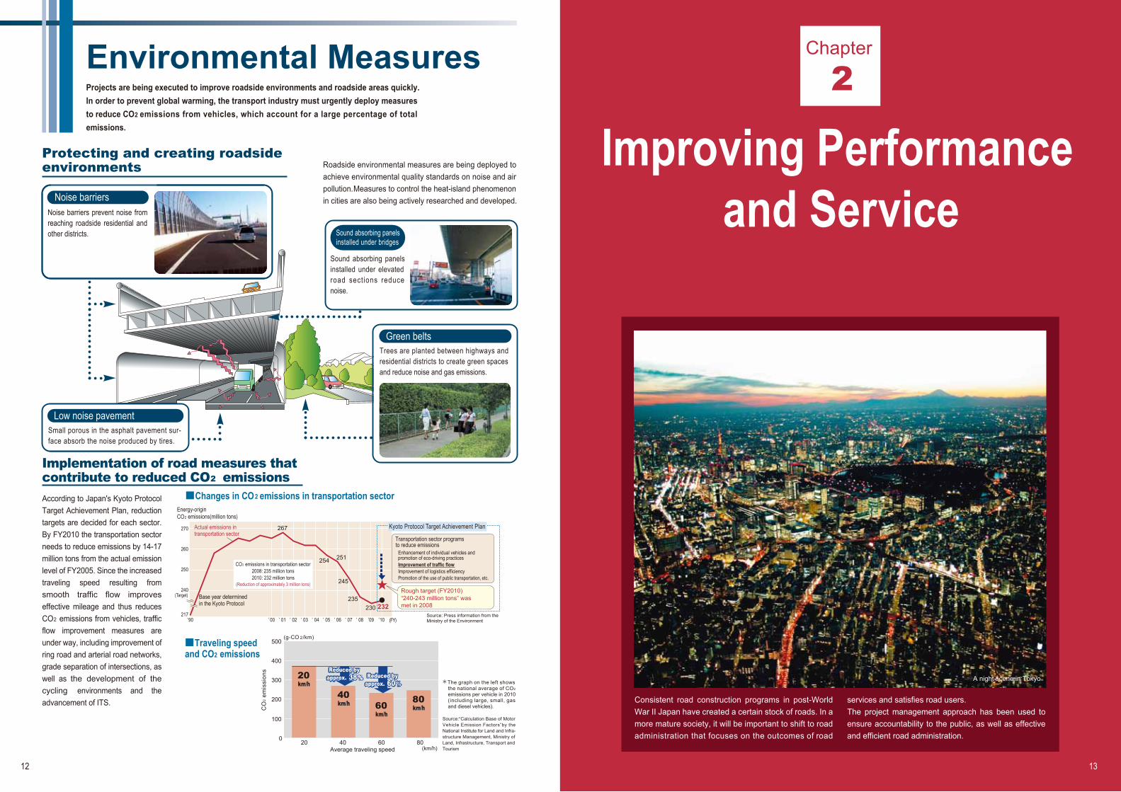
■A schematic diagram of a safe-to-walk area■ Intersectionimprovement
• Placement of right-turn lanes andimprovement of intersections
• Securing parking space and regu-lation of illegal parking (PublicSafety Commissions)
■ Improvement andmodification of trafficsignals(Public Safety Commissions)
• Controlling traffic signals basedon traffic volume and other infor-mation
• Installing LED traffic signals andbarrier free-type traffic signals
Arterial road measures
■ Development ofwalking spaces
Development of sidewalks, bicycleroads, wide sidewalks, and sharedpedestrian-vehicle roads andunderground installation of electriccables
Zone measures
Accident prevention measures for community roads
Meticulous traffic accident measures are being conductedfor community roads by establishing a problem solving cyclefrom problem identification and sorting to confirmation of
project implementation benefits through collaboration withregional residents and related organizations.
Route measures
Created from data on averages of accidentsthat occurred during four years (2003-2006)on approximately 180,000 km of national andprefectural roads throughout Japan.
Creation of zones wherepedestrians and bicycleshave priority
Chicane
Speed bump
Speed regulation within the zone(Public Safety Commissions)
The number of traffic fatalities has decreased for 12 consecutive years, fell below 4,500 in 2012, but the number of traffic fatalities and injuries still exceeds 800,000. In particular, the ratios of senior citizen and pedestrian fatalities are higher than in Europe and the United States.Therefore, effective and efficient measures are being implemented to reduce traffic accidents on both arterial roads and community roads.
71% of all death and injury accidents occur in 22% of these sections.
200,000 400,000 600,000 Approx. 710,000 sections
20,000
15,000
10,000
(Year)
1,191,041 people (2004)
Record high997,861 people
(1970)
718,080 accidents (1970)
16,765 people (1970)
Record high
5,000
1,500
1,000
500
0
952,709accidents (2004)
Record high
4,411 people (2012) Lowest in recent years
828,950 people(2012)
Fatalities andinjuries
Trafficaccidents
Traffic fatalities
664,907 accidents
(2012)
Fata
lities
(Per
sons
)
1955 1960 1965 1970 1975 1980 1985 1990 1995 2000 2005 2010 2012
Chapter 1 Initiatives to Ensure Safety, Security and Comfort

4 5
Creating a ComfortableLiving EnvironmentRoad construction and improvement projects are being implemented so that people can truly experience the improvements, such as safe and comfortable pedestrian spaces; high-qualityliving environments with roadside greening; running utility cables underground, etc.
Promoting universal design in pedestrian spaces
Eliminating utility poles
■Example of universal design in pedestrian spaces■Example of universal design in pedestrian spaces
Multiple methods for eliminating utility polesMultiple methods for eliminating utility poles
Moving cables to the side street behind thestreet where poles are to be eliminated
Running cables under/along the eavesof houses along the street
Common utility duct
SidewalkNew road
In progress
Cables in the main street
Moving poles tothe back streetEliminating utility
poles in the mainstreet Cables under the eaves
Example of utility pole elimination
Before elimination After elimination
Creating a safe and pleasant environment for cyclists riding
Development of cycling route networks
Collaboration with public transportation
Educating of people on bicycle riding rulesand etiquette
Development and promotion of communitybicycle programs
Construction of bicycle parking facilities
■Changes in the number of bicycle accidents classified according to the other party (last 5 years)
Aiming to create advanced urban settings for bicycle usage
Conceptual images of the initiative
Utility poles are being eliminated to help secure safe and comfortable pedestrian spaces; create a visually enhanced landscape and living environment; prevent disasters; improve the reliability of telecommunications networks conserve histori-cal townscapes; promote tourism, restore local culture; and revitalize local communities.
Identical installation of common utility duct simultaneous with road construction project
While bicycles play an important role in the urban transporta-tion system as a convenient transportation method, infrastruc-ture for cyclists is not yet sufficient and is resulting in an increase of bicycle accidents relative to the total number of traffic accidents. To stop this trend, MLIT and the National Police Agency (NPA) cooperated to launch the “Committee for Creating a Safe & Comfortable Bicycle-Use Environment” in 2011. The Committee submitted the following proposal to MLIT and the NPA: “A Bicycle Environment that is Friendly to Everybody: Proposal for a Safe & Comfortable Bicycle-Use Environment.” In response to the proposal, in November 2012, MLIT and the NPA jointly formulated, “Guideline for Creating a Safe & Comfortable Bicycle-Use Environment.”
(Source: Information from National Police Agency)
Note: "Accidents involving bicycles" means the first party or the second party is a bicyclist and accidents between two or more bicyclists are calculated as one instance.
By 2012, barrier-free pedestrian paths will be increased to represent about 75% of all road segments interconnecting railway stations, government facilities, hospitals and the like, which are designated by the Minister of Land, Infrastructure, Transport and Tourism as road sections where a large number of elderly and disabled people normally travel on foot.
We will continue to promote the elimination of utility poles in the future by aggressively utilizing multiple methods that suit local situations such as a combined approach of widening roads projects in conjunction with the elimination of utility poles and wiring in spaces under or behind building eaves. We will additionally look to reduce costs.
200,000
180,000
160,000
140,000
120,000
100,000
80,000
60,000
40,000
200,00
20,000
18,000
16,000
14,000
12,000
10,000
8,000
6,000
4,000
2,000
0 0
(times) (times)
(Year)
With
mot
orcy
cle
/ ped
estri
an /
bicy
cle/
othe
r
All
acci
dent
s in
volv
ing
bicy
cles
/ A
ccid
ents
with
mot
or v
ehic
les
171,018
141,345
11,642
11,016
4,159
2,856
162,525
134,300
10,639
10,322
4,322
2,942
156,405
130,747
9,973
8,841
3,9102,934
151,625 144,018
121,004127,419
9,496 9,134
7,468
3,611
2,801
8,155
3,7962,760
With pedestrian
With bicycle
Other
With motorcycle
With motor vehicle
All accidents involving bicycles
2007 2008 2009 2010 2011
Chapter 1 Initiatives to Ensure Safety, Security and Comfort

6 7
Disaster PreventionIn order to secure safe and reliable road networks, high-standardarterial highways, urban ring roads and other disaster-resistantroads are being constructed. Measures against earthquakes,storms and heavy snows are also being implemented. Roads arean important infrastructure after a disaster has occurred.
Earthquake Heavy rain
Heavy snow
July 2009Mudslide caused by heavy rain in Chugoku and northern Kyushu regions(National Highway 262, Hofu City, Yamaguchi Prefecture)
February 2014Record-breaking heavy snow in Kanto-region: Japan Self-Defence Force clearing snow on the route 20(Photo:Mainichi Shimbun)
Earthquake protection
Disaster prevention for roadside slopes
Protection of road transport in winter
Non-seismically reinforced bridge pier damaged byearthquake
Bridge pier seismically reinforced by concrete jacketing
Road with rockfall shelter
Protective concrete that prevents roadside slope collapsing
Snow shed that provides avalanche protection Snow removal operation
To ensure a highly reliable road network that allows for fast and safe emergency activities during earthquakes, bridges are being retrofitted with earthquake protection.
The land area of Japan comprises only 0.25% of the world's total, but Japan is one of the foremost countries to experi-ence earthquakes, with the probability of a large-scale earthquake (magnitude of 6.0 or more) occurring at about 23%.
Japan receives twice as much precipitation as the mean precipitation in the rest of the world, especially during the rainy season and typhoon seasons. During the last decade, local heavy rains have increased sharply, therefore increasing the risk of floods. The soft soil collapses easily during storms and is prone to sediment run-off, landslides and other sediment-related disasters.
Because the Sea of Japan lies between Japan and the Asian continent, Japan receives heavy snows brought by prevailing winds from the continent in winter, especially in areas facing the Sea. About 60% of the land is snowy and cold, where about one-fifth of the total population live, causing the popula-tion density to be as high as 105 people per km2, which far exceeds the values in other snowy countries.
Massive earthquake and the following giant tsunami on the 11th of March 2011 caused enormous damages to the roads(National Highway 6, hirono-machi, Fukushima Prefecture)(Photo:Tohoku Regional Development Bureau)
Road transport in snowy cold regions in the wintertime is protected by efficient snow removal as well as proactive installation of avalanche and other snow protection facilities.
A number of measures are implemented to protect road traffic from heavy rain and heavy snow. These include, among others, disaster prevention work on roadside slopes and construction of roads that circumvent disaster-prone sections.
Chapter 1 Initiatives to Ensure Safety, Security and Comfort

8 9
ITS (Intelligent Transport Systems)
■Changes in number of vehicles equipped with ETC on-board unit and percentage of ETC use
Automated parking lot payment
Simplified ferry boarding procedure
ETC (Electronic Toll Collection System)
Since it went into service in March 2001, ETC users have beenrapidly increasing in number with the quick popularization ofETC on-board units. At the end of March 2011, there wereabout 34.24 million ETC-equipped vehicles. ETC users nowaccount for 86.2% of all vehicles on expressways in Japan.The system has effectively eliminated congestion at toll gates.Previously, 30% of congestion on expressways occurred at toll
ETC for non-stop toll collection has been installed at almost all expresswaytoll gates in Japan, contributing toward mitigating toll-booth congestion.
Source: Survey by the Organization for Road System Enhancement
Congestionalmost
eliminated
56.2
21.2
12.1
3.9 2.86.1
19.8
6.1
19.8
38.1
65.3 73.0
Percentage of ETC use (%)Congestion (km-h/day)60
50
40
30
20
10
0
90
75
60
45
30
15
0
Congestion (left vertical scale)
Percentage of ETC use (right vertical scale)
March2003
March2004
March2005
March2006
March2007
Percentage of ETC use and congestion show March weekday averages at main-lane toll booths.
Source: Metropolitan Expressway data
■Congestion reduction effect of spreading ETC use onMetropolitan Expressway
B
B
6
95
4
12
311
C1
Japan Road TrafficInformation Center
Prefectural policeheadquarters
Road administrator
Trafficinformation VICS
Center
Radio wave beacon located on an expressway
Infrared beacon located on a major general road
Radio wave beacon
Infrared beacon
FM multiplex broadcasting
Beaconantenna
FM multiplex antenna
VICS receiver
Car navigationsystem main unit
LCD monitor
GPS antenna
Three mediaRadiowave
beaconInfraredbeacon
FMmultiplex
broad-casting
Nagoya-bound Accident
Lane closureTomei Kawasaki IC→Tokyo IC
Text (Level 1) Simple graphics (Level 2)
Infrared beaconRadio wave beacon FM multiplex broadcasting
Map (Level 3)
■Mechanism of VICS information
■Number of VICS-compatible on-board units in use(10,000 vehicles)
128 4421,020
1,8152,804
4,489
6,581
9,117
11,886
15,018
18,173
21,193
23,813
Prepared by MLIT based on VICS's data
VICS (Vehicle Information and Communication System)
Source: Vehicle Information and Communication System Center
VICS transmits road traffic data, such as congestion and traffic restrictions on a real-time basis, to onboard vehicle navigation units and displays data in the form of text, simple graphics and maps. The service started in Japan in April 1996, earlier than anywhere else in the world. VICS delivers information using three types of media: FM multiplex broad-casting, a radio wave beacon and an infrared beacon.At the end of March 2011, over 30.13 million vehicles were equipped with VICS compatible onboard units. VICS's best route guidance rectifies traffic flow and improves mileage, which in turn reduces CO2 emissions and environmental impacts. A target of the Kyoto Protocol Goal Achievement Plan is to reduce CO2 emissions by approximately 2.5 million tons (approximately 30% of all road related policy measures) by FY 2012. through the popularization of VICS.
3,200
3,000
2,800
2,600
2,400
2,200
2,000
1,800
1,600
1,400
1,200
1,000
800
600
400
200
04413
102 182280
449
658
912
1,189
1,5021,817
2,119
2,381
2,679
3,013
1996 1997 1998 1999 2000 2001 2002 2003 2004 2005 2006 2007 2008 2009 2010 (FY)
In Japan, ITS (Intelligent Transport Systems) are steadily expanding with the popularization of ETC (Electronic Toll Collection System) and VICS (Vehicle Information and Communication System), and have effectively opened up traffic by providing real-time information; eliminating congestion at toll gates; and mitigating environmental impacts by differential toll discounts. ITS has now entered its second stage and is being promoted in order to solve social issues. Installation of systems for collecting and providing information, which are the basis of ITS, is promoted and systems are being developed whereby drivers can enjoy diverse services via a single ITS on-board unit.
gates. By allowing drivers to pass through toll gates without having to stop, ETC improves the processing capability of toll gates, eliminating congestion that would otherwise occur there. ETC communication technology is also used by private operators for non-stop passage through parking gates and ferry boarding, among others.
(Percentage of ETC use)(Total number of ETC-equipped vehicles per 10,000 vehicles)
Number (Cumulative total, left vertical scale)Percentage (Nationwide average, right vertical scale)
4,000
4,200
4,400
3,600
3,800
3,400
3,200
3,000
2,800
2,600
2,400
2,200
2,000
1,800
1,600
1,400
1,200
1,000
800
600
400
200
0
100
90
80
70
60
50
40
30
20
10
02001 2002 2003 20052004 2007 2006 2008 2009 2010 2011Jun. Sep.Dec.Mar. Jun. Mar.Jun. Sep.Dec.Mar. Jun. Sep.Dec.
2012Sep.Dec.Mar.
Tomei Expressway
45 minutes via National Hwy 20
25 minutes via XX street
Chapter 1 Initiatives to Ensure Safety, Security and Comfort

10 11
Deployment of MultipleApplications via Smartway
Expanding ITS spot services throughout Japan
Car navigation system for ITS spot services
ITS spots
High speed, high volume,two-way communicationsHigh speed, high volume,two-way communication
Characteristics of smartway
ITS spot services
Enhanced services for ITS spots
■Outline of ITS Spots and Compatible Car Navigation System
■Comparison of scope of information provided by existing FM-VICS and ITS spot (Urban area)
■Locations of ITS spots
Legend Locations of ITS spots
• When sensor detects a traffic jam out of sight beyond an upcoming curve
• Normal driving
(Travel direction is indicated by a white arrow, while a simplified graphic image appears on the right.)
“Smartway” is a next-generation road traffic system incorporating ITS technologies that provide information to connect people, vehicles and roads with the primary aim of ensuring traffic safety, reducing traffic congestion, and protecting the environment. To make it a reality, industry, government and academia have been working together in research, development and demonstration testing. Services such as VICS and ETC are now provided by separate onboard units, but these services will be available using a single (ITS) onboard unit. Furthermore, aims are to build an "Open Platform" that develops wider services including account settlement, sightseeing, logistics, etc., in addition to providing a wide-range of road traffic information, safe driving support information and so on.
Central to the communication functions of Smartway is 5.8 GHz DSRC (Dedicated Short Range Communication), an interna-tional standard adopted by ISO (International Organization for Standardization) and ITU (International Telecommunication Union) that enables high speed, high volume, two-way commu-nication. DSRC will make various services available by using the roadside "ITS spots" and a "compatible in-vehicle car navigation system."
ITS spot services are available in about 1,600 places, centered on expressways in Japan, as of August 2011. With intercity expressways, an ITS spot is installed about every 10 to 15 km,
including about 90 locations before each junction, while with urban expressways, a spot is installed about every 4 km.
Because ITS spots are being built as an open platform where the public and private sectors can work together to provide diverse services, plans are to develop a wide variety of services, i.e., cashless bill payment for parking areas, logistics support, and so forth.
Moreover, it is possible to acquire probe information (actual travel distance and speed of the vehicle) from ITS spots, therefore plans are to use this information for road construction, road policy planning and assessing instituted measures.
From Tohoku expresswayFrom Tohoku expressway From Tohoku expresswayFrom Tohoku expressway
■Information provided by car navigation systems
■Example of provided image information
ITS spot services consist of three basic services that are made available as an all-in-one system by high speed, high volume road-to-vehicle communications. Wide-Range Road Traffic Information By transmitting road traffic information in real-time, car naviga-tion systems can search a wide-area of expressways that cross prefectural borders, urban expressways and other roads, and select the fastest route based on the latest information. Safe Driving SupportITS spots provide a wide range of road traffic information on a regular basis, including traffic safety issues for specific roads. In emergencies, they provide information that supports safe driving. ETCITS spot services utilize the same technologies as ETC, therefore existing ETC services can be enjoyed with a compat-ible car navigation system. Other servicesWith some car navigation systems, information on tourist sites and updated maps are provided over the internet.
Chapter 1 Initiatives to Ensure Safety, Security and Comfort
’90 00 ’ 01 ’ 02 ’ 03 ’ 04 ’ 05 ’ 06 ’ 07 ’ 08 09 10 (FY)
254 251
245
270
260
250
240 (Target)
217
267
’’’
12 13
Environmental MeasuresProjects are being executed to improve roadside environments and roadside areas quickly.In order to prevent global warming, the transport industry must urgently deploy measuresto reduce CO2 emissions from vehicles, which account for a large percentage of totalemissions.
Protecting and creating roadside environments Roadside environmental measures are being deployed to
achieve environmental quality standards on noise and airpollution. Measures to control the heat-island phenomenonin cities are also being actively researched and developed.
Implementation of road measures that contribute to reduced CO2 emissions
2
Trees are planted between highways andresidential districts to create green spacesand reduce noise and gas emissions.
Green belts
The graph on the left shows the national average of CO2
emissions per vehicle in 2010 (including large, small, gas and diesel vehicles).
Source:“Calculation Base of Motor Vehicle Emission Factors”by the National Institute for Land and Infra-structure Management, Ministry of Land, Infrastructure, Transport and Tourism
0
100
200
300
400
500
20 40 60 80Average traveling speed
20km/h
40km/h 60
km/h
80km/h
(g-CO 2/km)
(km/h)
Reduced by approx. 38 %%% Reduced by
approx. 60 %
Reduced by approx. 38 % Reduced by
approx. 60 %
CO
2 em
issi
ons
■Changes in CO2 emissions in transportation sector
■Traveling speedand CO2 emissions
Energy-origin CO2 emissions(million tons)
Actual emissions intransportation sector
Base year determinedin the Kyoto Protocol
CO2 emissions in transportation sector2008: 235 million tons2010: 232 million tons
(Reduction of approximately 3 million tons)
Chapter
2
A night scene in Tokyo
Improving Performanceand Service
Consistent road construction programs in post-World War II Japan have created a certain stock of roads. In a more mature society, it will be important to shift to road administration that focuses on the outcomes of road
services and satisfies road users.The project management approach has been used to ensure accountability to the public, as well as effective and efficient road administration.
Low noise pavementSmall porous in the asphalt pavement sur-face absorb the noise produced by tires.
Sound absorbing panelsinstalled under elevatedroad sections reducenoise.
Sound absorbing panelsinstalled under bridges
Noise barriers prevent noise fromreaching roadside residential andother districts.
Noise barriers
235230 232
According to Japan's Kyoto Protocol Target Achievement Plan, reduction targets are decided for each sector. By FY2010 the transportation sector needs to reduce emissions by 14-17 million tons from the actual emission level of FY2005. Since the increased traveling speed resulting from smooth traffic flow improves effective mileage and thus reduces CO emissions from vehicles, traffic flow improvement measures are under way, including improvement of ring road and arterial road networks, grade separation of intersections, as well as the development of the cycling environments and the advancement of ITS.
Transportation sector programsto reduce emissions
Enhancement of individual vehicles and promotion of eco-driving practices
Improvement of traffic flowImprovement of logistics efficiencyPromotion of the use of public transportation, etc.
Rough target (FY2010) “240-243 million tons” was met in 2008
Kyoto Protocol Target Achievement Plan
Source: Press information from theMinistry of the Environment

14 15
Administrative Management Results-oriented road administration management has been promotedto achieve a shift toward more effective, efficient and transparent roadadministration from the viewpoint of citizens.Today, efforts are under way to enhance road administrative manage-ment jointly with regional public corporations, NPOs and other citizens'groups.
Establishing a well organized evaluation system
■Target and past performance measured by Key Performance Indicators (KPIs) specified in the Priority Social Infrastructure Development Plan (five years from FY 2012-2016)
Effective implementation of projects by selection and concentration
■Road administration management that collaborates with general public
Evaluating measures
Plan
Check
Setting target anddeveloping plan by
reflecting challenges
ActionReflectingevaluatedresults in
administrativemanagement
DoImplementing
measuresand projects
Collaborationwith citizens
Is plan in keepingwith sense of
requirements of daily life?
Complaints,comments,
requests, etc.
Recognition ofeffects of
countermeasures
Verification ofeffects, exchange of
opinions
Example of how to align sites determined to be high priorityaccording to data analysis with requirements of daily life
Understanding regional needs and challenges
Selecting sites with high priority
Confirming whether selected sites aremeeting the requirements of daily life
Determining sites in need of measures
Sites with high priority Selecting sectionswith high priority
Clearly determining sec-tions with high priority by sorting in descending order according to the number of accidents and congestion.
Sites
Numb
er of
accid
ents,
time l
oss
due t
o con
gesti
on, e
tc.
Chapter 2 Improving Performance and Service
Road administration management is currently conducted according to the PDCA cycle, whereby policy goals are set by using citizen-oriented performance (outcome) indica-tors (Plan); policy measures and projects are
executed (Do); results are analyzed and achievements evalu-ated (Check); and the results are reflected in subsequent administrative activities (Action).
In order to effectively implement each project, data analysis is conducted for each policy issue to clearly select sites and sections especially in need of concentrated countermea-sures. Road administration becomes more effective, efficient and transparent through consultation with the
general public at each stage (P, D, C, A) so that, for example, regional needs and challenges can be understood and confirmation of whether selected sites are meeting the requirements of daily life can be made.
*1 Number of road links that provide fast connection between major cities: “fast connection” is defined as 60km/h or higher when the length of the shortest route between cities is divided by the shortest travel time.*2 “School road”: specified in the Article 3 of the Act on Advancement of Traffic Safety Facilities Improvement Program.Excerpt from “Chapter 3 Outline of Priority Objectives and Projects during the Target Period” in “the Priority Social Infrastructure Development Plan” (decided by the Cabinet on August 31 2013)
ObjectiveActual performance Target
201720132012
1-1 Enhance earthquake resistance in infrastructure and implement other non-infrastructure measures
1-2 Protect massive or region-wide tsunami-prone areas and improve the protection of areas below sea level, which either have a large population or a significant number of assets, from high tide water and abrasive action
1-3 Enhance flood and large-scale landslide control measures to protect areas with a large population or a significant number of assets or areas that were significantly damaged in recent years
2-1 Expand and enhance capacity and accessibility of internationally competitive large cities, ports, and airports and promote overseas projects through public-private cooperation
2-2 Maintain and enhance dynamism by stressing the unique strengths and charms of each area
3-1 Create a model for a sustainable and energy-efficient life style and encourage the diffusion of this life style domestically and internationally
3-2 Shift to a safe and secure society in this era of aging population, which correlates with a declining number of children
Number of quake-resistant bridges on emergency routes (percentage)
78%(as of the end
of FY2011)82%
15.3% 18%
47%(as of the end
of FY2011)About 50%
15.3% 18%
56%(as of the end
of FY2011)68%
58% About 75%
15.3% 18%
47%(as of the end
of FY2011)About 50%
1.24 million person-time/day
1.21 million person-time/day
81%About 100%
(as of the end of FY2020)
15.3% 18%
-About 30% of
potential accidents were prevented
52%(as of the end
of FY2011)About 60%
89% 100%
Number of power lines on arterial roads in urban areas that are buried in the ground
Number of road links that provide a fast connection between major cities*1
Number of power lines on arterial roads in urban areas that are buried in the ground (percentage)
Number of improved slopes and embankments that were in need of protection (percentage)
Length of ring roads in operation in the three largest metropolitan areas (percentage)
Number of power lines on arterial roads in urban areas that are buried in the ground (percentage)
Number of road links that provide fast connections between major cities (percentage)*1
Percentage of specified roads with barrier-free elements
Time lost due to railroad crossings that are closed all the time
Number of power lines on arterial roads in urban areas that are buried in the ground (percentage)
Number of prevented road traffic accidents at accident-prone locations (percentage)
Length of sidewalks provided for school roads (percentage)*2
Number of plans for extending road/ bridge life across the country (percentage)
1. Reduce disaster risk on a large scale or in wide areas
2. Enhance infrastructure across the country for industry and the economy, to boost international competitiveness
3. Achieve a sustainable and vibrant society and regional communities
4. Maintain, manage, and reconstruct social infrastructure in a proper manner
Measure KPI
77%(as of the end
of FY2010)
15%
46%(as of the end
of FY2010)
15%
54%(as of the end
of FY2010)
56%
15%
46%(as of the end
of FY2010)
1.28 million person-time/day
77%
15%
-
51%(as of the end
of FY2010)
76%

16 17
Road Development
Evaluation system implemented
This section describes how our road project is evaluated in order to achieve accountability.
■Procedure of road development project
Mai
nten
ance
/ m
anag
emen
tIm
plem
enta
tion
Measurement of road traffic volume
Understanding road traffic condition
Road development plan
Identify comparison route
Comparative review
Decision of sketch plan
Construction
Management
Commencement of development
Detail design
Purchase of land
Explanatory meeting
Conception Stage PI
Relevant municipalities
Open to public
Pile installation for right of wayAnnouncementof construction
Act for Assessment of EnvironmentalImpacts
Pre-project Assessment
for ProjectApproval
Post-project evaluation
Long-term planincl. land use plan
Announcementof opening
Negotiation ofconstruction with thelocal
Approved as a road project
Decision of city plan
In-situ surveyPeriodic
Assessment during
Project Adjustment anddecision of right of way
Consultationwith the local
Pla
nnin
g
Take
s ave
rage
of 10
year
s for
a typ
ical e
xpre
sswa
y pro
ject
Project evaluation is implemented for the entire process, from preparation, to execution and servicing, in order to improve efficiency and transparency. The first evaluation is conducted when planning a new project and involves cost-benefit analysis. Projects that are not completed in five years after their start are reassessed, and those that are found to be insufficiently effective are discontinued or
cancelled. Projects are also assessed when they are completed.In order to evaluate the sustainability of a project, it should be assessed in terms of economy, environment and social effects. Economic and environmental impacts are already being assessed through cost-benefit analyses and environmental assessments, respectively.
Policy goals assessments for road projects
■Flow of planning review and results-oriented management
To enhance the transparency and efficiency of road projects, reviews have been introduced into the planning stage of bypass, road widening and other projects, and "results-oriented management" practices that are based on data have been introduced for local projects.
Results-oriented management (New)
(Data, resident opinions, etc.)Identification of local issues
(Traffic safety, disaster preparedness,etc.)Local projects
Environmental impact assessment, urban planning
(Bypass, road widening, etc.)Project that seriously impacts traffic flow
(Data, resident opinions, etc.)
(Intersection improvement, etc.)
Revalidation of needs, project content (Detailed check)
Identification of urban/regional issues
Analysis of causes
Defining of policy goals
Comparison and assessment
of proposed measures
Selection of measures to implement
Bypass, road widening, etc.
Other projects, measures
Assessment for approval of new project
Approval of new project Start of new project
Identification and announcement of areas requiring attention (List)
Analysis of causes, measures proposal
Selection of measures to implement
‹Urgency›• Data (accidents, disasters, etc,)• Resident opinions‹Validity›• Progress of other projects• Feasibility of measures (Land availability, etc.)
Local governmentOpinions
Third-party panel
Local governmentOpinions
Third-party panel
Chapter 2 Improving Performance and Service

18
■Planning of road development
Measurement of road traffic volume
Assessment of road and traffic condition
Road development plan
I d e n t i f y c o m p a r i s o n r o u t e
Comparat ive rev iew
Decision of sketch plan
Covers vehicles, bicycles and pedestrians forthe purposes of;
Assess the current condition such as traffic volumeand traffic safety of the existing roads.
(1) Traffic volume(2) Origin and destination(3) Condition of road development
Identify multiple routes for comparison in the light of the plan.
Make a comparison with other routes with respectto nature, structure, care for control-points* andeconomy before deciding the optimal route.
Determine the road type and plan the fundamentalstructure (lane number and cross-section)
(1)
(1)
(2)
(2)
*Control-point: a spot where a route should avoid because of its societal condition such as shrines and temples or landslide-prone areas.
Comparison
Plan A
Plan B
Plan C
Plan A (Bypass route) Plan B (improvement) Plan C (no-build)Detour the
residential areasWiden the existing
route to build elevated roads
Continue to use the existing road
■Implementation of road project
(1)
(2)
(A) Embankment Pile Pile
Pile Pile
Roads are open to pedestrians and vehicles after completion of construction.
(1)
(2)
Explain measurement to theparties involved
Install piles for center mark (red) during the land survey
Designed based on thesurvey data (S=1/1,000)
Explanation of details to the parties involved using the design together with indemnityfor land loss.
Installed piles to mark right ofway (in yellow)
Measurement of properties of lands and buildings (ownersare asked for their presence for confirmation)
Negotiation with the parties involved on the indemnity for land loss
Payment of indemnity for land loss following conclusion of agreement
* Further survey of buried cultural properties is to be conducted as necessary
Pile installation
Measurements of centerline, horizontal/vertical profiles and geological are carried out.
Negotiation of compensation is conducted.
(1) Structures at grade (2) Elevated structures
(B) Cutting
Width determined in the city plan
Width determined in the city plan
Width determined in the city plan
Explanation of the construction methods and construction safety to the parties involved
Maintenance/management
Roads are constructed with utmost caution notto disturb the surrounding areas.
Land measurement/survey is carried out after explanation to the owners.
Decision of City Plan
Commencement of development
Explanatory meeting
In-situ survey
Detail design
Consultation with the local
Pile installation for right of way
Measurement of lands
Land acquisition negotiation
Explanation of construction plan
Construction
Completion/open to public
Chapter 2 Improving Performance and Service
19

■Road projects to be assessed
■Road Projects to be assessed
Environmental Impact Assessment (EIA)
An assessment system in which a project proponent itself identifies/predicts/evaluates the potential impacts of the project on the environment prior to decision being made on the details. This collected information is open to the public and municipalities for their inputs to create an improved project.
Class 1
All
4 lanes or more
4 lanes or more,10km or longer
Length between 7.5km and 10km
Length between 15km and 20km
2 lanes or more20km or longer
National Expressway
Tokyo Metropolitan Expressway
National Highway
National Highway
Class 2
-Class 1: A large-sized project with potentiallysignificant environmental impacts
-Class 2: A large-sized project that requires anassessment to determine whether it hassignificant environmental impacts.
Prepared by the project proponent identifying the evaluation items, method and other details.
(1) Screening Screening process to decide whether to put the project into further EIA process.
(2) Scoping Determining scope of the assessment including evaluation items, method and framework.
Assessment method Document identifying method
Prepared by the project proponent prior to implementation on the survey, prediction, evaluation and measures.
Draft EIS A draft summary of the assessment results for hearing opinions of residents and governor.
Prepared by the project proponent taking local opinions into consideration.
Research
Planning Outline of the project
Implementation of the project
No assessment required
(announcement)
(announcement)
(announcement)
Examination (responsibleminister)
Preparing Final environmentalImpact Statement (EIS)
Approval
Preparing assessment method
Document on primary environmental impact consideration
Draft of the assessment method
Preparing Draft Environmental Impact Statement (EIS)
(1) S
cree
ning
(2) S
copi
ng
Inputs from Residentsand Governor
Inputs from Residentsand Governor
Final EIS Modified form of environmental impact statement with the improvements taking into consideration the inputs of residents and governor.
Class-1project
Class-2 project
Input from Ministerof Environment
20
■Road project assessment
Target of the project assessment : New development or ImprovementEvaluation proponent : Project proponent (MLIT, municipalities or the kind)
Oversight of an outsiderIndependent Committee on Oversight of Project Evaluation is formed by each local office and public body for Periodic Assessment during Project and Postproject Evaluation
If construction has notstarted for 3 years
5 years
(Project Selection)(Project Selection)
Within 5 years after completion
(Start of Construction) (Start of Construction) (End of Project)(End of Project)
Pre-project Assessment for Project Approval Post-project EvaluationPeriodic Assessment during Project
3 years after the 1periodic assessment
st
(1) Pre-project assessment for project approval
(2) Periodic assessment during project
(3) Post-project evaluation
Project assessment including a cost-benefit analysis is conducted when approving a new project. This procedure was introduced in FY 1998.
When a project has not started for 3 years after approval or when a project is still in progress for 5 years, another assessment will be conducted and any necessary improvements will be made. If the continuation of the project is found to be inappropriate, it will be abandoned. This procedure was introduced in FY 1998.
Post-Project evaluation is carried out in order to confirm its effectiveness and environmental impacts. As necessary, improvements and appropriate planning and researching for similar projects are examined. This procedure was introduced in FY 2003.
Total : 1,458projects
Total : 3,397projects
Total : 217projects
(no pertinent project in FY2009)
Of which reviewed projects : 72 terminated projects : 32
Of which reviewed projects : 4 terminated projects : 0
FY2009 : 102projects
(FY2009 : 29projects)
Chapter 2 Improving Performance and Service
21

22 23
Two-wayCommunication
Substantial systems for responding to the diverse needs of users
Rest Facilities
steltuOselaSnoitamrofnI
Substantial road services by collaborating with NPOs and local communities
Roadside rest areas (Michi-no-eki )
Customer
Talk
Reply
Each OrganRoad
Counseling Service
Tel.
Fax.
Internet
Ministry
Prefecture
City
Expressway
Volunteer Groups
Municipal Goverments
●Cleaning up ●Tree planting ●Weeding
●Providing tools and implements
●Setting up signboards ●Safety guidance
●Collection and disposal of waste
●Contacts for the implementing organization
Agreements
Refresh
Information Community
Road Administrators
Road counseling and road telephone services are used to collect information about roads from users, which then serve as a reference when revising road policies. In addition, efforts are being made to constructively introduce various monitors and incorporate opinions from users before imple-menting road policies.
Groups involved in volunteer support programs, under agreements with road administrators and municipal governments, are steadily increasing and there are 2,258 groups working in many parts of Japan since the end of March 2011. Main activities include cleaning road sides; weeding, planting and growing flowers; as well as snow removal and information provision. Road administrators provide groups with clean-ing tools and garbage bags to support their volunteer activities.
Roadside rest areas, called Michi-no-eki, are being constructed on national highways to provide users with three amenities, i.e., parking areas, restrooms, as well as road and regional information outlets and serve as community centers for residents. Currently, 970 rest areas have been constructed in all parts of Japan (as of March 2011).Michi-no-eki are being built with emergency facilities so that the rest areas can serve as a staging ground for disaster-relief activities and evacuation centers. Information provision at rest areas is being enhanced to improve and increase services. Michi-no-eki are also expected to revitalize regional economies by serving as a base for tourists visiting nearby natural, historic and cultural sites.
Road users present increasingly complicated and diversified needs for the road adminis-tration. Interactive communication between users and road administrators is promoted to provide appropriate services. Strategies are being implemented to better understand the needs of users and to provide substantial services that respond to their needs.
■Cost-benefit (B/C Ratio) calculation
■Three benefit types of road development
B/C calculation
Calculation of Benefit (B)
Traffic flow estimate-Traffic volume-Travel speed and other factors
-Benefits from travel time savings
-Benefits from operating cost savings
-Benefits from accident cost savings
(Sum of each benefit for 50 years after the opening)
Converting to monetary value using time value of persons and vehicles
Total Benefit
Calculation of Cost (C)
-Project cost for road development
-Maintenance and operation cost (for 50 years after the opening)
Total Cost
-Social discount rate (4%)-Excluding price fluctuation (deflator)
Travel time saving
Travel time saving Saved time Traffic volume
Operating cost savings
Operating cost savings Traffic volume
Accident cost savings
Accident cost savingsAverage cost per injury accident(human loss, material loss and economicalloss due to congestion)
Operating cost saving rate from road development
Reduction in traffic accident from road development
Time value for 1 vehicle
Distance Traveled
Chapter 2 Improving Performance and Service

24 25
Asset Management
Development of road asset management
■Overview of a Bridge Management System ■Overview of Pavement Management System
■Number of newly constructed bridges
■Percentage of bridges olderthan 50 years
All road bridges nationwide: about 700,000 (those which are 2m or longer)
Efficient management of road assets
Preventive maintenance, which involves taking appropriatemeasures before roads are seriously damaged, is importantto ensuring the safety of roads and minimizing the costs ofrepairs and renovation.Efforts will be made to ensure long-term safety and securityof road traffic by extending the service life of road bridgesthat connect expressways with municipal roads through
planned implementation of“preventive maintenance, orearly detection and early maintenance”based on periodicinspection of the bridges.Cost-saving and other measures will be carried out throughefficient maintenance and management based on regionalcharacteristics.
■Schematic diagram of the effects of preventive repairing(comparison of total unit cost)
Years after completion
Reduct ion in cos t per year
Ex tend ing l i fe
Conventionalmanagementmethod
Appropriatemanagement
(estimated value)Total
unit c
ost
The bridge is appropriatelymaintained and repairedAdvanced corrosion
of bars means that the bridge needs to be rebuilt
Delay in implementing measures
Bridge inspection example Collapsed slab due to fatigue
Deterioration due to an alkali aggregate reactionDeterioration due to salt damage
Flow of the system
Current soundness Deterioration curve• Salt damage• Fatigue in
reinforced concrete slab
• Deterioration of coating
Each
bridg
eBr
idges
Future soundness
Cost of repairing
Medium to long-term management plan
Cycle of renovation(Supports and
expansion joints)
Standard unit cost of repairs
Fund limits
Time of repairingAmount of repair work
Flow of the system
Database
Predicting short-term serviceability
Effects of investmentestimated by
cost-benefit analysis
Long-termrepair plan
Short-termrepair plan
Drawing up a long-term (20 years)
repair plan
Drawing up ashort-termrepair plan
Predicting long-termserviceability
Calculatingthe urgency of repairs
A great deal of Japan’s infrastructure was constructed during the postwar rehabilitation period and the subsequent period of rapid economic growth in the 1950s to 1970s. As the Japanese society and its economy have matured, today's concern is to extend the use of accumulated capital stocks in order to cope with a decreasing birthrate, aging population and to protect the global environment. Infrastructure management in Japan is in the process of switching its focus from construction to maintenance.
The Bridge Management System (BMS) and the Pavement Management System (PMS) are being developed to predict future damage and deterioration of structures; to extend their life by extending the time until renova-tions are needed and reducing the total costs of maintenance and renovation.
The number of bridges aged 50 years or above, which is a yardstick of aging, will account for 43% of all bridges in ten years and 67% in 20 years.
Chapter 2 Improving Performance and Service
14,000
10,000
12,000
2,000
4,000
6,000
8,000
0
(bridges)
(FY)
Expressway companiesStatePrefecturesCities designated by ordinanceMunicipalities and wards
Source: Survey of current road infrastructure conditions (data as of April 2013)
18 % 43%Bridges aged
50 years or above (About 171,000)
67%
Bridges aged50 years or above
(About 267,000)
Bridges aged50 years or above
(About 71,000)
Present(2013)
Ten years later(2023)
Twenty years later(2033)

■On general roads
■On expressways■Weigh-in-motion
Roads are designed to ensure safe and smooth traffic for vehicles with certain specifications. In principle, vehicles that do not meet size and weight requirements are not allowed to be on the road, because they can potentially damage the road’s structure or disrupt traffic.However, road administrators are empowered to give permis-
sion to the vehicles that exceed the size or weight regulations to use the road, but only if the road administrator acknowl-edges that there are no alternatives after examining the vehicle’s structure and the cargo. In these cases, the road administrator will put certain conditions in place to protect the road structure and prevent potential dangers to road users.
Road-related systems in Japan
Road administrators are authorized to permit the drivers of vehicles that exceed the size or weight regulations to use the road, but only after the road administrator examines the vehicle’s structure and the cargo and determines that there are no alternatives. In these cases, the road administrator will put certain conditions in place to protect the road structure and to prevent any potential dangers to other road users. Road fatigue, which is caused by vehicle traffic that is over the weight or size regulations, has a significant effect on road structures and pavement. In order to utilize our road stock effectively in the future, it is important to ensure that road structures are properly maintained now.
Approval system for the use of special vehicles on roads
1. Instructive enforcementDrivers are told to pull over at "instruction stations", where vehicle weights and sizes are measured. If the vehicle exceeds the size or weight regulation, the drivers are ordered or warned to reduce the weight and size of the vehicle by splitting the cargo.
2. Weigh-in-motion (WIM)A WIM device automatically measures a vehicle’s gross weight as the vehicle drive over a measurement site. If the vehicle is over the weight regulations, it then determines if the overweight vehicle has a permit by accessing the database. Based on the results, repeated violators will be given an instructive warning.
Controlling illegal vehicles
General limit (upper limit) of vehicles according to Article 3.1, Vehicle Size and Weight Restriction
Dimension & weight limits for specified vehicles are more lenient than on general roads
●Specified vehicles
26
Width 2.5 m
Height 3.8 m * 4.1 m for designated road
Length 12 m
Minimum turning radius of 12m
Gross weight 20 t* 25 t for designated road(Net vehicle weight + load weight + occupants)
Wheel weight 5t
18t – 20t(depending on wheel base of neighboring axles)
Wheel weight 5t
Axle weight 10t
●Typical special vehicles
Van type Type for international marine containers
Heavy cargo carrying typeTruck crane type
Tank type
Carrier car type
Greatest axledistance
8m or
more
9m or
more
10mor
more
11m or
more
12mor
more
13mor
more
14mor
more
15mor
more
15.5m or
moreGross weight 25t 26t 27t 29t 30t 32t 33t 35t 36t
Length
Semi-trailer 16.5m Full-trailer 18.0m
Full-trailer
Semi-trailer
Number plate recognition device
Instructive enforcement
Warning message signRegistration number of the vehicle and violation code are displayed.
Number plate recognition deviceNumber plates of vehicles are photographed.
Chapter 2 Improving Performance and Service
27

28 29
Efficient Operation ofthe Road NetworkTraffic is controlled 24 hours a day to ensure efficient operation and to provide safe,smooth and comfortable traffic flow. Diverse kinds of road information are collect-ed, accumulated, analyzed and provided to road users.
Collecting information
TV camera
Meteorological observation apparatus
Vehicle detector
Vehicle equipped with satellite communication system
■Collecting data using probe cars; processing,accumulation and utilization of data collected
Displaying congested road sections on aninformation board
Warning of tunnel congestion, using aninformation board
Displaying traffic congestion information on large displays at Service Areas and Parking Areas
Displaying congested sections andthe time required to traverse these
Car radio
Providing information to VICS-compatiblecar navigation units
Providing information via the Internet
Accumulating, analyzing and providing information
■Traffic control center
■Providing road information
Taxis, buses, trucks, general vehicles, etc.
(Location, speed, etc.)
Utilization for project assessment
• Policy assessment • Project assessment • Traffic census • Work plan support • Advanced road manage- ment, etc.
Performance monitoring center
Calculating sectional traveling time from positional data Combining with traffic volume data
Losses caused by traffic congestion are calculated and published every year
Losses caused by traffic congestion in each prefecture (2001)
Before the project
After the project
Processing and accumulating dataCollecting data
Using data
Utilization for advanced road management
Vehicle detectors, TV cameras, meteorological observation apparatuses and other sensors are installed along roads to quickly collect correct information on traffic congestion, stationary vehicles, and accidents. During disaster events, patrol cars and vehicles equipped with satellite communication systems rush to the site and collect information. Today, efficient methods are used to identify congestion-prone points, such as the use of GPS equipped probe cars, VICS data and other ITS technologies, in coop-eration with police departments, instead of the conventional method of conducting field surveys at major intersections.
Information collected by on-road sensors is transmitted to traffic control centers and analyzed. Information on traffic congestion, accidents and traffic regulations is quickly and properly transmit-ted for use via roadside light information boards, VICS and the Internet.
Chapter 2 Improving Performance and Service

30 31
Chapter
3
2
Work within a shield tunneling machine for constructing Tokyo Bay Aqua-line Expressway
Advanced RoadTechnologies
Tunnels
Legend Cut and cover Shield tunneling Vertical shaft Elevated section
Ventilation Railway station (cut and cover) JCT Entrance and exit
Entrance and exit
JCT
JCT
JCT
Entrance and exit
Entrance and exit Entrance and exitExit
Entrance
S hield machineThe shield machine cuts the ground with the cutter face in the front,assembles segments inside the machine, and advances through theground by constructing the tunnel behind. Advanced robotic technologiesare used, with a computer controlling the series of tunneling work.
World's largest shield machine(diameter: 14.14 m) used for theTokyo Bay Aqua-line Expressway
Yamate Tunnel(Central Circular Shinjuku Route of the Metropolitan Expressway)
Kan-etsu Tunnel (Kan-etsu Expressway)
Chapter 3 Advanced Road Technologies
Of Japan's total land area of about 378,000 km, only one-third is suitable for living. Due to its topographi-cal, geological, meteorological and other natural conditions, Japan is prone to numerous natural
disasters such as storms, heavy snowfall, floods, landslides, earthquakes and tsunamis. Various road construction technologies have therefore been devel-oped to overcome such severe conditions and difficulties.
The islands of Japan stretch out long and thin from north to south with a backbone of steep mountains rising to elevations of 2,000 to 3,000 m. As about 70% of the land is mountainous, roads must be constructed on the narrow strips of land between steep slopes and the sea, along rivers winding between mountains, and through tunnels.Tunnels are increasingly used when constructing roads in highly populated areas of cities due to the shortage of land and to protect the environment.
The Kan-etsu Tunnel passes through steep mountains with a maximum depth of 1,100 m from a mountain top.The 11km long tunnel is the longest highway tunnel in Japan and the fifth-longest in the world. Of its four lanes, the outbound lanes were opened in 1985 and the inbound lanes were completed in 1991.
The Central Circular Shinjuku Route of the Metropolitan Expressway connects Shibuya, Shinjuku and Ikebukuro, which are major sub-centers of Tokyo. Two tunnels account for most of its 11 km length, one for the inbound lanes and the other for the outbound lanes. The tunnels were completed in 2010.

32 33
BridgesJapan consists of four major islands of Hokkaido, Honshu, Kyushu and Shikoku and a numberof small islands. Straits and inland seas hinder the traffic between islands. For well-balanceddevelopment of the nation, new transportation axes are needed, and bridges connectingislands have been constructed. Japan is also highly prone to earthquakes, typhoons andstrong winds, so cutting-edge technologies are used for constructing and maintaining long-span bridges that can withstand such severe natural conditions.
A manmade island "Umihotaru" and the Aqua-line Bridge
egdirBoteSegdirBarataTegdirBoykiaKihsakA
Long bridges are inspected daily using advanced technologies such as non-destructive methods of inspecting hangers of suspended bridges, and are main-tained to prolong their service life.Implementation of damage control earthquake-resistant designs for retrofittingexisting long bridges has reduced the cost of constructing long bridges to 65%.
Non-destructive inspection of hangers
Model experimentusing a 1/6-scalemodel of braces forrestraining buckling
Use of damage controlearthquake-resistantdesign on Minato-ohashiBridge reduced its con-struction cost (HanshinExpressway).
Reinforcement andmanagement of long bridges
Honshu-Shikoku Expressway
Tokyo Bay Aqua-line Expressway
Of the 15.1 km of the Tokyo Bay Aqua-line Expressway across Tokyo Bay,which was completed in 1997, about 10 km is a tunnel under the ocean and theremaining 5 km is a bridge (Aqua Bridge). A ventilation tower ("Kaze-no-to")was constructed in the middle of the tunnel, and a manmade island("Umihotaru") was constructed where the tunnel and the bridge meet.
PavementIn 1955, the paved road ratio of national highways in Japan was less than 14%. The ratioincreased sharply thereafter as motorization progressed rapidly, reaching 57% in 1965,79% in 1975, and over 90% today.Various paving technologies have been researched and developed since roads in Japanare subjected to large seasonal temperature differences and heavy rainfall. Technologiesare also being developed to address an aging society and environmental issues.
[Ordinary pavement]
Reducing the reflection of vehicle noise from the road surface
Tire
Surfaceof pavement
[Drainage pavement]Air is trapped between tire and pavement surface and produces noise.
Air escapes into porous, and noise is reduced.
[Ordinary pavement]Noise reflects.
Surfaceof pavement
Rain Solar heat
Base course
Binder course
Water-retaining materials
The road temper-ature is lowered by water retained in the pavement which consumes heat as it evaporates.
Evaporationheat
Binder course
MatrixAsphalt pavement
Heat-insulatingmaterials
Binder course
MatrixAsphalt pavement
Heat-insulatingmaterials
■Example of application ■Example of filling
Drainage and low-noisepavement
The surface is more porous than ordinarypavement, allowing water to seep downthrough it. The water passes through thepavement and flows along an inclined imper-meable course, and is then discharged to sidegutters. The pavement drains well, remainsnon-slippery on the surface even on rainydays, controls spray, and ensures good visibil-ity. The porousness also suppresses the noisegenerated by tires and traffic.
Water-retaining pavement
Heat-insulating pavement
Special paint is applied on the pavement surface to reflectinfrared rays from the sun and thus reduce the heat whichaccumulates in the pavement. The paint controls the rise in
surface temperature of pavement and improves the thermalenvironment for pedestrians and road-side areas, helping tomitigate the heat-island phenomenon.
[Drainage pavement]Noise is partly absorbed and reduced.
The Honshu-Shikoku Expressway, which was completed in 1999 and connects the main island of Honshu with the island of Shikoku, has three routes; the Kobe-Naruto route (the Kobe Naruto Expressway), the Kojima-Sakaide route (the Seto-Chuo Expressway and the JR Seto-Ohashi line), the
Onomichi-Imabari route (the Nishi-Seto Expressway). Control length of these roads is approximately 173 km.The center span of the Akashi Kaikyo Bridge is 1,991m; the longest in the world, and the height of the main tower is approximately 300m above sea level.
Water is retained in the pavement and the road temperature is lowered by the heat o f water evaporation. Diverse technologies have been proposed, such as injecting water-retaining materials like polymers into the voids of asphalt mixtures, from which rain water and underground water slowly evaporate.
Chapter 3 Advanced Road Technologies

Roads
Type of Road
■Roads in Japan
■National Expressway ■National Highway
6 35
What is a “Road” from a Legal Perspective?
”Road” in Road ActRoad ActArticle 2 In this Act, “Road” is defined as a thoroughfare that is open to public use and is classified according to the following types.Article 3 Road Types 1) National Expressways*1 2) National Highways*2 3) Prefectural Roads*3 4) Municipal Roads*4
Ichinomiya InterchangeOn Meishin Expressway
Definition: *1: National Expressways form the strategic traffic network for automobiles across the country and connects the areas of political/economical/cultural importance or with a critical influence on national interest. (Article 4 of the National Expressway Act)*2: Together with National Expressways, National Highways form the strategic road network and meet legal requirements (Article 5 of the Road Act)*3: Prefectural Roads form the regional arterial road network and meet legal requirements (Article 7 of the Road Act)*4: Municipal Roads serve within a municipal jurisdiction. (Article 8 of the Road Act)
National Highway No 20
“Roads” in Road Act
Private roads Old local
roads Roads in Road Transport Act
Farm roads
Forest roadsParkway /Garden path
“Roads” in Port and Harbor Act Roads
Chapter 4 Road Administration in Japan
This chapter describes road types which are administrated differently by national government, prefectural government, municipal government and expressway companies. It also explains how their development/improvement and maintenance/repair costs are secured along with their governing acts.
Chapter
4
Road Administrationin
Japan
Fukuoka
■Expressway networks in Japan
Fukuoka
HiroshimaHiroshima
KyotoKyoto
OsakaOsaka
NagoyaNagoya
okyookyoTT
SendaiSendai
SapporoSapporo
34
■Burden sharing of road development projects
36 37
Road Type Road Administrator
Burdenis carried by
Burden Sharing
Development/improvement Maintenance/repair
Natio
nal
Expr
essw
ay Article 3 & 4 of Act on Special Measures concerning Road Construction and Improvemen
Unde
r jur
isdict
ion
of ML
IT
Unde
r jur
isdict
ion
of Pr
ef.*
Article 20 of the National Expressway Act
Natio
nal
High
way
<Development/improvement>Minister*1
Article 12 of the Road Act
<Maintenance, Repair and other management> Designated section : Minister*1
Other :
Section 13 of the Road Act
Article 12 and 13 of the Road Act
Article 50 of the Road Act
Article 50 of the Road Act
Article 49 of the Road Act
Article 49 of the Road Act
Article 56 of the Road Act
Prefe
ctura
l Ro
ad
Prefecture*2
Article 56 of the Road Act
Article 56 of the Road Act
Article 49 of the Road Act
Munic
ipal
Road
Municipality Article 16 of the Road Act
Expressway Companies(NEXCOs)
Minister*1 Article 6 of the National Expressway Act National Gov : 3/4
Prefectural Gov*2 : 1/4 Article 20 of the National Expressway Act
National Gov : 10/10National Gov.Prefectures*2
National Gov.Prefectures*2
National Gov.Prefectures*2
National Gov : 2/3Prefectural Gov*2 : 1/3
National Gov : 10/10
National Gov : 1/2Prefectural Gov*2 : 1/2
Maintenance*3
: Prefectural Gov*2
Article 49 of the Road Act
Maintenance*3
: Prefectural Gov*2
Repair : Can be subsidized up to 1/2 by National Gov
Article 1 of the Road Repair Act
Repair : Can be subsidized 1/2 by National Gov
Article 1 of the Road Repair Act
Repair : Can be subsidized 1/2 by National Gov
Can be subsided up to 1/2 by National Gov
Can be subsided up to 1/2 by National GovMunicipalities
Maintenance*3 : Municipalities
Development, improvement and repair are carried out with the loan. The debt and management expense are repaid with toll revenue
Prefecture*2
Toll
Unde
r jur
isdict
ion
of ML
IT
Prefectures*2
*1 “Minister” refers to Minister of Land, Infrastructure and Transport*2 “Prefecture” includes ordinance-designated city*3 “Maintenance” includes repair
Note: Some national highways, prefectural roads and municipal roads are maintained by Expressway Companies or Road Public Corporations.
Arterial High-standard Highway
National Highway with access control
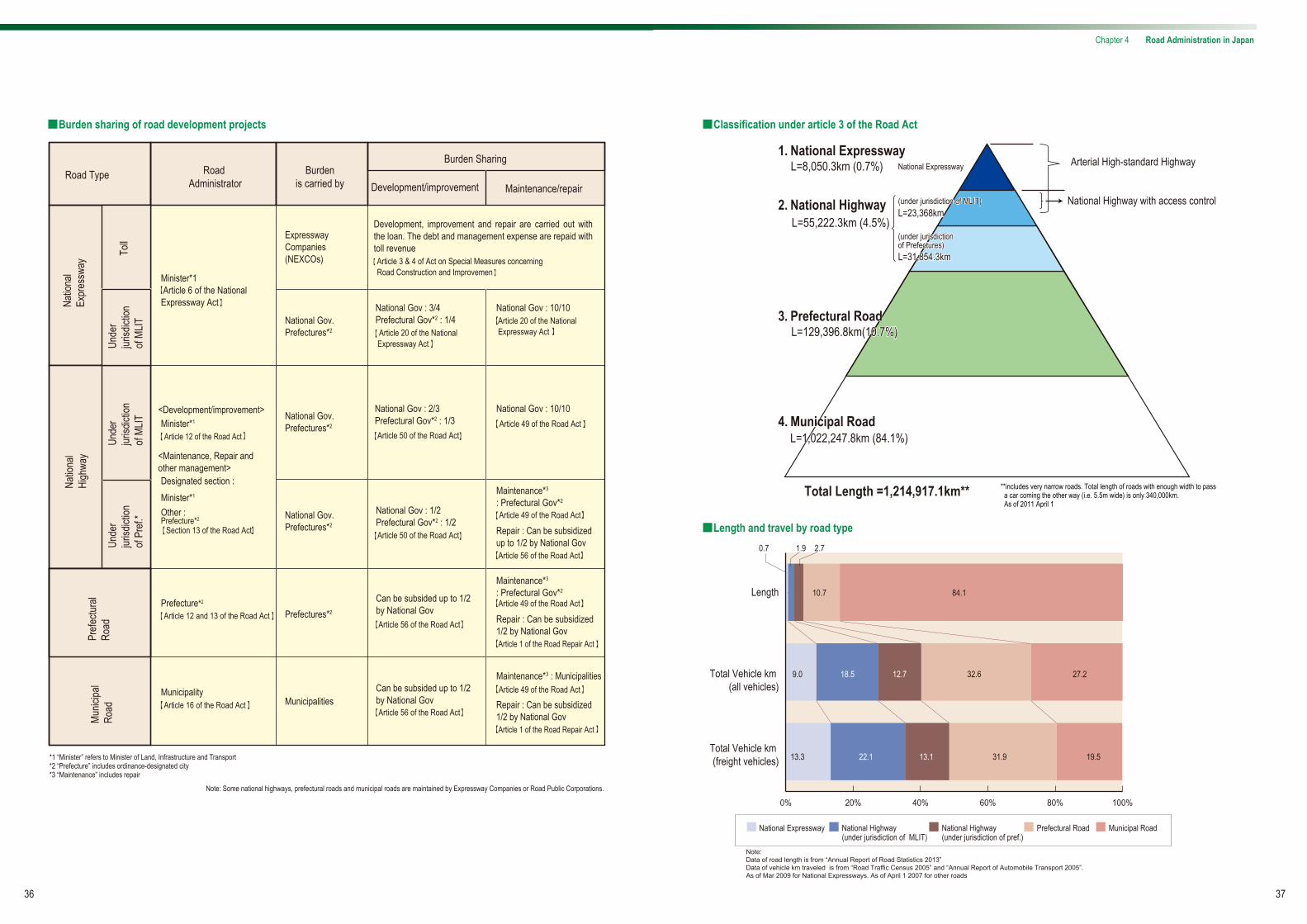
■Classification under article 3 of the Road Act
■Length and travel by road type
1. National ExpresswayL=8,050.3km (0.7%)
2. National HighwayL=55,222.3km (4.5%)
3. Prefectural Road3. Prefectural RoadL=129,396.8km(10.7%)L=129,396.8km(10.7%)
4. Municipal Road4. Municipal RoadL=1,022,247.8km (84.1%)L=1,022,247.8km (84.1%)
Total Length =1,214,917.1km**
(under jurisdiction of MLIT)(under jurisdiction of MLIT)
National Expressway
L=23,368kmL=23,368km
(under jurisdiction of Prefectures)(under jurisdiction of Prefectures)L=31,854.3kmL=31,854.3km
0%
0.7 1.9 2.7
20% 40% 60% 80% 100%
10.7 84.1
9.0
13.3 31.9 19.5
18.5
22.1 13.1
12.7 32.6 27.2
Length
Total Vehicle km (all vehicles)
Total Vehicle km (freight vehicles)
National Expressway National Highway(under jurisdiction of MLIT)
National Highway(under jurisdiction of pref.)
Prefectural Road Municipal Road
Note: Data of road length is from “Annual Report of Road Statistics 2013”Data of vehicle km traveled is from “Road Traffic Census 2005” and “Annual Report of Automobile Transport 2005”.As of Mar 2009 for National Expressways. As of April 1 2007 for other roads
**includes very narrow roads. Total length of roads with enough width to pass a car coming the other way (i.e. 5.5m wide) is only 340,000km. As of 2011 April 1
Chapter 4 Road Administration in Japan

■Classification of arterial high-standard highway system
38 39
* Planned as a strategic high-speed surface traffic network in “the Forth Comprehensive national Development Plan” (decided by the Cabinet on June 30 1987 and “Grand Design of Japan for the 21st century” (decided by the Cabinet on Mar 31 1998).
[System]
Contemplated route
Basic Plan
[Procedure]
National Highway with access controlNational Expressway
Arterial High-standard Highway*
Basic Plan
Development Plan
Legally determined in the National Development Arterial Express Construction Act
Decided by the Minister of Land,Infrastructure,Transport and Tourism after discussion in the National Development Arterial Automobile roads panel
Decided by the Minister of Land, Infrastructure,Transport and Tourism after discussion in the Panel on Infrastructure Development (Road division) (Mar 2009)
Toll rate based on the individual highway profitabilityDeveloped in a mixed way of public work project and toll road project
Decided by the Minister of Land, Infrastructure,Transport and Tourism after discussion in the Panel on Infrastructure Development (Road division) (Mar 2009)
Difficult to become profitable Financed by national and local governmentsToll-free
Distant-base toll systemThroughout the nationUse a pool system, which integrates more than one road in the redemption calculation.
Decided by the Minister of Land, Infrastructure,Transport and Tourism after discussion in the National Development Arterial Automobile roads panel
Section that is under direct jurisdiction of national government
Toll section
Decision by Minister of Land, Infrastructure, Transport and Tourism
Master Plan
Development Plan
(Total length : about 11,520km) (Total length : about 2,480km)
Development mainly as projects under jurisdiction of the national government
[ 2,480 km][11,520 km]
(Total length : about 14,000km)
■Burden-sharing of arterial high-standard highway network
Chapter 4 Road Administration in Japan
■Arterial high-standard highway network

40 41
■Introduction of toll road system in Japan
■Pool system
1952 Act on Special Measures concerning Road Construction and Improvement was enacted.
Toll road system was introduced to the public roads across the country.
(Project proponent : National, prefectural or municipal government as a road administrator)
In response to rapidly increasing traffic demand after World War II, immediate road development required
additional financial resource to supplement general revenue; namely, the following 2 systems.
Earmarking gasoline tax for road development
Toll Road System
1956 Full-fledged revision of the Act on Special Measures concerning Road Construction and Improvement
Act on Japan Highway Public Corporation was enacted.
1959 Act on the Metropolitan Expressway Public Corporation was enacted.
1962 Act on the Hanshin Expressway Public Corporation was enacted.
1970 Act on the Honsyu-Shikoku Bridge Authority was enacted.
To expand current toll road system as a measure of immediate development of roads across the country, an organization such as the Japan Highway Public Corporation (JHPC, provisional name) needs to be established so that private funds will be widely introduced and comprehensive and efficient operation will be carried out. (Road Council’s recommendation 1955)
After the partial opening of Meishin Expressway in 1963, about total of 3,400km of development plan was formulated by Mar 1972 based on individual profitability. About 710km of 8 expressways including Tomei Expressway and Chuou Expressway was developed.
Expressways should be an arterial traffic network, connected to each other across the country. Each link is not necessarily considered independent, therefore, the toll rates should remain consistent and integrated.
Under the circumstance where development costs are affected largely by changing land cost and construction costs depending on the construction period, cost differentiation due to project start timing should be avoided. In addition, debt repayment should be carried out smoothly. Shifting from individual profitability system to pool system seems effective.
Highway A Highway A
Highway B
Highway B
Highway C
Highway C (Cross subsidy) (Cross subsidy)
Toll revenue Toll
revenue
Toll revenue
Construc-tion
Adminis-tration
Construc-tion
Adminis-tration
Construc-tion
Adminis-tration
Total revenue Total cost
1972 Road Council Recommendation1)
2)
■Business Scheme
-Expressway Companies are responsible for constructing new roads funded by debt and loans before transferring expressway assets and debts to the Agency.-The Agency is responsible for completing the repayment of debts with the revenue of lease fees in 45 years.
Expressway Companies
(Carries on effective operation)
Agency (Ensures the complete repayment in 45 years)
Expresswayconstruction
Expresswaymanagement
Toll collection Fu
nds
rais
ed Holding of
expressways
Repayment of debts (inherited debts and new debts)
Transfer of expressway assets
and acceptance of debts
Leasing of expressway
assets
Payment of lease fees
Approval from the Minister of MLIT Approval from the Minister of MLIT
Agency
Debts Debt repayment
Lease fees
Toll
reve
nue
Borrowing*
Debts
Expressway Companies
New construction
Expresswayasset
Assets and liabilities shall be transferred to the Agency after completion
Assets and liabilities shall be transferred to the Agency after completion
*borrowed from both national and local governments forconstruction (and this money is loaned to the companies atno interest)
Responsibilities of the AgencyHolding and Lease of expressway assets
(property tax is exempted based on the premise of free service in the future
To ensure early repayment of the debts
Reduced national burden To support expressway companies in carrying out smooth business
■Organizational chart after privatization
Privatization objectives-Maintain the repayment of 40 trillion JPY-Construct essential roads promptly with the least national burden, while supporting expressway companies individual initiatives.-Provide various and flexible toll rate settings and services while taking advantage of being a private company.
*NEXCO: Nippon Expressway Company
Japan Highway Public Corporation (JHPC) Metropolitan ExpresswayPublic Corporation
Hanshin ExpresswayPublic Corporation
Honshu-ShikokuBridge Authority
[Private Company] Construction, Operation and Toll-collection
NEXCO* East NEXCO Central NEXCO West Metropolitan ExpresswayCompany Ltd.
Hanshin ExpresswayCompany Ltd.
Honshu-Shikoku BridgeExpressway CompanyLtd.
Will be merged with NEXCO West after business stabilizes
[Agency] Holding of expressways and repayment of debt
J a p a n E x p r e s s w a y H o l d i n g a n d D e b t R e p a y m e n t A g e n c y
4 Laws Related to Privatization of Former Highway Public Corporations
-Expressway Company Law -Japan Expressway Holding and Debt Repayment Agency Law -Law regarding the Development of Highway-related Laws in connection with the Privatization of the Japan Highway Public Corporation -Act for Enforcement of Acts Related to Privatization of the Japan Highway Public Corporation, etc.
Chapter 4 Road Administration in Japan

42 43
History of Roads in JapanThere is a country comprised of four major islands and numerous minor islands in a crescent shape situated to the east of the Asian continent in the northwestern Pacific Ocean. Of the 378,000 square km of land, a substantial 70% is mountainous terrain. That is Japan.It is a country with a wonderful harmony between traditional culture from ancient eras and a modern society with advanced technology. Japan’s fascinating natural environment changes from season to season and is home to more than 120 million people.The history of land transport in Japan over the last two thousand years can be roughly categorized into the following three ages: l) Age of People and Nature (ancient times until the Meiji Restoration in 1867), 2) Age of Modernization (from the Meiji Restoration until the 1950s), 3) Age of High Efficiency Networks (from the 1950s to the present day), and 4) Age of Good Maintenance and Management for Maximum Utilization of Existing Roads.
Chapter 4 Road Administration in Japan
l) The Ancient Foundations of Modern Japan
The oldest written record of roads in Japan appeared in a
Chinese history book in the 3rd Century called Gishi-wajin-
den. At that time, Japan was in the process of unifying the
country under the Yamato Dynasty. People travelled on foot
or horseback for hundreds of years until the Meiji Restora-
tion when Japan opened its doors to the modern nations of
the West, late in the 19th century.
Unlike in China and the European countries, horse-drawn
carriages never fully evolved in this country. The lack of use
of horse-drawn carriages in Japanese history may be
attributed to the country’s terrain, which is mostly mountain-
ous with numerous creeks and is surrounded by the sea.
After the Reformation of the Taika Era (645), when an elabo-
rate central government system with administrative and
judicial institutions was established and a new road network
was developed that connected Honshu (the main island) to
Shikoku (the smallest of the four main islands) and all the
way to Kyushu (the southernmost and third largest island).
This nationwide public road network system was called
“Seven Roads”, composed of Tokaido, Tosando, Hokuri-
kudo, San-indo, San-yodo, Nankaido, and Saikaido (‘-do’ in
Japanese means ‘road’). Once the Seven Roads were
opened, after bitter struggles with the rough terrain of the
country, they became a prototype for highways and roads in
much later years. Almost all routes of the Seven Roads were
used for the arterial railways in the Meiji Era (1868~) and the
expressways opened from 1964 onward. In short, the Seven
Roads established during this age have served as the
backbone of transport routes in Japan.
2) User-friendly Roads Can Be Traced Back to Early Times
With the establishment of the Seven Roads came another
system called "Ekiba, Tenma" (Post Horse System), which
eventually became the modern international word "Ekiden"
(a relay road race). In this Chinese-originated system, an
“Eki” (meaning station) was located at intervals of 16km and
would provide necessary services for the officials and people
of high rank on their journeys. About 400 “Eki” were devel-
oped across the country. In the mid-8th century, a number of
fruit trees were systematically planted along the Seven
Roads, which would eventually evolve into today’s tree-lined
roads.
In more recent years (later in the 16th century), a road
signage system called “Ichirizuka” was established by
referencing the practice in ancient China. This system can
be interpreted as the Asian version of the Roman milestone
l. Age of People and Nature (Ancient times until the Meiji Restoration in 1867)
system.
After the Edo Shogunate was established in 1603, the
Ichirizuka system was transformed into ample facilities and
the 5 Major Highway System radiating from Edo (old name
for the current Tokyo). The Shogunate specified that the five
major highways should be about 11m wide and secondary
roads 5.5m wide. The road was filled with gravel and cobbles
to a depth of 3cm and finished with sand after treading them
down.
Sir Rutherford Alcock, who came to Japan as the first British
minister in Japan, at the end of the Shogunate era, wrote,
“Their highways, the Tokaido, the imperial roads throughout
the kingdom, may challenge comparison with the finest in
Europe. Broad, level, carefully kept and well macadamized,
with magnificent avenues of timber to give shade from the
scorching heat of the sun, it is difficult to exaggerate their
merit."
3) Road Construction with a Consideration for People and Scenery
Japanese people frequently travelled, to a degree that
foreigners found incredible. They would not hesitate to travel
because there were excellent road facilities and services
even then.
In the middle of the Edo Era (1690), Engelbert Kaempfer, a
German doctor who came to Japan to work for a Dutch
trading house, wrote in his book1:
"An unbelievable number of people travel the highways of
this country every day. The reason for this is the high popula-
tion of this country, but another reason is that, unlike other
nations, the Japanese travel extremely often."
The Hakone Road was already paved in 1680. Sir Ernest
Satow, a British diplomat who came to Japan at the end of
the Edo Shogunate (mid-19th century), wrote in his book, “A
Diplomat in Japan”, about his astonishment at the pavement:
"Next morning we started at half-past six to ascend the pass
which climbs the range of mountains by an excellent road
paved with huge stones after the manner of the Via Appia
where it leaves Rome at the Forum, and lined with huge pine
trees and cryptomerias.”
Unlike Via Appia, however, Japanese surface transport
routes were developed primarily for people and horses,
because horse-drawn carriages were not common prior to
the Meiji Era (1868~). For this reason, roads in those days
were usually kept in good condition: damages from traffic
After ending two hundred years of national seclusion in the
Edo Era, the revolutionary government of the Meiji Era
(1868-1912) quickly started modernization of the surface
transport system by importing new technologies from
Europe. Unlike China and Europe, however, Japan did not
have a history of horse-drawn carriages as transport during
the Middle Ages. It was thus impossible to transform the
ancient roads designed strictly for the passage of people and
horses into modern roads in a single step.
The beautifully maintained pre-modern roads of the Edo Era
began to deteriorate under the burdens of modern horse-
drawn and human-powered vehicles (or rickshaws). Arthur
Crow, who visited Japan in 1881, recorded this observation
in “Highways and Byways in Japan”: “The Tokaido is in a
dreadfully bad state, with ruts and holes large enough almost
to swallow a cart, and yet traffic is very heavy, both for horse
and man-power vehicles”.
The slow improvement of roads can be partially attributed to
the decision by the Meiji Government to give rail and sea
transport a higher priority over roads. This decision was
intended to allow Japan to catch up with the advanced
nations of the West as quickly as possible. The backward-
ness of the road system in Japan continued until 1945 when
Japan was defeated in World War II and the entire national
landscape was devastated by bombings and other
influences of the war. During the process of reconstruction,
the modernization of roads in Japan was fully accelerated
along with the development of railways.
were not severe and the maintenance was relatively easy.
Road cleaning and other regular maintenance was not
performed by the Shogunate or the government of feudal
clans, but by residents alongside the roads. Back then,
roads were taken care of by roadside residents on a volun-
tary basis, not by the governments.
This implies that there was general understanding that roads
were not the exclusive property of the overlords, but were
“public property”.1 “Geschichte und Beschreibung von Japan”
2. Age of Modernization (from Meiji Restoration to the 1950's)

44 45
Chapter 4 Road Administration in Japan
3. Age of High Efficiency Networks (from the 1950’s ~ today)
1) Arrival of the Motorization Age
Automobiles proliferated quickly as the Japanese economy
recovered from defeat and the standard of living improved.
Only 130,000 vehicles were registered at the end of World
War II, but the number increased rapidly, reaching 500,000
vehicles by 1951, then doubling to one million in 1953, and
doubling again to two million in 1957. The Age of Motoriza-
tion had arrived in Japan.
However, the road system remained insufficient to support
the rapid motorization. Ralph J. Watkins, an economist
invited by the Japanese government to conduct research on
the Meishin Expressway wrote in his 1956 report, “The roads
of Japan are incredibly bad. No other industrial nation has so
completely neglected its highway system".
Japan’s road system in those days was indeed terrible. Only
23% of the first-class arterial national highway system was
paved. Only two-thirds of the total national Highway Route 1,
supposedly the major arterial highway connecting Tokyo
with Osaka, was paved. The Japanese Government at that
time accepted Mr. Watkins' proposals and immediately put
them into practice. Thus, road improvement in Japan moved
into high gear, propelling the nation into the high economic
growth era of later years.
2) The Five-Year Road Development Program, Toll Road System, and Tax Revenue System with Earmarks for Roads
Without a history of horse-drawn carriages, Japan had only
poor roads in those days. What is worse, road development
was inevitably slow, because the development of the railway
system was given priority over the development of roads.
Under these circumstances, the Five-Year Road Develop-
ment Program was launched so that road development
would be fully accelerated.
Because the public works budget under the general revenue
scheme was not sufficient to meet ever-increasing road
traffic demand, two financing systems were introduced so
that a significant number of road projects could be under-
taken in a short period: the toll road system and the tax
revenue system with earmarks for roads.
The former “Act on Special Measures concerning Road
Construction and Improvement”, enacted in 1952, enabled
the introduction of the toll road system where the national
and municipal governments could borrow sufficient money to
develop roads and the borrowed money would be repaid
with toll revenue from the new roads.
The toll road system was applied primarily for national
expressway projects. In 1956, the Japan Highway Public
Corporation (JH) was founded, so that expressways would
be operated efficiently and financial resources from the
private sector could be widely utilized.
With the founding of JH, toll road development was led by
JH instead of by the National Government. Although the
mechanism of the toll road system was similar to that of
The state of roads in the mid 1950s was "incredibly bad" as Watkins wrote in his report.
current PPP projects, the former included an ingenious
system that enabled them to carry out unprofitable road
projects if the road was recognized as necessary from an
economic vantage point. The National Government reduced
the business r isk, of unprofi table road projects, by
guaranteeing the loan and by paying a fixed rate of interest.
In addition, the Government utilized the pool system, in
which revenues and expenditures were balanced for the
integral road network as opposed to a collection of
individual roads. This system enabled them to develop not
only profitable urban roads but also unprofitable regional
roads across the country.
In 1953, the “Act on State´s Tentative Financial Measures
for Road Construction Projects” was enacted, which
introduced a new tax revenue system with earmarks for
roads. This system earmarked the revenues from gasoline
tax and other automobile-related taxes for road projects
based on the beneficiary payment principle. This measure
secured s tab le f inanc ia l resources fo r long- term
development of roads, including the 1st to 12th Five-Year
Road Development Programs.
The toll road system and the tax revenue system with
earmarks for roads supported the development of the
nationwide road network for more than 50 years.
During those years, all major roads were paved and more
than 10,000 km of expressways were developed all across
the country.
However, there were increasing calls for a change in both of
the financial revenue systems, since the road networks were
developed to a certain level. There were various criticisms
and opinions arguing that the roads were developed one
after another by spending a large amount of both borrowed
money and the national budget with a unilateral approach. At
the same time, the repayment and management costs were
not sufficiently saved due to the high-cost structure of JH’s
toll road system. As a result, JH was privatized and reorga-
nized into the Japan Expressway and Debt Repayment
Agency (JEDRA) and 6 other Expressway Companies. The
main purpose of this change was to ensure the full repay-
ment of the massive debt reaching 40 trillion yen, to stream-
line the administrative authority, and to provide various
services for road users by utilizing experience in the private
sector.
There was also increasing criticism of the tax revenue
system with earmarks for roads. Critics argued that fixed
expenditures from the abundant financial resources resulted
in a number of unnecessary road developments. In 2009,
the tax revenue system with earmarks for roads was
abandoned and the Government decided to cover road
expenditures with general revenue.
■Figure: Change in Investment in the Five-Year Road Development Program
0
10,000
1954-57
1958-60
1960-63
1964-66
1967-69
1970-72
1973-77
1978-82
1983-87
1988-92
1993-97
1998-02
20,000
30,000
40,000
50,000
60,000
70,000
80,000
Fiscal Year
Inve
stm
ent(b
illio
n JP
Y)
Unsubsidized Local Road Projects
Toll Road Projects
General Road Projects
1) Reserve fund (¥150 billion) is included. 2) Reserve fund (¥100 billion) is included. 3) Reserve fund (¥500 billion) is included. 4) Reserve fund (¥700 billion) is included. 5) Adjustment cost (¥1,300 billion) is included. 6) Adjustment cost (¥1,300 billion) is included. 7) Adjustment cost (¥1,400 billion) is included. 8) Adjustment cost (¥5,000 billion) is included. 9) Reserve fund (¥11.2 billion (for Okinawa)) is included in the total of the 6th plan.
Note:
April 1968 Vehicles running from Okazaki IC to Komaki IC after the opening ceremony of Tomei Expressway (Photo:Mainichi Shimbun)
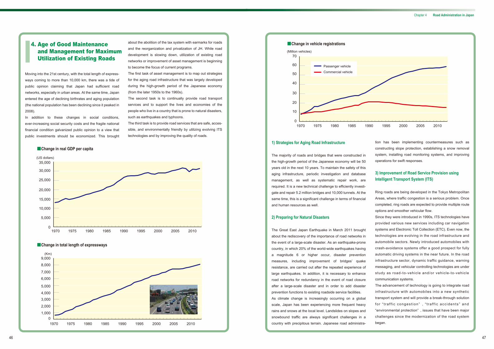
46
Chapter 4 Road Administration in Japan
47
about the abolition of the tax system with earmarks for roads
and the reorganization and privatization of JH. While road
development is slowing down, utilization of existing road
networks or improvement of asset management is beginning
to become the focus of current programs.
The first task of asset management is to map out strategies
for the aging road infrastructure that was largely developed
during the high-growth period of the Japanese economy
(from the later 1950s to the 1960s).
The second task is to continually provide road transport
services and to support the lives and economies of the
people who live in a country that is prone to natural disasters,
such as earthquakes and typhoons.
The third task is to provide road services that are safe, acces-
sible, and environmentally friendly by utilizing evolving ITS
technologies and by improving the quality of roads.
Moving into the 21st century, with the total length of express-
ways coming to more than 10,000 km, there was a tide of
public opinion claiming that Japan had sufficient road
networks, especially in urban areas. At the same time, Japan
entered the age of declining birthrates and aging population
(the national population has been declining since it peaked in
2008).
In addition to these changes in social conditions,
ever-increasing social security costs and the fragile national
financial condition galvanized public opinion to a view that
public investments should be economized. This brought
■Change in real GDP per capita
■Change in total length of expressways
4. Age of Good Maintenance and Management for Maximum Utilization of Existing Roads
0
5,000
15,000
10,000
20,000
25,000
30,000
35,000(US dollars)
1970 1975 1980 1985 1990 1995 2000 2005 2010
01,000
2,000
3,000
4,000
5,000
6,000
9,000
8,000
7,000
(Km)
1970 1975 1980 1985 1990 1995 2000 2005 2010
■Change in vehicle registrations
1) Strategies for Aging Road Infrastructure
The majority of roads and bridges that were constructed in
the high-growth period of the Japanese economy will be 50
years old in the next 10 years. To maintain the safety of this
aging infrastructure, periodic investigation and database
management, as well as systematic repair work, are
required. It is a new technical challenge to efficiently investi-
gate and repair 5.2 million bridges and 10,000 tunnels. At the
same time, this is a significant challenge in terms of financial
and human resources as well.
2) Preparing for Natural Disasters
The Great East Japan Earthquake in March 2011 brought
about the rediscovery of the importance of road networks in
the event of a large-scale disaster. As an earthquake-prone
country, in which 20% of the world-wide earthquakes having
a magnitude 6 or higher occur, disaster prevention
measures, including improvement of bridges’ quake
resistance, are carried out after the repeated experience of
large earthquakes. In addition, it is necessary to enhance
road networks for redundancy in the event of road closure
after a large-scale disaster and in order to add disaster
prevention functions to existing roadside service facilities.
As climate change is increasingly occurring on a global
scale, Japan has been experiencing more frequent heavy
rains and snows at the local level. Landslides on slopes and
snowbound traffic are always significant challenges in a
country with precipitous terrain. Japanese road administra-
tion has been implementing countermeasures such as
constructing slope protection, establishing a snow removal
system, installing road monitoring systems, and improving
operations for swift responses.
3) Improvement of Road Service Provision using Intelligent Transport System (ITS)
Ring roads are being developed in the Tokyo Metropolitan
Areas, where traffic congestion is a serious problem. Once
completed, ring roads are expected to provide multiple route
options and smoother vehicular flow.
Since they were introduced in 1990s, ITS technologies have
provided various new services including car navigation
systems and Electronic Toll Collection (ETC). Even now, the
technologies are evolving in the road infrastructure and
automobile sectors. Newly introduced automobiles with
crash-avoidance systems offer a good prospect for fully
automatic driving systems in the near future. In the road
infrastructure sector, dynamic traffic guidance, warning
messaging, and vehicular controlling technologies are under
study as road-to-vehic le and/or vehic le-to-vehic le
communication systems.
The advancement of technology is going to integrate road
infrastructure with automobiles into a new synthetic
transport system and will provide a break-through solution
fo r “ t ra f f i c conges t i on ” , “ t ra f f i c acc iden ts ” and
“environmental protection” , issues that have been major
challenges since the modernization of the road system
began.
0
10
20
30
40
50
60
70(Million vehicles)
Passenger vehicle
Commercial vehicle
1970 1975 1980 1985 1990 1995 2000 2005 2010

Minister of Land, Infrastructure, Transport and Tourism
Senior Vice-Minister of Land, Infrastructure, Transport and Tourism (2)
Parliamentary Secretary for Land, Infrastructure, Transport and Tourism (3)
Vice-Minister of Land, Infrastructure, Transport and Tourism
Vice-Minister for Engineering Affairs, Ministry of Land, Infrastructure, Transport and Tourism
Vice-Minister for Land, Infrastructure and Hokkaido Development, Ministry of Land, Infrastructure, Transport and TourismVice-Minister for Transport and Tourism, Ministry of Land, Infrastructure ,Transport and TourismVice-Minister for International Affairs, Ministry of Land, Infrastructure, Transport and Tourism
Private Secretary to the Minister of Land, Infrastructure, Transport and Tourism
Ministry of Land, Infrastructure, Transport and Tourism
Minister'sSecretariat
Water and Disaster Management BureauPolicy Bureau National and Regional
Policy BureauLand Economy and
Construction and Engineering Industry Bureau
City Bureau Road Bureau Housing Bureau Railway Bureau Road TransportBureau Maritime Bureau Ports and Harbours
BureauCivil Aviation
Bureau
Aviation Network Department
Aviation Safety Department
Air Navigation Services Department
Sewerage and Wastewater Management Department
Water Resources Department
Government Buildings Department
Hokkaido Bureau Director-General forPolicy Planning
Director-General for International Affairs
Policy Research Institute for Land, Infrastructure, Transport and Tourism
National Institute for Landand Infrastructure Management
College of Land, Infrastructure, Transport and Tourism
Aeronautical Safety College
Geospatial Information Authority
Ogasawara General Office
Marine Accident Tribunal
Japan Tourism Agency
Japan Meteorological Agency
Japan Transport Safety Board
Japan Coast Guard
Regional Development Bureau
Hokkaido RegionalDevelopment Bureau
District Transport Bureau
Regional Civil Aviation Bureau
Air Traffic Control Center
Director-General
Director-General
Planning Division
Environment and Regional Development Division
Capital Area Airports Division
Aviation Industries Division
Director-General
Air Navigation Services Planning Division
Air Traffic ControlDivision
Operations and Flight Inspection Division
Air Navigation Services Engineering Division
Airport Facilities Division
Director-General
Flight Standards Division
Airworthiness Division
Aviation Safety and Security Planning Division
Airport Safety and Aviation Security Division
Senior Deputy Director-General
Director-GeneralDirector-General
Senior Deputy Director-General
Senior Deputy Director-General
Director-GeneralDirector-General
Senior DeputyDirector-General
Director-General
General Affairs Division
Housing Policy Division
Housing Development Division
Residence Support Division
Housing Production Division
Building Guidance Division
Urban Building Division
General Affairs Division
Trunk Railway Division
Urban Railway Division
Financial Affairs Division
Railway Industries Policy Division
Facilities Division
Safety Administrator
Engineering Planning Division
General Affairs Division
Safety Policy Division
Environmental Policy Division
Engineering Policy Division
Registration and Information Division
Passenger Transport Division
Cargo Transport Division
Type Approval and Recall Division
Maintenance Service Division
General Affairs Division
Safety and Environment Policy Division
Maritime Human Resources Policy Division
International Shipping Division
Coastal Shipping Division
Safety Management and Seafarers Labour Division
Shipbuilding and Ship Machinery Division
Safety Standards Division
Inspection and Measurement Division
Seafarers License and Education Division
General Affairs Division
Port Management and Operation Division
General Affairs Division
Aviation Strategy Division
Planning Division
Port Area Promotion Division
Engineering Planning Division
International and Environmental Policy Division
Coastal Administration and Disaster Management Division
General Affairs Division
Counsellor
Budget Division
Road, City and Housing Administration Division
Water Administration Division
Port and Harbor Administration Division
Agriculture, Forestry and Fishery Division
Director for Policy Evaluation
Director-GeneralDirector-General
Director-General
Sewerage Planning Division
Sewerage Works Division
Director for Watershed Management
Sabo (Erosion and Sediment Control) Department
Director-General
Sabo (Erosion and Sediment Control) Planning Division
Land Conservation Division
Public Transport Policy Department
Director-General
Transport Planning Division
Director for Comprehensive Transport Policy
Public Transport Support Division
Director-General
Water Resources Policy Division
Water Resources Planning Division
Deputy Deputy Director-GeneralDirector-General
Director-GeneralDirector-General
DeputyDirector-General
Director-GeneralDirector-General
General Affairs Division
Policy Division
Policy Division for Universal Design
Environmental Policy Division
Ocean Policy Division
Public-Private Partnership Promotion Division
Logistics Policy Division
Policy Planning and Coordination Division for Public Works Project
Technology Policy Division
International Policy Division
Overseas Project Division
Information Policy Division
Ministerial Informatization Division
Director for Comprehensive Transport Policy (2)
General Affairs Division
National Planning Division
Regional Policy Division
National Land Information Division
Director for Planning (2)
Regional Development Division
Remote Islands Development Division
Director for Special Areas Development
General Affairs Division
Policy Planning Division
Land and Real Property Market Division
Land Price Research Division
Cadastral Promotion Division
Real Estate Industry Division
Real Estate Market Division
Construction Industry Division
Construction Market Division
General Affairs Division
Urban Policy Division
Urban Safety Affairs Division
Urban Renewal Promotion Division
City Planning Division
Urban Development and Improvement Division
General Affairs Division
Water Administration Division
River Planning Division
River Environment Division
River Improvement and Management Division
Disaster Prevention and Relief Division
General Affairs Division
Road Administration Division
Road Traffic Control Division
Environment and Safety Division
Planning Division
Expressway Division
National Highway and Risk Management Division
Urban Transport Facilities Division
Parks,Green Spaces and Landscape Division
Vice-Director-General
Deputy Vice-Minister
Director-General
Administration Division
Planning Division
Architecture and Building Engineering Division
Building Equipment and Environment Division
Personnel Division
General Affairs Division
Public Relations Division
Budget and Accounts Division
Local Affairs Division
Welfare Division
Engineering Affairs Division
Inspector-General
Director for Security Policy
Director for Transport Safety
Deputy Vice-Minister for Policy Coordination (2)
Deputy Minister for Technical Affairs
Deputy Vice-Minister for Security and Transport Safety Policy
Deputy Director-General for Policy Evaluation
Assistant Vice-Minister (21)
Assistant Vice-Minister for Engineering Affairs(4)
Counsellor (18)
Deputy Director-General for Engineering Affairs (2)
Deputy Vice-Minister for Construction, Engineering and Real Estate Industry
Director-General
The Organization of the Ministry of Land, Infrastructure, Transport and Tourism (As of July 1, 2011)
Organization Chart
■Organization Chart of MLT
48 49
TrThe Ministry of Land, Infrastructure, Transport, and Tourism (MLIT) is in charge of the comprehensive and systematical use of national land, development and conservation, consistent infrastructure development, implementation of traffic policies, development of meteorological service, and maritime safety and secu-rity. Below is the chart showing the organization of the MLIT.
Chapter 4 Road Administration in Japan

■Organization Chart of Road Bureau
Organization of Regional Development Bureau■
■Organization of Road Bureau
Director-General of
the Road Bureau
Vice-Director-General
Deputy Director-General
Director-GeneralRegional
DevelopmentBureau
Social OverheadCapital
Provision Council
Ministry of Land,Infrastructure,Transport and
Tourism
General Affairs Division
• Coordination of Bureau Affairs• Personnel Affairs of Bureau• Budgeting
Road Administration Division
• Drafting of Road related Bills• Administration and Supervision of Roads• Designation of Roads
Road Traffic Control Division
• Planning and Coordination of Road Traffic Control• Supervision of Center for Road Traffic Information• Planning and Coordination of ITS
Planning Division
• Planning of Important of Roads (except National Expressways)
• Survey and Statistics of Roads• Long-term Programs• Technical Standards• International Affairs
National Highway and Risk Management Division
• Construction and Management of • National Highways
• Risk Management of Roads• Planning of New Technology for Roads
Environment and Safety Division
• Technical Supervision and • Coordination of Local Roads
• Environment Planning of Roads• Safety Management of Roads
Expressway Division
• Planning and Survey of Expressway System• Permission for Construction of Expressway
Road Policy Planning Office
Road Use Coordination Office
Vehicle Traffic Management Office
ITS Policy and Program Office
Road Maintenance Management Office
Economic Research,Traffic Survey and Census Office
Performance Management Office
International Affairs Office
Road Risk Management Office
Toll Road Coordination Office
Road Environment Planning Office
Expressway Companies Affairs Office
Road Safety Management Office
Director-General, Regional
Development Bureau
Road Administration Division
Road Planning Division
Regional Road Division
Road Project Coordination Division
Road Construction Division
Road Management Division
Road Traffic Management Division
Branch Office
Road Department
Work Office
Ministry of Land, Infrastruc-ture, Transport and TourismHeadquarters Offices
10 Offices
12 Offices
12 Offices
6 Offices
10 Offices
11 Offices
9 Offices
6 Offices
11 Offices
2 Offices
34 Branches
41 Branches
46 Branches
17 Branches
27 Branches
31 Branches
25 Branches
15 Branches
32 Branches
4 Branches
Kyushu Regional Development Bureau
Okinawa Regional Development Bureau
Shikoku Regional Development Bureau
Chugoku Regional Development Bureau
Kinki Regional Development Bureau
Chubu Regional Development Bureau
Hokuriku Regional Development Bureau
Kanto Regional Development Bureau
Tohoku Regional Development Bureau
Hokkaido Regional Development Bureau
As of April 1,2012
10 Regional Development Bureaus 89 Offices 272 Branches
50 51
As of May 16, 2013
Chapter 4 Road Administration in Japan

52 53
Road Structure Ordinance(Government Ordinance No.320 of 29th October, 1970)
(Purpose of This Ordinance)
Article 1This Ordinance specifies general technical standards (limited to the provisions of the Road Act (hereinafter "Act") Article 30.1.1, 30.1.3 and 30.1.12 for general technical standards of the structure of prefec-tural roads and municipal roads) for the structure of national express-ways and national highways when these roads will be newly constructed or reconstructed and also specifies general technical
standards that should be taken into account when technical standards (except for the provisions in Article 30.1.1, 30.1.3 and 30.1.12) for the construction of prefectural roads and municipal roads are required under the ordinances of prefectural or municipal governments, who also serve as a road administrator.
(Definition)
Article 2 The following terminology definitions shall apply to the corresponding terms in this Ordinance:
1. Sidewalk: A road section provided for dedicated pedestrian traffic, which is separated by curb lines or fences or other similar structures.
2. Bicycle track: A road section provided for dedicated bicycle traffic, which is separated by curb lines or fences or other similar structures.
3. Bicycle/pedestrian track: A road section provided for dedicated bicycle/pedestrian traffic, which is separated by curb lines or fences or other similar structures.
4. Carriageway: A road section used by dedicated vehicle traffic, except for bicycles.
5. Lane: A strip section of the carriageway (except for the service road) provided for safe and smooth traffic by directional separation of vehicles traveling in a single direction.
6. Additional overtaking lane: An additional lane (except for climbing, turning and speed change lanes) provided specifically for vehicles to overtake other vehicles.
7. Climbing lane: A lane for slower vehicles to be separated from other vehicles on uphill roads.
8. Turning lane: A lane for vehicles to turn right or left. 9. Speed change lane: A lane for vehicles to accelerate or deceler-
ate. 10. Center strip: A strip road section provided to separate a lane from
the traffic in the opposite direction and ensure lateral clearances. 11. Service road: A strip of carriageway provided to applicable
sections, parallel to the carriageway, to ensure access of vehicles to roadsides where access is prevented by reason of embankment and/or cut, or other means.
12. Shoulder: A strip of road section connected with carriageway sidewalks, bicycle tracks or bicycle/pedestrian tracks to protect major road structure sections and to maintain carriageway functions.
13. Marginal strip: A strip section of the center strip or shoulder connected with the carriageway to provide optical guidance for drivers and ensure lateral clearance.
14. Stopping lane: A strip of carriageway section principally used to park vehicles.
15. Track bed: A road section dedicated for use by streetcar traffic (streetcars as specified in Article 2.1.13 of the Road Traffic Act [Act No.105 of 1960]; this definition of streetcars shall apply hereinafter).
16. Island: An area facility provided at intersections, carriageway separation points, bus bays, streetcars stops, or other areas to ensure safe and smooth vehicle traffic or the safety of pedestri-ans crossing streets or bus and streetcar passengers boarding or alighting.
17. Planting strip: A strip of road section provided for tree planting in order to improve road traffic environment and ensure a better living environment along roadsides, which is separated by using curb lines or fences or other similar structures.
18. On-street facility: A road accessory facility on sidewalks, bicycle tracks, bicycle/pedestrian tracks, center strips, shoulders, bicycle paths and bicycle/pedestrian paths, except for common ducts and common cable ducts.
19. Urban area: An area forming or expected to form a city or town. 20. Rural area: Other areas than urban areas. 21. Designed daily volume: Daily vehicle traffic volume determined
by planners for road construction or reconstruction planners designated by the Land, Infrastructure and Transport Ministry's ordinance according to requirements in the same ordinance for the basis of road design, in consideration of trends of develop-ment in the area and vehicle traffic conditions in the future.
22. Design speed: Vehicle speed that is used as a basis for road design.
23. Sight distance: The distance measured along the lane (or carriageway in the case of a road without a lane and the same is applied hereinafter) centerline at which an apex of a 10cm high object on the lane centerline is visible from 1.2m on the lane centerline.
Road Structure Ordinance
Structure of Road Technique Standards
Road Act[Act No. 108 of
1952]
Road Structure Ordinance
[Cabinet Order No. 320 of 1970]
Road TrafficAct
[Act No. 105 of 1960]
Ordinance on Road Signage and Marking
[Ordinance issued by Prime Minister´s Office and `Construction Ministry
in 1960]
Act
Cabinet Order / Ordinance of Ministry
Road technique standard
Geometric design
Earthworks
Pavement
Bridges
Tunnels
Traffic safety device
Road environment
Road disaster prevention
Maintenance and repair
Parking space
Toll facilities
[Provisional translation]

(General Technical Standards for Construction of National Expressways and National Highways Structures)
Article 3-2
(Lane)
Article 5
(Design Vehicles)
Article 4
3. Roads shall be classified as specified in the previous paragraph 2 based on traffic conditions.
4. Type 1, 2 and 3 Class 1 through 4 roads or Type 4 Class 1 through 3 roads (limited to elevated roads and other structures from which vehicles cannot access roadsides for Type 3 Class 1 through 4 roads and Type 4 Class 1 through 3 roads) can be specified as the roads provided exclusively for the traffic of smaller motor vehicles (hereinafter indicating small-sized vehicles and other similar small vehicles; and pedestrians and bicycles in the case of Type 3 Class 1 through 4 and Type 4 Class 1 through 3 roads), in an unavoid-able case such as for a topographical reason and due to conditions of urbanization, there shall be a neighboring detour road for other types of vehicles, other than smaller motor vehicles.
5. A lane specifically for the traffic of smaller motor vehicles can be provided, by separating other lanes on Type 1, 2 and 3 Class 1
through 4 roads or Type 4 Class 1 through 3 roads, in unavoidable cases such as for a topographical reason and due to conditions of urbanization. In the case of Type 3 Class 1 through 4 roads and Type 4 Class 1 through 3 roads, the lane specifically for the traffic of smaller motor vehicles shall be limited to elevated roads or other structures from which vehicles cannot access roadsides.
6. Roads shall be classified into smaller motor vehicle roads (hereinafter indicating the roads provided specifically for the traffic of smaller motor vehicles specified in the paragraph 4 and smaller motor vehicles and pedestrians and bicycles in Type 3 Class 1 through 4 and Type 4 Class 1 through 3 roads and vehicles specified in the previous paragraph) and regular motor vehicle roads (hereinafter indicating roads and road sections other than smaller motor vehicle roads).
1. The carriageway (except for the service road, stopping lane and other sections specified by the ordinances of Ministry of Land, Infrastructure, Transport and Tourism) shall consist of the below-specified lanes, except for those classified as Type 3 Class 5.
2. The number of lanes shall be 2 (except for additional overtaking, climbing, turning and speed change lanes and the same is applied
in the following paragraph) in accordance with the road classifica-tion and on rural roads where designed daily traffic volume is no more than values of standard design volume (hereinafter indicat-ing maximum allowable traffic volume) as listed in the following table, while taking into account topographic conditions.
1. Roads shall be so designed for the smooth and safe passage of small-sized motor vehicles and semitrailers (hereinafter indicating combined body consisting of trailing motor vehicle and trailed vehicle without front axle, in which a part of the trailed vehicle rests on the motor vehicle and substantial weight of the trailed vehicle and its load are supported by the motor vehicle) on Type 1, Type 2, Type 3 Class 1 or Type 4 Class 1 regular motor vehicle roads,
small-sized motor vehicles and regular-sized motor vehicles on other regular motor vehicle roads and smaller motor vehicles on smaller motor vehicle roads).
2. Specifications for the vehicle that is a basis of road design (hereinafter referred to as “design vehicle”) by Type shall be listed below.
The next Article through Article 40 specify general technical standards for the construction of national expressways and national
highways structures, when these roads will be newly constructed or reconstructed.
54 55
For this table, the following terminology definitions shall apply to the corresponding terms.1. Front-edge overhang: Distance from the front face of the vehicle body to the center of the front-wheel axle of a vehicle.2. Wheelbase: Distance from the center of front-wheel axle of a vehicle to the center of the rear-wheel axle.3. Rear-edge overhang: Distance from the rear face of the vehicle body to the center of the rear-wheel axle of a vehicle.
Length
4.7
6.0
12.0
16.5
1.7
2.0
2.5
2.5
2.0
2.8
3.8
3.8
0.8
1.0
1.5
1.3 2.2
2.7
3.7
6.5
1.2
1.3
4.0
12.0
6.0
7.0
12.0
Front section wheelbase: 4.0 Rear section wheelbase: 9.0
Small-sized motor vehicle
Smaller motor vehicles
Regular-sized motor vehicle
Semi-trailer
Width Height Front-edge overhang Wheelbase Rear-edge
overhangMinimum turning radius
2. Type 1 roads shall be classified into classes 1 through 4 as listed in Table 1, Type 2 roads shall be classified into Class 1 or 2 as listed in Table 2, Type 3 roads shall be classified into classes 1 through 5 as listed in Table 3, and Type 4 roads shall be classified into classes 1 through 4 except where topographic conditions or
other circumstances do not permit such provision. Roads can be classified into one class lower than the original class unless roads are otherwise applicable to Type 1 Class 4, Type 2 Class 3, Type 3 Class 5, or Type 4 Class 4.
1. Roads shall be classified into Types 1 through 4 as listed in the following table.
(Road Classification)
Article 3
Table 1 Type 1 Roads
Table 2 Type 2 Roads
Table 3 Type 3 Roads
Table 4 Type 4 Roads
Rural Area Urban Area
Type1 Type2
Type3 Type4
Area where road is located
National expressways and access-controlled highways
Other Roads
National expressways and access-controlled highways or other roads.
Designed daily volume (vehicles/day)Road type
National ExpresswayClass 1 Class 2
Class 2
Class 2Class 3
Class 3
Class 3
Class 3
Class 4
Class 4
More than 30,000
20,000~30,000
10,000~20,000
Less than 10,000
Mountainous Area
Level Area
Level Area
Mountainous AreaRoads other than National Expressway
Topography area where road is located
Area where road is located Areas other than Central Business District Central Business DistrictRoad type
Class 1
Class 1 Class 2
National Expressway
Roads other than National Expressway
Road type
National Highway
Prefectural Roads
Municipal Roads
Class 1 Class 2
Class 2
Class 2
Class 2
Class 3 Class 4
Class 4
Class 3
Class 3
Class 3
Class 3 Class 4
Class 5
Class 4Class 3 Class 5
Area where road is located
Level Area
Mountainous Area
Level Area
Mountainous Area
Level Area
Mountainous Area
Designed daily volume (vehicles/day)
More than 20,000
4,000~20,000
1,500~4,000
500~1,500
Less than 500
Designed daily volume (vehicles/day)
National Highway
Prefectural Roads
Municipal Roads
Road type
Class 1
Class 1
Class 1
Class 2
Class 2
Class 2
Class 3
Class 4Class 3
More than 10,000
4,000~10,000
500~4,000
Less than 500
Road Structure Ordinance

(Lane Division)
Article 6
5. Carriageway width on Type 3 Class 5 regular motor vehicle roads shall be 4m. However, the width could be reduced to 3m where designed daily traffic volume is extremely low and topographic
conditions or special reasons do not permit such provisions or where a narrow pass is created on regular motor vehicle roads pursuant to the provisions of Article 31.2.
1. The lanes (hereinafter this applies for all except one-way roads) on Type 1, Type 2 or Type 3 Class 1 roads shall be directionally divided. It is also applied to other roads with four or more lanes if necessary for safe and smooth traffic.
2. Notwithstanding the provisions of the first sentence of the preced-ing paragraph, Type 1 roads with three or less lanes (hereinafter, this applies for all except for climbing, turning and speed change lanes) may be left directionally undivided in unavoidable cases, such as for topographical conditions or any other reasons.
3. A center strip shall be provided, when required, for directional lane division.
4. Center strip width shall be no less than the values indicated in the left columns in the following table. However, the center strip width can be reduced to values listed in the right columns, in the same table, where tunnels longer than 100m, bridges longer than 50m, elevated roads, topographic conditions or other special conditions do not permit.
5. A marginal strip shall be provided to the center strip. 6. The width of the marginal strips shall be the values listed in the left
column of the following table in accordance with road classifica-tion. However, the center strip width can be reduced to the values listed in the right columns of the same table when the center strip width of the road or road section is reduced in accordance with paragraph 4.
57
7. Fences, or other similar structures, or curb lines connected to the marginal strip shall be provided to sections other than the marginal strip of the center strip (hereinafter referred to as the "median").
8. When on-street facilities are provided on the median, the center strip width shall be determined considering clearances as specified in Article 12.
9. If necessary, additional overtaking lanes shall be provided to the carriageway of Type 1 roads with single lanes in each direction.
Type1
Type2
Type3
Type4
Class 1
Classification Lane Width (m)
3.5
3.5
3.25
3.25
3.0
3.5
3.25
3.25
3.0
3.5
3.0
3.25
2.75
3.0
3.0
2.75
2.75
3.25
2.75
2.75
Class 1
Class 1
Class 1
Class 2
Class 2
Class 2
Class 3
Class 4
Class 3
Class 4
Class 2 and 3
Regular motor vehicle roads
Smaller motor vehicle roads
Regular motor vehicle roads
Smaller motor vehicle roads
Regular motor vehicle roads
Smaller motor vehicle roads
Regular motor vehicle roads
Smaller motor vehicle roads
Regular motor vehicle roads
Smaller motor vehicle roads
Regular motor vehicle roads
Smaller motor vehicle roads
Regular motor vehicle roads
Smaller motor vehicle roads
Regular motor vehicle roads
Smaller motor vehicle roads
Regular motor vehicle roadsSmaller motor vehicle roads
Type1
ClassificationClass 1 4.5
3.0
2.251.75
1.75
1.0
2.0
1.5
1.51.25
1.0
Class 2Class 3Class 4Class 1Class 2Class 1Class 2Class 3Class 4Class 1Class 2Class 3
Center Strip Width(m)
Type2
Type3
Type4
Type1
ClassificationClass 1 0.75
0.5
0.5
0.25
0.25
0.25
0.25
Class 2Class 3Class 4
Class 1Class 2Class 3Class 4Class 1Class 2Class 3
Width of Marginal Strip Provided to Center Strip(m)
Type2
Type3
Type4
3. The number of lanes on roads, other than those specified in the provision above, (except for Type 2 one-way roads and Type 3 Class 5) shall be more than 4 (a multiple of 2 unless otherwise required depending on traffic conditions) on Type 2 roads and one-way roads shall be more than 2 on roads that meet the road
classification and are located in rural areas, and shall be determined by the rate of designed daily volume on the road according to standard design traffic volume per lane as listed in the following table, taking into consideration topographic conditions.
4. Lane width (except for climbing, turning, and speed change lanes,) shall be the as listed in the columns for lane width, in the following table, in accordance with road classification. However, the lane width on Type 1 Class 1 and 2 or Type 3 Class 2 or Type 4 Class 1 regular motor vehicle roads may add 0.25m to the values as
listed in the columns depending on the traffic situation. Lane width on Type 1 Class 2 or 3 smaller motor vehicle roads or Type2 Class 1 roads may be reduced 0.25m from the values as listed in the columns in unavoidable cases, such as for topographical and other reasons.
Type1
Type3
Type4
As for Type 4 roads with many intersections, standard design traffic volume shall be calculated by multiplying standard design traffic volume herein by 0.8.
Classification Topography
Level Area
Level Area
Mountainous Area
Level Area
Mountainous Area
Level Area
Level Area
Mountainous Area
Level Area
Mountainous Area
14,000
14,000
10,000
13,000
9,000
9,000
8,000
6,000
8,000
6,000
12,000
10,000
9,000
Standard Design Volume(vehicles/day)
Class 2
Class 3
Class 4
Class 2
Class 3
Class 4
Class 1
Class 2
Class 3
Type1
Type2
Type3
Type4
In the case of Type 4 roads with many intersections, standard design traffic volume per lane shall be calculated by multiplying standard design traffic volume per lane herein by 0.6.
Classification Topography
Level Area
Level Area
Mountainous Area
Level Area
Mountainous Area
Level Area
Mountainous Area
Mountainous Area
Mountainous Area
Level Area
Level Area
Level Area
12,000
12,000
9,000
11,000
8,000
11,000
17,000
11,000
9,000
7,000
8,000
6,000
5,000
12,000
10,000
10,000
Standard Design TrafficVolume per Lane(vehicles/day)
Class 1
Class 2
Class 3
Class 4Mountainous Area 8,000
18,000Class 1
Class 2
Class 1
Class 2
Class 3
Class 1
Class 2
Class 3
Class 4
Road Structure Ordinance
56
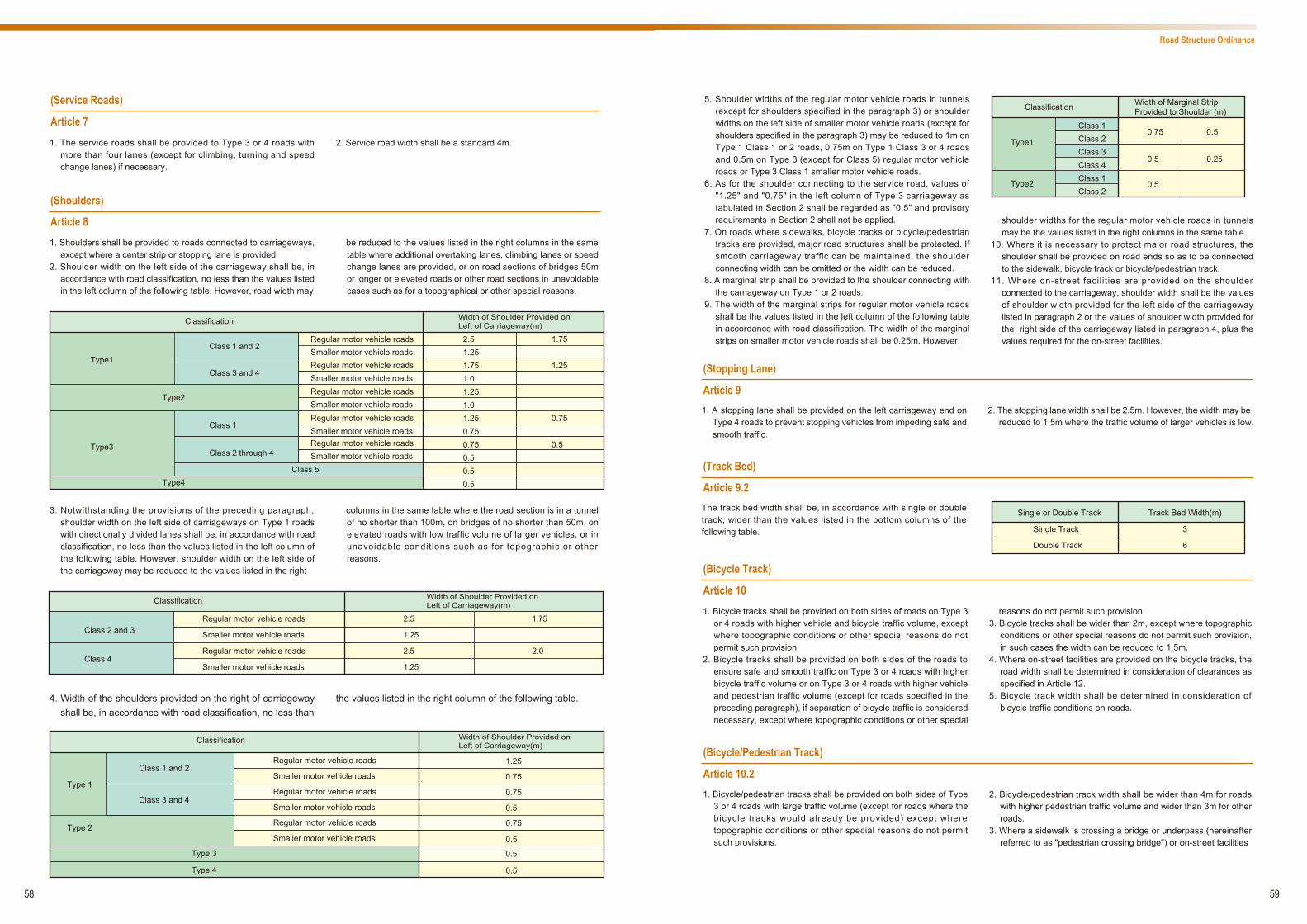
(Stopping Lane)
Article 9
5. Shoulder widths of the regular motor vehicle roads in tunnels (except for shoulders specified in the paragraph 3) or shoulder widths on the left side of smaller motor vehicle roads (except for shoulders specified in the paragraph 3) may be reduced to 1m on Type 1 Class 1 or 2 roads, 0.75m on Type 1 Class 3 or 4 roads and 0.5m on Type 3 (except for Class 5) regular motor vehicle roads or Type 3 Class 1 smaller motor vehicle roads.
6. As for the shoulder connecting to the service road, values of "1.25" and "0.75" in the left column of Type 3 carriageway as tabulated in Section 2 shall be regarded as "0.5" and provisory requirements in Section 2 shall not be applied.
7. On roads where sidewalks, bicycle tracks or bicycle/pedestrian tracks are provided, major road structures shall be protected. If smooth carriageway traffic can be maintained, the shoulder connecting width can be omitted or the width can be reduced.
8. A marginal strip shall be provided to the shoulder connecting with the carriageway on Type 1 or 2 roads.
9. The width of the marginal strips for regular motor vehicle roads shall be the values listed in the left column of the following table in accordance with road classification. The width of the marginal strips on smaller motor vehicle roads shall be 0.25m. However,
shoulder widths for the regular motor vehicle roads in tunnels may be the values listed in the right columns in the same table.
10. Where it is necessary to protect major road structures, the shoulder shall be provided on road ends so as to be connected to the sidewalk, bicycle track or bicycle/pedestrian track.
11. Where on-street facilities are provided on the shoulder connected to the carriageway, shoulder width shall be the values of shoulder width provided for the left side of the carriageway listed in paragraph 2 or the values of shoulder width provided for the right side of the carriageway listed in paragraph 4, plus the values required for the on-street facilities.
58 59
1. A stopping lane shall be provided on the left carriageway end on Type 4 roads to prevent stopping vehicles from impeding safe and smooth traffic.
2. The stopping lane width shall be 2.5m. However, the width may be reduced to 1.5m where the traffic volume of larger vehicles is low.
The track bed width shall be, in accordance with single or double track, wider than the values listed in the bottom columns of the following table.
(Bicycle Track)
Article 10 1. Bicycle tracks shall be provided on both sides of roads on Type 3
or 4 roads with higher vehicle and bicycle traffic volume, except where topographic conditions or other special reasons do not permit such provision.
2. Bicycle tracks shall be provided on both sides of the roads to ensure safe and smooth traffic on Type 3 or 4 roads with higher bicycle traffic volume or on Type 3 or 4 roads with higher vehicle and pedestrian traffic volume (except for roads specified in the preceding paragraph), if separation of bicycle traffic is considered necessary, except where topographic conditions or other special
reasons do not permit such provision. 3. Bicycle tracks shall be wider than 2m, except where topographic
conditions or other special reasons do not permit such provision, in such cases the width can be reduced to 1.5m.
4. Where on-street facilities are provided on the bicycle tracks, the road width shall be determined in consideration of clearances as specified in Article 12.
5. Bicycle track width shall be determined in consideration of bicycle traffic conditions on roads.
(Track Bed)
Article 9.2
(Bicycle/Pedestrian Track)
Article 10.21. Bicycle/pedestrian tracks shall be provided on both sides of Type
3 or 4 roads with large traffic volume (except for roads where the bicycle tracks would already be provided) except where topographic conditions or other special reasons do not permit such provisions.
2. Bicycle/pedestrian track width shall be wider than 4m for roads with higher pedestrian traffic volume and wider than 3m for other roads.
3. Where a sidewalk is crossing a bridge or underpass (hereinafter referred to as "pedestrian crossing bridge") or on-street facilities
Type1
Classification
Class 10.75
0.5
0.5
0.5
0.25
Class 2Class 3Class 4Class 1Class 2
Width of Marginal Strip Provided to Shoulder (m)
Type2
Single or Double Track
Single Track
Double Track
Track Bed Width(m)
3
6
(Service Roads)
Article 7
(Shoulders)
Article 8 1. Shoulders shall be provided to roads connected to carriageways,
except where a center strip or stopping lane is provided. 2. Shoulder width on the left side of the carriageway shall be, in
accordance with road classification, no less than the values listed in the left column of the following table. However, road width may
be reduced to the values listed in the right columns in the same table where additional overtaking lanes, climbing lanes or speed change lanes are provided, or on road sections of bridges 50m or longer or elevated roads or other road sections in unavoidable cases such as for a topographical or other special reasons.
1. The service roads shall be provided to Type 3 or 4 roads with more than four lanes (except for climbing, turning and speed change lanes) if necessary.
2. Service road width shall be a standard 4m.
3. Notwithstanding the provisions of the preceding paragraph, shoulder width on the left side of carriageways on Type 1 roads with directionally divided lanes shall be, in accordance with road classification, no less than the values listed in the left column of the following table. However, shoulder width on the left side of the carriageway may be reduced to the values listed in the right
columns in the same table where the road section is in a tunnel of no shorter than 100m, on bridges of no shorter than 50m, on elevated roads with low traffic volume of larger vehicles, or in unavoidable conditions such as for topographic or other reasons.
4. Width of the shoulders provided on the right of carriageway shall be, in accordance with road classification, no less than
the values listed in the right column of the following table.
Type1
Classification Width of Shoulder Provided on Left of Carriageway(m)
Type2
2.51.251.751.01.251.01.250.750.750.50.50.5
1.75
1.25
0.75
0.5
Class 1 and 2Regular motor vehicle roadsSmaller motor vehicle roadsRegular motor vehicle roadsSmaller motor vehicle roadsRegular motor vehicle roadsSmaller motor vehicle roadsRegular motor vehicle roadsSmaller motor vehicle roadsRegular motor vehicle roadsSmaller motor vehicle roads
Class 3 and 4
Class 1
Class 2 through 4
Class 5
Type3
Type4
Classification Width of Shoulder Provided on Left of Carriageway(m)
2.5
1.25
2.5
1.25
1.75
2.0
Class 2 and 3Regular motor vehicle roads
Smaller motor vehicle roads
Regular motor vehicle roads
Smaller motor vehicle roadsClass 4
Classification Width of Shoulder Provided on Left of Carriageway(m)
Type 1
Type 2
Type 3
Type 4
1.25
0.75
0.75
0.75
0.5
0.5
0.5
0.5
Class 1 and 2
Class 3 and 4
Regular motor vehicle roads
Smaller motor vehicle roads
Regular motor vehicle roads
Smaller motor vehicle roads
Regular motor vehicle roads
Smaller motor vehicle roads
Road Structure Ordinance

(Design Speed)
Article 13
60 61
1. Design speed on roads, except for service roads, shall be the values l isted in the left column of the following table, in accordance with road classification, except where topographical conditions or any other reasons do not permit such provisions. Design speed on roads may be the values listed in the right column of the same table when dealing with these exceptions, however this does not apply to Type 1 Class 4 roads that are national expressways.
2. Design speed on the service roads shall be 40km, 30km, or 20km per hour.
Fig.1
Fig. 2 (omitted)
(1) (2) (3)
Classification c (Unit: m) d (Unit: m)
Type 1
Type 2
Type 3Type 4
1.00.5
0.75
1.00.5
0.50.750.50.50.5
0.5
0.25
0.25
0.25
0.250.25
Class 1
Class 2
Class 3 and 4
Regular motor vehicle roadsSmaller motor vehicle roadsRegular motor vehicle roadsSmaller motor vehicle roadsRegular motor vehicle roadsSmaller motor vehicle roads
Regular motor vehicle roadsSmaller motor vehicle roads
e: Width of the shoulder connected with the carriageway (for shoulders where on-street facilities are provided, shoulder width minus value required for on-street facilities).
Carriageway of roads where the shoulder is provided by connecting with the carriageway [except for the road sections specified in (3)]
Carriageway of roads other than tunnels without sidewalk or bicycle track, bridge longer than 50m or viaduct
Carriageway in tunnels without sidewalk or bicycle track, on bridges longer than 50m or viaduct
Carriageway of roads where the shoulder is not provided by c o n n e c t i n g w i t h t h e carriageway[except for the road sections specified in (3) ]
Of car r iageway, sec t ions related to Separator or Island
Figure (omitted)In this figure, H, A, b, c, d and e indicate the following values.H: 4.5m for regular motor vehicle roads and 3m for smaller motor vehicle roads except for Type 3 Class 5 regular motor vehicle roads where the
value may be reduced to 4m in unavoidable cases such as for a topographical reason (or 3m when traffic volume of large-sized motor vehicles is extremely small and these may access neighboring bypass roads).
a: The width of the shoulder connected with the carriageway on regular motor vehicle roads (for shoulders where on-street facilities are provided, shoulder width minus value required for on-street facilities), provided that the value exceeds 1m shall be 1m. The width of the shoulder connected with the carriageway on smaller motor vehicle roads shall be 0.5m.
b: Value subtracting 3.8m from H (regarded as 3.8m where H is less than 3.8m) for regular motor vehicle roads and this value shall be 0.2m for smaller motor vehicle roads.
c and d: Concerning the separator, values listed in columns c and d in accordance with road classification and concerning the island, the value of c shall be 0.25m and the value of d shall be 0.5m.
Type1
Classification
Class 1 120100
806080608060
60,50 or 4050,40 or 3040,30 or 20
6060,50 or 4050,40 or 30
10080605060
50 or 4060
50 or 403020
50 or 403020
Class 2Class 3
Class 1Class 2Class 3
Class 4Class 1Class 2
Design Speed (km/h)
Type2
Type3
Type4
Class 1Class 2Class 3Class 4Class 5
(Sidewalk)
Article 11 1. A sidewalk shall be provided on both sides of Type 4 roads
(excluding those roads provided with bicycle/pedestrian tracks), Type 3 roads (except for Class 5 and excluding those roads provided with bicycle/pedestrian tracks) with higher pedestrian traffic volume or Type 3 roads already provided with bicycle tracks, except where topographical conditions or any other reasons prevent such provision.
2. Sidewalks shall be provided on Type 3 roads (excluding those roads already provided with bicycle/pedestrian tracks and those roads stipulated in the preceding paragraph) where it is required for safe and smooth traffic, except where topographic conditions or any other reasons do not permit such provision.
3. The sidewalk width shall be wider than 3.5m for roads with higher pedestrian traffic volume and wider than 2m for other roads.
4. Where a sidewalk is crossing a bridge or underpass (hereinafter referred to as "pedestrian crossing bridge") or on-street facilities are provided, bicycle/pedestrian track width shall be increased by 3m where a pedestrian crossing bridge is to be constructed, 2m where a roofed bench is to be installed, 1.5m where a row of trees is to be planted, 1m where a bench is installed or 0.5m in other cases, respectively to the values given in the preceding paragraph, and requirements as specified above shall be applied, except for Type 3 Class 5 roads where topographic condit ions or other special reasons do not permit such provisions.
5. The sidewalk width shall be determined in consideration of pedestrian traffic conditions on the roads.
(Waiting Area for Pedestrians)
Article 11.2 Waiting space for pedestrians shall be provided on sidewalks, bicycle-and pedestrian tracks, bicycle-and pedestrian paths or exclusive pedestrian roads, in the case that it is necessary to
(Planting Strip)
Article 11.4
(Clearances)
Article 12
ensure that the safe and smooth passage of pedestrians or bicycle riders will not be impeded due to the accumulation of pedestrians at the pedestrian crossings or at bus stops.
Center strip, shoulder, bicycle/pedestrian track and side walk width in snowy areas shall be determined in consideration of snow removal.
Clearances on roads shall be shown in Fig.1 for carriageways and in Fig.2 for sidewalks and bicycle tracks or bicycle/pedestrian tracks
(hereinafter referred to as "bicycle tracks").
1. The planting strip shall be provided to Type 4 Class 1 and Class 2 roads and i f necessary to other roads, except where topographic conditions or other special reasons do not permit such provisions.
2. The planting strip width standard shall be 1.5m. 3. The planting strips provided between road sections as described
below shall have proper width values, exceeding values specified in the sec t ion above when requ i red fo r cond i t ions in comprehensive consideration of road structure, traffic condition, and land use of adjoining areas and other measures taken to
improve road traffic environment or to ensure a better living environments along adjoining areas irrespective of the requirements above:
1) Sections of arterial roads and central business districts in large cities running through scenic spots.
2) Sections of arterial roads running through residential areas or areas that are expected to become residential.
4. For plant ing str ips, the select ion of plant species and arrangement of trees shall take into account with the ecological characteristics of the area.
(Center Strip Width in Snowy Areas)
Article 11.3
are provided, the bicycle/pedestrian track width shall be increased by 3m where a pedestrian crossing bridge is to be constructed, 2m where a roofed bench is to be installed, 1.5m where a row of trees is to be planted, 1m where a bench is installed or 0.5m in other cases, respectively to the values given in the preceding paragraph.The requirements as specified above shall be applied
except for Type 3 Class 5 roads where topographic conditions or other special reasons do not permit such provisions.
4. The bicycle/pedestrian track width shall be determined in consideration of bicycle and pedestrian traffic conditions on the road.
Road Structure Ordinance

(Sight Distance)
Article 19
(Grade)
Article 20
1. Sight distance shall not be less than the values below, as listed in the following table according to design speed.
2. For roads with two lanes (except for one-way roads), sufficient sections of oncoming highway visible to the driver shall be provided for overtaking.
62 63
Carriageway grades shall be no more than the values listed in the left grade column of the fol lowing table according to road classification and design speed, except where topographical
conditions or any other reasons do not permit such provisions; in such cases the values of the grade may be reduced to the values listed in the right grade column of the same table.
(Climbing Lane)
Article 21
1. A cl imbing lane, i f necessary, shal l be provided to the carriageway of the regular motor vehicle roads where grades exceed 5% (or 3% when the design speed is no less than 100
km per hour on other regular motor vehicle roads than national expressways and national highways).
2. The climbing lane width shall be 3m.
Design Speed (km/h) Transition Section Length (m)
120
100
80
60
50
40
30
20
210
160
110
75
55
40
30
20
Type 1, Type 2& Type3
Type 4
Classification Design Speed (km/h)120 2 5100 3 6
80 4 760 5 850 6 940 7 1030 8 1120
120100
80605040302060504030206050403020
9 12
4 56
789
101112
5 76 87 98 109 11
89
101112
Grade (%)
Regular motor vehicle roads
Smaller motor vehicle roads
Regular motor vehicle roads
Smaller motor vehicle roads
(Carriageway Bend Section)
Article 14Carriageway bend sections shall be curved in shape, except for transition sections, (hereinafter indicating certain sections, provided at the carriageway bend sections, that allow for smooth vehicle
traffic) or bend sections provided pursuant to the provision of Article 31.2.
(Radius of Curve)
Article 15
Radii of curve at the centerline of the carriageway (hereinafter referred to as "radius of curve"), except for transition sections, (hereinafter referred to as "carriageway curve section") shall not be less than the values as listed in the left column of the following table according to design speed, except when unavoidable due to, for example, topographical reasons, in which case the radii of curve may be reduced to the values as listed in the right column of the same table.
(Super-elevation at Curve Section)
Article 16Appropriate super-elevation with no more than the values as listed in the right column of the following table (6% for Type 3 roads without bicycle t rack) shal l be provided on curves of the carriageway, the center strip (except for median), and the shoulder connected with the carriageway, according to road classification and degree of snow fall or cold climate in the areas where the roads are located, in consideration of design speed, radii of curve, and topographical conditions, unless the radius of the curve is too large, except for Type 4 roads which can be omitted in such unavoidable cases as topographical conditions or any other reasons.
(Widening Lane at Curve Section)
Article 17The lane width on carriageway curve sections (or carriageway width in the case of roads without lanes) shall be appropriately widened
except for Type 2 and 4 roads, where topographical conditions or any other reasons do not permit such provisions.
(Transition Section)
Article 18 1. Transition sections shall be provided on carriageway bend
sections for Type 4 roads where topographical conditions or any other reasons do not permit such provisions.
2. When a curved section is widened and/or provided with super-elevation, a runoff for this widening and/or super-elevation shall be completed in the transition section.
3. The transition curve length shall not be less than the right side value as listed in the following table according to design speed (or length required for runoff when length required for runoff as specified in Section above exceeds values as listed in the same column).
Design Speed (km/h) Radius of Curve (m)
120 710 570100 460 38080 280 23060 150 12050 100 8040 60 5030 3020 15
Design Speed (km/h) Transition Section Length (m)
120
100
80
60
50
40
30
20
100
85
70
50
40
35
25
20
Type 1,2and 3
Classification Maximum Super-elevation (%)
6
8
10
6
Area Where Road is Located
Type4
Other Areas
Severely Snowy or Cold Area
Other Areas
Snowy or Cold Area
Road Structure Ordinance

64
(Compound Grade)
Article 25 1. Compound Grades (hereinafter indicating combination of vertical
grade and super-elevation or cross slope) shall be no more than the right side values as listed in the following table according to design speed, except for roads with design speed of 30km/h or 20km/h where compound grades may be 12.5% in unavoidable cases, such as topographical conditions or any other reasons.
2. Compound grades shall be not more than 8% on those roads located in severely snowy or cold areas.
(Drainage Facility)
Article 26Gutter, gully, or other drainage facilities shall be provided to roads if necessary.
(At-grade Intersection or Connection)
Article 27
1. An intersection shall be designed so as to contain no more than five intersecting legs, except when it is located in a special place such as in front of a station.
2. At an intersection where two or more roads join or intersect at grade, if necessary, a turning lane, speed change lane, or island shall be provided, and corners of intersection shall be cut, and unobstructed sight shall be ensured.
3. Where the turning lane or speed change lane is provided, lane width (except for the turning lane or speed change lane) of the
related section may be reduced to 3m for Type 4 Class 1 regular motor vehicle roads or to 2.75m for Type 4 Class 2 or 3 regular motor vehicle roads or to 2.5m for Type 4 smaller motor vehicle roads.
4. The standard width of turning and speed change lanes shall be 3m for regular motor vehicle roads and 2.5m for smaller motor vehicle roads.
5. Where a turning or speed change lane is provided, proper runoff shall be provided according to design speed.
(Grade Separation)
Article 28
1. When two regular motor vehicle roads having four or more lanes intersecting mutually, excluding climbing lanes, turning lanes and speed change lanes, the intersection shall be separated by grades as a rule, except when the grade separation is unsuitable due to traffic conditions or in an unavoidable case such as a topographical reason.
2. When a smaller motor vehicle road with four or more lanes (except for turning lanes and speed change lanes) crosses
another smaller motor or a regular motor vehicle road, the intersection shall be separated by grades.
3. Where the grade separation is provided, a road l inking intersecting roads mutually (hereinafter referred to as a “ramp” ) shall be provided if necessary.
4. Provisions of Articles 5 through 8, Article 12, Article 13, Article 15, Article 16, Articles 18 through 20, Articles 22 and 25 shall not be applied to the ramp.
(At-grade Intersection with Railway)
Article 29
When a road intersects at a grade with a railway or street railway newly constructed in accordance with the Street Railway Act (Act No.76 1921) (hereinafter referred to as a “railway” ), the road shall be so constructed as specified below. 1. Intersection angles shall be not less than 45 degrees. 2. Sections 30m from both ends of railroad crossing and the railroad
crossing section shall be straight and vertical carriageways, grades for these sections shall be less than 2.5%, except where there is extremely small vehicle traffic volume or topographical
conditions or any other reasons do not permit such provisions. 3. A visible distance, distance from the intersection point of the
railway end track centerline and the carriageway centerline to the point on the track centerline visible at the height of 1.2m at point 5m on the carriageway centerline from the track, shall not be less than the values listed in the following table, except for where a crossing gate or other security facilities are provided or with smaller vehicle traffic volume and fewer passing trains.
65
Design Speed (km/h) Compound Grade (%)
12010
10.5
11.5
100
80
60
50
40
30
20
(Vertical Curve)
Article 22
(Pavement)
Article 23
1. Vertical curves shall be provided where grades change on the carriageway.
2. Radii of vertical curves shall be more than the values listed in the radius of vertical curve column of the following table according to design speed and Types of vertical curves, except when the radii of crest vertical curves on Type 4 Class 1 roads, when design
speed is 60km per hour, the radii shall be reduced to 1,000m, where topographical conditions or any other reasons do not permit such provisions.
3. Vertical curve lengths shall be more than the values listed in the below right column of the following table according to design speed.
1. Carriageways, center strips (except for median), shoulders connected with carriageways, bicycle tracks and sidewalks shall be paved except in unavoidable cases, such as extremely small traffic volume.
2. The pavement of carriageways and marginal strips shall be constructed so that safe and smooth vehicle traffic can be ensured on the basis of the design wheel load of 49 kN, in consideration of designed daily volume, vehicle weight, subgrade conditions, and meteorological conditions and that shall meet the standards laid down in the Ordinance of Ministry of Land,
Infrastructure, Transport and Tourism, except in the case of small vehicle traffic volume or any other unavoidable conditions.
3. Type 4 roads (except for tunnels) shall be constructed so that it shall be capable of causing storm water to permeate smoothly under the road surfaces and reducing the traffic noise level, in consideration of the land uses and vehicle traffic conditions in the area where the roads are located or along them, except where road structure, meteorological conditions or other special reasons do not permit such provisions.
(Cross Slope)
Article 24
1. Cross slopes shall be provided to the carriageway, center strip (except for median) and shoulder connected wi th the carriageway according to road surface Type and the right side values as listed in the following table unless super-elevation is provided.
2. 2% of cross slope as a standard shall be provided to sidewalks and bicycle tracks.
3. The paved road of the structure specified in paragraph 3 of the previous Article may dispense with or reduce cross slope, if proper road surface drainage can be ensured in consideration of meteorological conditions.
Design Speed (km/h) Type of Vertical Curve Radius of Vertical Curve(m)
12011,000
100
4,000Crest
SagCrest
SagCrest
SagCrest
SagCrest
SagCrest
SagCrest
SagCrest
Sag
80
65,00
60
3,000
50
3,000
40
2,0001,4001,00065,00
800700450250250100100
30
20
Design Speed (km/h) Vertical Curve Length(m)
120
100
80
60
50
40
30
20
100
85
70
50
40
35
25
20
Road Surface Type
Paved Road Complying with Standards Specified in Article 23.2
Others
Cross Slope (%)
1.5-2
3-5
Road Structure Ordinance

66
(Tunnel)
Article 34
1. To ensure safe and smooth traffic, proper ventilation facilities shall be provided in the tunnel when required in consideration of designed daily volume and tunnel length on the road.
2. When required for safe and smooth traffic, proper lighting shall be provided in the tunnel in consideration of design speed.
3. When a vehicle fire or other accidents in the tunnel could cause risks to traffic, the communication facilities, warning facilities, firefighting facilities and other emergency facilities shall be provided in the tunnel if necessary.
(Bridge and Viaduct)
Article 35
1. Bridges, viaducts, or other similar roads shall be steel or concrete structure or the equivalent.
2. Design vehicle load for bridges, viaducts, and other similar regular motor vehicle roads shall be 245kN. The structures of said bridges, viaducts, and other similar regular motor vehicle roads shall secure safe traffic in view of large-sized vehicle traffic conditions for these roads.
3. Design vehicle load for bridges, viaducts, and other similar smaller motor vehicle roads shall be 30kN. The structures of said
bridges, viaducts, and other similar smaller motor vehicle roads shall secure safe traffic in view of smaller vehicle traffic conditions for these roads.
4. In addition to the requirements in the three previous paragraphs, necessary matters regarding construction standards for bridges, viaducts, or other similar roads shall be specified by the Ordinances of the Ministry of Land, Infrastructure, Transport and Tourism.
(Exception to Accessory Work)
Article 36 After a case is identified in which road work executed on others roads or work other than road work is executed and determined to be influencing roads, provisions from Articles 4 to 35 (except for
Article 8, Article 13, Article 14, Article 24, Article 26, Article 31 and Article 33) may be exempted from application after it is approved that the case is not subject to these requirements.
(Exception to Change of Road Classification)
Article 37
When classification, as specified in Article 3.2, is changed by plans as to change a part of national highways to prefectural or municipal roads, classification following the change shall result in applying requirements of Article 3.4, Article 3.5, Article 4, Article 5, Article 6.1, Article 6.4, Article 6.6, Article 8.2 through 8.6, Article 8.9, Article 8.11, Article 9.1, Article 10.2.3, Article 11.1, Article 11.2, Article 11.4, Article 11.4.1, Article 12, Article 13.1, Article 16, Article 17, Article 18.1, Article 20,Article 22.2, Article 23.3, Article 27.3, Article 30 and Article 31.2. In this case, "Type 3 Class 5 roads" in proviso of Article 5.1, Article 5.5, proviso of Article 10.2.3, proviso of Article
11.4 and Article 12 shall be read as "Type 3 Class 5 or Type 4 Class 4 roads". "Type 3 Class 5 roads" in Article 5.3 shall be read as "Type 3 Class 5 and Type 4 Class 4 roads". "Type 4 roads" in Article 9.1 and Article 11.1 shall be read as "Type 4 (except for Class 4)". "Type 3" in these paragraphs shall be read as "Type 3 or Type 4 Class 4". "Type 3" in Article 11.2 shall be read as "Type 3 or Type 4 Class 4". "Values listed in the top column" in Article 13.1 shall be read as "Values listed in the top column (for Type 4 Class 4 roads, 40km/h, 30km/h or 20km/h)". "Mainly" in Article 31.2 shall be read as "Type 4 Class 4 roads or mainly".
(Exception to Reconstruction of Short Section)
Article 38
1. When a short section on roads that severely prevents traffic is reconst ruc ted as an emergency measure , except fo r reconstruction as listed in the following requirements, this section may be exempted from application of Article 5, Article 6.4 through Article 6.6, Article 7, Article 9, Article 9.2, Article 10.3, Article 10.2.2, Article 10.2.3, Article 11.3, Article 11.4, Article 11.4.2, Article 11.4.3, Article 15 through Article 22, Article 23.3, and Article 25, if it is approved that the road structure of sections adjacent to this section do not satisfy these requirements.
2. When a short section of roads that severely impact safety is reconstructed as an emergency measure, this section shall be exempt from application of Article 5, Article 6.4 through Article 6.6, Article 7, Article 8.2, Article 9, Article 9.2, Article 10.3, Article 10.2.2, Article 10.2.3, Article 11.3, Article 11.4, Article ll.4.2, Article 11.4.3, Article 19.1, Article 21.2, Article 23.3, Article 39.1, Article 39.2, and Article 40.1, if it is determined in consideration of road condi t ions that i t is not proper to apply these requirements.
67
(Turnout)
Article 30
Turnout shall be provided on Type 3 Class 5 roads as specified below, except for on roads where smooth traffic can be ensured. 1. Distance between two turnouts shall be within 300m. 2. Roads between two turnouts shall be visible from one of these
turnouts. 3. The length shall be more than 20m and the total width of the
carriageway shall be more than 5m.
(Traffic Safety Device)
Article 31
When it is necessary for traffic accident prevention, the pedestrian crossing bridge, fence, lighting, safety post, emergency notification facility, and other similar facilities, as specified by the Land,
Infrastructure and Transport Ministry's Ordinances, shall be provided.
(Protrusions, Narrow Passes, etc.)
Article 31.2 When it is necessary for slowing down vehicles, to ensure safe pedestrian or bicycle traffic, protrusions shall be provided on the surface of the carriageway or on the shoulders connecting to the
carriageway, or narrow passes or bend sections shall be provided on the carriageway, on Type 3 Class 5 roads intended primarily for use by nearby residents.
(Islands Provided at Bus Bays)
Article 31.3
Islands shall be provided as necessary at bus bays or streetcar stops that do not connect to bicycle tracks, bicycle/pedestrian tracks
or sidewalks.
(Automobile Parking Lot)
Article 32
Automobile parking lots, bicycle parking lots, bus bays, emergency parking basis or other similar facilities specified by the Land, Infrastructure and Transport Ministry's Ordinances shall be
provided, if necessary, to ensure safe and smooth traffic or to contribute to public convenience.
(Snow Protection Facility and Other Protector)
Article 33
1. Where an avalanche, blizzard, snowfall or other meteorological events could prevent smooth traffic, snow shed, drain for snow removal, snow melting facilities or other facilities shall be provided as specified by the Land, Infrastructure and Transport
Ministry’ s Ordinances. 2. Unless specified above, a fence, retaining wall, and other proper
protectors shall be installed where falling stone, slope failure, billow, etc. could prevent traffic or damage road structure.
Maximum Train Speed at Railroad Crossing (km/h)
Less than 50
50-70
70-80
80-90
90-100
100-110
More than 110
Visible Distance (m)
110
160
200
230
260
300
350
Road Structure Ordinance

68
0.25m
0.25m
1.5m
b
H
Carriageway
a
b
H
e Carriageway
1.5m
b
C
d
H
Sparatoror
Island
1.5m
a
b
e
H
Carriageway
Marginal Strip(0.25m Where noMariginal strip exists)
2.5m
Sidewalk or bicycle track width
2.5m
Sidewalk or bicycle track width afterSections required for on-street facilitiesare subtracted
Sidewalk or bicycle track width
On-street facilities
(Bicycle Path and Bicycle/Pedestrian Path)
Article 39
1 . B icyc le pa th w id th sha l l be no t l ess than 3m, wh i le bicycle/pedestrian path width shall be no less than 4m. However, where topographical conditions or any other reasons do not permit such provisions, bicycle path width can be reduced to 2.5m.
2. Lateral clearances wider than 0.5m shall be provided to both sides of bicycle paths or bicycle/pedestrian paths as a part of the roads.
3. Where on-street facilities are provided on bicycle tracks or bicycle/pedestrian tracks, width of these tracks shall be determined in consideration of clearances as specified in the following provision.
4. Bicycle path and bicycle/pedestrian path clearances shall be in accordance with the following figure.
5. Alignment, grade, and other features of bicycle paths and bicycle/pedestrian paths shall be determined so as to ensure safe and smooth bicycle and pedestrian traffic.
6. Requirements of Article 3 through 37 and Section 1 of the preceding Article (excluding Article 1 1.2 for bicycle/pedestrian path) shall not be applied to bicycle paths and bicycle/pedestrian paths.
(Pedestrian Path)
Article 40
1. Pedestrian path width shall be not less than 2m in consideration of pedestrian traffic conditions and areas where the track is located, except where topographical conditions or other reasons do not permit such provisions, in which case the width can be reduced to 1m.
2. Where on-street facilities are provided on pedestrian paths, width shall be determined in consideration of clearances as specified in the following provision.
3. Pedestrian path clearances shall be in accordance with the following figure.
4. Alignment, grade and other features of pedestrian paths shall be determined so as to ensure safe and smooth pedestrian traffic.
5. Requirements of Articles 3 through 11, Article 11.3 through 37 and Section 1 of Article 38 shall not be applied to pedestrian paths.
(General technical standards for structure of prefectural and municipal roads)
Article 41
1. The provisions of Article 4, 12, 35.2, 35.3, 35.4 (limited to the matters listed in Article 30.1.12), 39.4, and 40.3 shall apply mutatis mutandis to general technical standards for the structure of prefectural or municipal roads when these roads are newly constructed or reconstructed. In this case, "Type 3 Class 5" in Article 12 shall be read as "Type 3 Class 5 or Type 4 Class 4".
2. The provisions of Article 5 through Article 11.4, Article 13 through 34, Article 35.1 and 35.4 (except for the provisions listed in Article 30.1.12), Article 36 through 38, Article 39.1 through 39.3, Article 39.5 and 39.6, Article 40.1, 40.2, 40.4, and 40.5 shall apply mutatis mutandis to the standard specified in Article 30.3. In this case, "Type 3 Class 5 roads" in proviso of Article 5.1, Article 5.5, proviso of Article 10.2.3, and proviso of Article 11.4 shall be read as "Type 3 Class 5 or Type 4 Class 4 roads". "Type
3 Class 5 roads" in Article 5.3 shall be read as "Type 3 Class 5 and Type 4 Class 4 roads". "Type 4 roads" in Article 9.1 and Article 11.1 shall be read as "Type 4 (except for Class 4)". "Type 3" in these paragraphs shall be read as "Type 3 or Type 4 Class 4". "Type 3" in Article 11.2 shall be read as "Type 3 or Type 4 Class 4". "Values listed in the left column" in Article 13.1 shall be read as "Values listed in the left column (for Type 4 Class 4 roads 40km/h, 30km/h or 20km/h)". "Primarily for use" in Article 31.2 shall be read as "Primarily for Type 4 Class 4 roads or use". In Article 37 "National highways" shall be read as "prefectural roads", "prefectural roads or municipal roads" and "other roads" shall be read as "municipal roads", "subject part" shall be read as "subject prefectural roads".
2.5m
Bicycle path orbicycle/pedestrianpath(excluding the
necessary area for on-street facilities)
2.5m
Pedestrian path(excluding the
necessary area for on-street facilities)
Road Structure Ordinance
69

70 71
Statistics
Vehicles in Use (Mar. 31, 2012)
(Source: Automobile Inspection & Registration Information Association website)
Vehicle type
Passenger cars 59,357,223
Buses & Motor coaches 226,047
Vans, pick-ups, lorries, road tractors 16,506,405
Total 76,089,675
(Reference) Motorcycles & Mopeds 3,535,528
Unit: vehicles
Road Accidents (2012)
(Source: Traffic Accidents Situation, and Number of Fatalities within 30 days from the Time of Accident, National Police Agency)
Number of Injury Accidents 665,138
Number of Persons Injured 825,396
Number of Persons Killed 5,237
Unit: accidents, or persons
・Expenditures for toll roads are excluded. (Source: Road Statistics Annual Report [Douro Toukei Nenpo] 2012, Road Bureau, MLIT)
Road Expenditure (2011)
Gross investment 3,974,213
Maintenance expenditures 1,740,214
Total 5,714,427
Unit: million yen
StatisticsRoad Statistics of Japan
Road Length by Category (April 1, 2012)
Vehicle Traffic Volume (2011)
Freight Transport (2011)
Passengers Transport (2009)
・Since 2010, survey and calculation methods for road traffic have been changed, so the data do not match the previous data. Private passenger car and private truck were excluded from the survey.・Due to Great East Japan Earthquake, traffic for March of FY2010 (2010.4-2011.3) in Hokkaido and Tohoku Regions are not included in 2010 figures. (Source: Transport-related Statistics Data [Kotsu Kanren Toukei Shiryoshu], Policy Bureau, MLIT)
・Roads less than 5.5m in width have been excluded from the statistics. (Source: Road Statistics Annual Report [Douro Toukei Nenpo] 2012, Road Bureau, MLIT)
Category
Motorways 8,050
Highways, Main or National Roads 51,237
Secondary or Regional Roads 91,440
Other Roads 190,782
Total 341,509
Unit : km
・Since 2010, survey and calculation methods for road traffic have been changed, so the data do not match the previous data.・Due to Great East Japan Earthquake, traffic for March of FY2010 (2010.4-2011.3) in Hokkaido and Tohoku Regions are not included in 2010 figures. (Source: Transport-related Statistics Data [Kotsu Kanren Toukei Shiryoshu], Policy Bureau, MLIT)
Vehicle type
Passenger cars 499,037
Buses & Motor coaches 6,124
Vans, pick-ups, lorries, road tractors 196,821
Total 701,982
Million vehicle km
Modes
Road 231,061
Rail 19,998
Inland Waterway 174,900
Total 425,959
Unit: million ton-km/year
Modes
Road, public transport 81,360
Road, private transport 817,361
Rail 393,765
Total 1,292,486
Unit: million passenger-km/year

72
The Five-Year Road Development Plans
1st Plan (A)FY1954-57 (a)a/A (%)
260.0182.170.0
100.059.0
-
610.0322.252.8
61.061.3
-
1,300.0722.255.6
61.957.7
-
2,200.01,244.1
56.6
53.756.8
-
3,550.01,795.6
50.6
53.851.9
-
5,200.03,108.0
59.8
50.249.9
-
9,340.07,757.8
83.1
47.947.3
-
13,500.012,947.9
95.9
47.445.0
-
16,000.015,926.5
99.5
41.943.1
-
2nd Plan (B)FY1958-60 (b)b/B (%)
3rd Plan (C)FY1960-63 (c)c/C (%)
4th Plan (D)FY1964-66 (d)d/D (%)
5th Plan (E)FY1967-69 (e)e/E (%)
6th Plan (F)FY1970-72 (f)f/F (%)
7th Plan (G)FY1973-77 (g)g/G (%)
8th Plan (H)FY1978-82 (h)h/H (%)
9th Plan (I)FY1983-87 (i)i/I (%)
23,800.022,637.6
9.1
44.941.1
-
-146.0
-
-4.7
-
200.051.025.5
20.09.7
-
450.0225.550.1
21.418.0
-
1,100.0443.240.3
26.820.2
-
1,800.0753.541.9
27.321.7
-
2,500.01,317.9
52.7
24.221.2
-
4,960.03,960.8
79.9
25.424.1
-
6,800.06,614.5
97.3
23.923.0
-
9,200.09,740.3
105.9
24.126.4
-14,000.014,238.7
101.7
26.425.9
-
-111.9
-
-36.3
-
190.0152.180.0
19.029.0
-
350.0304.587.0
16.724.3
-
800.0502.362.8
19.523.0
-
1,100.0912.783.0
16.626.4
-
2,550.01,786.3
70.1
24.628.8
-
4,700.04,693.9
99.9
24.128.6
-
7,500.09,231.4
123.1
26.332.0
-
11,700.011,252.7
96.2
30.630.5
-13,900.018,164.3
130.7
260.0308.6
-
1,000.0525.252.5
2,100.01,252.2
59.6
4,100.02,189.6
53.4
1) 66003,461.8
52.5
2) 103009) 6223.5
60.1
3) 1950016,412.5
84.2
4) 2850028,793.8
101.0
5) 3820036,919.4
96.66) 5300055,040.6
103.9
26.233.0
-
10th Plan (J)FY1988-92 (j)j/J (%)
28,800.028,627.4
99.4
37.939.9
-
11th Plan (K)FY1993-97 (k)k/K (%)
29,200.031,729.0
108.7
37.448.6
-
20,600.017,703.6
85.9
27.124.7
-
17,000.013,431.2
79.0
21.820.6
-
25,200.025,476.2
101.1
33.235.5
-
26,800.020,155.4
75.2
7) 7600071,807.2
94.5
8) 7800065,315.6
83.7
34.430.9
-
12th Plan (L)FY1998-02 (l)l/L (%)
Total¥billionsInvestment
¥billionsRatio%
Investment¥billions
Ratio%
Investment¥billions
Ratio%
General Road Projects Toll Road Projects Unsubsidized Local Road Projects
Change in Investment in the Five-Year Road Development Program
Statistics