road & bridge design publications - michigan.gov · road & bridge design publications...
TRANSCRIPT

Road & Bridge Design Publications
Monthly Update – August 2017
1
Revisions for the month of August are listed and displayed below. New special details will be included in projects submitted for the December letting as is stated on the special detail index sheets. E-mail road related questions on these changes to [email protected]. E-mail bridge related questions to [email protected]. Standard Plan Distribution The distribution letter explaining the changes and the inserts used to keep a hard copy of the standard plan booklet up to date can be found at: http://mdotcf.state.mi.us/public/design/files/englishstandardplans/files/standard_plan_distribution.pdf The new standard plans have been placed on the website. Special Details R-60-J: Guardrail Types A, B, BD, T, TD, MGS-8, & MGS-8D: Added a sheet which provides the details for connecting a Type 2M terminal to either Type B or Type T guardrail. R-67-G: Guardrail Anchorage, Bridge, Details: Added the “3-Tube with Pickets” to the list of railings which connect to guardrail with the details illustrated on sheets one and three. R-127-F: Delineator Installations: On sheets two, three, and four, flipped the symbol for the red-on-yellow delineators so the red is shown on the back. PC-1M, PC-2H & PC-4F: Updated Prestressed Concrete Beam Details for various criteria, including change to all epoxy coated steel reinforcement (including wire mesh), update of “Z” bar to “EL” bar which corresponds to bar shape as designated on Bridge Design Guide 7.15.01, update of various notes, bearing details (option of plate or stud embedment into beam) and option for new strand enclosure for beam Type I-IV (ED3 or EC & EF bars). Note that not all “Notes:” listed on beam sheets apply to all projects and designers and detailers are responsible to use only notes that apply

Road & Bridge Design Publications
Monthly Update – August 2017
2
Road Design Manual 6.08: Sidewalk: The following terminology was updated: “technical infeasibility” becomes “accessibility constraints”, “turning spaces” become “landings”, “infeasible” becomes “impracticable”, and “feasible” becomes “practicable”. 6.08.05C10: Measurement and Payment: This is a new section added to provide an illustration representing the various elements of a sidewalk ramp, their pay items, limits of payments and other considerations. 6.08.05D: Meeting Existing Sidewalk Grades and Elevations: Revised the second paragraph (and associated detail) to require a landing on a perpendicular ramp, even though no turning movement or other accessible feature requiring a landing exists. Also, added a statement that transition slabs are not included in the 15’ required to attain the “15’ Rule”. 6.08.05E: Section was renamed “Accessibility Constraints” to be consistent with Form 0370. 6.08.06A: Removed a sentence regarding compliant sidewalks and street crossings being a Department obligation and priority (regarding Building Access Alterations). 7.01.03, 7.01.06, 7.01.12F & G, 7.01.15, 7.01.25, 7.01.29, 7.01.30H, 7.01.41A, C, & I: Updated sections to include MASH approved guardrail and guardrail endings. 7.01.19: Runout Lengths for Barrier Design: Added values for 80 mph design speed. 7.01.33B: Wide Culverts: Revised the maximum length of guardrail which can be used to span a culvert (taken from Standard Plan R-72-series) from 18’-9” to 25’. Bridge Design Guides 6.65.02: Clarified that the 2’ offset on shoulders is an MDOT imposed policy and applies to MDOT jurisdictional facility/roadway. See also Bridge Design Manual section 7.01.12 & 7.02.31 C. Updates to MDOT Cell Library, Bridge Auto Draw Program, etc., may be required in tandem with some of this month's updates. Until such updates to automated tools can be made, it is the designer's/detailer's responsibility to manually incorporate any necessary revisions to notes and plan details to reflect these revisions.
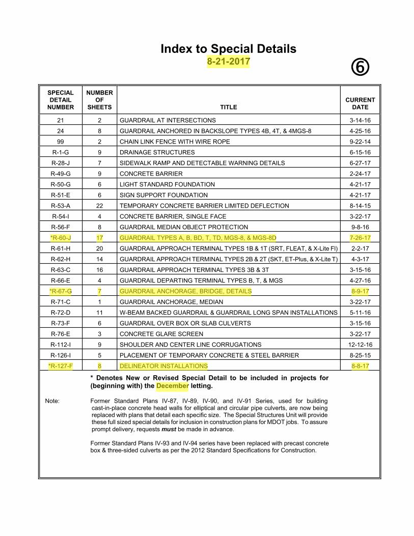
Index to Special Details
8-21-2017
SPECIAL DETAIL
NUMBER
NUMBER
OF SHEETS
TITLE
CURRENT
DATE
21
2 GUARDRAIL AT INTERSECTIONS 3-14-16
24
8
GUARDRAIL ANCHORED IN BACKSLOPE TYPES 4B, 4T, & 4MGS-8 4-25-16
99
2
CHAIN LINK FENCE WITH WIRE ROPE 9-22-14
R-1-G 9
DRAINAGE STRUCTURES 6-15-16
R-28-J 7
SIDEWALK RAMP AND DETECTABLE WARNING DETAILS 6-27-17
R-49-G 9
CONCRETE BARRIER 2-24-17
R-50-G 6
LIGHT STANDARD FOUNDATION 4-21-17
R-51-E 6
SIGN SUPPORT FOUNDATION 4-21-17
R-53-A 22
TEMPORARY CONCRETE BARRIER LIMITED DEFLECTION 8-14-15
R-54-I 4
CONCRETE BARRIER, SINGLE FACE 3-22-17
R-56-F 8
GUARDRAIL MEDIAN OBJECT PROTECTION 9-8-16
*R-60-J 17
GUARDRAIL TYPES A, B, BD, T, TD, MGS-8, & MGS-8D 7-26-17
R-61-H 20
GUARDRAIL APPROACH TERMINAL TYPES 1B & 1T (SRT, FLEAT, & X-Lite Fl) 2-2-17
R-62-H 14
GUARDRAIL APPROACH TERMINAL TYPES 2B & 2T (SKT, ET-Plus, & X-Lite T) 4-3-17
R-63-C 16
GUARDRAIL APPROACH TERMINAL TYPES 3B & 3T 3-15-16
R-66-E 4
GUARDRAIL DEPARTING TERMINAL TYPES B, T, & MGS 4-27-16
*R-67-G 7
GUARDRAIL ANCHORAGE, BRIDGE, DETAILS 8-9-17
R-71-C 1
GUARDRAIL ANCHORAGE, MEDIAN 3-22-17
R-72-D 11
W-BEAM BACKED GUARDRAIL & GUARDRAIL LONG SPAN INSTALLATIONS 5-11-16
R-73-F 6
GUARDRAIL OVER BOX OR SLAB CULVERTS 3-15-16
R-76-E 3
CONCRETE GLARE SCREEN 3-22-17
R-112-I 9
SHOULDER AND CENTER LINE CORRUGATIONS 12-12-16
R-126-I 5
PLACEMENT OF TEMPORARY CONCRETE & STEEL BARRIER 8-25-15
*R-127-F 8
DELINEATOR INSTALLATIONS 8-8-17
* Denotes New or Revised Special Detail to be included in projects for (beginning with) the December letting.
Note: Former Standard Plans IV-87, IV-89, IV-90, and IV-91 Series, used for building cast-in-place concrete head walls for elliptical and circular pipe culverts, are now being replaced with plans that detail each specific size. The Special Structures Unit will provide these full sized special details for inclusion in construction plans for MDOT jobs. To assure prompt delivery, requests must be made in advance.
Former Standard Plans IV-93 and IV-94 series have been replaced with precast concrete box & three-sided culverts as per the 2012 Standard Specifications for Construction.

Index to Bridge Detail Sheets
8-21-2017
DETAIL NUMBER
NUMBER
OF SHEETS
TITLE
CURRENT
DATE
B-22-E
4 BRIDGE RAILING, THRIE BEAM RETROFIT (R4 TYPE RAILING) 3-15-16
B-23-F
4 BRIDGE RAILING, THRIE BEAM RETROFIT (OPEN PARAPET RAILING) 3-15-16
B-101-G
2 DRAIN CASTING ASSEMBLEY DETAILS 2-8-16
EJ3AB
1 or 2
EXPANSION JOINT DETAILS 2-10-16
EJ4O
1 or 2
EXPANSION JOINT DETAILS 2-10-16
*PC-1M
1
PRESTRESSED CONCRETE I-BEAM DETAILS 8-23-17
*PC-2H
1
70" PRESTRESSED CONCRETE I-BEAM DETAILS 8-23-17
*PC-4F
1
PRESTRESSED CONCRETE 1800 BEAM DETAILS 8-23-17
* Denotes New or Revised Special Detail to be included in projects for
(beginning with) the December letting. Note: Details EJ3AA & EJ4N are interactive, i.e. designers and detailers choose details
based upon railing type and angle of crossing. Place all details appropriate for the project, structure specific information, and the Expansion Joint Device quantity on the sheet. The sheet shall then be added to the plans as a normal plan sheet.
Detail PC-1L, PC-2G and PC-4E shall have structure specific information and quantities added to the sheet. The sheet shall then be added to the plans as a normal plan sheet.

WOOD POST STEEL POST ELEVATION SHOWING POST SPACING
GUARDRAIL, TYPE A
ELEVATION SHOWING POST SPACING
GUARDRAIL, TYPE B
( WOOD POST )
22"
GROUND LINE
(TYP.)
SPLICE BOLT
6"
7"
6'-0"
3'-7"
WOOD LINE POST
6" x 8"
22"
(TYP.)
SPLICE BOLT
7"
6'-0"
3'-7"
UNDER NUT
ROUND WASHER
POST BOLT WITH
8"
UNDER NUT
ROUND WASHER
POST BOLT WITH
GROUND LINE
AND TYPICAL POST SPACING
EFFECTIVE BEAM ELEMENT LENGTH
12'-6"
* 28"
* SEE NOTES FOR GUARDRAIL IN CONJUNCTION WITH CURB
GROUND LINEOPTIONAL
* SEE NOTES FOR GUARDRAIL IN CONJUNCTION WITH CURB
GROUND LINE
* 2
8"
BEAM ELEMENT LENGTH
12'-6" EFFECTIVE
POST SPACING
6'-3" TYPICAL6" x 8" WOOD LINE POST
LINE
GROUND
HINGE POINT
SHOULDER
WASHER UNDER NUT
POST BOLT WITH ROUND
COATED NAIL
3" LONG HOT-DIP ZINC
WOOD POST WITH A MINIMUM
TOE NAIL WOOD BLOCK TO
SHOULDER
NORMAL
2'-0"
8"8"(TYP.)
SPLICE BOLT
14"
7"
22"
3'-7"
6'-0"
** 5'-0" OR AS SPECIFIED ON PLANS
** FOR PAVED SHOULDER WIDTHS OF AT LEAST 12', USE 3'-0".
B.L.T.
W.K.P. 1 17
DEPARTMENT DIRECTOR MICHIGAN DEPARTMENT OF TRANSPORTATION
OF
SHEET
PLAN DATEF.H.W.A. APPROVALCHECKED BY:
DRAWN BY:
Michigan Department of Transportation
BUREAU OF DEVELOPMENT STANDARD PLAN FOR
APPROVED BY:
APPROVED BY:
Kirk T. Steudle
BY
PREPARED
DESIGN DIVISION
DIRECTOR, BUREAU OF FIELD SERVICES
DIRECTOR, BUREAU OF DEVELOPMENTR-60-J
STEEL LINE POST
W6 x 9 OR W6 x 8.5
MGS-8, & MGS-8D
TYPES A, B, BD, T, TD,
GUARDRAIL,
7-26-2017

ELEVATION SHOWING POST SPACING
GUARDRAIL, TYPE BD
( WOOD POST )
BEAM ELEMENT LENGTH
12'-6" EFFECTIVE
POST SPACING
6'-3" TYPICAL
* 28"
GROUND LINE
* SEE NOTES FOR GUARDRAIL IN CONJUNCTION WITH CURB
6" x 8" WOOD LINE POST
GROUND LINE
WOOD OFFSET BLOCK
6" x 8"
WASHER UNDER NUT
POST BOLT WITH ROUND
8" 8" 8"(TYP.)
SPLICE BOLT
14"
7"
6'-0"
22"
3'-7"
NAIL
HOT-DIP ZINC COATED
A MINIMUM 3" LONG
TO WOOD POST WITH
TOE NAIL WOOD BLOCK
ELEVATION SHOWING POST SPACING
GUARDRAIL, TYPE B (OR BD)
( STEEL POST )
GROUND LINE
* 2
8"
POST SPACING
6'-3" TYPICAL
22"
(TYP.)
SPLICE BOLT
7"
6'-0"
3'-7"
14"
GROUND LINE
UNDER NUT
ROUND WASHER
POST BOLT WITH
FOR STEEL POST
WOOD OFFSET BLOCK
ROUTED 6" x 8"
BEAM ELEMENT
POST BOLT
BEAM ELEMENT LENGTH
12'-6" EFFECTIVE
* SEE NOTES FOR GUARDRAIL IN CONJUNCTION WITH CURB
172
MICHIGAN DEPARTMENT OF TRANSPORTATION
OF
SHEET
PLAN DATEF.H.W.A. APPROVAL
BUREAU OF DEVELOPMENT STANDARD PLAN FOR
R-60-J
STEEL LINE POST
W6 x 9 OR W6 x 8.5
NUT
ROUND WASHER
FOR STEEL POST
ROUTED 6" x 8" WOOD BLOCK
STEEL LINE POST
W6 x 9 OR W6 x 8.5
(OPTIONAL)
GALVANIZING HOLE
2" TO 3"
MGS-8, & MGS-8D
TYPES A, B, BD, T, TD,
GUARDRAIL,
7-26-2017

TOP
SIDEFRONT
WOOD OFFSET BLOCKS FOR GUARDRAIL, TYPE B AND TYPE BD
FOR USE ON WOOD POSTS
TOP
FRONT SIDE
FOR USE ON STEEL POSTS
WOOD POST STEEL POST
BEAM ELEMENT SPLICE DETAILS
1'-0•"
2"2" 4‚"4‚"
1„"
\ STEEL POST
POST BOLT SLOT
ƒ" x 2•"
\ POST BOLT SLOT
(TYP.)
SPLICE BOLT SLOT
x 1„"
1'-0•"
2"2" 4‚"4‚"
POST BOLT SLOT
ƒ" x 2•"
(TYP.)
SPLICE BOLT SLOT
x 1„"
\ WOOD POST
\ POST BOLT SLOT AND
3"
14"
7"
7"
1„"
ƒ" DIA. HOLE
+ „"-
\
14"
7"
7"
ƒ" DIA. HOLE
(SEE NOTES ON SHEET 16 OF 16)
173
MICHIGAN DEPARTMENT OF TRANSPORTATION
OF
SHEET
PLAN DATEF.H.W.A. APPROVAL
BUREAU OF DEVELOPMENT STANDARD PLAN FOR
R-60-J
8"
…"
6"
4‚" 3"3"8"
6"
MGS-8, & MGS-8D
TYPES A, B, BD, T, TD,
GUARDRAIL,
7-26-2017

ELEVATION SHOWING POST SPACING
GUARDRAIL, TYPE T
( WOOD POST )
ELEVATION SHOWING POST SPACING
GUARDRAIL, TYPE TD
( WOOD POST )
* SEE NOTES FOR GUARDRAIL IN CONJUNCTION WITH CURB
GROUND LINE
* 34"
POST SPACING
6'-3" TYPICAL
BEAM ELEMENT LENGTH
12'-6" EFFECTIVE
6" x 8" WOOD LINE POST
HINGE POINT
SHOULDER
LINE
GROUND
WASHER UNDER NUT
POST BOLT WITH ROUND
2'-0"
8"8"(TYP.)
SPLICE BOLT
SHOULDER
NORMAL
7‰
"28"
7'-0"
4'-0
Ž"
22"
7†
"
22"
(TYP.)
SPLICE BOLT
7'-0"
4'-0
Ž"
8" 8"
7†
"
WASHER UNDER NUT
POST BOLT WITH ROUND
6" x 8" WOOD LINE POST
28"
7‰
"
8"
OFFSET BLOCK
6" x 8" WOOD
GROUND LINE
GROUND LINE
* 3
4"
POST SPACING
6'-3" TYPICAL
BEAM ELEMENT LENGTH
12'-6" EFFECTIVE
* SEE NOTES FOR GUARDRAIL IN CONJUNCTION WITH CURB
** 5'-0" OR AS SPECIFIED ON PLANS
** FOR PAVED SHOULDER WIDTHS OF AT LEAST 12', USE 3'-0".
174
MICHIGAN DEPARTMENT OF TRANSPORTATION
OF
SHEET
PLAN DATEF.H.W.A. APPROVAL
BUREAU OF DEVELOPMENT STANDARD PLAN FOR
R-60-J
MGS-8, & MGS-8D
TYPES A, B, BD, T, TD,
GUARDRAIL,
7-26-2017

ELEVATION SHOWING POST SPACING
GUARDRAIL, TYPE T OR TD
( STEEL POST )
BLOCK AND POST CONNECTION DETAILS
GUARDRAIL, TYPE B
GUARDRAIL, TYPE T
GUARDRAIL, TYPE B
GUARDRAIL, TYPE T
22"
(TYP.)
SPLICE BOLT
7'-0"
4'-0
Ž"
7†
"
28"
7‰
"
GROUND LINEFOR STEEL POST
WOOD OFFSET BLOCK
ROUTED 6" x 8" UNDER NUT
ROUND WASHER
POST BOLT WITH
BEAM ELEMENT
POST BOLT (TYP.)
NUT (TYP.)
(TYP.)
ROUND WASHER
GROUND LINE
* 34"
POST SPACING
6'-3" TYPICAL
BEAM ELEMENT LENGTH
12'-6" EFFECTIVE
* SEE NOTES FOR GUARDRAIL IN CONJUNCTION WITH CURB
TO WOOD OFFSET BLOCK
CONNECTING STEEL POST
POST BOLT
ROUTED WOOD OFFSET BLOCK
CONNECTING STEEL POST TO
POST BOLT
WOOD POST STEEL POST
ROUTED WOOD OFFSET BLOCK
CONNECTING STEEL POST TO
POST BOLT
TO WOOD OFFSET BLOCK
CONNECTING STEEL POST
POST BOLT
WOOD POST STEEL POST
175
MICHIGAN DEPARTMENT OF TRANSPORTATION
OF
SHEET
PLAN DATEF.H.W.A. APPROVAL
BUREAU OF DEVELOPMENT STANDARD PLAN FOR
R-60-J
STEEL LINE POST
W6 x 9 OR W6 x 8.5
FOR STEEL POST
ROUTED 6" x 8" WOOD BLOCK
(OPTIONAL)
GALVANIZING HOLE
2" TO 3"
STEEL LINE POST
W6 x 9 OR W6 x 8.5
MGS-8, & MGS-8D
TYPES A, B, BD, T, TD,
GUARDRAIL,
7-26-2017

TOP
SIDEFRONT
WOOD OFFSET BLOCKS FOR GUARDRAIL, TYPE T AND TYPE TD
FOR USE ON WOOD POSTS
TOP
FRONT SIDE
FOR USE ON STEEL POSTS
WOOD POST STEEL POST
THRIE BEAM ELEMENT SPLICE DETAILS
1'-0•"
2"2" 4‚"4‚"
1„"
\ STEEL POST
POST BOLT SLOT
ƒ" x 2•"
\ POST BOLT SLOT
(TYP.)
SPLICE BOLT SLOT
x 1„"
1'-0•"
2"2" 4‚"4‚"
POST BOLT SLOT
ƒ" x 2•"
(TYP.)
SPLICE BOLT SLOT
x 1„"
\ WOOD POST
\ POST BOLT SLOT AND
3"3"
8"
8"
…"
6"6"
4‚"
3"2
2"
1„"
ƒ" DIA. HOLE
+ „"-
\
ƒ" DIA. HOLE
7‰
"7
‰"
7†
"
22"
7‰
"7
‰"
7†
"
(SEE NOTES ON SHEET 16 OF 16)
176
MICHIGAN DEPARTMENT OF TRANSPORTATION
OF
SHEET
PLAN DATEF.H.W.A. APPROVAL
BUREAU OF DEVELOPMENT STANDARD PLAN FOR
R-60-J
MGS-8, & MGS-8D
TYPES A, B, BD, T, TD,
GUARDRAIL,
7-26-2017

( WOOD POST )
6" x 8" WOOD LINE POST
LINE
GROUND
HINGE POINT
SHOULDER
WASHER UNDER NUT
POST BOLT WITH ROUND
COATED NAIL
3" LONG HOT-DIP ZINC
WOOD POST WITH A MINIMUM
TOE NAIL WOOD BLOCK TO
SHOULDER
NORMAL
2'-8"
8"
14"
7"
25"
3'-4"
** 5'-8" OR AS SPECIFIED ON PLANS
** FOR PAVED SHOULDER WIDTHS OF AT LEAST 12', USE 3'-8".
6" x 8" WOOD LINE POST
8"
14"
7"
25"
3'-4"
6'-0"
** FOR PAVED SHOULDER WIDTHS OF AT LEAST 12', USE 3'-0".
WASHER UNDER NUT
POST BOLT WITH ROUND
NAIL
HOT-DIP ZINC COATED
A MINIMUM 3" LONG
TO WOOD POST WITH
TOE NAIL WOOD BLOCK
GROUND LINE
GUARDRAIL, TYPE MGS-8D
( WOOD POST )
8"
8"8"
GUARDRAIL, TYPE MGS-8
177
MICHIGAN DEPARTMENT OF TRANSPORTATION
OF
SHEET
PLAN DATEF.H.W.A. APPROVAL
BUREAU OF DEVELOPMENT STANDARD PLAN FOR
R-60-J
6'-0"
MGS-8, & MGS-8D
TYPES A, B, BD, T, TD,
GUARDRAIL,
7-26-2017

( STEEL POST )
25"
7"
6'-0"
3'-4"
14"
UNDER NUT
ROUND WASHER
POST BOLT WITH
NUT
ROUND WASHER
BEAM ELEMENT
POST BOLT
GROUND LINE
FOR STEEL POST
WOOD OFFSET BLOCK
ROUTED 6" x 8"
FOR STEEL POST
ROUTED 6" x 8" WOOD BLOCK
STEEL LINE POST
W6 x 9 OR W6 x 8.5
STEEL LINE POST
W6 x 9 OR W6 x 8.5
GUARDRAIL, TYPE MGS-8 (OR MGS-8D)
178
MICHIGAN DEPARTMENT OF TRANSPORTATION
OF
SHEET
PLAN DATEF.H.W.A. APPROVAL
BUREAU OF DEVELOPMENT STANDARD PLAN FOR
R-60-J
(OPTIONAL)
GALVANIZING HOLE
2" TO 3"
MGS-8, & MGS-8D
TYPES A, B, BD, T, TD,
GUARDRAIL,
7-26-2017

ROUTED WOOD OFFSET BLOCK
CONNECTING STEEL POST TO
POST BOLT
WOOD POST STEEL POST
TO WOOD OFFSET BLOCK
CONNECTING WOOD POST
POST BOLT
1„"
\ STEEL POST
BLOCK AND POST CONNECTION DETAILS
TOP
SIDEFRONT
FOR USE ON WOOD POSTS
TOP
FRONT SIDE
FOR USE ON STEEL POSTS
3"3"
…"
6"6"
4‚"
3"
14"
7"
7"
1„"
ƒ" DIA. HOLE
+ „"-
\
14"
7"
7"
ƒ" DIA. HOLE
WOOD OFFSET BLOCKS FOR GUARDRAIL, TYPE MGS-8 AND TYPE MGS-8D
8
8"
179
MICHIGAN DEPARTMENT OF TRANSPORTATION
OF
SHEET
PLAN DATEF.H.W.A. APPROVAL
BUREAU OF DEVELOPMENT STANDARD PLAN FOR
R-60-J
(SEE NOTES ON SHEET 16 OF 16)
MGS-8, & MGS-8D
TYPES A, B, BD, T, TD,
GUARDRAIL,
7-26-2017

6'-3" TYPICAL POST SPACING
12'-6" EFFECTIVE BEAM ELEMENT LENGTH
GROUND LINE
* 31"
TOP OF RAIL
* SEE NOTES FOR GUARDRAIL IN CONJUNCTION WITH CURB
28"
31"
GROUND LINE
34"
GROUND LINE
31"
30"
\ MGS POST
GUARDRAIL POST
\ EXISTING
\ MGS POST
GUARDRAIL POST
\ EXISTING
TYPE 1B, 2B OR 3B
APPROACH TERMINAL
OR GUARDRAIL
GUARDRAIL, TYPE BD
GUARDRAIL, TYPE B
1710
MICHIGAN DEPARTMENT OF TRANSPORTATION
OF
SHEET
PLAN DATEF.H.W.A. APPROVAL
BUREAU OF DEVELOPMENT STANDARD PLAN FOR
R-60-J
DETAIL A1, T1, T4, OR T6
GUARDRAIL ANCHORAGE, BRIDGE
GUARDRAIL ANCHORAGE, MEDIAN
GUARDRAIL, TYPE TD
GUARDRAIL, TYPE T
GUARDRAIL, TYPE MGS-8 OR MGS-8D
ELEVATION SHOWING POST SPACING FOR
GUARDRAIL, TYPE MGS-8 OR MGS-8D
GUARDRAIL, TYPE MGS-8 OR MGS-8D
MGS-8, & MGS-8D
TYPES A, B, BD, T, TD,
GUARDRAIL,
BEAM ELEMENT LENGTH
12'-6" EFFECTIVE
BEAM ELEMENT LENGTH
9'-4•" EFFECTIVE
BEAM ELEMENT LENGTH
12'-6" EFFECTIVE
34'-4•" HEIGHT TRANSITION
W-BEAM ELEMENT
STANDARD (12'-6")
BEAM ELEMENT
MGS (9'-4•")
W-BEAM ELEMENT
STANDARD (12'-6")
BEAM ELEMENT LENGTH
9'-4•" EFFECTIVE
BEAM ELEMENT LENGTH
12'-6" EFFECTIVE
28'-1•" HEIGHT TRANSITION
LENGTH
EFFECTIVE
6'-3"
W-BEAM ELEMENT
STANDARD (12'-6")
BEAM ELEMENT
MGS (9'-4•")
TRANSITION
THRIE BEAM
POST SPACING
6'-3" TYPICAL
POST SPACING
6'-3" TYPICAL
7-26-2017
GUARDRAIL APPROACH TERMINAL TYPE 1B, 2B, OR 3B
GUARDRAIL, TYPE B, GUARDRAIL, TYPE BD, OR
GUARDRAIL, TYPE MGS-8 OR MGS-8D TO
ELEVATION SHOWING TRANSITION DETAIL FOR CONNECTING
GUARDRAIL ANCHORAGE, BRIDGE DETAIL A1, T1, T4 OR T6
GUARDRAIL ANCHORAGE, MEDIAN,
GUARDRAIL, TYPE T, GUARDRAIL, TYPE TD,
GUARDRAIL, TYPE MGS-8 OR MGS-8D TO
ELEVATION SHOWING TRANSITION DETAIL FOR CONNECTING

MICHIGAN DEPARTMENT OF TRANSPORTATION
OF
SHEET
PLAN DATEF.H.W.A. APPROVAL
BUREAU OF DEVELOPMENT STANDARD PLAN FOR
28"
31"
GROUND LINE
34"
GROUND LINE
31"
30"
\ MGS POST
\ MGS POST
1711R-60-J
MGS-8, & MGS-8D
TYPES A, B, BD, T, TD,
GUARDRAIL,
BEAM ELEMENT LENGTH
12'-6" EFFECTIVE
BEAM ELEMENT LENGTH
9'-4•" EFFECTIVE
BEAM ELEMENT LENGTH
12'-6" EFFECTIVE
34'-4•" HEIGHT TRANSITION
W-BEAM ELEMENT
STANDARD (12'-6")
BEAM ELEMENT
MGS (9'-4•")
W-BEAM ELEMENT
STANDARD (12'-6")
BEAM ELEMENT LENGTH
9'-4•" EFFECTIVE
BEAM ELEMENT LENGTH
12'-6" EFFECTIVE
28'-1•" HEIGHT TRANSITION
LENGTH
EFFECTIVE
6'-3"
POST SPACING
6'-3" TYPICAL
POST SPACING
6'-3" TYPICAL
7-26-2017
GUARDRAIL POST
\ EXISTING
GUARDRAIL POST
\ EXISTING
TRANSITION
THRIE BEAM
BEAM ELEMENT
MGS (9'-4•")
W-BEAM ELEMENT
STANDARD (12'-6")
TERMINAL TYPE 2M
GUARDRAIL APPROACH
GUARDRAIL, TYPE B
EXISTING
TERMINAL TYPE 2M
GUARDRAIL APPROACH
GUARDRAIL, TYPE T
EXISTING
GUARDRAIL APPROACH TERMINAL TYPE 2M
GUARDRAIL, TYPE B TO
ELEVATION SHOWING TRANSITION DETAIL FOR CONNECTING
GUARDRAIL APPROACH TERMINAL TYPE 2M
GUARDRAIL, TYPE T TO
ELEVATION SHOWING TRANSITION DETAIL FOR CONNECTING

SECTION THROUGH BEAM ELEMENT
Œ"
1˜"
3‰" ˆ"
3‚"
-0 + „"
TOLERANCE
3‚
"
…" R
(TYP.)
1'-0‚
"
+
‰"
(TYP.)
•" R
SYMMETRICAL
ABOUT \
•" R
(TYP.) NE
UT
RA
L
AXI
S
1̂ "
10°
1712
MICHIGAN DEPARTMENT OF TRANSPORTATION
OF
SHEET
PLAN DATEF.H.W.A. APPROVAL
BUREAU OF DEVELOPMENT STANDARD PLAN FOR
R-60-J
BEAM ELEMENT SPLICE DETAILS
1'-0•"
2"2" 4‚"4‚"
(TYP.)
SPLICE BOLT SLOT
x 1„"
\ SLOTTED HOLE
SLOTTED HOLE
ƒ" x 2•"
MGS-8, & MGS-8D
TYPES A, B, BD, T, TD,
GUARDRAIL,
4‚"4‚" 2"4‚"4‚"2"
3'-1•"
\ OF POST BOLT SLOTS
3'-1•" 3'-1•"
(TYP.)
SPLICE BOLT SLOT
ž" x 1„"
(TYP.)
POST BOLT SLOT
ƒ" x 2•"
10'-5"
FRONT ELEVATION OF BEAM ELEMENT
4‚"4‚" 2"
13'-6•"
4‚"4‚"2"
3'-1•"
\ OF POST BOLT SLOTS
3'-1•" 3'-1•" 3'-1•"
(TYP.)
SPLICE BOLT SLOT
ž" x 1„"
(TYP.)
POST BOLT SLOT
ƒ" x 2•"
FRONT ELEVATION OF MGS (9'-4•") BEAM ELEMENT
7-26-2017

SECTION THROUGH THRIE BEAM ELEMENT
FRONT ELEVATION OF THRIE BEAM ELEMENT
4‚"4‚" 2"
13'-6•"
POST BOLT SLOT (TYP.)
ƒ" x 2•"
6'-3"
4‚"4‚"2"
6'-3"
SPLICE BOLT SLOT (TYP.)
x 1„"
> OF POST BOLT SLOTS
(FOR GUARDRAIL, TYPE T AND TD)
3‰" ˆ"
3‚"
-0 + „"
TOLERANCE
1˜"
3‚
"
Œ"
1„
"3‚
"
•" R
(TYP.)
1̂ "
10°
…" R
(TYP.)
(TYP.)
•" R
Œ"
1„
"3‚
"3‚
"
1'-8"
+
‰"
1713R-60-J
MICHIGAN DEPARTMENT OF TRANSPORTATION
OF
SHEET
PLAN DATEF.H.W.A. APPROVAL
BUREAU OF DEVELOPMENT STANDARD PLAN FOR
MGS-8, & MGS-8D
TYPES A, B, BD, T, TD,
GUARDRAIL,
7-26-2017

4‚"4‚" 2"4‚"4‚"2"
7'-3•"
1'-6ƒ" 1'-6ƒ" 3'-1•"
1'-8"
+
‰"
SPLICE BOLT SLOT (TYP.)
ž" x 1„"
POST BOLT SLOT (TYP.)
ƒ" x 2•"
6„
"4„
"
4‚"4‚" 2"4‚"4‚"2"
7'-3•"
1'-6ƒ" 1'-6ƒ" 3'-1•"
+
‰"
1'-0‚
"
1'-8"
+
‰"
POST BOLT SLOT (TYP.)
ƒ" x 2•"
SPLICE BOLT SLOT (TYP.)
x 1„"
1714
MICHIGAN DEPARTMENT OF TRANSPORTATION
OF
SHEET
PLAN DATEF.H.W.A. APPROVAL
BUREAU OF DEVELOPMENT STANDARD PLAN FOR
R-60-J
4‚"4‚"2" 4‚"4‚" 2"
7'-3•"
1'-6ƒ"1'-6ƒ"3'-1•"
1'-8"
<
‰"6„
"4„
"
<
‰"
1'-0‚
"
<
‰"
1'-0‚
"
POST BOLT SLOT (TYP.)
ƒ" x 2•"
SPLICE BOLT SLOT (TYP.)
ž" x 1„"
ASYMMETRICAL THRIE BEAM TRANSITIONSNOTE: ASYMMETRICAL TRANSITION TYPE WILL VARY BY LOCATION DEPENDING ON GUARDRAIL LAYOUT
THRIE BEAM TRANSITION
SECTION THROUGH
THRIE BEAM TRANSITION
SECTION THROUGH
THRIE BEAM TRANSITION
SECTION THROUGH
THRIE BEAM TRANSITION
SECTION THROUGH
THRIE BEAM TRANSITION
SECTION THROUGH
THRIE BEAM TRANSITION
SECTION THROUGH
THRIE BEAM TRANSITION
MGS-8, & MGS-8D
TYPES A, B, BD, T, TD,
GUARDRAIL,
7-26-2017
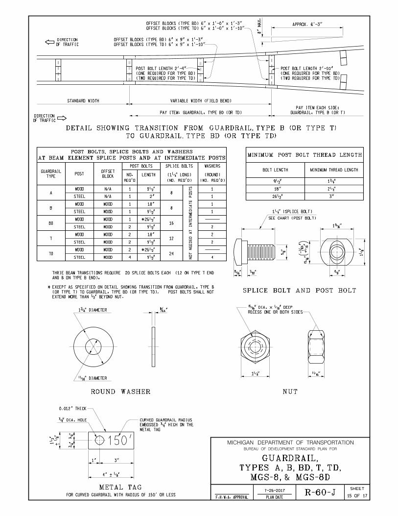
TO GUARDRAIL, TYPE BD (OR TYPE TD)
DETAIL SHOWING TRANSITION FROM GUARDRAIL, TYPE B (OR TYPE T)
SPLICE BOLT AND POST BOLT
MINIMUM POST BOLT THREAD LENGTHAT BEAM ELEMENT SPLICE POSTS AND AT INTERMEDIATE POSTS
POST BOLTS, SPLICE BOLTS AND WASHERS
)
150'
METAL TAG
ROUND WASHER NUT
STANDARD WIDTH VARIABLE WIDTH (FIELD BEND)
8"
MA
X.
OF TRAFFIC
DIRECTION
OF TRAFFIC
DIRECTION
(TWO REQUIRED FOR TYPE TD)
(ONE REQUIRED FOR TYPE BD)
POST BOLT LENGTH 2'-10"
PAY ITEM: GUARDRAIL, TYPE BD (OR TD) GUARDRAIL, TYPE B (OR T)
PAY ITEM EACH SIDE:
APPROX. 6'-3"OFFSET BLOCKS (TYPE TD) 6" x 1'-0" x 1'-10"
OFFSET BLOCKS (TYPE BD) 6" x 1'-0" x 1'-3"
OFFSET BLOCKS (TYPE TD) 6" x 9" x 1'-10"
OFFSET BLOCKS (TYPE BD) 6" x 9" x 1'-3"
(TWO REQUIRED FOR TYPE TD)
(ONE REQUIRED FOR TYPE BD)
POST BOLT LENGTH 2'-4"
BOLT LENGTH MINIMUM THREAD LENGTH
18"
26•" 3"
9•" 1ƒ"
2•"
POSTBLOCK
OFFSET
POST BOLTS
NO. LENGTH
SPLICE BOLTS WASHERS
WOOD
WOOD
STEEL
STEEL
WOOD
STEEL
WOOD
STEEL
WOOD
STEEL
(ROUND)
NO
T
NE
ED
ED
AT I
NT
ER
ME
DI
AT
E
PO
ST
S
WOOD
WOOD
WOOD
WOOD
WOOD
WOOD
WOOD
WOOD
A
B
BD
T
TD
1
1
1
1
1
2
2
2
2
4
8
8
16
12
24
1
1
1
2
2
4
1
2
*
REQ'D (NO. REQ'D)(NO. REQ'D)
TYPE
GUARDRAIL
N/A
N/A
26•"
9•"
18"
2"
9•"
9•"
9•"
9•"
* 26•"
18"
(1‚" LONG)
EXTEND MORE THAN •" BEYOND NUT.
(OR TYPE T) TO GUARDRAIL, TYPE BD (OR TYPE TD). POST BOLTS SHALL NOT
* EXCEPT AS SPECIFIED ON DETAIL SHOWING TRANSITION FROM GUARDRAIL, TYPE B
AND 8 ON TYPE B END).
THRIE BEAM TRANSITIONS REQUIRE 20 SPLICE BOLTS EACH (12 0N TYPE T END
1‚" (SPLICE BOLT)
SEE CHART (POST BOLT)
1Š"
†"
“"Š"
•"
+ˆ
"
-
"
1„
"
†"
RECESS ONE OR BOTH SIDES
•" DIA. x ˆ" DEEP¤"1ƒ" DIAMETER
•" DIAMETER
1‚" •"
0.012" THICK
ƒ" DIA. HOLE
+ „
"
1•
" ƒ"
ƒ"
1" 3"
4" + „"
METAL TAG
EMBOSSED ƒ" HIGH ON THE
CURVED GUARDRAIL RADIUS
FOR CURVED GUARDRAIL WITH RADIUS OF 150' OR LESS 1715R-60-J
MICHIGAN DEPARTMENT OF TRANSPORTATION
OF
SHEET
PLAN DATEF.H.W.A. APPROVAL
BUREAU OF DEVELOPMENT STANDARD PLAN FOR
MGS-8, & MGS-8D
TYPES A, B, BD, T, TD,
GUARDRAIL,
7-26-2017

MINIMUM POST BOLT THREAD LENGTHAT BEAM ELEMENT SPLICE POSTS AND AT INTERMEDIATE POSTS
POST BOLTS, SPLICE BOLTS AND WASHERS
STANDARD WIDTH VARIABLE WIDTH (FIELD BEND)
8"
MA
X.
OF TRAFFIC
DIRECTION
OF TRAFFIC
DIRECTION
APPROX. 6'-3"
BOLT LENGTH MINIMUM THREAD LENGTH
18"
26•" 3"
9•" 1ƒ"
2•"
POSTBLOCK
OFFSET
POST BOLTS
NO. LENGTH
SPLICE BOLTS WASHERS
(ROUND)
REQ'D (NO. REQ'D)(NO. REQ'D)
TYPE
GUARDRAIL(1‚" LONG)
WOOD
STEEL
WOOD
WOOD
1
216
2
* 26•"
9•"MGS-8D
WOOD
STEEL
WOOD
WOOD
1
18
1
1
9•"
18"MGS-8
1716
MICHIGAN DEPARTMENT OF TRANSPORTATION
OF
SHEET
PLAN DATEF.H.W.A. APPROVAL
BUREAU OF DEVELOPMENT STANDARD PLAN FOR
R-60-J
PAY ITEM: GUARDRAIL, TYPE MGS-8D
GUARDRAIL, TYPE MGS-8 TO GUARDRAIL, TYPE MGS-8D
DETAIL SHOWING TRANSITION FROM
OFFSET BLOCKS (TYPE MGS-8D) 6" x 1'-0" x 1'-2"
OFFSET BLOCKS (TYPE MGS-8D) 6" x 9" x 1'-2"
2'-4" FOR TYPE MGS-8D
POST BOLT LENGTH
2'-10" FOR TYPE MGS-8D
POST BOLT LENGTH
GUARDRAIL, TYPE MGS-8
PAY ITEM EACH SIDE:
NUT.
TO GUARDRAIL, TYPE MGS-8D POST BOLTS SHALL NOT EXTEND MORE THAN •" BEYOND
* EXCEPT AS SPECIFIED ON DETAIL SHOWING TRANSITION FROM GUARDRAIL, TYPE MGS-8
ON TYPE MGS END).
THRIE BEAM TRANSITIONS REQUIRE 20 SPLICE BOLTS EACH (12 0N TYPE T END AND 8
MGS-8, & MGS-8D
TYPES A, B, BD, T, TD,
GUARDRAIL,
7-26-2017

OF TRAFFIC
DIRECTION
PLACEMENT OF GUARDRAIL REFLECTORS
ONE-WAY TRAFFIC
TWO-WAY TRAFFIC
GUARDRAIL
NOTES GOVERNING THE USE OF GUARDRAIL REFLECTORS
GUARDRAIL REFLECTOR
DIRECTION OF RAIL LAP
TWO-WAY TRAFFIC
ONE-WAY TRAFFIC
3"
2"
ƒ"•
"
(TYP.)
REFLECTORIZED SIDE FACING TRAFFIC
13 GAGE GALVANIZED
(0.0934") NOMINAL
2ƒ"
5"
‚" R
1•
"96° + 4°
OF TRAFFIC
DIRECTION
OF TRAFFIC
DIRECTION
OF TRAFFIC
DIRECTION
OF TRAFFIC
DIRECTION
TRAFFIC
SURFACE FACING
REFLECTORIZED GUARDRAILSEE NOTES BELOW
OF TRAFFIC
DIRECTION
GUARDRAIL
SEE NOTES BELOW
ADJACENT GUARDRAIL POSTS
IN OPPOSITE DIRECTIONS ON
PLACE GUARDRAIL REFLECTORS
OF TRAFFIC
DIRECTION
OF TRAFFIC
DIRECTION
GUARDRAIL
HEIGHT AND COMPATIBILITY WITH POST HOLES.
THE POST BOLT HOLES SHALL BE LOCATED TO ENSURE PROPER RAIL
DEPTH OF THE BLOCK SHALL BE AS SPECIFIED ON THIS STANDARD AND
BEVELS SPECIFIED. THE LENGTH (FRONT AND BACK FACE), WIDTH AND
A 1" BEVELED TOP MAY BE USED IN LIEU OF WOOD BLOCKS WITHOUT
WOOD OFFSET BLOCKS WITH •" BEVELS AT THE TOP AND BOTTOM OR
HEIGHT.
THE POST BOLT HOLES SHALL BE LOCATED TO ENSURE PROPER RAIL
DEPTH OF THE POST SHALL BE AS SPECIFIED ON THIS STANDARD AND
WOOD POSTS WITHOUT BEVELS SPECIFIED. THE LENGTH, WIDTH AND
WOOD POSTS WITH •" BEVELS AT THE TOP MAY BE USED IN LIEU OF
BENT SECTION WILL BE REQUIRED FOR EACH CURVED ELEMENT.
150' OR LESS. A TAG IDENTIFYING THE CURVATURE OF THE SHOP
BEAM ELEMENTS SHALL BE SHOP BENT TO PLAN RADIUS FOR CURVE RADII
GUARDRAIL.
SHOULD BE MEASURED FROM THE GROUND JUST IN FRONT OF THE
THE GUARDRAIL PANEL IS LOCATED BEHIND THE CURB THE RAIL HEIGHT
CLOSEST TO THE EDGE OF THE TRAVELED LANE. WHEN THE FACE OF
GUTTER PAN, WHICH IS THE POINT ON THE GUTTER PAN THAT IS
THE RAIL HEIGHT SHOULD BE MEASURED FROM THE FRONT EDGE OF THE
WHEN THE FACE OF GUARDRAIL IS PLACED FLUSH WITH FACE OF CURB,
GUIDE TO STANDARDIZED HIGHWAY BARRIER HARDWARE."
AGC-ARTBA JOINT COMMITTEE, TASK FORCE 13 PUBLICATION TITLED "A
DETAILS SPECIFIED ON THIS STANDARD ARE ACCORDING TO THE AASHTO-
NOTES:
GUARDRAIL ANCHORAGE, BRIDGE.
GUARDRAIL DEPARTING TERMINALS AND STANDARD PLAN R-67-SERIES FOR
GUARDRAIL APPROACH TERMINALS, STANDARD PLAN R-66-SERIES FOR
SEE STANDARD PLAN R-61-SERIES, R-62-SERIES OR R-63-SERIES FOR
1717
MICHIGAN DEPARTMENT OF TRANSPORTATION
OF
SHEET
PLAN DATEF.H.W.A. APPROVAL
BUREAU OF DEVELOPMENT STANDARD PLAN FOR
R-60-J
BY THE ENGINEER.)
REASONABLY LEVEL BEYOND THE SHOULDER HINGE POINT, AS DETERMINED
EMBEDDED FOR ADDED STABILITY. (NOT NECESSARY WHEN THE SLOPE IS
PLAN, 8'-0" POSTS SHALL BE PROVIDED, WITH THE ADDITIONAL LENGTH
THE SHOULDER HINGE POINT, RATHER THAN AS SPECIFIED ON THIS
WHEN THE PLANS SPECIFY GUARDRAIL (TYPE B OR T) TO BE PLACED ON
REGARDLESS OF ROADWAY LIGHTING.
1. GUARDRAIL REFLECTORS SHALL BE USED ON ALL STANDARD GUARDRAIL RUNS,
b) 25'-0" ON CURVES WITH A RADIUS LESS THAN 1150'.
1150' OR MORE.
a) 5O'-0" ON TANGENT SECTIONS AND CURVES WITH A RADIUS OF
2. GUARDRAIL REFLECTORS ARE TO BE SPACED AT THE FOLLOWING INTERVALS:
APPROPRIATE GUARDRAIL APPROACH TERMINAL STANDARD PLAN.
3. FOR GUARDRAIL REFLECTOR PLACEMENT ON APPROACH TERMINALS, SEE THE
GUARDRAIL DEPARTING TERMINAL.
4. A GUARDRAIL REFLECTOR IS TO BE PLACED ON THE SECOND POST FROM THE
PLACED ON THE UPPER POST BOLT.
5. ON GUARDRAIL, TYPE T AND TYPE TD GUARDRAIL REFLECTORS ARE TO BE
6. GUARDRAIL REFLECTORS SHALL MATCH COLOR OF EDGE LINE.
BY THE ENGINEER.)
REASONABLY LEVEL BEYOND THE SHOULDER HINGE POINT, AS DETERMINED
EMBEDDED FOR ADDED STABILITY. (NOT NECESSARY WHEN THE SLOPE IS
9'-0" POSTS SHALL BE PROVIDED, WITH THE ADDITIONAL LENGTH
SHOULDER HINGE POINT, RATHER THAN AS SPECIFIED ON THIS PLAN,
WHEN THE PLANS SPECIFY GUARDRAIL TYPE MGS-8 TO BE PLACED ON THE
MGS-8, & MGS-8D
TYPES A, B, BD, T, TD,
GUARDRAIL,
7-26-2017

DEPARTMENT DIRECTOR MICHIGAN DEPARTMENT OF TRANSPORTATION
OF
SHEET
PLAN DATEF.H.W.A. APPROVALCHECKED BY:
DRAWN BY:
Michigan Department of Transportation
BUREAU OF DEVELOPMENT STANDARD PLAN FOR
APPROVED BY:
APPROVED BY:
Kirk T. Steudle
BY
PREPARED
DESIGN DIVISION
DIRECTOR, BUREAU OF FIELD SERVICES
DIRECTOR, BUREAU OF DEVELOPMENT
RAILING
BRIDGE BARRIER
E3 JOINT
PO
ST 6
PO
ST 5
PO
ST 4
PO
ST 3
PO
ST 2
PO
ST 1
PLAN VIEW
15"
(4 SPACES) (3 SPACES)
3'-1•" POST SPACING
GUARDRAIL ANCHORAGE, BRIDGE, DETAIL T-1 (SEE NOTES, SHEET 7 OF 7)
25'-0"
10'-7•"
POST SPACING
6'-3"
3'-6" POST SPACING
1'-6ƒ"
ELEVATION VIEW
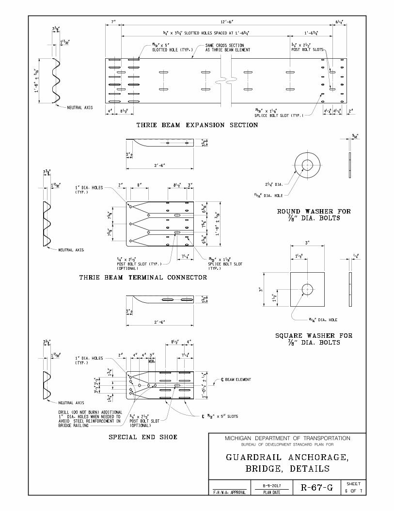
THRIE BEAM EXPANSION SECTION
BRIDGE BARRIER RAILING
THRIE BEAM TERMINAL CONNECTOR
34"
15"
(4 SPACES) (3 SPACES)
3'-1•" POST SPACING 6'-3" POST SPACING
(2 SPACES)
TRANSITION
THRIE BEAM
6'-3" TYPICAL POST SPACING
GUARDRAIL ANCHORAGE, BRIDGE, DETAIL T-2 (SEE NOTES, SHEET 7 OF 7)
3'-6" POST SPACING
1'-6ƒ"
31'-3"
10'-7•"
34"
28"33"
THRIE BEAM EXPANSION SECTIONTHRIE BEAM TERMINAL CONNECTOR
BRIDGE BARRIER RAILING
ELEVATION VIEW
(TO BE USED WITH GUARDRAIL, TYPE B)
(WITHOUT EXPANSION AT BACKWALL)
71R-67-G
BRIDGE, DETAILS
GUARDRAIL ANCHORAGE,
6'-3" TYPICAL POST SPACING
GUARDRAIL, TYPE T
GUARDRAIL, TYPE B
GUARDRAIL, TYPE MGS-8 *
INFORMATION)
FOR TYPE MGS-8 GUARDRAIL HEIGHT
(SEE STANDARD PLAN R-60-SERIES
34" TYPE T
(TO BE USED WITH GUARDRAIL, TYPE T & TYPE MGS-8)
ANCHORAGE, BRIDGE DETAILS T-1, T-4 & T-6
FROM GUARDRAIL, TYPE MGS-8 TO GUARDRAIL
SPACING AND GUARDRAIL LAYOUT TO TRANSITION
* SEE STANDARD PLAN R-60-SERIES FOR POST
AESTHETIC PARAPET TUBE, OR 3 TUBE WITH PICKETS
BRIDGE BARRIER RAILINGS, TYPE 4, 2-TUBE, 4-TUBE,
DETAILS FOR CONNECTING GUARDRAIL TO
8-9-2017

MICHIGAN DEPARTMENT OF TRANSPORTATION
OF
SHEET
PLAN DATEF.H.W.A. APPROVAL
BUREAU OF DEVELOPMENT STANDARD PLAN FOR
PO
ST 1
PO
ST 2
PO
ST 3
PO
ST 4
PO
ST 5
PO
ST 6
RAILING, TYPE 5
BRIDGE BARRIER
PLAN VIEW
E3 JOINT
(4 SPACES) (3 SPACES)
3'-1•" POST SPACING
TRANSITION
THRIE BEAM
(SEE NOTES, SHEET 7 OF 7)
GUARDRAIL ANCHORAGE, BRIDGE, DETAIL T-4
18'-9"
3'-6" POST SPACING
1'-6ƒ"
15"
ELEVATION VIEW
SPECIAL END SHOE
BRIDGE BARRIER RAILING, TYPE 5
30"
(WITHOUT EXPANSION AT BACKWALL)
DETAILS FOR CONNECTING GUARDRAIL TO BRIDGE BARRIER RAILINGS, TYPE 5
(TO BE USED WITH GUARDRAIL, TYPE B)
ELEVATION VIEW
33"
34"
BRIDGE BARRIER RAILING, TYPE 5
SPECIAL END SHOE
30"
(4 SPACES) (3 SPACES)
3'-1•" POST SPACING 6'-3" POST SPACING
(2 SPACES)
TRANSITION
THRIE BEAM
TRANSITION
THRIE BEAM
6'-3" TYPICAL POST SPACING
GUARDRAIL ANCHORAGE, BRIDGE, DETAIL T-3 (SEE NOTES, SHEET 7 OF 7)
37'-6"
3'-6" POST SPACING
1'-6ƒ"
15"
28"
72R-67-G
BRIDGE, DETAILS
GUARDRAIL ANCHORAGE,
6'-3" TYPICAL POST SPACING
GUARDRAIL, TYPE T
GUARDRAIL, TYPE B
GUARDRAIL, TYPE MGS-8 *
ANCHORAGE, BRIDGE DETAILS T-1, T-4 & T-6
FROM GUARDRAIL, TYPE MGS-8 TO GUARDRAIL
SPACING AND GUARDRAIL LAYOUT TO TRANSITION
* SEE STANDARD PLAN R-60-SERIES FOR POST
INFORMATION)
FOR TYPE MGS-8 GUARDRAIL HEIGHT
(SEE STANDARD PLAN R-60-SERIES
34" TYPE T
(TO BE USED WITH GUARDRAIL, TYPE T & TYPE MGS-8)
8-9-2017

MICHIGAN DEPARTMENT OF TRANSPORTATION
OF
SHEET
PLAN DATEF.H.W.A. APPROVAL
BUREAU OF DEVELOPMENT STANDARD PLAN FOR
PO
ST 1
PO
ST 2
PO
ST 3
PO
ST 4
PO
ST 5
PO
ST 6
RAILING, TYPE 4
BRIDGE BARRIER
PLAN VIEW
E3 JOINTEXPANSION JOINT
BRIDGE
(WITH EXPANSION AT BACKWALL)
(TO BE USED WITH GUARDRAIL, TYPE B)
ELEVATION VIEW
THRIE BEAM EXPANSION SECTION
34"
THRIE BEAM TERMINAL CONNECTOR
BRIDGE BARRIER RAILING, TYPE 4
34"
32"
16"
(4 SPACES) (4 SPACES)
3'- 1•" POST SPACING
MAX (2 SPACES)
6'-3" POST SPACING
TRANSITION
THRIE BEAM
GUARDRAIL ANCHORAGE, BRIDGE, DETAIL T-5 (SEE NOTES, SHEET 7 OF 7)
6'-3" TYPICAL POST SPACING
43'-9"
7'-10•" 6'-3" 12'-6"
3'-6"
MIN.
POST SPACING
1'-6ƒ"
ELEVATION VIEW
THRIE BEAM EXPANSION SECTIONTHRIE BEAM TERMINAL CONNECTOR
BRIDGE BARRIER RAILING, TYPE 4
34"
16"
(4 SPACES) (4 SPACES)
3'-1•" POST SPACING
MAX
GUARDRAIL ANCHORAGE, BRIDGE, DETAIL T-1 (SEE NOTES, SHEET 7 OF 7)
25'-0"
7'-10•" 6'-3" 12'-6"
POST SPACING
1'-6ƒ"
3'-6"
MIN.
28"
73R-67-G
BRIDGE, DETAILS
GUARDRAIL ANCHORAGE,
GUARDRAIL, TYPE B
6'-3" TYPICAL POST SPACING
GUARDRAIL, TYPE T
(TO BE USED WITH GUARDRAIL, TYPE T & TYPE MGS-8)
GUARDRAIL, TYPE MGS-8 *
ANCHORAGE, BRIDGE DETAILS T-1, T-4 & T-6
FROM GUARDRAIL, TYPE MGS-8 TO GUARDRAIL
SPACING AND GUARDRAIL LAYOUT TO TRANSITION
* SEE STANDARD PLAN R-60-SERIES FOR POST
INFORMATION)
FOR TYPE MGS-8 GUARDRAIL HEIGHT
(SEE STANDARD PLAN R-60-SERIES
34" TYPE T
AESTHETIC PARAPET TUBE, OR 3 TUBE WITH PICKETS
BRIDGE BARRIER RAILINGS, TYPE 4, 2-TUBE, 4-TUBE,
DETAILS FOR CONNECTING GUARDRAIL TO
8-9-2017

MICHIGAN DEPARTMENT OF TRANSPORTATION
OF
SHEET
PLAN DATEF.H.W.A. APPROVAL
BUREAU OF DEVELOPMENT STANDARD PLAN FOR
DETAILS FOR CONNECTING GUARDRAIL TO FILLER WALLS
ELEVATION VIEW
ELEVATION VIEW
PLAN VIEW
APPROACH POST SPACING REQUIREMENTS
5
4
BOLTS TO FIRST POST
DISTANCE FROM ANCHOR7'-11ƒ" 11'-1‚"
4
4
5
3
4
3
POST SPACINGS
NUMBER OF 1'-6ƒ"
POST SPACINGS
NUMBER OF 3'-1•"
9'-6•" 12'-8"
FILLER WALL END BLOCK
PIER
BRIDGE
DEPTH 1'-3" FROM BRIDGE PIER.
POST CAN BE INSTALLED FULL
OMITTED WHEN FIRST ANCHORAGE
NOTE: FILLER WALL END BLOCK MAY BE
AND FILLER WALLS, SHEET 5 OF 7)
REQUIREMENTS FOR CONNECTING GUARDRAIL TO BRIDGE RAILINGS
INSTALL BOLTS THROUGH FILLER WALL (SEE CHART FOR BOLT
FIRST POST
BLOCKS LESS THAN 3'-0" LONG)
NOT REQUIRED FOR FILLER WALL END
ROUND WASHERS ON BACK (BOLTS ARE
POST BOLT WASHERS ON FRONT AND
TWO †" DIA. x 14" POST BOLTS WITH CONNECTOR
TERMINAL
THRIE BEAM
34"
PIER
BRIDGE
15"
3'-1•" POST SPACING
(4 OR 5 SPACES) (3 OR 4 SPACES)
3'-1•"
SEE APPROACH POST SPACING REQUIREMENTS CHART
GUARDRAIL ANCHORAGE, BRIDGE, DETAIL T-6 (SEE NOTES, SHEET 7 OF 7)
MIN.
1'-6"
37'-6"
POST SPACING
1'-6ƒ"
15" 3'- 1•" POST SPACING
TRANSITION
THRIE BEAM
(4 OR 5 SPACES) (3 OR 4 SPACES)
SEE APPROACH POST SPACING REQUIREMENTS CHART 6'-3" TYPICAL POST SPACING
GUARDRAIL ANCHORAGE, BRIDGE, DETAIL T-5 (SEE NOTES, SHEET 7 OF 7)
MIN.
POST SPACING
1'-6ƒ"
1'-6"
43'-9"
PIER
BRIDGE
32"
CONNECTOR
TERMINAL
THRIE BEAM
(TO BE USED WITH GUARDRAIL, TYPE B)
ELEMENT AS SHOWN ABOVE.
3'-0" OR LONGER, BOLT BEAM
WHEN FILLER WALL END BLOCK IS
FIRST POST
32"
28"
74R-67-G
BRIDGE, DETAILS
GUARDRAIL ANCHORAGE,
GUARDRAIL, TYPE B
6'-3" TYPICAL POST SPACING
GUARDRAIL, TYPE T
6'-3" POST SPACING
(2 SPACES)
ANCHORAGE, BRIDGE DETAILS T-1, T-4 & T-6
FROM GUARDRAIL, TYPE MGS-8 TO GUARDRAIL
SPACING AND GUARDRAIL LAYOUT TO TRANSITION
* SEE STANDARD PLAN R-60-SERIES FOR POST
GUARDRAIL, TYPE MGS-8 *
INFORMATION)
FOR TYPE MGS-8 GUARDRAIL HEIGHT
(SEE STANDARD PLAN R-60-SERIES
34" TYPE T
(TO BE USED WITH GUARDRAIL, TYPE T & TYPE MGS-8)
8-9-2017

MICHIGAN DEPARTMENT OF TRANSPORTATION
OF
SHEET
PLAN DATEF.H.W.A. APPROVAL
BUREAU OF DEVELOPMENT STANDARD PLAN FOR
RAILING TYPE 4
BRIDGE BARRIER
RAILING TYPE 5
BRIDGE BARRIER
AESTHETIC PARAPET TUBE
2 TUBE, 4 TUBE, OR
BRIDGE RAILING,
SECTIONS AT BRIDGE RAILINGS
AESTHETIC PARAPET TUBE
BRIDGE RAILING, 4 TUBE OR
POST 3
RAILING, TYPE 5
BRIDGE BARRIER
POST 2 FOR
RAILING, TYPE 4
BRIDGE BARRIER
POST 2 FOR
RAILING, TYPE 5
BRIDGE BARRIER
POST 1 FOR
RAILING, TYPE 4
BRIDGE BARRIER
POST 1 FOR
POST 4 POST 5 POST 6
GUARDRAIL POST SECTIONS FOR GUARDRAIL ANCHORAGE, BRIDGE
GUARDRAIL TO BRIDGE RAILINGS & FILLER WALLS
BOLT REQUIREMENTS FOR CONNECTING
NUMBER REQUIRED.) WASHER DETAILS ARE SHOWN ON SHEET 6 OF 7.
AND SQUARE WASHERS ON BACK. (SEE CHART BELOW FOR LENGTHS AND
CONNECT GUARDRAIL TO BRIDGE RAILINGS WITH ROUND WASHERS ON FRONT
HIGH STRENGTH ‡" DIA. HEX HEAD BOLT AND NUTS SHALL BE USED TO
34"
(ROADWAY)
TOP OF SLAB
(ROADWAY)
TOP OF SLAB
30"
(ROADWAY)
TOP OF SLAB
34"
AESTHETIC PARAPET TUBE
4 TUBE, DOES NOT APPLY TO
7" FOR 2 TUBE, 9" FOR
34"
OR SIDEWALK
TOP OF CURB
AESTHETIC PARAPET TUBE
4 TUBE, DOES NOT APPLY TO
9" OR LESS FOR 2 TUBE AND
VARIABLE
(ROADWAY)
TOP OF SLAB
(WITH SIDEWALK)
(WITHOUT SIDEWALK OR BRUSH BLOCK)
6•"6•" 7‚"
8"8"
8" 8" 8"
6" 7"
1'-1
0"
3" 3"
1'-6" 3
Ž"
2†" 2†"
5…
"
1'-8"
2‚"
7•" 8"8"
8"
34"
1"1•"1‡"
NOTE: ADHESIVE ANCHORS SHALL BE SELECTED FROM THE QUALIFIED PRODUCTS LIST OF THE MATERIALS SAMPLING GUIDE.
SHALL BE AS SHOWN IN ELEVATION VIEWS.
BRIDGE RAILINGS SHALL BE THE SAME AS THAT SHOWN ON POST 6. POST SPACING
POST AND BLOCK SECTIONS FOR THE 2 TUBE, 4 TUBE, AND AESTHETIC PARAPET TUBE
NOTE:
TYPE 4
TYPE 5
2 TUBE
4 TUBE
FILLER WALL**
5
4
5
5
5
3. WHEN CONDITIONS PROHIBIT THE USE OF BOLTS.
**
BRIDGE RAILING BOLT LENGTHTHREAD LENGTH
MINIMUM
REQUIRED
NUMBER
THICKNESS THAN THE FILLER WALL EXTENSION.
1. AT OR NEAR THE JOINT LINE WHEN A FILLER WALL IS A DIFFERENT
WALL THICKNESS + 2"
WALL THICKNESS + 2"
WALL THICKNESS + 2"
‚" BEYOND THE NUT WHEN TIGHTENED.
SHORTER BOLT LENGTHS MAY BE USED PROVIDED THE BOLT EXTENDS
4"
4"
2"
2"
2"
2. IN EXISTING FILLER WALLS THICKER THAN 1'-6".
11•"
12•"
THROUGH THE FILLER WALL, IN THE FOLLOWING LOCATIONS:
GUARDRAIL TO FILLER WALLS WILL BE ALLOWED, INSTEAD OF BOLTING
THE USE OF ‡" DIA. ADHESIVE ANCHORED BOLTS EMBEDDED 8" TO ATTACH
AESTHETIC PARAPET
WALL THICKNESS + 2" 2" 5
75R-67-G
BRIDGE, DETAILS
GUARDRAIL ANCHORAGE,
8-9-2017
MICHIGAN DEPARTMENT OF TRANSPORTATION
OF
SHEET
PLAN DATEF.H.W.A. APPROVAL
BUREAU OF DEVELOPMENT STANDARD PLAN FOR
3…"
1˜"
1'-8"
+
‰"
NEUTRAL AXIS8•"
THRIE BEAM EXPANSION SECTION
4"
SPLICE BOLT SLOT (TYP.)
x 1„" 4‚" 4‚" 2"
6‚"
1'-6ƒ"
AS THRIE BEAM ELEMENT
SAME CROSS SECTION
POST BOLT SLOTS
ƒ" x 2•"
7" 12'-6"
ƒ" x 3ƒ" SLOTTED HOLES SPACED AT 1'-6ƒ"
SLOTTED HOLE (TYP.)
x 5"
‡" DIA. BOLTS
ROUND WASHER FOR
•" DIA. HOLE
2‚" DIA.
’"
‡" DIA. BOLTS
SQUARE WASHER FOR
•" DIA. HOLE
‚"
3"
1•"
3"
1•
"
SPECIAL END SHOE
\ BEAM ELEMENT
\ x 5" SLOTS
3"+
2"
8•"
7‚"3"
MIN.
3…"
2'-6"
4"4"
(TYP.)
1" DIA. HOLES1˜"
4"
3…
"
BRIDGE RAILING
AVOID STEEL REINFORCEMENT IN
1" DIA. HOLES WHEN NEEDED TO
DRILL (DO NOT BURN) ADDITIONAL
1ƒ
"
3•
"3•
"
1ƒ
"
NEUTRAL AXIS
(OPTIONAL)
POST BOLT SLOT
ƒ" x 2•"
1'-0‚
"
+ ‚
"
THRIE BEAM TERMINAL CONNECTOR
7†
"6
‰"
6‰
"
(TYP.)
SPLICE BOLT SLOT
x 1„"
1'-8"
+
‰"
3…
"
3"+
3"8•"2"
(TYP.)
1" DIA. HOLES8"
2'-6"
7†
"7
†"
3…"
1˜"
NEUTRAL AXIS
(OPTIONAL)
POST BOLT SLOT (TYP.)
ƒ" x 2•"7‚"
76R-67-G
BRIDGE, DETAILS
GUARDRAIL ANCHORAGE,
8-9-2017

MICHIGAN DEPARTMENT OF TRANSPORTATION
OF
SHEET
PLAN DATEF.H.W.A. APPROVAL
BUREAU OF DEVELOPMENT STANDARD PLAN FOR
77R-67-G
BRIDGE SPANS A BRIDGE EXPANSION JOINT.
SEE APPROPRIATE PLANS TO DETERMINE WHETHER GUARDRAIL ANCHORAGE,
FILLER WALL END BLOCK.
SEE THE CURRENT STANDARD PLAN R-55-SERIES FOR FILLER WALLS AND
SECTION.
THE ž" x 5" LONG SLOTTED HOLES IN THE THRIE BEAM EXPANSION
REQUIRE THAT THE THRIE BEAM TERMINAL CONNECTOR BE ATTACHED TO
GUARDRAIL ANCHORAGE, BRIDGE, DETAILS T-1, T-2, T-5, AND T-6
GUTTER AND DOWNSPOUT HEADER.
SEE THE CURRENT STANDARD PLAN R-32-SERIES FOR APPROACH CURB AND
CENTER PUNCH OR COLD CHISEL, SO THAT IT WILL NOT LOOSEN.
UPSETTING THE FIRST THREAD ON THE OUTSIDE OF THE NUT WITH A
THREAD EXTENDING BEYOND THE NUT. THIS SHALL BE FOLLOWED UP BY
AND SHALL FULLY ENGAGE THE SPLICE BOLT WITH A MINIMUM OF ONE
SECTION. THE SPLICE BOLT NUT SHALL BE INSTALLED FINGER-TIGHT
AND WHEN SPLICING THE SPECIAL END SHOE TO THE TRANSITION
BEAM TERMINAL CONNECTOR TO THE THRIE BEAM EXPANSION SECTION
STANDARD SPLICE BOLTS SHALL BE USED WHEN SPLICING THE THRIE
BE LAPPED IN EITHER DIRECTION.
TRAFFIC, EXCEPT FOR THE THRIE BEAM TERMINAL CONNECTOR WHICH MAY
GUARDRAIL BEAM ELEMENTS SHALL BE LAPPED IN THE DIRECTION OF
USE IN ANCHORAGE SHALL BE FIELD BENT.
SECTIONS OF THE THRIE BEAM ELEMENT REQUIRED TO BE TWISTED FOR
THEY SHALL NOT BE LIGHTER THAN 10 GAGE (0.138").
BE THE SAME MATERIAL AS ADJACENT RUN OF GUARDRAIL, EXCEPT THAT
THE THRIE BEAM TERMINAL CONNECTOR AND SPECIAL END SHOE SHALL
BE 7'-0" LONG.
ALL POSTS USED TO CONSTRUCT GUARDRAIL ANCHORAGE, BRIDGE SHALL
STANDARD.
PLAN R-60-SERIES, WHERE APPLICABLE, EXCEPT AS SPECIFIED ON THIS
THE CURRENT STANDARD SPECIFICATIONS AND TO THE CURRENT STANDARD
HARDWARE, (INCLUDING BOLTS, NUTS, AND WASHERS) SHALL CONFORM TO
ALL POSTS, OFFSET BLOCKS, BEAM ELEMENTS, REFLECTORS, AND
NOTES:
BRIDGE, DETAILS
GUARDRAIL ANCHORAGE,
8-9-2017

DIVERGE MERGE
FROM THE RIGHT AND NO OFFSET IN THE THROUGH LANES
TYPICAL FOR ALL 2-LANE MERGES EXCEPT WHERE THERE IS A MERGE
TYPICAL FOR ALL 2-LANE MERGES WITH NO OFFSET IN THE THROUGH LANES
TYPICAL FOR DIVERGING ROADWAYS WHEN WIDENING IS ON BOTH SIDES
TYPICAL FOR DIVERGING ROADWAYS WHEN WIDENING IS ON RIGHT SIDE
DELINEATION OF FREEWAY TO FREEWAY CONNECTIONS
TYPICAL FOR DIVERGING ROADWAYS WHEN WIDENING IS ON LEFT SIDE
( 9' OR 10' PAVED )
DELINEATOR REFERENCE POINTS FOR NORMAL 10' SHOULDERS
B.L.T.
W.K.P. 81R-127-F
DELINEATOR INSTALLATIONS
600' < EACH SIDE
600' <
EACH SIDE
BOTH ROADWAYS DELINEATOR REFERENCE POINT END OF MERGE LANE TAPER
END OF MERGE LANE TAPER
DELINEATOR REFERENCE POINTEND OF MERGE LANE TAPER
OF RAMP AND R
IGHT SIDE
OF TANGENT S
ECTION
DELINEATOR REFERENCE POINT
SPACING200'
TYP.BOTH ROADWAYS
DIVERGE LANE TAPER
BEGINNING OF
DIVERGE LANE TAPER
BEGINNING OF
DIVERGE LANE TAPER
BEGINNING OF
DELINEATOR REFERENCE POINT
SPACING
200' TYP.
BOTH ROADWAYS
SPACING200' TYP.
BOTH ROADWAYSDELINEATOR REFERENCE POINT
WIDTH
SHOULDER
PAVED
SHOULDER
WIDTH
SHOULDER
PAVED
SHOULDER
AREA
SHOULDER
PAVED
AREA
SHOULDER
PAVED
* DELINEATOR REFERENCE POINT DELINEATOR REFERENCE POINT
SHOULDER WIDTH
PAVED
SHOULDER WIDTH
PAVED
*
22'
*
12'
8'
*
12'
8'
*
22'
DIVERGE LANE TAPER
BEGINNING OF
EACH SIDE600'
<
EACH SIDE
600' *
EACH SIDE600' *
WILL BE INCREASED TO 24'.
THE WIDTH OF THE PAVED GORE
FROM THE EDGE OF TRAVELED WAY.
IS 12', PLACE DELINEATOR 14'
WHEN THE PAVED SHOULDER WIDTH
TRAVELED WAY
EDGE OF
EDGE OF TRAVELED WAY
TRAVELED WAY
EDGE OF
DEPARTMENT DIRECTOR MICHIGAN DEPARTMENT OF TRANSPORTATION
OF
SHEET
PLAN DATEF.H.W.A. APPROVALCHECKED BY:
DRAWN BY:
Michigan Department of Transportation
DIRECTOR, BUREAU OF DEVELOPMENT
BUREAU OF DEVELOPMENT STANDARD PLAN FOR
DIRECTOR, BUREAU OF FIELD SERVICES
APPROVED BY:
APPROVED BY:
Kirk T. Steudle
BY
PREPARED
DESIGN DIVISION
200' TYPICAL SPACING (YELLOW DELINEATORS)
200' TYPICAL SPACING (YELLOW DELINEATORS)
200' TYPICAL SPACING (WHITE DELINEATORS)
WHITE SHEETING DELINEATOR
YELLOW SHEETING DELINEATOR
8-8-2017

INTERCHANGE DELINEATION
82R-127-F
DELINEATOR INSTALLATIONS
END OF ACCELERATION LANE TAPER
DELINEATOR REFERENCE POINT
BEGINNING OF DECELERATION LANE TAPER
DELINEATOR REFERENCE POINT
REFERENCE POINT
DELINEATOR
IN
TE
RC
HA
NG
E
AR
EA
(TYPICAL)
DELINEATOR OVERLAP
SEE NOTES FOR
LANE TAPER
DECELERATION
BEGINNING OF
LANE TAPER
END OF ACCELERATION
REFERENCE POINTS
DELINEATOR
300'
MI
N.
500'
MIN.
IS LESS THAN 1000' (TYPICAL)
RIGHT-CURVING RAMP WHEN RADIUS
DELINEATORS ALSO ON THE LEFT OF
100'100'
100'
DELINEATORS AT ALL LOCATIONS
3" x 12" YELLOW SHEETING
THAN OR EQUAL TO 480', USE
WHEN THE RAMP RADIUS IS LESS
MICHIGAN DEPARTMENT OF TRANSPORTATION
OF
SHEET
PLAN DATEF.H.W.A. APPROVAL
BUREAU OF DEVELOPMENT STANDARD PLAN FOR
(BOTH SIDES OF ROADWAY)
RED ON BACK
5 DELINEATORS WITH
(BOTH SIDES OF ROADWAY)
RED ON BACK
5 DELINEATORS WITH
8-8-2017

DIVIDED HIGHWAY & MEDIAN CROSSOVER
REST AREA & WEIGH STATION
83R-127-F
DELINEATOR INSTALLATIONS
AT INTERSECTIONS
(FREEWAYS AND FREE ACCESS)
MEDIAN CROSSOVER DIRECTIONAL CROSSOVER
CURB RETURN OR SPRING POINT.
NOTE: BEGIN OR END DELINEATORS AT4 SPACES AT 100'
EN
D
OF
AC
CE
LE
RA
TI
ON
LA
NE
BE
GI
N
DELI
NE
AT
OR
REFERE
NCE P
OI
NT
DE
CE
LE
RA
TI
ON
LA
NE
DELI
NE
AT
OR
REFERE
NCE P
OI
NT
MIN. MIN.
300' 300'
DELINEATOR FACE
DELINEATOR FACERADIAL
DELINEATOR FACE
RADIAL
DELINEATOR
FACE
TANGENT
90°
90°
RURAL TWO-LANE TWO-WAY ROADWAYS (OPTIONAL)
MICHIGAN DEPARTMENT OF TRANSPORTATION
OF
SHEET
PLAN DATEF.H.W.A. APPROVAL
BUREAU OF DEVELOPMENT STANDARD PLAN FOR
AT INTERSECTIONS
4 SPACES AT 100'
FOR ONE WAY TRAFFIC
ON HORIZONTAL CURVES
DELINEATOR ORIENTATION
(BOTH SIDES OF ROADWAY)
RED ON BACK
5 DELINEATORS WITH
8-8-2017

LEGEND
DELINEATORS INSTALLED ON FLEXIBLE POSTS
DELINEATORS INSTALLED ON RIGID STEEL POSTS
THROUGH ROADWAY CURVES
DELINEATOR LOCATION ON
TWO LANE TWO WAY ROADWAY CURVES
DELINEATOR LOCATION ON
ON HORIZONTAL CURVES
SPACING OF DELINEATORS
84R-127-F
DELINEATOR INSTALLATIONS
SPACING BEYOND
(SEE CHART) (SEE CHART)
(SEE CHART)
SPACING BEYOND
SPACING IN ADVANCE
SPACING IN ADVANCE
(SEE CHART)
SPACING BEYOND(SEE CHART)
SPACING IN ADVANCE
(SEE CHART)
SPACING BEYOND
(SEE CHART) (SEE CHART)
SPACING IN ADVANCE
SPACING ON CURVE
SPACING ON CURVE
SPACING ON CURVE
(SEE CHART)
(SEE CHART)
(SEE CHART)
SPACING ON CURVE
(SEE CHART)
FOR RADII GREATER THAN 1900'
MEDIAN DELINEATORS NOT REQUIRED
NOTE:
400' MAXIMUM SPACING ON TANGENT AND CURVES WITH A RADIUS GREATER THAN 3500'
200' MAXIMUM SPACING IN INTERCHANGE AREAS
100' MAXIMUM SPACING ON INTERCHANGE RAMPS
200' MAXIMUM SPACING IN MERGE OR DIVERGE AREAS OF MAJOR ROADWAYS
100' MAXIMUM SPACING ON INTERCHANGE RAMPS
200' MAXIMUM SPACING IN INTERCHANGE AREAS
100' MAXIMUM SPACING ON INTERCHANGE RAMPS
200' MAXIMUM SPACING IN MERGE OR DIVERGE AREAS OF MAJOR ROADWAYS
100' MAXIMUM SPACING ON INTERCHANGE RAMPS
3,500 175 300 300 300
3,000 160 300 300 300
2,865 160 300 300 300
2,500 150 300 300 300
2,000 130 260 300 300
1,910 130 260 300 300
1,800 125 250 300 300
1,600 120 240 300 300
1,435 110 220 300 300
1,400 110 220 300 300
1,150 100 200 300 300
1,000 90 180 270 300
820 80 160 240 300
800 80 160 240 300
640 75 150 225 300
600 70 140 210 300
500 65 130 195 300
480 60 120 180 300
385 55 110 165 300
300 50 100 150 300
275 45 90 135 270
230 40 80 120 240
195 35 70 105 210
145 30 60 90 180
100 20 40 60 120
(FEET)
RADIUS
(FEET)
ON CURVE
SPACING
(NOT TO EXCEED 300')
(FEET)
AND BEYOND CURVE
SPACING IN ADVANCE
(2 x "S")
1ST SPACE
(3 x "S")
2ND SPACE
(6 x "S")
3RD SPACE
("R") ("S")
THE CURVE IN FEET.
S = 3 R - 50 WHERE "R" IS THE RADIUS OF
THE SPACING "S" IS FOUND USING THE FORMULA
WHITE DELINEATORS:
YELLOW DELINEATORS:
BACK TO BACK WHITE DELINEATORS:
RED DELINEATORS ON BACK OF WHITE DELINEATORS
RED DELINEATORS ON BACK OF YELLOW DELINEATORS
3" x 12" WHITE SHEETING DELINEATORS:
3" x 12" YELLOW SHEETING DELINEATORS:
(OR RADIAL) TO ROADWAY.
DELINEATOR FACE SHALL BE INSTALLED PERPENDICULAR
SAFETY ENGINEER.
LESS, OR AS DIRECTED BY THE REGION/TSC TRAFFIC AND
ROADWAY HORIZONTAL CURVES WITH A RADIUS OF 1910' OR
DELINEATORS SHALL BE PLACED ON TWO LANE TWO WAY
NOTE:
3" x 12" RED SHEETING ON BACK OF 3" x 12" WHITE SHEETING DELINEATORS
3" x 12" RED SHEETING ON BACK OF 3" x 12" YELLOW SHEETING DELINEATORS
GREEN DELINEATORS
MICHIGAN DEPARTMENT OF TRANSPORTATION
OF
SHEET
PLAN DATEF.H.W.A. APPROVAL
BUREAU OF DEVELOPMENT STANDARD PLAN FOR
BACK TO BACK 3" x 12" WHITE SHEETING DELINEATORS
400' MAXIMUM SPACING ON TANGENT AND CURVES WITH A RADIUS GREATER THAN 3500'
100' MAXIMUM SPACING ALONG RIGHT TURN LANES
8-8-2017

85R-127-F
DELINEATOR INSTALLATIONS
1
65
4
2
89
3
OF TRAFFIC
DIRECTION
7
OUTSIDE EDGE OF TRAVELED LANE
1
2
3
4
5
6
7
8
1'
1'
OF TRAFFIC
DIRECTION OUTSIDE EDGE OF TRAVELED LANE
6 7 8 954321
1'
OF TRAFFIC
DIRECTION OUTSIDE EDGE OF TRAVELED LANE
OF TRAFFIC
DIRECTION OUTSIDE EDGE OF TRAVELED LANE
(SRT)
GUARDRAIL APPROACH TERMINAL TYPES 1B & 1T
(FLEAT)
GUARDRAIL APPROACH TERMINAL TYPES 1B & 1T
GUARDRAIL DEPARTING TERMINAL TYPES B & T
1'
(ET OR SKT)
GUARDRAIL APPROACH TERMINAL TYPES 2B & 2T
GREEN DELINEATORS AT GUARDRAIL INSTALLATIONS
MICHIGAN DEPARTMENT OF TRANSPORTATION
OF
SHEET
PLAN DATEF.H.W.A. APPROVAL
BUREAU OF DEVELOPMENT STANDARD PLAN FOR
8-8-2017

86R-127-F
DELINEATOR INSTALLATIONS
MAINTENANCE CROSSOVER
INTERSECTION
YARDS AND FIELDS
AT CATCH BASINS IN
CURB & GUTTER AND CATCH BASINS
CURB & GUTTER RUN
EACH END OF
OR TAPER (TYP)
START OF PAVED DECELERATION LANE
1'
1'
CURB & GUTTER RUN
EACH END OF
1'
1'
GREEN DELINEATOR LOCATIONS
MICHIGAN DEPARTMENT OF TRANSPORTATION
OF
SHEET
PLAN DATEF.H.W.A. APPROVAL
BUREAU OF DEVELOPMENT STANDARD PLAN FOR
8-8-2017

CURBSHOULDER
ON RIGID STEEL POST
INSTALLATION OF DELINEATORS
RIGID STEEL POST DETAIL
ON FLEXIBLE POST
REFLECTIVE SHEETING
INSTALLATION OF
ELEVATION
EDGE OF PAVEMENT
1"
4
ELEVATION
EDGE OF PAVEMENT
BY THE MANUFACTURER
DEPTH AS RECOMMENDED
FLUSH WITH POST TOP
HEAD-MOUNT APPROX.
TOP OF DELINEATOR
FLUSH WITH POST TOP
HEAD-MOUNT APPROX.
TOP OF DELINEATOR
(1
8
RE
QUI
RE
D)
7'-
0"
< 1"
MIN.
4'-
0"
<
4'-
0"
<
4'-
0"
<
+ 2'-0" (MIN.)
NORMAL SHOULDER
2'-0"
POST
SHALL BE 1" BELOW TOP OF
TOP OF REFLECTIVE SHEETING
+ 2'-0" (MIN.)
NORMAL SHOULDER
“"
DI
AM
ET
ER
HO
LE
S
AT
1"
O.
C.
.382"
2.25"
.852"
.8
71"
X
Y
NOMINAL WEIGHT = 1.12 LBS/FT
X-X AXIS = 0.031 in.
MINIMUM MOMENT OF INERTIA ABOUT
MICHIGAN DEPARTMENT OF TRANSPORTATION
OF
SHEET
PLAN DATEF.H.W.A. APPROVAL
BUREAU OF DEVELOPMENT STANDARD PLAN FOR
87R-127-F
DELINEATOR INSTALLATIONS
DELINEATOR REFLECTOR DETAIL
3"
12"
1•
"
1•"
(TYP.)
‚" DIA. HOLE
(TYP.)
ƒ" R
8-8-2017

88R-127-F
DELINEATOR INSTALLATIONS
MICHIGAN DEPARTMENT OF TRANSPORTATION
OF
SHEET
PLAN DATEF.H.W.A. APPROVAL
BUREAU OF DEVELOPMENT STANDARD PLAN FOR
8-8-2017
EXCEED 528'.
OBSTACLES PREVENT DELINEATOR PLACEMENT. FINAL SPACING SHALL NOT
SPACING MAY BE ADJUSTED IN THE FIELD WHERE DRIVEWAYS OR OTHER
PRESENT.
AND DIVIDED HIGHWAYS WHERE NO CABLE BARRIER OR OTHER DELINEATION IS
CONSIDER PLACING YELLOW DELINEATORS ON THE LEFT SIDE OF FREEWAYS
MOUNTED ENHANCED DELINEATORS IS RECOMMENDED.
MOUNTED DELINEATOR PLACEMENT, INSTALLATION OF GUARDRAIL OR BARRIER
APPROACH TERMINALS. IF TERRAIN OR OTHER FACTORS PROHIBIT POST
BARRIER IS PRESENT. DO NOT PLACE DELINEATORS BEHIND GUARDRAIL
DELINEATOR PLACEMENT SHOULD CONTINUE WHERE GUARDRAIL OR CONCRETE
ON THE LEFT.
ON LEFT DECELERATION AND ACCELERATION LANES, USE YELLOW DELINEATORS
FACE SIDE OR THE POST SIDE.
PLAN. CRIMP TYPE COLLAR MAY BE SWAGED ON EITHER THE DELINEATOR
DELINEATOR TO POST ATTACHMENT SHALL BE AS SPECIFIED ON THIS STANDARD
TERMINAL AND END ‚ MILE IN ADVANCE OF THE DECELERATION LANE.
FACE WRONG-WAY TRAFFIC MOVEMENTS. PLACEMENT SHALL START AT RAMP
RED DELINEATORS SHALL BE LOCATED ON THE BACK OF RAMP DELINEATORS TO
ARE LIGHTED.
ON ALL RAMPS AT RURAL INTERCHANGES, WHETHER OR NOT THE INTERCHANGES
INTERCHANGES WHERE FIXED SOURCE LIGHTING EXISTS, BUT SHALL BE PLACED
DELINEATORS SHALL BE OMITTED ALONG THE THROUGH ROADWAY BETWEEN
OVERLAPPED A MINIMUM OF TWO UNITS.
DELINEATION ON THE OTHER SIDE APPEARS, THE DELINEATORS SHOULD BE
WHERE DELINEATION ON ONE SIDE OF THE ROADWAY OR RAMP ENDS AND
RAMP WITH A RADIUS OF 1000' OR LESS.
DELINEATORS SHALL ALSO BE PLACED ON THE LEFT FOR A RIGHT-CURVING
ON RAMPS, WHITE DELINEATORS SHALL BE PLACED ON THE RIGHT AND YELLOW
THIS STANDARD PLAN, OR WHERE DIRECTED BY THE ENGINEER.
CURRENT SPECIFICATIONS AND INSTALLED AT ALL LOCATIONS SPECIFIED ON
FLEXIBLE POST DELINEATORS SHALL BE INSTALLED ACCORDING TO THE
BE PLACED BEHIND GUARDRAIL.
GUARDRAIL POST. DELINEATORS INSTALLED ON FLEXIBLE POSTS SHALL NOT
2'-0" BEYOND THE FACE OF A BARRIER CURB, OR IMMEDIATELY BEHIND THE
DELINEATORS SHOULD BE PLACED 2'-0" BEYOND THE NORMAL SHOULDER,
NOTES:

LIFTING DEVICE
STRAND
SIZE
NO. OF
STRANDS
2
2
2
3
3
3
20 TONS
40.5 TONS
27 TONS
36 TONS
30 TONS
54 TONS
PRESTRESSING STRAND
E
E
SECTION E-E
1'-
11"
TY
PE I
2'-
7"
TY
PE II
3'-
4"
TY
PE III
4'-
1"
TY
PE I
V
6"
1'-0"
1'-0"
6"
1'-4"
3" 3"
5"
5"
2'-4"
3"4"
11"
1'-6"
2" 2"
1'-4"
1'-8"
7"
2" 2"
1'-10" 2'-2"
8"
3"
3'-0"
6"
6"
6"
1'-3"
7"
3'-9"
7"
1'-7"
4'-6"
8"
8"
6"
1'-11"
9"
2'-4"
3'-0"
3'-9"
4'-6"
1'-0"
5"5"2"
1
1
1'-4"
2"7" 7"
1'-8"
12
1'-0"
5"5"2"
5 SPA @ 7 SPA @ 9 SPA @
2"= 1'-6"2"= 1'-2"2"= 10"
1'-4"
3" 3"5 SPA @
2"= 10"
1'-6"
2" 2"7 SPA @
2"= 1'-2"
2" 2"
1'-10"
9 SPA @
2"= 1'-6"
2'-2"
TYPE I TYPE II TYPE III TYPE IV
TYPE I TYPE II TYPE III TYPE IV
SECTION A-A(28" BEAM) (36" BEAM) (45" BEAM) (54" BEAM)
(28" BEAM) (36" BEAM) (45" BEAM) (54" BEAM)
SECTION B-B
SHOWING STRAND ARRANGEMENT AT END FACE
MARK
TYPE
NO.REQ.
a
b
c
d
f
g
G
h
J
K
M
N
R
T
V
Z
APPROX.
WEIGHT
BEAM DIMENSIONS
A
A
R R
4"
G
4"
@ 3"
V V
BOND BREAKERS FOR LOW RELAXATION STRANDS
y12"
BOTT./SOLE PLATE
ELEVATION
A
SHOWING STRAND LOCATIONS AT MIDSPAN
END BLOCK DETAIL
E
X
Y
a SPA.
L
5"
E
f SPA. @ Z
h STRANDS FOR X
Y
TOP ROW DRAPED STRANDS
B
BBOTT./FORM
h STRANDS FOR X
f SPA. @ Z
M N
1'-2"
INSE
RTS
FO
R
DEPE
NDE
NT
BA
CK
WALL
POSITION
DOWEL DETAIL
(TYP.)
2"
b SPA.@ J c SPA. @ K
a SPA.@ 3" b SPA.@ J
5"
2" 2"
DOWN POINTS
STRAND HOLD
END
THIS
MARK
MIN.
1'-0"
DEBONDED STRAND FOR LOW RELAXATION STRAND
BEAM WT.
9"
3"
3"
3"
3"
L'
\ INSERTS 2" \ INSERTS
U
I
DIAPHRAGM
\ END
SECURELY
CLAMP
TIE OR
ALLOWABLE
LOW RELAXATION STRAND LOCATION
! INSERT
CONTINUOUS
CONCRETE INSERT DETAILS
!
INSERTS
STAGGERED
REINFORCEMENT (TYP.)
\ THREADED
L'*
L*
**
*
\ INTERMEDIATE DIAPHRAGM
P
Q**
P
2 SP
A.
@
Q
d SPA. @ I
SPA. @ 1'-6" = Ug
12"
BOTT./SOLE PLATE
BOTT./FORM
y'
3"
3"
2
2"
12
2"
34
5
12
2"
34
5
12
2"
34
5
12
2"
34
5
12
2"
34
5
T - (FINAL CENTER TO CENTER OF BEARING)
MEASURED ALONG BEAM \.
FORMING DIMENSION. IF L OR L'
BEAMLINE
y'y
SHIMS
LAYERS
GG
THICKNESS
(L) PARALLEL TO BEAM
(W) PERPENDIC. TO BEAM
SPAN
ELASTOMERIC PAD AND SHIM DIMENSIONS
PIER
SPAN
PIER
SPAN
PIER
SPAN
ABUTABUT PIER PIER PIER
@ @ @ @
@ @ @ @
@ @ @ @
@ @ @ @
ABUT PIER
SPAN
y'yPIER PIER
SPAN
y'yPIER PIER
SPAN
y'yPIER ABUT
SPAN
SOLE PLATE TILT TABLE
SECTION A-A
1'-
0"
SECTION B-B
VA
RI
ES
TY
PE
S I
& II
TY
PE
S III
& I
V1'-
6"
1'-0"
1'-
6"
6"
6"
3"
2"
MI
N.
1•
"
1•
"
2ƒ
"
1•" (TYP.)
*
BOTTOM TOP
1 2 3 4 5
TY
PE
STRAND LOCATION TABLE
28 DAY AT RELEASE
BOTTOM
1 2 3 4 5
SP
AN
(PSI)
COMPRESSIVE STRENGTH
REQUIRED CONCRETE
NU
MB
ER
TO
TA
L
(SECTION A-A)
END FACE
(SECTION B-B)
MIDSPAN
OMIT INSERTS ON OUTSIDE OF FASCIA BEAMS EXCEPT AT ABUTMENTS WITH DEPENDENT BACKWALLS.
ERECTED.
ANGLE PRIOR TO INSTALLATION. BENT REINFORCEMENT MAY REQUIRE INSTALLATION BEFORE BEAM IS
STAGGERED. THREADED REINFORCEMENT FOR STAGGERED INSERTS SHALL BE BENT TO THE REQUIRED !
CONCRETE INSERTS AT ENDS OF BEAM SHALL BE STAGGERED AND AT MIDSPAN MAY BE CONTINUOUS OR
CONTINUOUS HOLES IN BEAM WEB SHALL BE 1•"! AND MAY BE USED AT ENDS AND AT MIDSPAN.
ON THE INTERIOR OF FASCIA BEAMS ONLY. ALL OTHER BEAMS MAY USE INSERTS OR CONTINUOUS HOLES.
CONCRETE INSERTS SHALL BE REQUIRED AT MIDSPAN, PIERS AND INDEPENDENT BACK WALL BRIDGES
7" MIN.
LIFT DEVICE
6
5
SP
A
@
2"
= 1
0"
2
3"
2"
12
3"
2"
6
5
SP
A
@
2"
= 1
0" 6
5
SP
A
@
2"
= 1
0"
9" 9"2"
2"2"
6
5
SP
A
@
2"
= 1
0"
11 SPA @
2"= 1'-10"
2"2"
2"= 1'-10"
6
11 SPA @
66
5
SP
A
@
12
2"
34
56
5
SP
A
@
12
2"
34
56
5
SP
A
@
12
2"
34
56
5
SP
A
@
3
2"
= 4"
2
SP
A.
@
2"
=
10"
2"
=
10"
2"
=
10"
2"
=
10"
1 2 3
EL BAR
EL BAR
0.6" DIA. - 44,000 LBS. PRESTRESS
0.5" DIA. - 31,000 LBS. PRESTRESS
PRESTRESSING STRANDS SHALL BE GIVEN AN INITIAL PRESTRESS AS FOLLOWS:
INSTALLATION OF INSERTS IS NOT ALLOWED.
FORM, TYPE C 12; MEADOW BURKE, TYPE CT-2; OR EQUAL. INSERTS SHALL BE CAST WITH THE BEAMS. FIELD
CONCRETE INSERTS SHALL BE 1" DIAMETER; DAYTON SUPERIOR, TYPE B-1 STANDARD OR TYPE B-18; WILLIAMS
B-101-SERIES. INSERTS SHALL BE CAST WITH THE BEAMS. FIELD INSTALLATION OF INSERTS IS NOT ALLOWED.
CONCRETE INSERTS FOR DRAIN CASTING ASSEMBLY BRACKETS SHALL BE AS CALLED FOR ON STANDARD PLAN
ACCORDANCE WITH AASHTO M 111, AS POSITION DOWELS FOR PRECAST BEAMS.
USE NON-DEFORMED STEEL RODS IN ACCORDANCE WITH AASHTO M 270 GRADE 36 AND HOT-DIP GALVANIZED IN
GRADE 36.
STEEL FOR SOLE PLATES AND OTHER BEARING COMPONENTS SHALL MEET THE REQUIREMENTS OF AASHTO M 270
SUCH AS TRAFFIC SIGNALS/SIGN SUPPORTS.]
PRODUCTS LIST. [USE FOR ADHESIVE ANCHORS IN SUSTAINED, TENSILE-LOAD-ONLY OVERHEAD APPLICATIONS
ADHESIVE ANCHORS SHALL USE A NON-SHRINK GROUT (WHICH IS CEMENTITIOUS) LISTED IN MDOT'S QUALIFIED
REPAIRED AT THE CONTRACTOR'S EXPENSE AND APPROVED BY THE ENGINEER.
DETAILED ON TRAFFIC & SAFETY SIGN SUPPORT SPECIAL DETAILS. ANY DAMAGE TO THE BEAMS SHALL BE
FIELD DRILLING SHALL BE ALLOWED FOR SIGN SUPPORT ANCHORS ONLY. LOCATION OF ANCHORS SHALL BE AS
GALVANIZED OR EPOXY COATED.
ITEMS CAST INTO THE BEAMS TO FACILITATE BRIDGE CONSTRUCTION (FORMING, FINISHING, ETC.) SHALL BE
END BLOCKS ARE (REQUIRED) (OPTIONAL).
TOTAL ESTIMATED CHANGE OF LENGTH OF BOTTOM FLANGE AT TRANSFER OF PRESTRESS FORCE IS __".
REQUIREMENTS OF AASHTO M203 (ASTM A416), GRADE 270, LOW RELAXATION STRAND.
PRESTRESSING STRAND SHALL BE 0.6" NOMINAL DIAMETER (OR 0.5" NOMINAL DIAMETER) MEETING THE
BE CAST WITH THE BEAMS. FIELD INSTALLATION OF INSERTS IS NOT ALLOWED.
FORM, TYPE C 12 OR TYPE C -19; MEADOW BURKE, TYPE CT-2 OR TYPE CX-4; OR EQUAL. INSERTS SHALL
CONCRETE INSERTS SHALL BE ƒ" DIAMETER; DAYTON SUPERIOR, TYPE B-1 HEAVY OR TYPE B-18; WILLIAMS
THE BEAM ONLY AND IS MEASURED IN THE ERECTED POSITION.
THE ESTIMATED BEAM CAMBER AT RELEASE IS __". THIS CAMBER IS DUE TO PRESTRESS AND DEAD LOAD OF
BUCKLING IS 1.2 OR LESS.]
ARE NOT DAMAGED DURING HANDLING AND TRANSPORTATION. [USE WHEN FACTOR OF SAFETY FOR LATERAL
BEAMS IN SPAN(S) __ MAY BE LATERALLY UNSTABLE. PRECAUTIONS SHALL BE TAKEN TO INSURE THAT BEAMS
MISCELLANEOUS QUANTITIES
______ Sin Bearing, Elastomeric, __ inch
______ Ft Prest Conc I Beam, Furn, __ inch
______ Ft Prest Conc I Beam, Erect, __ inch
NOTES:
Michigan Department of Transportation
PLAN REVISIONS
NO.
DATE AUTH
DESCRIPTION NO.
DATE AUTH
DESCRIPTION
DRAWN BY:
CHK'D BY:
FILE:
CORR BY:
DATE:
DESIGN UNIT:
TSC:
CS:
JN:
DRAWING SHEET
NO SCALE
PRESTRESSED CONCRETE
I-BEAM DETAILS
PC-1M (08-23-2017)
"Prest Conc I Beam, Furn, __ inch".
THREADING OF REINFORCEMENT AND INSTALLATION INTO CONCRETE INSERTS IS INCLUDED IN THE BID ITEM
"Prest Conc I Beam, Erect, __ inch".
LIFTING DEVICES SHALL BE REMOVED AFTER BEAMS ARE ERECTED. REMOVAL IS INCLUDED IN THE BID ITEM
ED4 BAR
EA1 BARS #6
(4 REQUIRED FOR TYPE III & IV)
OMIT 1 INTERIOR BAR)
(3 REQUIRED FOR TYPE I & II,
* EA1 BARS #6
ARE REQUIRED)
6 OR MORE BARS
ONLY, WHERE
(TYPE III & IV
EA2 BARS #6
ED4 BAR
EA1 BARS
EA BAR
ED2 BAR
SHEAR AND FLEXURE)
WHEN REQUIRED FOR
(USE THESE BARS
(2 OR 4 REQUIRED)
EA3 BARS #8
ED4 #4
ED1#4ED1#4
ED2#4
EL1#4EL2#4EL1#4 EL2#4 EL2#4
ED
1
BA
RS
4•
"7•
"
ƒ" CHAMFER
1•
"!
IS COMPUTED TO BE BETWEEN -•"
& +•" USE L=0 OR L'=0.
TYPE IV Q=1'-10"
TYPE III Q=1'-5•"
TYPE II Q=1'-1"
TYPE I Q=9"
…"
‹"
•"
…"
‹"
•"
BEAM TYPEBAR DIM.
I II III IV
A
Y-3"
EA1#6
ED1#4
BAR DIMENSIONS
EA2#6
EA3#8
A
A
Y-3"
--
Y-3"
Y-3"
--
Y-3"
Y-3"
Y-3"
Y-3"
Y-3"Y-3"
A 4" 4" 6" 6"
4" 6" 6"B 10"
4" 4" 6"C 6"
4" 4" 6"D 6"
E
4" 6"F
G
5†"
5†"
4"
5†"
5†"
8•"
8•"
6"
8•"
8•"
A
B
3'-4" 4'-0" 4'-9" 5'-6"
2•" 2•" 3•" 4•"
ED2#4A
B 11•"
3" 3"
1'-3•"
5" 5"
1'-7•" 1'-11•"
ED3#3A
B 3•"
1'-0" 1'-2" 1'-4" 1'-5"
3•" 5•" 5•"
ED4#4A
B
2"
8"
4"
8"
5"
1'-0"
6"
1'-4"
A
B
C
D
E
F
G
H
J
11•" 1'-3•" 1'-7•" 1'-11•"
3•" 3•" 5•" 5•"
5†" 5†" 8•" 8•"
5†" 5†" 8•" 8•"
4"
4"
4"
4"
6"
6"
6"
6"
4"
4"
4"
4"
6"
6"
6"
6"
3•" 3•" 5•" 5•"
A 3'-4•" 4'-1•" 4'-10•"2'-8•"
B 3•" 3•" 4ƒ" 5ƒ"EL1#4
E 6" HOOK 6" HOOK 6" HOOK 6" HOOK
A 3'-4•" 4'-1•" 4'-10•"2'-8•"
B 3•" 3•" 4ƒ" 5ƒ"EL2#4
E 6"6"6"6"
B
A
EL1 BAR
DIA. HOOK
180° MIN. 90°
A
B
EL2 BAR
E
BA C GE
FD
EC BAR
EF BAR
A
BDE J
F H
C G
INSERT
\ ƒ"!
IV BEAMS ONLY
FOR TYPE III &
\ 3#4"! INSERT
BEAM STEEL REINFORCEMENT, INCLUDING STIRRUPS, SHALL BE EPOXY COATED GRADE 60 (KSI).
ENCLOSE STRANDS
EC & EF #3
ED3 OR
ENCLOSE STRANDS
EC & EF #3
ED3 OR
EC#3
EF#3
OTHERWISE USE ED3 BAR)
ROWS OF STRANDS ARE USED,
OR 4 OR MORE (TYPE III & IV)
IF 3 OR MORE (TYPE I & II)
(USE EF & EC BARS
ED3 OR EC & EF BAR
SOLE >)
(TYP. ALONG SIDES OF
ƒ" BEVEL (OPTIONAL)
SHIM (TYP)
BEARING PAD
ELASTOMERIC
ƒ" (TYP)
„" (MIN.)
LA
YE
R (
TY
P)
IN
TE
RI
OR
‚" (
MI
N.)
LA
YE
R (
TY
P)
EX
TE
RI
OR
SECTION D-D
2'-2" TYPE IV
1'-10" TYPE III
1'-6" TYPE II
1'-4" TYPE I
(SEE SECTION C-C)
SHEAR STUD ANCHOR
> „" x 3" x 5"
D D
C
C
3" MAX. 3" MAX.
‚"TYP
‚"TYP
(SEE SECTION C-C)
WITH 1‚" ! HOLES (TYP)
> ‚" x 2" x 4"
\ BEAM
BEARING DETAILS
PLAN
AND ELASTOMERIC PAD
* \ 1†" x 3" SLOT IN SOLE >
AND ELASTOMERIC PAD
\ 1†" x 4" SLOT IN SOLE >
\ 1•" ! x 1'-2" POSITION DOWEL
\ BEARING
BEAM
END OF
(ƒ")
SOLE >
BEAM
END OF
(ƒ")
SOLE >
SECTION C-C SECTION C-C
REQUIREMENTS DICTATE.
USED WHEN BEAM ROTATION AND PAD PRESSURE
* 4" MINIMUM PAD LENGTH WITH 3" SLOT MAY BE
PLATE OPTION SHEAR STUD OPTION
5"
1•" WITH HEAD
SHEAR STUD
•" !
OF BEAM
BOTTOM
5"
(1" MIN.)
PAD
ELASTOMERIC
OF BEAM
BOTTOM
(1" MIN.)
PAD
ELASTOMERIC1"
* 4"
6" (MIN.) 1" 1" 6" (MIN.)
* 4"
1"
•"
•"
4"
MI
N.
**
STRANDS WITHOUT INTERFERENCE TO REINFORCEMENT
** EXTEND SHEAR STUDS ABOVE HIGHEST ROW WITH
4"
1"
1ƒ
"
EA1#6

LIFTING DEVICE
STRAND
SIZE
NO. OF
STRANDS
3
3
3
ALLOWABLE
40.5 TONS
30 TONS
54 TONS
PRESTRESSING STRAND
LIFT DEVICE CAPACITY
E
E
SECTION E-E
BAR DIMENSIONS
MARK
NO.REQ.
a
b
c
f
g
G
h
J
K
M
N
T
U
V
Z
APPROX.
WEIGHT
BEAM DIMENSIONS
A
B
E
X
Y
SHOWING STRAND LOCATIONS
21
43
21
2"
2'-2"
2" 2"
2'-2"
2" 2"
1'-2" 1'-2"
2'-6"
3"
2"
5'-
10"
5'-
10"
3 1/2"
6"
2'-6"
1'-
0"
10"
3
SP
A.
@
1'-
4"
=
4'-
0"
2"
6"
I
(PSI)
STRENGTH
RELEASE
CONCRETE
REQUIRED
(LBS.)
FORCE/STRAND
PRESTRESS
INITIAL
NU
MB
ER
TO
TA
L
1 12 23 34 4
SP
AN
BOTTOM BOTTOM TOP
(SECTION A-A)
END FACE
(SECTION B-B)
MIDSPAN
5 6 8
4
4
4
40 TONS
54 TONS
72 TONS5'-
5"
10"
SIDE
FASCIA
1'-
6"
c SPA @ K
R R
HOLD DOWN POINTS
E G
4" V V 4"
5'-1
0"
1'-
0"
10"
1'-
6"
2
SP
A
@
1'-
6"
BOND BREAKERS FOR LOW RELAXATION STRANDS
6"
SECURELY
CLAMP
TIE OR
7" <2"
ELEVATION
SECTION B-B
SECTION A-A
SECTION A-A
2"
2"
1'-4"
2"
SECTION B-B
b SPA @ Jb SPA @ J
1'-4"
2"
2"
N
3
SP
A.
@
1'-
4"
2"
2"
\ INSERTS
Y
M
\ INSERTS
1'-4"
2"
2"
2"
IN
SE
RT
S
FO
R
FO
R
DE
P.
BK
WL.
=4'-0" I
NS
ER
TS
12"
X
\ INSERTS\ INSERTS
B
BA
A
BAR A B
9'-0"
1'-6"
3"
d
DIAPHRAGM INSERT DETAILSFASCIA BEAM INTERMEDIATE
STRANDS
DRAPED
TOP ROW
THIS END
MARK
3"
3"
3"
3"
L'
L 7'-6" WEB TRANSITION 7'-6" WEB TRANSITION PP
R
P
BEAM WT.
6"
OF STIRRUPS
TO FASCIA LEG
\ INSERTS-WIRE
!!
INSERTS
STAGGERED
OF FORM
BOTTOM
SOLE >
BOTTOM OF
Y - 3"
A
1'-4"
1'-
6"
2
SP
A.
@ 1'-6"
= 3'-0"
IN
SE
RT
S
\ INSERTS
ERECTION DIAGRAM
h STRANDS FOR Xh STRANDS FOR X
@ 3"
a SPA
@ 3"
a SPA
EN
D
DI
AP
HR
AG
M
DIAPHRAGM
\ INTERMEDIATE
REINFORCEMENT (TYP.)
\ THREADED
9"
L'*
L*
LOW RELAXATION STRAND LOCATION
6"
DEBONDED STRAND FOR LOW RELAXATION STRAND
f SPA @ Zf SPA @ Z
d SPA. @ I
SPA @ 1'-6"= Ug
(TYP.)
CHAMFER
3/4"
= 1'-10"
11 SPA.@ 2"
= 1'-10"
11 SPA.@ 2"
65
5 6
y'12"
y
OF FORM
BOTTOM
SOLE >
BOTTOM OF
CONCRETE INSERT DETAILS
IS ERECTED.
CONCRETE INSERTS AT ENDS OF BEAM SHALL BE STAGGERED AND
AT MIDSPAN MAY BE CONTINUOUS OR STAGGERED. THREADED
REINFORCEMENT FOR STAGGERED INSERTS SHALL BE BENT TO
THE REQUIRED ! ANGLE PRIOR TO INSTALLATION. BENT
REINFORCEMENT MAY REQUIRE INSTALLATION BEFORE BEAM
T (FINAL CENTER TO CENTER OF BEARING)
*
BEAMLINE
y'y
SHIMS
LAYERS
GG
THICKNESS
(L) PARALLEL TO BEAM
(W) PERPENDIC. TO BEAM
SPAN
ELASTOMERIC PAD AND SHIM DIMENSIONS
PIER
SPAN
PIER
SPAN
PIER
SPAN
ABUTABUT PIER PIER PIER
@ @ @ @
@ @ @ @
@ @ @ @
@ @ @ @
ABUT PIER
SPAN
y'yPIER PIER
SPAN
y'yPIER PIER
SPAN
y'yPIER ABUT
SPAN
SOLE PLATE TILT TABLE
* E INDICATES EPOXY COATED BAR
OR HOLE
CONTINUOUS INSERT
OMIT INSERTS ON OUTSIDE OF FASCIA BEAMS EXCEPT AT
ABUTMENTS WITH DEPENDENT BACKWALLS.
OR CONTINUOUS HOLES.
FASCIA BEAMS ONLY. ALL OTHER BEAMS MAY USE INSERTS
AND INDEPENDENT BACKWALL BRIDGES ON THE INTERIOR OF
CONCRETE INSERTS SHALL BE REQUIRED AT MIDSPAN, PIERS
BE USED AT ENDS AND AT MIDSPAN.
CONTINUOUS HOLES IN BEAM WEB SHALL BE 1•"! AND MAY
STRAND LOCATION TABLE
78
2"
=
1'-
2"
7
SP
A.
@
87
65
43
21
2"
=
1'-
2"
7
SP
A.
@
1877
3
2"
= 4"
2
SP
A.
@
2 3
EL1#4
EL2#4
EL1#4EL2#4
EL1#4 EL2#4 EL2#4 EL1#4EL2#4
E
6" HOOK
6"
1'-1•"
3•"
1'-0•"
1'-11•"
5•"
2'-2"
6'-1•"
6'-1•"
5•"
B
A
EL1 BAR
DIA. HOOK
180° MIN.90°
A
B
EL2 BAR
E
EL2#4
EL1#4
0.6" DIA. - 44,000 LBS. PRESTRESS
0.5" DIA. - 31,000 LBS. PRESTRESS
PRESTRESSING STRANDS SHALL BE GIVEN AN INITIAL PRESTRESS AS FOLLOWS:
INSTALLATION OF INSERTS IS NOT ALLOWED.
FORM, TYPE C 12; MEADOW BURKE, TYPE CT-2; OR EQUAL. INSERTS SHALL BE CAST WITH THE BEAMS. FIELD
CONCRETE INSERTS SHALL BE 1" DIAMETER; DAYTON SUPERIOR, TYPE B-1 STANDARD OR TYPE B-18; WILLIAMS
B-101-SERIES. INSERTS SHALL BE CAST WITH THE BEAMS. FIELD INSTALLATION OF INSERTS IS NOT ALLOWED.
CONCRETE INSERTS FOR DRAIN CASTING ASSEMBLY BRACKETS SHALL BE AS CALLED FOR ON STANDARD PLAN
"Prest Conc I Beam, Furn, __ inch".
THREADING OF REINFORCEMENT AND INSTALLATION INTO CONCRETE INSERTS IS INCLUDED IN THE BID ITEM
ACCORDANCE WITH AASHTO M 111, AS POSITION DOWELS FOR PRECAST BEAMS.
USE NON-DEFORMED STEEL RODS IN ACCORDANCE WITH AASHTO M 270 GRADE 36 AND HOT-DIP GALVANIZED IN
GRADE 36.
STEEL FOR SOLE PLATES AND OTHER BEARING COMPONENTS SHALL MEET THE REQUIREMENTS OF AASHTO M 270
SUCH AS TRAFFIC SIGNALS/SIGN SUPPORTS.]
PRODUCTS LIST. [USE FOR ADHESIVE ANCHORS IN SUSTAINED, TENSILE-LOAD-ONLY OVERHEAD APPLICATIONS
ADHESIVE ANCHORS SHALL USE A NON-SHRINK GROUT (WHICH IS CEMENTITIOUS) LISTED IN MDOT'S QUALIFIED
REPAIRED AT THE CONTRACTOR'S EXPENSE AND APPROVED BY THE ENGINEER.
DETAILED ON TRAFFIC & SAFETY SIGN SUPPORT SPECIAL DETAILS. ANY DAMAGE TO THE BEAMS SHALL BE
FIELD DRILLING SHALL BE ALLOWED FOR SIGN SUPPORT ANCHORS ONLY. LOCATION OF ANCHORS SHALL BE AS
GALVANIZED OR EPOXY COATED.
ITEMS CAST INTO THE BEAMS TO FACILITATE BRIDGE CONSTRUCTION (FORMING, FINISHING, ETC.) SHALL BE
END BLOCKS ARE (REQUIRED) (OPTIONAL).
TOTAL ESTIMATED CHANGE OF LENGTH OF BOTTOM FLANGE AT TRANSFER OF PRESTRESS FORCE IS __".
REQUIREMENTS OF AASHTO M203 (ASTM A416), GRADE 270, LOW RELAXATION STRAND.
PRESTRESSING STRAND SHALL BE 0.6" NOMINAL DIAMETER (OR 0.5" NOMINAL DIAMETER) MEETING THE
BE CAST WITH THE BEAMS. FIELD INSTALLATION OF INSERTS IS NOT ALLOWED.
FORM, TYPE C 12 OR TYPE C -19; MEADOW BURKE, TYPE CT-2 OR TYPE CX-4; OR EQUAL. INSERTS SHALL
CONCRETE INSERTS SHALL BE ƒ" DIAMETER; DAYTON SUPERIOR, TYPE B-1 HEAVY OR TYPE B-18; WILLIAMS
THE BEAM ONLY AND IS MEASURED IN THE ERECTED POSITION.
THE ESTIMATED BEAM CAMBER AT RELEASE IS __". THIS CAMBER IS DUE TO PRESTRESS AND DEAD LOAD OF
BUCKLING IS 1.2 OR LESS.]
ARE NOT DAMAGED DURING HANDLING AND TRANSPORTATION. [USE WHEN FACTOR OF SAFETY FOR LATERAL
BEAMS IN SPAN(S) __ MAY BE LATERALLY UNSTABLE. PRECAUTIONS SHALL BE TAKEN TO INSURE THAT BEAMS
NOTES:
Michigan Department of Transportation
PLAN REVISIONS
NO.
DATE AUTH
DESCRIPTION NO.
DATE AUTH
DESCRIPTION
DRAWN BY:
CHK'D BY:
FILE:
CORR BY:
DATE:
DESIGN UNIT:
TSC:
CS:
JN:
DRAWING SHEET
NO SCALE
70" PRESTRESSED CONCRETE
I-BEAM DETAILS
PC-2H (08-23-2017)
MISCELLANEOUS QUANTITIES
______ Sin Bearing, Elastomeric, __ inch
______ Ft Prest Conc I Beam, Furn, __ inch
______ Ft Prest Conc I Beam, Erect, __ inch
ADDITIONAL STRANDS ARE DRAPED, THE BEAMS CAN BE SUPPORTED __ FEET FROM THE END.
DURING HANDLING AND TRANSPORTATION, BEAMS CAN BE SUPPORTED __ FEET FROM THE END. IF TWO
"Prest Conc I Beam, Erect, __ inch".
LIFTING DEVICES SHALL BE REMOVED AFTER BEAMS ARE ERECTED. REMOVAL IS INCLUDED IN THE BID ITEM
ED BAR
EA BAR
EA1#6
EA2#6
ED1#4
ED4#4
ED3#3
ED2#4
ED4#4
EA1#6
EA2#6
EA1#6
EA2#6
EA1#6
EA2#6
ED4#4
EA1#6
EA2#6
ED2#4
1•"1•"
1•
"
ED3#3
…"
‹"
•"
…"
‹"
•"
EL1#4 BARS
ADDITIONAL
4'-
0"
LO
NG
EA#4
BA
RS
=
3'-
6"
7
SP
A.
@
6"
ED2#4
ED1#4ED1#4
EA1#6
ED4#4
MEASURED ALONG BEAM \.
& +•" USE L=0 OR L'=0.
IS COMPUTED TO BE BETWEEN -•"
FORMING DIMENSION. IF L OR L'
1•
"
1•"
1•"
ED1#4
4'-
1•
"
1•
"
7•
"
BEAM STEEL REINFORCEMENT, INCLUDING STIRRUPS, SHALL BE EPOXY COATED GRADE 60 (KSI).
1'-2"
DOWEL DETAILPOSITION
1•
"!
(SEE SECTION C-C)
SHEAR STUD ANCHOR
> „" x 3" x 5"
D D
C
C
3" MAX. 3" MAX.
‚"TYP
‚"TYP
(SEE SECTION C-C)
WITH 1‚" ! HOLES (TYP)
> ‚" x 2" x 4"
\ BEAM
BEARING DETAILS
PLAN
AND ELASTOMERIC PAD
* \ 1†" x 3" SLOT IN SOLE >
AND ELASTOMERIC PAD
\ 1†" x 4" SLOT IN SOLE >
\ 1•" ! x 1'-2" POSITION DOWEL
\ BEARING
BEAM
END OF
(ƒ")
SOLE >
BEAM
END OF
(ƒ")
SOLE >
SECTION C-C
SECTION C-C
PLATE OPTION
SHEAR STUD OPTION
5"
1•" WITH HEAD
SHEAR STUD
•" !
OF BEAM
BOTTOM
5"
(1" MIN.)
PAD
ELASTOMERIC
OF BEAM
BOTTOM
(1" MIN.)
PAD
ELASTOMERIC1"
* 4"
6" (MIN.) 1"
1" 6" (MIN.)
* 4"
1"
•"
•"
4"
MI
N.
**
4"
1"
1ƒ
"
SOLE >)
(TYP. ALONG SIDES OF
ƒ" BEVEL (OPTIONAL)
SHIM (TYP)
BEARING PAD
ELASTOMERIC
ƒ" (TYP)
„" (MIN.)
LA
YE
R (
TY
P)
IN
TE
RI
OR
‚" (
MI
N.)
LA
YE
R (
TY
P)
EX
TE
RI
OR
SECTION D-D
PAD PRESSURE REQUIREMENTS DICTATE.
MAY BE USED WHEN BEAM ROTATION AND
* 4" MINIMUM PAD LENGTH WITH 3" SLOT
REINFORCEMENT
WITH STRANDS WITHOUT INTERFERENCE TO
** EXTEND SHEAR STUDS ABOVE HIGHEST ROW
2'-2"
ENCLOSE STRANDS
ED3#3
ENCLOSE STRANDS
ED3#3
EL1#4

LIFTING DEVICE
E
E
SECTION E-E
BAR DIMENSIONSMARK
NO.REQ.
a
b
b'
f
g
G
h
J
K
M
N
T
U
V
Z
APPROX.
E
X
Y
SHOWING STRAND LOCATIONS
R R
HOLD DOWN POINTS
E G
V V
2
SP
A
@
SECURELY
CLAMP
TIE OR
ELEVATION
SECTION B-BSECTION A-A
b SPA @ J
2"
2"
N2"
2"
\ INSERTS
Y
M
IN
SE
RT
S
FO
R
X
\ INSERTS \ INSERTS
B
BA
A
BAR A B
c
DIAPHRAGM INSERT DETAILSFASCIA BEAM INTERMEDIATE
ENCLOSE STRANDS ENCLOSE STRANDS
STRANDS
DRAPED
TOP ROW
THIS END
MARK
3"3"
L'
L
R
!!
INSERTS
STAGGERED
DOWEL DETAILPOSITION
h STRANDS FOR Xh STRANDS FOR X
@ 3"
a SPA
@ 3"
a SPA
EN
D
DI
AP
HR
AG
M
DIAPHRAGM
\ INTERMEDIATE
L'*
L*
f SPA @ Zf SPA @ Z g
-y
CONCRETE INSERT DETAILS
T (FINAL CENTER TO CENTER OF BEARING)
*
STRAND LOCATION
DEBONDED STRAND
AND SHIM DIMENSIONS
BEAMLINE
@ @
@ @
2
3
2
3
y'y STRAND NO. OF
STRANDS
PRESTRESSING STRAND
LIFTING DEVICES
SHIMS
LAYERS
GG
PAD THICKNESS
SOLE > TILT TABLE
L PARALLEL TO BEAM
W PERPENDIC. TO BEAM
ELASTOMERIC PAD
34
53
43
53
70
2
2
3
3
2
3
1
___ MAX.
7" MIN.
BOND BREAKERS BOND BREAKERS
+y
+y'
-y'
LEVEL LEVEL
SOLE > TILT SOLE > TILT
NOTE: L AND L' SHOWN ARE POSITIVE.
STRAND LOOPS
2 OR 3 PRESTRESSING
SPAN 1SPAN 1
ABUT AABUT AABUT A
ABUT BABUT B
112
34
56
78
1112
34
56
78
MASS
Y-3" -
-
BEAM DATA
J'
S
c SPA @ K = S b' SPA @ J'
3"
5‡
"5•
"
5‡"
R=7‡"
R=2"
R=2"
2"
2"
3"
5‡
"5•
"
5‡"
R=7‡
"
R=7‡"
R=2"
R=2"
2"
2"
2"
SECTION A-A SECTION B-B
10‡
"9
SP
A.
@
6"
=
4'-
6"
IN
SE
RT
SP
ACI
NG
\ INSERTS
(IF 4 REQ.)
A
B
A
10‚"
9†"
15 SPA.@ 2" (-)
12
3"
15 SPA.@ 2" (-)
TOP STRAND
(IF 2 REQ.)
TOP STRAND
STRAND
TOP
(IF 4 REQ.)
TOP STRAND
(IF 2 REQ.)
TOP STRAND
STRAND
TOP
\ REINFORCEMENT (TYP.)
SPAN GRADE NO. REQD.
INSERT OR HOLE
CONTINUOUS
BOND BREAKERS
h' STRANDS FOR X'
BOND BREAKERS
h' STRANDS FOR X'
OMIT INSERTS ON OUTSIDE OF FASCIA BEAMS EXCEPT AT ABUTMENTS WITH DEPENDENT BACKWALLS.
ERECTED.
ANGLE PRIOR TO INSTALLATION. BENT REINFORCEMENT MAY REQUIRE INSTALLATION BEFORE BEAM IS
STAGGERED. THREADED REINFORCEMENT FOR STAGGERED INSERTS SHALL BE BENT TO THE REQUIRED !
CONCRETE INSERTS AT ENDS OF BEAM SHALL BE STAGGERED AND AT MIDSPAN MAY BE CONTINUOUS OR
ON THE INTERIOR OF FASCIA BEAMS ONLY. ALL OTHER BEAMS MAY USE INSERTS OR CONTINUOUS HOLES.
CONCRETE INSERTS SHALL BE REQUIRED AT MIDSPAN, PIERS AND INDEPENDENT BACK WALL BRIDGES
-
--
- - -
-
-
EL1
BOTTOM TOP
1 2 3 4 5
MIDSPAN
(SECTION B-B)
END FACE
(SECTION A-A)
TO
TA
L
NU
MB
ER
SP
AN
STRAND LOCATION TABLE
28 DAY AT RELEASE6 7 8
BOTTOM
(PSI)
COMPRESSIVE STRENGTH
REQUIRED CONCRETE
SIDE
FASCIA\ INSERTS
2"
2"
OF STIRRUPS
TO FASCIA LEG
\ INSERTS-WIRE
=3'-
6"
Y-3" - -
CONTINUOUS HOLES IN BEAM WEB SHALL BE 1• " ! AND MAY BE USED AT ENDS AND AT MIDSPAN.
1'-2"
1•
"!
9"
5'-
6"
62
SIZE
3'-11‚"
R=7‡
"
5'-
10‡
"
4'-
6•
"
2ƒ " 2ƒ "
2'-11•"
3'-11‚"
1'-10†" 1'-10†"
5'-
10‡
"
4'-
6•
"
2ƒ "2ƒ "
2'-11•"
8'-10ƒ"
4"
6'-2ƒ"
2•"
2'-9•"
3ƒ"
1'-11"4"
3•
"
1'-1"
1'-7"6" 6" 6" 6"
3'-9ƒ "
2'-2"
1'-1" 1'-1"
1ƒ "
6"
1„ "
6"
1…"
1…"
(TYP.)
ƒ" BEVEL
1…
"
TO 4 KIPS EACH.
TOP STRANDS SHALL BE PRESTRESSED
2'-2"
1'-1" 1'-1"
6"
1„ "
1'-
5"
2
SP
A.
@ 1'-6"
=
3'-
0"
1…"1…"
1'-
5‡
"
1…
"
4" SPA @ 1'-6"= U 4"
1'-
5‡
"1'-
5"
1'-
6"
1'-0"
5'-
10
‡"
1'-
6"
3
SP
A.
@ 1'-1
†"
FO
R
DE
P.
BK
WL.
=3'-
4‡
" I
NS
ER
TS
1'-1•
"
*
1'-
3…
"
*
58 STRANDS ARE USED IN THE BEAM.
* MODIFY TO 10" & 1'-8" IF MORE THAN
7
SP
A.
@ 6"
4'-
0"
LO
NG
(TONS)
BEAM WEIGHT
2"(-)
=
1'-
2"
7
SP
A.
@
34
2" (-)
=
6"
3
SP
A.
@
2"(-)
=
1'-2"
7
SP
A.
@
1 2 3 4 5 6 7 8 1 2 3 4
EL1
EL1 BARS EL2 BARS EL2 BARS EL1 BARSEL2 BARS
E
6" HOOK
"E" INDICATES EPOXY COATED BAR
6'-2ƒ" 3ƒ"EL2 6"
B
A
EL1 BAR
90°
A
B
EL2 BAR
E
DIA. HOOK
180° MIN.
Michigan Department of Transportation
PLAN REVISIONS
NO.
DATE AUTH
DESCRIPTION NO.
DATE AUTH
DESCRIPTION
DRAWN BY:
CHK'D BY:
FILE:
CORR BY:
DATE:
DESIGN UNIT:
TSC:
CS:
JN:
DRAWING SHEET
NO SCALE
PRESTRESSED CONCRETE
1800 BEAM DETAILS
PC-4F (10-23-2017)
0.6" DIA. - 44,000 LBS. PRESTRESS
0.5" DIA. - 31,000 LBS. PRESTRESS
PRESTRESSING STRANDS SHALL BE GIVEN AN INITIAL PRESTRESS AS FOLLOWS:
NOTES:
______ Sin Bearing, Elastomeric, __ inch
DEAD LOAD OF THE BEAM ONLY AND IS MEASURED IN THE ERECTED POSITION.
THE ESTIMATED BEAM CAMBER AT RELEASE IS __". THIS CAMBER IS DUE TO PRESTRESS AND
IS __".
TOTAL ESTIMATED CHANGE OF LENGTH OF BOTTOM FLANGE AT TRANSFER OF PRESTRESS FORCE
STANDARD SPECIFICATIONS.
FINISH, AND THEN COATED WITH A BOND BREAKER AS SPECIFIED IN SECTION 708 OF THE
THE OUTER 6" OF THE TOP SURFACE OF THE BEAM SHALL BE FABRICATED TO A SMOOTH TROWEL
INCLUDED IN THE BID ITEM "Prest Conc 1800 Beam, Erect."
ANY HOLES CAST OR FORMED IN THE BEAM SHALL BE FILLED WITH NON-SHRINKING GROUT.
ETC.) SHALL BE GALVANIZED OR EPOXY COATED.
ITEMS CAST INTO THE BEAMS TO FACILITATE BRIDGE CONSTRUCTION (FORMING, FINISHING,
APPROVED BY THE ENGINEER.
ANY DAMAGE TO THE BEAMS SHALL BE REPAIRED AT THE CONTRACTOR'S EXPENSE AND
ANCHORS SHALL BE AS DETAILED ON TRAFFIC & SAFETY SIGN SUPPORT SPECIAL DETAILS.
FIELD DRILLING SHALL BE ALLOWED FOR SIGN SUPPORT ANCHORS ONLY. LOCATION OF
FACTOR OF SAFETY FOR LATERAL BUCKLING IS 1.2 OR LESS.]
INSURE THAT BEAMS ARE NOT DAMAGED DURING HANDLING AND TRANSPORTATION. [USE WHEN
BEAMS IN SPAN(S) __ MAY BE LATERALLY UNSTABLE. PRECAUTIONS SHALL BE TAKEN TO
THE END.
IF TWO ADDITIONAL STRANDS ARE DRAPED, THE BEAMS CAN BE SUPPORTED __ FEET FROM
DURING HANDLING AND TRANSPORTATION, BEAMS CAN BE SUPPORTED __ FEET FROM THE END.
TENSILE-LOAD-ONLY OVERHEAD APPLICATIONS SUCH AS TRAFFIC SIGNALS/SIGN SUPPORTS.]
IN MDOT'S QUALIFIED PRODUCTS LIST. [USE FOR ADHESIVE ANCHORS IN SUSTAINED,
ADHESIVE ANCHORS SHALL USE A NON-SHRINK GROUT (WHICH IS CEMENTITIOUS) LISTED
OF AASHTO M 270 GRADE 36.
STEEL FOR SOLE PLATES AND OTHER BEARING COMPONENTS SHALL MEET THE REQUIREMENTS
GALVANIZED IN ACCORDANCE WITH AASHTO M 111, AS POSITION DOWELS FOR PRECAST BEAMS.
USE NON-DEFORMED STEEL RODS IN ACCORDANCE WITH AASHTO M 270 GRADE 36 AND HOT-DIP
THE BID ITEM "Prest Conc 1800 Beam, Furn".
THREADING OF REINFORCEMENT AND INSTALLATION INTO CONCRETE INSERTS IS INCLUDED IN
INSTALLATION OF INSERTS IS NOT ALLOWED.
ON STANDARD PLAN B-101-SERIES. INSERTS SHALL BE CAST WITH THE BEAMS. FIELD
CONCRETE INSERTS FOR DRAIN CASTING ASSEMBLY BRACKETS SHALL BE AS CALLED FOR
SHALL BE CAST WITH THE BEAMS. FIELD INSTALLATION OF INSERTS IS NOT ALLOWED.
TYPE B-18; WILLIAMS FORM, TYPE C 12; MEADOW BURKE, TYPE CT-2; OR EQUAL. INSERTS
CONCRETE INSERTS SHALL BE 1" DIAMETER; DAYTON SUPERIOR, TYPE B-1 STANDARD OR
INSERTS IS NOT ALLOWED.
CX-4; OR EQUAL. INSERTS SHALL BE CAST WITH THE BEAMS. FIELD INSTALLATION OF
B-18; WILLIAMS FORM, TYPE C 12 OR TYPE C -19; MEADOW BURKE, TYPE CT-2 OR TYPE
CONCRETE INSERTS SHALL BE ƒ" DIAMETER; DAYTON SUPERIOR, TYPE B-1 HEAVY OR TYPE
STRAND.
MEETING THE REQUIREMENTS OF AASHTO M203 (ASTM A416), GRADE 270, LOW RELAXATION
PRESTRESSING STRAND SHALL BE 0.6" NOMINAL DIAMETER (OR 0.5" NOMINAL DIAMETER)
______ Ft Prest Conc 1800 Beam, Furn
______ Ft Prest Conc 1800 Beam, Erect
MISCELLANEOUS QUANTITIES
THE BID ITEM "Prest Conc 1800 Beam, Erect".
LIFTING DEVICES SHALL BE REMOVED AFTER BEAMS ARE ERECTED. REMOVAL IS INCLUDED IN
EA#5
BA
RS
…"
•"
‹"
…"
•"
‹"
EA1#
(IF 4 REQ.)
ADDED EA1 BARS
EA1# (IF 2 REQD.)
ED2#4
EL1
EA2#5
EA2#5
EA3# EA3#
EA2#5
EA2#5
EX1#3
ED1#3
BA
RS
EA1
EA2#5
EA3
ED1#3
ED2#4
EX1#3
EA BAR
EX BAR
ED BAR
MEASURED ALONG BEAM \.
& +•" USE L=0 OR L'=0.
IS COMPUTED TO BE BETWEEN -•"
FORMING DIMENSION. IF L OR L'
(10) ED1#3 (10) ED1#3
EX1#3EX1#3 ED2#4
BEAM STEEL REINFORCEMENT, INCLUDING STIRRUPS, SHALL BE EPOXY COATED GRADE 60 (KSI).
SOLE >)
(TYP. ALONG SIDES OF
ƒ" BEVEL (OPTIONAL)
SHIM (TYP)
BEARING PAD
ELASTOMERIC
ƒ" (TYP)
„" (MIN.)
LA
YE
R (
TY
P)
IN
TE
RI
OR
‚" (
MI
N.)
LA
YE
R (
TY
P)
EX
TE
RI
OR
SECTION D-D
(SEE SECTION C-C)
SHEAR STUD ANCHOR
> „" x 3" x 5"
D D
C
C
3" MAX. 3" MAX.
‚"TYP
‚"TYP
(SEE SECTION C-C)
WITH 1‚" ! HOLES (TYP)
> ‚" x 2" x 4"
\ BEAM
BEARING DETAILS
PLAN
AND ELASTOMERIC PAD
* \ 1†" x 3" SLOT IN SOLE >
AND ELASTOMERIC PAD
\ 1†" x 4" SLOT IN SOLE >
\ 1•" ! x 1'-2" POSITION DOWEL
\ BEARING
2'-11…" BEAM
END OF
(ƒ")
SOLE >
BEAM
END OF
(ƒ")
SOLE >
SECTION C-C SECTION C-C
PLATE OPTION SHEAR STUD OPTION
5"
1•" WITH HEAD
SHEAR STUD
•" !
OF BEAM
BOTTOM
5"
(1" MIN.)
PAD
ELASTOMERIC
OF BEAM
BOTTOM
(1" MIN.)
PAD
ELASTOMERIC1"
* 4"
6" (MIN.) 1" 1" 6" (MIN.)
* 4"
1"
•"
•"
4"
MI
N.
**
4"
1"
1ƒ
"
PAD PRESSURE REQUIREMENTS DICTATE.
MAY BE USED WHEN BEAM ROTATION AND
* 4" MINIMUM PAD LENGTH WITH 3" SLOT
REINFORCEMENT
WITH STRANDS WITHOUT INTERFERENCE TO
** EXTEND SHEAR STUDS ABOVE HIGHEST ROW
EA2#5 (IF REQUIRED)
EL1 BARS
ADDITIONAL
EL1
MD130 @ 6"
EPOXY COATED
MW50 (TYP.)
EPOXY COATED
EWW1 MESH
EWW1 MESH EWW1 MESH
A 884 AND A 1064 RESPECTIVELY.
MD130, SHALL BE IN ACCORDANCE WITH ASTM
EPOXY COATED CLASS A, TYPE 1 MW50 AND
(LAPPING NOT REQUIRED)
SHALL BE A MINIMUM OF 13'-0" IN LENGTH.
OF ALL BEAMS. FABRIC PIECE AT END OF BEAM
WELDED WIRE FABRIC USED IN THE TOP FLANGE

MICHIGAN DESIGN MANUAL
ROAD DESIGN
CHAPTER 6 SURFACING AND SHOULDERS INDEX (continued) 6.06.15 Minimum Curb and Gutter Grades 6.06.16 Curb and Gutter for Erosion Control 6.06.17 Concrete Curb Cap 6.06.18 Deleted 6.06.19 Driveway Openings 6.06.20 Curb and Gutter Adjacent to HMA Base Course 6.07 CONCRETE DIVIDER 6.08 SIDEWALK 6.08.01 Department Position on Sidewalk Construction 6.08.02 Thickness 6.08.03 Reinforcement 6.08.04 Earth Excavation for Sidewalk 6.08.05 Sidewalk Ramps A. Warrants for Sidewalk Ramps and Sidewalk Ramp Upgrade B. Scoping Considerations C. Design Standards D. Meeting Existing Sidewalk Grades and Elevations E. Accessibility Constraints F. Driveways G. Sidewalk Ramp Location H. Traffic and Pedestrian Signals 6.08.06 Building Entrances A. Building Access Alterations B. Historic Buildings and Districts

MICHIGAN DESIGN MANUAL
ROAD DESIGN
6.08.02 (revised 4-8-2010) Thickness Concrete sidewalks are normally 4” thick. When part of a driveway, it should be constructed to the same thickness as the driveway approach, as detailed on Standard Plan R-29-Series. See Section 12.08.03D. When it is determined at the Plan Review Meeting that there is evidence of trucks encroaching on curb returns at short-radius intersections or where the potential for encroachment will exist after project completion, the designer should call for 6” thick concrete for sidewalk and sidewalk ramps within the return. This thickness can be increased if there is potential for very heavy trucks to encroach on the return. 6.08.03 Reinforcement Sidewalks are usually not reinforced. Occasionally, a municipality will request the Department to reinforce sidewalk within its limits. If such reinforcing of sidewalk is standard municipal policy elsewhere, the sidewalk may be reinforced at project cost. The plans should note that 6” x 6” mesh should be used, with either No. 10 wire weighing 21 pounds per 100 sft or No. 6 wire weighing, 42 pounds per 100 sft, whichever is the municipal standard. 6.08.04 Earth Excavation for Sidewalk Any earth excavation and backfilling required for construction of sidewalk is included in the pay item for sidewalk.
6.08.05 (revised 8-21-2017) Sidewalk Ramps Sidewalk ramps are mandated by Act 8, P.A. of 1973 (amended by Act 35 in 1998), as was the issuance of Standard Plan R-28-Series, “Sidewalk Ramp and Detectable Warning Details". FHWA guidance indicates that ramps be constructed whenever construction involves curb or sidewalk. On May 8, 1973, the Department extended this requirement, by policy to include resurfacing projects that did not ordinarily require the replacement of existing curb or sidewalk. Federal mandates followed this State law in conjunction with the Americans with Disabilities Act of 1990. The United States Access Board published the Americans with Disabilities Act Accessibility Guidelines (ADAAG) in 1991 and subsequently extended its application to Public Rights of Way in 1994. The Access Board later published the Public Rights of Way Accessibility Guideline (PROWAG) to address accessibility issues specific to public rights of way. It should be emphasized that there is little permitted reason for failure to place or upgrade a sidewalk ramp on a road construction project if a sidewalk meets a curb in an obvious crosswalk situation. An "obvious crosswalk situation" would be where a sidewalk intersects with the roadway, whether or not there are painted crosswalk lines or a traffic signal present.

MICHIGAN DESIGN MANUAL
ROAD DESIGN
6.08.05 (continued) Sidewalk Ramps A. Warrants for Sidewalk Ramps and
Sidewalk Ramp Upgrade
Based on FHWA guidance, sidewalk ramp construction and/or sidewalk ramp upgrade be incorporated with new construction, and roadway alterations. New Construction refers to the initial construction of a new roadway facility on a new alignment for which new right of way is acquired. Sidewalk ramp installation is required and new construction standards are fully enforced. Alteration refers to changes that affect or could affect the usability of an existing roadway facility. Sidewalk ramp installation and upgrading is required prior to or at the time of a roadway alteration. New construction standards are applicable to the maximum extent practicable. Maintenance refers to maintenance activities that do not affect the usability of an existing road. Sidewalk ramp accessibility upgrades are not required to be performed in conjunction with maintenance treatments. The U.S. Department of Justice and the FHWA issued a joint Technical Assistance memo in 2013 to clarify which roadway treatments fall within the definition of an alteration and which are considered maintenance.
6.08.05A (continued) Alterations include:
Reconstruction
Rehabilitation – including cold milling &
resurfacing, slab replacement, slab jacking, widening, adding pavement structural capacity.
Open-Graded Surface Course (open
graded friction course)
Micro-surfacing (includes rut filling) Double Chip Seal
HMA Overlay (regardless of thickness) Cape Seal - (Chip seal capped with a
slurry seal, micro-surface or other treatment to fill voids in a chip seal).
In-Place Asphalt Recycling
Other condition requiring accessibility upgrading includes: Altered crossings through driveways. See
Section 6.08.05F for driveway applications.
Independent shared use path crossing are
treated the same as sidewalks with regard to accessible roadway crossings.
Installation of pedestrian signals. See
Section 6.08.05G. Existing sidewalk ramps without
detectable warnings but otherwise compliant must be retrofitted with detectable warnings in conjunction with alterations to an existing roadway.

MICHIGAN DESIGN MANUAL
ROAD DESIGN
6.08.05A (continued) Sidewalk Ramps Maintenance includes:
Crack Filling and Sealing Surface Sealing (liquid sealant) Chip Seals Slurry Seals Fog Seals Scrub Sealing Joint Crack Seals Joint Repairs Dowel Retrofit Spot High Friction Treatments Diamond Grinding Pavement Patching Other routine operations where sidewalk ramp upgrades are not required include: Signing, pavement marking projects. Guardrail/Safety upgrade projects. Landscape/Streetscape projects (except
where an existing sidewalk or sidewalk ramp is altered)
Independent Utility Work/Maintenance
(except where an existing sidewalk or sidewalk ramp is altered or when work is extensive such that an entire crosswalk is reconstructed)
Two or more maintenance treatments may be combined and still be considered a maintenance treatment. However, if more than one of those treatments contains aggregate and/or filler, the combination will be considered an alteration. For example a cape seal is an integrated system comprised of two maintenance treatments, a chip seal and a slurry seal. The slurry seal includes aggregate and filler to fill the voids of the aggregate in the chip seal. They combine as an alteration.”
6.08.05 (continued) B. Scoping Considerations
If the projects limits include only a portion of an intersection, all ramps within the intersection shall be evaluated for compliance and the project limits extended to include all ramps. Smaller scale projects such as CPM may still require a right of way phase to accommodate consent to tie into existing sidewalk outside the right of way. See Section 5.05.02 for more information on right of way requirements. Alteration projects will likely require accurate contour and elevation information prior to designing compliant sidewalk ramps. C. Design Standards
Standard Plan R-28-Series details the requirements for ramp width, cross slope, running slope, landings, curb transition, and detectable warning surfaces. Designers should investigate site conditions in order to determine and design the appropriate treatment for each sidewalk ramp location. Where fully compliant sidewalk ramps are impracticable, compliance is required to the maximum extent practicable. See Section 6.08.05E “Accessibility Constraints”. This will require preliminary field work in order to design for maximum practicable compliance. The sidewalk ramp types detailed on Standard Plan R-28-Series represent some of the more conventional applications. Existing conditions may require variations not shown on the standard. The designer may need to combine the features of two or more ramp types to provide a compliant design.

MICHIGAN DESIGN MANUAL
ROAD DESIGN
6.08.05C (continued) Sidewalk Ramps There are several basic elements that should be incorporated into the design. These are: 1. Minimum width (5 ft.). The minimum
width of 5 ft. allows side by side wheelchair passing and is consistent with most sidewalk widths. Sidewalks less than 5 ft. wide require a 5 ft. x 5 ft. wide passing space every 200 ft. or less. In order to accommodate unavoidable existing width restrictions the PROWAG allows a reduction to not less than 4 ft.
2. Maximum running slope (8.3%). The
maximum running slope is absolute and therefore a target maximum of 5% to 7% is used to allow for construction inconsistencies. However, the running slope shall not require the ramp length to exceed 15 ft. (See Section 6.08.05D “Meeting Existing Sidewalk Grades and Elevations”).
3. Maximum cross slope (2%). The
maximum cross slope is absolute for ramps at intersections except as stated below. Designers should use a target cross slope less than the maximum to account for inconsistencies in concrete finishing.
When resurfacing or reconstructing existing roadways, the ramp cross slope may be blended to meet existing steeper roadway grades. Significant redesign of an existing cross road to accommodate a ramp cross slope commonly exceeds the scope of a roadway alteration. The curb ramp cross slope should be transitioned through the full length of the ramp to minimize abrupt changes. If opportunities within the roadway construction scope of work are available to achieve even partial compliance, they should be pursued.
6.08.05C (continued) For new roadways, the cross slope of the cross walk must not exceed 2% at stop controlled (stop sign) crossings and 5% at signalized and uncontrolled crossings. The cross slope at mid-block crossings may follow the roadway grade.
4. Landing - 5’ x 5’ minimum, 2% max slope
in the direction(s) of pedestrian travel. A landing is required even where there's not a change in direction in the pedestrian path. However, if there is a change in direction provided or planned in the pedestrian path these dimensions allow for optimal turning movement for wheel chairs. In order to accommodate unavoidable existing width restrictions the PROWAG allows a reduction to no less than 4’ x 4’.
5. Maximum Bottom Counter Slope - (5%
and flush with no vertical lip to the ramp). The maximum counter slope is provided to minimize wheelchair front caster snagging at the bottom of the ramp.

MICHIGAN DESIGN MANUAL
ROAD DESIGN
6.08.05C (continued) Sidewalk Ramps 6. Detectable Warning - Detectable
warnings are truncated domes that serve as surface tactile cues to alert persons with sight disabilities of an upcoming change from pedestrian to vehicular way. The dimensions and location are detailed on Standard Plan R-28-Series. They are not intended as a way finding device. Square dome alignment within the boundaries of the detectable warning is detailed on the standard plan. However, orientation of the detectable warning surface is relative to placement location. Although preferable, it is not always relative to the direction of travel. Radial alignment is acceptable to match a radial curb alignment. Detectable warnings are required at the intersection of sidewalks at streets regardless of whether the sidewalk is ramped or flush to the street or shoulder. In addition to roadway intersections, detectable warnings are also required at mid-block crossings, sidewalk/railroad crossings, and the intersection of sidewalks with controlled commercial driveways (see Section 6.08.05F).
6.08.05C (continued) 7. Grade Break Orientation – The grade
break at the sidewalk ramp terminals (top or bottom) should be flush and perpendicular to the direction of travel on the ramp. The objective is to provide a square approach to and from the ramp. The bottom grade break is generally located at the back of curb line for perpendicular ramps. However, it can be located up to 5 ft. from one end of a radial curb line in order to maintain a perpendicular orientation (see Standard Plan R-28-Series).
8. Flared Sidewalk Ramps - When a
sidewalk or pedestrian circulation path laterally crosses the sidewalk ramp, the sides of the curb ramp must be flared with a 10% maximum slope as shown in Standard Plan R-28-Series for Flared Sidewalk Ramps.
9. Rolled Curb - When the side of the ramp borders a non-walking surface such as grass or landscaping or a permanent obstruction, a rolled curb is permitted on the side of the ramp. Rolled curb is not defined as vertical faced or by a specified radius but rather curb not limited by the 10% maximum defined for flared curb. It can be as flat or steep as needed.
10. Measurement and Payment - When
determining Sidewalk Ramp Measurements and Payments the following illustration represents the various elements of a sidewalk ramp. It illustrates the breakdown of pay items and their limits of payment.
Any earth excavation and/or backfilling required to construct sidewalk ramp will be included in the pay item for sidewalk ramp, unless the contract documents specifically include separate pay items for this work.

MICHIGAN DESIGN MANUAL
ROAD DESIGN
6.08.05C (continued)
Sidewalk Ramps
Sidewalk Ramp Measurement and Payment Illustration

MICHIGAN DESIGN MANUAL
ROAD DESIGN
6.08.05 (continued) Sidewalk Ramps D. Meeting Existing Sidewalk Grades
and Elevations Sidewalk grades generally tend to follow the grade of the bordering street. When the existing sidewalk grade is steep, it becomes more difficult to comply with the maximum sidewalk ramp running slope of 8.3% without “chasing grade” to meet the existing sidewalk. In some cases it results in an infinite run. Excessive ramp runs might also result when the existing sidewalk is at a significantly higher elevation than the adjacent road. When this occurs, the maximum running slope may be exceeded in order to limit the ramp length(s) to not more than 15 ft. measured from the ramp grade break. The need to exceed the maximum slope must be documented (See Section 6.08.05E). The 15 ft. limit on ramp length does not include the landing or transition slabs to tie into the existing sidewalk. Even though there is no turning movement or other accessible features requiring a landing, a landing is still required for perpendicular ramps. Three examples are illustrated: Unlike other maximum dimensions, the 15 ft. limit is not absolute. If compliance with the maximum running slope (8.3%) can be achieved by extending the ramp by one or two flags of sidewalk beyond the 15 ft. limit, it should be considered within practicable limits.
6.08.05D (continued)

MICHIGAN DESIGN MANUAL
ROAD DESIGN
6.08.05 (continued) Sidewalk Ramps E. Accessibility Constraints When it is impracticable to meet all standard compliance elements, the standards must be met to the maximum extent practicable. Impracticability does not apply for new roadway construction. A strict definition of “practicable” is not provided since the potential circumstances for each installation is limitless. Some circumstances of impracticability are clear such as impacts on structural integrity of surrounding features, or an inability to adapt to existing immovable or unalterable conditions. Other circumstances such as real estate limitations and historic preservation can also represent impracticabilities. The curb ramp elements are not listed in any order of preference or importance. Order of importance may vary for each application. When it is impracticable to provide compliant elements, they should be provided to the maximum extent practicable. While cost is not itself an acceptable argument for noncompliance, scope can be a prevailing factor. If certain significant efforts required to meet the standard are not otherwise called for in a project, it may be a impracticability. Examples would be utility relocation or the acquisition of right of way for a roadway alteration project. If utility relocation or right of way acquisition is not required in the project for any other reasons, then it is preferred but not required that the same efforts be made solely for ADA compliance. See Section 5.05.02 for more information on fee, easement and consent requirements for sidewalks.
6.08.05E (continued) When full compliance is impracticable and compromises are necessary, consideration should be given to safe refuge for the pedestrian. Flush transitions and flatter bottom entrances or a marked refuge area in the pavement allows persons in wheelchairs to leave the vehicular way prior to negotiating possible steeper ramp grades or cross slopes that result from impracticability. When determining the correct balance to provide maximum extent practicable, it is best to follow good engineering judgment. Compromises may be needed for more than one standard element. If full compliance is impracticable, strive for maximum overall improved accessibility. Do not over compensate to favor one element. Over emphasis on a single element may cause a reduction in overall accessibility in comparison to the original condition. Accessibility constraints should always be documented in the project files using MDOT Form 0370. This is retained as justification to address possible future claims. It also serves as information for annual updating of the region’s sidewalk ramp inventory and the Department’s ADA transition plan. The documentation should include location, non-compliant element(s), reason for impracticability and maximum extent practicable.

MICHIGAN DESIGN MANUAL
ROAD DESIGN
6.08.06 (revised 8-21-2017) Building Entrances When constructing or reconstructing a public sidewalk, access to adjacent buildings might be impacted. Adjusting grade or cross slope on the sidewalk can change or compromise connectivity to adjacent buildings. Accessibility requirements and responsibilities differ between public and private entities. In general, access to buildings that abut or encroach on the public right–of-way is the responsibility of the building owner. The building owner is accountable for accessibility under Title III of the ADA if the building provides services or accommodations to the public. When constructing sidewalks, the Department’s responsibility is to construct sidewalks and street crossings compliant with the ADA under Title II. Private residences that do not serve the public are not regulated by the ADA. While the building owner is responsible for ADA compliance, the building owner may be entitled to restitution or compensation under the Uniform Relocation Act (URA) of 1970. When obtaining the Consent to Construct Sidewalk, Region Real Estate should discuss both temporary and permanent access with the property owners. See Section 5.05.02.
6.08.06 (continued) A. Building Access Alterations When steps or ramps are removed or altered by sidewalk construction, The Department will offer to reconstruct or restore them. To promote accessibility, the proposed replacement will be one that is compliant with ADA Title III to the extent practicable. The designer should consult the Roadside Development Unit for ADA building access requirements and accessibility options. The work necessary to make the facility accessible is eligible for federal participation. The Department is not a Title III enforcement agency. If a property owner refuses a compliant replacement, the Department will honor the owner’s preference and document the refusal. When an owner’s preference of steps over ramps is accommodated, ADA guidelines for steps will be followed to the extent practicable. The practicability of accommodating private access will be based largely on structural and spatial limitations. If the installation of an ADA-compliant private access compromises the accessibility of the sidewalk, this may be a basis for a determination of impracticability for full compliance of the building access. In all cases, replaced access to a building entrance must not be made less accessible than the previous existing condition. If restoration to the existing level of accessibility is impracticable, the building owner may be entitled to compensation for the loss of the entrance. The compensation would be a Real Estate action and ADA compliance remains the owner’s responsibility. Existing building access can also be replaced by the property owner, under the provisions of existing permits, without action by MDOT. New installation of stairs/ramps undertaken by the property owner in public rights-of-way would require a permit. In all cases, stairs/ramps once constructed become the responsibility (ownership and maintenance) of the private property owner.
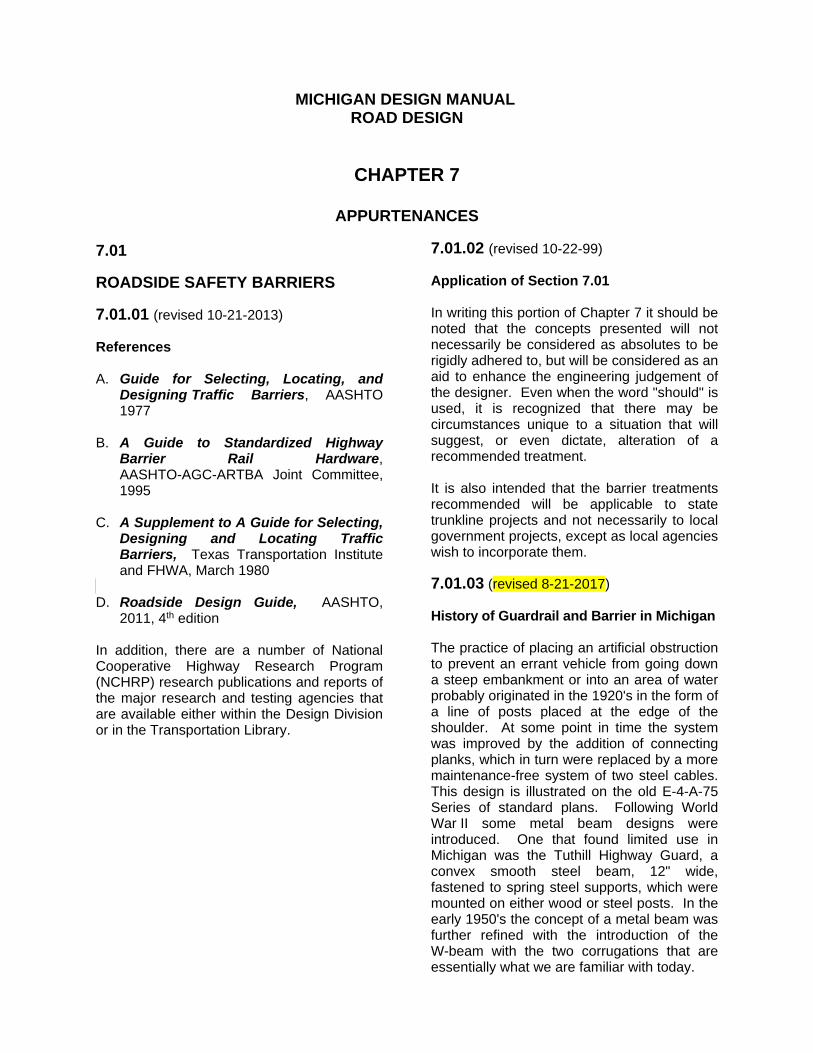
MICHIGAN DESIGN MANUAL
ROAD DESIGN
CHAPTER 7
APPURTENANCES 7.01 ROADSIDE SAFETY BARRIERS 7.01.01 (revised 10-21-2013) References A. Guide for Selecting, Locating, and
Designing Traffic Barriers, AASHTO 1977
B. A Guide to Standardized Highway
Barrier Rail Hardware, AASHTO-AGC-ARTBA Joint Committee, 1995
C. A Supplement to A Guide for Selecting,
Designing and Locating Traffic Barriers, Texas Transportation Institute and FHWA, March 1980
D. Roadside Design Guide, AASHTO,
2011, 4th edition In addition, there are a number of National Cooperative Highway Research Program (NCHRP) research publications and reports of the major research and testing agencies that are available either within the Design Division or in the Transportation Library.
7.01.02 (revised 10-22-99) Application of Section 7.01 In writing this portion of Chapter 7 it should be noted that the concepts presented will not necessarily be considered as absolutes to be rigidly adhered to, but will be considered as an aid to enhance the engineering judgement of the designer. Even when the word "should" is used, it is recognized that there may be circumstances unique to a situation that will suggest, or even dictate, alteration of a recommended treatment. It is also intended that the barrier treatments recommended will be applicable to state trunkline projects and not necessarily to local government projects, except as local agencies wish to incorporate them. 7.01.03 (revised 8-21-2017) History of Guardrail and Barrier in Michigan The practice of placing an artificial obstruction to prevent an errant vehicle from going down a steep embankment or into an area of water probably originated in the 1920's in the form of a line of posts placed at the edge of the shoulder. At some point in time the system was improved by the addition of connecting planks, which in turn were replaced by a more maintenance-free system of two steel cables. This design is illustrated on the old E-4-A-75 Series of standard plans. Following World War II some metal beam designs were introduced. One that found limited use in Michigan was the Tuthill Highway Guard, a convex smooth steel beam, 12" wide, fastened to spring steel supports, which were mounted on either wood or steel posts. In the early 1950's the concept of a metal beam was further refined with the introduction of the W-beam with the two corrugations that are essentially what we are familiar with today.

MICHIGAN DESIGN MANUAL
ROAD DESIGN
7.01.03 (continued) History of Guardrail and Barrier in Michigan Initially, the W-beam was not galvanized and had to be painted. The next step was to galvanize it for more economical maintenance. The first installations of W-beam rail involved attaching the beam element directly to posts placed 12'-6" on centers, at a top of rail height of 24". This design later became known as our Beam Guardrail - Type A. Research and crash testing in the late 1950's and early 1960's, principally by the state of California and by General Motors at its Milford Proving Grounds, produced the recommendations of closer post spacing, (6'-3"), blocking out the beam from the post, and a higher top of rail mounting height. This resulted in Michigan's development of our Beam Guardrail - Type C in 1965, and Beam Guardrail - Type B in 1966. A significant change in guardrail type in Michigan occurred in 1984 with the adoption of thrie beam, now called Guardrail, Type T. The most recent change occurred in 2017 with the adoption of the MASH-compliant, non-proprietary, 31" tall w-beam guardrail system with 8" offset blocks, called Guardrail, Type MGS-8. Until 1995, four basic end treatments had been used in conjunction with steel beam guardrail. Initially, a curved end shoe was placed on both ends of the run. The concept of turning down or burying the ending to form an anchorage was developed about 1966. The first standard plan to be approved by what was then the Federal Bureau of Public Roads was issued in 1968. A variation of the turned down ending, featuring the elimination of the first two posts (so the ending would collapse under impact) appeared in 1971 with the issuance of Standard Plan III-65A.
7.01.03 (continued) The Breakaway Cable Terminal (BCT) ending was adopted in 1973 with the issuance of Standard Plan III-58A. After 22 years as the standard guardrail terminal in most states, the FHWA disallowed further installation of the BCT on the National Highway System (NHS) after December 31, 1995. This, along with the adoption of new crash testing criteria (NCHRP 350) ended the use of the BCT as well as other traditional un-patented endings. This initiated the development and use of a number of proprietary terminals. The Department has divided these terminals into two basic categories of flared gating terminals and tangent terminals. Current standard designs are described in Section 7.01.25 along with other designs previously used. Development of concrete barrier in this country, principally concrete median barrier having the concave safety shape, is generally attributed jointly to General Motors and to the state of New Jersey, both of whom conceived shapes that bear their names. Michigan's first concrete barrier was on the DeQuindre Yard bridge, on I-94 in Detroit, in 1965. Although the New Jersey shape was used in this initial installation, the GM shape was adopted as standard. In 1976 the New Jersey shape became the standard and was used until 2017 when the single slope shape was adopted. 7.01.04 Section deleted

MICHIGAN DESIGN MANUAL
ROAD DESIGN
7.01.05 (revised 10-20-2008) Basic Concepts for Roadside Control The following are basic concepts and design options for the use or non-use of roadside barriers. The primary sources of information for roadside control are found in the AASHTO documents listed in Section 7.01.01, "References". A. A collision with a roadside barrier is
considered a crash, because the barrier itself is a roadside obstacle.
B. A roadside barrier may increase the
frequency of crashes, therefore a barrier should only be installed if it will reduce the severity of potential crashes.
C. When considering the design options for
roadside treatment and the progression of design options basic concepts for roadside control should be as follows.
1. Remove the obstacle or redesign it so
it can be safely traversed. 2. Relocate the obstacle to a point where
it is less likely to be struck. 3. Reduce impact severity by using an
appropriate breakaway or traversable device.
4. Redirect a vehicle by shielding the
obstacle with a longitudinal traffic barrier and/or crash cushion.
5. Delineate the obstacle if the above
alternatives are not appropriate. D. Generally, a roadside barrier should be
placed as far from the traveled way as conditions will permit. See Section 7.01.30G.
E. Standard Plan R-59-Series depicts
guardrail at approaches to bridges, both over and under. It is intended for new construction, where it is possible to grade approach fill sections to accommodate the flared ending. Generally, the more flare that can be achieved, the shorter the rail needs to be to afford the desired protection.
7.01.05 (continued) F. Longer runs of parallel barrier may be
required on upgrading projects, where less than ideal existing conditions preclude the use of flares as called for by Standard Plan R-59-Series.
G. To uniformly compute the length of need
for roadside barriers, a guardrail worksheet has been developed and should be used on both new and upgrading projects. Computation methods used on this worksheet complies with the guidelines described in the Roadside Design Guide. It still remains important that all designers become familiar with the "Guide" to understand the design process. For determining the length of need when non traversable embankments are the only obstacles of concern, see Section 7.01.30.
The worksheet shall be used by all
designers, including consulting firms performing work for the Department, to compute guardrail length of needs.
The designer should fill in all data and
compute each individual barrier run. This will assure proper compliance to standards and allow each barrier run calculation to be documented and checked for accuracy.
Construction field offices should be sent
the completed worksheets for reference during project construction.
The worksheet does not cover all situations
which may occur in the field, although it is expected to cover most installations. Any situation not covered by the worksheet shall be similarly documented, along with a sketch providing the details of the guardrail installation.
7.01.06 (revised 8-21-2017) Guardrail Worksheet The guardrail worksheet is shown on the following pages.

END OF BARRIER NEED
A B
TRAFFIC
1
DISTANCE LINE
CLEAR ZONE
EOP
EOP
FEATURE
ROADSIDE
AREA OF CONCERN
( )
SHY LINE
ROUTE
DESIGNED BY
APPROX. STATION OR M.P.
DATE
CONTROL SECTION
CHECKED BY
DESCRIPTION
JOB #
DATE
GUARDRAIL RUN #
32
LENGTH OF NEED
GUARDRAIL TAPER RATE (R-59-SERIES)
E.O.P. TO FACE OF BARRIER (DESIGNED)
E.O.P. TO ROADSIDE FEATURE (MEASURED)
EFFECTIVE TURNED OUT DISTANCE OF ANCHORAGE
LATERAL EXTENT OF ROADSIDE FEATURE (MEASURED)
LATERAL OFFSET AT END OF FLARE
H 1 2a
bL + ( ) ( L ) - ( L + d )
R
H
X
+L
La
b
X
L - ( L + d )H 2
R
HL
L
a
b
1 2
L
X
a
b
R
1L
L2L
LLC H
3 Z
SL
X
RL
2L
CL
3L
d
HL
Z
a
b
=========
= ==
. . . . . . . . . .
DESIGN ADT
DESIGN SPEED
STATION AT A
STATION AT B
1L =
SL =
NOTE:
CHLL <
SHEET 1 OF 2
d
Z
GUARDRAIL WORKSHEET
IF STATIONING IS NOT AVAILABLE, LOCATE TO NEAREST FIXED OBJECT
APPROACH SLOPE
81
SL
OPE
1:10
(M
AX.)
=d
FOR APPROACH TERMINALS ON R-61-SERIES AND R-62-SERIES
d=0 FOR TYPE 2 TERMINALS
NOTE: TYPE 1 TERMINAL ILLUSTRATED
Z L 2= ( For Type 2 Terminals )
Terminals
or Type 2
No Flare
)(
1.8' FOR TYPE 1 TERMINALS
Z ( X- L - 25 ) ( ) + L
( 25' MIN. )
SHY LINE ( 7.01.18 )
RUNOUT LENGTH ( 7.01.19 )
CLEAR ZONE ( 7.01.11 )
SECTION 7.01.30 FOR GUARDRAIL AT EMBANKMENTS
REFER TO STANDARD PLAN R-59-SERIES AND DESIGN MANUAL
GREATER THAN THE MAXIMUM DEFLECTION ( 7.01.20 )
DISTANCE OF OBJECT FROM BACK OF BARRIER MUST BE
. . . . . . . . . . . . . . . . . . . . . . . . . . . . . . .
(REV. 7-2017)
. . . . . . . . . . . . . . . . . . . . .
. . . . . . . . . . . .
. . . . . . . . . . .
. . . . . . . . . . . . . . . . . . . . . . . .
. . .
. . . . . . . . . . . . . . .
. .

Ft
Bridge Railing, Thrie Beam Retrofit
PROPOSED TREATMENT
PAY ITEMS
CALCULATIONS OR NOTES
SHEET 2 OF 2
Guardrail Reflector
Ft
Cyd
DEDUCTION TABLE
TYPE 1 TYPE 2
TYPE B
GUARDRAIL
TYPE T
GUARDRAIL31.25'
37.5'
43.75'
25'
GUARDRAIL APPROACH TERMINAL
Ea
*
Ea
Ea
Ea
Embankment, LM
Guardrail Anchorage, Bridge, Det
Guardrail Departing Terminal, Type
34.3'N/A
Guardrail, Type
Guardrail Approach Terminal, Type
NEED ( X ) MUST BE DEDUCTED
TERMINAL, TYPE PORTION OF LENGTH OF
* FOR THIS PAY ITEM, THE GUARDRAIL APPROACH
(REV. 7-2017)
TYPE MGS-8**
GUARDRAIL
TYPE MGS-8 GUARDRAIL.
TERMINAL TYPES 1B AND 2B, RESPECTIVELY) TO
APPROACH TERMINALS (I.E., GUARDRAIL APPROACH
ATTACHING NCHRP 350-COMPLIANT GUARDRAIL
TERMINAL TYPES 1B AND 2B, RESPECTIVELY, WHEN
USE DEDUCTIONS VALUES FOR GUARDRAIL APPROACH
(I.E., GUARDRAIL APPROACH TERMINAL, TYPE 2M).
MASH-COMPLIANT GUARDRAIL APPROACH TERMINAL
TYPE MGS-8 IS ONLY APPLICABLE WHEN USING A
DEDUCTION VALUE PROVIDED FOR GUARDRAIL,
** NOTE:
TYPE MGS-8.
TYPES 1B AND 2B, RESPECTIVELY, TO GUARDRAIL,
WHEN ATTACHING GUARDRAIL APPROACH TERMINAL
ROUND TO NEXT HIGHEST RAIL LENGTH, EXCEPT
PAY LENGTHS MUST BE DIVISIBLE BY 12.5'.

ROAD DESIGN MANUAL
ROAD DESIGN 7.01.12 (revised 8-21-2017) Types of Guardrail Used in Michigan There are seven standard types of steel beam guardrail in addition to cable barrier found on Michigan highways. The term "Current Use" means "currently proposed for use", not necessarily what may be found existing in the field. A. Type A (Standard Plan R-60-Series) Description: W-beam attached directly to posts, Terminal End Shoes on ends. 12'-6" post spacing, 28" height to top of rail. Current Use: 1. Cul-de-sacs 2. Limited to locations not exposed to
through traffic. B. Type B (Standard Plan R-60-Series) Description: W-beam guardrail, 8" offset blocks. 6'-3" post spacing, 28" height to top of rail. Current Use: 1. Basic type for all free access trunklines. 2. On local roads when part of a state
trunkline project. C. Type BD (Standard Plan R-60-Series) Description: Type B with W-beam on both sides of the post, 8" offset blocks. Current Use: 1. Limited use in medians on free access
highways when median barrier is recommended.
7.01.12 (continued) D. Type T (Standard Plan R-60-Series) Description: Offset thrie beam rail, 8" offset blocks, 6'-3" post spacing, 34" height to top of rail. Current Use: 1. Standard guardrail for new freeway
construction (including ramps). 2. Updating existing freeways and ramps
when the entire run of guardrail is being removed and replaced.
E. Type TD (Standard Plan R-60-Series) Description: Similar to Type T except beam elements and offset blocks are installed on both sides of the post. Current Use: 1. In freeway medians over 30' wide when
median barrier is recommended. Used to update existing freeway medians when there is a significant length of guardrail being replaced or where none was constructed initially, but barrier is now recommended.
F. Type MGS-8 (Standard Plan R-60-Series) Description: W-beam guardrail meeting MASH criteria, 8" offset blocks, standard 6'-3" post spacing, and 31" height to top of rail. Beam element splices occur between standard 6'-3" post spaces. Current Use: 1. Standard MASH-compliant guardrail for all
freeways (including ramps) and free access roadways. On projects let after December 31, 2017, Type MGS guardrail systems will be required for new guardrail installations on all freeways (including ramps) and free access roadways.

ROAD DESIGN MANUAL
ROAD DESIGN 7.01.12 (continued) Types of Guardrail used in Michigan G. Type MGS-8D (Standard Plan R-60-Series) Description: Type MGS-8 with W-beam guardrail and 8" offset blocks on both sides of the post. Current Use: 1. In all roadway medians, freeway and free
access, when median guardrail is recommended and a MASH-compliant guardrail system is desired. On projects let after December 31, 2017, Type MGS guardrail systems will be required for new guardrail installations on all freeways (including ramps) and free access roadways.
7.01.12 (continued) H. Cable Barrier (See Section 7.01.55C) Description: Three or four steel cables mounted on steel posts, anchored and tensioned. Current Use: 1. Medians where crash history indicates
cross median crashes and rigid barrier is not warranted.
2. Special situations where up to 90 degree
impacts can be expected and larger deflections can be tolerated.

ROAD DESIGN MANUAL
ROAD DESIGN 7.01.14 (continued) Guardrail Surface Finish C. Corrosion-Resistant Guardrail
Replacement Policy
The Engineering Operations Committee, meeting on January 20, 1989, decided that all existing corrosion resistant, or "rusty steel", guardrail encountered on proposed Interstate resurfacing or reconstruction projects should be removed and replaced as part of the project. On projects involving bridges only, the nominal provisions of the approach guardrail anchorage shall be replaced if the rail elements are rusty steel. Where guardrail at the bridge approaches is part of a more extensive installation, the decision to replace will be made on the merits of the specific project. See Section 7.01.44 for upgrading local roads.
7.01.15 (revised 8-21-2017) Guardrail Terminals On projects let on or before June 30, 2018, all of the following guardrail terminals may be used for new construction and where specified for updating. On projects let after June 30, 2018, the guardrail terminal types identified in items G and H are required for new construction and where specified for updating. On projects let after June 30, 2018, the guardrail terminal types identified in items A through F will be prohibited for new construction and where specified for updating. A. Guardrail Approach Terminal, Type 1B (Standard Plan R-61-Series) Current Use: 1. On one or both ends of Guardrail, Type B
and Guardrail, Type MGS-8 located within the clear zone of approaching traffic, where a Type 1 (flared) guardrail terminal is desired.
B. Guardrail Approach Terminal, Type 1T (Standard Plan R-61-Series) Current Use: 1. On one or both ends of Guardrail, Type T
located within the clear zone of approaching traffic, where a Type 1 (flared) guardrail terminal is desired.
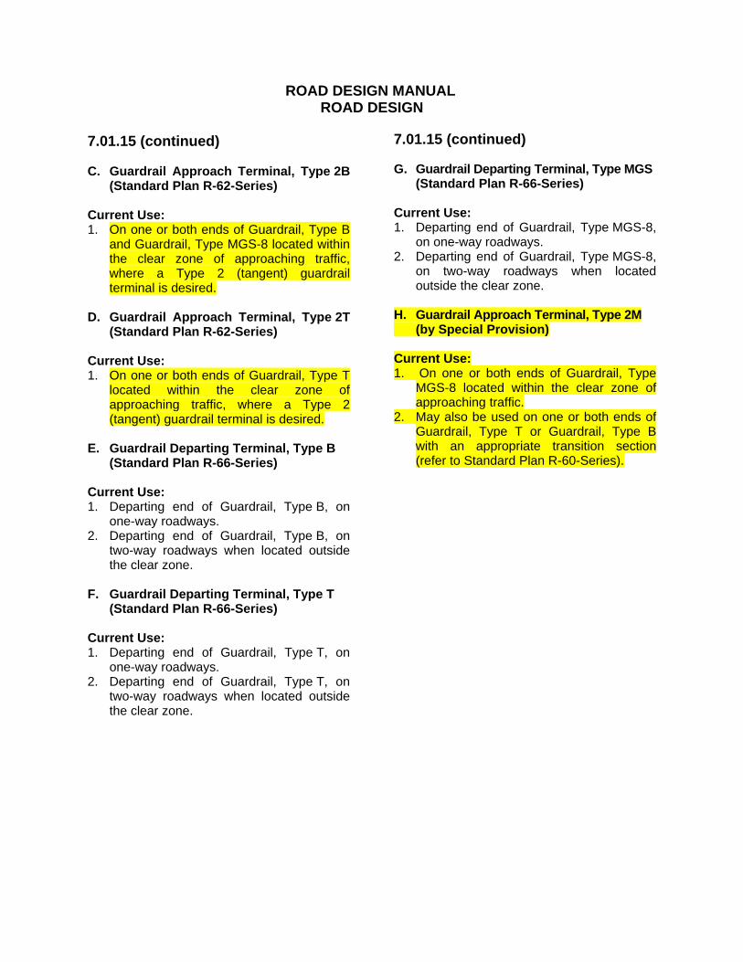
ROAD DESIGN MANUAL
ROAD DESIGN 7.01.15 (continued) C. Guardrail Approach Terminal, Type 2B
(Standard Plan R-62-Series) Current Use: 1. On one or both ends of Guardrail, Type B
and Guardrail, Type MGS-8 located within the clear zone of approaching traffic, where a Type 2 (tangent) guardrail terminal is desired.
D. Guardrail Approach Terminal, Type 2T
(Standard Plan R-62-Series) Current Use: 1. On one or both ends of Guardrail, Type T
located within the clear zone of approaching traffic, where a Type 2 (tangent) guardrail terminal is desired.
E. Guardrail Departing Terminal, Type B (Standard Plan R-66-Series) Current Use: 1. Departing end of Guardrail, Type B, on
one-way roadways. 2. Departing end of Guardrail, Type B, on
two-way roadways when located outside the clear zone.
F. Guardrail Departing Terminal, Type T (Standard Plan R-66-Series) Current Use: 1. Departing end of Guardrail, Type T, on
one-way roadways. 2. Departing end of Guardrail, Type T, on
two-way roadways when located outside the clear zone.
7.01.15 (continued) G. Guardrail Departing Terminal, Type MGS (Standard Plan R-66-Series) Current Use: 1. Departing end of Guardrail, Type MGS-8,
on one-way roadways. 2. Departing end of Guardrail, Type MGS-8,
on two-way roadways when located outside the clear zone.
H. Guardrail Approach Terminal, Type 2M (by Special Provision) Current Use: 1. On one or both ends of Guardrail, Type
MGS-8 located within the clear zone of approaching traffic.
2. May also be used on one or both ends of Guardrail, Type T or Guardrail, Type B with an appropriate transition section (refer to Standard Plan R-60-Series).

ROAD DESIGN MANUAL
ROAD DESIGN 7.01.19 (revised 8-21-2017) Suggested Runout Lengths for Barrier Design Runout length is the distance from the object being shielded to the point the vehicle is assumed to depart from the roadway.
Traffic Volume (ADT) veh/day
Over 10,000 Over
5,000-10,000 1000-5000 Under 1000
Design Speed (mph)
Runout Length LR (ft)
Runout Length LR (ft)
Runout Length LR (ft)
Runout Length LR (ft)
80 470 430 380 330
70 360 330 290 250
60 300 250 210 200
50 230 190 160 150
40 160 130 110 100
30 110 90 80 70
7.01.20 (revised 7-18-2016) Guardrail Deflection Being flexible barriers, both steel beam guardrail and cable barriers are expected to deflect under impact. This deflection is a result of deformation of the beam element or stretching of the steel cable, fracturing of the post (if wood) or bending of the post (if steel), and lateral displacement of the post in the soil. It is therefore necessary that room for deflection be provided between the back of the rail system (e.g. back of posts) and the object or area being shielded. For design purposes, use the chart at the end of this section for the recommended minimum design offset distances of the various guardrail systems. Refer to Section 7.01.55C, “Cable Barrier”, for expected deflections and offset recommends of cable barrier systems.
7.01.20 (continued) It should be noted that the recommended offset distances should not be treated as absolute values, since guardrail deflection may vary for different impact conditions, soil types and moisture contents, thawed or frozen ground, different types of posts, different types of anchorages, and differing lengths of installation. Therefore, the recommended offset distances should be treated as minimums, and larger offset distances between the back of the rail system (e.g., back of posts) and the object or area being shielded should be provided where feasible. In general and, where feasible, the offset should be increased by 12 inches or more beyond the recommended minimum value. If specific site conditions are such that it is predictable that greater deflection values may occur, and space for deflection is restricted, then shorter post spacing or deeper embedment of posts should be considered. Shorter post spacing is only effective, however, if the full effect of proper post embedment is realized. See Section 7.01.41D, "Guardrail Posts at or near the Shoulder Hinge Line". See also Section 5.5.2, 2011 AASHTO Roadside Design Guide.

ROAD DESIGN MANUAL
ROAD DESIGN 7.01.25 (revised 8-21-2017) Guardrail Approach Terminals Crashworthy end treatments are critical to guardrail installations. An approach terminal is designed to redirect an impacting vehicle and to reduce the occurrences of a vehicle being penetrated, rolled, or vaulted in an end on hit. The following section describes the characteristics and uses of approved standard treatments. A. Type 1 Terminals Type 1 Guardrail Approach Terminals are flared gating terminals. On projects let on or before June 30, 2018, this is the preferred design when grading limits allow for the appropriate 4'-0" offset of the terminal end from the tangent extension of the standard line of guardrail run. When the Type 1 terminal is called for on plans by reference to Standard Plan R-61-Series, the contractor may use one of three terminal options. Descriptions of the current approved options are described in this section. On projects let after June 30, 2018, Type 1 guardrail terminals will not be permitted for new construction and where specified for updating until further notice. 1. Slotted Rail Terminal (SRT) The SRT was adopted by the Department in 1995 when FHWA mandated the discontinued use of the BCT. It subsequently became the first guardrail terminal to pass the NHCRP Report 350 crash test criteria. The concept of a slotted rail terminal consists of longitudinal slots cut into the W-beam rail element to control the location of dynamic buckling thus reducing the potential for impact or penetration of the occupant compartment by the buckled rail element. The SRT was originally intended as a retrofit or replacement for the BCT ending.
7.01.25 (continued) The SRT uses many of the same components used in the BCT. It also uses features common to other end treatments such as the yoke and strut and controlled release terminal (CRT) posts. The parabolic flare of the SRT is identical to that of the BCT, simplifying the retrofit of existing terminals. 2. Flared Energy Absorbing Terminal (FLEAT) FLEAT was adopted in 1998 after it passed NCHRP Report 350 crash testing. Among other reasons, it was chosen as an alternate for the SRT because of the similarities in the components and installation configuration of the two systems. In addition to these similarities to the SRT and other flared terminals, the FLEAT includes an energy absorbing impact head. Unlike the SRT, the 4'-0" offset of the FLEAT is a straight taper rather than a parabolic flare. 3. X-Lite-Flared The X-Lite-Flared is an NCHRP-350 (TL-3) terminal manufactured by Lindsay Transportation Solutions (Barrier Systems, Inc). It was formally adopted as a flared, gating, Type 1 alternative in February 2016. 4. Minimum Offset The Type 1 Terminal is designed to have a minimum offset of 4'-0", measured from the tangent line of the guardrail run. Whenever conditions allow, the line of guardrail designed in advance of the terminal should be flared to further increase the total offset of the terminal from the traveled lane. On curved roadways the offset is measured from the circular extension of the standard rail alignment along the curve. Sometimes on certain minor trunklines and a great number of local roads, the end post may have to be placed on the slope beyond the shoulder hinge point, in which case care should be taken that the terminal end shoe and the steel sleeves are not left "high" nor placed too low.

ROAD DESIGN MANUAL
ROAD DESIGN 7.01.25 (continued) Guardrail Approach Terminals B. Type 2 Terminals Type 2 terminals are tangent, energy absorbing terminals. They are used when proper grading cannot be achieved to accommodate the 4'-0" offset called for with the Type 1 terminals. When the Type 2 terminal is called for on plans by reference to Standard Plan R-62-Series, or by special provision, the contractor may use one of the terminal options with the following caveat. On projects let after June 30, 2018, Type 2B and 2T guardrail terminals will not be permitted for new construction or for updating terminals. Instead, Type 2M guardrail terminals will be required for new installations and for updating guardrail terminals. Guardrail Approach Terminals 1. Extruder Terminal (ET) (Type 2B & 2T) The ET was installed experimentally by the Department in 1993 and was used occasionally when special situations called for a non flared terminal. In 1995 the ET became the first non-flared terminal to meet the NCHRP Report 350 crash test criteria. Frequent use of the ET led to its upgraded status as a standard plan in 1997. It features an impact head that, when hit head on, flattens the guardrail beam element as the head translates down the terminal rail. The flattened rail is then extruded away from the impacting vehicle. 2. X-Lite-Tangent-50 (Type 2B & 2T) The X-Lite-Tangent-50 is a NCHRP-350 (TL-3) terminal manufactured by Lindsay Transportation Solutions (Barrier Systems, Inc). It was first used in Michigan on a pilot project on I-94 in Calhoun County in March 2015 and formally adopted as a Type 2 alternative in February 2016.
7.01.25 (continued) 3. Sequential Kinking Terminal (SKT)
(Type 2B & 2T) The SKT was successfully crash tested in 1997 and adopted by the Department as a standard Type 2 terminal alternate in 1998, replacing the BEST. The materials and configuration of the SKT were more compatible with the ET. Like the FLEAT, its impact head includes a deflector plate that produces sequential kinks in the beam element before extruding it away from the impacting vehicle. 4. Type 2M Terminals Type 2M terminals are similar to the Type 2 terminals except they are MASH-compliant. They are specified by special provision and required on projects let after June 30, 2018 for new installations and when updating guardrail terminals. These terminals are intended to be attached directly to Type MGS-8 guardrail. Therefore, designers will need to include an appropriate transition section for connecting a Type 2M guardrail terminal to either Type B or Type T guardrail (refer to Standard Plan R-60-Series). Current Type 2M terminals available for use are the MSKT, the Soft-Stop, and the MAX-Tension. Contact the Geometrics Design Unit, Design Division, for additional information regarding MASH-compliant guardrail terminals. 5. Minimum Offset The original intent of the Type 2 terminals was to provide endings that required no offset. This was the orientation used in the crash tested system. It was later determined by the FHWA that a 12" offset would be acceptable without further testing. This minimal offset was adopted in Standard Plan R-62-Series in order to minimize the number of nuisance accidents that may occur when the impact head was located close to or encroaching on the shoulder.

ROAD DESIGN MANUAL
ROAD DESIGN 7.01.25 (continued) Guardrail Approach Terminals
Soil plate - Inhibits movement of the post in the soil; aids in keeping the post from pulling out of the ground. Steel sleeves - For ending impacts, reduces tendency for the post to rotate in the soil; aids in resisting movement so the post will break off at the weakening hole. For downstream impacts, distributes loads from the post to the soil.
D. Guardrail Full Strength Point When a standard guardrail terminal is used, the length of need is calculated to a point where the guardrail run develops the full strength of the system. This point on the approach end is considered to be the third post from the end (page 5-51, 2011 AASHTO, Roadside Design Guide). E. Clear Area Behind Guardrail Terminals When determining the length of need of a guardrail run, the designer should verify that there will be no obstacle behind or to the behind side of a guardrail terminal that would prevent gating. The area behind should be traversable for the vehicle after it passes through the terminal. The minimum recovery area behind and beyond a terminal should be an obstacle free area approximately 75' long and 20' wide. If it appears that the area behind will not be traversable, then the guardrail run will probably have to be extended to a point where the area behind the terminal is clear.
7.01.25 (continued) F. Burying Ending in a Backslope Occasionally high cut slopes adjacent to the traveled roadway do not provide sufficient clear area behind a Type 1 terminal to allow gating. The designer should consider terminating the guardrail inside the backslope. The designer or project manager can obtain a special detail for this treatment from the Design Standards Unit. G. Slope Under Guardrail Terminals The area under the terminal should be graded to a 1:10 slope or flatter from the edge of the traveled lane to the shoulder hinge point (2'-0" behind the face of the post). See the appropriate guardrail approach terminal Standard Plans for grading details.

ROAD DESIGN MANUAL
ROAD DESIGN 7.01.29 (revised 8-21-2017) Guardrail Flare When designing guardrail, the designer should take advantage of opportunities to flare the installation. This reduces the required length of need. It also places the guardrail terminal farther from the traveled lane, thus reducing the potential for nuisance hits. A. Flare Rate Historically, 1:15 has been the preferred flare rate for guardrail in Michigan. Other maximum flare rates for semi-rigid barriers are listed on page 5-48 of the 2011 AASHTO, Roadside Design Guide and on Standard Plan R-59-Series according to design speed. Flatter flare rates listed by AASHTO for barrier inside the shy line should only be used where it will not increase the length of the guardrail run. B. Uniform Flare from Structures Guardrail may need to be flared inward to meet the bridge barrier railing of bridges with narrow shoulders. When the guardrail length at a structure is increased, such as for an embankment, a uniform guardrail flare rate (not flatter than 1:30) may be substituted for the combined short parallel section and the two flared sections. The Illustration at right shows this situation on a left approach rail. When the shielded area in advance of the bridge rail is a steep embankment, the length of need is determined as outlined in Standard Plan R-59-Series. A uniform flare can then be constructed from the end of the tangent length of barrier at the bridge rail (L1) to the first post of the guardrail terminal at offset distance “z”.

ROAD DESIGN MANUAL
ROAD DESIGN 7.01.30 (revised 8-21-2017) Guardrail at Embankments As a general rule, a barrier should be placed to protect a vehicle from going down an embankment only if the barrier itself is the least severe of the two features. Such a comparison must of necessity be very subjective because of the many variables involved. The Department generally follows the criterion that, if the fill slope is 1:3 or flatter, no barrier is required. For slopes of 1:3 or flatter, the height of fill does not increase severity.
7.01.30 (continued) The economics of earthwork obviously dictate that all slopes cannot be 1:6, regardless of fill height. As the fill becomes higher, more consideration must be given to steepening the slopes, which in turn may call for a decision relative to placing a barrier. Slopes intended to be traversable, i.e., one flat enough that a barrier can be omitted but still perhaps 1:3, should be relatively free of discontinuities that might "trip up" a vehicle. Plans should note that half-buried boulders and large rocks should be removed as part of the final trimming operation.
A. Height-Slope Guidelines

ROAD DESIGN MANUAL
ROAD DESIGN 7.01.30 (continued) Guardrail at Embankments G. Placing Beam Guardrail on a Downslope Usually the greater the distance from the roadway that a barrier can be placed, the less chance there is of it being struck and less barrier length will be needed to shield the object. However, placing a barrier on a downslope close to the shoulder hinge point (approximately 12'-0" or less) introduces the potential for the barrier to be less effective because of the tendency for a vehicle, leaving the shoulder, to vault over it. The following guidelines therefore apply: 1. Beam guardrail may be placed on a slope,
beyond the shoulder point, if the slope is 1:10 or flatter.
2. Generally, a 1:10 or flatter slope should
not be constructed specifically to locate the barrier farther out.
3. Usually, the placement of guardrail on a
1:6 slope is not recommended. There has been one crash test where guardrail was placed on a 1:6 slope, 18 feet off the shoulder point that satisfactorily redirected a vehicle. However, a flatter slope is more desirable. The placing of guardrail on 1:6 slopes should be confined to the applications specified in Section 7.01.32F.
7.01.30 (continued) H. Guardrail Placed near Intersecting
Streets and Driveways An intersecting street or driveway located near a roadside object or feature may prevent installation of the full length of barrier required along the main road. An example of this would be a bridge on a main road with an intersecting driveway located near the bridge. The preferred solution is to close or relocate the intersecting street or driveway in order to install the full length of barrier required along the main road. A crash cushion or other impact attenuating devices may be used to shield a fixed object such as a bridge railing end, however, this may not provide the length of need required to shield other roadside objects or features in the vicinity. When closing or relocating the intersecting driveway or street is not feasible, two possible solutions are given in the accompanying sketches. A second guardrail run in advance of the intersecting street or driveway should be considered when the vehicle's runout path does not intersect guardrail, or when the runout path intersects the departing terminal or the first 16.5 feet of the approach terminal attached to the curved run of guardrail. See Special Detail 21 for installing a curved guardrail run near an intersecting street or driveway. Also, graphical design methods are suggested when utilizing the proposed solutions depicted in the accompanying sketches. Site-specific constraints must be taken into consideration when designing guardrail near intersecting streets and driveways. Examples of these constraints include limited intersection sight distance, right-of-way limitations, and the presence of multiple intersecting driveways in close proximity to each other. In addition, the use of excessively short advanced guardrail runs should be avoided. Questions regarding guardrail installations near intersecting streets and driveways should be directed to the Geometric Design Unit of the Design Division.

ROAD DESIGN MANUAL
ROAD DESIGN 7.01.30 (continued) Guardrail at Embankments

ROAD DESIGN MANUAL
ROAD DESIGN 7.01.32 (continued) Barrier at Bridge Approaches (Over and Under) F. Bridge Columns and Foundations in
70’ Medians Bridge columns and sign support foundations located in the center of 70’ medians were once considered outside the clear zone. Shielding is now required and should be included in any programmed project upgrading. The treatment for shielding columns and foundations for new construction and reconstruction projects should be according to the enclosed system designs shown on Standard Plan R-56-Series, Guardrail Median Object Protection. In addition to the enclosed systems discussed in the previous section, an open system is detailed in Standard Plan R-56-Series for other than new construction and reconstruction projects with 70’ medians and existing fill slope rates of 1:6 or flatter. This detail features twin parallel guardrail runs that shield the median objects independently for each direction of traffic. This option offers the advantage of better accessibility for maintenance equipment to service the median or sign foundations. It is intended only for the conditions stated above.
7.01.33 (revised 8-21-2017) Maintaining Guardrail Strength When One or More Posts Must Be Omitted A. Downspout Headers Standard Plan R-32-Series, under "Notes", advises field personnel to determine the location of proposed guardrail posts prior to locating the spillway or downspout header(s). If this is done, there will be no conflict. There are occasions however, when miscalculation in construction layout or when upgrading guardrail, that an existing downspout header will prevent a post from being placed at the proper spacing. Downspout headers that were constructed prior to 1970 and according to Standard Plan E-4-A-144 series, are an example. These downspouts had deeper throats and were designed to fit 12'-6" post spacing. When a post cannot be properly placed, Standard Plan R-72-Series, "W-Beam Backed Guardrail & Guardrail Long Span Installations" should be used. B. Wide Culverts Maintaining the continuity of the barrier strength is also necessary when a run of guardrail spans a wide culvert and the proper embedment of a guardrail post(s) cannot be obtained. When the spanning of a wide culvert requires the omission of one or two posts, Standard Plan R-72-Series, "W-Beam Backed Guardrail & Guardrail Long Span Installations" should be used. Where no barrier wall exists and the span is over 25’-0” Standard Plan R-73-Series, "Guardrail over Box or Slab Culverts" may be used.

ROAD DESIGN MANUAL
ROAD DESIGN 7.01.33 (continued) Maintaining Guardrail Strength When One or More Posts Must Be Omitted D. Guardrail Posts through Paved
Surfaces Guardrail posts embedded into paved surfaces present a problem similar to that of guardrail posts in rock formations. The paved surface will not allow the posts to rotate in their embedment (to distribute vehicle loads through the post into the embedment material) prior to breaking. Thus, an area of pavement around the post know as "leave out" must be omitted to allow the post to rotate. For both steel and wood posts, the size of the leave out should be an area of about 15" x 15" (square or round). The most critical measurement is the distance from the back of post to the back edge of the leave out, which should be a minimum of 7”. After post installation, patching material is generally placed around the guardrail post in the "leave out" area. This work should be included by special provision.
7.01.33 (continued) E. Additional Blockouts on Guardrail Posts Double blockouts (16" deep) may be used to increase the post offset to avoid obstacles such as curbs. Except at terminals, there is no limit to the number of posts in a guardrail run that use double blockouts. Under special circumstances, one or two posts in a run of guardrail may employ as many as four blockouts (up to 36") to provide proper clearance. There should be no voids between blockouts when using double or multiple blockouts. Furthermore, for aesthetic reasons, double or multiple blockouts should be installed without creating sudden changes in guardrail alignment. When using double or multiple blockouts, steps must be taken to prevent the placement of guardrail posts on steep fill slopes beyond the shoulder hinge point. Placing conventional length guardrail posts on steep fill slopes may result in posts having insufficient soil embedment depth, thereby reducing the post's strength to resist overturning. See Section 7.01.41.D, for guardrail post length requirements when placing guardrail at or near the shoulder hinge line.

ROAD DESIGN MANUAL
ROAD DESIGN 7.01.40 Guard Posts for Roadside Control Barrier systems should not be used merely for roadside control. Where it is impractical to use curb for this purpose, wooden posts without connecting beam elements will suffice. These posts should be weakened by adding two 3½” diameter holes, through the 8" face and 6" apart, with the bottom one about 1" above the ground. The holes should be perpendicular to traffic. Posts may be about 5'-0" apart or as necessary to control traffic in the specific situation. See Standard Plan R-74-Series.
7.01.41 (revised 8-21-2017) Upgrading and Replacement of Guardrail The upgrading and replacement of existing guardrail runs is a leading construction item in Michigan. Two principle reasons for updating are an obsolete design or because of changed conditions, e.g., a guardrail made too low by resurfacing the shoulder. A. Guidelines for Upgrading or Replacing Guardrail 1. If entire runs of guardrail must be replaced
because the guardrail is out of specifications or cannot be adjusted to meet specifications, then the guardrail should be replaced following the current MDOT recommendations as called for in Section 7.01.12.
2. Height adjustment may be made on
existing guardrail posts that pass a thorough inspection for soundness. Existing beam elements should be evaluated for expected life and may be used if they meet current design standards. If the existing guardrail cannot be made to meet these conditions, then the entire run should be replaced with new guardrail using the recommended type from Section 7.01.12.

ROAD DESIGN MANUAL
ROAD DESIGN 7.01.41A (continued) Upgrading and Replacement of Guardrail 3. When replacement of the existing
guardrail on freeway ramps is necessary, use Type T or Type MGS-8. If a continuous guardrail run is needed up to and along the crossroad, transition Type T to Type B or Type MGS-8 at a point 50'-0" minimum from the edge of the crossroad for a "T" type ramp terminal. For a continuous run through a free-flow ramp, transition to Type B or Type MGS-8 opposite the 2'-0" point in the gore. This should be done at both on and off ramp terminals. The transition to Type B or Type MGS-8 is to provide as much sight distance as possible at the ramp terminals.
4. Height adjustments may be made to
Type T guardrail meeting the conditions stated in 2 of this section. If the existing posts are too low to allow the thrie beam rail to be placed at the proper height, then new Type T should be installed.
The placing of the upper bolt shall not be
closer than 2" from top of wood or steel posts. See the following illustrations.
7.01.41A (continued)

ROAD DESIGN MANUAL
ROAD DESIGN 7.01.41A (continued) Upgrading and Replacement of Guardrail
7.01.41 (continued) B. Upgrading Guardrail Terminals A 1999 federal mandate required the replacement of Breakaway Cable Terminals (BCT) on 3R projects on the NHS. Along with a 1995 mandate that required the replacement of blunt ends and turned down endings, this expedites the elimination of all guardrail terminals that do not meet the crash test criteria of NCHRP Report 350. BCT’s shall be upgraded to current standard terminals on all 3R projects on the NHS and all NHS projects that include guardrail work. See Standard Plans R-61-Series and R-62-Series for details of approved terminals. Existing BCTs on Non-NHS projects that include guardrail work shall be upgraded to current standard terminals except existing BCTs on Non-NHS 3R projects will not require replacement if they are in good condition, properly installed and preceded by a flared guardrail run. This is summarized in the following table:
BCT Replacement
Policy
NHS Non NHS
3R New or
Reconstruct 3R
New or Reconstruct
Guardrail Work
Included
No Guardrail
Work Included
Guardrail Work
Included
No Guardrail
Work Included
Guardrail Work
Included
No Guardrail
Work Included
Guardrail Work
Included
No Guardrail
Work Included
Existing flared installation. Upgrade Upgrade Upgrade
No Upgrade required
No Upgrade required
No Upgrade required
Upgrade No
Upgrade required
Existing non-flared installation. Upgrade Upgrade Upgrade
No Upgrade required
Upgrade Upgrade Upgrade No
Upgrade required

ROAD DESIGN MANUAL
ROAD DESIGN
7.01.41B (continued) Upgrading and Replacement of Guardrail These guidelines do not apply to Capital Preventive Maintenance (CPM) projects. Safety Criteria for CPM projects are covered under a separate agreement with the FHWA. Maintenance forces are to replace a damaged BCT with an approved terminal from Standard Plan R-61 or R-62-Series. C. Intermixing Wood and Steel Posts At the present time, the Standard Specifications permit the use of either wood or steel guardrail posts. Both types of posts may be randomly intermixed in making repairs on Types A, B, T, and MGS-8 guardrail, but, for appearance, complete runs being reconstructed should utilize only one type of post. Wood and steel posts for types BD and TD cannot be intermixed because of post size. Posts in terminals shall be the same as those specified on Standard Plans R-61-Series, R-62-Series, R-63-Series, R-66-Series and the special provision which specifies the Type 2M endings. When the repair of an existing bullnose installation is necessary, wood posts shall be used. D. Guardrail Posts at or near the
Shoulder Hinge Line Guardrail upgrading on local roads and trunklines sometimes requires setting the posts at or near the shoulder hinge line rather than 2'-0" (shoulder hinge point to front face of post) for Guardrail Types B and T, or 2’-8” (shoulder hinge point to front face of post) for Guardrail Type MGS-8, as specified on Standard Plan R-60-Series. Most of the time this condition occurs on a fill, which means that the soil support behind the post will be reduced because of the close proximity of the slope. In these cases, 8'-0" long posts should be specified for Guardrail Types B and T, and 9’-0” long posts should be specified for Guardrail Type MGS-8. If the ground does not fall away behind the guardrail, then conventional length posts are sufficient.
7.01.41 (continued) E. Allowable Variation from Standard
Height
When evaluating existing guardrail to determine upgrading needs, variation from standard barrier height is a consideration. A variation of 3" from the standard height is allowable. This is considered a functional variation. Closer tolerances are expected for construction purposes. If an existing guardrail is of the proper type, and after all phases of the proposed project are complete, e.g., shoulder resurfacing, etc., the guardrail height should be within this limit. If any work must be done on it at all, however, then the run should be brought up to standard. Before allowing such a run of guardrail to remain untouched, it should pass a thorough inspection for the soundness of posts and the expected remaining life of the beam elements. The timing of future road improvements should also be a consideration. F. Unpainted Corrosion Resistant Beam Elements See Section 7.01.14B. The Engineering Operations Committee meeting on January 20, 1989 decided that all existing corrosion resistant, or "rusty steel", guardrail encountered on proposed Interstate resurfacing or reconstruction projects should be removed and replaced as part of the project. On projects involving bridges only, the nominal provisions of approach guardrail (guardrail anchorage to bridge and approach terminal) shall be replaced if the rail elements are rusty steel. Where guardrail at the bridge approaches is part of a more extensive installation, the decision to replace will be made on the merits of the specific project.

ROAD DESIGN MANUAL
ROAD DESIGN 7.01.41 (continued) Upgrading and Replacement of Guardrail G. Thick Shoulder Lifts Rehabilitation of rural freeways often entails placing a new concrete pavement on top of the old, or placing a thick HMA overlay. This procedure also raises the shoulder elevation, thus causing the existing guardrail to be too low. When this occurs, the designer is reminded that provisions should be made to either reconstruct or upgrade the guardrail. If reconstruction of the guardrail must precede the pavement lift by a year or so; the designer may be tempted to call for longer than normal posts, leaving them with tops protruding so that they will be long enough to fit the ultimate installation. This should not be done; crash test films frequently show the impacting vehicle laying over on the rail and sliding along it. Protruding post tops would thus have a detrimental effect on smooth redirection of the vehicle. H. Type A Guardrail Parallel to
Continuous Abutment, Twin Overpassing Structures
It was practice for a number of years to place Type A guardrail in front of the opening between twin overpassing structures, parallel to the continuous abutment and about 4'-0" in back of it. Current standards provide either a length or a configuration of guardrail that eliminates the need for this transverse section of barrier. On an updating project, if this transverse barrier is still in place and in good condition, it may be left as a determent to persons or animals who could accidentally fall over the backwall. If the condition of the barrier warrants removal, it should be removed and not replaced.
7.01.41 (continued) I. Replacing with Thrie Beam Guardrail Even though guardrail Type T and Type MGS-8 are the current standards for use on freeways, other guardrail types do not need to be replaced unless physical deficiencies exist. 7.01.43 Guidelines for Bridge Railing Replacement and Attached Approach and Trailing Guardrails See Chapter 12 of the Bridge Design Manual. 7.01.44 (revised 10-22-99) Guardrail Upgrading on Local Roads A. Guardrail Upgrading Guidelines on
Local Roads (In Conjunction with Freeway Work)
In conjunction with work programmed on a freeway, the Department may have occasion to upgrade guardrail on roads that are under local jurisdiction. Generally, the guardrail will be constructed to "trunkline standards" with respect to the type of guardrail and the type of ending. Depending on site conditions, the location and configuration of the guardrail used on local roads may not necessarily be to "trunkline standards". The Department attempts to prevent errant local road traffic from encroaching on the freeway and its appurtenances. The following guidelines have been established for upgrading guardrail on local roads over and under freeways.

6.05.02
VZ
BLT
TRUNKLINE, COUNTY & CITY BRIDGES
BRIDGE CROSS SECTIONS
FOR CURBED APPROACHES
PARAPET TUBE
AESTHETIC
BRIDGE RAILING
PEDESTRIAN FACILITY REQUIRED
MAXIMUM POSTED SPEED 40 MPH
4 TUBE
BRIDGE RAILING
OR
FENCE (TYP. OVER FREEWAYS)
10' CURVED TOP CHAIN LINK
(TYP. OVER RIVERS)
6" CONCRETE BRUSH BLOCK
4' CHAIN LINK FENCE WITH
PEDESTRIAN FACILITY REQUIRED
POSTED SPEEDS GREATER THAN 40 MPH
NO PEDESTRIAN FACILITY REQUIRED
ANY POSTED SPEED
AND 8' (TOTAL) MAX. ON RIGHT.
BRIDGE RAIL. USE 4' (TOTAL) MAX ON LEFT
SHOULDER AS THE LATERAL CLEARANCE TO THE
A CONTINUATION OF A RAMP, MATCH THE RAMP
WHERE AN AUXILIARY LANE ON THE STRUCTURE IS
SHOULDER + 2'SHOULDER + 2' LANE WIDTH x NO. OF LANES
********
BARRIER (TYP.)
CONCRETE
LANE WIDTH x NO. OF LANES
SHOULDER + 2'SHOULDER + 2' LANE WIDTH x NO. OF LANES
********
MIN.
4'-0"
PREFERRED
** 5'-0"
2'SIDEWALK 2' SIDEWALK
MIN.
* 5'-2"
MIN.
* 5'-2"
PEDESTRIAN FACILITY SHOWNSHARED USE FACILITY SHOWN
* 5'-2" TO TOE OF CURB, 5'-0" TO BEVEL POINT.
USED TROUGHOUT.
EVERY 200' OR LESS OR A 5'-0" SIDEWALK SHALL BE
(INCLUSIVE OF THE SIDEWALK), SHALL BE PRESENT
APPROACHES) A PASSING SPACE, 5'-0" x 5'-0"
FOR A LENGTH OF 200' OR MORE (INCLUDING
** WHEN A SIDEWALK WIDTH OF LESS THAN 5'-0" EXISTS
***
VARIABLE
DEVELOPMENT OF BICYCLE FACILITIES".
*** FOR WIDTH REFER TO AASHTO "GUIDE FOR THE
(42" MIN. HEIGHT RAILING REQUIRED)
CONCRETE BARRIER SHOWN
BRIDGE RAILING 4 TUBE SHOWN
54" PREFERRED
42" MIN. HEIGHT RAILING REQUIRED,
SEE BRIDGE DESIGN GUIDE 6.05.01
FOR TRUNKLINE BRIDGES WITHOUT PEDESTRIAN FACILITY
FOR COUNTY & CITY BRIDGES ONLY
********
MDOT JURISDICTIONAL FACILITY/ROADWAY.
2' ADDITIONAL OFFSET APPLIES TO BRIDGES OVER
GEOMETRIC DESIGN OF HIGHWAYS AND STREETS".
MANUAL CHAPTER 7 AND AASHTO "A POLICY ON
APPROACH SHOULDER WIDTHS SEE BRIDGE DESIGN
**** 2'-0" MIN. FOR CURB APPROACH. FOR MINIMUM
BUREAU OF DEVELOPMENT
MICHIGAN DEPARTMENT OF TRANSPORTATIONDRAWN BY:
APPROVED BY: DAJ
DESIGN DIVISION
PREPARED BY
SUPERSEDES:03/17/14
ISSUED: 08/21/17
CHECKED BY: