rms energy conversion
TRANSCRIPT
USOO5892293A
United States Patent [19] [11] Patent Number: 5,892,293 Lucas [45] Date of Patent: Apr. 6, 1999
[54] RMS ENERGY CONVERSION 5,659,173 8/1997 Putterman et a1. ............... .. 250/361 C
OTHER PUBLICATIONS
Swift, “Termoacoustic Engins”, Journal Acoust. Soc. Am., [75] Inventor: Timothy S. Lucas, Richmond, Va.
[73] Assignee: Macrosonix Corporation, Richmond, VOL 84, NO_ 4, (1988) pp 1145_1180_ Va- Putnam et al., “Pulse Combustion”, Prog. Energy Combust.
Sci., vol. 12, (1986) pp. 43—79. [21] Appl. No.: 783,701 VishWanath, “Advancement of Developmental Technology
_ for Pulse Combustion Applications”, Gas Research Institute [22] Flled: Jan- 15’ 1997 Report NO. GRI—85/0280 (1985). [51] Int. Cl.6 ...................................................... .. H02P 9/04 Gri?iths 6t a1~> “The Design of Pulse Combustion Burners’: [52] ' 290/1 R; 431/1; 60/3976 Research Bulletin, NO. 107, (1969).
of Search ................................... .. R, 1 A, Primary Examiner_Thomas Dougherty 290/2; 322/3; 431/1; 60/3976; 62/498 Assistant Examiner—Nicholas Ponomarenko
Attorney, Agent, or Firm—Foley & Lardner [56] References Cited
[57] ABSTRACT U.S. PATENT DOCUMENTS
An energy conversion device comprises an acoustic
411,253,221 $352 3515113611631 et a1. .................... .. 322/2 R reS°nat9i112.‘pu1S.§combuf?on dgvice flor ffea??g a it“??? 4,685,510 8/1987 Priem et a1. ........... .. .. 165/62 Wave W1 ,1“ Sal resona or’ an an 6 6C “C a em‘ or: e
4 752 209 6/1988 Vishwanath et aL 431/1 alternator is coupled to the resonator to convert acoustically 4762:4537 8/1988 Zappa _________________ __ __ 431/1 driven mechanical vibrations into electrical poWer.
5,263,341 11/1993 Lucas ......... .. ..
5,515,684 5/1996 Lucas et a1. ................................ .. 62/6 29 Claims, 7 Drawing Sheets
SPARK TIMING CIIINTRIIIL CIRCUIT
86 ARMATURE / 18
16—A L 30 /T i / 20
STATUR /
5,892,293
7\ SPARK TIMING
CUNTRUL CIRCUIT
Sheet 1 of7
10
U.S. Patent Apr. 6, 1999
18 1E
/18
/20
ARMATURE
1:: i / 28
STATUR
”’///1 // I”’’’////////////////////////////
30
86
16
FIG. 1

U.S. Patent Apr. 6, 1999 Sheet 2 0f 7 5,892,293
Peak Pressure Distribution
Pressure Node
2 Axis of Resonator
FIG. 2
Pressure Time Waveform
PO\ A f
time
FIG. 3
U.S. Patent Apr. 6, 1999 Sheet 3 0f 7 5,892,293
34
38
ARMATURE / STATUR FIG. 4
U.S. Patent Apr. 6, 1999 Sheet 4 0f 7 5,892,293
Peak Pressure Distribution
+1)
2 Axis of Resonator
FIG. 5
U.S. Patent Apr. 6, 1999 Sheet 6 0f 7 5,892,293
Tuned Induction Pressure Relationships
FIG. 7
5,892,293 U.S. Patent Apr. 6, 1999 Sheet 7 0f 7
64 W] /m ARMATURE
STATUR
FIG. 8
5,892,293 1
RMS ENERGY CONVERSION
BACKGROUND OF THE INVENTION
1) Field of Invention This invention relates to Resonant Macrosonic Synthesis
(RMS) resonators Which are either pulse combustion driven or thermo acoustically driven for the purpose of energy conversion, having speci?c applications to electric poWer production.
2) Description of Related Art History reveals a rich variety of technologies conceived
for the purpose of electric poWer production. Of particular interest are those technologies designed to combust liquid or gaseous fuels in order to produce electric poWer. Many types of internal combustion engines have been
employed Which convert the chemical potential energy of fuels into mechanical energy Which is used to drive an electric alternator. HoWever, internal combustion engines need frequent periodic maintenance and provide loW con version ef?ciencies. Currently, turbines provide the most ef?cient conversion of fuels, such as natural gas, into electric poWer. The design and manufacturing sophistication Which is inherent in turbine technology can be seen in both their initial cost and operating cost.
Some effort has been directed to the ?eld of standing acoustic Waves as a means of electric poWer production. For example, it Was suggested by SWift that the oscillating pressure of thermoacoustically driven standing Waves could be utiliZed for driving an alternator to produce electric poWer (G. W. SWift, “Thermoacoustic Engines,” J. Acoust. Soc. Am. 84, 1166 (1988)). This Would be accomplished by coupling a piston to an open end of the acoustic resonator and alloWing the vibrating piston to drive a linear alternator. The piston Would require a gas seal such as a diaphragm or belloWs Which raises issues of reliability. Moving pistons also limit the dynamic force Which can be extracted from the standing Wave, thereby limiting the thermoacoustic genera tor’s ef?ciency.
Another application of standing acoustic Waves to the production of electric poWer Was reported by SWift Which exploited Magneto Hydrodynamic effects in a thermoacous tically driven liquid sodium standing Wave engine (G. W. SWift, “Thermoacoustic Engines,” J. Acoust. Soc. Am. 84, 1169 (1988)).
Pulse combustion (PC) is a further ?eld of research Where electric poWer production has been proposed in connection With standing acoustic Waves. Other than Magneto Hydro dynamics the PC ?eld has apparently received little attention as a means of producing electric poWer. Considerable research and development has occurred in the PC ?eld dating back to the previous century. In the early 1920s pulse combustors ?rst received attention as a means to drive
electric poWer producing turbines as seen in US. Pat. No. 1,329,559 to Nikola Tesla. Most of the applications research performed today relates to producing either heat or propul sive thrust. For these applications, pulse combustors have alWays been comparatively attractive, due to their self sustaining combustion cycle, inherent simplicity, and loW production of pollutants. Putnam, Belles, and Kent?eld provide a comprehensive history of pulse combustor devel opment shoWing many of the embodiments and applications in the art of pulse combustion (A. A. Putnam, F. E. Belles, and J. A. C. Kent?eld, “Pulse Combustion,” Prog. Energy Combust. Sci. 12, 43—79 (1986)). The ?eld of PC research is very active With signi?cant efforts taking place at insti
15
25
35
45
55
65
2 tutions such as the Gas Research Institute, Sandia Combus tion Labs, and various universities.
In summary, thermoacoustic engines have been proposed as a means of driving piston-actuated electric alternators to produce electric poWer. HoWever, the concept is in need of certain optimiZations, practical improvements, and simpli ?cations. Little effort has been directed toWard developing a practical system for utiliZing PC-driven standing Waves as a means of electric poWer production. When compared to contemporary technologies, such as gas turbines, a PC electric poWer generator Would provide a fuel-to-electric conversion system of extraordinary simplicity.
SUMMARY OF THE INVENTION
It is an object of the present invention to provide pulse combustion (PC) driven acoustic resonators Whose vibratory motion is used to drive an electric alternator. A further object of the present invention is to employ
resonant macrosonic synthesis (RMS) resonators as a PC chamber in order to maximiZe the acoustic reaction force for a given fuel consumption rate, thereby improving fuel-to electric transduction ef?ciency. A still further object of the present invention is to increase
the poWer density of a PC by providing tuned induction as Well as pre-heating and premixing of the combustion reac tants.
An even further object of the present invention is to provide a comparatively inexpensive technology for con verting fuels such as natural gas into electric poWer. An additional object of the present invention is to provide
needed optimiZations and practical improvements to ther moacoustic electric poWer generators.
These and other objects and advantages of the invention Will become apparent from the accompanying speci?cations and draWings, Wherein like reference numerals refer to like parts throughout.
DETAILED DESCRIPTION OF DRAWINGS
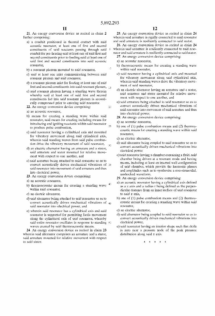
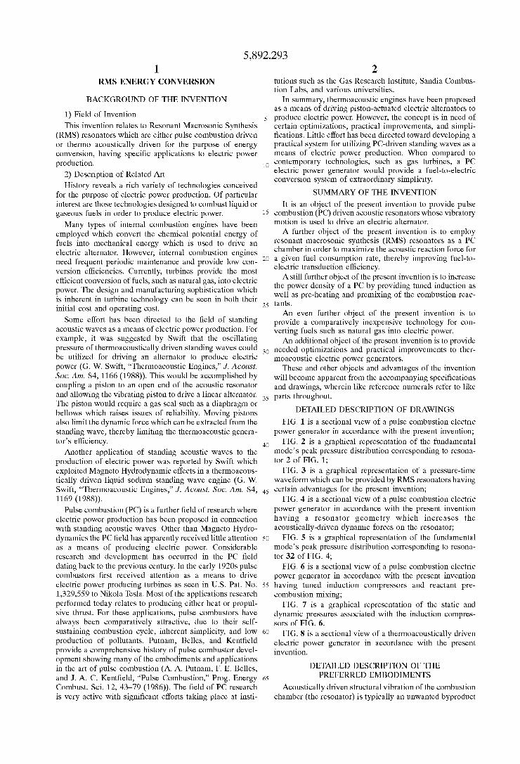
FIG. 1 is a sectional vieW of a pulse combustion electric poWer generator in accordance With the present invention;
FIG. 2 is a graphical representation of the fundamental mode’s peak pressure distribution corresponding to resona tor 2 of FIG. 1;
FIG. 3 is a graphical representation of a pressure-time Waveform Which can be provided by RMS resonators having certain advantages for the present invention;
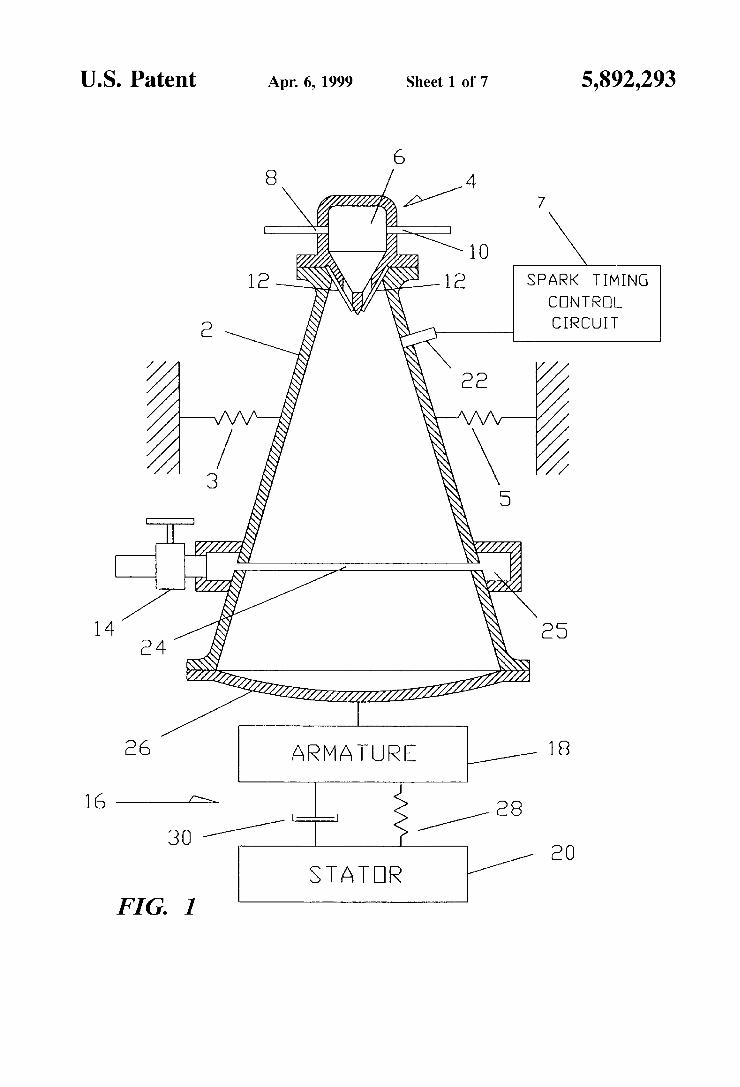
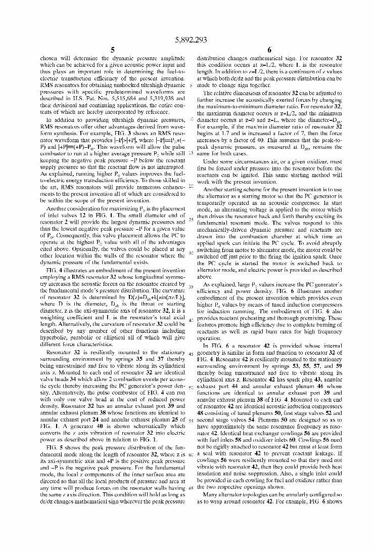
FIG. 4 is a sectional vieW of a pulse combustion electric poWer generator in accordance With the present invention having a resonator geometry Which increases the acoustically-driven dynamic forces on the resonator;
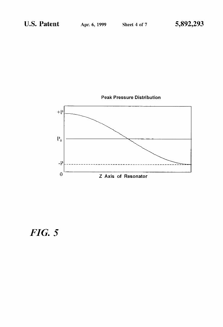
FIG. 5 is a graphical representation of the fundamental mode’s peak pressure distribution corresponding to resona tor 32 of FIG. 4;
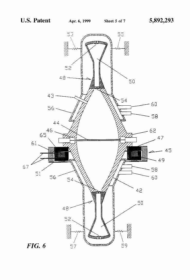
FIG. 6 is a sectional vieW of a pulse combustion electric poWer generator in accordance With the present invention having tuned induction compressors and reactant pre combustion mixing;
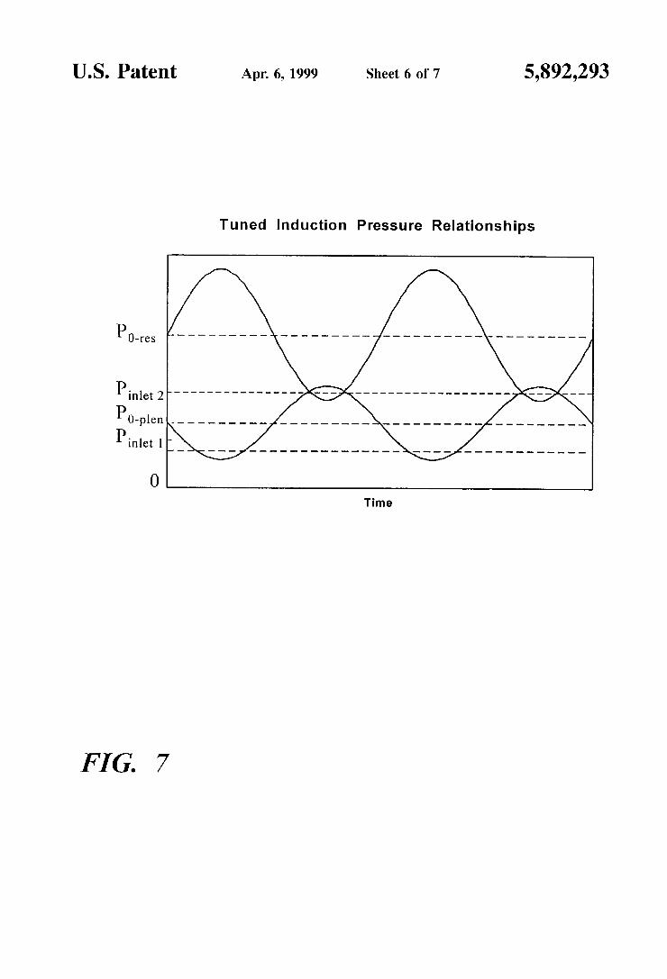
FIG. 7 is a graphical representation of the static and dynamic pressures associated With the induction compres sors of FIG. 6.
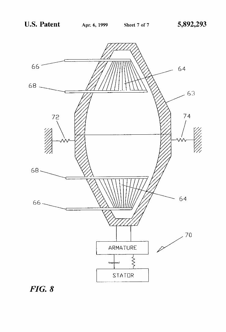
FIG. 8 is a sectional vieW of a thermoacoustically driven electric poWer generator in accordance With the present invention.
DETAILED DESCRIPTION OF THE PREFERRED EMBODIMENTS
Acoustically driven structural vibration of the combustion chamber (the resonator) is typically an unWanted byproduct

5,892,293 3
of PC operation. Considerable research is directed toWard minimizing this unWanted effect. In contrast, the present invention exploits these vibrations as a means of creating electric poWer by alloWing the entire resonator to be driven back and forth in response to the standing Wave’s dynamic pressure.
FIG. 1 shoWs an embodiment of the present invention Where a RMS resonator 2 is provided, Which is resiliently mounted to the stationary surrounding environment by springs 3 and 5 thereby being unrestrained and free to vibrate along its cylindrical axis Z. Resonator 2 has a rigid end Wall 26, an annular exhaust port 24, annular exhaust plenum 25, optional throttle valve 14, spark plug 22, and a valve head 4. Valve head 4 comprises a fuel-oxidiZer plenum 6, a fuel inlet 8, an oxidiZer inlet 10 and reactant inlet valves 12.
Connected to resonator 2 is alternator 16 comprising armature 18 Which is rigidly connected to resonator 2 and stator 20 Which is resiliently connected to armature 18. The resilient connection is shoWn schematically as spring 28 and damper 30. The term stator is not used here to imply that stator 20 is stationary. On the contrary, stator 20 can be unrestrained and free to vibrate or alternatively it can be rigidly restrained. Optionally, armature 18 could be spring mounted to resonator 2 in order to provide further control of the relative vibrational phases of stator 20, armature 18, and resonator 2.
Many methods exist for starting pulse combustors and spark plug 22 provides one such approach. In operation, spark plug 22 creates a spark Which initiates the combustion of the fuel-oxidiZer mixture inside resonator 2. This initial combustion starts the Well knoWn self-sustaining PC cycle Which is driven by the resultant oscillating pressure inside resonator 2. Once started, the spark plug can be deactivated and the PC system Will run at its characteristic resonant frequency.
Other methods can be used to vary the resonant frequency such as a spark timing control circuit 7 in FIG. 1 and rotary valves both of Which are per say Well knoWn. Variably-tuned resonator branches could also be used to vary the resonant frequency. For example, a variably tuned branch could comprise a narroW cylindrical tube having one end Which opens into the combustion resonator and the other end ?tted With a tuning piston. The resonant frequency of the com bustion chamber could be varied by sliding the tuning piston Within the tube.
Combustion products exit resonator 2 through annular port 24 Which must have sufficient ?oW area to support the design exhaust ?oW rate. FIG. 2 illustrates the fundamental mode’s peak pressure distribution along the length of reso nator 2, Where Z is its axi-symmetric axis for Which Z=0 at the narroW end and Z=L at the Wide end. Although port 24 can be placed anyWhere Within the Walls of resonator 2, the preferred placement corresponds to the fundamental’s pres sure node shoWn in FIG. 2 Which Will tend to minimiZe the transmission of dynamic pressure through port 24. If dynamic pressure is transmitted through port 24, then it can no longer be converted into useable force as described beloW. In general, exhaust port placement should be chosen so as to maximiZe the resonator’s internal dynamic pressure. Port 24 could be ?tted With optional throttle valve 14 or could be equipped With compressor-type discharge valves such as reed valves or plate valves Which Would open in response to the pressure difference across the valve.
Once the standing Wave is established its oscillating pressure exerts dynamic forces against the inner Walls of
10
15
45
55
65
4 resonator 2 causing it to vibrate as a rigid body along the Z direction at the acoustic frequency. Armature 18 is attached to resonator 2 and so is set into vibration With it. The resulting relative motion of armature 18 and stator 20 Will create electric poWer in a manner determined by the gen erator’s topology. In the preferred embodiment, stator 20 is not stationary but free to move at some phase angle With respect to the motion of armature 18. Alternator 16 could be a voice coil alternator, a variable reluctance alternator as shoWn in Us. Pat. No. 5,174,130 the entire contents of Which are hereby incorporated by reference, an alternator as shoWn in Us. Pat. No. 5,389,844 the entire contents of Which are hereby incorporated by reference, or any other of a great number of linear alternators. Other designs that could be employed, but Which lack a literal armature and stator, include pieZoelectric and magnetostrictive alternators. Alter nator selection Will re?ect the speci?c design requirements including frequency of operation, the resonator’s vibrational displacement amplitude, and transduction ef?ciency betWeen mechanical and electrical poWer.
The characteristics of the resilient mounting, shoWn sche matically as spring 28 and damper 30, betWeen armature 18 and stator 20 Will affect the transduction ef?ciency of the system. Optimal poWer factors can be found by modeling the system dynamics and accounting for all the moving masses, springs and damping in the system. The speci?c analytical model Will re?ect the type of alternator employed by the system. The resistance presented to the exhaust ?oW by port 24,
plenum 25 and optional throttle valve 14 Will in?uence the average pressure PO upon Which the dynamic pressure is superimposed as shoWn in FIG. 2. Other factors in?uencing the average pressure PO Will include the inlet ?oW resistances, the ?uid properties, and the resonator geometry. Throttle valve 14 can be used to adjust the exhaust ?oW resistance and thus vary the average pressure PO. Increasing the outlet ?oW resistance Will increase PO and decreasing the outlet ?oW resistance Will reduce PO. For a given poWer input, increasing PO Will generally increase the peak-to-peak dynamic pressure, thereby increasing the dynamic forces on the resonator, resulting in increased electric poWer output. Thus, in order to maximiZe fuel-to-electric transduction ef?ciency the average pressure PO should be as high as possible as long as the negative peak pressure —P does not rise above the reactant supply pressure Which Would inter rupt the intake of fresh reactants. If discharge valves are used in combination With port 24, then both the ?oW area of the valve system and the valve’s spring loading, if any, Will in?uence PO. Alternatively, compressor-type dynamic dis charge valves could be located at Z=0 Where discharge pressures are higher resulting in reduced exhaust volume ?oW rates.
Preferred embodiments of the present invention use the resonator’s ?rst longitudinal mode as illustrated by FIGS. 1 and 2 in order to maximiZe the reaction forces and thus the fuel-to-electric transduction ef?ciency as described. Alternatively, rigid Wall 26 could be resiliently attached to resonator 2 With a ?exible seal, such as a belloWs, Which Would alloW Wall 26 to vibrate independently of resonator 2. Resonator 2 could be rigidly restrained While alloWing Wall 26 to vibrate along the Z axis in response to the dynamic acoustic pressure, thereby driving armature 18 of alternator 16. Also, HelmholtZ type resonators could be used Within the scope of the present invention With an alternator also being connected to the resonator as in FIGS. 1 and 4.
Resonator design plays an important role in optimiZation of the present invention. The particular resonator design
5,892,293 5
chosen Will determine the dynamic pressure amplitude Which can be achieved for a given acoustic power input and thus plays an important role in determining the fuel-to electric transduction ef?ciency of the present invention. RMS resonators for obtaining unshocked ultrahigh dynamic pressures With speci?c predetermined Waveforms are described in US. Pat. Nos. 5,515,684 and 5,319,938 and their divisional and continuing applications, the entire con tents of Which are hereby incorporated by reference.
In addition to providing ultrahigh dynamic pressures, RMS resonators offer other advantages derived from Wave form synthesis. For example, FIG. 3 shoWs an RMS reso nator Waveform that provides |—P|>|+P|, Where |—P|EPO+(— P) and |+P|E(+P)—PO. This Waveform Will alloW the pulse combustor to run at a higher average pressure PO While still keeping the negative peak pressure —P beloW the reactant supply pressure so that the reactant How is not interrupted. As explained, running higher PO values improves the fuel to-electric energy transduction efficiency. To those skilled in the art, RMS resonators Will provide numerous enhance ments to the present invention all of Which are considered to be Within the scope of the present invention.
Another consideration for maximiZing PO is the placement of inlet valves 12 in FIG. 1. The small diameter end of resonator 2 Will provide the largest dynamic pressures and thus the loWest negative peak pressure —P for a given value of PO. Consequently, this valve placement alloWs the PC to operate at the highest PO value With all of the advantages cited above. Optionally, the valves could be placed at any other location Within the Walls of the resonator Where the dynamic pressure of the fundamental exists.
FIG. 4 illustrates an embodiment of the present invention employing a RMS resonator 32 Whose longitudinal symme try increases the acoustic forces on the resonator created by the fundamental mode’s pressure distribution. The curvature of resonator 32 is determined by D(Z)=Dth+l([S1I1(J1§Z/L)], Where D is the diameter, Dth is the throat or starting diameter, Z is the axi-symmetric axis of resonator 32, k is a Weighting coefficient and L is the resonator’s total axial length. Alternatively, the curvature of resonator 32 could be described by any number of other functions including hyperbolic, parabolic or elliptical all of Which Will give different force characteristics.
Resonator 32 is resiliently mounted to the stationary surrounding environment by springs 35 and 37 thereby being unrestrained and free to vibrate along its cylindrical axis Z. Mounted to each end of resonator 32 are identical valve heads 34 Which alloW 2 combustion events per acous tic cycle thereby increasing the PC generator’s poWer den sity. Alternatively, the pulse combustor of FIG. 4 can run With only one valve head at the cost of reduced poWer density. Resonator 32 has an annular exhaust port 39 and annular exhaust plenum 38 Whose functions are identical to annular exhaust port 24 and annular exhaust plenum 25 of FIG. 1. A generator 40 is shoWn schematically Which converts the Z axis vibration of resonator 32 into electric poWer as described above in relation to FIG. 1.
FIG. 5 shoWs the peak pressure distribution of the fun damental mode along the length of resonator 32, Where Z is its axi-symmetric axis and +P is the positive peak pressure and —P is the negative peak pressure. For the fundamental mode, the local Z components of the inner surface area are directed so that all the local products of pressure and area at any time Will produce forces on the resonator Walls having the same Z axis direction. This condition Will hold as long as dr/dZ changes mathematical sign Wherever the peak pressure
10
15
25
35
45
55
65
6 distribution changes mathematical sign. For resonator 32 this condition occurs at Z=L/2, Where L is the resonator length. In addition to Z=L/2, there is a continuum of Z values at Which both dr/dZ and the peak pressure distribution can be made to change sign together. The relative dimensions of resonator 32 can be adjusted to
further increase the acoustically exerted forces by changing the maximum-to-minimum diameter ratio. For resonator 32, the maximum diameter occurs at Z=L/2, and the minimum diameter occurs at Z=0 and Z=L, Where the diameter=Dth. For example, if the max/min diameter ratio of resonator 32 begins at 1.7 and is increased a factor of 7, then the force increases by a factor of 40. This assumes that the peak-to peak dynamic pressure, as measured at Dth, remains the same for both cases.
Under some circumstances air, or a given oxidiZer, must ?rst be forced under pressure into the resonator before the reactants can be ignited. This same starting method Will Work With the present invention.
Another starting scheme for the present invention is to use the alternator as a starting motor so that the PC generator is temporarily operated as an acoustic compressor. In start mode, an alternating voltage is applied to the motor Which then drives the resonator back and forth thereby exciting its fundamental resonant mode. The valves respond to this mechanically-driven dynamic pressure and reactants are draWn into the combustion chamber at Which time an applied spark can initiate the PC cycle. To avoid abruptly sWitching from motor to alternator mode, the motor could be sWitched off just prior to the ?ring the ignition spark. Once the PC cycle is started the motor is sWitched back to alternator mode, and electric poWer is provided as described above. As explained, large PO values increase the PC generator’s
ef?ciency and poWer density. FIG. 6 illustrates another embodiment of the present invention Which provides even higher PO values by means of tuned induction compressors for induction ramming. The embodiment of FIG. 6 also provides reactant preheating and thorough premixing. These features promote high ef?ciency due to complete burning of reactants as Well as rapid burn rates for high frequency operation.
In FIG. 6 a resonator 42 is provided Whose internal geometry is similar in form and function to resonator 32 of FIG. 4. Resonator 42 is resiliently mounted to the stationary surrounding environment by springs 53, 55, 57, and 59 thereby being unrestrained and free to vibrate along its cylindrical axis Z. Resonator 42 has spark plug 43, annular exhaust port 44 and annular exhaust plenum 46 Whose functions are identical to annular exhaust port 39 and annular exhaust plenum 38 of FIG. 4. Mounted to each end of resonator 42 are identical acoustic induction compressors 48 consisting of tuned plenums 50, ?rst stage valves 52 and second stage valves 54. Plenums 50 are designed so as to have approximately the same resonance frequency as reso nator 42. Identical heat exchanger coWlings 56 are provided With fuel inlets 58 and oxidiZer inlets 60. CoWlings 56 need not be rigidly attached to resonator 42 but must at least form a seal With resonator 42 to prevent reactant leakage. If coWlings 56 Were resiliently mounted so that they need not vibrate With resonator 42, then they could provide both heat insulation and noise suppression. Also, a single inlet could be provided in each coWling for fuel and oxidiZer rather than the tWo respective openings shoWn. Many alternator topologies can be annularly con?gured so
as to Wrap around resonator 42. For example, FIG. 6 shoWs

5,892,293 7
a variable reluctance alternator 45 Which is Wrapped annu larly around resonator 42. Alternator 45 has annular arma ture 47 Which is rigidly connected to ?ange 62 of resonator 42, annular stator 49 Which is resiliently connected to armature 47 via annular spring 51 and annular linkage 61, drive coil 65 Within annular stator 49, and drive coil leads 67. Dynamically, alternator 45 Will respond to the Z axis vibration of resonator 42 in the same manner as alternator 16 of FIG. 1 responds to the Z axis vibration of resonator 2.
FIG. 7 illustrates the dynamic and static pressure rela tionships of the various stages of compression. In operation, the pulse combustion driven standing Wave is initiated by spark plug 43. Reactant ?oW proceeds through inlets 58 and 60 at the inlet pressure Pinlek1 and through coWlings 56 Where the reactants pick up heat from the Wall of resonator 42 and experience some degree of How mixing. The vibra tion of the entire generator assembly Will excite the funda mental resonance of tuned plenums 50. The resulting dynamic pressure inside tuned plenums 50 Will draW in the heated reactants from coWling 56 through valves 52 and into tuned plenums 50 thereby compressing the reactants to the average plenum pressure Po?mum. Inside tuned plenums 50 the reactants experience further mixing due to the initial turbulent valve How and then due to the cyclic acoustic particle displacement.
The dynamic pressure inside plenums 50 Will compress the reactants again from the average plenum pressure Po_plmum up to the plenum discharge pressure Pinlep2 at Which time the reactants are discharged from plenums 50 through the 2”d stage valves 54 and into resonator 42. The overlap of the plenum’s peak acoustic pressure and the minimum acoustic pressure of resonator 42 forces second stage valves 54 open once per cycle thereby discharging the heated and mixed reactants into resonator 42 for combus tion. The passage of reactants through valves 54 induces further mixing. The result of this process as seen in FIG. 7 is an elevated average resonator pressure P0465 due to the pressure lift provided by induction compressors 48.
Additional induction compressors could be staged if desired to provide even higher P0465 values. CoWlings 56 also lend themselves to acoustical resonance and could provide additional dynamic pressure boost.
Consideration must be given to the acoustic design of resonant plenums 50. As shoWn in FIG. 7, the phase betWeen the plenum’s standing Wave and the resonator’s standing Wave is essential to the compression process. The plenum’s resonance is driven by tWo sources: the opening of 2nd stage valves 54 and the vibratory motion of the entire plenum. The superposition of these tWo driving sources must be taken into account When designing the plenum geometry. If the plenum resonant frequency is to be equal to the resonator’s, then the plenum design should ensure that the valves are the Weaker source.
Many improvements on the embodiment of FIG. 6 Will suggest themselves to those skilled in the art of tuned compressor or engine plenums and pulse combustors. For example, the plenums could be tuned to the resonator’s 2nd harmonic in Which case the 2"d stage valves could act as the sole driving source and the proper phases for induction ramming Would be provided. Further, the ratio of 1“ and 2”d stage valve areas can be used to increase Po_plmum and therefor P0465. Still further, if premixing of the reactants inside coWlings 56 is objectionable for safety reasons, then individual oxidiZer and fuel coWlings can be used Which Would keep the reactants separated up to the induction compressors. Similarly, individual fuel and oxidiZer lines
10
15
25
35
45
55
65
8 could be Wrapped in annular fashion around the exterior of resonator 42, thereby being placed in thermal contact With the hot resonator Walls.
If a gaseous fuel supply pressure is high enough, then induction compressors 48 could be used to compress only the oxidiZer and the fuel could be provided through a typical gas distributor Within resonator 42.
As an alternative to PC, the standing acoustic Waves of the present invention can be driven thermoacoustically. As described, current proposals for thermoacoustically driven electric generators require the coupling of a piston to an open end of the acoustic resonator and alloWing the vibrat ing piston to drive a linear alternator. This piston Would require a gas seal such as a diaphragm or belloWs Which raises issues of reliability. The dynamic forces produced by this system are limited by acoustic pressure amplitude and by the surface area of the piston.
Rather than being limited by a piston’s surface area, the present invention utiliZes the entire inner surface area of the resonator and so can generate very large dynamic forces. The use of RMS resonators further increases the desired dynamic forces by providing extremely high dynamic pres sures.
FIG. 8 illustrates a thermoacoustically-driven embodi ment of the present invention. An explanation of thermoa coustic engine fundamentals can be found in G. W. SWift, “Thermoacoustic Engines,” J. Acoust. Soc. Am. 84, 1169 (1988). In FIG. 8, a rigid Walled resonator 63 having heat plate stacks 64 is operated in the prime mover mode as is Well knoWn in the art of thermoacoustic engines. Resonator 63 is resiliently mounted to the stationary surrounding environment by springs 72 and 74 thereby being unre strained and free to vibrate along its cylindrical axis Z. Heat is applied at heat exchangers 66 and extracted at heat exchangers 68 so as to provide a temperature gradient along the plate stack sufficient for driving the standing acoustic Wave. Once the standing Wave is established its oscillating pressure exerts dynamic forces against the Walls of resonator 63 causing it to vibrate as a rigid body along Z at the acoustic frequency in response to these dynamic forces. As before, a generator 70 is shoWn schematically Which converts the Z axis vibration of resonator 32 into electric poWer.
The art of thermoacoustic engines is Well developed and Will suggest many methods and techniques to one skilled in the art for implementing the embodiment of FIG. 8. For example, the use of tWo plate stacks is optional. In addition, plate stacks can be used With RMS resonators to achieve high pressure amplitudes for a desired Waveform and With all of the advantages previously described. Further, heat sources used for the embodiment of FIG. 8 could include Waste heat from a PC generator of the type described above, Waste heat from other processes, direct combustion of fuels as Well as solar energy to name a feW.
While the above description contains many speci?cations, these should not be construed as limitations on the scope of the invention, but rather as an exempli?cation of preferred embodiments. Thus, the scope of the present invention is not limited to speci?c pulse combustor designs or thermoacous tic designs. The present invention can be applied Wherever electrical
poWer is needed. Frequency locking the PC embodiments of the present invention to the local poWer grid frequency may be achieved for example With spark timing, the timing of actuated valves such as rotary valves or With variably-tuned resonator branches. In this Way, the generated electric poWer could be linked to the local grid. The AC output from the