rms 2v164 user guide
DESCRIPTION
Voltage Regulation RelayTRANSCRIPT

2V164 User Guide Voltage Regulating & Control Relay
relay monitoring systems pty ltd
Advanced Protection Devices
User Guide
Test Manual
Relay Software
µMATRIXwin

2V164 User Guide
About This Manual
This User Guide covers all 2V164 relays manufactured from May 2009. Earlier relays do not necessarily incorporate all the features described. Our policy of continuous may means that extra
features & functionality may have been added. The 2V164 User Guide is designed as a generic document to describe the common operating
parameters for all relays built on this platform. Some relay applications are described but for specific model information the individual “K” number Product / Test manuals should be consulted.
The copyright and other intellectual property rights in this document, and in any model or article produced from it (and including any Registered or unregistered design rights) are the property of Relay Monitoring
Systems Pty Ltd. No part of this document shall be reproduced or modified or stored in another form, in any data retrieval system, without the permission of Relay Monitoring Systems Pty Ltd, nor shall any model or
article be reproduced from this document without consent from Relay Monitoring Systems Pty Ltd.
While the information and guidance given in this document is believed to be correct, no liability shall be accepted for any loss or damage caused by any error or omission, whether such error or omission is the
result of negligence or any other cause. Any and all such liability is disclaimed.
Contact Us
© Relay Monitoring Systems Pty Ltd 2001-2009 6 Anzed Court • Mulgrave 3170 • AUSTRALIA Phone 61 3 9561 0266 • Fax 61 3 9561 0277
Email [email protected] • Web www.rmspl.com.au To download a PDF version of this guide:
http://www.rmspl.com.au/userguide/2v164_user_guide.pdf To download the model specific Test Manual:
http://www.rmspl.com.au/search.asp

How this guide is organised This guide is divided into five parts:
Part 1 Overview About this Manual Contents Test Manual Mechanical Configuration Description of Operation L ine Drop Compensation
Part 2 Technical Bulletin
Part 3 Software Function Compatible Software Factory Default Software Determining Software UMX Determining UMX Functionality User Interface Field Calibration
Part 4 Installation Handling of Electronic Equipment Safety Unpacking Accessories Storage & Handling Recommended Mounting Position Relay Dimensions & Other Mounting Accessories Equipment Connections
Part 5 Maintenance Mechanical Inspection Test Intervals Defect Report Form
Visit www.rmspl.com.au for the latest product information.
Due to RMS continuous product improvement policy this information is subject to change without notice. 2V164_Guide/Iss E - 01/04/09

Part
1 Test Manual This User Guide covers all 2V164 relay versions & describes the generic features & attributes common across all versions. Different relay versions are required to cater for varying customer requirements such as auxiliary voltage range, I/O configuration, case style, relay functionality etc. The product ordering code described in the Technical Bulletin is used to generate a unique version of the relay specification & is called a type number. The type number takes the form 2V164Kxx where the Kxx is the “K” or version number.
Refer to: www.rmspl.com.au/handbook/parta3.pdf for a complete description of the RMS “K” number system. Each 2V164 version has a specific Test Manual which provides details on the unique attributes of the relay. Each Test Manual includes the following information:
• Test Certificate
• Specific technical variations from the standard model if applicable
• Test & calibration record
A Test Manual is provided with each relay shipped. A CD & serial comms. cable is supplied with each relay order. If you require a copy of the Test Manual for an RMS product the following options are available:
• Check the RMS web site at: www.rmspl.com.au/search.asp
• RMS CD catalogue select: List all Product/Test Manuals under Technical Library
• Contact RMS or a representative & request a hard copy or PDF by email.
Visit www.rmspl.com.au for the latest product information.
Due to RMS continuous product improvement policy this information is subject to change without notice. 2V164_Guide/Iss E - 01/04/09

Mechanical Configuration Great care has been taken to design a rugged, cost effective & flexible mechanical solution for the MATRIX range of RMS protection relays. The MATRIX range provides a compact draw out case solution with M4 screw terminals:
• 2M28 Size 2 with 28 terminals • 4M28 Size 4 with 28 terminals • 4M56 Size 4 with 56 terminals
Complete details & attributes for the M (MATRIX) cases & accessories may be found at:
http://www.rmspl.com.au/mseries.htm The 2V164 is configured in a 4M56 case & the following photographs depict the general mechanical configuration. It should be noted that re-usable JIS plastic threading (PT type) screws are used to bind the draw out relay module.
Visit www.rmspl.com.au for the latest product information.
Due to RMS continuous product improvement policy this information is subject to change without notice. 2V164_Guide/Iss E - 01/04/09
Image of generic inner relay module after removal from outer case.

Image of the relay module showing the switch mode power supply components at the top.
Typical set of three PCB’s. Note the terminal blocks fitted to the top two assemblies.
Visit www.rmspl.com.au for the latest product information.
Due to RMS continuous product improvement policy this information is subject to change without notice. 2V164_Guide/Iss E - 01/04/09

Description of Operation The 2V16x Series relays are designed for the control of motor driven on-load power transformer tap changers. The 2V164 Voltage Regulator Relay continuously monitors the transformer output voltage & current & provides "RAISE" & "LOWER" control commands to the on-load tap changer such that the load centre is automatically maintained within acceptable limits. Small variations in supply frequency will not affect the system performance. When designing the 2V164, considerable emphasis was placed on producing a relay, which would be very simple to install, set up & operate in the field. The result is a simple yet effective & very dependable voltage regulator relay available at a competitive price. The standard Micro MATRIX human machine interface (HMI) is combined with fully solid state voltage sensing & measuring circuitry to provide high accuracy, simple set up & flexible operation.
Visit www.rmspl.com.au for the latest product information.
Due to RMS continuous product improvement policy this information is subject to change without notice. 2V164_Guide/Iss E - 01/04/09

Line Drop Compensation The line drop compensation, i.e. the inclusion of the voltage drop of a line connected to the transformer in the regulating process, can be accomplished in two different ways. Two modes are available: Z-Compensation Z-compensation is easier to set than the vectorial compensation method and is suitable where only small shifts in the phase angle cosΦ are experienced. Vectorial compensation (Four setting modes: +PHASE and +QUAD) Vectorial compensation is more difficult to set as exact line data must be known but is more accurate when set correctly. Setting the LDC Mode of Operation Six settings are selected in the 2V164 from the LDC menu as follows: LDC mode: OFF LDC inactive + PHASE Use when relay wired in phase configuration - PHASE Use when relay wired in phase configuration + QUAD Use when relay wired in quadrature configuration - QUAD Use when relay wired in quadrature configuration Z-COMP Use when relay wired in phase configuration
Visit www.rmspl.com.au for the latest product information.
Due to RMS continuous product improvement policy this information is subject to change without notice. 2V164_Guide/Iss E - 01/04/09

Z Mode LCD Compensation Setting Z-Compensation may be employed with the relay wired in phase or in quadrature configuration where only small shifts in the phase angle cosΦ are experienced. The calculated percentage of the voltage rise, referred to the voltage level, set at the 2V164 LDC menu Z-Comp value in % as per the following formula:
Voltage rise % = 100 . UTr - ULoad . IN . RCT ______________ __________
ULoad I Where: Voltage rise = setting of Z-compensation in % UTr = transformer voltage at current I ULoad = line end voltage at current I and with the same service position of the tap
changer I = load current in amps IN = rated current in amps of the selected current transformer connection to the
voltage regulator, i.e. 1A or 5A RCT = current transformer ratio e.g. 200A/5A Check the Z-compensation operation using the following steps: 1. Set Z-compensation voltage rise to 0%; 2. Apply a voltage to achieve balanced state; 3. Set Z-compensation voltage rise to 15%; 4. A voltage raise LED must light up when a load current of 10% of the rated current input is
applied; 5. Now carry out the required setting of the Z-compensation as per the above formula.
Visit www.rmspl.com.au for the latest product information.
Due to RMS continuous product improvement policy this information is subject to change without notice. 2V164_Guide/Iss E - 01/04/09
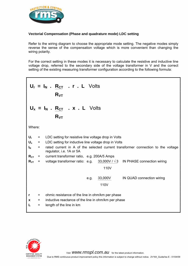
Vectorial Compensation (Phase and quadrature mode) LDC setting Refer to the wiring diagram to choose the appropriate mode setting. The negative modes simply reverse the sense of the compensation voltage which is more convenient than changing the wiring polarity. For the correct setting in these modes it is necessary to calculate the resistive and inductive line voltage drop, referred to the secondary side of the voltage transformer in V and the correct setting of the existing measuring transformer configuration according to the following formula:
RCT Ur = IN . . r . L Volts ____
RVT
RCT Ux = IN . . x . L Volts ____
RVT Where: Ur = LDC setting for resistive line voltage drop in Volts Ux = LDC setting for inductive line voltage drop in Volts IN = rated current in A of the selected current transformer connection to the voltage
regulator, i.e. 1A or 5A RCT = current transformer ratio, e.g. 200A/5 Amps R 33,000V / √ 3VT = voltage transformer ratio: e.g. IN PHASE connection wiring ________________
110V 33,000V
Visit www.rmspl.com.au for the latest product information.
Due to RMS continuous product improvement policy this information is subject to change without notice. 2V164_Guide/Iss E - 01/04/09
e.g. IN QUAD connection wiring ___________
110V r = ohmic resistance of the line in ohm/km per phase x = inductive reactance of the line in ohm/km per phase L = length of the line in km
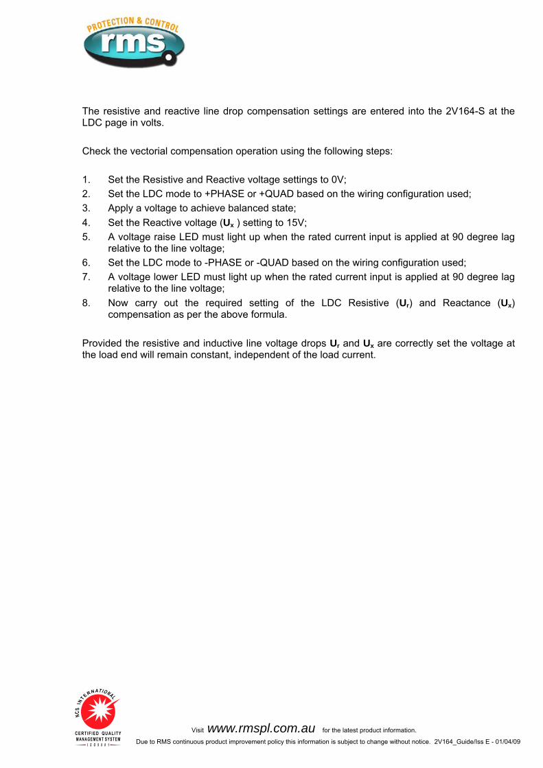
The resistive and reactive line drop compensation settings are entered into the 2V164-S at the LDC page in volts. Check the vectorial compensation operation using the following steps: 1. Set the Resistive and Reactive voltage settings to 0V; 2. Set the LDC mode to +PHASE or +QUAD based on the wiring configuration used; 3. Apply a voltage to achieve balanced state; 4. Set the Reactive voltage (Ux ) setting to 15V; 5. A voltage raise LED must light up when the rated current input is applied at 90 degree lag
relative to the line voltage; 6. Set the LDC mode to -PHASE or -QUAD based on the wiring configuration used; 7. A voltage lower LED must light up when the rated current input is applied at 90 degree lag
relative to the line voltage; 8. Now carry out the required setting of the LDC Resistive (Ur) and Reactance (Ux)
compensation as per the above formula. Provided the resistive and inductive line voltage drops Ur and Ux are correctly set the voltage at the load end will remain constant, independent of the load current.
Visit www.rmspl.com.au for the latest product information.
Due to RMS continuous product improvement policy this information is subject to change without notice. 2V164_Guide/Iss E - 01/04/09

Part
2 Technical Bulletin The detailed technical attributes, functional description & performance specifications for the
V164 are described in the attached Technical Bulletin. For the most up to date version go to: 2 www.rmspl.com.au/handbook/2v164.htm
For any specific attributes of a particular version refer to the Test Manual for that type (K) number. The order of precedence for technical information is as follows:
• Test Manual • Technical Bulletin • User Guide
Visit www.rmspl.com.au for the latest product information.
Due to RMS continuous product improvement policy this information is subject to change without notice. 2V164_Guide/Iss E - 01/04/09
Visit www.rmspl.com.au for the latest product information. Due to RMS continuous product improvement policy this information is subject to change without notice. 2V164/Issue S/17/11/08 - 1/8
Features SYSTEM FEATURES
Large back lit display panel System status LED indicators Simple menu setting procedure Wide auxiliary supply range with fail alarm contact
Self diagnosis & fail alarm Size 4M case Made in Australia
VOLTAGE CONTROL
Line drop compensation with 1A & 5A CT inputs
Z Compensation 63.5 & 110V AC VT inputs Definite time & inverse time delays
Independent fine & coarse voltage bandwidth windows
Over & under voltage alarms Under voltage blocking function Tap change fail alarm Two digital input load step stages
Overcurrent blocking METERING & EVENT RECORDING
Line voltage display Line current display Tap position indicator Tap rate of change alarm Tap change event counter Tap position mA output Line voltage mA output
COMMUNICATION
Non platform specific PC programming software: µMATRIXwin
Optically isolated communication ports
MODBUS RTU compatible network protocol
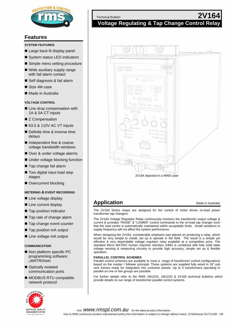
Technical Bulletin 2V164 Voltage Regulating & Tap Change Control Relay
2V164 depicted in a 4M56 case
Application Made in Australia The 2V164 Series relays are designed for the control of motor driven on-load power ransformer tap changers. t
The 2V164 Voltage Regulator Relay continuously monitors the transformer output voltage & current & provides "RAISE" & "LOWER" control commands to the on-load tap changer such that the load centre is automatically maintained within acceptable limits. Small variations in upply frequency will not affect the system performance. s
When designing the 2V164, considerable emphasis was placed on producing a relay, which would be very simple to install, set up & operate in the field. The result is a simple yet effective & very dependable voltage regulator relay available at a competitive price. The standard Micro MATRIX human machine interface (HMI) is combined with fully solid state voltage sensing & measuring circuitry to provide high accuracy, simple set up & flexible
peration. o PARALLEL CONTROL SCHEMES Parallel control schemes are available to meet a range of transformer control configurations based on the master / follower principal. These systems are supplied fully wired in 19” sub rack frames ready for integration into customer panels. Up to 4 transformers operating in
arallel on one or two groups are possible. p For further details refer to the RMS 1M122A, 1M122D & 2V165 technical bulletins which
rovide details on our range of transformer parallel control systems. p

Visit www.rmspl.com.au for the latest product information. Due to RMS continuous product improvement policy this information is subject to change without notice. 2V164/Issue S/17/11/08 - 2/8
Figure 1: User defined voltage set points
SETPOINT VOLTAGE RANGE 90V to 130V in 0.1V steps. 110V & 63.5V nominal inputs. “FINE” VOLTAGE BANDWIDTH SETTING (SENSITIVITY) 0.3 V to 5.0V in 0.1V steps. The bandwidth setting should be made in accordance with the relative step voltage of the tap changer. A narrow bandwidth may result in the tap changer hunting between adjacent taps. INITIAL RAISE / LOWER TIMER 10s to 300s in 10s steps. The initial time delay between the detection of an error in the monitored voltage & the resultant tap change output, is switch selectable as either a definite time or true inverse time response. The initial time delay starts when the voltage deviation exceeds the upper or lower limit. The respective instantaneous HIGH / LOWER LED illuminates. If the deviation falls back to within bandwidth limits before the pre set time delay is completed, the timer is reset. At the completion of the pre set time delay the respective RAISE / LOWER tap output contact will close. INTERVAL TIME DELAY 1s to 100s in 1s steps. The interval time delay only becomes active when the initial delay has caused a tap change but without affecting a balanced condition, ie. if more that one tap change operation is necessary to bring the voltage within set limits. INVERSE TIME DELAY CHARACTERISTIC In the inverse time mode, the initial time delay is inversely proportional to the ratio of deviation to bandwidth down to a minimum of a one-second delay. For example: ♦ When the detected error is equal to the selected bandwidth the
time delay is equal to the delay setting. ♦ For a detected error of N times the selected bandwidth, the
time delay is 1/N times the delay setting. ACCURACY OF TIMERS All timers +/-0.1s
Voltage Control Functions “COARSE” VOLTAGE BANDWIDTH SETTING 1V to 20V in 1V steps. 1s to 60s in 1s steps. A second independent voltage control window can be set with a definite time delay. This can be used for a fast tap change function for large voltage deviations, which are outside the fine bandwidth window. UNDER VOLTAGE BLOCKING FUNCTION 60V to 90V in 1V steps. 0s to 60s in 1s steps. An undervoltage blocking function is combined with a definite time delay output. Undervoltage blocking suppresses tap change operations during a system breakdown to avoid the tap changer mechanism from being driven to the top tap. The self reset Blocking alarm relay is activated when this element has timed out & a message reported on the HMI. OVER VOLTAGE ALARM 110V to 140V in 1V steps. 0s to 60s in 1s steps. An overvoltage alarm is combined with a definite time delay output. The self reset overvoltage alarm relay contact is activated when this element has timed out & a message reported on the HMI. OVER CURRENT BLOCKING 50 to 150% in 5% steps – Can also be set to OFF 0s to 60s in 1s steps Reset: >0.97Iset When timed out all tap commands are inhibited / cancelled. The self reset Blocking alarm relay is activated when this element has timed out & a message reported on the HMI. SET POINT HYSTERESIS All voltage set points have a hysteresis equal to 50% of the bandwidth voltage setting. Other values available on application. LINE DROP COMPENSATION Resistance & reactance compensation: 0V to 20V in 0.1V steps Settings are provided to cater for in phase & in quad connections, with either positive or negative reactance compensation. Correct setting of the LDC requires the calculation of the resistive & reactive line-drops as a voltage with reference to the secondary side of the VT & the setting of the instrument transformer for IN PHASE or IN QUAD connection. Z compensation is also available: 0 to +15% setting range. VOLTAGE LOAD STEP INPUTS -10% to +10% of the set point voltage in 0.5% steps Two independent load step stages are provided. The voltage reduction or boost level for each stage can be independently set while a separate digital input is provided to initiate each stage. If both stages are initiated then the stage 2 level is operative. OPERATIONAL INDICATORS Red LED’s on the front panel indicate the following conditions: Over voltage Bus voltage above alarm setting Blocking BUS voltage / current outside block settings Tap change fail Tap change time out alarm Raise volts Flash when timing / On for Raise tap initiate Lower volts Flash when timing / On for Lower tap initiate Tap rate Tap rate alarm level exceeded
TAP CHANGE FAIL ALARM 10s to 300s in 10s steps. The tap change fail alarm timer is initiated when an out of bandwidth voltage error is detected. Time out will result in the alarm contact closing. The alarm timer & contact is reset when he sensed voltage has moved back to a balanced condition. t
AUTO / MANUAL MODE CONTROL INPUT A digital input is provided to change the relay from AUTO to
ANUAL mode. M In AUTO mode the 2V164 will monitor the voltage & current inputs & output tap raise / lower commands to maintain the load enter in accordance with the relay settings. c
In MANUAL mode tap raise & lower commands are inhibited. The Blocking & Overvoltage alarm outputs remain active. The relay fail alarm remains active.

Visit www.rmspl.com.au for the latest product information. Due to RMS continuous product improvement policy this information is subject to change without notice. 2V164/Issue S/17/11/08 - 3/8
TAP POSITION INDICATOR A tap position indicator input is provided to enable the transformer tap to be displayed on the HMI. The output from the RMS type 2V200 Tap Position Transducer is required for this function to operate. Refer to the 2V200 Technical Bulletin for details. TAP POSITION INDICATOR INPUT For this function to operate an RMS type 2V200 transducer / sender unit is required at the tap changer. Refer to the 2V200 Technical Bulletin for application details.
The 2V200 is designed to interface to tap changes & convert one of the following parameters:
an analogue voltage signal proportional to the tap position a binary coded decimal signal a BCD signal
The 2V200 converts any of these inputs to a frequency signal proportional to the tap position. The 2V164 VRR is then simply programmed with the number of tap positions within the range 10 to 30. Scaling is carried out automatically so that the correct tap position is indicated on the 2V164 display. A 4-20mA analogue output proportional to tap position is also provided by the 2V164 for local panel indication or interface to SCADA. VOLTAGE DISPLAY The HMI displays the line voltage. The VT ratio may be entered so that the HMI display reads in primary voltage. A 4-20mA analogue output is also provided. Display range (Secondary): 10-145V VT setting range: 0.11KV to 132.00KV CURRENT DISPLAY The HMI displays the line current from the LDC input. The CT ratio may be entered so that the HMI display reads in primary current. Display range (Secondary): 0.1-1.35Is CT setting range: 1A to 6.00KA
Metering & Event Logging TAP CHANGE EVENT COUNTER A record is maintained & displayed of the number of tap operations since this function was last reset. The tap rate indicator takes account of all tap changes initiated by the 2V164 tap raise / lower contacts. Manual taps initiated by external control contacts are not included. RANGE OF TAP OPERATION A record is maintained & displayed of the minimum & maximum tap position reached since this function was last reset. TIME ELAPSED SINCE TAP COUNT RESET A record is maintained & displayed of the time in hours since the tap count was last reset. TAP RATE ALARM The 2V164 records & displays the rate at which tap raise/lower commands have been output over the preceding 15-minute period. If the set point rate is exceeded (taps per hour), an alarm contact is picked up. This alarm contact is automatically reset when a tap rate lower than the alarm set point is updated to the display or when the tap count is manually reset. The tap rate indicator takes account of all tap changes initiated by the 2V164 tap raise / lower contacts. Manual taps initiated by external control contacts are not included. TAP POSITION INDICATOR ANALOGUE OUTPUT A single tap position indicator analogue output signal is provided for interface to an RTU. The analogue output is linked to the tap position as follows: Output: 4 to 20mA Compliance voltage: 5V Maximum burden: 250 Ohms Accuracy: +/-3% Analogue output:
Tap 1 4mA Tap N 20mA
Where N = maximum selected tap setting
Tap 1
Use 400 Ohm 1% 0.5W resistors for RsOther resistor values possible:refer 2V200 Technical Bulletin
for tap 1 referencepadding resistor (Rp) values
Rs 1 Rs 21Ra*
Tap position indicator (TPI) hardware requirements and wiring configuration.
Transformer TPI selector switch
Frequencyoutput
Shielded cable recomendedfor long runs & parallel control
(2V165), applications
5KHz Max.
Integrated TPI display
** T/C EVENTS PAGE **
DATA to return
V F TPITransducer & sender unit
Tap Rate:Max Tap:Min Tap:
Tap Count:Time Elapsed:
4184
620160
2V164 VRR
2V20011 15
161
2
13 1012 4 5
The RMS type 4O200 Resistor Boxprovides a packaged TPI Rs solution
TPI output
Volts output
AlternativeBinary or BCD coded interface
Tap 1internal
referenceresistor
(400 ohms)
** Tap 1externalpaddingresistor
Rp
Vx
110V ACor 240V AC
TPI out of
step alarm
* If Rs x number taps > 600 ohmsthen resistor Ra is not required.
** If Rs = 400ohmthen resistor Rp is not required.
Figure 2

Visit www.rmspl.com.au for the latest product information. Due to RMS continuous product improvement policy this information is subject to change without notice. 2V164/Issue S/17/11/08 - 4/8
RELAY CONFIGURATION USING µMATRIXwin The purpose of the µMATRIXwin application is to provide display, configuration and diagnostic facilities required to support the entire family of µMATRIX digital relays. The prime functions of the application are:
Create a setting file off line To create & view relay setting files at your PC without the need for a relay;
Relay setting To down load a setting file (UMP) into a relay connected to a PC;
To display & change settings in a connected relay;
Relay status To display the Status of nominated inputs and outputs of a connected relay;
Relay Control Manual raise / lower commands & resetting functions can be performed;
Commissioning To export reports of setting parameters & status screen to confirm correct functionality during commissioning;
Upgrade relay software To configure a µMATRIX relay for a specific customer application;
To upgrade the operational software (UMX) of a µMATRIX relay;
All current UMX software applications may be downloaded from: www.rmspl.com.au/umatrix
Maintenance To provide utility and diagnostic facilities at a technical level.
Communications PORTS Two (2) communications ports are available. Programming port The programming port is accessible from the front panel of the relay via an RS232 physical link & PC configuration program supplied with the relay. The µMATRIXwin configuration program is designed to operate with all relays from the Micro MATRIX range & with all installed firmware version. Network port The network port is intended for applications where permanent connection to a master control system is required. An optically isolated RS232 or RS485 physical layer is provided for this function. The RS485 connection is intended for applications where multiple µMATRIX relays are to be connected on a common communications bus. The RS232 connection is intended for interface to an RS232 to optic fiber converter in environments subject to extreme electrical interference. The network port may be used for a permanent link to a modem, remote PC, data concentrator or SCADA system. The standard communications protocol is MODBUS RTU. Changing the Network port from RS485 to RS232 µMATRIX relays are shipped with the rear network port terminals configured as RS485. This configuration may be changed in the field to RS232 if required by withdrawing the relay module from the case & changing the three configuration links as depicted.
PC TO µMATRIX SERIAL CABLE One cable supplied with each order. P/N 290-406-151
Visit www.rmspl.com.au for the latest product information. Due to RMS continuous product improvement policy this information is subject to change without notice. 2V164/Issue S/17/11/08 - 5/8
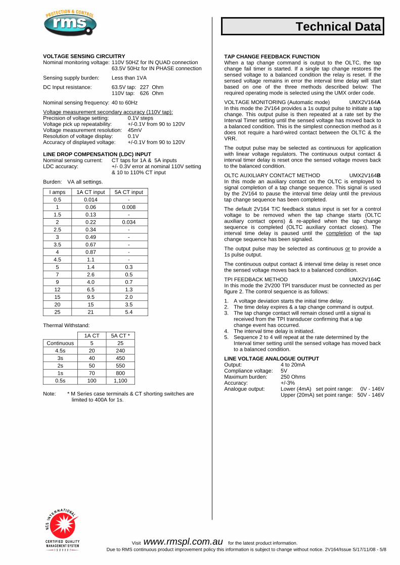
VOLTAGE SENSING CIRCUITRY Nominal monitoring voltage: 110V 50HZ for IN QUAD connection
63.5V 50Hz for IN PHASE connection
S
ensing supply burden: Less than 1VA
DC Input resistance: 63.5V tap: 227 Ohm
110V tap: 626 Ohm
N
ominal sensing frequency: 40 to 60Hz
Voltage measurement secondary accuracy (110V tap): Precision of voltage setting: 0.1V steps Voltage pick up repeatability: +/-0.1V from 90 to 120V Voltage measurement resolution: 45mV Resolution of voltage display: 0.1V Accuracy of displayed voltage: +/-0.1V from 90 to 120V LINE DROP COMPENSATION (LDC) INPUT Nominal sensing current: CT taps for 1A & 5A inputs LDC accuracy: +/- 0.3V error at nominal 110V setting
& 10 to 110% CT input B
urden: VA all settings.
I amps 1A CT input 5A CT input 0.5 0.014 - 1 0.06 0.008
1.5 0.13 - 2 0.22 0.034
2.5 0.34 - 3 0.49 -
3.5 0.67 - 4 0.87 -
4.5 1.1 - 5 1.4 0.3 7 2.6 0.5 9 4.0 0.7
12 6.5 1.3 15 9.5 2.0 20 15 3.5 25 21 5.4
T
hermal Withstand:
1A CT 5A CT * Continuous 5 25
4.5s 20 240 3s 40 450 2s 50 550 1s 70 800
0.5s 100 1,100 Note: * M Series case terminals & CT shorting switches are
limited to 400A for 1s.
Technical Data TAP CHANGE FEEDBACK FUNCTION When a tap change command is output to the OLTC, the tap change fail timer is started. If a single tap change restores the sensed voltage to a balanced condition the relay is reset. If the sensed voltage remains in error the interval time delay will start based on one of the three methods described below: The required operating mode is selected using the UMX order code. VOLTAGE MONITORING (Automatic mode) UMX2V164A In this mode the 2V164 provides a 1s output pulse to initiate a tap change. This output pulse is then repeated at a rate set by the Interval Timer setting until the sensed voltage has moved back to a balanced condition. This is the simplest connection method as it does not require a hard-wired contact between the OLTC & the VRR. The output pulse may be selected as continuous for application with linear voltage regulators. The continuous output contact & interval timer delay is reset once the sensed voltage moves back to the balanced condition. OLTC AUXILIARY CONTACT METHOD UMX2V164B In this mode an auxiliary contact on the OLTC is employed to signal completion of a tap change sequence. This signal is used by the 2V164 to pause the interval time delay until the previous tap change sequence has been completed. The default 2V164 T/C feedback status input is set for a control voltage to be removed when the tap change starts (OLTC auxiliary contact opens) & re-applied when the tap change sequence is completed (OLTC auxiliary contact closes). The interval time delay is paused until the completion of the tap change sequence has been signaled. The output pulse may be selected as continuous or to provide a 1s pulse output. The continuous output contact & interval time delay is reset once the sensed voltage moves back to a balanced condition. TPI FEEDBACK METHOD UMX2V164C In this mode the 2V200 TPI transducer must be connected as per figure 2. The control sequence is as follows: 1. A voltage deviation starts the initial time delay. 2. The time delay expires & a tap change command is output. 3. The tap change contact will remain closed until a signal is
received from the TPI transducer confirming that a tap change event has occurred.
4. The interval time delay is initiated. 5. Sequence 2 to 4 will repeat at the rate determined by the
Interval timer setting until the sensed voltage has moved back to a balanced condition.
LINE VOLTAGE ANALOGUE OUTPUT Output: 4 to 20mA Compliance voltage: 5V Maximum burden: 250 Ohms Accuracy: +/-3% Analogue output: Lower (4mA) set point range: 0V - 146V Upper (20mA) set point range: 50V - 146V

Visit www.rmspl.com.au for the latest product information. Due to RMS continuous product improvement policy this information is subject to change without notice. 2V164/Issue S/17/11/08 - 6/8
AUXILIARY SUPPLY 20-70V DC switchmode supply or 4
0-275V AC / 40-300V DC switchmode supply
Burden: Less than 10 watts with all output relays energized using 110V DC nominal supply.
Inputs: A high efficiency switchmode power supply is incorporated which provides a low burden to the auxiliary supply. Input Transients: Withstands multiple high-energy transients & ring waves in accordance with IEEE28 - ANSI C26.1 Cat. II, accordingly:
0.5uS 100KHz 6KV O/C, 500A S/C, 4J 1.2/50uS 6Kv O/C 8/20uS 3KA S/C, 80J clamped at 1,000V
Mains conducted EMI within limits specified by AS 3548 Class B. Isolation: The inputs are isolated from the outputs in accordance with AS3260 Class II Limited Current Circuitry, accordingly:
Withstand voltage of 2.5Kv RMS 50Hz for one minute Creepage & clearance distance greater than 4mm Output leakage current less than 0.25A to earth
Output Protection: Outputs will withstand continuous short circuit. Output regulators & switching control regulator are thermally protected. RELAY FAIL ALARM A C/O alarm contact is maintained in the energized state when all of the following conditions are met:
The auxiliary supply is applied The internal 24V DC rail is within acceptable limits The CPU hardware watchdog maintains a pulsing output
A CPU software watchdog records “suspect” events to an assert register & if necessary performs a soft restart. A front panel green LED is illuminated when the relay is healthy. A separate flashing red LED indicates a software problem has been encountered which caused causing the CPU to perform a warm boot. OPERATING TEMPERATURE RANGE -5 to +55 degrees Celsius ambient operating temperature range. HUMIDITY 40 degrees C & 95% RH non condensing CASE Size 4 draw out 56 M4 screw terminals Flush panel mount or 4U high 1/4 width 19 inch rack mount IP51 rating
Technical Data OUTPUT CONTACT RATINGS
Make & carry 30A AC or DC (Limits L/R=40ms & 300V max.) for 0.2s 20A AC or DC (Limits L/R=40ms & 300V max.) for 0.5s 5A AC or DC continuously Break (Limits 5A & 300V max.) 1,250VA AC resistive 250VA at 0.4PF AC inductive 75W DC resistive 30W DC inductive L/R = 40ms 50W DC inductive L/R = 10ms Minimum recommended load 0.5W, 10mA or 5V minimum.
INSULATION WITHSTAND IEC60255-5 2KV RMS & 1.2/50 5KV impulse between: ♦ all input terminals & frame ♦ all output terminals & frame ♦ all input & output terminals ♦ each input group ♦ each output group
Across open contacts: 1KV RMS HIGH FREQUENCY DISTURBANCE IEC60255-22-1 2.5KV 1MHz common mode 1.0KV 1MHz differential mode ELECTROSTATIC DISCHARGE EN61000-4-2:1995 8KV Level 3 RADIO FREQUENCY INTERFERENCE EN61000-4-3:1995 10V/m Level 3 FAST TRANSIENT DISTURBANCE EN61000-4-4:1995 4KV Level 4 SHIPPING DETAILS Each relay is supplied individually packed in pre formed cardboard cartons with internal moulded polystyrene former.
Weight: 4Kg Size: 370(L) x 240(W) x 145(D)mm - Size 4 case For large shipment individual cartons are packed in sturdy cardboard pallet boxes & surrounded by loose fill to absorb vibration & shock during transit. ACCESSORIES SUPPLIED WITH EACH RELAY 1 x M4 self threading mounting screw kit P/N 290-406-151 2 x M4 terminal screw kit (28 per kit) P/N 290-407-153 1 x µMATRIX User Guide per order 1 x CD of µMATRIXwin software, setting files & applications

Visit www.rmspl.com.au for the latest product information. Due to RMS continuous product improvement policy this information is subject to change without notice. 2V164/Issue S/17/11/08 - 7/8
Application Diagram
2V164 application diagram
1
1
5
45
7
47
3
3
Vx
Vx
29
29
31
31
33
33
Voltage input
Voltage input
Auxiliary supply
Auxiliary supply
110
110
63.5
63.5
0
0
44
44
42
42
Tap change feedback
TPI Input2V200TPI Tranducer
1A LDC input
1A LDC input
5A LDC input
5A LDC input
41
41
43
43
VOLTAGETRANSFORMER
AUXILIARYSUPPLY
(Shown connectedin parallel with VT)
Vrns63.5V
Vyns
63.5VVbns63.5V
N
B Y
R
VT Secondaries 110V AC
VT Secondaries 110V AC
Auto or TPI mode for tap change feedback control
Tap change feedback control mode depicted
In PHASE Connection
CURRENTTRANSFORMER
CURRENTTRANSFORMER
Relative polarity for +Quad
Relative polarity for +Phase
VOLTAGETRANSFORMER
AUXILIARYSUPPLY
(Shown connectedin parallel with VT)
N/C TAP CHANGER AUXILIARY CONTACT TO BEOPENED FOR 1 SECOND MINIMUM DURING TAP CHANGE
TO LDCCT
TO LDCCT
APPLY / REMOVE EXTERNAL CONTROLVOLTAGES TO INITIATE
STATUS INPUT FUNCTION
Vrns63.5V
Vyns
63.5VVbns63.5V
N
B Y
R
In QUAD Connection
2V164 INPUTS
2V164 INPUTS
All relay contacts are shown with a healthy supply applied, the 2V164 in a balanced condition, auxiliary supply connected in parallel with the 110V sensed voltage & 1 Amp CT tap LDC input wired.
+
+
+
+
+
+
R PhaseLoad
R PhaseLoad
9
7
11
15
13
13
Auto / Manual
Load step stage 1
Load step stage 2

Visit www.rmspl.com.au for the latest product information. Due to RMS continuous product improvement policy this information is subject to change without notice. 2V164/Issue S/17/11/08 - 8/8
Ordering Information Generate the required ordering code as follows: e.g. 2V164 BBBA 1 2 3 4
2V164 1 AUXILIARY SUPPLY RANGE A 20-70V DC B 40-300V DC / 40-275V AC 2 DIGITAL INPUT OPERATING VOLTAGE – GROUP 1 Opto-isolated input A 24-80V AC/DC B 75-150V AC/DC C
150-300V AC/DC
3 DIGITAL INPUT OPERATING VOLTAGE – GROUP 2 Opto-isolated input A 24-80V AC/DC B 75-150V AC/DC C 150-300V AC/DC 4 ANALOGUE OUTPUTS A Not required B Required 4 to 20mA
SELECT DEFAULT APPLICATION SOFTWARE A UMX2V164A Voltage monitoring feedback – Auto mode B UMX2V164B OLTC auxiliary contact method C UMX2V164C TPI feedback method Where the tap position is to be displayed on the 2V164 refer to the 2V200 TPI Transducer Technical Bulletin for ordering information.
2
17
40
39
34
50
56
51 55
23
19
36
35
30
46
52
25
21
38
37
32
48
54
49 53
27
2V164 wiring diagram* - Relays shown in de-energised condition
1
9
5
7
7
11
15
13
13
3Vx Powersupply /CPU fail
alarm
Tapraise
Taplower
Over voltagealarmoutput
Blockingalarm output
Tap changefail alarm
Tap ratealarm
Tap positionoutput
Line voltageoutput
29
31
33
45
Voltage input
Transformer tap position indicator input
Status input group 1
Status input group 2
110
63.5
0
47
44
42
Tap change feedback
Auto / Manual
Load step stage 1
Load step stage 2
1A LDC input
5A LDC input
41
43
*Note: The status inputs & some relay outputs are assigned by the software (UMX) loaded on the relay.
Shown here are the standard assignments of the A, B, C UMXs. Other UMX versions may differ. Consult the UMX data sheets for specific I/O assignments.
*(See Note)
28
28
24
24
26
26
FRONT PANELPC PROGRAMMING
PORT
SCADACOMMUNICATIONS
PORT(Use one only)
SHIELD
SEND
RECEIVERS232 tooptic fiber
or ethernetGND
GND
B
A
120 Ohm
RS485 Shielded twistedpair cable (Up to 1Km)
Dedicatedsupervisory connection
RS232Network port(Option C)
RS485Network port
(Option B)
D9 FemaleOne DE09 straight through male to female
2 metre connection cable suppliedwith each order of relays
(P/N 997-000-042B)
RS232
To other MATRIX relays (Up to 32 units)Fit external terminating resistor to end of BUS relay only
Fit internal BIAS jumper links for single relay connection only
u
J19 J18BIAS links

Visit www.rmspl.com.au for the latest product information. Due to RMS continuous product improvement policy this information is subject to change without notice. 2V200/Issue G/07/02/2008 - 1/3
Features
Suitable for interfacing to tap changers with binary or BCD TPI outputs
Suitable for application with voltage divider TPI circuits
(Resistor values in the range 20 - 400 ohms may be employed)
50V DC output drive circuit to improve contact whetting performance
Frequency output immune to line disturbance
Two core un-shielded cable between sender unit & 2V164
Isolated power supply Plug in measuring module Double insulated high impact polystyrol case
Termination socket included for surface mounting enabling front or rear connection with optional DIN rail mounting
Simple & robust construction
Technical Bulletin 2V200 Tap Position Indicator V to F Sender Unit
TERMINATIONS
2
1
3
4
5
6
7
8
9
13
12 Ω
16
11
15
10
14
TPITRANSDUCER
2V200
SUPPLY NORMAL
110V AC
Description Made in Australia The 2V200 is specifically designed for operation with the RMS type 2V164 Voltage Regulating Relay (VRR) & application on power transformers fitted with on load tap changers. The 2V200 provides a noise immune interface between the tap changer & a remote tap position indicator TPI), display. (
The 2V200 is designed to interface with tap changers using either binary / BCD coded signals or a traditional voltage divider circuit. The 2V200 generates a 50V DC output to connect to the auxiliary contacts on the tap changer. These contacts are often prone to high resistance &
wer voltages may prove unreliable due to poor whetting currents. lo The 2V200 converts the tap changer auxiliary contact inputs to a low frequency signal proportional to the tap position. The 2V164 VRR converts this frequency to a voltage signal through an optically isolated input which is then feed into an A-D converter. The tap position is displayed on the front panel of the 2V164 based on the pre-programmed maximum tap
osition. p The 2V164 optionally provides two independent analogue outputs proportional to the tap position & the line voltage. These 4-20mA outputs are intended for connection to a SCADA input or a local display.

Visit www.rmspl.com.au for the latest product information. Due to RMS continuous product improvement policy this information is subject to change without notice. 2V200/Issue G/07/02/2008 - 2/3
TAP CHANGER INTERFACE – RESISTOR DIVIDER INPUT Connect using 2V200 terminals 4,12 & 13. 400 ohm Resistors Recommended value for resistor Rs: 400 ohms Tollerance: 1% Power rating: 0.5W
Rs resistors are to be connected between adjacent taps as per the application diagram shown in figure 1. Where 400 ohm resistors are employed the padding resistor Rp is not required.
The RMS TPI Resistor Box type 4O200 is designed for this function & provides 0.5W 1% resistors to interface with tap changer auxiliary switches.
<400 ohm Resistors Resistor (Rs) values less than 400 ohms (20 ohms minimum), may be employed provided the following two conditions are met:
1 1 1_A padding resistor Rp is fitted as per figure 1: Rp = Rs - 400
The parallel resistance across Rp can be checked using an ohm meter across terminals 11 & 13 without the auxiliary supply applied. This value must be equal to the chosen value for Rs.
The total resistance between terminals 4 & 13 is > 600 ohms.
The number of taps T x Rs is > 600 ohms
(E.g. 30 taps x 20 ohms per tap = 600 ohms)
If the value calculated above is < 600 ohms due to < 30 taps then an additional resistor (Ra) can be placed above the top tap esistor to terminal 4. Calculate Ra & re-check as follows: r
Ra = (30 – T) x Rs & check that T x Rs + Ra is > 600 ohms
The 2V164 / 2V165 relays must always be set for ANALOGUE TPI operation with the number of taps set to 30 when Ra is added o the circuit. t
2V164 Voltage Regulator Relay Configuration The 2V164 / 2V165 relays must be programmed for ANALOGUE TPI operation & the number of tap positions T, within the range 10 to 30 entered. Scaling is carried out automatically within the 2V164 so that the correct tap position is indicated on the data display.
Technical Data TAP CHANGER INTERFACE – BINARY OR BCD INPUT Connect using 2V200 terminals 4 to 10. The 2V200 provides a powered 6-wire connection to tap changers with either binary or BCD outputs. Two links on the 2V200 PCB are used to change the configuration from BCD input (Factory default) to binary input.
2V164 Voltage Regulator Relay Configuration The 2V164 VRR must be programmed for DIGITAL TPI operation. The number of tap positions is not set.
VOLTAGE DIVIDER RESISTOR TOLLERANCE The maximum tolerance of the resistors used in the voltage divider string is determined by the following formula: 100 % Tolerance = 3T where T = The maximum tap number.
Resistors with a minimum 1% tolerance rating are recommended.
AUXILIARY POWER SUPPLY 110V AC or 240V AC
POWER CONSUMPTION <
6VA at scale maximum current
FREQUENCY OUTPUT 5KHz maximum
TAP RANGE S
uits tap changers with 10 to 30 taps
TAP CHANGER INTERFACE 2V200 connection options: Voltage divider, BCD or binary. 2
V200 generated drive voltage: 50V DC
OPERATING TEMPERATURE RANGE - 5 to 70 degrees C
TRANSIENT OVERVOLTAGE IEC60255-5 CLASS III Between independent circuits without
amage or flashover d
5kV 1.2/50us 0.5J
INSULATION COORDINATION IEC60255-5 CLASS III Between independent circuits 2.0kV RMS for 1 minute Across normally open contacts 1.0kV RMS for 1 minute
HIGH FREQUENCY DISTURBANCE IEC60255-22-1 CLASS III 2.5kV 1MHz common mode 1.0kV 1MHz differential mode ≤ 3% variation
Tap 1
Use 400 Ohm 1% 0.5W resistors for RsOther resistor values possible:refer 2V200 Technical Bulletin
for tap 1 referencepadding resistor (Rp) values
Rs 1 Rs 21Ra*
Tap position indicator (TPI) hardware requirements and wiring configuration.
Transformer TPI selector switch
Frequencyoutput
Shielded cable recomendedfor long runs & parallel control
(2V165), applications
5KHz Max.
Integrated TPI display
** T/C EVENTS PAGE **
DATA to return
V F TPITransducer & sender unit
Tap Rate:Max Tap:Min Tap:
Tap Count:Time Elapsed:
4184
620160
2V164 VRR
2V20011 15
161
2
13 1012 4 5
The RMS type 4O200 Resistor Boxprovides a packaged TPI Rs solution
TPI output
Volts output
AlternativeBinary or BCD coded interface
Tap 1internal
referenceresistor
(400 ohms)
** Tap 1externalpaddingresistor
Rp
Vx
110V ACor 240V AC
TPI out of
step alarm
* If Rs x number taps > 600 ohmsthen resistor Ra is not required.
** If Rs = 400ohmthen resistor Rp is not required.
Figure 1 – Application diagram

Visit www.rmspl.com.au for the latest product information. Due to RMS continuous product improvement policy this information is subject to change without notice. 2V200/Issue G/07/02/2008 - 3/3
Ordering Information
Generate the required ordering code as follows: e.g. 2V200 AA
1 2
2V200 1 AUXILIARY SUPPLY RANGE A 110V AC B 240V AC 2 DIN RAIL MOUNTING CLIP A Not required B Required
REQUEST SPECIFIC RESISTOR (Rs) VALUE Default 2V200 calibration is 400 Ohm
Please advise other value if required. Note that the 2V200 can be re-configured on site to suit other resistor values.
Part
3 Software Function
Compatible Software UMX The 2V164 relay has a number of software programs called UMX available, which can be installed by the user. Each UMX provides a different functional configuration to suit specific applications. They must be however, compatible with the relay hardware. D ownload the UMX compatibility list from the RMS website:
A copy of the UMX Hardware / Software Compatibility Register is attached.
Download the most up to date UMX Hardware / Software Compatibility Register from the RMS
ebsite: w http://www.rmspl.com.au/digital/compatibility.pdf
Factory Default Software The 2V164 relay is ordered with a customer specified default UMX so that it is ready for operation when received. To achieve this, an ordering code may be sought at time of quotation and specified on your order.
Visit www.rmspl.com.au for the latest product information.
Due to RMS continuous product improvement policy this information is subject to change without notice. 2V164_Guide/Iss E - 01/04/09

Determining Software UMX Determining which UMX is loaded onto a MATRIX relay may be done in three ways: 1. New relays received from the factory have a label located on the side of the draw out module.
This label is printed with information specific to the relay and includes the UMX type that was loaded during production.
2. Press the DATA and SET page buttons on the relay simultaneously to bring up the
DIAGNOSTICS page.
Now press SELECT to view the versions page and you will see:
** VERSION PAGE ** BIOS Version: Vxx.xx The version of the low level BIOS code loaded by the factory. S/W Version: Vxx.xx The version of the software UMX. CBD: RMS Default The .ump parameters file saved to the relay from µMATRIXwin. Model: xxxxxS The xxxxx is the relay hardware code. The “S” is the UMX code. S/N: xxxxxx.xx The production tracking serial number also found on the front label. H/W Config: xx This number is related to the PCB loading and is auto detected. Volt Adj: Select to enter a voltage calibration offset.
3. Connect to the relay through the front panel RS232 configuration port using µMATRIXwin and
a PC. The UMX code & version is displayed at the bottom of the centre panel. Determining UMX Functionality Now that you have determined the UMX loaded in the relay you need to obtain the Software Functional Description Document which relates to it. It may be obtained from our web site as follows: Document name is: UMX2V164s.pdf using the “s” code from the version page above.
The location is: www.rmspl.com.au/ptmanual/umx2v164x.pdf User Interface Refer to the µMATRIX Users Guide for detailed instructions on the operation of the user interface.
To download a PDF version of the guide: www.rmspl.com.au/digital/umatrixinfo.pdf
To download further µMATRIX software & documentation: www.rmspl.com.au/umatrix.htm
Visit www.rmspl.com.au for the latest product information.
Due to RMS continuous product improvement policy this information is subject to change without notice. 2V164_Guide/Iss E - 01/04/09

Field Calibration Small errors in voltage reading and miss match to other voltage measuring devices is a common observation during commissioning and routine testing. Adjustment of the voltage calibration is possible in the field by accessing the diagnostic menu as follows: 1. Press the DATA and SET page buttons on the relay simultaneously to bring up the
DIAGNOSTICS page as described above. 2. Now arrow down to the Volt Adj line and press SELECT to enter a voltage adjustment value. A calibration adjustment in 0.1V increments can be entered for the voltage measurement system. This adjustment changes the voltage measured by the relay and is reflected in the voltmeter display on the Data Page. This adjustment setting is stored in EEPROM memory and will not be overwritten when new setting (UMP) or application (UMX) files are up loaded to the relay. Changes can only be made at the relay using the Volt Adj line in the diagnostics menu. 3. Press the DATA page button to return to the DATA Page.
Visit www.rmspl.com.au for the latest product information.
Due to RMS continuous product improvement policy this information is subject to change without notice. 2V164_Guide/Iss E - 01/04/09

Part
4 Installation
Handling of Electronic Equipment A person’s normal movements can easily generate electrostatic potentials of several thousand volts. Discharge of these voltages into semiconductor devices when handling electronic circuits can cause serious damage, which often may not be immediately apparent but the reliability of the circuit will have been reduced.
The electronic circuits of Relay Monitoring Systems Pty Ltd products are immune to the relevant levels of electrostatic discharge when housed in the case. Do not expose them to the risk of damage by withdrawing modules unnecessarily.
Each module incorporates the highest practicable protection for its semiconductor devices. However, if it becomes necessary to withdraw a module, the following precautions should be taken to preserve the high reliability and long life for which the equipment has been designed and manufactured.
1. Before removing a module, ensure that you are at the same electrostatic potential as the equipment by touching the case.
2. Handle the module by its front-plate, frame, or edges of the printed circuit board.
3. Avoid touching the electronic components, printed circuit track or connectors.
4. Do not pass the module to any person without first ensuring that you are both at the same electrostatic potential. Shaking hands achieves equipotential.
5. Place the module on an antistatic surface, or on a conducting surface which is at the same potential as yourself.
6. Store or transport the module in a conductive bag.
If you are making measurements on the internal electronic circuitry of an equipment in service, it is preferable that you are earthed to the case with a conductive wrist strap.
Wrist straps should have a resistance to ground between 500k – 10M ohms. If a wrist strap is not available, you should maintain regular contact with the case to prevent the build up of static.
Instrumentation which may be used for making measurements should be earthed to the case whenever possible.
Visit www.rmspl.com.au for the latest product information.
Due to RMS continuous product improvement policy this information is subject to change without notice. User_Guide-5/IssE/25/08/08

Safety Section
This Safety Section should be read before commencing any work on the equipment.
The information in the Safety Section of the product documentation is intended to ensure that products are properly installed and handled in order to maintain them in a safe condition. It is assumed that everyone who will be associated with the equipment will be familiar with the contents of the Safety Section. Explanation of Symbols & Labels The meaning of symbols and labels which may be used on the equipment or in the product documentation, is given below. Caution: refer to product information
! Caution: risk of electric shock Functional earth terminal Note: this symbol may also be used for a protective/safety earth terminal if that terminal is part of a terminal block or sub-assembly eg. power supply.
Visit www.rmspl.com.au for the latest product information.
Due to RMS continuous product improvement policy this information is subject to change without notice. User_Guide-4/Iss E/25/08/08

Unpacking Upon receipt inspect the outer shipping carton or pallet for obvious damage.
Remove the individually packaged relays and inspect the cartons for obvious damage.
To prevent the possible ingress of dirt the carton should not be opened until the relay is to be used. Refer to the following images for unpacking the relay:
Outer packing carton showing shipping documentation pouch.
Address label on top of carton.
Inner packing carton showing front label detailing the customer name, order
number, relay part number & description, the relay job number & packing date.
(Size 2 inner packing carton depicted)
Visit www.rmspl.com.au for the latest product information.
Due to RMS continuous product improvement policy this information is subject to change without notice. User_Guide-4/Iss E/25/08/08

Unpacking (Continued)
Inner packing carton with lid open showing protective foam insert.
CD depicted supplied with digital relay
models or upon request at time of order.
Inner packing carton with protective foam insert removed showing relay location.
Where mechanical flags are fitted the yellow transit wedge must be removed
before operation using a gentle twisting action. The wedge should be stored with
the original packaging material.
Visit www.rmspl.com.au for the latest product information.
Due to RMS continuous product improvement policy this information is subject to change without notice. User_Guide-4/Iss E/25/08/08

Relay Module Side Label Depicting Product Details
Relay Module Side Label Depicting Wiring Diagram (6R MATRIX relays only)
Visit www.rmspl.com.au for the latest product information.
Due to RMS continuous product improvement policy this information is subject to change without notice. User_Guide-4/Iss E/25/08/08

Accessories Supplied With Each Relay Self threading M4 mounting screws M4 terminal screws with captured lock washers Storage & Handling If damage has been sustained a claim should immediately be made against the carrier, also inform Relay Monitoring Systems Pty Ltd and the nearest RMS agent
When not required for immediate use, the relay should be returned to its original carton and stored in a clean, dry place.
Relays which have been removed from their cases should not be left in situations where they are exposed to dust or damp. This particularly applies to installations which are being carried out at the same time as constructional work.
If relays are not installed immediately upon receipt they should be stored in a place free from dust and moisture in their original cartons.
Dust which collects on a carton may, on subsequent unpacking, find its ay into the relay; in damp conditions the carton and packing may become impregnated with moisture and the de-humidifying agent will lose is efficiency.
Visit www.rmspl.com.au for the latest product information.
Due to RMS continuous product improvement policy this information is subject to change without notice. User_Guide-4/Iss E/25/08/08

Equipment Operating Conditions The equipment should be operated within the specified electrical and environmental limits. Protective relays, although generally of robust construction, require careful treatment prior to installation and a wise selection of site. By observing a few simple rules the possibility of premature failure is eliminated and a high degree of performance can be expected. Care must be taken when unpacking and installing the relays so that none of the parts are damaged or their settings altered and must al all times be handled by skilled persons only. Relays should be examined for any wedges, clamps, or rubber bands necessary to secure moving parts to prevent damage during transit and these should be removed after installation and before commissioning. The relay should be mounted on the circuit breaker or panel to allow the operator the best access to the relay functions. Relay Dimensions & Other Mounting Accessories Refer drawing in Technical Bulletin. Relevant Auto Cad files & details on other accessories such as 19 inch sub rack frames, semi projection mount kits & stud terminal kits may be down loaded from:
http://www.rmspl.com.au/mseries.htm
Visit www.rmspl.com.au for the latest product information.
Due to RMS continuous product improvement policy this information is subject to change without notice. User_Guide-4/Iss E/25/08/08

Equipment Connections Personnel undertaking installation, commissioning or servicing work on this equipment should be aware of the correct working procedures to ensure safety. The product documentation should be consulted before installing, commissioning or servicing the equipment. Terminals exposed during installation, commissioning and maintenance may present hazardous voltage unless the equipment is electrically isolated. If there is unlocked access to the rear of the equipment, care should be taken by all personnel to avoid electric shock or energy hazards. Voltage and current connections should be made using insulated crimp terminations to ensure that terminal block insulation requirements are maintained for safety. To ensure that wires are correctly terminated, the correct crimp terminal and tool for the wire size should be used. Before energising the equipment it must be earthed using the protective earth terminal, or the appropriate termination of the supply plug in the case of plug connected equipment. Omitting or disconnecting the equipment earth may cause a safety hazard. The recommended minimum earth wire size is 2.5mm2, unless otherwise stated in the technical data section of the product documentation. Before energising the equipment, the following should be checked:
1. Voltage rating and polarity; 2. CT circuit rating and integrity of connections; 3. Protective fuse rating; 4. Integrity of earth connection (where applicable)
Visit www.rmspl.com.au for the latest product information.
Due to RMS continuous product improvement policy this information is subject to change without notice. User_Guide-4/Iss E/25/08/08

Current Transformer Circuits Do not open the secondary circuit of a live CT since the high voltage produced may be lethal to personnel and could damage insulation. External Resistors Where external resistors are fitted to relays, these may present a risk of electric shock or burns, if touched. Insulation & Dielectric Strength Testing Insulation testing may leave capacitors charged up to a hazardous voltage. At the end of each part of the test, the voltage should be gradually reduced to zero, to discharge capacitors, before the test leads are disconnected. Insertion of Modules These must not be inserted into or withdrawn from equipment whilst it is energised, since this may result in damage. Electrical Adjustments Pieces of equipment which require direct physical adjustments to their operating mechanism to change current or voltage settings, should have the electrical power removed before making the change, to avoid any risk of electric shock. Mechanical Adjustments The electrical power to the relay contacts should be removed before checking any mechanical settings, to avoid any risk of electric shock. Draw Out Case Relays Removal of the cover on equipment incorporating electromechanical operating elements, may expose hazardous live parts such as relay contacts. Insertion & Withdrawal of Heavy Current Test Plugs When using a heavy current test plug, CT shorting links must be in place before insertion or removal, to avoid potentially lethal voltages.
Visit www.rmspl.com.au for the latest product information.
Due to RMS continuous product improvement policy this information is subject to change without notice. User_Guide-4/Iss E/25/08/08

Commissioning Preliminaries Carefully examine the module and case to ser that no damage has occurred during transit. Check that the relay serial number on the module, case and cover are identical, and that the model number and rating information are correct. Carefully remove any elastic bands/packing fitting for transportation purposes. Check that the external wiring is correct to the relevant relay diagram or scheme diagram. The relay diagram number appears inside the case. Particular attention should be paid to the correct wiring and value of any external resistors indicated on the wiring diagram/relay rating information. Note that shorting switches shown on the relay diagram are fitted internally across the relevant case terminals and close when the module is withdrawn. It is essential that such switches are fitted across all CT circuits. If a test block system is to be employed, the connections should be checked to the scheme diagram, particularly that the supply connections are to the ‘live’ side of the test block. Earthing Ensure that the case earthing connection above the rear terminal block, is used to connect the relay to a local earth bar. Insulation The relay, and its associated wiring, may be insulation tested between: - all electrically isolated circuits
- all circuits and earth An electronic or brushless insulation tester should be used, having a dc voltage not exceeding 1000V. Accessible terminals of the same circuit should first be strapped together. Deliberate circuit earthing links, removed for the tests, subsequently must be replaced.
Visit www.rmspl.com.au for the latest product information.
Due to RMS continuous product improvement policy this information is subject to change without notice. User_Guide-4/Iss E/25/08/08

Commissioning Tests If the relay is wired through a test block it is recommended that all secondary injection tests should be carried out using this block. Ensure that the main system current transformers are shorted before isolating the relay from the current transformers in preparation for secondary injection tests. DANGER DO NOT OPEN CIRCUIT THE SECONDAY CIRCUIT OF A CURRENT TRANSFORMER SINCE
THE HIGH VOLTAGE PRODUCED MAY BE LETHAL AND COULD DAMAGE INSULATION. It is assumed that the initial preliminary checks have been carried out. Relay CT shorting switches With the relay removed from its case, check electrically that the CT shorting switch is closed. Primary injection testings It is essential that primary injection testing is carried out to prove the correct polarity of current transformers. Before commencing any primary injection testing it is essential to ensure that the circuit is dead, isolated from the remainder of the system and that only those earth connections associated with the primary test equipment are in position. Decommissioning & Disposal Decommissioning: The auxiliary supply circuit in the relay may include capacitors across the
supply or to earth. To avoid electric shock or energy hazards, after completely isolating the supplies to the relay (both poles of any dc supply), the capacitors should be safely discharged via the external terminals prior to decommissioning.
Disposal: It is recommended that incineration and disposal to water courses is avoided. The product should be disposed of in a safe manner.
Visit www.rmspl.com.au for the latest product information.
Due to RMS continuous product improvement policy this information is subject to change without notice. User_Guide-4/Iss E/25/08/08

Part
5 Maintenance
Mechanical Inspection
Relay Assembly
Inspect the relay for obvious signs of damage or ingress of moisture or other contamination.
Relay Module
Isolate the relay, remove the front cover & carefully withdraw the relay module from the case.
Care must be taken to avoid subjecting the relay element to static discharge which may damage or degrade sensitive electronic components.
Inspect the relay module for signs of any overheating or burn marks which may have been caused by overvoltage surge or transient conditions on the power supply or digital status inputs.
Inspect the VT & CT stages for degradation of insulation on the terminal wiring & transformer windings.
Remove cover by unscrewing black thumb screws & withdraw the relay module from the case.
Visit www.rmspl.com.au for the latest product information.
Due to RMS continuous product improvement policy this information is subject to change without notice. User_Guide-5/Iss D/10/07/08

Relay Case
Inspect the outer terminals checking insulation integrity & tightness.
Inspect inside the case and use a blower to remove dust.
Inspect the inner terminals for worn, distorted or tarnished contacts and if necessary clean the contacts using a brush dipped in a suitable substance.
Case outer terminals Case inner terminals Module plug in terminals
Test Intervals The maintenance tests required will largely depend upon experience and site conditions, but as a general rule it is recommended that the following inspection and tests are performed every twelve months.
♦ Mechanical Inspection
♦ Check of Connections
♦ Insulation Resistance Test
♦ Fault Setting Tests by Secondary Injection
♦ Tests using Load Current
♦ Check the continuity of the neutral CT loop with a bell test set or an ohmmeter
Visit www.rmspl.com.au for the latest product information.
Due to RMS continuous product improvement policy this information is subject to change without notice. User_Guide-5/Iss D/10/07/08

D efect Report Form
Please copy this sheet and use it to report any defect which may occur. Contact Name:
Telephone No:
Customers Name & Address:
Fax No:
Supplied by:
Date when installed:
Site:
Circuit:
When Defect Found Date: Commissioning? Maintenance? Systems Fault? Other, Please State:
Product Part No: Serial Number:
Copy any message displayed by the relay:
Describe Defect:
Describe any other action taken:
Signature:
Please Print Name: Date:
For RMS use only Date Received: Contact Name: Reference No: Date Acknowledged: Date of Reply: Date Cleared:
Visit www.rmspl.com.au for the latest product information.
Due to RMS continuous product improvement policy this information is subject to change without notice. User_Guide-5/Iss D/10/07/08

© 2 0 0 8 R e l a y M o n i t o r i n g S y s t e m s P t y L t d Due to RMS continuous product improvement policy this information is subject to change without notice.
Australian Content Unless otherwise stated the product(s) quoted are manufactured by RMS at our production facility in Melbourne Australia. Approximately 60% of our sales volume is derived from equipment manufactured in house with a local content close to 90%. Imported components such as semi-conductors are sourced from local suppliers & preference is given for reasonable stock holding to support our build requirements. Quality Assurance RMS holds NCSI (NATA Certification Services International), registration number 6869 for the certification of a quality assurance system to AS/NZS ISO9001-2000. Quality plans for all products involve 100% inspection and testing carried out before despatch. Further details on specific test plans, quality policy & procedures may be found in section A4 of the RMS product catalogue.
Product Packaging Protection relays are supplied in secure individual packing cardboard boxes with moulded styrene inserts suitable for recycling. Each product & packing box is labeled with the product part number, customer name & order details.
Design References The products & components produced by RMS are based on many years of field experience since Relays Pty Ltd was formed in 1955. A large population of equipment is in service throughout Australia, New Zealand, South Africa & South East Asia attesting to this fact. Specific product & customer reference sites may be provided on application.
Product Warranty All utility grade protection & auxiliary relay products, unless otherwise stated, are warranted for a period of 24 months from shipment for materials & labour on a return to factory basis. Repair of products damaged through poor application or circumstances outside the product ratings will be carried out at the customer’s expense.
Standard Conditions of Sale Unless otherwise agreed RMS Standard Terms & Conditions (QF 907) shall apply to all sales. These are available on request or from our web site.
Relay Monitoring Systems Pty Ltd 6 Anzed Court, Mulgrave, Victoria 3170, AUSTRALIA
Tel: 61 3 9561 0266 Fax: 61 3 9561 0277 Email: [email protected] Web: www.rmspl.com.au