rmg941 fs a - ssv-embedded.de · 6.3 using the ssv/webui ... regular mobile network with 2g!...
TRANSCRIPT

Remote Maintenance Gateway
RMG/941(L,N)with DNP/9535
First Steps
SSV Software Systems GmbH Dünenweg 5 D-30419 Hannover Phone: +49 (0)511/40 000-0 Fax: +49 (0)511/40 000-40 Email: [email protected]
Document Revision: 1.0 Date: 2019-12-13

Remote Maintenance Gateway RMG/941(L,N) – First Steps
2 Document Revis ion 1.0
CONTENT
1 INTRODUCTION ............................................................................................................... 3
1.1 Checklist ................................................................................................................................. 3
1.2 Conventions ........................................................................................................................... 3
2 SAFETY GUIDELINES ..................................................................................................... 4
3 REQUIRED EQUIPMENT ................................................................................................. 5
4 SIM CARD ......................................................................................................................... 6
5 CONNECTIONS ................................................................................................................ 7
5.1 LTE/NB-IoT Antenna .............................................................................................................. 7
5.1 Ethernet Link .......................................................................................................................... 8
5.2 Serial Port COM2 ................................................................................................................... 9
5.3 Power Supply ....................................................................................................................... 10
6 OPERATION ................................................................................................................... 11
6.1 Booting the RMG/941 .......................................................................................................... 11
6.2 Accessing the SSV/WebUI .................................................................................................... 11
6.3 Using the SSV/WebUI .......................................................................................................... 12
6.4 Accessing the SSV/WebUI with DHCP enabled ................................................................... 13
6.5 RMG/941N: Checking NB-IoT Connection ........................................................................... 15
6.6 RMG/941L: LTE Modem Configuration ............................................................................... 16
6.7 RMG/941L: WAN Configuration .......................................................................................... 17
6.8 RMG/941L: Firewall Configuration ...................................................................................... 18
6.9 LAN1 Configuration .............................................................................................................. 19
6.10 Access via Telnet .................................................................................................................. 20
6.11 Access via FTP ...................................................................................................................... 21
6.12 Serial Console via COM1 (Service Port) ............................................................................... 23
7 TECHNICAL DATA ......................................................................................................... 24
8 PINOUT SCREW TERMINALS ....................................................................................... 24
9 HELPFUL LITERATURE ................................................................................................ 25
CONTACT ............................................................................................................................. 25
DOCUMENT HISTORY ......................................................................................................... 25

Remote Maintenance Gateway RMG/941(L,N) – First Steps
Document Revis ion 1.0 3
1 INTRODUCTION
This documentation gives you an overview about the initial operation and the first steps of
use with the RMG/941.
1.1 Checklist
Compare the content of your RMG/941(L,N) start-up package with the checklist below.
If any item is missing or appears to be damaged, please contact SSV!
� Remote Maintenance Gateway RMG/941(L,N)
� 1x LTE/NB-IoT antenna (only for RMG/941L and RMG/941N)
� Adapter cable with power and RS232 connector
� Plug-in power supply
� Screwdriver
IMPORTANT!
You will need further equipment to operate the RMG/941. Please refer to chapter 3.
1.2 Conventions
Convention Usage
bold Important terms
monospace Filenames, Pathnames, program code, command lines
Table 1: Conventions used in this document

Remote Maintenance Gateway RMG/941(L,N) – First Steps
4 Document Revis ion 1.0
2 SAFETY GUIDELINES
Please read the following safety guidelines carefully! In case of property or personal
damage by not paying attention to this manual and/or by incorrect handling, we do not
assume liability. In such cases any warranty claim expires.
• The power supply should be in immediate proximity to the device.
• The power supply must provide a stable output voltage between 11 – 28 VDC. The out-
put power should be at least 2.5 W.
• Please pay attention that the power cord or other cables are not squeezed or damaged
in any way when you set up the device.
• Do NOT turn on the power supply while connecting any cables, especially the power
cables. This could cause damaged device components! First connect the cables and
THEN turn the power supply on.
• The installation of the device should be done only by qualified personnel.
• Discharge yourself electrostatic before you work with the device, e.g. by touching a
heater of metal, to avoid damages.
• Stay grounded while working with the device to avoid damage through electrostatic
discharge.
• The case of the device should be opened only by qualified personnel.

Remote Maintenance Gateway RMG/941(L,N) – First Steps
Document Revis ion 1.0 5
3 REQUIRED EQUIPMENT
To operate the RMG/941 the following hardware is required:
• one Ethernet cross-over cable or two Ethernet patch cables and a switch.
To operate the RMG/941L the following hardware is required:
• a valid SIM card with an appropriate mobile tariff. Please refer to chapter 4 to see how
the SIM card is inserted.
The RMG/941N comes with a preinstalled SIM card for NB-IoT.
To configure the RMG/941(L,N) a computer with the following features is required:
• Windows 7 or higher
• Web browser (e.g. Firefox, Chrome)
• Telnet/SSH client (e.g. TeraTerm)
• FTP client (e.g. FileZilla)
• 10/100 Mbps Ethernet network controller and TCP/IP configuration
• CD-ROM drive
RMG/941(L,N) – First Steps
6 Document Revis ion 1.0
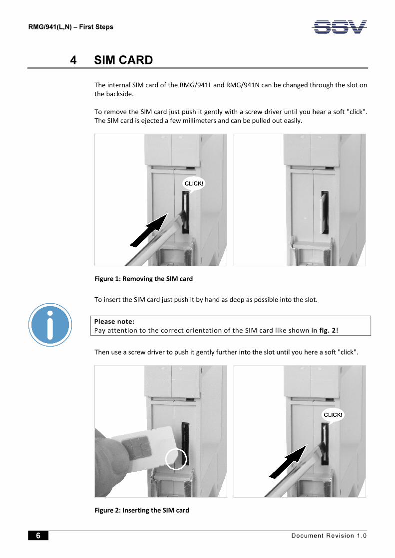
4 SIM CARD
The internal SIM card of the RMG/941L and RMG/941N can be changed through the slot on
the backside.
To remove the SIM card just push it gently with a screw driver until you hear a soft "click".
The SIM card is ejected a few millimeters and can be pulled out easily.
Figure 1: Removing the SIM card
To insert the SIM card just push it by hand as deep as possible into the slot.
Please note:
Pay attention to the correct orientation of the SIM card like shown in fig. 2!
Then use a screw driver to push it gently further into the slot until you here a soft "click".
Figure 2: Inserting the SIM card

Remote Maintenance Gateway RMG/941(L,N) – First Steps
Document Revis ion 1.0 7
5 CONNECTIONS
For a quick and easy start with the RMG/941 there are a few cable connections necessary.
The following chapters describe how these connections have to be made.
5.1 LTE/NB-IoT Antenna
Connect the LTE/NB-IoT antenna with the RMG/941(L,N) like shown in fig. 3 and place it
where the LTE/NB-IoT signal strength is high.
Figure 3: Connecting the LTE/NB-IoT antenna

Remote Maintenance Gateway RMG/941(L,N) – First Steps
8 Document Revis ion 1.0
5.1 Ethernet Link
The Ethernet link between the PC and LAN1 of the RMG/941 can be made on two ways:
• Direct with an Ethernet cross-over cable like shown in fig. 4.
• With two standard Ethernet patch cables over a hub or switch like shown in fig. 5.
Figure 4: Ethernet link with cross-over cable
Please note:
For the Ethernet connection in fig. 4 it is required to use a cross-over cable. Do not
use an ordinary patch cable. Both types of cables are in most cases visual indistin-
guishable. But the internal wiring is fully different. Mixing up these types of cables
leads to LAN errors. Hence pay attention to the label of the cable or packing.
Figure 5: Ethernet link with hub or switch
The IP address of the LAN1 interface is ex-factory set to 192.168.0.126.

Remote Maintenance Gateway RMG/941(L,N) – First Steps
Document Revis ion 1.0 9
5.2 Serial Port COM2
You can create an RS485 serial link on port COM2 of the RMG/941.
Figure 6: Serial link on COM2
Terminal Signal
A1 COM2 Serial Port: RS485 RX /TX+
A2 COM2 Serial Port: RS485 RX /TX-
B4 Signal Ground
Table 2: Screw terminals COM2
Please note:
The RS485 (officially called TIA/EIA-485-A) connection between your RMG/941 and
the field devices needs termination resistors on both ends for proper operation. The
RMG/941 does not offer internal termination resistors. Please make sure, that the
RS485 cable connection is equipped with external termination resistors.

Remote Maintenance Gateway RMG/941(L,N) – First Steps
10 Document Revis ion 1.0
5.3 Power Supply
The RMG/941 needs a supply voltage of 11 – 28 VDC to work.
Connect the cables of an appropriate power supply to provide the system with the neces-
sary power like shown in fig. 7.
Figure 7: Power supply for the RMG/941
Terminal Signal
A3 Vin (11 .. 28 VDC)
A4 GNDin
Table 3: Screw terminal power
CAUTION!
Providing the RMG/941 with a higher voltage than the regular 11 – 28 VDC could cause
damaged device components!
Do NOT turn on the power supply while connecting it with the RMG/941. This could cause
damaged device components! First connect the power supply and THEN turn it on.

Remote Maintenance Gateway RMG/941(L,N) – First Steps
Document Revis ion 1.0 11
6 OPERATION
6.1 Booting the RMG/941
Just power up the RMG/941 and the boot process starts immediately. The RMG/941 boots
an embedded Linux out of its Flash memory. This may take up to one minute.
6.2 Accessing the SSV/WebUI
To open the login page of the SSV/WebUI enter the ex-factory IP address and port number
of LAN1 of the RMG/941 manually in a web browser:
https://192.168.0.126:7777
Enter your username and password and click on [Login].
Figure 8: Login page of the SSV/WebUI

Remote Maintenance Gateway RMG/941(L,N) – First Steps
12 Document Revis ion 1.0
6.3 Using the SSV/WebUI
The SSV/WebUI allows to view log files and to configure the system settings of the
RMG/941 with a web browser, e.g. enabling and disabling services like Telnet or changing
the IP address.
Please note:
To keep changed settings after a reboot or an interruption of the power supply they
must be persisted. Therefore choose from the menu System > System management
(fig. 9). The section Temporary configuration shows which settings are not persisted
yet. To save the settings permanently just click on the button [Persist].
If there are any unsaved settings you can also always see on the right side of the
SSV/WebUI’s header under unsaved changes.
Figure 9: System management within the SSV/WebUI

Remote Maintenance Gateway RMG/941(L,N) – First Steps
Document Revis ion 1.0 13
6.4 Accessing the SSV/WebUI with DHCP enabled
If the automatic IP address configuration of LAN1 via DHCP is enabled, you have to check
the assigned IP address, which is necessary to access the RMG/941 via a Telnet client or a
web browser.
Therefore open in Windows Control Panel > Network and Internet > View network com-
puters and devices. The RMG/941 should show up in this list.
Figure 10: Selecting the RMG/941
Just right-click on the RMG/941 to open the properties dialog, where you can see the cur-
rent IP address of the RMG/941 like shown in fig. 11.
A double-click on the RMG/941 opens the SSV/WebUI in a web browser.
Please note:
To access the SSV/WebUI, it is important to add the port number 7777 to the cur-
rent IP address of the RMG/941, e.g.: http://192.168.0.126:7777!

RMG/941(L,N) – First Steps
14 Document Revis ion 1.0
Figure 11: The properties dialog shows the current IP address
Now you are able to access the RMG/941 via a Telnet client or a web browser.

Remote Maintenance Gateway RMG/941(L,N) – First Steps
Document Revis ion 1.0 15
6.5 RMG/941N: Checking NB-IoT Connection
The RMG/941N comes with a preinstalled NB-IoT SIM card with 500 MB free traffic volume.
To check if there is a connection with the NB-IoT mobile network choose from the menu
Network > Mobile.
Figure 12: Mobile network settings of the RMG/941N
In the section Modem configuration the line Status should display CONNECTED.
You can also check the signal strength by clicking on the button [Check signal].
Please note:
If the connection to the NB-IoT network fails, the modem tries to connect with the
regular mobile network with 2G!

RMG/941(L,N) – First Steps
16 Document Revis ion 1.0
6.6 RMG/941L: LTE Modem Configuration
The RMG/941L does NOT come with a SIM card. To connect with the LTE mobile network
you have to insert a valid SIM card first. Chapter 4 shows how to insert/change a SIM card.
To configure the LTE modem settings choose from the menu Network > Mobile.
Figure 13: Mobile network settings
1. In the section Modem configuration enable the checkbox.
2. If the provider is not recognized automatically disable the checkbox in the section ISP
settings and choose your provider manually.
3. Enter the PIN of the SIM card.
4. In the section Connection settings choose On System start.
5. Click on [Apply].
In the section Network configuration you can enter a DNS server if needed.
In the section Modem configuration the line Status should display CONNECTED after the
successful configuration.
You can also check the signal strength by clicking on the button [Check signal].

Remote Maintenance Gateway RMG/941(L,N) – First Steps
Document Revis ion 1.0 17
6.7 RMG/941L: WAN Configuration
To operate the RMG/941L as an LTE router the WAN (Wide Area Network) settings need to
be configured.
Choose from the menu Network > WAN.
Figure 14: WAN settings
1. In the section WAN configuration choose Mobile.
2. In the section Internet click on [Check] to test the Internet connection.
3. Click on [Apply].
Please note:
If the RMG/941L operates as an LTE router it is highly recommended to enable the
firewall (please refer to chapter 6.8)!

RMG/941(L,N) – First Steps
18 Document Revis ion 1.0
6.8 RMG/941L: Firewall Configuration
If the RMG/941L operates as an LTE router it is highly recommended to enable the fire-
wall!
Choose from the menu Services > Firewall and NAT.
Figure 15: Firewall and NAT settings
1. In the section Firewall configuration enable the checkbox.
2. In the section Forwarding with IP-Masquerading and NAT enable the checkbox.
3. Click on [Apply].
Remote Maintenance Gateway RMG/941(L,N) – First Steps
Document Revis ion 1.0 19
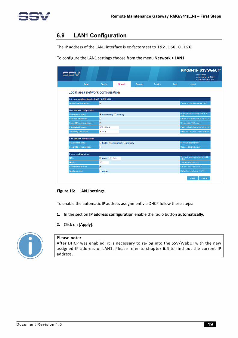
6.9 LAN1 Configuration
The IP address of the LAN1 interface is ex-factory set to 192.168.0.126.
To configure the LAN1 settings choose from the menu Network > LAN1.
Figure 16: LAN1 settings
To enable the automatic IP address assignment via DHCP follow these steps:
1. In the section IP address configuration enable the radio button automatically.
2. Click on [Apply].
Please note:
After DHCP was enabled, it is necessary to re-log into the SSV/WebUI with the new
assigned IP address of LAN1. Please refer to chapter 6.4 to find out the current IP
address.

Remote Maintenance Gateway RMG/941(L,N) – First Steps
20 Document Revis ion 1.0
6.10 Access via Telnet
Please note:
The Telnet server must be enabled via the SSV/WebUI. Therefore choose from the
menu Services > General, enable the checkbox in the line Telnet server and click on
[Apply].
To access the RMG/941 via Telnet open a Telnet client program (like TeraTerm) on your
host PC and enter the current IP address of the RMG/941 to activate a Telnet session.
In the upcoming Telnet window you can enter your login data.
Figure 17: Accessing the RMG/941 via Telnet client
Remote Maintenance Gateway RMG/941(L,N) – First Steps
Document Revis ion 1.0 21
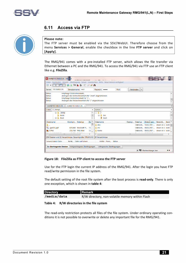
6.11 Access via FTP
Please note:
The FTP server must be enabled via the SSV/WebUI. Therefore choose from the
menu Services > General, enable the checkbox in the line FTP server and click on
[Apply].
The RMG/941 comes with a pre-installed FTP server, which allows the file transfer via
Ethernet between a PC and the RMG/941. To access the RMG/941 via FTP use an FTP client
like e.g. FileZilla.
Figure 18: FileZilla as FTP client to access the FTP server
Use for the FTP login the current IP address of the RMG/941. After the login you have FTP
read/write permission in the file system.
The default setting of the root file system after the boot process is read-only. There is only
one exception, which is shown in table 4:
Directory Remark
/media/data R/W directory, non-volatile memory within Flash
Table 4: R/W directories in the file system
The read-only restriction protects all files of the file system. Under ordinary operating con-
ditions it is not possible to overwrite or delete any important file for the RMG/941.
Remote Maintenance Gateway RMG/941(L,N) – First Steps
22 Document Revis ion 1.0
To disable the write protection just login and enter the following command:
remount rw
This command mounts the file system as read/write. All files are now writable and
deletable.
Please note:
Pay attention not to damage important system files!
The system is set back to the read-only initial condition like after the boot process with the
following command:
remount ro

Remote Maintenance Gateway RMG/941(L,N) – First Steps
Document Revis ion 1.0 23
6.12 Serial Console via COM1 (Service Port)
Over the serial port COM1 (service port) on the front panel of the RMG/941 a serial Linux
console can be accessed.
Figure 19: Serial Linux console in TeraTerm
Please note:
To create a connection between the RMG/941 and the PC an adapter cable and a
null modem cable are necessary. Please refer to the RMG/941 hardware reference
for more information.
Remote Maintenance Gateway RMG/941(L,N) – First Steps
24 Document Revis ion 1.0
7 TECHNICAL DATA
Supply voltage ................................................................................. 11 – 28 VDC
Weight ..................................................................................................... < 150 g
Mechanical Dimensions (LxWxH) .......................... 112 mm x 22.5 mm x 100 mm
Temperature range ........................................................................... 0° C – 60° C
Rel. air himudity .................................................................................. max. 85%
8 PINOUT SCREW TERMINALS
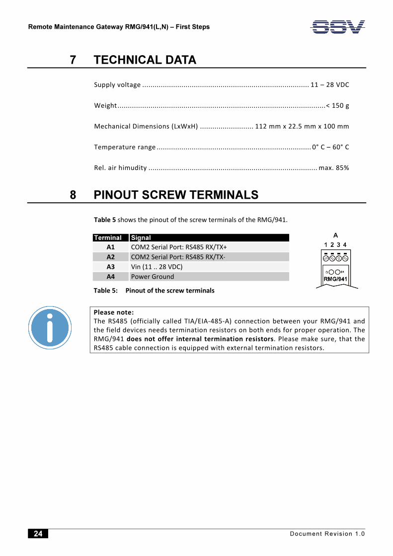
Table 5 shows the pinout of the screw terminals of the RMG/941.
Terminal Signal
A1 COM2 Serial Port: RS485 RX/TX+
A2 COM2 Serial Port: RS485 RX/TX-
A3 Vin (11 .. 28 VDC)
A4 Power Ground
Table 5: Pinout of the screw terminals
Please note:
The RS485 (officially called TIA/EIA-485-A) connection between your RMG/941 and
the field devices needs termination resistors on both ends for proper operation. The
RMG/941 does not offer internal termination resistors. Please make sure, that the
RS485 cable connection is equipped with external termination resistors.
Remote Maintenance Gateway RMG/941(L,N) – First Steps
Document Revis ion 1.0 25
9 HELPFUL LITERATURE
• RMG/941 hardware reference manual
• DNP/9535 hardware reference manual
CONTACT
SSV Software Systems GmbH
Dünenweg 5
D-30419 Hannover
Phone: +49 (0)511/40 000-0
Fax: +49 (0)511/40 000-40
Email: [email protected]
Internet: www.ssv-embedded.de
Forum: www.ssv-comm.de/forum
Wiki: mewi.ssv-embedded.de
DOCUMENT HISTORY
Revision Date Remarks Name Review
1.0 2019-12-13 First version WBU ENE
The content of this document can change any time without announcement. There is taken over no guaran-
tee for the accuracy of the statements. The user assumes the entire risk as to the accuracy and the use of
this document. Information in this document is provided ‘as is’ without warranty of any kind. Some names
within this document can be trademarks of their respective holders.
© 2019 SSV SOFTWARE SYSTEMS GMBH. All rights reserved.