rm2-1555/2355 positioner instructions...• this user guide provides an overview of the yaskawa...
TRANSCRIPT

Part Number: 166009-1CDRevision: 7
RM2-1555/2355 POSITIONER INSTRUCTIONSFOR DX100
Upon receipt of the product and prior to initial operation, read these instructions thoroughly and retain for future reference.
MOTOMAN INSTRUCTIONS
MOTOMAN RM2-1555/2355 POSITIONER INSTRUCTIONSCONTROLLER INSTRUCTIONSCONTROLLER OPERATOR’S MANUALCONTROLLER MAINTENANCE MANUAL
The controller operator’s manual above correspond to specific usage. Be sure to use the appropriate manual.
1 of 67

ii
166009-1CD
166009-1CD
RM2-1555/2355 Positioner
Copyright © 2017, 2015, 2014, 2013 Yaskawa America, Inc.
Terms of Use and Copyright Notice
All rights reserved. This manual is freely available as a service to Yaskawa customers to assist in the operation of Motoman robots, related equipment and software This manual is copyrighted property of Yaskawa and may not be sold or redistributed in any way. You are welcome to copy this document to your computer or mobile device for easy access but you may not copy the PDF files to another website, blog, cloud storage site or any other means of storing or distributing online content.
Printed in the United States of America
First Printing, 2013
Yaskawa America, Inc. Motoman Robotics Division 100 Automation Way Miamisburg, OH 45342 Phone: 937-847-6200
www.motoman.com
2 of 67

iii
166009-1CD
166009-1CD
RM2-1555/2355 Positioner
MANDATORY
• This user guide provides an overview of the Yaskawa RM2-1555/2355 Positioner system. It gives general information about the system, a description of its major components, and the procedures for installation, system operation, and preventive and repair maintenance. Be sure to read and understand this manual thoroughly before installing and operating the RM2-1555/2355 Positioner system.
• General items related to safety are listed in Section 2 of the Controller Manual. To ensure correct and safe operation, carefully read the Controller Manual before reading this manual.
• It is the purchaser’s responsibility to ensure that all local, county, state, and national codes, regulations, rules, or laws relating to safety and safe operating conditions for each installation are met and followed
CAUTION
• Some drawings in this manual are shown with the protective covers or shields removed for clarity. Be sure that all covers and shields are replaced before operating this product.
• The drawings and photos in this manual are representative, and differences may exist between them and the delivered product.
• YASKAWA may modify this model without notice when necessary due to product improvements, modifications, or changes in specifications. If such a modification is made, the manual number will also be revised.
• If your copy of the manual is damaged or lost, contact a YASKAWA representative to order a new copy. The representatives are listed on the back cover. Be sure to tell the representative the manual number listed on the front cover.
• YASKAWA is not responsible for incidents arising from unauthorized modification of its products. Unauthorized modification voids your product's warranty.
3 of 67

iv
166009-1CD
166009-1CD
RM2-1555/2355 Positioner
We suggest that you obtain and review a copy of the ANSI/RIA National Safety Standard for Industrial Robots and Robot Systems (ANSI/RIA R15.06-2012). You can obtain this document from the Robotic Industries Association (RIA) at the following address:
Robotic Industries Association900 Victors WayP.O. Box 3724
Ann Arbor, Michigan 48106TEL: (734) 994-6088FAX: (734) 994-3338
www.roboticsonline.com
Ultimately, well-trained personnel are the best safeguard against accidents and damage that can result from improper operation of the equipment. The customer is responsible for providing adequately trained personnel to operate, program, and maintain the equipment. NEVER ALLOW UNTRAINED PERSONNEL TO OPERATE, PROGRAM, OR REPAIR THE EQUIPMENT!
We recommend approved Yaskawa training courses for all personnel involved with the operation, programming, or repair of the equipment.
This equipment has been tested and found to comply with the limits for a Class A digital device, pursuant to part 15 of the FCC rules. These limits are designed to provide reasonable protection against harmful interference when the equipment is operated in a commercial environment. This equipment generates, uses, and can radiate radio frequency energy and, if not installed and used in accordance with the instruction manual, may cause harmful interference to radio communications.
4 of 67

v
166009-1CD
166009-1CD
RM2-1555/2355 Positioner
Notes for Safe Operation
Notes for Safe OperationRead this manual carefully before maintenance or inspection of the DX100.
In this manual, the Notes for Safe Operation are classified as “DANGER”, “WARNING”, “CAUTION”, “MANDATORY”, or “PROHIBITED”.
Even items described as “CAUTION” may result in a serious accident in some situations. At any rate, be sure to follow these important items.
DANGERIndicates an imminent hazardous situation which, if not avoided, could result in death or serious injury to personnel.
WARNINGIndicates a potentially hazardous situation which, if not avoided, could result in death or serious injury to personnel.
CAUTIONIndicates a potentially hazardous situation which, if not avoided, could result in minor or moderate injury to personnel and damage to equipment. It may also be used to alert against unsafe practices.
MANDATORYAlways be sure to follow explicitly the items listed under this heading.
PROHIBITED Must never be performed.
NOTETo ensure safe and efficient operation at all times, be sure to follow all instructions, even if not designated as “DANGER”, “WARNING” and “CAUTION”.
5 of 67

Notes for Safe Operation
vi
166009-1CD
166009-1CD
RM2-1555/2355 Positioner
WARNING• Before operating the manipulator, check that servo power is turned
OFF by pressing the EMERGENCY STOP buttons on the operator station or Programming Pendant (refer to Figure 1). When servo power is turned OFF, the SERVO ON LED on the Programming Pendant is turned OFF.
Injury or damage to machinery may result if the Emergency Stop circuit cannot stop the manipulator during an emergency. The manipulator should not be used if the EMERGENCY STOP buttons do not function.
Figure 1: EMERGENCY STOP Button
• Release the EMERGENCY STOP button (refer to Figure 2). Once this button is released, clear the cell of all items which could interfere with the operation of the manipulator. Then turn servo power ON.
0Injury may result from unintentional or unexpected manipulator motion.
Figure 2 : Release of EMERGENCY STOP Button
TURN
• Observe the following precautions when performing teaching operations within the P-point maximum envelope of the manipulator.
– View the manipulator from the front whenever possible.
– Always follow the predetermined operating procedure.
– Ensure that there is a safe place to retreat to in case of emergency.
Improper or unintended manipulator operation may result in injury.
• Confirm that no person is present in the P-point maximum envelope of the manipulator and that you are in a safe location before:
– Turning on the power for the controller.
– Moving the manipulator with the Programming Pendant.
– Running the system in the check mode.
– Performing automatic operations.
Injury may result if anyone enters the P-point maximum envelope of the manipulator during operation. Always press an EMERGENCY STOP button immediately if there is a problem. The EMERGENCY STOP buttons are located on the operator station and on the Programming Pendant.
6 of 67

vii
166009-1CD
166009-1CD
RM2-1555/2355 Positioner
Definition of Terms Used In this Manual
Definition of Terms Used In this ManualThe MOTOMAN manipulator is a YASKAWA industrial robot product.
The manipulator usually consists of the controller, the Programming Pendant, and supply cables.
In this manual, the equipment is designated as follows:
CAUTION
• Perform the following inspection procedures prior to conducting manipulator teaching. If problems are found, repair them immediately and be sure that all other necessary processing has been performed.
– Check for problems in manipulator movement.
– Check for damage to insulation and sheathing of external wires.
• Always return the Programming Pendant to the hook on the cabinet of the controller after use.
• The Programming Pendant can be damaged if it is left in the manipulator's work area, on the floor, or near fixtures.
• Read and understand the Explanation of Warning Labels in the Controller Manual before operating the RM2-1555/2355 Positioner system.
Equipment Manual Designation
DX100 Controller Controller
Programming Pendant Programming Pendant
Cable between the manipulator and the controller
Manipulator cable
7 of 67

Explanation of Safety Labels
viii
166009-1CD
166009-1CD
RM2-1555/2355 Positioner
Explanation of Safety LabelsThe following warning labels are attached to the positioner (refer to Figure 3).
Always follow the safety labels.
Also, an identification label with important information is placed on the body of the positioner. Prior to operating the manipulator, confirm the contents.
Figure 3: Warning Labels Location
Safety Label A:
WARNINGMoving partsmay causeinjury
WARNINGDo not enterrobot work area.
Safety Label B:
Safety Label C:
WARNINGArc flashmay injure
1555/2216
Safety Label E:
Safety Label D:
A
B
C
E
D
A
B
C
2355/2657
8 of 67

ix
166009-1CD
166009-1CD
RM2-1555/2355 Positioner
Safeguarding Tips
Safeguarding TipsAll operators, programmers, maintenance personnel, supervisors, and anyone working near the system must become familiar with the operation of this equipment. All personnel involved with the operation of the equipment must understand potential dangers of operation. General safeguarding tips are as follows:
• Improper operation can result in personal injury and/or damage to the equipment. Only trained personnel familiar with the operation of this equipment, the operator's manuals, the system equipment, and options and accessories should be permitted to operate this equipment.
• Improper connections can damage the equipment. All connections must be made within the standard voltage and current ratings of the equipment.
• The system must be placed in Emergency Stop (E-Stop) mode whenever it is not in use.
• In accordance with ANSI/RIA R15.06-2012, section 4.2.5, Sources of Energy, use lockout/tagout procedures during equipment maintenance. Refer also to Section 1910.147 (29CFR, Part 1910), Occupational Safety and Health Standards for General Industry (OSHA).
Mechanical Safety DevicesThe safe operation of this equipment is ultimately the users responsibility. The conditions under which the equipment will be operated safely should be reviewed by the user. The user must be aware of the various national codes, ANSI/RIA R15.06-2012 safety standards, and other local codes that may pertain to the installation and use of this equipment.
Additional safety measures for personnel and equipment may be required depending on system installation, operation, and/or location. The following safety equipment is provided as standard:
• Safety barriers
• Door interlocks
• Emergency stop palm buttons located on operator station
Check all safety equipment frequently for proper operation. Repair or replace any non-functioning safety equipment immediately.
9 of 67

Programming, Operation, and Maintenance Safety
x
166009-1CD
166009-1CD
RM2-1555/2355 Positioner
Programming, Operation, and Maintenance SafetyAll operators, programmers, maintenance personnel, supervisors, and anyone working near the system must become familiar with the operation of this equipment. Improper operation can result in personal injury and/or damage to the equipment. Only trained personnel familiar with the operation, manuals, electrical design, and equipment interconnections of this equipment should be permitted to program, or maintain the system. All personnel involved with the operation of the equipment must understand potential dangers of operation.
• Inspect the equipment to be sure no potentially hazardous conditions exist. Be sure the area is clean and free of water, oil, debris, etc.
• Be sure that all safeguards are in place. Check all safety equipment for proper operation. Repair or replace any non-functioning safety equipment immediately.
• Check the E-Stop button on the operator station for proper operation before programming. The equipment must be placed in Emergency Stop (E-Stop) mode whenever it is not in use.
• Back up all programs and jobs onto suitable media before program changes are made. To avoid loss of information, programs, or jobs, a backup must always be made before any service procedures are done and before any changes are made to options, accessories, or equipment.
• Any modifications to the controller unit can cause severe personal injury or death, as well as damage to the robot! Do not make any modifications to the controller unit. Making any changes without the written permission from Yaskawa will void the warranty.
• Some operations require standard passwords and some require special passwords.
• The equipment allows modifications of the software for maximum performance. Care must be taken when making these modifications. All modifications made to the software will change the way the equipment operates and can cause severe personal injury or death, as well as damage parts of the system. Double check all modifications under every mode of operation to ensure that the changes have not created hazards or dangerous situations.
• This equipment has multiple sources of electrical supply. Electrical interconnections are made between the controller and other equipment. Disconnect and lockout/tagout all electrical circuits before making any modifications or connections.
• Do not perform any maintenance procedures before reading and understanding the proper procedures in the appropriate manual.
• Use proper replacement parts.
• Improper connections can damage the equipment. All connections must be made within the standard voltage and current ratings of the equipment.
10 of 67

xi
166009-1CD
166009-1CD
RM2-1555/2355 Positioner
Maintenance Safety
Maintenance SafetyTurn the power OFF and disconnect and lockout/tagout all electrical circuits before making any modifications or connections.
Perform only the maintenance described in this manual. Maintenance other than specified in this manual should be performed only by Yaskawa-trained, qualified personnel.
Summary of Warning InformationThis manual is provided to help users establish safe conditions for operating the equipment. Specific considerations and precautions are also described in the manual, but appear in the form of Dangers, Warnings, Cautions, and Notes.
It is important that users operate the equipment in accordance with this instruction manual and any additional information which may be provided by Yaskawa. Address any questions regarding the safe and proper operation of the equipment to Yaskawa Motoman Customer Support.
11 of 67

Table of Contents
xii
166009-1CD
166009-1CD
RM2-1555/2355 Positioner
Table of Contents
1 Introduction
1.1 RM2-1555/2355 Positioner Configuration.......................................................................... 1-4
1.2 Welding Ground System....................................................................................................1-4
1.3 Major Components.............................................................................................................1-4
1.3.1 Optional Equipment .............................................................................................. 1-4
1.4 Reference Documentation ................................................................................................. 1-5
1.5 Customer Support Information........................................................................................... 1-5
2 Installation
2.1 Contents Confirmation ....................................................................................................... 2-1
2.1.1 Major Components ...............................................................................................2-1
2.1.2 Optional Equipment .............................................................................................. 2-1
2.2 Shipping Bolts and Bracket................................................................................................2-2
2.3 Transporting Method.......................................................................................................... 2-3
2.3.1 Using a Crane....................................................................................................... 2-3
2.3.2 Using Forklifts ....................................................................................................... 2-5
2.4 Installation of Safeguarding ...............................................................................................2-6
2.4.1 Responsibility for Safeguarding (ISO10218) ........................................................ 2-6
2.5 Mounting Procedures for the RM2-1555/2355 Positioner..................................................2-7
2.5.1 Mounting the Positioner on the Floor.................................................................... 2-7
2.5.1.1 Robotic Equipment Installation and Lagging Requirements.................... 2-8
2.5.1.2 Equipment Anchoring .............................................................................. 2-9
2.6 Location ...........................................................................................................................2-10
2.7 Customer-Supplied Tooling Fixtures................................................................................2-10
3 Wiring
3.1 Grounding ..........................................................................................................................3-1
3.2 Cable Connection .............................................................................................................. 3-2
3.2.1 Connection to the RM2-1555/2355 Positioner......................................................3-2
3.2.2 Connection to the Controller ................................................................................. 3-2
4 Basic Specifications
4.1 Basic Specifications List .................................................................................................... 4-1
4.2 Part Names and Working Axes.......................................................................................... 4-2
12 of 67

xiii
166009-1CD
166009-1CD
RM2-1555/2355 Positioner
Table of Contents
4.3 Mounting Dimensions ........................................................................................................ 4-2
4.4 Dimensions and Working Envelope................................................................................... 4-3
5 Load Specifications and Jig Mounting
5.1 Details of Fixture Mounting ................................................................................................ 5-1
5.2 Fixture Specifications......................................................................................................... 5-1
6 Maintenance and Inspection
6.1 Inspection Interval.............................................................................................................. 6-2
6.2 Battery Pack Replacement ................................................................................................ 6-4
6.3 Grease Replenishment/Exchange for Speed Reducers .................................................... 6-5
6.3.1 Main Axis .............................................................................................................. 6-5
6.3.1.1 Reducer................................................................................................... 6-5
6.3.1.2 Slewing Bearing Raceway....................................................................... 6-6
6.3.1.3 Gear and Pinion Teeth Lubrication.......................................................... 6-7
6.3.2 Tooling Axes Reducer .......................................................................................... 6-9
6.3.3 Tailstock Lubrication........................................................................................... 6-10
6.3.3.1 Swingarm Main Swing Axis ................................................................... 6-10
6.3.3.2 Motomount Lubrication......................................................................... 6-11
6.4 General Cleaning............................................................................................................. 6-12
6.5 SIGMA-5 Servomotors..................................................................................................... 6-12
6.6 Servo Pack ...................................................................................................................... 6-12
6.7 Main (Sweep) Axis Reduction Gear Unit (RV–320E–X) .................................................. 6-12
6.7.1 Setting (Sweep) Axis Backlash........................................................................... 6-12
6.8 Tooling Axis Reduction Gear Units (RV–320E) ............................................................... 6-13
6.9 Main (Swing) Axis Hardstops........................................................................................... 6-13
6.10 Welding Ground System................................................................................................ 6-13
6.10.1 Inspection and Cleaning of Carbon Brushes .................................................... 6-13
6.10.2 Ground Brush Replacement ............................................................................. 6-13
6.10.3 Ground Brush Installation ................................................................................. 6-14
6.10.4 Inspection of Welding Ground Connections ..................................................... 6-14
6.11 AC Servomotor Encoder Back-Up Battery..................................................................... 6-15
6.12 Positioner Home Position .............................................................................................. 6-16
6.12.1 Adjusting the Hardstops ................................................................................... 6-16
6.12.2 Setting S3 Tooling at Robot ............................................................................. 6-17
6.12.3 Setting S2 Tooling at Robot ............................................................................. 6-19
13 of 67

Table of Contents
xiv
166009-1CD
166009-1CD
RM2-1555/2355 Positioner
7 Recommended Spare Parts
Appendix A Illustrated Parts List
A.1 Introduction........................................................................................................................A-1
A.1.1 Arrangement.........................................................................................................A-1
A.1.2 General ................................................................................................................A-1
A.1.3 Purpose................................................................................................................A-1
A.2 Illustrated Parts List (IPL) ..................................................................................................A-1
A.2.1 IPL Layout ............................................................................................................A-1
A.2.2 Item Categories Not Included in the IPL...............................................................A-2
A.2.3 Parts List Table Structure.....................................................................................A-2
14 of 67

1-1
166009-1CD
166009-1CD
RM2-1555/2355 Positioner
1 Introduction
1 Introduction
The RM2-1555/2355 Positioner can be used with a variety of applications that require precise parts movement. Typically, the RM2-1555/2355 Positioner is integrated with a Motoman robot and controller in a work cell arrangement.
The RM2-1555/2355 Positioner is a two station headstock/tailstock (HS/TS) positioner. Because of certain operational dynamics, this type of positioner is often referred to as a “Ferris wheel” positioner.
The main (sweep) axis and both tooling plate (orbital) axes are rotated by individual SIGMA-5 servomotors (working through gear reduction units) that are controlled by circuitry in the controller.
All three axes can be driven simultaneously during a sweep motion. In addition, movement of the RM2-1555/2355 Positioner can be coordinated with robot motion to allow complex jobs such as the welding of circumferential joints.
Fig. 1-1: RM2-1555/2355 Positioner Assembly
The Headstock Drive Assembly, Headstock Swing Arm, and the Arc Shield Assembly rotate around a main (sweep) axis and are limited in rotation by hardstops located on the tooling drive swing arm.
HEADSTOCKASSY
FORK LIFT POCKETS
HEADSTOCK DRIVE ASSY
HEADSTOCKSWING ARM ASSY
FACE PLATE
ARC SHIELD ASSY
TAILSTOCK ASSY
TAILSTOCK SWING ARM ASSY
15 of 67

1 Introduction
1-2
166009-1CD
166009-1CD
RM2-1555/2355 Positioner
Dual “in position” switches are mounted in the headstock housing (see Fig. 1-2). These provide switch closures, as a backup to encoder data, to indicate to safety circuitry whether or not the swingarm assemblies are in the correct and safe position after a positioner sweep.
Fig. 1-2: Main (Sweep) Axis — Side-A, Side-B "In Position" Safety Switches
PLUNGER SWITCH,SIDE–B AT ROBOT
VIEW "A"
CABLE SUPPORTHANGER
PLUNGER SWITCH,SIDE–A AT ROBOT
MAIN AXIS OF ROTATION
ROBOT SIDE
OPERATOR SIDE
A
HEADSTOCK
SWINGARM ASSY,TOOLING DRIVE
16 of 67

1-3
166009-1CD
166009-1CD
RM2-1555/2355 Positioner
1 Introduction
A tooling plate multiple angle control feature allows the programmer to define the angle of the tooling presented to the operator (with a resolution of 6 degrees over 30 degrees). This improves load station ergonomics and part tacking (see Fig. 1-3).
Fig. 1-3: Tooling (Orbital) Axis “S” — Tooling Plate Multiple Angle Control Components
All RM2-1555/2355 Positioner tooling plates are fitted with the MotoMount™ flexible tool mounting system as the tooling interface (see Fig. 1-1 “RM2-1555/2355 Positioner Assembly” on page 1-1 and Fig. 1-3).
Each AC servomotor incorporates a small Lithium-Ion “keep alive” battery pack that maintains servo positioning data in memory, should the main cables between the positioner and controller be disconnected. This battery pack is a part of each cable assembly (internal to the RM2-1555/2355 Positioner) that connects each AC servomotor to its associated multi-pin plug on the positioner base (see Fig. 6.2 “Battery Pack Replacement” on page 6-4). These battery packs have a very long life. However, if they drop below a certain charge level, a “low battery” indication appears on the Programming Pendant LCD display screen.
Refer to Table 4-1 "RM2-1555/2355 Positioner Technical Specifications" on page 4-1.
TOOLING DRIVEAXIS, 2 PLCS
SWINGARM ASSY TOOLING DRIVE
TOOLING PLATE (REF)
POSITIONING SLOT (TYP)
A-B POSITION ACTUATOR
HEADSTOCKRUBBER WIPER
SENSOR ACTUATORRING
MOTOMOUNT (REF)
17 of 67

1 Introduction1.1 RM2-1555/2355 Positioner Configuration
1-4
166009-1CD
166009-1CD
RM2-1555/2355 Positioner
1.1 RM2-1555/2355 Positioner Configuration
The RM2-1555/2355 Positioner assembly is available in two configurations (1555 or 2355). The main (sweep) axis AC servomotor and tooling (orbital) axis AC servomotors are located on the headstock swingarm of the positioner. This configuration, along with other proprietary features, endow the RM2-1555/2355 Positioner with an exceptional Total Index Time (refer to Table 4-1 "RM2-1555/2355 Positioner Technical Specifications" on page 4-1 for a complete listing of specifications).
1.2 Welding Ground System
The RM2-1555/2355 Positioner incorporates spring-loaded carbon brushes to connect each tooling plate to the welding ground system. A group of 4 carbon brushes contact the positioner side of each tooling plate. The negative (–) ground cable to the welding power source is connected to a ground block located inside the RM2-1555/2355 Positioner headstock swingarm assembly.
1.3 Major Components
The RM2-1555/2355 Positioner includes the following major components;
• One tooling drive housing assembly (headstock)
• One main drive housing assembly (tailstock)
• One main (sweep) axis SIGMA-5 servomotor (and associated gear reduction unit)
• Two tooling (orbital) axes SIGMA-5 servomotors (and associated gear reduction units)
• One arc screen
• Two positioner-to-controller interconnect cables
• One assembly kit for the controller (servo packs, etc.)
1.3.1 Optional Equipment
This manual documents a standard Motoman positioner assembly. If the positioner assembly is modified or incorporates optional equipment, refer to the Engineering Drawing Package and associated Bill of Materials (BOM) in addition to this manual. The Engineering Drawing Package and BOM are included with the positioner shipment. Please refer to those documents, along with this manual, when troubleshooting or provisioning spare parts for the positioner assembly.
18 of 67

1-5
166009-1CD
166009-1CD
RM2-1555/2355 Positioner
1 Introduction1.4 Reference Documentation
1.4 Reference Documentation
For additional information on individual components of the RM2-1555/2355 Positioner system, refer to the following documentation that is included with the system:
• Motoman Manipulator Manual
• Motoman HeadStock Manual
• Motoman Controller Manual
• Motoman Maintenance Manual
• Motoman Operator's Manual for the application
• Motoman Controller Concurrent I/O Manual
• Motoman INFORM User’s Manual
• Vendor manuals for system components not manufactured by Motoman
1.5 Customer Support Information
If assistance is needed with any aspect of the RM2-1555/2355 Positioner, contact Yaskawa Customer Support at the following 24-hour telephone number:
For routine technical inquiries, feel free to contact Yaskawa Customer Support at the following e-mail address:
When using e-mail to contact Yaskawa Customer Support, please provide a detailed description of the issue, along with complete contact information. Please allow approximately 24 to 36 hours for a response to your inquiry.
Please have the following information ready before calling:
NOTEPlease use e-mail for routine inquiries only. If there is an urgent or emergency need for service, replacement parts, or information, contact Yaskawa Customer Support at the telephone number shown above.
• Positioner RM2-1555/2355 Positioner
• Controller DX100
• Software Version Access this information on the Programming Pendant’s LCD display screen by selecting MAIN MENU - SYSTEM INFO - VERSION
• Serial Number Located on the positioner data plate
• Sales Order Number Located on the positioner data plate
(937) 847-3200
19 of 67

2 Installation2.1 Contents Confirmation
2-1
166009-1CD
166009-1CD
RM2-1555/2355 Positioner
2 Installation
2.1 Contents Confirmation
Confirm the contents of the delivery when the product arrives.
Standard delivery includes the following items (information for the content of optional goods is given separately):
2.1.1 Major Components
The RM2-1555/2355 Positioner includes the following major components–
• One headstock swingarm assembly
• One tailstock swingarm assembly
• One main (sweep) axis SIGMA-5 servomotor drive (and associated gear reduction unit)
• Two tooling (orbital) axes SIGMA-5 servomotors (and associated gear reduction units)
• One spreader beam/arc screen
• Two positioner-to-controller interconnect cables
• Shipping bracket/ lifting bracket
2.1.2 Optional Equipment
This manual documents a standard Motoman positioner assembly. If positioner assembly is modified or incorporates optional equipment, refer to the Engineering Drawing Package and associated Bill of Materials (BOM) in addition to this manual. The Engineering Drawing Package and BOM are included with the positioner shipment. Please refer to those documents, along with this manual, when troubleshooting or provisioning spare parts for the positioner assembly.
WARNING• The RM2-1555/2355 Positioner must be installed by qualified
personnel who is familiar with the installation and set-up of this type of positioner.
• Always comply with established safety procedures during installation of the RM2-1555/2355 Positioner.
NOTE
All anchoring hardware for the RM2-1555/2355 Positioner must be supplied by the customer.
Refer to "Robotic Equipment Installation and Lagging Requirements" and section 2.5.1.2 “Equipment Anchoring” as a reference.
20 of 67

2-2
166009-1CD
166009-1CD
RM2-1555/2355 Positioner
2 Installation2.2 Shipping Bolts and Bracket
2.2 Shipping Bolts and Bracket
The RM2-1555/2355 Positioner is attached to a wooden shipping skid at the factory, prior to shipment to the customer. The customer is responsible for removing the positioner from the shipping skid and inspecting for shipping damage.
Fig. 2-4: Shipping Bolt Removal
The RM2-1555/2355 Positioner is provided with shipping bolts and nuts, (fig. 2-4) “Shipping Bolt Removal” ).
NOTE Notify shipping agent immediately if there is any shipping damage.
SHIPPING BOLT
SHIPPING SKID
ASSEMBLY
21 of 67

2 Installation2.3 Transporting Method
2-3
166009-1CD
166009-1CD
RM2-1555/2355 Positioner
2.3 Transporting Method
2.3.1 Using a Crane
As a rule, when unpacking the RM2-1555/2355 Positioner and moving it, a crane or forklift should be used. The positioner should be lifted using wire rope threaded through attached M20 eye-bolts on the head and tailstock. A forklift can be used with a spreader beam only when the positioner is in the shipping position and the shipping lifting bracket is installed (see Fig. 2-5). Be sure that the positioner is fixed with shipping bolts and bracket before transposition, and lift it in the posture as shown in Fig. 2-5 .
WARNING• Sling applications and crane or forklift operations must be
performed by authorized personnel only.
Failure to observe this caution may result in injury or damage.
• Never place any part of your body under a suspended load or move a suspended load over any part of another person’s body.
A shifted or dropped load could result in serious injury or death.
• Avoid excessive vibration or shock during transportation. The system consists of precision components.
Failure to observe this caution may adversely affect the performance.
CAUTION
• Avoid excessive vibration or shock during transportation. The system consists of precision components.
Failure to observe this caution may adversely affect the performance.
• Do not ship or move positioner in or around plant without shipping brackets and alignment bar installed.
Failure to observe this caution may cause damage to the system.
22 of 67

2-4
166009-1CD
166009-1CD
RM2-1555/2355 Positioner
2 Installation2.3 Transporting Method
Fig. 2-5: Transporting the Positioner (Crane or Hoist)
NOTE
• Check that the eyebolts are securely fastened.
• The weight of the RM2-1555/2355 Positioner is
approximately 4,800kg including the shipping bolts and
bracket. Use a wire rope strong enough to withstand this
weight.
• Be sure to mount the shipping bolts and bracket before
transporting the positioner.
• Avoid exerting force on the motors when transporting the
positioner. To avoid injury, be careful when using
transporting equipment other than a crane or forklift.
TRANSPORTINGBRACKET
TRANSPORTINGPOSITION
23 of 67

2 Installation2.3 Transporting Method
2-5
166009-1CD
166009-1CD
RM2-1555/2355 Positioner
2.3.2 Using Forklifts
Two forklifts can be used with the forklift pockets when the positioner is in the shipping position and the shipping lifting bracket is installed (see Fig. 2-6). Be sure that the positioner is fixed with shipping bolts and bracket before transposition, and lift it in the posture as shown in Fig. 2-6 .
Fig. 2-6: Transporting the Positioner (Forklift)
TRANSPORTINGBRACKET
FORKLIFTPOCKETS
24 of 67

2-6
166009-1CD
166009-1CD
RM2-1555/2355 Positioner
2 Installation2.4 Installation of Safeguarding
2.4 Installation of Safeguarding
To insure safety, be sure to install safeguarding. It prevents unforeseen accidents with personnel and damage to equipment. The following is quoted for information and guidance.
2.4.1 Responsibility for Safeguarding (ISO10218)
The user of a manipulator or robot system ensures that safeguards are provided and used in accordance with Sections 6, 7, and 8 of this standard. The means and degree of safeguarding, including any redundancies, shall correspond directly to the type and level of hazard presented by the robot system consistent with the robot application. Safeguarding may include but not be limited to safeguarding devices, barriers, interlock barriers, perimeter guarding, awareness barriers, and awareness signals.
WARNING• Install all safeguarding.
Failure to observe this warning may result in injury or damage.
• Install the RM2-1555/2355 Positioner in a location where the positioner with a jig does not hit against anything such as the wall or the safeguarding. Failure to observe this warning may result in injury or damage.
• Do not start operating the RM2-1555/2355 Positioner or turn ON the power before it is firmly anchored. The RM2-1555/2355 Positioner may overturn and cause injury or damage.
CAUTION
• The RM2-1555/2355 Positioner system should be installed by qualified personnel who are familiar with the installation and setup of a robotic system.
• Do not install or operate a positioner that is damaged or lacks parts. Failure to observe this caution may cause injury or damage.
• Before turning ON the power, check to be sure that all shipping bolts and brackets are removed. Failure to observe this caution may cause in damage to the major driving parts.
25 of 67

2 Installation2.5 Mounting Procedures for the RM2-1555/2355 Positioner
2-7
166009-1CD
166009-1CD
RM2-1555/2355 Positioner
2.5 Mounting Procedures for the RM2-1555/2355 Positioner
The RM2-1555/2355 Positioner should be firmly mounted on a baseplate or foundation strong enough to support the positioner and withstand repulsion forces in acceleration and deceleration.
Construct a solid foundation with the appropriate thickness to withstand maximum repulsion forces of the positioner.
Floor flatness and level must comply with ASTM E1155 code for minimum values of Ff of 20 and FI 15 otherwise the shape of the RM2-1555/2355 Positioner may deform and its functional ability may be compromised. Mount the positioner as described in section 2.5.1 “Mounting the Positioner on the Floor”.
2.5.1 Mounting the Positioner on the Floor
The floor should be strong enough to support the positioner. Construct a solid foundation with the appropriate thickness to withstand maximum repulsion forces of the positioner. When the thickness of the concrete floor is 200 mm or more, the positioner can be fixed directly to the floor with anchor bolts M20. Before mounting the positioner on the floor, check the flatness, cracks, etc. of the floor. If there are any cracks on the floor, they should be repaired before installation. Any thickness less than 200mm is insufficient for mounting, even if the floor is concrete.
CAUTION
• Consult with a licensed civil engineer if the strength or integrity of the floor is in question.
Not consulting a licensed civil engineer if there is any question concerning the strength or integrity of the floor can cause equipment damage.
26 of 67

2-8
166009-1CD
166009-1CD
RM2-1555/2355 Positioner
2 Installation2.5 Mounting Procedures for the RM2-1555/2355 Positioner
Fig. 2-7: Mounting the Positioner to the Floor
Head and tailstock column location should be checked for squareness using a cross measuring method and using a level to determine that they are parallel with each other vertically.
2.5.1.1 Robotic Equipment Installation and Lagging Requirements
• The customer is responsible for reviewing the data in section 2.5.1.2 “Equipment Anchoring” for equipment lagging requirements.
• The customer is responsible for determining the adequacy of the foundation in the area where the proposed Motoman equipment will be located.
• If the foundation is found to be inadequate for the proposed equipment, the customer will be responsible for installing or subcontracting the installation of a suitable foundation for the proposed equipment.
CONCRETEFLOOR
Units: mm
HEX HEAD M20 X 55
900.0
25
250.0
850.0
25.0
“B”
700.0
25.0
650.0
1190.01240.0
+0.7-0.012 X Ø20.0 THRU
800.0
50.0
8 X M20 X 2.5 THRU
50.0
600.0
3.0M 5126 mm3.5M 5626 mm4.0M 6126 mm
RM2-1555 AND 2355 "B" DIMENSIONS
325.0
27 of 67

2 Installation2.5 Mounting Procedures for the RM2-1555/2355 Positioner
2-9
166009-1CD
166009-1CD
RM2-1555/2355 Positioner
• Upon receipt of the Motoman supplied equipment, the customer is responsible for supplying the recommended lagging required per section 2.5.1.2 “Equipment Anchoring”. The customer is responsible for providing the labor and material for installing the lagging.
2.5.1.2 Equipment Anchoring
• The customer or designated contractor shall provide and install all required Hilti Anchors or equivalent.
• For the applications listed with Kwik Bolt II Expansion type Anchors, other proposed manufacturers' strength characteristics must meet the equivalent Hilti strength characteristics.
• Stud anchors shall extend above the nut no more than 25 mm.
• The customer or designated contractor will provide a minimum of 5/8” HVA Chemical Style anchor when choosing anchors for the equipment being installed.
• The customer or designated contractor shall use the approved anchors of the lengths consistent with 5/8” HVA Chemical Style anchor.
• The Hilti HVA Chemical Style anchors specified are Standard HAS Rod Material ASTM Type A36 as a minimum for Mechanical Properties required. Standard HAS-E Rod Material ISO 898 Class 5.8 or Super HAS Rod Material ASTM A193, Grade B7 may be substituted as required.
NOTEThe data in this document is to assist in the installation of equipment. Before installing any equipment evaluate the floor to determine if it is within the requirements of the equipment.
28 of 67

2-10
166009-1CD
166009-1CD
RM2-1555/2355 Positioner
2 Installation2.6 Location
2.6 Location
When the positioner is installed, it is necessary to satisfy the under mentioned environmental conditions:
• Ambient Temperature: 0° to +45°C
• Humidity: 20% to 80% RH (non-condensing)
• Free from dust, soot, or water
• Free from corrosive gas or liquid, or explosive gas
• Free from excessive vibration (Vibration acceleration: 4.9 m/s2 [0.5 G] or less)
• Free from large electrical noise (plasma)
• Flatness for installation: 0.5 mm or less
2.7 Customer-Supplied Tooling Fixtures
The RM2-1555/2355 Positioner is equipped with the MotoMount™ tool mounting system (see Fig. 1-1 “RM2-1555/2355 Positioner Assembly” on page 1-1 and Fig. 1-3 “Tooling (Orbital) Axis “S” — Tooling Plate Multiple Angle Control Components” on page 1-3). MotoMount is a flexible tool mounting system for headstock / tailstock style positioners, such as the RM2-1555/2355 Positioner. MotoMount provides improved part presentation repeatability compared to traditional hard-mounted systems.
The MotoMount system also minimizes headstock / tailstock bearing loads induced by tooling and headstock / tailstock misalignment (up to a maximum of ± 2 degrees), transmitting only the predictable moment loads resulting from simple beam loading.
For additional information on the correct use and care of the MotoMount tool mounting system, please contact Yaskawa Customer Support (refer to section 1.5 “Customer Support Information” on page 1-5).
NOTE
The customer shall supply all tooling fixtures for the RM2-1555/2355 Positioner.
Yaskawa recommends application of a corrosion/rust preventive compound to tooling fixtures located in a high-humidity environment.
29 of 67

3 Wiring3.1 Grounding
3-1
166009-1CD
166009-1CD
RM2-1555/2355 Positioner
3 Wiring
3.1 Grounding
Follow the local regulations and electrical installation standards for grounding. The recommended grounding wire size is 10ga (5.5mm2) or more.
Fig. 3-1: Grounding Method
WARNING• Ground resistance must be 100Ω or less.
Failure to observe this warning may result in fire or electric shock.
• Before wiring, make sure to turn OFF the primary power supply, and put up a warning sign. (ex. DO NOT TURN ON THE POWER.) Failure to observe this warning may result in fire or electric shock.
CAUTION
Wiring must be performed by authorized or certified personnel. Failure to observe this caution may result in fire or electric shock.
NOTE
Never use this line sharing with other ground lines or grounding electrodes for other electric power, motor power, welding devices, etc.
Where metal ducts, metallic conduits, or distributing racks are used for cable laying, ground in accordance with Electric Equipment Technical Standards.
A
5.5 mm2 or more
Bolt M8 (for grounding)(Delivered with M3XSL Positioner)
Enlarged View A
30 of 67

3-2
166009-1CD
166009-1CD
RM2-1555/2355 Positioner
3 Wiring3.2 Cable Connection
3.2 Cable Connection
There are two cables used to connect the positioner to the controller; a power cable and an encoder cable. Connect these cables to the positioner base connectors and the controller respectively. Refer to Fig. 3-2 and Fig. 3-3 for connection between the positioner and the controller.
3.2.1 Connection to the RM2-1555/2355 Positioner
Before connecting the cables to the positioner, check the numbers on both the cables and positioner base connectors. Connect each cable adjusting the cable connector positions to the main key positions of the positioner, and then tighten the nut until it clicks.
3.2.2 Connection to the Controller
Before connecting the cables to the controller, check the numbers on both the cables and controller connectors. Connect each cable adjusting the cable connector positions to the main key positions of the positioner, and then tighten the nut until it clicks.
Connect the power cable to the bone. Check the numbers on both the cable and the relay connectors before connecting.
Connect the encoder cable to the bone. Check the numbers on both the cable and the relay connector before connection.
Fig. 3-2: Connection between the RM2-1555/2355 Positioner and the Controller
Fig. 3-3: Connection between Positioner and Controller (Positioner Side)
POWER CABLE
ENCODER CABLE
I/O CABLE(OPTIONAL)
POSITIONER CABLE(OPTIONAL)
ENCODER CABLE
DEVICENET CABLE(OPTIONAL)
POWER CABLE
I/O CABLE(OPTIONAL)
31 of 67

4 Basic Specifications4.1 Basic Specifications List
4-1
166009-1CD
166009-1CD
RM2-1555/2355 Positioner
4 Basic Specifications
4.1 Basic Specifications List
Table 4-1: RM2-1555/2355 Positioner Technical Specifications
SPECIFICATION UNITS RM2-1555 RM2-2355
Model P/N — 164213-1 (3.0M)164213-1 (3.5M)164213-3 (4.0M)
164214-1 (3.0M)164214-2 (3.5M)164214-3 (4.0M)
Rated Payload kg/lb 1555/3428 2355/5191
Load Height (floor to centerline)
mm 1075 1018
Sweep Motor Power kW 3.7 3.7
Tooling Motor Power kW 3.7 3.7
Rated Sweep Time sec 5.1 7.5
Rated Sweep Speed rpm 7.0 5.1
Rated Sweep Torque N·m/lb·ft 6556/4835 6556/4835
Rated Tooling Torque N·m 3260/2404 3260/2404
Max. Tooling Envelope M 3.0/3.5/4.0 3.0/3.5/4.0
Max. Tooling Sweep mm 1524 1778
Position Repeatability mm/in. 0.1/0.004 0.1/0.004
32 of 67

4-2
166009-1CD
166009-1CD
RM2-1555/2355 Positioner
4 Basic Specifications4.2 Part Names and Working Axes
4.2 Part Names and Working Axes
Fig. 4-1: Part Names and Working Axes
4.3 Mounting Dimensions
Fig. 4-2: Mounting Dimensions (swingarms removed for clarity)
FORKLIFTPOCKETS
HEADSTOCK
ARC SCREEN ASSY
TAILSTOCK
SWINGARMASSEMBLY
TOOLING PLATEMOTOMOUNT
900.0
25
250.0
850.0
25.0
“B”
700.0
25.0
650.0
1190.01240.0
+0.7-0.012 X Ø20.0 THRU
800.0
50.0
8 X M20 X 2.5 THRU
50.0
600.0
3.0M 5126 mm3.5M 5626 mm4.0M 6126 mm
RM2-1555 AND 2355 "B" DIMENSIONS
325.0
33 of 67

4 Basic Specifications4.4 Dimensions and Working Envelope
4-3
166009-1CD
166009-1CD
RM2-1555/2355 Positioner
4.4 Dimensions and Working Envelope
Fig. 4-3: RM2-1555 Dimensions and Working Envelope
Fig. 4-4: RM2-2355 Dimensions and Working Envelope
57“D” CLEARANCE
741 741
1765.5WORK HT
25°
545
2X Ø1524 MAX TLG DIA
1635
Ø3160
Ø1635CENTERSWEEP
1420SWEEP CENTER
1074.5LOAD HEIGHT
127SHIELDCLEARANCE
48“D” CLEARANCE
863 863
1822.5WORK HT
25°
419
2X Ø1778 MAX TLG DIA
1905
Ø3683
Ø1905CENTERSWEEP
1420SWEEP CENTER
1017.5LOAD HEIGHT
127SHIELDCLEARANCE
34 of 67

5-1
166009-1CD
166009-1CD
RM2-1555/2355 Positioner
5 Load Specifications and Jig Mounting5.1 Details of Fixture Mounting
5 Load Specifications and Jig Mounting
5.1 Details of Fixture Mounting
The fixture mounting dimensions are shown in the figures below. It is a requirement that the fixture be located with the 16 mm dowel and attached with 4 x M12 bolts (10.9 or 8.8 grade)
Fig. 5-1: Details of Jig Mounting Face
5.2 Fixture Specifications
• Tool and part weight MUST not exceed rated positioner capacity.
• Length of fixture to be a nominal of ±1mm.
• Diameter of fixture not to exceed:
–RM2-1555 - 1524mm
–RM2-2355 - 1778mm
TAILSTOCK
146
73.0
HEADSTOCK
73.0
400
146
Ø16.0 TOOLING PIN
88.9 88.9
19.0
4X M12 X 1.75±20
180.0 180.0
15.0
30.4
°55
65.8
Ø16.0 TOOLING PIN
88.9
19.0
88.9
4X M12 X 1.75±24.0TOOLING MOUNTING
15.0
180.0 180.0
65.0
57.0
HOMING PIN
25°
400
35 of 67

6 Maintenance and Inspection
6-1
166009-1CD
166009-1CD
RM2-1555/2355 Positioner
6 Maintenance and Inspection
WARNING• Before maintenance or inspection, be sure to turn OFF the main
power supply, and put up a warning sign. (ex. DO NOT TURN THE POWER ON.) Failure to observe this warning may result in electric shock or injury.
CAUTION
• Maintenance and inspection must be performed by specified personnel.
• Failure to observe this caution may result in electric shock or injury.
• For disassembly or repair, contact a Yaskawa representative.
• Do not remove the motor or release the brake. Failure to observe this caution may result in injury from unexpected turning of the table.
36 of 67

6-2
166009-1CD
166009-1CD
RM2-1555/2355 Positioner
6 Maintenance and Inspection6.1 Inspection Interval
6.1 Inspection Interval
Proper inspections are essential not only to assure that the mechanism will be able to function for a long period, but also to prevent malfunctions and assure safe operation.
Table 6-1: Periodic Maintenance for Positioner
Inspection Item Frequency Inspection Operation
Physical damage Daily Check for physical damage; this indicates a load collision and is evidence of misuse.
Excessive or unusual noise Daily Listen for grinding, excessive or irregular noise. Contact YASKAWA Customer Support. Refer to section 1.5 “Customer Support Information” on page 1-5
Main Axis Gear and Pinion Teeth Weeklya)
a The S1 Gear and Pinion Axis needs to be lubricated when setting up for the first time. Refer to “Lubricating for the First Time” on page 6-7.
Grease with YASKAWA P/N 180144-1, Mobil CM-P, Lithium Complex. Apply grease with a grease gun thru the grease fitting on the bottom. Apply three squeezes of grease gun lever (proximately 4g). In TEACH mode rotate the Gear/Reducer pinion 180 degrees and apply grease to the grease fitting that is located on bottom.
NOTE: The Auto-lube assembly requires the use of a different grease. Make sure to refer to the Auto-lube Instructions.
Slewing Bearing Raceway Weekly Grease with YASKAWA P/N 132177-1, Gadus S2 V220 2.
Weld Brushes Weekly Check for dirt and ensure full contact with faceplate.
Cleaning As required Clean with dry cloth or compressed air.
Positioner Axis Motor Connectors • 1,000 H• 6,000 H• 12,000 H
Check for loose connections. tighten if necessary.
Positioner Main Axis Speed Reducer 6,000 H Grease with YASKAWA P/N 132412-1, Molywhite RE00
Positioner Tooling Axis Speed Reducer
12,000 H Grease with YASKAWA P/N 132412-1, Molywhite RE00
Limit Switch Actuator for Positioner Axis
• 6,000 H• 12,000 H
Check for damage and looseness. Tighten and check the actuator movement.
Tailstock Main Sweep Axis Bearing Monthly Grease with YASKAWA P/N 132177-1, Gadus S2 V220 2. Apply grease with a grease gun thru the two grease fittings on each side. Apply five squeezes of the grease gun lever (approximately 2@ 1.25g x 5).
Motomount Bearing Monthly Grease with YASKAWA P/N 132177-1, Gadus S2 V220 2. Apply grease with a grease gun thru the grease fitting. Apply 10 squeezes of the grease gun lever (approximately 1.25g x 10).
37 of 67

6 Maintenance and Inspection6.1 Inspection Interval
6-3
166009-1CD
166009-1CD
RM2-1555/2355 Positioner
NOTE
The inspection interval depends on the total servo operation time.
For axes which are used very frequently other than arc welding, it is recommended that inspections be conducted at shorter intervals. Contact your YASKAWA representative.
Table 6-2: Inspection Parts and Grease Used
No. Grease Used YASKAWA Part Number Inspected Parts
1 Moly-White RE00 132412-1 Speed reducers of all axes
2a) Mobil CM-P, Lithium Complex
180144-1 Slewing S1 Gear and Pinion Teeth
3 Gadus S2 V220 2 132177-1 Greasing tailstock swingarm main axis bearing, motomount bearing and slewing raceway.
38 of 67
6-4
166009-1CD
166009-1CD
RM2-1555/2355 Positioner
6 Maintenance and Inspection6.2 Battery Pack Replacement
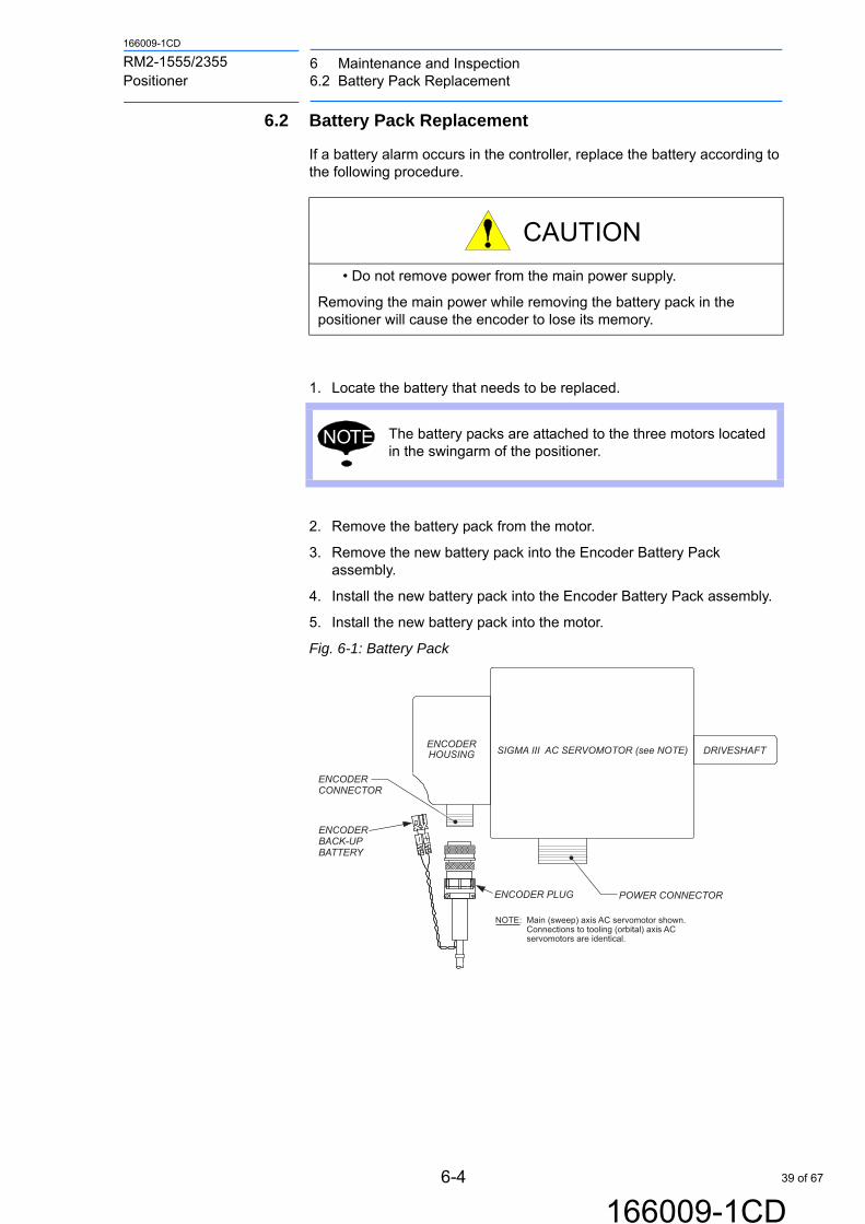
6.2 Battery Pack Replacement
If a battery alarm occurs in the controller, replace the battery according to the following procedure.
1. Locate the battery that needs to be replaced.
2. Remove the battery pack from the motor.
3. Remove the new battery pack into the Encoder Battery Pack assembly.
4. Install the new battery pack into the Encoder Battery Pack assembly.
5. Install the new battery pack into the motor.
Fig. 6-1: Battery Pack
CAUTION
• Do not remove power from the main power supply.
Removing the main power while removing the battery pack in the positioner will cause the encoder to lose its memory.
NOTE The battery packs are attached to the three motors located in the swingarm of the positioner.
SIGMA III AC SERVOMOTOR (see NOTE)
POWER CONNECTOR
DRIVESHAFTENCODERHOUSING
ENCODERCONNECTOR
ENCODER PLUG
ENCODER BACK-UPBATTERY
NOTE: Main (sweep) axis AC servomotor shown. Connections to tooling (orbital) axis AC servomotors are identical.
39 of 67

6 Maintenance and Inspection6.3 Grease Replenishment/Exchange for Speed Reducers
6-5
166009-1CD
166009-1CD
RM2-1555/2355 Positioner
6.3 Grease Replenishment/Exchange for Speed Reducers
6.3.1 Main Axis
6.3.1.1 Reducer
1. Rotate the B side toward the operator, until S1-motor is in the down position.
2. Remove four M6 screws, washers and lock washers holding the S1-axis Motor Cover.
Fig. 6-2: S1-axis Motor Cover Removal
3. Pump Mobil CM-P, Lithium Complex grease through the reducer from the motor side and vented on the gear side.
Fig. 6-3: Main Axis
4. Reinstall the S1-axis Motor Cover.
M6 SCREWS, WASHERS AND LOCKING WASHERS (X4)
Main Axis Grease Fitting
40 of 67

6-6
166009-1CD
166009-1CD
RM2-1555/2355 Positioner
6 Maintenance and Inspection6.3 Grease Replenishment/Exchange for Speed Reducers
6.3.1.2 Slewing Bearing Raceway
1. Remove the Headstock upper column cover.
2. Locate the grease fitting shown in Fig and grease with YASKAWA P/N 132177-1, Gadus S2 V220 2
Fig. 6-4: Slewing Bearing Raceway Grease Fittings
SLEWING BEARINGRACEWAY GREASE FITTINGS
41 of 67

6 Maintenance and Inspection6.3 Grease Replenishment/Exchange for Speed Reducers
6-7
166009-1CD
166009-1CD
RM2-1555/2355 Positioner
6.3.1.3 Gear and Pinion Teeth Lubrication
Lubricating for the First Time1. Turn the positioner so the S1-gear and pinion cover is pointing down.
2. Remove the S1-axis motor cover, by removing four M6 screws, washers, and lock washers. See Fig. 6-5.
Fig. 6-5: S1-axis Motor Cover Removal
3. Check the alignment of the grease hose outlets. The hose outlets are to be in alignment with the center of the gear as shown in Fig. 6-6. If the alignment of the grease hose outlet is not alignment with the gear, loosen the hose clamp by loosening the screw and adjust as required.
Fig. 6-6: Alignment of Grease Nozzles Looking From Underneath
CAUTION
• Make sure the grease hose outlets are in alignment with the center of the gear.
Not having the grease hose alignment correct may cause the gear and pinion to wear out prematurely.
M6 SCREWS, WASHERS AND LOCKING WASHERS (X4)
HOSE CLAMP AND SCREW
GREASE HOSE OUTLET
GEAR
42 of 67

6-8
166009-1CD
166009-1CD
RM2-1555/2355 Positioner
6 Maintenance and Inspection6.3 Grease Replenishment/Exchange for Speed Reducers
.
4. Tighten the hose clamp screws and inspect hoses for kinks or damages.
5. Insert Mobil CM-P, Lithium Complex (part number 180144-1) into the two grease fittings by squeezing the lever of a standard grease gun until grease comes out the hose outlets at the gears. Ensure grease comes out the grease hose outlets and there is no damage to the grease fittings, or hoses.
6. Reinstall the S1-axis motor cover by reinstalling the screws and washers to 12.2Nm removed from step 2.
Weekly Lubrication1. Turn the positioner so the S1-gear and pinion cover is pointing down.
Fig. 6-7: S1-gear and Pinion Cover Pointing Down
2. Wipe off any old grease from the grease fittings. See Fig. 6-7 for location of grease fittings.
3. Apply Mobil CM-P, Lithium Complex (part number 180144-1) with a grease gun thru the grease fitting on bottom. Squeeze the grease gun lever three times (approximately 1.25 g x 2.)
4. In Teach Mode rotate the S1-gear and pinion 180 degrees and repeat step 3.
NOTE Grease hose outlets are located 180 degrees apart from each other.
S1-GEAR AND PINION COVER POINTINGDOWN
GREASE FITTINGS (X2)
43 of 67

6 Maintenance and Inspection6.3 Grease Replenishment/Exchange for Speed Reducers
6-9
166009-1CD
166009-1CD
RM2-1555/2355 Positioner
6.3.2 Tooling Axes Reducer
1. Remove the M6 button head screw located on the top of the drive assembly.
Fig. 6-8: Tooling Greasing
2. Install the M6 grease fitting in the faceplate and pump Moly-White RE00 grease through the reducer.
3. Reinstall the M6 button head screw and remove the M6 grease fitting.
Button Head Screw
Grease Fitting
44 of 67

6-10
166009-1CD
166009-1CD
RM2-1555/2355 Positioner
6 Maintenance and Inspection6.3 Grease Replenishment/Exchange for Speed Reducers
6.3.3 Tailstock Lubrication
The lubrication of the swingarm main axis bearing and the motomount axis bearing are required to be lubricated monthly.
6.3.3.1 Swingarm Main Swing Axis
1. Remove the four M5 screws holding the tailstock swingarm center cover in place and slide cover out.
Fig. 6-9: Removing Swingarm Center Cover, Looking Down View
2. Apply Gadus S2 V220 2 grease to the grease fitting by using a standard grease gun and pressing the lever 10 times (1.25g x 10).
Fig. 6-10: Tailstock Swingarm Center Cover Opening
3. Replace the tailstock swingarm center cover and four M5 screws tightening the screws to 7.2Nm removed in step 1.
TAILSTOCK SWINGARM CENTER COVER AND FOUR M5 SCREWS
TAILSTOCK MAIN SWEEP AXIS GREASE FITTING
TAILSTOCK SWINGARM CENTER COVER OPENING
45 of 67

6 Maintenance and Inspection6.3 Grease Replenishment/Exchange for Speed Reducers
6-11
166009-1CD
166009-1CD
RM2-1555/2355 Positioner
6.3.3.2 Motomount Lubrication
1. Apply Gadus S2 V220 2 grease to each of grease fitting by squeezing the grease gun lever five times (approximately 5 @ 1.25g each). See Fig. 6-11 for location of motomount grease fitting.
Fig. 6-11: Motomount Grease Fittings
GREASE FITTINGS MOTOMOUNT TAILSTOCK
46 of 67

6-12
166009-1CD
166009-1CD
RM2-1555/2355 Positioner
6 Maintenance and Inspection6.4 General Cleaning
6.4 General Cleaning
The RM2-1555/2355 Positioner requires only occasional cleaning to remove dust and welding by-products. Use compressed air or vacuum, and a bristle brush (if required).
6.5 SIGMA-5 Servomotors
The SIGMA-5 servomotors (1 sweep axis, 2 tooling plate axis) are sealed units and have no parts that need inspection or replacement on a regular basis. Do NOT disassemble a SIGMA-5 servomotor. If suspecting that the servomotor requires maintenance or overhaul, contact Yaskawa Motoman Customer Support (refer to section 1.5 “Customer Support Information”).
6.6 Servo Pack
The servo pack (located in the controller) does not require customer maintenance. If suspecting a problem with the servo pack, contact Yaskawa Motoman Customer Support (refer to refer to chapter 1.5 “Customer Support Information” at page 1-5).
6.7 Main (Sweep) Axis Reduction Gear Unit (RV–320E–X)
The main (sweep) axis Reduction Gear Unit (RV–320E–X) is located on the Main Drive Housing Assembly (see Fig. 1-2 “Main (Sweep) Axis — Side-A, Side-B "In Position" Safety Switches” on page 1-2). This unit is sealed and contains no parts that need inspection or replacement on a regular basis. Do NOT disassemble the reduction gear unit or remove it from its associated AC servomotor. If suspecting the Reduction Gear Unit requires maintenance or an overhaul, contact Yaskawa Motoman Customer Support (refer to chapter 1.5 “Customer Support Information” at page 1-5).
6.7.1 Setting (Sweep) Axis Backlash
The backlash between the drive pinion and the ring gear needs to be set at 0.1 mm (-0.03 +0). Setting the backlash requires adding or removing shims under the sweep axis motor assembly. An indicator gage needs to be positioned to measure the pitch line movement of the meshing gears. The actual measurement is the free movement of the gears.
If tooling is present on the positioner, rotate the positioner to have the motor at the top (B side at operator) and block both sides to prevent movement. Position the first indicator to measure the pinion gear pitch line movement. Position a second indicator to the swing arm and touch the ring gear pitch line. With the teach pendent, rotate the S1 motor in single pulse mode, and measure the movement of the pinion gear until you see movement of the ring gear.
When backlash is set re-torque the bracket retaining bolts and re-check the lash. Torque of the retaining bolts to 490Nm.
NOTEYaskawa Motoman recommends application of a corrosion/rust preventive compound to tooling fixtures located in a high-humidity environment.
47 of 67

6 Maintenance and Inspection6.8 Tooling Axis Reduction Gear Units (RV–320E)
6-13
166009-1CD
166009-1CD
RM2-1555/2355 Positioner
6.8 Tooling Axis Reduction Gear Units (RV–320E)
Two Reduction Gear Units (RV–320E) are located in the Tooling Drive Swingarm Assembly, one for each tooling plate (see Fig. 1-1 “RM2-1555/2355 Positioner Assembly” on page 1-1). These units are sealed and contain no parts that need inspection or replacement on a regular basis. Do NOT disassemble the reduction gear unit or remove it from its associated AC servomotor. If suspecting the Reduction Gear Unit requires maintenance or an overhaul, contact Yaskawa Motoman Customer Support (refer to chapter 1.5 “Customer Support Information” at page 1-5).
6.9 Main (Swing) Axis Hardstops
The RM2-1555/2355 Positioner incorporates two buffered hardstops that are welded to the Tooling Drive Swingarm Assembly. The hardstops provide a positive stop for the Tailstock Tooling Drive Swingarm Assembly (and thus the Arc Shield and Main Axis Swingarm Assembly) during a sweep cycle. The tailstock hardstop is fixed while the headstock is adjustable. The adjustable hardstops must be set at the finial installation process and are located on the headstock. Refer to section 6.12.1 “Adjusting the Hardstops”
6.10 Welding Ground System
6.10.1 Inspection and Cleaning of Carbon Brushes
Inspect the ground brushes where they contact the rear of tooling drive plates. Make sure that the contact area is clean and free of dust and welding by-products. Use compressed air and a small bristle brush to clean the ground brushes where they contact the tooling plates.
6.10.2 Ground Brush Replacement
Ground Brush Removal Procedure –
1. Remove all hazardous energies from the RM2-1555/2355 Positioner and other system components.
NOTE
Always ensure that welding ground connections and brushes in the RM2-1555/2355 Positioner are clean and tight. If the ground points are not properly made and kept clean and secure, high welding currents can bypass the normal return path and, instead, pass through the drive components of the positioner. This is especially hard on positioner drive bearings when they are under load. High welding current, if allowed to pass through the drive components, can result in increased bearing wear and premature replacement.
NOTE
Each ground brush is enclosed in a box-shaped brush holder that is attached to a mounting plate. The brush holder incorporates a spring tensioner device that holds the ground brush, under spring tension, against the rear of the tooling plate when locked into position.
48 of 67

6-14
166009-1CD
166009-1CD
RM2-1555/2355 Positioner
6 Maintenance and Inspection6.10 Welding Ground System
2. Release the spring tensioner by squeezing together both of the black levers that are visible on each brush holder. While squeezing the levers together, pull out and away from the brush holder. This should produce the ground brush.
3. Each ground brush has two braided copper leads that connect to silver-plated, high current quick disconnect posts on the ground brush mounting plate. After the ground brush is free and clear of the brush holder, use a flat blade screwdriver or needle nose pliers to disconnect each of the braided copper brush leads from the quick disconnect posts.
6.10.3 Ground Brush Installation
1. Connect braided copper brush cables (from the new brush) to the quick disconnect posts on the ground brush mounting plate.
2. Make sure that the spring tensioner in the brush holder is released and pulled as far back as possible.
3. Insert the new brush into the brush holder and push forward as far as possible.
4. Lock the new brush into position by squeezing together the black tensioner levers and pushing the tensioner forward into the brush holder until it “clicks” into the locked position.
6.10.4 Inspection of Welding Ground Connections
Inspect all welding ground cable connections for cleanliness and security.
NOTEThis is a good time to check the cleanliness and condition of the quick disconnect posts. If dirt or grease buildup is noticed on the posts, clean them. Use a small bristle brush (toothbrush size) and compressed air.
NOTEGround cable connections must be clean and tight. A loose or dirty connection can cause excess heat (high resistance connection) or arcing. Either of these conditions can damage the cable and cable connection point.
49 of 67

6 Maintenance and Inspection6.11 AC Servomotor Encoder Back-Up Battery
6-15
166009-1CD
166009-1CD
RM2-1555/2355 Positioner
6.11 AC Servomotor Encoder Back-Up Battery
The main (sweep) axis and tooling (orbital) axes SIGMA-5 servomotors all incorporate an external Lithium-Ion “keep alive” battery pack that maintains encoder positioning data in system memory, should the main cables between the positioner and controller be disconnected
The “keep alive” batteries have a long life in this particular application. However, should one or more of these batteries drop below a certain charge level, an indicator will appear on the Programming Pendant display screen, indicating the need for battery renewal.
To replace a depleted encoder “keep alive” battery pack, gain access to the encoder plug on the applicable SIGMA-5 servomotor, locate the depleted battery pack, and replace it with a new battery pack of the same type.
50 of 67

6-16
166009-1CD
166009-1CD
RM2-1555/2355 Positioner
6 Maintenance and Inspection6.12 Positioner Home Position
6.12 Positioner Home Position
Home Position Definition:
S1 with Side B at Robot & Side A at Operator
S2 Tooling Down (At Operator Side)
S3 Tooling Up (At Robot Side)
6.12.1 Adjusting the Hardstops
Shock absorbing hardstops prevent the positioner from rotating a full 360°. It is important that the both the head and tailstock swingarms strike the hardstop shock absorbers at approximately the same time. To adjust the hardstops, proceed as follows:
1. Loosen the M16 bolts attaching the adjustable hard stop plates on the headstock swingarm.
Fig. 6-12: Headstock Hardstops
2. Rotate the square head adjusting screw to allow the hardstop to move away from the fixed component (you may need to snug one of the bolts to hold in this position). This will allow for the tailstock hardstops to contact first during motion.
3. Jog S1 axis into positioner hard stop with B-side at robot. Increment positioner against hard stop at the tailstock side until the holding torque is 45%. Record value into S1 Home position.
Table 6-3: Jog positioner for both A and B sides checking the holding torque values. EX Position Variable Settings°
Adjustment Screw
Adjustable Hardstop PlateM16 Bolts
Variable Value Description Variable Name
EX040 -180.000°a)
a EX40 Variable value will vary from positioner-to-positioner and gives results of homing routine. The results should have a value of 179.5° and 180.5° for proper FSU operation.
S1 A-Side at Robot (Value may change after homing)
S1 A-SIDE @ RBT
EX050 0.000° S1 B-Side at Robot S1 B-SIDE @ RBT
51 of 67

6 Maintenance and Inspection6.12 Positioner Home Position
6-17
166009-1CD
166009-1CD
RM2-1555/2355 Positioner
4. Adjust hard stop plate on the headstock by loosening the jam nut and rotating the square head adjusting screw. (Loosen the M16 bolts that were snugged in step 2). When set properly, the hardstop will compress the conical spring system and the hardstops will touch. Torque will increase to 60-70% during this process. Snug the M16 bolts holding the hardstop on the swingarm and rotate to a position and tighten the M16 bolts to 250Nm. Lock the adjusting screw with a jam nut.
5. Rotate positioner back to B-side position, torque should be 70-75%. Adjust position with teach pendent (if required) and reset Home. Once the “Home” position is set, if the FSU is enabled, a message will appear directing to flash reset the FSU in MAINTENANCE mode.
6. Repeat the above steps to set the A-side except set value to EX040 S1 Position.
7. Jog positioner to both A & B sides checking the holding torque values. Adjust position A as required until holding torque stays at 70-75%. Several cycles will be required on both sides for confirmation.
6.12.2 Setting S3 Tooling at Robot
1. Using the Programming Pendant, place the robotic system into MANAGEMENT mode.
2. Jog S3 tooling vertical (90 degrees from level).
3. Install the plastic homing pin (see Fig. 6-13) in the back side of the faceplate into the homing pin hole. (see Fig. 6-14).
Fig. 6-13: Homing Pin Details
NOTEOnce the home position is set, if the FSU enabled, a message will appear directing you to flash reset the FSU in Maintenance mode. This reset can be postponed until performing instructed later in the homing procedure.
NOTE Anytime the holding torque value changes on side “B” the holding torque value on side “A” needs to be adjusted.
0.5 x 45v
60 15
110
0.5 x 45v
4.5O
4.987 +0.0-0.05O
R 0.5
9.5253/8" Part Number 145896-6
52 of 67

6-18
166009-1CD
166009-1CD
RM2-1555/2355 Positioner
6 Maintenance and Inspection6.12 Positioner Home Position
Fig. 6-14: Tooling Plate Home (Zero) Position
4. Slowly jog S3-axis until homing pin just touches stationary edge of structure.
5. Press TOP MENU on the programming pendant.
6. Cursor to ROBOT and press [SELECT].
7. Cursor to HOME POSITION and press [SELECT].
8. Press [PAGE OVER] to S3 (indicated in top right corner of Programming Pendant display panel).
9. Press [SELECT].
10. Cursor to YES, press [SELECT].
The tooling plate is now reset to zero.
11. Remove the homing pin from the tooling plate.
12. Jog S3 to EX60 (S3 Home Pin to Level Home”) using the [FORWARD] key (not the [TEST START] key).
Table 6-4: Jog positioner variable to set S3 “Level Home” EX Position Variable Settings°
13. Once at the EX60 VARIABLE (S3 Level Home to Home Pin), Re-home the S3 axis by modifying the home position.
CAUTION
Do Not Jog the S3-axis too far.
• Jogging the axis too far will bend the pin causing an inaccuracy.
Slowly jog the axis in reverse until the pin is straight and still touching the edge of structure
TOOLING PLATE
HEADSTOCKDRIVE ASSY
HOMING PIN
Variable Value Description Variable Name
EX060 98.000° S3 Homing Pin to “Level Home” S3 Home Pin to Level Home
EX061 -98.000° S3 “Level Home” to Homing Pin S3 Level Home to Home Pin
53 of 67

6 Maintenance and Inspection6.12 Positioner Home Position
6-19
166009-1CD
166009-1CD
RM2-1555/2355 Positioner
6.12.3 Setting S2 Tooling at Robot
1. Using the Programming Pendant, place the robotic system into MANAGEMENT mode.
2. Jog S2 tooling vertical (90 degrees from level).
3. Install the plastic homing pin (see Fig. 6-13) in the back side of the faceplate into the homing pin hole (see Fig. 6-14).
4. Slowly jog S2-axis until homing pin just touches stationary edge of structure.
5. Press TOP MENU on the programming pendant.
6. Cursor to ROBOT and press [SELECT].
7. Cursor to HOME POSITION and press [SELECT].
8. Press [PAGE OVER] to S2 (indicated in top right corner of Programming Pendant display panel).
9. Press [SELECT].
10. Cursor to YES, press [SELECT].
11. Remove the homing pin from the tooling plate.
12. Jog S2 to EX62 (S2 Homing Pin to “Level Home”) using the [FORWARD] key (not the [TEST START] key.
Table 6-5: Jog positioner variable to set S2 “Level Home” EX Position Variable Settings°
13. Once at the EX62 VARIABLE (S2 Home Pin to “Level Home”), Re-home the S2 axis by modifying the home position.
14. If the FSU is enabled, reset the FSU in Maintenance Mode.
CAUTION
Do Not Jog the S2-axis too far.
• Jogging the axis too far will bend the pin causing an inaccuracy.
Slowly jog the axis in reverse until the pin is straight and still touching the edge of structure
NOTEOnce the home position is set, if the FSU enabled, a message will appear directing you to flash reset the FSU in Maintenance mode. This reset can be postponed until performing instructed later in the homing procedure.
Variable Value Description Variable Name
EX062 98.000° S2 Homing Pin to “Level Home” S2 Home Pin to Level Home
EX063 -98.000° S2 “Level Home” to Homing Pin S2 Level Home to Home Pin
54 of 67

7-1
166009-1CD
166009-1CD
RM2-1555/2355 Positioner
7 Recommended Spare Parts
7 Recommended Spare Parts
It is recommended that the parts and components in the following table be kept in stock as spare parts for the RM2-1555/2355 Positioner. Product performance can not be guaranteed when using spare parts from any company other than Yaskawa. The spare parts are ranked as follows:
• Rank A: Expendable and frequently replaced parts
• Rank B: Parts for which replacement may be necessary as a result of frequent operation
• Rank C: Drive Unit
To order spare parts or replacement parts for the RM2-1555/2355 Positioner, please contact Yaskawa Customer Support (Refer to chapter 1.5 “Customer Support Information” at page 1-5).
NOTETo replace parts in Rank B or Rank C, contact Yaskawa Motoman Customer Support. (Refer to chapter 1.5 “Customer Support Information” at page 1-5).
Table 7-1: Spare Parts for the RM2-1555/2355 Positioner
RankPartsNo.
Name Type QtyQtyperUnit
Remarks
A 1 GreaseMolywhite R00
-For speed reducer of each axis
A 2 GreaseMobil CM-P, Lithium Complex
-Slewing S1 Gear and Pinion Teeth
A 3 GreaseGadus S2 V220 2
Greasing tailstock swingarm main axis bearing, moto-mount bearing and slewing raceway.
A 4 Battery Pack 1 1
55 of 67

Appendix A Illustrated Parts ListA.1 Introduction
A-1
166009-1CD
166009-1CD
RM2-1555/2355 Positioner
Appendix A Illustrated Parts List
A.1 Introduction
A.1.1 Arrangement
Appendix A is arranged as follows –
• Appendix A.1 – Introduction
• Appendix A.2 – Illustrated Parts List (IPL)
A.1.2 General
The Illustrated Parts Lists (IPL) identifies, describes, and illustrates detail parts of the RM2-1555/2355 Positioners Included in this manual is an illustration and table for each of the different positioners. The illustrations included are:
• " Fig. A-1 Major Assemblies — RM2-1555 and 2355 "
• " Fig. A-2 Housing Assembly, Swingarm Headstock Main Drive "
• " Fig. A-3 Housing, Headstock Swingarm "
• " Fig. A-4 Main Sweep Drive Assembly "
• " Fig. A-5 Tailstock Swingarm Housing "
• " Fig. A-6 Slip-Ring Kit Assembly "
A.1.3 Purpose
The IPL provides parts identification and descriptive information for use in provisioning, purchasing, storing, and issuing spare parts.
A.2 Illustrated Parts List (IPL)
The Illustrated Parts List contains illustrations (exploded views) and associated parts list tables that show detail parts of a particular component, assembly, or subassembly.
A.2.1 IPL Layout
The IPL is arranged so that the illustration (exploded view) for an assembly appears directly above the parts list table for that illustration. When this is not possible, due to a large illustration or an extensive parts list table, the parts list table is listed on the facing page. This format always attempts to present the illustration and its associated parts list table to the reader in one view, regardless of viewing format (PDF or printed).
56 of 67

A-2
166009-1CD
166009-1CD
RM2-1555/2355 Positioner
Appendix A Illustrated Parts ListA.2 Illustrated Parts List (IPL)
A.2.2 Item Categories Not Included in the IPL
The following item categories are not included in the IPL –
• Standard hardware items (attaching parts) such as nuts, screws, washers, etc. These are commercially available to the customer.
• Bulk items and consumables such as wire, cable, sleeving, tubing, certain fluids, etc. These are commercially available to the customer.
• Permanently attached parts that lose their identity because they are welded, soldered, riveted, etc., to other parts, assemblies, or subassemblies.
A.2.3 Parts List Table Structure
Each figure’s parts list table contains the following data columns –
FIGURE AND ITEM NUMBERAn entry in this column gives the item number for a part shown in the associated illustration (exploded view). The item number listed in this column is the same as the item number shown on the illustration. Item numbers on the illustration are identified by a circled number and leader line that points to the particular part (item) on the illustration.
PART NUMBERAn entry in this column gives the part number for an item. Refer to this number when ordering or referencing the part.
DESCRIPTIONAn entry in this column gives the description (nomenclature) for an item number or part number.
QTYAn entry in this column gives the total quantity of an item or part number required for an assembly or subassembly in which the part appears. The quantity given in this column may or may not be the total quantity required for the complete end item. The letters "REF" in this column indicate a reference to the top assembly in the figure.
NOTEItems not shown in the illustrations are indicated by a dash (–) prefix to the item number. An example could include a right-hand (RH) part that is otherwise identical to the illustrated left-hand (LH) part.
57 of 67
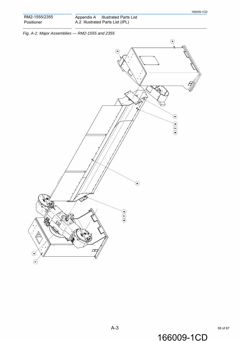
Appendix A Illustrated Parts ListA.2 Illustrated Parts List (IPL)
A-3
166009-1CD
166009-1CD
RM2-1555/2355 Positioner
Fig. A-1: Major Assemblies — RM2-1555 and 2355
67
45
2
3
9
1
8
67
8
58 of 67

A-4
166009-1CD
166009-1CD
RM2-1555/2355 Positioner
Appendix A Illustrated Parts ListA.2 Illustrated Parts List (IPL)
Table A-1: Major Assemblies — RM2-1555 and 2355
ITEM NO.
RM2-1555 RM2-2355 DESCRIPTION Qty
3.0M164213-1
3.5M164213-2
4.0M164213-3
3.0M164214-1
3.5M164214-2
4.0M164214-3
Span, Part Number
1 164213-1 HOUSE ASY, SWG HDSTK
1
2 163898-1 163899-1 ARM ASY, SWG,HDSTK,
2
3 163902-1 163903-1 ARM ASY, SWG, TLSTK
1
4 164350-1 HOUSE ASY,TLSTK
1
5 164218-1 164218-5 164218-2 164218-1 164218-5 164218-2 BEAM,Z-SPREADER
1
6 131274-4 SCREW,HHC, M6X40
28
7 132049-1 WASHER,CONICAL SPRING, GTS 16
28
8 132652-9 PIN,DOWEL, M20X40
5
9 3.0M
148102-4SCREW,SHC, M6X16
62
3.5M 66
4.0M 77
59 of 67

Appendix A Illustrated Parts ListA.2 Illustrated Parts List (IPL)
A-5
166009-1CD
166009-1CD
RM2-1555/2355 Positioner
Fig. A-2: Housing Assembly, Swingarm Headstock Main Drive
Table A-2: Housing Assembly, Swingarm Headstock Main Drive
1
43
40
39
43
36
4142
3435
3738
3953 26
55
58
57
565857
ITEM NO.
PART NO. DESCRIPTION Qty
1 164222-1 HOUSING ASSY, SWINGARM, HEADSTOCK,MAIN DRIVE
1
26 130424-5 SCREW,BHSC,M5 X 12 36
34 472303-16 SCREW,SHC,M12X90,CLASS 12.9 24
35 471075-1 WASHER, CONICAL SPRING, M12 24
36 164522-1 SPACER, GEAR BEAR, MAIN DR 1
37 130532-15 SCREW, SHC, M16X60 16
38 130556-2 WASHER, SPRING 16
39 142278-3 PIN, DOWEL, M16X40 4
40 163898-1 ARM ASSY, SWING, HDSTK,MAIN DR
1
41 163340-1 COVER, MAIN DRIVE, RM2-1255SL 1
42 148102-4 SCREW_SHC_M6X16 62
43 164371-1 DRIVE ASSY, HEADSTOCK, TOOLING, W/MOTOMOUNT & SW
2
53 166206-1 COVER,ACCESS,BLUE 1
55 166609-1 COVER, SWITCH AND CABLE, RH, 2
57 166609-2 COVER, SWITCH AND CABLE, LH, 2
58 130424-11 SCREW,BHSC,M5 X 40 4
60 of 67

A-6
166009-1CD
166009-1CD
RM2-1555/2355 Positioner
Appendix A Illustrated Parts ListA.2 Illustrated Parts List (IPL)
Fig. A-3: Housing, Headstock Swingarm
5
10
11
2
3
4
21
20
8
15
16
19
20
18
12
14
13
1417
3231
8
22
26
23
25
23
24
30
8 3534
3129
3334
27
3334
36
28
61 of 67
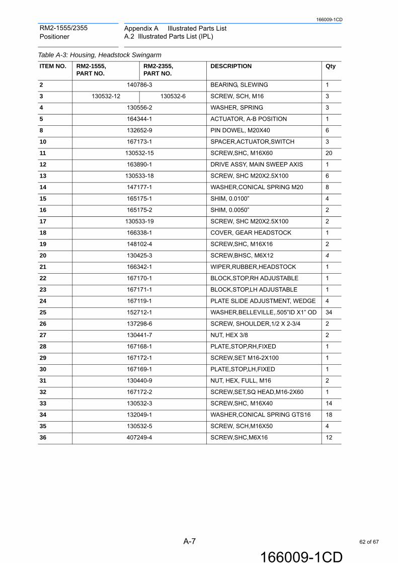
Appendix A Illustrated Parts ListA.2 Illustrated Parts List (IPL)
A-7
166009-1CD
166009-1CD
RM2-1555/2355 Positioner
Table A-3: Housing, Headstock Swingarm
ITEM NO. RM2-1555, PART NO.
RM2-2355, PART NO.
DESCRIPTION Qty
2 140786-3 BEARING, SLEWING 1
3 130532-12 130532-6 SCREW, SCH, M16 3
4 130556-2 WASHER, SPRING 3
5 164344-1 ACTUATOR, A-B POSITION 1
8 132652-9 PIN DOWEL, M20X40 6
10 167173-1 SPACER,ACTUATOR,SWITCH 3
11 130532-15 SCREW,SHC, M16X60 20
12 163890-1 DRIVE ASSY, MAIN SWEEP AXIS 1
13 130533-18 SCREW, SHC M20X2.5X100 6
14 147177-1 WASHER,CONICAL SPRING M20 8
15 165175-1 SHIM, 0.0100” 4
16 165175-2 SHIM, 0.0050” 2
17 130533-19 SCREW, SHC M20X2.5X100 2
18 166338-1 COVER, GEAR HEADSTOCK 1
19 148102-4 SCREW,SHC, M16X16 2
20 130425-3 SCREW,BHSC, M6X12 4
21 166342-1 WIPER,RUBBER,HEADSTOCK 1
22 167170-1 BLOCK,STOP,RH ADJUSTABLE 1
23 167171-1 BLOCK,STOP,LH ADJUSTABLE 1
24 167119-1 PLATE SLIDE ADJUSTMENT, WEDGE 4
25 152712-1 WASHER,BELLEVILLE,.505”ID X1” OD 34
26 137298-6 SCREW, SHOULDER,1/2 X 2-3/4 2
27 130441-7 NUT, HEX 3/8 2
28 167168-1 PLATE,STOP,RH,FIXED 1
29 167172-1 SCREW,SET M16-2X100 1
30 167169-1 PLATE,STOP,LH,FIXED 1
31 130440-9 NUT, HEX, FULL, M16 2
32 167172-2 SCREW,SET,SQ HEAD,M16-2X60 1
33 130532-3 SCREW,SHC, M16X40 14
34 132049-1 WASHER,CONICAL SPRING GTS16 18
35 130532-5 SCREW, SCH,M16X50 4
36 407249-4 SCREW,SHC,M6X16 12
62 of 67

A-8
166009-1CD
166009-1CD
RM2-1555/2355 Positioner
Appendix A Illustrated Parts ListA.2 Illustrated Parts List (IPL)
Fig. A-4: Main Sweep Drive Assembly
2
3
13
14
10
9
3
2
4
6
7
5
9
161
13
14
17
18
19
20
15
10
12
63 of 67

Appendix A Illustrated Parts ListA.2 Illustrated Parts List (IPL)
A-9
166009-1CD
166009-1CD
RM2-1555/2355 Positioner
Table A-4: Main Sweep Drive Assembly
ITEM NO.
PART NO. DESCRIPTION Qty
1 163837-1 BRACKET, MAIN DRIVE 1
2 130425-2 SCREW, BHSC, M6X10 2
3 470602-1 WASHER, CONICAL, SPRING M6 2
4 133937-3 FITTING,ZERK M6X1 1
5 163877-1 GEAR ASSY, INPUT,MAIN DRIVE 1
6 479297-3 SCREW,SHCS M10X20 18
7 470541-1 WASHER, CONICAL, SPRING M10 18
8 151592-7 REDUCER,RV 1
9 472303-9 SCREW,SHCS M12X50 16
10 471075-1 WASHER, CONICAL, SPRING M12 20
11 156009-6 MOTOR AC SERVO,3.7KW 1
12 472303-7 SCREW,SHCS M12X40 4
13 130440-9 NUT,HEX,M16 2
14 160113-2 SCREW,HHC M16X2 2
15 152538-1 ADAPTER FLYWHEEL 1
16 146924-1 SEAL,O-RING,INPUT 1
17 407248-21 SCREW,SHC M8X100 1
18 470617-1 WASHER, CONICAL, SPRING M8 1
19 145428-2 WASHER, FLAT M8X16OD,3THK 1
20 151593-7 GEAR,INPUT,PINION 1
64 of 67

A-10
166009-1CD
166009-1CD
RM2-1555/2355 Positioner
Appendix A Illustrated Parts ListA.2 Illustrated Parts List (IPL)
Fig. A-5: Tailstock Swingarm Housing
Table A-5: Tailstock Swingarm Housing Assembly
1
7
2
3
4
56
ITEM NO. RM2-1555 PART NO. RM2-2355 PART NO. DESCRIPTION Qty
1 163902-1 163903-1 TAILSTOCK, SWINGARM ASSEMBLY 1
2 167064-1 COVER,CYLINDER,TAILSTOCK 4
3 166205-2 166205-1 COVER,SWINGARM,TS,END 2
4 166992-1 STOP BLOCK TAILSTOCK 1
5 167065-1 COVER,CENTER,TAILSTOCK 2
6 168124-1 PLATE,CAPTURE,BEARING 1
7 164594-1 SLIP-RING KIT 1
65 of 67

Appendix A Illustrated Parts ListA.2 Illustrated Parts List (IPL)
A-11
166009-1CD
166009-1CD
RM2-1555/2355 Positioner
Fig. A-6: Slip-Ring Kit Assembly
Table A-6: Slip-Ring Kit Assembly
B
DETAIL B
7 10
8
1
2 34
56
5
7
89
5 6 1A
DETAIL A
ITEM NO.
PART NO. DESCRIPTION Qty
1 165110-1 BOLT,SHDR,5MM DIAX4MM,M4 4
2 164685-1 FIT,SWVEL,3/4-16 STR THD 2
3 164684-1 FIT,SWVEL,90 DEG,3/4-16STR THD 2
4 165140-1 SLIP-RING KIT,DEVICENET,RM2 2
5 164679-1 COUPLER,ACCY, 3/4” PNEUMATIC 2
6 164680-1 SLEEVE,COUP, 3/4” PNEUMATIC 2
7 142941-1 CONNECTOR,TEE,DEVICE NET 2
8 142945-1 RSISTR,TERM,DEVICE NET 1
9 164686-1 FIT,NIPPLE,1/2” NPTF X 3 1/2” LG 1
10 479295-9 SCREW, SHC, M4X30 2
66 of 67

Specifications are subject to change without noticefor ongoing product modifications and improvements.
MANUAL NO.
7166009-1CD
HEAD OFFICE2-1 Kurosakishiroishi, Yahatanishi-ku, Kitakyushu 806-0004, JapanPhone +81-93-645-7703 Fax +81-93-645-7802
100 Automation Way, Miamisburg, OH 45342, U.S.A. Phone +1-937-847-6200 Fax +1-937-847-6277
YASKAWA America Inc. (Motoman Robotics Division)
Yaskawastrasse 1, 85391 Allershausen, GermanyPhone +49-8166-90-100 Fax +49-8166-90-103
YASKAWA Europe GmbH Robotics Divsion )
Phone +82-2-784-7844 Fax +82-2-784-8495
151 Lorong Chuan, #04-02A, New Tech Park, Singapore 556741Phone +65-6282-3003 Fax +65-6289-3003
YASKAWA Electric (Singapore) PTE Ltd.
No7 Yongchang North Road, Beijing E&T Development Area China 100176Phone +86-10-6788-2858 Fax +86-10-6788-2878
YASKAWA SHOUGANG ROBOT Co. Ltd.
#426, Udyog Vihar, Phase- IV, Gurgaon, Haryana, IndiaFax +91-124-475-8542Phone +91-124-475-8500
YASKAWA India Private Ltd. (Robotics Division)
YASKAWA Electric (China) Co., Ltd.22F, One Corporate Avenue, No.222, Hubin Road, Huangpu District, Shanghai 200021, ChinaPhone +86-21-5385-2200 Fax 86-21-5385-3299
YASKAWA Electric (Thailand) Co., Ltd.59,1st-5th Floor, Flourish Building, Soi Ratchadapisek 18,Ratchadapisek Road, Huaykwang, Bangkok 10310, THAILANDPhone +66-2-017-0099 Fax +66-2-017-0199
12F, No.207, Sec. 3, Beishin Rd., Shindian District, New Taipei City 23143, TaiwanFax +886-2-8913-1513Phone +886-2-8913-1333
YASKAWA Electric Taiwan Corporation
Secure Building-Gedung B Lantai Dasar & Lantai 1 JI. Raya Protokol Halim Perdanakusuma, Jakarta 13610, Indonesia
Fax +62-21-2982-6741Phone +62-21-2982-6470
PT. YASKAWA Electric Indonesia
Phone +46-480-417-800 Fax +46-486-414-10
YASKAWA Nordic ABVerkstadsgatan 2, Box 504 ,SE-385 25 Torsas, Sweden
35F, Three IFC, 10 Gukjegeumyung-ro, Yeongdeungpo-gu, Seoul, Korea 07326YASKAWA Electric Korea Corporation
RM2-1555/2355 POSITIONERINSTRUCTIONS
67 of 67