rlc circuits - virginia techliab/lectures/ch_8/slides/natural... · boundary conditions ... an open...
TRANSCRIPT

RLC Circuits

Objective of Lecture Derive the equations that relate the voltages across and
currents flowing through a resistor, an inductor, and a capacitor in series as: the unit step function associated with voltage or current
source changes from 1 to 0 or
a switch disconnects a voltage or current source into the circuit.
Describe the solution to the 2nd order equations when the condition is: Overdamped
Critically Damped
Underdamped
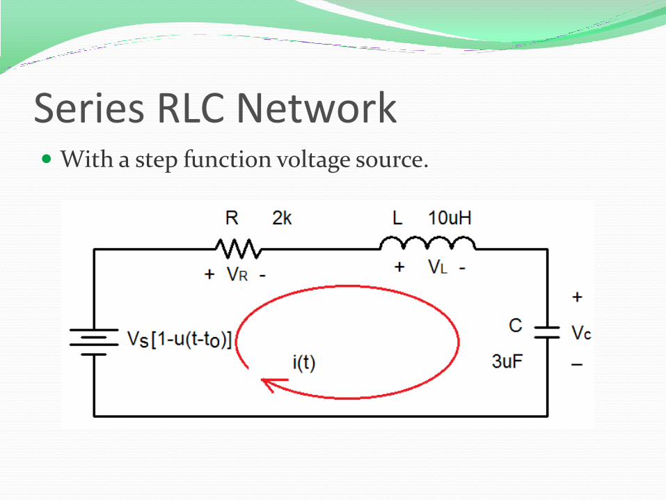
Series RLC Network With a step function voltage source.
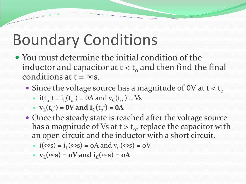
Boundary Conditions You must determine the initial condition of the
inductor and capacitor at t < to and then find the final conditions at t = ∞s. Since the voltage source has a magnitude of 0V at t < to
i(to-) = iL(to
-) = 0A and vC(to-) = Vs
vL(to-) = 0V and iC(to
-) = 0A
Once the steady state is reached after the voltage source has a magnitude of Vs at t > to, replace the capacitor with an open circuit and the inductor with a short circuit. i(∞s) = iL(∞s) = 0A and vC(∞s) = 0V
vL(∞s) = 0V and iC(∞s) = 0A
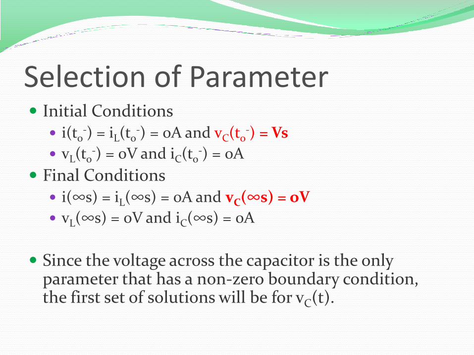
Selection of Parameter Initial Conditions i(to
-) = iL(to-) = 0A and vC(to
-) = Vs
vL(to-) = 0V and iC(to
-) = 0A
Final Conditions i(∞s) = iL(∞s) = 0A and vC(∞s) = oV
vL(∞s) = 0V and iC(∞s) = 0A
Since the voltage across the capacitor is the only parameter that has a non-zero boundary condition, the first set of solutions will be for vC(t).

Kirchhoff’s Voltage Law
0)(1)()(
0)()()(
)()()(
)()(
)()(
0)()()(
0)(
2
2
2
2
tvLCdt
tdv
L
R
dt
tvd
tvdt
tdvRC
dt
tvdLC
tititi
dt
tdvCti
Riv
dt
tdiLtv
tvtvtv
tv
CCC
CCC
RCL
CC
RR
LL
RLC
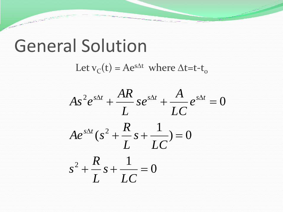
General SolutionLet vC(t) = AesDt where Dt=t-to
01
0)1
(
0
2
2
2
D
DDD
LCs
L
Rs
LCs
L
RsAe
eLC
Ase
L
AReAs
ts
tststs

LCL
R
L
Rs
LCL
R
L
Rs
1
22
1
22
2
2
2
1
012
LCs
L
Rs
General Solution (con’t)
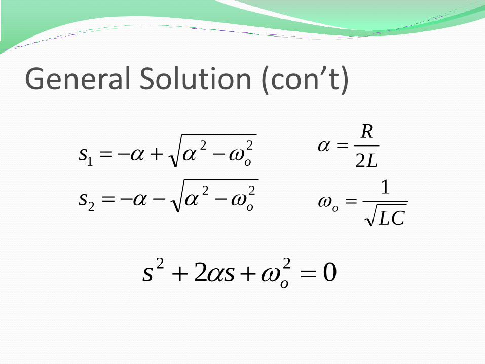
LC
L
R
o
1
2
22
2
22
1
o
o
s
s
02 22 oss
General Solution (con’t)

tsts
CCC
ts
C
ts
C
eAeAtvtvtv
eAtv
eAtv
DD
D
D
21
2
1
2121
22
11
)()()(
)(
)(
General Solution (con’t)
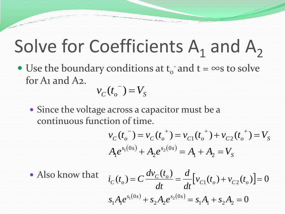
Solve for Coefficients A1 and A2 Use the boundary conditions at to
- and t = ∞s to solve for A1 and A2.
Since the voltage across a capacitor must be a continuous function of time.
Also know that
SoC Vtv )(
S
ssss
SoCoCoCoC
VAAeAeA
Vtvtvtvtv
21
0
2
0
1
21
21
)()()()(
0
0)()()(
)(
2211
0
22
0
11
21
21
AsAseAseAs
tvtvdt
d
dt
tdvCti
ssss
oCoCoC
oC

Overdamped Case > o
implies that C > 4L/R2
s1 and s2 are negative and real numbers
tsts
C eAeAtvDD
21
21)(
22
2
22
1
o
o
s
s

Critically Damped Case o
implies that C = 4L/R2
s1 = s2 = - = -R/2L
tt
C teAeAtv DD D 21)(
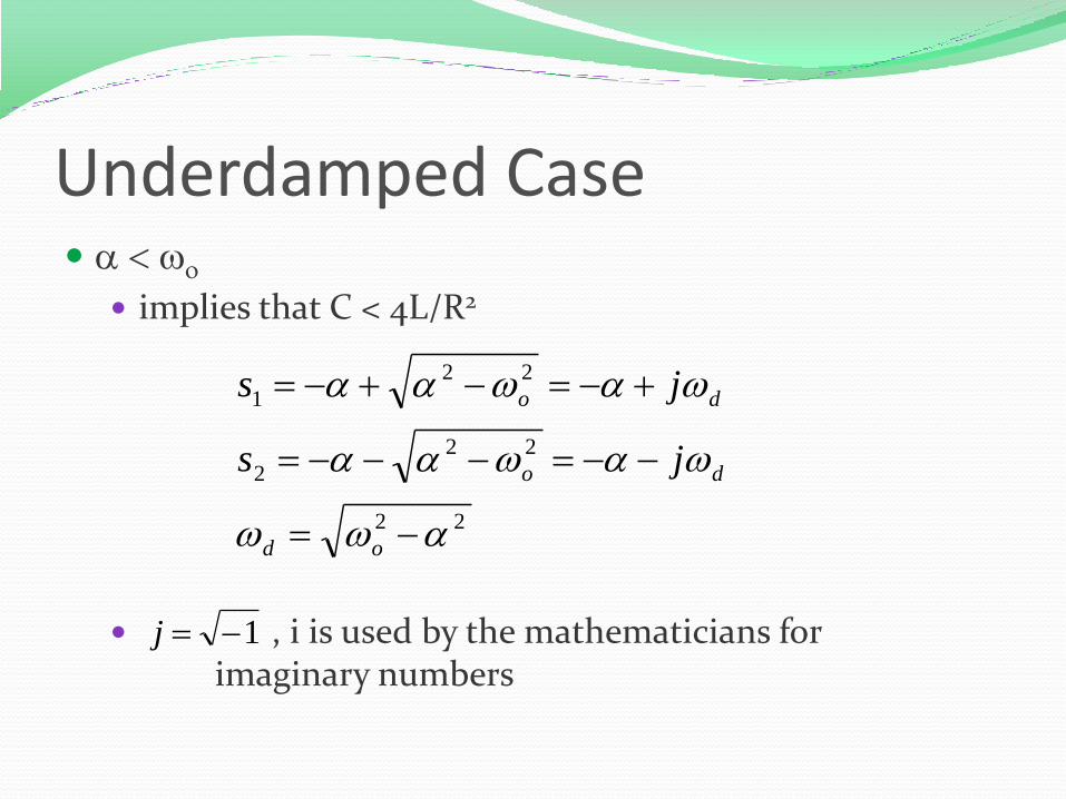
Underdamped Case < o
implies that C < 4L/R2
, i is used by the mathematicians for imaginary numbers
22
22
2
22
1
od
do
do
js
js
1j

]sincos[)(
]sin)(cos)[()(
)]sin(cos)sin(cos[)(
sincos
sincos
)()(
21
2121
21
21
tAtAetv
tBBjtBBetv
tjtBtjtBetv
je
je
eBeBetv
dd
t
C
dd
t
C
dddd
t
C
j
j
tjtjt
Cdd
DD
DD
DDDD
D
D
D
DDD
211 BBA 212 BBjA

Angular Frequencies o is called the undamped natural frequency
The frequency at which the energy stored in the capacitor flows to the inductor and then flows back to the capacitor. If R = 0W, this will occur forever.
d is called the damped natural frequency
Since the resistance of R is not usually equal to zero, some energy will be dissipated through the resistor as energy is transferred between the inductor and capacitor.
determined the rate of the damping response.


Properties of RLC network Behavior of RLC network is described as damping,
which is a gradual loss of the initial stored energy
The resistor R causes the loss
determined the rate of the damping response
If R = 0, the circuit is loss-less and energy is shifted back and forth between the inductor and capacitor forever at the natural frequency.
Oscillatory response of a lossy RLC network is possible because the energy in the inductor and capacitor can be transferred from one component to the other.
Underdamped response is a damped oscillation, which is called ringing.

Properties of RLC network Critically damped circuits reach the final steady state
in the shortest amount of time as compared to overdamped and underdamped circuits.
However, the initial change of an overdamped or underdamped circuit may be greater than that obtained using a critically damped circuit.
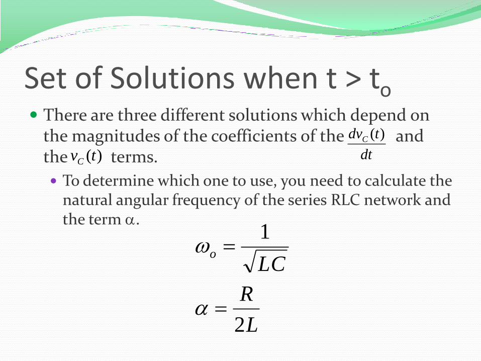
Set of Solutions when t > to There are three different solutions which depend on
the magnitudes of the coefficients of the and the terms.
To determine which one to use, you need to calculate the natural angular frequency of the series RLC network and the term .
L
R
LCo
2
1
)(tvCdt
tdvC )(
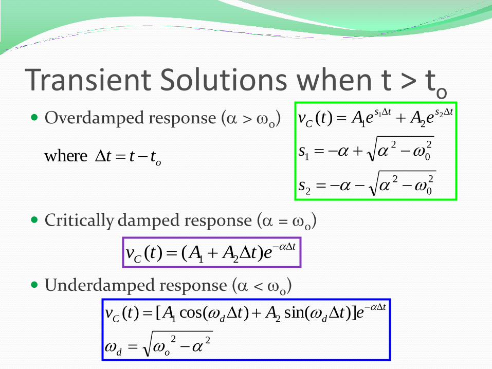
Transient Solutions when t > to Overdamped response ( > o)
Critically damped response ( = o)
Underdamped response ( < o)
2
0
2
2
2
0
2
1
2121)(
DD
s
s
eAeAtvtsts
C
t
C etAAtv DD )()( 21
22
21 )]sin()cos([)(
DD D
od
t
ddC etAtAtv
ottt D where

Find Coefficients After you have selected the form for the solution based
upon the values of o and
Solve for the coefficients in the equation by evaluating the equation and its first derivate at t = to
- using the initial boundary conditions.
vC(to-) = Vs and dvC(to
-)/dt = iC (to-)/C = 0V/s

Other Voltages and Currents Once the voltage across the capacitor is known, the
following equations for the case where t > to can be used to find:
)()(
)()(
)()()()(
)()(
tRitv
dt
tdiLtv
titititi
dt
tdvCti
RR
LL
RLC
CC

Solutions when t < to The initial conditions of all of the components are the
solutions for all times -∞s < t < to.
vC(t) = Vs
iC(t) = 0A
vL(t) = 0V
iL(t) = 0A
vR(t) = 0V
iR(t) = 0A
Summary The set of solutions when t > to for the voltage across the
capacitor in a RLC network in series was obtained.
Selection of equations is determine by comparing the natural frequency o to .
Coefficients are found by evaluating the equation and its first derivation at t = to
-.
The voltage across the capacitor is equal to the initial condition when t < to
Using the relationships between current and voltage, the current through the capacitor and the voltages and currents for the inductor and resistor can be calculated.