rl78/g14 7-segment led lighting control (arduino api)
TRANSCRIPT

Application Note
R01AN5387EJ0100 Rev.1.00 Page 1 of 27 July.10.20
RL78/G14 7-Segment LED Lighting Control (Arduino API) Introduction This application note describes a method to control dynamically lighting of 7-segment LEDs using a program written in an Arduino language using the RL78/G14 Fast Prototyping Board (FPB).
Target Device RL78/G14
When applying the sample program covered in this application note to another microcomputer, modify the program according to the specifications for the target microcomputer and conduct an extensive evaluation of the modified program.

RL78/G14 Seven-Segment LED Lighting Control (Arduino API)
R01AN5387EJ0100 Rev.1.00 Page 2 of 27 July.10.20
Contents
1. Specifications ............................................................................................................................ 3 1.1 Program Execution Environment ............................................................................................................. 4 1.2 Program (Sketch) Configuration .............................................................................................................. 5 1.3 Preparations for Project Startup .............................................................................................................. 5 1.4 Definitions in the Program (sketch) ......................................................................................................... 6 1.5 Initial Setting Processing ......................................................................................................................... 8 1.6 Main Processing Part .............................................................................................................................. 8
2. Operating Conditions ................................................................................................................. 9
3. Related Application Notes ......................................................................................................... 9
4. Hardware ................................................................................................................................. 10 4.1 Example of Hardware Configuration ..................................................................................................... 10 4.2 List of Pins Used ................................................................................................................................... 10
5. Software .................................................................................................................................. 11 5.1 Summary of Operation .......................................................................................................................... 11 (1) Pins to be used are set in the setup function. ................................................................................... 11 (2) The main processing is performed in the loop function. ................................................................... 11 (3) In the poll_sw function, the state of the SW_USR switch is confirmed every 10 milliseconds, and the
number of times the switch is pressed is counted. ........................................................................... 12 5.2 List of Constants .................................................................................................................................... 13 5.3 List of Variables ..................................................................................................................................... 14 5.4 List of Functions .................................................................................................................................... 15 5.5 Specification of Functions ..................................................................................................................... 16 5.6 Flowcharts ............................................................................................................................................. 18 5.6.1 Initial setting function ........................................................................................................................... 18 5.6.2 Main Processing Function ................................................................................................................... 20 5.6.3 Function to set display data for 7-segment LEDs ............................................................................... 24
6. Sample Code ........................................................................................................................... 26
7. Reference Documents ............................................................................................................. 26
Revision History .............................................................................................................................. 27

RL78/G14 Seven-Segment LED Lighting Control (Arduino API)
R01AN5387EJ0100 Rev.1.00 Page 3 of 27 July.10.20
1. Specifications In this application note, an FPB is used with a program written in an Arduino language to dynamically control lighting of three 7-segment LEDs (cathode-common) and eight LEDs that are externally connected to the FPB.
The 7-segment LEDs realize a one-minute timer that displays an elapsed time in 100-millisecond (0.1 second) units. Upon the passing of each minute, the eight LEDs are lit in sequence, to realize a timer that can measure times up to nine minutes. Moreover, the timer counting operation can be controlled using a switch (SW_USR) mounted on the FPB or using an externally connected switch (ex_SW).
Table 1.1 shows peripheral functions used in this program and their uses.
Table 1.1 Peripheral functions used and their uses
Peripheral Function
Use
Digital input Reading the state of the switch (SW_USR) or external switch (ex_SW) Digital output Control of the LEDs (three 7-segment LEDs and eight separate LEDs) Timer array unit Measurement of the elapsed time

RL78/G14 Seven-Segment LED Lighting Control (Arduino API)
R01AN5387EJ0100 Rev.1.00 Page 4 of 27 July.10.20
1.1 Program Execution Environment In this application note, a program in an Arduino language is executed in a development environment specific to the RL78 family. A conceptual diagram of the program execution environment is shown in Figure 1.1.
Arduino language program (sketch)
Function library for an Arduino language (Arduino API)
RL78 family development environment
Hardware (FPB)
Figure 1.1 Program execution environment
Library functions that can be used in this application note are shown in Table 1.2.
Table 1.2 Library functions
Item Library Function Function
Digital I/O pinMode(pin, mode) Specifies the operation mode (input mode/output mode/input mode with internal pull-up resistor enabled) for the pin specified by “pin”.
digitalWrite (pin, value) Sets the pin specified by “pin” to the state specified by “value” (high level/low level).
digitalRead(pin) Reads out the state of the pin specified by “pin”.
Time control millis() Returns, in millisecond units, the time from the start of program execution to the present time.
micros() Returns, in microsecond units, the time from the start of program execution to the present time.
delay (ms) Stops the program for the specified time in millisecond units.
delayMicroseconds (us) Stops the program for the specified time in microsecond units.

RL78/G14 Seven-Segment LED Lighting Control (Arduino API)
R01AN5387EJ0100 Rev.1.00 Page 5 of 27 July.10.20
1.2 Program (Sketch) Configuration Subfolders are prepared for each integrated development environment below the folder (workspace) in which the project is stored. In the folders for each of the integrated development environments the files are stored that are used in the RL78 family development environment.
In each sketch subfolder, AR_SKETCH.c is stored which is the Arduino language program (sketch). When viewing or modifying sketch, the "AR_SKETCH.c" file in the sketch subfolder is used.
1.3 Preparations for Project Startup Preparations for project startup are different depending on the integrated development environment used. For details, refer to the following application note.
RL78 Family Arduino API Introduction Guide (R01AN5413)

RL78/G14 Seven-Segment LED Lighting Control (Arduino API)
R01AN5387EJ0100 Rev.1.00 Page 6 of 27 July.10.20
1.4 Definitions in the Program (sketch) Definitions in the program (sketch) are indicated in Figure 1.2.
Figure 1.2 Program definition details
1)
2)
3)

RL78/G14 Seven-Segment LED Lighting Control (Arduino API)
R01AN5387EJ0100 Rev.1.00 Page 7 of 27 July.10.20
1) The digital output pins used to drive segments of the 7-segment LEDs are defined.
0 is specified for the segPinA pin, which controls segment A, allocating this pin to D0.
Similarly, segments B, C, D, E, F, G, and DP are defined.
The digital output pins used to drive commons (for selecting the LED display digits) of the 7-segment LEDs are defined.
8 is specified for the comPin0 pin, which controls the 10-second digit, allocating this pin to D8.
9 is specified for the comPin1 pin, which controls the 1-second digit, allocating this pin to D9.
10 is specified for the comPin2 pin, which controls the 0.1-second digit, allocating this pin to D10.
11 is specified for the comPin3 pin, which controls eight separate LEDs, allocating this pin to D11.
The digital input pins used to read the states of the switches are defined.
13 is specified for the ex_swPin pin, which controls the external switch, allocating this pin to D13.
18 is specified for the swPin pin, which controls the on-board switch (SW_USR), allocating this pin to D18.
2) Control data is defined using the array SEG_TABLE, which specifies the numerals (0 to 9) to be displayed by the 7-segment LEDs and specifies where there is no display (LED extinguished).
3) A number of variables used in the program (sketch) are defined.
old_time : Variable to confirm the elapsed time (in milliseconds)
sec_data : Variable to count seconds
mini_data : Variable to count minutes
precount1 : Counter variable to obtain 100 milliseconds from the timing of switching of the 4-millisecond display digit
precount2 : Variable to obtain 1 second by counting 100 milliseconds
digi_sel : Variable to control display dynamically
prescale4sw : Variable to count timing to confirm the switch state
sw_data : Variable to store change of the switch state
time_mode : Variable to start/stop counting time

RL78/G14 Seven-Segment LED Lighting Control (Arduino API)
R01AN5387EJ0100 Rev.1.00 Page 8 of 27 July.10.20
1.5 Initial Setting Processing The initial settings section of the program (sketch) is shown in Figure 1.3.
In the setup function, input or output mode is specified for each pin.
Figure 1.3 Initial setting processing section
1.6 Main Processing Part The leading section of the main processing, which is executed repeatedly, is shown in Figure 1.4. When preparations for project startup have been set correctly, the startup screen is as in Figure 1.4.
Figure 1.4 Leading section of main processing

RL78/G14 Seven-Segment LED Lighting Control (Arduino API)
R01AN5387EJ0100 Rev.1.00 Page 9 of 27 July.10.20
2. Operating Conditions The operation of the sample code provided with this application note has been tested under the following
conditions.
Table 2.1 Operating conditions
Item Description Microcontroller used RL78/G14 (R5F104MLAFB) Operating frequency High-speed on-chip oscillator clock (fIH): 32 MHz
CPU/peripheral hardware clock: 32 MHz Operating voltage 3.3 V (can be operated at 2.75 V to 5.5 V)
LVD operation: Reset mode LVD detection voltage (VLVD)
At rising edge: 2.81 V typ. (2.76 V to 2.87 V) At falling edge: 2.75 V typ. (2.70 V to 2.81 V)
Integrated development environment
Renesas Electronics CS+ for CC V8.03.00
Renesas Electronics e² studio V7.7.0
IAR Systems IAR Embedded Workbench for RL78
C compiler Renesas Electronics CC-RL V1.09.00
IAR Systems IAR C/C++ Compiler v4.20.1 for RL78
3. Related Application Notes The application notes related to this application note are shown below.
Refer to these together with this application note.
RL78 Family Arduino API Introduction Guide (R01AN5413)
RL78/G14 Onboard LED Flashing Control (Arduino API) (R01AN5384)

RL78/G14 Seven-Segment LED Lighting Control (Arduino API)
R01AN5387EJ0100 Rev.1.00 Page 10 of 27 July.10.20
4. Hardware 4.1 Example of Hardware Configuration
Figure 4.1 shows the hardware (FPB) that is used in this application note.
Figure 4.1 Hardware configuration example
Note: This conceptual diagram is simplified in order to summarize the connections.
As the power supply voltage, 3.3 V is supplied via USB.
4.2 List of Pins Used Table 4.1 shows the pins used and their functions.
Table 4.1 Pins used and their functions
Pin Port Name I/O Function D16 P43 Output Control of LED0 D17 P44 Output Control of LED1 D18 P137 Input Switch (SW_USR) input
RL78/G14 TERGET VCC VDD,EVDD
200Ω×8
SW_USR
SegA/LED0
VSS,EVSS
TERGET VCC
10kΩ
ex_SW Sink Driver
SegB/LED1 SegC/LED2 SegD/LED3 SegE/LED4 SegF/LED5 SegG/LED6 SegDP/LED7 COM2 COM0 COM1
D0 (P143) D1 (P144) D2 (P142)
D3 (P75) D4 (P76) D5 (P77) D6 (P10) D7 (P02)
7Segment LED x 3 LED x 8
COM3 D8 (P03) D9 (P11)
D10 (P12) D11 (P52)
D18 (P137)
D13 (P54)

RL78/G14 Seven-Segment LED Lighting Control (Arduino API)
R01AN5387EJ0100 Rev.1.00 Page 11 of 27 July.10.20
5. Software 5.1 Summary of Operation In this application note, when the initial settings (pin settings) are completed and the main processing (loop) is started, 7-segment LEDs display “00.0”.
When the ex_SW or the SW_USR switch is pressed, the 7-segment LED display begins counting up. When the ex_SW or SW_USR switch is again pressed, the counting stops. Thereafter, each time the ex_SW or SW_USR switch is pressed, counting is resumed or stopped.
When counting upward causes the 7-segment LED display to again return to "00.0", one LED is lit. Each time the 7-segment LED display reaches "00.0", an additional LED is lit. When all eight LEDs are lit and the 7-segment LED display again reaches "00.0", the eight LEDs are all extinguished.
Thereafter, the above operation is repeated.
Details are explained in (1) to (3) below.
(1) Pins to be used are set in the setup function.
The pins (segPinA to segPinDP) for driving segments of the 7-segment LEDs are set for digital output.
The pins (comPin0 to comPin3) for driving commons of the 7-segment LEDs are set for digital output.
The pin (ex_swPin) for confirmation of the state of the external switch (ex_SW) is set to an input mode in which an internal pull-up resistor is enabled.
The pin (swPin) for confirmation of the state of the on-board switch (SW_USR) is set for digital input.
(2) The main processing is performed in the loop function.
10 bits worth, bits 11 to 2, of the time elapsed from startup (in millisecond units) are acquired.
It is confirmed that the data acquired has changed from the old data (old_time).
If the data has not changed, processing is ended, and execution returns to the beginning of the loop function.
If the data has changed (4 milliseconds have elapsed), old_time is changed to the acquired data.
Processing is switched according to the values of bits 3 and 2.
If (bit 3, bit 2) = (0, 0), the comPin3 pin is set to Low (selection cancelled). Next, segment data for the 10-second digit is determined, and is set at segPin using the set_SEG function. The display digit specification (the comPin0 pin) is set to the com_sel variable.
If (bit 3, bit 2) = (0, 1), the comPin0 pin is set to Low (selection cancelled). Next, segment data for the one-second digit is determined, and is set at segPin using the set_SEG function. At this time, the DP are also set to be lit. The display digit specification (the comPin1 pin) is set to the com_sel variable.
If (bit 3, bit 2) = (1, 0), the comPin1 pin is set to Low (selection cancelled). Next, segment data for the 100-millisecond digit is determined, and is set at segPin using the set_SEG function. The display digit specification (the comPin2 pin) is set to the com_sel variable.
If (bit 3, bit 2) = (1, 1), the comPin2 pin is set to Low (selection cancelled). Next, data for the minute digit is set at segPin using the set_SEG function. The display digit specification (the comPin3 pin) is set to the com_sel variable.
The display digit specified by the com_sel variable is selected and displayed.

RL78/G14 Seven-Segment LED Lighting Control (Arduino API)
R01AN5387EJ0100 Rev.1.00 Page 12 of 27 July.10.20
When counting is permitted (the time_mode variable is 1), time counting is performed.
The precount1 variable (4-millisecond units) is counted up, and upon reaching 25 (when 100 milliseconds have elapsed), precount1 is cleared, and the precount2 variable (100-millisecond units) is counted up.
The precount2 variable (100-millisecond units) is counted up, and upon reaching 10 (when one second has elapsed), the precount2 variable is cleared, and the sec_data variable (1-second units) is counted up.
The sec_data variable (1-second units) is counted up, and upon reaching 60 (when one minute has elapsed), the sec_data variable is cleared, and the mini_data variable (1-minute units) is updated. When the value of mini_data is 0xFF, it is set to 0x00. When the value of mini_data is not 0xFF, it is shifted one bit to the left, and the LSB (least significant bit) is set (to 1). The value of mini_data changes to 0x00, 0x01, 0x03, 0x07, 0x0F, 0x1F, 0x3F, 0x7F, 0xFF.
The switch circumstances are checked every 20 milliseconds.
The prescale4sw variable is counted up, and upon reaching 5 (20 milliseconds), the prescale4sw variable is cleared. The sw_data variable is shifted one bit to the left, and bit 0 is set to the result of taking the logical sum of the states of the two switches (switches use negative logic, so the logical product is taken). When either of the switches is pressed, the time_mode variable is changed.
(3) In the poll_sw function, the state of the SW_USR switch is confirmed every 10 milliseconds, and the number of times the switch is pressed is counted.
The argument segment data is read into the work_data working variable.
The LSB (least significant bit) of the work_data variable is output to the segPinA pin, and the work_data variable is shifted one bit to the right.
The LSB (least significant bit) of the work_data variable is output to the segPinB pin, and the work_data variable is shifted one bit to the right.
The LSB (least significant bit) of the work_data variable is output to the segPinC pin, and the work_data variable is shifted one bit to the right.
The LSB (least significant bit) of the work_data variable is output to the segPinD pin, and the work_data variable is shifted one bit to the right.
The LSB (least significant bit) of the work_data variable is output to the segPinE pin, and the work_data variable is shifted one bit to the right.
The LSB (least significant bit) of the work_data variable is output to the segPinF pin, and the work_data variable is shifted one bit to the right.
The LSB (least significant bit) of the work_data variable is output to the segPinG pin, and the work_data variable is shifted one bit to the right.
The LSB (least significant bit) of the work_data variable is output to the segPinDP pin.

RL78/G14 Seven-Segment LED Lighting Control (Arduino API)
R01AN5387EJ0100 Rev.1.00 Page 13 of 27 July.10.20
5.2 List of Constants Table 5.1 shows constants that are used in the sample code.
Table 5.1 Constants used in sample code
Constant Name Setting Value
Description
segPinA 0 Number of the pin to control segment A segPinB 1 Number of the pin to control segment B segPinC 2 Number of the pin to control segment C segPinD 3 Number of the pin to control segment D segPinE 4 Number of the pin to control segment E segPinF 5 Number of the pin to control segment F segPinG 6 Number of the pin to control segment G segPinDP 7 Number of the pin to control segment DP comPin0 8 Number of the pin to select the 10-second
digit comPin1 9 Number of the pin to select the 1-second digit comPin2 10 Number of the pin to select the 100-
millisecond digit comPin3 11 Number of the pin to select separate LED ex_swPin 13 Number of the pin that reads external switch
(ex_SW) swPin 18 Number of the pin that reads SW_USR SEG_TABLE[] 0x3F Data to display 0 in a 7-segment LED
0x06 Data to display 1 in a 7-segment LED 0x5B Data to display 2 in a 7-segment LED 0x4F Data to display 3 in a 7-segment LED 0x66 Data to display 4 in a 7-segment LED 0x6D Data to display 5 in a 7-segment LED 0x7D Data to display 6 in a 7-segment LED 0x27 Data to display 7 in a 7-segment LED 0x7F Data to display 8 in a 7-segment LED 0x6F Data to display 9 in a 7-segment LED 0x00 Data to extinguish a 7-segment LED
HIGH 0x01 High level LOW 0x00 Low level

RL78/G14 Seven-Segment LED Lighting Control (Arduino API)
R01AN5387EJ0100 Rev.1.00 Page 14 of 27 July.10.20
5.3 List of Variables Table 5.1 lists global variables.
Table 5.2 Global variables
Type Variable Name Description Function used int old_time Time elapsed time from previous startup (in millisecond
units) loop()
char mini_data Data indicating minutes elapsed: 0x00/0x01/0x03/0x07/0x0F/0x1F/0x3F/0x7F/0xFF
loop()
char sec_data Second data loop() char precount1 Used to generate 100-millisecond timing (updated
every 4 milliseconds) loop()
char Precount2 Used to generate 1-second timing (updated every 100 milliseconds)
loop()
char digi_sel Specifies the digit to display (pin numbers: 8 to 11). loop() char prescale4sw Used to generate 20-second timing loop() Int sw_data Stores state changes of the switch (initial value is
0xFF). loop()
Int time_mode Flag to control time counting (0: do not count, 1: count)
loop()

RL78/G14 Seven-Segment LED Lighting Control (Arduino API)
R01AN5387EJ0100 Rev.1.00 Page 15 of 27 July.10.20
5.4 List of Functions Table 5.3 shows a list of functions.
Table 5.3 List of functions
Function Name Overview loop Main processing (sketch) setup Initialization function (sketch) set_SEG Function to set display data for 7-segment LEDs (sketch) pinMode Specifies the operation mode of a pin (input mode/output mode/input mode with
internal pull-up resistor enabled). digitalWrite Outputs data to a pin. digitalRead Reads the state of a pin. micros Returns the time, in microsecond units, from the start of program execution until the
present time. millis Returns the time, in millisecond units, from the start of program execution until the
present time. delay Stops the program for the specified time, in millisecond units. delayMicroseconds Stops the program for the specified time, in microsecond units.

RL78/G14 Seven-Segment LED Lighting Control (Arduino API)
R01AN5387EJ0100 Rev.1.00 Page 16 of 27 July.10.20
5.5 Specification of Functions The function specifications of the sample code are shown below.
[Function name] loop Overview Main function Header AR_LIB_PORT.h, AR_LIB_TIME.h, r_cg_macrodriver.h, AR_SKETCH.h,
r_cg_userdefine.h Declaration void loop(void) Description Upon starting, the time from startup is checked, and every 4 milliseconds the output
of 7-segment LED digit data is switched. Moreover, when counting is permitted, counting in units of 100 milliseconds, seconds, and minutes is performed. Every 20 milliseconds, the switch states are checked, and if a switch is being pressed, the count permission flag is changed.
Argument None Return value None
[Function name] setup Overview Initialization function Header AR_LIB_PORT.h, r_cg_macrodriver.h, r_cg_userdefine.h Declaration void setup(void); Description Pins used by the program (sketch) are set. Argument None Return value None
[Function name] set_SEG Overview Function to set display data for 7-segment LEDs Header AR_LIB_PORT.h Declaration void set_SEG(char data); Description Data passed in the argument is set in the corresponding segment control pins as
lighting data for the 7-segment LEDs. Argument Data : Data for segment to be lit Return value None
[Function name] pinMode Overview Function to set the pin function Header AR_LIB_PORT.h, r_cg_macrodriver.h, r_cg_userdefine.h Declaration void pinMode(uint8_t pin,uint8_t mode) Description The pin indicated by the first argument is set to the mode indicated by the second
argument. Argument uint8_t pin :
uint8_t mode : Number of the pin to be specified Specifies the pin mode with OUTPUT/INPUT/INPUT_PULLUP
Return value None

RL78/G14 Seven-Segment LED Lighting Control (Arduino API)
R01AN5387EJ0100 Rev.1.00 Page 17 of 27 July.10.20
[Function name] digitalWrite Overview Function to output digital data to a pin Header AR_LIB_PORT.h, r_cg_macrodriver.h, r_cg_userdefine.h Declaration void digitalWrite(uint8_t pin, uint8_t value); Description The data indicated by the second argument is output to the pin indicated by the first
argument. Argument uint8_t pin :
uint8_t value : Number of the pin for data output Data to output (HIGH/LOW)
Return value None
[Function name] digitalRead Overview Function to read out digital data from a pin Header AR_LIB_PORT.h, r_cg_macrodriver.h, r_cg_userdefine.h Declaration uint8_t digitalRead(uint8_t pin); Description The state of the pin specified by the argument is read out Argument uint8_t pin : Number of the pin to be read out Return value uint8_t : Data that was red out (HIGH/LOW)
[Function name] millis Overview Function to obtain the elapsed time in millisecond units Header AR_LIB_TIME.h, r_cg_macrodriver.h, r_cg_userdefine.h Declaration uint32_t millis (void); Description Returns the time elapsed from startup, in millisecond units. Argument None Return value uint32_t : Elapsed time in millisecond units

RL78/G14 Seven-Segment LED Lighting Control (Arduino API)
R01AN5387EJ0100 Rev.1.00 Page 18 of 27 July.10.20
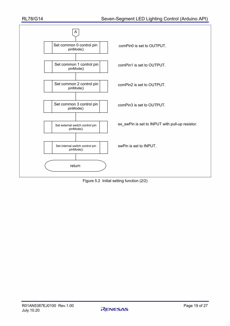
5.6 Flowcharts 5.6.1 Initial setting function Figure 5.1 and Figure 5.2 show flowcharts of the initial setting.
Figure 5.1 Initial setting function (1/2)
setup
Set segment A control pin pinMode()
Set segment B control pin pinMode()
segPinA is set to OUTPUT.
segPinB is set to OUTPUT.
Set segment C control pin pinMode()
segPinC is set to OUTPUT.
Set segment D control pin pinMode()
segPinD is set to OUTPUT.
Set segment E control pin pinMode()
segPinE is set to OUTPUT.
Set segment F control pin pinMode()
segPinF is set to OUTPUT.
Set segment G control pin pinMode()
segPinG is set to OUTPUT.
Set segment DP control pin pinMode()
segPinDP is set to OUTPUT.
A
RL78/G14 Seven-Segment LED Lighting Control (Arduino API)
R01AN5387EJ0100 Rev.1.00 Page 19 of 27 July.10.20
Figure 5.2 Initial setting function (2/2)
Set common 0 control pin pinMode()
Set common 1 control pin pinMode()
return
comPin0 is set to OUTPUT.
comPin1 is set to OUTPUT.
ex_swPin is set to INPUT with pull-up resistor.
Set common 2 control pin pinMode()
comPin2 is set to OUTPUT.
Set common 3 control pin pinMode()
comPin3 is set to OUTPUT.
A
Set external switch control pin pinMode()
Set internal switch control pin pinMode()
swPin is set to INPUT.

RL78/G14 Seven-Segment LED Lighting Control (Arduino API)
R01AN5387EJ0100 Rev.1.00 Page 20 of 27 July.10.20
5.6.2 Main Processing Function Figure 5.3 to Figure 5.6 show flowcharts of the main processing function.
Figure 5.3 Main processing function (1/4)
loop
Set segment data. set_SEG ()
Obtained segment data is output to pin.
D
Set common 3 pin. digitalWrite ()
Different from previous time?
No
Yes
Bits 11 to 2 for elapsed time in ms are read out. time_work variable ← millis() & 0x0FFC
Update previous time.
Read out elapsed time. millis()
G
If same as previous time (including when counting has stopped), no processing is performed.
old_time variable ← time_work variable
Extract bits 3 and 2.
time_work variable ← (Variable time_work & 0x000C)
Extracted time
0x00 0x04 0x08 0x0C
C A B
comPin3 ← LOW : Common 3 deselected
Extract segment value for 10-s digit.
seg_data variable ← SEG_TABLE array [10-s value]
Set display digit.
com_sel variable ← comPin0 : 10-s digit is set as display digit.

RL78/G14 Seven-Segment LED Lighting Control (Arduino API)
R01AN5387EJ0100 Rev.1.00 Page 21 of 27 July.10.20
Figure 5.4 Main processing function (2/4)
A
Set segment data. set_SEG ()
Obtained segment data is output to pin.
D
Set common 0 pin. digitalWrite ()
comPin0 ← LOW : Common 0 deselected
Extract segment value for 1-s digit.
seg_data variable ← SEG_TABLE array [1-s value] + 0x80
Set display digit.
com_sel variable ← comPin1 : 1-s digit is set as display digit.
B
Set segment data. set_SEG ()
Obtained segment data is output to pin.
D
Set common 1 pin. digitalWrite ()
comPin1 ← LOW: Common 1 deselected
Extract segment value for 100-ms digit.
seg_data variable ← SEG_TABLE array [100-ms value]
Set display digit.
com_sel variable ← comPin2 : 100-ms digit is set as display digit.

RL78/G14 Seven-Segment LED Lighting Control (Arduino API)
R01AN5387EJ0100 Rev.1.00 Page 22 of 27 July.10.20
Figure 5.5 Main processing function (3/4)
C D
Set common 2 pin. digitalWrite ()
comPin2 ← LOW : Common 2 deselected
Set display data for minute digit.
seg_data variable ← min_data variable
Set display digit.
com_sel variable ← comPin3 : Separate LED is set as display digit.
Outputs data to specfied pin. digitalWrite ()
HIGH is output to display digit pin.
100 ms elapsed?
No
Yes
If counting is permitted (time_mode = 1) and 100 ms have elapsed (precount1 variable = 25), the variable is initialized.
F
Initialize precount1.
precount1 variable ← 0 : 100-ms counter is cleared.
1 second elapsed?
No
Yes F
If 1 second has elapsed (precount2 variable = 10), the variable is initialized.
Initialize precount2.
precount2 variable ← 0 : 1-s counter is cleared.
1 minute elapsed?
No
Yes F
If 1 minute has elapsed (sec_data variable = 60), the variable is initialized.
Initialize Sec_data.
sec_data variable ← 0 : Second counter is cleared.
E
Set segment data. set_SEG ()
Obtained segment data is output to segment pin.

RL78/G14 Seven-Segment LED Lighting Control (Arduino API)
R01AN5387EJ0100 Rev.1.00 Page 23 of 27 July.10.20
Figure 5.6 Main processing function (4/4)
Change time_mode variable.
If bits 2 and 1 of sw_data variable are ”10”, processing for pressed switch is performed.
return
E F
com_sel variable is left-shifted 1 bit, and LSB (least significant bit) is set to 1.
9 seconds elapsed?
No
Yes
Initialize mini_data.
mini_data variable ← 0 : Minute counter is cleared.
If mini_data variable is 0xFF, the variable is initialized.
Update second data.
If 20 ms have elapsed (prescale4sw variable = 5), switch state is checked.
prescale4sw variable ← 0
Initialize prescale4sw.
The sw_data variable is left-shifted 1 bit, and the logical sum (logical product using negative logic) of the two switch states is set in the LSB (least significant bit).
Update switch state.
Extract bits 2 and 1 of sw_data variable.
Check switch state.
No
Yes
G
Switch pressed?
No
Yes
Change time counting mode.
Switch checking timing?

RL78/G14 Seven-Segment LED Lighting Control (Arduino API)
R01AN5387EJ0100 Rev.1.00 Page 24 of 27 July.10.20
5.6.3 Function to set display data for 7-segment LEDs Figure 5.7 and Figure 5.8 show flowcharts of the function to set display data for 7-segment LEDs.
Figure 5.7 Function to set display data for Segment LEDs (1/2)
set_SEG
work_data variable ← argument (segment data) Set display data.
Set segment A.
pinMode()
LSB of work_data variable is set to segPinA.
work_data variable is right-shifted 1 bit. Update display data.
Set segment B.
pinMode()
LSB of work_data variable is set to segPinB.
work_data variable is right-shifted 1 bit. Update display data.
Set segment C.
pinMode()
LSB of work_data variable is set to segPinC.
work_data variable is right-shifted 1 bit. Update display data.
Set segment D.
pinMode()
LSB of work_data variable is set to segPinD.
work_data variable is right-shifted 1 bit. Update display data.
Set segment E.
pinMode()
LSB of work_data variable is set to segPinE.
work_data variable is right-shifted 1 bit. Update display data.
A

RL78/G14 Seven-Segment LED Lighting Control (Arduino API)
R01AN5387EJ0100 Rev.1.00 Page 25 of 27 July.10.20
Figure 5.8 Function to set display data for Segment LEDs (2/2)
return
Set segment F. pinMode()
LSB of work_data variable is set to segPinF.
work_data variable is right-shifted 1 bit. Update display data.
Set segment G.
pinMode()
LSB of work_data variable is set to segPinG.
work_data variable is right-shifted 1 bit. Update display data.
Set segment DP.
pinMode()
LSB of work_data variable is set to segPinDP.
A

RL78/G14 Seven-Segment LED Lighting Control (Arduino API)
R01AN5387EJ0100 Rev.1.00 Page 26 of 27 July.10.20
6. Sample Code Sample code can be downloaded from the Renesas Electronics website.
7. Reference Documents RL78/G14 User's Manual: Hardware (R01UH0186) RL78 family User's Manual: Software (R01US0015) RL78/G14 Fast Prototyping Board User’s Manual (R20UT4573) RL78 Family Arduino API Introduction Guide (R01AN5413) (The latest versions can be downloaded from the Renesas Electronics website.)
Technical Update/Technical News
(The latest versions can be downloaded from the Renesas Electronics website.)
Website and Support Renesas Electronics Website
http://www.renesas.com/ Inquiries
http://www.renesas.com/contact/

RL78/G14 Seven-Segment LED Lighting Control (Arduino API)
R01AN5387EJ0100 Rev.1.00 Page 27 of 27 July.10.20
Revision History
Rev. Date Description Page Summary
1.00 July.10.20 ― First Edition

General Precautions in the Handling of Microprocessing Unit and Microcontroller Unit Products The following usage notes are applicable to all Microprocessing unit and Microcontroller unit products from Renesas. For detailed usage notes on the products covered by this document, refer to the relevant sections of the document as well as any technical updates that have been issued for the products.
1. Precaution against Electrostatic Discharge (ESD)
A strong electrical field, when exposed to a CMOS device, can cause destruction of the gate oxide and ultimately degrade the device operation. Steps
must be taken to stop the generation of static electricity as much as possible, and quickly dissipate it when it occurs. Environmental control must be
adequate. When it is dry, a humidifier should be used. This is recommended to avoid using insulators that can easily build up static electricity.
Semiconductor devices must be stored and transported in an anti-static container, static shielding bag or conductive material. All test and
measurement tools including work benches and floors must be grounded. The operator must also be grounded using a wrist strap. Semiconductor
devices must not be touched with bare hands. Similar precautions must be taken for printed circuit boards with mounted semiconductor devices. 2. Processing at power-on
The state of the product is undefined at the time when power is supplied. The states of internal circuits in the LSI are indeterminate and the states of
register settings and pins are undefined at the time when power is supplied. In a finished product where the reset signal is applied to the external reset
pin, the states of pins are not guaranteed from the time when power is supplied until the reset process is completed. In a similar way, the states of pins
in a product that is reset by an on-chip power-on reset function are not guaranteed from the time when power is supplied until the power reaches the
level at which resetting is specified. 3. Input of signal during power-off state
Do not input signals or an I/O pull-up power supply while the device is powered off. The current injection that results from input of such a signal or I/O
pull-up power supply may cause malfunction and the abnormal current that passes in the device at this time may cause degradation of internal
elements. Follow the guideline for input signal during power-off state as described in your product documentation. 4. Handling of unused pins
Handle unused pins in accordance with the directions given under handling of unused pins in the manual. The input pins of CMOS products are
generally in the high-impedance state. In operation with an unused pin in the open-circuit state, extra electromagnetic noise is induced in the vicinity of
the LSI, an associated shoot-through current flows internally, and malfunctions occur due to the false recognition of the pin state as an input signal
become possible. 5. Clock signals
After applying a reset, only release the reset line after the operating clock signal becomes stable. When switching the clock signal during program
execution, wait until the target clock signal is stabilized. When the clock signal is generated with an external resonator or from an external oscillator
during a reset, ensure that the reset line is only released after full stabilization of the clock signal. Additionally, when switching to a clock signal
produced with an external resonator or by an external oscillator while program execution is in progress, wait until the target clock signal is stable. 6. Voltage application waveform at input pin
Waveform distortion due to input noise or a reflected wave may cause malfunction. If the input of the CMOS device stays in the area between VIL
(Max.) and VIH (Min.) due to noise, for example, the device may malfunction. Take care to prevent chattering noise from entering the device when the
input level is fixed, and also in the transition period when the input level passes through the area between VIL (Max.) and VIH (Min.). 7. Prohibition of access to reserved addresses
Access to reserved addresses is prohibited. The reserved addresses are provided for possible future expansion of functions. Do not access these
addresses as the correct operation of the LSI is not guaranteed. 8. Differences between products
Before changing from one product to another, for example to a product with a different part number, confirm that the change will not lead to problems.
The characteristics of a microprocessing unit or microcontroller unit products in the same group but having a different part number might differ in terms
of internal memory capacity, layout pattern, and other factors, which can affect the ranges of electrical characteristics, such as characteristic values,
operating margins, immunity to noise, and amount of radiated noise. When changing to a product with a different part number, implement a system-
evaluation test for the given product.

© 2020 Renesas Electronics Corporation. All rights reserved.
Notice 1. Descriptions of circuits, software and other related information in this document are provided only to illustrate the operation of semiconductor products
and application examples. You are fully responsible for the incorporation or any other use of the circuits, software, and information in the design of your product or system. Renesas Electronics disclaims any and all liability for any losses and damages incurred by you or third parties arising from the use of these circuits, software, or information.
2. Renesas Electronics hereby expressly disclaims any warranties against and liability for infringement or any other claims involving patents, copyrights, or other intellectual property rights of third parties, by or arising from the use of Renesas Electronics products or technical information described in this document, including but not limited to, the product data, drawings, charts, programs, algorithms, and application examples.
3. No license, express, implied or otherwise, is granted hereby under any patents, copyrights or other intellectual property rights of Renesas Electronics or others.
4. You shall not alter, modify, copy, or reverse engineer any Renesas Electronics product, whether in whole or in part. Renesas Electronics disclaims any and all liability for any losses or damages incurred by you or third parties arising from such alteration, modification, copying or reverse engineering.
5. Renesas Electronics products are classified according to the following two quality grades: “Standard” and “High Quality”. The intended applications for each Renesas Electronics product depends on the product’s quality grade, as indicated below. "Standard": Computers; office equipment; communications equipment; test and measurement equipment; audio and visual equipment; home
electronic appliances; machine tools; personal electronic equipment; industrial robots; etc. "High Quality": Transportation equipment (automobiles, trains, ships, etc.); traffic control (traffic lights); large-scale communication equipment; key
financial terminal systems; safety control equipment; etc. Unless expressly designated as a high reliability product or a product for harsh environments in a Renesas Electronics data sheet or other Renesas Electronics document, Renesas Electronics products are not intended or authorized for use in products or systems that may pose a direct threat to human life or bodily injury (artificial life support devices or systems; surgical implantations; etc.), or may cause serious property damage (space system; undersea repeaters; nuclear power control systems; aircraft control systems; key plant systems; military equipment; etc.). Renesas Electronics disclaims any and all liability for any damages or losses incurred by you or any third parties arising from the use of any Renesas Electronics product that is inconsistent with any Renesas Electronics data sheet, user’s manual or other Renesas Electronics document.
6. When using Renesas Electronics products, refer to the latest product information (data sheets, user’s manuals, application notes, “General Notes for Handling and Using Semiconductor Devices” in the reliability handbook, etc.), and ensure that usage conditions are within the ranges specified by Renesas Electronics with respect to maximum ratings, operating power supply voltage range, heat dissipation characteristics, installation, etc. Renesas Electronics disclaims any and all liability for any malfunctions, failure or accident arising out of the use of Renesas Electronics products outside of such specified ranges.
7. Although Renesas Electronics endeavors to improve the quality and reliability of Renesas Electronics products, semiconductor products have specific characteristics, such as the occurrence of failure at a certain rate and malfunctions under certain use conditions. Unless designated as a high reliability product or a product for harsh environments in a Renesas Electronics data sheet or other Renesas Electronics document, Renesas Electronics products are not subject to radiation resistance design. You are responsible for implementing safety measures to guard against the possibility of bodily injury, injury or damage caused by fire, and/or danger to the public in the event of a failure or malfunction of Renesas Electronics products, such as safety design for hardware and software, including but not limited to redundancy, fire control and malfunction prevention, appropriate treatment for aging degradation or any other appropriate measures. Because the evaluation of microcomputer software alone is very difficult and impractical, you are responsible for evaluating the safety of the final products or systems manufactured by you.
8. Please contact a Renesas Electronics sales office for details as to environmental matters such as the environmental compatibility of each Renesas Electronics product. You are responsible for carefully and sufficiently investigating applicable laws and regulations that regulate the inclusion or use of controlled substances, including without limitation, the EU RoHS Directive, and using Renesas Electronics products in compliance with all these applicable laws and regulations. Renesas Electronics disclaims any and all liability for damages or losses occurring as a result of your noncompliance with applicable laws and regulations.
9. Renesas Electronics products and technologies shall not be used for or incorporated into any products or systems whose manufacture, use, or sale is prohibited under any applicable domestic or foreign laws or regulations. You shall comply with any applicable export control laws and regulations promulgated and administered by the governments of any countries asserting jurisdiction over the parties or transactions.
10. It is the responsibility of the buyer or distributor of Renesas Electronics products, or any other party who distributes, disposes of, or otherwise sells or transfers the product to a third party, to notify such third party in advance of the contents and conditions set forth in this document.
11. This document shall not be reprinted, reproduced or duplicated in any form, in whole or in part, without prior written consent of Renesas Electronics. 12. Please contact a Renesas Electronics sales office if you have any questions regarding the information contained in this document or Renesas
Electronics products.
(Note1) “Renesas Electronics” as used in this document means Renesas Electronics Corporation and also includes its directly or indirectly controlled subsidiaries.
(Note2) “Renesas Electronics product(s)” means any product developed or manufactured by or for Renesas Electronics.
(Rev.4.0-1 November 2017)
Corporate Headquarters Contact information TOYOSU FORESIA, 3-2-24 Toyosu, Koto-ku, Tokyo 135-0061, Japan www.renesas.com
For further information on a product, technology, the most up-to-date version of a document, or your nearest sales office, please visit: www.renesas.com/contact/.
Trademarks Renesas and the Renesas logo are trademarks of Renesas Electronics Corporation. All trademarks and registered trademarks are the property of their respective owners.