rj series 3rd gen. - circupool · circupool help guides: ( gen. rj series 3rd ) 5 basic water...
TRANSCRIPT

CircuPool Help Guides: RJ Series (3rd Gen.)
1
RJ Series (3rd Gen.) Troubleshooting Guide
Table of contents: Basic Water Chemistry pg.2
Phosphates & Nitrates pg.4
Langelier Saturation Index pg.5
Low Chlorine Level in Pool pg.6
System Status Menu Displays pg.9
Troubleshooting pg.10
How to Clean the Electrolytic Cell pg.12
How to Install the Flow Switch pg.13
How to Replace the Keypad pg.14
How to Install Temp. Flow Switch pg.17
How to Install the Display Circuit Board pg.18
Quick Reference pg.19
The complete RJ manual is always available at Circupool.com: http://www.circupool.com/how-to-install-a-salt-chlorine-generator.php
IMPORTANT - REMEMBER THAT YOUR POOL IS COMPATIBLE WITH CHLORINE AND SHOCK AS NORMAL. IF YOUR POOL IS
EXPERIENCING TEMPORARY LOSS OF CHLORINE OR OTHER DIFFICULTIES, ADD SANITIZER AS NEEDED TO MAINTAIN THE POOL.
WARNING - ALWAYS MAKE SURE THE INPUT POWER IS COMPLETELY DISCONNECTED BEFORE ATTEMPTING ANY
TROUBLESHOOTING PROCEDURES. ALL TROUBLESHOOTING SHOULD BE DONE BY A QUALIFIED PROFESSIONAL.
CircuPool Help Guides: RJ Series (3rd Gen.)
2
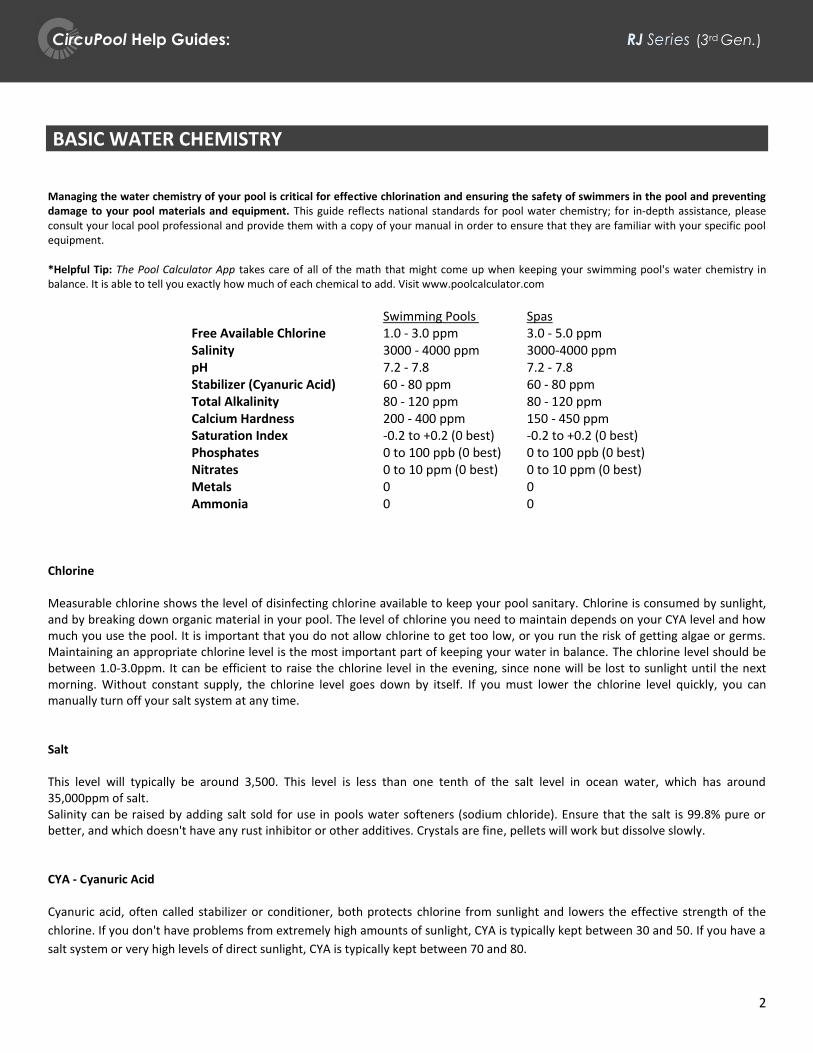
BASIC WATER CHEMISTRY Managing the water chemistry of your pool is critical for effective chlorination and ensuring the safety of swimmers in the pool and preventing damage to your pool materials and equipment. This guide reflects national standards for pool water chemistry; for in-depth assistance, please consult your local pool professional and provide them with a copy of your manual in order to ensure that they are familiar with your specific pool equipment. *Helpful Tip: The Pool Calculator App takes care of all of the math that might come up when keeping your swimming pool's water chemistry in balance. It is able to tell you exactly how much of each chemical to add. Visit www.poolcalculator.com
Swimming Pools Spas Free Available Chlorine 1.0 - 3.0 ppm 3.0 - 5.0 ppm Salinity 3000 - 4000 ppm 3000-4000 ppm pH 7.2 - 7.8 7.2 - 7.8 Stabilizer (Cyanuric Acid) 60 - 80 ppm 60 - 80 ppm Total Alkalinity 80 - 120 ppm 80 - 120 ppm Calcium Hardness 200 - 400 ppm 150 - 450 ppm Saturation Index -0.2 to +0.2 (0 best) -0.2 to +0.2 (0 best) Phosphates 0 to 100 ppb (0 best) 0 to 100 ppb (0 best) Nitrates 0 to 10 ppm (0 best) 0 to 10 ppm (0 best) Metals 0 0 Ammonia 0 0
Chlorine Measurable chlorine shows the level of disinfecting chlorine available to keep your pool sanitary. Chlorine is consumed by sunlight, and by breaking down organic material in your pool. The level of chlorine you need to maintain depends on your CYA level and how much you use the pool. It is important that you do not allow chlorine to get too low, or you run the risk of getting algae or germs. Maintaining an appropriate chlorine level is the most important part of keeping your water in balance. The chlorine level should be between 1.0-3.0ppm. It can be efficient to raise the chlorine level in the evening, since none will be lost to sunlight until the next morning. Without constant supply, the chlorine level goes down by itself. If you must lower the chlorine level quickly, you can manually turn off your salt system at any time. Salt This level will typically be around 3,500. This level is less than one tenth of the salt level in ocean water, which has around 35,000ppm of salt. Salinity can be raised by adding salt sold for use in pools water softeners (sodium chloride). Ensure that the salt is 99.8% pure or better, and which doesn't have any rust inhibitor or other additives. Crystals are fine, pellets will work but dissolve slowly. CYA - Cyanuric Acid Cyanuric acid, often called stabilizer or conditioner, both protects chlorine from sunlight and lowers the effective strength of the
chlorine. If you don't have problems from extremely high amounts of sunlight, CYA is typically kept between 30 and 50. If you have a
salt system or very high levels of direct sunlight, CYA is typically kept between 70 and 80.

CircuPool Help Guides: RJ Series (3rd Gen.)
3
pH - Acidity/Alkalinity pH indicates how acidic or basic the water is. pH should be tested daily at first. Once you gain experience with your pool, less frequent monitoring may be appropriate, depending on your pool's typical rate of pH change. pH levels between 7.5 and 7.8 are ideal, while levels between 7.2 and 7.8 are acceptable for swimming. TA - Total Alkalinity Total alkalinity indicates the water's ability to buffer pH changes. Buffering means you need to use a larger quantity of a chemical to change the pH. At low TA levels, the pH tends to swing around wildly. At high TA levels, the pH tends to drift up. TA contributes to the LSI which indicates the tendency for plaster damage or calcium scaling. You can raise TA with baking soda. It is often best to make large TA adjustments in a couple of steps, testing the water after each one, as adding baking soda will also affect the pH and you don't want the pH going out of range. CH - Calcium Hardness Calcium hardness indicates the amount of calcium in the water. A plaster pool should have CH levels between 250 and 350 if possible. If you have a spa you might want to keep CH at at least 100 to 150 to reduce foaming. CH contributes to the LSI which indicates the tendency for plaster damage or calcium scaling. You increase CH with calcium chloride, sold as a deicer and by pool stores, or calcium chloride dihydrate, sold by pools stores for increasing calcium. You lower calcium by replacing water or using a reverse osmosis water treatment.
See following Basic Water Chemistry pages for more specific information about Phosphates, Nitrates, and Saturation Index (LSI)

CircuPool Help Guides: RJ Series (3rd Gen.)
4
BASIC WATER CHEMISTRY - PHOSPHATES & NITRATES Phosphates are a part of the environment: Phosphates became a household word in the 1970's. This is when people started to use low-phosphate and phosphate-free laundry detergents to help minimize the detrimental effects of excess phosphates in lakes, streams, wetlands and other runoff areas- effects such as unwanted algae blooms. Phosphates accumulate in pools: What's true for lakes is also true for swimming pools; there are innumerable ways phosphates can get into your pool. Phosphates are a natural component of most swimmer wastes. It is also present in rain water. It can be blown in on the wind, in dirt or dust, or in plant material that enters the pool. It may also be introduced by landscaper's fertilizers at very high levels, which may blow into the pool or come in from water runoff. Phosphate levels are persistent and do not break down naturally- you have to treat the water to remove phosphates. For all of these reasons, pools can quickly build up phosphate levels. This can lower chlorine levels and create an abundant source for all strains of algae & microorganisms, and can make controlling their growth difficult. Remove the food source, and you can normalize chlorine demand and have a strong weapon against algae. When phosphates are present, chlorine levels go down and algae grows: Phosphate is the main ingredient in fertilizer. Phosphate is plant food, and algae are plants. If you have had persistent trouble with chlorine levels or algae, you may have a phosphate problem in your pool. When excess phosphate is present in a swimming pool, the symptoms often include the following: Quickly Dissipating Chlorine Levels or Excessive Chemical Consumption; Cloudy, Green Water; Slippery and Slimy Surfaces; Mustard and Green Colored Debris; Poor Water Quality. Remove the phosphates and solve the problem: It only takes tiny amounts of phosphates to become significant in pools. The maximum level of phosphate in pool water should be less than 100 ppb, as close to 0 as possible. Once the phosphates climbs above this level, the water quality begins to decrease. Fortunately, draining to eliminate the accumulated phosphate is no longer necessary. Phosphate removers can be added which allow the phosphates to be removed from the water. A popular choice is Natural Chemistry's Phos-Free, which is a natural mineral product and is non-toxic.
You can test for phosphates in your pool with the AquaChek Phosphate Test Kit found at www.aquachek.com
Nitrates: Nitrates are a matter similar to Phosphates, but of different origin; however both a food source for algae. Nitrate is a plant
nutrient and is present in all green plants and fertilizers. It is natural occurring and is found everywhere something is growing.
Nitrites (NO2) are a close cousin to Nitrates (NO3) and are just as much of a problem for pools, because when a Nitrite comes in
contact with water, it easily gains another Oxygen atom to become a Nitrate. This additional atom gives Nitrates real stability, and
makes eradication difficult. In fact, the only known way of Nitrate removal in pools practiced today is to drain a portion of the pool,
and refill with water that is Nitrate free, if possible. Shocking a pool heavily will revert the Nitrates back to Nitrites, but can easily
revert once again as an additional Oxygen atom is easy to come by in a swimming pool filled with H2O.
Where do Nitrates come from? Rural areas - those with water wells and septic tanks are particularly prone to Nitrate contamination
in pools. Fertilizer is the most common source of Nitrates in pools. Animals that enter the pool, as well as birds spend time above the
pool, can become a significant source of contaminants. Rain spilling off of overhanging trees can add Nitrates to a pool, and even
acid rain itself, so common in the Northeast, can increase Nitrate levels. Finally, human waste, sweat, cosmetics can all bring traces
of Nitrates into the pool. At levels as low as 10ppm of Nitrate, algae will grow even though you have used algaecide and are keeping
a proper chlorine residual. But keeping a proper residual of chlorine in the water can prove to be difficult when Nitrates are present.
This is what tricks people into believing in Chlorine Lock- it's not blocking chlorine, but using it very quickly.
What can be done to Eliminate Nitrates in my pool? There still however is no chemical to remove the Nitrates from the pool water,
so if you have a contamination, you will need to drain most if not all of the pool water.

CircuPool Help Guides: RJ Series (3rd Gen.)
5
BASIC WATER CHEMISTRY - LANGELIER SATURATION INDEX (LSI) LSI is a measurement of the water’s ability to absorb and hold solids in a solution. It is important to know that the scale on which LSI is measured is very narrow, meaning that a small change can indicate a significant difference in your pool. Like pH, the LSI value is logarithmic, meaning that a difference of 1.0 equates to a difference of ten times in reality. A Saturation Index of -2.0 is ten times more corrosive than an SI of –1.0. This is important, as many pool equipment manufacturers may not be able to warranty damage caused by an out-of-balance LSI. STEPS TO TAKE:
1. Obtain a complete water chemistry test from a pool store for the following items:
pH, Water Temperature, Alkalinity, Cyanuric Acid (Stabilizer), Calcium Hardness, Total Dissolved Solids
2. Go to www.aquachek.com
a. Click on “Calculators”
b. Click on “Langelier Saturation Index”
c. Plug in your results and obtain your Saturation Index number.
3. Go to www.poolcalculator.com to balance your water accordingly.
If LSI Index is between -0.2 and +0.2 pool water is Balanced. When pool water is balanced, it has no effect on the pool or equipment. There are two values you can readily change to help improve your LSI value to get it into the optimum range: pH and Alkalinity level. If LSI Index is less than -0.2 pool water is Corrosive. Pool water may cause etching, pitting, dissolving and staining of walls, grouting and plumbing. It will also cause erosion to the titanium salt cell.
• As Stabilizer Increases, LSI Decreases
• As Total Dissolved Solids Increase, LSI Decreases To raise your LSI value, you should first balance the calcium hardness in the pool. It needs to be between 200-400 PPM at all times. If the calcium hardness is in the correct range, add sodium bicarbonate or baking soda. Consult the calculator at www.poolcalculator.com to determine the target Alkalinity value (recommended range is 80-120ppm; however, you may find that a level lower than 80 may be ideal for a balanced LSI value). If LSI Index is greater than +0.2 pool water is Scale Forming. Pool water may deposit excess minerals on the pool and equipment. Scale generally appears as white or lightly colored rough blotches on the pool walls. It also adheres to other objects in the pool, piping and filter system. This will cause calcium deposits to rapidly form on the titanium salt cell. Scale can restrict water flow, shortening filter runs and reducing filtration efficiency.
• As Temperature Increases LSI Increases
• As Total Alkalinity Increases LSI Increases
• As pH Increases, LSI Increases
• As Calcium Hardness Increases, LSI Increases To lower your LSI value, you should first consider adding muriatic acid (can be found in pool supply stores), as it is more difficult to lower Calcium Hardness and especially temperature. Consult the calculator to determine the target pH value.

CircuPool Help Guides: RJ Series (3rd Gen.)
6
LOW CHLORINE LEVEL IN POOL
IMPORTANT: Measuring a low chlorine level does not indicate that your system is not working. Water chemistry and environmental conditions are the #1 cause of a low chlorine level in a saltwater pool. The following steps will enable you to verify with certainty whether or not your system is operational and creating chlorine. Following that, this help guide will help identify what may contributing to the low chlorine level in the pool water.
Verifying that the system is operational There are two variables involved in the generation of chlorine: salt and electricity. If there is salt in the water and power being sent to the Electrolytic Cell, the system is generating chlorine normally. If the salt level is in question, independently test a water sample.
+ = .
Verifying Power is present in Cell 1. Ensure no Warning Lights are on
o Is the No Flow LED indicator illuminated solidly? If it is, the system is not able to send power through the cell because the Flow Switch is not being triggered by the flow of water.
o Is the Check Cell (or Cell Maint.) LED indicator illuminated solidly? If it is, the system is not able to send power through the cell because of excess mineral build-up inside of the cell.
o Is the Hi Salt or Lo Salt LED indicator illuminated solidly? If it is, the system is not able to send power through the cell because of improper salinity levels. If the Check Cell light is also on, the Check Cell light takes priority.
o Is the Generating LED indicator flashing? If it is, the system is not able to send power through the cell because the water temperature is outside of operating range.
2. Confirming Cell Current (Note: a negative sign in the diagnostic numbers just indicates system is in negative Reverse-Polarity cycle) o If all warning lights are off, power is successfully able to pass through the cell. The Control Module has a built in
power meter that ensures that the full and complete amount of power is able to pass through the cell. o To verify the power being sent through the cell, turn the chlorine output setting up to 100% for diagnostic
purposes. To access the power reading, press the MENU button three times to display the "Cell Current" reading. As long as the "Cell Current" reads above zero when turned up to 100%, the system is at that moment able to pass its full amount of power through the Cell, and is fully operational and creating chlorine normally.
Summary: If salt is present above the minimum level of 3000 ppm, if the warning lights are not illuminated solidly, if the
Generating LED indicator is illuminated solidly, and if "Cell Current" reads above zero when the system is turned up to 100%, then the system is fully operational and creating chlorine normally. If a low chlorine level persists after continued operation, see the next pages to troubleshoot common causes of high chlorine demand.
IMPORTANT - REMEMBER THAT YOUR POOL IS COMPATIBLE WITH CHLORINE AND SHOCK AS NORMAL. IF YOUR POOL IS
EXPERIENCING TEMPORARY LOSS OF CHLORINE OR OTHER DIFFICULTIES, ADD SANITIZER AS NEEDED TO MAINTAIN THE POOL.
CHLORINE PRODUCTION
salt power

CircuPool Help Guides: RJ Series (3rd Gen.)
7
LOW CHLORINE LEVEL IN POOL (Continued)
Common Causes of Low Chlorine Levels
Examine the Water Chemistry (Also see Page 2):
• Water chemistry and environmental conditions are the #1 cause of a low chlorine level in a saltwater pool, as they cause chlorine demand to rise above normal levels. High chlorine demand means that chlorine is being consumed quicker than it is being replenished, resulting in the inability to measure the chlorine residual in the water. If operation has been verified (as described on the previous page), this does not mean that the chlorine generator is not working, only that the chlorine demand currently exceeds the rate of chlorine production.
• The ideal levels for a salt water pool are
Free Available Chlorine 1.0 - 3.0 ppm Salinity 3000 - 4000 ppm pH 7.2 - 7.8 Stabilizer (Cyanuric Acid) 60 - 80 ppm Total Alkalinity 80 - 120 ppm Calcium Hardness 200 - 400 ppm Saturation Index -0.2 to +0.2 (0 best) Phosphates 0 to 100 ppb (0 best) Nitrates 0 to 10 ppm (0 best) Iron 0 Copper 0 Other metals 0 Ammonia 0
The levels that are highlighted levels are the most common causes of high chlorine demand and depleted chlorine levels in
pools. Ensure that all three levels are being tested for and that their values are included on your chemistry report.
The Chlorine Stabilizer (Cyanuric Acid, or CYA) level must be within range, especially during the spring and summer
months. If there is not enough CYA in the pool, then your chlorine will not be protected from the sun and the chlorine
being produced by the salt system will be consumed once the sun hits the pool water. Up to 90% of the pool's chlorine can
be depleted within 2 hours without a sufficient level of chlorine stabilizer.
Phosphates and Nitrates that are present in the pool will cause the chlorine demand to rise and/or will consume the
chlorine being made by the salt system (Also see page 4). Phosphates are very common. Any Phosphate level near or
above 100 parts per billion can greatly increase the chlorine demand in the pool. Any Phosphate level over 200 Part Per
Billion will not only consume your chlorine, it will also readily feed algae. To remove phosphates, use commercial grade
Phosfree. When trying to lower significant phosphate levels, phosphate products meant for weekly maintenance are
usually not effective Nitrates will also rapidly consume your chlorine. If the Nitrate level is high, it is often most effective to
drain the pool and refill with new water, being sure to add the necessary amount of salt back to the pool.
Lower salt levels can affect chlorine generation and cause the system to work inefficiently.
Other chemistry imbalances and the presence of metals, ammonia, and other impurities can cause high chlorine demand.

CircuPool Help Guides: RJ Series (3rd Gen.)
8
Common Causes of Low Chlorine Levels (Continued)
Insufficient Operation:
• Ensure input power- Is the salt system turning on and off with the pump as normal? Has the fuse / fuse reset button been
tripped? If so, see "No Power", page 11.
• Output Level - The percentage output level that you set tells the system how much of its maximum capacity to use in order to
create chlorine. If you are experiencing high chlorine demand, ensure that you have your system turned up to 100% output so
that it is doing as much as possible to compensate. Leave the system at 100% output until the pool is balanced again. Since
every pool operates differently and has a different level of chlorine demand, during normal operation there is not a standard
percentage level at which to set the output.
• Run time - When sized right, a chlorine generator can typically achieve sufficient chlorination when run on the filter pump's
normal schedule. However, every pool has different equipment and its operation is unique, and you may require (or choose) to
run the filter pump more or less than is standard. As a rule of thumb however, run your system one hour for every ten degrees
of ambient temperature in order to achieve both sufficient filtration and chlorination. Periods of high use, harsh environmental
conditions, or excessive chlorine demand may require extended run times. For example, running your system twice as long will
allow it to create twice as much chlorine.
• Cell Maintenance - Make sure the cell plates are clean and free from any debris. The Self-Cleaning feature minimizes the
amount of mineral deposits that will occur, but as with every salt system, the electrolytic cell should be cleaned periodically. If
there are any calcium deposits or debris that may have made it past the filter (hair, grass, etc...) which are causing the cell plates
to bridge together, clean the cell with one part muriatic acid and five parts water for 10 minutes. If the cell plates need to be
cleaned the Check Cell (Cell Maint.) light will most likely be illuminated.
• During initial startup (springtime / new pools) - When being opened, pools typically have much higher than normal chlorine
demand. In these circumstances a pool requires a large amount of sanitizer all at once, which means that it is often more
effective to add chlorine or shock as needed initially instead of waiting on the system to slowly reach "break-point" chlorination.

CircuPool Help Guides: RJ Series (3rd Gen.)
9
System Status Menu Displays
Diagnostics displayed on RJ-Series Control Module.
1. Pool Temperature
Working temperature is 60°F-140°F. While displayed, can be changed to °C by pressing the left or right arrow
button.
2. Cell Voltage
Range can be 20.0-26.0 volts (while generating). If the voltage reads near 10.0-13.0, the system is configured to
accept 220V but is only receiving 110V.
3. Cell Current
Range can be 2.50-8.00 amps (while generating). May be 0 during normal operation when system turned to less
than 100% output and is in its rest mode. If present, a hyphen (-) indicates polarity, and not a negative value.
4. Instant Salinity
Real-time salinity test result in XXXX PPM. While displayed, can be changed to X.X g/L by pressing the left or right
arrow button. May display zeros while in rest mode or when LED warning lights are illuminated. If present, a
hyphen (-) indicates polarity, and not a negative value.
5. System ID
May vary, not a changeable option.
6. Software Revision
May vary, not a changeable option.
7. Cell Version
May vary with production and cell version.
Average Salinity (Default display when "Salinity" button is pressed)
This reading slowly changes as the system continues to collect salinity readings in real-time throughout its
operation. When first installed, this will display the salinity that was detected while testing at the factory. This
reading may show lower than actual salinity levels if the system has had any LED warning lights illuminated for a
time, and will slowly return to normal when the LED lights have turned off after the issue has been resolved.

CircuPool Help Guides: RJ Series (3rd Gen.)
10
Troubleshooting
1. Check Cell (or Cell Maint.) LED light is on solid:
a. This takes priority over Lo Salt / Hi Salt lights. Cell efficiency has been greatly reduced and the cell must be cleaned.
i. Depending on water chemistry, the cell may need to be cleaned more than once, or soon after the last
cleaning. If you have cleaned your cell and see the Check Cell light again (and have checked all other
troubleshooting items), clean your cell again.
ii. If you are needing frequent or multiple cleanings, the pool has a high Saturation Index, see page 5.
b. Ensure salinity is in range, ideally 3000-4000 PPM.
c. Ensure correct Cell Version is set in the System Status menu.
d. Ensure RJ voltage configuration matches input voltage.
e. Low speed pump does not have enough flow to clear air and gas from the Cell. This is often the case if the
appearance of the Check Cell light corresponds with pump operation, pump timer, or daily schedules. Invert cell.
2. Lo Salt / Hi Salt LED light is flashing:
a. The detected salinity level is approaching minimum / maximum limits. Operation will continue, but take steps to
ensure the salinity stays in range.
3. Lo Salt / Hi Salt LED light is on solid: a. The detected salinity is outside of the system's operating range, and the system has ceased operation.
b. Check Cell takes priority over Lo Salt / Hi Salt lights.
c. Ensure correct Cell Version is set in the System Status menu.
4. No Flow LED light is flashing:
a. The system has detected that water flow has been restored, and is ensuring constant and steady flow. This light
may blink for 30-60 seconds after flow has been restored.
5. No Flow LED light is on solid: a. The Flow Switch is not being triggered by water movement.
b. Ensure that the Flow Switch cord is connected to the bottom of the Control Module.
c. Ensure that the return line has pressure and the water flow rate exceeds 25 gpm.
d. Ensure that the Flow Switch itself is facing the correct direction in the plumbing. Refer to the arrow on the top of
the sensor for reference, make sure the arrow is pointing in the same direction as the water flow.
e. Ensure that the Flow Switch has not been installed too near to an angled pipe union or change in direction in the
plumbing. The manual specifies at least 6-12" of straight pipe before the water enters the Flow Switch.
6. Instant Salinity and Cell Current read zero: a. This will occur during the system's normal rest cycle when the chlorine output level is set to less than 100%..
b. If any warning lights are illuminated solidly, the system will stop sending power through the cell.
c. Ensure RJ voltage configuration matches input voltage (see below).
WARNING - ALWAYS MAKE SURE THE INPUT POWER IS COMPLETELY DISCONNECTED BEFORE ATTEMPTING ANY
TROUBLESHOOTING PROCEDURES. ALL TROUBLESHOOTING SHOULD BE DONE BY A QUALIFIED PROFESSIONAL.
CircuPool Help Guides: RJ Series (3rd Gen.)
11
7. Generate LED light flashing and/or screen displaying temperature error a. Water temperature is too cold or too hot for system to operate. b. If system reads significantly incorrect temperature, temperature sensor in cell may be damaged.
8. No power to Control Module: a. The fuse reset button has tripped. This is the Control Module's built-in circuit breaker located on the bottom of the
Control Module between the two cables in the aluminum base. b. The fuse has been blown and needs to be replaced. The 15 AMP fuse is available at any electronics or auto parts
store. The fuse is located inside the Control Module on the upper right-hand side of the main power circuit board.
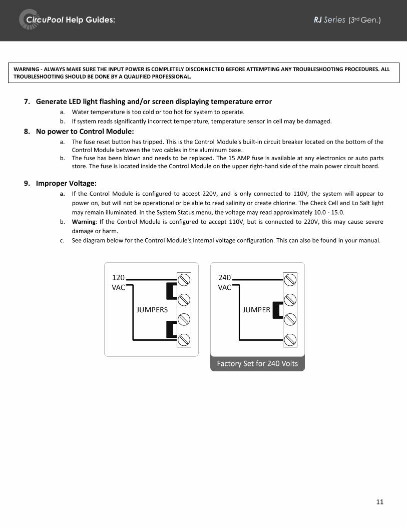
9. Improper Voltage:
a. If the Control Module is configured to accept 220V, and is only connected to 110V, the system will appear to
power on, but will not be operational or be able to read salinity or create chlorine. The Check Cell and Lo Salt light
may remain illuminated. In the System Status menu, the voltage may read approximately 10.0 - 15.0.
b. Warning: If the Control Module is configured to accept 110V, but is connected to 220V, this may cause severe
damage or harm.
c. See diagram below for the Control Module's internal voltage configuration. This can also be found in your manual.
WARNING - ALWAYS MAKE SURE THE INPUT POWER IS COMPLETELY DISCONNECTED BEFORE ATTEMPTING ANY TROUBLESHOOTING PROCEDURES. ALL TROUBLESHOOTING SHOULD BE DONE BY A QUALIFIED PROFESSIONAL.

CircuPool Help Guides: RJ Series (3rd Gen.)
12
How to Clean the Electrolytic Cell The Electrolytic Cell has the self-cleaning Reverse Polarity feature built-in, which prevents mineral deposits from forming rapidly. However, the Cell may eventually need to be manually cleaned. The frequency of mineral build-up is dependent upon the balance of the pool's water chemistry, specifically the Saturation Index (see page 5). In most circumstances, the Check Cell (Cell Maint.) LED indicator will be illuminated solidly when the cell needs to be cleaned.
Follow these steps to clean the cell:
1. Turn all power to the filter system and salt system off. Close return line valves if applicable. 2. Completely disconnect the Cell Cord from the Control Module. 3. Unscrew the two threaded collars at the inlet and outlet side of the cell. 4. Remove the cell from the return line. 5. IMPORTANT: Using gloves and eye protection during this process is recommended. Always add acid to the water,
never water to the acid. 6. In a separate bucket, mix a solution of: one part Muriatic Acid and five parts water. 7. There are two different ways to clean the cell.
a. Use an end-cap or cleaning stand (sold separately) to cap off then outlet side of the cell and pour the solution into the top of the cell.
i. Secure cell and let it soak until all mineral scaling has been disolved. ii. See picture below on left.
iii. The end cap can be purchased at www.circupool.com. b. Submerge the cell in a bucket of the solution.
i. Make sure the water line covers the internal components of the cell. ii. Secure the cell and let it soak until all mineral scaling has been dissolved.
iii. See picture below on right 8. You will notice a fizzing or fogging effect inside the cell once the solution has made contact with the titanium cell,
this is normal. The solution should completely cover the titanium plates, and should usually be allowed to soak for 10 minutes.
9. Dispose of the solution and wash out any remaining debris.
Cap
Water Line
Water Line

CircuPool Help Guides: RJ Series (3rd Gen.)
13
How to Install the Flow Switch
Installation Steps for installing a Flow Switch into existing equipment: 1. Disconnect the flow switch wire from the RJ control box.
2. Turn the top of the Flow Switch counter clockwise until the switch is loose enough to pull out of the PVC
fitting.
3. Install new flow switch and twist it clockwise to tighten. Make sure the directional arrow is facing the same
direction as the water flow. Additional Teflon tape can be added to the threads to ensure a tight water seal.
WARNING - ALWAYS MAKE SURE THE INPUT POWER IS COMPLETELY DISCONNECTED BEFORE ATTEMPTING ANY
TROUBLESHOOTING PROCEDURES. ALL TROUBLESHOOTING SHOULD BE DONE BY A QUALIFIED PROFESSIONAL.

CircuPool Help Guides: RJ Series (3rd Gen.)
14
How to Install the Keypad
Before Replacement or Installation:
IMPORTANT: VERIFY YOUR KEYPAD VERSION
Before ordering a replacement keypad, check your equipment and tell your Support Team member know which version you have. Keypad versions are not interchangeable. Your keypad will have two ribbon cables with end connectors as follows:
Installation Steps:
1. Disconnect the control panel from power and remove the unit from its wall mounting bracket. 2. Unscrew the six screws from the back of the control panel.
WARNING - ALWAYS MAKE SURE THE INPUT POWER IS COMPLETELY DISCONNECTED BEFORE ATTEMPTING ANY
TROUBLESHOOTING PROCEDURES. ALL TROUBLESHOOTING SHOULD BE DONE BY A QUALIFIED PROFESSIONAL.
Equal Width
11-Pins 11-Pins
Different Width
11-Pins 9-Pins
You have a:
RJNK15 Keypad
You have a:
RJNK16 Keypad

CircuPool Help Guides: RJ Series (3rd Gen.)
15
3. Remove the front control panel cover. 4. Disconnect the black/green ribbon cable from both terminals on the back of the display circuit board (see picture below).
5. Use a flat head screw driver to peel back one of the four corners of the original keypad (see picture below).
6. Peel off entire keypad away from the front blue cover. 7. Avoid excessive bending of the new keypad during the entire following process. 8. Peel of the paper sticker away from the back of the new keypad.
CircuPool Help Guides: RJ Series (3rd Gen.)
16
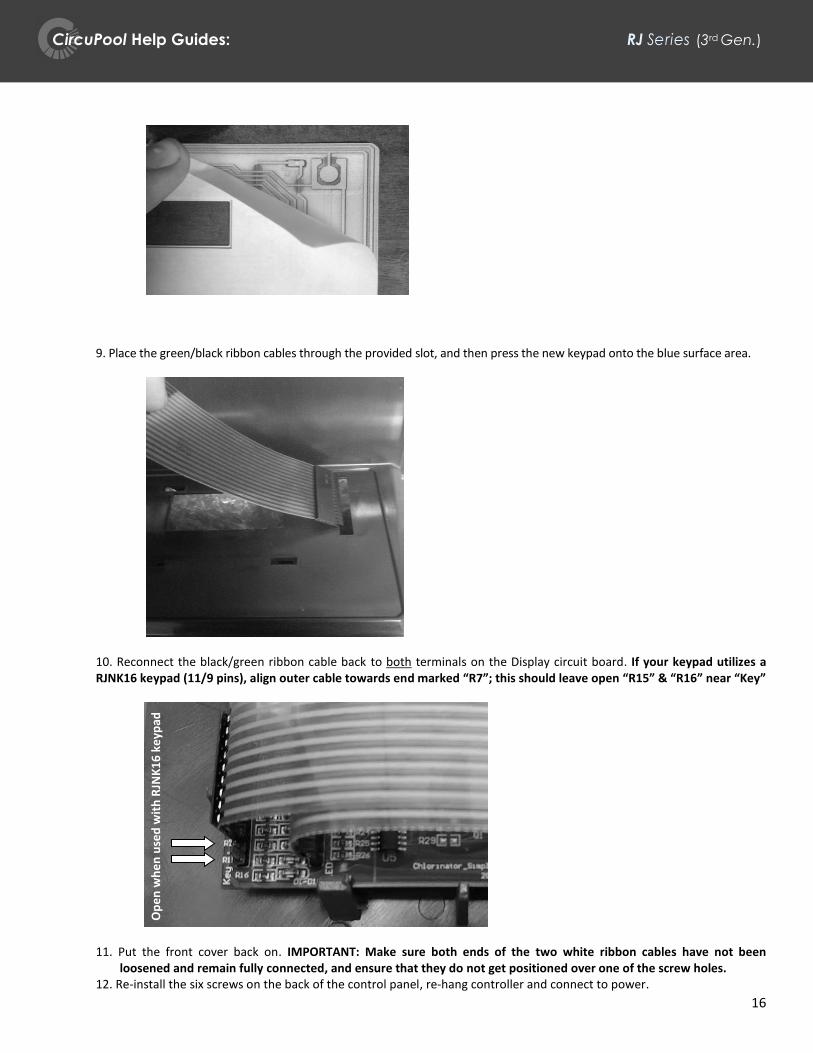
9. Place the green/black ribbon cables through the provided slot, and then press the new keypad onto the blue surface area.
10. Reconnect the black/green ribbon cable back to both terminals on the Display circuit board. If your keypad utilizes a RJNK16 keypad (11/9 pins), align outer cable towards end marked “R7”; this should leave open “R15” & “R16” near “Key”
11. Put the front cover back on. IMPORTANT: Make sure both ends of the two white ribbon cables have not been loosened and remain fully connected, and ensure that they do not get positioned over one of the screw holes.
12. Re-install the six screws on the back of the control panel, re-hang controller and connect to power.
Op
en
wh
en
use
d w
ith
RJN
K1
6 k
eyp
ad

CircuPool Help Guides: RJ Series (3rd Gen.)
17
How to Install Temperature / Flow Switch
This part replaces a standard Flow Switch and includes a temperature sensor, which can be used if accurate temperature
readings are no longer being provided by the Cell.
1. Replace the original flow switch. This part is threaded into your PVC plumbing (see “How to Install the Flow
Switch”).
2. Verify that equipment has no power, then remove six screws from back of Control Module, and remove blue
plastic cover.
3. Locate the three gold pins labeled “Temp” (see arrows in picture below). You will see a small black plastic
jumper connecting two of the three pins. Move this plastic spacer one space over.
4. Put the front cover back on. IMPORTANT: Make sure both ends of the two white ribbon cables have not been loosened and remain fully connected, and ensure that they do not get positioned over one of the screw holes.
5. Install the six screws on the back of the control panel.
WARNING - ALWAYS MAKE SURE THE INPUT POWER IS COMPLETELY DISCONNECTED BEFORE ATTEMPTING ANY
TROUBLESHOOTING PROCEDURES. ALL TROUBLESHOOTING SHOULD BE DONE BY A QUALIFIED PROFESSIONAL.

CircuPool Help Guides: RJ Series (3rd Gen.)
18
How to Install the Display Circuit Board
Installation Steps:
1. Disconnect the control panel from the black wall mounting bracket. 2. Lay unit on a flat surface and unscrew the six screws from the back of the control panel (Figure 1). 3. Remove the front control panel cover and two white ribbon cables (Figure 2). Turn the front control panel cover over to see
the display circuit board (Figure 3). 4. Disconnect the keypad’s clear black/green ribbon cables from the back of the display circuit board (Figure 4). 5. Remove the existing display circuit board by pulling from one edge to pop it out of the clips that hold it on place (Figure 5). 6. Install the new circuit board by placing the bottom side in first and then press in the top making sure the circuit board is
completely secured into the four clips. Make sure the orientation is correct. 7. Reconnect both sets ribbon cables making sure the orientation is correct. (Figure 2 and 4) 8. Put the front cover back on making sure the white ribbon cables do not get positioned over one of the six screw holes. 9. Reinstall the six screws on the back of the control panel.
10. Remount the control panel back on the mounting bracket.
WARNING - ALWAYS MAKE SURE THE INPUT POWER IS COMPLETELY DISCONNECTED BEFORE ATTEMPTING ANY
TROUBLESHOOTING PROCEDURES. ALL TROUBLESHOOTING SHOULD BE DONE BY A QUALIFIED PROFESSIONAL.
Figure 1 Figure 2 Figure 3
Figure 4 Figure 5

CircuPool Help Guides: RJ Series (3rd Gen.)
19
Quick Reference
See page 10 for more detailed explanations to common scenarios, diagnostic readings, and warning lights.
SCENARIO: POSSIBLE CAUSE: SUGGESTED ACTION:
Low or no chlorine residual in pool
Insufficient Chlorine Output Level Increase Output Level. This is often required seasonally with increasing temperatures.
Insufficient run time Increase run time to at least 1 hour per 10° ambient temp.
Heavy pool use, inclement weather, organic matter
Activate Super CL mode or chemically shock pool.
Water chemistry issues: Low Chlorine Stabilizer Low salt in pool Phosphates in pool Nitrates in pool
Contact pool professional, ensure all chemicals on p.2 are within range.
Cell is dirty, clogged, or Has excessive scaling or mineral build-up
Remove Cell from plumbing, inspect and clean (see p.12).
Low or no Chlorine residual in pool after recent installation
Water chemistry was not balanced prior to system installation and a high chlorine demand persists
Contact pool professional, ensure all chemicals on p.2 are within range, chemically shock pool if necessary.
System is connected to incorrect voltage and is not operational
Have a professional test power source and ensure correct connection.
Check Cell / Cell Maint. LED is on
It is time to inspect the Electrolytic Cell.
Inspect & clean cell if necessary (see page 12 for instructions).
(Has priority over salinity LED indicators if also lit.)
Cell efficiency has been greatly reduced Cell must be cleaned, or replaced (see page 12).
Incorrect Cell Version set Verify Cell Version in Status Menu.
Salinity is out of range Verify salinity.
No Power Fuse/Reset has tripped Check fuses on Control Module
Problem with input power, voltage, or configuration of system wiring
Have a professional test input power & ensure correct wiring configuration & connections.

CircuPool Help Guides: RJ Series (3rd Gen.)
20
Quick Reference (continued)uick Reference (Continued)
SCENARIO: POSSIBLE CAUSE: SUGGESTED ACTION:
Lo Salt LED is on / Salinity is out of range Verify salinity.
Hi Salt LED is on
Loose cell connection, Cell is dirty or clogged
Ensure correct connection, clean Cell if necessary.
Incorrect Cell Version set Verify Cell Version in Status Menu.
No Flow LED is on Incorrect installation Verify correct orientation, cable is plugged in, 6-12" of straight pipe before Flow Switch
Insufficient circulation Ensure operation of pump, at least 25-30 GPM. Check water level, filter pressure, or for air or blockages in PVC plumbing.
Water leak O-Ring improperly seated Ensure O-Rings are clean and in good condition.
Threaded collars are cross-threaded
Inspect threads for damage, ensure that each screws back on without resistance.
Real-Time Salinity and Cell current read zero
Zero reading during normal rest cycle
No action is required. Will rise after rest cycle or raising output
Incorrect voltage Have professional check wiring.
Incorrect Cell Version set Verify Cell Version in Status Menu.
No Flow, Lo Salt, High Salt, or Check Cell LED on
See above.
Cell frequently has mineral buildup
This is due to imbalanced water chemistry and a high Saturation Index
Ensure that your Saturation Index is at or near zero, in order to avoid damage or premature cell failure. (p.5)
Cell never or rarely has mineral buildup
Water may be corrosive due to imbalanced water chem. and a low Saturation Index
Ensure that your Saturation Index is at or near zero, in order to avoid damage or premature cell failure. (p.5)
HOT or COLD on screen Water temperature is too hot or cold for operation
Check operation of heater, or turn off until water temp is above 60°.
Cell is dirty or clogged Clean Cell (see p.12).
Damaged Cell or Cell cable Contact manufacturer.