rittal emc range - thorne and derrick uk...rittal emc range 3 the rittal emc concept emc...
TRANSCRIPT
Rittal EMC range
Perfect shielding
R

Rittal EMC range2
P e r f e c t s h i e l d i n g
T h e u l t i m a t e i n s h i e l d i n g f o r a l l
f r e q u e n c i e s
Today’s technical measurement and control, communication
and data technology systems are extremely powerful, as they
contain large numbers of complex electronic components
which can be highly sensitive to electromagnetic influences.
Good, professional planning of electromagnetic compatibility
(EMC) from the outset is therefore crucial to the lasting
functional reliability of equipment and systems.
Put your trust in the expert advice and wide range of
practically tested solutions from Rittal, one of the world’s
leading suppliers of enclosure and case technology. We have
decades of expertise in the handling of various materials and
are therefore able to translate the latest findings quickly and
reliably into practical solutions.
Y o u r p e r f e c t p a r t n e r – f r o m a n a l y s i s t o
p r o b l e m - s o l v i n g
It’s a familiar dilemma: Your product needs EMC, but you’re
not an EMC expert. We offer the ideal solution: Our
specialists will provide you with expert assistance and
advice. From obtaining initial information, to theoretical
training, through to practical implementation.
An analysis of the EMC risks of your application allows us to
discuss the proposed solutions and the range of products
available for selection. Rittal gives you the peace of mind
needed to confirm compliance with specified EMC protection
targets. It’s reassuring to know that you are also ideally
equipped to meet the requirements of the future.

Rittal EMC range
3
T h e R i t t a l E M C c o n c e p t
E M C w a l l - m o u n t e d e n c l o s u r e s
Terminal boxes KL
E-Box EB
Compact enclosures AE
Electronic Kombi system EL, 3-part
E M C s u b r a c k s
Ripac Vario
E M C e n c l o s u r e s
Baying systems TS 8
flexRack
E M C a c c e s s o r i e s
B a s i c E M C i n f o r m a t i o n
N o t e s / c o n t a c t
Page 6 – 7
Page 6 – 7
Page 6 – 7
Page 12 – 13
Page 8 – 9
Page 12 – 13
Page 10 – 11
Page 12 – 13
Page 14 – 19
Page 20 – 25
Page 26 – 27
Page 4 – 5
E M C i n s t r u m e n t c a s e s
Rittal Vario Case
iS
Rittal EMC range4
T h e R i t t a l E M C c o n c e p t
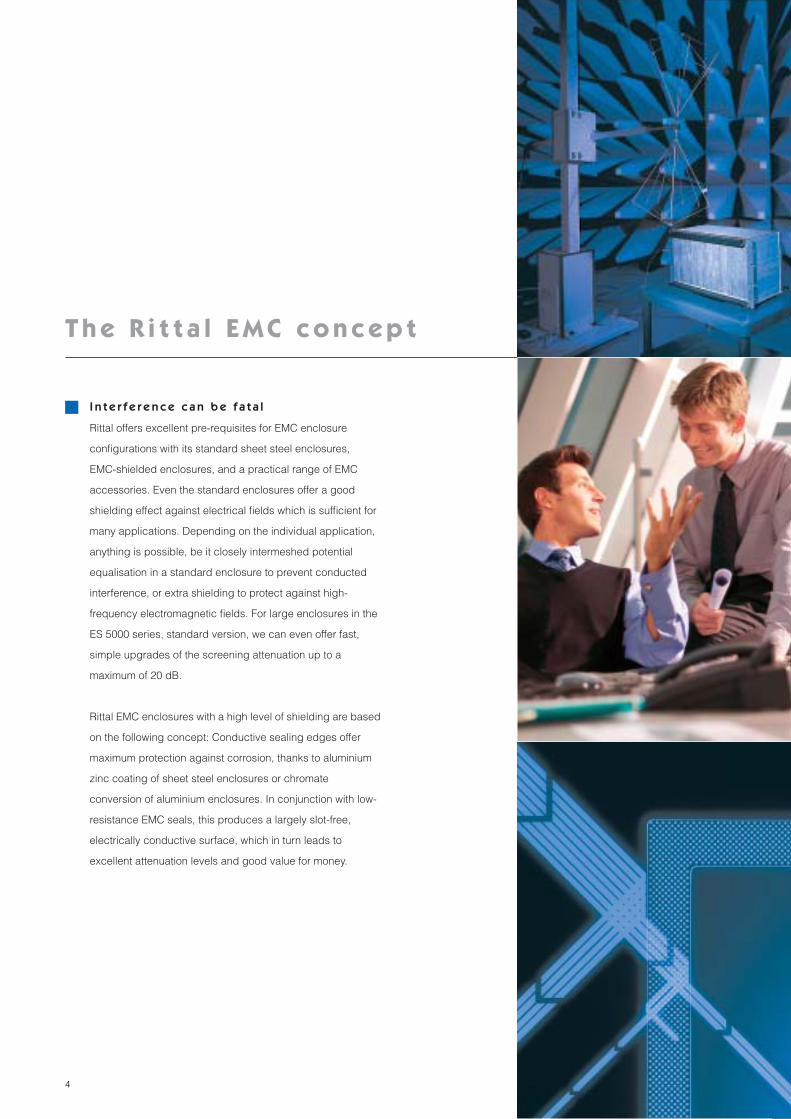
I n t e r f e r e n c e c a n b e f a t a l
Rittal offers excellent pre-requisites for EMC enclosure
configurations with its standard sheet steel enclosures,
EMC-shielded enclosures, and a practical range of EMC
accessories. Even the standard enclosures offer a good
shielding effect against electrical fields which is sufficient for
many applications. Depending on the individual application,
anything is possible, be it closely intermeshed potential
equalisation in a standard enclosure to prevent conducted
interference, or extra shielding to protect against high-
frequency electromagnetic fields. For large enclosures in the
ES 5000 series, standard version, we can even offer fast,
simple upgrades of the screening attenuation up to a
maximum of 20 dB.
Rittal EMC enclosures with a high level of shielding are based
on the following concept: Conductive sealing edges offer
maximum protection against corrosion, thanks to aluminium
zinc coating of sheet steel enclosures or chromate
conversion of aluminium enclosures. In conjunction with low-
resistance EMC seals, this produces a largely slot-free,
electrically conductive surface, which in turn leads to
excellent attenuation levels and good value for money.
Rittal EMC range 5
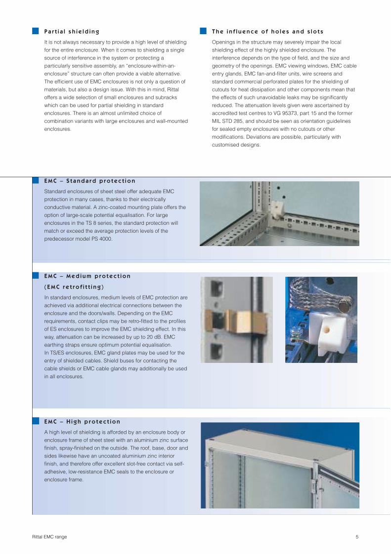
E M C – S t a n d a r d p r o t e c t i o n
Standard enclosures of sheet steel offer adequate EMC
protection in many cases, thanks to their electrically
conductive material. A zinc-coated mounting plate offers the
option of large-scale potential equalisation. For large
enclosures in the TS 8 series, the standard protection will
match or exceed the average protection levels of the
predecessor model PS 4000.
E M C – M e d i u m p r o t e c t i o n
( E M C r e t r o f i t t i n g )
In standard enclosures, medium levels of EMC protection are
achieved via additional electrical connections between the
enclosure and the doors/walls. Depending on the EMC
requirements, contact clips may be retro-fitted to the profiles
of ES enclosures to improve the EMC shielding effect. In this
way, attenuation can be increased by up to 20 dB. EMC
earthing straps ensure optimum potential equalisation.
In TS/ES enclosures, EMC gland plates may be used for the
entry of shielded cables. Shield buses for contacting the
cable shields or EMC cable glands may additionally be used
in all enclosures.
E M C – H i g h p r o t e c t i o n
A high level of shielding is afforded by an enclosure body or
enclosure frame of sheet steel with an aluminium zinc surface
finish, spray-finished on the outside. The roof, base, door and
sides likewise have an uncoated aluminium zinc interior
finish, and therefore offer excellent slot-free contact via self-
adhesive, low-resistance EMC seals to the enclosure or
enclosure frame.
P a r t i a l s h i e l d i n g
It is not always necessary to provide a high level of shielding
for the entire enclosure. When it comes to shielding a single
source of interference in the system or protecting a
particularly sensitive assembly, an “enclosure-within-an-
enclosure” structure can often provide a viable alternative.
The efficient use of EMC enclosures is not only a question of
materials, but also a design issue. With this in mind, Rittal
offers a wide selection of small enclosures and subracks
which can be used for partial shielding in standard
enclosures. There is an almost unlimited choice of
combination variants with large enclosures and wall-mounted
enclosures.
T h e i n f l u e n c e o f h o l e s a n d s l o t s
Openings in the structure may severely impair the local
shielding effect of the highly shielded enclosure. The
interference depends on the type of field, and the size and
geometry of the openings. EMC viewing windows, EMC cable
entry glands, EMC fan-and-filter units, wire screens and
standard commercial perforated plates for the shielding of
cutouts for heat dissipation and other components mean that
the effects of such unavoidable leaks may be significantly
reduced. The attenuation levels given were ascertained by
accredited test centres to VG 95373, part 15 and the former
MIL STD 285, and should be seen as orientation guidelines
for sealed empty enclosures with no cutouts or other
modifications. Deviations are possible, particularly with
customised designs.

6 Rittal EMC range
EMC terminal boxes KL
dB
MHz
80
60
40
20
0
120
1
100
0.01 0.05 0.1 0.5 5 10 50 100 500 1000 5000
1
2
3
4
Material/surface finish:
Sheet steel with aluminium zinc coating, powder coated in RAL 7032 on the outside, interior surfaces conductive.
Supply includes:
Enclosure, cover with special seal and cover screws.
Protection category:
IP 55 to EN 60 529/10.91. The EMC version (“high RF attenuation”)has been certified by the VDE.
Width mm Height mm Depth mm
Model No. KL
300 300 120
1507.710Other sizes available on request.
MHz = FrequencydB = RF attenuation
= E field, high RF attenuation= E field, standard= H field, high RF attenuation= H field, standard
1234
EMC E box EB
dB
MHz
80
60
40
20
0
120
1
100
0.01 0.05 0.1 0.5 5 10 50 100 500 1000 5000
1
2
3
4
Material/surface finish:
Sheet steel with aluminium zinc coating, powder coated in RAL 7032 on the outside, interior surfaces conductive.
Supply includes:
Enclosure with mounting plate, door with special seal including 180° hinge and cam lock with double-bit insert.
Protection category:
IP 55 to EN 60 529/10.91. The EMC version (“high RF attenuation”)has been certified by the VDE.
All sizes available on request.
MHz = FrequencydB = RF attenuation
= E field, high RF attenuation= E field, standard= H field, high RF attenuation= H field, standard
1234
EMC compact enclosures AE
dB
MHz
80
60
40
20
0
120
1
100
0.01 0.05 0.1 0.5 5 10 50 100 500 1000 5000
1
2
3
4
Material/surface finish:
Sheet steel with aluminium zinc coating, powder coated in RAL 7032 on the outside, interior surfaces conductive.
Supply includes:
Enclosure with mounting plate, door with special seal (130° hinge) including cam lock with double-bit insert.
Protection category:
IP 55 to EN 60 529/10.91. The EMC version (“high RF attenuation”)has been certified by the VDE.
Width mm Height mm Depth mm
Model No. AE
380 380 210
1380.700
600 380 210
1039.700
600 600 210
1060.700
800 1000 300
1180.700Other sizes available on request.
MHz = FrequencydB = RF attenuation
= E field, high RF attenuation= E field, standard= H field, high RF attenuation= H field, standard
1234

EMC enclosures
7Rittal EMC range
Terminal boxes KL, E box EB, compact enclosures AE
2
3
1
5
4
6
7
8
9
10
We have opted to eliminate gland plates from EMC enclosures, in order to achieve maximum shielding effectiveness.
EB:
Opening angle 180°.
KL/EB/AE:
The combined, self-adhesive EMC/IP seal provides reliable, long-lasting EMC/IP protection with low-resistance con-ductance values.
EB/AE:
The double-bit insert is easily exchanged for standard lock inserts.
KL:
Profile strips with mounting holes on both sides.
KL:
Removable cover, paint-free on the inside, with cover screws. Cover screws may be exchanged for quick-release fasteners or hinges.
KL/EB/AE:
The holes drilled in the rear panel are sealed by blind rivet nuts, thereby pre-serving the EMC protection when wall mounting.
KL/EB/AE:
In all wall-mounted enclosures, the enclo-sure edges are kept paint-free in order to ensure contact with the door or cover via the EMC seal.
1
2
3
4
5
6
7
Accessories:
EMC accessories, see page 14 – 19. EMC fan-and-filter units, see Climate Control brochure, page 142/143. Ripac Vario EMC, see page 8 – 9.
EMC wall-mounted enclosures KL, EB, AE have the following approvals:
●
UL
●
CSA
●
TÜV
●
Norske Veritas
●
Lloyds Register of Shipping
●
VDE
AE:
Opening angle 130°.
AE:
Perforated mounting strips are spot-welded to both inner sides of the door.
EB/AE:
The zinc-coated mounting plate installed in all EMC enclosures permits large-scale earthing of components, thereby making a direct contribution towards reducing EMC interference.
8
9
10

8 Rittal EMC range
MHz = FrequencydB = RF attenuation
= E field, high RF attenuation= E field, standard= H field, high RF attenuation= H field, standard
1234
Ripac Vario EMC
The Ripac Vario EMC subrack system was developed with a view to EMC aspects. The subracks are equipped with a conduc-tive surface and may be supplemented with additional EMC components such as gaskets and extrusions. This allows individ-ual EMC requirements to be met, depend-ing on the specific application in question.
Technical specifications:
Overall depth: 245, 285, 305, 345, 405, 465, 525, 585 mm Installation width: 84 HPHeight: 3 U, 4 U, 6 U, 7 U, 9 U
Material:
Side panels: 2.5 mm aluminium platesFlanges and horizontal rails: Extruded aluminium sectionCover plates: Aluminium
Surface finish:
Clear chromated
Testing:
Vibration and shock-tested to: IEC 600-68-2-6 test FcIEC 600-68-2-27 test Ea
Standards:
Ripac Vario subracks are based on the system dimensions to DIN 41 494, part 5 and IEC 60 297-3.
dB
MHz
1
100
0.01 0.05 0.1 0.5 5 10 50 100 500 1000 5000
80
60
40
20
0
120
3
4
2
1
EMC gaskets, horizontal
To ensure EMC protection between the subrack side panel and the front/rear panels. Both segmented and one-piece versions are optionally available.
For horizontal EMC protection. For snap-fastening onto the front horizontal rails.
EMC contact strip
EMC gaskets, vertical
To ensure EMC protection with recessed horizontal rails. Integral channel to accom-modate vertical EMC gaskets. 2 extrusions are required for each subrack.
For mounting the cover plates on the sub-rack side panel. For EMC applications, mounting blocks must be fitted across the entire subrack depth.
For EMC shielding between the horizontal rails and cover plates.
Mounting blocks
EMC gaskets for cover plates

9Rittal EMC range
EMC subracks
Ripac Vario EMC
5
13
4
3
6
7
2
2
6
The EMC subracks in the Rittal range pro-vide shielding for assemblies which may emit, or be sensitive to external influence.
Horizontal EMC gaskets for horizontal rails (optional).
EMC gaskets, vertical (optional).
Keyable plastic guide rails.
U-shaped EMC front panels with ejector/retainer handles.
Mounting blocks for covers.
Covers, punched or solid, with EMC gaskets.
Trim for rear 84 HP termination.
1
2
3
4
5
6
7
Accessories:
Other accessories for EMC configuration may be found in the Rittal Electronics Catalogue.
ESD clip in the PCB guide for reliable dis-charge of static charges.

10 Rittal EMC range
MHz = FrequencydB = RF attenuation
= E field, high RF attenuation= E field, medium RF attenuation= E field, standard= H field, high RF attenuation= H field, medium RF attenuation= H field, standard
123456
MHz = FrequencydB = RF attenuation
= E field, high RF attenuation= E field, standard= H field, high RF attenuation= H field, standard
1234
EMC baying systems TS 8
The enclosure frame is of sheet steel with an aluminium zinc surface finish. All exter-nally mounted parts likewise have a con-ductive aluminium zinc surface finish. The TS 8 Top Enclosure is painted on the out-side, including rear panel, roof and door. There are self-adhesive EMC/IP combina-tion seals on the zinc-plated interior sur-faces, which ensure slot-free all-round con-tact. The base is sealed by standard gland plates with a zinc-plated surface finish, which contact the same EMC/IP seal.
Material:
Sheet steel with an aluminium zinc surface finish
Door:
2.0 mm
Rear panel:
1.5 mm
Mounting plate:
3.0 mm
Surface finish:
Framework, door, rear panel and roof plate of sheet steel with an aluminium zinc sur-face finish, painted in RAL 7032 on the outside and unpainted on the inside.
Protection category:
IP 55 to EN 60 529/10.91.
Supply includes:
Enclosure frame with removable door, rear panel and roof plate, r/h door hinge, can be changed to oppo-site side, 4 eyebolts, fitted, mounting plate, three-part gland plates.
The EMC version (“high RF attenuation”) has been certified by the VDE.
dB
MHz
80
60
40
20
0
120
1
100
0.01 0.05 0.1 0.5 5 10 50 100 500 1000 5000
1
2
3
4
All sizes and side panels available on request.
Also required:
EMC baying seal TS 8800.690, see page 16, for bayed enclosures.
Approvals:
The enclosure body is of sheet steel with an aluminium zinc surface finish. The door and rear panel likewise have a conductive aluminium zinc surface finish. The ES 5000 free-standing enclosure is painted on the outside, including the rear panel and the door. There are self-adhesive EMC/IP com-bination seals on the zinc-plated interior surfaces, which ensure slot-free all-round contact. The base is sealed by standard gland plates with a zinc-plated surface fin-ish, which contact the same EMC/IP seal.
Material:
Sheet steel with an aluminium zinc surface finish
Enclosure body:
10-fold profiled
Door:
2.0 mm
Rear panel:
1.5 mm
Mounting plate:
3.0 mm
Surface finish:
Enclosure body, door and rear panel of sheet steel with an aluminium zinc surface finish, painted in RAL 7032 on the outside and unpainted on the inside.
Protection category:
IP 55 to EN 60 529/10.91.
Supply includes:
Enclosure, closed top and sides,removable rear wall, r/h door hinge, can be changed to oppo-site side, 2 eyebolts, not fitted, mounting plate, three-part gland plates.
The EMC version (“high RF attenuation”) has been certified by the VDE.
dB
MHz
80
60
40
20
0
120
1
100
0.01 0.05 0.1 0.5 5 10 50 100 500 1000 5000
1
3 4
2
5
6
All sizes available on request.
Also required:
EMC contact clips are required in order to achieve the medium attenuation level shown in the diagram with standard enclo-sure, see page 17.
Approvals:
EMC free-standing enclosure ES 5000
EMC enclosures
11Rittal EMC range
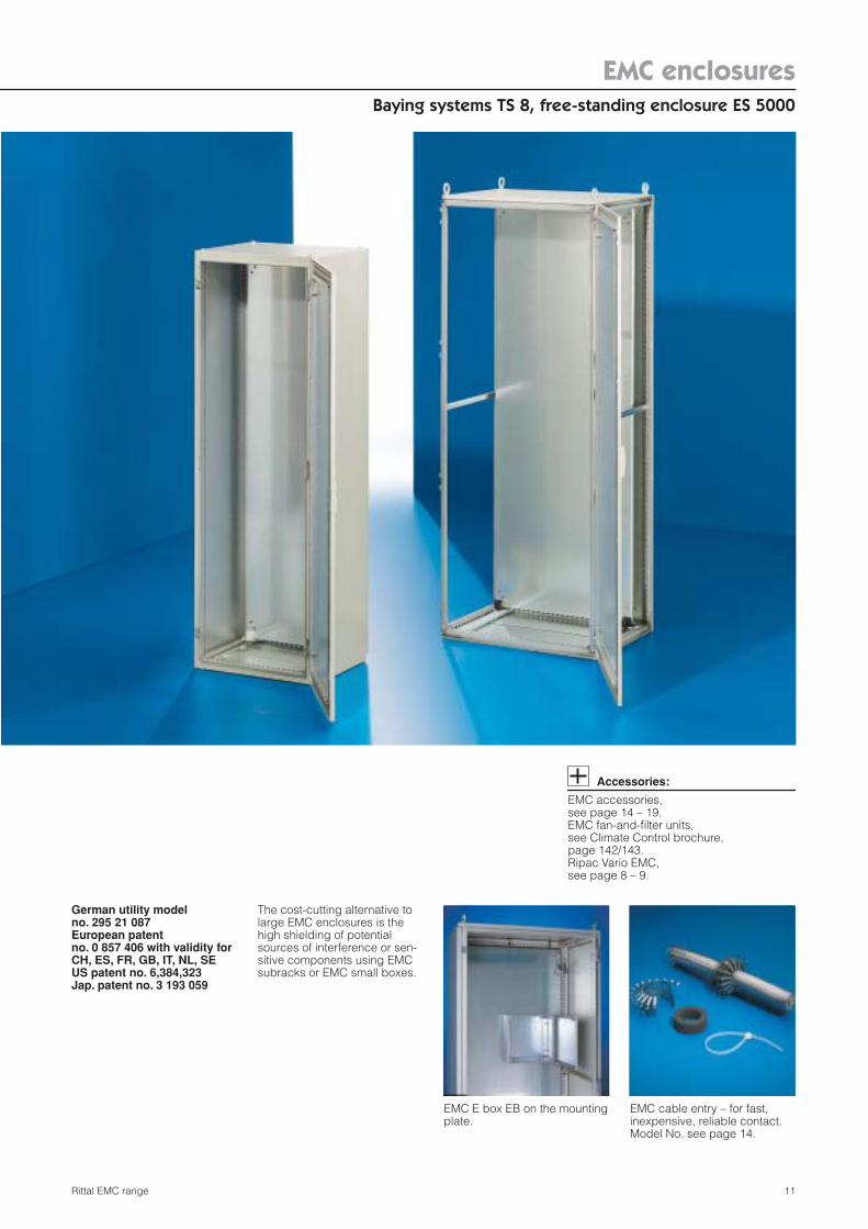
Baying systems TS 8, free-standing enclosure ES 5000
German utility model no. 295 21 087European patent no. 0 857 406 with validity for CH, ES, FR, GB, IT, NL, SE US patent no. 6,384,323 Jap. patent no. 3 193 059
The cost-cutting alternative to large EMC enclosures is the high shielding of potential sources of interference or sen-sitive components using EMC subracks or EMC small boxes.
Accessories:
EMC accessories, see page 14 – 19. EMC fan-and-filter units, see Climate Control brochure, page 142/143. Ripac Vario EMC, see page 8 – 9.
EMC E box EB on the mounting plate.
EMC cable entry – for fast, inexpensive, reliable contact. Model No. see page 14.
12 Rittal EMC range
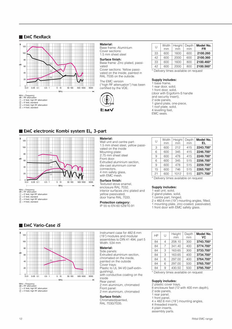
EMC flexRack
dB
MHz
80
60
40
20
0
120
1
100
0.01 0.05 0.1 0.5 5 10 50 100 500 1000 5000
2
3
4
1
Supply includes:
1 base frame, 1 rear door, solid, 1 front door, solid, (door with Ergoform-S handle and security insert), 2 side panels, 1 gland plate, one-piece, 1 roof plate, solid, 4 levelling feet, EMC seals.
U Width mm
Height mm
Depth mm
Model No. FR
33 600 1600 600
2100.260
42 600 2000 600
2100.360
33 600 1600 800
2100.460*
42 600 2000 800
2100.560*
* Delivery times available on request
MHz = FrequencydB = RF attenuation
= E field, high RF attenuation= E field, standard= H field, high RF attenuation= H field, standard
1234
Material:Base frame: AluminiumCover sections: 1.5 mm sheet steel
Surface finish:Base frame: Zinc plated, passi-vatedCover sections: Yellow passi-vated on the inside, painted in RAL 7035 on the outside.
The EMC version(“high RF attenuation”) has been certified by the VDE.
EMC electronic Kombi system EL, 3-part
dB
MHz
80
60
40
20
0
120
1
100
0.01 0.05 0.1 0.5 5 10 50 100 500 1000 5000
1
3
4
2
Supply includes:1 wall unit, solid, 2 gland plates, solid, 1 centre part, hinged, 2 x 482.6 mm (19˝) mounting angles, fitted, 1 mounting plate, zinc-coated, passivated, 1 front door with EMC safety glass.
U Width mm
Height mm
Depth mm
Model No. EL
3 600 212 415 2243.700*6 600 345 415 2246.700*9 600 478 415 2249.700*6 600 345 515 2256.700*9 600 478 515 2259.700*
15 600 746 515 2265.700*21 600 1012 515 2271.700*
* Delivery times available on request
MHz = FrequencydB = RF attenuation
= E field, high RF attenuation= E field, standard= H field, high RF attenuation= H field, standard
1234
Material:Wall unit and centre part: 1.5 mm sheet steel, yellow passi-vated on the insideMounting plate: 2.75 mm sheet steelFront door: Extruded aluminium section, die-cast aluminium corner connectors, 4 mm safety glass, with EMC mesh.
Surface finish:Textured stove enamel, enclosure RAL 7032, interior surfaces zinc plated and yellow passivated, door frame RAL 7033.
Protection category:IP 55 to EN 60 529/10.91
EMC Vario-Case iS
dB
MHz
80
60
40
20
0
120
1
100
0.01 0.05 0.1 0.5 5 10 50 100 500 1000 5000
1
2
Supply includes:2 plastic cover trays, 8 enclosure feet (12 with 400 mm depth), 2 side panels, 1 rear panel, 1 front panel, 4 x 482.6 mm (19˝) mounting angles, 4 threaded inserts, 4 plain inserts, assembly parts.
HP U Height mm
Depth mm
Model No. VC
84 4 208.10 300 3743.700*84 7 341.40 400 3774.700*84 3 163.65 300 3733.700*84 3 163.65 400 3734.700*84 6 297.00 400 3764.700*84 6 297.00 500 3765.700*84 9 430.50 500 3795.700*
* Delivery times available on request
MHz = FrequencydB = RF attenuation
= E field, high RF attenuation= H field, high RF attenuation
12
Instrument case for 482.6 mm (19˝) modules and modular assemblies to DIN 41 494, part 5 Width: 534 mm
Material:Side panels:Extruded aluminium section, chromated on the inside, painted on the outsideCover trays: Plastic to UL 94-V0 (self-extin-guishing), with conductive coating on the inside Rear panel: 2 mm aluminium, chromated Front panel: 2 mm aluminium, chromated
Surface finish:Chromated/painted, RAL 7030/7035.

EMC enclosures
13Rittal EMC range
17
16
15
10
11
12
3 4
5
67
8
9
12
14
13
EMC flexRack has the following approvals: ● UL● CSA
Accessories:
EMC accessories, see page 14 – 19. EMC fan-and-filter units, see Climate Control brochure, page 142/143.Ripac Vario EMC, see page 8 – 9.
EMC electronic Kombi system EL, has the following approvals: ● TÜV● Norske Veritas● Russian Maritime Register of Shipping● Lloyds Register of Shipping● VDE● UL – Underwriters Laboratories Inc.
For USA and Canada
Depth-adjustable 482.6 mm (19˝) or metric mounting angles (accessories).
Torsionally rigid aluminium section.
Removable, one-part gland plate.
Solid, removable front/rear door with EMC seal and Ergoform-S handle.
flexRack, electronic Kombi system EL, Vario-Case iS
1
2
3
4
5
6
7
8
9
10
11
12
13
14
15
16
17
Front door with EMC safety glass.
Aluminium door frame.
Lock system, may be exchanged for Ergoform-Mini handle.
482.6 mm (19˝) mounting angles, depth-adjustable.
Continuous knife edge.
Centre part of 1.5 mm sheet steel, multi-folded, yellow passivated on the inside.
Wall unit locked from the front.
Removable cable gland plate top and bottom.
Bonded EMC seal for protection category IP 55.
Extruded aluminium section side panels, interior surface chromated.
Plastic base and cover tray, coated in aluminium. Conductive connection to the side panels via RF spring seal system.
Removable side panel, yellow passivated on the inside.
One-part solid roof panel, removable.

14 Rittal EMC range
Accessories
EMC gland platesFor shielded cables with a maximum dia-meter of 20 mm. EMC cable shield contact over a conductive rubber cable clamp strip. Combined EMC/IP seal provides low-resistance contact between cable shield and gland plate. For all enclosures with a depth of 400, 500, 600 and 800 mm.
German patent no. 196 04 219
Single-row version (upper illustration): For one cable entry level in conjunction with standard gland plate.
Supply includes:1 gland plate with twin hammer-head punching, 1 sliding gland plate, 2 IP/EMC gaskets.
Twin-row version (bottom illustration): May only be used in conjunction with single-row EMC gland plates. Provides a further cable entry level.
Supply includes:1 gland plate with twin hammer-head punching and integral sliding gland plate, 2 IP/EMC gaskets.
Width mm
Model No. TS Model No. PS
single-row twin-row single-row2)
600 8800.660 8800.760 4314.060800 8800.680 8800.780 4314.080
1000 8800.6001) 8800.7001) 4314.1001200 8800.6201) 8800.7201) 4314.1201)
Packs of 1 kit1) For one enclosure half only2) For installation in ES, PC enclosures based on ES and PS, universal console with contact clip PS 4313.000, see page 17.
Metal cable tiesFor 360° contact of shielded cables on the EMC gland plate. The cable ties are not toothed, thereby eliminating the risk of damage to insulation and braided screens.
Tightening toolFor simple tightening of metal cable ties SZ 2598.125 and SZ 2598.200.
Material:Handle: PolypropyleneBlades: Chrome vanadium steel, tem-pered, nickel-plated.
Material:AISI 316 (similar to V4A), anti-magnetic and rust-proof.
Length mm
Width mm Packs of Model No.
SZ125 4.6 50 2598.125200 4.6 50 2598.200
Packs of Model No. SMTightening tool 1 2585.000
EMC cable entry glandThe EMC cable entry gland permits super-fast, EMC-compatible cable entry into the zinc-plated gland plates. Simply lock into position and voilà!
Other benefits include: ● 360° contact. ● Fastens without lock nuts. ● May be used with PG or metric holes. ● Adapts flexibly to existing cable diame-
ters.
● Contact directly at the point of cable entry on the enclosure.
● The spring action means permanent contact pressure.
● The cable insulation is only stripped off at the shielded point of contact.
Material: Stainless steel
Supply includes:Cable entry glands including seals and cable ties.
German patent no. 197 01 959
Installation diagram:Before snap-fastened Spring-loaded
piece snap-fastened, seal compressed
Cable shield diameter in mm Hole diameter in mmPacks of Model No. SZ
from to from to13 16 25 29 5 2491.15018 22 30 34 5 2491.20023 27 35 39 5 2491.25028 32 40 44 5 2491.300
Accessories
15Rittal EMC range
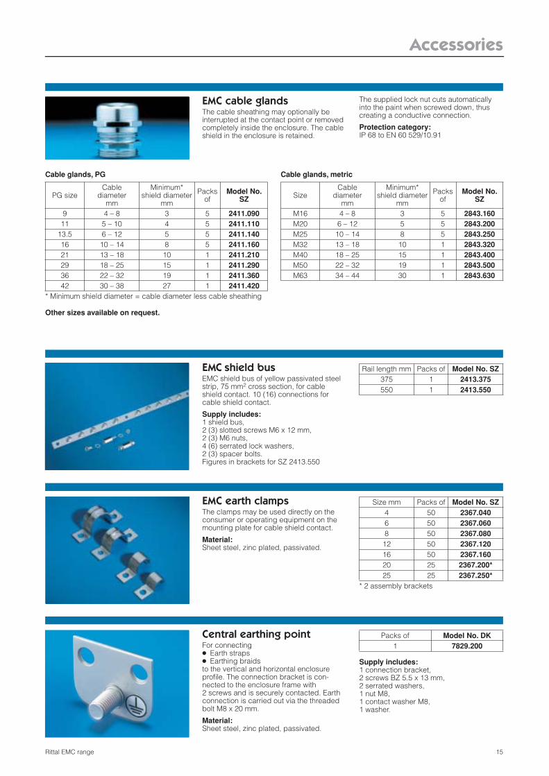
EMC cable glands The cable sheathing may optionally be interrupted at the contact point or removed completely inside the enclosure. The cable shield in the enclosure is retained.
The supplied lock nut cuts automatically into the paint when screwed down, thus creating a conductive connection.
Protection category:IP 68 to EN 60 529/10.91
Cable glands, PG
Other sizes available on request.
Cable glands, metric
PG sizeCable
diametermm
Minimum* shield diameter
mm
Packs of
Model No. SZ
9 4 – 8 3 5 2411.09011 5 – 10 4 5 2411.110
13.5 6 – 12 5 5 2411.14016 10 – 14 8 5 2411.16021 13 – 18 10 1 2411.21029 18 – 25 15 1 2411.29036 22 – 32 19 1 2411.36042 30 – 38 27 1 2411.420
* Minimum shield diameter = cable diameter less cable sheathing
SizeCable
diameter mm
Minimum*shield diameter
mm
Packs of
Model No. SZ
M16 4 – 8 3 5 2843.160M20 6 – 12 5 5 2843.200M25 10 – 14 8 5 2843.250M32 13 – 18 10 1 2843.320M40 18 – 25 15 1 2843.400M50 22 – 32 19 1 2843.500M63 34 – 44 30 1 2843.630
EMC shield busEMC shield bus of yellow passivated steel strip, 75 mm2 cross section, for cable shield contact. 10 (16) connections for cable shield contact.
Supply includes:1 shield bus, 2 (3) slotted screws M6 x 12 mm, 2 (3) M6 nuts, 4 (6) serrated lock washers, 2 (3) spacer bolts. Figures in brackets for SZ 2413.550
Rail length mm Packs of Model No. SZ375 1 2413.375550 1 2413.550
EMC earth clampsThe clamps may be used directly on the consumer or operating equipment on the mounting plate for cable shield contact.
Material:Sheet steel, zinc plated, passivated.
Size mm Packs of Model No. SZ4 50 2367.0406 50 2367.0608 50 2367.080
12 50 2367.12016 50 2367.16020 25 2367.200*25 25 2367.250*
* 2 assembly brackets
Central earthing pointFor connecting ● Earth straps● Earthing braids to the vertical and horizontal enclosure profile. The connection bracket is con-nected to the enclosure frame with 2 screws and is securely contacted. Earth connection is carried out via the threaded bolt M8 x 20 mm.
Material:Sheet steel, zinc plated, passivated.
Supply includes:1 connection bracket, 2 screws BZ 5.5 x 13 mm, 2 serrated washers, 1 nut M8, 1 contact washer M8, 1 washer.
Packs of Model No. DK1 7829.200

16 Rittal EMC range
Accessories
Assembly partsFor the attachment of earth straps and earthing straps to: ● Horizontal TS 8 enclosure sections ● PS/ES/universal console AP rail systems using captive nuts, see below.
Captive nuts/threaded blocksFor rectangular system punchings (10.5 x 12.5 mm) in: ● Horizontal TS 8 enclosure sections ● PS/ES/universal console AP rail systems
Size Packs of Model No. SZM6 10 set 2570.000M8 10 set 2559.000
Captive nuts The compression spring, designed as an insertion aid, ensures reliable mechanical and electrical connection in the system punchings.
Thread Packs of Model No. PSM6 50 4164.000M8 50 4165.000
Threaded blockWith snap-off insertion aid, die-cast zinc.
Thread Packs of Model No. PSM6 50 4162.000M8 50 4163.000
Captive nuts The nuts are inserted from the outside, thereby enabling the use of attachment points of the same height or width around corners. The spring cage also ensures electrical connection in the system punchings.
Thread Packs of Model No. TSM6 50 8800.340M8 50 8800.350
EMC baying sealFor baying enclosure systems. Seal with all-round, electrically conductive sheathing.
For enclosures
Diameter (mm) Model No.
TS 6.3 x 6.3 TS 8800.690PS 6.4 x 3.2 PS 4346.000
Packs of 1 set consisting of 3 seals, each 2 m long
EMC divider panel sealThis seal ensures optimum contact in bayed EMC enclosure systems and when using a zinc-plated divider panel.
Material:PU foam with electrically conductive sheathing.
Supply includes:1 roll (12.7 x 12.7 x 5300 mm)
Packs of Model No. PS1 4348.000

Accessories
17Rittal EMC range
PS 4332.000Clip for doors with square frame, with conductive surface.
PS 4334.000Clip for mounting plates with conductive surface when installed in the rearmost position. May also be retrofitted to an installed mounting plate.
PS 4313.000Clip for gland platesJoulean heat value I2 � T = 0.06 � 106A2 � s
PS 4337.000Clip for baying connection
Contact clips for Increases the shielding effect
PE conductor connection
(potential equalisation)Packs of Model No. PS
RoofSide panelRear panel
● ● 50 4312.000
Door ● 50 4332.000Mounting plate ● ● 50 4334.000Gland plate ● ● 50 4313.000Baying connection ● 50 4337.000
Contact cutterThe contact cutter enables EMC-compati-ble preparation of the contact point e.g. for earthing straps. Plastic-bound abrasive with guide pin for round system punch-ings. With location point for drill, grinder etc.
Contact paintContact paint prevents the corrosion of conductive, unprotected contact points.
Contents:12 ml
Model No. SMFor frame section 2414.000For earthing bolts* 2414.500
* Not necessary with TS 8
Packs of Model No. SZ1 2415.000
Contact clipsfor exclusive enclosures ES 5000There’s no faster, cheaper way of connecting a PE conductor/upgrading EMC shielding: ● Potential equalisation of the panels and
the frame of the switchgear enclosure.
● PE conductor connection in accordance with EN 60 439, part 1, VDE 0660, part 500 and IEC 60 439-1 on panels to which no electrical equipment is fas-tened.
● Multiple-contacting increases the shield-ing effect by up to 20 dB, raising it to a medium shielding level.
Material:Rust-proof spring steel
PS 4312.000Clip for roof, side panel and rear panelJoulean heat value I2 � T = 0.13 � 106A2 � s
EMC viewing windows are designed to prevent weakening of the shielding effect in enclosures with a high protection level, even with cutouts, and preserve this high standard of protection. Further information available on request.
18 Rittal EMC range
Accessories
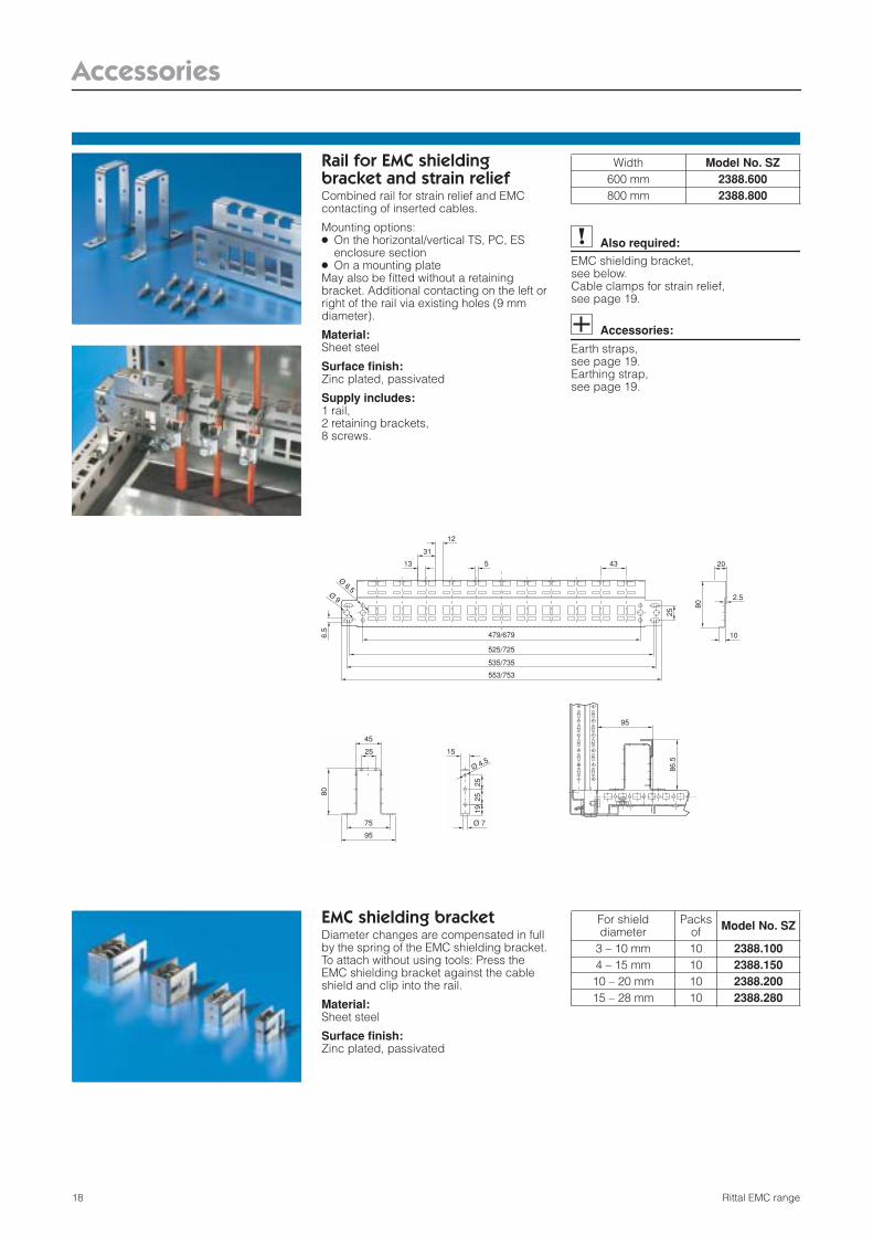
Rail for EMC shielding bracket and strain reliefCombined rail for strain relief and EMC contacting of inserted cables.
Mounting options: ● On the horizontal/vertical TS, PC, ES
enclosure section● On a mounting plateMay also be fitted without a retaining bracket. Additional contacting on the left or right of the rail via existing holes (9 mm diameter).
Material:Sheet steel
Surface finish:Zinc plated, passivated
Supply includes:1 rail, 2 retaining brackets, 8 screws.
Also required:
EMC shielding bracket, see below. Cable clamps for strain relief, see page 19.
Accessories:
Earth straps, see page 19. Earthing strap, see page 19.
19
Ø 4.5
25
Ø 7
25
15
25
435
31
13
12
Ø 9
Ø 6.5
6.5
553/753
535/735
525/725
479/679
25
45
75
95
80
86.5
95
80
2.5
20
10
Width Model No. SZ600 mm 2388.600800 mm 2388.800
EMC shielding bracketDiameter changes are compensated in full by the spring of the EMC shielding bracket. To attach without using tools: Press the EMC shielding bracket against the cable shield and clip into the rail.
Material:Sheet steel
Surface finish:Zinc plated, passivated
For shielddiameter
Packs of Model No. SZ
3 – 10 mm 10 2388.1004 – 15 mm 10 2388.150
10 – 20 mm 10 2388.20015 – 28 mm 10 2388.280
Accessories
19Rittal EMC range
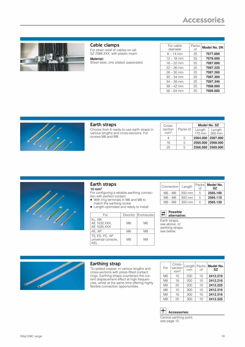
Cable clampsFor strain relief of cables on rail SZ 2388.XXX, with plastic insert.
Material:Sheet steel, zinc plated, passivated.
For cable diameter
Packs of Model No. DK
6 – 14 mm 25 7077.00012 – 18 mm 25 7078.00018 – 22 mm 25 7097.00022 – 26 mm 25 7097.22026 – 30 mm 25 7097.26030 – 34 mm 25 7097.30034 – 38 mm 25 7097.34038 – 42 mm 25 7098.00056 – 64 mm 25 7099.000
Earth straps10 mm2
For configuring a reliable earthing connec-tion with perfect contact. ● With ring terminals in M6 and M8 to
match the earthing screw● Length-optimised and ready to install.
Possible alternative:
Earth straps, see above, or earthing straps, see below.
For Door/lid EnclosuresKL, EB, AE 1032.XXX, AE 1035.XXX
M6 M6
AE, AP M6 M8TS, ES, PC, AP universal console, KEL
M8 M8
Connection Length Packs of
Model No. SZ
M6 – M6 200 mm 5 2565.100M6 – M8 300 mm 5 2565.110M8 – M8 300 mm 5 2565.120
Earthing strapTin-plated copper, in various lengths and cross-sections with press-fitted contact rings. Earthing straps counteract the cur-rent displacement effect at high frequen-cies, whilst at the same time offering highly flexible connection opportunities.
Accessories:
Central earthing point, see page 15.
ForCross-section
mm2
Length mm
Packs of
Model No. SZ
M6 10 200 10 2412.210M8 16 200 10 2412.216M8 25 200 10 2412.225M6 10 300 10 2412.310M8 16 300 10 2412.316M8 25 300 10 2412.325
Earth strapsChoose from 6 ready-to-use earth straps in various lengths and cross-sections. For screws M6 and M8.
Cross-section
mm2Packs of
Model No. SZLength 170 mm
Length 300 mm
4 5 2564.000 2567.00016 5 2565.000 2568.00025 5 2566.000 2569.000

Rittal EMC range20
B a s i c E M C i n f o r m a t i o n
W h a t i s m e a n t b y E M C ?
Electromagnetic compatibility (EMC) is the ability of an
electrical appliance to operate satisfactorily in its
electromagnetic environment without adversely affecting this
environment, which may also contain other equipment. High
packaging densities in electronic assemblies and ever-
increasing signal processing speeds often cause faults in
complex electronic equipment, measurement and control
systems, data processing and transmission systems, and
communications technology, which are attributable to
electromagnetic influences. There are fundamental
requirements for:
■ Defined immunity to interference
■ Prevention/reduction of interference emissions.
L e g a l f o u n d a t i o n s , s t a n d a r d i s a t i o n
EMC legislation, as national implementation of European
Directive 89/336/EEC, regulates the marketing, siting and
operation of equipment which may cause electromagnetic
interference or whose operation may be impaired by such
interference. Since 1 January 1996, the compliance of a
device or system with the protection requirements of EMC
legislation must be documented by the CE symbol.
The contribution of enclosures to the EMC of a device or
system lies primarily in the shielding effect from field-bound
interference, which in the case of Rittal enclosures is
measured at external laboratories to VG 95 373, part 15 and
documented in the corresponding attenuation diagrams.
These diagrams facilitate qualitative statements in
themselves. Testing of the finished enclosure, including
installed equipment, whilst in operation is indispensable for
compliance with and documentation of certain limits under
international regulations (e.g. radio interference suppression
in accordance with EN 55 011).
Rittal EMC range 21
Te c h n i c a l f o u n d a t i o n s
Radiation
Cable
Source of interference Coupling Potentially sus-
ceptible equip.
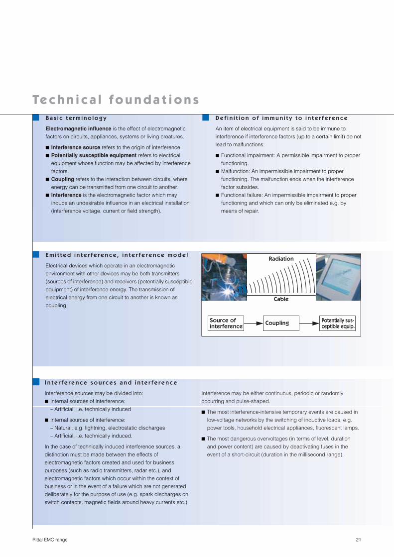
E m i t t e d i n t e r f e r e n c e , i n t e r f e r e n c e m o d e l
Electrical devices which operate in an electromagnetic
environment with other devices may be both transmitters
(sources of interference) and receivers (potentially susceptible
equipment) of interference energy. The transmission of
electrical energy from one circuit to another is known as
coupling.
I n t e r f e r e n c e s o u r c e s a n d i n t e r f e r e n c e
Interference sources may be divided into:
■ Internal sources of interference:
– Artificial, i.e. technically induced
■ Internal sources of interference:
– Natural, e.g. lightning, electrostatic discharges
– Artificial, i.e. technically induced.
In the case of technically induced interference sources, a
distinction must be made between the effects of
electromagnetic factors created and used for business
purposes (such as radio transmitters, radar etc.), and
electromagnetic factors which occur within the context of
business or in the event of a failure which are not generated
deliberately for the purpose of use (e.g. spark discharges on
switch contacts, magnetic fields around heavy currents etc.).
D e f i n i t i o n o f i m m u n i t y t o i n t e r f e r e n c e
An item of electrical equipment is said to be immune to
interference if interference factors (up to a certain limit) do not
lead to malfunctions:
■ Functional impairment: A permissible impairment to proper
functioning.
■ Malfunction: An impermissible impairment to proper
functioning. The malfunction ends when the interference
factor subsides.
■ Functional failure: An impermissible impairment to proper
functioning and which can only be eliminated e.g. by
means of repair.
Interference may be either continuous, periodic or randomly
occurring and pulse-shaped.
■ The most interference-intensive temporary events are caused in
low-voltage networks by the switching of inductive loads, e.g.
power tools, household electrical appliances, fluorescent lamps.
■ The most dangerous overvoltages (in terms of level, duration
and power content) are caused by deactivating fuses in the
event of a short-circuit (duration in the millisecond range).
B a s i c t e r m i n o l o g y
Electromagnetic influence is the effect of electromagnetic
factors on circuits, appliances, systems or living creatures.
■ Interference source refers to the origin of interference.
■ Potentially susceptible equipment refers to electrical
equipment whose function may be affected by interference
factors.
■ Coupling refers to the interaction between circuits, where
energy can be transmitted from one circuit to another.
■ Interference is the electromagnetic factor which may
induce an undesirable influence in an electrical installation
(interference voltage, current or field strength).

Rittal EMC range22
Te c h n i c a l f o u n d a t i o n sE l e c t r o s t a t i c d i s c h a r g e sWhen solid materials rub against one another, electrostatic charges may arise
which are rapidly discharged on conductive surfaces but which may persist for
a long time on less conductive surfaces. Upon contact with conductive parts,
the electrostatic voltages associated with such charges in non-conductors may
cause interference or even destruction in electronic components as discharge
current (conducted interference). Also, during discharge, an electromagnetic
pulse is irradiated, representing field-bound interference. Electrostatic
discharges from humans onto control components and enclosures are
particularly significant. The voltages occurring in such cases may be up to
15000 V, with discharge currents of up to 5 A, and current rise rates of up to
5 kA/µs. The risk of malfunctions or damage is increased by poorly conductive
floor coverings and low air humidity.
I n f l u e n c e m e c h a n i s m s a n d c o u n t e r - m e a s u r e sA distinction may be made between the following coupling influences:
■ Conducted interference
■ Field-bound interference
– Low-frequency field interference
– Radiation interference (high frequency)
Conducted interference
refers to interference voltages and currents. The principal causes lie in the
mechanical switching of electrical equipment (particularly inductive loads such
as motors, transformers, throttling via electronic systems). Coupling of
interference source and potentially susceptible equipment can occur via various
“routes”: conductive, inductive, capacitive or wave interference are the relevant
terms.
Field-bound interference (low frequency)
Very low-frequency currents cause a low-frequency magnetic field which may
induce interference voltage or initiate interference via direct magnetic effects
(magnetic memory in computers, monitors, sensitive electromagnetic test
equipment such as EEG). Low-frequency electric fields of high intensity may be
generated by low-frequency high voltages (high-voltage overhead cables),
resulting in interference voltage (capacitive interference). Of practical
significance are magnetic fields, the effects of which can be reduced via
■ Shielded cables
■ Shielding enclosures (the decisive material property is that of permeability,
which is too low in the case of sheet steel; nickel iron, for example, is much
better).
■ Distance from the field source
Radiation interference (high frequency)
Interference can be reduced via:
■ Shielded cables
■ Shielding enclosures (Faraday cage!).

Rittal EMC range 23
E l e c t r o m a g n e t i c i n t e r f e r e n c e ( E M I )E n c l o s u r e / R F s h i e l d i n gHigh-frequency electrical currents and voltages in electronic
circuits may initiate electromagnetic waves (e.g. mobile radio
transmission stations, radar, as well as industrial high-
frequency installations such as microwave drying, bonding
and welding). These, in turn, may generate interference
voltage in cables or directly in electronic assemblies via
enclosure openings. Every metal enclosure already offers
good basic shielding within a broad frequency range,
i.e. attenuation of electromagnetic fields. High shielding attenuation
levels in the frequency range above approx. 5 MHz can be
achieved via special seals which conductively connect the
conductive inner surfaces of doors and removable panels, roof and
gland plates to the conductive sealing edges of the enclosure
body or frame, largely in a slot-free manner. The higher the
frequencies occurring, the more critical openings in the enclosure
become.
E S D(ElectroStatic Discharge), effects
are both conducted and field-
bound
C o n d u c t e d Possible solutions:
■ Filters
■ Overvoltage protection
F i e l d - b o u n d
S h i e l d i n g p o s s i b l e v i aElectrically conductive material,
important factors:
■ Sealed cover
■ EMC enclosures made from sheet
steel/AlZn, stainless steel or Al
■ No holes permissible
S h i e l d i n g p o s s i b l e v i aMagnetically conductive material,
important factors:
■ Not sheet steel!
■ Not aluminium!
EMI
S h i e l d i n g p o s s i b l e v i aElectrically conductive material,
important factors:
■ Sealed cover
■ Standard enclosure made from
sheet steel, stainless steel or
aluminium
■ Large holes permissible
L o w f r e q u e n c y u p t o a p p r o x i m a t e l y 1 0 0 K H z
H i g h f r e q u e n c y > 1 0 0 K H z
M a g n e t i c fi e l d E l e c t r i c a l fi e l d E l e c t r o m a g n e t i c fi e l d

Rittal EMC range24
B a s i c E M C i n f o r m a t i o n
P r a c t i c a l E M C t i p s w h e n h a n d l i n g c o m p o n e n t s t h a t e m i t i n t e r f e r e n c e
■ With the inverters available on the market today, it is
impossible to maintain a level of radio interference
suppression without a radio interference suppression filter
at the mains input. Line filters also boost a system’s
resistance to interference.
■ Cables between the inverter and motor must be shielded:
Shield contact on both sides.
■ Metallic components in the enclosure must have a large
surface area and should be connected to one another with
a high level of RF conductivity. Avoid surface finishes such
as eloxal which have very high resistance levels.
■ Relays, contactors and magnetic valves installed in the
same circuit must be connected via arc extinguishing
combinations or overvoltage-limiting components.
■ Analog control leads should be shielded on one side and
contacted inside the enclosure where possible. Ensure low-
resistance connections across a large area!
■ Digital signal cables should be shielded on both sides
across a large area with low-resistance contact. In case of
differences in potential, an additional equalising conductor
should be laid parallel. Separable connections must always
be equipped with metal-cased connectors!
■ Avoid spare loops on all connection cables! These could
result in RF short-circuiting of the above measures.
Unassigned strands in the cable should be connected to
potential equalisation at both ends.
■ Unshielded cables in a circuit, i.e. outward and return
conductors, should be twisted against symmetrical
interference sources.
■ Physically separate “hot” and “cold” cables at the planning
stage. Pay special attention to the motor cable. The area
around the shared terminal strip for the mains input and
motor output is particularly at risk.
■ The cable routing in an enclosure should be as close as
possible to the reference potential; “free-floating cables” act
as both active and passive antennae!
■ When operating more than one inverter on a shared
network, EMC problems are to be expected. System
planners should integrate interference emission of high
frequency as well as interference sensitivity amongst the
frequency inverters into their concept from the outset, and
take appropriate counteractive action.
Rittal EMC range 25
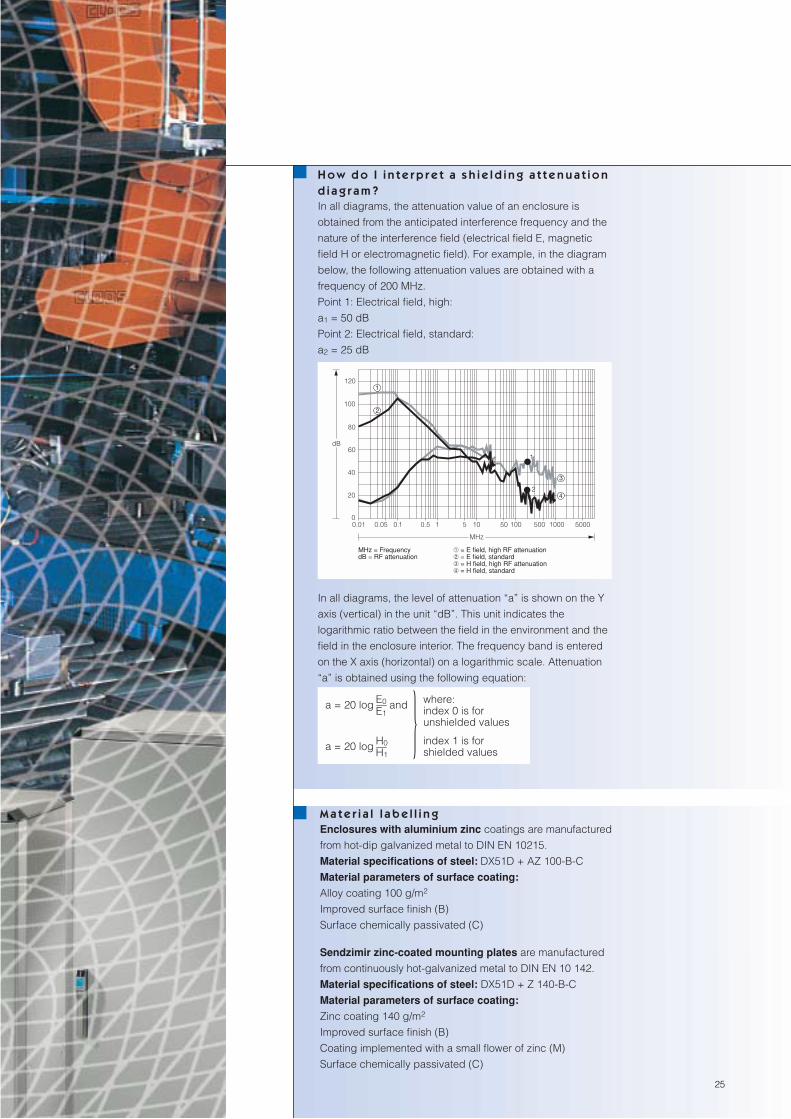
H o w d o I i n t e r p r e t a s h i e l d i n g a t t e n u a t i o n d i a g r a m ?In all diagrams, the attenuation value of an enclosure is
obtained from the anticipated interference frequency and the
nature of the interference field (electrical field E, magnetic
field H or electromagnetic field). For example, in the diagram
below, the following attenuation values are obtained with a
frequency of 200 MHz.
Point 1: Electrical field, high:
a1 = 50 dB
Point 2: Electrical field, standard:
a2 = 25 dB
In all diagrams, the level of attenuation “a” is shown on the Y
axis (vertical) in the unit “dB”. This unit indicates the
logarithmic ratio between the field in the environment and the
field in the enclosure interior. The frequency band is entered
on the X axis (horizontal) on a logarithmic scale. Attenuation
“a” is obtained using the following equation:
M a t e r i a l l a b e l l i n gEnclosures with aluminium zinc coatings are manufactured
from hot-dip galvanized metal to DIN EN 10215.
Material specifications of steel: DX51D + AZ 100-B-C
Material parameters of surface coating:
Alloy coating 100 g/m2
Improved surface finish (B)
Surface chemically passivated (C)
Sendzimir zinc-coated mounting plates are manufactured
from continuously hot-galvanized metal to DIN EN 10 142.
Material specifications of steel: DX51D + Z 140-B-C
Material parameters of surface coating:
Zinc coating 140 g/m2
Improved surface finish (B)
Coating implemented with a small flower of zinc (M)
Surface chemically passivated (C)
MHz = FrequencydB = RF attenuation
➀ = E field, high RF attenuation➁ = E field, standard➂ = H field, high RF attenuation➃ = H field, standard
} where: index 0 is for unshielded values
index 1 is for shielded values
a = 20 log E0 andE1
a = 20 log H0H1

26 Rittal EMC range
Notes
27Rittal EMC range
GermanyRittal GmbH & Co. KGPostfach 16 62D-35726 HerbornTel.: +49 (27 72) 5 05-0Fax: +49 (27 72) 5 05-2319email: [email protected]
ArgentinaRacklatina S.A.Av. Pedro B. Palacios 81 – 851704, Ramos MejíaBuenos AiresTel.: +54(11) 46 56-32 31Fax: +54(11) 46 56-23 23email: [email protected]
AustraliaRittal Pty. Ltd.130 – 140 Parraweena Rd.Taren Point. 2229 N. S. WTel.: +61(2) 95 25 27 66Fax: +61(2) 95 25 53 02Free Call 1800 350 665email: [email protected]
AustriaRittal-SchaltschränkeGes.m.b.H.Laxenburger Straße 246aA-1239 WienTel.: +43(1) 610 09-0Fax: +43(1) 610 09-21email: [email protected]
BahrainPlease contactRittal Middle East FZEDubai/U.A.E.
BelarusNetexpertVolocha Str. 1 of 310220036 MinskTel.: +3 75 (172) 86 20 03Fax: +3 75 (172) 56 65 15
BelgiumRittal nv/saIndustrieterrein E17/3Stokkelaar 8B-9160 LokerenTel.: +32(9) 3 53 91 11Fax: +32(9) 3 55 68 62email: [email protected]
Bosnia-HerzegovinaSYS Company d.o.o.Sibenska b.b.BiH-71000 SarajevoTel.: +3 87/33/27 70 90Fax: +3 87/33/23 05 57email: [email protected]
BrazilRittal Sist. Eletrom. Ltda.Av. Cândido Portinari, nr. 1.174VI Jaguara05114-001 São Paulo-SPTel.: +55(11) 36 22 23 77Fax: +55(11) 36 22 23 99email: [email protected]
BulgariaRITTBUL Ltd.56 Gorski patnik Str. Office 5BG-1421 SofiaTel.: +359(2) 65 10 66Fax: +359(2) 96 32 516email: [email protected]
CanadaRittal Systems Ltd.7320 Pacific CircleMississauga, OntarioL5T 1V1Tel.: +1(9 05) 7 95 07 77Fax: +1(9 05) 7 95 95 48email:[email protected]
ChileAMMY S.A.Camino El Cerro 5090Casilla 241-V C21HuechurabaSantiagoTel.: +56(2) 7 40 01 02Fax: +56(2) 7 40 10 65email: [email protected]
ChinaRittal Electrical Equipment (Shanghai) Co. Ltd.No. 353, Ri Ying North RoadP. R. ChinaShanghai, 200131Tel.: +86(21) 50 46 16 71 Fax: +86(21) 50 46 19 90email: [email protected]
ColombiaCOLSEIN Ltda.Medición y AutomatizaciónCalle 82 No. 5 – 48 Apartado Aereo 55479Santafé de Bogotá,D.C. ColumbiaTel.: +57(1) 6 10 26 74Fax: +57(1) 6 10 78 68email: [email protected]
Costa RicaElvatron400 metros norte de la agencia del Banco de Costa RicaSan JoséTel.: +5 06 (2 96) 10 60Fax: +5 06 (2 32) 60 71
CroatiaTechnoshell D.O.O.Av. V. Holjevca 20/III10020 ZagrebTel./Fax:+3 85/1/65 53-5 47 email: [email protected]
CyprusChristos Charalambous & Sons Ltd.9 – 11 Zanettos StreetP.O. Box 1268NicosiaTel.: +3 57/2 77 20 55Fax: +3 57/2 45 81 97email: [email protected]
Czech RepublicRittal Czech, s.r.o.Ke Zdibsku 182250 66 Zdiby u PrahyTel.: +420 234 099 000Fax: +420 234 099 099email: [email protected]
DenmarkDuelco a/sHoltvej 10Hoeruphav6400 SoenderborgTel.: +45-74 41 52 84Fax: +45-74 41 52 09email: [email protected]
Dubai/U.A.E.Rittal Middle East FZEWarehouse GC2P.O. Box 17 599Jebel Ali Free Zone – DubaiU.A.E.Tel.: +971(4) 8 83 41 31Fax: +971(4) 8 83 42 44email: [email protected]
EgyptRittal Egypt S.A.E.45, Gamiat Al Dewal Al Arabia St.Mohandesine, GizaTel.: +2(012) 74 28 012Fax: +2(02) 74 82 276
FinlandRittal OyValimotie 35PL 13401510 VantaaTel.: +3 58 9 4 13 44 00Fax: +3 58 9 4 13 44 410email: [email protected]
FranceRittal France SAS880, rue Marcel PaulZ.A. des Grands Godets94507 Champigny sur Marne CedexTel.: +33(1) 49 83 60 00Fax: +33(1) 49 83 82 06email: [email protected]
France-EastSermes S.A.14, rue des Frères EbertsBoîte Postale 17767025 Strasbourg-CedexTel.: +33(3) 88 40 72 00Fax: +33(3) 88 40 72 49email:[email protected]
Great BritainRittal LimitedBraithwell WayHellaby Industrial EstateHellabyRotherhamS YorksS66 8QYTel.: +44(17 09) 70 40 00Fax: +44(17 09) 70 12 17email: [email protected]
GreeceRITTAL EPEThessalonikis 9814342 Nea Philadelphia,AthenTel.: +30/210/27 17 975
976Fax: +30/210/27 12 398www.rittal.gr
GuatemalaINTEKIngeniería y TecnologíaVia 5 y Ruta 3, Zona 4 Esquina01004 Guatemala, C.A.Tel.: +50(2) 332 1489
332 4336Fax: +50(2) 334 4338
Hong KongRanger Enterprise Co. Ltd.Units A-B, 8/F, Block 1Tai Ping Industrial Center57 Ting Kok RoadTai Po, N. T.Hong KongTel.: +8 52 24 20 89 28Fax: +8 52 24 94 92 28email: [email protected]
HungaryRittal Kereskedelmi Kft.Ipari Park u.1.1044-BudapestTel.: +36(1) 399 8000Fax: +36(1) 399 8009email: [email protected]
IcelandSmith & Norland h/fNóatúni 4P.O. Box 519121 ReykjavíkTel.: +354 520 3000Fax: +354 520 3011email: [email protected]
IndiaRittal India Pvt. Ltd.Nos. 23 & 24 KiadbIndustrial AreaVeerapuraDoddaballapur Bangalore 561 203Tel.: +91(80) 76 22 335
76 23 075Fax: +91(80) 76 23 343email: [email protected]
IndonesiaPT Zuellig Services Wisma Budi, 2/F202 Jl. H.R. Rasuna Said, Kav. C-6Jakarta 12940Tel.:+62(21) 5296 1448 /58 /68Fax:+62(21) 5296 1450 /60 /70email: [email protected]
IrelandRittal Ltd.Sleaty RoadGraiguecullenCarlowIrelandTel.: +353(599) 182 100Fax: +353(599) 132 090email: [email protected]
IsraelRittal Enclosure Systems Ltd.15, Hátarshish St. Zone 29P.O. Box 3597 Industrial Park Caesarea 38900Tel.: +9 72(4) 6 27 55 05Fax: +9 72(4) 6 27 55 35
ItalyRittal S.p.A.S.P. n.14 Rivoltana-Km 9,520060 Vignate (MI)Tel.: +39(02) 95 93 01Fax: +39(02) 95 36 02 09email: [email protected]
JapanRittal K.K.1438-1 Shimonohara Nishi-izumidaSakai-machi, Sashima-gunIbaraki 306-0431Tel.: +81(280) 87 51 20Fax: +81(280) 87 51 08email: [email protected]
JordanPlease contactRittal Middle East FZEDubai/U.A.E.
KuwaitPlease contactRittal Middle East FZEDubai/U.A.E.
LebanonPlease contactRittal Middle East FZEDubai/U.A.E.
LithuaniaRittal UABMeistru 82038 VilniusTel.: +370/5 2 306 669Fax: +370/5 2 306 665email: [email protected]
LuxembourgD.M.E. s.a.r. l.Distribution de matériel électriqueZ.A.R.E. Ouest4384 EhlerangeTel.: +3 52-57 43 44Fax: +3 52-57 43 57email: [email protected]
MacedoniaSiskon System EngineeringTaskenska 4AMK-91000 SkopjeTel.: +389/91/36 24 23Fax: +389/91/36 12 50email: [email protected]
MalaysiaRittal Systems Sdn. Bhd.No. 5 Jalan 4/118CDesa Tun Razak56000 CherasKuala LumpurTel.: +60(3)-9173 64 88Fax: +60(3)-9173 64 99email: [email protected]
MexicoRittal, S.A. de C.V.Prol. 5 de Mayo No. 29Parque IndustrialNaucalpanNaucalpan de JuarezEstado de México53489 MéxicoTel.: +52(55) 53 00-25 70Fax: +52(55) 53 00-04 95email: [email protected]
MoroccoS.M.R.I.Société marocaine deréalisations industrielles109, Rue Abou IshakEl Marouni20110 CasablancaTel.: +212-2 25 94 90Fax: +212-2 23 77 08email: [email protected]
NetherlandsRittal bvHengelder 56Postbus 2466900 AE ZevenaarTel.: +31(3 16) 59 19 11Fax: +31(3 16) 52 51 45
New ZealandRittal Ltd.5 Pretoria StreetP.O. Box 30-453Lower HuttWellingtonTel.: +64(4) 5 66 76 30Fax: +64(4) 5 66 92 19
NorwayRittal ASPostboks 79 StovnerLuhrtoppen 20913 OsloTel.: +47-67 91 23 00Fax: +47-67 91 23 23email: [email protected]
OmanPlease contactRittal Middle East FZEDubai/U.A.E.
PeruCE-YE-SAIngenieria ElectricaAv. Enrique Meiggs 255 – 257Parque Internacional de Industria y ComercioCallaoTel.: +51(1) 4 51 79 36Fax: +51(1) 4 51 72 72
PhilippinesEnclosure Systems Specialist IncorporatedG/F, GE Phils Building2291 Pasong Tamo ExtensionMakati City 1231PhilippinesTel.: +63(2) 8 13 85 80Fax: +63(2) 8 13 85 96email: [email protected]
PolandRittal Sp. z o.o.Ul. Królewska 605-825 Grodzisk Maz.k/WarszawyTel.: +48(22) 724 27 84Fax: +48(22) 724 08 52email: [email protected]
PortugalRITTALSIS-SistemasElectricos e Electronicos Unipersonal Lda.Z.I. Rio Meao/Apdo. 4344520-907 Rio Meao. Sta Ma da FeiraTel.: +351 256 780 210Fax: +351 256 780 219email: [email protected]
QatarPlease contactRittal Middle East FZEDubai/U.A.E.
Republic of SlovakiaRittal s.r.o.Plynárenská 1SK-82109 BratislavaTel.: +421(2) 5363 0651Fax: +421(2) 5363 0951email: [email protected]
RomaniaCubrit s.r.l.Sos. Chitilei, no. 114Sector 1 – BucharestRomaniaTel./Fax: +40/21/3 12 94 97email: [email protected]
RussiaRittal OOOLetchika Babushkina 1a129344 MoscowTel.: +7(095) 775 02 30Fax: +7(095) 775 02 39email: [email protected]
Saudi ArabiaA. Abunayyan Electric Corp.King Abdulaziz StreetP.O. Box 321Riyadh 11411Kingdom of Saudi ArabiaTel.: +966(1) 477 91 11Fax: +966(1) 479 33 12email: [email protected]
SingaporeRittal Pte. Ltd.7 Loyang StreetLoyang Industrial EstateSingapore 508842Tel.: +65-65 42 68 18Fax: +65-65 42 68 33email: [email protected]
SloveniaRittal d.o.o.Smartinska 152SLO-1533 LjubljanaTel.: +386/1/5466370Fax.: +386/1/5411710email: [email protected]
South AfricaControp Rittal (Pty) Ltd.123, Terrace RoadSebenzaP.O. Box 462Edenvale, 1610Tel.: +27(11) 6 09-82 94Fax: +27(11) 4 52-58 16email: [email protected]
South KoreaRittal Co. Ltd.1 NA 509 Sihwa-Gongdan1254-8 Jeungwang-DongSihung-Shi, Gyeonggi-DoKorea 429-450Tel.: +82(031) 499-5961~3Fax: +82(031) 499-59 64email: [email protected]
SpainRittal Disprel, S.A.Mas Baiona, 40Polígono Industrial Can Roqueta08202 Sabadell (Barcelona)Tel.: +34(93) 700 13 00Fax: +34(93) 700 13 01email: [email protected]
S. R. VietnamESACO Ltd.15 – 17 Tran Quoc Taho StreetDistrict 3Hochiminh CitySocialist Republicof VietnamTel.: +84(8) 9 30 35 80Fax: +84(8) 9 30 31 93email: [email protected]
SwedenRittal Scandinavian ab26273 ÄngelholmTel.: +46(4 31) 44 26 00Fax: +46(4 31) 44 26 37email: [email protected]
SwitzerlandRittal AGRingstrasse 15432 NeuenhofTel.: +41 056 416 06 00Fax: +41 056 416 06 66email: [email protected]
SyriaPlease contactRittal Middle East FZEDubai/U.A.E.
TaiwanRittal Systems Taiwan Ltd.13 – 1 Fl., No. 87,Wen Hua 3rd Rd.Kuei ShanTaoyuan HsienTaiwanTel.: +8 86 (3) 397-1745
(3) 327-8871Fax: +8 86 (3) 397-2019email:[email protected]
ThailandRittal Ltd.101 Soi 7, Saeree 7Rama 9 RoadKwaeng SuanluangKhet SuanluangBangkok 10250Tel.: +66 (2) 7183 296
(2) 7183 297Fax: +66 (2) 7183 298email: [email protected]
TurkeySTOKS Ltd.Zümrütevier Mah. Visne Sok. No: 581530 MaltepeIstanbul/TurkeyTel.: +90(2 16) 4417009
4515739 Fax: +90(2 16) 4591290email: [email protected]
UkraineAdvanced Network TechnologyScherbakova Str. 3704111 KievTel.: +38(44) 495 11 36Fax: +38(44) 443 95 22
USARittal CorporationOne Rittal PlaceSpringfield, OH 45504Tel.: +1(9 37) 3 99-05 00Fax: +1(9 37) 3 90-55 99email: [email protected]
UzbekistanNaytov Ltd.Ul. Matbuotschilar 32700047 TaschkentTel.: +9 98/71-132 08 56Fax: +9 98/71-132 08 59
VenezuelaEMI Equipos y sistemas C. A.Edificio Centro Cyanamid, P.B. Calle 1 – 2La Urbina – 1073 Caracas Tel.: +58(212) 243 6401
5072Fax: +58(212) 243 6401
YemenPlease contactRittal Middle East FZEDubai/U.A.E.
YugoslaviaVesimpex d.o.o.Petra Konjovica 12 v11090 BeogradTel./Fax:+3 81/11/35 10 683email: [email protected]
Rittal internationalAgencies worldwide

Rittal has one of the largest ranges of enclosures available for
immediate delivery. However, Rittal also supplies integral
solutions at a high level – up to Level 4. Fully assembled and
functional, according to your specific requirements. Wherever
your location.
The global alliance between production, distribution and
service guarantees customer proximity. World-wide! Wherever
in the world you develop and implement solutions for yourself
and your customers, we are close at hand.
Global Rittal. Worldwide service.
Industrial enclosures
Electronic packaging
System climate control
Power distribution
IT solutions
Communication systems
12/0
3 � E
932
Switch to perfection
R
Rittal GmbH & Co. KG P.O. Box 1662 D-35726 HerbornTelephone: +49(0)2772 505-0 Telefax: +49(0)2772 505-2319eMail: [email protected] www.rittal.com