ripex radio modem & router - racom.eu · you can see an instructional video explaining the...
TRANSCRIPT

User manual.
RipEXRadio modem & Router
.
fw 1.8.x.x08/15/2018version 1.24
www.racom.euRACOM s.r.o. • Mirova 1283 • 592 31 Nove Mesto na Morave • Czech RepublicTel.: +420 565 659 511 • Fax: +420 565 659 512 • E-mail: [email protected]


Table of ContentsImportant Notice .................................................................................................................................. 7Quick guide ......................................................................................................................................... 81. RipEX – Radio router .................................................................................................................... 10
1.1. Introduction ......................................................................................................................... 101.2. Key Features ...................................................................................................................... 10
2. RipEX in detail ............................................................................................................................... 132.1. Applications ........................................................................................................................ 132.2. Bridge mode ....................................................................................................................... 13
2.2.1. Detailed Description ................................................................................................ 142.2.2. Functionality example .............................................................................................. 142.2.3. Configuration examples ........................................................................................... 16
2.3. Router mode ....................................................................................................................... 192.3.1. Router - Flexible, Detail description ......................................................................... 202.3.2. Router - Flexible, Functionality example ................................................................. 202.3.3. Router - Flexible, Configuration examples .............................................................. 212.3.4. Router - Flexible, Addressing hints .......................................................................... 232.3.5. Router - Base driven, Detail description .................................................................. 242.3.6. Router - Base driven, Functionality example ........................................................... 242.3.7. Router - Base driven, Configuration example ......................................................... 25
2.4. Serial SCADA protocols ..................................................................................................... 272.4.1. Detailed Description ................................................................................................ 27
2.5. Combination of IP and serial communication ..................................................................... 282.5.1. Detailed Description ................................................................................................ 28
2.6. Diagnostics & network management .................................................................................. 292.6.1. Logs ......................................................................................................................... 292.6.2. Graphs ..................................................................................................................... 292.6.3. SNMP ...................................................................................................................... 292.6.4. Ping ......................................................................................................................... 302.6.5. Monitoring ................................................................................................................ 30
2.7. Firmware update and upgrade ........................................................................................... 302.8. Software feature keys ......................................................................................................... 31
3. Network planning ........................................................................................................................... 323.1. Data throughput, response time ......................................................................................... 323.2. Frequency .......................................................................................................................... 333.3. Signal budget ..................................................................................................................... 34
3.3.1. Path loss and fade margin ....................................................................................... 353.4. Multipath propagation, DQ ................................................................................................. 35
3.4.1. How to battle with multipath propagation? .............................................................. 363.5. Network layout .................................................................................................................... 383.6. Hybrid networks .................................................................................................................. 403.7. Assorted practical comments ............................................................................................. 403.8. Recommended values ........................................................................................................ 41
4. Product .......................................................................................................................................... 424.1. Dimensions ......................................................................................................................... 424.2. Connectors ......................................................................................................................... 45
4.2.1. Antenna ................................................................................................................... 454.2.2. Power and Control ................................................................................................... 464.2.3. ETH ......................................................................................................................... 484.2.4. COM1 and COM2 .................................................................................................... 484.2.5. USB ......................................................................................................................... 494.2.6. GPS ......................................................................................................................... 51
3© RACOM s.r.o. – RipEX Radio modem & Router

4.2.7. Reset button ............................................................................................................ 524.3. Indication LEDs .................................................................................................................. 534.4. Technical specification ........................................................................................................ 54
4.4.1. Detailed Radio parameters ...................................................................................... 584.5. Model offerings ................................................................................................................... 68
4.5.1. Ordering code (Part No’s) ........................................................................................ 684.6. Accessories ........................................................................................................................ 71
5. Bench test ..................................................................................................................................... 795.1. Connecting the hardware ................................................................................................... 795.2. Powering up your RipEX .................................................................................................... 795.3. Connecting RipEX to a programming PC ........................................................................... 795.4. Basic setup ......................................................................................................................... 835.5. Functional test .................................................................................................................... 83
6. Installation ..................................................................................................................................... 846.1. Mounting ............................................................................................................................. 84
6.1.1. DIN rail mounting ..................................................................................................... 846.1.2. Flat mounting ........................................................................................................... 866.1.3. 19" rack mounting .................................................................................................... 876.1.4. IP51 mounting ......................................................................................................... 87
6.2. Antenna mounting .............................................................................................................. 876.3. Antenna feed line ............................................................................................................... 886.4. Grounding ........................................................................................................................... 886.5. Connectors ......................................................................................................................... 886.6. Power supply ...................................................................................................................... 89
7. Advanced Configuration ................................................................................................................ 907.1. Menu header ...................................................................................................................... 907.2. Status ................................................................................................................................. 927.3. Settings ............................................................................................................................... 93
7.3.1. Device ...................................................................................................................... 937.3.2. Radio ..................................................................................................................... 1227.3.3. ETH ....................................................................................................................... 1437.3.4. COM ...................................................................................................................... 1527.3.5. Protocols ................................................................................................................ 155
7.4. Routing ............................................................................................................................. 1717.4.1. Routing .................................................................................................................. 1717.4.2. Nomadic mode ...................................................................................................... 175
7.5. VPN .................................................................................................................................. 1837.5.1. IPsec ...................................................................................................................... 1837.5.2. GRE ....................................................................................................................... 191
7.6. Diagnostic ......................................................................................................................... 1947.6.1. Neighbours and Statistic ........................................................................................ 1947.6.2. Graphs ................................................................................................................... 1987.6.3. Ping ....................................................................................................................... 2007.6.4. Monitoring .............................................................................................................. 205
7.7. Maintenance ..................................................................................................................... 2177.7.1. SW feature keys .................................................................................................... 2177.7.2. Configuration ......................................................................................................... 2187.7.3. Firmware ................................................................................................................ 2187.7.4. Administrator account ............................................................................................ 2207.7.5. Miscellaneous ........................................................................................................ 2207.7.6. SSL certificate ....................................................................................................... 2207.7.7. Remote access keys ............................................................................................. 221
RipEX Radio modem & Router – © RACOM s.r.o.4
RipEXRadio modem & Router

7.7.8. RF transmission test .............................................................................................. 2227.7.9. Technical support package .................................................................................... 222
8. CLI Configuration ........................................................................................................................ 2238.1. CLI Examples ................................................................................................................... 223
9. Troubleshooting ........................................................................................................................... 22610. Safety, environment, licensing ................................................................................................... 228
10.1. Frequency ...................................................................................................................... 22810.2. Safety distance ............................................................................................................... 22810.3. High temperature ............................................................................................................ 23210.4. RoHS and WEEE compliance ........................................................................................ 23210.5. Hazardous locations ....................................................................................................... 23310.6. Conditions of Liability for Defects and Instructions for Safe Operation of Equipment .... 23410.7. Important Notifications .................................................................................................... 23410.8. EU Declaration of Conformity ......................................................................................... 23610.9. Simplified EU declaration of conformity .......................................................................... 23710.10. ATEX Certificate ........................................................................................................... 23910.11. IP51 Certificate ............................................................................................................. 24210.12. Compliance Federal Communications Commission .................................................... 24310.13. Country of Origin .......................................................................................................... 24410.14. Warranty ....................................................................................................................... 24510.15. RipEX maintenance ...................................................................................................... 246
A. OID mappings ............................................................................................................................. 247B. Abbreviations .............................................................................................................................. 248Index ................................................................................................................................................ 250C. Revision History .......................................................................................................................... 253
List of Tables4.1. Pin assignment ........................................................................................................................... 464.2. Ethernet to cable connector connections ................................................................................... 484.3. COM1, 2 pin description ............................................................................................................. 494.4. USB pin description .................................................................................................................... 494.5. Key to LEDs ............................................................................................................................... 534.6. Technical parameters ................................................................................................................. 544.7. Recommended Cables ............................................................................................................... 574.8. Unlimited 50 kHz ........................................................................................................................ 584.9. CE 50 kHz .................................................................................................................................. 594.10. CE 25 kHz ................................................................................................................................ 604.11. CE 12.5 kHz ............................................................................................................................. 614.12. CE 6.25 kHz ............................................................................................................................. 624.13. FCC 50 kHz .............................................................................................................................. 634.14. FCC 25 kHz .............................................................................................................................. 634.15. FCC 25 kHz RipEX-928, RipEX-215 ........................................................................................ 644.16. FCC 12.5 kHz ........................................................................................................................... 654.17. FCC 6.25 kHz ........................................................................................................................... 654.18. Narrow 25 kHz .......................................................................................................................... 6610.1. Minimum Safety Distance 160 MHz ....................................................................................... 22810.2. Minimum Safety Distance 216–220 MHz ............................................................................... 23010.3. Minimum Safety Distance 300–400 MHz ............................................................................... 23010.4. Minimum Safety Distance 928–960 MHz ............................................................................... 23210.5. Maximum voltage and current of individual interfaces ........................................................... 23310.6. Compliance Federal Communications Commission .............................................................. 243
5© RACOM s.r.o. – RipEX Radio modem & Router
RipEXRadio modem & Router

6

Important Notice
Copyright
© 2018 RACOM. All rights reserved. COM’sProducts offered may contain software proprietary to RACOM s. r. o. (further referred to under the ab-breviated name RACOM). The offer of supply of these products and services does not include or inferany transfer of ownership. No part of the documentation or information supplied may be divulged toany third party without the express written consent of RACOM.
Disclaimer
Trademark
All trademarks and product names are the property of their respective owners.
Important Notice
• Due to the nature of wireless communications, transmission and reception of data can never beguaranteed. Data may be delayed, corrupted (i.e., have errors), or be totally lost. Significant delaysor losses of data are rare when wireless devices such as the RipEX are used in an appropriatemanner within a well‐constructed network. RipEX should not be used in situations where failure totransmit or receive data could result in damage of any kind to the user or any other party, includingbut not limited to personal injury, death, or loss of property. RACOM accepts no liability for damagesof any kind resulting from delays or errors in data transmitted or received using RipEX, or for thefailure of RipEX to transmit or receive such data.
• Under no circumstances is RACOM or any other company or person responsible for incidental,accidental or related damage arising as a result of the use of this product. RACOM does not providethe user with any form of guarantee containing assurance of the suitability and applicability for itsapplication.
• RACOM products are not developed, designed or tested for use in applications which may directlyaffect health and/or life functions of humans or animals, nor to be a component of similarly importantsystems, and RACOM does not provide any guarantee when company products are used in suchapplications.
• The equipment should be used in hazardous locations under conditions according toSection 10.5,“Hazardous locations” only.
7© RACOM s.r.o. – RipEX Radio modem & Router
Important Notice

Quick guideRipEX is a widely configurable compact radio modem, more precisely a radio IP router. All you haveto do to put it into operation is to connect it to an antenna and a power supply and configure it using aPC (tablet, smart phone) and a web browser.
Antenna Indicator LEDs' Sleep InputHW Alarm Input- GND+HW Alarm OutputSupply +10 to +30 V- GND
Ethernet USBCOM1RS232
COM2RS232/485Default/Reset
-- + +SI AI AO
10 – 30VDC
ETH USB
ANT
COM 1 COM 2
Fig. 1: RipEX radio router
RipEX access defaults: username: admin, password: admin
Ethernet
RipEX default IP is 192.168.169.169/24, so set a static IP 192.168.169.x/24 on your PC, power on theRipEX and wait approximately 48 seconds for the RipEX OS to boot. Connect your PC to RipEXs' ETHinterface, start your browser and type https://192.168.169.169 in the address line.
Before attempting to do any configuration, make sure your RipEX is the only powered-up unit around.Since all units coming from factory share the same default settings ex factory, you could be accessinga different unit over the air without being aware of it.
USB/ETH adapter
When accessing over the optional “XA” USB/ETH adapter, your PC will get its IP settings from the built-in DHCP server and you have to type https://10.9.8.7 in your browser. You do not need to worry aboutother RipEX'es, you will be connected to the local unit in all cases.
Wifi adapter
When accessing over the optional “W1” Wifi adapter, connect your PC (tablet, smart phone) to theRipEX Wifi AP first. Its default SSID is “RipEX + Unit name + S/N”
Your PC will get its IP settings from the built-in DHCP server and you have to type http://10.9.8.7 inyour browser. Remaining steps are the same and you do not need to worry about other RipEX'es, sinceyou will be connected to the local unit in all cases.
RipEX Radio modem & Router – © RACOM s.r.o.8
Quick guide
SCADA radio network step-by-step
Building a reliable radio network for a SCADA system may not be that simple, even when you use sucha versatile and easy-to-operate device as the RipEX radio modem. The following step-by-step checklistcan help you to keep this process fast and efficient.
1. Design your network to ensure RF signal levels meet system requirements.
2. Calculate and estimate the network throughput and response times when loaded by your application.
3. Perform a bench-test with 3-5 sets of RipEX's and SCADA equipment (Chapter 5, Bench test).
4. Design the addressing and routing scheme of the network (Chapter 2, RipEX in detail and RipEXApp notes, Address planing1)
5. Preconfigure all RipEX's (Section 5.4, “Basic setup”).
6. Install individual sites1. Mount RipEX into cabinet (Section 6.1, “Mounting”).2. Install antenna (Section 6.2, “Antenna mounting”).3. Install feed line (Section 6.3, “Antenna feed line”).4. Ensure proper grounding (Section 6.4, “Grounding”).5. Run cables and plug-in all connectors except from the SCADA equipment (Section 4.2,
“Connectors”)6. Apply power supply to RipEX7. Test radio link quality (Section 5.5, “Functional test”).8. Check routing by the ping tool (Section 7.6.3, “Ping”) to verify accessibility of all IP addresses
with which the unit will communicate.9. Connect the SCADA equipment
7. Test your application
1 http://www.racom.eu/eng/products/m/ripex/app/routing.html
9© RACOM s.r.o. – RipEX Radio modem & Router
Quick guide

1. RipEX – Radio router
1.1. Introduction
RipEX is a best-in-class radio modem, not only in terms of data transfer speed. This Software DefinedRadio with Linux OS has been designed with attention to detail, performance and quality. All relevantstate-of-the-art concepts have been carefully implemented.
RipEX provides 24×7 reliable service for mission-critical applications like SCADA & Telemetry for Util-ities, SmartGrid power networks or transaction networks connecting lottery terminals, POS or ATM’s.
Any unit can serve as the central master, repeater, remote terminal, or all of these simultaneously, witha configuration interface easily accessible from a web browser.
Anybody with even basic knowledge of IP networking can set up a RipEX within a matter of minutesand maintain the network quite easily.
1.2. Key Features
• Exceptional data speeds on the radio channel- >200 kbps / 50 kHz, >100 kbps / 25 kHz, >50 kbps / 12.5 kHz, >25 kbps / 6.25 kHz
• 1× ETH, 2× COM, 1× USB, 5× virtual COM- Simultaneously on radio channel. COM1-RS232, COM2-RS232 or RS485, software configurable.Virtual COM ports over ETH controlled by Terminal servers. USB for independent service accessvia USB/ETH adapter and for automatic FW and SW keys upgrade.
• Wifi management- Any smart phone, tablet or notebook can be used as a RipEX portable display.
• 135–174; 215–240; 300–360; 368–512; 928–960 MHz- Licensed radio bands- Software-selectable channel spacing 50, 25, 12.5 or 6.25 kHz
• 10 watts- Transmission output control, nine stages from 0.1 to 10 W. Hence QAM modulations (the highestdata speed) require a very linear RF power amplifier, max. 2 W is available for them.
• Energy saving- Sleep mode – 0.1 W, controlled via a digital input.- Save mode – 2 W, wakes up by receiving a packet from the Radio channel
• Extended temperature range−40 to +70 ºC
• Easy to configure and maintain- Web interface,- Wizards,- On-line help,- Balloon tips,- Fastest web access to remote units
RipEX Radio modem & Router – © RACOM s.r.o.10
RipEX – Radio router

• Fast remote access- Only the effective data are transferred from remote RipEX over the air, html page is downloadedfrom the local unit.
• Bridge or Router- RipEX is a device with native IP support which can be set as a standard bridge or router.
• Modbus, IEC101, DNP3, PR2000, Siemens 3964(R), Comli, RP570, C24, DF1, Profibus, SLIP,Async Link, Cactus, ITT Flygt, RDS, UNI, Modbus TCP, IEC104, DNP3 TCP etc.- Unique implementation of industrial protocols enables a secure addressed transmission of allpackets in all directions
• Three protocols on Radio channel- Fully Transparent (Bridge)- Flexible (Router) - for meshing networks providing unlimited footprint coverage without base stations- Base driven (Router) - optimized for TCP/IP applications like IEC104 making them reliable andstable even with a high number of RTUs.
• Nomadic mode- Nomadic mode is a method of building a network that offers easy addition of a new 'NomadicRemote' station to the radio network or easy transfer of 'Nomadic Remote' stations within the networkcoverage of 'Nomadic Base' stations.
• Backup routes- When tested path between two RipEX IP addresses (even behind repeater or LAN) fails, automaticswitch-over to backup gateway behind Radio or Ethernet interfaces- Unlimited number of prioritized backup gateways- Instructional video http://www.racom.eu/ripex-backup
• VPN- IPsec is a network protocol suite that authenticates and encrypts the packets of data sent over anetwork.- GRE is a tunneling protocol that can encapsulate a wide variety of network layer protocols insidevirtual point-to-point links over an Internet Protocol network.
• QoS- Quality of Service (QoS) is an advanced feature that allows the user to prioritize certain types oftraffic stream over the Radio interface. Used to manage transmission of different traffic streams.
• NAT- Network address translation, also referred to as NAPT (Network Address and Port Translation) isa technique in which private Internet Protocol (IP) addresses and port numbers are mapped frommultiple internal hosts to one public IP address. Source NAT (SNAT) and Destination NAT (DNAT)were implemented. Ideal when all RTU's have the same IP address.
• Optimization– 3× higher throughput- Optimization method which joins short packets, compresses data, optimises both the traffic to thelink peer and the sharing of the radio channel capacity among the links.
• TCP proxy- Eliminates a transfer of TCP overhead over Radio channel when TCP overhead run locally betweenconnected device and RipEX on LAN. I.e. only payload (user) data are transferred further as UDP(over Radio channel)
11© RACOM s.r.o. – RipEX Radio modem & Router
RipEX – Radio router

- Higher RipEX network bandwidth, no more problems with TCP timeouts- Instructional video http://www.racom.eu/ripex-tcp-proxy
• ARP proxy- RipEX can simulate any IP address (it may reply to any ARP request)- This feature is typically used when RTU addresses behind different RipEX units are within thesame IP subnet and RTUs do not provide routing capabilities (neither default GW)- Instructional video http://www.racom.eu/ripex-arp-proxy
• VLAN & Subnets- RipEX can simulate any IP address (it may reply to any ARP request)- Unlimited number of virtual Ethernet interfaces (IP aliases) can be set
• Embedded diagnostic & NMS- Real time and historical (20 periods, e.g. days) statistics and graphs for the unit and its neighbours.- SNMP including generation of Notification alarms when preset thresholds are exceeded- on-line/off-line (recorded to a file in the RipEX) monitoring of all interfaces
• Security- 256 AES encryption, the most secure encryption meets FIPS 140 2 requirements- 2048 (1024, 512) bit SSL certificate (even your own one) for https web configuration
• SW feature keysSoftware authorization keys allow you to add advanced features when needed: Router mode, 166/83(The two highest Data rates for 25 and 50 kHz channel spacing), COM2, 10 W, Backup routes- Free Master-key trial – (all coded features) for 30 days in every RipEX
• Reliability- 3 years warranty, rugged die cast aluminium case, military or industrial components- Every single unit tested in a climatic chamber as well as in real traffic
• RipEX - HS- Redundant Hot Standby chassis- Two Hot Standby standard RipEX units inside- Automatic switchover capability on detection of failure- Suitable for Central sites, Repeaters or Important remote sites where no single point of failure isrequired
• Internal calendar time- Can be set manually or synchronized via NTP (Network Time Protocol)- Any RipEX also runs as a NTP server automatically- NTP synchronization via Ethernet or over the Radio channel from another RipEX or from the built-in GPS- Powered from internal long life Lithium Manganese battery, so it is accurate even when RipEX ispowered off
• Flash memory- All configuration parameters are saved in flash memory
• External Flash disc- Automatic firmware upgrade, SW keys upload, configuration backup/restore, ssl certificate andssh keys upload and configuration, tech-support package download
RipEX Radio modem & Router – © RACOM s.r.o.12
RipEX – Radio router

2. RipEX in detail
2.1. Applications
Radio modem RipEX is best suited for transmission of a large number of short messages where aguaranteed delivery is required, i.e. for mission critical applications.
RipEX has the following basic uses:
PollingIn poll-response networks a central master unit communicates with a number of remote radiomodemsone at a time. The master unit exchanges data with the currently connected remote radio, and whenfinished, it establishes a new connection with the next remote radio according to the polling order.
Report-by-exceptionIn report-by-exception networks remote units can be contacted similarly to polling networks. In ad-dition, any remote unit can spontaneously send data to the master unit (typically an alarm).
MeshIn mesh type networks any radio modem in the network can access any other radio modem randomlyand spontaneously. Mesh network can also host polling or report-by-exception applications, evenin several instances.
To be able to satisfy different types of applications, RipEX offers multiple options for building a radionetwork. There are 2 different Operation modes, Bridge and Router with 3 different protocols on Radiochannel:
Transparent used in Bridge mode
Flexible used in Router mode
Base driven used in Router mode
2.2. Bridge mode
Bridge mode with fully transparent Radio protocol is suitable for all polling (request-response) applicationswith star network topologies, however repeater(s) are possible.
A packet received through any interface is broadcast to the appropriate interfaces of all units within thenetwork. Packets received on COM are broadcast to both COM1 and COM2 at remote sites, allowingyou to connect 2 RTUs to any radio modem.
Any unit can be configured as a repeater. A repeater relays all packets it receives through the radiochannel. The network implements safety mechanisms which prevent cyclic loops in the radio channel(e.g. when a repeater receives a packet from another repeater) or duplicate packets delivered to theuser interface (e.g. when RipEX receives a packet directly and then from a repeater).
Beside standard packet termination by an "Idle" period on the serial port (a pause between receivedbytes) the bridge mode also offers "streaming". While in streaming mode, transmission on the radiochannel starts immediately, without waiting for the end of the received frame on COM => zero latency.
13© RACOM s.r.o. – RipEX Radio modem & Router
RipEX in detail

Note
Limited broadcast 255.255.255.255 and Direct broadcast e.g. 192.168.255.255 as well asMulticast (224.0.0.0 through 239.255.255.255) on Ethernet are supported and transferredover the network.
You can see an instructional video explaining the Bridge mode functionality here: http://www.ra-com.eu/ripex-bridge-mode
2.2.1. Detailed Description
Bridge mode is suitable for Point-to-Multipoint networks, where Master-Slave applications with polling-type communication protocol are used. RipEX in bridge mode is as easy to use as a simple transparentdevice, while providing communication reliability and spectrum efficiency by employing a sophisticatedprotocol in the radio channel.
In bridge mode, the radio channel protocol does not solve collisions. There is a CRC check of data in-tegrity, however, i.e. once a message is delivered, it is 100% error free.
All the messages received from user interfaces (ETH&COM) are immediately transmitted to the radiochannel.
ETH - The whole network of RipEX radiomodems behaves as a standard Ethernet network bridge.Each ETH interface automatically learns which devices (MAC addresses) are located in the local LANand which devices are accessible over the radio channel. Consequently, only the Ethernet frames ad-dressed to remote devices are physically transmitted on the radio channel. This arrangement savesthe precious RF spectrum from extra load which would be otherwise generated by local traffic in theLAN (the LAN to which the respective ETH interface is connected).
One has to be very careful when RipEX in Bridge mode is connected to LAN, because all LAN trafficis then broadcast to the Radio channel.
COM1,COM2 - All frames received from COM1(2) are broadcast over the radio channel and transmittedto all COM ports (COM1 as well as COM2) on all radio modems within the network, the other COM onthe source RipEX excluding.
There is a special parameter TX delay (Adv. Config., Device), which should be used when all substations(RTU) reply to a broadcast query from the master station. In such case massive collisions would ensuebecause all substations (RTU) would reply at nearly the same time. To prevent such collision, TX delayshould be set individually in each slave RipEX. The length of responding frame, the length of Radioprotocol overhead, modulation rate have to be taken into account.
2.2.2. Functionality example
In the following, common acronyms from SCADA systems are used:
• FEP - Front End Processor, designates the communication interface equipment in the centre• RTU - Remote Telemetry Unit, the terminal SCADA equipment at remote sites
The single digits in illustrations are “site names” and do not necessarily correspond with actual addressesof both the RipEX's and SCADA equipment. Address configuration examples are given in the nextchapter.
RipEX Radio modem & Router – © RACOM s.r.o.14
RipEX in detail

Step 1
Polling cycle starts:FEP sends a request packet for RTU3 through COM1 tothe connected RipEX.
Step 2
FEP’s RipEX broadcasts this packet on Radio channel.RipEX3 and RipEX1 receive this packet.RipEX2 doesn’t receive this packet, because it is not withinradio coverage of FEP’s RipEX.
Step 3
RipEX3 and RipEX1 send the received packet to theirCOM1 and COM2.Packet is addressed to RTU3, so only RTU3 responds.RipEX1 is set as a repeater, so it retransmits the packeton Radio channel. Packet is received by all RipEXes.
Step 4
RipEX2 sends repeated packet to its COM1 and COM2.RTU2 doesn’t react, because the packet is addressed toRTU3.RipEX3 and FEP’s RipEX do not send the repeatedpacket to their COM ports, because it has already beensent (RipEX3) or received (FEP’s RipEX) on their COM(anti-duplication mechanism).RTU3 sends the reply packet.
Step 5
RipEX3 broadcasts the reply packet from RTU3 on Radiochannel.Packet is received by RipEX1 and FEP’s RipEX.
15© RACOM s.r.o. – RipEX Radio modem & Router
RipEX in detail

Step 6
FEP’s RipEX sends the packet (the reply from RTU3) toFEP through COM1.RipEX1 sends this packet to RTU1. RTU1 doesn’t react,because the packet is addressed to FEP.RipEX1 repeats the packet on Radio channel.All RipEXes receive the packet.
Step 7
RipEX2 sends repeated packet to its COM1 and COM2.RTU2 doesn’t react, because the packet is addressed toFEP.RipEX3 and FEP’s RipEXes do not send the repeatedpacket to their COM ports, because it has been handledalready.FEP processes the reply from RTU3 and polling cyclecontinues…
2.2.3. Configuration examples
You can see an example of IP addresses of the SCADA equipment and RipEX's ETH interfaces in thepicture below.
In Bridge mode, the IP address of the ETH interface of RipEX is not relevant for user data communic-ation. However it is strongly recommended to assign a unique IP address to each RipEXs' ETH interface,since it allows for easy local as well as remote service access. Moreover, leaving all RipEX's with thesame (= default) IP on the ETH interface may cause serious problems, when more RipEX's are con-nected to the same LAN, even if by accident (e.g. during maintenance).
RipEX Radio modem & Router – © RACOM s.r.o.16
RipEX in detail

192.168.5.51/24
192.168.5.50/24
192.168.5.12/24
192.168.5.2/24
192.168.5.3/24
192.168.5.11/24
192.168.5.1/24
192.168.5.13/24 3
FEP
50
1
2
REPEATER
Fig. 2.1: Bridge mode example
Repeater
Because using the bridge mode makes the network transparent, the use of repeaters has certain limit-ations. To keep matters simple we recommend using a single repeater. However, if certain rules areobserved, using multiple repeaters in the same network is possible.
The total number of repeaters in the network is configured for every unit individually under Bridge modeparameters. This information is contained in every packet sent. All units that receive such packet willresume transmission only after sufficient time has been allowed for the packet to be repeated. Thepackets received from user ports remain buffered and are sent after the appropriate time passes. Thisprevents collisions between remote radio modems. There can be no repeater collisions if only one re-peater is used.
Where two or more repeaters are used, collisions resulting from simultaneous reception of a repeatedpacket must be eliminated. Collisions happen because repeaters repeat packets immediately after re-ception, i.e. if two repeaters receive a packet from the centre, they both relay it at the same time. Ifthere is a radiomodem which is within the range of both repeaters, it receives both repeated packetsat the same time rendering them unreadable.
Examples:
17© RACOM s.r.o. – RipEX Radio modem & Router
RipEX in detail

1. Repeaters connected serially
A packet is transmitted and repeatedin steps 1, 2, 3.
Centre RPT1 RPT2 Remote
1 2 3
In improperly designed networks collisions happenif a remote radio modem lies in the range of two
X
COLLISION!
1
12
2
WRONG
CEN RPT1 RPT2 REM
repeaters (see the image): the packet sent fromthe centre (1) is received by both repeaters. It isrepeated by them both (2) causing a collision atthe remote. In other words – there should not bemore than one repeater where the centre and re-motes' coverage areas overlap.
Solution 1.Adjust signal coverage so that RPT2 is out of rangeof the centre and RPT1 is out of the range of the
GOOD
Coverage area
1 2 3
CEN RPT1 RPT2 REMremote radio modem. This can be achieved forexample by reducing the output power or using aunidirectional antenna.
Solution 2.Use a single repeater. (Whenever network layoutallows that.)
12
Good
CEN RPT1 REM
RipEX Radio modem & Router – © RACOM s.r.o.18
RipEX in detail

2. Parallel repeaters
Improperly designed network:
Centre
Repeater1
Remote1
1
2
12
Remote2
Repeater2
XCOLLISION!
GOOD
WRONG
1
2
1
2
CEN
CEN
RPT1
RPT1
REM1
REM11
2
1
2 REM2
REM2
RPT2
RPT22
- RipEX REM1 is within the rangeof two repeaters (RPT1 and RPT2).The repeaters receive a packet (1)from the centre (CEN) and repeatit at the same time (2) causing acollision at REM1.
Well-designed network:
- A remote is only in the range of asingle repeater (REM1-RPT1,REM2-RPT2).There is always only one repeaterwhere the centre and remote cov-erage areas overlap.
2.3. Router mode
RipEX works as a standard IP router with 2 independent interfaces: Radio and ETH. Each interfacehas its own MAC address, IP address and mask.
IP packets are processed according to routing table rules. You can also set the router’s default gateway(applies to both interfaces) in the routing table.
The COM ports are treated as standard host devices, messages can be delivered to them as UDPdatagrams to selected port numbers. The destination IP address of a COM port is either the IP of ETHor the IP of a radio interface. The source IP address of outgoing packets from COM ports is always theIP of the ETH interface.
The additional Virtual COM ports and Terminal server can act as other IP router ports. This enablesSerial and TCP based RTUs to be combined in one network.
Two different Radio protocols are available in the Router mode: Flexible and Base driven.
• FlexibleSuitable for master or even multi master-slave polling and report by exception from remotes concur-rently. No limits in network design – each radio can work as base station, a repeater, a remote, orall of these simultaneously
• Base drivenThis protocol is optimized for TCP/IP traffic and/or 'hidden' Remotes in report-by-exception networks,when a Remote is not be heard by other Remotes and/or different Rx and Tx frequencies are used.It is suitable for a star network topology with up to 255 Remotes under one Base station, whereeach Remote can simultaneously work as a Repeater for one or more additional Remotes.
19© RACOM s.r.o. – RipEX Radio modem & Router
RipEX in detail

2.3.1. Router - Flexible, Detail description
Router mode with Flexible protocol is suitable for Multipoint networks of all topologies with unlimitednumber of repeaters on the way, and all types of network traffic where Multi-master applications andany combination of simultaneous polling and/or report-by-exception protocols can be used
Each RipEX can access the Radio channel spontaneously using sophisticated algorithms to preventcollisions when transmitting to the Radio channel. Radio channel access is a proprietary combinationof CSMA and TDMA; the Radio channel is deemed to be free when there is no noise, no interferingsignals and no frames being transmitted by other RipEX stations. In this situation, a random selectionof time slots follows and a frame is then transmitted on the Radio channel.
Frame acknowledgement, retransmissions and CRC check, guarantee data delivery and integrity evenunder harsh interference conditions on the Radio channel.
2.3.2. Router - Flexible, Functionality example
In the following example, there are two independent SCADA devices connected to RipEX's two COMports. One is designated RTU (Remote Telemetry Unit) and is assumed to be polled from the centreby the FEP (Front End Processor). The other is labelled PLC (Programmable Logic Controller) and isassumed to communicate spontaneously with arbitrary chosen peer PLCs.
Step 1
FEP sends a request packet for RTU1 through COM2 toits connected RipEX.Simultaneously PLC2 sends a packet for PLC1 to RipEX2through COM1.
Step 2
FEP’s RipEX transmits an addressed packet for RTU1 onRadio channel.RipEX1 receives this packet, checks data integrity andtransmits the acknowledgement.At the same time packet is sent to RTU1 through COM2.RipEX3 receives this packet too. It doesn’t react, becausethis packet is directed to RipEX1 only.
Step 3
RipEX2 waits till previous transaction on Radio channel isfinished (anti-collision mechanism).Then RipEX2 transmits on Radio channel the addressedpacket for PLC1.RipEX1 receives this packet, checks data integrity andtransmits acknowledgement.At the same time packet is sent to PLC1 through COM1.Simultaneously the reply packet from RTU1 for FEP is re-ceived on COM2.
RipEX Radio modem & Router – © RACOM s.r.o.20
RipEX in detail

Step 4
RipEX1 transmitts the reply packet from RTU1 for FEP onRadio channel.All RipEXes receive this packet. This packet is addressedto FEP’s RipEX, so only FEP’s RipEX reacts. It checksdata integrity and transmits the acknowledgement toRipEX1.At the same time the packet is sent to FEP through COM2.
Step 5
FEP receives the response from RTU1 and polling cyclecontinues…
However any PLC or RTU can spontaneously send apacket to any destination anytime.
2.3.3. Router - Flexible, Configuration examples
As it was mentioned above, RipEX radiomodem works as a standard IP router with two independentinterfaces: radio and ETH. Each interface has got its own MAC address, IP address and mask.
The IP router operating principles stipulate that every unit can serve as a repeater.. Everything whatis needed is the proper configuration of routing tables.
Radio IP addresses of the RipEX’s required to communicate over the radio channel must share thesame IP network. We recommend planning your IP network so that every RipEX is connected to aseparate sub-network over the Ethernet port. This helps to keep the routing tables clear and simple.
Note
Even if the IP addresses of all RipEXes in a radio channel share a single IP network, theymay not be communicating directly as in a common IP network. Only the RipEXes that arewithin the radio range of each other can communicate directly. When communication withradio IP addresses is required, routing tables must include even the routes that are withinthe same network (over repeaters), which is different from common IP networks. The exampleconfiguration below does not show such routing rules for the sake of simplicity (they are notneeded in most cases).
21© RACOM s.r.o. – RipEX Radio modem & Router
RipEX in detail

10.10.10.50/24
192.168.50.2/24
Routing table RipEX50:192.168.1.0/24 10.10.10.1192.168.2.0/24 10.10.10.1192.168.3.0/24 10.10.10.3Default GW 192.168.50.2
è
è
è
192.168.2.2/24
Routing table :192.168.1.0/24 10.10.10.1
RipEX2
192.168.50.0/24 10.10.10.1192.168.3.0/24 10.10.10.1
è
è
è
10.10.10.3/24
192.168.3.2/24
Routing table RipEX3:192.168.50.0/24 10.10.10.50192.168.1.0/24 10.10.10.50192.168.2.0/24 10.10.10.50
è
è
è
10.10.10.1/24
192.168.1.1/24
192.168.1.2/24
Routing table :192.168.2.0/24 10.10.10.2
RipEX1
192.168.50.0/24 10.10.10.50192.168.3.0/24 10.10.10.50
è
è
è
192.168.3.1/24 3
50
FEP
1
192.168.50.1/24
Radio IP
ETH IP
FEP IP
10.10.10.2/24
2192.168.2.1/24
Fig. 2.2: Router - Flexible, Addressing
Formal consistency between the last byte of the radio IP address and the penultimate byte of the Eth-ernet address is not necessary but simplifies orientation. The “Addressing” image shows a routing tablenext to every RipEX. The routing table defines the next gateway for each IP destination. In radiotransmission, the radio IP of the next radio-connected RipEX serves as the gateway.
Example of a route from FEP (RipEX 50) to RTU 2:
• The destination address is 192.168.2.2• The routing table of the RipEX 50 contains this record:
Destination 192.168.2.0/24 Gateway 10.10.10.1• Based on this record, all packets with addresses in the range from 192.168.2.1 to 192.168.2.254
are routed to 10.10.10.1• Because RipEX 50’s radio IP is 10.10.10.50/24, the router can tell that the IP 10.10.10.1 belongs
to the radio channel and sends the packet to that address over the radio channel• The packet is received by RipEX 1 with the address 10.10.10.1 where it enters the router• The routing table of RipEX 1 contains the record:
Destination 192.168.2.0/24 Gateway 10.10.10.2based on which the packet is routed to 10.10.10.2 over the radio channel
• The packet is received by RipEX 2• The router compares the destination IP 192.168.2.2 with its own Ethernet address 192.168.2.1/24
and determines that the packet’s destination is within its ETH network and sends the packet overthe Ethernet interface – eventually, the packet is received by RTU 2.
RipEX Radio modem & Router – © RACOM s.r.o.22
RipEX in detail

2.3.4. Router - Flexible, Addressing hints
In large and complex networks with numerous repeaters, individual routing tables may become longand difficult to comprehend. To keep the routing tables simple, the addressing scheme should followthe layout of the radio network.
More specifically, every group of IP addresses of devices (both RipEX's and SCADA), which is accessedvia a repeater, should fall in a range which can be defined by a mask and no address defined by thatmask exists in different part of the network.
A typical network consisting of a single centre and number of remotes has got a tree-like layout, whichcan be easily followed by the addressing scheme – see the example in the Figure "Optimised addressing"below.
10.10.10.50/24
192.168.50.2/24
Routing table RipEX50:192.168.0.0/22 10.10.10.1192.168.4.0/22 10.10.10.4Default GW 192.168.50.2
è
è
10.10.10.2/24
192.168.2.1/24
192.168.2.2/24
Routing table :192.168.0.0/16 10.10.10.1
RipEX2è
10.10.10.4/24
192.168.4.2/24
Routing table RipEX4:192.168.0.0/16 10.10.10.50è
10.10.10.1/24
192.168.1.1/24
192.168.1.2/24
Routing table :192.168.2.0/24 10.10.10.2
RipEX1
192.168.0.0/16 10.10.10.50è
è
192.168.4.1/24 4
50
FEP
1
2Radio IP
ETH IP
FEP IP
192.168.50.1/24
Fig. 2.3: Router - Flexible, Optimised addressing
The default gateway is also a very powerful routing tool, however be very careful whenever the defaultroute would go to the radio interface, i.e. to the radio channel. If a packet to non-existing IP destinationcame to the router, it would be transmitted over the radio channel. Such packets increase the load ofthe network at least, cause excessive collisions, may end-up looping etc. Consequently the defaultroute should always lead to the ETH interface, unless you are perfectly certain that a packet to non-existing destination IP may never appear (remember you are dealing with complex software writtenand configured by humans).
23© RACOM s.r.o. – RipEX Radio modem & Router
RipEX in detail

2.3.5. Router - Base driven, Detail description
All traffic over the Radio channel is managed by the Base station. Radio channel access is granted bya deterministic algorithm resulting in collision free operation regardless of the network load. Uniformdistribution of Radio channel capacity among all Remotes creates stable response times with minimumjitter in the network.
All communication on Radio channel is controlled by the Base station; all frames inside the radio networkhave to be routed through the Base station. Appropriate routing has to be set.
Base station can communicate with different Modulation data speeds and different FEC settings.
Any Remote can work as a Repeater for another Remote. Only one Repeater is possible between Basestation and Remote, however a number of Remotes can use the same Repeater.
There is no need to set any routes in Routing table(s) for Remote stations located behind Repeater.Forwarding of frames from the Base station over the Repeater in either direction is serviced transparentlyby the Base driven protocol.
When Remote to Remote communication is required, respective routes via the Base station must beset in Routing tables in the Remotes.
Frame acknowledgement, retransmissions and CRC check, guarantee data delivery and integrity evenunder harsh interference conditions on the Radio channel.
2.3.6. Router - Base driven, Functionality example
A star topology with one repeater is used in the following example of a SCADA network using a pollingand report by exception combination. The Repeater is also serving as a Remote radio. The packets’acknowledgement on Radio channel is used for transmissions in both directions in the example
Fig. 2.4: Router - Base driven, Functionality example
Step 1Base RipEX regularly checks thequeue status of remote RipEXradios for which it has noqueueing information. The feed-back enables the Base station tomanage time allocations for allRemotes to transmit.
Step 2FEP sends a request packet toRTU1 via Base RipEX; BaseRipEX packet transmits inshortest possible time. RemoteRipEX1 receives the packet andhands it over to RTU1, simultan-eously acknowledging packet re-ceipt to the Base RipEX.
Step 3RTU1 processes the request and
sends the reply to Remote RipEX1. During the checking process the Base RipEX detects a preparedpacket in the queue of RipEX1 and subsequently allots a Radio channel for transmission of the packet.
RipEX Radio modem & Router – © RACOM s.r.o.24
RipEX in detail

Remote RipEX 1 transmits the packet. If the Base RipEX successfully receives the packet, it sends anacknowledgement and then the Remote RipEX1 clears the packet from the queue. A part of the relationincludes a hand over of information about the number of packets waiting in the queue.
Step 4RTU2 is connected to Remote RipEX2 behind Repeater RipEX1, which manages all communicationbetween the Base RipEX and Remote RipEX2.
2.3.7. Router - Base driven, Configuration example
As already mentioned, RipEX works as a standard IP router with two independent interfaces: Radioand ETH. Each interface has its own MAC address, IP address and mask.When Base driven protocol is used, Radio IP addresses for all RipEX units must share the same IPsubnet.
The Base driven protocol routing table for each Remote RipEX can be simplified to a default gatewayroute rule directed to Base RipEX Radio IP. Only one record with respective IP address/mask combin-ation for each remote station is needed in the Base RipEX routing table.The repeaters are not considered in routing in Base driven protocol. Each Remote RipEX uses its ownRadio IP address as a gateway in the routing table of the Base RipEX.See chapter Advanced Configuration/ Settings/ Radio/ Base driven for more.
Fig. 2.5: Router - Base driven, Addressing
Important
For those accustomed to using the Flexible Radio protocol:Settings for radios connected over a repeater differ considerably in Base driven protocol.
25© RACOM s.r.o. – RipEX Radio modem & Router
RipEX in detail

NOTE: When only serial protocols are used (and Optimization is not active), there is no need to useRouting tables. Instead of using Routing tables records, Address translation in COM protocol settingsis used. Serial protocol address to IP address translation rules apply where the Radio IP addressesare used. Radio IP addresses will only be used for maintenance in such circumstances.
Fig. 2.6: Router - Base driven, Addressing - Serial
RipEX Radio modem & Router – © RACOM s.r.o.26
RipEX in detail

2.4. Serial SCADA protocols
Even when the SCADA devices are connected via serial port, communication remains secured andaddress-based in all directions (centre-RTU, RTU-centre, RTU-RTU).
In router mode, RipEX utilises a unique implementation of various SCADA protocols (Modbus, IEC101,DNP3, PR2000, Comli, RP570, C24, DF1, Profibus). In this implementation SCADA protocol addressesare mapped to RipEX addresses and individual packets are transmitted as acknowledged unicasts.Polled remote units respond to the unit that contacted them (multi master network possible) using securepackets. When needed, RTU-RTU parallel communication is also possible.
2.4.1. Detailed Description
Each SCADA protocol, such as Modbus, DNP3, IEC101, DF1, etc., has its own unique message format,and more importantly, its unique way of addressing remote units. The basic task for protocol utility isto check whether a received frame is in the correct protocol format and uncorrupted. Most of the SCADAprotocols use some type of error detection codes (Checksum, CRC, LRC, BCC, etc.) for data integritycontrol, so RipEX calculates this code and check it with the received one.
RipEX radio network works in IP environment, so the basic task for the protocol interface utility is toconvert SCADA serial packets to UDP datagrams. Address translation settings are used to define thedestination IP address and UDP port. Then these UDP datagrams are sent to RipEX router, processedand typically forwarded as unicasts over the radio channel to their destination. If the gateway definedin the routing table belongs to the Ethernet LAN, UDP datagrams are rather forwarded to the Ethernetinterface. After reaching the gateway (typically a RipEX router), the datagram is again forwarded ac-cording to the routing table.
Above that, RipEX is can to handle even broadcast packets from serial SCADA protocols. Whenbroadcasts are enabled in the respective Protocol settings, the defined packets are treated as broadcast(e.g. they are not acknowledged on Radio channel). On the Repeater station, it is possible to setwhether broadcast packets shall be repeated or not.
Note
Broadcast packets are supported only on serial interfaces. Neither broadcast nor mul-ticast are supported on Ethernet when in Router mode.
1.
2. UDP datagrams can be acknowledged on the radio channel (ACK parameter of routermode) but they are not acknowledged on the Ethernet channel.
When a UDP datagram reaches its final IP destination, it should be in a RipEX router again (either itsETH or radio interface). It is processed further according its UDP port. Either it is delivered to COM1(2)port daemon, where the datagram is decapsulated and the data received on serial interface of thesource unit is forwarded to COM1(2), or the UDP port is that of a Terminal server or any other specialprotocol daemon on Ethernet like Modbus TCP etc. Then the datagram is processed by that daemonaccordingly to the respective settings.
RipEX uses a unique, sophisticated protocol on the radio channel. It guaranties data integrity evenunder heavy interference or weak signal conditions due to the 32 bit CRC used, minimises the likelihoodof a collision and retransmits frames when collision happens, etc. These features allow for the mostefficient SCADA application arrangements to be used, e.g. multi-master polling and/or spontaneouscommunication from remote units and/or parallel communication between remote units, etc.
27© RACOM s.r.o. – RipEX Radio modem & Router
RipEX in detail

Important
The anti-collision protocol feature is available only in the router mode. The bridge mode issuitable for simple Master-Slave arrangements with polling-type application protocol.
2.5. Combination of IP and serial communication
RipEX enables combination of IP and serial protocols within a single application.
Five independent terminal servers are available in RipEX. A terminal server is a virtual substitute fordevices used as serial-to-TCP(UDP) converters. It encapsulates serial protocol to TCP(UDP) and viceversa eliminating the transfer of TCP overhead over the radio channel.
If the data structure of a packet is identical for IP and serial protocols, the terminal server can serve asa converter between TCP(UDP)/IP and serial protocols (RS232, RS485).
RipEX also provides a built-in converter Modbus RTU – Modbus TCP, where data structure is not thesame, so one application may combine both protocols, Modbus RTU and Modbus TCP.
You can see an instructional video explaining the Terminal server functionality here: http://www.ra-com.eu/ripex-terminal
2.5.1. Detailed Description
Generally, a terminal server (also referred to as serial server) enables connection of devices with aserial interface to a RipEX over the local area network (LAN). It is a virtual substitute for the devicesused as serial-to-TCP(UDP) converters.
Examples of the use:
A SCADA application in the centre should be connected to the radio network via serial interface, however,for some reason that serial interface is not used. The operating system (e.g. Windows) can provide avirtual serial interface to such application and converts the serial data to TCP (UDP) datagrams, whichare then received by the terminal server in RipEX. This type of connection between RipEX and applic-ation provides best results when:
• There is no hardware serial interface on the computer• Serial cable between RipEX and computer would be too long. E.g. the RipEX is installed very close
to the antenna to reduce feed line loss.• LAN already exists between the computer and the point of installation
Important
The TCP (UDP) session operates only locally between RipEX and the central computer,hence it does not increase the load on the radio channel.
In special cases, the terminal server can reduce network load from TCP applications . A TCP sessioncan be terminated locally at the terminal server in RipEX, user data extracted from the TCP messagesand processed as if it came from a COM port. When the data reaches the destination RipEX, it can betransferred to the RTU either via the serial interface or via TCP (UDP), using the terminal server again.Please note, that RipEX Terminal server implementation also supports the dynamical IP port changein every incoming application datagram. In such case the RipEX sends the reply to the port from whichthe last response has been received. This feature allows to extend the number of simultaneously
RipEX Radio modem & Router – © RACOM s.r.o.28
RipEX in detail

opened TCP connections between the RipEX and the locally connected application up to 10 on eachTerminal server.
2.6. Diagnostics & network management
RipEX radiomodem offers a wide range of built-in diagnostics and network management tools.
2.6.1. Logs
There are ‘Neighbours’ and Statistic logs in RipEX. For both logs there is a history of 20 log filesavailable, so the total history of saved values is 20 days (assuming the default value of 1440 min. isused as the Log save period).
Neighbours
The ‘Neighbours’ log provides information about neighbouring units (RipEX’s which can be accesseddirectly over the radio channel, i.e. without a repeater). Every RipEX on the network regularly broadcastsits status, the set of so called “Watched values”: the probability of packet loss when transmitting dataover the radio channel, current supply voltage, internal temperature, measured RF output power, theVoltage Standing Wave Ratio on the antenna feed line and the total number of packets received from/ transmitted to ETH, COM1, COM2 interfaces. In addition, the RipEX that records this data in its logalso keeps track of how many times it listened to its neighbouring unit as well as of the RSS and DQrecorded. See Adv. Conf., Diagnostic for more.
Statistic
The ‘Statistic’ log provides information about the volume of data traffic on all interfaces: radio, ETH,COM1, COM2. It offers detailed information about the number of transmitted packets, their size andthe throughput per second. Moreover, a detailed division into user and service packets is available forthe radio channel. See chapter Adv. Conf., Diagnostic for more.
2.6.2. Graphs
An independent database periodically stores the Watched values (see 'Neighbours' log above) fromup to five neighbouring RipEX's and from the local one, there including most important values from theStatistic log. All these values can be displayed as graphs.
The graphs are available in summary and detailed versions. Detailed logging is triggered on when athreshold value has been reached for the specific item to enable a more detailed investigation into theunits’ operation when an alarm event occurs. Each graph can display two different elements at once,including their set thresholds. Each of the values may originate from a different RipEX unit.
See chapter Adv. Conf., Graphs for more.
2.6.3. SNMP
RipEX implements an SNMPv1/v2c and SNMPv3. The values provided by RipEX are shown in theMIB table, its Severity level is 3. RipEX also allows generating SNMP Notification when thresholdshave been reached for the monitored values: RSScom, DQcom, TXLost[%], Ucc, Temp, PWR, VSWR,ETH[Rx/Tx], COM1[Rx/Tx], COM2[Rx/Tx], HW Alarm Input and/or for some internal warnings and errors.
29© RACOM s.r.o. – RipEX Radio modem & Router
RipEX in detail

See chapter RipEX App notes, SNMP for RACOM RipEX1 for more.MIB table can be found there too.
2.6.4. Ping
To diagnose the individual radio links RipEX is equipped with an enhanced Ping tool. In addition to thestandard info such as the number of sent and received packets or the round trip time, it provides theoverall load, the resulting throughput, BER, PER and specific data about the quality of the radio trans-mission, RSS and DQ for the weakest radio link on the route.
See chapter Adv. Conf., Ping for details.
2.6.5. Monitoring
Monitoring is an advanced on-line diagnostic tool, which enables a detailed analysis of communicationover any of the interfaces of a RipEX router. In addition to all the physical interfaces (RADIO, ETH,COM1, COM2), some internal interfaces between software modules (e.g. Terminal servers, ModbusTCP server etc.) can be monitored when such advanced diagnostics is needed.
Monitoring output can be viewed on-line or saved to a file in the RipEX (e.g. a remote RipEX) anddownloaded later.
COM PORTSMODULE
ROUTER&
BRIDGEMODULE
TERMINAL & MODBUS TCPSERVERS
& TCP PROXY
RADIOCHANNELMODULE
COM1
COM2
ETH
RADIO
virtual com/TCP ethernet
Radio Modem Unit
RxTx
RxMP1
MP6
MP5MP3
MP7
MP2 MP4
Rx RxRx
Rx
Rx
Tx Tx TxTx
Tx
Tx
COM: phy COM: rou RF: rou RF: phy
Fig. 2.7: Interfaces
See chapter Adv. Conf., Monitoring for details.
2.7. Firmware update and upgrade
Occasionally RipEX firmware update or upgrade is released. An update improves functionality and/orfix software bugs. Updates can be downloaded for free from www.racom.eu2.
1 http://www.racom.eu/eng/products/m/ripex/app/snmp.html2 http://www.racom.eu
RipEX Radio modem & Router – © RACOM s.r.o.30
RipEX in detail

A firmware upgrade implements significant improvements and new functions which take the productto a new level. Downloading and applying a firmware upgrade is the same as with firmware update.However a software key may have to be purchased and applied to activate the new functionality or theupgrade itself (see the next chapter).
See chapter Adv. Conf., Firmware for more.
2.8. Software feature keys
Certain advanced RipEX features are activated with software keys. SW feature keys enable the usersto initially purchase only the functionality they require and buy additional functions as the requirementsand expectations grow. Similarly, when some features (e.g. COM2) are required on certain sites, thecorresponding key can be activated only where needed.
• Keys protect the investment into hardware. Thanks to SDR-based hardware design of RipEX nophysical replacement is necessary – the user simply buys a key and activates the feature.
• For evaluation and testing, Time-limited keys can be supplied. These keys activate the coded featurefor a limited operational (power on) time only. Free Master-key trial for 30 days is in every RipEX.
• Software keys are always tied to a specific RipEX production code.
See chapter Model offerings SW feature keys for more.
31© RACOM s.r.o. – RipEX Radio modem & Router
RipEX in detail

3. Network planningThe significance of planning for even a small radio network is often neglected. A typical scenario insuch cases goes as follows – there's not enough time (sometimes money) to do proper planning, sothe network construction is started right away while decisions on antennas etc. are based mainly onbudget restrictions. When the deadline comes, the network is ready but its performance does not meetthe expectations. Finally the (expensive) experts are invited to fix the problem and that fix costs tentimes more than a proper design process done beforehand would have.
The following paragraphs are not a guide to network planning – that is a topic far beyond the scope ofa product manual. What is provided is the essential RipEX data needed plus some comments oncommon problems which should be addressed during the planning process.
3.1. Data throughput, response time
A UHF radio network provides very limited bandwidth for principal reasons. Hence the first and veryimportant step to be taken is estimating/calculating the capacity of the planned network. The goal is tomeet the application bandwidth and time-related requirements. Often this step determines the layoutof the network, for example when high speed is necessary, only near-LOS (Line-of-sight) radio hopscan be used.
RipEX offers an unprecedented range of data rates. The channel width available and signal levels ex-pected/measured on individual hops limit the maximum rate which can be used. The data rate definesthe total capacity of one radio channel in one area of coverage, which is shared by all the radio modemswithin the area. Then several overhead factors, which reduce the total capacity to 25-90% of the "raw"value, have to be considered. They are e.g. RF protocol headers, FEC, channel access proceduresand number of store-and-forward repeaters. There is one positive factor left – an optimum compression(e.g. IP optimization) can increase the capacity by 20-200%.
All these factors are heavily influenced by the way the application loads the network. For example, asimple polling-type application results in very long alarm delivery times – an event at a remote is reportedonly when the respective unit is polled. However the total channel capacity available can be 60-95%of the raw value, since there are no collisions. A report-by-exception type of load yields much betterapplication performance, yet the total channel capacity is reduced to 25-35% because of the protocoloverhead needed to avoid and solve collisions.
The basic calculations of network throughput and response times for different RipEX settings can bedone at www.racom.eu1.
Let us add one comment based on experience. Before committing to the actual network design, it isvery wise to do a thorough bench-test with real application equipment and carefully monitor the loadgenerated. A difference against the datasheets, which may be negligible in a LAN environment, mayhave fundamental consequences for the radio network design. To face that "small" difference whenthe network is about to be commissioned may be a very expensive experience. The bench test layoutshould include the application centre, two remotes (at least) and the use of a repeater. See the followingpicture for an example.
1 http://www.racom.eu/eng/products/radio-modem-ripex.html#calculation
RipEX Radio modem & Router – © RACOM s.r.o.32
Network planning

Centre
RTU
config. PC RTU
dummyantenna
Fig. 3.1: Application bench test
3.2. Frequency
Often the frequency is simply given. If there is a choice, using the optimum frequency range can makea significant difference. Let us make a brief comparison of the most used UHF frequency bands.
160 MHz
The best choice when you have to cover a hilly region and repeaters are not an option. The only fre-quency of the set of options which can possibly make it to a distant valley, 20 km from your nearestpoint-of-presence, it can reach a ship 100 km from the shore base. The penalty you pay is tremendous– high level of noise in urban and industry areas, omnipresent multi-path propagation, vulnerability tonumerous special propagation effects in troposphere etc. Consequently this frequency band is suitablefor low speeds using robust modulation techniques only, and even then a somewhat lower long-termcommunication reliability has to be acceptable for the application.
350 MHz
Put simply, character of this band is somewhere between 160 and 450 MHz.
450 MHz
The most popular of UHF frequency bands. It still can get you slightly “beyond the horizon”, while thesignal stability is good enough for 99% (or better) level of reliability. Multi-path propagation can be aproblem, hence high speeds may be limited to near-LOS conditions. Urban and industrial noise doesnot pose a serious threat (normally), but rather the interference caused by other transmissions is quitefrequent source of disturbances.
900 MHz
This band requires planning the network in “microwave” style. Hops longer than about 1 km have tohave “almost” clear LOS (Line-of-sight). Of course a 2–5 km link can handle one high building or abunch of trees in the middle, (which would be a fatal problem for e.g. an 11 GHz microwave). 900 MHzalso penetrates buildings quite well, in an industrial environment full of steel and concrete it may bethe best choice. The signal gets “everywhere” thanks to many reflections, unfortunately there is bad
33© RACOM s.r.o. – RipEX Radio modem & Router
Network planning

news attached to this - the reliability of high speed links in such environment is once again limited.Otherwise, if network capacity is your main problem, then 900 MHz allows you to build the fastest andmost reliable links. The price you pay (compared to lower frequency bands) is really the price – morerepeaters and higher towers increase the initial cost. Long term reliable performance is the reward.
The three frequency bands discussed illustrate the simple basic rules – the higher the frequency, thecloser to LOS the signal has to travel. That limits the distance over the Earth's surface – there is noother fundamental reason why shorter wavelengths could not be used for long distance communication.On the other hand, the higher the frequency, the more reliable the radio link is. The conclusion is thenvery simple – use the highest frequency band you can.
3.3. Signal budget
For every radio hop which may be used in the network, the signal level at the respective receiver inputhas to be calculated and assessed against requirements. The fundamental requirements are two – thedata rate, which is dictated by total throughput and response times required by the application, and theavailability, which is again derived from the required reliability of the application. The data rate translatesto receiver sensitivity and the availability (e.g. 99,9 % percent of time) results in size of the fade margin.
The basic rule of signal budget says, that the difference between the signal level at the receiver inputand the guaranteed receiver sensitivity for the given data rate has to be greater than the fade marginrequired:
RX signal [dBm] – RX sensitivity [dBm] >= Fade margin [dB]
To calculate the RX signal level, we follow the RF signal path:
TXoutput
RXinput
feed lineloss
feed lineloss
path lossTX
antennagain
RXantenna
gain
+ +
Fig. 3.2: Signal path
example:RX signal [dBm] =dBm (TX output 1 W)+30.0+ TX output [dBm]dB (20m cable RG-213 U, 400 MHz)-2.5- TX antenna feeder loss [dB]dBi (half-wave dipole, 0 dBd)+2.1+TX antenna gain [dBi]dB (calculated from field measurement)-125.0- Path loss [dB]dBi (7-el Yagi antenna, 7.6 dBd)+9.7+ RX antenna gain [dBi]dB (10 m cable RG-58 CU, 400 MHz)-3.1- RX antenna feeder loss [dB]dBm Received Signal Strength (RSS)= -88.8
RipEX Radio modem & Router – © RACOM s.r.o.34
Network planning

The available TX output power and guaranteed RX sensitivity level for the given data rate have to bedeclared by the radio manufacturer. RipEX values can be found in Table 4.6, “Technical parameters”and in Section 4.4.1, “Detailed Radio parameters”. Antenna gains and directivity diagrams have to besupplied by the antenna manufacturer. Note that antenna gains against isotropic radiator (dBi) areused in the calculation. The figures of feeder cable loss per meter should be also known. Note thatcoaxial cable parameters may change considerably with time, especially when exposed to an outdoorenvironment. It is recommended to add a 50-100 % margin for ageing to the calculated feeder loss.
3.3.1. Path loss and fade margin
The path loss is the key element in the signal budget. Not only does it form the bulk of the total loss,the time variations of path loss are the reason why a fade margin has to be added. In reality, very oftenthe fade margin is the single technical figure which expresses the trade-off between cost and perform-ance of the network. The decision to incorporate a particular long radio hop in a network, despite thatits fade margin indicates 90 % availability at best, is sometimes dictated by the lack of investment in ahigher tower or another repeater. Note that RipEXs Auto-speed feature allows the use of a lower datarate over specific hops in the network, without the need to reduce the rate and consequently thethroughput in the whole network. Lower data rate means lower (= better) value of receiver sensitivity,hence the fade margin of the respective hop improves. See the respective Application note to learnmore on the Auto-speed feature. Apart of Auto-speed, there is a possibility from fw ver. 1.6 to set certainRadio protocol parameters individually for a specific radio hop (Individual link options). For more seeSection 7.3.2, “Radio”.
When the signal path profile allows for LOS between the TX and RX antennas, the standard formulafor free-space signal loss (below) gives reliable results:
Path loss [dB] = 20 * log10 (distance [km]) + 20 * log10 (frequency [MHz]) + 32.5
In the real world the path loss is always greater. UHF radio waves can penetrate obstacles (buildings,vegetation), can be reflected from flat objects, can bend over round objects, can disperse behind sharpedges – there are numerous ways how a radio signal can propagate in non-LOS conditions. The addi-tional loss when these propagation modes are involved (mostly combined) is very difficult to calculate.There are sophisticated methods used in RF design software tools which can calculate the path lossand its variations (statistical properties) over a computer model of terrain. Their accuracy is unfortunatelyvery limited. The more obstacles on the path, the less reliable is the result. Such a tool can be veryuseful in the initial phase of network planning, e.g. to do the first network layout for the estimate of totalthroughput, however field measurements of every non-LOS radio hop should be done before the finalnetwork layout is designed.
Determining the fade margin value is even more difficult. Nevertheless the software tools mentionedcan give some guidance, since they can calculate the statistical properties of the signal. Generally thefade margin (for given availability) is proportional to the difference between the real path loss and theLOS path loss over the same distance. Then it is about inversely proportional to frequency (in the UHFrange at least). To give an example for 10 km, non-LOS, hop on 450 MHz, fade margin of 20 dB is abare minimum. A field test may help again, provided it is run for longer period of time (hours-days).RipEX diagnostic tools (ping) report the mean deviation of the RSS, which is a good indication of thesignal stability. A multiple of the mean deviation should be added to the fade margin.
3.4. Multipath propagation, DQ
Multipath propagation is the arch-enemy of UHF data networks. The signal coming out of the receivingantenna is always a combination of multiple signals. The transmitted signal arrives via different paths,by the various non-LOS ways of propagation. Different paths have different lengths, hence the waveforms
35© RACOM s.r.o. – RipEX Radio modem & Router
Network planning

are in different phases when hitting the receiving antenna. They may add-up, they may cancel eachother out.
TX antenna
Fig. 3.3: Multipath propagation
What makes things worse is that the path length changes over time. Since half the wavelength – e.g.0.3 m at 450 MHz - makes all the difference between summation and cancellation, a 0.001% changeof a path length (10 cm per 10 km) is often significant. And a small change of air temperature gradientcan do that. Well, that is why we have to have a proper fade margin. Now, what makes things reallybad is that the path length depends also on frequency. Normally this dependency is negligible withinthe narrow channel. Unfortunately, because of the phase combinations of multiple waveforms, theresulting signal may get so distorted, that even the sophisticated demodulating techniques cannot readthe original data. That is the situation known to RF data network engineers – signal is strong enoughand yet “it” does not work.
That is why RipEX reports the, somewhat mystic, figure of DQ (Data Quality) alongside the RSS. Thesoftware demodulator uses its own metrics to assess the level of distortion of the incoming signal andproduces a single number in one-byte range (0–255), which is proportionate to the “quality” of the signal.Though it is very useful information, it has some limitations. First, it is almost impossible to determinesignal quality from a single packet, especially a very short one. That results in quite a jitter of DQ valueswhen watching individual packets. However when DQ keeps jumping up and down it indicates a seriousmultipath problem. In fact, when DQ stays low all the time, it must be noise or permanent interferencebehind the problem. The second issue arises from the wide variety of modulation and data rates RipEXsupports. Though every attempt has been made to keep the DQ values modulation independent, thedifferences are inevitable. In other words, experience is necessary to make any conclusions from DQreading. The less experience you have, the more data you have to collect on the examined link anduse other links for comparison.
The DQ value is about proportional to BER (bit error ratio) and about independent of the data rate andmodulation used. Hence some rule-of-thumb values can be given. Values below 100 mean the link isunusable. For a value of 125, short packets should get through with some retransmissions, 150–200means occasional problems will exist (long term testing/evaluation of such link is recommended) andvalues above 200 should ensure reliable communication.
3.4.1. How to battle with multipath propagation?
The first step is the diagnosis. We have to realize we are in trouble and only a field measurement cantell us that. We should forget about software tools and simply assume that a multipath problem mayappear on every non-LOS hop in the network.
These are clear indicators of a serious multipath propagation problem:
RipEX Radio modem & Router – © RACOM s.r.o.36
Network planning

• directional antennas "do not work", e.g. a dipole placed at the right spot yields a better RSS thana long Yagi, or rotating the directional antenna shows several peaks and troughs of the signal andno clear maximum
• RSS changes rapidly (say 10 dB) when antenna is moved by less than a meter in any direction• ping test displays the mean deviation of RSS greater than 6 dB• DQ value keeps "jumping" abnormally from frame to frame
Quite often all the symptoms mentioned can be observed at a site simultaneously. The typical "beginner"mistake would be to chase the spot with the best RSS with an omnidirectional antenna and installingit there. Such a spot may work for several minutes (good luck), sometimes for several weeks (bad luck,since the network may be in full use by then). In fact, installing in such a spot guaranties that troublewill come - the peak is created by two or more signals added up, which means they will cancel outsooner or later.
The right strategy is to find an arrangement where a single signal becomes dominant, possibly themost stable one. "Sweeping" a directional antenna around the place (in different heights and with dif-ferent polarization) can tell us where the signals come from. If individual signals come from differentdirections, there is a good chance a long yagi can solve the problem by selecting just one of the bunch.Finding a spot where the unwanted signal is blocked by a local obstacle may help as well (e.g. installingat a side of the building instead of at the roof).
TX antenna
better
multipath
Fig. 3.4: Antenna location
When the multiple signals come from about the same direction, a long yagi alone would not help much.We have to move away from the location, again looking for a place where just one of the signals becomesdominant. 20–50 metres may save the situation, changing the height (if possible) is often the rightsolution. Sometimes changing the height means going down, not up, e.g. to the base of the buildingor tower.
We have to remember our hop has two ends, i.e. the solution may be to change antenna or its placementat the opposite end. If everything fails, it is better to use another site as a repeater. Even if such prob-lematic site seems to be usable after all (e.g. it can pass commissioning tests), it will keep generatingproblems for ever, hence it is very prudent to do something about it as early as possible.
Note
Never design hops where a directional antenna is used for a direction outside its main lobe.However economical and straightforward it may seem, it is a dangerous trap. Enigmaticcases of drop-outs lasting couple of minutes every other day, over a clear LOS hops werecreated exactly like that. They look like interference which is very difficult to identify and ,
37© RACOM s.r.o. – RipEX Radio modem & Router
Network planning

alas, they are caused by pure multipath propagation, a self-made one. So always use acombiner and another directional antenna if such arrangement is needed. Always.
combiner
correctly
incorrectly
Fig. 3.5: Main lobe
3.5. Network layout
In general a radio network layout is mostly (sometimes completely) defined by the application. Whenthe terrain allows for direct radio communication from all sites in the network, the designer can not dotoo much wrong. Unfortunately for RF network designers, the real world is seldom that simple.
The conditions desireable for every single radio hop were discussed in previous paragraphs. If we arelucky, assuming different layouts meeting those conditions are possible, we should exploit those layoutsfor the benefit of the network operation. The following options should be considered when defining thelayout of a radio network:
• Placing a single repeater, which serves most of the network, on the top of a hill is a straightforwardand very common option. Sometimes it is the only feasible option. However, there are a few thingswe must consider with this design. First, a dominant hilltop site is exposed to interference from alarge area; second, these sites are typically crowded with radio equipment of all kinds and it’s adynamic radio environment, so local interference may appear anytime; third, it makes the majorityof communication paths dependent on a single site, so one isolated failure may stop almost theentire network. We need to be careful that these hill top systems are well engineered with appropriatefiltering and antenna spacing so that the repeater radios operate under the best possible conditions.Hot Standby repeaters can also improve the repeater integrity. Here is an analogy… It’s hard tohave a quiet conversation when a crowd is shouting all around you. So, make sure you give yourRiPEX repeaters the chance to communicate in a reasonable RF environment. Sometimes a differentlayout can significantly reduce the vulnerability of a radio network.
RipEX Radio modem & Router – © RACOM s.r.o.38
Network planning

• When total throughput is important, as is typical in report-by-exception networks, splitting the networkinto several independent or only slightly overlapping areas of coverage can help. The placementof repeaters which serve the respective areas is crucial. They should be isolated from each otherwhenever possible.
M
Repeater
Centre
Fig. 3.6: Dominant repeater – straightforward layout
M Centre
Fig. 3.7: Isolated branches – more robust layout
• in report-by-exception networks the load of hops connecting the centre to major repeaters formsthe bottle-neck of total network capacity. Moving these hops to another channel, or, even better, toa wire (fibre, microwave) links can multiply the throughput of the network. It saves not only the loaditself, it also significantly reduces the probability of collision. More on that in the following chapterSection 3.6, “Hybrid networks”.
39© RACOM s.r.o. – RipEX Radio modem & Router
Network planning

3.6. Hybrid networks
If an extensive area needs to be covered and multiple retranslation would be uneconomical or unsuitable,RipEX’s can be interconnected via any IP network (WLAN, Internet, 3G, etc.). This is quite simple be-cause RipEX is a standard IP router with an Ethernet interface. Consequently interconnecting two ormore RipEX's over a nested IP network is a standard routing issue and the concrete solution dependson that network.
3.7. Assorted practical comments
Let us mention few issues, whose influence on network reliability or performance is sometimes neglectedby less experienced planners:
• Both vegetation and construction can grow. Especially when planning a high data rate hop whichrequires a near-LOS terrain profile, take into consideration the possible future growth of obstacles.
• When the signal passes a considerable amount of vegetation (e.g. a 100m strip of forest), think ofthe season. Typically the path loss imposed by vegetation increases when the foliage gets denseor wet (late spring, rainy season). Hence the fade margin should be increased if your field measure-ments are done in a dry autumn month. The attenuation depends on the distance the signal mustpenetrate through the forest, and it increases with frequency. According to a CCIR, the attenuationis of the order of 0.05 dB/m at 200 MHz, 0.1 dB/m at 500 MHz, 0.2 dB/m at 1 GHz. At lower frequen-cies, the attenuation is somewhat lower for horizontal polarization than for vertical, but the differencedisappears above about 1 GHz.
• Though being a rare problem, moving metallic objects may cause serious disruptions, especiallywhen they are close to one end of the radio hop. They may be cars on a highway, blades of a windturbine, planes taking off from a nearby airport runway etc.
• Even when the signal is very strong, be careful when considering various cheap whips or moregenerally any antennas requiring a ground plane to function properly. A tempting scenario is to usethe body of the metallic box, where the radio modem and connected application equipment (oftena computer) is installed, as the ground plane, which leads to never-ending problems with locallygenerated noise. The ground plane forms an integral part of such an antenna, hence it has to bein a safe distance (several metres) from any electronic equipment as well as the antenna itself. Ametallic plate used as shielding against interference must not form a part of the antenna.
RipEX Radio modem & Router – © RACOM s.r.o.40
Network planning

incorectly correctly
Power supply
RTU
Fig. 3.8: Antenna mounting
• Do not underestimate ageing of coaxial cables, especially at higher frequencies. Designing a 900MHz site with 30 m long antenna cable run outdoors would certainly result in trouble two years later.
• We recommend to use vertical polarization for all radio modem networks.
3.8. Recommended values
To check individual radio link quality run Ping test with these settings: Ping type - RSS, Length [bytes]equal to the longest packets in the networks. Use Operating mode Bridge, when Router, ACK set toOff. Switch off all other traffic on the Radio channel used for testing. The test should run at least hours,preferably day(s). The values below should guarantee a reliable radio link:
• Fade marginMin. 20 dBFade margin [dB] = RSS (Received Signal Strength) [dBm] – RX sensitivity [dBm].Respective RX sensitivity for different data rates can be found in Section 4.4.1, “Detailed Radioparameters”.
• DQ (Data Quality)Min. 180
• PER (Packet Error Rate)Max. 5 %
41© RACOM s.r.o. – RipEX Radio modem & Router
Network planning

4. ProductRipEX is built into a rugged die-cast aluminium casing that allows for multiple installation possibilities,see Section 6.1, “Mounting”.
4.1. Dimensions
Fig. 4.1: RipEX dimensions
RipEX Radio modem & Router – © RACOM s.r.o.42
Product

Fig. 4.2: RipEX dimensions – bottom
DIN 35 RailDIN Rail Clip 134
150 118
58
50
Fig. 4.3: RipEX with DIN rail
43© RACOM s.r.o. – RipEX Radio modem & Router
Product

Fig. 4.4: RipEX dimensions with connectors
For more information see Section 6.1.1, “DIN rail mounting” and Section 6.1.2, “Flat mounting”.
RipEX Radio modem & Router – © RACOM s.r.o.44
Product
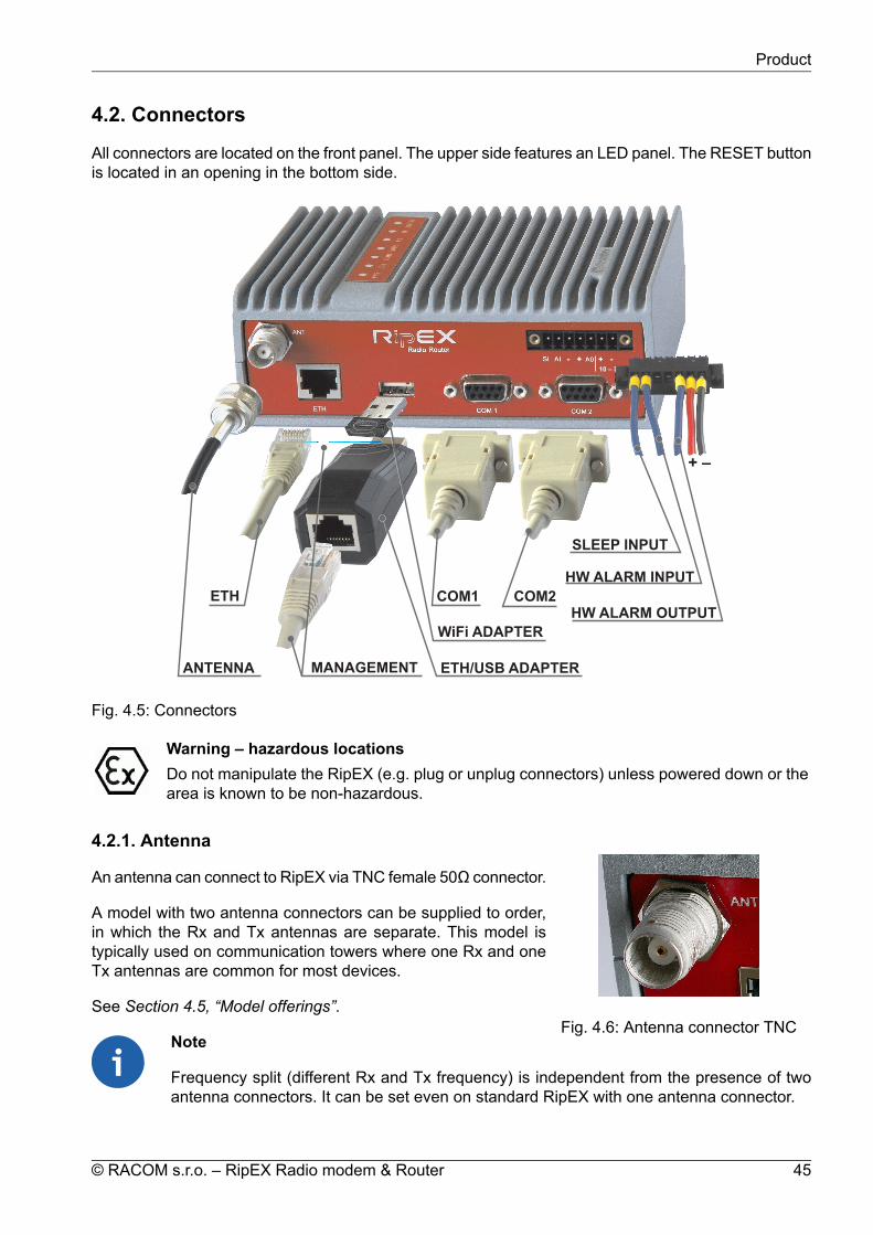
4.2. Connectors
All connectors are located on the front panel. The upper side features an LED panel. The RESET buttonis located in an opening in the bottom side.
HW ALARM OUTPUT
HW ALARM INPUT
+ –
SLEEP INPUT
COM1 COM2ETH
MANAGEMENT
WiFi ADAPTER
ETH/USB ADAPTERANTENNA
10 – 30VDC
++
ETH
Fig. 4.5: Connectors
Warning – hazardous locationsDo not manipulate the RipEX (e.g. plug or unplug connectors) unless powered down or thearea is known to be non-hazardous.
4.2.1. Antenna
Fig. 4.6: Antenna connector TNC
An antenna can connect to RipEX via TNC female 50Ω connector.
A model with two antenna connectors can be supplied to order,in which the Rx and Tx antennas are separate. This model istypically used on communication towers where one Rx and oneTx antennas are common for most devices.
See Section 4.5, “Model offerings”.
Note
Frequency split (different Rx and Tx frequency) is independent from the presence of twoantenna connectors. It can be set even on standard RipEX with one antenna connector.
45© RACOM s.r.o. – RipEX Radio modem & Router
Product

Warning – hazardous locationsAntenna has to be installed outside of the hazardous zone.
Fig. 4.7: Separated Rx and Tx antennas
Warning: RipEX radio modem may be damaged when operated without an antenna or a dummy load.
4.2.2. Power and Control
This rugged connector connects to a power supply and it contains control signals. A Plug with screw-terminals and retaining screws for power and control connector is supplied with each RipEX. It is Tyco7 pin terminal block plug, part No. 1776192-7, contact pitch 3.81 mm. The connector is designed forelectric wires with a cross section of 0.5 to 1.5 mm2. Strip the wire leads to 6 mm (1/4 inch). Isolatedcables should receive PKC 108 or less end sleeves before they are inserted in the clip. Insert the cablesin the wire ports, tightening securely.
Tab. 4.1: Pin assignment
signallabeledpinSLEEP INPUTSI1HW ALARM INPUTAI2−(GND) – for SLEEP IN, HW ALARM INPUT−3+(POWER) – for HW ALARM OUTPUT+4HW ALARM OUTPUTAO5+POWER (10 to 30 V)+10–30VDC6−POWER (GND)−10–30VDC7
Pins 3 and 7, 4 and 6 are connected internally.
RipEX Radio modem & Router – © RACOM s.r.o.46
Product

Warning – hazardous locationsThe unit must be powered with an intrinsic save power source for use in hazardous locations.
1 2 3 4 5 6Pin No.: 7
SI AI - + A0 + -
10–30VDC
Fig. 4.8: Supply connector
WirePorts (7)
RetainingScrews (2)
LeadBindingScrews (7)
Fig. 4.9: Power and Control - cable plug
1 2 3 4 5 6Pin No.: 7
SI AI - + A0 + -
10–30VDC
Sleep InputSLEEP INPUT
SLEEP INPUT is the digital input for activating the Sleep mode.When this pin is grounded (for example when connected to pin3), the RipEX switches into the Sleep mode. Using Power man-agement (Advanced Config.), the Entering the Sleep mode canbe delayed by a set time. Disconnecting SLEEP INPUT fromGND (-) ends the Sleep mode. Note that RipEX takes 48 secondsto wake up from the Sleep mode.
SLEEP INPUT can be also used for the wake-up from the Savestate. For details see chapter (Advanced Config., Power manage-ment)
1 2 3 4 5 6Pin No.: 7
SI AI - + A0 + -
10–30VDC
Alarm InputHW ALARM INPUT
HW ALARM INPUT is a digital input. If grounded (e.g. by connect-ing to PIN 3), an external alarm is triggered. This alarm can beused for example to transmit information using SNMP Notification,informing for instance about a power outage or RTU problem.For details about Alarm management see chapter AdvancedConfiguration.
1 2 3 4 5 6Pin No.: 7
SI AI - + A0 + -
10–30VDC
Alarm Output
max. 30 V DC, 1 A
HW ALARM OUTPUT
HW ALARM OUTPUT is a digital output. It can be activatedin Alarm management settings, chapter Advanced Configuration.It may be used for instance to inform the connected RTU abouta RipEX alarm or about the Unit ready status. If an alarm istriggered, HW ALARM OUTPUT is internally connected to GND.
47© RACOM s.r.o. – RipEX Radio modem & Router
Product

If the external device requires connection to positive terminal ofthe power supply, PIN 4 should be used.
POWER
The POWER pins labelled + and - serve to connect a power supply 10–30 VDC. The requirements fora power supply are defined in Section 6.6, “Power supply” and Section 4.4, “Technical specification”.
4.2.3. ETH
Standard RJ45 connector for Ethernet connection. RipEX has 10/100 BaseT Auto MDI/MDIX interfaceso it can connect to 10 Mbps or 100 Mbps Ethernet network. The speed can be selected manually orrecognised automatically by RipEX. RipEX is provided with Auto MDI/MDIX function which allows it toconnect over both standard and cross cables, adapting itself automatically.
Pin assignment
Fig. 4.10: RJ-45F
Tab. 4.2: Ethernet to cable connector connections
Crossed cableDirect cableSignalPINgreen – whiteorange – whiteTX+1greenorangeTX−2orange – whitegreen – whiteRX+3blueblue—4blue – whiteblue – white—5orangegreenRx−6brown – whitebrown – white—7brownbrown—8
4.2.4. COM1 and COM2
RipEX provides two serial interfaces COM1 and COM2 terminated by DSUB9F connectors. COM1 isalways RS232, COM2 can be configured as RS232 or RS485 (more in Adv. Conf., COM).
RipEX‘s RS232 is a hard-wired DCE (Data Communication Equipment) device. Equipment connectedto the RipEX’s serial ports should be DTE (Data Terminal Equipment) and a straight-through cableshould be used. If a DCE device is connected to the RipEX‘s serial ports, a null modem adapter orcross cable has to be used.
RipEX Radio modem & Router – © RACOM s.r.o.48
Product

Fig. 4.11: Serial connector
Tab. 4.3: COM1, 2 pin description
COM2 – RS485COM1, 2 – RS232DSUB9FIn/ OutsignalIn/ Outsignalpin
—OutCD1In/Outline BOutRxD2In/Outline AInTxD3
—InDTR4GNDGND5
—OutDSR6—InRTS7—OutCTS8———9
RipEX keeps pin 6 DSR at the level of 1 by RS232 standard permanently.
4.2.5. USB
RipEX uses USB 1.1, Host A interface. USB interface is wired as standard:
1 2 3 4
Fig. 4.12: Serial connector
Tab. 4.4: USB pin description
wiresignalUSB pinred+5 V1
whiteData(−)2greenData (+)3blackGND4
The USB interface is designed for the connection to an – external ETH/USB adapter or a Wifi adapter.They are optional accessories to RipEX, for more details see Section 5.3, “Connecting RipEX to aprogramming PC”. The adapters are used for service access to RipEX’s web configuration interface.
The USB interface can also be used for an external flash disc connection, which has been specificallydesigned to simplify complex maintenance tasks, so that these tasks can be performed by unqualifiedpersonnel in the field by simple plugging-in an USB stick and waiting until a LED flashes.
The USB connector also provides power supply (5 V/ 0.5 A). It can be used to temporarily power aconnected device, for instance a telephone. The USB connector should not be used as permanentsource of power supply.
Note – hazardous locationsOnly USB equipments dedicated for hazardous locations shall remain connected permanently.
External USB flash disc
An external USB flash disc can be used for firmware upgrade, SW keys upload, configuration backupand restore, ssl certificate and ssh keys upload and tech-support package download. Any commonUSB stick with several megabytes of free space can be used for these tasks.
49© RACOM s.r.o. – RipEX Radio modem & Router
Product

Note
The flash disc has to contain the FAT32 file system (the most common one at the time ofwriting). Any other file system will be simply ignored by the RipEX. When in doubt, consultyour IT expert.
Once the RipEX recognizes a flash disc inserted into the USB interface, the status LED starts blinkingslowly, alternating red and green colors. That indicates the start of the upload/download of files. TheLED flashing may change during the process, the successful completion of the recording is indicatedby fast alternating green and red flashes (about 3 times per second). Note that it may take up to 10minutes (when an FW upgrade is performed).
Warning
NEVER unplug the USB disc before the proper (fast) flashing of the status LED starts! Youmay damage your disc otherwise.
Following a successful detection of a USB flash disc, the RipEX writes the tech-support package, logfiles and the configuration text file to it. Then the README.txt file, which contains all the necessaryinformation on the structure and names of files and directories, is written into the root directory of thedisc. Please follow the detailed instructions in that file, or read it below:
Required FLASH structure:
for single radiomodem upgrade:
firmware package(s), newest version is used/ra1-RACOM-<VERSION>.cpiodirectory with SW keys/swkey/SW key(s)*_<SERNO>_*.txtnew configuration in text form/config.txtnew Web certificate (complete or first part)/web.pemsecond part of Web certificate (if necessary)/web.keynew CLI key/admin.pubnew remote access key/rmtaccess.key
for upgrade of multiple radiomodems:
firmware package, newest version is used/ra1-RACOM-<VERSION>.cpiodirectory with SW keys/swkey/SW key(s)*_<SERNO>_*.txtdirectory with new configurations/cnf/new configuration(s) in text form<SERNO>_*_config.txtnew Web certificate (complete or first part)/web.pemsecond part of Web certificate (if necessary)/web.keynew CLI key/admin.pubnew remote access key/rmtaccess.key
RipEX Radio modem & Router – © RACOM s.r.o.50
Product

All files/directories are optional, depending on the scope of upgrade. If no files are present, only datagathering will be performed.
Note
Whenever an FW file (.cpio) is found in the root directory of the disc, the upgrade is executedautomatically, regardless of the version of the currently active FW. If more than one FW fileis found, the latest version is used. Remember to remove the FW files from the disk rootwhen you do not intend to perform an upgrade. The same principles apply to a configurationupdate from the disc.
Created files:
README file/RipEX_README.txtdirectory with archived configurations/cnf_archive/archived configuration(s) in text form<SERNO>_<NAME>_config.txtdirectory with log files/logs/log file(s)log_<SERNO>.txtdirectory with technical support packages/tech_support/technical support package(s)<SERNO>_<NAME>_tsupport.tgz
4.2.6. GPS
Fig. 4.13: GPS Connector SMA
RipEX can be equipped with an internal GPS, see Section 4.5,“Model offerings”. The GPS module is used for time synchronisationof the NTP server inside RipEX. See Adv. Conf., Time for more. Inthis case the front panel contains a SMA female 50 ohm connectorfor connecting the GPS antenna.
• active or passive antenna• 3.3 VDC supply
51© RACOM s.r.o. – RipEX Radio modem & Router
Product

4.2.7. Reset button
Fig. 4.14: Reset button
A reset button is situated on the underside of each RipEX unit. Thebutton support multiple functions. Each function is activated dependanton how long the reset button is depressed. The "Physical security"parameter in Settings/Device/Management menu dictates the behaviorfeatures available when depressing the button.
Physical security = Off:When button is depressed
Action if button releasedStatus LED actionTime [seconds]—Goes dark0 - 5Device rebootFlashes Green5 - 15Default access settings, rebootFlashes Green faster15 - 18Factory Settings, rebootFlashes Red faster30 - 33
Physical security = On:When button is depressed
Action if button releasedStatus LED actionTime [seconds]—Goes dark0 - 5Device rebootFlashes Green5 - 15Total purge, rebootFlashes Green faster15 - 18
Default access settings:
192.168.169.169/240.0.0.0AutoOffOffOffOffDeletedDefault (Web server=HTTP+HTTPS, CLI=SSH)adminadmin
ETH IP and Mask:ETH Default GW:ETH Speed:DHCP:ARP proxy & VLAN:Firewall:Hot Standby:Routing table:Management:Username:Password:
Note
To reset the RipEX only use the RESET button as described above or use the button inRipEX’s web configuration, see Adv. Conf., Maintenance. Never use a power cycling (dis-connecting and reconnecting power supply) to reset it. While power cycle resets, or ratherreboots the RipEX, its software will not terminate correctly resulting in logs, statistics andgraphs not being saved properly.
RipEX Radio modem & Router – © RACOM s.r.o.52
Product
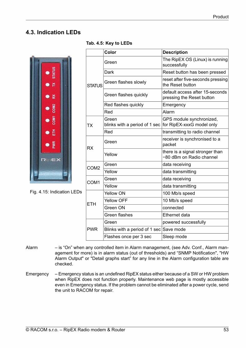
4.3. Indication LEDs
Fig. 4.15: Indication LEDs
Tab. 4.5: Key to LEDs
DescriptionColorThe RipEX OS (Linux) is runningsuccessfullyGreen
STATUS
Reset button has been pressedDarkreset after five-seconds pressingthe Reset buttonGreen flashes slowly
default access after 15-secondspressing the Reset buttonGreen flashes quickly
EmergencyRed flashes quicklyAlarmRedGPS module synchronized,for RipEX-xxxG model only
Greenblinks with a period of 1 secTX
transmitting to radio channelRedreceiver is synchronised to apacketGreen
RXthere is a signal stronger than−80 dBm on Radio channelYellow
data receivingGreenCOM2
data transmittingYellowdata receivingGreen
COM1data transmittingYellow100 Mb/s speedYellow ON
ETH10 Mb/s speedYellow OFFconnectedGreen ONEthernet dataGreen flashespowered successfullyGreen
PWR Save modeBlinks with a period of 1 secSleep modeFlashes once per 3 sec
Alarm – is “On” when any controlled item in Alarm management, (see Adv. Conf., Alarm man-agement for more) is in alarm status (out of thresholds) and “SNMP Notification", "HWAlarm Output" or "Detail graphs start” for any line in the Alarm configuration table arechecked.
Emergency – Emergency status is an undefined RipEX status either because of a SW or HW problemwhen RipEX does not function properly. Maintenance web page is mostly accessibleeven in Emergency status. If the problem cannot be eliminated after a power cycle, sendthe unit to RACOM for repair.
53© RACOM s.r.o. – RipEX Radio modem & Router
Product

4.4. Technical specification
Tab. 4.6: Technical parameters
Radio parameters135–154; 154–174; 215–240; 300–320; 320–340; 340–360;368–400; 400–432; 432–470; 470–512; 928–960 MHzFrequency bands
6.25 / 12.5 / 25 / 50 kHz[1]Channel spacing±1.0 ppmFrequency stabilityQAM (linear): 16DEQAM, D8PSK, π/4DQPSK, DPSK
ModulationFSK (exponential): 4CPFSK, 2CPFSK> 200 kbps@50 kHz; >100 kbps@25 kHz; >50 [email protected] kHz;>25 kbps@6,25 kHz[2]
Data speed (up to)
On/Off, ¾ Trellis code with Viterbi soft-decoderFEC (Forward Error Correction)
TransmitterQAM: 0.5 - 1.0 - 2.0 W[3]
FSK: 0.1 - 0.2 - 0.5 - 1.0 - 2.0 - 3.0 - 4.0 - 5.0 - 10 W[4]RF Output power(Both Carrier and Modulated)
ContinuousDuty cycle< 1.5 msRx to Tx Time> 40 dBIntermodulation Attenuation< −36 dBmSpurious Emissions (Conducted)< −36 dBmRadiated Spurious Emissions< −60 dBcAdjacent channel power< −60 dBcTransient adjacent channel power
Receiversee detailsSensitivity50 kHz @ −3 dB BWAnti-aliasing Selectivity< 1.5 msTx to Rx Time20 dBm (100 mW)Maximum Receiver Input Power< −57 dBmRx Spurious Emissions (Conducted)< −57 dBmRadiated Spurious Emissionssee detailsBlocking or desensitization> 70 dBSpurious response rejection
[1] 50 kHz channel spacing is HW dependent. Units with older version boards are still in production.50 kHz channel spacing requirement kindly specify in your order.6.25 kHz channel spacing is not available for RipEX-928.
[2] This is gross data speed in above table. User data speed varies and depends heavilyon the data structure, optimization effectivity, protocol on Radio channel, signal budgetsand many other parameters of the network. Practical tests are recommended.
[3] Output power displayed as average power, Max peak enwelope power (PEP) 7.0 W[4] For output power 10 W it is recommended to use input power above 11 VDC.
RipEX-470, RipEX-928 – max. RF Output power 8 W.
RipEX Radio modem & Router – © RACOM s.r.o.54
Product

Electrical10 to 30 VDC, negative GNDPrimary power5 W/13.8 V; 4.8 W/24 V; (Radio part < 2 W)RxPower consumptionRF power
Tx - Exponential - FSK(4CPFSK, 2CPFSK)
13.8 V 24V13.8 W 13.2 W0.1 W15.2 W 14.4 W1 W33.1 W 31.2 W5 W41.4 W 38.4 W10 W
30.4 W 30 W0.5 WTx - Linear - QAM
(16DEQAM, D8PSK,π/4DQPSK)
1 W2 W
0.1 WSleep mode2 WSave mode
InterfacesRJ4510/100 Base-T Auto MDI/MDIXEthernetDB9FRS232
COM 1300–115 200 bps
DB9FRS232/RS485 SW configurableCOM 2
300–115 200 bpsHost AUSB 1.1USBTNC female50 ΩAntenna
LED panelPower, ETH, COM1, COM2, Rx, Tx, Status7× tri-color status LEDs
EnvironmentalIP40, IP51** See Section 6.1.4, “IP51 mounting” for details.
IP Code (Ingress Protection)
> 900.000 hours (> 100 years)MTBF (Mean Time Between Failure)−40 to +70 °C (−40 to +158 °F)Operating temperature5 to 95 % non-condensingOperating humidity−40 to +85 °C (−40 to +185 °F) / 5 to 95 % non-condensingStorage
MechanicalRugged die-cast aluminiumCasing50 H × 150 W × 118 mm D (1.97× 5.9 × 4.65 in)Dimensions1.1 kg (2.4 lbs)WeightDIN rail, L-bracket, Flat-bracket, 19" Rack shelfMounting
SWBridge / RouterOperating modesModbus, IEC101, DNP3, PR2000, UNI, Comli, DF1, RP570,Profibus, …User protocols on COM
55© RACOM s.r.o. – RipEX Radio modem & Router
Product

Modbus TCP, IEC104, DNP3 TCP, Comli TCP, Terminal server…User protocols on EthernetModbus RTU / Modbus TCP, DNP3 / DNP3 TCPSerial to IP convertors
Protocol on Radio channelYesMulti master applicationsYesReport by exceptionYesCollision Avoidance CapabilityYesRemote to Remote communication
YesAddressed & acknowledged serialSCADA protocols
CRC 32Data integrity controlAES256Encryptionup to 3× higher throughputOptimization
Diagnostic and ManagementYes (ping with RSS, Data Quality, Homogeneity)Radio link testingDevice – Ucc, Temp, PWR, VSWR, *HW Alarm Input.Radio channel – *RSScom, *DQcom, TXLost[%]User interfaces – ETH[Rx/Tx], COM1[Rx/Tx], COM2[Rx/Tx]* not broadcast
Watched values (Can be broadcastto neighbouring units. Received infodisplayed in Neighbours table)
For Rx/Tx Packets on User interfaces (ETH, COM1, COM2) andfor User data and Radio protocol (Repeats, Lost, ACK etc.) onRadio channel
Statistics
For Watched values and StatisticsGraphs20 periods (configurable, e.g. days)History (Statistics, Neighbours,
Graphs)SNMPv1, SNMPv2c, SNMPv3Trap / Inform alarms generation as per settingsSNMP
Real time/Save to file analysis of all physical interfaces (RADIO,ETH, COM1, COM2) and some internal interfaces betweenMonitoring software modules (e.g. Terminal servers, Modbus TCP serveretc.)
RipEX Radio modem & Router – © RACOM s.r.o.56
Product

StandardsCE, FCC, ATEX
ETSI EN 302 561 V2.1.1:2017ETSI EN 300 113 V2.2.1:2017
Spectrum
ETSI EN 301 489-1 V2.1.1:2017ETSI EN 301 489-5 V2.1.1:2017
EMC (electromagnetic compatibility)
EN 60950-1:2006, A11:2009, A1:2010, A1:2010, A12:2011,A2:2013
Safety
EN 50385:2002EN 50383ed.2:2011
SAR
EN 61373:1999Vibration & shockIEC 980:1989 (seismic category 1a)Seismic qualification
II 3G Ex ic IIC T4 GcEN 60079-0:2012EN 60079-11:2012
Explosive atmospheres
Tab. 4.7: Recommended Cables
LengthRecommended cables and accessoriesPortMax. 3 mV03VH-H 2×0,5DC terminals – PowerMax. 3 mV03VH-H 1×0,5SI (Sleep Input)Max. 3 mV03VH-H 1×0,5AI (Alarm Input)Max. 3 mV03VH-H 1×0,5AO (Alarm Output)Max. 3 mLiYCY 4×0,14COM1Max. 3 mLiYCY 4×0,14COM2Max. 3 mUSB to 10/100 Ethernet Adapter ADE-X5USBAs neededSTP CAT 5eETH
Note – hazardous locationsThe cross sections mentioned in above table are the minimal cross sections used underhazardous location conditions.
57© RACOM s.r.o. – RipEX Radio modem & Router
Product

4.4.1. Detailed Radio parameters
The very first parameter which is often required for consideration is the receiver sensitivity. Anyoneinterested in the wireless data transmission probably aware what this parameter means, but we shouldregard it simultaneously in its relation to other receiver parameters, especially blocking and desensitiz-ation. Today’s wireless communication arena tends to be overcrowded and a modern radio modem,which is demanded to compete with others in that environment, should have good dynamic range thatis defined by the parameters listed above. Receiver of a radio modem, which is designed purely foroptimum sensitivity, will not be able to give proper performance. However, the main receiver parametersdetermining its dynamic range go against each other and a clear trade-off between the sensitivity andthe blocking is therefore an essential assumption. Then, from the viewpoint of a logical comparison,the consequence of better receiver sensitivity can be easily seen – a lower power level of the blockingand degradation parameters generally.
Blocking or desensitization values were determined according to the standards EN 302 561 V1.2.1 for50 kHz channel, EN 300 113-1 V1.7.1 for 25 and 12.5 kHz channels, and ETSI 301 166-1 V1.3.2 forchannel 6.25 kHz.
Tab. 4.8: Unlimited 50 kHz
Unlimited 50 kHz RxBlocking or
desensitization [dBm]Sensitivity [dBm]Classification±10 MHz±5 MHz±1 MHzBER 10-6BER 10-3BER 10-2ModulationFECkbps
-14-14-16-107-111-1142CPFSK0.7515.62-14-15-16-106-110-1132CPFSK1.0020.83-18-18-19-101-105-1084CPFSK0.7531.25-18-19-19-100-104-1074CPFSK1.0041.67-9-10-12-105-109-112DPSK0.7531.25-9-11-12-104-108-111DPSK1.0041.67-3-4-4-100-104-107π/4-DQPSK0.7562.49-4-5-5-99-103-106π/4-DQPSK1.0083.33-8-8-8-94-98-101D8PSK0.7593.75-8-8-8-93-97-100D8PSK1.00125.00-5-6-6-91-95-9816DEQAM0.75125.00-5-6-6-90-94-9716DEQAM1.00166.67
Unlimited 50 kHz Tx
26 dB BandwidthOBW 99% [kHz]Classification
EmissionModulationkbps30.622.124K0F1DBN2CPFSK20.8331.723.924K0F1DDN4CPFSK41.6751.045.145K0G1DBNDPSK41.6751.044.845K0G1DDNπ/4-DQPSK83.3351.345.345K0G1DEND8PSK12551.044.745K0D1DEN16DEQAM166.67
RipEX Radio modem & Router – © RACOM s.r.o.58
Product

Tab. 4.9: CE 50 kHz
CE 50 kHz RxBlocking or
desensitization [dBm]Sensitivity [dBm]Classification±10 MHz±5 MHz±1 MHzBER 10-6BER 10-3BER 10-2ModulationFECkbps
-14-14-16-107-111-1142CPFSK0.7515.62-14-15-16-106-110-1132CPFSK1.0020.83-18-18-19-101-105-1084CPFSK0.7531.25-18-19-19-100-104-1074CPFSK1.0041.67-15-15-15-105-109-112DPSK0.7526.04-15-15-15-104-108-110DPSK1.0034.72-17-21-21-100-104-107π/4-DQPSK0.7552.08-17-21-21-99-103-106π/4-DQPSK1.0069.44-15-21-20-96-99-102D8PSK0.7578.12-16-21-20-95-98-101D8PSK1.00104.17-14-17-17-95-98-10116DEQAM0.75104.17-15-1717-94-97-10016DEQAM1.00138.89
CE 50 kHz Tx
26 dB BandwidthOBW 99% [kHz]Classification
EmissionModulationkbps30.622.124K0F1DBN2CPFSK20.8331.723.924K0F1DDN4CPFSK41.6745.539.340K0G1DBNDPSK34.7245.639.240K0G1DDNπ/4-DQPSK69.4444.839.540K0G1DEND8PSK104.1745.139.140K0D1DEN16DEQAM138.89
59© RACOM s.r.o. – RipEX Radio modem & Router
Product
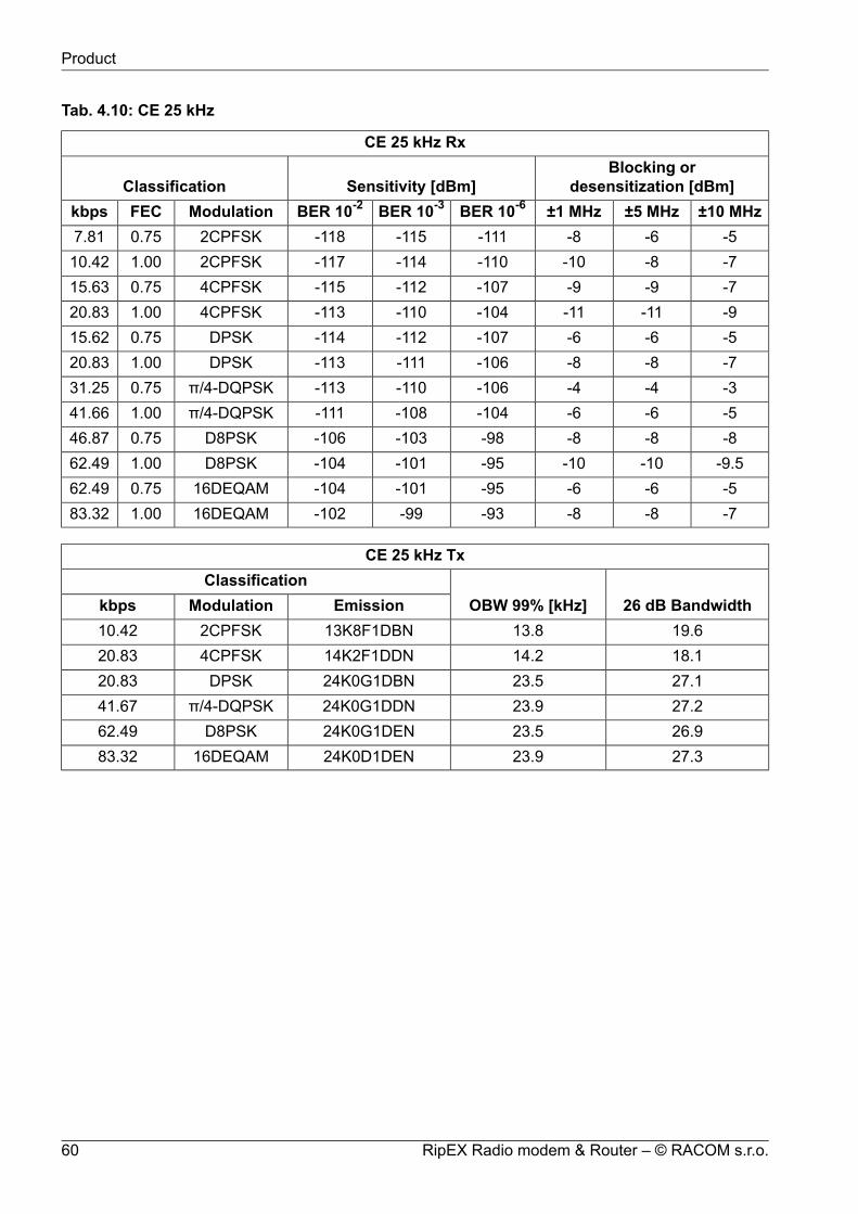
Tab. 4.10: CE 25 kHz
CE 25 kHz RxBlocking or
desensitization [dBm]Sensitivity [dBm]Classification±10 MHz±5 MHz±1 MHzBER 10-6BER 10-3BER 10-2ModulationFECkbps
-5-6-8-111-115-1182CPFSK0.757.81-7-8-10-110-114-1172CPFSK1.0010.42-7-9-9-107-112-1154CPFSK0.7515.63-9-11-11-104-110-1134CPFSK1.0020.83-5-6-6-107-112-114DPSK0.7515.62-7-8-8-106-111-113DPSK1.0020.83-3-4-4-106-110-113π/4-DQPSK0.7531.25-5-6-6-104-108-111π/4-DQPSK1.0041.66-8-8-8-98-103-106D8PSK0.7546.87
-9.5-10-10-95-101-104D8PSK1.0062.49-5-6-6-95-101-10416DEQAM0.7562.49-7-8-8-93-99-10216DEQAM1.0083.32
CE 25 kHz Tx
26 dB BandwidthOBW 99% [kHz]Classification
EmissionModulationkbps19.613.813K8F1DBN2CPFSK10.4218.114.214K2F1DDN4CPFSK20.8327.123.524K0G1DBNDPSK20.8327.223.924K0G1DDNπ/4-DQPSK41.6726.923.524K0G1DEND8PSK62.4927.323.924K0D1DEN16DEQAM83.32
RipEX Radio modem & Router – © RACOM s.r.o.60
Product

Tab. 4.11: CE 12.5 kHz
CE 12.5 kHz RxBlocking or
desensitization [dBm]Sensitivity [dBm]Classification±10 MHz±5 MHz±1 MHzBER 10-6BER 10-3BER 10-2ModulationFECkbps
-3-4-6-113-117-1202CPFSK0.753.91-5-6-8-112-116-1192CPFSK1.005.21-5-6-6-108-114-1174CPFSK0.757.81-7-8-8-105-112-1154CPFSK1.0010.42-3-4-4-110-114-116DPSK0.757.81-5-6-6-109-113-115DPSK1.0010.42-2-3-3.5-109-113-115π/4-DQPSK0.7515.62-3-4-4-106-111-114π/4-DQPSK1.0020.83-5-6-6-101-106-109D8PSK0.7523.44-7-8-8-98-104-107D8PSK1.0031.25-2-3-3-99-104-10716DEQAM0.7531.25-4-5-5-96-102-10516DEQAM1.0041.67
CE 12.5 kHz Tx
26 dB BandwidthOBW 99% [kHz]Classification
EmissionModulationkbps9.66.97K00F1DBN2CPFSK5.218.56.87K00F1DDN4CPFSK10.42
13.611.911K9G1DBNDPSK10.4213.611.811K9G1DDNπ/4-DQPSK20.8413.411.811K9G1DEND8PSK31.2513.511.811K9D1DEN16DEQAM41.66
61© RACOM s.r.o. – RipEX Radio modem & Router
Product

Tab. 4.12: CE 6.25 kHz
CE 6.25 kHz RxBlocking or
desensitization [dBm]Sensitivity [dBm]Classification±10 MHz±5 MHz±1 MHzBER 10-6BER 10-3BER 10-2ModulationFECkbps
+5.5+1.0-0.5-114-120-1222CPFSK0.751.96+4.0-1.0-2.5-113-119-1212CPFSK1.002.61+5.0-0.0-1.5-111-116-1194CPFSK0.753.91+3.0-1.5-3.5-108-114-1174CPFSK1.005.217.01.50.0-113-118-121DPSK0.753.915.0-0.5-2.0-112-117-119DPSK1.005.216.03.0+1.0-112-115-117π/4-DQPSK0.757.824.01.0-0.5-110-113-116π/4-DQPSK1.0010.424.01.0-1.0-104-109-111D8PSK0.7511.722.0-1.0-3.0-104-109-111D8PSK1.0015.631.5-2.0-7.5-103-107-11016DEQAM0.7515.630.0-3.5-5.5-99-104-10716DEQAM1.0020.83
CE 6.25 kHz Tx
26 dB BandwidthOBW 99% [kHz]Classification
EmissionModulationkbps4.352.953K00F1DBN2CPFSK2.613.923.173K00F1DDN4CPFSK5.216.715.916K00G1DBNDPSK5.216.818.946K00G1DDNπ/4-DQPSK10.426.685.936K00G1DEND8PSK15.626.745.816K00D1DEN16DEQAM20.83
RipEX Radio modem & Router – © RACOM s.r.o.62
Product

Tab. 4.13: FCC 50 kHz
FCC 50 kHz RxBlocking or
desensitization [dBm]Sensitivity [dBm]Classification±10 MHz±5 MHz±1 MHzBER 10-6BER 10-3BER 10-2ModulationFECkbps
-15-16-16-108-112-1152CPFSK0.7515.62-15-16-17-107-111-1132CPFSK1.0020.83-15-21-21-103-107-1104CPFSK0.7531.25-16-21-21-102-106-1094CPFSK1.0041.67-15-15-15-105-109-112DPSK0.7526.04-15-15-15-104-108-110DPSK1.0034.72-17-21-21-100-104-107π/4-DQPSK0.7552.08-17-21-21-99-103-106π/4-DQPSK1.0069.44-15-21-20-96-99-102D8PSK0.7578.12-16-21-20-95-98-101D8PSK1.00104.17-14-17-17-95-98-10116DEQAM0.75104.17-15-1717-94-97-10016DEQAM1.00138.89
FCC 50 kHz Tx
26 dB BandwidthOBW 99% [kHz]Classification
EmissionModulationkbps37.028.028K0F1D4CPFSK41.6745.539.340K0G1DDPSK34.7245.639.240K0G1Dπ/4-DQPSK69.4444.839.540K0G1DD8PSK104.1745.139.140K0D1D16DEQAM138.89
Tab. 4.14: FCC 25 kHz
FCC 25 kHz RxBlocking or
desensitization [dBm]Sensitivity [dBm]Classification±10 MHz±5 MHz±1 MHzBER 10-6BER 10-3BER 10-2ModulationFECkbps
-0-1-3-108-113-1164CPFSK0.7515.63-1-2-5-105-111-1144CPFSK1.0020.83-1-2-4-107-111-114π/4-DQPSK0.7526.04-2-4-6-105-109-112π/4-DQPSK1.0034.72-5-7-9-99-105-108D8PSK0.7539.06-7-9-11-96-103-106D8PSK1.0052.08-8-9-12-96-103-10616DEQAM0.7552.08
-10-12-14-94-101-10416DEQAM1.0069.44
63© RACOM s.r.o. – RipEX Radio modem & Router
Product

FCC 25 kHz Tx
26 dB BandwidthOBW 99% [kHz]Classification
EmissionModulationkbps23.618.518K6F1D4CPFSK20.8322.819.719K8G1Dπ/4-DQPSK34.7222.619.819K8G1DD8PSK52.0822.619.919K8D1D16DEQAM69.44
Tab. 4.15: FCC 25 kHz RipEX-928, RipEX-215
FCC 25 kHz Rx RipEX-928, RipEX-215Blocking or
desensitization [dBm]Sensitivity [dBm]Classification±10 MHz±5 MHz±1 MHzBER 10-6BER 10-3BER 10-2ModulationFECkbps
-8-8-8-106-112-1154CPFSK0.7515.63-10-10-10-104-110-1134CPFSK1.0020.83-9-9-9-108-112-115π/4-DQPSK0.7520.84-11-11-11-105-110-113π/4-DQPSK1.0027.78-8-8-8-101-107-110D8PSK0.7531.25-9-9-9-98-105-108D8PSK1.0041.67-11-11-11-96-103-10616DEQAM0.7541.67-13-13-13-94-101-10416DEQAM1.0055.56
FCC 25 kHz Tx RipEX-928, RipEX-215
26 dB BandwidthOBW 99% [kHz]Classification
EmissionModulationkbps22.615.916K0F1D4CPFSK20.8318.215.916K0G1Dπ/4-DQPSK27.7818.015.916K0G1DD8PSK41.6718.115.916K0D1D16DEQAM55.56
RipEX Radio modem & Router – © RACOM s.r.o.64
Product

Tab. 4.16: FCC 12.5 kHz
FCC 12.5 kHz RxBlocking or
desensitization [dBm]Sensitivity [dBm]Classification±10 MHz±5 MHz±1 MHzBER 10-6BER 10-3BER 10-2ModulationFECkbps
-4-5-5-108-114-1174CPFSK0.757.81-6-7-7-105-112-1154CPFSK1.0010.42-2-2-2-109-113-115π/4-DQPSK0.7513.02-3-4-4-106-111-114π/4-DQPSK1.0017.36-5-6-6-101-106-109D8PSK0.7519.53-7-8-8-98-104-107D8PSK1.0026.04-2-3-3-99-104-10716DEQAM0.7526.04-4-5-5-96-102-10516DEQAM1.0034.72
FCC 12.5 kHz Tx
26 dB BandwidthOBW 99% [kHz]Classification
EmissionModulationkbps11.38.68K60F1D4CPFSK10.4211.39.8310K0G1Dπ/4-DQPSK17.3611.29.8710K0G1DD8PSK26.0411.39.8810K0G1D16DEQAM34.72
Tab. 4.17: FCC 6.25 kHz
FCC 6.25 kHz RxBlocking or
desensitization [dBm]Sensitivity [dBm]Classification±10 MHz±5 MHz±1 MHzBER 10-6BER 10-3BER 10-2ModulationFECkbps
-2-2-2-112-117-1204CPFSK0.753.91-3-4-4-109-115-1184CPFSK1.005.21-2-3-3-113-116-118π/4-DQPSK0.756.51-4-5-5-111-114-117π/4-DQPSK1.008.68-2-2-2-105-110-112D8PSK0.759.77-3-4-4-102-107-110D8PSK1.0013.02-2-3-3-103-107-11016DEQAM0.7513.02-4-5-5-100-105-10816DEQAM1.0017.36
65© RACOM s.r.o. – RipEX Radio modem & Router
Product

FCC 6.25 kHz Tx
26 dB BandwidthOBW 99% [kHz]Classification
EmissionModulationkbps5.013.553K60F1D4CPFSK5.215.634.895K00G1Dπ/4-DQPSK8.685.564.885K00G1DD8PSK13.025.634.875K00G1D16DEQAM17.36
Tab. 4.18: Narrow 25 kHz
Narrow 25 kHz RxBlocking or
desensitization [dBm]Sensitivity [dBm]Classification±10 MHz±5 MHz±1 MHzBER 10-6BER 10-3BER 10-2ModulationFECkbps
-5-6-8-111-115-1182CPFSK0.757.81-7-8-10-110-114-1172CPFSK1.0010.42-7-9-9-107-112-1154CPFSK0.7515.63-9-11-11-104-110-1134CPFSK1.0020.83-6-7-7-109-114-116DPSK0.7510.41-7-8-8-108-113-115DPSK1.0013.89-8-8-8-107-111-113π/4-DQPSK0.7520.84-8-8-9-106-110-112π/4-DQPSK1.0027.78-8-8-9-101-105-108D8PSK0.7531.25-9-10-10-100-104-107D8PSK1.0041.67-9-9-11-99-103-10616DEQAM0.7541.67-9-10-11-95-101-10416DEQAM1.0055.56
Narrow 25 kHz Tx
26 dB BandwidthOBW 99% [kHz]Classification
EmissionModulationkbps19.613.813K8F1DBN2CPFSK10.4218.114.214K2F1DDN4CPFSK20.8318.215.915K9G1DBNDPSK13.8918.215.915K9G1DDNπ/4-DQPSK27.7818.015.915K9G1DEND8PSK41.6718.115.915K9D1DEN16DEQAM55.56
Note
All the Sensitivities above are guaranteed ones, i.e. every single unit has got typicallyeven better values for 0–4 dB.
1.
2. BER (Bit Error Rate) is calculated from PER (Packet Error Rate) when packet size was60 Bytes.
RipEX Radio modem & Router – © RACOM s.r.o.66
Product

3. All the values above are guaranteed for temperatures from -30 to +60 °C (-22 to +140 °F)and for all frequency channels.
4. The RipEX spurious response rejection is defined as "better than 70 dB", where 70 dBis the limit defined by ETSI EN 300 113. We confirm that the real measured values ofthis parameter are better than 75 dB.
5. The radio circuits in RipEX were designed to provide protection from the output of thepower amplifier and no oscillation, no damage into infinite VSWR at any phase angleoccurs.
6. OBW 99% (Occupied BandWidth) - the bandwidth containing 99% of the total integratedpower of the transmitted spectrum, centered on the assigned channel frequency.
7. "26 dB Bandwidth" - the bandwidth where, beyond its lower and upper limits, any discretespectrum component or the power spectral density is attenuated by at least 26 dB, rel-ative to a given and predetermined zero dB level.
8. Please contact RACOM for current status of official test reports for CE, FCC and otherstandards for different models (frequencies) and different channel spacings.
9. "Unlimited 50 kHz" channel mask is slightly wider than the relevant CE or FCC require-ments, " Narrow 25 kHz" is slightly narrower than the relevant CE requirement. If ne-cessary contact RACOM for more details.
67© RACOM s.r.o. – RipEX Radio modem & Router
Product

4.5. Model offerings
RipEX radio modem has been designed to have minimum possible number of hardware variants. Dif-ferent HW models are determined by frequency, internal GPS and separate connectors for RX and TXantennas.
Upgrade of functionality does not result in on-site hardware changes – it is done by activating softwarefeature keys (see chapter RipEX in detail and Adv. Config., Maintenance).
4.5.1. Ordering code (Part No’s)
Trade name: RipEXType (according to bands): RipEX-160, RipEX-200, RipEX-300, RipEX-400, RipEX-900.Code (according to the tuned frequency and specific HW models): e.g. RipEX-368, RipEX-432DG etc.
XXX – base frequencyCode Tuning freq. range
RipEX-135 135–154 MHzRipEX-154 154–174 MHzRipEX-215 215–240 MHzRipEX-300 300–320 MHzRipEX-320 320–340 MHzRipEX-340 340–360 MHzRipEX-368 368–400 MHzRipEX-400 400–432 MHzRipEX-432 432–470 MHzRipEX-470 470–512 MHzRipEX-928 928–960 MHz
yyy – HW modelsempty – basic modelD – separate connectors for RX and TX antennas (Part No. RipEX-HW-DUAL)G – internal GPS module (Part No. RipEX-HW-GPS)S – Up to 50 kHz channel spacing (Part No. RipEX-HW-50kHz). "S" is used, because units with olderversion radio boards (lower than 1.1.90.0 or 1.2.50.0.) don't support 50 kHz channel spacing.P - Ingress Protection level IP51 - see Section 6.1.4, “IP51 mounting” for IP51 mounting detailsD, G, P models are produced on request.
Code examples:RipEX-368 = RipEX for frequencies from 368 to 400 MHzRipEX-400G = RipEX for frequencies from 400 to 432 MHz, with GPS moduleRipEX-432DG = RipEX for frequencies from 432 to 470 MHz, with separate Rx and Tx antenna con-nectors, with GPS moduleRipEX-154S = RipEX for frequencies from 154 to 174 MHz, together with standard 6.25, 12.5, 25kHz also 50 kHz channel spacing supported
SW feature keys
ROUTER – enables Operating mode Router. If not activated, only Bridge mode is available(Part No. RipEX-SW-ROUTER)
RipEX Radio modem & Router – © RACOM s.r.o.68
Product

SPEED – enables the two highest Data rates for 50 and 25 kHz channel spacings(Part No. RipEX-SW-SPEED)
COM2 – enables the second serial interface configurable as RS232 or RS485(Part No. RipEX-SW-COM2)
10W – enables RF output power 10 W for CPSK modulations(Part No. RipEX-SW-10W)
BACKUPROUTES
– enables Backup routes(Part No. RipEX-SW-BACKUP ROUTES)
MASTER – enables all functionalities of all possible SW feature keys(Part No. RipEX-SW-MASTER)
Software keys are always tied to a specific RipEX Serial number (S/N). When SW key is ordered laterand not together with RipEX unit, this S/N must be given.
Ex feature key
Ex – authorization for use in hazardous locationII 3G Ex ic IIC T4 Gc
Ex key is always tied to a specific RipEX Serial number (S/N). When Ex key is ordered later and nottogether with RipEX unit, this S/N must be given. Ex keys are available only for units produced after1st of January 2014.
Important
Since SW feature key can be activated anytime within RipEX, it is not a part of the Code.
Standard RipEX package in paper box contents:
• RipEX – 1pc• Removable sticker plate – 1pc• Power and Control plug connector (counterpart) – 1pc• DIN set (a pair of DIN rail clips + screws) – 1pc
• USB port dust cap - 1pc, IP51 only
Accessories
Power suppliesPWS-AC/DC-AD-155A – Power supply with back-up 90–260 VAC/13.8 VDC/150 WPWS-AC/DC-DR-75-12 – Power supply 85–264 VAC/12 VDC/75 W DINPWS-AC/DC-MS2000/12 – Power supply with back-up 230 VAC/13.8 VDC/70 WBAT-12V/5Ah – Battery 12 V, 5.0 Ah (for RipEX_DEMO_CASE)BAT-12V/7.2Ah – Battery 12 V, 7.2 Ah (for RipEX-HSB)
HoldersRipEX_F_BRACKET – Flat-bracket, for flat mountingRipEX_L_BRACKET – L-bracket, for vertical mounting
19‘ rack mounting
69© RACOM s.r.o. – RipEX Radio modem & Router
Product

RipEX_D_RACK_230 – 19" rack shelf double, incl. 2× PS 100–256 VAC / 24 VDCRipEX_D_RACK_48 – 19" rack shelf double, incl. 2× PS 48 VDC / 24 VDCRipEX_S_RACK_MS – 19" rack shelf single, incl. MS2000/12 + AKU 7.2 AhRipEX_S_RACK_230 – 19" rack shelf single, incl. PS 100–256 VAC / 24 VDCRipEX_S_RACK_48 – 19" rack shelf single, incl. PS 48 VDC / 24 VDC
OthersRipEX_X5 – ETH/USB adapterRipEX_W1 – Wifi adapterRipEX_DEMO_CASE – Demo case (without radio modems)RipEX_DUMMYLOAD – Dummy load antennaRipEX_C_NM_50 – Feedline cable, RG58, 50 cm, TNC Male – N MaleOTH-VHF50HN – Coaxial overvoltage protection 100–512 MHz, N female/N femaleRipEX-HS – 19" Hot Standby chassis, RipEX units excl., pow.supplies incl. (has got its own orderingcodes, see RipEX-HS User manual)RipEX-HSB – 19" Battery pack chassis for RipEX-HS, batteries excl.
RipEX Radio modem & Router – © RACOM s.r.o.70
Product

4.6. Accessories
1. RipEX Hot Standby
RipEX-HS is redundant Hot Standby chassis. There are two Hot Standby standard RipEX unitsinside. In case of a detection of failure, automatic switchover between RipEX units sis performed.RipEX-HS is suitable for Central sites, Repeaters or Important remote sites where no single pointof failure is required.
Fig. 4.16: RipEX-HS
Fig. 4.17: RipEX-HS dimensions
For more information see RipEX-HS datasheet or User manual on www.racom.eu1.
2. ETH/USB adapter
Fig. 4.18: Adapter ETH/USB
ETH/USB adapter for service access to theweb interface via USB connector. Includes abuilt-in DHCP server which provides up to 5leases. To access the RipEX always use thefixed IP 10.9.8.7. For details on use see Sec-tion 5.3, “Connecting RipEX to a programmingPC”.
OTH-XA-ETH/USB requires FW 1.7.1.0 orhigher. The previous model OTH-X5-ETH/USBis supported in all FW versions.
1 http://www.racom.eu
71© RACOM s.r.o. – RipEX Radio modem & Router
Product

3. Wifi adapter
Fig. 4.19: WiFi adapter
Wifi adapter for service access to the web inter-face via USB connector. Includes a built-inDHCP server which provides up to 5 leases.To access the RipEX always use the fixed IP10.9.8.7. For details on use see Section 5.3,“Connecting RipEX to a programming PC”.
4. Demo case
A rugged plastic case for carrying up to three RipEX's and one M!DGE 3G SCADA router. It alsocontains all the accessories needed to perform an on-site signal measurement, complete applicationbench-test or a functional demonstration of both radiomodems and the 3G router. During a fieldtest, units can be powered from the backup battery and external antenna can be connected to oneof the RipEX units through „N“ connector on the case.
Fig. 4.20: Demo case
Content:• Brackets and cabling for installation of three RipEXes and one M!DGE (units are not part of
the delivery)• 1× power supply Mean Well AD-155A (100-240 V AC 50-60 Hz/13.8 V DC)• 1× Backup battery (12V/5Ah, FASTON.250), e.g. Fiamm 12FGH23• 1× Power cable (European Schuko CEE 7/7 to IEC 320 C13)• 1× Ethernet patch cable (3 m, UTP CAT 5E, 2× RJ-45)• Quick start guide
RipEX accessories:• 3× Dummy load antennas• 1× L-bracket, 1x Flat-bracket samples• 1× ETH/USB adapter• 1× Wifi adapter
M!DGE accessories:• Stick antenna (900–2100 MHz, 2.2 dBi, vertical)
Mechanical properties of case
RipEX Radio modem & Router – © RACOM s.r.o.72
Product

• Outside dimension: 455 × 365 × 185 mm• Weight approx. 4 kg (excluding the RipEX and M!DGE units)
5. L-bracket
Fig. 4.21: L-bracket
Installation L bracket for vertical mounting. Fordetails on use see chapter Mounting andchapter Dimensions.
133
124
60
122
L - bracket
32
100
Fig. 4.22: RipEX with L-bracket
6. Flat-bracket
Fig. 4.23: Flat bracket
Installation bracket for flat mounting. For detailson use see chapter Mounting.
73© RACOM s.r.o. – RipEX Radio modem & Router
Product

95
174
184
Flat - bracket 134
150 118
58
50
70
Fig. 4.24: RipEX with Flat-bracket
95
174
184
8
70
75,4
2×o4,5 4×M3/
101
Fig. 4.25: Flat-bracket dimensions
7. 19" rack shelf – single• 1,6U (70 mm) high• Ready for assembly with one RipEX• Weight 2.5 kg (without power supply and RipEX)• Can be assembled with power supply
100 – 256 V AC / 24 V DC 230 V AC / 24 V DC 48 V DC / 24 V DC MS2000/12 + back up battery 7.2 Ah
RipEX Radio modem & Router – © RACOM s.r.o.74
Product

Fig. 4.26: 19" Rack shelf
Fig. 4.27: 19" Rack shelf – dimensions
8. 19" rack shelf – double• 1,6U (70 mm) high• Ready for assembly with two RipEX’es• Can be assembled with power supplies
100 – 256 V AC / 24 V DC 230 V AC / 24 V DC 48 V DC / 24 V DC MS2000/12 + back up battery 7.2 Ah
75© RACOM s.r.o. – RipEX Radio modem & Router
Product
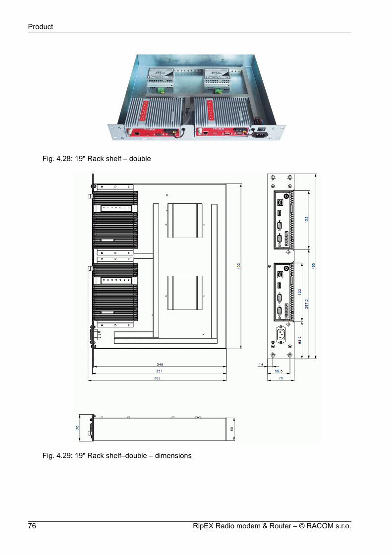
Fig. 4.28: 19" Rack shelf – double
Fig. 4.29: 19" Rack shelf–double – dimensions
RipEX Radio modem & Router – © RACOM s.r.o.76
Product

9. Dummy load antenna
Fig. 4.30: Dummy load antenna
Dummy load antenna for RipEX isused to test the configuration on adesk. It is unsuitable for higheroutput – use transmitting output of1.0 W only.
10. Coaxial overvoltage protection
Fig. 4.31: Overvoltage protection
Frequency range 100-512 MHz,connectors N(female) / N(female).
11. Feedline adapter cable
Fig. 4.32: Feedline adapter cable
Feedline cable is 50 cm long andis made from the RG58 coaxialcable. There are TNC Male (RipEXside) and N Male connectors onthe ends. It is intended for usebetween RipEX and cabinet panel.
12. Automatic antenna switch
Fig. 4.33: Automatic antenna switch
An Automatic antenna switch ismainly used for migrating legacyto RipEX networks. It automaticallymanages antenna switching: whenone base station transmits, theother one is disconnected from thecommon antenna.
77© RACOM s.r.o. – RipEX Radio modem & Router
Product

13. Migration serial cable
This is an RS232 crossing cable (null-modem) for connection of legacy base station to RipEX.There is also ‘Carrier On’ contact available for legacy base station keying (Relay Dry Contact),managed by CTS envelope from RipEX.
Fig. 4.34: Cable connection Fig. 4.35: Migration serial cable
14. Others
For other accessories (Power supplies, Antennas, Coaxial overvoltage protection etc.) kindly visithttp://www.racom.eu/eng/products/radio-modem-ripex.html#accessories
RipEX Radio modem & Router – © RACOM s.r.o.78
Product

5. Bench test
5.1. Connecting the hardware
Before installing a RipEX network in the field, a bench-test should be performed in the lab. The RipEXDemo case is great for this as it contains everything necessary: 3 RipEX’s, Power supply, dummy loadantennas, etc.
If you use your own installation for lab tests, don’t forget:
• A dummy load or an actual antenna with 50 ohm impedance should be connected to the RipEX
• The minimum RF output must be set to avoid overloading the dummy antenna and to keep the re-ceived signal at reasonable level, between -40 and -80 dBm.
• The power supplies must meet the requirements given in the specifications, Table 4.6, “Technicalparameters”. Make sure the power supplies do not generate interference in the radio channel andthat they can handle very fast changes in the load when RipEX switches from reception to transmis-sion and back.
Center RTU
RTU
24 VDC 24 VDC
24 VDC
config. PC
Fig. 5.1: Bench test
5.2. Powering up your RipEX
Switch on your power supply. LED PWR flashes quickly and after 8 seconds it switches to a greenlight. After approximately 30 seconds your RipEX will have booted and will be ready; the STATUS LEDshines. You’ll find the description of the individual LED states in Section 4.3, “Indication LEDs”.
5.3. Connecting RipEX to a programming PC
To configure a RipEX you can connect it to your PC in three ways:
79© RACOM s.r.o. – RipEX Radio modem & Router
Bench test

1. Using the external Wifi adapter
2. Using the external ETH/USB adapter
3. Directly over the Ethernet interface
https://192.168.169.169PC 192.168.169.250
https://10.9.8.7PC DHCP
https://10.9.8.7PC DHCP
Fig. 5.2: Connecting to a PC over ETH and over WiFi or ETH/USB adapter
1. PC connected via Wifi adapter
We recommend using the "W1" - external Wifi adapter (an optional accessory of the RipEX).Connect your PC or tablet or smart phone to RipEX Wifi AP first. Its default SSID is “RipEX + Unitname + S/N”. The W1 contains a built-in DHCP server, so if you have a DHCP client in your PC(as most users do), you don’t need to set anything up. The RipEX’s IP address for access overthe ETH/USB adapter is fixed: 10.9.8.7.
Go to Login to RipEX.
2. PC connected via ETH/USB adapter
We recommend using the "X5" - external ETH/USB adapter (an optional accessory of the RipEX).The ETH/USB contains a built-in DHCP server, so if you have a DHCP client in your PC as mostusers, you don’t need to set anything up. The RipEX’s IP address for access over the ETH/USBadapter is fixed: 10.9.8.7.
Go to Login to RipEX.
3. PC connected directly to ETH port
Set a static IP address in PC, example for Windows XP:
RipEX Radio modem & Router – © RACOM s.r.o.80
Bench test

Start > Settings > Network Connections > Local Area ConnectionsRight Click > Properties > Generalselect Internet Protocol (TCP/IP) > Properties > GeneralIP address 192.168.169.250 - for RipEX in the default stateSubnet mask 255.255.255.0Default gateway leave emptyOK (Internet Protocol Properties window)OK (Local Area Properties window)Some Operating systems may require you to reboot your PC.
Fig. 5.3: PC address setting
Important
When you change the RipEX ETH address from the default value later on and the newIP network does not include the default one, you will have to change your PC's staticIP again to be able to continue configuring the RipEX.
4. Login to RipEX
Start a web browser (Mozilla Firefox, Internet Explorer - JavaScript enabled) on your PC and typethe RipEX’s default IP in the address line default IP address in the address line field:• 10.9.8.7 – when connected via external ETH/USB or Wifi adapter. IP address 10.9.8.7 is fixed
and cannot be changed; it is independent of the IP address of the RipEX’s Ethernet interface.)• 192.168.169.169 – when connected directly to ETH
Note
https - For security reasons the http protocol with ssl encryption can be used for thecommunication between the PC and RipEX. The https protocol requires a security
81© RACOM s.r.o. – RipEX Radio modem & Router
Bench test

certificate. You must install this certificate into your web browser (Mozilla Firefox, InternetExplorer). The first time you connect to the RipEX, your computer will ask you for au-thorisation to import the certificate into your computer. The certificate is signed by thecertification authority Racom s.r.o. It meets all security regulations and you need notbe concerned about importing it into your computer. Confirm the import with all warningsand exceptions that your browser may display during installation.
The login screen appears:
Fig. 5.4: Authentication
The default entries for a new RipEX are:
User name: adminPassword: adminClick OK.
Initial screen should appear then:
Fig. 5.5: Status Menu
RipEX Radio modem & Router – © RACOM s.r.o.82
Bench test

Warning: Before you start any configuration, make sure only one unit is powered ON. Otherwise,a different radio modem could reply to your requests! (All units share the same IP address andare in Bridge mode when in factory settings.)
5. IP address unknown
If you don’t have the adapter or you have forgotten the password, you can reset the access para-meters to defaults, see Section 4.2.7, “Reset button”.
5.4. Basic setup
For the first functionality test we recommend that you use the setup wizard. The wizard will guide youthrough basic functionality setup. Simply select Wizard in the web interface and proceed according tothe information on the screen. Repeat for all RipEX’s in the test network.
If you want to test applications which require a more complex setup, see Chapter 7, Advanced Config-uration. To setup the IP addresses you can use the examples in Section 2.3.3, “Router - Flexible,Configuration examples” as your models, or the RipEX-App. notes, Address planing1.
5.5. Functional test
To test radio communication between the RipEX’s you can use the Ping test, under Diagnostic/Pingmenu. Setting up and the output of this test are described in chapter Adv. Conf., Tools.
If the radio communication between RipEX’s is functional, you can proceed with a test of communicationbetween the connected devices.
You can monitor the status of configuration using the diodes on the LED panel, see Section 4.3, “Indic-ation LEDs”.
1 http://www.racom.eu/eng/products/m/ripex/app/routing.html
83© RACOM s.r.o. – RipEX Radio modem & Router
Bench test

6. Installation
Step-by-step checklist
1. Mount RipEX into cabinet (Section 6.1, “Mounting”).2. Install antenna (Section 6.2, “Antenna mounting”).3. Install feed line (Section 6.3, “Antenna feed line”).4. Ensure proper grounding (Section 6.4, “Grounding”).5. Run cables and plug-in all connectors except from the SCADA equipment (Section 4.2, “Connect-
ors”)6. Apply power supply to RipEX7. Connect configuration PC (Section 5.3, “Connecting RipEX to a programming PC”).8. Configure RipEX (Chapter 7, Advanced Configuration ).9. Test radio link quality (Section 5.5, “Functional test”).10. Check routing by the ping tool (Section 7.6.3, “Ping”) to verify accessibility of all IP addresses with
which the unit will communicate.11. Connect the SCADA equipment12. Test your application.
Note – hazardous locationsInstallation in hazardous locations has to be done according to standardEN 60079-25 Explosive atmospheres Intrinsically safe electrical systems.
6.1. Mounting
6.1.1. DIN rail mounting
The radio modem RipEX is directly mounted using clips to the DIN rail. The mounting can be donelengthwise (recommended) or widthwise; in both cases with the RipEX lying flat. The choice is madeby mounting the clips, one M4 screw per clip. RipEX is delivered with two clips, two screws and fourthreaded holes. Only use the M4×5 mm screws that are supplied. Use of improper screws may resultin damage to the RipEX mainboard!
Fig. 6.1: Flat lengthwise mounting to DIN rail – recommended
RipEX Radio modem & Router – © RACOM s.r.o.84
Installation

Fig. 6.2: Flat widthwise mounting to DIN rail
When tightening the screw on the clip, leave a 0,5 mm gap between the clip and the washer.
Fig. 6.3: Clip mounting
For vertical mounting to DIN rail, L-bracket (optional accessory) is used. Only use the M4×5 mm screwsthat are supplied. Use of improper screws may result in damage to the RipEX mainboard!
Fig. 6.4: Vertical widthwise mounting to DIN rail
Fig. 6.5: Vertical lengthwise mounting to DIN rail
For more information see Section 4.6, “Accessories” – L-bracket.
85© RACOM s.r.o. – RipEX Radio modem & Router
Installation
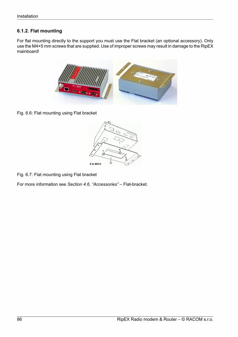
6.1.2. Flat mounting
For flat mounting directly to the support you must use the Flat bracket (an optional accessory). Onlyuse the M4×5 mm screws that are supplied. Use of improper screws may result in damage to the RipEXmainboard!
Fig. 6.6: Flat mounting using Flat bracket
Fig. 6.7: Flat mounting using Flat bracket
For more information see Section 4.6, “Accessories” – Flat-bracket.
RipEX Radio modem & Router – © RACOM s.r.o.86
Installation

6.1.3. 19" rack mounting
For installation into the 19" rack you can use the 19" rack shelf – single or 19" rack shelf- double forone or two RipEXes. 19" rack shelf is an optional accessory delivered with/without a power supply.
Fig. 6.8: Rack shelf
6.1.4. IP51 mounting
To meet IP51 protection requirements, two conditions must be met:
RipEX unit must host the "IP51 protection" option which is indicated by the letter "P" in the ordercode (e.g. RipEX-400SP).
RipEX unit must be physically installed with the connectors facing downward.
6.2. Antenna mounting
The type of antenna best suited for the individual sites of your network depends on the layout of thenetwork and your requirements for signal level at each site. Proper network planning, including fieldsignal measurements, should decide antenna types in the whole network. The plan will also determinewhat type of mast or pole should be used, where it should be located and where the antenna shouldbe directed to.
The antenna pole or mast should be chosen with respect to antenna dimensions and weight, to ensureadequate stability. Follow the antenna manufacturer’s instructions during installation.
The antenna should never be installed close to potential sources of interference, especially electronicdevices like computers or switching power supplies. A typical example of totally wrong placement ismount a whip antenna directly on top of the box containing all the industrial equipment which is supposedto communicate via RipEX, including all power supplies.
87© RACOM s.r.o. – RipEX Radio modem & Router
Installation
Additional safety recommendations
Only qualified personnel with authorisation to work at heights are entitled to install antennas on masts,roofs and walls of buildings. Do not install the antenna in the vicinity of electrical lines. The antennaand brackets should not come into contact with electrical wiring at any time.
The antenna and cables are electrical conductors. During installation electrostatic charges may buildup which may lead to injury. During installation or repair work all open metal parts must be temporarilygrounded.
The antenna and antenna feed line must be grounded at all times.
Do not mount the antenna in windy or rainy conditions or during a storm, or if the area is covered withsnow or ice. Do not touch the antenna, antenna brackets or conductors during a storm.
6.3. Antenna feed line
The antenna feed line should be chosen so that its attenuation does not exceed 3 to 6 dB as a rule ofthumb, see Chapter 3, Network planning. Use 50 Ω impedance cables only.
The shorter the feed line, the better. If RipEX is installed close to antenna, the data cable can be replacedby an Ethernet cable for other protocols utilising the serial port, see Advanced Configuration, Terminalserver. This arrangement is recommended especially when the feed line would be very long otherwise(more than 15 meters) or the link is expected to operate with low fading margin.
Always follow the installation recommendations provided by the cable manufacturer (bend radius, etc.).Use suitable connectors and install them diligently. Poorly attached connectors increase interferenceand can cause link instability.
6.4. Grounding
To minimise the odds of the transceiver and the connected equipment receiving any damage, a safetyground (NEC Class 2 compliant) should be used, which bonds the antenna system, transceiver, powersupply, and connected data equipment to a single-point ground, keeping the ground leads short.
The RipEX radio modem is generally considered adequately grounded if the supplied flat mountingbrackets are used to mount the radio modem to a properly grounded metal surface. If the radio modemis not mounted to a grounded surface, you should attach a safety ground wire to one of the mountingbrackets or a screw on the radio modem’s casing.
A lightning protector should be used where the antenna cable enters the building. Connect the protectorto the building grounding, if possible. All grounds and cabling must comply with the applicable codesand regulations.
6.5. Connectors
RipEX uses standard connectors. Use only standard counterparts to these connectors.
You will find the connectors’ pin-outs in chapter Section 4.2, “Connectors”.
RipEX Radio modem & Router – © RACOM s.r.o.88
Installation

6.6. Power supply
We do not recommend switching on the RipEX’s power supply before connecting the antenna andother devices. Connecting the RTU and other devices to RipEX while powered increases the likelihoodof damage due to the discharge of difference in electric potentials.
10 – 30VDC
++
+10 to +30 V
Fig. 6.9: 10–30 VDC Supplying
RipEX may be powered from any well-filtered10 to 30 VDC power source. The supply must be capableof providing the required input for the projected RF output.The power supply must be sufficiently stable so thatvoltage doesn’t drop when switching from receiving totransmission, which takes less than 1.5 ms. To avoid radiochannel interference, the power supply must meet allrelevant EMC standards. Never install a power supplyclose to the antenna. Maximal supply cable length is 3 m.
Warning – hazardous locationsThe unit must be powered with an intrinsic save power source for use in hazardous locations.
89© RACOM s.r.o. – RipEX Radio modem & Router
Installation

7. Advanced ConfigurationThis chapter is identical with the content of Helps for individual menu.
7.1. Menu header
Fig. 7.1: Menu Header
Generally
RipEX can be easily managed from your computer using any web browser (Mozilla Firefox, MicrosoftInternet Explorer, etc.). If there is an IP connection between the computer and the respective RipEX,you can simply enter the IP address of any RipEX in the network directly in the browser addressline and log in. However it is not recommended to manage an over-the-air connected RipEX in thisway, because high amounts of data would have to be transferred over the Radio channel, resultingin quite long response times.
When you need to manage an over-the-air connected RipEX, log-in to a RipEX, which your computeris connected to using either a cable (via LAN) or a high speed WAN (e.g. Internet). The RipEXwhich you are logged-in to in this way is called Local. Then you can manage any remote RipEX inthe network over-the-air in a throughput-saving way: all the static data (e.g. Web page graphic ob-jects) is downloaded from the Local RipEX and only information specific to the remote unit istransferred over the Radio channel. RipEX connected in this way is called Remote.
When in Router mode, the IP address of either the Radio or Ethernet interface in the remote unitcan be used for such remote management. IP routing between source (IP of ETH interface in LocalRipEX) and destination IP (either Radio or ETH interface in Remote RipEX) has to exist.
When in Bridge mode, IP addresses of Ethernet interfaces are used for both the Local and Remoteunits. Be careful, each RipEX MUST have its unique IP address and all these IP addresses haveto be within the same IP network (defined by the IP Mask) when remote management is requiredin Bridge mode.
Values from
The Unit name (Settings/Device/Unit name) of the RipEX from which data is currently displayedand which is currently managed.
Remote IP
IP address of the remotely connected RipEX. After filling-in the Connect button shall be pressed.
RipEX Radio modem & Router – © RACOM s.r.o.90
Advanced Configuration

Connect
Action button to connect to the remote RipEX, which is specified by the IP address in the Remotebox. The Unit name in "Values from" box is changed accordingly afterwards.
Disconnect
When a Remote RipEX is successfully connected, the Disconnect button shows up. When theDisconnect process is executed, the Local RipEX (IP address in the Local box) can be managedand the Unit name in the "Values from" box changes accordingly.
Logout
Use the Logout link in the top right corner of the screen to logout the current user from the Localunit.
Web browser tab description
Fig. 7.2: Web browser
To facilitate management of multiple RipEX units at the same time, Web Browser tab names changedynamically.
The tab name contains:
• IP address• RipEX Ethernet interface IP address or IP address if connected via IP tunnel• UDP port number if connected via IP tunnel• ">" mark when Fast remote connection is used (optional)
• /Menu name "Unit name"
91© RACOM s.r.o. – RipEX Radio modem & Router
Advanced Configuration

7.2. Status
Fig. 7.3: Menu Status
Device, Radio, ETH&COM
This part of Status page displays basic information about the RipEX (e.g. Serial No., MAC addresses,HW versions etc.) and overview of its most important settings. Configurable items are underlinedand one click can take you to the respective Settings menu.
Diagnostic
The current state of Watched values is displayed in the Diagnostic part of the Status page. Watchedvalues are values of parameters, which are continuously monitored by RipEX itself.
On-line help for each individual item is provided by balloon tips (when cursor is placed over an itemname). When an item goes red, it means that the item is monitored for alarm and its value is in thealarm range (see Settings/Device/Alarm management)
Refresh - complete refresh of displayed values is performed.
RipEX Radio modem & Router – © RACOM s.r.o.92
Advanced Configuration

7.3. Settings
Fig. 7.4: Menu Settings
7.3.1. Device
Device menu contains the following sections:
Unit name Operating mode Hot Standby Time SNMP Firewall & NAT Alarm management Power management WiFi Neighbours & Statistics Graphs Management
93© RACOM s.r.o. – RipEX Radio modem & Router
Advanced Configuration

Unit name
Default = NoNameEach Unit may have its unique name – an alphanumeric string of up to 32 characters. UTF8 issupported. Following characters are not allowed:" (Double quote)` (Grave accent)\ (Backslash)$ (Dollar symbol); (Semicolon)
Important
Unit name is solely for the user's convenience, no DNS (Domain Name Server) is usedin the RipEX network.
Operating Mode
List box: Bridge, RouterDefault = Bridge
Operating mode defines whether the RipEX unit acts as a simple transparent device (Bridge mode)or Ethernet router (Router mode).
Bridge
Bridge mode is suitable for Point-to-Multipoint networks, where Master-Slave application withpolling-type communication protocol is used. RipEX in Bridge mode is as easy to use as a simpletransparent device, while allowing a reasonable level of communication reliability and spectrumefficiency in small to medium size networks.
In Bridge mode, the protocol on the Radio channel does not have collision avoidance capability.There is CRC check of data integrity, i.e. once a message is delivered, it is 100% error free.
All the messages received from user interfaces (ETH&COM) are immediately transmitted toRadio channel, without any checking or processing.
ETH: The whole network of RipEX units behaves like a standard Ethernet network bridge, sothe Ethernet interface IP address itself is not significant. Each ETH interface automatically learnswhich devices (MAC addresses) lie in the local LAN and which devices are accessible via theRadio channel. Consequently only the Ethernet frames addressed to remote devices are phys-ically transmitted on the Radio channel. This arrangement saves RF spectrum from extra loadwhich would otherwise be generated by local traffic in the LAN (the LAN to which the respectiveETH interface is connected).
COM1, COM2: all frames received from COM1(2) are broadcast over Radio channel andtransmitted to all COM ports (COM1 as well as COM2) on all units within the network, the otherCOM on the source RipEX excluding.
Router
Router mode is suitable for Multipoint networks. Two different Radio protocols (Flexible andBase driven) are available to offer best performance dependent on type of application. These
RipEX Radio modem & Router – © RACOM s.r.o.94
Advanced Configuration
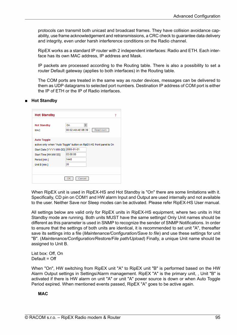
protocols can transmit both unicast and broadcast frames. They have collision avoidance cap-ability, use frame acknowledgement and retransmissions, a CRC check to guarantee data deliveryand integrity, even under harsh interference conditions on the Radio channel.
RipEX works as a standard IP router with 2 independent interfaces: Radio and ETH. Each inter-face has its own MAC address, IP address and Mask.
IP packets are processed according to the Routing table. There is also a possibility to set arouter Default gateway (applies to both interfaces) in the Routing table.
The COM ports are treated in the same way as router devices, messages can be delivered tothem as UDP datagrams to selected port numbers. Destination IP address of COM port is eitherthe IP of ETH or the IP of Radio interfaces.
Hot Standby
When RipEX unit is used in RipEX-HS and Hot Standby is "On" there are some limitations with it.Specifically, CD pin on COM1 and HW alarm Input and Output are used internally and not availableto the user. Neither Save nor Sleep modes can be activated. Please refer RipEX-HS User manual.
All settings below are valid only for RipEX units in RipEX-HS equipment, where two units in HotStandby mode are running. Both units MUST have the same settings! Only Unit names should bedifferent as this parameter is used in SNMP to recognize the sender of SNMP Notifications. In orderto ensure that the settings of both units are identical, it is recommended to set unit "A", thereaftersave its settings into a file (Maintenance/Configuration/Save to file) and use these settings for unit"B". (Maintenance/Configuration/Restore/File path/Upload) Finally, a unique Unit name should beassigned to Unit B.
List box: Off, OnDefault = Off
When "On", HW switching from RipEX unit "A" to RipEX unit "B" is performed based on the HWAlarm Output settings in Settings/Alarm management. RipEX "A" is the primary unit, , Unit "B" isactivated if there is HW alarm on unit "A" or unit "A" power source is down or when Auto TogglePeriod expired. When mentioned events passed, RipEX "A" goes to be active again.
MAC
95© RACOM s.r.o. – RipEX Radio modem & Router
Advanced Configuration

Both units in RipEX-HS are using the same MAC addresses (MAC cloning). Whichever unit isactive (either "A" or "B"), RipEX Ethernet interface will use this MAC address. This MAC addresshas to be unconditionally set to the same value in both units used in RipEX-HS. Otherwise, theswitching between units will not function properly.
Read own – it is possible to download the MAC address of this unit. The value in the secondunit has to be manually set to the same value then
Auto Toggle modeWhen Auto Toggle mode is On (HW button on front panel), controller automatically switches-over to RipEX "B", even if "A" doesn't have any alarm and uses "B" for a set time in order toconfirm that RipEX "B" is fully ready-to-operate.
Start Date [YYYY-MM-DD]Fill in the Date in the required format when Auto Toggle mode starts.
Start Time [HH:MM:SS]Fill in the Time in the required format when Auto Toggle mode starts on "Start Date" day.
Period [min.]Minimum value 60 min.Within this period units "A" and "B" will change their activities over. Unit "A" starts to operateat "Start Date and Time". When "Period" minus "Unit B" time expires, controller switches tounit "B".
Unit B [min.]Minimum value 5 min.Time when unit "B" will be active within "Period". It has to be shorter than Period by 5 min.
Time
RipEX Radio modem & Router – © RACOM s.r.o.96
Advanced Configuration

List box: Manual, NTPDefault = Manual
Internal calendar time of RipEX can be set manually or synchronized via NTP (Network Time Pro-tocol).
Manual
RipEX internally uses the Unix epoch time (or Unix time or POSIX time) - the number of secondsthat have elapsed since January 1, 1970. When RipEX calendar time is set, the Unix epoch timeis calculated based on filled in values (Date, Time) and the time zone, which is set in operatingsystem (computer), where the browser runs.
Current Date&TimeInformation about the actual date and time in the RipEX
Date [YYYY-MM-DD]Fill in Local Date in required format
Time [HH:MM:SS]Fill in Local Time in required format
RipEX Time zoneSelect RIPEX Time zone from list box.Default = (GMT +1:00) Central EuropeThis time zone is used for conversion of internal Unix epoch time to 'human readabledate&time' in RipEX logs.
Daylight savingList box: On, OffDefault = OnIf On, Daylight saving is activated according the respective rules for selected RipEX Timezone.
NTP
Internal calendar time in RipEX is synchronized via NTP and RipEX also acts as a standardNTP server simultaneously.
Current Date&TimeInformation about the actual date and time in RipEX
Time sourceList box: NTP server, Internal GPSDefault = NTP server
NTP server – The source of time is a standard NTP server. This server can be connectedeither via the Ethernet interface or over the Radio channel (any RipEX runs automaticallyas a NTP server).Internal GPS – The source of time is the internal GPS. In this case only RipEX Timezone and Daylight saving parameters below are active.
Source IPDefault = emptyIP address of the NTP server, which provides Time source. Date and Time will be requestedby RipEX from there. More NTP servers can be configured, the more servers, the better time
97© RACOM s.r.o. – RipEX Radio modem & Router
Advanced Configuration

accuracy. If the Time source is a RipEX over Radio channel, only one source server is re-commended, since the Radio channel could be overloaded.
Minimum polling intervalList box: 1min to 2h 17minRipEX polls the source server in order to synchronize itself in the set period or later.
RipEX Time zoneSelect RipEX Time zone from list box.Default = (GMT +1:00) Central EuropeThis time zone is used for conversion of internal Unix epoch time to "human readabledate&time" in RipEX logs..
Daylight savingList box: On, OffDefault = OnIf On, Daylight saving is activated according the respective rules for selected RipEX Timezone.
RipEX NTP server
Information about the status of internal NTP server in the RipEX
Statenot synced - not synchronizedsynced to GPS - synchronized to internal GPSsynced to NTP - synchronized to NTP server
Stratum1 to 16 (1=the best, 16=the worst, 8=when internal time in RipEX is set manually)The stratum represents the quality and accuracy of time, which the NTP server provides.
Delay [ms] This is the delay of packet (1/2 round trip time), which RipEX received from theNTP server while asked for synchronization. This delay is compensated in the RipEX NTPserver.
Jitter [ms]The Jitter of received times when RipEX asked for time synchronization from NTP server(s).
RipEX Radio modem & Router – © RACOM s.r.o.98
Advanced Configuration

SNMP
You can read more about SNMP in RipEX (MIB table description incl.) in RipEX application note"SNMP"1.
List box: Off, v1/v2c/v3, v3 onlyDefault = Off
When enabled, RipEX works as a standard SNMP agent, i.e. it responds to "SNMP GET Request"packets received from even several SNMP managers on any of its IP addresses. It transmits SNMPTraps or SNMP Informs as per its configuration (Settings/Device/Alarm management or Rout-ing/Backup).
The "v3 only" option can be enabled if the higher security is required.
SNMP v1/v2c
Community nameDefault = publicThis string is used for authentication with SNMP manager. Max. length is 32 chars. Followingcharacters are not allowed:
" (Double quote)` (Grave accent)\ (Backslash)$ (Dollar symbol)
1 http://www.racom.eu/eng/products/m/ripex/app/snmp/index.html
99© RACOM s.r.o. – RipEX Radio modem & Router
Advanced Configuration

; (Semicolon)(Space)
When there is not any char. filled, default value (public) is used.
SNMP v3
Security User nameThis User name is used for authentication with SNMP manager. Max. length is 32 chars.Following characters are not allowed:
" (Double quote)` (Grave accent)\ (Backslash)$ (Dollar symbol); (Semicolon)(Space)
Security levelList box: NoAuthNoPriv, AuthNoPriv, AuthPrivDefault = NoAuthNoPrivRequired SNMP communication security level:• NoAuthNoPriv - Communication without authentication and privacy.• AuthNoPriv - Communication with authentication and without privacy. The "Authentication"
parameter defines algorithm used for Authentication.• AuthPriv - Communication with authentication and privacy - encryption. The "Encryption"
parameter defines algorithms used for encryption to assure the data privacy.
AuthenticationList box: MD5, SHADefault = MD5The algorithm used for Authentication.
Auth. passphraseThe authentication passphrase is entered as a password. Max. length is 128 characters.Empty password is not allowed.Following characters are not allowed:
" (Double quote)` (Grave accent)\ (Backslash)$ (Dollar symbol); (Semicolon)(Space)
EncryptionList box: AES, DESDefault = DESThe algorithm used to encrypt the data.
Encr. passphraseThe encryption passphrase is entered as a password. Max. length is 128 characters. Emptypassword is not allowed.Following characters are not allowed:
" (Double quote)` (Grave accent)
RipEX Radio modem & Router – © RACOM s.r.o.100
Advanced Configuration

\ (Backslash)$ (Dollar symbol); (Semicolon)(Space)
SNMP NotificationList box: Off, Trap, InformDefault = Off
The SNMP Notification can be activated. The SNMP Trap or SNMP Inform can be used tonotify the remote management station(s) of unit alarms. The unit alarms are generated ac-cording to the settings in Alarm management (Settings/Device/Alarm management or Rout-ing/Backup). The SNMP Notification (Trap or Inform) is sent both when a parameter valueexceeds the alarm threshold and when it returns back within its 'normal' range. TheTrap/Inform OID is the same, the information whether it is alarm activation or deactivation isgiven in the Trap/Inform data.
SNMP Trap - notification from the unit to the managementSNMP Inform - acknowledged notification from the unit to the management
Notification destination 1IP address and Port where SNMP Notification (Trap or Inform) messages are sent. DefaultPort is 162, however it can be changed. IP 0.0.0.0 means, that SNMP Trap or Inform isnot sent.
Notification destination 2, 3SNMP Notification (Trap or Inform) messages can be sent simultaneously up to threedifferent destinations.
Inform repeatsDefault: 3SNMP Inform message is repeated multiple times until it is acknowledged or maximumnumber of repeats is reached.See "Inform timeout" description for further information.
Inform timeout [s]Default = 10 sec. Range 0.1-20 [sec]The SNMP Inform message is repeated when not acknowledged during "Inform timeout"period and when the number of "Inform repeats" has not been reached.The "Inform repeats" and "Inform timeout" must be set in accordance with the real networklatency between unit and management station. The unacknowledged SNMP Inform consumessystem resources - for that reason the maximum number of concurrent unacknowledgedSNMP Inform messages is 16 (for each "Notification destination").
101© RACOM s.r.o. – RipEX Radio modem & Router
Advanced Configuration

Firewall
IP (L3)
List box: Off, OnNOTE: The L3 Firewall may be activated in both the Router and Bridge modes.Default = Off
If "On", a standard Layer 3 Linux firewall is activated.Port – a range of port numbers can be entered. E.g. 2000-2120.Connection state – state-firewall active only for TCP protocol.New – relates to the first packet when a TCP connection starts (Request from TCP client toTCP server for opening a new TCP connection). Used e.g. for allowing to open TCP onlyfrom RipEX network to outside.Established – relates to an already existing TCP connection. Used e.g. for allowing to getreplies for TCP connections created from RipEX network to outside.Related – a connection related to the "Established" one. e.g. FTP typically uses 2 TCPconnections – control and data - where data connection is created automatically using dy-namic ports.
NOTE 1:L2/L3 firewall settings do not impact the local ETH access, i.e. the settings never deny accessto a locally connected RipEX (web interface, ping, ...).
NOTE 2:Ports 443 and 8889 are used internally for service access. Exercise caution when making ruleswhich may affect datagrams to/from these ports in L3 Firewall settings. Management connectionto a remote RipEX may be lost when another RipEX acts as a router along the managementpackets route and port 443 (or 8889) is disabled in firewall settings of that routing RipEX (RipEXuses iptables "forward"). When this happens, you have to use the Reset button on the bottomside of the misconfigured RipEX (keep it pressed for 15 sec.) in order to set Default access. It
RipEX Radio modem & Router – © RACOM s.r.o.102
Advanced Configuration

restores the default Ethernet IP, default password, sets the L3 Firewall to Off, sets ARPproxy&VLAN settings to Off and Ethernet speed to Auto.
NOTE 3:L3 Firewall settings do not impact packets received and redirected from/to Radio channel. Theproblem described in NOTE 2 will not happen when the affected RipEX router is a radio repeater,i.e. when it uses solely the radio channel for both the input and output.
MAC (L2)
List box: Off, OnDefault = Off
If "On" and when in the Router mode, simplified Layer 2 Linux firewall is activated:Filter modeList box: Blacklist, WhitelistDefault = Blacklist
BlacklistThe MAC addresses listed in the table are blocked, i.e. all packets to/from them are dis-carded. The traffic to/from other MAC addresses is allowed.WhitelistOnly the MAC addresses listed in the table are allowed, i.e. only packets to/from themare allowed. The traffic to/from other MAC addresses is blocked.
If "On" and when in the Bridge mode, a standard Layer 2 Linux firewall is activated.ProtocolList box: possible valuesDefault = All
All – Ethertype is not checked, i.e. no packets are selected by the filter. addresses is al-lowed.Manual – set 2 octets of Ethertype (in Ethernet frame) which are selected by the filter.Not VLAN – only frames which are not embedded in VLAN are selected by the filter.All VLAN – only VLAN frames are selected by the filter.IPv4 – only IPv4 frames are selected by the filter.IPv6 – only IPv6 frames are selected by the filter.ARP – only ARP frames are selected by the filter.LENGTH – only Ethernet frames from obsolete IEEE 802.3 Ethernet are selected by thefilter.
VLANDefault = NoneThis VLAN filter supersedes settings in Protocol. Frames with this ID of the 1st level VLANwill be selected by the filter.
NOTE: When VLAN field is set, all settings in Protocol are applied to frame embedded inVLAN (Ethertype of the 2nd level).
103© RACOM s.r.o. – RipEX Radio modem & Router
Advanced Configuration

Network Address and Port Translation
NAT Basic Description
Network address translation, or its extended version Network Address and Port Translation(NAPT) is a technique in which port numbers and private Internet Protocol (IP) addressesare mapped from multiple internal hosts to one public IP address.
• Source NAT (SNAT) changes the source address and/or port of the outgoing connection.The returning packets are modified in the opposite way.
Example:UDP SNAT to: 192.168.169.169:6667(Source IP addr: source port / destination IP addr. : destination port)Outgoing packet: 192.168.1.1:1024 / 192.168.169.250:8000after SNAT: 192.168.169.169:6667/ 192.168.169.250:8000Returning packet: 192.168.169.250:8000/ 192.168.169.169:6667after modification: 192.168.169.250:8000/ 192.168.1.1:1024
Source NAT is performed on packets leaving the device. It takes place after routing andfiltering in the firewall.
• Destination NAT (DNAT) changes the destination address and/or port of the incomingconnection. The returning packets are modified in the opposite way.
Example:UDP DNAT to: 192.168.169.250:8000Incoming packet: 192.168.1.1:1024 / 192.168.1.2:18000after DNAT: 192.168.1.1:1024 / 192.168.169.250:8000Returning packet: 192.168.169.250:8000/ 192.168.1.1:1024after modification: 192.168.1.2:18000 / 192.168.1.1:1024
Destination NAT is performed on packets entering the device. It takes place before routingand filtering in the firewall.
Configuration
NATList box: Off, OnDefault = OffEnabling/disabling modification of incoming and/or outgoing connections according toNAT rules.
Source NATSource NAT rules. The source packet IP address and/or Port is modified as a result ofthis function. The rules order is important - rules are actioned sequentially
• Prot.List box: All, ICMP, UDP, TCP, GRE, ESPDefault: AllIP Protocol to be affected by this rule.
• Source
RipEX Radio modem & Router – © RACOM s.r.o.104
Advanced Configuration

This group of parameters defines rules based on the original packet source.
• IPDefault = 0.0.0.0/0The original source of connections affected by the rule - defined by source IP addressand length of a compared prefix.
• MASKDefault = 0 [0 = all ports, 65535 = Max]The original source of connections affected by the rule - defined by source IP addressmask.
• PortDefault = 0 [0 = no modification, 65535 = Max]Source port. The Port rule is valid only for TCP and UDP Protocols.
• DestinationThis group of parameters defines rules based on the original packet destination.All the parameters - IP, Mask and Port - have similar meanings to the Source para-meters.
• Output interfaceList box: All, Radio, ETHDefault = AllInterface used by the connection to leave the unit.
• Rewrite source toThis group of parameters describes how to modify the connection source.
• IPDefault = 0.0.0.0New source IP address. It is not modified if set to "0.0.0.0".
• PortDefault = 0 [0 = no modification, 65535 = Max]New source port. The Port rule is only valid for TCP and UDP Protocols.
• ActiveYou may tick/un-tick each rule in order to make it active/not active.
• NoteYou may add a note to each rule with comments up to 16 characters in length (UTF8is supported) for your convenience.Characters not allowed:
" (Double quote)` (Grave accent)\ (Backslash)$ (Dollar symbol); (Semicolon)
NOTE: An Active rule with no Rewrite source to parameters assigned (both IP andPort in default value: 0.0.0.0 and 0) is not allowed.
105© RACOM s.r.o. – RipEX Radio modem & Router
Advanced Configuration

Destination NATDestination NAT rules. The packet destination IP address and/or Port is modified as aresult of this function. The rules order is important - rules are actioned sequentially.The Prot., Source, Destination, Active and Note parameters have the same meaningas in Source NAT.
• Input interfaceList box: All, Radio, ETHDefault = AllInterface used by the connection to enter the unit
• Rewrite destination toThis group of parameters describes how to modify the connection destination.
• IPDefault = 0.0.0.0New destination IP address. It is not modified if set to "0.0.0.0".
• PortDefault = 0 [0 = no modification, 65535 = Max]New destination port. The Port rule is only valid for TCP and UDP Protocols.
NOTE: An Active rule with no Rewrite destination to parameters assigned (both IPand Port in default value: 0.0.0.0 and 0) is not allowed.
WARNING: NAT configuration changes require station restart. The restart is initiatedautomatically when parameters are applied.
NAT diagnostics
Monitoring• SNAT rules are applied before the packet leaves the RipEX interface.• DNAT rules are applied after the packet has left the interface it arrived through.
Monitoring is processed inside the interface: SNAT will be monitored (SNAT rules wereapplied prior to monitoring) and DNAT will not be monitored (monitoring takes place priorto DNAT rules being applied).
NAT in relation to other RipEX services
GREUnder normal circumstances the GRE is only limited for use with the primary ETH addressor Radio address as the Peer address. Using the SNAT, the source address of the out-going GRE packet can be modified. This makes it possible to use any IP address as theGRE Peer address.Such a configuration can be used when combining GRE with Backup routes when oneof the alternative backup paths is routed over the GRE. Backup routes use the primaryETH address together with its specific routing rule. This prevents GRE from using thisaddress. The SNAT can solve such situations as described here.
TCP ProxySource NAT rules. The source packet IP address and/or Port is modified as a result ofthis function. The rules order is important - rules are actioned sequentially• TCP Proxy captures the TCP packets prior to DNAT rules being applied.
RipEX Radio modem & Router – © RACOM s.r.o.106
Advanced Configuration

• SNAT does not work correctly with TCP Proxy unpacked packets.
IPsec• DNAT rules can be used prior to packets entering the IPsec• SNAT rules can be used after packets leaving the IPsec• SNAT rules can be used before packets enter the IPsec (Output interface has to be
set to "All")
107© RACOM s.r.o. – RipEX Radio modem & Router
Advanced Configuration

Alarm management
The average values of parameters listed in the table (Watched values) are continuously monitored.When any of them exceeds the respective threshold, the selected action(s) is(are) invoked.
The Hot Standby unit RipEX-HS uses the Alarm management for switching between unit A and Bby means of signals of HW Alarm Output and HW Alarm Input. The Alarm Management Menu isslightly different (see description below).
Note
At least 10 values have to be calculated into average before it is checked for the possiblealarm. Since different values are sampled over different time periods, a range of resultsover time is required to obtain correct values:
Ucc, Temp – approx. 10 sec. after bootingPWR, VSWR - approx. 10 sec. after booting and after the first transmissionOthers – approx. 200 sec. of respective communication
ThresholdList box: Default, ManualDefault = Default• Default – Default (recommended) values are set and can not be edited.• Manual – Thresholds can be set manually. However, there are individual min. and max.
threshold values for each item. When your settings are beyond these thresholds, the webinterface will give you a warning and display the possible values.
RipEX Radio modem & Router – © RACOM s.r.o.108
Advanced Configuration

HW Alarm Output(not available for Hot Standby)List box: Off, N.O. (Normally Open), N.C. (Normally Closed)Default = Off• If "N.O." or "N.C.", the HW Alarm Output is active and its normal status (no alarm) is open
or closed, respectively.• The HW Alarm Output is a pin (open n-p-n collector) on the screw terminal at the Power and
Control connector on the front panel.
Type
Alarms are generated according to actual value of the following variables:
RSScomMax value shall be set to the network design RSS value plus a fade margin (e.g. 80+20 dBm),Min value can be 0 - stronger signals will typically not cause problems.
DQcomMore significant communication troubles start with values less than 100; all values above 100should be sufficient.
RSScom and DQcomtogether will indicate even partial damage or problems with the RipEX unit receiver parts orcoaxial feedline cable or antenna. Equally, the problem could be on the transmitter part of RipEXunit, coaxial feedline cable or antenna of transmitter counterpart(s).
TXLostthe value will indicate problems with packet deliveries to communicating parties. It is a percentageof lost packets on the Radio channel (acknowledge has not been received). Applicable only inRouter mode. Exercise caution when setting this alarm. Keep in mind, that problems on counter-part unit(s) can also be reflected here. E.g. counterpart doesn’t receive packets or doesn’ttransmit acknowledge.Min value shall be set to 0, Max value to tens of % (e.g. 50).
Uccactual value of the input power voltage of RipEX unit.
Hot Standby - since power supply for RipEX units is controlled independently, this alarm isnot recommended for switch-over to Standby unit. However, it can be used when an SNMPNotification informs about main power failure and switch to battery back-up. Min value shallbe set to lower than 24.5, Max value to the maximum voltage limit for charging the battery(e.g. 29).
TempInternal temperature of RipEX unit.
Hot Standby – the temperature of both RipEX units inside of RipEX-HS are likely to be thesame, so it doesn’t make any sense to use this alarm for switch-over. However, this alarmcan be used in case of hard duty cycle for switching between both units; Max value in sucha case should be set to approximately 65.
PWRThis value shall be set to a value of power with a margin of ±25-30%. Alarm will be active incase of faulty transmitter part on the active RipEX.
109© RACOM s.r.o. – RipEX Radio modem & Router
Advanced Configuration

VSWRVoltage Standing Wave Ratio measured on the antenna connector.
Hot Standby - this value mainly indicates problems with antenna or antenna coaxial feed linecable. When RipEX-HS-xO (one antenna switched for A and B units), a switch-over to unitB will probably not help. Recommended values vary between 1 and 3.
ETH [Rx/Tx]COM1 [Rx/Tx] COM2 [Rx/Tx]These three values represent the No of received/transmitted packets on respective interfaces.They are mainly applicable for a polling type applications network. Each communication hasone request and one reply ;the number of Rx and Tx packets should then be the same (Rx/Tx=1).These alarms should not be used for report by exception networks.
HW Alarm Input(not available for Hot Standby)List box: Off, N.O. (Normally Open), N.C. (Normally Closed) Default = OffIf "N.O." or "N.C.", the HW Alarm Input is active and its normal status (no alarm) is open orclosed, respectively.An Alarm event is triggered when the HW Alarm Input changes its status from "Normal" to"Alarm". Note that to "Close" the HW Alarm Input means connecting the respective screw ter-minal at the Power and Control connector on the front panel to the Ground terminal of the sameconnector.
Hot Standby - uses the HW Alarm Input for switching between unit A and B.
HS active(available only for Hot Standby)Switching between unit A and B shall be indicated by SNMP or in a Graph.
Unit ready(not available for Hot Standby)List box: Off, OnDefault = OffWhen “On”, the Hardware Alarm Output indicates the full functionality of the RipEX. The HardwareAlarm Output is only inactive when the RipEX is not powered or it is booting. When SNMP Trapand/or Detail Graphs are ticked in the Unit ready line, the respective action is taken after everyHardware Alarm Output state change (and also when the Apply button is activated after a recon-figuration). The “On” setting of this parameter disables any other assignment to the HardwareAlarm Output.
Hot Standby - the "Unit ready" parameter cannot be activated in Hot Standby mode, sincethe Hardware Alarm Output controls the Hot Standby switch.
RipEX Radio modem & Router – © RACOM s.r.o.110
Advanced Configuration

Above mentioned variables
should be individually defined thresholds and commands which will be executed in case of a deflectionfrom the thresholds:
Threshold Min MaxWhen the value of a parameter goes under Min or over Max, the command within the ticked boxwill be executed.
SNMP NotificationWhen ticked, the SNMP Notification message is sent when a parameter value exceeds the alarmthreshold and again when it returns back within its 'normal' range. Remember to set the IPdestination address(es) and port(s) for SNMP Notification messages in Settings/Device/SNMP.
When even one SNMP Notification tick box is reconfigured in Alarm table, all SNMP Notificationsfor active alarms (out of thresholds) are re-sent with exception of the HW alarm input.
After reboot all SNMP Notifications for active alarms (out of thresholds) are re-sent, HW alarminput (HS active when Hot Standby is "On") included.
When Statistic and Neighbours logs are cleared, RSScom, DQcom, ETH, COM1, COM2 alarmsare cleared as well (e.g. the continual records will be cleared and the alarms will start from zero).
Hot Standby - when it is "On", Alarm thresholds and HW alarm input are used internally forswitching between unit A and B. The "HW alarm input" parameter is changed to "Hot Standbyactive". Also, HW alarm output for Temperature is always On. Its thresholds can be Manuallyset in the interval of -50 to +90 °C (default -25 to +85 °C).
SNMP Alarm and Detailed Graphs tick boxes can be used for information about switchingbetween unit A and B.
HW Alarm OutputThe value is switched to On / Off (according to setting of parameter) when the Alarm status occurs.
Hot Standby – the ticked parameters will cause switching between unit A and B whenthresholds infringed.
Detail Graphs startIt has to be activated in Settings/Device/Graphs first.When threshold of a ticked parameter is infringed the 20 previous and the following 40 pointsof all active graphs are saved into graph database, items for RSScom a DQcom will be executedfor "Logged Neighbours IPs" written in menu Device/Graphs.
111© RACOM s.r.o. – RipEX Radio modem & Router
Advanced Configuration

Power management
Power supply modeList box: Always On, Save Mode, Sleep ModeDefault = Always On
Always OnRipEX is always on, no special power saving modes are active.
Save ModeWhen a RipEX is switched to the SAVE mode, it can be in one of two states – the SAVEstate or the ACTIVE state. In the SAVE state, the RipEX functionality is limited to listeningto the Radio channel in order to minimize the power consumption (approx. 2W). In theACTIVE state, the RipEX works normally, providing its full functionality (and consumingnormal amounts of power).Transitions between these states can be controlled by changes at the SI pin on the Powerand Control connector, by receiving packets on the Radio channel and by values of the SAVEmode configurable parameters.The transition from the SAVE to the ACTIVE state requires system boot and takes approxim-ately 48 sec. The transition from the ACTIVE to the SAVE state takes about 4 seconds.
SI hardware input (available from fw ver. 1.4.x.x)When in the SAVE state, the RipEX wakes up (starts the transition to the ACTIVE state) aftera rising edge is registered at the SI hardware input (after the respective pin connection tothe ground has been opened). If a pulse is sent to the SI input (i.e. the falling edge followsthe rising edge), it has to be longer than 50 msec.When in the ACTIVE state, the transition to the SAVE state starts when a falling edge is re-gistered at the SI hardware input (the respective pin has been connected to the ground). Thefalling edge triggers the transition only if the SI hardware input has been in the "high" state(opened) for 2 seconds at least during the ACTIVE state of the RipEX. Following the fallingedge, the SI input has to stay in the "low" state (closed) at least for another 2 seconds.
Radio channelRipEX is listening on Radio channel in the Save mode while consuming 2 W. It is woken upwhen a packet is received over the Radio channel. However data from this first receivedpacket is lost.
Bridge mode: Any packet received on Radio channel wakes the unit up.
RipEX Radio modem & Router – © RACOM s.r.o.112
Advanced Configuration

Router mode: RipEX is woken up when it receives a packet for its IP address. As "its IP" isconsidered any IP address configured in this RipEX (Radio, ETH, ETH Subnet, SLIP.) orany IP address routed through this RipEX. I.e. RipEX is woken up not only with packetswhich end in it, but also with packets which end in the connected device behind RipEX orwhich are relayed over the Radio channel (when this RipEX is configured as the Repeaterfor them).When an unexpected reboot happens while in the ACTIVE state, the RipEX enters theACTIVE state again and the "Timeout from wake-up" is reset. When a reboot happens whilein the SAVE state, the RipEX enters the SAVE state immediately after the reboot.When one of the configurable parameters is changed while the RipEX is in the ACTIVE state,the "Timeout from wake-up" is reset.
Timeout from wake-up [s]Default = 300 (min. 60, max. 64800)
RipEX stays ACTIVE for the set time from the moment of its wake-up. When this timeoutexpires, the RipEX switches back to the SAVE state.NOTE: It is possible to put RipEX into SAVE state anytime using the respective CLIcommand.
Reset timeout on received packetsList box: On, OffDefault = Off
If "On", the "Timeout from wake-up" is reset whenever a packet is received or transmittedover the Radio channel channel by the RipEX in the ACTIVE state. Consequently theRipEX stays in the ACTIVE state as long as it communicates over the Radio channelchannel.NOTE:HW wake-upWith any fw version higher than or equal to 1.2.1.0 you can take a RipEX in Save state,cycle the power and during the boot-up (approx. 48 sec.) the LED Status starts to flashquickly in green for approx. 10 sec. When Reset button is pressed for approx. 1 sec.during that period of quick blinking, the Power supply mode is set to Always On and theunit can be accessed in the usual way (Ethernet or "X5" USB/ETH adapter)
Sleep ModeSleep Mode is controlled via the digital input on Power and Control connector. When therespective pin (SI) is grounded, RipEX goes to sleep and consumes only 0,07 W. The timeneeded for a complete wake-up from the Sleep mode is approx. 48 seconds (booting time).
Timeout from sleep request [s]Default = 10RipEX remains On for the set time from the moment when the sleep input pin has beengrounded. When SI pin on Power and Control connector is not-grounded for 1 sec. (ormore) during this Timeout, the timeout is reset and starts again.
Note
Save and Sleep modes are not available with the following configurations:When Hot Standby is "On"•
• When Base driven protocol is used and Station type is "Base"
113© RACOM s.r.o. – RipEX Radio modem & Router
Advanced Configuration

Wifi
List box: Off, OnDefault = On
When "On", RipEX management can be executed over WiFi using the W1 - WIFI/USB adapter fromRipEX accessories. This equipment must be plugged into RipEX USB interface. You just switch onWiFi in your device (notebook, tablet, smartphone…) and connect it to the RipEX WiFi network.Your device will get its IP settings from the RipEX built-in DHCP server. Then type https://10.9.8.7in your browser address line and you will be connected to RipEX web pages.NOTE:DHCP in the W1 - WIFI/USB adapter provides max. 5 leases, so up to 5 devices can be connectedto one RipEX via WiFi.
ParametersList box: Default, Manual,Default = Default
Default – Default (recommended) values are set and can not be edited.Manual – Values can be set manually.
SSIDDefault = RipEX + Unit name + S/NAn SSID (Service Set IDentifier) is a unique ID that consists of max. 32 characters and isused for naming wireless networks. When multiple wireless networks overlap in a certainlocation, SSIDs make sure that data gets sent to the correct destination. If empty, defaultvalue is filled.
IEEE standardThere are different standards used for WiFi networks. RipEX supports some of them.List box: possible valuesDefault = 802.11g
802.11g2.4 GHz frequency band, data speed up to 54 Mbps802.11n802.11n is an advanced IEEE standard in the 2,4 GHz WiFi band. It was designed toimprove on 802.11g in the amount of bandwidth (100 Mbps) supported by utilizing multiplewireless signals and antennas.
RipEX Radio modem & Router – © RACOM s.r.o.114
Advanced Configuration

ChannelYour WiFi can work on different channels within 2,4 GHz band. When the selected channelis noisy, i.e. your WiFi connection is not stable, you can try another one.List box: possible valuesDefault = 1
SecurityList box: possible valuesDefault = Off
OffIf "Off", WiFi is without any security, i.e. anybody can be connected and access yourRipEX web pages.WPA2-PSKA Short for Wi-Fi Protected Access 2 - Pre-Shared Key. It is a method of securing yournetwork using WPA2 with the use of Pre-Shared Key (PSK) authentication. To encrypta network with WPA2-PSK you provide your router not with an encryption key, but ratherwith a plain-English passphrase between 13 and 64 characters long. Using a technologycalled TKIP (for Temporal Key Integrity Protocol), that passphrase, along with the networkSSID, is used to generate unique encryption keys for each wireless client. And thoseencryption keys are constantly changed.
WPA2 PSK Key - The string (13-64 characters) which is used for WPA2 encryptionkey generating.The following characters are not allowed in the key:" (Double quote)` (Grave accent)\ (Backslash)$ (Dollar symbol); (Semicolon)
Note
The WiFi connection needs to be reconnected when:Unit restart occurs•
• The menu Settings/Device/WiFi is changed• The item Settings/Device/Unit name is changed
115© RACOM s.r.o. – RipEX Radio modem & Router
Advanced Configuration

Neighbours&Statistics
ParametersList box: Default, ManualDefault = Default
DefaultDefault (recommended) values are set and can not be edited.
ManualValues can be set manually.
There are 2 tables with diagnostic information in the main menu - Diagnostic/Neighbours, Dia-gnostic/Statistic. The Neighbours table displays Watched values from RipEX and from all itsneighbours. (Neighbour = RipEX, which can be accessed directly over the radio channel, i.e.without a repeater). There is statistic information about the traffic volume in the Statistic table.
Watched values broadcasting period [min]Default = 120 min, [0 = Off]RipEX periodically broadcasts its Watched values to neighbouring units. The Watched valuescan be displayed in Graphs and Neighbours menu.NOTE 1:When Bridge mode is used, Watched values broadcasting creates collisions for user traffic.Be careful when using this feature.NOTE 2:When Router with Base driven Radio protocol is used:• Watched values from Remote stations are only transmitted to the Base station.• Watched values from the Base station are broadcast to all Remote stations.• Repeater station receives Watched values from the Base station and from all Remote
stations behind it.
Neighbours&Statistic log save period [min]Default = 1440 min (1 day) [10 - 7200 min]This is the period, in which Neighbours and Statistics logs are saved in the archive andcleared and new logs start from the beginning.
RipEX Radio modem & Router – © RACOM s.r.o.116
Advanced Configuration

Note
The history files are organized in a ring buffer. Whenever a new file is opened,the numbers of files are shifted, i.e. 0->1, 1->2, etc. There is a history of 20log files available.
•
• The Max value is 6.000.000 min. (more than 11 years) It used to be only 7.200min. up to the 1.3.x.x fw version.
117© RACOM s.r.o. – RipEX Radio modem & Router
Advanced Configuration

Graphs
ParametersList box: Default, ManualDefault = Default
Graphs displays history of Watched values and history of some of the items from the Statistic table.Displayed values are stored in each RipEX including data from selected five neighbouring units.Neighbour = RipEX, which can be accessed directly over the Radio channel (not over Ethernet),i.e. without a repeater. The graph data is stored in files, each file contains 60 samples of all values.The sampling period can be configured. There are two types of graphs- Overview and Detail.Overview graphs cover a continuous time interval back from the present, they use relatively longsampling period. Detail graph is supposed to be used in case of a special event, e.g. an alarm, andthe sampling period is much shorter.
Logged Neighbours' IPsDefault = 0.0.0.0Up to 5 IP addresses of neighbouring units can be set. (Neighbour = RipEX, which can be ac-cessed directly over the radio channel, i.e. without a repeater). Watched values from these unitsare stored in the graph files and can be displayed afterwards.
Overview graph sampling periodList box: 1, 2, 4, 12 hoursDefault = 12 hoursThe 60 samples per graph file result in (depending on the sampling period) 60, 120, 240 or 720hours in each file. There are 6 files available, so total history of saved values is 15, 30, 60 or180 days. The Overview graph files are organized in a ring buffer. Whenever a new file is opened,the oldest one is replaced.
Detail Graph sampling periodList box: 1, 5, 10, 20 minsDefault = 1 min
RipEX Radio modem & Router – © RACOM s.r.o.118
Advanced Configuration

The 60 samples per graph file result in 60, 300, 600, 1200 minutes in each file. There are 20files available. They are organized in a ring buffer. When a new file is opened, the one witholdest data is replaced. The Detail graph files may not cover a continuous segment of history.See Detail graph start for details.
Detail Graph startList box: No, Alarm, Single, ContinualDefault = NoDetail graph data sampling is started based on selected event from list box:No – Detail graph does not start.Alarm – if a tickbox in Detail graph column (Settings/Alarm management) is checked, then theDetail graph file is stored in case of that alarm. Twenty samples prior the alarm event and fortysamples after the alarm event are recorded. When another alarm occurs while a Detail graphfile is opened, the sampling continues normally and no other file is opened.Single – a single Detail graph file can be manually started. After Apply here, go to Diagnost-ic/Graph where a Start/Stop button is availableContinual – Detail graph files are periodically saved in the same way as Overview graph filesare.
119© RACOM s.r.o. – RipEX Radio modem & Router
Advanced Configuration

Management
ParametersList box: Default, ManualDefault = Default
DefaultDefault (recommended) values are set and can not be edited.
ManualValues can be set manually.
Web serverList box: HTTP+HTTPS, HTTPS, OffDefault = HTTP+HTTPSRequired protocol for configuration web page is set here. If "Off", configuration web pagesare inaccessible.For HTTPS either RACOM (default) or your own SSL certificate can be used.
HTTP PortDefault = 80Just for information, can not be changed.
HTTPS PortDefault = 443Just for information, can not be changed.
CLIList box: SSH, Off
RipEX Radio modem & Router – © RACOM s.r.o.120
Advanced Configuration

Default = SSHCommand Line Interface is accessible via the SSH protocol. If "Off", CLI is inaccessible. TheSSH keys are unique for each individual RipEX Serial number. The public key is downloadedin RipEX, for the private key kindly contact RACOM and provide the RipEX S/N.
SSH PortDefault = 22Just for information, can not be changed.
Physical securityList box: Off, OnDefault = OffWhen "On", external flash disc access is disabled (It is not possible to download or uploadthe configuration automatically). When the HW reset button is pressed, "Total purge" insteadof "Factory settings" is applied. The Total purge sets the very same settings as deliveredfrom the factory. For details see Section 7.7.2, “Configuration”.
Read-only Web AccountsThe two different levels of unit administration privileges are supported:
• admin user is not limited.• Read-only Web Accounts are limited to read only access. Only Status, Neighbours, Statistic
and Graphs screens are available.
Use the "Logout" link in the top right corner of the screen to logout the current user.
User nameUp to 10 different read-only users can be defined. Maximum length is 32 characters. Onlycharacters a-zA-Z0-9_ are allowed.
PasswordPassword length is at least 5 and maximum 32 characters long. Only characters a-zA-Z0-9.:_-are allowed.
121© RACOM s.r.o. – RipEX Radio modem & Router
Advanced Configuration
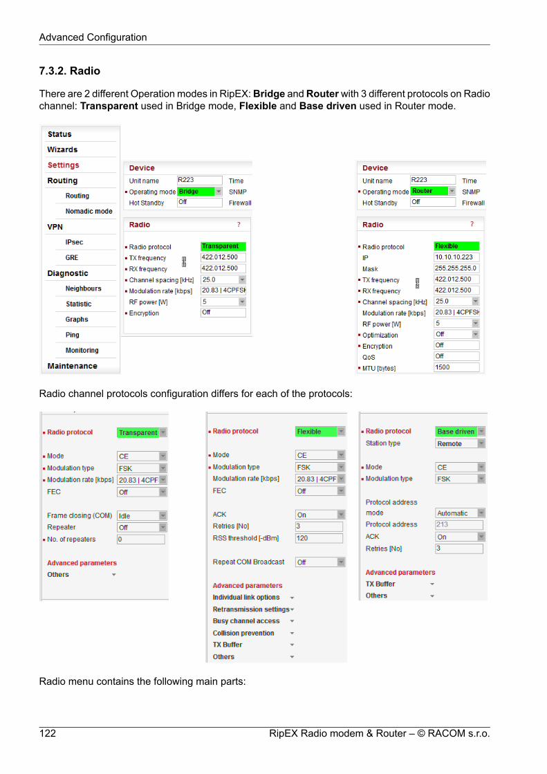
7.3.2. Radio
There are 2 different Operation modes in RipEX:Bridge andRouterwith 3 different protocols on Radiochannel: Transparent used in Bridge mode, Flexible and Base driven used in Router mode.
Radio channel protocols configuration differs for each of the protocols:
Radio menu contains the following main parts:
RipEX Radio modem & Router – © RACOM s.r.o.122
Advanced Configuration

Radio protocol protocol Transparent protocol Flexible protocol Base driven IP address, Mask, ... QoS
Radio protocol
Common Radio protocol parameters
The parameters described in this section are same for individual Radio protocols.There is only a link to them in description of the respective Radio protocol.
* These items are active only when in Router mode** These items have to be set in accordance with the license issued by the respective radioregulatory authority
Mode**RipEX allows multiple settings of modulation parameters for every channel spacing to enabledifferent regulations which apply in different countries to be met. Naturally different limits ontransmitted signal parameters result in different Modulation rates.The "Mode" menu conveniently groups the optimal settings for common internationally recog-nized standards. The detailed technical parameters for each setting can be found in theRipEX User manual.List box: possible valuesDefault = CE
CESettings optimized for ETSI standards and similar.
FCCSettings suitable for countries which follow the U.S. government group of standards.NOTE: CPFSK modulations have approx. 20% higher frequency deviation compared toCE, so the receiver sensitivity for the same modulation (data rate) is approx. 1-2 dB better.
NarrowSpecial settings for extra-restrictive regulations.NOTE: In the 25 kHz channel spacing, the RipEX transmitted signal 16kHz bandwidthcontains 99% of the total integrated power for transmitted spectrum according to ITU-RSM328 . This setting is required for 25 kHz channel spacing by authorities in Czech Re-public.
UnlimitedFull channel width used to achieve the maximum possible data rate.
Modulation typeList box: FSK, QAMDefault = FSK
FSK
123© RACOM s.r.o. – RipEX Radio modem & Router
Advanced Configuration

Suitable for difficult conditions - longer radio hops, non line of sight, noise / interferenceson Radio channel...NOTE: FSK belongs to the continuous-phase frequency-shift keying family of non-linearmodulations. It is possible to use higher RF output power (up to 10 watts) for these typesof modulation. Compared to QAM (linear modulations), FSK is characterized by narrowerbandwidth, a lower symbol rate and higher sensitivity. As a result, the system gain ishigher, power efficiency is higher, but spectral efficiency is lower.
QAMSuitable for normal conditions offering higher data throughput.NOTE: QAM belongs to the phase shift keying family of linear modulations. Comparedto FSK (non-linear modulations), QAM is characterized by wider bandwidth. RF outputpower is limited to max. 2 watts. The spectral efficiency is higher, power efficiency islower and system gain is typically lower.
Modulation rate [kbps]**List box: possible valuesPossible values in list box are dependent on the Modulation type setting. The two highestrates for 25 and 50 kHz channel spacing are available only when the corresponding SWfeature key is active (Either the 166/83 kbps key or the Master key).Higher Modulation rates provide higher data speeds but they also result in poorer receiversensitivity, i.e. reduced coverage range. Reliability of communication over a radio channelis always higher with lower Modulation rates.
FECList box: possible valuesDefault = OffFEC (Forward Error Correction) is a very effective method to minimize radio channelimpairments. Basically the sender inserts some redundant data into its messages. This re-dundancy allows the receiver to detect and correct errors. The improvement comes at theexpense of the user data rate. The lower the FEC ratio, the better the capability of errorcorrection and the lower the user data rate. The User data rate = Modulation rate x FEC ratio.
ACKList box: On, OffDefault = OnThis setting requires additional bandwidth to repeat corrupted frames.
OnEach frame transmitted on Radio channel from this RipEX has to be acknowledged bythe receiving RipEX, using the very short service packet (ACK), in order to indicate thatit has received the packet successfully. If ACK is not received, RipEX will retransmit thepacket according to its setting of Retries.NOTE: The acknowledgement/retransmission scheme is an embedded part of the Radioprotocol and works independently of any retries at higher protocol levels (e.g. TCP oruser application protocol)
OffThere is no requirement to receive ACK from the receiving RipEX. i.e. the packet istransmitted only once and it is not repeated.
Retries [No]Default = 3 [0=Off, 15=Max]
RipEX Radio modem & Router – © RACOM s.r.o.124
Advanced Configuration

When an acknowledge from the receiving RipEX is not received, the frame is retransmitted.The number of possible retries is specified.
Advanced parameters
TX BufferThe Radio protocol transmission buffer handles data waiting to be transmitted. Its size isdefined by both the number of records (Queue length) and total storage space (Queuesize) requirement. Records are held in a queue which is considered full, if either theQueue length or Queue size is reached. New incoming frames are not accepted whenthe queue is full.
Queue lengthDefault = 5 [1 - 31]Queue length dictates the maximum number of records held in the queue.
Queue size [kB]Default = 5 [1 - 48]Queue size dictates the total size of all records that can be held in the queue.
TX Buffer timeoutList box: Off, OnDefault = OffThe frames waiting for transmission in the Radio protocol output frame queue will bediscarded after the TX Buffer timeout expires. This parameter should be enabled fortypes of applications where sending old frames brings no benefit.When the frame is discarded the event is recorded, both in the statistics (as "Rejected")and in the monitoring (the respective frame is displayed with the "Tx buffer timeout"tag).
TX Buffer timeout [s]Default = 5 [0.01 – 150, Granularity 0.01s]Radio protocol transmit buffer timeout. The "TX Buffer timeout" must be enabled forthis parameter to be initiated.
Others
Radio ARP timeout [min]Default = 1440 [1=Min, 3579=Max]Each IP device refreshes its ARP records within some timeout. Because of that, thedevice transmits spontaneous ARP request packets to each IP address listed in itsARP table. That may generate unwanted collisions on Radio channel. Since RadioIP and MAC addresses are not changed during normal network operation, ARP tablerefreshing may be done in a long period (1440 min. = 1 day).The RipEX spontaneously transmits an ARP reply packet after each reboot. The ARPreply packet transmission can be also invoked by executing Maintenance/Miscel-laneous/BRC Radio MAC button.ARP reply packet refreshes the respective records in neighbouring units. This is ne-cessary e.g. when a RipEX unit has been replaced by a spare one with the sameRadio IP address.
125© RACOM s.r.o. – RipEX Radio modem & Router
Advanced Configuration
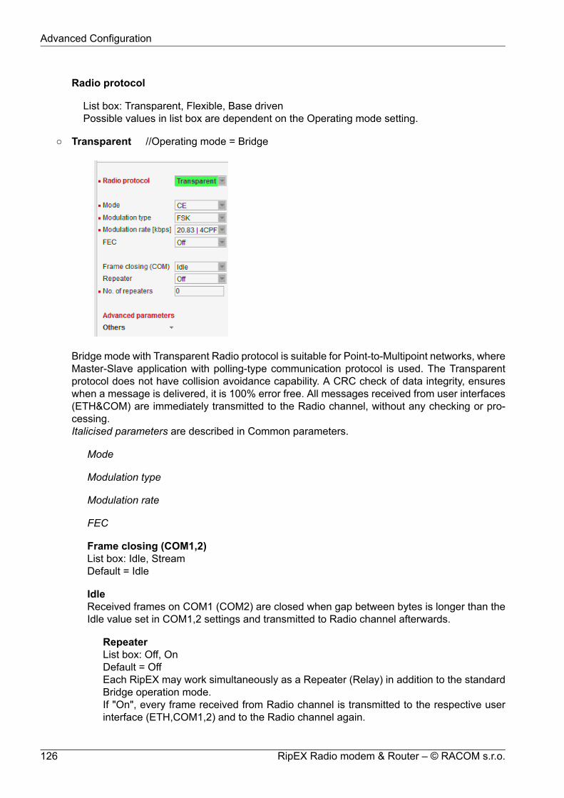
Radio protocol
List box: Transparent, Flexible, Base drivenPossible values in list box are dependent on the Operating mode setting.
Transparent //Operating mode = Bridge
Bridge mode with Transparent Radio protocol is suitable for Point-to-Multipoint networks, whereMaster-Slave application with polling-type communication protocol is used. The Transparentprotocol does not have collision avoidance capability. A CRC check of data integrity, ensureswhen a message is delivered, it is 100% error free. All messages received from user interfaces(ETH&COM) are immediately transmitted to the Radio channel, without any checking or pro-cessing.Italicised parameters are described in Common parameters.
Mode
Modulation type
Modulation rate
FEC
Frame closing (COM1,2)List box: Idle, StreamDefault = Idle
IdleReceived frames on COM1 (COM2) are closed when gap between bytes is longer than theIdle value set in COM1,2 settings and transmitted to Radio channel afterwards.
RepeaterList box: Off, OnDefault = OffEach RipEX may work simultaneously as a Repeater (Relay) in addition to the standardBridge operation mode.If "On", every frame received from Radio channel is transmitted to the respective userinterface (ETH,COM1,2) and to the Radio channel again.
RipEX Radio modem & Router – © RACOM s.r.o.126
Advanced Configuration

The Bridge functionality is not affected, i.e. only frames whose recipients belong to thelocal LAN are transmitted from the ETH interface.It is possible to use more than one Repeater within a network. To eliminate the risk ofcreating a loop, the "Number of repeaters" has to be set in all units in the network, includingthe Repeater units themselves.Warning: Should Repeater mode be enabled "Modulation rate" and "FEC" must be setto the same value throughout the whole network to prevent frame collisions occurring.
Number of repeatersDefault = 0If there is a repeater (or more of them) in the network, the total number of repeaterswithin the network MUST be set in all units in the network, including the Repeater unitsthemselves. After transmitting to or receiving from the Radio channel, further transmission(from this RipEX) is blocked for a period calculated to prevent collision with a frametransmitted by a Repeater. Furthermore, a copy of every frame transmitted to or receivedfrom the Radio channel is stored (for a period). Whenever a duplicate of a stored frameis received, it is discarded to avoid possible looping. These measures are not taken whenthe parameter "Number of repeaters" is zero, i.e. in a network without repeaters.
StreamIn this mode, the incoming bytes from a COM are immediately broadcast over the Radiochannel. COM port driver does not wait for the end of a frame. When the first byte is comingfrom a COM, the transmission in the Radio channel starts with the necessary frame header.If the next byte arrives before the end of transmission of the previous one, it is glued to itand the transmission on the Radio channel continues. If there is a gap between incomingbytes, the byte after the gap is treated as the first byte and the process starts again from thebeginning. Padding is never transmitted between block of bytes.The receiving RipEX transmits incoming bytes (block of bytes) from the Radio channel toboth COM ports immediately as they come.When the ETH interface is used simultaneously (e.g. for remote configuration), it works asthe standard bridge described above. ETH frames have higher priority, i.e. the stream fromCOM is interrupted by a frame from Ethernet.Stream mode is recommended to be used for time-critical application only, when the firstbyte has to be delivered as soon as possible. However there is not any data integrity control.If the Baud rate of COM is significantly lower than the Modulation rate on the Radio channel,frames are transmitted byte by byte. If it is higher, blocks of bytes are transmitted as framesover the Radio channel.NOTE: Stream mode can not be used when there is a Repeater in the network
Advanced parameters
Others
Radio ARP timeout [min]
TX Delay [bytes]Default = 0 [0=0ff, 1600=Max]Each packet is delayed before it is transmitted on Radio channel for time, which isequal to the time needed for transmition of the number of bytes set. This time dependson the set Modulation rate. E.g. if you want to delay all packets for time which equalsthe transmission time of a UDP packet with 150 user data bytes, you need to set 178bytes (20B IP header, 8B UDP leader, 150B user data).
127© RACOM s.r.o. – RipEX Radio modem & Router
Advanced Configuration

Flexible //Operating mode = Router
Router mode with Flexible protocol is suitable for Multipoint networks of all topologies with un-limited number of repeaters on the way, and all types of network traffic where Multi-master ap-plications and any combination of simultaneous polling and/or report-by-exception protocols canbe used.Each RipEX can access the Radio channel spontaneously using sophisticated algorithms toprevent collisions when transmitting to the Radio channel. Radio channel access is a proprietarycombination of CSMA and TDMA; the Radio channel is deemed to be free when there is nonoise, no interfering signals and no frames are being transmitted by other RipEX stations. Inthis situation a random selection of time slots follows and a frame is then transmitted on theRadio channel.Frame acknowledgement, retransmissions and CRC check, guarantee data delivery and integrityeven under harsh interference conditions on the Radio channelNOTE: The Flexible protocol was the only Radio protocol used in the RipEX with Router modefor fw ver. lower than 1.6.x.x (1.5.7.0).Italicised parameters are described in Common parameters.
Mode
Modulation type
Modulation rate
FEC
ACK
Retries
RSS threshold [-dBm]
RipEX Radio modem & Router – © RACOM s.r.o.128
Advanced Configuration

Default = 120RSS (Received Signal Strength) limit for access to Radio channel. RipEX does not starttransmitting when a frame is being received and the RSS is better than the set limit or whenthe destination MAC address of the frame is its own.
Repeat COM BroadcastList box: On, OffDefault = OffIf On, a broadcast originated on COM port (Protocol/Broadcast = On) in any remote unit andreceived by this unit on Radio channel is repeated to Radio channel.
Advanced parameters
Individual link optionsIt is possible to set certain Radio protocol parameters individually for a specific radio hop.The Radio hop is defined by a record in the table. General settings as above are usedfor radio hops, which are not defined in this table.
Counterpart Radio IPRadio IP address of RipEX on the opposite site of radio hop.
Modulation rate
FEC
ACK
Retries
NoteYou may add a note to each address with your comments up to 16 characters (UTF8is supported) for your convenience. (E.g. " Remote unit #1 " etc.). Following charactersare not allowed:" (Double quote)` (Grave accent)\ (Backslash)$ (Dollar symbol); (Semicolon)
ActiveYou may tick/un-tick each line in order to make it active/not active.
Retransmission settingsAn advanced user can modify the frame retransmission protocol parameters in this menuin order to optimize the network throughput under specific load. This menu is accessibleonly when parameter "ACK" is "On" and and "Retries [No]" is greater than zero.
The retransmission timeout is calculated as follows (see below for details):Rt = Ft + [0..Mv] * Vt + ProgWhere:Rt – Retransmission timeoutFt - time defined by the "Fix timeout [bytes]"Vt - time defined by the "Variable timeout [bytes]"Prog – zero when "Progressivity" is "Off"
129© RACOM s.r.o. – RipEX Radio modem & Router
Advanced Configuration

Mv – value "Max Variable [No]"[0..Mv] represents a random number from sequence 0 to Mv (limiting values included).
ProgressivityList box: Off, OnDefault = OffWhen On, the Prog value used in the formula above is calculated as follows:Prog = Ft * (Nr - 1)Ft – see aboveNr – the retransmission sequence number, e.g. Nr = 3 when the very same frame isto be retransmitted for the third time (Nr = 0 for the initial frame transmission)
Fix timeout [bytes]Default = 350 [10=Min, 10000=Max]This part of the retransmission timeout is always included (see the formula above).The actual time equals the time needed for transmition of the number of bytes set.This time depends on the set Modulation rate. E.g. when the Fix timeout should equalthe transmission of a UDP packet with 150 user data bytes, you need to set 178 bytes(20B IP header, 8B UDP leader, 150B user data).
Variable timeout [bytes]Default = 350 [10=Min, 10000=Max]This part of the retransmission timeout is multiplied by an integer random number(see the formula above) and then included. The actual time is obtained in the sameway as for the "Fix timeout [bytes]" above.
Max Variable [No]Default = 4 [0=Min, 15=Max]This number defines the range from which the random integer number is chosen tomultiply the Variable timeout (see the formula above).
Busy channel accessAn advanced user can modify the RF channel access parameters in this menu. The ex-planations below assume general knowledge of collision-oriented MAC layers of layer 2protocols.
TX Delay [bytes]Default = 0 [0=Off, 16000=Max]The number of bytes set in this parameter define time period the same way as e.g.the "Fix timeout [bytes]" above. This time period is added to the normal access time(i.e. random number of slots, see below) whenever the RF channel is evaluated asbusy in the moment the transmission is requested. Access to a free channel is notdelayed.
Slot length [bytes]Default = 0 [0=Min, 250=Max]Length of MAC layer access slot. The respective time period is calculated the sameway as for the "Fix timeout [bytes]" defined above. When value of 0 (default) is set,the slot time is set to the shortest possible frame size.WARNING: Sloth length significantly influences the network throughput under heavyload conditions. It MUST be set to the same value in every network member.
Slots after RX [No]Default = 4 [0=Min, 12=Max]
RipEX Radio modem & Router – © RACOM s.r.o.130
Advanced Configuration
The range from which the random integer number is chosen to multiply the slot lengthin order to get the access time period. This value is used when the previous channelevent was a data frame reception (by the same radio). Note that ACK is not considereda data frame.
Slots after TX [No]Default = 6 [0=Min, 12=Max]The range from which the random integer number is chosen to multiply the slot lengthin order to get the access time period. This value is used when the previous channelevent was a data frame transmission from the same radio. Note that ACK is not con-sidered a data frame.
Slots handicap [No]Default = 0 [0=Min, 7=Max]A fixed number which is always added to the random number of slots generated fromthe respective range (see above). The higher slot handicap a radio has, the lowerchance to win the channel access competition it may stand.NOTE: The maximum number of slots used to calculate the channel access period is14. When the sum of the slot handicap and the generated random number exceeds14, it is cut to that figure.
Collision preventionThis menu allows for setting up a prevention mechanism against application-driven colli-sions. Perfectly synchronized simultaneous transmission requests arriving to differentradios in long enough intervals may always come in free channel conditions and con-sequently the zero access time period is applied, resulting in a "guaranteed" collision.NOTE: These are not the "common" collisions taking place when RF channel is heavilyloaded.
Probability [%]Default = 0 [0=0ff, 100=Max]When a transmission request arrives in free channel conditions, a delay period definedbelow is applied with the probability set.
Delay length [bytes]Default = 10 [1=Min, 16000=Max]This item is visible only when the "Probability" value (see above) is non-zero. Theactual delay time period is calculated the same way as for e.g. the "Fix timeout [bytes]"item defined above. It is applied as the channel access period only when the RFchannel is free (hence the normal channel access period would be zero). When theRF channel is busy, standard mechanism of random slotted access is used.
TX Buffer
Queue length
Queue size [kB]
TX Buffer timeout
TX Buffer timeout [s]
OthersRadio ARP timeout [min]
131© RACOM s.r.o. – RipEX Radio modem & Router
Advanced Configuration

Base driven //Operating mode = Router
Router mode with Base driven protocol is suitable for a star network topology with up to 256Remotes under one Base station. Each Remote can simultaneously work as a Repeater for oneor more additional Remotes. This protocol is optimized for TCP/IP traffic and/or 'hidden' Remotesin report-by-exception networks when a Remote is not be heard by other Remotes and/or differentRx and Tx frequencies are used.All traffic over the Radio channel is managed by the Base station. Radio channel access isgranted by a deterministic algorithm resulting in collision free operation regardless of the networkload. Uniform distribution of Radio channel capacity among all Remotes creates stable responsetimes with minimum jitter in the network.Frame acknowledgement, retransmissions and CRC check, guarantee data delivery and integrityeven under harsh interference conditions on the Radio channel.NOTE 1:There is no need to set any routes in Routing table(s) for Remote stations located behind Re-peater. Forwarding of frames from the Base station over the Repeater in either direction is ser-viced transparently by the Base driven protocol.NOTE 2:When Remote to Remote communication is required, respective routes via Base station haveto be set in Routing tables in Remotes.
Station typeList box: Base, RemoteDefault = Base
RipEX Radio modem & Router – © RACOM s.r.o.132
Advanced Configuration

• Base
Only one Base station should be present within one radio coverage when Base drivenprotocol is used.
Italicised parameters are described in Common parameters.
Mode
Modulation type
Modulation rate
FEC
RemotesRadio protocol parameters for every Remote station must be configured in this table.Group(s) of remotes can be configured together if assigned within an interval of Pro-tocol addresses.
Protocol addressProtocol address [0 to 255] is the unique address assigned to each Remote andis only used by Base driven protocol. It is set in Remote unit in its Radio protocolsettings. The default and recommended setting assigns Protocol address to beequal to the Radio IP last byte (Protocol address mode in Remote unit is set toAutomatic then).There are two possibilities to fill in the Protocol address in the table:Write down one Protocol address (e.g. "10").Write down an interval of Protocol addresses (e.g. "10-29"). The settings are appliedto all addresses within the interval.
Note
If you configure any Remote station Protocol addresses which are notpresent in the running network, radio channel access will be grantedto them regularly resulting in lower total network throughput: Everyaddress listed in this table will be taken into consideration when config-uring radio channel access. It is possible to prepare configuration foran additional radio unit in the network if needed. The "Active" parameter(see below) within such a table record can be marked as not active. Inthis case, the record is never granted radio channel access.
Modulation rateSet value is used in both directions from Base to Remote and from Remote toBase. If the Remote station is behind Repeater, set value is used for both radiohops: Base station - Repeater and Repeater - Remote.
FECSet value is used in both directions from Base to Remote and from Remote toBase. If the Remote station is behind Repeater, set value is used for both radiohops: Base station - Repeater and Repeater - Remote.
ACK
133© RACOM s.r.o. – RipEX Radio modem & Router
Advanced Configuration

Set value is used in one direction from Base to Remote (Remote to Base directionis configured in Remote unit in its Radio protocol settings). If the Remote stationis behind Repeater, set value is used for both radio hops: Base station - Repeaterand Repeater - Remote.
RetriesSet value is used in one direction from Base to Remote (Remote to Base directionis configured in Remote unit in its Radio protocol settings). If the Remote stationis behind Repeater, set value is used for both radio hops: Base station - Repeaterand Repeater - Remote.
CTS RetriesDefault = 3 [0=Off, 15=Max]Based on sophisticated internal algorithm, Base station sends a CTS (Clear ToSend) packet which allows Remote station to transmit. If the Remote station isconnected directly to the Base station (not behind Repeater), and the Base stationdoesn't receive a frame from the Remote station, the Base station repeats permis-sion to transmit.
ConnectionList box: Direct, Direct & Repeater, Behind RepeaterDefault = DirectType of radio connection between Remote and the Base station defines the positionof the respective unit in the radio network topology:
DirectRemote station having direct radio communication with the Base station.
Direct & RepeaterRemote station having direct radio communication with the Base station andacting as a Repeater.
Behind RepeaterRemote station communicating with the Base station over a Repeater station.Max. one Repeater can be used between any Remote and the Base station.More than one Remote stations can be behind one Repeater.
Repeater Protocol addressIf Remote station is 'Behind Repeater' type, Protocol address of the Repeater mustbe assigned.
NoteYou may add a note to each address with your comments up to 16 characters(UTF8 is supported) for your convenience. (E.g. " Remote unit #1 " etc.). Followingcharacters are not allowed:" (Double quote)` (Grave accent)\ (Backslash)$ (Dollar symbol); (Semicolon)
ActiveYou may tick/un-tick each line in order to make it active/not active
RipEX Radio modem & Router – © RACOM s.r.o.134
Advanced Configuration

Advanced parameters
TX Buffer
Queue length
Queue size [kB]
TX Buffer timeout
TX Buffer timeout [s]
Others
Query timeout [s]Default = 3 [1 - 31]When any Remote doesn't communicate with the Base within a Query timeoutperiod, Base station transmits 'query packet' in order to find out whether this'non-communicating' Remote has anything to send even if other Remotes havecontinuing data transfers.NOTE: The Modulation rate and total number of Remotes should be consideredwhen setting this parameter. If the Modulation rate is low and the networkcontains a large number of Remotes, the Query timeout must be long enoughto allow a query packet to be sent to every remote within the network and alsoallow time for data transactions as well.
Broadcast repeatsDefault = 3 [0=Off, 15=Max]Every broadcast is repeated a given number of times. Broadcast repeats = 0turns off broadcast repetition. Broadcast frames aren't acknowledged, hencethe need for repetition.
Radio ARP timeout [min]
135© RACOM s.r.o. – RipEX Radio modem & Router
Advanced Configuration

.
• Remote
Up to 256 Remote stations can be configured under one Base station. Any Remote station[stand-alone, repeater or behind a repeater] must also be configured in Base station/Radioprotocol/Remotes.
If a frame needs to be routed from one Remote station to another Remote station, it mustbe routed through the Base station. Appropriate routing rules must be defined.
Italicised parameters are described in Common parameters.
Mode
Modulation type
Protocol address modeList box: Automatic, ManualDefault = AutomaticRadio protocol address can be determined in two different ways:
AutomaticProtocol address is the same as the last byte of Radio IP address.
ManualProtocol address is set up manually (see parameter Protocol address).
Protocol addressDefault = 1 [0 – 255]Can only be configured only when Protocol address mode is set to Manual.The same Protocol address must be set in the Base station/Radio protocol/Remotes.
ACK
Retries
Advanced parameters
RipEX Radio modem & Router – © RACOM s.r.o.136
Advanced Configuration

TX Buffer
Queue length
Queue size [kB]
TX Buffer timeout
TX Buffer timeout [s]
Others
Radio ARP timeout [min]
IP*Default = 10.10.10.169IP address of Radio interface
Mask*Default = 255.255.255.0Network Mask of Radio interface
TX frequency**Transmitting frequency. Format MHz.kHz.Hz. Step 5 (for 25 kHz channel spacing) or 6.25 kHz (for12.5 or 6.25 kHz channel spacing).The value entered must be within the frequency tuning range of the product as follows:
RIPEX-135: 135-154 MHzRIPEX-154: 154-174 MHzRIPEX-300: 300-320 MHzRIPEX-320: 320-340 MHzRIPEX-340: 340-360 MHzRIPEX-368: 368-400 MHzRIPEX-400: 400-432 MHzRIPEX-432: 432-470 MHzRIPEX-470: 470-512 MHzRIPEX-928: 928-960 MHz
RX frequency**Receiving frequency, the same format and rules apply.NOTE: By default, the TX and RX frequencies are locked together and change in one field is mirroredin the other. If clicked, the lock is removed and different TX and RX frequencies can be entered.
Channel spacing [kHz]**List box: possible valuesDefault = 25 kHzThe wider the channel the higher the possible Modulation rate.NOTE: The 50 kHz channel spacing is available only for HW versions of Radio board higher than1.1.90.0 or 1.2.50.0. See Status/Radio/HW version.
RF power [W]**List box: possible valuesDefault = 5 WThe range of values in the list box is limited to 2 W for high Modulation rates. 10 W is available onlyfor lower Modulation rates (CPFSK) and only when the corresponding SW feature key is active.
137© RACOM s.r.o. – RipEX Radio modem & Router
Advanced Configuration

NOTE: Max. RF power for RipEX-470 is 8 W. (Even if there was 10 W in list box for fw ver. 1.3.x.xand older)
Optimization*List box: On, OffDefault = OffOptimization is applicable in Router mode for packets directed to Radio channel. It watches packetson individual radio links and optimizes both the traffic to the counterpart of a link and the sharing ofthe Radio channel capacity among the links.On an individual link the optimizer supervises the traffic and it tries to join short packets when op-portunity comes. However in case of heavy load on one link (e.g. FTP download) it splits the con-tinuous stream of packets and creates a window for the other links. To minimize the actual load,Zlib compression (with LZ77 decimation and Huffman coding) and other sophisticated methods areused.There is also a "stream" compression, which is very effective for data streams consisting of similarpackets. E.g. when there are many remotes behind a single repeater, packets on the most loadedhop between the repeater and the central unit get very efficiently compressed.NOTE: when there is only one direction traffic, there should be also routing for ETH IP addressesset in RipEX routing tables to make stream compression effective.In addition a special TCP optimiser is used for TCP/IP connections. It supervises every TCP sessionand eliminates redundant packets. It also compresses TCP headers in a very efficient way. Theoverall effect of the Optimization depends on many factors (data content, packet lengths, networklayout etc.), the total increase of network throughput can be anything from 0 to 200%, or even morein special cases.NOTE: Apart from this Optimization, there is an independent compression on the Radio channel,which works in both Operating modes, Bridge and Router. This compression is always On.
EncryptionAES 256 (Advanced Encryption Standard) can be used to protect your data from an intrusion onRadio channel. When AES 256 is On, control block of 16 Bytes length is attached to each frameon Radio channel. AES requires an encryption key. The length of key is 256 bits (32 Bytes, 64 hexachars). The same key must be stored in all units within the network.List box: Off, AES 256Default = Off
When AES 256
Key modeList box: Pass Phrase, ManualDefault = Pass Phrase
Pass phraseIt is not necessary to fill in 32 Bytes of hexa chars in order to set the encryption key. The keycan be automatically generated based on a Pass phrase. Fill in your Pass phrase (anyprintable ASCII character, min. 1 char., max. 128 char.). The same Pass phrase must be setin all units within the network
ManualThe key can be configured manually (fill in 32 Bytes of 64 hexa chars) or it can be randomlygenerated using Generate button. The same key must be in all units within the network, i.e.it has to be generated only in one unit and copied to the others.
RipEX Radio modem & Router – © RACOM s.r.o.138
Advanced Configuration

QoS
QoS Basic description
Quality of Service (QoS) is an advanced feature that prioritizes certain types of traffic stream tominimize the impact on busy bandwidth.
Note
The QoS function is only available in Router mode.
Fig. 7.5: QoS description
• The QoS algorithm only affects packets waiting to be transmitted via the Radio interface.• There are always 8 different priority levels. Priority no. 1 being the highest, no. 8 the lowest.• Emptying of Priority queues is managed according to the strict algorithm: lower priority queues
are not dispatched till higher priority queues are empty.
139© RACOM s.r.o. – RipEX Radio modem & Router
Advanced Configuration

• When a specific priority level queue is full, new incoming packets are discarded (see packetno.12 in diagram). This situation is neither mentioned in monitoring (no "Queue full" message),nor in statistics (no "Rejected" counter increment).
• When the QoS is enabled - the Radio interface Transmit buffer depth is set to 2 packets (actualvalue of the TX Buffer parameter is ignored).
• A group of Stochastic Fair Queuing (SFQ) queues with limited length is assigned to each prioritylevel. The SFQ algorithm ensures fair bandwidth assignment to different connections sharingthe same priority level. The total SFQ queue length for one priority level is configured by theQueue size parameter.
Priority assignment
The packet priority can be classified according to:• The packet source (IP address and mask, TCP/UDP Port number)• The packet destination (IP address and mask, TCP/UDP Port number)• The DiffServ field in the IP header
Configuration
QoSList box: Off, OnDefault = OffEnabling/disabling QoS
Default priorityDefault = 8 [1 = Highest, 8 = Lowest]This is a default priority level for all traffic that doesn't match any rule in the Priority assignmenttable.
Queue size [pkts/queue]Default = 5 [2 = Min, 31 = Max]Parameter setting the individual length of all priority queues.
Priority assignment
Table of QoS traffic rules. Each packet entering the Radio interface that is classified by a rulehas a priority level assigned. The packet is then forwarded to its assigned priority queue.• Each rule can be defined to match single or multiple fields of the incoming packet. When
multiple fields are defined, all must match the rule.• The user defines the order in which the rules will be compared.• The rules order is important - rules are actioned sequentially. A packet is assigned the given
priority level of the first rule it matches.• The maximum allowed number of Active rules is 64.
Prot.List box: All, ICMP, UDP, TCP, GRE, ESPDefault: AllThe Priority assignment rule can be based on the incoming packet IP protocol.
SourceThese define rule parameters based on the packet source.
IPDefault = 0.0.0.0/0
RipEX Radio modem & Router – © RACOM s.r.o.140
Advanced Configuration

Source IP address and length of a comparable prefix.
MaskDefault = 0.0.0.0Source IP address mask.
PortList box: COM1, COM2, TS1, TS2, TS3, TS4, TS5, MBTCP, All, ManualDefault = All [1 - 65535]Source port. The Port rule is only valid for TCP and UDP Protocols. A specific Port numbermust be entered if "Manual" option is chosen.
DestinationThese define rule parameters based on the packet destination.All parameters - IP, Mask and Port - have similar definition to the Source parameters.
DS fieldThese define rule parameters based on the DiffServ field values.
TypeList box: Off, DSCP, TOS PrecedenceDefault = Off"DSCP" uses the 6 highest bits of the DiffServ field."TOS Precedence" uses the 3 highest bits of the DiffServ field.
PrecedenceDefault = 0Precedence value (packet DiffServ precedence) masked out by Type. Available range is [0- 63] for "DSCP" and [0 - 7] for "TOS Precedence" value.
Assigned priorityDefault = 1 [1 = Highest, 8 = Lowest]Assigned priority level of the packet after matching a rule.
ActiveUse check box to activate/deactivate the rule.
NoteYou may add a note to each rule with your comments up to 16 characters in lenght (UTF8is supported). Characters not allowed:" (Double quote)` (Grave accent)\ (Backslash)$ (Dollar symbol); (Semicolon)
QoS diagnostics• The DiffServ value can be monitored using "tcpdump -v".• The ping command together with "-Q <tos>" parameter can be used to test packet priority level
assignment using DiffServ field.• CLI command "tc -s qdisc show dev radio" can be used to show QoS queues status and their
statistics.
141© RACOM s.r.o. – RipEX Radio modem & Router
Advanced Configuration

QoS in relation to other RipEX services• QoS can not be used together with Optimization.• QoS can not be used together with Nomadic mode.• Packets originating from COM port can also be prioritized by determining their Port number
predefined in the Port parameter list box.• NTP daemon messages are marked with DiffServ priority 0xb8, which corresponds to
Type="DSCP" and Precedence=46 or Type="TOS Precedence" and Precedence=5. The NTPpackets can be prioritized using this field.
MTU [bytes]*Default = 1500 Bytes [70 - 1500] (max. packet size)When a packet to be transmitted from the Radio interface is longer than the MTU (MaximumTransmission Unit) set, the RipEX router performs standard IP fragmentation. A packet longer thanthe configured size is split into the needed number of fragments, which are then independentlytransmitted - the first packet(s) is (are) transmitted fragment-size long, the last packet contains theremaining bytes. The reassembly of the fragments into the original packet normally takes place inthe unit at the end of the path.Reducing the maximum length of a frame on a Radio link may improve its performance under unfa-vourable conditions (interference, multi-path propagation effects). However the recommended placeto determine the packet size is the actual user interface, e.g. a COM port. Note that the IP fragmentingis possible in the Router mode only.
RipEX Radio modem & Router – © RACOM s.r.o.142
Advanced Configuration
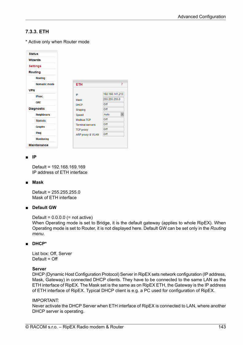
7.3.3. ETH
* Active only when Router mode
IP
Default = 192.168.169.169IP address of ETH interface
Mask
Default = 255.255.255.0Mask of ETH interface
Default GW
Default = 0.0.0.0 (= not active)When Operating mode is set to Bridge, it is the default gateway (applies to whole RipEX). WhenOperating mode is set to Router, it is not displayed here. Default GW can be set only in the Routingmenu.
DHCP*
List box: Off, ServerDefault = Off
ServerDHCP (Dynamic Host Configuration Protocol) Server in RipEX sets network configuration (IP address,Mask, Gateway) in connected DHCP clients. They have to be connected to the same LAN as theETH interface of RipEX. The Mask set is the same as on RipEX ETH, the Gateway is the IP addressof ETH interface of RipEX. Typical DHCP client is e.g. a PC used for configuration of RipEX.
IMPORTANT:Never activate the DHCP Server when ETH interface of RipEX is connected to LAN, where anotherDHCP server is operating.
143© RACOM s.r.o. – RipEX Radio modem & Router
Advanced Configuration

Start IPDefault = IP address of ETH interface + 1DHCP Server assigns addresses to connected clients starting from this address.
End IPDHCP server assigns IP addresses to clients from the range defined by Start IP and End IP(inclusive).
No of leasesDefault = 5 [1 - 255]Maximum number of DHCP client(s) which can RipEX simultaneously serve. It can not be morethan the number of addresses available in the Start IP - End IP range.
Lease timeout [DD:HH:MM:SS]Default = 1 day (max. 10 days)A DHCP Client has to ask DHCP Server for refresh of the received configuration within thistimeout, otherwise the Lease expires and the same settings can be assigned to another device(MAC).
Assigned IPsTable shows MAC addresses of Clients and IP addresses assigned to them by the Server. Ex-piration is the remaining time till the respective Lease expires. If the assigned IP addresses arerequired to be deleted, set DHCP Server to Off, then action Apply and set DHCP server to On(+Apply) again.
Preferred IPsIt is possible to define which IP should be assigned by the Server to a specific MAC. The reques-ted IP has to be within the Start IP – End IP range.
Shaping*
List box: On, OffDefault = OffEthernet interface could easily overload the Radio channel. Because of that, it is possible to shapetraffic received from the ETH interface.If "On", specified volume of Data [Bytes] in specified Period [s] is allowed to enter the RipEX fromETH interface. The first packet which exceeds the limit is stored in the buffer and transmitted whennew Period starts. Further over-limit packets are discarded.
Speed
List box: Auto, 100baseTX/Full, 100baseTX/Half, 10baseT/Full, 10baseT/HalfDefault = AutoCommunication speed on the Ethernet interface.
Modbus TCP*
Use this setttings only for Modbus TCP Master when it communicates with both types of Modbusslaves using either Modbus RTU or Modbus TCP protocols. Or when TCP/IP communication shouldrun locally between Modbus Master and RipEX in Modbus TCP network. Read Help and Applicationnote Modbus in RipEX.
For more information refer to the manual Application note / Modbus TCP2.
2 http://www.racom.eu/eng/products/m/ripex/app/modbus.html
RipEX Radio modem & Router – © RACOM s.r.o.144
Advanced Configuration

** - denotes items to be used only when either all or some RTUs (Remote Telemetry Unit) on remotesites are connected via RS232 or RS485 interface to RipEX, using the Modbus RTU protocol. Thenautomatic conversion between Modbus TCP and Modbus RTU protocols takes place for such units.
List box: On, OffDefault = Off
My TCP portDefault = 502TCP port used for Modbus TCP in RipEX.
TCP Inactivity [s]Default = 120TCP socket in RipEX is kept active after the receipt of data for the set number of seconds.
Broadcast**List box: On, OffDefault = OffSome Master SCADA units send broadcast messages to all Slave units. SCADA applicationtypically uses a specific address for such messages. RipEX (Protocol utility) converts suchmessage to an IP broadcast and broadcasts it to all RipEX units resp. to all SCADA units withinthe network.If On, the address for broadcast packets in SCADA protocol has to be defined:
Broadcast address format - List box Hex, Dec - format in which broadcast address isdefined.Broadcast address - address in the defined format (Hex, Dec)
Address translationList box: Table, MaskDefault = MaskIn a SCADA protocol, each SCADA unit has a unique address, a "Protocol address". In RipEXRadio network, each SCADA unit is represented by an IP address (typically that of ETH interface)and a UDP port (that of the protocol daemon or the COM port server to which the SCADA deviceis connected via serial interface).
A translation between "Protocol address" and the IP address & UDP port pair has to be done.It can be done either via Table or via Mask.
Each SCADA message received from serial interface is encapsulated into a UDP/IP datagram,where destination IP address and destination UDP port are defined according the settings ofAddress translation.
MaskTranslation using Mask is simpler to set, however it has some limitations:− all IP addresses used have to be within the same network, which is defined by this Mask− the same UDP port is used for all the SCADA units, which results in the following limitations:
− SCADA devices on all sites have to be connected to the same interface (COM1 orCOM2)− only one SCADA device to one COM port can be connected, even if the RS485 interfaceis used
Base IPDefault = IP address of ETH interface
145© RACOM s.r.o. – RipEX Radio modem & Router
Advanced Configuration

When the IP destination address of the UDP datagram, in which serial SCADA messagereceived from COM1(2) is encapsulated, is created, this Base IP is taken as the basisand only the part defined by Mask is replaced by 'Protocol address'.
MaskDefault = 255.255.255.0A part of Base IP address defined by this Mask is replaced by 'Protocol address'. TheSCADA protocol address is typically 1 Byte, so Mask 255.255.255.0 is most frequentlyused.
UDP port (Interface)List box: COM1, COM2, TS1-TS5, MBTCP, Manual.Default = COM1This UDP port is used as the destination UDP port in the UDP datagram in which serialSCADA packet received from COM1(2) is encapsulated. Default UDP ports for COM1,COM2 or Terminal servers 1-5 (TS1-TS5) or Modbus TCP (MBTCP) can be used or UDPport can be set manually. If the destination IP address belongs to a RipEX and the UDPport is not assigned to COM1(2) or to a Terminal server or to any special daemon runningin the destination RipEX, the packet is discarded.
TableThe Address translation is defined in a table. There are no limitations like when the Masktranslation is used. If there are more SCADA units on RS485 interface, their "Protocol ad-dresses" translate to the same IP address and UDP port pair.There are 3 possibilities how to fill in a line in the table:1. One "Protocol address" to one "IP address" (e.g.: 56 ===> 192.168.20.20)2. Interval of "Protocol addresses" to one "IP address" (e.g.: 56 – 62 ===> 192.168.20.20)3. Interval of "Protocol addresses" to interval of "IP addresses" (e.g.: 56 – 62 ===>192.168.20.20 – 26). It is possible to write only the start IP and dash, the system will add theend address itself.
Protocol addressThis is the address which is used by SCADA protocol. It may be set either in Hexadecimalor Decimal format according the List box value.Protocol address length can be maximum 1 Byte.
IPIP address to which Protocol address will be translated. This IP address is used as des-tination IP address in UDP datagram in which serial SCADA packet received from COM1(2)is encapsulated.
UDP port (Interface)This is the UDP port number which is used as destination UDP port in UDP datagram inwhich the serial SCADA message, received from COM1(2), is encapsulated.
NoteYou may add a note to each address up to 16 characters long (UTF8 is supported) foryour convenience. (E.g. "Remote unit #1 etc.). Following characters are not allowed:" (Double quote)` (Grave accent)\ (Backslash)$ (Dollar symbol); (Semicolon)
RipEX Radio modem & Router – © RACOM s.r.o.146
Advanced Configuration

ActiveYou may tick/untick each translation line in order to make it active/not active.
ModifyDelete and Add buttons allow to add or to delete a line. The lines can be sorted using upand down arrows.
Terminal servers*
Generally a Terminal Server (also referred to as a Serial Server) enables connection of deviceswith serial interface to a RipEX over the local area network (LAN). It is a virtual substitute for devicesused as serial-to-TCP(UDP) converters.
Examples of the use:A SCADA application in the centre should be connected to the Radio network via a serial interface,however for some reason that serial interface is not used. The operating system (e.g. Windows)can provide a virtual serial interface to such application and converts the serial data to TCP (UDP)datagrams, which are then received by the Terminal server in RipEX. This type of interconnectionbetween RipEX and application is especially advantageous when:• there is not any physical serial interface on the computer• the serial cable between the RipEX and computer would be too long (e.g. the RipEX is installed
very close to the antenna to improve radio coverage).• the LAN between the computer and the place of RipEX installation already exists• Modbus TCP is used with local TCP sessions on slave sites or when combination of Modbus
RTU and Modbus TCP is used. For more information refer to Application note Modbus TCP/RTU3
This applies also to other SCADA protocol TCP versions, e.g. DNP3 TCP.
NOTE: The TCP (UDP) session operates only locally between the RipEX and the central computer,hence it does not increase the load on Radio channel.
In some special cases, the Terminal server can be also used for reducing the network load fromapplications using TCP. A TCP session can be terminated locally at the Terminal server in RipEX,user data extracted from TCP messages and processed like it comes from a COM port. When datareaches the destination RipEX, it can be transferred to the RTU either via a serial interface or viaTCP (UDP), using the Terminal server again.
Terminal server
List box: On, OffDefault = Off
If "On", up to 5 independent Terminal servers can be set up. Each one can be either of TCP orUDP Type, Inactivity is the timeout in sec for which the TCP socket in RipEX is kept activeafter the last data reception or transmission, My IP address of a Terminal server has to be alwaysthe same as the IP address of the RipEX ETH interface, My Port can be set as required. Des-tination IP and Destination port values belong to the locally connected application (e.g. a vir-tual serial interface). In some cases, applications dynamically change the IP port with each da-tagram. In such a case set Destination port=0. RipEX will then send replies to the port fromwhich the last response was received. This feature allows to extend the number of simultaneouslyopened TCP connections between a RipEX and locally connected application to any value upto 10 on each Terminal server. Protocol follows the same principles as a protocol on COM in-terface. You may tick/untick each individual Terminal server in order to make it active/inactive.
3 http://www.racom.eu/eng/products/m/ripex/app/modbus.html
147© RACOM s.r.o. – RipEX Radio modem & Router
Advanced Configuration

NOTE: Max. user data length in a single datagram processed by the Terminal server is 8192Bytes.
TCP proxy*
Compared to UDP, the TCP protocol generates more load (longer headers, extra handshake data-grams), which in some circumstances may significantly reduce the user data throughput in a nar-rowband radio modem network. The TCP proxy module converts TCP to UDP (and vice-versa) sothat only UDP datagrams are transferred over the Radio channel. TCP sessions are maintainedonly locally between the end RipEX and the connected application device (at both ends of the RipEXnetwork).
NOTE 1: The TCP proxy module is activated and configured independently in each end RipEX. Tosuccessfully handle an end-to-end application TCP session, the two respective end RipEXes haveto be configured properly to match the same destination and source address/port pairs.
NOTE 2: Some applications use the TCP session status or handshake datagrams (TCP ACK) RTTfor important decisions at the application level. It is not recommended to use TCP proxy with suchapplications, since the status of the local TCP sessions at the respective ends of the RipEX networkis not synchronized. It is also highly recommended to use TCP proxy only with the ACK setting „On"(Settings/Device/Operating mode). Nevertheless be aware that any individual datagram can be lost.The locally run TCP sessions cannot guarantee 100% data integrity end-to-end.
NOTE 3: RipEX can handle up to 100 concurrent TCP proxy connections.
List box: On, OffDefault = Off
TCP Inactivity [s]Default = 120Timeout in sec for which the TCP socket in RipEX is kept active after the last data reception ortransmission.
IPIP address or interval of IP addresses (e.g.: 192.168.20.20 – 192.168.20.26) for which theTCP/UDP conversion is done.0.0.0.0 means all IP addresses.
PortPort or interval of Ports (e.g.: 40100 – 40200), in conjunction with IP addresses in the same line,for which the TCP/UDP conversion is done.
DirectionDst – IP and Port as defined above are considered as Destination in the received packetSrc – IP and Port as defined above are considered as Source in the received packet
NoteYou may add a note to each address up to 16 characters long (UTF8 is supported) for yourconvenience. (E.g. "Remote unit #1 etc.). Following characters are not allowed:" (Double quote)\ (Backslash)$ (Dollar symbol); (Semicolon)
RipEX Radio modem & Router – © RACOM s.r.o.148
Advanced Configuration

ActiveYou may tick/untick each line in order to make it active/not active.
ModifyDelete and Add buttons allow to add or to delete a line. The lines can be sorted using up anddown arrows.
ARP proxy & VLAN
General description
ARP proxy (Router mode only)
When a remote device connected over a Router-mode RipEX network does not support routing(i.e. the default gateway cannot be configured), the narrowest possible subnet should be con-figured on the respective Eth interface of the RipEX connected to it and the ARP proxy switchedon. The RipEX then answers ARP requests for all IP addresses routed to its radio interface.Corresponding settings can be used in the RipEX connected to the central application device,thus enabling the routed RipEX network to act as a direct (V)LAN connection for such devices.
WARNING:Whenever there is more than one IP device connected to a RipEX, or even more RipEXesconnected to the same physical Eth,
the ARP proxy must be used with the utmost care!Subnets routed to the radio interface must be reduced to the minimum necessary, defaultgateway should never be used. Accidental unwanted ARP responses may destroy all commu-nication in the connected LAN!
VLAN
Unlimited number of VLANs can be set, but only for the ETH interface, not for the Radio one.VLAN is defined by VLAN ID and IP and Mask. Several different Subnets can be assigned to aVLAN. Each VLAN may be seen as a virtual ETH0.VLAN_ID interface. In addition to settingmultiple VLANs, the original ETH0 interface may be left non-VLAN, i.e. for receiving/transmittingframes without a VLAN tag.
Router mode
When ARP proxy&VLAN is On, the RipEX Eth interface can receive/transmit also frameswith the respective VLAN IDs. Upon receiving a frame, the VLAN tag is stripped and the IPpacket continues through the RipEX network according to the routing table rules. When apacket is routed to be transmitted over one of the virtual Eth interfaces, the respective VLANtag is added to the frame.
NOTE 1: Since the VLAN ID added to a packet/frame transmitted from Eth interface dependssolely on the local RipEX configuration (Routing table and VLAN), it is independent of theoriginal VLAN ID which has been stripped off upon the packet entry into the first RipEX.Remember to double-check your configuration to avoid VLAN ID mismatching.
NOTE 2: When in Router mode, no Subnet on Ethernet may overlap with a Subnet on Radiointerface. Subnets on Ethernet could overlap each other (they may not be identical). For thesake of clarity, we nevertheless recommend IP subnets for different VLANs to be set withoutany overlapping.
Bridge mode
149© RACOM s.r.o. – RipEX Radio modem & Router
Advanced Configuration
VLAN settings apply only to packets destined to the local RipEX (e.g. management traffic,terminal server sessions etc.) All the remaining packets (frames) are processed transparentlyby the bridge regardless of their VLAN tags (these are kept untouched). Packets forwardedto the radio interface are transmitted as broadcasts over the radio channel. Reciprocally,only the packets sourced in the local RipEX are processed according to VLAN setting, i.e.possibly tagged with the respective VLAN ID. Packets arriving over the radio channel areagain transparently forwarded, depending on the bridge MAC address table.
Configuration
List box: On, OffDefault = Off
To create Subnet click on Add Subnet. The new Subnet line appears. Fill in IP/MASK. Unlimitednumber of virtual Ethernet interfaces (Alias IP addresses) can be set.To create VLAN click on Add VLAN.
The new VLAN line appears. Each VLAN can have its Subnets. Network overlapping amongsubnets is possible. When overlapping, the subnet with the narrowest mask takes effect for re-spective IP.
Interface.VLAN ID
Behind decimal point in ETH0. fill in VLAN ID. Values 1 - 4094 are possible.The first line (Main Ethernet interface) can be also defined as the VLAN. Tick the box andthe unit can be "VLAN only".
Priority
List box: possible valuesDefault = 0 Fixed priority can be assigned to a VLAN frame which is created in outgoingRipEX.
NOTE: Priority Code Point (PCP): a 3-bit field which refers to the IEEE 802.1p priority. Itindicates the frame priority level. Values are from 0 (best effort) to 7 (highest); 1 representsthe lowest priority. These values can be used to prioritize different classes of traffic (voice,video, data, etc.).
Unit Manag.
Tick when RipEX management shall be possible using this VLAN. Make sure Unit Manage-ment is On for one VLAN at least (typically the Eth0). Remember you could lose the connectionto your RipEX.
ARP proxy
Available only when Operating mode is set to Router.
When ticked, the respective interface generates ARP responses for all IP addresses whichare routed to the Radio interface according to the Routing table (in this specific RipEX unit).
Be very careful when using this feature, ARP proxy can disable all traffic in the LAN !
RipEX Radio modem & Router – © RACOM s.r.o.150
Advanced Configuration

NOTE 1: When two RipEX units are connected via their Ethernet ports in the same LAN,their IP networks defined on Radio interface must not overlap (both units would reply to thesame ARP request).
NOTE 2: It is highly recommended to activate ARP proxy as the last change when all theother settings are done.
NOTE 3: Check your routing rules twice – routing within a single LAN requires careful IPaddress planning to fit as narrow subnet masks as possible for the individual routes.
Note
You may add a note to each line up to 16 characters long (UTF8 is supported) for your con-venience. (E.g. "Remote unit #1 etc.). Following characters are not allowed:" (Double quote)` (Grave accent)\ (Backslash)$ (Dollar symbol); (Semicolon)
Active
You may tick/untick each line in order to make it active/not active. VLAN is active when atleast one of its subnets is active (even the first line can be inactive).
Modify
Add Subnet creates the new Subnet line. Add VLAN creates the new VLAN line. Delete deletesrespective line. The VLAN lines can be sorted using up and down arrows.
151© RACOM s.r.o. – RipEX Radio modem & Router
Advanced Configuration

7.3.4. COM
* Active only when Router mode
The COM ports in RipEX are served by special daemons, which are connected to the IP network througha standard Linux socket. Consequently a COM port can be accessed using any of the two IP addresses(either ETH or Radio interface) used in a RipEX and the respective UDP port number. The source IPaddress of outgoing packets from COM ports is equal to IP address of the interface (either Radio orEthernet) through which the packet has been sent. Outgoing interface is determined in Routing tableaccording to the destination IP. The default UDP port numbers are COM1 = 8881, COM2 = 8882. Ifnecessary they may be changed using CLI, nevertheless it is recommended to stick to the default valuesbecause of dependencies between different settings (e.g. Protocols) in the network.
Note
UDP port settings is valid only in Router mode. In Bridge mode all packets received by COMport are broadcasted to all COM ports on all RipEXes within the network.
Type
List box: possible valuesDefault = RS232COM1 is always RS232, COM2 can be configured to either RS232 or RS485.
Note
The settings of Data rate, Data bits, Parity and Stop bits of COM port and connecteddevice must match.
Baud rate [bps]
List box: standard series of rates from 300 to 115200 bps
RipEX Radio modem & Router – © RACOM s.r.o.152
Advanced Configuration

Default = 19200Select Baud rate from the list box: 300 to 115200 bps rates are available.Serial ports use two-level (binary) signaling, so the data rate in bits per second is equal to thesymbol rate in bauds
Data bits
List box: 8, 7Default = 8The number of data bits in each character.
Parity
List box: None, Odd, EvenDefault = NoneWikipedia: Parity is a method of detecting errors in transmission. When parity is used with a serialport, an extra data bit is sent with each data character, arranged so that the number of 1-bits ineach character, including the parity bit, is always odd or always even. If a byte is received with thewrong number of 1s, then it must have been corrupted. However, an even number of errors canpass the parity check.
Stop bits
List box: possible valuesDefault = 1Wikipedia:Stop bits sent at the end of every character allow the receiving signal hardware to detectthe end of a character and to resynchronise with the character stream.
Idle [bytes]
Default = 5 [0 - 2000]This parameter defines the maximum gap (in bytes) in the received data stream. If the gap exceedsthe value set, the link is considered idle, the received frame is closed and forwarded to the network.
MRU [bytes]
Default = 1600 [1 - 1600]MRU (Maximum Reception Unit) — an incoming frame is closed at this size even if the stream ofbytes continues. Consequently, a permanent data stream coming to a COM results in a sequenceof MRU-sized frames sent over the network.
Note1. Very long frames (>800 bytes) require good signal conditions on the Radio channel
and the probability of a collision increases rapidly with the length of the frames.Hence if your application can work with smaller MTU, it is recommended to usevalues in 200 – 400 bytes range.
2. This MRU and the MTU in Radio settings are independent. However MTU shouldbe greater or equal to MRU.
Flow control
List box: None, RTS/CTSDefault = None
153© RACOM s.r.o. – RipEX Radio modem & Router
Advanced Configuration

RTS/CTS (Request To Send / Clear To Send) hardware flow control (handshake) between the DTE(Data Terminal Equipment) and RipEX (DCE - Data Communications Equipment) can be enabledin order to pause and resume the transmission of data. If RX buffer of RipEX is full, the CTS goesdown.NOTE: RTS/CTS Flow control requires a 5-wire connection to the COM port.
Protocol*
List box: None, Async Link, C24, Cactus, Comli, DF1, DNP3, IEC101, ITT Flygt, Modbus, PR2000,Profibus, RDS, RP570, Siemens 3964(R), Slip, UNIDefault = NoneEach SCADA protocol used on serial interface is more or less unique. The COM port daemon per-forms conversion to standard UDP datagrams used in RipEX Radio network. Each protocol has itsindividual configuration parameters, which are described in separate Help page (accessible fromconfiguration light box Protocol - click on Protocol, then on Help). Protocol "None" simply discardsany data received by the COM port or from the network, which means that the respective COM portis virtually disconnected from the RipEX.
RipEX Radio modem & Router – © RACOM s.r.o.154
Advanced Configuration

7.3.5. Protocols
Fig. 7.6: Menu Protocols COM
This menu provides the following protocols:
Common parametersProtocols implemented:
Modbus None PR2000 Async link Profibus C24 RDS Cactus RP570 Comli Siemens 3964(R) DF1 SLIP DNP3 UNI IEC 870-5-101
ITT Flygt
Generally
Each SCADA protocol like Modbus, DNP3, IEC101, DF1 etc. has its unique message format, mostimportantly its unique way of addressing of remote units. The basic task for protocol utility is tocheck whether received frame is within protocol format and it is not corrupted. Most of the SCADAprotocols are using some type of Error Detection Codes (Checksum, CRC, LRC, BCC, etc.) for dataintegrity control, so RipEX calculates this code and check it with the received one.
155© RACOM s.r.o. – RipEX Radio modem & Router
Advanced Configuration

RipEX radio network works in IP environment, so the basic task for Protocol interface utility is toconvert SCADA serial packets to UDP datagrams. The Address translation settings are used todefine the destination IP address and UDP port. Then these UDP datagrams are sent to RipEXrouter, processed there and they are typically forwarded as unicasts to Radio channel to their des-tination. When the gateway defined in the Routing table belongs to the Ethernet LAN, UDP datagramsare rather forwarded to the Ethernet interface. After reaching the gateway (typically a RipEX routeragain), the datagram is forwarded according to the Routing table.
Note
Even if UDP datagrams, they can be acknowledged on the Radio channel (ACK para-meter of Router mode), however they are not acknowledged on Ethernet.
When the UDP datagram reaches its final IP destination, it should be in a RipEX router again (eitherits ETH or Radio interface). It is processed further according its UDP port. It can be delivered toCOM1(2) port daemon, where the datagram is decapsulated and the data received on the serialinterface of the source unit are forwarded to COM1(2). The UDP port can also be that of a Terminalserver or any other special protocol daemon on Ethernet like Modbus TCP etc. The datagram isthen processed accordingly to the respective settings.
RipEX uses a unique, sophisticated protocol on Radio channel. This protocol ensures high probab-ility of data delivery. It also guarantees data integrity even under heavy interference or weak signalconditions due to the 32 bit CRC used, minimises the probability of collision and retransmits framewhen a collision happens, etc., etc. These features allow for the most efficient SCADA applicationarrangements to be used, e.g. multi-master polling and/or spontaneous communication from remoteunits and/or parallel communication between remote units etc.
Note1. These Radio protocol features are available only in the Router mode. The Bridge
mode is suitable for simple Master-Slave arrangement with a polling-type applicationprotocol.
2. All timeouts in parameters described below are calculated from time, when packetis sent into COM driver, i.e. it includes the transfer time of the packet. Take it intoaccount especially when there is a low Baud rate set in COM settings.
Common parameters
The parameters described in this section are typical for most protocols.There is only a link to them in description of the respective Protocol.
Mode of Connected deviceList box: Master, SlaveDefault = MasterTypical SCADA application follows Master-Slave scheme, where the structure of the message isdifferent for Master and Slave SCADA units. Because of that it is necessary to set which type ofSCADA unit is connected to the RipEX.
Note
For SCADA Master set Master, for SCADA Slave set Slave.
Master
RipEX Radio modem & Router – © RACOM s.r.o.156
Advanced Configuration

SCADA Master always sends addressed messages to Slaves. The way of addressing is differentfrom SCADA protocol to SCADA protocol, so this is one of the main reasons why an individualProtocol utility in RipEX for each SCADA protocol has to be used.
BroadcastList box: On, OffDefault = OffSome Master SCADA units sends broadcast messages to all Slave units. SCADA applicationtypically uses a specific address for such messages. RipEX (Protocol utility) converts suchmessage to a customized IP broadcast and broadcasts it to all RipEX units resp. to all SCADAunits within the network.If On, the address for broadcast packets in SCADA protocol has to be defined:
Broadcast address format - List box Hex, Dec - format in which broadcast address isdefined.Broadcast address - address in the defined format (Hex, Dec)
Address translationList box: Table, MaskDefault = MaskIn a SCADA protocol, each SCADA unit has a unique address, a "Protocol address". In RipEXRadio network, each SCADA unit is represented by an IP address (typically that of ETH in-terface) and a UDP port (that of the protocol daemon or the COM port server to which theSCADA device is connected via serial interface).A translation between "Protocol address" and the IP address & UDP port pair has to be done.It can be done either via Table or via Mask.So SCADA message received from serial interface is encapsulated into a UDP/IP datagram,where destination IP address and destination UDP port are defined according the settingsof Address translation.
MaskTranslation using Mask is simpler to set, however it has some limitations:− all IP addresses used have to be within the same network, which is defined by thisMask− the same UDP port is used for all the SCADA units, which results in the following limit-ations:
− SCADA devices on all sites have to be connected to the same interface (COM1 orCOM2)
− only one SCADA device to one COM port can be connected, even if the RS485 inter-face is used
Base IPDefault = IP address of ETH interfaceWhen the IP destination address of UDP datagram, in which serial SCADA messagereceived from COM1(2) is encapsulated, is created, this Base IP is taken as the basisand only the part defined by Mask is replaced by 'Protocol address'.
MaskDefault = 255.255.255.0A part of Base IP address defined by this Mask is replaced by 'Protocol address'. TheSCADA protocol address is typically 1 Byte, so Mask 255.255.255.0 is most frequentlyused.
UDP port (Interface)
157© RACOM s.r.o. – RipEX Radio modem & Router
Advanced Configuration

List box: COM1,COM2, TS1-TS5, MBTCP, Manual.This UDP port is used as the destination UDP port in UDP datagram in which serialSCADA packet received from COM1(2) is encapsulated. Default UDP ports for COM1,COM2 or Terminal servers 1-5 (TS1-TS5) or Modbus TCP (MBTCP) can be used orUDP port can be set manually. If the destination IP address belongs to a RipEX andthe UDP port is not assigned to COM1(2) or to a Terminal server or to any specialdaemon running in the destination RipEX, the packet is discarded.
TableThe Address translation is defined in a table. There are no limitations such as when theMask translation is used. If there are more SCADA units on RS485 interface, their "Protocoladdresses" should be translated to the same IP address and UDP port pair, where themultiple SCADA units are connected. There are 3 possibilities how to fill in the line in thetable:− One "Protocol address" to one "IP address" (e.g.: 56 ===> 192.168.20.20)− Interval of "Protocol addresses" to one "IP address" (e.g.: 56 – 62 ===> 192.168.20.20)− Interval of "Protocol addresses" to interval of "IP addresses" (e.g.: 56 – 62 ===>192.168.20.20 – 26). It is possible to write only the start IP and dash, the system will addthe end address itself.
Protocol addressThis is the address which is used by SCADA protocol. It may be set either in Hexa-decimal or Decimal format according the List box value.Protocol address length can be 1 Byte, only for some protocols, e.g. DNP3 and UNIcan also be 2 Bytes.
IPIP address to which Protocol address will be translated. This IP address is used asdestination IP address in UDP datagram in which serial SCADA packet received fromCOM1(2) is encapsulated.
UDP port (Interface)This is UDP port number which is used as destination UDP port in UDP datagram inwhich the serial SCADA message, received from COM1(2), is encapsulated.
NoteYou may add a note to each address with your comments up to 16 characters (UTF8is supported) for your convenience. (E.g. " Remote unit #1 " etc.). Following charactersare not allowed:" (Double quote)` (Grave accent)\ (Backslash)$ (Dollar symbol); (Semicolon)
ActiveYou may tick/un-tick each translation line in order to make it active/not active.
ModifyEdit Delete Add buttons allow to edit or to add or to delete a line. The lines can besorted using up and down arrows.
Slave
RipEX Radio modem & Router – © RACOM s.r.o.158
Advanced Configuration

SCADA Slave typically only responds to Master requests, however in some SCADA protocolsit can communicate spontaneously.Messages from serial interface are processed in similar way as at Master site, i.e. they are en-capsulated in UDP datagrams, processed by router inside the RipEX and forwarded to the re-spective interface, typically to Radio channel.
Broadcast acceptList box: On, OffDefault = OnIf On, broadcast messages from the Master SCADA device to all Slave units are acceptedand sent to connected Slave SCADA unit.
Protocols implemented:
None
All received frames from COM port as well as from the RipEX network are discarded.
Async link
Async link creates asynchronous link between two COM ports on different RipEX units. Receivedframes from COM1(2) or from a Terminal server 1-5 are sent without any processing transparentlyto Radio channel to set IP destination and UDP port. Received frames from Radio channel are sentto COM1 or COM2 or Terminal server 1-5 according UDP port settings.
Parameters
Destination IPThis is IP address of destination RipEX, either ETH or Radio interface.
UDP port (Interface)This is UDP port number which is used as destination UDP port in UDP datagram in whichpacket received from COM1(2) is encapsulated.
C24
C24 is a serial polling-type communication protocol used in Master-Slave applications.
When a RipEX radio network runs in the Router mode, multiple C24 Masters can be used withinone Radio network and one Slave can be polled by more than one Master.
Italicised parameters are described in Common parameters.
Mode of Connected deviceMaster
Address translationTableMask
Slave
Protocol framesList box: 1C, 2C, 3C, 4CDefault = 1COne of the possible C24 Protocol frames can be selected.
159© RACOM s.r.o. – RipEX Radio modem & Router
Advanced Configuration

Frames formatList box: Format1,Format2,Format3,Format4,Format5Default = Format1One of the possible C24 Frames formats can be selected. According to the C24 protocol spe-cification, it is possible to set Frames formats 1-4 for Protocol frames 1C-3C and formats 1-5for 4C.
Important
The RipEX accepts only the set Protocol frames and Frames format combination.All other combinations frames are discarded by the RipEX and not passed to theapplication.
Local ACKList box: Off, OnDefault = OffAvailable for Protocol frame 1C only. When "On", ACK on COM1(2) is send locally from thisunit, not over the Radio channel.
Cactus
Cactus is a serial polling-type communication protocol used in Master-Slave applications.When a RipEX radio network runs in the Router mode, multiple Cactus Masters can be used withinone Radio network and one Slave can be polled by more than one Master.
Italicised parameters are described in Common parameters.
Mode of Connected deviceMaster
BroadcastThere is not the possibility to set Broadcast address, since Cactus broadcast messagesalways have the address 0x00. Hence when the Broadcast is On, packets with this des-tination are handled as broadcasts.Address translation
TableMask
SlaveBroadcast accept
Max gap timeout [ms]Default = 30The longest time gap for which a frame can be interrupted and still received successfully as oneframe. It should not be set below 10ms, while 15–40 ms should be OK for a typical Cactus protocoldevice.
Comli
Comli is a serial polling-type communication protocol used by Master-Slave application.When RipEX radio network run in Router mode, more Comli Masters can be used within one Radionetwork and one Slave can be polled by more Masters.Broadcasts packets are not used, so the configuration is using only some parameters describedCommon parameters.
RipEX Radio modem & Router – © RACOM s.r.o.160
Advanced Configuration

Mode of Connected deviceMaster
Address translationTableMask
Slave
DF1
Only the full duplex mode of DF1 is supported. Each frame in the Allen-Bradley DF1 protocol containsthe source and destination addresses in its header, so there is no difference between Master andSlave in the Full duplex mode in terms of RipEX configuration.
Block control modeList box: BCC, CRCDefault = BCCAccording to the DF1 specification, either BCC or CRC for Block control mode (data integrity)can be used.
BroadcastAccording to the DF1 specification, packets for the destination address 0xFF are consideredbroadcasts. Hence when Broadcast is On, packets with this destination are handled as broad-casts.
Address translationTableMask
Advanced parametersACK LocallyList box: Off, OnDefault = OnIf "On", ACK frames (0x1006) are not transferred over-the-air.When the RipEX receives a data frame from the connected device, it generates the ACKframe (0x1006) locally. When the RipEX receives the data frame from the Radio channel, itsends the frame to the connected device and waits for the ACK. If the ACK is not receivedwithin 1 sec. timeout, RipEX sends ENQ (0x1005). ENQ and ACK are not generated forbroadcast packets.
DNP3
Each frame in the DNP3 protocol contains the source and destination addresses in its header, sothere is no difference between Master and Slave in terms of the RipEX configuration. The DNP3allows both Master-Slave polling as well as spontaneous communication from remote units.
BroadcastThere is not the option to set the Broadcast address, since DNP3 broadcast messages alwayshave addresses in the range 0xFFFD - 0xFFFF. Hence when Broadcast is On, packets withthese destinations are handled as broadcasts.
Address translationTableMask
161© RACOM s.r.o. – RipEX Radio modem & Router
Advanced Configuration

IEC 870-5-101
IEC 870-5-101 is a serial polling-type communication protocol used by Master-Slave application.When RipEX radio network run in Router mode, more IEC 870-5-101 Masters can be used withinone Radio network and one Slave can be polled by more Masters.IEC 870-5-101 protocol configuration is using all parameters described in Common parameters.
Mode of Connected deviceMaster
BroadcastOn, Off only. Protocol broadcast address is not configurable, it is defined by Addressmode in Advance parameter (default 0xFF)Address translation
TableMask
SlaveBroadcast accept
Advanced parameters
Address modeEven if IEC 870-5-101 is the standard, there are some users which customized this standardaccording their needs. When addressed byte has been moved, RipEX has to read it on thecorrect location.
IEC101Address byte location according to IEC 870-5-101 standard.Broadcast from Master station is generated when address byte is 0xFF.
2B ADDRTwo byte address (IEC 870-5-101 standard is 1 Byte). The frame is 1 Byte longer thanstandard one. There is Intel sequence of bytes: low byte, high byte. Mask Addresstranslation has to be used, because Table one is limited just to one byte address length.Broadcast from Master station is generated when address is 0xFFFF.
TELEGYRThe Control byte in standard IEC packet is omitted. The frame is 1 Byte shorter thanstandard one. This is typically used in Telegyr 805/809 protocol.Broadcast from Master station is generated when address byte is 0x00.
SINAUTThe sequence of Address byte and Control byte in the frame is changed-over.Broadcast from Master station is generated when address byte is 0x00.
ITT Flygt
ITT Flygt is a serial polling-type communication protocol used in Master-Slave applications.
ITT Flygt protocol configuration uses all parameters described in Common parameters.
Mode of Connected deviceMaster
Broadcast
RipEX Radio modem & Router – © RACOM s.r.o.162
Advanced Configuration

There is not a possibility to set the Broadcast address, since ITT Flygt broadcast messagesalways have the address 0xFFFF. Hence when the Broadcast is On, packets with thisdestination are handled as broadcasts.
First Slave AddressDefault = 1Slave addresses are not defined in the ITT Flygt protocol. However Slave addresseshave to be defined in the RipEX network. This is the First Slave address in decimal format.
Number of SlavesDefault = 1Since the ITT Flygt protocol Master (centre) polls the Slaves (remotes) one by one withoutany addressing, number of slaves has to be defined.
Address translationTableMask
Slave
Broadcast accept
Wait timeout [ms]Default = 5000An ITT Flygt Slave sometimes sends the WAIT COMMAND (0x13) to its Master. TheRipEX does not accept the next WAIT COMMAND (discards it), till the Wait timeout doesnot expire. The Recommended value is in the 1-10 seconds range.
Modbus
Modbus RTU is a serial polling-type communication protocol used by Master-Slave application.When RipEX radio network run in Router mode, more Modbus Masters can be used within oneRadio network and one Slave can be polled by more Masters.Modbus protocol configuration uses all parameters described in Common parameters.
Mode of Connected deviceMaster
BroadcastAddress translation
TableMask
SlaveBroadcast accept
Advanced parameters, Slave
Retries [No]Default = 0 (min. 0, max. 7)When an original frame is received from the Radio channel, it is transmitted to the connecteddevice and waits for an acknowledgement. Any incoming frame from the device is treatedas an acknowledgement. If there is no acknowledgement (no incoming frame), the originalframe is re-transmitted to the connected device. The Retries parameter controls how manytimes the frame is re-transmitted when not acknowledged.
Repeat timeout [ms]
163© RACOM s.r.o. – RipEX Radio modem & Router
Advanced Configuration

Default = 300 (min. 0, max. 8190)The Repeat timeout parameter controls how long the unit waits for an acknowledgementframe (see Retries parameter description). The timeout is started when the original framereceived from the Radio channel is transmitted to the connected device (over the serialchannel). Transmission of any other frame to the connected device is temporarily blocked,whilst Repeat timeout is active. Repeat timeout = 0 disables this feature.
PR2000
PR2000 is an abbreviation for the PROTEUS 2000 SCADA protocol. This protocol is used in Master-Slave applications.The PR2000 protocol is implemented in a fully transparent manner. The original protocol framesare transported over the RipEX network in their entirety.The PR2000 protocol configuration uses the following parameters as described in Common para-meters:
Mode of Connected deviceMaster
Address translationTableMask
Slave
Sync Word (Hex)Two protocol synchronization bytes (SYNC1 and SYNC2) concatenated.The typical value is AA80
Profibus
RipEX supports Profibus DP (Process Field Bus, Decentralized Periphery) the widest-spread versionof Profibus. The Profibus protocol configuration uses all parameters described in Common paramet-ers.
Mode of Connected deviceMaster
BroadcastAddress translation
TableMask
SlaveBroadcast
RDS
RDS protocol is a protocol used in MRxx networks. It supports network communication; any nodein the network can talk to any other (unlike Master-Slave type of protocols). The RDS protocol shouldonly be used when combining RipEX and MRxx networks or SCADA networks adapted to MRxxnetworks.
Frames are received from the Radio channel and sent to COM1, COM2 or Terminal server 1-5 ac-cording to UDP port settings and vice versa - from wire to radio channel.
Italicised parameters are described in Common parameters.
RipEX Radio modem & Router – © RACOM s.r.o.164
Advanced Configuration

ACKList box: On, OffDefault = OnFrame acknowledgement when transmitted over wire (COM or Ethernet) interface. ACK (0x06)frames are transmitted on successful reception and NAK (0x15) on unsuccessful frame reception.
ACK timeout [ms]Default = 1000 (min. 0, max. 65535)When "ACK" is enabled, RipEX is waiting "ACK timeout [ms]" after transmitting frame to receiveacknowledgement. If the ACK frame isn't received, the frame is re-transmitted. Frame re-trans-mission happens up to "Repeats" number of times.
RepeatsDefault = 2 (min. 0, max. 65535)Number of frame re-transmissions.
Reverse modeList box: On, OffDefault = OnIf a frame must be transmitted over a further wire channel, source and destination addresses inthe frame must be reversed.
Reverse address (Hex)Default = 00 (min. 0x00, max. 0xFF)When Reverse mode is enabled, the destination address is overwritten by Reverse addresswhen the frame is received from the wire channel and before it is transmitted to the air channel.This only happens if the Reverse mode is enabled.
Address translationTableMask
RP570
RP570 is a serial polling-type communication protocol used in Master-Slave applications.
When a RipEX radio network runs in the Router mode, multiple RP570 Masters can be used withinone Radio network and one Slave can be polled by more than one Master.
Italicised parameters are described in Common parameters.
Mode of Connected deviceMaster
Local simulation RBList box: Off, OnDefault = OffThe RP570 protocol Master very often transmits the RB packets (hold packets) solely tocheck whether slaves are connected. In order to minimize the Radio channel load, theRipEX can be configured to respond to these packets locally and not to transmit them tothe slaves over the Radio channel.
If "On", the RipEX responds to RB packets received from the RP 570 master locally overthe COM interface. However from time to time (RB period) the RB packets are transferred
165© RACOM s.r.o. – RipEX Radio modem & Router
Advanced Configuration

over the network in order to check whether the respective slave is still on. When the RBresponse from the slave to this RB packet is not received over the Radio channel withinthe set RB timeout, i.e. the respective slave is out of order, the central RipEX stops localanswering to RB packets from the master for the respective slave.
RB Net period [s]Default = 10The RipEX responds to the RB packets locally and in the set RB period the RB packetsare transferred over the network.
RB Net timeout [s]Default = 10 (maximum=8190)Whenever an RB packet is sent over the network, the set RB Net timeout starts. Whenthe RB response from the remote unit (slave) is not received within the timeout, i.e. therespective slave is out of order, the central RipEX stops the local answering to RB packetsfrom the master for the respective slave.
Address translationTableMask
Slave
Local simulation RBList box: Off, OnDefault = OffThe RP570 Slave expects to receive RB packets from the Master. When the Local simu-lation RB on the Master is On, the RB packets are transferred over the Radio channelonly in the RB Net period (see Master settings). The Local simulation RB has to be setthe same (On or Off) on all sites in the network, i.e. on the master as well as all slaves.
IfOn, the RipEX generates RB packets locally and transmits them over the COM interfacein the RB Request period and expects the RB response for each RB packet from theRP570 Slave within the RB Response timeout. When the RipEX does not receive theresponse(s) from the RP570 slave, the RipEX does not respond to the RB packet fromthe Master which it receives over the Radio channel.
RB Request period [ms]Default = 200 (maximum=8190)RipEX sends locally RB packets to the connected RTU in the set period.
RB Response timeout [ms]Default = 500 (maximum=8190)The RipEX expects a response to the RB packet within the set timeout. If it is not received,the RipEX does not respond to RB packets from the Master received over the Radiochannel.
RTU address (Hex)Default = 01Active only when the Local simulation RB is On. The connected RTU’s address is sup-posed to be filled in. This address (0x00-0xFF) is used in the RB packets generated locallyin the RipEX and transmitted over the COM.
Siemens 3964(R)
RipEX Radio modem & Router – © RACOM s.r.o.166
Advanced Configuration

The 3964 protocol is utilized by the Siemens Company as a Point-to-Point connection between twocontrollers. Meanwhile it has developed into an industry standard that can be found on many devicesas a universal communications interface. 3964R is the same as 3964, in addition it only uses BCC(Block Check Character). 3964(R) handles only the link layer (L2 in OSI model), hence RipEX usesa similar way to read "SCADA address" as in UNI protocol.
There is a handshake STX(0x02) – DLE(Ox10) on the start of communication and DLE+ETX – DLEon the end. This handshake is performed by RipEX locally, it is not transferred over the RipEXnetwork.
Communication goes as follows:LocalRTU -> STX -> LocalRipexLocalRipex -> DLE -> LocalRTULocalRTU -> DATA+DLE+ETX+BCC -> LocalRipexLocalRipex -> DATA -> RemoteRipex*LocalRipex -> DLE -> LocalRTURemoteRipex -> STX -> RemoteRTURemoteRTU -> DLE -> RemoteRipexRemoteRipex -> DATA+DLE+ETX+BCC -> RemoteRTURemoteRTU -> DLE -> RemoteRipex
* only this packet is transferred over the RipEX network, all the other ones are handled locally.
Italicised parameters are described in Common parameters.
Mode of Connected device
Master
Address modeList box: Binary (1 B), Binary (2B LSB first). Binary (2B MSB first).Default = Binary (1 B)RipEX reads the Protocol address in the format and length set (in Bytes).
Address positionSpecify the sequence number of the byte, where the Protocol address starts.NOTE 1: 3964(R) protocol is using escape sequence (control sequence) for DLE(0x10).I.e. when 0x10 is in user data, 0x1010 is sent instead. When address position is calculated,the bytes added by escape sequence algorithm are not taken into account.NOTE 2: The first byte in the packet has the sequence number 1, not 0.
Broadcast
Address translationTableMask
SlaveBroadcast accept
DLE timeout [ms]Default = 1000 (min. 300, max. 8190)RipEX expects a response (DLE) from the connected device (RTU) within the set timeout.If it is not received, RipEX repeats the frame according to the "Retries" setting.
167© RACOM s.r.o. – RipEX Radio modem & Router
Advanced Configuration

Retries [No]Default = 3 (min. 0, max. 7)When DLE timeout is „On", and DLE packet is not received from the connected device (RTU)within the set DLE timeout, RipEX retransmits the frame. The number of possible retries isspecified.
PriorityList box: Low, HighDefault = LowWhen the equipment sends STX and receives STX instead of DLE, there is a collision, bothequipments want to start communication. In such a case, one unit has to have a priority. Ifthe Priority is High, RipEX waits for DLE. When it is Low, RipEX send DLE.NOTE: Obviously, two pieces of equipment which are communicating together must be setso that one has High priority and the other has Low.
BCCList box: On, OffDefault = OnBCC (Block Check Character) is a control byte used for data integrity control, it makes thereliability higher. BCC is used by 3964R, 3964 does not use it.RipEX checks (calculates itself) this byte while receiving a packet on COM. RipEX transmitsDLE (accepts the frame) only when the check result is OK. BCC byte is not transferred overthe RipEX network, it is calculated locally in the end RipEX and appended to the receiveddata.
SLIP
SLIP (Serial Line Internet Protocol) allows the Internet Protocol4 (IP), normally used on Ethernet5,to be used over a serial line6. SLIP modifies a standard IP packet by prepending and appending aspecial SLIP END character to it, which allows packets to be distinguished as separate. SLIP requiresa COM port configuration of 8 data bits, no parity7 and flow control8. SLIP does not provide errordetection9, being reliant on other high-layer protocols for this. A SLIP connection needs to have itsIP address10 configuration set each time before it is established.
Local IPIP address assigned to COM port (local point of SLIP protocol) used for p-t-p communicationwith Connected device. It has to be within the subnet defined by Peer IP and Peer IP mask.
Peer IPThis is IP address of Connected device (remote point of SLIP protocol) on the other end ofRS232.
Peer IP maskPeer IP and Peer IP mask defines Subnet, which is routed into SLIP on respective COM.
NOTE: Peer IP and Peer IP mask defines IP subnet which is automatically routed to respectiveCOM. This subnet can not overlap with any other subnet in RipEX defined on Radio, ETH or VLAN.
4 http://dictionary.reference.com/browse/Internet%20Protocol5 http://dictionary.reference.com/browse/Ethernet6 http://dictionary.reference.com/browse/serial%20line7 http://dictionary.reference.com/browse/parity8 http://dictionary.reference.com/browse/hardware%20flow%20control9 http://dictionary.reference.com/browse/error%20detection10 http://dictionary.reference.com/browse/IP%20address
RipEX Radio modem & Router – © RACOM s.r.o.168
Advanced Configuration

UNI
UNI is the 'Universal' protocol utility designed by RACOM. It is supposed to be used when the ap-plication protocol is not in the RipEX list and the addressed mode of communication is preferablein the network (which is a typical scenario). The key condition is that messages generated by theMaster application device always contain the respective Slave address and that address (or itsrelevant part) position, relative to the beginning of the message (packet, frame), is always the same(Address position).
Generally two communication modes are typical for UNI protocol: In the first one, communicationhas to be always initiated by the Master and only one response to a request is supported; in thesecond mode, Master-Master communication or combination of UNI protocol with ASYNC LINKprotocol and spontaneous packets generation on remote sites are possible.
The UNI protocol is fully transparent, i.e. all messages are transported and delivered in full, withoutany modifications. Italicised parameters are described in Common parameters.
Mode of Connected deviceMaster
Address modeList box: Binary (1 B), ASCII (2 B), Binary (2B LSB first). Binary (2B MSB first).Default = Binary (1 B)RipEX reads the Protocol address in the format and length set (in Bytes).
The ASCII 2-Byte format is read as 2-character hexadecimal representation of one-bytevalue. E.g. ASCII characters AB are read as 0xAB hex (10101011 binary, 171 decimal)value.
Address positionSpecify the sequence number of the byte, where the Protocol address starts. Note thatthe first byte in the packet has the sequence number 1, not 0.
Address mask (Hex)When the Address mode is Binary 2 Bytes, a 16-bit value is read from the SCADA protocolmessage according to the Address mode setting (either the MSB or the LSB first), Theresulting value is then bit-masked by the Address mask and used as the input value forSCADA to IP address translation (e.g. by a table). The default value of the Address maskis FFFF, hence the full 16-bit value is used by default.
Example:The Address mode is set to Binary (2B LSB first), the Address mask is set to 7FF0 andthe Address position is set to 2. The SCADA message starts with bytes (in hex) 02 DA92 C3 .. The 2-Byte address is read as 0x92DA (note the LSB came first in the message),Then 0x7FF0 mask is applied and the resulting value 0x12D0 (0x92DA & 0x7FF0) isused as the input for the translation.
Poll response controlList box: On, OffDefault = On
"On" – The Master accepts only one response per a request and it must come from thespecific remote to which the request has been sent. All other packets are discarded. Thisapplies to the Master - Slave communication scheme.
169© RACOM s.r.o. – RipEX Radio modem & Router
Advanced Configuration

NOTE: It may happen, that a response from a slave (No.1) is delivered after the respectivetimeout expired and the Master generates the request for the next slave (No.2) in themeantime. In such case the delayed response from No.1 would have been consideredas the response from No.2. When Poll response control is On, the delayed response fromthe slave No.1 is discarded and the Master stays ready for the response from No.2.
"Off" – The Master does not check packets incoming from the RF channel - all packetsare passed to the application, including broadcasts . That allows E.g. spontaneouspackets to be generated at remote sites. This mode is suitable for Master-Master commu-nication scheme or a combination of the UNI and ASYNC LINK protocols.
Broadcast
Address translationTableMask
SlaveBroadcast accept
Advanced parameters
CTS EnvelopeList box: On, OffDefault = OffOn - CTS Envelope function makes it possible to use the CTS signal to control radio trans-mission in some old transparent radio networks. This feature is used to enable smooth mi-gration from a legacy to the new RipEX based networks. See Migration solution11.The "Flow control" parameter must be disabled to enable the "CTS Envelope" to function.
CTS Pre-time [ms]The CTS signal (CTS Pre-time) is activated a number of milliseconds prior to transmittingthe data from the serial port.
CTS Post-time [ms]The CTS signal (CTS Post-time) is deactivated a number of milliseconds after the data hasbeen transmitted from the serial port.
COM Broadcast delay [ms]Radio transmissions in the transparent network are delayed by this parameter to make itpossible to transmit the broadcast in the RipEX network first.
11 http://www.racom.eu/eng/products/radio-modem-ripex.html#migration
RipEX Radio modem & Router – © RACOM s.r.o.170
Advanced Configuration

7.4. Routing
7.4.1. Routing
Fig. 7.7: Menu Routing
Routing table is active only when Router mode (Settings/Device/Operating mode) is set. In such acase RipEX works as a standard IP router with 2 independent interfaces: Radio and ETH. Each interfacehas its own MAC address, IP address and Mask. IP packets are then processed according the Routingtable.Unlimited number of Subnets and VLAN’s can be defined on the ETH interface, menu Set-tings/Device/ARP proxy & VLAN. They are routed independently.
The COM ports are treated in the standard way as router devices, messages can be delivered to themas UDP datagrams to selected UDP port numbers. Destination IP address of COM port is either IP ofETH or IP of Radio interfaces. The source IP address of outgoing packets from COM ports is equal toIP address of interface (either Radio or Ethernet) through packet has been sent. Outgoing interface isdetermined in Routing table according the destination IP.The IP addressing scheme can be chosen arbitrarily, only 127.0.0.0/8 and 192.0.2.233/30 and192.0.2.228/30 restriction applies. It may happen that also the subsequent addresses from the192.0.2.0/24 subnet according RFC5737 may be reserved for internal usage in the future.
Interfaces
RadioIP address and Mask define the IP network (Radio LAN) within RipEX can communicate directlyover the Radio channel, however the radio repeater (defined as the gateway in the route) can beused. All units which are supposed to communicate directly have to be within the same Radio LAN.
ETHIP address and Mask define the IP network (LAN) in which RipEX can communicate directly overthe Ethernet. All devices which should be accessible directly have to be within the same LAN.
171© RACOM s.r.o. – RipEX Radio modem & Router
Advanced Configuration

If Subnets (Aliases) or VLAN’s are defined (menu Settings/Device/ARP proxy & VLAN) you cansee them by clicking on VLAN & Subnets on the right side.
Routes
Destination, Mask, GatewayEach IP packet, received by RipEX through any interface (Radio, ETH, COM1 or COM2), has gota destination IP address. RipEX (router) forwards the received packet either directly to the destinationIP address or to the respective Gateway, according to the Routing table. Any Gateway has to bewithin the network defined by IP and Mask of one of the interfaces (Radio, ETH), otherwise thepacket is discarded.Each line in the routing table defines a Gateway (the route, the next hop) for the network (group ofaddresses) defined by Destination IP and Mask. When the Gateway for the respective destinationIP address is not found in the Routing table, the packet is forwarded to the Default gateway. WhenDefault gateway is not defined (0.0.0.0), the packet is discarded.The network (Destination and Mask) can by specified in both formats. Either 10.11.12.13/24 inDestination or 10.11.12.13 in Destination and 255.255.255.0 in Mask columns. RipEX displays andconverts both formats. There is also a balloon tip while the cursor is in the specific line on the Mask.It shows which IP addresses are included in the network which is routed to the respective Gateway.
NOTE: Networks defined by IP and Mask for Radio and ETH interfaces must not overlap.
ModeList box: Static, Backup, NomadicDefault = Static
StaticUsed for static IP routing rules. If the next hop on the specific route is over the radio channel,the Radio IP is used as a Gateway. If Base driven protocol is used and the destination Remoteis behind a Repeater, the destination Remote Radio IP is used as a Gateway (not the Repeateraddress).
BackupAny Backup route defined in Backup table can be assigned to a specific route. Assignment isachieved by selecting "Backup" Mode and putting the Backup route Name to the Gateway. Thesame Backup can be assigned for different routes.
NomadicIf the station is configured using Flexible protocol and Nomadic mode with the station type "Re-mote", any routing rule forwarding traffic to the Center must be set to "Nomadic".
NoteYou may add a note to each route with your comments up to 16 characters (UTF8 is supported) foryour convenience. (E.g. "Central station" etc.). Following characters are not allowed:" (Double quote)` (Grave accent)\ (Backslash)$ (Dollar symbol); (Semicolon)
ActiveYou may tick/un-tick each route in order to make it active/not active. This feature is advantageouse.g. when one needs to redirect some route temporarily. When Default GW is un-ticked to not active,
RipEX Radio modem & Router – © RACOM s.r.o.172
Advanced Configuration

its Gateway is set to 0.0.0.0 and Backup is set to Off. The other lines keep their settings even whennot-active.
ModifyDelete and Add buttons allow to delete or add a line. One may order the lines using up and downarrows.
Backup
RipEX is capable to test path between two RipEX IP addresses (even behind a repeater or LAN). Whenthe connection fails, RipEX automatically uses alternative gateway(s) defined in the Alternative pathscolumn with the priority according to the line sequence. The system always tries to use the route withthe highest priority, e.g. automatically switches back when the failed route starts to work.
Hello packets are used for path testing. Each direction (back and forth) is tested independently, i.e. therouting can be non-symmetrical. Data in the transmitted Hello packet carry the information about receivedHello packets from the counterpart (Peer IP). The path is evaluated as the good one, when Hellopackets from counterpart (carried the info, that counterpart successfully received 'my' Hello packets)are received. i.e. each side decides itself which outbound route (gateway) will be used.
Backup path status is displayed: Up – green background, Down – red background, Unknown – yellowbackground, Currently used – bold.
NameYou can name Backup path as per your choice. The name can be up to 16 characters long (UTF8is supported) for your convenience. (E.g. "Remote unit #1 etc.). Following characters are not allowed:
" (Double quote)` (Grave accent)\ (Backslash)$ (Dollar symbol); (Semicolon)
Peer IPIP address of the RipEX (either its Radio or Ethernet interface) on the remote end of the Backuppath (Hello packet is sent there). Only RipEX IP of Radio or the main Ethernet interface can beused, no Subnets.NOTE: Do not forget to set correct routing to „Peer IP" for Hello packets.
Hysteresis [s]Alterative path is kept for the time set in order to avoid chaotic switching among different paths underunstable conditions.
SNMP TrapWhen ticked, SNMP Trap is sent whenever there is a change in the path status: Up, Down, Unknown,Currently used.
HW Alarm OutputNOTE: HW Alarm Output has to be enabled first, i.e. Settings/Alarm management/HW Alarm Outputmust not be „Off"When ticked , the HW Alarm Output contact on the Power connector is activated when the highestpriority Gateway of the respective Backup path fails. When the HW Alarm Output is ticked for multipleBackups, it is activate while at least one of the highest priority Gateways is in the fail state
173© RACOM s.r.o. – RipEX Radio modem & Router
Advanced Configuration

GatewayMore Gateways (alternatives) can be defined for one Backup path. When the path using the first(highest priority) Gateway fails, the next one (defined on the next line) is automatically used. Gatewaydisplayed in Bold is currently used.
PolicyPolicy defines the conditions for switching to the alternative gateway.
ParametersList box: Default, Manual,Default = Default
Default – Default (recommended) values are set and can not be edited.
Manual – Values can be set manually.
Hello packet period [s]Default = 60 sec, [Max=3600]When the set period expires, the next Hello packet is transmitted. To avoid the collisions,there is a jitter of approx. 5%.
Hello packet success rate [%]List box: possible valuesDefault = 87.5When succes rate of Hello packets drops bellow this threshold, the unit switches to the nextalternative gateway in the line. Hello packet success rate evaluation is based on last 8transmitted Hello packets. (The info about successfully delivered outbound Hello packetsare carried by received Hello packets).
RSS [-dBm]Default = Off [255= Off]Hello packets carry the info about average RSS (saved in respective Statistic table) on eachradio hop on its way. When any RSS on the way is lower than the set one, the unit switchesto the next alternative gateway in the line. Each individual packet is evaluated.
Test when lower priorityNOTE: This menu item has been renamed to improve understanding. It read "Lower prioritypath checking" until FW ver. 1.4.x.x. Its functionality has NOT been changed.List box: On/OffDefault = OnIf On, the alternative path is tested, even if it is lower priority than the currently active one(Hello packets are transmitted). Advantage – if the active path fails, system switches only toa functional alternative. Disadvantage – when e.g. GSM for backup is used, Hello packetsused for testing are charged. When Off, the respective alternative path is tested only whenits priority is higher than that of the active path.
NOTE 1: The number of Backup paths is not limited. The number of Alternative routes is min.2 andmax. 16 (active ones). There can be more than 16 Alternative routes defined, only the active ones aretested.
NOTE 2: When Optimization (Settings/Radio/Optimization) is "On", UDP packets with both source anddestination port 8886 are not transferred over the network, they are discarded in the end RipEX. UDPpackets with source port 8903 are not optimized, even if Optimization is "On".
RipEX Radio modem & Router – © RACOM s.r.o.174
Advanced Configuration

NOTE 3: When SW key Backup routes or Master key expires, Backup path configuration is lost.
Buttons
Apply - applies and saves the changes.Cancel - restores original values.Find - finds (highlights the respective line in the table) the route for a specific IP address if exists.Check routing - highlights duplicate routes for specific IP if they exist.Backup status - refresh the status of backup routes (Good, Failure, Unknown, Currently used)
7.4.2. Nomadic mode
Fig. 7.8: Menu Nomadic mode
Basic description
Nomadic mode is a method of building a network that offers easy addition of a new 'nomadic remote'station to the radio network or easy transfer of 'nomadic remote' stations between different 'nomadicbase' stations. Switching between 'nomadic base' stations will not be a rapid process; in order of minutesand longer.
Nomadic mode is only available in Router mode operating in Flexible radio protocol.
There are 3 types of network stations in a Nomadic mode enabled network:
• Center: There can only be one Center in a Nomadic network. This is the root of any Nomadic networktopology. Any Nomadic tunnel forwarding user traffic to Remotes is originated here. The Centercan also act as a Base
• Base: The station to which Remotes connect
175© RACOM s.r.o. – RipEX Radio modem & Router
Advanced Configuration

• Remote: Connected over one radio hop to the Base and through the Base to the Center. Nomadictunnel encapsulates traffic between Remote and Center
All figures below represent simplified examples of a Nomadic network using the following abbreviations:
• C - Center• B - Base• R - Remote• FEP - Front End Processor - application center for user data• RTU - Remote Terminal Unit - application end point
C B2
B3
B1
R RTU
FEP
seek
responseRSS=-80 dBm
responseRSS=-100 dBm
responseRSS=-90 dBm
Fig. 7.9: Establishing connection
• The Remote station broadcasts a "seek" packet - Base stations within radio coverage reply• Connection is automatically established through the Base station with strongest signal• Routing rules to and from Remote to Center are established automatically• The maximum number of Remotes that can be connected to one Base is 64• If there is no connection between Base and Center, Remotes connected to the Base automatically
initiate new Base station search
C B2
B3
B1
R RTU
FEP
Fig. 7.10: Remote connected
Remote is connected to the Base with best signal quality. User traffic from the RTU is transfered throughthe Nomadic tunnel from the Remote to the Center and transmitted to the FEP and vice versa.
RipEX Radio modem & Router – © RACOM s.r.o.176
Advanced Configuration

C B2B1
R RTU
FEP
B3
checkRSS=-110 dBm
checkRSS=-90 dBm
checkRSS=-100 dBm
Fig. 7.11: Best Base periodic check
• Checks are carried out at pre-set intervals to establish which Base station provides strongest signal• Signal must be more than 5 dBm stronger to force a Base station change
C B1
R RTU
FEP
B3
B2
alive check
Fig. 7.12: Dead Base periodic check
The Base is checked periodically to see if it is still connected to the Center. If there is no connection,the Remote connects to another Base with the strongest signal.
Configuration
Nomadic modeList box: Off, Remote, Base, CenterDefault = OffNomadic mode selection.
Center - Configuration
Base stations• All Base stations within the network are listed in this table• The number of Active Bases is limited to 256• The same IP address can not be used more than once• The "Unknown Base stations" records can be accessed to add a new Base to the table
IP addressDefault = 0.0.0.0Base station IP address. The primary ETH address or the Radio IP address must be used. The IPaddress type used (Radio or ETH) must match the IP address assigned in Base configuration settings.
177© RACOM s.r.o. – RipEX Radio modem & Router
Advanced Configuration

ActiveUse check box to activate/deactivate the rule
NoteYou may add a note to each rule up to 16 characters in length (UTF8 is supported). Characters notallowed:" (Double quote)` (Grave accent)\ (Backslash)$ (Dollar symbol); (Semicolon)
ModifyDelete and Add buttons allow the user to delete or add a record (navigate the records using up anddown arrows).
Base - Configuration
IP address of the CenterDefault = 0.0.0.0Radio or ETH address can be used. The same type of address must be used when configuring theconnection to this Base from the Center in the "Base stations" table.
Base - Advanced Configuration
Center refresh period [s]Default = 300 s [1 - 86400]Refresh period of connection with the Center.
Remote - Configuration
Backward routingList box: Manual, AutomaticDefault: AutomaticMethod to establish how Backward routing table is created.• Automatic: The primary ETH address range is entered. If the SLIP protocol on COM1 and/or
COM2 interface is enabled, the range of address of its tunnel interface is also entered.• Manual: The rules are manually entered in the "Backward routes" configuration table.
Backward routesRouting rules for routing all the traffic from the Center to the Remote via the Nomadic tunnel.Rules are transferred to Center after Remote registration. Number of rules is limited to 8. The sameIP address range can not be used more than once within the whole network (to prevent routingmismatch).
DestinationDefault = 0.0.0.0/0Destination IP address. Matching packets will be forwarded to the Remote.Note: Both, ETH and Radio address can be used to access COM1 and COM2 by Serial SCADAprotocols (Modbus, DNP3 etc.). Default ETH address can be used.
MaskDefault = 0.0.0.0Destination IP address mask.
RipEX Radio modem & Router – © RACOM s.r.o.178
Advanced Configuration

ActiveUse check box to activate/deactivate the rule
NoteYou may add a note to each rule up to 16 characters in length (UTF8 is supported). Characters notallowed:You may tick/un-tick each rule in order to make it active/not active" (Double quote)` (Grave accent)\ (Backslash)$ (Dollar symbol); (Semicolon)
Forward rulesConfigured in Routing - Routes table.Rules to route the traffic from the Remote to the Center.The "Mode" parameter of each routing rule (Routing - Routes) must be set to "Nomadic" in orderto establish forwarding to the Nomadic tunnel.The "Default GW" must also be configured. If the RTU unit is directly connected to the Ethernetport, this rule is enough; no other routing rule is necessary.
Remote - Advanced Configuration
Base quality samplesDefault = 3 [3 - 8]Number of packets used to asses signal quality between Remote and Base. Higher numberequals longer process but more accurate signal quality measurement. User data transmissionmay be affected by this process.
Base refresh period [s]Default = 3600 s [10 - 86400]The period of refreshing Remote station registration in its Base.
Dead Base timeout [s]Default = 120 s [5 - 120]Used to set time period to check Base station availability. Service packet checking the Baseavailability is sent after this timeout if there is no other communication running. No responseinitiates a new Base search.
Nomadic mode diagnostics
Remote stations are accessible using Fast remote access using the same address as is configured intheir Backward routing tables. The nomadic protocol uses UDP datagrams, with default port number8905.
Center - Status
Base stationsConfigured Base stations list provides the following status information:• Base stations connected to Center are highlighted in green• Base stations not connected to Center are highlighted in red
Unknown Base stations
179© RACOM s.r.o. – RipEX Radio modem & Router
Advanced Configuration

Provides a list of Base stations configured as nomadic Base but not added to "Base stations" listin the Center. Use the "Add" button to complete configuration setup.
RemotesAll Remotes connected to the network are listed with the following details provided:• Remote Radio and ETH address• Remote Serial number• Base station address the Remote is connected to. If connected directly to the Center "Center"
is listed instead of IP address• Time since the last registration• Remote station record is highlighted in red if evidence suggests Remote station IP address is
duplicated• List of Backward routes
Backward route record is not highlighted if the rule is acceptedBackward route record is highlighted in light green if there is a collision and the rule is acceptedBackward route record is highlighted in red if there is a collision and the rule is not accepted
Locally connected RemotesRemotes connected directly to the Center are listed with the following details provided:• Remote Radio address• Remote Serial number• Time since the last record refresh
Measured Remotes (local)This table provides the following results of signal quality measurement between Remote stationsand the Center. Signal is measured when Remote is checking for Base station with best signal.• Remote Radio address• RSS and DQ measurement• Time since the last measurement• Remotes connected to the Center are highlighted in green
Base - Status
Connection to the Center status indicates if the Base is connected to the Center.
Connected RemotesRemotes connected to the Base are listed with the following details provided:• Remote Radio address• Remote Serial number• Time since the last record refresh
Measured RemotesThis table provides the following results of signal quality measurement between Remote stationsand the Base. Signal is measured when Remote is checking for Base station with best signal.• Remote Radio address• RSS and DQ measurement• Time since the last measurement• Connected Remotes are highlighted in green
Remote - Status
Base station - IP address for the Base station the Remote is connected to.
Measured Base stations
RipEX Radio modem & Router – © RACOM s.r.o.180
Advanced Configuration

This table provides the following results of signal quality measurement between Remote stationsand the Base stations within radio coverage. Signal is measured when Remote is checking for Basestation with best signal.• Remote Radio address• RSS and DQ measurement• Time since the last measurement• Active Base is highlighted in green• Base stations having rejected a connection are highlighted in red
Advanced - Monitoring• There is no dedicated monitoring for the Nomadic mode• The Nomadic protocol mode packets can be monitored on the "RADIO" interface as UDP frames
with default port 8905• The Nomadic tunnel can be monitored on the "ETH" interface at the Center or Remote terminal.
The "User rule" must be set as "-i nomad"
Nomadic mode in relation to other RipEX services
• Packets originating in a unit routed to the Nomadic tunnel use the primary ETH address as theirSource address
• Communication between different Remote stations is possible but must be routed via the Center• Communication between a Remote station and a static network station is also possible but must
be routed via the Center
Firewall• Firewall can not be used to filter packets between Center and Remotes forwarded through the
tunnel• For the packet filtering rules based on interface ("Input device", "Output device"). If the "Radio"
option is used, the Nomadic tunnel may be affected.
Optimization• Optimization can only be used for User and management traffic between Remote and Center• Traffic from Remote to another unit via the Center can not be Optimized
Proxy ARP• Proxy ARP is working correctly for the address behind the nomadic connection
Terminal servers• Terminal servers can communicate over the Nomadic tunnel
TCP Proxy• TCP Proxy can be established over the Nomadic tunnel
IPsec• An IPsec tunnel can be established over the Nomadic tunnel (e.g. between Remote station and
Center)• A nomadic connection between Center and Base can be established over the IPsec tunnel
GRE• The GRE tunnel can be established over the Nomadic tunnel• The nomadic connection between Center and Base can be established over the GRE tunnel
Backup routes
181© RACOM s.r.o. – RipEX Radio modem & Router
Advanced Configuration

• It is possible to create a Backup route with one of the alternative paths using a Nomadic tunnel.The "Gateway" address must be set to "127.1.1.1". The back up routing rules in the Center mustbe added to the Backward routes in the Remote. Such a scenario can be used to back up anomadic connection using the radio channel between Center and Remote station using a Cellularnetwork.
• Center to Base connection can be back up using Backup routes
HotStandby• Remote, Base and Center can be operated in HotStandby configuration• If the unit is hot-swapped, it can be reported in the Center as being duplicated. The message
disappears after a certain time.
Buttons
Apply - applies and saves the changesCancel - restores original valuesSeek Base stations - for Remote unit forces new Base station searchRefresh status - refreshes all Status information
RipEX Radio modem & Router – © RACOM s.r.o.182
Advanced Configuration

7.5. VPN
VPN (Virtual Private Network) extends a private network across a public network, and enables usersto send and receive data across shared or public networks as if their computing devices were directlyconnected to the private network. Applications running across the VPN may therefore benefit from thefunctionality, security, and management of the private network.
7.5.1. IPsec
Fig. 7.13: Menu IPsec
Basic Description
Internet Protocol Security (IPsec) is a network protocol suite that authenticates and encrypts thepackets of data sent over a network. IPsec includes protocols for establishing mutual authenticationbetween agents at the beginning of the session and negotiation of cryptographic keys for use duringthe session. IPsec uses cryptographic security services to protect communications over Internet Protocol(IP) networks. IPsec supports network-level peer authentication, data-origin authentication, data integrity,data confidentiality (encryption), and replay protection. IPsec is an end-to-end security scheme operating
183© RACOM s.r.o. – RipEX Radio modem & Router
Advanced Configuration

within the Internet Layer of the Internet Protocol Suite. IPsec is recognized as a secure, standardizedand well-proven solution by the professional public.
Although there are 2 modes of operation RipEX only offers Tunnel mode. In Tunnel mode, the entireIP packet is encrypted and authenticated. It is then encapsulated into a new IP packet (ESP - Encap-sulating Security Payloads) with a new IP header.
Symmetrical cryptography is used to encrypt the packets. The symmetric keys must be safely deliveredto the peer. In order to maintain a secure connection, symmetric keys must be regularly exchanged.The protocol used for secure key exchange is IKE (Internet Key Exchange). Both IKE version 1 andthe newer version 2 are available in RipEX.
IKE protocol communication with the peer is established using UDP frames on port 500. However, ifNAT-T (NAT Traversal) or MOBIKE (MOBile IKE) are active, the UDP port 4500 is used instead.
NOTE:NAT-T is automatically recognized by IPsec implementation in RipEX.
The IPsec tunnel is provided by Security Association (SA). There are 2 types of SA:
IKE SA: IKE Security Association providing SA keys exchange with the peer.CHILD SA: IPsec Security Association providing packet encryption.
Every IPsec tunnel contains 1 IKE SA and at least 1 CHILD SA.
Link partner (peer) secure authentication is assured using Pre-Shared Key (PSK) authenticationmethod: Both link partners share the same key (password).
As and when the CHILD SA expires, new keys are generated and exchanged using IKE SA.
As and when the IKE SA version IKEv1 expires - new authentication and key exchange occurs and anew IKE SA is created. Any CHILD SA belonging to this IKE SA is re-created as well.
As and when the IKE SA version IKEv2 expires one of two different scenarios might occur:
If the re-authentication is required - the behavior is similar to IKEv1 (see above).It the re-authentication is not required - only new IKE SA keys are generated and exchanged.
Configuration
IPsec
IPsecList box: On, OffDefault = OffIPsec system turning On/Off
Make-before-breakList box: On, OffDefault = OffThis parameter is valid for all IKE SA using IKEv2 with re-authentication. A temporary connectionbreak during IKE_SA re-authentication is suppressed by this parameter. This function may notoperate correctly with some IPsec implementations (on peer side).
IPsec associations
RipEX Radio modem & Router – © RACOM s.r.o.184
Advanced Configuration

Every line in the table represents one IKE SA. There can be a maximum of 8 active IKE SA (limitedby system resources).
The "Peer ID" is a unique identifier of the IKE SA serving as a link between CHILD SA ("Traffic se-lectors" table) and PSK.
IKE versionList box: IKEv1, IKEv2Default = IKEv2IKE version selection. The IKE peer must use the same version.
Peer addressDefault = 0.0.0.0IKE peer IP address.
Local IDIP address or FQDN (Fully Qualified Domain Name) is used as the Local side identification. Itmust be same as "Peer ID" of the IKE peer.
Peer IDIP address or FQDN (Fully Qualified Domain Name) is used as the IKE peer identification. Itmust be same as "Local ID" of the IKE peer. The "Peer ID" must be unique in the whole table.
NoteYou may add a note to each tunnel with your comments up to 16 characters (UTF8 is supported)for your convenience. Following characters are not allowed:" (Double quote)` (Grave accent)\ (Backslash)$ (Dollar symbol); (Semicolon)
ActiveDefault = OnWhen disabled the related IKE SA and all associated CHILD SA are disabled.
Traffic selectors"Traffic selector" defines which traffic is forwarded to the IPsec tunnel. The rule that defines thisselection matches an incoming packet to "Local network" and "Remote network" address ranges.
Basic rules:
Each line contains the configuration settings of one CHILD SA and indicates its associationto a specific IKE SA
There can be a maximum of 16 active CHILD SA (in total over all Active IKE SA)
Every "Active" line must have an equivalent on the peer side with reversed "Local network"and "Remote network" fields
"Local network" and "Remote network" fields must contain different address ranges and mustnot interfere with the USB service connection (10.9.8.7/28) or internal connection to FPGA(192.0.2.233/30)
Each "Active" Traffic selector in the configuration table must be unique
185© RACOM s.r.o. – RipEX Radio modem & Router
Advanced Configuration

Configuration:
Local networkSource IP address and mask of the packets to be captured and forwarded to the encryptedtunnel.
Remote networkDestination IP address and mask of the packets to be captured and forwarded to the encryptedtunnel.
NoteYou may add a note to each tunnel with your comments up to 16 characters (UTF8 is sup-ported) for your convenience. Following characters are not allowed:" (Double quote)` (Grave accent)\ (Backslash)$ (Dollar symbol); (Semicolon)
ActiveList box: On, OffDefault = OnRelevant CHILD SA can be enabled/disabled.
Start stateList box: Passive, On Demand, StartDefault = PassiveThis parameter defines initial state of the IPsec connection.• Passive: Connection is not established. Waiting for the peer to initiate the connection• On Demand: Connection is established when first packet transmission through tunnel is at-
tempted; packet is waiting for the connection to be established• Start: Connection is established immediately
MOBIKEList box: On, OffDefault = OnEnables MOBIKE for IKEv2 supporting mobility or migration of the tunnels. Please note IKE ismoved from port 500 to port 4500 when MOBIKE is enabled. The peer configuration must match.
Dead Peer DetectionList box: On, OffDefault = OnDetection of lost connection with the peer. IKE test packets are sent periodically. When packetsare not acknowledged after several attempts, the connection is closed (corresponding actionsare initialized). In the case when Detection is not enabled, a connection loss is discovered whenregular key exchange process is initiated.
DPD check period [s]Default = 30 sec. Range [5 - 28800] secDead Peer Detection check period.
Dead Peer DetectionList box: Clear, Hold, RestartDefault = Hold
RipEX Radio modem & Router – © RACOM s.r.o.186
Advanced Configuration

One of three connection states automatically activated when connection loss is detected:• Clear: Connection is closed and waiting• Hold: Connection is closed. Connection is established when first packet transmission
through tunnel is attempted• Restart: Connection is established immediately
Phase 1 - IKEParameters related to IKE SA (IKE Security Association) provide SA keys exchange with thepeer.
Authentication methodList box: PSKDefault = PSKPeer authentication method. Peer configuration must match.The "main mode" negotiation is the only option supported. The "aggressive mode" is not suppor-ted; it is recognized as unsafe when combined with PSK type of authentication
Encryption algorithmList box: 3DES (legacy), AES128, AES192, AES256Default = AES128IKE SA encryption algorithm. The "legacy" marked methods are recognized as unsafe. Peerconfiguration must match.
Integrity algorithmList box: MD5 (legacy), SHA1 (legacy), SHA256, SHA384, SHA512Default = SHA256IKE SA integrity algorithm. The "legacy" marked methods are recognized as unsafe. Peer con-figuration must match.The same value as selected for the Integrity algorithm, is used for the PRF (Pseudo-RandomFunction).
Diffie-Hellman group (PFS)List box: None (legacy), Group 2 (MODP1024, legacy), Group 5 (MODP1536, legacy), Group14 (MODP2048), Group 15 (MODP3072), Group 25 (ECP192), Group 26 (ECP224), Group 19(ECP256), Group 20 (ECP384), Group 21 (ECP521), Group 27 (ECP224BP), Group 28(ECP256BP), Group 29 (ECP384BP), Group 30 (ECP512BP)Default = Group 15 (MODP3072)The PFS (Perfect Forward Secrecy) feature is performed using the Diffie-Hellman group method.PFS increases IKE SA key exchange security. The RipEX unit load is seriously affected whenkey exchange is in process. The "legacy" marked methods are recognized as unsafe. Peerconfiguration must match.The higher the Diffie-Hellman group, the higher the security but also the higher the network andCPU load.
ReauthenticationList box: On, OffDefault = OffThis parameter is valid if IKEv2 is used. It determines the next action after IKE SA has expired.When enabled: the new IKE SA is negotiated including new peer authentication. When disabled:only the new keys are exchanged.
Phase 2 - IPsecCertain parameters are shared by all subordinate CHILD SA. IPsec Security Association providespacket encryption (user traffic encryption).
187© RACOM s.r.o. – RipEX Radio modem & Router
Advanced Configuration

Encryption algorithmList box: 3DES (legacy), AES128, AES192, AES256Default = AES128CHILD SA (user traffic) encryption algorithm. The "legacy" marked methods are recognized asunsafe. Peer configuration must match
Integrity algorithmList box: MD5 (legacy), SHA1 (legacy), SHA256, SHA384, SHA512Default = SHA256CHILD SA (user traffic) integrity algorithm. The "legacy" marked methods are recognized asunsafe. Peer configuration must match.The same value as selected for the Integrity algorithm, is used for the PRF (Pseudo-RandomFunction).
Diffie-Hellman group (PFS)List box: None (legacy), Group 2 (MODP1024, legacy), Group 5 (MODP1536, legacy), Group14 (MODP2048), Group 15 (MODP3072), Group 25 (ECP192), Group 26 (ECP224), Group 19(ECP256), Group 20 (ECP384), Group 21 (ECP521), Group 27 (ECP224BP), Group 28(ECP256BP), Group 29 (ECP384BP), Group 30 (ECP512BP)Default = Group 15 (MODP3072)The PFS (Perfect Forward Secrecy) feature is performed using the Diffie-Hellman group method.PFS increases CHILD SA (user traffic) key exchange security. The RipEX unit load is seriouslyaffected when key exchange is in process. The "legacy" marked methods are recognized asunsafe. Peer configuration must match.The higher the Diffie-Hellman group, the higher the security but also the higher the network andCPU load.
IPcomp compressionList box: On, OffDefault = OffThis parameter enables packet compression. This takes place before encryption. Peer configur-ation must match
SA lifetime [s]Default = 3600 sec (1 hour). Range [180 - 86400] secTime of CHILD SA validity. The new key exchange or re-authentication is triggered immediatelythe key expires. The true time of expiration is randomly selected within the range of 90-110%,to prevent collision when the key exchange is triggered from both sides simultaneously.The SA lifetime for CHILD SA is normally much shorter than SA lifetime for IKE SA because theCHILD SA normally transfers much more data than IKE SA (key exchange only). Changing thekeys serves as protection against breaking the cypher by analyzing big amounts of data encryptedby the same cypher.Unfortunately, the more frequent the key exchange, the higher the network and CPU load.
Pre-shared keysPSK (Pre-shared key) authentication is used for IKE SA authentication. The relevant peer isidentified using it's "Peer ID". The key must be the same for both local and peer side of the IPsectunnel.
ModeList box: Pass phrase, KeyDefault = Pass phraseHow the PSK key is entered.
RipEX Radio modem & Router – © RACOM s.r.o.188
Advanced Configuration

Pass phraseThe PSK key is entered as a password. Empty password is not allowed.
KeyThe 256 bits long PSK key is entered as a hexadecimal number containing 64 digits.
GenerateThe Generate button creates a new 256 bits long PSK key and enters it in the Key field.
IPsec diagnostics
Refresh status
The IKE SA status is indicated by the color assigned to the configuration row in the IPsec associationstable after the "Refresh status" button is selected:• Green color; "Up" status; The IKE SA is established. The associated CHILD SA are also estab-
lished under normal conditions.• Red color; "Down" status; The IKE SA is not established.• Yellow color; "Unknown" status; The IKE SA status is not available.• Gray color; The individual CHILD SA line:
is not marked as Active, orit's configuration was not accepted
Monitoring• IPsec uses UDP frames with port 500 or 4500. IP protocol number 50 is ESP (Encapsulating
Security Payloads).• When using monitoring filters, the "Protocol type" filter "UDP and "Other" can be used.• Example of ESP packet monitoring:
14:26:21.899413 [RF:phy:Rx] IP 10.10.1.67 > 10.10.1.41: IP protocol 50, length 174, rss:53 dq:223RLhead: 4880 ffab 8f5a 5a40 ((MC:B0) 10.10.1.67 > 10.10.1.41 DATA_RTS: T:255 LN:90 Rp:- nA:y Ofr:0)DChead: 04 (|F:-|C:-|E:a|)
Troubleshooting• User data packets are dropped until the IPsec connection is established. ICMP "admin prohibited"
packets are sent back to the source address. The ping response is "Packet filtered".• There is only one instance of the SA under normal conditions. When the key exchange is in
process, two instances may exist at the same moment. The connection can be duplicated incertain circumstances. It should not cause any problems for user traffic. On the other hand, itconsumes system resources and increases network load.
• When the "SA lifetime" expires and the connection is broken, the "Diffie-Hellman group" isprobably set up incorrectly.
189© RACOM s.r.o. – RipEX Radio modem & Router
Advanced Configuration

IPsec in relation to other RipEX services
IPsec cannot be used in Bridge mode.
Any user defined firewall filtering is active prior to IPsec encryption and after IPsec decryption.
IPsec can be routed via the radio channel. The radio IP address or ETH IP address can be usedas a "Peer address".
IPsec can operate concurrently with IP Optimization. The traffic can be forwarded (based on it'srouting rules) to the IPsec or the optimization module.
IPsec can be routed via the Backup routes. This happens when the "Peer address" is routed usinga routing rule with the backup route defined.
IPsec can be used to cooperate with the TCP Proxy. In this case, the packet is captured by TCPProxy first, encapsulated to UDP frame and then forwarded to the IPsec. The peer side processworks in reverse.
IPsec can be used together with the SLIP protocol (COM interface, terminal server). The IPsectunnel can be configured through the SLIP tunnel and user traffic can be routed to this tunnel.
IPsec can build a connection viaVLAN or subnet. A corresponding source address must be selected.
IPsec also functions in Hot Standby mode. When in passive mode, IPsec is turned off. IPsec isstarted on transition to active mode. New SA (security associations) are opened. On the peer side:the new SA replaces the SA belonging to the RipEX which has transitioned to passive mode.The specific behavior depends on the "Start state" and "Dead-peer detection" parameters. Thefastest transition occurs if the "Start state" parameter is set to "Start" value.
Buttons
Apply - applies and saves the changes.Cancel - restores original values.Refresh status - refresh the status - see above
RipEX Radio modem & Router – © RACOM s.r.o.190
Advanced Configuration
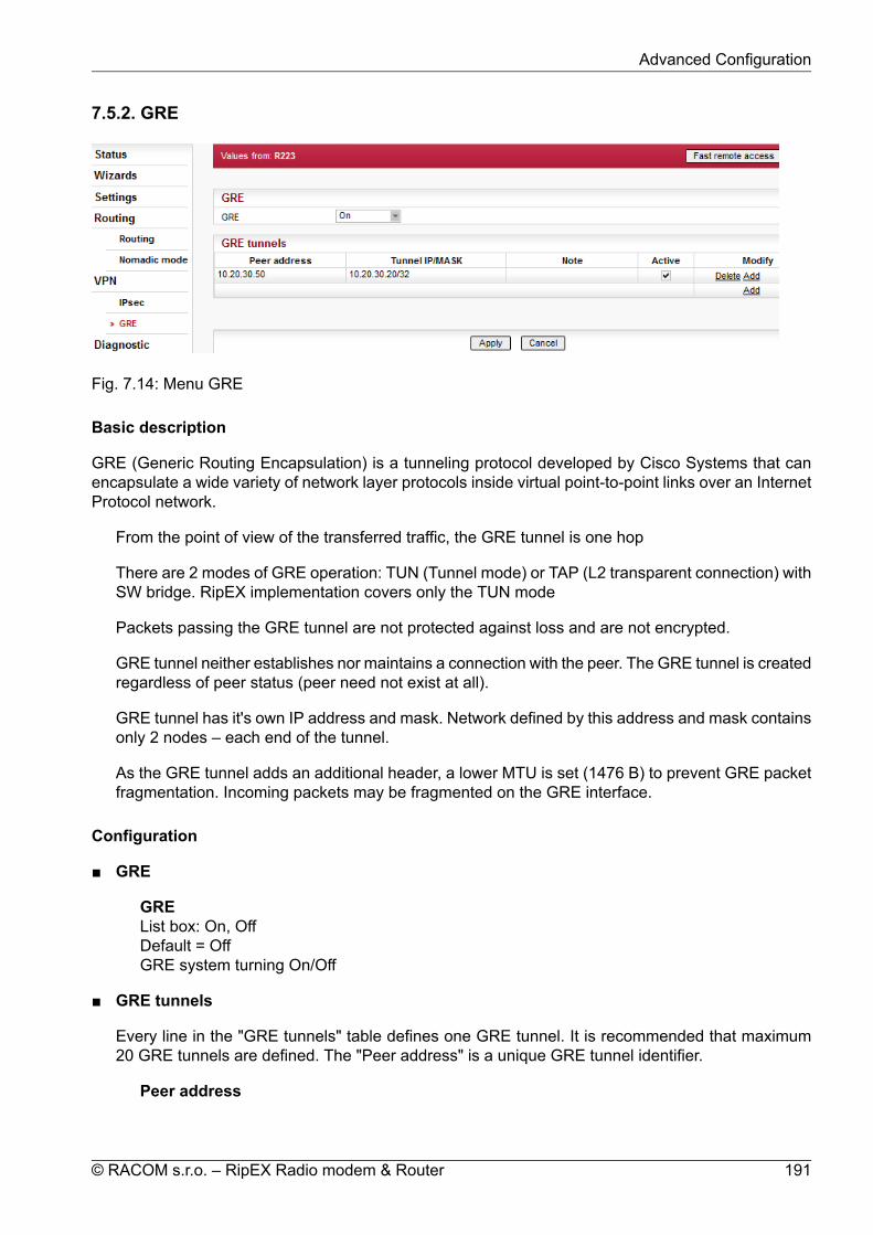
7.5.2. GRE
Fig. 7.14: Menu GRE
Basic description
GRE (Generic Routing Encapsulation) is a tunneling protocol developed by Cisco Systems that canencapsulate a wide variety of network layer protocols inside virtual point-to-point links over an InternetProtocol network.
From the point of view of the transferred traffic, the GRE tunnel is one hop
There are 2 modes of GRE operation: TUN (Tunnel mode) or TAP (L2 transparent connection) withSW bridge. RipEX implementation covers only the TUN mode
Packets passing the GRE tunnel are not protected against loss and are not encrypted.
GRE tunnel neither establishes nor maintains a connection with the peer. The GRE tunnel is createdregardless of peer status (peer need not exist at all).
GRE tunnel has it's own IP address and mask. Network defined by this address and mask containsonly 2 nodes – each end of the tunnel.
As the GRE tunnel adds an additional header, a lower MTU is set (1476 B) to prevent GRE packetfragmentation. Incoming packets may be fragmented on the GRE interface.
Configuration
GRE
GREList box: On, OffDefault = OffGRE system turning On/Off
GRE tunnels
Every line in the "GRE tunnels" table defines one GRE tunnel. It is recommended that maximum20 GRE tunnels are defined. The "Peer address" is a unique GRE tunnel identifier.
Peer address
191© RACOM s.r.o. – RipEX Radio modem & Router
Advanced Configuration

Defined as the IP address for the opposite end of the GRE tunnel. It is not possible to createmultiple GRE tunnels with the same peer address. Corresponding "Peer address" on either sideof the GRE tunnel must match.Routing to this IP address must be configured.
Tunnel IP/MASKBoth sides of the tunnel must be configured with the same MASK and different Tunnel IP ad-dresses. The Tunnel IP is used as a "Gateway" when routing traffic to the tunnel.Routing of assigned packets to the GRE tunnel is provided by the "Routing" configuration. The"Gateway" field shall be filled with the corresponding "Tunnel IP" address (i.e. peer side - "TunnelIP")
NoteYou may add a note to each tunnel with your comments up to 16 characters (UTF8 is supported)for your convenience. Following characters are not allowed:" (Double quote)` (Grave accent)\ (Backslash)$ (Dollar symbol); (Semicolon)
ActiveYou may tick/un-tick each GRE tunnel in order to make it active/not active.
GRE diagnostics
GRE tunnels are named after the pattern "gretunX" where "X" is the tunnel index. Tunnel index is cor-respond to lines in the "GRE tunnels" starting with "0". Each line is counted including the lines whichare not "Active". Example: the first line tunnel name is "gretun0".
Monitoring• IP protocol number 47 is GRE.• To be able to monitor the traffic on the GRE tunnel interface, the GRE tunnel ID must be set up
in the ETH monittoring: Advanced parameters/User rule/-i gretun0 (as an example of the firstGRE tunnel).
• Example of GRE packet monitoring on the Radio interface:
11:18:44.323793 [RF:phy:Tx] IP 10.10.1.41 > 10.10.1.67: IP protocol 47, length 126
• Example of GRE packet monitoring on the ETH interface:
11:22:58.643627 [ETH] IP 192.168.1.41 > 192.168.1.1: GREv0, length 88: IP 10.144.1.41 > 10.144.1.2: ICMP echo request, id 319, seq 1, length 64
Troubleshooting• The packet forwarded to the GRE tunnel must only be routed to the corresponding IP at the
other side of the tunnel. If the IP address fits the IP address range of the tunnel, but it does notexist, the packet is permanently looped back and forth until the TTL expires. The ICMP message"Time exceeded: TTL expired in transit" is sent to the original sender of the packet.
• The tunnel only accepts and extracts GRE packets with a source address which is the same asthe GRE tunnel's Peer address. If a GRE packet from another source appears, it is discarded
RipEX Radio modem & Router – © RACOM s.r.o.192
Advanced Configuration

and the ICMP message "Destination unreachable: Destination port unreachable" is sent to theoriginal sender of the packet.
GRE in relation to other RipEX services
GRE tunnel cannot be used to access management of the destination unit.
GRE tunnel can be used to manage destination unit using Fast remote access.
User defined firewall can be used to filter packets entering and leaving the GRE tunnel.
Proxy ARP for the LAN interface also works properly for addresses being routed to the GRE tunnel.
GRE tunnel can be routed via the radio channel.
Backup routes can use an alternative path through the GRE tunnel. The "Gateway" in "Alternativepath" section must be filled with corresponding "Tunnel IP" address.
GRE tunnel can be routed via the Backup route.NOTE: GRE packets source address will typically be the main ETH address of the RipEX unit.Configuration settings for the other side of the GRE tunnel must take this into consideration. TheRipEX Radio IP will only be selected as a source if the backup route contains a routing rule for theaddress range of the Radio network (in the "Routes" table).
GRE can operate concurrently with IP Optimization. Packets entering the GRE tunnel are not op-timized. GRE packets passing through the RipEX are optimized.
Creating a GRE tunnel on top of another GRE tunnel is possible (even in the same RipEX). NOTE:Be careful not to create a network loop! Another GRE tunnel also generates more overhead (anotherGRE header; packet fragmentation).
GRE can be used together with the TCP Proxy. TCP Proxy is capable of capturing packets leavingthe GRE tunnel as well as sending it's UDP packets over the GRE tunnel.
GRE also functions in Hot Standby mode. The GRE tunnel is state-less so there are no limits inHot Standby operation.
IPsec traffic can go through the GRE tunnel.
GRE tunnel traffic can be protected using IPsec.NOTE: The IPsec Traffic selector must be configured to capture the GRE packets without interferingwith the routing to the GRE tunnel. When necessary, it is possible to add other addresses in "ARPproxy & VLAN" configuration.
Buttons
Apply - applies and saves the changes.Cancel - restores original values.
193© RACOM s.r.o. – RipEX Radio modem & Router
Advanced Configuration

7.6. Diagnostic
7.6.1. Neighbours and Statistic
Fig. 7.15: Menu Neighbours
Neighbours and Statistics follow the same pattern.Most importantly, they share a common time frame. One Log save period and one Difference log (pairof Clear and Display buttons) apply to both logs.For both logs there is a history of 20 log files available, so the total history of saved values is 20 days(assuming the default value of 1440 min. is used as Log save period). The files are organized in a ringbuffer. Whenever a new file is opened or the Operating mode is changed, the numbers of files areshifted, i.e. 0->1, 1->2, etc.Then both the Neighbours and the Statistic log values are accumulated and weight-averaged over thewhole Log save period (one day by default). Hence a fresh change in a traffic pattern is not completelyaveraged out when the recent log is e.g. 23 hours long.When a fresh and shorter sample of the log values is needed, there is a Difference log available. Ituses an independent buffer for data and can be cleared and displayed anytime.
Buttons
All buttons are common for both logs, Neighbours and Statistic:
Save button – the log is manually saved, stored in the history file and cleared. This equals to situationwhen the Log save period expires. When the Operating mode (Bridge / Router) is changed, the logis also Saved.NOTE: Remember that both the Neighbours and Statistic logs are saved.
Difference• Clear button – when pressed, the Difference log is cleared. The standard Neighbour and Stat-
istic logs are not touched. Similarly, when the Log save period expires and the Neighbour andStatistic logs are cleared, the values in Difference log are not touched.NOTE: Remember that both Neighbours and Statistic logs are cleared.
• Display button – displays values of the Difference log, i.e. the values accumulated from timewhen the Set button has been pressed.
RipEX Radio modem & Router – © RACOM s.r.o.194
Advanced Configuration
Notice, that the Log start, Last upd. and Log uptime labels at the top change to Diff. start, Diff.upd. and Diff. uptime when the Difference log is displayed. They show the respective values forDifference log.
HistoryThere is a possibility to display history logs using standard buttons. They are placed on the left sideof the button bar. The Refresh button displays the latest log values.
Top bar
• Date Information about the actual date and time in the RipEX. It can be set in Settings/Device/Timemenu.
• Log startDate and time when the log has been cleared and started.The log is cleared and started when Log save period expires or when Save button is pressed orwhen power is switched On.
• Last updateDate and time when log has been displayed. For actual values click the Refresh button.
• Log uptimeThe difference between Log start and Last update.
• Log Save periodIt redirects to Settings/Device/Neighbours&Statistics where Statistic&Neighbours log save periodcan be set.Also the Watched values broadcasting period can be set there. This is a period in which RipEXperiodically broadcasts its Watched values to neighbouring units, where they are saved and canbe displayed in the Neighbours table.
Neighbours
Neighbours log provides information about neighbouring units (Neighbour = RipEX, which can be ac-cessed directly over the radio channel, i.e. without a repeater).Protocol on Radio channel uses Protocol addresses: MAC address for Bridge mode and Router -Flexible mode. Protocol address for Router - Base driven mode. A unit can learn the IP address of itsneighbour only when it receives its broadcast of Watched values (it contains both MAC and IP ad-dresses). Thus when Watched values broadcasting is Off in a Neighbour (Settings/Device/Neigh-bours&Statistics), there is MAC address on the respective line in the Neighbours table. When a knownIP address of a Neighbour changes, the unit cumulates data to the old IP address till it receives thenext Watched values broadcast.Maximum number of Neighbours listed in the table is 100. If this number is exceeded, the least signi-ficant Neighbour is omitted. The first criterion is whether this RipEX communicates with the Neighbourand the second criterion is the RSS level.
Neighbours Table
Generally:
• there are balloon tips with on line help for column names• the table can be sorted (descending/ascending) by any column, by clicking the column name• two values are displayed for each item: Last and Average. Last is the last value received, the Average
is a running average over all values received since the start of the log. The values received morerecently weigh up to 50% more in the average than the earlier ones.
• if a value in the table is underlined, it is a link to Graphs
195© RACOM s.r.o. – RipEX Radio modem & Router
Advanced Configuration

• green background indicates, that the item is monitored for alarm and its average value is within the"normal" range (Settings/Device/Alarm management)
• red background indicates, that the item is monitored for alarm and its average value is in the alarmrange (Settings/Device/Alarm management)
• when the value of RSS, DQ, Ucc, Temp, PWR, VSWR is not known, N/A is displayed. These N/Avalues are not displayed in Graphs
• Ucc, Temp, PWR, VSWR are refreshed every 1s. The other values in both, Neighbours and Statisticstables are refreshed every 20s
• IP addresses:Bridge modeDue to broadcast pattern of traffic in Radio channel, all frames generated by user application(s)cumulate in one line in the Neighbour table. When diagnostic or service frames (e.g. Watchedvalues) are transmitted in the network, they are listed in separate lines, distinguished by IP ad-dress of their respective Ethernet interfaces.Router modeMAC addresses of Radio interface are used for link layer communication on Radio channel.When RipEX knows the IP address corresponding with the MAC address (the IP has been thedestination IP of a packet transferred), IP address is displayed. If the IP address is not known,the MAC address is displayed.
The first three columns are logged by the receiving RipEX itself. Received headers [Count]
Total number of frame headers received from the respective RipEX. RSS [dBm]
Received Signal Strength. DQ
Data Quality of received frames. The DQ value is about proportional to BER (bit error ratio) andabout independent of the data rate and modulation used. Consequently when data rate is lowered,the DQ value increases and the other way round. Judging the DQ values requires experience,rule-of-thumb figures are as follows. Values: DQ below 100 means the link is unusable, around125 short packets should start getting through, about 160 and above can be considered "good"values.
The remaining columns contain values broadcasted by neighbouring units in their Watched valuesbroadcasting periods(Settings/Device/Neighbours&Statistics). TxLost [%]
The probability of a transmitted frame being lost (100 * Lost frames / All transmitted frames).This value is broadcasted only when Router mode is used and ACK is On.
Ucc [V]Power voltage measured on power input.
Temp [°C]Temperature inside of the RipEX.
PWR [W]The actual value of Radio output power measured by RipEX itself.
VSWRVoltage Standing Wave Ratio (1.0=best, 1.0–1.8=acceptable, >2.5=indicates a serious problemin antenna or feeder)
Packets [Rx/Tx]The total number of packets received from / transmitted to ETH, COM1, COM2 interfaces.Can be used for interface activity diagnostic.
RipEX Radio modem & Router – © RACOM s.r.o.196
Advanced Configuration

Statistic
Fig. 7.16: Menu Statistic
Statistic log provides information about communication on all interfaces: Radio, ETH, COM1, COM2and ETH Protocols (Modbus TCP, Terminal servers, TCP proxy). VLAN packets are part of ETH.Balloon tips provide on line help for all column names. These tips explain the meanings and the wayof calculation of individual values.Meaning of IP addresses listed:Rx - for received (Rx) packets, the IP source address from UDP header is displayed. Values in DATApart of the table are calculated for this source IP (origin), values in RADIO PROTOCOL part are for thelast radio hop.Tx - for transmitted (Tx) packets, the IP destination address from UDP header is displayed. Values inDATA part of the table are calculated for this destination IP (final destination), values in RADIO PRO-TOCOL part are for the next radio hop.
197© RACOM s.r.o. – RipEX Radio modem & Router
Advanced Configuration

Note
Remember that the IP source and IP destination addresses of user IP packets are notthe IP addresses of RipEXes who transport them.
1.
2. ETH Protocol packets for TCP proxy are counted on "TCP socket", i.e. between RipEXEthernet and Host device. Rx from Host device to RipEX, Tx from RipEX to Host.
7.6.2. Graphs
Graphs functions as well as meanings of Overview, Detail, Sampling period are described in thehelp Settings/Device.
Fig. 7.17: Menu Graphs
• Sampling periodHere just for information, to be set in Settings/Graphs.
• File period
RipEX Radio modem & Router – © RACOM s.r.o.198
Advanced Configuration
File period corresponds to the time, for which the values have been recorded in the file. The 60samples per graph file result in (depending on the Sampling period) 60 (2d 11:00:00), 120 (4d23:00:00), 240 (9d 23:00:00) or 720 (29d 23:00:00) hours recorded in each file.
• Available filesList box: possible valuesDefault = the newest fileThere is a list of files, which are saved in RipEX and which can be displayed. Date and time corres-ponds with the start of the file.
• 1st IPList box: possible valuesDefault = This unitList of IP addresses of RipEX units from which the graph values are available. The list of recordedunits can be set in Settings/Device/Graphs. More in help Settings/Device.
• 1st lineList box: possible valuesDefault = TxLostThere is a list of values, which can be displayed. These values are also recorded in Neighbours orStatistic files. Their meanings can be found in help Neighbours&Statistic.
• 2nd IP, 2nd lineIt is possible to display two values from the same unit or from two different ones.
• Show thresholdsYou can show thresholds for the displayed value which are set in the unit (Settings/Device/Alarmmanagement).When graph file is opened and threshold values are changed, new values are displayed in the nextgraph file. Present graph works till the end of its range threshold values set when started.
• AlarmWhen displayed value is out of threshold, a red line on the bottom of the graph is shown with itsdate and time displayed in a balloon tip.
• HistoryThere is a possibility to change displayed file(s) using standard buttons (Previous 10…6 5 4 .. Next).They are placed below the graph.
• Buttons
Refresh - complete refresh of the screen, i.e. also files in list boxes are updatedDisplay - displays/refresh ONLY data in graph according to current settings aboveStart/Stop - only for Detail graph. Active (displayed on the screen) when Detail Graph start (to beset in Settings/Graphs) is set to Single. Start button activates the sampling. Stop button can closethe file before 60 samples are saved.
199© RACOM s.r.o. – RipEX Radio modem & Router
Advanced Configuration

7.6.3. Ping
Fig. 7.18: ICMP Ping
Ping (Packet InterNet Groper) is a utility used to test the reachability of a particular host on an IP network.It operates by sending echo request packets to the target host and waiting for an echo response. Inthe process it measures the rtt (round trip time - the time from transmission to reception) and recordsany packet loss.The source IP address of Ping in RipEX is always the IP address of Ethernet interface (Settings/ETH/IP).
While using Ping, be sure that correct routing between source and destination IP addresses exists.Also pinged device has to have ICMP echo response enabled. RipEX has the ICMP echo responsealways enabled.
NOTE: Ping utility generates on-line report each 2 seconds while you are connected to Local unit andeach 10 sec. while it is generated from Remote unit and it is transferred over the Radio channel.
Ping TypeList box: ICMP, RSSDefault = RSS
ICMPThis is a standard ICMP (Internet Control Message Protocol) ping. It can be used against eitherRipEX or any other IP device connected to RipEX Radio network.
RSSRSS ping is a proprietary utility using UDP frames to trace the frame passing through the networkincluding radio hop RSS and DQ. Following values are measured and reported:• RSS and DQ information for each radio hop for each individual ping• RSS and DQ statistic (average, min., max.) for radio hop with the lowest RSS in both directions• Histogram of rtt of pings divided to 5 intervals• Load and Throughput• PER (Packet Error Rate)• BER (Bit Error Rate)
RipEX Radio modem & Router – © RACOM s.r.o.200
Advanced Configuration

DestinationDefault = 127.0.0.1Destination IP address
Length [bytes]Default = 80The length of user data, the range from 8 to 4096 Byte. Some overhead to this Length is alwaysadded like these:ICMP - 28 bytesRSS - 43 bytes for IP+UDP+RACOM header + 8 bytes (Trace-RSS and DQ) per each radio hop +4 bytes (marking in server)RSS ping can not be longer than 3/4 MTU.
CountDefault = 5Number of pings to be transmitted. The allowed range is from 1 to 1024.
Period [ms]Default = 1000When this Period expires, the next Ping is transmitted. The range is from 1000 (1 sec.) to 3600000(1 hour).
Timeout [ms]Default = 10000Timeout from 1000 (1 sec.) to 3600000 (1 hour).When ping (the response) is not received within this timeout, it is counted as lost.
A short report is generated in run-time for each individual ping packet. When the Ping utility isstopped, an overall statistic report is displayed.
ICMP Ping reportStandard Linux ping reports are provided, see Fig. 7.18, “ICMP Ping”:
Run-time report:
88 bytes from 192.168.141.215: icmp_req=1 ttl=63 time=413 ms
88 bytes total packet length
192.168.141.215 destination IP
icmp_req=1 ping sequence number
ttl=63 time to live, max. number of hops (passing through router)of the packet in the network
time=413 ms rtt (round trip time), the time from transmission of ICMP echorequest to reception of ICMP echo response
Statistic report:
5 packets transmitted, 5 received, 0% packet loss, time 4005msrtt min/avg/max/mdev = 358.988/391.840/413.061/21.665 ms
time 4005ms total time of ping utility (from Start to Stop buttons)
201© RACOM s.r.o. – RipEX Radio modem & Router
Advanced Configuration

rtt min/avg/max/mdev round trip time, minimal/average/maximal/standard deviation
RSS Ping report
RSS Ping report provides rich set of diagnostic information:
RSS Ping from 192.168.141.213 to 192.168.141.215, size:80+43(+trace)131 bytes from 192.168.141.215: seq=1 rtt=0.391s
192.168.141.213-->10.10.10.214 :52/229[RSS/DQ]-->10.10.10.215 :45/220[RSS/DQ]-->192.168.141.215
192.168.141.215-->10.10.10.214 :45/232[RSS/DQ]-->10.10.10.213 :51/229[RSS/DQ]-->192.168.141.213
131 bytes from 192.168.141.215: seq=2 rtt=0.458s192.168.141.213-->10.10.10.214 :52/232[RSS/DQ]-->
10.10.10.215 :45/223[RSS/DQ]-->192.168.141.215192.168.141.215-->10.10.10.214 :45/229[RSS/DQ]-->
10.10.10.213 :51/241[RSS/DQ]-->192.168.141.213
131 bytes from 192.168.141.215: seq=3 rtt=0.431s192.168.141.213-->10.10.10.214 :52/220[RSS/DQ]-->
10.10.10.215 :45/232[RSS/DQ]-->192.168.141.215192.168.141.215-->10.10.10.214 :45/235[RSS/DQ]-->
10.10.10.213 :51/232[RSS/DQ]-->192.168.141.213
---RSS Ping from 192.168.141.213 to 192.168.141.215 statistics---3 packet(s) transmitted, 3 received, 0.00% packet loss (0 corrupted), time 2.44 secrtt: min/avg/max/mdev = 0.391/0.427/0.458/0.0277 sec.
Load: 1211 bpsThroughput: 1211 bps
PER: 0.00% round trip, 0.00% one-wayBER: 0.00% round trip, 0.00% one-way
Radio hop with lowest RSS – direction to DestinationRSS: 52.0/52.0/52.0/0.0 min/avg/max/mdevDQ : 220.0/221.0/223.0/1.4 min/avg/max/mdev
Radio hop with lowest RSS – direction from DestinationRSS: 51.0/51.3/52.0/0.5 min/avg/max/mdevDQ : 229.0/230.0/232.0/1.4 min/avg/max/mdev
rtt histogram (time interval in sec.: %, count)0 - 2.5: 100.00% 3 XXXXXXXXXX
2.5 - 5: 0.00% 05 - 7.5: 0.00% 0
7.5 - 10: 0.00% 010 - inf: 0.00% 0
RipEX Radio modem & Router – © RACOM s.r.o.202
Advanced Configuration

Run-time report:
RSS Ping from 192.168.141.213 to 192.168.141.215, size:80+43(+trace)131 bytes from 192.168.141.215: seq=1 rtt=0.391s
192.168.141.213-->10.10.10.214 :52/229[RSS/DQ]-->10.10.10.215 :45/220[RSS/DQ]-->192.168.141.215
192.168.141.215-->10.10.10.214 :45/232[RSS/DQ]-->10.10.10.213 :51/229[RSS/DQ]-->192.168.141.213
131 bytes RSS packet size (RACOM header + data + trace)
seq ping sequence number
rtt round trip time, the time from transmission to reception
10.10.10.214 repeater IP
192.168.141.215 destination IP
Statistic report:
3 packet(s) transmitted, 3 received, 0.00% packet loss (0 corrupted), time 2.44 secrtt: min/avg/max/mdev = 0.391/0.427/0.458/0.0277 sec.
corrupted number of packets which have been received (UDP headeris OK) nevertheless their data have been corrupted (CRCover data is not OK)
time the total time of ping utility (From Start to Stop buttons)
rtt min/avg/max/mdev round trip time, minimal/average/maximal/standard deviation
Load: 1211 bpsThroughput: 1211 bps
Load the load generated by Ping utility
Throughput the throughput provided by Radio network
PER: 0.00% round trip, 0.00% one-wayBER: 0.00% round trip, 0.00% one-way
PER Packet Error Rate, i.e. the probability of a packet being lost.It is calculated for both the whole round trip and a one-waytrip.
BER Bit Error Rate, the probability of one bit received with incorrectvalue. Only packets, no bits can be lost in packet radio net-work. When a single bit is received wrong, the whole packetis lost. The BER is calculated from the PER based on thisassumption.
203© RACOM s.r.o. – RipEX Radio modem & Router
Advanced Configuration

Radio hop with lowest RSS – direction to DestinationRSS: 52.0/52.0/52.0/0.0 min/avg/max/mdevDQ : 220.0/221.0/223.0/1.4 min/avg/max/mdev
Radio hop with lowest RSS – direction from DestinationRSS: 51.0/51.3/52.0/0.5 min/avg/max/mdevDQ : 229.0/230.0/232.0/1.4 min/avg/max/mdev
There is RSS (Received Signal Strength) and DQ (Data Quality) information from the radio hopwith lowest RSS, separately for both directions (To and From the destination RipEX). DQ valueis optimally 200 - 255, more in Network planning.
The mdev values for both the RSS and DQ are provided, giving idea on signal homogeneity.The lower mdev values are recorded, the more reliable the link should be.
rtt histogram (time interval in sec.: %, count)0 - 2.5: 100.00% 3 XXXXXXXXXX
2.5 - 5: 0.00% 05 - 7.5: 0.00% 0
7.5 - 10: 0.00% 010 - inf: 0.00% 0
There is the distribution of rtt (round trip times) of received pings. Time intervals in the table are1/4 of the Timeout set in ping parameters. The XXXX... characters at the end of the line form asimple bar chart.
Buttons
Start - starts pingingStop - stops pinging, Statistic report is displayed afterwardsClear - clears the reports on the screen
RipEX Radio modem & Router – © RACOM s.r.o.204
Advanced Configuration

7.6.4. Monitoring
Monitoring is an advanced on-line diagnostic tool, which enables a detailed analysis of communicationover any of the RipEX router interfaces. In addition to all the physical interfaces (RADIO, ETH, COM1,COM2), some internal interfaces between software modules can be monitored when such advanceddiagnostics is needed.Monitoring output can be viewed on-line or saved to a file in the RipEX (e.g. a remote RipEX) anddownloaded later.
Please find Internal interfaces explanation later in this description.
205© RACOM s.r.o. – RipEX Radio modem & Router
Advanced Configuration

A short demonstration of a monitoring message:
07:55:04.661446 [COM1:phy:Rx] length 20x0000: aaaa
07:55:04.674861 [RF:phy:Tx] (88) IP 192.168.141.213.8881>192.168.141.214.8882: UDP,length 320x0000: 0800 4500 001e 0000 4000 4011 9dd2 c0a80x0010: 8dd5 c0a8 8dd6 22b1 22b2 000a 72cf aaaa
Examples of more complex monitoring outputs can be found later in this description.
Interfaces
Tick boxes:RADIO, COM1, COM2, ETH, InternalWhen ticked, the setting for the respective interface(s) is enabled. When the "Internal" interface isticked, another set of interface tick-boxes appears as follows:
Internal:RADIO, COM1, COM2, TS1, TS2, TS3, TS4, TS5, Modbus TCP, TCP proxyWhen ticked, the setting for the respective internal interface(s) is enabled (see the description below).
Common parameters for all interfaces:
Rx TxTick boxes.When ticked, packets (frames, messages) coming in the respective direction are monitored. Apacket is considered a Tx one when it comes out from the respective software module (e.g.RADIO or Terminal Server) and vice versa. When an external interface (e.g. COM:phy) ismonitored, the Tx also means packets being transmitted from the RipEX over the respectiveinterface (Rx means "received"). Understanding the directions over the internal interfaces maynot be that straightforward, please consult the diagram below for clarification.Please note the separate monitoring of Rx or Tx frames is not possible at the ETH interface.
DisplayList box: HEX, HEX+ASCII, ASCIIDefault = HEXThe format of monitoring output.
Offset [bytes]Default = 0Number of bytes from the beginning of packet/frame, which will not be displayed. The Lengthof bytes will be displayed starting from the immediately next byte.This feature is not available at the ETH interface.
Length [bytes]Default = 100Number of bytes, which will be displayed from each packet/frame.
Example: Offset=2, Length=4 means, that bytes from the 3rd byte to the 6th (inclusive) will bedisplayed:Data (HEX): 01AB3798A28593CD6B96Monitoring output: 3798A285
Filter parameters for IP/ARP packets
RipEX Radio modem & Router – © RACOM s.r.o.206
Advanced Configuration
Available for RADIO, ETH and Internal RADIO (router), COMn(router), TSn(router), ModbusTCP(router), TCP proxy (TCP), TCP proxy(router):
IP srcIP source address range in the following format: aaa.bbb.ccc.ddd/mask
IP dstIP destination address range in the following format: aaa.bbb.ccc.ddd/mask
Port srcTCP/UDP source port (range) in the following format: aaaa(-bbbb)
Port dstTCP/UDP destination port (range) in the following format: aaaa(-bbbb)
Include reverseTick box.When ticked, the frames defined by the IP src (or the IP dst) and the Port src (or the Port dst)will be displayed from both route directions, i.e. any „src" value is used as a „dst" as well (andvice-versa) by the filter.
Protocol type(available for RADIO, ETH and Internal RADIO (router))Tick boxes for displaying specific protocols only. "Other" means displaying everything exceptthe four listed protocols (even non-IP frames in case of the RADIO interface).
Interface specific parameters – RADIO
Radio IP srcThe Radio IP source address of the frame has to be within the range defined:aaa.bbb.ccc.ddd/mask.
Radio IP dstThe Radio IP destination address of the frame has to be within the range defined:aaa.bbb.ccc.ddd/mask.
Headers:List box: None, Radio Link, Data Coding, BothDefault = None• None – only the Radio Link Protocol data is displayed• Radio Link – Radio Link Control Header is displayed. It contains e.g. frame type, No., Radio
MAC addresses etc.• Data Coding – Data Coding Header is displayed. It contains information on data part com-
pression, fragmentation and encryption.• Both – Both the above mentioned headers are displayed.
Note that it may be quite difficult to locate the original payload in the data part of a Radio LinkProtocol frame. Depending on the operation mode (Bridge vs. Router) and the interface usedby the application (ETH, COM, Terminal Server...), different protocol headers (ETH, IP, UDP...)may be present and the whole data part may be compressed and encrypted.
Promiscuous mode:List box: On, OffDefault = Off
207© RACOM s.r.o. – RipEX Radio modem & Router
Advanced Configuration

• Off – only frames which are normally received by this unit, i.e. frames whose Radio IP des-tination equals to Radio IP address of this RipEX unit and broadcast frames are processedfurther by monitoring filters.
• On – all frames detected on the Radio channel are passed to monitoring filters
Link Control FramesList box: On, OffDefault = Off• Off – Radio Link Control Frames (e.g. ACK frames) are never displayed.• On – Radio Link Control Frames which pass the other monitoring filters are displayed
Other modesTick boxes.When RADIO interface is in the Promiscuous mode, the unit is capable to monitor (receive) theframes which are transmitted in different operation modes (Bridge x Router) from the one set inthis unit. Although such frames cannot be fully analysed by the monitoring engine, their contentis displayed when the corresponding mode tick box is ticked. Note that only the applicable tickbox is visible, i.e. when Operating mode is Router, than Bridge mode tick box and vice versa.
Rx streamTick box.When ticked, received stream mode frames are included in the monitoring output. Applies toBridge mode with Stream mode frame closing only. Warning : Stream mode traffic typicallyconsists of large number of short frames, hence excessive amount of monitoring data may begenerated. Note that TX frames in stream mode are not monitored.
Corrupted framesTick box.Default = TickedWhen un-ticked, the corrupted ("header CRC error", "data CRC error", etc.) received frames arenot displayed. This may be useful when the communication in the channel is heavily disturbedby interference or noise, resulting in „garbage" messages which can make the monitoring outputdifficult to read.
Interface specific parameters - ETH
ETH HeadersList box: On, OffDefault = OffWhen On, the ETH header is included in the monitoring output. Otherwise only the IP packet isdisplayed.NOTE: When VLAN ID of VLAN packets is required to be displayed, ETH Headers must be"On".
Management trafficList box: On, OffDefault=OffWhen Off, datagrams to and from HTTPS, HTTP and SSH ports in this unit are not monitored.This avoids monitoring loop under normal circumstances, i.e. when the on-line monitoring isviewed on local PC connected via the ETH interface.
Advanced parameters:User rule
RipEX Radio modem & Router – © RACOM s.r.o.208
Advanced Configuration

The standard tcpdump program is used for ETH monitoring. An arbitrary user rule in tcpdumpsyntax can be written in the text box. The rule is then added after the rules generated fromthe filters set for the ETH interface on this web page.
NOTE: Not all general rules are supported. When unsupported or wrong syntaxes are used,the warning (ETH monitoring terminated. Invalid tcpdump parameters?) will be displayed.
Internal - RADIO (router):
Headers:List box: None, Packet (IP), Frame (ETH)Default: None• None – Only the payload data is displayed, e.g. the data part of a UDP datagram.• Packet (IP) – Headers up to Packet layer are included, i.e. the full IP packet is displayed.• Frame (ETH) – The full Ethernet frame is displayed, i.e. including the ETH header.
Monitoring output control
Show time diff.Tick box.Default = UntickedWhen ticked, the time difference between subsequent packets is displayed in the monitoringoutput.
File periodList box: 1 min, 2 min, 5 min, 10 min, 20 min, 30 min, 1 hour, 3 hours, 24 hours, OffDefault = 5 min
File sizeList box: 1 KB, 10 KB, 50 KB, 100 KB, 500 KB, 1 MB, max (~2 MB)Default = 100 KBUpon clicking the "File start" button, the file is cleared and the monitoring output is copied intoit. When the selected "File period" expires or the "File size" has been reached, whichever eventoccurs first, the file is closed and left waiting to be downloaded later. The start and stop ofmonitoring to file is independent of the on-line monitoring, i.e. the monitoring output is recordedeven when the on-line monitoring is stopped.
Buttons
Buttons located at the bottom of the monitoring screen come in two groups:left: Start, Stop, Clear buttons, which control the on-line monitoring, andright: File Start, File Stop, File Status, Download buttons, which control the recording into thefile.The two processes can be started/stopped by the respective buttons independently any time. Onlyone of the Start/Stop (File Start/File Stop) button pair is accessible at a time, depending on thestatus of the respective monitoring process (the other button is gray).The Clear button clears the screen with on-line monitoring output, even when the monitoring isrunning at the moment.The File Status button refreshes the status of the file which is stored in RipEX and of the recordingprocess. It is recommended to use this button whenever you can not be sure whether your browseris synchronized with the server in the RipEX.The Download button invokes the Download File dialog.Whenever the Start or File Start button is activated, the current settings of the monitoring fromyour web page are applied. When you change any setting on the page, both Start and File Start
209© RACOM s.r.o. – RipEX Radio modem & Router
Advanced Configuration

buttons indicate that a change has been made. They turn red when the respective monitoring processis idle and they change into Apply button when the monitoring is running, i.e. when the respectiveStart (File Start) button has been gray. Clicking the Apply button enforces the configuration change(e.g. adding one more interface) to the running monitoring process
Internal interfaces description
Internal interfaces are the interfaces between a SW module and the central router module. All theseinterfaces can be found in next figure:
COM PORTSMODULE
ROUTER&
BRIDGEMODULE
TERMINAL & MODBUS TCPSERVERS
& TCP PROXY
RADIOCHANNELMODULE
COM1
COM2
ETH
RADIO
virtual com/TCP ethernet
Radio Modem Unit
RxTx
RxMP1
MP6
MP5MP3
MP7
MP2 MP4
Rx RxRx
Rx
Rx
Tx Tx TxTx
Tx
Tx
COM: phy COM: rou RF: rou RF: phy
Fig. 7.19: Interfaces
• The Router and Bridge module acts as a standard IP router or bridge, i.e. decides to whichinterface an IP packet goes next.
• The COM ports module does the conversion from messages received over the serial ports toUDP datagrams and vice-versa.
• The Radio channel module wraps (unwraps) IP packets into radio channel frames and handlesall sorts of service frames.
• The Terminal servers process messages from/to virtual COM ports, transforming them into/fromthe same UDP datagrams as the COM port module does.
• The Modbus TCP server similarly processes packets of Modbus TCP(RTU) protocol - see therelevant application note (Modbus TCP/RTU) for details. Since it is possible to monitor themessages from virtual COM and the resulting UDP datagrams independently, the TSn and theModbus TCP have two internal interfaces – distinguished as (com) and (router).
• The TCP proxy server converts TCP datagrams to UDP ones, while maintaining the originalTCP session locally. The two internal interfaces can be used to independently monitor the TCPand UDP sides on the (com) and (router), respectively.
• MP1, MP2, ... labels are the monitoring points referred to in following Monitoring examples.
RipEX Radio modem & Router – © RACOM s.r.o.210
Advanced Configuration

Monitoring examples
Monitoring examples - COM, RADIO
The hexadecimal data aaaa is coming through the port COM1 and then the frame is sent overthe radio channel. Monitored on IP address 192.168.141.213:
07:55:04.661446 [COM1:phy:Rx] length 20x0000: aaaa
07:55:04.674861 [RF:phy:Tx] (88) IP 192.168.141.213.8881>192.168.141.214.8882: UDP,length 320x0000: 0800 4500 001e 0000 4000 4011 9dd2 c0a80x0010: 8dd5 c0a8 8dd6 22b1 22b2 000a 72cf aaaa
07:55:04.661446 timestamp -it is recommended to synchronize time in the network (e.g. usingNTP server) to be able to analyse records from multiple units
[COM1:phy:Rx] (MP1) interface monitored -COM port 1: physical layer : frame received from an external device
length 2 monitored frame length [bytes]
0x0000: monitored frame position, Byte increments, hexadecimal
aaaa monitored frame
07:55:04.674861 timestamp
[RF:phy:Tx] (MP4) interface monitored -RADIO channel : physical layer : frame transmitted to the antenna
(88) physical layer Tx frame number
IP 192.168.141.213.8881> SRC IP address and UDP port number
192.168.141.214.8882: DST IP address and UDP port number
UDP Ethernet Protocol type
length 32 monitored frame length [bytes]
0x0000: monitored frame report position, Byte increments, hexadecimal
0800 4500 001e 0000 40004011 9dd2 c0a8
monitored frame report
NOTE: (MP1),(MP4) are the monitoring points as described in Fig. 7.19, “Interfaces”
211© RACOM s.r.o. – RipEX Radio modem & Router
Advanced Configuration

Monitoring including internal interfaces. Monitored on IP address 192.168.141.213:
12:26:34.700971 [COM1:phy:Rx] length 20x0000: aaaa12:26:34.701476 [COM1:rou:Tx] IP 0.0.0.0.8881 > 192.168.141.215.8882: UDP, length 0+20x0000: aaaa12:26:34.702074 [RF:rou:Rx] IP 192.168.141.213.8881 > 192.168.141.215.8882: UDP, length 28+20x0000: 4500 001e aa0f 0000 4011 33c2 c0a8 8dd50x0010: c0a8 8dd7 22b1 22b2 000a 72ce aaaa12:26:34.734036 [RF:phy:Tx] (84) IP 192.168.141.213.8881 > 192.168.141.215.8882: UDP,len 32RLhead: 4e80 01ac c701 ae0f 21 ((MC:10) 10.10.10.213 > 10.10.10.214, |LN:4|P:0|A:y|R:-|)0x0000: 0800 4500 001e aa0f 0000 4011 33c2 c0a80x0010: 8dd5 c0a8 8dd7 22b1 22b2 000a 72ce aaaa12:26:34.748841 [RF:phy:Rx] (84) ACK, rss:52 dq:238RLhead: 4000 ae0f 21
[COM1:phy:Rx] (MP1) frame incoming through physical interface
aaaa monitored frame report
[COM1:rou:Tx] (MP2) packet sent from the COM PORT module to the ROUTER module
IP 0.0.0.0.8881 > the source port does not have an IP address, only port number 8881source UDP frame with no IP address and port number 8881
192.168.141.215.8882: the destination IP and port depends on the com port protocol setting
aaaa monitored frame report, data transmitted over the radio channel canbe shortened (it depends on the COM port protocol)
[RF:rou:Rx] (MP3) packet received by the radio channel module from router module
IP 192.168.141.213.8881> source IP address and port
192.168.141.215.8882: destination IP address and port given by Async Link protocol
length 28+2 overhead length + data length
[RF:phy:Tx] (MP4) frame sent from the radio channel module to the antenna
(84) radio channel transmitted frames internal numbering
RLhead: Radio Link header (enable "RADIO/Headers" = Radio Link)
10.10.10.213 > transmitting radio channel IP address
10.10.10.214 receiving radio channel IP address (according to the Routing table)
[RF:phy:Rx] (MP5) Acknowledgement frame (ACK) reception
(84) ACK frame number is the same as the acknowledged frame number
ACK, rss:52 dq:238 received signal strength and data quality of the ACK frame
RipEX Radio modem & Router – © RACOM s.r.o.212
Advanced Configuration

Ethernet frame received and transmitted via radio. Monitored on IP address 192.168.141.213:
08:23:19.197235 [ETH] ARP, Request who-has 192.168.141.214 tell 192.168.141.212, length 460x0000: 0001 0800 0604 0001 0002 a949 c067 c0a80x0010: 8dd4 0000 0000 0000 c0a8 8dd6 0000 09040x0020: 690f 5600 aaaa 1234 ffff ffff ffff
08:23:19.930106 [ETH] ARP, Reply 192.168.141.214 is-at 00:02:a9:ae:0b:39, length 280x0000: 0001 0800 0604 0002 0002 a9ae 0b39 c0a80x0010: 8dd6 0002 a949 c067 c0a8 8dd4
08:23:20.441093 [ETH] IP 192.168.141.212.8888 > 192.168.141.214.8001: UDP, length 100x0000: 4500 0026 0002 4000 4011 9dc9 c0a8 8dd40x0010: c0a8 8dd6 22b8 1f41 0012 ae15 0000 09050x0020: 690f 5600 aaaa 0000 0000 0000 0000
08:23:20.443997 [RF:rou:Rx] IP 192.168.141.212.8888 > 192.168.141.214.8001: UDP, length 28+100x0000: 4500 0026 0002 4000 3f11 9ec9 c0a8 8dd40x0010: c0a8 8dd6 22b8 1f41 0012 ae15 0000 09050x0020: 690f 5600 aaaa
08:23:20.479097 [RF:phy:Tx] (88) IP 192.168.141.212.8888 > 192.168.141.214.8001: UDP,len 40RLhead: 4ea0 01ac c701 ae0f 21 ((MC:10) 10.10.10.213 > 10.10.10.214, |LN:5|P:0|A:y|R:-|)0x0000: 0800 4500 0026 0002 4000 3f11 9ec9 c0a80x0010: 8dd4 c0a8 8dd6 22b8 1f41 0012 ae15 00000x0020: 0905 690f 5600 aaaa
08:23:20.493823 [RF:phy:Rx] (88) ACK, rss:50 dq:235RLhead: 4000 ae0f 21
[ETH] ARP, Request (MP6) ARP Request received
[ETH] ARP, Reply (MP7) ARP Reply transmitted
[ETH] IP (MP6) frame received from the ETH device
IP 192.168.141.212.8888> ETH frame source IP address and port
192.168.141.214.8001: ETH frame destination IP address and port
[RF:rou:Rx] (MP3) packet received by the Radio ch. module from the Router module
[RF:phy:Tx] (MP4) frame sent from the Radio channel module to the antenna
IP 192.168.141.212.8888> source IP address and port, same as the incoming ETH frame
192.168.141.214.8001: destination IP address and port, same as the incoming ETH frame
10.10.10.213 > transmitting radio channel IP address
10.10.10.214 receiving radio channel IP address (according to the Routing table)
[RF:phy:Rx] (MP5) receipt of the confirmation frame (ACK)
213© RACOM s.r.o. – RipEX Radio modem & Router
Advanced Configuration

Internal Errors and Warning displayed by monitoring
Errors (red background)
Requested monitoring data missingRequired data for monitoring are not available for an unknown reason.
Can be displayed on an independent line while any interface is being monitored.
RF preheader error"RF-preheader" is a part of header transmitted by the most robust modulation.
Displayed while "RADIO" (Rx) interface is being monitored as part of a packet header.
RL header CRC error"RL-header" is Radio Link protocol header.
Displayed while "RADIO" (Rx) interface is being monitored as part of a packet header.
Bridge stream datablock header CRC error"Bridge stream DB-header" is header of Data block transmitted while Operating mode is Bridgeand Frame closing (COM) is Stream.
Displayed while "RADIO" (Rx) interface is monitored as part of a packet header.
Data CRC errorData CRC error.
Displayed while "RADIO" (Rx) interface is monitored as part of a packet header.
Warnings (yellow background)
Record sequence problem - reconfiguration?There is a problem in sequence of records. The system may have to be reconfigured with otherSettings or Routing pages.
Can be displayed on an independent line while any interface is being monitored.
Record sequence problem. Some records may be lost.There is a problem in sequence of records for an unknown reason. One or more records havebeen lost.
Can be displayed on an independent line while any interface is being monitored.
[x] missing record(s) detected"x" (replaced by specific number) records are missing.
Can be displayed on an independent line while any interface is being monitored.
Monitoring restarted. Some records may be lost.Monitoring system has been restarted e.g. because of monitoring configuration change. Somerecords may be lost.
Can be displayed on an independent line while any interface is being monitored.
ETH monitoring terminated. Invalid tcpdump parameters?Monitoring of ETH interface has been stopped. Probably because of unsupported or wrong'tcpdump' syntax in Monitoring/ETH/Advanced parameters/User rule.
Can be displayed on an independent line while ETH interface is being monitored.
Interface not ready!RF interface is not ready. May happen when system is booting, after reconfiguration, after radiopart recalibration made automatically after some time etc. The packet is discarded.
Displayed while "RADIO" (Tx) interface is being monitored as part of a packet header.
RipEX Radio modem & Router – © RACOM s.r.o.214
Advanced Configuration

RF interface not ready!RF interface is not ready. May happen when system is booting, after reconfiguration, after radiopart recalibration made automatically after some time etc. The packet is discarded.
Displayed while "Internal-RADIO" (Tx) interface is being monitored as part of a packetheader.
Interface not ready - high radio board temperature!The transmitting is blocked because radio board has reached a temperature higher than 95 °C.
Displayed while "RADIO" (Tx) interface is being monitored as part of a packet header.
RF interface not ready - high radio board temperature!The transmitting is blocked because radio board has reached a temperature higher than 95 °C.
Displayed while "Internal-RADIO" (Tx) interface is being monitored as part of a packetheader.
Frame reception cancelledThe process of frame reception has been interrupted.
Displayed while "RADIO" (Rx) interface is being monitored as part of a packet header.
Duplicated frameDuplicated frame has been detected. It is discarded.
Displayed while "RADIO" (Rx) interface is being monitored as part of a packet header.
Queue fullRadio interface Tx queues are full and next request for frame transmitting has been received.The frame is discarded.
Displayed while "RADIO" (Tx) interface is being monitored as part of a packet header.
Incompatible frame?Incompatible frame has been received. A few of the possible causes may be foreign RL-protocol,unknown RLP packet type, unknown RLP packet group, unknown service, incorrect ETH frame,unsupported IP frame type, ...
Displayed while "RADIO" (Rx) interface is being monitored as part of a packet header.
ACKUnexpected ACK received.
Displayed while "RADIO" (Rx) interface is being monitored as part of packet header.
Can't decrypt - configuration problem?The frame cannot be decrypted. Probably wrong configuration, e.g. different AES encryptionkeys are used.
Displayed while "RADIO" (Rx) interface is being monitored as part of a packet header.
Can't decryptThe frame cannot be decrypted.
Displayed while "RADIO" (Rx) interface is being monitored as part of a packet header.
Can't decompressThe frame cannot be decompressed. (The compression is done automatically and can beswitched off only over the CLI).
Displayed while "RADIO" (Rx) interface is being monitored as part of a packet header.
Bridge mode frameThe frame in "Bridge" format has been received, but Operating mode is set to Router.
215© RACOM s.r.o. – RipEX Radio modem & Router
Advanced Configuration

Displayed while "RADIO" (Rx) interface is being monitored as part of a packet header.
Stream mode frameThe frame in "Bridge/Stream" format has been received, but Operating mode is not Bridge orFrame closing (COM) is not Stream.
Displayed while "RADIO" (Rx) interface is being monitored as part of a packet header.
Router mode frameThe frame in "Router" format has been received, but Operating mode is set to Bridge.
Displayed while "RADIO" (Rx) interface is being monitored as part of a packet header.
RipEX Radio modem & Router – © RACOM s.r.o.216
Advanced Configuration

7.7. Maintenance
7.7.1. SW feature keys
Fig. 7.20: Menu Maintenance SW feature keys
Certain advanced RipEX features have to be activated by software keys. On the right side one maysee the list of available keys and their respective status values.Possible status values are:
• Not present• Active• Active (timeout dd:hh:mm:ss) – the key can be time limited. For such a key, the remaining time
of activity is displayed (1d 07:33:20). Time of activity of a key is counted only when the unit isswitched on. Time limited key can be put on hold, i.e. temporarily deactivated. Press the correspond-ing Hold button (possibly several Hold buttons for several selected keys) and then press the Applybutton to put the selected key(s) on hold.
On hold (timeout dd:hh:mm:ss) – the key is On hold, i.e. temporarily not active. To re-activatesuch a key, press the Activate and then Apply buttons.
• Master – when Master key (unlocks all keys) is active.• Master (On hold) – The time-limited key for a specific feature is On hold, however the feature is
active because of the Master key.
There are two ways to input the SW key into RipEX: Fill in the key you have received from RACOM oryour distributor in the Key box using copy/paste or the SW key can be uploaded from a file. Fill in theSW Key file, or browse your disk in order to find the file. When a file is selected, it can be uploaded.
• Upload – when pressed, the selected SW key is uploaded into the RipEX, however it is not yetactive. You can subsequently upload more keys.
• Apply – when pressed, all the uploaded keys are activated and/or status values of Time limitedkeys are changed following their respective buttons Activate or Hold have been pressed. Afterwardsthe unit automatically reboots itself.
NOTE: SW feature key can be downloaded also from USB flash. Read details in the Firmware paragraph.
217© RACOM s.r.o. – RipEX Radio modem & Router
Advanced Configuration

7.7.2. Configuration
Fig. 7.21: Menu Maintenance Configuration
UNIT• Back up – Back up saves the active configuration into a backup file in the unit.• Restore – configuration saved in the backup file in the unit is activated and the unit reboots itself.• Factory settings – Sets the factory defaults and activates them. Neighbours, Statistic and
Graphs databases are cleared including their histories. The unit reboots afterwards.
The following items are NOT cleared when the Factory settings are applied:1. Admin password2. Technical support package3. Firmware archive4. Configuration backup5. SSL certificate (when your own certificate is used)6. Remote access keys (when User key is used)7. Folder /home/… in Linux
When you need to reset the device access parameters (the login, password, Ethernet IPetc.) to defaults, press the RESET button on the bottom-side of RipEX enclosure for 15 sec.See the User manual for details.
• Total purge – sets the very same settings as when the device was delivered from the factory.I.e. Factory settings as above is applied and the flash memory is also totally cleared. I.e. the"not cleared" items in Factory settings are cleared by Total purge. The whole operation takesapprox. 5 mins. and the unit is rebooted afterwards.
FILE• Save to file – saves the active configuration into a file.
Configuration can be uploaded from a file. Fill in the Configuration file, or browse your disk inorder to find the file. When a file is selected, it can be uploaded.
• Upload – uploads configuration from the selected file and activates it. The unit reboots itselfafterwards.
7.7.3. Firmware
Fig. 7.22: Menu Maintenance Firmware
RipEX Radio modem & Router – © RACOM s.r.o.218
Advanced Configuration

The firmware in the unit consists of several parts, however they come in one firmware package(file_name.cpio). Individual part names and their versions can be seen. There can be two versions offirmware packages stored within the unit – "Active" and "Archive". Unit is always using the Active version.The Archive version is there just for convenience and safety of firmware manipulations. It can also beuploaded to a remote unit over the Radio channel.
• Upload to Archive – Fill in Firmware file, or browse your disk in order to find the file. When a fileis selected and the "Upload to Archive" button pressed, it is uploaded and becomes the Archivefirmware.
Note
it is recommended to do this only over reliable Ethernet connections and not over theRadio channel.
• Archive to Active – when pressed, the Active firmware is substituted by the Archive firmware.Either "All" or only "Only the different" versions are replaced according to the Versions list boxsetting. The unit reboots itself afterwards.
• Copy Archive to Other unit – he Archive firmware package can be copied to another unit typicallyover Radio channel. Fill in the IP address of the desired unit and press the button.
Note
If possible, copy FW only over one Radio hop where radio link is quality sufficiently high.Otherwise it can be very time consuming. When Router mode is used, don’t forget toset correct Routing tables settings.
NOTE: New firmware as well as SW feature keys can be uploaded directly from a USB flash disk. OnlyFAT32 file system on flash disk is supported. Download firmware file from www.racom.eu. Save thisfile in the root directory of USB flash (in a format "ra1-RACOM-<VERSION>.cpio"). When SW key(s)will be uploaded, save the respective file(s) also in the root directory with the file name(s) unchanged.More SW keys can be saved on a single flash disk. Remember that SW key is unique for each individualRipEX S/N. See the flash disc structure requirements in more details Section 4.2.5, “USB” .
When more than one fw files is on the flash disk, the most recent version is uploaded. The most recentversion on the flash disk can not be older than in the RipEX; downgrade from flash is not supported.Upload from the flash is equivalent to Maintenance/Firmware/Upload to Archive plus Maintenance/Firm-ware/Versions=All plus Maintenance/Firmware/Archive to Active.
Plug USB flash with file(s) as above in RipEX USB connector, Status LED starts to blink within 5 sec.,it changes between green and red colors. When the LED blinks slowly (1x per sec.), correct file(s) hasbeen detected on flash.NOTE: when LED blinks fast (3x per sec.), expected files have not been found and USB flash can beremoved.
Upload starts and Status LED can change its colors and blinking during upload. When upload is finished,the LED blinks fast (3x per sec.). USB flash can be removed.
The whole process can take up to 10 min. (FW approx. 8 min., SW key approx. 1 min.). There is alog(s) saved on USB disk (/logs) with information about upload process.
Don’t remove USB flash while uploading. USB flash could be damaged!
219© RACOM s.r.o. – RipEX Radio modem & Router
Advanced Configuration

7.7.4. Administrator account
Fig. 7.23: Menu Maintenance Administrator account
The Administrator account (user name "admin") is the primary account for unrestricted unit configuration.
Password length is at least 5 and maximum 32 characters long. Only characters a-zA-Z0-9.:_- are al-lowed.
It is highly recommended to change default the password (admin) even if the user name remains alwaysthe same (admin). When the Apply button is pressed, the unit reboots.
7.7.5. Miscellaneous
• Reboot – when pressed, the unit correctly shuts down and starts again (performs the cold startwhich equals to a power cycle). The reboot time is approx. 25 sec.
• BRC Radio MAC – when pressed, an ARP reply packet is broadcasted over the Radio channel.When e.g. a RipEX unit has been replaced by a spare one with the same Radio IP, but differentRadio MAC address, the neighbouring RipEXes update their ARP tables only after their respectivetimeout expires. Forced transmission of an ARP reply restores the communication with the neigboursimmediately.
NOTE: The ARP reply packet is automatically transmitted after every boot, hence the manual invoc-ation should not be necessary. Nevertheless broadcasting an extra ARP reply following any IP orMAC address change is a good and recommended practice.
• RSS sample – when pressed, the current level of Received Signal Strength (one sample) on Radiochannel is measured. This sample is measured regardless of the current Radio channel status(Quiet/Rx/Tx)
7.7.6. SSL certificate
Fig. 7.24: Menu Maintenance SSL certificate
It is possible to download your own SSL certificate into RipEX for https communication used for webconfiguration. 2048 bits certificate is supported and recommended, however the 512 or 1024 bits certi-ficates can also be used. SSL certificate may have one or two files. Both options are supported.
• Certificate file
Fill in the Certificate file, or browse your disk in order to find the file.• Key file
RipEX Radio modem & Router – © RACOM s.r.o.220
Advanced Configuration

When your SSL certificate consists of two files, fill in the Key file, or browse your disk in order to findthe file.When file(s) is selected, it can be uploaded.
• Upload – when pressed, the selected Certificate is uploaded into the RipEX, however it is not activeyet.
• Apply – when pressed, the uploaded certificate is activated. Afterwards the unit automatically rebootsitself.
• Default – when pressed, the default RACOM SSL certificate is uploaded. To be activated, Applybutton has to be executed.
7.7.7. Remote access keys
Fig. 7.25: Menu Maintenance Remote access keys
The "Fast remote access" is a secured communication channel over the Radio interface based on amodified ssh protocol. It is possible to use own security keys for this communication.
NOTE: It is not possible to use the Fast remote access between two RipEX units with different Remoteaccess keys. When you want to change the Remote access key in a network, start from the most remoteunit.
• Active – Information only, the Active key is displayed here• Default – Information only, the Default key is displayed here• User – Information only, the User key is displayed here after the Generate button has been pressed.
Activate User key
– when pressed, the User key displayed above is activated. When the User key is already active, thebutton is not active (grey).
Activate Default key
– when pressed, the Default key displayed above is activated. When the Default key is already active,the button is not active (grey).
User key
There are several possibilities to create User key, which is displayed in the User box afterwards:
• Generate– the system generates a random User key. It is saved in the flash. This can be done only locally;this button is not active in the remote unit while using Fast remote access.
• Upload from file
221© RACOM s.r.o. – RipEX Radio modem & Router
Advanced Configuration

– browse your disk in order to find the file with your User key and upload. This can be done onlylocally; this button is not active in the remote unit while using Fast remote access.
• Save to file– the User key displayed in the box can be saved into a file. This can be done only locally and whenthe User key exists; this button is not active in the remote unit while using Fast remote.
• Copy to Other unit– the User key displayed in the box is transferred to another unit in the network with the specifiedIP address. Afterwards it has to be activated in the remote unit manually. This button can be usedalso in the remote unit via Fast remote access. The button is not active when a User key doesn’texist.
7.7.8. RF transmission test
Fig. 7.26: Menu Maintenance Technical support package
It is intended to be used for laboratory measurements or antenna testing.
• TypeList box: Carrier, Random dataCarrier – only unmodulated carrier is transmittedRandom data – modulated random data is transmittedDefault = Carrier
• Period [s]Default = 15 s (possible values 1s – 50s)During this time period RipEX transmits after Start button is executed.
7.7.9. Technical support package
Technical support package is the file where some internal events are recorded. It can be used by RACOMtechnical support when a deeper diagnostic is required. The most recent part of it can be downloadedto the local PC.
• Log depthList box: possible valuesDefault = 500This is the number of rows downloaded. The greater the number of rows, the longer the history tobe found in the file. However more lines means greater file size as well. When downloaded from aremote unit over Radio channel in poor signal conditions, a lower Log depth should be selected.
RipEX Radio modem & Router – © RACOM s.r.o.222
Advanced Configuration

8. CLI ConfigurationCLI interface (Command Line Interface) is an alternative to web access. You can work with the CLIinterface in text mode using an appropriate client, either ssh (putty) or telnet.
CLI “login” and “password” are the same as those for web access via browser. Access using ssh keysis also possible. Keys are unique for each individual RipEX Serial number. The public key is downloadedin RipEX, for the private key kindly contact RACOM and provide RipEX S/N.
Connecting with a putty client. Type the following command into the window Host Name (or IP address):
Press Open. Then enter the password admin.
Thu Mar 31 10:56:47 CEST 2011Welcome to RipEX Command Line Interface (CLI) on station: RipEX 50
For help try: cli_help
CLI(admin):~$
The cli_help command shows a list of all available functions. The commands can be completedusing the Tab key. If you select the command with the left mouse button, you can copy it to the clipboardand then use the right mouse button to insert it into the location of the cursor. You can use the -tparameter to send commands to remote RipEX’s. Every command gives a comprehensive help wheninvoked with -h or –help parameter.
There are two ways how to execute the CLI command. It can either be executed in the interactive modeor in the script mode.
In the interactive mode, you need to save, apply or cancel every command. If you choose the "save"option, the change is stored in the buffer and it is not yet active. In this way, you can save severalcommands in the buffer (e.g. change the frequency, COM settings and RF power) and "apply" all thechanges in one step. If you do not wish to save or apply the command, you can "cancel" it and issueanother command.
In the script mode, all the commands are automatically saved in the buffer without any confirmation.When you need to apply the changes, issue the command cli_cnf_apply_change (in the script modeagain). The CLI commands can be used in the scripts thanks to this mode.
8.1. CLI Examples
An example of a parameter request for the COM1 port of the RipEX with IP 192.168.1.1:
CLI(admin):~$ cli_cnf_show_com 1 -t 10.10.10.2COM link type: RS232 (RS232)COM bitrate: 19200 (19200)COM data bits: 8 (8)COM parity: None (n)COM stop bits: 1 (1)COM idle size: 5 chars
223© RACOM s.r.o. – RipEX Radio modem & Router
CLI Configuration

COM MTU: 1600 bytesCOM handshake: None (n)COM break length: 1000 charsCOM protocol: Modbus (mod)
The CLI is a powerful tool for advanced management of RipEX, especially suited for automated tasks.It is best learned through its own help system, hence it is not described in further detail here.
Setting the COM1 baud rate (interactive mode)
CLI(admin):~$ cli_cnf_set_com 1 -bitrate 9600Starting new update. Updated values:COM link type: RS232 (RS232)COM bitrate: 9600 (9600)COM data bits: 8 (8)COM parity: None (n)COM stop bits: 1 (1)COM idle size: 5 charsCOM MTU: 1600 bytesCOM handshake: None (n)COM break length: 1000 chars
Please select action (save, apply, cancel):acli_cnf_set_com: Configuration update accepted, starting to perform. Estimated time to finish: 4000ms.
Setting the COM1 baud rate (script mode):
CLI(admin):~$ cli_cnf_set_com 1 -bitrate 9600 -csCLI(admin):~$ cli_cnf_apply_change -csCLI(admin):~$
Applying several commands at once
CLI(admin):~$ cli_cnf_set_radio -rf-power 19Starting new update. Updated values:Radio IP: 10.10.10.1Radio mask: 24Radio Tx freq.: 435.750.000 HzRadio Rx freq.: 435.750.000 HzFreq. values locked: On (n)RF power: 1W, M-PSK (19)Channel spacing: 25.0 kHz (25.0)Modulation type: M-PSK (-)Radio approval type: CE (CE)Modulation rate: 83.33kbps | 16DEQAM (25.0kHz, CE) (691)FEC: Off (o)IP optimization: Off (f)Fragment size: 1500 bytesRadio compression: LZO (l)
RipEX Radio modem & Router – © RACOM s.r.o.224
CLI Configuration

Please select action (save, apply, cancel):scli_cnf_set_radio: Update saved.
CLI(admin):~$ cli_cnf_set_com 1 -bitrate 19200Continuing from previous update(s). Updated values:COM link type: RS232 (RS232)COM bitrate: 19200 (19200)COM data bits: 8 (8)COM parity: Even (e)COM stop bits: 1 (1)COM idle size: 5 charsCOM MTU: 1600 bytesCOM handshake: None (n)COM break length: 1000 chars
Please select action (save, apply, cancel):scli_cnf_set_com: Update saved.
CLI(admin):~$ cli_cnf_apply_changeDo you really want to apply modified configuration? (yes, no)ycli_cnf_apply_change: Configuration update accepted, starting to perform. Estimated time to finish: 13000 ms.cli_cnf_apply_change: You may be disconnected during update.
Remote RipEX COM1 parity configuration
CLI(admin):~$ cli_cnf_set_com 1 -bitrate 9600 -parity e -t 10.10.10.3Starting new update. Updated values:COM link type: RS232 (RS232)COM bitrate: 9600 (9600)COM data bits: 8 (8)COM parity: Even (e)COM stop bits: 1 (1)COM idle size: 5 charsCOM MTU: 1600 bytesCOM handshake: None (n)COM break length: 1000 chars
Please select action (save, apply, cancel):acli_cnf_set_com: Configuration update accepted, starting to perform. Estimated time to finish: 4000ms.
225© RACOM s.r.o. – RipEX Radio modem & Router
CLI Configuration

9. Troubleshooting1. I don’t know what my RipEX’s IP is – how do I connect?
• Use the "X5" – external ETH/USB adapter and a PC as a DHCP client. Type 10.9.8.7 into yourbrowser’s location field.
• Alternatively, you can reset your RipEX to default access by pressing the Reset button for along time, see Section 4.2.7, “Reset button” .
. Afterwards, you can use the IP 192.168.169.169/24 to connect to the RipEX. Note that, inaddition to resetting access parameters to defaults, your firewall rules will be cleared as well.
2. My PC is unable to connect to the RipEX.
• In PC settings, Network protocol (TCP/IP)/Properties, the following configuration is sometimesused:
General tab - Automatically receive address from a DHCP serverAlternate configuration tab - User defined configuration,e.g. 192.168.169.250
Use this configuration instead:
General tab - Use the following IP,e.g. 192.168.169.250
• Verify your PC’s IP address from the command line:
Start/Run/commandipconfig
Send a ping to the RipEX:
ping 192.168.169.169
If the ping runs successfully, look for a problem with the browser configuration. Sometimes thebrowser may need minutes to make new connection.
3. I’m configuring the RipEX in its default state but it’s not working.
• There is another RipEX with the default configuration in close vicinity. Switch it off.4. I have configured one RipEX in its default state. But I cannot connect to another.
• Your PC keeps a table of IP addresses and their associated MAC addresses. You can view itfrom the command line:
Start/Run/commandarp -a
IP address physical address type192.168.169.169 00-02-a9-00-fe-2c dynamic
All RipEX’s share the default IP address but their MAC addresses are different, meaning thisrecord interferes with your purpose. The timeout for automatic cache clearing may be longerso you can delete the entry manually by typing:
RipEX Radio modem & Router – © RACOM s.r.o.226
Troubleshooting

arp -d 192.168.169.169
or delete the entire table by typing:
arp -d *
Then you can ping the newly connected RipEX again.5. I have assigned the RipEX a new IP address and my PC lost connection to it.
• Change the PC’s IP address so that it is on the same subnet as the RipEX.6. I entered the Router mode and lost connection to the other RipEX’s.
• Enter correct data into the routing tables in all RipEX’s.7. The RSS Ping test shows low RSS for the required speed.
• Use higher output, a unidirectional antenna, better direct the antenna, use a better feed line,taller pole. If nothing helps, lower the speed.
8. The RSS Ping test reports good RSS but low DQ.
• When the DQ value is much lower then it should be at the given RSS, typically it is a case ofmulti-path propagation. It can cause serious problems to data communication, especially whenhigh data rates are used. Since the interfering signals come from different directions, changingthe direction of the antenna may solve the problem. A unidirectional antenna should be usedin the first place. Metallic objects in close vicinity of the antenna may cause harmful reflections,relocating the antenna by few meters may help. Change of polarization at both ends of the linkcould be the solution as well.
9. The RSS Ping test shows bad homogeneity.
• Quite often the bad homogeneity comes together with a low DQ. In that case follow the advicegiven in the previous paragraph. If the DQ does correspond to the RSS level, you should lookfor unstable elements along the signal route – a poorly installed antenna or cable, movingobstacles (e.g. cars in front of the antenna), shifting reflective areas etc. If you cannot removethe cause of disturbances, you will need to ensure signal is strong enough to cope with it.
227© RACOM s.r.o. – RipEX Radio modem & Router
Troubleshooting
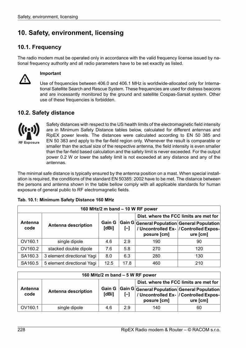
10. Safety, environment, licensing
10.1. Frequency
The radio modem must be operated only in accordance with the valid frequency license issued by na-tional frequency authority and all radio parameters have to be set exactly as listed.
Important
Use of frequencies between 406.0 and 406.1 MHz is worldwide-allocated only for Interna-tional Satellite Search and Rescue System. These frequencies are used for distress beaconsand are incessantly monitored by the ground and satellite Cospas-Sarsat system. Otheruse of these frequencies is forbidden.
10.2. Safety distance
Safety distances with respect to the US health limits of the electromagnetic field intensityare in Minimum Safety Distance tables below, calculated for different antennas andRipEX power levels. The distances were calculated according to EN 50 385 andEN 50 383 and apply to the far-field region only. Whenever the result is comparable orsmaller than the actual size of the respective antenna, the field intensity is even smallerthan the far-field based calculation and the safety limit is never exceeded. For the outputpower 0.2 W or lower the safety limit is not exceeded at any distance and any of theantennas.
The minimal safe distance is typically ensured by the antenna position on a mast. When special install-ation is required, the conditions of the standard EN 50385: 2002 have to be met. The distance betweenthe persons and antenna shown in the table bellow comply with all applicable standards for humanexposure of general public to RF electromagnetic fields.
Tab. 10.1: Minimum Safety Distance 160 MHz
160 MHz/2 m band – 10 W RF powerDist. where the FCC limits are met for
Gain G[–]
Gain G[dBi]Antenna descriptionAntenna
codeGeneral Population/ Controlled Expos-
ure [cm]
General Population/ Uncontrolled Ex-
posure [cm]901902.94.6single dipoleOV160.1
1202705.87.6stacked double dipoleOV160.21302806.38.03 element directional YagiSA160.321046017.812.55 element directional YagiSA160.5
160 MHz/2 m band – 5 W RF powerDist. where the FCC limits are met for
Gain G[–]
Gain G[dBi]Antenna descriptionAntenna
codeGeneral Population/ Controlled Expos-
ure [cm]
General Population/ Uncontrolled Ex-
posure [cm]601402.94.6single dipoleOV160.1
RipEX Radio modem & Router – © RACOM s.r.o.228
Safety, environment, licensing

160 MHz/2 m band – 5 W RF power901905.87.6stacked double dipoleOV160.2902006.38.03 element directional YagiSA160.3
15033017.812.55 element directional YagiSA160.5
160 MHz/2 m band – 4 W RF powerDist. where the FCC limits are met for
Gain G[–]
Gain G[dBi]Antenna descriptionAntenna
codeGeneral Population/ Controlled Expos-
ure [cm]
General Population/ Uncontrolled Ex-
posure [cm]601202.94.6single dipoleOV160.1801705.87.6stacked double dipoleOV160.2801806.38.03 element directional YagiSA160.3
13029017.812.55 element directional YagiSA160.5
160 MHz/2 m band – 3 W RF powerDist. where the FCC limits are met for
Gain G[–]
Gain G[dBi]Antenna descriptionAntenna
codeGeneral Population/ Controlled Expos-
ure [cm]
General Population/ Uncontrolled Ex-
posure [cm]451102.94.6single dipoleOV160.1701505.87.6stacked double dipoleOV160.2701506.38.03 element directional YagiSA160.3
12026017.812.55 element directional YagiSA160.5
160 MHz/2 m band – 2 W RF powerDist. where the FCC limits are met for
Gain G[–]
Gain G[dBi]Antenna descriptionAntenna
codeGeneral Population/ Controlled Expos-
ure [cm]
General Population/ Uncontrolled Ex-
posure [cm]40902.94.6single dipoleOV160.1601205.87.6stacked double dipoleOV160.2601306.38.03 element directional YagiSA160.3
10021017.812.55 element directional YagiSA160.5
160 MHz/2 m band – 1 W RF powerDist. where the FCC limits are met for
Gain G[–]
Gain G[dBi]Antenna descriptionAntenna
codeGeneral Population/ Controlled Expos-
ure [cm]
General Population/ Uncontrolled Ex-
posure [cm]30602.94.6single dipoleOV160.140905.87.6stacked double dipoleOV160.240906.38.03 element directional YagiSA160.3
229© RACOM s.r.o. – RipEX Radio modem & Router
Safety, environment, licensing

160 MHz/2 m band – 1 W RF power7015017.812.55 element directional YagiSA160.5
Tab. 10.2: Minimum Safety Distance 216–220 MHz
216–220 MHz – 10 W RF powerDist. where the FCC limits are met for
Gain G[–]
Gain G[dBi]Antenna descriptionAntenna
codeGeneral Population/ Controlled Expos-
ure [cm]
General Population/ Uncontrolled Ex-
posure [cm]651352.94.6single dipoleOV200.1901955.87.6stacked double dipoleOV200.2901955.87.63 element directional YagiSA200.3
Tab. 10.3: Minimum Safety Distance 300–400 MHz
300–400 MHz/70 cm band – 10 W RF powerDist. where the FCC limits are met for
Gain G[–]
Gain G[dBi]Antenna descriptionAntenna
codeGeneral Population/ Controlled Expos-
ure [cm]
General Population/ Uncontrolled Ex-
posure [cm]601302.94.6single dipoleOV380.1801805.87.6stacked double dipoleOV380.2801805.87.63 element directional YagiSA380.3902007.48.75 element directional YagiSA380.5
14031017.812.59 element directional YagiSA380.9
300–400 MHz/70 cm band – 5 W RF powerDist. where the FCC limits are met for
Gain G[–]
Gain G[dBi]Antenna descriptionAntenna
codeGeneral Population/ Controlled Expos-
ure [cm]
General Population/ Uncontrolled Ex-
posure [cm]40902.94.6single dipoleOV380.1601305.87.6stacked double dipoleOV380.2601305.87.63 element directional YagiSA380.3701407.48.75 element directional YagiSA380.5
10022017.812.59 element directional YagiSA380.9
300–400 MHz/70 cm band – 4 W RF powerDist. where the FCC limits are met for
Gain G[–]
Gain G[dBi]Antenna descriptionAntenna
codeGeneral Population/ Controlled Expos-
ure [cm]
General Population/ Uncontrolled Ex-
posure [cm]35802.94.6single dipoleOV380.1501105.87.6stacked double dipoleOV380.2
RipEX Radio modem & Router – © RACOM s.r.o.230
Safety, environment, licensing

300–400 MHz/70 cm band – 4 W RF power501105.87.63 element directional YagiSA380.3601307.48.75 element directional YagiSA380.59020017.812.59 element directional YagiSA380.9
300–400 MHz/70 cm band – 3 W RF powerDist. where the FCC limits are met for
Gain G[–]
Gain G[dBi]Antenna descriptionAntenna
codeGeneral Population/ Controlled Expos-
ure [cm]
General Population/ Uncontrolled Ex-
posure [cm]30702.94.6single dipoleOV380.1451005.87.6stacked double dipoleOV380.2451005.87.63 element directional YagiSA380.3501107.48.75 element directional YagiSA380.58017017.812.59 element directional YagiSA380.9
300–400 MHz/70 cm band – 2 W RF powerDist. where the FCC limits are met for
Gain G[–]
Gain G[dBi]Antenna descriptionAntenna
codeGeneral Population/ Controlled Expos-
ure [cm]
General Population/ Uncontrolled Ex-
posure [cm]25602.94.6single dipoleOV380.135805.87.6stacked double dipoleOV380.235805.87.63 element directional YagiSA380.340907.48.75 element directional YagiSA380.57014017.812.59 element directional YagiSA380.9
300–400 MHz/70 cm band – 1 W RF powerDist. where the FCC limits are met for
Gain G[–]
Gain G[dBi]Antenna descriptionAntenna
codeGeneral Population/ Controlled Expos-
ure [cm]
General Population/ Uncontrolled Ex-
posure [cm]20402.94.6single dipoleOV380.125605.87.6stacked double dipoleOV380.225605.87.63 element directional YagiSA380.330707.48.75 element directional YagiSA380.55010017.812.59 element directional YagiSA380.9
300–400 MHz/70 cm band – 0.5 W RF powerDist. where the FCC limits are met for
Gain G[–]
Gain G[dBi]Antenna descriptionAntenna
codeGeneral Population/ Controlled Expos-
ure [cm]
General Population/ Uncontrolled Ex-
posure [cm]
231© RACOM s.r.o. – RipEX Radio modem & Router
Safety, environment, licensing

300–400 MHz/70 cm band – 0.5 W RF power15302.94.6single dipoleOV380.120405.87.6stacked double dipoleOV380.220405.87.63 element directional YagiSA380.320457.48.75 element directional YagiSA380.5307017.812.59 element directional YagiSA380.9
Tab. 10.4: Minimum Safety Distance 928–960 MHz
928–960 MHz – 8 W RF powerDist. where the FCC limits are met for
Gain G[–]
Gain G[dBi]Antenna descriptionAntenna
codeGeneral Population/ Controlled Expos-
ure [cm]
General Population/ Uncontrolled Ex-
posure [cm]30.869.02.924.65single dipoleOV900.148.9109.37.338.655 element directional YagiSA900.592.1205.926.014.1512 element directional YagiSA900.12
10.3. High temperature
If the RipEX is operated in an environment where the ambient temperature exceeds55 °C, the RipEX must be installed within a restricted access location to prevent humancontact with the enclosure heatsink.
10.4. RoHS and WEEE compliance
This product is fully compliant with the European Parlament's 2011/65/EU RoHS(Restriction of Certain Hazardous Substances in Electrical and ElectronicEquipment) and 2012/19/EU WEEE (Waste Electrical and Electronic Equipment)environmental directives.
Used equipment must be collected separately, and disposed of properly. Racomhas instigated a programme to manage the reuse, recycling, and recovery ofwaste in an environmentally safe manner using processes that comply with theWEEE Directive.
Battery Disposal - This product may contain a battery. Batteries must be disposed of properly, and maynot be disposed of as unsorted municipal waste within the European Union. See the product document-ation for specific battery information. Batteries are marked with a symbol, which may include letteringto indicate cadmium (Cd), lead (Pb), or mercury (Hg). For proper recycling, return the battery to yoursupplier or to a designated collection point.
RipEX Radio modem & Router – © RACOM s.r.o.232
Safety, environment, licensing

10.5. Hazardous locations
RipEX unit shall be used in hazardous locations with following specification:II 3G Ex ic IIC T4 Gc
according to IEC 60079-0 standard under following conditions:
• Installation has to be done with conformity to standard EN 60079-25 Explosive atmospheres -Intrinsically safe electrical systems, with special attention to lightning protection.
• The unit must be powered with an intrinsically safe power source.
• The antenna has to be installed outside the hazardous zone.
• Do not manipulate the RipEX (e.g. plug or unplug connectors) unless powered down or the area isknown to be non-hazardous.
• Only USB equipment dedicated for hazardous locations shall remain connected permanently.
• Repairs, including exchange of internal battery, shall only be undertaken by an authorized repairshop.
• This equipment is not intended to withstand particularly adverse service conditions (for example,rough handling, humidity effects, ambient temperature variations, effects of chemical agents, corro-sion).
Important
DO NOT HANDLE UNLESS THE AREA IS KNOWN TO BE NON-HAZARDOUS
For individual interface maximum voltage and current see the following table:
Tab. 10.5: Maximum voltage and current of individual interfaces
recommendedmin. cross sectionof Cu wiremax. currentmax. voltageIN/OUT
V03VH-H 2×0.55 A30 VDCDC Power 0.5 mm2
V03VH-H 1×0.510 mA30 VDCSI 0.5 mm2
V03VH-H 1×0.510 mA30 VDCAlarm input 0.5 mm2
V03VH-H 1×0.52 A30 VDCAlarm output 0.5 mm2
LiYCY 4×0.1460 mA±15 VDCRS232 0.14 mm2
LiYCY 4×0.1460 mA±15 VDCRS485 0.14 mm2
0.5 A5 VDCUSB 0.5 mm2
STP CAT 5E±2.5 VDCEthernet RJ45
See Fig. 10.2, “ATEX Certificate RipEX, 1/3”.
233© RACOM s.r.o. – RipEX Radio modem & Router
Safety, environment, licensing

10.6. Conditions of Liability for Defects and Instructions for Safe Operationof Equipment
Please read these safety instructions carefully before using the product:
• Liability for defects does not apply to any product that has been used in a manner which conflictswith the instructions contained in this operator manual, or if the case in which the radio modem islocated has been opened, or if the equipment has been tampered with.
• The radio equipment can only be operated on frequencies stipulated by the body authorised by theradio operation administration in the respective country and cannot exceed the maximum permittedoutput power. RACOM is not responsible for products used in an unauthorised way.
• Equipment mentioned in this operator manual may only be used in accordance with instructionscontained in this manual. Error-free and safe operation of this equipment is only guaranteed if thisequipment is transported, stored, operated and controlled in the proper manner. The same appliesto equipment maintenance.
• In order to prevent damage to the radio modem and other terminal equipment the supply must alwaysbe disconnected upon connecting or disconnecting the cable to the radio modem data interface. Itis necessary to ensure that connected equipment has been grounded to the same potential.
• Only undermentioned manufacturer is entitled to repair any devices.
10.7. Important Notifications
Sole owner of all rights to this operating manual is the company RACOM s. r. o. (further in this manualreferred to under the abbreviated name RACOM). All rights reserved. Drawing written, printed or repro-duced copies of this manual or records on various media or translation of any part of this manual toforeign languages (without written consent of the rights owner) is prohibited.
RACOM reserves the right to make changes in the technical specification or in this product function orto terminate production of this product or to terminate its service support without previous written noti-fication of customers.
Conditions of use of this product software abide by the license mentioned below. The program spreadby this license has been freed with the purpose to be useful, but without any specific guarantee. Theauthor or another company or person is not responsible for secondary, accidental or related damagesresulting from application of this product under any circumstances.
The maker does not provide the user with any kind of guarantee containing assurance of suitabilityand usability for his application. Products are not developed, designed nor tested for utilization indevices directly affecting health and life functions of persons and animals, nor as a part of another im-portant device, and no guarantees apply if the company product has been used in these aforementioneddevices.
RACOM Open Software License
Version 1.0, November 2009Copyright (c) 2001, RACOM s.r.o., Mírová 1283, Nové Město na Moravě, 592 31
Everyone can copy and spread word-for-word copies of this license, but any change is not permitted.
The program (binary version) is available for free on the contacts listed on http://www.racom.eu. Thisproduct contains open source or another software originating from third parties subject to GNU GeneralPublic License (GPL), GNU Library / Lesser General Public License (LGPL) and / or further author li-cences, declarations of responsibility exclusion and notifications. Exact terms of GPL, LGPL and some
RipEX Radio modem & Router – © RACOM s.r.o.234
Safety, environment, licensing

further licences is mentioned in source code packets (typically the files COPYING or LICENSE). Youcan obtain applicable machine-readable copies of source code of this software under GPL or LGPL li-cences on contacts listed on http://www.racom.eu. This product also includes software developed bythe University of California, Berkeley and its contributors.
235© RACOM s.r.o. – RipEX Radio modem & Router
Safety, environment, licensing

10.8. EU Declaration of Conformity
EU DECLARATION OF CONFORMITY
ver. 1.3
www.racom.euRACOM s.r.o. | Mirova 1283 | 592 31 Nove Mesto na Morave | Czech Republic
Radio equipment type RipEX-160
RipEX-300
RipEX-400
Manufacturer RACOM s.r.o.
Mirova 1283, 592 31 Nove Mesto na Morave, Czech Republic
This declaration of conformity is issued under the sole responsibility of the manufacturer.
The radio equipment described above is in conformity with the Directive 2014/53/EU of the European
Parliament and of the Council on the harmonisation of the laws of the Member States relating to the
making available on the market of radio equipment and repealing Directive 1999/5/EC.
Harmonised standards used for demonstration of conformity:
Spectrum EN 302 561 V2.1.1:2017
EMC EN 301 489-1 V2.1.1
EN 301 489-5 V2.1.1
Safety EN 60950-1:2006, A11:2009, A1:2010, A12:2011, A2:2013
SAR EN 50385:2002
EN 50383ed.2:2011
EN 300 113 V2.2.1:2017
:2017
:2017
Signed for and on behalf of the manufacturer:
thNove Mesto na Morave, 16 of December 2017
Jiri Hruska, CEO
Radio SW
SDDR ver. 0.24.0.58
Driver ver. 0.5.19.0
Tel.: +420 565 659 511 | E -mail: [email protected]
Fig. 10.1: EU Declaration of Conformity
RipEX Radio modem & Router – © RACOM s.r.o.236
Safety, environment, licensing

10.9. Simplified EU declaration of conformity
BGС настоящото RACOM s.r.o. декларира, че този тип радиосъоръжение RipEX-160, RipEX-300,RipEX-400 е в съответствие с Директива 2014/53/ЕС.
ESPor la presente, RACOM s.r.o. declara que el tipo de equipo radioeléctrico RipEX-160, RipEX-300,RipEX-400 es conforme con la Directiva 2014/53/UE.
CSTímto RACOM s.r.o. prohlašuje, že typ rádiového zařízení RipEX-160, RipEX-300, RipEX-400 je vsouladu se směrnicí 2014/53/EU.
DAHermed erklærer RACOM s.r.o., at radioudstyrstypen RipEX-160, RipEX-300, RipEX-400 er i over-ensstemmelse med direktiv 2014/53/EU.
DEHiermit erklärt RACOM s.r.o., dass der Funkanlagentyp RipEX-160, RipEX-300, RipEX-400 derRichtlinie 2014/53/EU entspricht.
ETKäesolevaga deklareerib RACOM s.r.o., et käesolev raadioseadme tüüpRipEX-160, RipEX-300, RipEX-400 vastab direktiivi 2014/53/EL nõuetele.
ELΜε την παρούσα ο/η RACOM s.r.o., δηλώνει ότι ο ραδιοεξοπλισμός RipEX-160, RipEX-300, RipEX-400 πληροί την οδηγία 2014/53/ΕΕ.
ENHereby, RACOM s.r.o. declares that the radio equipment type RipEX-160, RipEX-300, RipEX-400 isin compliance with Directive 2014/53/EU.
FRLe soussigné, RACOM s.r.o., déclare que l'équipement radioélectrique du type RipEX-160, RipEX-300,RipEX-400 est conforme à la directive 2014/53/UE.
HRRACOM s.r.o. ovime izjavljuje da je radijska oprema tipa RipEX-160, RipEX-300, RipEX-400 u skladus Direktivom 2014/53/EU.
ITIl fabbricante, RACOM s.r.o., dichiara che il tipo di apparecchiatura radio RipEX-160, RipEX-300,RipEX-400 è conforme alla direttiva 2014/53/UE.
LVAr šo RACOM s.r.o. deklarē, ka radioiekārta RipEX-160, RipEX-300, RipEX-400 atbilst Direktīvai2014/53/ES.
LTAš, RACOM s.r.o., patvirtinu, kad radijo įrenginių tipas RipEX-160, RipEX-300, RipEX-400 atitinkaDirektyvą 2014/53/ES.
237© RACOM s.r.o. – RipEX Radio modem & Router
Safety, environment, licensing

HURACOM s.r.o. igazolja, hogy a RipEX-160, RipEX-300, RipEX-400 típusú rádióberendezés megfelela 2014/53/EU irányelvnek.
MTB'dan, RACOM s.r.o., niddikjara li dan it-tip ta' tagħmir tar-radju RipEX-160, RipEX-300, RipEX-400huwa konformi mad-Direttiva 2014/53/UE.
NLHierbij verklaar ik, RACOM s.r.o., dat het type radioapparatuur RipEX-160, RipEX-300, RipEX-400conform is met Richtlijn 2014/53/EU.
PLRACOM s.r.o. niniejszym oświadcza, że typ urządzenia radiowego RipEX-160, RipEX-300, RipEX-400jest zgodny z dyrektywą 2014/53/UE.
PTO(a) abaixo assinado(a) RACOM s.r.o. declara que o presente tipo de equipamento de rádio RipEX-160, RipEX-300, RipEX-400 está em conformidade com a Diretiva 2014/53/UE.
ROPrin prezenta, RACOM s.r.o. declară că tipul de echipamente radio RipEX-160, RipEX-300, RipEX-400 este în conformitate cu Directiva 2014/53/UE.
SKRACOM s.r.o. týmto vyhlasuje, že rádiové zariadenie typu RipEX-160, RipEX-300, RipEX-400 je vsúlade so smernicou 2014/53/EÚ.
SLRACOM s.r.o. potrjuje, da je tip radijske opreme RipEX-160, RipEX-300, RipEX-400 skladen z Direktivo2014/53/EU.
FIRACOM s.r.o. vakuuttaa, että radiolaitetyyppi RipEX-160, RipEX-300, RipEX-400 on direktiivin2014/53/EU mukainen.
SVHärmed försäkrar RACOM s.r.o. att denna typ av radioutrustning RipEX-160, RipEX-300, RipEX-400överensstämmer med direktiv 2014/53/EU.
RipEX Radio modem & Router – © RACOM s.r.o.238
Safety, environment, licensing

10.10. ATEX Certificate
Fig. 10.2: ATEX Certificate RipEX, 1/3
239© RACOM s.r.o. – RipEX Radio modem & Router
Safety, environment, licensing

Fig. 10.3: ATEX Certificate RipEX, 2/3
RipEX Radio modem & Router – © RACOM s.r.o.240
Safety, environment, licensing

Fig. 10.4: ATEX Certificate RipEX, 3/3
241© RACOM s.r.o. – RipEX Radio modem & Router
Safety, environment, licensing

10.11. IP51 Certificate
Fig. 10.5: EZU Certificate IP51
RipEX Radio modem & Router – © RACOM s.r.o.242
Safety, environment, licensing
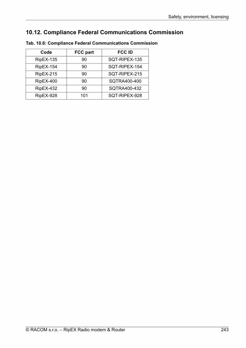
10.12. Compliance Federal Communications Commission
Tab. 10.6: Compliance Federal Communications Commission
FCC IDFCC partCodeSQT-RIPEX-13590RipEX-135SQT-RIPEX-15490RipEX-154SQT-RIPEX-21590RipEX-215SQTRA400-40090RipEX-400SQTRA400-43290RipEX-432SQT-RIPEX-928101RipEX-928
243© RACOM s.r.o. – RipEX Radio modem & Router
Safety, environment, licensing
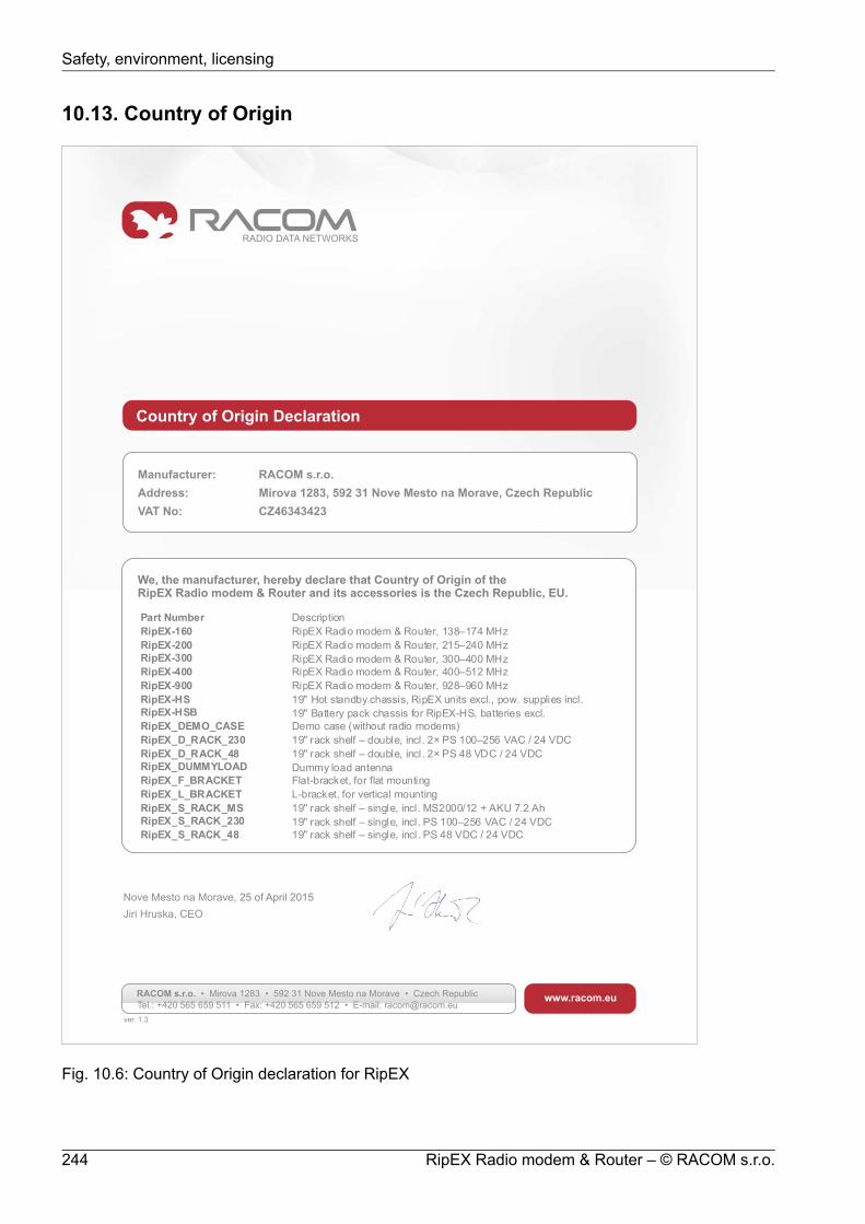
10.13. Country of Origin
Country of Origin Declaration
Manufacturer: RACOM s.r.o.
Address: Mirova 1283, 592 31 Nove Mesto na Morave, Czech Republic
VAT No: CZ46343423
We, the manufacturer, hereby declare that Country of Origin of theand its accessories is the Czech Republic, EU.RipEX Radio modem & Router
Nove Mesto na Morave,
Jiri Hruska, CEO
25 of April 2015
www.racom.euRACOM s.r.o. • Mirova 1283 • 592 31 Nove Mesto na Morave • Czech Republic
Tel.: +420 565 659 511 • Fax: +420 565 659 512 • E-mail: [email protected]
Part Number Description
RipEX-160 RipEX Radio modem & Router, 138–174 MHz
RipEX-200 RipEX Radio modem & Router, 215–240 MHz
RipEX-300 RipEX Radio modem & Router, 300–400 MHz
RipEX-400 RipEX Radio modem & Router, 400–512 MHz
RipEX-900 RipEX Radio modem & Router, 928–960 MHz
RipEX-HS 19" Hot standby chassis, RipEX units excl., pow. supplies incl.
RipEX-HSB 19" Battery pack chassis for RipEX-HS, batteries excl.
RipEX_DEMO_CASE Demo case (without radio modems)
RipEX_D_RACK_230 19" rack shelf – double, incl. 2× PS 100–256 VAC / 24 VDC
RipEX_D_RACK_48 19" rack shelf – double, incl. 2× PS 48 VDC / 24 VDC
RipEX_DUMMYLOAD Dummy load antenna
RipEX_F_BRACKET Flat-bracket, for flat mounting
RipEX_L_BRACKET L-bracket, for vertical mounting
RipEX_S_RACK_MS 19" rack shelf – single, incl. MS2000/12 + AKU 7.2 Ah
RipEX_S_RACK_230 19" rack shelf – single, incl. PS 100–256 VAC / 24 VDC
RipEX_S_RACK_48 19" rack shelf – single, incl. PS 48 VDC / 24 VDC
ver. 1.3
Fig. 10.6: Country of Origin declaration for RipEX
RipEX Radio modem & Router – © RACOM s.r.o.244
Safety, environment, licensing

10.14. Warranty
RACOM-supplied parts or equipment ("equipment") is covered by warranty for inherently faulty partsand workmanship for a warranty period as stated in the delivery documentation from the date of dispatchto the customer. The warranty does not cover custom modifications to software. During the warrantyperiod RACOM shall, on its option, fit, repair or replace ("service") faulty equipment, always providedthat malfunction has occurred during normal use, not due to improper use, whether deliberate or acci-dental, such as attempted repair or modification by any unauthorised person; nor due to the action ofabnormal or extreme environmental conditions such as overvoltage, liquid immersion or lightning strike.
Any equipment subject to repair under warranty must be returned by prepaid freight to RACOM direct.The serviced equipment shall be returned by RACOM to the customer by prepaid freight. If circumstancesdo not permit the equipment to be returned to RACOM, then the customer is liable and agrees to reim-burse RACOM for expenses incurred by RACOM during servicing the equipment on site. Whenequipment does not qualify for servicing under warranty, RACOM shall charge the customer and bereimbursed for costs incurred for parts and labour at prevailing rates.
This warranty agreement represents the full extent of the warranty cover provided by RACOM to thecustomer, as an agreement freely entered into by both parties.
RACOM warrants the equipment to function as described, without guaranteeing it as befitting customerintent or purpose. Under no circumstances shall RACOM's liability extend beyond the above, nor shallRACOM, its principals, servants or agents be liable for any consequential loss or damage caused directlyor indirectly through the use, misuse, function or malfunction of the equipment, always subject to suchstatutory protection as may explicitly and unavoidably apply hereto.
245© RACOM s.r.o. – RipEX Radio modem & Router
Safety, environment, licensing

10.15. RipEX maintenance
NotePeriodAction
Quarterly
Visual check – Antenna:Draining hole on dipole must be downward pointingThere should be no damaged elements on the antennaAngle of elevation of antennaAzimuth (angle of horizontal deviation) in accordance with design
Annually
Visual check – Coaxial Cable:Mechanical damageSolar degradationEntire cable correctly mounted to surfaceConnectors tightened to function optimallySelf-vulcanizing tape used for all connections requiring insulationPSV & RF measurements
Annually
Visual check – Cabinet:Mechanical damageDamage resulting in lower categorization for cabinet coverageBushings for running cables
AnnuallyVisual check – Electricity Supply:
Insulation damageConnection to terminals
AnnuallyVisual check – Accumulator:
Capacity in accordance with customer requirementsCondition of the accumulator
AnnuallyFunctionality check – power source:
OverchargingAccumulator damage
AnnuallyFull utilization of provided protective coveringsAnnuallyRemove any items which are not part of the installationAnnuallyFix and secure makeshift installations correctly
As requiredCheck grounding connectionsAs requiredCheck lightning arrester : connectors must be tightened
AnnuallyCheck data connectors connected including securing screws
MonthlyEvaluate the RSS and DQ values as a preventive measure against
the failure of the connection. RSS and DQ values be similar tothose at time of comissioning.
MonthlyCheck activity logs to detect abnormalities in data transmissionsMonthlyCheck if internal temperature alarm has been triggered
As requiredCheck that firmware is latest stable version – upgrading FWrecommended when new features required
If you are unsure on any of the above please contact RACOM technical support.
RipEX Radio modem & Router – © RACOM s.r.o.246
Safety, environment, licensing

Appendix A. OID mappingsRipEX internal SNMP server messages (answers) contain OID according to RFC1157.
"MIB tables", and whole file "OID mappings" can be downloaded from:http://www.racom.eu/eng/products/radio-modem-ripex.html#download
More details are described in Application note:See RipEX App notes, SNMP1
1 http://www.racom.eu/eng/products/m/ripex/app/snmp.html
247© RACOM s.r.o. – RipEX Radio modem & Router
OID mappings

Appendix B. Abbreviations
MDIX Medium dependent interface crossoverACK Acknowledgement
AES Advanced Encryption Standard MIB Management Information Base
NMS Network Management SystemATM Automated teller machine
BER Bit Error Rate N.C. Normally Closed
N.O. Normally OpenCLI Command Line Interface
CRC Cyclic Redundancy Check NTP Network Time Protocol
MRU Maximum Reception UnitCTS Clear To Send
dBc decibel relative to the carrier MTU Maximum Transmission Unit
OS Operation SystemdBi decibel relative to the isotropic
dBm decibel relative to the milliwat PC Personal Computer
PER Packet Error RateDCE Data Communication Equipment
DHCP Dynamic Host Configuration Protocol POS Point of sale
PWR PowerDNS Domain Name Server
DQ Data Quality RF Radio Frequency
RipEX Radio IP ExchangerDTE Data Terminal Equipment
EMC Electro-Magnetic Compatibility RoHS Restriction of the use of HazardeousSubstances
FCC Federal Communications CommissionRPT Repeater
FEC Forward Error CorrectionRSS Received Signal Strength
FEP Front End ProcessorRTS Request To Send
GPL General Public LicenseRTU Remote Terminal Unit
https Hypertext Transfer Protocol SecureRX Receiver
IP Internet ProtocolSCADA Supervisory control and data acquisition
kbps kilobit per secondSDR Software Defined Radio
LAN Local Area NetworkSNMP Simple Network Management Protocol
LOS Line-of-sight
MAC Media Access Control
RipEX Radio modem & Router – © RACOM s.r.o.248
Abbreviations

TCP Transmission Control Protocol
TS5 Terminal server 5
TX Transmitter
UDP User Datagram Protocol
VSWR Voltage Standing Wave Ratio
WEEE Waste Electrical and Electronic Equipment
249© RACOM s.r.o. – RipEX Radio modem & Router
Abbreviations

Index
Aaccessories, 71addressing
bridge, 16router, 21
administrator account, 220alarm
in/out, 47management, 108
antenna, 45dummy load, 77, 79mounting, 87overvoltage, 77separated, 68
antenna switch, 77
Bbackup
configuration, 218route, 173
Base driven protocol, 132base driven protocol, 24basic setup, 83bench test, 79bridge, 13, 94, 126
CCOM
parameters, 152config. file, 218configuration
CLI, 223web, 90
connect PC, 79connecting HW, 79connectors, 45Copyright, 7
Ddefault
parameters, 8, 80setting, 52, 218
demo case, 72diagnostic, 29dimensions, 42DQ, 35, 204, 212
Eenvironment, 228ETH param., 143
Ffactory settings, 218features, 10feedline cable, 77firewall
IP (L3), 102MAC (L2), 103NAT, 104
firmware, 218firmware update, 30flexible protocol, 19
GGNU licence, 234GPS, 51, 68graphs, 118, 198grounding, 88
Hhazardous locations, 233helps on web, 90Hot Standby, 95
Iimportant notifications, 234input hw, 47installation, 84IP/serial, 28
Kkeys sw, 31, 217
LLED, 53licensing, 228
Mmanagement, 120menu Diagnostic, 194
Graphs, 198Monitoring, 205Neighbours, 195Ping, 200Statistic, 197
menu Header, 90menu Maintenance, 217
250© RACOM s.r.o. – RipEX Radio modem & Router

menu RoutingNomadic mode, 175Routing, 171
menu SettingsCOM protocols, 155
Async link, 159C24, 159Cactus, 160Comli, 160Common parameters, 156DF1, 161DNP3, 161IEC 870-5-101, 162ITT Flygt, 162Modbus, 163None, 159PR2000, 164Profibus, 164RDS, 164RP570, 165Siemens 3964(R), 166SLIP, 168UNI, 169
Device, 93Alarm management, 108Firewall & NAT, 102Graphs, 118Hot Standby, 95Management, 120Neighbours&Statistics, 116Operating mode, 94Power management, 112SNMP, 99Time, 96Unit name, 94WiFi, 114
Radio, 122IP, Mask..., 137prot. Base driven, 132prot. Flexible, 128prot. Transparent, 126QoS, 139
menu Status, 92menu VPN
GRE, 191IPsec, 183
MIB tables, 247migration cable, 78Modbus TCP, 144mode
bridge, 13router, 19
base driven, 24flexible, 20
model offerings, 68mounting
bracket, 73, 85DIN rail, 84IP51, 87rack, 74, 87
multipath propagation, 35
Nneighbours, 116network
example, 23layout, 38management, 29planning, 32
nomadic mode, 175
Oordering code, 68output hw, 47
Ppart number, 68password, 220ping menu, 200pooling, 13power management, 112product
code, 68conformity
ATEX, 239CE, 236EU, 237FCC, 243IP51, 242
protocolsethernet, 144radio, 13serial port, 155
QQoS, 139quick guide, 8
Rradio
parameters, 58remote access, 90repeater
251© RACOM s.r.o. – RipEX Radio modem & Router
Index

bridge, 13router, 21
report-by-exception, 13reset, 52, 220RipEX, 10RipEX Hot Standby, 71RoHS and WEEE, 232router, 19, 94, 128routing configuration, 171RSS, 204, 212
Ssafety, 228
distance, 228SCADA, 27sensitivity, 57sleep, 47, 55SNMP, 99statistics, 116supply
connection, 46, 48, 89consumption, 55, 112
SW feature keys, 217
Ttechnical parameters, 54technical support, 222terminal server, 147time, 96transparent protocol, 13troubleshooting, 226
UUSB adapter, 71–72users
admin, 220read-only, 121
VVPN, 183
WWiFi, 114
disconnection, 115
RipEX Radio modem & Router – © RACOM s.r.o.252
Index

Appendix C. Revision HistoryRevisionThis manual was prepared to cover a specific version of firmware code. Accordingly, some screensand features may differ from the actual unit you are working with. While every reasonable effort hasbeen made to ensure the accuracy of this publication, product improvements may also result in minordifferences between the manual and the product shipped to you.
2011-08-31Revision 1.1First issue
2011-12-31Revision 1.2PoE is not supported in RipEX from 1.1.2012, so all information about PoE has been removed.
2011-01-26Revision 1.3Added information about Monitoring Upgraded information about Terminal servers (IP port dynamicalchanges support)New serial SCADA protocols - RP570, C24 Melsec, ITT Flygt, Cactus
2012-07-11Revision 1.4Added information about RipEX-HS, Hot Standby unit.Upgraded chapters: Technical specification, Model offerings, Accessories, Safety distance, AdvancedConfiguration
2013-04-29Revision 1.5Added information about new features: Backup routes, TCP proxy, ARP proxy& VLAN, FW and SWkeys upgrade via USB, SLIP and Siemens 3964(R) SCADA protocolsUpgraded chapters: Important Notice, Key Features, Bridge mode, Firmware update and upgrade,Technical specification, Model offerings, Accessories, Warranty, Advanced Configuration
2014-02-17Revision 1.6Added information about new features: 50 kHz channel spacing, Wifi management, L2 firewall, Flashdisc – unit configuration, ssl certificate.Upgraded chapters: Getting started, Key Features, RipEX in detail, Product, Bench test, Technicalspecification, Model offerings, Accessories, Advanced Configuration
2014-05-30Revision 1.7Added information about Country of OriginAdded chapter: Country of Origin
2014-11-25Revision 1.8Added information about hazardous locationsAdded Ex CertificatesUpgraded chapter Advanced Configuration
2015-01-22Revision 1.9Added information about RipEX-900Upgraded information about Ex Certificates
253© RACOM s.r.o. – RipEX Radio modem & Router
Revision History

2015-02-25Revision 1.10Changed information in Section 4.6, “Accessories”Upgraded information in Country of Origin,Vibration & shock and Seismic qualification standards
2015-04-28Revision 1.11Added information about RipEX-200Upgraded chapter Safety, Environment, LicensingAdded Physical security, Advanced anti-collision paremetresUpgraded chapter Advanced Configuration
2015-08-28Revision 1.12Upgraded chapter Advanced Configuration
2016-11-04Revision 1.13Basic information about new features of fw 1.6
2016-11-06Revision 1.14Information about new features of fw 1.6 incorporated:Base driven Radio protocolIndividual link option in Flexible Radio protocolNew serial SCADA protocol – PR2000Migration solutionUpgraded chapters: RipEX – Radio router, RipEX in detail, Network planning, Accessories, AdvancedConfiguration
2016-12-12Revision 1.15Update of the firmware upgrade via USB
2016-12-28Revision 1.16Formal adjustments in the chapter Advanced Configuration
2017-03-15Revision 1.17Product Conformity upgradedRipEX maintenance section added
2017-05-12Revision 1.18Coaxial overvoltage protection added
2017-06-13Revision 1.19EU Declaration of Conformity
2017-08-01Revision 1.20SNMP v3IPsecGRE tunnelsRead-only userPing examplesMonitoring examplesETH/USB adapter replaced
2018-01-24Revision 1.21Alarm description upgraded.
RipEX Radio modem & Router – © RACOM s.r.o.254
Revision History

2018-03-03Revision 1.22NAT - Network Address and Port TranslationQoS - Quality of ServiceNomadic modeEU Declaration of Conformity
2018-04-16Revision 1.23Power supply MSU120 is no longer offered - EOL.
2018-05-11Revision 1.24Navigation menu Device, Radio and COM protocols supplementedStandards updated
255© RACOM s.r.o. – RipEX Radio modem & Router
Revision History