ripcord: a modular platform for data center networking · ripcord: a modular platform for data...
TRANSCRIPT

Ripcord: A Modular Platform for Data Center
Networking
Martin CasadoDavid EricksonIgor Anatolyevich GanichevRean GriffithBrandon HellerNick MckeownDaekyeong MoonTeemu KoponenScott ShenkerKyriakos Zarifis
Electrical Engineering and Computer SciencesUniversity of California at Berkeley
Technical Report No. UCB/EECS-2010-93
http://www.eecs.berkeley.edu/Pubs/TechRpts/2010/EECS-2010-93.html
June 7, 2010

Copyright © 2010, by the author(s).All rights reserved.
Permission to make digital or hard copies of all or part of this work forpersonal or classroom use is granted without fee provided that copies arenot made or distributed for profit or commercial advantage and that copiesbear this notice and the full citation on the first page. To copy otherwise, torepublish, to post on servers or to redistribute to lists, requires prior specificpermission.

Ripcord: A Modular Platform for Data Center Networking
Martin Casado†, David Erickson‡, Igor Ganichev?,Rean Griffith?, Brandon Heller‡, Nick Mckeown‡,
Daekyeong Moon?, Teemu Koponen†, Scott Shenker?,Kyriakos Zarifis?
? - UC Berkeley, ‡ - Stanford University, † - Nicira Networks
ABSTRACTData centers present many interesting challenges, such asextreme scalability, location independence of workload,fault-tolerant operation, and server migration. While manydata center network architectures have been proposed, therehas been no systematic way to compare and evaluate them—apples-to-apples—in a meaningful or realistic way. Inthis paper, we present Ripcord, a platform for rapidlyprototyping, testing, and comparing different data centernetworks. Ripcord provides a common infrastructure, anda set of libraries to allow quick prototyping of new schemes.
We built a prototype of Ripcord and evaluated it insoftware and running on a real network of commodityswitches. To evaluate Ripcord, we implemented and de-ployed several schemes, including VL2 and PortLand. Akey feature of Ripcord is its ability to run multiple routingapplications, side-by-side on the same physical network.Although our prototype implementation is not productionquality, we believe that Ripcord provides a framework forboth researchers and data center operators to implement,evaluate, and (eventually) deploy new ideas.
1. INTRODUCTIONThe meteoric growth of data centers over the past decade
has redefined how they are designed and built. Today, a largedata center may contain over one hundred thousand serversand tens of thousands of individual networking components(switches, routers or both). Data centers often host many ap-plications with dynamic capacity requirements, and differingservice requirements. For example, it is not uncommon forthe same data center to host applications requiring terabytesof internal bandwidth, and others requiring low-latencystreaming to the Internet.
Their sheer scale, coupled with application dynamics anddiversity, makes data centers unlike any systems that havecome before. And to construct and manage them, networkdesigners have had to rethink traditional methodologies. Aprevailing design principle is to use scale-out system design.Scale-out systems are generally characterized by the use ofredundant commodity components. Managed workloads areconstructed so the system can gracefully tolerate componentfailures. Capacity is increased by adding hardware without
requiring new configuration state or system software.While scale-out design is well understood for building
compute services from commodity end-hosts, it is a rela-tively new way to build out network capacity while retaininga rich service model to applications. Other authors haveexplained clearly [5,12] how traditional data center networksstood in the way of supporting highly dynamic applications,scale-out bandwidth, and the commodity cost model suchsystems are suited for.
Due to these limitations, the research community, and thelargest data center operators – those with the deepest pockets– innovate fast, moving towards new schemes that allowthem to construct systems with the requisite properties fortheir operations.
While many schemes remain proprietary and unpublished,some notable data center network designs have been de-scribed. VL2 [5] uses Valiant load balancing and IP-in-IPencapsulation to spread traffic over a network of unmodifiedswitches. On the other hand, PortLand [12] modifies theswitches to route based on a pseudo-MAC header, andaims to eliminate switch configuration. Other researchershave proposed Monsoon [7] and FatTree [1]; Trill [17] andDCE [4] have been proposed as standards.
Each proposal holds a unique point in the design space,and subtle differences can have large ramifications on costand performance, raising the question: How can we evaluatewhich scheme is best for a given data center, or for a givenservice? And how can we build on the work of others,modifying an existing scheme to suit our needs?
In this paper we set out to answer these questions. Specif-ically, we developed and describe a new platform, calledRipcord, that is designed so that researchers can quickly pro-totype new data center network solutions, and then comparemultiple schemes - side by side, apples to apples. Ripcordincludes a collection of library components to facilitate rapidprototyping (e.g. multi-path routing protocols, topologymappers, ...). But perhaps most interestingly, Ripcord allowsseveral data center network schemes to run simultaneouslyon the same physical network. We illustrate this later byrunning VL2 and Portland at the same time. A researchermay use this capability to evaluate two schemes side by side;an experimental data center can host multiple researchers at
1

the same time; a multi-tenant hosting service may providedifferent customers with different networks; and a multi-service data center may use schemes optimized for differentservices (e.g. one scheme for map-reduce, alongside anotherfor video streaming).
We evaluate the generality of Ripcord by implementingmultiple data center proposals and running them in tandemin software, and individually in both software and on a testdata center made from commercial hardware. We presentour results in Section 5.
Contributions: In summary, we believe Ripcord makesthe following contributions:
1. It allows different data center networking schemes tobe compared side by side in the same network.
2. It allows multiple schemes to be run simultaneously inthe same network.
3. It allows a researcher to build and deploy a new datacenter network scheme in a few hours; or downloadand modify an existing one.
The rest of the paper is arranged as follows: In Section 3we describe the architecture of Ripcord in detail, and thenin Section 4 we describe our first prototype. Our firstexperiences with Ripcord suggest that by reusing existingtechnologies, it is possible to meet our goals with a relativelysimple system. In Section 4.8 we describe how we imple-mented three different schemes on Ripcord: VL2, Portland,and VL2 with middlebox traversal [10], and compare theirperformance in Section 5.
2. OVERVIEW OF RIPCORDRipcord’s design follows directly from four high-level
design requirements: The system must allow researchersto prototype quickly, with minimum interference from theplatform itself. Ripcord must allow experimenters to evalu-ate a new scheme, and compare it side-by-side with others.Finally, it must be easy to transfer and deploy a new schemeto physical hardware.
To help researchers prototype quickly, and to encouragecode re-use, Ripcord is modular and extensible. We chosea logically centralized design, allowing the experimenter tocreate control logic for the entire data center without concernfor how decisions are distributed.
If we are to help experimenters evaluate and comparedifferent schemes, we need to understand the main criteriathey will use. Based on recent proposals (and the needs ofdata centers) the most challenging criteria are:
Scalability.Large data centers scale to many thousands of servers or
millions of virtual machines (VMs). The experimenter willneed ways to compare topologies, routing and addressingschemes and their consequences on forwarding tables andbroadcasts. Ripcord’s scalability is discussed in Section 6.
Location Independence.Dynamic resource provisioning in data centers is much
more efficient if resources can be assigned in a location-agnostic manner and VMs can migrate without service-interruption. Ripcord must support routing that operates atdifferent layers, and novel addressing schemes.
Failure Management.Scale-out data centers are designed to tolerate network
failures. Ripcord must provide a means to inject failures tolinks and switches, to explore how different schemes react.
Load balancing.Data centers commonly spread load to avoid hotspots.
Ripcord must enable randomized, deterministic and pre-defined load-balancing schemes.
Isolation and Resource Management.If multiple experiments are to run simultaneously - just
as multiple services run concurrently in a real data center -Ripcord must isolate one from another.
The requirements above led to the following high-levelapproach. In the next section, we describe the design ingreater detail.
Logically centralized control.At the heart of Ripcord is a logically centralized control
platform. Ripcord’s centralized approach reflects a commontrend in recent proposals (e.g., VL2’s directory service,PortLand’s fabric manager). While logically centralized,Ripcord can scale by running several controllers in parallel.
Multi-tenant.In Ripcord, each tenant manages a portion of the data
center and controls routing. A tenant can be an experiment(e.g. PortLand and VL2). Alternatively, in a productiondata center, the tenant is a management and routing schemetailored to support a service (e.g. MapReduce or contentdelivery). Ripcord supports multiple tenants concurrentlyby managing the resources they use in the network.
Modular.The central platform is modular. It maintains a shared
current view of the topology and the state of each switch;it enforces isolation between tenants (i.e. controls whichresources they are allowed to view and control). Tenantscan select among a variety of routing schemes, arranged asmodules connected in a pipeline.
2.1 Our PrototypeOur Ripcord prototype builds upon and replaces the de-
fault applications of NOX [8]. NOX is a logically cen-tralized platform for controlling network switches via theOpenFlow [11] control protocol. We summarize NOXand OpenFlow briefly in the appendix. We chose these
2

Events SemanticsSWITCH JOIN Switch joined network.SWITCH LEAVE Switch left network.PACKET IN Packet without matching flows came in.STATS REPLY Flow stats are available.
Table 1: Network events expected from switch.
Commands SemanticsFLOW MOD Installs/removes flows.PACKET OUT Sends out a given packet.STATS REQUEST Polls flow stats.
Table 2: Expected switch commands.
technologies because they provide a clean vendor-agnosticabstraction of the underlying network, and NOX providesa well-defined API to control the network as a whole. Ourprototype could, in principle, be built on any network controlabstraction offering the set of events and commands listed inTable 1 and Table 2.
3. DESIGNTo help orient the reader we use an example walkthrough
as a a high-level introduction to key components in thesystem. The following steps describe how Ripcord handlesincoming flows by passing them to the correct tenant forrouting and setup in the network.
PhysicalDC Network Programmable Switches
Authenticator &Demultiplexer
App Engine
Tenants
Monitor
Topology Engine
RawTopo DB
LogicalTopoViews
Routing Engine
Routing Pipelines
FlowInstaller
Flow In
Flow In
Flow Out
SWITCH_JOINSWITCH_LEAVEPACKET_IN
SWITCH_JOINSWITCH_LEAVE
STATS_REQSTATS_REP
Event flowCommand
FLOW_MODPACKET_OUT
Config &Policy
DB
Topo Update
Figure 1: Ripcord architecture and event flow diagram
3.1 Example Walkthrough
Configuration.The first step in the deployment of a Ripcord data center
is to provide the Configuration and Policy Database with
the particulars of the network. This includes topologycharacteristics (FatTree/Clos/etc), the tenants, and a map-ping from the tenants to the available routing applications(PortLand/VL2/etc).
Startup.The App, Routing and Topology Engines are instantiated
based on administrative information fed to the Configurationand Policy Database. At this point, optional networkbootstrap operations (e.g. proactive installation of flows)are carried out. In addition, the Routing Engine and theApp Engine register to receive notification on each incomingflow.
Running.In this state, Ripcord listens for incoming routing re-
quests. These requests are generated as events by switcheseach time they receive a packet for which there is noexisting flow table entry. When Ripcord receives the routingrequest it makes sure that the packet is either processed bya responsible (per-tenant) Management App and its routingpipeline or discarded. The sequence of steps for handlingrouting requests is outlined below:
1. When a switch receives a packet for which there is nomatching flow-table entry it creates a routing requestcontaining the packet and notifies the Authenticator-Demultiplexer.
2. The Authenticator-Demultiplexer, receives the rout-ing request, tags it with the identifier of the tenantthat should handle it, and, if the routing request islegitimate, notifies the App Engine. If the routingrequest is not legitimate, e.g., it would result in trafficbetween isolated networking domains, it is denied andthe packet is discarded.
3. The App Engine dispatches routing requests to thepoint of contact associated with each tenant – itsManagement App. The Management App determineswhether it should discard the incoming packet, processit, e.g. to handle control requests like ARP, or propa-gate the request to the Routing Engine.
4. When the Routing Engine receives the routing requestit invokes the tenant’s predefined routing pipeline,which computes a route and then the Routing Engineinforms the Flow Installer.
5. Finally, the Flow Installer sends out commands toselect switches, along the path inserting flow entriesin their tables thus establishing the new flow on theselected path.
Monitoring.Under normal operation, the Monitoring module tracks
switches as they join or leave the network. With “always-on” passive monitoring, the network is constantly supervised
3

for abnormalities. If an aberrant behavior is detected, theoperator can invoke active monitoring commands to delveinto the problem and troubleshoot.
3.2 ComponentsFigure 1 depicts Ripcord’s high-level architecture. It
consists of the following seven components:
1. Config & Policy DB: is a simple storage for platform-level configuration and data center policy information.Administrators configure the Database with globalnetwork characteristics as well as tenant-specific poli-cies. This centralized configuration provides ease ofmanagement. As this module merely stores the config-uration, the actual policy enforcement is delegated toother components.
2. Topology Engine: maintains a global topology viewby tracking SWITCH JOIN as well as SWITCH LEAVEevents. This allows for real-time network visual-ization, expedites fault-detection and simplifies trou-bleshooting. The component also builds per-tenantlogical topology views which are used by App andRouting Engines when serving a specific tenant.
3. Authenticator-Demultiplexer: performs admissioncontrol and demultiplexes to the correct application.Upon receipt of a PACKET IN event, it invokes theConfiguration/Policy Database and resolves the tenantin charge of the packet. If the packet is not legitimate,the component drops it. Otherwise, it passes on therouting request to the App and Routing Engines, asa FLOW IN event tagged with the packet and tenantinformation.
4. App Engine: each tenant can have its own manage-ment app. Hence, the Management App can be seen asa centralized controller for a particular tenant. Thiscomponent typically inspects incoming packets in aFLOW IN event and updates its internal state. For ex-ample, PortLand’s fabric manager can be implementedas a management app on Ripcord. On receipt of aFLOW IN event, the App Engine dispatches the eventto a proper app based on tenant information associatedwith the event.
5. Routing Engine: this module calculates routes througha multi-stage process: starting as a loose source routebetween the source-destination pair, a path is graduallyfilled through each of the routing pipeline stages. Onepipeline stage may consist of zero or more routingmodules. Ripcord does not limit the size of routingpipeline. It does, however, enforce the order of stagesso as to help verify routing modules’ composability.Table 3 describes these stages.
This small routing module is far easier to verify andmanage than a larger, all-in-one routing algorithm
package. At the same time, it gives great flexibility asthe routing algorithm is not predetermined, but definedby the arrangement of the routing modules. Hence,new routing algorithms can be easily deployed as longas the underlying topology supports them. One can,for instance, shift from shortest-path to policy-basedrouting merely by replacing one of its routing modulesin the ComputeRoute stage. The routing pipeline foreach Ripcord tenant is configured in the Config/PolicyDatabase as a list of routing modules. We envisionthat open source developers will contribute routingmodules and datacenter administrators will evaluatenew routing algorithms on Ripcord.
6. Flow Installer: is in charge of translating FLOW OUTevent into hardware-dependent control message to mod-ify the switch flow table. We introduce this indirectionlayer to make Ripcord independent of a particularswitch control technology.
7. Monitor: provides support for passive and activestatistics collection from network elements. Passivecollection periodically polls switches for aggregatestatistics, while active collection is targeted to probea particular flow in the network.
When a switch joins the network, the componentrecords its capabilities (e.g., port speeds supported)and then maintains a limited history of its statisticssnapshots. Snapshots contain aggregate flow statistics(e.g., flow, packet and byte counts for a switch), sum-mary table statistics (e.g., number of active flow entriesand entry hit-rates), port statistics (e.g., bytes/packetsreceived, transmitted or dropped) and their changessince the last collection.
4. IMPLEMENTATIONOur Ripcord prototype consists of a technology-independent
core library (implementing the seven components explainedin Section 3), and NOX-dependent wrapper code. It totals6,988 lines of Python code plus NOX’s standard library.
4.1 Configuration & Policy DatabaseWhen Ripcord starts, this module reads a directory of
configuration files describing the configuration and policy,expressed as key-value pairs. The configuration language isdescribed in JSON because of its ability to richly expressdictionary and array types. New configurations can beloaded dynamically via command line arguments, for exam-ple to instantiate a new tenant or debug a running system.The policy database needs to be quite general: For example,an administrator might set a policy such as ‘Packets sent fromthe host with MAC address A to the host with IP address Bshould be routed by tenant Y’. The policy may be based onany combination of the following fields: the unique ID ofthe switch the packet was received at, the incoming port on
4

Stage DescriptionTweakSrcDst The source/destination information is altered at this stage.
This is usually for the purpose of loadbalancing among hosts.InsertWayPoints This stage inserts particular switches or middleboxes to traverse (e.g. for security reasons)Loadbalance This stage can alter a loose source route computed so far to loadbalance among switches and links.ComputeRoute This stage completes route(s). If previous stages generated multiple routes, this stage selects a final one.TriggerFlowOut This stage triggers Flow Out event with the computed route.
Table 3: Ripcord’s routing pipeline stages. Earlier stages in the table cannot appear later in routing pipeline. Each routingmodule should be in one of these stages.
that switch, source MAC and IP addresses, and destinationMAC and IP addresses.
4.2 TopologyWhen Ripcord starts, this module loads the topology from
a configuration file. We assume the topology is known inadvance, has a regular layered structure (e.g. tree, multi-roottree, fat-tree, Clos, . . . ), and is relatively static. Each layer isassumed to consist of identical switches; but the number oflayers, ports and link speeds may vary. The regular structuremakes it quick and easy for the routing engines to traversethe topology. Routing engines may view the entire topology,or be restricted t o view only the part of the topology theycontrol. The module has APIs to filter by layer or powerstatus, or return the physical port numbers connecting twoswitches. See Figure 4 and Figure 5 below for examples ofpre-existing Ripcord topologies.
4.3 Authenticator-DemultiplexerWhen Ripcord starts, this module builds a lookup table
from the configuration and policy database, to map incomingtraffic to the correct tenants. The process is triggered bya new PACKET IN event when a switch doesn’t recog-nize a flow. The Authenticator-Demultiplexer generates aFLOW IN event and hands the App Engine an ID identifyingwhich tenant(s) to alert.
4.4 App Engine and Management AppsWhen Ripcord starts this module instantiates the manage-
ment application for each tenant; Figure 2 shows how a man-agement application is configured. In the example, the AppEngine instantiates a Python class ripcord.apps.PortLandand assigns it AppID 1. AppID is the demultiplexing keysent by the Authenticator-Demultiplexer module.
The App Engine is responsible for dispatching FLOW INevents to the correct tenant management application. TheApp Engine instantiates applications without knowing theirinternal implementation, and so is independent of the detailsof each tenant. A management application is free to imple-ment whatever it chooses, so long as it provides an eventhandler for FLOW IN.
For example, in our implementation of PortLand, themanagement application performs ARPs and maintains theAMAC-PMAC mapping table. A management application
” apps ” : [{” i d ” : 1 ,
”name ” : ” r i p c o r d . apps . Por tLand ” ,” param ” : [ ” f i r e w a l l = f a l s e ” , ” v e r b o s i t y =debug ” ] ,” r o u t i n g ” : {
” modules ” : [{”name ” : ” r i p c o r d . r o u t i n g . PLComputeRoutes ” ,
” param ” : [ ” m a x s e l e c t i o n =4” ]} ,{”name ” : ” r i p c o r d . r o u t i n g . PLPickRoute ” ,
” param ” : [ ” s e l e c t i o n c r i t e r i a =random ” ]} ,{”name ” : ” r i p c o r d . r o u t i n g . PLOpenFlowTrigger ” ,
” param ” : [ ]}]}
} ]
Figure 2: App configuration example (PortLand). Each appis assigned a unique app identifier. It also specifies a name inthe form of a path to Python class and routing pipeline in theform of a list of routing modules.
” d e f a u l t ” : {” r o u t i n g ” : {
” e x p a n d a b l e ” : t r u e ,” modules ” : [{”name ” : ” r i p c o r d . r o u t i n g . F i x S w i t c h ” ,
” param ” : [ ]} ,{”name ” : ” r i p c o r d . r o u t i n g . Inser tMB ” ,
” param ” : [ ’ 1 0 . 0 . 0 . 2 ’ , ’ 1 0 . 0 . 0 . 3 ’ ] }]}
}}
Figure 3: Routing policy example.
may tag an event with additional information for its routingmodules; by default the event is propagated to the routing en-gine when the management application returns CONTINUE.
4.5 Routing Engine and Per-tenant RoutingPipeline
The Routing Engine is responsible — for each tenant— for passing FLOW IN events to the correct sequence ofrouting modules (based on the AppID). When Ripcord starts,the module generates a pipeline for each tenant from theconfiguration database. For example, Figure 2 shows howa pipeline of three routing modules is defined for PortLand.The name of each routing module is its Python class nameso that the routing engine can correctly locate the module.The routing pipeline can be of any length, although eachrouting module must be in one of the routing stages in
5
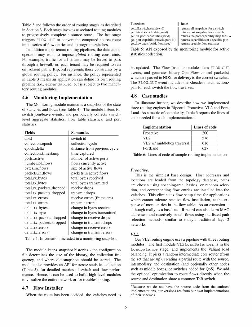
Table 3 and follows the order of routing stages as describedin Section 3. Each stage invokes associated routing modulesto progressively complete a source route. The last stagetriggers FLOW OUT to convert the computed source routeinto a series of flow entries and to program switches.
In addition to per-tenant routing pipelines, the data centeroperator may want to impose global routing constraints.For example, traffic for all tenants may be forced to passthrough a firewall; or, each tenant may be required to runon isolated paths. Ripcord represents these constraints by aglobal routing policy. For instance, the policy representedin Table 3 means an application can define its own routingpipeline (i.e., expandable), but is subject to two manda-tory routing modules.
4.6 Monitoring ImplementationThe Monitoring module maintains a snapshot of the state
of switches and flows (see Table 4). The module listens forswitch join/leave events, and periodically collects switch-level aggregate statistics, flow table statistics, and portstatistics.
Fields Semanticsdpid switch idcollection epoch collection cycleepoch delta distance from previous cyclecollection timestamp time capturedports active number of active portsnumber of flows flows currently activebytes in flows size of active flowspackets in flows packets in active flowstotal rx bytes total bytes receivedtotal tx bytes total bytes transmittedtotal rx packets dropped receive dropstotal tx packets dropped transmit dropstotal rx errors receive errors (frame,crc)total tx errors transmit errorsdelta rx bytes change in bytes receiveddelta tx bytes change in bytes transmitteddelta rx packets dropped change in receive dropsdelta tx packets dropped change in transmit dropsdelta rx errors change in receive errorsdelta tx errors change in transmit errorsTable 4: Information included in a monitoring snapshot.
The module keeps snapshot histories - the configurationfile determines the size of the history, the collection fre-quency, and where old snapshots should be stored. Themodule also provides an API for active statistics collection(Table 5), for detailed metrics of switch and flow perfor-mance. Hence, it can be used to build high-level modulesto visualize the entire network or for troubleshooting.
4.7 Flow InstallerWhen the route has been decided, the switches need to
Functions Rolesget all switch stats(swid) returns all snapshots for a switchget latest switch stats(swid) returns last snapshot for a switchget all port capabilities(swid) returns the port capability map for SWget port capabilities(swid,port id) returns capabilities of a specific portget flow stats(swid, flow spec) returns specific flow statistics
Table 5: API exposed by the monitoring module for activestatistics collection.
be updated. The Flow Installer module takes FLOW OUTevents, and generates binary OpenFlow control packet(s)which are passed to NOX for delivery to the correct switches.The FLOW OUT event includes the <header match, action>pair for each switch the flow traverses.
4.8 Case studiesTo illustrate further, we describe how we implemented
three routing engines in Ripcord: Proactive, VL2 and Port-Land. As a metric of complexity, Table 6 reports the lines ofcode needed for each implementation.1
Implementation Lines of codeProactive 200VL2 576VL2 w/ middlebox traversal 616PortLand 627
Table 6: Lines of code of sample routing implementation
Proactive.This is the simplest base design. Host addresses and
locations are loaded from the topology database, pathsare chosen using spanning-tree, hashes, or random selec-tion, and corresponding flow entries are installed into theswitches. This eliminates flow setup time for applicationswhich cannot tolerate reactive flow installation, at the ex-pense of more entries in the flow table. As an extension—although really as a baseline—Ripcord can also learn MACaddresses, and reactively install flows using the listed pathselection methods, similar to today’s traditional layer-2networks.
VL2.Our VL2 routing engine uses a pipeline with three routing
modules. The first module VL2LoadBalancer is in theLoadbalance stage, and implements the Valiant loadbalancing. It picks a random intermediate core router (fromthe set that are up), creating a partial route with the source,intermediary and destination (and optionally other nodessuch as middle boxes, or switches added for QoS). We addthe optional optimization to route flows directly when thesource and destination share a common ToR switch.
1Because we do not have the source code from the authors’implementations, our versions are from our own implementationsof their schemes.
6

Switch and Direction Match ActionToR, Up in port, src mac, dst mac replace dst ip with destination’s ToR IP addr
insert coreID into the highest order byte of src ipToR, Down in port, src mac, dst mac restore original dst ip and src ipAggregation, Up in port, highest order byte of src ip forward to a portAggregation, Down in port, dst ip forward to a portCore, Down dst ip forward to a port
Table 7: OpenFlow entries realizing compact VL2 routing.
Next, in the ComputeRoute stage, theVL2ComputeRoute module completes the route by iden-tifying the shortest path from source to intermediary, andintermediary to destination. If there are multiple shortestpaths, one is chosen at random (but only if the switches areup). If a switch is marked down (e.g. for maintenance) it isnot used.
Finally, VL2Open-FlowTrigger, calculates the flowentries to realize the chosen route. We use the designdescribed in [16] because it is simple, and supports middle-box traversal (see Table 7).
Comparing VL2 as defined by its authors with VL2implemented on Ripcord, we make the following obser-vations. VL2 uses double IP-in-IP encapsulation to routepackets from the source to the core switch (anycast andECMP), and then onto the destination ToR. In Ripcord,our implementation simply overwrites the destination IPaddress with the IP address of the destination’s top-of-rackswitch (ToR), and explicitly routes it via a randomly chosencore switch. In VL2, the destination’s ToR decapsulatesthe packet to restore its original form, whereas we directlyinstruct the destination’s ToR to overwrite the IP addresseswith original values. The implementation is different, butthe outcome is identical.
Just as in VL2, ARP packets are not broadcast to thewhole network, but are forwarded to the controller; themanagement application handles them and replies directlyto the source host. Unknown broadcast types can be ratelimited, or sent to a host to be satisfied.
PortLand.PortLand routes traffic by replacing the usual flat MAC
destination address (AMAC) with a source-routed pseudo-MAC (PMAC). The PMAC encodes the location of thedestination. The source server is “tricked” into using thePMAC when it sends an ARP — a special fabric managerreplies to the ARP with the PMAC instead of the AMAC.The egress ToR switch converts the PMAC back into thecorrect AMAC to preserve the illusion of transparency forthe unmodified end host.
Portland’s fabric manager is centralized, and is naturallyimplemented as a Ripcord management application. Theapplication assigns each AMAC a PMAC based on its ToRswitch. Like in PortLand, ARP requests are interceptedand the management application replies (without routing the
ARP request).PortLand routes flows with a pipeline of three rout-
ing modules: PLComputeRoutes, PLPickRoute andPLOpenFlowTrigger. Although the modules are suffi-cient to implement the PortLand’s routing, we allow it tobe extended with other routing modules (e.g., middleboxinterposition module or load balancer). Hence,PLComputeRoutes, which belongs to the ComputeRoutestage, first examines loose source routes computed by theprevious routing stages. If no route is given, it takesa pair of ingress switch and the ToR switch of desti-nation address as a loose source route. Then, it com-pletes each loose source route by computing a shortestpath between each two consecutive hops in the sourceroute. Hence, this routing module results in a list ofcomplete source routes. PLPickRoute is also in theComputeRoute stage and it randomly selects a routeamong those computed by PLComputeRoutes. Finally,PLOpenFlowTrigger converts the selected route into asequence of flow entries to be installed in switches along thepath.
The ingress ToR replaces the source AMAC with thesource PMAC for the return journey. Aggregate switchesand core switches route solely based on the destinationPMAC. Because our OpenFlow implementation does notsupport longest prefix matching on MAC addresses, wecurrently match full destination address. A flow entry in theegress ToR switch is to restore the destination PMAC backto AMAC.
4.9 Additional CapabilitiesBecause of its fine-grained control over routing, Ripcord
can do many things a current data center network cannot.We describe some examples below.
Middle-box Traversal..Flows can easily be routed through arbitrary middle-boxes
by inserting a waypoint in a loose source route (in theInsertWayPoints routing stage). In the ComputeRoutestage, the complete path is calculated to traverse the way-points. As an experiment, we implemented a routing moduleVL2MiddleBoxInserter to insert a random middle-box (specified in a configuration file) into the VL2 routingpipeline. Thus, the complete VL pipeline becomes:
If the middle box doesn’t modify the packet header,
7
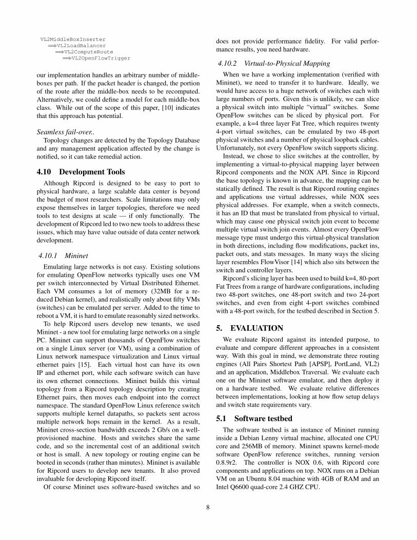
VL2MiddleBoxInserter=⇒VL2LoadBalancer
=⇒VL2ComputeRoute=⇒VL2OpenFlowTrigger
our implementation handles an arbitrary number of middle-boxes per path. If the packet header is changed, the portionof the route after the middle-box needs to be recomputed.Alternatively, we could define a model for each middle-boxclass. While out of the scope of this paper, [10] indicatesthat this approach has potential.
Seamless fail-over..Topology changes are detected by the Topology Database
and any management application affected by the change isnotified, so it can take remedial action.
4.10 Development ToolsAlthough Ripcord is designed to be easy to port to
physical hardware, a large scalable data center is beyondthe budget of most researchers. Scale limitations may onlyexpose themselves in larger topologies, therefore we needtools to test designs at scale — if only functionally. Thedevelopment of Ripcord led to two new tools to address theseissues, which may have value outside of data center networkdevelopment.
4.10.1 MininetEmulating large networks is not easy. Existing solutions
for emulating OpenFlow networks typically uses one VMper switch interconnected by Virtual Distributed Ethernet.Each VM consumes a lot of memory (32MB for a re-duced Debian kernel), and realistically only about fifty VMs(switches) can be emulated per server. Added to the time toreboot a VM, it is hard to emulate reasonably sized networks.
To help Ripcord users develop new tenants, we usedMininet - a new tool for emulating large networks on a singlePC. Mininet can support thousands of OpenFlow switcheson a single Linux server (or VM), using a combination ofLinux network namespace virtualization and Linux virtualethernet pairs [15]. Each virtual host can have its ownIP and ethernet port, while each software switch can haveits own ethernet connections. Mininet builds this virtualtopology from a Ripcord topology description by creatingEthernet pairs, then moves each endpoint into the correctnamespace. The standard OpenFlow Linux reference switchsupports multiple kernel datapaths, so packets sent acrossmultiple network hops remain in the kernel. As a result,Mininet cross-section bandwidth exceeds 2 Gb/s on a well-provisioned machine. Hosts and switches share the samecode, and so the incremental cost of an additional switchor host is small. A new topology or routing engine can bebooted in seconds (rather than minutes). Mininet is availablefor Ripcord users to develop new tenants. It also provedinvaluable for developing Ripcord itself.
Of course Mininet uses software-based switches and so
does not provide performance fidelity. For valid perfor-mance results, you need hardware.
4.10.2 Virtual-to-Physical MappingWhen we have a working implementation (verified with
Mininet), we need to transfer it to hardware. Ideally, wewould have access to a huge network of switches each withlarge numbers of ports. Given this is unlikely, we can slicea physical switch into multiple “virtual” switches. SomeOpenFlow switches can be sliced by physical port. Forexample, a k=4 three layer Fat Tree, which requires twenty4-port virtual switches, can be emulated by two 48-portphysical switches and a number of physical loopback cables.Unfortunately, not every OpenFlow switch supports slicing.
Instead, we chose to slice switches at the controller, byimplementing a virtual-to-physical mapping layer betweenRipcord components and the NOX API. Since in Ripcordthe base topology is known in advance, the mapping can bestatically defined. The result is that Ripcord routing enginesand applications use virtual addresses, while NOX seesphysical addresses. For example, when a switch connects,it has an ID that must be translated from physical to virtual,which may cause one physical switch join event to becomemultiple virtual switch join events. Almost every OpenFlowmessage type must undergo this virtual-physical translationin both directions, including flow modifications, packet ins,packet outs, and stats messages. In many ways the slicinglayer resembles FlowVisor [14] which also sits between theswitch and controller layers.
Ripcord’s slicing layer has been used to build k=4, 80-portFat Trees from a range of hardware configurations, includingtwo 48-port switches, one 48-port switch and two 24-portswitches, and even from eight 4-port switches combinedwith a 48-port switch, for the testbed described in Section 5.
5. EVALUATIONWe evaluate Ripcord against its intended purpose, to
evaluate and compare different approaches in a consistentway. With this goal in mind, we demonstrate three routingengines (All Pairs Shortest Path [APSP], PortLand, VL2)and an application, Middlebox Traversal. We evaluate eachone on the Mininet software emulator, and then deploy iton a hardware testbed. We evaluate relative differencesbetween implementations, looking at how flow setup delaysand switch state requirements vary.
5.1 Software testbedThe software testbed is an instance of Mininet running
inside a Debian Lenny virtual machine, allocated one CPUcore and 256MB of memory. Mininet spawns kernel-modesoftware OpenFlow reference switches, running version0.8.9r2. The controller is NOX 0.6, with Ripcord corecomponents and applications on top. NOX runs on a DebianVM on an Ubuntu 8.04 machine with 4GB of RAM and anIntel Q6600 quad-core 2.4 GHZ CPU.
8

5.2 Hardware testbedThe hardware testbed implements a k=4 three-layer Fat
Tree running at 1Gb/s. Aggregation and core switchesare implemented by slicing a 48-port 1GE switch (QuantaLB4G) running OpenFlow. Eight 4-port NetFPGAs act asedge switches. The OpenFlow implementation on the NetF-PGAs can rewrite source and destination MAC addresses atline-rate (required for PortLand) and can append, modifyand remove VLAN tags to distinguish multiple simultaneousrouting engines.
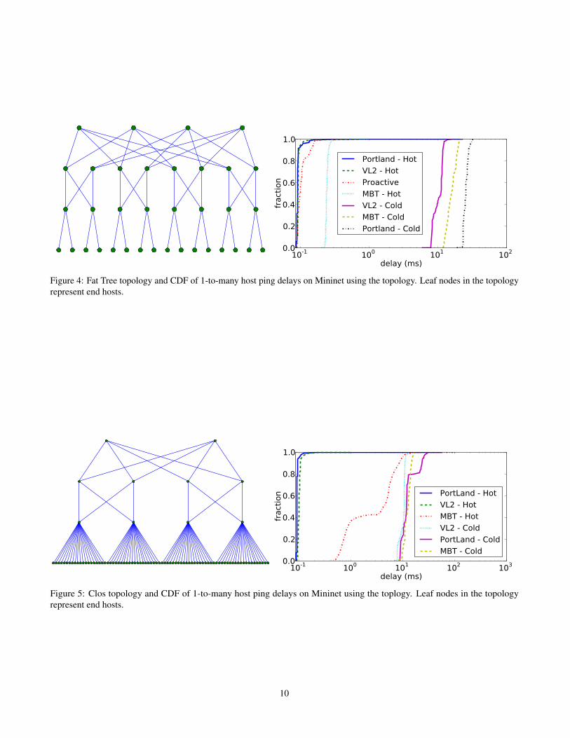
5.3 Experiments on Software TestbedOur first topology is the k=4 Fat Tree in the left-hand side
of Figure 4. The graph on the right hand side show a CDFof the ping times from the left-most host in our topologyto all other hosts, sending one ping at a time. The graphcontains curves from all four routing engines: APSP, VL2,MBT (Middle Box Traversal using VL2), and PortLand. Wefurther break up VL2, MBT, and PortLand into two separateconfigurations. In the first configuration (Hot) permanentflow entries are pre-installed into switches, resulting in notrips to the controller. In the second configuration (Cold)the ARP caches are filled, but no flow entries are pre-installed into the switches. When a packet arrives at anedge switch and there is no matching flow, it heads for thecontroller, where its trip through the routing engine pipelinemay generate flow entries for multiple switches. The APSProuting engine only supports Hot operation. It does noreactive lookups and simply pushes out all possible pathsdirectly to the switches.
APSP experiences slightly higher delay compared to Port-Land (Hot) and VL2 (Hot), due to the higher number ofwildcard flow entries in the software switch, which arescanned linearly to determine a match. PortLand (Hot) andVL2 (Hot) both show similar curves, and since they leveragetopology information to reduce flow state, switch traversalis faster. MBT (Hot) is roughly one and a half times worsethan VL2 (Hot) because it must traverse a middle box inboth directions, and experiences delays from our repeateragent running on the middle box. VL2 (Cold), MBT (Cold),and PortLand (Cold), as expected, trail by over two ordersof magnitude, because both the ping request and responsemust pass up to the controller and back. Note that thesenumbers are from an unoptimized Python implementation,running on a single thread, with a worst case traffic pattern.The specific ping time of 10 ms is unimportant; our goal hereis functional correctness. For example, we can see from thegraph that our PortLand implementation is slower than theVL2 implementation in the Cold setting, possibly because ofits unoptimized memory accesses (PMAC-AMAC mappingtable) and the latency to install more entries at core switchesand aggregation switches.
Our second topology is a Clos network shown on theleft-hand side of Figure 5. The graph shows a CDF ofping times from the left-most host in the topology. This
is the topology used in the VL2 paper’s evaluation, exceptinstead of a mix of 10 Gb/s and 1 Gb/s links, we haveone link speed of whatever the CPU will support. Thegeneral trends are the same; flow setups are two ordersof magnitude more expensive than forwarding. Middleboxtraversal has an unexpected knee. Our hunch is that theadditional flow entries required by multiple hops exceeds theCPU cache, which given linear lookups, would cause poorcache locality. These graphs are useful for comparing thedifferent routing engines, but clearly CPU overheads fromrunning in software result in low performance fidelity.
(Note to reviewer: APSP is not present; it will be addedin the final version of the paper.)
5.4 Experiment on Hardware Testbed
100 101 102
delay (ms)
0.0
0.2
0.4
0.6
0.8
1.0
fract
ion
Proactive
Portland - Hot
Portland - Cold
Figure 6: CDF of 1 to many host ping delays on a Quanta48x1GE switch + NetFPGA topology
The hardware testbed described in Section 5.2 implementsa k=4 Fat Tree, with twelve core and aggregation switchesand eight NetFPGAs for edge switches. Individual vir-tual switches are connected together via physical loopbackcables, and all packets are processed in hardware at line-rate. Both switch types use the OpenFlow 0.8.9 referencedistribution.
Figure 6 confirms our expectation of lower variance inhardware than in software — overall we can expect greaterperformance fidelity. PortLand (Hot) and Proactive showidentical delay curves, with minimal variation. (PortLand(Cold) exposes a limitation of our edge switch implementa-tion, and needs to be corrected).
Next, we attempt to gain insight into tradeoffs betweenstate management and flow setup delay.
5.5 Flow Table SizeTo test our implementation and to illustrate the conse-
quences of choosing different flow entry timeout intervals,we preformed the following two tests. First, we run our VL2Ripcord application on the Clos topology on the softwaretestbed, with permanent flow entries, and perform an all-to-all ping. After the test, we query all the switches andrecord the number of flows entries in each switch. Table 8presents the data. The choice of a CRC-based hash function
9
10-1 100 101 102
delay (ms)
0.0
0.2
0.4
0.6
0.8
1.0
fract
ion
Portland - Hot
VL2 - Hot
Proactive
MBT - Hot
VL2 - Cold
MBT - Cold
Portland - Cold
Figure 4: Fat Tree topology and CDF of 1-to-many host ping delays on Mininet using the topology. Leaf nodes in the topologyrepresent end hosts.
10-1 100 101 102 103
delay (ms)
0.0
0.2
0.4
0.6
0.8
1.0
fract
ion PortLand - Hot
VL2 - Hot
MBT - Hot
VL2 - Cold
PortLand - Cold
MBT - Cold
Figure 5: Clos topology and CDF of 1-to-many host ping delays on Mininet using the toplogy. Leaf nodes in the topologyrepresent end hosts.
10
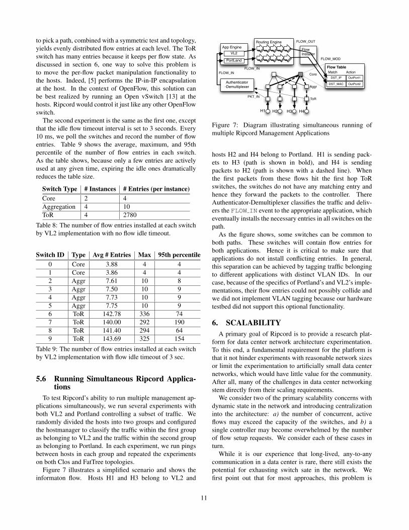
to pick a path, combined with a symmetric test and topology,yields evenly distributed flow entries at each level. The ToRswitch has many entries because it keeps per flow state. Asdiscussed in section 6, one way to solve this problem isto move the per-flow packet manipulation functionality tothe hosts. Indeed, [5] performs the IP-in-IP encapsulationat the host. In the context of OpenFlow, this solution canbe best realized by running an Open vSwitch [13] at thehosts. Ripcord would control it just like any other OpenFlowswitch.
The second experiment is the same as the first one, exceptthat the idle flow timeout interval is set to 3 seconds. Every10 ms, we poll the switches and record the number of flowentries. Table 9 shows the average, maximum, and 95thpercentile of the number of flow entries in each switch.As the table shows, because only a few entries are activelyused at any given time, expiring the idle ones dramaticallyreduces the table size.
Switch Type # Instances # Entries (per instance)Core 2 4Aggregation 4 10ToR 4 2780
Table 8: The number of flow entries installed at each switchby VL2 implementation with no flow idle timeout.
Switch ID Type Avg # Entries Max 95th percentile0 Core 3.88 4 41 Core 3.86 4 42 Aggr 7.61 10 83 Aggr 7.50 10 94 Aggr 7.73 10 95 Aggr 7.75 10 96 ToR 142.78 336 747 ToR 140.00 292 1908 ToR 141.40 294 649 ToR 143.69 325 154
Table 9: The number of flow entries installed at each switchby VL2 implementation with flow idle timeout of 3 sec.
5.6 Running Simultaneous Ripcord Applica-tions
To test Ripcord’s ability to run multiple management ap-plications simultaneously, we run several experiments withboth VL2 and Portland controlling a subset of traffic. Werandomly divided the hosts into two groups and configuredthe hostmanager to classify the traffic within the first groupas belonging to VL2 and the traffic within the second groupas belonging to Portland. In each experiment, we run pingsbetween hosts in each group and repeated the experimentson both Clos and FatTree topologies.
Figure 7 illustrates a simplified scenario and shows theinformaton flow. Hosts H1 and H3 belong to VL2 and
H1 H2 H3 H4
Authenticator-Demultiplexer
App EngineVL2
PortLand
ToR
Aggr
Core
Routing Engine
PKT_IN
FLOW_INFLOW_IN
FlowInstaller
Flow Table
DST_IP
DST_MAC
FLOW_OUT
FLOW_MOD
OutPort1
OutPort2
Match Action
Figure 7: Diagram illustrating simultaneous running ofmultiple Ripcord Management Applications
hosts H2 and H4 belong to Portland. H1 is sending pack-ets to H3 (path is shown in bold), and H4 is sendingpackets to H2 (path is shown with a dashed line). Whenthe first packets from these flows hit the first hop ToRswitches, the switches do not have any matching entry andhence they forward the packets to the controller. ThereAuthenticator-Demultiplexer classifies the traffic and deliv-ers the FLOW IN event to the appropriate application, whicheventually installs the necessary entries in all switches on thepath.
As the figure shows, some switches can be common toboth paths. These switches will contain flow entries forboth applications. Hence it is critical to make sure thatapplications do not install conflicting entries. In general,this separation can be achieved by tagging traffic belongingto different applications with distinct VLAN IDs. In ourcase, because of the specifics of Portland’s and VL2’s imple-mentations, their flow entries could not possibly collide andwe did not implement VLAN tagging because our hardwaretestbed did not support this optional functionality.
6. SCALABILITYA primary goal of Ripcord is to provide a research plat-
form for data center network architecture experimentation.To this end, a fundamental requirement for the platform isthat it not hinder experiments with reasonable network sizesor limit the experimentation to artificially small data centernetworks, which would have little value for the community.After all, many of the challenges in data center networkingstem directly from their scaling requirements.
We consider two of the primary scalability concerns withdynamic state in the network and introducing centralizationinto the architecture: a) the number of concurrent, activeflows may exceed the capacity of the switches, and b) asingle controller may become overwhelmed by the numberof flow setup requests. We consider each of these cases inturn.
While it is our experience that long-lived, any-to-anycommunication in a data center is rare, there still exists thepotential for exhausting switch sate in the network. Wefirst point out that for most approaches, this problem is
11

limited to the ToR switches as aggregation and core layerscan often handle flows in aggregate. Secondly, if per-transport flow policy is not required, flows can be set up ona per-source/destination pair basis which is limited by thenumber of servers attached to the switch. Today chipsetsare available which can support tens of thousands of flows,which is suitable for moderate to large size workloads.
Another approach described in [13] proposes pushingnetwork switching state into the hypervisor layer on endhosts to overcome the hardware limitations of ToR switches.With such a software-based switch, the issue of exhaustionat first-hop switch can also be alleviated.
Flow setups can become a scalability bottleneck of theplatform in terms of flow setup latencies and throughput.We’ll discuss the scalability of setup latency first. Whilemany of the data center applications like MapReduce toler-ate delays on the order of tens of milliseconds, applicationsthat have strict latency requirements may not tolerate anyextra delay incurred by setting up flow entries. For suchdemanding applications, assuming a large enough flow tableat the ToR switch either in hardware or software, Ripcordcan pre-install flow entries towards all possible network des-tinations into the switch. In this proactive mode, therefore,the network virtually behaves as if MPLS-tunneled, andapplications are not exposed to additional latency for flowsetup. If the luxury of large flow tables is not available,additional decision hints such as application priorities orcommunication pair likelihood can be used to select pre-loaded flows. In our current prototype, such informationcould be stored in the configuration database module and/ortopology database module.
Scaling flow setup throughput beyond the limits of asingle controller requires that the platform support multi-ple controller instances. However, before diving into thedetails, it is worthwhile to explicitly differentiate betweenthe scalability requirements research and production qualityplatforms for data center networks.
The goal of Ripcord, at least in its current incarnation,is not to provide a researcher with a production qualityimplementation. The implementation lacks in many aspects,such as in efficiency, robustness, and importantly Ripcord isbuilt around a simple, centralized, single-host state sharingmechanism. If subjected to the extreme scalability and avail-ability requirements of data center networks in production,this mechanism is clearly insufficient.
In research experiments the lack of extreme scalabilityand availability properties is a non-issue as long as theprogramming abstractions offered for the application devel-opers are similar to the ones, which would be provided insystems designed to scale for production use. To this end, webriefly overview the scalability approaches of both Portlandand VL2:
• Portland centralizes all state sharing into a fabricmanager component, which manages the switch mod-ules over OpenFlow. As such, the fabric manager
corresponds directly with a single Ripcord controllerinstance.
• VL2 assumes no single, centralized controller instance,but uses a distributed directory system to share stateamong multiple controllers (agents). The directorysystem is essentially a strongly-consistent, reliable andcentralized store, which has an eventually consistentcaching layer for reads on top.
The descriptions above suggest that the design of Ripcordis well aligned with the scalability approaches of theseindividual proposals. In particular, Ripcord can providethe platform for centralized single-controller designs likePortLand, while for VL2 like designs, which rely on adistributed state sharing mechanism, Ripcord can providea single-host configuration database with the identical se-mantics. This is clearly not scalable (nor highly-available),but the programming abstractions within the controllersconnected to the database will be the same as if a distributedstate sharing mechanism were used. Eventually, as Ripcordmatures, it could also replace this centralized, single-hostconfiguration database with a distributed database.
It is still an open question to what extent the platformshould scale to provide value to different communities.The research community, which principally targets devising,rapidly developing, and evaluating new ideas, could bean immediate beneficiary, even with networks on smallerscales. For those networks, even our current Ripcord proto-type can be an ideal vehicle since it is capable of emulatinga 100-node data center on a modern laptop computer andit supports seamless porting from software emulation to realhardware testbeds. For a designer of a production data centerseeking radically new approaches to improve networkingperformance, or trying to introduce competitive features,Ripcord may also prove valuable, as long as the size of thetestbed is not on the order of the production network.
7. RELATED WORKRipcord is built on top of programmable switches and
a logically centralized control platform. In our prototypewe use OpenFlow [11] switches and NOX [8], an open-source OpenFlow controller. While NOX was designedto be a general controller platform applicable to manyenvironments, Ripcord was designed around needs specificto the datacenter. This includes providing infrastructure formanaging structured topology, location independence, andservice quality as well as exposing higher-level abstractions,such as tenants.
While we chose NOX in large part due to our familiaritywith it, Ripcord could also have been implemented withinother centralized network control platforms such as Tesser-act [6] or Maestro [3]. Like NOX, both of these projectsprovide centralized development platforms on top of whichnetwork control logics can be implemented.
12

The use of OpenFlow was similarly a matter of familiarityand convenience. However, other than the table and portabstractions, no low-level details of OpenFlow are exposedthrough Ripcord. Therefore, the Ripcord design should becompatible with other programmable datapath technologiesthat maintain table-entry level control of the network.
Having described related technologies for programmableswitches and controllers we now discuss Ripcord in thecontext of recent data center networking proposals (e.g.,VL2 [5], Monsoon [7], BCube [9], PLayer [10], and Port-Land [12]). We note that each of these networking proposalspresents a solution based on specific requirements, someof which overlap across solutions, but may be prioritizeddifferently in each solution. As a consequence specificarchitectural choices are made that may make it difficultto accommodate new requirements, changes to data centerenvironments or modifications to the solution that attempt totailor/tweak it for another data center environment.
Ripcord is not in direct competition with any of thesenetworking proposals, rather it provides a platform thatallows network administrators to experiment with one ormore of data center networking proposals (side-by-side ifnecessary), make modifications and evaluate the proposalin their own data center environments. Further, whereasRipcord does not include or propose any novel distributedalgorithms for managing data center networks, we posit thatit provides a suitable platform for experimentation in thisspace based on its modular design.
Ripcord is also similar in spirit to the broad testbasedwork which allows multple experiments to share the sameinfrastructure. Notable recent proposals include VINI [2],and FlowVisor [14]. Ripcord differs from these and similarproposals in that our goal is to construct a modular platformat the control level which provides primitives useful inthe data center context. To this end, we have designedmultiple components (such as the topology and monitoringinterfaces) which aid (and limit!) the applications suitablefor running on Ripcord.
8. REFERENCES[1] M. Al-Fares, A. Loukissas, and A. Vahdat. A scalable,
commodity data center network architecture. In SIGCOMM’08: Proceedings of the ACM SIGCOMM 2008 conference onData communication, pages 63–74, New York, NY, USA,2008. ACM.
[2] A. Bavier, N. Feamster, M. Huang, L. Peterson, andJ. Rexford. In VINI Veritas: Realistic and Controlled NetworkExperimentation. In Proc. of SIGCOMM, Pisa, Italy, 2006.
[3] Z. Cai, F. Dinu, J. Zheng, A. L. Cox, and T. S. E. Ng. ThePreliminary Design and Implementation of the MaestroNetwork Control Platform. Technical Report TR08-13, RiceUniversity, 2008. Available athttp://www.cs.rice.edu/˜eugeneng/papers/Maestro-TR.pdf.
[4] Cisco. Data Center Ethernet.http://www.cisco.com/go/dce.
[5] A. Greenberg, J. R. Hamilton, N. Jain, S. Kandula, C. Kim,P. Lahiri, D. A. Maltz, P. Patel, and S. Sengupta. VL2: AScalable and Flexible Data Center Network. In Proc. ofSIGCOMM, Barcelona, Spain, 2009.
[6] A. Greenberg, G. Hjalmtysson, D. A. Maltz, A. Myers,J. Rexford, G. Xie, H. Yan, J. Zhan, and H. Zhang. A CleanSlate 4D Approach to Network Control and Management.ACM SIGCOMM CCR, 35(5):41–54, 2005.
[7] A. Greenberg, P. Lahiri, D. A. Maltz, P. Patel, andS. Sengupta. Towards a next generation data centerarchitecture: scalability and commoditization. In PRESTO
’08: Proceedings of the ACM workshop on Programmablerouters for extensible services of tomorrow, pages 57–62, NewYork, NY, USA, 2008. ACM.
[8] N. Gude, T. Koponen, J. Pettit, B. Pfaff, M. Casado,N. McKeown, and S. Shenker. Nox: towards an operatingsystem for networks. SIGCOMM Comput. Commun. Rev.,38(3):105–110, 2008.
[9] C. Guo, G. Lu, D. Li, H. Wu, X. Zhang, Y. Shi, C. Tian,Y. Zhang, and S. Lu. Bcube: a high performance,server-centric network architecture for modular data centers.In SIGCOMM, pages 63–74, 2009.
[10] D. A. Joseph, A. Tavakoli, and I. Stoica. A policy-awareswitching layer for data centers. SIGCOMM Comput.Commun. Rev., 38(4):51–62, 2008.
[11] N. McKeown, T. Anderson, H. Balakrishnan, G. Parulkar,L. Peterson, J. Rexford, S. Shenker, and J. Turner. OpenFlow:Enabling Innovation in Campus Networks. ACM SIGCOMMCCR, 38(2):69–74, 2008.
[12] R. Niranjan Mysore, A. Pamboris, N. Farrington, N. Huang,P. Miri, S. Radhakrishnan, V. Subramanya, and A. Vahdat.Portland: a scalable fault-tolerant layer 2 data center networkfabric. In SIGCOMM ’09: Proceedings of the ACMSIGCOMM 2009 conference on Data communication, pages39–50, New York, NY, USA, 2009. ACM.
[13] B. Pfaff, J. Pettit, T. Koponen, K. Amidon, M. Casado, andS. Shenker. Extending Networking into the VirtualizationLayer. In 8th ACM Workshop on Hot Topics in Networking(Hotnets), New York City, NY, October 2009.
[14] R. Sherwood, M. Chan, G. Gibb, N. Handigol, , T.-Y. Huang,P. Kazemian, M. Kobayashi, D. Underhill, K.-K. Yap,G. Appenzeller, and N. McKeown. Carving Research SlicesOut of Your Production Networks with OpenFlow, 2009.
[15] SourceForge. Linux containers - network namespaceconfiguration. http://lxc.sourceforge.net/network/configuration.php.
[16] A. Tavakoli, M. Casado, T. Koponen, and S. Shenker.Applying NOX to the Datacenter. In 8th ACM Workshop onHot Topics in Networking (Hotnets), New York City, NY,October 2009.
[17] J. Touch and R. Perlman. Transparent Interconnection of Lotsof Links (TRILL): Problem and Applicability Statement. RFC5556 (Informational), May 2009.
APPENDIXNOX and OpenFlow OpenFlow is a vendor-agnostic interface tocontrol network switches and routers. In particular, it provides anabstraction of the flow-tables already present in most devices - theywere originally placed there to hold firewall rules. OpenFlow allowsrules to be placed in a table, consisting of a ¡header pattern, action¿pair. If an arriving packet matches the header pattern, the associatedaction is performed. Actions are generally simple, such as forwardto a port or set of ports, drop, or send to the controller. NOX is anetwork-wide operating system that controls a collection of switchesand routers using the OpenFlow protocol. NOX provides a globalview of the topology, and presents an API to hosted applications toboth view and control the network state. A hosted application mightreactively respond to new flows, choose whether to allow them andthen install rules to determine their path. Or it could proactively addrules to define how new flows will be routed.
13