rip bushings - deutsche messe ag
TRANSCRIPT
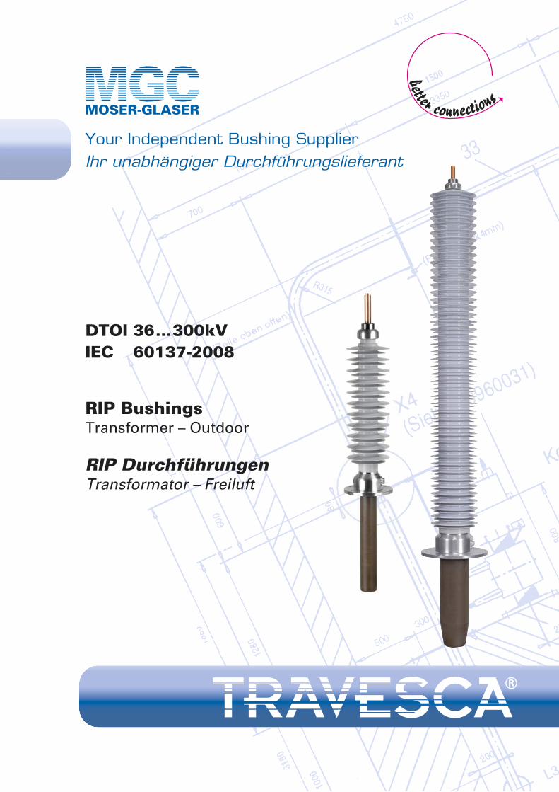
DTOI 36...300kVIEC 60137-2008
RIP BushingsTransformer – Outdoor
RIP DurchführungenTransformator – Freiluft
Your Independent Bushing SupplierIhr unabhängiger Durchführungslieferant
2
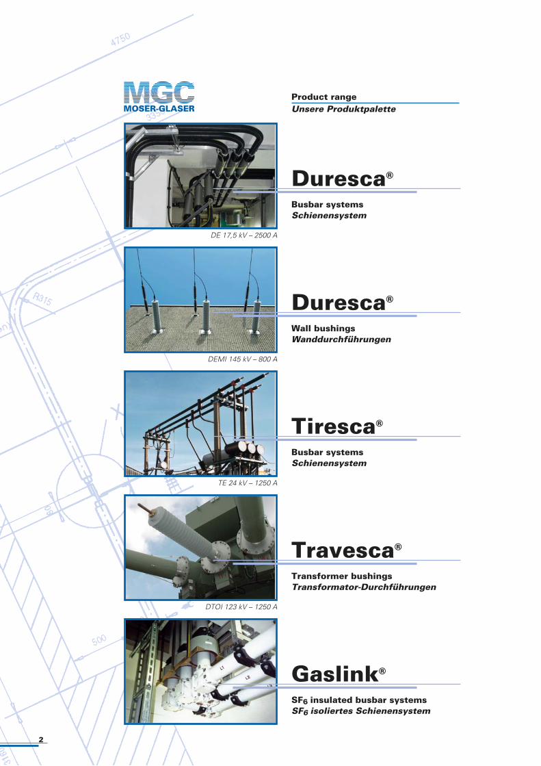
Product rangeUnsere Produktpalette
DTOI 123 kV – 1250 A
Travesca®
Transformer bushingsTransformator-Durchführungen
Tiresca®
Busbar systemsSchienensystem
TE 24 kV – 1250 A
DEMI 145 kV – 800 A
Duresca®
Busbar systemsSchienensystem
DE 17,5 kV – 2500 A
Gaslink®
SF6 insulated busbar systemsSF6 isoliertes Schienensystem
Duresca®
Wall bushingsWanddurchführungen
3
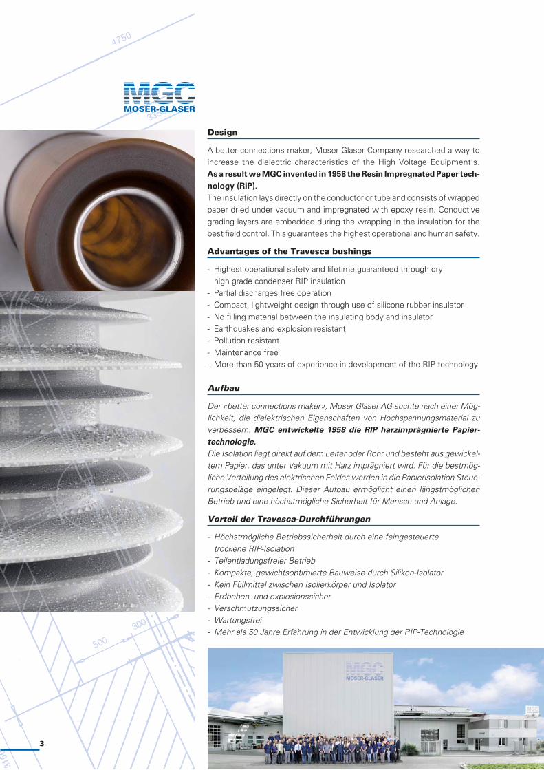
Design
A better connections maker, Moser Glaser Company researched a way toincrease the dielectric characteristics of the High Voltage Equipment’s. As a result we MGC invented in 1958 the Resin Impregnated Paper tech-
nology (RIP).
The insulation lays directly on the conductor or tube and consists of wrappedpaper dried under vacuum and impregnated with epoxy resin. Conductivegrading layers are embedded during the wrapping in the insulation for thebest field control. This guarantees the highest operational and human safety.
Advantages of the Travesca bushings
- Highest operational safety and lifetime guaranteed through dry high grade condenser RIP insulation- Partial discharges free operation- Compact, lightweight design through use of silicone rubber insulator- No filling material between the insulating body and insulator- Earthquakes and explosion resistant - Pollution resistant- Maintenance free- More than 50 years of experience in development of the RIP technology
Aufbau
Der «better connections maker», Moser Glaser AG suchte nach einer Mög-lichkeit, die dielektrischen Eigenschaften von Hochspannungsmaterial zuverbessern. MGC entwickelte 1958 die RIP harzimprägnierte Papier-
technologie.
Die Isolation liegt direkt auf dem Leiter oder Rohr und besteht aus gewickel-tem Papier, das unter Vakuum mit Harz imprägniert wird. Für die bestmög-liche Verteilung des elektrischen Feldes werden in die Papierisolation Steue-rungsbeläge eingelegt. Dieser Aufbau ermöglicht einen längstmöglichenBetrieb und eine höchstmögliche Sicherheit für Mensch und Anlage.
Vorteil der Travesca-Durchführungen
- Höchstmögliche Betriebssicherheit durch eine feingesteuerte trockene RIP-Isolation- Teilentladungsfreier Betrieb- Kompakte, gewichtsoptimierte Bauweise durch Silikon-Isolator- Kein Füllmittel zwischen Isolierkörper und Isolator- Erdbeben- und explosionssicher- Verschmutzungssicher- Wartungsfrei- Mehr als 50 Jahre Erfahrung in der Entwicklung der RIP-Technologie
4
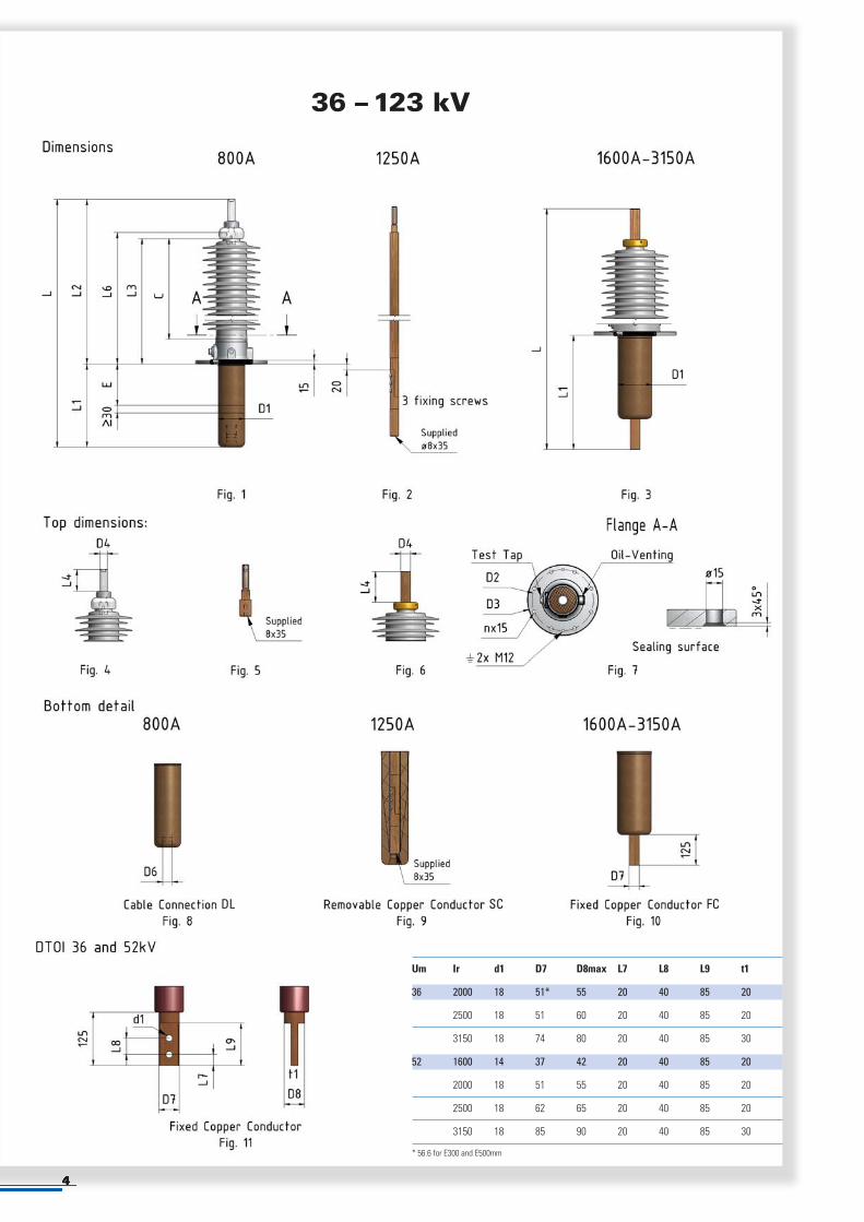
Um Ir d1 D7 D8max L7 L8 L9 t1
36 2000 18 51* 55 20 40 85 20
2500 18 51 60 20 40 85 20
3150 18 74 80 20 40 85 30
52 1600 14 37 42 20 40 85 20
2000 18 51 55 20 40 85 20
2500 18 62 65 20 40 85 20
3150 18 85 90 20 40 85 30
* 56.6 for E300 and E500mm
36 – 123 kV
DL SC FC
5
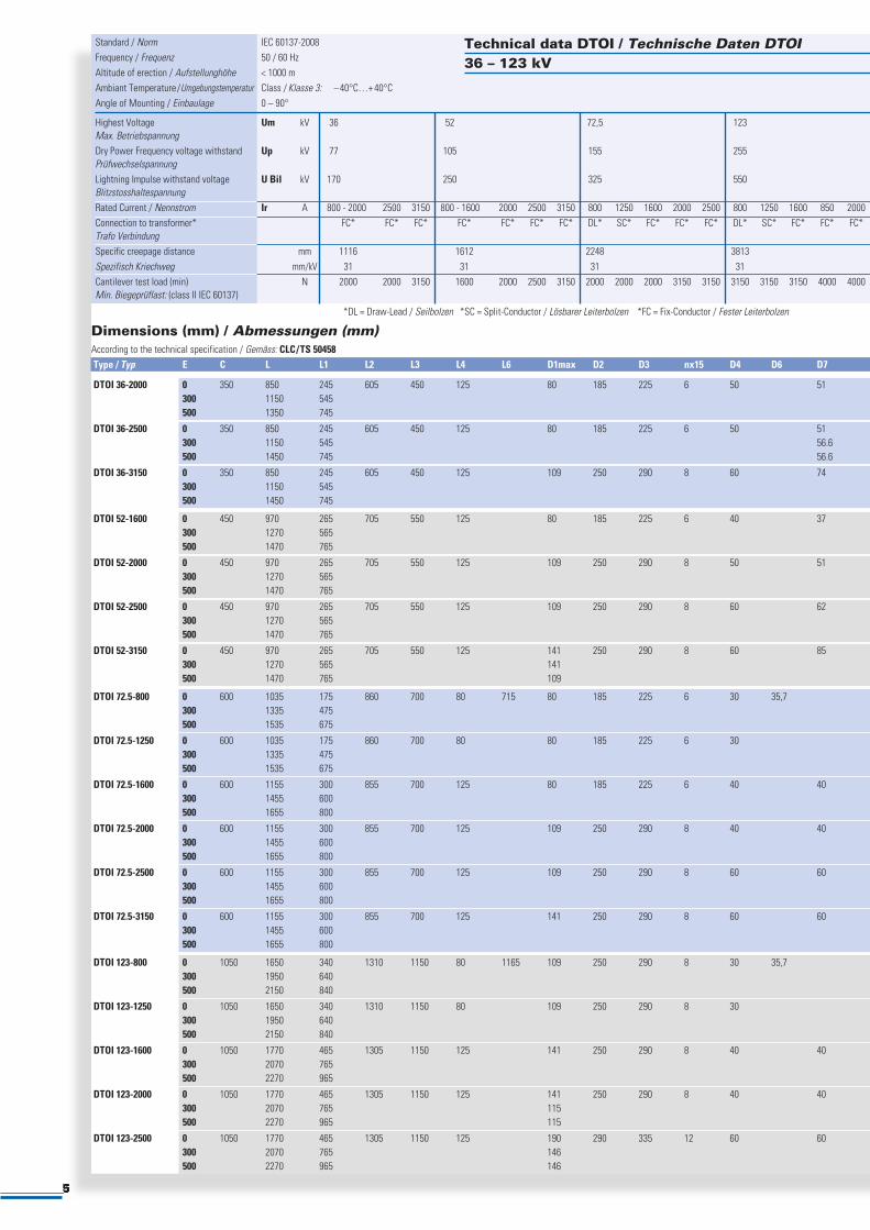
Standard / Norm IEC 60137-2008 Frequency / Frequenz 50 / 60 Hz Altitude of erection / Aufstellunghöhe < 1000 m Ambiant Temperature/Umgebungstemperatur Class / Klasse 3: –40°C…+ 40°C Angle of Mounting / Einbaulage 0 – 90°
Highest Voltage Um kV 36 52 72,5 123Max. Betriebspannung Dry Power Frequency voltage withstand Up kV 77 105 155 255 Prüfwechselspannung Lightning Impulse withstand voltage U Bil kV 170 250 325 550 Blitzstosshaltespannung Rated Current / Nennstrom Ir A 800 - 2000 2500 3150 800 - 1600 2000 2500 3150 800 1250 1600 2000 2500 800 1250 1600 850 2000Connection to transformer* FC* FC* FC* FC* FC* FC* FC* DL* SC* FC* FC* FC* DL* SC* FC* FC* FC*Trafo Verbindung Specific creepage distance mm 1116 1612 2248 3813 Spezifisch Kriechweg mm/kV 31 31 31 31 Cantilever test load (min) N 2000 2000 3150 1600 2000 2500 3150 2000 2000 2000 3150 3150 3150 3150 3150 4000 4000Min. Biegeprüflast: (class II IEC 60137)
*DL = Draw-Lead / Seilbolzen *SC = Split-Conductor / Lösbarer Leiterbolzen *FC = Fix-Conductor / Fester Leiterbolzen
Technical data DTOI / Technische Daten DTOI36 – 123 kV
Dimensions (mm) / Abmessungen (mm)According to the technical specification / Gemäss: CLC/TS 50458 Type / Typ E C L L1 L2 L3 L4 L6 D1max D2 D3 nx15 D4 D6 D7
DTOI 36-2000 0 350 850 245 605 450 125 80 185 225 6 50 51 300 1150 545 500 1350 745
DTOI 36-2500 0 350 850 245 605 450 125 80 185 225 6 50 51 300 1150 545 56.6 500 1450 745 56.6
DTOI 36-3150 0 350 850 245 605 450 125 109 250 290 8 60 74 300 1150 545 500 1450 745
DTOI 52-1600 0 450 970 265 705 550 125 80 185 225 6 40 37 300 1270 565 500 1470 765
DTOI 52-2000 0 450 970 265 705 550 125 109 250 290 8 50 51 300 1270 565 500 1470 765
DTOI 52-2500 0 450 970 265 705 550 125 109 250 290 8 60 62 300 1270 565 500 1470 765
DTOI 52-3150 0 450 970 265 705 550 125 141 250 290 8 60 85 300 1270 565 141 500 1470 765 109
DTOI 72.5-800 0 600 1035 175 860 700 80 715 80 185 225 6 30 35,7 300 1335 475 500 1535 675
DTOI 72.5-1250 0 600 1035 175 860 700 80 80 185 225 6 30 300 1335 475 500 1535 675
DTOI 72.5-1600 0 600 1155 300 855 700 125 80 185 225 6 40 40 300 1455 600 500 1655 800
DTOI 72.5-2000 0 600 1155 300 855 700 125 109 250 290 8 40 40 300 1455 600 500 1655 800
DTOI 72.5-2500 0 600 1155 300 855 700 125 109 250 290 8 60 60 300 1455 600 500 1655 800
DTOI 72.5-3150 0 600 1155 300 855 700 125 141 250 290 8 60 60 300 1455 600 500 1655 800
DTOI 123-800 0 1050 1650 340 1310 1150 80 1165 109 250 290 8 30 35,7 300 1950 640 500 2150 840
DTOI 123-1250 0 1050 1650 340 1310 1150 80 109 250 290 8 30 300 1950 640 500 2150 840
DTOI 123-1600 0 1050 1770 465 1305 1150 125 141 250 290 8 40 40 300 2070 765 500 2270 965
DTOI 123-2000 0 1050 1770 465 1305 1150 125 141 250 290 8 40 40 300 2070 765 115 500 2270 965 115
DTOI 123-2500 0 1050 1770 465 1305 1150 125 190 290 335 12 60 60 300 2070 765 146 500 2270 965 146
6
145 – 300 kV
DL SC FC
7
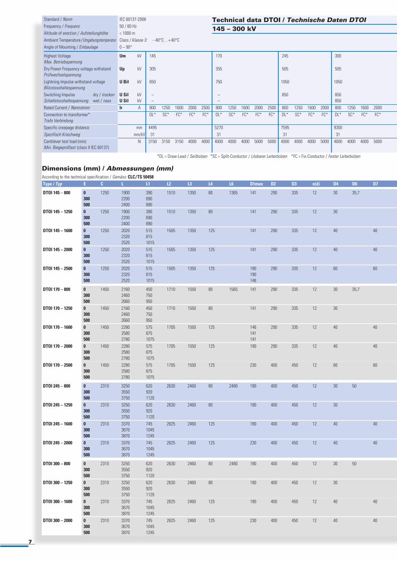
Standard / Norm IEC 60137-2008 Frequency / Frequenz 50 / 60 Hz Altitude of erection / Aufstellunghöhe < 1000 m Ambiant Temperature/Umgebungstemperatur Class / Klasse 3: –40°C…+ 40°C Angle of Mounting / Einbaulage 0 – 90°
Highest Voltage Um kV 145 170 245 300Max. Betriebspannung Dry Power Frequency voltage withstand Up kV 305 355 505 505 Prüfwechselspannung Lightning Impulse withstand voltage U Bil kV 650 750 1050 1050 Blitzstosshaltespannung Switching Impulse dry / trocken U Sil kV – – 850 850Schaltstosshaltespannung wet / nass U Sil kV – – 850 Rated Current / Nennstrom Ir A 800 1250 1600 2000 2500 800 1250 1600 2000 2500 800 1250 1600 2000 800 1250 1600 2000 Connection to transformer* DL* SC* FC* FC* FC* DL* SC* FC* FC* FC* DL* SC* FC* FC* DL* SC* FC* FC*Trafo Verbindung Specific creepage distance mm 4495 5270 7595 9300 Spezifisch Kriechweg mm/kV 31 31 31 31 Cantilever test load (min) N 3150 3150 3150 4000 4000 4000 4000 4000 5000 5000 4000 4000 4000 5000 4000 4000 4000 5000Min. Biegeprüflast: (class II IEC 60137)
*DL = Draw-Lead / Seilbolzen *SC = Split-Conductor / Lösbarer Leiterbolzen *FC = Fix-Conductor / Fester Leiterbolzen
Technical data DTOI / Technische Daten DTOI145 – 300 kV
Dimensions (mm) / Abmessungen (mm)According to the technical specification / Gemäss: CLC/TS 50458 Type / Typ E C L L1 L2 L3 L4 L6 D1max D2 D3 n(d) D4 D6 D7
DTOI 145 – 800 0 1250 1900 390 1510 1350 80 1365 141 290 335 12 30 35,7 300 2200 690 500 2400 890 DTOI 145 – 1250 0 1250 1900 390 1510 1350 80 141 290 335 12 30 300 2200 690 500 2400 890 DTOI 145 – 1600 0 1250 2020 515 1505 1350 125 141 290 335 12 40 40 300 2320 815 500 2520 1015 DTOI 145 – 2000 0 1250 2020 515 1505 1350 125 141 290 335 12 40 40 300 2320 815 500 2520 1015 DTOI 145 – 2500 0 1250 2020 515 1505 1350 125 190 290 335 12 60 60 300 2320 815 190 500 2520 1015 146
DTOI 170 – 800 0 1450 2160 450 1710 1550 80 1565 141 290 335 12 30 35,7 300 2460 750 500 2660 950 DTOI 170 – 1250 0 1450 2160 450 1710 1550 80 141 290 335 12 30 300 2460 750 500 2660 950 DTOI 170 – 1600 0 1450 2280 575 1705 1550 125 146 290 335 12 40 40 300 2580 875 141 500 2780 1075 141 DTOI 170 – 2000 0 1450 2280 575 1705 1550 125 190 290 335 12 40 40 300 2580 875 500 2780 1075 DTOI 170 – 2500 0 1450 2280 575 1705 1550 125 230 400 450 12 60 60 300 2580 875 500 2780 1075
DTOI 245 – 800 0 2310 3250 620 2630 2460 80 2480 190 400 450 12 30 50 300 3550 920 500 3750 1120 DTOI 245 – 1250 0 2310 3250 620 2630 2460 80 190 400 450 12 30 300 3550 920 500 3750 1120 DTOI 245 – 1600 0 2310 3370 745 2625 2460 125 190 400 450 12 40 40 300 3670 1045 500 3870 1245 DTOI 245 – 2000 0 2310 3370 745 2625 2460 125 230 400 450 12 40 40 300 3670 1045 500 3870 1245
DTOI 300 – 800 0 2310 3250 620 2630 2460 80 2480 190 400 450 12 30 50 300 3550 920 500 3750 1120 DTOI 300 – 1250 0 2310 3250 620 2630 2460 80 190 400 450 12 30 300 3550 920 500 3750 1120 DTOI 300 – 1600 0 2310 3370 745 2625 2460 125 190 400 450 12 40 40 300 3670 1045 500 3870 1245 DTOI 300 – 2000 0 2310 3370 745 2625 2460 125 230 400 450 12 40 40 300 3670 1045 500 3870 1245
8
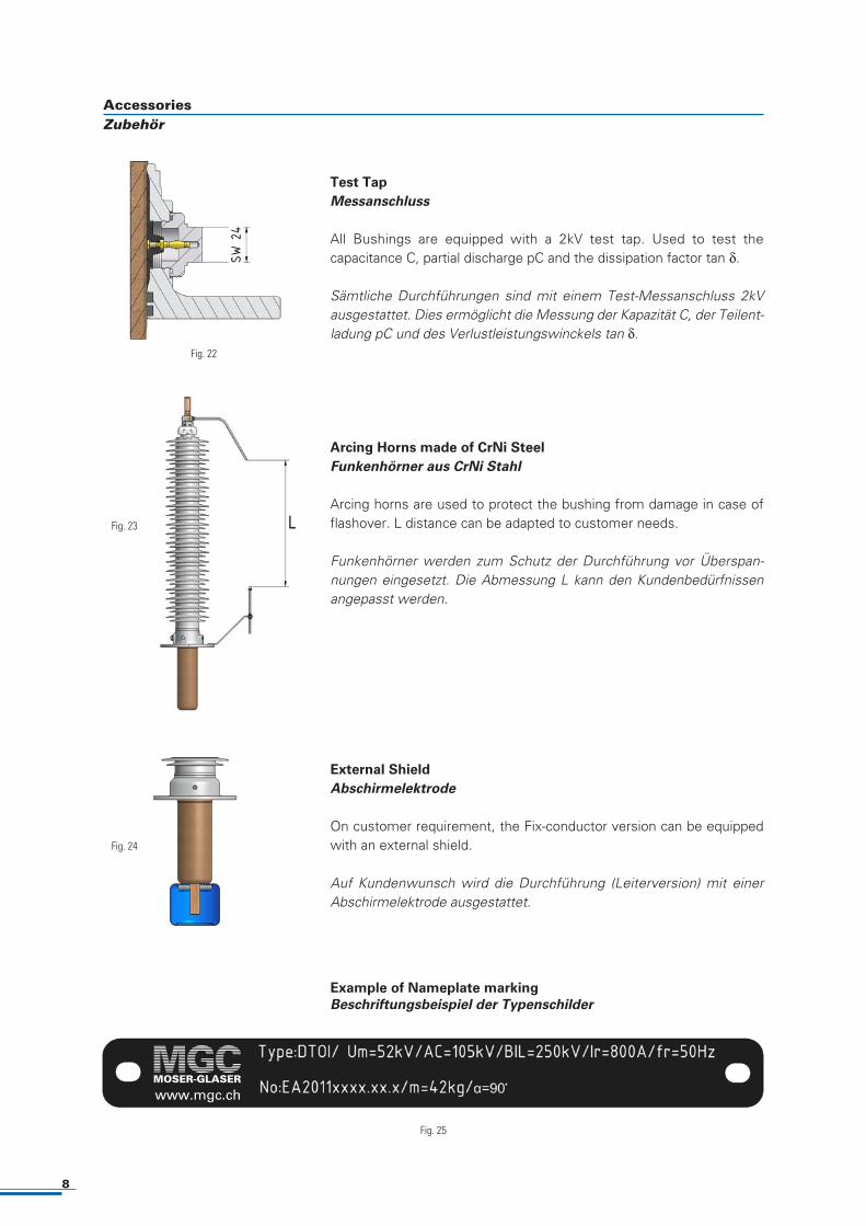
Test Tap
Messanschluss
All Bushings are equipped with a 2kV test tap. Used to test the capacitance C, partial discharge pC and the dissipation factor tan δ.
Sämtliche Durchführungen sind mit einem Test-Messanschluss 2kVausgestattet. Dies ermöglicht die Messung der Kapazität C, der Teilent-ladung pC und des Verlustleistungswinckels tan δ.
Arcing Horns made of CrNi Steel
Funkenhörner aus CrNi Stahl
Arcing horns are used to protect the bushing from damage in case offlashover. L distance can be adapted to customer needs.
Funkenhörner werden zum Schutz der Durchführung vor Überspan-nungen eingesetzt. Die Abmessung L kann den Kundenbedürfnissen
angepasst werden.
External Shield
Abschirmelektrode
On customer requirement, the Fix-conductor version can be equippedwith an external shield.
Auf Kundenwunsch wird die Durchführung (Leiterversion) mit einer Abschirmelektrode ausgestattet.
Fig. 22
Fig. 24
Fig. 25
Example of Nameplate marking
Beschriftungsbeispiel der Typenschilder
www.mgc.ch
Fig. 23
AccessoriesZubehör
9
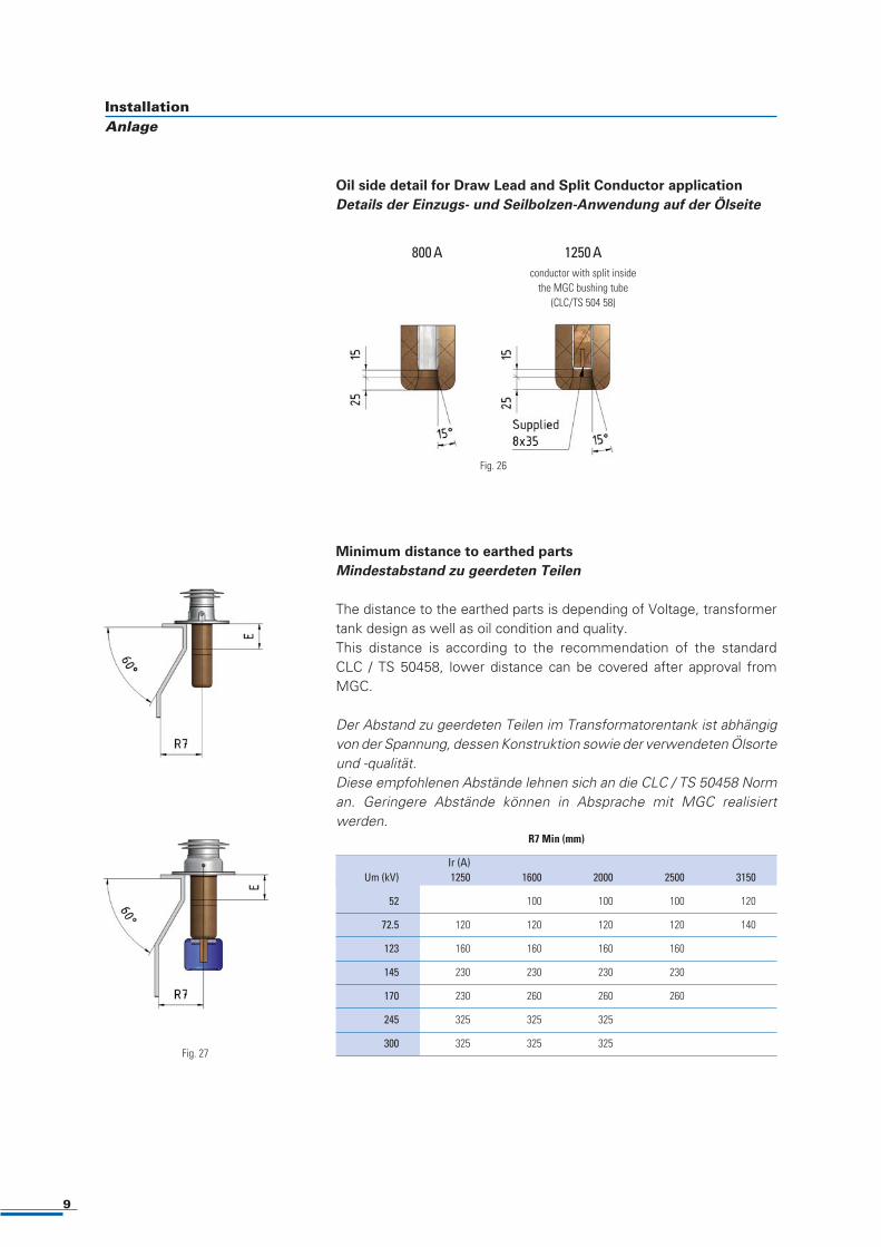
Oil side detail for Draw Lead and Split Conductor application
Details der Einzugs- und Seilbolzen-Anwendung auf der Ölseite
Minimum distance to earthed parts
Mindestabstand zu geerdeten Teilen
The distance to the earthed parts is depending of Voltage, transformertank design as well as oil condition and quality.This distance is according to the recommendation of the standard CLC / TS 50458, lower distance can be covered after approval fromMGC.
Der Abstand zu geerdeten Teilen im Transformatorentank ist abhängigvon der Spannung, dessen Konstruktion sowie der verwendeten Ölsorteund -qualität.Diese empfohlenen Abstände lehnen sich an die CLC / TS 50458 Norman. Geringere Abstände können in Absprache mit MGC realisiert
werden.
1250 Aconductor with split inside
the MGC bushing tube(CLC/TS 504 58)
800 A
Fig. 26
Fig. 27
InstallationAnlage
R7 Min (mm)
Ir (A)Um (kV) 1250 1600 2000 2500 3150
52 100 100 100 120
72.5 120 120 120 120 140
123 160 160 160 160
145 230 230 230 230
170 230 260 260 260
245 325 325 325
300 325 325 325
Routine Tests
Each DTOI is tested in accordance with the bushings specification IEC60137-2008Type Tests
Our DTOI range of products have been type tested, reports are availableon request.
Routineprüfung
Jede DTOI ist nach IEC – Norm 60137-2008 ausgelegt und geprüft.Typenprüfung
Unsere DTOI Produkte sind typengeprüft. Entsprechende Dokumentesind auf Anfrage erhältlich.
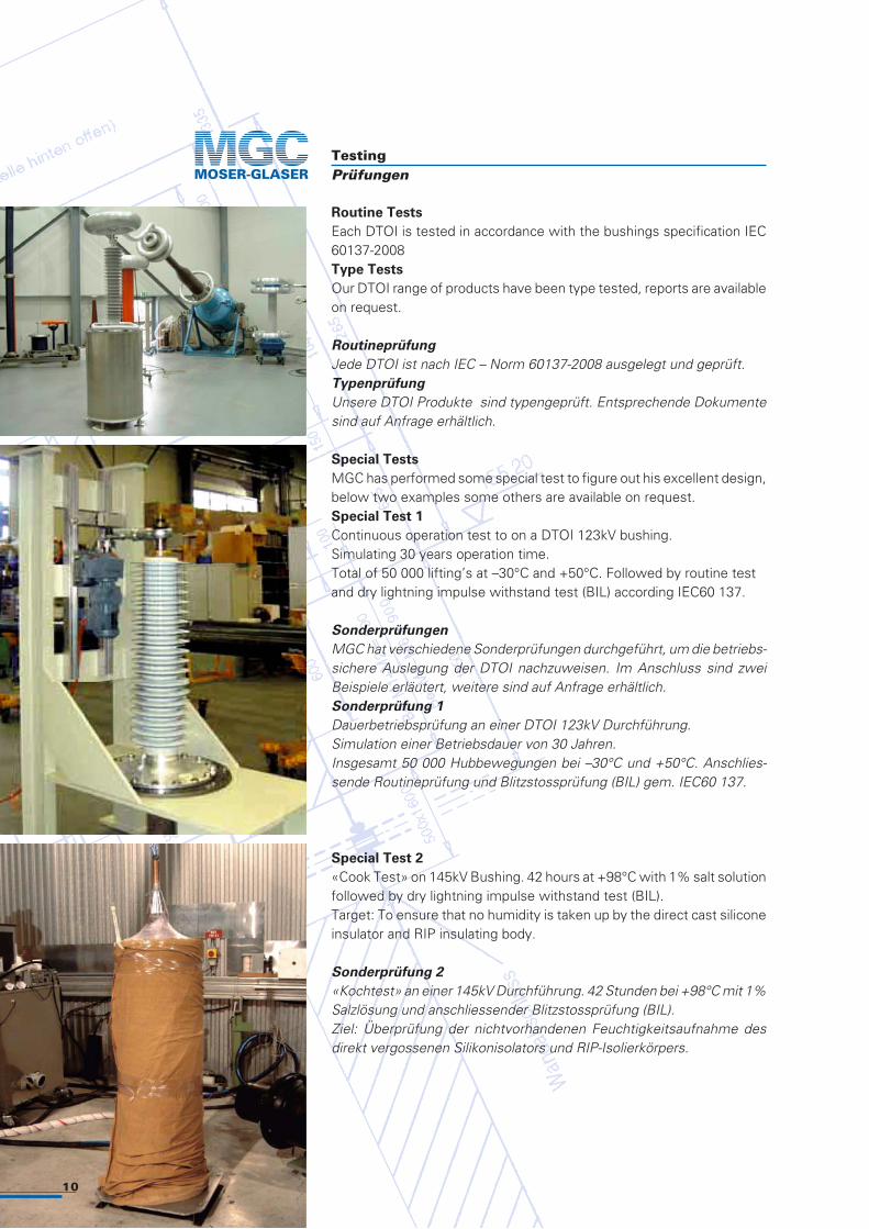
Special Tests
MGC has performed some special test to figure out his excellent design,below two examples some others are available on request.Special Test 1
Continuous operation test to on a DTOI 123kV bushing.Simulating 30 years operation time.Total of 50 000 lifting’s at –30°C and +50°C. Followed by routine testand dry lightning impulse withstand test (BIL) according IEC60 137.
Sonderprüfungen
MGC hat verschiedene Sonderprüfungen durchgeführt, um die betriebs-sichere Auslegung der DTOI nachzuweisen. Im Anschluss sind zwei Beispiele erläutert, weitere sind auf Anfrage erhältlich. Sonderprüfung 1
Dauerbetriebsprüfung an einer DTOI 123kV Durchführung.Simulation einer Betriebsdauer von 30 Jahren.Insgesamt 50 000 Hubbewegungen bei –30°C und +50°C. Anschlies-sende Routineprüfung und Blitzstossprüfung (BIL) gem. IEC60 137.
Special Test 2
«Cook Test» on 145kV Bushing. 42 hours at +98°C with 1% salt solutionfollowed by dry lightning impulse withstand test (BIL).Target: To ensure that no humidity is taken up by the direct cast siliconeinsulator and RIP insulating body.
Sonderprüfung 2
«Kochtest» an einer 145kV Durchführung. 42 Stunden bei +98°C mit 1%Salzlösung und anschliessender Blitzstossprüfung (BIL).Ziel: Überprüfung der nichtvorhandenen Feuchtigkeitsaufnahme desdirekt vergossenen Silikonisolators und RIP-Isolierkörpers.
TestingPrüfungen
10
Electrical data
Standard: � � � FSK Other _______
Rated voltage _______ kV
Bushing Insulation Level
Lightning impulse withstand voltage 1.2/50µs (BIL) _______ kV
Dry power frequency voltage withstand (AC) _______ kV
Switching Impulse (SIL) _______ kV
Rated frequency _______ Hz
Rated current _______ A
Connections
Altitude < 1000m Other __________ m
Ambient temperature -40 / +40 °C Other__________ °C
Oil temperature 90°C Other__________ °C
Creepage distance 31 mm/kV
Cantilever test load Acc to the IEC 60137 class II
Seismic conditions
Angle of mounting 0-90° Other__________ °
Horizontal acceleration __________ m/s2
Vertical acceleration __________ m/s2
Design
Top terminal material ����������
����
� ����������������
�Tin Plated Copper
CT extension E � ���
������
�500mm
�_____ mm
Arcing horns �Yes �No
Oil side shield �Yes �No
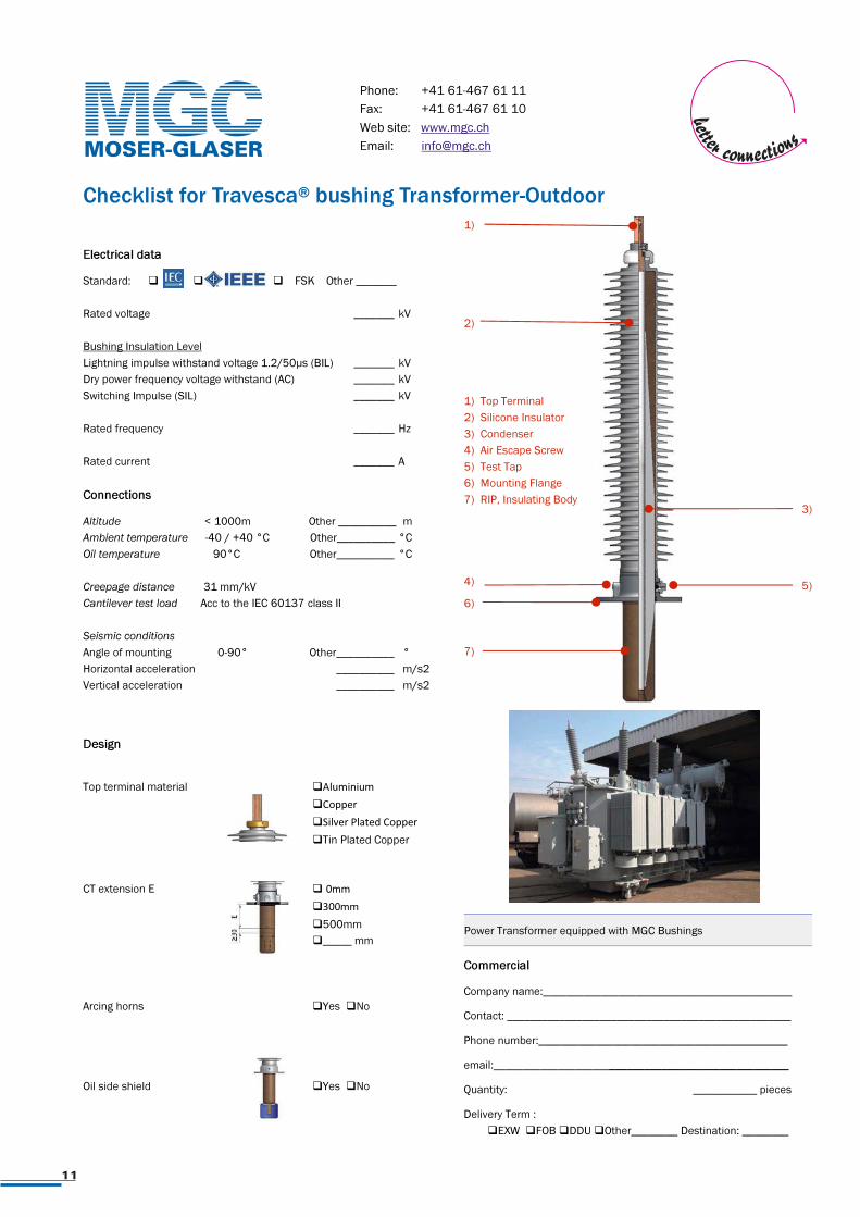
Checklist for Travesca®
bushing Transformer-Outdoor
Power Transformer equipped with MGC Bushings
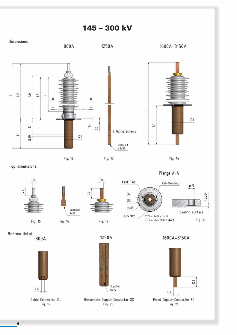
1) Top Terminal
2) Silicone Insulator
3) Condenser
4) Air Escape Screw
5) Test Tap
6) Mounting Flange
7) RIP, Insulating Body
1)
6)
2)
3)
Commercial
Company name:___________________________________________
Contact: _________________________________________________
Phone number:___________________________________________
email:___________________________________________________
Quantity: ___________ pieces
Delivery Term :
�EXW �FOB �DDU �Other________ Destination: ________
5) 4)
7)
Phone: +41 61-467 61 11
Fax: +41 61-467 61 10
Web site: www.mgc.ch
Email: [email protected]
11
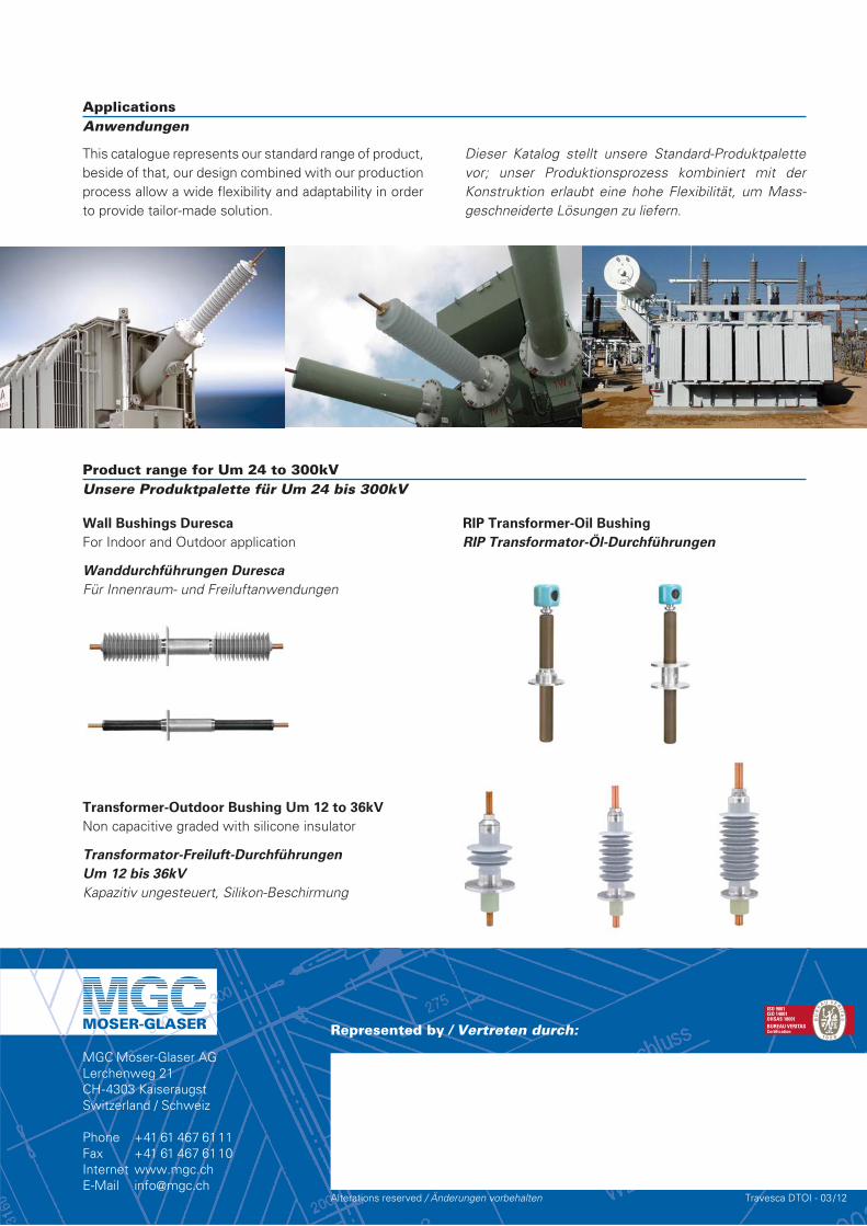
This catalogue represents our standard range of product,beside of that, our design combined with our productionprocess allow a wide flexibility and adaptability in orderto provide tailor-made solution.
Dieser Katalog stellt unsere Standard-Produktpalette vor; unser Produktionsprozess kombiniert mit der Konstruktion erlaubt eine hohe Flexibilität, um Mass -geschneiderte Lösungen zu liefern.
ApplicationsAnwendungen
Product range for Um 24 to 300kVUnsere Produktpalette für Um 24 bis 300kV
MGC Moser-Glaser AGLerchenweg 21CH-4303 KaiseraugstSwitzerland / Schweiz
Phone +41 61 467 6111Fax +41 61 467 6110Internet www.mgc.ch E-Mail [email protected]
Represented by / Vertreten durch:
Alterations reserved / Änderungen vorbehalten Travesca DTOI - 03/12
Transformer-Outdoor Bushing Um 12 to 36kV
Non capacitive graded with silicone insulator
Transformator-Freiluft-Durchführungen
Um 12 bis 36kV
Kapazitiv ungesteuert, Silikon-Beschirmung
Wall Bushings Duresca
For Indoor and Outdoor application
Wanddurchführungen Duresca
Für Innenraum- und Freiluftanwendungen
RIP Transformer-Oil Bushing
RIP Transformator-Öl-Durchführungen