rigid calculation
TRANSCRIPT

The tower crane is subjected to its weight and the load it supports. In order to calculatethe support reactions for the crane, it is necessary to apply the principles of equilibrium.
Unpublished Work © 2007 by R. C. Hibbeler. To be published by Pearson Prentice Hall, Pearson Education, Inc., Upper Saddle River,New Jersey. All rights reserved. This publication is protected by Copyright and written permission should be obtained from the
publisher prior to any prohibited reproduction, storage in a retrieval system, or transmission in any form or by any means, electronic,mechanical, photocopying, recording, or likewise. For information regarding permission(s), write to: Rights and Permissions Department.

5.1 Conditions for Rigid-BodyEquilibrium
In this section we will develop both the necessary and sufficient conditionsrequired for equilibrium of a rigid body.To do this, consider the rigid bodyin Fig. 5–1a, which is fixed in the x, y, z reference and is either at rest ormoves with the reference at constant velocity.A free-body diagram of thearbitrary ith particle of the body is shown in Fig. 5–1b.There are two typesof forces which act on it. The resultant internal force, is caused byinteractions with adjacent particles. The resultant external forcerepresents, for example, the effects of gravitational, electrical, magnetic, orcontact forces between the ith particle and adjacent bodies or particlesnot included within the body. If the particle is in equilibrium, then applyingNewton’s first law we have
When the equation of equilibrium is applied to each of the otherparticles of the body, similar equations will result. If all these equationsare added together vectorially, we obtain
©Fi + ©fi = 0
Fi + fi = 0
Fifi,
Equilibrium of a Rigid Body
201
F3 y
x
z
F4
F1F2
(a)
i
O
y
x
z
fi
ri
iFi
(b)
O
Fig. 5–1
CHAPTER OBJECTIVES
• To develop the equations of equilibrium for a rigid body.
• To introduce the concept of the free-body diagram for a rigid body.
• To show how to solve rigid-body equilibrium problems using theequations of equilibrium.
Unpublished Work © 2007 by R. C. Hibbeler. To be published by Pearson Prentice Hall, Pearson Education, Inc., Upper Saddle River,New Jersey. All rights reserved. This publication is protected by Copyright and written permission should be obtained from the
publisher prior to any prohibited reproduction, storage in a retrieval system, or transmission in any form or by any means, electronic,mechanical, photocopying, recording, or likewise. For information regarding permission(s), write to: Rights and Permissions Department.

202 CHAPTER 5 EQUIL IBR IUM OF A R IG ID BODY
The summation of the internal forces will equal zero since the internalforces between particles within the body will occur in equal but oppositecollinear pairs, Newton’s third law. Consequently, only the sum of theexternal forces will remain; and therefore, letting the aboveequation can be written as
Let us now consider the moments of the forces acting on the ith particleabout the arbitrary point O, Fig. 5–1b. Using the above particleequilibrium equation and the distributive law of the vector cross productwe have
Similar equations can be written for the other particles of the body, andadding them together vectorially, we obtain
The second term is zero since, as stated above, the internal forcesoccur in equal but opposite collinear pairs, and therefore the resultantmoment of each pair of forces about point O is zero. Using thenotation we have
Hence the two equations of equilibrium for a rigid body can besummarized as follows:
(5–1)©F = 0
©Mo = 0
©MO = 0
©MO = ©ri * Fi,
©ri * Fi + ©ri * fi = 0
ri * 1Fi + fi2 = ri * Fi + ri * fi = 0
©F = 0
©Fi = ©F,
F3y
x
z
F4
F1F2
(a)
i
O
Fig. 5–1
y
x
z
fi
ri
i
Fi
(b)
O
Unpublished Work © 2007 by R. C. Hibbeler. To be published by Pearson Prentice Hall, Pearson Education, Inc., Upper Saddle River,New Jersey. All rights reserved. This publication is protected by Copyright and written permission should be obtained from the
publisher prior to any prohibited reproduction, storage in a retrieval system, or transmission in any form or by any means, electronic,mechanical, photocopying, recording, or likewise. For information regarding permission(s), write to: Rights and Permissions Department.

5.2 FREE-BODY DIAGRAMS 203
These equations require that a rigid body will remain in equilibriumprovided the sum of all the external forces acting on the body is equal tozero and the sum of the moments of the external forces about a point isequal to zero.The fact that these conditions are necessary for equilibriumhas now been proven. They are also sufficient for maintainingequilibrium. To show this, let us assume that the body is in equilibriumand the force system acting on the body satisfies Eqs. 5–1. Suppose thatan additional force is applied to the body. As a result, the equilibriumequations become
where is the moment of about O. Since and then we require (also ). Consequently, the additionalforce is not required, and indeed Eqs. 5–1 are also sufficientconditions for maintaining equilibrium.
Many types of engineering problems involve symmetric loadings andcan be solved by projecting all the forces acting on a body onto a singleplane. And so in the next section, the equilibrium of a body subjected toa coplanar or two-dimensional force system will be considered.Ordinarily the geometry of such problems is not very complex, so ascalar solution is suitable for analysis. The more general discussion ofrigid bodies subjected to three-dimensional force systems is given in thelatter part of this chapter. It will be seen that many of these types ofproblems are best solved using vector analysis.
EQUILIBRIUM IN TWO DIMENSIONS
5.2 Free-Body Diagrams
Successful application of the equations of equilibrium requires acomplete specification of all the known and unknown external forcesthat act on the body. The best way to account for these forces is to drawthe body’s free-body diagram. This diagram is a sketch of the outlinedshape of the body, which represents it as being isolated or “free” fromits surroundings, i.e., a “free body.” On this sketch it is necessary toshow all the forces and couple moments that the surroundings exert onthe body so that these effects can be accounted for when the equationsof equilibrium are applied. For this reason, a thorough understandingof how to draw a free-body diagram is of primary importance for solvingproblems in mechanics.
F¿MO
œ = 0F¿ = 0©MO = 0,©F = 0F¿MO
œ
©MO + MOœ = 0
©F + F¿ = 0
F¿
Unpublished Work © 2007 by R. C. Hibbeler. To be published by Pearson Prentice Hall, Pearson Education, Inc., Upper Saddle River,New Jersey. All rights reserved. This publication is protected by Copyright and written permission should be obtained from the
publisher prior to any prohibited reproduction, storage in a retrieval system, or transmission in any form or by any means, electronic,mechanical, photocopying, recording, or likewise. For information regarding permission(s), write to: Rights and Permissions Department.

204 CHAPTER 5 EQUIL IBR IUM OF A R IG ID BODY
Support Reactions. Before presenting a formal procedure as tohow to draw a free-body diagram, we will first consider the various typesof reactions that occur at supports and points of support between bodiessubjected to coplanar force systems. As a general rule, if a support preventsthe translation of a body in a given direction, then a force is developed onthe body in that direction. Likewise, if rotation is prevented, a couplemoment is exerted on the body.
For example, let us consider three ways in which a horizontal member,such as a beam, is supported at its end. One method consists of a roller orcylinder, Fig. 5–2a. Since this support only prevents the beam fromtranslating in the vertical direction, the roller can only exert a force onthe beam in this direction, Fig. 5–2b.
The beam can be supported in a more restrictive manner by using apin as shown in Fig. 5–3a. The pin passes through a hole in the beamand two leaves which are fixed to the ground. Here the pin can preventtranslation of the beam in any direction Fig. 5–3b, and so the pinmust exert a force F on the beam in this direction. For purposes ofanalysis, it is generally easier to represent this resultant force F by itstwo components and Fig. 5–3c. If and are known, then Fand can be calculated.
The most restrictive way to support the beam would be to use a fixedsupport as shown in Fig. 5–4a.This support will prevent both translation androtation of the beam, and so to do this a force and couple moment must bedeveloped on the beam at its point of connection, Fig. 5–4b.As in the case ofthe pin, the force is usually represented by its components and
Table 5–1 lists other common types of supports for bodies subjected tocoplanar force systems. (In all cases the angle is assumed to be known.)Carefully study each of the symbols used to represent these supports andthe types of reactions they exert on their contacting members. Althoughconcentrated forces and couple moments are shown in this table, they actually represent the resultants of small distributed surface loads that existbetween each support and its contacting member. It is these resultantswhich will be determined from the equations of equilibrium.
u
Fy.Fx
f
FyFxFy,Fx
f,
(a)
roller
Fig. 5–2
(b)
F
(a)
pin
or
Fy
Fx
F
(c)(b)
f
Fig. 5–3
(a)
fixed support Fy
Fx
M
(b)
Fig. 5–4
Unpublished Work © 2007 by R. C. Hibbeler. To be published by Pearson Prentice Hall, Pearson Education, Inc., Upper Saddle River,New Jersey. All rights reserved. This publication is protected by Copyright and written permission should be obtained from the
publisher prior to any prohibited reproduction, storage in a retrieval system, or transmission in any form or by any means, electronic,mechanical, photocopying, recording, or likewise. For information regarding permission(s), write to: Rights and Permissions Department.

5.2 FREE-BODY DIAGRAMS 205
(3)
Types of Connection Reaction Number of Unknowns
One unknown. The reaction is a tension force which actsaway from the member in the direction of the cable.
One unknown. The reaction is a force which acts alongthe axis of the link.
One unknown. The reaction is a force which actsperpendicular to the surface at the point of contact.
One unknown. The reaction is a force which actsperpendicular to the slot.
One unknown. The reaction is a force which actsperpendicular to the surface at the point of contact.
One unknown. The reaction is a force which actsperpendicular to the surface at the point of contact.
One unknown. The reaction is a force which actsperpendicular to the rod.
continued
(1)
cable
F
(2)
weightless linkF
roller F
or
(4)
roller or pin in confined smooth slot
(5)
rocker
(6)
smooth contacting surface
F
F
F
(7)
or
orF
F
F
TABLE 5–1 Supports for Rigid Bodies Subjected to Two-Dimensional Force Systems
member pin connected to collar on smooth rod
u
u uu
uu
u u
u
u
u
u
u u u
u
u
Unpublished Work © 2007 by R. C. Hibbeler. To be published by Pearson Prentice Hall, Pearson Education, Inc., Upper Saddle River,New Jersey. All rights reserved. This publication is protected by Copyright and written permission should be obtained from the
publisher prior to any prohibited reproduction, storage in a retrieval system, or transmission in any form or by any means, electronic,mechanical, photocopying, recording, or likewise. For information regarding permission(s), write to: Rights and Permissions Department.

206 CHAPTER 5 EQUIL IBR IUM OF A R IG ID BODY
The cable exerts a force on the bracketin the direction of the cable. (1)
The rocker support for this bridgegirder allows horizontal movement sothe bridge is free to expand andcontract due to temperature. (5)
This concrete girder rests on theledge that is assumed to act as asmooth contacting surface. (6)
This utility building is pin supportedat the top of the column. (8)
The floor beams of this buildingare welded together and thusform fixed connections. (10)
Types of Connection Reaction Number of Unknowns
Two unknowns. The reactions are two components offorce, or the magnitude and direction of the resultantforce. Note that and are not necessarily equal [usuallynot, unless the rod shown is a link as in (2)].
Three unknowns. The reactions are the couple moment and the two force components, or the couple moment and the magnitude and direction of the resultant force.
Two unknowns. The reactions are the couple moment and the force which acts perpendicular to the rod.
F
Fy
M
or
Fx
F
fixed support
Fy
Fx
F
or
M M
f
f
f
u
TABLE 5–1 Continued
member fixed connected to collar on smooth rod
smooth pin or hinge
(8)
(9)
(10)
u f
f
Typical examples of actual supports are shown in the following sequence of photos.The numbers refer to the connection typesin Table 5–1.
Unpublished Work © 2007 by R. C. Hibbeler. To be published by Pearson Prentice Hall, Pearson Education, Inc., Upper Saddle River,New Jersey. All rights reserved. This publication is protected by Copyright and written permission should be obtained from the
publisher prior to any prohibited reproduction, storage in a retrieval system, or transmission in any form or by any means, electronic,mechanical, photocopying, recording, or likewise. For information regarding permission(s), write to: Rights and Permissions Department.

5.2 FREE-BODY DIAGRAMS 207
External and Internal Forces. Since a rigid body is acomposition of particles, both external and internal loadings may acton it. It is important to realize, however, that if the free-body diagramfor the body is drawn, the forces that are internal to the body are notrepresented on the free-body diagram. As discussed in Sec. 5.1, theseforces always occur in equal but opposite collinear pairs, and thereforetheir net effect on the body is zero.
In some problems, a free-body diagram for a “system” of connectedbodies may be used for an analysis. An example would be the free-body diagram of an entire automobile (system) composed of its manyparts. Obviously, the connecting forces between its parts wouldrepresent internal forces which would not be included on the free-body diagram of the automobile. To summarize, internal forces actbetween particles which are contained within the boundary of thefree-body diagram. Particles or bodies outside this boundary exertexternal forces on the system, and these alone must be shown on thefree-body diagram.
Weight and the Center of Gravity. When a body is subjectedto a gravitational field, then each of its particles has a specified weight.For the entire body it is appropriate to consider these gravitationalforces to be represented as a system of parallel forces acting on all theparticles contained within the boundary of the body. It was shown inSec. 4.9 that such a system can be reduced to a single resultant forceacting through a specified point. We refer to this force resultant as theweight W of the body and to the location of its point of application asthe center of gravity. The methods used for its calculation will bedeveloped in Chapter 9.
In the examples and problems that follow, if the weight of the bodyis important for the analysis, this force will then be reported in theproblem statement. Also, when the body is uniform or made ofhomogeneous material, the center of gravity will be located at thebody’s geometric center or centroid; however, if the body isnonhomogeneous or has an unusual shape, then the location of itscenter of gravity will be given.
Idealized Models. When an engineer performs a force analysisof any object, he or she considers a corresponding analytical oridealized model that gives results that approximate as closely aspossible the actual situation. To do this, careful choices have to be madeso that selection of the type of supports, the material behavior, and theobject’s dimensions can be justified. This way the engineer can feelconfident that any design or analysis will yield results which can betrusted. In complex cases this process may require developing severaldifferent models of the object that must be analyzed, but in any case,this selection process requires both skill and experience.
Unpublished Work © 2007 by R. C. Hibbeler. To be published by Pearson Prentice Hall, Pearson Education, Inc., Upper Saddle River,New Jersey. All rights reserved. This publication is protected by Copyright and written permission should be obtained from the
publisher prior to any prohibited reproduction, storage in a retrieval system, or transmission in any form or by any means, electronic,mechanical, photocopying, recording, or likewise. For information regarding permission(s), write to: Rights and Permissions Department.

208 CHAPTER 5 EQUIL IBR IUM OF A R IG ID BODY
The cases that follow illustrate what is required to develop a propermodel. In Fig. 5–5a, the steel beam is to be used to support the roofjoists of a building. For a force analysis it is reasonable to assume thematerial is rigid since only very small deflections will occur when the beam is loaded. A bolted connection at A will allow for any slightrotation that occurs when the load is applied, and so a pin can be considered for this support. At B a roller can be considered since thesupport offers no resistance to horizontal movement here. Buildingcode requirements are used to specify the roof loading which results ina calculation of the joist loads F. These forces will be larger than any actual loading on the beam since they account for extreme loading casesand for dynamic or vibrational effects.The weight of the beam is generallyneglected when it is small compared to the load the beam supports. Theidealized model of the beam is shown with average dimensions a, b, c,and d in Fig. 5–5b.
As a second case, consider the lift boom in Fig. 5–6a. By inspection, it issupported by a pin at A and by the hydraulic cylinder BC, which can beapproximated as a weightless link. The material can be assumed rigid,and with its density known, the weight of the boom and the location of itscenter of gravity G are determined.When a design loading P is specified,the idealized model shown in Fig. 5–6b can be used for a force analysis.Average dimensions (not shown) are used to specify the location of theloads and the supports.
Idealized models of specific objects will be given in some of theexamples throughout the text. It should be realized, however, that eachcase represents the reduction of a practical situation using simplifying assumptions like the ones illustrated here.
(a)
Fig. 5–5a
(a)
B
C
A
Fig. 5–6a
(b)
B
C
G
A
P
Fig. 5–6b
F F F
A B
(b)
a b c d
Fig. 5–5b
Unpublished Work © 2007 by R. C. Hibbeler. To be published by Pearson Prentice Hall, Pearson Education, Inc., Upper Saddle River,New Jersey. All rights reserved. This publication is protected by Copyright and written permission should be obtained from the
publisher prior to any prohibited reproduction, storage in a retrieval system, or transmission in any form or by any means, electronic,mechanical, photocopying, recording, or likewise. For information regarding permission(s), write to: Rights and Permissions Department.
5.2 FREE-BODY DIAGRAMS 209
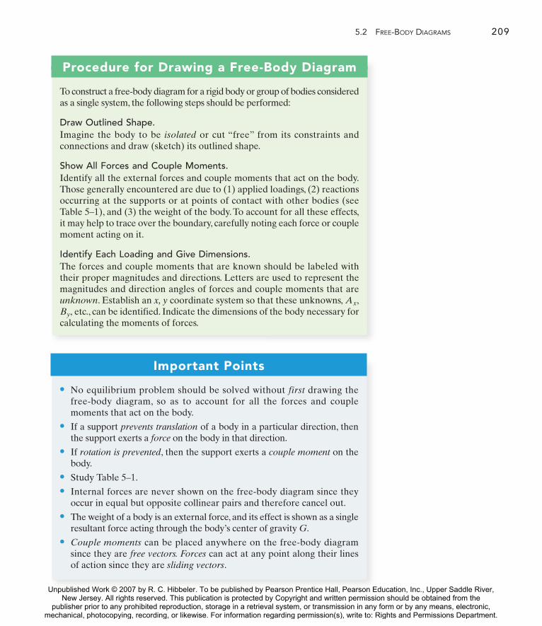
Procedure for Drawing a Free-Body Diagram
To construct a free-body diagram for a rigid body or group of bodies consideredas a single system, the following steps should be performed:
Draw Outlined Shape.Imagine the body to be isolated or cut “free” from its constraints andconnections and draw (sketch) its outlined shape.
Show All Forces and Couple Moments.Identify all the external forces and couple moments that act on the body.Those generally encountered are due to (1) applied loadings, (2) reactionsoccurring at the supports or at points of contact with other bodies (seeTable 5–1), and (3) the weight of the body. To account for all these effects,it may help to trace over the boundary, carefully noting each force or couplemoment acting on it.
Identify Each Loading and Give Dimensions.The forces and couple moments that are known should be labeled withtheir proper magnitudes and directions. Letters are used to represent themagnitudes and direction angles of forces and couple moments that areunknown. Establish an x, y coordinate system so that these unknowns,
etc., can be identified. Indicate the dimensions of the body necessary forcalculating the moments of forces.By,
Ax,
Important Points
• No equilibrium problem should be solved without first drawing thefree-body diagram, so as to account for all the forces and couple moments that act on the body.
• If a support prevents translation of a body in a particular direction, thenthe support exerts a force on the body in that direction.
• If rotation is prevented, then the support exerts a couple moment on thebody.
• Study Table 5–1.
• Internal forces are never shown on the free-body diagram since theyoccur in equal but opposite collinear pairs and therefore cancel out.
• The weight of a body is an external force, and its effect is shown as a singleresultant force acting through the body’s center of gravity G.
• Couple moments can be placed anywhere on the free-body diagramsince they are free vectors. Forces can act at any point along their linesof action since they are sliding vectors.
Unpublished Work © 2007 by R. C. Hibbeler. To be published by Pearson Prentice Hall, Pearson Education, Inc., Upper Saddle River,New Jersey. All rights reserved. This publication is protected by Copyright and written permission should be obtained from the
publisher prior to any prohibited reproduction, storage in a retrieval system, or transmission in any form or by any means, electronic,mechanical, photocopying, recording, or likewise. For information regarding permission(s), write to: Rights and Permissions Department.

210 CHAPTER 5 EQUIL IBR IUM OF A R IG ID BODY
EXAMPLE 5.1
Draw the free-body diagram of the uniform beam shown in Fig. 5–7a.The beam has a mass of 100 kg.
(a)
2 m1200 N
6 m
A
Ay
Ax
2 m1200 N
3 m
A
981 N
MA
G
Effect of appliedforce acting on beam
Effect of gravity (weight)acting on beam
Effect of fixedsupport actingon beam
(b)
y
x
Fig. 5–7
SOLUTIONThe free-body diagram of the beam is shown in Fig. 5–7b. Since thesupport at A is a fixed wall, there are three reactions acting on the beamat A, denoted as and drawn in an arbitrary direction. Themagnitudes of these vectors are unknown, and their sense has beenassumed. The weight of the beam, actsthrough the beam’s center of gravity G, which is 3 m from A since thebeam is uniform.
W = 10019.812 = 981 N,
MAAy,Ax,
Unpublished Work © 2007 by R. C. Hibbeler. To be published by Pearson Prentice Hall, Pearson Education, Inc., Upper Saddle River,New Jersey. All rights reserved. This publication is protected by Copyright and written permission should be obtained from the
publisher prior to any prohibited reproduction, storage in a retrieval system, or transmission in any form or by any means, electronic,mechanical, photocopying, recording, or likewise. For information regarding permission(s), write to: Rights and Permissions Department.

5.2 FREE-BODY DIAGRAMS 211
EXAMPLE 5.2
Draw the free-body diagram of the foot lever shown in Fig. 5–8a. Theoperator applies a vertical force to the pedal so that the spring isstretched 1.5 in. and the force in the short link at B is 20 lb.
A
B
(a)
SOLUTIONBy inspection, the lever is loosely bolted to the frame at A.The rod at Bis pinned at its ends and acts as a “short link.” After making the propermeasurements, the idealized model of the lever is shown in Fig. 5–8b.From this the free-body diagram must be drawn. As shown in Fig. 5–8c,the pin support at A exerts force components and on the lever,each force has a known line of action but unknown magnitude.The link at B exerts a force of 20 lb, acting in the direction of the link. Inaddition the spring also exerts a horizontal force on the lever. If the stiffness is measured and found to be then since thestretch using Eq. 3–2,Finally, the operator’s shoe applies a vertical force of F on the pedal.Thedimensions of the lever are also shown on the free-body diagram, sincethis information will be useful when computing the moments of theforces. As usual, the senses of the unknown forces at A have been assumed. The correct senses will become apparent after solving the equilibrium equations.
Fs = ks = 20 lb>in. 11.5 in.2 = 30 lb.s = 1.5 in.,k = 20 lb>in.,
AyAx
F
5 in.
1.5 in.
1 in.
A
B
k # 20 lb/in.
(b)
F
30 lb
5 in.
1.5 in.
1 in.
A
B
20 lb
Ay
Ax
(c)Fig. 5–8
Unpublished Work © 2007 by R. C. Hibbeler. To be published by Pearson Prentice Hall, Pearson Education, Inc., Upper Saddle River,New Jersey. All rights reserved. This publication is protected by Copyright and written permission should be obtained from the
publisher prior to any prohibited reproduction, storage in a retrieval system, or transmission in any form or by any means, electronic,mechanical, photocopying, recording, or likewise. For information regarding permission(s), write to: Rights and Permissions Department.

212 CHAPTER 5 EQUIL IBR IUM OF A R IG ID BODY
EXAMPLE 5.3
Two smooth pipes, each having a mass of 300 kg, are supported by theforks of the tractor in Fig. 5–9a. Draw the free-body diagrams for eachpipe and both pipes together.
(a)
SOLUTIONThe idealized model from which we must draw the free-body diagrams is shown in Fig. 5–9b. Here the pipes are identified, the dimensions have been added, and the physical situation reduced to itssimplest form.
The free-body diagram for pipe A is shown in Fig. 5–9c. Its weight isAssuming all contacting surfaces are
smooth, the reactive forces T, F, R act in a direction normal to the tangent at their surfaces of contact.
The free-body diagram of pipe B is shown in Fig. 5–9d. Can youidentify each of the three forces acting on this pipe? In particular, notethat R, representing the force of A on B, Fig. 5–9d, is equal and opposite to R representing the force of B on A, Fig. 5–9c. This is a consequence of Newton’s third law of motion.
The free-body diagram of both pipes combined (“system”) is shownin Fig. 5–9e. Here the contact force R, which acts between A and B, isconsidered as an internal force and hence is not shown on the free-body diagram. That is, it represents a pair of equal but oppositecollinear forces which cancel each other.
W = 30019.812 = 2943 N.
(b)
30$
A
B
0.35 m
0.35 m
30$
B
30$
P
R 2943 N
(d)
30$
A30$
30$
Effect of gravity(weight) acting on A
Effect of slopedfork acting on A
Effect of B acting on A
Effect of slopedblade acting on A
T
F
R
2943 N
(c)
Fig. 5–9
30$
A
30$
T
F
2943 N
(e)
30$
B
P
2943 N
Unpublished Work © 2007 by R. C. Hibbeler. To be published by Pearson Prentice Hall, Pearson Education, Inc., Upper Saddle River,New Jersey. All rights reserved. This publication is protected by Copyright and written permission should be obtained from the
publisher prior to any prohibited reproduction, storage in a retrieval system, or transmission in any form or by any means, electronic,mechanical, photocopying, recording, or likewise. For information regarding permission(s), write to: Rights and Permissions Department.

5.2 FREE-BODY DIAGRAMS 213
EXAMPLE 5.4
Draw the free-body diagram of the unloaded platform that issuspended off the edge of the oil rig shown in Fig. 5–10a.The platformhas a mass of 200 kg.
(a)
Fig. 5–10
SOLUTIONThe idealized model of the platform will be considered in two dimensions because by observation the loading and the dimensionsare all symmetrical about a vertical plane passing through its center,Fig. 5–10b. Here the connection at A is assumed to be a pin, and thecable supports the platform at B. The direction of the cable andaverage dimensions of the platform are listed, and the center ofgravity G has been determined. It is from this model that we mustproceed to draw the free-body diagram, which is shown in Fig. 5–10c.The platform’s weight is The force components
and along with the cable force T represent the reactions thatboth pins and both cables exert on the platform, Fig. 5–10a.Consequently, after the solution for these reactions, half theirmagnitude is developed at A and half is developed at B.
AyAx20019.812 = 1962 N.
1.40 m
1 m
70$
0.8 m
(b)
AG
B
1.40 m
1 m
70$
0.8 m
1962 N
(c)
Ax
Ay
G
A
T
Unpublished Work © 2007 by R. C. Hibbeler. To be published by Pearson Prentice Hall, Pearson Education, Inc., Upper Saddle River,New Jersey. All rights reserved. This publication is protected by Copyright and written permission should be obtained from the
publisher prior to any prohibited reproduction, storage in a retrieval system, or transmission in any form or by any means, electronic,mechanical, photocopying, recording, or likewise. For information regarding permission(s), write to: Rights and Permissions Department.

214 CHAPTER 5 EQUIL IBR IUM OF A R IG ID BODY
EXAMPLE 5.5
The free-body diagram of each object in Fig. 5–11 is drawn. Carefullystudy each solution and identify what each loading represents, as wasdone in Fig. 5–7b.
SOLUTION
30$
B200 N
5 4
3
A
30$
200 N
5
43
By
Bx
NA
(a)
y
x
30$
60$ 400 lb % ft
B
A
400 lb % ft
By
AxMA
(c)
y
x
Fig. 5–11
Note: Internal forces of one memberon another are equal but oppositecollinear forces which are not tobe included here since they cancel out.
(d)
4 kN
5 kN
Bx
Ay
Ax
y
x
4 kN
5 kN
A
B
A
B
C
500 N % m
30$
500 N % m
Ax T
Ay
(b)
30$
y
x
Unpublished Work © 2007 by R. C. Hibbeler. To be published by Pearson Prentice Hall, Pearson Education, Inc., Upper Saddle River,New Jersey. All rights reserved. This publication is protected by Copyright and written permission should be obtained from the
publisher prior to any prohibited reproduction, storage in a retrieval system, or transmission in any form or by any means, electronic,mechanical, photocopying, recording, or likewise. For information regarding permission(s), write to: Rights and Permissions Department.

PROBLEMS 215
P R O B L E M S
A
B
3 ft
30$
40 lb/ft
4 ft
Prob. 5–3
5–1. Draw the free-body diagram of the 10-lb sphere restingbetween the smooth inclined planes. Explain the significanceof each force on the diagram. (See Fig. 5–7b.)
5–2. Draw the free-body diagram of the hand punch, whichis pinned at A and bears down on the smooth surface at B.
5–3. Draw the free-body diagram of the beam supportedat A by a fixed support and at B by a roller. Explain thesignificance of each force on the diagram. (See Fig. 5–7b.)
*5–4. Draw the free-body diagram of the jib crane AB,whichis pin-connected at A and supported by member (link) BC.
105$
45$
A
B
Prob. 5–1
F # 8 lb
AB
1.5 ft
2 ft0.2 ft
Prob. 5–2
8 kN
3 m
0.4 m
C
B
3
4
5
4 m
A
Prob. 5–4
5–5. Draw the free-body diagram of the C-bracketsupported at A, B, and C by rollers. Explain the significanceof each force on the diagram. (See Fig. 5–7b.)
A
B C
30$ 20$
4 ft
200 lb
3 ft
Prob. 5–5
Unpublished Work © 2007 by R. C. Hibbeler. To be published by Pearson Prentice Hall, Pearson Education, Inc., Upper Saddle River,New Jersey. All rights reserved. This publication is protected by Copyright and written permission should be obtained from the
publisher prior to any prohibited reproduction, storage in a retrieval system, or transmission in any form or by any means, electronic,mechanical, photocopying, recording, or likewise. For information regarding permission(s), write to: Rights and Permissions Department.

216 CHAPTER 5 EQUIL IBR IUM OF A R IG ID BODY
5–6. Draw the free-body diagram of the smooth 20-g rodwhich rests inside the glass. Explain the significance of eachforce on the diagram. (See Fig. 5–7b.)
5–7. Draw the free-body diagram of the “spanner wrench”subjected to the 20-lb force. The support at A can beconsidered a pin, and the surface of contact at B is smooth.Explain the significance of each force on the diagram. (SeeFig. 5–7b.)
*5–8. Draw the free-body diagram of the automobile,which is being towed at constant velocity up the inclineusing the cable at C.The automobile has a mass of 5 Mg andcenter of mass at G. The tires are free to roll. Explain thesignificance of each force on the diagram. (See Fig. 5–7b.)
5–9. Draw the free-body diagram of the uniform bar, whichhas a mass of 100 kg and a center of mass at G.The supportsA, B, and C are smooth.
5–10. Draw the free-body diagram of the beam, which ispin-connected at A and rocker-supported at B.
75 mm
200 mm
40$
B
A
Prob. 5–6
A
B
6 in.
20 lb
1 in.
Prob. 5–7
F
0.75 m
30$0.3 m
0.6 m
G
20$
A
C
B1.50 m
1 m
Prob. 5–8
C
1.75 m0.1 m
1.25 m
0.5 m 0.2 m
30$A
GGG
B
Prob. 5–9
B
A
8 m 4 m
500 N800 N % m
5 m
Prob. 5–10
Unpublished Work © 2007 by R. C. Hibbeler. To be published by Pearson Prentice Hall, Pearson Education, Inc., Upper Saddle River,New Jersey. All rights reserved. This publication is protected by Copyright and written permission should be obtained from the
publisher prior to any prohibited reproduction, storage in a retrieval system, or transmission in any form or by any means, electronic,mechanical, photocopying, recording, or likewise. For information regarding permission(s), write to: Rights and Permissions Department.

5.3 EQUATIONS OF EQUILIBRIUM 217
C
B A
(a)
a
F3
a
F2
F4
F1
C
B A
MRA
FR
(b)
a
a
C
B A
(c)
a
a
FR
Fig. 5–12
5.3 Equations of Equilibrium
In Sec. 5.1 we developed the two equations which are both necessary andsufficient for the equilibrium of a rigid body,namely, and When the body is subjected to a system of forces, which all lie in the x–yplane, then the forces can be resolved into their x and y components.Consequently, the conditions for equilibrium in two dimensions are
(5–2)
Here and represent, respectively, the algebraic sums of the xand y components of all the forces acting on the body, andrepresents the algebraic sum of the couple moments and the momentsof all the force components about an axis perpendicular to the x–yplane and passing through the arbitrary point O, which may lie eitheron or off the body.
Alternative Sets of Equilibrium Equations. Although Eqs. 5–2are most often used for solving coplanar equilibrium problems, twoalternative sets of three independent equilibrium equations may also beused. One such set is
(5–3)
When using these equations it is required that a line passing throughpoints A and B is not perpendicular to the a axis. To prove that Eqs. 5–3provide the conditions for equilibrium, consider the free-body diagramof an arbitrarily shaped body shown in Fig. 5–12a. Using the methods ofSec. 4.8, all the forces on the free-body diagram may be replaced by anequivalent resultant force acting at point A, and a resultantcouple moment Fig. 5–12b. If is satisfied, it isnecessary that Furthermore, in order that satisfy it must have no component along the a axis, and therefore its line of action must be perpendicular to the a axis, Fig. 5–12c. Finally, if it is required that where B does not lie on the line of action of then Since and indeed the body in Fig. 5–12amust be in equilibrium.
©MA = 0,©F = 0FR = 0.FR,©MB = 0,
©Fa = 0,FRMRA = 0.©MA = 0MRA = ©MA,
FR = ©F,
©Fa = 0©MA = 0©MB = 0
©MO©Fy©Fx
©Fx = 0©Fy = 0©Mo = 0
©MO = 0.©F = 0
Unpublished Work © 2007 by R. C. Hibbeler. To be published by Pearson Prentice Hall, Pearson Education, Inc., Upper Saddle River,New Jersey. All rights reserved. This publication is protected by Copyright and written permission should be obtained from the
publisher prior to any prohibited reproduction, storage in a retrieval system, or transmission in any form or by any means, electronic,mechanical, photocopying, recording, or likewise. For information regarding permission(s), write to: Rights and Permissions Department.

218 CHAPTER 5 EQUIL IBR IUM OF A R IG ID BODY
Procedure for Analysis
Coplanar force equilibrium problems for a rigid body can be solvedusing the following procedure.
Free-Body Diagram.
• Establish the x, y coordinate axes in any suitable orientation.
• Draw an outlined shape of the body.
• Show all the forces and couple moments acting on the body.
• Label all the loadings and specify their directions relative to thex, y axes. The sense of a force or couple moment having anunknown magnitude but known line of action can be assumed.
• Indicate the dimensions of the body necessary for computingthe moments of forces.
Equations of Equilibrium.
• Apply the moment equation of equilibrium, about apoint (O) that lies at the intersection of the lines of action oftwo unknown forces. In this way, the moments of theseunknowns are zero about O, and a direct solution for the thirdunknown can be determined.
• When applying the force equilibrium equations, andorient the x and y axes along lines that will provide the
simplest resolution of the forces into their x and y components.
• If the solution of the equilibrium equations yields a negativescalar for a force or couple moment magnitude, this indicatesthat the sense is opposite to that which was assumed on the free-body diagram.
©Fy = 0,©Fx = 0
©MO = 0,
C
B A
MRA
FR
a
a
Fig. 5–13
A second alternative set of equilibrium equations is
(5–4)
Here it is necessary that points A, B, and C do not lie on the same line.Toprove that these equations, when satisfied, ensure equilibrium, considerthe free-body diagram in Fig. 5–13. If is to be satisfied, then
is satisfied if the line of action of passes throughpoint B as shown. Finally, if we require where C does not lieon line AB, it is necessary that and the body in Fig. 5–12a mustthen be in equilibrium.
FR = 0,©MC = 0,
FR©MB = 0MRA = 0.©MA = 0
©MA = 0©MB = 0©MC = 0
Unpublished Work © 2007 by R. C. Hibbeler. To be published by Pearson Prentice Hall, Pearson Education, Inc., Upper Saddle River,New Jersey. All rights reserved. This publication is protected by Copyright and written permission should be obtained from the
publisher prior to any prohibited reproduction, storage in a retrieval system, or transmission in any form or by any means, electronic,mechanical, photocopying, recording, or likewise. For information regarding permission(s), write to: Rights and Permissions Department.

5.3 EQUATIONS OF EQUILIBRIUM 219
(a)
600 N
D
100 N
A B
200 N
45$
2 m 3 m 2 m
0.2 m
By
2 m
600 sin 45$ N
3 m 2 m
AB
200 N
600 cos 45$ N
Ay
Bxx
y
(b)
100 N
0.2 m
D
Fig. 5–14
EXAMPLE 5.6
Determine the horizontal and vertical components of reaction on thebeam caused by the pin at B and the rocker at as shown in Fig. 5–14a.Neglect the weight of the beam.
A
SOLUTIONFree-Body Diagram. Identify each of the forces shown on the free-body diagram of the beam, Fig. 5–14b. (See Example 5.1.) Forsimplicity, the 600-N force is represented by its x and y componentsas shown. Also, note that a 200-N force acts on the beam at B and isindependent of the force components and which represent theeffect of the pin on the beam.
Equations of Equilibrium. Summing forces in the x direction yields
Ans.A direct solution for can be obtained by applying the moment
equation about point B. For the calculation, it should be apparent that forces 200 N, and all create zero moment about B.Assuming counterclockwise rotation about B to be positive (in the direction), Fig. 5–14b, we have
Ans.
Summing forces in the y direction, using this result, gives
Ans.
NOTE: We can check this result by summing moments about point A.
Ans.By = 405 N
-1100 N215 m2 - 1200 N217 m2 + By17 m2 = 0
-1600 sin 45° N212 m2 - 1600 cos 45° N210.2 m2d+©MA = 0;
By = 405 N
319 N - 600 sin 45° N - 100 N - 200 N + By = 0+ c©Fy = 0;
Ay = 319 N
- 1600 cos 45° N210.2 m2 - Ay17 m2 = 0100 N12 m2 + 1600 sin 45° N215 m2d+©MB = 0;
+kByBx,
©MB = 0Ay
Bx = 424 N600 cos 45° N - Bx = 0:+ ©Fx = 0;
By,Bx
Unpublished Work © 2007 by R. C. Hibbeler. To be published by Pearson Prentice Hall, Pearson Education, Inc., Upper Saddle River,New Jersey. All rights reserved. This publication is protected by Copyright and written permission should be obtained from the
publisher prior to any prohibited reproduction, storage in a retrieval system, or transmission in any form or by any means, electronic,mechanical, photocopying, recording, or likewise. For information regarding permission(s), write to: Rights and Permissions Department.

220 CHAPTER 5 EQUIL IBR IUM OF A R IG ID BODY
100 lb
0.5 ft
# 30$
C
(a)
A
u
Fig. 5–15
T100 lb
30$
p
Ax
Ay
A
(b)
p
Ax
Ay
A
T100 lb
0.5 ft
# 30$
(c)
x
y
u
EXAMPLE 5.7
The cord shown in Fig. 5–15a supports a force of 100 lb and wrapsover the frictionless pulley. Determine the tension in the cord at C andthe horizontal and vertical components of reaction at pin A.
SOLUTIONFree-Body Diagrams. The free-body diagrams of the cord and pulleyare shown in Fig. 5–15b. Note that the principle of action, equal butopposite reaction must be carefully observed when drawing each ofthese diagrams: the cord exerts an unknown load distribution p alongpart of the pulley’s surface, whereas the pulley exerts an equal butopposite effect on the cord. For the solution, however, it is simpler tocombine the free-body diagrams of the pulley and the contactingportion of the cord, so that the distributed load becomes internal to thesystem and is therefore eliminated from the analysis, Fig. 5–15c.
Equations of Equilibrium. Summing moments about point A toeliminate and Fig. 5–15c, we have
Ans.
Using the result for T, a force summation is applied to determinethe components of reaction at pin A.
Ans.
Ans.
NOTE: It is seen that the tension remains constant as the cord passesover the pulley. (This of course is true for any angle at which thecord is directed and for any radius r of the pulley.)
u
Ay = 187 lb
Ay - 100 lb - 100 cos 30° lb = 0+ c©Fy = 0;
Ax = 50.0 lb
-Ax + 100 sin 30° lb = 0:+ ©Fx = 0;
T = 100 lb
100 lb 10.5 ft2 - T10.5 ft2 = 0d+©MA = 0;
Ay,Ax
Unpublished Work © 2007 by R. C. Hibbeler. To be published by Pearson Prentice Hall, Pearson Education, Inc., Upper Saddle River,New Jersey. All rights reserved. This publication is protected by Copyright and written permission should be obtained from the
publisher prior to any prohibited reproduction, storage in a retrieval system, or transmission in any form or by any means, electronic,mechanical, photocopying, recording, or likewise. For information regarding permission(s), write to: Rights and Permissions Department.

5.3 EQUATIONS OF EQUILIBRIUM 221
0.75 m
30$
1 m0.5 m
60 N
90 N % m
A
B
(a)
NB30$
0.75 m1 m
60 N
A
Ax
Ay
30$
(b)
x
y90 N % m
Fig. 5–16
EXAMPLE 5.8
The link shown in Fig. 5–16a is pin-connected at A and rests against asmooth support at B. Compute the horizontal and verticalcomponents of reaction at the pin A.
SOLUTIONFree-Body Diagram. As shown in Fig. 5–16b, the reaction isperpendicular to the link at B.Also, horizontal and vertical componentsof reaction are represented at A.Equations of Equilibrium. Summing moments about A, we obtaina direct solution for
Using this result,
Ans.
Ans.Ay = 233 N
Ay - 200 cos 30° N - 60 N = 0+ c©Fy = 0;Ax = 100 N
Ax - 200 sin 30° N = 0:+ ©Fx = 0;
NB = 200 N
-90 N # m - 60 N11 m2 + NB10.75 m2 = 0d+©MA = 0;
NB,
NB
Unpublished Work © 2007 by R. C. Hibbeler. To be published by Pearson Prentice Hall, Pearson Education, Inc., Upper Saddle River,New Jersey. All rights reserved. This publication is protected by Copyright and written permission should be obtained from the
publisher prior to any prohibited reproduction, storage in a retrieval system, or transmission in any form or by any means, electronic,mechanical, photocopying, recording, or likewise. For information regarding permission(s), write to: Rights and Permissions Department.

222 CHAPTER 5 EQUIL IBR IUM OF A R IG ID BODY
300 mm 400 mm
13 12
5
B C60$
52 N 30 N(a)
A
Fig. 5–17a
C
0.3 m 0.4 m
13 125
60$
52 N 30 N
(b)
Ay
MA
Axy
x
Fig. 5–17b
EXAMPLE 5.9
The box wrench in Fig. 5–17a is used to tighten the bolt at A. If thewrench does not turn when the load is applied to the handle,determine the torque or moment applied to the bolt and the force ofthe wrench on the bolt.
SOLUTIONFree-Body Diagram. The free-body diagram for the wrench is shownin Fig. 5–17b. Since the bolt acts as a “fixed support,” it exerts forcecomponents and and a torque on the wrench at A.
Equations of Equilibrium.
Ans.
Ans.
Ans.
Point A was chosen for summing moments because the lines of action of the unknown forces and pass through this point, andtherefore these forces were not included in the moment summation.Realize, however, that must be included in this momentsummation. This couple moment is a free vector and represents thetwisting resistance of the bolt on the wrench. By Newton’s third law,the wrench exerts an equal but opposite moment or torque on thebolt. Furthermore, the resultant force on the wrench is
Ans.
Because the force components and were calculated as positive quantities, their directional sense is shown correctly on thefree-body diagram in Fig. 5–17b. Hence
Realize that acts in the opposite direction on the bolt. Why?
NOTE: Although only three independent equilibrium equations can bewritten for a rigid body, it is a good practice to check the calculationsusing a fourth equilibrium equation. For example, the abovecomputations may be verified in part by summing moments aboutpoint C:
19.2 N # m + 32.6 N # m - 51.8 N # m = 0
52 A1213 BN10.4 m2 + 32.6 N # m - 74.0 N10.7 m2 = 0d+©MC = 0;
FA
u = tan-1 74.0 N5.00 N
= 86.1° a u
AyAx
FA = 215.0022 + 174.022 = 74.1 N
MA
AyAx
MA = 32.6 N # mMA - 52 A12
13 BN10.3 m2 - 130 sin 60° N210.7 m2 = 0d+©MA = 0;
Ay = 74.0 N
Ay - 52 A1213 BN - 30 sin 60° N = 0+ c©Fy = 0;
Ax = 5.00 N
Ax - 52 A 513 BN + 30 cos 60° N = 0:+ ©Fx = 0;
MAAyAx
Unpublished Work © 2007 by R. C. Hibbeler. To be published by Pearson Prentice Hall, Pearson Education, Inc., Upper Saddle River,New Jersey. All rights reserved. This publication is protected by Copyright and written permission should be obtained from the
publisher prior to any prohibited reproduction, storage in a retrieval system, or transmission in any form or by any means, electronic,mechanical, photocopying, recording, or likewise. For information regarding permission(s), write to: Rights and Permissions Department.

5.3 EQUATIONS OF EQUILIBRIUM 223
(a)
(b)
2 ft
GB C
A4 ft
30$
4 ft
8 ft
0.25 ft
y
x
(c)
2 ftB
A Ax
Ay
FBC
4 ft4 ft
0.25 ft
560 lb
30$
30$
Fig. 5–18
EXAMPLE 5.10
Placement of concrete from the truck is accomplished using the chuteshown in the photos, Fig. 5–18a. Determine the force that the hydraulic cylinder and the truck frame exert on the chute to hold it inthe position shown. The chute and wet concrete contained along itslength have a uniform weight of
SOLUTIONThe idealized model of the chute is shown in Fig. 5–18b. Here the dimensions are given, and it is assumed the chute is pin connected tothe frame at A and the hydraulic cylinder BC acts as a short link.
35 lb>ft.
Free-Body Diagram. Since the chute has a length of 16 ft, the totalsupported weight is which is assumed to actat its midpoint, G.The hydraulic cylinder exerts a horizontal force on the chute, Fig. 5–18c.
Equations of Equilibrium. A direct solution for is possible bysumming moments about the pin at A. To do this we will use theprinciple of moments and resolve the weight into components paralleland perpendicular to the chute. We have,
Ans.
Summing forces to obtain and we obtain
Ans.
Ans.
NOTE: To verify this solution we can sum moments about point B.
560 cos 30° lb 14 ft2 + 560 sin 30° lb 10.25 ft2 = 0-1975 lb 12 ft2 + 560 lb 14 cos 30° ft2+d+©MB = 0;
Ay = 560 lbAy - 560 lb = 0+ c©Fy = 0;
Ax = 1975 lb-Ax + 1975 lb = 0:+ ©Fx = 0;
Ay,Ax
FBC = 1975 lb-FBC12 ft2 + 560 cos 30° lb 18 ft2 + 560 sin 30° lb 10.25 ft2 = 0
d+©MA = 0;
FBC
FBC135 lb>ft2116 ft2 = 560 lb,
Unpublished Work © 2007 by R. C. Hibbeler. To be published by Pearson Prentice Hall, Pearson Education, Inc., Upper Saddle River,New Jersey. All rights reserved. This publication is protected by Copyright and written permission should be obtained from the
publisher prior to any prohibited reproduction, storage in a retrieval system, or transmission in any form or by any means, electronic,mechanical, photocopying, recording, or likewise. For information regarding permission(s), write to: Rights and Permissions Department.

224 CHAPTER 5 EQUIL IBR IUM OF A R IG ID BODY
(a)
A
2 m
300 N
4000 N % m
4 m
2 m
C
B
30$2 m
Fig. 5–19a
(b)
2 m
300 N
4000 N % m
4 m
2 m30$
30$
Cy¿
By¿
30$ 30$
Ax
y y¿
x
x¿
30$
Fig. 5–19b
EXAMPLE 5.11
The uniform smooth rod shown in Fig. 5–19a is subjected to a forceand couple moment. If the rod is supported at A by a smooth wall andat B and C either at the top or bottom by rollers, determine thereactions at these supports. Neglect the weight of the rod.
SOLUTIONFree-Body Diagram. As shown in Fig. 5–19b, all the supportreactions act normal to the surface of contact since the contactingsurfaces are smooth. The reactions at B and C are shown acting in thepositive direction. This assumes that only the rollers located on thebottom of the rod are used for support.
Equations of Equilibrium. Using the x, y coordinate system inFig. 5–19b, we have
(1)
(2)
(3)
When writing the moment equation, it should be noticed that the lineof action of the force component 300 sin 30° N passes through point A, and therefore this force is not included in the moment equation.
Solving Eqs. 2 and 3 simultaneously, we obtain
Ans.
Ans.
Since is a negative scalar, the sense of is opposite to that shownon the free-body diagram in Fig. 5–19b. Therefore, the top roller at Bserves as the support rather than the bottom one. Retaining the negativesign for (Why?) and substituting the results into Eq. 1, we obtain
Ans.Ax = 173 N
1346.4 sin 30° N - 1000.0 sin 30° N - Ax = 0
By¿
By¿By¿
Cy¿ = 1346.4 N = 1.35 kN
By¿ = -1000.0 N = -1 kN
+ 1300 cos 30° N218 m2 = 0
-By¿12 m2 + 4000 N # m - Cy¿16 m2d+©MA = 0;
-300 N + Cy¿ cos 30° + By¿ cos 30° = 0+ c©Fy = 0;
Cy¿ sin 30° + By¿ sin 30° - Ax = 0:+ ©Fx = 0;
y¿
Unpublished Work © 2007 by R. C. Hibbeler. To be published by Pearson Prentice Hall, Pearson Education, Inc., Upper Saddle River,New Jersey. All rights reserved. This publication is protected by Copyright and written permission should be obtained from the
publisher prior to any prohibited reproduction, storage in a retrieval system, or transmission in any form or by any means, electronic,mechanical, photocopying, recording, or likewise. For information regarding permission(s), write to: Rights and Permissions Department.

5.3 EQUATIONS OF EQUILIBRIUM 225
(c)
G
B
A C
Ay
Ax
T
T
30$
2 ft
10$20$
5 ft400 lb
20$20$
d
x
y
Fig. 5–20c
EXAMPLE 5.12
The uniform truck ramp shown in Fig. 5–20a has a weight of 400 lb andis pinned to the body of the truck at each end and held in the positionshown by the two side cables. Determine the tension in the cables.
SOLUTIONThe idealized model of the ramp, which indicates all necessarydimensions and supports, is shown in Fig. 5–20b. Here the center ofgravity is located at the midpoint since the ramp is approximatelyuniform.
Free-Body Diagram. Working from the idealized model, the ramp’sfree-body diagram is shown in Fig. 5–20c.
Equations of Equilibrium. Summing moments about point A will yielda direct solution for the cable tension. Using the principle of moments,there are several ways of determining the moment of T about A. If weuse x and y components, with T applied at B, we have
By the principle of transmissibility, we can locate T at C, eventhough this point is not on the ramp, Fig. 5–20c. In this case thehorizontal component of T does not create a moment about A. Firstwe must determine d using the sine law.
The simplest way to compute the moment of T about A is to resolveit into components parallel and perpendicular to the ramp at B. Thenthe moment of the parallel component is zero about A, so that
Since there are two cables supporting the ramp,
Ans.
NOTE: As an exercise, show that and Ay = 887.4 lb.Ax = 1339 lb
T¿ =T
2= 712 lb
T = 1425 lb
-T sin 10°17 ft2 + 400 lb 15 cos 30° ft2 = 0d+©MA = 0;
T = 1425 lb
-T sin 20°13.554 ft2 + 400 lb 15 cos 30° ft2 = 0d+©MA = 0;
d = 3.554 ftd
sin 10°=
7 ftsin 20°
;
T = 1425 lb
+ 400 lb 15 cos 30° ft2 = 0
-T cos 20°17 sin 30° ft2 + T sin 20°17 cos 30° ft2d+©MA = 0;
(a)
Fig. 5–20a
(b)
G
B
A30$
20$
2 ft
5 ft
Fig. 5–20b
Unpublished Work © 2007 by R. C. Hibbeler. To be published by Pearson Prentice Hall, Pearson Education, Inc., Upper Saddle River,New Jersey. All rights reserved. This publication is protected by Copyright and written permission should be obtained from the
publisher prior to any prohibited reproduction, storage in a retrieval system, or transmission in any form or by any means, electronic,mechanical, photocopying, recording, or likewise. For information regarding permission(s), write to: Rights and Permissions Department.

226 CHAPTER 5 EQUIL IBR IUM OF A R IG ID BODY
A
B
FA
FB # "FA
F1
A
B
F2F3
F6
F5F4
(a)
(b)
Two-force member
Fig. 5–21
FA
A B
FB #"FA
FB #"FA FB #"FA
FA
FA
A
A
B
B
Two-force members
Fig. 5–22
5.4 Two- and Three-Force Members
The solution to some equilibrium problems can be simplified by recognizingmembers that are subjected to only two or three forces.
Two-Force Members. When a member is subjected to no couplemoments and forces are applied at only two points on the member, themember is called a two-force member.An example is shown in Fig. 5–21a.The forces at A and B are summed to obtain their respective resultantsand Fig. 5–21b. These two forces will maintain translational or forceequilibrium provided is of equal magnitude and oppositedirection to Furthermore, rotational or moment equilibrium
is satisfied if is collinear with As a result, the line ofaction of both forces is known since it always passes through A and B.Hence, only the force magnitude must be determined or stated. Otherexamples of two-force members held in equilibrium are shown in Fig. 5–22.
FB.FA1©MO = 02 FB.FA1©F = 02FB,
FA
Three-Force Members. If a member is subjected to only threeforces, then it is necessary that the forces be either concurrent or parallelfor the member to be in equilibrium.To show the concurrency requirement,consider the body in Fig. 5–23a and suppose that any two of the threeforces acting on the body have lines of action that intersect at point O. Tosatisfy moment equilibrium about O, i.e., , the third force mustalso pass through O, which then makes the force system concurrent. Iftwo of the three forces are parallel, Fig. 5–23b, the point of concurrency,O, is considered to be at “infinity,” and the third force must be parallel tothe other two forces to intersect at this “point.”
©MO = 0
Unpublished Work © 2007 by R. C. Hibbeler. To be published by Pearson Prentice Hall, Pearson Education, Inc., Upper Saddle River,New Jersey. All rights reserved. This publication is protected by Copyright and written permission should be obtained from the
publisher prior to any prohibited reproduction, storage in a retrieval system, or transmission in any form or by any means, electronic,mechanical, photocopying, recording, or likewise. For information regarding permission(s), write to: Rights and Permissions Department.

5.4 TWO- AND THREE-FORCE MEMBERS 227
F2
F2
O
F1
F1
F3
F3
Parallel forcesConcurrent forces
(b)(a)
Three-force members
Fig. 5–23
A
B
ABD
C
C
B
A
Many mechanical elements act as two- or three-force members, and the ability torecognize them in a problem will considerably simplify an equilibrium analysis.
• The bucket link AB on the back-hoe is a typical example of a two-forcemember since it is pin connected at its ends and, provided its weight isneglected, no other force acts on this member.
• The hydraulic cylinder BC is pin connected at its ends. It is a two-forcemember.The boom ABD is subjected to the weight of the suspended motorat D, the force of the hydraulic cylinder at B, and the force of the pin at A.If the boom’s weight is neglected, it is a three-force member.
• The dump bed of the truck operates by extending the telescopic hydrauliccylinder AB. If the weight of AB is neglected, we can classify it as a two-force member since it is pin connected at its end points.
Unpublished Work © 2007 by R. C. Hibbeler. To be published by Pearson Prentice Hall, Pearson Education, Inc., Upper Saddle River,New Jersey. All rights reserved. This publication is protected by Copyright and written permission should be obtained from the
publisher prior to any prohibited reproduction, storage in a retrieval system, or transmission in any form or by any means, electronic,mechanical, photocopying, recording, or likewise. For information regarding permission(s), write to: Rights and Permissions Department.

228 CHAPTER 5 EQUIL IBR IUM OF A R IG ID BODY
0.5 m
0.2 m
B
A
D
C
0.1 m
0.2 m
(a)
400 N
Fig. 5–24a
45$
F
F
B
D
(b)
0.2 mB
A
C
0.5 m
0.5 m
F
45$
45$
45$
O
0.1 m(c)
0.4 m
FA
400 N
u
Fig. 5–24b
EXAMPLE 5.13
The lever ABC is pin-supported at A and connected to a short linkBD as shown in Fig. 5–24a. If the weight of the members is negligible,determine the force of the pin on the lever at A.
SOLUTIONFree-Body Diagrams. As shown by the free-body diagram, Fig. 5–24b,the short link BD is a two-force member, so the resultant forces at pinsD and B must be equal, opposite, and collinear.Although the magnitudeof the force is unknown, the line of action is known since it passesthrough B and D.
Lever ABC is a three-force member, and therefore, in order tosatisfy moment equilibrium, the three nonparallel forces acting on itmust be concurrent at O, Fig. 5–24c. In particular, note that the force Fon the lever at B is equal but opposite to the force F acting at B on thelink. Why? The distance CO must be 0.5 m since the lines of action of F and the 400-N force are known.
Equations of Equilibrium. By requiring the force system to beconcurrent at O, since the angle which defines the line of action of can be determined from trigonometry,
Ans.
Using the x, y axes and applying the force equilibrium equations, wecan obtain and F.
Solving, we get
Ans.
NOTE: We can also solve this problem by representing the force at A by its two components and and applying
to the lever. Once and are determined,
how would you find and u?FA
AyAx©Fy = 0©Fx = 0,©MA = 0,AyAx
F = 1.32 kN
FA = 1.07 kN
FA sin 60.3° - F sin 45° = 0+ c©Fy = 0;
FA cos 60.3° - F cos 45° + 400 N = 0:+ ©Fx = 0;
FA
u = tan-1a0.70.4b = 60.3° au
FAu©MO = 0,
Unpublished Work © 2007 by R. C. Hibbeler. To be published by Pearson Prentice Hall, Pearson Education, Inc., Upper Saddle River,New Jersey. All rights reserved. This publication is protected by Copyright and written permission should be obtained from the
publisher prior to any prohibited reproduction, storage in a retrieval system, or transmission in any form or by any means, electronic,mechanical, photocopying, recording, or likewise. For information regarding permission(s), write to: Rights and Permissions Department.

PROBLEMS 229
400 N15$600 N
8 m
3
4
5
4 m
AB
Prob. 5–19
A B6 ft 6 ft 6 ft
250 lb % ft
Prob. 5–20
14 in.2 in.
0.8 in.
B
H
A
CGFB
FC
FA
75$
H
Prob. 5–21
P R O B L E M S
5–11. Determine the reactions at the supports in Prob. 5–1.
*5–12. Determine the magnitude of the resultant forceacting at pin A of the handpunch in Prob. 5–2.
5–13. Determine the reactions at the supports at C inProb. 5–5.
5–14. Determine the reactions on the rod in Prob. 5–6.
5–15. Determine the support reactions on the spannerwrench in Prob. 5–7.
*5–16. Determine the reactions on the car in Prob. 5–8.
5–17. Determine the reactions at the points of contact atA, B, and C of the bar in Prob. 5–9.
5–18. Determine the reactions at the pin A and at the rollerat B of the beam in Prob. 5–10.
5–19. Determine the magnitude of the reactions on thebeam at A and B. Neglect the thickness of the beam.
*5–20. Determine the reactions at the supports.
5–21. When holding the 5-lb stone in equilibrium, thehumerus H, assumed to be smooth, exerts normal forces and on the radius C and ulna A as shown. Determinethese forces and the force that the biceps B exerts on theradius for equilibrium. The stone has a center of mass at G.Neglect the weight of the arm.
FBFA
FC
5–22. The uniform door has a weight of 100 lb and a centerof gravity at G. Determine the reactions at the hinges if thehinge at A supports only a horizontal reaction on the door,whereas the hinge at B exerts both horizontal and verticalreactions.
A
3 ft
3 ft
2 ft
B
G
0.5 ft
Prob. 5–22
Unpublished Work © 2007 by R. C. Hibbeler. To be published by Pearson Prentice Hall, Pearson Education, Inc., Upper Saddle River,New Jersey. All rights reserved. This publication is protected by Copyright and written permission should be obtained from the
publisher prior to any prohibited reproduction, storage in a retrieval system, or transmission in any form or by any means, electronic,mechanical, photocopying, recording, or likewise. For information regarding permission(s), write to: Rights and Permissions Department.

230 CHAPTER 5 EQUIL IBR IUM OF A R IG ID BODY
4 ft
3 ft
G
A
D
CB
6 ft
30$
20$
Prob. 5–23
0.4 m
AB u
Prob. 5–24
T
A
C
B
FA
FB
NC
15 mm
5 mm20
mm100mm
Prob. 5–25
A
B8 ft 4 ft
3 ft
800 lb % ft
390 lb
5
1213
30$
Prob. 5–26
5–23. The ramp of a ship has a weight of 200 lb and a centerof gravity at G. Determine the cable force in CD needed tojust start lifting the ramp, (i.e., so the reaction at B becomeszero). Also, determine the horizontal and verticalcomponents of force at the hinge (pin) at A.
*"5–24. The 1.4-Mg drainpipe is held in the tines of the forklift. Determine the normal forces at A and B as functions ofthe blade angle and plot the results of force (ordinate)versus (abscissa) for 0 … u … 90°.u
u
5–25. While slowly walking, a man having a total mass of80 kg places all his weight on one foot. Assuming that thenormal force of the ground acts on his foot at C,determine the resultant vertical compressive force whichthe tibia T exerts on the astragalus B, and the vertical tension
in the achilles tendon A at the instant shown.FA
FBNC
5–26. Determine the reactions at the roller A and pin B.
Unpublished Work © 2007 by R. C. Hibbeler. To be published by Pearson Prentice Hall, Pearson Education, Inc., Upper Saddle River,New Jersey. All rights reserved. This publication is protected by Copyright and written permission should be obtained from the
publisher prior to any prohibited reproduction, storage in a retrieval system, or transmission in any form or by any means, electronic,mechanical, photocopying, recording, or likewise. For information regarding permission(s), write to: Rights and Permissions Department.

PROBLEMS 231
C
40$
BGA 1 ft
4 ft
1 ft
8 ft
Prob. 5–28
150 mm 125 mm
A
B
100 mm
30$
k
Prob. 5–29
3 ft3 ft
3
45
100 lb
200 lb % ft
2 ft
B 125
13
A
Prob. 5–30
6 ft
8 ft
1 ft1 ft
C
B
G1
D
2 ft6 ft
G2
Prob. 5–27
5–27. The platform assembly has a weight of 250 lb andcenter of gravity at If it is intended to support a maximumload of 400 lb placed at point determine the smallestcounterweight W that should be placed at B in order toprevent the platform from tipping over.
G2,G1.
*5–28. The articulated crane boom has a weight of 125 lband mass center at G. If it supports a load of 600 lb,determine the force acting at the pin A and the compressionin the hydraulic cylinder BC when the boom is in theposition shown.
5–29. The device is used to hold an elevator door open. Ifthe spring has a stiffness of and it is compressed0.2 m, determine the horizontal and vertical components ofreaction at the pin A and the resultant force at the wheelbearing B.
k = 40 N>m
5–30. Determine the reactions on the bent rod which issupported by a smooth surface at B and by a collar at A,which is fixed to the rod and is free to slide over the fixedinclined rod.
Unpublished Work © 2007 by R. C. Hibbeler. To be published by Pearson Prentice Hall, Pearson Education, Inc., Upper Saddle River,New Jersey. All rights reserved. This publication is protected by Copyright and written permission should be obtained from the
publisher prior to any prohibited reproduction, storage in a retrieval system, or transmission in any form or by any means, electronic,mechanical, photocopying, recording, or likewise. For information regarding permission(s), write to: Rights and Permissions Department.

232 CHAPTER 5 EQUIL IBR IUM OF A R IG ID BODY
A10$
30$
5 ft
C
B
T
Prob. 5–32
20 in. 20 in.6 in.A
GTGM
B
Prob. 5–34
8 ft
4 ft
780 lb
x
T
B
A
Prob. 5–31
4 ft450 lb
400 lb
800 lb
2 ft
D
3 ft
Prob. 5–33
5–31. The cantilevered jib crane is used to support the loadof 780 lb. If the trolley T can be placed anywhere between
determine the maximum magnitude ofreaction at the supports A and B. Note that the supports arecollars that allow the crane to rotate freely about the verticalaxis.The collar at B supports a force in the vertical direction,whereas the one at A does not.
1.5 ft … x … 7.5 ft,
*5–32. The uniform rod AB has a weight of 15 lb.Determinethe force in the cable when the rod is in the position shown.
5–33. The power pole supports the three lines, each lineexerting a vertical force on the pole due to its weight asshown. Determine the reactions at the fixed support D. If itis possible for wind or ice to snap the lines, determine whichline(s) when removed create(s) a condition for the greatestmoment reaction at D.
5–34. The picnic table has a weight of 50 lb and a center ofgravity at If a man weighing 225 lb has a center of gravityat and sits down in the centered position shown,determine the vertical reaction at each of the two legs at B.Neglect the thickness of the legs.What can you conclude fromthe results?
GM
GT.
Unpublished Work © 2007 by R. C. Hibbeler. To be published by Pearson Prentice Hall, Pearson Education, Inc., Upper Saddle River,New Jersey. All rights reserved. This publication is protected by Copyright and written permission should be obtained from the
publisher prior to any prohibited reproduction, storage in a retrieval system, or transmission in any form or by any means, electronic,mechanical, photocopying, recording, or likewise. For information regarding permission(s), write to: Rights and Permissions Department.

PROBLEMS 233
0.5 m
BG
A
0.6 m 0.5 m
0.9 m
Prob. 5–35
A
B
Luf
Prob. 5–36
B A
C
D
k
100 mm
50 mm
10 mm
30$40 mm
Prob. 5–37
F # 80 lb
30 ft
10 ft
B
C
30$
E
D
h
D¿ A
Prob. 5–38
5–35. If the wheelbarrow and its contents have a mass of60 kg and center of mass at G, determine the magnitude ofthe resultant force which the man must exert on each of thetwo handles in order to hold the wheelbarrow in equilibrium.
*5–36. The man has a weight W and stands at the center ofthe plank. If the planes at A and B are smooth, determinethe tension in the cord in terms of W and u.
5–37. When no force is applied to the brake pedal of thelightweight truck, the retainer spring AB keeps the pedal incontact with the smooth brake light switch at C. If the forceon the switch is 3 N, determine the unstretched length of thespring if the stiffness of the spring is k = 80 N>m.
5–38. The telephone pole of negligible thickness issubjected to the force of 80 lb directed as shown. It issupported by the cable BCD and can be assumed pinned atits base A. In order to provide clearance for a sidewalk rightof way, where D is located, the strut CE is attached at C, asshown by the dashed lines (cable segment CD is removed).If the tension in is to be twice the tension in BCD,determine the height h for placement of the strut CE.
CD¿
Unpublished Work © 2007 by R. C. Hibbeler. To be published by Pearson Prentice Hall, Pearson Education, Inc., Upper Saddle River,New Jersey. All rights reserved. This publication is protected by Copyright and written permission should be obtained from the
publisher prior to any prohibited reproduction, storage in a retrieval system, or transmission in any form or by any means, electronic,mechanical, photocopying, recording, or likewise. For information regarding permission(s), write to: Rights and Permissions Department.

234 CHAPTER 5 EQUIL IBR IUM OF A R IG ID BODY
200 lb/ ft
6 ft
w1
w2
2 ft
12 ft
A B
F
Prob. 5–40
200 mm 150 mm
Gp
Gm
A
B
50 mm
40 mm
60 mm
Prob. 5–41
3 m
500 N
0.15 m
w1
w2
Prob. 5–42
5–39. The worker uses the hand truck to move materialdown the ramp. If the truck and its contents are held in theposition shown and have a weight of 100 lb with center ofgravity at G, determine the resultant normal force of bothwheels on the ground A and the magnitude of the forcerequired at the grip B.
*5–40. Soil pressure acting on the concrete retaining wallis represented as a loading per foot length of wall. Ifconcrete has a specific weight of determine themagnitudes of the soil distribution, and and thefrictional force F for equilibrium.
w2,w1
150 lb>ft3,
5–41. The shelf supports the electric motor which has amass of 15 kg and mass center at The platform uponwhich it rests has a mass of 4 kg and mass center at Assuming that a single bolt B holds the shelf up and thebracket bears against the smooth wall at A, determine thisnormal force at A and the horizontal and vertical componentsof reaction of the bolt on the bracket.
Gp.Gm.
5–42. A cantilever beam, having an extended length of 3 m,is subjected to a vertical force of 500 N. Assuming that thewall resists this load with linearly varying distributed loadsover the 0.15-m length of the beam portion inside the wall,determine the intensities and for equilibrium.w2w1
1.75 ft
2 ft
1.5 ft
1.5 ft
0.5 ftA
B
30$
60$
1 ftG
Prob. 5–39
Unpublished Work © 2007 by R. C. Hibbeler. To be published by Pearson Prentice Hall, Pearson Education, Inc., Upper Saddle River,New Jersey. All rights reserved. This publication is protected by Copyright and written permission should be obtained from the
publisher prior to any prohibited reproduction, storage in a retrieval system, or transmission in any form or by any means, electronic,mechanical, photocopying, recording, or likewise. For information regarding permission(s), write to: Rights and Permissions Department.

PROBLEMS 235
6 ft
12 ft
15 ft
4 ft 3 ft
A B
G2
uG1
Probs. 5–44/45
A B
G4 ft
4 ft
3 ft0.5 ft
u
Prob. 5–46
1.5 ft1 ft
0.5 ft
CA
B
30$10$10$
850 lb
Prob. 5–47
5–43. The upper portion of the crane boom consists of thejib AB, which is supported by the pin at A, the guy line BC,and the backstay CD, each cable being separately attached tothe mast at C. If the 5-kN load is supported by the hoist line,which passes over the pulley at B, determine the magnitudeof the resultant force the pin exerts on the jib at A forequilibrium, the tension in the guy line BC, and the tensionT in the hoist line. Neglect the weight of the jib. The pulleyat B has a radius of 0.1 m.
*5–44. The mobile crane has a weight of 120,000 lb andcenter of gravity at the boom has a weight of 30,000 lband center of gravity at Determine the smallest angle oftilt of the boom, without causing the crane to overturn ifthe suspended load is Neglect the thicknessof the tracks at A and B.
5–45. The mobile crane has a weight of 120,000 lb andcenter of gravity at the boom has a weight of 30,000 lband center of gravity at If the suspended load has a weightof determine the normal reactions at thetracks A and B. For the calculation, neglect the thickness ofthe tracks and take u = 30°.
W = 16,000 lb,G2.
G1;
W = 40,000 lb.u
G2.G1;
5–46. The man attempts to support the load of boardshaving a weight W and a center of gravity at G. If he isstanding on a smooth floor, determine the smallest angle atwhich he can hold them up in the position shown. Neglecthis weight.
u
5–47. The motor has a weight of 850 lb. Determine the forcethat each of the chains exerts on the supporting hooks at A,B, and C. Neglect the size of the hooks and the thickness ofthe beam.
1.5 m
0.1 m
5 mA
5 kN
C
r # 0.1 mB
D
T
Prob. 5–43
Unpublished Work © 2007 by R. C. Hibbeler. To be published by Pearson Prentice Hall, Pearson Education, Inc., Upper Saddle River,New Jersey. All rights reserved. This publication is protected by Copyright and written permission should be obtained from the
publisher prior to any prohibited reproduction, storage in a retrieval system, or transmission in any form or by any means, electronic,mechanical, photocopying, recording, or likewise. For information regarding permission(s), write to: Rights and Permissions Department.

236 CHAPTER 5 EQUIL IBR IUM OF A R IG ID BODY
1.5 m
30$
3
C
B
F1
F2
D
A
4
5
1 m
Probs. 5–48/49
L
u
fc
Prob. 5–50
100 mm30$
A
300 mmk # 5 N/m
300 mm
B
Prob. 5–51
P
k k
CB
A
L L/2 L/2
Prob. 5–52
*5–48. The boom supports the two vertical loads.Neglect the size of the collars at D and B and thethickness of the boom, and compute the horizontal andvertical components of force at the pin A and the force incable CB. Set and
5–49. The boom is intended to support two vertical loads,and If the cable CB can sustain a maximum load of
1500 N before it fails, determine the critical loads if Also, what is the magnitude of the maximum reaction at pin A?
F1 = 2F2.F2.F1
F2 = 350 N.F1 = 800 N
5–50. The uniform rod of length L and weight W issupported on the smooth planes. Determine its position forequilibrium. Neglect the thickness of the rod.
u
5–51. The toggle switch consists of a cocking lever that ispinned to a fixed frame at A and held in place by the springwhich has an unstretched length of 200 mm. Determine themagnitude of the resultant force at A and the normal forceon the peg at B when the lever is in the position shown.
*5–52. The rigid beam of negligible weight is supportedhorizontally by two springs and a pin. If the springs are uncompressed when the load is removed, determine theforce in each spring when the load P is applied. Also,compute the vertical deflection of end C.Assume the springstiffness k is large enough so that only small deflectionsoccur. Hint: The beam rotates about A so the deflections inthe springs can be related.
Unpublished Work © 2007 by R. C. Hibbeler. To be published by Pearson Prentice Hall, Pearson Education, Inc., Upper Saddle River,New Jersey. All rights reserved. This publication is protected by Copyright and written permission should be obtained from the
publisher prior to any prohibited reproduction, storage in a retrieval system, or transmission in any form or by any means, electronic,mechanical, photocopying, recording, or likewise. For information regarding permission(s), write to: Rights and Permissions Department.

PROBLEMS 237
3 ft3 ft
2 ft100 lb % ftk # 50 lb/ft
B
A u
Prob. 5–53
30$
45 lb
A
B
C
16 in.
20 in.
8 in.
90$
Prob. 5–54
50 mm 50 mm
10 mmA
B
C
k
k
Probs. 5–55/56
d
a
uP
Prob. 5–57
5–53. The rod supports a weight of 200 lb and is pinned atits end A. If it is also subjected to a couple moment of
determine the angle for equilibrium. The springhas an unstretched length of 2 ft and a stiffness ofk = 50 lb/ft.
u100 lb # ft,
5–54. The smooth pipe rests against the wall at the pointsof contact A, B, and C. Determine the reactions at thesepoints needed to support the vertical force of 45 lb. Neglectthe pipe’s thickness in the calculation.
5–55. The rigid metal strip of negligible weight is used aspart of an electromagnetic switch. If the stiffness of thesprings at A and B is and the strip is originallyhorizontal when the springs are unstretched, determine thesmallest force needed to close the contact gap at C.
*5–56. The rigid metal strip of negligible weight is used aspart of an electromagnetic switch. Determine the maximumstiffness k of the springs at A and B so that the contact at Ccloses when the vertical force developed there is 0.5 N.Originally the strip is horizontal as shown.
k = 5 N>m,
5–57. Determine the distance d for placement of the load P for equilibrium of the smooth bar in the position asshown. Neglect the weight of the bar.
u
Unpublished Work © 2007 by R. C. Hibbeler. To be published by Pearson Prentice Hall, Pearson Education, Inc., Upper Saddle River,New Jersey. All rights reserved. This publication is protected by Copyright and written permission should be obtained from the
publisher prior to any prohibited reproduction, storage in a retrieval system, or transmission in any form or by any means, electronic,mechanical, photocopying, recording, or likewise. For information regarding permission(s), write to: Rights and Permissions Department.

238 CHAPTER 5 EQUIL IBR IUM OF A R IG ID BODY
20$
A
B
P
0.6 m
0.1 m
u
Prob. 5–59
20$
A
B
P
0.6 m
0.1 m
u
Prob. 5–60
B
r
A
u
Prob. 5–61
0.2 m
r # 2 m
BA k
u
Prob. 5–62
5–59. Determine the force P needed to pull the 50-kg rollerover the smooth step. Take u = 60°.
*5–60. Determine the magnitude and direction of theminimum force P needed to pull the 50-kg roller over thesmooth step.
u
5–61. A uniform glass rod having a length L is placed inthe smooth hemispherical bowl having a radius r. Determinethe angle of inclination for equilibrium.u
5–62. The disk B has a mass of 20 kg and is supported on thesmooth cylindrical surface by a spring having a stiffness of
and unstretched length of The springremains in the horizontal position since its end A is attachedto the small roller guide which has negligible weight.Determine the angle to the nearest degree for equilibriumof the roller.
u
l0 = 1 m.k = 400 N>m
G
cb
ra
u
Prob. 5–58
5–58. The wheelbarrow and its contents have a mass m andcenter of mass at G. Determine the greatest angle of tilt without causing the wheelbarrow to tip over.
u
Unpublished Work © 2007 by R. C. Hibbeler. To be published by Pearson Prentice Hall, Pearson Education, Inc., Upper Saddle River,New Jersey. All rights reserved. This publication is protected by Copyright and written permission should be obtained from the
publisher prior to any prohibited reproduction, storage in a retrieval system, or transmission in any form or by any means, electronic,mechanical, photocopying, recording, or likewise. For information regarding permission(s), write to: Rights and Permissions Department.
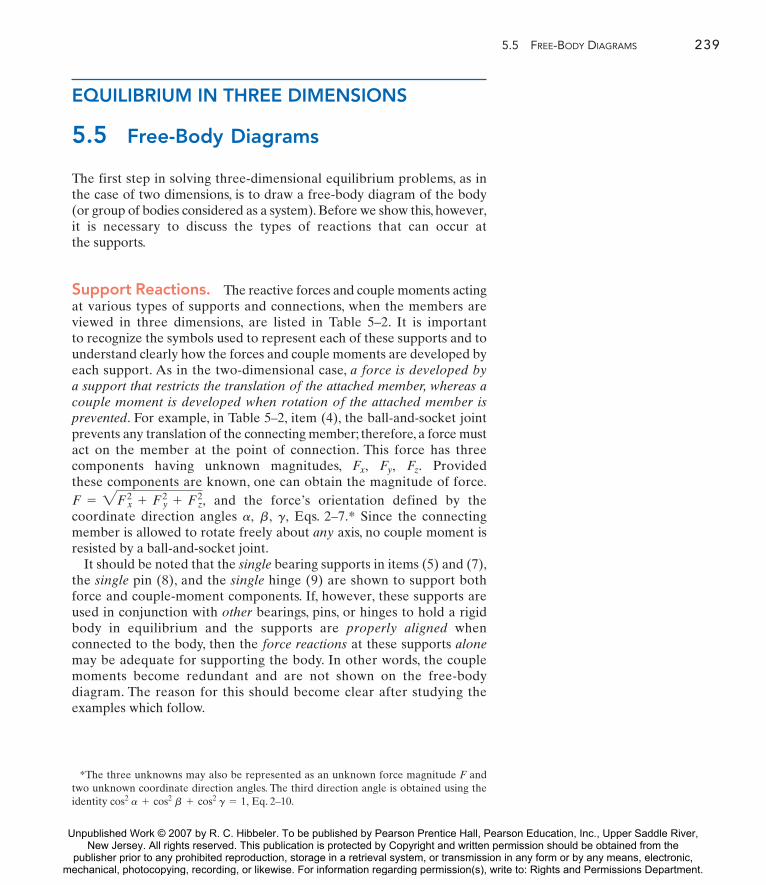
5.5 FREE-BODY DIAGRAMS 239
EQUILIBRIUM IN THREE DIMENSIONS
5.5 Free-Body Diagrams
The first step in solving three-dimensional equilibrium problems, as in the case of two dimensions, is to draw a free-body diagram of the body (or group of bodies considered as a system). Before we show this, however,it is necessary to discuss the types of reactions that can occur at the supports.
Support Reactions. The reactive forces and couple moments actingat various types of supports and connections, when the members areviewed in three dimensions, are listed in Table 5–2. It is important to recognize the symbols used to represent each of these supports and tounderstand clearly how the forces and couple moments are developed byeach support. As in the two-dimensional case, a force is developed bya support that restricts the translation of the attached member, whereas acouple moment is developed when rotation of the attached member isprevented. For example, in Table 5–2, item (4), the ball-and-socket jointprevents any translation of the connecting member; therefore, a force mustact on the member at the point of connection. This force has threecomponents having unknown magnitudes, Provided these components are known, one can obtain the magnitude of force.
and the force’s orientation defined by thecoordinate direction angles Eqs. 2–7.* Since the connectingmember is allowed to rotate freely about any axis, no couple moment isresisted by a ball-and-socket joint.
It should be noted that the single bearing supports in items (5) and (7),the single pin (8), and the single hinge (9) are shown to support bothforce and couple-moment components. If, however, these supports areused in conjunction with other bearings, pins, or hinges to hold a rigidbody in equilibrium and the supports are properly aligned whenconnected to the body, then the force reactions at these supports alonemay be adequate for supporting the body. In other words, the couplemoments become redundant and are not shown on the free-bodydiagram. The reason for this should become clear after studying theexamples which follow.
g,b,a,F = 2Fx2 + Fy2 + Fz2,
Fz.Fy,Fx,
*The three unknowns may also be represented as an unknown force magnitude F andtwo unknown coordinate direction angles. The third direction angle is obtained using theidentity Eq. 2–10.cos2 a + cos2 b + cos2 g = 1,
Unpublished Work © 2007 by R. C. Hibbeler. To be published by Pearson Prentice Hall, Pearson Education, Inc., Upper Saddle River,New Jersey. All rights reserved. This publication is protected by Copyright and written permission should be obtained from the
publisher prior to any prohibited reproduction, storage in a retrieval system, or transmission in any form or by any means, electronic,mechanical, photocopying, recording, or likewise. For information regarding permission(s), write to: Rights and Permissions Department.

240 CHAPTER 5 EQUIL IBR IUM OF A R IG ID BODY
Types of Connection Reaction Number of Unknowns
continued
One unknown. The reaction is a force which acts away from the member in the known direction of the cable.
One unknown. The reaction is a force which actsperpendicular to the surface at the point of contact.
One unknown. The reaction is a force which actsperpendicular to the surface at the point of contact.
Three unknowns. The reactions are three rectangularforce components.
Four unknowns. The reactions are two force and twocouple-moment components which act perpendicular to the shaft.
F
F
F
Fz
FyFx
single journal bearing
Fz
Fx
Mz
Mx
(1)
cable
(2)
(3)
roller
ball and socket
(4)
(5)
smooth surface support
TABLE 5–2 Supports for Rigid Bodies Subjected to Three-Dimensional Force Systems
Unpublished Work © 2007 by R. C. Hibbeler. To be published by Pearson Prentice Hall, Pearson Education, Inc., Upper Saddle River,New Jersey. All rights reserved. This publication is protected by Copyright and written permission should be obtained from the
publisher prior to any prohibited reproduction, storage in a retrieval system, or transmission in any form or by any means, electronic,mechanical, photocopying, recording, or likewise. For information regarding permission(s), write to: Rights and Permissions Department.

5.5 FREE-BODY DIAGRAMS 241
Reaction Number of Unknowns
Five unknowns. The reactions are two force and three couple-moment components.
Five unknowns. The reactions are three force and two couple-moment components.
Five unknowns. The reactions are three force and two couple-moment components.
Five unknowns. The reactions are three force and two couple-moment components.
Six unknowns. The reactions are three force and three couple-moment components.
Fz
Fx
Mz
Mx
Fy
Fz
Fx
Mz
MxMy
Fz
Mz
Fx
Fy My
Mz
Fx
Fy
Mx
Fz
Mz
FxMyMx
Fy
Fz
Types of Connection
TABLE 5–2 Continued
single hinge
fixed support
single thrust bearing
single journal bearingwith square shaft
single smooth pin
(7)
(6)
(8)
(10)
(9)
Unpublished Work © 2007 by R. C. Hibbeler. To be published by Pearson Prentice Hall, Pearson Education, Inc., Upper Saddle River,New Jersey. All rights reserved. This publication is protected by Copyright and written permission should be obtained from the
publisher prior to any prohibited reproduction, storage in a retrieval system, or transmission in any form or by any means, electronic,mechanical, photocopying, recording, or likewise. For information regarding permission(s), write to: Rights and Permissions Department.

242 CHAPTER 5 EQUIL IBR IUM OF A R IG ID BODY
Typical examples of actual supports that are referenced to Table 5–2 are shown inthe following sequence of photos.
This ball-and-socket joint provides aconnection for the housing of an earthgrader to its frame. (4)
This journal bearing supports the endof the shaft. (5)
This thrust bearing is used to supportthe drive shaft on a machine. (7)
This pin is used to support the end ofthe strut used on a tractor. (8)
Free-Body Diagrams. The general procedure for establishing thefree-body diagram of a rigid body has been outlined in Sec. 5.2. Essentiallyit requires first “isolating” the body by drawing its outlined shape. This isfollowed by a careful labeling of all the forces and couple moments inreference to an established x, y, z coordinate system. As a general rule,components of reaction having an unknown magnitude are shown actingon the free-body diagram in the positive sense. In this way, if any negativevalues are obtained, they will indicate that the components act in thenegative coordinate directions.
Unpublished Work © 2007 by R. C. Hibbeler. To be published by Pearson Prentice Hall, Pearson Education, Inc., Upper Saddle River,New Jersey. All rights reserved. This publication is protected by Copyright and written permission should be obtained from the
publisher prior to any prohibited reproduction, storage in a retrieval system, or transmission in any form or by any means, electronic,mechanical, photocopying, recording, or likewise. For information regarding permission(s), write to: Rights and Permissions Department.

5.5 FREE-BODY DIAGRAMS 243
(a)
W
Cy
d
M # Wd
(b)
W
By
"Fx
Fx
Ay
dd¿
45 N % m
500 N
Properly aligned journalbearings at A, B, C.
A
B
C
45 N % m
500 N
The force reactions developed bythe bearings are sufficient for equilibrium since they prevent the shaft from rotating abouteach of the coordinate axes.
Bz
Bx
CxCy
xy
(a)
AyAz
z
Fig. 5–25 a
EXAMPLE 5.14
Several examples of objects along with their associated free-body diagrams are shown in Fig. 5–25. In all cases, the x, y, z axes are established and the unknown reaction components are indicated inthe positive sense. The weight of the objects is neglected.
SOLUTION
It is a mistake to support a door using a single hinge (a) since the hinge mustdevelop a force to support the weight W of the door and a couple moment Mto support the moment of W, i.e., If instead two properly aligned hingesare used, (b) then the weight is carried by both hinges, and themoment of the door is resisted by the two hinge forces and These forcesform a couple, such that In other words, no couple moments areproduced by the hinges on the door provided they are in proper alignment. Instead,the forces and resist the rotation caused by W.-FxFx
Fxd¿ = Wd.-Fx.Fx
Ay + By = W,M = Wd.
Cy
continued
Unpublished Work © 2007 by R. C. Hibbeler. To be published by Pearson Prentice Hall, Pearson Education, Inc., Upper Saddle River,New Jersey. All rights reserved. This publication is protected by Copyright and written permission should be obtained from the
publisher prior to any prohibited reproduction, storage in a retrieval system, or transmission in any form or by any means, electronic,mechanical, photocopying, recording, or likewise. For information regarding permission(s), write to: Rights and Permissions Department.

244 CHAPTER 5 EQUIL IBR IUM OF A R IG ID BODY
C
200 lb % ft
Pin at A and cable BC.
A
B300 lb
Fig. 5–25b1
200 lb % ft
Moment components are developedby the pin on the rod to preventrotation about the x and z axes.
x
B300 lb
y
Az
z
MAz
MAx
Ax
Ay
T
Fig. 5–25b2
400 lb
A
B
C
Properly aligned journal bearingat A and hinge at C. Roller at B.
Fig. 5–25c1
Ax
400 lb
Bz
z
yx
Az
Cx
Cz
Cy
Only force reactions are developed bythe bearing and hinge on the plate to prevent rotation about each coordinate axis.No moments at the hinge are developed.
Fig. 5–25c2
B A
C
4 kN
Thrust bearing at A andcable BC
6 kN
Fig. 5–25d1
B
z
C6 kN
4 kNT
y
x
MAz
Az Ax
Ay
MAy
Moment components are developedby the bearing on the rod in order to prevent rotation about the y and z axes.
Fig. 5–25 (cont.)d2
Unpublished Work © 2007 by R. C. Hibbeler. To be published by Pearson Prentice Hall, Pearson Education, Inc., Upper Saddle River,New Jersey. All rights reserved. This publication is protected by Copyright and written permission should be obtained from the
publisher prior to any prohibited reproduction, storage in a retrieval system, or transmission in any form or by any means, electronic,mechanical, photocopying, recording, or likewise. For information regarding permission(s), write to: Rights and Permissions Department.

5.6 EQUATIONS OF EQUILIBRIUM 245
5.6 Equations of Equilibrium
As stated in Sec.5.1, the conditions for equilibrium of a rigid body subjectedto a three-dimensional force system require that both the resultant forceand resultant couple moment acting on the body be equal to zero.
Vector Equations of Equilibrium. The two conditions forequilibrium of a rigid body may be expressed mathematically in vectorform as
(5–5)
where is the vector sum of all the external forces acting on the bodyand is the sum of the couple moments and the moments of all theforces about any point O located either on or off the body.
Scalar Equations of Equilibrium. If all the applied externalforces and couple moments are expressed in Cartesian vector form andsubstituted into Eqs. 5–5, we have
Since the i, j, and k components are independent from one another, theabove equations are satisfied provided
(5–6a)
and
(5–6b)
These six scalar equilibrium equations may be used to solve for at mostsix unknowns shown on the free-body diagram. Equations 5–6a expressthe fact that the sum of the external force components acting in the x, y,and z directions must be zero, and Eqs. 5–6b require the sum of the moment components about the x, y, and z axes to be zero.
©Mx = 0©My = 0©Mz = 0
©Fx = 0©Fy = 0©Fz = 0
©MO = ©Mxi + ©Myj + ©Mzk = 0
©F = ©Fxi + ©Fy j + ©Fzk = 0
©MO
©F
©F = 0©Mo = 0
Unpublished Work © 2007 by R. C. Hibbeler. To be published by Pearson Prentice Hall, Pearson Education, Inc., Upper Saddle River,New Jersey. All rights reserved. This publication is protected by Copyright and written permission should be obtained from the
publisher prior to any prohibited reproduction, storage in a retrieval system, or transmission in any form or by any means, electronic,mechanical, photocopying, recording, or likewise. For information regarding permission(s), write to: Rights and Permissions Department.

246 CHAPTER 5 EQUIL IBR IUM OF A R IG ID BODY
*See R. C. Hibbeler, Mechanics of Materials, 6th edition (Pearson Education/PrenticeHall, Inc., 2005).
B
A
400 N
200 N
400 N
200 N
Ay
Az
ByBx
Mx My
Bz
Mz
(b)
y
z
x
Fig. 5–26b
Fig. 5–26a
5.7 Constraints for a Rigid Body
To ensure the equilibrium of a rigid body, it is not only necessary to satisfythe equations of equilibrium, but the body must also be properly held orconstrained by its supports. Some bodies may have more supports than arenecessary for equilibrium, whereas others may not have enough or the supports may be arranged in a particular manner that could cause thebody to collapse. Each of these cases will now be discussed.
Redundant Constraints. When a body has redundant supports,that is, more supports than are necessary to hold it in equilibrium, itbecomes statically indeterminate. Statically indeterminate means that therewill be more unknown loadings on the body than equations of equilibriumavailable for their solution. For example, the two-dimensional problem,Fig. 5–26a, and the three-dimensional problem, Fig. 5–26b, shown togetherwith their free-body diagrams, are both statically indeterminate becauseof additional support reactions. In the two-dimensional case, there are fiveunknowns, that is, and for which only threeequilibrium equations can be written ( and Eqs. 5–2).The three-dimensional problem has eight unknowns, for whichonly six equilibrium equations can be written, Eqs. 5–6. The additionalequations needed to solve indeterminate problems of the type shown inFig. 5–26 are generally obtained from the deformation conditions at thepoints of support. These equations involve the physical properties of the body which are studied in subjects dealing with the mechanics of deformation, such as “mechanics of materials.”*
©MO = 0,©Fy = 0,©Fx = 0,Cy,By,Ay,Ax,MA,
500 N
B C
A
2 kN % m
500 N
2 kN % m
Ax
Ay
MABy Cy
(a)
x
y
Unpublished Work © 2007 by R. C. Hibbeler. To be published by Pearson Prentice Hall, Pearson Education, Inc., Upper Saddle River,New Jersey. All rights reserved. This publication is protected by Copyright and written permission should be obtained from the
publisher prior to any prohibited reproduction, storage in a retrieval system, or transmission in any form or by any means, electronic,mechanical, photocopying, recording, or likewise. For information regarding permission(s), write to: Rights and Permissions Department.

Fig. 5–27a
5.7 CONSTRAINTS FOR A RIGID BODY 247
400 N
0.6 m
B
x Az
Ay
Bx
& Mx ' 0
(a)
By
Bz
Ax
400 N
0.6 m
y
z
A
& MO ' 0
A B
C
O0.2 m
100 N
O0.2 m
100 N
FC
FBFA
(b)
Fig. 5–27b
Improper Constraints. In some cases, there may be as manyunknown forces on the body as there are equations of equilibrium;however, instability of the body can develop because of improperconstraining by the supports. In the case of three-dimensional problems,the body is improperly constrained if the support reactions all intersect acommon axis. For two-dimensional problems, this axis is perpendicular tothe plane of the forces and therefore appears as a point. Hence, when allthe reactive forces are concurrent at this point, the body is improperlyconstrained. Examples of both cases are given in Fig. 5–27. From the free-body diagrams it is seen that the summation of moments about the x axis,Fig. 5–27a, or point O, Fig. 5–27b, will not be equal to zero; thus rotationabout the x axis or point O will take place.* Furthermore, in both cases,it becomes impossible to solve completely for all the unknowns since onecan write a moment equation that does not involve any of the unknownsupport reactions, and as a result, this reduces the number of availableequilibrium equations by one.
*For the three-dimensional problem, and for the two-dimensional problem, ©MO = 1100 N210.2 m2 Z 0.
©Mx = 1400 N210.6 m2 Z 0,
Unpublished Work © 2007 by R. C. Hibbeler. To be published by Pearson Prentice Hall, Pearson Education, Inc., Upper Saddle River,New Jersey. All rights reserved. This publication is protected by Copyright and written permission should be obtained from the
publisher prior to any prohibited reproduction, storage in a retrieval system, or transmission in any form or by any means, electronic,mechanical, photocopying, recording, or likewise. For information regarding permission(s), write to: Rights and Permissions Department.

Fig. 5–29a
Fig. 5–28b
Fig. 5–28a
248 CHAPTER 5 EQUIL IBR IUM OF A R IG ID BODY
Another way in which improper constraining leads to instability occurswhen the reactive forces are all parallel. Three- and two-dimensional examples of this are shown in Fig. 5–28. In both cases, the summation offorces along the x axis will not equal zero.
In some cases, a body may have fewer reactive forces than equations ofequilibrium that must be satisfied. The body then becomes only partiallyconstrained. For example, consider the body shown in Fig. 5–29a with itscorresponding free-body diagram in Fig. 5–29b. If O is a point not locatedon the line AB, the equation gives however,will not be satisfied for the loading conditions and therefore equilibriumwill not be maintained.
Proper constraining therefore requires that:
1. The lines of action of the reactive forces do not intersect points on acommon axis.
2. The reactive forces must not all be parallel to one another.
When the minimum number of reactive forces is needed to properlyconstrain the body in question, the problem will be statically determinate,and therefore the equations of equilibrium can be used to determine allthe reactive forces.
©Fy = 0FA = FB,©Fx = 0
FB
100 N
A
B
C
100 N
FA
FC
x& Fx ' 0
(a)
z
y
& Fx ' 0
FC
100 N
FB
FA
(b)
y
x
C100 N
B
A
100 N
A BO
(a)
100 N
A B
(b)
FA FB
& Fy ' 0
x
y
O
Fig. 5–29b
Unpublished Work © 2007 by R. C. Hibbeler. To be published by Pearson Prentice Hall, Pearson Education, Inc., Upper Saddle River,New Jersey. All rights reserved. This publication is protected by Copyright and written permission should be obtained from the
publisher prior to any prohibited reproduction, storage in a retrieval system, or transmission in any form or by any means, electronic,mechanical, photocopying, recording, or likewise. For information regarding permission(s), write to: Rights and Permissions Department.

5.7 CONSTRAINTS FOR A RIGID BODY 249
Important Points
• Always draw the free-body diagram first.
• If a support prevents translation of a body in a specific direction, then it exerts a force on the body in thatdirection.
• If rotation about an axis is prevented, then the support exerts a couple moment on the body about theaxis.
• If a body is subjected to more unknown reactions than available equations of equilibrium, then theproblem is statically indeterminate.
• To avoid instability of a body require that the lines of action of the reactive forces do not intersect acommon axis and are not parallel to one another.
Procedure for Analysis
Three-dimensional equilibrium problems for a rigid body can be solved using the following procedure.
Free-Body Diagram.
• Draw an outlined shape of the body.
• Show all the forces and couple moments acting on the body.
• Establish the origin of the x, y, z axes at a convenient point and orient the axes so that they are parallelto as many of the external forces and moments as possible.
• Label all the loadings and specify their directions relative to the x, y, z axes. In general, show all theunknown components having a positive sense along the x, y, z axes if the sense cannot be determined.
• Indicate the dimensions of the body necessary for computing the moments of forces.
Equations of Equilibrium.
• If the x, y, z force and moment components seem easy to determine, then apply the six scalar equationsof equilibrium; otherwise use the vector equations.
• It is not necessary that the set of axes chosen for force summation coincide with the set of axes chosenfor moment summation. Also, any set of nonorthogonal axes may be chosen for this purpose.
• Choose the direction of an axis for moment summation such that it intersects the lines of action of as manyunknown forces as possible.The moments of forces passing through points on this axis and forces whichare parallel to the axis will then be zero.
• If the solution of the equilibrium equations yields a negative scalar for a force or couple momentmagnitude, it indicates that the sense is opposite to that assumed on the free-body diagram.
Unpublished Work © 2007 by R. C. Hibbeler. To be published by Pearson Prentice Hall, Pearson Education, Inc., Upper Saddle River,New Jersey. All rights reserved. This publication is protected by Copyright and written permission should be obtained from the
publisher prior to any prohibited reproduction, storage in a retrieval system, or transmission in any form or by any means, electronic,mechanical, photocopying, recording, or likewise. For information regarding permission(s), write to: Rights and Permissions Department.

250 CHAPTER 5 EQUIL IBR IUM OF A R IG ID BODY
EXAMPLE 5.15
A
B
C
200 N % m
1.5 m
2 m3 m
(a)
300 N
Fig. 5–30a
200 N % m
1.5 m
1.5 my
y¿x!
1 m
1 mAz
Bz
Bx By
z
z¿
981 N TC
(b)
300 N
x
Fig. 5–30b
The homogeneous plate shown in Fig. 5–30a has a mass of 100 kg andis subjected to a force and couple moment along its edges. If it issupported in the horizontal plane by means of a roller at A, a ball-and-socket joint at B, and a cord at C, determine the components ofreaction at the supports.
SOLUTION (SCALAR ANALYSIS)Free-Body Diagram. There are five unknown reactions acting onthe plate, as shown in Fig. 5–30b. Each of these reactions is assumed toact in a positive coordinate direction.
Equations of Equilibrium. Since the three-dimensional geometry israther simple, a scalar analysis provides a direct solution to this problem.A force summation along each axis yields
Ans.
Ans.
(1)
Recall that the moment of a force about an axis is equal to the productof the force magnitude and the perpendicular distance (moment arm)from the line of action of the force to the axis.The sense of the moment isdetermined by the right-hand rule.Also, forces that are parallel to an axisor pass through it create no moment about the axis. Hence, summingmoments of the forces on the free-body diagram, with positive momentsacting along the positive x or y axis, we have
(2)
(3)
The components of force at B can be eliminated if the axesare used. We obtain
(4)
(5)
Solving Eqs. 1 through 3 or the more convenient Eqs. 1, 4, and 5 yields
Ans.
The negative sign indicates that acts downward.
NOTE: The solution of this problem does not require the use of a summation of moments about the z axis. The plate is partially constrained since the supports cannot prevent it from turning aboutthe z axis if a force is applied to it in the x–y plane.
Bz
Az = 790 N Bz = -217 N TC = 707 N
- 300 N11.5 m2 - 981 N11.5 m2 - 200 N #m + TC13 m2 = 0
©My¿ = 0;
981 N11 m2 + 300 N12 m2 - Az12 m2 = 0©Mx¿ = 0;
z¿y¿,x¿,
300 N11.5 m2 + 981 N11.5 m2 - Bz13 m2 -Az13 m2 - 200 N #m = 0
©My = 0;
TC12 m2 - 981 N11 m2 + Bz12 m2 = 0©Mx = 0;
Az + Bz + TC - 300 N - 981 N = 0©Fz = 0;
By = 0©Fy = 0;
Bx = 0©Fx = 0;
Unpublished Work © 2007 by R. C. Hibbeler. To be published by Pearson Prentice Hall, Pearson Education, Inc., Upper Saddle River,New Jersey. All rights reserved. This publication is protected by Copyright and written permission should be obtained from the
publisher prior to any prohibited reproduction, storage in a retrieval system, or transmission in any form or by any means, electronic,mechanical, photocopying, recording, or likewise. For information regarding permission(s), write to: Rights and Permissions Department.

Fig. 5–31a
5.7 CONSTRAINTS FOR A RIGID BODY 251
EXAMPLE 5.16
The windlass shown in Fig. 5–31a is supported by a thrust bearing at Aand a smooth journal bearing at B, which are properly aligned on theshaft. Determine the magnitude of the vertical force P that must beapplied to the handle to maintain equilibrium of the 100-kg bucket.Also calculate the reactions at the bearings.
B
A
P
30$
0.3 m
(a)
0.3 m
0.5 m
0.3 m0.1 m
0.1 m
100 kg
B
A
P
30$
0.3 cos 30$ m
0.3 m
0.4 m
0.1 m
By
Ay
Az
Bz
981 N
zy
(b)
Ax
x
0.5 m
Fig. 5–31b
SOLUTION (SCALAR ANALYSIS)Free-Body Diagram. Since the bearings at A and B are alignedcorrectly, only force reactions occur at these supports, Fig. 5–31b.Whyare there no moment reactions?
Equations of Equilibrium. Summing moments about the x axis yieldsa direct solution for P. Why? For a scalar moment summation, it isnecessary to determine the moment of each force as the product of theforce magnitude and the perpendicular distance from the x axis to the line of action of the force. Using the right-hand rule and assumingpositive moments act in the direction, we have
Ans.Using this result for P and summing moments about the y and zaxes yields
Ans.
The reactions at B are determined by a force summation usingthese results.
Ans.
NOTE: As expected, the force on the handle is much smaller than theweight of the bucket.
424.3 - 981 + Bz - 377.6 = 0 Bz = 934 N©Fz = 0;
0 + By = 0 By = 0©Fy = 0;
Ax = 0©Fx = 0;
-Ay10.8 m2 = 0 Ay = 0©Mz = 0;
Az = 424.3 N
-981 N10.5 m2 + Az10.8 m2 + 1377.6 N210.4 m2 = 0©My = 0;
P = 377.6 N
981 N10.1 m2 - P10.3 cos 30° m2 = 0©Mx = 0;
+ i
Unpublished Work © 2007 by R. C. Hibbeler. To be published by Pearson Prentice Hall, Pearson Education, Inc., Upper Saddle River,New Jersey. All rights reserved. This publication is protected by Copyright and written permission should be obtained from the
publisher prior to any prohibited reproduction, storage in a retrieval system, or transmission in any form or by any means, electronic,mechanical, photocopying, recording, or likewise. For information regarding permission(s), write to: Rights and Permissions Department.

z
yx
B
A
C
D
6 m3 m
6 m
6 m
F # 1 kN
(a)
252 CHAPTER 5 EQUIL IBR IUM OF A R IG ID BODY
B
A
FA
FB # "FA
(c)
Fig. 5–32c
EXAMPLE 5.17 Determine the tension in cables BC and BD and the reactions at the ball-and-socket joint A for the mast shown in Fig. 5–32a.
SOLUTION (VECTOR ANALYSIS)Free-Body Diagram. There are five unknown force magnitudes shownon the free-body diagram, Fig. 5–32b.
Equations of Equilibrium. Expressing each force in Cartesian vectorform, we have
Applying the force equation of equilibrium gives
(1)
(2)
(3)
Summing moments about point A, we have
Evaluating the cross product and combining terms yields
(4)
(5)
The moment equation about the z axis, is automaticallysatisfied. Why? Solving Eqs. 1 through 5 we have
Ans.
Ans.
NOTE: Since the mast is a two-force member, Fig. 5–32c, the valuecould have been determined by inspection.Ax = Ay = 0
Ax = 0 N Ay = 0 N Az = 1500 N
TC = 707 N TD = 1500 N
©Mz = 0,
4.24TC - 2TD = 0©My = 0;
-4TD + 6000 = 0©Mx = 0;
1-4TD + 60002i + 14.24TC - 2TD2j = 0
-39TDi +
69TDj -
69TDk2 = 06k * 1-1000j + 0.707TCi - 0.707TCk
rB * 1F + TC + TD2 = 0©MA = 0;
Az - 0.707TC -69TD = 0©Fz = 0;
Ay +69TD - 1000 = 0©Fy = 0;
Ax + 0.707TC -39TD = 0©Fx = 0;
+ 1Az - 0.707TC -69TD2k = 0
1Ax + 0.707TC -39TD2i + 1-1000 + Ay +
69TD2jF + FA + TC + TD = 0©F = 0;
TD = TDa rBDrBDb = -
39TDi +
69TDj -
69TDk
TC = 0.707TCi - 0.707TCk
FA = Axi + Ayj + AzkF = 5-1000j6 N
z
B
A
6 m
F # 1000 N
yx Ax
Ay
Az
TCTD
rB
(b)
Fig. 5–32b
Fig. 5–32a
Unpublished Work © 2007 by R. C. Hibbeler. To be published by Pearson Prentice Hall, Pearson Education, Inc., Upper Saddle River,New Jersey. All rights reserved. This publication is protected by Copyright and written permission should be obtained from the
publisher prior to any prohibited reproduction, storage in a retrieval system, or transmission in any form or by any means, electronic,mechanical, photocopying, recording, or likewise. For information regarding permission(s), write to: Rights and Permissions Department.

5.7 CONSTRAINTS FOR A RIGID BODY 253
EXAMPLE 5.18
1.5 m
2 m
200 N
1.5 m
2 m
E
A
B
D
C
(a)
1 m
Fig. 5–33a
Rod AB shown in Fig. 5–33a is subjected to the 200-N force.Determine the reactions at the ball-and-socket joint A and thetension in cables BD and BE.
SOLUTION (VECTOR ANALYSIS)Free-Body Diagram. Fig. 5–33b.
Equations of Equilibrium. Representing each force on the free-bodydiagram in Cartesian vector form, we have
Applying the force equation of equilibrium.
(1)
(2)
(3)
Summing moments about point A yields
Since then
Expanding and rearranging terms gives
(4)
(5)
(6)
Solving Eqs. 1 through 6, we get
Ans.Ans.Ans.Ans.Ans.
NOTE: The negative sign indicates that and have a sense which isopposite to that shown on the free-body diagram, Fig. 5–33b.
AyAx
Az = 200 NAy = -100 NAx = -50 NTE = 50 NTD = 100 N
TD - 2TE = 0©Mz = 0;
-2TE + 100 = 0©My = 0;
2TD - 200 = 0©Mx = 0;
12TD - 2002i + 1-2TE + 1002j + 1TD - 2TE2k = 0
10.5i + 1j - 1k2 * 1-200k2 + 11i + 2j - 2k2 * 1TEi + TDj2 = 0
rC = 12 rB,
rC * F + rB * 1TE + TD2 = 0©MA = 0;
Az - 200 = 0©Fz = 0;
Ay + TD = 0©Fy = 0;
Ax + TE = 0©Fx = 0;
1Ax + TE2i + 1Ay + TD2j + 1Az - 2002k = 0
FA + TE + TD + F = 0©F = 0;
F = 5-200k6 NTD = TDj
TE = TEi
FA = Axi + Ayj + Azk
200 N
y
B
C
x
z
rB
rC
TD
TE
Az
A Ay
Ax
(b)
Fig. 5–33b
Unpublished Work © 2007 by R. C. Hibbeler. To be published by Pearson Prentice Hall, Pearson Education, Inc., Upper Saddle River,New Jersey. All rights reserved. This publication is protected by Copyright and written permission should be obtained from the
publisher prior to any prohibited reproduction, storage in a retrieval system, or transmission in any form or by any means, electronic,mechanical, photocopying, recording, or likewise. For information regarding permission(s), write to: Rights and Permissions Department.

The bent rod in Fig. 5–34a is supported at A by a journal bearing, at Dby a ball-and-socket joint, and at B by means of cable BC. Using onlyone equilibrium equation, obtain a direct solution for the tension incable BC. The bearing at A is capable of exerting force componentsonly in the z and y directions since it is properly aligned on the shaft.
SOLUTION (VECTOR ANALYSIS)Free-Body Diagram. As shown in Fig. 5–34b, there are six unknowns:three force components caused by the ball-and-socket joint, two causedby the bearing, and one caused by the cable.
Equations of Equilibrium. The cable tension may be obtaineddirectly by summing moments about an axis passing through points Dand A. Why? The direction of the axis is defined by the unit vector u,where
Hence, the sum of the moments about this axis is zero provided
Here r represents a position vector drawn from any point on the axisDA to any point on the line of action of force F (see Eq. 4–11). Withreference to Fig. 5–34b, we can therefore write
Ans.
The advantage of using Cartesian vectors for this solution should benoted. It would be especially tedious to determine the perpendiculardistance from the DA axis to the line of action of using scalarmethods.
NOTE: In a similar manner, we can obtain by summingmoments about an axis passing through AB.Also, is obtainedby summing moments about the y axis.
Az 1= 02Dz 1= 490.5 N2TB
TB =490.50.857
= 572 N
- 0.7071-0.857TB + 490.52 + 0 + 0 = 0
1-0.707i - 0.707j2 # [1-0.857TB + 490.52i + 0.286TBk] = 0+ 1-0.5j2 * 1-981k2 D = 0
1-0.707i - 0.707j2 # C1-1j2 * A0.20.7TBi - 0.3
0.7TBj + 0.60.7TBk Bu # 1rB * TB + rE * W2 = 0
©MDA = u # ©1r * F2 = 0
= -0.707i - 0.707j
u =rDArDA
= -122
i -122
j
TB
0.5 m
0.5 m
x
z
y
E
0.6 m
0.2 m
0.3 mB
A
D
100 kg
C
(a)
1 m
Fig. 5–34a
TB
x
z
y
B
A
D
Az
Ay
Dy
DzDx
rE
rB
W # 981 N
u
(b)
Fig. 5–34b
254 CHAPTER 5 EQUIL IBR IUM OF A R IG ID BODY
EXAMPLE 5.19
Unpublished Work © 2007 by R. C. Hibbeler. To be published by Pearson Prentice Hall, Pearson Education, Inc., Upper Saddle River,New Jersey. All rights reserved. This publication is protected by Copyright and written permission should be obtained from the
publisher prior to any prohibited reproduction, storage in a retrieval system, or transmission in any form or by any means, electronic,mechanical, photocopying, recording, or likewise. For information regarding permission(s), write to: Rights and Permissions Department.

*5–64. The wing of the jet aircraft is subjected to a thrustof from its engine and the resultant lift force
If the mass of the wing is 2.1 Mg and the masscenter is at G, determine the x, y, z components of reactionwhere the wing is fixed to the fuselage at A.
L = 45 kN.T = 8 kN
5–65. The uniform concrete slab has a weight of 5500 lb.Determine the tension in each of the three parallel supportingcables when the slab is held in the horizontal plane as shown.
PROBLEMS 255
P R O B L E M S
5–63. Determine the x, y, z components of reaction at thefixed wall A. The 150-N force is parallel to the z axis and the 200-N force is parallel to the y axis.
5–66. The air-conditioning unit is hoisted to the roof of abuilding using the three cables. If the tensions in the cablesare and determinethe weight of the unit and the location (x, y) of its center ofgravity G.
TC = 200 lb,TB = 300 lb,TA = 250 lb,
Ay
TA
TB
TC
B
z
6 ft
x
C
y
3 ft
7 ft
G
x 5 ft4 ft
Prob. 5–66
z
AG
L # 45 kNT # 8 kN
x
y
5 m
2.5 m
3 m7 m
Prob. 5–64
TA
x
AC
B
TC
TB
y
z
6 ft3 ft 3 ft
6 ft
Prob. 5–65
2 m1 m
150 N
200 N
2.5 m
z
yx
A
2 m
Prob. 5–63
Unpublished Work © 2007 by R. C. Hibbeler. To be published by Pearson Prentice Hall, Pearson Education, Inc., Upper Saddle River,New Jersey. All rights reserved. This publication is protected by Copyright and written permission should be obtained from the
publisher prior to any prohibited reproduction, storage in a retrieval system, or transmission in any form or by any means, electronic,mechanical, photocopying, recording, or likewise. For information regarding permission(s), write to: Rights and Permissions Department.

256 CHAPTER 5 EQUIL IBR IUM OF A R IG ID BODY
5–69. If the cable can be subjected to a maximum tensionof 300 lb, determine the maximum force F which may beapplied to the plate. Compute the x, y, z components ofreaction at the hinge A for this loading.
5–70. The boom AB is held in equilibrium by a ball-and-socket joint A and a pulley and cord system as shown.Determine the x, y, z components of reaction at A and thetension in cable DEC if
5–71. The cable CED can sustain a maximum tension of800 lb before it fails. Determine the greatest vertical force Fthat can be applied to the boom. Also, what are the x, y, zcomponents of reaction at the ball-and-socket joint A?
F = 5-1500k6 lb.
12 in.
12 in.
B
CA
5 in.
8 in.12 in.
10 in.
500 lb
800 lb
380 lb
Prob. 5–67
8 ft20 ft
ABD
E
F
8 ft6 ft
6 ft
4 ft
3 ft
z
x
y
C
Prob. 5–68
9 ft
F
3 ft
z
x
y
A
B
2 ft
3 ft
1 ftC
Prob. 5–69
5–67. The platform truck supports the three loadingsshown. Determine the normal reactions on each of its threewheels.
*5–68. Due to an unequal distribution of fuel in the wingtanks, the centers of gravity for the airplane fuselage A andwings B and C are located as shown. If these components haveweights and determine the normal reactions of the wheels D, E, and F onthe ground.
WC = 6000 lb,WB = 8000 lb,WA = 45 000 lb,
z
xF
y
EA
D
C
5 ft5 ft
5 ft
4 ft
4 ft
2 ft
B
Probs. 5–70/71
Unpublished Work © 2007 by R. C. Hibbeler. To be published by Pearson Prentice Hall, Pearson Education, Inc., Upper Saddle River,New Jersey. All rights reserved. This publication is protected by Copyright and written permission should be obtained from the
publisher prior to any prohibited reproduction, storage in a retrieval system, or transmission in any form or by any means, electronic,mechanical, photocopying, recording, or likewise. For information regarding permission(s), write to: Rights and Permissions Department.

PROBLEMS 257
*5–72. The uniform table has a weight of 20 lb and issupported by the framework shown. Determine the smallestvertical force P that can be applied to its surface that willcause it to tip over.Where should this force be applied?
5–73. The windlass is subjected to a load of 150 lb.Determine the horizontal force P needed to hold the handlein the position shown, and the components of reaction at theball-and-socket joint A and the smooth journal bearing B.The bearing at B is in proper alignment and exerts only forcereactions on the windlass.
5–74. The 2-kg ball rests between the 45° grooves A and Bof the 10° incline and against a vertical wall at C. If all threesurfaces of contact are smooth, determine the reactions ofthe surfaces on the ball. Hint: Use the x, y, z axes, with originat the center of the ball, and the z axis inclined as shown.
5–75. Member AB is supported by a cable BC and at A bya square rod which fits loosely through the square hole atthe end joint of the member as shown. Determine thecomponents of reaction at A and the tension in the cableneeded to hold the 800-lb cylinder in equilibrium.
1 ft
3.5 ft
2.5 ft
3 ft
1 ft1.5 ft
1.5 ft
Prob. 5–72
B
3 ft
6 ft
2 ft
C
z
x
y
A
Prob. 5–75
A
z
x 2 ft
2 ft1 ft
150 lb
B0.5 ft
1 ft
y
P
1 ft
Prob. 5–73
y
z
x
10$
10$
45$
AC
B
Prob. 5–74
Unpublished Work © 2007 by R. C. Hibbeler. To be published by Pearson Prentice Hall, Pearson Education, Inc., Upper Saddle River,New Jersey. All rights reserved. This publication is protected by Copyright and written permission should be obtained from the
publisher prior to any prohibited reproduction, storage in a retrieval system, or transmission in any form or by any means, electronic,mechanical, photocopying, recording, or likewise. For information regarding permission(s), write to: Rights and Permissions Department.
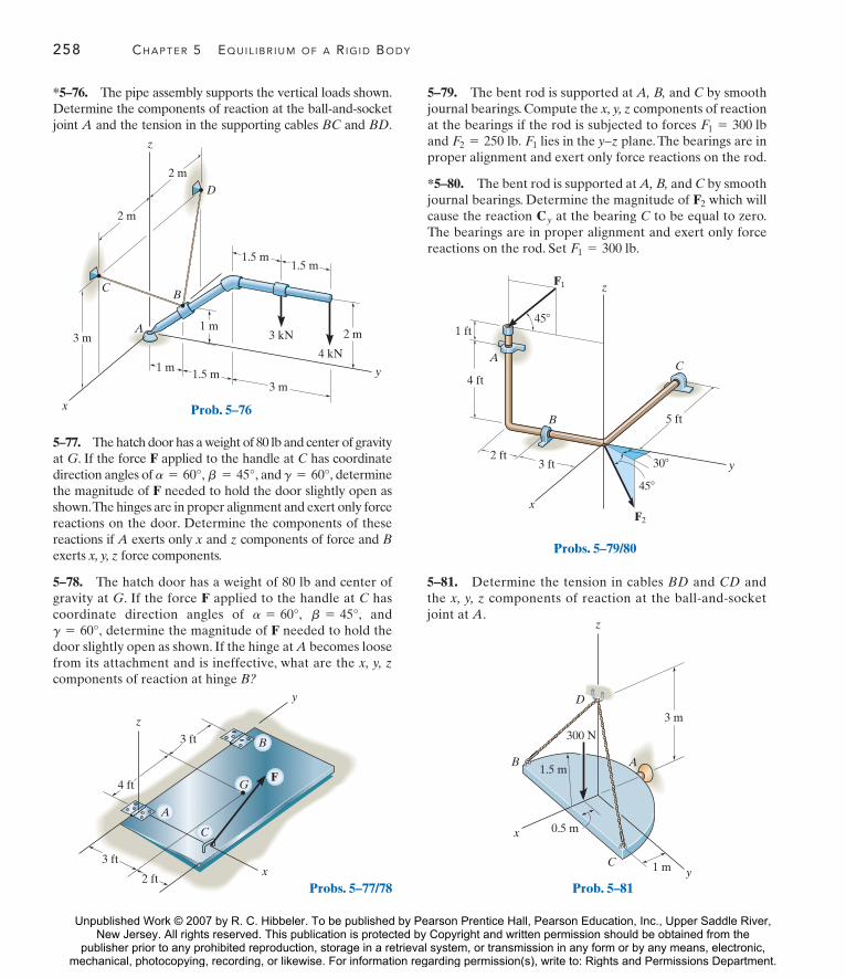
258 CHAPTER 5 EQUIL IBR IUM OF A R IG ID BODY
y
z
x
C
GF
A
B3 ft
4 ft
3 ft
2 ftProbs. 5–77/78
*5–76. The pipe assembly supports the vertical loads shown.Determine the components of reaction at the ball-and-socketjoint A and the tension in the supporting cables BC and BD.
5–77. The hatch door has a weight of 80 lb and center of gravityat G. If the force F applied to the handle at C has coordinatedirection angles of and determinethe magnitude of F needed to hold the door slightly open asshown.The hinges are in proper alignment and exert only forcereactions on the door. Determine the components of thesereactions if A exerts only x and z components of force and Bexerts x, y, z force components.
5–78. The hatch door has a weight of 80 lb and center ofgravity at G. If the force F applied to the handle at C hascoordinate direction angles of and
determine the magnitude of F needed to hold thedoor slightly open as shown. If the hinge at A becomes loosefrom its attachment and is ineffective, what are the x, y, zcomponents of reaction at hinge B?
g = 60°,b = 45°,a = 60°,
g = 60°,b = 45°,a = 60°,
5–79. The bent rod is supported at A, B, and C by smoothjournal bearings. Compute the x, y, z components of reactionat the bearings if the rod is subjected to forces and lies in the y–z plane. The bearings are inproper alignment and exert only force reactions on the rod.
*5–80. The bent rod is supported at A, B, and C by smoothjournal bearings. Determine the magnitude of which willcause the reaction at the bearing C to be equal to zero.The bearings are in proper alignment and exert only forcereactions on the rod. Set F1 = 300 lb.
CyF2
F1F2 = 250 lb.F1 = 300 lb
5–81. Determine the tension in cables BD and CD andthe x, y, z components of reaction at the ball-and-socketjoint at A.
y
2 m
1.5 m1.5 m
1 m3 kN
4 kN
1.5 m3 m
1 m
2 m
2 m
3 m
B
z
C
A
D
x Prob. 5–76
z
y3 ft
5 ft
F2
45$
30$
45$
F1
C4 ft
1 ft
A
2 ft
B
x
Probs. 5–79/80
z
y
x
C
B A
3 m
300 N
D
1 m
0.5 m
1.5 m
Prob. 5–81
Unpublished Work © 2007 by R. C. Hibbeler. To be published by Pearson Prentice Hall, Pearson Education, Inc., Upper Saddle River,New Jersey. All rights reserved. This publication is protected by Copyright and written permission should be obtained from the
publisher prior to any prohibited reproduction, storage in a retrieval system, or transmission in any form or by any means, electronic,mechanical, photocopying, recording, or likewise. For information regarding permission(s), write to: Rights and Permissions Department.

PROBLEMS 259
5–82. Determine the tensions in the cables and thecomponents of reaction acting on the smooth collar at Anecessary to hold the 50-lb sign in equilibrium.The center ofgravity for the sign is at G.
5–83. The member is supported by a pin at A and a cableBC. If the load at D is 300 lb, determine the x, y, z componentsof reaction at these supports.
*5–84. Determine the x, y, z components of reaction at thepin A and the tension in the cable BC necessary forequilibrium of the rod.
5–85. Rod AB is supported by a ball-and-socket joint at Aand a cable at the smooth wall at B. Determine the x, y, zcomponents of reaction at these supports if the rod issubjected to a 50-lb vertical force as shown.
z
2.5 ft
1 ft
1 ft
2.5 ft
3 ft
2 ft
4 ft
3 ft
2 ft
2 ft G
BA
C
E
Dyx
2 ft
Prob. 5–82
C
1 ft
z
AB
D
x
6 ft
2 ft
2 ft
2 ft
2 ft
y
Prob. 5–83
y
A
Bx
z
4 ft
5 ft
4 ft
12 ft
2 ft
F # 350 lb
4 ft
4 ft
10 ft
C
Prob. 5–84
y
z
x
D
A
E
B
2 ft
4 ft
50 lb
2 ft 2 ft
Prob. 5–85
Unpublished Work © 2007 by R. C. Hibbeler. To be published by Pearson Prentice Hall, Pearson Education, Inc., Upper Saddle River,New Jersey. All rights reserved. This publication is protected by Copyright and written permission should be obtained from the
publisher prior to any prohibited reproduction, storage in a retrieval system, or transmission in any form or by any means, electronic,mechanical, photocopying, recording, or likewise. For information regarding permission(s), write to: Rights and Permissions Department.

260 CHAPTER 5 EQUIL IBR IUM OF A R IG ID BODY
y
z
x
A
B2 ft 1 ft
2 ft
50 lb % ft
F # {20i " 40j " 30k} lb
Prob. 5–86
4 m
2 my
3 m
z
6 m
D
E
4 m
G
B
A
C
3 m3 mx
Probs. 5–87/88
C
z
B
x
y5 ft
10 ft
15 ft
140 lb 30$
D
75 lb
A
Prob. 5–89
5–86. The member is supported by a square rod which fitsloosely through a smooth square hole of the attached collarat A and by a roller at B. Determine the x, y, z componentsof reaction at these supports when the member is subjectedto the loading shown.
5–87. The platform has a mass of 3 Mg and center of masslocated at G. If it is lifted with constant velocity using thethree cables, determine the force in each of the cables.
*5–88. The platform has a mass of 2 Mg and center ofmass located at G. If it is lifted using the three cables,determine the force in each of the cables. Solve for eachforce by using a single moment equation of equilibrium.
5–89. The cables exert the forces shown on the pole.Assuming the pole is supported by a ball-and-socket joint atits base, determine the components of reaction at A. Theforces of 140 lb and 75 lb lie in a horizontal plane.
5–90. The silo has a weight of 3500 lb and a center of gravityat G. Determine the vertical component of force that each ofthe three struts at A, B, and C exerts on the silo if it issubjected to a resultant wind loading of 250 lb which acts inthe direction shown.
120$120$
30$
5 ft
F # 250 lb
y
x
Top view
A
120$
30$
B
C
30$
AB
C
G
15 ft12 ft
F # 250 lb
30$
Prob. 5–90
Unpublished Work © 2007 by R. C. Hibbeler. To be published by Pearson Prentice Hall, Pearson Education, Inc., Upper Saddle River,New Jersey. All rights reserved. This publication is protected by Copyright and written permission should be obtained from the
publisher prior to any prohibited reproduction, storage in a retrieval system, or transmission in any form or by any means, electronic,mechanical, photocopying, recording, or likewise. For information regarding permission(s), write to: Rights and Permissions Department.

CHAPTER REVIEW 261
Chapter Review
F3 y
x
z
F4
F1F2
O
A
B
C
500 N % m
30$
Ax T
Ay
500 N % m
30$
y
x
1 m
1 m
2 m
2 m
roller
u
smooth pin or hinge
u
fixed support
Equilibrium
A body in equilibrium does not accelerate, soit either moves at constant velocity, or doesnot move at all or is at rest.(See page 201.)
©M = 0
©F = 0
Two Dimensions
Before analyzing the equilibrium of a body, it isfirst necessary to draw its free-body diagram.This is an outlined shape of the body, whichshows all the forces and couple moments thatact on it.
Couple moments can be placed anywhere on afree-body diagram since they are free vectors.Forces can act at any point along their line ofaction since they are sliding vectors.
Angles used to resolve forces, and dimensionsused to take moments of the forces, shouldalso be shown on the free-body diagram.
Some common types of supports and theirreactions are shown below in two dimensions.
Remember that a support will exert a force onthe body in a particular direction if it preventstranslation of the body in that direction, and itwill exert a couple moments on the body if itprevents rotation.(See pages 203–204.)
F
u
[[A 5883]]
Fy
Fx
M
[[A 5885]]
Fy
Fx
[[A 5884]]
The three scalar equations of equilibrium canbe applied when solving problems in twodimensions, since the geometry is easy tovisualize. ©MO = 0
©Fy = 0
©Fx = 0
Unpublished Work © 2007 by R. C. Hibbeler. To be published by Pearson Prentice Hall, Pearson Education, Inc., Upper Saddle River,New Jersey. All rights reserved. This publication is protected by Copyright and written permission should be obtained from the
publisher prior to any prohibited reproduction, storage in a retrieval system, or transmission in any form or by any means, electronic,mechanical, photocopying, recording, or likewise. For information regarding permission(s), write to: Rights and Permissions Department.

262 CHAPTER 5 EQUIL IBR IUM OF A R IG ID BODY
For the most direct solution, try to sum forcesalong an axis that will eliminate as manyunknown forces as possible. Sum momentsabout a point A that passes through the line ofaction of as many unknown forces as possible.(See pages 217 and 218.)
By =P1d1 - P2d2
dB
P2d2 + BydB - P1d1 = 0
©MA = 0;
Ax - P2 = 0 Ax = P2
©Fx = 0;
Three Dimensions
Some common types of supports and theirreactions are shown in three dimensions.
By
d1
P1
P2
d2
Ay
Ax A
dB
roller ball and socket fixed support
F
[[A 5886]]
Fz
FyFx
[[A 5888]]
Fz
Mz
FxMyMx
Fy
[[A 5887]]
In three dimensions, it is often advantageousto use a Cartesian vector analysis whenapplying the equations of equilibrium. To dothis, first express each known and unknownforce and couple moment shown on the free-body diagram as a Cartesian vector. Then setthe force summation equal to zero. Takemoments about a point O that lies on the lineof action of as many unknown forcecomponents as possible. From point O directposition vectors to each force, and then use thecross product to determine the moment ofeach force. The six scalar equations ofequilibrium are established by setting therespective i, j, and k components of these forceand moment summations equal to zero.(See page 245.)
©Mz = 0
©My = 0
©Mx = 0
©Fz = 0
©Fy = 0
©Fx = 0
©MO = 0©F = 0
Determinacy and Stability
If a body is supported by a minimum numberof constraints to ensure equilibrium, then it isstatically determinate. If it has moreconstraints than required, then it is staticallyindeterminate.
To properly constrain the body, the reactionsmust not all be parallel to one another orconcurrent.(See pages 246–248.)
500 N
Statically indeterminate,five reactions, threeequilibrium equations
2 kN % m
600 N
100 N
Proper constraint, statically determinant
200 N
45$
Unpublished Work © 2007 by R. C. Hibbeler. To be published by Pearson Prentice Hall, Pearson Education, Inc., Upper Saddle River,New Jersey. All rights reserved. This publication is protected by Copyright and written permission should be obtained from the
publisher prior to any prohibited reproduction, storage in a retrieval system, or transmission in any form or by any means, electronic,mechanical, photocopying, recording, or likewise. For information regarding permission(s), write to: Rights and Permissions Department.

R E V I E W P R O B L E M S
5–91. The shaft assembly is supported by two smoothjournal bearings A and B and a short link DC. If a couplemoment is applied to the shaft as shown, determine thecomponents of force reaction at the bearings and the force inthe link.The link lies in a plane parallel to the y–z plane andthe bearings are properly aligned on the shaft.
*5–92. If neither the pin at A nor the roller at B cansupport a load no greater than 6 kN, determine themaximum intensity of the distributed load measured in
so that failure of a support does not occur.kN>m,w,
5–94. Determine the normal reaction at the roller A andhorizontal and vertical components at pin B for equilibriumof the member.
250 mm300 mm
400 mm250 N % m
y
Ax
20$
120 mm
30$D
B
z
C
Prob. 5–91
3 m
A B
w
3 m
Prob. 5–93
3 m
A B
w
3 m
Prob. 5–92
REVIEW PROBLEMS 263
0.4 m
60$
0.8 m
10 kN
0.6 m0.6 m
6 kN
A
B
Prob. 5–94
5–93. If the maximum intensity of the distributed loadacting on the beam is determine the reactionsat the pin A and roller B.
w = 4 kN>m,
Unpublished Work © 2007 by R. C. Hibbeler. To be published by Pearson Prentice Hall, Pearson Education, Inc., Upper Saddle River,New Jersey. All rights reserved. This publication is protected by Copyright and written permission should be obtained from the
publisher prior to any prohibited reproduction, storage in a retrieval system, or transmission in any form or by any means, electronic,mechanical, photocopying, recording, or likewise. For information regarding permission(s), write to: Rights and Permissions Department.

264 CHAPTER 5 EQUIL IBR IUM OF A R IG ID BODY
z
y
2 lb/ ft2
4 ft
A
B
C
x
2 ft
2 ft
1 ft
Prob. 5–98
*5–96. A uniform beam having a weight of 200 lb supportsa vertical load of 800 lb. If the ground pressure varieslinearly as shown, determine the load intensities and measured in necessary for equilibrium.lb>ft, w2,w1
5–97. The uniform ladder rests along the wall of a buildingat A and on the roof at B. If the ladder has a weight of 25 lband the surfaces at A and B are assumed smooth, determinethe angle for equilibrium.u
5–98. Determine the x, y, z components of reaction at theball supports B and C and the ball-and-socket A (not shown)for the uniformly loaded plate.
7 ft
w1
w2
6 ft
800 lb
Prob. 5–96
18 ft
40$
A
B
u
Prob. 5–97
5–95. The symmetrical shelf is subjected to a uniform loadof 4 kPa. Support is provided by a bolt (or pin) located ateach end A and and by the symmetrical brace arms, whichbear against the smooth wall on both sides at B and Determine the force resisted by each bolt at the wall and thenormal force at B for equilibrium.
B¿.A¿
0.2 m
0.15 m
4 kPa
1.5 mA
A¿
B
B¿
Prob. 5–95
Unpublished Work © 2007 by R. C. Hibbeler. To be published by Pearson Prentice Hall, Pearson Education, Inc., Upper Saddle River,New Jersey. All rights reserved. This publication is protected by Copyright and written permission should be obtained from the
publisher prior to any prohibited reproduction, storage in a retrieval system, or transmission in any form or by any means, electronic,mechanical, photocopying, recording, or likewise. For information regarding permission(s), write to: Rights and Permissions Department.

REVIEW PROBLEMS 265
*5–100. The horizontal beam is supported by springs at itsends. If the stiffness of the spring at A is determine the required stiffness of the spring at B so that ifthe beam is loaded with the 800-N force, it remains in thehorizontal position both before and after loading.
kA = 5 kN>m,
A
P
B
z
x
y80 lb
14 in.
10 in.
14 in.
6 in.
4 in.
8 in.
Prob. 5–99
1 m 2 m
800 N
A C
kA kB
B
Prob. 5–100
5–99. A vertical force of 80 lb acts on the crankshaft.Determine the horizontal equilibrium force P that must beapplied to the handle and the x, y, z components of force atthe smooth journal bearing A and the thrust bearing B. Thebearings are properly aligned and exert only force reactionson the shaft.
Unpublished Work © 2007 by R. C. Hibbeler. To be published by Pearson Prentice Hall, Pearson Education, Inc., Upper Saddle River,New Jersey. All rights reserved. This publication is protected by Copyright and written permission should be obtained from the
publisher prior to any prohibited reproduction, storage in a retrieval system, or transmission in any form or by any means, electronic,mechanical, photocopying, recording, or likewise. For information regarding permission(s), write to: Rights and Permissions Department.