rigging fieldguide final clr - pipeweldrig.com fieldguide final clr.pdf3 capacity reductions:...
TRANSCRIPT

Refinery Rigging(Field Guide)


1
TABLE OF CONTENTS
1 Purpose 2
2 Capacity Reductions 3
3 Rigging Best Practices 15
4 Capacity Charts 19
5 Weight Calculations 22
6 Inspection Criteria 28
7 Signalperson 33
8 Broderson Cranes 37
9 Site Safety 47
10 Knots 53
11 Glossary and References 55

2
Purpose
This book is meant as a quick reference field guide anddoes not replace the requirement for qualified Riggers tobe familiar with Standards, Regulations and Policieslisted in the References.
The material presented is consistent with standards forBasic Rigging and Flex Rigging training.
Advanced Rigging and Mobile Crane certificationconcepts are outside the scope of this book.
Core Competencies of a Basic/Flex Rigger (at aminimum):
- Calculate capacity reductions to WLLs of slings,hitches, hardware, rigging configurations.
- Calculate basic load weight, center of gravity, slingtension.
- Inspect slings, hardware and rigging gear.- Select and attach rigging gear appropriate to the lift.- Signalperson qualified.- Understand Gross/Net Load/Capacity as it regards
crane operations.- Identify and mitigate crush/pinch points and other site
safety hazards.

3
Capacity Reductions: Definitions
Working Load Limit – WLL is the Rated Capacity ofrigging gear based on the ideal rigging situation andconfiguration. It is calculated in straight line pulls, neverside loading.
Example: the tag on a web sling will show the WLLfor a basket hitch, but that will only be true for theideal configuration, 90°.
Reduced WLL is when the WLL must be Reducedbecause of the rigging situation and configuration.
Example: a basket hitch at a 30° configuration willhave its WLL reduced by half. (see page 5). Whenyou decrease the angle the WLL must be adjusted toa reduced level.
NOTE: Rigging equipment does not operate at ratedcapacity safety factor indefinitely. A variety of things candegrade it: corrosion, stress, UV sunlight, damage, etc.

4
Capacity Reductions: Basket or 2-leg Vertical Hitch
As Sling Angle is lowered:
1. Load Capacity (WLL) decreases.
2. Sling Tension increases.

5
Capacity Reductions: Basket or 2-leg Vertical Hitch
Calculate Sling Tension. (L x LAF) / 2 = Sling Tension.
Example (2 legs):1. Determine sling angles. (45°)2. Select corresponding Load Angle Factor. (1.414)3. Multiply Load weight by Load Angle Factor to get
total load on sling legs.(2000 lbs x 1.414 = 2828 lbs)
4. Divide total load by number of sling legs.(2828 lbs ÷ 2 = 1414 lbs per sling leg)
5. Select slings from the single vertical leg columnwithin the sling capacity table.

6
Capacity Reductions: D/d Ratio - Wire Rope
D/d Ratio, as it applies to wire rope, is the Diameter of theLoad or Hardware divided by the diameter of the wire rope.A fully rated wire rope Basket Hitch must have 90º sling legs,a D/d Ratio of at least 25:1, an even wrap.
D/d Ratios smaller than 25:1 will reduce the WLL.
For example: If the shackle or object has2 times the diameter of the wire rope sling(D/d 2:1) the basket sling capacity will be65% of WLL. So if a Basket Hitch WLL is1000 lbs, a 2:1 D/d ratio will reduce it to a650 lb Reduced WLL.
WLL x .65 = Reduced WLL
A D/d ratio of 1:1 will cut WLL in half.
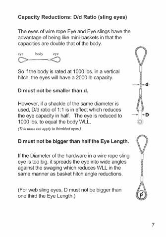
Capacity Reductions: D/d Ratio (sling eyes)
The eyes of wire rope Eye and Eye slings have theadvantage of being like mini-baskets in that thecapacities are double that of the body.
eye body eye
So if the body is rated at 1000 lbs. in a verticalhitch, the eyes will have a 2000 lb capacity.
D must not be smaller than d.
However, if a shackle of the same diameter isused, D/d ratio of 1:1 is in effect which reducesthe eye capacity in half. The eye is reduced to1000 lbs. to equal the body WLL.(This does not apply to thimbled eyes.)
D must not be bigger than half the Eye Length.
If the Diameter of the hardware in a wire rope slingeye is too big, it spreads the eye into wide anglesagainst the swaging which reduces WLL in thesame manner as basket hitch angle reductions.
(For web sling eyes, D must not be bigger thanone third the Eye Length.)
7
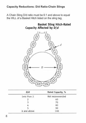
Capacity Reductions: D/d Ratio-Chain Slings
A Chain Sling D/d ratio must be 6:1 and above to equalthe WLL of a Basket Hitch listed on the sling tag.
8

9
Capacity Reductions: Chain Slings
Do not use Synthetic Slings in temperatures above 180°.

Capacity Reductions: Choker Hitch
When a Choker Hitch Angle is less than 120°, thechoker capacity (WLL) must be adjusted.
10
11
Capacity Reductions: Choker Hitch
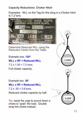
Example one, 120°WLL x RF = Reduced WLL7.2 x 1.00 = 7.2 tons.Full choker capacity.
Example two, 30°WLL x RF = Reduced WLL7.2 x .50 = 3.6 tons.Reduced choker capacity by half.
Tip: resist the urge to pound down achoke to “grab” the load. Doublewrap the choke instead.
Examples: WLL on the Tag for this sling in a Choker hitchis 7.2 tons.
Determine Reduced WLL using theReduction Factor from the Table.

12
Capacity Reductions: ShacklesShackles symmetrically loaded with an included angle of
120º can be used to the full WLL.Do not exceed 120º included angle loading.
However, Shackles that are single side loaded will havea Reduced WLL (see next page).
Multiply Rated Capacity (WLL) by Reduction Factor toget actual Reduced Working Load Limit.
WLL x RF = Reduced WLL
Examples – a Shackle rated 1000 pounds can lift:•1000 x 1.0 = 1000 pounds in-line.•1000 x 0.7 = 700 pounds at 45°.•1000 x 0.5 = 500 pounds at 90° (half).

13
Capacity Reductions: Shackles
For Screw-Pin and Bolt-type shackles only. Do notside load Round-Pin shackles.

14
Capacity Reductions: Eyebolts
Angle pull in the plane of the eye only.Use shims to line up eyebolt.
15
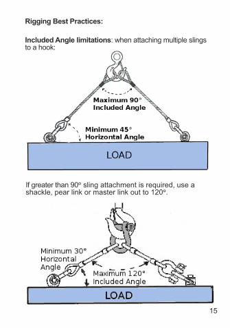
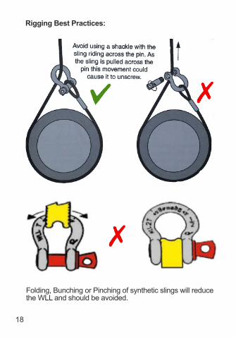
Rigging Best Practices:
Included Angle limitations: when attaching multiple slingsto a hook:
If greater than 90° sling attachment is required, use ashackle, pear link or master link out to 120°.

16
Rigging Best Practices:
Wrong Hook Loading methods.
Attaching to a Hook.
Attaching to Eyebolts.

17
Rigging Best Practices:
Attaching to Shackles, gather slings in the bow.
Attaching to Hoist Rings, ensure free rotation.
Chain sling no-no’s.
18
Rigging Best Practices:
Folding, Bunching or Pinching of synthetic slings will reducethe WLL and should be avoided.

19
Capacity Chart: Roundsling (Lift-It)
Minimum Connection Diameter, as the above tablereferences, is the minimum diameter a connection device(shackle, ring, hook) must have to avoid WLL reduction.
Minimum Edge Radii - unprotectedroundslings on corner edges requirea minimum radius rounded edge toavoid too much point stress. Thiscan vary from 3/16th to 7/8th inchdepending on WLL.Use Softeners and Padding to bestavoid corner stress.
20
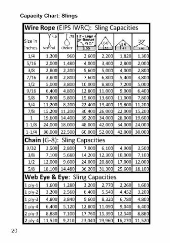
Capacity Chart: Slings
.751.0
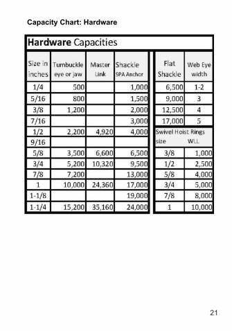
Capacity Chart: Hardware
21

22
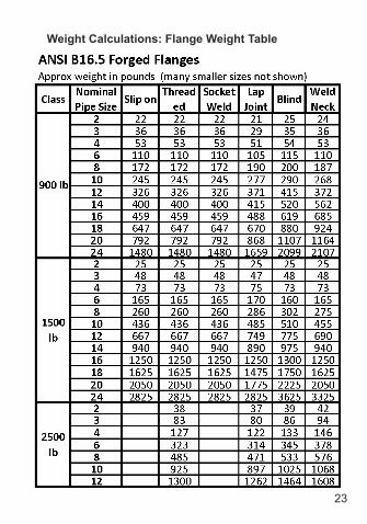
Weight Calculations: Flange Weight Table
23
Weight Calculations: Flange Weight Table

Weight Calculations: Pipe Weight Table
24

Weight Calculations: Material Weight Tables
25

Weight Calculations: Formulas
Circumference of a Circle =π x D.
Area of a Triangle = (L x W) ÷ 2.Area of a Square or Rectangle = L x W.
Area of a Circle =πr².
Volume of a Cube = L x W x H.
Volume of a Cylinder =πr² x L(pipe, tower, tank).
Pythagorean Theorem: a² + b² = c².
So, a = c² - b²
b = c² - a²
c = a² + b²
L = LengthW = WidthH = Heightr = RadiusD = Diameter
π = 3.1416
1 gal = .134 cf1 cf = 7.48 gal1 in = .0833 ft1 si = .00694 sf1 sf = 144 si
26

Weight Calculations: Example
27
Calculate the weight of a Tank using theTables & Formulas.Diameter 10 ft, height 15 feet, steel ½ in thick.
1. Calculate the Area and Weight of the topand bottom. Top weight = Area of a Circle x the load
weight of Steel per square foot.
=π x r x r x Steel weight
= 3.1416 x 5ft x 5ft x 20 lbs/sf = 1,571 lbs. 2. Bottom = same as Top = 1,571 lbs.
3. Calculate the Area and Weight ofthe Body using Circumference tounravel the cylinder into a steel sheet.
Body weight = the circumferenceof the cylinder x the height x theload weight of Steel per squarefoot.
=π x D x H x Steel weight
= 3.1416 x 10ft x 15ft x 20 lbs/sf = 9,425 lbs.
4. Total weight = 1,571 lbs. + 1,571 lbs. + 9,425 lbs. = 12,567 lbs.

28
Inspection: Web Sling

29
Inspection: Round Sling

30
Inspection: Wire Rope Sling
3/6 RULE: Three broken wires in one strand in one ropelay, or Six randomly distributed broken wires in one ropelay, where a rope lay is the length along the rope in whichone strand makes a complete revolution around the rope.
Lay Length

31
Inspection: Chain slings and hardware

Inspection: slings and hardware continued
All rigging gear requires some form of identification withrated capacity (WLL) legible.Polyester and nylon slings shall not be used in contactwith an object or at temperatures in excess of 180°F.
Hooks shall be removed from service if:● wear exceeds 10% of original dimension.● throat opening of 5%.● Any bend or twist.● Self-locking hook doesn’t lock.
32
Annual Inspection Color Coding5 year rotation
2015 White2016 Yellow2017 Red2018 Green2019 Orange

33
Conducting a Voice Signal:
Maintain constant communication with the Operator once alift move has begun:
- Hold down the microphone key.- Repeat the function command, talking it through. This reassures the Operator the move is proceeding
as planned.- Un-key the microphone at the end of the move.- Repeat for any follow-on moves.
If the Operator senses a problem, they will stop the move.
All signals shall be given from Operators perspective.
3 elements of voice signals1. Function (hoist, boom, etc), Direction2. Distance and/or speed3. Function, stop command
Example: swing right 50 ft, 25 ft, 15 ft, 10 ft, 5 ft, swing stop
Only one signalperson at a time, except when STOP orEmergency STOP are given for safety reasons.
Audible Travel Signals:STOP: one short audible signal ●GO AHEAD: two short audible signals ● ●BACK UP: three short audible signals ● ● ●
Signalperson: Voice Signals

34
Signalperson: Hand Signals (mobile crane)

35
Signalperson: Hand Signals (mobile crane)

36
Signalperson: Hand Signals (mobile & bridge crane)
Bridge andGantryCrane
Signals.
37
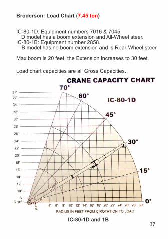
Broderson: Load Chart (7.45 ton)
IC-80-1D: Equipment numbers 7016 & 7045.D model has a boom extension and All-Wheel steer.
IC-80-1B: Equipment number 2858.B model has no boom extension and is Rear-Wheel steer.
Max boom is 20 feet, the Extension increases to 30 feet.
Load chart capacities are all Gross Capacities.
IC-80-1D and 1B

38
Broderson: Load Chart (7.45 ton)
It is a Critical Lift if actual Gross Load exceeds 75% ofcharted capacity.
- Example: If the Gross Load (load + rigging gear +hook&ball) = 4000 lbs., can you pick this up at 16 feeton outriggers, with extension stowed, without it being acritical lift?
- No. (4450 lbs. x .75 = 3337 lbs.)- 4000 lbs > 3337 lbs so it is a critical lift, move to 14 feet.
IC-80-1D

39IC-80-1B
Broderson: Load Chart (7.45 ton)
- Example: If the Gross Load (load + rigging gear +hook&ball) = 10000 lbs., can you pick this up at 6 feeton outriggers, with extension stowed,single part of line,without it being a critical lift?
- No. Single part of line is limited to 9000 lbs.(9000 lbs. x .75 = 6750 lbs.)
- 6750 lbs. Is the max you can lift without it being acritical lift. Install 2-part line block.

40IC-80-1D and 1B
Broderson: Load Chart (7.45 ton)
Note: for accurate Hydraulic Oil level indication duringpre-check, ensure boom and outriggers are fullyretracted.

Broderson: Load Chart Terminology
Gross Capacity = Net Capacity + deductions. These arethe numbers on the Load Chart.
Deductions = headache ball + hook + rigging gear, etc.
Net Capacity = Gross Capacity - deductions. This is themaximum Net Load for the crane configuration.
Gross Load = Net Load + Deductions. Use thisnumber when checking the Load Chart. It must neverexceed Gross Capacity for the radius and craneconfiguration.
Deductions = headache ball + hook + rigging gear, etc.
Net Load = Gross Load - deductions. Actual weight ofitem lifted.
Ground Bearing Pressure - to avoid soil cave-in, thepressure of the outrigger mats/cribbing on the groundmust be determined and not exceed:
1. Dirt or Gravel - 1000 psf
2, Asphalt - 2000 psf
3. Concrete - 3000 psf
Determine if the mat size is sufficient:
Area = 0.65 x (Crane weight + Load weight) max pressure for soil typeMat length will be the square root of the result.
41
Load Radius - Horizontal distance from center ofrotation to CoG of the load.

Broderson: Load Chart (4 ton)
42

Broderson: Load Chart (4 ton)
43

44
If actual radius falls between the chart listings,use next longer radius, never split the difference,to determine the Gross Load limitation.
If calculated Gross Load falls between the chart listings,use next shorter radius, never split the difference,to determine the Load Radius limitation.
Broderson: Load Chart Terminology
17 feet
4200 lbs

Broderson: Standard Lift Plan Checklist
□ Identify Load size, shape, weight, and center of gravity.
□ Select and inspect the proper rigging equipment andthe method for connecting and disconnecting the load.
□ Identify the lifting radii at the pick and set locations.
□ Determine head room, hoist height, travel path.
□ Select correct size crane for the load to be lifted.
□ Job site conditions, examples; obstructions, groundconditions, crane access, SIMOPS, nearby equipment(e.g. live process equipment, overhead power lines).
□ Pinch points and crush hazards identified and marked.
□ Environmental conditions: wind, temp, visibility,weather.
□ Establish roles and responsibilities of the work crew.
□ Communication method agreed to by the CraneOperator, Rigger, and Signalperson (i.e. radio, handsignals, etc.).
□ A contingency plan for emergencies related orunrelated to the lifting operation.
□ Lift area (fall zone) is clear of non-essential personnel,and is properly barricaded.
45

Regeneration Procedure1. The vehicle should stand level.2. Switch off the motor.3. Ignition: “ON”, do not start engine. Voltage is supplied
to the Control Unit.4. Press “M” and hold for 5 seconds. The display will
countdown 5 seconds, then regeneration will begin.You can interrupt regeneration by turning OFF theignition on smaller vehicles, or by pressing the “F” key.
5. Allow several minutes to finish. Filter casing will bevery hot.
Broderson: HUSS Filter
46
47
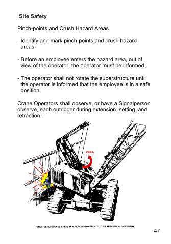
Site Safety
Pinch-points and Crush Hazard Areas
- Identify and mark pinch-points and crush hazardareas.
- Before an employee enters the hazard area, out ofview of the operator, the operator must be informed.
- The operator shall not rotate the superstructure untilthe operator is informed that the employee is in a safeposition.
Crane Operators shall observe, or have a Signalpersonobserve, each outrigger during extension, setting, andretraction.

48
Site Safety
Never walk or work under a suspended load.
Never ride a load.
Avoid swinging loads over other people.
Use tag lines for positioning and controlling loads.
Spotters are required for all cranes over 15 tons travelingLAR roadways.
Wind speeds> 20 mph - LTA approval required to continue lift.> 30 mph - stop Lifts.
Line of Fire: identify rigging line of fire. Examples: slings and hoists under tension, wire rope
under bundle pulling stress.Avoid standing near or in-line with stressed rigging and
cables to avoid snap-back if it breaks.
49
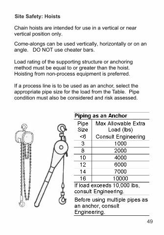
Site Safety: Hoists
Chain hoists are intended for use in a vertical or nearvertical position only.
Come-alongs can be used vertically, horizontally or on anangle. DO NOT use cheater bars.
Load rating of the supporting structure or anchoringmethod must be equal to or greater than the hoist.Hoisting from non-process equipment is preferred.
If a process line is to be used as an anchor, select theappropriate pipe size for the load from the Table. Pipecondition must also be considered and risk assessed.

50
Site Safety: Power Lines
Maintain 20 feet clearance from power lines.
To preventing encroachment / electrocution:- Use non-conductive tag-lines.- Erect elevated warning lines, signs, barricades, flags
to mark minimum approach distance to theProhibited Zone.
- Use a Dedicated Spotter:
Dedicated Spotter: a qualified Signalperson whose soleresponsibility is to:
- watch the separation between the power line and theequipment,
- watch the separation between the power line and theload line and load (including rigging and liftingaccessories),
- ensure through communication with the operator thatthe applicable minimum approach distance is notbreached.

51
Site Safety: Power Lines
Electrocution:
● Can result from contacting the ground and any part ofthe crane, hoist wire or load simultaneously.
● Can result from stepping across ground voltagedifferential which occurs as the voltage passesthrough ground resistance the further it travels.
● The distance of a mere stride can be enough voltagedifference to electrocute you.
Procedure: Ground Crew- Do not touch crane or hoist line or load.- Maintain balance and hop with feet together or shuffle
away from the affected area.

Site Safety: Power Lines
Procedure: Crane Operator- Stay in the crane.- Attempt to move crane away from electrical hazard.- If it becomes necessary to abandon the crane, DO
NOT step down from the crane. Jump away with feettogether.
- Maintain balance and hop with feet together or shuffleaway from the affected area.
52

53
Knots
Bowline
CloveHitch

Knots
54
Timber Hitch & Half Hitch
Round Turn & 2 Half Hitches

Glossary
CoG - Center of Gravity.Critical Lift - Lifts exceeding 75% of the crane’s capacity asconfigured, multiple crane lift, lifting personnel, lifts near powerlines, tilting, high-risk lifts.Dedicated spotter (power lines) - is a qualified Signalpersonwith the sole responsibility to ensure no portion of the crane orload encroaches upon the prohibited zone.D/d Ratio - the ratio of the diameter around which a wire ropesling is bent, divided by the body diameter of the wire rope sling.Gross Capacity & Gross Load - see page 37.Lift Director - The qualified Rigger that is directly in charge ofthe work crew performing the task/lift.LTA - Lifting Technical Authority - overall accountability forlifts. Provides technical advice and assurance, ensuringprocedures are followed.Minimum Connection Diameter - is the minimum diameter aconnection device (shackle, ring, hook) must have to avoid WLLreduction on roundslings.Minimum Edge Radii - unprotected roundslings on corneredges require a minimum radius rounded edge to avoid toomuch point stress. This can vary from 3/16th to 7/8th inchdepending on WLL.Net Capacity & Net Load - see page 37.Prohibited Zone - the area immediately surrounding anElectrical Hazard in which no lifting operations or other work isallowed. For lifting operations at LAR, the minimum radius of theProhibited Zone is 20 feet.Working Load Limit – WLL is the rated capacity of Rigginggear based on the ideal rigging situation and configuration. It iscalculated in straight line pulls, never side loading.Reduced Working Load Limit – RWLL is when the WLL mustbe Reduced because of the rigging situation and configuration.
55

56
References: Standards, Regulations, Policies
ASME B30.5 Mobile CranesASME B30.9 SlingsASME B30.10 HooksASME B30.26 Rigging HardwareCAL/OSHA CSO Construction (1610-1619)CAL/OSHA GISO General Industry (4884-5049)HSS-602 Mobile Crane SafetyHSS-604 Rigging and HoistingMNT-RIG-023 Inspection & Maintenance Requirements
for Rigging and Hoisting Equipment
References: General
IPT’s Crane and Rigging Handbook, Ronald G. GarbyJourneyman Riggers Reference Card, ITILift-It CatalogMobile Cranes, James HeadleyRigging Manual, CSAO

57

58

59

60


(8/20/2015)