rift-basin structure and its influence on sedimentary systemsschlisch/a33_2002_sepm_rifts.pdf ·...
TRANSCRIPT
57STRUCTURE AND SEDIMENTARY SYSTEMS
RIFT-BASIN STRUCTURE AND ITS INFLUENCE ON SEDIMENTARY SYSTEMS
MARTHA OLIVER WITHJACK AND ROY W. SCHLISCHEDepartment of Geological Sciences, Rutgers University, Piscataway, New Jersey 08854-8066, U.S.A.
e-mail: [email protected]; [email protected]
PAUL E. OLSENLamont-Doherty Earth Observatory of Columbia University, Palisades, New York 10964, U.S.A.
e-mail: [email protected]
Sedimentation in Continental RiftsSEPM Special Publication No. 73, Copyright © 2002SEPM (Society for Sedimentary Geology), ISBN 1-56576-082-4, p. 57–81.
INTRODUCTION
Knowledge of continental rifting has increased steadily dur-ing the past several decades. Field geologists have more preciselydefined the timing and style of deformation in many exposed riftbasins (e.g., the Newark basin of eastern North America, theUpper Rhine rift basin of central Europe, and Kenya basin of EastAfrica). Simultaneously, seismic interpreters, using 2D and 3Ddata acquired during hydrocarbon exploration and productionactivities, have identified and mapped many of the world’ssubsurface rift basins (e.g., the Viking and Central rift basins ofthe North Sea, the Jeanne d’Arc rift basin of the Canadian GrandBanks, and the Dampier rift basin on the Northwest Shelf ofAustralia). Additionally, experimentalists have used scaled labo-ratory models to simulate rift-basin development under a varietyof geologic conditions. Together, these field, seismic, and experi-mental approaches have yielded valuable information about thestructural styles and depositional patterns of rift basins.
Most previous reviews of rift-basin structures have focusedon one particular rift system using one, or possibly two, of theabove approaches (e.g., Rosendahl, 1987; Schlische, 1993; Morley,1995, 1999b). In this paper, we examine rift systems from aroundthe world, using information provided by field, seismic, andexperimental approaches. This broad perspective allows us todescribe the variety of structures associated with continentalrifting and to infer the influence of these structural styles on thedepositional patterns within them. Because of space limitations,
we have left out or abbreviated many important topics related tocontinental rifting. Readers interested in tectonic-scale aspects ofrifting and continental extension should consult the review pa-pers by Roberts and Yielding (1994), Leeder (1995), and Ruppel(1995). Also, Peacock et al. (2000) presented a useful compilationof the voluminous nomenclature related to normal faults, riftbasins, and extensional tectonics.
RIFT BASINS AND RIFT SYSTEMS
Rift basins are elongate crustal depressions bounded on oneor both sides by basement-involved normal faults (i.e., faults thatcut the crystalline basement) (Figs. 1 and 2). These extensionalfeatures are up to several kilometers deep, tens of kilometerswide, and hundreds of kilometers long. Rift systems are collec-tions of stepping, intersecting, and/or parallel rift basins (e.g.,Nelson et al., 1992) (Fig. 3). For example, the Bresse and UpperRhine rift basins of southern France and Germany are right-stepping rift basins that form part of the Tertiary rift system ofcentral Europe (e.g., Ziegler, 1992) (Fig. 3B). The Culpeper andTaylorsville rift basins of the southeastern United States areparallel rift basins that form part of the Mesozoic rift system ofeastern North America (e.g., Withjack et al., 1998) (Fig. 3C).Although many rift systems are associated with continentalbreakup and passive-margin development (e.g., the Mesozoic riftsystem of eastern North America), rift systems can form in avariety of tectonic settings. For example, the Tertiary rift system
ABSTRACT: Rift basins are complex features defined by several large-scale structural components including faulted margins, the borderfaults of the faulted margins, the uplifted flanks of the faulted margins, hinged margins, deep troughs, surrounding platforms, and large-scale transfer zones. Moderate- to small-scale structures also develop within rift basins. These include: basement-involved and detachednormal faults; strike-slip and reverse faults; and extensional fault-displacement, fault-propagation, forced, and fault-bend folds.
Four factors strongly influence the structural styles of rift basins: the mechanical behavior of the prerift and synrift packages, the tectonicactivity before rifting, the obliquity of rifting, and the tectonic activity after rifting. On the basis of these factors, we have defined a standardrift basin and four end-member variations. Most rift basins have attributes of the standard rift basin and/or one or more of the end-membervariations. The standard rift basin is characterized by moderately to steeply dipping basement-involved normal faults that strike roughlyperpendicular to the direction of maximum extension. Type 1 rift basins, with salt or thick shale in the prerift and/or synrift packages, arecharacterized by extensional forced folds above basement-involved normal faults and detached normal faults with associated fault-bendfolds. In Type 2 rift basins, contractional activity before rifting produced low-angle thrust faults in the prerift strata and/or crystallinebasement. The reactivation of these contractional structures during rifting created the low-angle normal faults characteristic of Type 2 riftbasins. In Type 3 rift basins, preexisting zones of weakness in the prerift strata and/or crystalline basement strike obliquely to the directionof maximum extension, leading to oblique rifting. Type 3 rift basins are characterized by faults with strike-slip, normal, and oblique-slipdisplacement and with multiple trends. Contractional activity followed rifting in Type 4 rift basins. These inverted rift basins are affectedby late-formed contractional structures including normal faults reactivated with reverse displacement, newly formed reverse faults, andcontractional fault-bend and fault-propagation folds.
Structures within rift basins affect depositional patterns by creating sites of uplift and erosion, by controlling pathways of sedimenttransport, and by defining the accommodation space for sediment deposition and preservation. The relationships among basin capacity(structurally controlled), sediment supply, and water supply determine the primary depositional regime in nonmarine rift basins, fluvialor lacustrine. Changes in basin capacity resulting from the growth of a rift basin may yield a tripartite stratigraphy (fluvial, deep lacustrine,and shallow lacustrine–fluvial) common to many nonmarine rift basins.
MARTHA OLIVER WITHJACK, ROY W. SCHLISCHE, AND PAUL E. OLSEN58
0
?
SE
62 4
NW
Inte
rbed
ded
Tria
ssic
prer
ift e
vapo
rites
and
silts
tone
s
8 10
SN
SW
NE
NW
Low
er J
uras
sic
and
Upp
er T
riass
icev
apor
ites
NW
SE
a
CB
E
WE
NW
SE
SE
WS
WE
NE
Mai
n tr
ough
Pla
tfo
rmM
ain
trou
ghP
latf
orm
BF
BF
BF
BF
D
20 4
Mai
n tr
ough
BF
Intr
abas
in f
ault
A
Mai
n tr
ough
BF
BF
Mai
n tr
ough
BF
Hin
ge
dm
arg
inH
inge
d m
argi
n
Pla
tfo
rm
Mai
n tr
ough
BF
BF
BF
0 2 4 6
Mai
n tr
ough
Pla
tfo
rmB
FB
FB
F
0 2 4 6
Pla
tfo
rmB
F
BF
F
G
H
Hin
ged
mar
gin
Upl
ift a
ssoc
iate
dw
ith T
ertia
rysh
orte
ning
Ter
tiary
inv
ersi
on
Mio
cene
synr
iftev
apor
ites
5 km
H =
V
Upl
ift
asso
ciat
ed w
ithT
ertia
ry s
hort
enin
g
Pos
trift
Syn
rift
Pre
rift
and
base
men
tE
vapo
rites
in
prer
iftan
d sy
nrift
str
ata
20 4
20 4
Thi
ck T
riass
icsh
ales
5 km
Inte
rpre
tatio
ns o
f sei
smic
sect
ions
dis
play
ed 1
:1 a
t 4 k
m/s
Mes
ozoi
cin
vers
ion
5 km
Inte
rpre
tatio
ns o
f sei
smic
sect
ions
dis
play
ed 1
:1 a
t 4 k
m/s
seconds
seconds
seconds6
seconds
seconds
seconds
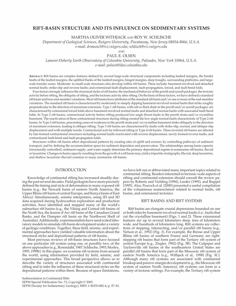
F IG
. 1—
Cro
ss se
ctio
ns o
f rif
t bas
ins.
All
of th
e se
ctio
ns h
ave
the
sam
e ho
rizo
ntal
scal
e, a
nd a
re sh
own
wit
h th
e fa
ulte
d m
argi
n an
d b
ord
er fa
ults
(BF)
on
the
left
. The
geo
logi
ccr
oss s
ecti
ons a
re d
ispl
ayed
wit
hout
ver
tica
l exa
gger
atio
n. T
he se
ism
ic se
ctio
ns a
re d
ispl
ayed
wit
hout
ver
tica
l exa
gger
atio
n as
sum
ing
a ve
loci
ty o
f 4 k
m/
s; th
e ve
rtic
alax
es a
re in
sec
ond
s of
two-
way
trav
el ti
me.
A) L
ine
dra
win
g of
sei
smic
line
NB
-1 th
roug
h th
e M
esoz
oic
New
ark
rift
bas
in, e
aste
rn U
nite
d S
tate
s (a
fter
Wit
hjac
k et
al.,
1998
). Fi
gure
2A
giv
es th
e lin
e lo
cati
on. B
) Lin
e d
raw
ing
of s
eism
ic li
ne 8
1-47
thro
ugh
the
Mes
ozoi
c Fu
ndy
rift
bas
in, s
outh
east
ern
Can
ada
(aft
er W
ithj
ack
et a
l., 1
998)
.C
) Lin
e d
raw
ing
of se
ism
ic li
ne 8
5-4A
thro
ugh
the
Mes
ozoi
c Jea
nne
d’A
rc ri
ft b
asin
, sou
thea
ster
n C
anad
a (a
fter
Wit
hjac
k an
d C
alla
way
, 200
0). D
) Geo
logi
c cro
ss se
ctio
nth
roug
h th
e T
erti
ary
Upp
er R
hine
rift
bas
in, G
erm
any
(aft
er S
ittl
er, 1
969)
. Fig
ure
2B g
ives
the
sect
ion
loca
tion
. E) G
eolo
gic
cros
s se
ctio
n th
roug
h th
e T
erti
ary
Suez
rift
basi
n, E
gypt
(aft
er C
olle
tta
et a
l., 1
988)
. Fig
ure
2C g
ive
the
sect
ion
loca
tion
. F) L
ine
dra
win
g of
a s
egm
ent o
f sei
smic
line
GM
NR
94-3
10 th
roug
h th
e M
esoz
oic
Vør
ing
rift
bas
in o
f off
shor
e N
orw
ay (a
fter
Wit
hjac
k an
d In
gebr
igts
en, 1
999;
Wit
hjac
k an
d C
alla
way
, 200
0). G
) Com
posi
te li
ne d
raw
ing
of s
ever
al s
eism
ic li
nes
thro
ugh
the
Mes
ozoi
c V
ikin
g ri
ft b
asin
, nor
ther
n N
orth
Sea
. H) C
ompo
site
line
dra
win
g of
sev
eral
sei
smic
line
s th
roug
h th
e M
esoz
oic
Dam
pier
rif
t bas
in o
f the
Nor
thw
est S
helf
,of
fsho
re A
ustr
alia
(aft
er W
ithj
ack
and
Eis
enst
adt,
1999
; Sch
lisch
e et
al.,
200
2). F
igur
e 2D
giv
es th
e lin
e lo
cati
on.
59STRUCTURE AND SEDIMENTARY SYSTEMS
Figure 1D
Platform
BF
BC
Prerift and basement
Synrift
30 km
N
Platform
lateOligocene–Miocene
extension
LateTriassic–Early
Jurassicextension
BF
Hingedmargin
A
Figure 1A
EarlyJurassic to
EarlyCretaceousextension
D
Platform
Platform
N
Transferzone
Figure 1E
Transferzone
Hingedmargin
N
N
Hingedmargin
Platform
BF
BF
BF
Hingedmargin
BF
Hingedmargin
Figure 1H
Monoclineabove BF
BF
BF
BF
BF
BF
BF
Dip direction of synrift strata
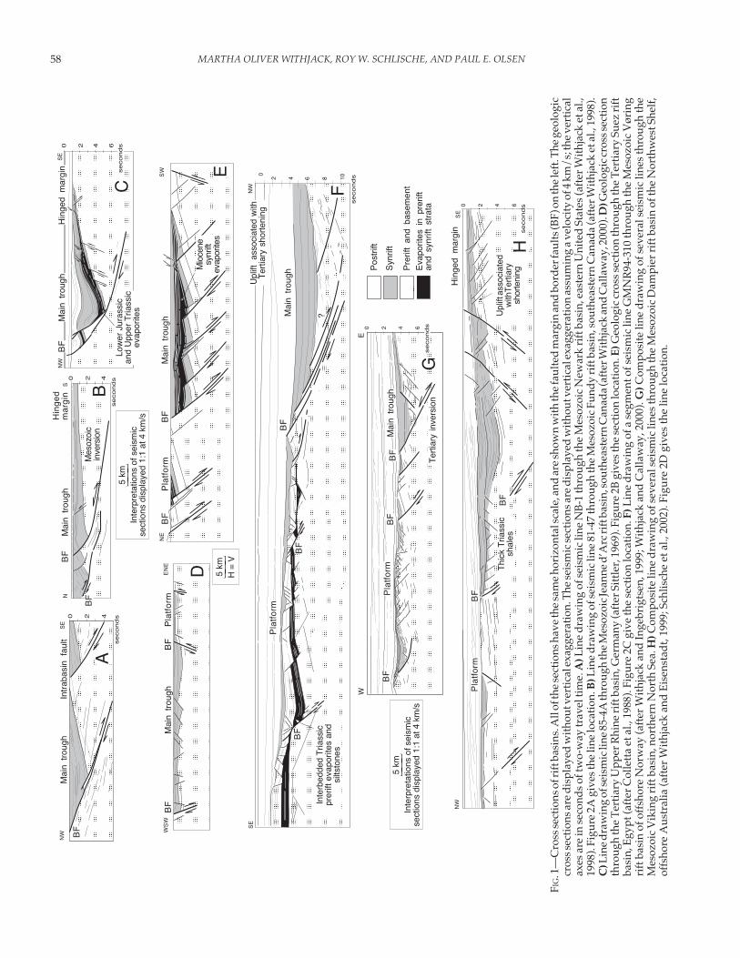
FIG. 2.—Map views of rift basins. All maps are shown at the same scale, and are oriented such that the rift axis is vertical. Thin blacklines are normal faults with more than several hundred meters of displacement. Thick black lines are normal faults with severalkilometers of displacement. BF is border fault. A) Mesozoic Newark rift basin, eastern United States (after Schlische, 1992). Thestrike of the rift-basin border faults is subparallel to the strike of the Paleozoic reverse faults (gray barbed lines). B) Tertiary UpperRhine rift basin, Germany (after Breyer, 1974; Illies and Greiner, 1978). C) Tertiary Suez rift basin, Egypt (after Patton et al., 1994).D) Mesozoic Dampier rift basin of Northwest shelf, offshore Australia (after Withjack and Eisenstadt, 1999; Schlische et al., 2002).The strike of many of the normal faults on the northwestern margin of the basin is oblique to the trend of the rift axis.
of central Europe developed adjacent to the active Alpine colli-sion zone (e.g., Ziegler, 1992) (Fig. 3B), whereas the Mesozoic riftsystem of eastern North America formed within a Paleozoicorogenic belt (e.g., Withjack et al., 1998) (Fig. 3C).
LARGE-SCALE STRUCTURAL COMPONENTSOF RIFT BASINS
Rift basins are complex features defined by several large-scale structural components. These components include faultedmargins, the border faults of the faulted margins, the upliftedflanks of the faulted margins, hinged margins, deep troughs,large-scale intrabasin fault blocks, and large-scale transfer zones(Figs. 1 and 2).
Faulted Margins
Basement-involved normal faults with displacements of sev-eral kilometers and lengths of several tens of kilometers are afundamental part of every faulted margin. These faults are com-monly called border faults, and their spatial arrangement variesconsiderably (Fig. 4). Some border faults have a stepping geom-
etry and similar dip directions, forming asymmetric rift basinswith a faulted margin and a hinged margin (Fig. 4A). For ex-ample, the northwestern faulted margin of the asymmetric New-ark rift basin is composed of closely spaced, right-stepping,southeast-dipping, basement-involved normal faults (e.g.,Withjack et al., 1998) (Figs. 1A and 2A). Some border faults havea stepping geometry and convergent dip directions, causing thefaulted and hinged margins to shift from side to side of the riftbasin (Fig. 4B). For example, the faulted and hinged margins shiftfrom side to side in the Suez rift basin (e.g., Moustafa, 1976;Thiebaud and Robson, 1979; Colletta et al., 1988) (Fig. 2C) and inmany of the rift basins of the East African rift system (e.g.,Rosendahl et al., 1986; Ebinger et al., 1987; Morley et al., 1990).Some border faults are parallel, overlapping, and have similardip directions (Fig. 4C). The fault blocks between these borderfaults are called platform structures in the Upper Rhine rift basin(Breyer, 1974) (Figs. 1D and 2B), stepfault platforms in the Kenyarift basin (Baker and Wohlenberg, 1971), border zones in the Suezrift basin (Garfunkel and Bartov, 1977) (Figs. 1E and 2C), benchesin the Rio Grande rift basin (Kelley, 1979), and terraces in theVøring rift basin of offshore Norway (Blystad et al., 1995) (Fig.1F). Some border faults are parallel, overlapping, and have con-

MARTHA OLIVER WITHJACK, ROY W. SCHLISCHE, AND PAUL E. OLSEN60
vergent dip directions, forming symmetric rift basins with twofaulted margins and no hinged margin (Fig. 4D). For example, thewestern and eastern faulted margins of the symmetric UpperRhine rift basin are composed of east- and west-dipping borderfaults, respectively (e.g., Sittler, 1969) (Figs. 1D and 2B). Finally,some border faults intersect each other (Fig. 4E). For example, thenorthwestern faulted margins of the Fundy and Chignecto riftbasins are composed of northeast-striking, basement-involvednormal faults. An intersecting east-striking, basement-involvedfault with both normal and strike-slip components of displace-
ment bounds the adjoining Minas rift basin (Withjack et al.,1995b) (see Figs. 7C and 7D).
The secondary deformation associated with border faultsalso varies considerably. In many rift basins, folds form in thesedimentary cover above the border faults. For example, mono-clinal flexures occur above the border faults of the southernUpper Rhine rift basin (Laubscher, 1982; Maurin, 1995) (see Fig.12E) and in the Haltenbanken area of offshore Norway (Fig. 1F).Evaporites in the prerift package facilitated the development ofthese folds by decoupling the shallow strata from the deep,
0 ~ 400km
N
Connecticut Valley basin
Fundy basin
Newark basin
Gettysburg basin
Culpeper basinTaylorsville basin
Scotsville basin
Deep River basin
Dan River/Danville basin
NorthAmerica
Jedburgbasin
Norfolkbasin
Atlantic Ocean
I
BC
Alps
Upper Rhinebasin
Bressebasin
Limagnebasin
A
P
S
I
S
P
P
Richmond basin
Synrift
Prerift andbasement
P
P
P
Continent–oceanboundary
Orpheus basin
Emerald/Naskapi basins
FIG. 3.—Map views of rift systems. Maps B and C are shown at the same scale. A) Schematic drawing of parallel (P), stepping (S), andintersecting (I) rift basins. B) Tertiary rift system of central Europe, showing a right-stepping arrangement of the Upper Rhine andBresse rift basins and a parallel arrangement of the Bresse and Ligmagne rift basins (after Ziegler, 1992). Note the proximity ofthe coeval Alpine collision zone. C) Mesozoic rift system of eastern North America, showing parallel and intersecting rift basins(after Withjack et al., 1998). The rift system is now part of the Atlantic passive margin. It formed within a Paleozoic orogenic belt.The strike of the rift-basin border faults is subparallel to the strike of the Paleozoic contractional structures (gray, barbed lines).
61STRUCTURE AND SEDIMENTARY SYSTEMS
faulted strata and basement. In some rift basins, the borderfaults are oblique-slip faults with both normal and strike-slipcomponents of displacement. In these rift basins, many of thesecondary normal faults strike obliquely to the trend of theborder faults. For example, the trend of the faulted margin (and
the deep-seated border faults) of the Dampier rift basin isnortheast–southwest. Most of the secondary normal faults inthe sedimentary cover, however, strike north–south (Withjackand Eisenstadt, 1999) (Fig. 2D).
Flanks and Troughs
The footwall of each border fault is generally uplifted, pro-ducing an elevated rift flank (Figs. 4 and 5A) (e.g., Zandt andOwens, 1980; Jackson and McKenzie, 1983; King and Ellis, 1990;Anders and Schlische, 1994). Similarly, the hanging wall of eachborder fault is generally depressed, producing a trough (Figs. 4and 5A). The magnitude of the footwall uplift and hanging-wallsubsidence is greatest near the border fault and decreases awayfrom the border fault into the footwall and hanging-wall blocks,respectively (e.g., Barnett et al., 1987) (Fig. 5B). It also decreasestoward the tips of the border fault (e.g., Jackson and McKenzie,1983; Anders and Schlische, 1994) (Fig. 5C). The ratio of footwalluplift to hanging-wall subsidence varies significantly, rangingfrom 1:1 to 1:10 (e.g., Jackson and McKenzie, 1983; Stein et al.,1988; Anders and Schlische, 1994).
Most rift basins are composed of several troughs separated byintrabasin highs (Fig. 4). The arrangement of the troughs and
Platform
Uplift
Uplift
CBF
BF
D
Uplift
Uplift
B
BF
BF
Relayramp
Uplift
Uplift
ABF
BF
T
Uplift
E
BF
Uplift Uplift
BF
BF
BF
Synrift
Prerift and basement
Trough
Border fault
T
H
T TH
T
T
H
T
T
T
T
Intrabasin high
T
BF
H
H
Hingedmargin
Hingedmargin
Hingedmargin
Hingedmargin
Hingedmargin
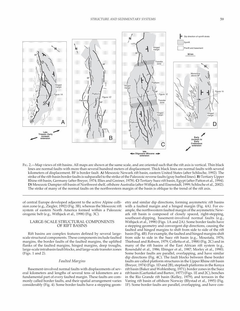
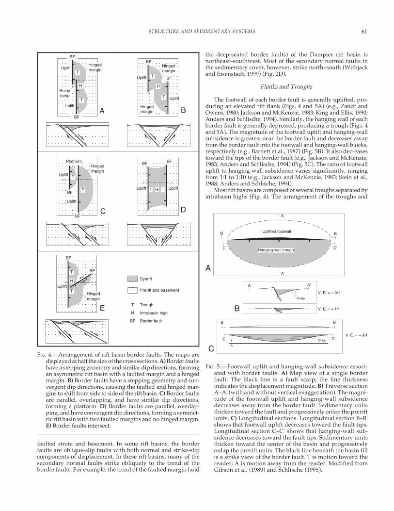
FIG. 4.—Arrangement of rift-basin border faults. The maps aredisplayed at half the size of the cross sections. A) Border faultshave a stepping geometry and similar dip directions, formingan asymmetric rift basin with a faulted margin and a hingedmargin. B) Border faults have a stepping geometry and con-vergent dip directions, causing the faulted and hinged mar-gins to shift from side to side of the rift basin. C) Border faultsare parallel, overlapping, and have similar dip directions,forming a platform. D) Border faults are parallel, overlap-ping, and have convergent dip directions, forming a symmet-ric rift basin with two faulted margins and no hinged margin.E) Border faults intersect.
A A'
Onlap
T
A
B B'
C C'Onlap
A
A'
B B'
C C'
V. E. = ~ 3/1
V. E. = ~ 3/1
V. E. = ~ 1/1
Hanging-wall trough
Uplifted footwall
A
B
C
FIG. 5.—Footwall uplift and hanging-wall subsidence associ-ated with border faults. A) Map view of a single borderfault. The black line is a fault scarp; the line thicknessindicates the displacement magnitude. B) Traverse sectionA–A' (with and without vertical exaggeration). The magni-tude of the footwall uplift and hanging-wall subsidencedecreases away from the border fault. Sedimentary unitsthicken toward the fault and progressively onlap the preriftunits. C) Longitudinal sections. Longitudinal section B–B'shows that footwall uplift decreases toward the fault tips.Longitudinal section C–C' shows that hanging-wall sub-sidence decreases toward the fault tips. Sedimentary unitsthicken toward the center of the basin and progressivelyonlap the prerift units. The black line beneath the basin fillis a strike view of the border fault. T is motion toward thereader; A is motion away from the reader. Modified fromGibson et al. (1989) and Schlische (1995).
MARTHA OLIVER WITHJACK, ROY W. SCHLISCHE, AND PAUL E. OLSEN62
highs depends on the arrangement of the border faults. If theborder faults have a stepping geometry and the same dip direc-tion, then a series of adjacent troughs and highs develops on thefaulted margin of the rift basin (Fig. 4A). If the border faults havea stepping geometry and convergent dip directions, then a seriesof offset troughs separated by intrabasin highs develops onopposing sides of the rift basin (Fig. 4B). If the border faults areparallel, overlapping, and have the same dip direction, then aseries of parallel troughs and highs develops on the faultedmargin of the rift basin (Fig. 4C).
Large-Scale Intrabasin Fault Blocks
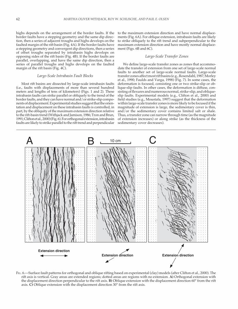
Most rift basins are dissected by large-scale intrabasin faults(i.e., faults with displacements of more than several hundredmeters and lengths of tens of kilometers) (Figs. 1 and 2). Theseintrabasin faults can strike parallel or obliquely to the trend of theborder faults, and they can have normal and/or strike-slip compo-nents of displacement. Experimental studies suggest that the orien-tation and displacement on these intrabasin faults is controlled, inpart, by the obliquity of the maximum extension direction relativeto the rift-basin trend (Withjack and Jamison, 1986; Tron and Brun,1991; Clifton et al., 2000) (Fig. 6). For orthogonal extension, intrabasinfaults are likely to strike parallel to the rift trend and perpendicular
to the maximum extension direction and have normal displace-ments (Fig. 6A). For oblique extension, intrabasin faults are likelyto strike obliquely to the rift trend and subperpendicular to themaximum extension direction and have mostly normal displace-ment (Figs. 6B and 6C).
Large-Scale Transfer Zones
We define large-scale transfer zones as zones that accommo-date the transfer of extension from one set of large-scale normalfaults to another set of large-scale normal faults. Large-scaletransfer zones affect most rift basins (e.g., Rosendahl, 1987; Morleyet al., 1990; Faulds and Varga, 1998) (Fig. 7). In some cases, thedeformation is focused, consisting one or two strike-slip or ob-lique-slip faults. In other cases, the deformation is diffuse, con-sisting of flexures and numerous normal, strike-slip, and oblique-slip faults. Experimental models (e.g., Clifton et al., 2000) andfield studies (e.g., Moustafa, 1997) suggest that the deformationwithin large-scale transfer zones is more likely to be focused if themagnitude of extension is large, the sedimentary cover is thin,and/or the sedimentary cover contains limited salt or shale.Thus, a transfer zone can narrow through time (as the magnitudeof extension increases) or along strike (as the thickness of thesedimentary cover decreases).
FIG. 6.—Surface fault patterns for orthogonal and oblique rifting based on experimental (clay) models (after Clifton et al., 2000). Therift axis is vertical. Gray areas are extended regions; dotted areas are regions with no extension. A) Orthogonal extension withthe displacement direction perpendicular to the rift axis. B) Oblique extension with the displacement direction 60° from the riftaxis. C) Oblique extension with the displacement direction 30° from the rift axis.
10 cm
Extension directionExtension direction Extension direction
A CB
63STRUCTURE AND SEDIMENTARY SYSTEMS
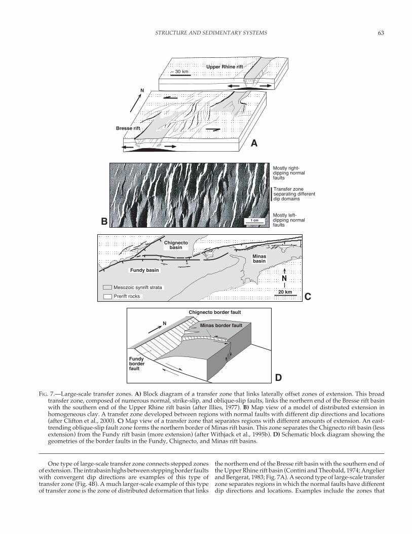
One type of large-scale transfer zone connects stepped zonesof extension. The intrabasin highs between stepping border faultswith convergent dip directions are examples of this type oftransfer zone (Fig. 4B). A much larger-scale example of this typeof transfer zone is the zone of distributed deformation that links
the northern end of the Bresse rift basin with the southern end ofthe Upper Rhine rift basin (Contini and Theobald, 1974; Angelierand Bergerat, 1983; Fig. 7A). A second type of large-scale transferzone separates regions in which the normal faults have differentdip directions and locations. Examples include the zones that
FIG. 7.—Large-scale transfer zones. A) Block diagram of a transfer zone that links laterally offset zones of extension. This broadtransfer zone, composed of numerous normal, strike-slip, and oblique-slip faults, links the northern end of the Bresse rift basinwith the southern end of the Upper Rhine rift basin (after Illies, 1977). B) Map view of a model of distributed extension inhomogeneous clay. A transfer zone developed between regions with normal faults with different dip directions and locations(after Clifton et al., 2000). C) Map view of a transfer zone that separates regions with different amounts of extension. An east-trending oblique-slip fault zone forms the northern border of Minas rift basin. This zone separates the Chignecto rift basin (lessextension) from the Fundy rift basin (more extension) (after Withjack et al., 1995b). D) Schematic block diagram showing thegeometries of the border faults in the Fundy, Chignecto, and Minas rift basins.
Upper Rhine rift
Bresse rift
~ 30 km
20 kmMesozoic synrift strata
Prerift rocks
Minasbasin
Fundy basin
Chignectobasin
Chignecto border fault
Fundyborderfault
Minas border fault
1 cmB
C
D
Transfer zoneseparating differentdip domains
Mostly right-dipping normalfaults
Mostly left-dipping normalfaults
A
N
N
MARTHA OLIVER WITHJACK, ROY W. SCHLISCHE, AND PAUL E. OLSEN64
bound the three dip provinces of the Suez rift basin (Moustafa,1976; Thiebaud and Robson, 1979; Colletta et al., 1988; Fig. 2C). Ineach of these dip provinces, the dip directions of the normal faultsand strata differ from those in the adjacent dip province(s).Experimental models of distributed extension with a homoge-neous modeling material have produced similar transfer zones(Clifton et al., 2000) (Fig. 7B). A third type of large-scale transferzone separates regions with different amounts of extension. Forexample, the east-striking oblique-slip fault zone on the northernmargin of the Minas rift basin is a transfer zone that separates theFundy rift basin from the less-extended Chignecto rift basin (Figs.7C and 7D).
FAULTS
Normal Faults
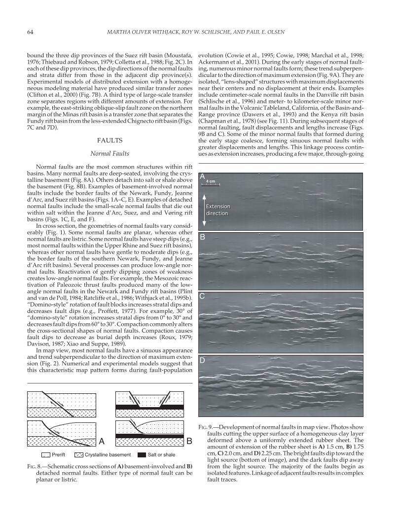
Normal faults are the most common structures within riftbasins. Many normal faults are deep-seated, involving the crys-talline basement (Fig. 8A). Others detach into salt or shale abovethe basement (Fig. 8B). Examples of basement-involved normalfaults include the border faults of the Newark, Fundy, Jeanned’Arc, and Suez rift basins (Figs. 1A–C, E). Examples of detachednormal faults include the small-scale normal faults that die outwithin salt within the Jeanne d’Arc, Suez, and and Vøring riftbasins (Figs. 1C, E, and F).
In cross section, the geometries of normal faults vary consid-erably (Fig. 1). Some normal faults are planar, whereas othernormal faults are listric. Some normal faults have steep dips (e.g.,most normal faults within the Upper Rhine and Suez rift basins),whereas other normal faults have gentle to moderate dips (e.g.,the border faults of the southern Newark, Fundy, and Jeanned’Arc rift basins). Several processes can produce low-angle nor-mal faults. Reactivation of gently dipping zones of weaknesscreates low-angle normal faults. For example, the Mesozoic reac-tivation of Paleozoic thrust faults produced many of the low-angle normal faults in the Newark and Fundy rift basins (Plintand van de Poll, 1984; Ratcliffe et al., 1986; Withjack et al., 1995b).“Domino-style” rotation of fault blocks increases stratal dips anddecreases fault dips (e.g., Proffett, 1977). For example, 30° of“domino-style” rotation increases stratal dips from 0° to 30° anddecreases fault dips from 60° to 30°. Compaction commonly altersthe cross-sectional shapes of normal faults. Compaction causesfault dips to decrease as burial depth increases (Roux, 1979;Davison, 1987; Xiao and Suppe, 1989).
In map view, most normal faults have a sinuous appearanceand trend subperpendicular to the direction of maximum exten-sion (Fig. 2). Numerical and experimental models suggest thatthis characteristic map pattern forms during fault-population
evolution (Cowie et al., 1995; Cowie, 1998; Marchal et al., 1998;Ackermann et al., 2001). During the early stages of normal fault-ing, numerous minor normal faults form; these trend subperpen-dicular to the direction of maximum extension (Fig. 9A). They areisolated, “lens-shaped” structures with maximum displacementsnear their centers and no displacement at their ends. Examplesinclude centimeter-scale normal faults in the Danville rift basin(Schlische et al., 1996) and meter- to kilometer-scale minor nor-mal faults in the Volcanic Tableland, California, of the Basin-and-Range province (Dawers et al., 1993) and the Kenya rift basin(Chapman et al., 1978) (see Fig. 11). During subsequent stages ofnormal faulting, fault displacements and lengths increase (Figs.9B and C). Some of the minor normal faults that formed duringthe early stage coalesce, forming sinuous normal faults withgreater displacements and lengths. This linkage process contin-ues as extension increases, producing a few major, through-going
FIG. 8.—Schematic cross sections of A) basement-involved and B)detached normal faults. Either type of normal fault can beplanar or listric.
ACrystalline basement Salt or shalePrerift
B
4 cmA
B
C
D
Extension
direction
Extension
direction
FIG. 9.—Development of normal faults in map view. Photos showfaults cutting the upper surface of a homogeneous clay layerdeformed above a uniformly extended rubber sheet. Theamount of extension of the rubber sheet is A) 1.5 cm, B) 1.75cm, C) 2.0 cm, and D) 2.25 cm. The bright faults dip toward thelight source (bottom of image), and the dark faults dip awayfrom the light source. The majority of the faults begin asisolated features. Linkage of adjacent faults results in complexfault traces.

65STRUCTURE AND SEDIMENTARY SYSTEMS
normal faults (Fig. 9D). Many of the faults not involved in thelinkage process either stop growing entirely or grow at a slowerrate. Because major normal faults are composed of linked minornormal faults, fault displacements, trends, and dips can varyconsiderably along strike (Fig. 9D).
Strike-Slip, Oblique-Slip, and Reverse Faults
Strike-slip, oblique-slip, and reverse faults also form withinrift basins. Strike-slip and oblique-slip faults are most commonin large-scale transfer zones (e.g., Rosendahl, 1987) and in riftbasins produced by oblique extension (e.g., Withjack andJamison, 1986) (Figs. 6B, 6C, and 7). Experimental models showthat reverse faults can develop as steeply dipping normal faultspropagate to the surface (Fig. 10A; Horsfield, 1977; Vendeville,1987; Withjack and Callaway, 2000). Reverse faults in the Suezrift basin might be analogous to those observed in these models(Fig. 10B; Patton, 1984; Gawthorpe et al., 1997). Some reversefaults in rift basins are actually rotated normal faults. Forexample, strata and normal faults rotated up to 70° during thepast 30 million years in the Lemitar Mountains of the Rio
Grande rift basin (Chamberlin, 1983) (Fig. 10C). This largerotation caused some initially high-angle, west-dipping normalfaults to become high-angle, east-dipping reverse faults. Fi-nally, reverse faults are common in inverted rift basins, (e.g.,Cooper and Williams, 1989). These reverse faults form afterrifting, and many are reactivated normal faults. For example,normal faults reactivated with reverse displacement exist in theFundy rift basin (Fig. 1B), the Viking rift basin (Fig. 1G), and theSunda arc rift basins (Fig. 10D).
FOLDS
Three types of folds are genetically associated with normalfaulting: fault-displacement folds, fault-propagation folds, andfault-bend folds (e.g., Figs. 11–14; Hamblin, 1965; Withjack andDrickman Pollock, 1984; Schlische, 1995; Janecke et al., 1998). Asdiscussed below, the geometry referred to in the literature as“normal-drag” folding (i.e., the hanging-wall beds dip awayfrom the normal fault) is generally produced by fault-propaga-tion folding and/or fault-bend folding. The geometry referred toin the literature as “reverse-drag” folding (i.e., the hanging-wall
4 cmH = V A
0
1
2
3
2 km
SW NE
km Normal fault reactivated asreverse fault
Anticline associated withinversion - harpoon
geometryAnticlines and synclinesassociated with inversion
SW NE
Reverse faults associated with upward-steepeningnormal faults and fault-propagation fold
1 kmH = V
Reverse fault associatedwith fault-propagation fold
500 m
H = V
Rotated normal fault
Synrift
Postrift
Prerift and basement
B C
D
FIG. 10.—Reverse faults associated with rifting. A) Line drawing of a clay model showing steeply dipping reverse faults associatedwith an upward-propagating normal fault (after Withjack and Callaway, 2000). B) Example of a reverse fault associated with fault-propagation folding in the Suez rift basin (after Gawthorpe et al., 1997). This reverse fault may be analogous to those in theexperimental models. C) Rotated normal fault from the Lemitar Mountains of the Rio Grande rift basin (after Chamberlin, 1983).Strata and normal faults rotated up to 70°, causing some initially high-angle, west-dipping normal faults to become high-angle,east-dipping reverse faults. D) Normal faults reactivated with reverse displacement in inverted rift basins from the Sunda arc.During basin inversion, some normal faults became reverse faults, producing synclines and anticlines with harpoon geometries(after Letouzey, 1990).
MARTHA OLIVER WITHJACK, ROY W. SCHLISCHE, AND PAUL E. OLSEN66
beds dip toward the normal fault) is generally produced by fault-displacement folding and/or fault-bend folding.
Fault-Displacement Folds
We define fault-displacement folds as flexures produced bychanges in fault displacement (Fig. 11). The axes of some fault-displacement folds are subparallel to the associated fault; theyform because the displacement decreases with increasing dis-tance from a normal fault (Fig. 5B). This displacement geometryleads to monoclinal upfolding in the footwall block (i.e., footwalluplift) and monoclinal downfolding (i.e., “reverse-drag”) in thehanging-wall block (e.g., Zandt and Owens, 1980; Barnett et al.,1987). The axes of other fault-displacement folds are subperpen-dicular to the associated fault; they form because the displace-ment varies along the strike of a normal fault (Walsh andWatterson, 1987) (Fig. 5C). Several factors produce displacementvariations along strike: fault segmentation during the early stages
of faulting, linkage during the later stages of faulting, and/orfault-surface irregularities. These fault-displacement folds in-clude the hanging-wall synclines and footwall anticlines thatform where fault displacements are greatest (Fig. 11B) and thefootwall synclines and hanging-wall anticlines that form wherefault displacements are least. As shown below, fault-displace-ment folding produces three-dimensional culminations and de-pressions in the footwalls and hanging walls of many normalfaults.
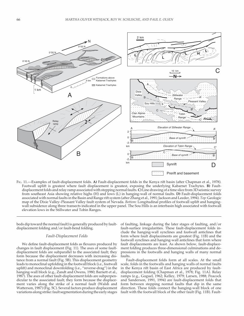
Fault-displacement folds form at all scales. At the smallscale, folds in the footwalls and hanging walls of normal faultsin the Kenya rift basin of East Africa are produced by fault-displacement folding (Chapman et al., 1978; Fig. 11A). Relayramps (e.g., Goguel, 1962; Kelley, 1979; Larsen, 1988; Peacockand Sanderson, 1991, 1994) are fault-displacement folds thatform between stepping normal faults that dip in the samedirection. These folds connect the hanging-wall block of onefault with the footwall block of the other fault (Fig. 11B). Fault-
FIG. 11.—Examples of fault-displacement folds. A) Fault-displacement folds in the Kenya rift basin (after Chapman et al., 1978).Footwall uplift is greatest where fault displacement is greatest, exposing the underlying Kabarnet Trachytes. B) Fault-displacement folds and relay ramp associated with stepping normal faults. C) Line drawing of a time slice from 3D seismic surveyfrom southeast Asia showing relative highs (H) and lows (L) in hanging-wall of normal faults. D) Fault-displacement foldsassociated with normal faults in the Basin and Range rift system (after Zhang et al., 1991; Jackson and Leeder, 1994). Top: Geologicmap of the Dixie Valley–Pleasant Valley fault system of Nevada. Bottom: Longitudinal profiles of footwall uplift and hanging-wall subsidence along three transects indicated in the upper panel. The Sou Hills is an interbasin high associated with footwallelevation lows in the Stillwater and Tobin Ranges.
2 km
0
-2km
BB'
C
C'
2
0
-2km
Elevation of Stillwater RangeA A'
BB'
Sou HillsPleasant Valley
TobinRange
DixieValley Stillwater
Range
Clan AlpineMountains
A
A'B
B'C
C'
N10 km
N
0°45 N
0°50 N
0°55 N
Formations aboveKabarnet Trachytes
Kabarnet Trachytes
1 km0
5 km
A
C
D
LL
L HL
Base of synrift
Elevation of Tobin Range
Base of synrift
Synrift
Prerift and basement
Relayramp
B
Relayramp
67STRUCTURE AND SEDIMENTARY SYSTEMS
displacement folds are evident on time slices from 3D seismicsurveys, appearing as anticlinal highs and synclinal lows in thefootwalls and hanging walls of normal faults (Fig. 11C). Theresidual intrabasin highs between stepping border faults withconvergent dip directions are large-scale fault-displacementfolds (as well as transfer zones) (Figs. 4D and 11D). Finally, atthe largest scale, the uplifted flank and the depressed trough of
a rift basin are produced by fault-displacement folding associ-ated with the border fault (Fig. 5).
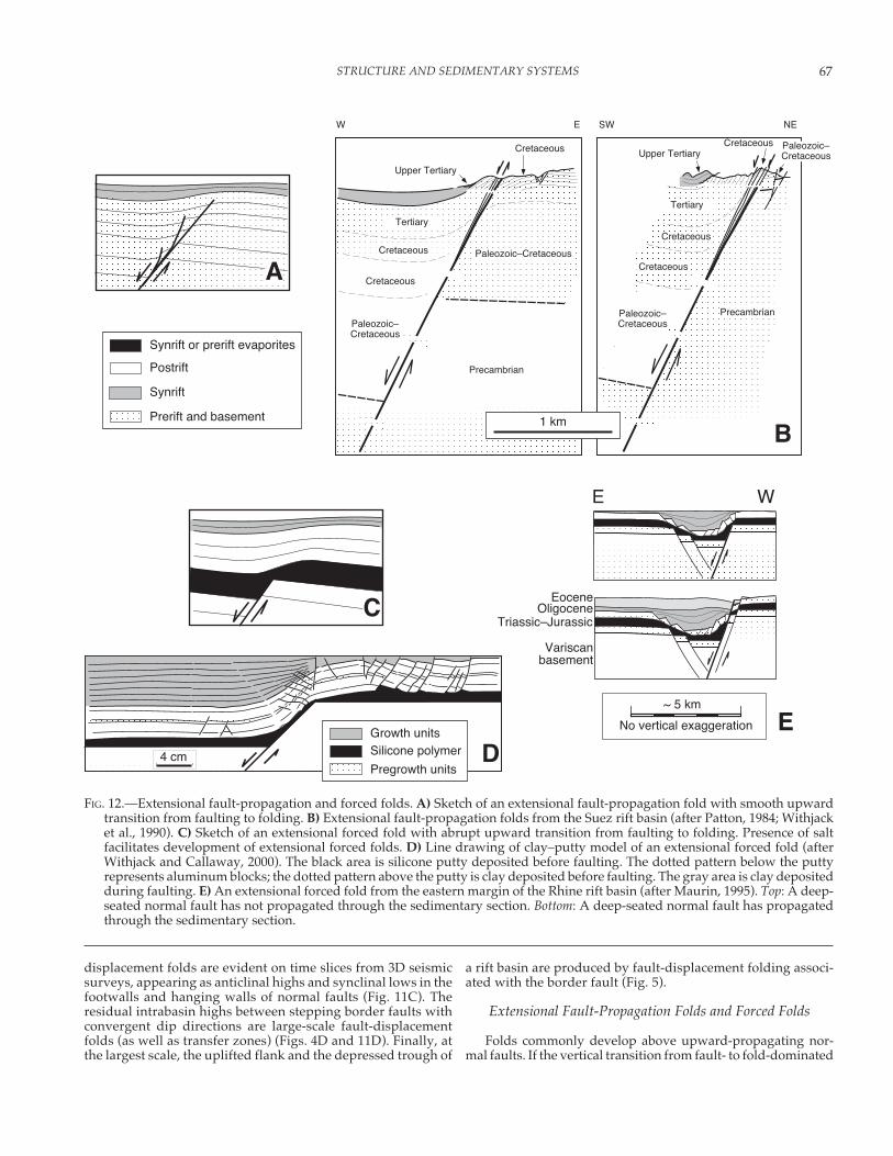
Extensional Fault-Propagation Folds and Forced Folds
Folds commonly develop above upward-propagating nor-mal faults. If the vertical transition from fault- to fold-dominated
FIG. 12.—Extensional fault-propagation and forced folds. A) Sketch of an extensional fault-propagation fold with smooth upwardtransition from faulting to folding. B) Extensional fault-propagation folds from the Suez rift basin (after Patton, 1984; Withjacket al., 1990). C) Sketch of an extensional forced fold with abrupt upward transition from faulting to folding. Presence of saltfacilitates development of extensional forced folds. D) Line drawing of clay–putty model of an extensional forced fold (afterWithjack and Callaway, 2000). The black area is silicone putty deposited before faulting. The dotted pattern below the puttyrepresents aluminum blocks; the dotted pattern above the putty is clay deposited before faulting. The gray area is clay depositedduring faulting. E) An extensional forced fold from the eastern margin of the Rhine rift basin (after Maurin, 1995). Top: A deep-seated normal fault has not propagated through the sedimentary section. Bottom: A deep-seated normal fault has propagatedthrough the sedimentary section.
4 cm
SW NEW
1 kmB
WE
Variscanbasement
Triassic–Jurassic
EoceneOligocene
~ 5 km
No vertical exaggeration
Synrift
Postrift
Prerift and basement
Synrift or prerift evaporites
A
C
DE
Precambrian
Paleozoic–Cretaceous
Paleozoic–Cretaceous
Cretaceous
Cretaceous
Cretaceous
Tertiary
Upper Tertiary
PrecambrianPaleozoic–Cretaceous
Paleozoic–Cretaceous
Cretaceous
Cretaceous
Cretaceous
Tertiary
Upper Tertiary
Growth units
Pregrowth units
Silicone polymer
E
MARTHA OLIVER WITHJACK, ROY W. SCHLISCHE, AND PAUL E. OLSEN68
deformation is smooth, we call these folds extensional fault-propagation folds (Fig. 12A). If the vertical transition from fault-to fold-dominated deformation is abrupt, we call these foldsextensional forced folds (Fig. 12C). The presence of subsurfaceevaporites and overpressured shales facilitates the developmentof extensional forced folds by decoupling the shallow, foldedstrata from the deep, faulted strata and basement (Laubscher,1982; Vendeville, 1987; Withjack et al., 1989; Withjack et al., 1990;Maurin, 1995; Withjack and Callaway, 2000).
Examples of extensional fault-propagation folds occur in theprerift and synrift packages above the faulted crystalline base-ment of the Suez rift basin (Robson, 1971; Garfunkel and Bartov,1977; Thiebaud and Robson, 1979, 1981; Brown, 1980; Patton,1984; Coffield and Schamel, 1989; Gawarecki and Coffield, 1990)(Figs. 10B and 12B). The folds in the Paleozoic through Eoceneprerift strata are relatively narrow flexures with steeply dippingbeds. Secondary faults associated with the fault-propagationfolding include upward-steepening normal and reverse faults
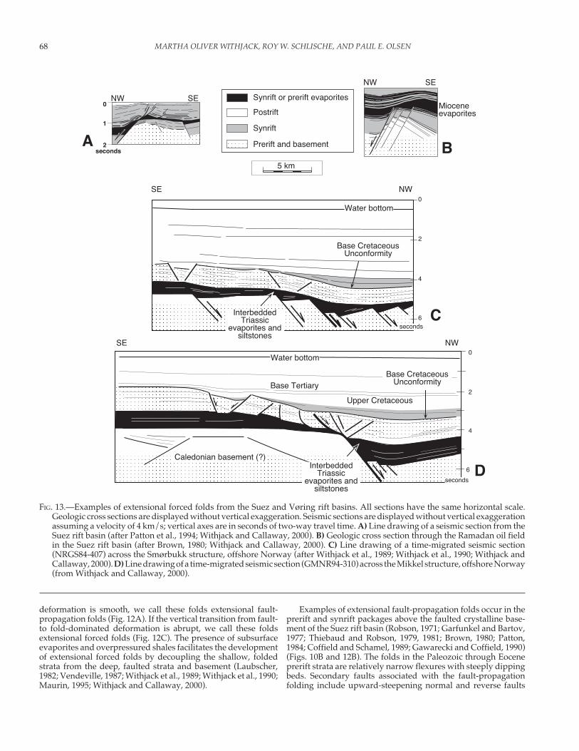
FIG. 13.—Examples of extensional forced folds from the Suez and Vøring rift basins. All sections have the same horizontal scale.Geologic cross sections are displayed without vertical exaggeration. Seismic sections are displayed without vertical exaggerationassuming a velocity of 4 km/s; vertical axes are in seconds of two-way travel time. A) Line drawing of a seismic section from theSuez rift basin (after Patton et al., 1994; Withjack and Callaway, 2000). B) Geologic cross section through the Ramadan oil fieldin the Suez rift basin (after Brown, 1980; Withjack and Callaway, 2000). C) Line drawing of a time-migrated seismic section(NRGS84-407) across the Smørbukk structure, offshore Norway (after Withjack et al., 1989; Withjack et al., 1990; Withjack andCallaway, 2000). D) Line drawing of a time-migrated seismic section (GMNR94-310) across the Mikkel structure, offshore Norway(from Withjack and Callaway, 2000).
SE0
2
4
Base CretaceousUnconformity
seconds
Base Tertiary
Water bottom
NW
Upper Cretaceous
Caledonian basement (?)
6Interbedded
Triassicevaporites and
siltstones
2
6
0
4
NWSE
seconds
Base CretaceousUnconformity
InterbeddedTriassic
evaporites andsiltstones
Water bottom
0
1
2
SENW
seconds
Mioceneevaporites
SENW
5 km
C
D
Synrift
Postrift
Prerift and basement
Synrift or prerift evaporites
BA

69STRUCTURE AND SEDIMENTARY SYSTEMS
FIG. 14.—Extensional fault-bend folds. A) Geometric models of extensional fault-bend folds (with vertical shear as the deformationmechanism) produced by changes in fault dip with depth. B) Line drawing of a seismic section showing an extensional fault-bendfold from the Vøring rift basin (after Withjack and Peterson, 1993). The normal fault has a listric shape and detaches within Triassicsalt. Hanging-wall strata dip toward the normal fault, and secondary normal faults emanate from the fault bend. C) Line drawingof a clay model showing the evolution of an extensional fault-bend fold (after Withjack et al., 1995a). D) Extensional fault-bendfold related to variation in fault shape along strike. Top: Contours (in seconds of two-way travel time) on the surface of the borderfault of the Chignecto rift basin. Note the “bump” on the fault surface. Bottom: Contours (in seconds of two-way travel time) ona prominent synrift reflection. The gray line is the hanging-wall cut off. This hanging-wall fold is an extensional fault-bend foldrelated to the “bump” on the surface of border fault of the Chignecto rift basin.
0 cm
2 cm
6 cm
4 cm
Aluminum block Superficial markingsshowing bedding
C
1.0
2.0
2.5
3.0
1.5
1.5
1.3
5 km
1.1
1.81.6
1.41.2 1.0
0
1
2
3
4
5seconds
1 km
NW SE
SynriftPostrift
Prerift and basement
A
D
B
NewBrunswick,
Canada
Chignecto Bay,Chignecto rift basin
1 cm
MARTHA OLIVER WITHJACK, ROY W. SCHLISCHE, AND PAUL E. OLSEN70
(e.g., Patton, 1984; Gawthorpe et al., 1997; Fig. 10B). The exten-sional fault-propagation folds in the Suez rift basin resemblethose from single-layer experimental models (Withjack et al.,1990; Withjack and Callaway, 2000) (Fig. 10A).
Examples of extensional forced folds are found along theeastern and western margins of the Upper Rhine rift basin (Fig.12E; Laubscher, 1982; Maurin, 1995), in the Suez rift basin (Figs.13A and 13B; Withjack and Callaway, 2000), and throughout theHaltenbanken area of offshore Norway (Figs. 13C and 13D;Withjack et al., 1989; Withjack et al., 1990). In the Haltenbankenarea, the extensional forced folds affect Triassic, Jurassic, andCretaceous strata above Triassic evaporites. The evaporites sepa-rate folded strata from underlying faulted strata and crystallinebasement. These forced folds are several kilometers wide andhave up to several kilometers of structural relief. Narrow, de-tached grabens formed near the anticlinal axial surfaces of manyof these forced folds (Withjack and Callaway, 2000). The exten-sional forced folds in the Haltenbanken area resemble those frommulti-layer experimental models (Vendeville, 1987; Withjackand Callaway, 2000) (Fig. 12D).
Extensional Fault-Bend Folds
Extensional fault-bend folds are flexures that form in thehanging walls of nonplanar normal faults (e.g., Xiao and Suppe,1992). Simple geometric models, assuming that rock volumeremains constant during folding, show how the shape of a normalfault influences the shape of the fault-bend fold in its hangingwall (Fig. 14A). If the surface of a normal fault has a gentlydipping upper segment and a steeply dipping lower segment, thegeometric models show that a monocline forms in the hangingwall of the normal fault (Fig. 14A, top). The folded strata dip awayfrom the fault (i.e., “normal-drag” folding). If the surface of anormal fault has a steeply dipping upper segment and a gentlydipping lower segment, the models show that a monocline alsoforms in the hanging wall of the normal fault (Fig. 14A, bottom).The folded strata, however, dip toward the fault (i.e., “reverse-drag” folding). Experimental models and seismic examples ofthis latter type of fault-bend fold suggest that secondary normalfaults commonly dip toward the main fault and emanate from thefault bend (e.g., Figs. 14B and 14 C; Withjack and Peterson, 1993;Withjack et al., 1995a).
Variations in fault shape along strike also produce extensionalfault-bend folds. Unlike more typical fault-bend folds whose axesare parallel to the master normal fault, the axes of these folds areperpendicular to the master normal fault. These fault-bend foldsresemble fault-displacement folds. For example, a gentle anti-cline has formed in the hanging-wall strata above a pronounced“bump” on the surface of the border fault of the Chignecto riftbasin (Fig. 14D). The fold axis is roughly perpendicular to theboundary fault.
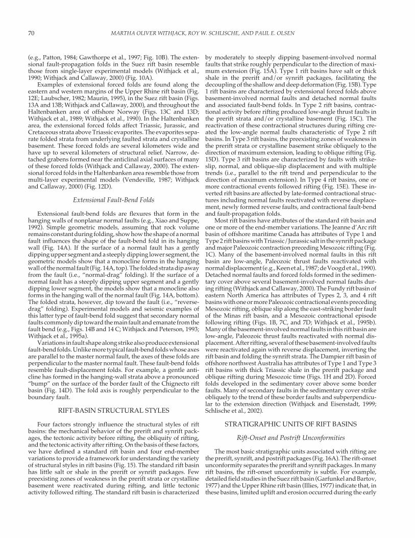
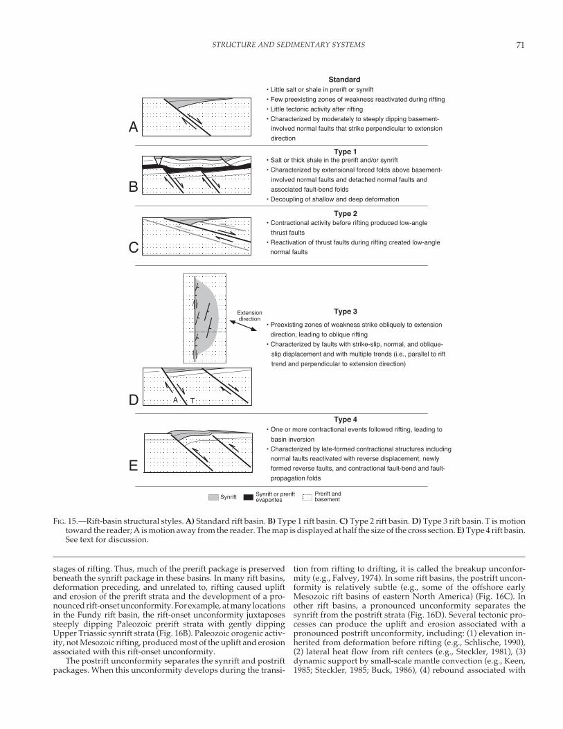
RIFT-BASIN STRUCTURAL STYLES
Four factors strongly influence the structural styles of riftbasins: the mechanical behavior of the prerift and synrift pack-ages, the tectonic activity before rifting, the obliquity of rifting,and the tectonic activity after rifting. On the basis of these factors,we have defined a standard rift basin and four end-membervariations to provide a framework for understanding the varietyof structural styles in rift basins (Fig. 15). The standard rift basinhas little salt or shale in the prerift or synrift packages. Fewpreexisting zones of weakness in the prerift strata or crystallinebasement were reactivated during rifting, and little tectonicactivity followed rifting. The standard rift basin is characterized
by moderately to steeply dipping basement-involved normalfaults that strike roughly perpendicular to the direction of maxi-mum extension (Fig. 15A). Type 1 rift basins have salt or thickshale in the prerift and/or synrift packages, facilitating thedecoupling of the shallow and deep deformation (Fig. 15B). Type1 rift basins are characterized by extensional forced folds abovebasement-involved normal faults and detached normal faultsand associated fault-bend folds. In Type 2 rift basins, contrac-tional activity before rifting produced low-angle thrust faults inthe prerift strata and/or crystalline basement (Fig. 15C). Thereactivation of these contractional structures during rifting cre-ated the low-angle normal faults characteristic of Type 2 riftbasins. In Type 3 rift basins, the preexisting zones of weakness inthe prerift strata or crystalline basement strike obliquely to thedirection of maximum extension, leading to oblique rifting (Fig.15D). Type 3 rift basins are characterized by faults with strike-slip, normal, and oblique-slip displacement and with multipletrends (i.e., parallel to the rift trend and perpendicular to thedirection of maximum extension). In Type 4 rift basins, one ormore contractional events followed rifting (Fig. 15E). These in-verted rift basins are affected by late-formed contractional struc-tures including normal faults reactivated with reverse displace-ment, newly formed reverse faults, and contractional fault-bendand fault-propagation folds.
Most rift basins have attributes of the standard rift basin andone or more of the end-member variations. The Jeanne d’Arc riftbasin of offshore maritime Canada has attributes of Type 1 andType 2 rift basins with Triassic/Jurassic salt in the synrift packageand major Paleozoic contraction preceding Mesozoic rifting (Fig.1C). Many of the basement-involved normal faults in this riftbasin are low-angle, Paleozoic thrust faults reactivated withnormal displacement (e.g., Keen et al., 1987; de Voogd et al., 1990).Detached normal faults and forced folds formed in the sedimen-tary cover above several basement-involved normal faults dur-ing rifting (Withjack and Callaway, 2000). The Fundy rift basin ofeastern North America has attributes of Types 2, 3, and 4 riftbasins with one or more Paleozoic contractional events precedingMesozoic rifting, oblique slip along the east-striking border faultof the Minas rift basin, and a Mesozoic contractional episodefollowing rifting (Figs. 1B, 7C, and 7D; Withjack et al., 1995b).Many of the basement-involved normal faults in this rift basin arelow-angle, Paleozoic thrust faults reactivated with normal dis-placement. After rifting, several of these basement-involved faultswere reactivated again with reverse displacement, inverting therift basin and folding the synrift strata. The Dampier rift basin ofoffshore northwest Australia has attributes of Type 1 and Type 3rift basins with thick Triassic shale in the prerift package andoblique rifting during Mesozoic time (Figs. 1H and 2D). Forcedfolds developed in the sedimentary cover above some borderfaults. Many of secondary faults in the sedimentary cover strikeobliquely to the trend of these border faults and subperpendicu-lar to the extension direction (Withjack and Eisenstadt, 1999;Schlische et al., 2002).
STRATIGRAPHIC UNITS OF RIFT BASINS
Rift-Onset and Postrift Unconformities
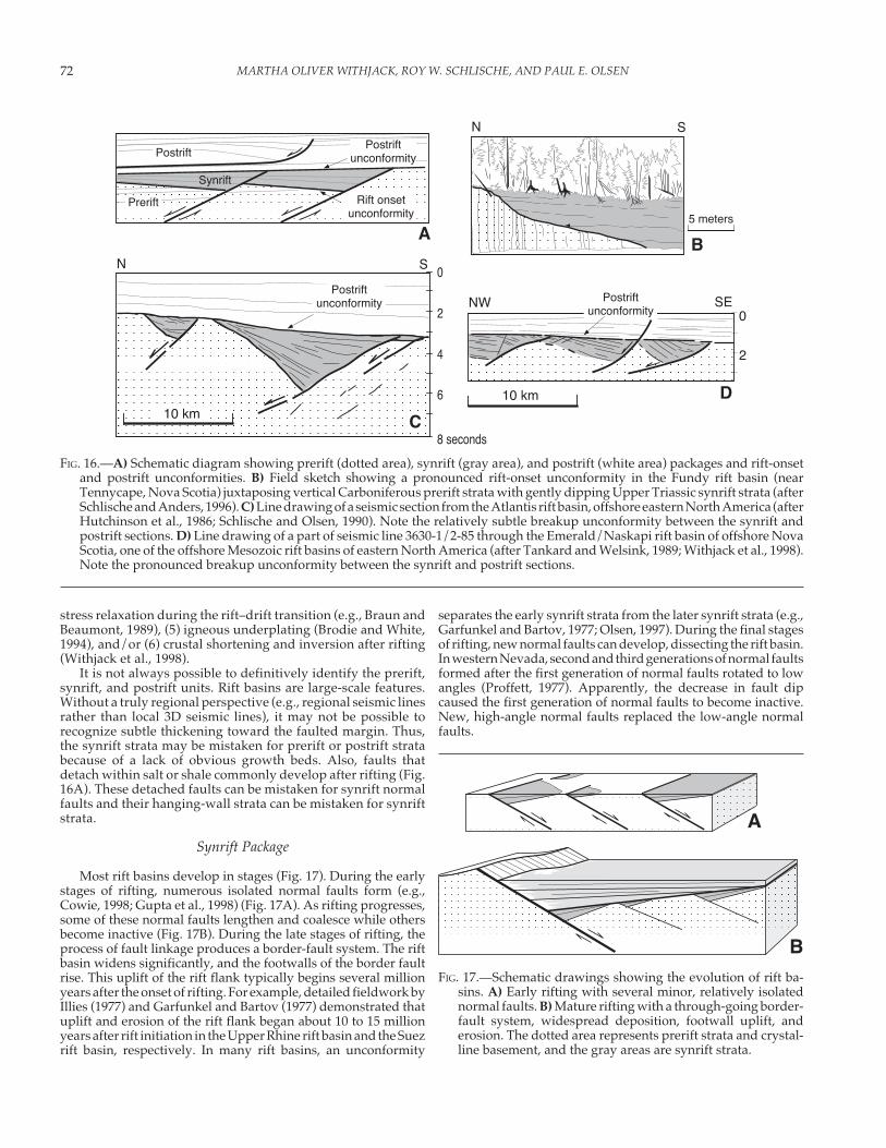
The most basic stratigraphic units associated with rifting arethe prerift, synrift, and postrift packages (Fig. 16A). The rift-onsetunconformity separates the prerift and synrift packages. In manyrift basins, the rift-onset unconformity is subtle. For example,detailed field studies in the Suez rift basin (Garfunkel and Bartov,1977) and the Upper Rhine rift basin (Illies, 1977) indicate that, inthese basins, limited uplift and erosion occurred during the early
71STRUCTURE AND SEDIMENTARY SYSTEMS
stages of rifting. Thus, much of the prerift package is preservedbeneath the synrift package in these basins. In many rift basins,deformation preceding, and unrelated to, rifting caused upliftand erosion of the prerift strata and the development of a pro-nounced rift-onset unconformity. For example, at many locationsin the Fundy rift basin, the rift-onset unconformity juxtaposessteeply dipping Paleozoic prerift strata with gently dippingUpper Triassic synrift strata (Fig. 16B). Paleozoic orogenic activ-ity, not Mesozoic rifting, produced most of the uplift and erosionassociated with this rift-onset unconformity.
The postrift unconformity separates the synrift and postriftpackages. When this unconformity develops during the transi-
tion from rifting to drifting, it is called the breakup unconfor-mity (e.g., Falvey, 1974). In some rift basins, the postrift uncon-formity is relatively subtle (e.g., some of the offshore earlyMesozoic rift basins of eastern North America) (Fig. 16C). Inother rift basins, a pronounced unconformity separates thesynrift from the postrift strata (Fig. 16D). Several tectonic pro-cesses can produce the uplift and erosion associated with apronounced postrift unconformity, including: (1) elevation in-herited from deformation before rifting (e.g., Schlische, 1990),(2) lateral heat flow from rift centers (e.g., Steckler, 1981), (3)dynamic support by small-scale mantle convection (e.g., Keen,1985; Steckler, 1985; Buck, 1986), (4) rebound associated with
FIG. 15.—Rift-basin structural styles. A) Standard rift basin. B) Type 1 rift basin. C) Type 2 rift basin. D) Type 3 rift basin. T is motiontoward the reader; A is motion away from the reader. The map is displayed at half the size of the cross section. E) Type 4 rift basin.See text for discussion.
B
C
E
D
Synrift or preriftevaporites
Prerift andbasement
Type 1
Type 2
Type 4
Type 3
Synrift
Extensiondirection
A
TA
Standard• Little salt or shale in prerift or synrift
• Few preexisting zones of weakness reactivated during rifting
• Little tectonic activity after rifting
• Characterized by moderately to steeply dipping basement-
involved normal faults that strike perpendicular to extension
direction
• Salt or thick shale in the prerift and/or synrift
• Characterized by extensional forced folds above basement-
involved normal faults and detached normal faults and
associated fault-bend folds
• Decoupling of shallow and deep deformation
• Contractional activity before rifting produced low-angle
thrust faults
• Reactivation of thrust faults during rifting created low-angle
normal faults
• Preexisting zones of weakness strike obliquely to extension
direction, leading to oblique rifting
• Characterized by faults with strike-slip, normal, and oblique-
slip displacement and with multiple trends (i.e., parallel to rift
trend and perpendicular to extension direction)
• One or more contractional events followed rifting, leading to
basin inversion
• Characterized by late-formed contractional structures including
normal faults reactivated with reverse displacement, newly
formed reverse faults, and contractional fault-bend and fault-
propagation folds
MARTHA OLIVER WITHJACK, ROY W. SCHLISCHE, AND PAUL E. OLSEN72
stress relaxation during the rift–drift transition (e.g., Braun andBeaumont, 1989), (5) igneous underplating (Brodie and White,1994), and/or (6) crustal shortening and inversion after rifting(Withjack et al., 1998).
It is not always possible to definitively identify the prerift,synrift, and postrift units. Rift basins are large-scale features.Without a truly regional perspective (e.g., regional seismic linesrather than local 3D seismic lines), it may not be possible torecognize subtle thickening toward the faulted margin. Thus,the synrift strata may be mistaken for prerift or postrift stratabecause of a lack of obvious growth beds. Also, faults thatdetach within salt or shale commonly develop after rifting (Fig.16A). These detached faults can be mistaken for synrift normalfaults and their hanging-wall strata can be mistaken for synriftstrata.
Synrift Package
Most rift basins develop in stages (Fig. 17). During the earlystages of rifting, numerous isolated normal faults form (e.g.,Cowie, 1998; Gupta et al., 1998) (Fig. 17A). As rifting progresses,some of these normal faults lengthen and coalesce while othersbecome inactive (Fig. 17B). During the late stages of rifting, theprocess of fault linkage produces a border-fault system. The riftbasin widens significantly, and the footwalls of the border faultrise. This uplift of the rift flank typically begins several millionyears after the onset of rifting. For example, detailed fieldwork byIllies (1977) and Garfunkel and Bartov (1977) demonstrated thatuplift and erosion of the rift flank began about 10 to 15 millionyears after rift initiation in the Upper Rhine rift basin and the Suezrift basin, respectively. In many rift basins, an unconformity
separates the early synrift strata from the later synrift strata (e.g.,Garfunkel and Bartov, 1977; Olsen, 1997). During the final stagesof rifting, new normal faults can develop, dissecting the rift basin.In western Nevada, second and third generations of normal faultsformed after the first generation of normal faults rotated to lowangles (Proffett, 1977). Apparently, the decrease in fault dipcaused the first generation of normal faults to become inactive.New, high-angle normal faults replaced the low-angle normalfaults.
FIG. 16.—A) Schematic diagram showing prerift (dotted area), synrift (gray area), and postrift (white area) packages and rift-onsetand postrift unconformities. B) Field sketch showing a pronounced rift-onset unconformity in the Fundy rift basin (nearTennycape, Nova Scotia) juxtaposing vertical Carboniferous prerift strata with gently dipping Upper Triassic synrift strata (afterSchlische and Anders, 1996). C) Line drawing of a seismic section from the Atlantis rift basin, offshore eastern North America (afterHutchinson et al., 1986; Schlische and Olsen, 1990). Note the relatively subtle breakup unconformity between the synrift andpostrift sections. D) Line drawing of a part of seismic line 3630-1/2-85 through the Emerald/Naskapi rift basin of offshore NovaScotia, one of the offshore Mesozoic rift basins of eastern North America (after Tankard and Welsink, 1989; Withjack et al., 1998).Note the pronounced breakup unconformity between the synrift and postrift sections.
0
2
0
2
4
6
8 seconds
5 meters
SN
B
Rift onsetunconformity
PostriftunconformityPostrift
Synrift
Prerift
A
C
SN
SENW
D10 km
Postriftunconformity Postrift
unconformity
10 km
FIG. 17.—Schematic drawings showing the evolution of rift ba-sins. A) Early rifting with several minor, relatively isolatednormal faults. B) Mature rifting with a through-going border-fault system, widespread deposition, footwall uplift, anderosion. The dotted area represents prerift strata and crystal-line basement, and the gray areas are synrift strata.
B
A
73STRUCTURE AND SEDIMENTARY SYSTEMS
STRUCTURAL CONTROLS ONSEDIMENTARY SYSTEMS
The accommodation space created by faulting and fault-relatedtopography is the primary control on the large-scale sedimentarysystems within rift basins. This topic has been addressed in manypapers (e.g., Barr, 1987; Leeder and Gawthorpe, 1987; Blair andBilodeau, 1988; Gibson et al., 1989; Lambiase, 1990; Schlische andOlsen, 1990; Schlische, 1991; Gawthorpe and Hurst, 1993; Lambiaseand Bosworth, 1995; Leeder, 1995; Schlische and Anders, 1996;Contreras et al., 1997; Gawthorpe and Leeder, 2000). This sectionbriefly reviews some of the more fundamental structural controlson sedimentary systems and highlights some recent developments.
Depositional Patterns in Transverse Cross Sections
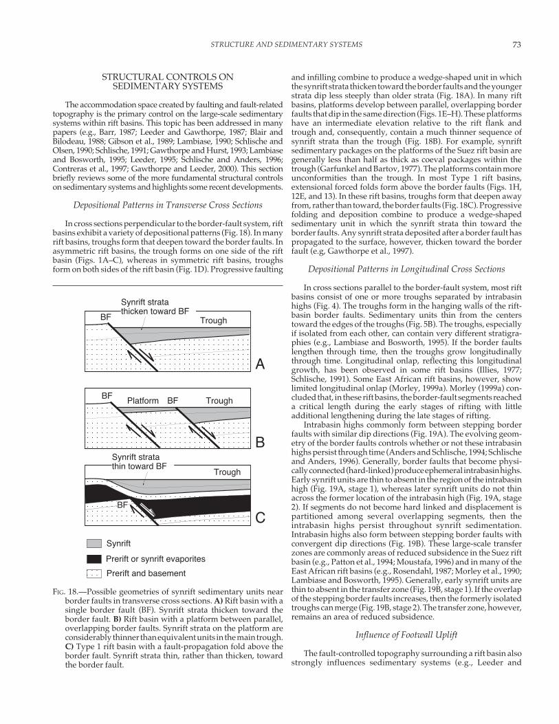
In cross sections perpendicular to the border-fault system, riftbasins exhibit a variety of depositional patterns (Fig. 18). In manyrift basins, troughs form that deepen toward the border faults. Inasymmetric rift basins, the trough forms on one side of the riftbasin (Figs. 1A–C), whereas in symmetric rift basins, troughsform on both sides of the rift basin (Fig. 1D). Progressive faulting
and infilling combine to produce a wedge-shaped unit in whichthe synrift strata thicken toward the border faults and the youngerstrata dip less steeply than older strata (Fig. 18A). In many riftbasins, platforms develop between parallel, overlapping borderfaults that dip in the same direction (Figs. 1E–H). These platformshave an intermediate elevation relative to the rift flank andtrough and, consequently, contain a much thinner sequence ofsynrift strata than the trough (Fig. 18B). For example, synriftsedimentary packages on the platforms of the Suez rift basin aregenerally less than half as thick as coeval packages within thetrough (Garfunkel and Bartov, 1977). The platforms contain moreunconformities than the trough. In most Type 1 rift basins,extensional forced folds form above the border faults (Figs. 1H,12E, and 13). In these rift basins, troughs form that deepen awayfrom, rather than toward, the border faults (Fig. 18C). Progressivefolding and deposition combine to produce a wedge-shapedsedimentary unit in which the synrift strata thin toward theborder faults. Any synrift strata deposited after a border fault haspropagated to the surface, however, thicken toward the borderfault (e.g, Gawthorpe et al., 1997).
Depositional Patterns in Longitudinal Cross Sections
In cross sections parallel to the border-fault system, most riftbasins consist of one or more troughs separated by intrabasinhighs (Fig. 4). The troughs form in the hanging walls of the rift-basin border faults. Sedimentary units thin from the centerstoward the edges of the troughs (Fig. 5B). The troughs, especiallyif isolated from each other, can contain very different stratigra-phies (e.g., Lambiase and Bosworth, 1995). If the border faultslengthen through time, then the troughs grow longitudinallythrough time. Longitudinal onlap, reflecting this longitudinalgrowth, has been observed in some rift basins (Illies, 1977;Schlische, 1991). Some East African rift basins, however, showlimited longitudinal onlap (Morley, 1999a). Morley (1999a) con-cluded that, in these rift basins, the border-fault segments reacheda critical length during the early stages of rifting with littleadditional lengthening during the late stages of rifting.
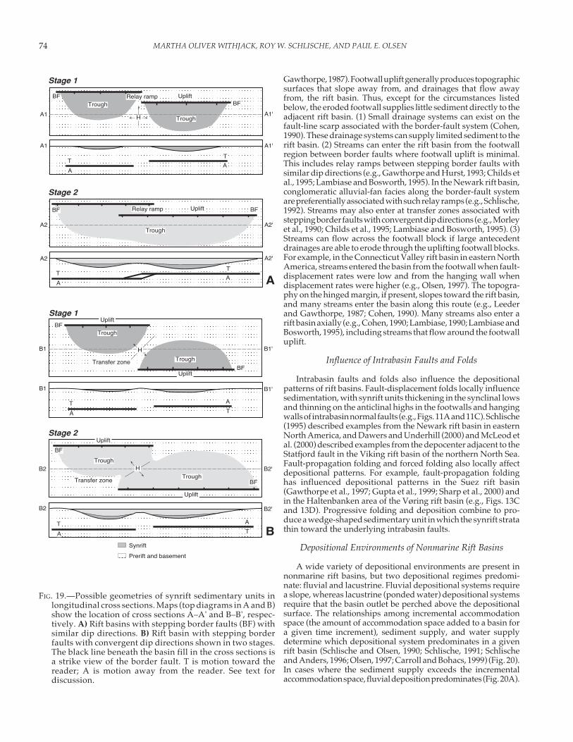
Intrabasin highs commonly form between stepping borderfaults with similar dip directions (Fig. 19A). The evolving geom-etry of the border faults controls whether or not these intrabasinhighs persist through time (Anders and Schlische, 1994; Schlischeand Anders, 1996). Generally, border faults that become physi-cally connected (hard-linked) produce ephemeral intrabasin highs.Early synrift units are thin to absent in the region of the intrabasinhigh (Fig. 19A, stage 1), whereas later synrift units do not thinacross the former location of the intrabasin high (Fig. 19A, stage2). If segments do not become hard linked and displacement ispartitioned among several overlapping segments, then theintrabasin highs persist throughout synrift sedimentation.Intrabasin highs also form between stepping border faults withconvergent dip directions (Fig. 19B). These large-scale transferzones are commonly areas of reduced subsidence in the Suez riftbasin (e.g., Patton et al., 1994; Moustafa, 1996) and in many of theEast African rift basins (e.g., Rosendahl, 1987; Morley et al., 1990;Lambiase and Bosworth, 1995). Generally, early synrift units arethin to absent in the transfer zone (Fig. 19B, stage 1). If the overlapof the stepping border faults increases, then the formerly isolatedtroughs can merge (Fig. 19B, stage 2). The transfer zone, however,remains an area of reduced subsidence.
Influence of Footwall Uplift
The fault-controlled topography surrounding a rift basin alsostrongly influences sedimentary systems (e.g., Leeder and
FIG. 18.—Possible geometries of synrift sedimentary units nearborder faults in transverse cross sections. A) Rift basin with asingle border fault (BF). Synrift strata thicken toward theborder fault. B) Rift basin with a platform between parallel,overlapping border faults. Synrift strata on the platform areconsiderably thinner than equivalent units in the main trough.C) Type 1 rift basin with a fault-propagation fold above theborder fault. Synrift strata thin, rather than thicken, towardthe border fault.
Platform Trough
Trough
Trough
BF
BF BF
A
C
B
Synrift stratathicken toward BF
Prerift and basement
Synrift
Synrift stratathin toward BF
Prerift or synrift evaporites
BF
MARTHA OLIVER WITHJACK, ROY W. SCHLISCHE, AND PAUL E. OLSEN74
Gawthorpe, 1987). Footwall uplift generally produces topographicsurfaces that slope away from, and drainages that flow awayfrom, the rift basin. Thus, except for the circumstances listedbelow, the eroded footwall supplies little sediment directly to theadjacent rift basin. (1) Small drainage systems can exist on thefault-line scarp associated with the border-fault system (Cohen,1990). These drainage systems can supply limited sediment to therift basin. (2) Streams can enter the rift basin from the footwallregion between border faults where footwall uplift is minimal.This includes relay ramps between stepping border faults withsimilar dip directions (e.g., Gawthorpe and Hurst, 1993; Childs etal., 1995; Lambiase and Bosworth, 1995). In the Newark rift basin,conglomeratic alluvial-fan facies along the border-fault systemare preferentially associated with such relay ramps (e.g., Schlische,1992). Streams may also enter at transfer zones associated withstepping border faults with convergent dip directions (e.g., Morleyet al., 1990; Childs et al., 1995; Lambiase and Bosworth, 1995). (3)Streams can flow across the footwall block if large antecedentdrainages are able to erode through the uplifting footwall blocks.For example, in the Connecticut Valley rift basin in eastern NorthAmerica, streams entered the basin from the footwall when fault-displacement rates were low and from the hanging wall whendisplacement rates were higher (e.g., Olsen, 1997). The topogra-phy on the hinged margin, if present, slopes toward the rift basin,and many streams enter the basin along this route (e.g., Leederand Gawthorpe, 1987; Cohen, 1990). Many streams also enter arift basin axially (e.g., Cohen, 1990; Lambiase, 1990; Lambiase andBosworth, 1995), including streams that flow around the footwalluplift.
Influence of Intrabasin Faults and Folds
Intrabasin faults and folds also influence the depositionalpatterns of rift basins. Fault-displacement folds locally influencesedimentation, with synrift units thickening in the synclinal lowsand thinning on the anticlinal highs in the footwalls and hangingwalls of intrabasin normal faults (e.g., Figs. 11A and 11C). Schlische(1995) described examples from the Newark rift basin in easternNorth America, and Dawers and Underhill (2000) and McLeod etal. (2000) described examples from the depocenter adjacent to theStatfjord fault in the Viking rift basin of the northern North Sea.Fault-propagation folding and forced folding also locally affectdepositional patterns. For example, fault-propagation foldinghas influenced depositional patterns in the Suez rift basin(Gawthorpe et al., 1997; Gupta et al., 1999; Sharp et al., 2000) andin the Haltenbanken area of the Vøring rift basin (e.g., Figs. 13Cand 13D). Progressive folding and deposition combine to pro-duce a wedge-shaped sedimentary unit in which the synrift stratathin toward the underlying intrabasin faults.
Depositional Environments of Nonmarine Rift Basins
A wide variety of depositional environments are present innonmarine rift basins, but two depositional regimes predomi-nate: fluvial and lacustrine. Fluvial depositional systems requirea slope, whereas lacustrine (ponded water) depositional systemsrequire that the basin outlet be perched above the depositionalsurface. The relationships among incremental accommodationspace (the amount of accommodation space added to a basin fora given time increment), sediment supply, and water supplydetermine which depositional system predominates in a givenrift basin (Schlische and Olsen, 1990; Schlische, 1991; Schlischeand Anders, 1996; Olsen, 1997; Carroll and Bohacs, 1999) (Fig. 20).In cases where the sediment supply exceeds the incrementalaccommodation space, fluvial deposition predominates (Fig. 20A).
B1'B1
B1 B1'
Trough
Trough
Uplift
Uplift
B2 B2'
B
Trough
Trough
Uplift
Uplift
B2'B2
Stage 1
Stage 2
A2 A2'
A2 A2'
A
A1 A1'
A1 A1'
TroughUplift
Trough
Trough
Uplift
Stage 1
Stage 2
Prerift and basement
Synrift
BFBF
H
Relay ramp
TT
AA
BF BFRelay ramp
TT
AA
TT
A
A
BF
BFTransfer zone
H
TT
A
A
H
Transfer zone
BF
BF
FIG. 19.—Possible geometries of synrift sedimentary units inlongitudinal cross sections. Maps (top diagrams in A and B)show the location of cross sections A–A' and B–B', respec-tively. A) Rift basins with stepping border faults (BF) withsimilar dip directions. B) Rift basin with stepping borderfaults with convergent dip directions shown in two stages.The black line beneath the basin fill in the cross sections isa strike view of the border fault. T is motion toward thereader; A is motion away from the reader. See text fordiscussion.

75STRUCTURE AND SEDIMENTARY SYSTEMS
In cases where the incremental accommodation space exceeds thesediment supply, lacustrine deposition predominates (althoughdeltaic and fluvial deposition occurs around the margins of thelake). The relationship between the available supply of water andthe excess capacity (the difference between the incremental ac-commodation space and the sediment supply) of the basin deter-mines the hydrological conditions in the lake. If the water supplyexceeds the excess capacity, the lake is hydrologically open (Fig.20B). If the excess capacity exceeds the water supply, the lake ishydrologically closed (Fig. 20C). Given these relationships, thedepth of the lake is an unreliable recorder of climate. For example,if the excess capacity of the basin is very small, the lake depth iscontrolled by the distance between the depositional surface andthe lowest outlet. Thus, even if the climate is very wet, the lakewill still be shallow.
Many nonmarine rift basins from a wide variety of climaticregimes and tectonic settings share a similar synrift stratigraphicarchitecture (e.g., Lambiase, 1990; Schlische and Olsen, 1990). Thesuccession generally begins with a fluvial unit. This is overlain bya lacustrine unit that demonstrates a rapid deepening-upwardinterval to a lake-highstand interval. The deep-water lacustrineinterval is succeeded by a gradually upward-shoaling lacustrineunit that is commonly capped by a fluvial unit. This succession isknown as a tripartite stratigraphy. Lambiase (1990) observed thatsome continental rift basins contain multiple stratigraphic suc-cessions, consisting of all or part of the tripartite stratigraphy. Forthe Mesozoic rift basins of eastern North America, the individual
stratigraphic successions are bounded by unconformities, par-ticularly along the margins of the basins, separating the synriftdeposits into tectonostratigraphic packages (Olsen, 1997; Olsenet al., 2000). Some dominantly marine rift basins (e.g., in Crete;Postma and Drinia, 1993) display similar stratigraphic succes-sions. In these cases, marine deposits take the place of lacustrinedeposits, but the water depth varies in a manner similar to that ofcontinental rift basins.
Given the relationships among incremental accommodationspace, sediment supply, and water supply, several mechanismscan produce the major stratigraphic transitions within the tripar-tite succession. The fluvial–lacustrine transition may result froman increase in incremental accommodation space and/or a de-crease in sediment supply. The shallow-water to deep-waterlacustrine transition may result from an increase in incrementalaccommodation space, a decrease in the sediment supply, or anincrease in the water supply. The deep-water to shallow-waterlacustrine transition may result from a decrease or increase inincremental accommodation space (depending on the geometryof the excess accommodation space in the basin), an increase inthe sediment supply, and/or a decrease in the water supply. Thelacustrine–fluvial transition may result from a decrease in incre-mental accommodation space or an increase in sediment supply.Because three of four of the stratigraphic transitions may resultfrom an increase in incremental accommodation space and be-cause accommodation space is structurally controlled (e.g., Leederand Gawthorpe, 1987; Gibson et al., 1989), the structural evolu-
FIG. 20.—Relationships among basin capacity (incremental accommodation space), sediment supply, and water supply in nonmarinerift basins. A) Sediment supply exceeds basin capacity. B) Basin capacity exceeds sediment supply and water supply exceedsexcess basin capacity. C) Basin capacity greatly exceeds sediment supply and water supply is less than excess basin capacity. Seetext for discussion.
B
Capacity Sediment Water
SedimentCapacity
Excess water
Water
Excess sedimentand all water
SedimentCapacity Water
C
A • Predominantly fluvial sedimentation• No large-scale lakes
• Predominantly shallow-waterlacustrine sedimentation
• Predominantly deep-waterlacustrine sedimentation

MARTHA OLIVER WITHJACK, ROY W. SCHLISCHE, AND PAUL E. OLSEN76
tion of rift basins most strongly influences the stratigraphicarchitecture (Lambiase, 1990; Schlische and Olsen, 1990; Schlische,1991; Contreras et al., 1997).
Basin-Filling Models for Rift Basins
The basin-filling model of Schlische (1991) emphasized therole of fault growth in an asymmetric rift basin with a singleborder fault (Fig. 21). As discussed previously, faults generallyincrease in length as fault displacement increases. Thus, as dis-placement on the border fault accrues, the rift basin generallyincreases in depth, length, and width. Thus, incremental accom-modation space within the basin increases through time. If sedi-mentation keeps pace with incremental accommodation space,then the basin is always filled to its lowest outlet with sediment.Strata progressively onlap the hanging-wall hinged margin as thebasin widens and lengthens through time. It is unlikely, however,that sedimentation always keeps pace with incremental accom-modation space. If the sediment-supply rate and the water-supply rate are constant and if the incremental accommodationspace progressively increases, then the rift basin undergoes threeof the four major stratigraphic transitions contained within thetripartite stratigraphy. The fourth major stratigraphic transition,the lacustrine–fluvial transition, cannot be reproduced in a basin-filling model that requires a progressive increase in incrementalaccommodation space. Accommodation space, however, cannotincrease indefinitely. Once extension slows considerably or ceases,the basin gradually infills with sediment, with fluvial conditionsreturning when sediment supply exceeds incremental accommo-dation space. Multiple extensional pulses may produce multiplesynrift tectonostratigraphic packages separated by unconformi-ties if the time between pulses is large (Olsen, 1997).
The quantitative basin-filling models of Contreras et al. (1997)predicted how accumulation rates vary with location and throughtime. These predictions are in broad agreement with actualaccumulation rates from the Newark rift basin (Olsen, 1997). Thequalitative basin-filling models of Lambiase (1990) and Lambiaseand Bosworth (1995) emphasized the role of footwall uplift andtransfer zones. They argued that deep lakes form only when highrelief is produced by significant footwall uplift and the formationof transfer zones between stepping borders faults with conver-gent dip directions. They also pointed out that depocentersbounded by transfer zones exhibit different stratigraphies, par-ticularly if a large axial supply of sediment exists. In this case, thedepocenter located nearest the axial supply is the first to becomecompletely infilled, with succeeding depocenters in the sedi-ment-transport direction being progressively infilled. Smoot (1991)presented a qualitative basin-filling model that is most appropri-ate for the initial fluvial deposits and immediately succeedinglacustrine deposits. He hypothesized that reductions in fluvialgradients and clogging of the basin’s outlets contribute to thefluvial–lacustrine transition. This model accounts for a changefrom initial braided-stream deposits to meandering-stream de-posits observed in the basal fluvial sequences of many Mesozoicrift basins in eastern North America.
Gupta et al. (1998) and Cowie et al. (2000) presented asemiquantitative model to explain the large-scale structural andstratigraphic evolution of rift basins. They noted that manymarine rift basins appear to undergo a period of acceleratedsubsidence (associated with deeper-water marine sedimenta-tion) several million years after the initiation of rifting. Theirbasin-evolution model, based on the results of numerical modelsof fault-population evolution, showed that certain normal faultsundergo periods of accelerated displacement, even though theregional extensional strain rate is constant (Cowie et al., 1995;
Cowie, 1998; Cowie et al., 2000). They proposed that the period ofincreased subsidence and deeper-water marine sedimentationobserved in many marine rift basins correlates with the period ofstrain localization on faults within the border-fault system. Ap-plying their model to nonmarine rift basins, the period of widelydistributed faulting would correspond to fluvial sedimentation,whereas deep-water lacustrine sedimentation would correspondto the phase of strain localization.
Influence of Plate-Tectonic Movementson Sedimentary Systems
The forgoing discussion has highlighted how the structurewithin rift basins and rift systems influences sedimentary sys-tems. Tectonics at the plate-tectonic scale also influences sedi-mentary systems. Plate movement can cause a rift basin to driftfrom one climatic zone to another. For example, the Mesozoic riftbasins of eastern North America gradually drifted northwardduring Late Triassic and Early Jurassic time (e.g., Olsen et al.,2000; Olsen, 1997; Olsen and Kent, 2000). Relatively humid facieswere deposited when a basin was located near the paleoequator,whereas relatively arid facies were deposited when a basin waslocated at more northern latitudes. Given the structural controlon the tripartite stratigraphic architecture of synrift strata dis-cussed above, it is important to draw a distinction betweenhumid and arid facies deposited under different climatic regimesversus fluvial and lacustrine strata deposited under differenthydrologic conditions (Olsen et al., 2000). The combinations ofvarious facies (e.g., arid fluvial, humid fluvial, arid lacustrine,humid lacustrine) are produced by the creation of accommoda-tion space by border faults, the balance between accommodationspace and sediment infilling, and changes in climatic regimecontrolled by the drift of tectonic plates.
SUMMARY
1. Rift basins are complex features defined by several large-scalestructural components including faulted margins, the borderfaults of the faulted margins, the uplifted flanks of the faultedmargins, hinged margins, deep troughs, large-scale intrabasinfault blocks, and large-scale transfer zones. A variety of mod-erate- to small-scale structures also develop within rift basins.These structures include normal faults (basement-involvedand detached), strike-slip and reverse faults, and extensionalfolds (fault-displacement, fault-propagation, forced, and fault-bend). All of these structures, regardless of their size, affectthe depositional patterns of rift basins by creating sites ofuplift and erosion, by influencing pathways of sedimenttransport, and by defining the accommodation space forsediment deposition and preservation.
2. To provide a framework for understanding the variety ofstructural styles in rift basins, we have defined a standardrift basin and four end-member variations. Most rift basinshave attributes of the standard rift basin and one or more ofthe end-member variations. The standard rift basin has littlesalt or shale in the prerift or synrift packages. Few preexist-ing zones of weakness in the prerift strata or crystallinebasement were reactivated during rifting, and little tectonicactivity followed rifting. The standard rift basin is character-ized by moderately to steeply dipping basement-involvednormal faults that strike roughly perpendicular to the direc-tion of maximum extension. Type 1 rift basins have salt orthick shale in the prerift or synrift packages. They are char-acterized by extensional forced folds above basement-in-
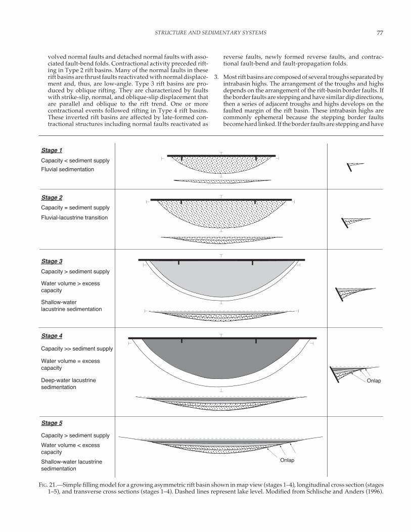
77STRUCTURE AND SEDIMENTARY SYSTEMS
FIG. 21.—Simple filling model for a growing asymmetric rift basin shown in map view (stages 1–4), longitudinal cross section (stages1–5), and transverse cross sections (stages 1–4). Dashed lines represent lake level. Modified from Schlische and Anders (1996).
Fluvial sedimentation
Fluvial-lacustrine transition
Shallow-waterlacustrine sedimentation
Deep-water lacustrinesedimentation
Stage 1
Stage 2
Stage 3
Stage 4
Onlap
Stage 5
Shallow-water lacustrinesedimentation
Onlap
Capacity < sediment supply
Capacity = sediment supply
Capacity > sediment supply
Capacity >> sediment supply
Capacity > sediment supply
Water volume > excesscapacity
Water volume = excesscapacity
Water volume < excesscapacity
volved normal faults and detached normal faults with asso-ciated fault-bend folds. Contractional activity preceded rift-ing in Type 2 rift basins. Many of the normal faults in theserift basins are thrust faults reactivated with normal displace-ment and, thus, are low-angle. Type 3 rift basins are pro-duced by oblique rifting. They are characterized by faultswith strike-slip, normal, and oblique-slip displacement thatare parallel and oblique to the rift trend. One or morecontractional events followed rifting in Type 4 rift basins.These inverted rift basins are affected by late-formed con-tractional structures including normal faults reactivated as
reverse faults, newly formed reverse faults, and contrac-tional fault-bend and fault-propagation folds.
3. Most rift basins are composed of several troughs separated byintrabasin highs. The arrangement of the troughs and highsdepends on the arrangement of the rift-basin border faults. Ifthe border faults are stepping and have similar dip directions,then a series of adjacent troughs and highs develops on thefaulted margin of the rift basin. These intrabasin highs arecommonly ephemeral because the stepping border faultsbecome hard linked. If the border faults are stepping and have
MARTHA OLIVER WITHJACK, ROY W. SCHLISCHE, AND PAUL E. OLSEN78
convergent dip directions, then a series of offset troughsseparated by highs develops on opposing sides of the riftbasin. Generally, synrift units are thin to absent on theseintrabasin highs throughout synrift sedimentation.
4. In cross sections perpendicular to the border-fault system,rift basins exhibit a variety of structural and depositionalpatterns. In many rift basins, troughs form that deepentoward the border faults. Progressive faulting and infillingcombine to produce a wedge-shaped unit in which thesynrift strata thicken toward the border faults. In other riftbasins, platforms develop between parallel, overlappingborder faults that dip in the same direction. These platformshave an intermediate elevation relative to the rift flank andtrough and, consequently, contain a much thinner sequenceof synrift strata than the trough. In most Type 1 rift basins, anextensional forced fold forms above the border faults. Inthese rift basins, troughs form that deepen away from, ratherthan toward, the border faults. Progressive folding anddeposition combine to produce a wedge-shaped sedimen-tary unit in which the synrift strata thin toward the borderfaults.
5. Many nonmarine rift basins share a similar synrift strati-graphic architecture known as a tripartite stratigraphy. Thesuccession begins with a fluvial unit. This is overlain by alacustrine unit that demonstrates a rapid deepening-upwardinterval to a lake-highstand interval. This is succeeded by agradually upward-shoaling lacustrine unit that is commonlycapped by a fluvial unit. These stratigraphic transitions resultfrom changes in the relative balance between sediment sup-ply, water supply, and accommodation space, the last ofwhich is structurally controlled. Fluvial sedimentation occurswhen sediment supply exceeds accommodation space. Lacus-trine sedimentation results when accommodation space ex-ceeds sediment supply. Hydrologically open lakes resultwhen the supply of water exceeds the basin’s excess capacity(accommodation space minus sediment supply). Hydrologi-cally closed lakes result when the supply of water is less thanthe excess capacity.
6. A simple rift basin increases in depth, length, and width asdisplacement on its border-fault system accrues. Thus, incre-mental accommodation space increases through time. If sedi-mentation keeps pace with incremental accommodation space,then the basin is always filled to its lowest outlet with sedi-ment. If the sediment-supply rate and the water-supply rateare constant and if the incremental accommodation spaceprogressively increases, then the rift basin may undergo threeof the four major stratigraphic transitions contained withinthe tripartite stratigraphy. The final lacustrine-fluvial transi-tion requires that faulting slow considerably or cease. As aresult, the basin gradually infills with sediment, with fluvialconditions returning when sediment supply exceeds incre-mental accommodation space.
ACKNOWLEDGMENTS
We thank Gail Ashley for her encouragement to write thispaper and our colleagues, Rolf Ackermann and Amy Clifton, forproviding their experimental insights about normal-fault devel-opment. We also thank Nancye Dawers and David Peacock fortheir careful and thoughtful reviews of the manuscript. Some ofthe research presented here was supported by Mobil TechnologyCompany and National Science Foundation grants EAR-9017785and EAR-9706199 to Schlische.
REFERENCES
ACKERMANN, R.V., SCHLISCHE, R.W., AND WITHJACK, M.O., 2001, The geomet-ric and statistical evolution of normal fault systems: an experimentalstudy of the effects of mechanical layer thickness on scaling laws:Journal of Structural Geology, v. 23, p. 1803–1819.
ANDERS, M.H., AND SCHLISCHE, R.W., 1994, Overlapping faults, intrabasinhighs, and the growth of normal faults: Journal of Geology, v. 102, p.165–179.
ANGELIER, J., AND BERGERAT, F., 1983, Systemés de contrainte et extensionintracontinentale: Bull. Centres Recherches Exploration–ProductionElf-Aquitaine, v. 7, p. 137–147.
BAKER, B.H., AND WOHLENBERG, J., 1971, Structure and evolution of theKenya rift valley: Nature, v. 229, p. 538–542.
BARNETT, J.A.M., MORTIMER, J., RIPPON, J.H., WALSH, J.J., AND WATTERSON, J.,1987, Displacement geometry in the volume containing a singlenormal fault: American Association of Petroleum Geologists, Bulle-tin, v. 71, p. 925–937.
BARR, D., 1987, Structural/stratigraphic models for extensional basins ofhalf-graben type: Journal of Structural Geology, v. 9, p. 491–500.
BLAIR, T.C., AND BILODEAU, W.L., 1988, Development of tectonic cyclothemsin rift, pull-apart, and foreland basins—sedimentary response toepisodic tectonism: Geology, v. 16, p. 517–520.
BLYSTAD, P., BREKKE, H., FAERSETH, R.B., LARSEN, B.T., SKOGSEID, J., AND
TØRUDBAKKEN, B., 1995, Structural Elements of the Norwegian Conti-nental Shelf, Part II—The Norwegian Sea Region: Norwegian Petro-leum Directorate, Bulletin 8, 45 p.
BRAUN, J., AND BEAUMONT, C., 1989, A physical explanation of the relationbetween flank uplifts and the breakup unconformity at rifted conti-nental margins: Geology, v. 17, p. 760–764.
BREYER, F., 1974, Structure and development of the southern part of theRhine graben according to geological and geophysical observations,in Illies, J.H., and Fuchs, K., eds., Approaches to Taphrogenesis:Inter-Union Commission on Geodynamics, Scientific Report 8, p.145–155.
BRODIE, J., AND WHITE, N.J., 1994, Sedimentary basin inversion caused byigneous underplating: Northwest European continental shelf: Geol-ogy, v. 22, p. 147–150.
BROWN, R.N., 1980, History of exploration and discovery of Morgan,Ramadan, and July oilfields, Gulf of Suez, Egypt, in Maill, A.D., ed.,Facts and Principles of World Petroleum Occurrence: Canadian Soci-ety of Petroleum Geologists, Memoir 6, p. 733–764.
BUCK, W.R., 1986, Small-scale convection induced by passive rifting—thecause for uplift of rift shoulders: Earth and Planetary Science Letters,v. 77, p. 362–372.
CARROLL, A.R., AND BOHACS, K.M., 1999, Stratigraphic classification ofancient lakes—balancing tectonic and climatic controls: Geology, v.27, p. 99–102.
CHAMBERLIN, R.N., 1983, Cenozoic domino-style crustal extension in theLemitar Mountains, New Mexico: a summary: New Mexico Geologi-cal Society 34th Field Conference, Guidebook, Socorro Region II, p.111–118.
CHAPMAN, G.R., LIPPARD, S.J., AND MARTYN, J.E., 1978, The stratigraphy andstructure of the Kamasia Range, Kenya Rift Valley: Geological Societyof London, Journal, v. 135, p. 265–281.
CHILDS, C., WATTERSON, J., AND WALSH, J.J., 1995, Fault overlap zones withindeveloping normal fault systems: Geological Society of London,Journal, v. 152, p. 535–549.
CLIFTON, A.E., SCHLISCHE, R.W., WITHJACK, M.O., AND ACKERMANN, R.V.,2000, Influence of rift obliquity on fault-population systematics:results of clay modeling experiments: Journal of Structural Geology,v. 22, p. 1491–1509.
COFFIELD, D.Q., AND SCHAMEL, S., 1989, Surface expression of an accommoda-tion zone within the Gulf of Suez rift, Egypt: Geology, v. 17, p. 76–79.
COHEN, A.S., 1990, Tectono-stratigraphic model for sedimentation in LakeTanganyika, Africa, in Katz, B.J., ed., Lacustrine Basin Exploration—
79STRUCTURE AND SEDIMENTARY SYSTEMS
Case Studies and Modern Analogs: American Association of Petro-leum Geologists, Memoir 50, p. 137–150.
COLLETTA, B., LE QUELLEC, P., LETOUZEY, J., AND MORETTI, I., 1988, Longitudi-nal evolution of the Suez structure (Egypt): Tectonophysics, v. 153, p.221–233.
CONTINI, D., AND THEOBALD, N., 1974, Relations entre le Fosse Rhenan et leFosse de la Soane, tectonique des régions sous-vosgiennes etpréjurassiennes, in Illies, J.H. and Fuchs, K., eds., Approaches toTaphrogenesis: Inter-Union Commission on Geodynamics, ScientificReport 8, p. 310–321.
CONTRERAS, J., SCHOLZ, C.H., AND KING, G.C.P., 1997, A general model of riftbasin evolution: constraints of first order stratigraphic observations:Journal of Geophysical Research, v. 102, p. 7673–7690.
COOPER, M.A., AND WILLIAMS, G.D., eds., 1989, Inversion Tectonics: Geo-logical Society of London, Special Publication 44, 375 p.
COWIE, P.A., 1998, A healing–reloading feedback control on the growthrate of seismogenic faults: Journal of Structural Geology, v. 20, p.1075–1088.
COWIE, P.A., GUPTA, S., AND DAWERS, N.H., 2000, Implications of fault arrayevolution for synrift depocentre development: insights from a nu-merical fault growth model: Basin Research, v. 12, p. 241–261.
COWIE, P.A., SORNETTE, D., AND VANNESTE, C., 1995, Multifractal scalingproperties of a growing fault population: Geophysical Journal Inter-national, v. 122, p. 457–469.
DAVISON, I., 1987, Normal fault geometry related to sediment compactionand burial: Journal of Structural Geology, v. 9, p. 393–401.
DAWERS, N.H., ANDERS, M.H., AND SCHOLZ, C.H., 1993, Growth of normalfaults—displacement-length scaling: Geology, v. 21, p. 1107–1110.
DAWERS, N.H., AND UNDERHILL, J.R., 2000, The role of fault interaction andlinkage in controlling synrift stratigraphic sequences—Late Jurassic,Statfjord East area, northern North Sea: American Association ofPetroleum Geologists, Bulletin, v. 84, p. 45–64.
DE VOOGD, B., KEEN, C.E., AND KAY, W.A., 1990, Fault reactivation duringMesozoic extension in eastern offshore Canada: Tectonophysics, v.173, p. 567–580.
EBINGER, C.J., ROSENDAHL, B.R., AND REYNOLDS, D.J., 1987, Tectonic model ofthe Malawi rift, Africa: Tectonophysics, v. 141, p. 215–235.
FALVEY, D.A., 1974, The development of continental margins in platetectonic theory: APEA Journal, v. 14, p. 95–106.
FAULDS, J.E., AND VARGA, R.J., 1998, The role of accommodation zones andtransfer zones in the regional segmentation of extended terranes, inFaulds, J.E., and Stewart, J.H., eds., Accommodation Zones andTransfer Zones: The Regional Segmentation of the Basin and RangeProvince: Geological Society of America, Special Paper 323, p. 1–45.
GARFUNKEL, Z., AND BARTOV, Y., 1977, The tectonics of the Suez rift:Geological Survey of Israel, Bulletin 71, 44 p.
GAWARECKI, S.L., AND COFFIELD, D.Q., 1990, Mechanical response to strati-graphic inhomogeneity during extension, and surface expression ofburied structures, Gulf of Suez, Egypt: Tectonophysics, v. 174, p.7–20.
GAWTHORPE, R.L., AND HURST, J.M., 1993, Transfer zones in extensionalbasins—their structural style and influence on drainage developmentand stratigraphy: Geological Society of London, Journal, v. 150, p.1137–1152.
GAWTHORPE, R.L., AND LEEDER, M.R., 2000, Tectono-sedimentary evolutionof active extensional basins: Basin Research, v. 12, p. 195–218.
GAWTHORPE, R.L., SHARP, I., UNDERHILL, J.R., AND GUPTA, S., 1997, Linkedsequence stratigraphic and structural evolution of propagating nor-mal faults: Geology, v. 25, p. 795–798.
GIBSON, J.R., WALSH, J.J., AND WATTERSON, J., 1989, Modelling of bed con-tours and cross-sections adjacent to planar normal faults: Journal ofStructural Geology, v. 11, p. 317–328.
GOGUEL, J., 1962, Tectonics (translated from French edition, 1952, byThalman, H.E.): San Francisco, Freeman, 384 p.
GUPTA, S., COWIE, P.A., DAWERS, N.H., AND UNDERHILL, J.R., 1998, A mecha-nism to explain rift-basin subsidence and stratigraphic patternsthrough fault-array evolution: Geology, v. 26, p. 595–598.
GUPTA, S., UNDERHILL, J.R., SHARP, I.R., AND GAWTHORPE, R.L., 1999, Role offault interactions in controlling synrift sediment dispersal patterns—Miocene, Abu Alaqa Group, Suez rift, Sinai, Egypt: Basin Research, v.11, p. 167–189.
HAMBLIN, W.K., 1965, Origin of “reverse drag” on the downthrown sidesof normal faults: Geological Society of America, Bulletin, v. 76, p.1145–1164.
HORSFIELD, W.T., 1977, An experimental approach to basement-controlledfaulting: Geologie en Mijnbouw, v. 56, p. 363–370.
HUTCHINSON, D.R., KLITGORD, K.D., AND DETRICK, R.S., 1986, Rift basins ofthe Long Island Platform: Geological Society of America, Bulletin, v.97, p. 688–702.
ILLIES, J.H., 1977, Ancient and recent rifting in the Rhinegraben: Geologieen Mijnbouw, v. 56, p. 329–350.
ILLIES, J.H., AND GREINER, G., 1978, Rhinegraben and Alpine system: Geo-logical Society of America, Bulletin, v. 89, p. 770–782.
JACKSON, J., AND LEEDER, M., 1994, Drainage systems and the developmentof normal faults—an example from Pleasant Valley, Nevada: Journalof Structural Geology, v. 16, p. 1041–1059.
JACKSON, J., AND MCKENZIE, D., 1983, The geometrical evolution of normalfault systems: Journal of Structural Geology, v. 5, p. 471–482.
JANECKE, S.U., VANDERBURG, C.J., AND BLANKENAU, J.J., 1998, Geometry,mechanisms and significance of extensional folds from examples inthe Rocky Mountain Basin and Range province, U.S.A.: Journal ofStructural Geology, v. 20, p. 841–856.
KEEN, C.E., l985, The dynamics of rifting: deformation of the lithosphereby active and passive driving mechanisms: Geophysical Journal ofthe Royal Astronomical Society, v. 80, p. 95–120.
KEEN, C.E., BOUTILIER, R., DEVOOGD, B., MUDFORD, B., AND ENACHESCU, M.E.,1987, Crustal geometry and extensional models for the Grand Banks,eastern Canada: constraints from deep seismic reflection data, inBeaumont, C., and Tankard, A., eds., Sedimentary Basins and Basin-Forming Mechanisms: Canadian Society of Petroleum Geologists,Memoir 12, p. 101–115.
KELLEY, V., 1979, Tectonics, middle Rio Grande rift, New Mexico, inRiecker, R.E., ed., Rio Grande Rift: Tectonics and Magmatism: Wash-ington, D.C., American Geophysical Union, p. 57–70.
KING, G., AND ELLIS, M., 1990, The origin of large local uplift in extensionalregions: Nature, v. 348, p. 689–693.
LAMBIASE, J.J., 1990, A model for tectonic control of lacustrine stratigraphicsequences in continental rift basins, in Katz, B.J., ed., Lacustrine BasinExploration—Case Studies and Modern Analogs: American Associa-tion of Petroleum Geologists, Memoir 50, p. 265–276.
LAMBIASE, J.J., AND BOSWORTH, W., 1995, Structural controls on sedimenta-tion in continental rifts, in Lambiase, J.J., ed., Hydrocarbon Habitat inRift Basins: Geological Society of London, Special Publication 80, p.117–144.
LARSEN, P.-H., 1988, Relay structures in a Lower Permian basement-involved extension system, East Greenland: Journal of StructuralGeology, v. 10, p. 3–8.
LAUBSCHER, H.P., 1982, Die Südostecke des Rheingrabens—einkinematisches und dynamisches Problem: Eclogae GeologicaeHelvetiae, v. 75, p. 101–116.
LEEDER, M.R., 1995, Continental rifts and proto-oceanic rift troughs, inBusby, C.J. and Ingersoll, R.V., eds., Tectonics of Sedimentary Basins:Cambridge, Massachusetts, Blackwell, p. 119–148.
LEEDER, M.R., AND GAWTHORPE, R.L., 1987, Sedimentary models for exten-sional tilt-block/half-graben basins, in Coward, M.P., Dewey, J.F.,and Hancock, P.L., eds., Continental Extensional Tectonics: Geologi-cal Society of London, Special Publication 28, p. 139–152.
LETOUZEY, J., 1990, Fault reactivation, inversion, and fold-thrust belt, inLetouzey, J., ed., Petroleum and Tectonics in Mobile Belts: Paris, IFPEditions Technip, p. 101–128
MARCHAL, D., GUIRAUD, M., RIVES, T., AND VAN DEN DRIESSCHE, J., 1998, Spaceand time propagation processes of normal faults, in Jones, G., Fisher,Q.J., and Knipe, R.J., eds., Faulting, Fault Sealing, and Fluid Flow in
MARTHA OLIVER WITHJACK, ROY W. SCHLISCHE, AND PAUL E. OLSEN80
Hydrocarbon Reservoirs: Geological Society of London, Special Pub-lication 147, p. 51–70.
MAURIN, J.-C., 1995, Drapage et décollement des séries jurassiques sur lafaille de détachement majeure du rift rhénan sud: implications sur lagéométrie des dépôts syn-rifts oligocenes: Académie des Sciences[Paris], Comptes Rendus, v. 321, p. 1025–1032.
MCLEOD, A.E., DAWERS, N.H., AND UNDERHILL, J.R., 2000, The propagationand linkage of normal faults—Insights from the Strathsey–Brent–Statfjord fault array, northern North Sea: Basin Research, v. 12, p.263–284.
MORLEY, C.K., 1995, Developments in the structural geology of rifts overthe last decade and their impact on hydrocarbon exploration, inLambiase, J.J., ed., Hydrocarbon Habitat in Rift Basins: GeologicalSociety of London, Special Publication 80, p. 1–32.
MORLEY, C.K., 1999a, Patterns of displacement along large normal faults—implications for basin evolution and fault propagation, based onexamples from East Africa: American Association of Petroleum Ge-ologists, Bulletin, v. 83, p. 613–634.
MORLEY, C.K., ED. 1999b, Geoscience of Rift Systems—Evolution of EastAfrica: American Association of Petroleum Geologists, Studies inGeology 44, 250 p.
MORLEY, C.K., NELSON, R.A., PATTON, T.L., AND MUNN, S.G., 1990, Transferzones in the East African rift system and their relevance to hydrocar-bon exploration in rifts: American Association of Petroleum Geolo-gists, Bulletin, v. 74, p. 1234–1253.
MOUSTAFA, A.M., 1976, Block faulting in the Gulf of Suez: Proceedings ofthe 5th Exploration Seminar, Egyptian General Petroleum Organiza-tion, Cairo.
MOUSTAFA, A.R., 1996, Internal structure and deformation of an accommo-dation zone in the northern part of the Suez rift: Journal of StructuralGeology, v. 18, p. 93–108.
MOUSTAFA, A.R., 1997, Controls on the development and evolution oftransfer zones—the influence of basement structure and sedimentarythickness in the Suez rift and Red Sea: Journal of Structural Geology,v. 19, p. 755–768.
NELSON, R.A., PATTON, T.L., AND MORLEY, C.K., 1992, Rift-segment interac-tion and its relation to hydrocarbon exploration in continental riftsystems: American Association of Petroleum Geologists, Bulletin, v.76, p. 1153–1169.
OLSEN, P.E., 1997, Stratigraphic record of the early Mesozoic breakup ofPangea in the Laurasia–Gondwana rift system: Annual Review ofEarth and Planetary Sciences, v. 25, p. 337–401.
OLSEN, P.E. AND KENT, D.V., 2000, High resolution early Mesozoic Pangeanclimatic transect in lacustrine environments, in Bachmann, G., andLerche, I., eds., Epicontinental Triassic, Volume 3, Zentralblatt fürGeologie und Paläontologie, VIII, p. 1475–1496.
OLSEN, P.E., KENT, D.V., FOWELL, S.J., SCHLISCHE, R.W., WITHJACK, M.O., AND
LETOURNEAU, P.M., 2000, Implications of a comparison of the stratig-raphy and depositional environments of the Argana (Morocco) andFundy (Nova Scotia, Canada) Permian–Jurassic basins, in Oujidi, M.and Et-Touhami, M., eds., Le Permien et le Trias du Maroc, Actes dela Premièr Réunion su Groupe Marocain du Permien et du Trias:Oujda, Hilal Impression, p. 165–183.
PATTON, T., 1984, Normal fault and fold development in sedimentaryrocks above a pre-existing basement normal fault [unpublished Ph.D.thesis]: Texas A&M University, College Station, 164 p.
PATTON, T.L., MOUSTAFA, A.R., NELSON, R.A., AND ABDINE, S.A., 1994, Tec-tonic evolution and structural setting of the Suez rift, in Landon, S.M.,ed., Interior Rift Basins: American Association of Petroleum Geolo-gists, Memoir 59, p. 9–55.
PEACOCK, D.C.P., AND SANDERSON, D.J., 1991, Displacements, segmentlinkage and relay ramps in normal fault zones: Journal of StructuralGeology, v. 13, p. 721–733.
PEACOCK, D.C.P., AND SANDERSON, D.J., 1994, Geometry and developmentof relay ramps in normal fault systems: American Association ofPetroleum Geologists, Bulletin, v. 78, p. 147–165.
PEACOCK, D.C.P., KNIPE, R.J., AND SANDERSON, D.J., 2000, Glossary of normalfaults: Journal of Structural Geology, v. 22, p. 291–306.
PLINT, A.G., AND VAN DE POLL, H.W., 1984, Structural and sedimentaryhistory of the Quaco Head area, southern New Brunswick: CanadianJournal of Earth Sciences, v. 21, p. 753–761.
POSTMA, G., AND DRINIA, H., 1993, Architecture and sedimentary faciesevolution of a marine, expanding half-graben (Crete, Late Miocene):Basin Research, v. 5, p. 103–124.
PROFFETT, J.M., JR., 1977, Cenozoic geology of the Yerington district, Nevada,and implications for the nature and origin of Basin and Range faulting:Geological Society of America, Bulletin, v. 88, p. 247–266.
RATCLIFFE, N.M., BURTON, W.C., D’ANGELO, R.M., AND COSTAIN, J.K., 1986,Low-angle extensional faulting, reactivated mylonites, and seismicreflection geometry of the Newark Basin margin in eastern Pennsyl-vania: Geology, v. 14, p. 766–770.
ROBERTS, A., AND YIELDING, G., 1994, Continental extensional tectonics, inHancock, P.L., ed., Continental Deformation: New York, Pergamon,p. 223–250.
ROBSON, D.A., 1971, The structure of the Gulf of Suez (Clysmic) rift, withspecial reference to the eastern side: Geological Society of London,Journal, v. 127, p. 247–276.
ROSENDAHL, B.R., 1987, Architecture of continental rifts with special refer-ence to East Africa: Annual Review of Earth and Planetary Sciences,v. 15, p. 445–503.
ROSENDAHL, B.R., REYNOLDS, D.J., LORBER, P.M., BURGESS, C.F., MCGILL, J.,SCOTT, D., LAMBIASE, J.J., AND DERSKEN, S.J., 1986, Structural expressionsof rifting: lessons from Lake Tanganyika, Africa, in Frostick, L.E.,Renault R.W., Reid, I., and Tiercelin, J.–J., eds., Sedimentation in theAfrican Rifts: Geological Society of London, Special Publication 25, p.29–43.
ROUX, W.F., 1979, The development of growth fault structures: AmericanAssociation of Petroleum Geologists, Structural Geology CourseNotes, 33 p.
RUPPEL, C., 1995, Extensional processes in continental lithosphere: Journalof Geophysical Research, v. 100, p. 24,187–24,215.
SCHLISCHE, R.W., 1990, Aspects of the structural and stratigraphic evolu-tion of early Mesozoic rift basins of eastern North America [unpub-lished Ph.D. thesis]: Columbia University, New York, 479 p.
SCHLISCHE, R.W., 1991, Half-graben basin filling models: New constraintson continental extensional basin evolution: Basin Research, v. 3, p.123–141.
SCHLISCHE, R.W., 1992, Structural and stratigraphic development of theNewark extensional basin, eastern North America—implications forthe growth of the basin and its bounding structures: GeologicalSociety of America, Bulletin, v. 104, p. 1246–1263.
SCHLISCHE, R.W., 1993, Anatomy and evolution of the Triassic–Jurassiccontinental rift system, eastern North America: Tectonics, v. 12, p.1026–1042.
SCHLISCHE, R.W., 1995, Geometry and origin of fault-related folds inextensional settings: American Association of Petroleum Geologists,Bulletin, v. 79, p. 1661–1678.
SCHLISCHE, R.W., AND ANDERS, M.H., 1996, Stratigraphic effects and tectonicimplications of the growth of normal faults and extensional basins, inBeratan, K.K., ed., Reconstructing the Structural History of Basin andRange Extension Using Sedimentology and Stratigraphy: GeologicalSociety of America, Special Paper 303, p. 183–203.
SCHLISCHE, R.W., AND OLSEN, P.E., 1990, Quantitative filling model forcontinental extensional basins with applications to early Mesozoicrifts of eastern North America: Journal of Geology, v. 98, p. 135–155.
SCHLISCHE, R.W., YOUNG, S.S., ACKERMANN, R.V., AND GUPTA, A., 1996,Geometry and scaling relations of a population of very small rift-related normal faults: Geology, v. 24, p. 683–686.
SCHLISCHE, R.W., WITHJACK, M.O., AND EISENSTADT, G., 2002, An experimen-tal study of the secondary fault patterns produced by oblique-slipnormal faulting: American Association of Petroleum Geologists,Bulletin, v. 86, p. 885–906.
81STRUCTURE AND SEDIMENTARY SYSTEMS
SHARP, I.R., GAWTHORPE, R.L., UNDERHILL, J.R., AND GUPTA, S., 2000, Fault-propagation folding in extensional settings—examples of structuralstyle and synrift sedimentary response from the Suez rift, Sinai,Egypt: Geological Society of America, Bulletin, v. 112, p. 1877–1899.
SITTLER, C., 1969, The sedimentary trough of the Rhine Graben:Tectonophysics, v. 8, p. 543–560.
SMOOT, J.P., 1991, Sedimentary facies and depositional environments ofearly Mesozoic Newark Supergroup basins, eastern North America:Palaeogeography, Palaeoclimatology, Palaeoecology, v. 84, p. 369–423.
STECKLER, M.S., 1981, The thermal and mechanical evolution of Atlantic-type continental margins [unpublished Ph.D. dissertation]: Colum-bia University, New York, 261 p.
STECKLER, M.S., 1985, Uplift and extension at the Gulf of Suez: implicationsof induced mantle convection: Nature, v. 317, p. 135–139.
STEIN, R.S., KING, G.C.P., AND RUNDLE, J.B., 1988, The growth of geologicalstructures by repeated earthquakes; 2. field examples of continentaldip-slip faults: Journal of Geophysical Research, v. 93, p. 13,319–13,331.
TANKARD, A.J., AND WELSINK, H.J., 1989, Mesozoic extension and styles ofbasin formation in Atlantic Canada, in Tankard, A.J., and Balkwill,H.R., eds., Extensional Tectonics and Stratigraphy of the North Atlan-tic Margins: American Association of Petroleum Geologists, Memoir46, p. 175–195.
THIEBAUD, C.E., AND ROBSON, D.A., 1979, The geology of the area betweenWadi Warden and Wadi Gharandal, east Clysmic rift, Sinai, Egypt:Journal of Petroleum Geology, v. 1, p. 63–75.
THIEBAUD, C.E., AND ROBSON, D.A., 1981, The geology of Asl oilfield,western Sinai, Egypt: Journal of Petroleum Geology, v. 4, p. 77–87.
TRON, V., AND BRUN, J.-P., 1991, Experiments on oblique rifting in brittle–ductile systems: Tectonophysics, v. 188, p. 71–84.
VENDEVILLE, B., 1987, Champs de failles et tectonique en extension:modélisation expérimentale [unpublished Ph.D. dissertation]:Université de Rennes, France, 395 p.
WALSH, J.J., AND WATTERSON, J., 1987, Distributions of cumulative displace-ment and seismic slip on a single normal fault surface: Journal ofStructural Geology, v. 9, p. 1039–1046.
WITHJACK, M.O., AND CALLAWAY, J.S., 2000, Active normal faulting beneatha salt layer—an experimental study of deformation in the coversequence: American Association of Petroleum Geologists, Bulletin, v.84, p. 627–651.
WITHJACK, M.O., AND DRICKMAN POLLOCK, D.J., 1984, Synthetic seismic-reflection profiles and rift-related structures: American Associationof Petroleum Geologists, Bulletin, v. 68, p. 1160–1178.
WITHJACK, M.O., AND EISENSTADT, G., 1999, Structural history of the North-west Shelf, Australia—an integrated geological, geophysical andexperimental approach (abstract): American Association of Petro-leum Geologists, Program and Abstracts, v. 8, p. A151.
WITHJACK, M.O., AND INGEBRIGTSEN, M., 1999, Basement-involved and de-tached extensional structures—examples from the Norwegian Sea(abstract): American Association of Petroleum Geologists, Programand Abstracts, p. 509.
WITHJACK, M.O., AND JAMISON, W.R., 1986, Deformation produced byoblique rifting: Tectonophysics, v. 126, p. 99–124.
WITHJACK, M.O., AND PETERSON, E., 1993, Prediction of normal-fault geom-etries—a sensitivity analysis: American Association of PetroleumGeologists, Bulletin, v. 77, p. 1860–1873.
WITHJACK, M.O., MEISLING, K.E., AND RUSSELL, L.R., 1989, Forced foldingand basement-detached normal faulting in the Haltenbanken area,offshore Norway, in Tankard, A.J., and Balkwill, H.R., eds., Exten-sional Tectonics and Stratigraphy of the North Atlantic Margins:American Association of Petroleum Geologists, Memoir 46, p. 567–575.
WITHJACK, M.O., OLSON, J., AND PETERSON, E., 1990, Experimental models ofextensional forced folds: American Association of Petroleum Geolo-gists, Bulletin, v. 74, p. 1038–1054.
WITHJACK, M.O., ISLAM, Q., AND LAPOINTE, P., 1995a, Normal faults and theirhanging-wall deformation—an experimental study: American Asso-ciation of Petroleum Geologists, Bulletin, v. 79, p. 1–18.
WITHJACK, M.O., OLSEN, P.E., AND SCHLISCHE, R.W., 1995b, Tectonic evolu-tion of the Fundy basin, Canada: Evidence of extension and shorten-ing during passive-margin development: Tectonics, v. 14, p. 390–405.
WITHJACK, M.O., SCHLISCHE, R.W., AND OLSEN, P.E., 1998, Diachronousrifting, drifting, and inversion on the passive margin of centraleastern North America—an analog for other passive margins: Ameri-can Association of Petroleum Geologists Bulletin, v. 82, p. 817–835.
XIAO, H., AND SUPPE, J., 1992, Origin of rollover: American Association ofPetroleum Geologists, Bulletin, v. 76, p. 509–529.
ZANDT, G., AND OWENS, T.J., 1980, Crustal flexure associated with normalfaulting and implications for seismicity along the Wasatch front,Utah: Seismological Society of America, Bulletin, v. 70, p. 1501–1520.
ZHANG, P., SLEMMONS, D.B., AND MAO, F., 1991, Geometric pattern, rupturetermination and fault segmentation of the Dixie Valley–PleasantValley active normal fault system, Nevada, U.S.A.: Journal of Struc-tural Geology, v. 13, p. 165–176.
ZIEGLER, P.A., 1992, European Cenozoic rift system: Tectonophysics, v.208, p. 91–111.

MARTHA OLIVER WITHJACK, ROY W. SCHLISCHE, AND PAUL E. OLSEN82