rideshare payload user's guide...this rideshare payload user’s guide is intended to help...
TRANSCRIPT
RIDESHARE PAYLOAD
GUIDE
January 2020
COPYRIGHT
Subject to the existing rights of third parties, Space Exploration Technologies Corp. (SpaceX) is the owner of the copyright in this work, and no portion hereof is to be copied, reproduced, or disseminated without the prior written consent of SpaceX.
No U.S. Export Controlled Technical Data or Technology.
RIDESHARE PAYLOAD USER’S GUIDE
© Space Exploration Technologies Corp. All rights reserved. No U.S. Export Controlled Data. ii
TABLE OF CONTENTS
1 INTRODUCTION .................................................................................................................... 1
1.1 Rideshare Payload User’s Guide Purpose ...................................................................................................................... 1
1.2 Company Description ......................................................................................................................................................... 2
1.3 Falcon 9 Program ............................................................................................................................................................... 2
Pricing.................................................................................................................................................................................... 2
2 PERFORMANCE ................................................................................................................... 3
Mass Properties .................................................................................................................................................................. 3
Launch Windows ................................................................................................................................................................. 3
Separation Attitude and Accuracy ................................................................................................................................... 3
Separation Rates and Velocity ......................................................................................................................................... 4
3 ENVIRONMENTS .................................................................................................................. 5
Transportation Environments........................................................................................................................................... 5
Cleanroom Environments .................................................................................................................................................. 5
Flight Environments ........................................................................................................................................................... 5
3.3.1 Loads .................................................................................................................................................................................................... 6
3.3.2 Sine Vibration ...................................................................................................................................................................................... 6
3.3.3 Acoustic ............................................................................................................................................................................................... 6
3.3.4 Shock .................................................................................................................................................................................................... 8
3.3.5 Random Vibration .............................................................................................................................................................................. 9
3.3.6 Electromagnetic ............................................................................................................................................................................... 10
3.3.7 Fairing Internal Pressure ................................................................................................................................................................ 14
3.3.8 Payload Temperature Exposure during Flight ............................................................................................................................ 14
3.3.9 Free Molecular Heating .................................................................................................................................................................. 15
3.3.10 Payload Conductive Boundary Temperatures ........................................................................................................................... 15
3.3.11 Contamination .................................................................................................................................................................................. 16
Environmental Verification Testing ............................................................................................................................... 16
4 INTERFACES ...................................................................................................................... 18
Mechanical Interfaces ...................................................................................................................................................... 18
4.1.1 Launch Vehicle Coordinate Frame ............................................................................................................................................... 18
4.1.2 Launch Vehicle Fairing .................................................................................................................................................................... 18
4.1.3 Payload Coordinate Frame ............................................................................................................................................................ 19
4.1.4 Mechanical Interface Ring ............................................................................................................................................................. 19
4.1.5 Payload Available Volume .............................................................................................................................................................. 22
Electrical Interface ............................................................................................................................................................ 24
RIDESHARE PAYLOAD USER’S GUIDE
© Space Exploration Technologies Corp. All rights reserved. No U.S. Export Controlled Data. iii
4.2.1 Connectivity during Payload Processing..................................................................................................................................... 24
4.2.2 Launch Vehicle-to-Payload Command Interface ....................................................................................................................... 26
4.2.3 Timing Services ................................................................................................................................................................................ 26
Interface Compatibility Verification Requirements .................................................................................................... 27
5 LAUNCH SITE FACILITIES ..............................................................................................28
Facility Access and Working Hours ............................................................................................................................... 28
Customer Offices .............................................................................................................................................................. 28
SpaceX Payload Processing Facility (PPF) .................................................................................................................. 28
Launch Complex ............................................................................................................................................................... 28
Launch Countdown Monitoring ...................................................................................................................................... 29
6 MISSION INTEGRATION AND SERVICES ....................................................................30
Contracting ......................................................................................................................................................................... 30
US Export and Import Control Laws .............................................................................................................................. 30
Mission Management ...................................................................................................................................................... 30
Program Documentation ................................................................................................................................................. 31
6.4.1 Interface Control Document (ICD) ................................................................................................................................................ 31
6.4.2 Launch Campaign Plan ................................................................................................................................................................... 31
6.4.3 Program Status, Meetings, Working Groups and Reviews ...................................................................................................... 31
Customer Responsibilities .............................................................................................................................................. 31
6.5.1 Transportation .................................................................................................................................................................................. 31
6.5.2 Hardware, Processing and Integration ........................................................................................................................................ 32
6.5.3 Hazardous Procedures ................................................................................................................................................................... 32
6.5.4 Entry and Exit Visas ......................................................................................................................................................................... 33
6.5.5 Anomaly, Mishap, Accident or Other Event ................................................................................................................................ 33
6.5.6 Payload Licensing and Registration ............................................................................................................................................. 33
SpaceX Responsibilities .................................................................................................................................................. 33
6.6.1 Launch Scheduling .......................................................................................................................................................................... 33
6.6.2 Transportation Services ................................................................................................................................................................. 33
6.6.3 Payload Integration and Associated Hardware ......................................................................................................................... 34
6.6.4 Photographic Services .................................................................................................................................................................... 34
6.6.5 Security .............................................................................................................................................................................................. 34
6.6.6 Launch Campaign ............................................................................................................................................................................ 34
6.6.7 Facility Support and Operations ................................................................................................................................................... 34
6.6.8 Licensing and Registration ............................................................................................................................................................ 35
6.6.9 Mission Integration Analyses ........................................................................................................................................................ 35
7 OPERATIONS ...................................................................................................................... 37
RIDESHARE PAYLOAD USER’S GUIDE
© Space Exploration Technologies Corp. All rights reserved. No U.S. Export Controlled Data. iv
Overview and Schedule .................................................................................................................................................... 37
Rideshare Payload Delivery and Transportation......................................................................................................... 37
Rideshare Payload Processing ....................................................................................................................................... 37
Joint Operations and Integration ................................................................................................................................... 37
Launch Operations ............................................................................................................................................................ 37
7.5.1 Organization ...................................................................................................................................................................................... 37
7.5.2 Launch Control ................................................................................................................................................................................. 38
7.5.3 Rollout and Pad Operations ........................................................................................................................................................... 38
7.5.4 Countdown ........................................................................................................................................................................................ 38
7.5.5 Recycle and Scrub ........................................................................................................................................................................... 38
Flight Operations ............................................................................................................................................................... 38
8 SAFETY ................................................................................................................................39
Safety Requirements ........................................................................................................................................................ 39
Hazardous Systems and Operations ............................................................................................................................ 39
Waivers................................................................................................................................................................................ 39
APPENDIX A: MECHANICAL INTERFACE AND ALLOWABLE PAYLOAD VOLUME 40
APPENDIX B: PAYLOAD DYNAMIC MODEL REQUIREMENTS ...................................... 48
APPENDIX C: PAYLOAD CAD MODEL REQUIREMENTS ................................................. 51
APPENDIX D: PAYLOAD LAUNCH READINESS CERTIFICATE ..................................... 52
APPENDIX E: DELIVERY FORMAT OF SEPARATION STATE VECTOR ........................ 53
APPENDIX F: PAYLOAD LICENSING CERTIFICATION ....................................................54
APPENDIX G: DELIVERABLES DESCRIPTIONS ................................................................ 55
APPENDIX H: PAYLOAD CONSTITUENTS .......................................................................... 61
APPENDIX I: OPTIONAL SERVICES ..................................................................................... 62
APPENDIX J: DEFINITIONS.....................................................................................................63
RIDESHARE PAYLOAD USER’S GUIDE
© Space Exploration Technologies Corp. All rights reserved. No U.S. Export Controlled Data. v
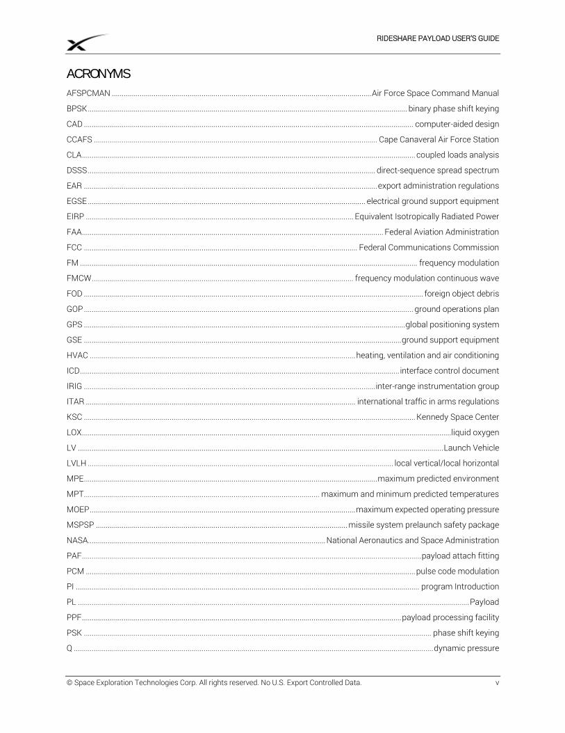
ACRONYMS
AFSPCMAN .................................................................................................................................. Air Force Space Command Manual
BPSK ................................................................................................................................................................ binary phase shift keying
CAD ..................................................................................................................................................................... computer-aided design
CCAFS .............................................................................................................................................. Cape Canaveral Air Force Station
CLA ....................................................................................................................................................................... coupled loads analysis
DSSS ................................................................................................................................................ direct-sequence spread spectrum
EAR ................................................................................................................................................... export administration regulations
EGSE ........................................................................................................................................... electrical ground support equipment
EIRP ...................................................................................................................................... Equivalent Isotropically Radiated Power
FAA ....................................................................................................................................................... Federal Aviation Administration
FCC ......................................................................................................................................... Federal Communications Commission
FM ......................................................................................................................................................................... frequency modulation
FMCW ................................................................................................................................... frequency modulation continuous wave
FOD .......................................................................................................................................................................... foreign object debris
GOP ..................................................................................................................................................................... ground operations plan
GPS ................................................................................................................................................................. global positioning system
GSE ............................................................................................................................................................... ground support equipment
HVAC ..................................................................................................................................... heating, ventilation and air conditioning
ICD ................................................................................................................................................................ interface control document
IRIG .................................................................................................................................................. inter-range instrumentation group
ITAR ....................................................................................................................................... international traffic in arms regulations
KSC ...................................................................................................................................................................... Kennedy Space Center
LOX .........................................................................................................................................................................................liquid oxygen
LV ....................................................................................................................................................................................... Launch Vehicle
LVLH ......................................................................................................................................................... local vertical/local horizontal
MPE ................................................................................................................................................... maximum predicted environment
MPT...................................................................................................................... maximum and minimum predicted temperatures
MOEP ..................................................................................................................................... maximum expected operating pressure
MSPSP .............................................................................................................................. missile system prelaunch safety package
NASA....................................................................................................................... National Aeronautics and Space Administration
PAF .......................................................................................................................................................................... payload attach fitting
PCM ..................................................................................................................................................................... pulse code modulation
PI ............................................................................................................................................................................ program Introduction
PL .................................................................................................................................................................................................... Payload
PPF ................................................................................................................................................................ payload processing facility
PSK .............................................................................................................................................................................. phase shift keying
Q .................................................................................................................................................................................... dynamic pressure
RIDESHARE PAYLOAD USER’S GUIDE
© Space Exploration Technologies Corp. All rights reserved. No U.S. Export Controlled Data. vi
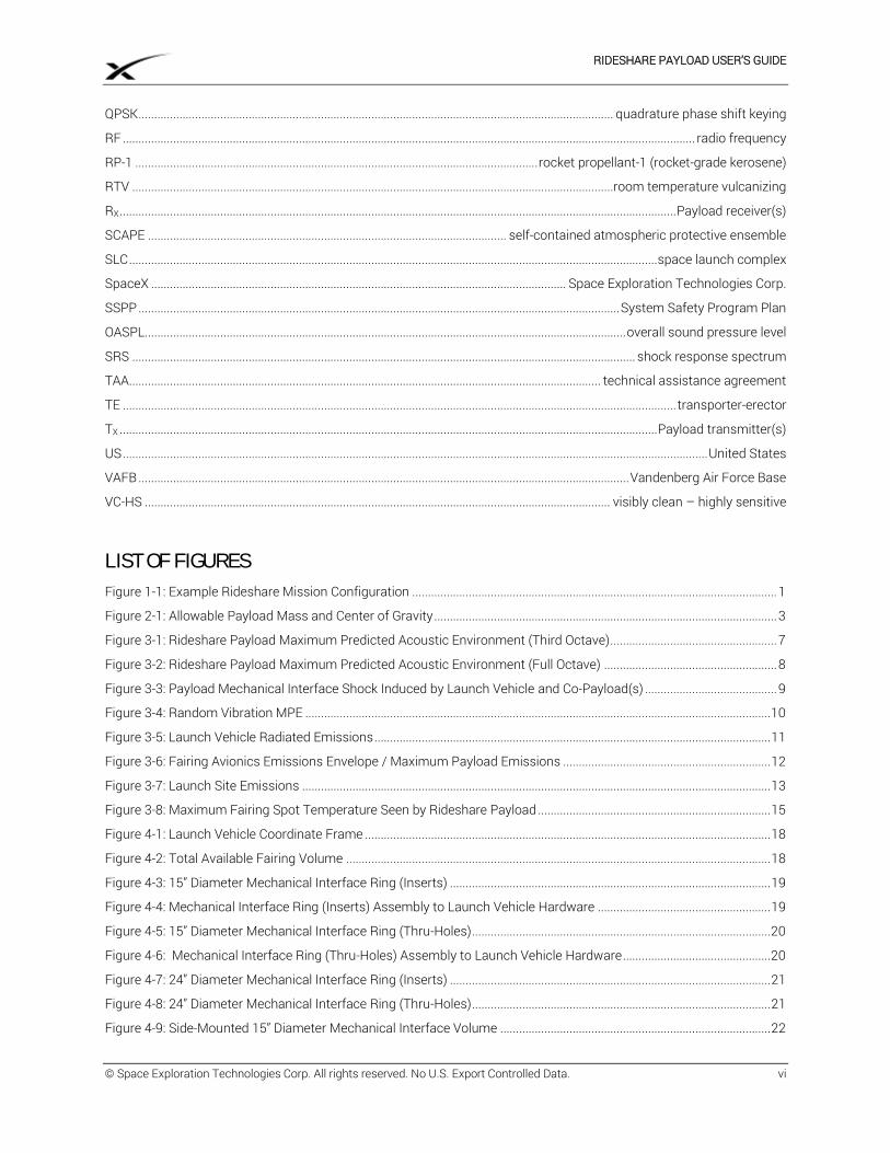
QPSK ....................................................................................................................................................... quadrature phase shift keying
RF ...................................................................................................................................................................................... radio frequency
RP-1 ................................................................................................................................ rocket propellant-1 (rocket-grade kerosene)
RTV .........................................................................................................................................................room temperature vulcanizing
RX ................................................................................................................................................................................. Payload receiver(s)
SCAPE .................................................................................................................. self-contained atmospheric protective ensemble
SLC ........................................................................................................................................................................ space launch complex
SpaceX .................................................................................................................................... Space Exploration Technologies Corp.
SSPP ......................................................................................................................................................... System Safety Program Plan
OASPL......................................................................................................................................................... overall sound pressure level
SRS ................................................................................................................................................................ shock response spectrum
TAA...................................................................................................................................................... technical assistance agreement
TE ................................................................................................................................................................................ transporter-erector
TX ........................................................................................................................................................................... Payload transmitter(s)
US .......................................................................................................................................................................................... United States
VAFB ............................................................................................................................................................ Vandenberg Air Force Base
VC-HS .................................................................................................................................................... visibly clean – highly sensitive
LIST OF FIGURES
Figure 1-1: Example Rideshare Mission Configuration .................................................................................................................... 1
Figure 2-1: Allowable Payload Mass and Center of Gravity ............................................................................................................. 3
Figure 3-1: Rideshare Payload Maximum Predicted Acoustic Environment (Third Octave) ..................................................... 7
Figure 3-2: Rideshare Payload Maximum Predicted Acoustic Environment (Full Octave) ....................................................... 8
Figure 3-3: Payload Mechanical Interface Shock Induced by Launch Vehicle and Co-Payload(s) .......................................... 9
Figure 3-4: Random Vibration MPE .................................................................................................................................................... 10
Figure 3-5: Launch Vehicle Radiated Emissions .............................................................................................................................. 11
Figure 3-6: Fairing Avionics Emissions Envelope / Maximum Payload Emissions .................................................................. 12
Figure 3-7: Launch Site Emissions ..................................................................................................................................................... 13
Figure 3-8: Maximum Fairing Spot Temperature Seen by Rideshare Payload .......................................................................... 15
Figure 4-1: Launch Vehicle Coordinate Frame ................................................................................................................................. 18
Figure 4-2: Total Available Fairing Volume ....................................................................................................................................... 18
Figure 4-3: 15” Diameter Mechanical Interface Ring (Inserts) ...................................................................................................... 19
Figure 4-4: Mechanical Interface Ring (Inserts) Assembly to Launch Vehicle Hardware ....................................................... 19
Figure 4-5: 15” Diameter Mechanical Interface Ring (Thru-Holes) ............................................................................................... 20
Figure 4-6: Mechanical Interface Ring (Thru-Holes) Assembly to Launch Vehicle Hardware ............................................... 20
Figure 4-7: 24” Diameter Mechanical Interface Ring (Inserts) ...................................................................................................... 21
Figure 4-8: 24” Diameter Mechanical Interface Ring (Thru-Holes) ............................................................................................... 21
Figure 4-9: Side-Mounted 15” Diameter Mechanical Interface Volume ...................................................................................... 22
RIDESHARE PAYLOAD USER’S GUIDE
© Space Exploration Technologies Corp. All rights reserved. No U.S. Export Controlled Data. vii
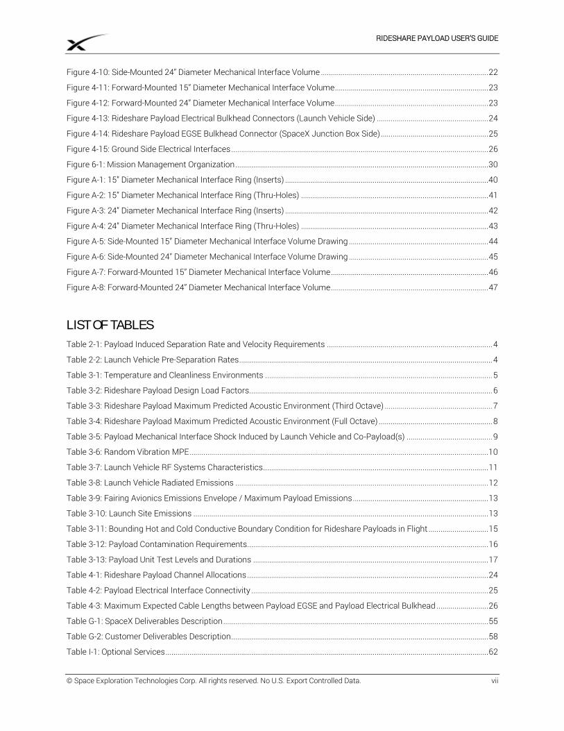
Figure 4-10: Side-Mounted 24” Diameter Mechanical Interface Volume .................................................................................... 22
Figure 4-11: Forward-Mounted 15” Diameter Mechanical Interface Volume ............................................................................. 23
Figure 4-12: Forward-Mounted 24” Diameter Mechanical Interface Volume ............................................................................. 23
Figure 4-13: Rideshare Payload Electrical Bulkhead Connectors (Launch Vehicle Side) ........................................................ 24
Figure 4-14: Rideshare Payload EGSE Bulkhead Connector (SpaceX Junction Box Side) ...................................................... 25
Figure 4-15: Ground Side Electrical Interfaces ................................................................................................................................. 26
Figure 6-1: Mission Management Organization ............................................................................................................................... 30
Figure A-1: 15” Diameter Mechanical Interface Ring (Inserts) ...................................................................................................... 40
Figure A-2: 15” Diameter Mechanical Interface Ring (Thru-Holes) .............................................................................................. 41
Figure A-3: 24” Diameter Mechanical Interface Ring (Inserts) ...................................................................................................... 42
Figure A-4: 24” Diameter Mechanical Interface Ring (Thru-Holes) .............................................................................................. 43
Figure A-5: Side-Mounted 15” Diameter Mechanical Interface Volume Drawing ...................................................................... 44
Figure A-6: Side-Mounted 24” Diameter Mechanical Interface Volume Drawing ...................................................................... 45
Figure A-7: Forward-Mounted 15” Diameter Mechanical Interface Volume ............................................................................... 46
Figure A-8: Forward-Mounted 24” Diameter Mechanical Interface Volume ............................................................................... 47
LIST OF TABLES
Table 2-1: Payload Induced Separation Rate and Velocity Requirements ................................................................................... 4
Table 2-2: Launch Vehicle Pre-Separation Rates ............................................................................................................................... 4
Table 3-1: Temperature and Cleanliness Environments .................................................................................................................. 5
Table 3-2: Rideshare Payload Design Load Factors.......................................................................................................................... 6
Table 3-3: Rideshare Payload Maximum Predicted Acoustic Environment (Third Octave) ...................................................... 7
Table 3-4: Rideshare Payload Maximum Predicted Acoustic Environment (Full Octave) ......................................................... 8
Table 3-5: Payload Mechanical Interface Shock Induced by Launch Vehicle and Co-Payload(s) ........................................... 9
Table 3-6: Random Vibration MPE ...................................................................................................................................................... 10
Table 3-7: Launch Vehicle RF Systems Characteristics ................................................................................................................. 11
Table 3-8: Launch Vehicle Radiated Emissions ............................................................................................................................... 12
Table 3-9: Fairing Avionics Emissions Envelope / Maximum Payload Emissions .................................................................... 13
Table 3-10: Launch Site Emissions .................................................................................................................................................... 13
Table 3-11: Bounding Hot and Cold Conductive Boundary Condition for Rideshare Payloads in Flight .............................. 15
Table 3-12: Payload Contamination Requirements......................................................................................................................... 16
Table 3-13: Payload Unit Test Levels and Durations ...................................................................................................................... 17
Table 4-1: Rideshare Payload Channel Allocations ......................................................................................................................... 24
Table 4-2: Payload Electrical Interface Connectivity ....................................................................................................................... 25
Table 4-3: Maximum Expected Cable Lengths between Payload EGSE and Payload Electrical Bulkhead .......................... 26
Table G-1: SpaceX Deliverables Description ..................................................................................................................................... 55
Table G-2: Customer Deliverables Description ................................................................................................................................. 58
Table I-1: Optional Services .................................................................................................................................................................. 62
RIDESHARE PAYLOAD USER’S GUIDE
© Space Exploration Technologies Corp. All rights reserved. No U.S. Export Controlled Data. viii
CHANGE LOG
Date Update
03 December 2019 Original Release
29 January 2020 Updated Definitions
RIDESHARE PAYLOAD USER’S GUIDE
© Space Exploration Technologies Corp. All rights reserved. No U.S. Export Controlled Data. 1
1 INTRODUCTION
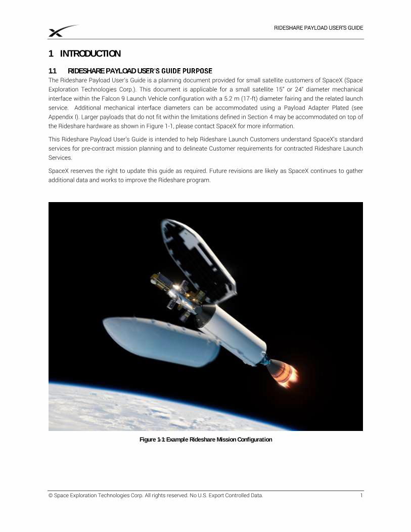
1.1 RIDESHARE PAYLOAD US The Rideshare Payload User’s Guide is a planning document provided for small satellite customers of SpaceX (Space Exploration Technologies Corp.). This document is applicable for a small satellite 15” or 24” diameter mechanical interface within the Falcon 9 Launch Vehicle configuration with a 5.2 m (17-ft) diameter fairing and the related launch service. Additional mechanical interface diameters can be accommodated using a Payload Adapter Plated (see Appendix I). Larger payloads that do not fit within the limitations defined in Section 4 may be accommodated on top of the Rideshare hardware as shown in Figure 1-1, please contact SpaceX for more information.
This Rideshare Payload User’s Guide is intended to help Rideshare Launch Customers understand SpaceX’s standard services for pre-contract mission planning and to delineate Customer requirements for contracted Rideshare Launch Services.
SpaceX reserves the right to update this guide as required. Future revisions are likely as SpaceX continues to gather additional data and works to improve the Rideshare program.
Figure 1-1: Example Rideshare Mission Configuration
RIDESHARE PAYLOAD USER’S GUIDE
© Space Exploration Technologies Corp. All rights reserved. No U.S. Export Controlled Data. 2
1.2 COMPANY DESCRIPTION SpaceX offers a family of Launch Vehicles that improves launch reliability and increases access to space. The company was founded on the philosophy that simplicity, reliability and cost effectiveness are closely connected. We approach all elements of Launch Services with a focus on simplicity to both increase reliability and lower cost. The SpaceX corporate structure is flat and business processes are lean, resulting in fast decision-making and product delivery. SpaceX products are designed to require low-infrastructure facilities with little overhead, while vehicle design teams are co-located with production and quality assurance staff to tighten the critical feedback loop. The result is highly reliable and producible Launch Vehicles with quality embedded throughout the process.
Established in 2002 by Elon Musk, the founder of Tesla Motors, PayPal and the Zip2 Corporation, SpaceX has developed and flown the Falcon 1 light-lift Launch Vehicle, the Falcon 9 medium-lift Launch Vehicle, the Falcon Heavy heavy-lift Launch Vehicle, the most powerful operational rocket in the world by a factor of two, and Dragon, which is the first commercially produced spacecraft to visit the International Space Station.
SpaceX has built a launch manifest that includes a broad array of commercial, government and international customers. In 2008, NASA selected the SpaceX Falcon 9 Launch Vehicle and Dragon spacecraft for the International Space Station Cargo Resupply Services contract. NASA has also awarded SpaceX contracts to develop the capability to transport astronauts to space as well as to launch scientific satellites. In addition, SpaceX services the National Security community and is on contract with the Air Force for multiple missions on the Falcon family of Launch Vehicles.
SpaceX has state-of-the-art production, testing, launch and operations facilities. SpaceX design and manufacturing facilities are conveniently located near the Los Angeles International Airport. This location allows the company to leverage Southern California’s rich aerospace talent pool. The company also operates cutting-edge propulsion and structural test facilities in Central Texas, along with Launch Sites in Florida and California, and the world’s first commercial orbital Launch Site in development in South Texas.
1.3 FALCON 9 PROGRAM Please refer to the SpaceX Falcon User’s Guide, latest revision, available on www.spacex.com/falcon9 for detailed information regarding the Falcon program including Launch Vehicle safety and reliability.
PRICING Pricing for rideshare Launch Services can be found at www.spacex.com/smallsat.
RIDESHARE PAYLOAD USER’S GUIDE
© Space Exploration Technologies Corp. All rights reserved. No U.S. Export Controlled Data. 3
2 PERFORMANCE
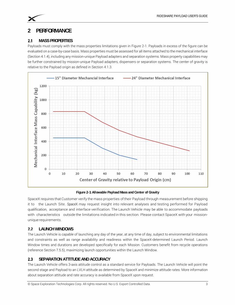
MASS PROPERTIES Payloads must comply with the mass properties limitations given in Figure 2-1. Payloads in excess of the figure can be evaluated on a case-by-case basis. Mass properties must be assessed for all items attached to the mechanical interface (Section 4.1.4), including any mission-unique Payload adapters and separation systems. Mass property capabilities may be further constrained by mission-unique Payload adapters, dispensers or separation systems. The center of gravity is relative to the Payload origin as defined in Section 4.1.3.
Figure 2-1: Allowable Payload Mass and Center of Gravity
SpaceX requires that Customer verify the mass properties of their Payload through measurement before shipping it to the Launch Site. SpaceX may request insight into relevant analyses and testing performed for Payload qualification, acceptance and interface verification. The Launch Vehicle may be able to accommodate payloads with characteristics outside the limitations indicated in this section. Please contact SpaceX with your mission-unique requirements.
LAUNCH WINDOWS The Launch Vehicle is capable of launching any day of the year, at any time of day, subject to environmental limitations and constraints as well as range availability and readiness within the SpaceX-determined Launch Period. Launch Window times and durations are developed specifically for each Mission. Customers benefit from recycle operations (reference Section 7.5.5), maximizing launch opportunities within the Launch Window.
SEPARATION ATTITUDE AND ACCURACY The Launch Vehicle offers 3-axis attitude control as a standard service for Payloads. The Launch Vehicle will point the second stage and Payload to an LVLH attitude as determined by SpaceX and minimize attitude rates. More information about separation attitude and rate accuracy is available from SpaceX upon request.
RIDESHARE PAYLOAD USER’S GUIDE
© Space Exploration Technologies Corp. All rights reserved. No U.S. Export Controlled Data. 4
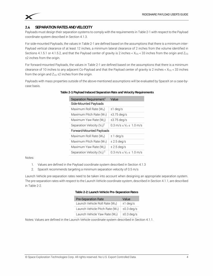
SEPARATION RATES AND VELOCITY Payloads must design their separation systems to comply with the requirements in Table 2-1 with respect to the Payload coordinate system described in Section 4.1.3.
For side-mounted Payloads, the values in Table 2-1 are defined based on the assumptions that there is a minimum inter-Payload vertical clearance of at least 12 inches, a minimum lateral clearance of 2 inches from the volume identified in Sections 4.1.5.1 or 4.1.5.2, and that the Payload center of gravity is 2 inches < XCG < 33 inches from the origin and ZCG ±2 inches from the origin.
For forward-mounted Payloads, the values in Table 2-1 are defined based on the assumptions that there is a minimum clearance of 10 inches to any adjacent Co-Payload and that the Payload center of gravity is 2 inches < XCG < 33 inches from the origin and ZCG ±2 inches from the origin.
Payloads with mass properties outside of the above-mentioned assumptions will be evaluated by SpaceX on a case-by-case basis.
Table 2-1: Payload Induced Separation Rate and Velocity Requirements
Separation Requirement1 Value Side-Mounted Payloads
Maximum Roll Rate (WX) ±1 deg/s
Maximum Pitch Rate (WY) ±3.75 deg/s
Maximum Yaw Rate (WZ) ±3.75 deg/s
Separation Velocity (VX)2 0.3 m/s ≤ VX ≤ 1.0 m/s
Forward-Mounted Payloads
Maximum Roll Rate (WX) ± 1 deg/s
Maximum Pitch Rate (WY) ± 2.5 deg/s
Maximum Yaw Rate (WZ) ± 2.5 deg/s
Separation Velocity (VX) 2 0.3 m/s ≤ VX ≤ 1.0 m/s
Notes:
1. Values are defined in the Payload coordinate system described in Section 4.1.3 2. SpaceX recommends targeting a minimum separation velocity of 0.5 m/s
Launch Vehicle pre-separation rates need to be taken into account when designing an appropriate separation system. The pre-separation rates with respect to the Launch Vehicle coordinate system, described in Section 4.1.1, are described in Table 2-2.
Table 2-2: Launch Vehicle Pre-Separation Rates
Pre-Separation Rate Value Launch Vehicle Roll Rate (WX) ±1 deg/s
Launch Vehicle Pitch Rate (WY) ±0.3 deg/s
Launch Vehicle Yaw Rate (WZ) ±0.3 deg/s
Notes: Values are defined in the Launch Vehicle coordinate system described in Section 4.1.1.
RIDESHARE PAYLOAD USER’S GUIDE
© Space Exploration Technologies Corp. All rights reserved. No U.S. Export Controlled Data. 5
3 ENVIRONMENTS The Launch Vehicle has been designed to provide a benign Payload environment, via the use of all-liquid propulsion, a single staging event, deeply throttleable engines and pneumatic separation systems. The environments presented below reflect typical mission levels for Payloads; mission-specific analyses will be performed as indicated in the subsequent sections.
TRANSPORTATION ENVIRONMENTS Transportation environments will be enveloped by the flight environments in Section 3.3.
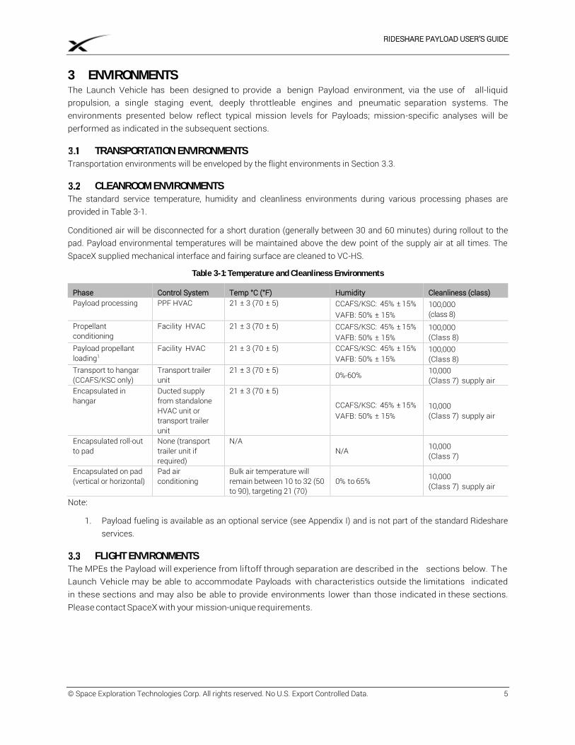
CLEANROOM ENVIRONMENTS The standard service temperature, humidity and cleanliness environments during various processing phases are provided in Table 3-1.
Conditioned air will be disconnected for a short duration (generally between 30 and 60 minutes) during rollout to the pad. Payload environmental temperatures will be maintained above the dew point of the supply air at all times. The SpaceX supplied mechanical interface and fairing surface are cleaned to VC-HS.
Table 3-1: Temperature and Cleanliness Environments
Phase Control System Temp °C (°F) Humidity Cleanliness (class) Payload processing PPF HVAC 21 ± 3 (70 ± 5) CCAFS/KSC: 45% ± 15%
VAFB: 50% ± 15% 100,000 (class 8)
Propellant conditioning
Facility HVAC 21 ± 3 (70 ± 5) CCAFS/KSC: 45% ± 15% VAFB: 50% ± 15%
100,000 (Class 8)
Payload propellant loading1
Facility HVAC 21 ± 3 (70 ± 5) CCAFS/KSC: 45% ± 15% VAFB: 50% ± 15%
100,000 (Class 8)
Transport to hangar (CCAFS/KSC only)
Transport trailer unit
21 ± 3 (70 ± 5) 0%-60% 10,000
(Class 7) supply air Encapsulated in hangar
Ducted supply from standalone HVAC unit or transport trailer unit
21 ± 3 (70 ± 5)
CCAFS/KSC: 45% ± 15% VAFB: 50% ± 15%
10,000 (Class 7) supply air
Encapsulated roll-out to pad
None (transport trailer unit if required)
N/A N/A 10,000
(Class 7)
Encapsulated on pad (vertical or horizontal)
Pad air conditioning
Bulk air temperature will remain between 10 to 32 (50 to 90), targeting 21 (70)
0% to 65% 10,000 (Class 7) supply air
Note:
1. Payload fueling is available as an optional service (see Appendix I) and is not part of the standard Rideshare services.
FLIGHT ENVIRONMENTS The MPEs the Payload will experience from liftoff through separation are described in the sections below. The Launch Vehicle may be able to accommodate Payloads with characteristics outside the limitations indicated in these sections and may also be able to provide environments lower than those indicated in these sections. Please contact SpaceX with your mission-unique requirements.
RIDESHARE PAYLOAD USER’S GUIDE
© Space Exploration Technologies Corp. All rights reserved. No U.S. Export Controlled Data. 6
3.3.1 LOADS
During flight, the Payload will experience a range of axial and bending accelerations. Payload axial and bending mode fundamental frequencies should be greater than 40 Hz. Lower frequencies may be acceptable but will need to be confirmed via mission specific analyses. Payload design load factors are listed in Table 3-2 for Payloads less than or greater than 200 kg. Load factors are defined for both side-mounted and forward-mounted Payloads as defined in Section 4.1.5.
Payload loads are a function of both the Launch Vehicle and Payload structural dynamic properties and are verified via mission specific CLA. If Payload results are found to exceed the MPE defined in Table 3-2, SpaceX will provide the CLA results to the Customer for further evaluation.
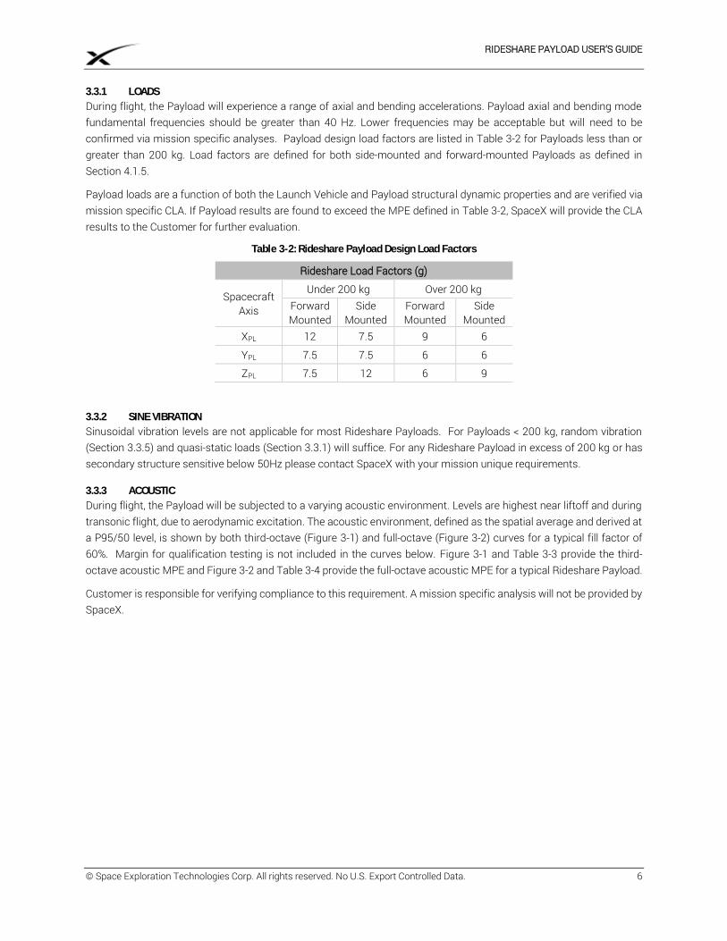
Table 3-2: Rideshare Payload Design Load Factors
Rideshare Load Factors (g)
Spacecraft Axis
Under 200 kg Over 200 kg Forward Mounted
Side Mounted
Forward Mounted
Side Mounted
XPL 12 7.5 9 6
YPL 7.5 7.5 6 6
ZPL 7.5 12 6 9
3.3.2 SINE VIBRATION
Sinusoidal vibration levels are not applicable for most Rideshare Payloads. For Payloads < 200 kg, random vibration (Section 3.3.5) and quasi-static loads (Section 3.3.1) will suffice. For any Rideshare Payload in excess of 200 kg or has secondary structure sensitive below 50Hz please contact SpaceX with your mission unique requirements.
3.3.3 ACOUSTIC
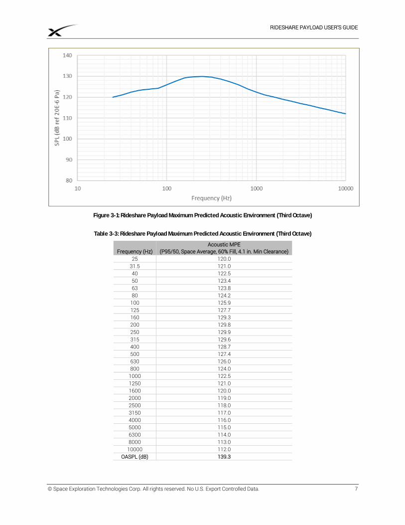
During flight, the Payload will be subjected to a varying acoustic environment. Levels are highest near liftoff and during transonic flight, due to aerodynamic excitation. The acoustic environment, defined as the spatial average and derived at a P95/50 level, is shown by both third-octave (Figure 3-1) and full-octave (Figure 3-2) curves for a typical fill factor of 60%. Margin for qualification testing is not included in the curves below. Figure 3-1 and Table 3-3 provide the third-octave acoustic MPE and Figure 3-2 and Table 3-4 provide the full-octave acoustic MPE for a typical Rideshare Payload.
Customer is responsible for verifying compliance to this requirement. A mission specific analysis will not be provided by SpaceX.
RIDESHARE PAYLOAD USER’S GUIDE
© Space Exploration Technologies Corp. All rights reserved. No U.S. Export Controlled Data. 7
Figure 3-1: Rideshare Payload Maximum Predicted Acoustic Environment (Third Octave)
Table 3-3: Rideshare Payload Maximum Predicted Acoustic Environment (Third Octave)
Frequency (Hz) Acoustic MPE
(P95/50, Space Average, 60% Fill, 4.1 in. Min Clearance) 25 120.0
31.5 121.0 40 122.5 50 123.4 63 123.8 80 124.2
100 125.9 125 127.7 160 129.3 200 129.8 250 129.9 315 129.6 400 128.7 500 127.4 630 126.0 800 124.0
1000 122.5 1250 121.0 1600 120.0 2000 119.0 2500 118.0 3150 117.0 4000 116.0 5000 115.0 6300 114.0 8000 113.0
10000 112.0 OASPL (dB) 139.3
RIDESHARE PAYLOAD USER’S GUIDE
© Space Exploration Technologies Corp. All rights reserved. No U.S. Export Controlled Data. 8
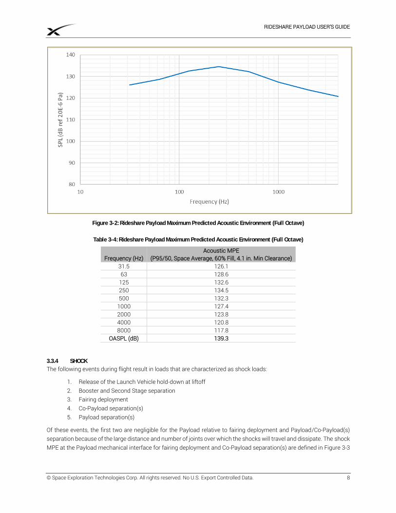
Figure 3-2: Rideshare Payload Maximum Predicted Acoustic Environment (Full Octave)
Table 3-4: Rideshare Payload Maximum Predicted Acoustic Environment (Full Octave)
Frequency (Hz) Acoustic MPE
(P95/50, Space Average, 60% Fill, 4.1 in. Min Clearance) 31.5 126.1 63 128.6
125 132.6 250 134.5 500 132.3
1000 127.4 2000 123.8 4000 120.8 8000 117.8
OASPL (dB) 139.3
3.3.4 SHOCK
The following events during flight result in loads that are characterized as shock loads:
1. Release of the Launch Vehicle hold-down at liftoff 2. Booster and Second Stage separation 3. Fairing deployment 4. Co-Payload separation(s) 5. Payload separation(s)
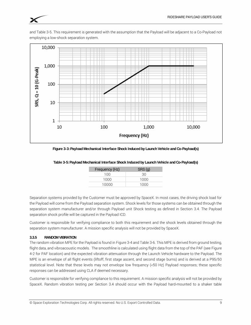
Of these events, the first two are negligible for the Payload relative to fairing deployment and Payload/Co-Payload(s) separation because of the large distance and number of joints over which the shocks will travel and dissipate. The shock MPE at the Payload mechanical interface for fairing deployment and Co-Payload separation(s) are defined in Figure 3-3
RIDESHARE PAYLOAD USER’S GUIDE
© Space Exploration Technologies Corp. All rights reserved. No U.S. Export Controlled Data. 9
and Table 3-5. This requirement is generated with the assumption that the Payload will be adjacent to a Co-Payload not employing a low-shock separation system.
Figure 3-3: Payload Mechanical Interface Shock Induced by Launch Vehicle and Co-Payload(s)
Table 3-5: Payload Mechanical Interface Shock Induced by Launch Vehicle and Co-Payload(s)
Frequency (Hz) SRS (g) 100 30
1000 1000 10000 1000
Separation systems provided by the Customer must be approved by SpaceX. In most cases, the driving shock load for the Payload will come from the Payload separation system. Shock levels for those systems can be obtained through the separation system manufacturer and/or through Payload unit Shock testing as defined in Section 3.4. The Payload separation shock profile will be captured in the Payload ICD.
Customer is responsible for verifying compliance to both this requirement and the shock levels obtained through the separation system manufacturer. A mission specific analysis will not be provided by SpaceX.
3.3.5 RANDOM VIBRATION
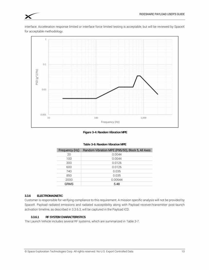
The random vibration MPE for the Payload is found in Figure 3-4 and Table 3-6. This MPE is derived from ground testing, flight data, and vibroacoustic models. The smoothline is calculated using flight data from the top of the PAF (see Figure 4-2 for PAF location) and the expected vibration attenuation through the Launch Vehicle hardware to the Payload. The MPE is an envelope of all flight events (liftoff, first stage ascent, and second stage burns) and is derived at a P95/50 statistical level. Note that these levels may not envelope low frequency (<50 Hz) Payload responses; these specific responses can be addressed using CLA if deemed necessary.
Customer is responsible for verifying compliance to this requirement. A mission specific analysis will not be provided by SpaceX. Random vibration testing per Section 3.4 should occur with the Payload hard-mounted to a shaker table
RIDESHARE PAYLOAD USER’S GUIDE
© Space Exploration Technologies Corp. All rights reserved. No U.S. Export Controlled Data. 10
interface. Acceleration response limited or interface force limited testing is acceptable, but will be reviewed by SpaceX for acceptable methodology.
Figure 3-4: Random Vibration MPE
Table 3-6: Random Vibration MPE
Frequency (Hz) Random Vibration MPE (P95/50), Block 5, All Axes 20 0.0044
100 0.0044 300 0.0126 600 0.0126 740 0.035 850 0.035
2000 0.00644 GRMS 5.48
3.3.6 ELECTROMAGNETIC
Customer is responsible for verifying compliance to this requirement. A mission specific analysis will not be provided by SpaceX. Payload radiated emissions and radiated susceptibility along with Payload receiver/transmitter post-launch activation timeline, as described in 3.3.6.3, will be captured in the Payload ICD.
3.3.6.1 RF SYSTEM CHARACTERISTICS
The Launch Vehicle includes several RF systems, which are summarized in Table 3-7.
RIDESHARE PAYLOAD USER’S GUIDE
© Space Exploration Technologies Corp. All rights reserved. No U.S. Export Controlled Data. 11
Table 3-7: Launch Vehicle RF Systems Characteristics
Part Description TX/RX Frequency (MHz) 99% Bandwidth (MHz) Modulation S1TX1 Telemetry Transmitter TX 2247.5 4.84 PCM/FM S1TX2 Telemetry Transmitter TX 2255.5 4.84 PCM/FM S2TX1 Telemetry Transmitter TX 2232.5 4.14 PCM/FM S2TX2 Telemetry Transmitter TX 2272.5 4.14 PCM/FM
GPS Receiver RX 1575.42 20 BPSK DSSS Iridium/GPS Tracker TX 1610 - 1626.5 0.042 BPSK/QPSK Iridium/GPS Tracker RX 1610 - 1626.5 0.042 QPSK Iridium/GPS Tracker RX 1575.42 20 BPSK DSSS
S-Band BPSK Receiver RX 2090 - 2093 1 BPSK Radar Altimeter TX 4235-4275 40 FMCW Radar Altimeter TX 4325-4365 40 FMCW Radar Altimeter TX 4250-4350 100 FMCW Radar Altimeter RX 4235-4275 40 FMCW Radar Altimeter RX 4325-4365 40 FMCW Radar Altimeter RX 4250-4350 40 FMCW
3.3.6.2 LAUNCH VEHICLE EMISSIONS
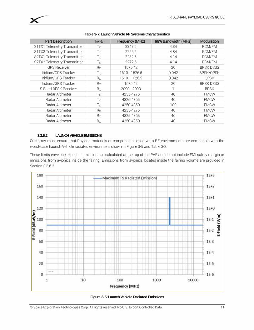
Customer must ensure that Payload materials or components sensitive to RF environments are compatible with the worst-case Launch Vehicle radiated environment shown in Figure 3-5 and Table 3-8.
These limits envelope expected emissions as calculated at the top of the PAF and do not include EMI safety margin or emissions from avionics inside the fairing. Emissions from avionics located inside the fairing volume are provided in Section 3.3.6.3.
Figure 3-5: Launch Vehicle Radiated Emissions
RIDESHARE PAYLOAD USER’S GUIDE
© Space Exploration Technologies Corp. All rights reserved. No U.S. Export Controlled Data. 12
Table 3-8: Launch Vehicle Radiated Emissions
Frequency Range (MHz) E Field Limit (dBμV/m) Launch Vehicle Transmit System
1.00 – 2200.0 90 2200.0 – 2300.0 140 S-band telemetry and video
2300.0 – 18000.0 90
3.3.6.3 MAXIMUM PAYLOAD EMISSIONS
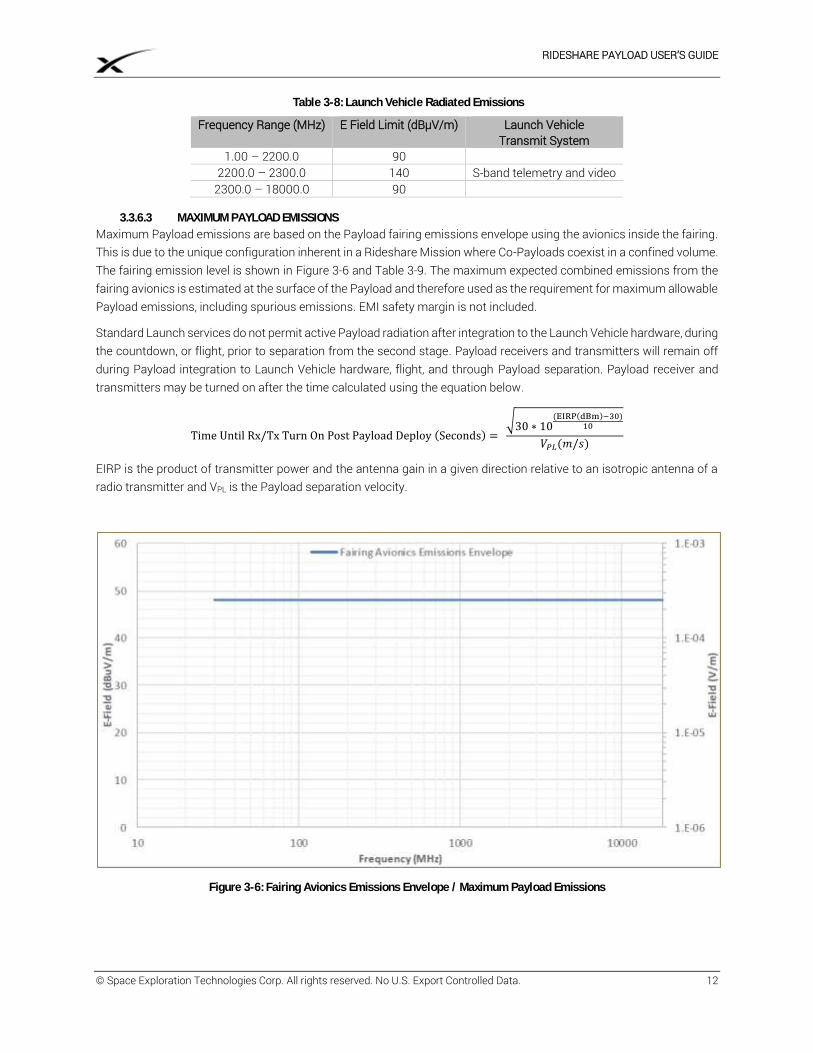
Maximum Payload emissions are based on the Payload fairing emissions envelope using the avionics inside the fairing. This is due to the unique configuration inherent in a Rideshare Mission where Co-Payloads coexist in a confined volume. The fairing emission level is shown in Figure 3-6 and Table 3-9. The maximum expected combined emissions from the fairing avionics is estimated at the surface of the Payload and therefore used as the requirement for maximum allowable Payload emissions, including spurious emissions. EMI safety margin is not included.
Standard Launch services do not permit active Payload radiation after integration to the Launch Vehicle hardware, during the countdown, or flight, prior to separation from the second stage. Payload receivers and transmitters will remain off during Payload integration to Launch Vehicle hardware, flight, and through Payload separation. Payload receiver and transmitters may be turned on after the time calculated using the equation below.
Time Until Rx/Tx Turn On Post Payload Deploy (Seconds) =
√30 ∗ 10(EIRP(dBm)−30)
10
𝑉𝑃𝐿(𝑚/𝑠)
EIRP is the product of transmitter power and the antenna gain in a given direction relative to an isotropic antenna of a radio transmitter and VPL is the Payload separation velocity.
Figure 3-6: Fairing Avionics Emissions Envelope / Maximum Payload Emissions
RIDESHARE PAYLOAD USER’S GUIDE
© Space Exploration Technologies Corp. All rights reserved. No U.S. Export Controlled Data. 13
Table 3-9: Fairing Avionics Emissions Envelope / Maximum Payload Emissions
Frequency Range (MHz)
E Field Limit (dBμV/m)
30.0 – 18000.0 48
3.3.6.4 LAUNCH SITE EMISSIONS ENVELOPE
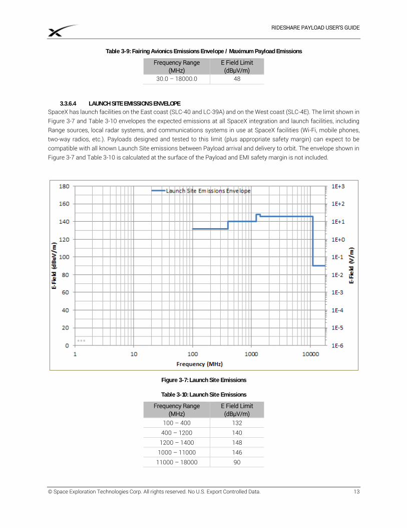
SpaceX has launch facilities on the East coast (SLC-40 and LC-39A) and on the West coast (SLC-4E). The limit shown in Figure 3-7 and Table 3-10 envelopes the expected emissions at all SpaceX integration and launch facilities, including Range sources, local radar systems, and communications systems in use at SpaceX facilities (Wi-Fi, mobile phones, two-way radios, etc.). Payloads designed and tested to this limit (plus appropriate safety margin) can expect to be compatible with all known Launch Site emissions between Payload arrival and delivery to orbit. The envelope shown in Figure 3-7 and Table 3-10 is calculated at the surface of the Payload and EMI safety margin is not included.
Figure 3-7: Launch Site Emissions
Table 3-10: Launch Site Emissions
Frequency Range (MHz)
E Field Limit (dBμV/m)
100 – 400 132 400 – 1200 140
1200 – 1400 148 1000 – 11000 146
11000 – 18000 90
RIDESHARE PAYLOAD USER’S GUIDE
© Space Exploration Technologies Corp. All rights reserved. No U.S. Export Controlled Data. 14
3.3.6.5 EMI SAFETY MARGIN
To account for unexpected variation in hardware and environments, 6dB of EMI safety margin is required. EMI safety margin is typically expected to be included on the “victim” side of the source-victim analysis. Each emissions section in this guide specifies whether safety margin has been included in the envelope provided. When safety margin has not been included, it is expected that the relevant Payload susceptibility limit will include 6dB of EMI safety margin.
3.3.6.6 LIGHTNING PROTECTION
SpaceX launch pads at CCAFS/KSC contain full lightning protection systems. The integration facilities and hangars are equipped with lightning grounding systems to protect personnel and hardware from lightning. The SpaceX launch pad at VAFB uses operational mitigations in the event of a lightning risk due to the low likelihood of lightning at VAFB. The SLC-40 and LC-39A launch pads are equipped with overhead wire lightning protection systems. These systems are designed to:
1. Be a preferential path for lightning in order to prevent direct attachments to personnel and hardware in the protection zone.
2. Avoid side flash between the overhead wires and flight hardware and ground systems. 3. Minimize electromagnetic coupling to flight hardware and ground systems in order to protect sensitive
electronics.
3.3.6.7 LIGHTNING RETEST
Well-defined lightning retest criteria are important to minimize both the risk of damage and the risk of missed Launch opportunities for Payload and the Launch Vehicle. As such, SpaceX follows a well-defined lightning retest criteria based on the lightning distance and amplitude data measured using Range-provided lightning monitoring systems. In the event of a lightning strike with an amplitude ≥ 40kA occurring within a half nautical mile of the Launch Vehicle, SpaceX will follow lightning retest criteria guidelines for the Launch Vehicle and inform the Customer of the lightning event.
3.3.7 FAIRING INTERNAL PRESSURE
Inside the Launch Vehicle, the fairing internal pressure will decay at a rate no larger than 0.40 psi/sec (2.8 kPa/sec) from liftoff through immediately prior to fairing separation, except for brief periods during flight, where the fairing internal pressure will decay at a rate no larger than 0.65 psi/sec (4.5 kPa/sec), for no more than 5 seconds.
3.3.8 PAYLOAD TEMPERATURE EXPOSURE DURING FLIGHT
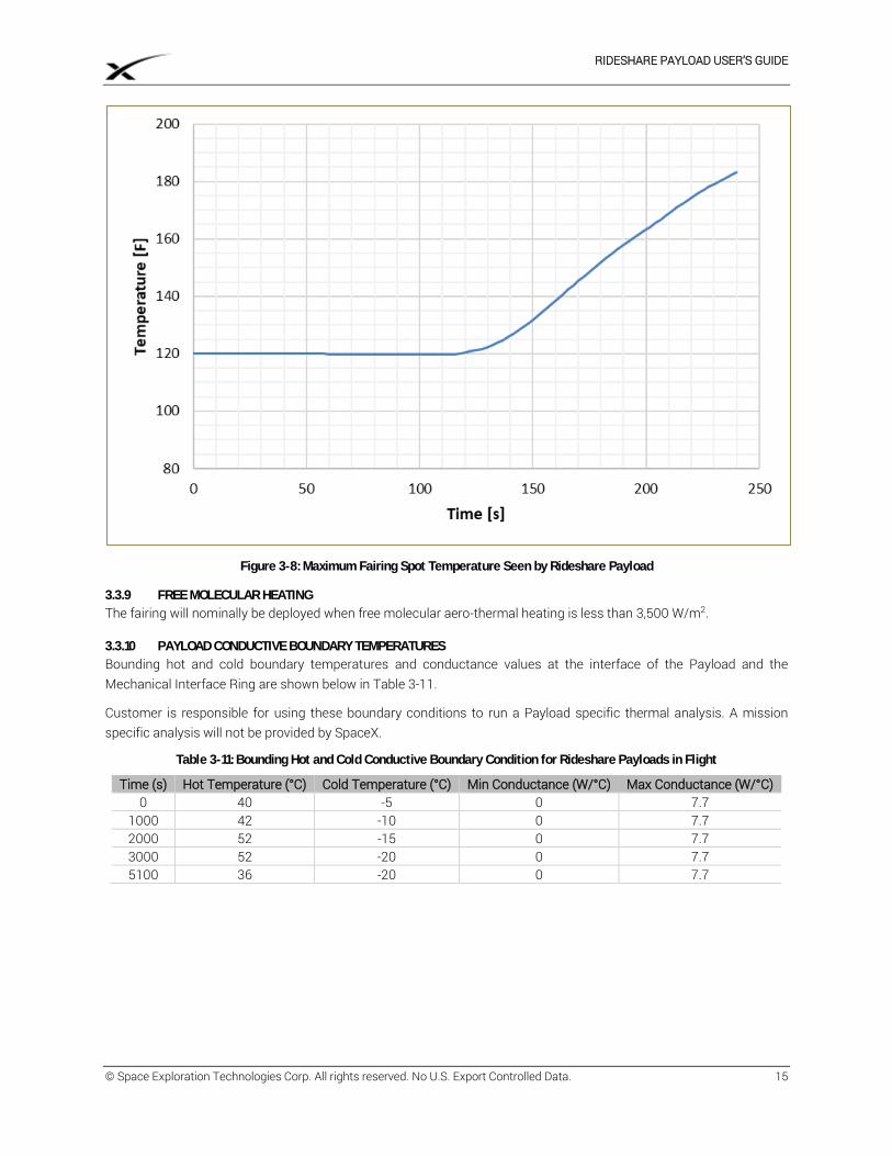
The Launch Vehicle fairing is a composite structure consisting of a 1.9 cm (0.75 in.) thick aluminum honeycomb core surrounded by carbon fiber face sheet plies. The emissivity of the fairing is approximately 0.9. The fairing thermal insulation, which is attached to the outside of the fairing composite, is sized such that the composite never exceeds the bounding fairing composite temperature profile shown in Figure 3-8. The curve is truncated at 240 seconds. Fairing jettison timing is determined by SpaceX for each mission.
RIDESHARE PAYLOAD USER’S GUIDE
© Space Exploration Technologies Corp. All rights reserved. No U.S. Export Controlled Data. 15
Figure 3-8: Maximum Fairing Spot Temperature Seen by Rideshare Payload
3.3.9 FREE MOLECULAR HEATING
The fairing will nominally be deployed when free molecular aero-thermal heating is less than 3,500 W/m2.
3.3.10 PAYLOAD CONDUCTIVE BOUNDARY TEMPERATURES
Bounding hot and cold boundary temperatures and conductance values at the interface of the Payload and the Mechanical Interface Ring are shown below in Table 3-11.
Customer is responsible for using these boundary conditions to run a Payload specific thermal analysis. A mission specific analysis will not be provided by SpaceX.
Table 3-11: Bounding Hot and Cold Conductive Boundary Condition for Rideshare Payloads in Flight
Time (s) Hot Temperature (°C) Cold Temperature (°C) Min Conductance (W/°C) Max Conductance (W/°C) 0 40 -5 0 7.7
1000 42 -10 0 7.7 2000 52 -15 0 7.7 3000 52 -20 0 7.7 5100 36 -20 0 7.7
RIDESHARE PAYLOAD USER’S GUIDE
© Space Exploration Technologies Corp. All rights reserved. No U.S. Export Controlled Data. 16
3.3.11 CONTAMINATION
SpaceX contamination control is described in Section 3.2. Payload contamination must fall within the requirements found in Table 3-12.
Customer is responsible for verifying compliance to this requirement in the form of a Payload contamination report, submitted for SpaceX review addressing the items listed in Table 3-12. A mission specific analysis will not be provided by SpaceX.
Table 3-12: Payload Contamination Requirements
Name Description
Visual Cleanliness
Payloads must be cleaned to VC-HS standards per NASA-SN-C-005D prior to integration onto Launch Vehicle hardware.
Non-Metallic Materials
Non-metallic materials used in the construction of the Payload that will be exposed to vacuum must not exceed a total mass loss of 1.0% and the volatile condensable matter must be less than 0.1% when tested per ASTM E595. A complete vacuum-exposed non-metallic materials list including quantities (surface area or mass) will be delivered to SpaceX for review. Any exceedances will be evaluated and approved on a case-by-case basis.
Metallic Materials
The selection of metallic materials by the Customer will include consideration of corrosion, wear products, shedding, and flaking in order to reduce particulate contamination. Dissimilar metals in contact will be avoided unless adequately protected against galvanic corrosion.
Payload Particulate Generation
The Payload will not create particulate during the vibroacoustic ascent environment. Actuation of any Payload mechanisms nearby any Co-Payload(s) or Launch Vehicle Hardware must not create particulate.
Payload Deployment
The Payload deployment system will not include the use of uncontained pyrotechnics (e.g. Frangible nuts).
Payload Propulsion
Payload propulsion systems will not be operated in close proximity (within 1km) of Co-Payload(s).
Prohibited Materials
The following materials are not to be used on Payload hardware: cadmium parts cadmium-plated parts zinc plating mercury, compounds containing mercury pure tin or tin electroplate (except when alloyed with lead, antimony, or bismuth)
Silicone Sensitivity
All silicone rubber or RTV silicones with probability of transfer to Co-Payload(s) or Launch Vehicle hardware will require SpaceX approval, coordination, and notification prior to use.
ENVIRONMENTAL VERIFICATION TESTING Prior to launch, SpaceX requires that Customer verifies the compatibility of their Payload with the Launch Vehicle’s flight MPEs found in Section 3.3. Environmental testing for Payloads must be performed by either:
1. A Fleet Qualification Approach a. Qualification testing levels on a qualification unit followed by b. Acceptance testing levels on flight units
OR
2. A Single Unit Approach a. Protoqualification testing on the flight unit
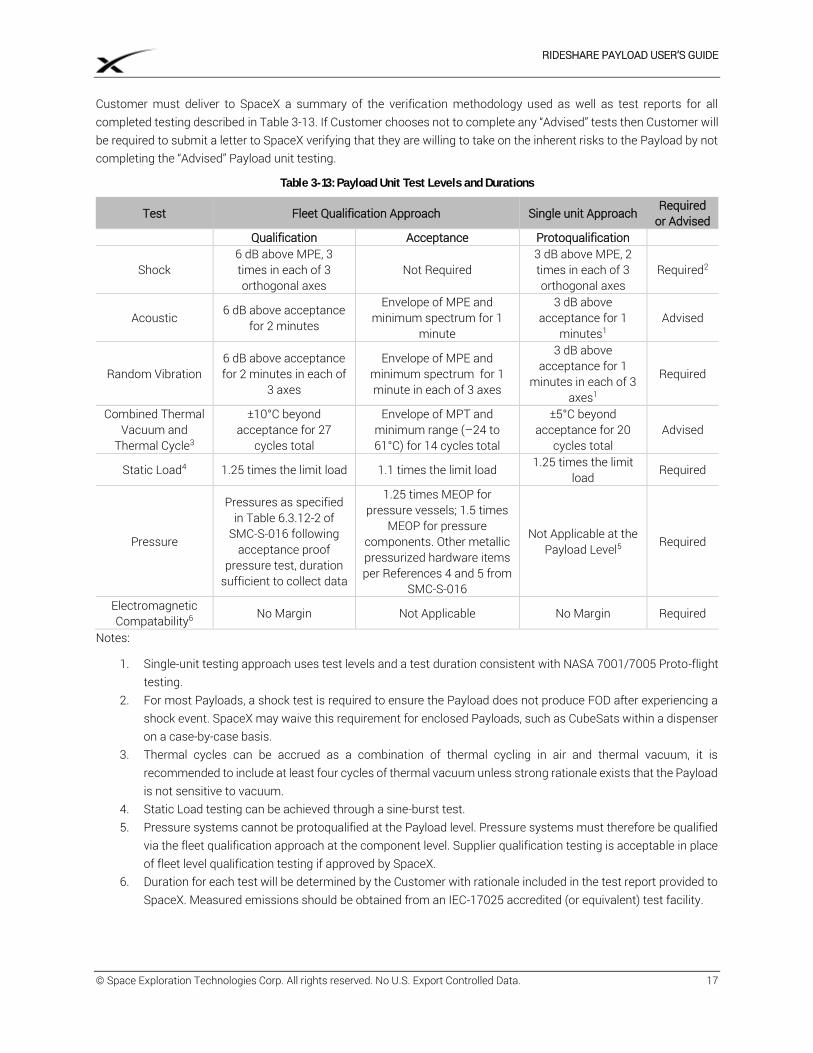
Payload unit testing must conform to the parameters shown in Table 3-13. Deviations may be acceptable but must be reviewed and approved by SpaceX. Tests that are “Advised” are designed to ensure on-orbit health and functionality of the Payload but are not required in order to fly on a SpaceX Rideshare Mission. Tests that are “Required” must be completed by the Customer.
RIDESHARE PAYLOAD USER’S GUIDE
© Space Exploration Technologies Corp. All rights reserved. No U.S. Export Controlled Data. 17
Customer must deliver to SpaceX a summary of the verification methodology used as well as test reports for all completed testing described in Table 3-13. If Customer chooses not to complete any “Advised” tests then Customer will be required to submit a letter to SpaceX verifying that they are willing to take on the inherent risks to the Payload by not completing the “Advised” Payload unit testing.
Table 3-13: Payload Unit Test Levels and Durations
Test Fleet Qualification Approach Single unit Approach Required
or Advised Qualification Acceptance Protoqualification
Shock 6 dB above MPE, 3 times in each of 3 orthogonal axes
Not Required 3 dB above MPE, 2 times in each of 3 orthogonal axes
Required2
Acoustic 6 dB above acceptance for 2 minutes
Envelope of MPE and minimum spectrum for 1
minute
3 dB above acceptance for 1
minutes1 Advised
Random Vibration 6 dB above acceptance for 2 minutes in each of
3 axes
Envelope of MPE and minimum spectrum for 1 minute in each of 3 axes
3 dB above acceptance for 1
minutes in each of 3 axes1
Required
Combined Thermal Vacuum and
Thermal Cycle3
±10°C beyond acceptance for 27
cycles total
Envelope of MPT and minimum range (–24 to 61°C) for 14 cycles total
±5°C beyond acceptance for 20
cycles total Advised
Static Load4 1.25 times the limit load 1.1 times the limit load 1.25 times the limit load
Required
Pressure
Pressures as specified in Table 6.3.12-2 of
SMC-S-016 following acceptance proof
pressure test, duration sufficient to collect data
1.25 times MEOP for pressure vessels; 1.5 times
MEOP for pressure components. Other metallic pressurized hardware items per References 4 and 5 from
SMC-S-016
Not Applicable at the Payload Level5 Required
Electromagnetic Compatability6 No Margin Not Applicable No Margin Required
Notes:
1. Single-unit testing approach uses test levels and a test duration consistent with NASA 7001/7005 Proto-flight testing.
2. For most Payloads, a shock test is required to ensure the Payload does not produce FOD after experiencing a shock event. SpaceX may waive this requirement for enclosed Payloads, such as CubeSats within a dispenser on a case-by-case basis.
3. Thermal cycles can be accrued as a combination of thermal cycling in air and thermal vacuum, it is recommended to include at least four cycles of thermal vacuum unless strong rationale exists that the Payload is not sensitive to vacuum.
4. Static Load testing can be achieved through a sine-burst test. 5. Pressure systems cannot be protoqualified at the Payload level. Pressure systems must therefore be qualified
via the fleet qualification approach at the component level. Supplier qualification testing is acceptable in place of fleet level qualification testing if approved by SpaceX.
6. Duration for each test will be determined by the Customer with rationale included in the test report provided to SpaceX. Measured emissions should be obtained from an IEC-17025 accredited (or equivalent) test facility.
RIDESHARE PAYLOAD USER’S GUIDE
© Space Exploration Technologies Corp. All rights reserved. No U.S. Export Controlled Data. 18
4 INTERFACES
MECHANICAL INTERFACES
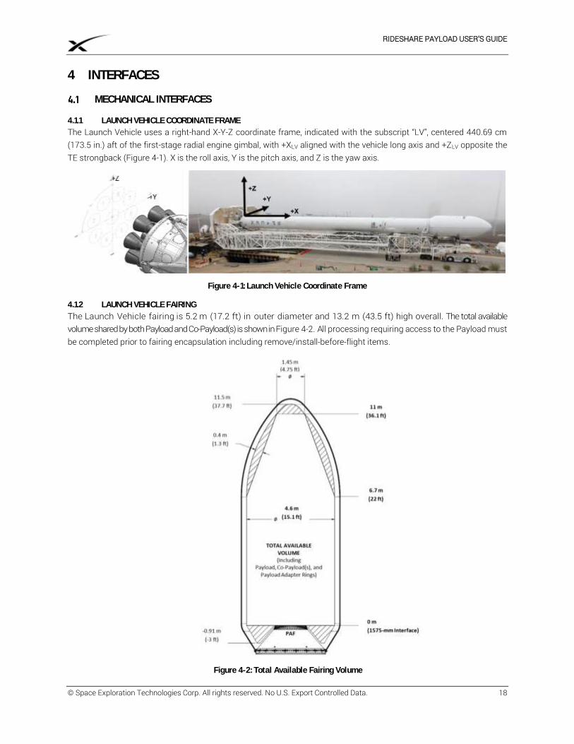
4.1.1 LAUNCH VEHICLE COORDINATE FRAME
The Launch Vehicle uses a right-hand X-Y-Z coordinate frame, indicated with the subscript “LV”, centered 440.69 cm (173.5 in.) aft of the first-stage radial engine gimbal, with +XLV aligned with the vehicle long axis and +ZLV opposite the TE strongback (Figure 4-1). X is the roll axis, Y is the pitch axis, and Z is the yaw axis.
Figure 4-1: Launch Vehicle Coordinate Frame
4.1.2 LAUNCH VEHICLE FAIRING
The Launch Vehicle fairing is 5.2 m (17.2 ft) in outer diameter and 13.2 m (43.5 ft) high overall. The total available volume shared by both Payload and Co-Payload(s) is shown in Figure 4-2. All processing requiring access to the Payload must be completed prior to fairing encapsulation including remove/install-before-flight items.
Figure 4-2: Total Available Fairing Volume
RIDESHARE PAYLOAD USER’S GUIDE
© Space Exploration Technologies Corp. All rights reserved. No U.S. Export Controlled Data. 19
4.1.3 PAYLOAD COORDINATE FRAME
The Payload will utilize a right-hand X-Y-Z coordinate system, indicated with a subscript "PL" with XPL in the Payload axial direction, see Section 4.1.5 for examples. The origin of the Payload coordinate system is fixed at the center of the mechanical interface between Customer supplied hardware and SpaceX supplied hardware.
4.1.4 MECHANICAL INTERFACE RING
The standard mechanical interface between SpaceX-provided Launch Vehicle hardware and the Customer-provided hardware is either a 15” or a 24” diameter interface via a SpaceX provided Mechanical Interface Ring. The Mechanical Interface Ring can accommodate Payload mechanical attachments with either threaded inserts or thru-holes. Non-standard mechanical interface diameters can be accommodated by using an adapter plate provided by SpaceX as an optional service (see Appendix I).
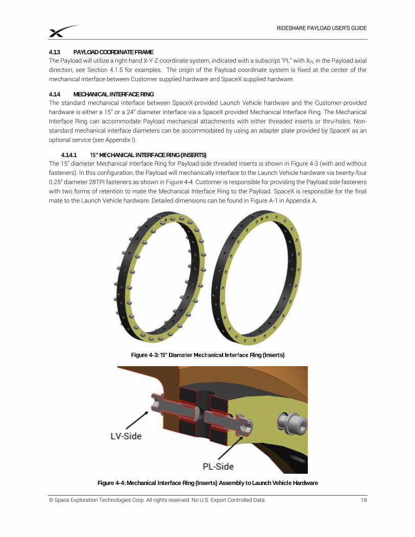
4.1.4.1 HANICAL INTERFACE RING (INSERTS)
The 15” diameter Mechanical Interface Ring for Payload-side threaded inserts is shown in Figure 4-3 (with and without fasteners). In this configuration, the Payload will mechanically interface to the Launch Vehicle hardware via twenty-four 0.25” diameter 28TPI fasteners as shown in Figure 4-4. Customer is responsible for providing the Payload side fasteners with two forms of retention to mate the Mechanical Interface Ring to the Payload. SpaceX is responsible for the final mate to the Launch Vehicle hardware. Detailed dimensions can be found in Figure A-1 in Appendix A.
Figure 4-3 Ring (Inserts)
Figure 4-4: Mechanical Interface Ring (Inserts) Assembly to Launch Vehicle Hardware
RIDESHARE PAYLOAD USER’S GUIDE
© Space Exploration Technologies Corp. All rights reserved. No U.S. Export Controlled Data. 20
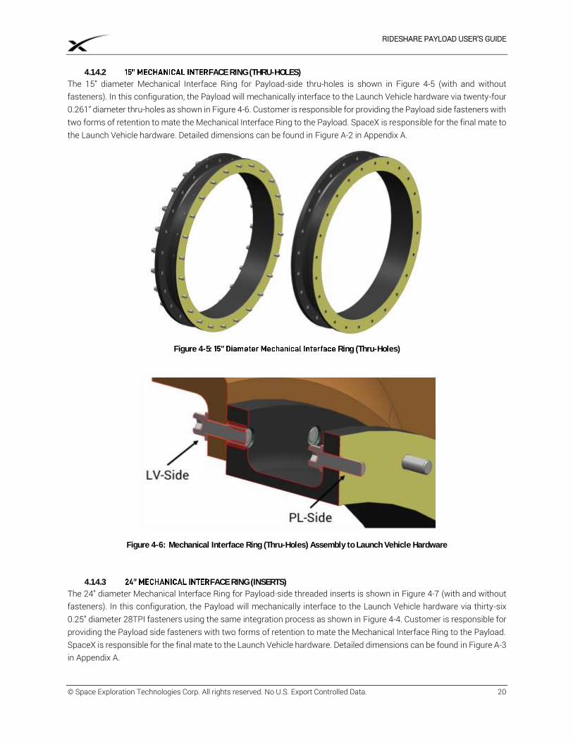
4.1.4.2 FACE RING (THRU-HOLES)
The 15” diameter Mechanical Interface Ring for Payload-side thru-holes is shown in Figure 4-5 (with and without fasteners). In this configuration, the Payload will mechanically interface to the Launch Vehicle hardware via twenty-four 0.261” diameter thru-holes as shown in Figure 4-6. Customer is responsible for providing the Payload side fasteners with two forms of retention to mate the Mechanical Interface Ring to the Payload. SpaceX is responsible for the final mate to the Launch Vehicle hardware. Detailed dimensions can be found in Figure A-2 in Appendix A.
Figure 4-5 Ring (Thru-Holes)
Figure 4-6: Mechanical Interface Ring (Thru-Holes) Assembly to Launch Vehicle Hardware
4.1.4.3 FACE RING (INSERTS)
The 24” diameter Mechanical Interface Ring for Payload-side threaded inserts is shown in Figure 4-7 (with and without fasteners). In this configuration, the Payload will mechanically interface to the Launch Vehicle hardware via thirty-six 0.25” diameter 28TPI fasteners using the same integration process as shown in Figure 4-4. Customer is responsible for providing the Payload side fasteners with two forms of retention to mate the Mechanical Interface Ring to the Payload. SpaceX is responsible for the final mate to the Launch Vehicle hardware. Detailed dimensions can be found in Figure A-3 in Appendix A.
RIDESHARE PAYLOAD USER’S GUIDE
© Space Exploration Technologies Corp. All rights reserved. No U.S. Export Controlled Data. 21
Figure 4-7: 24 Ring (Inserts)
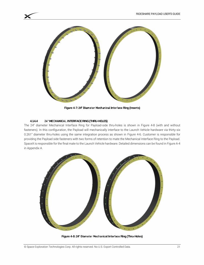
4.1.4.4 INTERFACE RING (THRU-HOLES)
The 24” diameter Mechanical Interface Ring for Payload-side thru-holes is shown in Figure 4-8 (with and without fasteners). In this configuration, the Payload will mechanically interface to the Launch Vehicle hardware via thirty-six 0.261” diameter thru-holes using the same integration process as shown in Figure 4-6. Customer is responsible for providing the Payload side fasteners with two forms of retention to mate the Mechanical Interface Ring to the Payload. SpaceX is responsible for the final mate to the Launch Vehicle hardware. Detailed dimensions can be found in Figure A-4 in Appendix A.
Figure 4-8: 24 Ring (Thru-Holes)
RIDESHARE PAYLOAD USER’S GUIDE
© Space Exploration Technologies Corp. All rights reserved. No U.S. Export Controlled Data. 22
4.1.5 PAYLOAD AVAILABLE VOLUME
The Payload must be no larger than the available volume defined in the following sections depending on the launch configuration and mechanical interface diameter. Depending on the Mission, SpaceX will inform Customer whether the Payload will be on a side-mounted (horizontal when the Launch Vehicle is vertical on the Launch pad) or forward-mounted (vertical when the Launch Vehicle is vertical on the Launch pad) interface. Customer may request small dimension changes to this volume and SpaceX will reasonably consider whether the Launch Services can support such changes with minimal additional work or risks to the Mission.
4.1.5.1 SIDE- HANICAL INTERFACE
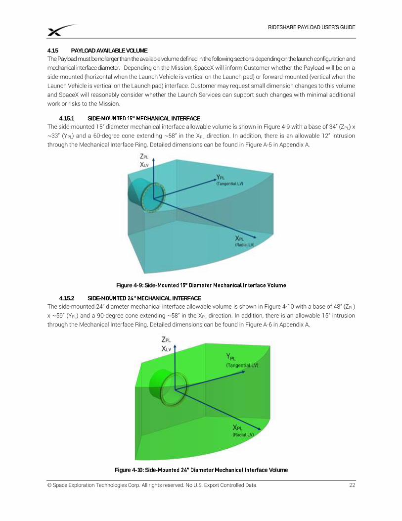
The side-mounted 15” diameter mechanical interface allowable volume is shown in Figure 4-9 with a base of 34” (ZPL) x ~33” (YPL) and a 60-degree cone extending ~58” in the XPL direction. In addition, there is an allowable 12” intrusion through the Mechanical Interface Ring. Detailed dimensions can be found in Figure A-5 in Appendix A.
Figure 4-9: Side-
4.1.5.2 SIDE- HANICAL INTERFACE
The side-mounted 24” diameter mechanical interface allowable volume is shown in Figure 4-10 with a base of 48” (ZPL) x ~59” (YPL) and a 90-degree cone extending ~58” in the XPL direction. In addition, there is an allowable 15” intrusion through the Mechanical Interface Ring. Detailed dimensions can be found in Figure A-6 in Appendix A.
Figure 4-10: Side- face Volume
RIDESHARE PAYLOAD USER’S GUIDE
© Space Exploration Technologies Corp. All rights reserved. No U.S. Export Controlled Data. 23
4.1.5.3 FORWARD- MECHANICAL INTERFACE
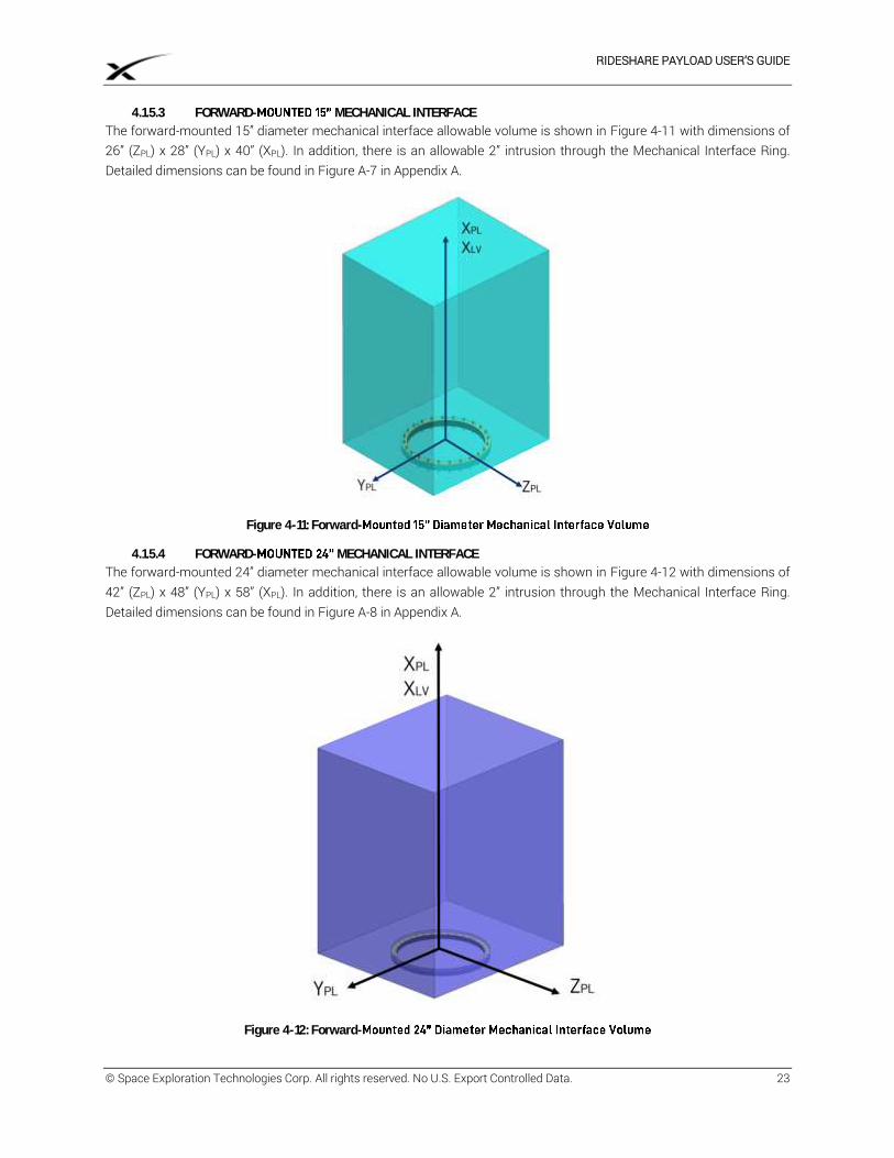
The forward-mounted 15” diameter mechanical interface allowable volume is shown in Figure 4-11 with dimensions of 26” (ZPL) x 28” (YPL) x 40” (XPL). In addition, there is an allowable 2” intrusion through the Mechanical Interface Ring. Detailed dimensions can be found in Figure A-7 in Appendix A.
Figure 4-11: Forward-
4.1.5.4 FORWARD- MECHANICAL INTERFACE
The forward-mounted 24” diameter mechanical interface allowable volume is shown in Figure 4-12 with dimensions of 42” (ZPL) x 48” (YPL) x 58” (XPL). In addition, there is an allowable 2” intrusion through the Mechanical Interface Ring. Detailed dimensions can be found in Figure A-8 in Appendix A.
Figure 4-12: Forward-
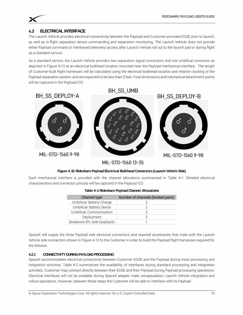
RIDESHARE PAYLOAD USER’S GUIDE
© Space Exploration Technologies Corp. All rights reserved. No U.S. Export Controlled Data. 24
ELECTRICAL INTERFACE The Launch Vehicle provides electrical connectivity between the Payload and Customer-provided EGSE prior to launch, as well as in-flight separation device commanding and separation monitoring. The Launch Vehicle does not provide either Payload command or interleaved telemetry access after Launch Vehicle roll out to the launch pad or during flight as a standard service.
As a standard service, the Launch Vehicle provides two separation signal connectors and one umbilical connector as depicted in Figure 4-13 at an electrical bulkhead location mounted near the Payload mechanical interface. The length of Customer-built flight harnesses will be calculated using the electrical bulkhead location and relative clocking of the Payload separation system, and are expected to be less than 5 feet. Final dimensions and mechanical attachment points will be captured in the Payload ICD.
Figure 4-13: Rideshare Payload Electrical Bulkhead Connectors (Launch Vehicle Side)
Each mechanical interface is provided with the channel allocations summarized in Table 4-1. Detailed electrical characteristics and connector pinouts will be captured in the Payload ICD.
Table 4-1: Rideshare Payload Channel Allocations
Channel type Number of channels (twisted pairs) Umbilical: Battery Charge 2 Umbilical: Battery Sense 2
Umbilical: Communication 2 Deployment 2
Breakwire (PL-side loopback) 1
SpaceX will supply the three Payload side electrical connectors and required accessories that mate with the Launch Vehicle side connectors shown in Figure 4-13 to the Customer in order to build the Payload flight harnesses required for the Mission.
4.2.1 CONNECTIVITY DURING PAYLOAD PROCESSING
SpaceX accommodates electrical connectivity between Customer EGSE and the Payload during most processing and integration activities. Table 4-2 summarizes the availability of interfaces during standard processing and integration activities. Customer may connect directly between their EGSE and their Payload during Payload processing operations. Electrical interfaces will not be available during SpaceX adapter mate, encapsulation, Launch Vehicle integration and rollout operations. However, between these steps the Customer will be able to interface with its Payload.
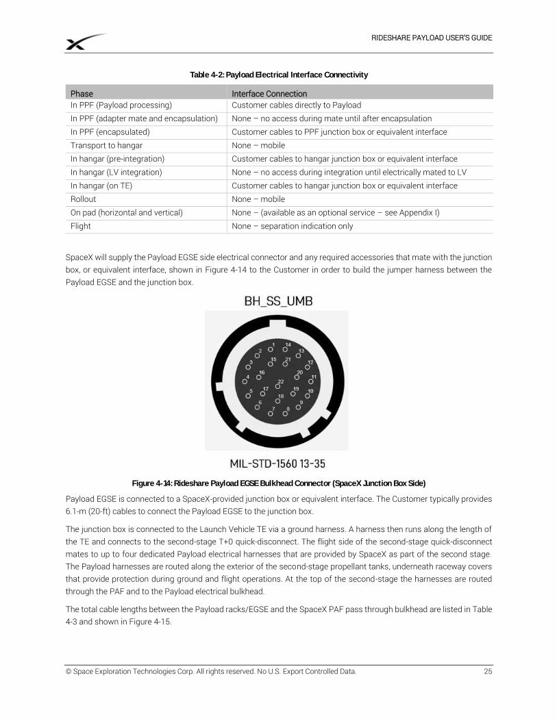
RIDESHARE PAYLOAD USER’S GUIDE
© Space Exploration Technologies Corp. All rights reserved. No U.S. Export Controlled Data. 25
Table 4-2: Payload Electrical Interface Connectivity
Phase Interface Connection In PPF (Payload processing) Customer cables directly to Payload In PPF (adapter mate and encapsulation) None – no access during mate until after encapsulation In PPF (encapsulated) Customer cables to PPF junction box or equivalent interface Transport to hangar None – mobile In hangar (pre-integration) Customer cables to hangar junction box or equivalent interface In hangar (LV integration) None – no access during integration until electrically mated to LV In hangar (on TE) Customer cables to hangar junction box or equivalent interface Rollout None – mobile On pad (horizontal and vertical) None – (available as an optional service – see Appendix I) Flight None – separation indication only
SpaceX will supply the Payload EGSE side electrical connector and any required accessories that mate with the junction box, or equivalent interface, shown in Figure 4-14 to the Customer in order to build the jumper harness between the Payload EGSE and the junction box.
Figure 4-14: Rideshare Payload EGSE Bulkhead Connector (SpaceX Junction Box Side)
Payload EGSE is connected to a SpaceX-provided junction box or equivalent interface. The Customer typically provides 6.1-m (20-ft) cables to connect the Payload EGSE to the junction box.
The junction box is connected to the Launch Vehicle TE via a ground harness. A harness then runs along the length of the TE and connects to the second-stage T+0 quick-disconnect. The flight side of the second-stage quick-disconnect mates to up to four dedicated Payload electrical harnesses that are provided by SpaceX as part of the second stage. The Payload harnesses are routed along the exterior of the second-stage propellant tanks, underneath raceway covers that provide protection during ground and flight operations. At the top of the second-stage the harnesses are routed through the PAF and to the Payload electrical bulkhead.
The total cable lengths between the Payload racks/EGSE and the SpaceX PAF pass through bulkhead are listed in Table 4-3 and shown in Figure 4-15.
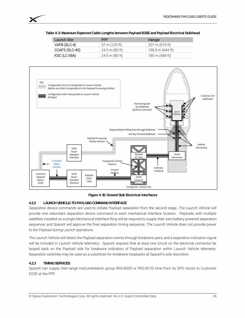
RIDESHARE PAYLOAD USER’S GUIDE
© Space Exploration Technologies Corp. All rights reserved. No U.S. Export Controlled Data. 26
Table 4-3: Maximum Expected Cable Lengths between Payload EGSE and Payload Electrical Bulkhead
Launch Site PPF Hangar VAFB (SLC-4) 37 m (120 ft) 207 m (679 ft) CCAFS (SLC-40) 24.5 m (80 ft) 196.5 m (644 ft) KSC (LC-39A) 24.5 m (80 ft) 180 m (589 ft)
Figure 4-15: Ground Side Electrical Interfaces
4.2.2 LAUNCH VEHICLE-TO-PAYLOAD COMMAND INTERFACE
Separation device commands are used to initiate Payload separation from the second stage. The Launch Vehicle will provide one redundant separation device command to each mechanical interface location. Payloads with multiple satellites installed on a single Mechanical Interface Ring will be required to supply their own battery powered separation sequencer and SpaceX will approve the final separation timing sequence. The Launch Vehicle does not provide power to the Payload during Launch operations.
The Launch Vehicle will detect the Payload separation events through breakwire pairs, and a separation indication signal will be included in Launch Vehicle telemetry. SpaceX requires that at least one circuit on the electrical connector be looped back on the Payload side for breakwire indication of Payload separation within Launch Vehicle telemetry. Separation switches may be used as a substitute for breakwire loopbacks at SpaceX’s sole discretion.
4.2.3 TIMING SERVICES
SpaceX can supply inter-range instrumentation group IRIG-B000 or IRIG-B120 time from its GPS clocks to Customer EGSE at the PPF.
RIDESHARE PAYLOAD USER’S GUIDE
© Space Exploration Technologies Corp. All rights reserved. No U.S. Export Controlled Data. 27
INTERFACE COMPATIBILITY VERIFICATION REQUIREMENTS SpaceX requires that Customer verify the compatibility of their systems with the Launch Vehicle mechanical and electrical interfaces before shipment to the Launch Site. SpaceX, in its sole discretion, may provide access to the Launch Vehicle Mechanical Interface Ring to support a Payload-to-Launch Vehicle mechanical fit check after Payload arrival at the Launch Site but before flight mating. The fit check will confirm the mechanical compatibility of the Mechanical Interface Ring and Customer Payload interface and, optionally, the mechanical alignment of the umbilical connectors, as documented in the Payload ICD.
RIDESHARE PAYLOAD USER’S GUIDE
© Space Exploration Technologies Corp. All rights reserved. No U.S. Export Controlled Data. 28
5 LAUNCH SITE FACILITIES SpaceX operates a Launch Site at Space Launch Complex 40 (SLC-40) at Cape Canaveral Air Force Station (CCAFS), Florida, Launch Complex 39A (LC-39A) at John F. Kennedy Space Center (KSC), located on Merritt Island off the central Florida coast, and Space Launch Complex 4 East (SLC-4E) at Vandenberg Air Force Base (VAFB), California. Details about these Launch Sites can be found in the SpaceX Falcon User’s Guide, latest revision, available on www.spacex.com/falcon9. SpaceX will provide the Launch Site facilities, equipment, documentation, and procedures to receive Customer’s hardware, validate interfaces to Customer’s hardware, integrate the Payload with the Launch Vehicle, and perform a Launch of the Payload.
FACILITY ACCESS AND WORKING HOURS SpaceX supports Customer personnel access to Launch Site facilities for two eight-hour working shifts per day, during those portions of the Launch Campaign when Customer’s activities require use of a given facility. SpaceX additionally supports 24/7 access to Launch Site facilities on an as-needed basis for Customer’s scheduled activities throughout the campaign, provided such access is coordinated in advance and mutually agreed with SpaceX. SpaceX supports 24/7 access (24 hours per day, 7 days per week) to Launch Site facilities for responding to emergency or off-nominal situations related to flight hardware.
During the Launch Campaign, SpaceX may provide short-term, controlled facility access to SpaceX personnel, SpaceX’s contractors, or other third parties (e.g., other customers, potential customers, VIPs, SpaceX-hosted tours). SpaceX is not required to provide Customer advance notice for short-term, controlled access to areas free of Payload or Customer’s hardware. SpaceX will provide prior notice and request approval for physical or visual access to areas with Payload or Customer’s hardware. At all times, SpaceX will follow Customer proprietary information and security requirements.
CUSTOMER OFFICES SpaceX provides an office area at the Launch Site during Payload processing for up to five (5) Customer and Customer’s Related Third Party personnel. The office areas may not be located at the PPF and may be shared with Co-Payload Customer(s). Office accommodations include 100-Mbps-class Internet connection, which may be common with other Customer Internet connections, air conditioning, and standard office equipment such as desks chairs and phones.
SPACEX PAYLOAD PROCESSING FACILITY (PPF) SpaceX provides a PPF at the Launch Site for the Customer to perform Payload pre-Launch processing activities. Payload and Co-Payload(s) may be co-located in the processing area. The processing area will be defined in a Mission specific Launch Campaign Plan based on Payload and Co-Payload(s) space requirements. The Payload processing area will:
a. Operate at ISO 14644-1 Class 8 (Class 100,000) cleanliness. b. Operate at 70°F ± 5°F air temperature (21°C ± 3°C). c. Operate at 45% ± 15% relative humidity. d. Be equipped with blast shielding. e. Include 50- and 10-ton capacity cranes with 100 ft (30 m) hook height. f. Provide minimum floor dimensions of 15 ft x 10 ft. for Payload processing activities.
The PPF includes an area for Payload EGSE, which is located adjacent to the Payload processing area and provide a 100-Mbps-class Internet connection, which may be common with other Customer Internet connections.
LAUNCH COMPLEX SpaceX provides a Launch Complex including the launch pad, and related Launch Vehicle GSE. SpaceX provides conditioned air into the fairing including environmental monitoring of the encapsulated Payload when at the launch pad. In the event of a Launch Site power outage, conditioned air will be resumed on backup power systems within 10 minutes.
RIDESHARE PAYLOAD USER’S GUIDE
© Space Exploration Technologies Corp. All rights reserved. No U.S. Export Controlled Data. 29
LAUNCH COUNTDOWN MONITORING SpaceX may provide Customer personnel (determined on an as-needed basis) a space at the Launch Site for launch countdown monitoring. Space will be shared between Payload and Co-Payload Customer(s), as documented in the Mission specific Launch Campaign Plan.
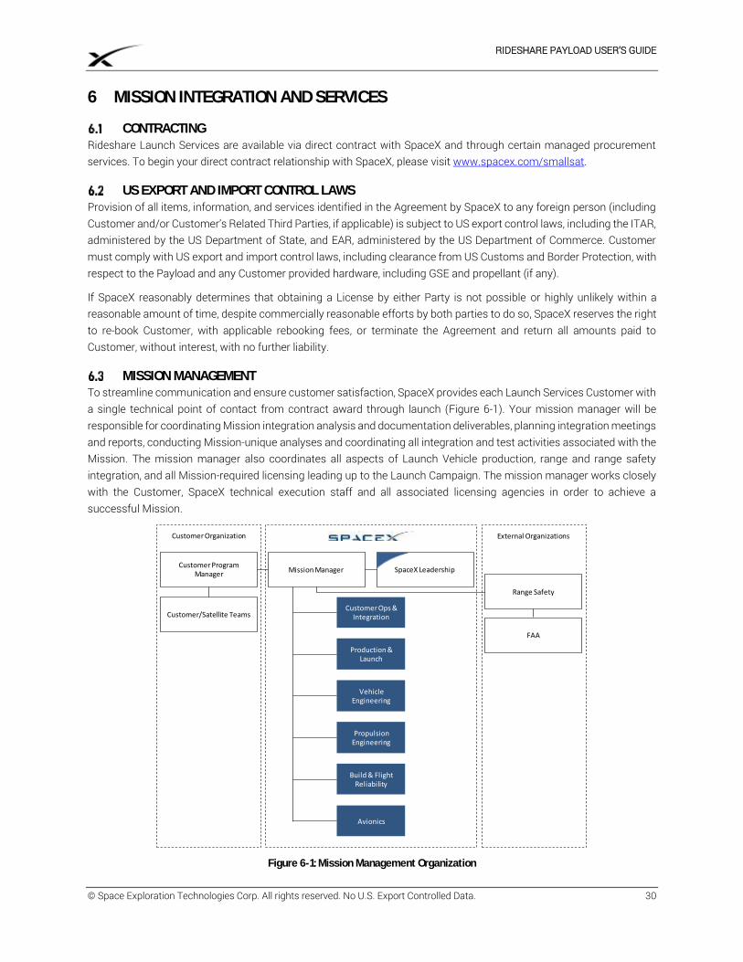
RIDESHARE PAYLOAD USER’S GUIDE
© Space Exploration Technologies Corp. All rights reserved. No U.S. Export Controlled Data. 30
6 MISSION INTEGRATION AND SERVICES
CONTRACTING Rideshare Launch Services are available via direct contract with SpaceX and through certain managed procurement services. To begin your direct contract relationship with SpaceX, please visit www.spacex.com/smallsat.
US EXPORT AND IMPORT CONTROL LAWS Provision of all items, information, and services identified in the Agreement by SpaceX to any foreign person (including Customer and/or Customer’s Related Third Parties, if applicable) is subject to US export control laws, including the ITAR, administered by the US Department of State, and EAR, administered by the US Department of Commerce. Customer must comply with US export and import control laws, including clearance from US Customs and Border Protection, with respect to the Payload and any Customer provided hardware, including GSE and propellant (if any).
If SpaceX reasonably determines that obtaining a License by either Party is not possible or highly unlikely within a reasonable amount of time, despite commercially reasonable efforts by both parties to do so, SpaceX reserves the right to re-book Customer, with applicable rebooking fees, or terminate the Agreement and return all amounts paid to Customer, without interest, with no further liability.
MISSION MANAGEMENT To streamline communication and ensure customer satisfaction, SpaceX provides each Launch Services Customer with a single technical point of contact from contract award through launch (Figure 6-1). Your mission manager will be responsible for coordinating Mission integration analysis and documentation deliverables, planning integration meetings and reports, conducting Mission-unique analyses and coordinating all integration and test activities associated with the Mission. The mission manager also coordinates all aspects of Launch Vehicle production, range and range safety integration, and all Mission-required licensing leading up to the Launch Campaign. The mission manager works closely with the Customer, SpaceX technical execution staff and all associated licensing agencies in order to achieve a successful Mission.
Figure 6-1: Mission Management Organization
Build & Flight Reliability
Customer Ops & Integration
Avionics
Customer Program Manager
Mission Manager SpaceX Leadership
Production &Launch
Vehicle Engineering
Propulsion Engineering
Customer/Satellite Teams
Range Safety
FAA
Customer Organization External Organizations
RIDESHARE PAYLOAD USER’S GUIDE
© Space Exploration Technologies Corp. All rights reserved. No U.S. Export Controlled Data. 31
PROGRAM DOCUMENTATION
6.4.1 INTERFACE CONTROL DOCUMENT (ICD)
SpaceX creates and maintains the Payload ICD in conjunction with Customer inputs. The Payload ICD will be negotiated in good faith between the Parties and at a minimum define physical interfaces (mechanical and electrical), functional requirements (orbit, attitude, etc.), Payload MPEs, and Launch operations requirements. Following signature by SpaceX and Customer, the Payload ICD will take precedence (in the event of a conflict) over the Statement of Work (SOW). Prior to signature, the Payload ICD is maintained in draft. SpaceX will deliver the Payload ICD for signature following the completion of Mission integration analyses. Once delivered for signature, the Parties will work in good faith to promptly sign the Payload ICD.
6.4.2 LAUNCH CAMPAIGN PLAN
SpaceX provides a Launch Campaign Plan and schedule of Launch Site operations, including required delivery dates for Launch Range-related documentation. SpaceX will coordinate with the Customer to integrate Launch Vehicle and Payload timelines into this plan.
6.4.3 PROGRAM STATUS, MEETINGS, WORKING GROUPS AND REVIEWS
SpaceX will provide program status and conduct meetings, working groups and reviews as described in the following subsections. SpaceX will provide advance copies of deliverables, as noted; otherwise, deliverables will be provided at the time of the corresponding event.
6.4.3.1 INTEGRATION WORKING GROUPS
SpaceX will organize integration working group meetings on an as-needed basis to address specific issues or operations related to integration of the Payload with the Launch Vehicle. The meeting schedules and locations will be mutually agreed between the Parties. Topics may include the following:
a. Coordinating Mission integration analyses and reviewing results. b. Confirming physical and functional interfaces. c. Preparing, reviewing, and approving the Payload ICD. d. Preparing Payload-to-Launch Vehicle test activities. e. Planning the logistics and shipment of hardware to the Launch Site. f. Planning Mission-specific ground and flight operations, including associated GSE. g. Scheduling PPF activities including hazardous operations between Payload and Co-Payload(s)
6.4.3.2 PROGRAM REVIEWS AND MILESTONES
SpaceX will hold program reviews and achieve the program milestones summarized below. Program reviews and milestones include:
a. Mission Integration Kickoff. b. Completion of Mission Integration Analyses. c. Launch Campaign Readiness Review.
CUSTOMER RESPONSIBILITIES Customer responsibilities include the following items. Timely completion is necessary to ensure that SpaceX can fulfill its responsibilities and obligations described in Section 6.6. The Parties understand that any material failure by Customer to meet its responsibilities, including any non-compliance with the Payload ICD, may result in a Customer delay requiring rebooking with applicable fees.
6.5.1 TRANSPORTATION
Customer is responsible for delivering the Payload and associated GSE via road transport to the PPF or other Launch Site facility designated by SpaceX. Customer remains responsible for environmental control of the
RIDESHARE PAYLOAD USER’S GUIDE
© Space Exploration Technologies Corp. All rights reserved. No U.S. Export Controlled Data. 32
Payload during Payload delivery, until the Payload is removed from its shipping container, including generators and fuel to maintain environmental control.
Customer delivers the Payload and GSE to the Launch Site no more than six weeks prior to the Launch Date unless requested by SpaceX. Timing of delivery will be coordinated by SpaceX based on Payload and Co-Payload(s) processing schedule.
Customer arranges and executes the shipment of the Payload shipping container and all Customer-furnished GSE from the Launch Site no later than three days after Launch.
Customer is responsible for all shipping and logistics of hazardous items from the port of entry to the Launch Site, including the required labeling for storage at the Launch Site.
Customer is responsible for obtaining any required permits, Licenses, or clearances, including from U.S. Customs and Border Protection for Customer’s and Customer’s Related Third Parties’ hardware and consumables.
6.5.2 HARDWARE, PROCESSING AND INTEGRATION
Customer provides the Payload and all Payload-unique GSE required for Customer’s Launch readiness activities at the Launch Site, interfacing to SpaceX hardware at the Launch Site (as defined in the Payload ICD), and ensure that all Payload and Payload-unique GSE meet the appropriate safety requirements, reference Section 8.1.
Customer will coordinate activities with SpaceX to create an integrated schedule and procedures where necessary.
Beginning upon Payload arrival at the Launch Site and throughout the Launch Campaign, Customer provides to SpaceX once per working day, an updated Payload processing schedule. The schedule should include a three day look-ahead summarizing all items requiring SpaceX support, such as: opening processing area doors, SpaceX GSE usage (cranes, forklifts, man lifts, etc.), and any other items requiring SpaceX support. Note also, Payload hazardous operations require 72 hours’ advance notice, with precise activity timing, from SpaceX to the Launch Range safety authorities.
Upon request, Customer will provide SpaceX with access to the flight-mating interface for a mating interface to Mechanical Interface Ring fit check after Payload arrival at the Launch Site but before flight mating.
Customer is responsible for providing all personal protective equipment, such as fall protection harnesses, for Customer and Customer’s Related Third Parties at the Launch Site. Customer and Customer’s Related Third Parties may not borrow personal protective equipment from SpaceX personnel.
Customer is responsible for cleaning all Customer-provided equipment and hardware to the appropriate SpaceX-designated contamination-control levels prior to entering SpaceX’s cleanliness-controlled facilities at the Launch Site (e.g. the PPF). Standard cleaning products (e.g. isopropyl alcohol and cleanroom wipes) are provided by SpaceX; however, SpaceX personnel will not clean Customer hardware.
The Payload will not have RF transmissions once mated to Launch Vehicle hardware until after Payload separation as defined Section 3.3.6.3. Any Payload RF checkouts required at the PPF must be contained within the processing area referenced in Section 5.3. Timeline for any approved checkouts will be documented in the Launch Campaign Plan.
The Payload will have access to the electrical harnesses referenced in Section 4.2 for Payload health checks and battery charging up until Launch Vehicle rollout from the integration hangar to the Launch pad. Additional access to Payload telemetry and battery charging can be procured as an optional service (see Appendix I).
6.5.3 HAZARDOUS PROCEDURES
Fueling of Rideshare Payloads at the Launch Site is available as an optional service (see Appendix I), but not part of the standard offering.
RIDESHARE PAYLOAD USER’S GUIDE
© Space Exploration Technologies Corp. All rights reserved. No U.S. Export Controlled Data. 33
Customer will provide any pressurant and other consumables required by the Payload, including transportation of such consumables to and from the Launch Site. Delivery of all Payload consumables must be coordinated in advance with SpaceX.
Customer will provide advance copies of all hazardous operation procedures, in addition to a Payload GOP (Ground Operations Plan) which references each hazardous procedure (reference Appendix G). Hazardous procedures and the GOP are reviewed and approved by the Launch Range safety authority. Customer will also provide copies of any non-hazardous procedures requested by the Launch Range safety authority.
Customer will arrange for and implement the disposal of hazardous waste generated during Payload processing activities in accordance with Launch Range and facility regulations.
Customer will provide the necessary decontamination equipment and perform all required decontamination activities for Payload GSE that is contaminated by hazardous substances during Payload processing activities in accordance with Launch Range and facility regulations.
6.5.4 ENTRY AND EXIT VISAS
Customer is responsible for obtaining any visas required for Customer’s personnel; including Customer’s Related Third Parties and guests. SpaceX can provide letters of invitation for Customer’s Launch Campaign personnel to support the issuance of U.S. entry visas by the U.S. Department of State
6.5.5 ANOMALY, MISHAP, ACCIDENT OR OTHER EVENT
In the event of an anomaly, mishap, accident or other event resulting in property damage, bodily injury or other loss, Customer will cooperate with SpaceX, any insurers, and federal, state and local government agencies, in their respective investigations of the event, including the completion of witness statements, if applicable. Such cooperation will include providing all data arising out of or related to the Payload, any ground support, and any activities relating to the performance of the Agreement, reasonably requested by SpaceX, the insurers, or federal, state and local agencies. Notwithstanding Customer’s obligation to cooperate, SpaceX may use reasonable means to independently access such information. Customer and Customer’s customers may not make any public comment, announcement, or other disclosure regarding such event without SpaceX’s review and approval.
6.5.6 PAYLOAD LICENSING AND REGISTRATION
Customer will flow down its responsibilities relating to Payload licensing and registration under the Agreement (including registration pursuant to the Convention on Registration of Objects Launched into Outer Space) to each of its customers, in writing. Evidence of proper flow-down will be provided to SpaceX upon request. Customer will provide a letter in the form of Appendix F, certifying that Customer has obtained all required Licenses and that all Payload information provided to SpaceX and/or any licensing agencies is complete and accurate.
SPACEX RESPONSIBILITIES SpaceX responsibilities include the following items. The Parties understand that any material failure by SpaceX to meet its responsibilities may result in changes in the scheduling of the Launch Period or Launch Date; such changes are not subject to any Customer rebooking fees.
6.6.1 LAUNCH SCHEDULING
SpaceX will advise the Customer approximately sixty days prior to the start of the Launch Period, of the Launch Date. The above-referenced dates will be determined by SpaceX in its sole discretion.
6.6.2 TRANSPORTATION SERVICES
SpaceX will provide transportation of the Payload and associated GSE between facilities at the Launch Site. This includes transportation of the Payload from the PPF to the Launch Complex and transportation of hazardous fluids and gasses between facilities at the Launch Site.
SpaceX will provide Launch Range coordination for Payload and associated GSE transportation activities when at the Launch Site.
RIDESHARE PAYLOAD USER’S GUIDE
© Space Exploration Technologies Corp. All rights reserved. No U.S. Export Controlled Data. 34
To the extent required by the Launch Range, SpaceX will arrange safety and security escorts for Payload and GSE transportation events at the Launch Site.
SpaceX will provide transportation for Customer’s non-U.S. personnel between a designated off-site parking area and SpaceX Launch Site facilities, and between SpaceX facilities, on a reasonable schedule. U.S. government regulations require that non-U.S. personnel and U.S. personnel representing non-U.S. entities must be escorted while on a U.S. government Launch Site.
6.6.3 PAYLOAD INTEGRATION AND ASSOCIATED HARDWARE
SpaceX will lead the operations required to physically integrate the Payload with the Launch Vehicle, including any operations involving integrated Payload and Launch Vehicle hardware.
SpaceX will provide all non-Payload-unique encapsulation equipment, the GSE required to handle the encapsulated Payload, and the GSE required to transport the encapsulated Payload to the Launch Complex.
SpaceX will provide the equipment to integrate the encapsulated Payload with the Launch Vehicle at the Launch Complex.
6.6.4 PHOTOGRAPHIC SERVICES
At SpaceX’s sole discretion, SpaceX may provide still photography and/or videography services during selected Payload processing, testing and integration operations. This service does not include delivery or broadcast of photography or videography in real-time or near real-time.
All media intended for release is subject to Launch Range security procedures, U.S. export control laws, and where applicable, the prior written approval of the U.S. Government. Media that includes images of SpaceX hardware or facilities is also subject to SpaceX’s prior written approval for release.
6.6.5 SECURITY
SpaceX provides security via a combination of locked facilities (security card access or cipher locks), closed circuit video monitoring and/or personnel present 24 hours/day at the relevant Launch Site facilities when Customer flight hardware is present. During any hazardous operations for which the Launch Range safety authority requires non-essential personnel to evacuate, video monitoring will be the sole method of surveillance available. Customer will not be granted access to SpaceX’s video footage.
6.6.6 LAUNCH CAMPAIGN
SpaceX will prepare for and perform a Launch of the Payload. Starting upon Payload arrival at the Launch Site and throughout the Launch Campaign, the SpaceX mission manager will provide to the Customer, at least once per working day, an updated Launch Campaign schedule (including key milestones and joint operations), relevant Launch Range safety status and information, and Launch Vehicle integration status.
SpaceX may conduct one or more Launch Vehicle wet dress rehearsals (inclusive of loading the Launch Vehicle with propellant) and static fire tests (inclusive of first-stage engine ignition) at the launch pad prior to Launch.
6.6.7 FACILITY SUPPORT AND OPERATIONS
SpaceX will integrate the scheduling of Payload processing activities with Launch Vehicle processing activities. SpaceX will maintain and communicate the integrated schedules and procedures. In addition, SpaceX will act as the primary point of contact between the Launch Range and the Customer and coordinate all Launch Range support, including the following
a. Launch Range security and badge control. b. Launch Range scheduling. c. Launch Range system safety. d. Meteorology. e. Communications and timing.
RIDESHARE PAYLOAD USER’S GUIDE
© Space Exploration Technologies Corp. All rights reserved. No U.S. Export Controlled Data. 35
f. Fire protection. g. Non-hazardous fluids and gases:
a. Gaseous helium per MIL-PRF-27407, Grade A (5700 psi max) b. Gaseous nitrogen per MIL-PRF-27401, Grade A (4150 psi max) c. Compressed Air (120 psi max) d. Isopropyl Alcohol (IPA)
SpaceX will maintain PPF management and scheduling responsibilities throughout the Payload processing and encapsulation phase. As facility manager, SpaceX will require some oversight of Payload activities.
SpaceX will provide training for Customer personnel regarding the PPF (cranes, warning lights, etc.) and applicable Launch Range/facility safety and security procedures. Training will be provided in advance of Payload arrival and offloading at the Launch Site.
6.6.8 LICENSING AND REGISTRATION
SpaceX will provide to Customer commercially reasonable support and information to enable Customer to satisfy the requirements of all applicable regulatory/licensing agencies and associated statutes, including Launch Range safety, the US Departments of State and Commerce, the US FAA, the US FCC and the CSLA.
Each Party will be responsible for obtaining all Licenses to carry out its obligations under the Agreement. For example, SpaceX is responsible for licensing RF emissions entering free-space from SpaceX-provided hardware and the Customer is responsible for licensing RF emissions entering free-space from Customer-provided hardware.
If Customer or any of Customer’s Related Third Parties takes any action or fails to take an action that SpaceX reasonably determines requires delaying any application for or amending any License for which SpaceX is responsible to obtain, SpaceX reserves the right to re-book Customer, with applicable rebooking fees.
6.6.9 MISSION INTEGRATION ANALYSES
SpaceX will conduct the following analyses in support of the Payload. All other environments are verified by Customer using requirements found in Section 3.
6.6.9.1 TRAJECTORY
SpaceX performs a trajectory and performance analysis, including Monte Carlo, in order to analyze the following Mission parameters:
a. The nominal flight timeline, profile (plots of altitude and acceleration. vs. time), and ground track b. The free molecular heating environment at fairing jettison c. The Earth-Centered-Earth-Fixed (ECEF) Payload separation state vector d. Payload and Co-Payload(s) deploy timeline e. Orbit injection accuracy
SpaceX analyzes and implements a single Earth-referenced Launch trajectory, a single Earth-referenced ascent attitude profile, and a single Earth-referenced Payload separation attitude, which will be used for all dates and times throughout the Launch Period. SpaceX does not implement multiple trajectories for various dates/times within the Launch Period, and does not provide sun-referenced or inertially-referenced attitudes during ascent or for Payload separation. The trajectory will be analyzed using the maximum Payload mass, including worst-case Payload mass properties tolerances. SpaceX does not implement multiple trajectories for multiple masses and does not utilize nominal Payload mass in the analysis. Results will be provided by SpaceX.
6.6.9.2 COLLISION AVOIDANCE
SpaceX performs an analysis to determine the need for a collision avoidance maneuver following separation of Payload and Co-Payload(s). This analysis will characterize the relative separation distance between the second stage and the
RIDESHARE PAYLOAD USER’S GUIDE
© Space Exploration Technologies Corp. All rights reserved. No U.S. Export Controlled Data. 36
Payload for one orbit after separation. This analysis will assume that no propulsive activities are executed by the Payload during the period analyzed. SpaceX does not perform additional analyses with respect to collision avoidance of potential debris or other space objects. These results will be provided by SpaceX as part of the trajectory and performance results described in Section 6.6.9.1.
SpaceX coordinates with applicable US regulatory authorities, such as the FAA and the Combined Space Operations Center (CSpOC), to select a Launch Window that results in a sufficiently low risk of collision with another space object during the Mission. In order to facilitate this coordination with the regulatory authorities, SpaceX will utilize the separation velocity imposed on the Payload by the separation system as documented in the Payload ICD and position predicted by the Trajectory analysis. Any Payload propulsive maneuvers or secondary Payload deployments within three (3) hours of Launch must be coordinated with SpaceX for inclusion in CSpOC analysis and will be documented in the Payload ICD.
6.6.9.3 COUPLED LOADS
SpaceX performs a CLA to verify the predicted dynamic flight loads and responses of the Payload are within the MPE described in Section 3.3.1. If any results are found to exceed the MPE described in Section 3.3.1, SpaceX will provide the CLA results to the Customer for further evaluation.
6.6.9.4 FAIRING VENTING
SpaceX performs a fairing venting analysis to verify the predicted internal pressure and pressurization rate of the fairing compartment as a function of time from lift-off to fairing jettison, using inputs from Payload and Co-Payload(s). If the predicted internal pressure or pressurization rate exceed the MPE described in Section 3.3.7 results will be provided to the Customer for further evaluation.
6.6.9.5 PAYLOAD SEPARATION
SpaceX performs a separation analysis of the Payload and Co-Payload(s) from the Launch Vehicle to verify compliance to the requirements listed in Section 2.4. These results are used for collision avoidance analysis as well. Since Payload mass properties and slosh are outside of SpaceX’s control, SpaceX will evaluate requirements compliance via the ideal analysis case. SpaceX will provide a presentation summarizing the results of the analysis and highlighting any issues or concerns.
6.6.9.6 PAYLOAD CLEARANCE
SpaceX performs a clearance analysis to validate the dynamic envelope compatibility between the Launch Vehicle and the Payload, and the Co-Payload(s) to the Payload, during all phases of the Mission. Clearance analysis results will be provided to the Customer for any Payload in excess of the allowable Payload volume defined in Appendix A.
RIDESHARE PAYLOAD USER’S GUIDE
© Space Exploration Technologies Corp. All rights reserved. No U.S. Export Controlled Data. 37
7 OPERATIONS Launch Vehicle operations are described in this section for launches from CCAFS, KSC, and VAFB. SpaceX launch operations are designed for rapid response (targeting less than one hour from vehicle rollout from the hangar to launch). Customers are strongly encouraged to develop launch readiness capabilities and timelines consistent with a rapid prelaunch concept of operations.
OVERVIEW AND SCHEDULE The Launch Vehicle system and associated operations have been designed for minimal complexity and minimal time at the pad. Customer Payload processing is performed in the PPF. After completion of standalone Payload operations (over a 7-day period), SpaceX performs the Payload mate to Launch Vehicle hardware followed by fairing encapsulation at the PPF. Payload and Co-Payload arrivals will be scheduled by SpaceX and may be staggered. The encapsulated assembly is then transported to the integration hangar. The Launch Vehicle is processed in the integration hangar at the Launch Complex and then loaded on the TE. The encapsulated assembly is mated to the Launch Vehicle at approximately L-5 days, followed by end-to-end system checkouts. Launch Vehicle systems are designed for rollout and Launch on the same day.
RIDESHARE PAYLOAD DELIVERY AND TRANSPORTATION Payload and associated GSE must be delivered to the Launch Site via ground transport. Customer is responsible for arranging transport to the Launch Site, while SpaceX will assist in arranging for Air Force Base access.
RIDESHARE PAYLOAD PROCESSING SpaceX provides an ISO Class 8 (Class 100,000) PPF for processing Customer Payload, including equipment unloading, unpacking/packing, final assembly, nonhazardous flight preparations, and checkouts. The PPF is available to Customer for two eight-hour working shifts per day. Layouts as well as standard services and equipment available in the PPF for VAFB and CCAFS can be found in the SpaceX Falcon User’s Guide, latest revision, available on www.spacex.com/falcon9.
The PPF is also designed to accommodate hazardous operations such as hypergolic propellant loading and ordnance installation. Fueling operations are allowed as an optional service (see Appendix I).
JOINT OPERATIONS AND INTEGRATION Joint operations begin once Customer has completed the Payload mate to the Mechanical Interface Ring. Payload (with the Mechanical Interface Ring) mate to Launch Vehicle hardware and fairing encapsulation are performed by SpaceX within the PPF. Fairing encapsulation is performed in the vertical orientation. Transportation is performed in the vertical orientation, and environmental control is provided throughout the transportation activity. Once at the Launch Vehicle integration hangar, the encapsulated assembly is rotated to horizontal and mated with the Launch Vehicle already positioned on the TE.
Once the encapsulated assembly is mated to the Launch Vehicle, the hangar facility HVAC system is connected via a fairing air conditioning duct to maintain environmental control inside the fairing. The Payload and Co-Payload(s) are then reconnected to EGSE (if required) and Customer has a final chance to perform electrical checkouts prior to Launch Vehicle rollout and launch.
LAUNCH OPERATIONS
7.5.1 ORGANIZATION
A breakdown of decision-making roles between SpaceX and the Launch range can be found in SpaceX Falcon User’s Guide, latest revision, available on www.spacex.com/falcon9.
RIDESHARE PAYLOAD USER’S GUIDE
© Space Exploration Technologies Corp. All rights reserved. No U.S. Export Controlled Data. 38
7.5.2 LAUNCH CONTROL
Launch countdown monitoring and access to Payload telemetry throughout the Launch countdown is available as an optional service (see Appendix I). Space within the Launch Control Center would be shared between Payload and Co-Payload Customer(s), as documented in a Launch Campaign Plan.
7.5.3 ROLLOUT AND PAD OPERATIONS
After all Payload and Co-Payload(s) EGSE is disconnected and readiness is verified the integrated Launch Vehicle may be rolled out from the hangar to the pad on the TE. Once the Launch Vehicle is at the pad, the fairing air conditioning system is reconnected, which helps maintain environmental control through liftoff. Electrical connectivity is provided via ground cables (reference Section 4.2.1). The Launch Vehicle will typically be erected only once, although the capability exists to easily return it to a horizontal orientation if necessary.
7.5.4 COUNTDOWN
The Launch Vehicle is designed to support a countdown duration as short as one hour. Early in the countdown, the vehicle performs LOX, RP-1 and pressurant loading, and it executes a series of vehicle and range checkouts. The TE strongback is retracted just prior to launch. Automated software sequencers control all critical Launch Vehicle functions during terminal countdown. Final Launch activities include verifying flight termination system status, transferring to internal power, and activating the transmitters. Engine ignition occurs shortly before liftoff, while the Launch Vehicle is held down at the base via hydraulic clamps. The flight computer evaluates engine ignition and full -power performance during the prelaunch hold-down, and if nominal criteria are satisfied, the hydraulic release system is activated at T-0. A safe shutdown is executed should any off-nominal condition be detected.
7.5.5 RECYCLE AND SCRUB
Launch Vehicle systems and operations have been designed to enable recycle operations when appropriate. Although every recycle event and launch window requirement is unique, the Launch Vehicle offers the general capability to perform multiple recycles within a given launch window, eliminating unnecessary launch delays.
In the event of a launch scrub, the TE and Launch Vehicle will stay vertical. However, for any long-duration Launch postponements, SpaceX will return the Launch Vehicle on the TE to the hangar.
FLIGHT OPERATIONS A summary of Launch Vehicle flight operations including Liftoff and Ascent and Payload Separation can be found in SpaceX Falcon User’s Guide, latest revision, available on www.spacex.com/falcon9. SpaceX will provide a quick-look orbit injection report to the Customer shortly after Payload separation, including a best-estimate Payload separation state vector as described in Appendix E.
RIDESHARE PAYLOAD USER’S GUIDE
© Space Exploration Technologies Corp. All rights reserved. No U.S. Export Controlled Data. 39
8 SAFETY
SAFETY REQUIREMENTS Customers are required to meet AFSPCMAN 91-710 Range User's Manual and FAA 14 CFR Part 400 requirements in the design and operation of their flight and ground systems. These requirements encompass mechanical design, electrical design, fluid and pressurant systems, lifting and handling systems, ordnance and RF systems, GSE, and other design and operational features. SpaceX will serve as the safety liaison between the Customer and the range and will provide templates for document compliance.
HAZARDOUS SYSTEMS AND OPERATIONS Most ranges consider hazardous systems and operations to include ordnance operations, pressurized systems that operate below a 4-to-1 safety factor, lifting operations, operations or systems that include toxic or hazardous materials, high-power RF systems and laser systems, and a variety of other systems and operations. The details of the system design and its operation will determine whether the system or related operations are considered hazardous. Typically, additional precautions are required for operating systems that are considered hazardous, such as redundant valving between pressurant and propellant. Additional precautions will be determined during the safety approval process with SpaceX and the Launch Range. All hazardous operations require procedures that are approved by both SpaceX and the Launch Range prior to execution. Ordnance operations, in particular, require coordination to provide reduced RF environments, cleared areas, safety support and other requirements.
WAIVERS For systems or operations that do not meet safety requirements but are believed to be acceptable for ground operations and launch, a waiver is typically produced for approval by the Launch Range safety authority. Waivers require considerable coordination and are considered a last resort; they should not be considered a standard practice.
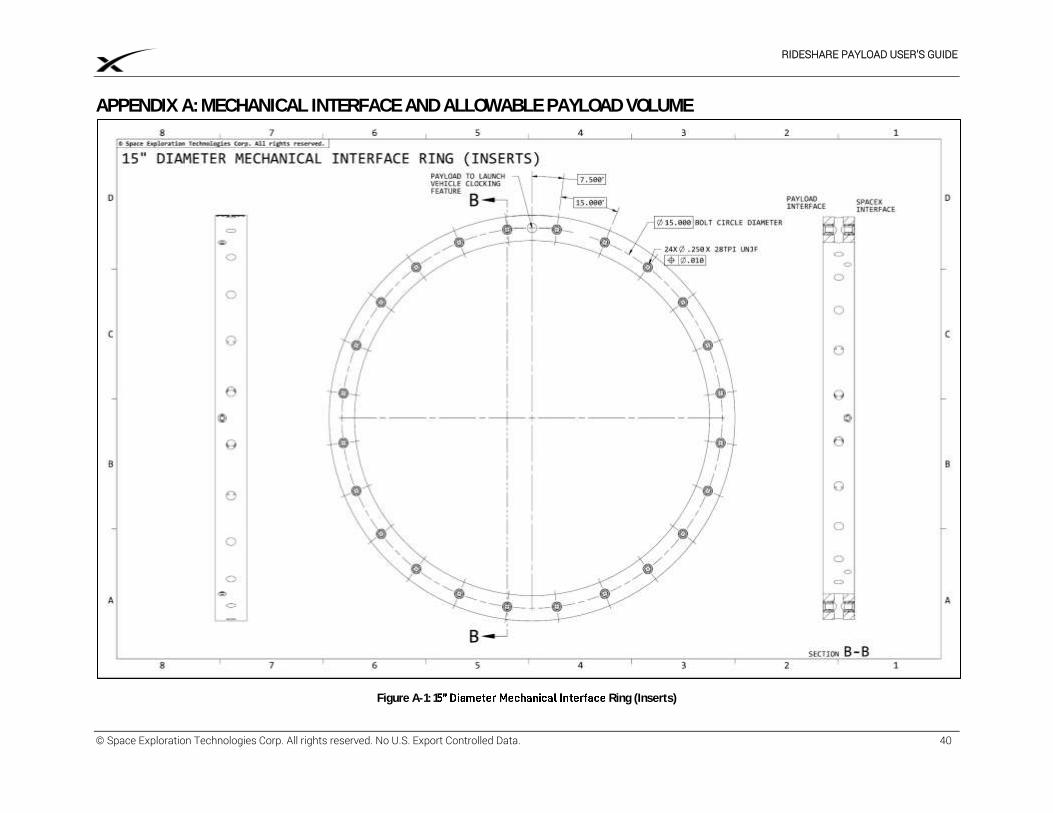
RIDESHARE PAYLOAD USER’S GUIDE
© Space Exploration Technologies Corp. All rights reserved. No U.S. Export Controlled Data. 40
APPENDIX A: MECHANICAL INTERFACE AND ALLOWABLE PAYLOAD VOLUME
Figure A-1: 1 Ring (Inserts)
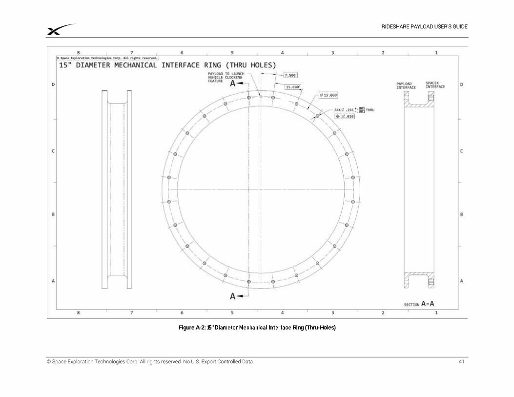
RIDESHARE PAYLOAD USER’S GUIDE
© Space Exploration Technologies Corp. All rights reserved. No U.S. Export Controlled Data. 41
Figure A-2: 1 Ring (Thru-Holes)
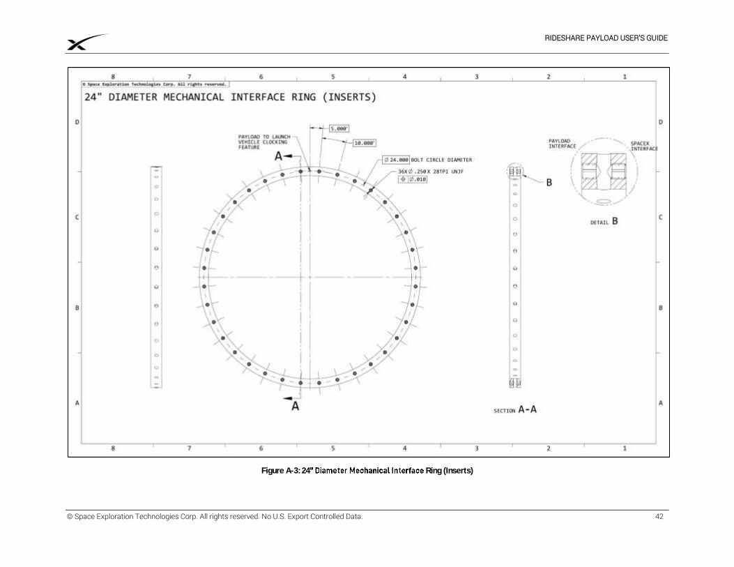
RIDESHARE PAYLOAD USER’S GUIDE
© Space Exploration Technologies Corp. All rights reserved. No U.S. Export Controlled Data. 42
Figure A-3: 24 Ring (Inserts)
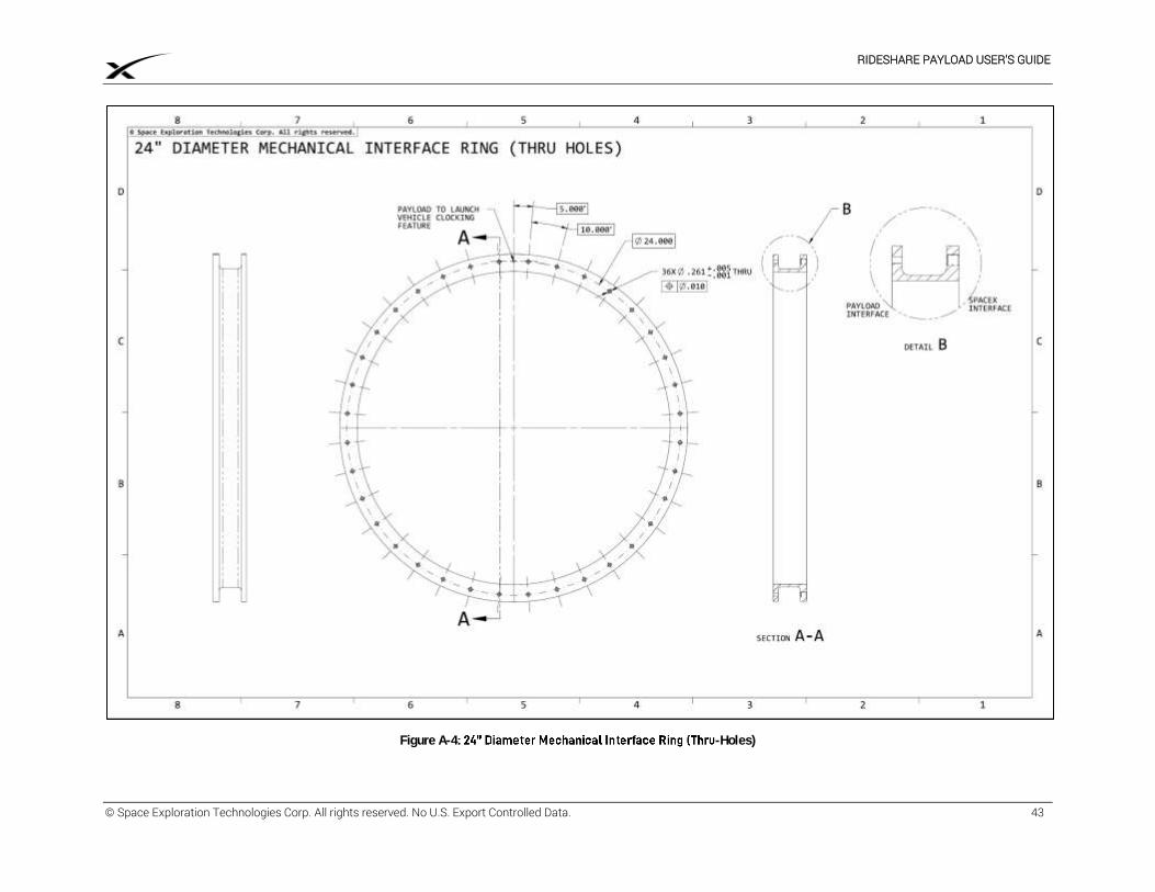
RIDESHARE PAYLOAD USER’S GUIDE
© Space Exploration Technologies Corp. All rights reserved. No U.S. Export Controlled Data. 43
Figure A-4 -Holes)
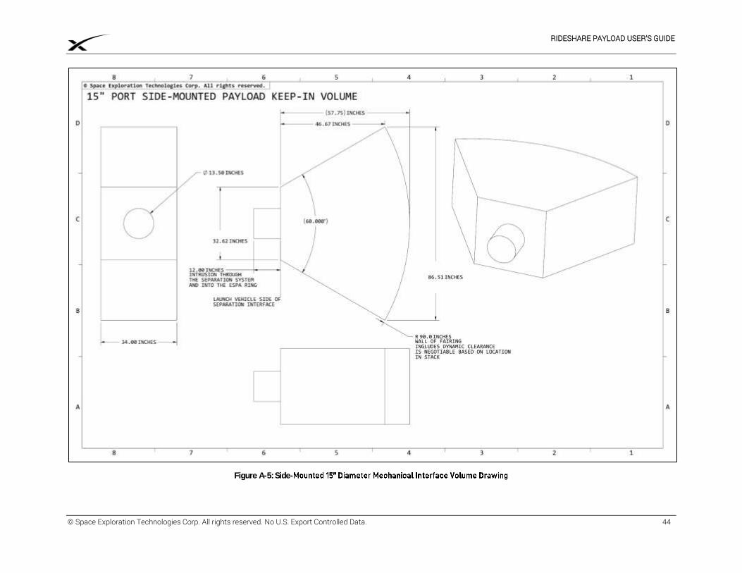
RIDESHARE PAYLOAD USER’S GUIDE
© Space Exploration Technologies Corp. All rights reserved. No U.S. Export Controlled Data. 44
Figure A-5: Side-
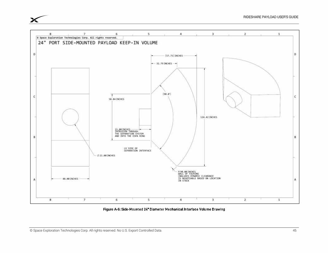
RIDESHARE PAYLOAD USER’S GUIDE
© Space Exploration Technologies Corp. All rights reserved. No U.S. Export Controlled Data. 45
Figure A-6: Side-
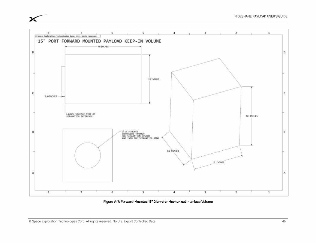
RIDESHARE PAYLOAD USER’S GUIDE
© Space Exploration Technologies Corp. All rights reserved. No U.S. Export Controlled Data. 46
Figure A-7: Forward- erface Volume
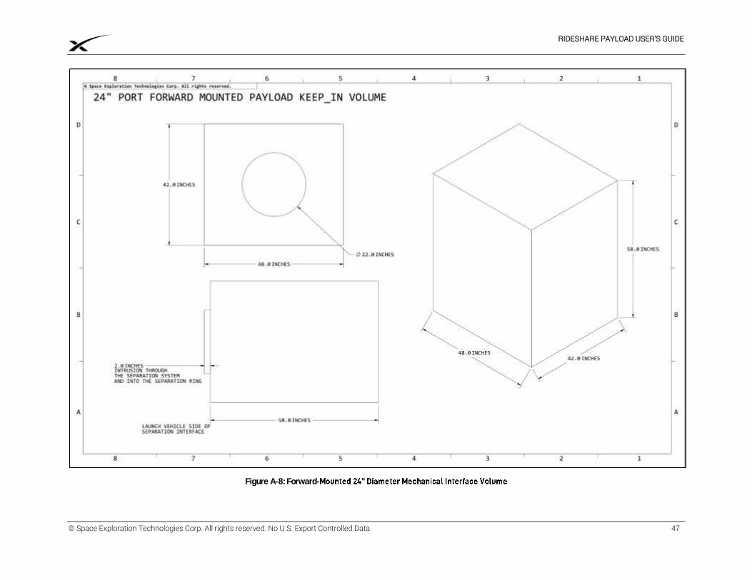
RIDESHARE PAYLOAD USER’S GUIDE
© Space Exploration Technologies Corp. All rights reserved. No U.S. Export Controlled Data. 47
Figure A-8: Forward-
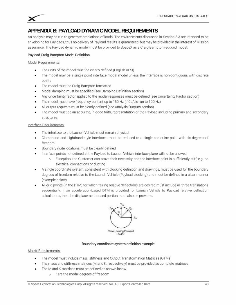
RIDESHARE PAYLOAD USER’S GUIDE
© Space Exploration Technologies Corp. All rights reserved. No U.S. Export Controlled Data. 48
APPENDIX B: PAYLOAD DYNAMIC MODEL REQUIREMENTS An analysis may be run to generate predictions of loads. The environments discussed in Section 3.3 are intended to be enveloping for Payloads, thus no delivery of Payload results is guaranteed, but may be provided in the interest of Mission assurance. The Payload dynamic model must be provided to SpaceX as a Craig-Bampton reduced model.
Payload Craig-Bampton Model Definition
Model Requirements:
The units of the model must be clearly defined (English or SI) The model may be a single point interface modal model unless the interface is non-contiguous with discrete
points The model must be Craig-Bampton formatted Modal damping must be specified (see Damping Definition section) Any uncertainty factor applied to the modal responses must be defined (see Uncertainty Factor section) The model must have frequency content up to 150 Hz (if CLA is run to 100 Hz) All output requests must be clearly defined (see Analysis Outputs section) The model must be an accurate, in good faith, representation of the Payload including primary and secondary
structures.
Interface Requirements:
The interface to the Launch Vehicle must remain physical Clampband and Lightband-style interfaces must be reduced to a single centerline point with six degrees of
freedom Boundary node locations must be clearly defined Interface points not defined at the Payload to Launch Vehicle interface plane will not be allowed
o Exception: the Customer can prove their necessity and the interface point is sufficiently stiff, e.g. no electrical connections or ducting
A single coordinate system, consistent with clocking definition and drawings, must be used for the boundary degrees of freedom relative to the Launch Vehicle (Payload clocking) and must be defined in a clear manner (example below).
All grid points (in the DTM) for which fairing relative deflections are desired must include all three translations sequentially. If an acceleration-based DTM is provided for Launch Vehicle to Payload relative deflection calculations, then the displacement-based portion must also be provided.
Boundary coordinate system definition example
Matrix Requirements:
The model must include mass, stiffness and Output Transformation Matrices (OTMs) The mass and stiffness matrices (M and K, respectively) must be provided as complete matrices The M and K matrices must be defined as shown below.
o 𝑖 are the modal degrees of freedom
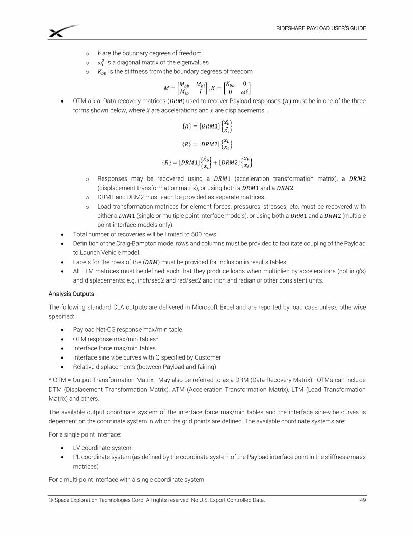
RIDESHARE PAYLOAD USER’S GUIDE
© Space Exploration Technologies Corp. All rights reserved. No U.S. Export Controlled Data. 49
o 𝑏 are the boundary degrees of freedom o 𝜔𝑖
2 is a diagonal matrix of the eigenvalues o 𝐾𝑏𝑏 is the stiffness from the boundary degrees of freedom
𝑀 = [𝑀𝑏𝑏 𝑀𝑏𝑖
𝑀𝑖𝑏 𝐼] , 𝐾 = [
𝐾𝑏𝑏 0
0 𝜔𝑖2]
OTM a.k.a. Data recovery matrices (𝐷𝑅𝑀) used to recover Payload responses (𝑅) must be in one of the three forms shown below, where �̈� are accelerations and 𝑥 are displacements.
{𝑅} = [𝐷𝑅𝑀1] {𝑥�̈�
𝑥�̈�}
{𝑅} = [𝐷𝑅𝑀2] {𝑥𝑏
𝑥𝑖}
{𝑅} = [𝐷𝑅𝑀1] {𝑥�̈�
𝑥�̈�} + [𝐷𝑅𝑀2] {
𝑥𝑏
𝑥𝑖}
o Responses may be recovered using a 𝐷𝑅𝑀1 (acceleration transformation matrix), a 𝐷𝑅𝑀2 (displacement transformation matrix), or using both a 𝐷𝑅𝑀1 and a 𝐷𝑅𝑀2.
o DRM1 and DRM2 must each be provided as separate matrices. o Load transformation matrices for element forces, pressures, stresses, etc. must be recovered with
either a 𝐷𝑅𝑀1 (single or multiple point interface models), or using both a 𝐷𝑅𝑀1 and a 𝐷𝑅𝑀2 (multiple point interface models only).
Total number of recoveries will be limited to 500 rows. Definition of the Craig-Bampton model rows and columns must be provided to facilitate coupling of the Payload
to Launch Vehicle model. Labels for the rows of the (𝐷𝑅𝑀) must be provided for inclusion in results tables. All LTM matrices must be defined such that they produce loads when multiplied by accelerations (not in g’s)
and displacements: e.g. inch/sec2 and rad/sec2 and inch and radian or other consistent units.
Analysis Outputs
The following standard CLA outputs are delivered in Microsoft Excel and are reported by load case unless otherwise specified:
Payload Net-CG response max/min table OTM response max/min tables* Interface force max/min tables Interface sine vibe curves with Q specified by Customer Relative displacements (between Payload and fairing)
* OTM = Output Transformation Matrix. May also be referred to as a DRM (Data Recovery Matrix). OTMs can include DTM (Displacement Transformation Matrix), ATM (Acceleration Transformation Matrix), LTM (Load Transformation Matrix) and others.
The available output coordinate system of the interface force max/min tables and the interface sine-vibe curves is dependent on the coordinate system in which the grid points are defined. The available coordinate systems are:
For a single point interface:
LV coordinate system PL coordinate system (as defined by the coordinate system of the Payload interface point in the stiffness/mass
matrices)
For a multi-point interface with a single coordinate system
RIDESHARE PAYLOAD USER’S GUIDE
© Space Exploration Technologies Corp. All rights reserved. No U.S. Export Controlled Data. 50
LV coordinate system PL coordinate system (as defined by the coordinate system of the Payload interface DOF in the stiffness/mass
matrices)
For a multi-point interface with multiple coordinate systems
LV coordinate system PL coordinate system (as defined by the coordinate system of the first boundary point in the stiffness/mass
matrices)
If outputs in any other coordinate system are desired, then the Customer must generate and provide such outputs in the ATM and/or LTM response recovery matrices.
Damping Definition
Diagonal modal damping must be defined as a percent of critical (and may vary from mode to mode) unless there is firm rationale why full matrix damping should be exercised, such as the existence of an internal highly damped isolation system with known physical characteristics.
Uncertainty Factor
SpaceX, as a standard practice, will apply a model uncertainty factor to all responses that reflects Launch Vehicle maturity. However, if Customer desires the application of a larger model uncertainty factor, this must be specifically requested. Under no circumstance will the model uncertainty factor be less than that used in SpaceX standard practice.
Documentation
SpaceX requests that the Customer’s dynamic model be accompanied by documentation that includes:
1. Definition of units used (SI or English). 2. Definition of the Payload coordinate system relative to the Launch Vehicle. 3. Location of all interface grids in Payload coordinate system. 4. Comparison of unreduced (FEM) and condensed (Craig-Bampton) models.
a. Mass. b. Center of gravity relative to interface. c. Strain energy. d. First seven modes of free-free analysis. e. Modal analysis, including modal effective mass.
5. A list of all frequencies. 6. Pictures and/or descriptions and frequencies of the first few mode shapes (including the three fundamental
modes in X, Y, and Z). 7. Definition of damping. 8. Definition of the model response (dynamic) uncertainty factor. 9. Definition of output format and requests, e.g., interface loads, interface accelerations, net CG loads, internal
Payload loads, shock response spectra (SRSs), power spectral densities (PSDs), etc. 10. If internal Payload responses are requested, provide appropriate DRMs (ATMs, DTMs, and LTMs) as well as
tables defining the rows of these matrices. 11. Definition of any Payload limit loads, including primary structure and component level, in order for SpaceX to
evaluate the CLA results (net CG, interface loads, and ATM/DTM/LTM) and determine if the CLA indicates an exceedance of Payload structural capability.
The above list is not all-inclusive, and Customer is encouraged to provide additional information that will assist SpaceX in processing the Payload dynamic model for the coupled loads analysis.
RIDESHARE PAYLOAD USER’S GUIDE
© Space Exploration Technologies Corp. All rights reserved. No U.S. Export Controlled Data. 51
APPENDIX C: PAYLOAD CAD MODEL REQUIREMENTS Customer must provide SpaceX a CAD model of the Payload in STEP or IGES format. SpaceX will integrate the Payload CAD model with the models of the Launch Vehicle second stage, Mechanical Interface Ring, and fairing for visualization, integration, clearance check, and operations development purposes.
SpaceX uses Siemens NX for CAD processing and, upon mutual agreement of the Parties, can accept Customer CAD models in a Parasolid file, the native format of NX.
The Payload CAD model must be simplified by the Customer and focus primarily on outer mold line and interface fidelity (to facilitate efficient model manipulation and processing). Customer must limit their CAD model complexity, as requested by SpaceX, to only the details and interfaces necessary for integration with the Launch Vehicle, while retaining the basic structure of the Payload. Spurious information must be removed from the model by Customer before transmission to SpaceX (an example of unnecessary detail is thousands of bodies within a CAD model representing individual cells on a solar array).
The Payload CAD model must include the following information in order for SpaceX to analyze clearances, prepare compatibility drawings, and produce Payload ICD images:
Payload interface to Launch Vehicle: o Payload mechanical interface to Launch Vehicle o Separation connectors and associated brackets o Pusher pads
Components subject to review for clearance analysis: o External components to review for clearance to fairing volume (e.g. solar array panels, aft and forward
antenna components, reflectors) o Any components in the immediate vicinity ( <20 cm) of the interface components above o Any components which protrude below the separation plane
Any points which may require access after encapsulation Simple Payload bus structure.
The Payload CAD model must not include:
Internal Payload or bus components Spurious details, including individual solar array cells, fasteners, antenna, reflectors, etc., that do not add to the
understanding of external volumes.
RIDESHARE PAYLOAD USER’S GUIDE
© Space Exploration Technologies Corp. All rights reserved. No U.S. Export Controlled Data. 52
APPENDIX D: PAYLOAD LAUNCH READINESS CERTIFICATE [Insert Company Logo] [Insert Company Name] [Insert Company Address]
To: Space Exploration Technologies Corp. (SpaceX) From: [Insert Company Name] Date: [Insert Date] Subject: Launch Readiness Certification Letter
[Insert Company] certifies that the [Insert Mission] Payload is GO for launch on the Falcon 9 rocket, including conforming to all applicable Payload safety requirements of the Air Force Space Command Range Safety User Requirement Manual (AFSPCMAN 91-710), as tailored for the Mission.
[Insert Company] has reviewed all open issues and risks and certifies that there are no constraints to launch. The current open issues and risks are:
[Insert any open issues]
All open items are under active review with Responsible Engineering authority and will be closed prior to launch. If there are any new issues that arise or if current open issues are not closed prior to launch, [Insert Company] will inform SpaceX and the 45 SW Range Safety office in writing for approval.
Sincerely,
[Insert Signature]
[Insert Company]
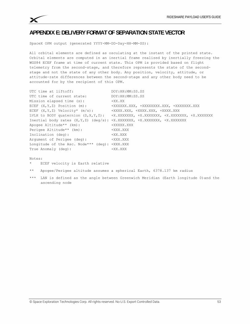
RIDESHARE PAYLOAD USER’S GUIDE
© Space Exploration Technologies Corp. All rights reserved. No U.S. Export Controlled Data. 53
APPENDIX E: DELIVERY FORMAT OF SEPARATION STATE VECTOR
SpaceX OPM output (generated YYYY-MM-DD-Day-HH-MM-SS):
All orbital elements are defined as osculating at the instant of the printed state.
Orbital elements are computed in an inertial frame realized by inertially freezing the
WGS84 ECEF frame at time of current state. This OPM is provided based on flight
telemetry from the second-stage, and therefore represents the state of the second-
stage and not the state of any other body. Any position, velocity, attitude, or
attitude-rate differences between the second-stage and any other body need to be
accounted for by the recipient of this OPM.
UTC time at liftoff: DOY:HH:MM:SS.SS UTC time of current state: DOY:HH:MM:SS.SS Mission elapsed time (s): +XX.XX ECEF (X,Y,Z) Position (m): +XXXXXX.XXX, +XXXXXXXX.XXX, +XXXXXXX.XXX ECEF (X,Y,Z) Velocity* (m/s): +XXXX.XXX, +XXXX.XXX, +XXXX.XXX LVLH to BODY quaternion (S,X,Y,Z): +X.XXXXXXX, +X.XXXXXXX, +X.XXXXXXX, +X.XXXXXXX Inertial body rates (X,Y,Z) (deg/s): +X.XXXXXXX, +X.XXXXXXX, +X.XXXXXXX Apogee Altitude** (km): +XXXXX.XXX Perigee Altitude** (km): +XXX.XXX Inclination (deg): +XX.XXX Argument of Perigee (deg): +XXX.XXX Longitude of the Asc. Node*** (deg): +XXX.XXX True Anomaly (deg): +XX.XXX Notes: * ECEF velocity is Earth relative
** Apogee/Perigee altitude assumes a spherical Earth, 6378.137 km radius
*** LAN is defined as the angle between Greenwich Meridian (Earth longitude 0)and the
ascending node
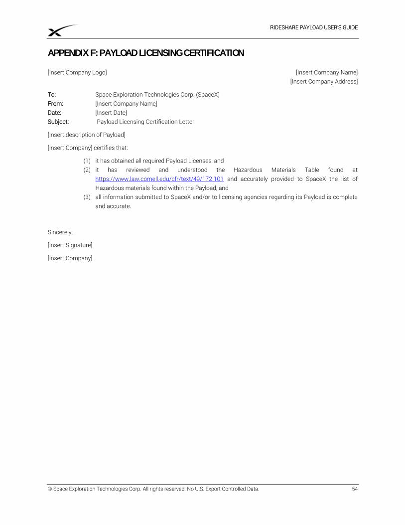
RIDESHARE PAYLOAD USER’S GUIDE
© Space Exploration Technologies Corp. All rights reserved. No U.S. Export Controlled Data. 54
APPENDIX F: PAYLOAD LICENSING CERTIFICATION [Insert Company Logo] [Insert Company Name] [Insert Company Address]
To: Space Exploration Technologies Corp. (SpaceX) From: [Insert Company Name] Date: [Insert Date] Subject: Payload Licensing Certification Letter
[Insert description of Payload]
[Insert Company] certifies that:
(1) it has obtained all required Payload Licenses, and (2) it has reviewed and understood the Hazardous Materials Table found at
https://www.law.cornell.edu/cfr/text/49/172.101 and accurately provided to SpaceX the list of Hazardous materials found within the Payload, and
(3) all information submitted to SpaceX and/or to licensing agencies regarding its Payload is complete and accurate.
Sincerely,
[Insert Signature]
[Insert Company]
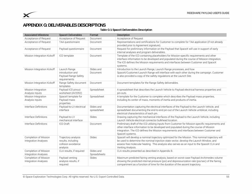
RIDESHARE PAYLOAD USER’S GUIDE
© Space Exploration Technologies Corp. All rights reserved. No U.S. Export Controlled Data. 55
APPENDIX G: DELIVERABLES DESCRIPTIONS Table G-1: SpaceX Deliverables Description
Associated Milestone SpaceX Deliverables Format Description Acceptance of Request Acceptance of Request Document Acceptance of Request Acceptance of Request TAA questionnaire Document Representations and certifications for Customer to complete for TAA application (if not already
provided prior to Agreement signature). Acceptance of Request Payload questionnaire Document Request for preliminary information on the Payload that SpaceX will use in support of early
internal analyses and program deliverables. Mission Integration Kickoff ICD template Document Template of the ICD containing placeholders for Mission-specific requirements and other
interface information to be developed and populated during the course of Mission integration. The ICD defines the Mission requirements and interfaces between Customer and SpaceX systems.
Mission Integration Kickoff Launch Range introduction and Payload Range Safety requirements
Slides and Document
Introduction to the Launch Range, Launch Range processes, and how SpaceX/Customer/Launch Range will interface with each other during the campaign. Customer is also provided a copy of the safety regulations at the Launch Site.
Mission Integration Kickoff Range Safety document templates
Document Document templates for the Range Safety deliverables.
Mission Integration Analysis Inputs
Payload ICD pinout worksheet (AV2052)
Spreadsheet A spreadsheet that describes the Launch Vehicle to Payload electrical harness properties and pin-outs.
Mission Integration Analysis Inputs
SpaceX template for Payload mass properties
Spreadsheet A template for the Customer to complete which describes the Payload mass properties, including its center of mass, moments of inertia and products of inertia.
Interface Definitions Payload-to-LV electrical interface
Slides and spreadsheet
Documentation capturing the electrical interfaces of the Payload to the Launch Vehicle, and spreadsheet documenting the end-to-end pin-out of the Launch Vehicle umbilical, including electrical characteristics of each pin.
Interface Definitions Payload-to-LV mechanical interface
Slides Drawing capturing the mechanical interfaces of the Payload to the Launch Vehicle, including Launch Vehicle electrical connector bulkhead location.
Interface Definitions ICD Draft Document Preliminary draft of the ICD utilizing inputs from Customer for Mission-specific requirements and other interface information to be developed and populated during the course of Mission integration. The ICD defines the Mission requirements and interfaces between Customer and SpaceX systems.
Completion of Mission Integration Analyses
Trajectory analysis results, including collision avoidance analysis
Slides SpaceX will develop a nominal trajectory optimized for the Mission. This nominal trajectory will be used to determine the nominal injection state vector, develop the Launch Window, and assess free molecular heating. This analysis also serves as an input to the SpaceX CLA and Venting Analysis.
Completion of Mission Integration Analyses
CLA results, if required Slides and Spreadsheets
CLA results presented as described in Appendix B.
Completion of Mission Integration Analyses
Payload venting analysis results, if required
Slides Maximum predicted fairing venting analysis, based on worst-case Payload Archimedes volume showing the predicted internal pressure (psi) and depressurization rate (psi/sec) of the fairing compartment as a function of time for the duration of the ascent trajectory.
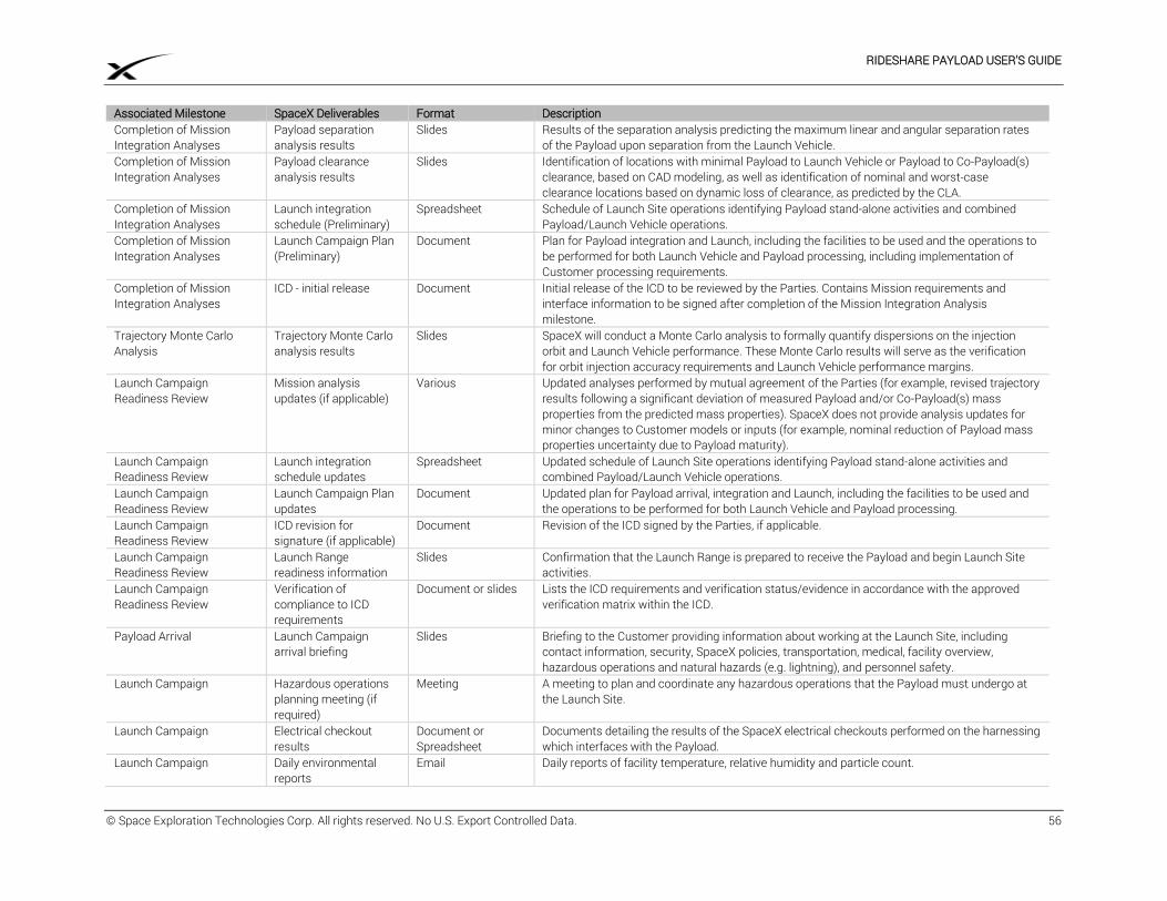
RIDESHARE PAYLOAD USER’S GUIDE
© Space Exploration Technologies Corp. All rights reserved. No U.S. Export Controlled Data. 56
Associated Milestone SpaceX Deliverables Format Description Completion of Mission Integration Analyses
Payload separation analysis results
Slides Results of the separation analysis predicting the maximum linear and angular separation rates of the Payload upon separation from the Launch Vehicle.
Completion of Mission Integration Analyses
Payload clearance analysis results
Slides Identification of locations with minimal Payload to Launch Vehicle or Payload to Co-Payload(s) clearance, based on CAD modeling, as well as identification of nominal and worst-case clearance locations based on dynamic loss of clearance, as predicted by the CLA.
Completion of Mission Integration Analyses
Launch integration schedule (Preliminary)
Spreadsheet Schedule of Launch Site operations identifying Payload stand-alone activities and combined Payload/Launch Vehicle operations.
Completion of Mission Integration Analyses
Launch Campaign Plan (Preliminary)
Document Plan for Payload integration and Launch, including the facilities to be used and the operations to be performed for both Launch Vehicle and Payload processing, including implementation of Customer processing requirements.
Completion of Mission Integration Analyses
ICD - initial release Document Initial release of the ICD to be reviewed by the Parties. Contains Mission requirements and interface information to be signed after completion of the Mission Integration Analysis milestone.
Trajectory Monte Carlo Analysis
Trajectory Monte Carlo analysis results
Slides SpaceX will conduct a Monte Carlo analysis to formally quantify dispersions on the injection orbit and Launch Vehicle performance. These Monte Carlo results will serve as the verification for orbit injection accuracy requirements and Launch Vehicle performance margins.
Launch Campaign Readiness Review
Mission analysis updates (if applicable)
Various Updated analyses performed by mutual agreement of the Parties (for example, revised trajectory results following a significant deviation of measured Payload and/or Co-Payload(s) mass properties from the predicted mass properties). SpaceX does not provide analysis updates for minor changes to Customer models or inputs (for example, nominal reduction of Payload mass properties uncertainty due to Payload maturity).
Launch Campaign Readiness Review
Launch integration schedule updates
Spreadsheet Updated schedule of Launch Site operations identifying Payload stand-alone activities and combined Payload/Launch Vehicle operations.
Launch Campaign Readiness Review
Launch Campaign Plan updates
Document Updated plan for Payload arrival, integration and Launch, including the facilities to be used and the operations to be performed for both Launch Vehicle and Payload processing.
Launch Campaign Readiness Review
ICD revision for signature (if applicable)
Document Revision of the ICD signed by the Parties, if applicable.
Launch Campaign Readiness Review
Launch Range readiness information
Slides Confirmation that the Launch Range is prepared to receive the Payload and begin Launch Site activities.
Launch Campaign Readiness Review
Verification of compliance to ICD requirements
Document or slides Lists the ICD requirements and verification status/evidence in accordance with the approved verification matrix within the ICD.
Payload Arrival Launch Campaign arrival briefing
Slides Briefing to the Customer providing information about working at the Launch Site, including contact information, security, SpaceX policies, transportation, medical, facility overview, hazardous operations and natural hazards (e.g. lightning), and personnel safety.
Launch Campaign Hazardous operations planning meeting (if required)
Meeting A meeting to plan and coordinate any hazardous operations that the Payload must undergo at the Launch Site.
Launch Campaign Electrical checkout results
Document or Spreadsheet
Documents detailing the results of the SpaceX electrical checkouts performed on the harnessing which interfaces with the Payload.
Launch Campaign Daily environmental reports
Email Daily reports of facility temperature, relative humidity and particle count.
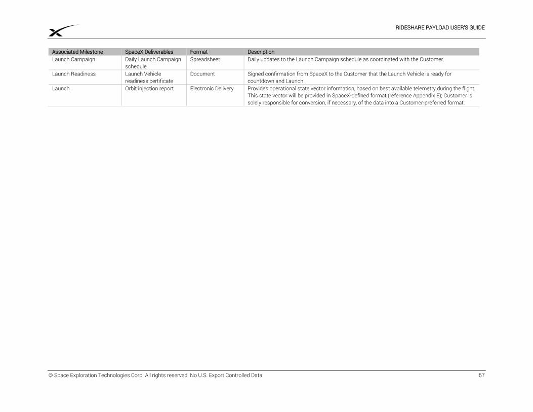
RIDESHARE PAYLOAD USER’S GUIDE
© Space Exploration Technologies Corp. All rights reserved. No U.S. Export Controlled Data. 57
Associated Milestone SpaceX Deliverables Format Description Launch Campaign Daily Launch Campaign
schedule Spreadsheet Daily updates to the Launch Campaign schedule as coordinated with the Customer.
Launch Readiness Launch Vehicle readiness certificate
Document Signed confirmation from SpaceX to the Customer that the Launch Vehicle is ready for countdown and Launch.
Launch Orbit injection report Electronic Delivery Provides operational state vector information, based on best available telemetry during the flight. This state vector will be provided in SpaceX-defined format (reference Appendix E); Customer is solely responsible for conversion, if necessary, of the data into a Customer-preferred format.
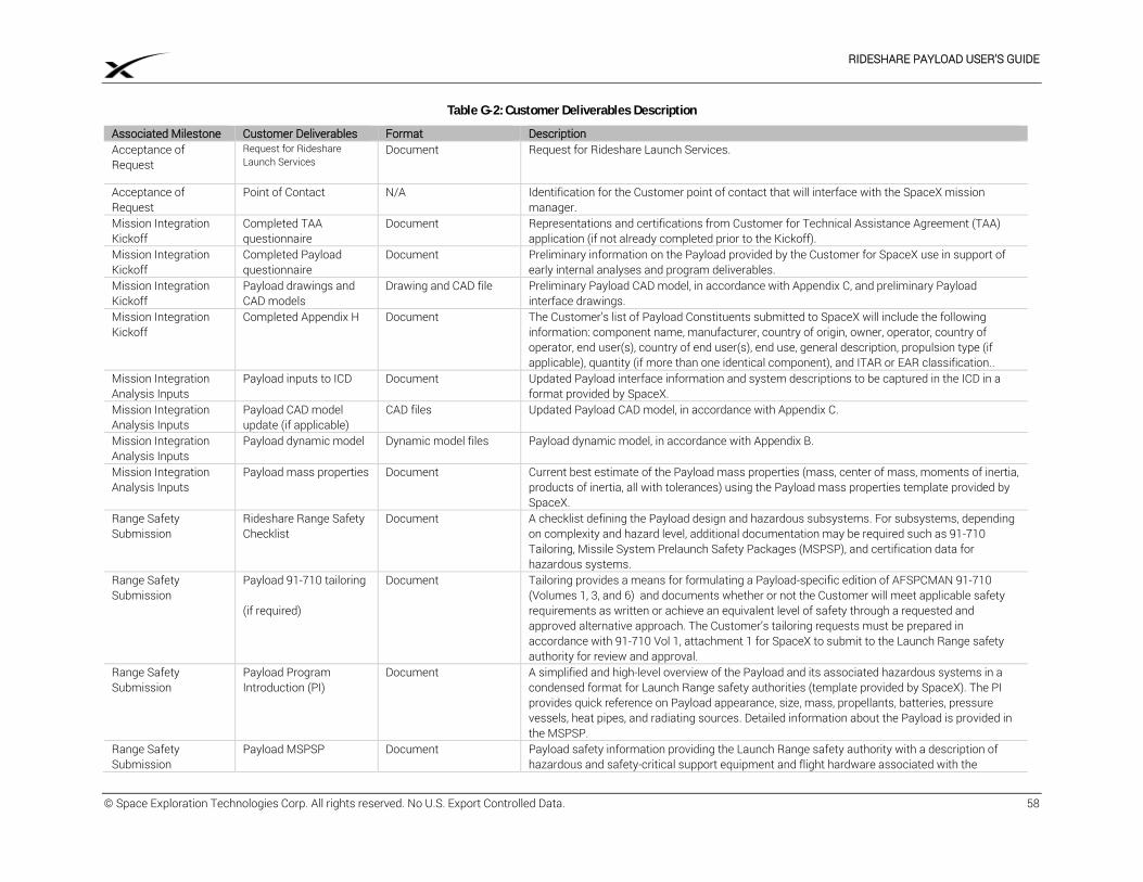
RIDESHARE PAYLOAD USER’S GUIDE
© Space Exploration Technologies Corp. All rights reserved. No U.S. Export Controlled Data. 58
Table G-2: Customer Deliverables Description
Associated Milestone Customer Deliverables Format Description Acceptance of Request
Request for Rideshare Launch Services
Document Request for Rideshare Launch Services.
Acceptance of Request
Point of Contact N/A Identification for the Customer point of contact that will interface with the SpaceX mission manager.
Mission Integration Kickoff
Completed TAA questionnaire
Document Representations and certifications from Customer for Technical Assistance Agreement (TAA) application (if not already completed prior to the Kickoff).
Mission Integration Kickoff
Completed Payload questionnaire
Document Preliminary information on the Payload provided by the Customer for SpaceX use in support of early internal analyses and program deliverables.
Mission Integration Kickoff
Payload drawings and CAD models
Drawing and CAD file Preliminary Payload CAD model, in accordance with Appendix C, and preliminary Payload interface drawings.
Mission Integration Kickoff
Completed Appendix H Document The Customer’s list of Payload Constituents submitted to SpaceX will include the following information: component name, manufacturer, country of origin, owner, operator, country of operator, end user(s), country of end user(s), end use, general description, propulsion type (if applicable), quantity (if more than one identical component), and ITAR or EAR classification..
Mission Integration Analysis Inputs
Payload inputs to ICD Document Updated Payload interface information and system descriptions to be captured in the ICD in a format provided by SpaceX.
Mission Integration Analysis Inputs
Payload CAD model update (if applicable)
CAD files Updated Payload CAD model, in accordance with Appendix C.
Mission Integration Analysis Inputs
Payload dynamic model Dynamic model files Payload dynamic model, in accordance with Appendix B.
Mission Integration Analysis Inputs
Payload mass properties Document Current best estimate of the Payload mass properties (mass, center of mass, moments of inertia, products of inertia, all with tolerances) using the Payload mass properties template provided by SpaceX.
Range Safety Submission
Rideshare Range Safety Checklist
Document A checklist defining the Payload design and hazardous subsystems. For subsystems, depending on complexity and hazard level, additional documentation may be required such as 91-710 Tailoring, Missile System Prelaunch Safety Packages (MSPSP), and certification data for hazardous systems.
Range Safety Submission
Payload 91-710 tailoring (if required)
Document Tailoring provides a means for formulating a Payload-specific edition of AFSPCMAN 91-710 (Volumes 1, 3, and 6) and documents whether or not the Customer will meet applicable safety requirements as written or achieve an equivalent level of safety through a requested and approved alternative approach. The Customer’s tailoring requests must be prepared in accordance with 91-710 Vol 1, attachment 1 for SpaceX to submit to the Launch Range safety authority for review and approval.
Range Safety Submission
Payload Program Introduction (PI)
Document A simplified and high-level overview of the Payload and its associated hazardous systems in a condensed format for Launch Range safety authorities (template provided by SpaceX). The PI provides quick reference on Payload appearance, size, mass, propellants, batteries, pressure vessels, heat pipes, and radiating sources. Detailed information about the Payload is provided in the MSPSP.
Range Safety Submission
Payload MSPSP
Document Payload safety information providing the Launch Range safety authority with a description of hazardous and safety-critical support equipment and flight hardware associated with the
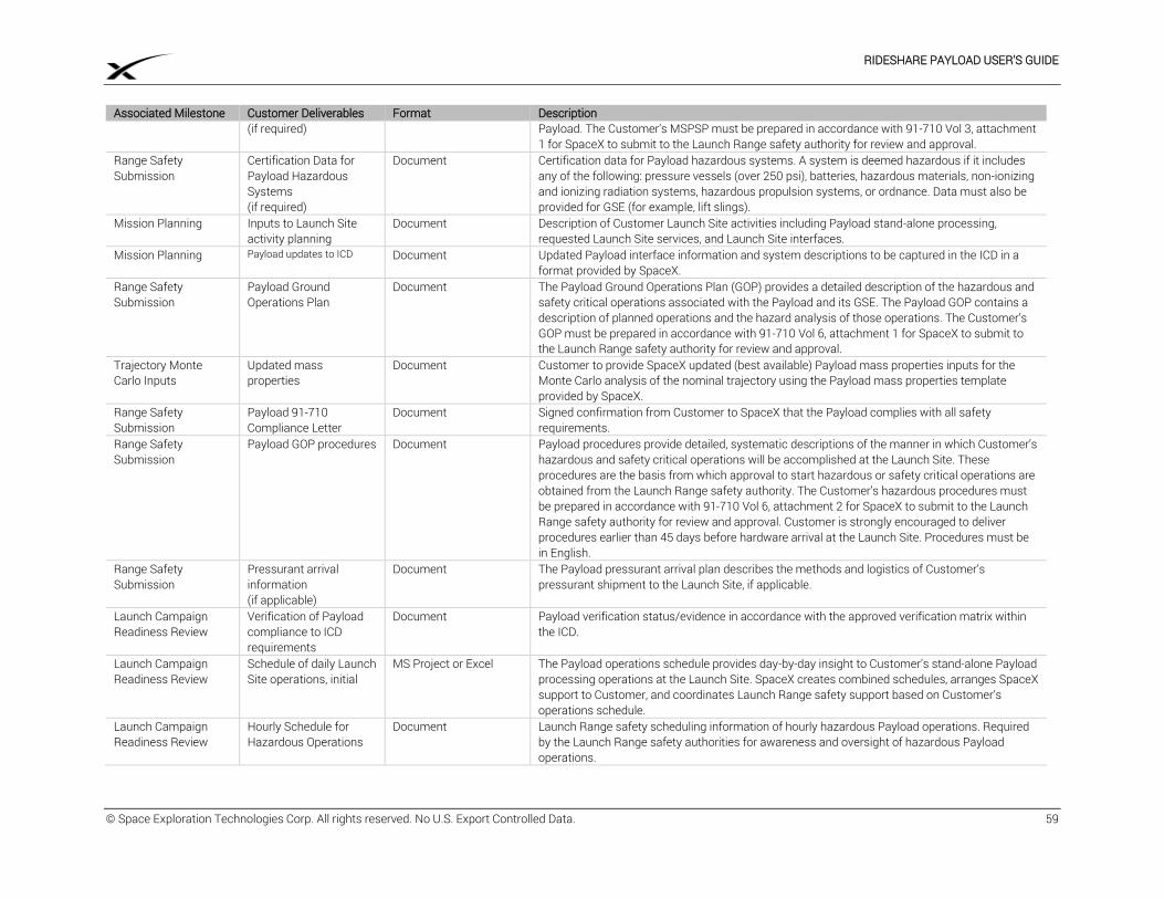
RIDESHARE PAYLOAD USER’S GUIDE
© Space Exploration Technologies Corp. All rights reserved. No U.S. Export Controlled Data. 59
Associated Milestone Customer Deliverables Format Description (if required) Payload. The Customer’s MSPSP must be prepared in accordance with 91-710 Vol 3, attachment
1 for SpaceX to submit to the Launch Range safety authority for review and approval. Range Safety Submission
Certification Data for Payload Hazardous Systems (if required)
Document Certification data for Payload hazardous systems. A system is deemed hazardous if it includes any of the following: pressure vessels (over 250 psi), batteries, hazardous materials, non-ionizing and ionizing radiation systems, hazardous propulsion systems, or ordnance. Data must also be provided for GSE (for example, lift slings).
Mission Planning Inputs to Launch Site activity planning
Document Description of Customer Launch Site activities including Payload stand-alone processing, requested Launch Site services, and Launch Site interfaces.
Mission Planning Payload updates to ICD Document Updated Payload interface information and system descriptions to be captured in the ICD in a format provided by SpaceX.
Range Safety Submission
Payload Ground Operations Plan
Document The Payload Ground Operations Plan (GOP) provides a detailed description of the hazardous and safety critical operations associated with the Payload and its GSE. The Payload GOP contains a description of planned operations and the hazard analysis of those operations. The Customer’s GOP must be prepared in accordance with 91-710 Vol 6, attachment 1 for SpaceX to submit to the Launch Range safety authority for review and approval.
Trajectory Monte Carlo Inputs
Updated mass properties
Document Customer to provide SpaceX updated (best available) Payload mass properties inputs for the Monte Carlo analysis of the nominal trajectory using the Payload mass properties template provided by SpaceX.
Range Safety Submission
Payload 91-710 Compliance Letter
Document Signed confirmation from Customer to SpaceX that the Payload complies with all safety requirements.
Range Safety Submission
Payload GOP procedures Document Payload procedures provide detailed, systematic descriptions of the manner in which Customer’s hazardous and safety critical operations will be accomplished at the Launch Site. These procedures are the basis from which approval to start hazardous or safety critical operations are obtained from the Launch Range safety authority. The Customer’s hazardous procedures must be prepared in accordance with 91-710 Vol 6, attachment 2 for SpaceX to submit to the Launch Range safety authority for review and approval. Customer is strongly encouraged to deliver procedures earlier than 45 days before hardware arrival at the Launch Site. Procedures must be in English.
Range Safety Submission
Pressurant arrival information (if applicable)
Document The Payload pressurant arrival plan describes the methods and logistics of Customer’s pressurant shipment to the Launch Site, if applicable.
Launch Campaign Readiness Review
Verification of Payload compliance to ICD requirements
Document Payload verification status/evidence in accordance with the approved verification matrix within the ICD.
Launch Campaign Readiness Review
Schedule of daily Launch Site operations, initial
MS Project or Excel The Payload operations schedule provides day-by-day insight to Customer’s stand-alone Payload processing operations at the Launch Site. SpaceX creates combined schedules, arranges SpaceX support to Customer, and coordinates Launch Range safety support based on Customer’s operations schedule.
Launch Campaign Readiness Review
Hourly Schedule for Hazardous Operations
Document Launch Range safety scheduling information of hourly hazardous Payload operations. Required by the Launch Range safety authorities for awareness and oversight of hazardous Payload operations.
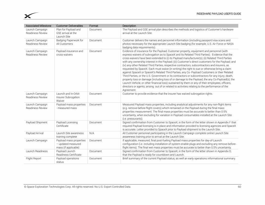
RIDESHARE PAYLOAD USER’S GUIDE
© Space Exploration Technologies Corp. All rights reserved. No U.S. Export Controlled Data. 60
Associated Milestone Customer Deliverables Format Description Launch Campaign Readiness Review
Plan for Payload and GSE arrival at the Launch Site
Document The Payload and GSE arrival plan describes the methods and logistics of Customer’s hardware arrival at the Launch Site.
Launch Campaign Readiness Review
Badging Paperwork for All Customers
Document Customer delivers the names and personnel information (including passport/visa scans and photos necessary for the appropriate Launch Site badging (for example, U.S. Air Force or NASA badging data requirements).
Launch Campaign Readiness Review
Payload insurance and cross-waivers
Document Evidence of insurance for the Payload, Customer property, equipment and personnel (with express waivers of subrogation as to SpaceX and its Related Third Parties). Evidence that the cross-waivers have been extended to (i) its Payload manufacturer(s); (ii) Related Third Parties with any ownership interest in the Payload; (iii) Customer’s direct customers for the Payload; and (iv) any other Related Third Parties, respective contractors, subcontractors and insurers, as requested by SpaceX. Each must waive (in writing) the right to sue or otherwise bring a claim against SpaceX or SpaceX’s Related Third Parties, any Co- Payload Customers or their Related Third Parties, or the U.S. Government or its contractors or subcontractors for any injury, death, property loss or damage (including loss of or damage to the Payload, the any Co-Payload(s), the Launch Vehicle, or other financial loss) sustained by them or any of their employees, officers, directors or agents, arising out of or related to activities relating to the performance of the Agreement.
Launch Campaign Readiness Review
Launch and In-Orbit Insurer Subrogation Waiver
Document Customer to provide evidence that the insurer has waived subrogation rights.
Launch Campaign Readiness Review
Payload mass properties - measured mass
Document Measured Payload mass properties, including analytical adjustments for any non-flight items (e.g. remove-before-flight covers) which remained on the Payload during the final mass properties measurement. The final mass properties must be accurate to better than 0.5% uncertainty, when excluding for variation in Payload consumables installed at the Launch Site (i.e. pressurants).
Payload Shipment Payload Licensing Certificate
Document Signed confirmation from Customer to SpaceX, in the form of the letter shown in Appendix F that required Payload licensing is in place and information provided to licensing agencies and SpaceX is accurate. Letter provided to SpaceX prior to Payload shipment to the Launch Site.
Payload Arrival Launch Site awareness training complete
N/A All Customer personnel participating in the Launch Campaign complete online Launch Site awareness training prior to arrival at the Launch Site.
Launch Campaign Payload mass properties – updated measured mass (if applicable)
Document If applicable, measured, final post-fueling Payload mass properties for day-of-Launch configuration (i.e. including installation of system enable plugs and excluding any remove-before-flight items). The final wet mass properties must be accurate to better than 0.5% uncertainty.
Launch Readiness Payload Launch Readiness Certificate
Document Signed confirmation from Customer to SpaceX, in the form of the letter shown in Appendix D, that the Payload is ready for countdown and Launch.
Flight Report Payload operations status
Document Brief summary of the current Payload status, as well an early operations informational summary.
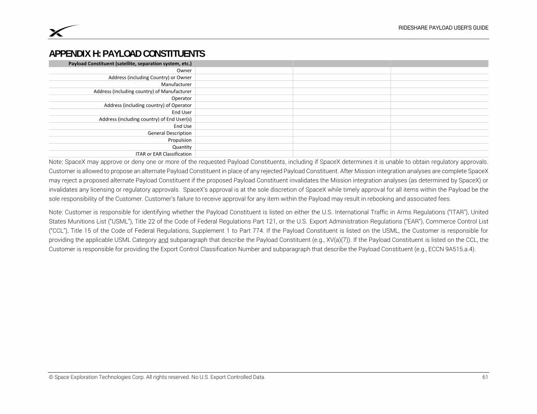
RIDESHARE PAYLOAD USER’S GUIDE
© Space Exploration Technologies Corp. All rights reserved. No U.S. Export Controlled Data. 61
APPENDIX H: PAYLOAD CONSTITUENTS Payload Constituent (satellite, separation system, etc.)
Owner
Address (including Country) or Owner
Manufacturer
Address (including country) of Manufacturer
Operator
Address (including country) of Operator
End User
Address (including country) of End User(s)
End Use
General Description
Propulsion
Quantity
ITAR or EAR Classification
Note: SpaceX may approve or deny one or more of the requested Payload Constituents, including if SpaceX determines it is unable to obtain regulatory approvals. Customer is allowed to propose an alternate Payload Constituent in place of any rejected Payload Constituent. After Mission integration analyses are complete SpaceX may reject a proposed alternate Payload Constituent if the proposed Payload Constituent invalidates the Mission integration analyses (as determined by SpaceX) or invalidates any licensing or regulatory approvals. SpaceX’s approval is at the sole discretion of SpaceX while timely approval for all items within the Payload be the sole responsibility of the Customer. Customer’s failure to receive approval for any item within the Payload may result in rebooking and associated fees.
Note: Customer is responsible for identifying whether the Payload Constituent is listed on either the U.S. International Traffic in Arms Regulations (“ITAR”), United States Munitions List (“USML”), Title 22 of the Code of Federal Regulations Part 121, or the U.S. Export Administration Regulations (“EAR”), Commerce Control List (“CCL”), Title 15 of the Code of Federal Regulations, Supplement 1 to Part 774. If the Payload Constituent is listed on the USML, the Customer is responsible for providing the applicable USML Category and subparagraph that describe the Payload Constituent (e.g., XV(a)(7)). If the Payload Constituent is listed on the CCL, the Customer is responsible for providing the Export Control Classification Number and subparagraph that describe the Payload Constituent (e.g., ECCN 9A515.a.4).
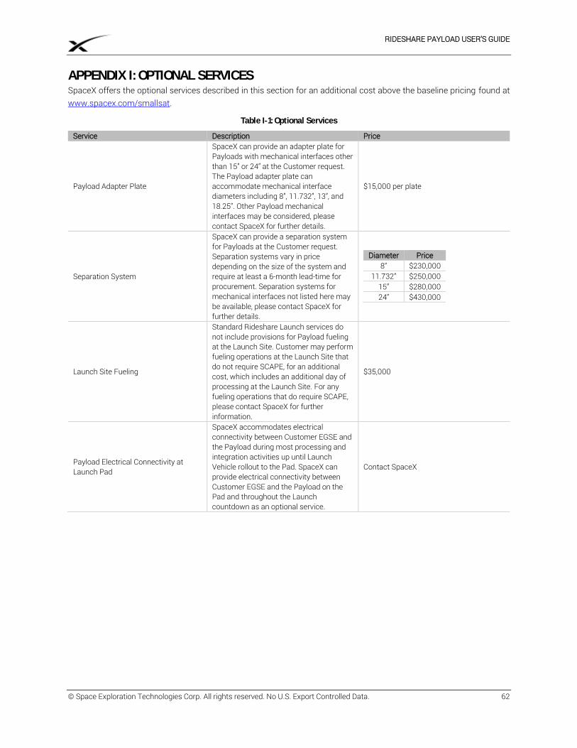
RIDESHARE PAYLOAD USER’S GUIDE
© Space Exploration Technologies Corp. All rights reserved. No U.S. Export Controlled Data. 62
APPENDIX I: OPTIONAL SERVICES SpaceX offers the optional services described in this section for an additional cost above the baseline pricing found at www.spacex.com/smallsat.
Table I-1: Optional Services
Service Description Price
Payload Adapter Plate
SpaceX can provide an adapter plate for Payloads with mechanical interfaces other than 15” or 24” at the Customer request. The Payload adapter plate can accommodate mechanical interface diameters including 8”, 11.732”, 13”, and 18.25”. Other Payload mechanical interfaces may be considered, please contact SpaceX for further details.
$15,000 per plate
Separation System
SpaceX can provide a separation system for Payloads at the Customer request. Separation systems vary in price depending on the size of the system and require at least a 6-month lead-time for procurement. Separation systems for mechanical interfaces not listed here may be available, please contact SpaceX for further details.
Diameter Price 8” $230,000
11.732” $250,000 15” $280,000 24” $430,000
Launch Site Fueling
Standard Rideshare Launch services do not include provisions for Payload fueling at the Launch Site. Customer may perform fueling operations at the Launch Site that do not require SCAPE, for an additional cost, which includes an additional day of processing at the Launch Site. For any fueling operations that do require SCAPE, please contact SpaceX for further information.
$35,000
Payload Electrical Connectivity at Launch Pad
SpaceX accommodates electrical connectivity between Customer EGSE and the Payload during most processing and integration activities up until Launch Vehicle rollout to the Pad. SpaceX can provide electrical connectivity between Customer EGSE and the Payload on the Pad and throughout the Launch countdown as an optional service.
Contact SpaceX
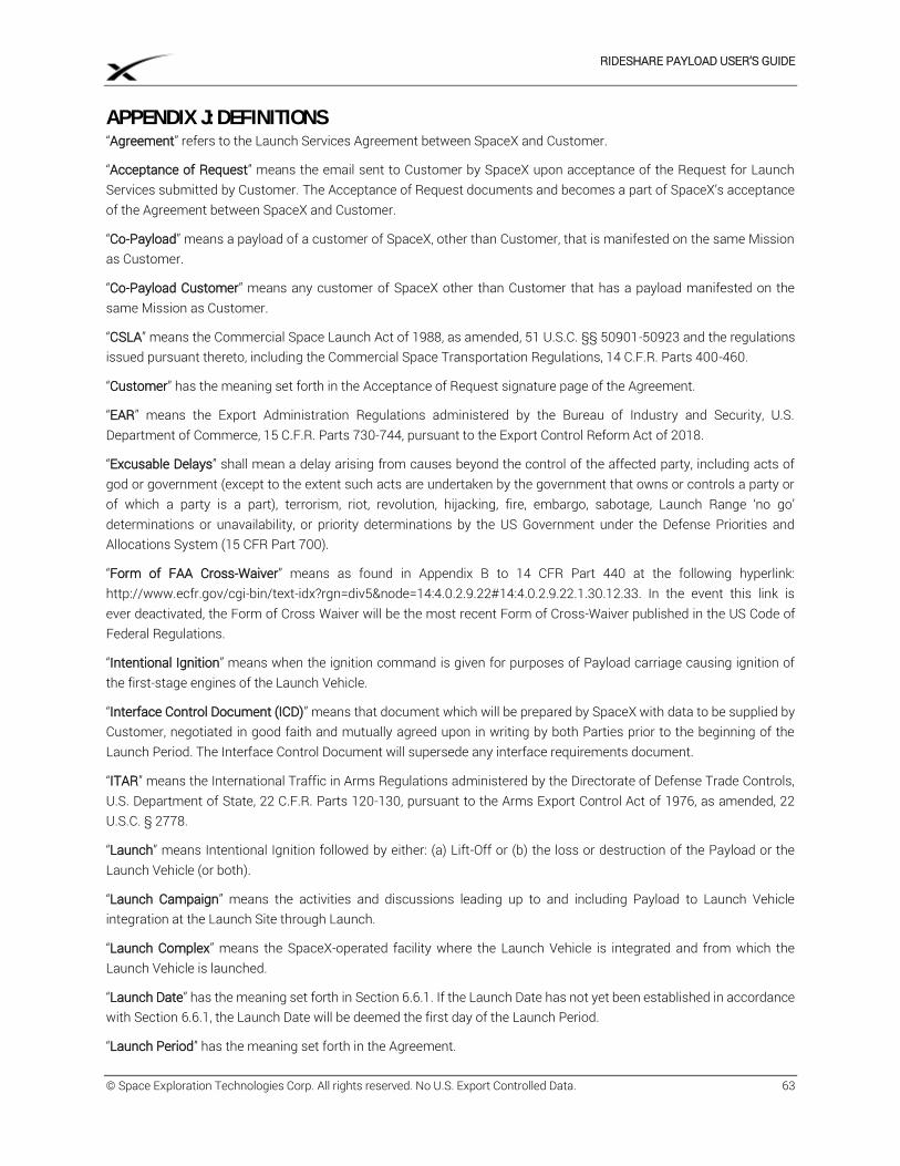
RIDESHARE PAYLOAD USER’S GUIDE
© Space Exploration Technologies Corp. All rights reserved. No U.S. Export Controlled Data. 63
APPENDIX J: DEFINITIONS “Agreement” refers to the Launch Services Agreement between SpaceX and Customer.
“Acceptance of Request” means the email sent to Customer by SpaceX upon acceptance of the Request for Launch Services submitted by Customer. The Acceptance of Request documents and becomes a part of SpaceX’s acceptance of the Agreement between SpaceX and Customer.
“Co-Payload” means a payload of a customer of SpaceX, other than Customer, that is manifested on the same Mission as Customer.
“Co-Payload Customer” means any customer of SpaceX other than Customer that has a payload manifested on the same Mission as Customer.
“CSLA” means the Commercial Space Launch Act of 1988, as amended, 51 U.S.C. §§ 50901-50923 and the regulations issued pursuant thereto, including the Commercial Space Transportation Regulations, 14 C.F.R. Parts 400-460.
“Customer” has the meaning set forth in the Acceptance of Request signature page of the Agreement.
“EAR” means the Export Administration Regulations administered by the Bureau of Industry and Security, U.S. Department of Commerce, 15 C.F.R. Parts 730-744, pursuant to the Export Control Reform Act of 2018.
“Excusable Delays” shall mean a delay arising from causes beyond the control of the affected party, including acts of god or government (except to the extent such acts are undertaken by the government that owns or controls a party or of which a party is a part), terrorism, riot, revolution, hijacking, fire, embargo, sabotage, Launch Range ‘no go’ determinations or unavailability, or priority determinations by the US Government under the Defense Priorities and Allocations System (15 CFR Part 700).
“Form of FAA Cross-Waiver” means as found in Appendix B to 14 CFR Part 440 at the following hyperlink: http://www.ecfr.gov/cgi-bin/text-idx?rgn=div5&node=14:4.0.2.9.22#14:4.0.2.9.22.1.30.12.33. In the event this link is ever deactivated, the Form of Cross Waiver will be the most recent Form of Cross-Waiver published in the US Code of Federal Regulations.
“Intentional Ignition” means when the ignition command is given for purposes of Payload carriage causing ignition of the first-stage engines of the Launch Vehicle.
“Interface Control Document (ICD)” means that document which will be prepared by SpaceX with data to be supplied by Customer, negotiated in good faith and mutually agreed upon in writing by both Parties prior to the beginning of the Launch Period. The Interface Control Document will supersede any interface requirements document.
“ITAR” means the International Traffic in Arms Regulations administered by the Directorate of Defense Trade Controls, U.S. Department of State, 22 C.F.R. Parts 120-130, pursuant to the Arms Export Control Act of 1976, as amended, 22 U.S.C. § 2778.
“Launch” means Intentional Ignition followed by either: (a) Lift-Off or (b) the loss or destruction of the Payload or the Launch Vehicle (or both).
“Launch Campaign” means the activities and discussions leading up to and including Payload to Launch Vehicle integration at the Launch Site through Launch.
“Launch Complex” means the SpaceX-operated facility where the Launch Vehicle is integrated and from which the Launch Vehicle is launched.
“Launch Date” has the meaning set forth in Section 6.6.1. If the Launch Date has not yet been established in accordance with Section 6.6.1, the Launch Date will be deemed the first day of the Launch Period.
“Launch Period” has the meaning set forth in the Agreement.
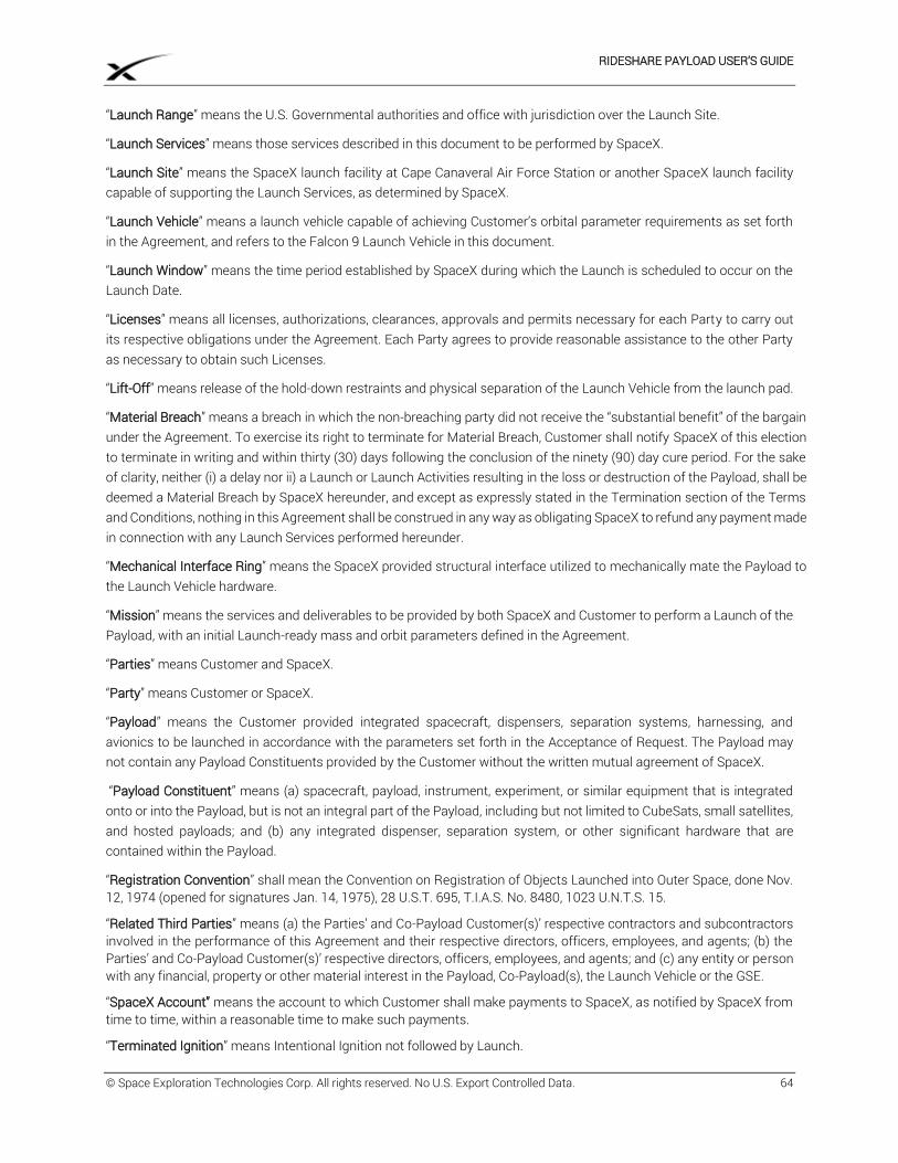
RIDESHARE PAYLOAD USER’S GUIDE
© Space Exploration Technologies Corp. All rights reserved. No U.S. Export Controlled Data. 64
“Launch Range” means the U.S. Governmental authorities and office with jurisdiction over the Launch Site.
“Launch Services” means those services described in this document to be performed by SpaceX.
“Launch Site” means the SpaceX launch facility at Cape Canaveral Air Force Station or another SpaceX launch facility capable of supporting the Launch Services, as determined by SpaceX.
“Launch Vehicle” means a launch vehicle capable of achieving Customer’s orbital parameter requirements as set forth in the Agreement, and refers to the Falcon 9 Launch Vehicle in this document.
“Launch Window” means the time period established by SpaceX during which the Launch is scheduled to occur on the Launch Date.
“Licenses” means all licenses, authorizations, clearances, approvals and permits necessary for each Party to carry out its respective obligations under the Agreement. Each Party agrees to provide reasonable assistance to the other Party as necessary to obtain such Licenses.
“Lift-Off” means release of the hold-down restraints and physical separation of the Launch Vehicle from the launch pad.
“Material Breach” means a breach in which the non-breaching party did not receive the “substantial benefit” of the bargain under the Agreement. To exercise its right to terminate for Material Breach, Customer shall notify SpaceX of this election to terminate in writing and within thirty (30) days following the conclusion of the ninety (90) day cure period. For the sake of clarity, neither (i) a delay nor ii) a Launch or Launch Activities resulting in the loss or destruction of the Payload, shall be deemed a Material Breach by SpaceX hereunder, and except as expressly stated in the Termination section of the Terms and Conditions, nothing in this Agreement shall be construed in any way as obligating SpaceX to refund any payment made in connection with any Launch Services performed hereunder.
“Mechanical Interface Ring” means the SpaceX provided structural interface utilized to mechanically mate the Payload to the Launch Vehicle hardware.
“Mission” means the services and deliverables to be provided by both SpaceX and Customer to perform a Launch of the Payload, with an initial Launch-ready mass and orbit parameters defined in the Agreement.
“Parties” means Customer and SpaceX.
“Party” means Customer or SpaceX.
“Payload” means the Customer provided integrated spacecraft, dispensers, separation systems, harnessing, and avionics to be launched in accordance with the parameters set forth in the Acceptance of Request. The Payload may not contain any Payload Constituents provided by the Customer without the written mutual agreement of SpaceX.
“Payload Constituent” means (a) spacecraft, payload, instrument, experiment, or similar equipment that is integrated onto or into the Payload, but is not an integral part of the Payload, including but not limited to CubeSats, small satellites, and hosted payloads; and (b) any integrated dispenser, separation system, or other significant hardware that are contained within the Payload.
“Registration Convention” shall mean the Convention on Registration of Objects Launched into Outer Space, done Nov. 12, 1974 (opened for signatures Jan. 14, 1975), 28 U.S.T. 695, T.I.A.S. No. 8480, 1023 U.N.T.S. 15.
“Related Third Parties” means (a) the Parties’ and Co-Payload Customer(s)’ respective contractors and subcontractors involved in the performance of this Agreement and their respective directors, officers, employees, and agents; (b) the Parties’ and Co-Payload Customer(s)’ respective directors, officers, employees, and agents; and (c) any entity or person with any financial, property or other material interest in the Payload, Co-Payload(s), the Launch Vehicle or the GSE.
“SpaceX Account” means the account to which Customer shall make payments to SpaceX, as notified by SpaceX from time to time, within a reasonable time to make such payments.
“Terminated Ignition” means Intentional Ignition not followed by Launch.