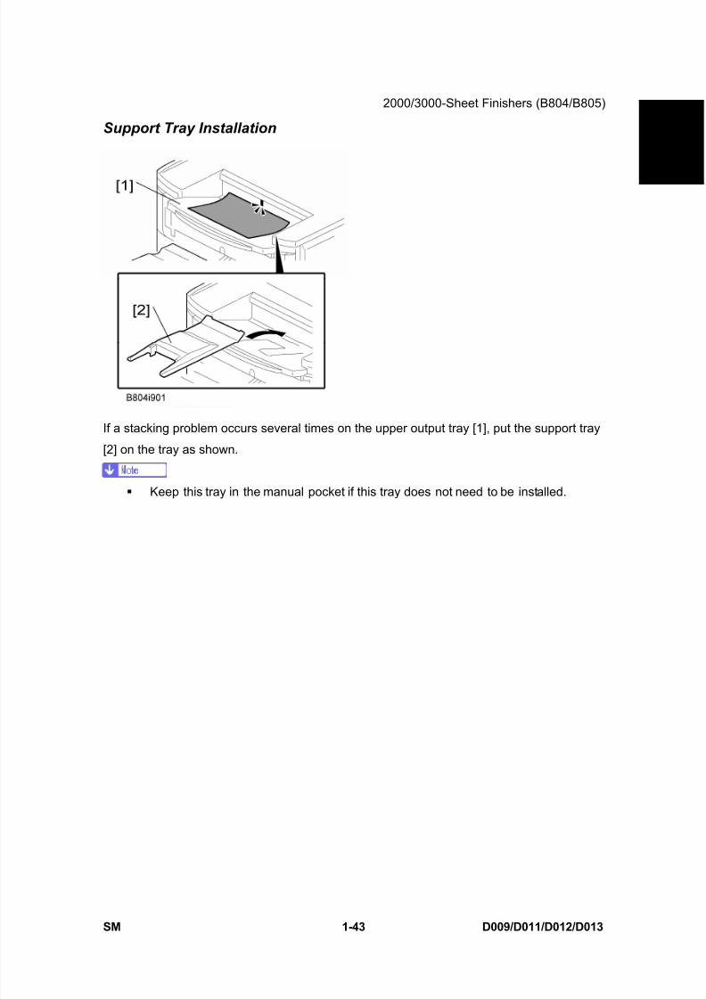
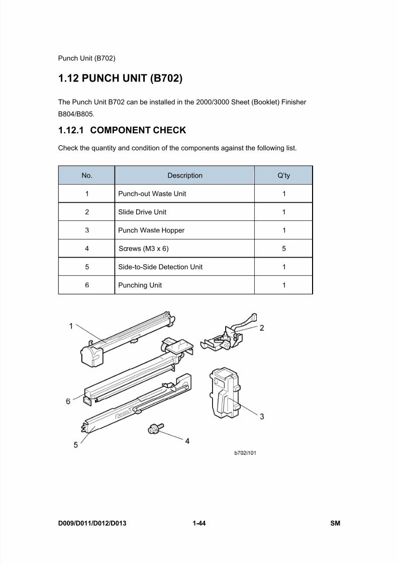
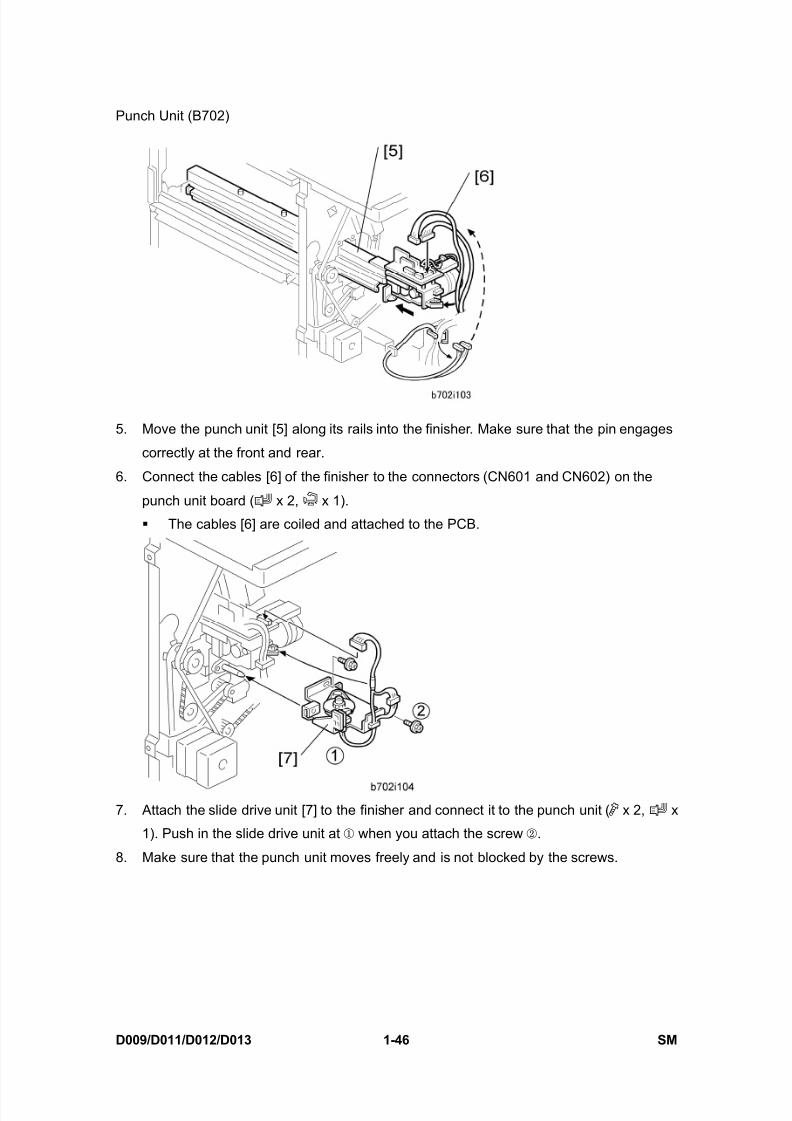
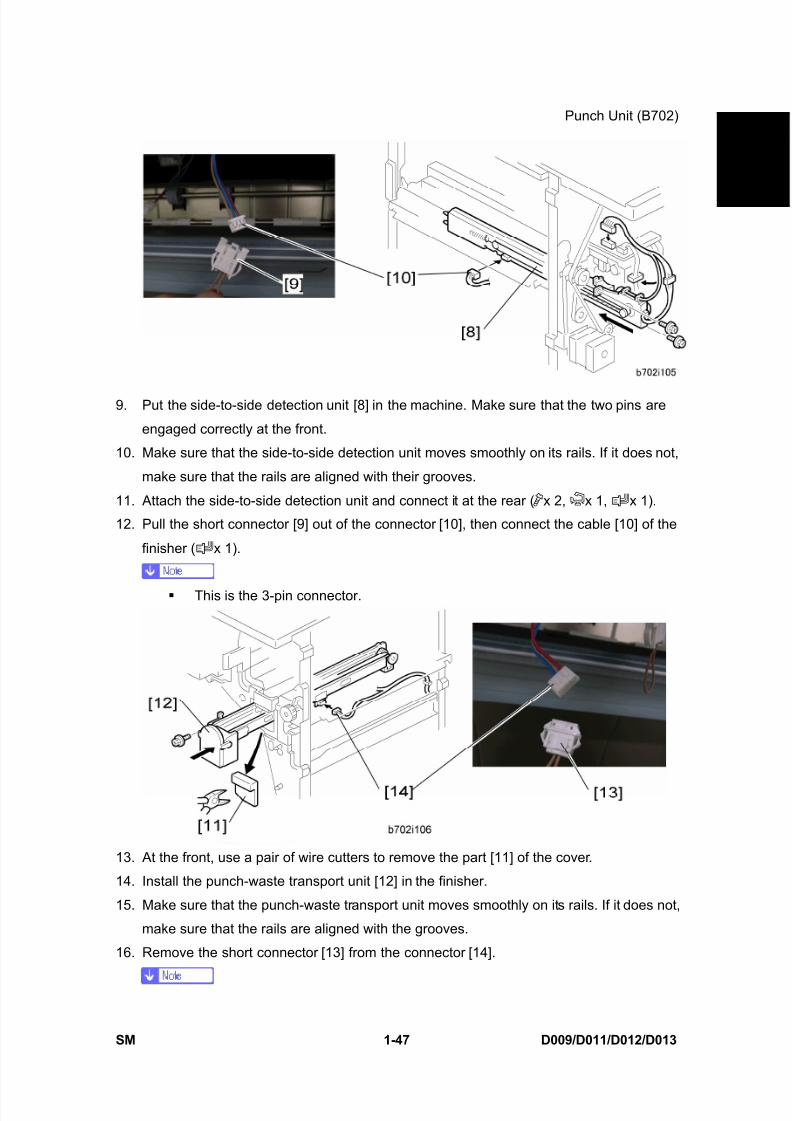
ricoh mp 4000 sm d009_d011_d012_d013 service manual .pdf
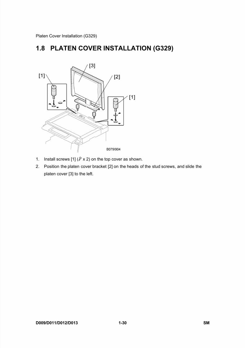
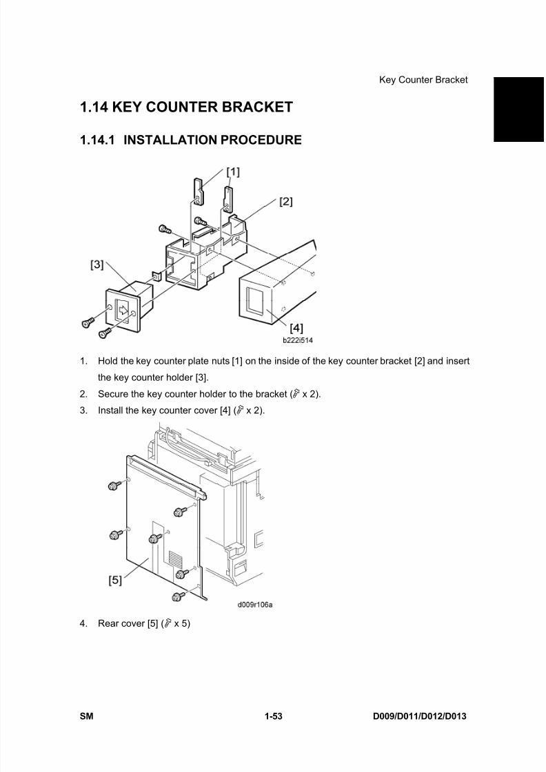
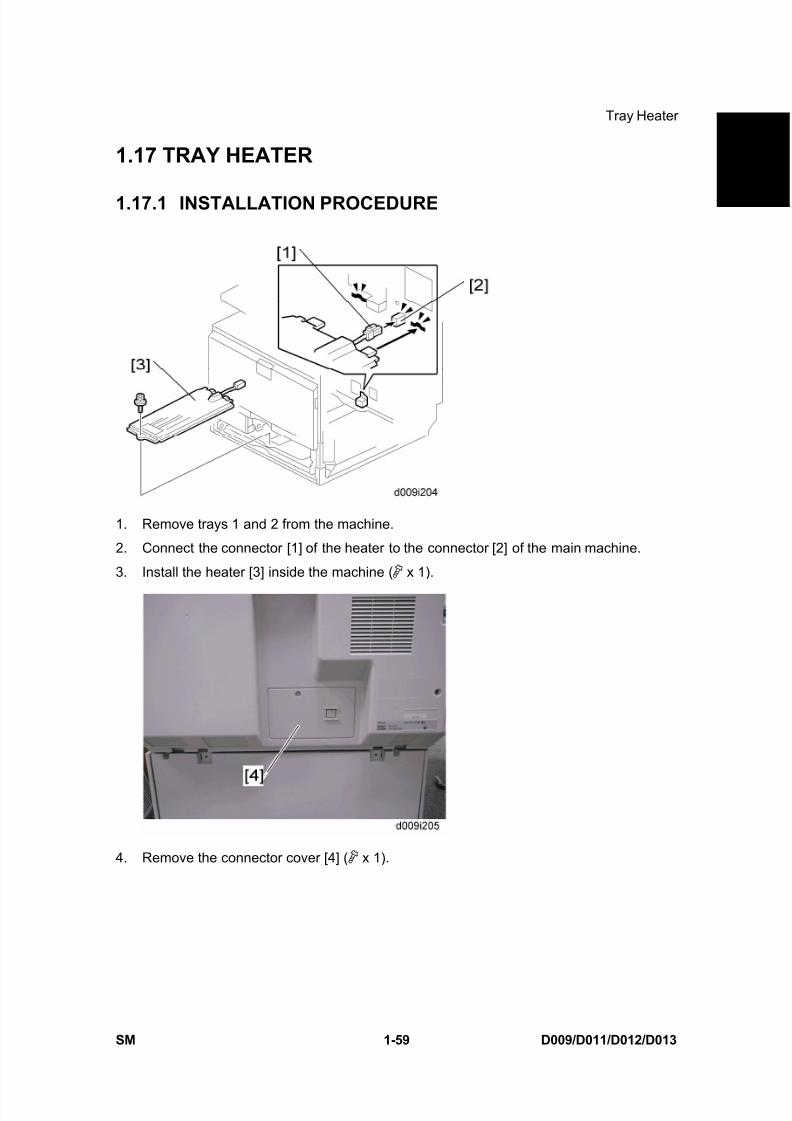
TRANSCRIPT

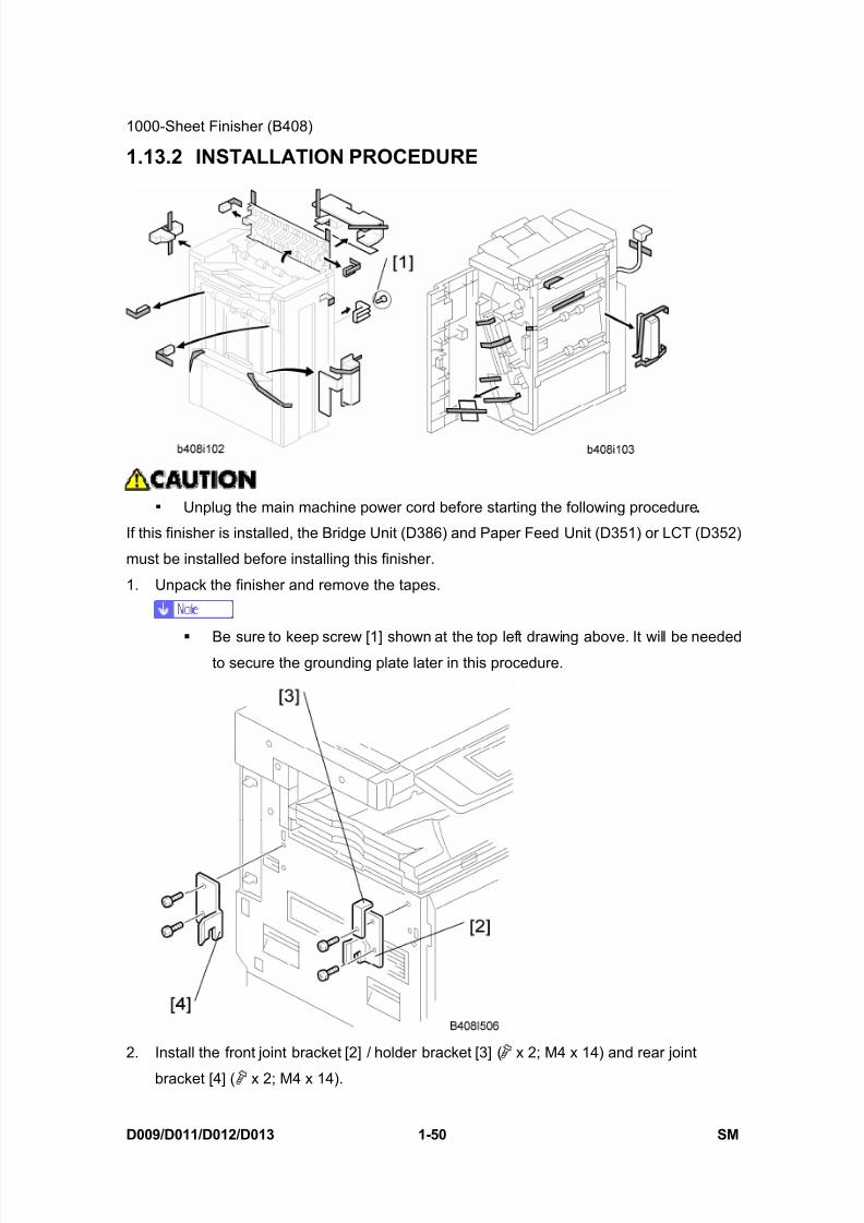
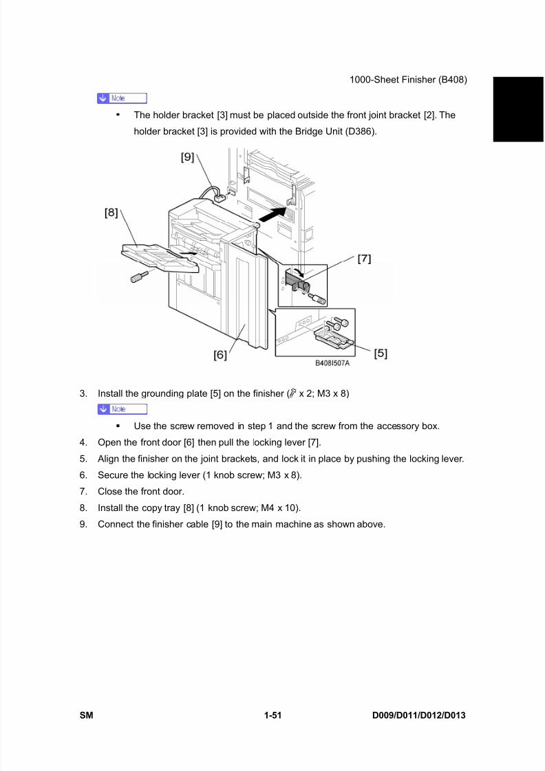
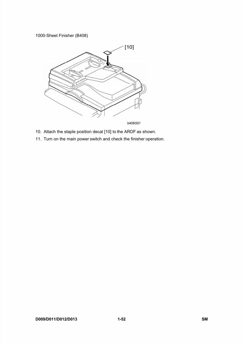
8/15/2019 Ricoh MP 4000 SM D009_D011_D012_D013 SERVICE MANUAL .pdf
http://slidepdf.com/reader/full/ricoh-mp-4000-sm-d009d011d012d013-service-manual-pdf 1/1162

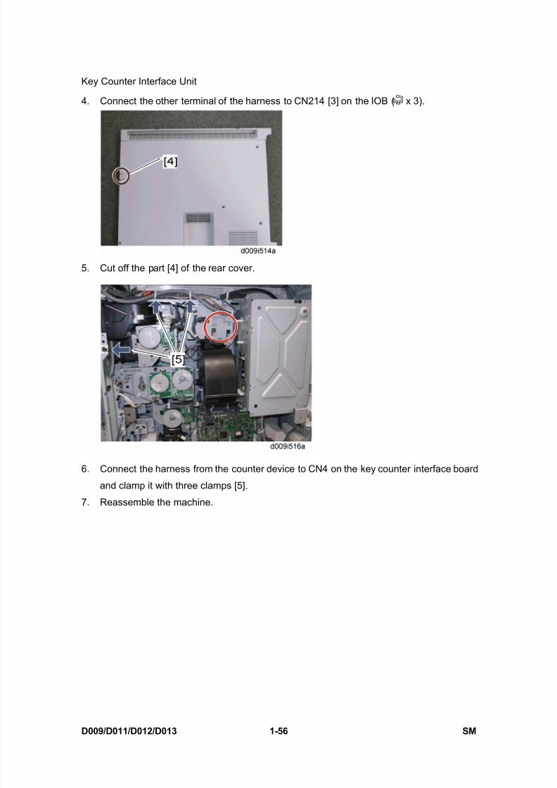
8/15/2019 Ricoh MP 4000 SM D009_D011_D012_D013 SERVICE MANUAL .pdf
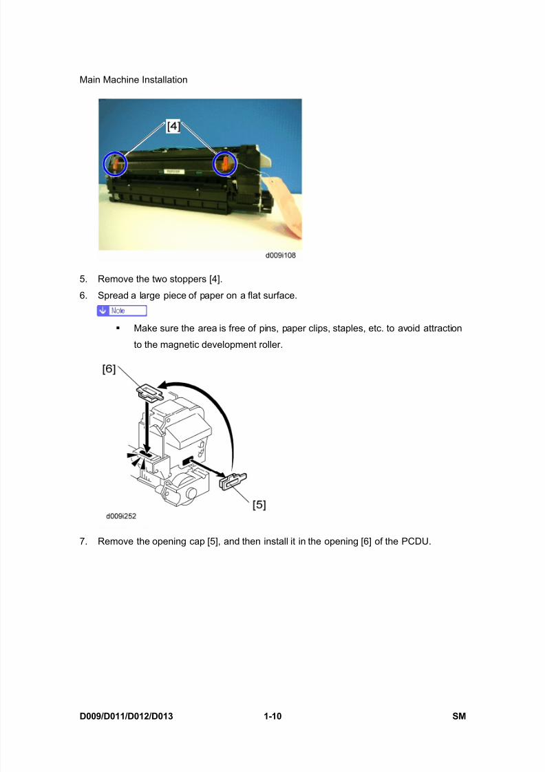
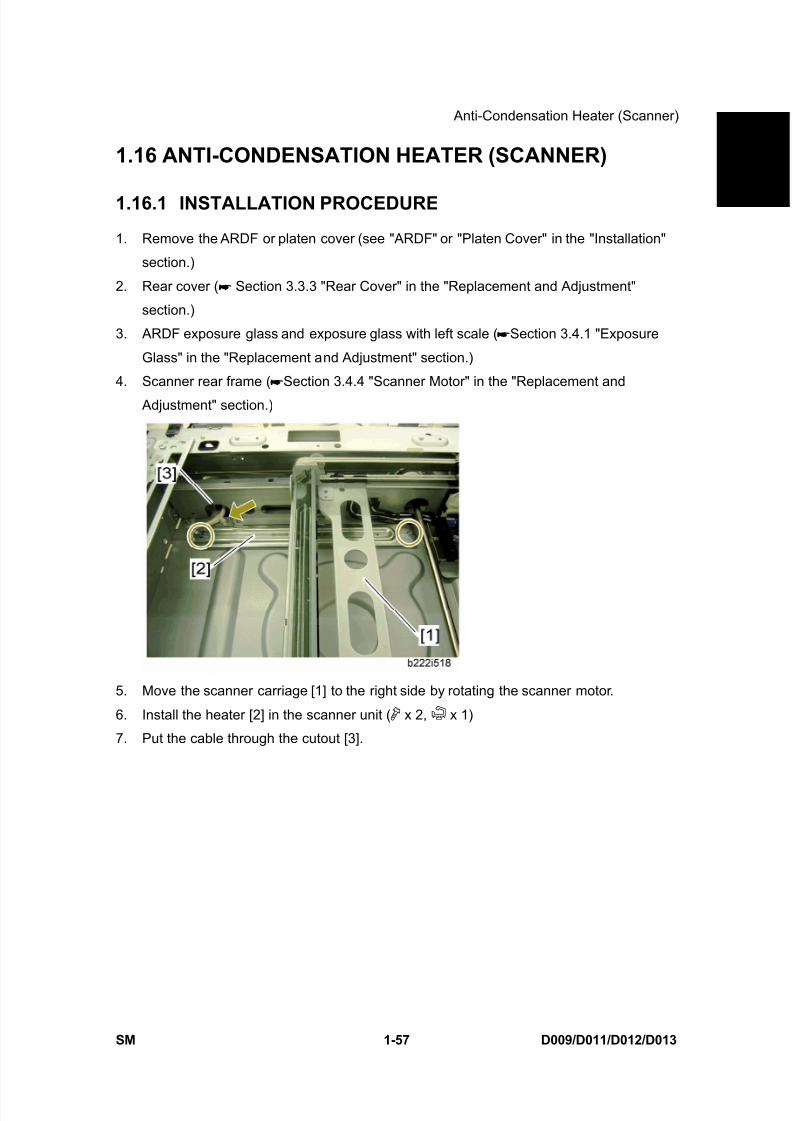
http://slidepdf.com/reader/full/ricoh-mp-4000-sm-d009d011d012d013-service-manual-pdf 2/1162
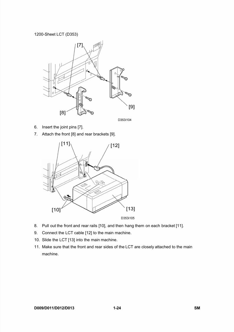
8/15/2019 Ricoh MP 4000 SM D009_D011_D012_D013 SERVICE MANUAL .pdf
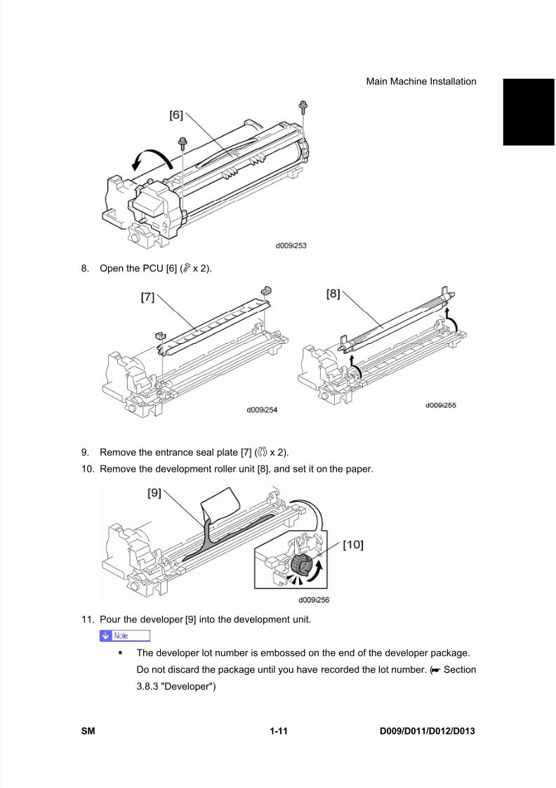
http://slidepdf.com/reader/full/ricoh-mp-4000-sm-d009d011d012d013-service-manual-pdf 3/1162

8/15/2019 Ricoh MP 4000 SM D009_D011_D012_D013 SERVICE MANUAL .pdf
http://slidepdf.com/reader/full/ricoh-mp-4000-sm-d009d011d012d013-service-manual-pdf 4/1162
8/15/2019 Ricoh MP 4000 SM D009_D011_D012_D013 SERVICE MANUAL .pdf
http://slidepdf.com/reader/full/ricoh-mp-4000-sm-d009d011d012d013-service-manual-pdf 5/1162

8/15/2019 Ricoh MP 4000 SM D009_D011_D012_D013 SERVICE MANUAL .pdf
http://slidepdf.com/reader/full/ricoh-mp-4000-sm-d009d011d012d013-service-manual-pdf 6/1162
8/15/2019 Ricoh MP 4000 SM D009_D011_D012_D013 SERVICE MANUAL .pdf
http://slidepdf.com/reader/full/ricoh-mp-4000-sm-d009d011d012d013-service-manual-pdf 7/1162

8/15/2019 Ricoh MP 4000 SM D009_D011_D012_D013 SERVICE MANUAL .pdf
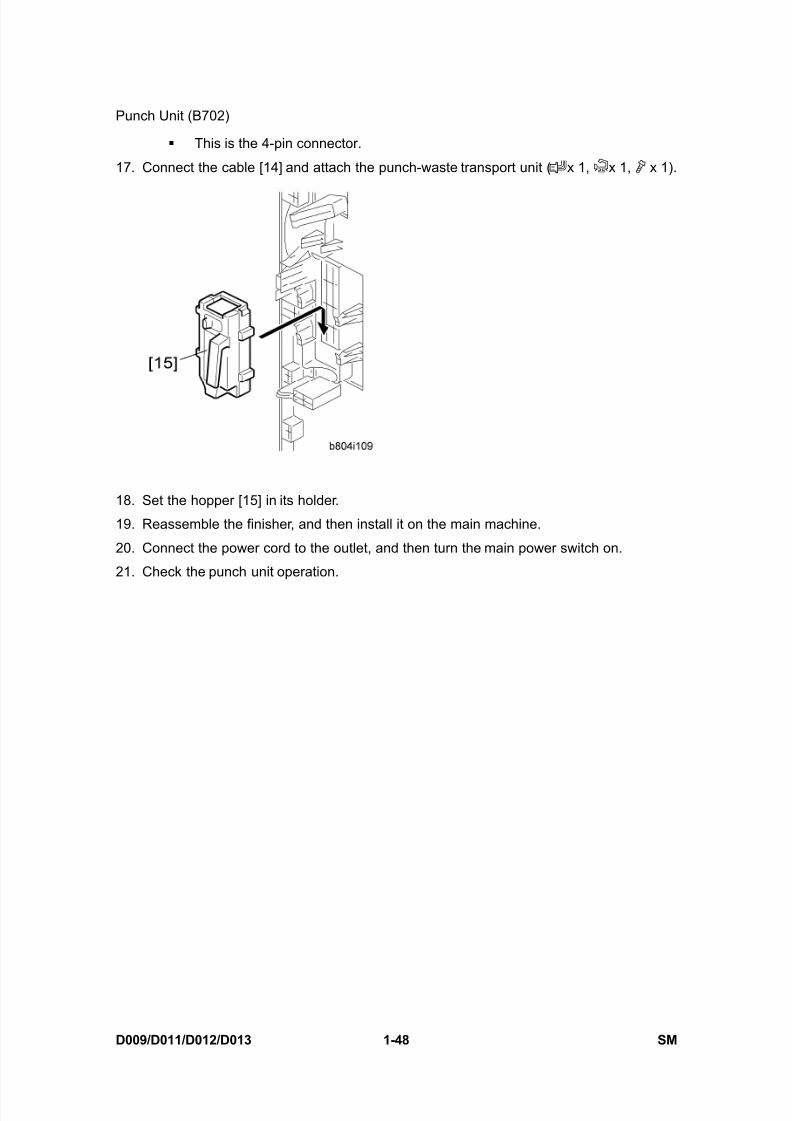
http://slidepdf.com/reader/full/ricoh-mp-4000-sm-d009d011d012d013-service-manual-pdf 8/1162

8/15/2019 Ricoh MP 4000 SM D009_D011_D012_D013 SERVICE MANUAL .pdf
http://slidepdf.com/reader/full/ricoh-mp-4000-sm-d009d011d012d013-service-manual-pdf 9/1162

8/15/2019 Ricoh MP 4000 SM D009_D011_D012_D013 SERVICE MANUAL .pdf
http://slidepdf.com/reader/full/ricoh-mp-4000-sm-d009d011d012d013-service-manual-pdf 10/1162
8/15/2019 Ricoh MP 4000 SM D009_D011_D012_D013 SERVICE MANUAL .pdf
http://slidepdf.com/reader/full/ricoh-mp-4000-sm-d009d011d012d013-service-manual-pdf 11/1162

8/15/2019 Ricoh MP 4000 SM D009_D011_D012_D013 SERVICE MANUAL .pdf
http://slidepdf.com/reader/full/ricoh-mp-4000-sm-d009d011d012d013-service-manual-pdf 12/1162
8/15/2019 Ricoh MP 4000 SM D009_D011_D012_D013 SERVICE MANUAL .pdf
http://slidepdf.com/reader/full/ricoh-mp-4000-sm-d009d011d012d013-service-manual-pdf 13/1162
8/15/2019 Ricoh MP 4000 SM D009_D011_D012_D013 SERVICE MANUAL .pdf
http://slidepdf.com/reader/full/ricoh-mp-4000-sm-d009d011d012d013-service-manual-pdf 14/1162
8/15/2019 Ricoh MP 4000 SM D009_D011_D012_D013 SERVICE MANUAL .pdf
http://slidepdf.com/reader/full/ricoh-mp-4000-sm-d009d011d012d013-service-manual-pdf 15/1162

8/15/2019 Ricoh MP 4000 SM D009_D011_D012_D013 SERVICE MANUAL .pdf
http://slidepdf.com/reader/full/ricoh-mp-4000-sm-d009d011d012d013-service-manual-pdf 16/1162

8/15/2019 Ricoh MP 4000 SM D009_D011_D012_D013 SERVICE MANUAL .pdf
http://slidepdf.com/reader/full/ricoh-mp-4000-sm-d009d011d012d013-service-manual-pdf 17/1162
8/15/2019 Ricoh MP 4000 SM D009_D011_D012_D013 SERVICE MANUAL .pdf
http://slidepdf.com/reader/full/ricoh-mp-4000-sm-d009d011d012d013-service-manual-pdf 18/1162
8/15/2019 Ricoh MP 4000 SM D009_D011_D012_D013 SERVICE MANUAL .pdf
http://slidepdf.com/reader/full/ricoh-mp-4000-sm-d009d011d012d013-service-manual-pdf 19/1162
8/15/2019 Ricoh MP 4000 SM D009_D011_D012_D013 SERVICE MANUAL .pdf
http://slidepdf.com/reader/full/ricoh-mp-4000-sm-d009d011d012d013-service-manual-pdf 20/1162

8/15/2019 Ricoh MP 4000 SM D009_D011_D012_D013 SERVICE MANUAL .pdf
http://slidepdf.com/reader/full/ricoh-mp-4000-sm-d009d011d012d013-service-manual-pdf 21/1162
8/15/2019 Ricoh MP 4000 SM D009_D011_D012_D013 SERVICE MANUAL .pdf
http://slidepdf.com/reader/full/ricoh-mp-4000-sm-d009d011d012d013-service-manual-pdf 22/1162

8/15/2019 Ricoh MP 4000 SM D009_D011_D012_D013 SERVICE MANUAL .pdf
http://slidepdf.com/reader/full/ricoh-mp-4000-sm-d009d011d012d013-service-manual-pdf 23/1162
8/15/2019 Ricoh MP 4000 SM D009_D011_D012_D013 SERVICE MANUAL .pdf
http://slidepdf.com/reader/full/ricoh-mp-4000-sm-d009d011d012d013-service-manual-pdf 24/1162
8/15/2019 Ricoh MP 4000 SM D009_D011_D012_D013 SERVICE MANUAL .pdf
http://slidepdf.com/reader/full/ricoh-mp-4000-sm-d009d011d012d013-service-manual-pdf 25/1162

8/15/2019 Ricoh MP 4000 SM D009_D011_D012_D013 SERVICE MANUAL .pdf
http://slidepdf.com/reader/full/ricoh-mp-4000-sm-d009d011d012d013-service-manual-pdf 26/1162
8/15/2019 Ricoh MP 4000 SM D009_D011_D012_D013 SERVICE MANUAL .pdf
http://slidepdf.com/reader/full/ricoh-mp-4000-sm-d009d011d012d013-service-manual-pdf 27/1162
8/15/2019 Ricoh MP 4000 SM D009_D011_D012_D013 SERVICE MANUAL .pdf
http://slidepdf.com/reader/full/ricoh-mp-4000-sm-d009d011d012d013-service-manual-pdf 28/1162

8/15/2019 Ricoh MP 4000 SM D009_D011_D012_D013 SERVICE MANUAL .pdf
http://slidepdf.com/reader/full/ricoh-mp-4000-sm-d009d011d012d013-service-manual-pdf 29/1162

8/15/2019 Ricoh MP 4000 SM D009_D011_D012_D013 SERVICE MANUAL .pdf
http://slidepdf.com/reader/full/ricoh-mp-4000-sm-d009d011d012d013-service-manual-pdf 30/1162

8/15/2019 Ricoh MP 4000 SM D009_D011_D012_D013 SERVICE MANUAL .pdf
http://slidepdf.com/reader/full/ricoh-mp-4000-sm-d009d011d012d013-service-manual-pdf 31/1162

8/15/2019 Ricoh MP 4000 SM D009_D011_D012_D013 SERVICE MANUAL .pdf
http://slidepdf.com/reader/full/ricoh-mp-4000-sm-d009d011d012d013-service-manual-pdf 32/1162

8/15/2019 Ricoh MP 4000 SM D009_D011_D012_D013 SERVICE MANUAL .pdf
http://slidepdf.com/reader/full/ricoh-mp-4000-sm-d009d011d012d013-service-manual-pdf 33/1162

8/15/2019 Ricoh MP 4000 SM D009_D011_D012_D013 SERVICE MANUAL .pdf
http://slidepdf.com/reader/full/ricoh-mp-4000-sm-d009d011d012d013-service-manual-pdf 34/1162

8/15/2019 Ricoh MP 4000 SM D009_D011_D012_D013 SERVICE MANUAL .pdf
http://slidepdf.com/reader/full/ricoh-mp-4000-sm-d009d011d012d013-service-manual-pdf 35/1162
8/15/2019 Ricoh MP 4000 SM D009_D011_D012_D013 SERVICE MANUAL .pdf
http://slidepdf.com/reader/full/ricoh-mp-4000-sm-d009d011d012d013-service-manual-pdf 36/1162
8/15/2019 Ricoh MP 4000 SM D009_D011_D012_D013 SERVICE MANUAL .pdf
http://slidepdf.com/reader/full/ricoh-mp-4000-sm-d009d011d012d013-service-manual-pdf 37/1162

8/15/2019 Ricoh MP 4000 SM D009_D011_D012_D013 SERVICE MANUAL .pdf
http://slidepdf.com/reader/full/ricoh-mp-4000-sm-d009d011d012d013-service-manual-pdf 38/1162

8/15/2019 Ricoh MP 4000 SM D009_D011_D012_D013 SERVICE MANUAL .pdf
http://slidepdf.com/reader/full/ricoh-mp-4000-sm-d009d011d012d013-service-manual-pdf 39/1162
8/15/2019 Ricoh MP 4000 SM D009_D011_D012_D013 SERVICE MANUAL .pdf
http://slidepdf.com/reader/full/ricoh-mp-4000-sm-d009d011d012d013-service-manual-pdf 40/1162
8/15/2019 Ricoh MP 4000 SM D009_D011_D012_D013 SERVICE MANUAL .pdf
http://slidepdf.com/reader/full/ricoh-mp-4000-sm-d009d011d012d013-service-manual-pdf 41/1162

8/15/2019 Ricoh MP 4000 SM D009_D011_D012_D013 SERVICE MANUAL .pdf
http://slidepdf.com/reader/full/ricoh-mp-4000-sm-d009d011d012d013-service-manual-pdf 42/1162
8/15/2019 Ricoh MP 4000 SM D009_D011_D012_D013 SERVICE MANUAL .pdf
http://slidepdf.com/reader/full/ricoh-mp-4000-sm-d009d011d012d013-service-manual-pdf 43/1162
8/15/2019 Ricoh MP 4000 SM D009_D011_D012_D013 SERVICE MANUAL .pdf
http://slidepdf.com/reader/full/ricoh-mp-4000-sm-d009d011d012d013-service-manual-pdf 44/1162
8/15/2019 Ricoh MP 4000 SM D009_D011_D012_D013 SERVICE MANUAL .pdf
http://slidepdf.com/reader/full/ricoh-mp-4000-sm-d009d011d012d013-service-manual-pdf 45/1162

8/15/2019 Ricoh MP 4000 SM D009_D011_D012_D013 SERVICE MANUAL .pdf
http://slidepdf.com/reader/full/ricoh-mp-4000-sm-d009d011d012d013-service-manual-pdf 46/1162

8/15/2019 Ricoh MP 4000 SM D009_D011_D012_D013 SERVICE MANUAL .pdf
http://slidepdf.com/reader/full/ricoh-mp-4000-sm-d009d011d012d013-service-manual-pdf 47/1162
8/15/2019 Ricoh MP 4000 SM D009_D011_D012_D013 SERVICE MANUAL .pdf
http://slidepdf.com/reader/full/ricoh-mp-4000-sm-d009d011d012d013-service-manual-pdf 48/1162

8/15/2019 Ricoh MP 4000 SM D009_D011_D012_D013 SERVICE MANUAL .pdf
http://slidepdf.com/reader/full/ricoh-mp-4000-sm-d009d011d012d013-service-manual-pdf 49/1162

8/15/2019 Ricoh MP 4000 SM D009_D011_D012_D013 SERVICE MANUAL .pdf
http://slidepdf.com/reader/full/ricoh-mp-4000-sm-d009d011d012d013-service-manual-pdf 50/1162
8/15/2019 Ricoh MP 4000 SM D009_D011_D012_D013 SERVICE MANUAL .pdf
http://slidepdf.com/reader/full/ricoh-mp-4000-sm-d009d011d012d013-service-manual-pdf 51/1162

8/15/2019 Ricoh MP 4000 SM D009_D011_D012_D013 SERVICE MANUAL .pdf
http://slidepdf.com/reader/full/ricoh-mp-4000-sm-d009d011d012d013-service-manual-pdf 52/1162
8/15/2019 Ricoh MP 4000 SM D009_D011_D012_D013 SERVICE MANUAL .pdf
http://slidepdf.com/reader/full/ricoh-mp-4000-sm-d009d011d012d013-service-manual-pdf 53/1162

8/15/2019 Ricoh MP 4000 SM D009_D011_D012_D013 SERVICE MANUAL .pdf
http://slidepdf.com/reader/full/ricoh-mp-4000-sm-d009d011d012d013-service-manual-pdf 54/1162
8/15/2019 Ricoh MP 4000 SM D009_D011_D012_D013 SERVICE MANUAL .pdf
http://slidepdf.com/reader/full/ricoh-mp-4000-sm-d009d011d012d013-service-manual-pdf 55/1162
8/15/2019 Ricoh MP 4000 SM D009_D011_D012_D013 SERVICE MANUAL .pdf
http://slidepdf.com/reader/full/ricoh-mp-4000-sm-d009d011d012d013-service-manual-pdf 56/1162
8/15/2019 Ricoh MP 4000 SM D009_D011_D012_D013 SERVICE MANUAL .pdf
http://slidepdf.com/reader/full/ricoh-mp-4000-sm-d009d011d012d013-service-manual-pdf 57/1162
8/15/2019 Ricoh MP 4000 SM D009_D011_D012_D013 SERVICE MANUAL .pdf
http://slidepdf.com/reader/full/ricoh-mp-4000-sm-d009d011d012d013-service-manual-pdf 58/1162
8/15/2019 Ricoh MP 4000 SM D009_D011_D012_D013 SERVICE MANUAL .pdf
http://slidepdf.com/reader/full/ricoh-mp-4000-sm-d009d011d012d013-service-manual-pdf 59/1162

8/15/2019 Ricoh MP 4000 SM D009_D011_D012_D013 SERVICE MANUAL .pdf
http://slidepdf.com/reader/full/ricoh-mp-4000-sm-d009d011d012d013-service-manual-pdf 60/1162
8/15/2019 Ricoh MP 4000 SM D009_D011_D012_D013 SERVICE MANUAL .pdf
http://slidepdf.com/reader/full/ricoh-mp-4000-sm-d009d011d012d013-service-manual-pdf 61/1162
8/15/2019 Ricoh MP 4000 SM D009_D011_D012_D013 SERVICE MANUAL .pdf
http://slidepdf.com/reader/full/ricoh-mp-4000-sm-d009d011d012d013-service-manual-pdf 62/1162

8/15/2019 Ricoh MP 4000 SM D009_D011_D012_D013 SERVICE MANUAL .pdf
http://slidepdf.com/reader/full/ricoh-mp-4000-sm-d009d011d012d013-service-manual-pdf 63/1162
8/15/2019 Ricoh MP 4000 SM D009_D011_D012_D013 SERVICE MANUAL .pdf
http://slidepdf.com/reader/full/ricoh-mp-4000-sm-d009d011d012d013-service-manual-pdf 64/1162

8/15/2019 Ricoh MP 4000 SM D009_D011_D012_D013 SERVICE MANUAL .pdf
http://slidepdf.com/reader/full/ricoh-mp-4000-sm-d009d011d012d013-service-manual-pdf 65/1162

8/15/2019 Ricoh MP 4000 SM D009_D011_D012_D013 SERVICE MANUAL .pdf
http://slidepdf.com/reader/full/ricoh-mp-4000-sm-d009d011d012d013-service-manual-pdf 66/1162
8/15/2019 Ricoh MP 4000 SM D009_D011_D012_D013 SERVICE MANUAL .pdf
http://slidepdf.com/reader/full/ricoh-mp-4000-sm-d009d011d012d013-service-manual-pdf 67/1162
8/15/2019 Ricoh MP 4000 SM D009_D011_D012_D013 SERVICE MANUAL .pdf
http://slidepdf.com/reader/full/ricoh-mp-4000-sm-d009d011d012d013-service-manual-pdf 68/1162

8/15/2019 Ricoh MP 4000 SM D009_D011_D012_D013 SERVICE MANUAL .pdf
http://slidepdf.com/reader/full/ricoh-mp-4000-sm-d009d011d012d013-service-manual-pdf 69/1162
8/15/2019 Ricoh MP 4000 SM D009_D011_D012_D013 SERVICE MANUAL .pdf
http://slidepdf.com/reader/full/ricoh-mp-4000-sm-d009d011d012d013-service-manual-pdf 70/1162

8/15/2019 Ricoh MP 4000 SM D009_D011_D012_D013 SERVICE MANUAL .pdf
http://slidepdf.com/reader/full/ricoh-mp-4000-sm-d009d011d012d013-service-manual-pdf 71/1162
8/15/2019 Ricoh MP 4000 SM D009_D011_D012_D013 SERVICE MANUAL .pdf
http://slidepdf.com/reader/full/ricoh-mp-4000-sm-d009d011d012d013-service-manual-pdf 72/1162
8/15/2019 Ricoh MP 4000 SM D009_D011_D012_D013 SERVICE MANUAL .pdf
http://slidepdf.com/reader/full/ricoh-mp-4000-sm-d009d011d012d013-service-manual-pdf 73/1162
8/15/2019 Ricoh MP 4000 SM D009_D011_D012_D013 SERVICE MANUAL .pdf
http://slidepdf.com/reader/full/ricoh-mp-4000-sm-d009d011d012d013-service-manual-pdf 74/1162

8/15/2019 Ricoh MP 4000 SM D009_D011_D012_D013 SERVICE MANUAL .pdf
http://slidepdf.com/reader/full/ricoh-mp-4000-sm-d009d011d012d013-service-manual-pdf 75/1162
8/15/2019 Ricoh MP 4000 SM D009_D011_D012_D013 SERVICE MANUAL .pdf
http://slidepdf.com/reader/full/ricoh-mp-4000-sm-d009d011d012d013-service-manual-pdf 76/1162
8/15/2019 Ricoh MP 4000 SM D009_D011_D012_D013 SERVICE MANUAL .pdf
http://slidepdf.com/reader/full/ricoh-mp-4000-sm-d009d011d012d013-service-manual-pdf 77/1162
8/15/2019 Ricoh MP 4000 SM D009_D011_D012_D013 SERVICE MANUAL .pdf
http://slidepdf.com/reader/full/ricoh-mp-4000-sm-d009d011d012d013-service-manual-pdf 78/1162

8/15/2019 Ricoh MP 4000 SM D009_D011_D012_D013 SERVICE MANUAL .pdf
http://slidepdf.com/reader/full/ricoh-mp-4000-sm-d009d011d012d013-service-manual-pdf 79/1162
8/15/2019 Ricoh MP 4000 SM D009_D011_D012_D013 SERVICE MANUAL .pdf
http://slidepdf.com/reader/full/ricoh-mp-4000-sm-d009d011d012d013-service-manual-pdf 80/1162
8/15/2019 Ricoh MP 4000 SM D009_D011_D012_D013 SERVICE MANUAL .pdf
http://slidepdf.com/reader/full/ricoh-mp-4000-sm-d009d011d012d013-service-manual-pdf 81/1162
8/15/2019 Ricoh MP 4000 SM D009_D011_D012_D013 SERVICE MANUAL .pdf
http://slidepdf.com/reader/full/ricoh-mp-4000-sm-d009d011d012d013-service-manual-pdf 82/1162

8/15/2019 Ricoh MP 4000 SM D009_D011_D012_D013 SERVICE MANUAL .pdf
http://slidepdf.com/reader/full/ricoh-mp-4000-sm-d009d011d012d013-service-manual-pdf 83/1162
8/15/2019 Ricoh MP 4000 SM D009_D011_D012_D013 SERVICE MANUAL .pdf
http://slidepdf.com/reader/full/ricoh-mp-4000-sm-d009d011d012d013-service-manual-pdf 84/1162
8/15/2019 Ricoh MP 4000 SM D009_D011_D012_D013 SERVICE MANUAL .pdf
http://slidepdf.com/reader/full/ricoh-mp-4000-sm-d009d011d012d013-service-manual-pdf 85/1162
8/15/2019 Ricoh MP 4000 SM D009_D011_D012_D013 SERVICE MANUAL .pdf
http://slidepdf.com/reader/full/ricoh-mp-4000-sm-d009d011d012d013-service-manual-pdf 86/1162
8/15/2019 Ricoh MP 4000 SM D009_D011_D012_D013 SERVICE MANUAL .pdf
http://slidepdf.com/reader/full/ricoh-mp-4000-sm-d009d011d012d013-service-manual-pdf 87/1162

8/15/2019 Ricoh MP 4000 SM D009_D011_D012_D013 SERVICE MANUAL .pdf
http://slidepdf.com/reader/full/ricoh-mp-4000-sm-d009d011d012d013-service-manual-pdf 88/1162

8/15/2019 Ricoh MP 4000 SM D009_D011_D012_D013 SERVICE MANUAL .pdf
http://slidepdf.com/reader/full/ricoh-mp-4000-sm-d009d011d012d013-service-manual-pdf 89/1162
8/15/2019 Ricoh MP 4000 SM D009_D011_D012_D013 SERVICE MANUAL .pdf
http://slidepdf.com/reader/full/ricoh-mp-4000-sm-d009d011d012d013-service-manual-pdf 90/1162
8/15/2019 Ricoh MP 4000 SM D009_D011_D012_D013 SERVICE MANUAL .pdf
http://slidepdf.com/reader/full/ricoh-mp-4000-sm-d009d011d012d013-service-manual-pdf 91/1162

8/15/2019 Ricoh MP 4000 SM D009_D011_D012_D013 SERVICE MANUAL .pdf
http://slidepdf.com/reader/full/ricoh-mp-4000-sm-d009d011d012d013-service-manual-pdf 92/1162
8/15/2019 Ricoh MP 4000 SM D009_D011_D012_D013 SERVICE MANUAL .pdf
http://slidepdf.com/reader/full/ricoh-mp-4000-sm-d009d011d012d013-service-manual-pdf 93/1162
8/15/2019 Ricoh MP 4000 SM D009_D011_D012_D013 SERVICE MANUAL .pdf
http://slidepdf.com/reader/full/ricoh-mp-4000-sm-d009d011d012d013-service-manual-pdf 94/1162

8/15/2019 Ricoh MP 4000 SM D009_D011_D012_D013 SERVICE MANUAL .pdf
http://slidepdf.com/reader/full/ricoh-mp-4000-sm-d009d011d012d013-service-manual-pdf 95/1162
8/15/2019 Ricoh MP 4000 SM D009_D011_D012_D013 SERVICE MANUAL .pdf
http://slidepdf.com/reader/full/ricoh-mp-4000-sm-d009d011d012d013-service-manual-pdf 96/1162
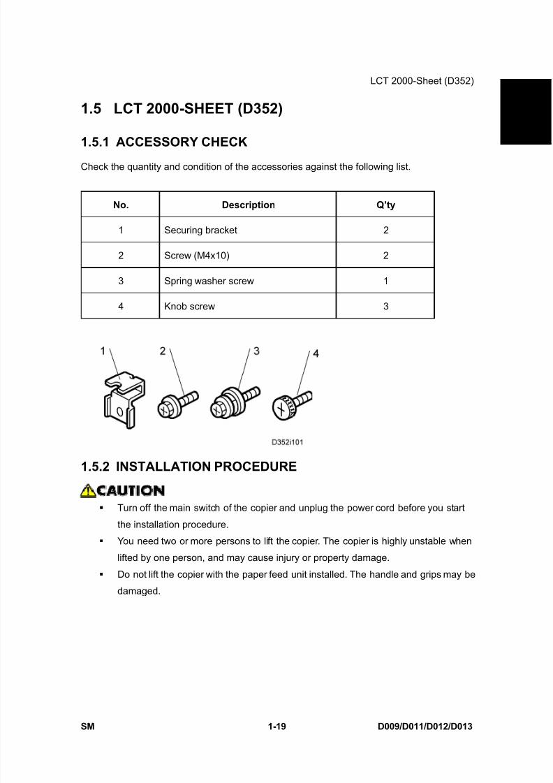
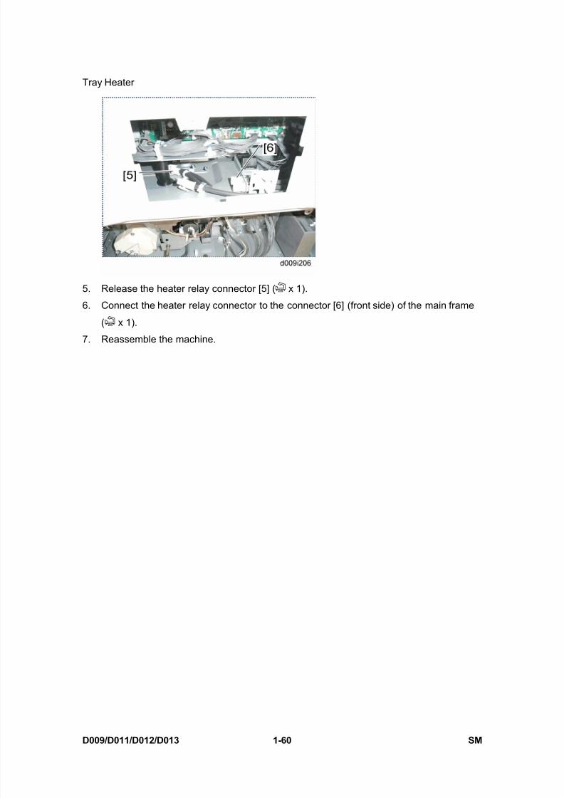
Tray Heater (Optional Paper Feed Unit)
D009/D011/D012/D013 1-62 SM
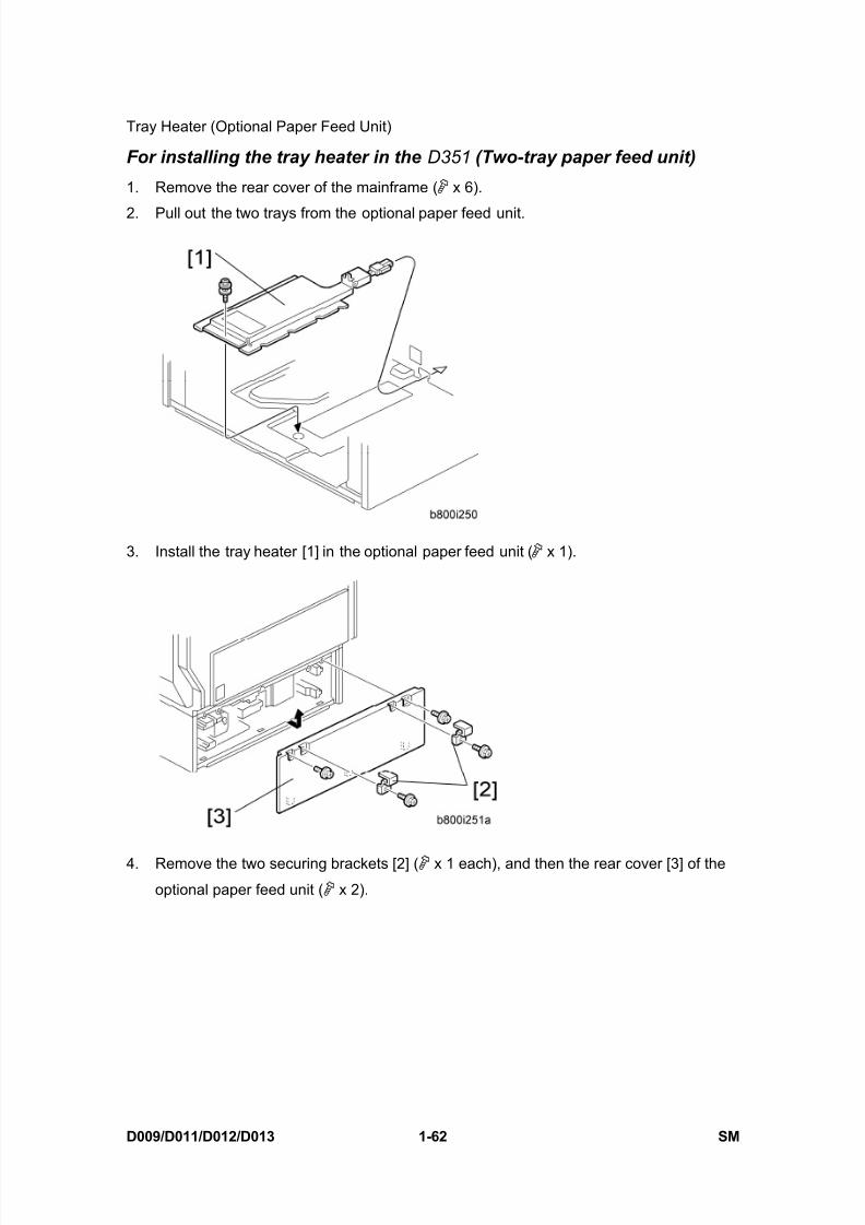
For installing the tray heater in the D351 (Two-tray paper feed unit)
1. Remove the rear cover of the mainframe ( x 6).
2. Pull out the two trays from the optional paper feed unit.
3. Install the tray heater [1] in the optional paper feed unit ( x 1).
4. Remove the two securing brackets [2] ( x 1 each), and then the rear cover [3] of the
optional paper feed unit ( x 2).

8/15/2019 Ricoh MP 4000 SM D009_D011_D012_D013 SERVICE MANUAL .pdf
http://slidepdf.com/reader/full/ricoh-mp-4000-sm-d009d011d012d013-service-manual-pdf 97/1162
Tray Heater (Optional Paper Feed Unit)
SM 1-63 D009/D011/D012/D013
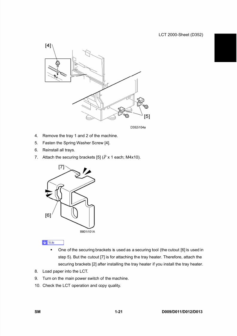
I n s t a l l a t i o n
5. Pull out tray 2 from the mainframe.
6. Replace the shoulder screw [4] with the washer screw [5], using the securing bracket [6]
( x 1).
7. Connect the harness [7] to the connector [8] of the tray heater.
8. Route the harness [7] as shown and clamp it with four clamps ( x 4).
9. Connect the harness [7] to the connector [9] of the mainframe.

8/15/2019 Ricoh MP 4000 SM D009_D011_D012_D013 SERVICE MANUAL .pdf
http://slidepdf.com/reader/full/ricoh-mp-4000-sm-d009d011d012d013-service-manual-pdf 98/1162
Tray Heater (Optional Paper Feed Unit)
D009/D011/D012/D013 1-64 SM
10. Remove the connector cover [10] ( x 1).
11. Release the optional heater relay connector [11] ( x 1).
12. Connect the optional heater relay connector to the connector [12] (rear side) of the main
frame ( x 1).
13. Reassemble the mainframe and optional paper feed unit.
14. Attach the on/standby decal [13] to the right-hand side of the main power switch.

8/15/2019 Ricoh MP 4000 SM D009_D011_D012_D013 SERVICE MANUAL .pdf
http://slidepdf.com/reader/full/ricoh-mp-4000-sm-d009d011d012d013-service-manual-pdf 99/1162
Tray Heater (Optional Paper Feed Unit)
SM 1-65 D009/D011/D012/D013
I n s t a l l a t i o n
For installing the tray heater in the D352 (LCT)
1. Remove the rear cover of the mainframe ( x 6).
2. Pull out the LCT drawer.
If the right tray comes out with the left tray, push the right tray into the LCT.
3. Left tray [A] ( x 2)
4. Remove the right tray [2] while pressing down the stopper [3].
When reinstalling the right tray, set the right tray on the guide rail and carefully
push the tray in, making sure to keep the tray level.

8/15/2019 Ricoh MP 4000 SM D009_D011_D012_D013 SERVICE MANUAL .pdf
http://slidepdf.com/reader/full/ricoh-mp-4000-sm-d009d011d012d013-service-manual-pdf 100/1162
Tray Heater (Optional Paper Feed Unit)
D009/D011/D012/D013 1-66 SM
5. Install the tray heater [4] in the optional LCT ( x 1).
6. Remove the two securing brackets [5] ( x 1 each), and then the rear cover [6] of the
optional LCT ( x 2).
7. Pull out tray 2 from the mainframe.
8. Replace the shoulder screw [7] with the washer screw [8], using the securing bracket [9]
8/15/2019 Ricoh MP 4000 SM D009_D011_D012_D013 SERVICE MANUAL .pdf
http://slidepdf.com/reader/full/ricoh-mp-4000-sm-d009d011d012d013-service-manual-pdf 101/1162
Tray Heater (Optional Paper Feed Unit)
SM 1-67 D009/D011/D012/D013
I n s t a l l a t i o n
( x 1).
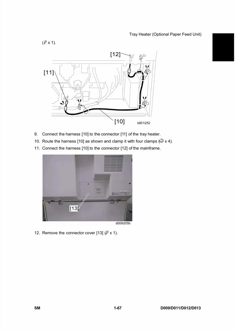
9. Connect the harness [10] to the connector [11] of the tray heater.
10. Route the harness [10] as shown and clamp it with four clamps ( x 4).
11. Connect the harness [10] to the connector [12] of the mainframe.
12. Remove the connector cover [13] ( x 1).
8/15/2019 Ricoh MP 4000 SM D009_D011_D012_D013 SERVICE MANUAL .pdf
http://slidepdf.com/reader/full/ricoh-mp-4000-sm-d009d011d012d013-service-manual-pdf 102/1162
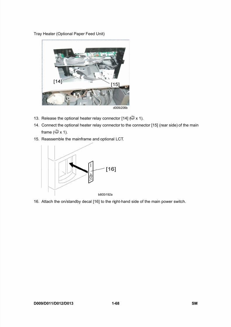
Tray Heater (Optional Paper Feed Unit)
D009/D011/D012/D013 1-68 SM
13. Release the optional heater relay connector [14] ( x 1).
14. Connect the optional heater relay connector to the connector [15] (rear side) of the main
frame ( x 1).
15. Reassemble the mainframe and optional LCT.
16. Attach the on/standby decal [16] to the right-hand side of the main power switch.

8/15/2019 Ricoh MP 4000 SM D009_D011_D012_D013 SERVICE MANUAL .pdf
http://slidepdf.com/reader/full/ricoh-mp-4000-sm-d009d011d012d013-service-manual-pdf 103/1162
HDD Option (D362, only for D009/D012)
SM 1-69 D009/D011/D012/D013
I n s t a l l a t i o n
1.19 HDD OPTION (D362, ONLY FOR D009/D012)
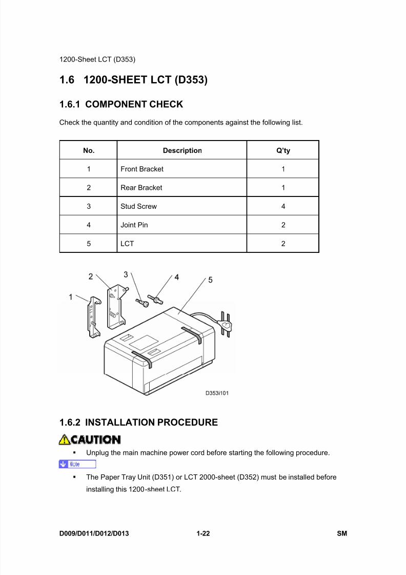
1.19.1 COMPONENT CHECK
No. Description Q’ty For D009/D012
1 HDD Unit 1
2 Screw 3
Keytop: Copy 2 3
Keytop: Document Server 2
- Knob Screw 3 ---
= Necessary, --- = Not necessary
8/15/2019 Ricoh MP 4000 SM D009_D011_D012_D013 SERVICE MANUAL .pdf
http://slidepdf.com/reader/full/ricoh-mp-4000-sm-d009d011d012d013-service-manual-pdf 104/1162
HDD Option (D362, only for D009/D012)
D009/D011/D012/D013 1-70 SM
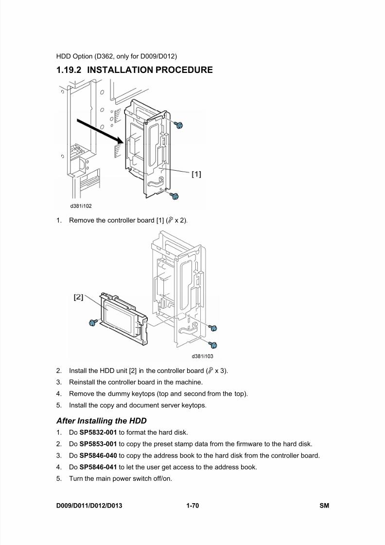
1.19.2 INSTALLATION PROCEDURE
1. Remove the controller board [1] ( x 2).
2. Install the HDD unit [2] in the controller board ( x 3).
3. Reinstall the controller board in the machine.4. Remove the dummy keytops (top and second from the top).
5. Install the copy and document server keytops.
After Installing the HDD1. Do SP5832-001 to format the hard disk.
2. Do SP5853-001 to copy the preset stamp data from the firmware to the hard disk.
3. Do SP5846-040 to copy the address book to the hard disk from the controller board.
4. Do SP5846-041 to let the user get access to the address book.
5. Turn the main power switch off/on.

8/15/2019 Ricoh MP 4000 SM D009_D011_D012_D013 SERVICE MANUAL .pdf
http://slidepdf.com/reader/full/ricoh-mp-4000-sm-d009d011d012d013-service-manual-pdf 105/1162
8/15/2019 Ricoh MP 4000 SM D009_D011_D012_D013 SERVICE MANUAL .pdf
http://slidepdf.com/reader/full/ricoh-mp-4000-sm-d009d011d012d013-service-manual-pdf 106/1162
DataOverwriteSecurity Unit Type I (D362)
D009/D011/D012/D013 1-72 SM
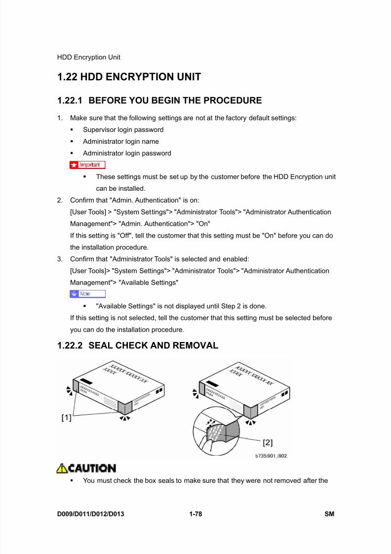
You must check the box seals to make sure that they were not removed after the
items were sealed in the box at the factory before you do the installation.1. Check the box seals [1] on each corner of the box.
Make sure that a tape is attached to each corner.
The surfaces of the tapes must be blank. If you see “VOID” on the tapes, do not
install the components in the box.
2. If the surfaces of the tapes do not show “VOID”, remove them from the corners of the
box.
3. You can see the “VOID” marks [2] when you remove each seal. In this condition, they
cannot be attached to the box again.
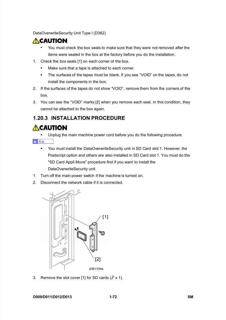
1.20.3 INSTALLATION PROCEDURE
Unplug the main machine power cord before you do the following procedure.
You must install the DataOverwriteSecurity unit in SD Card slot 1. However, the
Postscript option and others are also installed in SD Card slot 1. You must do the
"SD Card Appli Move" procedure first if you want to install the
DataOverwriteSecurity unit.1. Turn off the main power switch if the machine is turned on.
2. Disconnect the network cable if it is connected.
3. Remove the slot cover [1] for SD cards ( x 1).

8/15/2019 Ricoh MP 4000 SM D009_D011_D012_D013 SERVICE MANUAL .pdf
http://slidepdf.com/reader/full/ricoh-mp-4000-sm-d009d011d012d013-service-manual-pdf 107/1162
DataOverwriteSecurity Unit Type I (D362)
SM 1-73 D009/D011/D012/D013
I n s t a l l a t i o n
4. Turn the SD-card label face [2] to the rear of the machine. Then push it slowly into slot 1
until you hear a click.
5. Connect the network cable if it needs to be connected.6. Turn on the main power switch.
7. Go into the SP mode and push “EXECUTE” with SP5-878-001.
8. Exit the SP mode and turn off the operation switch. Then turn off the main power switch.
9. Turn on the machine power.
10. Do SP5990-005 (SP print mode Diagnostic Report).
11. Make sure the ROM number and firmware version in area [a] of the diagnostic report
are the same as those in area [b].
[a]: “ROM Number/Firmware Version” – “HDD Format Option”
[b]: “Loading Program” – “GW2a_zoffy”
Diagnostic Report:“ROM No. / Firmware
Version” [a]“Loading Program” [b]
DataOverwriteSecurity
Unit
HDD Format Option:
D3775912 / 1.00m
GW2a_zoffy:
D3775912 / 1.00m
The ROM number and firmware version number change when the firmware is
upgraded. However, the important thing is to make sure the numbers in [a] are
the same as the numbers in [b].
If the ROM numbers are not the same, or the version numbers are not the same,
this means the unit was not installed correctly.
If this happens:
Make sure of the unit type (must be Type I).
If they do not match:
1) Replace the NV-RAM on the controller.
2) Replace the “DataOverwriteSecurity Unit” (SD card) with the correct type
3) Do the installation procedure in this procedure again, from Step 1.
12. Go into the User Tools mode, and select System Settings> Administrator Tools> Auto
Erase Memory Setting> On.
13. Exit the User Tools mode.
8/15/2019 Ricoh MP 4000 SM D009_D011_D012_D013 SERVICE MANUAL .pdf
http://slidepdf.com/reader/full/ricoh-mp-4000-sm-d009d011d012d013-service-manual-pdf 108/1162
DataOverwriteSecurity Unit Type I (D362)
D009/D011/D012/D013 1-74 SM
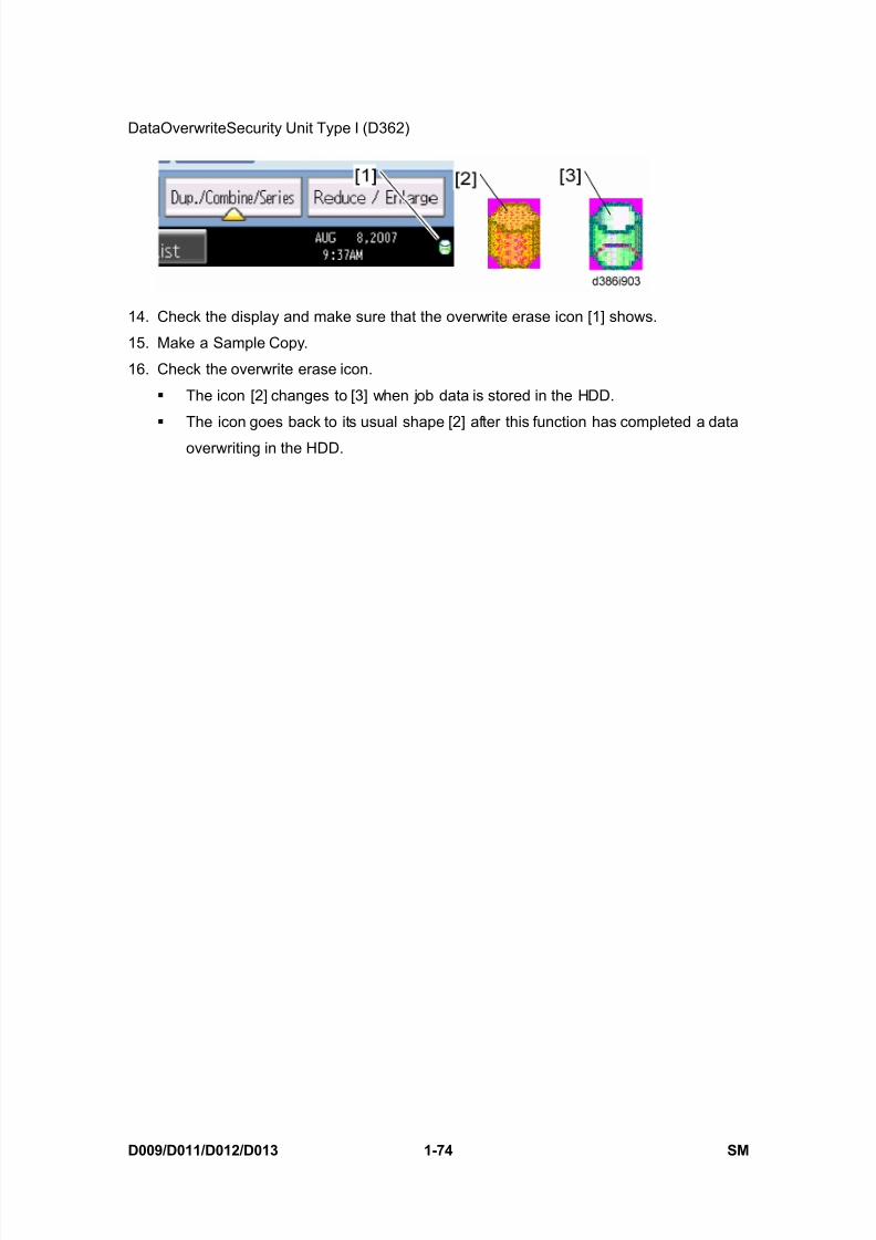
14. Check the display and make sure that the overwrite erase icon [1] shows.
15. Make a Sample Copy.
16. Check the overwrite erase icon.
The icon [2] changes to [3] when job data is stored in the HDD.
The icon goes back to its usual shape [2] after this function has completed a data
overwriting in the HDD.
8/15/2019 Ricoh MP 4000 SM D009_D011_D012_D013 SERVICE MANUAL .pdf
http://slidepdf.com/reader/full/ricoh-mp-4000-sm-d009d011d012d013-service-manual-pdf 109/1162
8/15/2019 Ricoh MP 4000 SM D009_D011_D012_D013 SERVICE MANUAL .pdf
http://slidepdf.com/reader/full/ricoh-mp-4000-sm-d009d011d012d013-service-manual-pdf 110/1162
Copy Data Security Unit
D009/D011/D012/D013 1-76 SM
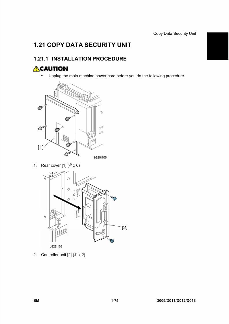
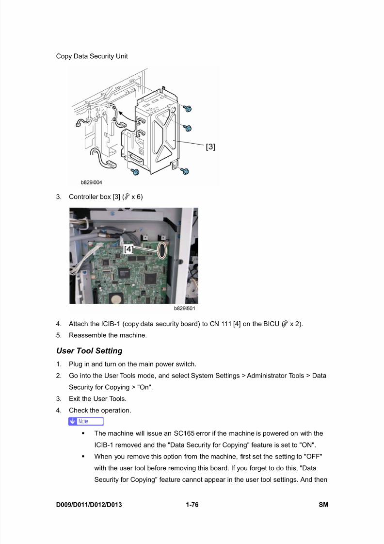
3. Controller box [3] ( x 6)
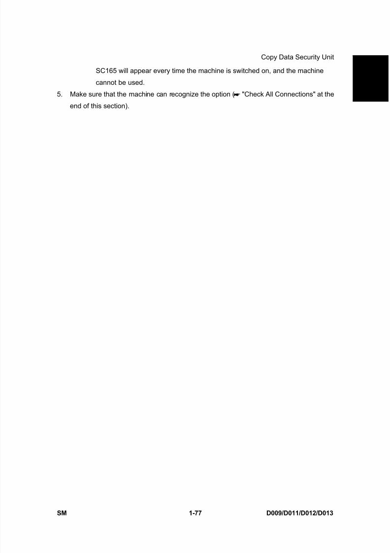
4. Attach the ICIB-1 (copy data security board) to CN 111 [4] on the BICU ( x 2).
5. Reassemble the machine.
User Tool Setting
1. Plug in and turn on the main power switch.
2. Go into the User Tools mode, and select System Settings > Administrator Tools > Data
Security for Copying > "On".
3. Exit the User Tools.
4. Check the operation.
The machine will issue an SC165 error if the machine is powered on with the
ICIB-1 removed and the "Data Security for Copying" feature is set to "ON".
When you remove this option from the machine, first set the setting to "OFF"
with the user tool before removing this board. If you forget to do this, "Data
Security for Copying" feature cannot appear in the user tool settings. And then
8/15/2019 Ricoh MP 4000 SM D009_D011_D012_D013 SERVICE MANUAL .pdf
http://slidepdf.com/reader/full/ricoh-mp-4000-sm-d009d011d012d013-service-manual-pdf 111/1162
8/15/2019 Ricoh MP 4000 SM D009_D011_D012_D013 SERVICE MANUAL .pdf
http://slidepdf.com/reader/full/ricoh-mp-4000-sm-d009d011d012d013-service-manual-pdf 112/1162
8/15/2019 Ricoh MP 4000 SM D009_D011_D012_D013 SERVICE MANUAL .pdf
http://slidepdf.com/reader/full/ricoh-mp-4000-sm-d009d011d012d013-service-manual-pdf 113/1162
HDD Encryption Unit
SM 1-79 D009/D011/D012/D013
I n s
t a l l a t i o n
items were sealed in the box at the factory before you do the installation.
1. Check the box seals [1] on each corner of the box.
Make sure that a tape is attached to each corner. The surfaces of the tapes must be blank. If you see “VOID” on the tapes, do not
install the components in the box.
2. If the surfaces of the tapes do not show “VOID”, remove them from the corners of the
box.
3. You can see the “VOID” marks [2] when you remove each seal. In this condition, they
cannot be attached to the box again.
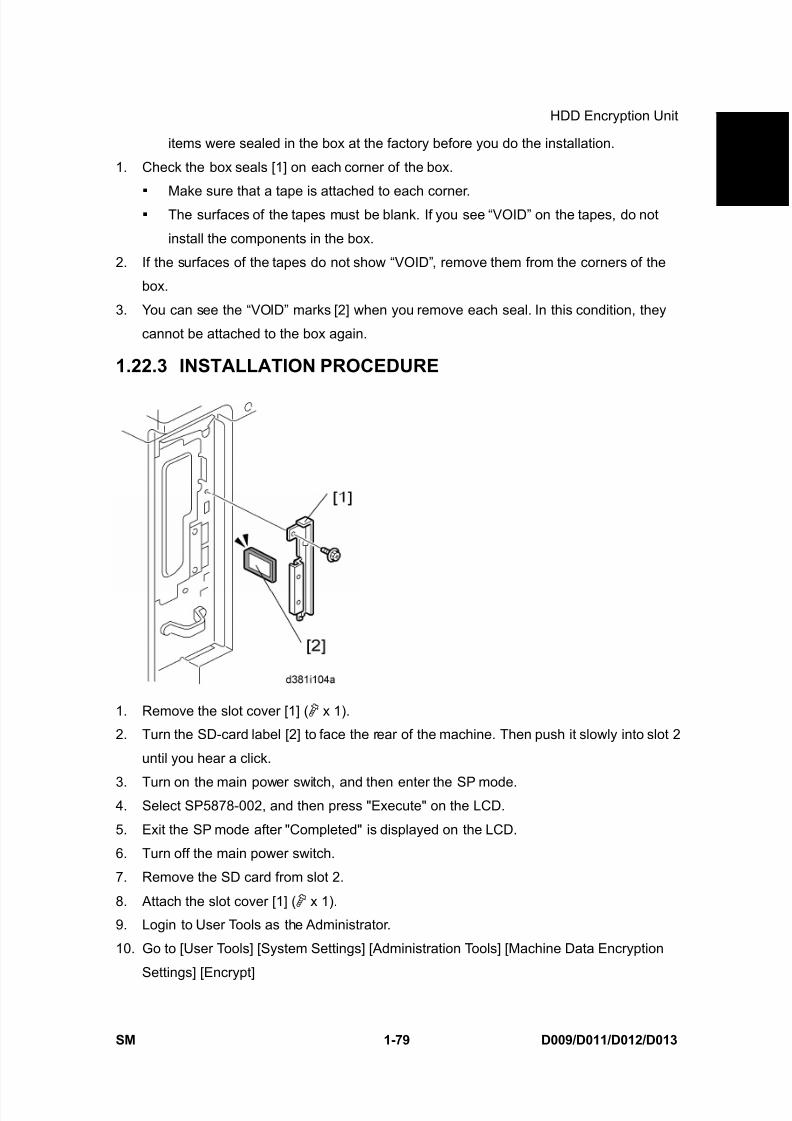
1.22.3 INSTALLATION PROCEDURE
1. Remove the slot cover [1] ( x 1).
2. Turn the SD-card label [2] to face the rear of the machine. Then push it slowly into slot 2
until you hear a click.
3. Turn on the main power switch, and then enter the SP mode.4. Select SP5878-002, and then press "Execute" on the LCD.
5. Exit the SP mode after "Completed" is displayed on the LCD.
6. Turn off the main power switch.
7. Remove the SD card from slot 2.
8. Attach the slot cover [1] ( x 1).
9. Login to User Tools as the Administrator.
10. Go to [User Tools] [System Settings] [Administration Tools] [Machine Data Encryption
Settings] [Encrypt]
8/15/2019 Ricoh MP 4000 SM D009_D011_D012_D013 SERVICE MANUAL .pdf
http://slidepdf.com/reader/full/ricoh-mp-4000-sm-d009d011d012d013-service-manual-pdf 114/1162
HDD Encryption Unit
D009/D011/D012/D013 1-80 SM
Depending on the customers needs, choose one from the following three choices: [All Data],
[File System Data Only], or [Format All Data].
11. From the window that will appear, print out the Data Encryption key by pressing the“Start” key.
12. Confirm that the Data Encryption key has been printed correctly. After confirming that
the Data Encryption Key has correctly printed, press OK.
13. A new window will appear informing of the changed settings. Press EXIT to continue.
14. Reboot the machine. Note: First reboot time may be significantly longer.
15. Store the Encryption Key Printout in a secure location.
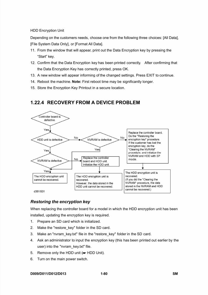
1.22.4 RECOVERY FROM A DEVICE PROBLEM
Restoring the encryption key
When replacing the controller board for a model in which the HDD encryption unit has been
installed, updating the encryption key is required.
1. Prepare an SD card which is initialized.
2. Make the "restore_key" folder in the SD card.
3. Make an "nvram_key.txt" file in the "restore_key" folder in the SD card.
4. Ask an administrator to input the encryption key (this has been printed out earlier by the
user) into the "nvram_key.txt" file.
5. Remove only the HDD unit ( HDD Unit).
6. Turn on the main power switch.
8/15/2019 Ricoh MP 4000 SM D009_D011_D012_D013 SERVICE MANUAL .pdf
http://slidepdf.com/reader/full/ricoh-mp-4000-sm-d009d011d012d013-service-manual-pdf 115/1162
HDD Encryption Unit
SM 1-81 D009/D011/D012/D013
I n s
t a l l a t i o n
7. Confirm that the prompt on the LCD tells you to install the SD card (storing the
encryption key) in the machine.
8. Turn off the main power switch.9. Insert the SD card that contains the encryption key into slot 2.
10. Turn on the main power switch, and the machine automatically restores the encryption
key in the flash memory on the controller board.
11. Turn off the main power switch after the machine has returned to normal status.
12. Remove the SD card from slot 2.
13. Reinstall the HDD unit.
Clearing the NVRAM
When replacing the controller board for a model in which the HDD encryption unit has beeninstalled and a customer has lost the encryption key, clearing the NVRAM is required to
recover the HDD encryption unit.
1. Prepare an SD card which is initialized.
2. Make the "restore_key" folder in the SD card.
3. Make an "nvram_key.txt" file in the "restore_key" folder in the SD card.
4. Input "nvclear" into the "nvram_key.txt" file.
5. Turn on the main power switch.
6. Confirm that the prompt on the LCD tells you to install the SD card (storing theencryption key) in the machine.
7. Turn off the main power switch.
8. Insert the SD card that contains “nvclear” into slot 2.
9. Turn on the main power switch, and the machine automatically restores the encryption
key in the flash memory on the controller board.
10. Turn off the main power switch after the machine has returned to normal status.
11. Remove the SD card from slot 2.
12. Turn on the main power switch.
13. Initialize the NVRAM (SP5801-001) and HDD unit (SP5832-001) with SP mode.
14. The user must enable the HDD encryption unit with a user tool.

8/15/2019 Ricoh MP 4000 SM D009_D011_D012_D013 SERVICE MANUAL .pdf
http://slidepdf.com/reader/full/ricoh-mp-4000-sm-d009d011d012d013-service-manual-pdf 116/1162
Browser Unit Type D
D009/D011/D012/D013 1-82 SM
1.23 BROWSER UNIT TYPE D
1.23.1 INSTALLATION PROCEDURE
This option requires a HDD unit.
Unplug the main machine power cord before you do the following procedure.
SD card slot 2 is basically used only for service maintenance. Do not leave an SD card in
slot 2 after installing an application.
1. Remove the slot cover [1] for SD cards ( x 1).
2. Turn the SD-card label face [2] to the rear of the machine. Then push it slowly into slot 2
until you hear a click.
3. Plug in and turn on the main power switch.
4. Push the "User Tools" key.
If an administrator setting is registered for the machine, steps 5 and 6 are required.Otherwise, skip to step 7.
5. Push the "Login/Logout" key.
6. Login with the administrator user name and password.
7. Touch "Extended Feature Settings" twice on the LCD.
8. Touch "Install" on the LCD.
9. Touch "SD Card".
10. Touch the "Browser" line.
11. Under "Install to", touch "Machine HDD" and touch "Next".
8/15/2019 Ricoh MP 4000 SM D009_D011_D012_D013 SERVICE MANUAL .pdf
http://slidepdf.com/reader/full/ricoh-mp-4000-sm-d009d011d012d013-service-manual-pdf 117/1162
Browser Unit Type D
SM 1-83 D009/D011/D012/D013
I n s t a l l a t i o n
12. When you see "Ready to Install", check the information on the screen to confirm your
previous selection.
13. Touch "OK". You will see "Installing the extended feature... Please wait.", and then"Completed".
14. Touch "Exit" to go back to the setting screen.
15. Touch "Change Allocation".
16. Touch the "Browser" line.
17. Press one of the hard keys, which you want to use for the Browser Unit. By default, this
function is assigned to the "Other Functions" key (bottom key of the function keys).
18. Touch "OK".
19. Touch "Exit" twice to go back to the copy screen.
20. Turn off the main power switch.
21. Install the key for "Browser Unit" to the place where you want it.
22. Remove the SD card from slot 2.
23. Attach the slot cover [1] ( x 1).
24. Tell a customer to keep the SD card in a safe place ( Section 5.32 "SD Card Appli
Move" in the "Service Tables" section) after you have installed the application program
from the card to the HDD.
This is because:
The SD card is the only proof that the user is licensed to use the application
program.
You may need to check the SD card and its data to solve a problem in the future.
Update Procedure
1. Remove the slot cover [1] for SD cards ( x 1).
2. Turn the SD-card label face [2] to the rear of the machine. Then push it slowly into slot 2
until you hear a click.
3. Plug in and turn on the main power switch.
4. Push the "User Tools" key.
If an administrator setting is registered for the machine, step 5 and 6 are required.
Otherwise, skip to step 7.
5. Push the "Login/ Logout" key.
6. Login with the administrator user name and password.
7. Touch "Extended Feature Settings" twice on the LCD.
8. Touch "Uninstall" on the LCD.
9. Touch the "Browser" line
10. A confirmation message appears on the LCD.

8/15/2019 Ricoh MP 4000 SM D009_D011_D012_D013 SERVICE MANUAL .pdf
http://slidepdf.com/reader/full/ricoh-mp-4000-sm-d009d011d012d013-service-manual-pdf 118/1162
Browser Unit Type D
D009/D011/D012/D013 1-84 SM
11. Touch "Yes" to proceed.
12. A reconfirmation message appears on the LCD.
13. Touch "Yes" to uninstall the browser unit.14. You will see "Uninstalling the extended feature... Please wait.", and then "Completed".
15. Touch "Exit" to go back to the setting screen.
16. Exit "User/Tools" setting, and then turn off the main power switch.
17. Remove the SD card from the SD card slot 2.
18. Overwrite the updated program in the "sdk" folder of the browser unit application with
PC.
19. Do the "Installation Procedure" to install the browser unit.

8/15/2019 Ricoh MP 4000 SM D009_D011_D012_D013 SERVICE MANUAL .pdf
http://slidepdf.com/reader/full/ricoh-mp-4000-sm-d009d011d012d013-service-manual-pdf 119/1162

8/15/2019 Ricoh MP 4000 SM D009_D011_D012_D013 SERVICE MANUAL .pdf
http://slidepdf.com/reader/full/ricoh-mp-4000-sm-d009d011d012d013-service-manual-pdf 120/1162
8/15/2019 Ricoh MP 4000 SM D009_D011_D012_D013 SERVICE MANUAL .pdf
http://slidepdf.com/reader/full/ricoh-mp-4000-sm-d009d011d012d013-service-manual-pdf 121/1162
PM Table - Mainframe
SM 2-1 D009/D011/D012/D013
P r e v e n
t i v e
M a i n
t e n a n c e
2. PREVENTIVE MAINTENANCE
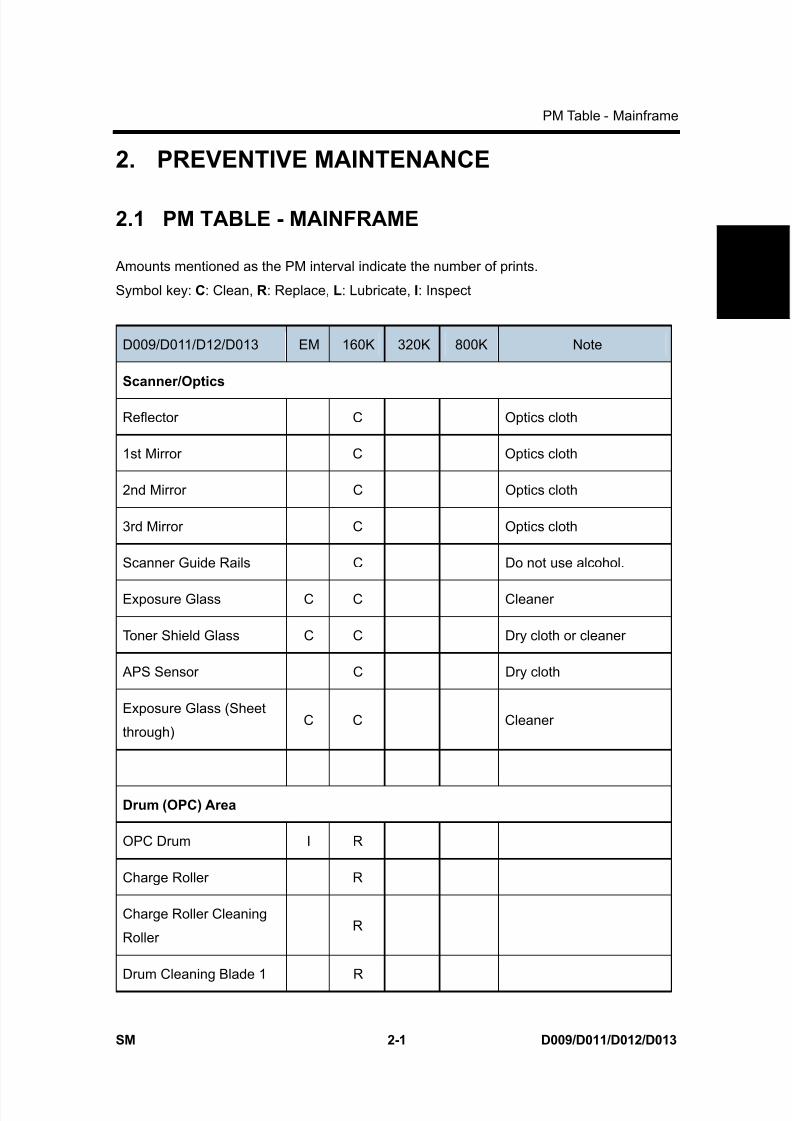
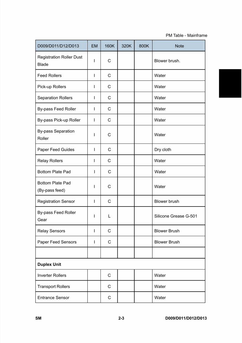
2.1 PM TABLE - MAINFRAME
Amounts mentioned as the PM interval indicate the number of prints.
Symbol key: C: Clean, R: Replace, L: Lubricate, I: Inspect
D009/D011/D12/D013 EM 160K 320K 800K Note
Scanner/Optics
Reflector C Optics cloth
1st Mirror C Optics cloth
2nd Mirror C Optics cloth
3rd Mirror C Optics cloth
Scanner Guide Rails C Do not use alcohol.
Exposure Glass C C Cleaner
Toner Shield Glass C C Dry cloth or cleaner
APS Sensor C Dry cloth
Exposure Glass (Sheet
through)C C Cleaner
Drum (OPC) Area
OPC Drum I R
Charge Roller R
Charge Roller Cleaning
RollerR
Drum Cleaning Blade 1 R

8/15/2019 Ricoh MP 4000 SM D009_D011_D012_D013 SERVICE MANUAL .pdf
http://slidepdf.com/reader/full/ricoh-mp-4000-sm-d009d011d012d013-service-manual-pdf 122/1162
8/15/2019 Ricoh MP 4000 SM D009_D011_D012_D013 SERVICE MANUAL .pdf
http://slidepdf.com/reader/full/ricoh-mp-4000-sm-d009d011d012d013-service-manual-pdf 123/1162
PM Table - Mainframe
SM 2-3 D009/D011/D012/D013
P r e v e n
t i v e
M a i n
t e n a n c e
D009/D011/D12/D013 EM 160K 320K 800K Note
Registration Roller Dust
BladeI C Blower brush.
Feed Rollers I C Water
Pick-up Rollers I C Water
Separation Rollers I C Water
By-pass Feed Roller I C Water
By-pass Pick-up Roller I C Water
By-pass Separation
RollerI C Water
Paper Feed Guides I C Dry cloth
Relay Rollers I C Water
Bottom Plate Pad I C Water
Bottom Plate Pad
(By-pass feed)I C Water
Registration Sensor I C Blower brush
By-pass Feed Roller
GearI L Silicone Grease G-501
Relay Sensors I C Blower Brush
Paper Feed Sensors I C Blower Brush
Duplex Unit
Inverter Rollers C Water
Transport Rollers C Water
Entrance Sensor C Water

8/15/2019 Ricoh MP 4000 SM D009_D011_D012_D013 SERVICE MANUAL .pdf
http://slidepdf.com/reader/full/ricoh-mp-4000-sm-d009d011d012d013-service-manual-pdf 124/1162
PM Table - Mainframe
D009/D011/D012/D013 2-4 SM
D009/D011/D12/D013 EM 160K 320K 800K Note
Exit Sensor C Water
Transfer Belt Unit
Transfer Belt C R
Dry cloth.
To prevent damage to the
cleaning blade, always
replace these items
together.
Transfer Belt CleaningBlade
R
Transfer Belt Rollers C Dry cloth
Entrance Seal C Dry cloth
Transfer Entrance Guide C C Dry cloth
Used Toner Tank I C Empty the tank
Paper Exit
Paper Exit Sensor I I Blower brush
Junction Gate Jam
sensorI C Blower brush
Fusing Exit Sensor I I Blower brush
Paper Exit Rollers I I Water
Junction Transport Roller I I Water
Paper Exit Guide I I Water
Due to their durability and extended service life, the feed rollers, separation rollers,
and pick-up rollers of the mainframe, optional paper trays, and LCT are not
replaced at PM.*1: Lubricate the by-pass feed clutch gear with Silicone Grease G501 every P.M.

8/15/2019 Ricoh MP 4000 SM D009_D011_D012_D013 SERVICE MANUAL .pdf
http://slidepdf.com/reader/full/ricoh-mp-4000-sm-d009d011d012d013-service-manual-pdf 125/1162

8/15/2019 Ricoh MP 4000 SM D009_D011_D012_D013 SERVICE MANUAL .pdf
http://slidepdf.com/reader/full/ricoh-mp-4000-sm-d009d011d012d013-service-manual-pdf 126/1162
PM Table - Options
D009/D011/D012/D013 2-6 SM
2.2 PM TABLE - OPTIONS
Amounts mentioned as the PM interval indicate the number of prints/ originals.
Symbol key: C: Clean, R: Replace, L: Lubricate, I: Inspect
B802 EM120K
(Originals)Note
ARDF (for originals)
Pick-up Roller R Damp cloth; alcohol
Feed Belt R Damp cloth; alcohol
Separation Roller R Damp cloth; alcohol
Sensors C Blower brush
Platen Sheet Cover C Damp cloth; alcohol (Replace if required.)
White Plate C Dry or damp cloth
Drive Gear L Grease G501
Transport Roller C Damp cloth; alcohol
Exit Roller C Damp cloth; alcohol
Inverter Roller C Damp cloth; alcohol
Idle Rollers C Damp cloth; alcohol
D351 EM 150K 300K 450K Note
Paper Feed Unit
Relay Rollers C Dry or damp cloth
Bottom Plate Pad C Dry or damp cloth

8/15/2019 Ricoh MP 4000 SM D009_D011_D012_D013 SERVICE MANUAL .pdf
http://slidepdf.com/reader/full/ricoh-mp-4000-sm-d009d011d012d013-service-manual-pdf 127/1162

8/15/2019 Ricoh MP 4000 SM D009_D011_D012_D013 SERVICE MANUAL .pdf
http://slidepdf.com/reader/full/ricoh-mp-4000-sm-d009d011d012d013-service-manual-pdf 128/1162
PM Table - Options
D009/D011/D012/D013 2-8 SM
D386 EM Note
Bridge Unit
Rollers C Dry or damp cloth
Copy Tray C Dry or damp cloth
Sensors C Blower brush
D389 EM Note
1-Bin Tray Unit
Rollers C Dry or damp cloth
Copy Tray C Dry or damp cloth
Sensors C Blower brush
8/15/2019 Ricoh MP 4000 SM D009_D011_D012_D013 SERVICE MANUAL .pdf
http://slidepdf.com/reader/full/ricoh-mp-4000-sm-d009d011d012d013-service-manual-pdf 129/1162

8/15/2019 Ricoh MP 4000 SM D009_D011_D012_D013 SERVICE MANUAL .pdf
http://slidepdf.com/reader/full/ricoh-mp-4000-sm-d009d011d012d013-service-manual-pdf 130/1162
8/15/2019 Ricoh MP 4000 SM D009_D011_D012_D013 SERVICE MANUAL .pdf
http://slidepdf.com/reader/full/ricoh-mp-4000-sm-d009d011d012d013-service-manual-pdf 131/1162
General Cautions
SM 3-1 D009/D011/D012/D013
R e p
l a c e m e n
t
A d j u s t m e n
t
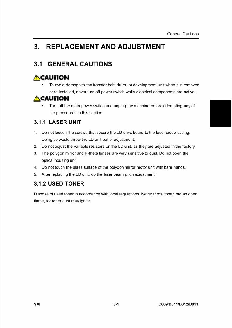
3. REPLACEMENT AND ADJUSTMENT
3.1 GENERAL CAUTIONS
To avoid damage to the transfer belt, drum, or development unit when it is removed
or re-installed, never turn off power switch while electrical components are active.
Turn off the main power switch and unplug the machine before attempting any of
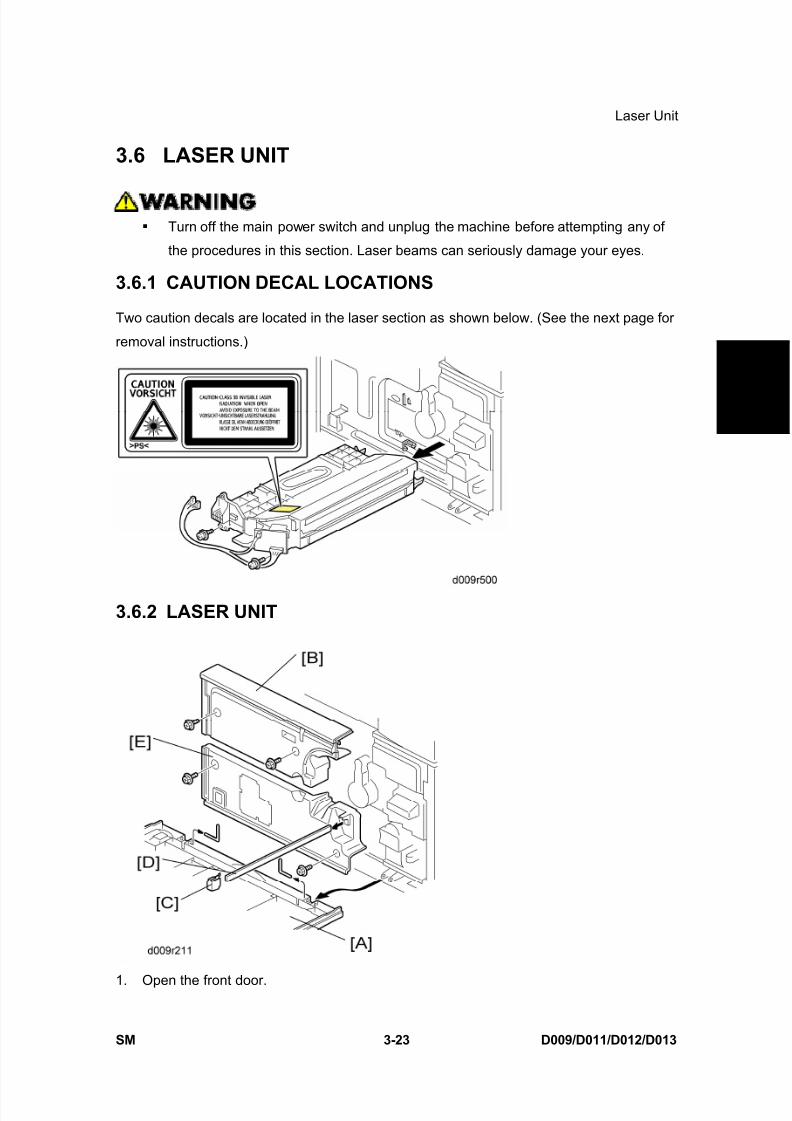
the procedures in this section.3.1.1 LASER UNIT
1. Do not loosen the screws that secure the LD drive board to the laser diode casing.
Doing so would throw the LD unit out of adjustment.
2. Do not adjust the variable resistors on the LD unit, as they are adjusted in the factory.
3. The polygon mirror and F-theta lenses are very sensitive to dust. Do not open the
optical housing unit.
4. Do not touch the glass surface of the polygon mirror motor unit with bare hands.
5. After replacing the LD unit, do the laser beam pitch adjustment.
3.1.2 USED TONER
Dispose of used toner in accordance with local regulations. Never throw toner into an open
flame, for toner dust may ignite.
8/15/2019 Ricoh MP 4000 SM D009_D011_D012_D013 SERVICE MANUAL .pdf
http://slidepdf.com/reader/full/ricoh-mp-4000-sm-d009d011d012d013-service-manual-pdf 132/1162
Special Tools and Lubricants
D009/D011/D012/D013 3-2 SM
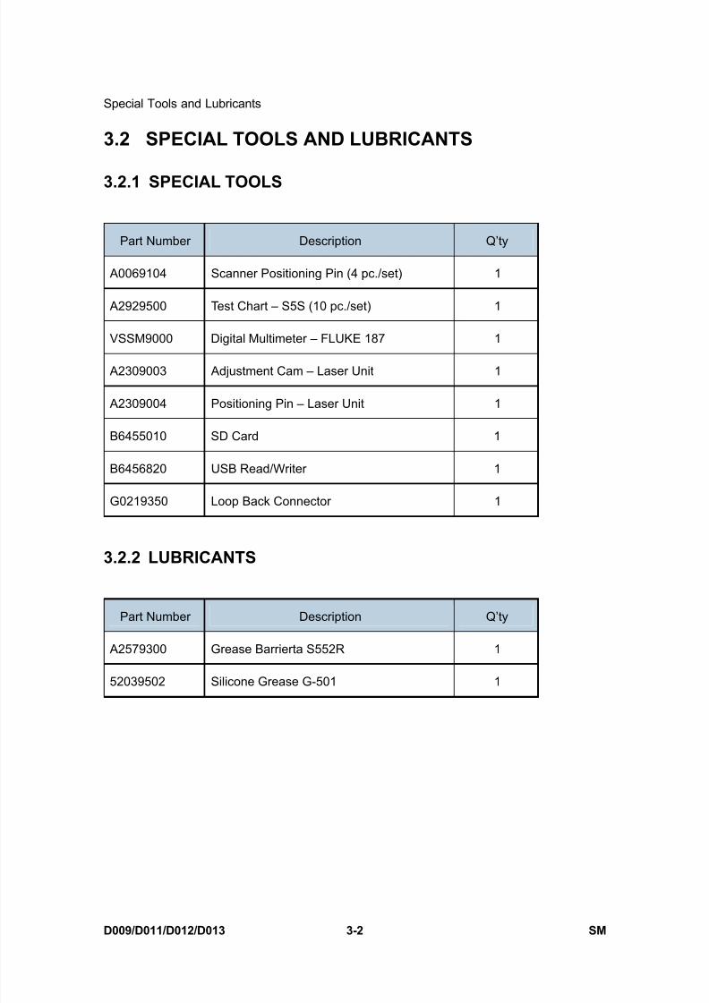
3.2 SPECIAL TOOLS AND LUBRICANTS
3.2.1 SPECIAL TOOLS
Part Number Description Q’ty
A0069104 Scanner Positioning Pin (4 pc./set) 1
A2929500 Test Chart – S5S (10 pc./set) 1
VSSM9000 Digital Multimeter – FLUKE 187 1
A2309003 Adjustment Cam – Laser Unit 1
A2309004 Positioning Pin – Laser Unit 1
B6455010 SD Card 1
B6456820 USB Read/Writer 1
G0219350 Loop Back Connector 1
3.2.2 LUBRICANTS
Part Number Description Q’ty
A2579300 Grease Barrierta S552R 1
52039502 Silicone Grease G-501 1
8/15/2019 Ricoh MP 4000 SM D009_D011_D012_D013 SERVICE MANUAL .pdf
http://slidepdf.com/reader/full/ricoh-mp-4000-sm-d009d011d012d013-service-manual-pdf 133/1162
Exterior Covers
SM 3-3 D009/D011/D012/D013
R e p
l a c e m e n
t
A d j u s t m e n
t
3.3 EXTERIOR COVERS
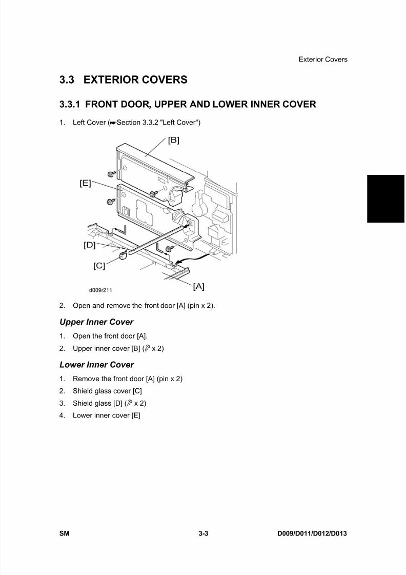
3.3.1 FRONT DOOR, UPPER AND LOWER INNER COVER
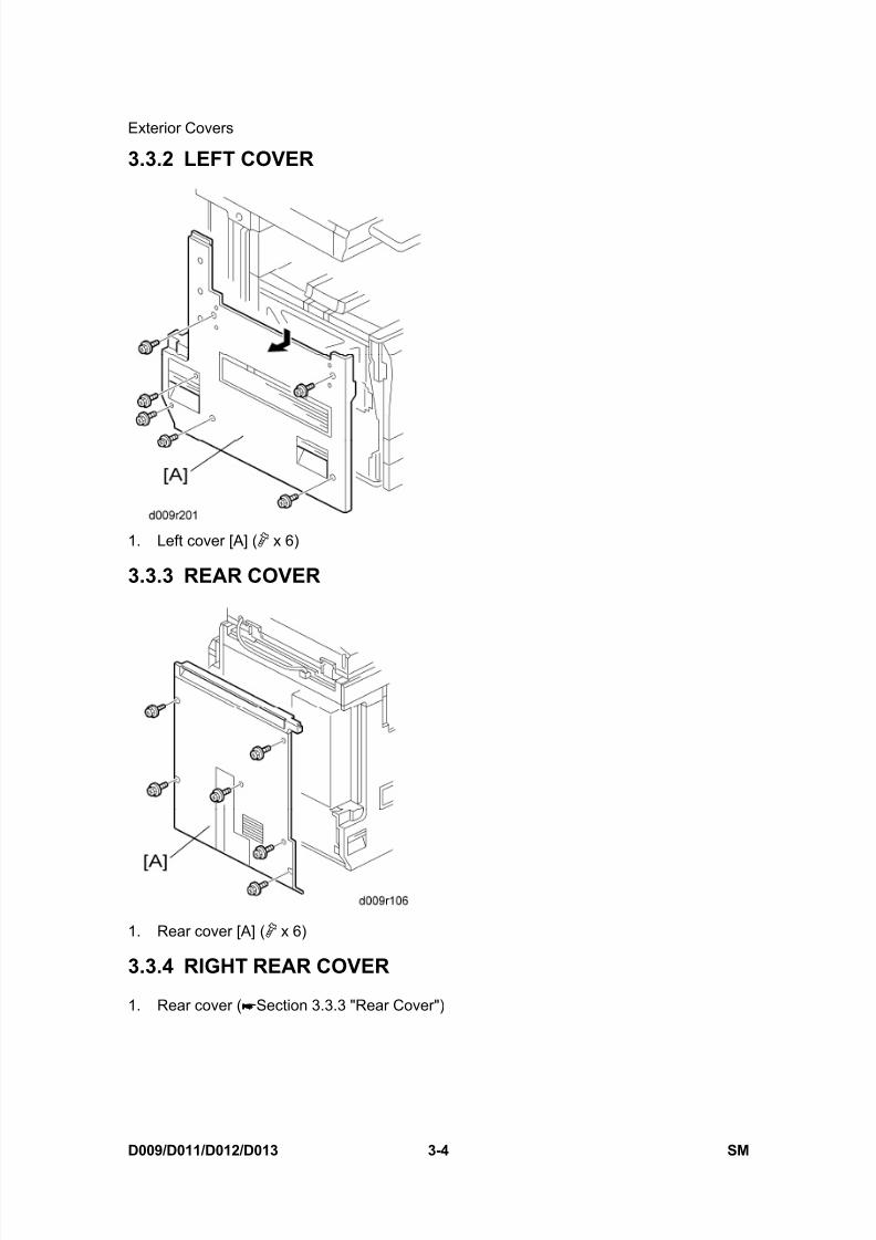
1. Left Cover ( Section 3.3.2 "Left Cover")
2. Open and remove the front door [A] (pin x 2).
Upper Inner Cover
1. Open the front door [A].
2. Upper inner cover [B] ( x 2)
Lower Inner Cover
1. Remove the front door [A] (pin x 2)
2. Shield glass cover [C]
3. Shield glass [D] ( x 2)4. Lower inner cover [E]
8/15/2019 Ricoh MP 4000 SM D009_D011_D012_D013 SERVICE MANUAL .pdf
http://slidepdf.com/reader/full/ricoh-mp-4000-sm-d009d011d012d013-service-manual-pdf 134/1162
8/15/2019 Ricoh MP 4000 SM D009_D011_D012_D013 SERVICE MANUAL .pdf
http://slidepdf.com/reader/full/ricoh-mp-4000-sm-d009d011d012d013-service-manual-pdf 135/1162
Exterior Covers
SM 3-5 D009/D011/D012/D013
R e p
l a c e m e n
t
A d j u s t m e n
t
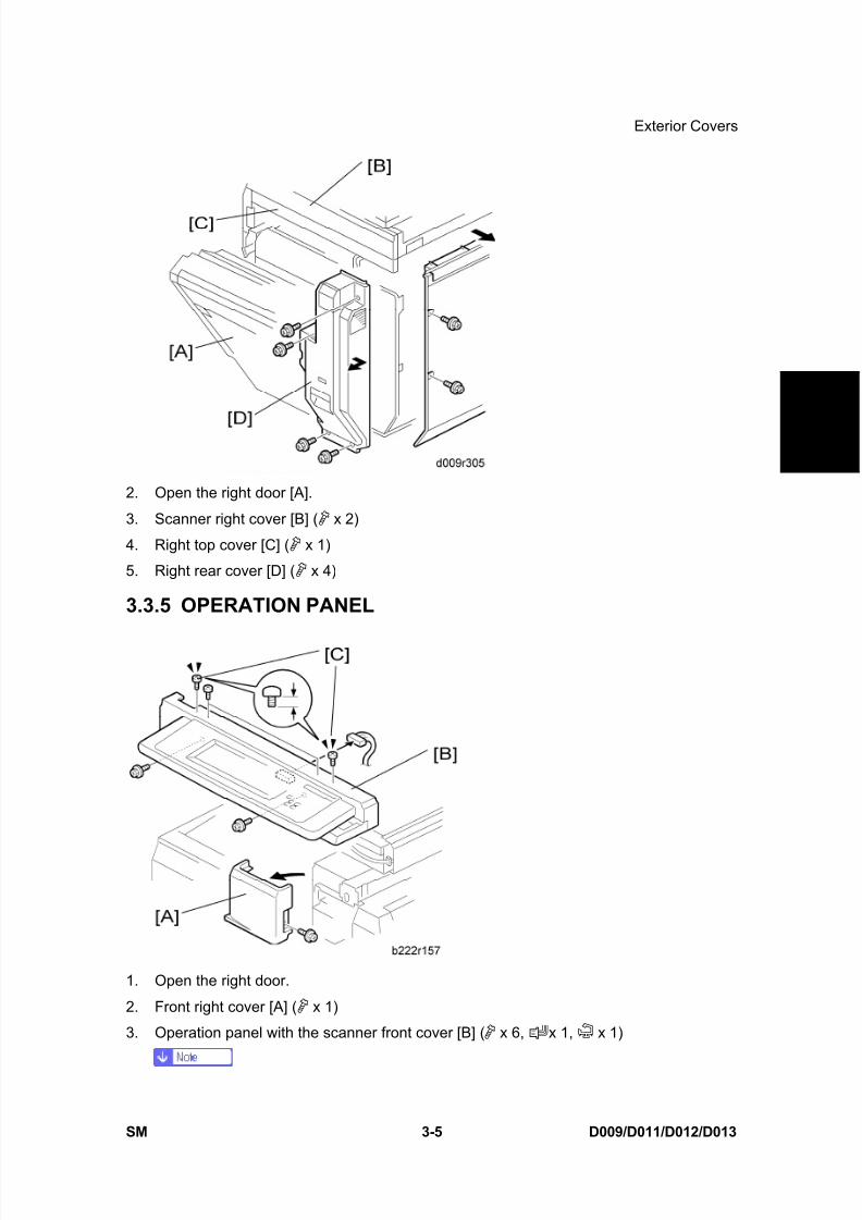
2. Open the right door [A].
3. Scanner right cover [B] ( x 2)
4. Right top cover [C] ( x 1)
5. Right rear cover [D] ( x 4)
3.3.5 OPERATION PANEL
1. Open the right door.
2. Front right cover [A] ( x 1)
3. Operation panel with the scanner front cover [B] ( x 6, x 1, x 1)
8/15/2019 Ricoh MP 4000 SM D009_D011_D012_D013 SERVICE MANUAL .pdf
http://slidepdf.com/reader/full/ricoh-mp-4000-sm-d009d011d012d013-service-manual-pdf 136/1162
Exterior Covers
D009/D011/D012/D013 3-6 SM
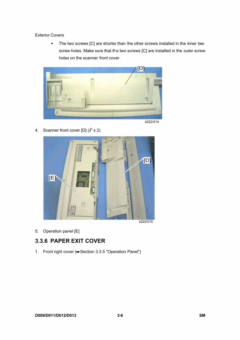
The two screws [C] are shorter than the other screws installed in the inner two
screw holes. Make sure that the two screws [C] are installed in the outer screw
holes on the scanner front cover.
4. Scanner front cover [D] ( x 2)
5. Operation panel [E]
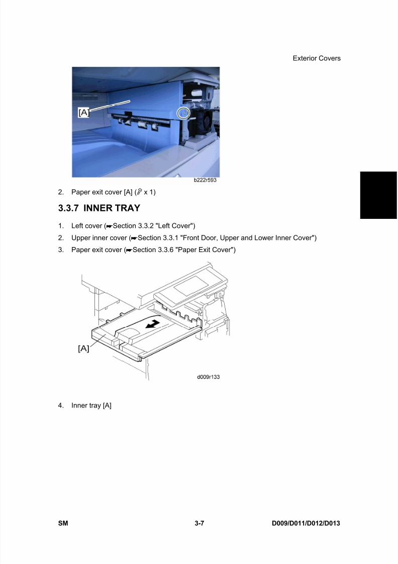
3.3.6 PAPER EXIT COVER
1. Front right cover ( Section 3.3.5 "Operation Panel")
8/15/2019 Ricoh MP 4000 SM D009_D011_D012_D013 SERVICE MANUAL .pdf
http://slidepdf.com/reader/full/ricoh-mp-4000-sm-d009d011d012d013-service-manual-pdf 137/1162

8/15/2019 Ricoh MP 4000 SM D009_D011_D012_D013 SERVICE MANUAL .pdf
http://slidepdf.com/reader/full/ricoh-mp-4000-sm-d009d011d012d013-service-manual-pdf 138/1162

8/15/2019 Ricoh MP 4000 SM D009_D011_D012_D013 SERVICE MANUAL .pdf
http://slidepdf.com/reader/full/ricoh-mp-4000-sm-d009d011d012d013-service-manual-pdf 139/1162
Scanner -1
SM 3-9 D009/D011/D012/D013
R e p
l a c e m e n
t
A d j u s t m e n
t
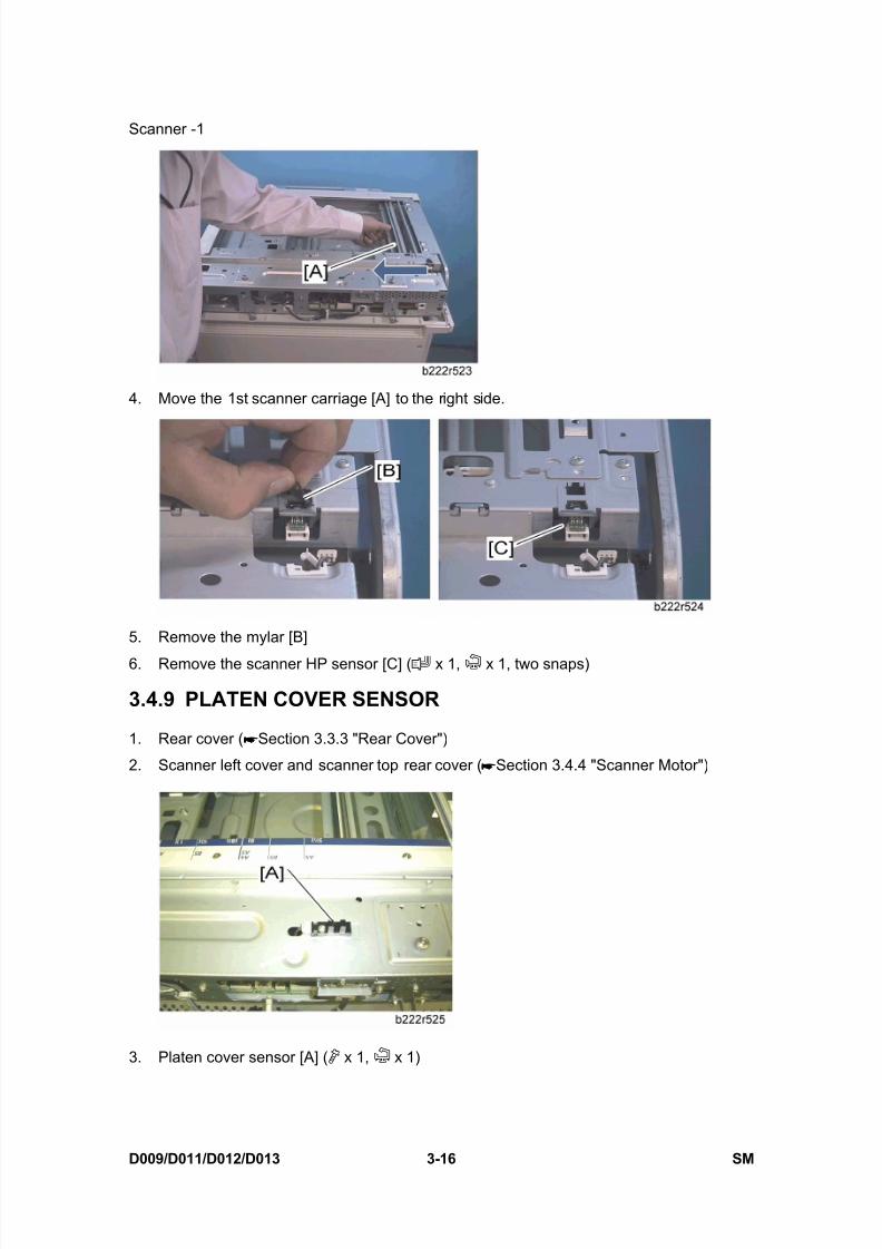
2. Scanner right cover [A] ( x 2)
3. Lens cover [B] ( x 2)
4. Original width sensor bracket [C] ( x 1)
5. Original length sensor bracket [D] ( x 2)
6. Original width and length sensors [E] ( x 1 each)
Color Scanner Model
1. Exposure glass with left scale ( Section 3.4.1 "Exposure Glass")2. Ground plate ( Section 3.4.5 "Sensor Board Unit (SBU)")
3. Original width sensor bracket [A] ( x 1)
4. Original length sensor bracket [B] ( x 1, x 2)
5. Original width and length sensors [C] ( x 1 each)

8/15/2019 Ricoh MP 4000 SM D009_D011_D012_D013 SERVICE MANUAL .pdf
http://slidepdf.com/reader/full/ricoh-mp-4000-sm-d009d011d012d013-service-manual-pdf 140/1162
Scanner -1
D009/D011/D012/D013 3-10 SM
3.4.3 EXPOSURE LAMP
Color Scanner Model
1. Operation panel with scanner front cover ( Section 3.3.5 "Operation Panel")
2. Exposure glass ( Section 3.4.1 "Exposure Glass")
3. Move the 1st scanner carriage [A] to the cutout [B] in the front frame.
4. Scanner left stays [C] ( x 2)
5. Scanner front frame [D] ( x 5)
8/15/2019 Ricoh MP 4000 SM D009_D011_D012_D013 SERVICE MANUAL .pdf
http://slidepdf.com/reader/full/ricoh-mp-4000-sm-d009d011d012d013-service-manual-pdf 141/1162
Scanner -1
SM 3-11 D009/D011/D012/D013
R e p
l a c e m e n
t
A d j u s t m e n
t
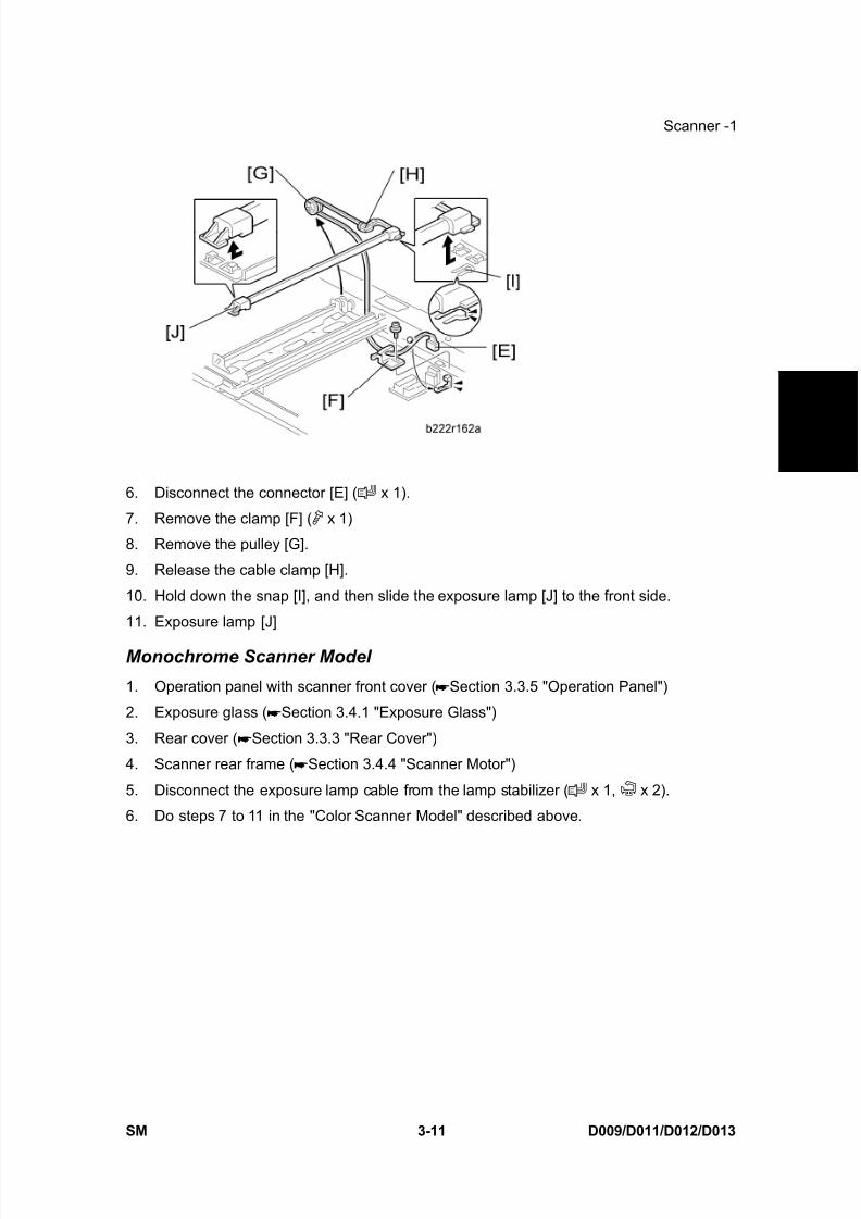
6. Disconnect the connector [E] ( x 1).
7. Remove the clamp [F] ( x 1)
8. Remove the pulley [G].
9. Release the cable clamp [H].
10. Hold down the snap [I], and then slide the exposure lamp [J] to the front side.
11. Exposure lamp [J]
Monochrome Scanner Model
1. Operation panel with scanner front cover ( Section 3.3.5 "Operation Panel")
2. Exposure glass ( Section 3.4.1 "Exposure Glass")
3. Rear cover ( Section 3.3.3 "Rear Cover")
4. Scanner rear frame ( Section 3.4.4 "Scanner Motor")
5. Disconnect the exposure lamp cable from the lamp stabilizer ( x 1, x 2).
6. Do steps 7 to 11 in the "Color Scanner Model" described above.
8/15/2019 Ricoh MP 4000 SM D009_D011_D012_D013 SERVICE MANUAL .pdf
http://slidepdf.com/reader/full/ricoh-mp-4000-sm-d009d011d012d013-service-manual-pdf 142/1162
Scanner -1
D009/D011/D012/D013 3-12 SM
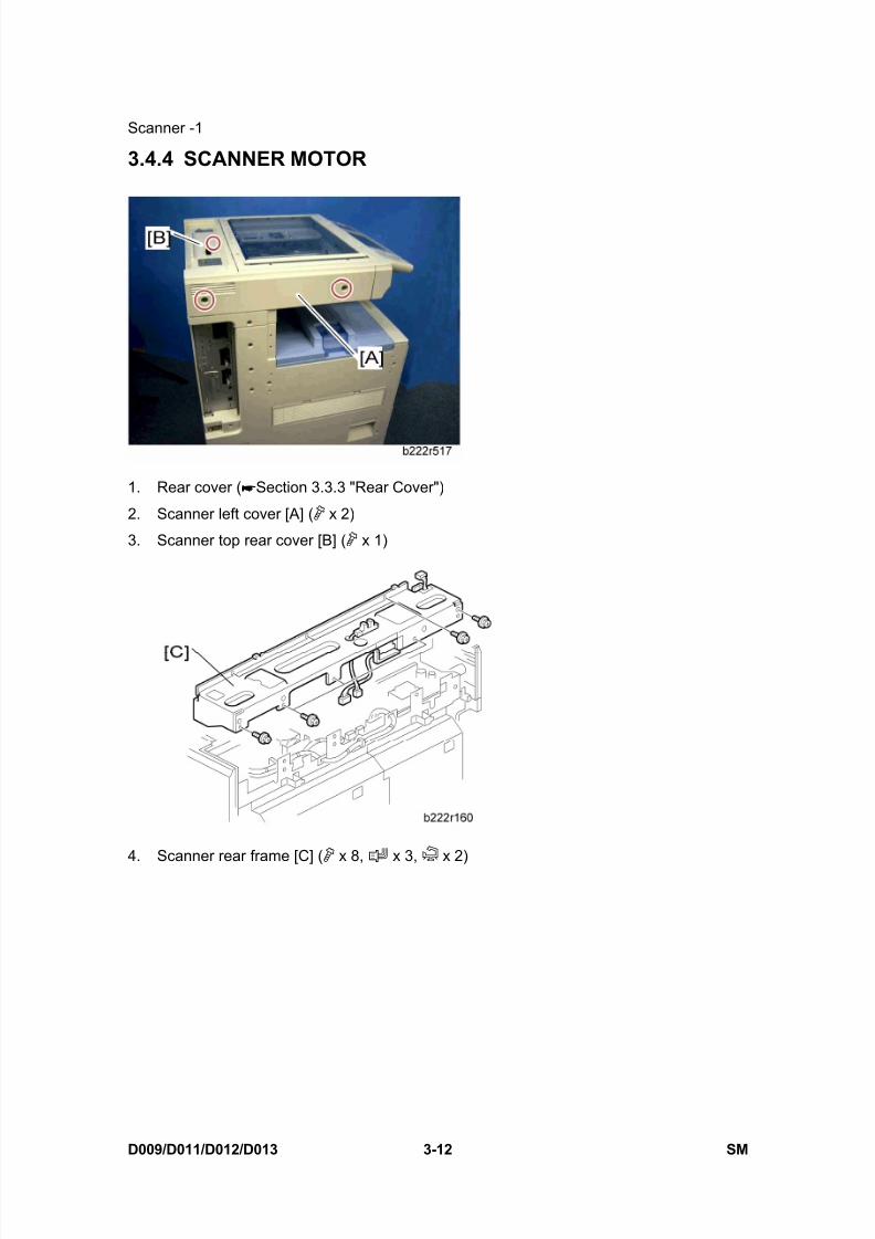
3.4.4 SCANNER MOTOR
1. Rear cover ( Section 3.3.3 "Rear Cover")
2. Scanner left cover [A] ( x 2)
3. Scanner top rear cover [B] ( x 1)
4. Scanner rear frame [C] ( x 8, x 3, x 2)

8/15/2019 Ricoh MP 4000 SM D009_D011_D012_D013 SERVICE MANUAL .pdf
http://slidepdf.com/reader/full/ricoh-mp-4000-sm-d009d011d012d013-service-manual-pdf 143/1162
Scanner -1
SM 3-13 D009/D011/D012/D013
R e p
l a c e m e n
t
A d j u s t m e n
t
5. Scanner motor bracket [D] ( x 1)
6. Scanner motor [E] ( x 2, spring x 1)
After replacing the scanner motor, do the image adjustments in the following section
of the manual ( Section 3.17.3 "Scanning").
3.4.5 SENSOR BOARD UNIT (SBU)
Monochrome Scanner Model1. Exposure glass ( Section 3.4.1 "Exposure Glass")
2. Original length sensor bracket ( Section 3.4.2 "Original Length/Width Sensors")
3. Sensor board unit [A] ( x 4, flat cable x 1)
Color Scanner Model
1. Exposure glass ( Section 3.4.1 "Exposure Glass")

8/15/2019 Ricoh MP 4000 SM D009_D011_D012_D013 SERVICE MANUAL .pdf
http://slidepdf.com/reader/full/ricoh-mp-4000-sm-d009d011d012d013-service-manual-pdf 144/1162
Scanner -1
D009/D011/D012/D013 3-14 SM
2. Scanner right cover [A] ( x 2)
3. SBU cover bracket [B] ( x 4)
4. Ground plate [C] ( x 4)
5. Sensor board unit [D] ( x 4, x 3, x 1)
When reassembling
Adjust the following SP modes after you replace the sensor board unit: SP4–008 (Sub Scan Mag): ( Section 3.17.3 "Scanning").
SP4–010 (Sub Mag Reg.): ( Section 3.17.3 "Scanning")
SP4–011 (Main Scan Reg): ( Section 3.17.3 "Scanning") "
SP4–688 (DF: Density Adjustment): Use this to adjust the density level if the ID of
outputs made in the DF and Platen mode is different.
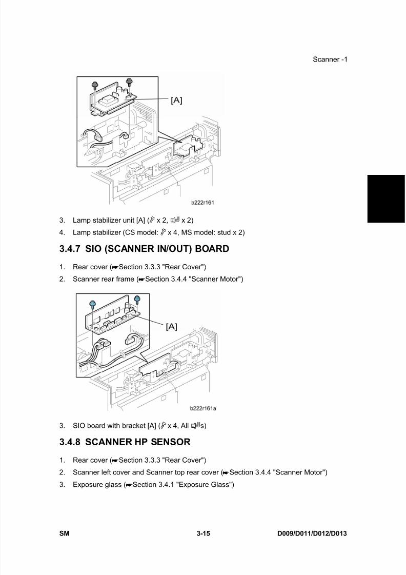
3.4.6 LAMP STABILIZER
1. Rear cover ( Section 3.3.3 "Rear Cover")
2. Scanner rear frame ( Section 3.4.4 "Scanner Motor")
8/15/2019 Ricoh MP 4000 SM D009_D011_D012_D013 SERVICE MANUAL .pdf
http://slidepdf.com/reader/full/ricoh-mp-4000-sm-d009d011d012d013-service-manual-pdf 145/1162
8/15/2019 Ricoh MP 4000 SM D009_D011_D012_D013 SERVICE MANUAL .pdf
http://slidepdf.com/reader/full/ricoh-mp-4000-sm-d009d011d012d013-service-manual-pdf 146/1162

8/15/2019 Ricoh MP 4000 SM D009_D011_D012_D013 SERVICE MANUAL .pdf
http://slidepdf.com/reader/full/ricoh-mp-4000-sm-d009d011d012d013-service-manual-pdf 147/1162

8/15/2019 Ricoh MP 4000 SM D009_D011_D012_D013 SERVICE MANUAL .pdf
http://slidepdf.com/reader/full/ricoh-mp-4000-sm-d009d011d012d013-service-manual-pdf 148/1162

8/15/2019 Ricoh MP 4000 SM D009_D011_D012_D013 SERVICE MANUAL .pdf
http://slidepdf.com/reader/full/ricoh-mp-4000-sm-d009d011d012d013-service-manual-pdf 149/1162
8/15/2019 Ricoh MP 4000 SM D009_D011_D012_D013 SERVICE MANUAL .pdf
http://slidepdf.com/reader/full/ricoh-mp-4000-sm-d009d011d012d013-service-manual-pdf 150/1162
8/15/2019 Ricoh MP 4000 SM D009_D011_D012_D013 SERVICE MANUAL .pdf
http://slidepdf.com/reader/full/ricoh-mp-4000-sm-d009d011d012d013-service-manual-pdf 151/1162
Scanner -2
SM 3-21 D009/D011/D012/D013
R e p
l a c e m e n
t
A d j u s t m e n
t
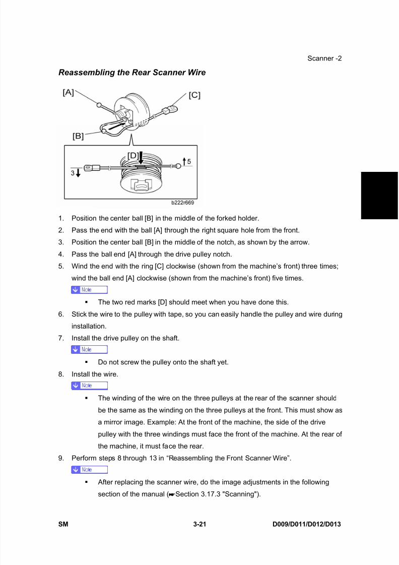
Reassembling the Rear Scanner Wire
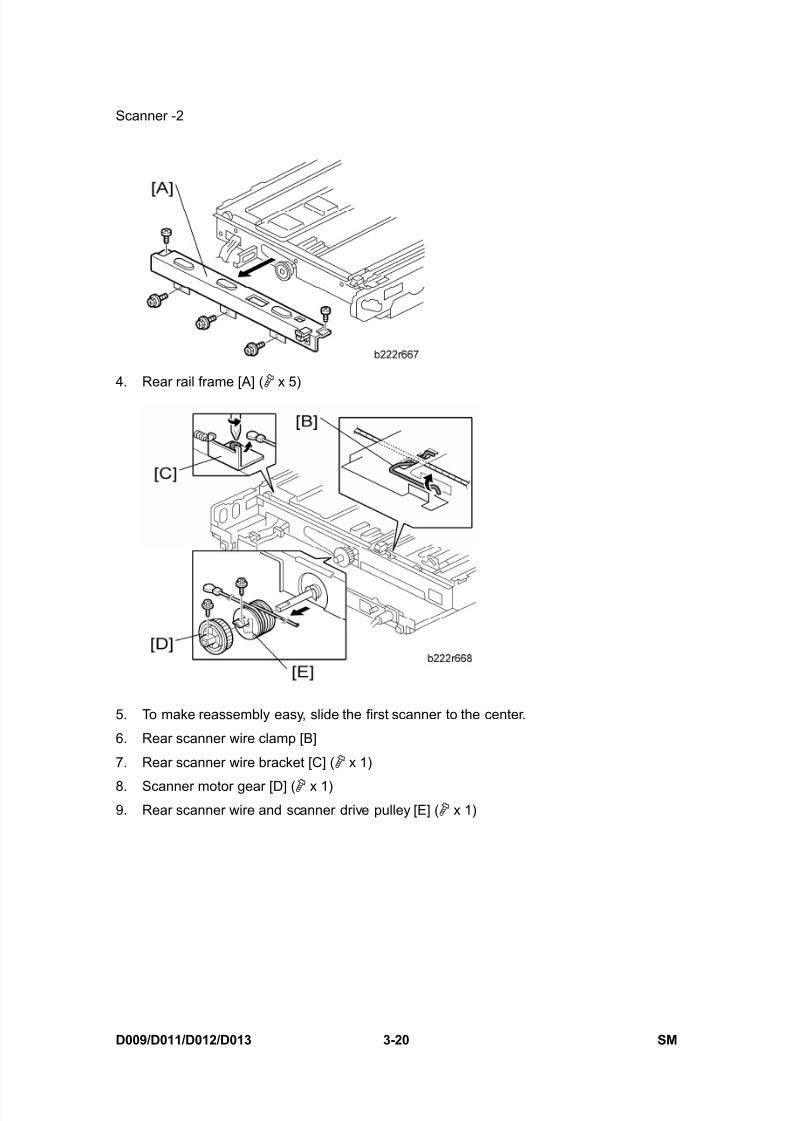
1. Position the center ball [B] in the middle of the forked holder.
2. Pass the end with the ball [A] through the right square hole from the front.
3. Position the center ball [B] in the middle of the notch, as shown by the arrow.
4. Pass the ball end [A] through the drive pulley notch.
5. Wind the end with the ring [C] clockwise (shown from the machine’s front) three times;
wind the ball end [A] clockwise (shown from the machine’s front) five times.
The two red marks [D] should meet when you have done this.
6. Stick the wire to the pulley with tape, so you can easily handle the pulley and wire during
installation.
7. Install the drive pulley on the shaft.
Do not screw the pulley onto the shaft yet.
8. Install the wire.
The winding of the wire on the three pulleys at the rear of the scanner should
be the same as the winding on the three pulleys at the front. This must show as
a mirror image. Example: At the front of the machine, the side of the drive
pulley with the three windings must face the front of the machine. At the rear of
the machine, it must face the rear.
9. Perform steps 8 through 13 in “Reassembling the Front Scanner Wire”.
After replacing the scanner wire, do the image adjustments in the following
section of the manual ( Section 3.17.3 "Scanning").
8/15/2019 Ricoh MP 4000 SM D009_D011_D012_D013 SERVICE MANUAL .pdf
http://slidepdf.com/reader/full/ricoh-mp-4000-sm-d009d011d012d013-service-manual-pdf 152/1162
Scanner -2
D009/D011/D012/D013 3-22 SM
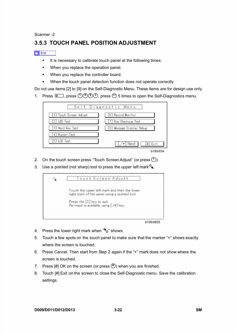
3.5.3 TOUCH PANEL POSITION ADJUSTMENT
It is necessary to calibrate touch panel at the following times:
When you replace the operation panel.
When you replace the controller board.
When the touch panel detection function does not operate correctly
Do not use items [2] to [9] on the Self-Diagnostic Menu. These items are for design use only.
1. Press , press , press 5 times to open the Self-Diagnostics menu.
2. On the touch screen press “Touch Screen Adjust” (or press ).
3. Use a pointed (not sharp) tool to press the upper left mark .
4. Press the lower right mark when “ ” shows.
5. Touch a few spots on the touch panel to make sure that the marker “+” shows exactly
where the screen is touched.
6. Press Cancel. Then start from Step 2 again if the “+” mark does not show where the
screen is touched.
7. Press [#] OK on the screen (or press ) when you are finished.
8. Touch [#] Exit on the screen to close the Self-Diagnostic menu. Save the calibration
settings.
8/15/2019 Ricoh MP 4000 SM D009_D011_D012_D013 SERVICE MANUAL .pdf
http://slidepdf.com/reader/full/ricoh-mp-4000-sm-d009d011d012d013-service-manual-pdf 153/1162
8/15/2019 Ricoh MP 4000 SM D009_D011_D012_D013 SERVICE MANUAL .pdf
http://slidepdf.com/reader/full/ricoh-mp-4000-sm-d009d011d012d013-service-manual-pdf 154/1162
Laser Unit
D009/D011/D012/D013 3-24 SM
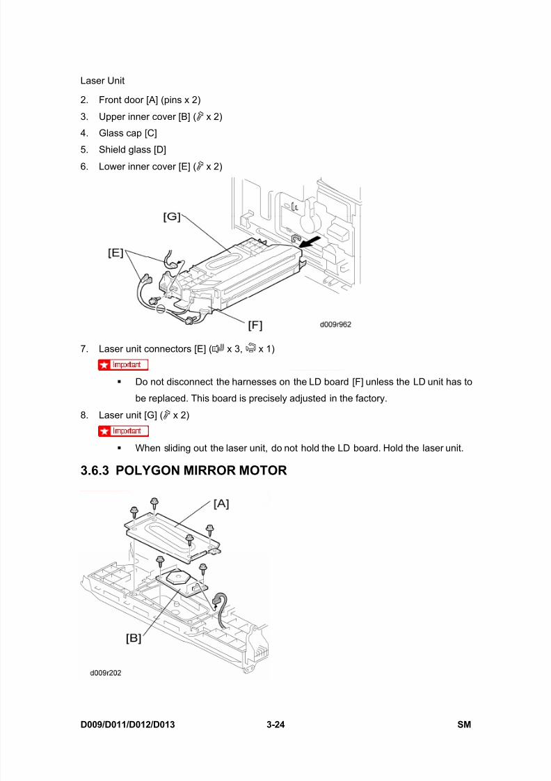
2. Front door [A] (pins x 2)
3. Upper inner cover [B] ( x 2)
4. Glass cap [C]5. Shield glass [D]
6. Lower inner cover [E] ( x 2)
7. Laser unit connectors [E] ( x 3, x 1)
Do not disconnect the harnesses on the LD board [F] unless the LD unit has to
be replaced. This board is precisely adjusted in the factory.
8. Laser unit [G] ( x 2)
When sliding out the laser unit, do not hold the LD board. Hold the laser unit.
3.6.3 POLYGON MIRROR MOTOR

8/15/2019 Ricoh MP 4000 SM D009_D011_D012_D013 SERVICE MANUAL .pdf
http://slidepdf.com/reader/full/ricoh-mp-4000-sm-d009d011d012d013-service-manual-pdf 155/1162
Laser Unit
SM 3-25 D009/D011/D012/D013
R e p
l a c e m e n
t
A d j u s t m e n
t
1. Laser unit ( Section 3.6.2 "Laser Unit")
2. Laser unit cover [A] ( x 4)
3. Polygon mirror motor [B] ( x 4, x 1)4. After replacing the polygon mirror motor, do the image adjustment ( Section 3.17.2
"Printing").
3.6.4 LASER SYNCHRONIZATION DETECTOR
1. Laser unit ( Section 3.6.2 "Laser Unit")
2. Laser synchronization detector [A] ( x1, x1)
3.6.5 LD UNIT
1. Laser unit ( Section 3.6.2 "Laser Unit")
2. Upper spring plate [A] ( x 1)
3. Lower spring plate [B] ( x 1)
4. LD unit [C] ( x 1, x1, spring x 1)
8/15/2019 Ricoh MP 4000 SM D009_D011_D012_D013 SERVICE MANUAL .pdf
http://slidepdf.com/reader/full/ricoh-mp-4000-sm-d009d011d012d013-service-manual-pdf 156/1162
Laser Unit
D009/D011/D012/D013 3-26 SM
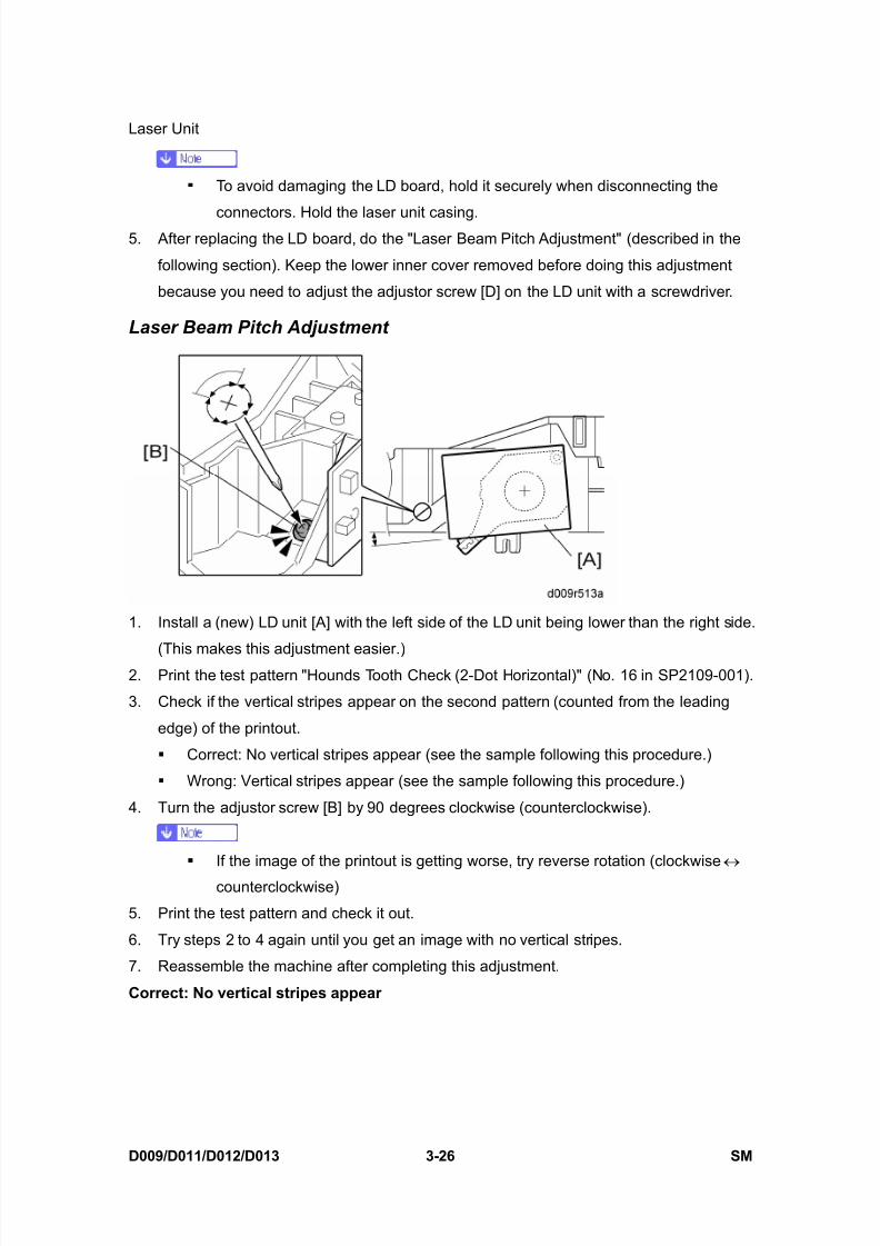
To avoid damaging the LD board, hold it securely when disconnecting the
connectors. Hold the laser unit casing.5. After replacing the LD board, do the "Laser Beam Pitch Adjustment" (described in the
following section). Keep the lower inner cover removed before doing this adjustment
because you need to adjust the adjustor screw [D] on the LD unit with a screwdriver.
Laser Beam Pitch Adjustment
1. Install a (new) LD unit [A] with the left side of the LD unit being lower than the right side.
(This makes this adjustment easier.)2. Print the test pattern "Hounds Tooth Check (2-Dot Horizontal)" (No. 16 in SP2109-001).
3. Check if the vertical stripes appear on the second pattern (counted from the leading
edge) of the printout.
Correct: No vertical stripes appear (see the sample following this procedure.)
Wrong: Vertical stripes appear (see the sample following this procedure.)
4. Turn the adjustor screw [B] by 90 degrees clockwise (counterclockwise).
If the image of the printout is getting worse, try reverse rotation (clockwise ↔
counterclockwise)
5. Print the test pattern and check it out.
6. Try steps 2 to 4 again until you get an image with no vertical stripes.
7. Reassemble the machine after completing this adjustment.
Correct: No vertical stripes appear

8/15/2019 Ricoh MP 4000 SM D009_D011_D012_D013 SERVICE MANUAL .pdf
http://slidepdf.com/reader/full/ricoh-mp-4000-sm-d009d011d012d013-service-manual-pdf 157/1162
8/15/2019 Ricoh MP 4000 SM D009_D011_D012_D013 SERVICE MANUAL .pdf
http://slidepdf.com/reader/full/ricoh-mp-4000-sm-d009d011d012d013-service-manual-pdf 158/1162

8/15/2019 Ricoh MP 4000 SM D009_D011_D012_D013 SERVICE MANUAL .pdf
http://slidepdf.com/reader/full/ricoh-mp-4000-sm-d009d011d012d013-service-manual-pdf 159/1162
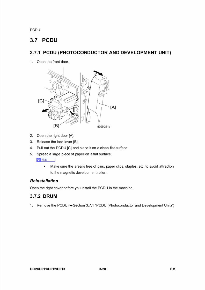
PCDU
SM 3-29 D009/D011/D012/D013
R e p
l a c e m e n
t
A d j u s t m e n
t
2. Toner cap [A]
3. Insert cap [A] into the opening of the PCDU [B].
Make sure that the cap is inserted completely into the opening.
4. Remove the spring [C] on the rear side of the PCDU.
5. Remove the spring [D] on the front side of the PCDU and attach it to the hooks asshown.
To prevent breaking the weaker hook , use a pair of needle-nose pliers to
disconnect the spring at , remove the spring, then re-attach to and .
When you move this spring, this retracts the movable drum cleaning blade so that it
does not touch the surface of the drum when the drum is re-installed.
8/15/2019 Ricoh MP 4000 SM D009_D011_D012_D013 SERVICE MANUAL .pdf
http://slidepdf.com/reader/full/ricoh-mp-4000-sm-d009d011d012d013-service-manual-pdf 160/1162
PCDU
D009/D011/D012/D013 3-30 SM
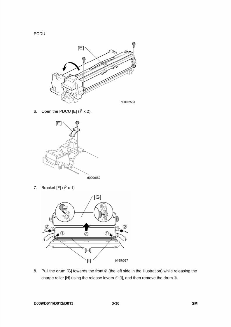
6. Open the PDCU [E] ( x 2).
7. Bracket [F] ( x 1)
8. Pull the drum [G] towards the front (the left side in the illustration) while releasing the
charge roller [H] using the release levers [I], and then remove the drum .
8/15/2019 Ricoh MP 4000 SM D009_D011_D012_D013 SERVICE MANUAL .pdf
http://slidepdf.com/reader/full/ricoh-mp-4000-sm-d009d011d012d013-service-manual-pdf 161/1162
PCDU
SM 3-31 D009/D011/D012/D013
R e p
l a c e m e n
t
A d j u s t m e n
t
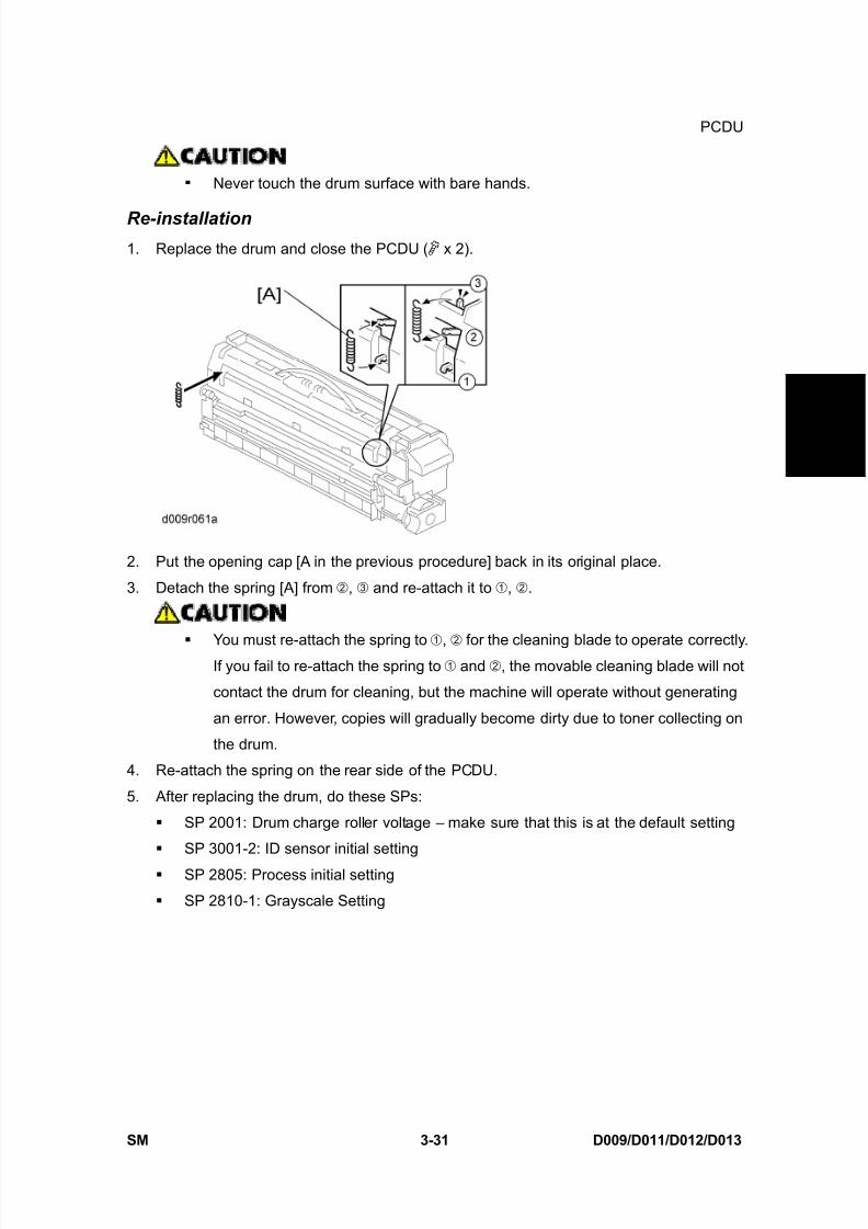
Never touch the drum surface with bare hands.
Re-installation1. Replace the drum and close the PCDU ( x 2).
2. Put the opening cap [A in the previous procedure] back in its original place.
3. Detach the spring [A] from , and re-attach it to , .
You must re-attach the spring to , for the cleaning blade to operate correctly.If you fail to re-attach the spring to and , the movable cleaning blade will not
contact the drum for cleaning, but the machine will operate without generating
an error. However, copies will gradually become dirty due to toner collecting on
the drum.
4. Re-attach the spring on the rear side of the PCDU.
5. After replacing the drum, do these SPs:
SP 2001: Drum charge roller voltage – make sure that this is at the default setting
SP 3001-2: ID sensor initial setting
SP 2805: Process initial setting
SP 2810-1: Grayscale Setting
8/15/2019 Ricoh MP 4000 SM D009_D011_D012_D013 SERVICE MANUAL .pdf
http://slidepdf.com/reader/full/ricoh-mp-4000-sm-d009d011d012d013-service-manual-pdf 162/1162
PCDU
D009/D011/D012/D013 3-32 SM
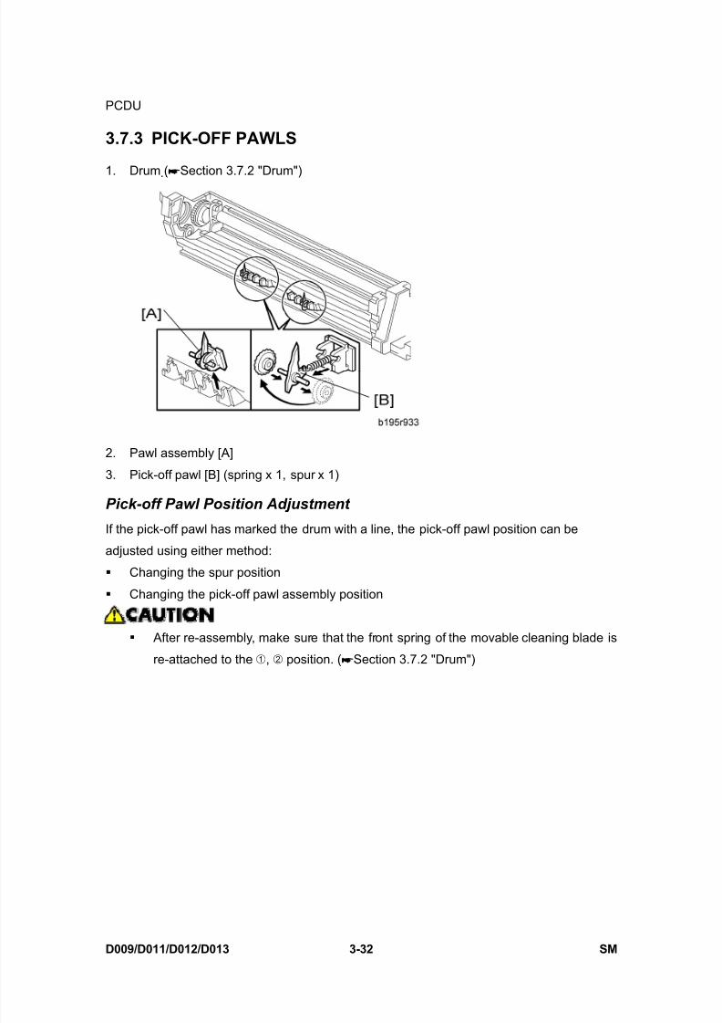
3.7.3 PICK-OFF PAWLS
1. Drum ( Section 3.7.2 "Drum")
2. Pawl assembly [A]
3. Pick-off pawl [B] (spring x 1, spur x 1)
Pick-off Pawl Position Adjustment
If the pick-off pawl has marked the drum with a line, the pick-off pawl position can be
adjusted using either method:
Changing the spur position
Changing the pick-off pawl assembly position
After re-assembly, make sure that the front spring of the movable cleaning blade is
re-attached to the , position. ( Section 3.7.2 "Drum")
8/15/2019 Ricoh MP 4000 SM D009_D011_D012_D013 SERVICE MANUAL .pdf
http://slidepdf.com/reader/full/ricoh-mp-4000-sm-d009d011d012d013-service-manual-pdf 163/1162
PCDU
SM 3-33 D009/D011/D012/D013
R e p
l a c e m e n
t
A d j u s t m e n
t
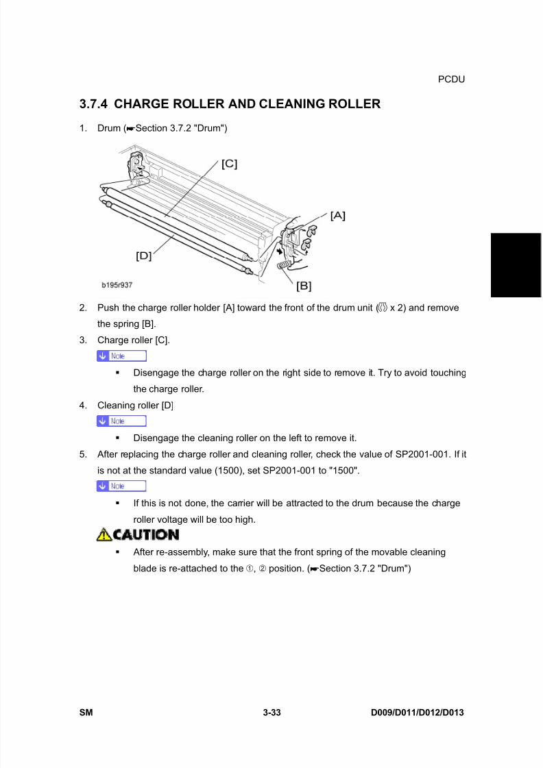
3.7.4 CHARGE ROLLER AND CLEANING ROLLER
1. Drum ( Section 3.7.2 "Drum")
2. Push the charge roller holder [A] toward the front of the drum unit ( x 2) and remove
the spring [B].
3. Charge roller [C].
Disengage the charge roller on the right side to remove it. Try to avoid touching
the charge roller.
4. Cleaning roller [D]
Disengage the cleaning roller on the left to remove it.
5. After replacing the charge roller and cleaning roller, check the value of SP2001-001. If it
is not at the standard value (1500), set SP2001-001 to "1500".
If this is not done, the carrier will be attracted to the drum because the charge
roller voltage will be too high.
After re-assembly, make sure that the front spring of the movable cleaning
blade is re-attached to the , position. ( Section 3.7.2 "Drum")

8/15/2019 Ricoh MP 4000 SM D009_D011_D012_D013 SERVICE MANUAL .pdf
http://slidepdf.com/reader/full/ricoh-mp-4000-sm-d009d011d012d013-service-manual-pdf 164/1162
PCDU
D009/D011/D012/D013 3-34 SM
3.7.5 DRUM CLEANING BLADE 21. Drum ( Section 3.7.2 "Drum")
2. Charge roller and cleaning roller ( Section 3.7.4 "Charge Roller and Cleaning Roller")
3. Remove cleaning blade 2 [A]. ( x 1, bushing x 1)
Re-installation
Engage the left end of the cleaning blade first, then make sure that both arms [B] and
[C] are through the holes on the left and right side.
When you re-attach the snap-ring, make sure that the head of the snap ring [D] is below
the blade.
After re-assembly make sure that the front spring of the movable cleaning blade is
re-attached to the , position. ( Section 3.7.2 "Drum")
3.7.6 DRUM CLEANING BLADE 11. Drum ( Section 3.7.2 "Drum")
2. Charge roller and cleaning roller ( Section 3.7.4 "Charge Roller and Cleaning Roller")
3. Drum cleaning blade 2 ( Section3.7.5 "Drum Cleaning Blade 2")
8/15/2019 Ricoh MP 4000 SM D009_D011_D012_D013 SERVICE MANUAL .pdf
http://slidepdf.com/reader/full/ricoh-mp-4000-sm-d009d011d012d013-service-manual-pdf 165/1162
PCDU
SM 3-35 D009/D011/D012/D013
R e p
l a c e m e n
t
A d j u s t m e n
t
4. Remove drum cleaning blade 1 [A] ( x 2)
Re-installation
Put toner on the edge of cleaning blade 1 and the mylar at the back side of cleaning blade 1
before re-installing this blade.
After re-assembly, make sure that the front spring of the movable cleaning blade is
re-attached to the , position. ( Section 3.7.2 "Drum")
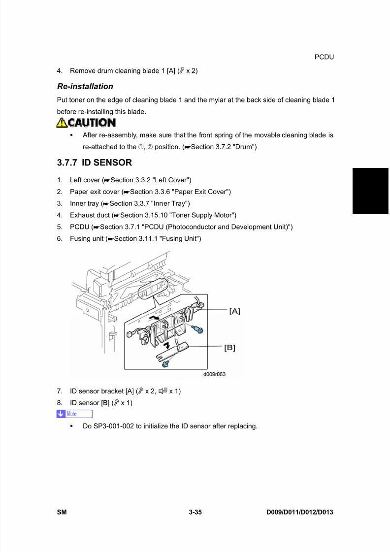
3.7.7 ID SENSOR
1. Left cover ( Section 3.3.2 "Left Cover")
2. Paper exit cover ( Section 3.3.6 "Paper Exit Cover")3. Inner tray ( Section 3.3.7 "Inner Tray")
4. Exhaust duct ( Section 3.15.10 "Toner Supply Motor")
5. PCDU ( Section 3.7.1 "PCDU (Photoconductor and Development Unit)")
6. Fusing unit ( Section 3.11.1 "Fusing Unit")
7. ID sensor bracket [A] ( x 2, x 1)
8. ID sensor [B] ( x 1)
Do SP3-001-002 to initialize the ID sensor after replacing.
8/15/2019 Ricoh MP 4000 SM D009_D011_D012_D013 SERVICE MANUAL .pdf
http://slidepdf.com/reader/full/ricoh-mp-4000-sm-d009d011d012d013-service-manual-pdf 166/1162
Development
D009/D011/D012/D013 3-36 SM
3.8 DEVELOPMENT
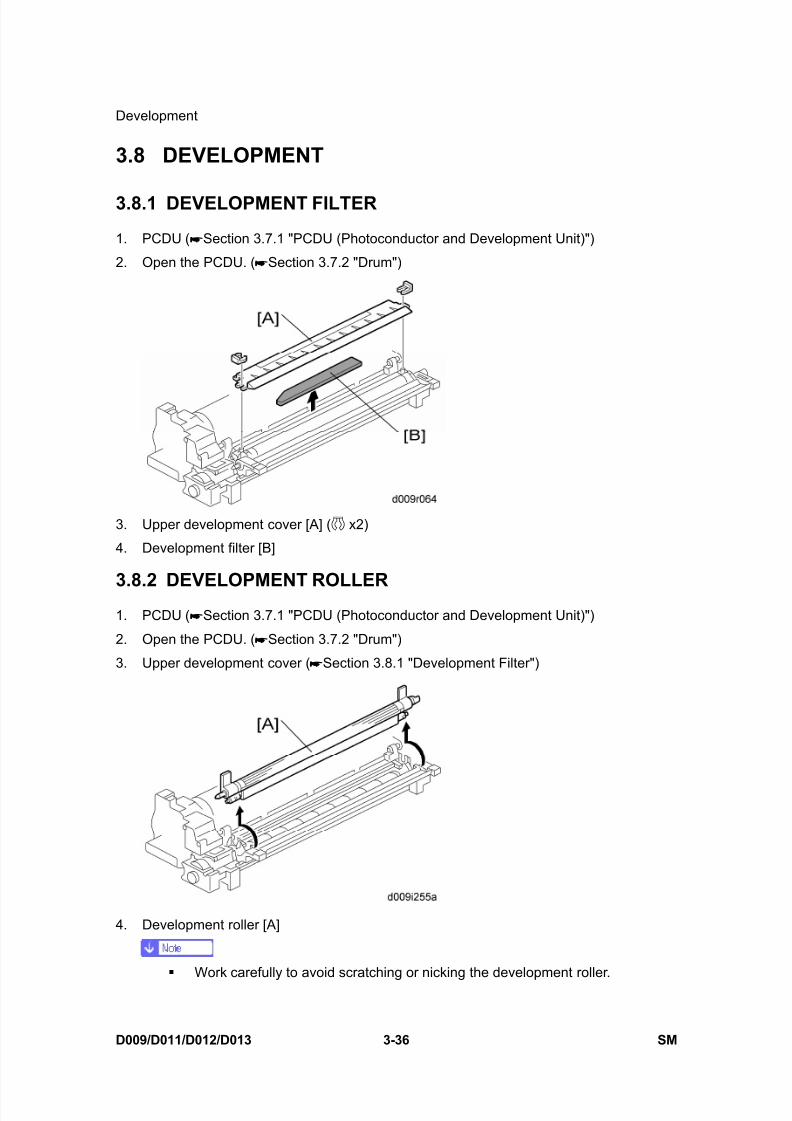
3.8.1 DEVELOPMENT FILTER
1. PCDU ( Section 3.7.1 "PCDU (Photoconductor and Development Unit)")
2. Open the PCDU. ( Section 3.7.2 "Drum")
3. Upper development cover [A] ( x2)
4. Development filter [B]
3.8.2 DEVELOPMENT ROLLER1. PCDU ( Section 3.7.1 "PCDU (Photoconductor and Development Unit)")
2. Open the PCDU. ( Section 3.7.2 "Drum")
3. Upper development cover ( Section 3.8.1 "Development Filter")
4. Development roller [A]
Work carefully to avoid scratching or nicking the development roller.
8/15/2019 Ricoh MP 4000 SM D009_D011_D012_D013 SERVICE MANUAL .pdf
http://slidepdf.com/reader/full/ricoh-mp-4000-sm-d009d011d012d013-service-manual-pdf 167/1162
Development
SM 3-37 D009/D011/D012/D013
R e p
l a c e m e n
t
A d j u s t m e n
t
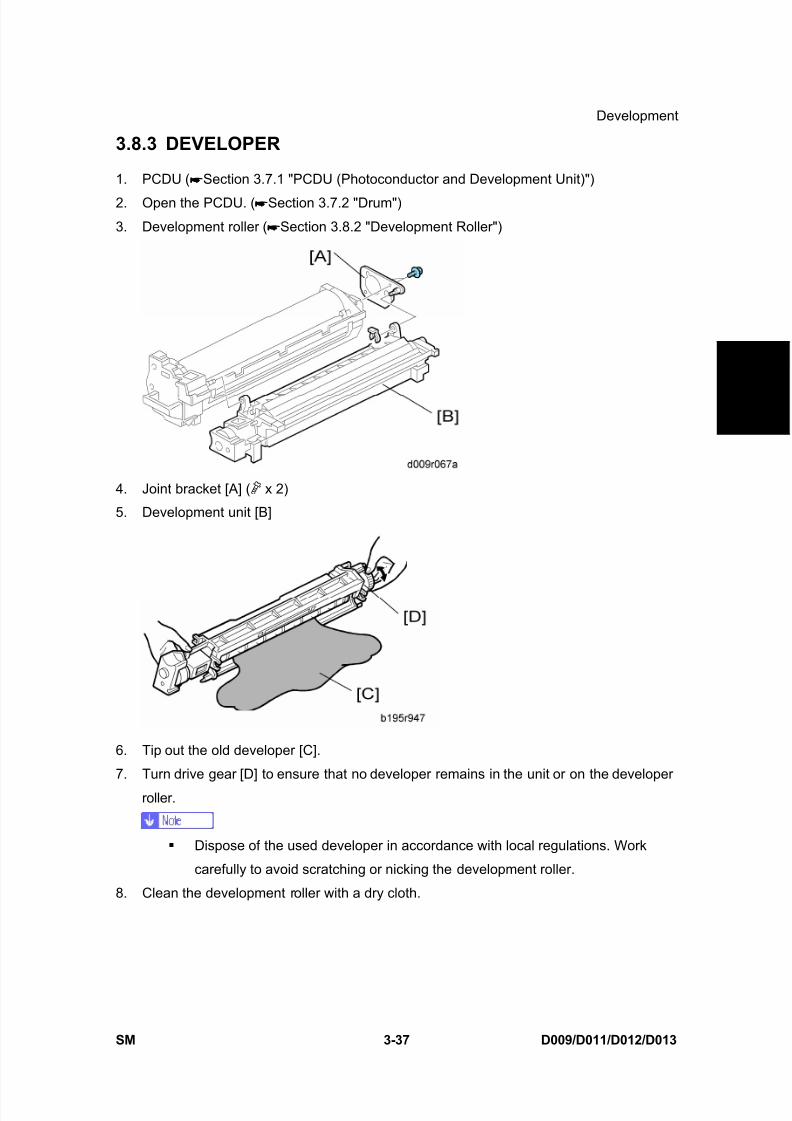
3.8.3 DEVELOPER
1. PCDU ( Section 3.7.1 "PCDU (Photoconductor and Development Unit)")
2. Open the PCDU. ( Section 3.7.2 "Drum")
3. Development roller ( Section 3.8.2 "Development Roller")
4. Joint bracket [A] ( x 2)
5. Development unit [B]
6. Tip out the old developer [C].
7. Turn drive gear [D] to ensure that no developer remains in the unit or on the developer
roller.
Dispose of the used developer in accordance with local regulations. Work
carefully to avoid scratching or nicking the development roller.
8. Clean the development roller with a dry cloth.

8/15/2019 Ricoh MP 4000 SM D009_D011_D012_D013 SERVICE MANUAL .pdf
http://slidepdf.com/reader/full/ricoh-mp-4000-sm-d009d011d012d013-service-manual-pdf 168/1162
Development
D009/D011/D012/D013 3-38 SM
9. Pour approximately 1/3 of the developer [E] evenly along the length of the development
unit.
10. Rotate the drive gear [F] to work the developer into the unit.
11. Repeat steps 8 and 9 until all toner is in the unit and level with the edges.
12. Re-install the development roller.
Make sure that the seals at the both sides of the development roller are set
inside the case after you re-install the development roller.
13. Place a piece of paper [G] over the toner entrance hole. This prevents used toner fallingfrom the drum unit into the development unit during the TD sensor initial setting and
interfering with the Vref setting (toner density reference voltage)
14. Secure the drum unit [H] to the development unit, to close the PCDU ( x 2).
15. Install the PCDU in the machine and close the front and right doors.
16. Turn on the main power switch, and wait for the machine to warm up.
17. Do SP2801 to initialize the TD sensor and enter the developer lot number.
18. After performing the TD sensor initial setting, remove the sheet of paper from the
PCDU.

8/15/2019 Ricoh MP 4000 SM D009_D011_D012_D013 SERVICE MANUAL .pdf
http://slidepdf.com/reader/full/ricoh-mp-4000-sm-d009d011d012d013-service-manual-pdf 169/1162
Development
SM 3-39 D009/D011/D012/D013
R e p
l a c e m e n
t
A d j u s t m e n
t
3.8.4 TD SENSOR
1. PCDU ( Section 3.7.1 "PCDU (Photoconductor and Development Unit)")
2. Empty all developer from the development unit. ( Section 3.8.3 "Developer")
3. Seal
4. TD sensor [A] ( x1)
The TD sensor is attached to the casing with double-sided tape [B]. Pry it off
with the flat head of a screwdriver. Use fresh double-sided tape to re-attach thesensor.
5. Pour new developer into the development unit and perform the TD sensor initial setting
using SP2-801.
When performing the TD sensor initial setting, cover the toner entrance hole
with a piece of paper.

8/15/2019 Ricoh MP 4000 SM D009_D011_D012_D013 SERVICE MANUAL .pdf
http://slidepdf.com/reader/full/ricoh-mp-4000-sm-d009d011d012d013-service-manual-pdf 170/1162
Transfer
D009/D011/D012/D013 3-40 SM
3.9 TRANSFER
3.9.1 TRANSFER BELT UNIT
To avoid exposing the drum to strong light, cover it with paper if the right cover will
be open for a long period.
1. Open the right door [A].
2. Release the lever [B].
3. Transfer belt unit [C]
Avoid touching the transfer belt surface.
3.9.2 TRANSFER BELT
1. Transfer belt unit ( Section 3.9.1 "Transfer Belt Unit")
8/15/2019 Ricoh MP 4000 SM D009_D011_D012_D013 SERVICE MANUAL .pdf
http://slidepdf.com/reader/full/ricoh-mp-4000-sm-d009d011d012d013-service-manual-pdf 171/1162
Transfer
SM 3-41 D009/D011/D012/D013
R e p
l a c e m e n
t
A d j u s t m e n
t
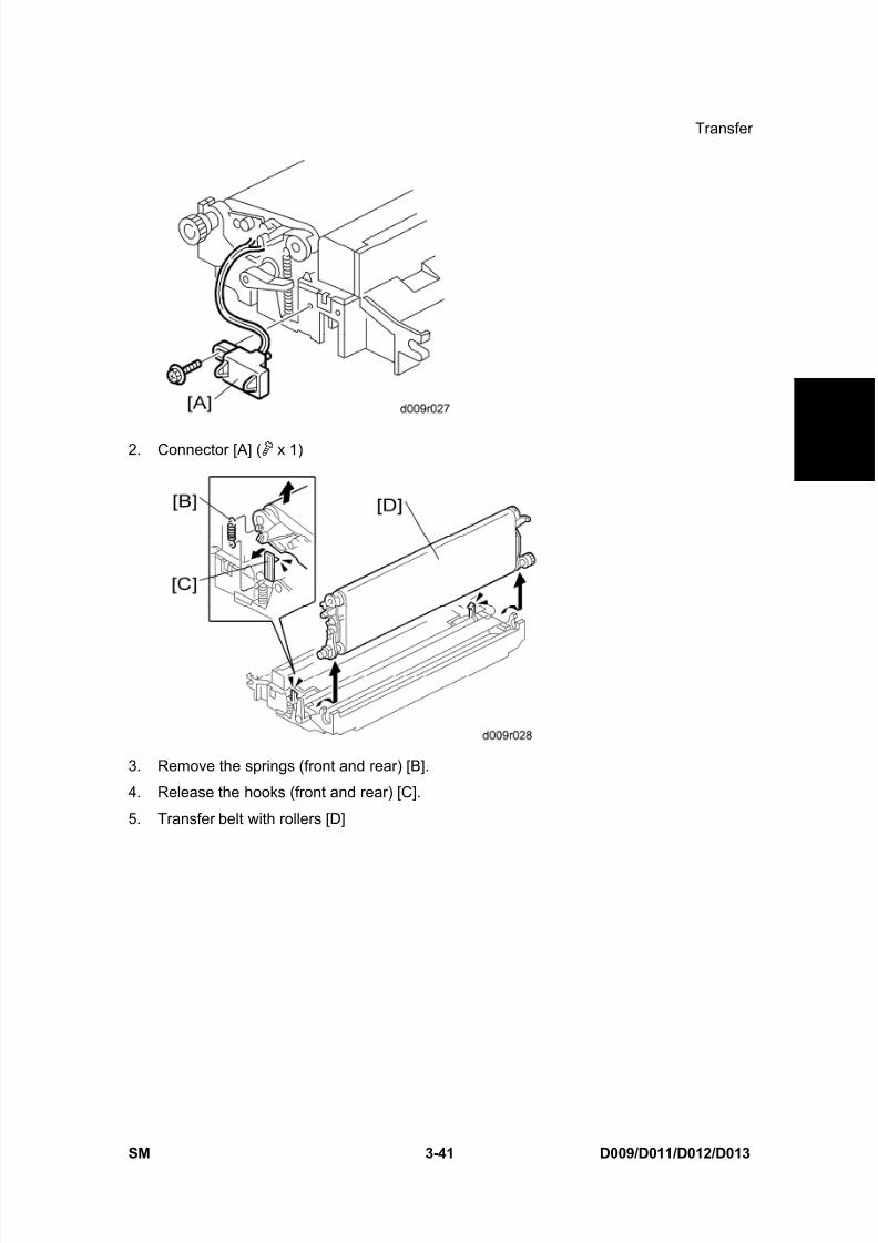
2. Connector [A] ( x 1)
3. Remove the springs (front and rear) [B].
4. Release the hooks (front and rear) [C].
5. Transfer belt with rollers [D]
8/15/2019 Ricoh MP 4000 SM D009_D011_D012_D013 SERVICE MANUAL .pdf
http://slidepdf.com/reader/full/ricoh-mp-4000-sm-d009d011d012d013-service-manual-pdf 172/1162
Transfer
D009/D011/D012/D013 3-42 SM
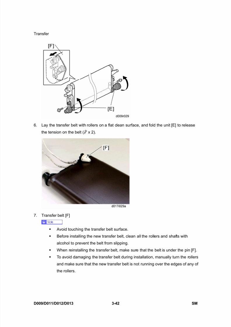
6. Lay the transfer belt with rollers on a flat clean surface, and fold the unit [E] to release
the tension on the belt ( x 2).
7. Transfer belt [F]
Avoid touching the transfer belt surface. Before installing the new transfer belt, clean all the rollers and shafts with
alcohol to prevent the belt from slipping.
When reinstalling the transfer belt, make sure that the belt is under the pin [F].
To avoid damaging the transfer belt during installation, manually turn the rollers
and make sure that the new transfer belt is not running over the edges of any of
the rollers.

8/15/2019 Ricoh MP 4000 SM D009_D011_D012_D013 SERVICE MANUAL .pdf
http://slidepdf.com/reader/full/ricoh-mp-4000-sm-d009d011d012d013-service-manual-pdf 173/1162
Transfer
SM 3-43 D009/D011/D012/D013
R e p
l a c e m e n
t
A d j u s t m e n
t
3.9.3 TONER OVERFLOW SENSOR
1. Transfer belt unit ( Section 3.9.1 "Transfer Belt Unit")
2. Toner overflow sensor [A] ( x 1, x 1)
3.9.4 TRANSFER BELT CLEANING BLADE
1. Transfer belt unit ( Section 3.9.1 "Transfer Belt Unit")
2. Transfer belt ( Section 3.9.2 "Transfer Belt")
3. Transfer belt cleaning blade [A] ( x 2)
Avoid touching the edge of the new blade. Check the new blade for dust or
damage.
8/15/2019 Ricoh MP 4000 SM D009_D011_D012_D013 SERVICE MANUAL .pdf
http://slidepdf.com/reader/full/ricoh-mp-4000-sm-d009d011d012d013-service-manual-pdf 174/1162
Paper Feed
D009/D011/D012/D013 3-44 SM
3.10 PAPER FEED
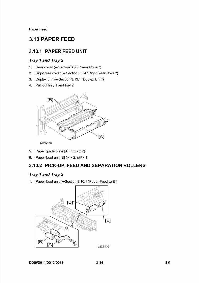
3.10.1 PAPER FEED UNIT
Tray 1 and Tray 2
1. Rear cover ( Section 3.3.3 "Rear Cover")
2. Right rear cover ( Section 3.3.4 "Right Rear Cover")
3. Duplex unit ( Section 3.13.1 "Duplex Unit")
4. Pull out tray 1 and tray 2.
5. Paper guide plate [A] (hook x 2)
6. Paper feed unit [B] ( x 2, x 1)
3.10.2 PICK-UP, FEED AND SEPARATION ROLLERS
Tray 1 and Tray 2
1. Paper feed unit ( Section 3.10.1 "Paper Feed Unit")
8/15/2019 Ricoh MP 4000 SM D009_D011_D012_D013 SERVICE MANUAL .pdf
http://slidepdf.com/reader/full/ricoh-mp-4000-sm-d009d011d012d013-service-manual-pdf 175/1162
Paper Feed
SM 3-45 D009/D011/D012/D013
R e p
l a c e m e n
t
A d j u s t m e n
t
2. Roller holder [A] ( x 1)
3. Pick-up roller [B]
4. Feed roller [C]5. Separation roller [D] and torque limiter [E] ( x 1)
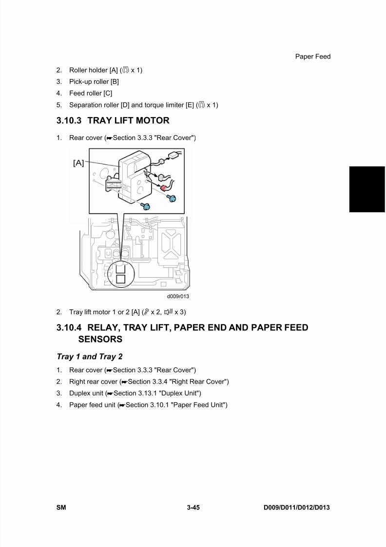
3.10.3 TRAY LIFT MOTOR
1. Rear cover ( Section 3.3.3 "Rear Cover")
2. Tray lift motor 1 or 2 [A] ( x 2, x 3)
3.10.4 RELAY, TRAY LIFT, PAPER END AND PAPER FEEDSENSORS
Tray 1 and Tray 2
1. Rear cover ( Section 3.3.3 "Rear Cover")
2. Right rear cover ( Section 3.3.4 "Right Rear Cover")3. Duplex unit ( Section 3.13.1 "Duplex Unit")
4. Paper feed unit ( Section 3.10.1 "Paper Feed Unit")
8/15/2019 Ricoh MP 4000 SM D009_D011_D012_D013 SERVICE MANUAL .pdf
http://slidepdf.com/reader/full/ricoh-mp-4000-sm-d009d011d012d013-service-manual-pdf 176/1162
8/15/2019 Ricoh MP 4000 SM D009_D011_D012_D013 SERVICE MANUAL .pdf
http://slidepdf.com/reader/full/ricoh-mp-4000-sm-d009d011d012d013-service-manual-pdf 177/1162
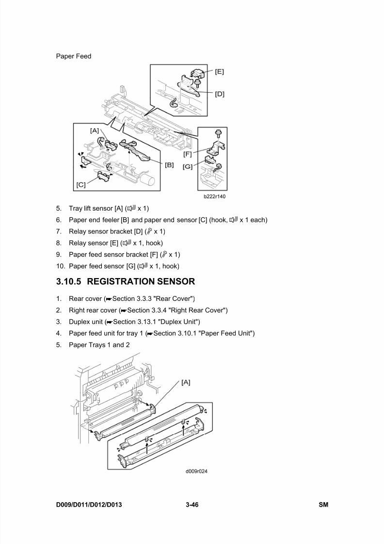
Paper Feed
SM 3-47 D009/D011/D012/D013
R e p
l a c e m e n
t
A d j u s t m e n
t
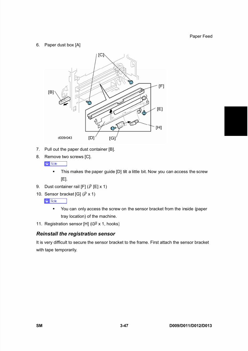
6. Paper dust box [A]
7. Pull out the paper dust container [B].
8. Remove two screws [C].
This makes the paper guide [D] tilt a little bit. Now you can access the screw
[E].
9. Dust container rail [F] ( [E] x 1)
10. Sensor bracket [G] ( x 1)
You can only access the screw on the sensor bracket from the inside (paper
tray location) of the machine.
11. Registration sensor [H] ( x 1, hooks)
Reinstall the registration sensor
It is very difficult to secure the sensor bracket to the frame. First attach the sensor bracket
with tape temporarily.

8/15/2019 Ricoh MP 4000 SM D009_D011_D012_D013 SERVICE MANUAL .pdf
http://slidepdf.com/reader/full/ricoh-mp-4000-sm-d009d011d012d013-service-manual-pdf 178/1162
Fusing
D009/D011/D012/D013 3-48 SM
3.11 FUSING
3.11.1 FUSING UNIT
Turn off the main switch and wait until the fusing unit cools down before beginning
any of the procedures in this section. The fusing unit can cause serious burns.
1. Turn off the main power switch.
2. Open the right door.
3. Pull up the lock levers [A].
4. Pull the fusing unit [B] until you hear a click.
The lock levers lock the fusing unit again at this time to prevent the fusing unit
from falling down.
5. Pull up the lock levers [A] again, and then remove the fusing unit [B].
3.11.2 WEB ROLLER UNIT
1. Fusing unit ( Section 3.11.1 "Fusing Unit")

8/15/2019 Ricoh MP 4000 SM D009_D011_D012_D013 SERVICE MANUAL .pdf
http://slidepdf.com/reader/full/ricoh-mp-4000-sm-d009d011d012d013-service-manual-pdf 179/1162
Fusing
SM 3-49 D009/D011/D012/D013
R e p
l a c e m e n
t
A d j u s t m e n
t
2. Web roller unit [A] ( x 2)
3.11.3 BRAKE PAD
1. Web roller unit ( Section 3.11.2 "Web Roller Unit")
2. Web left cover [A] (front: x 2, rear: stepped screw x 2)
3. Web top frame [B] ( x 2)

8/15/2019 Ricoh MP 4000 SM D009_D011_D012_D013 SERVICE MANUAL .pdf
http://slidepdf.com/reader/full/ricoh-mp-4000-sm-d009d011d012d013-service-manual-pdf 180/1162
Fusing
D009/D011/D012/D013 3-50 SM
4. Web left frame [C] ( x 2)
5. Brake pad [D]
3.11.4 WEB HOLDER ROLLER AND WEB ROLLERS
1. Web roller unit ( Section 3.11.2 "Web Roller Unit")
2. Web left cover ( Section 3.11.3 "Brake Pad")
3. Web top frame ( Section 3.11.3 "Brake Pad")
4. Web left frame ( Section 3.11.3 "Brake Pad")
5. Front gear bracket [A] ( x 2)
6. All gears and bushings (rear side) [B] ( x 2)
8/15/2019 Ricoh MP 4000 SM D009_D011_D012_D013 SERVICE MANUAL .pdf
http://slidepdf.com/reader/full/ricoh-mp-4000-sm-d009d011d012d013-service-manual-pdf 181/1162
Fusing
SM 3-51 D009/D011/D012/D013
R e p
l a c e m e n
t
A d j u s t m e n
t
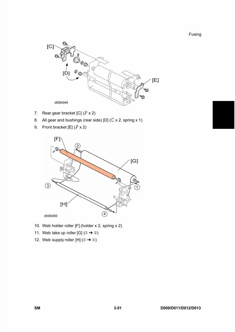
7. Rear gear bracket [C] ( x 2)
8. All gear and bushings (rear side) [D] ( x 2, spring x 1)
9. Front bracket [E] ( x 2)
10. Web holder roller [F] (holder x 2, spring x 2)
11. Web take up roller [G] ( )12. Web supply roller [H] ( )
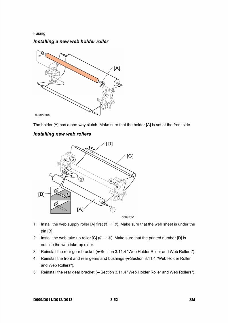
8/15/2019 Ricoh MP 4000 SM D009_D011_D012_D013 SERVICE MANUAL .pdf
http://slidepdf.com/reader/full/ricoh-mp-4000-sm-d009d011d012d013-service-manual-pdf 182/1162
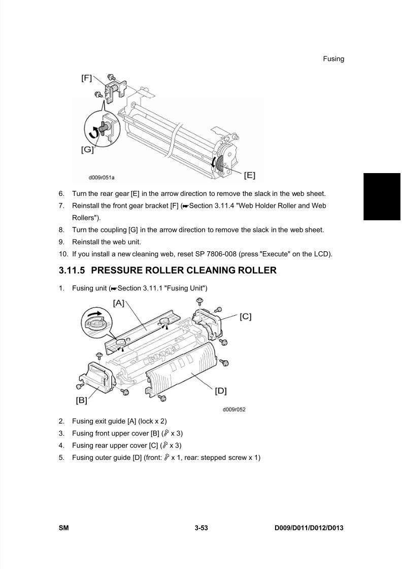
8/15/2019 Ricoh MP 4000 SM D009_D011_D012_D013 SERVICE MANUAL .pdf
http://slidepdf.com/reader/full/ricoh-mp-4000-sm-d009d011d012d013-service-manual-pdf 183/1162
Fusing
SM 3-53 D009/D011/D012/D013
R e p
l a c e m e n
t
A d j u s t m e n
t
6. Turn the rear gear [E] in the arrow direction to remove the slack in the web sheet.
7. Reinstall the front gear bracket [F] ( Section 3.11.4 "Web Holder Roller and Web
Rollers").
8. Turn the coupling [G] in the arrow direction to remove the slack in the web sheet.
9. Reinstall the web unit.
10. If you install a new cleaning web, reset SP 7806-008 (press "Execute" on the LCD).
3.11.5 PRESSURE ROLLER CLEANING ROLLER
1. Fusing unit ( Section 3.11.1 "Fusing Unit")
2. Fusing exit guide [A] (lock x 2)
3. Fusing front upper cover [B] ( x 3)
4. Fusing rear upper cover [C] ( x 3)
5. Fusing outer guide [D] (front: x 1, rear: stepped screw x 1)

8/15/2019 Ricoh MP 4000 SM D009_D011_D012_D013 SERVICE MANUAL .pdf
http://slidepdf.com/reader/full/ricoh-mp-4000-sm-d009d011d012d013-service-manual-pdf 184/1162
Fusing
D009/D011/D012/D013 3-54 SM
6. Cleaning roller unit [E] ( x 4)
7. Pressure roller cleaning roller [F] (spring x 2, holder x 2)
3.11.6 THERMOSTAT
1. Fusing unit ( Section 3.11.1 "Fusing Unit")
2. Web roller unit ( Section 3.11.2 "Web Roller Unit")
3. Fusing top cover [A] (front: x 1, rear: stepped screw x 1)
4. Thermostat holder [B] ( x 2)
5. Thermostat cover [C] ( x 2)
6. Thermostat [D] (terminal x 2)

8/15/2019 Ricoh MP 4000 SM D009_D011_D012_D013 SERVICE MANUAL .pdf
http://slidepdf.com/reader/full/ricoh-mp-4000-sm-d009d011d012d013-service-manual-pdf 185/1162
Fusing
SM 3-55 D009/D011/D012/D013
R e p
l a c e m e n
t
A d j u s t m e n
t
3.11.7 THERMISTOR
1. Fusing unit ( Section 3.11.1 "Fusing Unit")
2. Web roller unit ( Section 3.11.2 "Web Roller Unit")
3. Fusing top cover ( Section 3.11.6 "Thermostat")
4. Pull the two tabs [A].
5. Disconnect the two terminals [B].6. Sensor stays [C] ( x 1 each)
7. Thermistors [D] ( x 2, x 1)
3.11.8 HOT ROLLER STRIPPERS
1. Fusing unit ( Section 3.11.1 "Fusing Unit")
2. Web roller unit ( Section 3.11.2 "Web Roller Unit")
3. Fusing top cover ( Section 3.11.6 "Thermostat")
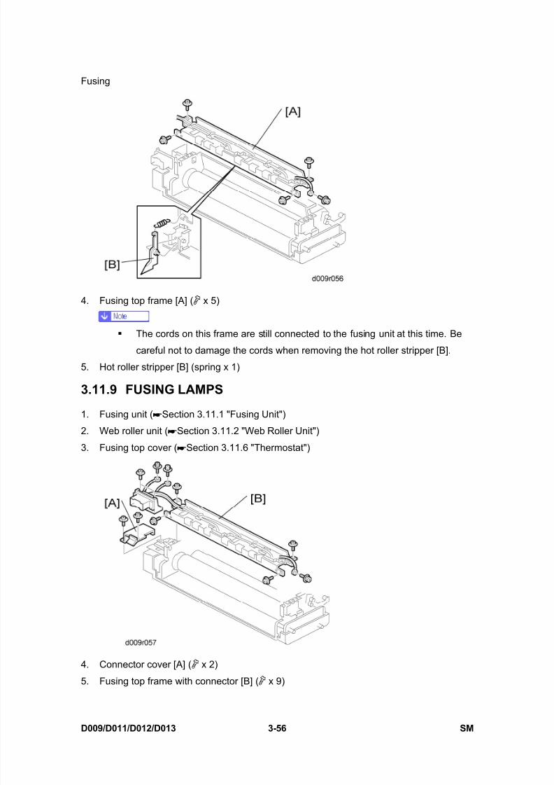
8/15/2019 Ricoh MP 4000 SM D009_D011_D012_D013 SERVICE MANUAL .pdf
http://slidepdf.com/reader/full/ricoh-mp-4000-sm-d009d011d012d013-service-manual-pdf 186/1162
Fusing
D009/D011/D012/D013 3-56 SM
4. Fusing top frame [A] ( x 5)
The cords on this frame are still connected to the fusing unit at this time. Be
careful not to damage the cords when removing the hot roller stripper [B].
5. Hot roller stripper [B] (spring x 1)
3.11.9 FUSING LAMPS
1. Fusing unit ( Section 3.11.1 "Fusing Unit")2. Web roller unit ( Section 3.11.2 "Web Roller Unit")
3. Fusing top cover ( Section 3.11.6 "Thermostat")
4. Connector cover [A] ( x 2)
5. Fusing top frame with connector [B] ( x 9)

8/15/2019 Ricoh MP 4000 SM D009_D011_D012_D013 SERVICE MANUAL .pdf
http://slidepdf.com/reader/full/ricoh-mp-4000-sm-d009d011d012d013-service-manual-pdf 187/1162
Fusing
SM 3-57 D009/D011/D012/D013
R e p
l a c e m e n
t
A d j u s t m e n
t
6. Fusing front lower cover [C] ( x 2)
7. Fusing front frame [D] ( x 3)
8. Fusing rear lower cover [E] ( x 2)
9. Fusing rear frame [F] ( x 5)
10. Terminal bracket [G] ( x 4)11. Front holder bracket [H] ( x 1)
12. Terminal base [I] ( x 3)
13. Rear holder bracket [J] ( x 1)
14. Fusing lamp-Center (550W) [K]
15. Fusing lamp-End (750W) [L]
3.11.10 HOT ROLLER AND PRESSURE ROLLER
1. Fusing lamps-Center and End ( Section 3.11.9 "Fusing Lamps")

8/15/2019 Ricoh MP 4000 SM D009_D011_D012_D013 SERVICE MANUAL .pdf
http://slidepdf.com/reader/full/ricoh-mp-4000-sm-d009d011d012d013-service-manual-pdf 188/1162
Fusing
D009/D011/D012/D013 3-58 SM
2. Hot roller [A] (snap ring x 2, gear x 2, bushing x 2)
3. Pressure roller [B] ( x 2, bushing x 2)
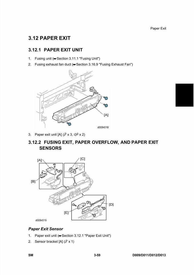
8/15/2019 Ricoh MP 4000 SM D009_D011_D012_D013 SERVICE MANUAL .pdf
http://slidepdf.com/reader/full/ricoh-mp-4000-sm-d009d011d012d013-service-manual-pdf 189/1162
Paper Exit
SM 3-59 D009/D011/D012/D013
R e p
l a c e m e n
t
A d j u s t m e n
t
3.12 PAPER EXIT
3.12.1 PAPER EXIT UNIT
1. Fusing unit ( Section 3.11.1 "Fusing Unit")
2. Fusing exhaust fan duct ( Section 3.16.9 "Fusing Exhaust Fan")
3. Paper exit unit [A] ( x 3, x 2)
3.12.2 FUSING EXIT, PAPER OVERFLOW, AND PAPER EXITSENSORS
Paper Exit Sensor
1. Paper exit unit ( Section 3.12.1 "Paper Exit Unit")
2. Sensor bracket [A] ( x 1)
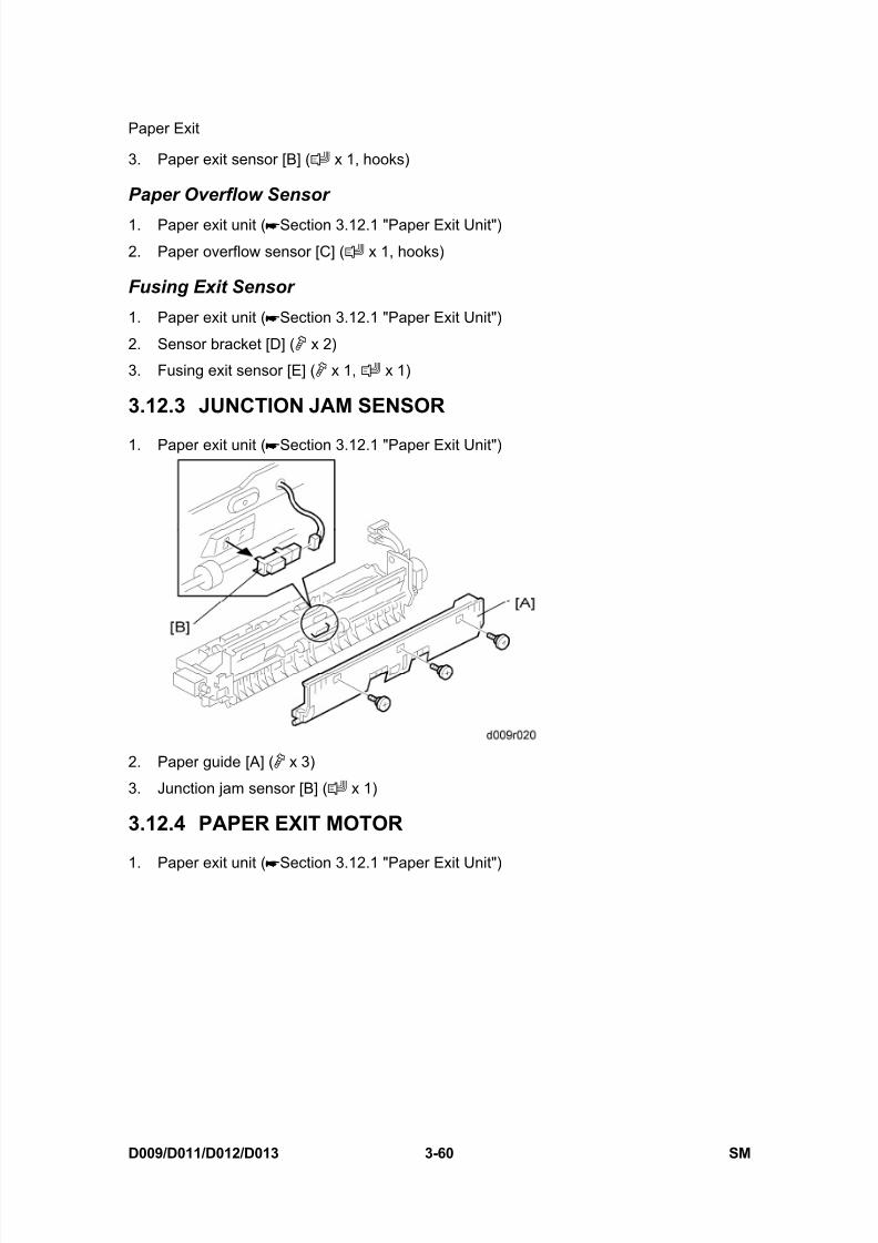
8/15/2019 Ricoh MP 4000 SM D009_D011_D012_D013 SERVICE MANUAL .pdf
http://slidepdf.com/reader/full/ricoh-mp-4000-sm-d009d011d012d013-service-manual-pdf 190/1162
Paper Exit
D009/D011/D012/D013 3-60 SM
3. Paper exit sensor [B] ( x 1, hooks)
Paper Overflow Sensor
1. Paper exit unit ( Section 3.12.1 "Paper Exit Unit")
2. Paper overflow sensor [C] ( x 1, hooks)
Fusing Exit Sensor
1. Paper exit unit ( Section 3.12.1 "Paper Exit Unit")
2. Sensor bracket [D] ( x 2)
3. Fusing exit sensor [E] ( x 1, x 1)
3.12.3 JUNCTION JAM SENSOR
1. Paper exit unit ( Section 3.12.1 "Paper Exit Unit")
2. Paper guide [A] ( x 3)
3. Junction jam sensor [B] ( x 1)
3.12.4 PAPER EXIT MOTOR
1. Paper exit unit ( Section 3.12.1 "Paper Exit Unit")

8/15/2019 Ricoh MP 4000 SM D009_D011_D012_D013 SERVICE MANUAL .pdf
http://slidepdf.com/reader/full/ricoh-mp-4000-sm-d009d011d012d013-service-manual-pdf 191/1162
Paper Exit
SM 3-61 D009/D011/D012/D013
R e p
l a c e m e n
t
A d j u s t m e n
t
2. Motor cover [A] ( x 1)
3. Paper exit motor [B] ( x 2, x 2, x 1)

8/15/2019 Ricoh MP 4000 SM D009_D011_D012_D013 SERVICE MANUAL .pdf
http://slidepdf.com/reader/full/ricoh-mp-4000-sm-d009d011d012d013-service-manual-pdf 192/1162
Duplex
D009/D011/D012/D013 3-62 SM
3.13 DUPLEX
3.13.1 DUPLEX UNIT
1. Rear cover ( Section 3.3.3 "Rear Cover")
2. Right rear cover ( Section 3.3.4 "Right Rear Cover")
3. Open the lower door [A] at the duplex unit.
4. Release the tab [B] and remove the lower door (spring x 2).
5. Open the right door.
6. Release the front link [C] ( x 1).
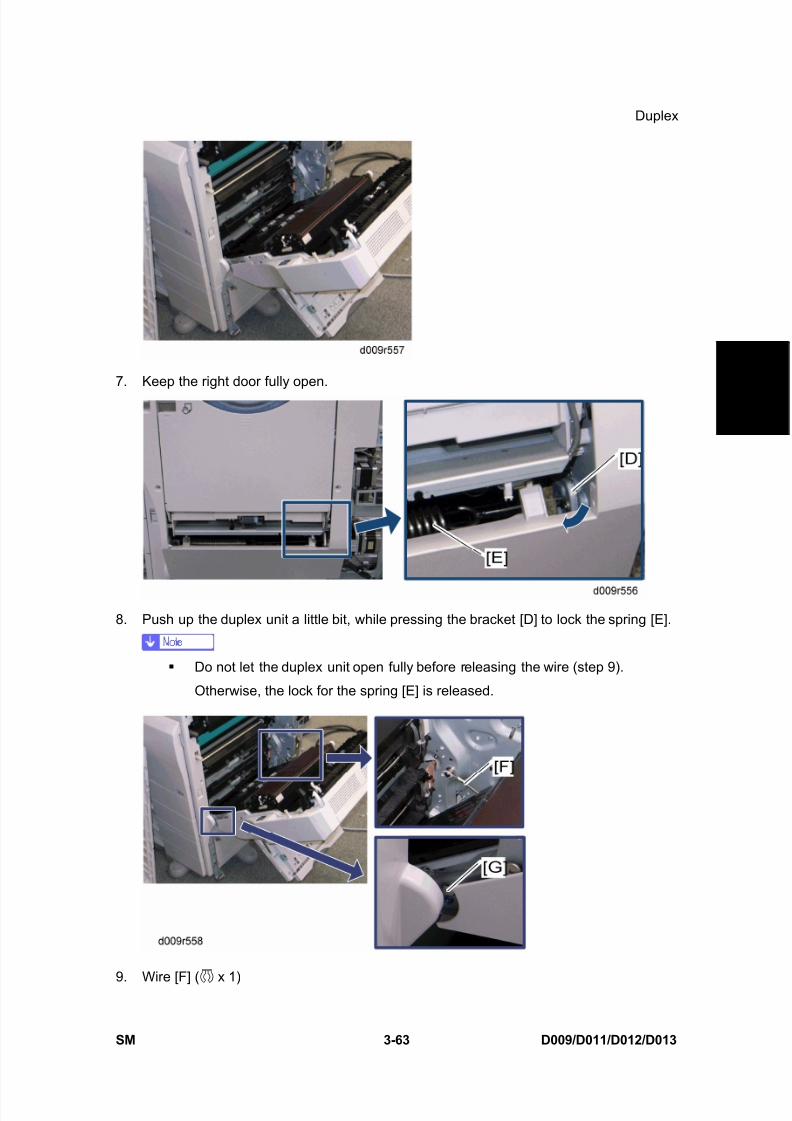
8/15/2019 Ricoh MP 4000 SM D009_D011_D012_D013 SERVICE MANUAL .pdf
http://slidepdf.com/reader/full/ricoh-mp-4000-sm-d009d011d012d013-service-manual-pdf 193/1162
Duplex
SM 3-63 D009/D011/D012/D013
R e p
l a c e m e n
t
A d j u s t m e n
t
7. Keep the right door fully open.
8. Push up the duplex unit a little bit, while pressing the bracket [D] to lock the spring [E].
Do not let the duplex unit open fully before releasing the wire (step 9).
Otherwise, the lock for the spring [E] is released.
9. Wire [F] ( x 1)
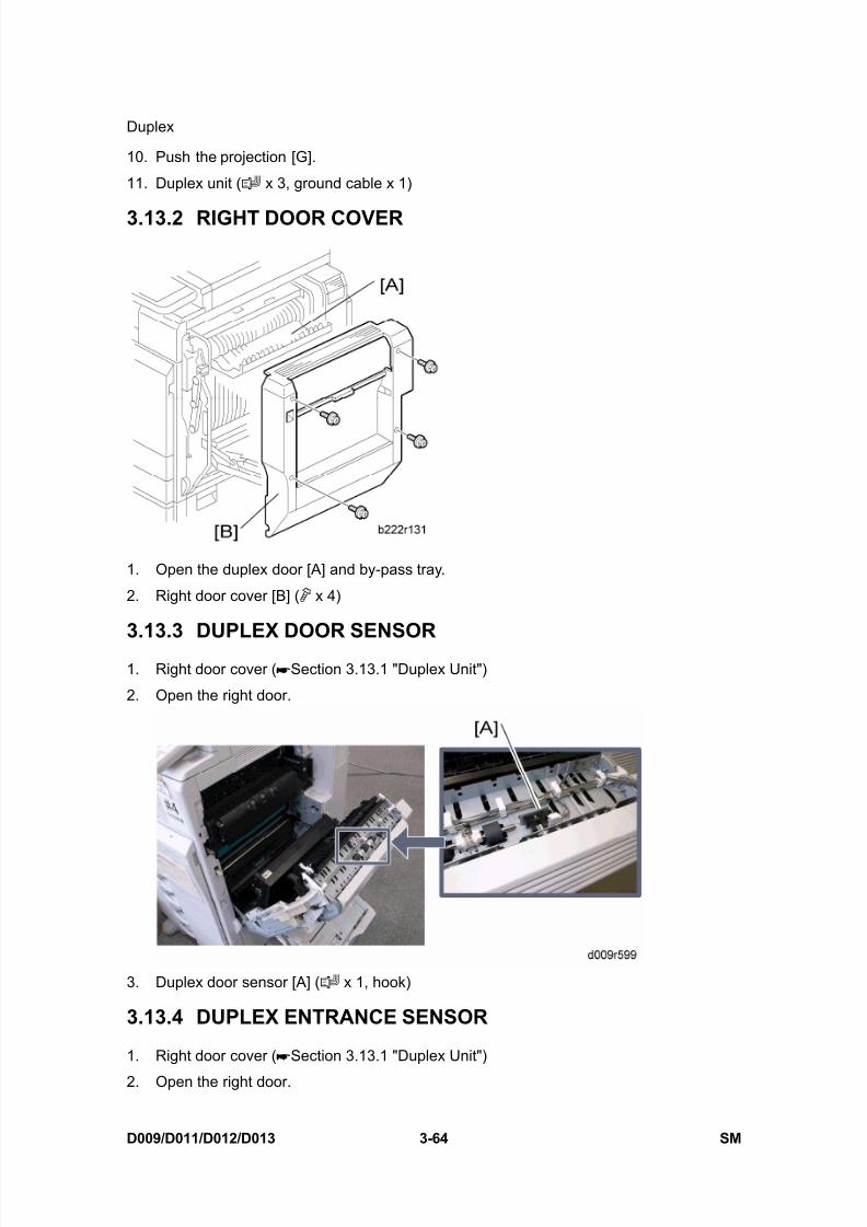
8/15/2019 Ricoh MP 4000 SM D009_D011_D012_D013 SERVICE MANUAL .pdf
http://slidepdf.com/reader/full/ricoh-mp-4000-sm-d009d011d012d013-service-manual-pdf 194/1162
Duplex
D009/D011/D012/D013 3-64 SM
10. Push the projection [G].
11. Duplex unit ( x 3, ground cable x 1)
3.13.2 RIGHT DOOR COVER
1. Open the duplex door [A] and by-pass tray.
2. Right door cover [B] ( x 4)
3.13.3 DUPLEX DOOR SENSOR
1. Right door cover ( Section 3.13.1 "Duplex Unit")
2. Open the right door.
3. Duplex door sensor [A] ( x 1, hook)
3.13.4 DUPLEX ENTRANCE SENSOR
1. Right door cover ( Section 3.13.1 "Duplex Unit")
2. Open the right door.

8/15/2019 Ricoh MP 4000 SM D009_D011_D012_D013 SERVICE MANUAL .pdf
http://slidepdf.com/reader/full/ricoh-mp-4000-sm-d009d011d012d013-service-manual-pdf 195/1162
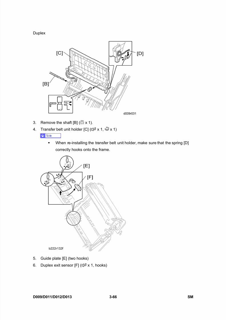
8/15/2019 Ricoh MP 4000 SM D009_D011_D012_D013 SERVICE MANUAL .pdf
http://slidepdf.com/reader/full/ricoh-mp-4000-sm-d009d011d012d013-service-manual-pdf 196/1162
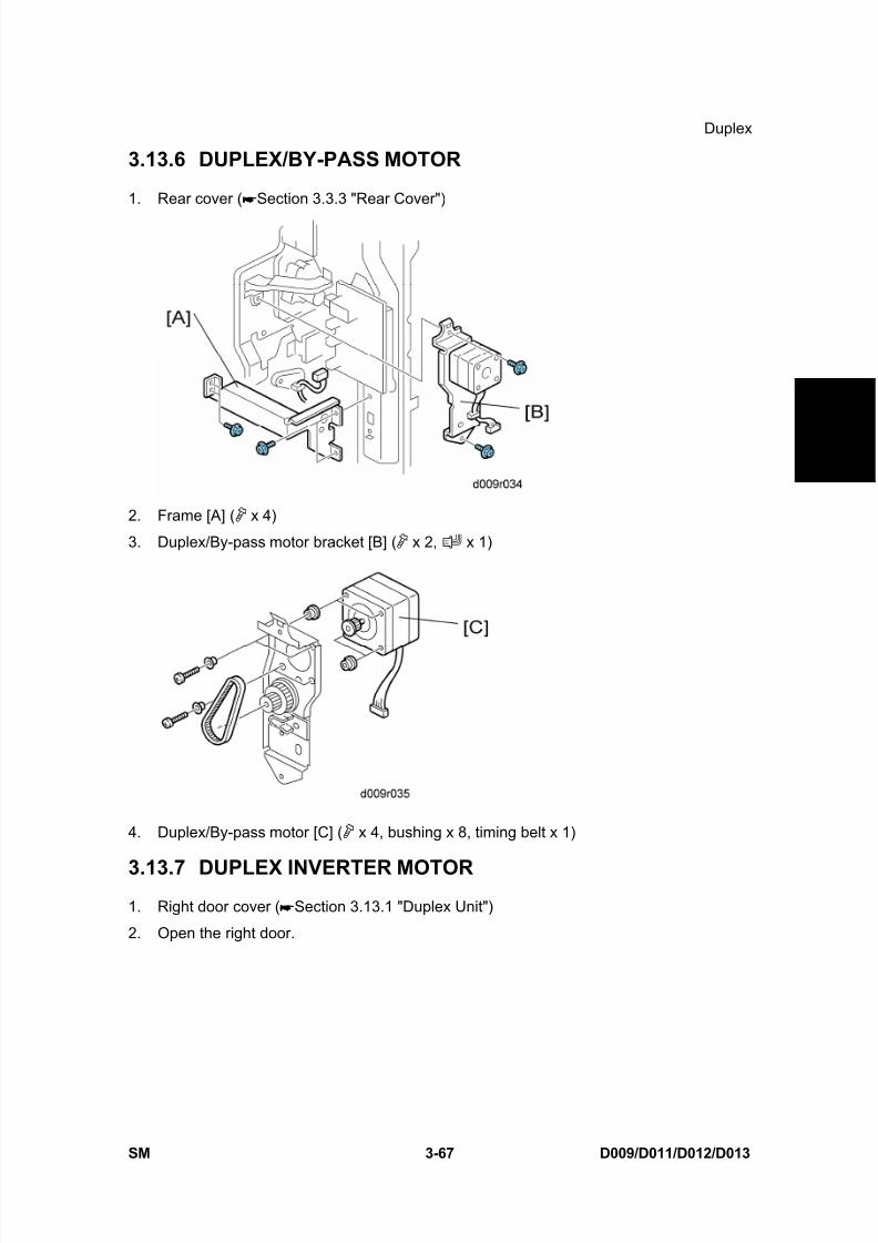
8/15/2019 Ricoh MP 4000 SM D009_D011_D012_D013 SERVICE MANUAL .pdf
http://slidepdf.com/reader/full/ricoh-mp-4000-sm-d009d011d012d013-service-manual-pdf 197/1162
Duplex
SM 3-67 D009/D011/D012/D013
R e p
l a c e m e n
t
A d j u s t m e n
t
3.13.6 DUPLEX/BY-PASS MOTOR
1. Rear cover ( Section 3.3.3 "Rear Cover")
2. Frame [A] ( x 4)
3. Duplex/By-pass motor bracket [B] ( x 2, x 1)
4. Duplex/By-pass motor [C] ( x 4, bushing x 8, timing belt x 1)
3.13.7 DUPLEX INVERTER MOTOR1. Right door cover ( Section 3.13.1 "Duplex Unit")
2. Open the right door.

8/15/2019 Ricoh MP 4000 SM D009_D011_D012_D013 SERVICE MANUAL .pdf
http://slidepdf.com/reader/full/ricoh-mp-4000-sm-d009d011d012d013-service-manual-pdf 198/1162
Duplex
D009/D011/D012/D013 3-68 SM
3. Right door rear cover [A] ( x 3)
4. Duplex door [B]
5. Duplex guide plate [C] ( x 3)

8/15/2019 Ricoh MP 4000 SM D009_D011_D012_D013 SERVICE MANUAL .pdf
http://slidepdf.com/reader/full/ricoh-mp-4000-sm-d009d011d012d013-service-manual-pdf 199/1162
Duplex
SM 3-69 D009/D011/D012/D013
R e p
l a c e m e n
t
A d j u s t m e n
t
6. Bracket [D] ( x 2)
7. Duplex inverter motor [E] ( x 3, x 1)
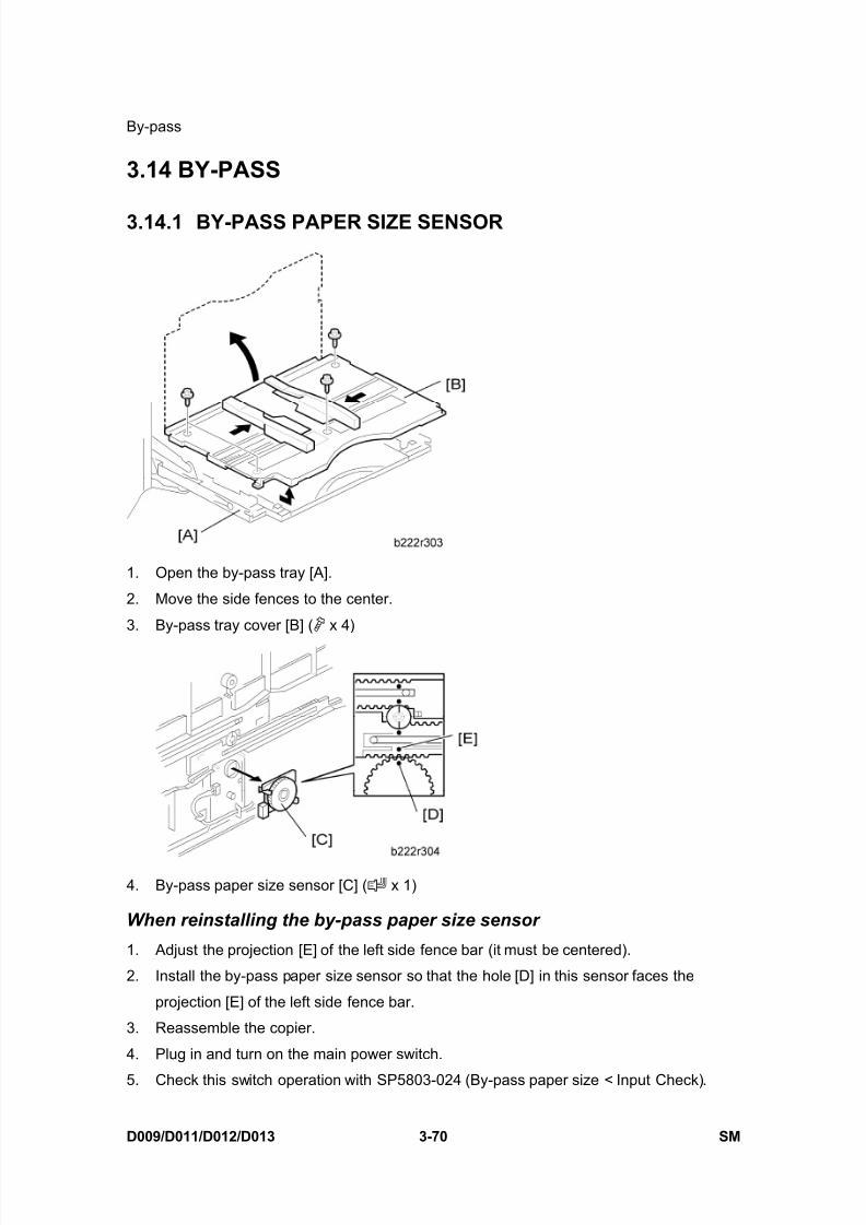
8/15/2019 Ricoh MP 4000 SM D009_D011_D012_D013 SERVICE MANUAL .pdf
http://slidepdf.com/reader/full/ricoh-mp-4000-sm-d009d011d012d013-service-manual-pdf 200/1162
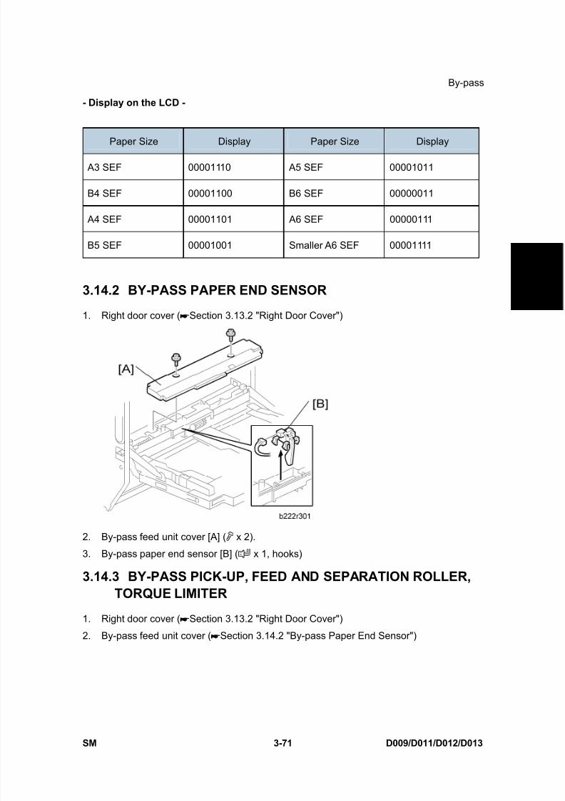
8/15/2019 Ricoh MP 4000 SM D009_D011_D012_D013 SERVICE MANUAL .pdf
http://slidepdf.com/reader/full/ricoh-mp-4000-sm-d009d011d012d013-service-manual-pdf 201/1162
By-pass
SM 3-71 D009/D011/D012/D013
R e p
l a c e m e n
t
A d j u s t m e n
t
- Display on the LCD -
Paper Size Display Paper Size Display
A3 SEF 00001110 A5 SEF 00001011
B4 SEF 00001100 B6 SEF 00000011
A4 SEF 00001101 A6 SEF 00000111
B5 SEF 00001001 Smaller A6 SEF 00001111
3.14.2 BY-PASS PAPER END SENSOR
1. Right door cover ( Section 3.13.2 "Right Door Cover")
2. By-pass feed unit cover [A] ( x 2).
3. By-pass paper end sensor [B] ( x 1, hooks)
3.14.3 BY-PASS PICK-UP, FEED AND SEPARATION ROLLER,TORQUE LIMITER
1. Right door cover ( Section 3.13.2 "Right Door Cover")
2. By-pass feed unit cover ( Section 3.14.2 "By-pass Paper End Sensor")
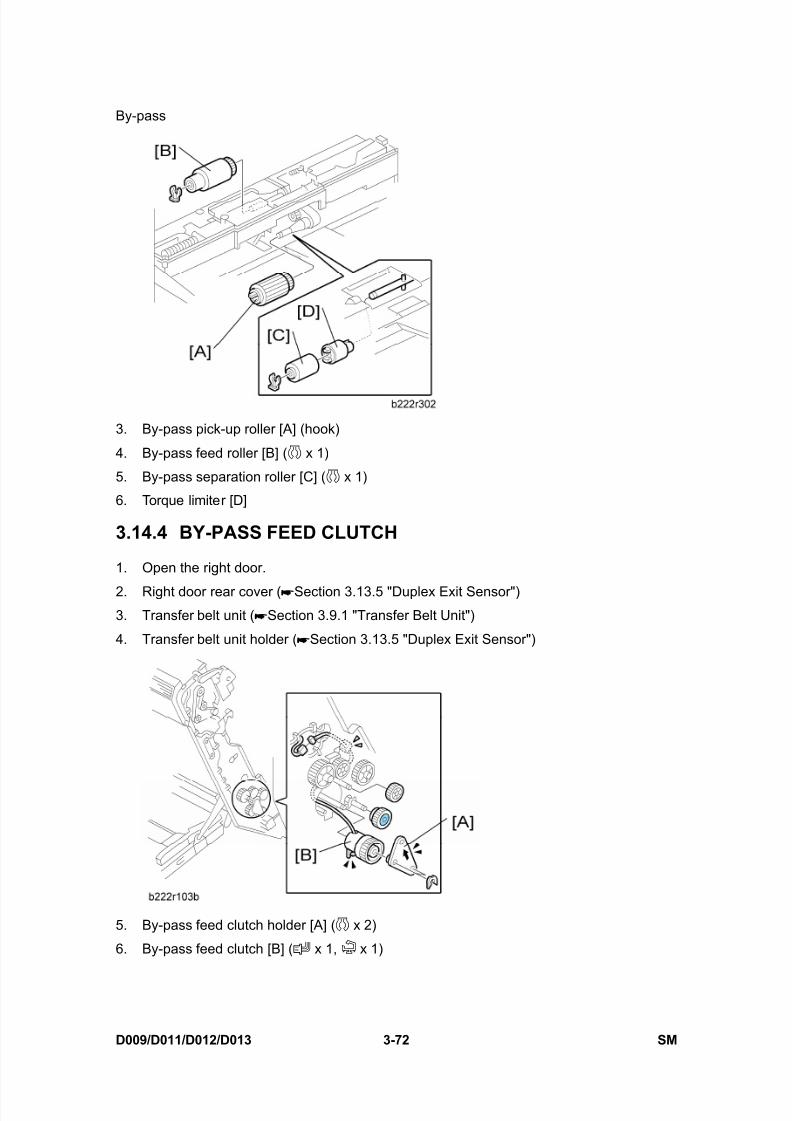
8/15/2019 Ricoh MP 4000 SM D009_D011_D012_D013 SERVICE MANUAL .pdf
http://slidepdf.com/reader/full/ricoh-mp-4000-sm-d009d011d012d013-service-manual-pdf 202/1162
By-pass
D009/D011/D012/D013 3-72 SM
3. By-pass pick-up roller [A] (hook)
4. By-pass feed roller [B] ( x 1)
5. By-pass separation roller [C] ( x 1)
6. Torque limiter [D]
3.14.4 BY-PASS FEED CLUTCH
1. Open the right door.
2. Right door rear cover ( Section 3.13.5 "Duplex Exit Sensor")3. Transfer belt unit ( Section 3.9.1 "Transfer Belt Unit")
4. Transfer belt unit holder ( Section 3.13.5 "Duplex Exit Sensor")
5. By-pass feed clutch holder [A] ( x 2)
6. By-pass feed clutch [B] ( x 1, x 1)

8/15/2019 Ricoh MP 4000 SM D009_D011_D012_D013 SERVICE MANUAL .pdf
http://slidepdf.com/reader/full/ricoh-mp-4000-sm-d009d011d012d013-service-manual-pdf 203/1162
Drive Area
SM 3-73 D009/D011/D012/D013
R e p
l a c e m e n
t
A d j u s t m e n
t
3.15 DRIVE AREA
3.15.1 PAPER FEED CLUTCH
Tray 1 and Tray 2
1. Rear cover ( Section 3.3.3 "Rear Cover")
2. Clutch bracket [A] ( x 2, x 1, bushing x 1)
3. Paper feed clutch [B] ( x 1)
3.15.2 DEVELOPMENT PADDLE MOTOR
1. Rear cover ( Section 3.3.3 "Rear Cover")

8/15/2019 Ricoh MP 4000 SM D009_D011_D012_D013 SERVICE MANUAL .pdf
http://slidepdf.com/reader/full/ricoh-mp-4000-sm-d009d011d012d013-service-manual-pdf 204/1162
Drive Area
D009/D011/D012/D013 3-74 SM
2. Development paddle motor [A] ( x 4, x 1)
3.15.3 TRANSFER/DEVELOPMENT MOTOR
1. Rear cover ( Section 3.3.3 "Rear Cover")
2. Transfer/development motor [A] ( x 4, x 1)
3.15.4 DRUM MOTOR
1. Rear cover ( Section 3.3.3 "Rear Cover")
2. Drum motor [A] ( x 4, x 1)
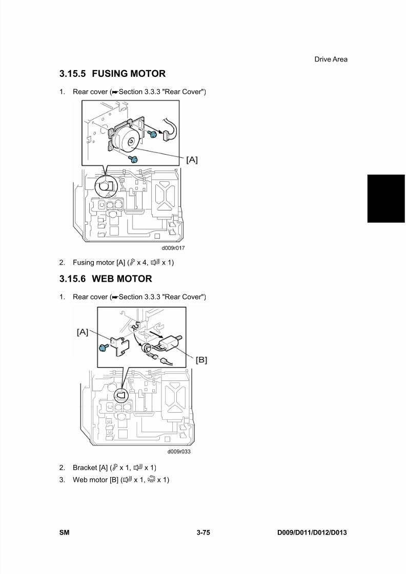
8/15/2019 Ricoh MP 4000 SM D009_D011_D012_D013 SERVICE MANUAL .pdf
http://slidepdf.com/reader/full/ricoh-mp-4000-sm-d009d011d012d013-service-manual-pdf 205/1162
Drive Area
SM 3-75 D009/D011/D012/D013
R e p
l a c e m e n
t
A d j u s t m e n
t
3.15.5 FUSING MOTOR
1. Rear cover ( Section 3.3.3 "Rear Cover")
2. Fusing motor [A] ( x 4, x 1)
3.15.6 WEB MOTOR
1. Rear cover ( Section 3.3.3 "Rear Cover")
2. Bracket [A] ( x 1, x 1)
3. Web motor [B] ( x 1, x 1)
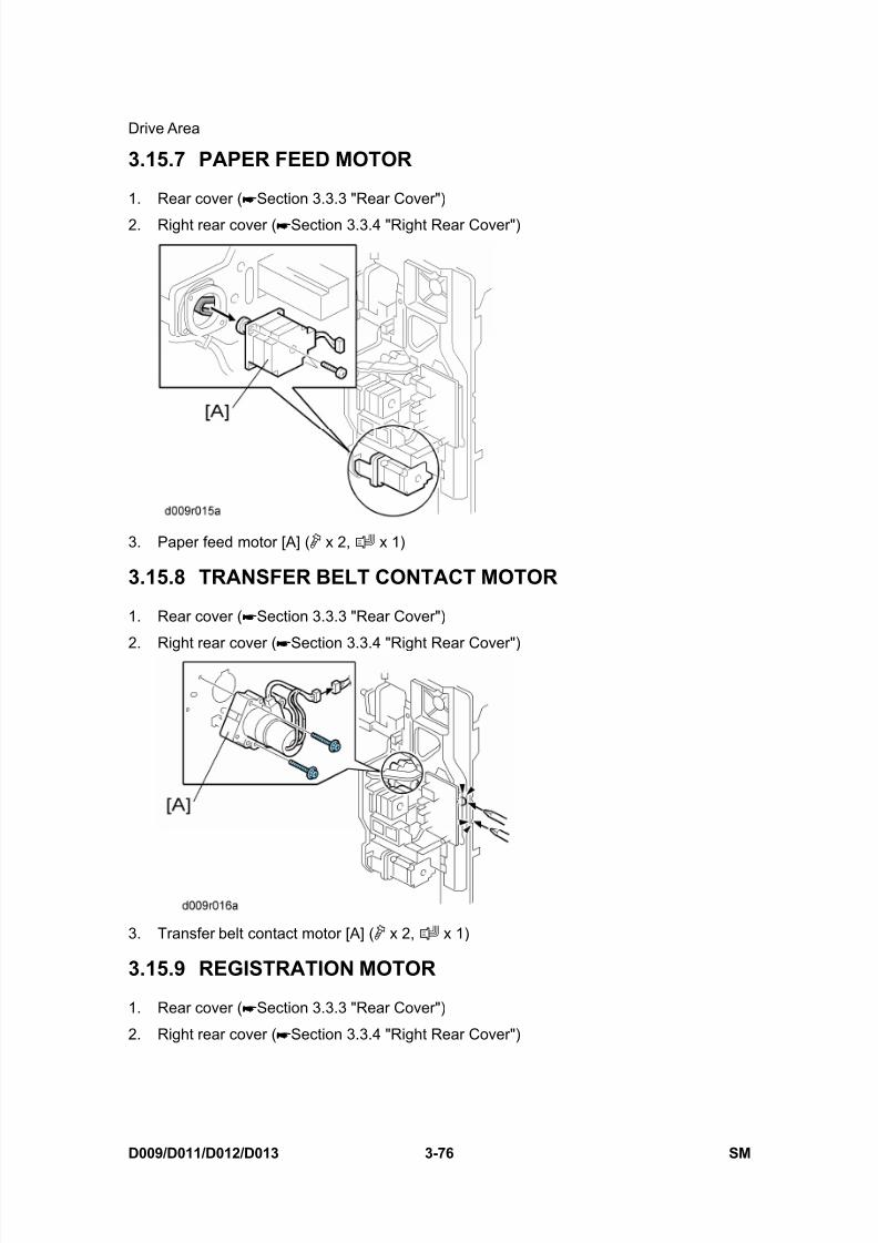
8/15/2019 Ricoh MP 4000 SM D009_D011_D012_D013 SERVICE MANUAL .pdf
http://slidepdf.com/reader/full/ricoh-mp-4000-sm-d009d011d012d013-service-manual-pdf 206/1162
Drive Area
D009/D011/D012/D013 3-76 SM
3.15.7 PAPER FEED MOTOR
1. Rear cover ( Section 3.3.3 "Rear Cover")
2. Right rear cover ( Section 3.3.4 "Right Rear Cover")
3. Paper feed motor [A] ( x 2, x 1)
3.15.8 TRANSFER BELT CONTACT MOTOR
1. Rear cover ( Section 3.3.3 "Rear Cover")
2. Right rear cover ( Section 3.3.4 "Right Rear Cover")
3. Transfer belt contact motor [A] ( x 2, x 1)
3.15.9 REGISTRATION MOTOR
1. Rear cover ( Section 3.3.3 "Rear Cover")
2. Right rear cover ( Section 3.3.4 "Right Rear Cover")
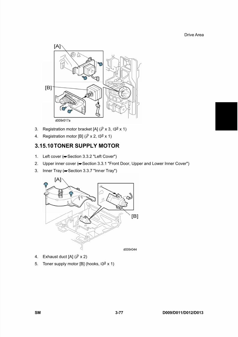
8/15/2019 Ricoh MP 4000 SM D009_D011_D012_D013 SERVICE MANUAL .pdf
http://slidepdf.com/reader/full/ricoh-mp-4000-sm-d009d011d012d013-service-manual-pdf 207/1162
Drive Area
SM 3-77 D009/D011/D012/D013
R e p
l a c e m e n
t
A d j u s t m e n
t
3. Registration motor bracket [A] ( x 3, x 1)
4. Registration motor [B] ( x 2, x 1)
3.15.10 TONER SUPPLY MOTOR
1. Left cover ( Section 3.3.2 "Left Cover")
2. Upper inner cover ( Section 3.3.1 "Front Door, Upper and Lower Inner Cover")
3. Inner Tray ( Section 3.3.7 "Inner Tray")
4. Exhaust duct [A] ( x 2)
5. Toner supply motor [B] (hooks, x 1)

8/15/2019 Ricoh MP 4000 SM D009_D011_D012_D013 SERVICE MANUAL .pdf
http://slidepdf.com/reader/full/ricoh-mp-4000-sm-d009d011d012d013-service-manual-pdf 208/1162
Electrical Components
D009/D011/D012/D013 3-78 SM
3.16 ELECTRICAL COMPONENTS
3.16.1 CONTROLLER UNIT
1. Controller unit [A] ( x 2)
3.16.2 HDD UNIT (STANDARD FOR D011/D013)
Before replacing the HDD unitCopy the address book data to an SD card from the HDD with SP5846-051 if possible.
Replacement Procedure
1. Controller unit ( Section 3.16.1 "Controller Unit")
2. HDD unit [A] ( x 3)

8/15/2019 Ricoh MP 4000 SM D009_D011_D012_D013 SERVICE MANUAL .pdf
http://slidepdf.com/reader/full/ricoh-mp-4000-sm-d009d011d012d013-service-manual-pdf 209/1162

8/15/2019 Ricoh MP 4000 SM D009_D011_D012_D013 SERVICE MANUAL .pdf
http://slidepdf.com/reader/full/ricoh-mp-4000-sm-d009d011d012d013-service-manual-pdf 210/1162
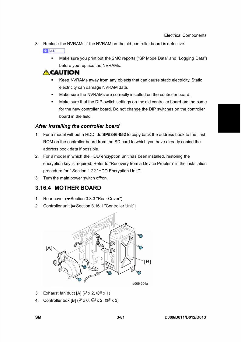
8/15/2019 Ricoh MP 4000 SM D009_D011_D012_D013 SERVICE MANUAL .pdf
http://slidepdf.com/reader/full/ricoh-mp-4000-sm-d009d011d012d013-service-manual-pdf 211/1162
Electrical Components
SM 3-81 D009/D011/D012/D013
R e p
l a c e m e n
t
A d j u s t m e n
t
3. Replace the NVRAMs if the NVRAM on the old controller board is defective.
Make sure you print out the SMC reports (“SP Mode Data” and “Logging Data”)before you replace the NVRAMs.
Keep NVRAMs away from any objects that can cause static electricity. Static
electricity can damage NVRAM data.
Make sure the NVRAMs are correctly installed on the controller board.
Make sure that the DIP-switch settings on the old controller board are the same
for the new controller board. Do not change the DIP switches on the controller
board in the field.
After installing the controller board
1. For a model without a HDD, do SP5846-052 to copy back the address book to the flash
ROM on the controller board from the SD card to which you have already copied the
address book data if possible.
2. For a model in which the HDD encryption unit has been installed, restoring the
encryption key is required. Refer to “Recovery from a Device Problem” in the installation
procedure for " Section 1.22 "HDD Encryption Unit"".
3. Turn the main power switch off/on.
3.16.4 MOTHER BOARD
1. Rear cover ( Section 3.3.3 "Rear Cover")
2. Controller unit ( Section 3.16.1 "Controller Unit")
3. Exhaust fan duct [A] ( x 2, x 1)
4. Controller box [B] ( x 6, x 2, x 3)

8/15/2019 Ricoh MP 4000 SM D009_D011_D012_D013 SERVICE MANUAL .pdf
http://slidepdf.com/reader/full/ricoh-mp-4000-sm-d009d011d012d013-service-manual-pdf 212/1162
Electrical Components
D009/D011/D012/D013 3-82 SM
5. Mother board [C] ( x 6)
3.16.5 BICU
1. Controller box ( Section 3.16.4 "Mother Board")
2. BICU[[A] ( x 7, x all)
3.16.6 IOB
1. Rear cover ( Section 3.3.3 "Rear Cover")
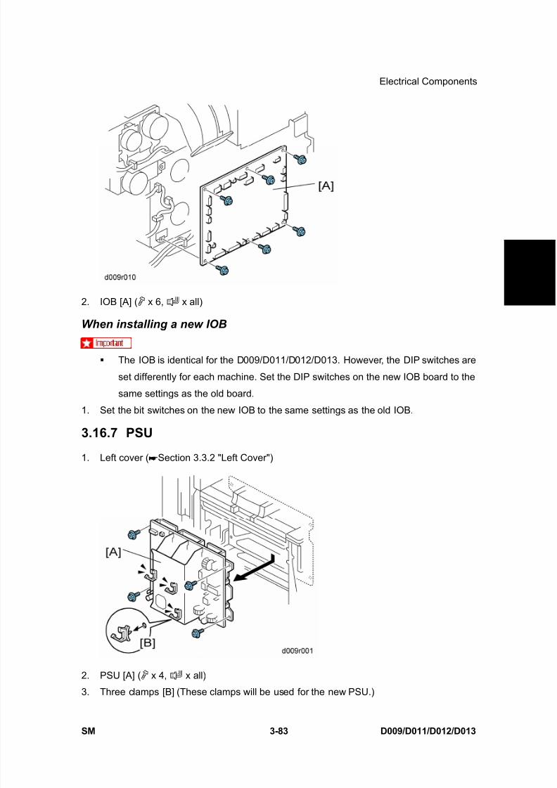
8/15/2019 Ricoh MP 4000 SM D009_D011_D012_D013 SERVICE MANUAL .pdf
http://slidepdf.com/reader/full/ricoh-mp-4000-sm-d009d011d012d013-service-manual-pdf 213/1162
Electrical Components
SM 3-83 D009/D011/D012/D013
R e p
l a c e m e n
t
A d j u s t m e n
t
2. IOB [A] ( x 6, x all)
When installing a new IOB
The IOB is identical for the D009/D011/D012/D013. However, the DIP switches are
set differently for each machine. Set the DIP switches on the new IOB board to the
same settings as the old board.
1. Set the bit switches on the new IOB to the same settings as the old IOB.
3.16.7 PSU
1. Left cover ( Section 3.3.2 "Left Cover")
2. PSU [A] ( x 4, x all)
3. Three clamps [B] (These clamps will be used for the new PSU.)
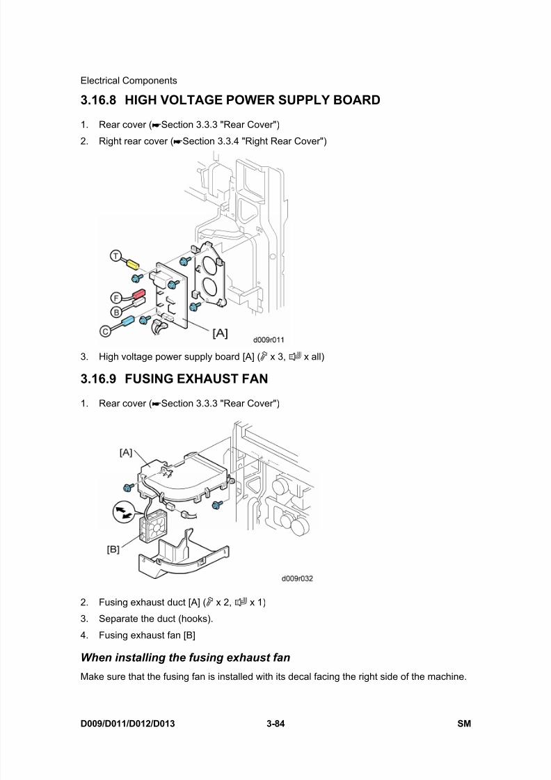
8/15/2019 Ricoh MP 4000 SM D009_D011_D012_D013 SERVICE MANUAL .pdf
http://slidepdf.com/reader/full/ricoh-mp-4000-sm-d009d011d012d013-service-manual-pdf 214/1162
Electrical Components
D009/D011/D012/D013 3-84 SM
3.16.8 HIGH VOLTAGE POWER SUPPLY BOARD
1. Rear cover ( Section 3.3.3 "Rear Cover")
2. Right rear cover ( Section 3.3.4 "Right Rear Cover")
3. High voltage power supply board [A] ( x 3, x all)
3.16.9 FUSING EXHAUST FAN
1. Rear cover ( Section 3.3.3 "Rear Cover")
2. Fusing exhaust duct [A] ( x 2, x 1)
3. Separate the duct (hooks).
4. Fusing exhaust fan [B]
When installing the fusing exhaust fan
Make sure that the fusing fan is installed with its decal facing the right side of the machine.

8/15/2019 Ricoh MP 4000 SM D009_D011_D012_D013 SERVICE MANUAL .pdf
http://slidepdf.com/reader/full/ricoh-mp-4000-sm-d009d011d012d013-service-manual-pdf 215/1162
Electrical Components
SM 3-85 D009/D011/D012/D013
R e p
l a c e m e n
t
A d j u s t m e n
t
3.16.10 CONTROLLER FAN
1. Controller box ( Section 3.16.4 "Mother Board")
2. Fan cover [A] ( x 2)
3. Controller fan [B] ( x 1)
When installing the controller fan
Make sure that the controller fan is installed with its decal facing upward.
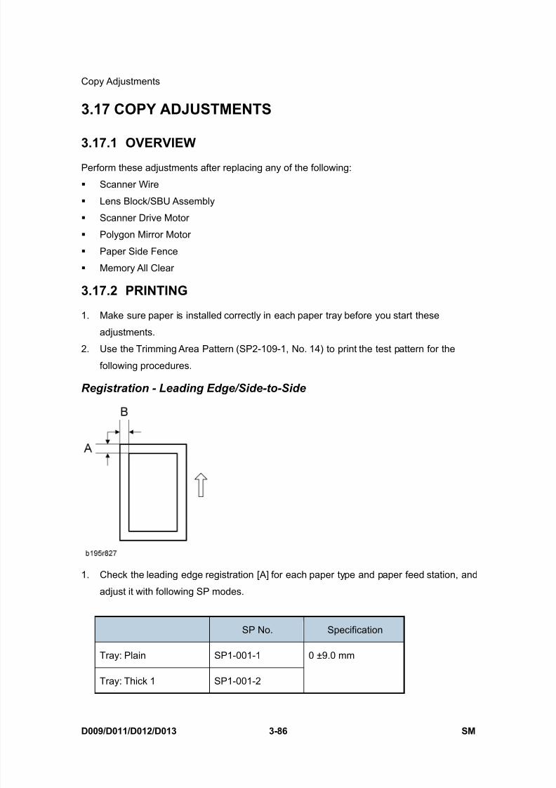
8/15/2019 Ricoh MP 4000 SM D009_D011_D012_D013 SERVICE MANUAL .pdf
http://slidepdf.com/reader/full/ricoh-mp-4000-sm-d009d011d012d013-service-manual-pdf 216/1162
Copy Adjustments
D009/D011/D012/D013 3-86 SM
3.17 COPY ADJUSTMENTS
3.17.1 OVERVIEW
Perform these adjustments after replacing any of the following:
Scanner Wire
Lens Block/SBU Assembly
Scanner Drive Motor
Polygon Mirror Motor
Paper Side Fence
Memory All Clear
3.17.2 PRINTING
1. Make sure paper is installed correctly in each paper tray before you start these
adjustments.
2. Use the Trimming Area Pattern (SP2-109-1, No. 14) to print the test pattern for the
following procedures.
Registration - Leading Edge/Side-to-Side
1. Check the leading edge registration [A] for each paper type and paper feed station, and
adjust it with following SP modes.
SP No. Specification
Tray: Plain SP1-001-1
Tray: Thick 1 SP1-001-2
0 ±9.0 mm
8/15/2019 Ricoh MP 4000 SM D009_D011_D012_D013 SERVICE MANUAL .pdf
http://slidepdf.com/reader/full/ricoh-mp-4000-sm-d009d011d012d013-service-manual-pdf 217/1162
Copy Adjustments
SM 3-87 D009/D011/D012/D013
R e p
l a c e m e n
t
A d j u s t m e n
t
SP No. Specification
Tray: Thick 2 SP1-001-3
By-pass: Plain SP1-001-4
By-pass: Thick 1 SP1-001-5
By-pass: Thick 2 SP1-001-6
Duplex: Plain SP1-001-7
Duplex: Thick 1 SP1-001-8
2. Check side-to-side registration [B] for each paper feed station, and adjust with the
following SP modes.
SP No. Specification
By-pass SP1-002-1
Tray 1 SP1-002-2
Tray 2 SP1-002-3
Tray 3 SP1-002-4
Tray 4 SP1-002-5
LCT SP1-002-6
Duplex SP1-002-7
0 ±4.0 mm
Blank Margin
If the leading edge/side-to-side registration cannot be adjusted within specifications,
adjust the leading/left side edge blank margin.

8/15/2019 Ricoh MP 4000 SM D009_D011_D012_D013 SERVICE MANUAL .pdf
http://slidepdf.com/reader/full/ricoh-mp-4000-sm-d009d011d012d013-service-manual-pdf 218/1162
Copy Adjustments
D009/D011/D012/D013 3-88 SM
1. Check the trailing edge [A], right edge [B], leading edge [C] and left edge [D] blank
margins, and adjust them with the following SP modes.
SP No. Specification
Leading Edge SP2-103-1
Trailing Edge SP2-103-2
3.0 mm [0.0 to 9.0 mm]
Left SP2-103-3
Right SP2-103-42.0 mm [0.0 to 9.0 mm]
Duplex: Trailing Edge:
L Size: PlainSP2-103-5 1.0 mm [0.0 to 4.0 mm]
Duplex: Trailing Edge:
M Size: PlainSP2-103-6 0.8 mm [0.0 to 4.0 mm]
Duplex: Trailing Edge:
S Size: PlainSP2-103-7 0.6 mm [0.0 to 4.0 mm]
Duplex: Left: Plain SP2-103-8
Duplex: Right: Plain SP2-103-9
0.3 mm [0.0 to 1.5 mm]
Duplex: Trailing Edge:
L Size: ThickSP2-103-10 0.8 mm [0.0 to 4.0 mm]
Duplex: Trailing Edge:
M Size: ThickSP2-103-11 0.6 mm [0.0 to 4.0 mm]
8/15/2019 Ricoh MP 4000 SM D009_D011_D012_D013 SERVICE MANUAL .pdf
http://slidepdf.com/reader/full/ricoh-mp-4000-sm-d009d011d012d013-service-manual-pdf 219/1162
Copy Adjustments
SM 3-89 D009/D011/D012/D013
R e p
l a c e m e n
t
A d j u s t m e n
t
SP No. Specification
Duplex: Trailing Edge:
S Size: ThickSP2-103-12 0.4 mm [0.0 to 4.0 mm]
Duplex: Left: Thick SP2-103-13
Duplex: Right: Thick SP2-103-14
0.1 mm [0.0 to 1.5 mm]
L Size: Paper length is 297.1 mm or more.
M Size: Paper length is 216.1 to 297 mm
S Size: Paper length is 216 mm or less.Main Scan Magnification
1. Use SP2-109-001 no 5 (Grid Pattern) to print a single dot pattern.
2. Check magnification, and then SP2-102 (Magnification Adjustment Main Scan) to adjust
magnification if required. Specification: ±2%.
Parallelogram Image Adjustment
Do the following procedure if a parallelogram prints while adjusting the printing registration
or printing margin using a trimming area pattern.
The following procedure should be done after adjusting the side-to-side registration for each
paper tray station.
Use SP2-109-1 No. 14 (Trimming Area) to determine whether a parallelogram image
appears. If the parallelogram pattern appears, perform the following procedure.

8/15/2019 Ricoh MP 4000 SM D009_D011_D012_D013 SERVICE MANUAL .pdf
http://slidepdf.com/reader/full/ricoh-mp-4000-sm-d009d011d012d013-service-manual-pdf 220/1162
Copy Adjustments
D009/D011/D012/D013 3-90 SM
1. Laser unit [A]
2. Bracket [B] ( x2)
3. Install adjustment cam [C] (P/N: A2309003).
4. Secure positioning pin [D] (P/N A2309004) with the two screws removed with the
bracket [B]. Do not tighten the screws at this time.
5. To adjust the position of the laser unit [E]
1) Adjust the laser unit position by turning the adjustment cam. (See the illustration
above.)
2) Tighten the adjustment bracket.
3) Print the trimming area pattern to check the image. If the results are not satisfactory,
repeat steps 5-1) to 5-3).
3.17.3 SCANNING
Before doing the following scanner adjustments, perform or check the printingregistration/side-to-side adjustment and the blank margin adjustment.
Use the S5S test chart to perform the following adjustments.
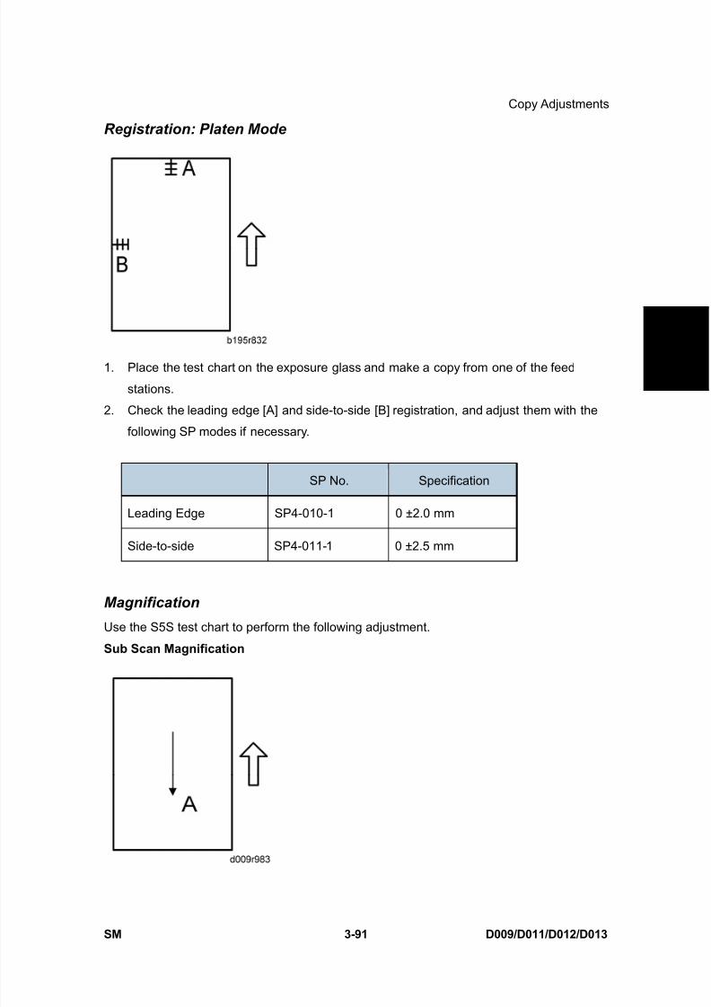
8/15/2019 Ricoh MP 4000 SM D009_D011_D012_D013 SERVICE MANUAL .pdf
http://slidepdf.com/reader/full/ricoh-mp-4000-sm-d009d011d012d013-service-manual-pdf 221/1162
Copy Adjustments
SM 3-91 D009/D011/D012/D013
R e p
l a c e m e n
t
A d j u s t m e n
t
Registration: Platen Mode
1. Place the test chart on the exposure glass and make a copy from one of the feed
stations.
2. Check the leading edge [A] and side-to-side [B] registration, and adjust them with the
following SP modes if necessary.
SP No. Specification
Leading Edge SP4-010-1 0 ±2.0 mm
Side-to-side SP4-011-1 0 ±2.5 mm
Magnification
Use the S5S test chart to perform the following adjustment.
Sub Scan Magnification

8/15/2019 Ricoh MP 4000 SM D009_D011_D012_D013 SERVICE MANUAL .pdf
http://slidepdf.com/reader/full/ricoh-mp-4000-sm-d009d011d012d013-service-manual-pdf 222/1162
Copy Adjustments
D009/D011/D012/D013 3-92 SM
1. Place the test chart on the exposure glass and make a copy from one of the feed
stations.
2. Check the magnification ratio. Use SP4-008 (Scanner Sub Scan Magnification) to adjustif necessary. Specification: ±0.9%.
3.17.4 ADF IMAGE ADJUSTMENT
Registration
1. Make a temporary test chart as shown above using A3/DLT paper.
2. Place the temporary test chart on the ADF and make a copy from one of the feed
stations.
3. Check the registration, and adjust using the following SP modes if necessary.
SP No. Specification
Side-to-side: 1st side SP6-006-1
Side-to-side: 2nd side SP6-006-2
0.0 mm ±3 mm
Leading Edge SP6-006-3 0.0 mm ±5 mm
Leading Edge: 1st side SP6-006-5 0.0 mm ±3 mm
Leading Edge: 2nd side SP6-006-6 0.0 mm ±2.5 mm
Trailing Erase edge: SP6-006-7 0.0 mm ±10.0 mm
3.17.5 TOUCH SCREEN CALIBRATION
After clearing the memory, or if the touch panel detection function is not working correctly,
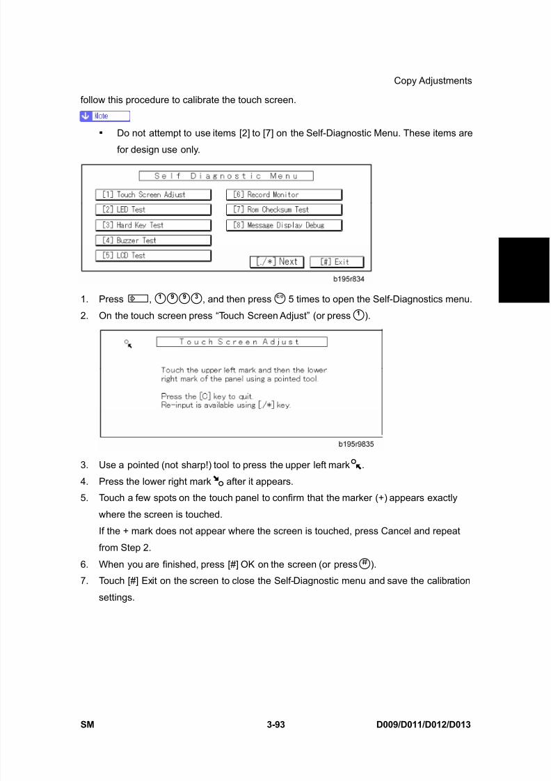
8/15/2019 Ricoh MP 4000 SM D009_D011_D012_D013 SERVICE MANUAL .pdf
http://slidepdf.com/reader/full/ricoh-mp-4000-sm-d009d011d012d013-service-manual-pdf 223/1162
Copy Adjustments
SM 3-93 D009/D011/D012/D013
R e p
l a c e m e n
t
A d j u s t m e n
t
follow this procedure to calibrate the touch screen.
Do not attempt to use items [2] to [7] on the Self-Diagnostic Menu. These items arefor design use only.
1. Press , , and then press 5 times to open the Self-Diagnostics menu.
2. On the touch screen press “Touch Screen Adjust” (or press ).
3. Use a pointed (not sharp!) tool to press the upper left mark .
4. Press the lower right mark after it appears.
5. Touch a few spots on the touch panel to confirm that the marker (+) appears exactly
where the screen is touched.
If the + mark does not appear where the screen is touched, press Cancel and repeat
from Step 2.6. When you are finished, press [#] OK on the screen (or press ).
7. Touch [#] Exit on the screen to close the Self-Diagnostic menu and save the calibration
settings.

8/15/2019 Ricoh MP 4000 SM D009_D011_D012_D013 SERVICE MANUAL .pdf
http://slidepdf.com/reader/full/ricoh-mp-4000-sm-d009d011d012d013-service-manual-pdf 224/1162

8/15/2019 Ricoh MP 4000 SM D009_D011_D012_D013 SERVICE MANUAL .pdf
http://slidepdf.com/reader/full/ricoh-mp-4000-sm-d009d011d012d013-service-manual-pdf 225/1162
TROUBLESHOOTING

8/15/2019 Ricoh MP 4000 SM D009_D011_D012_D013 SERVICE MANUAL .pdf
http://slidepdf.com/reader/full/ricoh-mp-4000-sm-d009d011d012d013-service-manual-pdf 226/1162
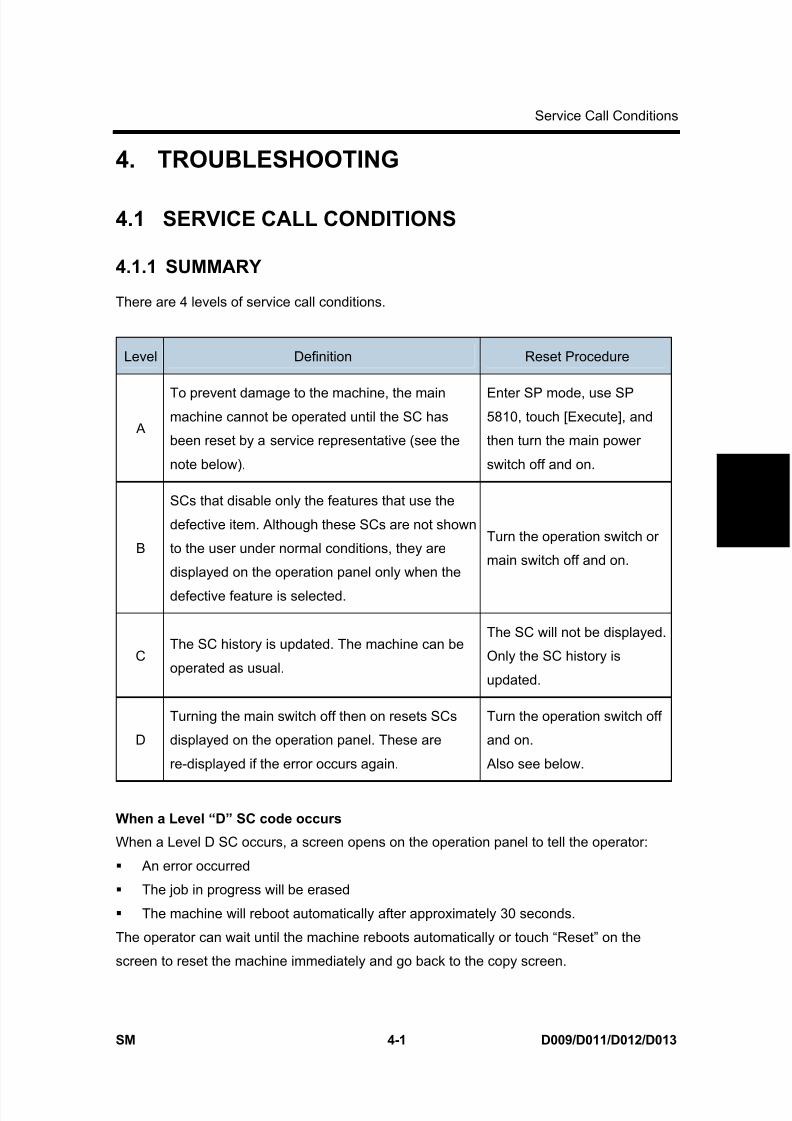
8/15/2019 Ricoh MP 4000 SM D009_D011_D012_D013 SERVICE MANUAL .pdf
http://slidepdf.com/reader/full/ricoh-mp-4000-sm-d009d011d012d013-service-manual-pdf 227/1162
Service Call Conditions
SM 4-1 D009/D011/D012/D013
T r o u
b l e -
s h o o
t i n g
4. TROUBLESHOOTING
4.1 SERVICE CALL CONDITIONS
4.1.1 SUMMARY
There are 4 levels of service call conditions.
Level Definition Reset Procedure
A
To prevent damage to the machine, the mainmachine cannot be operated until the SC has
been reset by a service representative (see the
note below).
Enter SP mode, use SP5810, touch [Execute], and
then turn the main power
switch off and on.
B
SCs that disable only the features that use the
defective item. Although these SCs are not shown
to the user under normal conditions, they are
displayed on the operation panel only when the
defective feature is selected.
Turn the operation switch or
main switch off and on.
CThe SC history is updated. The machine can be
operated as usual.
The SC will not be displayed.
Only the SC history is
updated.
D
Turning the main switch off then on resets SCs
displayed on the operation panel. These are
re-displayed if the error occurs again.
Turn the operation switch off
and on.
Also see below.
When a Level “D” SC code occurs
When a Level D SC occurs, a screen opens on the operation panel to tell the operator:
An error occurred
The job in progress will be erased
The machine will reboot automatically after approximately 30 seconds.
The operator can wait until the machine reboots automatically or touch “Reset” on the
screen to reset the machine immediately and go back to the copy screen.
8/15/2019 Ricoh MP 4000 SM D009_D011_D012_D013 SERVICE MANUAL .pdf
http://slidepdf.com/reader/full/ricoh-mp-4000-sm-d009d011d012d013-service-manual-pdf 228/1162
Service Call Conditions
D009/D011/D012/D013 4-2 SM
If the operator does not touch “Reset”
The next message tells the operator that the machine will reset automatically and that the
previous job was lost and must be started again. After reading the message, the operatortouches “Confirm” on the screen. The next screen shows the number and title of the SC
code, and stops until the operator turns the machine off and on.
If the operator touches “Reset”
If the operator touches "Reset" to bypass the 30-second interval for the machine to reboot,
the machine reboots immediately and the operation panel displays the copy screen.
Do not try to use the operation panel during an automatic reboot.
If the Remote Service System is in use, the SC code is sent immediately to the
Service Center.
4.1.2 SC CODE DESCRIPTIONS
If a problem concerns a circuit board, disconnect and reconnect the connectors and
then test the machine. Often a loose or disconnected harness is the cause of the
problem. Always do this before you decide to replace the PCB.
If a motor lock error occurs, check the mechanical load before you decide to
replace the motor or sensors. When a Level “A” or “B” SC occurs while in an SP mode, the machine cannot
display the SC number. If this occurs, check the SC number after leaving the SP
mode.
The machine reboots automatically when the machine issues a Level “D” SC code.
This is done for Level “D” SC codes only.
Never turn off the main power switch when the power LED is lit or flashing. To avoid
damaging the hard disk or memory, press the operation switch to switch the poweroff, wait for the power LED to go off, and then switch the main power switch off.
The main power LED ( ) lights or flashes while the platen cover or ARDF is open,
while the main machine is communicating with a facsimile or the network server, or
while the machine is accessing the hard disk or memory for reading or writing data.
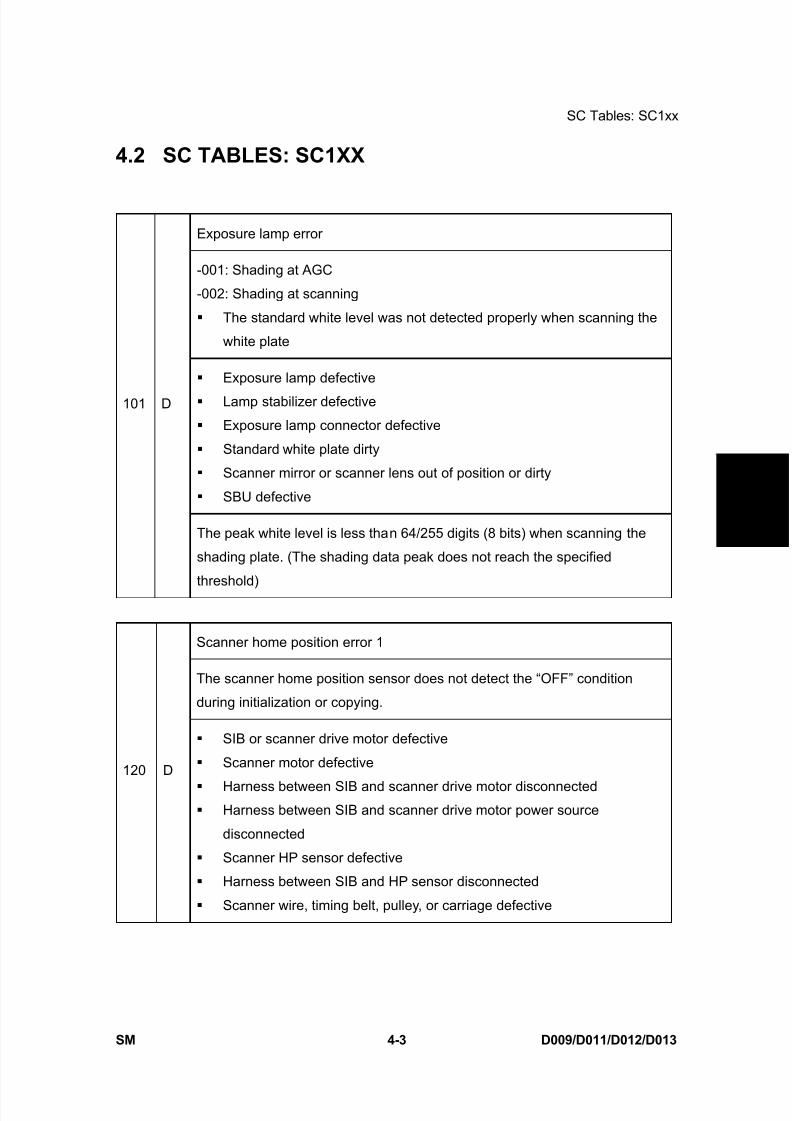
8/15/2019 Ricoh MP 4000 SM D009_D011_D012_D013 SERVICE MANUAL .pdf
http://slidepdf.com/reader/full/ricoh-mp-4000-sm-d009d011d012d013-service-manual-pdf 229/1162
SC Tables: SC1xx
SM 4-3 D009/D011/D012/D013
T r o u
b l e -
s h o o
t i n g
4.2 SC TABLES: SC1XX
Exposure lamp error
-001: Shading at AGC
-002: Shading at scanning
The standard white level was not detected properly when scanning the
white plate
Exposure lamp defective
Lamp stabilizer defective
Exposure lamp connector defective
Standard white plate dirty
Scanner mirror or scanner lens out of position or dirty
SBU defective
101 D
The peak white level is less than 64/255 digits (8 bits) when scanning the
shading plate. (The shading data peak does not reach the specified
threshold)
Scanner home position error 1
The scanner home position sensor does not detect the “OFF” condition
during initialization or copying.
120 D
SIB or scanner drive motor defective
Scanner motor defective
Harness between SIB and scanner drive motor disconnected Harness between SIB and scanner drive motor power source
disconnected
Scanner HP sensor defective
Harness between SIB and HP sensor disconnected
Scanner wire, timing belt, pulley, or carriage defective
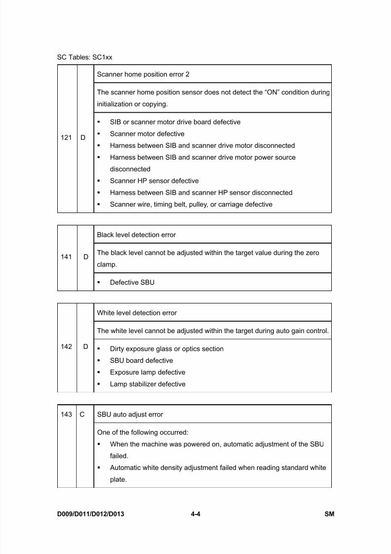
8/15/2019 Ricoh MP 4000 SM D009_D011_D012_D013 SERVICE MANUAL .pdf
http://slidepdf.com/reader/full/ricoh-mp-4000-sm-d009d011d012d013-service-manual-pdf 230/1162
SC Tables: SC1xx
D009/D011/D012/D013 4-4 SM
Scanner home position error 2
The scanner home position sensor does not detect the “ON” condition during
initialization or copying.
121 D
SIB or scanner motor drive board defective
Scanner motor defective
Harness between SIB and scanner drive motor disconnected
Harness between SIB and scanner drive motor power source
disconnected
Scanner HP sensor defective
Harness between SIB and scanner HP sensor disconnected Scanner wire, timing belt, pulley, or carriage defective
Black level detection error
The black level cannot be adjusted within the target value during the zero
clamp.141 D
Defective SBU
White level detection error
The white level cannot be adjusted within the target during auto gain control.
142 D Dirty exposure glass or optics section
SBU board defective
Exposure lamp defective
Lamp stabilizer defective
SBU auto adjust error143 C
One of the following occurred:
When the machine was powered on, automatic adjustment of the SBU
failed.
Automatic white density adjustment failed when reading standard white
plate.
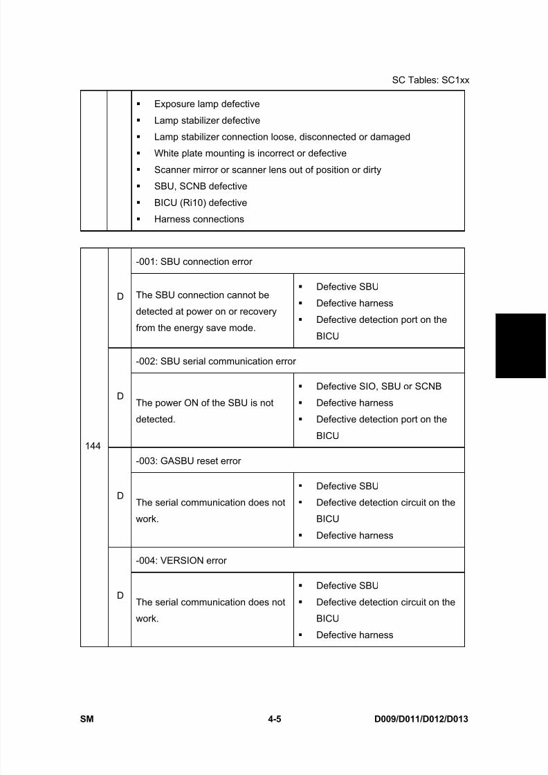
8/15/2019 Ricoh MP 4000 SM D009_D011_D012_D013 SERVICE MANUAL .pdf
http://slidepdf.com/reader/full/ricoh-mp-4000-sm-d009d011d012d013-service-manual-pdf 231/1162
SC Tables: SC1xx
SM 4-5 D009/D011/D012/D013
T r o u
b l e -
s h o o
t i n g
Exposure lamp defective
Lamp stabilizer defective
Lamp stabilizer connection loose, disconnected or damaged White plate mounting is incorrect or defective
Scanner mirror or scanner lens out of position or dirty
SBU, SCNB defective
BICU (Ri10) defective
Harness connections
-001: SBU connection error
D The SBU connection cannot be
detected at power on or recovery
from the energy save mode.
Defective SBU
Defective harness
Defective detection port on the
BICU
-002: SBU serial communication error
D
The power ON of the SBU is notdetected.
Defective SIO, SBU or SCNB
Defective harness Defective detection port on the
BICU
-003: GASBU reset error
DThe serial communication does not
work.
Defective SBU
Defective detection circuit on the
BICU
Defective harness
-004: VERSION error
144
DThe serial communication does not
work.
Defective SBU
Defective detection circuit on the
BICU
Defective harness
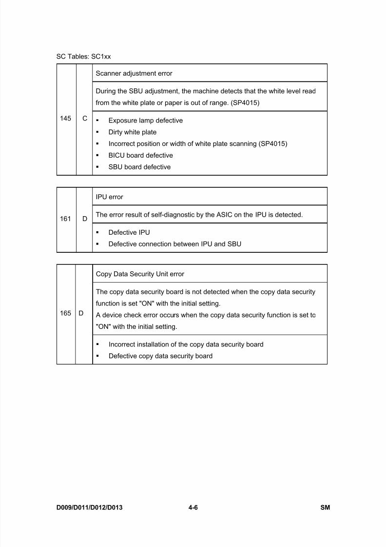
8/15/2019 Ricoh MP 4000 SM D009_D011_D012_D013 SERVICE MANUAL .pdf
http://slidepdf.com/reader/full/ricoh-mp-4000-sm-d009d011d012d013-service-manual-pdf 232/1162
SC Tables: SC1xx
D009/D011/D012/D013 4-6 SM
Scanner adjustment error
During the SBU adjustment, the machine detects that the white level read
from the white plate or paper is out of range. (SP4015)
145 C Exposure lamp defective
Dirty white plate
Incorrect position or width of white plate scanning (SP4015)
BICU board defective
SBU board defective
IPU error
The error result of self-diagnostic by the ASIC on the IPU is detected.161 D
Defective IPU
Defective connection between IPU and SBU
Copy Data Security Unit error
The copy data security board is not detected when the copy data security
function is set "ON" with the initial setting.
A device check error occurs when the copy data security function is set to
"ON" with the initial setting.
165 D
Incorrect installation of the copy data security board
Defective copy data security board

8/15/2019 Ricoh MP 4000 SM D009_D011_D012_D013 SERVICE MANUAL .pdf
http://slidepdf.com/reader/full/ricoh-mp-4000-sm-d009d011d012d013-service-manual-pdf 233/1162
SC Tables: SC2xx
SM 4-7 D009/D011/D012/D013
T r o u
b l e -
s h o o
t i n g
4.3 SC TABLES: SC2XX
Polygon motor error 1: ON timeout
202 DThe polygon mirror motor does not reach the targeted operating speed within
10 sec. after turning on or changing speed
Polygon motor error 2: OFF timeout
203 DThe polygon mirror motor does not leave the READY status within 3 sec.
after the polygon motor switched off.
Polygon motor error 3: XSCRDY signal error
The SCRDY_N signal remains HIGH for 200 ms while the LD unit is firing.
204 D Polygon motor/driver board harness loose or broken
Polygon motor/driver board defective
Laser optics unit defective
IPU defective
Laser synchronizing detection error: start position LD0
The laser synchronizing detection signal for the start position of the LDB is
not output for two seconds after LDB unit turns on while the polygon motor is
rotating normally220 D
The Copy Data Security Unit card not installed
The Copy Data Security Unit card is installed, but it is not the correct
type for the machine.
Laser synchronizing detection error: start position LD1
The laser synchronizing detection signal for the start position of the LDB is
not output for two seconds after LDB unit turns on while the polygon motor is
rotating normally.
221 D
The Copy Data Security Unit card not installed
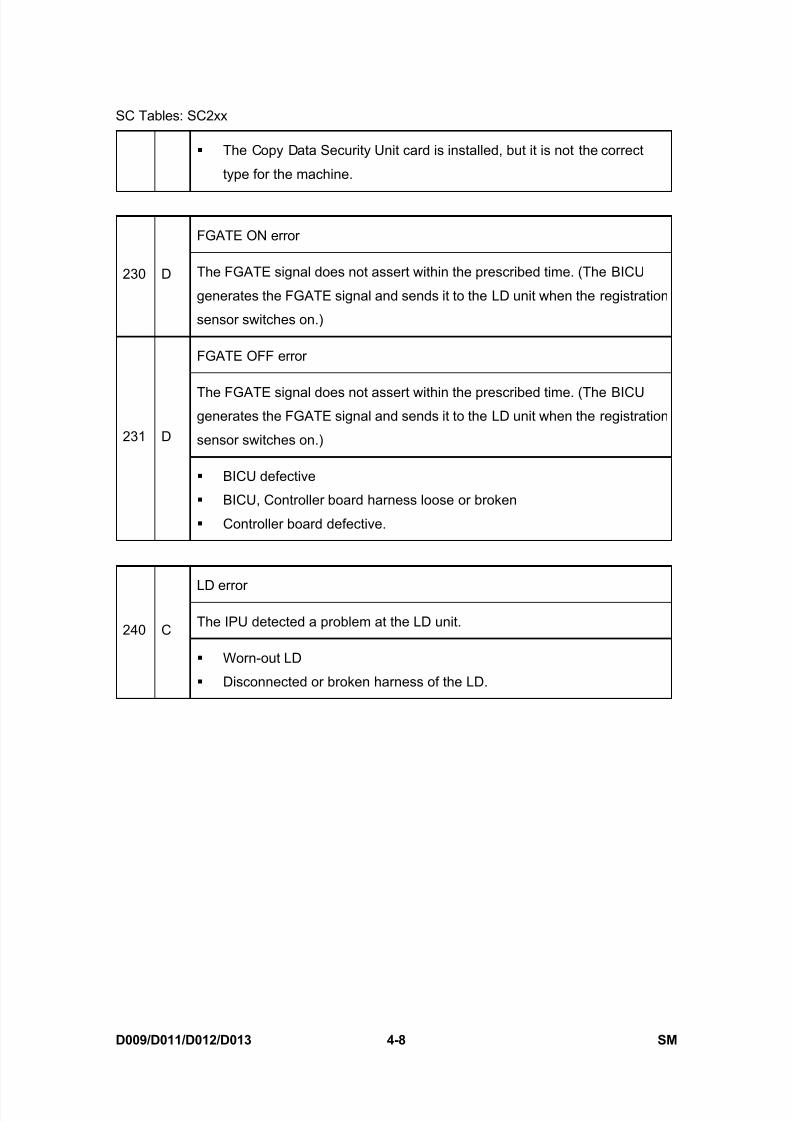
8/15/2019 Ricoh MP 4000 SM D009_D011_D012_D013 SERVICE MANUAL .pdf
http://slidepdf.com/reader/full/ricoh-mp-4000-sm-d009d011d012d013-service-manual-pdf 234/1162
SC Tables: SC2xx
D009/D011/D012/D013 4-8 SM
The Copy Data Security Unit card is installed, but it is not the correct
type for the machine.
FGATE ON error
230 D The FGATE signal does not assert within the prescribed time. (The BICU
generates the FGATE signal and sends it to the LD unit when the registration
sensor switches on.)
FGATE OFF error
The FGATE signal does not assert within the prescribed time. (The BICUgenerates the FGATE signal and sends it to the LD unit when the registration
sensor switches on.)231 D
BICU defective
BICU, Controller board harness loose or broken
Controller board defective.
LD error
The IPU detected a problem at the LD unit.240 C
Worn-out LD
Disconnected or broken harness of the LD.

8/15/2019 Ricoh MP 4000 SM D009_D011_D012_D013 SERVICE MANUAL .pdf
http://slidepdf.com/reader/full/ricoh-mp-4000-sm-d009d011d012d013-service-manual-pdf 235/1162
SC Tables: SC3xx
SM 4-9 D009/D011/D012/D013
T r o u
b l e -
s h o o
t i n g
4.4 SC TABLES: SC3XX
Charge roller bias leak
A charge roller bias leak signal was detected.302 D
Charge roller damaged
High voltage supply board defective
PCDU harness defective or disconnected
Charge roller bias correction leak
The charge roller bias correction is performed twice even if the maximum
charge roller bias (-2000V) is applied to the roller.304 D
ID sensor defective
Worn charge roller
Charge roller damaged
Development roller bias leak
The maximum PMW duty (65%) is detected for 60 ms after the high voltage
has been supplied to the development unit.320 D
Development bias leak
Broken harness
Defective high voltage power supply, voltage supply
Defective high voltage supply unit
Development paddle motor error
The machine detects a lock signal error from the development puddle motor
for 2 seconds after the drum motor has turned on.324 D
Overload on the development puddle motor
Defective development puddle motor

8/15/2019 Ricoh MP 4000 SM D009_D011_D012_D013 SERVICE MANUAL .pdf
http://slidepdf.com/reader/full/ricoh-mp-4000-sm-d009d011d012d013-service-manual-pdf 236/1162
SC Tables: SC3xx
D009/D011/D012/D013 4-10 SM
Defective harness
Defective IOB
ID sensor pattern test error
One of the following readings occurred 10 times in the ID sensor output when
the ID sensor pattern was checked:
1) Vsp ≥ 2.5V
2) Vsg ≤ 2.5V
3) Vsp =0V
4) Vsg = 0V
350 D
ID sensor connector defective
Poor ID sensor connector connection
I/O board (IOB) defective
Poor writing of ID sensor pattern on the drum
High voltage supply board defective
ID sensor Vsg test error
When the ID sensor was checked, the ID sensor output voltage is 5.0V while
the LED current value is 0.
351 D ID sensor defective or dirty
ID sensor connector defective
Poor ID sensor connection
I/O board (IOB) defective
Scanning system defective
High voltage supply board defective
Defect at the ID sensor pattern writing area of the drum
Grayscale measurement error
When the grayscale control result is the maximum and it does not operate
correctly and these cases are detected 15 times.355 C
ID sensor defective or dirty

8/15/2019 Ricoh MP 4000 SM D009_D011_D012_D013 SERVICE MANUAL .pdf
http://slidepdf.com/reader/full/ricoh-mp-4000-sm-d009d011d012d013-service-manual-pdf 237/1162
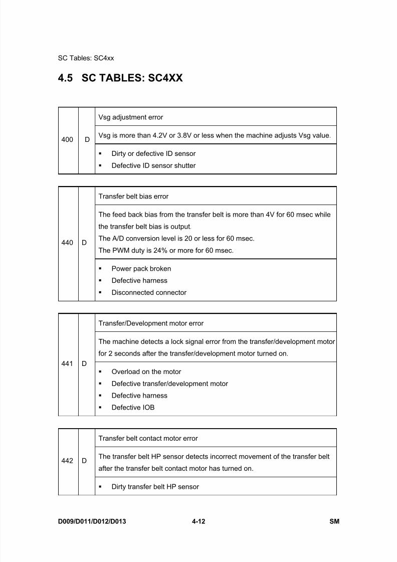
8/15/2019 Ricoh MP 4000 SM D009_D011_D012_D013 SERVICE MANUAL .pdf
http://slidepdf.com/reader/full/ricoh-mp-4000-sm-d009d011d012d013-service-manual-pdf 238/1162
SC Tables: SC4xx
D009/D011/D012/D013 4-12 SM
4.5 SC TABLES: SC4XX
Vsg adjustment error
Vsg is more than 4.2V or 3.8V or less when the machine adjusts Vsg value.400 D
Dirty or defective ID sensor
Defective ID sensor shutter
Transfer belt bias error
The feed back bias from the transfer belt is more than 4V for 60 msec while
the transfer belt bias is output.
The A/D conversion level is 20 or less for 60 msec.
The PWM duty is 24% or more for 60 msec.440 D
Power pack broken
Defective harness
Disconnected connector
Transfer/Development motor error
The machine detects a lock signal error from the transfer/development motor
for 2 seconds after the transfer/development motor turned on.441 D
Overload on the motor
Defective transfer/development motor
Defective harness
Defective IOB
Transfer belt contact motor error
The transfer belt HP sensor detects incorrect movement of the transfer belt
after the transfer belt contact motor has turned on.442 D
Dirty transfer belt HP sensor
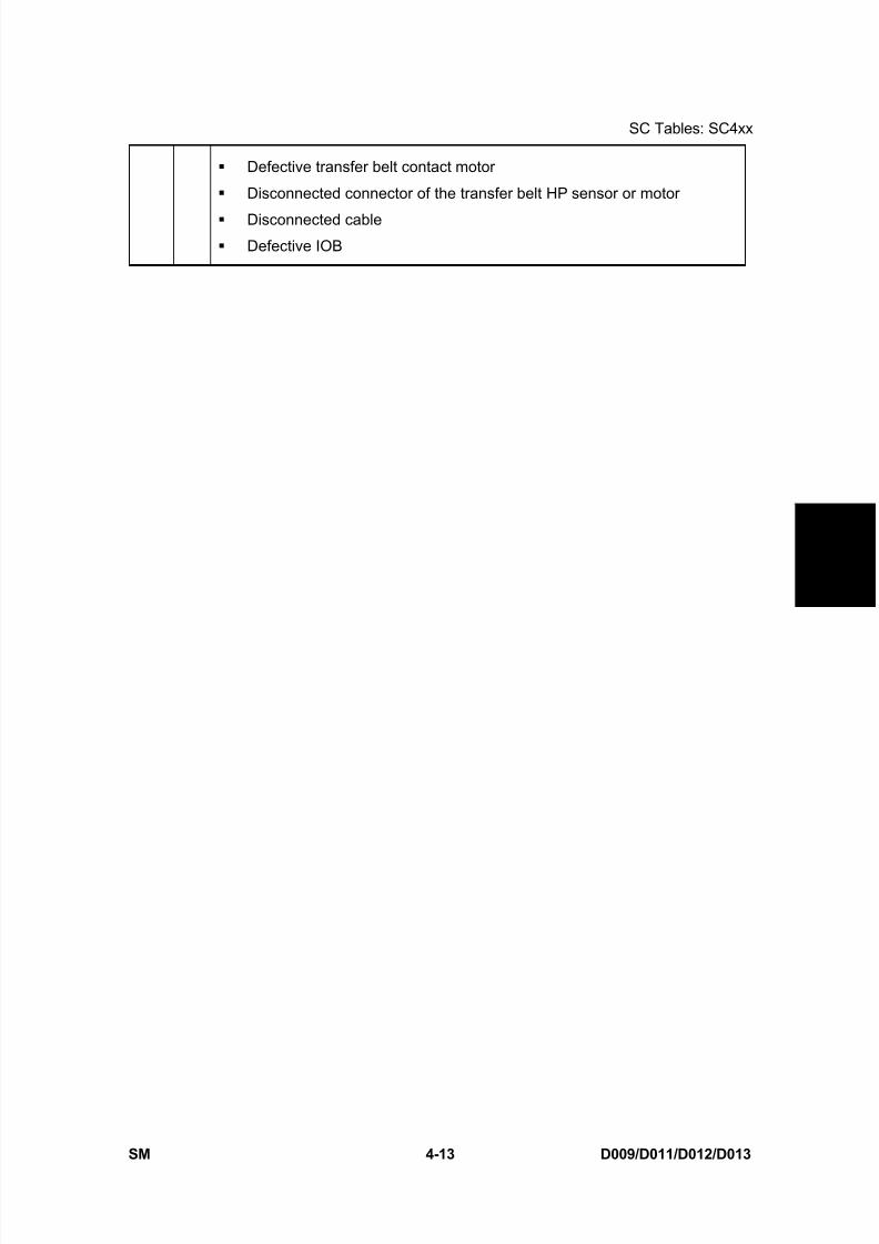
8/15/2019 Ricoh MP 4000 SM D009_D011_D012_D013 SERVICE MANUAL .pdf
http://slidepdf.com/reader/full/ricoh-mp-4000-sm-d009d011d012d013-service-manual-pdf 239/1162
SC Tables: SC4xx
SM 4-13 D009/D011/D012/D013
T r o u
b l e -
s h o o
t i n g
Defective transfer belt contact motor
Disconnected connector of the transfer belt HP sensor or motor
Disconnected cable Defective IOB
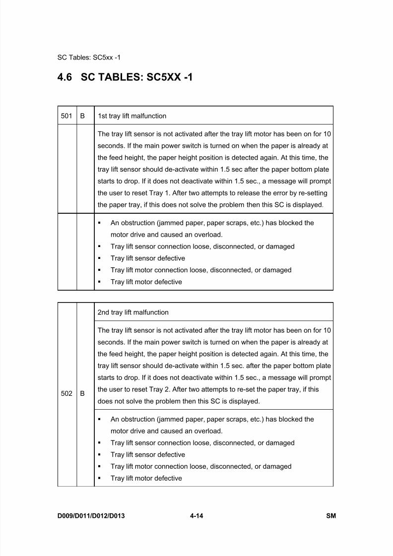
8/15/2019 Ricoh MP 4000 SM D009_D011_D012_D013 SERVICE MANUAL .pdf
http://slidepdf.com/reader/full/ricoh-mp-4000-sm-d009d011d012d013-service-manual-pdf 240/1162
SC Tables: SC5xx -1
D009/D011/D012/D013 4-14 SM
4.6 SC TABLES: SC5XX -1
501 B 1st tray lift malfunction
The tray lift sensor is not activated after the tray lift motor has been on for 10
seconds. If the main power switch is turned on when the paper is already at
the feed height, the paper height position is detected again. At this time, the
tray lift sensor should de-activate within 1.5 sec after the paper bottom plate
starts to drop. If it does not deactivate within 1.5 sec., a message will prompt
the user to reset Tray 1. After two attempts to release the error by re-settingthe paper tray, if this does not solve the problem then this SC is displayed.
An obstruction (jammed paper, paper scraps, etc.) has blocked the
motor drive and caused an overload.
Tray lift sensor connection loose, disconnected, or damaged
Tray lift sensor defective
Tray lift motor connection loose, disconnected, or damaged
Tray lift motor defective
2nd tray lift malfunction
The tray lift sensor is not activated after the tray lift motor has been on for 10
seconds. If the main power switch is turned on when the paper is already at
the feed height, the paper height position is detected again. At this time, the
tray lift sensor should de-activate within 1.5 sec. after the paper bottom plate
starts to drop. If it does not deactivate within 1.5 sec., a message will prompt
the user to reset Tray 2. After two attempts to re-set the paper tray, if thisdoes not solve the problem then this SC is displayed.
502 B
An obstruction (jammed paper, paper scraps, etc.) has blocked the
motor drive and caused an overload.
Tray lift sensor connection loose, disconnected, or damaged
Tray lift sensor defective
Tray lift motor connection loose, disconnected, or damaged
Tray lift motor defective
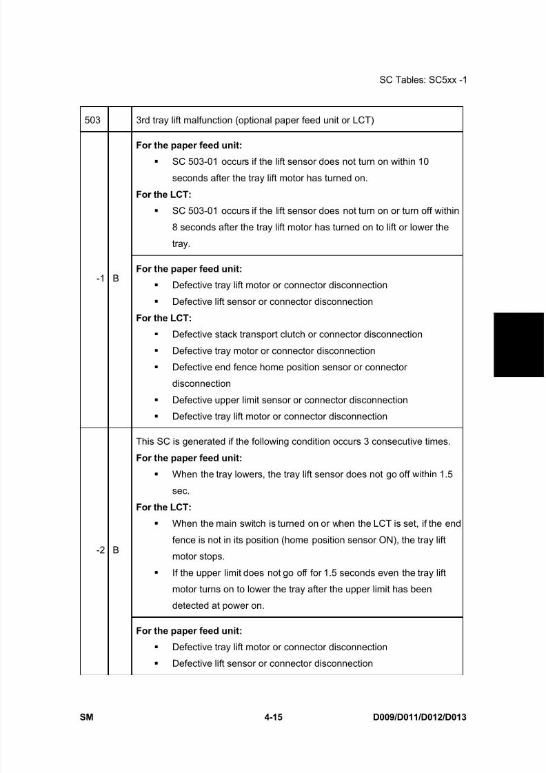
8/15/2019 Ricoh MP 4000 SM D009_D011_D012_D013 SERVICE MANUAL .pdf
http://slidepdf.com/reader/full/ricoh-mp-4000-sm-d009d011d012d013-service-manual-pdf 241/1162
SC Tables: SC5xx -1
SM 4-15 D009/D011/D012/D013
T r o u
b l e -
s h o o
t i n g
503 3rd tray lift malfunction (optional paper feed unit or LCT)
For the paper feed unit:
SC 503-01 occurs if the lift sensor does not turn on within 10
seconds after the tray lift motor has turned on.
For the LCT:
SC 503-01 occurs if the lift sensor does not turn on or turn off within
8 seconds after the tray lift motor has turned on to lift or lower the
tray.
-1 B For the paper feed unit: Defective tray lift motor or connector disconnection
Defective lift sensor or connector disconnection
For the LCT:
Defective stack transport clutch or connector disconnection
Defective tray motor or connector disconnection
Defective end fence home position sensor or connector
disconnection
Defective upper limit sensor or connector disconnection
Defective tray lift motor or connector disconnection
This SC is generated if the following condition occurs 3 consecutive times.
For the paper feed unit:
When the tray lowers, the tray lift sensor does not go off within 1.5
sec.
For the LCT:
When the main switch is turned on or when the LCT is set, if the end
fence is not in its position (home position sensor ON), the tray liftmotor stops.
If the upper limit does not go off for 1.5 seconds even the tray lift
motor turns on to lower the tray after the upper limit has been
detected at power on.
-2 B
For the paper feed unit:
Defective tray lift motor or connector disconnection
Defective lift sensor or connector disconnection

8/15/2019 Ricoh MP 4000 SM D009_D011_D012_D013 SERVICE MANUAL .pdf
http://slidepdf.com/reader/full/ricoh-mp-4000-sm-d009d011d012d013-service-manual-pdf 242/1162
SC Tables: SC5xx -1
D009/D011/D012/D013 4-16 SM
For the LCT:
Defective stack transport clutch or connector disconnection
Defective tray motor or connector disconnection Defective end fence home position sensor or connector
disconnection
504 4th tray lift malfunction (optional paper feed unit)
For the paper feed unit:
When the tray lift motor turns on, the upper limit is not detected within 10
seconds. If this condition occurs three consecutive times, the SC isgenerated.-1 B
For the paper feed unit:
Defective tray lift motor or connector disconnection
Defective lift sensor or connector disconnection
For the paper feed unit:
When the tray lift motor is turned on, the upper limit is not detected within 10
seconds.If this condition occurs three consecutive times, the SC is generated.
-2 B
Defective tray lift motor or connector disconnection
Defective lift sensor or connector disconnection
505 5th tray lift malfunction (optional LCT)
This SC is generated if the following condition occurs:
When the tray lift sensor of the LCT 1200-sheet does not go on after thetray lift motor has turned on to lift the paper tray.
When the tray lift sensor of the LCT 1200-sheet does not go off after the
tray lift motor has turned on to lower the paper tray.
When the tray lift sensor of the LCT 1200-sheet does not go on after the
pick-up roller solenoid has turned on at power on.
-1 B
Tray lift motor defective or disconnected
Tray lift sensor defective or disconnected
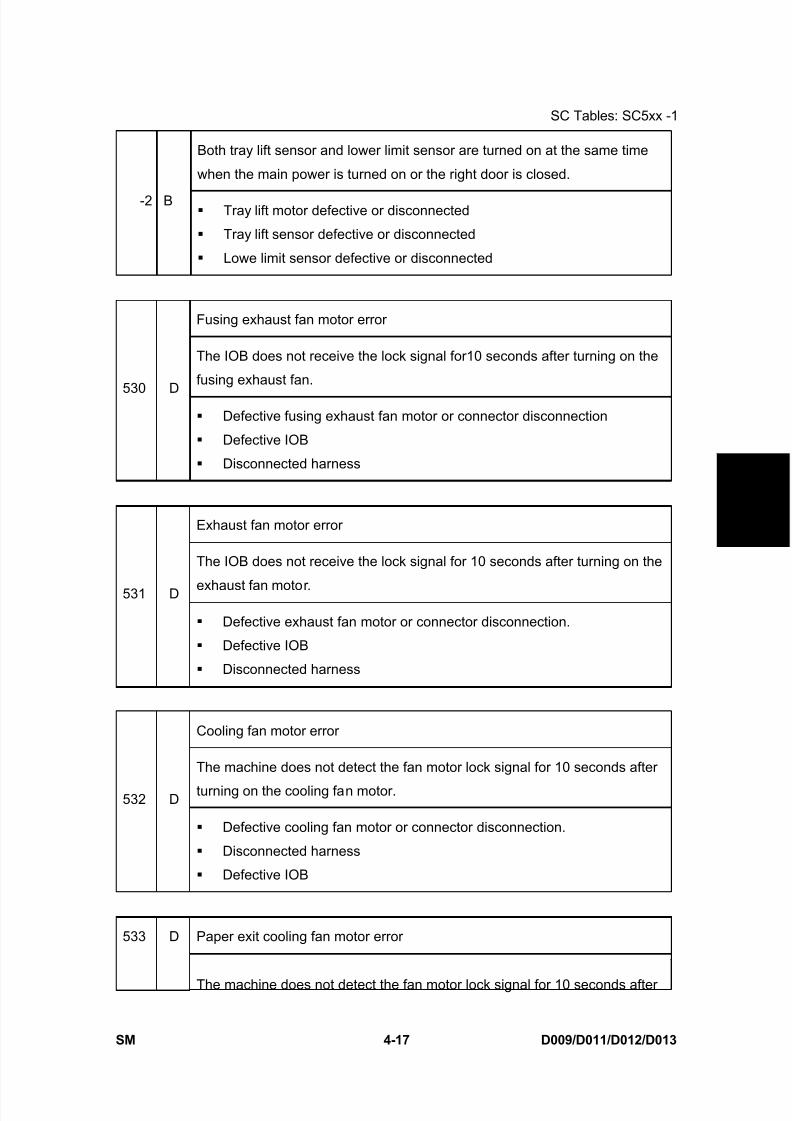
8/15/2019 Ricoh MP 4000 SM D009_D011_D012_D013 SERVICE MANUAL .pdf
http://slidepdf.com/reader/full/ricoh-mp-4000-sm-d009d011d012d013-service-manual-pdf 243/1162
SC Tables: SC5xx -1
SM 4-17 D009/D011/D012/D013
T r o u
b l e -
s h o o
t i n g
Both tray lift sensor and lower limit sensor are turned on at the same time
when the main power is turned on or the right door is closed.
-2 B Tray lift motor defective or disconnected
Tray lift sensor defective or disconnected
Lowe limit sensor defective or disconnected
Fusing exhaust fan motor error
The IOB does not receive the lock signal for10 seconds after turning on the
fusing exhaust fan.530 D
Defective fusing exhaust fan motor or connector disconnection
Defective IOB
Disconnected harness
Exhaust fan motor error
The IOB does not receive the lock signal for 10 seconds after turning on the
exhaust fan motor.531 D
Defective exhaust fan motor or connector disconnection.
Defective IOB
Disconnected harness
Cooling fan motor error
The machine does not detect the fan motor lock signal for 10 seconds after
turning on the cooling fan motor.532 D
Defective cooling fan motor or connector disconnection.
Disconnected harness
Defective IOB
Paper exit cooling fan motor error533 D
The machine does not detect the fan motor lock signal for 10 seconds after

8/15/2019 Ricoh MP 4000 SM D009_D011_D012_D013 SERVICE MANUAL .pdf
http://slidepdf.com/reader/full/ricoh-mp-4000-sm-d009d011d012d013-service-manual-pdf 244/1162
SC Tables: SC5xx -1
D009/D011/D012/D013 4-18 SM
turning on the paper exit cooling fan motor.
Defective paper exit cooling fan motor or connector disconnection.
Defective IOB
Disconnected harness
Fusing motor error
The IOB does not receive the lock signal for 2 seconds after turning on the
fusing motor.540 D
Motor overload Defective fusing motor or connector disconnection.
Defective IOB
Disconnected harness
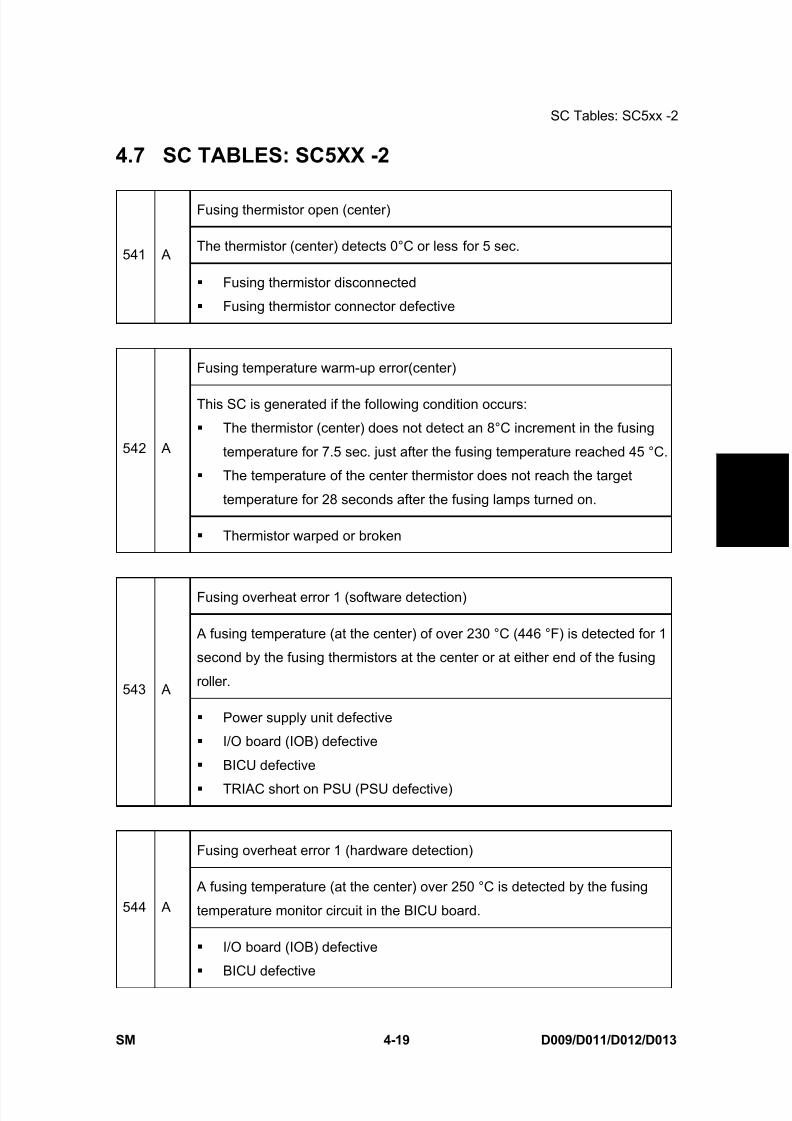
8/15/2019 Ricoh MP 4000 SM D009_D011_D012_D013 SERVICE MANUAL .pdf
http://slidepdf.com/reader/full/ricoh-mp-4000-sm-d009d011d012d013-service-manual-pdf 245/1162
SC Tables: SC5xx -2
SM 4-19 D009/D011/D012/D013
T r o u
b l e -
s h o o
t i n g
4.7 SC TABLES: SC5XX -2
Fusing thermistor open (center)
The thermistor (center) detects 0°C or less for 5 sec.541 A
Fusing thermistor disconnected
Fusing thermistor connector defective
Fusing temperature warm-up error(center)
This SC is generated if the following condition occurs:
The thermistor (center) does not detect an 8°C increment in the fusing
temperature for 7.5 sec. just after the fusing temperature reached 45 °C.
The temperature of the center thermistor does not reach the target
temperature for 28 seconds after the fusing lamps turned on.
542 A
Thermistor warped or broken
Fusing overheat error 1 (software detection)
A fusing temperature (at the center) of over 230 °C (446 °F) is detected for 1
second by the fusing thermistors at the center or at either end of the fusing
roller.543 A
Power supply unit defective
I/O board (IOB) defective
BICU defective
TRIAC short on PSU (PSU defective)
Fusing overheat error 1 (hardware detection)
A fusing temperature (at the center) over 250 °C is detected by the fusing
temperature monitor circuit in the BICU board.544 A
I/O board (IOB) defective
BICU defective

8/15/2019 Ricoh MP 4000 SM D009_D011_D012_D013 SERVICE MANUAL .pdf
http://slidepdf.com/reader/full/ricoh-mp-4000-sm-d009d011d012d013-service-manual-pdf 246/1162
SC Tables: SC5xx -2
D009/D011/D012/D013 4-20 SM
Fusing lamp consecutive full power 1
After warm-up the fusing lamp remains at full power for 15 seconds without
the hot roller rotating.545 A
Disconnected or defective thermistors (center)
Defective fusing lamp
Fusing thermistor open (end)
The thermistor (end) detects 0°C or less for 5 sec.551 A
Fusing thermistor (end) disconnected
Fusing thermistor (end) connector defective
Fusing temperature warm-up error (end)
This SC is generated if the following condition occurs:
The thermistor (end) does not detect an 8°C increment in the fusing
temperature for 7.5 sec. just after the fusing temperature reached 45 °C.
The temperature of the end thermistor does not reach the target
temperature for 31 seconds after the fusing lamps turned on.
552 A
Thermistor warped or broken
Fusing overheat error 1 (software detection)
A fusing temperature (at the end) of over 230 °C (446 °F) is detected for 1second by the fusing thermistors at the center or at either end of the fusing
roller.553 A
Power supply unit defective
I/O board (IOB) defective
BICU defective
TRIAC short on PSU (PSU defective)
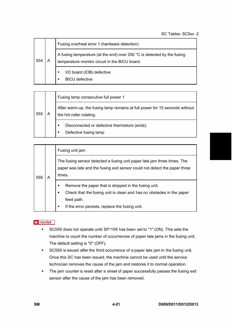
8/15/2019 Ricoh MP 4000 SM D009_D011_D012_D013 SERVICE MANUAL .pdf
http://slidepdf.com/reader/full/ricoh-mp-4000-sm-d009d011d012d013-service-manual-pdf 247/1162
SC Tables: SC5xx -2
SM 4-21 D009/D011/D012/D013
T r o u
b l e -
s h o o
t i n g
Fusing overheat error 1 (hardware detection)
A fusing temperature (at the end) over 250 °C is detected by the fusing
temperature monitor circuit in the BICU board.554 A
I/O board (IOB) defective
BICU defective
Fusing lamp consecutive full power 1
After warm-up, the fusing lamp remains at full power for 15 seconds without
the hot roller rotating.555 A
Disconnected or defective thermistors (ends)
Defective fusing lamp
Fusing unit jam
The fusing sensor detected a fusing unit paper late jam three times. The
paper was late and the fusing exit sensor could not detect the paper three
times.559 A
Remove the paper that is stopped in the fusing unit.
Check that the fusing unit is clean and has no obstacles in the paper
feed path.
If the error persists, replace the fusing unit.
SC559 does not operate until SP1159 has been set to "1" (ON). This sets themachine to count the number of occurrences of paper late jams in the fusing unit.
The default setting is "0" (OFF).
SC559 is issued after the third occurrence of a paper late jam in the fusing unit.
Once this SC has been issued, the machine cannot be used until the service
technician removes the cause of the jam and restores it to normal operation.
The jam counter is reset after a sheet of paper successfully passes the fusing exit
sensor after the cause of the jam has been removed.

8/15/2019 Ricoh MP 4000 SM D009_D011_D012_D013 SERVICE MANUAL .pdf
http://slidepdf.com/reader/full/ricoh-mp-4000-sm-d009d011d012d013-service-manual-pdf 248/1162
SC Tables: SC6xx
D009/D011/D012/D013 4-22 SM
4.8 SC TABLES: SC6XX
Mechanical counter error: BK
This SC is only for NA models.
The machine detects the mechanical counter error when SP5987-001 is set
to "1".610 D
Disconnected mechanical counter
Defective mechanical counter
Communication error between IOB and ADF
After the ARDF is detected, the break signal occurs or communication
timeout occurs.620 B
Incorrect installation of ARDF
ARDF defective
IOB board defective External noise
Communication timeout error between IOB and finisher or mailbox
A break (low) signal is received from the finisher or the mailbox.621 D
Disconnected cable
Defective IOB
Defective main board in the peripherals
Paper feed unit communication error622 D
While the IOB communicates with a peripheral, an SC code is displayed if
one of following conditions occurs.
The IOB receives the break signal which is generated by the peripheral
only just after the main switch is turned on.
The IOB receives the break signal which is generated by URAT.

8/15/2019 Ricoh MP 4000 SM D009_D011_D012_D013 SERVICE MANUAL .pdf
http://slidepdf.com/reader/full/ricoh-mp-4000-sm-d009d011d012d013-service-manual-pdf 249/1162
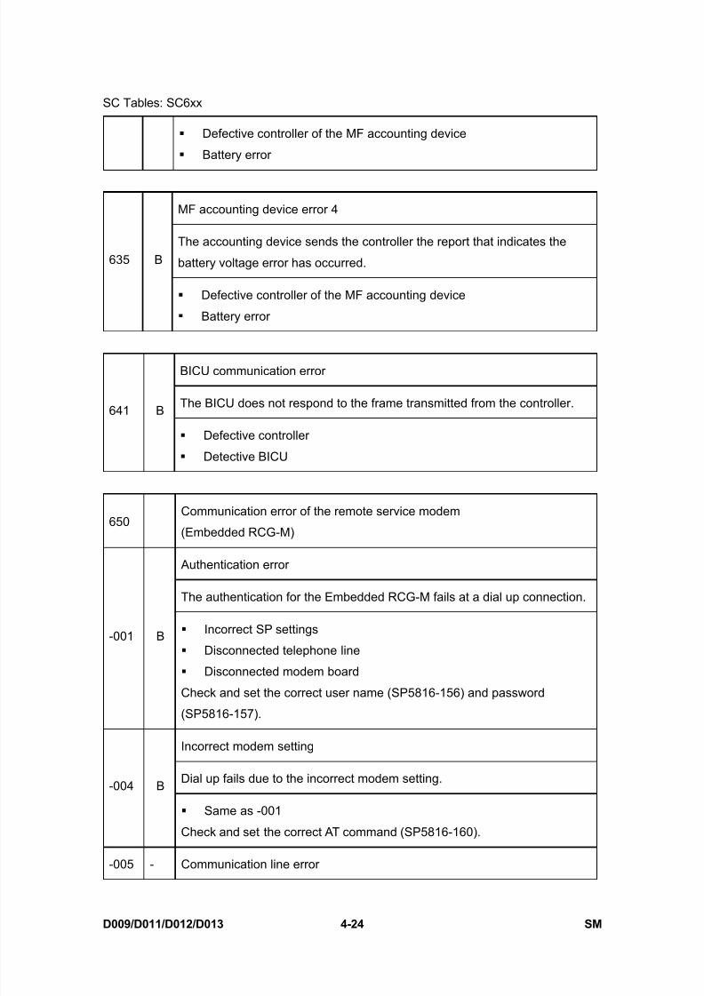
8/15/2019 Ricoh MP 4000 SM D009_D011_D012_D013 SERVICE MANUAL .pdf
http://slidepdf.com/reader/full/ricoh-mp-4000-sm-d009d011d012d013-service-manual-pdf 250/1162
SC Tables: SC6xx
D009/D011/D012/D013 4-24 SM
Defective controller of the MF accounting device
Battery error
MF accounting device error 4
The accounting device sends the controller the report that indicates the
battery voltage error has occurred.635 B
Defective controller of the MF accounting device
Battery error
BICU communication error
The BICU does not respond to the frame transmitted from the controller.641 B
Defective controller
Detective BICU
650Communication error of the remote service modem
(Embedded RCG-M)
Authentication error
The authentication for the Embedded RCG-M fails at a dial up connection.
-001 B Incorrect SP settings
Disconnected telephone line
Disconnected modem board
Check and set the correct user name (SP5816-156) and password(SP5816-157).
Incorrect modem setting
Dial up fails due to the incorrect modem setting.-004 B
Same as -001
Check and set the correct AT command (SP5816-160).
-005 - Communication line error

8/15/2019 Ricoh MP 4000 SM D009_D011_D012_D013 SERVICE MANUAL .pdf
http://slidepdf.com/reader/full/ricoh-mp-4000-sm-d009d011d012d013-service-manual-pdf 251/1162
SC Tables: SC6xx
SM 4-25 D009/D011/D012/D013
T r o u
b l e -
s h o o
t i n g
The supplied voltage is not sufficient due to a defective communication line
or defective connection.
Same as -001
Consult with the user's local telephone company.
Incorrect network setting
Both the NIC and Embedded RCG-M are activated at the same time.-011 -
Same as -001
Disable the NIC with SP5985-1.
Modem board error
The modem board does not work properly even though the setting of the
modem board is installed with a dial up connection.-012 -
Same as -001
1. Install the modem board.
2. Check and reset the modem board setting with SP5816.
3. Replace the modem board.
Incorrect dial up connection
-001: Program parameter error
-002: Program execution error
An unexpected error occurs when the modem (Embedded RCG-M) tries to
call the center with a dial up connection.
651 C
Caused by a software bug
Engine startup error
The BICU fails to respond with the prescribed time when the machine is
turned on.670 D
Connections between BICU and controller board are loose,
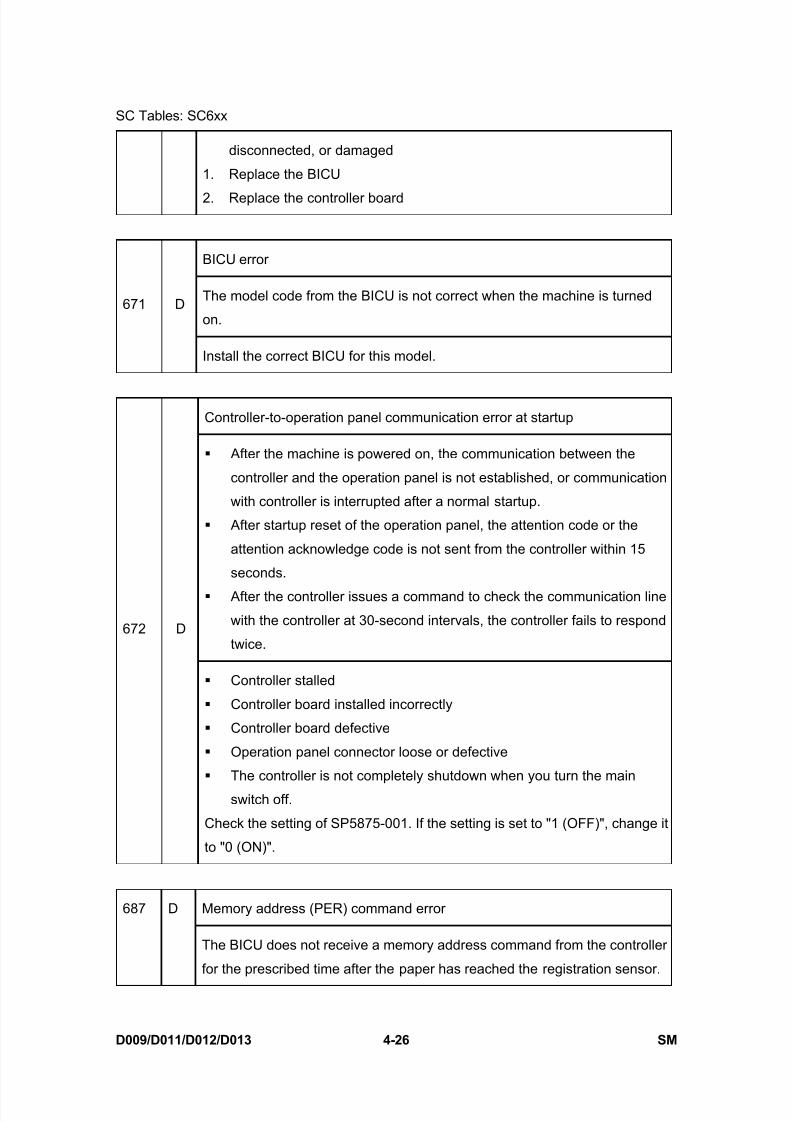
8/15/2019 Ricoh MP 4000 SM D009_D011_D012_D013 SERVICE MANUAL .pdf
http://slidepdf.com/reader/full/ricoh-mp-4000-sm-d009d011d012d013-service-manual-pdf 252/1162
SC Tables: SC6xx
D009/D011/D012/D013 4-26 SM
disconnected, or damaged
1. Replace the BICU
2. Replace the controller board
BICU error
The model code from the BICU is not correct when the machine is turned
on.671 D
Install the correct BICU for this model.
Controller-to-operation panel communication error at startup
After the machine is powered on, the communication between the
controller and the operation panel is not established, or communication
with controller is interrupted after a normal startup.
After startup reset of the operation panel, the attention code or the
attention acknowledge code is not sent from the controller within 15
seconds.
After the controller issues a command to check the communication line
with the controller at 30-second intervals, the controller fails to respond
twice.672 D
Controller stalled
Controller board installed incorrectly
Controller board defective
Operation panel connector loose or defective
The controller is not completely shutdown when you turn the main
switch off.
Check the setting of SP5875-001. If the setting is set to "1 (OFF)", change it
to "0 (ON)".
Memory address (PER) command error687 D
The BICU does not receive a memory address command from the controller
for the prescribed time after the paper has reached the registration sensor.
8/15/2019 Ricoh MP 4000 SM D009_D011_D012_D013 SERVICE MANUAL .pdf
http://slidepdf.com/reader/full/ricoh-mp-4000-sm-d009d011d012d013-service-manual-pdf 253/1162
SC Tables: SC6xx
SM 4-27 D009/D011/D012/D013
T r o u
b l e -
s h o o
t i n g
Harness Disconnection at BICU
Controller board loose or broken
Defective BICU Defective Controller Board
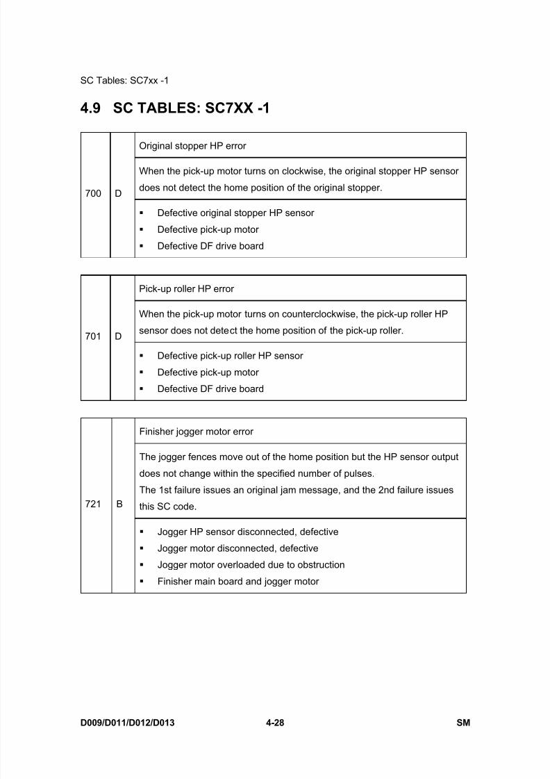
8/15/2019 Ricoh MP 4000 SM D009_D011_D012_D013 SERVICE MANUAL .pdf
http://slidepdf.com/reader/full/ricoh-mp-4000-sm-d009d011d012d013-service-manual-pdf 254/1162
SC Tables: SC7xx -1
D009/D011/D012/D013 4-28 SM
4.9 SC TABLES: SC7XX -1
Original stopper HP error
When the pick-up motor turns on clockwise, the original stopper HP sensor
does not detect the home position of the original stopper.700 D
Defective original stopper HP sensor
Defective pick-up motor
Defective DF drive board
Pick-up roller HP error
When the pick-up motor turns on counterclockwise, the pick-up roller HP
sensor does not detect the home position of the pick-up roller.701 D
Defective pick-up roller HP sensor
Defective pick-up motor
Defective DF drive board
Finisher jogger motor error
The jogger fences move out of the home position but the HP sensor output
does not change within the specified number of pulses.
The 1st failure issues an original jam message, and the 2nd failure issues
this SC code.721 B
Jogger HP sensor disconnected, defective
Jogger motor disconnected, defective
Jogger motor overloaded due to obstruction
Finisher main board and jogger motor
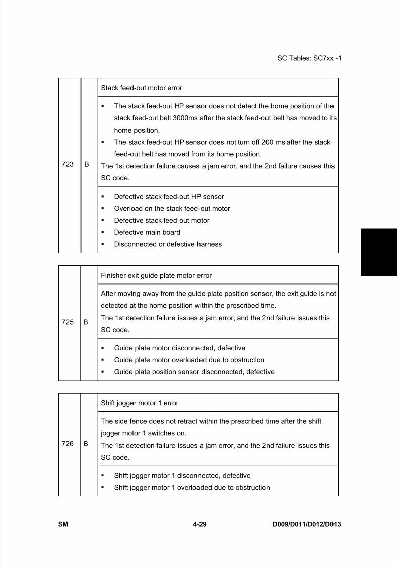
8/15/2019 Ricoh MP 4000 SM D009_D011_D012_D013 SERVICE MANUAL .pdf
http://slidepdf.com/reader/full/ricoh-mp-4000-sm-d009d011d012d013-service-manual-pdf 255/1162

8/15/2019 Ricoh MP 4000 SM D009_D011_D012_D013 SERVICE MANUAL .pdf
http://slidepdf.com/reader/full/ricoh-mp-4000-sm-d009d011d012d013-service-manual-pdf 256/1162
SC Tables: SC7xx -1
D009/D011/D012/D013 4-30 SM
Shift jogger 1 HP sensor disconnected, defective
Shift jogger motor 2 error
The side fence does not retract within the prescribed time after the shift
jogger motor 2 switches on.
The 1st detection failure issues a jam error, and the 2nd failure issues this
SC code.727 B
Shift jogger motor 2 disconnected, defective
Shift jogger motor 2 overloaded due to obstruction
Shift jogger 2 HP sensor disconnected, defective
Shift jogger retraction motor error
The side fences do not retract within the prescribed time after the retraction
motor switches on.
The 1st detection failure issues a jam error, and the 2nd failure issues this
SC code.728 B
Shift jogger retraction motor broken
Shift jogger retraction motor connection loose
Shift jogger retraction motor overloaded
Defective shift jogger retraction HP sensor
730 B Finisher Tray 1 shift motor error
The shift roller HP sensor of the upper tray does not activate within theprescribed time after the shift tray starts to move toward or away from the
home position.
The 1st detection failure issues a jam error, and the 2nd failure issues this
SC code.
Shift tray HP sensor of the upper tray disconnected, defective
Shift tray motor of the upper tray disconnected, defective
Shift tray motor of the upper tray overloaded due to obstruction
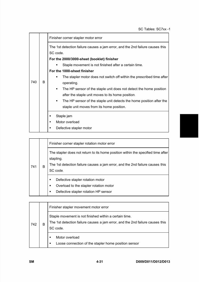
8/15/2019 Ricoh MP 4000 SM D009_D011_D012_D013 SERVICE MANUAL .pdf
http://slidepdf.com/reader/full/ricoh-mp-4000-sm-d009d011d012d013-service-manual-pdf 257/1162
SC Tables: SC7xx -1
SM 4-31 D009/D011/D012/D013
T r o u
b l e -
s h o o
t i n g
Finisher corner stapler motor error
The 1st detection failure causes a jam error, and the 2nd failure causes this
SC code.
For the 2000/3000-sheet (booklet) finisher
Staple movement is not finished after a certain time.
For the 1000-sheet finisher
The stapler motor does not switch off within the prescribed time after
operating.
The HP sensor of the staple unit does not detect the home position
after the staple unit moves to its home position.
The HP sensor of the staple unit detects the home position after the
staple unit moves from its home position.
740 B
Staple jam
Motor overload
Defective stapler motor
Finisher corner stapler rotation motor error
The stapler does not return to its home position within the specified time after
stapling.
The 1st detection failure causes a jam error, and the 2nd failure causes this
SC code.741 B
Defective stapler rotation motor
Overload to the stapler rotation motor
Defective stapler rotation HP sensor
Finisher stapler movement motor error
Staple movement is not finished within a certain time.
The 1st detection failure causes a jam error, and the 2nd failure causes this
SC code.742 B
Motor overload
Loose connection of the stapler home position sensor
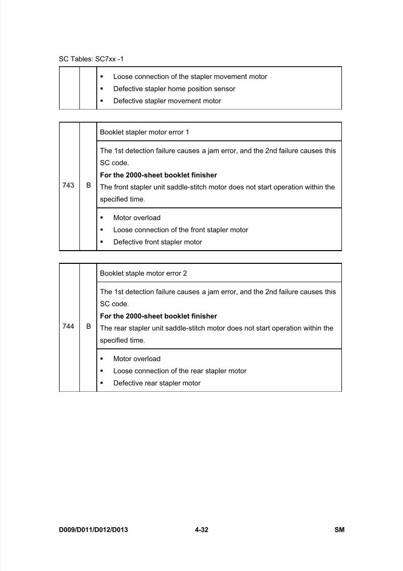
8/15/2019 Ricoh MP 4000 SM D009_D011_D012_D013 SERVICE MANUAL .pdf
http://slidepdf.com/reader/full/ricoh-mp-4000-sm-d009d011d012d013-service-manual-pdf 258/1162
SC Tables: SC7xx -1
D009/D011/D012/D013 4-32 SM
Loose connection of the stapler movement motor
Defective stapler home position sensor
Defective stapler movement motor
Booklet stapler motor error 1
The 1st detection failure causes a jam error, and the 2nd failure causes this
SC code.
For the 2000-sheet booklet finisher
The front stapler unit saddle-stitch motor does not start operation within the
specified time.
743 B
Motor overload
Loose connection of the front stapler motor
Defective front stapler motor
Booklet staple motor error 2
The 1st detection failure causes a jam error, and the 2nd failure causes this
SC code.
For the 2000-sheet booklet finisher
The rear stapler unit saddle-stitch motor does not start operation within the
specified time.
744 B
Motor overload
Loose connection of the rear stapler motor
Defective rear stapler motor
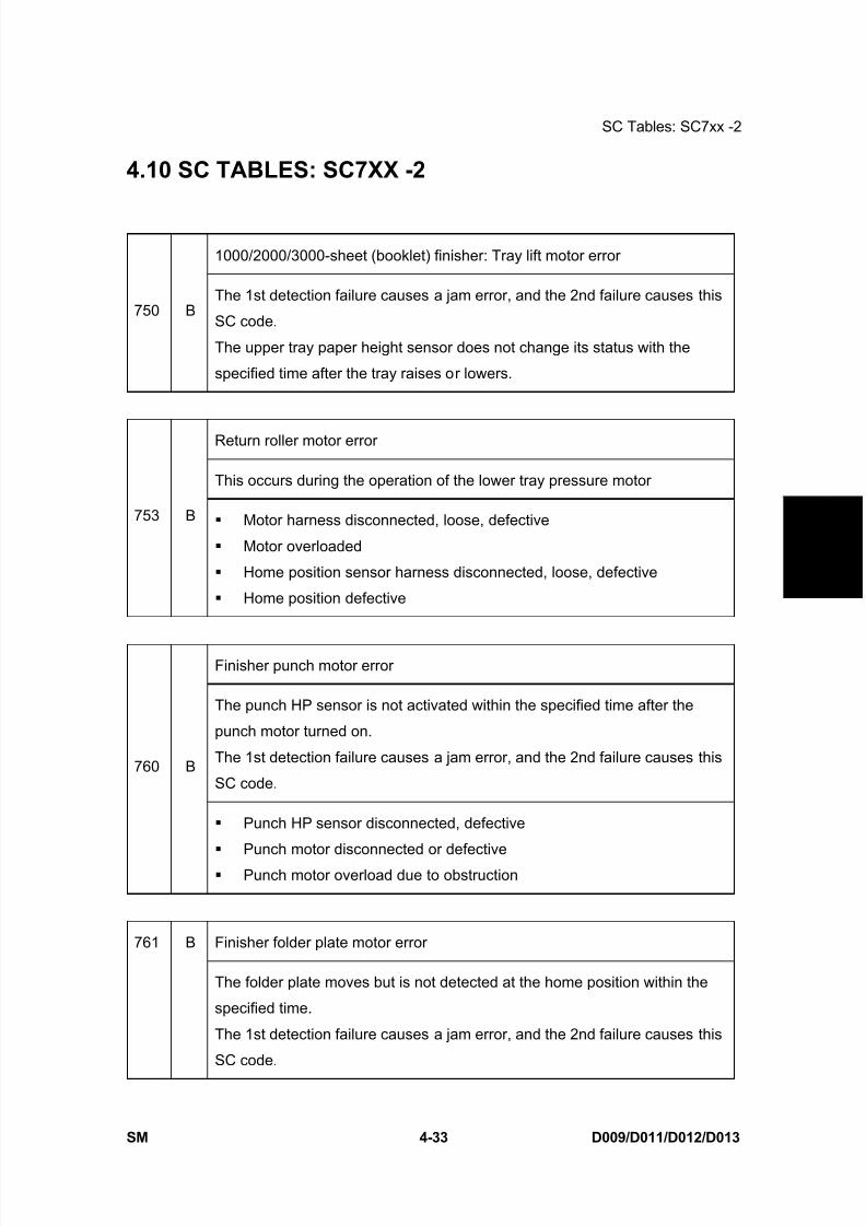
8/15/2019 Ricoh MP 4000 SM D009_D011_D012_D013 SERVICE MANUAL .pdf
http://slidepdf.com/reader/full/ricoh-mp-4000-sm-d009d011d012d013-service-manual-pdf 259/1162
SC Tables: SC7xx -2
SM 4-33 D009/D011/D012/D013
T r o u
b l e -
s h o o
t i n g
4.10 SC TABLES: SC7XX -2
1000/2000/3000-sheet (booklet) finisher: Tray lift motor error
750 BThe 1st detection failure causes a jam error, and the 2nd failure causes this
SC code.
The upper tray paper height sensor does not change its status with the
specified time after the tray raises or lowers.
Return roller motor error
This occurs during the operation of the lower tray pressure motor
753 B Motor harness disconnected, loose, defective
Motor overloaded
Home position sensor harness disconnected, loose, defective
Home position defective
Finisher punch motor error
The punch HP sensor is not activated within the specified time after the
punch motor turned on.
The 1st detection failure causes a jam error, and the 2nd failure causes this
SC code.760 B
Punch HP sensor disconnected, defective
Punch motor disconnected or defective
Punch motor overload due to obstruction
Finisher folder plate motor error761 B
The folder plate moves but is not detected at the home position within the
specified time.
The 1st detection failure causes a jam error, and the 2nd failure causes this
SC code.
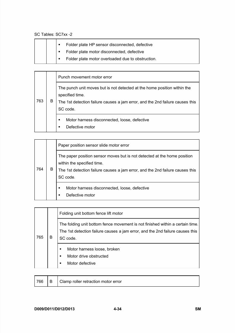
8/15/2019 Ricoh MP 4000 SM D009_D011_D012_D013 SERVICE MANUAL .pdf
http://slidepdf.com/reader/full/ricoh-mp-4000-sm-d009d011d012d013-service-manual-pdf 260/1162
SC Tables: SC7xx -2
D009/D011/D012/D013 4-34 SM
Folder plate HP sensor disconnected, defective
Folder plate motor disconnected, defective
Folder plate motor overloaded due to obstruction.
Punch movement motor error
The punch unit moves but is not detected at the home position within the
specified time.
The 1st detection failure causes a jam error, and the 2nd failure causes this
SC code.
763 B
Motor harness disconnected, loose, defective
Defective motor
Paper position sensor slide motor error
The paper position sensor moves but is not detected at the home position
within the specified time.
The 1st detection failure causes a jam error, and the 2nd failure causes this
SC code.
764 B
Motor harness disconnected, loose, defective
Defective motor
Folding unit bottom fence lift motor
The folding unit bottom fence movement is not finished within a certain time.
The 1st detection failure causes a jam error, and the 2nd failure causes thisSC code.765 B
Motor harness loose, broken
Motor drive obstructed
Motor defective
766 B Clamp roller retraction motor error

8/15/2019 Ricoh MP 4000 SM D009_D011_D012_D013 SERVICE MANUAL .pdf
http://slidepdf.com/reader/full/ricoh-mp-4000-sm-d009d011d012d013-service-manual-pdf 261/1162
SC Tables: SC7xx -2
SM 4-35 D009/D011/D012/D013
T r o u
b l e -
s h o o
t i n g
The clamp roller movement is not finished within a certain time.
The 1st detection failure causes a jam error, and the 2nd failure causes this
SC code.
Motor harness loose, broken
Motor drive obstructed
Motor defective
Stack junction gate motor error
The stack junction gate motor moves but the stack junction gate is not
detected at its position within a specific time.
The 1st detection failure causes a jam error, and the 2nd failure causes this
SC code.767 B
Motor broken
Motor connection loose
Motor overloaded
Bridge unit error
The machine recognizes the finisher, but does not recognize the bridge unit.791 D
Defective connector
Broken harness
Finisher error
The machine does not recognize the finisher, but recognizes the bridge unit.792 B
Defective connector
Defective harness
Incorrect installation
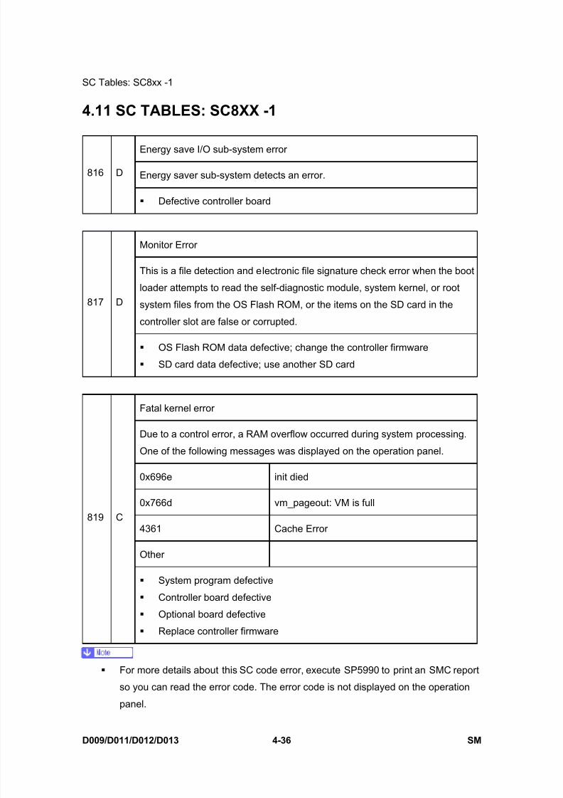
8/15/2019 Ricoh MP 4000 SM D009_D011_D012_D013 SERVICE MANUAL .pdf
http://slidepdf.com/reader/full/ricoh-mp-4000-sm-d009d011d012d013-service-manual-pdf 262/1162
SC Tables: SC8xx -1
D009/D011/D012/D013 4-36 SM
4.11 SC TABLES: SC8XX -1
Energy save I/O sub-system error
Energy saver sub-system detects an error.816 D
Defective controller board
Monitor Error
This is a file detection and electronic file signature check error when the boot
loader attempts to read the self-diagnostic module, system kernel, or root
system files from the OS Flash ROM, or the items on the SD card in the
controller slot are false or corrupted.
817 D
OS Flash ROM data defective; change the controller firmware
SD card data defective; use another SD card
Fatal kernel error
Due to a control error, a RAM overflow occurred during system processing.
One of the following messages was displayed on the operation panel.
0x696e init died
0x766d vm_pageout: VM is full
4361 Cache Error
Other
819 C
System program defective
Controller board defective
Optional board defective
Replace controller firmware
For more details about this SC code error, execute SP5990 to print an SMC report
so you can read the error code. The error code is not displayed on the operation
panel.

8/15/2019 Ricoh MP 4000 SM D009_D011_D012_D013 SERVICE MANUAL .pdf
http://slidepdf.com/reader/full/ricoh-mp-4000-sm-d009d011d012d013-service-manual-pdf 263/1162
SC Tables: SC8xx -1
SM 4-37 D009/D011/D012/D013
T r o u
b l e -
s h o o
t i n g
821 DSelf-diagnostics error: ASIC
[XXXX]: Detailed error code
ASIC error
The write-&-verify check error has occurred in the ASIC.[0B00]
Defective ASIC device
Replace the controller board.
ASIC detection error
The I/O ASIC for system control is not detected.[0B06]
Defective ASIC
Defective North Bridge and PCI I/F
Replace the controller board.
SHM register error
The initialization of bus connection or read for SHM fails.
The register of SHM is different from the specified value.[0B10]
Defective connection bus Defective SHM
Replace the controller board.
Self-diagnosis error: ASIC
The CPU checks if the ASIC timer works correctly compared with the CPU
timer. If the ASIC timer does not function in the specified range, this SC code
is displayed.[0D05]
System firmware problem Defective RAM-DIMM
Defective controller
Replace the controller board.
For more details about this SC code error, execute SP5990 to print an SMC report
so you can read the error code. The error code is not displayed on the operation
panel.
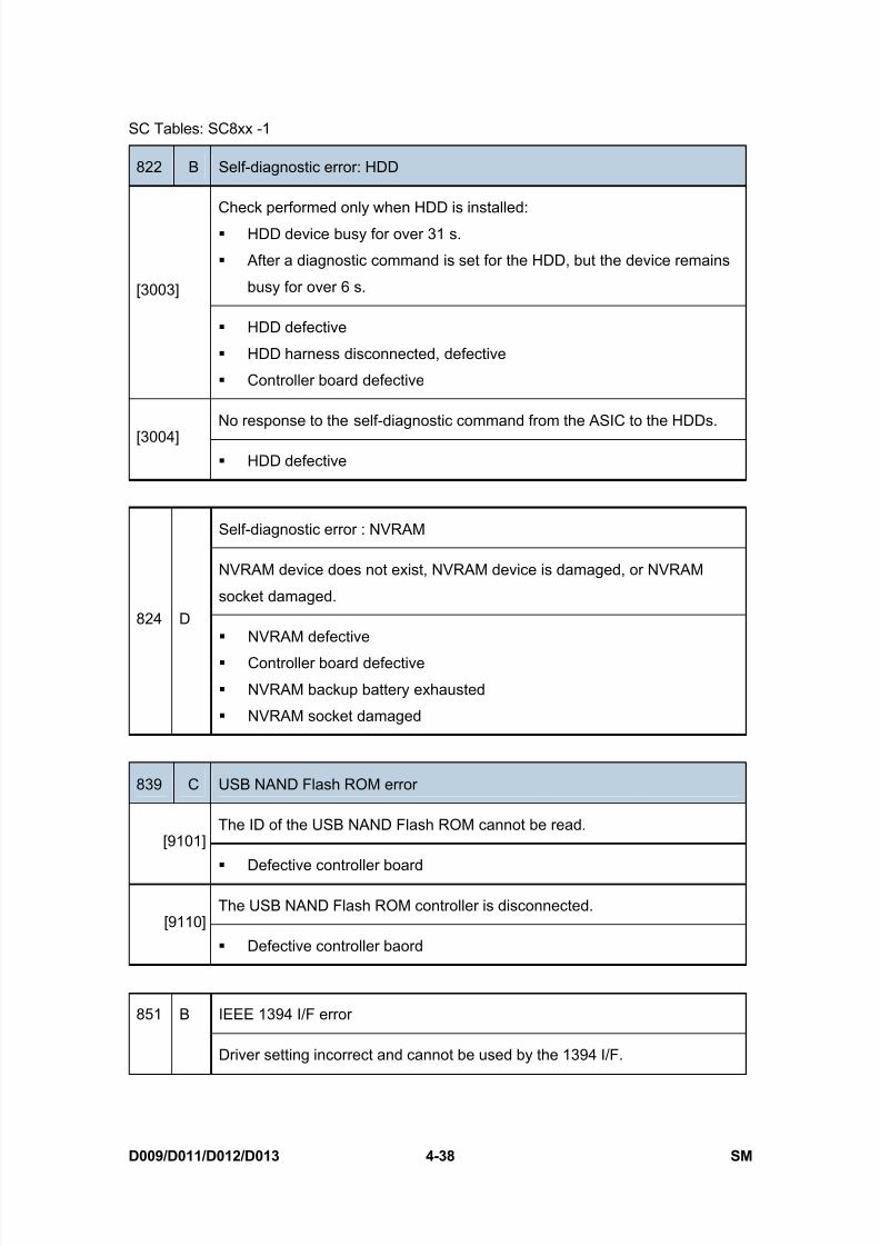
8/15/2019 Ricoh MP 4000 SM D009_D011_D012_D013 SERVICE MANUAL .pdf
http://slidepdf.com/reader/full/ricoh-mp-4000-sm-d009d011d012d013-service-manual-pdf 264/1162
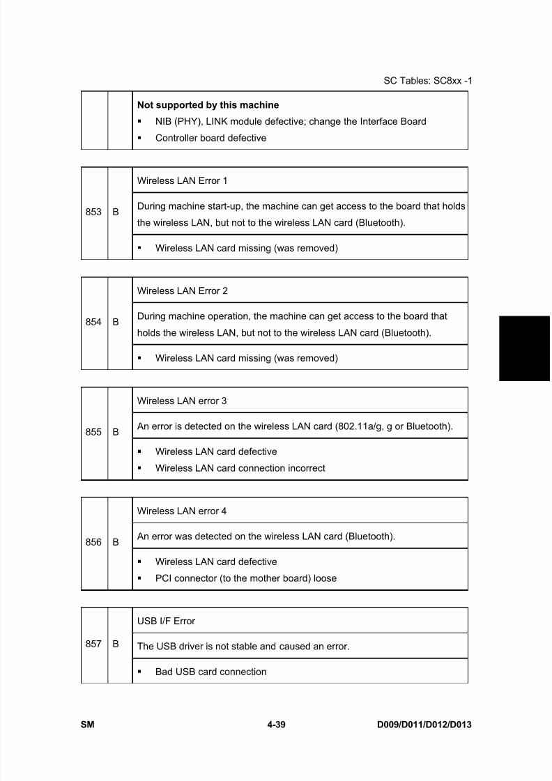
8/15/2019 Ricoh MP 4000 SM D009_D011_D012_D013 SERVICE MANUAL .pdf
http://slidepdf.com/reader/full/ricoh-mp-4000-sm-d009d011d012d013-service-manual-pdf 265/1162
SC Tables: SC8xx -1
SM 4-39 D009/D011/D012/D013
T r o u
b l e -
s h o o
t i n g
Not supported by this machine
NIB (PHY), LINK module defective; change the Interface Board
Controller board defective
Wireless LAN Error 1
During machine start-up, the machine can get access to the board that holds
the wireless LAN, but not to the wireless LAN card (Bluetooth).853 B
Wireless LAN card missing (was removed)
Wireless LAN Error 2
During machine operation, the machine can get access to the board that
holds the wireless LAN, but not to the wireless LAN card (Bluetooth).854 B
Wireless LAN card missing (was removed)
Wireless LAN error 3
An error is detected on the wireless LAN card (802.11a/g, g or Bluetooth).855 B
Wireless LAN card defective
Wireless LAN card connection incorrect
Wireless LAN error 4
An error was detected on the wireless LAN card (Bluetooth).856 B
Wireless LAN card defective
PCI connector (to the mother board) loose
USB I/F Error
The USB driver is not stable and caused an error.857 B
Bad USB card connection
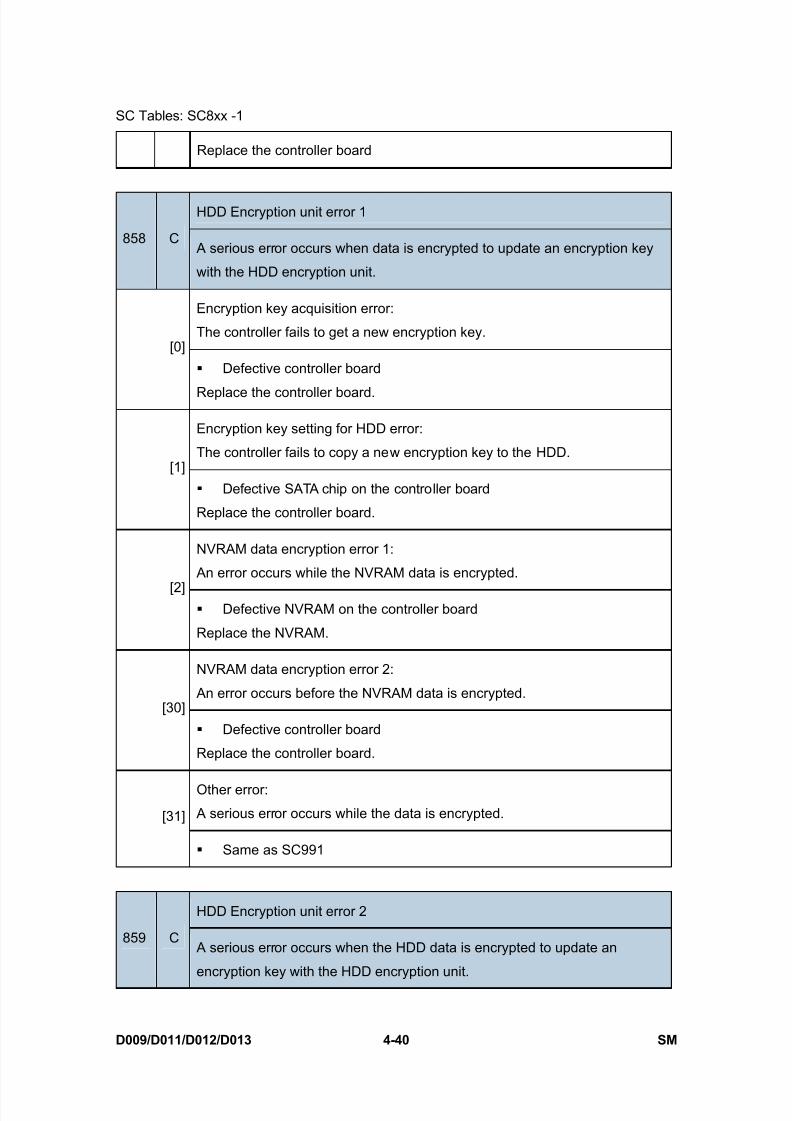
8/15/2019 Ricoh MP 4000 SM D009_D011_D012_D013 SERVICE MANUAL .pdf
http://slidepdf.com/reader/full/ricoh-mp-4000-sm-d009d011d012d013-service-manual-pdf 266/1162
SC Tables: SC8xx -1
D009/D011/D012/D013 4-40 SM
Replace the controller board
HDD Encryption unit error 1
858 C A serious error occurs when data is encrypted to update an encryption key
with the HDD encryption unit.
Encryption key acquisition error:
The controller fails to get a new encryption key.[0]
Defective controller board
Replace the controller board.
Encryption key setting for HDD error:
The controller fails to copy a new encryption key to the HDD.[1]
Defective SATA chip on the controller board
Replace the controller board.
NVRAM data encryption error 1:
An error occurs while the NVRAM data is encrypted.
[2] Defective NVRAM on the controller board
Replace the NVRAM.
NVRAM data encryption error 2:
An error occurs before the NVRAM data is encrypted.[30]
Defective controller board
Replace the controller board.
Other error:
A serious error occurs while the data is encrypted.[31]
Same as SC991
HDD Encryption unit error 2
859 C A serious error occurs when the HDD data is encrypted to update an
encryption key with the HDD encryption unit.
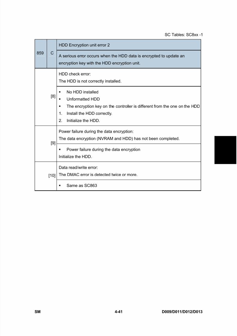
8/15/2019 Ricoh MP 4000 SM D009_D011_D012_D013 SERVICE MANUAL .pdf
http://slidepdf.com/reader/full/ricoh-mp-4000-sm-d009d011d012d013-service-manual-pdf 267/1162
SC Tables: SC8xx -1
SM 4-41 D009/D011/D012/D013
T r o u
b l e -
s h o o
t i n g
HDD Encryption unit error 2
859 C A serious error occurs when the HDD data is encrypted to update an
encryption key with the HDD encryption unit.
HDD check error:
The HDD is not correctly installed.
[8] No HDD installed
Unformatted HDD
The encryption key on the controller is different from the one on the HDD
1. Install the HDD correctly.
2. Initialize the HDD.
Power failure during the data encryption:
The data encryption (NVRAM and HDD) has not been completed.[9]
Power failure during the data encryption
Initialize the HDD.
Data read/write error:
The DMAC error is detected twice or more.[10]
Same as SC863
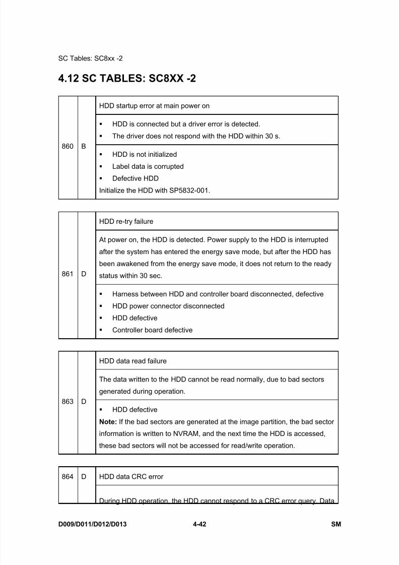
8/15/2019 Ricoh MP 4000 SM D009_D011_D012_D013 SERVICE MANUAL .pdf
http://slidepdf.com/reader/full/ricoh-mp-4000-sm-d009d011d012d013-service-manual-pdf 268/1162
SC Tables: SC8xx -2
D009/D011/D012/D013 4-42 SM
4.12 SC TABLES: SC8XX -2
HDD startup error at main power on
HDD is connected but a driver error is detected.
The driver does not respond with the HDD within 30 s.860 B
HDD is not initialized
Label data is corrupted
Defective HDD
Initialize the HDD with SP5832-001.
HDD re-try failure
At power on, the HDD is detected. Power supply to the HDD is interrupted
after the system has entered the energy save mode, but after the HDD has
been awakened from the energy save mode, it does not return to the ready
status within 30 sec.861 D
Harness between HDD and controller board disconnected, defective HDD power connector disconnected
HDD defective
Controller board defective
HDD data read failure
The data written to the HDD cannot be read normally, due to bad sectors
generated during operation.863 D
HDD defective
Note: If the bad sectors are generated at the image partition, the bad sector
information is written to NVRAM, and the next time the HDD is accessed,
these bad sectors will not be accessed for read/write operation.
HDD data CRC error864 D
During HDD operation, the HDD cannot respond to a CRC error query. Data

8/15/2019 Ricoh MP 4000 SM D009_D011_D012_D013 SERVICE MANUAL .pdf
http://slidepdf.com/reader/full/ricoh-mp-4000-sm-d009d011d012d013-service-manual-pdf 269/1162
SC Tables: SC8xx -2
SM 4-43 D009/D011/D012/D013
T r o u
b l e -
s h o o
t i n g
transfer does not execute normally while data is being written to the HDD.
HDD defective
HDD access error
HDD responded to an error during operation for a condition other than those
for SC863, 864.865 D
HDD defective.
SD card error 1: Confirmation
The machine detects an electronic license error in the application on the SD
card in the controller slot immediately after the machine is turned on. The
program on the SD card contains electronic confirmation license data. If the
program does not contain this license data, or if the result of the check shows
that the license data in the program on the SD card is incorrect, then the
checked program cannot execute and this SC code is displayed.
866 B
Program missing from the SD card
Download the correct program for the machine to the SD card
SD card error 2: SD card removed
The SD card in the slot is removed while the machine is on.867 D
Insert the SD card, then turn the machine off and on.
SD card error 3: SC card access
An error occurs while an SD card is used.
868 D SD card not inserted correctly
SD card defective
Controller board defective
Note: If you want to try to reformat the SC card, use SD Formatter Ver 1.1.

8/15/2019 Ricoh MP 4000 SM D009_D011_D012_D013 SERVICE MANUAL .pdf
http://slidepdf.com/reader/full/ricoh-mp-4000-sm-d009d011d012d013-service-manual-pdf 270/1162
SC Tables: SC8xx -2
D009/D011/D012/D013 4-44 SM
Address book data error
The address book data cannot be read from the HDD, SD card or flash ROM
on the controller where it is stored, or the data read from the media is
defective.
Software defective:
Turn the machine off/on. If this is not the solution for the problem, then
replace the controller firmware.
HDD defective.
More Details
870 B
Do SP5846-046 (Initialize All Setting & Addr Book) to reset all address
book data.
Reset the user information with SP5832-006 (HDD Formatting– User
Information).
Replace the HDDs.
HDD mail receive data error
The machine detects that the HDD is not operating correctly at power on.
The machine detects that the HDD is not operating correctly (can neither
read nor write) while processing incoming email.872 B
HDD defective
The machine is turned off while the HDD is being accessed.
Do SP5832-007 to format the mail RX data on the HDD.
HDD mail send data error
An error is detected on the HDD immediately after the machine has been
turned on, or power has been turned off while the machine has used the
HDD.873 B
1. Do SP5832-008 (Format HDD – Mail TX Data) to initialize the HDD.
2. Replace the HDD
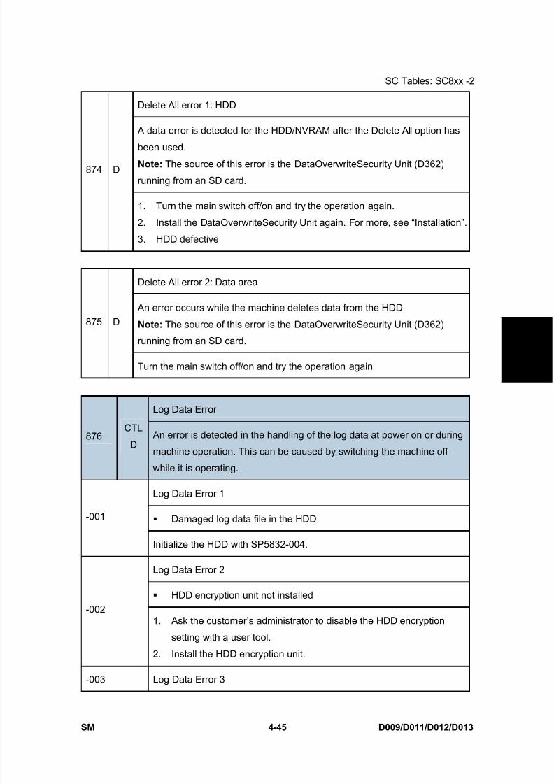
8/15/2019 Ricoh MP 4000 SM D009_D011_D012_D013 SERVICE MANUAL .pdf
http://slidepdf.com/reader/full/ricoh-mp-4000-sm-d009d011d012d013-service-manual-pdf 271/1162
SC Tables: SC8xx -2
SM 4-45 D009/D011/D012/D013
T r o u
b l e -
s h o o
t i n g
Delete All error 1: HDD
A data error is detected for the HDD/NVRAM after the Delete All option has
been used.
Note: The source of this error is the DataOverwriteSecurity Unit (D362)
running from an SD card.874 D
1. Turn the main switch off/on and try the operation again.
2. Install the DataOverwriteSecurity Unit again. For more, see “Installation”.
3. HDD defective
Delete All error 2: Data area
An error occurs while the machine deletes data from the HDD.
Note: The source of this error is the DataOverwriteSecurity Unit (D362)
running from an SD card.
875 D
Turn the main switch off/on and try the operation again
Log Data Error
876CTL
D An error is detected in the handling of the log data at power on or during
machine operation. This can be caused by switching the machine off
while it is operating.
Log Data Error 1
Damaged log data file in the HDD-001
Initialize the HDD with SP5832-004.
Log Data Error 2
HDD encryption unit not installed-002
1. Ask the customer’s administrator to disable the HDD encryption
setting with a user tool.
2. Install the HDD encryption unit.
-003 Log Data Error 3
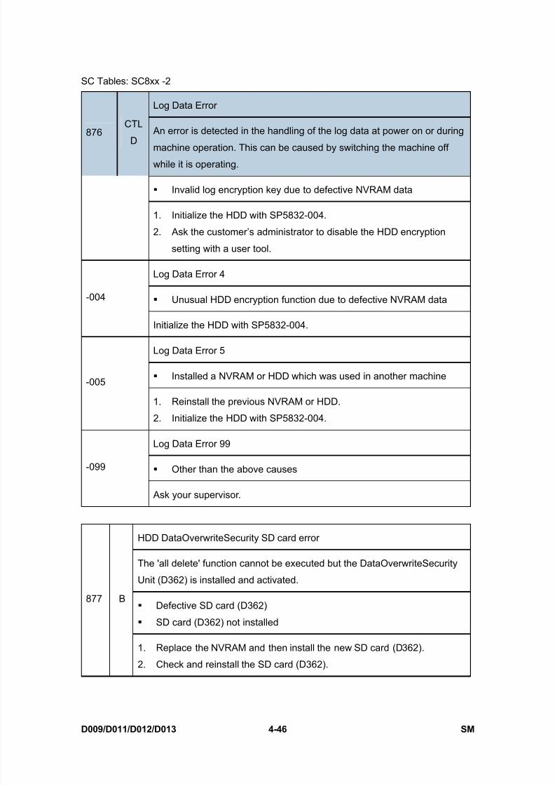
8/15/2019 Ricoh MP 4000 SM D009_D011_D012_D013 SERVICE MANUAL .pdf
http://slidepdf.com/reader/full/ricoh-mp-4000-sm-d009d011d012d013-service-manual-pdf 272/1162
SC Tables: SC8xx -2
D009/D011/D012/D013 4-46 SM
Log Data Error
876
CTL
D An error is detected in the handling of the log data at power on or during
machine operation. This can be caused by switching the machine off
while it is operating.
Invalid log encryption key due to defective NVRAM data
1. Initialize the HDD with SP5832-004.
2. Ask the customer’s administrator to disable the HDD encryption
setting with a user tool.
Log Data Error 4
Unusual HDD encryption function due to defective NVRAM data-004
Initialize the HDD with SP5832-004.
Log Data Error 5
Installed a NVRAM or HDD which was used in another machine-005
1. Reinstall the previous NVRAM or HDD.
2. Initialize the HDD with SP5832-004.
Log Data Error 99
Other than the above causes-099
Ask your supervisor.
HDD DataOverwriteSecurity SD card error
The 'all delete' function cannot be executed but the DataOverwriteSecurity
Unit (D362) is installed and activated.
Defective SD card (D362)
SD card (D362) not installed
877 B
1. Replace the NVRAM and then install the new SD card (D362).
2. Check and reinstall the SD card (D362).

8/15/2019 Ricoh MP 4000 SM D009_D011_D012_D013 SERVICE MANUAL .pdf
http://slidepdf.com/reader/full/ricoh-mp-4000-sm-d009d011d012d013-service-manual-pdf 273/1162
SC Tables: SC8xx -2
SM 4-47 D009/D011/D012/D013
T r o u
b l e -
s h o o
t i n g
TPM system authentication error
The system firmware is not authenticated by TPM (security chip).878 D
Incorrect updating for the system firmware
Defective flash ROM on the controller board
Replace the controller board.
File Format Converter (MLB) error
A request to get access to the MLB is not answered within the specified time.880 B
MLB defective, replace the MLB
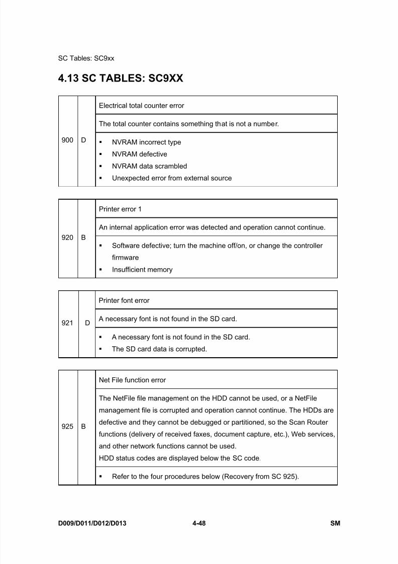
8/15/2019 Ricoh MP 4000 SM D009_D011_D012_D013 SERVICE MANUAL .pdf
http://slidepdf.com/reader/full/ricoh-mp-4000-sm-d009d011d012d013-service-manual-pdf 274/1162
SC Tables: SC9xx
D009/D011/D012/D013 4-48 SM
4.13 SC TABLES: SC9XX
Electrical total counter error
The total counter contains something that is not a number.
900 D NVRAM incorrect type
NVRAM defective
NVRAM data scrambled
Unexpected error from external source
Printer error 1
An internal application error was detected and operation cannot continue.920 B
Software defective; turn the machine off/on, or change the controller
firmware
Insufficient memory
Printer font error
A necessary font is not found in the SD card.921 D
A necessary font is not found in the SD card.
The SD card data is corrupted.
Net File function error
The NetFile file management on the HDD cannot be used, or a NetFile
management file is corrupted and operation cannot continue. The HDDs are
defective and they cannot be debugged or partitioned, so the Scan Router
functions (delivery of received faxes, document capture, etc.), Web services,
and other network functions cannot be used.
HDD status codes are displayed below the SC code.
925 B
Refer to the four procedures below (Recovery from SC 925).
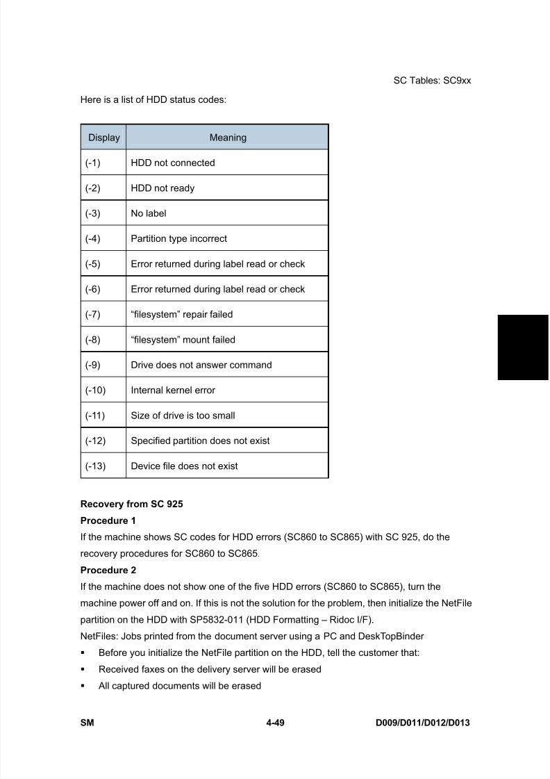
8/15/2019 Ricoh MP 4000 SM D009_D011_D012_D013 SERVICE MANUAL .pdf
http://slidepdf.com/reader/full/ricoh-mp-4000-sm-d009d011d012d013-service-manual-pdf 275/1162
SC Tables: SC9xx
SM 4-49 D009/D011/D012/D013
T r o u
b l e -
s h o o
t i n g
Here is a list of HDD status codes:
Display Meaning
(-1) HDD not connected
(-2) HDD not ready
(-3) No label
(-4) Partition type incorrect
(-5) Error returned during label read or check
(-6) Error returned during label read or check
(-7) “filesystem” repair failed
(-8) “filesystem” mount failed
(-9) Drive does not answer command
(-10) Internal kernel error
(-11) Size of drive is too small
(-12) Specified partition does not exist
(-13) Device file does not exist
Recovery from SC 925
Procedure 1
If the machine shows SC codes for HDD errors (SC860 to SC865) with SC 925, do the
recovery procedures for SC860 to SC865.
Procedure 2
If the machine does not show one of the five HDD errors (SC860 to SC865), turn the
machine power off and on. If this is not the solution for the problem, then initialize the NetFile
partition on the HDD with SP5832-011 (HDD Formatting – Ridoc I/F).
NetFiles: Jobs printed from the document server using a PC and DeskTopBinder
Before you initialize the NetFile partition on the HDD, tell the customer that:
Received faxes on the delivery server will be erased
All captured documents will be erased
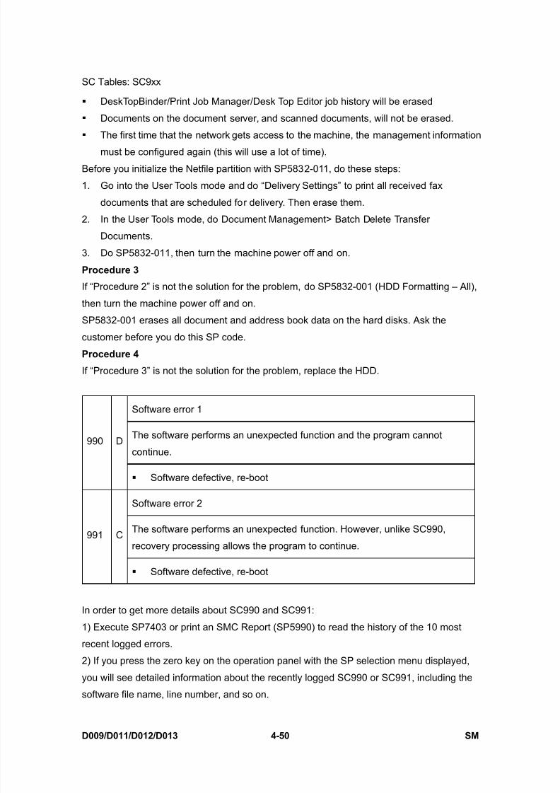
8/15/2019 Ricoh MP 4000 SM D009_D011_D012_D013 SERVICE MANUAL .pdf
http://slidepdf.com/reader/full/ricoh-mp-4000-sm-d009d011d012d013-service-manual-pdf 276/1162
SC Tables: SC9xx
D009/D011/D012/D013 4-50 SM
DeskTopBinder/Print Job Manager/Desk Top Editor job history will be erased
Documents on the document server, and scanned documents, will not be erased.
The first time that the network gets access to the machine, the management informationmust be configured again (this will use a lot of time).
Before you initialize the Netfile partition with SP5832-011, do these steps:
1. Go into the User Tools mode and do “Delivery Settings” to print all received fax
documents that are scheduled for delivery. Then erase them.
2. In the User Tools mode, do Document Management> Batch Delete Transfer
Documents.
3. Do SP5832-011, then turn the machine power off and on.
Procedure 3
If “Procedure 2” is not the solution for the problem, do SP5832-001 (HDD Formatting – All),
then turn the machine power off and on.
SP5832-001 erases all document and address book data on the hard disks. Ask the
customer before you do this SP code.
Procedure 4
If “Procedure 3” is not the solution for the problem, replace the HDD.
Software error 1
The software performs an unexpected function and the program cannot
continue.990 D
Software defective, re-boot
Software error 2
The software performs an unexpected function. However, unlike SC990,
recovery processing allows the program to continue.991 C
Software defective, re-boot
In order to get more details about SC990 and SC991:
1) Execute SP7403 or print an SMC Report (SP5990) to read the history of the 10 most
recent logged errors.
2) If you press the zero key on the operation panel with the SP selection menu displayed,
you will see detailed information about the recently logged SC990 or SC991, including the
software file name, line number, and so on.
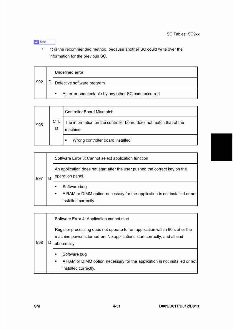
8/15/2019 Ricoh MP 4000 SM D009_D011_D012_D013 SERVICE MANUAL .pdf
http://slidepdf.com/reader/full/ricoh-mp-4000-sm-d009d011d012d013-service-manual-pdf 277/1162
SC Tables: SC9xx
SM 4-51 D009/D011/D012/D013
T r o u
b l e -
s h o o
t i n g
1) is the recommended method, because another SC could write over the
information for the previous SC.
Undefined error
Defective software program992 D
An error undetectable by any other SC code occurred
Controller Board Mismatch
The information on the controller board does not match that of the
machine995
CTL
D
Wrong controller board installed
Software Error 3: Cannot select application function
An application does not start after the user pushed the correct key on the
operation panel.997 B
Software bug
A RAM or DIMM option necessary for the application is not installed or not
installed correctly.
Software Error 4: Application cannot start
Register processing does not operate for an application within 60 s after themachine power is turned on. No applications start correctly, and all end
abnormally.998 D
Software bug
A RAM or DIMM option necessary for the application is not installed or not
installed correctly.
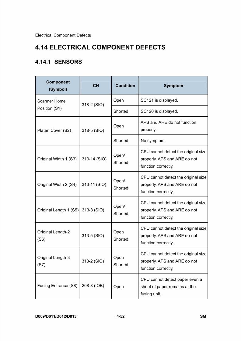
8/15/2019 Ricoh MP 4000 SM D009_D011_D012_D013 SERVICE MANUAL .pdf
http://slidepdf.com/reader/full/ricoh-mp-4000-sm-d009d011d012d013-service-manual-pdf 278/1162
Electrical Component Defects
D009/D011/D012/D013 4-52 SM
4.14 ELECTRICAL COMPONENT DEFECTS
4.14.1 SENSORS
Component
(Symbol) CN Condition Symptom
Open SC121 is displayed.Scanner Home
Position (S1)318-2 (SIO)
Shorted SC120 is displayed.
Open APS and ARE do not function
properly.Platen Cover (S2) 318-5 (SIO)
Shorted No symptom.
Original Width 1 (S3) 313-14 (SIO)Open/
Shorted
CPU cannot detect the original size
properly. APS and ARE do not
function correctly.
Original Width 2 (S4) 313-11 (SIO)Open/
Shorted
CPU cannot detect the original sizeproperly. APS and ARE do not
function correctly.
Original Length 1 (S5) 313-8 (SIO)Open/
Shorted
CPU cannot detect the original size
properly. APS and ARE do not
function correctly.
Original Length-2
(S6)313-5 (SIO)
Open
Shorted
CPU cannot detect the original size
properly. APS and ARE do not
function correctly.
Original Length-3
(S7)313-2 (SIO)
Open
Shorted
CPU cannot detect the original size
properly. APS and ARE do not
function correctly.
Fusing Entrance (S8) 208-8 (IOB) Open
CPU cannot detect paper even a
sheet of paper remains at the
fusing unit.

8/15/2019 Ricoh MP 4000 SM D009_D011_D012_D013 SERVICE MANUAL .pdf
http://slidepdf.com/reader/full/ricoh-mp-4000-sm-d009d011d012d013-service-manual-pdf 279/1162
Electrical Component Defects
SM 4-53 D009/D011/D012/D013
T r o u
b l e -
s h o o
t i n g
Component
(Symbol) CN Condition Symptom
Shorted
CPU detects paper even a sheet of
paper does not remain at the fusing
unit.
Open SC350 is displayed after copying.ID (Image Density)
(S9)208-11 (IOB)
Shorted SC351 is displayed after copying.
OpenCPU detects the web end even the
web is not used up.Web End (S10) 208-16 (IOB)
ShortedCPU cannot detect the web end
even the web is used up.
Open
The add toner indicator blinks even
if there is toner in the development
unit.TD (Toner Density)
(S11)213-14 (IOB)
Shorted SC390 is displayed.
Open
CPU cannot detect the toner
overflow even the waste toner in
the transfer belt unit is full.Toner Overflow (S13) 217-B15 (IOB)
Shorted
CPU detects the toner overflow
even the waste toner in the transfer
belt unit is not full.
Open Jam Z (Jam 26/27)Duplex Entrance(S14)
217-A8 (IOB)Shorted Jam Z (Jam 1)
Open "Open Cover" is displayedDuplex Cover (S15) 217-A11 (IOB)
Shorted "Open cover" cannot be detected.
Open Jam Z (Jam 25)Duplex Exit (S16) 217-A14 (IOB)
Shorted Jam Z (Jam 1)
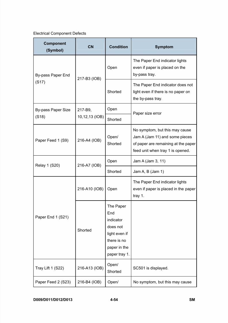
8/15/2019 Ricoh MP 4000 SM D009_D011_D012_D013 SERVICE MANUAL .pdf
http://slidepdf.com/reader/full/ricoh-mp-4000-sm-d009d011d012d013-service-manual-pdf 280/1162
Electrical Component Defects
D009/D011/D012/D013 4-54 SM
Component
(Symbol) CN Condition Symptom
Open
The Paper End indicator lights
even if paper is placed on the
by-pass tray.By-pass Paper End
(S17)217-B3 (IOB)
Shorted
The Paper End indicator does not
light even if there is no paper on
the by-pass tray.
OpenBy-pass Paper Size
(S18)
217-B9,
10,12,13 (IOB)Shorted
Paper size error
Paper Feed 1 (S9) 216-A4 (IOB)Open/
Shorted
No symptom, but this may cause
Jam A (Jam 11) and some pieces
of paper are remaining at the paper
feed unit when tray 1 is opened.
Open Jam A (Jam 3, 11)Relay 1 (S20) 216-A7 (IOB)
Shorted Jam A, B (Jam 1)
216-A10 (IOB) Open
The Paper End indicator lights
even if paper is placed in the paper
tray 1.
Paper End 1 (S21)
Shorted
The Paper
End
indicator
does notlight even if
there is no
paper in the
paper tray 1.
Tray Lift 1 (S22) 216-A13 (IOB)Open/
ShortedSC501 is displayed.
Paper Feed 2 (S23) 216-B4 (IOB) Open/ No symptom, but this may cause
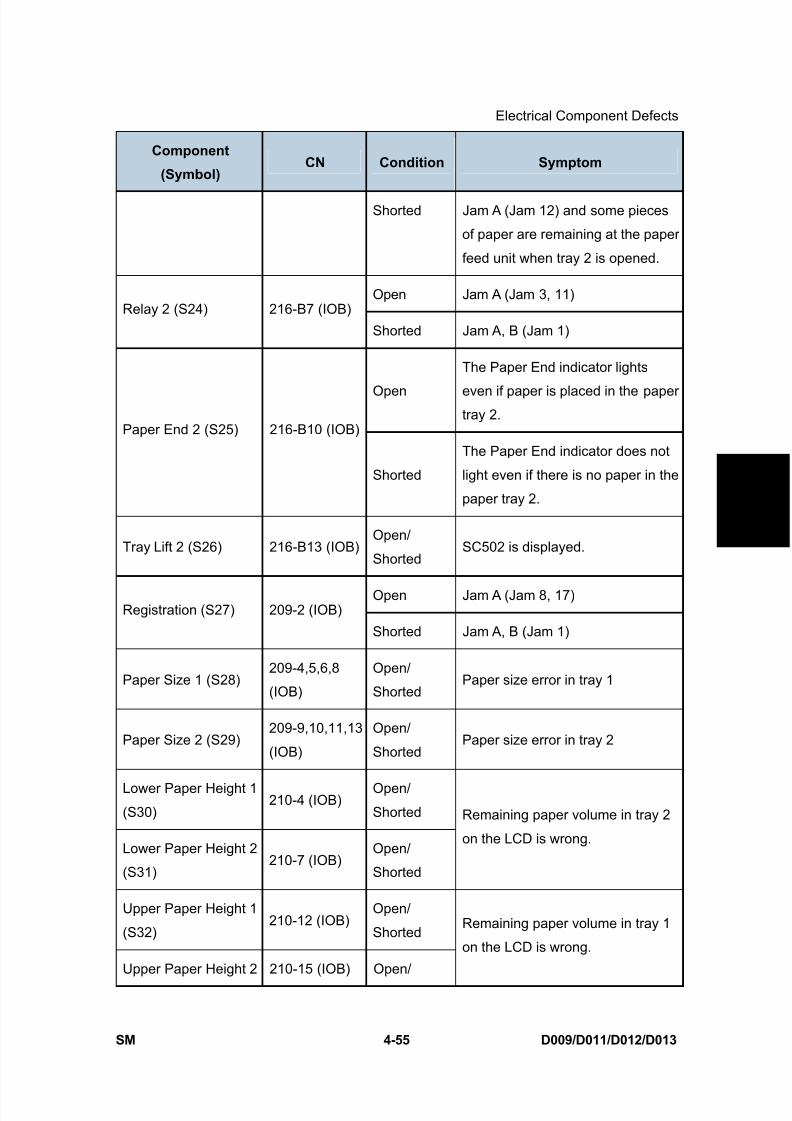
8/15/2019 Ricoh MP 4000 SM D009_D011_D012_D013 SERVICE MANUAL .pdf
http://slidepdf.com/reader/full/ricoh-mp-4000-sm-d009d011d012d013-service-manual-pdf 281/1162
Electrical Component Defects
SM 4-55 D009/D011/D012/D013
T r o u
b l e -
s h o o
t i n g
Component
(Symbol) CN Condition Symptom
Shorted Jam A (Jam 12) and some pieces
of paper are remaining at the paper
feed unit when tray 2 is opened.
Open Jam A (Jam 3, 11)Relay 2 (S24) 216-B7 (IOB)
Shorted Jam A, B (Jam 1)
Open
The Paper End indicator lights
even if paper is placed in the papertray 2.
Paper End 2 (S25) 216-B10 (IOB)
Shorted
The Paper End indicator does not
light even if there is no paper in the
paper tray 2.
Tray Lift 2 (S26) 216-B13 (IOB)Open/
ShortedSC502 is displayed.
Open Jam A (Jam 8, 17)Registration (S27) 209-2 (IOB)
Shorted Jam A, B (Jam 1)
Paper Size 1 (S28)209-4,5,6,8
(IOB)
Open/
ShortedPaper size error in tray 1
Paper Size 2 (S29)209-9,10,11,13
(IOB)
Open/
ShortedPaper size error in tray 2
Lower Paper Height 1(S30)
210-4 (IOB)Open/Shorted
Lower Paper Height 2
(S31)210-7 (IOB)
Open/
Shorted
Remaining paper volume in tray 2
on the LCD is wrong.
Upper Paper Height 1
(S32)210-12 (IOB)
Open/
Shorted
Upper Paper Height 2 210-15 (IOB) Open/
Remaining paper volume in tray 1
on the LCD is wrong.

8/15/2019 Ricoh MP 4000 SM D009_D011_D012_D013 SERVICE MANUAL .pdf
http://slidepdf.com/reader/full/ricoh-mp-4000-sm-d009d011d012d013-service-manual-pdf 282/1162
Electrical Component Defects
D009/D011/D012/D013 4-56 SM
Component
(Symbol) CN Condition Symptom
(S33) Shorted
Junction Jam (S34) 221-A10 (IOB)Open/
ShortedJam C (Jam 24/64)
Open Jam C (Jam 20)Paper Exit (S35) 221-B2 (IOB)
Shorted Jam C (Jam 1)
Open Jam C (Jam 19)Fusing Exit 221-B5
Shorted Jam C (Jam 1)
Open
Paper overflow message is not
displayed when a paper overflow
condition exists.Paper Overflow 221-B8
Shorted
Paper overflow message is
displayed when a paper overflow
condition does not exist.
4.14.2 SWITCHES
Component
(Symbol) CN Condition Symptom
Open The machine does not turn on.Main Power
(SW1)
903-1,2
(PSU)Shorted The machine does not turn off.
Open“Doors/Covers Open” is displayed even if
the front or right door is closed.Interlock 1
(SW2)
913-1
(PSU)
ShortedThe LCD goes blank when the front or right
door is opened.
Interlock 2 913-2
Open “Open Cover” is displayed even if the front
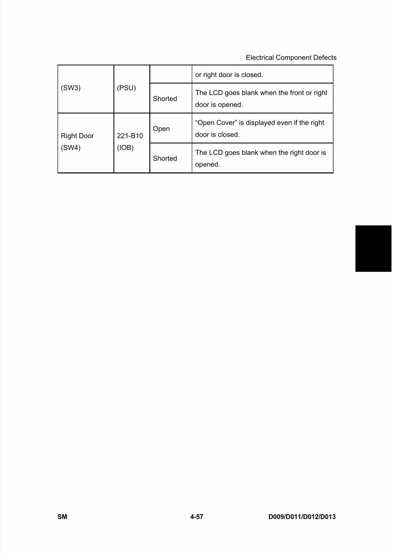
8/15/2019 Ricoh MP 4000 SM D009_D011_D012_D013 SERVICE MANUAL .pdf
http://slidepdf.com/reader/full/ricoh-mp-4000-sm-d009d011d012d013-service-manual-pdf 283/1162
Electrical Component Defects
SM 4-57 D009/D011/D012/D013
T r o u
b l e -
s h o o
t i n g
or right door is closed.
(SW3) (PSU)
ShortedThe LCD goes blank when the front or right
door is opened.
Open“Open Cover” is displayed even if the right
door is closed.Right Door
(SW4)
221-B10
(IOB)
ShortedThe LCD goes blank when the right door is
opened.

8/15/2019 Ricoh MP 4000 SM D009_D011_D012_D013 SERVICE MANUAL .pdf
http://slidepdf.com/reader/full/ricoh-mp-4000-sm-d009d011d012d013-service-manual-pdf 284/1162
Blown Fuse Conditions
D009/D011/D012/D013 4-58 SM
4.15 BLOWN FUSE CONDITIONS
RatingFuse
115V 210 to 230V
Symptom at power on
Power Supply Board
FU21 6.3A / 125V 6.3A / 250V SC 533 (Power to IOB)
FU22 6.3A / 125V 6.3A / 250V SC 144-02 (Power to SIO)
FU23 10A / 125V 10A / 250V "Open Cover" is displayed.(Power to Interlock Switch)
FU24 10A / 125V 10A / 250V"Open Cover" is displayed.
(Power to Interlock Switch)
FU25 6.3A / 125V 6.3A / 250V Alert LED turns on and operation panel does
not turn on. (Power to MB)
FU26 6.3A / 125V 6.3A / 250V
Stack paper in the optional paper feed unit or
LCT is not detected. SC 503 is issued after
opening and closing the tray 3 or 4. (Power
to optional PFU or LCT)
FU27 6.3A / 250V 6.3 A/ 250VThe machine does not detect a finisher.
(Power to optional Finisher)
FU101 15A / 125V 8A / 250V No response
FU102 12A / 125V 4A / 250V No response
8/15/2019 Ricoh MP 4000 SM D009_D011_D012_D013 SERVICE MANUAL .pdf
http://slidepdf.com/reader/full/ricoh-mp-4000-sm-d009d011d012d013-service-manual-pdf 285/1162
SERVICE TABLES

8/15/2019 Ricoh MP 4000 SM D009_D011_D012_D013 SERVICE MANUAL .pdf
http://slidepdf.com/reader/full/ricoh-mp-4000-sm-d009d011d012d013-service-manual-pdf 286/1162
8/15/2019 Ricoh MP 4000 SM D009_D011_D012_D013 SERVICE MANUAL .pdf
http://slidepdf.com/reader/full/ricoh-mp-4000-sm-d009d011d012d013-service-manual-pdf 287/1162
Service Program Mode
SM 5-1 D009/D011/D012/D013
S e r v i c e
T a b l e s
5. SERVICE TABLES
5.1 SERVICE PROGRAM MODE
Never turn off the main power switch when the power LED is lit or flashing. To avoid
damaging the hard disk or memory, press the operation switch to switch the power
off, wait for the power LED to go off, and then switch the main power switch off.
The main power LED lights or flashes while the platen cover or ARDF is open, whilethe main machine is communicating with a facsimile or the network server, or while
the machine is accessing the hard disk or memory for reading or writing data.
5.1.1 SERVICE PROGRAM MODE OPERATION
The service program (SP) mode is used to check electrical data, change modes, and adjust
values.
Never turn off the main power switch when the power LED is lit or flashing. To avoid
damaging the hard disk or memory, press the operation switch to switch the power
off, wait for the power LED to go off, and then switch the main power switch off.
Service Mode Lock/Unlock
At locations where the machine contains sensitive data, the customer engineer cannot
operate the machine until the Administrator turns the service mode lock off. This function
makes sure that work on the machine is always done with the permission of the
Administrator.
1. If you cannot go into the SP mode, ask the Administrator to log in with the User Tool and
then set “Service Mode Lock” to OFF. After he or she logs in:
[User Tools] > System Settings > Administrator Tools > Service Mode Lock > OFF
This unlocks the machine and lets you get access to all the SP codes.
The service technician can do servicing on the machine and turn the machine off
and on. It is not necessary to ask the Administrator to log in again each time the
machine is turned on.
2. If you must use the printer bit switches, go into the SP mode and set SP5169 to “1”.
3. After machine servicing is completed:
Change SP5169 from “1” to “0”.
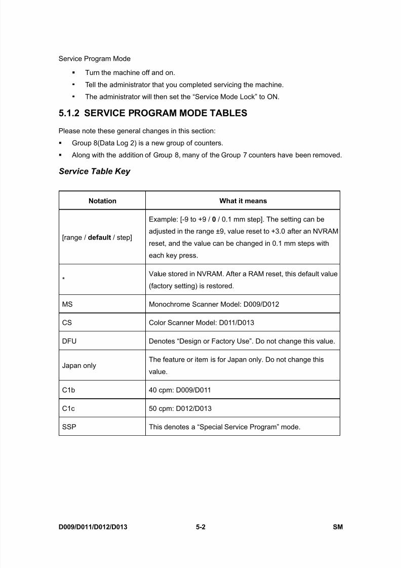
8/15/2019 Ricoh MP 4000 SM D009_D011_D012_D013 SERVICE MANUAL .pdf
http://slidepdf.com/reader/full/ricoh-mp-4000-sm-d009d011d012d013-service-manual-pdf 288/1162
Service Program Mode
D009/D011/D012/D013 5-2 SM
Turn the machine off and on.
Tell the administrator that you completed servicing the machine.
The administrator will then set the “Service Mode Lock” to ON.
5.1.2 SERVICE PROGRAM MODE TABLES
Please note these general changes in this section:
Group 8(Data Log 2) is a new group of counters.
Along with the addition of Group 8, many of the Group 7 counters have been removed.
Service Table Key
Notation What it means
[range / default / step]
Example: [-9 to +9 / 0 / 0.1 mm step]. The setting can be
adjusted in the range ±9, value reset to +3.0 after an NVRAM
reset, and the value can be changed in 0.1 mm steps with
each key press.
*Value stored in NVRAM. After a RAM reset, this default value
(factory setting) is restored.
MS Monochrome Scanner Model: D009/D012
CS Color Scanner Model: D011/D013
DFU Denotes “Design or Factory Use”. Do not change this value.
Japan onlyThe feature or item is for Japan only. Do not change this
value.
C1b 40 cpm: D009/D011
C1c 50 cpm: D012/D013
SSP This denotes a “Special Service Program” mode.
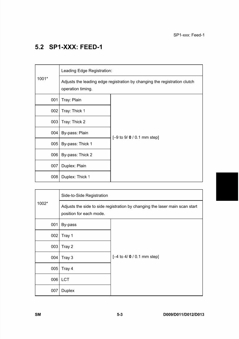
8/15/2019 Ricoh MP 4000 SM D009_D011_D012_D013 SERVICE MANUAL .pdf
http://slidepdf.com/reader/full/ricoh-mp-4000-sm-d009d011d012d013-service-manual-pdf 289/1162
SP1-xxx: Feed-1
SM 5-3 D009/D011/D012/D013
S e r v i c e
T a b l e s
5.2 SP1-XXX: FEED-1
Leading Edge Registration:
1001* Adjusts the leading edge registration by changing the registration clutch
operation timing.
001 Tray: Plain
002 Tray: Thick 1
003 Tray: Thick 2
004 By-pass: Plain
005 By-pass: Thick 1
006 By-pass: Thick 2
007 Duplex: Plain
008 Duplex: Thick 1
[–9 to 9/ 0 / 0.1 mm step]
Side-to-Side Registration
1002* Adjusts the side to side registration by changing the laser main scan start
position for each mode.
001 By-pass
002 Tray 1
003 Tray 2
004 Tray 3
005 Tray 4
006 LCT
007 Duplex
[–4 to 4/ 0 / 0.1 mm step]

8/15/2019 Ricoh MP 4000 SM D009_D011_D012_D013 SERVICE MANUAL .pdf
http://slidepdf.com/reader/full/ricoh-mp-4000-sm-d009d011d012d013-service-manual-pdf 290/1162
SP1-xxx: Feed-1
D009/D011/D012/D013 5-4 SM
Registration Buckle Adjustment
1003* Adjusts the paper feed motor timing. Paper feed motor timing determines
the amount of paper buckle at Registration. (A “+” setting causes more
buckling.)
001 Tray 1: Plain
002 Tray 1: Thick 1
003 Tray 1: Thick 2
004 Tray 2, 3, 4: Plain
005 Tray 2, 3, 4: Thick1
006 Tray 2, 3, 4: Thick2
[-9 to 5 / -4 / 1 mm step]
007 By-pass: Plain
008 By-pass: Thick 1
009 By-pass: Thick 2
[-9 to 5 / -2 /1 mm step]
010 Duplex: Plain [-9 to 5 / -4 / 1 mm step]
011 Duplex: Thick 1 [-9 to 5 / -3 / 1 mm step]
012 LCT: Plain
013 LCT: Thick1
014 LCT: Thick2
[-9 to 5 / -4 / 1 mm step]
By-pass Paper Size Detection1007*
Controls paper size detection for the by-pass feed table.
1007 1 Detection Timing [-15 to 15 / 0 / 5 mm step]
1007 2 LG Detection[0 to 1 / 0 / 1]
0: LT SEF, 1: LG

8/15/2019 Ricoh MP 4000 SM D009_D011_D012_D013 SERVICE MANUAL .pdf
http://slidepdf.com/reader/full/ricoh-mp-4000-sm-d009d011d012d013-service-manual-pdf 291/1162
SP1-xxx: Feed-1
SM 5-5 D009/D011/D012/D013
S e r v i c e
T a b l e s
Fusing Idling
1103 *
Switches fusing idling on/off. When on, printing will not start until enough
time has elapsed so the hot roller can reach optimum temperature. This
ensures even heat on the hot roller.
Switch on if fusing on the 1st and 2nd copies is incomplete (this may occur if
the room is cold.). You must switch SP1103-1 ON before you set the fusing
interval with SP1103-2.
001 Enable Fusing Idling 0 = Off , 1 = On
002 Interval [0 to 60 / 30 / 1 sec.]
003 Idling Time at Every Job
Sets the machine to fusing idling only for 30
sec. for every job (when the original is set on
the ARDF, when the ARDF cover is opened,
etc.) and the fusing unit has reached the
reload temperature (optimum temperature for
operation).
[0 to 30 / 0 / 1 sec.]
0: No idling done before a job.
Fusing Temperature Control
On-Off/Phase
1104 *
Selects the fusing temperature control method. After changing this setting,
be sure to turn the machine off and on again with the main power switch to
enable the new setting.
[0 to 1 / 0 / 1]0: Normal (ON/OFF control). Allows full application from ac power supply to
bring the hot roller up to the target fusing temperature then shuts off.
Determines the on-time from the present temperature (detected by the
thermistor on the hot roller) and the temperature of 1 cycle before.
1: Phase (hysterisis) control. Sets the upper and lower limits for the
temperature; at the lower temperature the fusing lamp is on and at the
higher temperature the fusing lamp is off.
Change this setting to “0” only if the user has excessive electrical noise or

8/15/2019 Ricoh MP 4000 SM D009_D011_D012_D013 SERVICE MANUAL .pdf
http://slidepdf.com/reader/full/ricoh-mp-4000-sm-d009d011d012d013-service-manual-pdf 292/1162
SP1-xxx: Feed-1
D009/D011/D012/D013 5-6 SM
interference on the power supply line. Such interference can cause voltage
to drop when power is applied using the ON/OFF control method.
Interference can be caused by the general poor quality of the power supplylines, or if the machine is sharing a power supply with other electrical
devices such as fluorescent lights. Before changing this setting, make sure
that the machine is connected to a power supply not shared by other
electrical equipment.
Selecting Phase control (“1”) could cause the fusing temperature
control board to emit low pitched noise
Fusing Temperature Adjustment
1105 *
Allows adjustment of the hot roller temperature at the center and ends of the
roller for the quality or thickness of the paper. The hot roller in this machine
has two fusing lamps: one heats the center of the roller, the other heats both
ends. Each fusing lamp can be adjusted separately.
The “re-load temperature” is the “print ready temperature". When the fusing
temperature exceeds this setting, the machine can operate. Do not set up a
re-load temperature (Re-load Temp. = Fusing. Temp – SP Value.) that is
higher than the SP1-105-2 setting.
Roller CenterC1b: [100 to 170 / 140 / 1 deg]
C1c: [100 to 170 / 150 / 1 deg]001
Adjusts the fusing temperature at the center of the hot roller.
Roller EndsC1b: [100 to 170 / 145 / 1 deg]
C1c: [100 to 170 / 155 / 1 deg]002
Adjusts the fusing temperature at the ends of the hot roller.
Re-load Temp. Minus: Roller Center [0 to 60 / 0 / 1 deg]
003Sets the reload temperature for the center of the hot roller. This setting
depends on the target temperature.
Reload temp. = Target Temp – This SP Setting
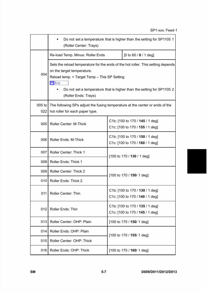
8/15/2019 Ricoh MP 4000 SM D009_D011_D012_D013 SERVICE MANUAL .pdf
http://slidepdf.com/reader/full/ricoh-mp-4000-sm-d009d011d012d013-service-manual-pdf 293/1162
SP1-xxx: Feed-1
SM 5-7 D009/D011/D012/D013
S e r v i c e
T a b l e s
Do not set a temperature that is higher than the setting for SP1105 1
(Roller Center: Trays)
Re-load Temp. Minus: Roller Ends [0 to 60 / 0 / 1 deg]
004
Sets the reload temperature for the ends of the hot roller. This setting depends
on the target temperature.
Reload temp. = Target Temp – This SP Setting
Do not set a temperature that is higher than the setting for SP1105 2
(Roller Ends: Trays)
005 to
022
The following SPs adjust the fusing temperature at the center or ends of the
hot roller for each paper type.
005 Roller Center: M-ThickC1b: [100 to 170 / 145 / 1 deg]
C1c: [100 to 170 / 155 / 1 deg]
006 Roller Ends: M-ThickC1b: [100 to 170 / 150 / 1 deg]
C1c: [100 to 170 / 160 / 1 deg]
007 Roller Center: Thick 1
008 Roller Ends: Thick 1
[100 to 170 / 130 / 1 deg]
009 Roller Center: Thick 2
010 Roller Ends: Thick 2
[100 to 170 / 150 / 1 deg]
011 Roller Center: ThinC1b: [100 to 170 / 130 / 1 deg]
C1c: [100 to 170 / 140 / 1 deg]
012 Roller Ends: ThinC1b: [100 to 170 / 135 / 1 deg]
C1c: [100 to 170 / 145 / 1 deg]
013 Roller Center: OHP: Plain [100 to 170 / 150 / 1 deg]
014 Roller Ends: OHP: Plain
015 Roller Center: OHP: Thick
[100 to 170 / 155 / 1 deg]
016 Roller Ends: OHP: Thick [100 to 170 / 160 / 1 deg]

8/15/2019 Ricoh MP 4000 SM D009_D011_D012_D013 SERVICE MANUAL .pdf
http://slidepdf.com/reader/full/ricoh-mp-4000-sm-d009d011d012d013-service-manual-pdf 294/1162
SP1-xxx: Feed-1
D009/D011/D012/D013 5-8 SM
017 Roller Center: Special 1C1b: [100 to 170 / 140 / 1 deg]
C1c: [100 to 170 / 150 / 1 deg]
018 Roller Ends: Special 1C1b: [100 to 170 / 145 / 1 deg]
C1c: [100 to 170 / 155 / 1 deg]
019 Roller Center: Special 2C1b: [100 to 170 / 140 / 1 deg]
C1c: [100 to 170 / 150 / 1 deg]
020 Roller Ends: Special 2C1b: [100 to 170 / 145 / 1 deg]
C1c: [100 to 170 / 155 / 1 deg]
021 Roller Center: Special 3 C1b: [100 to 170 / 140 / 1 deg]C1c: [100 to 170 / 150 / 1 deg]
022 Roller Ends: Special 3C1b: [100 to 170 / 145 / 1 deg]
C1c: [100 to 170 / 155 / 1 deg]
023 Feed Waiting: Plain
024 Feed Waiting: M-Thick
025 Feed Waiting: Thick 1
026 Feed Waiting: Thick 2
027 Feed Waiting: Thin
Turns the feed waiting mode on or off for
each paper type.
[0 to 1 / 0 / 1]
0=Off, 1=OnThe paper waits at the registration roller
until the fusing temperature reaches the
prescribed temperature (adjustable with
SP1105-028 to -37).
If you enable this feature, also set SP
1105-38 to a convenient value for the
customer.
028 Feed Wait: Center Minus: Plain
029 Feed Wait: Center Minus: Plain
030 Feed Wait: Center Minus: M-Thick
031 Feed Wait: Ends Minus: M-Thick
032 Feed Wait: Center Minus: Thick 1
033 Feed Wait: Ends Minus: Thick 1
Adjusts the offset value for each re-loadtemperature to exit the feed waiting
mode.
[0 to 60 / 0 / 1 deg]

8/15/2019 Ricoh MP 4000 SM D009_D011_D012_D013 SERVICE MANUAL .pdf
http://slidepdf.com/reader/full/ricoh-mp-4000-sm-d009d011d012d013-service-manual-pdf 295/1162
SP1-xxx: Feed-1
SM 5-9 D009/D011/D012/D013
S e r v i c e
T a b l e s
034 Feed Wait: Center Minus: Thick 2
035 Feed Wait: Ends Minus: Thick 2
036 Feed Wait: Center Minus: Thin
037 Feed Wait: Ends Minus: Thin
038 Feed Waiting: Maximum Time
Sets the maximum feed waiting time.
[0 to 30 / 0 / 1 sec]
The paper is fed when the time specified
with this SP has passed even though the
fusing temperature has not reached theprescribed temperature.
0: Disabled.
1106 Fusing Temperature Display
001 Roller Center
002 Roller Ends
Displays the temperature of the fusing
unit.
[-20 to 250 / 0 / 1 deg]
003 Machine Inside at Power On
004 Machine Inside
Displays the temperature inside the
machine.
[-20 to 250 / 0 / 1 deg]
Fusing Nip Band Check1109 *
Checks the fusing nip band.
001 Execution
Idling Rotation Time [0 to 120 / 60 / 1 sec]002
Specifies the fusing rotation time before executing SP1109-001.
Pre-Idling Time [5 to 30 / 10 / 1 sec]
003Specifies the time that the paper stops in the fusing unit for measuring the
nip.

8/15/2019 Ricoh MP 4000 SM D009_D011_D012_D013 SERVICE MANUAL .pdf
http://slidepdf.com/reader/full/ricoh-mp-4000-sm-d009d011d012d013-service-manual-pdf 296/1162
SP1-xxx: Feed-1
D009/D011/D012/D013 5-10 SM
Fusing Jam Detection
1159SC Code Display
[0 to 1 / 0 / 1] 0:OFF, 1:ON
This SP setting determines whether SC559 is issued after three paper late
jams occur in the fusing unit. After this SP code is turned on, a counter
monitors the number of paper late jams that occur in the fusing unit. After
the 3rd occurrence of a fusing jam, SC559 is issued and the machine
cannot be used until the service technician releases the error.
Switching the machine off/on does not reset this jam counter. The
counter is reset after the cause of the jam has been removed and a
sheet of paper successfully passes the fusing exit sensor.
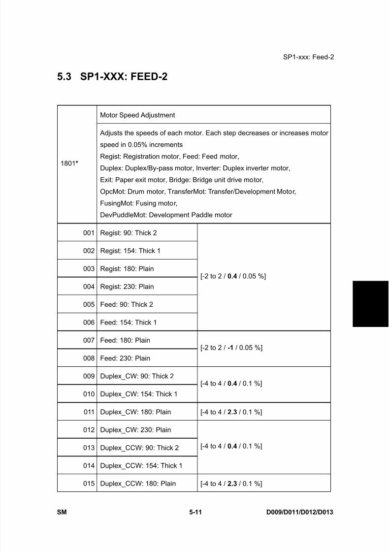
8/15/2019 Ricoh MP 4000 SM D009_D011_D012_D013 SERVICE MANUAL .pdf
http://slidepdf.com/reader/full/ricoh-mp-4000-sm-d009d011d012d013-service-manual-pdf 297/1162
SP1-xxx: Feed-2
SM 5-11 D009/D011/D012/D013
S e r v i c e
T a b l e s
5.3 SP1-XXX: FEED-2
Motor Speed Adjustment
1801 *
Adjusts the speeds of each motor. Each step decreases or increases motor
speed in 0.05% increments
Regist: Registration motor, Feed: Feed motor,
Duplex: Duplex/By-pass motor, Inverter: Duplex inverter motor,
Exit: Paper exit motor, Bridge: Bridge unit drive motor,
OpcMot: Drum motor, TransferMot: Transfer/Development Motor,FusingMot: Fusing motor,
DevPuddleMot: Development Paddle motor
001 Regist: 90: Thick 2
002 Regist: 154: Thick 1
003 Regist: 180: Plain
004 Regist: 230: Plain
005 Feed: 90: Thick 2
006 Feed: 154: Thick 1
[-2 to 2 / 0.4 / 0.05 %]
007 Feed: 180: Plain
008 Feed: 230: Plain
[-2 to 2 / -1 / 0.05 %]
009 Duplex_CW: 90: Thick 2
010 Duplex_CW: 154: Thick 1[-4 to 4 / 0.4 / 0.1 %]
011 Duplex_CW: 180: Plain [-4 to 4 / 2.3 / 0.1 %]
012 Duplex_CW: 230: Plain
013 Duplex_CCW: 90: Thick 2
014 Duplex_CCW: 154: Thick 1
[-4 to 4 / 0.4 / 0.1 %]
015 Duplex_CCW: 180: Plain [-4 to 4 / 2.3 / 0.1 %]
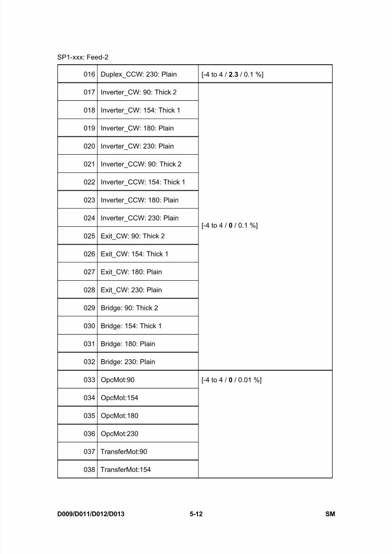
8/15/2019 Ricoh MP 4000 SM D009_D011_D012_D013 SERVICE MANUAL .pdf
http://slidepdf.com/reader/full/ricoh-mp-4000-sm-d009d011d012d013-service-manual-pdf 298/1162
SP1-xxx: Feed-2
D009/D011/D012/D013 5-12 SM
016 Duplex_CCW: 230: Plain [-4 to 4 / 2.3 / 0.1 %]
017 Inverter_CW: 90: Thick 2
018 Inverter_CW: 154: Thick 1
019 Inverter_CW: 180: Plain
020 Inverter_CW: 230: Plain
021 Inverter_CCW: 90: Thick 2
022 Inverter_CCW: 154: Thick 1
023 Inverter_CCW: 180: Plain
024 Inverter_CCW: 230: Plain
025 Exit_CW: 90: Thick 2
026 Exit_CW: 154: Thick 1
027 Exit_CW: 180: Plain
028 Exit_CW: 230: Plain
029 Bridge: 90: Thick 2
030 Bridge: 154: Thick 1
031 Bridge: 180: Plain
032 Bridge: 230: Plain
[-4 to 4 / 0 / 0.1 %]
033 OpcMot:90
034 OpcMot:154
035 OpcMot:180
036 OpcMot:230
037 TransferMot:90
038 TransferMot:154
[-4 to 4 / 0 / 0.01 %]
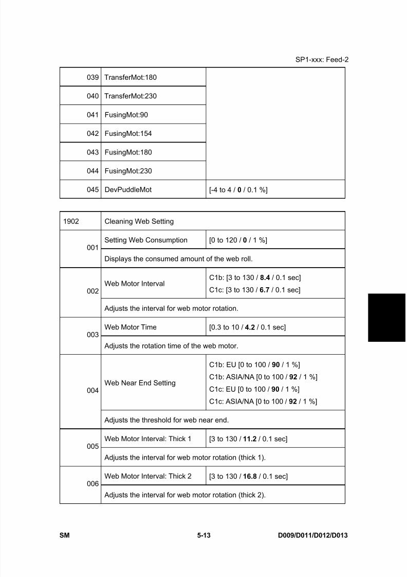
8/15/2019 Ricoh MP 4000 SM D009_D011_D012_D013 SERVICE MANUAL .pdf
http://slidepdf.com/reader/full/ricoh-mp-4000-sm-d009d011d012d013-service-manual-pdf 299/1162
SP1-xxx: Feed-2
SM 5-13 D009/D011/D012/D013
S e r v i c e
T a b l e s
039 TransferMot:180
040 TransferMot:230
041 FusingMot:90
042 FusingMot:154
043 FusingMot:180
044 FusingMot:230
045 DevPuddleMot [-4 to 4 / 0 / 0.1 %]
1902 Cleaning Web Setting
Setting Web Consumption [0 to 120 / 0 / 1 %]001
Displays the consumed amount of the web roll.
Web Motor IntervalC1b: [3 to 130 / 8.4 / 0.1 sec]
C1c: [3 to 130 / 6.7 / 0.1 sec]002
Adjusts the interval for web motor rotation.
Web Motor Time [0.3 to 10 / 4.2 / 0.1 sec]003
Adjusts the rotation time of the web motor.
Web Near End Setting
C1b: EU [0 to 100 / 90 / 1 %]
C1b: ASIA/NA [0 to 100 / 92 / 1 %]
C1c: EU [0 to 100 / 90 / 1 %]
C1c: ASIA/NA [0 to 100 / 92 / 1 %]
004
Adjusts the threshold for web near end.
Web Motor Interval: Thick 1 [3 to 130 / 11.2 / 0.1 sec]005
Adjusts the interval for web motor rotation (thick 1).
Web Motor Interval: Thick 2 [3 to 130 / 16.8 / 0.1 sec]006
Adjusts the interval for web motor rotation (thick 2).

8/15/2019 Ricoh MP 4000 SM D009_D011_D012_D013 SERVICE MANUAL .pdf
http://slidepdf.com/reader/full/ricoh-mp-4000-sm-d009d011d012d013-service-manual-pdf 300/1162
SP1-xxx: Feed-2
D009/D011/D012/D013 5-14 SM
Paper Interval Time [0 to 10 / 5 / 1 sec]
007 Adjusts the threshold for paper feeding. When the time between trailing
edge detection and leading edge detection is within the value of this setting,
the machine determines that the paper is still being fed.
Web Motor Setting: Web End [0 to 60 / 27 / 1 sec]008
Adjusts the motor rotation time after the web end.
Web Motor Rotation: Power On [0 to 10 / 2 / 1 times]009
Adjusts the number of web motor rotations at the re-load state.
Web Motor Interval: Pre-idle [0 to 30 / 5 / 1 sec]010
Adjusts the motor waiting time after the fusing motor idling.
Web Motor Rotation: Pre-idle [0 to 10 / 2 / 1 times]011
Adjusts the number of web motor rotations at the fusing idling state.
1903 Cleaning Web Setting
Total Paper Counter [0 to 999999999 / 0 / 1 sec]001
Displays the total paper feeding time.
Total Web Motor Drive Time [0 to 999999999 / 0 / 1 sec]002
Displays the total time of web motor rotation.
1907 Paper Feed Timing Adj. (DFU)
001 Feed Solenoid ON: Plain
002 Feed Solenoid ON: Thick
[-10 to 40 / 0 / 2.5 mm]
003 Feed Solenoid OFF: Plain
004 Feed Solenoid OFF: Thick
005 Feed Clutch ON: Plain
[-10 to 10 / 0 / 1 mm]
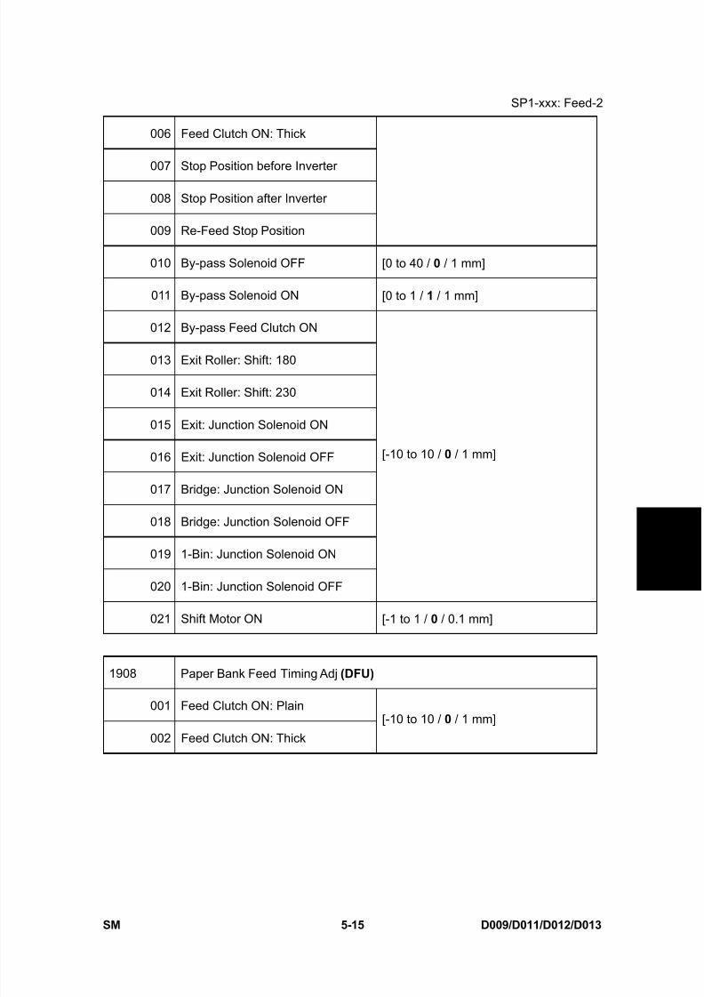
8/15/2019 Ricoh MP 4000 SM D009_D011_D012_D013 SERVICE MANUAL .pdf
http://slidepdf.com/reader/full/ricoh-mp-4000-sm-d009d011d012d013-service-manual-pdf 301/1162
SP1-xxx: Feed-2
SM 5-15 D009/D011/D012/D013
S e r v i c e
T a b l e s
006 Feed Clutch ON: Thick
007 Stop Position before Inverter
008 Stop Position after Inverter
009 Re-Feed Stop Position
010 By-pass Solenoid OFF [0 to 40 / 0 / 1 mm]
011 By-pass Solenoid ON [0 to 1 / 1 / 1 mm]
012 By-pass Feed Clutch ON
013 Exit Roller: Shift: 180
014 Exit Roller: Shift: 230
015 Exit: Junction Solenoid ON
016 Exit: Junction Solenoid OFF
017 Bridge: Junction Solenoid ON
018 Bridge: Junction Solenoid OFF
019 1-Bin: Junction Solenoid ON
020 1-Bin: Junction Solenoid OFF
[-10 to 10 / 0 / 1 mm]
021 Shift Motor ON [-1 to 1 / 0 / 0.1 mm]
1908 Paper Bank Feed Timing Adj (DFU)
001 Feed Clutch ON: Plain
002 Feed Clutch ON: Thick
[-10 to 10 / 0 / 1 mm]
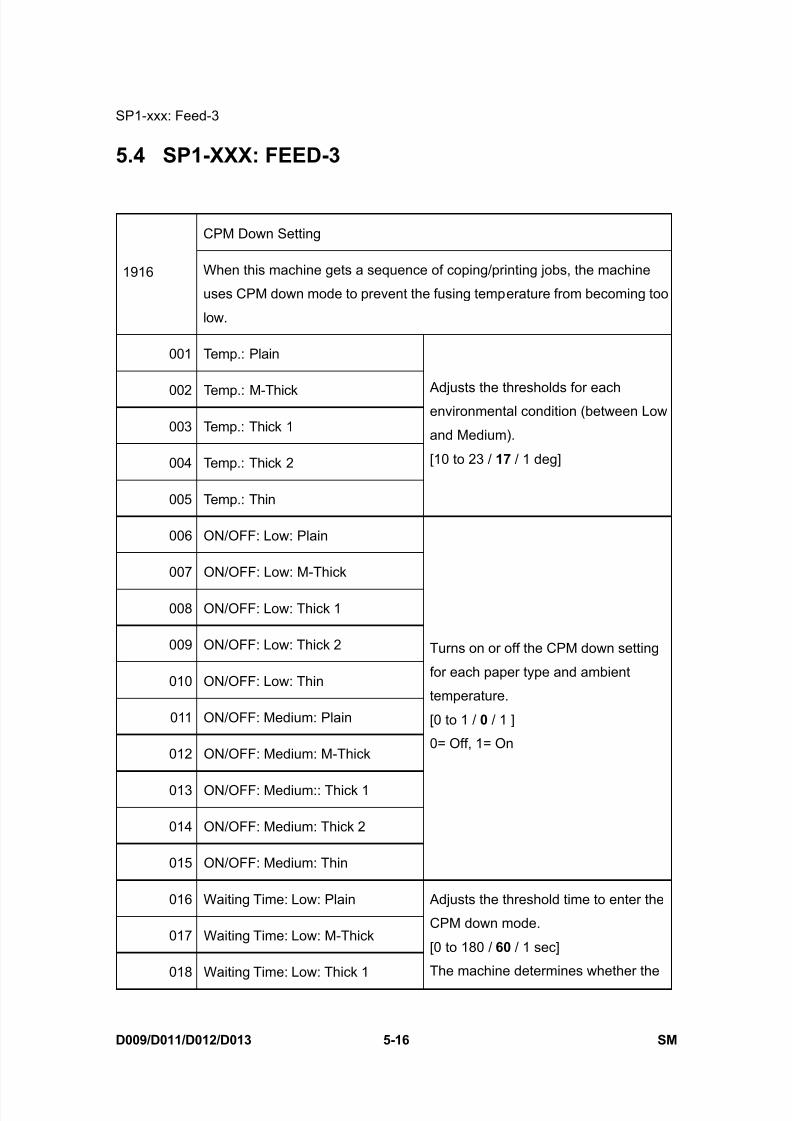
8/15/2019 Ricoh MP 4000 SM D009_D011_D012_D013 SERVICE MANUAL .pdf
http://slidepdf.com/reader/full/ricoh-mp-4000-sm-d009d011d012d013-service-manual-pdf 302/1162
SP1-xxx: Feed-3
D009/D011/D012/D013 5-16 SM
5.4 SP1-XXX: FEED-3
CPM Down Setting
1916 When this machine gets a sequence of coping/printing jobs, the machine
uses CPM down mode to prevent the fusing temperature from becoming too
low.
001 Temp.: Plain
002 Temp.: M-Thick
003 Temp.: Thick 1
004 Temp.: Thick 2
005 Temp.: Thin
Adjusts the thresholds for eachenvironmental condition (between Low
and Medium).
[10 to 23 / 17 / 1 deg]
006 ON/OFF: Low: Plain
007 ON/OFF: Low: M-Thick
008 ON/OFF: Low: Thick 1
009 ON/OFF: Low: Thick 2
010 ON/OFF: Low: Thin
011 ON/OFF: Medium: Plain
012 ON/OFF: Medium: M-Thick
013 ON/OFF: Medium:: Thick 1
014 ON/OFF: Medium: Thick 2
015 ON/OFF: Medium: Thin
Turns on or off the CPM down setting
for each paper type and ambient
temperature.
[0 to 1 / 0 / 1 ]
0= Off, 1= On
016 Waiting Time: Low: Plain
017 Waiting Time: Low: M-Thick
018 Waiting Time: Low: Thick 1
Adjusts the threshold time to enter the
CPM down mode.
[0 to 180 / 60 / 1 sec]
The machine determines whether the
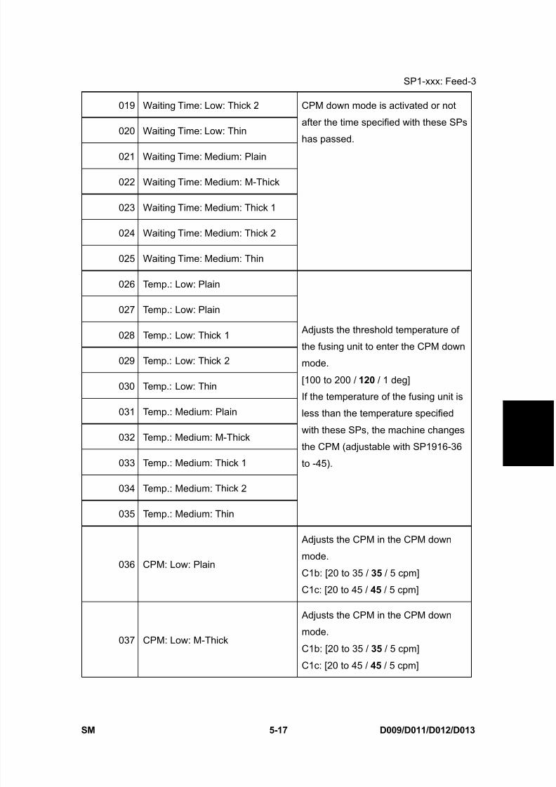
8/15/2019 Ricoh MP 4000 SM D009_D011_D012_D013 SERVICE MANUAL .pdf
http://slidepdf.com/reader/full/ricoh-mp-4000-sm-d009d011d012d013-service-manual-pdf 303/1162
SP1-xxx: Feed-3
SM 5-17 D009/D011/D012/D013
S e r v i c e
T a b l e s
019 Waiting Time: Low: Thick 2
020 Waiting Time: Low: Thin
021 Waiting Time: Medium: Plain
022 Waiting Time: Medium: M-Thick
023 Waiting Time: Medium: Thick 1
024 Waiting Time: Medium: Thick 2
025 Waiting Time: Medium: Thin
CPM down mode is activated or not
after the time specified with these SPs
has passed.
026 Temp.: Low: Plain
027 Temp.: Low: Plain
028 Temp.: Low: Thick 1
029 Temp.: Low: Thick 2
030 Temp.: Low: Thin
031 Temp.: Medium: Plain
032 Temp.: Medium: M-Thick
033 Temp.: Medium: Thick 1
034 Temp.: Medium: Thick 2
035 Temp.: Medium: Thin
Adjusts the threshold temperature of
the fusing unit to enter the CPM down
mode.
[100 to 200 / 120 / 1 deg]
If the temperature of the fusing unit is
less than the temperature specifiedwith these SPs, the machine changes
the CPM (adjustable with SP1916-36
to -45).
036 CPM: Low: Plain
Adjusts the CPM in the CPM down
mode.
C1b: [20 to 35 / 35 / 5 cpm]
C1c: [20 to 45 / 45 / 5 cpm]
037 CPM: Low: M-Thick
Adjusts the CPM in the CPM down
mode.
C1b: [20 to 35 / 35 / 5 cpm]
C1c: [20 to 45 / 45 / 5 cpm]

8/15/2019 Ricoh MP 4000 SM D009_D011_D012_D013 SERVICE MANUAL .pdf
http://slidepdf.com/reader/full/ricoh-mp-4000-sm-d009d011d012d013-service-manual-pdf 304/1162
SP1-xxx: Feed-3
D009/D011/D012/D013 5-18 SM
038 CPM: Low: Thick 1
Adjusts the CPM in the CPM down
mode.
C1b: [5 to 15 / 15 / 5 cpm]C1c: [5 to 25 / 25 / 5 cpm]
039 CPM: Low: Thick 2
Adjusts the CPM in the CPM down
mode.
[5 to 15 / 15 / 5 cpm]
040 CPM: Low: Thin
041 CPM: Medium: Plain
042 CPM: Medium: M-Thick
Adjusts the CPM in the CPM down
mode.
C1b: [20 to 35 / 35 / 5 cpm]C1c: [30 to 45 / 45 / 5 cpm]
043 CPM: Medium: Thick 1
Adjusts the CPM in the CPM down
mode.
C1b: [5 to 15 / 15 / 5 cpm]
C1c: [5 to 25 / 25 / 5 cpm]
044 CPM: Medium: Thick 2
Adjusts the CPM in the CPM down
mode.[5 to 15 / 15 / 5 cpm]
045 CPM: Medium: Thin
Adjusts the CPM in the CPM down
mode.
C1b: [20 to 35 / 35 / 5 cpm]
C1c: [30 to 45 / 45 / 5 cpm]
1930 OnOff Time Adjust
On Time Adjust [0 to 100 / 40 / 10 msec]
001 Adjusts the Off-On interval of the transfer belt contact motor. ("On" means
that the transfer belt is in contact with the drum.)
Off Time Adjust [0 to 100 / 20 / 10 msec]
002 Adjusts the On-Off interval of the transfer belt contact motor. ("Off" means
that the transfer belt is away from the drum.)
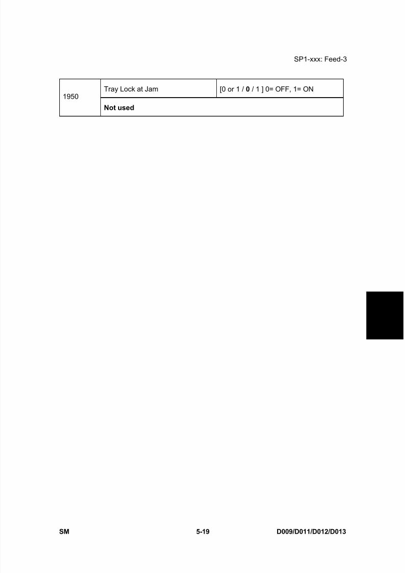
8/15/2019 Ricoh MP 4000 SM D009_D011_D012_D013 SERVICE MANUAL .pdf
http://slidepdf.com/reader/full/ricoh-mp-4000-sm-d009d011d012d013-service-manual-pdf 305/1162
SP1-xxx: Feed-3
SM 5-19 D009/D011/D012/D013
S e r v i c e
T a b l e s
Tray Lock at Jam [0 or 1 / 0 / 1 ] 0= OFF, 1= ON
1950Not used
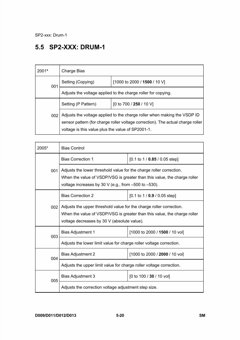
8/15/2019 Ricoh MP 4000 SM D009_D011_D012_D013 SERVICE MANUAL .pdf
http://slidepdf.com/reader/full/ricoh-mp-4000-sm-d009d011d012d013-service-manual-pdf 306/1162
SP2-xxx: Drum-1
D009/D011/D012/D013 5-20 SM
5.5 SP2-XXX: DRUM-1
2001 * Charge Bias
Setting (Copying) [1000 to 2000 / 1500 / 10 V]001
Adjusts the voltage applied to the charge roller for copying.
Setting (P Pattern) [0 to 700 / 250 / 10 V]
002 Adjusts the voltage applied to the charge roller when making the VSDP ID
sensor pattern (for charge roller voltage correction). The actual charge roller
voltage is this value plus the value of SP2001-1.
2005* Bias Control
Bias Correction 1 [0.1 to 1 / 0.85 / 0.05 step]
001 Adjusts the lower threshold value for the charge roller correction.
When the value of VSDP/VSG is greater than this value, the charge rollervoltage increases by 30 V (e.g., from –500 to –530).
Bias Correction 2 [0.1 to 1 / 0.9 / 0.05 step]
002 Adjusts the upper threshold value for the charge roller correction.
When the value of VSDP/VSG is greater than this value, the charge roller
voltage decreases by 30 V (absolute value).
Bias Adjustment 1 [1000 to 2000 / 1500 / 10 vol]
003 Adjusts the lower limit value for charge roller voltage correction.
Bias Adjustment 2 [1000 to 2000 / 2000 / 10 vol]004
Adjusts the upper limit value for charge roller voltage correction.
Bias Adjustment 3 [0 to 100 / 30 / 10 vol]005
Adjusts the correction voltage adjustment step size.
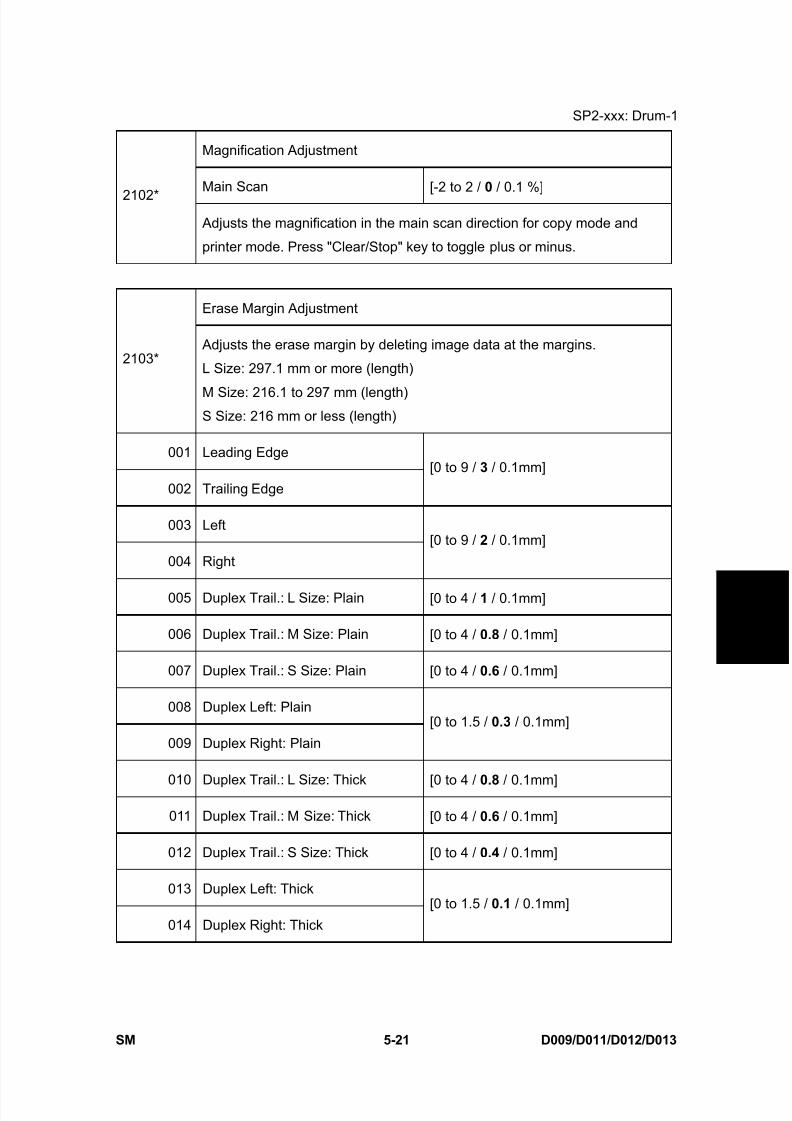
8/15/2019 Ricoh MP 4000 SM D009_D011_D012_D013 SERVICE MANUAL .pdf
http://slidepdf.com/reader/full/ricoh-mp-4000-sm-d009d011d012d013-service-manual-pdf 307/1162
SP2-xxx: Drum-1
SM 5-21 D009/D011/D012/D013
S e r v i c e
T a b l e s
Magnification Adjustment
Main Scan [-2 to 2 / 0 / 0.1 %]2102*
Adjusts the magnification in the main scan direction for copy mode and
printer mode. Press "Clear/Stop" key to toggle plus or minus.
Erase Margin Adjustment
2103* Adjusts the erase margin by deleting image data at the margins.
L Size: 297.1 mm or more (length)
M Size: 216.1 to 297 mm (length)S Size: 216 mm or less (length)
001 Leading Edge
002 Trailing Edge
[0 to 9 / 3 / 0.1mm]
003 Left
004 Right
[0 to 9 / 2 / 0.1mm]
005 Duplex Trail.: L Size: Plain [0 to 4 / 1 / 0.1mm]
006 Duplex Trail.: M Size: Plain [0 to 4 / 0.8 / 0.1mm]
007 Duplex Trail.: S Size: Plain [0 to 4 / 0.6 / 0.1mm]
008 Duplex Left: Plain
009 Duplex Right: Plain
[0 to 1.5 / 0.3 / 0.1mm]
010 Duplex Trail.: L Size: Thick [0 to 4 / 0.8 / 0.1mm]
011 Duplex Trail.: M Size: Thick [0 to 4 / 0.6 / 0.1mm]
012 Duplex Trail.: S Size: Thick [0 to 4 / 0.4 / 0.1mm]
013 Duplex Left: Thick
014 Duplex Right: Thick
[0 to 1.5 / 0.1 / 0.1mm]

8/15/2019 Ricoh MP 4000 SM D009_D011_D012_D013 SERVICE MANUAL .pdf
http://slidepdf.com/reader/full/ricoh-mp-4000-sm-d009d011d012d013-service-manual-pdf 308/1162
SP2-xxx: Drum-1
D009/D011/D012/D013 5-22 SM
LD Power Adjustment
2105 * Adjusts the LD power for each mode.
Each LD power setting is decided by the process control.
001 LD1: Copy
002 LD2: Copy
[–50 to 79 / -24 (C1b), 5 (C1c) /1 ]
003 LD1: Printer/Fax
004 LD2: Printer/Fax
[–50 to 79 / -44 (C1b), -25 (C1c) /1 ]
2106 * POL REV TIME (Polygon motor rotation time)
PRE TIME [0 to 60 / 10 /1 sec]
001 Adjusts the time of polygon motor rotation before a job.
If this is set to "0", this SP is not activated.
POST TIME [0 to 60 / 0 /1 sec]
002 Adjusts the time of the polygon motor rotation after a job.If this is set to "0", the polygon motor never switches off in standby mode.
However, if the machine enters the energy saver mode, the polygon motor
will ignore the zero setting and switch itself off.
2109 Test Pattern
001 Pattern Selection[0 to 24 / 0 /1 ]
Test pattern of the GAVD
0: None
1: Vertical Line (1 dot)
2: Vertical Line (2 dot)
3: Horizontal Line (1 dot)
4: Horizontal Line (2 dot)
5: Grid Vertical Line
6: Grid Horizontal Line
13: Independent Pattern (3 dot)
14: Trimming Area
15: Hound’s Tooth Check (Vertical)
16: Hound’s Tooth Check (Horizontal)
17: Black Band (Horizontal)
18: Black band ( Vertical)
19: Checker Flag Pattern
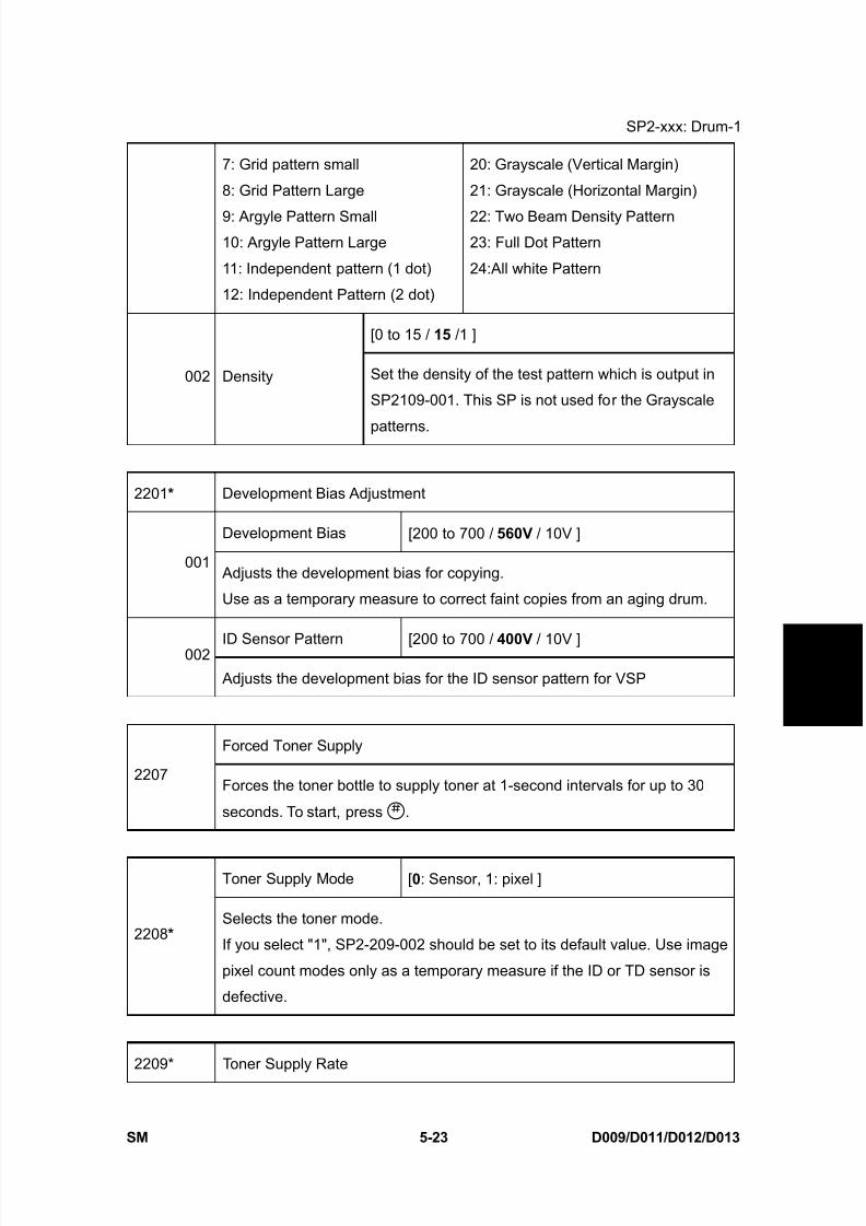
8/15/2019 Ricoh MP 4000 SM D009_D011_D012_D013 SERVICE MANUAL .pdf
http://slidepdf.com/reader/full/ricoh-mp-4000-sm-d009d011d012d013-service-manual-pdf 309/1162
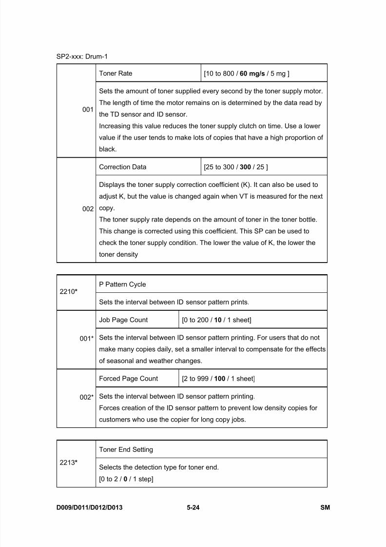
8/15/2019 Ricoh MP 4000 SM D009_D011_D012_D013 SERVICE MANUAL .pdf
http://slidepdf.com/reader/full/ricoh-mp-4000-sm-d009d011d012d013-service-manual-pdf 310/1162
SP2-xxx: Drum-1
D009/D011/D012/D013 5-24 SM
Toner Rate [10 to 800 / 60 mg/s / 5 mg ]
001
Sets the amount of toner supplied every second by the toner supply motor.
The length of time the motor remains on is determined by the data read by
the TD sensor and ID sensor.
Increasing this value reduces the toner supply clutch on time. Use a lower
value if the user tends to make lots of copies that have a high proportion of
black.
Correction Data [25 to 300 / 300 / 25 ]
002
Displays the toner supply correction coefficient (K). It can also be used to
adjust K, but the value is changed again when VT is measured for the next
copy.
The toner supply rate depends on the amount of toner in the toner bottle.
This change is corrected using this coefficient. This SP can be used to
check the toner supply condition. The lower the value of K, the lower the
toner density
P Pattern Cycle2210 *
Sets the interval between ID sensor pattern prints.
Job Page Count [0 to 200 / 10 / 1 sheet]
001* Sets the interval between ID sensor pattern printing. For users that do not
make many copies daily, set a smaller interval to compensate for the effects
of seasonal and weather changes.
Forced Page Count [2 to 999 / 100 / 1 sheet]
002* Sets the interval between ID sensor pattern printing.
Forces creation of the ID sensor pattern to prevent low density copies for
customers who use the copier for long copy jobs.
Toner End Setting
2213 * Selects the detection type for toner end.
[0 to 2 / 0 / 1 step]
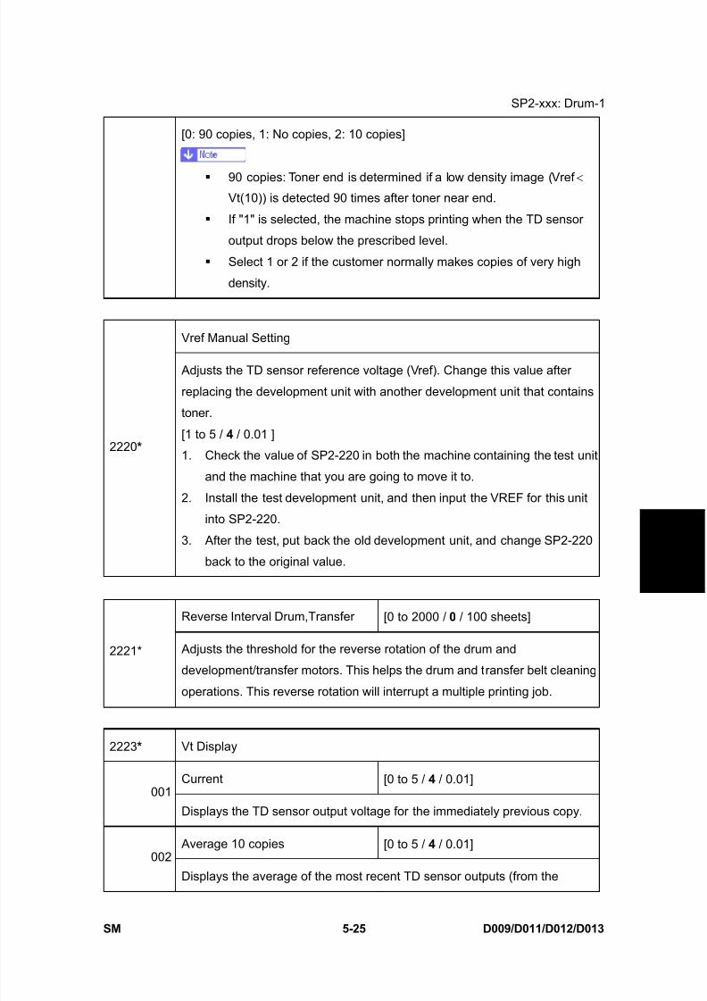
8/15/2019 Ricoh MP 4000 SM D009_D011_D012_D013 SERVICE MANUAL .pdf
http://slidepdf.com/reader/full/ricoh-mp-4000-sm-d009d011d012d013-service-manual-pdf 311/1162
SP2-xxx: Drum-1
SM 5-25 D009/D011/D012/D013
S e r v i c e
T a b l e s
[0: 90 copies, 1: No copies, 2: 10 copies]
90 copies: Toner end is determined if a low density image (Vref < Vt(10)) is detected 90 times after toner near end.
If "1" is selected, the machine stops printing when the TD sensor
output drops below the prescribed level.
Select 1 or 2 if the customer normally makes copies of very high
density.
Vref Manual Setting
2220 *
Adjusts the TD sensor reference voltage (Vref). Change this value after
replacing the development unit with another development unit that contains
toner.
[1 to 5 / 4 / 0.01 ]
1. Check the value of SP2-220 in both the machine containing the test unit
and the machine that you are going to move it to.
2. Install the test development unit, and then input the VREF for this unit
into SP2-220.
3. After the test, put back the old development unit, and change SP2-220
back to the original value.
Reverse Interval Drum,Transfer [0 to 2000 / 0 / 100 sheets]
2221* Adjusts the threshold for the reverse rotation of the drum and
development/transfer motors. This helps the drum and transfer belt cleaning
operations. This reverse rotation will interrupt a multiple printing job.
2223 * Vt Display
Current [0 to 5 / 4 / 0.01]001
Displays the TD sensor output voltage for the immediately previous copy.
Average 10 copies [0 to 5 / 4 / 0.01]002
Displays the average of the most recent TD sensor outputs (from the

8/15/2019 Ricoh MP 4000 SM D009_D011_D012_D013 SERVICE MANUAL .pdf
http://slidepdf.com/reader/full/ricoh-mp-4000-sm-d009d011d012d013-service-manual-pdf 312/1162
SP2-xxx: Drum-1
D009/D011/D012/D013 5-26 SM
previous 10 copies).
Rate of Change [-10000 to 10000 / 0 / 1]003
Displays the rate of change in the TD sensor output.
GAIN [0 to 255 / 0 / 1]
004Displays the GAIN value used to calculate the on time for the toner supply
motor.
Image Pixel Count [0 to 255 / 0 / 1]005
Displays the image pixel count.
Developer Lot
2228*Displays the lot number of the developer. (The lot number is embossed on
the top edge of the developer pack.)
Transfer Current Adjustment
2301* If the transfer current of image area is set highly than normal, the print
image is easily come out. If the leading transfer current is set as same, the
black line is come out due to exfoliation leave.
Image Area: 1st Side [10 to 100 / 35 / 1 μ A ]001
Adjusts the transfer current for printing the first side of the paper
Image Area: 2nd Side [10 to 100 / 35 / 1 μ A ]
002 Adjusts the transfer current for printing the second side of the paper
Leading Edge: 1st Side [10 to 100 / 20 / 1 μ A ]
003 Adjusts the transfer current for copying at leading edge the first side of the
paper.
Increase the current to separate the paper from the drum properly in high
humidity and high temperature conditions.
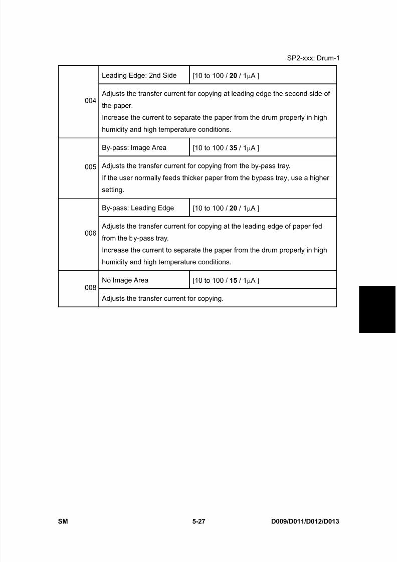
8/15/2019 Ricoh MP 4000 SM D009_D011_D012_D013 SERVICE MANUAL .pdf
http://slidepdf.com/reader/full/ricoh-mp-4000-sm-d009d011d012d013-service-manual-pdf 313/1162
SP2-xxx: Drum-1
SM 5-27 D009/D011/D012/D013
S e r v i c e
T a b l e s
Leading Edge: 2nd Side [10 to 100 / 20 / 1 μ A ]
004 Adjusts the transfer current for copying at leading edge the second side of
the paper.
Increase the current to separate the paper from the drum properly in high
humidity and high temperature conditions.
By-pass: Image Area [10 to 100 / 35 / 1 μ A ]
005 Adjusts the transfer current for copying from the by-pass tray.
If the user normally feeds thicker paper from the bypass tray, use a higher
setting.
By-pass: Leading Edge [10 to 100 / 20 / 1 μ A ]
006 Adjusts the transfer current for copying at the leading edge of paper fed
from the by-pass tray.
Increase the current to separate the paper from the drum properly in high
humidity and high temperature conditions.
No Image Area [10 to 100 / 15 / 1 μ A ]008
Adjusts the transfer current for copying.
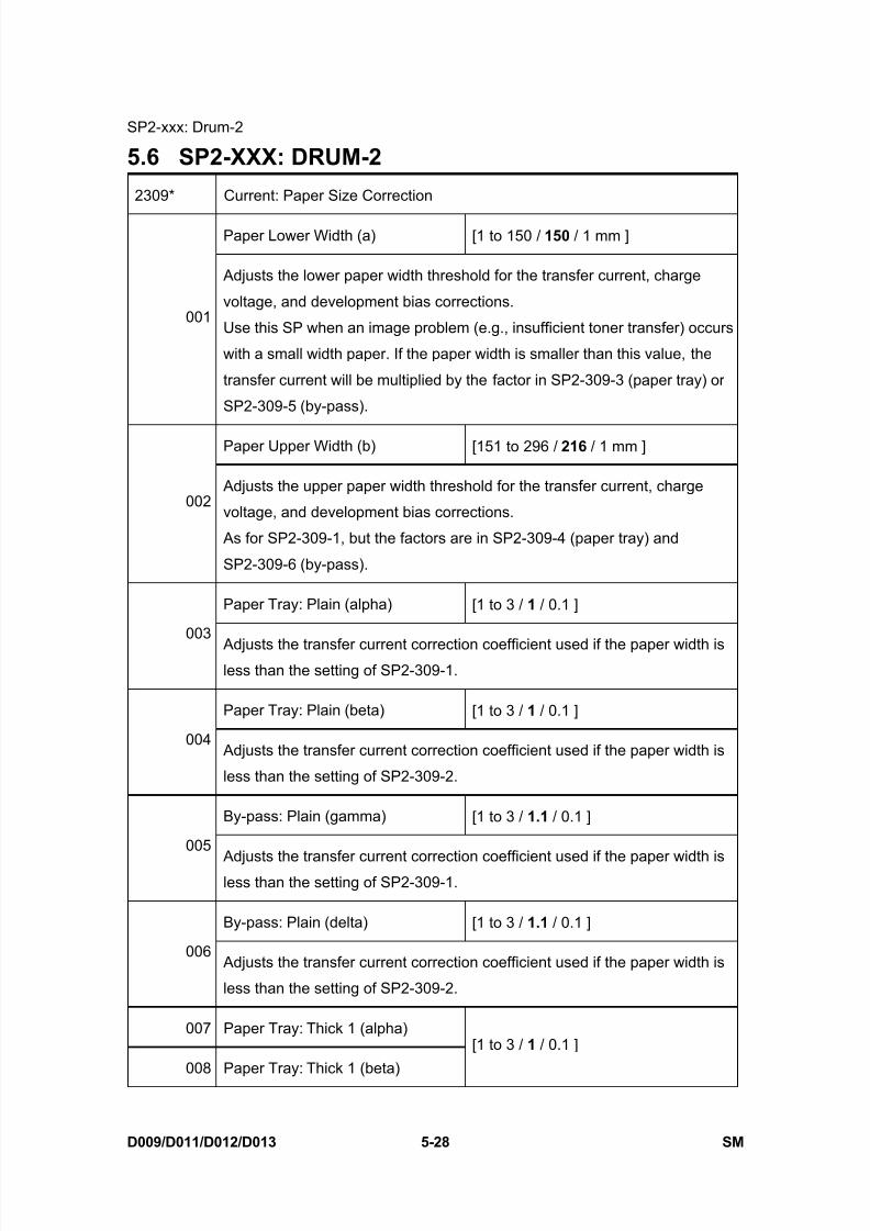
8/15/2019 Ricoh MP 4000 SM D009_D011_D012_D013 SERVICE MANUAL .pdf
http://slidepdf.com/reader/full/ricoh-mp-4000-sm-d009d011d012d013-service-manual-pdf 314/1162
SP2-xxx: Drum-2
D009/D011/D012/D013 5-28 SM
5.6 SP2-XXX: DRUM-2
2309* Current: Paper Size Correction
Paper Lower Width (a) [1 to 150 / 150 / 1 mm ]
001
Adjusts the lower paper width threshold for the transfer current, charge
voltage, and development bias corrections.
Use this SP when an image problem (e.g., insufficient toner transfer) occurs
with a small width paper. If the paper width is smaller than this value, the
transfer current will be multiplied by the factor in SP2-309-3 (paper tray) or
SP2-309-5 (by-pass).
Paper Upper Width (b) [151 to 296 / 216 / 1 mm ]
002 Adjusts the upper paper width threshold for the transfer current, charge
voltage, and development bias corrections.
As for SP2-309-1, but the factors are in SP2-309-4 (paper tray) and
SP2-309-6 (by-pass).
Paper Tray: Plain (alpha) [1 to 3 / 1 / 0.1 ]
003 Adjusts the transfer current correction coefficient used if the paper width isless than the setting of SP2-309-1.
Paper Tray: Plain (beta) [1 to 3 / 1 / 0.1 ]
004 Adjusts the transfer current correction coefficient used if the paper width is
less than the setting of SP2-309-2.
By-pass: Plain (gamma) [1 to 3 / 1.1 / 0.1 ]
005
Adjusts the transfer current correction coefficient used if the paper width isless than the setting of SP2-309-1.
By-pass: Plain (delta) [1 to 3 / 1.1 / 0.1 ]
006 Adjusts the transfer current correction coefficient used if the paper width is
less than the setting of SP2-309-2.
007 Paper Tray: Thick 1 (alpha)
008 Paper Tray: Thick 1 (beta)
[1 to 3 / 1 / 0.1 ]

8/15/2019 Ricoh MP 4000 SM D009_D011_D012_D013 SERVICE MANUAL .pdf
http://slidepdf.com/reader/full/ricoh-mp-4000-sm-d009d011d012d013-service-manual-pdf 315/1162
SP2-xxx: Drum-2
SM 5-29 D009/D011/D012/D013
S e r v i c e
T a b l e s
009 By-pass: Thick 1 (gamma)
010 By-pass: Thick 1 (delta)
011 Paper Tray: Thick 2 (alpha)
[1 to 3 / 1.1 / 0.1 ]
012 Paper Tray: Thick 2 (beta) [1 to 3 / 1.1 / 0.1 ]
013 By-pass: Thick 2 (gamma) [1 to 3 / 1.5 / 0.1 ]
014 By-pass: Thick 2 (delta) [1 to 3 / 1.1 / 0.1 ]
015 Paper Tray: M-Thick (alpha)
016 Paper Tray: M-Thick (beta)
[1 to 3 / 1 / 0.1 ]
017 By-pass: M-Thick (gamma)
018 By-pass: M-Thick (delta)
[1 to 3 / 1.1 / 0.1 ]
019 Paper Tray: Thin (alpha)
020 Paper Tray: Thin (beta)
[1 to 3 / 1 / 0.1 ]
021 By-pass: Thin (gamma)
022 By-pass: Thin (delta)
[1 to 3 / 1.1 / 0.1 ]
023 Paper Tray: Special 1 (alpha)
024 Paper Tray: Special 1 (beta)
[1 to 3 / 1 / 0.1 ]
025 By-pass: Special 1 (gamma)
026 By-pass: Special 1 (delta)
[1 to 3 / 1.1 / 0.1 ]
027 Paper Tray: Special 2 (alpha)
028 Paper Tray: Special 2 (beta)
[1 to 3 / 1 / 0.1 ]
029 By-pass: Special 2 (gamma)
030 By-pass: Special 2 (delta)
[1 to 3 / 1.1 / 0.1 ]
031 Paper Tray: Special 3 (alpha) [1 to 3 / 1 / 0.1 ]
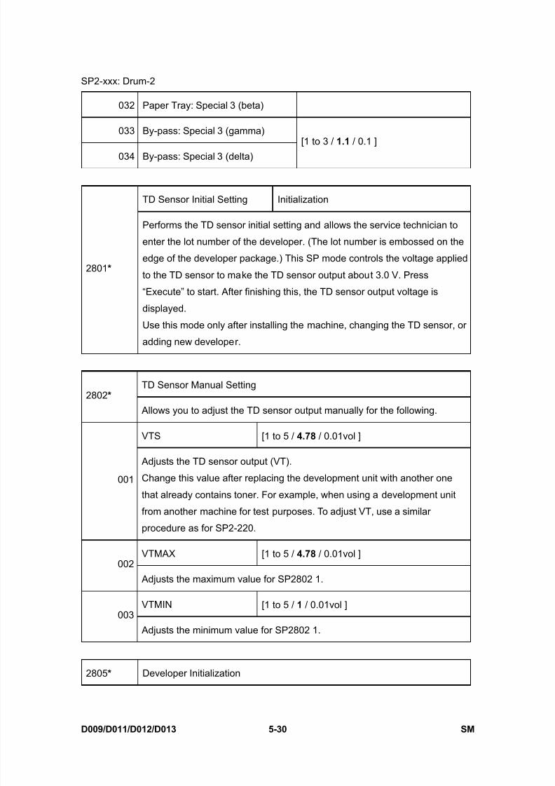
8/15/2019 Ricoh MP 4000 SM D009_D011_D012_D013 SERVICE MANUAL .pdf
http://slidepdf.com/reader/full/ricoh-mp-4000-sm-d009d011d012d013-service-manual-pdf 316/1162
SP2-xxx: Drum-2
D009/D011/D012/D013 5-30 SM
032 Paper Tray: Special 3 (beta)
033 By-pass: Special 3 (gamma)
034 By-pass: Special 3 (delta)
[1 to 3 / 1.1 / 0.1 ]
TD Sensor Initial Setting Initialization
2801 *
Performs the TD sensor initial setting and allows the service technician to
enter the lot number of the developer. (The lot number is embossed on the
edge of the developer package.) This SP mode controls the voltage applied
to the TD sensor to make the TD sensor output about 3.0 V. Press“Execute” to start. After finishing this, the TD sensor output voltage is
displayed.
Use this mode only after installing the machine, changing the TD sensor, or
adding new developer.
TD Sensor Manual Setting2802 *
Allows you to adjust the TD sensor output manually for the following.
VTS [1 to 5 / 4.78 / 0.01vol ]
001
Adjusts the TD sensor output (VT).
Change this value after replacing the development unit with another one
that already contains toner. For example, when using a development unit
from another machine for test purposes. To adjust VT, use a similar
procedure as for SP2-220.
VTMAX [1 to 5 / 4.78 / 0.01vol ]002
Adjusts the maximum value for SP2802 1.
VTMIN [1 to 5 / 1 / 0.01vol ]003
Adjusts the minimum value for SP2802 1.
2805 * Developer Initialization
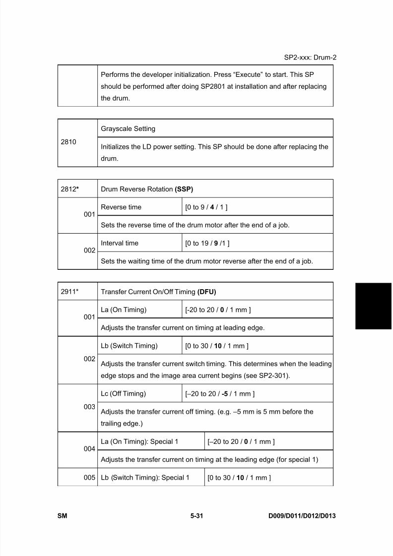
8/15/2019 Ricoh MP 4000 SM D009_D011_D012_D013 SERVICE MANUAL .pdf
http://slidepdf.com/reader/full/ricoh-mp-4000-sm-d009d011d012d013-service-manual-pdf 317/1162
SP2-xxx: Drum-2
SM 5-31 D009/D011/D012/D013
S e r v i c e
T a b l e s
Performs the developer initialization. Press “Execute” to start. This SP
should be performed after doing SP2801 at installation and after replacing
the drum.
Grayscale Setting
2810Initializes the LD power setting. This SP should be done after replacing the
drum.
2812 * Drum Reverse Rotation (SSP)
Reverse time [0 to 9 / 4 / 1 ]001
Sets the reverse time of the drum motor after the end of a job.
Interval time [0 to 19 / 9 /1 ]002
Sets the waiting time of the drum motor reverse after the end of a job.
2911* Transfer Current On/Off Timing (DFU)
La (On Timing) [-20 to 20 / 0 / 1 mm ]001
Adjusts the transfer current on timing at leading edge.
Lb (Switch Timing) [0 to 30 / 10 / 1 mm ]
002 Adjusts the transfer current switch timing. This determines when the leading
edge stops and the image area current begins (see SP2-301).
Lc (Off Timing) [–20 to 20 / -5 / 1 mm ]
003 Adjusts the transfer current off timing. (e.g. –5 mm is 5 mm before the
trailing edge.)
La (On Timing): Special 1 [–20 to 20 / 0 / 1 mm ]004
Adjusts the transfer current on timing at the leading edge (for special 1)
005 Lb (Switch Timing): Special 1 [0 to 30 / 10 / 1 mm ]

8/15/2019 Ricoh MP 4000 SM D009_D011_D012_D013 SERVICE MANUAL .pdf
http://slidepdf.com/reader/full/ricoh-mp-4000-sm-d009d011d012d013-service-manual-pdf 318/1162
SP2-xxx: Drum-2
D009/D011/D012/D013 5-32 SM
Adjusts the switching timing of the transfer current between the leading
edge and the image area.
Lc (Off Timing): Special 1 [–20 to 20 / -5 / 1 mm ]
006 Adjusts the transfer current off timing (e.g. -5 mm is 5 mm before the trailing
edge) (for special 1)
La (On Timing): Special 2 [–20 to 20 / 0 / 1 mm ]007
Adjusts the transfer current on timing at the leading edge (for special 2)
Lb (Switch Timing): Special 2 [0 to 30 / 10 / 1 mm ]
008 Adjusts the transfer current on timing. This determines when the leading
edge stops and the image area current begins (for special 2)
Lc (Off Timing): Special 2 [–20 to 20 / -5 / 1 mm ]
009 Adjusts the transfer current off timing (e.g. -5 mm is 5 mm before the trailing
edge) (for special 2)
La (On Timing): Special 3 [–20o 20 / 0 / 1 mm ]
010 Adjusts the transfer current on timing at the leading edge (for special 3)
Lb (Switch Timing): Special 3 [0 to 30 / 10 / 1 mm ]
011 Adjusts the transfer current on timing. This determines when the leading
edge stops and the image area current begins (for special 3)
Lc (Off Timing): Special 3 [–20 to 20 / -5 / 1 mm ]
012
Adjusts the transfer current off timing (e.g. -5 mm is 5 mm before the trailingedge) (for special 3)
2912* Transfer Reverse Rotation
Interval [0 to 10 / 3 / 1 ]
001Sets the reverse time of the transfer/development motor after the end of a
job.
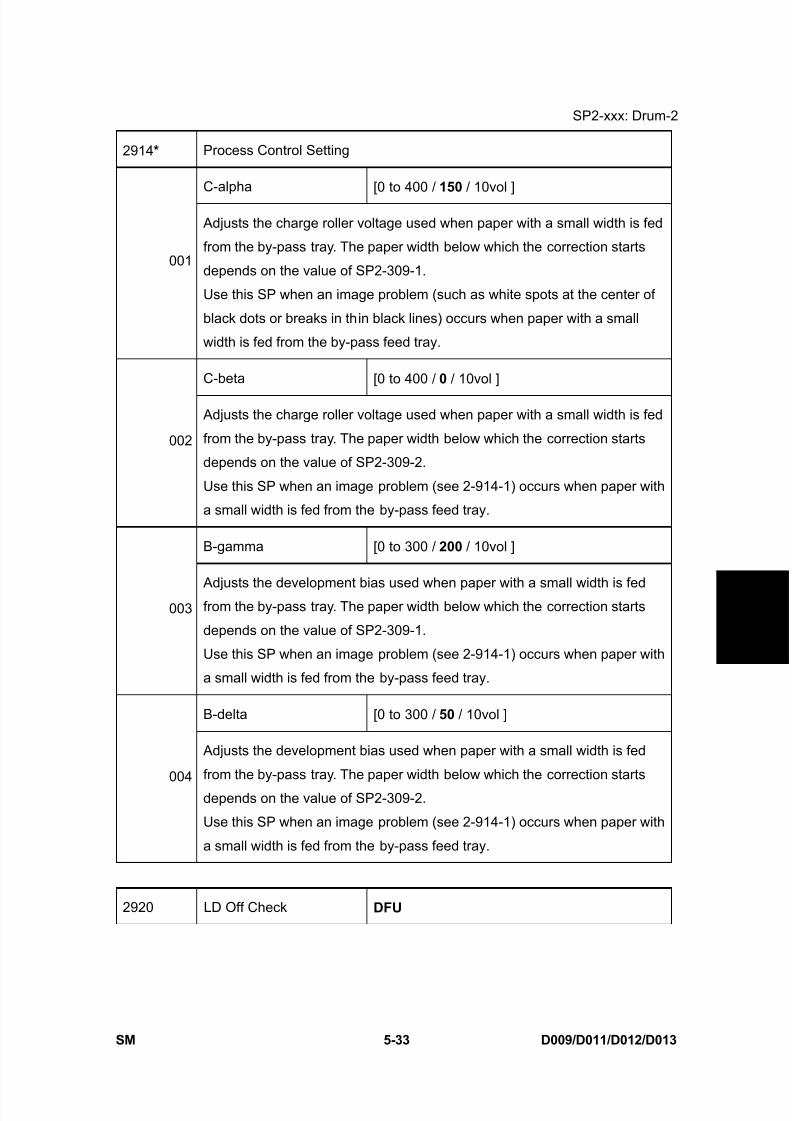
8/15/2019 Ricoh MP 4000 SM D009_D011_D012_D013 SERVICE MANUAL .pdf
http://slidepdf.com/reader/full/ricoh-mp-4000-sm-d009d011d012d013-service-manual-pdf 319/1162
SP2-xxx: Drum-2
SM 5-33 D009/D011/D012/D013
S e r v i c e
T a b l e s
2914 * Process Control Setting
C-alpha [0 to 400 / 150 / 10vol ]
001
Adjusts the charge roller voltage used when paper with a small width is fed
from the by-pass tray. The paper width below which the correction starts
depends on the value of SP2-309-1.
Use this SP when an image problem (such as white spots at the center of
black dots or breaks in thin black lines) occurs when paper with a small
width is fed from the by-pass feed tray.
C-beta [0 to 400 / 0 / 10vol ]
002
Adjusts the charge roller voltage used when paper with a small width is fed
from the by-pass tray. The paper width below which the correction starts
depends on the value of SP2-309-2.
Use this SP when an image problem (see 2-914-1) occurs when paper with
a small width is fed from the by-pass feed tray.
B-gamma [0 to 300 / 200 / 10vol ]
003 Adjusts the development bias used when paper with a small width is fedfrom the by-pass tray. The paper width below which the correction starts
depends on the value of SP2-309-1.
Use this SP when an image problem (see 2-914-1) occurs when paper with
a small width is fed from the by-pass feed tray.
B-delta [0 to 300 / 50 / 10vol ]
004
Adjusts the development bias used when paper with a small width is fed
from the by-pass tray. The paper width below which the correction starts
depends on the value of SP2-309-2.
Use this SP when an image problem (see 2-914-1) occurs when paper with
a small width is fed from the by-pass feed tray.
2920 LD Off Check DFU

8/15/2019 Ricoh MP 4000 SM D009_D011_D012_D013 SERVICE MANUAL .pdf
http://slidepdf.com/reader/full/ricoh-mp-4000-sm-d009d011d012d013-service-manual-pdf 320/1162
SP2-xxx: Drum-3
D009/D011/D012/D013 5-34 SM
5.7 SP2-XXX: DRUM-3Toner Overflow Sensor [0 = No, 1= Yes]
2960*
Selects whether or not the toner overflow sensor is activated.
Transfer Cleaning Blade Forming
2964*
Applies a pattern of toner to the transfer belt at a defined interval between
sheets on the transfer belt in order to reduce friction between the belt
surface and the cleaning blade.
Under conditions of high temperature and high humidity, the density control
feature may reduce the amount of toner, which also reduces the amount of
toner on the surface of the transfer belt. With less toner on the belt, the
friction between the belt and the blade increases, and could cause the blade
to bend or scour the surface of the belt.
001 0: OFF, 1: ON [0 to 1 / 0 / 1 ]
002 Pattern Interval [1 to 100 / 15 / 1 sheet]
003 Pattern Number [1 to 3 / 1 / 1 line]
004 Pattern LD Power [0 to 15 / 2 / 1 ]
Grayscale Limit
2972* Controls the halftone density level to prevent deterioration of the OPC. The
halftone density is detected by the ID sensor, and the machine adjusts the
intensity of the LD beam according to the upper/lower limit setting.
Upper Limit [0 to 100 / 58 (C1b), 63 (C1c) / 1vol ]
001Defines the upper limit for grayscale.
A larger value allows a wider range of halftones at the pale end of the scale.
If the image contains pale areas with fuzzy borders surrounded by dark
areas, reduce this value to make the borders clearer.
Lower Limit [0 to 100 / 52 (C1b), 57 (C1c) / 1vol ]002
Defines the lower limit for grayscale.

8/15/2019 Ricoh MP 4000 SM D009_D011_D012_D013 SERVICE MANUAL .pdf
http://slidepdf.com/reader/full/ricoh-mp-4000-sm-d009d011d012d013-service-manual-pdf 321/1162
SP2-xxx: Drum-3
SM 5-35 D009/D011/D012/D013
S e r v i c e
T a b l e s
A smaller value allows a wider range of halftones at the dark end of the
scale.
Grayscale Cycle (SSP) [0 to 1000 / 100 / 10 sheets ]
2973* Set s the halftone operation interval in order to prevent deterioration of the
OPC. If the number of copies exceeds this setting, at the end of the job, or if
the door is opened and closed, charge correction is executed.
2974* Image Density
Adjustment Mode [1 to 5 / 3 / 1 ]
001 Adjusts image density. Changing this setting adjusts development bias and
ID sensor output voltage that in turn raises or lowers image density.
Near End Setting
Detection Time [0 to 2000 / 0 / 10 sec ]
2975 * Sets a time for toner supply motor rotation for issuing the toner near end
warning on the operation panel. The time may need to be shorter for
customers who run especially large print jobs (working at night, for example)
to ensure earlier warning of the toner near end condition so toner out does
not interrupt a long job.
Bottle Motor Time
Displays the total ON time of the toner supply motor, calculated from when
the toner bottle was replaced. Use this to check that the toner end count
(SP2975) is working properly.
When SP2975 is set to any value other than “0”, this value is displayed
when it matches the setting of SP2975. When SP2975 is set to “0”, SP2976
is disabled. SP2976 is automatically set to zero by toner end recovery.)
2976*
Time [0 to 7,000,000 / 0 / 1 msec]
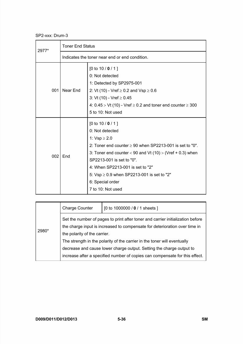
8/15/2019 Ricoh MP 4000 SM D009_D011_D012_D013 SERVICE MANUAL .pdf
http://slidepdf.com/reader/full/ricoh-mp-4000-sm-d009d011d012d013-service-manual-pdf 322/1162
SP2-xxx: Drum-3
D009/D011/D012/D013 5-36 SM
Toner End Status2977*
Indicates the toner near end or end condition.
001 Near End
[0 to 10 / 0 / 1 ]
0: Not detected
1: Detected by SP2975-001
2: Vt (10) - Vref ≥ 0.2 and Vsp ≥ 0.6
3: Vt (10) - Vref ≥ 0.45
4: 0.45 > Vt (10) - Vref ≥ 0.2 and toner end counter ≥ 300
5 to 10: Not used
002 End
[0 to 10 / 0 / 1 ]
0: Not detected
1: Vsp ≥ 2.0
2: Toner end counter ≥ 90 when SP2213-001 is set to "0".
3: Toner end counter < 90 and Vt (10) > (Vref + 0.3) when
SP2213-001 is set to "0".
4: When SP2213-001 is set to "2"
5: Vsp ≥ 0.9 when SP2213-001 is set to "2"
6: Special order
7 to 10: Not used
Charge Counter [0 to 1000000 / 0 / 1 sheets ]
2980*
Set the number of pages to print after toner and carrier initialization before
the charge input is increased to compensate for deterioration over time in
the polarity of the carrier.
The strength in the polarity of the carrier in the toner will eventuallydecrease and cause lower charge output. Setting the charge output to
increase after a specified number of copies can compensate for this effect.

8/15/2019 Ricoh MP 4000 SM D009_D011_D012_D013 SERVICE MANUAL .pdf
http://slidepdf.com/reader/full/ricoh-mp-4000-sm-d009d011d012d013-service-manual-pdf 323/1162
SP3-xxx: Process-1
SM 5-37 D009/D011/D012/D013
S e r v i c e
T a b l e s
5.8 SP3-XXX: PROCESS-1
3001* P Sensor Setting
Current [0 to 43 / 13 / 0.1 mA ]
001 Allows you to reset the PWM of the ID sensor LED to avoid a service call
error after clearing NVRAM or replacing the NVRAM.
The PWM data is stored by executing SP-3001-2.
ID Initialization —
002Performs the ID sensor initial setting. ID sensor output for the bare drum
(VSG) is adjusted automatically to 4.0 ±0.2 V.
Press “Execute” to start. Perform this setting after replacing or cleaning the
ID sensor, replacing the drum, or clearing NVRAM.
Toner End Setting, ON/OFF DFU 3045*
[0 to 1 / 0 / 1] 0=Off, 1=On
P Sensor Output
3103*
Displays the current VSG, VSP, VSDP, and grayscale control.
If the P sensor does not detect the P pattern, “VSP = 5.0 V/VSG = 5.0 V” is
displayed and an SC code is generated.
If the P sensor does not detect the bare area of the drum, “VSP = 0.0
V/VSG =0.0 V” is displayed and an SC code is generated.
001 Vsg [0 to 5 / 0 / 0.1]
002 Vsp [0 to 5 / 0 / 0.1]
003 Vsdp [0 to 5 / 0 / 0.1]
004 Vsm/Vsg [0 to 5 / 0 / 0.1]
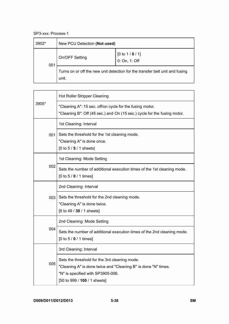
8/15/2019 Ricoh MP 4000 SM D009_D011_D012_D013 SERVICE MANUAL .pdf
http://slidepdf.com/reader/full/ricoh-mp-4000-sm-d009d011d012d013-service-manual-pdf 324/1162
SP3-xxx: Process-1
D009/D011/D012/D013 5-38 SM
3902* New PCU Detection (Not used)
On/OFF Setting[0 to 1 / 0 / 1]
0: On, 1: Off001
Turns on or off the new unit detection for the transfer belt unit and fusing
unit.
Hot Roller Stripper Cleaning
3905*"Cleaning A": 15 sec. off/on cycle for the fusing motor.
"Cleaning B": Off (45 sec.) and On (15 sec.) cycle for the fusing motor.
1st Cleaning: Interval
001 Sets the threshold for the 1st cleaning mode.
"Cleaning A" is done once.
[0 to 5 / 5 / 1 sheets]
1st Cleaning: Mode Setting
002Sets the number of additional execution times of the 1st cleaning mode.[0 to 5 / 0 / 1 times]
2nd Cleaning: Interval
003 Sets the threshold for the 2nd cleaning mode.
"Cleaning A" is done twice.
[6 to 49 / 30 / 1 sheets]
2nd Cleaning: Mode Setting
004Sets the number of additional execution times of the 2nd cleaning mode.
[0 to 5 / 0 / 1 times]
3rd Cleaning: Interval
005Sets the threshold for the 3rd cleaning mode.
"Cleaning A" is done twice and "Cleaning B" is done "N" times.
"N" is specified with SP3905-006.
[50 to 999 / 100 / 1 sheets]
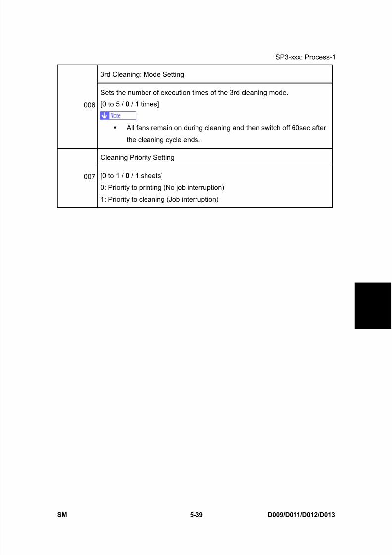
8/15/2019 Ricoh MP 4000 SM D009_D011_D012_D013 SERVICE MANUAL .pdf
http://slidepdf.com/reader/full/ricoh-mp-4000-sm-d009d011d012d013-service-manual-pdf 325/1162
SP3-xxx: Process-1
SM 5-39 D009/D011/D012/D013
S e r v i c e
T a b l e s
3rd Cleaning: Mode Setting
006
Sets the number of execution times of the 3rd cleaning mode.
[0 to 5 / 0 / 1 times]
All fans remain on during cleaning and then switch off 60sec after
the cleaning cycle ends.
Cleaning Priority Setting
007 [0 to 1 / 0 / 1 sheets]
0: Priority to printing (No job interruption)
1: Priority to cleaning (Job interruption)
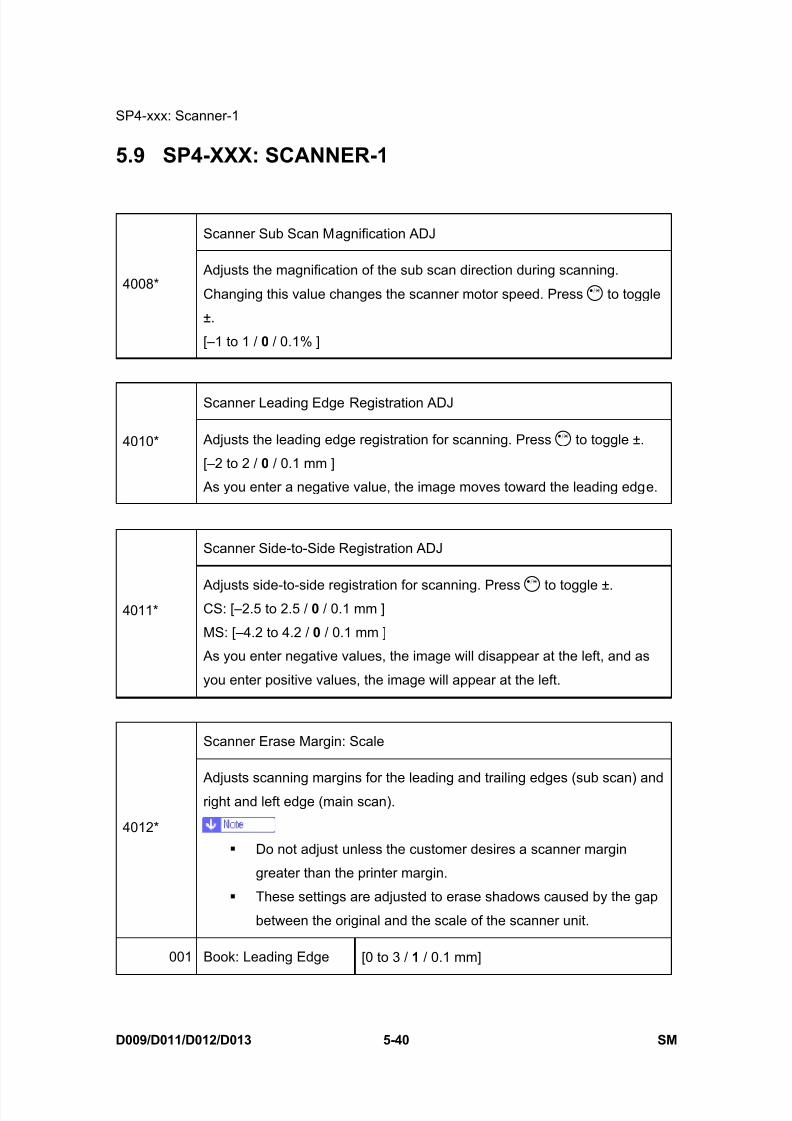
8/15/2019 Ricoh MP 4000 SM D009_D011_D012_D013 SERVICE MANUAL .pdf
http://slidepdf.com/reader/full/ricoh-mp-4000-sm-d009d011d012d013-service-manual-pdf 326/1162
SP4-xxx: Scanner-1
D009/D011/D012/D013 5-40 SM
5.9 SP4-XXX: SCANNER-1
Scanner Sub Scan Magnification ADJ
4008* Adjusts the magnification of the sub scan direction during scanning.
Changing this value changes the scanner motor speed. Press to toggle
±.
[–1 to 1 / 0 / 0.1% ]
Scanner Leading Edge Registration ADJ
4010* Adjusts the leading edge registration for scanning. Press to toggle ±.
[–2 to 2 / 0 / 0.1 mm ]
As you enter a negative value, the image moves toward the leading edge.
Scanner Side-to-Side Registration ADJ
4011* Adjusts side-to-side registration for scanning. Press to toggle ±.CS: [–2.5 to 2.5 / 0 / 0.1 mm ]
MS: [–4.2 to 4.2 / 0 / 0.1 mm ]
As you enter negative values, the image will disappear at the left, and as
you enter positive values, the image will appear at the left.
Scanner Erase Margin: Scale
4012*
Adjusts scanning margins for the leading and trailing edges (sub scan) and
right and left edge (main scan).
Do not adjust unless the customer desires a scanner margin
greater than the printer margin.
These settings are adjusted to erase shadows caused by the gap
between the original and the scale of the scanner unit.
001 Book: Leading Edge [0 to 3 / 1 / 0.1 mm]
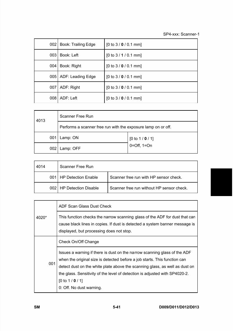
8/15/2019 Ricoh MP 4000 SM D009_D011_D012_D013 SERVICE MANUAL .pdf
http://slidepdf.com/reader/full/ricoh-mp-4000-sm-d009d011d012d013-service-manual-pdf 327/1162
SP4-xxx: Scanner-1
SM 5-41 D009/D011/D012/D013
S e r v i c e
T a b l e s
002 Book: Trailing Edge [0 to 3 / 0 / 0.1 mm]
003 Book: Left [0 to 3 / 1 / 0.1 mm]
004 Book: Right [0 to 3 / 0 / 0.1 mm]
005 ADF: Leading Edge [0 to 3 / 0 / 0.1 mm]
007 ADF: Right [0 to 3 / 0 / 0.1 mm]
008 ADF: Left [0 to 3 / 0 / 0.1 mm]
Scanner Free Run4013
Performs a scanner free run with the exposure lamp on or off.
001 Lamp: ON
002 Lamp: OFF
[0 to 1 / 0 / 1]
0=Off, 1=On
4014 Scanner Free Run
001 HP Detection Enable Scanner free run with HP sensor check.
002 HP Detection Disable Scanner free run without HP sensor check.
ADF Scan Glass Dust Check
4020* This function checks the narrow scanning glass of the ADF for dust that can
cause black lines in copies. If dust is detected a system banner message is
displayed, but processing does not stop.
Check On/Off Change
001
Issues a warning if there is dust on the narrow scanning glass of the ADF
when the original size is detected before a job starts. This function can
detect dust on the white plate above the scanning glass, as well as dust on
the glass. Sensitivity of the level of detection is adjusted with SP4020-2.
[0 to 1 / 0 / 1]
0: Off. No dust warning.

8/15/2019 Ricoh MP 4000 SM D009_D011_D012_D013 SERVICE MANUAL .pdf
http://slidepdf.com/reader/full/ricoh-mp-4000-sm-d009d011d012d013-service-manual-pdf 328/1162
SP4-xxx: Scanner-1
D009/D011/D012/D013 5-42 SM
1: On. Dust warning. This warning does not stop the job.
Before switching this setting on, clean the ADF scanning glass andthe white plate above the scanning glass.
Detect Level
002
Adjusts the sensitivity for dust detection on the ADF scanning glass. This SP
is available only after SP4020-1 is switched on.
[0 to 8 / 4 / 1]
If you see black streaks in copies when no warning has been issued, raise
the setting to increase the level of sensitivity. If warnings are issued whenyou see not black streaks in copies, lower the setting.
Dust that triggers a warning could move be removed from the glass
by the originals in the feed path. If the dust is removed by passing
originals, this is not detected and the warning remains on.
Correction Level
003Selects the level of the sub scan line correction when using the ARDF.
[0 to 4 / 0 / 1]
0: OFF, 1: Weakest, 2: Weak, 3: Strong, 4: Strongest
APS Sensor Output Display
4301Displays a code that represents the original size detected by the original
sensors. (* " Section 5.25 "Input Check - 1"")
APS A5/LT Size Detection
4303*
Determines whether an original of non-standard size is detected as A5/HLT
size by the APS sensor.
0: No original
1: A5/HLT- lengthwise (SEF)
2:A5/HLT - Sideways (LEF)
If "0" is selected, “Cannot detect original size” will be displayed.

8/15/2019 Ricoh MP 4000 SM D009_D011_D012_D013 SERVICE MANUAL .pdf
http://slidepdf.com/reader/full/ricoh-mp-4000-sm-d009d011d012d013-service-manual-pdf 329/1162
SP4-xxx: Scanner-1
SM 5-43 D009/D011/D012/D013
S e r v i c e
T a b l e s
Original Size Detection
4305
[0 to 3 / 0 / 1 step]
0: Normal Detection ( the machine detects A4/LT size as A4 or LT,
depending on the paper size setting)
1: A4-sideways LT-Lengthwise
2: LT-sideways A4-Lenghtwise
3: 8K 16K
Scanner Erase Margin4400*
These SPs set the area to be masked during platen (book) mode scanning.
001 Book: Leading Edge
002 Book: Trailing Edge
003 Book: Left
004 Book: Right
[0 to 3 / 0 / 0.1 mm]
005 ADF: Leading Edge [0 to 3 / 2 / 0.1 mm]
007 ADF: Right
008 ADF: Left
[0 to 3 / 0 / 0.1 mm]
IPU Test Pattern
Selects the IPU test Pattern.
[0 to 28 / 0 / 1]
0: Scanned image 15: Gray pattern (1)
1: Gradation main scan A 16: Gray pattern (2)
2: Gradation main scan B 17: Gray pattern (3)
4417
Test
Pattern
Selection
3: Gradation main scan C 18: Shading pattern
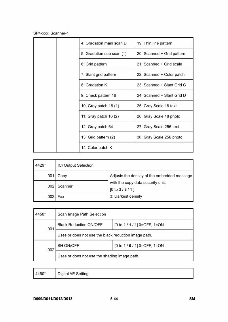
8/15/2019 Ricoh MP 4000 SM D009_D011_D012_D013 SERVICE MANUAL .pdf
http://slidepdf.com/reader/full/ricoh-mp-4000-sm-d009d011d012d013-service-manual-pdf 330/1162
SP4-xxx: Scanner-1
D009/D011/D012/D013 5-44 SM
4: Gradation main scan D 19: Thin line pattern
5: Gradation sub scan (1) 20: Scanned + Grid pattern
6: Grid pattern 21: Scanned + Grid scale
7: Slant grid pattern 22: Scanned + Color patch
8: Gradation K 23: Scanned + Slant Grid C
9: Check pattern 16 24: Scanned + Slant Grid D
10: Gray patch 16 (1) 25: Gray Scale 18 text
11: Gray patch 16 (2) 26: Gray Scale 18 photo
12: Gray patch 64 27: Gray Scale 256 text
13: Grid pattern (2) 28: Gray Scale 256 photo
14: Color patch K
4429* ICI Output Selection
001 Copy
002 Scanner
003 Fax
Adjusts the density of the embedded message
with the copy data security unit.
[0 to 3 / 3 / 1 ]
3: Darkest density
4450* Scan Image Path Selection
Black Reduction ON/OFF [0 to 1 / 1 / 1] 0=OFF, 1=ON001
Uses or does not use the black reduction image path.
SH ON/OFF [0 to 1 / 0 / 1] 0=OFF, 1=ON002
Uses or does not use the shading image path.
4460* Digital AE Setting
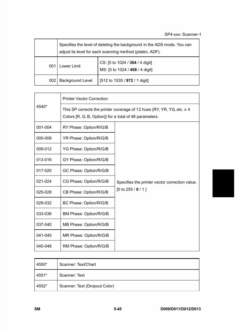
8/15/2019 Ricoh MP 4000 SM D009_D011_D012_D013 SERVICE MANUAL .pdf
http://slidepdf.com/reader/full/ricoh-mp-4000-sm-d009d011d012d013-service-manual-pdf 331/1162
SP4-xxx: Scanner-1
SM 5-45 D009/D011/D012/D013
S e r v i c e
T a b l e s
Specifies the level of deleting the background in the ADS mode. You can
adjust its level for each scanning method (platen, ADF).
001 Lower LimitCS: [0 to 1024 / 364 / 4 digit]
MS: [0 to 1024 / 408 / 4 digit]
002 Background Level [512 to 1535 / 972 / 1 digit]
Printer Vector Correction
4540*This SP corrects the printer coverage of 12 hues (RY, YR, YG, etc. x 4
Colors [R, G, B, Option]) for a total of 48 parameters.
001-004 RY Phase: Option/R/G/B
005-008 YR Phase: Option/R/G/B
009-012 YG Phase: Option/R/G/B
013-016 GY Phase: Option/R/G/B
017-020 GC Phase: Option/R/G/B
021-024 CG Phase: Option/R/G/B
025-028 CB Phase: Option/R/G/B
029-032 BC Phase: Option/R/G/B
033-036 BM Phase: Option/R/G/B
037-040 MB Phase: Option/R/G/B
041-040 MR Phase: Option/R/G/B
045-048 RM Phase: Option/R/G/B
Specifies the printer vector correction value.
[0 to 255 / 0 / 1 ]
4550* Scanner: Text/Chart
4551* Scanner: Text
4552* Scanner: Text (Dropout Color)

8/15/2019 Ricoh MP 4000 SM D009_D011_D012_D013 SERVICE MANUAL .pdf
http://slidepdf.com/reader/full/ricoh-mp-4000-sm-d009d011d012d013-service-manual-pdf 332/1162
SP4-xxx: Scanner-1
D009/D011/D012/D013 5-46 SM
4553* Scanner: Text/photo
4554* Scanner: photo
4565* Scanner: Gray Scale
4570* Scanner: Color: Text/photo
4571* Scanner: Color: Photo
4572* Scanner: Color: Auto Color
MTF: 0(Off), 1-15(High)[0 to 15 / 8 / 1 ]
0: MTF OFF-005
Sets the MTF level (Modulation Transfer Function) designed to improve
image contrast. Set higher for stronger effect, lower for weaker effect.
Smoothing: 0(x1), 1-7(High) [0 to 7 / 4 / 1 ]-006
Use to remove "jaggies" if they appear. Set higher for smoother images.
Brightness: 1-255 [1 to 255 / 128 / 1 ]-007
Set higher for darker, set lower for lighter.
Contrast: 1-255 [1 to 255 / 128 / 1 ]-008
Set higher for more contrast, set lower for less contrast.
Ind. Dot Erase: 0(x1), 1-7(High) [0 to 7 / 0 / 1 ]
-009 Sets the erasure level of Irregular Dots. Set higher for stronger effect, lower
for weaker effect.
0: Not activated
4580* Fax: Text/Chart
4581* Fax: Text
4582* Fax: Text/photo
4583* Fax: /Photo

8/15/2019 Ricoh MP 4000 SM D009_D011_D012_D013 SERVICE MANUAL .pdf
http://slidepdf.com/reader/full/ricoh-mp-4000-sm-d009d011d012d013-service-manual-pdf 333/1162
SP4-xxx: Scanner-1
SM 5-47 D009/D011/D012/D013
S e r v i c e
T a b l e s
4584* Fax: Original 1
4585* Fax: Original 2
MTF: 0(Off), 1-15(High)[0 to 15 / 8 / 1 ]
0: MTF OFF-005
Sets the MTF level (Modulation Transfer Function) designed to improve
image contrast. Set higher for stronger effect, lower for weaker effect.
Smoothing: 0(x1), 1-7(High) [0 to 7 / 4 / 1 ]-006
Use to remove "jaggies" if they appear. Set higher for smoother images.
Brightness: 1-255 [1 to 255 / 128 / 1 ]-007
Set higher for darker, set lower for lighter.
Contrast: 1-255 [1 to 255 / 128 / 1 ]-008
Set higher for more contrast, set lower for less contrast.
Ind. Dot Erase: 0(x1), 1-7(High) [0 to 7 / 0 / 1 ]
-009 Sets the erasure level of Irregular Dots. Set higher for stronger effect, lower
for weaker effect.
0: Not activated
Texture Erase: 0(Fix), 1-2(High) [0 to 2 / 0 / 1]
-010 Sets the erasure level of textures. Set higher for stronger effect, lower for
weaker effect. This SP (suffix "-010") only exists in SP4580, 4582 and 4583.
0: Not activated
SBU Version4600
Displays the ID of the SBU.
4602 Scanner Memory Access
001 Scanner Memory Access Enables the read and write check for the
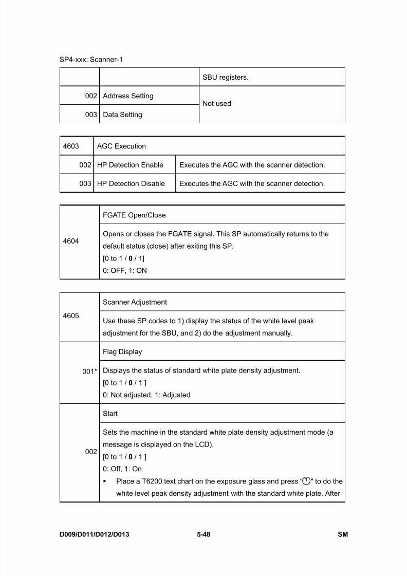
8/15/2019 Ricoh MP 4000 SM D009_D011_D012_D013 SERVICE MANUAL .pdf
http://slidepdf.com/reader/full/ricoh-mp-4000-sm-d009d011d012d013-service-manual-pdf 334/1162
SP4-xxx: Scanner-1
D009/D011/D012/D013 5-48 SM
SBU registers.
002 Address Setting
003 Data Setting
Not used
4603 AGC Execution
002 HP Detection Enable Executes the AGC with the scanner detection.
003 HP Detection Disable Executes the AGC with the scanner detection.
FGATE Open/Close
4604Opens or closes the FGATE signal. This SP automatically returns to the
default status (close) after exiting this SP.
[0 to 1 / 0 / 1]
0: OFF, 1: ON
Scanner Adjustment4605
Use these SP codes to 1) display the status of the white level peak
adjustment for the SBU, and 2) do the adjustment manually.
Flag Display
001* Displays the status of standard white plate density adjustment.
[0 to 1 / 0 / 1 ]
0: Not adjusted, 1: Adjusted
Start
002
Sets the machine in the standard white plate density adjustment mode (a
message is displayed on the LCD).
[0 to 1 / 0 / 1 ]
0: Off, 1: On
Place a T6200 text chart on the exposure glass and press " " to do the
white level peak density adjustment with the standard white plate. After
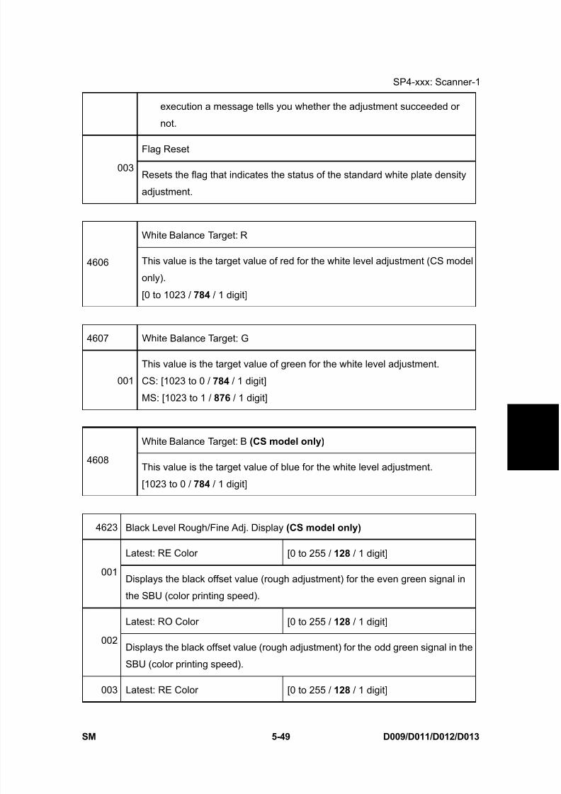
8/15/2019 Ricoh MP 4000 SM D009_D011_D012_D013 SERVICE MANUAL .pdf
http://slidepdf.com/reader/full/ricoh-mp-4000-sm-d009d011d012d013-service-manual-pdf 335/1162
SP4-xxx: Scanner-1
SM 5-49 D009/D011/D012/D013
S e r v i c e
T a b l e s
execution a message tells you whether the adjustment succeeded or
not.
Flag Reset
003Resets the flag that indicates the status of the standard white plate density
adjustment.
White Balance Target: R
4606 This value is the target value of red for the white level adjustment (CS model
only).[0 to 1023 / 784 / 1 digit]
4607 White Balance Target: G
001
This value is the target value of green for the white level adjustment.
CS: [1023 to 0 / 784 / 1 digit]
MS: [1023 to 1 / 876 / 1 digit]
White Balance Target: B (CS model only)
4608This value is the target value of blue for the white level adjustment.
[1023 to 0 / 784 / 1 digit]
4623 Black Level Rough/Fine Adj. Display (CS model only)
Latest: RE Color [0 to 255 / 128 / 1 digit]001
Displays the black offset value (rough adjustment) for the even green signal in
the SBU (color printing speed).
Latest: RO Color [0 to 255 / 128 / 1 digit]
002Displays the black offset value (rough adjustment) for the odd green signal in the
SBU (color printing speed).
003 Latest: RE Color [0 to 255 / 128 / 1 digit]

8/15/2019 Ricoh MP 4000 SM D009_D011_D012_D013 SERVICE MANUAL .pdf
http://slidepdf.com/reader/full/ricoh-mp-4000-sm-d009d011d012d013-service-manual-pdf 336/1162
SP4-xxx: Scanner-1
D009/D011/D012/D013 5-50 SM
Displays the black offset value (fine adjustment) for the even green signal in the
SBU (color printing speed).
Latest: RO Color [0 to 255 / 128 / 1 digit]
004Displays the black offset value (fine adjustment) for the odd green signal in the
SBU (color printing speed).
Latest: RE B/W [0 to 255 / 128 / 1 digit]
005Displays the black offset value (rough adjustment) for the even red signal in the
SBU (black and white printing speed).
Latest: RO B/W [0 to 255 / 128 / 1 digit]
006Displays the black offset value (rough adjustment) for the odd red signal in the
SBU (black and white printing speed).
Latest: RE B/W [0 to 255 / 128 / 1 digit]
007Displays the black offset value (fine adjustment) for the even red signal in the
SBU (black and white printing speed).
Latest: RO B/W [0 to 255 / 128 / 1 digit]
008Displays the black offset value (fine adjustment) for the odd red signal in the
SBU (black and white printing speed).
RE: Red Even signal, RO: Red Odd signal
4624 Black Level Rough/Fine Adj. Display (CS model only)
Latest: GE Color
001 [0 to 255 / 128 / 1 digit]
Displays the black offset value (rough adjustment) for the even green signal in
the SBU (color printing speed).
002 Latest: GO Color
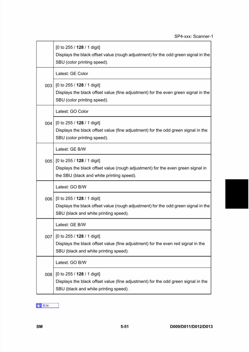
8/15/2019 Ricoh MP 4000 SM D009_D011_D012_D013 SERVICE MANUAL .pdf
http://slidepdf.com/reader/full/ricoh-mp-4000-sm-d009d011d012d013-service-manual-pdf 337/1162
SP4-xxx: Scanner-1
SM 5-51 D009/D011/D012/D013
S e r v i c e
T a b l e s
[0 to 255 / 128 / 1 digit]
Displays the black offset value (rough adjustment) for the odd green signal in the
SBU (color printing speed).
Latest: GE Color
003 [0 to 255 / 128 / 1 digit]
Displays the black offset value (fine adjustment) for the even green signal in the
SBU (color printing speed).
Latest: GO Color
004 [0 to 255 / 128 / 1 digit]Displays the black offset value (fine adjustment) for the odd green signal in the
SBU (color printing speed).
Latest: GE B/W
005 [0 to 255 / 128 / 1 digit]
Displays the black offset value (rough adjustment) for the even green signal in
the SBU (black and white printing speed).
Latest: GO B/W
006 [0 to 255 / 128 / 1 digit]
Displays the black offset value (rough adjustment) for the odd green signal in the
SBU (black and white printing speed).
Latest: GE B/W
007 [0 to 255 / 128 / 1 digit]
Displays the black offset value (fine adjustment) for the even red signal in the
SBU (black and white printing speed).
Latest: GO B/W
008 [0 to 255 / 128 / 1 digit]
Displays the black offset value (fine adjustment) for the odd green signal in the
SBU (black and white printing speed).
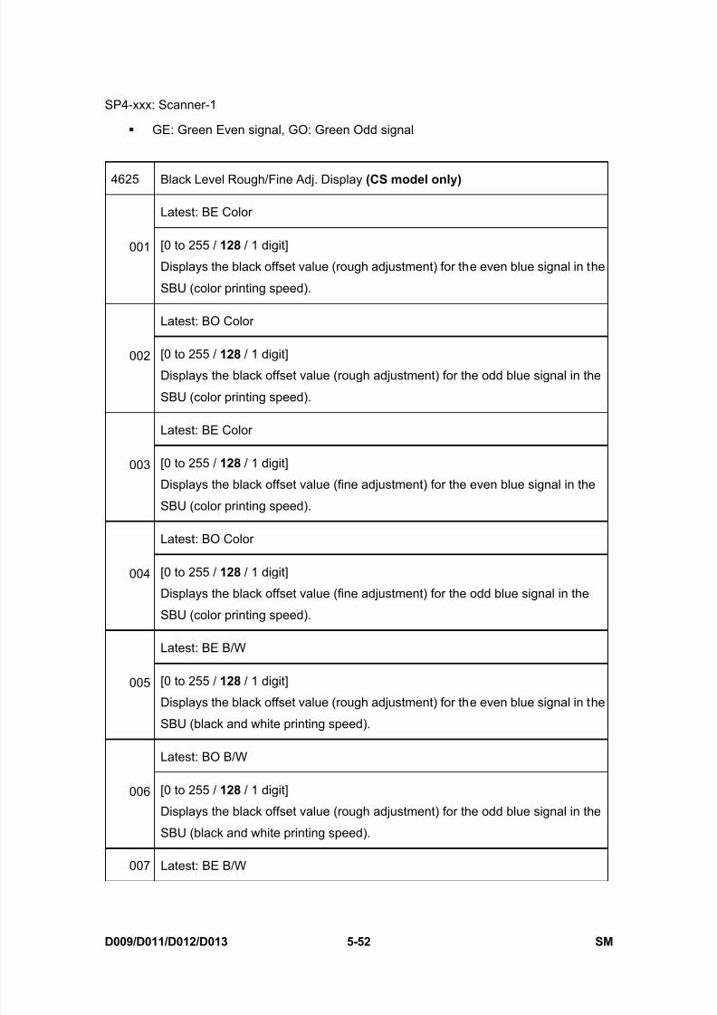
8/15/2019 Ricoh MP 4000 SM D009_D011_D012_D013 SERVICE MANUAL .pdf
http://slidepdf.com/reader/full/ricoh-mp-4000-sm-d009d011d012d013-service-manual-pdf 338/1162
SP4-xxx: Scanner-1
D009/D011/D012/D013 5-52 SM
GE: Green Even signal, GO: Green Odd signal
4625 Black Level Rough/Fine Adj. Display (CS model only)
Latest: BE Color
001 [0 to 255 / 128 / 1 digit]
Displays the black offset value (rough adjustment) for the even blue signal in the
SBU (color printing speed).
Latest: BO Color
002 [0 to 255 / 128 / 1 digit]Displays the black offset value (rough adjustment) for the odd blue signal in the
SBU (color printing speed).
Latest: BE Color
003 [0 to 255 / 128 / 1 digit]
Displays the black offset value (fine adjustment) for the even blue signal in the
SBU (color printing speed).
Latest: BO Color
004 [0 to 255 / 128 / 1 digit]
Displays the black offset value (fine adjustment) for the odd blue signal in the
SBU (color printing speed).
Latest: BE B/W
005 [0 to 255 / 128 / 1 digit]
Displays the black offset value (rough adjustment) for the even blue signal in the
SBU (black and white printing speed).
Latest: BO B/W
006 [0 to 255 / 128 / 1 digit]
Displays the black offset value (rough adjustment) for the odd blue signal in the
SBU (black and white printing speed).
007 Latest: BE B/W

8/15/2019 Ricoh MP 4000 SM D009_D011_D012_D013 SERVICE MANUAL .pdf
http://slidepdf.com/reader/full/ricoh-mp-4000-sm-d009d011d012d013-service-manual-pdf 339/1162
SP4-xxx: Scanner-1
SM 5-53 D009/D011/D012/D013
S e r v i c e
T a b l e s
[0 to 255 / 128 / 1 digit]
Displays the black offset value (fine adjustment) for the even blue signal in the
SBU (black and white printing speed).
Latest: BO B/W
008 [0 to 255 / 128 / 1 digit]
Displays the black offset value (fine adjustment) for the odd blue signal in the
SBU (black and white printing speed).
BE: Blue Even signal, BO: Blue Odd signal
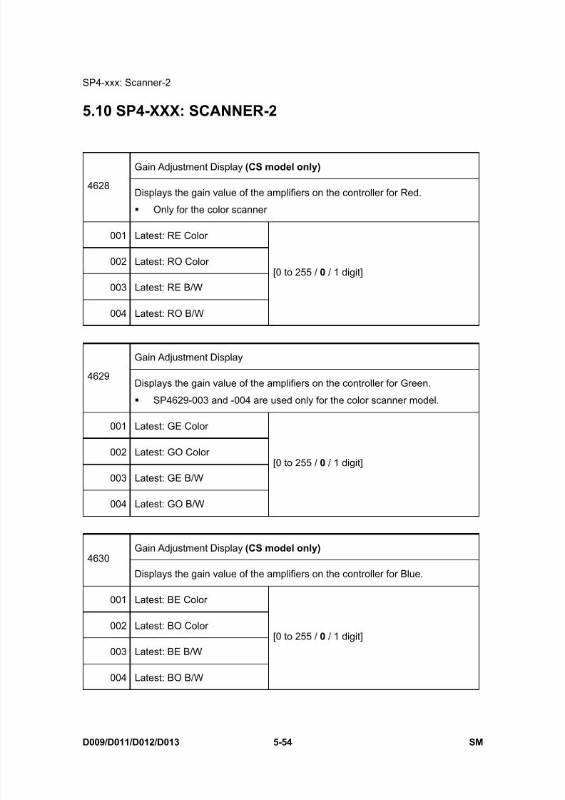
8/15/2019 Ricoh MP 4000 SM D009_D011_D012_D013 SERVICE MANUAL .pdf
http://slidepdf.com/reader/full/ricoh-mp-4000-sm-d009d011d012d013-service-manual-pdf 340/1162

8/15/2019 Ricoh MP 4000 SM D009_D011_D012_D013 SERVICE MANUAL .pdf
http://slidepdf.com/reader/full/ricoh-mp-4000-sm-d009d011d012d013-service-manual-pdf 341/1162
SP4-xxx: Scanner-2
SM 5-55 D009/D011/D012/D013
S e r v i c e
T a b l e s
SBU: Black Level Loop (CS model only)
4640Displays the black level adjustment time for each mode.
The black level adjustment is done twice. The 1st adjustment decides the
reference value for the 2nd adjustment.
001 Loop Count (1st): Color
002 Loop Count (1st): B/W
003 Loop Count (2nd): Color
004 Loop Count (2nd): B/W
[0 to 20 / 0 / 1 ]
SBU: White Level Loop4641
Displays the white level adjustment time for each mode.
001 Loop Count: Color
002 Loop Count: B/W
[0 to 20 / 0 / 1 ]
SBU: Time-out Error4646
Displays the result of the AGC adjustment.
001 Black Level Adjustment 1
002 Black Level Adjustment 2
[0 to 1 / 0 / 1 ]
0:OK, 1: AGC adjustment failure
003 White Level Adjustment [0 x 0000 to 0 x 003F / 0 / 1 Hex ]
SBU Error
Displays the result of the SBU connection check.
4647
Power-On
[0 to 1 / 0 / 1 ]
0: OK, 1: SBU connection check failure
If the SBU connection check fails, SC144-001, -002 or
-003 occurs.

8/15/2019 Ricoh MP 4000 SM D009_D011_D012_D013 SERVICE MANUAL .pdf
http://slidepdf.com/reader/full/ricoh-mp-4000-sm-d009d011d012d013-service-manual-pdf 342/1162
SP4-xxx: Scanner-2
D009/D011/D012/D013 5-56 SM
4654* Black Level 1: Rough/Fine Adj. Display (CS model only)
Previous: RE Color
001 [0 to 255 / 112 / 1 digit ]
Displays the previous black offset value (rough adjustment) for the even red
signal in the SBU (color printing speed).
Previous: RO Color
002 [0 to 255 / 112 / 1 digit ]
Displays the previous black offset value (rough adjustment) for the odd redsignal in the SBU (color printing speed).
Previous: RE Color
003 [0 to 255 / 128 / 1 digit ]
Displays the previous black offset value (fine adjustment) for the even red
signal in the SBU (color printing speed).
Previous: RO Color
004 [0 to 255 / 128 / 1 digit ]
Displays the previous black offset value (fine adjustment) for the odd red
signal in the SBU (color printing speed).
Previous: RE B/W
005 [0 to 255 / 112 / 1 digit ]
Displays the previous black offset value (rough adjustment) for the even red
signal in the SBU (black and white printing speed).
Previous: RO B/W
006 [0 to 255 / 112 / 1 digit ]
Displays the previous black offset value (rough adjustment) for the odd red
signal in the SBU (black and white printing speed).
Previous: RE B/W007
[0 to 255 / 128 / 1 digit ]
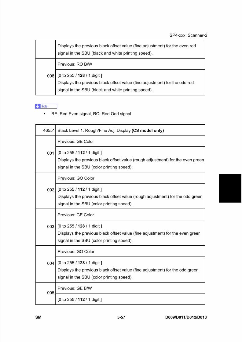
8/15/2019 Ricoh MP 4000 SM D009_D011_D012_D013 SERVICE MANUAL .pdf
http://slidepdf.com/reader/full/ricoh-mp-4000-sm-d009d011d012d013-service-manual-pdf 343/1162

8/15/2019 Ricoh MP 4000 SM D009_D011_D012_D013 SERVICE MANUAL .pdf
http://slidepdf.com/reader/full/ricoh-mp-4000-sm-d009d011d012d013-service-manual-pdf 344/1162
SP4-xxx: Scanner-2
D009/D011/D012/D013 5-58 SM
Displays the previous black offset value (rough adjustment) for the even green
signal in the SBU (black and white printing speed).
Previous: GO B/W
006 [0 to 255 / 112 / 1 digit ]
Displays the previous black offset value (rough adjustment) for the odd green
signal in the SBU (black and white printing speed).
Previous: GE B/W
007 [0 to 255 / 128 / 1 digit ]
Displays the previous black offset value (fine adjustment) for the even greensignal in the SBU (black and white printing speed).
Previous: GO B/W
008 [0 to 255 / 128 / 1 digit ]
Displays the previous black offset value (fine adjustment) for the odd green
signal in the SBU (black and white printing speed).
GE: Green Even signal, GO: Green Odd signal
4656* Black Level 1: Rough/Fine Adj. Display (CS model only)
Previous: BE Color
001 [0 to 255 / 112 / 1 digit ]
Displays the previous black offset value (rough adjustment) for the even blue
signal in the SBU (color printing speed).
Previous: BO Color
002 [0 to 255 / 112 / 1 digit ]
Displays the previous black offset value (rough adjustment) for the odd blue
signal in the SBU (color printing speed).
Previous: BE Color003
[0 to 255 / 128 / 1 digit ]

8/15/2019 Ricoh MP 4000 SM D009_D011_D012_D013 SERVICE MANUAL .pdf
http://slidepdf.com/reader/full/ricoh-mp-4000-sm-d009d011d012d013-service-manual-pdf 345/1162
SP4-xxx: Scanner-2
SM 5-59 D009/D011/D012/D013
S e r v i c e
T a b l e s
Displays the previous black offset value (fine adjustment) for the even blue
signal in the SBU (color printing speed).
Previous: BO Color
004 [0 to 255 / 128 / 1 digit ]
Displays the previous black offset value (fine adjustment) for the odd blue
signal in the SBU (color printing speed).
Previous: BE B/W
005 [0 to 255 / 112 / 1 digit ]
Displays the previous black offset value (rough adjustment) for the even bluesignal in the SBU (black and white printing speed).
Previous: BO B/W
006 [0 to 255 / 112 / 1 digit ]
Displays the previous black offset value (rough adjustment) for the odd blue
signal in the SBU (black and white printing speed).
Previous: BE B/W
007 [0 to 255 / 128 / 1 digit ]
Displays the previous black offset value (fine adjustment) for the even blue
signal in the SBU (black and white printing speed).
Previous: BO B/W
008 [0 to 255 / 128 / 1 digit ]
Displays the previous black offset value (fine adjustment) for the odd blue
signal in the SBU (black and white printing speed).
BE: Blue Even signal, BO: Blue Odd signal
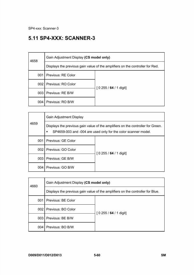
8/15/2019 Ricoh MP 4000 SM D009_D011_D012_D013 SERVICE MANUAL .pdf
http://slidepdf.com/reader/full/ricoh-mp-4000-sm-d009d011d012d013-service-manual-pdf 346/1162
SP4-xxx: Scanner-3
D009/D011/D012/D013 5-60 SM
5.11 SP4-XXX: SCANNER-3
Gain Adjustment Display (CS model only) 4658
Displays the previous gain value of the amplifiers on the controller for Red.
001 Previous: RE Color
002 Previous: RO Color
003 Previous: RE B/W
004 Previous: RO B/W
[ 0 255 / 64 / 1 digit]
Gain Adjustment Display
4659Displays the previous gain value of the amplifiers on the controller for Green.
SP4659-003 and -004 are used only for the color scanner model.
001 Previous: GE Color
002 Previous: GO Color
003 Previous: GE B/W
004 Previous: GO B/W
[ 0 255 / 64 / 1 digit]
Gain Adjustment Display (CS model only) 4660
Displays the previous gain value of the amplifiers on the controller for Blue.
001 Previous: BE Color
002 Previous: BO Color
003 Previous: BE B/W
004 Previous: BO B/W
[ 0 255 / 64 / 1 digit]

8/15/2019 Ricoh MP 4000 SM D009_D011_D012_D013 SERVICE MANUAL .pdf
http://slidepdf.com/reader/full/ricoh-mp-4000-sm-d009d011d012d013-service-manual-pdf 347/1162
SP4-xxx: Scanner-3
SM 5-61 D009/D011/D012/D013
S e r v i c e
T a b l e s
4661* Black Level 2: Rough/Fine Adj. Display (CS model only)
Before Previous: RE Color
001 [0 to 255 / 112 / 1 digit ]
Displays the previous 2nd black offset value (rough adjustment) for the even
red signal in the SBU (color printing speed).
Before Previous: RO Color
002 [0 to 255 / 112 / 1 digit ]
Displays the previous 2nd black offset value (rough adjustment) for the odd
red signal in the SBU (color printing speed).
Before Previous: RE Color
003 [0 to 255 / 128 / 1 digit ]
Displays the previous 2nd black offset value (fine adjustment) for the even red
signal in the SBU (color printing speed).
Before Previous: RO Color
004 [0 to 255 / 128 / 1 digit ]Displays the previous 2nd black offset value (fine adjustment) for the odd red
signal in the SBU (color printing speed).
Before Previous: RE B/W
005 [0 to 255 / 112 / 1 digit ]
Displays the previous 2nd black offset value (rough adjustment) for the even
red signal in the SBU (black and white printing speed).
Before Previous: RO B/W
006 [0 to 255 / 112 / 1 digit ]
Displays the previous 2nd black offset value (rough adjustment) for the odd
red signal in the SBU (black and white printing speed).
Before Previous: RE B/W
007[0 to 255 / 128 / 1 digit ]
Displays the previous 2nd black offset value (fine adjustment) for the even red
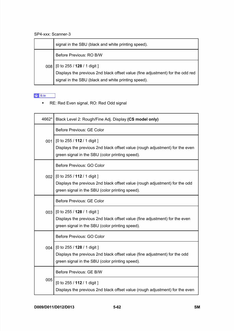
8/15/2019 Ricoh MP 4000 SM D009_D011_D012_D013 SERVICE MANUAL .pdf
http://slidepdf.com/reader/full/ricoh-mp-4000-sm-d009d011d012d013-service-manual-pdf 348/1162
SP4-xxx: Scanner-3
D009/D011/D012/D013 5-62 SM
signal in the SBU (black and white printing speed).
Before Previous: RO B/W
008 [0 to 255 / 128 / 1 digit ]
Displays the previous 2nd black offset value (fine adjustment) for the odd red
signal in the SBU (black and white printing speed).
RE: Red Even signal, RO: Red Odd signal
4662* Black Level 2: Rough/Fine Adj. Display (CS model only)
Before Previous: GE Color
001 [0 to 255 / 112 / 1 digit ]
Displays the previous 2nd black offset value (rough adjustment) for the even
green signal in the SBU (color printing speed).
Before Previous: GO Color
002 [0 to 255 / 112 / 1 digit ]
Displays the previous 2nd black offset value (rough adjustment) for the odd
green signal in the SBU (color printing speed).
Before Previous: GE Color
003 [0 to 255 / 128 / 1 digit ]
Displays the previous 2nd black offset value (fine adjustment) for the even
green signal in the SBU (color printing speed).
Before Previous: GO Color
004 [0 to 255 / 128 / 1 digit ]
Displays the previous 2nd black offset value (fine adjustment) for the odd
green signal in the SBU (color printing speed).
Before Previous: GE B/W
005[0 to 255 / 112 / 1 digit ]
Displays the previous 2nd black offset value (rough adjustment) for the even
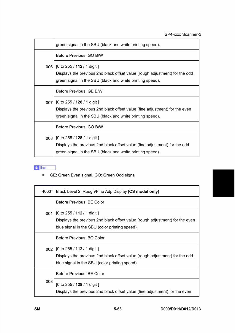
8/15/2019 Ricoh MP 4000 SM D009_D011_D012_D013 SERVICE MANUAL .pdf
http://slidepdf.com/reader/full/ricoh-mp-4000-sm-d009d011d012d013-service-manual-pdf 349/1162
SP4-xxx: Scanner-3
SM 5-63 D009/D011/D012/D013
S e r v i c e
T a b l e s
green signal in the SBU (black and white printing speed).
Before Previous: GO B/W
006 [0 to 255 / 112 / 1 digit ]
Displays the previous 2nd black offset value (rough adjustment) for the odd
green signal in the SBU (black and white printing speed).
Before Previous: GE B/W
007 [0 to 255 / 128 / 1 digit ]
Displays the previous 2nd black offset value (fine adjustment) for the even
green signal in the SBU (black and white printing speed).
Before Previous: GO B/W
008 [0 to 255 / 128 / 1 digit ]
Displays the previous 2nd black offset value (fine adjustment) for the odd
green signal in the SBU (black and white printing speed).
GE: Green Even signal, GO: Green Odd signal
4663* Black Level 2: Rough/Fine Adj. Display (CS model only)
Before Previous: BE Color
001 [0 to 255 / 112 / 1 digit ]
Displays the previous 2nd black offset value (rough adjustment) for the even
blue signal in the SBU (color printing speed).
Before Previous: BO Color
002 [0 to 255 / 112 / 1 digit ]
Displays the previous 2nd black offset value (rough adjustment) for the odd
blue signal in the SBU (color printing speed).
Before Previous: BE Color
003[0 to 255 / 128 / 1 digit ]
Displays the previous 2nd black offset value (fine adjustment) for the even
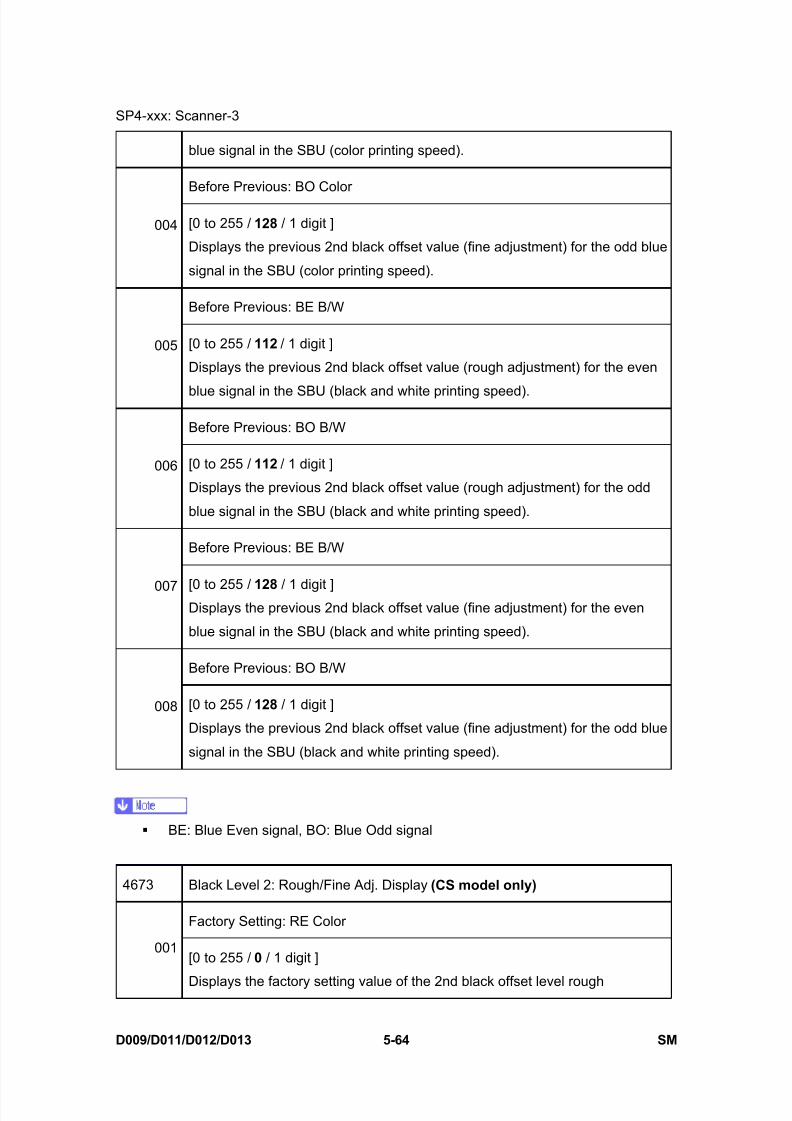
8/15/2019 Ricoh MP 4000 SM D009_D011_D012_D013 SERVICE MANUAL .pdf
http://slidepdf.com/reader/full/ricoh-mp-4000-sm-d009d011d012d013-service-manual-pdf 350/1162
SP4-xxx: Scanner-3
D009/D011/D012/D013 5-64 SM
blue signal in the SBU (color printing speed).
Before Previous: BO Color
004 [0 to 255 / 128 / 1 digit ]
Displays the previous 2nd black offset value (fine adjustment) for the odd blue
signal in the SBU (color printing speed).
Before Previous: BE B/W
005 [0 to 255 / 112 / 1 digit ]
Displays the previous 2nd black offset value (rough adjustment) for the even
blue signal in the SBU (black and white printing speed).
Before Previous: BO B/W
006 [0 to 255 / 112 / 1 digit ]
Displays the previous 2nd black offset value (rough adjustment) for the odd
blue signal in the SBU (black and white printing speed).
Before Previous: BE B/W
007 [0 to 255 / 128 / 1 digit ]Displays the previous 2nd black offset value (fine adjustment) for the even
blue signal in the SBU (black and white printing speed).
Before Previous: BO B/W
008 [0 to 255 / 128 / 1 digit ]
Displays the previous 2nd black offset value (fine adjustment) for the odd blue
signal in the SBU (black and white printing speed).
BE: Blue Even signal, BO: Blue Odd signal
4673 Black Level 2: Rough/Fine Adj. Display (CS model only)
Factory Setting: RE Color
001[0 to 255 / 0 / 1 digit ]
Displays the factory setting value of the 2nd black offset level rough
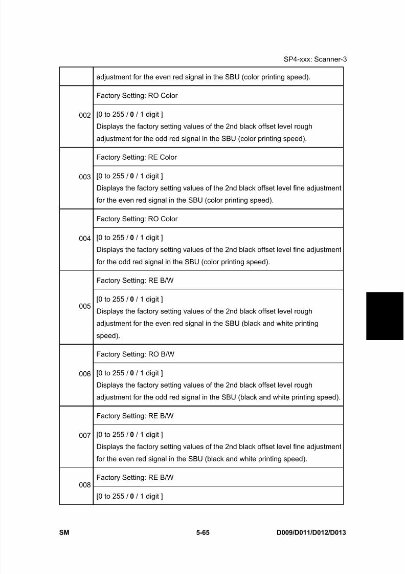
8/15/2019 Ricoh MP 4000 SM D009_D011_D012_D013 SERVICE MANUAL .pdf
http://slidepdf.com/reader/full/ricoh-mp-4000-sm-d009d011d012d013-service-manual-pdf 351/1162
SP4-xxx: Scanner-3
SM 5-65 D009/D011/D012/D013
S e r v i c e
T a b l e s
adjustment for the even red signal in the SBU (color printing speed).
Factory Setting: RO Color
002 [0 to 255 / 0 / 1 digit ]
Displays the factory setting values of the 2nd black offset level rough
adjustment for the odd red signal in the SBU (color printing speed).
Factory Setting: RE Color
003 [0 to 255 / 0 / 1 digit ]
Displays the factory setting values of the 2nd black offset level fine adjustment
for the even red signal in the SBU (color printing speed).
Factory Setting: RO Color
004 [0 to 255 / 0 / 1 digit ]
Displays the factory setting values of the 2nd black offset level fine adjustment
for the odd red signal in the SBU (color printing speed).
Factory Setting: RE B/W
005 [0 to 255 / 0 / 1 digit ]Displays the factory setting values of the 2nd black offset level rough
adjustment for the even red signal in the SBU (black and white printing
speed).
Factory Setting: RO B/W
006 [0 to 255 / 0 / 1 digit ]
Displays the factory setting values of the 2nd black offset level rough
adjustment for the odd red signal in the SBU (black and white printing speed).
Factory Setting: RE B/W
007 [0 to 255 / 0 / 1 digit ]
Displays the factory setting values of the 2nd black offset level fine adjustment
for the even red signal in the SBU (black and white printing speed).
Factory Setting: RE B/W008
[0 to 255 / 0 / 1 digit ]
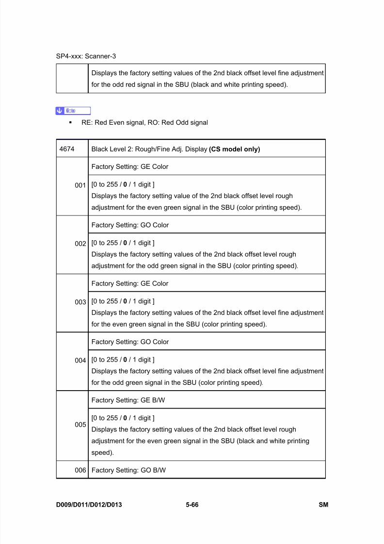
8/15/2019 Ricoh MP 4000 SM D009_D011_D012_D013 SERVICE MANUAL .pdf
http://slidepdf.com/reader/full/ricoh-mp-4000-sm-d009d011d012d013-service-manual-pdf 352/1162
SP4-xxx: Scanner-3
D009/D011/D012/D013 5-66 SM
Displays the factory setting values of the 2nd black offset level fine adjustment
for the odd red signal in the SBU (black and white printing speed).
RE: Red Even signal, RO: Red Odd signal
4674 Black Level 2: Rough/Fine Adj. Display (CS model only)
Factory Setting: GE Color
001 [0 to 255 / 0 / 1 digit ]
Displays the factory setting value of the 2nd black offset level rough
adjustment for the even green signal in the SBU (color printing speed).
Factory Setting: GO Color
002 [0 to 255 / 0 / 1 digit ]
Displays the factory setting values of the 2nd black offset level rough
adjustment for the odd green signal in the SBU (color printing speed).
Factory Setting: GE Color
003 [0 to 255 / 0 / 1 digit ]
Displays the factory setting values of the 2nd black offset level fine adjustment
for the even green signal in the SBU (color printing speed).
Factory Setting: GO Color
004 [0 to 255 / 0 / 1 digit ]
Displays the factory setting values of the 2nd black offset level fine adjustment
for the odd green signal in the SBU (color printing speed).
Factory Setting: GE B/W
005[0 to 255 / 0 / 1 digit ]
Displays the factory setting values of the 2nd black offset level rough
adjustment for the even green signal in the SBU (black and white printing
speed).
006 Factory Setting: GO B/W

8/15/2019 Ricoh MP 4000 SM D009_D011_D012_D013 SERVICE MANUAL .pdf
http://slidepdf.com/reader/full/ricoh-mp-4000-sm-d009d011d012d013-service-manual-pdf 353/1162
SP4-xxx: Scanner-3
SM 5-67 D009/D011/D012/D013
S e r v i c e
T a b l e s
[0 to 255 / 0 / 1 digit ]
Displays the factory setting values of the 2nd black offset level rough
adjustment for the odd green signal in the SBU (black and white printingspeed).
Factory Setting: GE B/W
007 [0 to 255 / 0 / 1 digit ]
Displays the factory setting values of the 2nd black offset level fine adjustment
for the even green signal in the SBU (black and white printing speed).
Factory Setting: GE B/W
008 [0 to 255 / 0 / 1 digit ]
Displays the factory setting values of the 2nd black offset level fine adjustment
for the odd green signal in the SBU (black and white printing speed).
GE: Green Even signal, GO: Green Odd signal
4675 Black Level 2: Rough/Fine Adj. Display (CS model only)
Factory Setting: BE Color
001 [0 to 255 / 0 / 1 digit ]
Displays the factory setting value of the 2nd black offset level rough
adjustment for the even blue signal in the SBU (color printing speed).
Factory Setting: BO Color
002 [0 to 255 / 0 / 1 digit ]Displays the factory setting values of the 2nd black offset level rough
adjustment for the odd blue signal in the SBU (color printing speed).
Factory Setting: BE Color
003 [0 to 255 / 0 / 1 digit ]
Displays the factory setting values of the 2nd black offset level fine adjustment
for the even blue signal in the SBU (color printing speed).
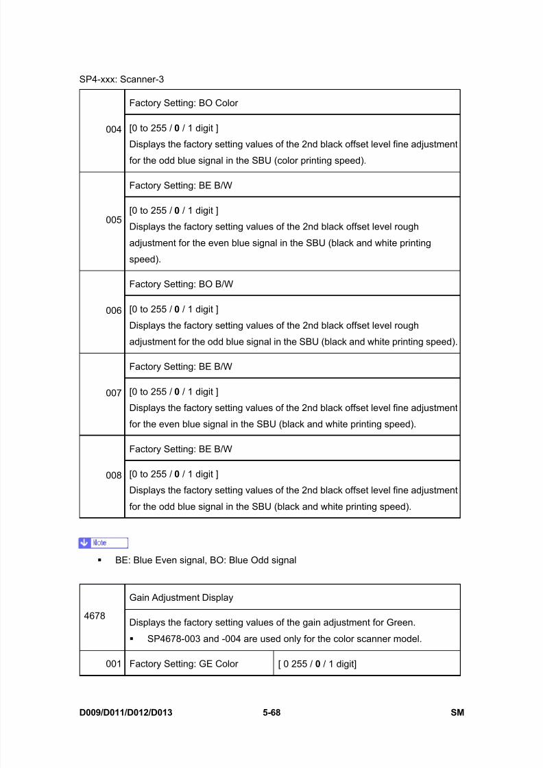
8/15/2019 Ricoh MP 4000 SM D009_D011_D012_D013 SERVICE MANUAL .pdf
http://slidepdf.com/reader/full/ricoh-mp-4000-sm-d009d011d012d013-service-manual-pdf 354/1162
SP4-xxx: Scanner-3
D009/D011/D012/D013 5-68 SM
Factory Setting: BO Color
004[0 to 255 / 0 / 1 digit ]
Displays the factory setting values of the 2nd black offset level fine adjustment
for the odd blue signal in the SBU (color printing speed).
Factory Setting: BE B/W
005[0 to 255 / 0 / 1 digit ]
Displays the factory setting values of the 2nd black offset level rough
adjustment for the even blue signal in the SBU (black and white printing
speed).
Factory Setting: BO B/W
006 [0 to 255 / 0 / 1 digit ]
Displays the factory setting values of the 2nd black offset level rough
adjustment for the odd blue signal in the SBU (black and white printing speed).
Factory Setting: BE B/W
007 [0 to 255 / 0 / 1 digit ]
Displays the factory setting values of the 2nd black offset level fine adjustment
for the even blue signal in the SBU (black and white printing speed).
Factory Setting: BE B/W
008 [0 to 255 / 0 / 1 digit ]
Displays the factory setting values of the 2nd black offset level fine adjustment
for the odd blue signal in the SBU (black and white printing speed).
BE: Blue Even signal, BO: Blue Odd signal
Gain Adjustment Display
4678Displays the factory setting values of the gain adjustment for Green.
SP4678-003 and -004 are used only for the color scanner model.
001 Factory Setting: GE Color [ 0 255 / 0 / 1 digit]
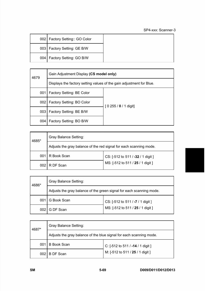
8/15/2019 Ricoh MP 4000 SM D009_D011_D012_D013 SERVICE MANUAL .pdf
http://slidepdf.com/reader/full/ricoh-mp-4000-sm-d009d011d012d013-service-manual-pdf 355/1162
SP4-xxx: Scanner-3
SM 5-69 D009/D011/D012/D013
S e r v i c e
T a b l e s
002 Factory Setting:: GO Color
003 Factory Setting: GE B/W
004 Factory Setting: GO B/W
Gain Adjustment Display (CS model only) 4679
Displays the factory setting values of the gain adjustment for Blue.
001 Factory Setting: BE Color
002 Factory Setting: BO Color
003 Factory Setting: BE B/W
004 Factory Setting: BO B/W
[ 0 255 / 0 / 1 digit]
Gray Balance Setting:4685*
Adjusts the gray balance of the red signal for each scanning mode.
001 R Book Scan
002 R DF Scan
CS: [-512 to 511 / -32 / 1 digit ]
MS: [-512 to 511 / 25 / 1 digit ]
Gray Balance Setting:4686*
Adjusts the gray balance of the green signal for each scanning mode.
001 G Book Scan
002 G DF Scan
CS: [-512 to 511 / -7 / 1 digit ]
MS: [-512 to 511 / 25 / 1 digit ]
Gray Balance Setting:4687*
Adjusts the gray balance of the blue signal for each scanning mode.
001 B Book Scan
002 B DF Scan
C: [-512 to 511 / -14 / 1 digit ]
M: [-512 to 511 / 25 / 1 digit ]

8/15/2019 Ricoh MP 4000 SM D009_D011_D012_D013 SERVICE MANUAL .pdf
http://slidepdf.com/reader/full/ricoh-mp-4000-sm-d009d011d012d013-service-manual-pdf 356/1162
SP4-xxx: Scanner-3
D009/D011/D012/D013 5-70 SM
DF: Density Adjustment
Adjusts the white shading parameter when scanning an image with the ARDF.
Adjusts the density level if the ID of outputs made in the DF and Platen mode
is different.
4688*
[50 to 150 / 100 / 1 % ]
White Peak Level (CS model only) 4690
Displays the peak level of the white level scanning.
001 RE
002 RO
003 RE: BK
004 RO: BK
[0 to 1023 / 0 / 1 digit ]
White Peak Level
4691Displays the peak level of the white level scanning.
SP 4691-003 and -004 are used only for the color scanner model.
001 GE
002 GO
003 GE: BK
004 GO: BK
[0 to 1023 / 0 / 1 digit ]
White Peak Level (CS model only) 4692
Displays the peak level of the white level scanning.
001 BE
002 BO
[0 to 1023 / 0 / 1 digit ]
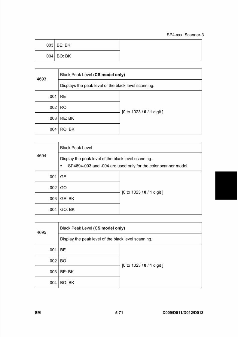
8/15/2019 Ricoh MP 4000 SM D009_D011_D012_D013 SERVICE MANUAL .pdf
http://slidepdf.com/reader/full/ricoh-mp-4000-sm-d009d011d012d013-service-manual-pdf 357/1162
SP4-xxx: Scanner-3
SM 5-71 D009/D011/D012/D013
S e r v i c e
T a b l e s
003 BE: BK
004 BO: BK
Black Peak Level (CS model only) 4693
Displays the peak level of the black level scanning.
001 RE
002 RO
003 RE: BK
004 RO: BK
[0 to 1023 / 0 / 1 digit ]
Black Peak Level
4694Display the peak level of the black level scanning.
SP4694-003 and -004 are used only for the color scanner model.
001 GE
002 GO
003 GE: BK
004 GO: BK
[0 to 1023 / 0 / 1 digit ]
Black Peak Level (CS model only) 4695
Display the peak level of the black level scanning.
001 BE
002 BO
003 BE: BK
004 BO: BK
[0 to 1023 / 0 / 1 digit ]

8/15/2019 Ricoh MP 4000 SM D009_D011_D012_D013 SERVICE MANUAL .pdf
http://slidepdf.com/reader/full/ricoh-mp-4000-sm-d009d011d012d013-service-manual-pdf 358/1162
SP4-xxx: Scanner-3
D009/D011/D012/D013 5-72 SM
4802 DF Shading Free Run
001 Lamp ON
002 Lamp OFF
[0 to 1 / 0 / 1 ]
Executes the scanner free run of the shading
movement with exposure lamp on or off.
Press "OFF" to stop this free run. Otherwise, the free
run continues.
4803* Home Position Adjustment (DFU) [-1 to 1 / 0 / 0.1 mm ]
001 Adjusts the home position of the exposure lamp.
4804* Returning to Scanner HP
Moves the exposure lamp a short distance
and immediately returns it to its home
position.
Touch [Execute] > ”Completed” > [Exit]
Moving from Scanner HP
4806
Moves the exposure lamp a short distance away from the home position and
stops.
Touch [Execute] > ”Completed” > [Exit]
Do SP4804 to return the exposure lamp to its home position.
This SP is done before shipping the machine to another location.
Cycling the machine power off/on also returns the exposure lamp to
its home position.
Filter Setting
4903*
This SP code sets the threshold value for independent dot erase.
These adjustments are effective only for the “Custom Setting” original type.
The "0" setting disables independent dot erase.
A higher setting detects more spurious dots for erasing. However, this
could erase dots in images that contain areas filled by dithering.

8/15/2019 Ricoh MP 4000 SM D009_D011_D012_D013 SERVICE MANUAL .pdf
http://slidepdf.com/reader/full/ricoh-mp-4000-sm-d009d011d012d013-service-manual-pdf 359/1162
SP4-xxx: Scanner-3
SM 5-73 D009/D011/D012/D013
S e r v i c e
T a b l e s
001 Independent Dot Erase: Text/Photo
002 Independent Dot Erase: Generation Copy
[0 to 7 / 0 / 1 ]
4905* Dither SelectionChanges the parameters for dithering.
[0 to 255 / 0 / 1 ]
4907 SBU Test Pattern Change
[0 to 255 / 0 / 1 ]
0: Default (Scanning Image)1: Grid pattern
2: Gradation main scan
3: Gradation sub scan
4 to 250: Default (Scanning Image)
4908* Factory Setting Input
Execution: ON/OFF001
Copies the settings of the previous black level adjustment and gain
adjustment to the factory settings.
Execution Flag [0 to 1 / 0 / 1 ]
002Displays the execution flag of the factory setting input. "1" means that the
scanner settings have been adjusted at the factory.
4918 Manual Gamma Adjustment (DFU)
Adjusts the offset data of the printer gamma for black in Photo mode or
Letter mode.
Touch [Change] to open the printer gamma screen.
Enter the manual gamma adjustment screen.
4993* Highlight Correction
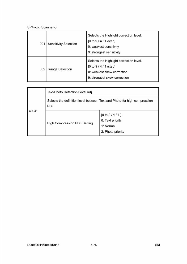
8/15/2019 Ricoh MP 4000 SM D009_D011_D012_D013 SERVICE MANUAL .pdf
http://slidepdf.com/reader/full/ricoh-mp-4000-sm-d009d011d012d013-service-manual-pdf 360/1162
SP4-xxx: Scanner-3
D009/D011/D012/D013 5-74 SM
001 Sensitivity Selection
Selects the Highlight correction level.
[0 to 9 / 4 / 1 /step]
0: weakest sensitivity9: strongest sensitivity
002 Range Selection
Selects the Highlight correction level.
[0 to 9 / 4 / 1 /step]
0: weakest skew correction,
9: strongest skew correction
Text/Photo Detection Level Adj.
Selects the definition level between Text and Photo for high compression
PDF.4994*
High Compression PDF Setting
[0 to 2 / 1 / 1 ]
0: Text priority
1: Normal
2: Photo priority
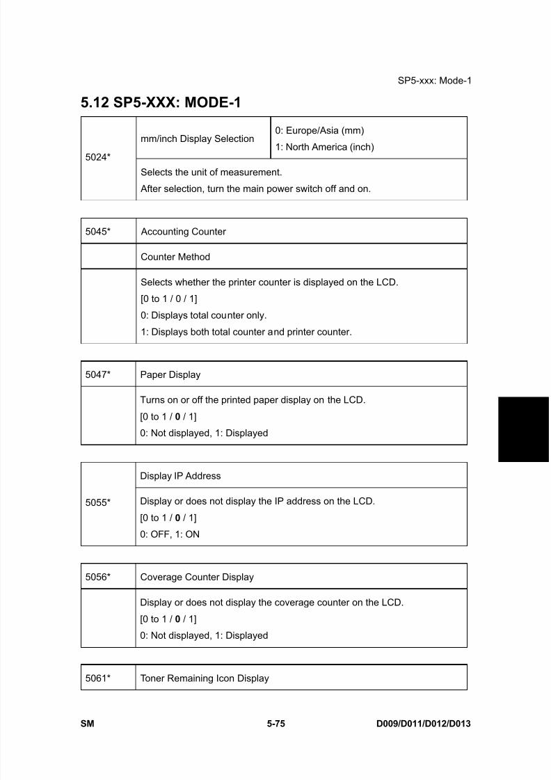
8/15/2019 Ricoh MP 4000 SM D009_D011_D012_D013 SERVICE MANUAL .pdf
http://slidepdf.com/reader/full/ricoh-mp-4000-sm-d009d011d012d013-service-manual-pdf 361/1162
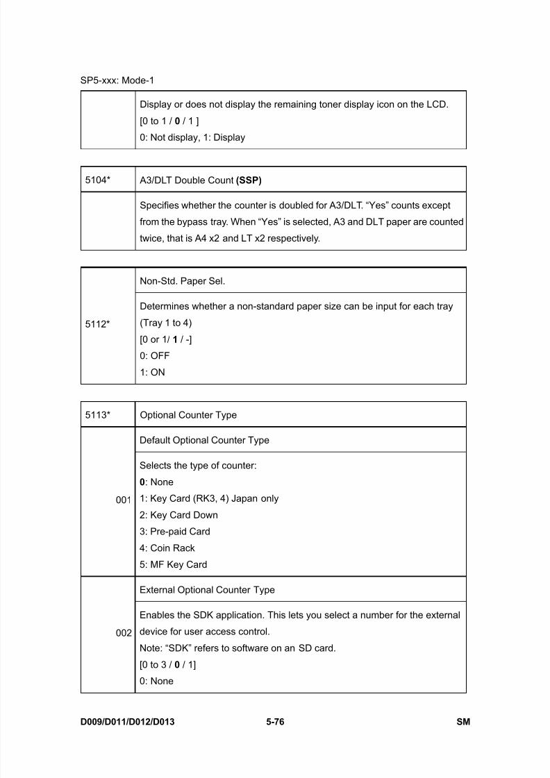
8/15/2019 Ricoh MP 4000 SM D009_D011_D012_D013 SERVICE MANUAL .pdf
http://slidepdf.com/reader/full/ricoh-mp-4000-sm-d009d011d012d013-service-manual-pdf 362/1162
SP5-xxx: Mode-1
D009/D011/D012/D013 5-76 SM
Display or does not display the remaining toner display icon on the LCD.
[0 to 1 / 0 / 1 ]
0: Not display, 1: Display
5104* A3/DLT Double Count (SSP)
Specifies whether the counter is doubled for A3/DLT. “Yes” counts except
from the bypass tray. When “Yes” is selected, A3 and DLT paper are counted
twice, that is A4 x2 and LT x2 respectively.
Non-Std. Paper Sel.
5112*
Determines whether a non-standard paper size can be input for each tray
(Tray 1 to 4)
[0 or 1/ 1 / -]
0: OFF
1: ON
5113* Optional Counter Type
Default Optional Counter Type
001
Selects the type of counter:
0: None
1: Key Card (RK3, 4) Japan only
2: Key Card Down
3: Pre-paid Card
4: Coin Rack
5: MF Key Card
External Optional Counter Type
002
Enables the SDK application. This lets you select a number for the external
device for user access control.
Note: “SDK” refers to software on an SD card.
[0 to 3 / 0 / 1]
0: None
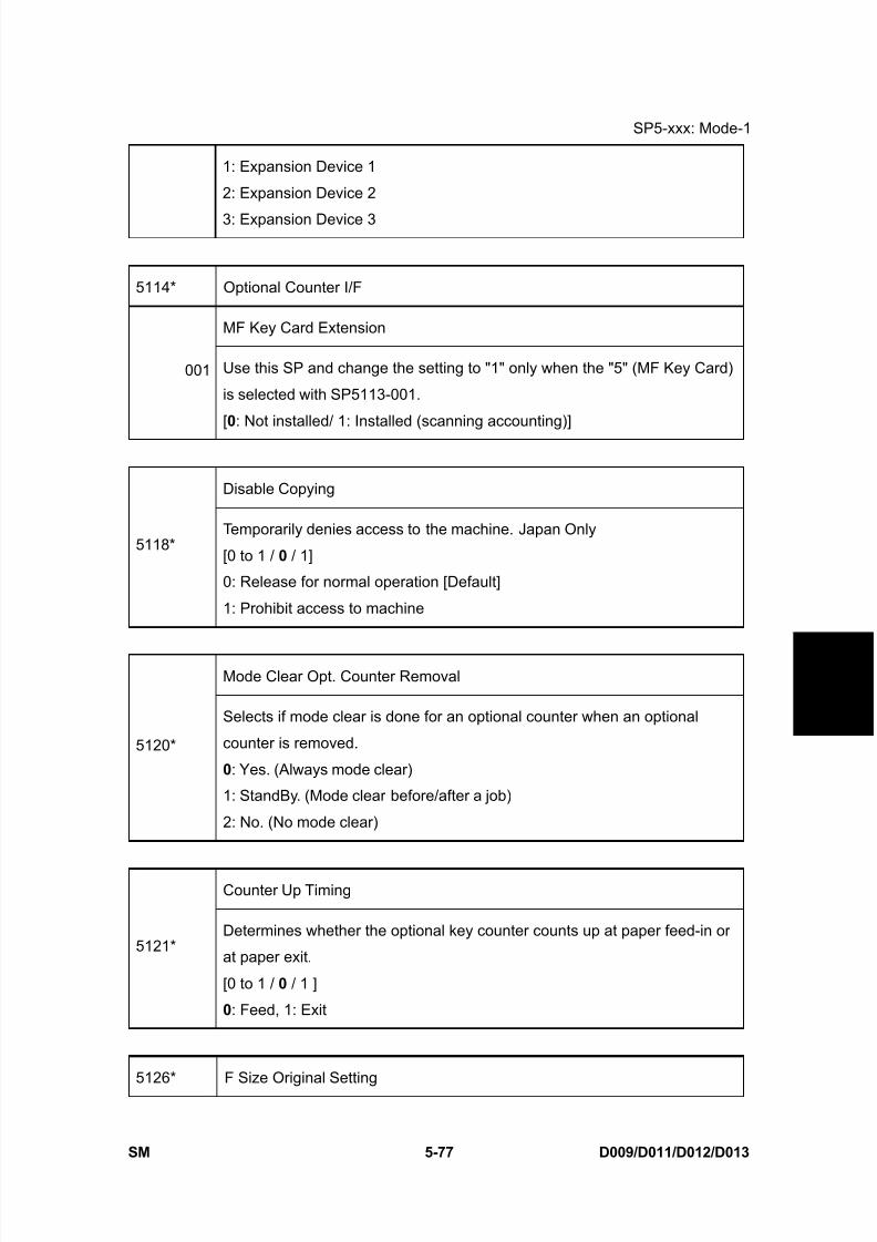
8/15/2019 Ricoh MP 4000 SM D009_D011_D012_D013 SERVICE MANUAL .pdf
http://slidepdf.com/reader/full/ricoh-mp-4000-sm-d009d011d012d013-service-manual-pdf 363/1162
SP5-xxx: Mode-1
SM 5-77 D009/D011/D012/D013
S e r v i c e
T a b l e s
1: Expansion Device 1
2: Expansion Device 2
3: Expansion Device 3
5114* Optional Counter I/F
MF Key Card Extension
001 Use this SP and change the setting to "1" only when the "5" (MF Key Card)
is selected with SP5113-001.
[0: Not installed/ 1: Installed (scanning accounting)]
Disable Copying
5118*Temporarily denies access to the machine. Japan Only
[0 to 1 / 0 / 1]
0: Release for normal operation [Default]
1: Prohibit access to machine
Mode Clear Opt. Counter Removal
5120*
Selects if mode clear is done for an optional counter when an optional
counter is removed.
0: Yes. (Always mode clear)
1: StandBy. (Mode clear before/after a job)
2: No. (No mode clear)
Counter Up Timing
5121*Determines whether the optional key counter counts up at paper feed-in or
at paper exit.
[0 to 1 / 0 / 1 ]
0: Feed, 1: Exit
5126* F Size Original Setting
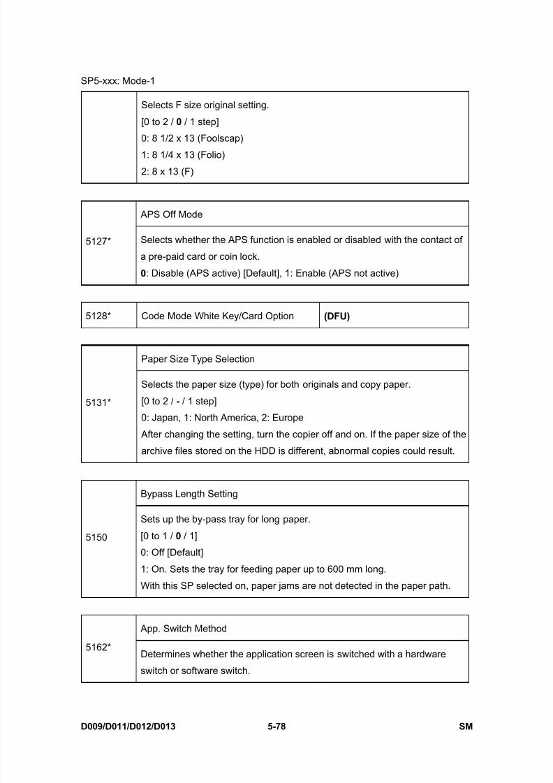
8/15/2019 Ricoh MP 4000 SM D009_D011_D012_D013 SERVICE MANUAL .pdf
http://slidepdf.com/reader/full/ricoh-mp-4000-sm-d009d011d012d013-service-manual-pdf 364/1162

8/15/2019 Ricoh MP 4000 SM D009_D011_D012_D013 SERVICE MANUAL .pdf
http://slidepdf.com/reader/full/ricoh-mp-4000-sm-d009d011d012d013-service-manual-pdf 365/1162
SP5-xxx: Mode-1
SM 5-79 D009/D011/D012/D013
S e r v i c e
T a b l e s
0: Soft Key Set
1: Hard Key Set
5165* Z - fold Position
001 to 008 Not used
Fax Printing Mode at Optional Counter Off
5167*
Enables or disables the automatic print out without an accounting device.
This SP is used when the receiving fax is accounted for by an externalaccounting device.
0: Automatic printing
1: No automatic printing
CE Login
5169*
If you will change the printer bit switches, you must ‘log in’ to service mode
with this SP before you go into the printer SP mode.[0 to 1 / 0 / 1]
0: Off. Printer bit switches cannot be adjusted.
1: On. Printer bit switches can be adjusted.
By-pass Tray Paper Size Error [0 to 1 / 0 / 1 ] 0= OFF, 1= ON
5179* This SP determines whether a paper size error prompt appears when the
machine detects the wrong paper size for the job and during feed from theby-pass tray.
Paper Size Setting5181*
Adjusts the paper size for each tray. [0 to 1 / 0 / 1]
001 Tray 1: 1 0: A4 LEF, 1: LT LEF
002 Tray 1: 2 0: A3, 1: DLT

8/15/2019 Ricoh MP 4000 SM D009_D011_D012_D013 SERVICE MANUAL .pdf
http://slidepdf.com/reader/full/ricoh-mp-4000-sm-d009d011d012d013-service-manual-pdf 366/1162
SP5-xxx: Mode-1
D009/D011/D012/D013 5-80 SM
003 Tray 1: 3 0: B4, 1: LG
004 Tray 1: 4 0: B5 LEF, 1: Exe LEF
005 Tray 2: 1 0: A4 LEF, 1: LT LEF
006 Tray 2: 2 0: A3, 1: DLT
007 Tray 2: 3 0: B4, 1: LG
008 Tray 2: 4 0: B5 LEF, 1: Exe LEF
009 Tray 3: 1 (Tandem) 0: A4 LEF, 1: LT LEF
010 Tray 3: 2 0: A3, 1: DLT
011 Tray 3: 3 0: B4, 1: LG
012 Tray 3: 4 0: B5 LEF, 1: Exe LEF
013 Tray 4: 1 0: A4 LEF, 1: LT LEF
014 Tray 4: 2 0: A3, 1: DLT
015 Tray 4: 3 0: B4, 1: LG
016 Tray 4: 4 0: B5 LEF, 1: Exe LEF
017 LCT [0 to 2 / - / 1 ] 0: A4 LEF, 1: LT LEF, 2: B5 LEF
RK4 Setting (Japan only)
5186*
Enable or distance the prevention for RK4 (Accounting device)
Disconnection. If the RK4 is disconnected for 10 seconds when this SP isset to “1 (Enable)”, the machine automatically jams a sheet of paper and
stops.
[0 to 1 / 0 / 1]
Copy Nv Version5188*
Displays the NV version on the controller.
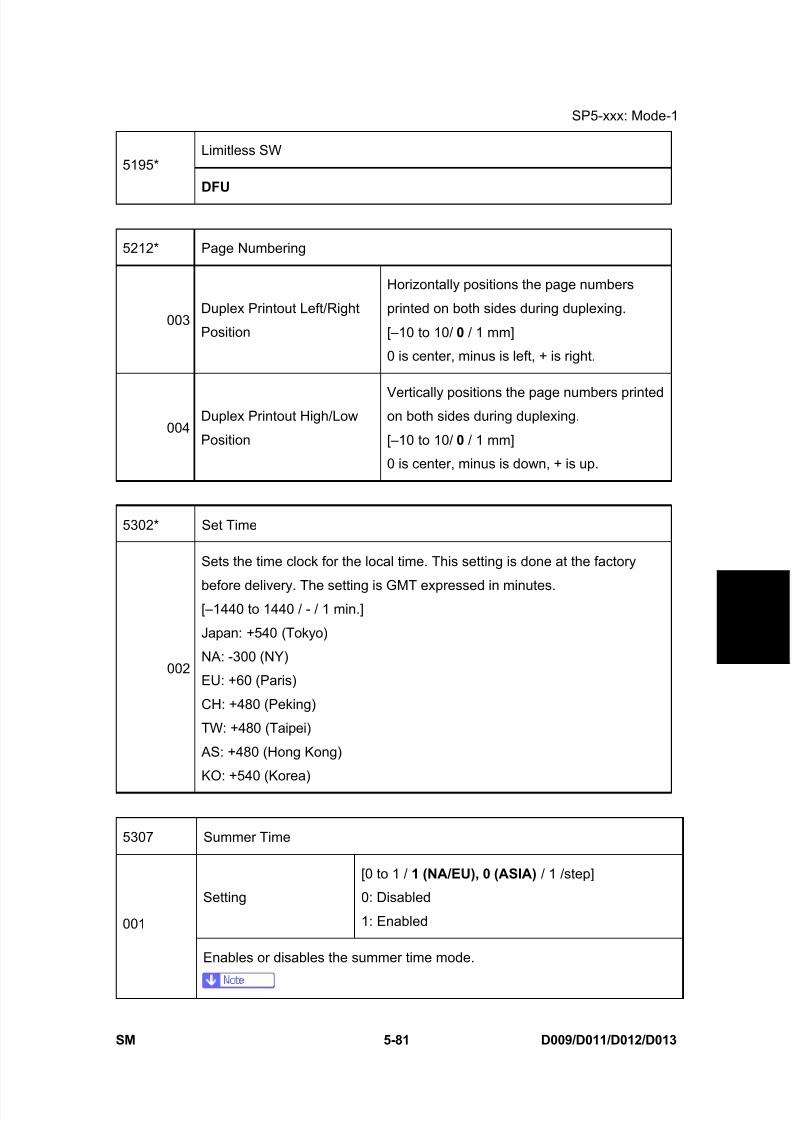
8/15/2019 Ricoh MP 4000 SM D009_D011_D012_D013 SERVICE MANUAL .pdf
http://slidepdf.com/reader/full/ricoh-mp-4000-sm-d009d011d012d013-service-manual-pdf 367/1162
SP5-xxx: Mode-1
SM 5-81 D009/D011/D012/D013
S e r v i c e
T a b l e s
Limitless SW5195*
DFU
5212* Page Numbering
003Duplex Printout Left/Right
Position
Horizontally positions the page numbers
printed on both sides during duplexing.
[–10 to 10/ 0 / 1 mm]
0 is center, minus is left, + is right.
004Duplex Printout High/Low
Position
Vertically positions the page numbers printedon both sides during duplexing.
[–10 to 10/ 0 / 1 mm]
0 is center, minus is down, + is up.
5302* Set Time
002
Sets the time clock for the local time. This setting is done at the factory
before delivery. The setting is GMT expressed in minutes.[–1440 to 1440 / - / 1 min.]
Japan: +540 (Tokyo)
NA: -300 (NY)
EU: +60 (Paris)
CH: +480 (Peking)
TW: +480 (Taipei)
AS: +480 (Hong Kong)
KO: +540 (Korea)
5307 Summer Time
Setting
[0 to 1 / 1 (NA/EU), 0 (ASIA) / 1 /step]
0: Disabled
1: Enabled001
Enables or disables the summer time mode.
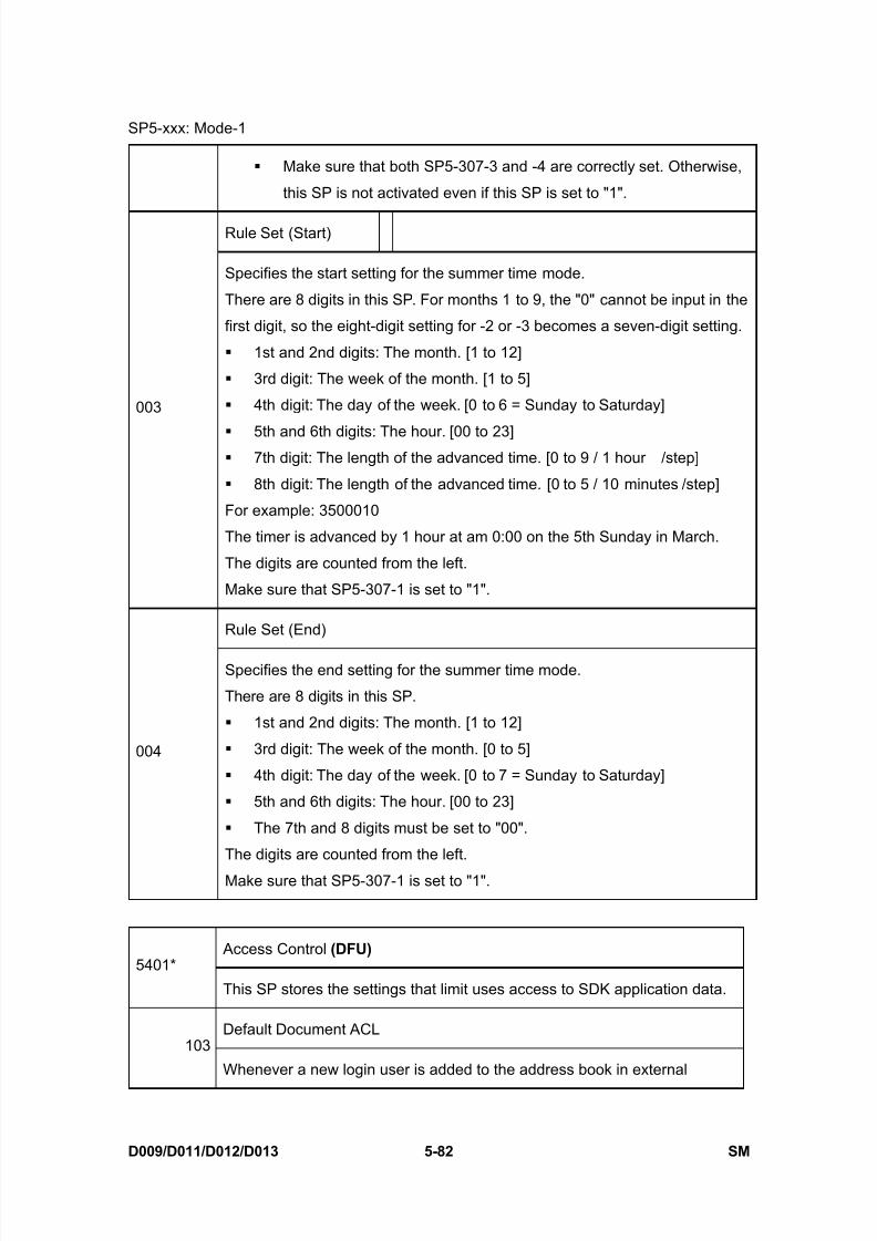
8/15/2019 Ricoh MP 4000 SM D009_D011_D012_D013 SERVICE MANUAL .pdf
http://slidepdf.com/reader/full/ricoh-mp-4000-sm-d009d011d012d013-service-manual-pdf 368/1162
SP5-xxx: Mode-1
D009/D011/D012/D013 5-82 SM
Make sure that both SP5-307-3 and -4 are correctly set. Otherwise,
this SP is not activated even if this SP is set to "1".
Rule Set (Start)
003
Specifies the start setting for the summer time mode.
There are 8 digits in this SP. For months 1 to 9, the "0" cannot be input in the
first digit, so the eight-digit setting for -2 or -3 becomes a seven-digit setting.
1st and 2nd digits: The month. [1 to 12]
3rd digit: The week of the month. [1 to 5]
4th digit: The day of the week. [0 to 6 = Sunday to Saturday]
5th and 6th digits: The hour. [00 to 23] 7th digit: The length of the advanced time. [0 to 9 / 1 hour /step]
8th digit: The length of the advanced time. [0 to 5 / 10 minutes /step]
For example: 3500010
The timer is advanced by 1 hour at am 0:00 on the 5th Sunday in March.
The digits are counted from the left.
Make sure that SP5-307-1 is set to "1".
Rule Set (End)
004
Specifies the end setting for the summer time mode.
There are 8 digits in this SP.
1st and 2nd digits: The month. [1 to 12]
3rd digit: The week of the month. [0 to 5]
4th digit: The day of the week. [0 to 7 = Sunday to Saturday]
5th and 6th digits: The hour. [00 to 23]
The 7th and 8 digits must be set to "00".
The digits are counted from the left.
Make sure that SP5-307-1 is set to "1".
Access Control (DFU) 5401*
This SP stores the settings that limit uses access to SDK application data.
Default Document ACL103
Whenever a new login user is added to the address book in external

8/15/2019 Ricoh MP 4000 SM D009_D011_D012_D013 SERVICE MANUAL .pdf
http://slidepdf.com/reader/full/ricoh-mp-4000-sm-d009d011d012d013-service-manual-pdf 369/1162
SP5-xxx: Mode-1
SM 5-83 D009/D011/D012/D013
S e r v i c e
T a b l e s
certification mode (for Windows, LDAP, RDH), the default document ACL is
updated according to this SP setting.
[0 to 3 / 0 / 1]0: View
1: Edit
2: Edit/Delete
3: Full control
Note: This SP setting is ignored on a machine that is not using document
server.
200 SDK1 Unique ID
201 SDK1 Certification Method
210 SDK2 Unique ID
211 SDK2 Certification Method
220 SDK3 Unique ID
221 SDK3 Certification Method
230 SDK certification device
"SDK" is the "Software
Development Kit". This data can
be converted from SAS (VAS)
when installed or uninstalled.
(DFU)
User Code Count Clear
5404Clears the counts of the user codes assigned by the key operator to restrict
the use of the machine. Press [Execute] to clear.
5411* LDAP Certification
004 Easy Certification
Turns simple authentication on or off for LDAP.
[0 to 1 / 1 / 1]
0: OFF
1: ON
005Password Null
Not Permit
This SP is enabled only when SP5411-4 is set to “1”
(ON).
[0 to 1 / 0 / 1]
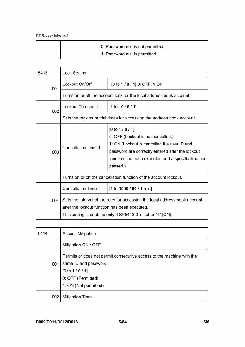
8/15/2019 Ricoh MP 4000 SM D009_D011_D012_D013 SERVICE MANUAL .pdf
http://slidepdf.com/reader/full/ricoh-mp-4000-sm-d009d011d012d013-service-manual-pdf 370/1162

8/15/2019 Ricoh MP 4000 SM D009_D011_D012_D013 SERVICE MANUAL .pdf
http://slidepdf.com/reader/full/ricoh-mp-4000-sm-d009d011d012d013-service-manual-pdf 371/1162
SP5-xxx: Mode-1
SM 5-85 D009/D011/D012/D013
S e r v i c e
T a b l e s
Sets the prohibiting time for consecutive access to the machine with the
same ID and password.
[0 to 60 / 15 / 1 min]
5415* Password Attack
Permissible Number [0 to 100 / 30 / 1 times]
001Sets the threshold number of attempts to attack the system with random
passwords to gain illegal access to the system.
Detect Time [0 to 10 / 5 / 1 sec]002
Sets a detection time to count a password attack.
5416* Access Information
Access User Max Num [50 to 200 / 200 / 1 ]
001Sets the number of users for the access exclusion and password attack
detection function.
Access Password Num [50 to 200 / 200 / 1 ]
002Sets the number of passwords for the access exclusion and password
attack detection function.
Monitor interval [1 to 10 / 3 / 1 sec]003
Sets the interval of watching out for user information and passwords.
5417 Access Attack
Access Permissible number [0 to 500 / 100 / 1]001
Sets a limit on access attempts to prevent password cracking.
Access Detect Time [10 to 30 / 10 / 1 sec]002
Sets a detection time to count password cracking.
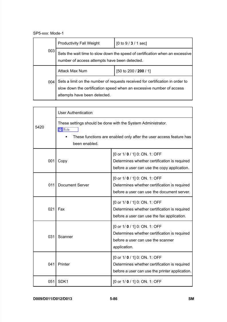
8/15/2019 Ricoh MP 4000 SM D009_D011_D012_D013 SERVICE MANUAL .pdf
http://slidepdf.com/reader/full/ricoh-mp-4000-sm-d009d011d012d013-service-manual-pdf 372/1162
SP5-xxx: Mode-1
D009/D011/D012/D013 5-86 SM
Productivity Fall Weight [0 to 9 / 3 / 1 sec]
003Sets the wait time to slow down the speed of certification when an excessive
number of access attempts have been detected.
Attack Max Num [50 to 200 / 200 / 1]
004 Sets a limit on the number of requests received for certification in order to
slow down the certification speed when an excessive number of access
attempts have been detected.
User Authentication
5420These settings should be done with the System Administrator.
These functions are enabled only after the user access feature has
been enabled.
001 Copy
[0 or 1/ 0 / 1] 0: ON. 1: OFF
Determines whether certification is required
before a user can use the copy application.
011 Document Server
[0 or 1/ 0 / 1] 0: ON. 1: OFF
Determines whether certification is required
before a user can use the document server.
021 Fax
[0 or 1/ 0 / 1] 0: ON. 1: OFF
Determines whether certification is required
before a user can use the fax application.
031 Scanner
[0 or 1/ 0 / 1] 0: ON. 1: OFFDetermines whether certification is required
before a user can use the scanner
application.
041 Printer
[0 or 1/ 0 / 1] 0: ON. 1: OFF
Determines whether certification is required
before a user can use the printer application.
051 SDK1 [0 or 1/ 0 / 1] 0: ON. 1: OFF

8/15/2019 Ricoh MP 4000 SM D009_D011_D012_D013 SERVICE MANUAL .pdf
http://slidepdf.com/reader/full/ricoh-mp-4000-sm-d009d011d012d013-service-manual-pdf 373/1162
SP5-xxx: Mode-1
SM 5-87 D009/D011/D012/D013
S e r v i c e
T a b l e s
061 SDK2
071 SDK3
Determines whether certification is required
before a user can use the SDK application.
Authentication Error Code5481
These SP codes determine how the authentication failures are displayed.
001 System Log Disp
[0 or 1 / 0 / -]
0: OFF [Default], 1: ON
Determines whether an error code appears in the
system log after a user authentication failure occurs.
002 Panel Disp
[0 or 1 / 1 / 1]
0: OFF, 1: ON [Default]
Determines whether an error code appears on the
operation panel after a user authentication failure
occurs.
MF Key Card (Japan only)
5490Sets up operation of the machine with a keycard.
[0 to 1 / 0 / 1]
0: Disabled. Cancels operation without a user code.
1: Enabled. Allows operation without a user code.
5501* PM Alarm
PM Alarm Interval
001 Sets the PM alarm interval.
[0 to 9999 / 0 / 1 k copies/step]
0: No PM alarm
Original Count Alarm (DFU)
002Selects whether the PM alarm for the number of scans is enabled or not.
If this is “1”, the PM alarm function is enabled.

8/15/2019 Ricoh MP 4000 SM D009_D011_D012_D013 SERVICE MANUAL .pdf
http://slidepdf.com/reader/full/ricoh-mp-4000-sm-d009d011d012d013-service-manual-pdf 374/1162
SP5-xxx: Mode-1
D009/D011/D012/D013 5-88 SM
[0 = No / 1 = Yes]
Jam Alarm
5504*
Sets the alarm to sound for the specified jam level (document misfeeds are
not included).
[0 to 3 / 3 / 1 step]
0: Zero (Off)
1: Low (2.5K jams)
2: Medium (3K jams)
3: High (6K jams)
Error Alarm
5505*
Sets the number of sheets to clear the error alarm counter.
The error alarm counter counts "1" when any SC is detected. However, the
error alarm counter decreases by "1" when an SC is not detected during a
set number of copied sheets (for example, default 5000 (C1b) or 10000
(C1c) sheets). The error alarm occurs when the SC error alarm counterreaches "5".
[0 to 255 / 50 (C1b), 100 (C1c) / 100 copies / step]
5507* Supply Alarm
001Paper supply Alarm
(0:Off 1:On)
Switches the control call on/off for the paper
supply. (DFU)
0: Off, 1: On
0: No alarm.
1: Sets the alarm to sound for the specified
number transfer sheets for each paper size (A3,
A4, B4, B5, DLT, LG, LT, HLT)
002Staple Supply Alarm
(0:Off 1:On)
Switches the control call on/off for the stapler
installed in the finisher. (DFU)
0: Off, 1: On
0: No alarm

8/15/2019 Ricoh MP 4000 SM D009_D011_D012_D013 SERVICE MANUAL .pdf
http://slidepdf.com/reader/full/ricoh-mp-4000-sm-d009d011d012d013-service-manual-pdf 375/1162
SP5-xxx: Mode-1
SM 5-89 D009/D011/D012/D013
S e r v i c e
T a b l e s
1: Alarm goes off for every 1K of staples used.
003Toner Supply Alarm
(0:Off 1:On)
Switches the control call on/off for the toner end.
(DFU)
0: Off, 1: On
If you select “1” the alarm will sound when the
copier detects toner end.
128 Interval: Others
132 Interval: A3
133 Interval: A4
134 Interval: A5
141 Interval: B4
142 Interval: B5
160 Interval: DLT
164 Interval: LG
166 Interval: LT
172 Interval: HLT
The “Paper Supply Call Level: nn” SPs specify the
paper control call interval for the referenced paper
sizes. (DFU)
[250 to 10000 / 1000 / 1 Step]
5508 CC Call
001 Jam Remains
002 Continuous Jams
003 Continuous Door Open
Enables/disables initiating a call.
[0 to 1 / 1 / 1]
0: Disable
1: Enable
011 Jam Detection: Time Length
Sets the length of time to determine the
length of an unattended paper jam.
[3 to 30 / 10 / 1 minute]
012Jam Detection Continuous
Count
Sets the number of continuous paper jams
required to initiate a call.
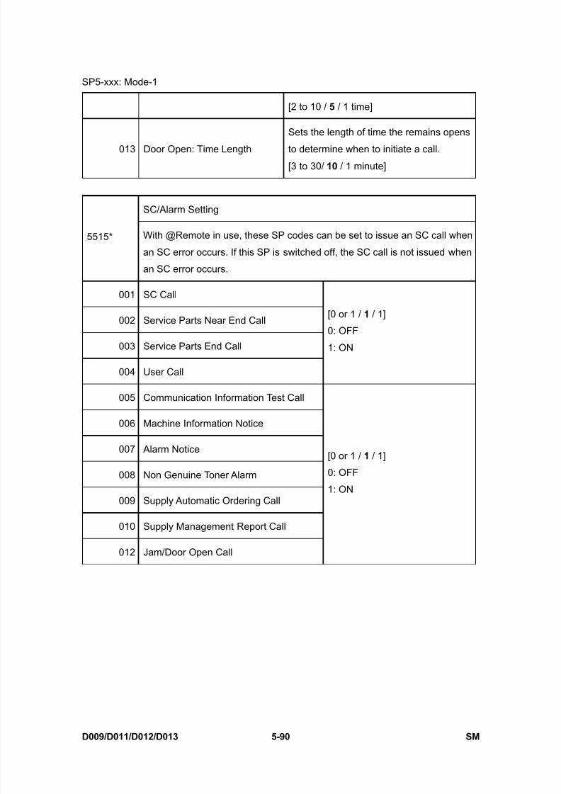
8/15/2019 Ricoh MP 4000 SM D009_D011_D012_D013 SERVICE MANUAL .pdf
http://slidepdf.com/reader/full/ricoh-mp-4000-sm-d009d011d012d013-service-manual-pdf 376/1162
SP5-xxx: Mode-1
D009/D011/D012/D013 5-90 SM
[2 to 10 / 5 / 1 time]
013 Door Open: Time Length
Sets the length of time the remains opens
to determine when to initiate a call.
[3 to 30/ 10 / 1 minute]
SC/Alarm Setting
5515* With @Remote in use, these SP codes can be set to issue an SC call when
an SC error occurs. If this SP is switched off, the SC call is not issued when
an SC error occurs.
001 SC Call
002 Service Parts Near End Call
003 Service Parts End Call
004 User Call
[0 or 1 / 1 / 1]
0: OFF
1: ON
005 Communication Information Test Call
006 Machine Information Notice
007 Alarm Notice
008 Non Genuine Toner Alarm
009 Supply Automatic Ordering Call
010 Supply Management Report Call
012 Jam/Door Open Call
[0 or 1 / 1 / 1]
0: OFF
1: ON
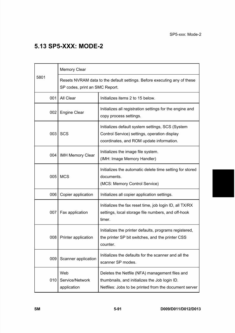
8/15/2019 Ricoh MP 4000 SM D009_D011_D012_D013 SERVICE MANUAL .pdf
http://slidepdf.com/reader/full/ricoh-mp-4000-sm-d009d011d012d013-service-manual-pdf 377/1162
SP5-xxx: Mode-2
SM 5-91 D009/D011/D012/D013
S e r v i c e
T a b l e s
5.13 SP5-XXX: MODE-2
Memory Clear
5801Resets NVRAM data to the default settings. Before executing any of these
SP codes, print an SMC Report.
001 All Clear Initializes items 2 to 15 below.
002 Engine ClearInitializes all registration settings for the engine and
copy process settings.
003 SCS
Initializes default system settings, SCS (System
Control Service) settings, operation display
coordinates, and ROM update information.
004 IMH Memory ClearInitializes the image file system.
(IMH: Image Memory Handler)
005 MCS
Initializes the automatic delete time setting for stored
documents.
(MCS: Memory Control Service)
006 Copier application Initializes all copier application settings.
007 Fax application
Initializes the fax reset time, job login ID, all TX/RX
settings, local storage file numbers, and off-hook
timer.
008 Printer application
Initializes the printer defaults, programs registered,
the printer SP bit switches, and the printer CSS
counter.
009 Scanner applicationInitializes the defaults for the scanner and all the
scanner SP modes.
010
Web
Service/Network
application
Deletes the Netfile (NFA) management files and
thumbnails, and initializes the Job login ID.
Netfiles: Jobs to be printed from the document server

8/15/2019 Ricoh MP 4000 SM D009_D011_D012_D013 SERVICE MANUAL .pdf
http://slidepdf.com/reader/full/ricoh-mp-4000-sm-d009d011d012d013-service-manual-pdf 378/1162
SP5-xxx: Mode-2
D009/D011/D012/D013 5-92 SM
using a PC and the DeskTopBinder software
011 NCS
Initializes the system defaults and interface settings
(IP addresses also), the SmartDeviceMonitor for
Admin settings, WebStatusMonitor settings, and the
TELNET settings.
(NCS: Network Control Service)
012 R-FAXInitializes the job login ID, SmartDeviceMonitor for
Admin, job history, and local storage file numbers.
014 Clear DCS Setting Initializes the DCS (Delivery Control Service) settings.
015 Clear UCS SettingInitializes the UCS (User Information Control Service)
settings.
016 MIRS SettingInitializes the MIRS (Machine Information Report
Service) settings.
017 CCSInitializes the CCS (Certification and Charge-control
Service) settings.
018 SRM ClearInitializes the SRM (System Resource Manager)
settings.
019 LCS Clear Initializes the LCS (Log Count Service) settings.
020 Web Uapli Initializes the web user application settings.
021 ECS Initializes the ECS settings.
Free Run
5802*
Performs a free run on the copier engine.
The correct paper should be loaded in the 1st tray or 2nd tray, but paper
is not fed.
The main switch has to be turned off and on after using the free run
mode for a test.
001 TRAY1:A4LEF -
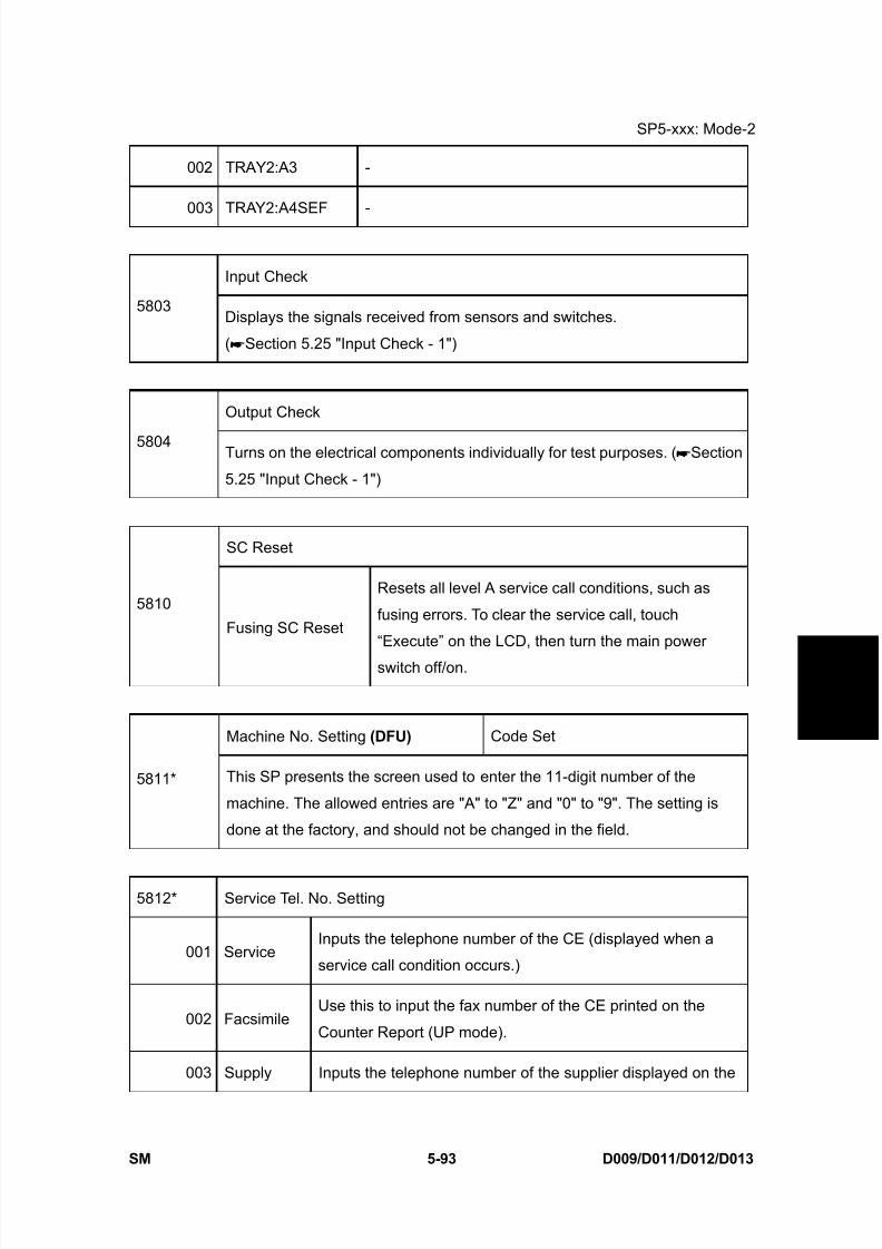
8/15/2019 Ricoh MP 4000 SM D009_D011_D012_D013 SERVICE MANUAL .pdf
http://slidepdf.com/reader/full/ricoh-mp-4000-sm-d009d011d012d013-service-manual-pdf 379/1162
SP5-xxx: Mode-2
SM 5-93 D009/D011/D012/D013
S e r v i c e
T a b l e s
002 TRAY2:A3 -
003 TRAY2:A4SEF -
Input Check
5803Displays the signals received from sensors and switches.
( Section 5.25 "Input Check - 1")
Output Check
5804 Turns on the electrical components individually for test purposes. ( Section
5.25 "Input Check - 1")
SC Reset
5810
Fusing SC Reset
Resets all level A service call conditions, such as
fusing errors. To clear the service call, touch
“Execute” on the LCD, then turn the main power
switch off/on.
Machine No. Setting (DFU) Code Set
5811* This SP presents the screen used to enter the 11-digit number of the
machine. The allowed entries are "A" to "Z" and "0" to "9". The setting is
done at the factory, and should not be changed in the field.
5812* Service Tel. No. Setting
001 ServiceInputs the telephone number of the CE (displayed when a
service call condition occurs.)
002 FacsimileUse this to input the fax number of the CE printed on the
Counter Report (UP mode).
003 Supply Inputs the telephone number of the supplier displayed on the
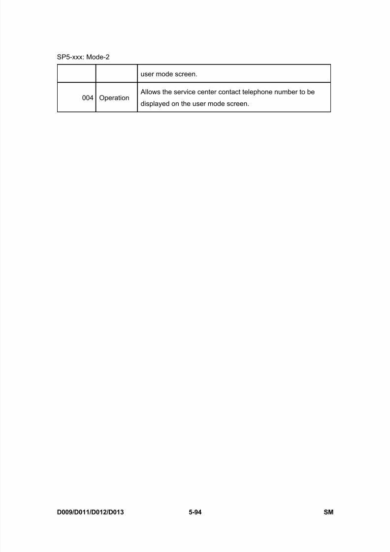
8/15/2019 Ricoh MP 4000 SM D009_D011_D012_D013 SERVICE MANUAL .pdf
http://slidepdf.com/reader/full/ricoh-mp-4000-sm-d009d011d012d013-service-manual-pdf 380/1162
SP5-xxx: Mode-2
D009/D011/D012/D013 5-94 SM
user mode screen.
004 Operation Allows the service center contact telephone number to be
displayed on the user mode screen.

8/15/2019 Ricoh MP 4000 SM D009_D011_D012_D013 SERVICE MANUAL .pdf
http://slidepdf.com/reader/full/ricoh-mp-4000-sm-d009d011d012d013-service-manual-pdf 381/1162
SP5-xxx: Mode-3
SM 5-95 D009/D011/D012/D013
S e r v i c e
T a b l e s
5.14 SP5-XXX: MODE-3
5816* Remote Service
I/F Setting
001
Turns the remote diagnostics off and on.
[0 to 2 / 2 / 1]
0: Remote diagnostics OFF.
1: Serial (CSS) remote diagnostics ON.
2: @Remote diagnostics. ON
CE Call
002Lets the customer engineer start or end the remote machine check with CSS
or @Remote; to do this, push the center report key
Function Flag
003Enables or disables the remote service function.
[0 to 1 / 0 / 1]
0: Disables remote diagnosis over the network.
1: Enables remote diagnosis over the network.
SSL Disable
007
Controls if RCG (Remote Communication Gate) confirmation is done by SSL
during an RCG send for the @Remote over a network interface.
[0 to 1 / 0 / 1]
0: Yes. SSL not used.
1: No. SSL used.
RCG Connect Timeout
008 Sets the length of time (seconds) for the time-out when the RCG (Remote
Communication Gate) connects during a call via the @Remote network.
[1 to 90 / 30 / 1 sec.]
RCG Write Timeout
009Sets the length of time (seconds) for the time-out when sent data is written to
the RCG during a call over the @Remote network.
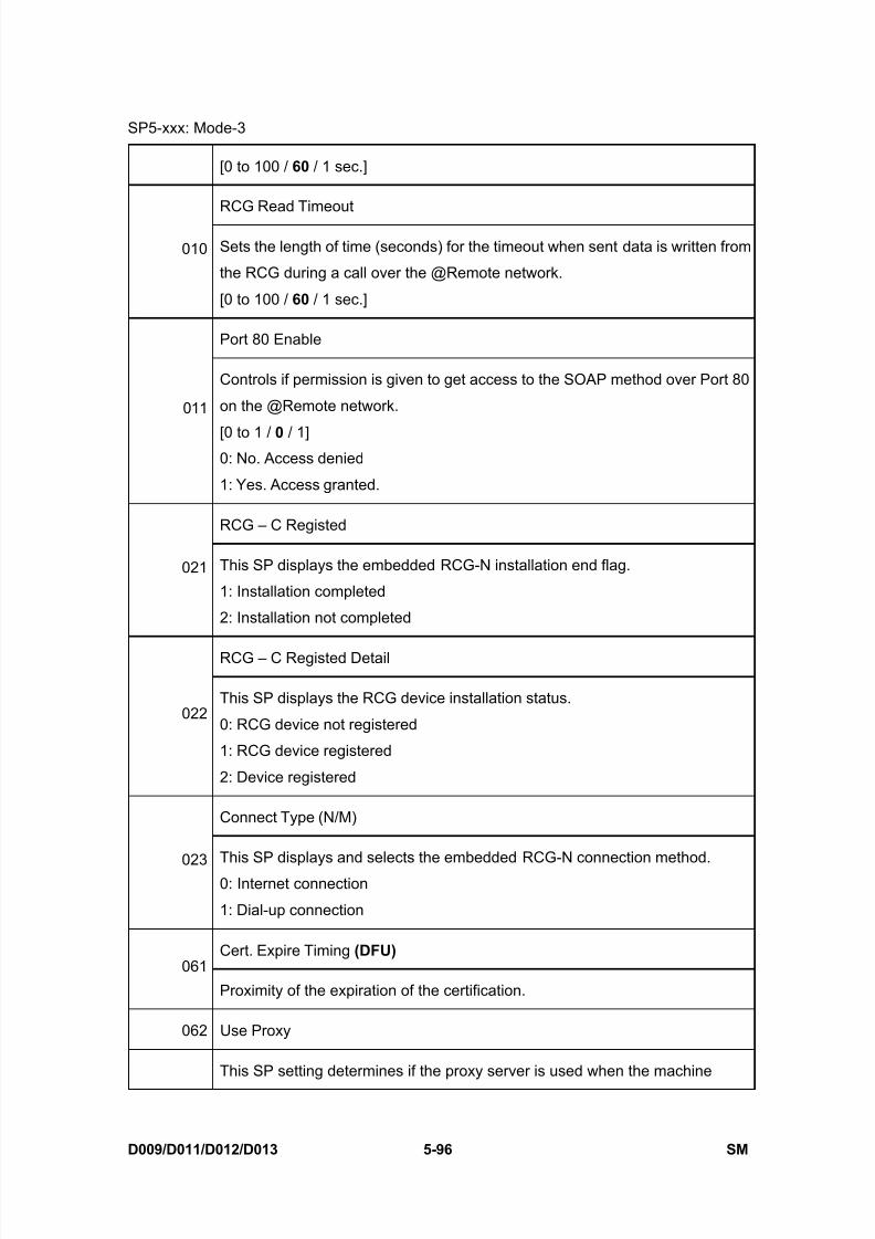
8/15/2019 Ricoh MP 4000 SM D009_D011_D012_D013 SERVICE MANUAL .pdf
http://slidepdf.com/reader/full/ricoh-mp-4000-sm-d009d011d012d013-service-manual-pdf 382/1162
SP5-xxx: Mode-3
D009/D011/D012/D013 5-96 SM
[0 to 100 / 60 / 1 sec.]
RCG Read Timeout
010 Sets the length of time (seconds) for the timeout when sent data is written from
the RCG during a call over the @Remote network.
[0 to 100 / 60 / 1 sec.]
Port 80 Enable
011
Controls if permission is given to get access to the SOAP method over Port 80
on the @Remote network.
[0 to 1 / 0 / 1]0: No. Access denied
1: Yes. Access granted.
RCG – C Registed
021 This SP displays the embedded RCG-N installation end flag.
1: Installation completed
2: Installation not completed
RCG – C Registed Detail
022This SP displays the RCG device installation status.
0: RCG device not registered
1: RCG device registered
2: Device registered
Connect Type (N/M)
023 This SP displays and selects the embedded RCG-N connection method.
0: Internet connection
1: Dial-up connection
Cert. Expire Timing (DFU) 061
Proximity of the expiration of the certification.
062 Use Proxy
This SP setting determines if the proxy server is used when the machine
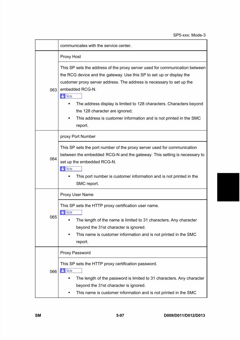
8/15/2019 Ricoh MP 4000 SM D009_D011_D012_D013 SERVICE MANUAL .pdf
http://slidepdf.com/reader/full/ricoh-mp-4000-sm-d009d011d012d013-service-manual-pdf 383/1162
SP5-xxx: Mode-3
SM 5-97 D009/D011/D012/D013
S e r v i c e
T a b l e s
communicates with the service center.
Proxy Host
063
This SP sets the address of the proxy server used for communication between
the RCG device and the gateway. Use this SP to set up or display the
customer proxy server address. The address is necessary to set up the
embedded RCG-N.
The address display is limited to 128 characters. Characters beyond
the 128 character are ignored.
This address is customer information and is not printed in the SMCreport.
proxy Port Number
064
This SP sets the port number of the proxy server used for communication
between the embedded RCG-N and the gateway. This setting is necessary to
set up the embedded RCG-N.
This port number is customer information and is not printed in the
SMC report.
Proxy User Name
065
This SP sets the HTTP proxy certification user name.
The length of the name is limited to 31 characters. Any character
beyond the 31st character is ignored.
This name is customer information and is not printed in the SMC
report.
Proxy Password
066
This SP sets the HTTP proxy certification password.
The length of the password is limited to 31 characters. Any character
beyond the 31st character is ignored.
This name is customer information and is not printed in the SMC

8/15/2019 Ricoh MP 4000 SM D009_D011_D012_D013 SERVICE MANUAL .pdf
http://slidepdf.com/reader/full/ricoh-mp-4000-sm-d009d011d012d013-service-manual-pdf 384/1162
SP5-xxx: Mode-3
D009/D011/D012/D013 5-98 SM
report.
CERT: Up State
Displays the status of the certification update.
0 The certification used by the embedded RCG-N is set correctly.
1The certification request (setAuthKey) for update has been received
from the GW URL and certification is presently being updated.
2The certification update is completed and the GW URL is being notified
of the successful update.
3The certification update failed, and the GW URL is being notified of the
failed update.
4The period of the certification has expired and new request for an
update is being sent to the GW URL.
11 A rescue update for certification has been issued and a rescue
certification setting is in progress for the rescue GW connection.
12The rescue certification setting is completed and the GW URL is being
notified of the certification update request.
13
The notification of the request for certification update has completed
successfully, and the system is waiting for the certification update
request from the rescue GW URL.
14The notification of the certification request has been received from the
rescue GW controller, and the certification is being stored.
15The certification has been stored, and the GW URL is being notified of
the successful completion of this event.
067
16The storing of the certification has failed, and the GW URL is being
notified of the failure of this event.
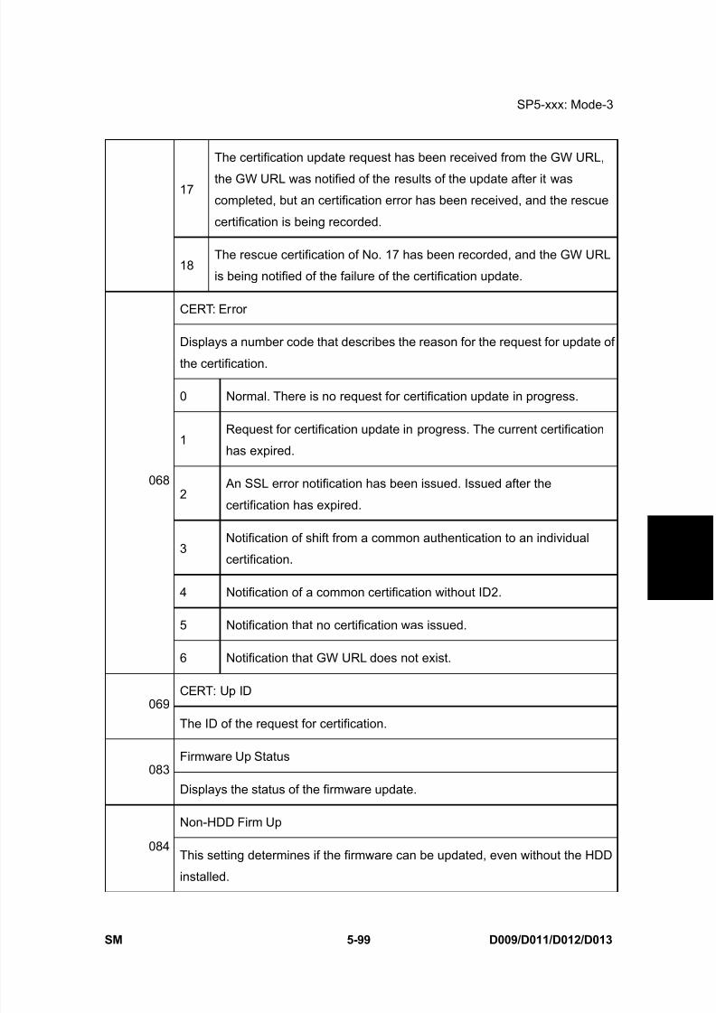
8/15/2019 Ricoh MP 4000 SM D009_D011_D012_D013 SERVICE MANUAL .pdf
http://slidepdf.com/reader/full/ricoh-mp-4000-sm-d009d011d012d013-service-manual-pdf 385/1162
SP5-xxx: Mode-3
SM 5-99 D009/D011/D012/D013
S e r v
i c e
T a
b l e s
17
The certification update request has been received from the GW URL,
the GW URL was notified of the results of the update after it wascompleted, but an certification error has been received, and the rescue
certification is being recorded.
18The rescue certification of No. 17 has been recorded, and the GW URL
is being notified of the failure of the certification update.
CERT: Error
Displays a number code that describes the reason for the request for update of
the certification.
0 Normal. There is no request for certification update in progress.
1Request for certification update in progress. The current certification
has expired.
2 An SSL error notification has been issued. Issued after the
certification has expired.
3Notification of shift from a common authentication to an individual
certification.
4 Notification of a common certification without ID2.
5 Notification that no certification was issued.
068
6 Notification that GW URL does not exist.
CERT: Up ID
069The ID of the request for certification.
Firmware Up Status083
Displays the status of the firmware update.
Non-HDD Firm Up
084This setting determines if the firmware can be updated, even without the HDD
installed.

8/15/2019 Ricoh MP 4000 SM D009_D011_D012_D013 SERVICE MANUAL .pdf
http://slidepdf.com/reader/full/ricoh-mp-4000-sm-d009d011d012d013-service-manual-pdf 386/1162
SP5-xxx: Mode-3
D009/D011/D012/D013 5-100 SM
Firm Up User Check
085This SP setting determines if the operator can confirm the previous version of
the firmware before the firmware update execution. If the option to confirm the
previous version is selected, a notification is sent to the system manager and
the firmware update is done with the firmware files from the URL.
Firmware Size
086 Allows the service technician to confirm the size of the firmware data files
during the firmware update execution.
CERT: Macro087
Displays the macro version of the @Remote certification
CERT: PAC088
Displays the PAC version of the @Remote certification.
CERT: ID2 Code
089 Displays ID2 for the @Remote certification. Spaces are displayed as
underscores (_). Asterisks (****) indicate that no NRS certification exists.
CERT: Subject
090 Displays the common name of the @Remote certification subject. CN = the
following 17 bytes. Spaces are displayed as underscores (_). Asterisks (****)
indicate that no DESS exists.
CERT: Serial No.
091Displays serial number for the @Remote certification. Asterisks (****) indicate
that no DESS exists.
CERT: Issuer
092Displays the common name of the issuer of the @Remote certification. CN =
the following 30 bytes. Asterisks (****) indicate that no DESS exists.
093 CERT: Valid Start
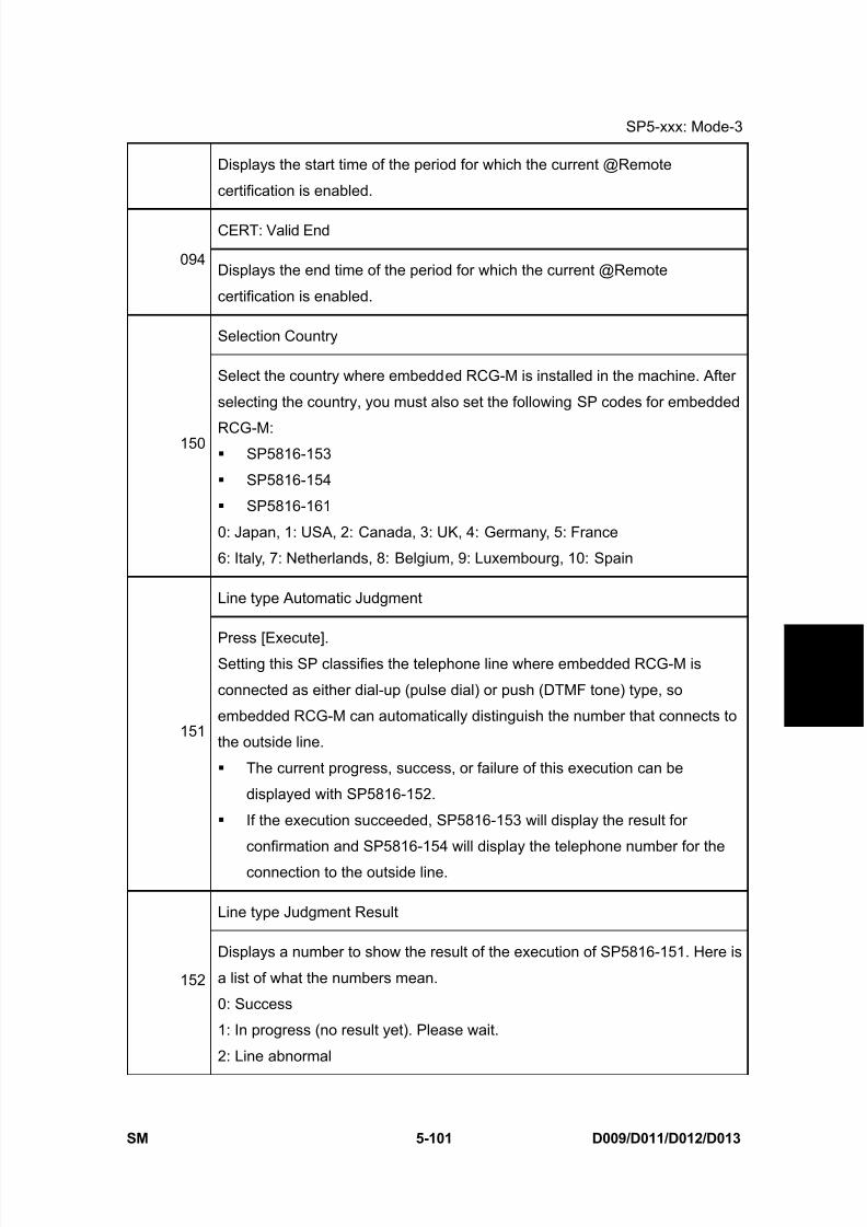
8/15/2019 Ricoh MP 4000 SM D009_D011_D012_D013 SERVICE MANUAL .pdf
http://slidepdf.com/reader/full/ricoh-mp-4000-sm-d009d011d012d013-service-manual-pdf 387/1162
SP5-xxx: Mode-3
SM 5-101 D009/D011/D012/D013
S e r v i c e
T a b l e s
Displays the start time of the period for which the current @Remote
certification is enabled.
CERT: Valid End
094Displays the end time of the period for which the current @Remote
certification is enabled.
Selection Country
150
Select the country where embedded RCG-M is installed in the machine. After
selecting the country, you must also set the following SP codes for embedded
RCG-M: SP5816-153
SP5816-154
SP5816-161
0: Japan, 1: USA, 2: Canada, 3: UK, 4: Germany, 5: France
6: Italy, 7: Netherlands, 8: Belgium, 9: Luxembourg, 10: Spain
Line type Automatic Judgment
151
Press [Execute].Setting this SP classifies the telephone line where embedded RCG-M is
connected as either dial-up (pulse dial) or push (DTMF tone) type, so
embedded RCG-M can automatically distinguish the number that connects to
the outside line.
The current progress, success, or failure of this execution can be
displayed with SP5816-152.
If the execution succeeded, SP5816-153 will display the result for
confirmation and SP5816-154 will display the telephone number for the
connection to the outside line.
Line type Judgment Result
152
Displays a number to show the result of the execution of SP5816-151. Here is
a list of what the numbers mean.
0: Success
1: In progress (no result yet). Please wait.
2: Line abnormal

8/15/2019 Ricoh MP 4000 SM D009_D011_D012_D013 SERVICE MANUAL .pdf
http://slidepdf.com/reader/full/ricoh-mp-4000-sm-d009d011d012d013-service-manual-pdf 388/1162
SP5-xxx: Mode-3
D009/D011/D012/D013 5-102 SM
3: Cannot detect dial tone automatically
4: Line is disconnected
5: Insufficient electrical power supply6: Line classification not supported
7: Error because fax transmission in progress – ioctl() occurred.
8: Other error occurred
9: Line classification still in progress. Please wait.
Selection Dial/push
153
This SP displays the classification (tone or pulse) of the telephone line to the
access point for embedded RCG-M. The number displayed (0 or 1) is theresult of the execution of SP5816-151. However, this setting can also be
changed manually.
[0 to 1 / 0 / 1 /step]
0: Tone Dialing Phone
1: Pulse Dialing Phone
Outside Line Outgoing Number
154
The SP sets the number that switches to PSTN for the outside connection for
embedded RCG-M in a system that employs a PBX (internal line).
If the execution of SP5816-151 has succeeded and embedded RCG-M
has connected to the external line, this SP display is completely blank.
If embedded RCG-M has connected to an internal line, then the number of
the
connection to the external line is displayed.
If embedded RCG-M has connected to an external line, a comma is
displayed with
the number. The comma is inserted for a 2 sec. pause.
The number setting for the external line can be entered manually
(including commas).
Remove Service: PPP Certification Timeout (SSP)
155 Sets the length of the timeout for the embedded RCG-M connection to its
access point. The timeout is the time from when the modem sends the ATD to
when it receives the result code.
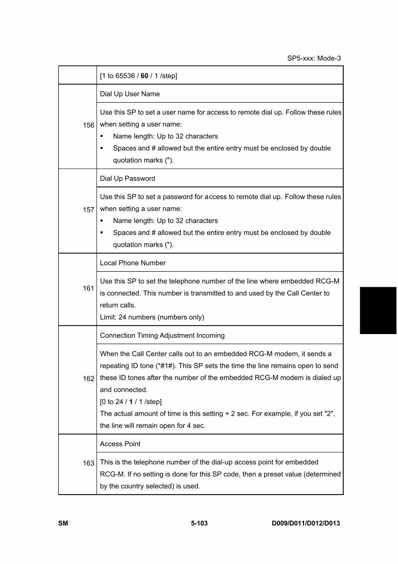
8/15/2019 Ricoh MP 4000 SM D009_D011_D012_D013 SERVICE MANUAL .pdf
http://slidepdf.com/reader/full/ricoh-mp-4000-sm-d009d011d012d013-service-manual-pdf 389/1162
SP5-xxx: Mode-3
SM 5-103 D009/D011/D012/D013
S e r v i c e
T a b l e s
[1 to 65536 / 60 / 1 /step]
Dial Up User Name
156
Use this SP to set a user name for access to remote dial up. Follow these rules
when setting a user name:
Name length: Up to 32 characters
Spaces and # allowed but the entire entry must be enclosed by double
quotation marks (").
Dial Up Password
157Use this SP to set a password for access to remote dial up. Follow these ruleswhen setting a user name:
Name length: Up to 32 characters
Spaces and # allowed but the entire entry must be enclosed by double
quotation marks (").
Local Phone Number
161Use this SP to set the telephone number of the line where embedded RCG-M
is connected. This number is transmitted to and used by the Call Center toreturn calls.
Limit: 24 numbers (numbers only)
Connection Timing Adjustment Incoming
162
When the Call Center calls out to an embedded RCG-M modem, it sends a
repeating ID tone (*#1#). This SP sets the time the line remains open to send
these ID tones after the number of the embedded RCG-M modem is dialed up
and connected.
[0 to 24 / 1 / 1 /step]
The actual amount of time is this setting + 2 sec. For example, if you set "2",
the line will remain open for 4 sec.
Access Point
163 This is the telephone number of the dial-up access point for embedded
RCG-M. If no setting is done for this SP code, then a preset value (determined
by the country selected) is used.

8/15/2019 Ricoh MP 4000 SM D009_D011_D012_D013 SERVICE MANUAL .pdf
http://slidepdf.com/reader/full/ricoh-mp-4000-sm-d009d011d012d013-service-manual-pdf 390/1162
SP5-xxx: Mode-3
D009/D011/D012/D013 5-104 SM
Default: 0
Allowed: Up to 16 numeral characters
Line Connecting
164
This SP sets the connection conditions for the customer. This setting dedicates
the line to embedded RCG-M only, or sets the line for sharing between
embedded RCG-M and a fax unit.
[0 or 1 / 0 / - ]
0: Line shared by embedded RCG-M/Fax
1: Line dedicated to embedded RCG-M only
If this setting is changed, the copier must be cycled off and on. SP5816-187 determines whether the off-hook button can be used to
interrupt an embedded RCG-M transmission in progress to open the line
for fax transaction.
Modem serial No.173
This SP displays the serial number registered for the embedded RCG-M.
Retransmission Limit
174
Normally, it is best to allow unlimited time for certification and ID2 update
requests, and for the notification that the certification has been completed.
However, embedded RCGM generates charges based on transmission time
for the customer, so a limit is placed upon the time allowed for these
transactions.
If these transactions cannot be completed within the allowed time, do this SP
to cancel the time restriction.
RCG - C M Debug Bit SW186
FAX TX Priority
187This SP determines whether pushing the off-hook button will interrupt an
embedded RCGM transmission in progress to open the line for fax transaction.
This SP can be used only if SP5816-164 is set to "0".
[0 or 1/ 0 / - ]
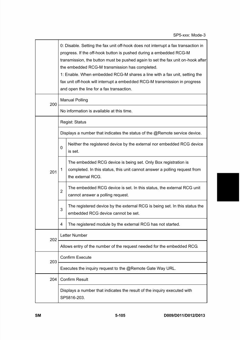
8/15/2019 Ricoh MP 4000 SM D009_D011_D012_D013 SERVICE MANUAL .pdf
http://slidepdf.com/reader/full/ricoh-mp-4000-sm-d009d011d012d013-service-manual-pdf 391/1162
SP5-xxx: Mode-3
SM 5-105 D009/D011/D012/D013
S e r v i c e
T a b l e s
0: Disable. Setting the fax unit off-hook does not interrupt a fax transaction in
progress. If the off-hook button is pushed during a embedded RCG-M
transmission, the button must be pushed again to set the fax unit on-hook afterthe embedded RCG-M transmission has completed.
1: Enable. When embedded RCG-M shares a line with a fax unit, setting the
fax unit off-hook will interrupt a embedded RCG-M transmission in progress
and open the line for a fax transaction.
Manual Polling200
No information is available at this time.
Regist: Status
Displays a number that indicates the status of the @Remote service device.
0Neither the registered device by the external nor embedded RCG device
is set.
1
The embedded RCG device is being set. Only Box registration is
completed. In this status, this unit cannot answer a polling request from
the external RCG.
2The embedded RCG device is set. In this status, the external RCG unit
cannot answer a polling request.
3The registered device by the external RCG is being set. In this status the
embedded RCG device cannot be set.
201
4 The registered module by the external RCG has not started.
Letter Number202
Allows entry of the number of the request needed for the embedded RCG.
Confirm Execute203
Executes the inquiry request to the @Remote Gate Way URL.
Confirm Result204
Displays a number that indicates the result of the inquiry executed with
SP5816-203.

8/15/2019 Ricoh MP 4000 SM D009_D011_D012_D013 SERVICE MANUAL .pdf
http://slidepdf.com/reader/full/ricoh-mp-4000-sm-d009d011d012d013-service-manual-pdf 392/1162
SP5-xxx: Mode-3
D009/D011/D012/D013 5-106 SM
0 Succeeded
1 Inquiry number error
2 Registration in progress
3 Proxy error (proxy enabled)
4 Proxy error (proxy disabled)
5 Proxy error (Illegal user name or password)
6 Communication error
7 Certification update error
8 Other error
9 Inquiry executing
Confirm Place
205 Displays the result of the notification sent to the device from the GW URL in
answer to the inquiry request. Displayed only when the result is registered at
the GW URL.
Register Execute206
Executes "Embedded RCG Registration".
Register Result
Displays a number that indicates the registration result.
0 Succeeded
2 Registration in progress
3 Proxy error (proxy enabled)
4 Proxy error (proxy disabled)
5 Proxy error (Illegal user name or password)
207
6 Communication error

8/15/2019 Ricoh MP 4000 SM D009_D011_D012_D013 SERVICE MANUAL .pdf
http://slidepdf.com/reader/full/ricoh-mp-4000-sm-d009d011d012d013-service-manual-pdf 393/1162
SP5-xxx: Mode-3
SM 5-107 D009/D011/D012/D013
S e r v i c e
T a b l e s
7 Certification update error
8 Other error
9 Registration executing
Error Code
Displays a number that describes the error code that was issued when either
SP5816 204 or SP5816 207 was executed.
Cause Code Meaning
-11001 Chat parameter error
-11002 Chat execution errorIllegal Modem Parameter
-11003 Unexpected error
-12002Inquiry, registration attempted without
acquiring device status.
-12003
Attempted registration without execution
of an inquiry and no previousregistration.
-12004 Attempted setting with illegal entries for
certification and ID2.
-12005 @Remove communication prohibited
-12006Confirmation requested again after
confirmation completed.
-12007Different numbers were used for
registration and confirmation.
Operation Error, Incorrect
Setting
-12008Update certification failed because
device was in use.
208
Error Caused by
Response from GW URL-2385
Attempted dial up overseas without the
correct international prefix for the
telephone number.
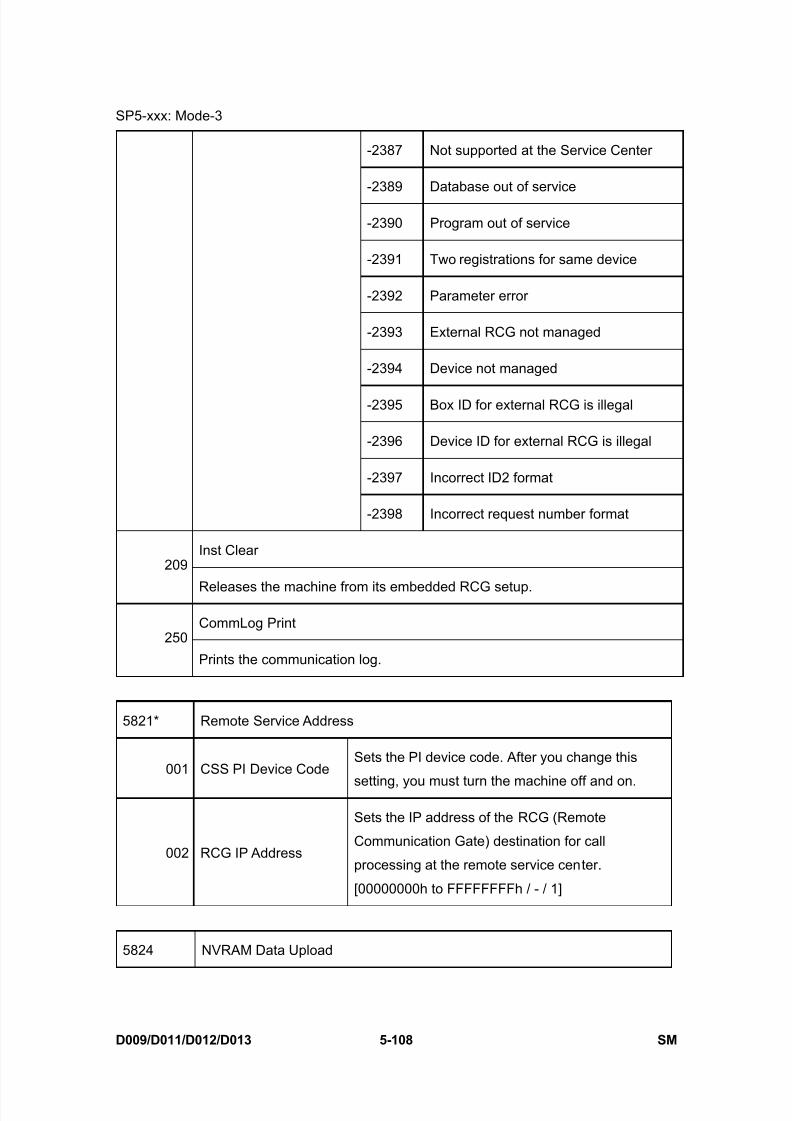
8/15/2019 Ricoh MP 4000 SM D009_D011_D012_D013 SERVICE MANUAL .pdf
http://slidepdf.com/reader/full/ricoh-mp-4000-sm-d009d011d012d013-service-manual-pdf 394/1162
SP5-xxx: Mode-3
D009/D011/D012/D013 5-108 SM
-2387 Not supported at the Service Center
-2389 Database out of service
-2390 Program out of service
-2391 Two registrations for same device
-2392 Parameter error
-2393 External RCG not managed
-2394 Device not managed
-2395 Box ID for external RCG is illegal
-2396 Device ID for external RCG is illegal
-2397 Incorrect ID2 format
-2398 Incorrect request number format
Inst Clear209
Releases the machine from its embedded RCG setup.
CommLog Print250
Prints the communication log.
5821* Remote Service Address
001 CSS PI Device CodeSets the PI device code. After you change this
setting, you must turn the machine off and on.
002 RCG IP Address
Sets the IP address of the RCG (Remote
Communication Gate) destination for call
processing at the remote service center.
[00000000h to FFFFFFFFh / - / 1]
5824 NVRAM Data Upload

8/15/2019 Ricoh MP 4000 SM D009_D011_D012_D013 SERVICE MANUAL .pdf
http://slidepdf.com/reader/full/ricoh-mp-4000-sm-d009d011d012d013-service-manual-pdf 395/1162
SP5-xxx: Mode-3
SM 5-109 D009/D011/D012/D013
S e r v i c e
T a b l e s
Uploads the NVRAM data to an SD card. Push Execute.
Note : When uploading data in this SP mode, the front door must be open.
NVRAM Data Download
5825 Downloads data from an SD card to the NVRAM in the machine. After
downloading is completed, remove the card and turn the machine power off
and on.
5828 Network Setting
IPv4 Address (Ethernet/IEEE 802.11)
001This SP allows you to confirm and reset the IPv4 address for Ethernet and
wireless LAN (802.11): aaa.bbb.ccc.ddd
IPv4 Subnet Mask (Ethernet/IEEE 802.11)
002This SP allows you to confirm and reset the IPv4 subnet mask for Ethernet
and wireless LAN (802.11): aaa.bbb.ccc.ddd
IPv4 default Gateway
(Ethernet/IEEE 802.11)003
This SP allows you to confirm and reset the IPv4 default gateway used by
the network for Ethernet and wireless LAN (802.11): aaa.bbb.ccc.ddd
DHCP (Ethernet/IEEE 802.11)
006
This SP code allows you confirm and change the setting that determines
whether the IP address is used with DHCP on an Ethernet or wireless
(802.11) LAN network.
[0 to 1 / 1 / 1]
0: Not used (manual setting)
1: Used
Active IPv4 Address021
This SP allows you to confirm the IPv4 address that was used when the

8/15/2019 Ricoh MP 4000 SM D009_D011_D012_D013 SERVICE MANUAL .pdf
http://slidepdf.com/reader/full/ricoh-mp-4000-sm-d009d011d012d013-service-manual-pdf 396/1162
SP5-xxx: Mode-3
D009/D011/D012/D013 5-110 SM
machine started up with DHCP.
Active IPv4 Subnet Mask
022This SP allows you to confirm the IPv4 subnet mask setting that was used
when the machine started up with DHCP.
Active IPv4 Gateway Address
023This SP allows you to confirm the IPv4 default gateway setting that was
used when the machine started up with DHCP.
0501284 Compatibility
(Centro)
Enables and disables bi-directional
communication on the parallel connection
between the machine and a computer.
[0 to 1 / 1 / 1 ]
0:Off, 1: On
052 ECP (Centro)
Disables and enables the ECP feature (1284
Mode) for data transfer.
[0 to 1 / 1 / 1]
0: Disabled, 1: Enabled
065 Job Spooling
Switches the job spooling on and off.
[0 to 1 / 0 / 1]
0: No spooling, 1: Spooling enabled
066Job Spooling Clear: Start
Time
This SP determines whether the job interrupted
at power off is resumed at the next power on.
This SP operates only when SP5828-065 is set
to "1".
[0 to 1 / 1 / 1]
1: Resumes printing spooled jog.
0: Clears spooled job.
069 Job Spooling (Protocol)
This SP determines whether job spooling is
enabled or disabled for each protocol. This is a
8-bit setting.
[0 to 1 / 1 / 1]
0: No spooling, 1: Spooling enabled

8/15/2019 Ricoh MP 4000 SM D009_D011_D012_D013 SERVICE MANUAL .pdf
http://slidepdf.com/reader/full/ricoh-mp-4000-sm-d009d011d012d013-service-manual-pdf 397/1162
SP5-xxx: Mode-3
SM 5-111 D009/D011/D012/D013
S e r v i c e
T a b l e s
0 LPR 4 BMLinks (Japan Only)
1 FTP (Not Used) 5 DIPRINT
2 IPP 6 Reserved (Not Used)
3 SMB 7 Reserved (Not Used)
090TELNET
(0:OFF 1:ON)
Disables or enables Telnet operation. If this SP
is disabled, the Telnet port is closed.
[0 to 1 / 1 / 1]
0: Disable, 1: Enable
091Web
(0:OFF 1:ON)
Disables or enables the Web operation.
[0 to 1 / 1 / 1]
0: Disable, 1: Enable
145 Active IPv6 Link Local
Address
This is the IPv6 local address referenced on the
Ethernet or wireless LAN (802.11) in the format:
"Link-Local address" + "Prefix Length"
The IPv6 address consists of a total 128 bits
configured in 8 blocks of 16 bits each. Thesenotations can be abbreviated. See "Note: IPV6
Addresses " below this table.
147 Active IPv6 Stateless
Address 1
149 Active IPv6 Stateless
Address 2
151 Active IPv6 Stateless Address 3
153 Active IPv6 Stateless
Address 4
155 Active IPv6 Stateless
Address 5
These SPs are the IPv6 stateless addresses (1
to 5) referenced on the Ethernet or wireless LAN
(802.11b) in the format:"Stateless Address" + "Prefix Length"
The IPv6 address consists of a total 128 bits
configured in 8 blocks of 16 bits each.
156 IPv6 Manual Address
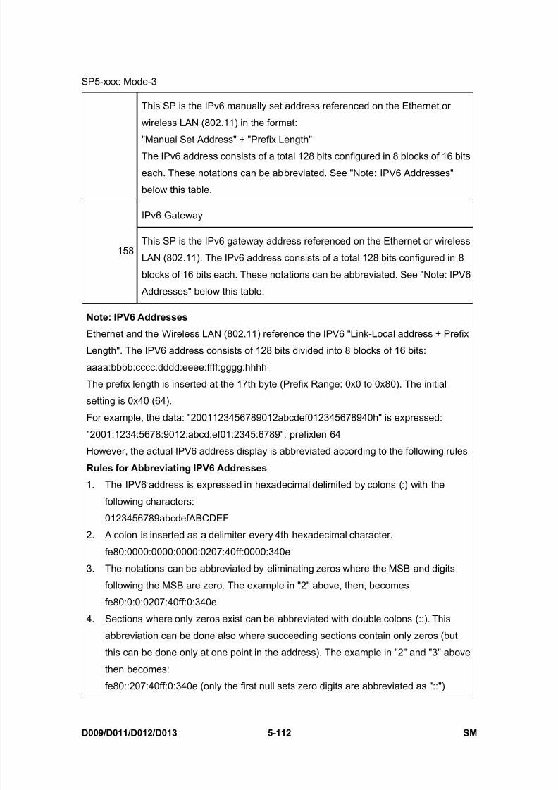
8/15/2019 Ricoh MP 4000 SM D009_D011_D012_D013 SERVICE MANUAL .pdf
http://slidepdf.com/reader/full/ricoh-mp-4000-sm-d009d011d012d013-service-manual-pdf 398/1162
SP5-xxx: Mode-3
D009/D011/D012/D013 5-112 SM
This SP is the IPv6 manually set address referenced on the Ethernet or
wireless LAN (802.11) in the format:
"Manual Set Address" + "Prefix Length"The IPv6 address consists of a total 128 bits configured in 8 blocks of 16 bits
each. These notations can be abbreviated. See "Note: IPV6 Addresses"
below this table.
IPv6 Gateway
158This SP is the IPv6 gateway address referenced on the Ethernet or wireless
LAN (802.11). The IPv6 address consists of a total 128 bits configured in 8
blocks of 16 bits each. These notations can be abbreviated. See "Note: IPV6 Addresses" below this table.
Note: IPV6 Addresses
Ethernet and the Wireless LAN (802.11) reference the IPV6 "Link-Local address + Prefix
Length". The IPV6 address consists of 128 bits divided into 8 blocks of 16 bits:
aaaa:bbbb:cccc:dddd:eeee:ffff:gggg:hhhh:
The prefix length is inserted at the 17th byte (Prefix Range: 0x0 to 0x80). The initial
setting is 0x40 (64).
For example, the data: "2001123456789012abcdef012345678940h" is expressed:
"2001:1234:5678:9012:abcd:ef01:2345:6789": prefixlen 64
However, the actual IPV6 address display is abbreviated according to the following rules.
Rules for Abbreviating IPV6 Addresses
1. The IPV6 address is expressed in hexadecimal delimited by colons (:) with the
following characters:
0123456789abcdefABCDEF
2. A colon is inserted as a delimiter every 4th hexadecimal character.
fe80:0000:0000:0000:0207:40ff:0000:340e3. The notations can be abbreviated by eliminating zeros where the MSB and digits
following the MSB are zero. The example in "2" above, then, becomes
fe80:0:0:0207:40ff:0:340e
4. Sections where only zeros exist can be abbreviated with double colons (::). This
abbreviation can be done also where succeeding sections contain only zeros (but
this can be done only at one point in the address). The example in "2" and "3" above
then becomes:
fe80::207:40ff:0:340e (only the first null sets zero digits are abbreviated as "::")

8/15/2019 Ricoh MP 4000 SM D009_D011_D012_D013 SERVICE MANUAL .pdf
http://slidepdf.com/reader/full/ricoh-mp-4000-sm-d009d011d012d013-service-manual-pdf 399/1162
SP5-xxx: Mode-3
SM 5-113 D009/D011/D012/D013
S e r v i c e
T a b l e s
-or-
fe80:0:0:0:207:40ff::340e (only the last null set before "340e" is abbreviated as "::")
161IPv6 Stateless Auto
Setting
Enable or disables the automatic setting for IPv6
stateless.
Web Item visible
236
Displays or does not display the Web system items.
[0 x 0000 to 0 x ffff / 0 x ffff ] 0: Not displayed, 1: Displayed
bit0: Net RICOH
bit1: Consumable Supplier
bit2-15: Reserved (all)
Web shopping link visible
237Displays or does not display the link to Net RICOH on the top page and link
page of the web system.
[0 to 1 / 1 / 1]
0: Not display, 1:Display
Web supplies Link visible
238Displays or does not display the link to Consumable Supplier on the top
page and link page of the web system.
[0 to 1 / 1 / 1]
0: Not display, 1:Display
Web Link1 Name
239This SP confirms or changes the URL1 name on the link page of the web
system. The maximum characters for the URL name are 31 characters.
Web URL
240his SP confirms or changes the link to URL1 on the link page of the web
system. The maximum characters for the URL are 127 characters.
Web visible
241Displays or does not display the link to URL1 on the top page of the web
system.
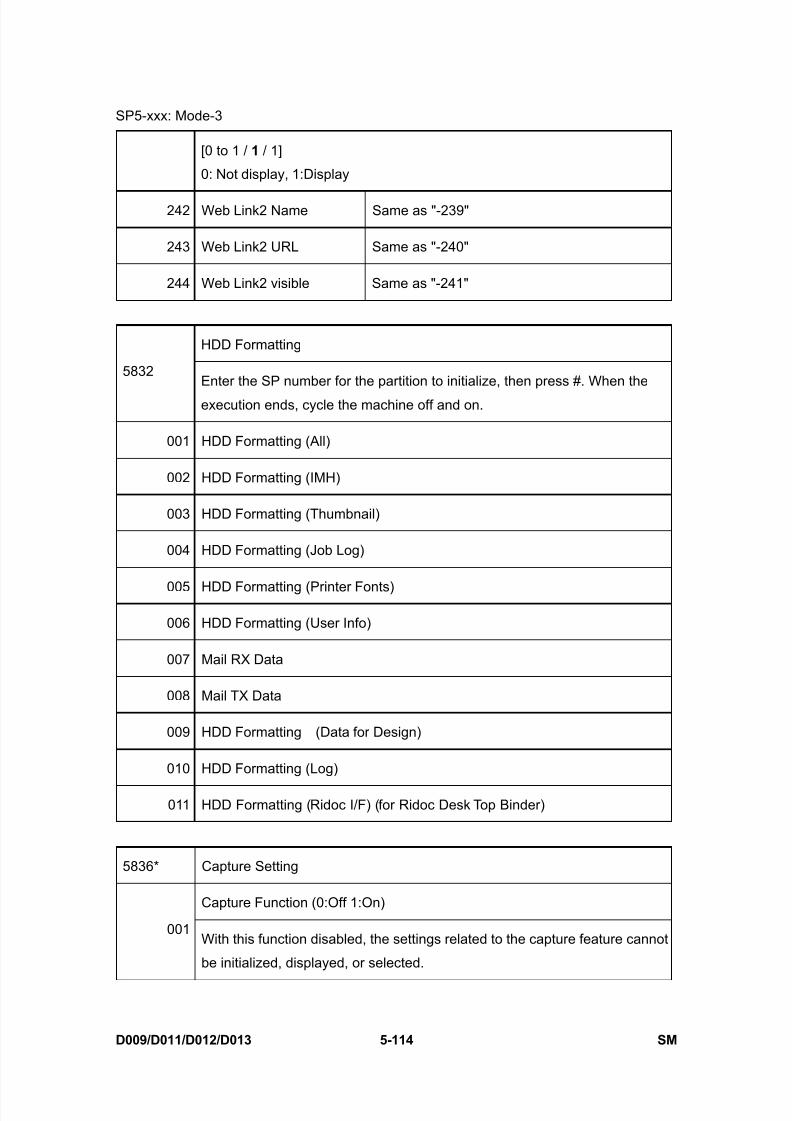
8/15/2019 Ricoh MP 4000 SM D009_D011_D012_D013 SERVICE MANUAL .pdf
http://slidepdf.com/reader/full/ricoh-mp-4000-sm-d009d011d012d013-service-manual-pdf 400/1162
SP5-xxx: Mode-3
D009/D011/D012/D013 5-114 SM
[0 to 1 / 1 / 1]
0: Not display, 1:Display
242 Web Link2 Name Same as "-239"
243 Web Link2 URL Same as "-240"
244 Web Link2 visible Same as "-241"
HDD Formatting
5832Enter the SP number for the partition to initialize, then press #. When the
execution ends, cycle the machine off and on.
001 HDD Formatting (All)
002 HDD Formatting (IMH)
003 HDD Formatting (Thumbnail)
004 HDD Formatting (Job Log)
005 HDD Formatting (Printer Fonts)
006 HDD Formatting (User Info)
007 Mail RX Data
008 Mail TX Data
009 HDD Formatting (Data for Design)
010 HDD Formatting (Log)
011 HDD Formatting (Ridoc I/F) (for Ridoc Desk Top Binder)
5836* Capture Setting
Capture Function (0:Off 1:On)
001With this function disabled, the settings related to the capture feature cannot
be initialized, displayed, or selected.

8/15/2019 Ricoh MP 4000 SM D009_D011_D012_D013 SERVICE MANUAL .pdf
http://slidepdf.com/reader/full/ricoh-mp-4000-sm-d009d011d012d013-service-manual-pdf 401/1162
SP5-xxx: Mode-3
SM 5-115 D009/D011/D012/D013
S e r v i c e
T a b l e s
[0 to 1 / 0 / 1]
0: Disable, 1: Enable
Panel Setting
002
Determines whether each capture related setting can be selected or
updated from the initial system screen.
[0 to 1 / 0 / 1]
0: Disable, 1: Enable
The setting for SP5836-001 has priority.
071 Reduction for Copy Color[0 to 3 / 2 / 1] (DFU)
0:1, 1:1/2, 2:1/3, 3:1/4
072 Reduction for Copy B&W Text[0 to 6 / 0 / 1]
0:1, 1:1/2, 2:1/3, 3:1/4, 6:2/3
073 Reduction for Copy B&W Other[0 to 6 / 0 / 1]
0:1, 1:1/2, 2:1/3, 3:1/4, 6:2/3
074 Reduction for Printer Color[0 to 3 / 2 / 1] (DFU)
0:1, 1:1/2, 2:1/3, 3:1/4
075 Reduction for Printer B&W[0 to 6 / 0 / 1]
0 1, 1:1/2, 2:1/3, 3:1/4, 6:2/3
076 Reduction for Printer B&W HQ[0 to 3 / 0 / 1]
0:1, 1:1/2, 2:1/3, 3:1/4
081 Format for Copy Color
[0 to 3 / 0 / 1] (DFU)
0: JFIF/JPEG, 1: TIFF/MMR, 2:
TIFF/MH, 3: TIFF/MR
082 Format for Copy B&W Text
[0 to 3 / 1 / 1]
0: JFIF/JPEG, 1: TIFF/MMR, 2:
TIFF/MH, 3: TIFF/MR
083 Format Copy B&W Other
[0 to 3 / 1 / 1]
0: JFIF/JPEG, 1: TIFF/MMR, 2:
TIFF/MH, 3: TIFF/MR
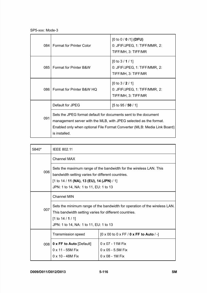
8/15/2019 Ricoh MP 4000 SM D009_D011_D012_D013 SERVICE MANUAL .pdf
http://slidepdf.com/reader/full/ricoh-mp-4000-sm-d009d011d012d013-service-manual-pdf 402/1162
SP5-xxx: Mode-3
D009/D011/D012/D013 5-116 SM
084 Format for Printer Color
[0 to 0 / 0 /1] (DFU)
0: JFIF/JPEG, 1: TIFF/MMR, 2:
TIFF/MH, 3: TIFF/MR
085 Format for Printer B&W
[0 to 3 / 1 / 1]
0: JFIF/JPEG, 1: TIFF/MMR, 2:
TIFF/MH, 3: TIFF/MR
086 Format for Printer B&W HQ
[0 to 3 / 2 / 1]
0: JFIF/JPEG, 1: TIFF/MMR, 2:
TIFF/MH, 3: TIFF/MR
Default for JPEG [5 to 95 / 50 / 1]
091Sets the JPEG format default for documents sent to the document
management server with the MLB, with JPEG selected as the format.
Enabled only when optional File Format Converter (MLB: Media Link Board)
is installed.
5840* IEEE 802.11
Channel MAX
006Sets the maximum range of the bandwidth for the wireless LAN. This
bandwidth setting varies for different countries.
[1 to 14 / 11 (NA), 13 (EU), 14 (JPN) / 1]
JPN: 1 to 14, NA: 1 to 11, EU: 1 to 13
Channel MIN
007Sets the minimum range of the bandwidth for operation of the wireless LAN.This bandwidth setting varies for different countries.
[1 to 14 / 1 / 1]
JPN: 1 to 14, NA: 1 to 11, EU: 1 to 13
Transmission speed [0 x 00 to 0 x FF / 0 x FF to Auto / -]
008 0 x FF to Auto [Default]
0 x 11 - 55M Fix
0 x 10 - 48M Fix
0 x 07 - 11M Fix
0 x 05 - 5.5M Fix
0 x 08 - 1M Fix

8/15/2019 Ricoh MP 4000 SM D009_D011_D012_D013 SERVICE MANUAL .pdf
http://slidepdf.com/reader/full/ricoh-mp-4000-sm-d009d011d012d013-service-manual-pdf 403/1162
SP5-xxx: Mode-3
SM 5-117 D009/D011/D012/D013
S e r v i c e
T a b l e s
0 x 0F - 36M Fix
0 x 0E - 18M Fix
0 x 0D - 12M Fix0 x 0B - 9M Fix
0 x 0A - 6M Fix
0 x 13 - 0 x FE (reserved)
0 x 12 - 72M (reserved)
0 x 09 - 22M (reserved)
WEP Key Select
011
Selects the WEP key.
Bit 1 and 0
00: Key1, 01: Key2 (Reserved),
10: Key3 (Reserved), 11: Key4(Reserved)This SP is displayed only when the IEEE802.11 card is installed.
Fragment Thresh
042 Adjusts the fragment threshold for the IEEE802.11 card.
[256 to 2346 / 2346 / 1]
This SP is displayed only when the IEEE802.11 card is installed.
11g CTS to self
043 Determines whether the CTS self function is turned on or off.
[0 to 1 / 1 / 1] 0: Off, 1: On
This SP is displayed only when the IEEE802.11 card is installed.
11g Slot Time
044 Selects the slot time for IEEE802.11.
[0 to 1 / 0 / 1] 0: 20 μm, 1: 9 μm
This SP is displayed only when the IEEE802.11 card is installed.
WPA Debug Lvl
045 Selects the debug level for WPA authentication application.
[1 to 3 / 3 / 1] 1: Info, 2: warning, 3: error
This SP is displayed only when the IEEE802.11 card is installed.

8/15/2019 Ricoh MP 4000 SM D009_D011_D012_D013 SERVICE MANUAL .pdf
http://slidepdf.com/reader/full/ricoh-mp-4000-sm-d009d011d012d013-service-manual-pdf 404/1162
SP5-xxx: Mode-4
D009/D011/D012/D013 5-118 SM
5.15 SP5-XXX: MODE-4
Supply Name Setting
5841*Press the User Tools key. These names appear when the user presses the
Inquiry button on the User Tools screen.
001 Toner Name Setting: Black
007 Org Stamp
011 StapleStd1
012 StapleStd2 Standard Staples for B804/B805
013 StapleStd3 Standard Staples for B408
014 StapleStd4
021 StapleBind1
022 StapleBind2 Booklet Staples for B804
023 StapleBind3
GWWS Analysis (DFU)
Bit Groups
0 System & other groups (LSB)
1 Capture related
2 Certification related
3 Address book related
4 Machine management related
5 Output related (printing, delivery)
5842*
This is a debugging tool. It
sets the debugging output
mode of each Net File
process.
Bit SW 0011 1111
6 Repository related
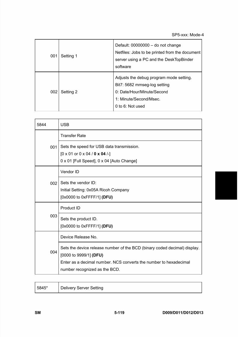
8/15/2019 Ricoh MP 4000 SM D009_D011_D012_D013 SERVICE MANUAL .pdf
http://slidepdf.com/reader/full/ricoh-mp-4000-sm-d009d011d012d013-service-manual-pdf 405/1162
SP5-xxx: Mode-4
SM 5-119 D009/D011/D012/D013
S e r v i c e
T a b l e s
001 Setting 1
Default: 00000000 – do not change
Netfiles: Jobs to be printed from the document
server using a PC and the DeskTopBindersoftware
002 Setting 2
Adjusts the debug program mode setting.
Bit7: 5682 mmseg-log setting
0: Date/Hour/Minute/Second
1: Minute/Second/Msec.
0 to 6: Not used
5844 USB
Transfer Rate
001 Sets the speed for USB data transmission.
[0 x 01 or 0 x 04 / 0 x 04 /-]
0 x 01 [Full Speed], 0 x 04 [Auto Change]
Vendor ID
002 Sets the vendor ID:
Initial Setting: 0x05A Ricoh Company
[0x0000 to 0xFFFF/1] (DFU)
Product ID
003Sets the product ID.
[0x0000 to 0xFFFF/1] (DFU)
Device Release No.
004Sets the device release number of the BCD (binary coded decimal) display.
[0000 to 9999/1] (DFU)
Enter as a decimal number. NCS converts the number to hexadecimal
number recognized as the BCD.
5845* Delivery Server Setting
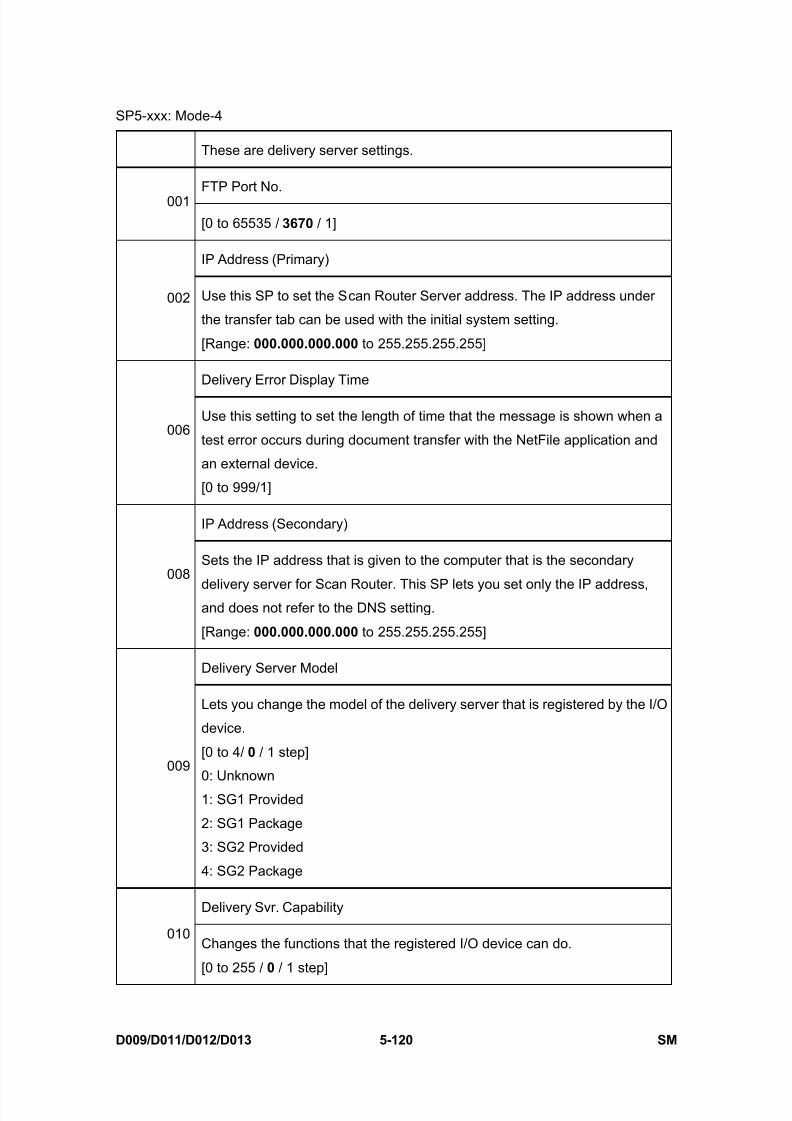
8/15/2019 Ricoh MP 4000 SM D009_D011_D012_D013 SERVICE MANUAL .pdf
http://slidepdf.com/reader/full/ricoh-mp-4000-sm-d009d011d012d013-service-manual-pdf 406/1162
SP5-xxx: Mode-4
D009/D011/D012/D013 5-120 SM
These are delivery server settings.
FTP Port No.001
[0 to 65535 / 3670 / 1]
IP Address (Primary)
002 Use this SP to set the Scan Router Server address. The IP address under
the transfer tab can be used with the initial system setting.
[Range: 000.000.000.000 to 255.255.255.255]
Delivery Error Display Time
006Use this setting to set the length of time that the message is shown when a
test error occurs during document transfer with the NetFile application and
an external device.
[0 to 999/1]
IP Address (Secondary)
008Sets the IP address that is given to the computer that is the secondary
delivery server for Scan Router. This SP lets you set only the IP address,and does not refer to the DNS setting.
[Range: 000.000.000.000 to 255.255.255.255]
Delivery Server Model
009
Lets you change the model of the delivery server that is registered by the I/O
device.
[0 to 4/ 0 / 1 step]
0: Unknown
1: SG1 Provided
2: SG1 Package
3: SG2 Provided
4: SG2 Package
Delivery Svr. Capability
010Changes the functions that the registered I/O device can do.
[0 to 255 / 0 / 1 step]
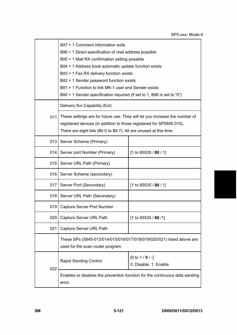
8/15/2019 Ricoh MP 4000 SM D009_D011_D012_D013 SERVICE MANUAL .pdf
http://slidepdf.com/reader/full/ricoh-mp-4000-sm-d009d011d012d013-service-manual-pdf 407/1162
SP5-xxx: Mode-4
SM 5-121 D009/D011/D012/D013
S e r v i c e
T a b l e s
Bit7 = 1 Comment information exits
Bit6 = 1 Direct specification of mail address possible
Bit5 = 1 Mail RX confirmation setting possibleBit4 = 1 Address book automatic update function exists
Bit3 = 1 Fax RX delivery function exists
Bit2 = 1 Sender password function exists
Bit1 = 1 Function to link MK-1 user and Sender exists
Bit0 = 1 Sender specification required (if set to 1, Bit6 is set to “0”)
Delivery Svr.Capability (Ext)
011 These settings are for future use. They will let you increase the number ofregistered devices (in addition to those registered for SP5845 010).
There are eight bits (Bit 0 to Bit 7). All are unused at this time.
013 Server Scheme (Primary)
014 Server port Number (Primary) [1 to 65535 / 80 / 1]
015 Server URL Path (Primary)
016 Server Scheme (secondary)
017 Server Port (Secondary) [1 to 65535 / 80 / 1]
018 Server URL Path (Secondary)
019 Capture Server Port Number
020 Capture Server URL Path [1 to 65535 / 80 /1]
021 Capture Server URL Path
These SPs (5845-013/014/015/016/017/018/019/020/021) listed above are
used for the scan router program.
Rapid Sending Control[0 to 1 / 0 / -]
0: Disable, 1: Enable022
Enables or disables the prevention function for the continuous data sending
error.
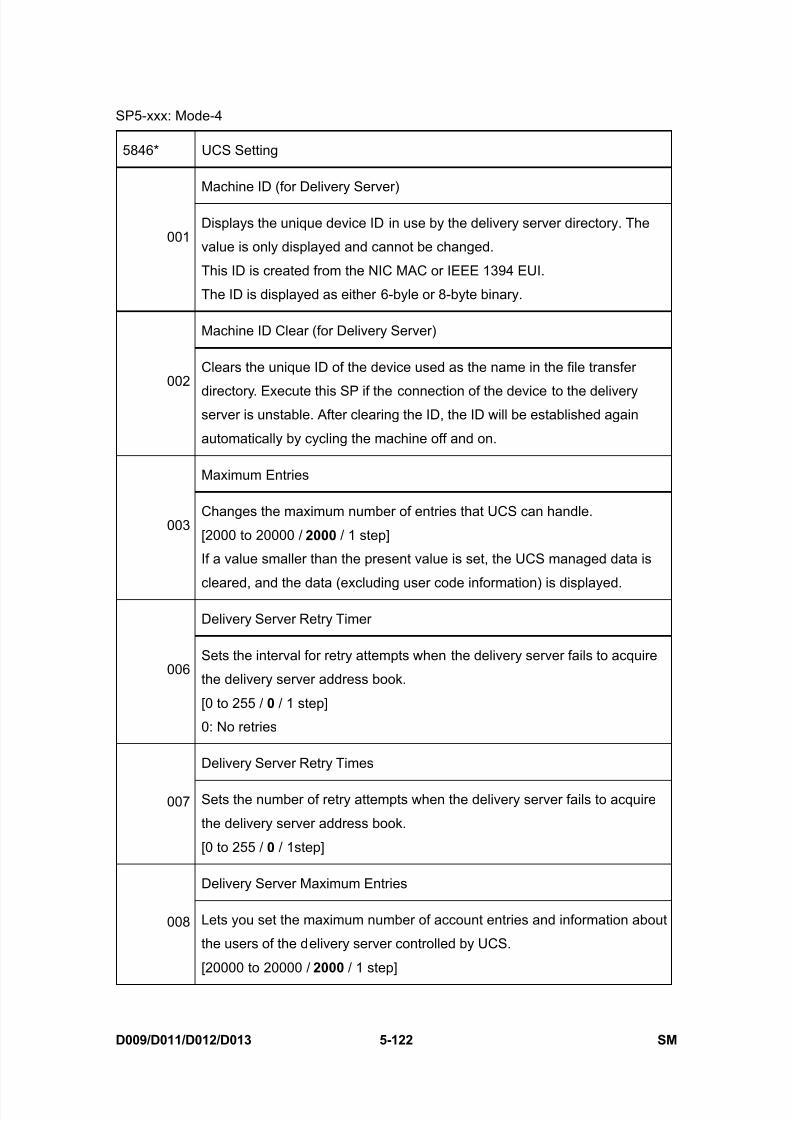
8/15/2019 Ricoh MP 4000 SM D009_D011_D012_D013 SERVICE MANUAL .pdf
http://slidepdf.com/reader/full/ricoh-mp-4000-sm-d009d011d012d013-service-manual-pdf 408/1162
SP5-xxx: Mode-4
D009/D011/D012/D013 5-122 SM
5846* UCS Setting
Machine ID (for Delivery Server)
001Displays the unique device ID in use by the delivery server directory. The
value is only displayed and cannot be changed.
This ID is created from the NIC MAC or IEEE 1394 EUI.
The ID is displayed as either 6-byle or 8-byte binary.
Machine ID Clear (for Delivery Server)
002Clears the unique ID of the device used as the name in the file transfer
directory. Execute this SP if the connection of the device to the deliveryserver is unstable. After clearing the ID, the ID will be established again
automatically by cycling the machine off and on.
Maximum Entries
003Changes the maximum number of entries that UCS can handle.
[2000 to 20000 / 2000 / 1 step]
If a value smaller than the present value is set, the UCS managed data is
cleared, and the data (excluding user code information) is displayed.
Delivery Server Retry Timer
006Sets the interval for retry attempts when the delivery server fails to acquire
the delivery server address book.
[0 to 255 / 0 / 1 step]
0: No retries
Delivery Server Retry Times
007 Sets the number of retry attempts when the delivery server fails to acquire
the delivery server address book.
[0 to 255 / 0 / 1step]
Delivery Server Maximum Entries
008 Lets you set the maximum number of account entries and information about
the users of the delivery server controlled by UCS.
[20000 to 20000 / 2000 / 1 step]

8/15/2019 Ricoh MP 4000 SM D009_D011_D012_D013 SERVICE MANUAL .pdf
http://slidepdf.com/reader/full/ricoh-mp-4000-sm-d009d011d012d013-service-manual-pdf 409/1162
SP5-xxx: Mode-4
SM 5-123 D009/D011/D012/D013
S e r v i c e
T a b l e s
LDAP Search Timeout
010Sets the length of the time-out for the search of the LDAP server.
[1 to 255 / 60 /1 step]
Addr Book Migration (USB -> HDD)
040
This SP moves the address book data from the SD card or flash ROM on the
controller board to the HDD. You must cycle the machine off and on after
executing this SP.
1. Turn the machine off.
2. Install the HDD.
3. Turn the machine on.
4. Do SP5846 040.
5. Turn the machine off/on.
Executing this SP overwrites any address book data already on the
HDD with the data from the flash ROM on the controller board.
We recommend that you back up all directory information to an SD
card with SP5846-051 before you execute this SP.
After the address book data is copied to HDD, all the address book
data is deleted from the flash ROM. If the operation fails, the data is
not erased from the flash ROM.
041 Fill Addr Acl Info.
This SP must be executed immediately after installation of an HDD unit in a
basic machine that previously had no HDD. The first time the machine is
powered on with the new HDD installed, the system automatically takes the
address book from the NVRAM and writes it onto the new HDD. However,the new address book on the HDD can be accessed only by the system
administrator at this stage. Executing this SP by the service technician
immediately after power on grants full address book access to all users.
Procedure
1. Turn the machine off.
2. Install the new HDD.
3. Turn the machine on.
4. The address book and its initial data are created on the HDD
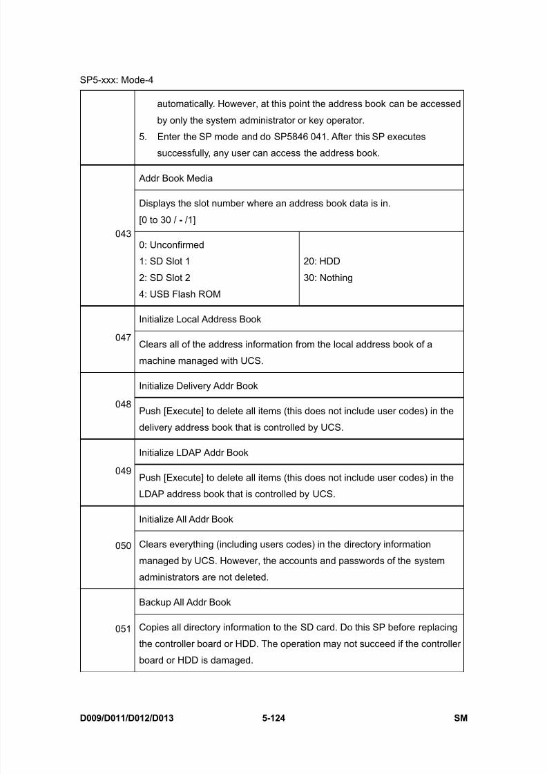
8/15/2019 Ricoh MP 4000 SM D009_D011_D012_D013 SERVICE MANUAL .pdf
http://slidepdf.com/reader/full/ricoh-mp-4000-sm-d009d011d012d013-service-manual-pdf 410/1162
SP5-xxx: Mode-4
D009/D011/D012/D013 5-124 SM
automatically. However, at this point the address book can be accessed
by only the system administrator or key operator.
5. Enter the SP mode and do SP5846 041. After this SP executessuccessfully, any user can access the address book.
Addr Book Media
Displays the slot number where an address book data is in.
[0 to 30 / - /1]043
0: Unconfirmed
1: SD Slot 1
2: SD Slot 2
4: USB Flash ROM
20: HDD
30: Nothing
Initialize Local Address Book
047Clears all of the address information from the local address book of a
machine managed with UCS.
Initialize Delivery Addr Book
048 Push [Execute] to delete all items (this does not include user codes) in the
delivery address book that is controlled by UCS.
Initialize LDAP Addr Book
049Push [Execute] to delete all items (this does not include user codes) in the
LDAP address book that is controlled by UCS.
Initialize All Addr Book
050 Clears everything (including users codes) in the directory informationmanaged by UCS. However, the accounts and passwords of the system
administrators are not deleted.
Backup All Addr Book
051 Copies all directory information to the SD card. Do this SP before replacing
the controller board or HDD. The operation may not succeed if the controller
board or HDD is damaged.
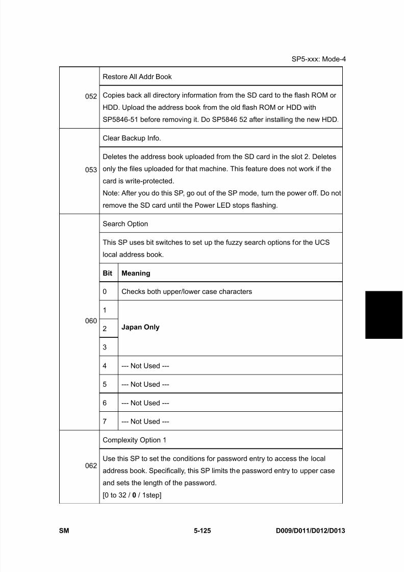
8/15/2019 Ricoh MP 4000 SM D009_D011_D012_D013 SERVICE MANUAL .pdf
http://slidepdf.com/reader/full/ricoh-mp-4000-sm-d009d011d012d013-service-manual-pdf 411/1162
SP5-xxx: Mode-4
SM 5-125 D009/D011/D012/D013
S e r v i c e
T a b l e s
Restore All Addr Book
052Copies back all directory information from the SD card to the flash ROM or
HDD. Upload the address book from the old flash ROM or HDD with
SP5846-51 before removing it. Do SP5846 52 after installing the new HDD.
Clear Backup Info.
053
Deletes the address book uploaded from the SD card in the slot 2. Deletes
only the files uploaded for that machine. This feature does not work if the
card is write-protected.
Note: After you do this SP, go out of the SP mode, turn the power off. Do not
remove the SD card until the Power LED stops flashing.
Search Option
This SP uses bit switches to set up the fuzzy search options for the UCS
local address book.
Bit Meaning
0 Checks both upper/lower case characters
1
2
3
Japan Only
4 --- Not Used ---
5 --- Not Used ---
6 --- Not Used ---
060
7 --- Not Used ---
Complexity Option 1
062Use this SP to set the conditions for password entry to access the local
address book. Specifically, this SP limits the password entry to upper case
and sets the length of the password.
[0 to 32 / 0 / 1step]
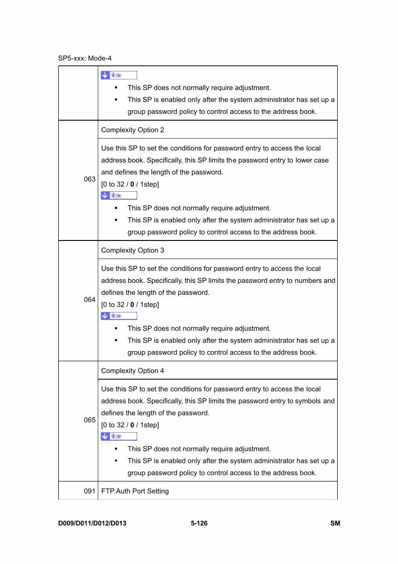
8/15/2019 Ricoh MP 4000 SM D009_D011_D012_D013 SERVICE MANUAL .pdf
http://slidepdf.com/reader/full/ricoh-mp-4000-sm-d009d011d012d013-service-manual-pdf 412/1162
SP5-xxx: Mode-4
D009/D011/D012/D013 5-126 SM
This SP does not normally require adjustment.
This SP is enabled only after the system administrator has set up agroup password policy to control access to the address book.
Complexity Option 2
063
Use this SP to set the conditions for password entry to access the local
address book. Specifically, this SP limits the password entry to lower case
and defines the length of the password.
[0 to 32 / 0 / 1step]
This SP does not normally require adjustment.
This SP is enabled only after the system administrator has set up a
group password policy to control access to the address book.
Complexity Option 3
064
Use this SP to set the conditions for password entry to access the local
address book. Specifically, this SP limits the password entry to numbers and
defines the length of the password.
[0 to 32 / 0 / 1step]
This SP does not normally require adjustment.
This SP is enabled only after the system administrator has set up a
group password policy to control access to the address book.
Complexity Option 4
065
Use this SP to set the conditions for password entry to access the local
address book. Specifically, this SP limits the password entry to symbols and
defines the length of the password.
[0 to 32 / 0 / 1step]
This SP does not normally require adjustment.
This SP is enabled only after the system administrator has set up a
group password policy to control access to the address book.
091 FTP Auth Port Setting
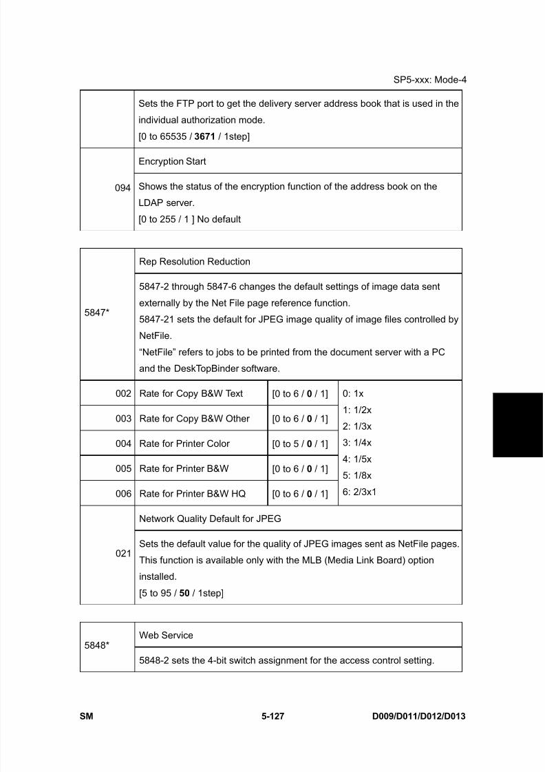
8/15/2019 Ricoh MP 4000 SM D009_D011_D012_D013 SERVICE MANUAL .pdf
http://slidepdf.com/reader/full/ricoh-mp-4000-sm-d009d011d012d013-service-manual-pdf 413/1162
SP5-xxx: Mode-4
SM 5-127 D009/D011/D012/D013
S e r v i c e
T a b l e s
Sets the FTP port to get the delivery server address book that is used in the
individual authorization mode.
[0 to 65535 / 3671 / 1step]
Encryption Start
094 Shows the status of the encryption function of the address book on the
LDAP server.
[0 to 255 / 1 ] No default
Rep Resolution Reduction
5847*
5847-2 through 5847-6 changes the default settings of image data sent
externally by the Net File page reference function.
5847-21 sets the default for JPEG image quality of image files controlled by
NetFile.
“NetFile” refers to jobs to be printed from the document server with a PC
and the DeskTopBinder software.
002 Rate for Copy B&W Text [0 to 6 / 0 / 1]
003 Rate for Copy B&W Other [0 to 6 / 0 / 1]
004 Rate for Printer Color [0 to 5 / 0 / 1]
005 Rate for Printer B&W [0 to 6 / 0 / 1]
006 Rate for Printer B&W HQ [0 to 6 / 0 / 1]
0: 1x
1: 1/2x
2: 1/3x
3: 1/4x
4: 1/5x
5: 1/8x
6: 2/3x1
Network Quality Default for JPEG
021Sets the default value for the quality of JPEG images sent as NetFile pages.
This function is available only with the MLB (Media Link Board) option
installed.
[5 to 95 / 50 / 1step]
Web Service5848*
5848-2 sets the 4-bit switch assignment for the access control setting.
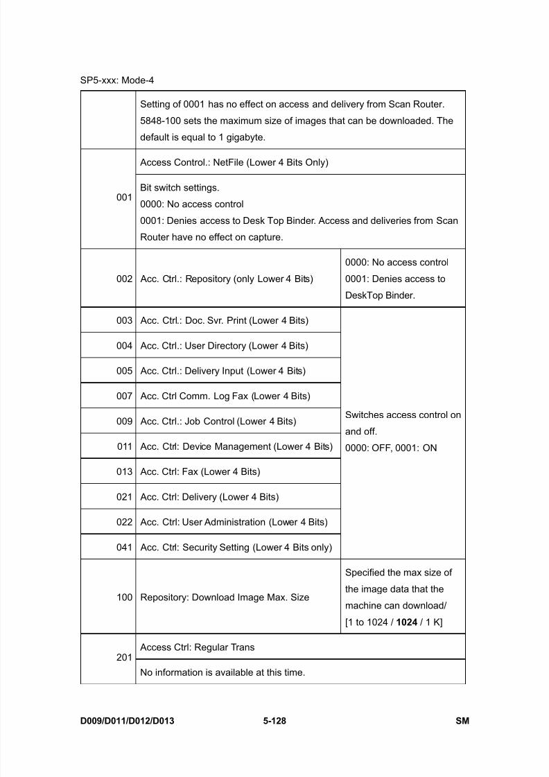
8/15/2019 Ricoh MP 4000 SM D009_D011_D012_D013 SERVICE MANUAL .pdf
http://slidepdf.com/reader/full/ricoh-mp-4000-sm-d009d011d012d013-service-manual-pdf 414/1162
SP5-xxx: Mode-4
D009/D011/D012/D013 5-128 SM
Setting of 0001 has no effect on access and delivery from Scan Router.
5848-100 sets the maximum size of images that can be downloaded. The
default is equal to 1 gigabyte.
Access Control.: NetFile (Lower 4 Bits Only)
001Bit switch settings.
0000: No access control
0001: Denies access to Desk Top Binder. Access and deliveries from Scan
Router have no effect on capture.
002 Acc. Ctrl.: Repository (only Lower 4 Bits)
0000: No access control
0001: Denies access to
DeskTop Binder.
003 Acc. Ctrl.: Doc. Svr. Print (Lower 4 Bits)
004 Acc. Ctrl.: User Directory (Lower 4 Bits)
005 Acc. Ctrl.: Delivery Input (Lower 4 Bits)
007 Acc. Ctrl Comm. Log Fax (Lower 4 Bits)
009 Acc. Ctrl.: Job Control (Lower 4 Bits)
011 Acc. Ctrl: Device Management (Lower 4 Bits)
013 Acc. Ctrl: Fax (Lower 4 Bits)
021 Acc. Ctrl: Delivery (Lower 4 Bits)
022 Acc. Ctrl: User Administration (Lower 4 Bits)
041 Acc. Ctrl: Security Setting (Lower 4 Bits only)
Switches access control on
and off.
0000: OFF, 0001: ON
100 Repository: Download Image Max. Size
Specified the max size of
the image data that the
machine can download/
[1 to 1024 / 1024 / 1 K]
Access Ctrl: Regular Trans201
No information is available at this time.

8/15/2019 Ricoh MP 4000 SM D009_D011_D012_D013 SERVICE MANUAL .pdf
http://slidepdf.com/reader/full/ricoh-mp-4000-sm-d009d011d012d013-service-manual-pdf 415/1162
SP5-xxx: Mode-4
SM 5-129 D009/D011/D012/D013
S e r v i c e
T a b l e s
0: Not allowed
1: Allowed
Setting: Log Type: Job 1210
No information is available at this time.
Setting: Log Type: Job 2211
No information is available at this time.
Setting: Log Type: Access212
No information is available at this time.
Setting: Primary Srv213
No information is available at this time.
Setting: Secondary Srv214
No information is available at this time.
Setting: Start Time215
No information is available at this time.
Setting: Interval Time216
No information is available at this time.
Setting: Timing217
No information is available at this time.
Installation Date5849
Displays or prints the installation date of the machine.
001 DisplayThe “Counter Clear Day” has been changed to
“Installation Date” or “Inst. Date”.
002 Switch to PrintDetermines whether the installation date is printed on
the printout for the total counter.
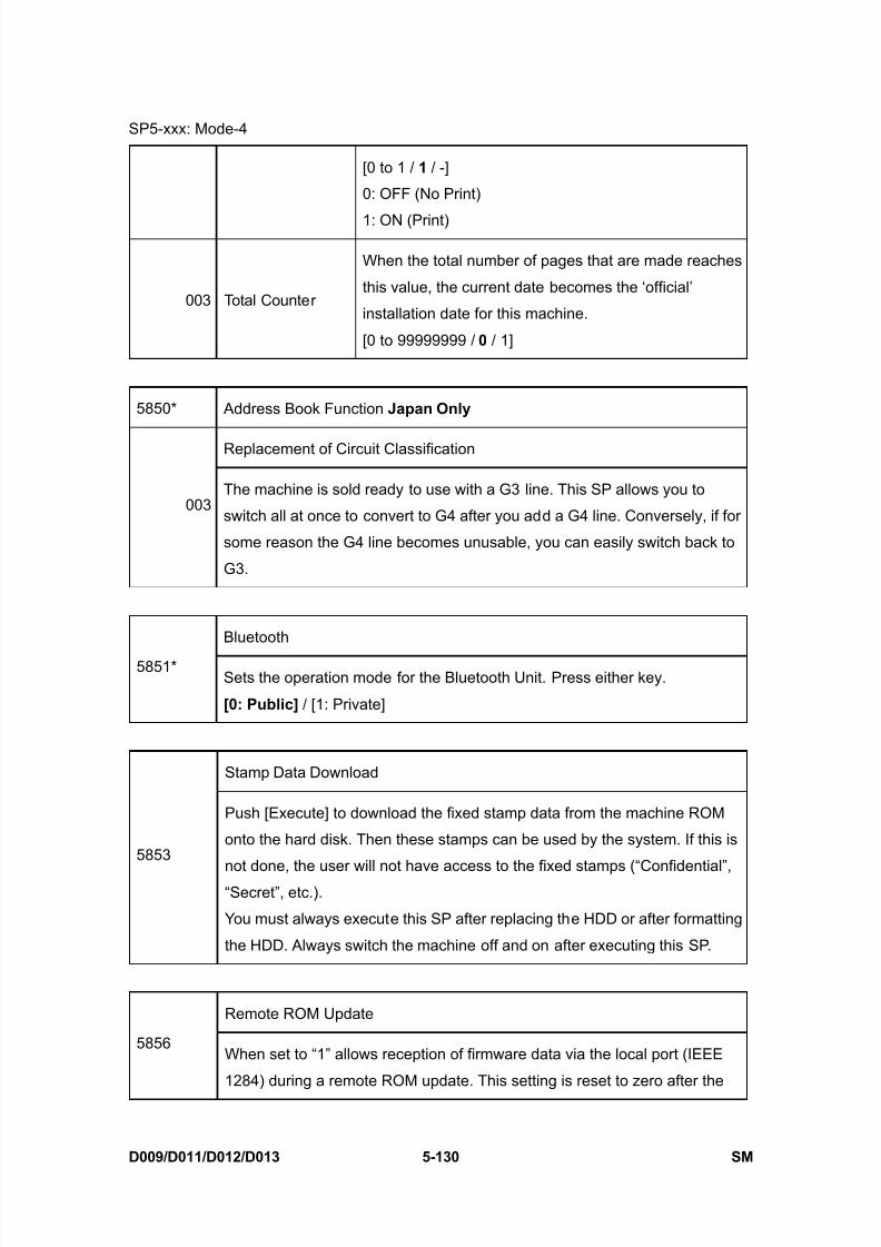
8/15/2019 Ricoh MP 4000 SM D009_D011_D012_D013 SERVICE MANUAL .pdf
http://slidepdf.com/reader/full/ricoh-mp-4000-sm-d009d011d012d013-service-manual-pdf 416/1162
SP5-xxx: Mode-4
D009/D011/D012/D013 5-130 SM
[0 to 1 / 1 / -]
0: OFF (No Print)
1: ON (Print)
003 Total Counter
When the total number of pages that are made reaches
this value, the current date becomes the ‘official’
installation date for this machine.
[0 to 99999999 / 0 / 1]
5850* Address Book Function Japan Only
Replacement of Circuit Classification
003The machine is sold ready to use with a G3 line. This SP allows you to
switch all at once to convert to G4 after you add a G4 line. Conversely, if for
some reason the G4 line becomes unusable, you can easily switch back to
G3.
Bluetooth
5851*Sets the operation mode for the Bluetooth Unit. Press either key.
[0: Public] / [1: Private]
Stamp Data Download
5853
Push [Execute] to download the fixed stamp data from the machine ROM
onto the hard disk. Then these stamps can be used by the system. If this is
not done, the user will not have access to the fixed stamps (“Confidential”,“Secret”, etc.).
You must always execute this SP after replacing the HDD or after formatting
the HDD. Always switch the machine off and on after executing this SP.
Remote ROM Update
5856When set to “1” allows reception of firmware data via the local port (IEEE
1284) during a remote ROM update. This setting is reset to zero after the
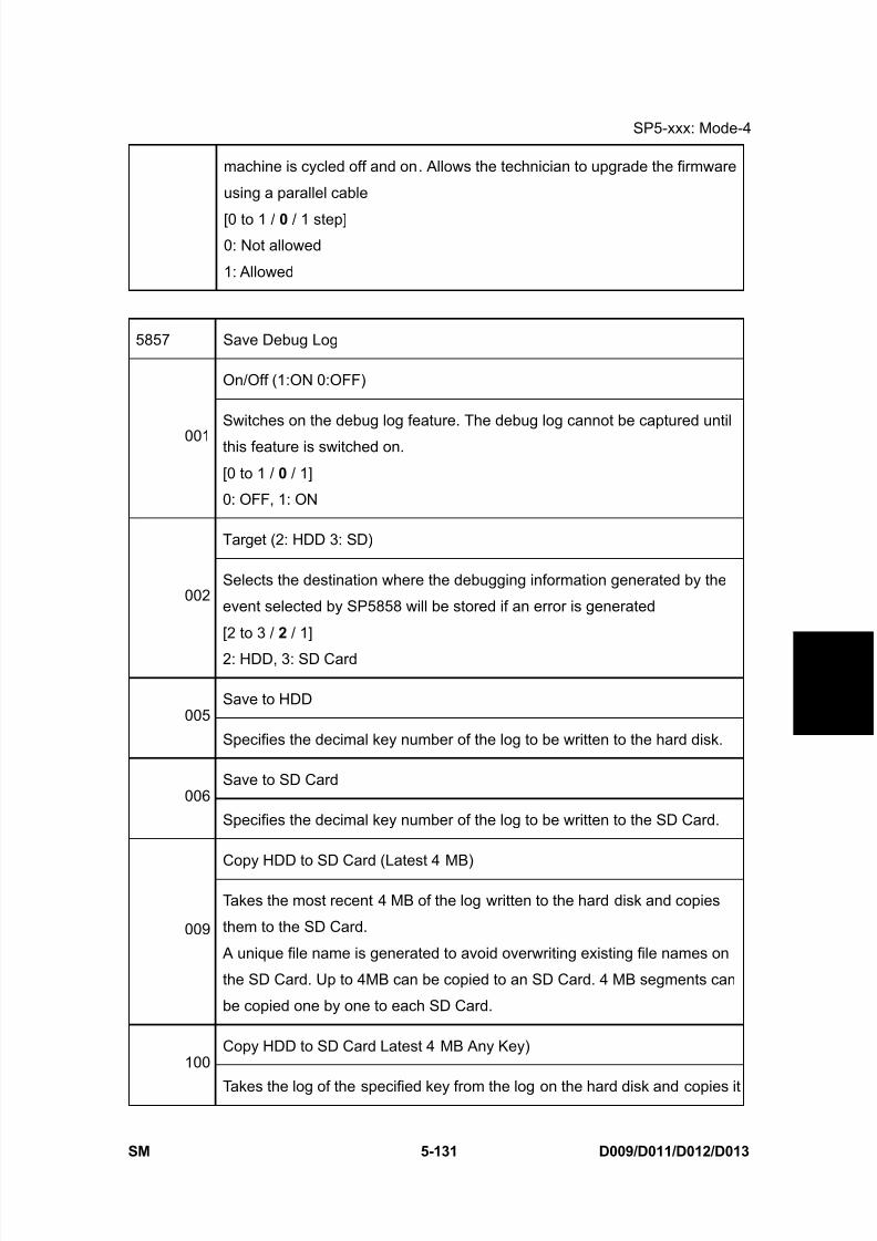
8/15/2019 Ricoh MP 4000 SM D009_D011_D012_D013 SERVICE MANUAL .pdf
http://slidepdf.com/reader/full/ricoh-mp-4000-sm-d009d011d012d013-service-manual-pdf 417/1162
SP5-xxx: Mode-4
SM 5-131 D009/D011/D012/D013
S e r v i c e
T a b l e s
machine is cycled off and on. Allows the technician to upgrade the firmware
using a parallel cable
[0 to 1 / 0 / 1 step]0: Not allowed
1: Allowed
5857 Save Debug Log
On/Off (1:ON 0:OFF)
001Switches on the debug log feature. The debug log cannot be captured until
this feature is switched on.
[0 to 1 / 0 / 1]
0: OFF, 1: ON
Target (2: HDD 3: SD)
002Selects the destination where the debugging information generated by the
event selected by SP5858 will be stored if an error is generated
[2 to 3 / 2 / 1]
2: HDD, 3: SD Card
Save to HDD005
Specifies the decimal key number of the log to be written to the hard disk.
Save to SD Card006
Specifies the decimal key number of the log to be written to the SD Card.
Copy HDD to SD Card (Latest 4 MB)
009
Takes the most recent 4 MB of the log written to the hard disk and copies
them to the SD Card.
A unique file name is generated to avoid overwriting existing file names on
the SD Card. Up to 4MB can be copied to an SD Card. 4 MB segments can
be copied one by one to each SD Card.
Copy HDD to SD Card Latest 4 MB Any Key)100
Takes the log of the specified key from the log on the hard disk and copies it
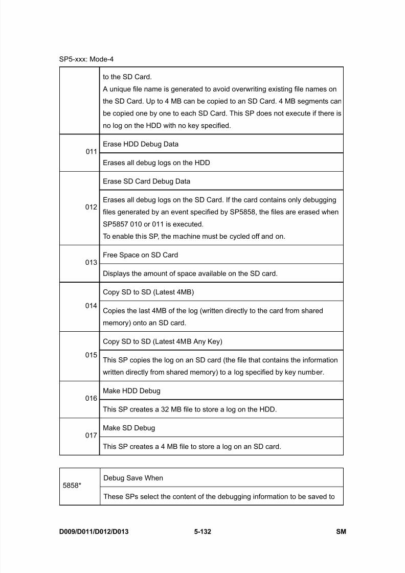
8/15/2019 Ricoh MP 4000 SM D009_D011_D012_D013 SERVICE MANUAL .pdf
http://slidepdf.com/reader/full/ricoh-mp-4000-sm-d009d011d012d013-service-manual-pdf 418/1162
SP5-xxx: Mode-4
D009/D011/D012/D013 5-132 SM
to the SD Card.
A unique file name is generated to avoid overwriting existing file names on
the SD Card. Up to 4 MB can be copied to an SD Card. 4 MB segments canbe copied one by one to each SD Card. This SP does not execute if there is
no log on the HDD with no key specified.
Erase HDD Debug Data011
Erases all debug logs on the HDD
Erase SD Card Debug Data
012 Erases all debug logs on the SD Card. If the card contains only debuggingfiles generated by an event specified by SP5858, the files are erased when
SP5857 010 or 011 is executed.
To enable this SP, the machine must be cycled off and on.
Free Space on SD Card013
Displays the amount of space available on the SD card.
Copy SD to SD (Latest 4MB)
014Copies the last 4MB of the log (written directly to the card from shared
memory) onto an SD card.
Copy SD to SD (Latest 4MB Any Key)
015This SP copies the log on an SD card (the file that contains the information
written directly from shared memory) to a log specified by key number.
Make HDD Debug
016This SP creates a 32 MB file to store a log on the HDD.
Make SD Debug017
This SP creates a 4 MB file to store a log on an SD card.
Debug Save When5858*
These SPs select the content of the debugging information to be saved to

8/15/2019 Ricoh MP 4000 SM D009_D011_D012_D013 SERVICE MANUAL .pdf
http://slidepdf.com/reader/full/ricoh-mp-4000-sm-d009d011d012d013-service-manual-pdf 419/1162
SP5-xxx: Mode-4
SM 5-133 D009/D011/D012/D013
S e r v i c e
T a b l e s
the destination selected by SP5857-002.
SP5858-003 stores one SC specified by number.
001* Engine SC Error (0:OFF 1:ON)Stores SC codes generated by copier
engine errors.
002*Controller SC Error (0:OFF
1:ON)
Stores SC codes generated by GW
controller errors.
003* Any SC Error [0 to 65535 / 0 / 1step]
004* Jam (0:OFF 1:ON) Stores jam errors.
5859* Debug Log Save Function
001 Key 1
002 Key 2
003 Key 3
004 Key 4
005 Key 5
006 Key 6
007 Key 7
008 Key 8
009 Key 9
010 Key 10
These SPs allow you to set up to 10 keys for log files for
functions that use common memory on the controller board.
[-9999999 to 9999999 / - / 1]

8/15/2019 Ricoh MP 4000 SM D009_D011_D012_D013 SERVICE MANUAL .pdf
http://slidepdf.com/reader/full/ricoh-mp-4000-sm-d009d011d012d013-service-manual-pdf 420/1162
SP5-xxx: Mode-5
D009/D011/D012/D013 5-134 SM
5.16 SP5-XXX: MODE-5
5860* SMTP/POP3/IMAP4
Partial Mail Receive Timeout
020[1 to 168 / 72 /1]
Sets the amount of time to wait before saving a mail that breaks up during
reception. The received mail is discarded if the remaining portion of the mail
is not received during this prescribed time.
MDN Response RFC2298 Compliance
021Determines whether RFC2298 compliance is switched on for MDN reply
mail.
[0 to 1 / 1 / 1]
0: No, 1: Yes
SMTP Auth. From Field Replacement
022
Determines whether the FROM item of the mail header is switched to the
validated account after the SMTP server is validated.
[0 to 1 / 0 / 1]
0: No. “From” item not switched.
1: Yes. “From” item switched.
SMTP Certification Account Mail
023
This is the mail address for SMTP certification. When SMTP certification is
done in response to a send request for a document or text mail, this SP setsthe mail address for the SMTP protocol MAIL FROM command in the
following cases:
When the SMTP certification information has not been set from the
software application.
When the SMTP certification information for UCS has been set or not
set on the mainframe with the User Tools.
024 POP3/IMAP4 Account Mail Address
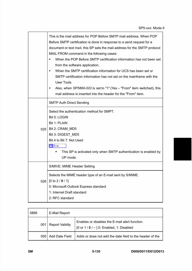
8/15/2019 Ricoh MP 4000 SM D009_D011_D012_D013 SERVICE MANUAL .pdf
http://slidepdf.com/reader/full/ricoh-mp-4000-sm-d009d011d012d013-service-manual-pdf 421/1162
SP5-xxx: Mode-5
SM 5-135 D009/D011/D012/D013
S e r v i c e
T a b l e s
This is the mail address for POP Before SMTP mail address. When POP
Before SMTP certification is done in response to a send request for a
document or text mail, this SP sets the mail address for the SMTP protocolMAIL FROM command in the following cases:
When the POP Before SMTP certification information has not been set
from the software application.
When the SMTP certification information for UCS has been set or
SMTP certification information has not set on the mainframe with the
User Tools.
Also, when SP5860-022 is set to "1" (Yes – "From" item switched), this
mail address is inserted into the header for the "From" item.
SMTP Auth Direct Sending
025
Select the authentication method for SMPT.
Bit 0: LOGIN
Bit 1: PLAIN
Bit 2: CRAM_MD5
Bit 3: DIGEST_MD5
Bit 4 to Bit 7: Not Used
This SP is activated only when SMTP authentication is enabled by
UP mode.
S/MIVE: MIME Header Setting
026
Selects the MIME header type of an E-mail sent by S/MIME.
[0 to 2 / 0 / 1]
0: Microsoft Outlook Express standard
1: Internet Draft standard
2: RFC standard
5866 E-Mail Report
001 Report ValidityEnables or disables the E-mail alert function.
[0 or 1 / 0 / – ] 0: Enabled, 1: Disabled
005 Add Date Field Adds or does not add the date field to the header of the
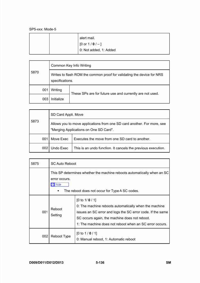
8/15/2019 Ricoh MP 4000 SM D009_D011_D012_D013 SERVICE MANUAL .pdf
http://slidepdf.com/reader/full/ricoh-mp-4000-sm-d009d011d012d013-service-manual-pdf 422/1162
SP5-xxx: Mode-5
D009/D011/D012/D013 5-136 SM
alert mail.
[0 or 1 / 0 / – ]
0: Not added, 1: Added
Common Key Info Writing
5870Writes to flash ROM the common proof for validating the device for NRS
specifications.
001 Writing
003 Initialize
These SPs are for future use and currently are not used.
SD Card Appli. Move
5873 Allows you to move applications from one SD card another. For more, see
"Merging Applications on One SD Card".
001 Move Exec Executes the move from one SD card to another.
002 Undo Exec This is an undo function. It cancels the previous execution.
5875 SC Auto Reboot
This SP determines whether the machine reboots automatically when an SC
error occurs.
The reboot does not occur for Type A SC codes.
001Reboot
Setting
[0 to 1/ 0 / 1]
0: The machine reboots automatically when the machine
issues an SC error and logs the SC error code. If the same
SC occurs again, the machine does not reboot.
1: The machine does not reboot when an SC error occurs.
002 Reboot Type[0 to 1 / 0 / 1]
0: Manual reboot, 1: Automatic reboot
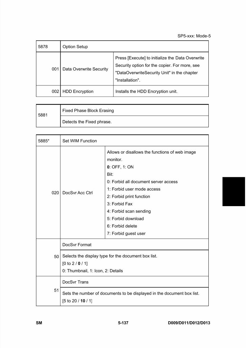
8/15/2019 Ricoh MP 4000 SM D009_D011_D012_D013 SERVICE MANUAL .pdf
http://slidepdf.com/reader/full/ricoh-mp-4000-sm-d009d011d012d013-service-manual-pdf 423/1162
SP5-xxx: Mode-5
SM 5-137 D009/D011/D012/D013
S e r v i c e
T a b l e s
5878 Option Setup
001 Data Overwrite Security
Press [Execute] to initialize the Data Overwrite
Security option for the copier. For more, see
"DataOverwriteSecurity Unit" in the chapter
"Installation".
002 HDD Encryption Installs the HDD Encryption unit.
Fixed Phase Block Erasing5881
Detects the Fixed phrase.
5885* Set WIM Function
020 DocSvr Acc Ctrl
Allows or disallows the functions of web image
monitor.
0: OFF, 1: ON
Bit:
0: Forbid all document server access1: Forbid user mode access
2: Forbid print function
3: Forbid Fax
4: Forbid scan sending
5: Forbid download
6: Forbid delete
7: Forbid guest user
DocSvr Format
50 Selects the display type for the document box list.
[0 to 2 / 0 / 1]
0: Thumbnail, 1: Icon, 2: Details
DocSvr Trans
51Sets the number of documents to be displayed in the document box list.
[5 to 20 / 10 / 1]

8/15/2019 Ricoh MP 4000 SM D009_D011_D012_D013 SERVICE MANUAL .pdf
http://slidepdf.com/reader/full/ricoh-mp-4000-sm-d009d011d012d013-service-manual-pdf 424/1162
SP5-xxx: Mode-5
D009/D011/D012/D013 5-138 SM
Set Encryption
101Determines whether the scanned documents with the WIM are encrypted
when they are transmitted by an e-mail.
[0 to 1 / 0 / 1]
0: Not encrypted, 1:Encryption
Farm Update Procedure
5886*
Permit ROM Update
This SP determines whether the ROM can be
updated
[0 or 1 / 0 / 1 step]
0: ON, 1: OFF
Personal Information Protect
5888*Selects the protection level for logs.
[0 to 1 / 0 / 1}
0: No authentication, No protection for logs
1: No authentication, Protected logs (only an administrator can see the logs)
Plug & Play Maker/Model Name
5907
Selects the brand name and the production name for Windows Plug & Play.
This information is stored in the NVRAM. If the NVRAM is defective, these
names should be registered again.
After selecting, press the “Original Type” key and “#” key at the same time.
When the setting is completed, the beeper sounds five times.
[0 to 23 / - / 1 step] FA
0: RICOH Aficio MP 4000B
1: RICOH Aficio MP 4000
2: RICOH Aficio MP 5000B
3: RICOH Aficio MP 5000
4: SAVIN 9040b
5: SAVIN 9040
↓
12: LANIER MP 4000B/LD040B
13: LANIER MP 4000/LD040
14: LANIER MP 5000B/LD050B
15: LANIER MP 5000/LD050
16: NRG MP 4000B
17: NRG MP 4000
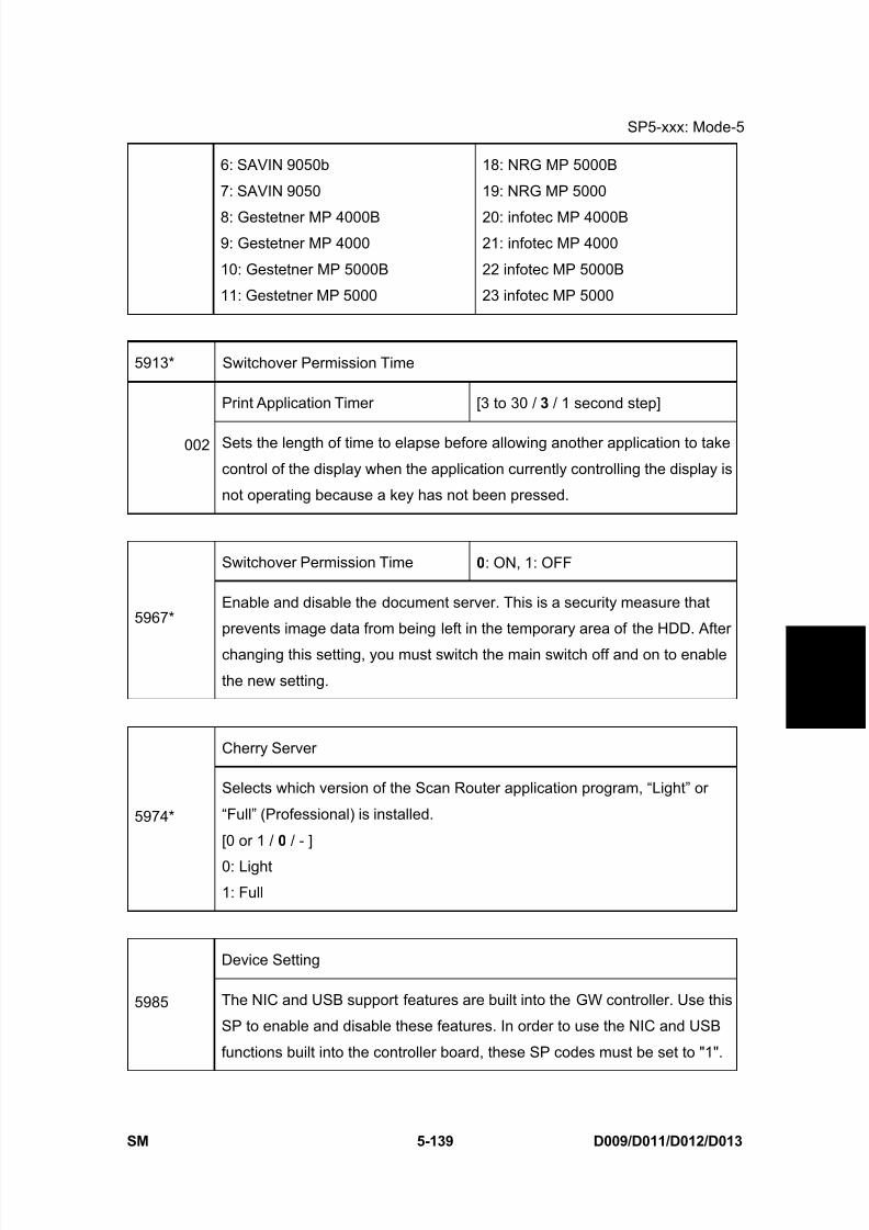
8/15/2019 Ricoh MP 4000 SM D009_D011_D012_D013 SERVICE MANUAL .pdf
http://slidepdf.com/reader/full/ricoh-mp-4000-sm-d009d011d012d013-service-manual-pdf 425/1162
SP5-xxx: Mode-5
SM 5-139 D009/D011/D012/D013
S e r v i c e
T a b l e s
6: SAVIN 9050b
7: SAVIN 9050
8: Gestetner MP 4000B9: Gestetner MP 4000
10: Gestetner MP 5000B
11: Gestetner MP 5000
18: NRG MP 5000B
19: NRG MP 5000
20: infotec MP 4000B21: infotec MP 4000
22 infotec MP 5000B
23 infotec MP 5000
5913* Switchover Permission Time
Print Application Timer [3 to 30 / 3 / 1 second step]
002 Sets the length of time to elapse before allowing another application to take
control of the display when the application currently controlling the display is
not operating because a key has not been pressed.
Switchover Permission Time 0: ON, 1: OFF
5967*Enable and disable the document server. This is a security measure that
prevents image data from being left in the temporary area of the HDD. After
changing this setting, you must switch the main switch off and on to enable
the new setting.
Cherry Server
5974*
Selects which version of the Scan Router application program, “Light” or
“Full” (Professional) is installed.
[0 or 1 / 0 / - ]
0: Light
1: Full
Device Setting
5985 The NIC and USB support features are built into the GW controller. Use this
SP to enable and disable these features. In order to use the NIC and USB
functions built into the controller board, these SP codes must be set to "1".
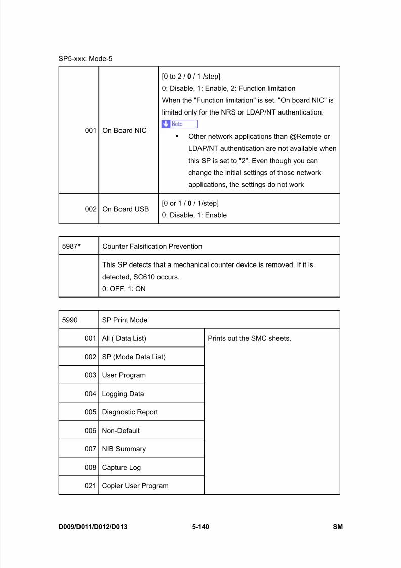
8/15/2019 Ricoh MP 4000 SM D009_D011_D012_D013 SERVICE MANUAL .pdf
http://slidepdf.com/reader/full/ricoh-mp-4000-sm-d009d011d012d013-service-manual-pdf 426/1162
SP5-xxx: Mode-5
D009/D011/D012/D013 5-140 SM
001 On Board NIC
[0 to 2 / 0 / 1 /step]
0: Disable, 1: Enable, 2: Function limitation
When the "Function limitation" is set, "On board NIC" islimited only for the NRS or LDAP/NT authentication.
Other network applications than @Remote or
LDAP/NT authentication are not available when
this SP is set to "2". Even though you can
change the initial settings of those network
applications, the settings do not work
002 On Board USB[0 or 1 / 0 / 1/step]
0: Disable, 1: Enable
5987* Counter Falsification Prevention
This SP detects that a mechanical counter device is removed. If it is
detected, SC610 occurs.
0: OFF. 1: ON
5990 SP Print Mode
001 All ( Data List)
002 SP (Mode Data List)
003 User Program
004 Logging Data
005 Diagnostic Report
006 Non-Default
007 NIB Summary
008 Capture Log
021 Copier User Program
Prints out the SMC sheets.

8/15/2019 Ricoh MP 4000 SM D009_D011_D012_D013 SERVICE MANUAL .pdf
http://slidepdf.com/reader/full/ricoh-mp-4000-sm-d009d011d012d013-service-manual-pdf 427/1162
SP5-xxx: Mode-5
SM 5-141 D009/D011/D012/D013
S e r v i c e
T a b l e s
022 Scanner SP
023 Scanner User Program

8/15/2019 Ricoh MP 4000 SM D009_D011_D012_D013 SERVICE MANUAL .pdf
http://slidepdf.com/reader/full/ricoh-mp-4000-sm-d009d011d012d013-service-manual-pdf 428/1162
SP6-xxx: Peripherals-1
D009/D011/D012/D013 5-142 SM
5.17 SP6-XXX: PERIPHERALS-1
ADF Registration Adjust
6006* Adjusts the side-to-side and leading edge registration for simplex and
duplex original feeding in ARDF mode. Press to toggle ±.
SP6006-5 sets the maximum setting allowed for rear edge erase.
001 Adjust Side-to-Side: 1st Side
002 Adjust Side-to-Side: 2nd Side
[–3 to 3 / 0 / 0.1 mm / step]
003 Leading Edge [–5 to 5 / 0 / 0.1 mm / step]
005 Leading Edge: 1st Side [–3 to 3 / 0 / 0.1 mm / step]
006 Leading Edge: 2nd Side [–2.5 to 2.5 / 0 / 0.1 mm / step]
007 Trailing Edge Erase [–10 to 10 / 0 / 0.1 mm / step]
6007 ADF Input Check
001 Original B5 Sensor
002 Original A4 Sensor
003 Original LG Sensor
004 Original Width Sensor 1
005 Original Width Sensor 2
006 Original Width Sensor 3
007 Original Width Sensor 4
008 Original Width Sensor 5
009 Original Set Sensor
010 Separation Sensor
0: Paper not detected
1: Paper detected

8/15/2019 Ricoh MP 4000 SM D009_D011_D012_D013 SERVICE MANUAL .pdf
http://slidepdf.com/reader/full/ricoh-mp-4000-sm-d009d011d012d013-service-manual-pdf 429/1162
SP6-xxx: Peripherals-1
SM 5-143 D009/D011/D012/D013
S e r v i c e
T a b l e s
011 Skew Correction Sensor
012 Interval Sensor
013 Registration Sensor
014 Exit Sensor
015 Top Cover Sensor0: ADF cover closed
1: ADF cover open
016 Lift Sensor0: ADF closed
1: ADF open
017 Inverter Sensor0: Paper not detected
1: Paper detected
018 Pick-up HP Sensor0: HP (Pick-up roller: Up)
1: Not HP (Pick-up roller: Down)
019 Original Stopper HP Sensor0: HP (Stopper: UP)
1: Not HP (Stopper: Down)
6008 ADF Output Check
001 Pick-up Motor: Fwd
002 Pick-up Motor: Rev
003 Feed Motor: Fwd
004 Feed Motor: Rev
005 Transport Motor: Fwd
006 Inverter Motor: Fwd
007 Inverter Motor: Rev
011 Junction Gate Solenoid
012 Stamp Solenoid
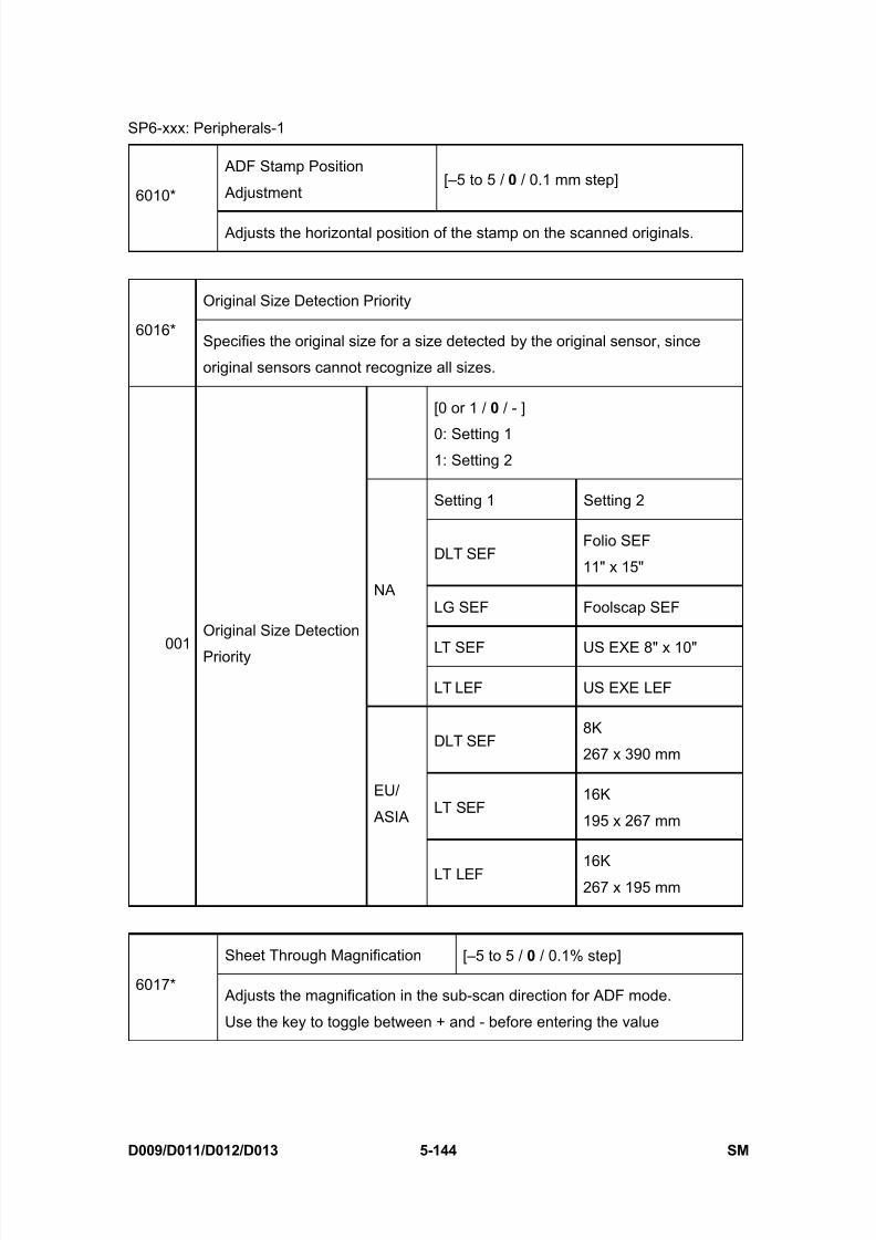
8/15/2019 Ricoh MP 4000 SM D009_D011_D012_D013 SERVICE MANUAL .pdf
http://slidepdf.com/reader/full/ricoh-mp-4000-sm-d009d011d012d013-service-manual-pdf 430/1162
SP6-xxx: Peripherals-1
D009/D011/D012/D013 5-144 SM
ADF Stamp Position
Adjustment[–5 to 5 / 0 / 0.1 mm step]
6010*
Adjusts the horizontal position of the stamp on the scanned originals.
Original Size Detection Priority
6016*Specifies the original size for a size detected by the original sensor, since
original sensors cannot recognize all sizes.
[0 or 1 / 0 / - ]
0: Setting 11: Setting 2
Setting 1 Setting 2
DLT SEFFolio SEF
11" x 15"
LG SEF Foolscap SEF
LT SEF US EXE 8" x 10"
NA
LT LEF US EXE LEF
DLT SEF8K
267 x 390 mm
LT SEF16K
195 x 267 mm
001
Original Size Detection
Priority
EU/
ASIA
LT LEF 16K267 x 195 mm
Sheet Through Magnification [–5 to 5 / 0 / 0.1% step]
6017* Adjusts the magnification in the sub-scan direction for ADF mode.
Use the key to toggle between + and - before entering the value

8/15/2019 Ricoh MP 4000 SM D009_D011_D012_D013 SERVICE MANUAL .pdf
http://slidepdf.com/reader/full/ricoh-mp-4000-sm-d009d011d012d013-service-manual-pdf 431/1162
SP6-xxx: Peripherals-1
SM 5-145 D009/D011/D012/D013
S e r v i c e
T a b l e s
Skew Correction Adjustment
6020*Turns the original skew correction in the ARDF for all original sizes on or off.
[0 to 1 / 0 / 1 ]
0: Off (only for small original sizes)
1: On (for all original sizes)
Punch Position: Sub Scan6128
Adjusts the punching position in the sub scan direction. (For B804/B805)
001 2-Hole: DOM (Japan)
002 3-Hole: NA
003 4-Hole: EU
004 5-Hole: SCAN
005 2-Hole: NA
006 1-Hole: DOM (Japan)
[-7.5 to 7.5 / 0 / 0.5 mm]
Punch Position: Main Scan6129
Adjusts the punching position in the main scan direction. (For B804/B805)
001 2-Hole: DOM (Japan)
002 3-Hole: NA
003 4-Hole: EU
004 4-Hole: SCAN
005 2-Hole: NA
006 1-Hole: DOM (Japan)
[-2 to 2 / 0 / 0.4 mm]
6130* Skew Correction: Buckle Adj.

8/15/2019 Ricoh MP 4000 SM D009_D011_D012_D013 SERVICE MANUAL .pdf
http://slidepdf.com/reader/full/ricoh-mp-4000-sm-d009d011d012d013-service-manual-pdf 432/1162
SP6-xxx: Peripherals-1
D009/D011/D012/D013 5-146 SM
Adjusts the paper buckle at the punch unit for each paper size. (For
B804/B805)
001 A3 SEF
002 B4 SEF
003 A4 SEF
004 A4 LEF
005 B5 SEF
006 B5 LEF
007 DLT SEF
008 LG SEF
009 LT SEF
010 LT LEF
011 12" x 18"
012 Other
[-5 to 5 / 0 / 0.25 mm]
Skew Correction Control6131*
Selects the skew correction control for each paper size. (For B804/B805)
001 A3 SEF
002 B4 SEF
003 A4 SEF
004 A4 LEF
005 B5 SEF
006 B5 LEF
007 DLT SEF
[0 to 1 / 1 / 1 mm]
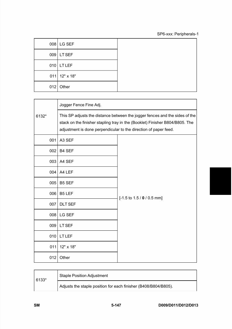
8/15/2019 Ricoh MP 4000 SM D009_D011_D012_D013 SERVICE MANUAL .pdf
http://slidepdf.com/reader/full/ricoh-mp-4000-sm-d009d011d012d013-service-manual-pdf 433/1162
SP6-xxx: Peripherals-1
SM 5-147 D009/D011/D012/D013
S e r v i c e
T a b l e s
008 LG SEF
009 LT SEF
010 LT LEF
011 12" x 18"
012 Other
Jogger Fence Fine Adj.
6132* This SP adjusts the distance between the jogger fences and the sides of thestack on the finisher stapling tray in the (Booklet) Finisher B804/B805. The
adjustment is done perpendicular to the direction of paper feed.
001 A3 SEF
002 B4 SEF
003 A4 SEF
004 A4 LEF
005 B5 SEF
006 B5 LEF
007 DLT SEF
008 LG SEF
009 LT SEF
010 LT LEF
011 12" x 18"
012 Other
[-1.5 to 1.5 / 0 / 0.5 mm]
Staple Position Adjustment6133*
Adjusts the staple position for each finisher (B408/B804/B805).
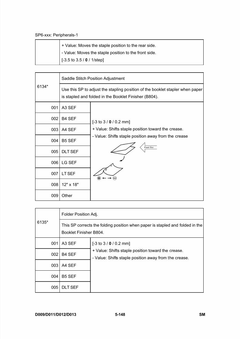
8/15/2019 Ricoh MP 4000 SM D009_D011_D012_D013 SERVICE MANUAL .pdf
http://slidepdf.com/reader/full/ricoh-mp-4000-sm-d009d011d012d013-service-manual-pdf 434/1162
SP6-xxx: Peripherals-1
D009/D011/D012/D013 5-148 SM
+ Value: Moves the staple position to the rear side.
- Value: Moves the staple position to the front side.
[-3.5 to 3.5 / 0 / 1/step]
Saddle Stitch Position Adjustment
6134*Use this SP to adjust the stapling position of the booklet stapler when paper
is stapled and folded in the Booklet Finisher (B804).
001 A3 SEF
002 B4 SEF
003 A4 SEF
004 B5 SEF
005 DLT SEF
006 LG SEF
007 LT SEF
008 12" x 18"
009 Other
[-3 to 3 / 0 / 0.2 mm]
+ Value: Shifts staple position toward the crease.
- Value: Shifts staple position away from the crease
Folder Position Adj.
6135*This SP corrects the folding position when paper is stapled and folded in the
Booklet Finisher B804.
001 A3 SEF
002 B4 SEF
003 A4 SEF
004 B5 SEF
005 DLT SEF
[-3 to 3 / 0 / 0.2 mm]
+ Value: Shifts staple position toward the crease.
- Value: Shifts staple position away from the crease.
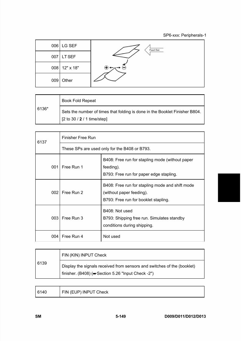
8/15/2019 Ricoh MP 4000 SM D009_D011_D012_D013 SERVICE MANUAL .pdf
http://slidepdf.com/reader/full/ricoh-mp-4000-sm-d009d011d012d013-service-manual-pdf 435/1162
SP6-xxx: Peripherals-1
SM 5-149 D009/D011/D012/D013
S e r v i c e
T a b l e s
006 LG SEF
007 LT SEF
008 12" x 18"
009 Other
Book Fold Repeat
6136*Sets the number of times that folding is done in the Booklet Finisher B804.
[2 to 30 / 2 / 1 time/step]
Finisher Free Run6137
These SPs are used only for the B408 or B793.
001 Free Run 1
B408: Free run for stapling mode (without paper
feeding).
B793: Free run for paper edge stapling.
002 Free Run 2
B408: Free run for stapling mode and shift mode
(without paper feeding).
B793: Free run for booklet stapling.
003 Free Run 3
B408: Not used
B793: Shipping free run. Simulates standby
conditions during shipping.
004 Free Run 4 Not used
FIN (KIN) INPUT Check
6139Display the signals received from sensors and switches of the (booklet)
finisher. (B408) ( Section 5.26 "Input Check -2")
6140 FIN (EUP) INPUT Check
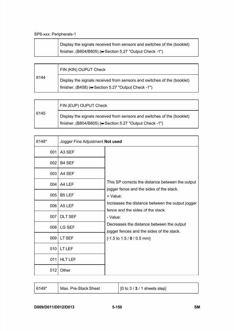
8/15/2019 Ricoh MP 4000 SM D009_D011_D012_D013 SERVICE MANUAL .pdf
http://slidepdf.com/reader/full/ricoh-mp-4000-sm-d009d011d012d013-service-manual-pdf 436/1162
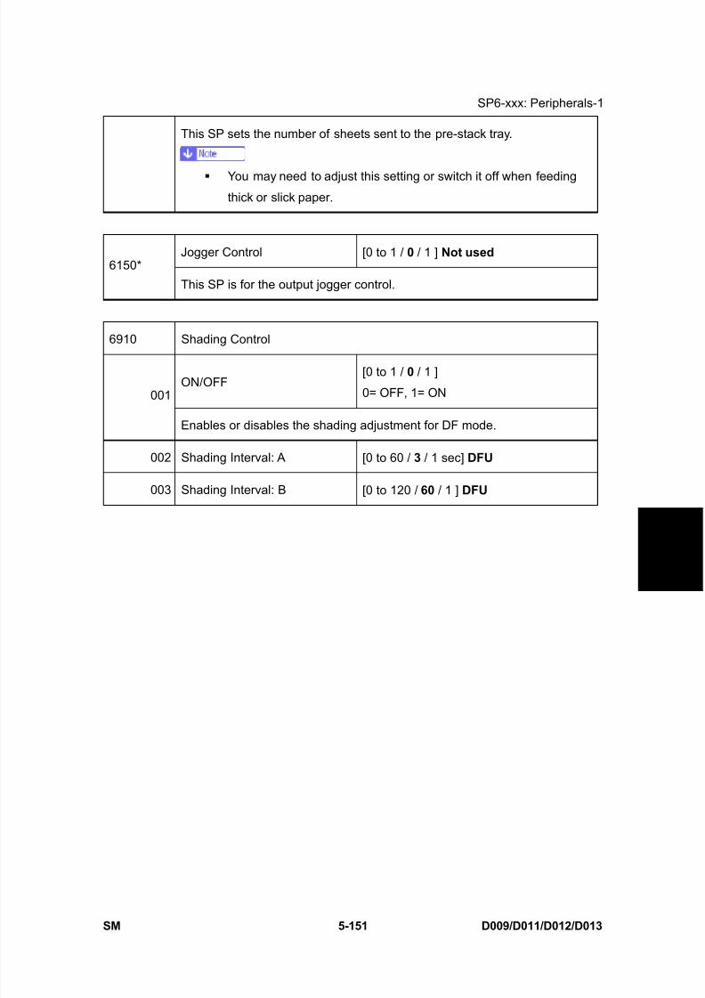
8/15/2019 Ricoh MP 4000 SM D009_D011_D012_D013 SERVICE MANUAL .pdf
http://slidepdf.com/reader/full/ricoh-mp-4000-sm-d009d011d012d013-service-manual-pdf 437/1162
SP6-xxx: Peripherals-1
SM 5-151 D009/D011/D012/D013
S e r v i c e
T a b l e s
This SP sets the number of sheets sent to the pre-stack tray.
You may need to adjust this setting or switch it off when feedingthick or slick paper.
Jogger Control [0 to 1 / 0 / 1 ] Not used 6150*
This SP is for the output jogger control.
6910 Shading Control
ON/OFF[0 to 1 / 0 / 1 ]
0= OFF, 1= ON001
Enables or disables the shading adjustment for DF mode.
002 Shading Interval: A [0 to 60 / 3 / 1 sec] DFU
003 Shading Interval: B [0 to 120 / 60 / 1 ] DFU
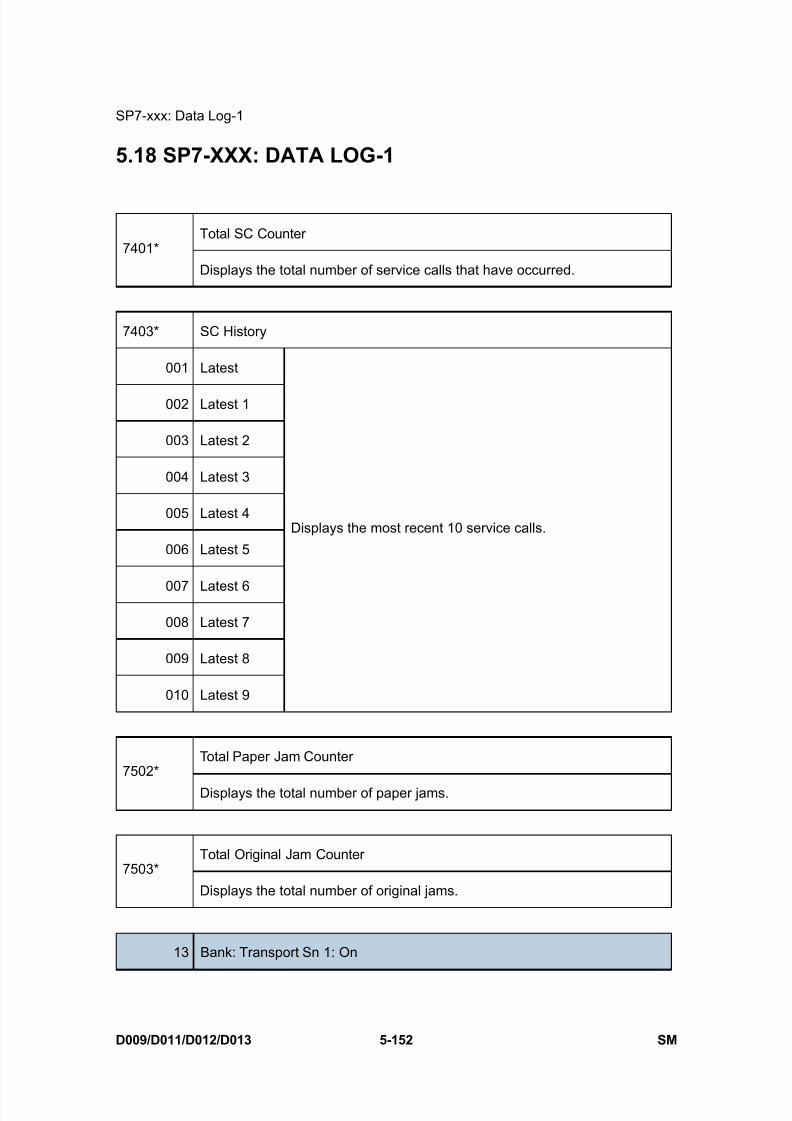
8/15/2019 Ricoh MP 4000 SM D009_D011_D012_D013 SERVICE MANUAL .pdf
http://slidepdf.com/reader/full/ricoh-mp-4000-sm-d009d011d012d013-service-manual-pdf 438/1162
SP7-xxx: Data Log-1
D009/D011/D012/D013 5-152 SM
5.18 SP7-XXX: DATA LOG-1
Total SC Counter7401*
Displays the total number of service calls that have occurred.
7403* SC History
001 Latest
002 Latest 1
003 Latest 2
004 Latest 3
005 Latest 4
006 Latest 5
007 Latest 6
008 Latest 7
009 Latest 8
010 Latest 9
Displays the most recent 10 service calls.
Total Paper Jam Counter7502*
Displays the total number of paper jams.
Total Original Jam Counter7503*
Displays the total number of original jams.
13 Bank: Transport Sn 1: On
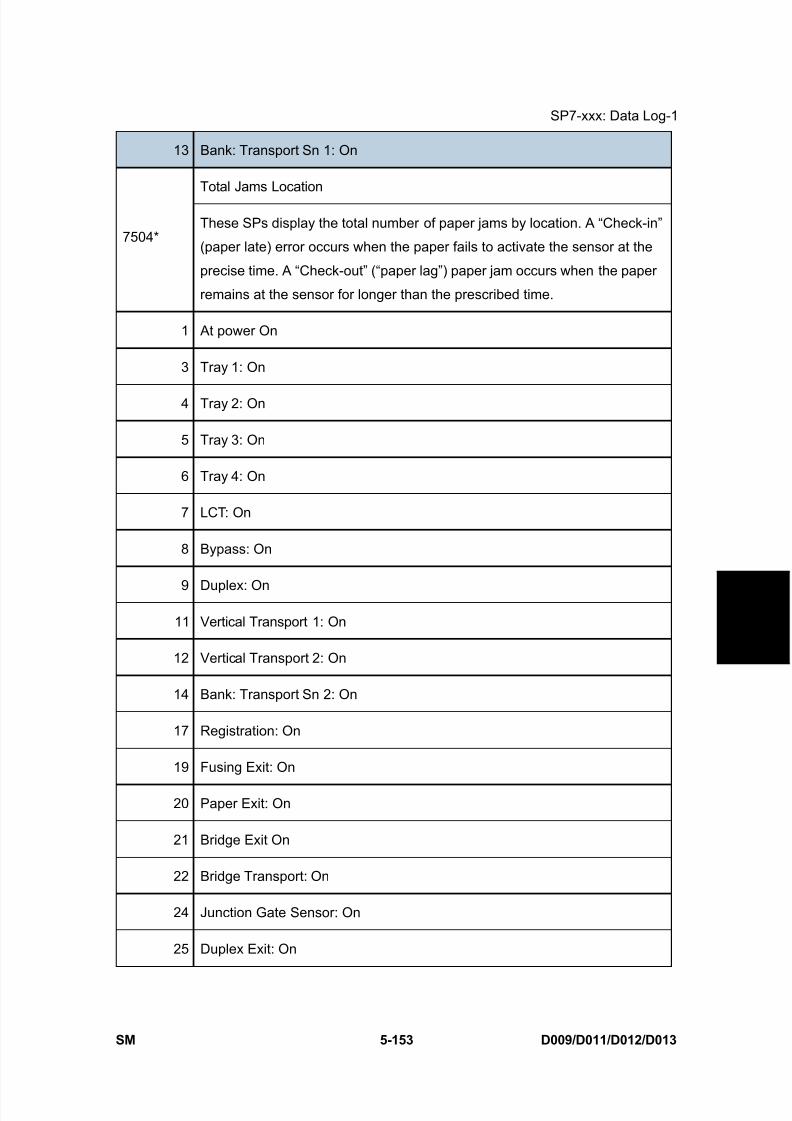
8/15/2019 Ricoh MP 4000 SM D009_D011_D012_D013 SERVICE MANUAL .pdf
http://slidepdf.com/reader/full/ricoh-mp-4000-sm-d009d011d012d013-service-manual-pdf 439/1162
SP7-xxx: Data Log-1
SM 5-153 D009/D011/D012/D013
S e r v i c e
T a b l e s
13 Bank: Transport Sn 1: On
Total Jams Location
7504*These SPs display the total number of paper jams by location. A “Check-in”
(paper late) error occurs when the paper fails to activate the sensor at the
precise time. A “Check-out” (“paper lag”) paper jam occurs when the paper
remains at the sensor for longer than the prescribed time.
1 At power On
3 Tray 1: On
4 Tray 2: On
5 Tray 3: On
6 Tray 4: On
7 LCT: On
8 Bypass: On
9 Duplex: On
11 Vertical Transport 1: On
12 Vertical Transport 2: On
14 Bank: Transport Sn 2: On
17 Registration: On
19 Fusing Exit: On
20 Paper Exit: On
21 Bridge Exit On
22 Bridge Transport: On
24 Junction Gate Sensor: On
25 Duplex Exit: On
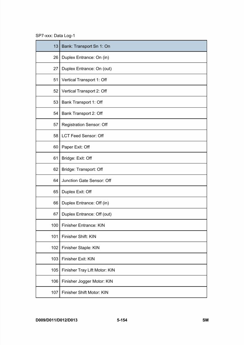
8/15/2019 Ricoh MP 4000 SM D009_D011_D012_D013 SERVICE MANUAL .pdf
http://slidepdf.com/reader/full/ricoh-mp-4000-sm-d009d011d012d013-service-manual-pdf 440/1162
SP7-xxx: Data Log-1
D009/D011/D012/D013 5-154 SM
13 Bank: Transport Sn 1: On
26 Duplex Entrance: On (in)
27 Duplex Entrance: On (out)
51 Vertical Transport 1: Off
52 Vertical Transport 2: Off
53 Bank Transport 1: Off
54 Bank Transport 2: Off
57 Registration Sensor: Off
58 LCT Feed Sensor: Off
60 Paper Exit: Off
61 Bridge: Exit: Off
62 Bridge: Transport: Off
64 Junction Gate Sensor: Off
65 Duplex Exit: Off
66 Duplex Entrance: Off (in)
67 Duplex Entrance: Off (out)
100 Finisher Entrance: KIN
101 Finisher Shift: KIN
102 Finisher Staple: KIN
103 Finisher Exit: KIN
105 Finisher Tray Lift Motor: KIN
106 Finisher Jogger Motor: KIN
107 Finisher Shift Motor: KIN
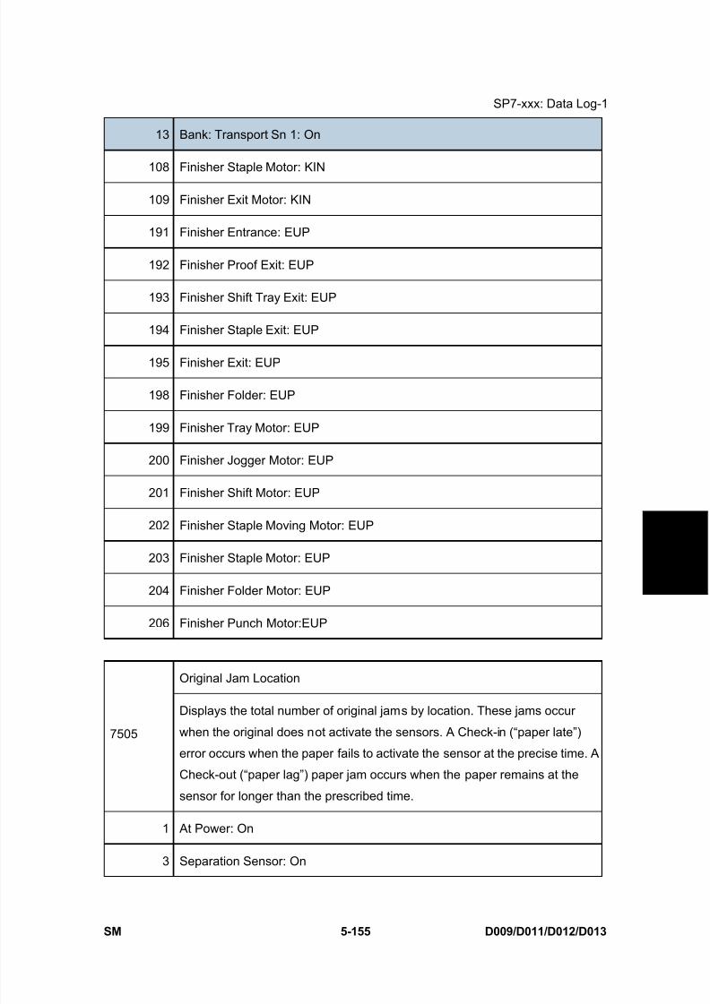
8/15/2019 Ricoh MP 4000 SM D009_D011_D012_D013 SERVICE MANUAL .pdf
http://slidepdf.com/reader/full/ricoh-mp-4000-sm-d009d011d012d013-service-manual-pdf 441/1162
SP7-xxx: Data Log-1
SM 5-155 D009/D011/D012/D013
S e r v i c e
T a b l e s
13 Bank: Transport Sn 1: On
108 Finisher Staple Motor: KIN
109 Finisher Exit Motor: KIN
191 Finisher Entrance: EUP
192 Finisher Proof Exit: EUP
193 Finisher Shift Tray Exit: EUP
194 Finisher Staple Exit: EUP
195 Finisher Exit: EUP
198 Finisher Folder: EUP
199 Finisher Tray Motor: EUP
200 Finisher Jogger Motor: EUP
201 Finisher Shift Motor: EUP
202 Finisher Staple Moving Motor: EUP
203 Finisher Staple Motor: EUP
204 Finisher Folder Motor: EUP
206 Finisher Punch Motor:EUP
Original Jam Location
7505
Displays the total number of original jams by location. These jams occur
when the original does not activate the sensors. A Check-in (“paper late”)
error occurs when the paper fails to activate the sensor at the precise time. A
Check-out (“paper lag”) paper jam occurs when the paper remains at the
sensor for longer than the prescribed time.
1 At Power: On
3 Separation Sensor: On

8/15/2019 Ricoh MP 4000 SM D009_D011_D012_D013 SERVICE MANUAL .pdf
http://slidepdf.com/reader/full/ricoh-mp-4000-sm-d009d011d012d013-service-manual-pdf 442/1162
SP7-xxx: Data Log-1
D009/D011/D012/D013 5-156 SM
4 Skew Correction Sensor: On
5 Interval Sensor: On
6 Registration Sensor: On
7 Inverter Sensor: On
8 Original Exit Sensor: On
53 Separation Sensor: Off
54 Skew Correction Sensor: Off
55 Interval Sensor: Off
56 Registration Sensor: Off
57 Inverter Sensor: Off
58 Original Exit Sensor: Off
7506* Jam Count by Paper Size
005 A4 LEF
006 A5 LEF
014 B5 LEF
038 LT LEF
044 HLT LEF
132 A3 SEF
133 A4 SEF
134 A5 SEF
141 B4 SEF
142 B5 SEF
160 DLT SEF
Displays the total number of copy jams by paper size.
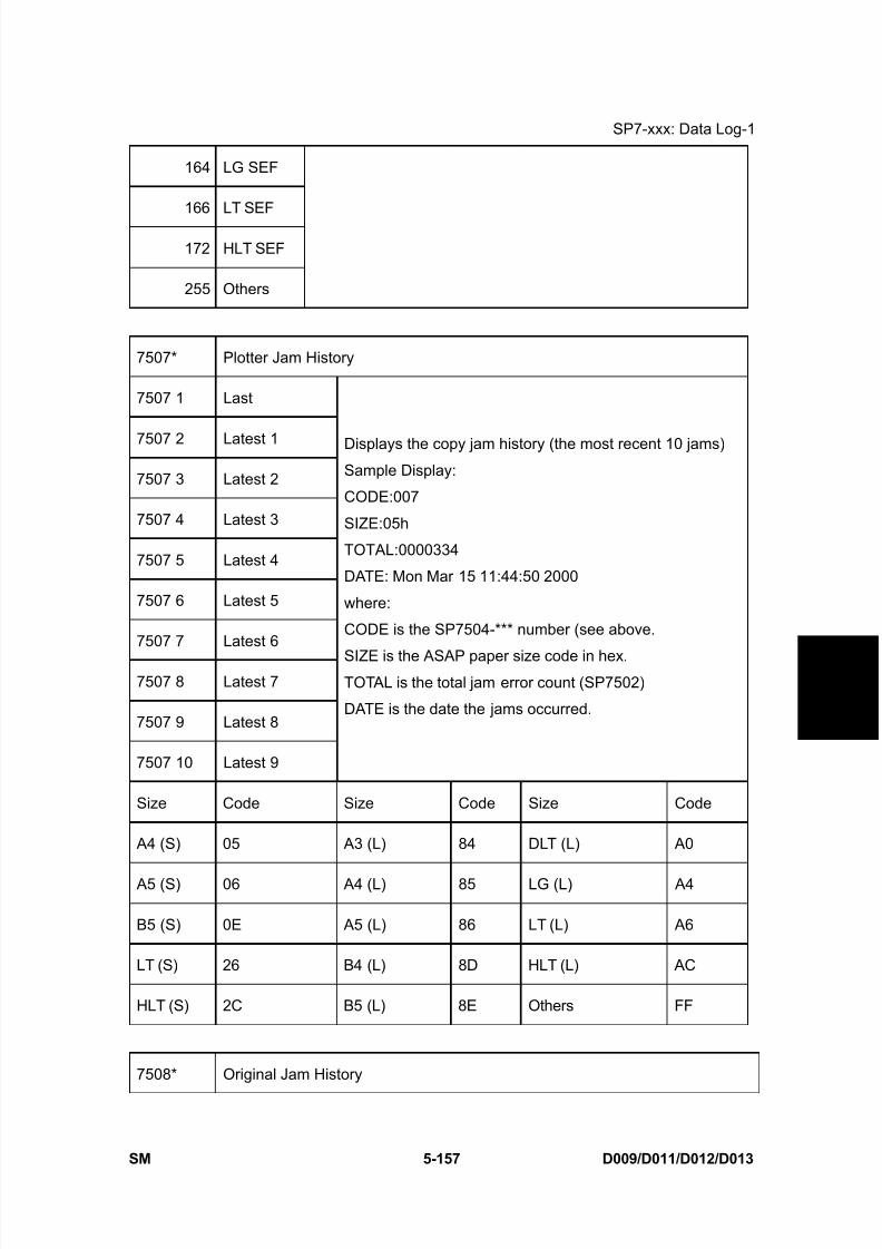
8/15/2019 Ricoh MP 4000 SM D009_D011_D012_D013 SERVICE MANUAL .pdf
http://slidepdf.com/reader/full/ricoh-mp-4000-sm-d009d011d012d013-service-manual-pdf 443/1162
SP7-xxx: Data Log-1
SM 5-157 D009/D011/D012/D013
S e r v i c e
T a b l e s
164 LG SEF
166 LT SEF
172 HLT SEF
255 Others
7507* Plotter Jam History
7507 1 Last
7507 2 Latest 1
7507 3 Latest 2
7507 4 Latest 3
7507 5 Latest 4
7507 6 Latest 5
7507 7 Latest 6
7507 8 Latest 7
7507 9 Latest 8
7507 10 Latest 9
Displays the copy jam history (the most recent 10 jams)
Sample Display:
CODE:007
SIZE:05h
TOTAL:0000334
DATE: Mon Mar 15 11:44:50 2000
where:
CODE is the SP7504-*** number (see above.
SIZE is the ASAP paper size code in hex.TOTAL is the total jam error count (SP7502)
DATE is the date the jams occurred.
Size Code Size Code Size Code
A4 (S) 05 A3 (L) 84 DLT (L) A0
A5 (S) 06 A4 (L) 85 LG (L) A4
B5 (S) 0E A5 (L) 86 LT (L) A6
LT (S) 26 B4 (L) 8D HLT (L) AC
HLT (S) 2C B5 (L) 8E Others FF
7508* Original Jam History

8/15/2019 Ricoh MP 4000 SM D009_D011_D012_D013 SERVICE MANUAL .pdf
http://slidepdf.com/reader/full/ricoh-mp-4000-sm-d009d011d012d013-service-manual-pdf 444/1162
SP7-xxx: Data Log-1
D009/D011/D012/D013 5-158 SM
001 Last
002 Last 1
003 Last 2
004 Last 3
005 Last 4
006 Last 5
007 Last 6
008 Last 7
009 Last 8
010 Last 9
Displays the original jam history (the most recent 10 jams).Sample Display:
CODE:007
SIZE:05h
TOTAL:0000334
DATE: Mon Mar 15 11:44:50 2000
where:
CODE is the SP7505*** number (see above.
SIZE is the ASAP paper size code in hex.
TOTAL is the total jam error count (SP7503)
DATE is the date the jams occurred.
Size Code Size Code Size Code
A4 (S) 05 A3 (L) 84 DLT (L) A0
A5 (S) 06 A4 (L) 85 LG (L) A4
B5 (S) 0E A5 (L) 86 LT (L) A6
LT (S) 26 B4 (L) 8D HLT (L) AC
HLT (S) 2C B5 (L) 8E Others FF
7801 ROM No./Firmware Version
002 ROM No: Engine
005 ADF
007 Finisher
009 Bank
010 LCT
019 Bank 2
Displays the ROM number and firmware
version numbers.

8/15/2019 Ricoh MP 4000 SM D009_D011_D012_D013 SERVICE MANUAL .pdf
http://slidepdf.com/reader/full/ricoh-mp-4000-sm-d009d011d012d013-service-manual-pdf 445/1162
SP7-xxx: Data Log-1
SM 5-159 D009/D011/D012/D013
S e r v i c e
T a b l e s
102 Firmware Version: Engine
105 ADF
107 Finisher
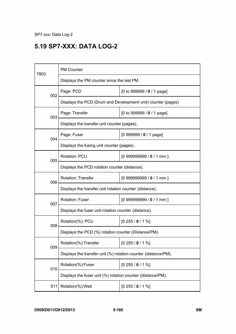
8/15/2019 Ricoh MP 4000 SM D009_D011_D012_D013 SERVICE MANUAL .pdf
http://slidepdf.com/reader/full/ricoh-mp-4000-sm-d009d011d012d013-service-manual-pdf 446/1162
SP7-xxx: Data Log-2
D009/D011/D012/D013 5-160 SM
5.19 SP7-XXX: DATA LOG-2
PM Counter7803
Displays the PM counter since the last PM.
Page: PCD [0 to 999999 / 0 / 1 page]002
Displays the PCD (Drum and Development unit) counter (pages)
Page: Transfer [0 to 999999 / 0 / 1 page]003
Displays the transfer unit counter (pages).
Page: Fuser [0 999999 / 0 / 1 page]004
Displays the fusing unit counter (pages).
Rotation: PCU [0 999999999 / 0 / 1 mm ]005
Displays the PCD rotation counter (distance).
Rotation: Transfer [0 999999999 / 0 / 1 mm ]006
Displays the transfer unit rotation counter (distance).
Rotation: Fuser [0 999999999 / 0 / 1 mm ]007
Displays the fuser unit rotation counter (distance).
Rotation(%): PCU [0 255 / 0 / 1 %]008
Displays the PCD (%) rotation counter (Distance/PM).
Rotation(%):Transfer [0 255 / 0 / 1 %]009
Displays the transfer unit (%) rotation counter (distance/PM).
Rotation(%):Fuser [0 255 / 0 / 1 %]010
Displays the fuser unit (%) rotation counter (distance/PM).
011 Rotation(%):Web [0 255 / 0 / 1 %]
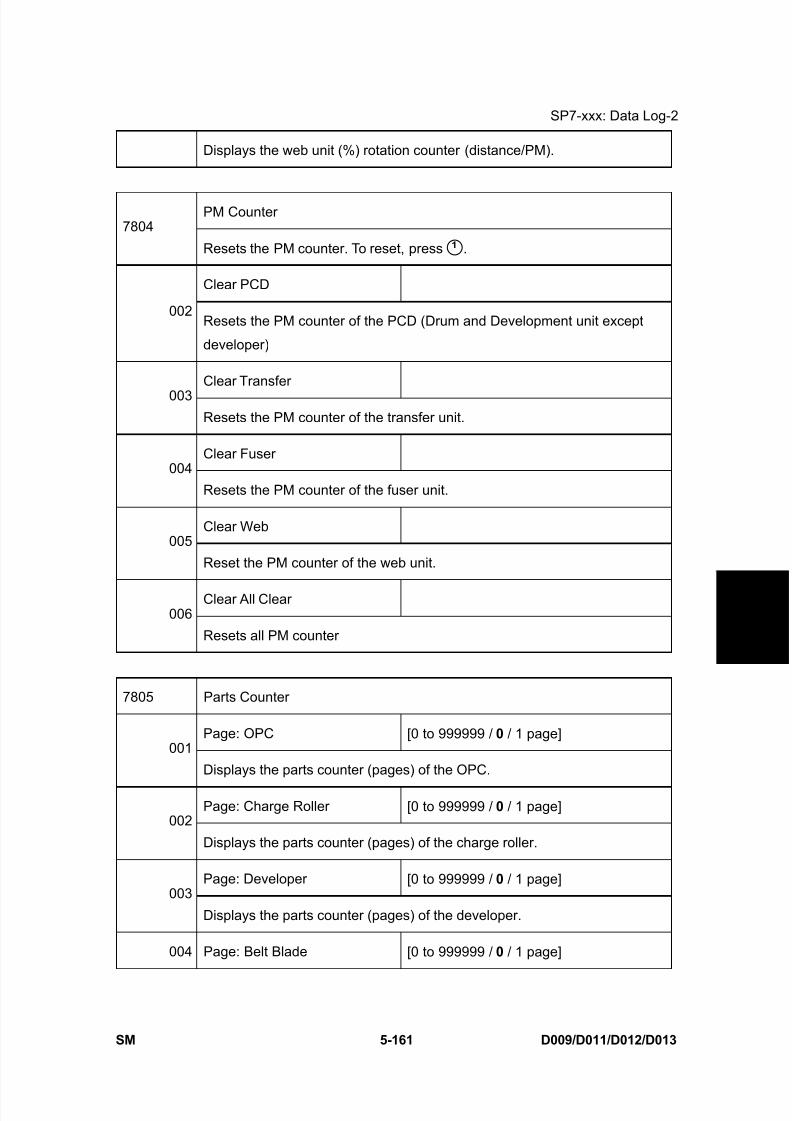
8/15/2019 Ricoh MP 4000 SM D009_D011_D012_D013 SERVICE MANUAL .pdf
http://slidepdf.com/reader/full/ricoh-mp-4000-sm-d009d011d012d013-service-manual-pdf 447/1162
SP7-xxx: Data Log-2
SM 5-161 D009/D011/D012/D013
S e r v i c e
T a b l e s
Displays the web unit (%) rotation counter (distance/PM).
PM Counter7804
Resets the PM counter. To reset, press .
Clear PCD
002Resets the PM counter of the PCD (Drum and Development unit except
developer)
Clear Transfer003
Resets the PM counter of the transfer unit.
Clear Fuser004
Resets the PM counter of the fuser unit.
Clear Web005
Reset the PM counter of the web unit.
Clear All Clear006
Resets all PM counter
7805 Parts Counter
Page: OPC [0 to 999999 / 0 / 1 page]001
Displays the parts counter (pages) of the OPC.
Page: Charge Roller [0 to 999999 / 0 / 1 page]002
Displays the parts counter (pages) of the charge roller.
Page: Developer [0 to 999999 / 0 / 1 page]003
Displays the parts counter (pages) of the developer.
004 Page: Belt Blade [0 to 999999 / 0 / 1 page]
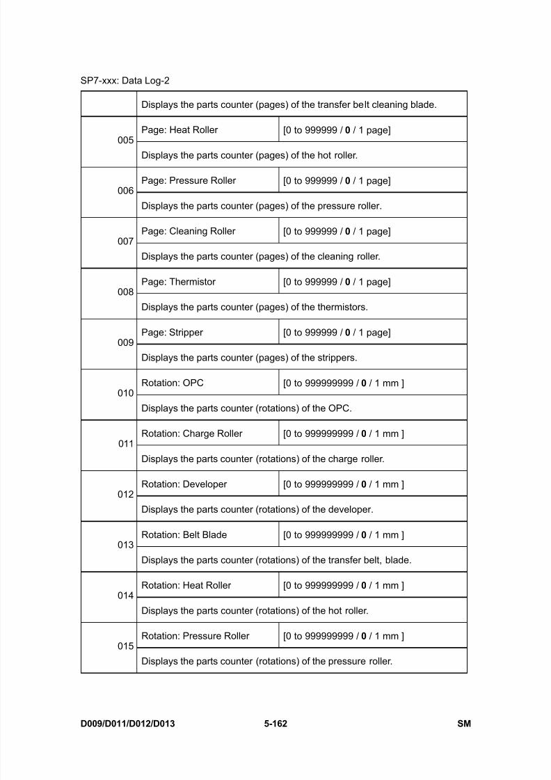
8/15/2019 Ricoh MP 4000 SM D009_D011_D012_D013 SERVICE MANUAL .pdf
http://slidepdf.com/reader/full/ricoh-mp-4000-sm-d009d011d012d013-service-manual-pdf 448/1162
SP7-xxx: Data Log-2
D009/D011/D012/D013 5-162 SM
Displays the parts counter (pages) of the transfer belt cleaning blade.
Page: Heat Roller [0 to 999999 / 0 / 1 page]005
Displays the parts counter (pages) of the hot roller.
Page: Pressure Roller [0 to 999999 / 0 / 1 page]006
Displays the parts counter (pages) of the pressure roller.
Page: Cleaning Roller [0 to 999999 / 0 / 1 page]007
Displays the parts counter (pages) of the cleaning roller.
Page: Thermistor [0 to 999999 / 0 / 1 page]008
Displays the parts counter (pages) of the thermistors.
Page: Stripper [0 to 999999 / 0 / 1 page]009
Displays the parts counter (pages) of the strippers.
Rotation: OPC [0 to 999999999 / 0 / 1 mm ]010
Displays the parts counter (rotations) of the OPC.
Rotation: Charge Roller [0 to 999999999 / 0 / 1 mm ]011
Displays the parts counter (rotations) of the charge roller.
Rotation: Developer [0 to 999999999 / 0 / 1 mm ]012
Displays the parts counter (rotations) of the developer.
Rotation: Belt Blade [0 to 999999999 / 0 / 1 mm ]
013Displays the parts counter (rotations) of the transfer belt, blade.
Rotation: Heat Roller [0 to 999999999 / 0 / 1 mm ]014
Displays the parts counter (rotations) of the hot roller.
Rotation: Pressure Roller [0 to 999999999 / 0 / 1 mm ]015
Displays the parts counter (rotations) of the pressure roller.

8/15/2019 Ricoh MP 4000 SM D009_D011_D012_D013 SERVICE MANUAL .pdf
http://slidepdf.com/reader/full/ricoh-mp-4000-sm-d009d011d012d013-service-manual-pdf 449/1162
SP7-xxx: Data Log-2
SM 5-163 D009/D011/D012/D013
S e r v i c e
T a b l e s
Rotation: Cleaning Roller [0 to 999999999 / 0 / 1 mm ]016
Displays the parts counter (rotations) of the cleaning roller.
Rotation: Thermistor [0 to 999999999 / 0 / 1 mm ]017
Displays the parts counter (rotations) of the thermistors.
Rotation: Stripper [0 to 999999999 / 0 / 1 mm ]018
Displays the parts counter (rotations) of the strippers.
Page(%): Web [0 to 255 / 0 / 1 %]019
Displays the parts counter (rotations/PM %) of the cleaning web.
7806 Counter Clear
OPC001
Resets the parts counter of the OPC.
Charge Roller002
Resets the parts counter of the charge roller.
Developer003
Resets the parts counter of the developer.
Belt: Blade004
Resets the parts counter of the transfer belt cleaning blade.
Heat Roller005
Resets the parts counter of the hot roller.
Pressure Roller006
Resets the parts counter of the pressure roller.
Cleaning Roller007
Resets the parts counter of the cleaning roller.
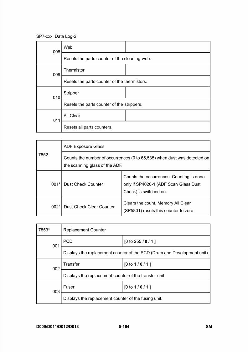
8/15/2019 Ricoh MP 4000 SM D009_D011_D012_D013 SERVICE MANUAL .pdf
http://slidepdf.com/reader/full/ricoh-mp-4000-sm-d009d011d012d013-service-manual-pdf 450/1162
SP7-xxx: Data Log-2
D009/D011/D012/D013 5-164 SM
Web008
Resets the parts counter of the cleaning web.
Thermistor009
Resets the parts counter of the thermistors.
Stripper010
Resets the parts counter of the strippers.
All Clear011
Resets all parts counters.
ADF Exposure Glass
7852Counts the number of occurrences (0 to 65,535) when dust was detected on
the scanning glass of the ADF.
001* Dust Check Counter
Counts the occurrences. Counting is done
only if SP4020-1 (ADF Scan Glass DustCheck) is switched on.
002* Dust Check Clear CounterClears the count. Memory All Clear
(SP5801) resets this counter to zero.
7853* Replacement Counter
PCD [0 to 255 / 0 / 1 ]
001Displays the replacement counter of the PCD (Drum and Development unit).
Transfer [0 to 1 / 0 / 1 ]002
Displays the replacement counter of the transfer unit.
Fuser [0 to 1 / 0 / 1 ]003
Displays the replacement counter of the fusing unit.

8/15/2019 Ricoh MP 4000 SM D009_D011_D012_D013 SERVICE MANUAL .pdf
http://slidepdf.com/reader/full/ricoh-mp-4000-sm-d009d011d012d013-service-manual-pdf 451/1162
SP7-xxx: Data Log-2
SM 5-165 D009/D011/D012/D013
S e r v i c e
T a b l e s
Web [0 to 1 / 0 / 1 ]004
Displays the replacement counter of the cleaning web.
Zero Cross [0 to 255 / 60 / 1 ]
7856* 1Stores and displays the detected zero cross frequency of the main ac power
supply from the wall socket.
7906 Prev Counter
Page: PCD [0 999999 / 0 / 1 page]001
Displays the counter (pages) of the previous PCD
Page: Transfer [0 999999 / 0 / 1 page]002
Displays the previous counter (pages) of the previous transfer unit.
Page: Fuser [0 999999 / 0 / 1 page]003
Displays the previous counter (pages) of the previous fusing unit.
Rotation: PCD [0 999999999 / 0 / 1 mm ]004
Displays the previous counter (rotations) of the previous PCD
Rotation: Transfer [0 999999999 / 0 / 1 mm ]005
Displays the previous counter (rotations) of the previous transfer unit.
Rotation: Fuser [0 999999999 / 0 / 1 mm ]
006Displays the previous counter (rotations/PM %) of the previous fusing unit.
Rotation(%):PCD [0 to 255 / 0 / 1 mm]007
Displays the previous counter (rotations/PM %) of the previous PCD
Rotation(%):Transfer [0 to 255 / 0 / 1 mm]008
Displays the previous counter (rotations/PM %) of the previous transfer unit.

8/15/2019 Ricoh MP 4000 SM D009_D011_D012_D013 SERVICE MANUAL .pdf
http://slidepdf.com/reader/full/ricoh-mp-4000-sm-d009d011d012d013-service-manual-pdf 452/1162
SP7-xxx: Data Log-2
D009/D011/D012/D013 5-166 SM
Rotation(%):Fuser [0 to 255 / 0 / 1 mm]009
Displays the previous counter (rotations/PM %) of the previous fusing unit.
Rotation(%):Web [0 to 255 / 0 / 1 %]
010Displays the previous counter (rotations/PM %) of the previous cleaning
web.
7950 Replacement Date
PCD [0 to 1 / 0 / 1 ]001
Displays the replacement date of the PCD.
Transfer [0 to 1 / 0 / 1 ]002
Displays the replacement date of the transfer unit.
Fuser [0 to 1 / 0 / 1 ]003
Displays the replacement date of the fusing unit.
Web [0 to 1 / 0 / 1 ]004
Displays the replacement date of the web unit.
7951 Remaining Counter
PCD(Page) [0 to 255 / 255 / 1 days]001
Displays the remaining counter (pages) of the PCD.
Transfer(Page) [0 to 255 / 255 / 1 days]002
Displays the remaining counter (pages) of the transfer unit.
Fuser(Page) [0 to 255 / 255 / 1 days]003
Displays the remaining counter (pages) of the fusing unit.
004 Developer(Page) [0 to 255 / 255 / 1 days]

8/15/2019 Ricoh MP 4000 SM D009_D011_D012_D013 SERVICE MANUAL .pdf
http://slidepdf.com/reader/full/ricoh-mp-4000-sm-d009d011d012d013-service-manual-pdf 453/1162
SP7-xxx: Data Log-2
SM 5-167 D009/D011/D012/D013
S e r v i c e
T a b l e s
Displays the remaining counter (pages) of the developer.
PCD(Rotation) [0 to 255 / 255 / 1 days]005
Displays the remaining counter (rotations) of the PCD.
Transfer(Rotation) [0 to 255 / 255 / 1 days]006
Displays the remaining counter (rotations) of the transfer unit.
Fuser(Rotation) [0 to 255 / 255 / 1 days]007
Displays the remaining counter (rotations) of the fusing unit.
Developer(Rotation) [0 to 255 / 255 / 1 days]008
Displays the remaining counter (rotations) of the developer.
PCD (%) [0 to 255 / 100 / 1 %]009
Displays the remaining counter (%) of the PCD.
Transfer (%) [0 to 255 / 100 / 1 %]010
Displays the remaining counter (%) of the transfer unit.
Fuser (%) [0 to 255 / 100 / 1 %]011
Displays the remaining counter (%) of the fusing unit.
Developer (%) [0 to 255 / 100 / 1 %]012
Displays the remaining counter (%) of the developer.
Web (%) [0 to 255 / 100 / 1 %]
013Displays the remaining counter (%) of the cleaning web.
PM Yield Setting7952
Sets the each yield of the following.
PCD(Page) [0 to 99999999/ 160000 / 1 sheet]001
Sets the PM yield of the PCD (Pages).
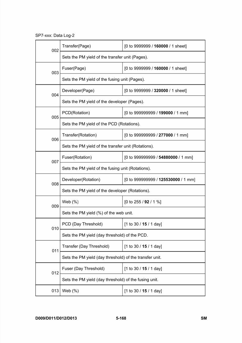
8/15/2019 Ricoh MP 4000 SM D009_D011_D012_D013 SERVICE MANUAL .pdf
http://slidepdf.com/reader/full/ricoh-mp-4000-sm-d009d011d012d013-service-manual-pdf 454/1162
SP7-xxx: Data Log-2
D009/D011/D012/D013 5-168 SM
Transfer(Page) [0 to 9999999 / 160000 / 1 sheet]002
Sets the PM yield of the transfer unit (Pages).
Fuser(Page) [0 to 9999999 / 160000 / 1 sheet]003
Sets the PM yield of the fusing unit (Pages).
Developer(Page) [0 to 9999999 / 320000 / 1 sheet]004
Sets the PM yield of the developer (Pages).
PCD(Rotation) [0 to 999999999 / 199000 / 1 mm]005
Sets the PM yield of the PCD (Rotations).
Transfer(Rotation) [0 to 999999999 / 277000 / 1 mm]006
Sets the PM yield of the transfer unit (Rotations).
Fuser(Rotation) [0 to 999999999 / 54880000 / 1 mm]007
Sets the PM yield of the fusing unit (Rotations).
Developer(Rotation) [0 to 999999999 / 125530000 / 1 mm]008
Sets the PM yield of the developer (Rotations).
Web (%) [0 to 255 / 92 / 1 %]009
Sets the PM yield (%) of the web unit.
PCD (Day Threshold) [1 to 30 / 15 / 1 day]010
Sets the PM yield (day threshold) of the PCD.
Transfer (Day Threshold) [1 to 30 / 15 / 1 day]011
Sets the PM yield (day threshold) of the transfer unit.
Fuser (Day Threshold) [1 to 30 / 15 / 1 day]012
Sets the PM yield (day threshold) of the fusing unit.
013 Web (%) [1 to 30 / 15 / 1 day]
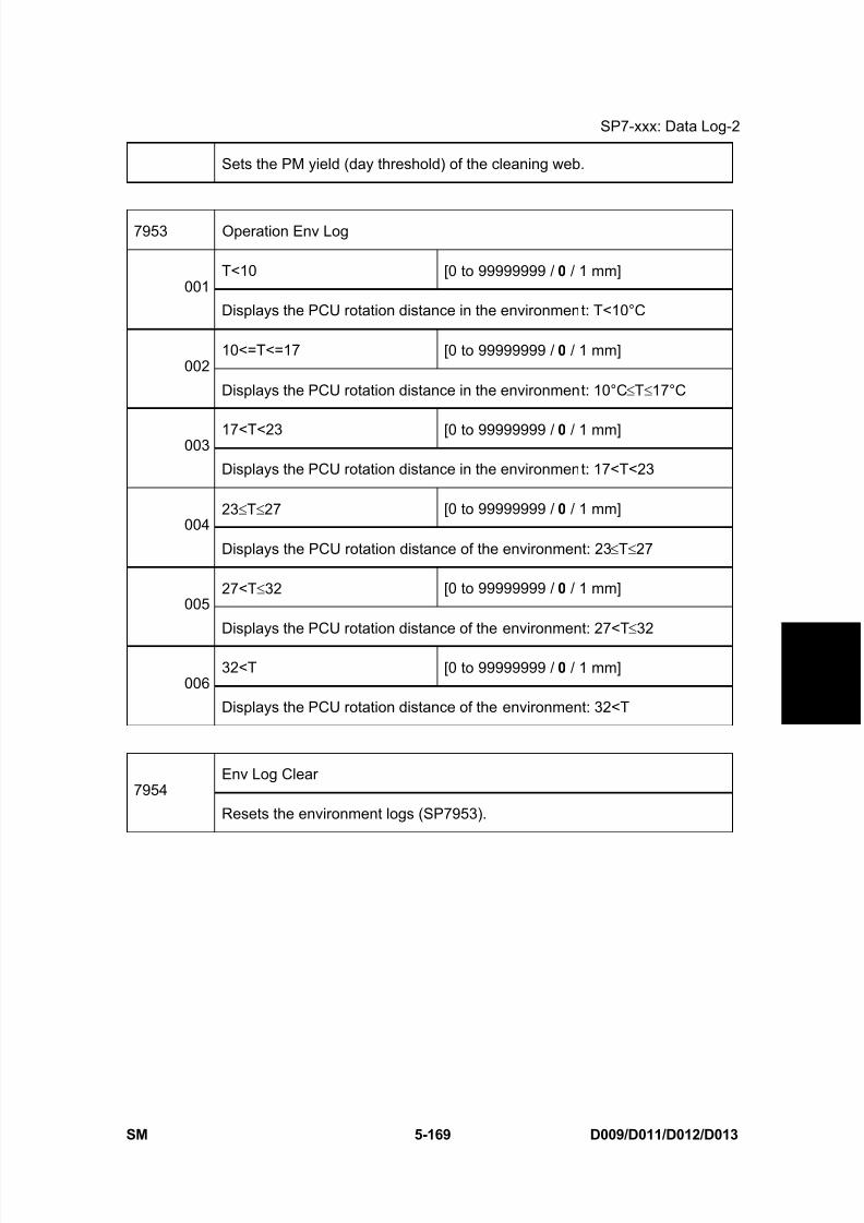
8/15/2019 Ricoh MP 4000 SM D009_D011_D012_D013 SERVICE MANUAL .pdf
http://slidepdf.com/reader/full/ricoh-mp-4000-sm-d009d011d012d013-service-manual-pdf 455/1162
SP7-xxx: Data Log-2
SM 5-169 D009/D011/D012/D013
S e r v i c e
T a b l e s
Sets the PM yield (day threshold) of the cleaning web.
7953 Operation Env Log
T<10 [0 to 99999999 / 0 / 1 mm]001
Displays the PCU rotation distance in the environment: T<10°C
10<=T<=17 [0 to 99999999 / 0 / 1 mm]002
Displays the PCU rotation distance in the environment: 10°C ≤T≤17°C
17<T<23 [0 to 99999999 / 0 / 1 mm]003
Displays the PCU rotation distance in the environment: 17<T<23
23 ≤T≤27 [0 to 99999999 / 0 / 1 mm]004
Displays the PCU rotation distance of the environment: 23 ≤T≤27
27<T ≤32 [0 to 99999999 / 0 / 1 mm]005
Displays the PCU rotation distance of the environment: 27<T ≤32
32<T [0 to 99999999 / 0 / 1 mm]006
Displays the PCU rotation distance of the environment: 32<T
Env Log Clear7954
Resets the environment logs (SP7953).
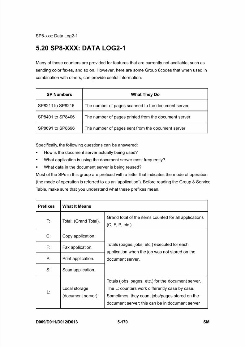
8/15/2019 Ricoh MP 4000 SM D009_D011_D012_D013 SERVICE MANUAL .pdf
http://slidepdf.com/reader/full/ricoh-mp-4000-sm-d009d011d012d013-service-manual-pdf 456/1162
SP8-xxx: Data Log2-1
D009/D011/D012/D013 5-170 SM
5.20 SP8-XXX: DATA LOG2-1
Many of these counters are provided for features that are currently not available, such as
sending color faxes, and so on. However, here are some Group 8codes that when used in
combination with others, can provide useful information.
SP Numbers What They Do
SP8211 to SP8216 The number of pages scanned to the document server.
SP8401 to SP8406 The number of pages printed from the document server
SP8691 to SP8696 The number of pages sent from the document server
Specifically, the following questions can be answered:
How is the document server actually being used?
What application is using the document server most frequently?
What data in the document server is being reused?
Most of the SPs in this group are prefixed with a letter that indicates the mode of operation
(the mode of operation is referred to as an ‘application’). Before reading the Group 8 ServiceTable, make sure that you understand what these prefixes mean.
Prefixes What It Means
T: Total: (Grand Total).Grand total of the items counted for all applications
(C, F, P, etc.).
C: Copy application.
F: Fax application.
P: Print application.
S: Scan application.
Totals (pages, jobs, etc.) executed for each
application when the job was not stored on the
document server.
L:Local storage
(document server)
Totals (jobs, pages, etc.) for the document server.
The L: counters work differently case by case.
Sometimes, they count jobs/pages stored on the
document server; this can be in document server
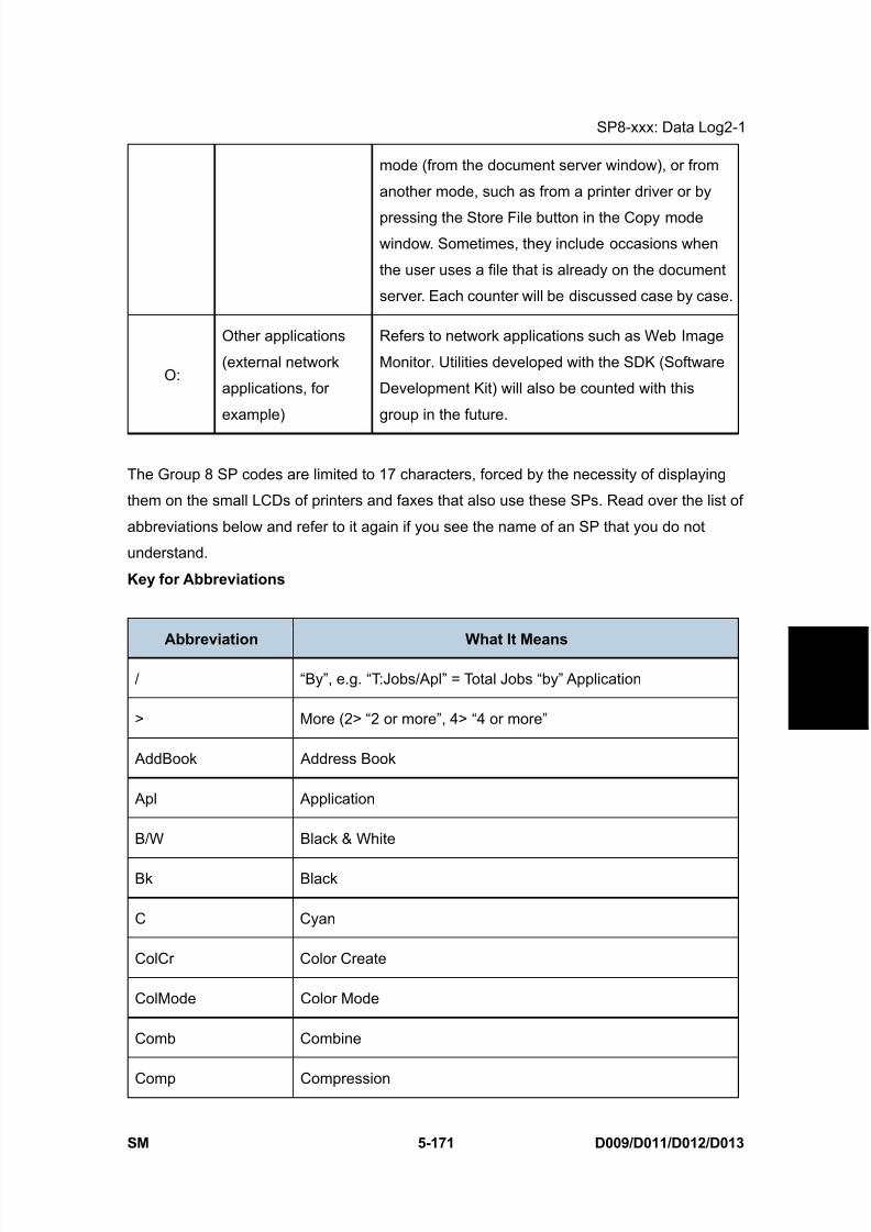
8/15/2019 Ricoh MP 4000 SM D009_D011_D012_D013 SERVICE MANUAL .pdf
http://slidepdf.com/reader/full/ricoh-mp-4000-sm-d009d011d012d013-service-manual-pdf 457/1162
SP8-xxx: Data Log2-1
SM 5-171 D009/D011/D012/D013
S e r v i c e
T a b l e s
mode (from the document server window), or from
another mode, such as from a printer driver or by
pressing the Store File button in the Copy modewindow. Sometimes, they include occasions when
the user uses a file that is already on the document
server. Each counter will be discussed case by case.
O:
Other applications
(external network
applications, for
example)
Refers to network applications such as Web Image
Monitor. Utilities developed with the SDK (Software
Development Kit) will also be counted with this
group in the future.
The Group 8 SP codes are limited to 17 characters, forced by the necessity of displaying
them on the small LCDs of printers and faxes that also use these SPs. Read over the list of
abbreviations below and refer to it again if you see the name of an SP that you do not
understand.
Key for Abbreviations
Abbreviation What It Means
/ “By”, e.g. “T:Jobs/Apl” = Total Jobs “by” Application
> More (2> “2 or more”, 4> “4 or more”
AddBook Address Book
Apl Application
B/W Black & White
Bk Black
C Cyan
ColCr Color Create
ColMode Color Mode
Comb Combine
Comp Compression
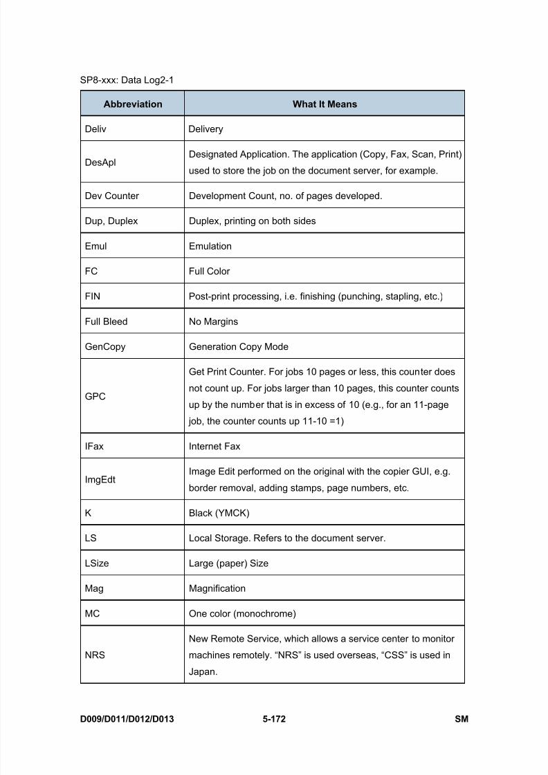
8/15/2019 Ricoh MP 4000 SM D009_D011_D012_D013 SERVICE MANUAL .pdf
http://slidepdf.com/reader/full/ricoh-mp-4000-sm-d009d011d012d013-service-manual-pdf 458/1162
SP8-xxx: Data Log2-1
D009/D011/D012/D013 5-172 SM
Abbreviation What It Means
Deliv Delivery
DesAplDesignated Application. The application (Copy, Fax, Scan, Print)
used to store the job on the document server, for example.
Dev Counter Development Count, no. of pages developed.
Dup, Duplex Duplex, printing on both sides
Emul Emulation
FC Full Color
FIN Post-print processing, i.e. finishing (punching, stapling, etc.)
Full Bleed No Margins
GenCopy Generation Copy Mode
GPC
Get Print Counter. For jobs 10 pages or less, this counter does
not count up. For jobs larger than 10 pages, this counter counts
up by the number that is in excess of 10 (e.g., for an 11-page job, the counter counts up 11-10 =1)
IFax Internet Fax
ImgEdtImage Edit performed on the original with the copier GUI, e.g.
border removal, adding stamps, page numbers, etc.
K Black (YMCK)
LS Local Storage. Refers to the document server.
LSize Large (paper) Size
Mag Magnification
MC One color (monochrome)
NRS
New Remote Service, which allows a service center to monitor
machines remotely. “NRS” is used overseas, “CSS” is used in
Japan.
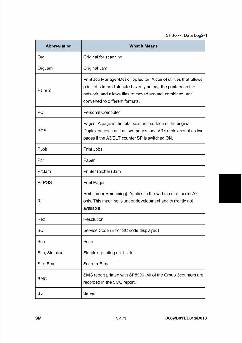
8/15/2019 Ricoh MP 4000 SM D009_D011_D012_D013 SERVICE MANUAL .pdf
http://slidepdf.com/reader/full/ricoh-mp-4000-sm-d009d011d012d013-service-manual-pdf 459/1162
SP8-xxx: Data Log2-1
SM 5-173 D009/D011/D012/D013
S e r v i c e
T a b l e s
Abbreviation What It Means
Org Original for scanning
OrgJam Original Jam
Palm 2
Print Job Manager/Desk Top Editor: A pair of utilities that allows
print jobs to be distributed evenly among the printers on the
network, and allows files to moved around, combined, and
converted to different formats.
PC Personal Computer
PGS
Pages. A page is the total scanned surface of the original.
Duplex pages count as two pages, and A3 simplex count as two
pages if the A3/DLT counter SP is switched ON.
PJob Print Jobs
Ppr Paper
PrtJam Printer (plotter) Jam
PrtPGS Print Pages
R
Red (Toner Remaining). Applies to the wide format model A2
only. This machine is under development and currently not
available.
Rez Resolution
SC Service Code (Error SC code displayed)
Scn Scan
Sim, Simplex Simplex, printing on 1 side.
S-to-Email Scan-to-E-mail
SMCSMC report printed with SP5990. All of the Group 8counters are
recorded in the SMC report.
Svr Server
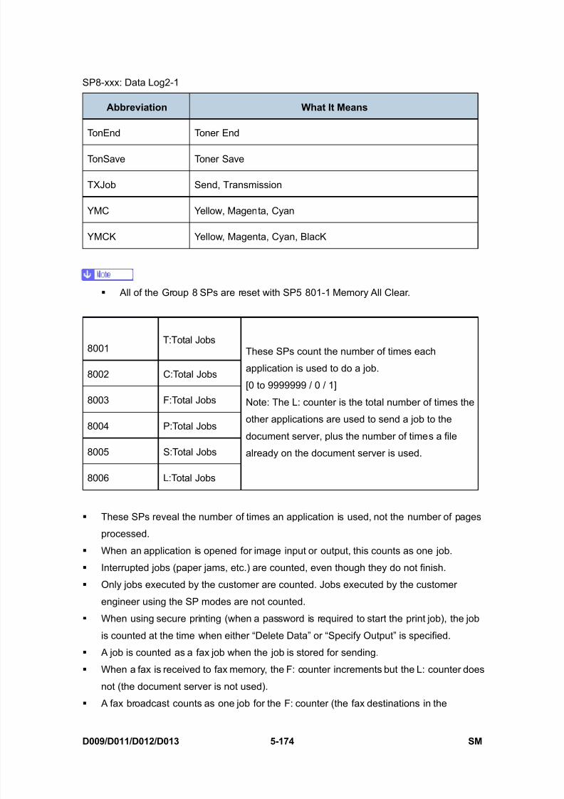
8/15/2019 Ricoh MP 4000 SM D009_D011_D012_D013 SERVICE MANUAL .pdf
http://slidepdf.com/reader/full/ricoh-mp-4000-sm-d009d011d012d013-service-manual-pdf 460/1162
SP8-xxx: Data Log2-1
D009/D011/D012/D013 5-174 SM
Abbreviation What It Means
TonEnd Toner End
TonSave Toner Save
TXJob Send, Transmission
YMC Yellow, Magenta, Cyan
YMCK Yellow, Magenta, Cyan, BlacK
All of the Group 8 SPs are reset with SP5 801-1 Memory All Clear.
8001T:Total Jobs
8002 C:Total Jobs
8003 F:Total Jobs
8004 P:Total Jobs
8005 S:Total Jobs
8006 L:Total Jobs
These SPs count the number of times each
application is used to do a job.
[0 to 9999999 / 0 / 1]
Note: The L: counter is the total number of times the
other applications are used to send a job to thedocument server, plus the number of times a file
already on the document server is used.
These SPs reveal the number of times an application is used, not the number of pages
processed.
When an application is opened for image input or output, this counts as one job.
Interrupted jobs (paper jams, etc.) are counted, even though they do not finish.
Only jobs executed by the customer are counted. Jobs executed by the customer
engineer using the SP modes are not counted.
When using secure printing (when a password is required to start the print job), the job
is counted at the time when either “Delete Data” or “Specify Output” is specified.
A job is counted as a fax job when the job is stored for sending.
When a fax is received to fax memory, the F: counter increments but the L: counter does
not (the document server is not used).
A fax broadcast counts as one job for the F: counter (the fax destinations in the
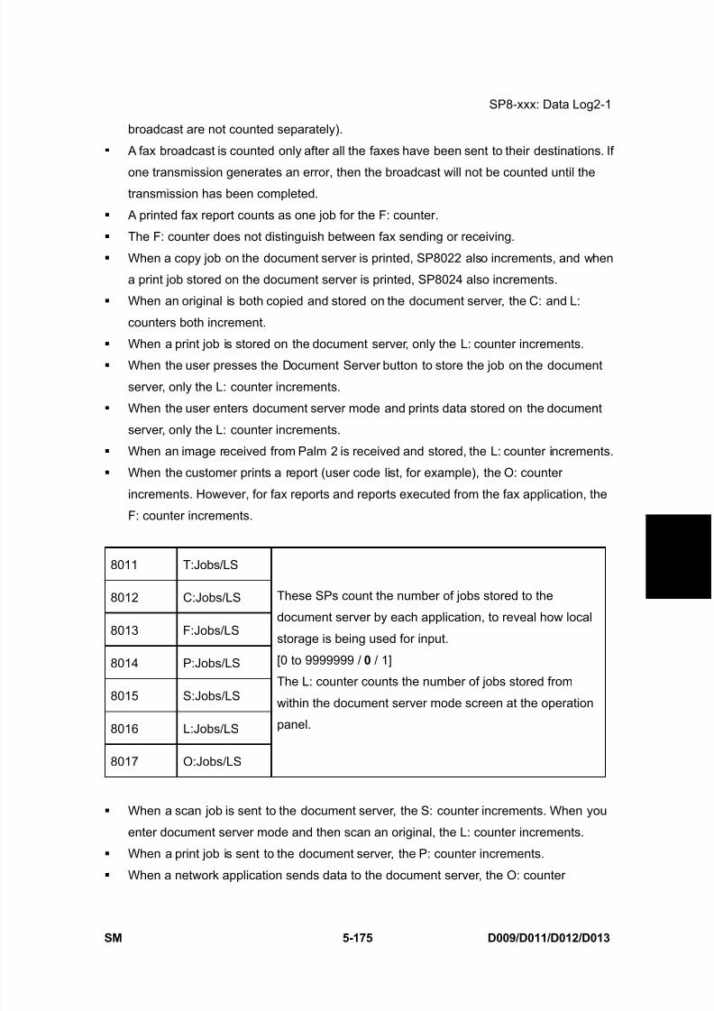
8/15/2019 Ricoh MP 4000 SM D009_D011_D012_D013 SERVICE MANUAL .pdf
http://slidepdf.com/reader/full/ricoh-mp-4000-sm-d009d011d012d013-service-manual-pdf 461/1162
SP8-xxx: Data Log2-1
SM 5-175 D009/D011/D012/D013
S e r v i c e
T a b l e s
broadcast are not counted separately).
A fax broadcast is counted only after all the faxes have been sent to their destinations. If
one transmission generates an error, then the broadcast will not be counted until thetransmission has been completed.
A printed fax report counts as one job for the F: counter.
The F: counter does not distinguish between fax sending or receiving.
When a copy job on the document server is printed, SP8022 also increments, and when
a print job stored on the document server is printed, SP8024 also increments.
When an original is both copied and stored on the document server, the C: and L:
counters both increment.
When a print job is stored on the document server, only the L: counter increments.
When the user presses the Document Server button to store the job on the document
server, only the L: counter increments.
When the user enters document server mode and prints data stored on the document
server, only the L: counter increments.
When an image received from Palm 2 is received and stored, the L: counter increments.
When the customer prints a report (user code list, for example), the O: counter
increments. However, for fax reports and reports executed from the fax application, the
F: counter increments.
8011 T:Jobs/LS
8012 C:Jobs/LS
8013 F:Jobs/LS
8014 P:Jobs/LS
8015 S:Jobs/LS
8016 L:Jobs/LS
8017 O:Jobs/LS
These SPs count the number of jobs stored to the
document server by each application, to reveal how local
storage is being used for input.
[0 to 9999999 / 0 / 1]
The L: counter counts the number of jobs stored from
within the document server mode screen at the operationpanel.
When a scan job is sent to the document server, the S: counter increments. When you
enter document server mode and then scan an original, the L: counter increments.
When a print job is sent to the document server, the P: counter increments.
When a network application sends data to the document server, the O: counter
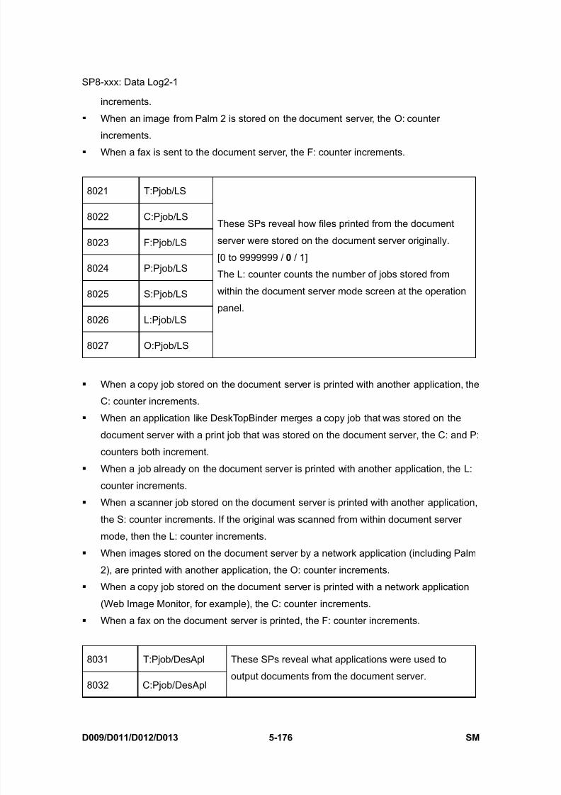
8/15/2019 Ricoh MP 4000 SM D009_D011_D012_D013 SERVICE MANUAL .pdf
http://slidepdf.com/reader/full/ricoh-mp-4000-sm-d009d011d012d013-service-manual-pdf 462/1162
SP8-xxx: Data Log2-1
D009/D011/D012/D013 5-176 SM
increments.
When an image from Palm 2 is stored on the document server, the O: counter
increments. When a fax is sent to the document server, the F: counter increments.
8021 T:Pjob/LS
8022 C:Pjob/LS
8023 F:Pjob/LS
8024 P:Pjob/LS
8025 S:Pjob/LS
8026 L:Pjob/LS
8027 O:Pjob/LS
These SPs reveal how files printed from the document
server were stored on the document server originally.
[0 to 9999999 / 0 / 1]
The L: counter counts the number of jobs stored fromwithin the document server mode screen at the operation
panel.
When a copy job stored on the document server is printed with another application, the
C: counter increments.
When an application like DeskTopBinder merges a copy job that was stored on thedocument server with a print job that was stored on the document server, the C: and P:
counters both increment.
When a job already on the document server is printed with another application, the L:
counter increments.
When a scanner job stored on the document server is printed with another application,
the S: counter increments. If the original was scanned from within document server
mode, then the L: counter increments.
When images stored on the document server by a network application (including Palm2), are printed with another application, the O: counter increments.
When a copy job stored on the document server is printed with a network application
(Web Image Monitor, for example), the C: counter increments.
When a fax on the document server is printed, the F: counter increments.
8031 T:Pjob/DesApl
8032 C:Pjob/DesApl
These SPs reveal what applications were used to
output documents from the document server.
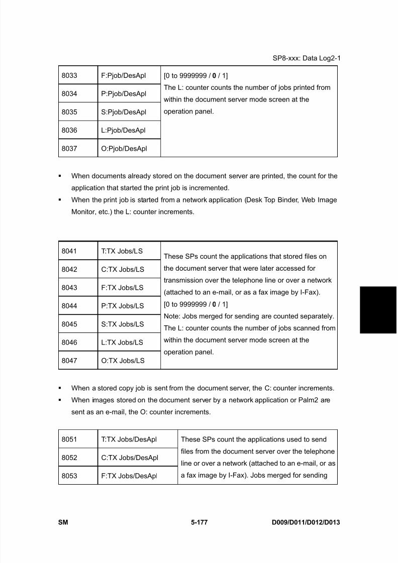
8/15/2019 Ricoh MP 4000 SM D009_D011_D012_D013 SERVICE MANUAL .pdf
http://slidepdf.com/reader/full/ricoh-mp-4000-sm-d009d011d012d013-service-manual-pdf 463/1162
SP8-xxx: Data Log2-1
SM 5-177 D009/D011/D012/D013
S e r v i c e
T a b l e s
8033 F:Pjob/DesApl
8034 P:Pjob/DesApl
8035 S:Pjob/DesApl
8036 L:Pjob/DesApl
8037 O:Pjob/DesApl
[0 to 9999999 / 0 / 1]
The L: counter counts the number of jobs printed from
within the document server mode screen at theoperation panel.
When documents already stored on the document server are printed, the count for the
application that started the print job is incremented.
When the print job is started from a network application (Desk Top Binder, Web Image
Monitor, etc.) the L: counter increments.
8041 T:TX Jobs/LS
8042 C:TX Jobs/LS
8043 F:TX Jobs/LS
8044 P:TX Jobs/LS
8045 S:TX Jobs/LS
8046 L:TX Jobs/LS
8047 O:TX Jobs/LS
These SPs count the applications that stored files on
the document server that were later accessed for
transmission over the telephone line or over a network
(attached to an e-mail, or as a fax image by I-Fax).[0 to 9999999 / 0 / 1]
Note: Jobs merged for sending are counted separately.
The L: counter counts the number of jobs scanned from
within the document server mode screen at the
operation panel.
When a stored copy job is sent from the document server, the C: counter increments.
When images stored on the document server by a network application or Palm2 are
sent as an e-mail, the O: counter increments.
8051 T:TX Jobs/DesApl
8052 C:TX Jobs/DesApl
8053 F:TX Jobs/DesApl
These SPs count the applications used to send
files from the document server over the telephone
line or over a network (attached to an e-mail, or as
a fax image by I-Fax). Jobs merged for sending
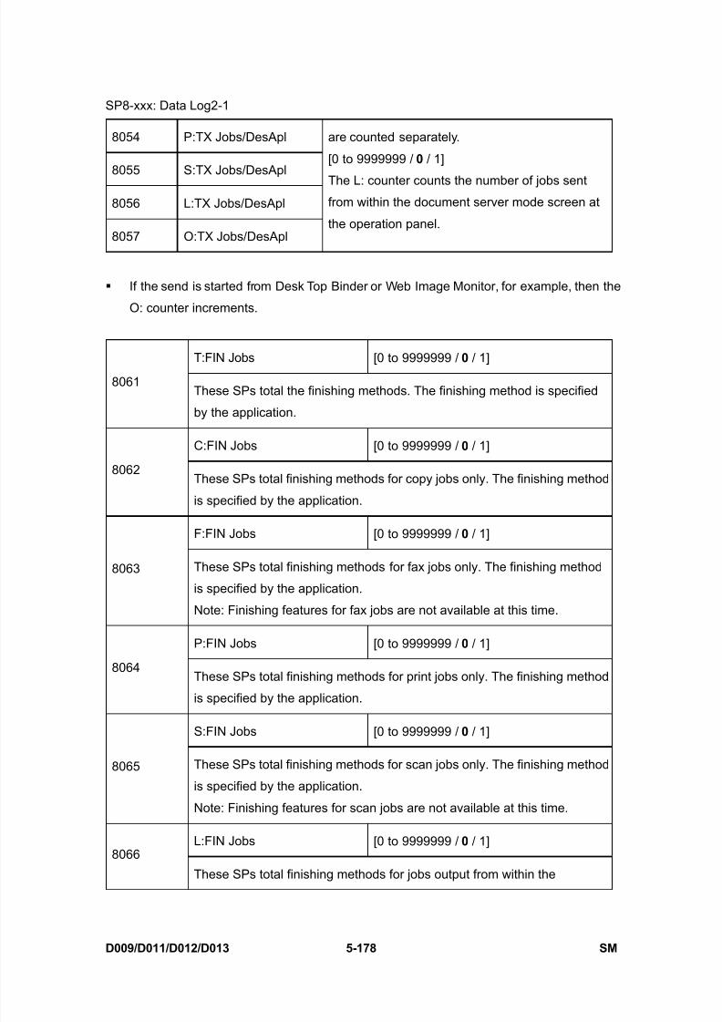
8/15/2019 Ricoh MP 4000 SM D009_D011_D012_D013 SERVICE MANUAL .pdf
http://slidepdf.com/reader/full/ricoh-mp-4000-sm-d009d011d012d013-service-manual-pdf 464/1162
SP8-xxx: Data Log2-1
D009/D011/D012/D013 5-178 SM
8054 P:TX Jobs/DesApl
8055 S:TX Jobs/DesApl
8056 L:TX Jobs/DesApl
8057 O:TX Jobs/DesApl
are counted separately.
[0 to 9999999 / 0 / 1]
The L: counter counts the number of jobs sentfrom within the document server mode screen at
the operation panel.
If the send is started from Desk Top Binder or Web Image Monitor, for example, then the
O: counter increments.
T:FIN Jobs [0 to 9999999 / 0 / 1]8061
These SPs total the finishing methods. The finishing method is specified
by the application.
C:FIN Jobs [0 to 9999999 / 0 / 1]
8062These SPs total finishing methods for copy jobs only. The finishing method
is specified by the application.
F:FIN Jobs [0 to 9999999 / 0 / 1]
8063 These SPs total finishing methods for fax jobs only. The finishing method
is specified by the application.
Note: Finishing features for fax jobs are not available at this time.
P:FIN Jobs [0 to 9999999 / 0 / 1]
8064These SPs total finishing methods for print jobs only. The finishing method
is specified by the application.
S:FIN Jobs [0 to 9999999 / 0 / 1]
8065 These SPs total finishing methods for scan jobs only. The finishing method
is specified by the application.
Note: Finishing features for scan jobs are not available at this time.
L:FIN Jobs [0 to 9999999 / 0 / 1]8066
These SPs total finishing methods for jobs output from within the
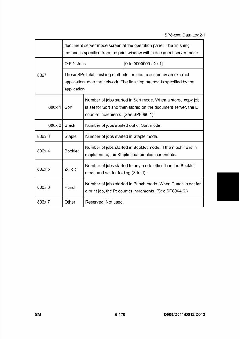
8/15/2019 Ricoh MP 4000 SM D009_D011_D012_D013 SERVICE MANUAL .pdf
http://slidepdf.com/reader/full/ricoh-mp-4000-sm-d009d011d012d013-service-manual-pdf 465/1162
SP8-xxx: Data Log2-1
SM 5-179 D009/D011/D012/D013
S e r v i c e
T a b l e s
document server mode screen at the operation panel. The finishing
method is specified from the print window within document server mode.
O:FIN Jobs [0 to 9999999 / 0 / 1]
8067 These SPs total finishing methods for jobs executed by an external
application, over the network. The finishing method is specified by the
application.
806x 1 Sort
Number of jobs started in Sort mode. When a stored copy job
is set for Sort and then stored on the document server, the L:
counter increments. (See SP8066 1)
806x 2 Stack Number of jobs started out of Sort mode.
806x 3 Staple Number of jobs started in Staple mode.
806x 4 BookletNumber of jobs started in Booklet mode. If the machine is in
staple mode, the Staple counter also increments.
806x 5 Z-FoldNumber of jobs started In any mode other than the Booklet
mode and set for folding (Z-fold).
806x 6 PunchNumber of jobs started in Punch mode. When Punch is set for
a print job, the P: counter increments. (See SP8064 6.)
806x 7 Other Reserved. Not used.
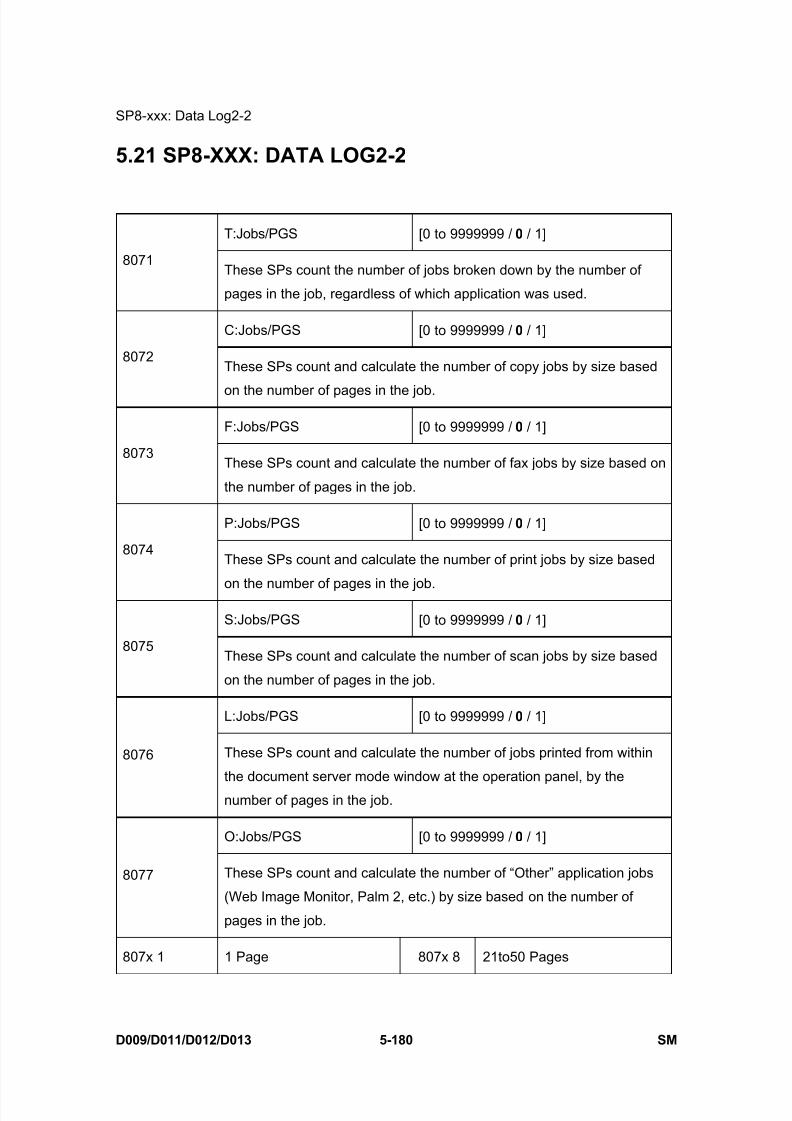
8/15/2019 Ricoh MP 4000 SM D009_D011_D012_D013 SERVICE MANUAL .pdf
http://slidepdf.com/reader/full/ricoh-mp-4000-sm-d009d011d012d013-service-manual-pdf 466/1162
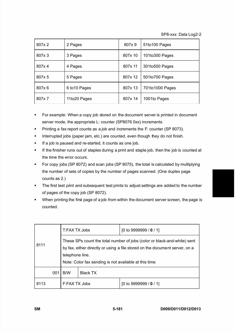
8/15/2019 Ricoh MP 4000 SM D009_D011_D012_D013 SERVICE MANUAL .pdf
http://slidepdf.com/reader/full/ricoh-mp-4000-sm-d009d011d012d013-service-manual-pdf 467/1162
SP8-xxx: Data Log2-2
SM 5-181 D009/D011/D012/D013
S e r v i c e
T a b l e s
807x 2 2 Pages 807x 9 51to100 Pages
807x 3 3 Pages 807x 10 101to300 Pages
807x 4 4 Pages 807x 11 301to500 Pages
807x 5 5 Pages 807x 12 501to700 Pages
807x 6 6 to10 Pages 807x 13 701to1000 Pages
807x 7 11to20 Pages 807x 14 1001to Pages
For example: When a copy job stored on the document server is printed in documentserver mode, the appropriate L: counter (SP8076 0xx) increments.
Printing a fax report counts as a job and increments the F: counter (SP 8073).
Interrupted jobs (paper jam, etc.) are counted, even though they do not finish.
If a job is paused and re-started, it counts as one job.
If the finisher runs out of staples during a print and staple job, then the job is counted at
the time the error occurs.
For copy jobs (SP 8072) and scan jobs (SP 8075), the total is calculated by multiplying
the number of sets of copies by the number of pages scanned. (One duplex page
counts as 2.)
The first test print and subsequent test prints to adjust settings are added to the number
of pages of the copy job (SP 8072).
When printing the first page of a job from within the document server screen, the page is
counted.
T:FAX TX Jobs [0 to 9999999 / 0 / 1]
8111These SPs count the total number of jobs (color or black-and-white) sent
by fax, either directly or using a file stored on the document server, on a
telephone line.
Note: Color fax sending is not available at this time.
001 B/W Black TX
8113 F:FAX TX Jobs [0 to 9999999 / 0 / 1]

8/15/2019 Ricoh MP 4000 SM D009_D011_D012_D013 SERVICE MANUAL .pdf
http://slidepdf.com/reader/full/ricoh-mp-4000-sm-d009d011d012d013-service-manual-pdf 468/1162
SP8-xxx: Data Log2-2
D009/D011/D012/D013 5-182 SM
These SPs count the total number of jobs (color or black-and-white) sent
by fax directly on a telephone line.
Note: Color fax sending is not available at this time.
001 B/W Black TX
These counters count jobs, not pages.
This SP counts fax jobs sent over a telephone line with a fax application, including
documents stored on the document server.
If the mode is changed during the job, the job will count with the mode set when the job
started.
If the same document is faxed to both a public fax line and an I-Fax at a destination
where both are available, then this counter increments, and the I-Fax counter (812x)
also increments.
The fax job is counted when the job is scanned for sending, not when the job is sent.
T:IFAX TX Jobs [0 to 9999999 / 0 / 1]
8121
These SPs count the total number of jobs (color or black-and-white) sent,
either directly or using a file stored on the document server, as fax images
using I-Fax.
Note: Color fax sending is not available at this time.
001 B/W Black TX
F:IFAX TX Jobs [0 to 9999999 / 0 / 1]
8123 These SPs count the number of jobs (color or black-and-white) sent (not
stored on the document server), as fax images using I-Fax.
Note: Color fax sending is not available at this time.
001 B/W Black TX
These counters count jobs, not pages.
The counters for color are provided for future use; the color fax feature is not available
at this time.
The fax job is counted when the job is scanned for sending, not when the job is sent.

8/15/2019 Ricoh MP 4000 SM D009_D011_D012_D013 SERVICE MANUAL .pdf
http://slidepdf.com/reader/full/ricoh-mp-4000-sm-d009d011d012d013-service-manual-pdf 469/1162
SP8-xxx: Data Log2-2
SM 5-183 D009/D011/D012/D013
S e r v i c e
T a b l e s
T:S-to-Email Jobs [0 to 9999999 / 0 / 1]
8131These SPs count the total number of jobs scanned and attached to an
e-mail, regardless of whether the document server was used or not.
001 B/W Black TX
002 Color Color TX / Only for 011 or B013
003 ACS Color TX / Only for B011 or B013
S:S-to-Email Jobs
8135These SPs count the number of jobs scanned and attached to an e-mail,without storing the original on the document server.
001 B/W Black TX
002 Color Color TX / Only for B011 or B013
003 ACS Color TX / Only for B011 or B013
These counters count jobs, not pages.
If the job is stored on the document server, after the job is stored it is determined to be
color or black-and-white then counted.
If the job is cancelled during scanning, or if the job is cancelled while the document is
waiting to be sent, the job is not counted.
If the job is cancelled during sending, it may or may not be counted, depending on what
stage of the process had been reached when the job was cancelled.
If several jobs are combined for sending to the Scan Router, Scan-to-Email, or
Scan-to-PC, or if one job is sent to more than one destination. each send is counted
separately. For example, if the same document is sent by Scan-to-Email as well as
Scan-to-PC, then it is counted twice (once for Scan-to-Email and once for Scan-to-PC).
T:Deliv Jobs/Svr [0 to 9999999 / 0 / 1]
8141These SPs count the total number of jobs scanned and sent to a Scan
Router server.
001 B/W Black Deliv
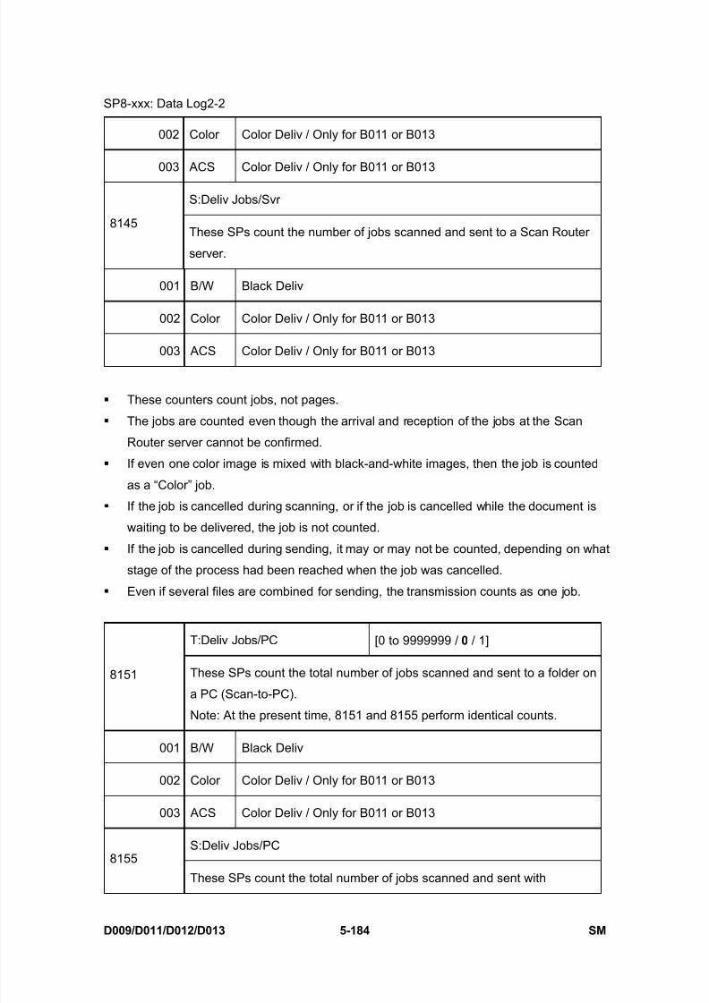
8/15/2019 Ricoh MP 4000 SM D009_D011_D012_D013 SERVICE MANUAL .pdf
http://slidepdf.com/reader/full/ricoh-mp-4000-sm-d009d011d012d013-service-manual-pdf 470/1162
SP8-xxx: Data Log2-2
D009/D011/D012/D013 5-184 SM
002 Color Color Deliv / Only for B011 or B013
003 ACS Color Deliv / Only for B011 or B013
S:Deliv Jobs/Svr
8145These SPs count the number of jobs scanned and sent to a Scan Router
server.
001 B/W Black Deliv
002 Color Color Deliv / Only for B011 or B013
003 ACS Color Deliv / Only for B011 or B013
These counters count jobs, not pages.
The jobs are counted even though the arrival and reception of the jobs at the Scan
Router server cannot be confirmed.
If even one color image is mixed with black-and-white images, then the job is counted
as a “Color” job.
If the job is cancelled during scanning, or if the job is cancelled while the document is
waiting to be delivered, the job is not counted. If the job is cancelled during sending, it may or may not be counted, depending on what
stage of the process had been reached when the job was cancelled.
Even if several files are combined for sending, the transmission counts as one job.
T:Deliv Jobs/PC [0 to 9999999 / 0 / 1]
8151 These SPs count the total number of jobs scanned and sent to a folder on
a PC (Scan-to-PC).
Note: At the present time, 8151 and 8155 perform identical counts.
001 B/W Black Deliv
002 Color Color Deliv / Only for B011 or B013
003 ACS Color Deliv / Only for B011 or B013
S:Deliv Jobs/PC8155
These SPs count the total number of jobs scanned and sent with

8/15/2019 Ricoh MP 4000 SM D009_D011_D012_D013 SERVICE MANUAL .pdf
http://slidepdf.com/reader/full/ricoh-mp-4000-sm-d009d011d012d013-service-manual-pdf 471/1162
SP8-xxx: Data Log2-2
SM 5-185 D009/D011/D012/D013
S e r v i c e
T a b l e s
Scan-to-PC.
001 B/W Black Deliv
002 Color Color Deliv / Only for B011 or B013
003 ACS Color Deliv / Only for B011 or B013
These counters count jobs, not pages.
If the job is cancelled during scanning, it is not counted.
If the job is cancelled while it is waiting to be sent, the job is not counted.
If the job is cancelled during sending, it may or may not be counted, depending on whatstage of the process had been reached when the job was cancelled.
Even if several files are combined for sending, the transmission counts as one job.
8161 T:PCFAX TX Jobs
8163 F:PCFAX TX Jobs
These SPs count the number of PC Fax
transmission jobs. A job is counted from when it is
registered for sending, not when it is sent.
[0 to 9999999 / 0 / 1]
Note: At the present time, these counters performidentical counts.
This counts fax jobs started from a PC using a PC fax application, and sending the data
out to the destination from the PC through the copier.
8191 T:Total Scan PGS
8192 C:Total Scan PGS
8193 F:Total Scan PGS
8195 S:Total Scan PGS
8196 L:Total Scan PGS
These SPs count the pages scanned by eachapplication that uses the scanner to scan images.
[0 to 9999999 / 0 / 1]
SP 8191 to 8196 count the number of scanned sides of pages, not the number of
physical pages.
These counters do not count reading user stamp data, or reading color charts to adjust
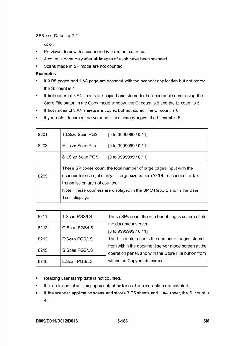
8/15/2019 Ricoh MP 4000 SM D009_D011_D012_D013 SERVICE MANUAL .pdf
http://slidepdf.com/reader/full/ricoh-mp-4000-sm-d009d011d012d013-service-manual-pdf 472/1162
SP8-xxx: Data Log2-2
D009/D011/D012/D013 5-186 SM
color.
Previews done with a scanner driver are not counted.
A count is done only after all images of a job have been scanned. Scans made in SP mode are not counted.
Examples
If 3 B5 pages and 1 A3 page are scanned with the scanner application but not stored,
the S: count is 4.
If both sides of 3 A4 sheets are copied and stored to the document server using the
Store File button in the Copy mode window, the C: count is 6 and the L: count is 6.
If both sides of 3 A4 sheets are copied but not stored, the C: count is 6.
If you enter document server mode then scan 6 pages, the L: count is 6.
8201 T:LSize Scan PGS [0 to 9999999 / 0 / 1]
8203 F Lsize Scan Pgs. [0 to 9999999 / 0 / 1]
S:LSize Scan PGS [0 to 9999999 / 0 / 1]
8205
These SP codes count the total number of large pages input with the
scanner for scan jobs only. Large size paper (A3/DLT) scanned for fax
transmission are not counted.
Note: These counters are displayed in the SMC Report, and in the User
Tools display..
8211 T:Scan PGS/LS
8212 C:Scan PGS/LS
8213 F:Scan PGS/LS
8215 S:Scan PGS/LS
8216 L:Scan PGS/LS
These SPs count the number of pages scanned into
the document server .
[0 to 9999999 / 0 / 1]
The L: counter counts the number of pages stored
from within the document server mode screen at the
operation panel, and with the Store File button from
within the Copy mode screen
Reading user stamp data is not counted.
If a job is cancelled, the pages output as far as the cancellation are counted.
If the scanner application scans and stores 3 B5 sheets and 1 A4 sheet, the S: count is
4.
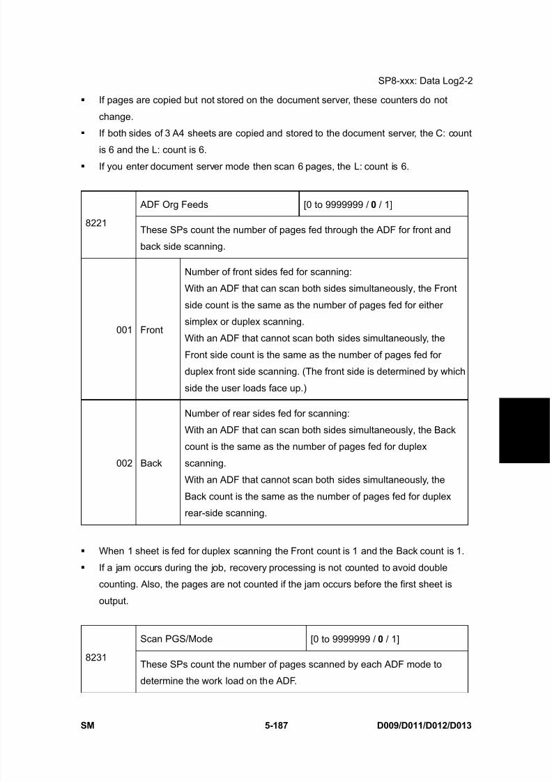
8/15/2019 Ricoh MP 4000 SM D009_D011_D012_D013 SERVICE MANUAL .pdf
http://slidepdf.com/reader/full/ricoh-mp-4000-sm-d009d011d012d013-service-manual-pdf 473/1162

8/15/2019 Ricoh MP 4000 SM D009_D011_D012_D013 SERVICE MANUAL .pdf
http://slidepdf.com/reader/full/ricoh-mp-4000-sm-d009d011d012d013-service-manual-pdf 474/1162
SP8-xxx: Data Log2-2
D009/D011/D012/D013 5-188 SM
001 Large VolumeSelectable. Large copy jobs that cannot be loaded in
the ADF at one time.
002 SADFSelectable. Feeding pages one by one through the
ADF.
003 Mixed SizeSelectable. Select “Mixed Sizes” on the operation
panel.
004 Custom Size Selectable. Originals of non-standard size.
005 PlatenBook mode. Raising the ADF and placing the original
directly on the platen.
006 Simplex / DuplexSelectable. Select “Simplex/Duplex” on the operation
panel.
If the scan mode is changed during the job, for example, if the user switches from ADF
to Platen mode, the count is done for the last selected mode.
The user cannot select mixed sizes or non-standard sizes with the fax application so if
the original’s page sizes are mixed or non-standard, these are not counted.
If the user selects “Mixed Sizes” for copying in the platen mode, the Mixed Size count is
enabled.
In the SADF mode if the user copies 1 page in platen mode and then copies 2 pages
with SADF, the Platen count is 1 and the SADF count is 3.
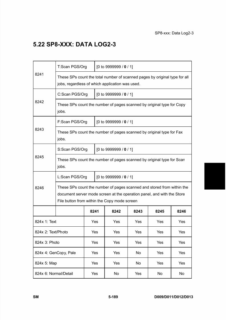
8/15/2019 Ricoh MP 4000 SM D009_D011_D012_D013 SERVICE MANUAL .pdf
http://slidepdf.com/reader/full/ricoh-mp-4000-sm-d009d011d012d013-service-manual-pdf 475/1162
SP8-xxx: Data Log2-3
SM 5-189 D009/D011/D012/D013
S e r v i c e
T a b l e s
5.22 SP8-XXX: DATA LOG2-3
T:Scan PGS/Org [0 to 9999999 / 0 / 1]
8241These SPs count the total number of scanned pages by original type for all
jobs, regardless of which application was used.
C:Scan PGS/Org [0 to 9999999 / 0 / 1]
8242These SPs count the number of pages scanned by original type for Copy
jobs.
F:Scan PGS/Org [0 to 9999999 / 0 / 1]
8243These SPs count the number of pages scanned by original type for Fax
jobs.
S:Scan PGS/Org [0 to 9999999 / 0 / 1]
8245These SPs count the number of pages scanned by original type for Scan
jobs.
L:Scan PGS/Org [0 to 9999999 / 0 / 1]
8246 These SPs count the number of pages scanned and stored from within the
document server mode screen at the operation panel, and with the Store
File button from within the Copy mode screen
8241 8242 8243 8245 8246
824x 1: Text Yes Yes Yes Yes Yes
824x 2: Text/Photo Yes Yes Yes Yes Yes
824x 3: Photo Yes Yes Yes Yes Yes
824x 4: GenCopy, Pale Yes Yes No Yes Yes
824x 5: Map Yes Yes No Yes Yes
824x 6: Normal/Detail Yes No Yes No No
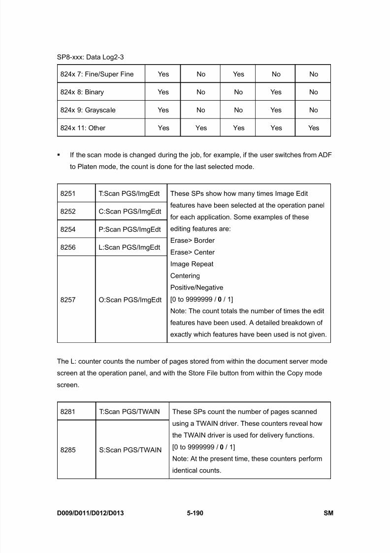
8/15/2019 Ricoh MP 4000 SM D009_D011_D012_D013 SERVICE MANUAL .pdf
http://slidepdf.com/reader/full/ricoh-mp-4000-sm-d009d011d012d013-service-manual-pdf 476/1162
SP8-xxx: Data Log2-3
D009/D011/D012/D013 5-190 SM
824x 7: Fine/Super Fine Yes No Yes No No
824x 8: Binary Yes No No Yes No
824x 9: Grayscale Yes No No Yes No
824x 11: Other Yes Yes Yes Yes Yes
If the scan mode is changed during the job, for example, if the user switches from ADF
to Platen mode, the count is done for the last selected mode.
8251 T:Scan PGS/ImgEdt
8252 C:Scan PGS/ImgEdt
8254 P:Scan PGS/ImgEdt
8256 L:Scan PGS/ImgEdt
8257 O:Scan PGS/ImgEdt
These SPs show how many times Image Editfeatures have been selected at the operation panel
for each application. Some examples of these
editing features are:
Erase> Border
Erase> Center
Image Repeat
Centering
Positive/Negative[0 to 9999999 / 0 / 1]
Note: The count totals the number of times the edit
features have been used. A detailed breakdown of
exactly which features have been used is not given.
The L: counter counts the number of pages stored from within the document server mode
screen at the operation panel, and with the Store File button from within the Copy mode
screen.
8281 T:Scan PGS/TWAIN
8285 S:Scan PGS/TWAIN
These SPs count the number of pages scanned
using a TWAIN driver. These counters reveal how
the TWAIN driver is used for delivery functions.
[0 to 9999999 / 0 / 1]
Note: At the present time, these counters perform
identical counts.
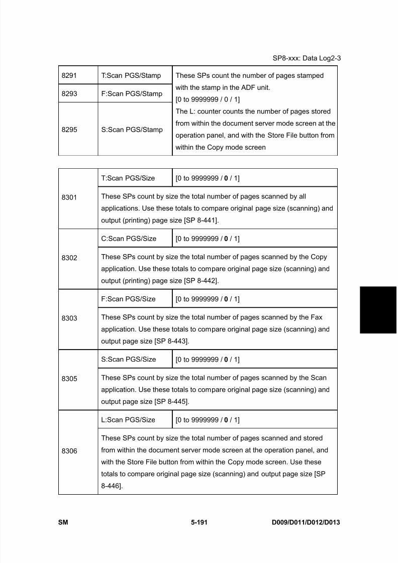
8/15/2019 Ricoh MP 4000 SM D009_D011_D012_D013 SERVICE MANUAL .pdf
http://slidepdf.com/reader/full/ricoh-mp-4000-sm-d009d011d012d013-service-manual-pdf 477/1162
SP8-xxx: Data Log2-3
SM 5-191 D009/D011/D012/D013
S e r v i c e
T a b l e s
8291 T:Scan PGS/Stamp
8293 F:Scan PGS/Stamp
8295 S:Scan PGS/Stamp
These SPs count the number of pages stamped
with the stamp in the ADF unit.
[0 to 9999999 / 0 / 1]The L: counter counts the number of pages stored
from within the document server mode screen at the
operation panel, and with the Store File button from
within the Copy mode screen
T:Scan PGS/Size [0 to 9999999 / 0 / 1]
8301 These SPs count by size the total number of pages scanned by allapplications. Use these totals to compare original page size (scanning) and
output (printing) page size [SP 8-441].
C:Scan PGS/Size [0 to 9999999 / 0 / 1]
8302 These SPs count by size the total number of pages scanned by the Copy
application. Use these totals to compare original page size (scanning) and
output (printing) page size [SP 8-442].
F:Scan PGS/Size [0 to 9999999 / 0 / 1]
8303 These SPs count by size the total number of pages scanned by the Fax
application. Use these totals to compare original page size (scanning) and
output page size [SP 8-443].
S:Scan PGS/Size [0 to 9999999 / 0 / 1]
8305 These SPs count by size the total number of pages scanned by the Scan
application. Use these totals to compare original page size (scanning) and
output page size [SP 8-445].
L:Scan PGS/Size [0 to 9999999 / 0 / 1]
8306
These SPs count by size the total number of pages scanned and stored
from within the document server mode screen at the operation panel, and
with the Store File button from within the Copy mode screen. Use these
totals to compare original page size (scanning) and output page size [SP
8-446].

8/15/2019 Ricoh MP 4000 SM D009_D011_D012_D013 SERVICE MANUAL .pdf
http://slidepdf.com/reader/full/ricoh-mp-4000-sm-d009d011d012d013-service-manual-pdf 478/1162
SP8-xxx: Data Log2-3
D009/D011/D012/D013 5-192 SM
830x 1 A3
830x 2 A4
830x 3 A5
830x 4 B4
830x 5 B5
830x 6 DLT
830x 7 LG
830x 8 LT
830x 9 HLT
830x 10 Full Bleed
830x 254 Other (Standard)
830x 255 Other (Custom)
T:Scan PGS/Rez [0 to 9999999 / 0 / 1]
8311These SPs count by resolution setting the total number of pages scanned by
applications that can specify resolution settings.
S:Scan PGS/Rez [0 to 9999999 / 0 / 1]
8315 These SPs count by resolution setting the total number of pages scanned by
applications that can specify resolution settings.
Note: At the present time, 8311 and 8315 perform identical counts.
831x 1 1200dpi to
831x 2 600dpito1199dpi
831x 3 400dpito599dpi
831x 4 200dpito399dpi
831x 5 to199dpi

8/15/2019 Ricoh MP 4000 SM D009_D011_D012_D013 SERVICE MANUAL .pdf
http://slidepdf.com/reader/full/ricoh-mp-4000-sm-d009d011d012d013-service-manual-pdf 479/1162
SP8-xxx: Data Log2-3
SM 5-193 D009/D011/D012/D013
S e r v i c e
T a b l e s
Copy resolution settings are fixed so they are not counted.
The Fax application does not allow finely-adjusted resolution settings so no count isdone for the Fax application.
8381 T:Total PrtPGS
8382 C:Total PrtPGS
8383 F:Total PrtPGS
8384 P:Total PrtPGS
8385 S:Total PrtPGS
8386 L:Total PrtPGS
8387 O:Total PrtPGS
These SPs count the number of pages printed by
the customer. The counter for the application used
for storing the pages increments.
[0 to 9999999 / 0 / 1]
The L: counter counts the number of pages stored
from within the document server mode screen at
the operation panel. Pages stored with the Store
File button from within the Copy mode screen go to
the C: counter.
When the A3/DLT double count function is switched on with SP5104, 1 A3/DLT page is
counted as 2.
When several documents are merged for a print job, the number of pages stored arecounted for the application that stored them.
These counters are used primarily to calculate charges on use of the machine, so the
following pages are not counted as printed pages:
Blank pages in a duplex printing job.
Blank pages inserted as document covers, chapter title sheets, and slip sheets.
Reports printed to confirm counts.
All reports done in the service mode (service summaries, engine maintenance reports,
etc.)Test prints for machine image adjustment.
Error notification reports.
Partially printed pages as the result of a copier jam.
LSize PrtPGS [0 to 9999999 / 0 / 1]
8391These SPs count pages printed on paper sizes A3/DLT and larger.
Note: In addition to being displayed in the SMC Report, these counters are

8/15/2019 Ricoh MP 4000 SM D009_D011_D012_D013 SERVICE MANUAL .pdf
http://slidepdf.com/reader/full/ricoh-mp-4000-sm-d009d011d012d013-service-manual-pdf 480/1162
SP8-xxx: Data Log2-3
D009/D011/D012/D013 5-194 SM
also displayed in the User Tools display on the copy machine.
8401 T:PrtPGS/LS
8402 C:PrtPGS/LS
8403 F:PrtPGS/LS
8404 P:PrtPGS/LS
8405 S:PrtPGS/LS
8406 L:PrtPGS/LS
These SPs count the number of pages printed from the
document server. The counter for the application used
to print the pages is incremented.
The L: counter counts the number of jobs stored from
within the document server mode screen at the
operation panel.
[0 to 9999999 / 0 / 1]
Print jobs done with Web Image Monitor and Desk Top Binder are added to the L: count.
Fax jobs done with Web Image Monitor and Desk Top Binder are added to the F: count.
8411 Prints/Duplex
This SP counts the amount of paper (front/back
counted as 1 page) used for duplex printing. Last pages
printed only on one side are not counted.
[0 to 9999999 / 0 / 1]
T:PrtPGS/Dup Comb [0 to 9999999 / 0 / 1]
8421These SPs count by binding and combine, and n-Up settings the number of
pages processed for printing. This is the total for all applications.
C:PrtPGS/Dup Comb [0 to 9999999 / 0 / 1]
8422 These SPs count by binding and combine, and n-Up settings the number of
pages processed for printing by the copier application.
F:PrtPGS/Dup Comb [0 to 9999999 / 0 / 1]
8423These SPs count by binding and combine, and n-Up settings the number of
pages processed for printing by the fax application.
8424 P:PrtPGS/Dup Comb [0 to 9999999 / 0 / 1]

8/15/2019 Ricoh MP 4000 SM D009_D011_D012_D013 SERVICE MANUAL .pdf
http://slidepdf.com/reader/full/ricoh-mp-4000-sm-d009d011d012d013-service-manual-pdf 481/1162
SP8-xxx: Data Log2-3
SM 5-195 D009/D011/D012/D013
S e r v i c e
T a b l e s
These SPs count by binding and combine, and n-Up settings the number of
pages processed for printing by the printer application.
S:PrtPGS/Dup Comb [0 to 9999999 / 0 / 1]
8425These SPs count by binding and combine, and n-Up settings the number of
pages processed for printing by the scanner application.
L:PrtPGS/Dup Comb [0 to 9999999 / 0 / 1]
8426 These SPs count by binding and combine, and n-Up settings the number of
pages processed for printing from within the document server mode window
at the operation panel.
O:PrtPGS/Dup Comb [0 to 9999999 / 0 / 1]
8427These SPs count by binding and combine, and n-Up settings the number of
pages processed for printing by Other applications
842x 1 Simplex> Duplex
842x 2 Duplex> Duplex
842x 3 Book> Duplex
842x 4 Simplex Combine
842x 5 Duplex Combine
842x 6 2> 2 pages on 1 side (2-Up)
842x 7 4> 4 pages on 1 side (4-Up)
842x 8 6> 6 pages on 1 side (6-Up)
842x 9 8> 8pages on 1 side (8-Up)
842x 10 9> 9 pages on 1 side (9-Up)
842x 11 16> 16 pages on 1 side (16-Up)
842x 12 Booklet
842x 13 Magazine

8/15/2019 Ricoh MP 4000 SM D009_D011_D012_D013 SERVICE MANUAL .pdf
http://slidepdf.com/reader/full/ricoh-mp-4000-sm-d009d011d012d013-service-manual-pdf 482/1162
SP8-xxx: Data Log2-3
D009/D011/D012/D013 5-196 SM
These counts (SP8421 to SP8427) are especially useful for customers who need to
improve their compliance with ISO standards for the reduction of paper consumption.
Pages that are only partially printed with the n-Up functions are counted as 1 page. Here is a summary of how the counters work for Booklet and Magazine modes:
Booklet Magazine
Original Pages Count Original Pages Count
1 1 1 1
2 2 2 2
3 2 3 2
4 2 4 2
5 3 5 4
6 4 6 4
7 4 7 4
8 4 8 4
T:PrtPGS/ImgEdt [0 to 9999999 / 0 / 1]
8431These SPs count the total number of pages output with the three features
below, regardless of which application was used.
C:PrtPGS/ImgEdt [0 to 9999999 / 0 / 1]
8432 These SPs count the total number of pages output with the three features
below with the copy application.
P:PrtPGS/ImgEdt [0 to 9999999 / 0 / 1]
8434These SPs count the total number of pages output with the three features
below with the print application.
8436 L:PrtPGS/ImgEdt [0 to 9999999 / 0 / 1]
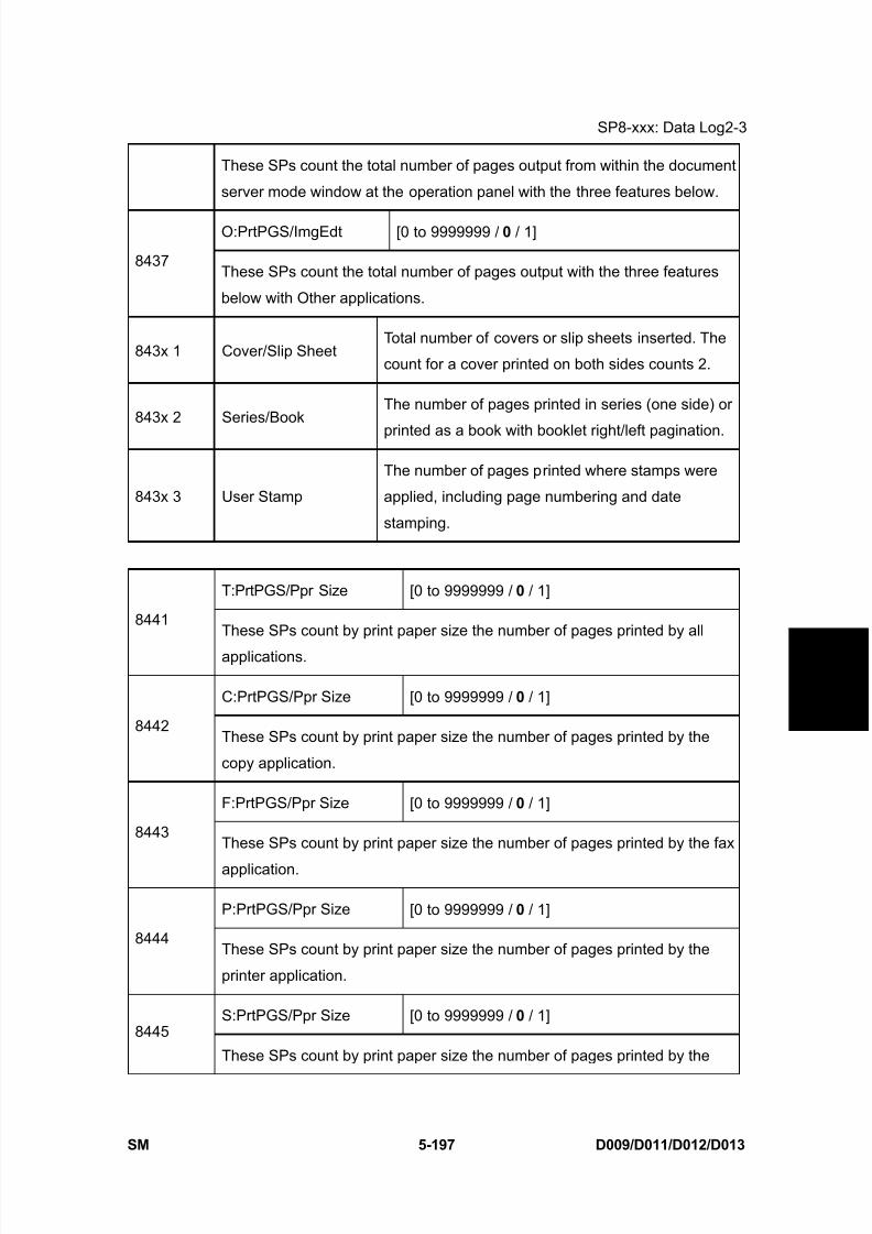
8/15/2019 Ricoh MP 4000 SM D009_D011_D012_D013 SERVICE MANUAL .pdf
http://slidepdf.com/reader/full/ricoh-mp-4000-sm-d009d011d012d013-service-manual-pdf 483/1162
SP8-xxx: Data Log2-3
SM 5-197 D009/D011/D012/D013
S e r v i c e
T a b l e s
These SPs count the total number of pages output from within the document
server mode window at the operation panel with the three features below.
O:PrtPGS/ImgEdt [0 to 9999999 / 0 / 1]
8437These SPs count the total number of pages output with the three features
below with Other applications.
843x 1 Cover/Slip SheetTotal number of covers or slip sheets inserted. The
count for a cover printed on both sides counts 2.
843x 2 Series/BookThe number of pages printed in series (one side) or
printed as a book with booklet right/left pagination.
843x 3 User Stamp
The number of pages printed where stamps were
applied, including page numbering and date
stamping.
T:PrtPGS/Ppr Size [0 to 9999999 / 0 / 1]
8441These SPs count by print paper size the number of pages printed by all
applications.
C:PrtPGS/Ppr Size [0 to 9999999 / 0 / 1]
8442These SPs count by print paper size the number of pages printed by the
copy application.
F:PrtPGS/Ppr Size [0 to 9999999 / 0 / 1]
8443These SPs count by print paper size the number of pages printed by the fax
application.
P:PrtPGS/Ppr Size [0 to 9999999 / 0 / 1]
8444These SPs count by print paper size the number of pages printed by the
printer application.
S:PrtPGS/Ppr Size [0 to 9999999 / 0 / 1]8445
These SPs count by print paper size the number of pages printed by the

8/15/2019 Ricoh MP 4000 SM D009_D011_D012_D013 SERVICE MANUAL .pdf
http://slidepdf.com/reader/full/ricoh-mp-4000-sm-d009d011d012d013-service-manual-pdf 484/1162
SP8-xxx: Data Log2-3
D009/D011/D012/D013 5-198 SM
scanner application.
L:PrtPGS/Ppr Size [0 to 9999999 / 0 / 1]
8446These SPs count by print paper size the number of pages printed from
within the document server mode window at the operation panel.
O:PrtPGS/Ppr Size [0 to 9999999 / 0 / 1]
8447These SPs count by print paper size the number of pages printed by Other
applications.
844x 1 A3
844x 2 A4
844x 3 A5
844x 4 B4
844x 5 B5
844x 6 DLT
844x 7 LG
844x 8 LT
844x 9 HLT
844x 10 Full Bleed
844x 254 Other (Standard)
844x 255 Other (Custom)
These counters do not distinguish between LEF and SEF.
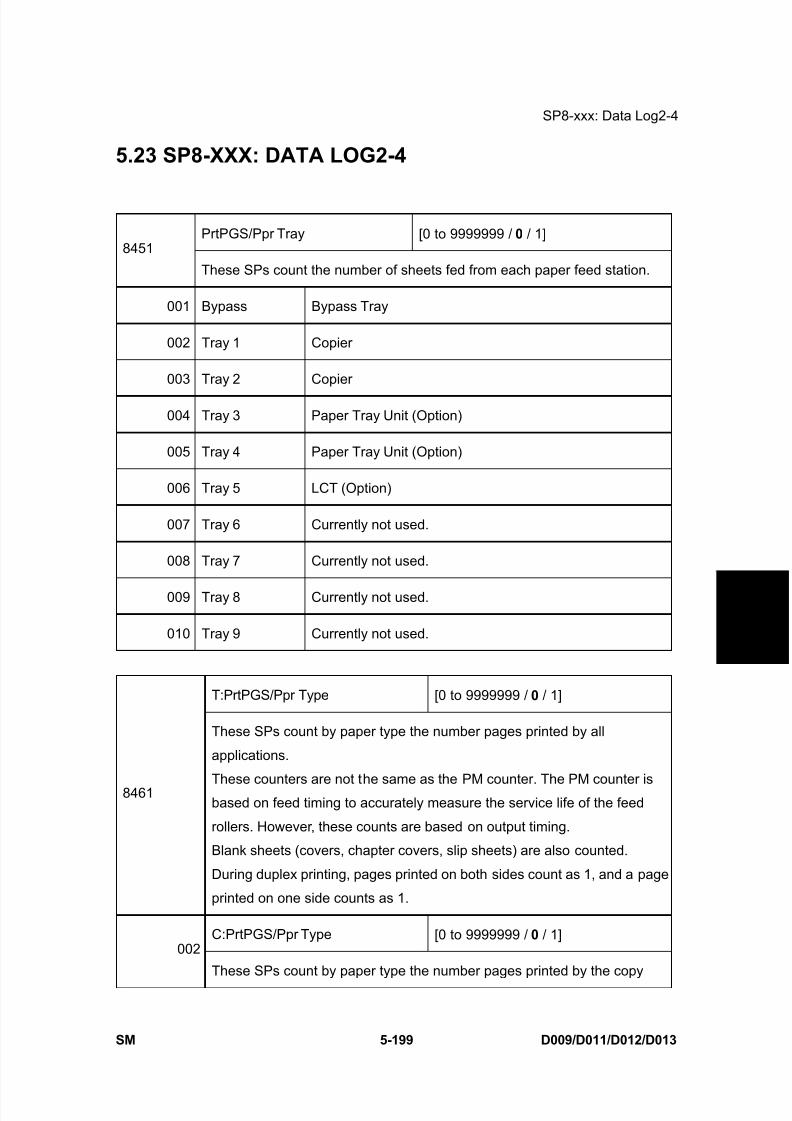
8/15/2019 Ricoh MP 4000 SM D009_D011_D012_D013 SERVICE MANUAL .pdf
http://slidepdf.com/reader/full/ricoh-mp-4000-sm-d009d011d012d013-service-manual-pdf 485/1162
SP8-xxx: Data Log2-4
SM 5-199 D009/D011/D012/D013
S e r v i c e
T a b l e s
5.23 SP8-XXX: DATA LOG2-4
PrtPGS/Ppr Tray [0 to 9999999 / 0 / 1]8451
These SPs count the number of sheets fed from each paper feed station.
001 Bypass Bypass Tray
002 Tray 1 Copier
003 Tray 2 Copier
004 Tray 3 Paper Tray Unit (Option)
005 Tray 4 Paper Tray Unit (Option)
006 Tray 5 LCT (Option)
007 Tray 6 Currently not used.
008 Tray 7 Currently not used.
009 Tray 8 Currently not used.
010 Tray 9 Currently not used.
T:PrtPGS/Ppr Type [0 to 9999999 / 0 / 1]
8461
These SPs count by paper type the number pages printed by all
applications.
These counters are not the same as the PM counter. The PM counter isbased on feed timing to accurately measure the service life of the feed
rollers. However, these counts are based on output timing.
Blank sheets (covers, chapter covers, slip sheets) are also counted.
During duplex printing, pages printed on both sides count as 1, and a page
printed on one side counts as 1.
C:PrtPGS/Ppr Type [0 to 9999999 / 0 / 1]002
These SPs count by paper type the number pages printed by the copy
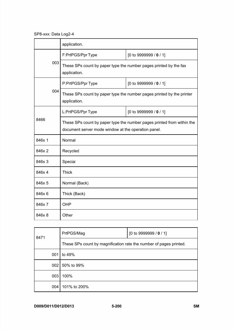
8/15/2019 Ricoh MP 4000 SM D009_D011_D012_D013 SERVICE MANUAL .pdf
http://slidepdf.com/reader/full/ricoh-mp-4000-sm-d009d011d012d013-service-manual-pdf 486/1162
SP8-xxx: Data Log2-4
D009/D011/D012/D013 5-200 SM
application.
F:PrtPGS/Ppr Type [0 to 9999999 / 0 / 1]
003These SPs count by paper type the number pages printed by the fax
application.
P:PrtPGS/Ppr Type [0 to 9999999 / 0 / 1]
004These SPs count by paper type the number pages printed by the printer
application.
L:PrtPGS/Ppr Type [0 to 9999999 / 0 / 1]
8466These SPs count by paper type the number pages printed from within the
document server mode window at the operation panel.
846x 1 Normal
846x 2 Recycled
846x 3 Special
846x 4 Thick
846x 5 Normal (Back)
846x 6 Thick (Back)
846x 7 OHP
846x 8 Other
PrtPGS/Mag [0 to 9999999 / 0 / 1]8471
These SPs count by magnification rate the number of pages printed.
001 to 49%
002 50% to 99%
003 100%
004 101% to 200%
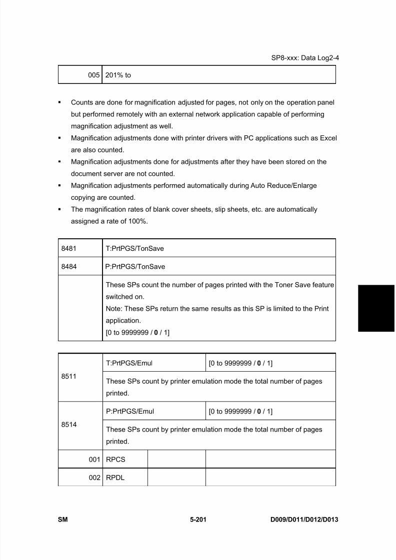
8/15/2019 Ricoh MP 4000 SM D009_D011_D012_D013 SERVICE MANUAL .pdf
http://slidepdf.com/reader/full/ricoh-mp-4000-sm-d009d011d012d013-service-manual-pdf 487/1162
SP8-xxx: Data Log2-4
SM 5-201 D009/D011/D012/D013
S e r v i c e
T a b l e s
005 201% to
Counts are done for magnification adjusted for pages, not only on the operation panel
but performed remotely with an external network application capable of performing
magnification adjustment as well.
Magnification adjustments done with printer drivers with PC applications such as Excel
are also counted.
Magnification adjustments done for adjustments after they have been stored on the
document server are not counted.
Magnification adjustments performed automatically during Auto Reduce/Enlarge
copying are counted. The magnification rates of blank cover sheets, slip sheets, etc. are automatically
assigned a rate of 100%.
8481 T:PrtPGS/TonSave
8484 P:PrtPGS/TonSave
These SPs count the number of pages printed with the Toner Save feature
switched on.
Note: These SPs return the same results as this SP is limited to the Print
application.
[0 to 9999999 / 0 / 1]
T:PrtPGS/Emul [0 to 9999999 / 0 / 1]
8511These SPs count by printer emulation mode the total number of pages
printed.
P:PrtPGS/Emul [0 to 9999999 / 0 / 1]
8514These SPs count by printer emulation mode the total number of pages
printed.
001 RPCS
002 RPDL
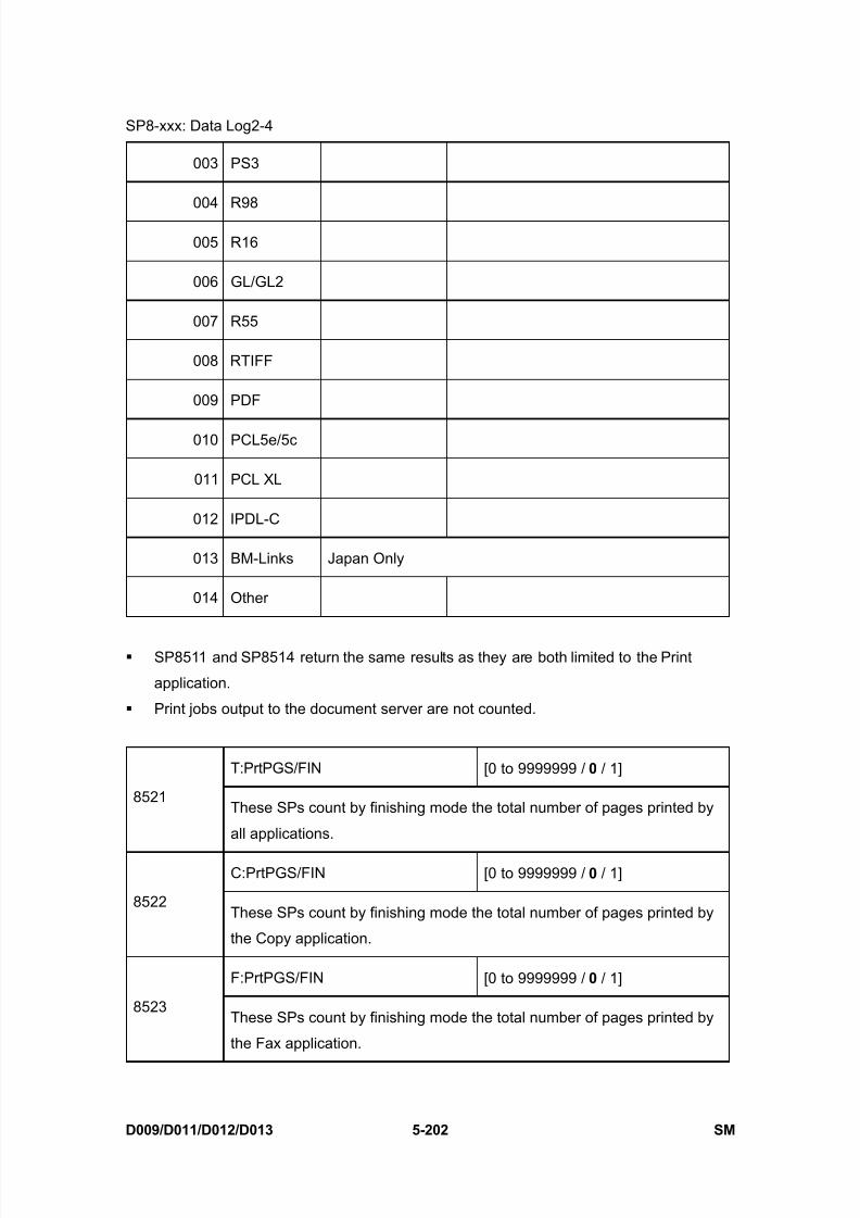
8/15/2019 Ricoh MP 4000 SM D009_D011_D012_D013 SERVICE MANUAL .pdf
http://slidepdf.com/reader/full/ricoh-mp-4000-sm-d009d011d012d013-service-manual-pdf 488/1162
SP8-xxx: Data Log2-4
D009/D011/D012/D013 5-202 SM
003 PS3
004 R98
005 R16
006 GL/GL2
007 R55
008 RTIFF
009 PDF
010 PCL5e/5c
011 PCL XL
012 IPDL-C
013 BM-Links Japan Only
014 Other
SP8511 and SP8514 return the same results as they are both limited to the Print
application.
Print jobs output to the document server are not counted.
T:PrtPGS/FIN [0 to 9999999 / 0 / 1]
8521These SPs count by finishing mode the total number of pages printed by
all applications.
C:PrtPGS/FIN [0 to 9999999 / 0 / 1]
8522These SPs count by finishing mode the total number of pages printed by
the Copy application.
F:PrtPGS/FIN [0 to 9999999 / 0 / 1]
8523These SPs count by finishing mode the total number of pages printed by
the Fax application.
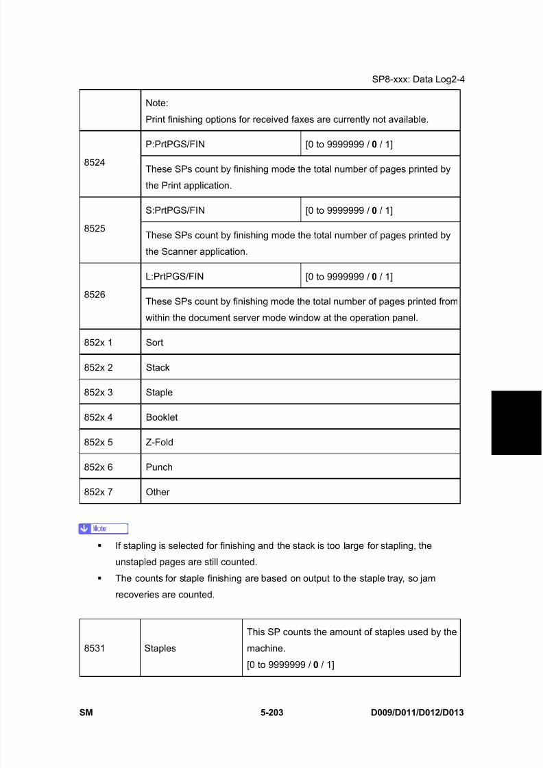
8/15/2019 Ricoh MP 4000 SM D009_D011_D012_D013 SERVICE MANUAL .pdf
http://slidepdf.com/reader/full/ricoh-mp-4000-sm-d009d011d012d013-service-manual-pdf 489/1162
SP8-xxx: Data Log2-4
SM 5-203 D009/D011/D012/D013
S e r v i c e
T a b l e s
Note:
Print finishing options for received faxes are currently not available.
P:PrtPGS/FIN [0 to 9999999 / 0 / 1]
8524These SPs count by finishing mode the total number of pages printed by
the Print application.
S:PrtPGS/FIN [0 to 9999999 / 0 / 1]
8525These SPs count by finishing mode the total number of pages printed by
the Scanner application.
L:PrtPGS/FIN [0 to 9999999 / 0 / 1]
8526These SPs count by finishing mode the total number of pages printed from
within the document server mode window at the operation panel.
852x 1 Sort
852x 2 Stack
852x 3 Staple
852x 4 Booklet
852x 5 Z-Fold
852x 6 Punch
852x 7 Other
If stapling is selected for finishing and the stack is too large for stapling, the
unstapled pages are still counted.
The counts for staple finishing are based on output to the staple tray, so jam
recoveries are counted.
8531 Staples
This SP counts the amount of staples used by the
machine.
[0 to 9999999 / 0 / 1]
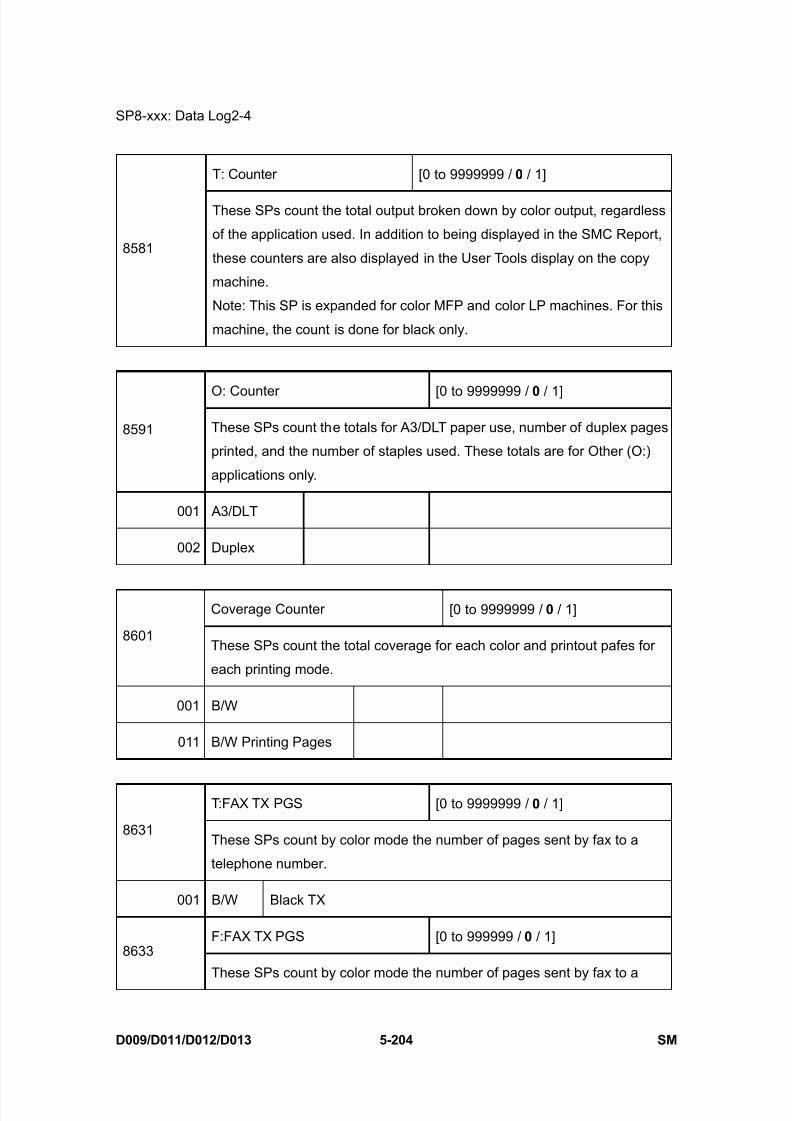
8/15/2019 Ricoh MP 4000 SM D009_D011_D012_D013 SERVICE MANUAL .pdf
http://slidepdf.com/reader/full/ricoh-mp-4000-sm-d009d011d012d013-service-manual-pdf 490/1162
SP8-xxx: Data Log2-4
D009/D011/D012/D013 5-204 SM
T: Counter [0 to 9999999 / 0 / 1]
8581
These SPs count the total output broken down by color output, regardless
of the application used. In addition to being displayed in the SMC Report,
these counters are also displayed in the User Tools display on the copy
machine.
Note: This SP is expanded for color MFP and color LP machines. For this
machine, the count is done for black only.
O: Counter [0 to 9999999 / 0 / 1]
8591 These SPs count the totals for A3/DLT paper use, number of duplex pages
printed, and the number of staples used. These totals are for Other (O:)
applications only.
001 A3/DLT
002 Duplex
Coverage Counter [0 to 9999999 / 0 / 1]
8601These SPs count the total coverage for each color and printout pafes for
each printing mode.
001 B/W
011 B/W Printing Pages
T:FAX TX PGS [0 to 9999999 / 0 / 1]
8631These SPs count by color mode the number of pages sent by fax to a
telephone number.
001 B/W Black TX
F:FAX TX PGS [0 to 999999 / 0 / 1]8633
These SPs count by color mode the number of pages sent by fax to a

8/15/2019 Ricoh MP 4000 SM D009_D011_D012_D013 SERVICE MANUAL .pdf
http://slidepdf.com/reader/full/ricoh-mp-4000-sm-d009d011d012d013-service-manual-pdf 491/1162
SP8-xxx: Data Log2-4
SM 5-205 D009/D011/D012/D013
S e r v i c e
T a b l e s
telephone number.
002 B/W Black TX
If a document has color and black-and-white pages mixed, the pages are counted
separately as B/W or Color.
At the present time, this feature is provided for the Fax application only so SP8631 and
SP8633 are the same.
The counts include error pages.
If a document is sent to more than one destination with a Group transmission, the count
is done for each destination.
Polling transmissions are counted but polling RX are not.
Relay, memory, and confidential mailbox transmissions and are counted for each
destination.
T:FAX TX PGS [0 to 9999999 / 0 / 1]
8641These SPs count by color mode the number of pages sent by fax to as fax
images using I-Fax.
001 B/W Black TX
F:FAX TX PGS [0 o 9999999 / 0 / 1]
8643These SPs count by color mode the number of pages sent by Fax as fax
images using I-Fax.
002 B/W Black TX
If a document has color and black-and-white pages mixed, the pages are counted
separately as B/W or Color.
At the present time, this feature is provided for the Fax application only so SP8641 and
SP8643 are the same.
The counts include error pages.
If a document is sent to more than one destination with a Group transmission, the count
is done for each destination.
Polling transmissions are counted but polling RX are not.
Relay, memory, and confidential mailbox transmissions and are counted for each

8/15/2019 Ricoh MP 4000 SM D009_D011_D012_D013 SERVICE MANUAL .pdf
http://slidepdf.com/reader/full/ricoh-mp-4000-sm-d009d011d012d013-service-manual-pdf 492/1162
SP8-xxx: Data Log2-4
D009/D011/D012/D013 5-206 SM
destination.
T:S-to-Email PGS [0 to 9999999 / 0 / 1]
8651These SPs count by color mode the total number of pages attached to an
e-mail for both the Scan and document server applications.
001 B/W
002 Color
S:S-to-Email PGS [0 to 9999999 / 0 / 1]
8655 These SPs count by color mode the total number of pages attached to an
e-mail for the Scan application only.
001 B/W
002 Color
The count for B/W and Color pages is done after the document is stored on the
HDD. If the job is cancelled before it is stored, the pages are not counted.
If Scan-to-Email is used to send a 10-page document to 5 addresses, the count is
10 (the pages are sent to the same SMTP server together).
If Scan-to-PC is used to send a 10-page document to 5 folders, the count is 50 (the
document is sent to each destination of the SMB/FTP server).
Due to restrictions on some devices, if Scan-to-Email is used to send a 10-page
document to a large number of destinations, the count may be divided and counted
separately. For example, if a 10-page document is sent to 200 addresses, the count
is 10 for the first 100 destinations and the count is also 10 for the second 100
destinations, for a total of 20).
T:Deliv PGS/Svr [0 to 9999999 / 0 / 1]
8661These SPs count by color mode the total number of pages sent to a Scan
Router server by both Scan and LS applications.
001 B/W

8/15/2019 Ricoh MP 4000 SM D009_D011_D012_D013 SERVICE MANUAL .pdf
http://slidepdf.com/reader/full/ricoh-mp-4000-sm-d009d011d012d013-service-manual-pdf 493/1162
SP8-xxx: Data Log2-4
SM 5-207 D009/D011/D012/D013
S e r v i c e
T a b l e s
002 Color
S:Deliv PGS/Svr [0 to 9999999 / 0 / 1]
8665These SPs count by color mode the total number of pages sent to a Scan
Router server by the Scan application.
001 B/W
002 Color
The B/W and Color counts are done after the document is stored on the HDD of the
Scan Router server.
If the job is canceled before storage on the Scan Router server finishes, the counts
are not done.
The count is executed even if regardless of confirmation of the arrival at the Scan
Router server.
T: Deliv PGS/PC [0 to 9999999 / 0 / 1]
8671These SPs count by color mode the total number of pages sent to a folder
on a PC (Scan-to-PC) with the Scan and LS applications.
001 B/W
002 Color
S: Deliv PGS/PC [0 to 9999999 / 0 / 1]
8675These SPs count by color mode the total number of pages sent with
Scan-to-PC with the Scan application.
001 B/W
002 Color
8681 T:PCFAX TXPGS
8683 F:PCFAX TXPGS
These SPs count the number of pages sent by PC
Fax. These SPs are provided for the Fax application
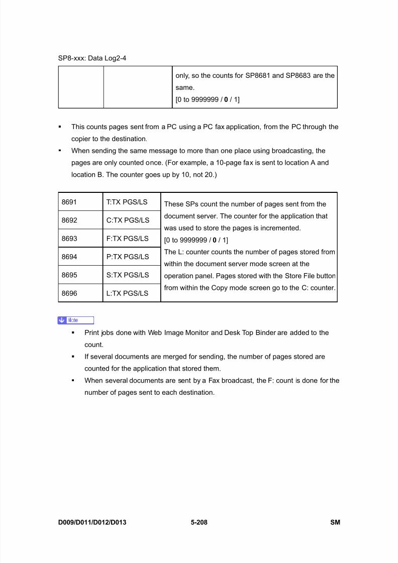
8/15/2019 Ricoh MP 4000 SM D009_D011_D012_D013 SERVICE MANUAL .pdf
http://slidepdf.com/reader/full/ricoh-mp-4000-sm-d009d011d012d013-service-manual-pdf 494/1162
SP8-xxx: Data Log2-4
D009/D011/D012/D013 5-208 SM
only, so the counts for SP8681 and SP8683 are the
same.
[0 to 9999999 / 0 / 1]
This counts pages sent from a PC using a PC fax application, from the PC through the
copier to the destination.
When sending the same message to more than one place using broadcasting, the
pages are only counted once. (For example, a 10-page fax is sent to location A and
location B. The counter goes up by 10, not 20.)
8691 T:TX PGS/LS
8692 C:TX PGS/LS
8693 F:TX PGS/LS
8694 P:TX PGS/LS
8695 S:TX PGS/LS
8696 L:TX PGS/LS
These SPs count the number of pages sent from the
document server. The counter for the application that
was used to store the pages is incremented.
[0 to 9999999 / 0 / 1]
The L: counter counts the number of pages stored from
within the document server mode screen at the
operation panel. Pages stored with the Store File button
from within the Copy mode screen go to the C: counter.
Print jobs done with Web Image Monitor and Desk Top Binder are added to the
count.
If several documents are merged for sending, the number of pages stored are
counted for the application that stored them.
When several documents are sent by a Fax broadcast, the F: count is done for the
number of pages sent to each destination.

8/15/2019 Ricoh MP 4000 SM D009_D011_D012_D013 SERVICE MANUAL .pdf
http://slidepdf.com/reader/full/ricoh-mp-4000-sm-d009d011d012d013-service-manual-pdf 495/1162
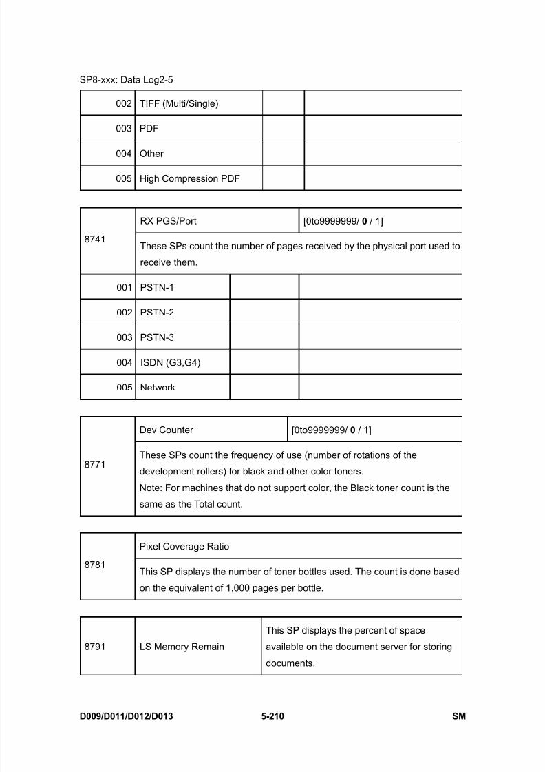
8/15/2019 Ricoh MP 4000 SM D009_D011_D012_D013 SERVICE MANUAL .pdf
http://slidepdf.com/reader/full/ricoh-mp-4000-sm-d009d011d012d013-service-manual-pdf 496/1162
SP8-xxx: Data Log2-5
D009/D011/D012/D013 5-210 SM
002 TIFF (Multi/Single)
003 PDF
004 Other
005 High Compression PDF
RX PGS/Port [0to9999999/ 0 / 1]
8741These SPs count the number of pages received by the physical port used to
receive them.
001 PSTN-1
002 PSTN-2
003 PSTN-3
004 ISDN (G3,G4)
005 Network
Dev Counter [0to9999999/ 0 / 1]
8771These SPs count the frequency of use (number of rotations of the
development rollers) for black and other color toners.
Note: For machines that do not support color, the Black toner count is the
same as the Total count.
Pixel Coverage Ratio
8781This SP displays the number of toner bottles used. The count is done based
on the equivalent of 1,000 pages per bottle.
8791 LS Memory Remain
This SP displays the percent of space
available on the document server for storing
documents.
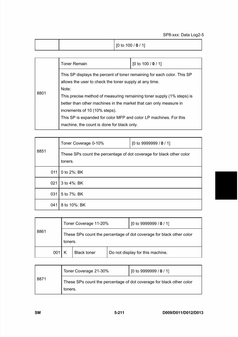
8/15/2019 Ricoh MP 4000 SM D009_D011_D012_D013 SERVICE MANUAL .pdf
http://slidepdf.com/reader/full/ricoh-mp-4000-sm-d009d011d012d013-service-manual-pdf 497/1162
SP8-xxx: Data Log2-5
SM 5-211 D009/D011/D012/D013
S e r v i c e
T a b l e s
[0 to 100 / 0 / 1]
Toner Remain [0 to 100 / 0 / 1]
8801
This SP displays the percent of toner remaining for each color. This SP
allows the user to check the toner supply at any time.
Note:
This precise method of measuring remaining toner supply (1% steps) is
better than other machines in the market that can only measure in
increments of 10 (10% steps).
This SP is expanded for color MFP and color LP machines. For thismachine, the count is done for black only.
Toner Coverage 0-10% [0 to 9999999 / 0 / 1]
8851These SPs count the percentage of dot coverage for black other color
toners.
011 0 to 2%: BK
021 3 to 4%: BK
031 5 to 7%: BK
041 8 to 10%: BK
Toner Coverage 11-20% [0 to 9999999 / 0 / 1]
8861
These SPs count the percentage of dot coverage for black other colortoners.
001 K Black toner Do not display for this machine.
Toner Coverage 21-30% [0 to 9999999 / 0 / 1]
8871These SPs count the percentage of dot coverage for black other color
toners.
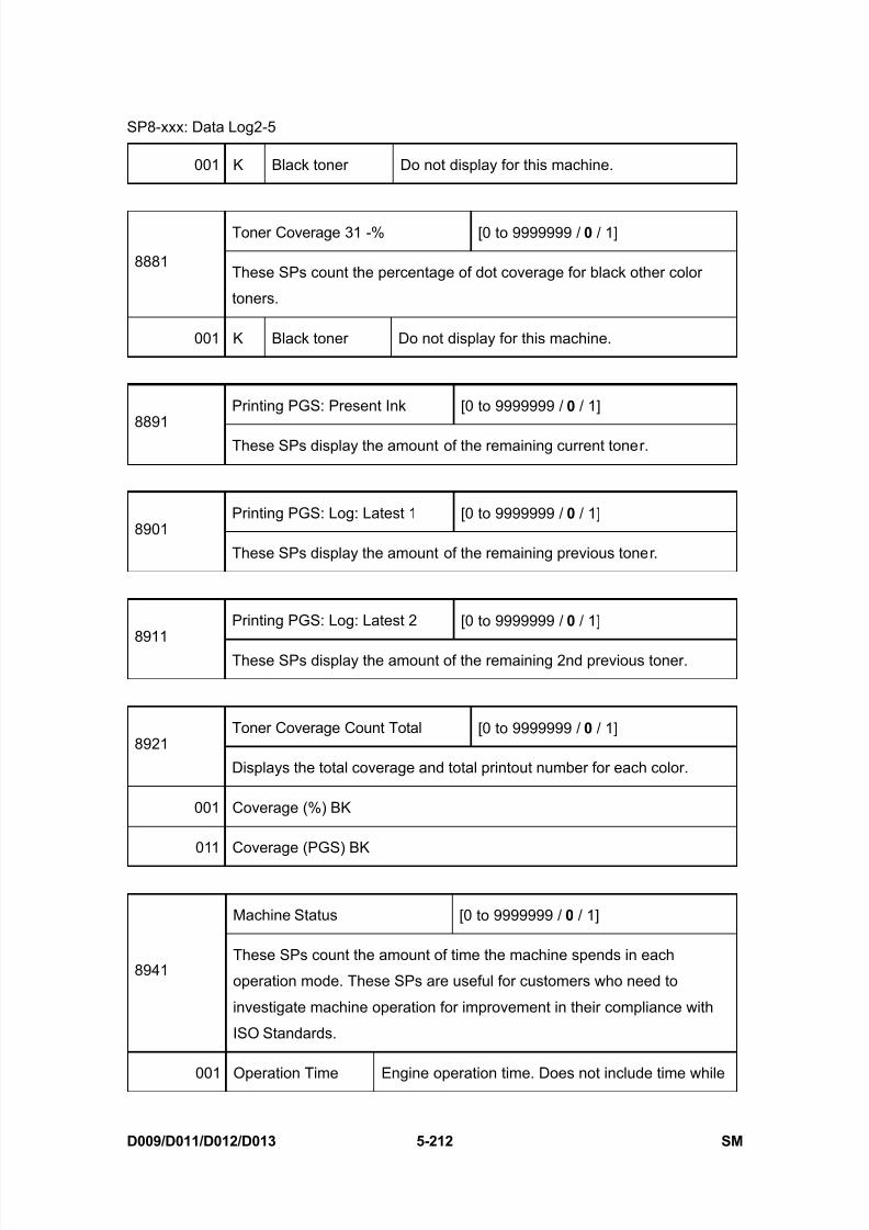
8/15/2019 Ricoh MP 4000 SM D009_D011_D012_D013 SERVICE MANUAL .pdf
http://slidepdf.com/reader/full/ricoh-mp-4000-sm-d009d011d012d013-service-manual-pdf 498/1162
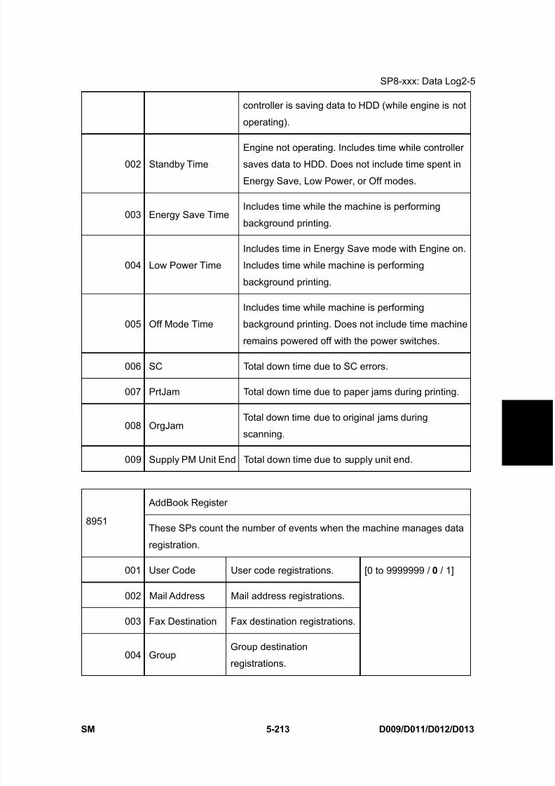
8/15/2019 Ricoh MP 4000 SM D009_D011_D012_D013 SERVICE MANUAL .pdf
http://slidepdf.com/reader/full/ricoh-mp-4000-sm-d009d011d012d013-service-manual-pdf 499/1162
SP8-xxx: Data Log2-5
SM 5-213 D009/D011/D012/D013
S e r v i c e
T a b l e s
controller is saving data to HDD (while engine is not
operating).
002 Standby Time
Engine not operating. Includes time while controller
saves data to HDD. Does not include time spent in
Energy Save, Low Power, or Off modes.
003 Energy Save TimeIncludes time while the machine is performing
background printing.
004 Low Power Time
Includes time in Energy Save mode with Engine on.
Includes time while machine is performing
background printing.
005 Off Mode Time
Includes time while machine is performing
background printing. Does not include time machine
remains powered off with the power switches.
006 SC Total down time due to SC errors.
007 PrtJam Total down time due to paper jams during printing.
008 OrgJamTotal down time due to original jams during
scanning.
009 Supply PM Unit End Total down time due to supply unit end.
AddBook Register
8951These SPs count the number of events when the machine manages data
registration.
001 User Code User code registrations.
002 Mail Address Mail address registrations.
003 Fax Destination Fax destination registrations.
004 GroupGroup destination
registrations.
[0 to 9999999 / 0 / 1]
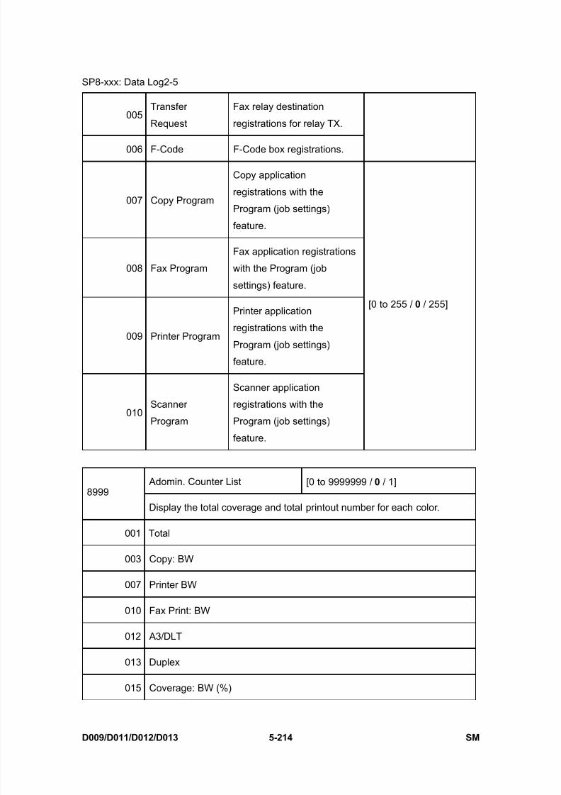
8/15/2019 Ricoh MP 4000 SM D009_D011_D012_D013 SERVICE MANUAL .pdf
http://slidepdf.com/reader/full/ricoh-mp-4000-sm-d009d011d012d013-service-manual-pdf 500/1162
SP8-xxx: Data Log2-5
D009/D011/D012/D013 5-214 SM
005Transfer
Request
Fax relay destination
registrations for relay TX.
006 F-Code F-Code box registrations.
007 Copy Program
Copy application
registrations with the
Program (job settings)
feature.
008 Fax Program
Fax application registrations
with the Program (job
settings) feature.
009 Printer Program
Printer application
registrations with the
Program (job settings)
feature.
010
Scanner
Program
Scanner application
registrations with the
Program (job settings)
feature.
[0 to 255 / 0 / 255]
Adomin. Counter List [0 to 9999999 / 0 / 1]8999
Display the total coverage and total printout number for each color.
001 Total
003 Copy: BW
007 Printer BW
010 Fax Print: BW
012 A3/DLT
013 Duplex
015 Coverage: BW (%)
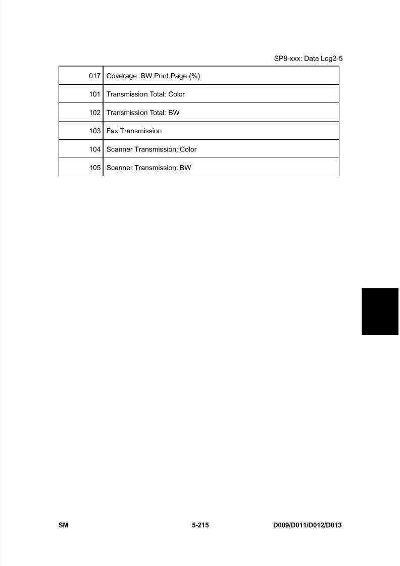
8/15/2019 Ricoh MP 4000 SM D009_D011_D012_D013 SERVICE MANUAL .pdf
http://slidepdf.com/reader/full/ricoh-mp-4000-sm-d009d011d012d013-service-manual-pdf 501/1162
SP8-xxx: Data Log2-5
SM 5-215 D009/D011/D012/D013
S e r v i c e
T a b l e s
017 Coverage: BW Print Page (%)
101 Transmission Total: Color
102 Transmission Total: BW
103 Fax Transmission
104 Scanner Transmission: Color
105 Scanner Transmission: BW

8/15/2019 Ricoh MP 4000 SM D009_D011_D012_D013 SERVICE MANUAL .pdf
http://slidepdf.com/reader/full/ricoh-mp-4000-sm-d009d011d012d013-service-manual-pdf 502/1162
Input Check - 1
D009/D011/D012/D013 5-216 SM
5.25 INPUT CHECK - 1
5.25.1 COPIER
When entering the Input Check mode, 8 digits display the result for a section. Each digit
corresponds to a different device as shown in the table.
Bit No. 7 6 5 4 3 2 1 0
Result 0 or 1 0 or 1 0 or 1 0 or 1 0 or 1 0 or 1 0 or 1 0 or 1
Input Check
Reading 5803Description
0 1
001 Tray 1: Paper Size Sensor See the table 1 following this table.
002 Tray 1: Tray Set Sensor Set Not set
003 Tray 1: Paper Lift Sensor Not upper limit Upper limit
004 Tray 1: Paper End Sensor No paper Paper remaining
005Tray 1:
Paper Height Sensor 1
006Tray 1:
Paper Height Sensor 2
See the table 2 following this table.
007 Tray 2: Paper Size Sensor See the table 1 following this table.
008 Tray 2: Tray Set Sensor Set Not set
009 Tray 2: Paper Lift Sensor Not upper limit Upper limit
010 Tray 2: Paper End Sensor No paper Paper remaining
011Tray 2:
Paper Height Sensor 1See the table 2 following this table.

8/15/2019 Ricoh MP 4000 SM D009_D011_D012_D013 SERVICE MANUAL .pdf
http://slidepdf.com/reader/full/ricoh-mp-4000-sm-d009d011d012d013-service-manual-pdf 503/1162
Input Check - 1
SM 5-217 D009/D011/D012/D013
S e r v i c e
T a b l e s
012Tray 2:
Paper Height Sensor 2
013 Tray 1: Paper Feed Sensor Paper detected No paper detected
014 Tray 2: Paper Feed Sensor Paper detected No paper detected
015 Tray 3: Paper Feed Sensor Paper detected No paper detected
016 Tray 4: Paper Feed Sensor Paper detected No paper detected
017 LCT: Paper Feed Sensor No paper detected Paper detected
018 Relay Sensor 1 Paper detected No paper detected
019 Relay Sensor 2 Paper detected No paper detected
020 Relay Sensor 3 No paper detected Paper detected
021 Relay Sensor 4 No paper detected Paper detected
022 Relay Sensor: LCT No paper detected Paper detected
023 By-pass: Paper End Sensor Not end Paper end
024 By-pass: Paper Size Sensor See the table 3 following this table.
025 Registration Sensor Paper detected No paper detected
026 Fusing Exit Sensor No paper detected Paper detected
027 Fusing Entrance Sensor Paper detected No paper detected
028 Junction Gate Relay Sensor Paper detected No paper detected
029 Exit Sensor Paper detected No paper detected
030 Paper Overflow Sensor Not full Full
031 Right Cover Open/Close Close Open
032 Duplex Unit Open/Close Open Close
033 Duplex Entrance Sensor Paper detected No paper detected
034 Duplex Exit Sensor Paper detected No paper detected
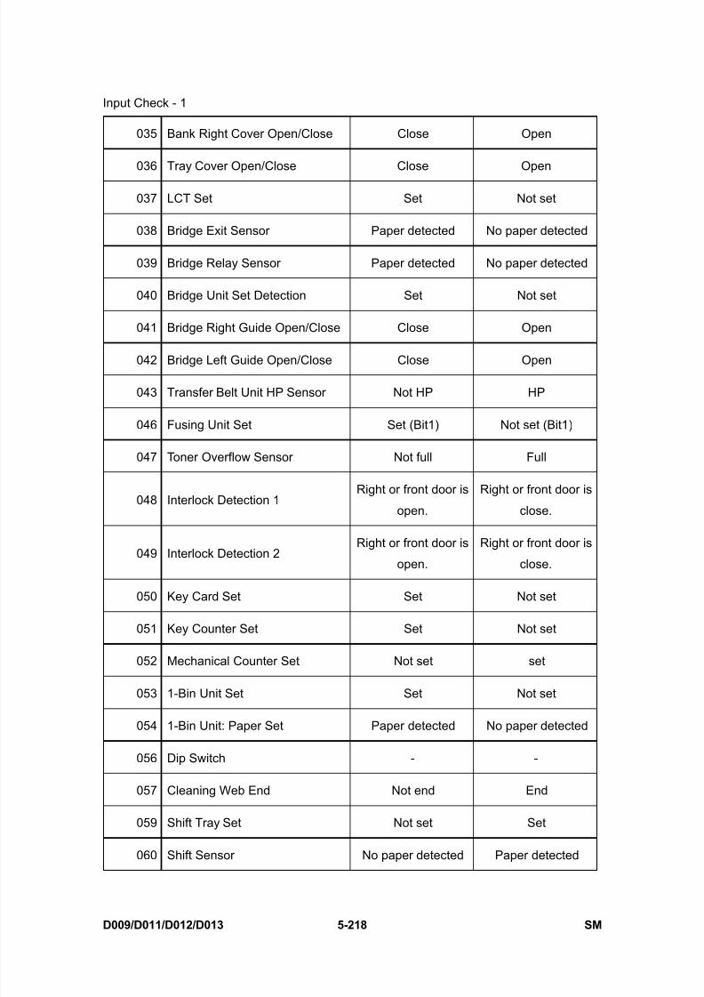
8/15/2019 Ricoh MP 4000 SM D009_D011_D012_D013 SERVICE MANUAL .pdf
http://slidepdf.com/reader/full/ricoh-mp-4000-sm-d009d011d012d013-service-manual-pdf 504/1162
Input Check - 1
D009/D011/D012/D013 5-218 SM
035 Bank Right Cover Open/Close Close Open
036 Tray Cover Open/Close Close Open
037 LCT Set Set Not set
038 Bridge Exit Sensor Paper detected No paper detected
039 Bridge Relay Sensor Paper detected No paper detected
040 Bridge Unit Set Detection Set Not set
041 Bridge Right Guide Open/Close Close Open
042 Bridge Left Guide Open/Close Close Open
043 Transfer Belt Unit HP Sensor Not HP HP
046 Fusing Unit Set Set (Bit1) Not set (Bit1)
047 Toner Overflow Sensor Not full Full
048 Interlock Detection 1Right or front door is
open.
Right or front door is
close.
049 Interlock Detection 2Right or front door is
open.
Right or front door is
close.
050 Key Card Set Set Not set
051 Key Counter Set Set Not set
052 Mechanical Counter Set Not set set
053 1-Bin Unit Set Set Not set
054 1-Bin Unit: Paper Set Paper detected No paper detected
056 Dip Switch - -
057 Cleaning Web End Not end End
059 Shift Tray Set Not set Set
060 Shift Sensor No paper detected Paper detected
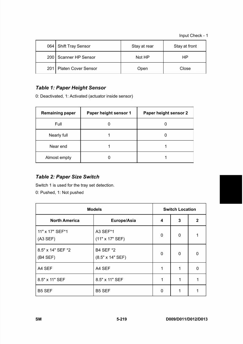
8/15/2019 Ricoh MP 4000 SM D009_D011_D012_D013 SERVICE MANUAL .pdf
http://slidepdf.com/reader/full/ricoh-mp-4000-sm-d009d011d012d013-service-manual-pdf 505/1162
Input Check - 1
SM 5-219 D009/D011/D012/D013
S e r v i c e
T a b l e s
064 Shift Tray Sensor Stay at rear Stay at front
200 Scanner HP Sensor Not HP HP
201 Platen Cover Sensor Open Close
Table 1: Paper Height Sensor
0: Deactivated, 1: Activated (actuator inside sensor)
Remaining paper Paper height sensor 1 Paper height sensor 2
Full 0 0
Nearly full 1 0
Near end 1 1
Almost empty 0 1
Table 2: Paper Size Switch
Switch 1 is used for the tray set detection.
0: Pushed, 1: Not pushed
Models Switch Location
North America Europe/Asia 4 3 2
11" x 17" SEF*1
(A3 SEF)
A3 SEF*1
(11" x 17" SEF)
0 0 1
8.5" x 14" SEF *2
(B4 SEF)
B4 SEF *2
(8.5" x 14" SEF)0 0 0
A4 SEF A4 SEF 1 1 0
8.5" x 11" SEF 8.5" x 11" SEF 1 1 1
B5 SEF B5 SEF 0 1 1
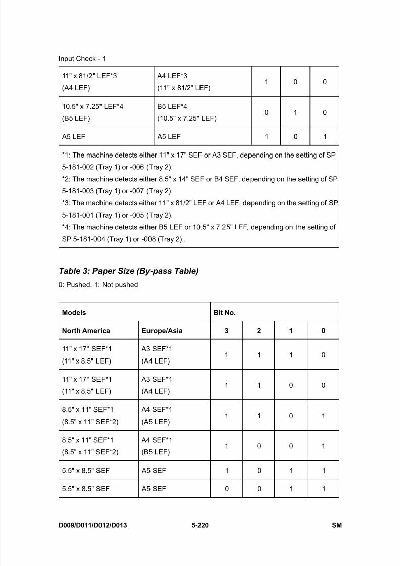
8/15/2019 Ricoh MP 4000 SM D009_D011_D012_D013 SERVICE MANUAL .pdf
http://slidepdf.com/reader/full/ricoh-mp-4000-sm-d009d011d012d013-service-manual-pdf 506/1162
Input Check - 1
D009/D011/D012/D013 5-220 SM
11" x 81/2" LEF*3
(A4 LEF)
A4 LEF*3
(11" x 81/2" LEF)1 0 0
10.5" x 7.25" LEF*4
(B5 LEF)
B5 LEF*4
(10.5" x 7.25" LEF)0 1 0
A5 LEF A5 LEF 1 0 1
*1: The machine detects either 11" x 17" SEF or A3 SEF, depending on the setting of SP
5-181-002 (Tray 1) or -006 (Tray 2).
*2: The machine detects either 8.5" x 14" SEF or B4 SEF, depending on the setting of SP
5-181-003 (Tray 1) or -007 (Tray 2).
*3: The machine detects either 11" x 81/2" LEF or A4 LEF, depending on the setting of SP
5-181-001 (Tray 1) or -005 (Tray 2).
*4: The machine detects either B5 LEF or 10.5" x 7.25" LEF, depending on the setting of
SP 5-181-004 (Tray 1) or -008 (Tray 2)..
Table 3: Paper Size (By-pass Table)
0: Pushed, 1: Not pushed
Models Bit No.
North America Europe/Asia 3 2 1 0
11" x 17" SEF*1
(11" x 8.5" LEF)
A3 SEF*1
(A4 LEF)1 1 1 0
11" x 17" SEF*1
(11" x 8.5" LEF)
A3 SEF*1
(A4 LEF)1 1 0 0
8.5" x 11" SEF*1
(8.5" x 11" SEF*2)
A4 SEF*1
(A5 LEF)1 1 0 1
8.5" x 11" SEF*1
(8.5" x 11" SEF*2)
A4 SEF*1
(B5 LEF)1 0 0 1
5.5" x 8.5" SEF A5 SEF 1 0 1 1
5.5" x 8.5" SEF A5 SEF 0 0 1 1

8/15/2019 Ricoh MP 4000 SM D009_D011_D012_D013 SERVICE MANUAL .pdf
http://slidepdf.com/reader/full/ricoh-mp-4000-sm-d009d011d012d013-service-manual-pdf 507/1162
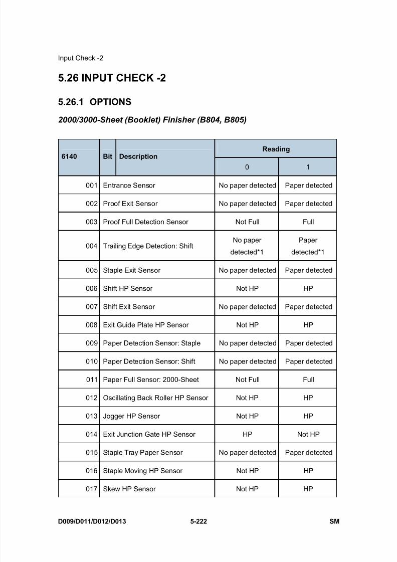
8/15/2019 Ricoh MP 4000 SM D009_D011_D012_D013 SERVICE MANUAL .pdf
http://slidepdf.com/reader/full/ricoh-mp-4000-sm-d009d011d012d013-service-manual-pdf 508/1162
Input Check -2
D009/D011/D012/D013 5-222 SM
5.26 INPUT CHECK -2
5.26.1 OPTIONS
2000/3000-Sheet (Booklet) Finisher (B804, B805)
Reading 6140 Bit Description
0 1
001 Entrance Sensor No paper detected Paper detected
002 Proof Exit Sensor No paper detected Paper detected
003 Proof Full Detection Sensor Not Full Full
004 Trailing Edge Detection: ShiftNo paper
detected*1
Paper
detected*1
005 Staple Exit Sensor No paper detected Paper detected
006 Shift HP Sensor Not HP HP
007 Shift Exit Sensor No paper detected Paper detected
008 Exit Guide Plate HP Sensor Not HP HP
009 Paper Detection Sensor: Staple No paper detected Paper detected
010 Paper Detection Sensor: Shift No paper detected Paper detected
011 Paper Full Sensor: 2000-Sheet Not Full Full
012 Oscillating Back Roller HP Sensor Not HP HP
013 Jogger HP Sensor Not HP HP
014 Exit Junction Gate HP Sensor HP Not HP
015 Staple Tray Paper Sensor No paper detected Paper detected
016 Staple Moving HP Sensor Not HP HP
017 Skew HP Sensor Not HP HP
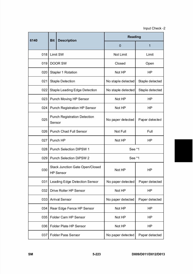
8/15/2019 Ricoh MP 4000 SM D009_D011_D012_D013 SERVICE MANUAL .pdf
http://slidepdf.com/reader/full/ricoh-mp-4000-sm-d009d011d012d013-service-manual-pdf 509/1162
Input Check -2
SM 5-223 D009/D011/D012/D013
S e r v i c e
T a b l e s
Reading 6140 Bit Description
0 1
018 Limit SW Not Limit Limit
019 DOOR SW Closed Open
020 Stapler 1 Rotation Not HP HP
021 Staple Detection No staple detected Staple detected
022 Staple Leading Edge Detection No staple detected Staple detected
023 Punch Moving HP Sensor Not HP HP
024 Punch Registration HP Sensor Not HP HP
025Punch Registration Detection
SensorNo paper detected Paper detected
026 Punch Chad Full Sensor Not Full Full
027 Punch HP Not HP HP
028 Punch Selection DIPSW 1 See *1
029 Punch Selection DiPSW 2 See *1
030Stack Junction Gate Open/Closed
HP SensorNot HP HP
031 Leading Edge Detection Sensor No paper detected Paper detected
032 Drive Roller HP Sensor Not HP HP
033 Arrival Sensor No paper detected Paper detected
034 Rear Edge Fence HP Sensor Not HP HP
035 Folder Cam HP Sensor Not HP HP
036 Folder Plate HP Sensor Not HP HP
037 Folder Pass Sensor No paper detected Paper detected
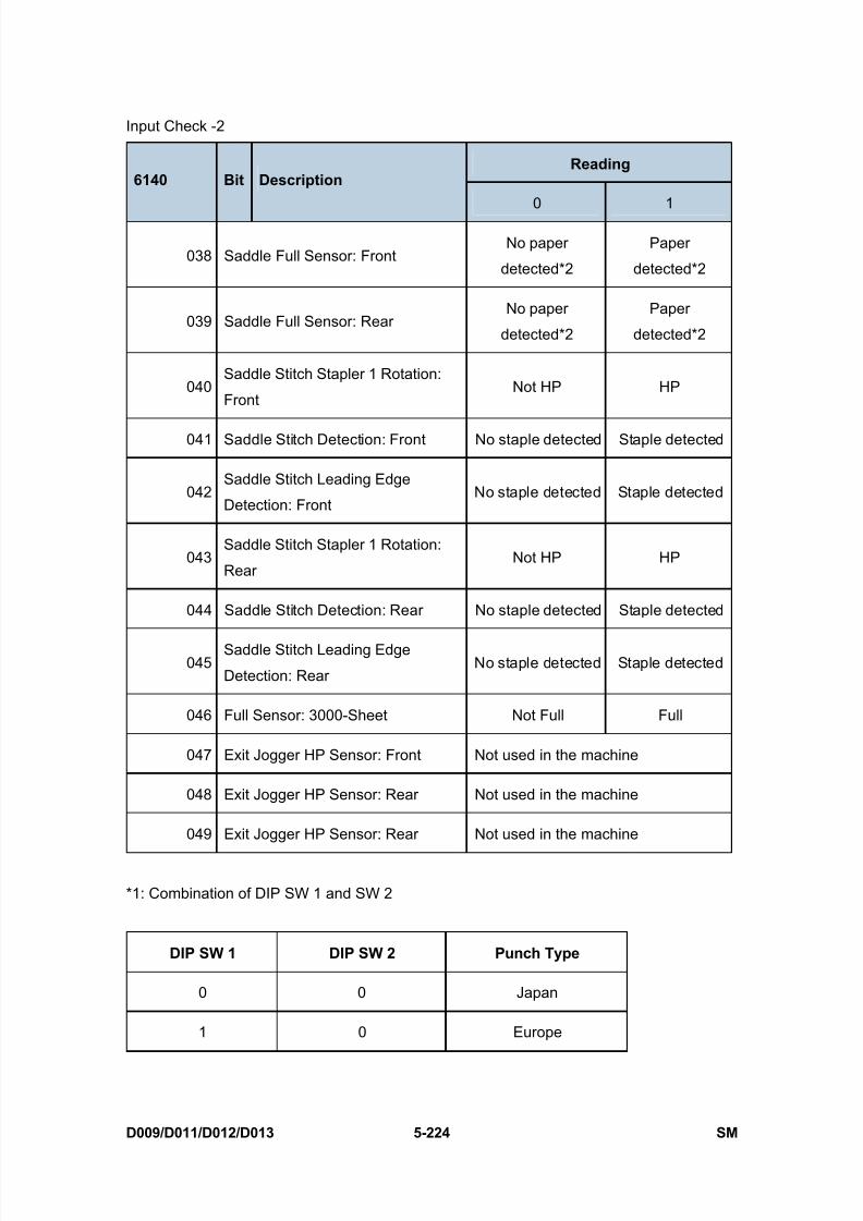
8/15/2019 Ricoh MP 4000 SM D009_D011_D012_D013 SERVICE MANUAL .pdf
http://slidepdf.com/reader/full/ricoh-mp-4000-sm-d009d011d012d013-service-manual-pdf 510/1162
Input Check -2
D009/D011/D012/D013 5-224 SM
Reading 6140 Bit Description
0 1
038 Saddle Full Sensor: FrontNo paper
detected*2
Paper
detected*2
039 Saddle Full Sensor: RearNo paper
detected*2
Paper
detected*2
040Saddle Stitch Stapler 1 Rotation:
FrontNot HP HP
041 Saddle Stitch Detection: Front No staple detected Staple detected
042Saddle Stitch Leading Edge
Detection: FrontNo staple detected Staple detected
043Saddle Stitch Stapler 1 Rotation:
RearNot HP HP
044 Saddle Stitch Detection: Rear No staple detected Staple detected
045Saddle Stitch Leading Edge
Detection: RearNo staple detected Staple detected
046 Full Sensor: 3000-Sheet Not Full Full
047 Exit Jogger HP Sensor: Front Not used in the machine
048 Exit Jogger HP Sensor: Rear Not used in the machine
049 Exit Jogger HP Sensor: Rear Not used in the machine
*1: Combination of DIP SW 1 and SW 2
DIP SW 1 DIP SW 2 Punch Type
0 0 Japan
1 0 Europe
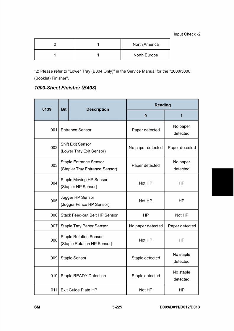
8/15/2019 Ricoh MP 4000 SM D009_D011_D012_D013 SERVICE MANUAL .pdf
http://slidepdf.com/reader/full/ricoh-mp-4000-sm-d009d011d012d013-service-manual-pdf 511/1162
Input Check -2
SM 5-225 D009/D011/D012/D013
S e r v i c e
T a b l e s
0 1 North America
1 1 North Europe
*2: Please refer to "Lower Tray (B804 Only)" in the Service Manual for the "2000/3000
(Booklet) Finisher".
1000-Sheet Finisher (B408)
Reading 6139 Bit Description
0 1
001 Entrance Sensor Paper detectedNo paper
detected
002Shift Exit Sensor
(Lower Tray Exit Sensor)No paper detected Paper detected
003Staple Entrance Sensor
(Stapler Tray Entrance Sensor)Paper detected
No paper
detected
004Staple Moving HP Sensor
(Stapler HP Sensor)Not HP HP
005Jogger HP Sensor
(Jogger Fence HP Sensor)Not HP HP
006 Stack Feed-out Belt HP Sensor HP Not HP
007 Staple Tray Paper Sensor No paper detected Paper detected
008Staple Rotation Sensor
(Staple Rotation HP Sensor)Not HP HP
009 Staple Sensor Staple detectedNo staple
detected
010 Staple READY Detection Staple detectedNo staple
detected
011 Exit Guide Plate HP Not HP HP

8/15/2019 Ricoh MP 4000 SM D009_D011_D012_D013 SERVICE MANUAL .pdf
http://slidepdf.com/reader/full/ricoh-mp-4000-sm-d009d011d012d013-service-manual-pdf 512/1162
Input Check -2
D009/D011/D012/D013 5-226 SM
Reading 6139 Bit Description
0 1
(Exit Guide Plate HP Sensor)
012 Shift HP Sensor Not HP HP
013Paper Sensor
(Stack Height Sensor)
No output tray
detected
Output tray
detected
014Tray Lower Sensor
(Lower Tray Lower Limit Sensor)Lower limit Not lower limit
015Proof Full Sensor
(Paper Limit Sensor)Not full Full
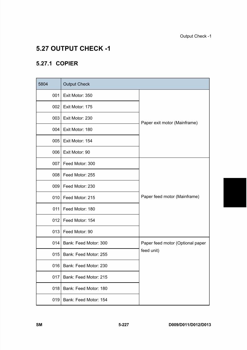
8/15/2019 Ricoh MP 4000 SM D009_D011_D012_D013 SERVICE MANUAL .pdf
http://slidepdf.com/reader/full/ricoh-mp-4000-sm-d009d011d012d013-service-manual-pdf 513/1162
Output Check -1
SM 5-227 D009/D011/D012/D013
S e r v i c e
T a b l e s
5.27 OUTPUT CHECK -1
5.27.1 COPIER
5804 Output Check
001 Exit Motor: 350
002 Exit Motor: 175
003 Exit Motor: 230
004 Exit Motor: 180
005 Exit Motor: 154
006 Exit Motor: 90
Paper exit motor (Mainframe)
007 Feed Motor: 300
008 Feed Motor: 255
009 Feed Motor: 230
010 Feed Motor: 215
011 Feed Motor: 180
012 Feed Motor: 154
013 Feed Motor: 90
Paper feed motor (Mainframe)
014 Bank: Feed Motor: 300
015 Bank: Feed Motor: 255
016 Bank: Feed Motor: 230
017 Bank: Feed Motor: 215
018 Bank: Feed Motor: 180
019 Bank: Feed Motor: 154
Paper feed motor (Optional paperfeed unit)

8/15/2019 Ricoh MP 4000 SM D009_D011_D012_D013 SERVICE MANUAL .pdf
http://slidepdf.com/reader/full/ricoh-mp-4000-sm-d009d011d012d013-service-manual-pdf 514/1162
Output Check -1
D009/D011/D012/D013 5-228 SM
5804 Output Check
020 Bank: Feed Motor: 90
021 LCT: Feed Motor: 300
022 LCT: Feed Motor: 255
023 LCT: Feed Motor: 230
024 LCT: Feed Motor: 215
025 LCT: Feed Motor: 180
026 LCT: Feed Motor: 154
027 LCT: Feed Motor: 90
Paper feed motor (Optional LCT)
028 Paper Feed Clutch 1
029 Paper Feed Clutch 2
Paper feed clutch 1/2 (Mainframe)
030 Bank: Paper Feed Clutch 3
031 Bank: Paper Feed Clutch 4
Paper feed clutch 3/4 (Optional
paper feed unit)
032 LCT: Paper Feed Clutch Paper feed clutch (Optional LCT)
033 Pick-up Solenoid 1
034 Pick-up Solenoid 2
Pick-up Solenoid 1/2 (Mainframe)
035 Bank: Pick-up Solenoid 3
036 Bank: Pick-up Solenoid 4
Pick-up Solenoid 3/4 (Optional
paper feed unit)
037 LCT: Pick-up Solenoid Pick-up Solenoid (LCT)
038 Tray Lift Motor 1: Up
039 Tray Lift Motor 1: Down
040 Tray Lift Motor 2: Up
041 Tray Lift Motor 2: Down
-

8/15/2019 Ricoh MP 4000 SM D009_D011_D012_D013 SERVICE MANUAL .pdf
http://slidepdf.com/reader/full/ricoh-mp-4000-sm-d009d011d012d013-service-manual-pdf 515/1162
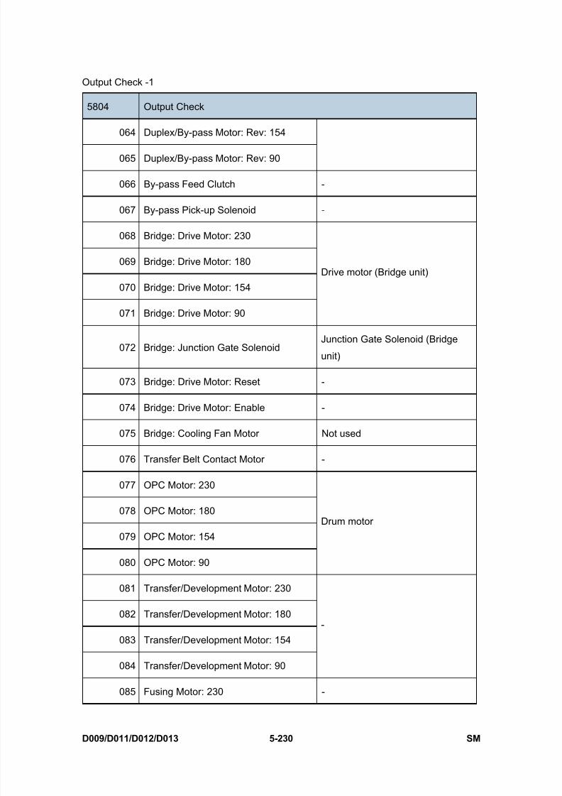
8/15/2019 Ricoh MP 4000 SM D009_D011_D012_D013 SERVICE MANUAL .pdf
http://slidepdf.com/reader/full/ricoh-mp-4000-sm-d009d011d012d013-service-manual-pdf 516/1162
Output Check -1
D009/D011/D012/D013 5-230 SM
5804 Output Check
064 Duplex/By-pass Motor: Rev: 154
065 Duplex/By-pass Motor: Rev: 90
066 By-pass Feed Clutch -
067 By-pass Pick-up Solenoid -
068 Bridge: Drive Motor: 230
069 Bridge: Drive Motor: 180
070 Bridge: Drive Motor: 154
071 Bridge: Drive Motor: 90
Drive motor (Bridge unit)
072 Bridge: Junction Gate SolenoidJunction Gate Solenoid (Bridge
unit)
073 Bridge: Drive Motor: Reset -
074 Bridge: Drive Motor: Enable -
075 Bridge: Cooling Fan Motor Not used
076 Transfer Belt Contact Motor -
077 OPC Motor: 230
078 OPC Motor: 180
079 OPC Motor: 154
080 OPC Motor: 90
Drum motor
081 Transfer/Development Motor: 230
082 Transfer/Development Motor: 180
083 Transfer/Development Motor: 154
084 Transfer/Development Motor: 90
-
085 Fusing Motor: 230 -
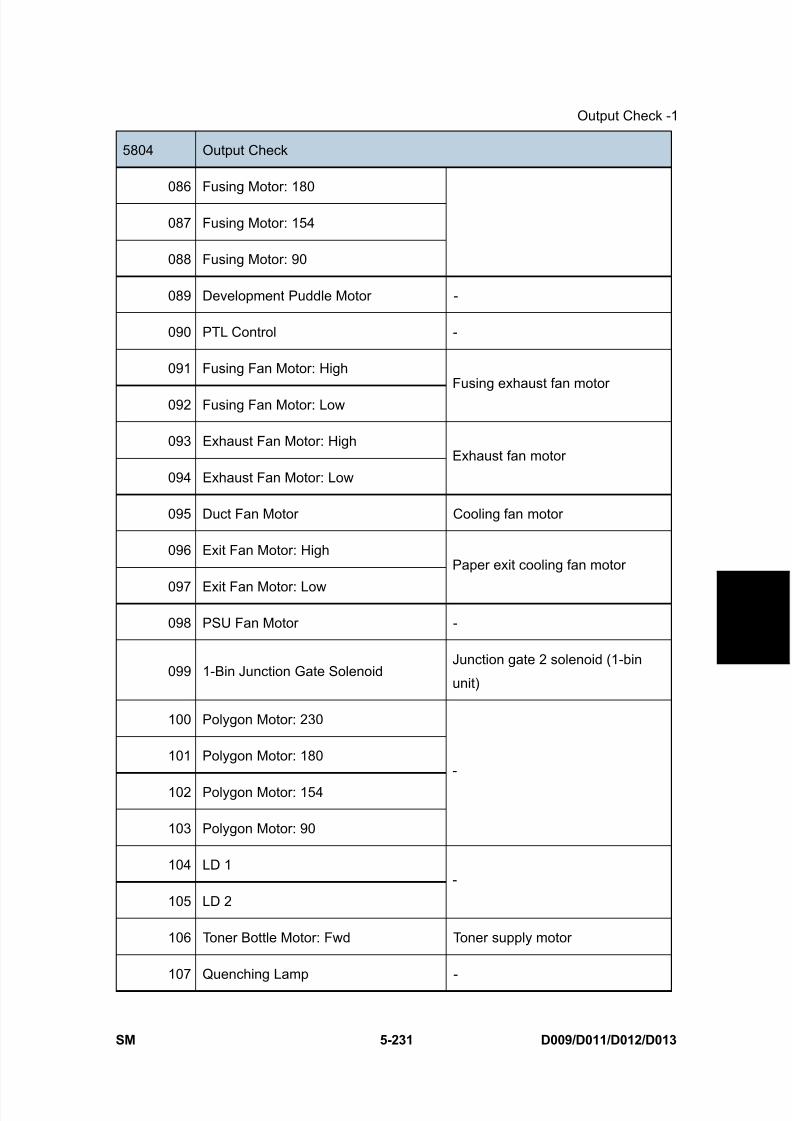
8/15/2019 Ricoh MP 4000 SM D009_D011_D012_D013 SERVICE MANUAL .pdf
http://slidepdf.com/reader/full/ricoh-mp-4000-sm-d009d011d012d013-service-manual-pdf 517/1162
Output Check -1
SM 5-231 D009/D011/D012/D013
S e r v i c e
T a b l e s
5804 Output Check
086 Fusing Motor: 180
087 Fusing Motor: 154
088 Fusing Motor: 90
089 Development Puddle Motor -
090 PTL Control -
091 Fusing Fan Motor: High
092 Fusing Fan Motor: Low
Fusing exhaust fan motor
093 Exhaust Fan Motor: High
094 Exhaust Fan Motor: Low
Exhaust fan motor
095 Duct Fan Motor Cooling fan motor
096 Exit Fan Motor: High
097 Exit Fan Motor: Low
Paper exit cooling fan motor
098 PSU Fan Motor -
099 1-Bin Junction Gate SolenoidJunction gate 2 solenoid (1-bin
unit)
100 Polygon Motor: 230
101 Polygon Motor: 180
102 Polygon Motor: 154
103 Polygon Motor: 90
-
104 LD 1
105 LD 2
-
106 Toner Bottle Motor: Fwd Toner supply motor
107 Quenching Lamp -
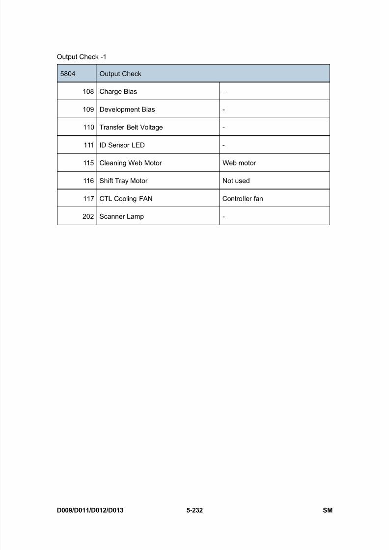
8/15/2019 Ricoh MP 4000 SM D009_D011_D012_D013 SERVICE MANUAL .pdf
http://slidepdf.com/reader/full/ricoh-mp-4000-sm-d009d011d012d013-service-manual-pdf 518/1162
Output Check -1
D009/D011/D012/D013 5-232 SM
5804 Output Check
108 Charge Bias -
109 Development Bias -
110 Transfer Belt Voltage -
111 ID Sensor LED -
115 Cleaning Web Motor Web motor
116 Shift Tray Motor Not used
117 CTL Cooling FAN Controller fan
202 Scanner Lamp -
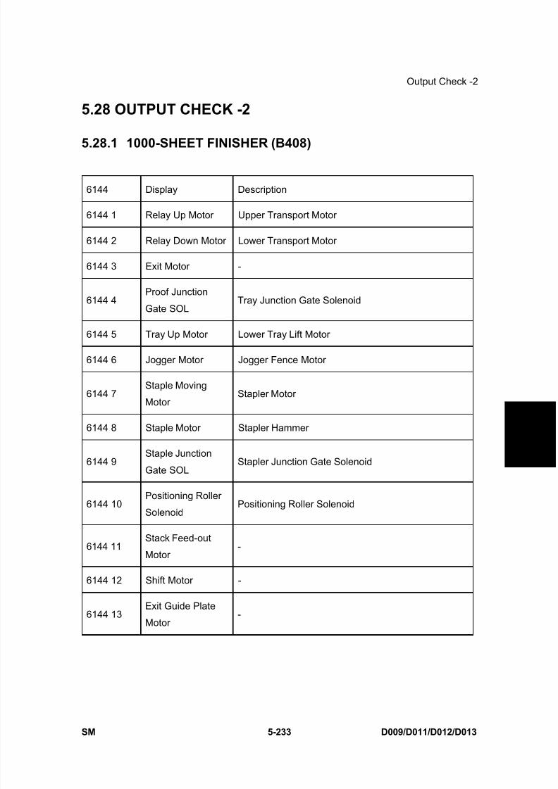
8/15/2019 Ricoh MP 4000 SM D009_D011_D012_D013 SERVICE MANUAL .pdf
http://slidepdf.com/reader/full/ricoh-mp-4000-sm-d009d011d012d013-service-manual-pdf 519/1162
Output Check -2
SM 5-233 D009/D011/D012/D013
S e r v i c e
T a b l e s
5.28 OUTPUT CHECK -2
5.28.1 1000-SHEET FINISHER (B408)
6144 Display Description
6144 1 Relay Up Motor Upper Transport Motor
6144 2 Relay Down Motor Lower Transport Motor
6144 3 Exit Motor -
6144 4Proof Junction
Gate SOLTray Junction Gate Solenoid
6144 5 Tray Up Motor Lower Tray Lift Motor
6144 6 Jogger Motor Jogger Fence Motor
6144 7Staple Moving
MotorStapler Motor
6144 8 Staple Motor Stapler Hammer
6144 9Staple Junction
Gate SOLStapler Junction Gate Solenoid
6144 10Positioning Roller
SolenoidPositioning Roller Solenoid
6144 11Stack Feed-out
Motor-
6144 12 Shift Motor -
6144 13Exit Guide Plate
Motor-
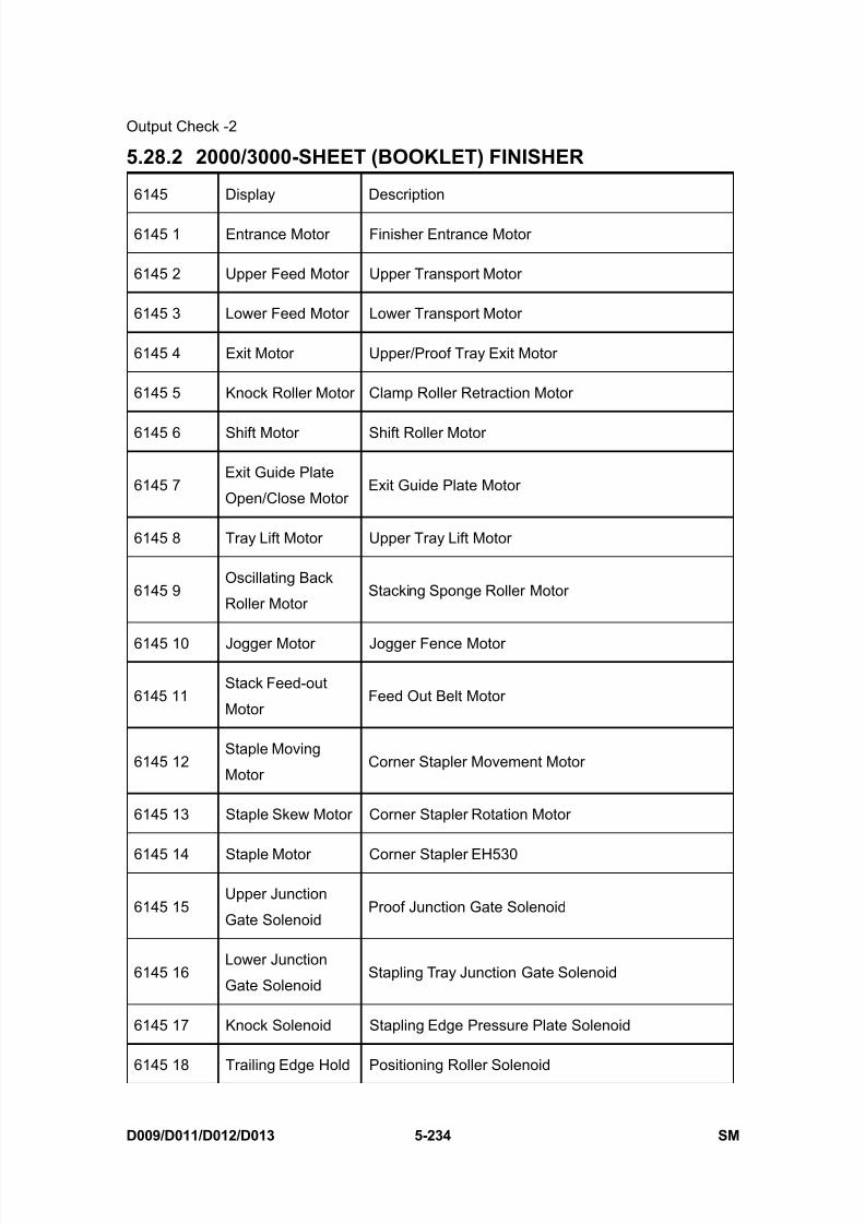
8/15/2019 Ricoh MP 4000 SM D009_D011_D012_D013 SERVICE MANUAL .pdf
http://slidepdf.com/reader/full/ricoh-mp-4000-sm-d009d011d012d013-service-manual-pdf 520/1162
Output Check -2
D009/D011/D012/D013 5-234 SM
5.28.2 2000/3000-SHEET (BOOKLET) FINISHER
6145 Display Description
6145 1 Entrance Motor Finisher Entrance Motor
6145 2 Upper Feed Motor Upper Transport Motor
6145 3 Lower Feed Motor Lower Transport Motor
6145 4 Exit Motor Upper/Proof Tray Exit Motor
6145 5 Knock Roller Motor Clamp Roller Retraction Motor
6145 6 Shift Motor Shift Roller Motor
6145 7Exit Guide Plate
Open/Close MotorExit Guide Plate Motor
6145 8 Tray Lift Motor Upper Tray Lift Motor
6145 9Oscillating Back
Roller MotorStacking Sponge Roller Motor
6145 10 Jogger Motor Jogger Fence Motor
6145 11Stack Feed-out
MotorFeed Out Belt Motor
6145 12Staple Moving
MotorCorner Stapler Movement Motor
6145 13 Staple Skew Motor Corner Stapler Rotation Motor
6145 14 Staple Motor Corner Stapler EH530
6145 15Upper Junction
Gate SolenoidProof Junction Gate Solenoid
6145 16Lower Junction
Gate SolenoidStapling Tray Junction Gate Solenoid
6145 17 Knock Solenoid Stapling Edge Pressure Plate Solenoid
6145 18 Trailing Edge Hold Positioning Roller Solenoid
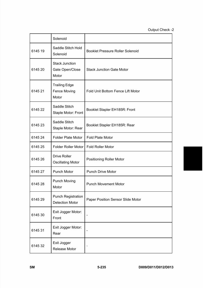
8/15/2019 Ricoh MP 4000 SM D009_D011_D012_D013 SERVICE MANUAL .pdf
http://slidepdf.com/reader/full/ricoh-mp-4000-sm-d009d011d012d013-service-manual-pdf 521/1162
Output Check -2
SM 5-235 D009/D011/D012/D013
S e r v i c e
T a b l e s
Solenoid
6145 19Saddle Stitch Hold
SolenoidBooklet Pressure Roller Solenoid
6145 20
Stack Junction
Gate Open/Close
Motor
Stack Junction Gate Motor
6145 21
Trailing Edge
Fence Moving
Motor
Fold Unit Bottom Fence Lift Motor
6145 22Saddle Stitch
Staple Motor: FrontBooklet Stapler EH185R: Front
6145 23Saddle Stitch
Staple Motor: RearBooklet Stapler EH185R: Rear
6145 24 Folder Plate Motor Fold Plate Motor
6145 25 Folder Roller Motor Fold Roller Motor
6145 26Drive Roller
Oscillating MotorPositioning Roller Motor
6145 27 Punch Motor Punch Drive Motor
6145 28Punch Moving
MotorPunch Movement Motor
6145 29Punch Registration
Detection MotorPaper Position Sensor Slide Motor
6145 30Exit Jogger Motor:
Front-
6145 31Exit Jogger Motor:
Rear-
6145 32Exit Jogger
Release Motor-
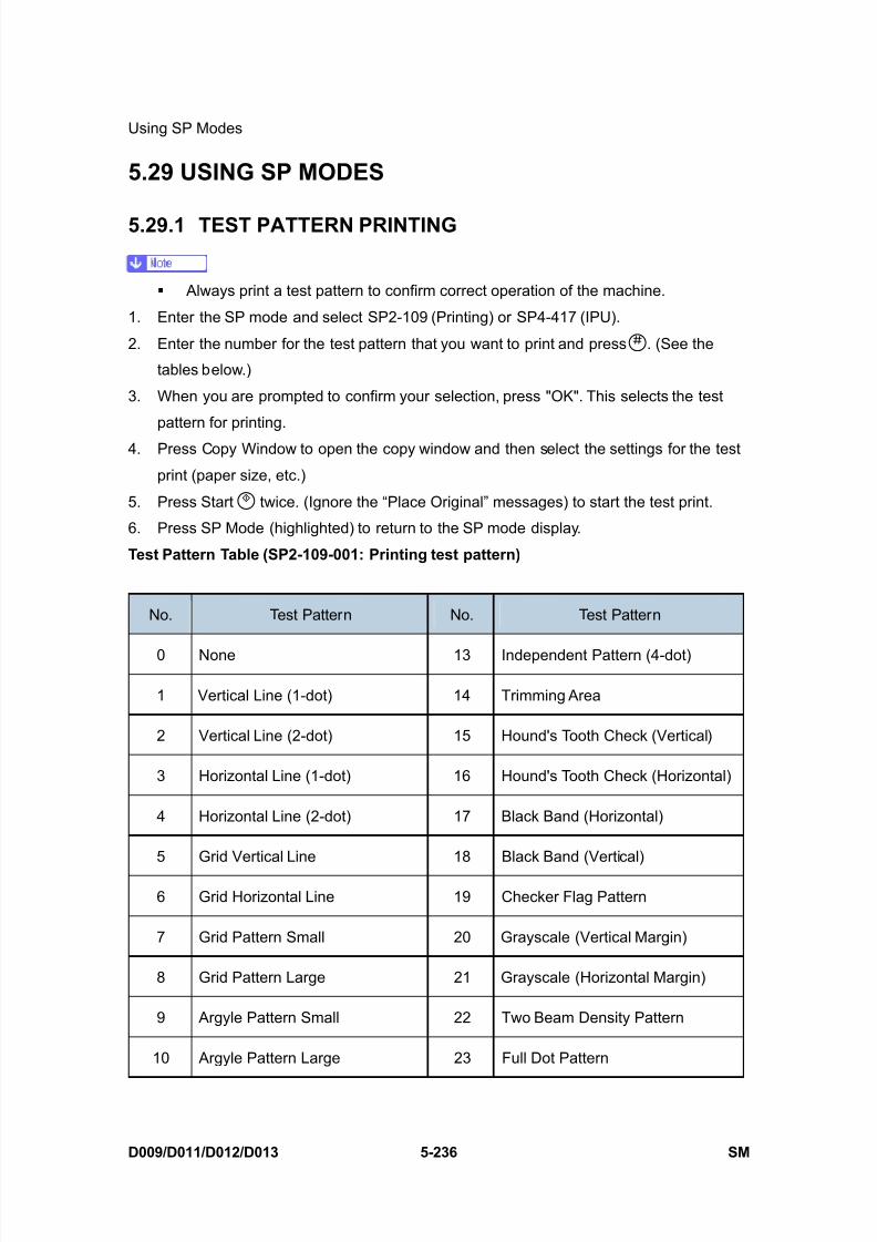
8/15/2019 Ricoh MP 4000 SM D009_D011_D012_D013 SERVICE MANUAL .pdf
http://slidepdf.com/reader/full/ricoh-mp-4000-sm-d009d011d012d013-service-manual-pdf 522/1162
Using SP Modes
D009/D011/D012/D013 5-236 SM
5.29 USING SP MODES
5.29.1 TEST PATTERN PRINTING
Always print a test pattern to confirm correct operation of the machine.
1. Enter the SP mode and select SP2-109 (Printing) or SP4-417 (IPU).
2. Enter the number for the test pattern that you want to print and press . (See the
tables below.)
3. When you are prompted to confirm your selection, press "OK". This selects the test
pattern for printing.
4. Press Copy Window to open the copy window and then select the settings for the test
print (paper size, etc.)
5. Press Start twice. (Ignore the “Place Original” messages) to start the test print.
6. Press SP Mode (highlighted) to return to the SP mode display.
Test Pattern Table (SP2-109-001: Printing test pattern)
No. Test Pattern No. Test Pattern
0 None 13 Independent Pattern (4-dot)
1 Vertical Line (1-dot) 14 Trimming Area
2 Vertical Line (2-dot) 15 Hound's Tooth Check (Vertical)
3 Horizontal Line (1-dot) 16 Hound's Tooth Check (Horizontal)
4 Horizontal Line (2-dot) 17 Black Band (Horizontal)
5 Grid Vertical Line 18 Black Band (Vertical)
6 Grid Horizontal Line 19 Checker Flag Pattern
7 Grid Pattern Small 20 Grayscale (Vertical Margin)
8 Grid Pattern Large 21 Grayscale (Horizontal Margin)
9 Argyle Pattern Small 22 Two Beam Density Pattern
10 Argyle Pattern Large 23 Full Dot Pattern

8/15/2019 Ricoh MP 4000 SM D009_D011_D012_D013 SERVICE MANUAL .pdf
http://slidepdf.com/reader/full/ricoh-mp-4000-sm-d009d011d012d013-service-manual-pdf 523/1162
Using SP Modes
SM 5-237 D009/D011/D012/D013
S e r v i c e
T a b l e s
No. Test Pattern No. Test Pattern
11 Independent Pattern (1-dot) 24 All White Pattern
12 Independent Pattern (2-dot)
Test Pattern Table: SP4-417-001 IPU Test Patterns
No. Test Pattern No. Test Pattern
0 Scanned image 13 Grid pattern CMYK
1 Gradation main scan A 14 Color patch CMYK
2 Gradation main scan B 15 Gray pattern (1)
3 Gradation main scan C 16 Gray pattern (2)
4 Gradation main scan D 17 Gray Pattern (3)
5 Gradation sub scan (1) 18 Shading pattern
6 Grid pattern 19 Thin line pattern
7 Slant grid pattern 20 Scanned + Grid pattern
8 Gradation RGBCMYK 21 Scanned + Gray scale
9 UCR pattern 22 Scanned + Color patch
10 Color patch 16 (1) 23 Scanned + Slant Grid C
11 Color patch 16 (2) 24 Scanned + Slant Grid D
12 Color patch 64
5.29.2 SMC PRINT OUT LISTS: SP5-990
1. Open SP mode 5-990 and select the number corresponding to the list that you wish to
print.
SMC (System Parameter and Data Lists)

8/15/2019 Ricoh MP 4000 SM D009_D011_D012_D013 SERVICE MANUAL .pdf
http://slidepdf.com/reader/full/ricoh-mp-4000-sm-d009d011d012d013-service-manual-pdf 524/1162
Using SP Modes
D009/D011/D012/D013 5-238 SM
1 All Data List
2 SP Mode Data List
3 UP Mode Data List
4 Logging Data List
5 Self-Diagnostics Results List
6 Non-Default
7 NIB Summary
8 NetFile Log
21 Copy UP Mode List
22 Scanner SP Mode List
23 Scanner UP Mode List
2. Press “Execute” on the touch panel.
3. Select “Single Face” or “Both Face”.
4. After printing the list, press “Close” to return to the SP mode display.
5. Press Exit twice to close the SP Mode screen and return to copy mode.
5.29.3 NIP BAND WIDTH ADJUSTMENT: SP1-109
When paper wrinkling or image offset occurs, the pressure from the pressure roller can be
adjusted by changing the position of the pressure springs. At this time, the nip bandwidth
can also be checked with SP1-109.
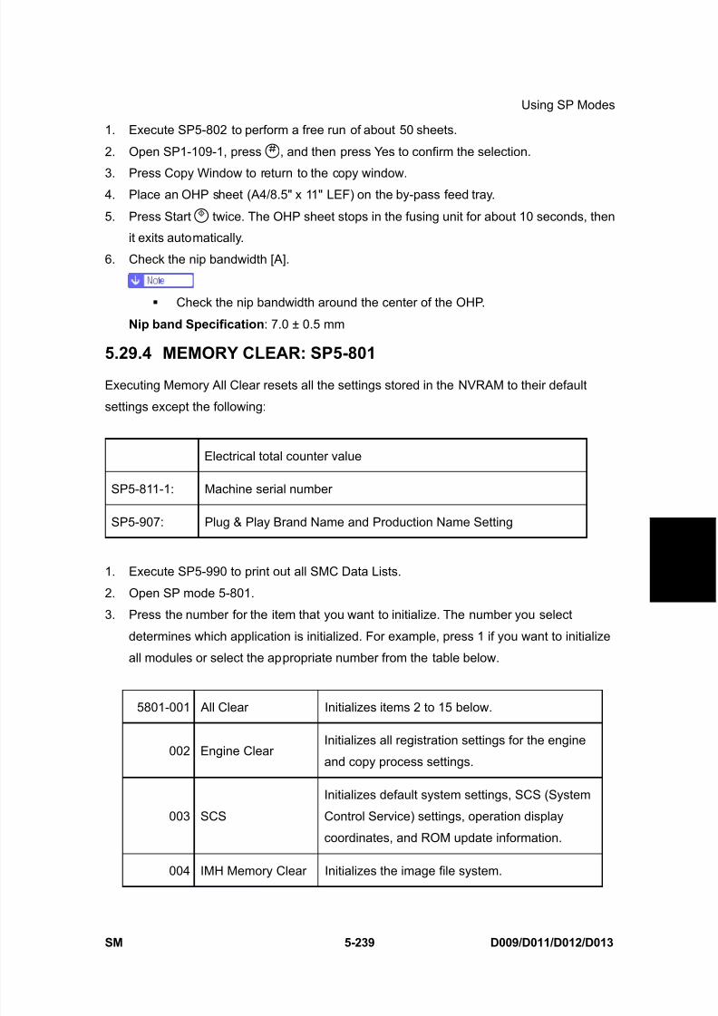
8/15/2019 Ricoh MP 4000 SM D009_D011_D012_D013 SERVICE MANUAL .pdf
http://slidepdf.com/reader/full/ricoh-mp-4000-sm-d009d011d012d013-service-manual-pdf 525/1162
Using SP Modes
SM 5-239 D009/D011/D012/D013
S e r v i c e
T a b l e s
1. Execute SP5-802 to perform a free run of about 50 sheets.
2. Open SP1-109-1, press , and then press Yes to confirm the selection.
3. Press Copy Window to return to the copy window.4. Place an OHP sheet (A4/8.5" x 11" LEF) on the by-pass feed tray.
5. Press Start twice. The OHP sheet stops in the fusing unit for about 10 seconds, then
it exits automatically.
6. Check the nip bandwidth [A].
Check the nip bandwidth around the center of the OHP.
Nip band Specification : 7.0 ± 0.5 mm
5.29.4 MEMORY CLEAR: SP5-801Executing Memory All Clear resets all the settings stored in the NVRAM to their default
settings except the following:
Electrical total counter value
SP5-811-1: Machine serial number
SP5-907: Plug & Play Brand Name and Production Name Setting
1. Execute SP5-990 to print out all SMC Data Lists.
2. Open SP mode 5-801.
3. Press the number for the item that you want to initialize. The number you select
determines which application is initialized. For example, press 1 if you want to initialize
all modules or select the appropriate number from the table below.
5801-001 All Clear Initializes items 2 to 15 below.
002 Engine ClearInitializes all registration settings for the engine
and copy process settings.
003 SCS
Initializes default system settings, SCS (System
Control Service) settings, operation display
coordinates, and ROM update information.
004 IMH Memory Clear Initializes the image file system.
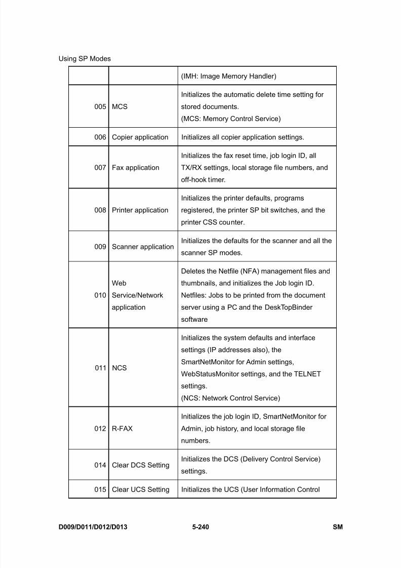
8/15/2019 Ricoh MP 4000 SM D009_D011_D012_D013 SERVICE MANUAL .pdf
http://slidepdf.com/reader/full/ricoh-mp-4000-sm-d009d011d012d013-service-manual-pdf 526/1162
Using SP Modes
D009/D011/D012/D013 5-240 SM
(IMH: Image Memory Handler)
005 MCS
Initializes the automatic delete time setting for
stored documents.
(MCS: Memory Control Service)
006 Copier application Initializes all copier application settings.
007 Fax application
Initializes the fax reset time, job login ID, all
TX/RX settings, local storage file numbers, and
off-hook timer.
008 Printer applicationInitializes the printer defaults, programsregistered, the printer SP bit switches, and the
printer CSS counter.
009 Scanner applicationInitializes the defaults for the scanner and all the
scanner SP modes.
010
Web
Service/Networkapplication
Deletes the Netfile (NFA) management files and
thumbnails, and initializes the Job login ID.
Netfiles: Jobs to be printed from the documentserver using a PC and the DeskTopBinder
software
011 NCS
Initializes the system defaults and interface
settings (IP addresses also), the
SmartNetMonitor for Admin settings,
WebStatusMonitor settings, and the TELNET
settings.
(NCS: Network Control Service)
012 R-FAX
Initializes the job login ID, SmartNetMonitor for
Admin, job history, and local storage file
numbers.
014 Clear DCS SettingInitializes the DCS (Delivery Control Service)
settings.
015 Clear UCS Setting Initializes the UCS (User Information Control
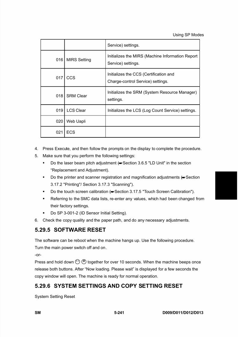
8/15/2019 Ricoh MP 4000 SM D009_D011_D012_D013 SERVICE MANUAL .pdf
http://slidepdf.com/reader/full/ricoh-mp-4000-sm-d009d011d012d013-service-manual-pdf 527/1162
Using SP Modes
SM 5-241 D009/D011/D012/D013
S e r v i c e
T a b l e s
Service) settings.
016 MIRS SettingInitializes the MIRS (Machine Information Report
Service) settings.
017 CCSInitializes the CCS (Certification and
Charge-control Service) settings.
018 SRM ClearInitializes the SRM (System Resource Manager)
settings.
019 LCS Clear Initializes the LCS (Log Count Service) settings.
020 Web Uapli
021 ECS
4. Press Execute, and then follow the prompts on the display to complete the procedure.
5. Make sure that you perform the following settings:
Do the laser beam pitch adjustment ( Section 3.6.5 "LD Unit" in the section
“Replacement and Adjustment).
Do the printer and scanner registration and magnification adjustments ( Section3.17.2 "Printing"/ Section 3.17.3 "Scanning").
Do the touch screen calibration ( Section 3.17.5 "Touch Screen Calibration").
Referring to the SMC data lists, re-enter any values, which had been changed from
their factory settings.
Do SP 3-001-2 (ID Sensor Initial Setting).
6. Check the copy quality and the paper path, and do any necessary adjustments.
5.29.5 SOFTWARE RESET
The software can be reboot when the machine hangs up. Use the following procedure.
Turn the main power switch off and on.
-or-
Press and hold down together for over 10 seconds. When the machine beeps once
release both buttons. After “Now loading. Please wait” is displayed for a few seconds the
copy window will open. The machine is ready for normal operation.
5.29.6 SYSTEM SETTINGS AND COPY SETTING RESET
System Setting Reset
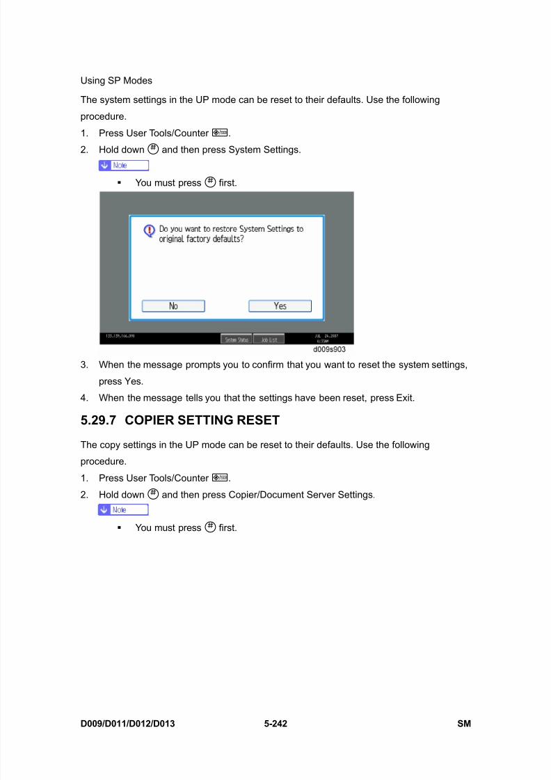
8/15/2019 Ricoh MP 4000 SM D009_D011_D012_D013 SERVICE MANUAL .pdf
http://slidepdf.com/reader/full/ricoh-mp-4000-sm-d009d011d012d013-service-manual-pdf 528/1162
Using SP Modes
D009/D011/D012/D013 5-242 SM
The system settings in the UP mode can be reset to their defaults. Use the following
procedure.
1. Press User Tools/Counter .2. Hold down and then press System Settings.
You must press first.
3. When the message prompts you to confirm that you want to reset the system settings,
press Yes.
4. When the message tells you that the settings have been reset, press Exit.
5.29.7 COPIER SETTING RESET
The copy settings in the UP mode can be reset to their defaults. Use the following
procedure.
1. Press User Tools/Counter .
2. Hold down and then press Copier/Document Server Settings.
You must press first.

8/15/2019 Ricoh MP 4000 SM D009_D011_D012_D013 SERVICE MANUAL .pdf
http://slidepdf.com/reader/full/ricoh-mp-4000-sm-d009d011d012d013-service-manual-pdf 529/1162
Using SP Modes
SM 5-243 D009/D011/D012/D013
S e r v i c e
T a b l e s
3. When the message prompts you to confirm that you want to reset the Copier Document
Server settings, press "Yes".
4. When the message tells you that the settings have been reset, press "Exit".
8/15/2019 Ricoh MP 4000 SM D009_D011_D012_D013 SERVICE MANUAL .pdf
http://slidepdf.com/reader/full/ricoh-mp-4000-sm-d009d011d012d013-service-manual-pdf 530/1162
Updating the Firmware
D009/D011/D012/D013 5-244 SM
5.30 UPDATING THE FIRMWARE
To update the firmware for this machine, you must have the new version of the firmware
downloaded onto an SD (Secure Digital) Card. The SD Card is inserted into SD Card Slot 2
on the controller box.
5.30.1 BEFORE YOU BEGIN
An SD card is a precision device. Always observe the following precautions when you
handle SD cards:
Always switch the machine off before you insert an SD card. Never insert the SD card
into the slot with the power on. Do not remove the SD card from the service slot after the power has been switched on.
Never switch the machine off while the firmware is downloading from the SD card.
Keep SD cards in a safe location where they are not exposed to high temperature, high
humidity, or exposure to direct sunlight.
Always handle SD cards with care. Do not bend or scratch them. Do not let the SD card
get exposed to shock or vibration.
Make sure that the write protection of an SD card is unlocked when you download an
application to it. If not, downloading fails and a download error (e.g. Error Code 44)
occurs during a firmware upgrade.
Keep the following points in mind when you use the firmware update software:
“Upload” means to send data from the machine to the SD card. “Download” means to
send data from the SD card to the machine.
To select an item on the LCD, touch the appropriate button on the soft touch-screen of
the LCD, or, press the appropriate number key on the 10-key pad of the operation panel.
For example, when “Exit (0)” shows on the screen you can touch the Exit button on the
screen, or, press the button on the operation panel of the copier.
Make sure that the machine is disconnected from the network to prevent a print job for
arriving while the firmware update is in progress before you start the firmware update
procedure.
5.30.2 UPDATING FIRMWARE
Preparation
1. If the SD card is blank, copy the entire “romdata” folder onto the SD card.
2. If the card already contains the “romdata” folder, copy the “D009” folder onto the card.
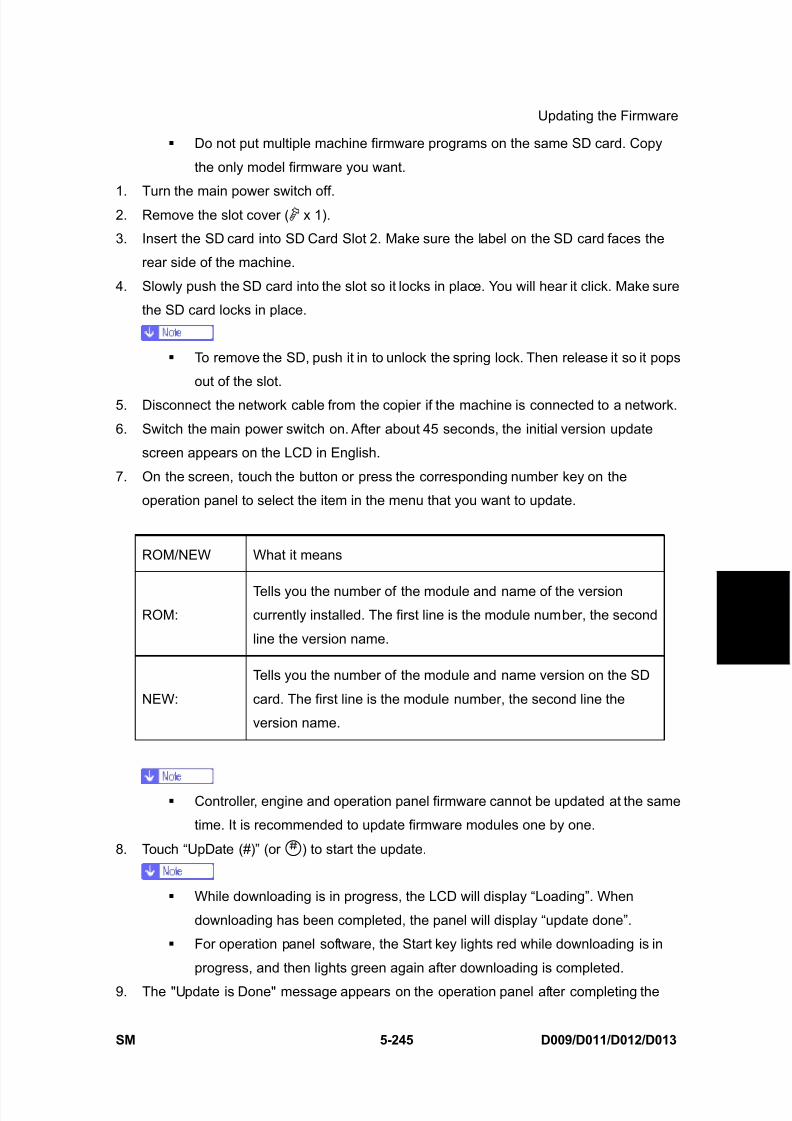
8/15/2019 Ricoh MP 4000 SM D009_D011_D012_D013 SERVICE MANUAL .pdf
http://slidepdf.com/reader/full/ricoh-mp-4000-sm-d009d011d012d013-service-manual-pdf 531/1162
Updating the Firmware
SM 5-245 D009/D011/D012/D013
S e r v i c e
T a b l e s
Do not put multiple machine firmware programs on the same SD card. Copy
the only model firmware you want.
1. Turn the main power switch off.2. Remove the slot cover ( x 1).
3. Insert the SD card into SD Card Slot 2. Make sure the label on the SD card faces the
rear side of the machine.
4. Slowly push the SD card into the slot so it locks in place. You will hear it click. Make sure
the SD card locks in place.
To remove the SD, push it in to unlock the spring lock. Then release it so it pops
out of the slot.
5. Disconnect the network cable from the copier if the machine is connected to a network.
6. Switch the main power switch on. After about 45 seconds, the initial version update
screen appears on the LCD in English.
7. On the screen, touch the button or press the corresponding number key on the
operation panel to select the item in the menu that you want to update.
ROM/NEW What it means
ROM:Tells you the number of the module and name of the versioncurrently installed. The first line is the module number, the second
line the version name.
NEW:
Tells you the number of the module and name version on the SD
card. The first line is the module number, the second line the
version name.
Controller, engine and operation panel firmware cannot be updated at the same
time. It is recommended to update firmware modules one by one.
8. Touch “UpDate (#)” (or ) to start the update.
While downloading is in progress, the LCD will display “Loading”. When
downloading has been completed, the panel will display “update done”.
For operation panel software, the Start key lights red while downloading is in
progress, and then lights green again after downloading is completed.
9. The "Update is Done" message appears on the operation panel after completing the
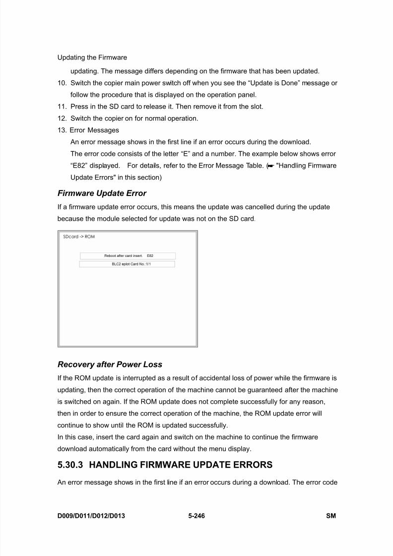
8/15/2019 Ricoh MP 4000 SM D009_D011_D012_D013 SERVICE MANUAL .pdf
http://slidepdf.com/reader/full/ricoh-mp-4000-sm-d009d011d012d013-service-manual-pdf 532/1162
Updating the Firmware
D009/D011/D012/D013 5-246 SM
updating. The message differs depending on the firmware that has been updated.
10. Switch the copier main power switch off when you see the “Update is Done” message or
follow the procedure that is displayed on the operation panel.11. Press in the SD card to release it. Then remove it from the slot.
12. Switch the copier on for normal operation.
13. Error Messages
An error message shows in the first line if an error occurs during the download.
The error code consists of the letter “E” and a number. The example below shows error
“E82” displayed. For details, refer to the Error Message Table. ( "Handling Firmware
Update Errors" in this section)
Firmware Update ErrorIf a firmware update error occurs, this means the update was cancelled during the update
because the module selected for update was not on the SD card.
Recovery after Power Loss
If the ROM update is interrupted as a result of accidental loss of power while the firmware is
updating, then the correct operation of the machine cannot be guaranteed after the machineis switched on again. If the ROM update does not complete successfully for any reason,
then in order to ensure the correct operation of the machine, the ROM update error will
continue to show until the ROM is updated successfully.
In this case, insert the card again and switch on the machine to continue the firmware
download automatically from the card without the menu display.
5.30.3 HANDLING FIRMWARE UPDATE ERRORS
An error message shows in the first line if an error occurs during a download. The error code
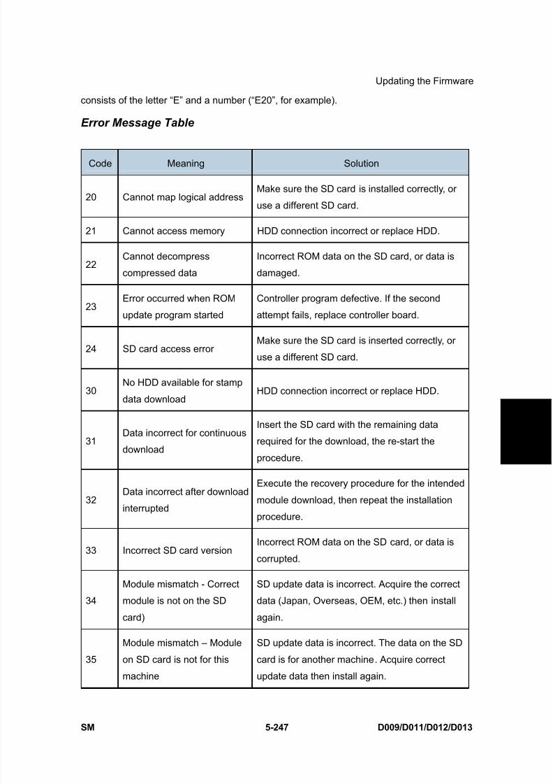
8/15/2019 Ricoh MP 4000 SM D009_D011_D012_D013 SERVICE MANUAL .pdf
http://slidepdf.com/reader/full/ricoh-mp-4000-sm-d009d011d012d013-service-manual-pdf 533/1162
Updating the Firmware
SM 5-247 D009/D011/D012/D013
S e r v i c e
T a b l e s
consists of the letter “E” and a number (“E20”, for example).
Error Message Table
Code Meaning Solution
20 Cannot map logical addressMake sure the SD card is installed correctly, or
use a different SD card.
21 Cannot access memory HDD connection incorrect or replace HDD.
22Cannot decompress
compressed data
Incorrect ROM data on the SD card, or data is
damaged.
23Error occurred when ROM
update program started
Controller program defective. If the second
attempt fails, replace controller board.
24 SD card access errorMake sure the SD card is inserted correctly, or
use a different SD card.
30No HDD available for stamp
data downloadHDD connection incorrect or replace HDD.
31Data incorrect for continuous
download
Insert the SD card with the remaining data
required for the download, the re-start the
procedure.
32Data incorrect after download
interrupted
Execute the recovery procedure for the intended
module download, then repeat the installation
procedure.
33 Incorrect SD card versionIncorrect ROM data on the SD card, or data is
corrupted.
34
Module mismatch - Correct
module is not on the SD
card)
SD update data is incorrect. Acquire the correct
data (Japan, Overseas, OEM, etc.) then install
again.
35
Module mismatch – Module
on SD card is not for this
machine
SD update data is incorrect. The data on the SD
card is for another machine. Acquire correct
update data then install again.

8/15/2019 Ricoh MP 4000 SM D009_D011_D012_D013 SERVICE MANUAL .pdf
http://slidepdf.com/reader/full/ricoh-mp-4000-sm-d009d011d012d013-service-manual-pdf 534/1162
Updating the Firmware
D009/D011/D012/D013 5-248 SM
Code Meaning Solution
36Cannot write module –Cause other than E34, E35
SD update data is incorrect. The data on the SD
card is for another machine. Acquire correct
update data then install again.
40Engine module download
failed
Replace the update data for the module on the
SD card and try again, or replace the BCU
board.
42Operation panel module
download failed
Replace the update data for the module on the
SD card and try again, or replace the LCDC.
43Stamp data module
download failed
Replace the update data for the module on the
SD card and try again, or replace the hard disks.
44Controller module download
failed
Replace the update data for the module on the
SD card and tray again, or replace controller
board.
50
Electronic confirmation check
failed
SD update data is incorrect. The data on the SD
card is for another machine. Acquire correctupdate data then install again.

8/15/2019 Ricoh MP 4000 SM D009_D011_D012_D013 SERVICE MANUAL .pdf
http://slidepdf.com/reader/full/ricoh-mp-4000-sm-d009d011d012d013-service-manual-pdf 535/1162
NVRAM Data Upload/Download
SM 5-249 D009/D011/D012/D013
S e r v i c e
T a b l e s
5.31 NVRAM DATA UPLOAD/DOWNLOAD
The content of the NVRAM can be uploaded to and downloaded from an SD card.
5.31.1 UPLOADING NVRAM DATA (SP5-824)
1. Turn off the main switch.
2. Remove the SD card cover ( x 1).
3. Insert the SD card into SD card slot 2.
4. Turn on the main switch.
5. Execute SP5-824.
6. Press to start uploading the NVRAM data.
5.31.2 DOWNLOADING NVRAM DATA (SP5-825)
The following data are not downloaded from the SD card:
Total counter
C/O, P/O Counter
Dupelx, A3/DLT/Over 420 mm, Staple and Scanner application scanning counters
(system settings).
1. Turn off the main switch.
2. Remove the SD card cover [A].
3. Plug the SD card [B] into SD card slot 2.
4. Turn on the main switch.
5. Execute SP5-825.
6. Press to start downloading the NVRAM data.
Note that the following errors could occur during downloading:
If a card is not installed in the card slot and a message tells you that downloading
cannot proceed, you cannot execute downloading, even by pressing .
If the correct card for the NVRAM data is not inserted in the card slot, after you press
a message will tell you that downloading cannot proceed because the card is abnormal
and the execution will halt.
8/15/2019 Ricoh MP 4000 SM D009_D011_D012_D013 SERVICE MANUAL .pdf
http://slidepdf.com/reader/full/ricoh-mp-4000-sm-d009d011d012d013-service-manual-pdf 536/1162
SD Card Appli Move
D009/D011/D012/D013 5-250 SM
5.32 SD CARD APPLI MOVE
5.32.1 OVERVIEW
The service program “SD Card Appli Move” (SP5-873) lets you to copy application programs
from one SD card to another SD card.
Slot 1 and Slot 2 are used to store application programs. However you can move application
programs from Slot 2 to Slot 1 with the following procedure.
If PostScript3 is not to be installed, the printer/scanner card in slot 1 has enough space for
the other applications. Use the printer/scanner card as a destination card.
But if PostScript3 is to be installed, use the PostScript3 card as a destination card because
moving the data from the PostScript3 card is not licensed from the maker of this software.
Use caution when you do the SD Card Appli Move procedure:
1. The data necessary for authentication is transferred with the application program from
an SD card to another SD card. Authentication fails if you try to use the SD card after
you copy the application program from one card to another card.
2. Do not use the SD card if it has been used by the user on the computer. Normal
operation is not guaranteed when such an SD card is used.
3. Return the SD card to a customer for safekeeping place after you copy the applicationprogram from one card to another card. This is done for the following reasons:
The SD card can be the only proof that the user is licensed to use the application
program.
You may need to check the SD card and its data to solve a problem in the future.
4. You cannot copy PostScript data to another SD card. You have to copy other data to the
same SD card that stores PostScript data.
5.32.2 MOVE EXEC
The menu “Move Exec” (SP5-873-001) lets you copy application programs from the original
SD card to another SD card.
Do not turn ON the write protect switch of the system SD card or application SD
card on the machine. If the write protect switch is ON, a download error (e.g. Error
Code 44) occurs during a firmware upgrade or application merge.
1. Turn the main switch off.
2. Make sure that an SD card is in SD Card Slot 1. The application program is copied into
this SD card.

8/15/2019 Ricoh MP 4000 SM D009_D011_D012_D013 SERVICE MANUAL .pdf
http://slidepdf.com/reader/full/ricoh-mp-4000-sm-d009d011d012d013-service-manual-pdf 537/1162
SD Card Appli Move
SM 5-251 D009/D011/D012/D013
S e r v i c e
T a b l e s
3. Insert the SD card (having stored the application program) to SD Card Slot 2. The
application program is copied from this SD card.
4. Turn the main switch on.5. Start the SP mode.
6. Select SP5-873-001 “Move Exec.”
7. Follow the messages shown on the operation panel.
8. Turn the main switch off.
9. Remove the SD card from SD Card Slot 2.
10. Turn the main switch on.
11. Check that the application programs run normally.
5.32.3 UNDO EXECThe menu “Undo Exec” (SP5-873-002) lets you copy back application programs from an SD
card to the original SD card. You can use this program when, for example, you have
mistakenly copied some programs by using Move Exec (SP5-873-001).
Do not turn ON the write protect switch of the system SD card or application SD
card on the machine. If the write protect switch is ON, a download error (e.g. Error
Code 44) occurs during a firmware upgrade or application merge.
1. Turn the main switch off.2. Insert the original SD card in SD Card Slot 2. The application program is copied back
into this card.
3. Insert the SD card (having stored the application program) to SD Card Slot 1. The
application program is copied back from this SD card.
4. Turn the main switch on.
5. Start the SP mode.
6. Select SP5-873-002 “Undo Exec.”
7. Follow the messages shown on the operation panel.8. Turn the main switch off.
9. Remove the SD card from SD Card Slot 2.
This step assumes that the application programs in the SD card are used by
the machine.
10. Turn the main switch on.
11. Check that the application programs run normally.

8/15/2019 Ricoh MP 4000 SM D009_D011_D012_D013 SERVICE MANUAL .pdf
http://slidepdf.com/reader/full/ricoh-mp-4000-sm-d009d011d012d013-service-manual-pdf 538/1162
Self-Diagnostic Mode
D009/D011/D012/D013 5-252 SM
5.33 SELF-DIAGNOSTIC MODE
5.33.1 SELF-DIAGNOSTIC MODE AT POWER ON
As soon as the main machine is powered on, the controller waits for the initial settings of the
copy engine to take effect and then starts an independent self-diagnostic test program. The
self-diagnostic test follows the path of the flow chart shown below and checks the CPU,
memory, HDD, and so on. An SC code is displayed in the touch panel if the self-diagnostic
program detects any malfunction or abnormal condition.
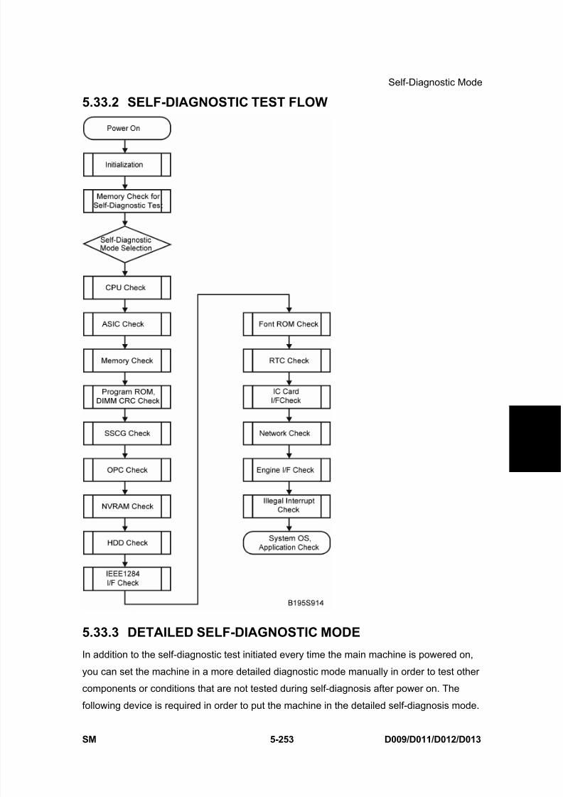
8/15/2019 Ricoh MP 4000 SM D009_D011_D012_D013 SERVICE MANUAL .pdf
http://slidepdf.com/reader/full/ricoh-mp-4000-sm-d009d011d012d013-service-manual-pdf 539/1162
Self-Diagnostic Mode
SM 5-253 D009/D011/D012/D013
S e r v i c e
T a b l e s
5.33.2 SELF-DIAGNOSTIC TEST FLOW
5.33.3 DETAILED SELF-DIAGNOSTIC MODE
In addition to the self-diagnostic test initiated every time the main machine is powered on,
you can set the machine in a more detailed diagnostic mode manually in order to test other
components or conditions that are not tested during self-diagnosis after power on. The
following device is required in order to put the machine in the detailed self-diagnosis mode.
8/15/2019 Ricoh MP 4000 SM D009_D011_D012_D013 SERVICE MANUAL .pdf
http://slidepdf.com/reader/full/ricoh-mp-4000-sm-d009d011d012d013-service-manual-pdf 540/1162
Self-Diagnostic Mode
D009/D011/D012/D013 5-254 SM
No. Name
G02119350 Parallel Loopback Connector
5.33.4 EXECUTING DETAILED SELF-DIAGNOSIS
Follow this procedure to execute detailed self-diagnosis.
1. Switch off the machine, and connect the parallel loopback device to the Centronics I/F
port.
2. Hold down , press and hold down , and then while pressing both keys at the same
time, switch on the machine.
You will see “Now Loading” on the touch-panel, and then you will see the results of the
test.
A report is printed every time a detailed self-diagnostic test is executed, whether errors
were detected or not.
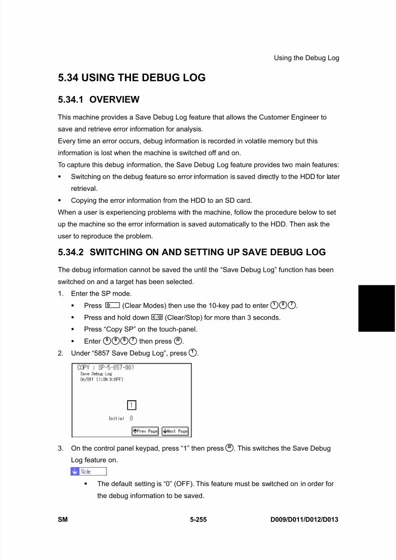
8/15/2019 Ricoh MP 4000 SM D009_D011_D012_D013 SERVICE MANUAL .pdf
http://slidepdf.com/reader/full/ricoh-mp-4000-sm-d009d011d012d013-service-manual-pdf 541/1162
Using the Debug Log
SM 5-255 D009/D011/D012/D013
S e r v i c e
T a b l e s
5.34 USING THE DEBUG LOG
5.34.1 OVERVIEW
This machine provides a Save Debug Log feature that allows the Customer Engineer to
save and retrieve error information for analysis.
Every time an error occurs, debug information is recorded in volatile memory but this
information is lost when the machine is switched off and on.
To capture this debug information, the Save Debug Log feature provides two main features:
Switching on the debug feature so error information is saved directly to the HDD for later
retrieval.
Copying the error information from the HDD to an SD card.
When a user is experiencing problems with the machine, follow the procedure below to set
up the machine so the error information is saved automatically to the HDD. Then ask the
user to reproduce the problem.
5.34.2 SWITCHING ON AND SETTING UP SAVE DEBUG LOG
The debug information cannot be saved the until the “Save Debug Log” function has been
switched on and a target has been selected.
1. Enter the SP mode. Press (Clear Modes) then use the 10-key pad to enter .
Press and hold down (Clear/Stop) for more than 3 seconds.
Press “Copy SP” on the touch-panel.
Enter then press .
2. Under “5857 Save Debug Log”, press .
3. On the control panel keypad, press “1” then press . This switches the Save Debug
Log feature on.
The default setting is “0” (OFF). This feature must be switched on in order for
the debug information to be saved.
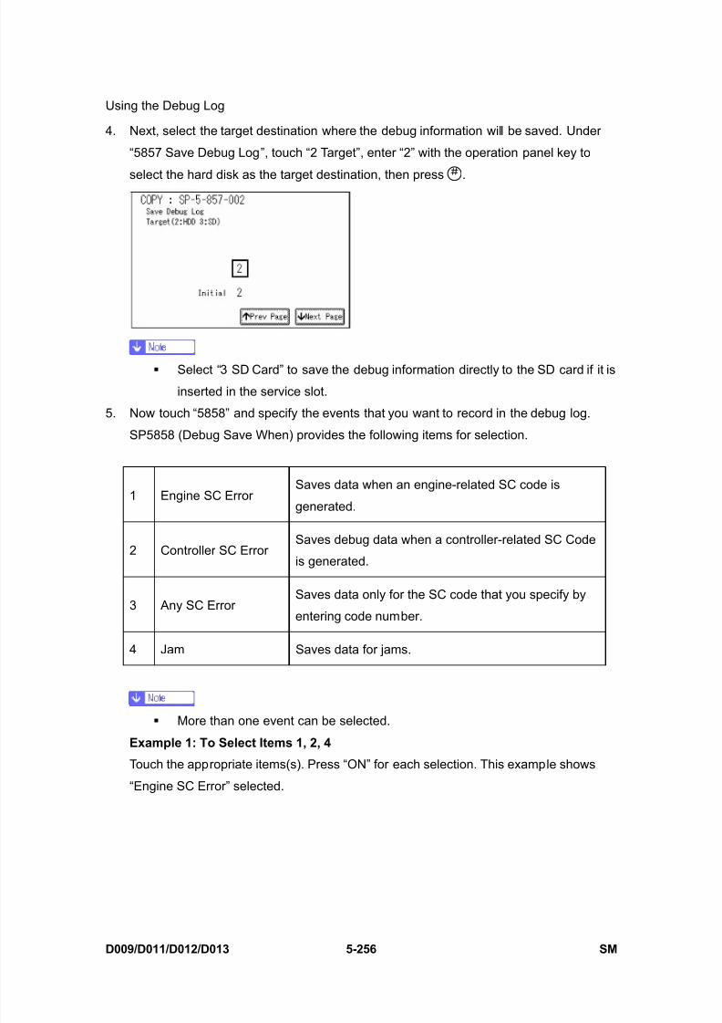
8/15/2019 Ricoh MP 4000 SM D009_D011_D012_D013 SERVICE MANUAL .pdf
http://slidepdf.com/reader/full/ricoh-mp-4000-sm-d009d011d012d013-service-manual-pdf 542/1162
Using the Debug Log
D009/D011/D012/D013 5-256 SM
4. Next, select the target destination where the debug information will be saved. Under
“5857 Save Debug Log”, touch “2 Target”, enter “2” with the operation panel key to
select the hard disk as the target destination, then press .
Select “3 SD Card” to save the debug information directly to the SD card if it is
inserted in the service slot.
5. Now touch “5858” and specify the events that you want to record in the debug log.
SP5858 (Debug Save When) provides the following items for selection.
1 Engine SC ErrorSaves data when an engine-related SC code is
generated.
2 Controller SC Error Saves debug data when a controller-related SC Codeis generated.
3 Any SC ErrorSaves data only for the SC code that you specify by
entering code number.
4 Jam Saves data for jams.
More than one event can be selected.
Example 1: To Select Items 1, 2, 4
Touch the appropriate items(s). Press “ON” for each selection. This example shows
“Engine SC Error” selected.

8/15/2019 Ricoh MP 4000 SM D009_D011_D012_D013 SERVICE MANUAL .pdf
http://slidepdf.com/reader/full/ricoh-mp-4000-sm-d009d011d012d013-service-manual-pdf 543/1162
Using the Debug Log
SM 5-257 D009/D011/D012/D013
S e r v i c e
T a b l e s
Example 2: To Specify an SC Code
Touch “3 Any SC Error”, enter the 3-digit SC code number with the control panel number
keys, then press . This example shows an entry for SC670.
For details about SC code numbers, please refer to the SC tables in Section “4.
Troubleshooting”
6. Next, select the one or more memory modules for reading and recording debug
information. Touch “5859”.
Under “5859” press the appropriate key item for the module that you want to record.
Enter the appropriate 4-digit number, then press .
Refer to the two tables below for the 4-digit numbers to enter for each key.
The example below shows “Key 1” with “2222” entered.
The following keys can be set with the corresponding numbers. (The initials in
parentheses indicate the names of the modules.)
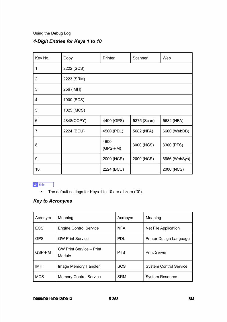
8/15/2019 Ricoh MP 4000 SM D009_D011_D012_D013 SERVICE MANUAL .pdf
http://slidepdf.com/reader/full/ricoh-mp-4000-sm-d009d011d012d013-service-manual-pdf 544/1162
Using the Debug Log
D009/D011/D012/D013 5-258 SM
4-Digit Entries for Keys 1 to 10
Key No. Copy Printer Scanner Web
1 2222 (SCS)
2 2223 (SRM)
3 256 (IMH)
4 1000 (ECS)
5 1025 (MCS)
6 4848(COPY) 4400 (GPS) 5375 (Scan) 5682 (NFA)
7 2224 (BCU) 4500 (PDL) 5682 (NFA) 6600 (WebDB)
84600
(GPS-PM)3000 (NCS) 3300 (PTS)
9 2000 (NCS) 2000 (NCS) 6666 (WebSys)
10 2224 (BCU) 2000 (NCS)
The default settings for Keys 1 to 10 are all zero (“0”).
Key to Acronyms
Acronym Meaning Acronym Meaning
ECS Engine Control Service NFA Net File Application
GPS GW Print Service PDL Printer Design Language
GSP-PMGW Print Service – Print
ModulePTS Print Server
IMH Image Memory Handler SCS System Control Service
MCS Memory Control Service SRM System Resource
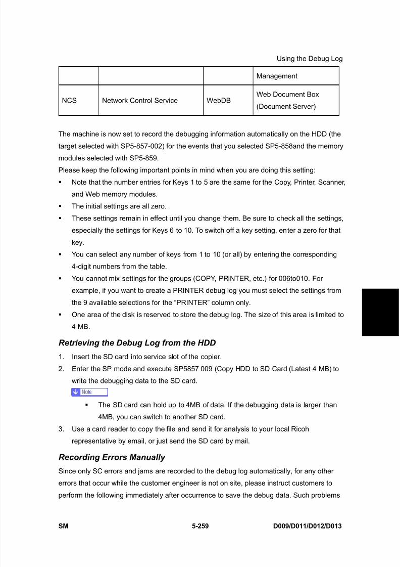
8/15/2019 Ricoh MP 4000 SM D009_D011_D012_D013 SERVICE MANUAL .pdf
http://slidepdf.com/reader/full/ricoh-mp-4000-sm-d009d011d012d013-service-manual-pdf 545/1162
Using the Debug Log
SM 5-259 D009/D011/D012/D013
S e r v i c e
T a b l e s
Management
NCS Network Control Service WebDBWeb Document Box
(Document Server)
The machine is now set to record the debugging information automatically on the HDD (the
target selected with SP5-857-002) for the events that you selected SP5-858and the memory
modules selected with SP5-859.
Please keep the following important points in mind when you are doing this setting:
Note that the number entries for Keys 1 to 5 are the same for the Copy, Printer, Scanner,
and Web memory modules.
The initial settings are all zero.
These settings remain in effect until you change them. Be sure to check all the settings,
especially the settings for Keys 6 to 10. To switch off a key setting, enter a zero for that
key.
You can select any number of keys from 1 to 10 (or all) by entering the corresponding
4-digit numbers from the table.
You cannot mix settings for the groups (COPY, PRINTER, etc.) for 006to010. For
example, if you want to create a PRINTER debug log you must select the settings from
the 9 available selections for the “PRINTER” column only.
One area of the disk is reserved to store the debug log. The size of this area is limited to
4 MB.
Retrieving the Debug Log from the HDD
1. Insert the SD card into service slot of the copier.
2. Enter the SP mode and execute SP5857 009 (Copy HDD to SD Card (Latest 4 MB) to
write the debugging data to the SD card.
The SD card can hold up to 4MB of data. If the debugging data is larger than
4MB, you can switch to another SD card.
3. Use a card reader to copy the file and send it for analysis to your local Ricoh
representative by email, or just send the SD card by mail.
Recording Errors Manually
Since only SC errors and jams are recorded to the debug log automatically, for any other
errors that occur while the customer engineer is not on site, please instruct customers to
perform the following immediately after occurrence to save the debug data. Such problems

8/15/2019 Ricoh MP 4000 SM D009_D011_D012_D013 SERVICE MANUAL .pdf
http://slidepdf.com/reader/full/ricoh-mp-4000-sm-d009d011d012d013-service-manual-pdf 546/1162
Using the Debug Log
D009/D011/D012/D013 5-260 SM
would include a controller or panel freeze.
In order to use this feature, the customer engineer must have previously switchedon the Save Debug Feature (SP5857-001) and selected the hard disk as the save
destination (SP5857-002).
1. When the error occurs, on the operation panel, press (Clear Modes).
2. On the control panel, enter “01” then hold down for at least 3 sec. until the
machine beeps then release. This saves the debug log to the hard disk for later retrieval
with an SD card by the service representatives.
3. Switch the machine off and on to resume operation.
The debug information for the error is saved on the hard disk so the service
representatives can retrieve it on their next visit by copying it from the HDD to an SD
card.

8/15/2019 Ricoh MP 4000 SM D009_D011_D012_D013 SERVICE MANUAL .pdf
http://slidepdf.com/reader/full/ricoh-mp-4000-sm-d009d011d012d013-service-manual-pdf 547/1162
Dip Switches
SM 5-261 D009/D011/D012/D013
S e r v i c e
T a b l e s
5.35 DIP SWITCHES
5.35.1 I/O BOARD: DIP SW101
BitLocation
6 7 8
Japan ON ON OFF
North America OFF ON OFF
Europe ON OFF OFF
China OFF OFF ON
Taiwan OFF ON ON
Korea ON OFF ON
Asia ON ON ON
ON: Up, OFF: Down

8/15/2019 Ricoh MP 4000 SM D009_D011_D012_D013 SERVICE MANUAL .pdf
http://slidepdf.com/reader/full/ricoh-mp-4000-sm-d009d011d012d013-service-manual-pdf 548/1162

8/15/2019 Ricoh MP 4000 SM D009_D011_D012_D013 SERVICE MANUAL .pdf
http://slidepdf.com/reader/full/ricoh-mp-4000-sm-d009d011d012d013-service-manual-pdf 549/1162
DETAILED SECTION DESCRIPTIONS

8/15/2019 Ricoh MP 4000 SM D009_D011_D012_D013 SERVICE MANUAL .pdf
http://slidepdf.com/reader/full/ricoh-mp-4000-sm-d009d011d012d013-service-manual-pdf 550/1162

8/15/2019 Ricoh MP 4000 SM D009_D011_D012_D013 SERVICE MANUAL .pdf
http://slidepdf.com/reader/full/ricoh-mp-4000-sm-d009d011d012d013-service-manual-pdf 551/1162
Overview
SM 6-1 D009/D011/D012/D013
D e t a i l e d
D e s c r i p
t i o n s
6. DETAILED SECTION DESCRIPTIONS
6.1 OVERVIEW
6.1.1 COMPONENT LAYOUT

8/15/2019 Ricoh MP 4000 SM D009_D011_D012_D013 SERVICE MANUAL .pdf
http://slidepdf.com/reader/full/ricoh-mp-4000-sm-d009d011d012d013-service-manual-pdf 552/1162

8/15/2019 Ricoh MP 4000 SM D009_D011_D012_D013 SERVICE MANUAL .pdf
http://slidepdf.com/reader/full/ricoh-mp-4000-sm-d009d011d012d013-service-manual-pdf 553/1162
Overview
SM 6-3 D009/D011/D012/D013
D e t a i l e d
D e s c r i p
t i o n s
Paper Path
1 ARDF
2 Interchange Unit
3 Duplex Unit
4 By-pass Tray
5 Large Capacity Tray (LCT: 1200-sheet)
6 Paper Tray Unit
7 Two-Tray Finisher
8 Bridge Unit
9 1-Bin Tray
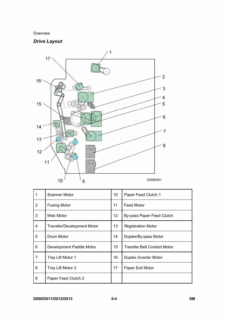
8/15/2019 Ricoh MP 4000 SM D009_D011_D012_D013 SERVICE MANUAL .pdf
http://slidepdf.com/reader/full/ricoh-mp-4000-sm-d009d011d012d013-service-manual-pdf 554/1162
Overview
D009/D011/D012/D013 6-4 SM
Drive Layout
1 Scanner Motor 10 Paper Feed Clutch 1
2 Fusing Motor 11 Feed Motor
3 Web Motor 12 By-pass Paper Feed Clutch
4 Transfer/Development Motor 13 Registration Motor
5 Drum Motor 14 Duplex/By-pass Motor
6 Development Paddle Motor 15 Transfer Belt Contact Motor
7 Tray Lift Motor 1 16 Duplex Inverter Motor
8 Tray Lift Motor 2 17 Paper Exit Motor
9 Paper Feed Clutch 2
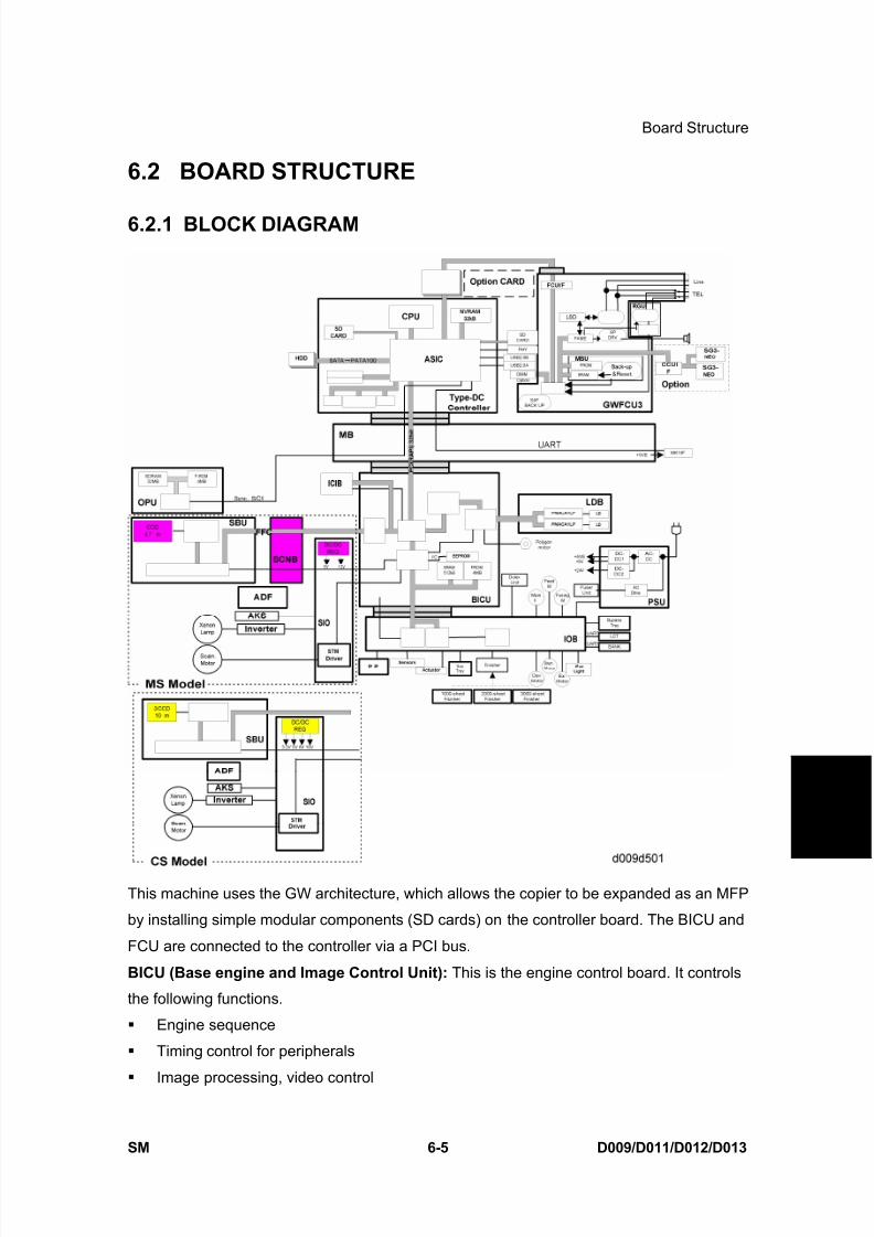
8/15/2019 Ricoh MP 4000 SM D009_D011_D012_D013 SERVICE MANUAL .pdf
http://slidepdf.com/reader/full/ricoh-mp-4000-sm-d009d011d012d013-service-manual-pdf 555/1162
Board Structure
SM 6-5 D009/D011/D012/D013
D e t a i l e d
D e s c r i p
t i o n s
6.2 BOARD STRUCTURE
6.2.1 BLOCK DIAGRAM
This machine uses the GW architecture, which allows the copier to be expanded as an MFP
by installing simple modular components (SD cards) on the controller board. The BICU and
FCU are connected to the controller via a PCI bus.
BICU (Base engine and Image Control Unit): This is the engine control board. It controls
the following functions.
Engine sequence
Timing control for peripherals
Image processing, video control

8/15/2019 Ricoh MP 4000 SM D009_D011_D012_D013 SERVICE MANUAL .pdf
http://slidepdf.com/reader/full/ricoh-mp-4000-sm-d009d011d012d013-service-manual-pdf 556/1162
Board Structure
D009/D011/D012/D013 6-6 SM
Scanner Motor
Controller: The GW Controller controls memory and all peripheral devices. The NCU
(Network Control Unit) and USB 2.0 are built into this control board.FCU (Facsimile Control Unit): This option controls fax communications and fax features.
ICIB (Copy Data Security Unit): This option provides copy protection of sensitive
documents. Once a document is copied or printed with an RCPS or other printer driver that
supports this function, the hard copy cannot be copied on a copier that supports hard copy
protection.
IOB (Input/Output Board): The IOB uses the new eI0 chips and handles the following
functions.
Drive control for the sensors, motors, and solenoids of the main unit
PWM control for the high voltage supply board
Serial interface with peripherals
Fusing control
Paper feed control
The IOB is located behind the rear covers for easy access. The same IOB is used for all
models but the DIP switches must be set correctly for each model. ( High Voltage Power
Supply)
LDB (Laser Drive Board): Holds the laser diodes. The board and diodes are controlled by
the GAVD Type-R mounted on the BICU not the LDB itself.
MB (Mother Board): Interfaces the BICU with controller and the optional FCU.
OPU (Operation Panel Unit): Controls operation panel and display.
PSU (Power Supply Unit): The improved PSU on this machine consumes less than 1 W
when the machine is in the energy save (low power) mode.
SBU (Sensor Board Unit): Receives analog signals from the CCD (now encased in plastic,
not ceramic) and converts them into digital signals.
SIO (Scanner In/Out): Controls the scanner motor and exposure lamp.
SCNB (Scanner Connector Board): Relays the SIB passes signals between the BICU andthe scanner unit components, and transmits video signals from the SBU to the BICU. This
board is used only for the monochrome scanner model.
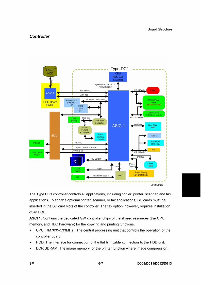
8/15/2019 Ricoh MP 4000 SM D009_D011_D012_D013 SERVICE MANUAL .pdf
http://slidepdf.com/reader/full/ricoh-mp-4000-sm-d009d011d012d013-service-manual-pdf 557/1162
8/15/2019 Ricoh MP 4000 SM D009_D011_D012_D013 SERVICE MANUAL .pdf
http://slidepdf.com/reader/full/ricoh-mp-4000-sm-d009d011d012d013-service-manual-pdf 558/1162
Board Structure
D009/D011/D012/D013 6-8 SM
image rotation and other operations are done.
SD. This is the interface for SD card slots 1 and 2. Slot 2 is for optional applications or
service slot for firmware version updates, moving. applications to other SD cards, anddownloading/uploading NVRAM contents
Board Option Slot Only one of the following options can be installed in either I/F Slot:
IEEE1284 Interface Board (Centronics), IEEE802.11a/g, g (Wireless LAN), Bluetooth
Interface Unit, File Format Converter (MLB) or Cumin-M.
Flash ROM. Stores the program. Maximum capacity: 128 MB.
USB . The interface for USB 2.0 devices. Supports both low-speed and high-speed
modes. USB support is built-into the controller. No installation is required for the USB
function. But, SP5985 001 must be set to " 1" to enable the network functions.
NIB. The Ethernet interface connection. Network support is built-into the controller. No
installation is required for the network function. But, SP5985 002 must be set to " 1" to
enable the network functions.
EEPROM. Stores the data for the SP code settings.
NVRAM. The memory that stores the system configuration and other information.
HDD: A 2.5" HDD (more than 40 GB) can be connected using an S-ATA I/F.
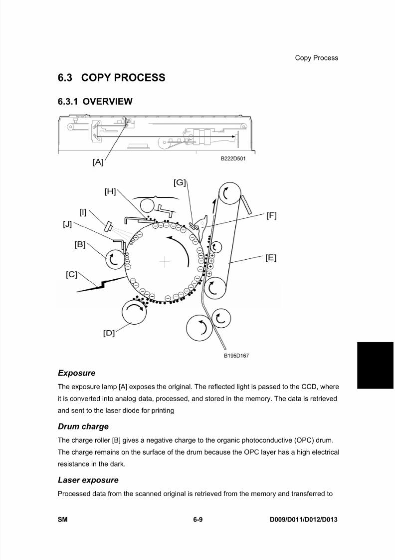
8/15/2019 Ricoh MP 4000 SM D009_D011_D012_D013 SERVICE MANUAL .pdf
http://slidepdf.com/reader/full/ricoh-mp-4000-sm-d009d011d012d013-service-manual-pdf 559/1162
Copy Process
SM 6-9 D009/D011/D012/D013
D e t a i l e d
D e s c r i p
t i o n s
6.3 COPY PROCESS
6.3.1 OVERVIEW
Exposure
The exposure lamp [A] exposes the original. The reflected light is passed to the CCD, where
it is converted into analog data, processed, and stored in the memory. The data is retrieved
and sent to the laser diode for printing
Drum charge
The charge roller [B] gives a negative charge to the organic photoconductive (OPC) drum.
The charge remains on the surface of the drum because the OPC layer has a high electrical
resistance in the dark.
Laser exposure
Processed data from the scanned original is retrieved from the memory and transferred to
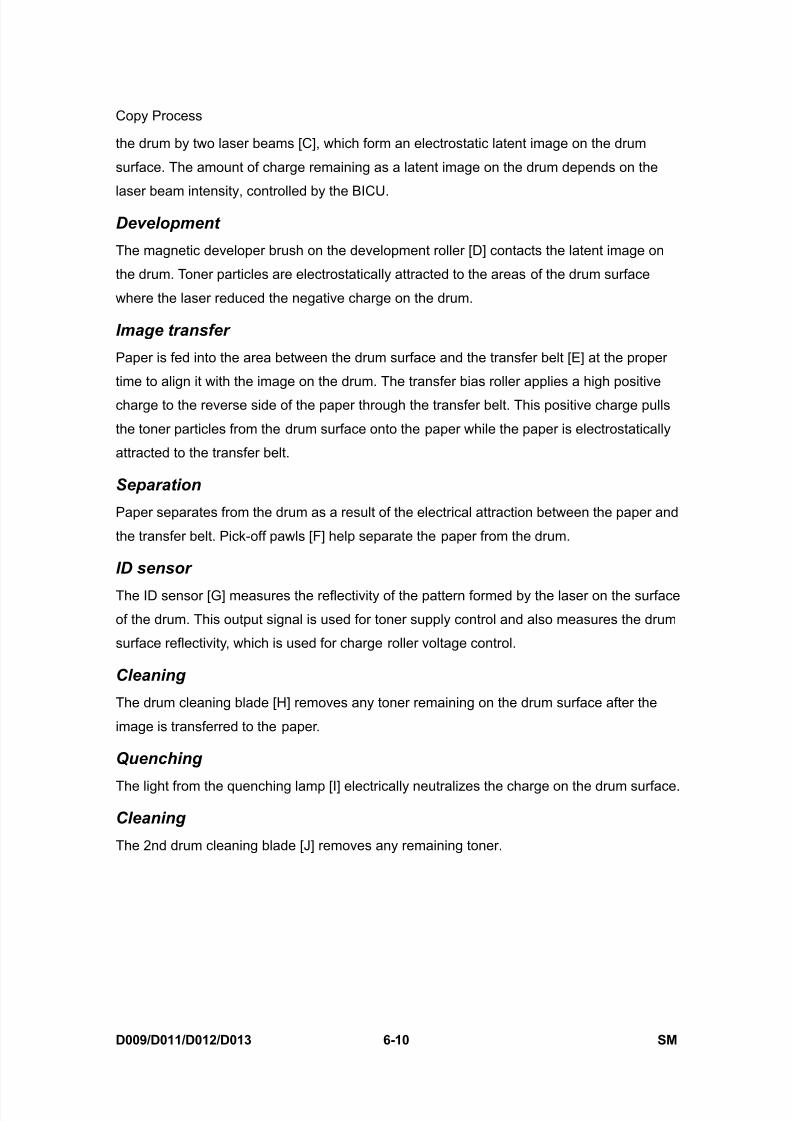
8/15/2019 Ricoh MP 4000 SM D009_D011_D012_D013 SERVICE MANUAL .pdf
http://slidepdf.com/reader/full/ricoh-mp-4000-sm-d009d011d012d013-service-manual-pdf 560/1162
Copy Process
D009/D011/D012/D013 6-10 SM
the drum by two laser beams [C], which form an electrostatic latent image on the drum
surface. The amount of charge remaining as a latent image on the drum depends on the
laser beam intensity, controlled by the BICU.
Development
The magnetic developer brush on the development roller [D] contacts the latent image on
the drum. Toner particles are electrostatically attracted to the areas of the drum surface
where the laser reduced the negative charge on the drum.
Image transfer
Paper is fed into the area between the drum surface and the transfer belt [E] at the proper
time to align it with the image on the drum. The transfer bias roller applies a high positive
charge to the reverse side of the paper through the transfer belt. This positive charge pulls
the toner particles from the drum surface onto the paper while the paper is electrostatically
attracted to the transfer belt.
Separation
Paper separates from the drum as a result of the electrical attraction between the paper and
the transfer belt. Pick-off pawls [F] help separate the paper from the drum.
ID sensor
The ID sensor [G] measures the reflectivity of the pattern formed by the laser on the surface
of the drum. This output signal is used for toner supply control and also measures the drum
surface reflectivity, which is used for charge roller voltage control.
Cleaning
The drum cleaning blade [H] removes any toner remaining on the drum surface after the
image is transferred to the paper.
Quenching
The light from the quenching lamp [I] electrically neutralizes the charge on the drum surface.
Cleaning
The 2nd drum cleaning blade [J] removes any remaining toner.

8/15/2019 Ricoh MP 4000 SM D009_D011_D012_D013 SERVICE MANUAL .pdf
http://slidepdf.com/reader/full/ricoh-mp-4000-sm-d009d011d012d013-service-manual-pdf 561/1162
Scanning
SM 6-11 D009/D011/D012/D013
D e t a i l e d
D e s c r i p
t i o n s
6.4 SCANNING
6.4.1 OVERVIEW
1. Scanner HP sensor
2. ADF exposure glass
3. 2nd scanner (2nd carriage)
4. Scanner lamp
5. 1st scanner (1st carriage)
6. Exposure glass
7. Sensor board unit (SBU)
8. Lens block
9. Original length sensor
10. Scanner motor
11. Original width sensor
The original is illuminated by the exposure lamp (a xenon lamp). The image is reflected onto
a CCD (charge coupled device) on the lens block via the 1st, 2nd, and 3rd mirrors, and
through the lens on the lens block.
The 1st scanner consists of the exposure lamp, a reflector, and the 1st mirror.
The exposure lamp is energized by a dc supply to avoid uneven light intensity while the 1st
scanner moves in the sub scan direction (down the page). The entire exposure lamp surface
is frosted to ensure even exposure in the main scan direction (across the page).
The light reflected by the reflector is of almost equal intensity in all directions, to reduce
shadows on pasted originals.
When the optional optics anti-condensation heater is installed on the left side of the scanner,
it turns on whenever the power cord is plugged in.
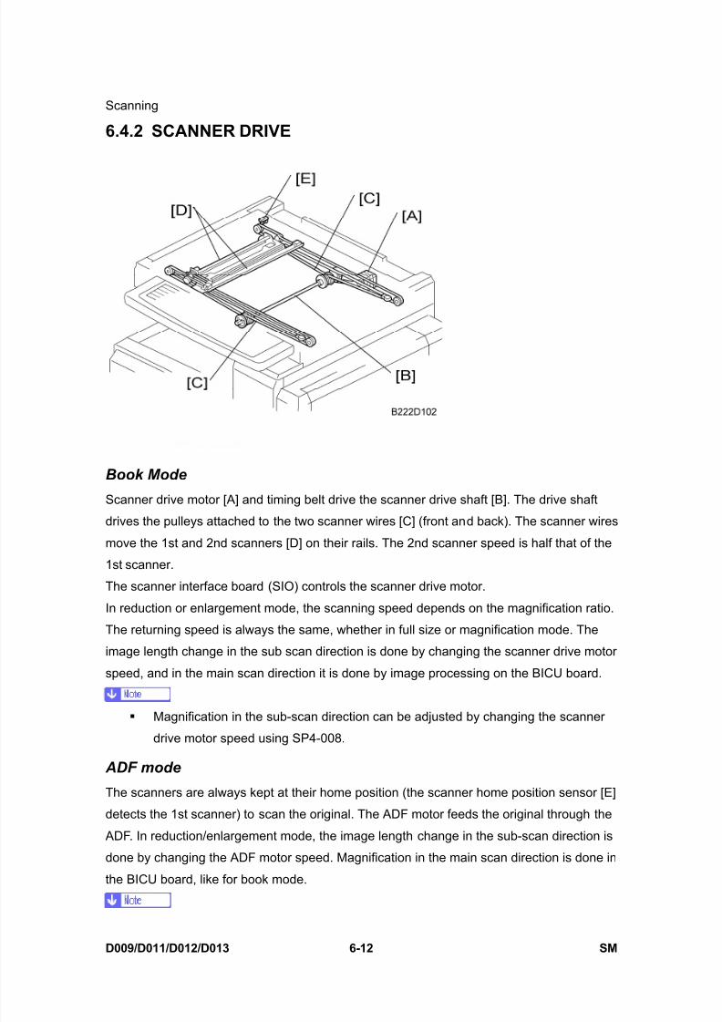
8/15/2019 Ricoh MP 4000 SM D009_D011_D012_D013 SERVICE MANUAL .pdf
http://slidepdf.com/reader/full/ricoh-mp-4000-sm-d009d011d012d013-service-manual-pdf 562/1162
Scanning
D009/D011/D012/D013 6-12 SM
6.4.2 SCANNER DRIVE
Book Mode
Scanner drive motor [A] and timing belt drive the scanner drive shaft [B]. The drive shaft
drives the pulleys attached to the two scanner wires [C] (front and back). The scanner wires
move the 1st and 2nd scanners [D] on their rails. The 2nd scanner speed is half that of the
1st scanner.
The scanner interface board (SIO) controls the scanner drive motor.
In reduction or enlargement mode, the scanning speed depends on the magnification ratio.
The returning speed is always the same, whether in full size or magnification mode. The
image length change in the sub scan direction is done by changing the scanner drive motor
speed, and in the main scan direction it is done by image processing on the BICU board.
Magnification in the sub-scan direction can be adjusted by changing the scannerdrive motor speed using SP4-008.
ADF mode
The scanners are always kept at their home position (the scanner home position sensor [E]
detects the 1st scanner) to scan the original. The ADF motor feeds the original through the
ADF. In reduction/enlargement mode, the image length change in the sub-scan direction is
done by changing the ADF motor speed. Magnification in the main scan direction is done in
the BICU board, like for book mode.

8/15/2019 Ricoh MP 4000 SM D009_D011_D012_D013 SERVICE MANUAL .pdf
http://slidepdf.com/reader/full/ricoh-mp-4000-sm-d009d011d012d013-service-manual-pdf 563/1162
Scanning
SM 6-13 D009/D011/D012/D013
D e t a i l e d
D e s c r i p
t i o n s
Magnification in the sub-scan direction can be adjusted by changing the ADF motor
speed using SP6-017. In the main scan direction, it can be adjusted with SP2-102,
like for book mode.
6.4.3 ORIGINAL SIZE DETECTION IN PLATEN MODE
The original width sensors [A] detect the original width, and the original length sensors [B]
detect the original length. These reflective photo sensors are referred to collectively as the
APS (Auto Paper Select) sensors.
While the power is on, these sensors are active and the original size data is always sent to
the CPU. However, the CPU checks the data only when the platen cover sensor [C] isactivated after the platen reaches about 15 cm above the exposure glass as it is closed. The
main CPU detects the original size by the on/off signals received from the APS sensors.
If the copy is made with the platen fully open, the main CPU determines the original
size from the sensor outputs after the Start key is pressed.
In the diagram, ‘MS’ means monochrome scanner, and ‘CS’ means color scanner.
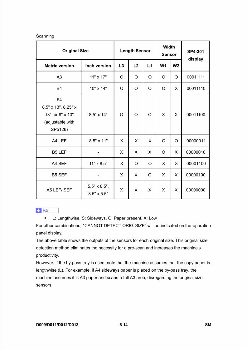
8/15/2019 Ricoh MP 4000 SM D009_D011_D012_D013 SERVICE MANUAL .pdf
http://slidepdf.com/reader/full/ricoh-mp-4000-sm-d009d011d012d013-service-manual-pdf 564/1162
Scanning
D009/D011/D012/D013 6-14 SM
Original Size Length Sensor Width
Sensor
Metric version Inch version L3 L2 L1 W1 W2
SP4-301
display
A3 11" x 17" O O O O O 00011111
B4 10" x 14" O O O O X 00011110
F4
8.5" x 13", 8.25" x
13", or 8" x 13"
(adjustable withSP5126)
8.5” x 14” O O O X X 00011100
A4 LEF 8.5" x 11" X X X O O 00000011
B5 LEF - X X X O X 00000010
A4 SEF 11" x 8.5" X O O X X 00001100
B5 SEF - X X O X X 00000100
A5 LEF/ SEF5.5" x 8.5",
8.5" x 5.5"X X X X X 00000000
L: Lengthwise, S: Sideways, O: Paper present, X: Low
For other combinations, "CANNOT DETECT ORIG. SIZE" will be indicated on the operation
panel display.
The above table shows the outputs of the sensors for each original size. This original size
detection method eliminates the necessity for a pre-scan and increases the machine's
productivity.
However, if the by-pass tray is used, note that the machine assumes that the copy paper is
lengthwise (L). For example, if A4 sideways paper is placed on the by-pass tray, the
machine assumes it is A3 paper and scans a full A3 area, disregarding the original size
sensors.
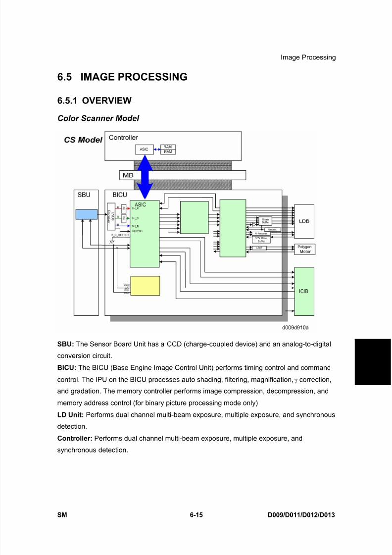
8/15/2019 Ricoh MP 4000 SM D009_D011_D012_D013 SERVICE MANUAL .pdf
http://slidepdf.com/reader/full/ricoh-mp-4000-sm-d009d011d012d013-service-manual-pdf 565/1162
Image Processing
SM 6-15 D009/D011/D012/D013
D e t a i l e d
D e s c r i p
t i o n s
6.5 IMAGE PROCESSING
6.5.1 OVERVIEW
Color Scanner Model
SBU: The Sensor Board Unit has a CCD (charge-coupled device) and an analog-to-digital
conversion circuit.
BICU: The BICU (Base Engine Image Control Unit) performs timing control and command
control. The IPU on the BICU processes auto shading, filtering, magnification, γ correction,
and gradation. The memory controller performs image compression, decompression, and
memory address control (for binary picture processing mode only)
LD Unit: Performs dual channel multi-beam exposure, multiple exposure, and synchronous
detection.
Controller: Performs dual channel multi-beam exposure, multiple exposure, and
synchronous detection.
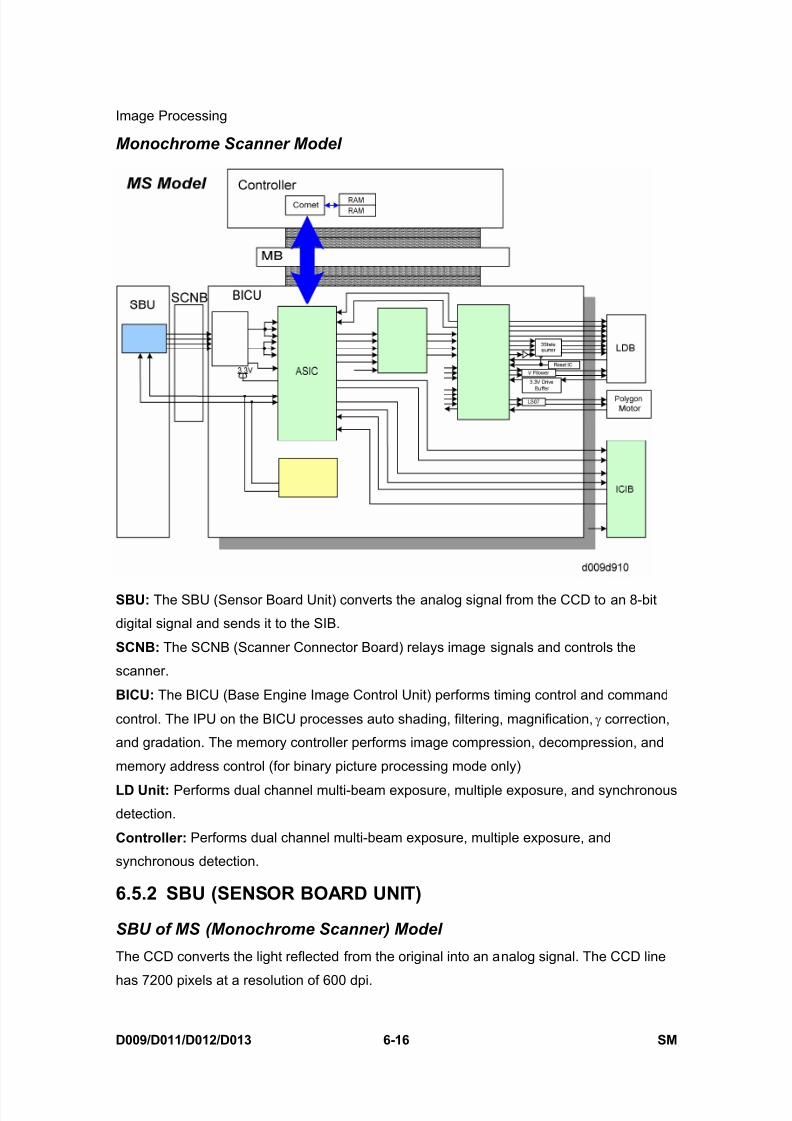
8/15/2019 Ricoh MP 4000 SM D009_D011_D012_D013 SERVICE MANUAL .pdf
http://slidepdf.com/reader/full/ricoh-mp-4000-sm-d009d011d012d013-service-manual-pdf 566/1162
Image Processing
D009/D011/D012/D013 6-16 SM
Monochrome Scanner Model
SBU: The SBU (Sensor Board Unit) converts the analog signal from the CCD to an 8-bit
digital signal and sends it to the SIB.
SCNB: The SCNB (Scanner Connector Board) relays image signals and controls the
scanner.
BICU: The BICU (Base Engine Image Control Unit) performs timing control and command
control. The IPU on the BICU processes auto shading, filtering, magnification, γ correction,
and gradation. The memory controller performs image compression, decompression, and
memory address control (for binary picture processing mode only)
LD Unit: Performs dual channel multi-beam exposure, multiple exposure, and synchronous
detection.
Controller: Performs dual channel multi-beam exposure, multiple exposure, and
synchronous detection.
6.5.2 SBU (SENSOR BOARD UNIT)
SBU of MS (Monochrome Scanner) Model
The CCD converts the light reflected from the original into an analog signal. The CCD line
has 7200 pixels at a resolution of 600 dpi.

8/15/2019 Ricoh MP 4000 SM D009_D011_D012_D013 SERVICE MANUAL .pdf
http://slidepdf.com/reader/full/ricoh-mp-4000-sm-d009d011d012d013-service-manual-pdf 567/1162
Image Processing
SM 6-17 D009/D011/D012/D013
D e t a i l e d
D e s c r i p
t i o n s
The CCD has two output lines to the analog processing ASIC, one for handling odd and one
for handling even pixels. The analog processing ASIC performs the following operations on
the signals received from the CCD:Z/C (Zero/Clamp): Adjusts the black level for even pixels to match the odd pixels.
Signal composition: Analog signals for odd and even pixels from the CCD are merged by a
switching device.
Signal amplification: The analog signal is amplified by amplifiers in the AGC circuit. The
maximum gains of the amplifiers are controlled by the CPU on the BICU board.
After the above processing, the analog signals are converted to 8-bit signals by the A/D
converter. This gives a value for each pixel on a scale of 256 shades of gray. Then, this data
goes to the BICU via the SIB.
SBU of CS (Color Scanner) Model
SBU
The VPU (Video Processor Unit) does the following functions:
Black level correction
White level correction
Gradation calibration
ADS control (Background Density)
Creating the SBU test patternOperation Summary
The signals from the 3-line CCD, one line for each color (R, G, B) and 2 analog signals per
line (ODD, EVEN), are sampled by the ASIC and converted to digital signals in the 10-bit
A/D converter. This is the first phase of processing the data scanned from the original.
Storing Operation Settings
The controller stores the SBU settings. These values must be restored after the lens block is
replaced:
SP4-008-001 Scanner Sub Scan Mag Sub Scan Magnification Adjustment
SP4-010-001 Scanner Leading Edge
RegistrationSub Scan Registration Adjustment
SP4-011-001 Scanner Side-to-Side
RegistrationMain Scan Registration Adjustment
SBU Test Mode

8/15/2019 Ricoh MP 4000 SM D009_D011_D012_D013 SERVICE MANUAL .pdf
http://slidepdf.com/reader/full/ricoh-mp-4000-sm-d009d011d012d013-service-manual-pdf 568/1162
8/15/2019 Ricoh MP 4000 SM D009_D011_D012_D013 SERVICE MANUAL .pdf
http://slidepdf.com/reader/full/ricoh-mp-4000-sm-d009d011d012d013-service-manual-pdf 569/1162
Image Processing
SM 6-19 D009/D011/D012/D013
D e t a i l e d
D e s c r i p
t i o n s
6.5.4 IPU (IMAGE PROCESSING UNIT)
Overview
The image data from the SBU goes to the IPU (Image Processing Unit) IC on the BICU
board, which carries out the following processes on the image data:
1. Auto shading
2. Filtering (MTF and smoothing)
3. Magnification
4. γ correction
5. Grayscale processing
6. Binary picture processing
7. Error diffusion
8. Dithering
9. Video path control
10. Test pattern generation
The image data then goes to the HDD.
6.5.5 IMAGE PROCESSING MODES
The user can select one of the following modes with the User Tools screen: Text, Text/Photo,
Photo, Pale, Generation. Some of these modes have a range of different settings (e.g. etc).To display this screen, press User Tools/Counter> Copier/Document Server Settings>
General Features> Original Photo Type Quality.
Mode Function
Text/Photo Glossy Photo/ Printed Photo/ Copied Photo
Photo Glossy Photo/ Printed Photo/ Copied Photo
6.5.6 SUMMARY OF IMAGE PROCESSING FUNCTIONS
Shading correction: Compensates for the possible differences in the amount of light at the
edges and center of a scanned image caused by the scanner lens, or scatter among pixels
of the CCD.
Pre-Filter Background erase: Attempts to eliminate the heavy background texture from
copies (newspaper print or documents printed on coarse paper). Elements below the
selected threshold level are eliminated.
8/15/2019 Ricoh MP 4000 SM D009_D011_D012_D013 SERVICE MANUAL .pdf
http://slidepdf.com/reader/full/ricoh-mp-4000-sm-d009d011d012d013-service-manual-pdf 570/1162
Image Processing
D009/D011/D012/D013 6-20 SM
Pre-Filter Smoothing: Reproduces halftones while reducing the incidence of moiré which
can occur as a result of compressing and then decompressing the image.
Main scan magnification: Adjusts magnification to the desired level by processingadjusting multiple, adjacent pixels in the direction of main scanning. Adjustment of
magnification in the sub scan direction is done by changing the scanning speed.
Independent dot erase: Attempts to recognize and eliminate scattered, independent dots
in copies. Processes only pixels of high density and eliminates those of low density.
Filtering (MTF filter/smoothing): Performs mainly edge enhancement with the MTF filter.
Performs smoothing only in the Photo mode. The matrix size of the filter is 9 pixels x 7 lines.
Gamma ( γ) coefficient: Controls the image density for images processed with grayscaling.
Copy density adjustment is achieved with special notch γ coefficient conversion. The best γ
coefficient suited for the selected mode can be stored and adjusted as needed.
Grayscale processing: Performs reproduction of grayscales, using mainly error diffusion.
(In the Photo mode, conducts processing with dithering.)
6.5.7 IMAGE PROCESSING STEPS
Text Mode
The Text mode achieves quality reproduction of text and sharp lines and ignores
background texture. Processing is conducted with a high resolution MTF filter; special
processing with the γ coefficient prevents background reproduction and achieves the best
reproduction of images with error diffusion. Because the Soft and Normal settings use a
weak MTF filter, the quality of the image is improved with the elimination of moiré. The Sharp
selection uses an MTF filter stronger than that of the Normal setting, thus increasing the
sharpness of lines.
Text/Photo Mode
Text/Photo mode achieves high quality reproduction of pictures with accurate grayscaling.
Processing is conducted with the special γ coefficient which reproduces a wide range of
grayscale. Compared with the Text mode, text reproduced in the Text/Photo mode appears
lighter and textured backgrounds could appear on copies, but the incidence of moiré is
reduced with and edge detection filter. Because Photo Priority uses an MTF filter weaker
than that of the Normal setting, the quality of the image is improved with the elimination of
moiré. The Text Priority selection uses an MTF filter stronger than that of the Normal setting,
thus increasing the sharpness of lines.
Photo Mode
Photo mode emphasizes grayscale processing to achieve the best possible reproduction of
8/15/2019 Ricoh MP 4000 SM D009_D011_D012_D013 SERVICE MANUAL .pdf
http://slidepdf.com/reader/full/ricoh-mp-4000-sm-d009d011d012d013-service-manual-pdf 571/1162
Image Processing
SM 6-21 D009/D011/D012/D013
D e t a i l e d
D e s c r i p
t i o n s
photographs and eliminate moiré by using the highest density and γ coefficient in the
reproduction of grayscales and dithering. Print Photo performs smoothing and dithering for
photos copied from magazines, newspapers, etc. The Normal selection uses a higherresolution setting and employs error diffusion but does not use smoothing to improve the
appearance of text in photographs. Glossy photo paper employs MTF filter processing and
error diffusion to copy glossy or matte photographs and achieves a low incidence of moiré,
thus reproducing copies of photographs of high resolution.
For photo mode, the features used depend on which type of greyscale processing has been
selected for Photo mode (either ‘dithering and smoothing’ or ‘error diffusion and MTF’).
Pale (Low-Density Mode)
Pale achieves image quality comparable with Text mode, but of lower contrast. Paleemploys an MTF filter stronger than that employed by the Text mode and uses a darker γ
coefficient, thus increasing the incidence of copying textured backgrounds. Ideal for copying
extremely thin originals. Soft employs an MTF filter weaker than Normal, thus achieving a
softer image with less moiré. Sharp employs an MTF filter stronger than that of Normal, thus
increasing the sharpness of lines.
Generation Copy Mode
Generation Copy, based mainly on Text mode, aims to achieve the best reproduction of
copied originals (so called “generation copies” or copies of copies). This mode 1) employs
an MTF filter weaker than that of the Text mode to eliminate spurious dots, 2) uses the γ
coefficient to smooth the image, and 3) uses generation processing to thicken thin lines. Soft
employs an MTF filter weaker than the Normal setting to achieve a softer image with less
moiré. Sharp employs an MTF filter stronger than that for Normal to emphasize lines for
better image quality.
6.5.8 INDEPENDENT DOT ERASE
Independent dot erase (set with the SP mode settings listed in the table below) remains ineffect even when a “Custom Setting” is selected with the User Tools.
Independent dot erase targets for elimination random, irregular shaped black dots on the
surface of the original that would otherwise appear in the copy after scanning and printing.
The strength of the application of this feature can be adjusted for each mode.
The filter compares each pixel with the pixels around an area 7 pixels x 7 lines. If the sum of
the pixels at the edges is smaller than the threshold value, the object pixel is changed to
zero (white) depending on the strength of the SP mode setting. Setting a larger setting
increases the number of dots erased, but if set too high, this SP can also remove small or
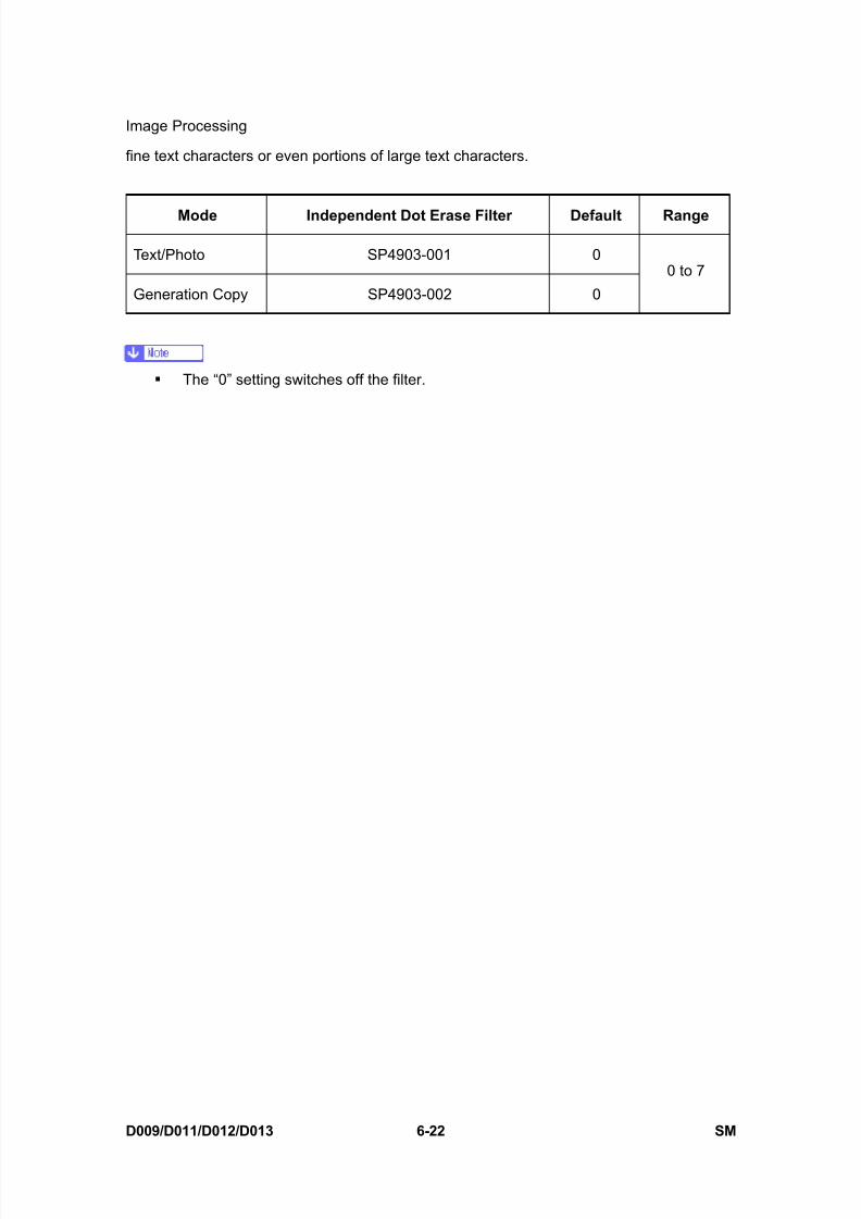
8/15/2019 Ricoh MP 4000 SM D009_D011_D012_D013 SERVICE MANUAL .pdf
http://slidepdf.com/reader/full/ricoh-mp-4000-sm-d009d011d012d013-service-manual-pdf 572/1162
Image Processing
D009/D011/D012/D013 6-22 SM
fine text characters or even portions of large text characters.
Mode Independent Dot Erase Filter Default Range
Text/Photo SP4903-001 0
Generation Copy SP4903-002 0
0 to 7
The “0” setting switches off the filter.
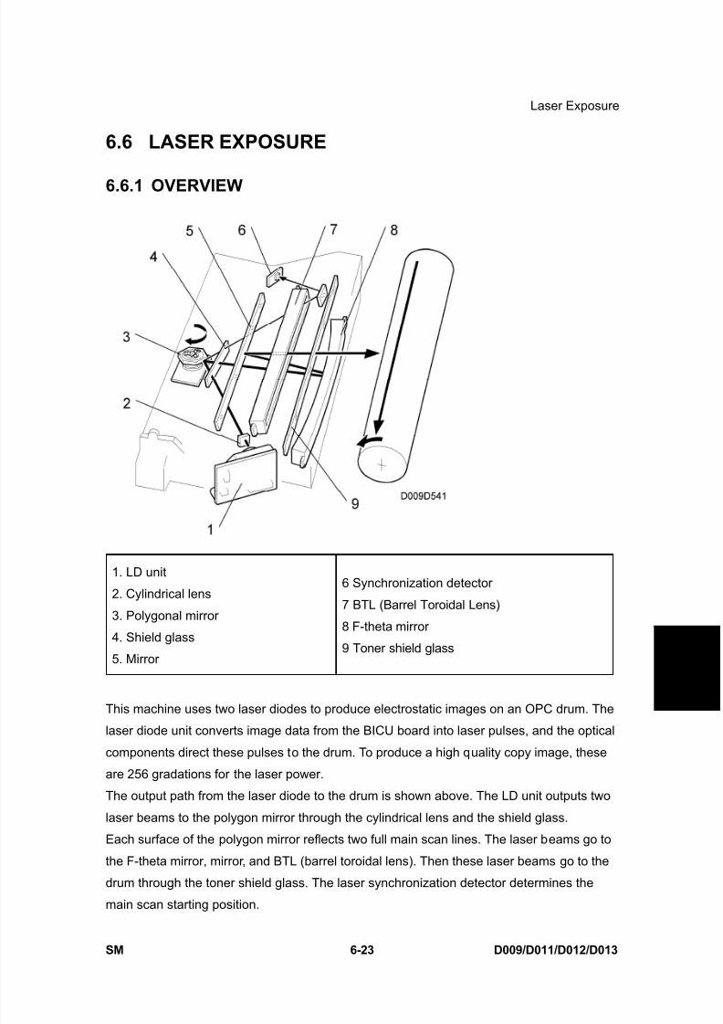
8/15/2019 Ricoh MP 4000 SM D009_D011_D012_D013 SERVICE MANUAL .pdf
http://slidepdf.com/reader/full/ricoh-mp-4000-sm-d009d011d012d013-service-manual-pdf 573/1162
Laser Exposure
SM 6-23 D009/D011/D012/D013
D e t a i l e d
D e s c r i p
t i o n s
6.6 LASER EXPOSURE
6.6.1 OVERVIEW
1. LD unit
2. Cylindrical lens
3. Polygonal mirror
4. Shield glass
5. Mirror
6 Synchronization detector
7 BTL (Barrel Toroidal Lens)
8 F-theta mirror
9 Toner shield glass
This machine uses two laser diodes to produce electrostatic images on an OPC drum. The
laser diode unit converts image data from the BICU board into laser pulses, and the optical
components direct these pulses to the drum. To produce a high quality copy image, these
are 256 gradations for the laser power.
The output path from the laser diode to the drum is shown above. The LD unit outputs two
laser beams to the polygon mirror through the cylindrical lens and the shield glass.
Each surface of the polygon mirror reflects two full main scan lines. The laser beams go to
the F-theta mirror, mirror, and BTL (barrel toroidal lens). Then these laser beams go to the
drum through the toner shield glass. The laser synchronization detector determines the
main scan starting position.
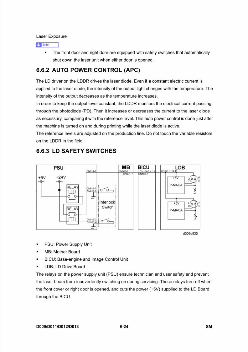
8/15/2019 Ricoh MP 4000 SM D009_D011_D012_D013 SERVICE MANUAL .pdf
http://slidepdf.com/reader/full/ricoh-mp-4000-sm-d009d011d012d013-service-manual-pdf 574/1162
Laser Exposure
D009/D011/D012/D013 6-24 SM
The front door and right door are equipped with safety switches that automatically
shut down the laser unit when either door is opened.
6.6.2 AUTO POWER CONTROL (APC)
The LD driver on the LDDR drives the laser diode. Even if a constant electric current is
applied to the laser diode, the intensity of the output light changes with the temperature. The
intensity of the output decreases as the temperature increases.
In order to keep the output level constant, the LDDR monitors the electrical current passing
through the photodiode (PD). Then it increases or decreases the current to the laser diode
as necessary, comparing it with the reference level. This auto power control is done just after
the machine is turned on and during printing while the laser diode is active.
The reference levels are adjusted on the production line. Do not touch the variable resistors
on the LDDR in the field.
6.6.3 LD SAFETY SWITCHES
PSU: Power Supply Unit
MB: Mother Board
BICU: Base-engine and Image Control Unit
LDB: LD Drive Board
The relays on the power supply unit (PSU) ensure technician and user safety and prevent
the laser beam from inadvertently switching on during servicing. These relays turn off when
the front cover or right door is opened, and cuts the power (+5V) supplied to the LD Board
through the BICU.
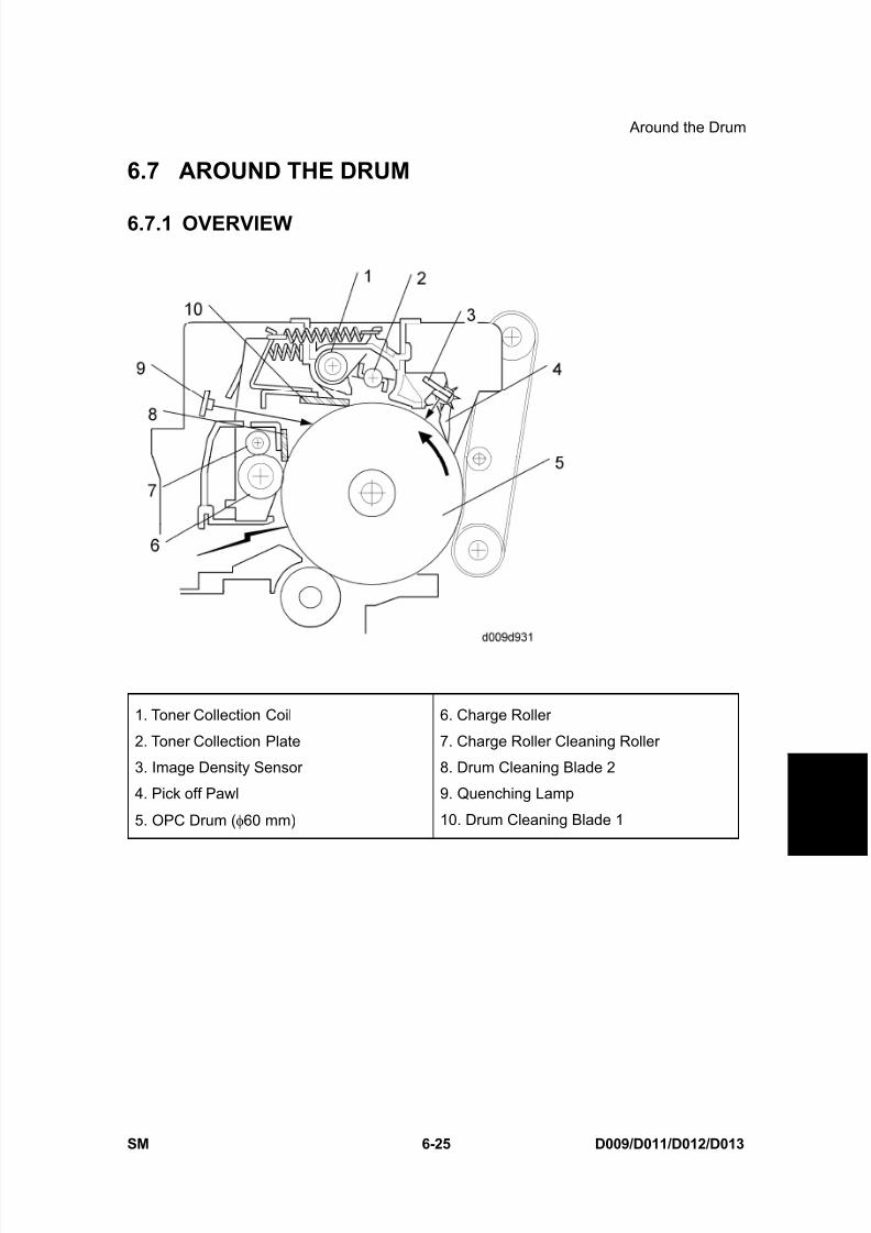
8/15/2019 Ricoh MP 4000 SM D009_D011_D012_D013 SERVICE MANUAL .pdf
http://slidepdf.com/reader/full/ricoh-mp-4000-sm-d009d011d012d013-service-manual-pdf 575/1162
Around the Drum
SM 6-25 D009/D011/D012/D013
D e t a i l e d
D e s c r i p
t i o n s
6.7 AROUND THE DRUM
6.7.1 OVERVIEW
1. Toner Collection Coil
2. Toner Collection Plate
3. Image Density Sensor
4. Pick off Pawl
5. OPC Drum ( φ60 mm)
6. Charge Roller
7. Charge Roller Cleaning Roller
8. Drum Cleaning Blade 2
9. Quenching Lamp
10. Drum Cleaning Blade 1

8/15/2019 Ricoh MP 4000 SM D009_D011_D012_D013 SERVICE MANUAL .pdf
http://slidepdf.com/reader/full/ricoh-mp-4000-sm-d009d011d012d013-service-manual-pdf 576/1162
Around the Drum
D009/D011/D012/D013 6-26 SM
6.7.2 DRUM CLEANING
The PxP (Polyester Polymerization) toner of this machine is of much finer particle size so in
addition to the stationary cleaning blade (cleaning blade 1), mounted with two screws to a
spring loaded plate at the top of the PCDU, an additional cleaning blade (cleaning blade 2)
[A] has been added to increase the efficiency of drum cleaning.
The new cleaning blade is held in contact with the drum by two small springs [B] (one oneach end) that keep the cleaning blade in contact with the drum. This cleaning blade is not a
counter blade.
The tension of these springs has been reduced for this model in order to reduce the amount
of pressure applied by the bladed against the drum.
Every time the PCDU is opened for replacement or cleaning, the spring closest to the front
of the PCDU must moved in order to retract the cleaning blade away from the OPC drum.
After cleaning or replacement, the spring must be returned to its original position to keep the
blade in contact with the OPC drum for normal operation. For details, see “Replacement and
Adjustment”.
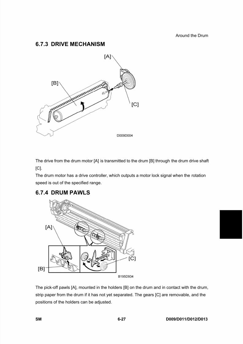
8/15/2019 Ricoh MP 4000 SM D009_D011_D012_D013 SERVICE MANUAL .pdf
http://slidepdf.com/reader/full/ricoh-mp-4000-sm-d009d011d012d013-service-manual-pdf 577/1162
Around the Drum
SM 6-27 D009/D011/D012/D013
D e t a i l e d
D e s c r i p
t i o n s
6.7.3 DRIVE MECHANISM
The drive from the drum motor [A] is transmitted to the drum [B] through the drum drive shaft
[C].
The drum motor has a drive controller, which outputs a motor lock signal when the rotation
speed is out of the specified range.
6.7.4 DRUM PAWLS
The pick-off pawls [A], mounted in the holders [B] on the drum and in contact with the drum,
strip paper from the drum if it has not yet separated. The gears [C] are removable, and the
positions of the holders can be adjusted.
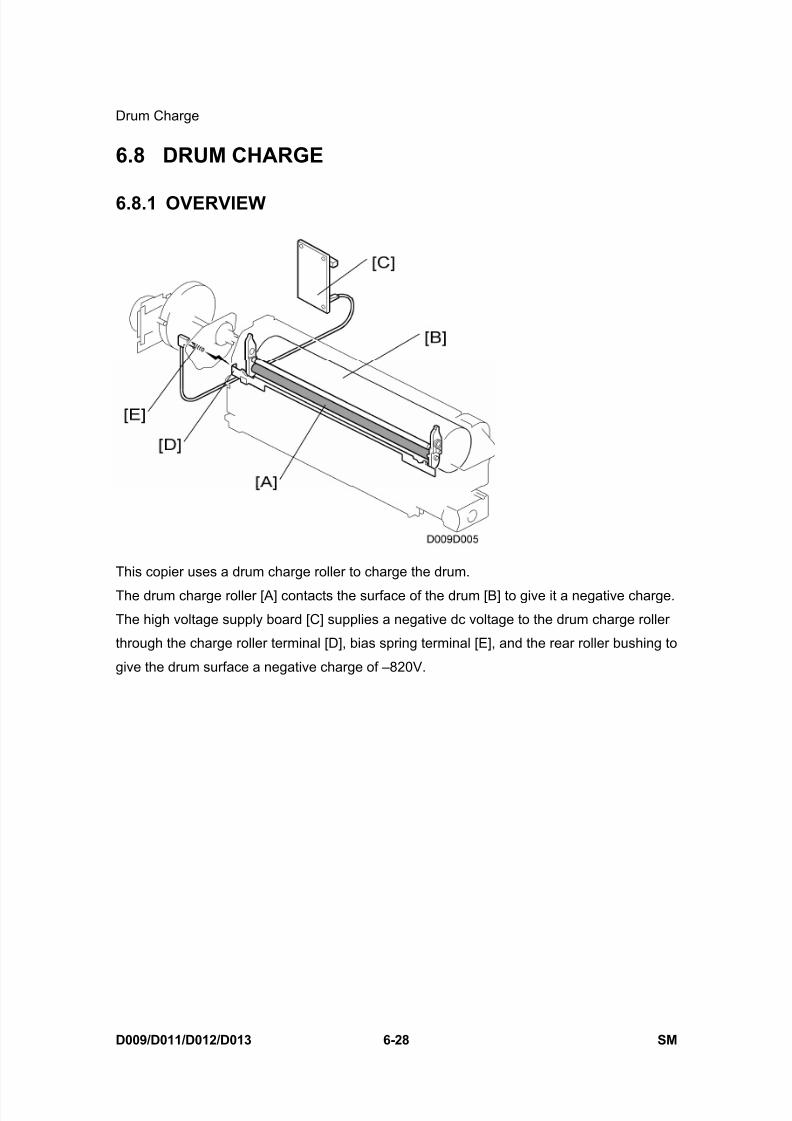
8/15/2019 Ricoh MP 4000 SM D009_D011_D012_D013 SERVICE MANUAL .pdf
http://slidepdf.com/reader/full/ricoh-mp-4000-sm-d009d011d012d013-service-manual-pdf 578/1162
Drum Charge
D009/D011/D012/D013 6-28 SM
6.8 DRUM CHARGE
6.8.1 OVERVIEW
This copier uses a drum charge roller to charge the drum.
The drum charge roller [A] contacts the surface of the drum [B] to give it a negative charge.
The high voltage supply board [C] supplies a negative dc voltage to the drum charge roller
through the charge roller terminal [D], bias spring terminal [E], and the rear roller bushing to
give the drum surface a negative charge of –820V.

8/15/2019 Ricoh MP 4000 SM D009_D011_D012_D013 SERVICE MANUAL .pdf
http://slidepdf.com/reader/full/ricoh-mp-4000-sm-d009d011d012d013-service-manual-pdf 579/1162
Drum Charge
SM 6-29 D009/D011/D012/D013
D e t a i l e d
D e s c r i p
t i o n s
6.8.2 CHARGE ROLLER VOLTAGE CORRECTION
Correction for Environmental Conditions
The voltage transferred from roller to drum could vary with the temperature and humidity
around the drum charge roller. The lower the temperature or humidity, the higher the applied
voltage required.
The ID sensor measures the effects of ambient conditions, and any small change in drum
potential caused by changes in temperature/humidity is reflected in the amount of toner
transferred to the drum.
This measurement is done immediately after the ID sensor pattern for toner density control.
After creating ID sensor pattern [A], another pattern [B] is made. To do this, the LD switches
off, the charge roller voltage drops, and the drum potential is reduced to -600V. At the same
time, development bias returns to -550V. The drum potential is now slightly higher than the
development bias, so only a very small amount of toner transfers to the drum. The ID sensor
measures the density of pattern [B], and Vsdp, the output voltage, is compared with Vsg
which was read from the bare drum at the same time.

8/15/2019 Ricoh MP 4000 SM D009_D011_D012_D013 SERVICE MANUAL .pdf
http://slidepdf.com/reader/full/ricoh-mp-4000-sm-d009d011d012d013-service-manual-pdf 580/1162
Drum Charge
D009/D011/D012/D013 6-30 SM
Correction for Paper Width and Thickness
This correction is done for the bypass tray only. The by-pass tray can be used for non-standard paper narrower than sizes accepted
by the paper trays. Thicker paper, OHP sheets, etc. can also be loaded in the
by-pass tray but adjustments must be performed with the SP modes listed below in
order to avoid jams and copy quality problems.
SP Mode SP Name
SP2001-001Charge Roller Bias
Adjustment Width 216 - 297 mm (Default: -1500 V)
SP2309-001 Paper Lower Width [a] Width limit (Default: 150 mm)
SP2309-002 Paper Upper Width [b] Width limit (Default: 216 mm)
SP2914-001 C-alpha Adjust 10V/step (Default: 150 V)
SP2914-002 C-beta Adjust 10V/step (Default: 0 V)
The way that these SP modes are used is shown below.
For example, with the default settings, if the paper width fed from the by-pass tray is 200 mm,
the charge roller voltage will be –1500 +0 V.

8/15/2019 Ricoh MP 4000 SM D009_D011_D012_D013 SERVICE MANUAL .pdf
http://slidepdf.com/reader/full/ricoh-mp-4000-sm-d009d011d012d013-service-manual-pdf 581/1162
Drum Charge
SM 6-31 D009/D011/D012/D013
D e t a i l e d
D e s c r i p
t i o n s
6.8.3 ID SENSOR PATTERN PRODUCTION TIMING
When the machine temperature is less than 16°C at power on, an ID sensor pattern is
created after the main machine is powered on, and after finishing a job of 10 or more sheets.The ID sensor pattern production interval can be adjusted with SP2210-001 (ID Sensor
Pattern Interval).
6.8.4 DRUM CHARGE ROLLER CLEANING
The drum charge roller [A] (always in contact with the drum), gets dirty easily.
The brush roller [B] remains in contact with the charge roller to clean the charge roller.
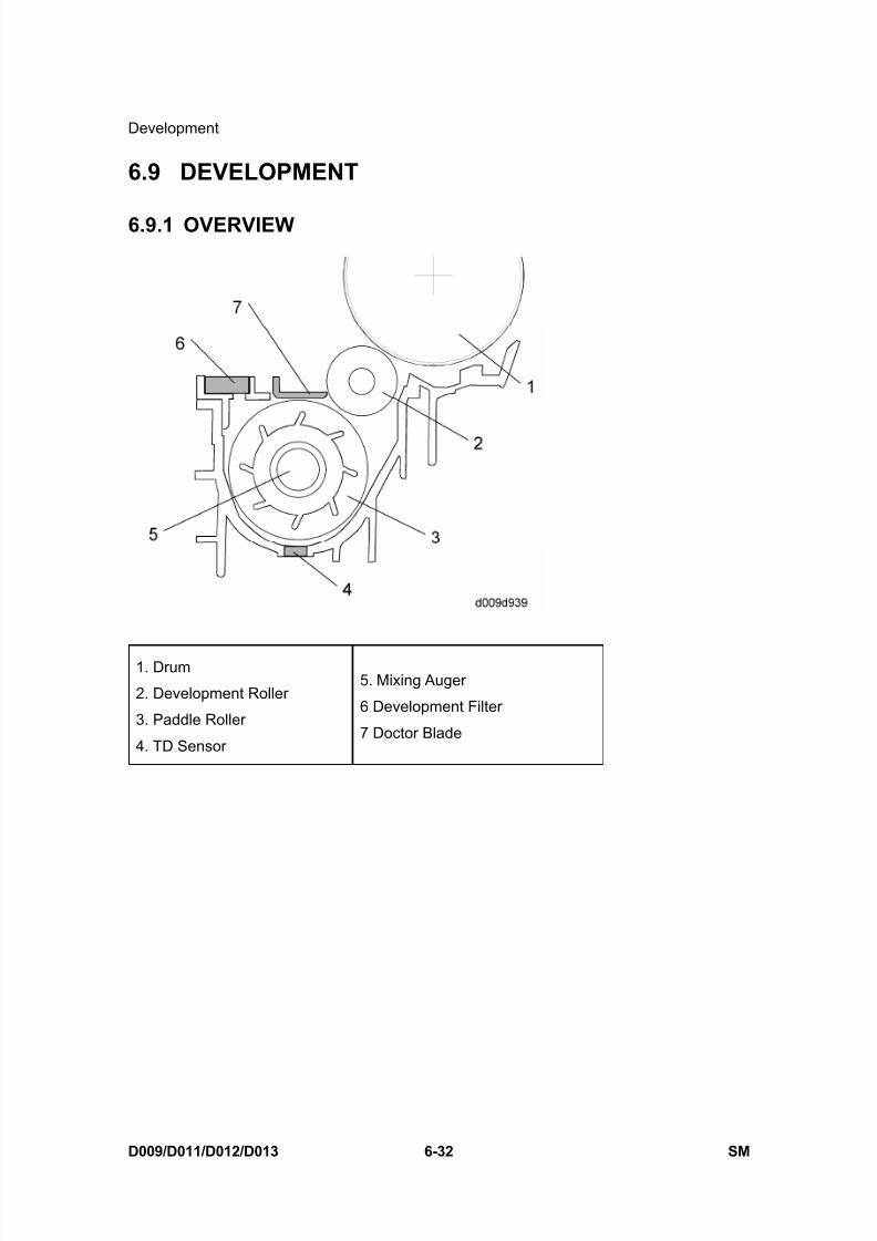
8/15/2019 Ricoh MP 4000 SM D009_D011_D012_D013 SERVICE MANUAL .pdf
http://slidepdf.com/reader/full/ricoh-mp-4000-sm-d009d011d012d013-service-manual-pdf 582/1162
Development
D009/D011/D012/D013 6-32 SM
6.9 DEVELOPMENT
6.9.1 OVERVIEW
1. Drum
2. Development Roller
3. Paddle Roller
4. TD Sensor
5. Mixing Auger
6 Development Filter
7 Doctor Blade

8/15/2019 Ricoh MP 4000 SM D009_D011_D012_D013 SERVICE MANUAL .pdf
http://slidepdf.com/reader/full/ricoh-mp-4000-sm-d009d011d012d013-service-manual-pdf 583/1162
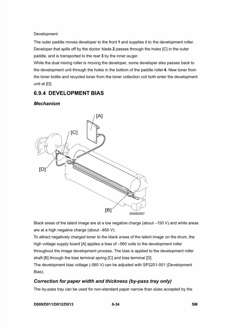
8/15/2019 Ricoh MP 4000 SM D009_D011_D012_D013 SERVICE MANUAL .pdf
http://slidepdf.com/reader/full/ricoh-mp-4000-sm-d009d011d012d013-service-manual-pdf 584/1162
Development
D009/D011/D012/D013 6-34 SM
The outer paddle moves developer to the front 1 and supplies it to the development roller.
Developer that spills off by the doctor blade 2 passes through the holes [C] in the outer
paddle, and is transported to the rear 3 by the inner auger.While the dual mixing roller is moving the developer, some developer also passes back to
the development unit through the holes in the bottom of the paddle roller 4. New toner from
the toner bottle and recycled toner from the toner collection coil both enter the development
unit at [D].
6.9.4 DEVELOPMENT BIAS
Mechanism
Black areas of the latent image are at a low negative charge (about –150 V) and white areas
are at a high negative charge (about –850 V).To attract negatively charged toner to the black areas of the latent image on the drum, the
high voltage supply board [A] applies a bias of –560 volts to the development roller
throughout the image development process. The bias is applied to the development roller
shaft [B] through the bias terminal spring [C] and bias terminal [D].
The development bias voltage (-560 V) can be adjusted with SP2201-001 (Development
Bias).
Correction for paper width and thickness (by-pass tray only)
The by-pass tray can be used for non-standard paper narrow than sizes accepted by the
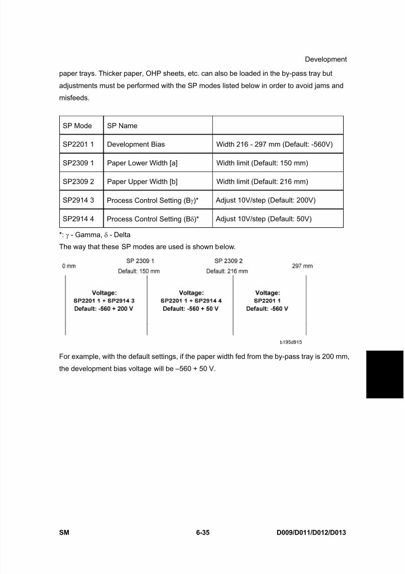
8/15/2019 Ricoh MP 4000 SM D009_D011_D012_D013 SERVICE MANUAL .pdf
http://slidepdf.com/reader/full/ricoh-mp-4000-sm-d009d011d012d013-service-manual-pdf 585/1162
Development
SM 6-35 D009/D011/D012/D013
D e t a i l e d
D e s c r i p
t i o n s
paper trays. Thicker paper, OHP sheets, etc. can also be loaded in the by-pass tray but
adjustments must be performed with the SP modes listed below in order to avoid jams and
misfeeds.
SP Mode SP Name
SP2201 1 Development Bias Width 216 - 297 mm (Default: -560V)
SP2309 1 Paper Lower Width [a] Width limit (Default: 150 mm)
SP2309 2 Paper Upper Width [b] Width limit (Default: 216 mm)
SP2914 3 Process Control Setting (B γ)* Adjust 10V/step (Default: 200V)
SP2914 4 Process Control Setting (B δ)* Adjust 10V/step (Default: 50V)
*: γ - Gamma, δ - Delta
The way that these SP modes are used is shown below.
For example, with the default settings, if the paper width fed from the by-pass tray is 200 mm,
the development bias voltage will be –560 + 50 V.
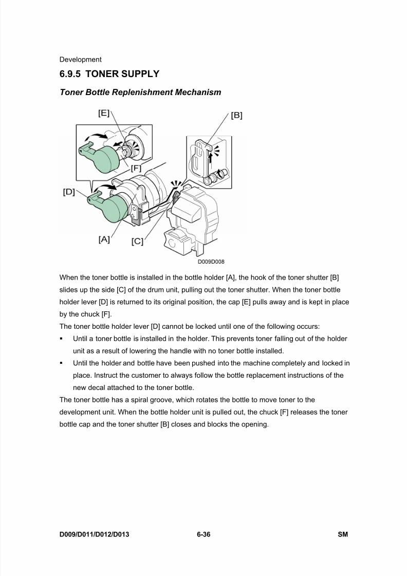
8/15/2019 Ricoh MP 4000 SM D009_D011_D012_D013 SERVICE MANUAL .pdf
http://slidepdf.com/reader/full/ricoh-mp-4000-sm-d009d011d012d013-service-manual-pdf 586/1162
Development
D009/D011/D012/D013 6-36 SM
6.9.5 TONER SUPPLY
Toner Bottle Replenishment Mechanism
When the toner bottle is installed in the bottle holder [A], the hook of the toner shutter [B]
slides up the side [C] of the drum unit, pulling out the toner shutter. When the toner bottle
holder lever [D] is returned to its original position, the cap [E] pulls away and is kept in placeby the chuck [F].
The toner bottle holder lever [D] cannot be locked until one of the following occurs:
Until a toner bottle is installed in the holder. This prevents toner falling out of the holder
unit as a result of lowering the handle with no toner bottle installed.
Until the holder and bottle have been pushed into the machine completely and locked in
place. Instruct the customer to always follow the bottle replacement instructions of the
new decal attached to the toner bottle.
The toner bottle has a spiral groove, which rotates the bottle to move toner to the
development unit. When the bottle holder unit is pulled out, the chuck [F] releases the toner
bottle cap and the toner shutter [B] closes and blocks the opening.
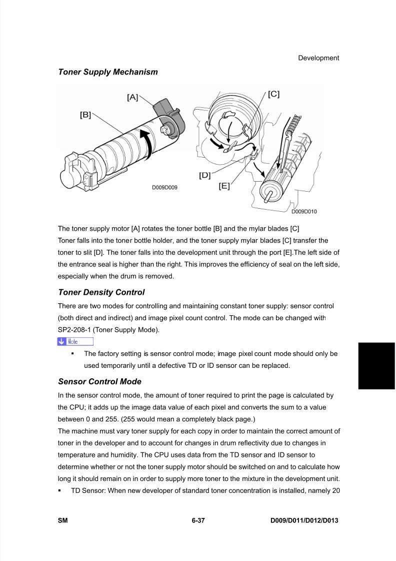
8/15/2019 Ricoh MP 4000 SM D009_D011_D012_D013 SERVICE MANUAL .pdf
http://slidepdf.com/reader/full/ricoh-mp-4000-sm-d009d011d012d013-service-manual-pdf 587/1162
Development
SM 6-37 D009/D011/D012/D013
D e t a i l e d
D e s c r i p
t i o n s
Toner Supply Mechanism
The toner supply motor [A] rotates the toner bottle [B] and the mylar blades [C]
Toner falls into the toner bottle holder, and the toner supply mylar blades [C] transfer the
toner to slit [D]. The toner falls into the development unit through the port [E].The left side of
the entrance seal is higher than the right. This improves the efficiency of seal on the left side,
especially when the drum is removed.
Toner Density ControlThere are two modes for controlling and maintaining constant toner supply: sensor control
(both direct and indirect) and image pixel count control. The mode can be changed with
SP2-208-1 (Toner Supply Mode).
The factory setting is sensor control mode; image pixel count mode should only be
used temporarily until a defective TD or ID sensor can be replaced.
Sensor Control Mode
In the sensor control mode, the amount of toner required to print the page is calculated by
the CPU; it adds up the image data value of each pixel and converts the sum to a value
between 0 and 255. (255 would mean a completely black page.)
The machine must vary toner supply for each copy in order to maintain the correct amount of
toner in the developer and to account for changes in drum reflectivity due to changes in
temperature and humidity. The CPU uses data from the TD sensor and ID sensor to
determine whether or not the toner supply motor should be switched on and to calculate how
long it should remain on in order to supply more toner to the mixture in the development unit.
TD Sensor: When new developer of standard toner concentration is installed, namely 20

8/15/2019 Ricoh MP 4000 SM D009_D011_D012_D013 SERVICE MANUAL .pdf
http://slidepdf.com/reader/full/ricoh-mp-4000-sm-d009d011d012d013-service-manual-pdf 588/1162
Development
D009/D011/D012/D013 6-38 SM
g of toner per 500 g of developer (4.0% by weight), the TD sensor must be set to its
initial setting of 3.0V with SP2-801. This initial setting is used as the toner supply
reference voltage or Vref. For every copy cycle, the TD sensor directly checks the tonerdensity in the developer mixture, and after 10 copies these 10 readings are averaged
and this value becomes TD sensor output voltage Vt(10).
The machine compares Vt(10) with Vref. If Vt(10) is greater than Vref, the toner
concentration in the development unit judged to be low. When Vt(10) is detected to be
greater than Vref 20 times, then this indicates that the toner concentration is
consistently low, Vref is incremented by 0.1V, and the conditions are checked again.
The result of this check determines the value of K, the toner supply rate coefficient,
which is one of the factors for the toner supply motor on-time calculation.
ID Sensor: In addition to comparing Vt(10) from the TD sensor and Vref, after every 10
copies the ID sensor, located at the lower right area of the drum, checks both the
reflectivity (Vsg) and the pattern on the drum (Vsp), created by the laser diodes and
charge roller. If the reflected light is too strong, this indicates that toner is low and toner
is added to the development unit. (The frequency of these checks can be adjusted with
SP2-210 (ID Sensor Pattern Interval).
Image Pixel Count Mode
This mode should only be used as a temporary measure while waiting for replacement parts,such as a TD sensor. This mode controls the toner supply amount using the same method
for determining the toner bottle motor on time. However, the values that were in effect when
the toner density control mode was changed over to image pixel count mode with
SP2-208-1 (Toner Supply Mode) remain in effect and cannot be changed.
6.9.6 TONER NEAR END/END DETECTION
Toner Near End
The machine triggers the toner near-end alert and starts to rotate the toner supply bottle
when either of the following two conditions occur.
The machine detects (1) the toner supply rate (amount of toner supplied per second set
with SP2209-1) drops to 25, (2) the current output of the TD sensor (Vt) has dropped
below the target value after 40 samples, and then (3) still fails to detect the target Vt
after an additional 40 samples.
The machine determines that the toner density is too light after it detects that (1) the
difference between Vref (the TD sensor reference voltage) and the averaged density of
the previous 10 copies is more than 0.2V, and (2) Vsp (the reflectivity of the ID sensor
pattern) is greater than 0.7V.
8/15/2019 Ricoh MP 4000 SM D009_D011_D012_D013 SERVICE MANUAL .pdf
http://slidepdf.com/reader/full/ricoh-mp-4000-sm-d009d011d012d013-service-manual-pdf 589/1162
Development
SM 6-39 D009/D011/D012/D013
D e t a i l e d
D e s c r i p
t i o n s
Toner End
After the machine enters the toner near-mode, it will trigger the toner end alert if any of the
conditions below continue to exist: TD sensor output does not reach the target value within 90 copies after the toner
near-end alert ("90" is the default setting for SP2213).
The ID sensor output from reading the ID sensor pattern (Vsp) is extremely low (light).
The averaged TD sensor output Vt exceeds 0.15V.
6.9.7 TONER END RECOVERY
If the front door is opened for 10 seconds and then closed while a toner near end/end
condition exists, the machine will attempt to recover. When the front door is closed, the toner
supply motor turns on to supply toner. The machine checks the TD sensor output 2 seconds
after the main motor turns on (Vtp), and the sensor is checked again every 1 second (Vtp1)
The machine detects the toner concentration using Vref, Vt (10), Vtp, and Vtp1. If the toner
concentration is still too low, the toner supply motor remains on for another 10 seconds while
the machine checks Vt. If toner concentration is judged to be at the standard level, then the
toner near end/end condition is cancelled and K (toner supply coefficient) is reset. If toner
concentration has not reached the standard level, the toner supply motor rotates
continuously until it does (maximum motor on time is 16 seconds) and then it will switch off.
6.9.8 TONER SUPPLY WITH ABNORMAL SENSORS
The TD sensor is checked every copy. If the readings from the TD sensor become abnormal
during a copy job, the machine holds the GAIN factor constant (GAIN is normally calculated
from TD sensor readings) to allow toner supply to vary with only pixel count for the rest of
the copy job. Then at the end of the copy job, an SC code is generated and the machine
must be repaired.
The ID sensor is checked every 10 copies. If readings become abnormal, an SC code is
generated and the machine must be repaired. If this happens during a copy job, Vref is notchanged, the copy job is allowed to finish, and then the SC code is generated.
If spare parts are not available, the technician can use SP2-208-1 to temporarily put the
machine in image pixel count mode. ( Chapter 5 Service Tables)
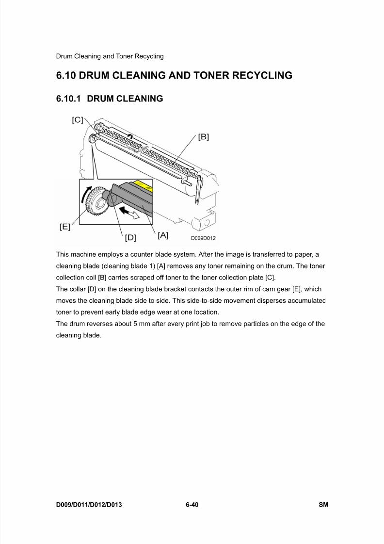
8/15/2019 Ricoh MP 4000 SM D009_D011_D012_D013 SERVICE MANUAL .pdf
http://slidepdf.com/reader/full/ricoh-mp-4000-sm-d009d011d012d013-service-manual-pdf 590/1162
Drum Cleaning and Toner Recycling
D009/D011/D012/D013 6-40 SM
6.10 DRUM CLEANING AND TONER RECYCLING
6.10.1 DRUM CLEANING
This machine employs a counter blade system. After the image is transferred to paper, a
cleaning blade (cleaning blade 1) [A] removes any toner remaining on the drum. The toner
collection coil [B] carries scraped off toner to the toner collection plate [C].
The collar [D] on the cleaning blade bracket contacts the outer rim of cam gear [E], which
moves the cleaning blade side to side. This side-to-side movement disperses accumulated
toner to prevent early blade edge wear at one location.
The drum reverses about 5 mm after every print job to remove particles on the edge of the
cleaning blade.
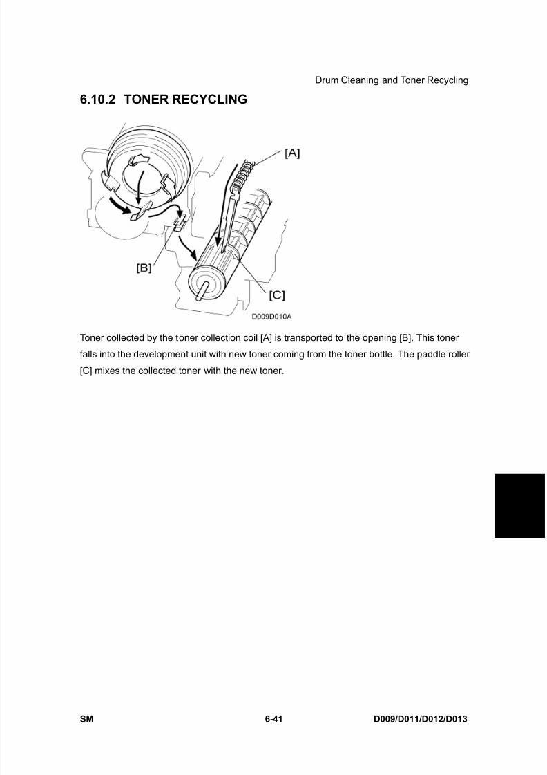
8/15/2019 Ricoh MP 4000 SM D009_D011_D012_D013 SERVICE MANUAL .pdf
http://slidepdf.com/reader/full/ricoh-mp-4000-sm-d009d011d012d013-service-manual-pdf 591/1162
Drum Cleaning and Toner Recycling
SM 6-41 D009/D011/D012/D013
D e t a i l e d
D e s c r i p
t i o n s
6.10.2 TONER RECYCLING
Toner collected by the toner collection coil [A] is transported to the opening [B]. This toner
falls into the development unit with new toner coming from the toner bottle. The paddle roller
[C] mixes the collected toner with the new toner.

8/15/2019 Ricoh MP 4000 SM D009_D011_D012_D013 SERVICE MANUAL .pdf
http://slidepdf.com/reader/full/ricoh-mp-4000-sm-d009d011d012d013-service-manual-pdf 592/1162
Paper Feed
D009/D011/D012/D013 6-42 SM
6.11 PAPER FEED
6.11.1 OVERVIEW
1. Pick-up roller - tray 1
2. Separation roller - tray 1
3. Feed roller - tray 1
4. Registration roller
5. Transport roller - By-pass feed
6. Feed roller - By-pass feed
7. Pick-up roller - By-pass feed
8. Separation roller - By-pass feed
9. Vertical transport roller 1
10. Vertical transport roller 2
11. Feed roller - tray 2
12. Separation roller - tray 2
13. Paper tray 2
14. Pick-up roller - tray 2
15. Paper tray 1
There are two paper trays (500 sheets each), and a by-pass feed table (100 sheets).
The paper feed mechanism uses an FRR system for tray 1, 2 and by-pass tray.
Tray 1 and Tray 2 can hold a range of sizes.
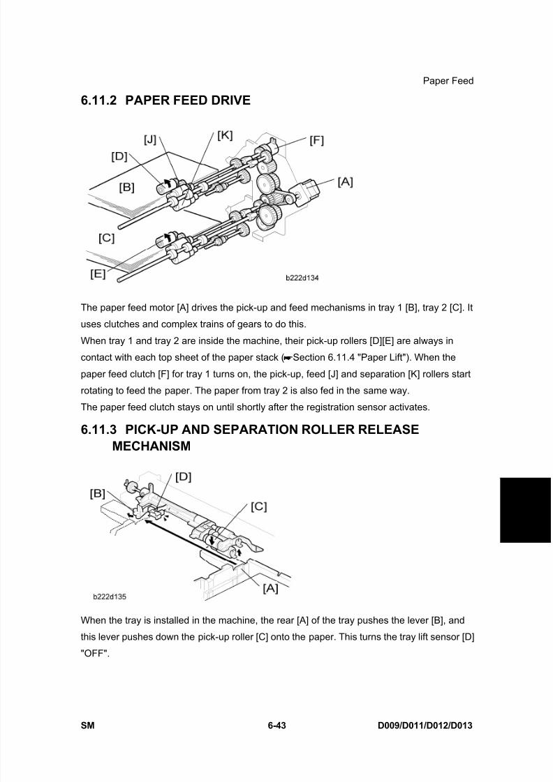
8/15/2019 Ricoh MP 4000 SM D009_D011_D012_D013 SERVICE MANUAL .pdf
http://slidepdf.com/reader/full/ricoh-mp-4000-sm-d009d011d012d013-service-manual-pdf 593/1162
Paper Feed
SM 6-43 D009/D011/D012/D013
D e t a i l e d
D e s c r i p
t i o n s
6.11.2 PAPER FEED DRIVE
The paper feed motor [A] drives the pick-up and feed mechanisms in tray 1 [B], tray 2 [C]. It
uses clutches and complex trains of gears to do this.
When tray 1 and tray 2 are inside the machine, their pick-up rollers [D][E] are always in
contact with each top sheet of the paper stack ( Section 6.11.4 "Paper Lift"). When the
paper feed clutch [F] for tray 1 turns on, the pick-up, feed [J] and separation [K] rollers start
rotating to feed the paper. The paper from tray 2 is also fed in the same way.
The paper feed clutch stays on until shortly after the registration sensor activates.
6.11.3 PICK-UP AND SEPARATION ROLLER RELEASEMECHANISM
When the tray is installed in the machine, the rear [A] of the tray pushes the lever [B], and
this lever pushes down the pick-up roller [C] onto the paper. This turns the tray lift sensor [D]
"OFF".

8/15/2019 Ricoh MP 4000 SM D009_D011_D012_D013 SERVICE MANUAL .pdf
http://slidepdf.com/reader/full/ricoh-mp-4000-sm-d009d011d012d013-service-manual-pdf 594/1162
Paper Feed
D009/D011/D012/D013 6-44 SM
When the paper feed sensor [E] detects the trailing edge of the paper, the pick-up solenoid
[F] turns on and off. This lifts the pick-up roller [G] from the top of the stack paper briefly and
then releases the pick-up roller. This makes paper pick-up more effective.
The paper feed sensor [E] also controls the paper feed clutch "ON" and "OFF" timing.
6.11.4 PAPER LIFT
The rear end of the paper tray pushes the tray set switch (for tray 2, this is the paper size
switch). As a result, the machine detects that the paper tray is installed.
When the machine detects that a tray has been placed in the machine, the tray lift motor [A]
rotates and the coupling gear [B] on the tray lift motor engages the pin [C] on the lift arm
shaft [D]. Then the tray lift arm lifts the tray bottom plate [E]. When the tray is removed from
the machine, the connection between the coupling gear and lift arm shaft is disengaged, and
the tray bottom plate lowers. After that, the coupling gear is moved to its home position.

8/15/2019 Ricoh MP 4000 SM D009_D011_D012_D013 SERVICE MANUAL .pdf
http://slidepdf.com/reader/full/ricoh-mp-4000-sm-d009d011d012d013-service-manual-pdf 595/1162
Paper Feed
SM 6-45 D009/D011/D012/D013
D e t a i l e d
D e s c r i p
t i o n s
When the paper tray is set in the machine, the pick-up roller [F] lowers. When the top sheet
of paper reaches the proper height for paper feed, the paper pushes up the pick-up roller,
and the actuator on the pick-up roller supporter activates the paper lift sensor [G] to stop the
tray lift motor.
After several paper feed cycles, the paper level gradually lowers and the paper lift sensor is
de-activated. The tray lift motor turns on again until this sensor is activated again.
When the paper tray is removed from the machine, the tray lift motor coupling gear
disengages the pin on the lift arm shaft, and the tray bottom plate then drops under its own
weight.
6.11.5 TRAY LOCK MECHANISM
This machine has a tray lock mechanism.
The lock at the front prevents the tray from coming out of the machine during transporting or
shipping. When you pull the handle [A], the lock lever [B] is lowered. As a result, you can pull
out the tray.

8/15/2019 Ricoh MP 4000 SM D009_D011_D012_D013 SERVICE MANUAL .pdf
http://slidepdf.com/reader/full/ricoh-mp-4000-sm-d009d011d012d013-service-manual-pdf 596/1162
Paper Feed
D009/D011/D012/D013 6-46 SM
6.11.6 PAPER SIZE DETECTION – TRAYS 1 AND 2
There are four paper size switches [A] in tray 1 and tray 2. Switch 1 (right end) is for tray set
detection. The other three switches detect the paper size as shown in the table below. The
actuator [B] is moved by the end plate [C].
0: Pushed, 1: Not pushed
Models Switch Location
North America Europe/Asia SW4 SW3 SW2
DLT (A3) SEF* 1 A3 (DLT) SEF* 1 0 0 1
LG (B4) SEF* 2 B4 (LG) SEF* 2 0 0 0
A4 SEF A4 SEF 1 1 0
LT SEF LT SEF 1 1 1
B5 SEF B5 SEF 0 1 1
LT (A4) LEF* 3 A4 (LT) LEF* 3 1 0 0
Exe (B5) LEF* 4 B5 (Exe) LEF* 4 0 1 0
A5 LEF A5 LEF 1 0 1
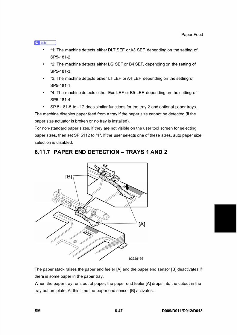
8/15/2019 Ricoh MP 4000 SM D009_D011_D012_D013 SERVICE MANUAL .pdf
http://slidepdf.com/reader/full/ricoh-mp-4000-sm-d009d011d012d013-service-manual-pdf 597/1162
Paper Feed
SM 6-47 D009/D011/D012/D013
D e t a i l e d
D e s c r i p
t i o n s
*1: The machine detects either DLT SEF or A3 SEF, depending on the setting of
SP5-181-2. *2: The machine detects either LG SEF or B4 SEF, depending on the setting of
SP5-181-3.
*3: The machine detects either LT LEF or A4 LEF, depending on the setting of
SP5-181-1.
*4: The machine detects either Exe LEF or B5 LEF, depending on the setting of
SP5-181-4
SP 5-181-5 to –17 does similar functions for the tray 2 and optional paper trays.
The machine disables paper feed from a tray if the paper size cannot be detected (if the
paper size actuator is broken or no tray is installed).
For non-standard paper sizes, if they are not visible on the user tool screen for selecting
paper sizes, then set SP 5112 to "1". If the user selects one of these sizes, auto paper size
selection is disabled.
6.11.7 PAPER END DETECTION – TRAYS 1 AND 2
The paper stack raises the paper end feeler [A] and the paper end sensor [B] deactivates if
there is some paper in the paper tray.
When the paper tray runs out of paper, the paper end feeler [A] drops into the cutout in the
tray bottom plate. At this time the paper end sensor [B] activates.
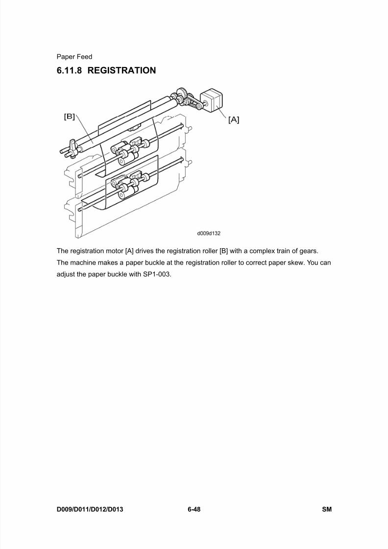
8/15/2019 Ricoh MP 4000 SM D009_D011_D012_D013 SERVICE MANUAL .pdf
http://slidepdf.com/reader/full/ricoh-mp-4000-sm-d009d011d012d013-service-manual-pdf 598/1162
Paper Feed
D009/D011/D012/D013 6-48 SM
6.11.8 REGISTRATION
The registration motor [A] drives the registration roller [B] with a complex train of gears.
The machine makes a paper buckle at the registration roller to correct paper skew. You can
adjust the paper buckle with SP1-003.
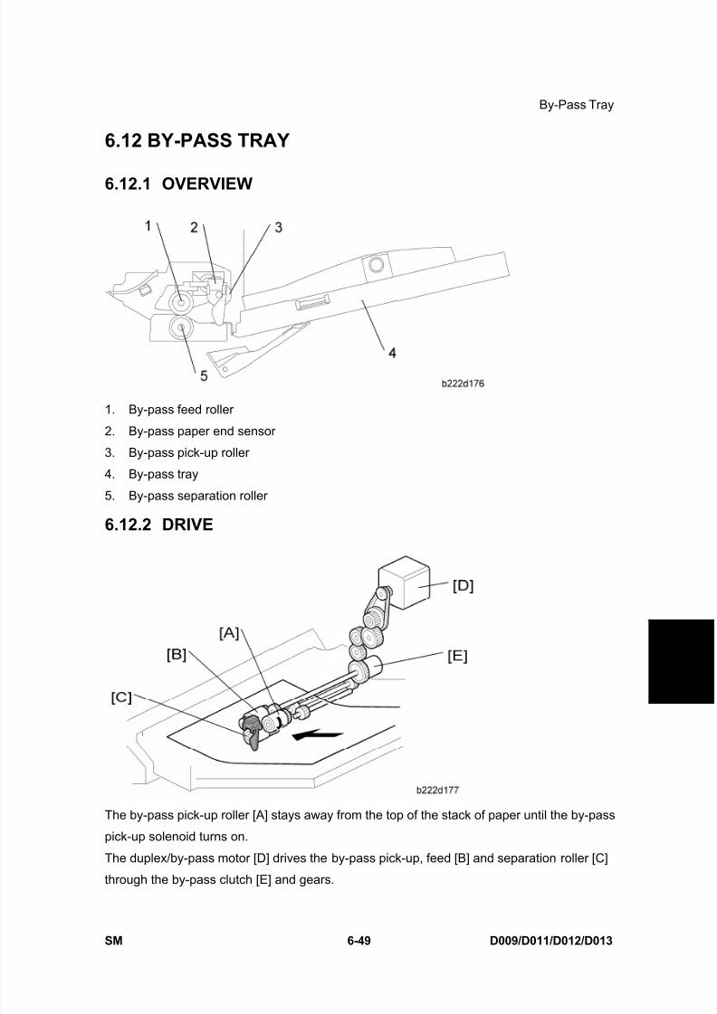
8/15/2019 Ricoh MP 4000 SM D009_D011_D012_D013 SERVICE MANUAL .pdf
http://slidepdf.com/reader/full/ricoh-mp-4000-sm-d009d011d012d013-service-manual-pdf 599/1162
By-Pass Tray
SM 6-49 D009/D011/D012/D013
D e t a i l e d
D e s c r i p
t i o n s
6.12 BY-PASS TRAY
6.12.1 OVERVIEW
1. By-pass feed roller
2. By-pass paper end sensor
3. By-pass pick-up roller
4. By-pass tray
5. By-pass separation roller
6.12.2 DRIVE
The by-pass pick-up roller [A] stays away from the top of the stack of paper until the by-pass
pick-up solenoid turns on.
The duplex/by-pass motor [D] drives the by-pass pick-up, feed [B] and separation roller [C]
through the by-pass clutch [E] and gears.

8/15/2019 Ricoh MP 4000 SM D009_D011_D012_D013 SERVICE MANUAL .pdf
http://slidepdf.com/reader/full/ricoh-mp-4000-sm-d009d011d012d013-service-manual-pdf 600/1162
By-Pass Tray
D009/D011/D012/D013 6-50 SM
6.12.3 BY-PASS PAPER SEPARATION
When the by-pass paper end sensor [A] sensor detects paper and the machine gets a
by-pass printing job, the by-pass solenoid [B] drops the by-pass pick-up roller [C] onto the
top of the paper stack on the by-pass tray. After that, the by-pass pick-up roller moves one
sheet of paper to the feed roller.
This machine uses an FRR (Feed and Reverse Roller) system for feeding paper.
There is friction between the by-pass feed roller [E] and separation roller [D]. This frictionseparates the top sheet of paper from the stack.
6.12.4 BY-PASS PAPER SIZE DETECTION
There are two paper side plates [A] on the by-pass tray. These connect with the paper size
sensor [B] through a rack-and-pinion mechanism.
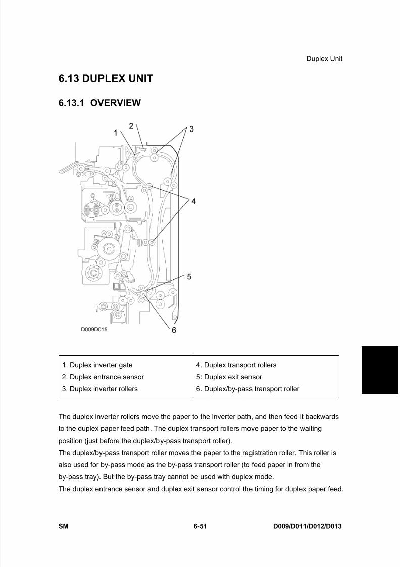
8/15/2019 Ricoh MP 4000 SM D009_D011_D012_D013 SERVICE MANUAL .pdf
http://slidepdf.com/reader/full/ricoh-mp-4000-sm-d009d011d012d013-service-manual-pdf 601/1162
Duplex Unit
SM 6-51 D009/D011/D012/D013
D e t a i l e d
D e s c r i p
t i o n s
6.13 DUPLEX UNIT
6.13.1 OVERVIEW
1. Duplex inverter gate
2. Duplex entrance sensor
3. Duplex inverter rollers
4. Duplex transport rollers
5: Duplex exit sensor
6. Duplex/by-pass transport roller
The duplex inverter rollers move the paper to the inverter path, and then feed it backwards
to the duplex paper feed path. The duplex transport rollers move paper to the waiting
position (just before the duplex/by-pass transport roller).
The duplex/by-pass transport roller moves the paper to the registration roller. This roller is
also used for by-pass mode as the by-pass transport roller (to feed paper in from the
by-pass tray). But the by-pass tray cannot be used with duplex mode.
The duplex entrance sensor and duplex exit sensor control the timing for duplex paper feed.
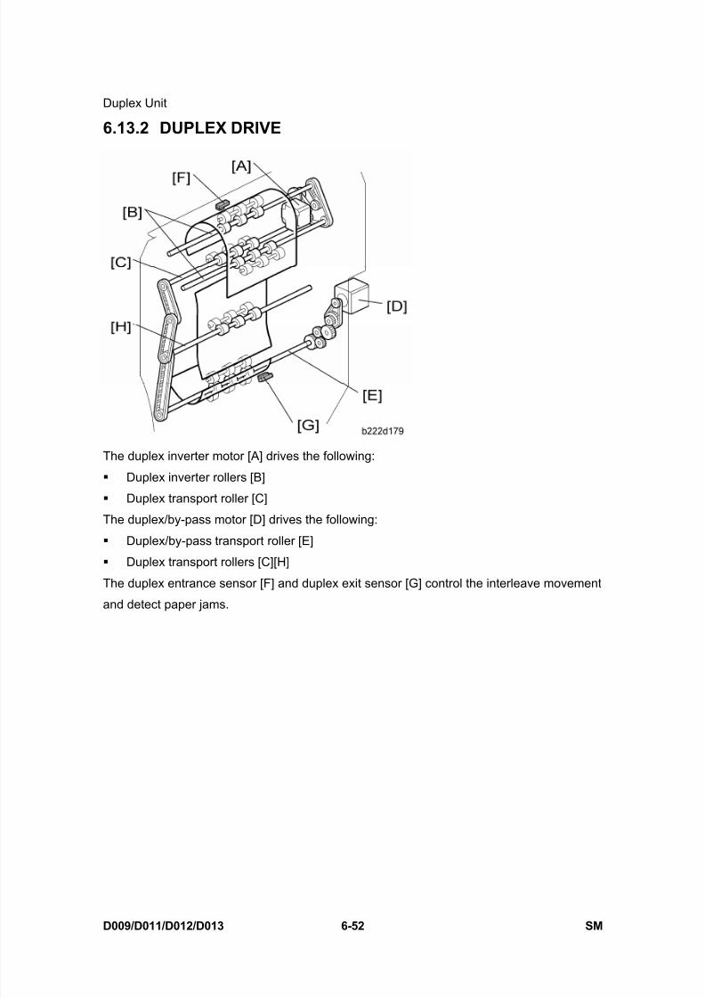
8/15/2019 Ricoh MP 4000 SM D009_D011_D012_D013 SERVICE MANUAL .pdf
http://slidepdf.com/reader/full/ricoh-mp-4000-sm-d009d011d012d013-service-manual-pdf 602/1162
Duplex Unit
D009/D011/D012/D013 6-52 SM
6.13.2 DUPLEX DRIVE
The duplex inverter motor [A] drives the following:
Duplex inverter rollers [B]
Duplex transport roller [C]
The duplex/by-pass motor [D] drives the following: Duplex/by-pass transport roller [E]
Duplex transport rollers [C][H]
The duplex entrance sensor [F] and duplex exit sensor [G] control the interleave movement
and detect paper jams.
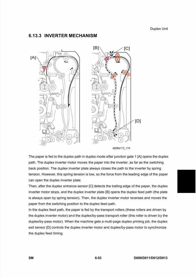
8/15/2019 Ricoh MP 4000 SM D009_D011_D012_D013 SERVICE MANUAL .pdf
http://slidepdf.com/reader/full/ricoh-mp-4000-sm-d009d011d012d013-service-manual-pdf 603/1162
Duplex Unit
SM 6-53 D009/D011/D012/D013
D e t a i l e d
D e s c r i p
t i o n s
6.13.3 INVERTER MECHANISM
The paper is fed to the duplex path in duplex mode after junction gate 1 [A] opens the duplex
path. The duplex inverter motor moves the paper into the inverter, as far as the switching
back position. The duplex inverter plate always closes the path to the inverter by spring
tension. However, this spring tension is low, so the force from the leading edge of the paper
can open the duplex inverter plate.
Then, after the duplex entrance sensor [C] detects the trailing edge of the paper, the duplex
inverter motor stops, and the duplex inverter plate [B] opens the duplex feed path (the plate
is always open by spring tension). Then, the duplex inverter motor reverses and moves the
paper from the switching position to the duplex feed path.
In the duplex feed path, the paper is fed by the transport rollers (these rollers are driven by
the duplex inverter motor) and the duplex/by-pass transport roller (this roller is driven by the
duplex/by-pass motor). When the machine gets a multi-page duplex printing job, the duplex
exit sensor [D] controls the duplex inverter motor and duplex/by-pass motor to synchronize
the duplex feed timing.
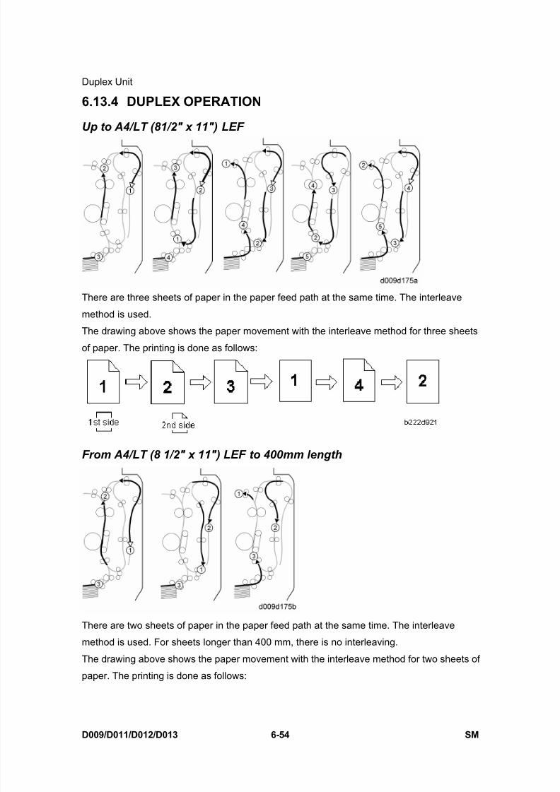
8/15/2019 Ricoh MP 4000 SM D009_D011_D012_D013 SERVICE MANUAL .pdf
http://slidepdf.com/reader/full/ricoh-mp-4000-sm-d009d011d012d013-service-manual-pdf 604/1162
Duplex Unit
D009/D011/D012/D013 6-54 SM
6.13.4 DUPLEX OPERATION
Up to A4/LT (81/2" x 11") LEF
There are three sheets of paper in the paper feed path at the same time. The interleave
method is used.
The drawing above shows the paper movement with the interleave method for three sheets
of paper. The printing is done as follows:
From A4/LT (8 1/2" x 11") LEF to 400mm length
There are two sheets of paper in the paper feed path at the same time. The interleave
method is used. For sheets longer than 400 mm, there is no interleaving.
The drawing above shows the paper movement with the interleave method for two sheets of
paper. The printing is done as follows:
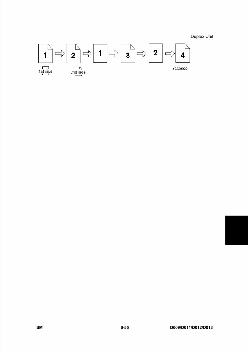
8/15/2019 Ricoh MP 4000 SM D009_D011_D012_D013 SERVICE MANUAL .pdf
http://slidepdf.com/reader/full/ricoh-mp-4000-sm-d009d011d012d013-service-manual-pdf 605/1162
Duplex Unit
SM 6-55 D009/D011/D012/D013
D e t a i l e d
D e s c r i p
t i o n s
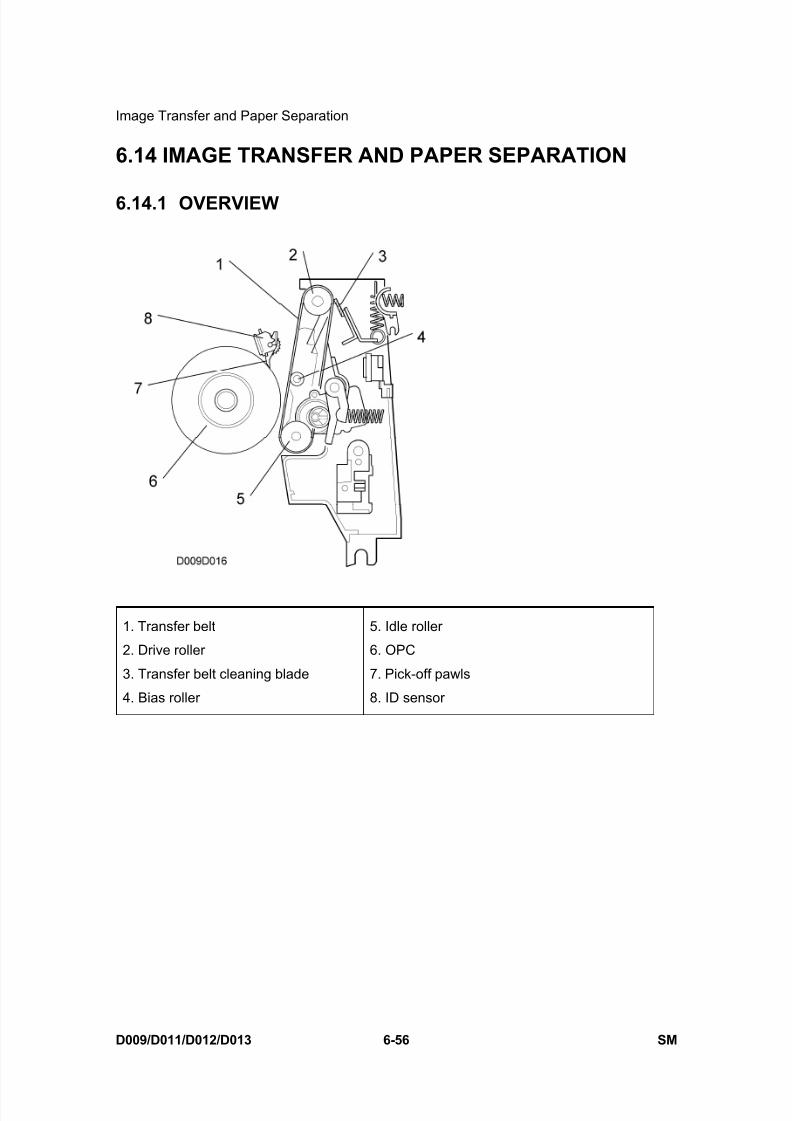
8/15/2019 Ricoh MP 4000 SM D009_D011_D012_D013 SERVICE MANUAL .pdf
http://slidepdf.com/reader/full/ricoh-mp-4000-sm-d009d011d012d013-service-manual-pdf 606/1162
Image Transfer and Paper Separation
D009/D011/D012/D013 6-56 SM
6.14 IMAGE TRANSFER AND PAPER SEPARATION
6.14.1 OVERVIEW
1. Transfer belt
2. Drive roller
3. Transfer belt cleaning blade
4. Bias roller
5. Idle roller
6. OPC
7. Pick-off pawls
8. ID sensor
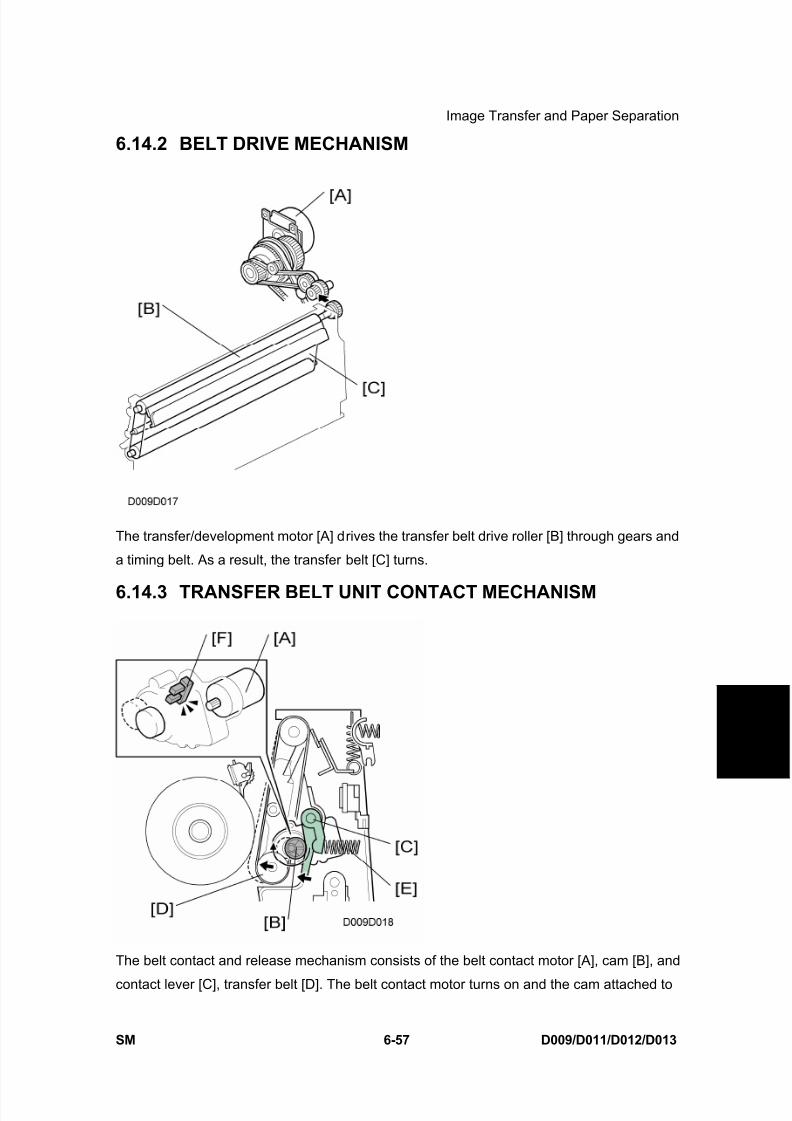
8/15/2019 Ricoh MP 4000 SM D009_D011_D012_D013 SERVICE MANUAL .pdf
http://slidepdf.com/reader/full/ricoh-mp-4000-sm-d009d011d012d013-service-manual-pdf 607/1162
Image Transfer and Paper Separation
SM 6-57 D009/D011/D012/D013
D e t a i l e d
D e s c r i p
t i o n s
6.14.2 BELT DRIVE MECHANISM
The transfer/development motor [A] drives the transfer belt drive roller [B] through gears and
a timing belt. As a result, the transfer belt [C] turns.
6.14.3 TRANSFER BELT UNIT CONTACT MECHANISM
The belt contact and release mechanism consists of the belt contact motor [A], cam [B], and
contact lever [C], transfer belt [D]. The belt contact motor turns on and the cam attached to
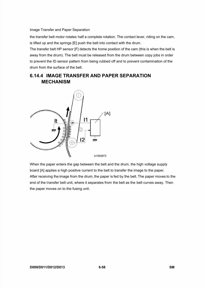
8/15/2019 Ricoh MP 4000 SM D009_D011_D012_D013 SERVICE MANUAL .pdf
http://slidepdf.com/reader/full/ricoh-mp-4000-sm-d009d011d012d013-service-manual-pdf 608/1162
Image Transfer and Paper Separation
D009/D011/D012/D013 6-58 SM
the transfer belt motor rotates half a complete rotation. The contact lever, riding on the cam,
is lifted up and the springs [E] push the belt into contact with the drum.
The transfer belt HP sensor [F] detects the home position of the cam (this is when the belt isaway from the drum). The belt must be released from the drum between copy jobs in order
to prevent the ID sensor pattern from being rubbed off and to prevent contamination of the
drum from the surface of the belt.
6.14.4 IMAGE TRANSFER AND PAPER SEPARATIONMECHANISM
When the paper enters the gap between the belt and the drum, the high voltage supply
board [A] applies a high positive current to the belt to transfer the image to the paper.
After receiving the image from the drum, the paper is fed by the belt. The paper moves to the
end of the transfer belt unit, where it separates from the belt as the belt curves away. Then
the paper moves on to the fusing unit.

8/15/2019 Ricoh MP 4000 SM D009_D011_D012_D013 SERVICE MANUAL .pdf
http://slidepdf.com/reader/full/ricoh-mp-4000-sm-d009d011d012d013-service-manual-pdf 609/1162
Image Transfer and Paper Separation
SM 6-59 D009/D011/D012/D013
D e t a i l e d
D e s c r i p
t i o n s
6.14.5 TRANSFER BELT CHARGE
Mechanism
The high voltage supply board [A] applies a positive current to the transfer belt [B] through
the terminal block [C], terminal plate [D], and the bias roller [E].
The high voltage supply board adjusts the current to the roller to keep a small but constant
current flow to ground through the belt, paper, and drum. If this current is not kept constant,
efficiency of toner transfer and paper separation will vary with paper thickness, type,
environmental condition, or changes in transfer belt surface resistance.
Correction for paper width and thickness
A range of SP modes is available in order to adjust the machine so it can handle papers of
non-standard size and thickness.
For paper width, there are two thresholds. The factory settings are 150 mm (5.9”) and 216
mm (8.5”). Below 216 mm, the transfer current can be increased. By default, the current is
multiplied by 1.2 for the main machine paper trays. For paper widths below 150 mm, the
transfer current can be set higher, but by default it is kept the same as the current for paper
widths below 216 mm. The higher current allows for the tendency of the current to flow
directly from the transfer belt to the drum and not through the paper which could cause an
insufficient amount of toner to transfer to narrow width paper.
Thick paper must be fed from the by-pass tray because SP modes are available only for the
by-pass tray in order to accommodate thick paper. By default, the current for paper narrower
than 216 mm is 1.5 times the normal current.

8/15/2019 Ricoh MP 4000 SM D009_D011_D012_D013 SERVICE MANUAL .pdf
http://slidepdf.com/reader/full/ricoh-mp-4000-sm-d009d011d012d013-service-manual-pdf 610/1162
Image Transfer and Paper Separation
D009/D011/D012/D013 6-60 SM
This illustration shows the SP modes, which control these currents. The base transfer
current (‘current’ in the diagram) depends on SP 2-301. This is different for various parts of
the image, and is different for the by-pass tray; see the next page for details.
Currents applied to leading edge, image areas - by-pass feed
Transfer current can also be adjusted for the leading edge and the image area, and for
by-pass feed. The timing for starting to apply leading edge current, for the switchover from
leading edge current to image area current, and for switching off at the trailing edge can also
be changed.
The table below lists the SP modes you can use to adjust these settings.
SP2-301 Transfer Current Adjustment
Image areas SP2-301-1 1st Side of Paper
SP2-301-2 2nd Side of Paper
SP2-301-5 By-pass Feed
Leading edge areas SP2-301-3 Leading Edge 1st side
SP2-301-4 Leading Edge 2nd side
SP2-301-6 Leading Edge By-pass Feed
SP2-911 Transfer Current Timing
Timing SP2-911-1 On Timing (at leading edge)
SP2-911-2Switch Timing (from leading edge
to image area current

8/15/2019 Ricoh MP 4000 SM D009_D011_D012_D013 SERVICE MANUAL .pdf
http://slidepdf.com/reader/full/ricoh-mp-4000-sm-d009d011d012d013-service-manual-pdf 611/1162
Image Transfer and Paper Separation
SM 6-61 D009/D011/D012/D013
D e t a i l e d
D e s c r i p
t i o n s
SP2-911-3 Off Timing (at trailing edge)
6.14.6 TRANSFER BELT CLEANING MECHANISM
The cleaning blade [A], always in contact with the transfer belt, scrapes off toner and paper
dust remaining on the transfer belt.
Scraped off toner and paper dust falls into the toner collection tank [B] in the transfer belt
unit. This toner is not recycled. When the toner overflow sensor [C] detects toner overflow,
the toner overflow indicator lights. Up to 999 copies can be made before the toner overflow
condition shuts down the machine.
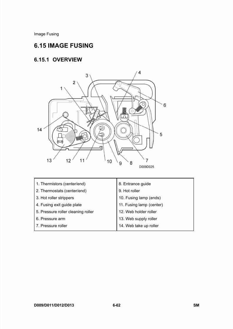
8/15/2019 Ricoh MP 4000 SM D009_D011_D012_D013 SERVICE MANUAL .pdf
http://slidepdf.com/reader/full/ricoh-mp-4000-sm-d009d011d012d013-service-manual-pdf 612/1162
Image Fusing
D009/D011/D012/D013 6-62 SM
6.15 IMAGE FUSING
6.15.1 OVERVIEW
1. Thermistors (center/end)
2. Thermostats (center/end)
3. Hot roller strippers
4. Fusing exit guide plate
5. Pressure roller cleaning roller
6. Pressure arm
7. Pressure roller
8. Entrance guide
9. Hot roller
10. Fusing lamp (ends)
11. Fusing lamp (center)
12. Web holder roller
13. Web supply roller
14. Web take up roller
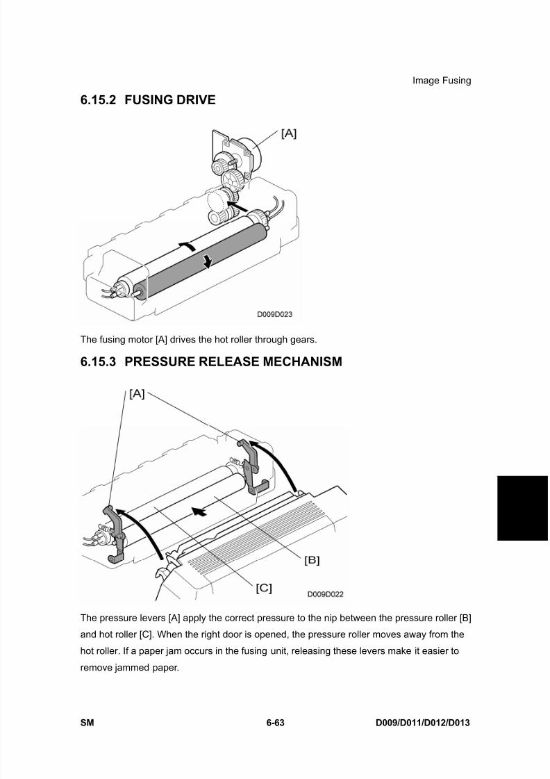
8/15/2019 Ricoh MP 4000 SM D009_D011_D012_D013 SERVICE MANUAL .pdf
http://slidepdf.com/reader/full/ricoh-mp-4000-sm-d009d011d012d013-service-manual-pdf 613/1162
Image Fusing
SM 6-63 D009/D011/D012/D013
D e t a i l e d
D e s c r i p
t i o n s
6.15.2 FUSING DRIVE
The fusing motor [A] drives the hot roller through gears.
6.15.3 PRESSURE RELEASE MECHANISM
The pressure levers [A] apply the correct pressure to the nip between the pressure roller [B]
and hot roller [C]. When the right door is opened, the pressure roller moves away from the
hot roller. If a paper jam occurs in the fusing unit, releasing these levers make it easier to
remove jammed paper.
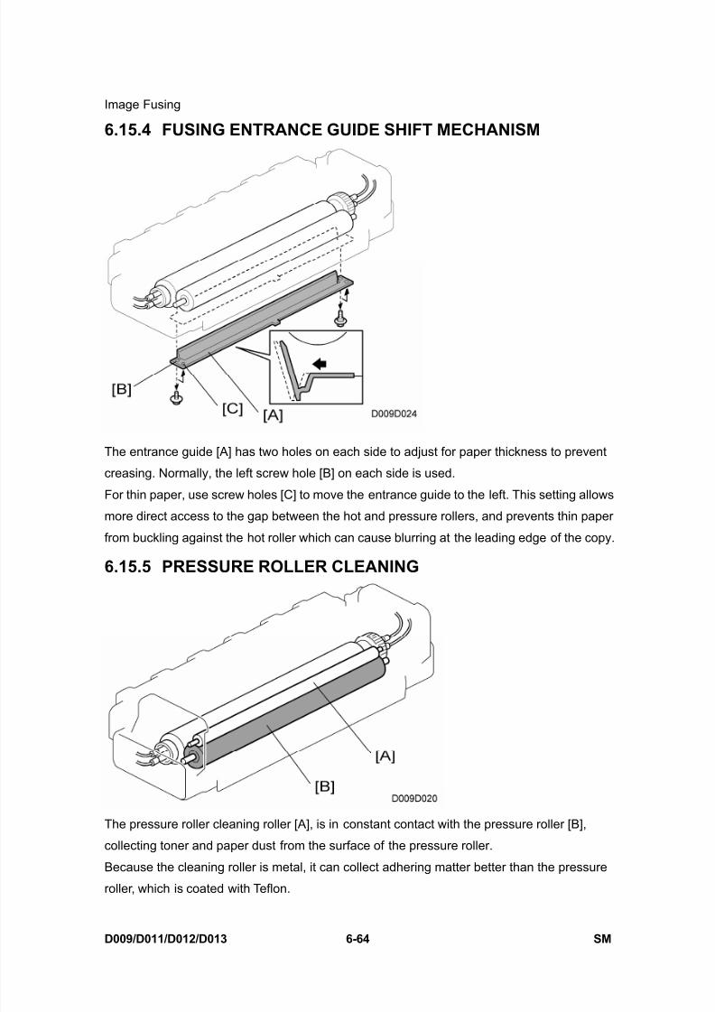
8/15/2019 Ricoh MP 4000 SM D009_D011_D012_D013 SERVICE MANUAL .pdf
http://slidepdf.com/reader/full/ricoh-mp-4000-sm-d009d011d012d013-service-manual-pdf 614/1162
Image Fusing
D009/D011/D012/D013 6-64 SM
6.15.4 FUSING ENTRANCE GUIDE SHIFT MECHANISM
The entrance guide [A] has two holes on each side to adjust for paper thickness to prevent
creasing. Normally, the left screw hole [B] on each side is used.
For thin paper, use screw holes [C] to move the entrance guide to the left. This setting allows
more direct access to the gap between the hot and pressure rollers, and prevents thin paper
from buckling against the hot roller which can cause blurring at the leading edge of the copy.
6.15.5 PRESSURE ROLLER CLEANING
The pressure roller cleaning roller [A], is in constant contact with the pressure roller [B],
collecting toner and paper dust from the surface of the pressure roller.
Because the cleaning roller is metal, it can collect adhering matter better than the pressure
roller, which is coated with Teflon.
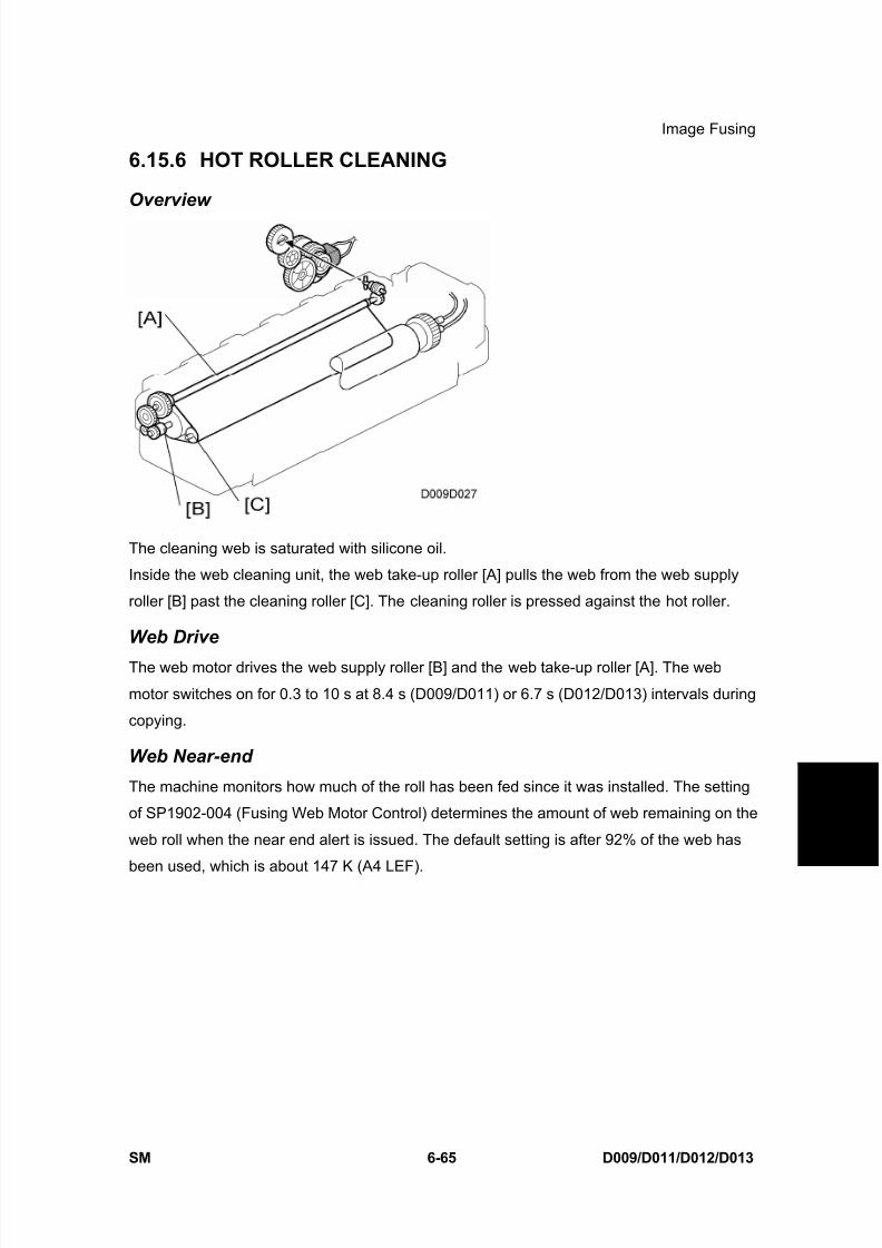
8/15/2019 Ricoh MP 4000 SM D009_D011_D012_D013 SERVICE MANUAL .pdf
http://slidepdf.com/reader/full/ricoh-mp-4000-sm-d009d011d012d013-service-manual-pdf 615/1162
Image Fusing
SM 6-65 D009/D011/D012/D013
D e t a i l e d
D e s c r i p
t i o n s
6.15.6 HOT ROLLER CLEANING
Overview
The cleaning web is saturated with silicone oil.
Inside the web cleaning unit, the web take-up roller [A] pulls the web from the web supply
roller [B] past the cleaning roller [C]. The cleaning roller is pressed against the hot roller.
Web Drive
The web motor drives the web supply roller [B] and the web take-up roller [A]. The web
motor switches on for 0.3 to 10 s at 8.4 s (D009/D011) or 6.7 s (D012/D013) intervals during
copying.
Web Near-end
The machine monitors how much of the roll has been fed since it was installed. The setting
of SP1902-004 (Fusing Web Motor Control) determines the amount of web remaining on the
web roll when the near end alert is issued. The default setting is after 92% of the web has
been used, which is about 147 K (A4 LEF).

8/15/2019 Ricoh MP 4000 SM D009_D011_D012_D013 SERVICE MANUAL .pdf
http://slidepdf.com/reader/full/ricoh-mp-4000-sm-d009d011d012d013-service-manual-pdf 616/1162
Image Fusing
D009/D011/D012/D013 6-66 SM
Web End
The feeler stays on the top of the web roll. When the roll runs out, the actuator on the rear
end of the feeler [A] enters the web end sensor [B] in its on weight.
When all of the web has been used (after about another 30k copies), the actuator rotates, its
feeler actuates the web end sensor. The machine detects the web end status when the web
motor has rotated for 27 seconds after the first web end detection and the web end sensor is
interrupted again.
6.15.7 HOT ROLLER STRIPPER CLEANING
Toner clinging to the hot roller strippers can cause black dots to appear on the back sides of
copies. To ensure that the hot roller strippers are clean and not contaminated by old toner,
the machine switches on the fusing motor and rotates the hot roller after the job. The hot
roller rotation sequence at the end of a job depends on the size of the job.
1st Cleaning Mode
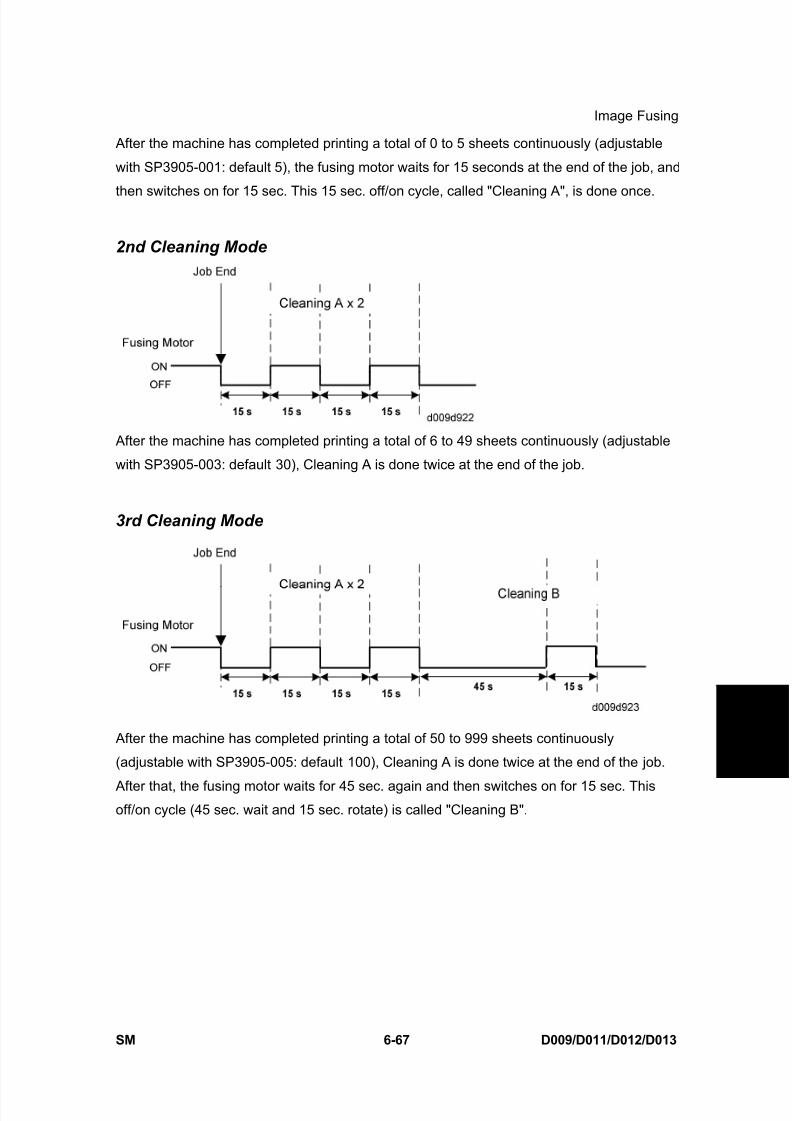
8/15/2019 Ricoh MP 4000 SM D009_D011_D012_D013 SERVICE MANUAL .pdf
http://slidepdf.com/reader/full/ricoh-mp-4000-sm-d009d011d012d013-service-manual-pdf 617/1162
Image Fusing
SM 6-67 D009/D011/D012/D013
D e t a i l e d
D e s c r i p
t i o n s
After the machine has completed printing a total of 0 to 5 sheets continuously (adjustable
with SP3905-001: default 5), the fusing motor waits for 15 seconds at the end of the job, and
then switches on for 15 sec. This 15 sec. off/on cycle, called "Cleaning A", is done once.
2nd Cleaning Mode
After the machine has completed printing a total of 6 to 49 sheets continuously (adjustable
with SP3905-003: default 30), Cleaning A is done twice at the end of the job.
3rd Cleaning Mode
After the machine has completed printing a total of 50 to 999 sheets continuously
(adjustable with SP3905-005: default 100), Cleaning A is done twice at the end of the job.
After that, the fusing motor waits for 45 sec. again and then switches on for 15 sec. Thisoff/on cycle (45 sec. wait and 15 sec. rotate) is called "Cleaning B".
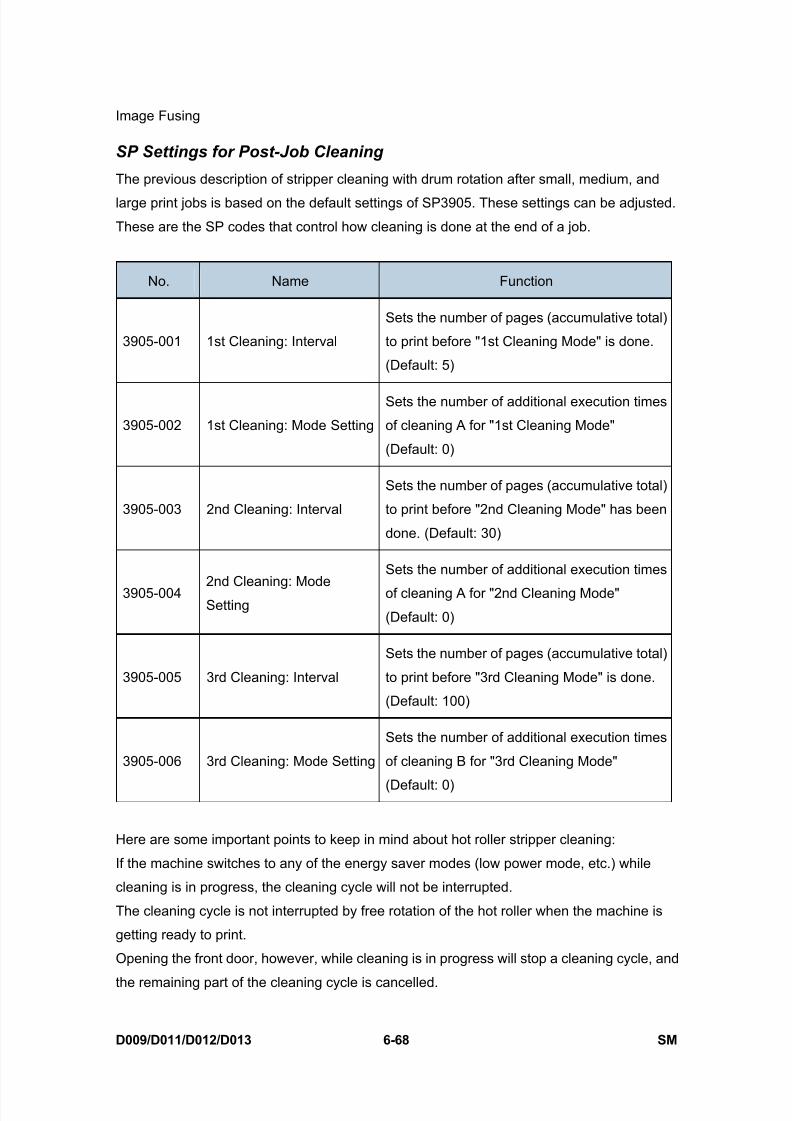
8/15/2019 Ricoh MP 4000 SM D009_D011_D012_D013 SERVICE MANUAL .pdf
http://slidepdf.com/reader/full/ricoh-mp-4000-sm-d009d011d012d013-service-manual-pdf 618/1162
Image Fusing
D009/D011/D012/D013 6-68 SM
SP Settings for Post-Job Cleaning
The previous description of stripper cleaning with drum rotation after small, medium, and
large print jobs is based on the default settings of SP3905. These settings can be adjusted.
These are the SP codes that control how cleaning is done at the end of a job.
No. Name Function
3905-001 1st Cleaning: Interval
Sets the number of pages (accumulative total)
to print before "1st Cleaning Mode" is done.
(Default: 5)
3905-002 1st Cleaning: Mode Setting
Sets the number of additional execution times
of cleaning A for "1st Cleaning Mode"
(Default: 0)
3905-003 2nd Cleaning: Interval
Sets the number of pages (accumulative total)
to print before "2nd Cleaning Mode" has been
done. (Default: 30)
3905-0042nd Cleaning: Mode
Setting
Sets the number of additional execution times
of cleaning A for "2nd Cleaning Mode"
(Default: 0)
3905-005 3rd Cleaning: Interval
Sets the number of pages (accumulative total)
to print before "3rd Cleaning Mode" is done.
(Default: 100)
3905-006 3rd Cleaning: Mode Setting
Sets the number of additional execution times
of cleaning B for "3rd Cleaning Mode"
(Default: 0)
Here are some important points to keep in mind about hot roller stripper cleaning:
If the machine switches to any of the energy saver modes (low power mode, etc.) while
cleaning is in progress, the cleaning cycle will not be interrupted.
The cleaning cycle is not interrupted by free rotation of the hot roller when the machine is
getting ready to print.
Opening the front door, however, while cleaning is in progress will stop a cleaning cycle, and
the remaining part of the cleaning cycle is cancelled.

8/15/2019 Ricoh MP 4000 SM D009_D011_D012_D013 SERVICE MANUAL .pdf
http://slidepdf.com/reader/full/ricoh-mp-4000-sm-d009d011d012d013-service-manual-pdf 619/1162
Image Fusing
SM 6-69 D009/D011/D012/D013
D e t a i l e d
D e s c r i p
t i o n s
6.15.8 FUSING TEMPERATURE CONTROL
The fusing unit has two fusing lamps: the first fusing lamp (ends: 750 W) [A] heats the center
of the fusing roller, and the second fusing lamp (center: 550 W) [B] heats both ends of the
hot roller. This arrangement ensures even heat on all surfaces of the roller.
In order to control the temperature of the roller, two high response thermistors are attached
to the unit, one near the center [C] and one at the end [D] of the hot roller.
Temperature Control
There are two types of temperature control:
On/off control (Default)
Phase control.
Either mode can be selected with SP1104 (Fusing Temperature Control).
After the machine is powered on, the CPU checks the AC frequency for 500 ms, in case
phase control is selected later for the temperature control, and then switches on the fusing
lamp.

8/15/2019 Ricoh MP 4000 SM D009_D011_D012_D013 SERVICE MANUAL .pdf
http://slidepdf.com/reader/full/ricoh-mp-4000-sm-d009d011d012d013-service-manual-pdf 620/1162
Image Fusing
D009/D011/D012/D013 6-70 SM
This model has a new temperature control theory. In previous models , the target
temperature, paper feed temperature and print ready temperature are set to the same
temperature. The machine turns the fusing lamp on and off to keep this temperature.
However, after the start of a job [A], the fusing temperature goes down [D] when the first
sheet of paper [C] goes into the fusing unit while the fusing lamp is turned off [B]. In this case,at the lowest temperature [D], the difference between an ideal fusing temperature and the
actual fusing temperature is up to 40°C. This may cause cold offset on the first output sheet
of paper.
In the D009/D011/D012/D013 models the target temperature and print ready temperature
are set to the same temperature, but the paper feed temperature is different. The machine
turns on the fusing lamp after it gets a print job [A], even if the fusing temperature is at the
target temperature or more. Because the lamp-off time [B] is shorter than previous models,
the lowest temperature [D] while feeding the first sheet of paper is kept closer to the target
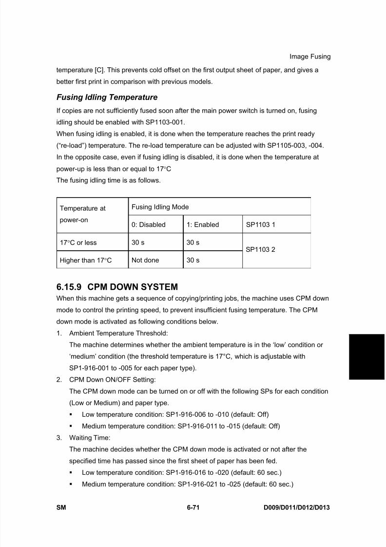
8/15/2019 Ricoh MP 4000 SM D009_D011_D012_D013 SERVICE MANUAL .pdf
http://slidepdf.com/reader/full/ricoh-mp-4000-sm-d009d011d012d013-service-manual-pdf 621/1162
Image Fusing
SM 6-71 D009/D011/D012/D013
D e t a i l e d
D e s c r i p
t i o n s
temperature [C]. This prevents cold offset on the first output sheet of paper, and gives a
better first print in comparison with previous models.
Fusing Idling TemperatureIf copies are not sufficiently fused soon after the main power switch is turned on, fusing
idling should be enabled with SP1103-001.
When fusing idling is enabled, it is done when the temperature reaches the print ready
(“re-load”) temperature. The re-load temperature can be adjusted with SP1105-003, -004.
In the opposite case, even if fusing idling is disabled, it is done when the temperature at
power-up is less than or equal to 17 °C
The fusing idling time is as follows.
Fusing Idling ModeTemperature at
power-on0: Disabled 1: Enabled SP1103 1
17 °C or less 30 s 30 s
Higher than 17 °C Not done 30 s
SP1103 2
6.15.9 CPM DOWN SYSTEMWhen this machine gets a sequence of copying/printing jobs, the machine uses CPM down
mode to control the printing speed, to prevent insufficient fusing temperature. The CPM
down mode is activated as following conditions below.
1. Ambient Temperature Threshold:
The machine determines whether the ambient temperature is in the ‘low’ condition or
‘medium’ condition (the threshold temperature is 17°C, which is adjustable with
SP1-916-001 to -005 for each paper type).
2. CPM Down ON/OFF Setting:
The CPM down mode can be turned on or off with the following SPs for each condition
(Low or Medium) and paper type.
Low temperature condition: SP1-916-006 to -010 (default: Off)
Medium temperature condition: SP1-916-011 to -015 (default: Off)
3. Waiting Time:
The machine decides whether the CPM down mode is activated or not after the
specified time has passed since the first sheet of paper has been fed.
Low temperature condition: SP1-916-016 to -020 (default: 60 sec.)
Medium temperature condition: SP1-916-021 to -025 (default: 60 sec.)
8/15/2019 Ricoh MP 4000 SM D009_D011_D012_D013 SERVICE MANUAL .pdf
http://slidepdf.com/reader/full/ricoh-mp-4000-sm-d009d011d012d013-service-manual-pdf 622/1162
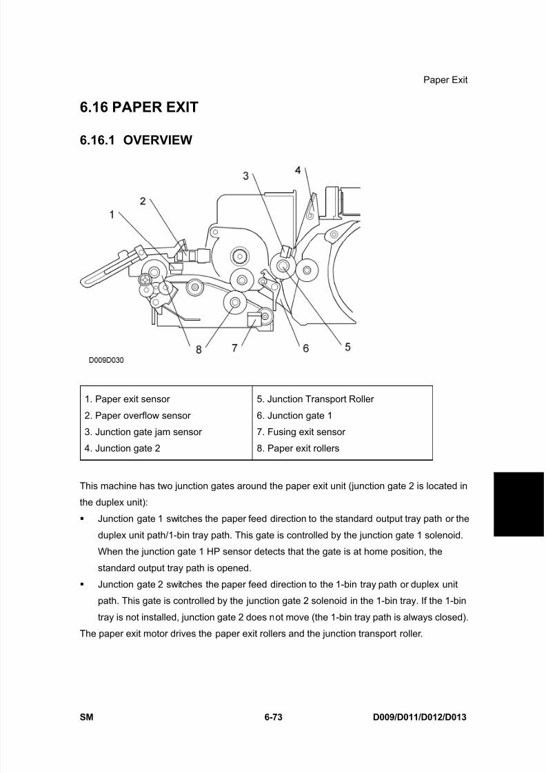
8/15/2019 Ricoh MP 4000 SM D009_D011_D012_D013 SERVICE MANUAL .pdf
http://slidepdf.com/reader/full/ricoh-mp-4000-sm-d009d011d012d013-service-manual-pdf 623/1162
Paper Exit
SM 6-73 D009/D011/D012/D013
D e t a i l e d
D e s c r i p
t i o n s
6.16 PAPER EXIT
6.16.1 OVERVIEW
1. Paper exit sensor
2. Paper overflow sensor
3. Junction gate jam sensor
4. Junction gate 2
5. Junction Transport Roller
6. Junction gate 1
7. Fusing exit sensor
8. Paper exit rollers
This machine has two junction gates around the paper exit unit (junction gate 2 is located in
the duplex unit):
Junction gate 1 switches the paper feed direction to the standard output tray path or the
duplex unit path/1-bin tray path. This gate is controlled by the junction gate 1 solenoid.
When the junction gate 1 HP sensor detects that the gate is at home position, the
standard output tray path is opened.
Junction gate 2 switches the paper feed direction to the 1-bin tray path or duplex unit
path. This gate is controlled by the junction gate 2 solenoid in the 1-bin tray. If the 1-bin
tray is not installed, junction gate 2 does not move (the 1-bin tray path is always closed).
The paper exit motor drives the paper exit rollers and the junction transport roller.

8/15/2019 Ricoh MP 4000 SM D009_D011_D012_D013 SERVICE MANUAL .pdf
http://slidepdf.com/reader/full/ricoh-mp-4000-sm-d009d011d012d013-service-manual-pdf 624/1162
Paper Exit
D009/D011/D012/D013 6-74 SM
6.16.2 JUNCTION GATE MECHANISM
To the Standard Tray
The paper exit rollers [A] feed paper to the standard output tray. These rollers are driven by
the paper exit motor [B].
When a sheet of paper stays in the paper exit unit, the paper exit sensor [C] detects the
paper jam and a jam message is displayed.
When outputs push up the tray full actuator [D], the paper overflow sensor [E] detects that
standard output tray is full of outputs and a jam message is displayed after a job end.
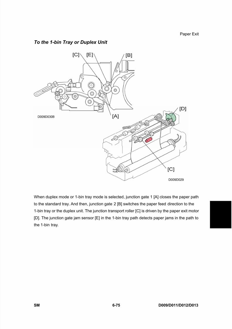
8/15/2019 Ricoh MP 4000 SM D009_D011_D012_D013 SERVICE MANUAL .pdf
http://slidepdf.com/reader/full/ricoh-mp-4000-sm-d009d011d012d013-service-manual-pdf 625/1162
Paper Exit
SM 6-75 D009/D011/D012/D013
D e t a i l e d
D e s c r i p
t i o n s
To the 1-bin Tray or Duplex Unit
When duplex mode or 1-bin tray mode is selected, junction gate 1 [A] closes the paper path
to the standard tray. And then, junction gate 2 [B] switches the paper feed direction to the
1-bin tray or the duplex unit. The junction transport roller [C] is driven by the paper exit motor
[D]. The junction gate jam sensor [E] in the 1-bin tray path detects paper jams in the path to
the 1-bin tray.
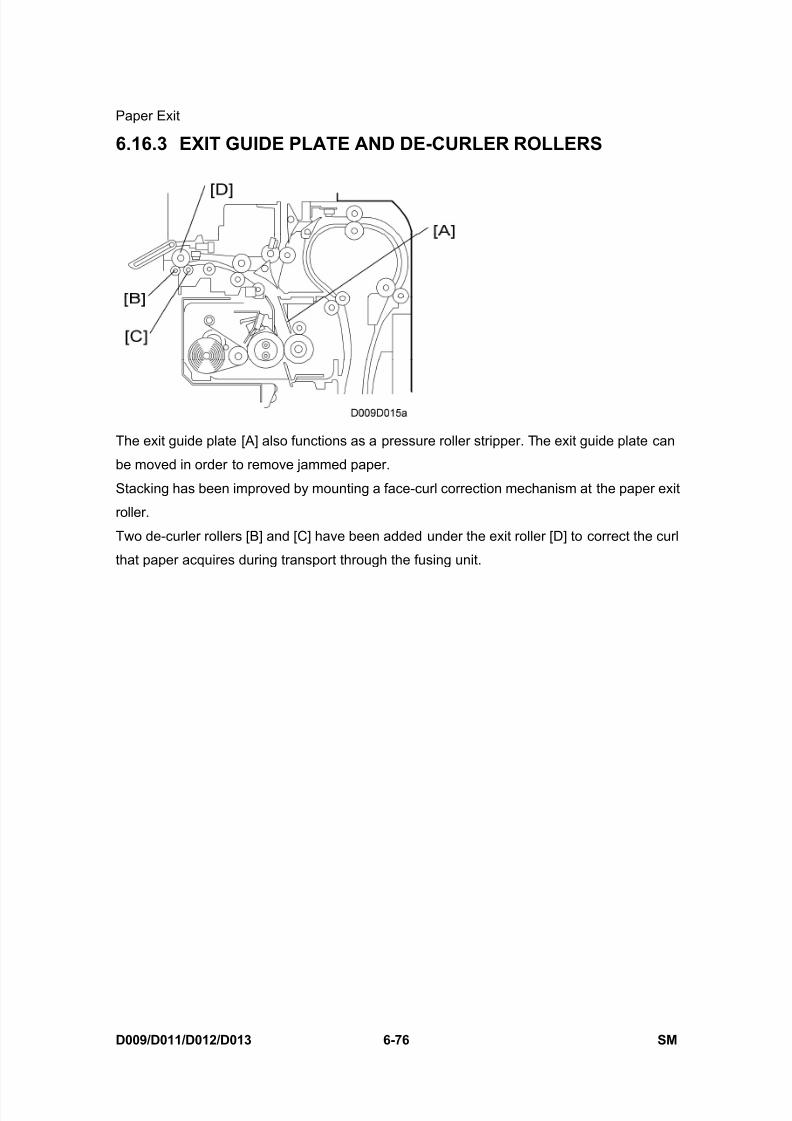
8/15/2019 Ricoh MP 4000 SM D009_D011_D012_D013 SERVICE MANUAL .pdf
http://slidepdf.com/reader/full/ricoh-mp-4000-sm-d009d011d012d013-service-manual-pdf 626/1162
Paper Exit
D009/D011/D012/D013 6-76 SM
6.16.3 EXIT GUIDE PLATE AND DE-CURLER ROLLERS
The exit guide plate [A] also functions as a pressure roller stripper. The exit guide plate can
be moved in order to remove jammed paper.
Stacking has been improved by mounting a face-curl correction mechanism at the paper exit
roller.
Two de-curler rollers [B] and [C] have been added under the exit roller [D] to correct the curl
that paper acquires during transport through the fusing unit.
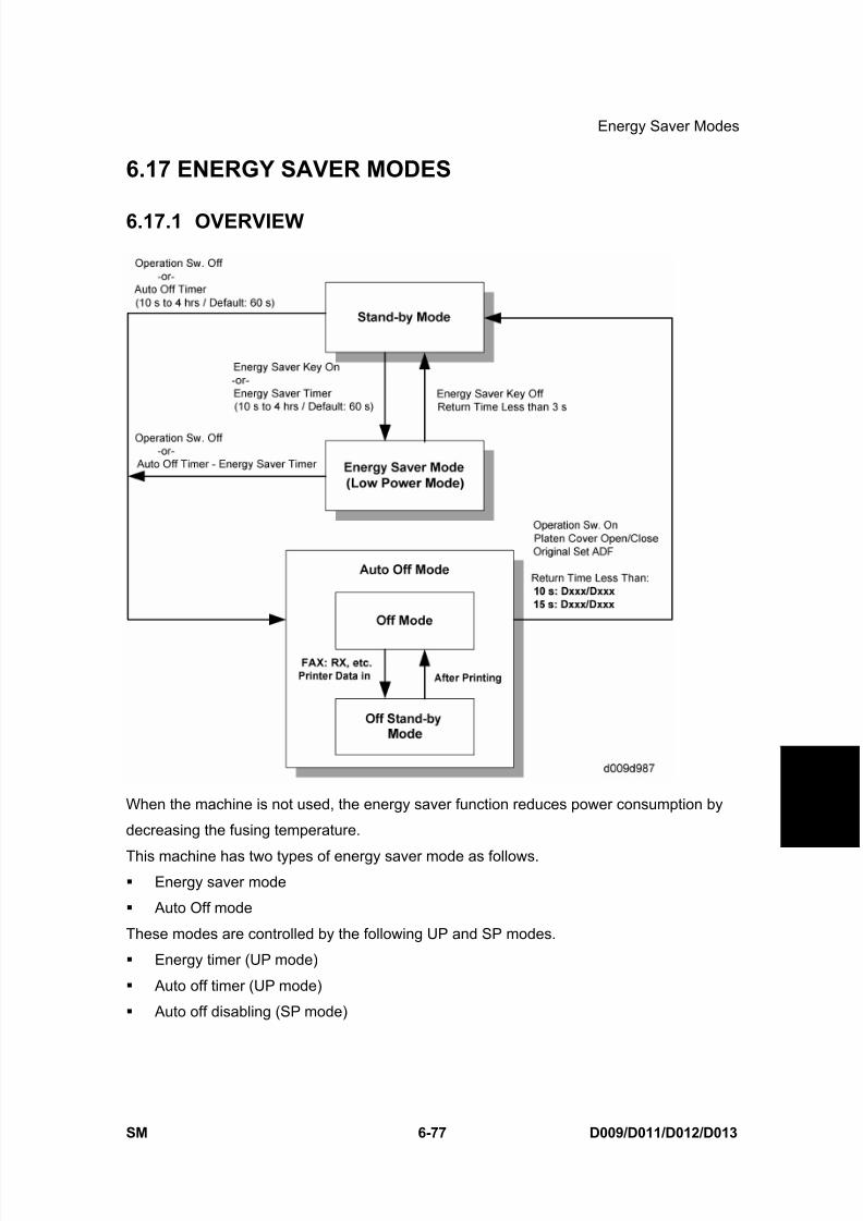
8/15/2019 Ricoh MP 4000 SM D009_D011_D012_D013 SERVICE MANUAL .pdf
http://slidepdf.com/reader/full/ricoh-mp-4000-sm-d009d011d012d013-service-manual-pdf 627/1162
Energy Saver Modes
SM 6-77 D009/D011/D012/D013
D e t a i l e d
D e s c r i p
t i o n s
6.17 ENERGY SAVER MODES
6.17.1 OVERVIEW
When the machine is not used, the energy saver function reduces power consumption by
decreasing the fusing temperature.
This machine has two types of energy saver mode as follows. Energy saver mode
Auto Off mode
These modes are controlled by the following UP and SP modes.
Energy timer (UP mode)
Auto off timer (UP mode)
Auto off disabling (SP mode)

8/15/2019 Ricoh MP 4000 SM D009_D011_D012_D013 SERVICE MANUAL .pdf
http://slidepdf.com/reader/full/ricoh-mp-4000-sm-d009d011d012d013-service-manual-pdf 628/1162
Energy Saver Modes
D009/D011/D012/D013 6-78 SM
6.17.2 ENERGY SAVER MODE
Entering the energy saver mode
The machine enters energy saver mode when one of the following is done.
The Clear Mode/Energy Saver Key is held down for a second.
The energy saver timer runs out after the end of a job.
What happens in energy saver mode
When the machine enters energy saver mode, the fusing lamp drops to a certain
temperature, and the operation panel indicators are turned off except for the Energy Saver
LED and the Power LED.
If the CPU receives the image print out command from an application (e. g. to print incomingfax data or to print data from a PC), the fusing temperature rises to print the data.
Return to stand-by mode
If one of the following is done, the machine returns to stand-by mode:
The Clear Mode/Energy Saver Mode key is pressed
Any key on the operation panel or touch panel screen is pressed
An original is placed in the ADF
The ADF is lifted
A sheet of paper is placed in the by-pass feed tableThe recovery time from energy saver mode is about 3 s.
ModeOperation
Switch
Energy Saver
LEDFusing Temp. +24V System +5V
Energy
SaverOn On
Target
temperature* 1 –
35°C
On On
*1: SP1-105-001, -002
6.17.3 AUTO OFF MODE
There are two Auto Off modes: Off Stand-by mode and Off mode. The difference between
Off Stand-by mode and Off mode is the machine’s condition when the machine enters Auto
Off mode.

8/15/2019 Ricoh MP 4000 SM D009_D011_D012_D013 SERVICE MANUAL .pdf
http://slidepdf.com/reader/full/ricoh-mp-4000-sm-d009d011d012d013-service-manual-pdf 629/1162
Energy Saver Modes
SM 6-79 D009/D011/D012/D013
D e t a i l e d
D e s c r i p
t i o n s
Entering off stand-by and off modes
The machine enters the Off Stand-by mode or Off mode when one of the following is done.
The auto off timer runs out The operation switch is pressed to turn the power off
If one or more of the following conditions exits, the machine enters Off Stand-by mode. If
none of these conditions exist, the machine enters Off Mode.
Error or SC condition
An optional G4 unit is installed
Image data is stored in the memory
During memory TX or polling RX
The handset is off hook An original is in the ADF
The ADF is open
Off Stand-by mode
The system +5V is still supplied to all components. When the machine detects a ringing
signal or receives a stream of data for a print job, the +24V supply is activated and the
machine automatically prints the incoming message or executes the print job.
Off Mode
The system +5V supply also turns off. However, +5VE (+5V for energy saver mode) is still
activated. When the machine detects a ringing signal, off-hook signal, or receives a print job,
the machine returns to the Off Stand-by mode and the system +5V and +24V supplies are
activated.
Returning to stand-by mode
The machine returns to stand-by mode when the operation switch is pressed. The recovery
time is about 10 s (D009/D011) or 15 s for the (D012/D013).
ModeOperation
Switch
Energy
Saver
Mode
Fusing Lamp +24VSystem
+5VNote
Off Stand-by Off OffOff
(On in printing)On On
Off Off Off Off Off Off+5VE is
supplied
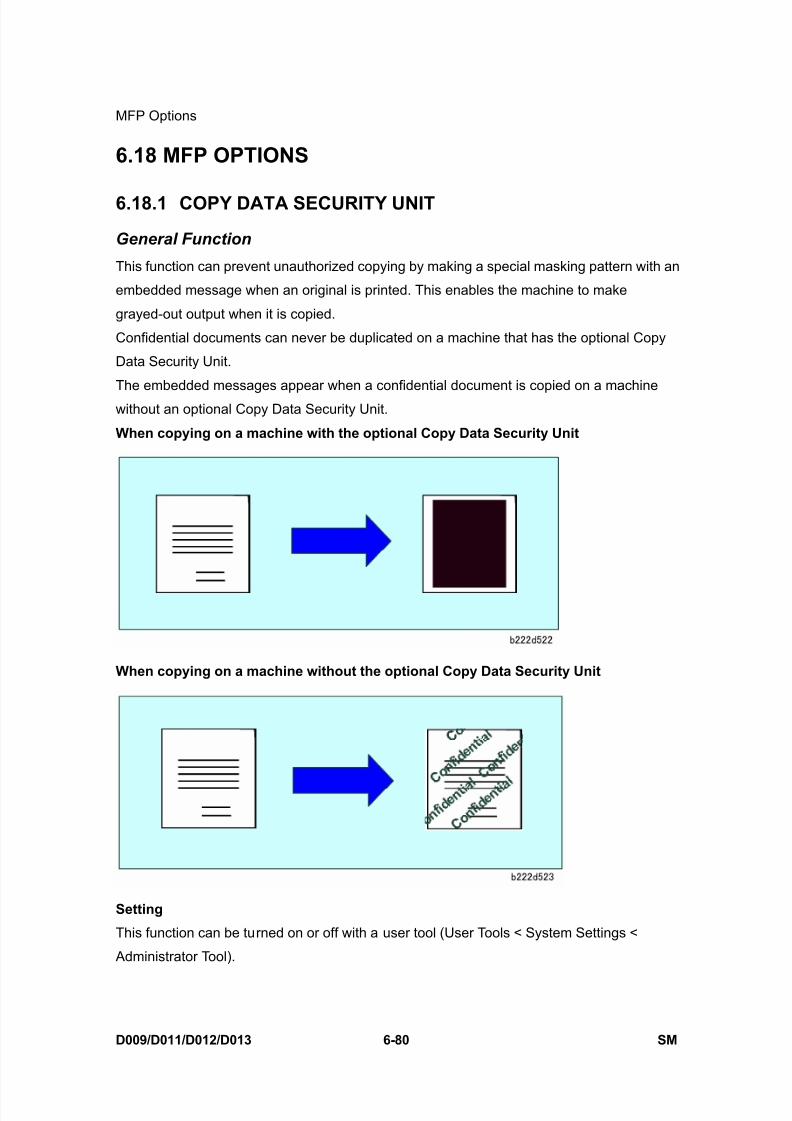
8/15/2019 Ricoh MP 4000 SM D009_D011_D012_D013 SERVICE MANUAL .pdf
http://slidepdf.com/reader/full/ricoh-mp-4000-sm-d009d011d012d013-service-manual-pdf 630/1162
MFP Options
D009/D011/D012/D013 6-80 SM
6.18 MFP OPTIONS
6.18.1 COPY DATA SECURITY UNIT
General Function
This function can prevent unauthorized copying by making a special masking pattern with an
embedded message when an original is printed. This enables the machine to make
grayed-out output when it is copied.
Confidential documents can never be duplicated on a machine that has the optional Copy
Data Security Unit.
The embedded messages appear when a confidential document is copied on a machinewithout an optional Copy Data Security Unit.
When copying on a machine with the optional Copy Data Security Unit
When copying on a machine without the optional Copy Data Security Unit
Setting
This function can be turned on or off with a user tool (User Tools < System Settings <
Administrator Tool).
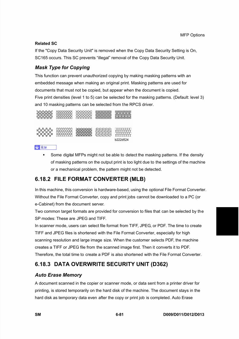
8/15/2019 Ricoh MP 4000 SM D009_D011_D012_D013 SERVICE MANUAL .pdf
http://slidepdf.com/reader/full/ricoh-mp-4000-sm-d009d011d012d013-service-manual-pdf 631/1162
MFP Options
SM 6-81 D009/D011/D012/D013
D e t a i l e d
D e s c r i p
t i o n s
Related SC
If the "Copy Data Security Unit" is removed when the Copy Data Security Setting is On,
SC165 occurs. This SC prevents “illegal” removal of the Copy Data Security Unit.
Mask Type for Copying
This function can prevent unauthorized copying by making masking patterns with an
embedded message when making an original print. Masking patterns are used for
documents that must not be copied, but appear when the document is copied.
Five print densities (level 1 to 5) can be selected for the masking patterns. (Default: level 3)
and 10 masking patterns can be selected from the RPCS driver.
Some digital MFPs might not be able to detect the masking patterns. If the density
of masking patterns on the output print is too light due to the settings of the machine
or a mechanical problem, the pattern might not be detected.
6.18.2 FILE FORMAT CONVERTER (MLB)
In this machine, this conversion is hardware-based, using the optional File Format Converter.
Without the File Format Converter, copy and print jobs cannot be downloaded to a PC (or
e-Cabinet) from the document server.
Two common target formats are provided for conversion to files that can be selected by the
SP modes: These are JPEG and TIFF.
In scanner mode, users can select file format from TIFF, JPEG, or PDF. The time to create
TIFF and JPEG files is shortened with the File Format Converter, especially for high
scanning resolution and large image size. When the customer selects PDF, the machine
creates a TIFF or JPEG file from the scanned image first. Then it converts it to PDF.
Therefore, the total time to create a PDF is also shortened with the File Format Converter.
6.18.3 DATA OVERWRITE SECURITY UNIT (D362)
Auto Erase Memory
A document scanned in the copier or scanner mode, or data sent from a printer driver for
printing, is stored temporarily on the hard disk of the machine. The document stays in the
hard disk as temporary data even after the copy or print job is completed. Auto Erase

8/15/2019 Ricoh MP 4000 SM D009_D011_D012_D013 SERVICE MANUAL .pdf
http://slidepdf.com/reader/full/ricoh-mp-4000-sm-d009d011d012d013-service-manual-pdf 632/1162
MFP Options
D009/D011/D012/D013 6-82 SM
Memory erases the temporary data on the hard disk by writing over it.
Types of Data Overwritten and Not Overwritten
The following table shows the types of data that can or cannot be overwritten by Auto Erase
Memory.
Copier Copy jobs
Printer
1) Print jobs
2) Sample Print/Locked Print jobs(*1)
3) Spool Printing jobs
Scanner(*2)
1) Scanned files sent by e-mail
2) Files sent by Scan to Folder
3) Documents sent or retrieved by using Web
Image Monitor, Desk Top Binder, or Scan
Router
Fax PC fax print jobs, Internet fax transmission jobs
Data overwritten by
Auto Erase Memory
Document
Server
Temporary data that still remains in the
Document Server even after user erases the
data in the Document Server.
Data not overwritten
by Auto Erase
Memory
1) Documents stored by the user in the Document Server using
the Copier, Printer or Scanner functions
2) Information registered in the Address Book (*3)
3) Counters stored under each user code
4) Network setting
*1: A Sample Print or Locked Print job can only be overwritten after it has been
executed.
*2: Temporary data via TWAIN scanner function are not originally stored in HDD.
You can use TWAIN scanner functions together with the DOS unit.
*3: Data stored in the Address Book can be encrypted for security.
Overwrite timing
Overwriting starts automatically once a copy, print or scanner job is completed.

8/15/2019 Ricoh MP 4000 SM D009_D011_D012_D013 SERVICE MANUAL .pdf
http://slidepdf.com/reader/full/ricoh-mp-4000-sm-d009d011d012d013-service-manual-pdf 633/1162
MFP Options
SM 6-83 D009/D011/D012/D013
D e t a i l e d
D e s c r i p
t i o n s
Copier, printer and scanner functions take priority over the Data Overwrite function. If a
copier, printer or scanner job comes while a previous job is being overwritten, the overwrite
process is automatically interrupted until the next job is completed.
6.18.4 HDD ENCRYPTION UNIT (D377)
Overview
The HDD Encryption unit encodes user data and machine settings to prevent this data from
being stolen if somebody steals the hard disk. To activate this unit, an administrator must
enable the unit with the user mode after installation by a customer engineer. Also, if
"Administrator Authentication Management" is not turned on, this function is not displayed in
the menu on the LCD.
Encrypted Data
The data to be encoded are shown below:
User Data in the HDD
Address book data* 2
User authentication data
Stored document data
Temporary data on the HDD
Security log data* 2
Network I/F setting data* 1
User mode setting data* 2
Machine Data in the NVRAM
Machine settings data* 1
An administrator can choose one of three types in the UP mode to encrypt the data that is
already in the NVRAM and HDD unit.
1. "File System Data Only" encrypts the items indicated with *1 and *2 in the table above
and deletes other data.
2. "Format All Data" encrypts the item indicated with *1 in the table above and deletes
other data.
3. "All Data" encrypts all data in the table above.
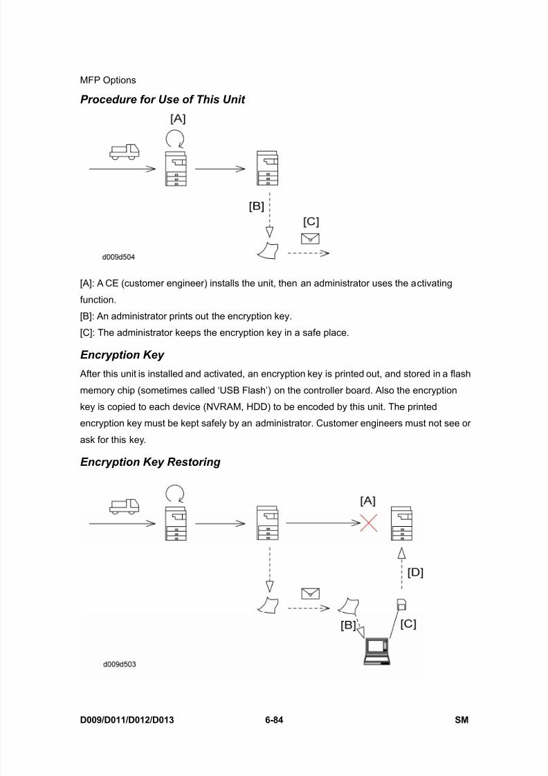
8/15/2019 Ricoh MP 4000 SM D009_D011_D012_D013 SERVICE MANUAL .pdf
http://slidepdf.com/reader/full/ricoh-mp-4000-sm-d009d011d012d013-service-manual-pdf 634/1162
MFP Options
D009/D011/D012/D013 6-84 SM
Procedure for Use of This Unit
[A]: A CE (customer engineer) installs the unit, then an administrator uses the activating
function.
[B]: An administrator prints out the encryption key.
[C]: The administrator keeps the encryption key in a safe place.
Encryption Key
After this unit is installed and activated, an encryption key is printed out, and stored in a flash
memory chip (sometimes called ‘USB Flash’) on the controller board. Also the encryption
key is copied to each device (NVRAM, HDD) to be encoded by this unit. The printedencryption key must be kept safely by an administrator. Customer engineers must not see or
ask for this key.
Encryption Key Restoring
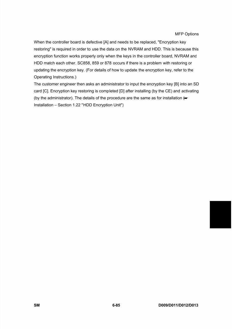
8/15/2019 Ricoh MP 4000 SM D009_D011_D012_D013 SERVICE MANUAL .pdf
http://slidepdf.com/reader/full/ricoh-mp-4000-sm-d009d011d012d013-service-manual-pdf 635/1162
MFP Options
SM 6-85 D009/D011/D012/D013
D e t a i l e d
D e s c r i p
t i o n s
When the controller board is defective [A] and needs to be replaced, "Encryption key
restoring" is required in order to use the data on the NVRAM and HDD. This is because this
encryption function works properly only when the keys in the controller board, NVRAM andHDD match each other. SC858, 859 or 878 occurs if there is a problem with restoring or
updating the encryption key. (For details of how to update the encryption key, refer to the
Operating Instructions.)
The customer engineer then asks an administrator to input the encryption key [B] into an SD
card [C]. Encryption key restoring is completed [D] after installing (by the CE) and activating
(by the administrator). The details of the procedure are the same as for installation (
Installation – Section 1.22 "HDD Encryption Unit")

8/15/2019 Ricoh MP 4000 SM D009_D011_D012_D013 SERVICE MANUAL .pdf
http://slidepdf.com/reader/full/ricoh-mp-4000-sm-d009d011d012d013-service-manual-pdf 636/1162

8/15/2019 Ricoh MP 4000 SM D009_D011_D012_D013 SERVICE MANUAL .pdf
http://slidepdf.com/reader/full/ricoh-mp-4000-sm-d009d011d012d013-service-manual-pdf 637/1162
SPECIFICATIONS

8/15/2019 Ricoh MP 4000 SM D009_D011_D012_D013 SERVICE MANUAL .pdf
http://slidepdf.com/reader/full/ricoh-mp-4000-sm-d009d011d012d013-service-manual-pdf 638/1162
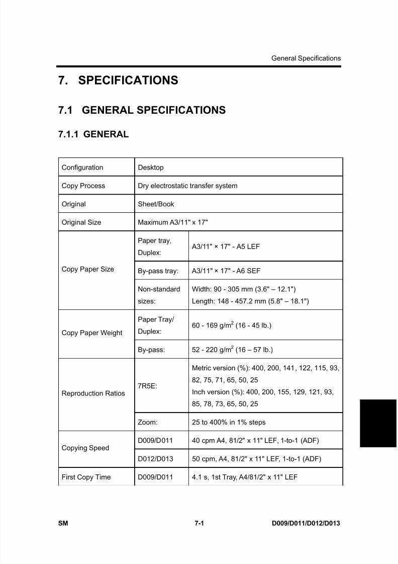
8/15/2019 Ricoh MP 4000 SM D009_D011_D012_D013 SERVICE MANUAL .pdf
http://slidepdf.com/reader/full/ricoh-mp-4000-sm-d009d011d012d013-service-manual-pdf 639/1162
General Specifications
SM 7-1 D009/D011/D012/D013
S p e c i f i c a t i o n s
7. SPECIFICATIONS
7.1 GENERAL SPECIFICATIONS
7.1.1 GENERAL
Configuration Desktop
Copy Process Dry electrostatic transfer system
Original Sheet/Book
Original Size Maximum A3/11" x 17"
Paper tray,
Duplex: A3/11" × 17" - A5 LEF
By-pass tray: A3/11" × 17" - A6 SEFCopy Paper Size
Non-standard
sizes:
Width: 90 - 305 mm (3.6" – 12.1")
Length: 148 - 457.2 mm (5.8" – 18.1")
Paper Tray/
Duplex:60 - 169 g/m 2 (16 - 45 lb.)
Copy Paper Weight
By-pass: 52 - 220 g/m 2 (16 – 57 lb.)
7R5E:
Metric version (%): 400, 200, 141, 122, 115, 93,
82, 75, 71, 65, 50, 25
Inch version (%): 400, 200, 155, 129, 121, 93,85, 78, 73, 65, 50, 25
Reproduction Ratios
Zoom: 25 to 400% in 1% steps
D009/D011 40 cpm A4, 81/2" x 11" LEF, 1-to-1 (ADF)Copying Speed
D012/D013 50 cpm, A4, 81/2" x 11" LEF, 1-to-1 (ADF)
First Copy Time D009/D011 4.1 s, 1st Tray, A4/81/2" x 11" LEF
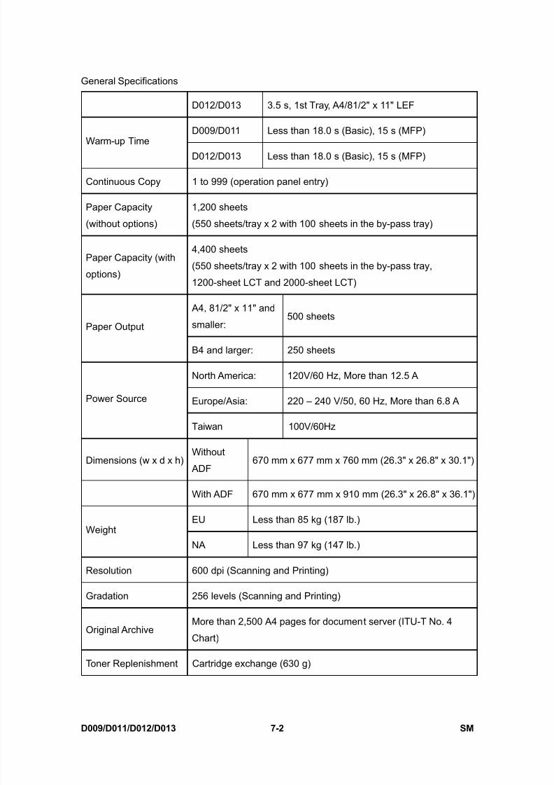
8/15/2019 Ricoh MP 4000 SM D009_D011_D012_D013 SERVICE MANUAL .pdf
http://slidepdf.com/reader/full/ricoh-mp-4000-sm-d009d011d012d013-service-manual-pdf 640/1162
General Specifications
D009/D011/D012/D013 7-2 SM
D012/D013 3.5 s, 1st Tray, A4/81/2" x 11" LEF
D009/D011 Less than 18.0 s (Basic), 15 s (MFP)Warm-up Time
D012/D013 Less than 18.0 s (Basic), 15 s (MFP)
Continuous Copy 1 to 999 (operation panel entry)
Paper Capacity
(without options)
1,200 sheets
(550 sheets/tray x 2 with 100 sheets in the by-pass tray)
Paper Capacity (with
options)
4,400 sheets
(550 sheets/tray x 2 with 100 sheets in the by-pass tray,
1200-sheet LCT and 2000-sheet LCT)
A4, 81/2" x 11" and
smaller:500 sheets
Paper Output
B4 and larger: 250 sheets
North America: 120V/60 Hz, More than 12.5 A
Europe/Asia: 220 – 240 V/50, 60 Hz, More than 6.8 APower Source
Taiwan 100V/60Hz
Dimensions (w x d x h)Without
ADF670 mm x 677 mm x 760 mm (26.3" x 26.8" x 30.1")
With ADF 670 mm x 677 mm x 910 mm (26.3" x 26.8" x 36.1")
EU Less than 85 kg (187 lb.)Weight
NA Less than 97 kg (147 lb.)
Resolution 600 dpi (Scanning and Printing)
Gradation 256 levels (Scanning and Printing)
Original ArchiveMore than 2,500 A4 pages for document server (ITU-T No. 4
Chart)
Toner Replenishment Cartridge exchange (630 g)

8/15/2019 Ricoh MP 4000 SM D009_D011_D012_D013 SERVICE MANUAL .pdf
http://slidepdf.com/reader/full/ricoh-mp-4000-sm-d009d011d012d013-service-manual-pdf 641/1162
General Specifications
SM 7-3 D009/D011/D012/D013
S p e c i f i c a t i o n s
Total Counter Electric counter
Mainframe Only Full System
D009/D011 68 db(A) or less 72 db(A) or lessNoise Emission:
Copying
D012/D013 68 db(A) or less 72 db(A) or less
D009/D011 45 db(A) or less 45 db(A) or lessNoise Emission:
Stand-by
D012/D013 48 db(A) or less 48 db(A) or less
7.1.2 POWER CONSUMPTION
Mainframe Only
D009/D011 D012/D013
Copying Less than 1.3 kW Less than 1.3 kW
Warm-up Less than 1.4 kW Less than 1.4 kW
NA Less than 123W NA Less than 148WStand-by
EU, Asia Less than 126W EU, Asia Less than 138W
NA Ave. 1.2W NA Ave. 1.2W Auto Off Mode
EU, Asia Ave. 1.2W EU, Asia Ave. 1.2W
Maximum Less than 1.44 kW (NA)Less than 1.5 kW (EU, Asia)
Less than 1.44 kW (NA)Less than 1.5 kW (EU, Asia)
Full System (Including Options)
D009/D011 D012/D013
Copying Less than 1.4 kW Less than 1.4 kW

8/15/2019 Ricoh MP 4000 SM D009_D011_D012_D013 SERVICE MANUAL .pdf
http://slidepdf.com/reader/full/ricoh-mp-4000-sm-d009d011d012d013-service-manual-pdf 642/1162
General Specifications
D009/D011/D012/D013 7-4 SM
D009/D011 D012/D013
Warm-up Less than 1.3 kW Less than 1.3 kW
NA Less than 125W NA Less than 159WStand-by
EU, Asia Less than 130W EU, Asia Less than 149W
NA Ave. 8.5W NA Ave. 8.5 Auto Off Mode
EU, Asia Ave. 8.5 EU, Asia Ave. 8.5
MaximumLess than 1.44 kW (NA)
Less than 1.5 kW (EU, Asia)
Less than 1.44 kW (NA)
Less than 1.5 kW (EU, Asia)
The above measurements were made in accordance with ISO 7779.
Full system measurements include the ARDF, Finisher and LCT unit.
In the above stand-by condition, the polygonal mirror motor is not rotating.
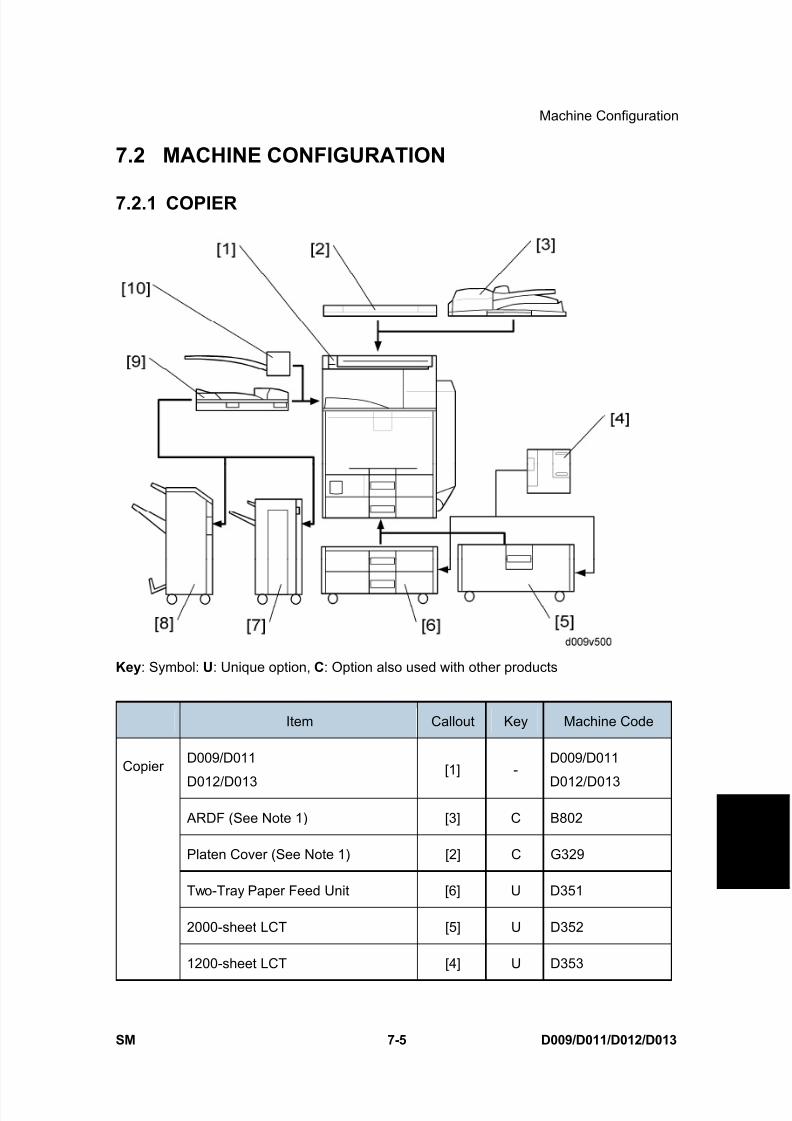
8/15/2019 Ricoh MP 4000 SM D009_D011_D012_D013 SERVICE MANUAL .pdf
http://slidepdf.com/reader/full/ricoh-mp-4000-sm-d009d011d012d013-service-manual-pdf 643/1162
Machine Configuration
SM 7-5 D009/D011/D012/D013
S p e c i f i c a t i o n s
7.2 MACHINE CONFIGURATION
7.2.1 COPIER
Key : Symbol: U: Unique option, C: Option also used with other products
Item Callout Key Machine Code
D009/D011
D012/D013
[1] -D009/D011
D012/D013
ARDF (See Note 1) [3] C B802
Platen Cover (See Note 1) [2] C G329
Two-Tray Paper Feed Unit [6] U D351
2000-sheet LCT [5] U D352
Copier
1200-sheet LCT [4] U D353

8/15/2019 Ricoh MP 4000 SM D009_D011_D012_D013 SERVICE MANUAL .pdf
http://slidepdf.com/reader/full/ricoh-mp-4000-sm-d009d011d012d013-service-manual-pdf 644/1162
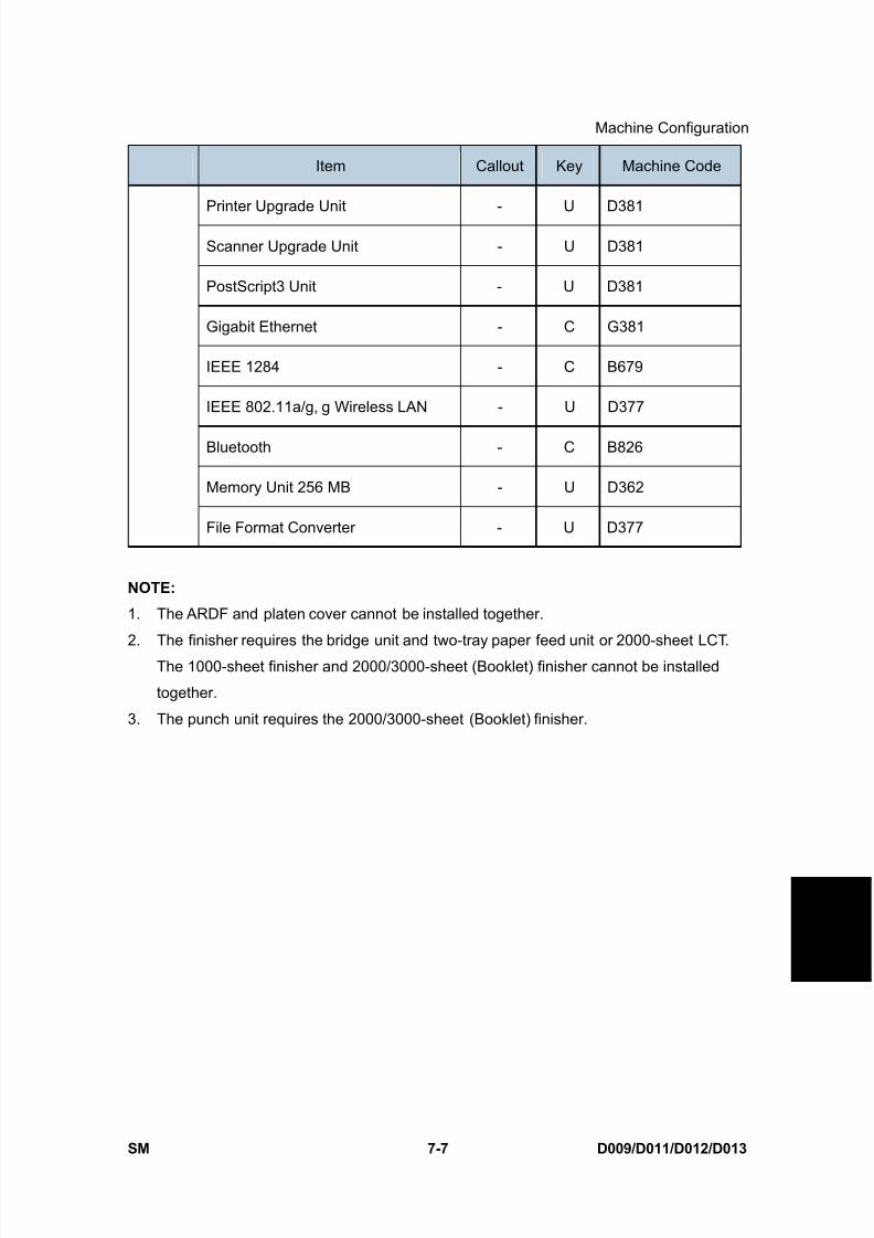
8/15/2019 Ricoh MP 4000 SM D009_D011_D012_D013 SERVICE MANUAL .pdf
http://slidepdf.com/reader/full/ricoh-mp-4000-sm-d009d011d012d013-service-manual-pdf 645/1162
Machine Configuration
SM 7-7 D009/D011/D012/D013
S p e c i f i c a t i o n s
Item Callout Key Machine Code
Printer Upgrade Unit - U D381
Scanner Upgrade Unit - U D381
PostScript3 Unit - U D381
Gigabit Ethernet - C G381
IEEE 1284 - C B679
IEEE 802.11a/g, g Wireless LAN - U D377
Bluetooth - C B826
Memory Unit 256 MB - U D362
File Format Converter - U D377
NOTE:
1. The ARDF and platen cover cannot be installed together.
2. The finisher requires the bridge unit and two-tray paper feed unit or 2000-sheet LCT.
The 1000-sheet finisher and 2000/3000-sheet (Booklet) finisher cannot be installed
together.
3. The punch unit requires the 2000/3000-sheet (Booklet) finisher.
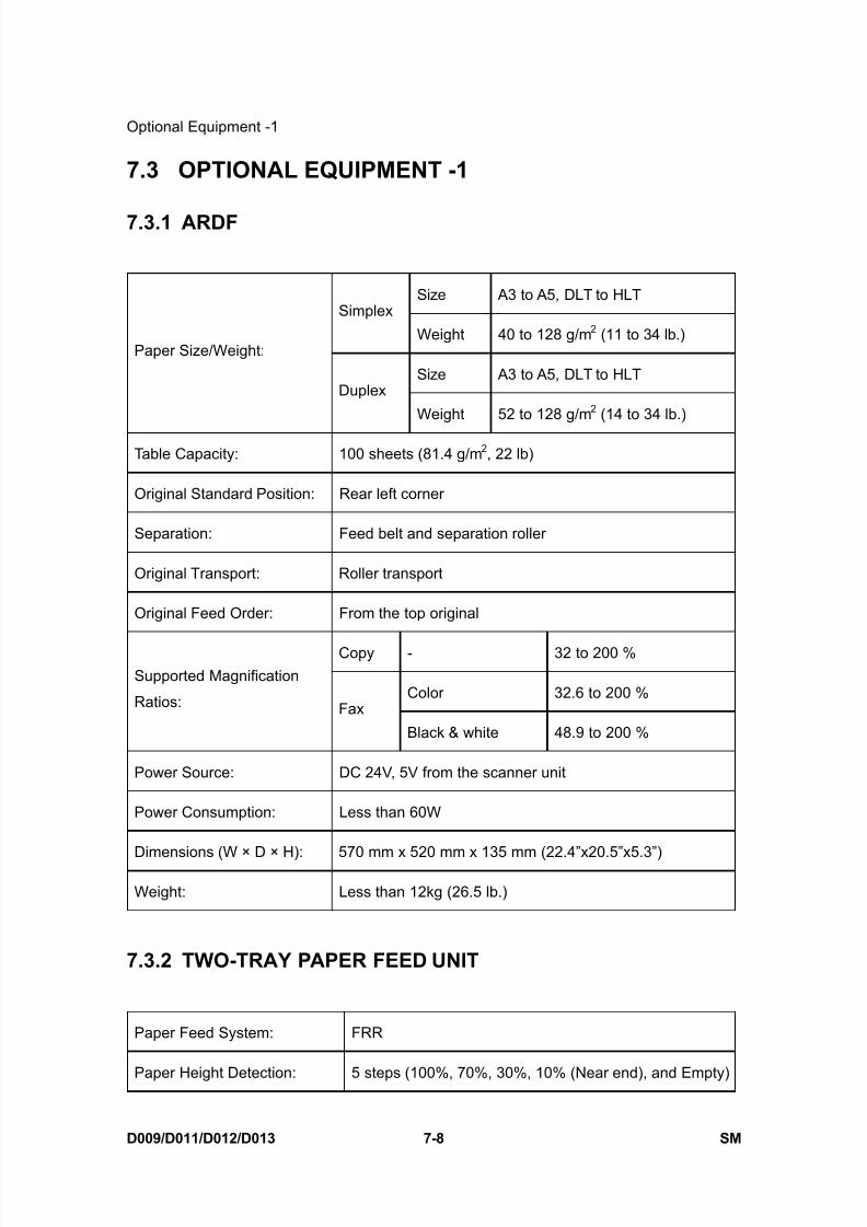
8/15/2019 Ricoh MP 4000 SM D009_D011_D012_D013 SERVICE MANUAL .pdf
http://slidepdf.com/reader/full/ricoh-mp-4000-sm-d009d011d012d013-service-manual-pdf 646/1162
Optional Equipment -1
D009/D011/D012/D013 7-8 SM
7.3 OPTIONAL EQUIPMENT -1
7.3.1 ARDF
Size A3 to A5, DLT to HLTSimplex
Weight 40 to 128 g/m 2 (11 to 34 lb.)
Size A3 to A5, DLT to HLT
Paper Size/Weight:
Duplex
Weight 52 to 128 g/m 2 (14 to 34 lb.)
Table Capacity: 100 sheets (81.4 g/m 2, 22 lb)
Original Standard Position: Rear left corner
Separation: Feed belt and separation roller
Original Transport: Roller transport
Original Feed Order: From the top original
Copy - 32 to 200 %
Color 32.6 to 200 %Supported Magnification
Ratios: Fax
Black & white 48.9 to 200 %
Power Source: DC 24V, 5V from the scanner unit
Power Consumption: Less than 60W
Dimensions (W × D × H): 570 mm x 520 mm x 135 mm (22.4”x20.5”x5.3”)
Weight: Less than 12kg (26.5 lb.)
7.3.2 TWO-TRAY PAPER FEED UNIT
Paper Feed System: FRR
Paper Height Detection: 5 steps (100%, 70%, 30%, 10% (Near end), and Empty)

8/15/2019 Ricoh MP 4000 SM D009_D011_D012_D013 SERVICE MANUAL .pdf
http://slidepdf.com/reader/full/ricoh-mp-4000-sm-d009d011d012d013-service-manual-pdf 647/1162
Optional Equipment -1
SM 7-9 D009/D011/D012/D013
S p e c i f i c a t i o n s
Capacity: 550 sheets x 2 trays
Paper Weight: 60 to 169 g/m 2 (16 to 45 lb.)
Paper Size: A3 SEF to A5, DLT SEF to HLT
Power Source: DC 24V, 5V (from the main frame)
Power Consumption: Less than 50 W (Max.)/ Less than 35 W (Ave,)
Dimensions (W x D x H): 580 mm x 620 mm x 260 mm (22.8" x 24.4" x 10.2")
Weight: 26 kg (57.3 lb.)
7.3.3 LCT 2000-SHEET
Paper Size: A4 LEF/LT LEF
Paper Weight: 60 g/m 2 to 169 g/m 2, 16 lb. to 45 lb.
Tray Capacity: 2,000 sheets (80 g/m 2, 20lb.)
Remaining Paper Detection:5 steps (100%, 70%, 30%, 10%, Empty): Right Tray
4 steps (100%, 70%, 30%, Empty): Left Tray
Power Source: DC 24 V, 5 V (from copier/printer)
Power Consumption: 50 W (Max.)/30 W (Ave.)
Weight: 26 kg (57.3 lb.)
Size (W x D x H): 580 mm x 620 mm x 260 mm (22.8" x 24.4" x 10.2")
7.3.4 LCT 1200-SHEET
Paper Size : A4 LEF/ LT LEF/ B5 LEF
Paper Weight: 60 g/m 2 to 169 g/m 2, 16 lb to 45 lb
Tray Capacity: 1200 sheets (80 g/m2
, 20lb)
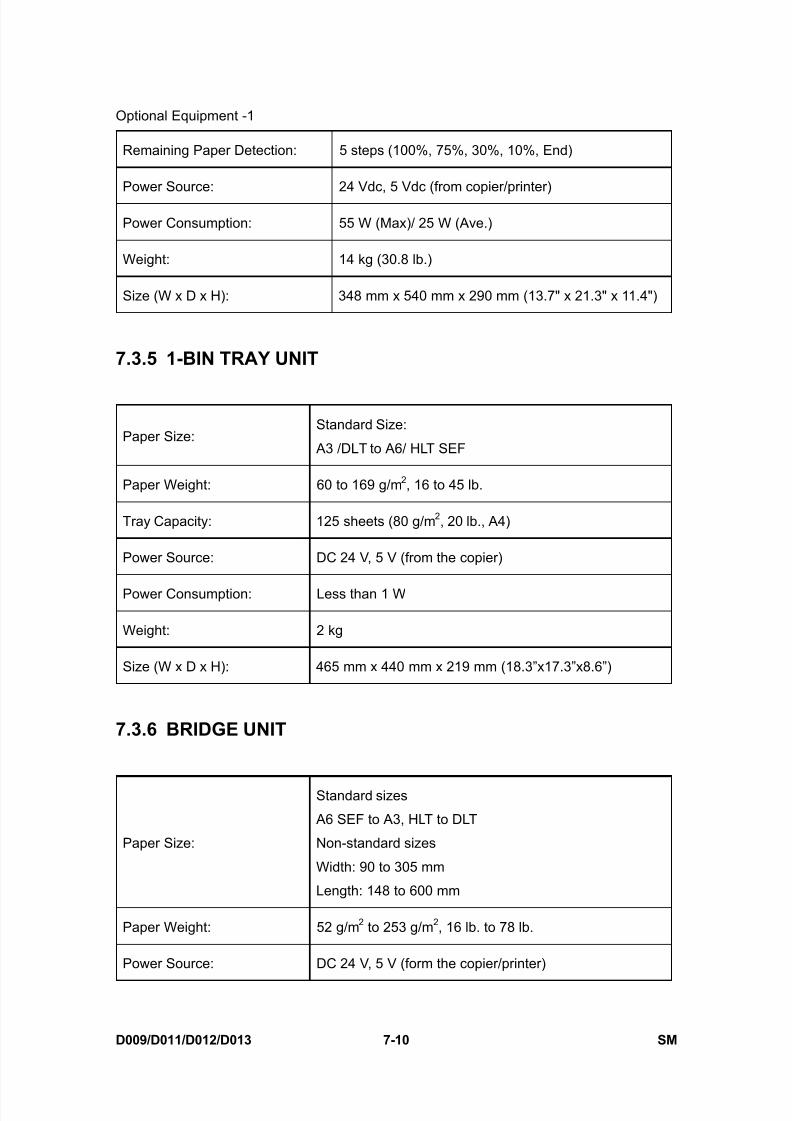
8/15/2019 Ricoh MP 4000 SM D009_D011_D012_D013 SERVICE MANUAL .pdf
http://slidepdf.com/reader/full/ricoh-mp-4000-sm-d009d011d012d013-service-manual-pdf 648/1162
Optional Equipment -1
D009/D011/D012/D013 7-10 SM
Remaining Paper Detection: 5 steps (100%, 75%, 30%, 10%, End)
Power Source: 24 Vdc, 5 Vdc (from copier/printer)
Power Consumption: 55 W (Max)/ 25 W (Ave.)
Weight: 14 kg (30.8 lb.)
Size (W x D x H): 348 mm x 540 mm x 290 mm (13.7" x 21.3" x 11.4")
7.3.5 1-BIN TRAY UNIT
Paper Size:Standard Size:
A3 /DLT to A6/ HLT SEF
Paper Weight: 60 to 169 g/m 2, 16 to 45 lb.
Tray Capacity: 125 sheets (80 g/m 2, 20 lb., A4)
Power Source: DC 24 V, 5 V (from the copier)
Power Consumption: Less than 1 W
Weight: 2 kg
Size (W x D x H): 465 mm x 440 mm x 219 mm (18.3”x17.3”x8.6”)
7.3.6 BRIDGE UNIT
Paper Size:
Standard sizes
A6 SEF to A3, HLT to DLT
Non-standard sizes
Width: 90 to 305 mm
Length: 148 to 600 mm
Paper Weight: 52 g/m 2 to 253 g/m 2, 16 lb. to 78 lb.
Power Source: DC 24 V, 5 V (form the copier/printer)
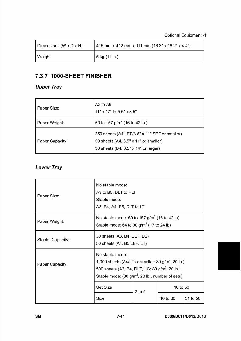
8/15/2019 Ricoh MP 4000 SM D009_D011_D012_D013 SERVICE MANUAL .pdf
http://slidepdf.com/reader/full/ricoh-mp-4000-sm-d009d011d012d013-service-manual-pdf 649/1162
Optional Equipment -1
SM 7-11 D009/D011/D012/D013
S p e c i f i c a t i o n s
Dimensions (W x D x H): 415 mm x 412 mm x 111 mm (16.3" x 16.2" x 4.4")
Weight 5 kg (11 lb.)
7.3.7 1000-SHEET FINISHER
Upper Tray
Paper Size: A3 to A6
11" x 17" to 5.5" x 8.5"
Paper Weight: 60 to 157 g/m 2 (16 to 42 lb.)
Paper Capacity:
250 sheets (A4 LEF/8.5" x 11" SEF or smaller)
50 sheets (A4, 8.5" x 11" or smaller)
30 sheets (B4, 8.5" x 14" or larger)
Lower Tray
Paper Size:
No staple mode:
A3 to B5, DLT to HLT
Staple mode:
A3, B4, A4, B5, DLT to LT
Paper Weight:No staple mode: 60 to 157 g/m 2 (16 to 42 lb)
Staple mode: 64 to 90 g/m 2 (17 to 24 lb)
Stapler Capacity:30 sheets (A3, B4, DLT, LG)
50 sheets (A4, B5 LEF, LT)
No staple mode:
1,000 sheets (A4/LT or smaller: 80 g/m 2, 20 lb.)
500 sheets (A3, B4, DLT, LG: 80 g/m 2, 20 lb.)
Staple mode: (80 g/m 2, 20 lb., number of sets)
Set Size 10 to 50
Paper Capacity:
Size
2 to 9
10 to 30 31 to 50
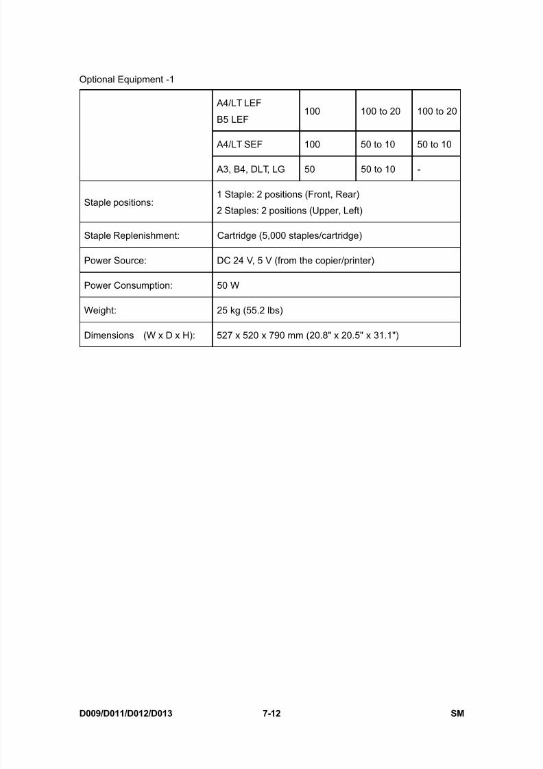
8/15/2019 Ricoh MP 4000 SM D009_D011_D012_D013 SERVICE MANUAL .pdf
http://slidepdf.com/reader/full/ricoh-mp-4000-sm-d009d011d012d013-service-manual-pdf 650/1162
Optional Equipment -1
D009/D011/D012/D013 7-12 SM
A4/LT LEF
B5 LEF100 100 to 20 100 to 20
A4/LT SEF 100 50 to 10 50 to 10
A3, B4, DLT, LG 50 50 to 10 -
Staple positions:1 Staple: 2 positions (Front, Rear)
2 Staples: 2 positions (Upper, Left)
Staple Replenishment: Cartridge (5,000 staples/cartridge)
Power Source: DC 24 V, 5 V (from the copier/printer)
Power Consumption: 50 W
Weight: 25 kg (55.2 lbs)
Dimensions (W x D x H): 527 x 520 x 790 mm (20.8" x 20.5" x 31.1")

8/15/2019 Ricoh MP 4000 SM D009_D011_D012_D013 SERVICE MANUAL .pdf
http://slidepdf.com/reader/full/ricoh-mp-4000-sm-d009d011d012d013-service-manual-pdf 651/1162
Optional Equipment -2
SM 7-13 D009/D011/D012/D013
S p e c i f i c a t i o n s
7.4 OPTIONAL EQUIPMENT -2
7.4.1 3000-SHEET FINISHER
Finisher
Dimension (w x d x h) 657 mm x 613 mm x 960 mm (25.9” x 24.1” x 37.8”)
WeightLess than 54 kg (119 lb.) (no punch unit)
Less than 56 kg (123.5 lb.) (with punch unit)
Power Consumption Less than 96 W
Noise Less than 75 db
Configuration Console type attached base-unit
Power Source From base-unit
Stack Capacity250 sheets: A4, 8.5” x 11” or smaller
50 sheets: B4, 8.5” x 14 or larger
Paper Size A5-A3 SEF, A6 SEF, A6 SEF
5.5” x 8.5”-11” x 17” SEF, 12” x 18” SEF
Proof Tray
Paper Weight 52 g/m 2 - 163 g/m 2 (14 lb. - 43 lb.)
3,000 sheets A4 LEF, 8.5" x 11” LEF
1,500 sheets
A3 SEF, A4 SEF, B4 SEF, B5, 11” x 17”
SEF, 8.5” x 14” SEF, 8.5” x 11” SEF,
12” x 18” SEF
500 sheets A5 LEF
Stack Capacity
100 sheets A5 SEF, B6 SEF, A6 SEF,
5.5” x 8.5” SEF
Paper Size A5 - A3 SEF, A6 SEF, B6 SEF, 5.5” x 8.5”- 11” x 17”
SEF, 12” x 18” SEF
Shift Tray
Paper Weight 52 g/m2 - 256 g/m
2 (14 lb. - 68 lb.)
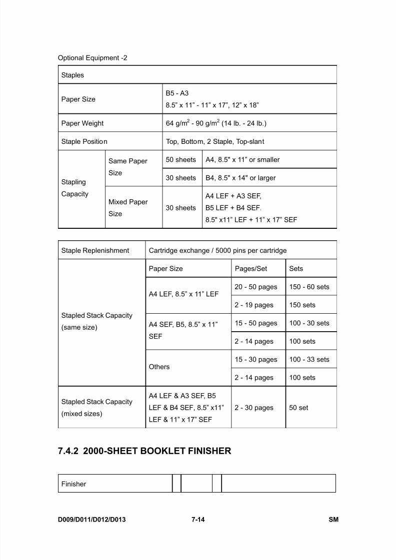
8/15/2019 Ricoh MP 4000 SM D009_D011_D012_D013 SERVICE MANUAL .pdf
http://slidepdf.com/reader/full/ricoh-mp-4000-sm-d009d011d012d013-service-manual-pdf 652/1162
Optional Equipment -2
D009/D011/D012/D013 7-14 SM
Staples
Paper SizeB5 - A3
8.5” x 11” - 11” x 17”, 12” x 18”
Paper Weight 64 g/m 2 - 90 g/m 2 (14 lb. - 24 lb.)
Staple Position Top, Bottom, 2 Staple, Top-slant
50 sheets A4, 8.5" x 11” or smallerSame Paper
Size30 sheets B4, 8.5" x 14" or largerStapling
Capacity Mixed Paper
Size30 sheets
A4 LEF + A3 SEF,B5 LEF + B4 SEF,
8.5" x11” LEF + 11” x 17” SEF
Staple Replenishment Cartridge exchange / 5000 pins per cartridge
Paper Size Pages/Set Sets
20 - 50 pages 150 - 60 sets A4 LEF, 8.5” x 11” LEF
2 - 19 pages 150 sets
15 - 50 pages 100 - 30 sets A4 SEF, B5, 8.5” x 11”
SEF2 - 14 pages 100 sets
15 - 30 pages 100 - 33 sets
Stapled Stack Capacity
(same size)
Others
2 - 14 pages 100 sets
Stapled Stack Capacity
(mixed sizes)
A4 LEF & A3 SEF, B5
LEF & B4 SEF, 8.5” x11”
LEF & 11” x 17” SEF
2 - 30 pages 50 set
7.4.2 2000-SHEET BOOKLET FINISHER
Finisher

8/15/2019 Ricoh MP 4000 SM D009_D011_D012_D013 SERVICE MANUAL .pdf
http://slidepdf.com/reader/full/ricoh-mp-4000-sm-d009d011d012d013-service-manual-pdf 653/1162
Optional Equipment -2
SM 7-15 D009/D011/D012/D013
S p e c i f i c a t i o n s
Dimension W x D x H 657 mm x 613 mm x 960 mm (25.9 x 24.1 x 37.8")
WeightLess than 63 kg (138.6 lb.) (no punch unit)
Less than 65 kg (143 lb.) (with punch unit)
Power Consumption Less than 96 W
Noise Less than 75 db
Configuration Console type attached base-unit
Power Source From base-unit
Stack Capacity 250 sheets: A4, 8.5” x 11” or smaller50 sheets: B4, 8.5” x 14 or larger
Paper Size A5 - A3 SEF, B6 SEF, A6 LEF
5.5" x 8.5" to 11” x 17” SEF, 12”x18” SEF
Proof Tray
Paper Weight 52 g/m 2 - 163 g/m 2 (14 lb. - 43 lb.)
2,000
sheets A4 LEF, 8.5” x 11” LEF
1,000
sheets
A3 SEF, A4 SEF, B4 SEF, B5
11” x 17” SEF, 8.5" x 14” SEF,
8.5" x 11” SEF, 12”x18” SEF
500 sheets A5 LEF
Stack Capacity
100 sheets A5 SEF, B6 SEF, A6 SEF, 5.5" x 8.5"
SEF
Paper Size A5 - A3 SEF, A6 SEF, B6 SEF
5.5" x 8.5" to 11” x 17” SEF, 12” x 18” SEF
Shift Tray
Paper Weight 52 g/m 2 - 256 g/m 2 (14 lb. - 68 lb.)
Staple
Paper Size B5-A3, 8.5" x 11” - 11” x 17”, 12” x 18”
Paper Weight 64 g/m 2 - 90 g/m 2, 17 lb. Bond - 28 lb. Bond
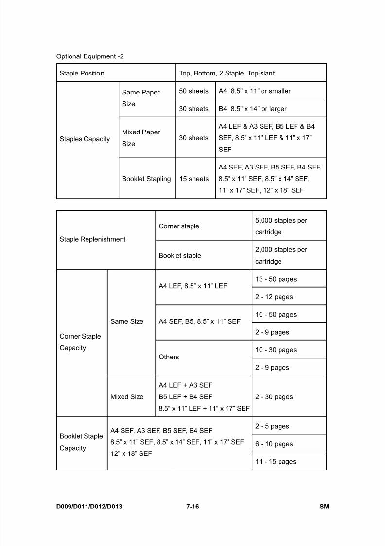
8/15/2019 Ricoh MP 4000 SM D009_D011_D012_D013 SERVICE MANUAL .pdf
http://slidepdf.com/reader/full/ricoh-mp-4000-sm-d009d011d012d013-service-manual-pdf 654/1162
Optional Equipment -2
D009/D011/D012/D013 7-16 SM
Staple Position Top, Bottom, 2 Staple, Top-slant
50 sheets A4, 8.5" x 11” or smallerSame PaperSize
30 sheets B4, 8.5" x 14” or larger
Mixed Paper
Size30 sheets
A4 LEF & A3 SEF, B5 LEF & B4
SEF, 8.5" x 11” LEF & 11” x 17”
SEF
Staples Capacity
Booklet Stapling 15 sheets
A4 SEF, A3 SEF, B5 SEF, B4 SEF,
8.5" x 11” SEF, 8.5” x 14” SEF,
11” x 17” SEF, 12” x 18” SEF
Corner staple5,000 staples per
cartridgeStaple Replenishment
Booklet staple2,000 staples per
cartridge
13 - 50 pages
A4 LEF, 8.5” x 11” LEF2 - 12 pages
10 - 50 pages A4 SEF, B5, 8.5” x 11” SEF
2 - 9 pages
10 - 30 pages
Same Size
Others
2 - 9 pages
Corner Staple
Capacity
Mixed Size
A4 LEF + A3 SEF
B5 LEF + B4 SEF
8.5” x 11” LEF + 11” x 17” SEF
2 - 30 pages
2 - 5 pages
6 - 10 pagesBooklet Staple
Capacity
A4 SEF, A3 SEF, B5 SEF, B4 SEF
8.5” x 11” SEF, 8.5” x 14” SEF, 11” x 17” SEF
12” x 18” SEF11 - 15 pages

8/15/2019 Ricoh MP 4000 SM D009_D011_D012_D013 SERVICE MANUAL .pdf
http://slidepdf.com/reader/full/ricoh-mp-4000-sm-d009d011d012d013-service-manual-pdf 655/1162
Optional Equipment -2
SM 7-17 D009/D011/D012/D013
S p e c i f i c a t i o n s
7.4.3 PUNCH UNIT FOR 2000/3000-SHEET (BOOKLET)FINISHER
NA 2/3 holes switchable
EU 2/4 holes switchable Available Punch Units
Scandinavia 4 holes
NA 2-holes Up to 5,000 sheets
NA 3-holes Up to 5,000 sheets
EU 2-holes Up to 14,000 sheets
EU 4-holes Up to 7,000 sheets
Punch Waste Replenishment
Scandinavia
4-holesUp to 7,000 sheets
Paper Weight 52 g/m 2 - 163 g/m 2, 14 lb Bond - 43 lb Bond
SEF A5 to A3, 5.5" x 8.5" to 11” x 17”NA 2-holes
LEF A5 to A4, 5.5" x 8.5" , 8.5" x 11”
SEF A3, B4, 11” x 17”NA 3-holes
LEF A4, B5, 8.5" x 11”
SEF A5 to A3, 5.5" x 8.5" to 11” x 17”EU 2-holes
LEF A5 to A4, 5.5" x 8.5", 8.5" x 11”
SEF A3, B4, 11”x17”EU 4-holes
LEF A4, B5, 8.5" x 11”
SEF A5 to A3, 5.5" x 8.5" to 11” x 17”
Paper Sizes
Scandinavia
4-holesLEF A5 to A4, 5.5" x 8.5", 8.5" x 11”

8/15/2019 Ricoh MP 4000 SM D009_D011_D012_D013 SERVICE MANUAL .pdf
http://slidepdf.com/reader/full/ricoh-mp-4000-sm-d009d011d012d013-service-manual-pdf 656/1162

8/15/2019 Ricoh MP 4000 SM D009_D011_D012_D013 SERVICE MANUAL .pdf
http://slidepdf.com/reader/full/ricoh-mp-4000-sm-d009d011d012d013-service-manual-pdf 657/1162
1000-SHEET FINISHERB408

8/15/2019 Ricoh MP 4000 SM D009_D011_D012_D013 SERVICE MANUAL .pdf
http://slidepdf.com/reader/full/ricoh-mp-4000-sm-d009d011d012d013-service-manual-pdf 658/1162

8/15/2019 Ricoh MP 4000 SM D009_D011_D012_D013 SERVICE MANUAL .pdf
http://slidepdf.com/reader/full/ricoh-mp-4000-sm-d009d011d012d013-service-manual-pdf 659/1162
SM i B408
1000-SHEET FINISHER B408TABLE OF CONTENTS
1. REPLACEMENT AND ADJUSTMENT.............................................11.1 MAIN PCB ....................................................................................................11.2 STAPLER UNIT............................................................................................21.3 MOTORS......................................................................................................3
1.3.1 SHIFT MOTOR....................................................................................31.3.2 STAPLER MOTOR ..............................................................................31.3.3 UPPER TRANSPORT MOTOR AND EXIT MOTOR ...........................41.3.4 LOWER TRANSPORT MOTOR ..........................................................4
1.4 MOTORS AND SENSORS...........................................................................51.4.1 PREPARATION ...................................................................................51.4.2 STACK HEIGHT SENSOR ..................................................................61.4.3 STAPLER TRAY PAPER SENSOR.....................................................61.4.4 LOWER TRAY LIFT MOTOR ..............................................................71.4.5 STACK FEED-OUT MOTOR ...............................................................7
2. TROUBLESHOOTING ...................................................................... 82.1 JAM DETECTION.........................................................................................8
3. SERVICE TABLES............................................................................ 93.1 DIP SWITCH SETTINGS..............................................................................9
4. DETAILED DESCRIPTIONS...........................................................104.1 GENERAL LAYOUT ...................................................................................104.2 ELECTRICAL COMPONENT LAYOUT ......................................................114.3 ELECTRICAL COMPONENT DESCRIPTION............................................134.4 DRIVE LAYOUT .........................................................................................154.5 JUNCTION GATES ....................................................................................16
Upper Tray Mode...................................................................................16Sort/Stack Mode ....................................................................................16Staple Mode...........................................................................................16
4.6 UPPER TRAY.............................................................................................174.7 LOWER TRAY UP/DOWN MECHANISMS.................................................184.8 PAPER SHIFT MECHANISM .....................................................................194.9 JOGGER UNIT PAPER POSITIONING MECHANISM...............................204.10 EXIT GUIDE PLATE.................................................................................214.11 STAPLER MECHANISM...........................................................................224.12 STAPLER UNIT MOVEMENT MECHANISM............................................234.13 PAPER FEED-OUT MECHANISM ........................................................... 24

8/15/2019 Ricoh MP 4000 SM D009_D011_D012_D013 SERVICE MANUAL .pdf
http://slidepdf.com/reader/full/ricoh-mp-4000-sm-d009d011d012d013-service-manual-pdf 660/1162
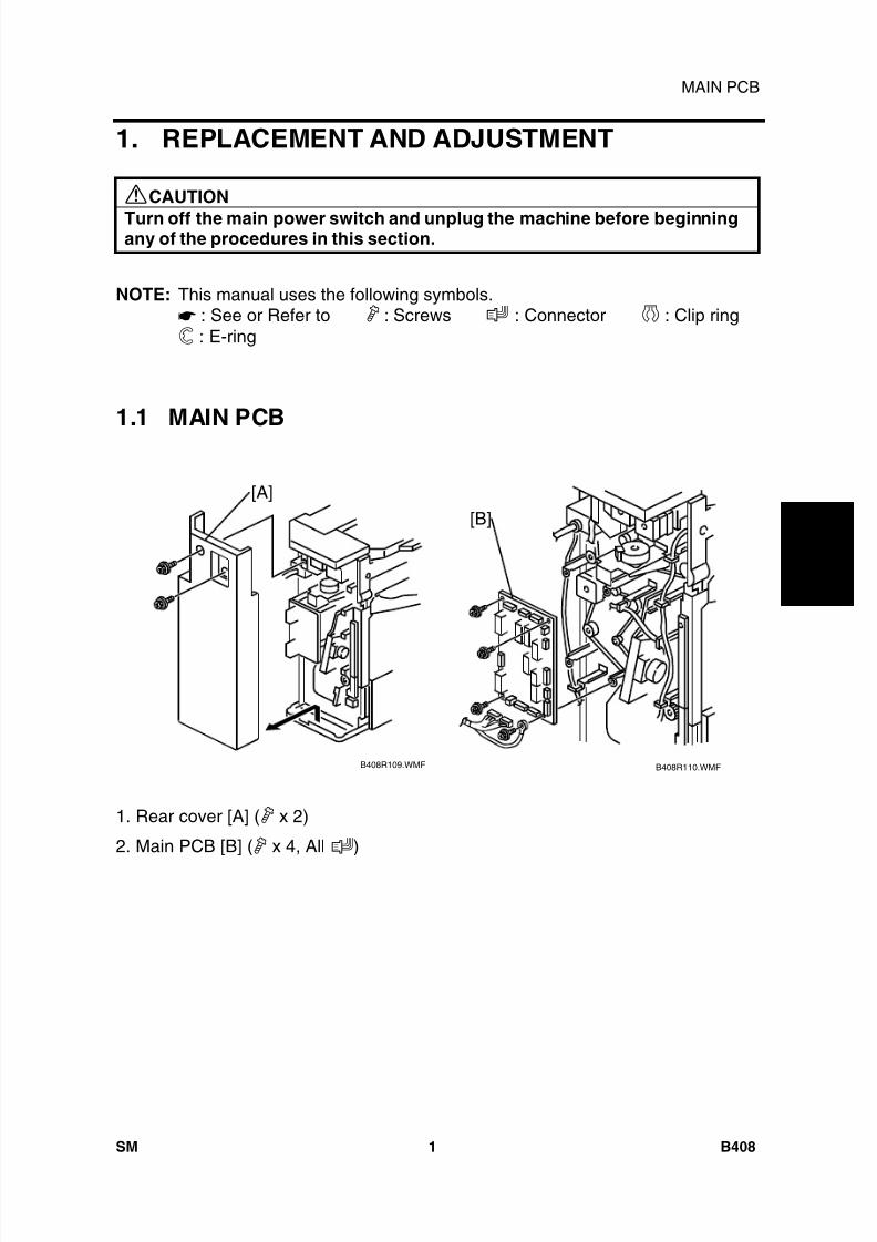
8/15/2019 Ricoh MP 4000 SM D009_D011_D012_D013 SERVICE MANUAL .pdf
http://slidepdf.com/reader/full/ricoh-mp-4000-sm-d009d011d012d013-service-manual-pdf 661/1162
1 0 0 0
- S h e e t
F i n i s h e r
B 4 0 8
MAIN PCB
SM 1 B408
1. REPLACEMENT AND ADJUSTMENT
CAUTION
Turn off the main power switch and unplug the machine before beginningany of the procedures in this section.
NOTE: This manual uses the following symbols.: See or Refer to : Screws : Connector : Clip ring: E-ring
1.1 MAIN PCB
1. Rear cover [A] ( x 2)
2. Main PCB [B] ( x 4, All )
B408R110.WMFB408R109.WMF
[B][A]

8/15/2019 Ricoh MP 4000 SM D009_D011_D012_D013 SERVICE MANUAL .pdf
http://slidepdf.com/reader/full/ricoh-mp-4000-sm-d009d011d012d013-service-manual-pdf 662/1162
STAPLER UNIT
B408 2 SM
1.2 STAPLER UNIT
1. Side cover [A] ( x 2)
2. Open exit guide plate [B]3. Upper side cover [C] ( x 2)
4. Front cover support plate [D] ( x 1)
5. Front cover [E]
6. Front inner cover [F] ( x 2)
7. Harness [G]
8. Unhook the spring [H]
9. Turn the stapler unit [I] and take itout.
10. Bracket [J] ( x 2)
B408R102.WMF
B408R113.WMF
B408R114.WMF
[A]
[B][C]
[D][E]
[F]
[G]
[H]
[I]
[J]
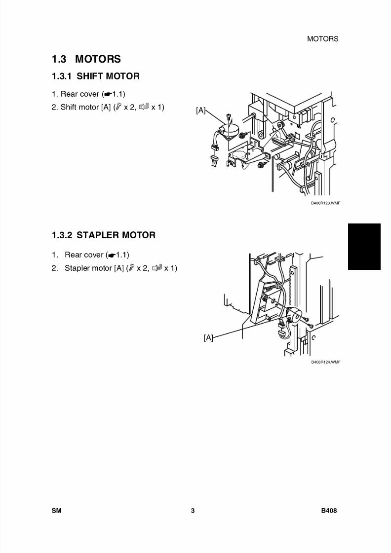
8/15/2019 Ricoh MP 4000 SM D009_D011_D012_D013 SERVICE MANUAL .pdf
http://slidepdf.com/reader/full/ricoh-mp-4000-sm-d009d011d012d013-service-manual-pdf 663/1162
1 0 0 0
- S h e e t
F i n i s h e r
B 4 0 8
MOTORS
SM 3 B408
1.3 MOTORS
1.3.1 SHIFT MOTOR
1. Rear cover ( 1.1)2. Shift motor [A] ( x 2, x 1)
1.3.2 STAPLER MOTOR
1. Rear cover ( 1.1)
2. Stapler motor [A] ( x 2, x 1)
B408R123.WMF
B408R124.WMF
[A]
[A]
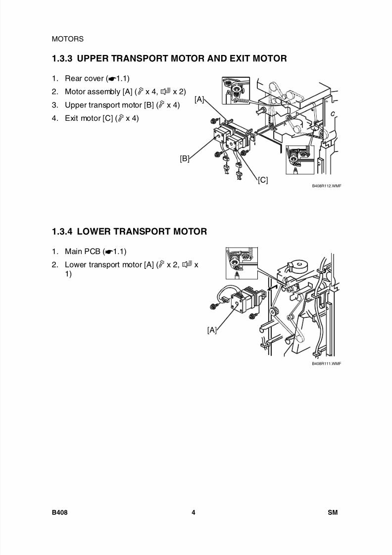
8/15/2019 Ricoh MP 4000 SM D009_D011_D012_D013 SERVICE MANUAL .pdf
http://slidepdf.com/reader/full/ricoh-mp-4000-sm-d009d011d012d013-service-manual-pdf 664/1162
MOTORS
B408 4 SM
1.3.3 UPPER TRANSPORT MOTOR AND EXIT MOTOR
1. Rear cover ( 1.1)
2. Motor assembly [A] ( x 4, x 2)
3. Upper transport motor [B] ( x 4)
4. Exit motor [C] ( x 4)
1.3.4 LOWER TRANSPORT MOTOR
1. Main PCB ( 1.1)
2. Lower transport motor [A] ( x 2, x1)
B408R112.WMF
B408R111.WMF
[A]
[B]
[C]
[A]

8/15/2019 Ricoh MP 4000 SM D009_D011_D012_D013 SERVICE MANUAL .pdf
http://slidepdf.com/reader/full/ricoh-mp-4000-sm-d009d011d012d013-service-manual-pdf 665/1162
1 0 0 0
- S h e e t
F i n i s h e r
B 4 0 8
MOTORS AND SENSORS
SM 5 B408
1.4 MOTORS AND SENSORS
1.4.1 PREPARATION
1. Front cover and inner cover ( 1.2)2. Upper side cover [A] ( x 2)
3. Upper tray [B] ( x 1)
4. Lower side cover [C] ( x 2)
5. Loosen the 2 screws [D].
6. Lower the lower tray guide plate [E].
7. Guide plate [F] ( x 4)
B408R116.WMF
B408R117.WMF
B408R118.WMF
[A]
[B]
[C]
[D]
[E]
[F]
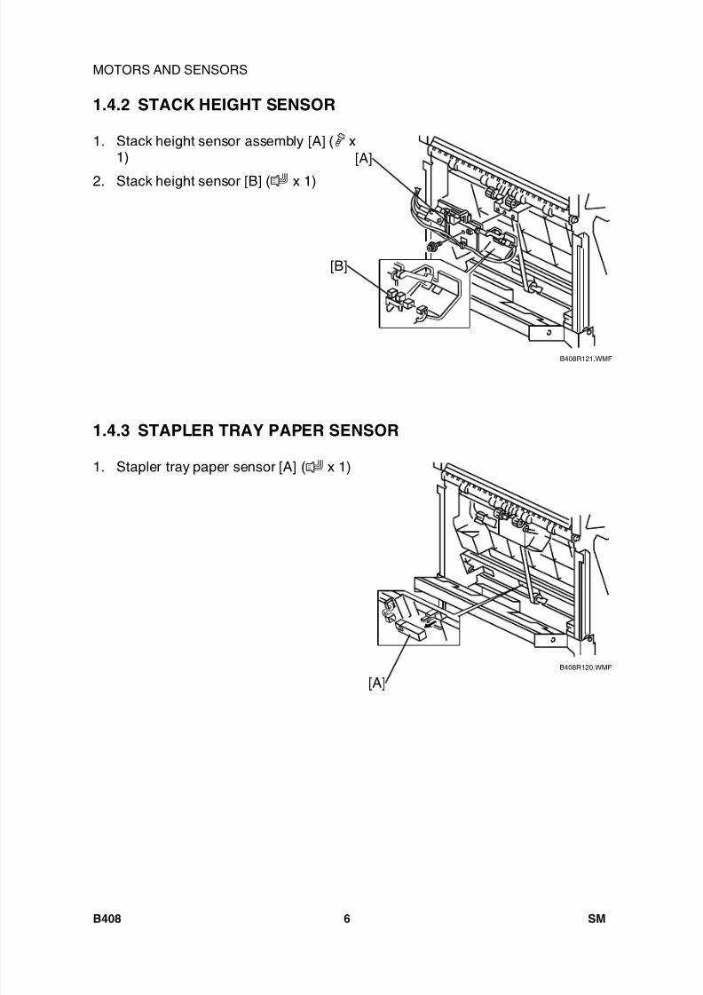
8/15/2019 Ricoh MP 4000 SM D009_D011_D012_D013 SERVICE MANUAL .pdf
http://slidepdf.com/reader/full/ricoh-mp-4000-sm-d009d011d012d013-service-manual-pdf 666/1162
MOTORS AND SENSORS
B408 6 SM
1.4.2 STACK HEIGHT SENSOR
1. Stack height sensor assembly [A] ( x1)
2. Stack height sensor [B] ( x 1)
1.4.3 STAPLER TRAY PAPER SENSOR
1. Stapler tray paper sensor [A] ( x 1)
B408R121.WMF
B408R120.WMF
[A]
[B]
[A]
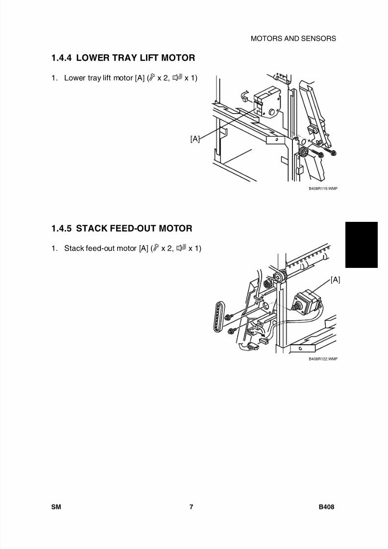
8/15/2019 Ricoh MP 4000 SM D009_D011_D012_D013 SERVICE MANUAL .pdf
http://slidepdf.com/reader/full/ricoh-mp-4000-sm-d009d011d012d013-service-manual-pdf 667/1162
1 0 0 0
- S h e e t
F i n i s h e r
B 4 0 8
MOTORS AND SENSORS
SM 7 B408
1.4.4 LOWER TRAY LIFT MOTOR
1. Lower tray lift motor [A] ( x 2, x 1)
1.4.5 STACK FEED-OUT MOTOR
1. Stack feed-out motor [A] ( x 2, x 1)
B408R119.WMF
B408R122.WMF
[A]
[A]
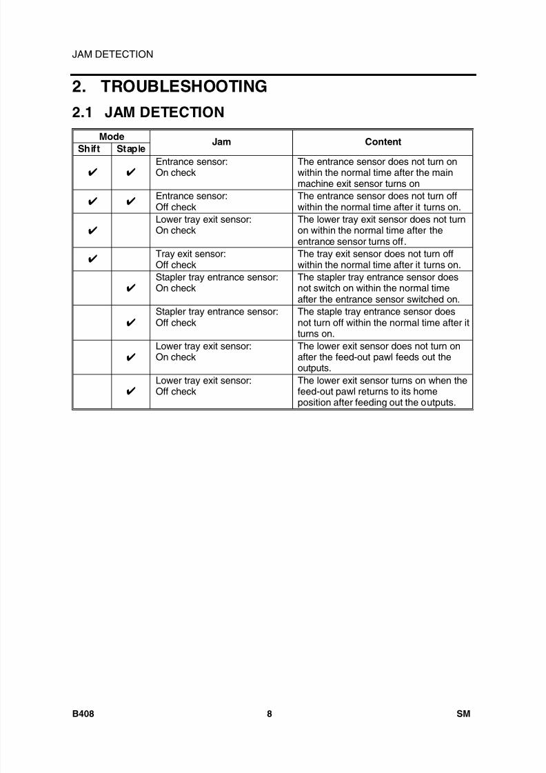
8/15/2019 Ricoh MP 4000 SM D009_D011_D012_D013 SERVICE MANUAL .pdf
http://slidepdf.com/reader/full/ricoh-mp-4000-sm-d009d011d012d013-service-manual-pdf 668/1162
JAM DETECTION
B408 8 SM
2. TROUBLESHOOTING2.1 JAM DETECTION
ModeShift Staple
Jam Content
Entrance sensor:On check
The entrance sensor does not turn onwithin the normal time after the mainmachine exit sensor turns on
Entrance sensor:Off check
The entrance sensor does not turn offwithin the normal time after it turns on.
Lower tray exit sensor:On check
The lower tray exit sensor does not turnon within the normal time after theentrance sensor turns off.
Tray exit sensor:Off check
The tray exit sensor does not turn offwithin the normal time after it turns on.
Stapler tray entrance sensor:On check
The stapler tray entrance sensor doesnot switch on within the normal timeafter the entrance sensor switched on.
Stapler tray entrance sensor:Off check
The staple tray entrance sensor doesnot turn off within the normal time after itturns on.
Lower tray exit sensor:On check
The lower exit sensor does not turn onafter the feed-out pawl feeds out theoutputs.
Lower tray exit sensor:Off check
The lower exit sensor turns on when thefeed-out pawl returns to its home
position after feeding out the outputs.
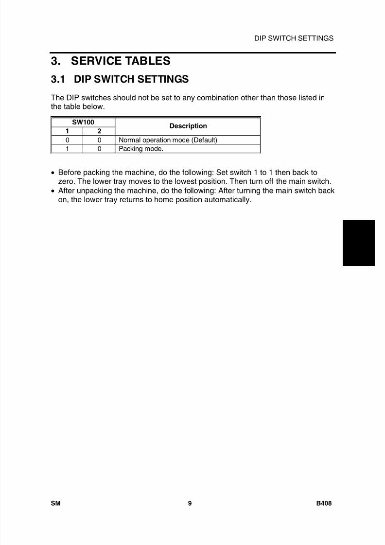
8/15/2019 Ricoh MP 4000 SM D009_D011_D012_D013 SERVICE MANUAL .pdf
http://slidepdf.com/reader/full/ricoh-mp-4000-sm-d009d011d012d013-service-manual-pdf 669/1162
1 0 0 0
- S h e e t
F i n i s h e r
B 4 0 8
DIP SWITCH SETTINGS
SM 9 B408
3. SERVICE TABLES3.1 DIP SWITCH SETTINGS
The DIP switches should not be set to any combination other than those listed inthe table below.
SW1001 2
Description
0 0 Normal operation mode (Default)1 0 Packing mode.
• Before packing the machine, do the following: Set switch 1 to 1 then back tozero. The lower tray moves to the lowest position. Then turn off the main switch.
• After unpacking the machine, do the following: After turning the main switch backon, the lower tray returns to home position automatically.
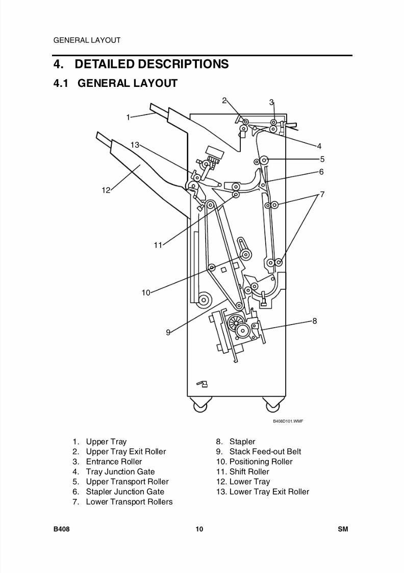
8/15/2019 Ricoh MP 4000 SM D009_D011_D012_D013 SERVICE MANUAL .pdf
http://slidepdf.com/reader/full/ricoh-mp-4000-sm-d009d011d012d013-service-manual-pdf 670/1162
GENERAL LAYOUT
B408 10 SM
4. DETAILED DESCRIPTIONS4.1 GENERAL LAYOUT
1. Upper Tray2. Upper Tray Exit Roller3. Entrance Roller4. Tray Junction Gate5. Upper Transport Roller6. Stapler Junction Gate
7. Lower Transport Rollers
8. Stapler9. Stack Feed-out Belt10. Positioning Roller11. Shift Roller12. Lower Tray13. Lower Tray Exit Roller
B408D101.WMF
1
2 3
4
5
6
7
89
10
11
12
13
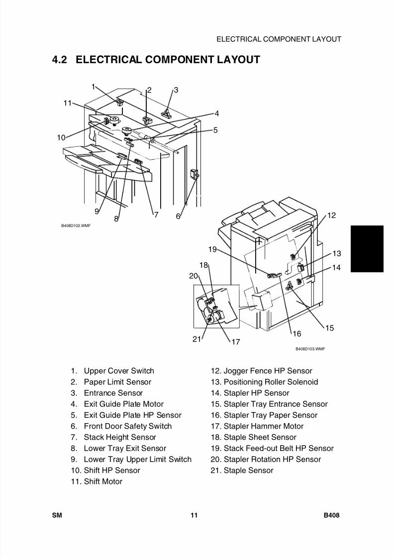
8/15/2019 Ricoh MP 4000 SM D009_D011_D012_D013 SERVICE MANUAL .pdf
http://slidepdf.com/reader/full/ricoh-mp-4000-sm-d009d011d012d013-service-manual-pdf 671/1162
1 0 0 0
- S h e e t
F i n i s h e r
B 4 0 8
ELECTRICAL COMPONENT LAYOUT
SM 11 B408
4.2 ELECTRICAL COMPONENT LAYOUT
1. Upper Cover Switch2. Paper Limit Sensor
3. Entrance Sensor4. Exit Guide Plate Motor5. Exit Guide Plate HP Sensor6. Front Door Safety Switch7. Stack Height Sensor8. Lower Tray Exit Sensor9. Lower Tray Upper Limit Switch10. Shift HP Sensor11. Shift Motor
12. Jogger Fence HP Sensor13. Positioning Roller Solenoid
14. Stapler HP Sensor15. Stapler Tray Entrance Sensor16. Stapler Tray Paper Sensor17. Stapler Hammer Motor18. Staple Sheet Sensor19. Stack Feed-out Belt HP Sensor20. Stapler Rotation HP Sensor21. Staple Sensor
B408D102.WMF
B408D103.WMF
1 2 3
4
5
6789
10
11
12
13
14
1516
17
18
19
20
21
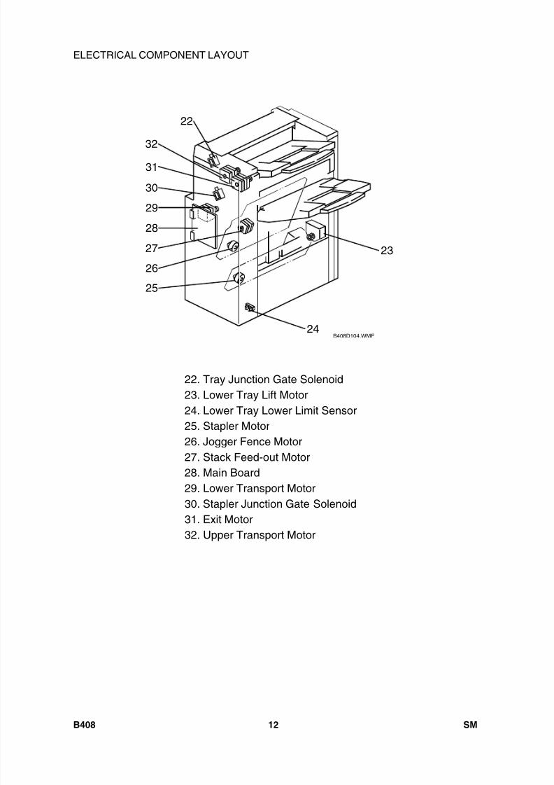
8/15/2019 Ricoh MP 4000 SM D009_D011_D012_D013 SERVICE MANUAL .pdf
http://slidepdf.com/reader/full/ricoh-mp-4000-sm-d009d011d012d013-service-manual-pdf 672/1162
ELECTRICAL COMPONENT LAYOUT
B408 12 SM
22. Tray Junction Gate Solenoid23. Lower Tray Lift Motor
24. Lower Tray Lower Limit Sensor25. Stapler Motor26. Jogger Fence Motor27. Stack Feed-out Motor28. Main Board29. Lower Transport Motor30. Stapler Junction Gate Solenoid31. Exit Motor32. Upper Transport Motor
B408D104.WMF
23
24
25
26
27
28
22
29
30
31
32
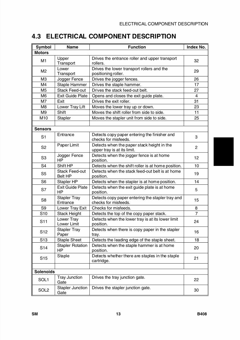
8/15/2019 Ricoh MP 4000 SM D009_D011_D012_D013 SERVICE MANUAL .pdf
http://slidepdf.com/reader/full/ricoh-mp-4000-sm-d009d011d012d013-service-manual-pdf 673/1162
1 0 0 0
- S h e e t
F i n i s h e r
B 4 0 8
ELECTRICAL COMPONENT DESCRIPTION
SM 13 B408
4.3 ELECTRICAL COMPONENT DESCRIPTIONSymbol Name Function Index No.
Motors
M1 UpperTransport Drives the entrance roller and upper transportrollers. 32
M2 LowerTransport
Drives the lower transport rollers and thepositioning roller. 29
M3 Jogger Fence Drives the jogger fences. 26M4 Staple Hammer Drives the staple hammer. 17M5 Stack Feed-out Drives the stack feed-out belt. 27M6 Exit Guide Plate Opens and closes the exit guide plate. 4M7 Exit Drives the exit roller. 31M8 Lower Tray Lift Moves the lower tray up or down. 23M9 Shift Moves the shift roller from side to side. 11
M10 Stapler Moves the stapler unit from side to side. 25
Sensors
S1 Entrance Detects copy paper entering the finisher andchecks for misfeeds. 3
S2 Paper Limit Detects when the paper stack height in theupper tray is at its limit. 2
S3 Jogger FenceHP
Detects when the jogger fence is at homeposition. 12
S4 Shift HP Detects when the shift roller is at home position. 10
S5 Stack Feed-outBelt HP
Detects when the stack feed-out belt is at homeposition. 19
S6 Stapler HP Detects when the stapler is at home position. 14
S7 Exit Guide PlateHP
Detects when the exit guide plate is at homeposition. 5
S8 Stapler TrayEntrance
Detects copy paper entering the stapler tray andchecks for misfeeds. 15
S9 Lower Tray Exit Checks for misfeeds. 8S10 Stack Height Detects the top of the copy paper stack. 7
S11 Lower TrayLower Limit
Detects when the lower tray is at its lower limitposition. 24
S12 Stapler TrayPaper
Detects when there is copy paper in the staplertray. 16
S13 Staple Sheet Detects the leading edge of the staple sheet. 18
S14 Stapler RotationHP
Detects when the staple hammer is at homeposition. 20
S15 Staple Detects whether there are staples in the staplecartridge. 21
Solenoids
SOL1 Tray JunctionGate
Drives the tray junction gate. 22
SOL2 Stapler JunctionGate
Drives the stapler junction gate. 30
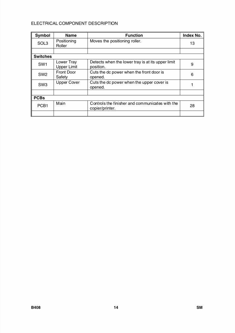
8/15/2019 Ricoh MP 4000 SM D009_D011_D012_D013 SERVICE MANUAL .pdf
http://slidepdf.com/reader/full/ricoh-mp-4000-sm-d009d011d012d013-service-manual-pdf 674/1162
ELECTRICAL COMPONENT DESCRIPTION
B408 14 SM
Symbol Name Function Index No.
SOL3 PositioningRoller
Moves the positioning roller. 13
SwitchesSW1 Lower Tray
Upper LimitDetects when the lower tray is at its upper limitposition. 9
SW2 Front DoorSafety
Cuts the dc power when the front door isopened. 6
SW3 Upper Cover Cuts the dc power when the upper cover isopened. 1
PCBs
PCB1 Main Controls the finisher and communicates with thecopier/printer. 28
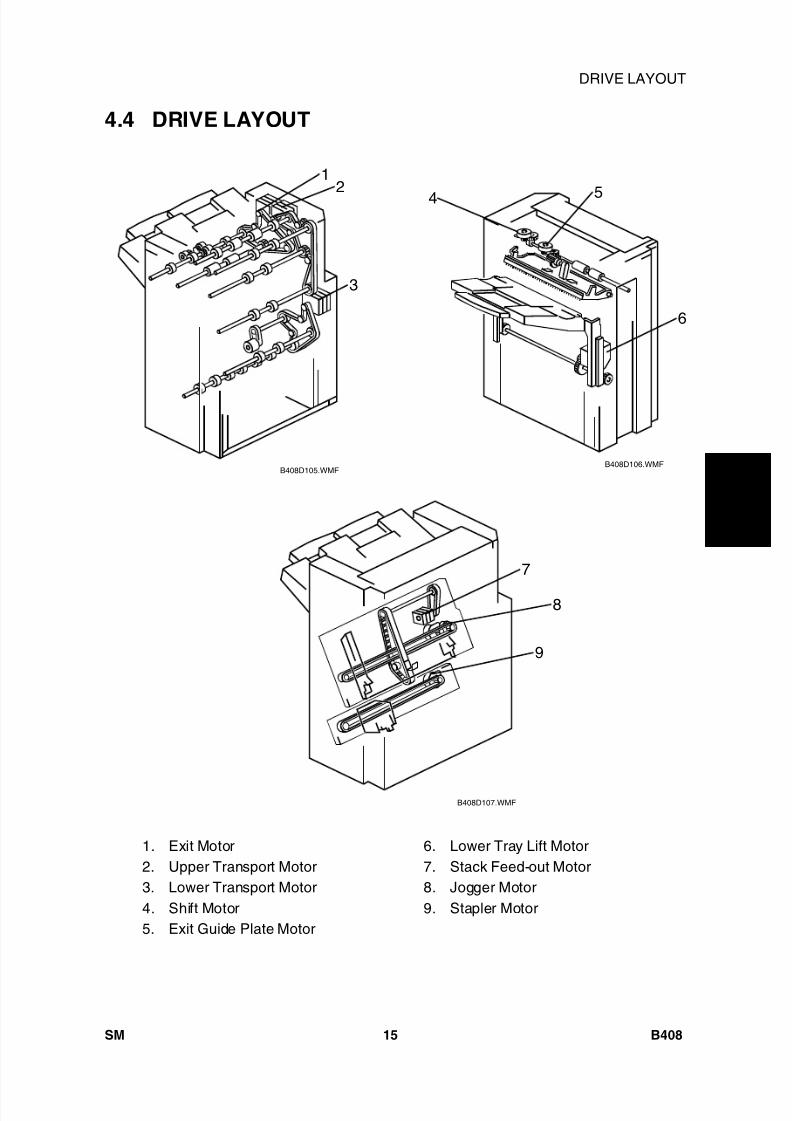
8/15/2019 Ricoh MP 4000 SM D009_D011_D012_D013 SERVICE MANUAL .pdf
http://slidepdf.com/reader/full/ricoh-mp-4000-sm-d009d011d012d013-service-manual-pdf 675/1162
1 0 0 0
- S h e e t
F i n i s h e r
B 4 0 8
DRIVE LAYOUT
SM 15 B408
4.4 DRIVE LAYOUT
1. Exit Motor2. Upper Transport Motor3. Lower Transport Motor4. Shift Motor5. Exit Guide Plate Motor
6. Lower Tray Lift Motor7. Stack Feed-out Motor8. Jogger Motor9. Stapler Motor
B408D105.WMFB408D106.WMF
B408D107.WMF
1
3
24 5
6
7
8
9
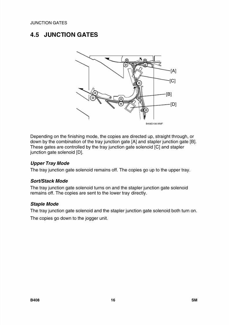
8/15/2019 Ricoh MP 4000 SM D009_D011_D012_D013 SERVICE MANUAL .pdf
http://slidepdf.com/reader/full/ricoh-mp-4000-sm-d009d011d012d013-service-manual-pdf 676/1162
JUNCTION GATES
B408 16 SM
4.5 JUNCTION GATES
Depending on the finishing mode, the copies are directed up, straight through, ordown by the combination of the tray junction gate [A] and stapler junction gate [B].These gates are controlled by the tray junction gate solenoid [C] and stapler
junction gate solenoid [D].
Upper Tray Mode
The tray junction gate solenoid remains off. The copies go up to the upper tray.
Sort/Stack Mode The tray junction gate solenoid turns on and the stapler junction gate solenoidremains off. The copies are sent to the lower tray directly.
Staple Mode The tray junction gate solenoid and the stapler junction gate solenoid both turn on.
The copies go down to the jogger unit.
B408D108.WMF
[A]
[B]
[C]
[D]
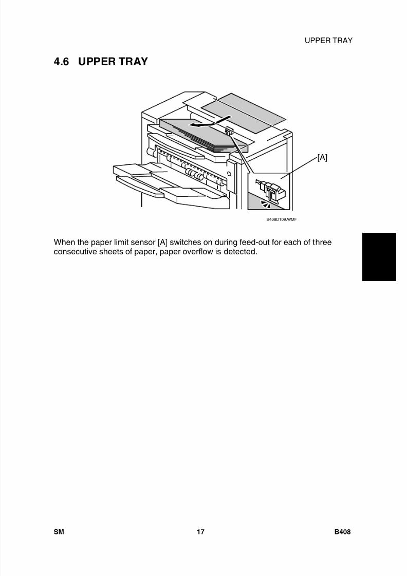
8/15/2019 Ricoh MP 4000 SM D009_D011_D012_D013 SERVICE MANUAL .pdf
http://slidepdf.com/reader/full/ricoh-mp-4000-sm-d009d011d012d013-service-manual-pdf 677/1162
1 0 0 0
- S h e e t
F i n i s h e r
B 4 0 8
UPPER TRAY
SM 17 B408
4.6 UPPER TRAY
When the paper limit sensor [A] switches on during feed-out for each of threeconsecutive sheets of paper, paper overflow is detected.
B408D109.WMF
[A]

8/15/2019 Ricoh MP 4000 SM D009_D011_D012_D013 SERVICE MANUAL .pdf
http://slidepdf.com/reader/full/ricoh-mp-4000-sm-d009d011d012d013-service-manual-pdf 678/1162
LOWER TRAY UP/DOWN MECHANISMS
B408 18 SM
4.7 LOWER TRAY UP/DOWN MECHANISMS
The vertical position of the lower tray [A] depends on the height of the copied paperstack on the lower tray. The stack height sensor feeler [B] contacts the top of thestack, and the lower tray lift motor [C] controls the tray height.
When the lower tray reaches its lowest possible position, the actuator [D] turns onthe lower tray lower limit sensor [E], and copying stops.
Tray Up When the copy paper on the tray is removed, the stack height sensor [F] turns offand the tray lifts up. Then, the tray stops when the sensor turns on again (the traypushes up the feeler).If the stack height sensor fails, the lower tray upper limit switch [G] detects the trayand stops the motor. This is a safety measure against stack height sensor failure.
Sort/Stack Mode (Tray Down) Every five sheets of paper, the tray goes down until the sensor turns off again.Then, it goes up until the sensor is on again.
Staple Mode (Tray Down) After a stapled copy is fed out, the tray goes up for 220 ms and stops for 300 ms.Then, it goes down for 1 second, waits for 500 ms, then goes up until the sensorturns on.
B408D112.WMF
[E]
[D]
[A]
[C]
[G] [B] [F]
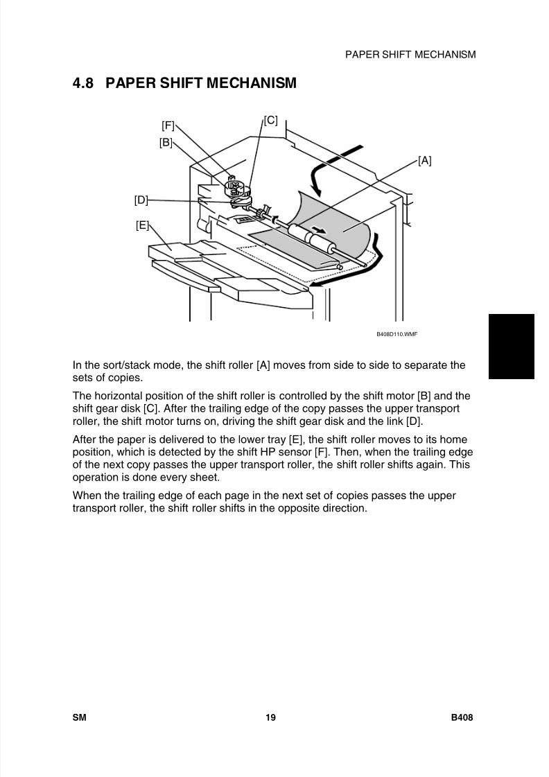
8/15/2019 Ricoh MP 4000 SM D009_D011_D012_D013 SERVICE MANUAL .pdf
http://slidepdf.com/reader/full/ricoh-mp-4000-sm-d009d011d012d013-service-manual-pdf 679/1162
1 0 0 0
- S h e e t
F i n i s h e r
B 4 0 8
PAPER SHIFT MECHANISM
SM 19 B408
4.8 PAPER SHIFT MECHANISM
In the sort/stack mode, the shift roller [A] moves from side to side to separate thesets of copies.
The horizontal position of the shift roller is controlled by the shift motor [B] and the
shift gear disk [C]. After the trailing edge of the copy passes the upper transportroller, the shift motor turns on, driving the shift gear disk and the link [D].
After the paper is delivered to the lower tray [E], the shift roller moves to its homeposition, which is detected by the shift HP sensor [F]. Then, when the trailing edgeof the next copy passes the upper transport roller, the shift roller shifts again. Thisoperation is done every sheet.
When the trailing edge of each page in the next set of copies passes the uppertransport roller, the shift roller shifts in the opposite direction.
B408D110.WMF
[A]
[B][F] [C]
[E]
[D]
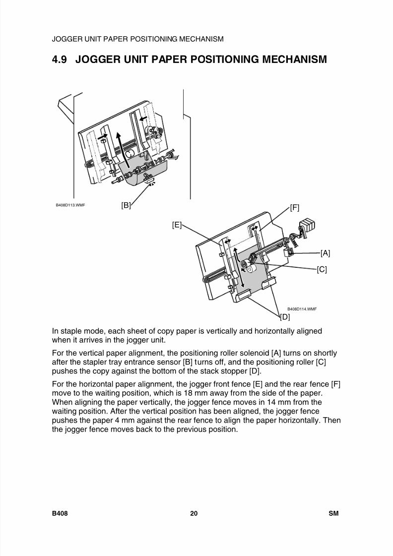
8/15/2019 Ricoh MP 4000 SM D009_D011_D012_D013 SERVICE MANUAL .pdf
http://slidepdf.com/reader/full/ricoh-mp-4000-sm-d009d011d012d013-service-manual-pdf 680/1162
JOGGER UNIT PAPER POSITIONING MECHANISM
B408 20 SM
4.9 JOGGER UNIT PAPER POSITIONING MECHANISM
In staple mode, each sheet of copy paper is vertically and horizontally alignedwhen it arrives in the jogger unit.
For the vertical paper alignment, the positioning roller solenoid [A] turns on shortlyafter the stapler tray entrance sensor [B] turns off, and the positioning roller [C]pushes the copy against the bottom of the stack stopper [D].
For the horizontal paper alignment, the jogger front fence [E] and the rear fence [F]move to the waiting position, which is 18 mm away from the side of the paper.When aligning the paper vertically, the jogger fence moves in 14 mm from thewaiting position. After the vertical position has been aligned, the jogger fencepushes the paper 4 mm against the rear fence to align the paper horizontally. Thenthe jogger fence moves back to the previous position.
B408D113.WMF
B408D114.WMF
[B]
[A]
[C]
[D]
[E]
[F]
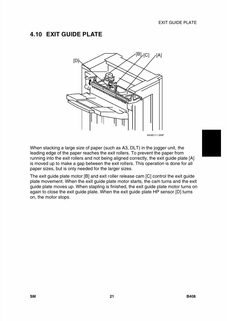
8/15/2019 Ricoh MP 4000 SM D009_D011_D012_D013 SERVICE MANUAL .pdf
http://slidepdf.com/reader/full/ricoh-mp-4000-sm-d009d011d012d013-service-manual-pdf 681/1162
1 0 0 0
- S h e e t
F i n i s h e r
B 4 0 8
EXIT GUIDE PLATE
SM 21 B408
4.10 EXIT GUIDE PLATE
When stacking a large size of paper (such as A3, DLT) in the jogger unit, theleading edge of the paper reaches the exit rollers. To prevent the paper fromrunning into the exit rollers and not being aligned correctly, the exit guide plate [A]is moved up to make a gap between the exit rollers. This operation is done for all
paper sizes, but is only needed for the larger sizes.The exit guide plate motor [B] and exit roller release cam [C] control the exit guideplate movement. When the exit guide plate motor starts, the cam turns and the exitguide plate moves up. When stapling is finished, the exit guide plate motor turns onagain to close the exit guide plate. When the exit guide plate HP sensor [D] turnson, the motor stops.
B408D111.WMF
[A][B] [C][D]
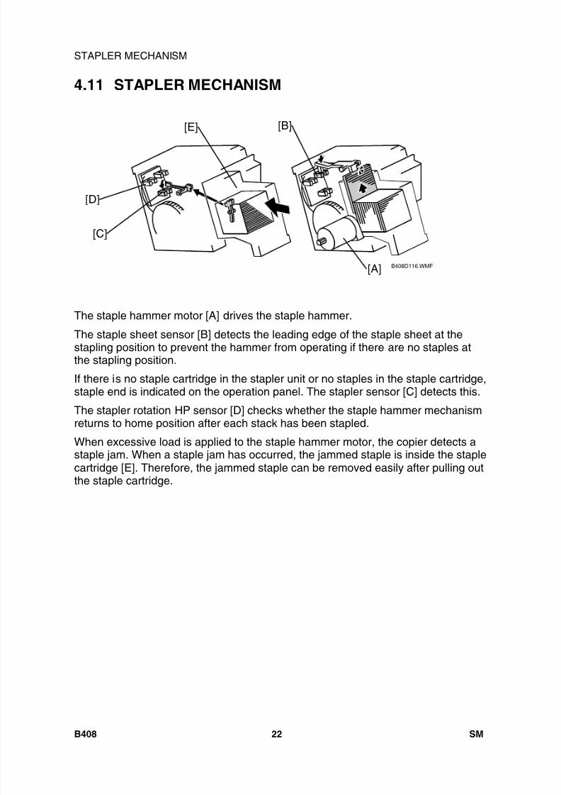
8/15/2019 Ricoh MP 4000 SM D009_D011_D012_D013 SERVICE MANUAL .pdf
http://slidepdf.com/reader/full/ricoh-mp-4000-sm-d009d011d012d013-service-manual-pdf 682/1162
STAPLER MECHANISM
B408 22 SM
4.11 STAPLER MECHANISM
The staple hammer motor [A] drives the staple hammer.
The staple sheet sensor [B] detects the leading edge of the staple sheet at thestapling position to prevent the hammer from operating if there are no staples atthe stapling position.
If there is no staple cartridge in the stapler unit or no staples in the staple cartridge,staple end is indicated on the operation panel. The stapler sensor [C] detects this.
The stapler rotation HP sensor [D] checks whether the staple hammer mechanismreturns to home position after each stack has been stapled.
When excessive load is applied to the staple hammer motor, the copier detects astaple jam. When a staple jam has occurred, the jammed staple is inside the staplecartridge [E]. Therefore, the jammed staple can be removed easily after pulling outthe staple cartridge.
B408D116.WMF[A]
[E]
[C]
[B]
[D]

8/15/2019 Ricoh MP 4000 SM D009_D011_D012_D013 SERVICE MANUAL .pdf
http://slidepdf.com/reader/full/ricoh-mp-4000-sm-d009d011d012d013-service-manual-pdf 683/1162
1 0 0 0
- S h e e t
F i n i s h e r
B 4 0 8
STAPLER UNIT MOVEMENT MECHANISM
SM 23 B408
4.12 STAPLER UNIT MOVEMENT MECHANISM
The stapler motor moves the stapler [A] from side to side. After the start key ispressed, the stapler moves from its home position to the stapling position.
If two-staple-position mode is selected, the stapler moves to the front staplingposition first, then moves to the rear stapling position. However, for the next copyset, it staples in the reverse order (at the rear side first, then at the front side).
After the job is completed, the stapler moves back to its home position. The staplerHP sensor [B] detects this.
B408D117.WMF
[A]
[B]

8/15/2019 Ricoh MP 4000 SM D009_D011_D012_D013 SERVICE MANUAL .pdf
http://slidepdf.com/reader/full/ricoh-mp-4000-sm-d009d011d012d013-service-manual-pdf 684/1162
PAPER FEED-OUT MECHANISM
B408 24 SM
4.13 PAPER FEED-OUT MECHANISM
After the copies have been stapled, the stack feed-out motor [A] starts. The pawl[B] on the stack feed-out belt [C] transports the set of stapled copies up and feedsit to the shift roller. The shift roller takes over stack feed-out after the leading edgereaches this roller.
Just before the stapled stack passes through the lower tray exit sensor, the stack-feed-out motor turns off until the shift rollers have completely fed the stack out tothe lower tray. Then, the stack-feed-out motor turns on again until the pawl [B]actuates the stack feed-out belt home position sensor [D].
B408D118.WMF
[A]
[B]
[C][D]

8/15/2019 Ricoh MP 4000 SM D009_D011_D012_D013 SERVICE MANUAL .pdf
http://slidepdf.com/reader/full/ricoh-mp-4000-sm-d009d011d012d013-service-manual-pdf 685/1162
AUTO REVERSE DOCUMENTFEEDER DF3010
B802

8/15/2019 Ricoh MP 4000 SM D009_D011_D012_D013 SERVICE MANUAL .pdf
http://slidepdf.com/reader/full/ricoh-mp-4000-sm-d009d011d012d013-service-manual-pdf 686/1162

8/15/2019 Ricoh MP 4000 SM D009_D011_D012_D013 SERVICE MANUAL .pdf
http://slidepdf.com/reader/full/ricoh-mp-4000-sm-d009d011d012d013-service-manual-pdf 687/1162
SM i B802
ARDF DF3010 B802TABLE OF CONTENTS
1. REPLACEMENT AND ADJUSTMENT ............................................ 11.1 COVERS AND TRAY.................................................................................... 1
1.1.1 FRONT AND REAR COVER................................................................ 11.1.2 ORIGINAL TRAY ................................................................................. 1
1.2 DOCUMENT FEED COMPONENTS ............................................................ 31.2.1 PICK-UP ROLLER ............................................................................... 3
1.2.2 FEED BELT.......................................................................................... 31.2.3 SEPARATION ROLLER....................................................................... 5
1.3 ELECTRICAL COMPONENTS ..................................................................... 61.3.1 DF DRIVE BOARD............................................................................... 61.3.2 ORIGINAL LENGTH SENSORS AND TRAILING EDGE SENSOR..... 61.3.3 ORIGINAL SET, SEPARATION, SKEW CORRECTION ANDSCANNING ENTRANCE SENSOR............................................................... 71.3.4 ORIGINAL WIDTH SENSORS............................................................. 8
1.3.5 REGISTRATION SENSOR .................................................................. 91.3.6 ORIGINAL EXIT SENSOR................................................................... 91.3.7 DF POSITION SENSOR .................................................................... 101.3.8 COVER SENSOR .............................................................................. 101.3.9 PICK-UP ROLLER HP AND ORIGINAL STOPPER HP SENSOR..... 111.3.10 STAMP SOLENOID...................................................................... 12
1.4 ORIGINAL FEED DRIVE............................................................................. 141.4.1 ADF FEED MOTOR........................................................................... 14
1.4.2 ADF INVERTER MOTOR .................................................................. 151.4.3 ADF TRANSPORT MOTOR............................................................... 151.4.4 ADF PICK-UP MOTOR ...................................................................... 15
2. DETAILED DESCRIPTIONS .......................................................... 172.1 COMPONENT LAYOUT.............................................................................. 17
2.1.1 MECHANICAL COMPONENT LAYOUT............................................ 172.1.2 ELECTRICAL COMPONENT LAYOUT ............................................. 18
2.1.3 DRIVE LAYOUT................................................................................. 21
8/15/2019 Ricoh MP 4000 SM D009_D011_D012_D013 SERVICE MANUAL .pdf
http://slidepdf.com/reader/full/ricoh-mp-4000-sm-d009d011d012d013-service-manual-pdf 688/1162
B802 ii SM
2.2 BASIC OPERATION ................................................................................... 232.2.1 ORIGINAL SIZE DETECTION ........................................................... 23
2.2.2 MIXED ORIGINAL SIZE MODE......................................................... 252.2.3 PICK-UP AND SEPARATION............................................................ 262.2.4 SKEW CORRECTION ....................................................................... 272.2.5 SLIP DETECTION.............................................................................. 282.2.6 ORIGINAL TRANSPORT AND EXIT ................................................. 282.2.7 CONDITIONS FOR JAM DETECTION .............................................. 30
3. SERVICE TABLES ......................................................................... 313.1 DIP SWITCHES .......................................................................................... 31
8/15/2019 Ricoh MP 4000 SM D009_D011_D012_D013 SERVICE MANUAL .pdf
http://slidepdf.com/reader/full/ricoh-mp-4000-sm-d009d011d012d013-service-manual-pdf 689/1162
Read This First
Safety and SymbolsReplacement Procedure Safety
Turn off the main power switch and unplug the machine before beginning any of
the replacement procedures in this manual.
Symbols Used in this ManualThis manual uses the following symbols.
: See or Refer to
: Screws
: Connector
: Clip ring
: E-ring : Clamp

8/15/2019 Ricoh MP 4000 SM D009_D011_D012_D013 SERVICE MANUAL .pdf
http://slidepdf.com/reader/full/ricoh-mp-4000-sm-d009d011d012d013-service-manual-pdf 690/1162
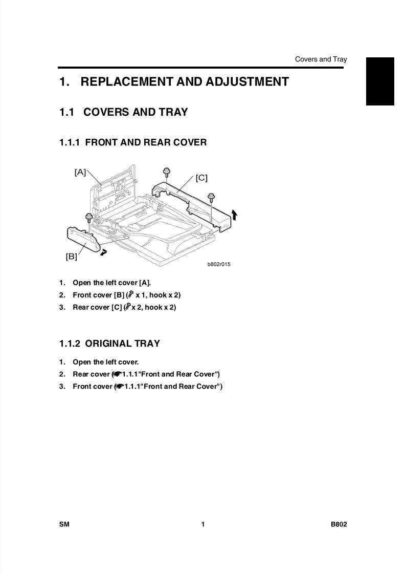
8/15/2019 Ricoh MP 4000 SM D009_D011_D012_D013 SERVICE MANUAL .pdf
http://slidepdf.com/reader/full/ricoh-mp-4000-sm-d009d011d012d013-service-manual-pdf 691/1162
Covers and Tray
SM 1 B802
A u t o R e v e r s e
D o c
F e e
d e r
B 8 0 2
1. REPLACEMENT AND ADJUSTMENT
1.1 COVERS AND TRAY
1.1.1 FRONT AND REAR COVER
1. Open the left cover [A].
2. Front cover [B] ( x 1, hook x 2)
3. Rear cover [C] ( x 2, hook x 2)
1.1.2 ORIGINAL TRAY
1. Open the left cover.
2. Rear cover ( 1.1.1"Front and Rear Cover")
3. Front cover ( 1.1.1"Front and Rear Cover")
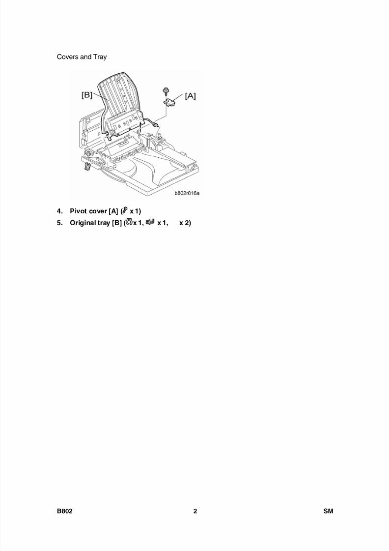
8/15/2019 Ricoh MP 4000 SM D009_D011_D012_D013 SERVICE MANUAL .pdf
http://slidepdf.com/reader/full/ricoh-mp-4000-sm-d009d011d012d013-service-manual-pdf 692/1162
Covers and Tray
B802 2 SM
4. Pivot cover [A] ( x 1)
5. Original tray [B] ( x 1, x 1, x 2)
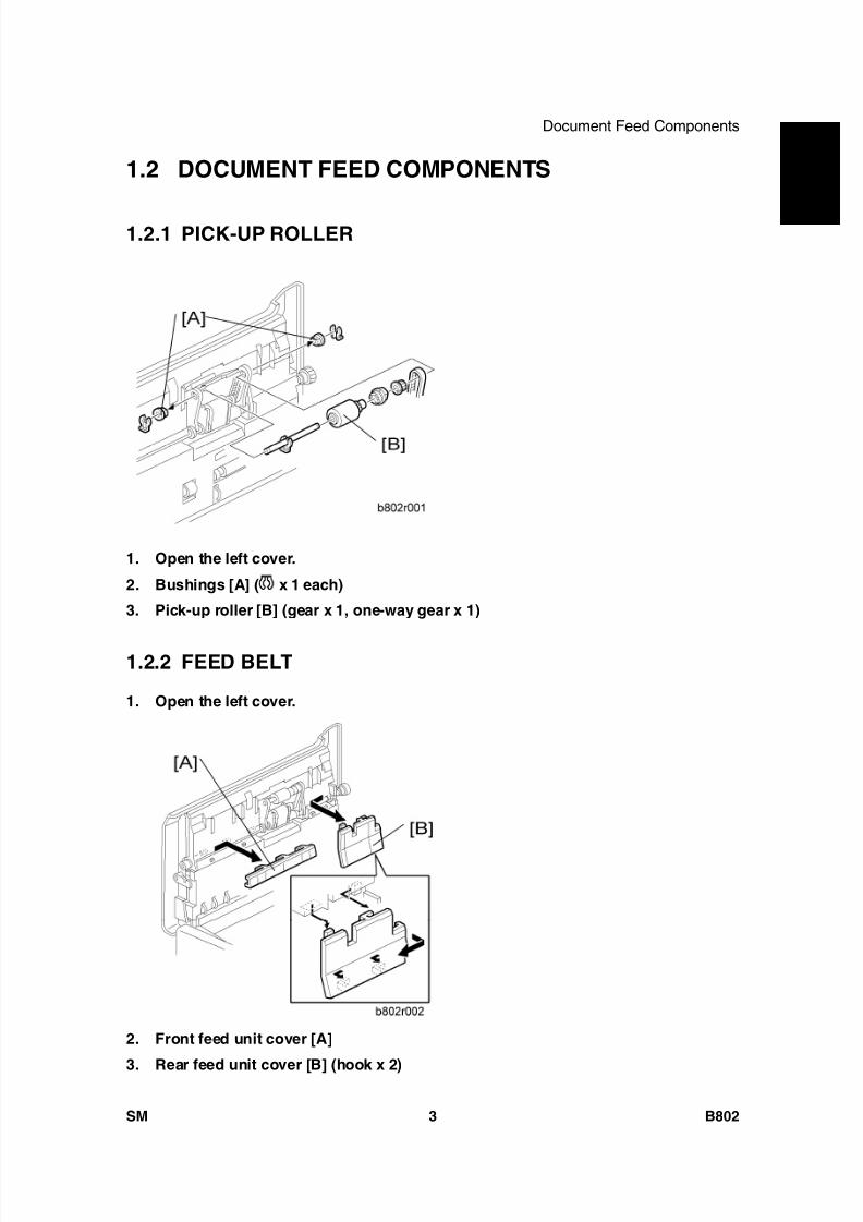
8/15/2019 Ricoh MP 4000 SM D009_D011_D012_D013 SERVICE MANUAL .pdf
http://slidepdf.com/reader/full/ricoh-mp-4000-sm-d009d011d012d013-service-manual-pdf 693/1162
Document Feed Components
SM 3 B802
A u t o R e v e r s e
D o c
F e e
d e r
B 8 0 2
1.2 DOCUMENT FEED COMPONENTS
1.2.1 PICK-UP ROLLER
1. Open the left cover.
2. Bushings [A] ( x 1 each)
3. Pick-up roller [B] (gear x 1, one-way gear x 1)
1.2.2 FEED BELT
1. Open the left cover.
2. Front feed unit cover [A]
3. Rear feed unit cover [B] (hook x 2)
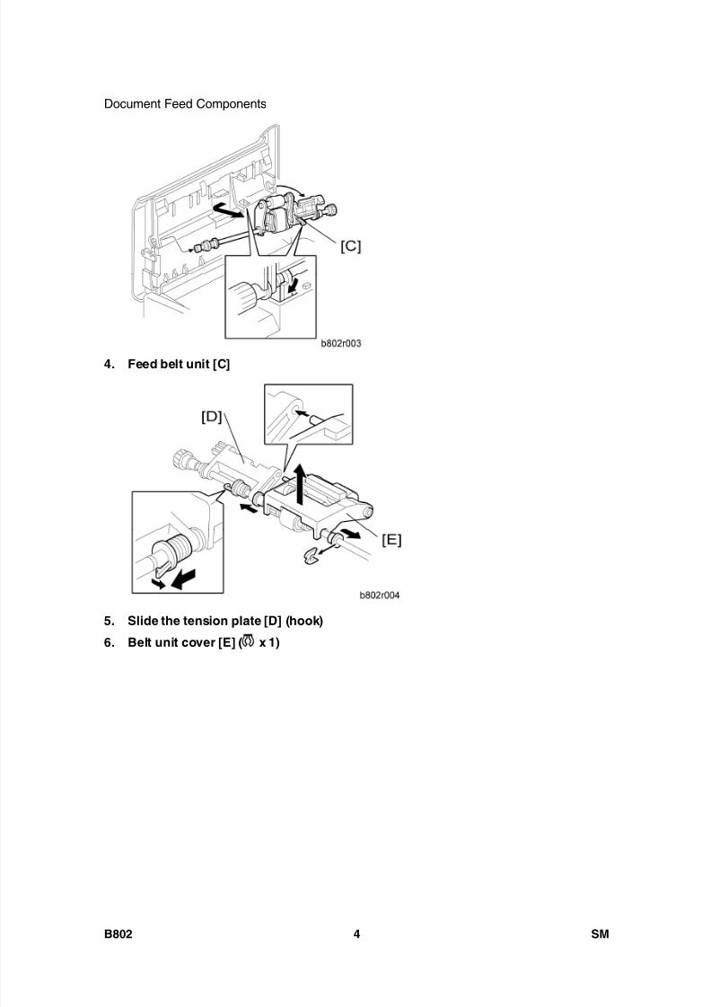
8/15/2019 Ricoh MP 4000 SM D009_D011_D012_D013 SERVICE MANUAL .pdf
http://slidepdf.com/reader/full/ricoh-mp-4000-sm-d009d011d012d013-service-manual-pdf 694/1162
Document Feed Components
B802 4 SM
4. Feed belt unit [C]
5. Slide the tension plate [D] (hook)
6. Belt unit cover [E] ( x 1)
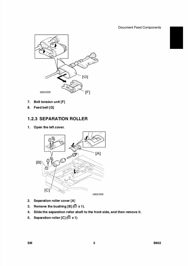
8/15/2019 Ricoh MP 4000 SM D009_D011_D012_D013 SERVICE MANUAL .pdf
http://slidepdf.com/reader/full/ricoh-mp-4000-sm-d009d011d012d013-service-manual-pdf 695/1162
Document Feed Components
SM 5 B802
A u t o R e v e r s e
D o c
F e e
d e r
B 8 0 2
7. Belt tension unit [F]
8. Feed belt [G]
1.2.3 SEPARATION ROLLER
1. Open the left cover.
2. Separation roller cover [A]
3. Remove the bushing [B] ( x 1).
4. Slide the separation roller shaft to the front side, and then remove it.
5. Separation roller [C] ( x 1)
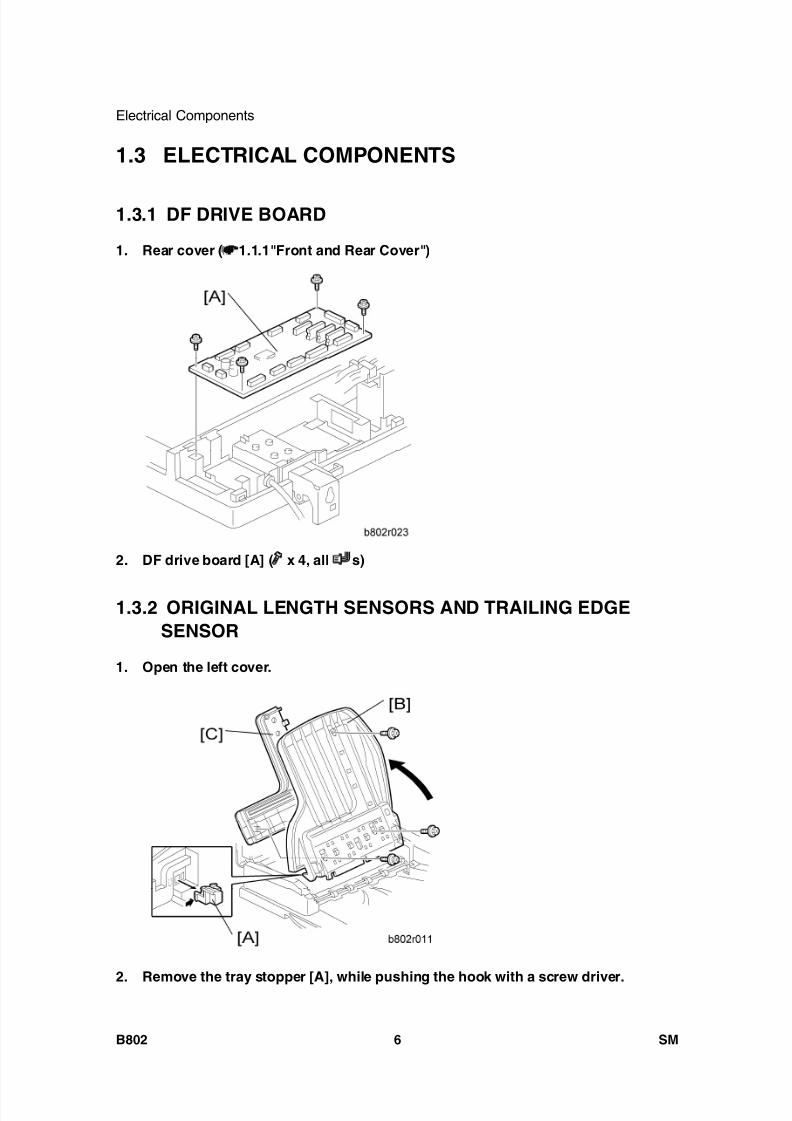
8/15/2019 Ricoh MP 4000 SM D009_D011_D012_D013 SERVICE MANUAL .pdf
http://slidepdf.com/reader/full/ricoh-mp-4000-sm-d009d011d012d013-service-manual-pdf 696/1162
Electrical Components
B802 6 SM
1.3 ELECTRICAL COMPONENTS
1.3.1 DF DRIVE BOARD
1. Rear cover ( 1.1.1"Front and Rear Cover")
2. DF drive board [A] ( x 4, all s)
1.3.2 ORIGINAL LENGTH SENSORS AND TRAILING EDGESENSOR
1. Open the left cover.
2. Remove the tray stopper [A], while pushing the hook with a screw driver.
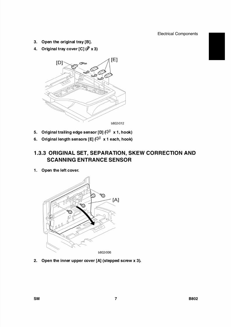
8/15/2019 Ricoh MP 4000 SM D009_D011_D012_D013 SERVICE MANUAL .pdf
http://slidepdf.com/reader/full/ricoh-mp-4000-sm-d009d011d012d013-service-manual-pdf 697/1162
Electrical Components
SM 7 B802
A u t o R e v e r s e
D o c
F e e
d e r
B 8 0 23. Open the original tray [B].
4. Original tray cover [C] ( x 3)
5. Original trailing edge sensor [D] ( x 1, hook)
6. Original length sensors [E] ( x 1 each, hook)
1.3.3 ORIGINAL SET, SEPARATION, SKEW CORRECTION ANDSCANNING ENTRANCE SENSOR
1. Open the left cover.
2. Open the inner upper cover [A] (stepped screw x 3).
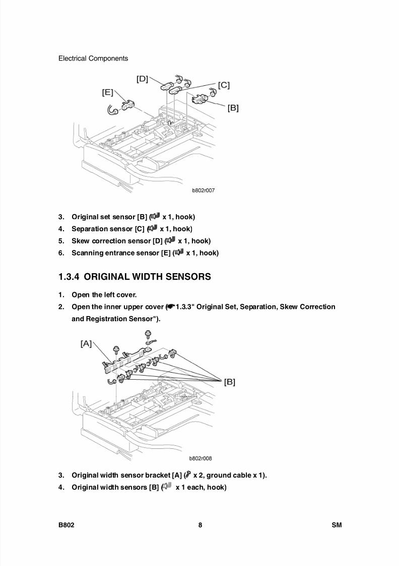
8/15/2019 Ricoh MP 4000 SM D009_D011_D012_D013 SERVICE MANUAL .pdf
http://slidepdf.com/reader/full/ricoh-mp-4000-sm-d009d011d012d013-service-manual-pdf 698/1162
Electrical Components
B802 8 SM
3. Original set sensor [B] ( x 1, hook)
4. Separation sensor [C] ( x 1, hook)
5. Skew correction sensor [D] ( x 1, hook)
6. Scanning entrance sensor [E] ( x 1, hook)
1.3.4 ORIGINAL WIDTH SENSORS
1. Open the left cover.2. Open the inner upper cover ( 1.3.3" Original Set, Separation, Skew Correction
and Registration Sensor").
3. Original width sensor bracket [A] ( x 2, ground cable x 1).
4. Original width sensors [B] ( x 1 each, hook)
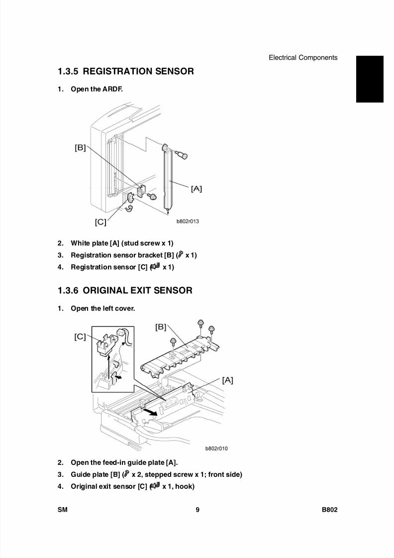
8/15/2019 Ricoh MP 4000 SM D009_D011_D012_D013 SERVICE MANUAL .pdf
http://slidepdf.com/reader/full/ricoh-mp-4000-sm-d009d011d012d013-service-manual-pdf 699/1162
Electrical Components
SM 9 B802
A u t o R e v e r s e
D o c
F e e
d e r
B 8 0 21.3.5 REGISTRATION SENSOR
1. Open the ARDF.
2. White plate [A] (stud screw x 1)
3. Registration sensor bracket [B] ( x 1)
4. Registration sensor [C] ( x 1)
1.3.6 ORIGINAL EXIT SENSOR1. Open the left cover.
2. Open the feed-in guide plate [A].
3. Guide plate [B] ( x 2, stepped screw x 1; front side)
4. Original exit sensor [C] ( x 1, hook)
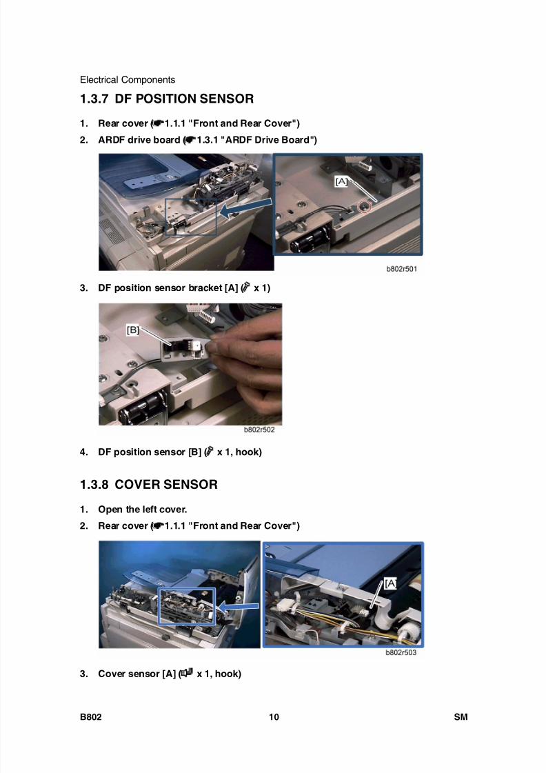
8/15/2019 Ricoh MP 4000 SM D009_D011_D012_D013 SERVICE MANUAL .pdf
http://slidepdf.com/reader/full/ricoh-mp-4000-sm-d009d011d012d013-service-manual-pdf 700/1162
Electrical Components
B802 10 SM
1.3.7 DF POSITION SENSOR
1. Rear cover ( 1.1.1 "Front and Rear Cover")
2. ARDF drive board ( 1.3.1 "ARDF Drive Board")
3. DF position sensor bracket [A] ( x 1)
4. DF position sensor [B] ( x 1, hook)
1.3.8 COVER SENSOR
1. Open the left cover.
2. Rear cover ( 1.1.1 "Front and Rear Cover")
3. Cover sensor [A] ( x 1, hook)

8/15/2019 Ricoh MP 4000 SM D009_D011_D012_D013 SERVICE MANUAL .pdf
http://slidepdf.com/reader/full/ricoh-mp-4000-sm-d009d011d012d013-service-manual-pdf 701/1162
Electrical Components
SM 11 B802
A u t o R e v e r s e
D o c
F e e
d e r
B 8 0 21.3.9 PICK-UP ROLLER HP AND ORIGINAL STOPPER HP
SENSOR
1. Open the left cover.
2. Rear cover ( 1.1.1 "Front and Rear Cover")
3. Release the clamp [A] ( x 1), and then slide the harnesses away.
4. Sensor bracket [B] ( x 1, x 2)
5. Pick-up roller HP sensor [C] (hook)
6. Original stopper HP sensor [D] (hook)

8/15/2019 Ricoh MP 4000 SM D009_D011_D012_D013 SERVICE MANUAL .pdf
http://slidepdf.com/reader/full/ricoh-mp-4000-sm-d009d011d012d013-service-manual-pdf 702/1162
Electrical Components
B802 12 SM
1.3.10 STAMP SOLENOID
1. Open the left cover.
2. Remove the platen plate [A].
3. Stamp solenoid cover [B] ( x 1)
4. Remove the screw [C] ( x 1).
You cannot remove the stamp solenoid at this time.5. Rear cover ( 1.1.1. "Front and Rear Cover")
6. Disconnect the stamp solenoid harness [D].
7. ADF feed motor ( 1.4.1 "ADF Feed Motor")
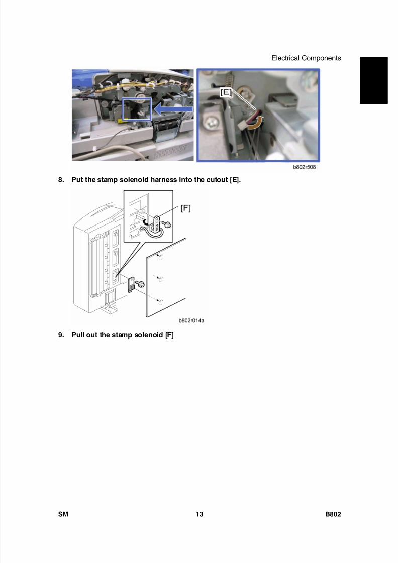
8/15/2019 Ricoh MP 4000 SM D009_D011_D012_D013 SERVICE MANUAL .pdf
http://slidepdf.com/reader/full/ricoh-mp-4000-sm-d009d011d012d013-service-manual-pdf 703/1162
Electrical Components
SM 13 B802
A u t o R e v e r s e
D o c
F e e
d e r
B 8 0 2
8. Put the stamp solenoid harness into the cutout [E].
9. Pull out the stamp solenoid [F]
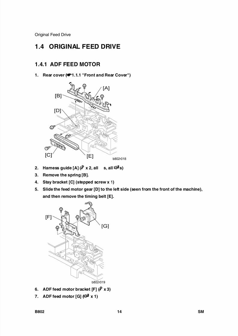
8/15/2019 Ricoh MP 4000 SM D009_D011_D012_D013 SERVICE MANUAL .pdf
http://slidepdf.com/reader/full/ricoh-mp-4000-sm-d009d011d012d013-service-manual-pdf 704/1162
Original Feed Drive
B802 14 SM
1.4 ORIGINAL FEED DRIVE
1.4.1 ADF FEED MOTOR
1. Rear cover ( 1.1.1 "Front and Rear Cover")
2. Harness guide [A] ( x 2, all s, all s)
3. Remove the spring [B].4. Stay bracket [C] (stepped screw x 1)
5. Slide the feed motor gear [D] to the left side (seen from the front of the machine),
and then remove the timing belt [E].
6. ADF feed motor bracket [F] ( x 3)
7. ADF feed motor [G] ( x 1)

8/15/2019 Ricoh MP 4000 SM D009_D011_D012_D013 SERVICE MANUAL .pdf
http://slidepdf.com/reader/full/ricoh-mp-4000-sm-d009d011d012d013-service-manual-pdf 705/1162
Original Feed Drive
SM 15 B802
A u t o R e v e r s e
D o c
F e e
d e r
B 8 0 21.4.2 ADF INVERTER MOTOR
1. ADF feed motor ( 1.4.1 " ADF Feed Motor")
2. ADF inverter motor bracket [A] ( x 2, x 1, timing belt)
3. ADF inverter motor [B] ( x 4)
1.4.3 ADF TRANSPORT MOTOR
1. Rear cover ( 1.1.1 "Front and Rear Cover")
2. Ground cable [A] ( x 1)
3. ADF transport motor bracket [B] ( x 2, x 1)
4. ADF transport motor [C] ( x 2)
1.4.4 ADF PICK-UP MOTOR
1. Rear cover ( 1.1.1 "Front and Rear Cover")
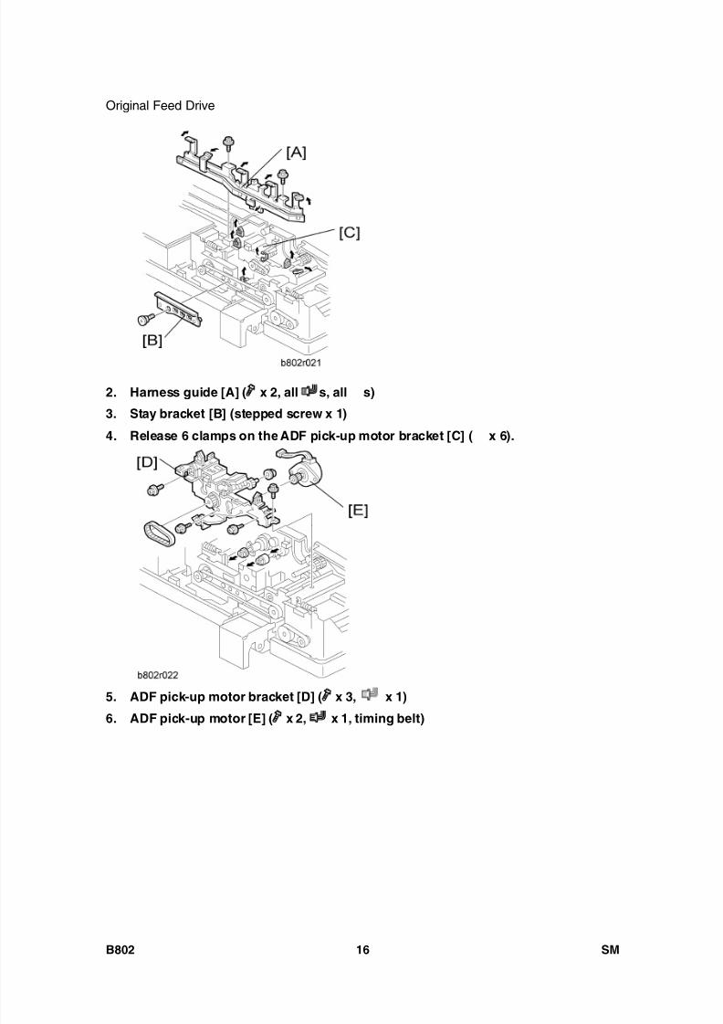
8/15/2019 Ricoh MP 4000 SM D009_D011_D012_D013 SERVICE MANUAL .pdf
http://slidepdf.com/reader/full/ricoh-mp-4000-sm-d009d011d012d013-service-manual-pdf 706/1162
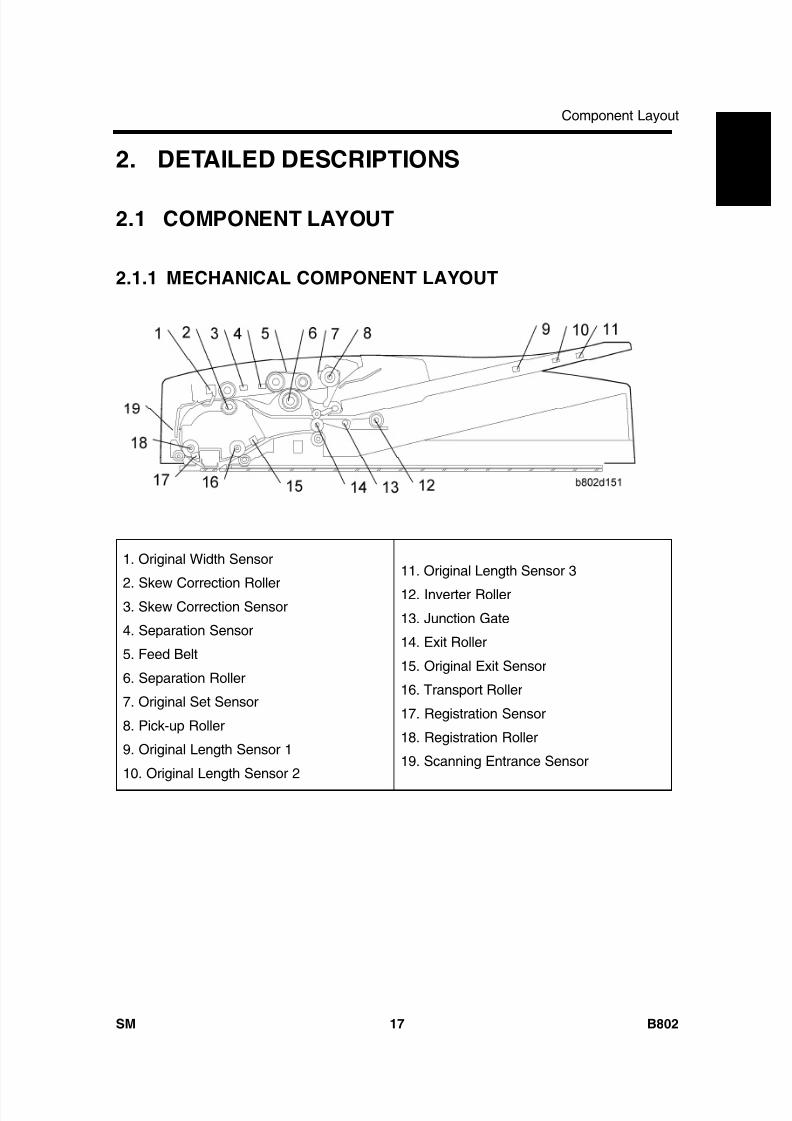
8/15/2019 Ricoh MP 4000 SM D009_D011_D012_D013 SERVICE MANUAL .pdf
http://slidepdf.com/reader/full/ricoh-mp-4000-sm-d009d011d012d013-service-manual-pdf 707/1162
Component Layout
SM 17 B802
A u t o R e v e r s e
D o c
F e e
d e r
B 8 0 2
2. DETAILED DESCRIPTIONS
2.1 COMPONENT LAYOUT
2.1.1 MECHANICAL COMPONENT LAYOUT
1. Original Width Sensor
2. Skew Correction Roller3. Skew Correction Sensor
4. Separation Sensor
5. Feed Belt
6. Separation Roller
7. Original Set Sensor
8. Pick-up Roller
9. Original Length Sensor 1
10. Original Length Sensor 2
11. Original Length Sensor 3
12. Inverter Roller
13. Junction Gate
14. Exit Roller
15. Original Exit Sensor
16. Transport Roller
17. Registration Sensor
18. Registration Roller
19. Scanning Entrance Sensor

8/15/2019 Ricoh MP 4000 SM D009_D011_D012_D013 SERVICE MANUAL .pdf
http://slidepdf.com/reader/full/ricoh-mp-4000-sm-d009d011d012d013-service-manual-pdf 708/1162
Component Layout
B802 18 SM
2.1.2 ELECTRICAL COMPONENT LAYOUT
Sensors and Drive Components
1. Original Width Sensors
2. Scanning Entrance Sensor
3. Skew Correction Sensor
4. ADF Transport Motor
5. Left Cover Sensor
6. Pick-up Motor
7. Pick-up Roller HP Sensor
8. Original Stopper HP Sensor
9. ADF Inverter Motor
10. ADF Feed Motor11. Original Length Sensor 1
12. Original Length Sensor 213. Original Length Sensor 4
14. DF Drive Board
15. Original Trailing Edge Sensor
16. Original Set Sensor
17. Stamp Solenoid
18. Separation Sensor
19. Original Exit Sensor
20. Junction Gate Solenoid
21. Registration Sensor
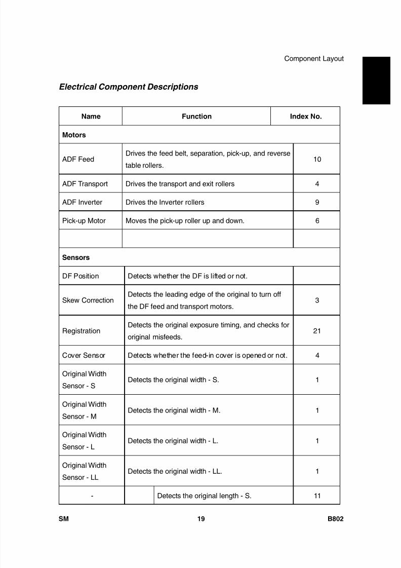
8/15/2019 Ricoh MP 4000 SM D009_D011_D012_D013 SERVICE MANUAL .pdf
http://slidepdf.com/reader/full/ricoh-mp-4000-sm-d009d011d012d013-service-manual-pdf 709/1162
Component Layout
SM 19 B802
A u t o R e v e r s e
D o c
F e e
d e r
B 8 0 2
Electrical Component Descriptions
Name Function Index No.
Motors
ADF FeedDrives the feed belt, separation, pick-up, and reverse
table rollers.10
ADF Transport Drives the transport and exit rollers 4
ADF Inverter Drives the Inverter rollers 9
Pick-up Motor Moves the pick-up roller up and down. 6
Sensors
DF Position Detects whether the DF is lifted or not.
Skew CorrectionDetects the leading edge of the original to turn off
the DF feed and transport motors.3
RegistrationDetects the original exposure timing, and checks for
original misfeeds.21
Cover Sensor Detects whether the feed-in cover is opened or not. 4
Original Width
Sensor - SDetects the original width - S. 1
Original Width
Sensor - MDetects the original width - M. 1
Original Width
Sensor - LDetects the original width - L. 1
Original Width
Sensor - LLDetects the original width - LL. 1
- Detects the original length - S. 11
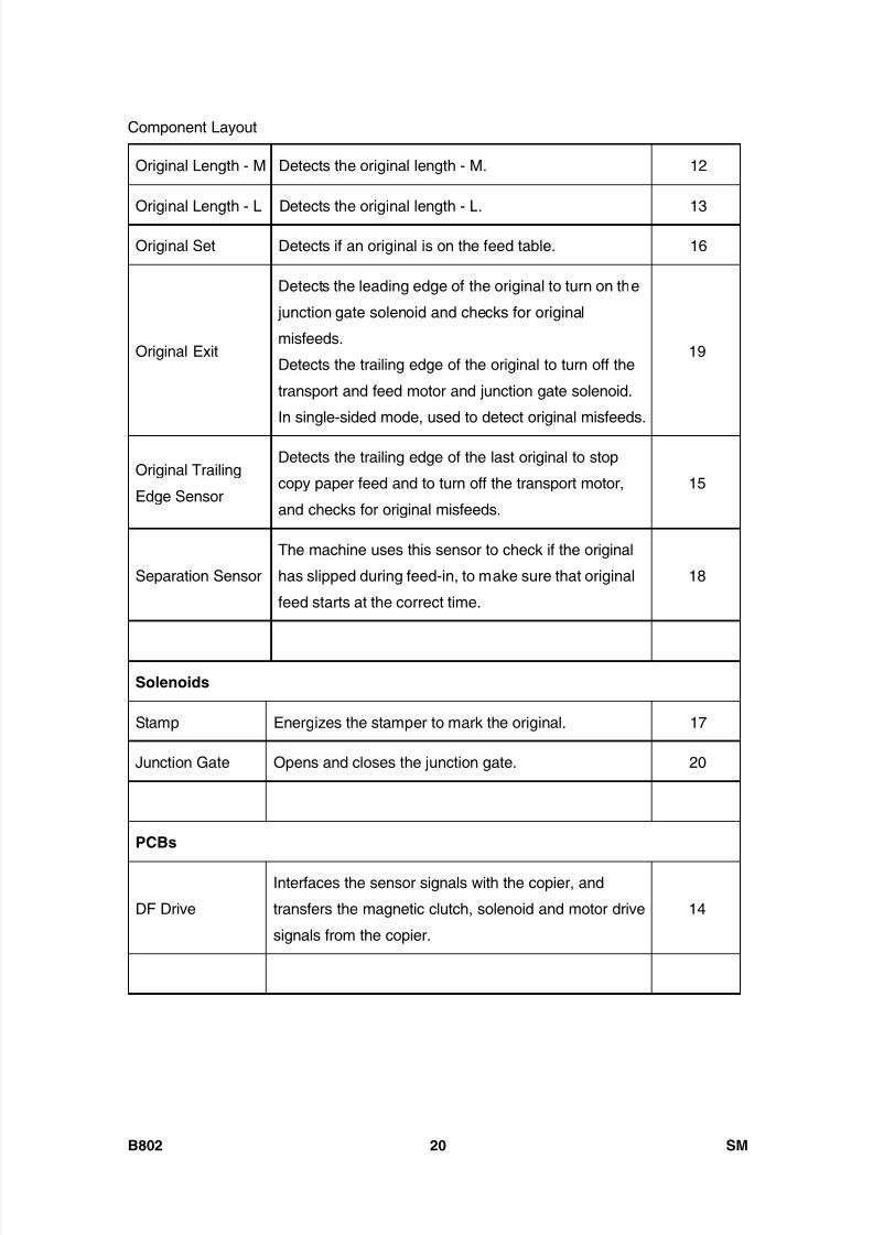
8/15/2019 Ricoh MP 4000 SM D009_D011_D012_D013 SERVICE MANUAL .pdf
http://slidepdf.com/reader/full/ricoh-mp-4000-sm-d009d011d012d013-service-manual-pdf 710/1162

8/15/2019 Ricoh MP 4000 SM D009_D011_D012_D013 SERVICE MANUAL .pdf
http://slidepdf.com/reader/full/ricoh-mp-4000-sm-d009d011d012d013-service-manual-pdf 711/1162
Component Layout
SM 21 B802
A u t o R e v e r s e
D o c
F e e
d e r
B 8 0 22.1.3 DRIVE LAYOUT
1. Registration Roller
2. Transport Roller
3. Skew Correction Roller
4. Separation Roller
5. Feed Belt6. ADF Transport Motor
7. Pick-up Roller
8. Exit Roller
9. ADF Inverter Motor
10. ADF Feed Motor
11. Inverter Roller

8/15/2019 Ricoh MP 4000 SM D009_D011_D012_D013 SERVICE MANUAL .pdf
http://slidepdf.com/reader/full/ricoh-mp-4000-sm-d009d011d012d013-service-manual-pdf 712/1162
Component Layout
B802 22 SM
ADF Feed Motor
ADF Feed Motor [A] drives the pick-up [B], feed belt [C], separation [D] and skew
correction rollers [E].
ADF Transport Motor and ADF Inverter Motor
ADF Transport Motor [A] drives the registration roller [B], transport roller [C] and exit
roller [D].
ADF Inverter Motor [E] drives the Inverter Roller [F].

8/15/2019 Ricoh MP 4000 SM D009_D011_D012_D013 SERVICE MANUAL .pdf
http://slidepdf.com/reader/full/ricoh-mp-4000-sm-d009d011d012d013-service-manual-pdf 713/1162
Basic Operation
SM 23 B802
A u t o R e v e r s e
D o c
F e e
d e r
B 8 0 2
2.2 BASIC OPERATION
2.2.1 ORIGINAL SIZE DETECTION
The original size detection mechanism consists of the five original width sensors ([A]: Width
Sensor SS, [B]: Width Sensor S, [C] Width Sensor M, [D]: Width Sensor L, [E]: WidthSensor LL) and three original length sensors ([F]: Length Sensor S, [G]: Length Sensor M,
[H]: Length Sensor L). Based on the combined output of the length sensors and the width
sensors, the machine can detect the size of the original. This integrated detection
mechanism is detailed in the table below.
Width Sensor Length Sensor AreaSize
SS S M L LL S M L LT A/B
A3/SEF (297 x 420) ON ON ON ON ON ON ON ON O O
B4/SEF (257 x 364) ON ON ON - - ON ON ON - O
A4/SEF (210 x 297) ON ON - - - ON ON - O O
A4/LEF (297 x 210) ON ON ON ON ON - - - O O
B5/SEF (182 x 257) ON - - - - ON - - - O

8/15/2019 Ricoh MP 4000 SM D009_D011_D012_D013 SERVICE MANUAL .pdf
http://slidepdf.com/reader/full/ricoh-mp-4000-sm-d009d011d012d013-service-manual-pdf 714/1162
Basic Operation
B802 24 SM
B5/LEF (257 x 182) ON ON ON - - - - - - O
A5/SEF (148 x 210) ON - - - - - - - - O
A5/LEF (210 x 148) ON ON - - - - - - - O
11" x 17"/SEF
(DLT)ON ON ON ON - ON ON ON O 1 O5
11" x 15"/SEF ON ON ON ON - ON ON ON 1 -
10" x 14"/SEF ON ON ON ON ON ON ON ON O -
8.5" x 14"/SEF (LG) ON ON - - - ON ON ON O2
-
8.5" x 13"/SEF (F4) ON ON - - - ON ON ON 2 O
8.25" x 13"/SEF ON ON - - - ON ON ON - -
8" x 13"/SEF (F) ON ON - - - ON ON ON - -
8.5" x 11"/SEF (LT) ON ON - - - ON - - O 3 O6
8.5" x 11"/LEF (LT) ON ON ON On - - - - O 4 O7
7.25" x 10.5"/SEF
(US EXE)ON ON - - - ON - - O -
10.5" x 7.25"/SEF
(US EXE)ON ON ON ON - - - - 4 -
10" x 8"/SEF ON ON - - - ON - - 3 -
5.5" x 8.5"/SEF
(HLT) - - - - - - - - O -
5.5" x 8.5"/LEF
(HLT)ON ON - - - - - - O -
267 mm x 390 mm ON ON ON ON - ON ON ON - 5
195 mm x 267 mm ON ON - - - ON - - - 6
267 mm x 195 mm ON ON ON ON - - - - - 7

8/15/2019 Ricoh MP 4000 SM D009_D011_D012_D013 SERVICE MANUAL .pdf
http://slidepdf.com/reader/full/ricoh-mp-4000-sm-d009d011d012d013-service-manual-pdf 715/1162
Basic Operation
SM 25 B802
A u t o R e v e r s e
D o c
F e e
d e r
B 8 0 2Symbols
O: Yes (Default), : Yes (Can select this with SP mode), ON: Paper present, LT: North
America, A/B: Europe, Asia
For "O/ " mark, which has superscripted number, it is possible to change the
original detection size with SP6-016. For example, instead of LT (O 3), the machine
can be set up to detect 10” x 8” ( 3).
The F size can be selected with SP5-126. The default is 8.5" x 13"
The machine cannot detect more than one size of original in the same job.
2.2.2 MIXED ORIGINAL SIZE MODE
This section explains what happens when the user selects mixed original size mode.
Because this ARDF is a sheet-through document feeder, the method for original document
width detection is the same as when the originals are the same size, but the document
length detection method is different. Therefore, the scanning speed is slightly slower.
Document length detection
From when the skew correction sensor switches on until it switches off, the CPU counts the
transport motor pulses. The number of pulses determines the length of the original.
Feed-in cycle
When the original size for the copy modes listed below cannot be determined, the image
cannot be correctly scaled (reduced or enlarged) or processed until the original’s length
has been accurately detected. The length must be determined before the image is
scanned.
Auto Reduce/Enlarge
Centering
Erase Center/Border
Booklet
Image Repeat
The originals follow this path:
1. Length detection Scanning glass Inverter table
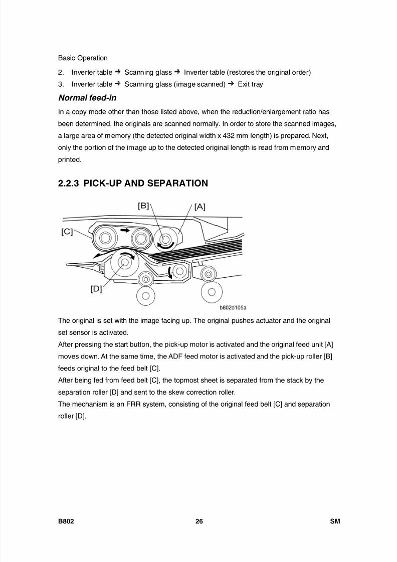
8/15/2019 Ricoh MP 4000 SM D009_D011_D012_D013 SERVICE MANUAL .pdf
http://slidepdf.com/reader/full/ricoh-mp-4000-sm-d009d011d012d013-service-manual-pdf 716/1162
Basic Operation
B802 26 SM
2. Inverter table Scanning glass Inverter table (restores the original order)
3. Inverter table Scanning glass (image scanned) Exit tray
Normal feed-in In a copy mode other than those listed above, when the reduction/enlargement ratio has
been determined, the originals are scanned normally. In order to store the scanned images,
a large area of memory (the detected original width x 432 mm length) is prepared. Next,
only the portion of the image up to the detected original length is read from memory and
printed.
2.2.3 PICK-UP AND SEPARATION
The original is set with the image facing up. The original pushes actuator and the original
set sensor is activated.
After pressing the start button, the pick-up motor is activated and the original feed unit [A]
moves down. At the same time, the ADF feed motor is activated and the pick-up roller [B]
feeds original to the feed belt [C].
After being fed from feed belt [C], the topmost sheet is separated from the stack by the
separation roller [D] and sent to the skew correction roller.The mechanism is an FRR system, consisting of the original feed belt [C] and separation
roller [D].
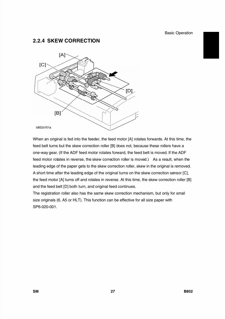
8/15/2019 Ricoh MP 4000 SM D009_D011_D012_D013 SERVICE MANUAL .pdf
http://slidepdf.com/reader/full/ricoh-mp-4000-sm-d009d011d012d013-service-manual-pdf 717/1162

8/15/2019 Ricoh MP 4000 SM D009_D011_D012_D013 SERVICE MANUAL .pdf
http://slidepdf.com/reader/full/ricoh-mp-4000-sm-d009d011d012d013-service-manual-pdf 718/1162
Basic Operation
B802 28 SM
2.2.5 SLIP DETECTION
[A]: Separation sensor[B]: Skew correction sensor
These two sensors are used to measure the amount of slippage and to correct for this.
The machine measures the time it takes for the original to get to the separation sensor [A]
after the [Start] key is pressed.
If the original arrives at the correct time, it feeds normally.
If the original arrives late, the machine enters the slip mode.
In the slip mode, the machine measures the time for the leading edge of the original to
move from the separation sensor to the skew correction sensor [B].The machine uses this time to adjust the length of time that the entrance roller stays off to
correct skew. This stops feed for enough time for the original to be in the correct position for
feeding.
2.2.6 ORIGINAL TRANSPORT AND EXIT
Single-Sided Originals
The feed motor feeds the separated original to the skew correction roller [A] at maximum

8/15/2019 Ricoh MP 4000 SM D009_D011_D012_D013 SERVICE MANUAL .pdf
http://slidepdf.com/reader/full/ricoh-mp-4000-sm-d009d011d012d013-service-manual-pdf 719/1162
Basic Operation
SM 29 B802
A u t o R e v e r s e
D o c
F e e
d e r
B 8 0 2speed. After skew correction, the feed and transport motors feed the original through the
scanning area at a lower speed (the scanning area contains the original exposure guide [B]
and DF exposure glass [C]). After scanning, the original is fed out by the transport roller [D]and exit roller [E].
Double-Sided Originals
After skew correction, the ADF feed and transport motors drive the skew correction roller
[A], registration roller [B], transport roller [C] and the exit roller [D]. The front side of the
original is then scanned.
When the original exit sensor [E] detects the leading edge of the original, the junction gate
solenoid is activated and the junction gate [F] opens. The original is then transported
towards the inverter table.
Soon after the trailing edge of the original passes the exit sensor, the junction gate solenoid
switches off and the junction gate [F] is closed. When the original has been fed onto the
inverter table, the ADF inverter motor switches on. The original is then fed by the inverter
roller [G], and then by the skew correction roller [A] and registration roller [B] to the
scanning area (where the reverse side will be scanned).
The original is then sent to the inverter table [H] again to be turned over. This is done so
that the duplex copies will be properly stacked front side down in the exit tray [I] in the
correct order.
Original Sensor
During one-to-one copying, copy paper is fed to the skew correction roller in advance
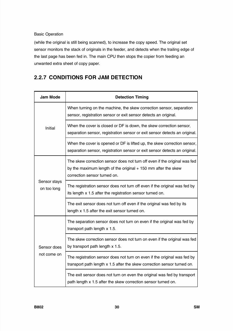
8/15/2019 Ricoh MP 4000 SM D009_D011_D012_D013 SERVICE MANUAL .pdf
http://slidepdf.com/reader/full/ricoh-mp-4000-sm-d009d011d012d013-service-manual-pdf 720/1162
Basic Operation
B802 30 SM
(while the original is still being scanned), to increase the copy speed. The original set
sensor monitors the stack of originals in the feeder, and detects when the trailing edge of
the last page has been fed in. The main CPU then stops the copier from feeding anunwanted extra sheet of copy paper.
2.2.7 CONDITIONS FOR JAM DETECTION
Jam Mode Detection Timing
When turning on the machine, the skew correction sensor, separation
sensor, registration sensor or exit sensor detects an original.
When the cover is closed or DF is down, the skew correction sensor,
separation sensor, registration sensor or exit sensor detects an original.Initial
When the cover is opened or DF is lifted up, the skew correction sensor,
separation sensor, registration sensor or exit sensor detects an original.
The skew correction sensor does not turn off even if the original was fed
by the maximum length of the original + 150 mm after the skew
correction sensor turned on.
The registration sensor does not turn off even if the original was fed by
its length x 1.5 after the registration sensor turned on.
Sensor stays
on too long
The exit sensor does not turn off even if the original was fed by its
length x 1.5 after the exit sensor turned on.
The separation sensor does not turn on even if the original was fed by
transport path length x 1.5.
The skew correction sensor does not turn on even if the original was fed
by transport path length x 1.5.
The registration sensor does not turn on even if the original was fed by
transport path length x 1.5 after the skew correction sensor turned on.
Sensor does
not come on
The exit sensor does not turn on even the original was fed by transport
path length x 1.5 after the skew correction sensor turned on.
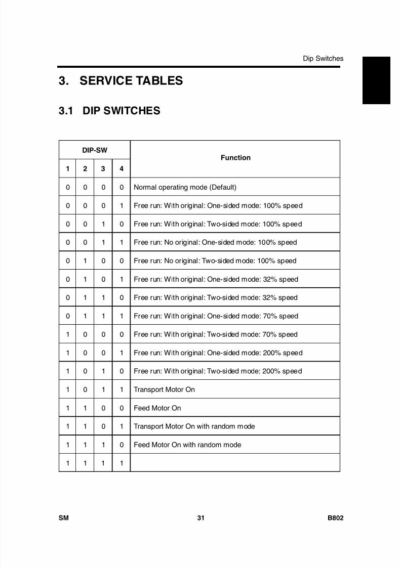
8/15/2019 Ricoh MP 4000 SM D009_D011_D012_D013 SERVICE MANUAL .pdf
http://slidepdf.com/reader/full/ricoh-mp-4000-sm-d009d011d012d013-service-manual-pdf 721/1162
Dip Switches
SM 31 B802
A u t o R e v e r s e
D o c
F e e
d e r
B 8 0 2
3. SERVICE TABLES
3.1 DIP SWITCHES
DIP-SW
1 2 3 4
Function
0 0 0 0 Normal operating mode (Default)
0 0 0 1 Free run: With original: One-sided mode: 100% speed
0 0 1 0 Free run: With original: Two-sided mode: 100% speed
0 0 1 1 Free run: No original: One-sided mode: 100% speed
0 1 0 0 Free run: No original: Two-sided mode: 100% speed
0 1 0 1 Free run: With original: One-sided mode: 32% speed
0 1 1 0 Free run: With original: Two-sided mode: 32% speed
0 1 1 1 Free run: With original: One-sided mode: 70% speed
1 0 0 0 Free run: With original: Two-sided mode: 70% speed
1 0 0 1 Free run: With original: One-sided mode: 200% speed
1 0 1 0 Free run: With original: Two-sided mode: 200% speed
1 0 1 1 Transport Motor On
1 1 0 0 Feed Motor On
1 1 0 1 Transport Motor On with random mode
1 1 1 0 Feed Motor On with random mode
1 1 1 1

8/15/2019 Ricoh MP 4000 SM D009_D011_D012_D013 SERVICE MANUAL .pdf
http://slidepdf.com/reader/full/ricoh-mp-4000-sm-d009d011d012d013-service-manual-pdf 722/1162
8/15/2019 Ricoh MP 4000 SM D009_D011_D012_D013 SERVICE MANUAL .pdf
http://slidepdf.com/reader/full/ricoh-mp-4000-sm-d009d011d012d013-service-manual-pdf 723/1162
BOOKLET FINISHER SR3020/ FINISHER SR3030
B804/B805

8/15/2019 Ricoh MP 4000 SM D009_D011_D012_D013 SERVICE MANUAL .pdf
http://slidepdf.com/reader/full/ricoh-mp-4000-sm-d009d011d012d013-service-manual-pdf 724/1162

8/15/2019 Ricoh MP 4000 SM D009_D011_D012_D013 SERVICE MANUAL .pdf
http://slidepdf.com/reader/full/ricoh-mp-4000-sm-d009d011d012d013-service-manual-pdf 725/1162
SM i B804/B805
BOOKLET FINISHER SR3020/
FINISHER SR3030 B804/B805TABLE OF CONTENTS
1. REPLACEMENT AND ADJUSTMENT ............................................ 11.1 COVERS ....................................................................................................... 1
1.1.1 EXTERIOR COVERS........................................................................... 11.1.2 UPPER TRAY, END FENCE................................................................ 2
1.2 MAIN UNIT.................................................................................................... 31.2.1 UPPER TRAY LIMIT SENSOR, LIMIT SWITCH.................................. 31.2.2 POSITIONING ROLLER ...................................................................... 41.2.3 PROOF TRAY EXIT SENSOR............................................................. 41.2.4 UPPER TRAY HEIGHT SENSORS 1, 2 .............................................. 51.2.5 EXIT GUIDE PLATE, UPPER TRAY EXIT SENSOR........................... 51.2.6 PROOF TRAY FULL SENSOR............................................................ 61.2.7 FINISHER ENTRANCE SENSOR........................................................ 7
1.2.8 PRE-STACK TRAY EXIT SENSOR..................................................... 71.3 STAPLER UNIT............................................................................................. 8
1.3.1 CORNER STAPLER ............................................................................ 81.3.2 POSITIONING ROLLER ...................................................................... 9
1.4 FOLD UNIT ................................................................................................. 101.4.1 FOLD UNIT........................................................................................ 101.4.2 FOLD UNIT ENTRANCE SENSOR ................................................... 121.4.3 FOLD UNIT EXIT SENSOR............................................................... 12
1.4.4 STACK PRESENT SENSOR ............................................................. 131.4.5 FOLDING HORIZONTAL SKEW ADJUSTMENT (FOR B804 ONLY)
141.4.6 FOLD VERTICAL SKEW ADJUSTMENT (FOR B804 ONLY)............ 17
1.5 BOOKLET STAPLER UNIT......................................................................... 191.5.1 BOOKLET STAPLER......................................................................... 191.5.2 BOOKLET STAPLER MOTOR........................................................... 19
2. DETAILED SECTION DESCRIPTIONS ......................................... 222.1 COMPONENT LAYOUT.............................................................................. 22

8/15/2019 Ricoh MP 4000 SM D009_D011_D012_D013 SERVICE MANUAL .pdf
http://slidepdf.com/reader/full/ricoh-mp-4000-sm-d009d011d012d013-service-manual-pdf 726/1162
B804/B805 ii SM
2.1.1 GENERAL LAYOUT........................................................................... 222.1.2 ELECTRICAL COMPONENTS .......................................................... 24
2.1.3 SUMMARY OF ELECTRICAL COMPONENTS ................................. 282.1.4 DRIVE LAYOUT................................................................................. 38
2.2 JUNCTION GATES..................................................................................... 402.2.1 PROOF MODE................................................................................... 402.2.2 SHIFT MODE..................................................................................... 402.2.3 STAPLE MODE.................................................................................. 41
2.3 PRE-STACKING ......................................................................................... 422.4 TRAY MOVEMENT MECHANISM .............................................................. 44
2.4.1 UPPER TRAY .................................................................................... 442.4.2 LOWER TRAY (B804 ONLY)............................................................. 46
2.5 CORNER STAPLING.................................................................................. 492.5.1 STACKING AND JOGGING............................................................... 492.5.2 STAPLER MOVEMENT ..................................................................... 502.5.3 CORNER STAPLING......................................................................... 52
2.6 BOOKLET STAPLING (B804 ONLY) .......................................................... 532.6.1 BOOKLET PRESSURE MECHANISM............................................... 532.6.2 BOOKLET STAPLING AND FOLDING .............................................. 542.6.3 BOOKLET STAPLING AND FOLDING MECHANISMS..................... 60
2.7 UPPER TRAY OUTPUT.............................................................................. 632.7.1 FEED OUT......................................................................................... 632.7.2 FEED OUT STACKING...................................................................... 64
2.8 PUNCH UNIT B702 (FOR B804/B805) ....................................................... 652.8.1 OVERVIEW OF OPERATION............................................................ 652.8.2 PUNCH MECHANISMS ..................................................................... 672.8.3 PUNCH HOPPER MECHANISM ....................................................... 70
2.9 FINISHER JAM DETECTION...................................................................... 72
8/15/2019 Ricoh MP 4000 SM D009_D011_D012_D013 SERVICE MANUAL .pdf
http://slidepdf.com/reader/full/ricoh-mp-4000-sm-d009d011d012d013-service-manual-pdf 727/1162
Read This First
Safety and SymbolsReplacement Procedure Safety
Turn off the main power switch and unplug the machine before beginning any of the
replacement procedures in this manual.
Symbols Used in this ManualThis manual uses the following symbols.
: See or Refer to
: Screws
: Connector
: Clip ring
: E-ring

8/15/2019 Ricoh MP 4000 SM D009_D011_D012_D013 SERVICE MANUAL .pdf
http://slidepdf.com/reader/full/ricoh-mp-4000-sm-d009d011d012d013-service-manual-pdf 728/1162
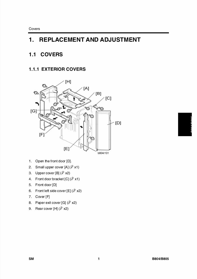
8/15/2019 Ricoh MP 4000 SM D009_D011_D012_D013 SERVICE MANUAL .pdf
http://slidepdf.com/reader/full/ricoh-mp-4000-sm-d009d011d012d013-service-manual-pdf 729/1162
Covers
SM 1 B804/B805
B o o
k l e t
F i n i s h e r /
F i n i s h e r
1. REPLACEMENT AND ADJUSTMENT
1.1 COVERS
1.1.1 EXTERIOR COVERS
1. Open the front door [D].
2. Small upper cover [A] ( x1)
3. Upper cover [B] ( x2)
4. Front door bracket [C] ( x1)
5. Front door [D]
6. Front left side cover [E] ( x2)
7. Cover [F]
8. Paper exit cover [G] ( x2)
9. Rear cover [H] ( x2)
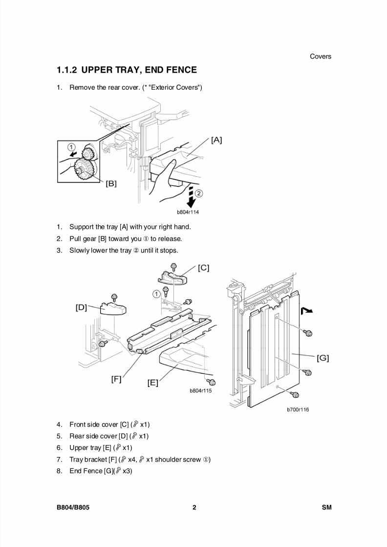
8/15/2019 Ricoh MP 4000 SM D009_D011_D012_D013 SERVICE MANUAL .pdf
http://slidepdf.com/reader/full/ricoh-mp-4000-sm-d009d011d012d013-service-manual-pdf 730/1162
Covers
B804/B805 2 SM
1.1.2 UPPER TRAY, END FENCE
1. Remove the rear cover. (* "Exterior Covers")
1. Support the tray [A] with your right hand.
2. Pull gear [B] toward you to release.
3. Slowly lower the tray until it stops.
4. Front side cover [C] ( x1)
5. Rear side cover [D] ( x1)
6. Upper tray [E] ( x1)
7. Tray bracket [F] ( x4, x1 shoulder screw )
8. End Fence [G]( x3)

8/15/2019 Ricoh MP 4000 SM D009_D011_D012_D013 SERVICE MANUAL .pdf
http://slidepdf.com/reader/full/ricoh-mp-4000-sm-d009d011d012d013-service-manual-pdf 731/1162
Main Unit
SM 3 B804/B805
B o o
k l e t
F i n i s h e r /
F i n i s h e r
1.2 MAIN UNIT
1.2.1 UPPER TRAY LIMIT SENSOR, LIMIT SWITCH
1. Front door, front left side cover, rear cover, upper cover ( "Exterior Cover")
2. End fence ( 1.1.2 "Upper Tray, End Fence")
3. Upper tray exit mechanism [A] ( x4, x3)
4. Upper tray limit sensor [B] ( x1, x1)
5. Upper tray limit switch [C] ( x2)

8/15/2019 Ricoh MP 4000 SM D009_D011_D012_D013 SERVICE MANUAL .pdf
http://slidepdf.com/reader/full/ricoh-mp-4000-sm-d009d011d012d013-service-manual-pdf 732/1162
Main Unit
B804/B805 4 SM
1.2.2 POSITIONING ROLLER
1. Open the front door [A].
2. Pull out the stapling unit [B].
3. Positioning roller [C] ( x1, timing belt x1)
1.2.3 PROOF TRAY EXIT SENSOR
1. Small upper cover ( 1.1.1 "Exterior Cover")
2. Proof tray exit sensor bracket [A] ( x1)

8/15/2019 Ricoh MP 4000 SM D009_D011_D012_D013 SERVICE MANUAL .pdf
http://slidepdf.com/reader/full/ricoh-mp-4000-sm-d009d011d012d013-service-manual-pdf 733/1162
Main Unit
SM 5 B804/B805
B o o
k l e t
F i n i s h e r /
F i n i s h e r
3. Proof tray exit sensor [B] ( x1)
1.2.4 UPPER TRAY HEIGHT SENSORS 1, 2
1. Small upper cover, upper cover ( 1.1.1 "Exterior Cover")
2. Upper tray paper height sensor bracket [A] ( x1)
3. Upper tray paper height sensor [B] – staple mode (S08) ( x1)
4. Upper tray paper height sensor [C] – non-staple mode (S09) ( x1)
1.2.5 EXIT GUIDE PLATE, UPPER TRAY EXIT SENSOR
1. Rear cover, Upper covers, Front door, Cover, Paper exit cover ( 1.1.1 "Exterior
Cover")
2. Inner cover [A] ( x2)

8/15/2019 Ricoh MP 4000 SM D009_D011_D012_D013 SERVICE MANUAL .pdf
http://slidepdf.com/reader/full/ricoh-mp-4000-sm-d009d011d012d013-service-manual-pdf 734/1162
Main Unit
B804/B805 6 SM
3. Exit guide plate [B] ( x1, Link and spring, x1, x1)
4. Upper tray exit sensor [C] (S6) ( x1)
1.2.6 PROOF TRAY FULL SENSOR
1. Exit guide plate. ( 1.2.5 "Exit Guide Plate, Upper Tray Exit Sensor")
2. Guide plate [A] (hook x 2)
3. Sensor bracket [B] ( x1)
4. Proof tray full sensor [C] (S11) ( x1)
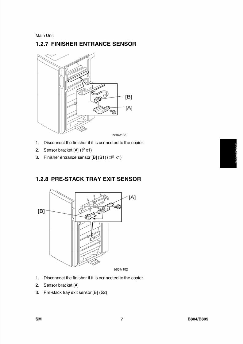
8/15/2019 Ricoh MP 4000 SM D009_D011_D012_D013 SERVICE MANUAL .pdf
http://slidepdf.com/reader/full/ricoh-mp-4000-sm-d009d011d012d013-service-manual-pdf 735/1162
Main Unit
SM 7 B804/B805
B o o
k l e t
F i n i s h e r /
F i n i s h e r
1.2.7 FINISHER ENTRANCE SENSOR
1. Disconnect the finisher if it is connected to the copier.
2. Sensor bracket [A] ( x1)
3. Finisher entrance sensor [B] (S1) ( x1)
1.2.8 PRE-STACK TRAY EXIT SENSOR
1. Disconnect the finisher if it is connected to the copier.
2. Sensor bracket [A]
3. Pre-stack tray exit sensor [B] (S2)

8/15/2019 Ricoh MP 4000 SM D009_D011_D012_D013 SERVICE MANUAL .pdf
http://slidepdf.com/reader/full/ricoh-mp-4000-sm-d009d011d012d013-service-manual-pdf 736/1162
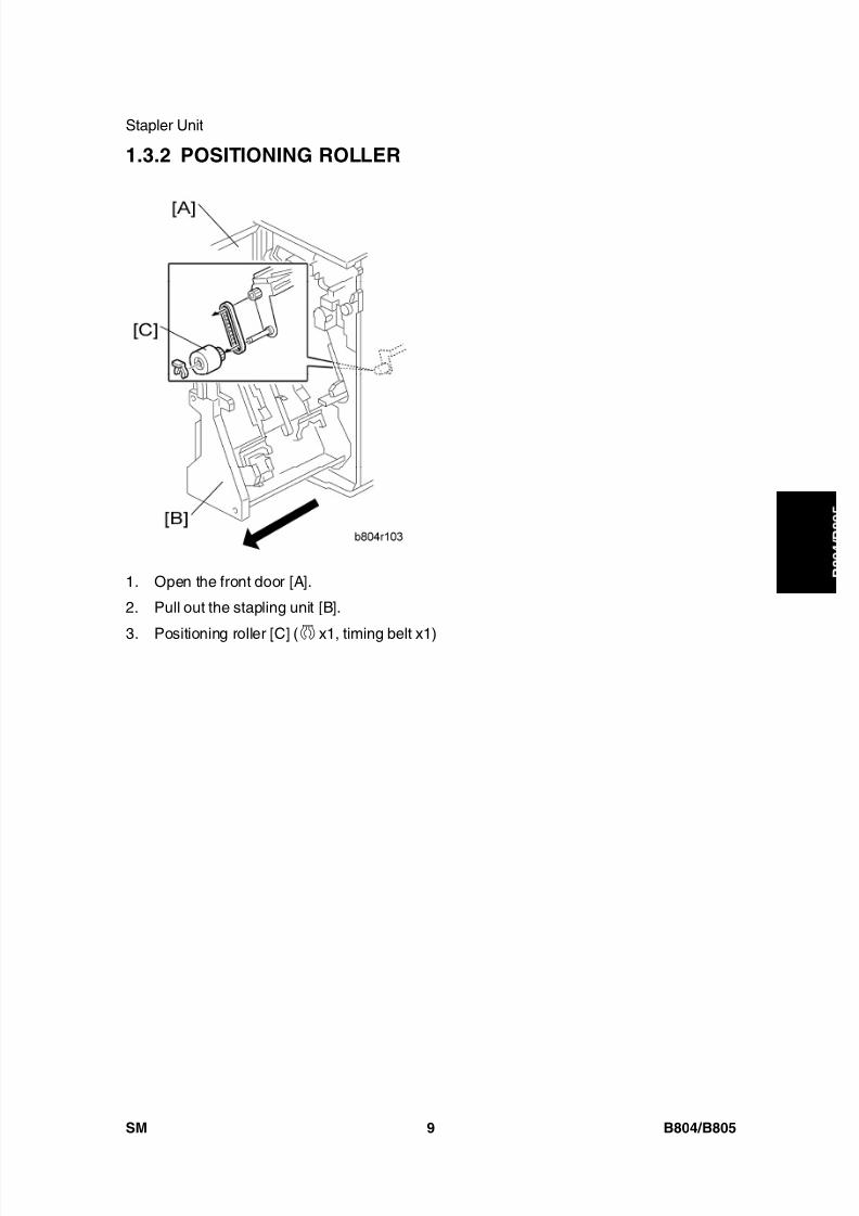
8/15/2019 Ricoh MP 4000 SM D009_D011_D012_D013 SERVICE MANUAL .pdf
http://slidepdf.com/reader/full/ricoh-mp-4000-sm-d009d011d012d013-service-manual-pdf 737/1162
Stapler Unit
SM 9 B804/B805
B o o
k l e t
F i n i s h e r /
F i n i s h e r
1.3.2 POSITIONING ROLLER
1. Open the front door [A].
2. Pull out the stapling unit [B].
3. Positioning roller [C] ( x1, timing belt x1)

8/15/2019 Ricoh MP 4000 SM D009_D011_D012_D013 SERVICE MANUAL .pdf
http://slidepdf.com/reader/full/ricoh-mp-4000-sm-d009d011d012d013-service-manual-pdf 738/1162
Fold Unit
B804/B805 10 SM
1.4 FOLD UNIT
1.4.1 FOLD UNIT
1. Remove the back cover ( 1.1.1 "Exterior Covers").
2. Open the front door.
The stapler unit is heavy.
3. Ground cable [A] ( x1)
4. Harness [B] ( x6, x6)
5. Stapler unit [C] ( x4)
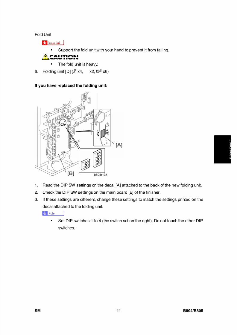
8/15/2019 Ricoh MP 4000 SM D009_D011_D012_D013 SERVICE MANUAL .pdf
http://slidepdf.com/reader/full/ricoh-mp-4000-sm-d009d011d012d013-service-manual-pdf 739/1162
Fold Unit
SM 11 B804/B805
B o o
k l e t
F i n i s h e r /
F i n i s h e r
Support the fold unit with your hand to prevent it from falling.
The fold unit is heavy.
6. Folding unit [D] ( x4, x2, x6)
If you have replaced the folding unit:
1. Read the DIP SW settings on the decal [A] attached to the back of the new folding unit.
2. Check the DIP SW settings on the main board [B] of the finisher.
3. If these settings are different, change these settings to match the settings printed on the
decal attached to the folding unit.
Set DIP switches 1 to 4 (the switch set on the right). Do not touch the other DIP
switches.

8/15/2019 Ricoh MP 4000 SM D009_D011_D012_D013 SERVICE MANUAL .pdf
http://slidepdf.com/reader/full/ricoh-mp-4000-sm-d009d011d012d013-service-manual-pdf 740/1162
Fold Unit
B804/B805 12 SM
1.4.2 FOLD UNIT ENTRANCE SENSOR
1. Pull out the stapler unit ( 1.3.2 "Positioning Roller").
2. Fold unit entrance sensor bracket [A] ( x2)
3. Fold unit entrance sensor [B] (S26) ( x1, x1)
1.4.3 FOLD UNIT EXIT SENSOR
1. Open the front door.
2. Pull out the stapler unit ( 1.3.2 "Positioning Roller").
3. Fold unit vertical guide plate [A]
4. Fold unit inner cover [B] ( x2, Spring pin x1)
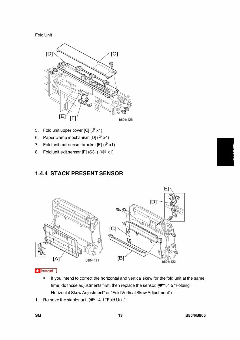
8/15/2019 Ricoh MP 4000 SM D009_D011_D012_D013 SERVICE MANUAL .pdf
http://slidepdf.com/reader/full/ricoh-mp-4000-sm-d009d011d012d013-service-manual-pdf 741/1162
Fold Unit
SM 13 B804/B805
B o o
k l e t
F i n i s h e r /
F i n i s h e r
5. Fold unit upper cover [C] ( x1)
6. Paper clamp mechanism [D] ( x4)
7. Fold unit exit sensor bracket [E] ( x1)
8. Fold unit exit sensor [F] (S31) ( x1)
1.4.4 STACK PRESENT SENSOR
If you intend to correct the horizontal and vertical skew for the fold unit at the same
time, do those adjustments first, then replace the sensor. ( 1.4.5 "Folding
Horizontal Skew Adjustment" or "Fold Vertical Skew Adjustment")
1. Remove the stapler unit ( 1.4.1 "Fold Unit")
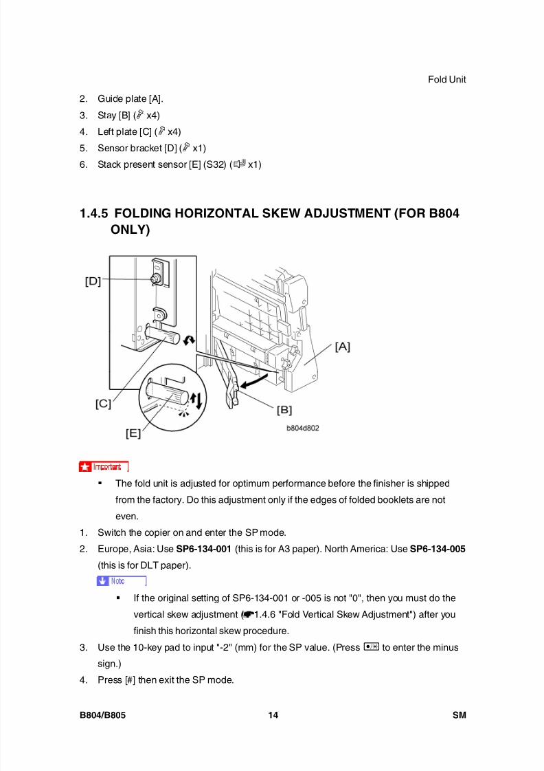
8/15/2019 Ricoh MP 4000 SM D009_D011_D012_D013 SERVICE MANUAL .pdf
http://slidepdf.com/reader/full/ricoh-mp-4000-sm-d009d011d012d013-service-manual-pdf 742/1162
Fold Unit
B804/B805 14 SM
2. Guide plate [A].
3. Stay [B] ( x4)
4. Left plate [C] ( x4)5. Sensor bracket [D] ( x1)
6. Stack present sensor [E] (S32) ( x1)
1.4.5 FOLDING HORIZONTAL SKEW ADJUSTMENT (FOR B804ONLY)
The fold unit is adjusted for optimum performance before the finisher is shipped
from the factory. Do this adjustment only if the edges of folded booklets are not
even.
1. Switch the copier on and enter the SP mode.
2. Europe, Asia: Use SP6-134-001 (this is for A3 paper). North America: Use SP6-134-005
(this is for DLT paper).
If the original setting of SP6-134-001 or -005 is not "0", then you must do the
vertical skew adjustment ( 1.4.6 "Fold Vertical Skew Adjustment") after you
finish this horizontal skew procedure.
3. Use the 10-key pad to input "-2" (mm) for the SP value. (Press to enter the minus
sign.)
4. Press [#] then exit the SP mode.

8/15/2019 Ricoh MP 4000 SM D009_D011_D012_D013 SERVICE MANUAL .pdf
http://slidepdf.com/reader/full/ricoh-mp-4000-sm-d009d011d012d013-service-manual-pdf 743/1162
Fold Unit
SM 15 B804/B805
B o o
k l e t
F i n i s h e r /
F i n i s h e r
5. Open the front door and pull the stapler unit [A] out of the finisher.
6. Open the guide plate [B].
7. Loosen the adjustment screw [C] and then tighten until it stops. (Do not over tighten.)8. Remove the lock screw [D].
9. Raise the tip [E] of the adjustment screw very slightly and allow it to descend under its
own weight.
10. Push the stapler unit into the finisher and close the front door.
11. Do a folding test.
Switch the copier on.
Put one page of A3 or DLT paper in the ARDF.
On the copier operation panel, select booklet stapling.
Press [Start]. One sheet is folded.
12. Remove the sheet from the lower tray.
13. Hold the folded sheet with the creased side pointing down and face-up (the same way
that it came out of the finisher).
14. Referring to the diagram, determine if the skew is + [F] or - [G].
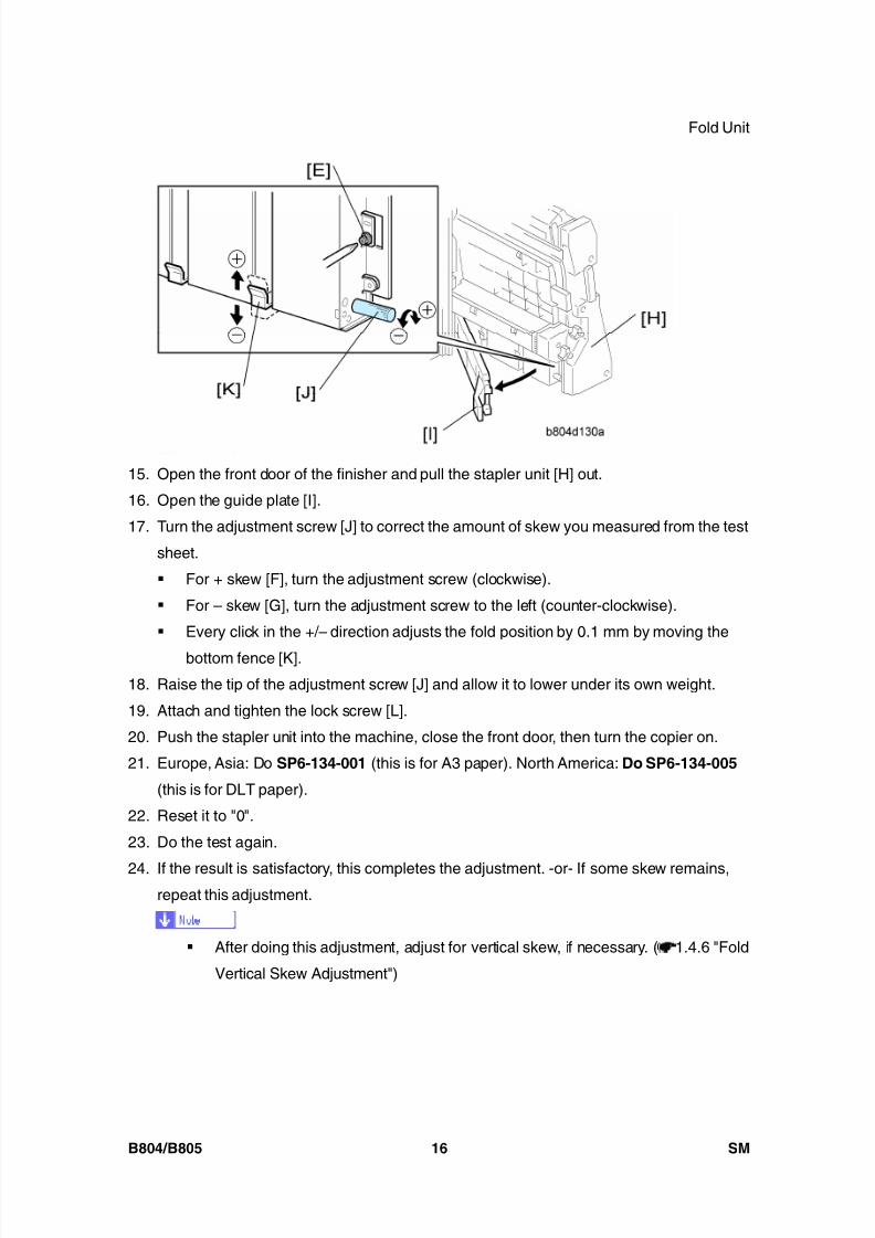
8/15/2019 Ricoh MP 4000 SM D009_D011_D012_D013 SERVICE MANUAL .pdf
http://slidepdf.com/reader/full/ricoh-mp-4000-sm-d009d011d012d013-service-manual-pdf 744/1162
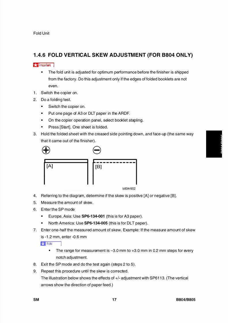
8/15/2019 Ricoh MP 4000 SM D009_D011_D012_D013 SERVICE MANUAL .pdf
http://slidepdf.com/reader/full/ricoh-mp-4000-sm-d009d011d012d013-service-manual-pdf 745/1162
Fold Unit
SM 17 B804/B805
B o o
k l e t
F i n i s h e r /
F i n i s h e r
1.4.6 FOLD VERTICAL SKEW ADJUSTMENT (FOR B804 ONLY)
The fold unit is adjusted for optimum performance before the finisher is shipped
from the factory. Do this adjustment only if the edges of folded booklets are not
even.
1. Switch the copier on.
2. Do a folding test.
Switch the copier on.
Put one page of A3 or DLT paper in the ARDF. On the copier operation panel, select booklet stapling.
Press [Start]. One sheet is folded.
3. Hold the folded sheet with the creased side pointing down, and face-up (the same way
that it came out of the finisher).
4. Referring to the diagram, determine if the skew is positive [A] or negative [B].
5. Measure the amount of skew.
6. Enter the SP mode
Europe, Asia: Use SP6-134-001 (this is for A3 paper).
North America: Use SP6-134-005 (this is for DLT paper).
7. Enter one-half the measured amount of skew. Example: If the measure amount of skew
is -1.2 mm, enter -0.6 mm
The range for measurement is –3.0 mm to +3.0 mm in 0.2 mm steps for every
notch adjustment.
8. Exit the SP mode and do the test again (steps 2 to 5).
9. Repeat this procedure until the skew is corrected.
The illustration below shows the effects of +/- adjustment with SP6113. (The vertical
arrows show the direction of paper feed.)
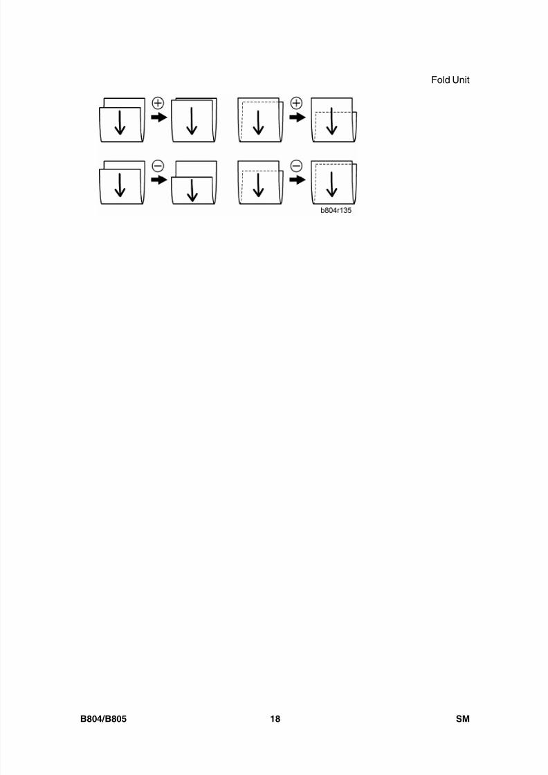
8/15/2019 Ricoh MP 4000 SM D009_D011_D012_D013 SERVICE MANUAL .pdf
http://slidepdf.com/reader/full/ricoh-mp-4000-sm-d009d011d012d013-service-manual-pdf 746/1162
Fold Unit
B804/B805 18 SM
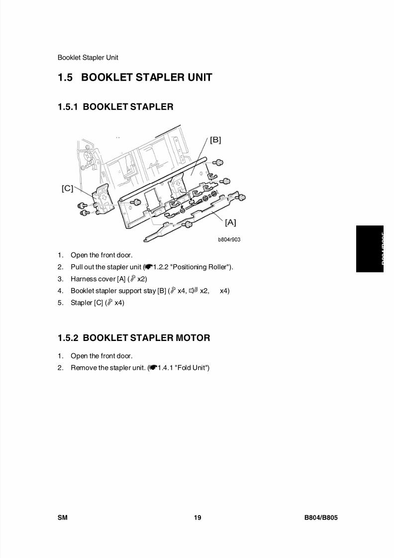
8/15/2019 Ricoh MP 4000 SM D009_D011_D012_D013 SERVICE MANUAL .pdf
http://slidepdf.com/reader/full/ricoh-mp-4000-sm-d009d011d012d013-service-manual-pdf 747/1162
Booklet Stapler Unit
SM 19 B804/B805
B o o
k l e t
F i n i s h e r /
F i n i s h e r
1.5 BOOKLET STAPLER UNIT
1.5.1 BOOKLET STAPLER
1. Open the front door.
2. Pull out the stapler unit ( 1.2.2 "Positioning Roller").
3. Harness cover [A] ( x2)
4. Booklet stapler support stay [B] ( x4, x2,
x4)5. Stapler [C] ( x4)
1.5.2 BOOKLET STAPLER MOTOR
1. Open the front door.
2. Remove the stapler unit. ( 1.4.1 "Fold Unit")

8/15/2019 Ricoh MP 4000 SM D009_D011_D012_D013 SERVICE MANUAL .pdf
http://slidepdf.com/reader/full/ricoh-mp-4000-sm-d009d011d012d013-service-manual-pdf 748/1162
Booklet Stapler Unit
B804/B805 20 SM
3. Stay [A] ( x4).
4. Left plate [B] ( x4)
5. Harness cover [C] ( x2)
6. Booklet stapler support stay [D] ( x4, x2, x4)7. Booklet stapler [E] ( x4)
8. Booklet stapler motor [F] ( x2, x1)
To Reattach the Booklet Stapler Motor
1. Reattach the booklet stapler motor.
Do not tighten the screws.
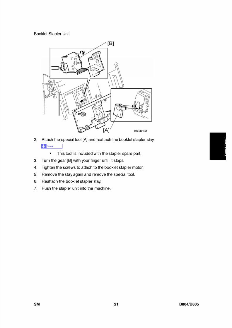
8/15/2019 Ricoh MP 4000 SM D009_D011_D012_D013 SERVICE MANUAL .pdf
http://slidepdf.com/reader/full/ricoh-mp-4000-sm-d009d011d012d013-service-manual-pdf 749/1162
Booklet Stapler Unit
SM 21 B804/B805
B o o
k l e t
F i n i s h e r /
F i n i s h e r2. Attach the special tool [A] and reattach the booklet stapler stay.
This tool is included with the stapler spare part.
3. Turn the gear [B] with your finger until it stops.
4. Tighten the screws to attach to the booklet stapler motor.
5. Remove the stay again and remove the special tool.
6. Reattach the booklet stapler stay.
7. Push the stapler unit into the machine.
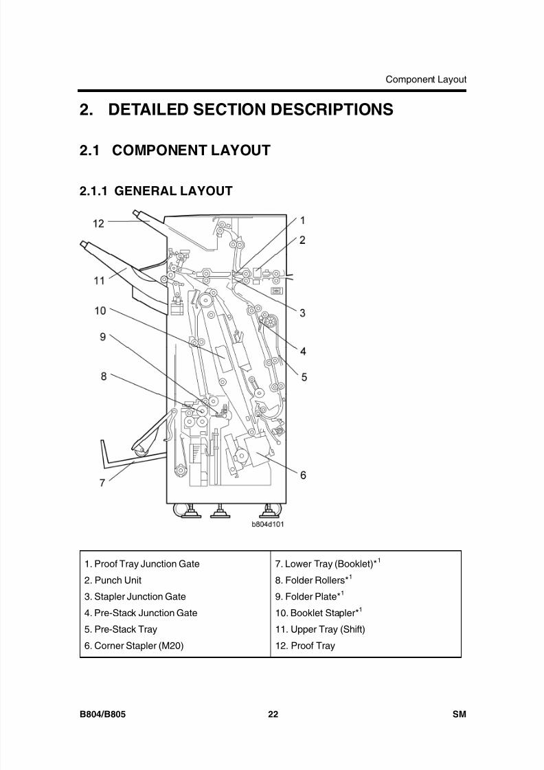
8/15/2019 Ricoh MP 4000 SM D009_D011_D012_D013 SERVICE MANUAL .pdf
http://slidepdf.com/reader/full/ricoh-mp-4000-sm-d009d011d012d013-service-manual-pdf 750/1162
Component Layout
B804/B805 22 SM
2. DETAILED SECTION DESCRIPTIONS
2.1 COMPONENT LAYOUT
2.1.1 GENERAL LAYOUT
1. Proof Tray Junction Gate
2. Punch Unit
3. Stapler Junction Gate
4. Pre-Stack Junction Gate
5. Pre-Stack Tray
6. Corner Stapler (M20)
7. Lower Tray (Booklet)* 1
8. Folder Rollers* 1
9. Folder Plate* 1
10. Booklet Stapler* 1
11. Upper Tray (Shift)
12. Proof Tray
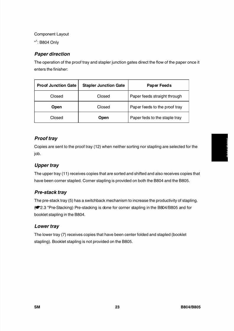
8/15/2019 Ricoh MP 4000 SM D009_D011_D012_D013 SERVICE MANUAL .pdf
http://slidepdf.com/reader/full/ricoh-mp-4000-sm-d009d011d012d013-service-manual-pdf 751/1162
Component Layout
SM 23 B804/B805
B o o
k l e t
F i n i s h e r /
F i n i s h e r
*1: B804 Only
Paper direction
The operation of the proof tray and stapler junction gates direct the flow of the paper once it
enters the finisher:
Proof Junction Gate Stapler Junction Gate Paper Feeds
Closed Closed Paper feeds straight through
Open Closed Paper feeds to the proof tray
Closed Open Paper feds to the staple tray
Proof tray
Copies are sent to the proof tray (12) when neither sorting nor stapling are selected for the
job.
Upper tray
The upper tray (11) receives copies that are sorted and shifted and also receives copies thathave been corner stapled. Corner stapling is provided on both the B804 and the B805.
Pre-stack tray
The pre-stack tray (5) has a switchback mechanism to increase the productivity of stapling.
( 2.3 "Pre-Stacking) Pre-stacking is done for corner stapling in the B804/B805 and for
booklet stapling in the B804.
Lower tray
The lower tray (7) receives copies that have been center folded and stapled (booklet
stapling). Booklet stapling is not provided on the B805.
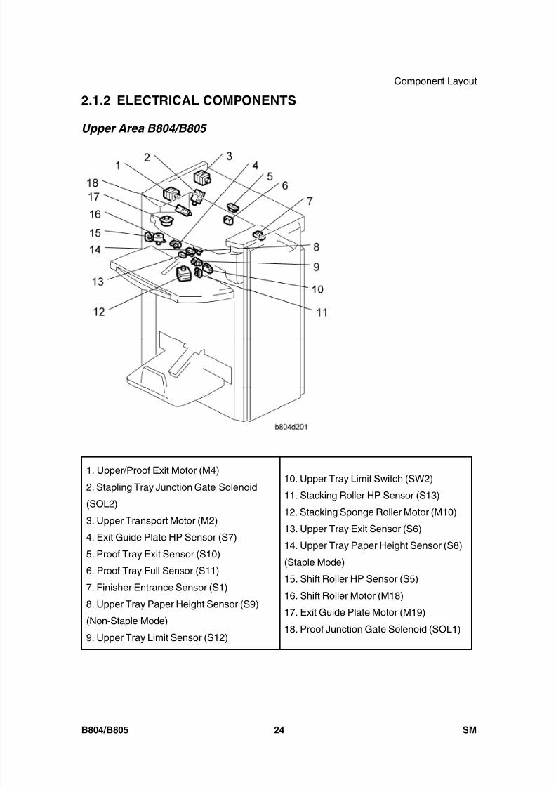
8/15/2019 Ricoh MP 4000 SM D009_D011_D012_D013 SERVICE MANUAL .pdf
http://slidepdf.com/reader/full/ricoh-mp-4000-sm-d009d011d012d013-service-manual-pdf 752/1162
Component Layout
B804/B805 24 SM
2.1.2 ELECTRICAL COMPONENTS
Upper Area B804/B805
1. Upper/Proof Exit Motor (M4)
2. Stapling Tray Junction Gate Solenoid
(SOL2)
3. Upper Transport Motor (M2)
4. Exit Guide Plate HP Sensor (S7)
5. Proof Tray Exit Sensor (S10)6. Proof Tray Full Sensor (S11)
7. Finisher Entrance Sensor (S1)
8. Upper Tray Paper Height Sensor (S9)
(Non-Staple Mode)
9. Upper Tray Limit Sensor (S12)
10. Upper Tray Limit Switch (SW2)
11. Stacking Roller HP Sensor (S13)
12. Stacking Sponge Roller Motor (M10)
13. Upper Tray Exit Sensor (S6)
14. Upper Tray Paper Height Sensor (S8)
(Staple Mode)
15. Shift Roller HP Sensor (S5)
16. Shift Roller Motor (M18)
17. Exit Guide Plate Motor (M19)
18. Proof Junction Gate Solenoid (SOL1)
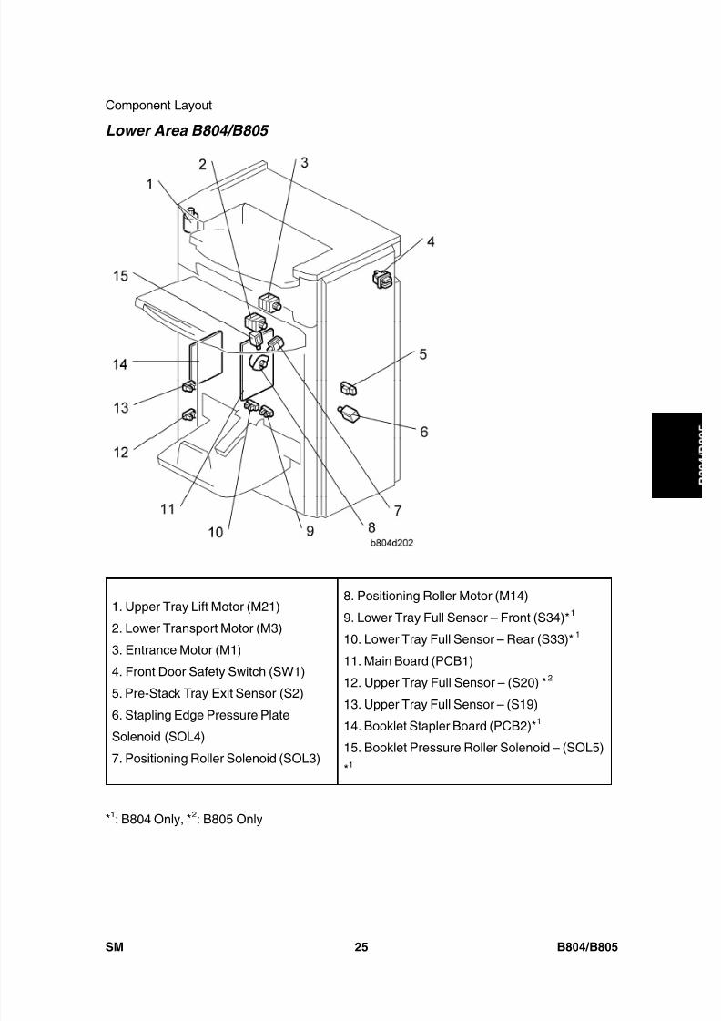
8/15/2019 Ricoh MP 4000 SM D009_D011_D012_D013 SERVICE MANUAL .pdf
http://slidepdf.com/reader/full/ricoh-mp-4000-sm-d009d011d012d013-service-manual-pdf 753/1162
Component Layout
SM 25 B804/B805
B o o
k l e t
F i n i s h e r /
F i n i s h e r
Lower Area B804/B805
1. Upper Tray Lift Motor (M21)
2. Lower Transport Motor (M3)
3. Entrance Motor (M1)
4. Front Door Safety Switch (SW1)
5. Pre-Stack Tray Exit Sensor (S2)
6. Stapling Edge Pressure PlateSolenoid (SOL4)
7. Positioning Roller Solenoid (SOL3)
8. Positioning Roller Motor (M14)
9. Lower Tray Full Sensor – Front (S34)* 1
10. Lower Tray Full Sensor – Rear (S33)* 1
11. Main Board (PCB1)
12. Upper Tray Full Sensor – (S20) * 2
13. Upper Tray Full Sensor – (S19)
14. Booklet Stapler Board (PCB2)* 1
15. Booklet Pressure Roller Solenoid – (SOL5)
*1
*1: B804 Only, * 2: B805 Only
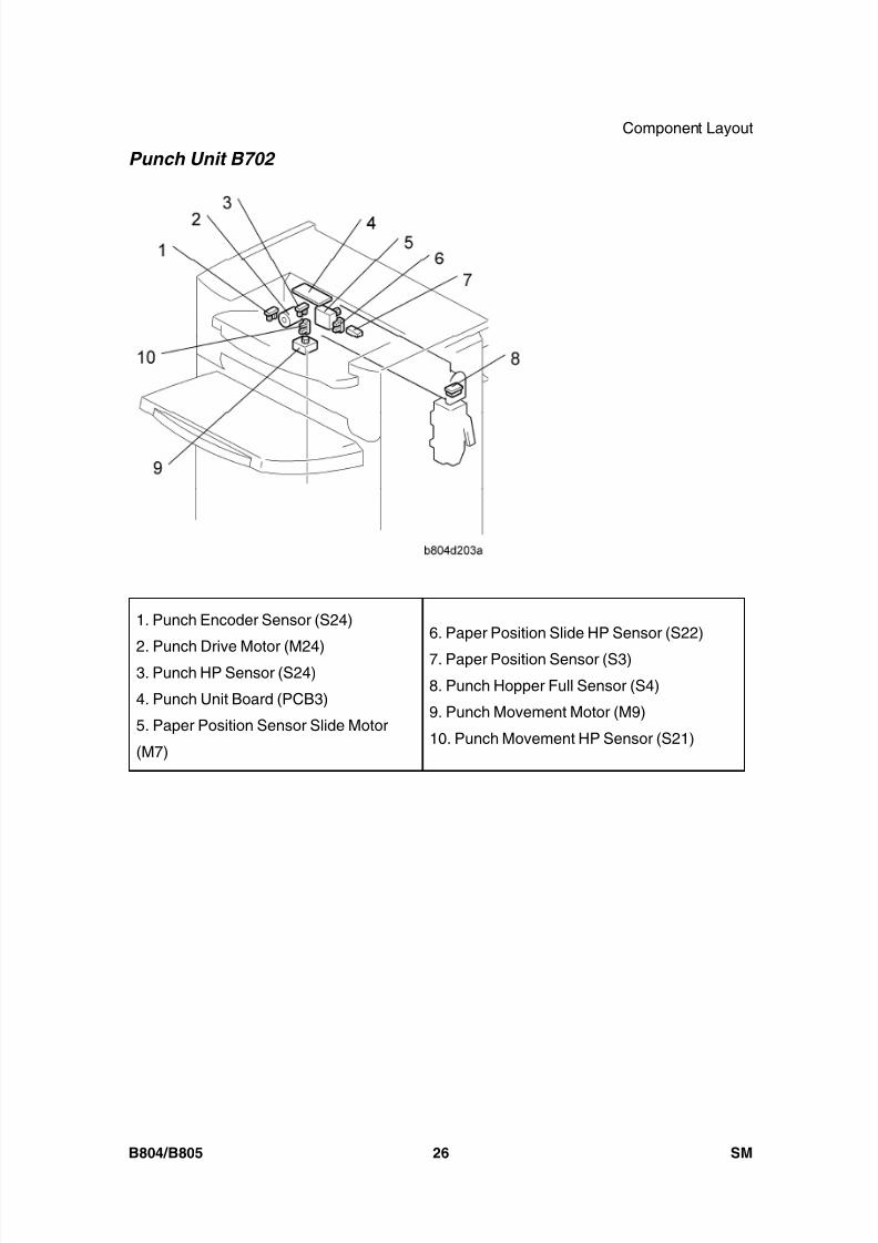
8/15/2019 Ricoh MP 4000 SM D009_D011_D012_D013 SERVICE MANUAL .pdf
http://slidepdf.com/reader/full/ricoh-mp-4000-sm-d009d011d012d013-service-manual-pdf 754/1162
Component Layout
B804/B805 26 SM
Punch Unit B702
1. Punch Encoder Sensor (S24)
2. Punch Drive Motor (M24)3. Punch HP Sensor (S24)
4. Punch Unit Board (PCB3)
5. Paper Position Sensor Slide Motor
(M7)
6. Paper Position Slide HP Sensor (S22)
7. Paper Position Sensor (S3)
8. Punch Hopper Full Sensor (S4)
9. Punch Movement Motor (M9)
10. Punch Movement HP Sensor (S21)
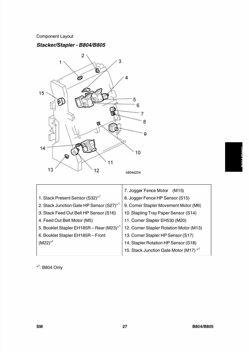
8/15/2019 Ricoh MP 4000 SM D009_D011_D012_D013 SERVICE MANUAL .pdf
http://slidepdf.com/reader/full/ricoh-mp-4000-sm-d009d011d012d013-service-manual-pdf 755/1162
Component Layout
SM 27 B804/B805
B o o
k l e t
F i n i s h e r /
F i n i s h e r
Stacker/Stapler - B804/B805
1. Stack Present Sensor (S32)* 1
2. Stack Junction Gate HP Sensor (S27)* 1
3. Stack Feed Out Belt HP Sensor (S16)
4. Feed Out Belt Motor (M5)
5. Booklet Stapler EH185R – Rear (M23)* 1
6. Booklet Stapler EH185R – Front
(M22)*1
7. Jogger Fence Motor (M15)
8. Jogger Fence HP Sensor (S15)
9. Corner Stapler Movement Motor (M6)
10. Stapling Tray Paper Sensor (S14)
11. Corner Stapler EH530 (M20)
12. Corner Stapler Rotation Motor (M13)
13. Corner Stapler HP Sensor (S17)
14. Stapler Rotation HP Sensor (S18)
15. Stack Junction Gate Motor (M17) * 1
*1: B804 Only
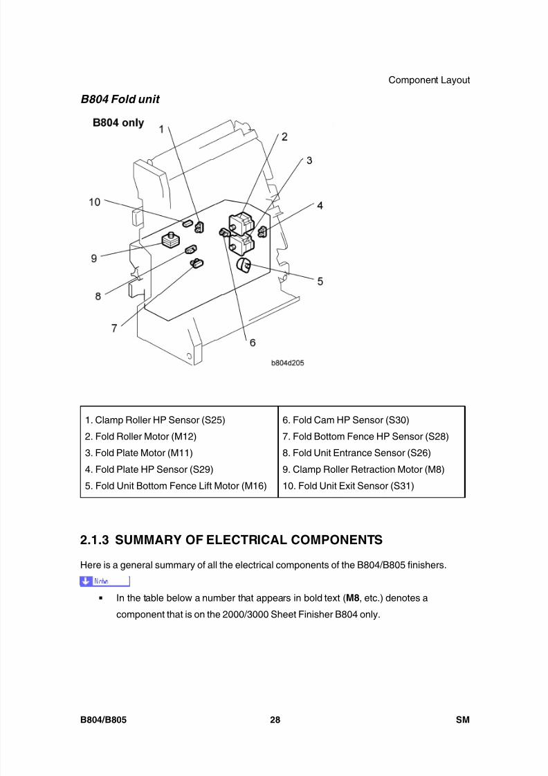
8/15/2019 Ricoh MP 4000 SM D009_D011_D012_D013 SERVICE MANUAL .pdf
http://slidepdf.com/reader/full/ricoh-mp-4000-sm-d009d011d012d013-service-manual-pdf 756/1162
Component Layout
B804/B805 28 SM
B804 Fold unit
1. Clamp Roller HP Sensor (S25)
2. Fold Roller Motor (M12)
3. Fold Plate Motor (M11)
4. Fold Plate HP Sensor (S29)
5. Fold Unit Bottom Fence Lift Motor (M16)
6. Fold Cam HP Sensor (S30)
7. Fold Bottom Fence HP Sensor (S28)
8. Fold Unit Entrance Sensor (S26)
9. Clamp Roller Retraction Motor (M8)
10. Fold Unit Exit Sensor (S31)
2.1.3 SUMMARY OF ELECTRICAL COMPONENTSHere is a general summary of all the electrical components of the B804/B805 finishers.
In the table below a number that appears in bold text ( M8, etc.) denotes a
component that is on the 2000/3000 Sheet Finisher B804 only.
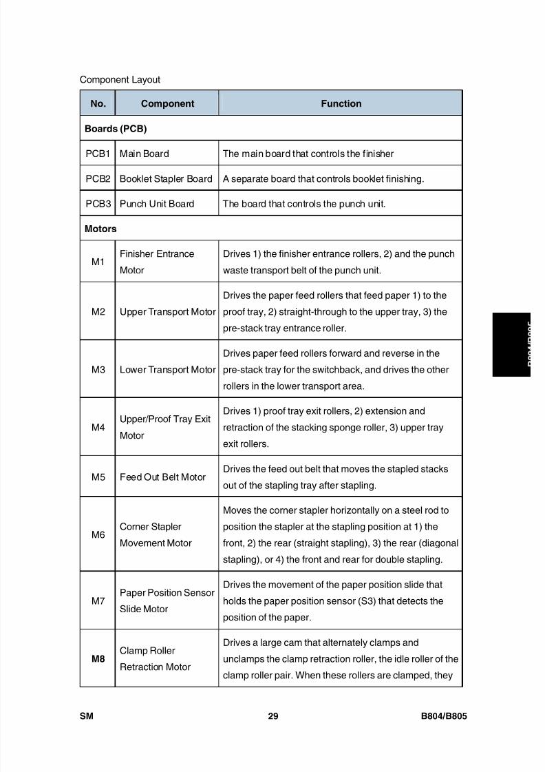
8/15/2019 Ricoh MP 4000 SM D009_D011_D012_D013 SERVICE MANUAL .pdf
http://slidepdf.com/reader/full/ricoh-mp-4000-sm-d009d011d012d013-service-manual-pdf 757/1162
Component Layout
SM 29 B804/B805
B o o
k l e t
F i n i s h e r /
F i n i s h e r
No. Component Function
Boards (PCB)
PCB1 Main Board The main board that controls the finisher
PCB2 Booklet Stapler Board A separate board that controls booklet finishing.
PCB3 Punch Unit Board The board that controls the punch unit.
Motors
M1Finisher Entrance
Motor
Drives 1) the finisher entrance rollers, 2) and the punch
waste transport belt of the punch unit.
M2 Upper Transport Motor
Drives the paper feed rollers that feed paper 1) to the
proof tray, 2) straight-through to the upper tray, 3) the
pre-stack tray entrance roller.
M3 Lower Transport Motor
Drives paper feed rollers forward and reverse in the
pre-stack tray for the switchback, and drives the other
rollers in the lower transport area.
M4Upper/Proof Tray Exit
Motor
Drives 1) proof tray exit rollers, 2) extension and
retraction of the stacking sponge roller, 3) upper tray
exit rollers.
M5 Feed Out Belt MotorDrives the feed out belt that moves the stapled stacks
out of the stapling tray after stapling.
M6Corner Stapler
Movement Motor
Moves the corner stapler horizontally on a steel rod to
position the stapler at the stapling position at 1) the
front, 2) the rear (straight stapling), 3) the rear (diagonalstapling), or 4) the front and rear for double stapling.
M7Paper Position Sensor
Slide Motor
Drives the movement of the paper position slide that
holds the paper position sensor (S3) that detects the
position of the paper.
M8Clamp Roller
Retraction Motor
Drives a large cam that alternately clamps and
unclamps the clamp retraction roller, the idle roller of the
clamp roller pair. When these rollers are clamped, they

8/15/2019 Ricoh MP 4000 SM D009_D011_D012_D013 SERVICE MANUAL .pdf
http://slidepdf.com/reader/full/ricoh-mp-4000-sm-d009d011d012d013-service-manual-pdf 758/1162
Component Layout
B804/B805 30 SM
No. Component Function
are part of the paper feed path and feed the stack
toward the bottom fence of the fold unit. When the idle
roller is retracted, the stacks falls a very short distance
(3 mm) onto the fold unit bottom fence below. These
rollers remain unclamped while the bottom fence
positions the stack for folding and while the stack is
folded by the fold rollers.
M9Punch Movement
Motor
Drives the front/back movement of the punch unit to
position it correctly for stapling the paper below.
M10Stacking Sponge
Roller Motor
Rotates the stacking roller that drags each sheet back
against the end fence to jog the bottom of each sheet
after feed out to the upper tray.
M11 Fold Plate MotorDrives the fold plate that pushes the center of the stack
into the nip of the fold rollers to start the fold.
M12 Fold Roller Motor
Rotates forward and drives the fold rollers that fold the
stack and feed it out of the fold unit, reverses to feed the
fold once more into the fold unit, and then rotates
forward again to feed the fold out of the fold unit.
M13Corner Stapler
Rotation Motor
Swivels the corner stapler and positions it so the staple
fires at an oblique angle at the rear corner of the paper
stack.
M14Positioning Roller
MotorDrives the positioning roller in the stapling tray.
M15 Jogger Fence MotorDrives the jogger fences in the stapling tray to jog both
sides of the stack before stapling.
M16Fold Unit Bottom
Fence Lift Motor
Raises the bottom fence and stops when the center of
the vertical stack is opposite the edge of the horizontal
fold blade. The distance for raising the blade is
prescribed as one-half the size of the paper selected for
the job. For large paper, (A3, B4) the bottom fence first

8/15/2019 Ricoh MP 4000 SM D009_D011_D012_D013 SERVICE MANUAL .pdf
http://slidepdf.com/reader/full/ricoh-mp-4000-sm-d009d011d012d013-service-manual-pdf 759/1162
Component Layout
SM 31 B804/B805
B o o
k l e t
F i n i s h e r /
F i n i s h e r
No. Component Function
lowers the stack 10 mm below the fold position, and
then raises it to the fold position.
M17Stack Junction Gate
Motor
Drives the large cam that operates the stack junction
gate at the top of the stapling tray. When this gate is
open, it directs the ascending stack to the upper tray if it
has been corner stapled, or if it is closed the gate turns
the booklet stapled stack down so it falls onto the
bottom fence of the folding unit.
M18 Shift Roller Motor
Drives the shift roller that operates in shift mode to
stagger document sets as they feed out to the upper
tray (making them easier to separate).
M19 Exit Guide Plate MotorDrives the mechanism that raises and lowers the exit
guide plate.
M20 Corner Stapler EH530
This is the roving corner stapler, mounted on a steel rail
that staples 1) at the front, 2) at the rear (straight
staple), 3) at the rear (diagonal staple), and 4) font and
rear (two staples).
M21 Upper Tray Lift MotorRaises and lowers the upper tray during feed out to
keep the tray at the optimum height until it is full.
M22Booklet Stapler
EH185R: Front
Booklet stapler. Staples paper stacks in the center
before they are folded.
M23Booklet Stapler
EH185R: Rear
Booklet stapler. Staples paper stacks in the center
before they are folded.
M24 Punch Drive Motor Fires the punches that punch the holes in the paper.
Sensors
S1Finisher Entrance
Sensor
Provides two functions: (1) Detects paper entering the
finisher from the copier, and (2) Signals a jam if it
detects paper at the entrance when the copier is
switched on.

8/15/2019 Ricoh MP 4000 SM D009_D011_D012_D013 SERVICE MANUAL .pdf
http://slidepdf.com/reader/full/ricoh-mp-4000-sm-d009d011d012d013-service-manual-pdf 760/1162
Component Layout
B804/B805 32 SM
No. Component Function
S2Pre-stack Tray Exit
Sensor
Detects 1) paper fed from the pre-stack tray to the
stapling tray, and detects 2) paper in the pre-stack when
the copier is switched on. (This sensor performs no
timing function. The entire flow of paper through the
pre-stacking mechanism is controlled by motor pulse
counts.)
S3 Paper Position Sensor
The photosensor that detects the edge of the paper and
sends this information to the punch unit board where it
is used to position the punch for punching the holes inthe paper.
S4Punch Hopper Full
Sensor
1) A photosensor that detects and signals that the punch
hopper is filled with punch waste and needs emptying,
and 2) confirms the presence of the punch hopper and
signals an error if it is missing or not installed
completely.
S5 Shift Roller HP SensorLocated near the shift roller motor, controls thefront-to-back movement of the shift roller as shifts paper
during straight-through feed.
S6Upper Tray Exit
Sensor
A flat, photo sensor located inside the guide plate,
detects the leading edge and trailing edge of the paper
as it feeds out to the upper tray during straight-through
jobs (with and without stapling). When paper is fed to
the upper tray, at the paper output slot this sensor
signals an error when it detects (1) paper has failed toleave the paper exit (lag error), (2) detects paper has
failed to arrive at the paper exit (late error), (3) detects
paper is in the exit slot when the machine is turned on.
S7Exit Guide Plate HP
Sensor
Controls the vertical movement of the control exit
guide . The guide plate is in the home position when the
guide plate is down and the actuator interrupts the
sensor gap.

8/15/2019 Ricoh MP 4000 SM D009_D011_D012_D013 SERVICE MANUAL .pdf
http://slidepdf.com/reader/full/ricoh-mp-4000-sm-d009d011d012d013-service-manual-pdf 761/1162
Component Layout
SM 33 B804/B805
B o o
k l e t
F i n i s h e r /
F i n i s h e r
No. Component Function
S8Upper Tray PaperHeight Sensor (Staple
Mode)
This is the upper sensor of the upper/lower paper height
sensor pair that controls the lift of the upper tray. This
sensor detects the paper height of the stack in the upper
tray when the copier is operating in the staple mode.
S9
Upper Tray Paper
Height Sensor
(Non-Staple Mode)
This is the lower sensor of the upper/lower paper height
sensor pair that controls the lift of the upper tray. When
the machine is switched on, the upper tray rises until the
actuator on the tray triggers this sensor to switch off the
upper tray lift motor.
S10 Proof Tray Exit Sensor
This sensor detects and times the feeding of paper to
the proof tray. It also detects whether paper is present at
the proof tray exit when the copier is switched on.
S11 Proof Tray Full Sensor
The top of the stack in the proof tray increases until it
nudges the feeler of this sensor. The sensor then
signals that the proof tray is full and the job halts until
some paper is removed from the proof tray.
S12Upper Tray Limit
Sensor
This sensor controls the position of the upper tray 1)
during straight-through feed out, 2) during shift feed out,
3) when the machine is turned on. The machine obeys
the signal of whichever sensor is actuated first.
An actuator attached to an arm triggers this sensor. The
tip of the same arm depresses the upper tray limit
switch. If the sensor fails, the tip of the arm will activate
the upper tray limit microswitch (SW2) and stop the liftof the upper tray.
Note : When the machine is turned on, the upper tray
position is controlled by either this sensor or the upper
tray paper height sensor (S9).
S13Stacking Roller HP
Sensor
Controls the forward and back motion of the stacking
roller (a sponge roller) located at the output slot of the
upper tray. The sponge roller drags each ejected sheet

8/15/2019 Ricoh MP 4000 SM D009_D011_D012_D013 SERVICE MANUAL .pdf
http://slidepdf.com/reader/full/ricoh-mp-4000-sm-d009d011d012d013-service-manual-pdf 762/1162
Component Layout
B804/B805 34 SM
No. Component Function
back against the end fence of the upper tray to keep the
bottom of the stack aligned.
S14Stapling Tray Paper
Sensor
A photo sensor that detects whether paper is in the
stapling tray. When this sensor detects paper, the
bottom fence motor raises or lowers the bottom fence to
position the selected paper size for booklet stapling.
S15Jogger Fence HP
Sensor
Detects the home position of the jogger fences. When
the actuator on the jogger fence interrupts this sensor,
the jogger fence is in its home position and the jogger
fence motor (M15) stops.
S16Stack Feed-Out Belt
HP Sensor
Controls the position of the stack feed-out pawl on the
stack feed-out belt. Once the actuator on the feed belt
nudges the feeler of this sensor near the top of the
stapling unit, the feed out belt motor (M5) remains on for
the time prescribed to position the pawl at the home
position to catch the next stack.
S17Corner Stapler HP
Sensor
Located at the front the stapling tray and mounted
above the steel rod where the corner stapler travels, this
sensor detects the home position of the corner stapler.
The corner stapler is in its home position when the
actuator on the corner stapler unit interrupts this sensor.
S18Stapler Rotation HP
Sensor
Controls the angle of the position of the corner stapler
during oblique stapling.
S19Upper Tray Full
Sensor (B804/B805)
B804 : When the actuator on the side of the upper fence
enters the gap of this sensor, the sensor signals that the
upper tray is at its lowest position (full) and stops the
job.
B805 : One of two upper tray full sensors. This is the
higher tray full sensor for A3 and other heavy paper.
The other upper tray full sensor (20) is for lighter paper.
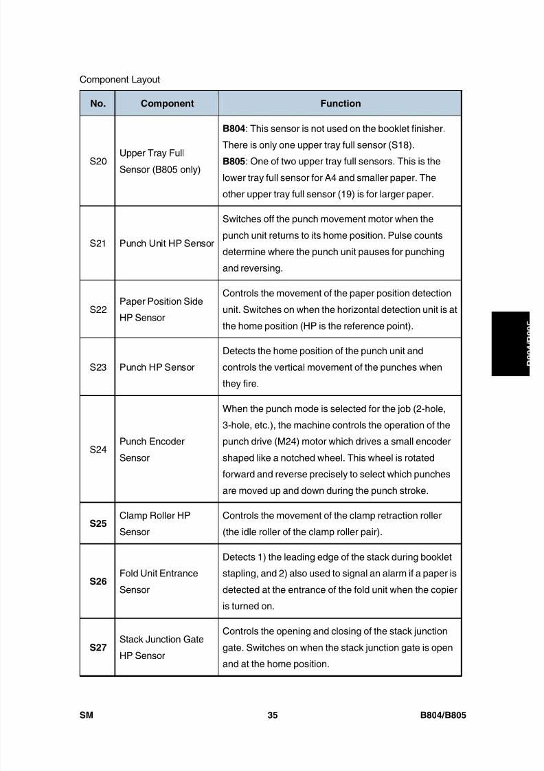
8/15/2019 Ricoh MP 4000 SM D009_D011_D012_D013 SERVICE MANUAL .pdf
http://slidepdf.com/reader/full/ricoh-mp-4000-sm-d009d011d012d013-service-manual-pdf 763/1162
Component Layout
SM 35 B804/B805
B o o
k l e t
F i n i s h e r /
F i n i s h e r
No. Component Function
S20Upper Tray Full
Sensor (B805 only)
B804 : This sensor is not used on the booklet finisher.
There is only one upper tray full sensor (S18).
B805 : One of two upper tray full sensors. This is the
lower tray full sensor for A4 and smaller paper. The
other upper tray full sensor (19) is for larger paper.
S21 Punch Unit HP Sensor
Switches off the punch movement motor when the
punch unit returns to its home position. Pulse counts
determine where the punch unit pauses for punching
and reversing.
S22Paper Position Side
HP Sensor
Controls the movement of the paper position detection
unit. Switches on when the horizontal detection unit is at
the home position (HP is the reference point).
S23 Punch HP Sensor
Detects the home position of the punch unit and
controls the vertical movement of the punches when
they fire.
S24Punch Encoder
Sensor
When the punch mode is selected for the job (2-hole,
3-hole, etc.), the machine controls the operation of the
punch drive (M24) motor which drives a small encoder
shaped like a notched wheel. This wheel is rotated
forward and reverse precisely to select which punches
are moved up and down during the punch stroke.
S25Clamp Roller HP
Sensor
Controls the movement of the clamp retraction roller
(the idle roller of the clamp roller pair).
S26Fold Unit Entrance
Sensor
Detects 1) the leading edge of the stack during booklet
stapling, and 2) also used to signal an alarm if a paper is
detected at the entrance of the fold unit when the copier
is turned on.
S27Stack Junction Gate
HP Sensor
Controls the opening and closing of the stack junction
gate. Switches on when the stack junction gate is open
and at the home position.
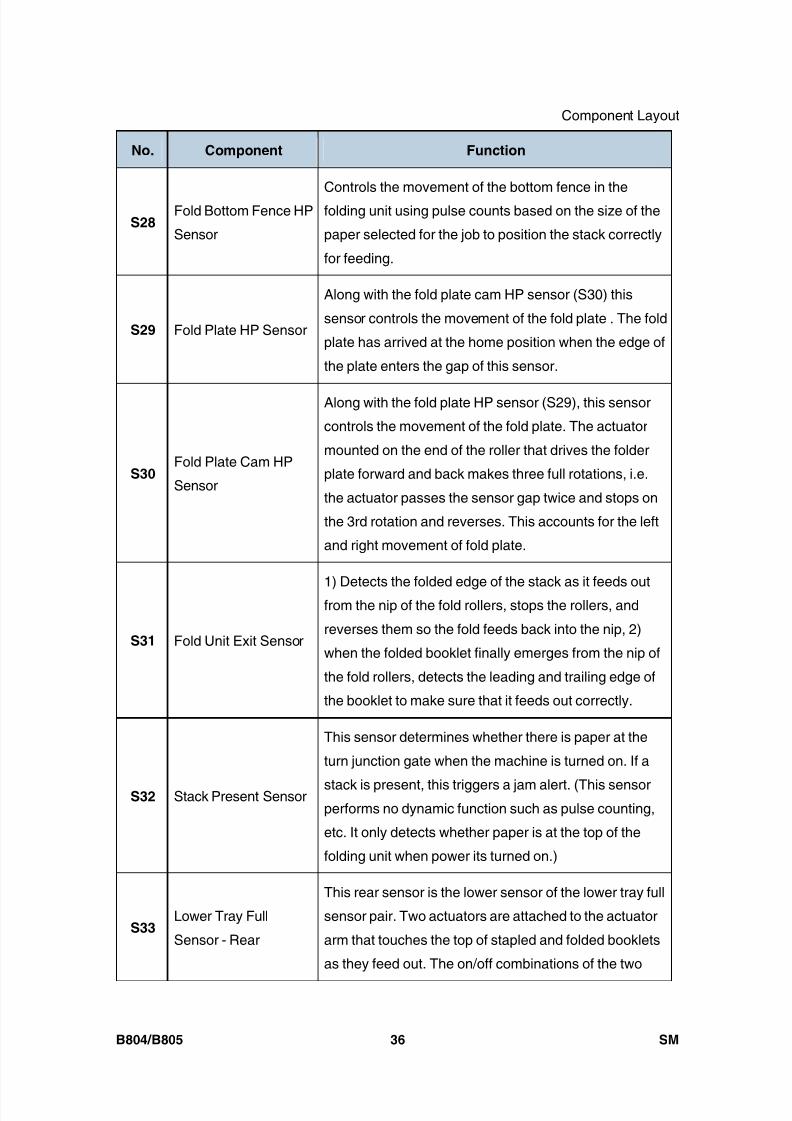
8/15/2019 Ricoh MP 4000 SM D009_D011_D012_D013 SERVICE MANUAL .pdf
http://slidepdf.com/reader/full/ricoh-mp-4000-sm-d009d011d012d013-service-manual-pdf 764/1162
Component Layout
B804/B805 36 SM
No. Component Function
S28Fold Bottom Fence HP
Sensor
Controls the movement of the bottom fence in the
folding unit using pulse counts based on the size of the
paper selected for the job to position the stack correctly
for feeding.
S29 Fold Plate HP Sensor
Along with the fold plate cam HP sensor (S30) this
sensor controls the movement of the fold plate . The fold
plate has arrived at the home position when the edge of
the plate enters the gap of this sensor.
S30Fold Plate Cam HP
Sensor
Along with the fold plate HP sensor (S29), this sensor
controls the movement of the fold plate. The actuator
mounted on the end of the roller that drives the folder
plate forward and back makes three full rotations, i.e.
the actuator passes the sensor gap twice and stops on
the 3rd rotation and reverses. This accounts for the left
and right movement of fold plate.
S31 Fold Unit Exit Sensor
1) Detects the folded edge of the stack as it feeds outfrom the nip of the fold rollers, stops the rollers, and
reverses them so the fold feeds back into the nip, 2)
when the folded booklet finally emerges from the nip of
the fold rollers, detects the leading and trailing edge of
the booklet to make sure that it feeds out correctly.
S32 Stack Present Sensor
This sensor determines whether there is paper at the
turn junction gate when the machine is turned on. If a
stack is present, this triggers a jam alert. (This sensorperforms no dynamic function such as pulse counting,
etc. It only detects whether paper is at the top of the
folding unit when power its turned on.)
S33Lower Tray Full
Sensor - Rear
This rear sensor is the lower sensor of the lower tray full
sensor pair. Two actuators are attached to the actuator
arm that touches the top of stapled and folded booklets
as they feed out. The on/off combinations of the two
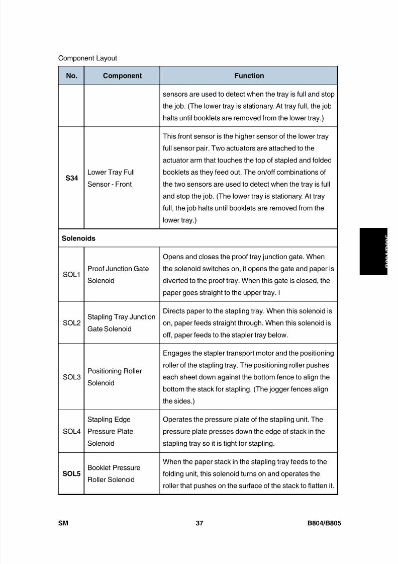
8/15/2019 Ricoh MP 4000 SM D009_D011_D012_D013 SERVICE MANUAL .pdf
http://slidepdf.com/reader/full/ricoh-mp-4000-sm-d009d011d012d013-service-manual-pdf 765/1162
Component Layout
SM 37 B804/B805
B o o
k l e t
F i n i s h e r /
F i n i s h e r
No. Component Function
sensors are used to detect when the tray is full and stop
the job. (The lower tray is stationary. At tray full, the job
halts until booklets are removed from the lower tray.)
S34Lower Tray Full
Sensor - Front
This front sensor is the higher sensor of the lower tray
full sensor pair. Two actuators are attached to the
actuator arm that touches the top of stapled and folded
booklets as they feed out. The on/off combinations of
the two sensors are used to detect when the tray is full
and stop the job. (The lower tray is stationary. At trayfull, the job halts until booklets are removed from the
lower tray.)
Solenoids
SOL1Proof Junction Gate
Solenoid
Opens and closes the proof tray junction gate. When
the solenoid switches on, it opens the gate and paper is
diverted to the proof tray. When this gate is closed, the
paper goes straight to the upper tray. I
SOL2Stapling Tray Junction
Gate Solenoid
Directs paper to the stapling tray. When this solenoid is
on, paper feeds straight through. When this solenoid is
off, paper feeds to the stapler tray below.
SOL3Positioning Roller
Solenoid
Engages the stapler transport motor and the positioning
roller of the stapling tray. The positioning roller pushes
each sheet down against the bottom fence to align the
bottom the stack for stapling. (The jogger fences align
the sides.)
SOL4
Stapling Edge
Pressure Plate
Solenoid
Operates the pressure plate of the stapling unit. The
pressure plate presses down the edge of stack in the
stapling tray so it is tight for stapling.
SOL5Booklet Pressure
Roller Solenoid
When the paper stack in the stapling tray feeds to the
folding unit, this solenoid turns on and operates the
roller that pushes on the surface of the stack to flatten it.
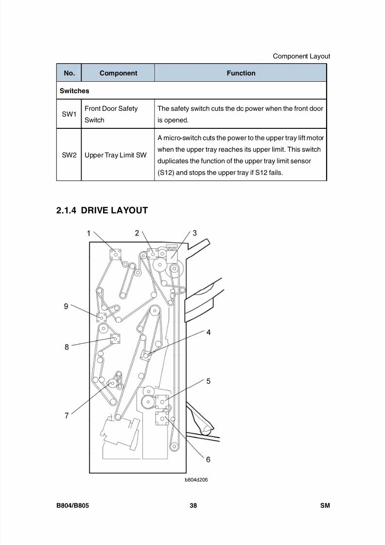
8/15/2019 Ricoh MP 4000 SM D009_D011_D012_D013 SERVICE MANUAL .pdf
http://slidepdf.com/reader/full/ricoh-mp-4000-sm-d009d011d012d013-service-manual-pdf 766/1162
Component Layout
B804/B805 38 SM
No. Component Function
Switches
SW1Front Door Safety
Switch
The safety switch cuts the dc power when the front door
is opened.
SW2 Upper Tray Limit SW
A micro-switch cuts the power to the upper tray lift motor
when the upper tray reaches its upper limit. This switch
duplicates the function of the upper tray limit sensor
(S12) and stops the upper tray if S12 fails.
2.1.4 DRIVE LAYOUT
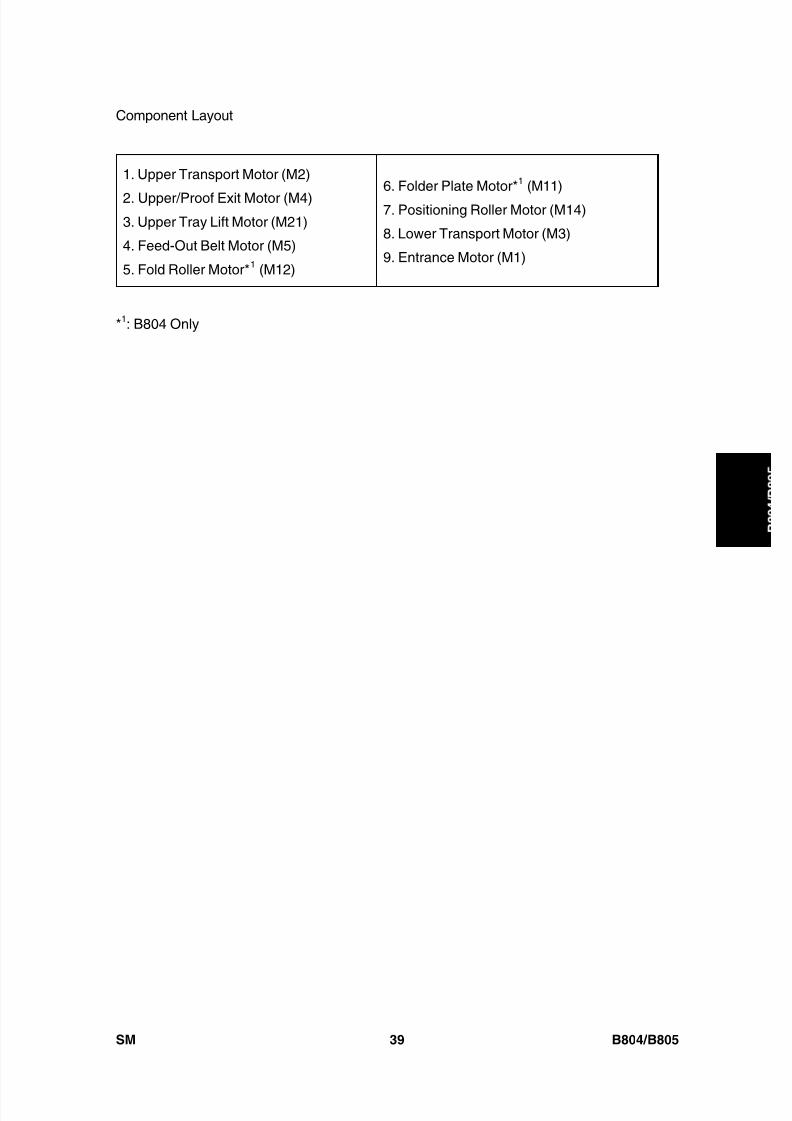
8/15/2019 Ricoh MP 4000 SM D009_D011_D012_D013 SERVICE MANUAL .pdf
http://slidepdf.com/reader/full/ricoh-mp-4000-sm-d009d011d012d013-service-manual-pdf 767/1162
Component Layout
SM 39 B804/B805
B o o
k l e t
F i n i s h e r /
F i n i s h e r
1. Upper Transport Motor (M2)
2. Upper/Proof Exit Motor (M4)3. Upper Tray Lift Motor (M21)
4. Feed-Out Belt Motor (M5)
5. Fold Roller Motor* 1 (M12)
6. Folder Plate Motor* 1 (M11)
7. Positioning Roller Motor (M14)
8. Lower Transport Motor (M3)
9. Entrance Motor (M1)
*1: B804 Only
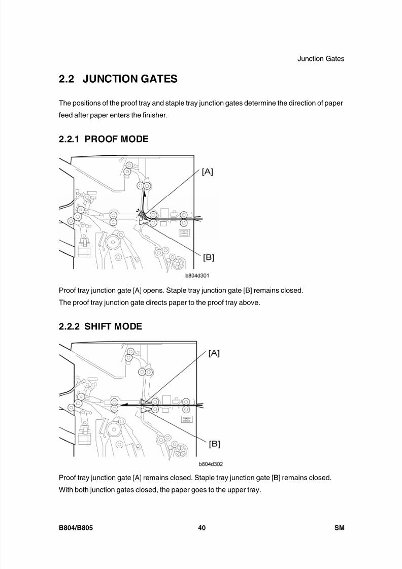
8/15/2019 Ricoh MP 4000 SM D009_D011_D012_D013 SERVICE MANUAL .pdf
http://slidepdf.com/reader/full/ricoh-mp-4000-sm-d009d011d012d013-service-manual-pdf 768/1162
Junction Gates
B804/B805 40 SM
2.2 JUNCTION GATES
The positions of the proof tray and staple tray junction gates determine the direction of paper
feed after paper enters the finisher.
2.2.1 PROOF MODE
Proof tray junction gate [A] opens. Staple tray junction gate [B] remains closed.
The proof tray junction gate directs paper to the proof tray above.
2.2.2 SHIFT MODE
Proof tray junction gate [A] remains closed. Staple tray junction gate [B] remains closed.
With both junction gates closed, the paper goes to the upper tray.

8/15/2019 Ricoh MP 4000 SM D009_D011_D012_D013 SERVICE MANUAL .pdf
http://slidepdf.com/reader/full/ricoh-mp-4000-sm-d009d011d012d013-service-manual-pdf 769/1162
Junction Gates
SM 41 B804/B805
B o o
k l e t
F i n i s h e r /
F i n i s h e r
2.2.3 STAPLE MODE
Proof tray junction gate [A] remains closed. Staple tray junction gate [B] opens
The staple tray junction gate directs the paper to the staple tray below for jogging and
stapling.
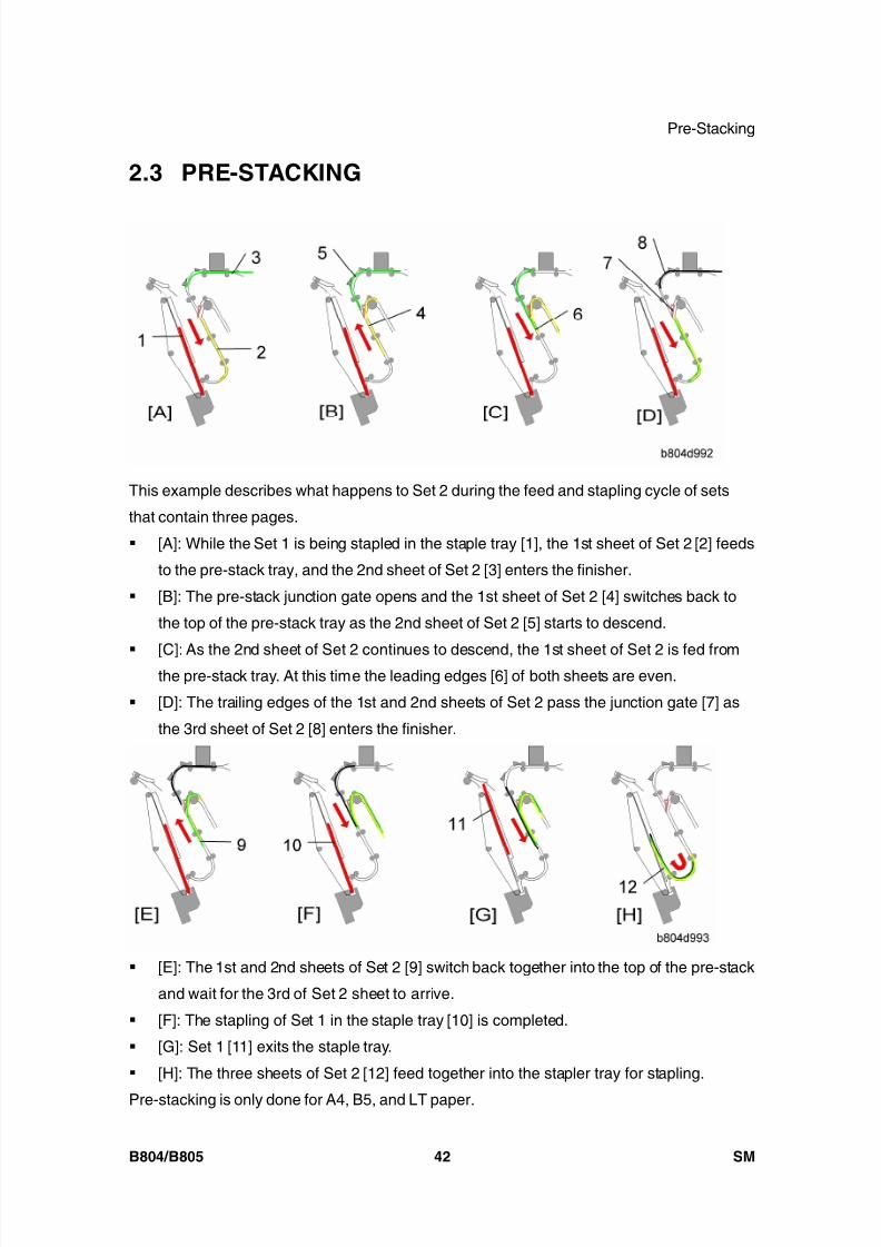
8/15/2019 Ricoh MP 4000 SM D009_D011_D012_D013 SERVICE MANUAL .pdf
http://slidepdf.com/reader/full/ricoh-mp-4000-sm-d009d011d012d013-service-manual-pdf 770/1162
Pre-Stacking
B804/B805 42 SM
2.3 PRE-STACKING
This example describes what happens to Set 2 during the feed and stapling cycle of sets
that contain three pages.
[A]: While the Set 1 is being stapled in the staple tray [1], the 1st sheet of Set 2 [2] feeds
to the pre-stack tray, and the 2nd sheet of Set 2 [3] enters the finisher.
[B]: The pre-stack junction gate opens and the 1st sheet of Set 2 [4] switches back to
the top of the pre-stack tray as the 2nd sheet of Set 2 [5] starts to descend.
[C]: As the 2nd sheet of Set 2 continues to descend, the 1st sheet of Set 2 is fed fromthe pre-stack tray. At this time the leading edges [6] of both sheets are even.
[D]: The trailing edges of the 1st and 2nd sheets of Set 2 pass the junction gate [7] as
the 3rd sheet of Set 2 [8] enters the finisher.
[E]: The 1st and 2nd sheets of Set 2 [9] switch back together into the top of the pre-stack
and wait for the 3rd of Set 2 sheet to arrive.
[F]: The stapling of Set 1 in the staple tray [10] is completed.
[G]: Set 1 [11] exits the staple tray.
[H]: The three sheets of Set 2 [12] feed together into the stapler tray for stapling.
Pre-stacking is only done for A4, B5, and LT paper.
8/15/2019 Ricoh MP 4000 SM D009_D011_D012_D013 SERVICE MANUAL .pdf
http://slidepdf.com/reader/full/ricoh-mp-4000-sm-d009d011d012d013-service-manual-pdf 771/1162
Pre-Stacking
SM 43 B804/B805
B o o
k l e t
F i n i s h e r /
F i n i s h e r
In one-staple mode, one sheet goes to the pre-stacking tray. Then two sheets go to the
stapler tray at the same time.
In two-staple mode and booklet mode, three sheets go to the pre-stacking tray. Then foursheets go to the stapler tray at the same time.

8/15/2019 Ricoh MP 4000 SM D009_D011_D012_D013 SERVICE MANUAL .pdf
http://slidepdf.com/reader/full/ricoh-mp-4000-sm-d009d011d012d013-service-manual-pdf 772/1162
Tray Movement Mechanism
B804/B805 44 SM
2.4 TRAY MOVEMENT MECHANISM
2.4.1 UPPER TRAY
[A]: Upper Tray Lift Motor
[B]: Upper Feeler
[C]: Upper Tray Paper Height Sensor 1 (Staple Mode)
[D]: Upper Tray Paper Height Sensor 2 (Non-Staple Mode)
[E]: Lower Feeler
[F]: Upper Tray Limit Sensor
[G]: Upper Tray Limit Switch
[H]: Upper Tray Full Sensors
The B804 (shown above) has only one upper tray full sensor (the higher sensor at
[H]).
The B805 has two upper tray full sensors (the upper and lower sensor at [H]). On
the B805 the upper sensor detects tray full for heavier paper (A3, DLT, B4, LG, 12 x
18”), and the lower sensor detects tray full for lighter paper (A4, LT, etc.).
The tray full capacity is 2,000 sheets (B804) for A4, LT and 3,000 sheets (B805) for
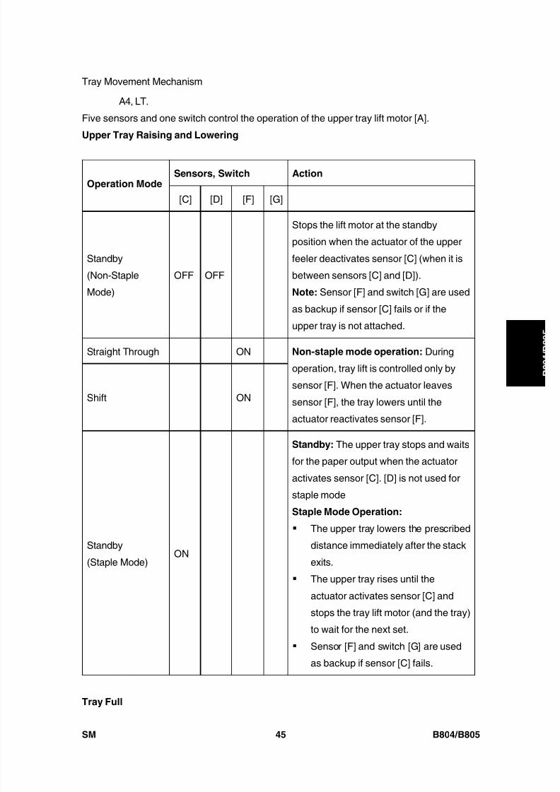
8/15/2019 Ricoh MP 4000 SM D009_D011_D012_D013 SERVICE MANUAL .pdf
http://slidepdf.com/reader/full/ricoh-mp-4000-sm-d009d011d012d013-service-manual-pdf 773/1162
Tray Movement Mechanism
SM 45 B804/B805
B o o
k l e t
F i n i s h e r /
F i n i s h e r
A4, LT.
Five sensors and one switch control the operation of the upper tray lift motor [A].
Upper Tray Raising and Lowering
Sensors, Switch ActionOperation Mode
[C] [D] [F] [G]
Standby
(Non-StapleMode)
OFF OFF
Stops the lift motor at the standby
position when the actuator of the upper
feeler deactivates sensor [C] (when it is
between sensors [C] and [D]).Note: Sensor [F] and switch [G] are used
as backup if sensor [C] fails or if the
upper tray is not attached.
Straight Through ON
Shift ON
Non-staple mode operation: During
operation, tray lift is controlled only by
sensor [F]. When the actuator leaves
sensor [F], the tray lowers until the
actuator reactivates sensor [F].
Standby
(Staple Mode) ON
Standby: The upper tray stops and waits
for the paper output when the actuator
activates sensor [C]. [D] is not used for
staple mode
Staple Mode Operation:
The upper tray lowers the prescribed
distance immediately after the stack
exits.
The upper tray rises until the
actuator activates sensor [C] and
stops the tray lift motor (and the tray)
to wait for the next set.
Sensor [F] and switch [G] are used
as backup if sensor [C] fails.
Tray Full
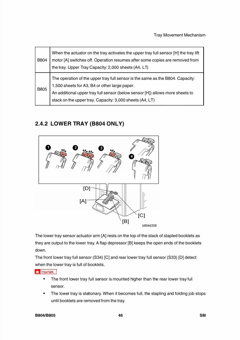
8/15/2019 Ricoh MP 4000 SM D009_D011_D012_D013 SERVICE MANUAL .pdf
http://slidepdf.com/reader/full/ricoh-mp-4000-sm-d009d011d012d013-service-manual-pdf 774/1162
Tray Movement Mechanism
B804/B805 46 SM
B804
When the actuator on the tray activates the upper tray full sensor [H] the tray lift
motor [A] switches off. Operation resumes after some copies are removed fromthe tray. Upper Tray Capacity: 2,000 sheets (A4, LT)
B805
The operation of the upper tray full sensor is the same as the B804. Capacity:
1,500 sheets for A3, B4 or other large paper.
An additional upper tray full sensor (below sensor [H]) allows more sheets to
stack on the upper tray. Capacity: 3,000 sheets (A4, LT)
2.4.2 LOWER TRAY (B804 ONLY)
The lower tray sensor actuator arm [A] rests on the top of the stack of stapled booklets as
they are output to the lower tray. A flap depressor [B] keeps the open ends of the booklets
down.
The front lower tray full sensor (S34) [C] and rear lower tray full sensor (S33) [D] detect
when the lower tray is full of booklets.
The front lower tray full sensor is mounted higher than the rear lower tray full
sensor.
The lower tray is stationary. When it becomes full, the stapling and folding job stops
until booklets are removed from the tray.
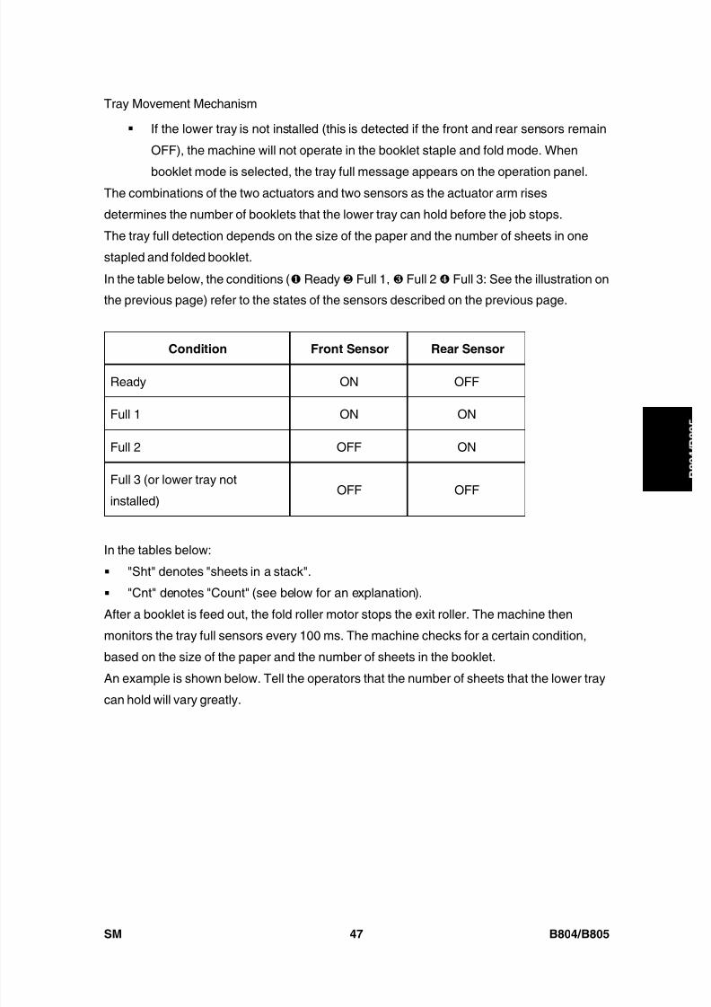
8/15/2019 Ricoh MP 4000 SM D009_D011_D012_D013 SERVICE MANUAL .pdf
http://slidepdf.com/reader/full/ricoh-mp-4000-sm-d009d011d012d013-service-manual-pdf 775/1162
Tray Movement Mechanism
SM 47 B804/B805
B o o
k l e t
F i n i s h e r /
F i n i s h e r
If the lower tray is not installed (this is detected if the front and rear sensors remain
OFF), the machine will not operate in the booklet staple and fold mode. When
booklet mode is selected, the tray full message appears on the operation panel.The combinations of the two actuators and two sensors as the actuator arm rises
determines the number of booklets that the lower tray can hold before the job stops.
The tray full detection depends on the size of the paper and the number of sheets in one
stapled and folded booklet.
In the table below, the conditions ( Ready Full 1, Full 2 Full 3: See the illustration on
the previous page) refer to the states of the sensors described on the previous page.
Condition Front Sensor Rear Sensor
Ready ON OFF
Full 1 ON ON
Full 2 OFF ON
Full 3 (or lower tray not
installed)OFF OFF
In the tables below:
"Sht" denotes "sheets in a stack".
"Cnt" denotes "Count" (see below for an explanation).
After a booklet is feed out, the fold roller motor stops the exit roller. The machine then
monitors the tray full sensors every 100 ms. The machine checks for a certain condition,
based on the size of the paper and the number of sheets in the booklet.
An example is shown below. Tell the operators that the number of sheets that the lower tray
can hold will vary greatly.
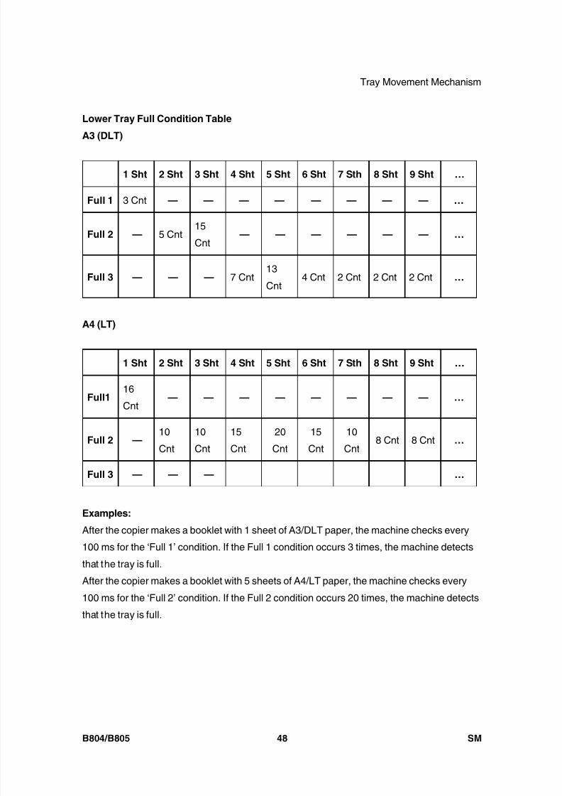
8/15/2019 Ricoh MP 4000 SM D009_D011_D012_D013 SERVICE MANUAL .pdf
http://slidepdf.com/reader/full/ricoh-mp-4000-sm-d009d011d012d013-service-manual-pdf 776/1162
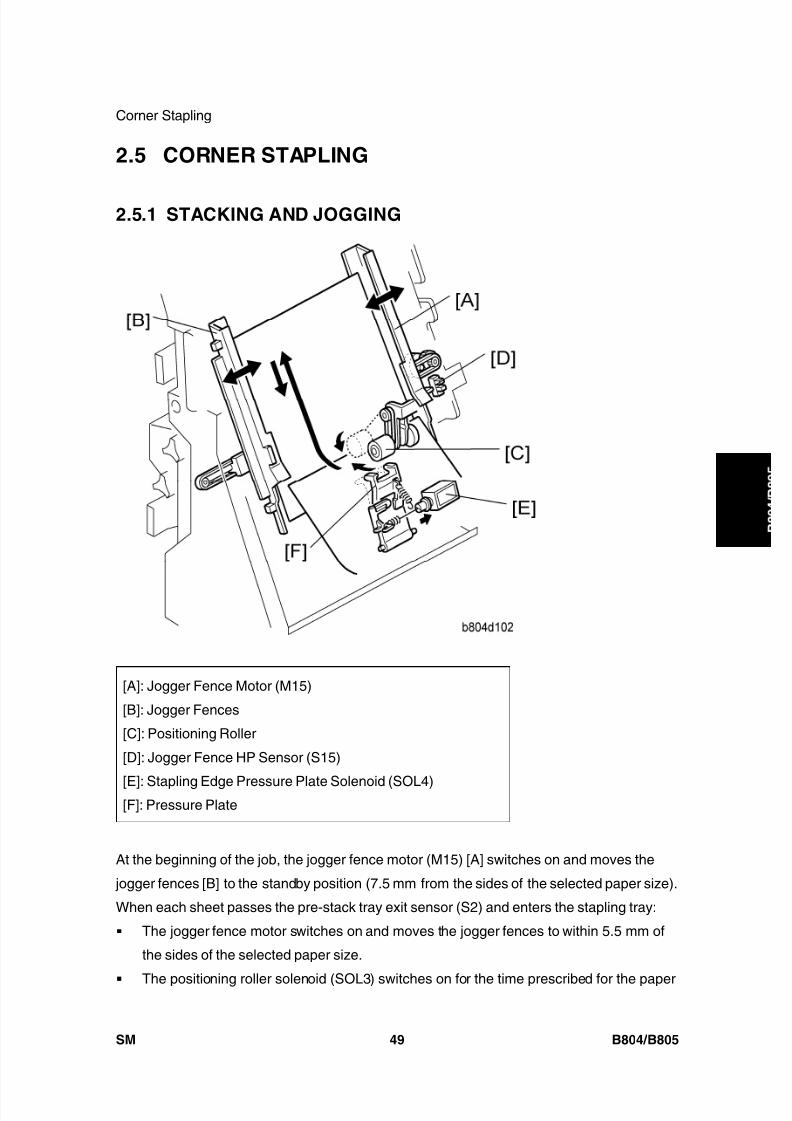
8/15/2019 Ricoh MP 4000 SM D009_D011_D012_D013 SERVICE MANUAL .pdf
http://slidepdf.com/reader/full/ricoh-mp-4000-sm-d009d011d012d013-service-manual-pdf 777/1162
Corner Stapling
SM 49 B804/B805
B o o
k l e t
F i n i s h e r /
F i n i s h e r
2.5 CORNER STAPLING
2.5.1 STACKING AND JOGGING
[A]: Jogger Fence Motor (M15)
[B]: Jogger Fences
[C]: Positioning Roller
[D]: Jogger Fence HP Sensor (S15)
[E]: Stapling Edge Pressure Plate Solenoid (SOL4)[F]: Pressure Plate
At the beginning of the job, the jogger fence motor (M15) [A] switches on and moves the
jogger fences [B] to the standby position (7.5 mm from the sides of the selected paper size).
When each sheet passes the pre-stack tray exit sensor (S2) and enters the stapling tray:
The jogger fence motor switches on and moves the jogger fences to within 5.5 mm of
the sides of the selected paper size.
The positioning roller solenoid (SOL3) switches on for the time prescribed for the paper
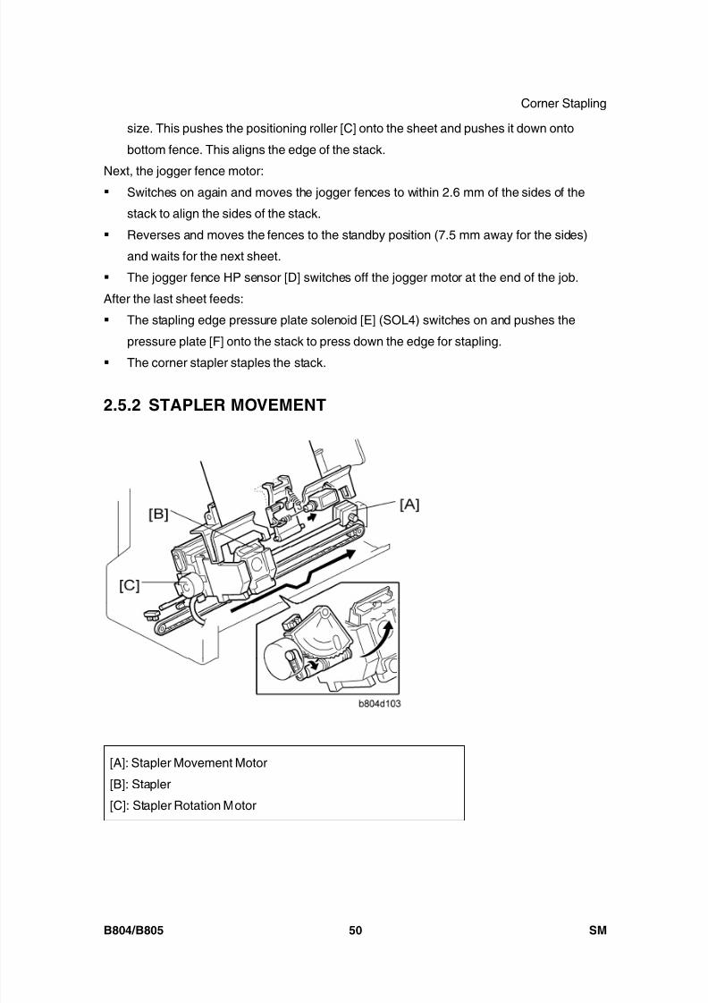
8/15/2019 Ricoh MP 4000 SM D009_D011_D012_D013 SERVICE MANUAL .pdf
http://slidepdf.com/reader/full/ricoh-mp-4000-sm-d009d011d012d013-service-manual-pdf 778/1162
Corner Stapling
B804/B805 50 SM
size. This pushes the positioning roller [C] onto the sheet and pushes it down onto
bottom fence. This aligns the edge of the stack.
Next, the jogger fence motor: Switches on again and moves the jogger fences to within 2.6 mm of the sides of the
stack to align the sides of the stack.
Reverses and moves the fences to the standby position (7.5 mm away for the sides)
and waits for the next sheet.
The jogger fence HP sensor [D] switches off the jogger motor at the end of the job.
After the last sheet feeds:
The stapling edge pressure plate solenoid [E] (SOL4) switches on and pushes the
pressure plate [F] onto the stack to press down the edge for stapling.
The corner stapler staples the stack.
2.5.2 STAPLER MOVEMENT
[A]: Stapler Movement Motor
[B]: Stapler
[C]: Stapler Rotation Motor
8/15/2019 Ricoh MP 4000 SM D009_D011_D012_D013 SERVICE MANUAL .pdf
http://slidepdf.com/reader/full/ricoh-mp-4000-sm-d009d011d012d013-service-manual-pdf 779/1162
Corner Stapling
SM 51 B804/B805
B o o
k l e t
F i n i s h e r /
F i n i s h e r
The stapler performs horizontal and rotational movement in each of the four staple modes:
Front 1 staple
Rear 1 staple Rear diagonal staple
Rear/Front 2 staples
The stapler movement motor [A] drives a timing belt that moves stapler [B] left and right on
its stainless steel rail.
The stapler rotation motor [C] rotates the stapler into position for diagonal stapling at the
rear.
The stapler movement motor switches on and moves the stapler the standby stapling
position. (This is the stapling position for the paper size selected for the job.)
The stapler movement motor switches off and the stapler waits for the signal to fire (or
swivel and for diagonal stapling).
If the stack is to be stapled at two positions:
The stapler movement motor moves the stapler to the front position and staples the
front.
The stapler movement motor moves the stapler to the rear and the stapler staples the
rear.
If the stack is stapled at the rear with a diagonal staple, the staple moves to the rear. When it
is time for stapling, the rotation motor rotates the stapler to the correct angle and holds the
stapler in that position while the stapler fires.
The stapling positions can be fine adjusted with SP6-133-001 .

8/15/2019 Ricoh MP 4000 SM D009_D011_D012_D013 SERVICE MANUAL .pdf
http://slidepdf.com/reader/full/ricoh-mp-4000-sm-d009d011d012d013-service-manual-pdf 780/1162
Corner Stapling
B804/B805 52 SM
2.5.3 CORNER STAPLING
Staple firing is driven by the stapler motor [A] inside the stapler unit. The stapler hammer [B]
fires the stapler [C].
The cartridge set sensor [D] detects the cartridge at the correct position.
The staple end sensor [E] detects the staple end condition.
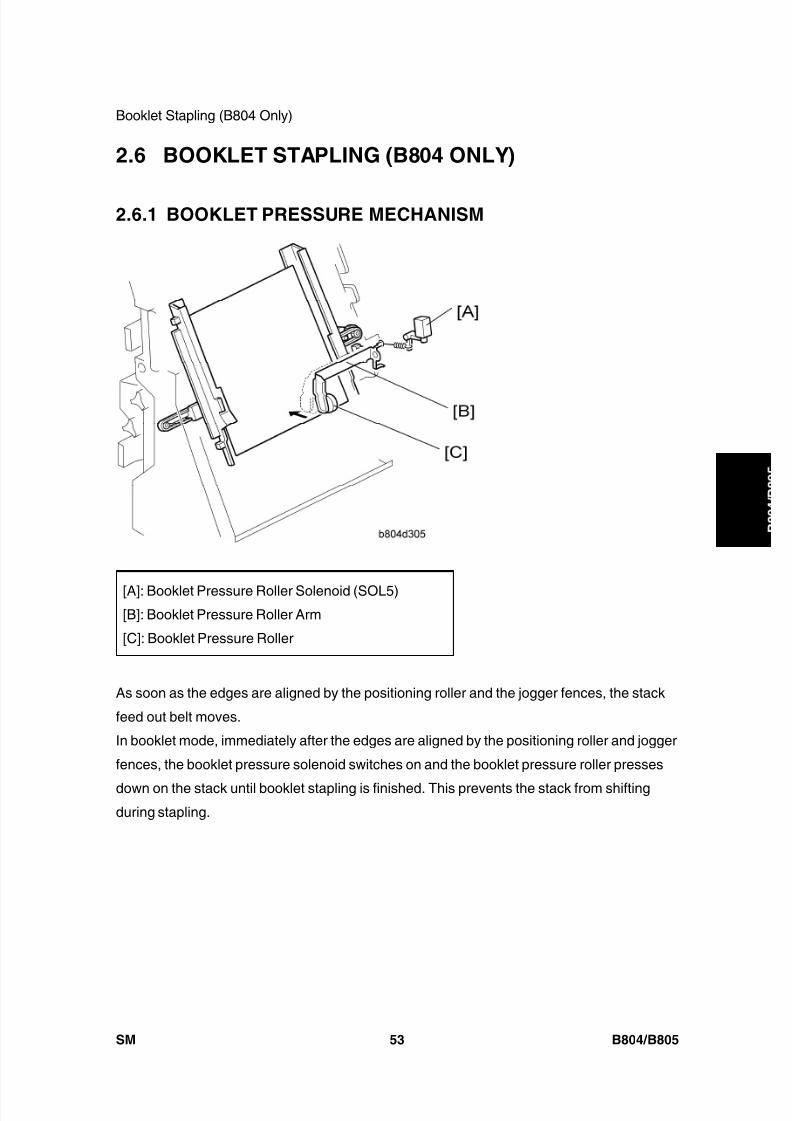
8/15/2019 Ricoh MP 4000 SM D009_D011_D012_D013 SERVICE MANUAL .pdf
http://slidepdf.com/reader/full/ricoh-mp-4000-sm-d009d011d012d013-service-manual-pdf 781/1162
Booklet Stapling (B804 Only)
SM 53 B804/B805
B o o
k l e t
F i n i s h e r /
F i n i s h e r
2.6 BOOKLET STAPLING (B804 ONLY)
2.6.1 BOOKLET PRESSURE MECHANISM
[A]: Booklet Pressure Roller Solenoid (SOL5)[B]: Booklet Pressure Roller Arm
[C]: Booklet Pressure Roller
As soon as the edges are aligned by the positioning roller and the jogger fences, the stack
feed out belt moves.
In booklet mode, immediately after the edges are aligned by the positioning roller and jogger
fences, the booklet pressure solenoid switches on and the booklet pressure roller presses
down on the stack until booklet stapling is finished. This prevents the stack from shiftingduring stapling.
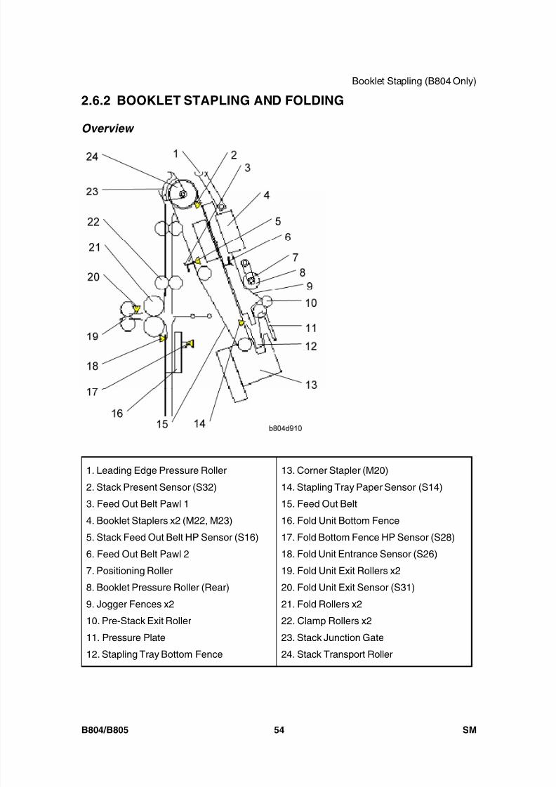
8/15/2019 Ricoh MP 4000 SM D009_D011_D012_D013 SERVICE MANUAL .pdf
http://slidepdf.com/reader/full/ricoh-mp-4000-sm-d009d011d012d013-service-manual-pdf 782/1162
Booklet Stapling (B804 Only)
B804/B805 54 SM
2.6.2 BOOKLET STAPLING AND FOLDING
Overview
1. Leading Edge Pressure Roller
2. Stack Present Sensor (S32)
3. Feed Out Belt Pawl 1
4. Booklet Staplers x2 (M22, M23)
5. Stack Feed Out Belt HP Sensor (S16)
6. Feed Out Belt Pawl 27. Positioning Roller
8. Booklet Pressure Roller (Rear)
9. Jogger Fences x2
10. Pre-Stack Exit Roller
11. Pressure Plate
12. Stapling Tray Bottom Fence
13. Corner Stapler (M20)
14. Stapling Tray Paper Sensor (S14)
15. Feed Out Belt
16. Fold Unit Bottom Fence
17. Fold Bottom Fence HP Sensor (S28)
18. Fold Unit Entrance Sensor (S26)19. Fold Unit Exit Rollers x2
20. Fold Unit Exit Sensor (S31)
21. Fold Rollers x2
22. Clamp Rollers x2
23. Stack Junction Gate
24. Stack Transport Roller

8/15/2019 Ricoh MP 4000 SM D009_D011_D012_D013 SERVICE MANUAL .pdf
http://slidepdf.com/reader/full/ricoh-mp-4000-sm-d009d011d012d013-service-manual-pdf 783/1162
Booklet Stapling (B804 Only)
SM 55 B804/B805
B o o
k l e t
F i n i s h e r /
F i n i s h e r1:
The last sheet of the stack [1] enters the stapling tray. The jogger fences [2] jog the last
sheet into position (based on the width of the selected paper size) and then retract and stop
1 mm away from the sides of the stack.
2:
The pressure plate [3] and booklet pressure roller [4] press down on the sheet. The stack
feed out belt switches on and the pawl [5] on the feed out belt catches the bottom of the
stack and raises it. The stapling tray sensor [6] detects the trailing edge of the paper stack.
3:
The feed out belt [7] raises the stack to the prescribed stapling position and stops. The
jogger fences move to the sides of the stack and the booklet staplers [8] staple the stack.

8/15/2019 Ricoh MP 4000 SM D009_D011_D012_D013 SERVICE MANUAL .pdf
http://slidepdf.com/reader/full/ricoh-mp-4000-sm-d009d011d012d013-service-manual-pdf 784/1162
Booklet Stapling (B804 Only)
B804/B805 56 SM
4:
The jogger fences remain 1 mm away from the sides of the stack. The feed out belt [1]
raises the stack until the top of the stack is 10 mm past the leading edge pressure roller [2]
and stops. The leading edge pressure roller descends and applies pressure to the top of the
stack. The stack junction gate [3] (normally open) closes. The pressure roller [4] and
pressure plate [5] retract.
5:
The feed out belt [6], transport rollers [7], [8], and clamp rollers [9] rotate and feed the stack
past the closed stack junction, over the top and down toward the bottom fence [10]. At the
same time, the fold unit bottom fence descends from its home position and stops 10 mm
below the fold position.
6:
The rollers feed the leading edge of the stack to within 3 mm of the stack stopper of the
bottom fence [13]. The fold unit entrance sensor [11] detects the stack and opens the clamprollers [12]. The stack drops 3 mm onto the fold unit bottom fence [13]. At this time, the first
sheet [14] of the next stack feeds to the stapling tray.

8/15/2019 Ricoh MP 4000 SM D009_D011_D012_D013 SERVICE MANUAL .pdf
http://slidepdf.com/reader/full/ricoh-mp-4000-sm-d009d011d012d013-service-manual-pdf 785/1162
Booklet Stapling (B804 Only)
SM 57 B804/B805
B o o
k l e t
F i n i s h e r /
F i n i s h e r
7:
The bottom fence [1] raises the stack to the prescribed fold position [2].
8:
The fold plate [3] moves to the left and advances 1/3 its maximum horizontal stroke and
exerts 20 kg (44 lb.) of pressure at the fold rollers [4].
9:
With the fold plate pushing the stack into nip of the fold rollers [5], the fold rollers begin to
rotate and fold the stack as it feeds out.

8/15/2019 Ricoh MP 4000 SM D009_D011_D012_D013 SERVICE MANUAL .pdf
http://slidepdf.com/reader/full/ricoh-mp-4000-sm-d009d011d012d013-service-manual-pdf 786/1162
Booklet Stapling (B804 Only)
B804/B805 58 SM
10:
When the fold rollers [1] feed the stack 10 mm past the nip, the fold plate retracts until it no
longer touches the stack. The fold unit exit sensor [2] detects the folded edge of the stack
and stops the fold rollers.
11:
The rotation of the fold rollers [4] reverses and feeds the folded edge back until only 3 mm of
the fold [5] remains at the nip.
12:
The fold rollers [6] rotate forward once again feed out. The fold unit exit sensor [7] once
again detects the edge of the fold.
You can do SP6-136-001 to increase the sharpness of the fold. The number of
forward and reverse feeds can be set in the range of 2 to 30. The machine repeats
Steps 11 and 12. For more, please refer to Section "Service Tables".

8/15/2019 Ricoh MP 4000 SM D009_D011_D012_D013 SERVICE MANUAL .pdf
http://slidepdf.com/reader/full/ricoh-mp-4000-sm-d009d011d012d013-service-manual-pdf 787/1162
Booklet Stapling (B804 Only)
SM 59 B804/B805
B o o
k l e t
F i n i s h e r /
F i n i s h e r
13:
With the feed of the stack halted, the fold plate [1] retracts. The fold plate HP sensor (not
shown) detects the fold plate and stops it at its home position.
14:
The fold rollers [2] and fold unit exit rollers [3] begin to rotate together and feed out the
folded booklet to the lower tray.
15:
Once the trailing edge of the stack passes the fold unit exit sensor [4], the clamp rollers [5]
close to be ready to feed the next stack. The fold unit bottom fence [6] descends. The
bottom fence HP sensor [7] stops the bottom fence when it detects the actuator on the
bottom fence.
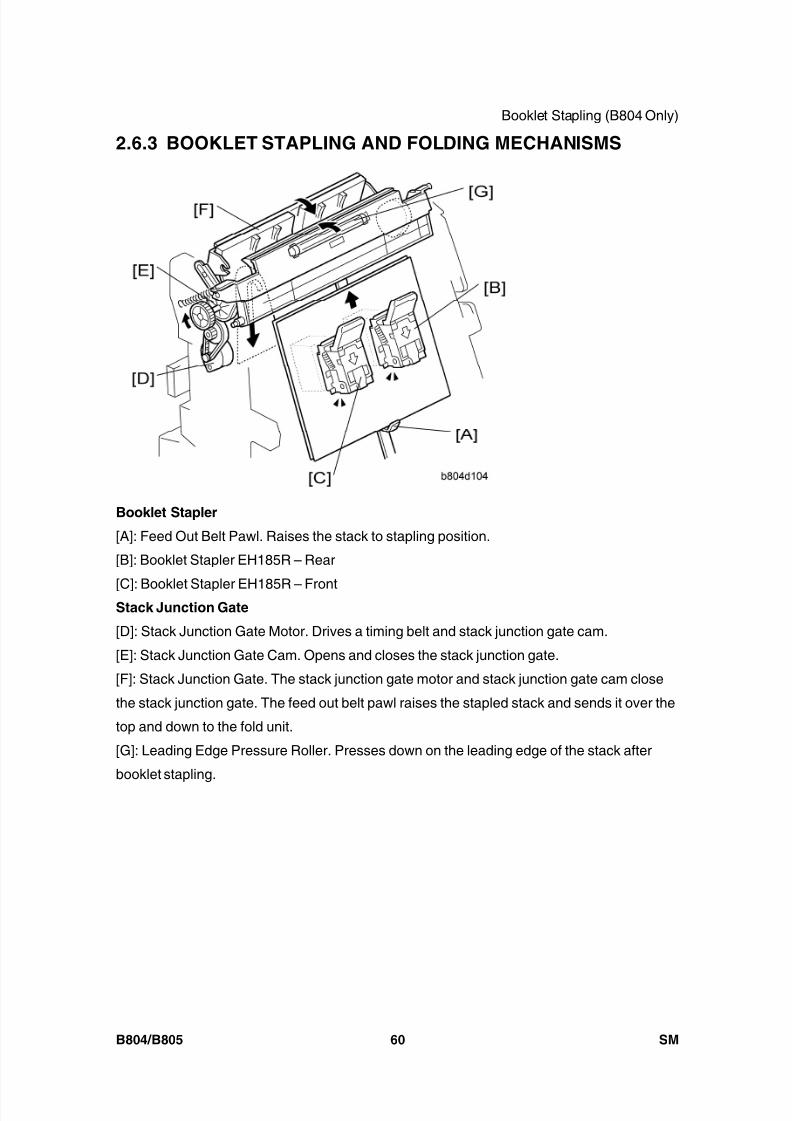
8/15/2019 Ricoh MP 4000 SM D009_D011_D012_D013 SERVICE MANUAL .pdf
http://slidepdf.com/reader/full/ricoh-mp-4000-sm-d009d011d012d013-service-manual-pdf 788/1162
Booklet Stapling (B804 Only)
B804/B805 60 SM
2.6.3 BOOKLET STAPLING AND FOLDING MECHANISMS
Booklet Stapler
[A]: Feed Out Belt Pawl. Raises the stack to stapling position.
[B]: Booklet Stapler EH185R – Rear
[C]: Booklet Stapler EH185R – FrontStack Junction Gate
[D]: Stack Junction Gate Motor. Drives a timing belt and stack junction gate cam.
[E]: Stack Junction Gate Cam. Opens and closes the stack junction gate.
[F]: Stack Junction Gate. The stack junction gate motor and stack junction gate cam close
the stack junction gate. The feed out belt pawl raises the stapled stack and sends it over the
top and down to the fold unit.
[G]: Leading Edge Pressure Roller. Presses down on the leading edge of the stack after
booklet stapling.

8/15/2019 Ricoh MP 4000 SM D009_D011_D012_D013 SERVICE MANUAL .pdf
http://slidepdf.com/reader/full/ricoh-mp-4000-sm-d009d011d012d013-service-manual-pdf 789/1162
Booklet Stapling (B804 Only)
SM 61 B804/B805
B o o
k l e t
F i n i s h e r /
F i n i s h e r
[H]
Clamp Roller
[A]: Fold Roller Motor. Drives the stationary clamp drive roller as well as the fold rollers
(see next page).
[B]: Clamp Rollers.
Clamp Roller – Drive. Rotated by the fold roller motor, this stationary roller feeds the stack
down with the retracting roller closed.
Clamp Roller – Retracting. Opened and closed by the retraction motor [C].
[C]: Clamp Roller Retraction Motor. Operates the clamp roller cam that retracts the retracting
clamp roller. The clamp rollers feed the stack to within 3 mm of the bottom fence when
closed and then open to drop the stack onto the bottom fence.
[D]: Clamp Roller HP Sensor. Controls the rotation of the clamp roller retraction motor andcam that open and close the retracting clamp roller.
[E]: Clamp Roller Cam. Forces open the spring loaded retracting clamp roller.
Bottom Fence
[F]: Bottom Fence. Raises the booklet stapled stack to the fold position.
[G]: Bottom Fence HP Sensor. Detects the actuator on the bottom fence and stops it at the
home position after folding.
[H]: Bottom Fence Lift Motor. Raises the bottom fence and stapled stack to the fold position
prescribed for the paper size.
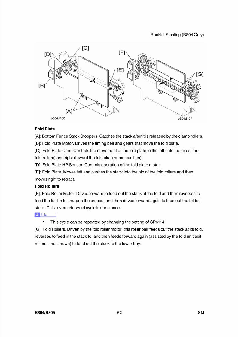
8/15/2019 Ricoh MP 4000 SM D009_D011_D012_D013 SERVICE MANUAL .pdf
http://slidepdf.com/reader/full/ricoh-mp-4000-sm-d009d011d012d013-service-manual-pdf 790/1162
Booklet Stapling (B804 Only)
B804/B805 62 SM
Fold Plate
[A]: Bottom Fence Stack Stoppers. Catches the stack after it is released by the clamp rollers.
[B]: Fold Plate Motor. Drives the timing belt and gears that move the fold plate.
[C]: Fold Plate Cam. Controls the movement of the fold plate to the left (into the nip of the
fold rollers) and right (toward the fold plate home position).
[D]: Fold Plate HP Sensor. Controls operation of the fold plate motor.
[E]: Fold Plate. Moves left and pushes the stack into the nip of the fold rollers and then
moves right to retract.
Fold Rollers
[F]: Fold Roller Motor. Drives forward to feed out the stack at the fold and then reverses to
feed the fold in to sharpen the crease, and then drives forward again to feed out the folded
stack. This reverse/forward cycle is done once.
This cycle can be repeated by changing the setting of SP6114.
[G]: Fold Rollers. Driven by the fold roller motor, this roller pair feeds out the stack at its fold,
reverses to feed in the stack to, and then feeds forward again (assisted by the fold unit exitrollers – not shown) to feed out the stack to the lower tray.
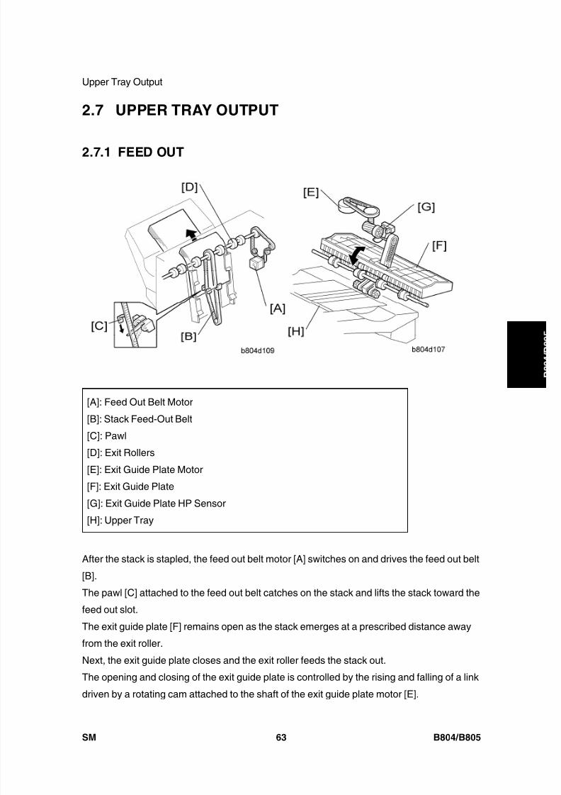
8/15/2019 Ricoh MP 4000 SM D009_D011_D012_D013 SERVICE MANUAL .pdf
http://slidepdf.com/reader/full/ricoh-mp-4000-sm-d009d011d012d013-service-manual-pdf 791/1162
Upper Tray Output
SM 63 B804/B805
B o o
k l e t
F i n i s h e r /
F i n i s h e r
2.7 UPPER TRAY OUTPUT
2.7.1 FEED OUT
[A]: Feed Out Belt Motor
[B]: Stack Feed-Out Belt[C]: Pawl
[D]: Exit Rollers
[E]: Exit Guide Plate Motor
[F]: Exit Guide Plate
[G]: Exit Guide Plate HP Sensor
[H]: Upper Tray
After the stack is stapled, the feed out belt motor [A] switches on and drives the feed out belt[B].
The pawl [C] attached to the feed out belt catches on the stack and lifts the stack toward the
feed out slot.
The exit guide plate [F] remains open as the stack emerges at a prescribed distance away
from the exit roller.
Next, the exit guide plate closes and the exit roller feeds the stack out.
The opening and closing of the exit guide plate is controlled by the rising and falling of a link
driven by a rotating cam attached to the shaft of the exit guide plate motor [E].
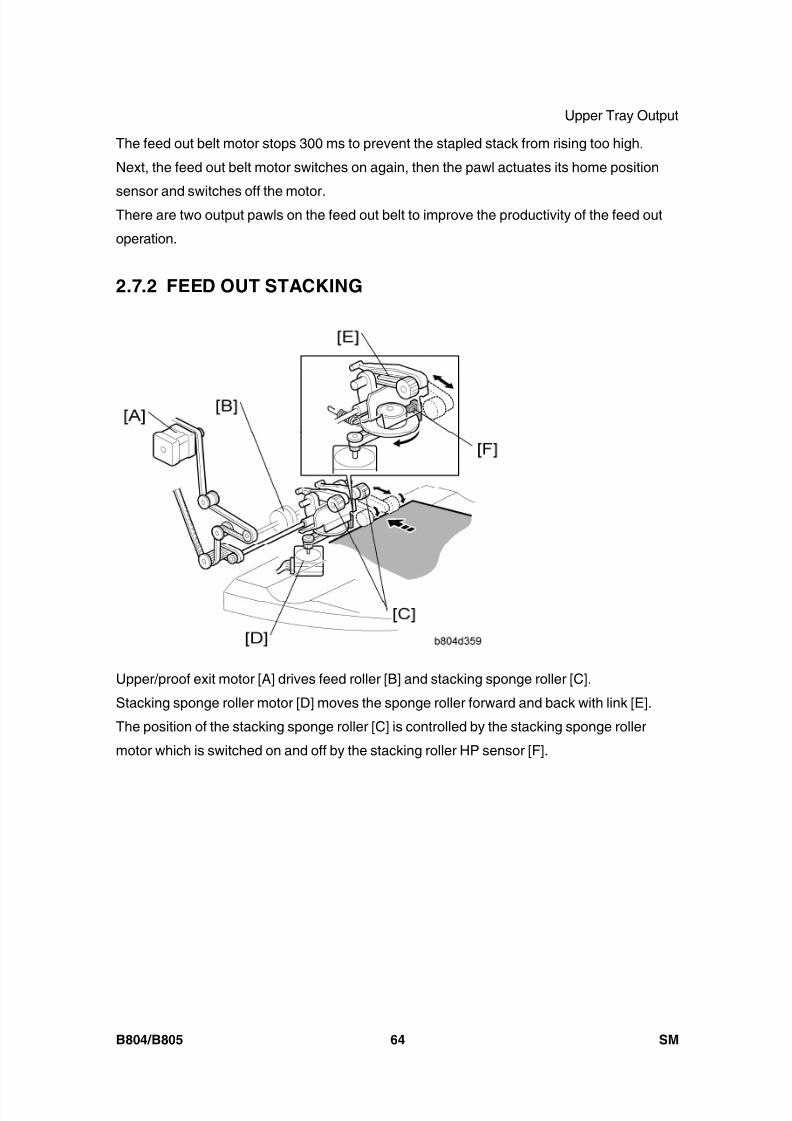
8/15/2019 Ricoh MP 4000 SM D009_D011_D012_D013 SERVICE MANUAL .pdf
http://slidepdf.com/reader/full/ricoh-mp-4000-sm-d009d011d012d013-service-manual-pdf 792/1162
Upper Tray Output
B804/B805 64 SM
The feed out belt motor stops 300 ms to prevent the stapled stack from rising too high.
Next, the feed out belt motor switches on again, then the pawl actuates its home position
sensor and switches off the motor.There are two output pawls on the feed out belt to improve the productivity of the feed out
operation.
2.7.2 FEED OUT STACKING
Upper/proof exit motor [A] drives feed roller [B] and stacking sponge roller [C].
Stacking sponge roller motor [D] moves the sponge roller forward and back with link [E].
The position of the stacking sponge roller [C] is controlled by the stacking sponge roller
motor which is switched on and off by the stacking roller HP sensor [F].
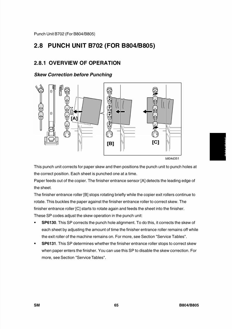
8/15/2019 Ricoh MP 4000 SM D009_D011_D012_D013 SERVICE MANUAL .pdf
http://slidepdf.com/reader/full/ricoh-mp-4000-sm-d009d011d012d013-service-manual-pdf 793/1162
Punch Unit B702 (For B804/B805)
SM 65 B804/B805
B o o
k l e t
F i n i s h e r /
F i n i s h e r
2.8 PUNCH UNIT B702 (FOR B804/B805)
2.8.1 OVERVIEW OF OPERATION
Skew Correction before Punching
This punch unit corrects for paper skew and then positions the punch unit to punch holes at
the correct position. Each sheet is punched one at a time.Paper feeds out of the copier. The finisher entrance sensor [A] detects the leading edge of
the sheet.
The finisher entrance roller [B] stops rotating briefly while the copier exit rollers continue to
rotate. This buckles the paper against the finisher entrance roller to correct skew. The
finisher entrance roller [C] starts to rotate again and feeds the sheet into the finisher.
These SP codes adjust the skew operation in the punch unit:
SP6130 . This SP corrects the punch hole alignment. To do this, it corrects the skew of
each sheet by adjusting the amount of time the finisher entrance roller remains off whilethe exit roller of the machine remains on. For more, see Section "Service Tables".
SP6131 . This SP determines whether the finisher entrance roller stops to correct skew
when paper enters the finisher. You can use this SP to disable the skew correction. For
more, see Section "Service Tables".

8/15/2019 Ricoh MP 4000 SM D009_D011_D012_D013 SERVICE MANUAL .pdf
http://slidepdf.com/reader/full/ricoh-mp-4000-sm-d009d011d012d013-service-manual-pdf 794/1162
Punch Unit B702 (For B804/B805)
B804/B805 66 SM
Punch Unit Position Correction
These operations (skew correction before punching, and punch unit position correction)
increase the accuracy of the punch alignment.
:
The trailing edge of the sheet passes the finisher entrance sensor [A].
The paper position slide unit [B] moves the paper position sensor [C] forward to the edge of
the paper.
The paper position sensor detects the position of the paper edge and sends this information
to the punch unit board. The machine uses the detected position of the paper edge to
calculate the correct position for punching.
The upper transport motor switches on and rotates the feed rollers [D] the prescribed
distance to position the paper under the punch unit.
:
Using the result of the position calculation, the punch unit control board moves the punch
unit [E] to the adjusted punch position.
The paper position slide unit and its paper sensor, move back to the paper position slide
home position sensor [F], and the punch unit fires the punches to make the holes.
:
The feed rollers [G] feed the punched paper out of the punch unit and into the paper path.

8/15/2019 Ricoh MP 4000 SM D009_D011_D012_D013 SERVICE MANUAL .pdf
http://slidepdf.com/reader/full/ricoh-mp-4000-sm-d009d011d012d013-service-manual-pdf 795/1162
Punch Unit B702 (For B804/B805)
SM 67 B804/B805
B o o
k l e t
F i n i s h e r /
F i n i s h e rThese SP codes adjust the punch hole alignment:
SP6-128 Adjusts the punch positions in the direction of paper feed.
SP6-129 Adjusts the punch position perpendicular to the direction of feed.
For more, see Section "Service Tables".
2.8.2 PUNCH MECHANISMS
Paper Position Detection
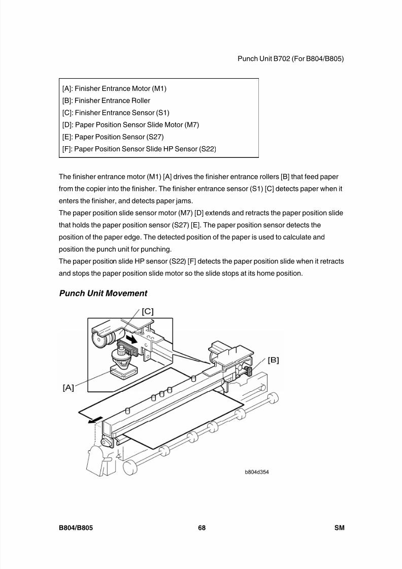
8/15/2019 Ricoh MP 4000 SM D009_D011_D012_D013 SERVICE MANUAL .pdf
http://slidepdf.com/reader/full/ricoh-mp-4000-sm-d009d011d012d013-service-manual-pdf 796/1162
Punch Unit B702 (For B804/B805)
B804/B805 68 SM
[A]: Finisher Entrance Motor (M1)
[B]: Finisher Entrance Roller[C]: Finisher Entrance Sensor (S1)
[D]: Paper Position Sensor Slide Motor (M7)
[E]: Paper Position Sensor (S27)
[F]: Paper Position Sensor Slide HP Sensor (S22)
The finisher entrance motor (M1) [A] drives the finisher entrance rollers [B] that feed paper
from the copier into the finisher. The finisher entrance sensor (S1) [C] detects paper when it
enters the finisher, and detects paper jams.The paper position slide sensor motor (M7) [D] extends and retracts the paper position slide
that holds the paper position sensor (S27) [E]. The paper position sensor detects the
position of the paper edge. The detected position of the paper is used to calculate and
position the punch unit for punching.
The paper position slide HP sensor (S22) [F] detects the paper position slide when it retracts
and stops the paper position slide motor so the slide stops at its home position.
Punch Unit Movement

8/15/2019 Ricoh MP 4000 SM D009_D011_D012_D013 SERVICE MANUAL .pdf
http://slidepdf.com/reader/full/ricoh-mp-4000-sm-d009d011d012d013-service-manual-pdf 797/1162
Punch Unit B702 (For B804/B805)
SM 69 B804/B805
B o o
k l e t
F i n i s h e r /
F i n i s h e r
[A]: Punch Movement Motor (M9)
[B]: Punch Movement HP Sensor (S21)
[C]: Punch Drive Motor (M24)
The punch movement motor (M9) [A] extends and retracts the punch unit to position it at the
correct position for punching.
The punch movement HP sensor (S21) [B] detects the position when it retracts, switches off
the punch position movement motor, and stops the punch unit at its home position.
The punch drive motor (M24) [C] fires the punches that punch holes in the paper below.
Punch Selection and Firing
[A]: Punch Drive Motor (M24)
[B]: Punch Encoder Wheel[C]: Punch Encoder Sensor (S24)
[D]: Punch HP Sensor (S23)
The punch drive motor (M24) [A] turns the small, notched encoder wheel [B] through the gap
in the punch encoder sensor [C] (S24). The sensor output is used to control the punch
timing.
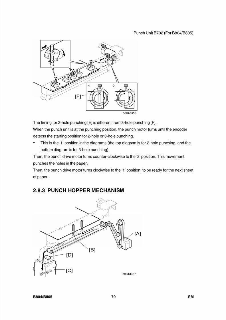
8/15/2019 Ricoh MP 4000 SM D009_D011_D012_D013 SERVICE MANUAL .pdf
http://slidepdf.com/reader/full/ricoh-mp-4000-sm-d009d011d012d013-service-manual-pdf 798/1162
Punch Unit B702 (For B804/B805)
B804/B805 70 SM
The timing for 2-hole punching [E] is different from 3-hole punching [F].
When the punch unit is at the punching position, the punch motor turns until the encoder
detects the starting position for 2-hole or 3-hole punching.
This is the ‘1’ position in the diagrams (the top diagram is for 2-hole punching, and the
bottom diagram is for 3-hole punching).
Then, the punch drive motor turns counter-clockwise to the ‘2’ position. This movement
punches the holes in the paper.
Then, the punch drive motor turns clockwise to the ‘1’ position, to be ready for the next sheet
of paper.
2.8.3 PUNCH HOPPER MECHANISM
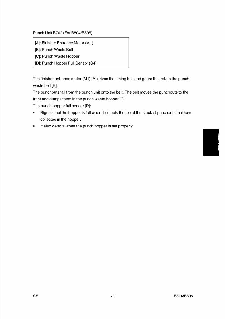
8/15/2019 Ricoh MP 4000 SM D009_D011_D012_D013 SERVICE MANUAL .pdf
http://slidepdf.com/reader/full/ricoh-mp-4000-sm-d009d011d012d013-service-manual-pdf 799/1162
Punch Unit B702 (For B804/B805)
SM 71 B804/B805
B o o
k l e t
F i n i s h e r /
F i n i s h e r
[A]: Finisher Entrance Motor (M1)
[B]: Punch Waste Belt
[C]: Punch Waste Hopper[D]: Punch Hopper Full Sensor (S4)
The finisher entrance motor (M1) [A] drives the timing belt and gears that rotate the punch
waste belt [B].
The punchouts fall from the punch unit onto the belt. The belt moves the punchouts to the
front and dumps them in the punch waste hopper [C].
The punch hopper full sensor [D]:
Signals that the hopper is full when it detects the top of the stack of punchouts that havecollected in the hopper.
It also detects when the punch hopper is set properly.
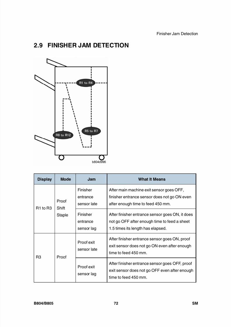
8/15/2019 Ricoh MP 4000 SM D009_D011_D012_D013 SERVICE MANUAL .pdf
http://slidepdf.com/reader/full/ricoh-mp-4000-sm-d009d011d012d013-service-manual-pdf 800/1162
Finisher Jam Detection
B804/B805 72 SM
2.9 FINISHER JAM DETECTION
Display Mode Jam What It Means
Finisher
entrance
sensor late
After main machine exit sensor goes OFF,
finisher entrance sensor does not go ON even
after enough time to feed 450 mm.R1 to R3
Proof
Shift
Staple Finisher
entrance
sensor lag
After finisher entrance sensor goes ON, it does
not go OFF after enough time to feed a sheet
1.5 times its length has elapsed.
Proof exit
sensor late
After finisher entrance sensor goes ON, proof
exit sensor does not go ON even after enough
time to feed 450 mm.R3 Proof
Proof exit
sensor lag
After finisher entrance sensor goes OFF, proof
exit sensor does not go OFF even after enough
time to feed 450 mm.

8/15/2019 Ricoh MP 4000 SM D009_D011_D012_D013 SERVICE MANUAL .pdf
http://slidepdf.com/reader/full/ricoh-mp-4000-sm-d009d011d012d013-service-manual-pdf 801/1162
Finisher Jam Detection
SM 73 B804/B805
B o o
k l e t
F i n i s h e r /
F i n i s h e r
Display Mode Jam What It Means
Upper tray exitsensor late
After finisher entrance sensor goes ON, upper
tray exit sensor does not go ON even after
enough time to feed 485 mm.R4 Shift
Upper tray exit
sensor lag
After finisher entrance sensor goes OFF, upper
tray exit sensor does not go OFF even after
enough time to feed 650 mm.
Pre-stack tray
exit sensor lag
After finisher entrance sensor goes ON,
pre-stack tray exit sensor does not go ON even
after enough time to feed 650 mm.R5 to R7 Staple
Pre-stack tray
exit sensor late
After finisher entrance sensor goes ON,
pre-stack tray exit sensor does not go OFF
even after enough time to feed 1650 mm.
Fold unit
entrance
sensor late(S26)
The fold unit entrance sensor goes not go ON
after enough time has elapsed to feed 1.5 times
the length of the stack after the leading edge of
the stack reaches the stack present sensor
(S32).
Fold unit exit
sensor late
(S31)
The fold unit exit sensor does not go ON after
enough time has elapsed for the stack to feed
1.5 times its length from the fold position.
R8 to
R12
Booklet
Staple
(B700
Only)
Fold unit exit
sensor lag
(S31)
After the fold unit exit sensor goes ON, it does
not go OFF after enough time has elapsed to
feed 442.9 mm.

8/15/2019 Ricoh MP 4000 SM D009_D011_D012_D013 SERVICE MANUAL .pdf
http://slidepdf.com/reader/full/ricoh-mp-4000-sm-d009d011d012d013-service-manual-pdf 802/1162
8/15/2019 Ricoh MP 4000 SM D009_D011_D012_D013 SERVICE MANUAL .pdf
http://slidepdf.com/reader/full/ricoh-mp-4000-sm-d009d011d012d013-service-manual-pdf 803/1162
SCANNER ACCESSIBILITY OPTIONTYPE 4045
B838

8/15/2019 Ricoh MP 4000 SM D009_D011_D012_D013 SERVICE MANUAL .pdf
http://slidepdf.com/reader/full/ricoh-mp-4000-sm-d009d011d012d013-service-manual-pdf 804/1162
8/15/2019 Ricoh MP 4000 SM D009_D011_D012_D013 SERVICE MANUAL .pdf
http://slidepdf.com/reader/full/ricoh-mp-4000-sm-d009d011d012d013-service-manual-pdf 805/1162
SM i B838
SCANNER ACCESSIBILITY OPTION
TYPE 4045 B838TABLE OF CONTENTS
1. SCANNER ACCESSIBILITY OPTION (B838) .................................1
1.1 INSTALLATION REQUIREMENTS............................................................... 1
1.1.1 GENERAL REQUIREMENTS .............................................................. 1
1.1.2 SPECIFIC REQUIREMENTS............................................................... 1
1.1.3 ACCESSORY CHECK......................................................................... 3 1.2 REMOVAL PROCEDURE FOR COVERS .................................................... 5
1.3 REMOVAL PROCEDURE FOR SCANNER UNIT ........................................ 7
1.4 CONNECTING PROCEDURE FOR SCANNER UNIT.................................. 9
1.5 CONNECTING PROCEDURE FOR OP PANEL......................................... 20
1.6 HARNESS BRACKET ATTACHMENT PROCEDURE................................ 23
1.7 CONNECTING PROCEDURE FOR MAINFRAME ..................................... 25
1.8 INSTALLATION FOR KEY COUNTER ....................................................... 31

8/15/2019 Ricoh MP 4000 SM D009_D011_D012_D013 SERVICE MANUAL .pdf
http://slidepdf.com/reader/full/ricoh-mp-4000-sm-d009d011d012d013-service-manual-pdf 806/1162
8/15/2019 Ricoh MP 4000 SM D009_D011_D012_D013 SERVICE MANUAL .pdf
http://slidepdf.com/reader/full/ricoh-mp-4000-sm-d009d011d012d013-service-manual-pdf 807/1162
Read This First
Safety and Symbols
Replacement Procedure Safety
Turn OFF the main power switch and unplug the machine beforebeginning any of the replacement procedures in this manual.
Symbols Used in this ManualThis manual uses the following symbols.
:See or Refer to
: Screws: Connector
: Clip ring: E-ring

8/15/2019 Ricoh MP 4000 SM D009_D011_D012_D013 SERVICE MANUAL .pdf
http://slidepdf.com/reader/full/ricoh-mp-4000-sm-d009d011d012d013-service-manual-pdf 808/1162
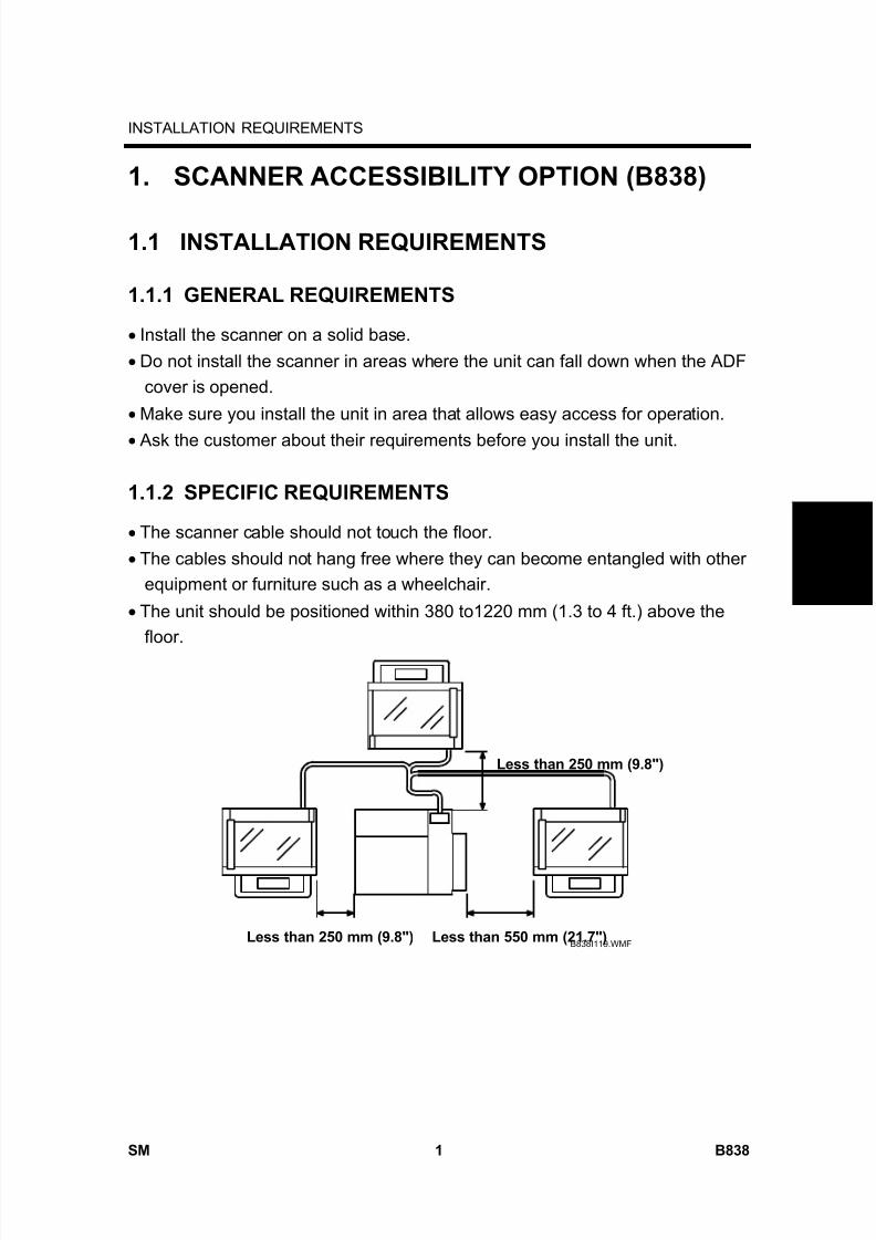
8/15/2019 Ricoh MP 4000 SM D009_D011_D012_D013 SERVICE MANUAL .pdf
http://slidepdf.com/reader/full/ricoh-mp-4000-sm-d009d011d012d013-service-manual-pdf 809/1162
INSTALLATION REQUIREMENTS
SM 1 B838
S c a n n e r
A c c e s s
i b i l i t y
O p
t i o n
B 8 3 8
1. SCANNER ACCESSIBILITY OPTION (B838)
1.1 INSTALLATION REQUIREMENTS
1.1.1 GENERAL REQUIREMENTS
• Install the scanner on a solid base.• Do not install the scanner in areas where the unit can fall down when the ADF
cover is opened.• Make sure you install the unit in area that allows easy access for operation.• Ask the customer about their requirements before you install the unit.
1.1.2 SPECIFIC REQUIREMENTS
• The scanner cable should not touch the floor.• The cables should not hang free where they can become entangled with other
equipment or furniture such as a wheelchair.• The unit should be positioned within 380 to1220 mm (1.3 to 4 ft.) above the
floor.
B838I119.WMF
Less than 250 mm (9.8")
Less than 550 mm (21.7")Less than 250 mm (9.8")

8/15/2019 Ricoh MP 4000 SM D009_D011_D012_D013 SERVICE MANUAL .pdf
http://slidepdf.com/reader/full/ricoh-mp-4000-sm-d009d011d012d013-service-manual-pdf 810/1162
INSTALLATION REQUIREMENTS
B838 2 SM
• The scanner should be positioned as follows:
Within 250 mm (9.8") from the left and rear side of the main unitWithin 550 mm (21.7") from the right side of the main unit
B838I120.WMF
Height: 380 to 1200 mm (1.3 to 4 ft.)

8/15/2019 Ricoh MP 4000 SM D009_D011_D012_D013 SERVICE MANUAL .pdf
http://slidepdf.com/reader/full/ricoh-mp-4000-sm-d009d011d012d013-service-manual-pdf 811/1162
INSTALLATION REQUIREMENTS
SM 3 B838
S c a n n e r
A c c e s s
i b i l i t y
O p
t i o n
B 8 3 8
1.1.3 ACCESSORY CHECK
Check the accessories and their quantities against the following list.
No. Description Q'ty
1 Top Rear Cover 1
2 Rear Bracket 1
3 Key Counter Bracket (only for installing key counter) 1
4 Left Scanner Stay 1
5 Right Bottom Plate 1
6 Left Bottom Plate 1
7 Left Stopper 1
8 Right Stopper 1
9 Cable Bracket Unit 1
10 Operation Panel Interface Board 1
11 MB Interface Board 1
12 Gasket - Scanner Frame 1
13 Gasket - Scanner Lens 1
14 Seal - Bottom 1
15 Ferrite Core 17
16 Shoulder Screw (only for installing key counter) 1
17 Adjuster 2
18 Spacer 219 Rubber Leg 3
20 Cap 3
21 Saddle Clamp 1
22 Clamp 1
23 Plate Clamp 4
24 Screw-Round: M4x8 2
25 Screw-Tapping: M3x8 (blue) 7
26 Screw-Round: M3x6 4
27 Screw 2-Tapping: M3x8 4
28 Screw-Tapping: M4x16 4
29 Screw-Tapping: M4x8 4
30 Screw-Tapping: M3x6 5
31 Screw-Tapping: M3x8 6
32 Left Bracket 1
33 Harness - MB 1
34 Harness - Operation Panel Board 1
35 Top Right Cover 1
36 Cable Bracket Cover 1
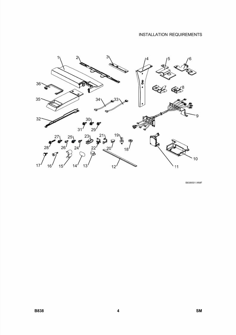
8/15/2019 Ricoh MP 4000 SM D009_D011_D012_D013 SERVICE MANUAL .pdf
http://slidepdf.com/reader/full/ricoh-mp-4000-sm-d009d011d012d013-service-manual-pdf 812/1162
INSTALLATION REQUIREMENTS
B838 4 SM
B838I501.WMF
1 2 3 4 5 6
7 8
9
10
11121314151617
18
19
20
21
22
23
24
25
26
27
28
29
30
31
32
333435
36
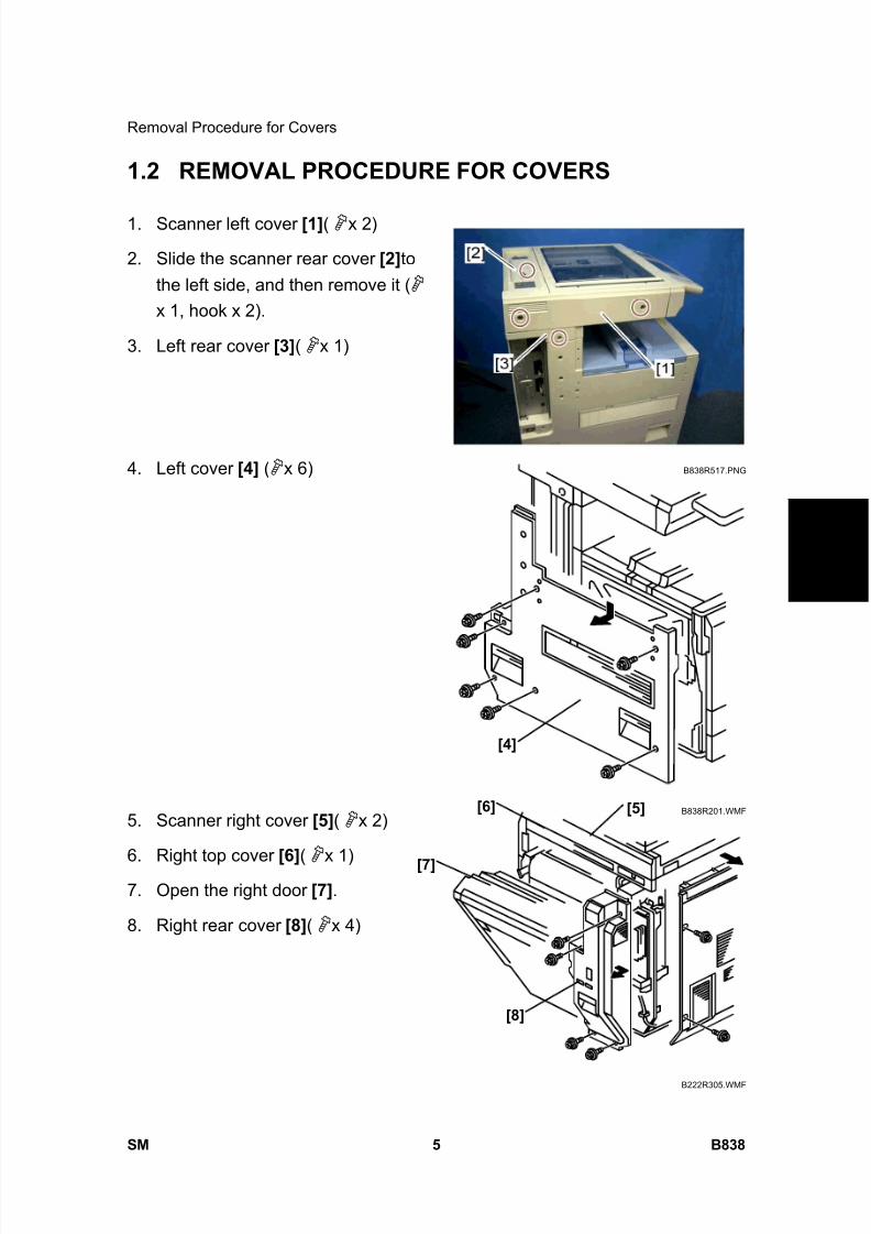
8/15/2019 Ricoh MP 4000 SM D009_D011_D012_D013 SERVICE MANUAL .pdf
http://slidepdf.com/reader/full/ricoh-mp-4000-sm-d009d011d012d013-service-manual-pdf 813/1162
Removal Procedure for Covers
SM 5 B838
S c a n n e r
A c c e s s
i b i l i t y
O p
t i o n
B 8 3 8
1.2 REMOVAL PROCEDURE FOR COVERS
1. Scanner left cover [1] ( x 2)
2. Slide the scanner rear cover [2] tothe left side, and then remove it ( x 1, hook x 2).
3. Left rear cover [3] ( x 1)
4. Left cover [4] ( x 6)
5. Scanner right cover [5] ( x 2)
6. Right top cover [6] ( x 1)
7. Open the right door [7] .
8. Right rear cover [8] ( x 4)
B838R517.PNG
B838R201.WMF
B222R305.WMF
[4]
[8]
[7]
[6] [5]

8/15/2019 Ricoh MP 4000 SM D009_D011_D012_D013 SERVICE MANUAL .pdf
http://slidepdf.com/reader/full/ricoh-mp-4000-sm-d009d011d012d013-service-manual-pdf 814/1162
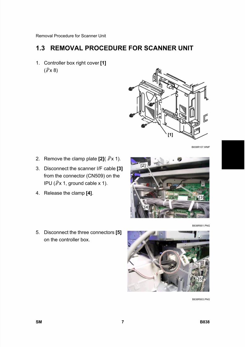
8/15/2019 Ricoh MP 4000 SM D009_D011_D012_D013 SERVICE MANUAL .pdf
http://slidepdf.com/reader/full/ricoh-mp-4000-sm-d009d011d012d013-service-manual-pdf 815/1162
Removal Procedure for Scanner Unit
SM 7 B838
S c a n n e r
A c c e s s
i b i l i t y
O p
t i o n
B 8 3 8
1.3 REMOVAL PROCEDURE FOR SCANNER UNIT
1. Controller box right cover [1] ( x 8)
2. Remove the clamp plate [2] ( x 1).
3. Disconnect the scanner I/F cable [3] from the connector (CN509) on the
IPU ( x 1, ground cable x 1).
4. Release the clamp [4] .
5. Disconnect the three connectors [5] on the controller box.
B838R107.WMF
B838R901.PNG
B838R903.PNG
[1]

8/15/2019 Ricoh MP 4000 SM D009_D011_D012_D013 SERVICE MANUAL .pdf
http://slidepdf.com/reader/full/ricoh-mp-4000-sm-d009d011d012d013-service-manual-pdf 816/1162
Removal Procedure for Scanner Unit
B838 8 SM
6. Scanner unit [6] ( x 5; right side x 2, left side x 3)
7. Scanner left stay [7] ( x 3)
B838R902.PNG
B838R904.PNG
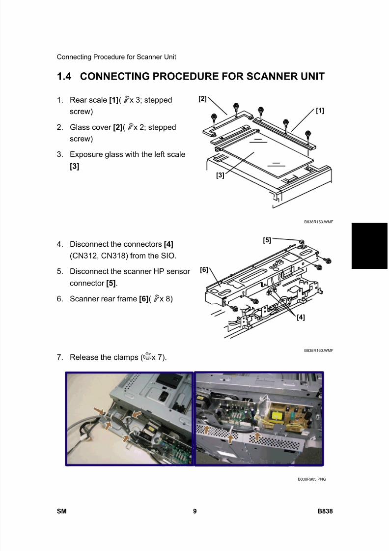
8/15/2019 Ricoh MP 4000 SM D009_D011_D012_D013 SERVICE MANUAL .pdf
http://slidepdf.com/reader/full/ricoh-mp-4000-sm-d009d011d012d013-service-manual-pdf 817/1162
Connecting Procedure for Scanner Unit
SM 9 B838
S c a n n e r
A c c e s s
i b i l i t y
O p
t i o n
B 8 3 8
1.4 CONNECTING PROCEDURE FOR SCANNER UNIT
1. Rear scale [1] ( x 3; steppedscrew)
2. Glass cover [2] ( x 2; steppedscrew)
3. Exposure glass with the left scale[3]
4. Disconnect the connectors [4] (CN312, CN318) from the SIO.
5. Disconnect the scanner HP sensorconnector [5] .
6. Scanner rear frame [6] ( x 8)
7. Release the clamps ( x 7).
B838R153.WMF
B838R160.WMF
B838R905.PNG
[1]
[2]
[3]
[4]
[5]
[6]
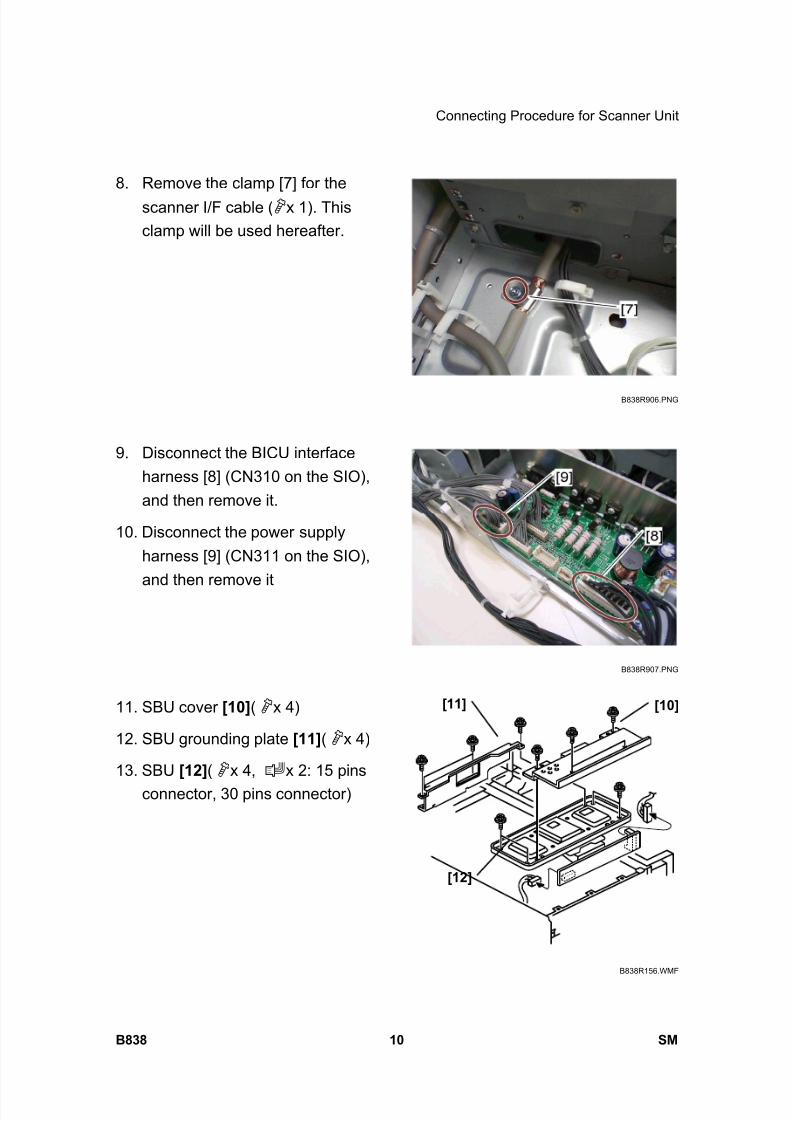
8/15/2019 Ricoh MP 4000 SM D009_D011_D012_D013 SERVICE MANUAL .pdf
http://slidepdf.com/reader/full/ricoh-mp-4000-sm-d009d011d012d013-service-manual-pdf 818/1162
Connecting Procedure for Scanner Unit
B838 10 SM
8. Remove the clamp [7] for the
scanner I/F cable ( x 1). Thisclamp will be used hereafter.
9. Disconnect the BICU interfaceharness [8] (CN310 on the SIO),and then remove it.
10. Disconnect the power supplyharness [9] (CN311 on the SIO),and then remove it
11. SBU cover [10] ( x 4)
12. SBU grounding plate [11] ( x 4)
13. SBU [12] ( x 4, x 2: 15 pinsconnector, 30 pins connector)
B838R906.PNG
B838R907.PNG
B838R156.WMF
[11]
[12]
[10]

8/15/2019 Ricoh MP 4000 SM D009_D011_D012_D013 SERVICE MANUAL .pdf
http://slidepdf.com/reader/full/ricoh-mp-4000-sm-d009d011d012d013-service-manual-pdf 819/1162
Connecting Procedure for Scanner Unit
SM 11 B838
S c a n n e r
A c c e s s
i b i l i t y
O p
t i o n
B 8 3 8
14. Scanner I/F cable [13] ( x 1,ground cable x 1)
15. Operation panel I/F harness [14] ( x 5)
16. Scanner left stay [15] ( x 2)
17. Move the scanner carriage [16] to the center position.
B838R908.PNG
B838R909.PNG
B838R910.PNG
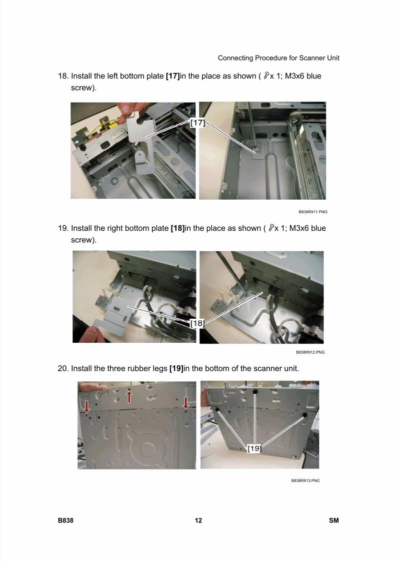
8/15/2019 Ricoh MP 4000 SM D009_D011_D012_D013 SERVICE MANUAL .pdf
http://slidepdf.com/reader/full/ricoh-mp-4000-sm-d009d011d012d013-service-manual-pdf 820/1162
Connecting Procedure for Scanner Unit
B838 12 SM
18. Install the left bottom plate [17] in the place as shown ( x 1; M3x6 bluescrew).
19. Install the right bottom plate [18] in the place as shown ( x 1; M3x6 bluescrew).
20. Install the three rubber legs [19] in the bottom of the scanner unit.
B838R911.PNG
B838R912.PNG
B838R913.PNG
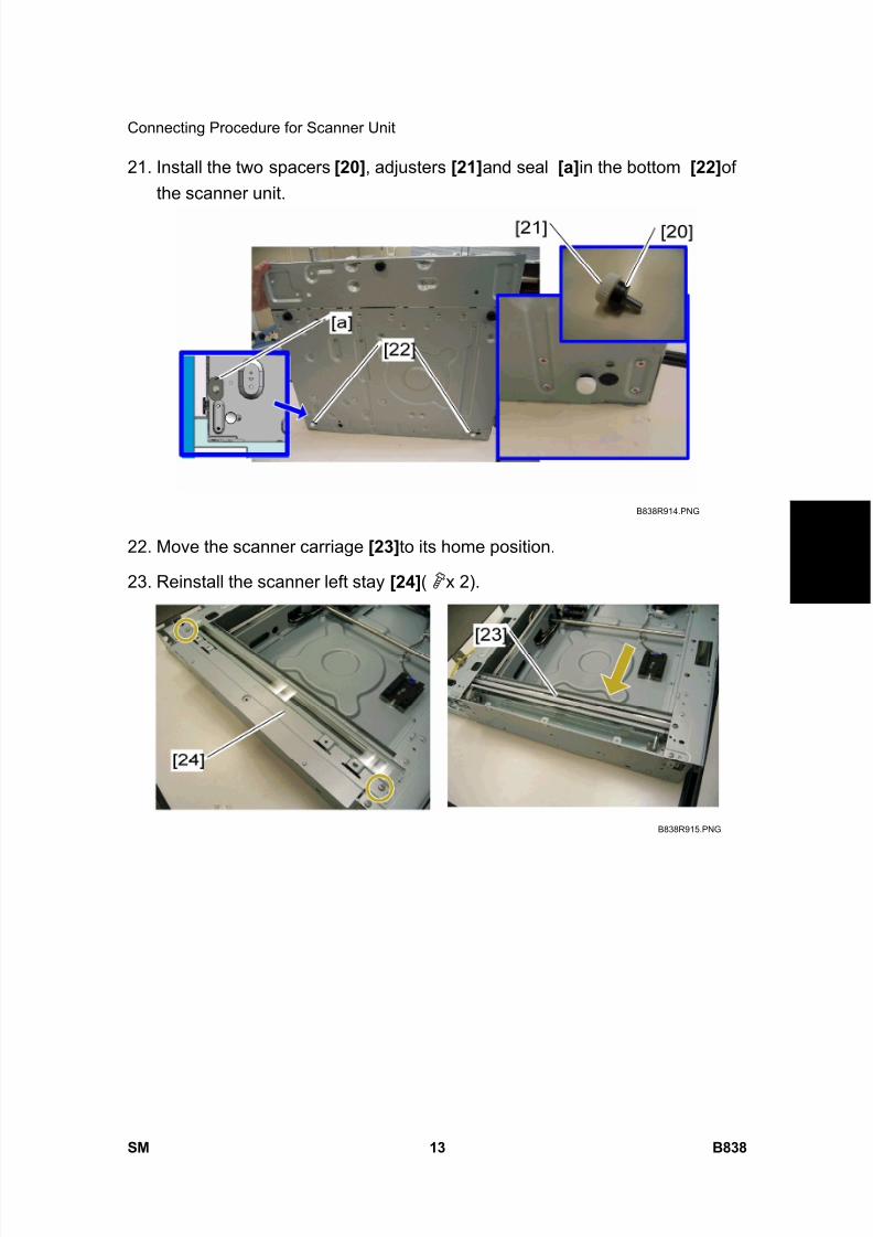
8/15/2019 Ricoh MP 4000 SM D009_D011_D012_D013 SERVICE MANUAL .pdf
http://slidepdf.com/reader/full/ricoh-mp-4000-sm-d009d011d012d013-service-manual-pdf 821/1162
Connecting Procedure for Scanner Unit
SM 13 B838
S c a n n e r
A c c e s s
i b i l i t y
O p
t i o n
B 8 3 8
21. Install the two spacers [20] , adjusters [21] and seal [a] in the bottom [22] ofthe scanner unit.
22. Move the scanner carriage [23] to its home position.
23. Reinstall the scanner left stay [24] ( x 2).
B838R914.PNG
B838R915.PNG

8/15/2019 Ricoh MP 4000 SM D009_D011_D012_D013 SERVICE MANUAL .pdf
http://slidepdf.com/reader/full/ricoh-mp-4000-sm-d009d011d012d013-service-manual-pdf 822/1162
Connecting Procedure for Scanner Unit
B838 14 SM
24. Install the rear bracket [25] to the outside of the scanner rear frame ( x 2;M3x6 blue screw).
25. Install the left bracket [26] to the outside of the scanner left frame ( x 2;M3x6 blue screw).
B838R916.PNG
B838R917.PNG
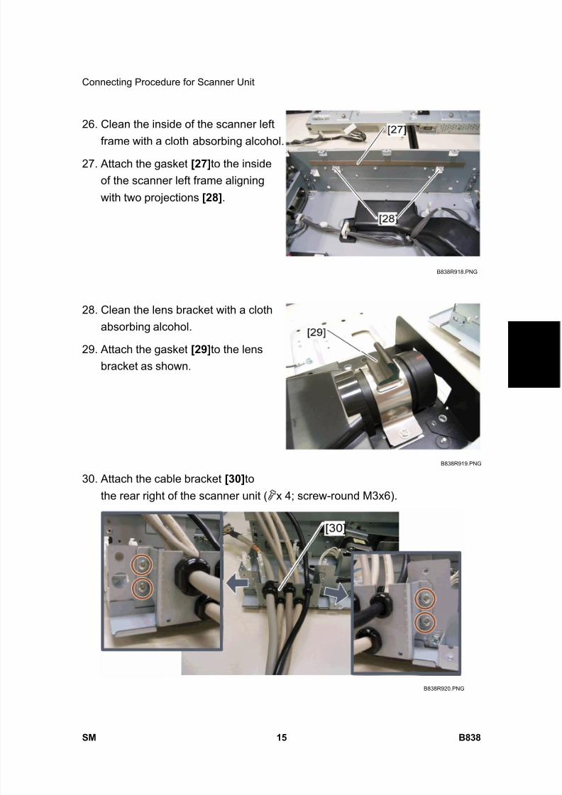
8/15/2019 Ricoh MP 4000 SM D009_D011_D012_D013 SERVICE MANUAL .pdf
http://slidepdf.com/reader/full/ricoh-mp-4000-sm-d009d011d012d013-service-manual-pdf 823/1162
Connecting Procedure for Scanner Unit
SM 15 B838
S c a n n e r
A c c e s s
i b i l i t y
O p
t i o n
B 8 3 8
26. Clean the inside of the scanner left
frame with a cloth absorbing alcohol.
27. Attach the gasket [27] to the insideof the scanner left frame aligningwith two projections [28] .
28. Clean the lens bracket with a clothabsorbing alcohol.
29. Attach the gasket [29] to the lensbracket as shown.
30. Attach the cable bracket [30] tothe rear right of the scanner unit ( x 4; screw-round M3x6).
B838R918.PNG
B838R919.PNG
B838R920.PNG

8/15/2019 Ricoh MP 4000 SM D009_D011_D012_D013 SERVICE MANUAL .pdf
http://slidepdf.com/reader/full/ricoh-mp-4000-sm-d009d011d012d013-service-manual-pdf 824/1162
Connecting Procedure for Scanner Unit
B838 16 SM
31. Put the scanner I/F cable [31]
through the cutout of the scannerrear frame.
32. Reinstall the SBU [32] ( x 4, x2: 15 pins connector, 30 pinsconnector) and ground cable of the
scanner I/F cable ( x 1).
33. Reinstall the SBU grounding plate
[33] ( x 4).
34. Reinstall the SBU cover [34] ( x4).
35. Remove the rap on the scanner I/F
cable.36. Attach the clamp [35] (this clamp is
removed in step 8 in the"Connecting Procedure for ScannerUnit") to the scanner I/F cable andthen secure it ( x 1; M3x6 bluescrew).
B838R921.PNG
B838R156.WMF
B838R922.PNG
[32]
[33] [34]
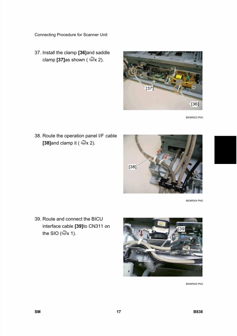
8/15/2019 Ricoh MP 4000 SM D009_D011_D012_D013 SERVICE MANUAL .pdf
http://slidepdf.com/reader/full/ricoh-mp-4000-sm-d009d011d012d013-service-manual-pdf 825/1162
Connecting Procedure for Scanner Unit
SM 17 B838
S c a n n e r
A c c e s s
i b i l i t y
O p
t i o n
B 8 3 8
37. Install the clamp [36] and saddle
clamp [37] as shown ( x 2).
38. Route the operation panel I/F cable[38] and clamp it ( x 2).
39. Route and connect the BICUinterface cable [39] to CN311 on
the SIO ( x 1).
B838R923.PNG
B838R924.PNG
B838R925.PNG

8/15/2019 Ricoh MP 4000 SM D009_D011_D012_D013 SERVICE MANUAL .pdf
http://slidepdf.com/reader/full/ricoh-mp-4000-sm-d009d011d012d013-service-manual-pdf 826/1162
Connecting Procedure for Scanner Unit
B838 18 SM
40. Route and connect the powersupply cable [40] to CN310 on the
SIO ( x 4).41. Secure two ground cables [41]
(BICU interface cable and powersupply cable) ( x 1; M3x6 bluescrew).
42. Route the heater relay cable [42] as shown and secure ground cable [43] ( x 6, x 1; screw-round M4x8).
43. Reinstall the scanner rear frame[44] ( x 8, x 2).
44. Connect the harness [45] to thescanner HP sensor.
B838R926.PNG
B838R927.PNG
B838R160.WMF
[44]
[45]
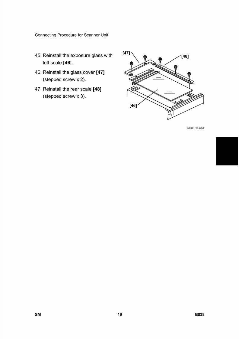
8/15/2019 Ricoh MP 4000 SM D009_D011_D012_D013 SERVICE MANUAL .pdf
http://slidepdf.com/reader/full/ricoh-mp-4000-sm-d009d011d012d013-service-manual-pdf 827/1162
Connecting Procedure for Scanner Unit
SM 19 B838
S c a n n e r
A c c e s s
i b i l i t y
O p
t i o n
B 8 3 8
45. Reinstall the exposure glass withleft scale [46] .
46. Reinstall the glass cover [47] (stepped screw x 2).
47. Reinstall the rear scale [48] (stepped screw x 3).
B838R153.WMF
[46]
[47][48]

8/15/2019 Ricoh MP 4000 SM D009_D011_D012_D013 SERVICE MANUAL .pdf
http://slidepdf.com/reader/full/ricoh-mp-4000-sm-d009d011d012d013-service-manual-pdf 828/1162
Connecting Procedure for Op Panel
B838 20 SM
1.5 CONNECTING PROCEDURE FOR OP PANEL
1. Route and attach the operationpanel I/F cable to the outside ofthe scanner right frame with
four plate clamps ( x 4; screw- tapping M3x8).
NOTE: Make sure that the operation panel I/F cable [A] does not cover thethree cutouts [B].
2. Connect the harness [2] to theoperation panel interface board[3] as shown.
B838R928.PNG
B838R934.PNG
B838R929.PNG
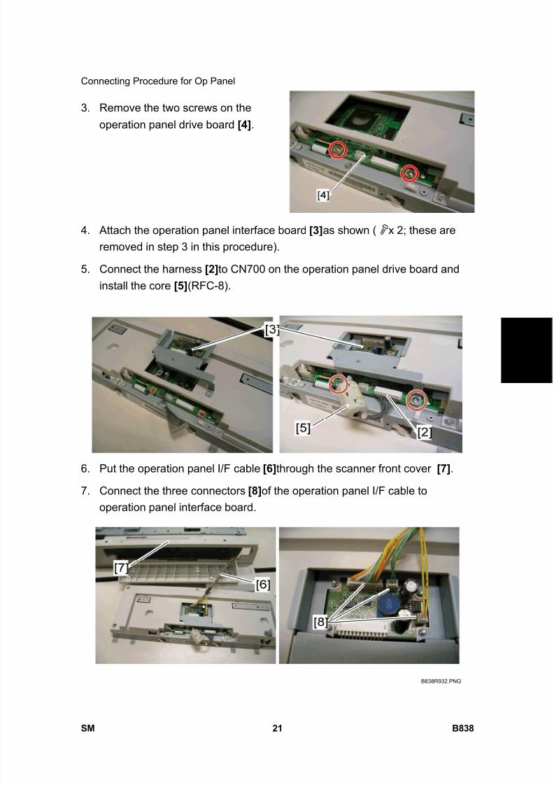
8/15/2019 Ricoh MP 4000 SM D009_D011_D012_D013 SERVICE MANUAL .pdf
http://slidepdf.com/reader/full/ricoh-mp-4000-sm-d009d011d012d013-service-manual-pdf 829/1162
Connecting Procedure for Op Panel
SM 21 B838
S c a n n e r
A c c e s s
i b i l i t y
O p
t i o n
B 8 3 8
3. Remove the two screws on theoperation panel drive board [4] .
4. Attach the operation panel interface board [3] as shown ( x 2; these areremoved in step 3 in this procedure).
5. Connect the harness [2] to CN700 on the operation panel drive board andinstall the core [5] (RFC-8).
6. Put the operation panel I/F cable [6] through the scanner front cover [7] .
7. Connect the three connectors [8] of the operation panel I/F cable tooperation panel interface board.
B838R932.PNG

8/15/2019 Ricoh MP 4000 SM D009_D011_D012_D013 SERVICE MANUAL .pdf
http://slidepdf.com/reader/full/ricoh-mp-4000-sm-d009d011d012d013-service-manual-pdf 830/1162
Connecting Procedure for Op Panel
B838 22 SM
8. Remove the clip tray [9] from thescanner front cover [10] .
9. Attach the scanner front cover [11] to the operation panel ( x 2).
10. Reinstall the operation panel withthe scanner front cover [12] in thescanner front frame ( x 6; M3x3bind screw x 2, M3x5 bind screw x2 on the top of the scanner front
cover, M3x8 tapping screw x 2 onthe bottom of the scanner frontcover).
11. Reinstall the scanner right cover[13] ( x 2).
B838R933.PNG
B838R157.WMF
[12]
[13]
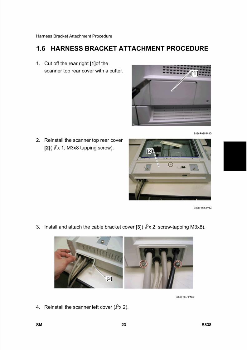
8/15/2019 Ricoh MP 4000 SM D009_D011_D012_D013 SERVICE MANUAL .pdf
http://slidepdf.com/reader/full/ricoh-mp-4000-sm-d009d011d012d013-service-manual-pdf 831/1162
Harness Bracket Attachment Procedure
SM 23 B838
S c a n n e r
A c c e s s
i b i l i t y
O p
t i o n
B 8 3 8
1.6 HARNESS BRACKET ATTACHMENT PROCEDURE
1. Cut off the rear right [1] of thescanner top rear cover with a cutter.
2. Reinstall the scanner top rear cover
[2] ( x 1; M3x8 tapping screw).
3. Install and attach the cable bracket cover [3] ( x 2; screw-tapping M3x8).
4. Reinstall the scanner left cover ( x 2).
B838R935.PNG
B838R936.PNG
B838R937.PNG
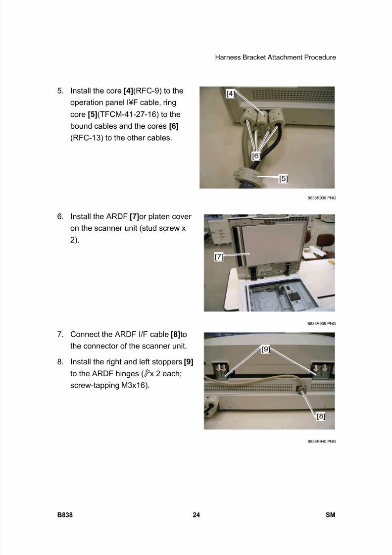
8/15/2019 Ricoh MP 4000 SM D009_D011_D012_D013 SERVICE MANUAL .pdf
http://slidepdf.com/reader/full/ricoh-mp-4000-sm-d009d011d012d013-service-manual-pdf 832/1162
Harness Bracket Attachment Procedure
B838 24 SM
5. Install the core [4] (RFC-9) to theoperation panel I¥F cable, ringcore [5] (TFCM-41-27-16) to thebound cables and the cores [6] (RFC-13) to the other cables.
6. Install the ARDF [7] or platen coveron the scanner unit (stud screw x2).
7. Connect the ARDF I/F cable [8] tothe connector of the scanner unit.
8. Install the right and left stoppers [9] to the ARDF hinges ( x 2 each;
screw-tapping M3x16).
B838R938.PNG
B838R939.PNG
B838R940.PNG
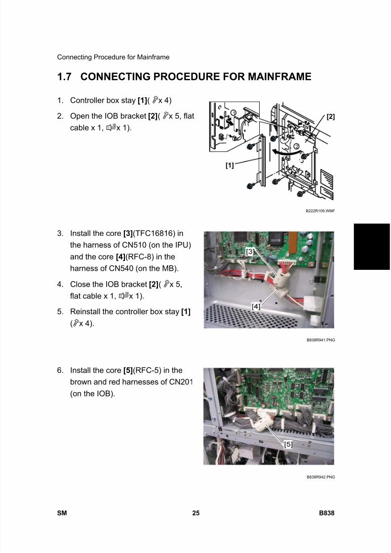
8/15/2019 Ricoh MP 4000 SM D009_D011_D012_D013 SERVICE MANUAL .pdf
http://slidepdf.com/reader/full/ricoh-mp-4000-sm-d009d011d012d013-service-manual-pdf 833/1162
Connecting Procedure for Mainframe
SM 25 B838
S c a n n e r
A c c e s s
i b i l i t y
O p
t i o n
B 8 3 8
1.7 CONNECTING PROCEDURE FOR MAINFRAME
1. Controller box stay [1] ( x 4)
2. Open the IOB bracket [2] ( x 5, flatcable x 1, x 1).
3. Install the core [3] (TFC16816) inthe harness of CN510 (on the IPU)and the core [4] (RFC-8) in theharness of CN540 (on the MB).
4. Close the IOB bracket [2] ( x 5,flat cable x 1, x 1).
5. Reinstall the controller box stay [1] ( x 4).
6. Install the core [5] (RFC-5) in thebrown and red harnesses of CN201(on the IOB).
1
2
B222R109.WMF
B838R941.PNG
B838R942.PNG
[1]
[2]
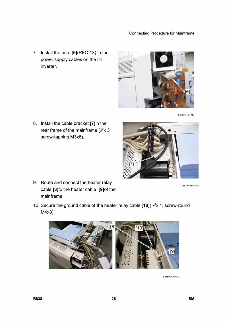
8/15/2019 Ricoh MP 4000 SM D009_D011_D012_D013 SERVICE MANUAL .pdf
http://slidepdf.com/reader/full/ricoh-mp-4000-sm-d009d011d012d013-service-manual-pdf 834/1162
Connecting Procedure for Mainframe
B838 26 SM
7. Install the core [6] (RFC-13) in thepower supply cables on the IHinverter.
8. Install the cable bracket [7] in therear frame of the mainframe ( x 3;screw-tapping M3x6).
9. Route and connect the heater relaycable [8] to the heater cable [9] of themainframe.
10. Secure the ground cable of the heater relay cable [10] ( x 1; screw-roundM4x8).
B838R943.PNG
B838R944.PNG
B838R945.PNG
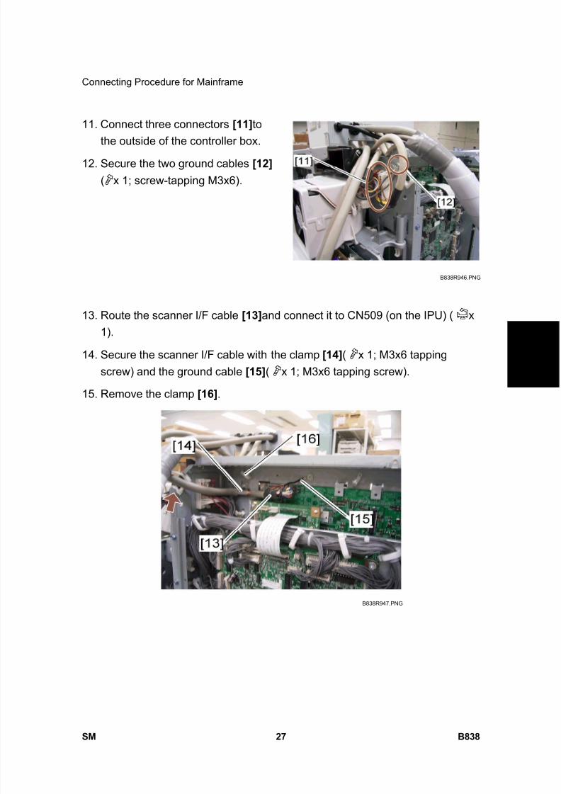
8/15/2019 Ricoh MP 4000 SM D009_D011_D012_D013 SERVICE MANUAL .pdf
http://slidepdf.com/reader/full/ricoh-mp-4000-sm-d009d011d012d013-service-manual-pdf 835/1162
Connecting Procedure for Mainframe
SM 27 B838
S c a n n e r
A c c e s s
i b i l i t y
O p
t i o n
B 8 3 8
11. Connect three connectors [11] to
the outside of the controller box.
12. Secure the two ground cables [12] ( x 1; screw-tapping M3x6).
13. Route the scanner I/F cable [13] and connect it to CN509 (on the IPU) ( x1).
14. Secure the scanner I/F cable with the clamp [14] ( x 1; M3x6 tappingscrew) and the ground cable [15] ( x 1; M3x6 tapping screw).
15. Remove the clamp [16] .
B838R946.PNG
B838R947.PNG
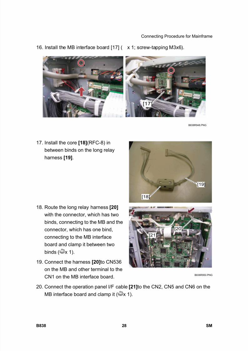
8/15/2019 Ricoh MP 4000 SM D009_D011_D012_D013 SERVICE MANUAL .pdf
http://slidepdf.com/reader/full/ricoh-mp-4000-sm-d009d011d012d013-service-manual-pdf 836/1162
Connecting Procedure for Mainframe
B838 28 SM
16. Install the MB interface board [17] ( x 1; screw-tapping M3x6).
17. Install the core [18] (RFC-8) inbetween binds on the long relayharness [19] .
18. Route the long relay harness [20] with the connector, which has twobinds, connecting to the MB and theconnector, which has one bind,connecting to the MB interface
board and clamp it between twobinds ( x 1).
19. Connect the harness [20] to CN536on the MB and other terminal to theCN1 on the MB interface board.
20. Connect the operation panel I/F cable [21] to the CN2, CN5 and CN6 on theMB interface board and clamp it ( x 1).
B838R948.PNG
B838R949.PNG
B838R950.PNG

8/15/2019 Ricoh MP 4000 SM D009_D011_D012_D013 SERVICE MANUAL .pdf
http://slidepdf.com/reader/full/ricoh-mp-4000-sm-d009d011d012d013-service-manual-pdf 837/1162
Connecting Procedure for Mainframe
SM 29 B838
S c a n n e r
A c c e s s
i b i l i t y
O p
t i o n
B 8 3 8
21. Reinstall the controller box right cover ( x 8).
22. Install the left scanner stay [22] (
x 2; M4x6 tapping screw) in the leftside of the main machine.
23. Reinstall the left cover ( x 6).
24. Reinstall the left rear cover ( x 1).
25. Reinstall the right rear cover ( x4).
26. Close the right door.
27. Reinstall the right top cover ( x 1).
IMPORTANT: If you install the key counter, first refer to the "Installation forKey Counter".
28. Install the top rear cover [23] ( x2; screw-tapping M3x8).
29. Install the top right cover [24] ( x3; screw-tapping M3x8).
B838R951.PNG
B838R952.PNG
B838R953.PNG
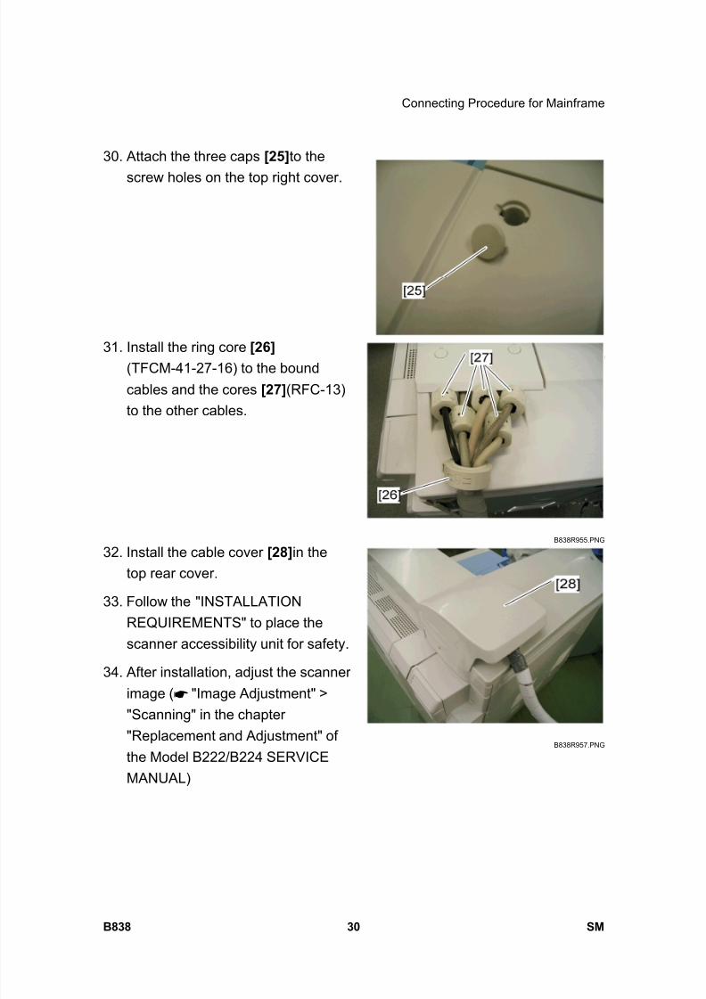
8/15/2019 Ricoh MP 4000 SM D009_D011_D012_D013 SERVICE MANUAL .pdf
http://slidepdf.com/reader/full/ricoh-mp-4000-sm-d009d011d012d013-service-manual-pdf 838/1162
Connecting Procedure for Mainframe
B838 30 SM
30. Attach the three caps [25] to the
screw holes on the top right cover.
31. Install the ring core [26] (TFCM-41-27-16) to the boundcables and the cores [27] (RFC-13)to the other cables.
32. Install the cable cover [28] in thetop rear cover.
33. Follow the "INSTALLATIONREQUIREMENTS" to place thescanner accessibility unit for safety.
34. After installation, adjust the scanner
image ( "Image Adjustment" >"Scanning" in the chapter"Replacement and Adjustment" ofthe Model B222/B224 SERVICEMANUAL)
B838R954.PNG
B838R955.PNG
B838R957.PNG
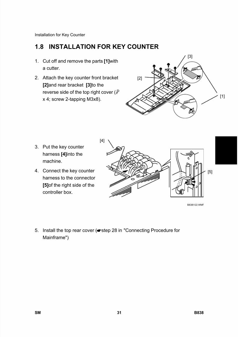
8/15/2019 Ricoh MP 4000 SM D009_D011_D012_D013 SERVICE MANUAL .pdf
http://slidepdf.com/reader/full/ricoh-mp-4000-sm-d009d011d012d013-service-manual-pdf 839/1162
Installation for Key Counter
SM 31 B838
S c a n n e r
A c c e s s
i b i l i t y
O p
t i o n
B 8 3 8
1.8 INSTALLATION FOR KEY COUNTER
1. Cut off and remove the parts [1] witha cutter.
2. Attach the key counter front bracket[2] and rear bracket [3] to thereverse side of the top right cover ( x 4; screw 2-tapping M3x8).
3. Put the key counterharness [4] into themachine.
4. Connect the key counter
harness to the connector[5] of the right side of thecontroller box.
5. Install the top rear cover ( step 28 in "Connecting Procedure for
Mainframe")
B838I122.WMF
[4]
[5]
[1]
[2]
[3]
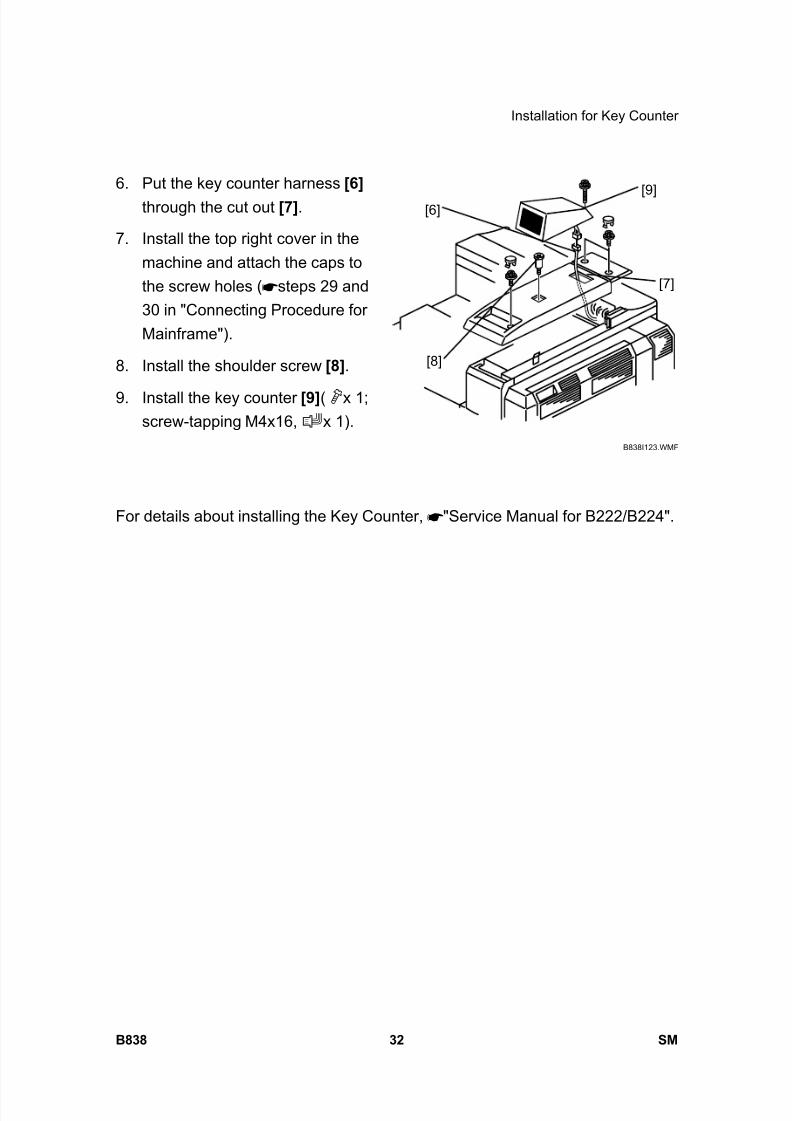
8/15/2019 Ricoh MP 4000 SM D009_D011_D012_D013 SERVICE MANUAL .pdf
http://slidepdf.com/reader/full/ricoh-mp-4000-sm-d009d011d012d013-service-manual-pdf 840/1162
Installation for Key Counter
B838 32 SM
6. Put the key counter harness [6] through the cut out [7] .
7. Install the top right cover in themachine and attach the caps tothe screw holes ( steps 29 and30 in "Connecting Procedure forMainframe").
8. Install the shoulder screw [8] .
9. Install the key counter [9] ( x 1;screw-tapping M4x16, x 1).
For details about installing the Key Counter, "Service Manual for B222/B224".
B838I123.WMF
[6]
[7]
[8]
[9]
8/15/2019 Ricoh MP 4000 SM D009_D011_D012_D013 SERVICE MANUAL .pdf
http://slidepdf.com/reader/full/ricoh-mp-4000-sm-d009d011d012d013-service-manual-pdf 841/1162
FAX OPTION TYPE 5000D346

8/15/2019 Ricoh MP 4000 SM D009_D011_D012_D013 SERVICE MANUAL .pdf
http://slidepdf.com/reader/full/ricoh-mp-4000-sm-d009d011d012d013-service-manual-pdf 842/1162
8/15/2019 Ricoh MP 4000 SM D009_D011_D012_D013 SERVICE MANUAL .pdf
http://slidepdf.com/reader/full/ricoh-mp-4000-sm-d009d011d012d013-service-manual-pdf 843/1162
SM i D346
FAX OPTION TYPE 5000 (D346)TABLE OF CONTENTS
1. INSTALLATION PROCEDURE .......................................................1
1.1 FAX OPTION INSTALLATION...................................................................... 1
1.1.1 COMPONENT CHECK ........................................................................ 1
1.1.2 FAX OPTION INSTALLATION PROCEDURE..................................... 2
1.2 G3 INTERFACE BOARD INSTALLATION.................................................... 5
1.2.1 COMPONENT CHECK ........................................................................ 5
1.2.2 INSTALLATION: ONE G3 BOARD ...................................................... 6 1.2.3 INSTALLATION: TWO G3 BOARDS ................................................... 7
1.3 FAX UNIT OPTIONS..................................................................................... 9
1.3.1 MEMORY UNIT (G578) ....................................................................... 9
1.3.2 HANDSET (B433) ................................................................................ 9
2. REPLACEMENT AND ADJUSTMENT ..........................................12
2.1 FCU............................................................................................................. 12
3. TROUBLESHOOTING ...................................................................13 3.1 ERROR CODES ......................................................................................... 13
3.2 IFAX TROUBLESHOOTING ....................................................................... 34
3.3 IP-FAX TROUBLESHOOTING ................................................................... 37
3.3.1 IP-FAX TRANSMISSION ................................................................... 37
3.3.2 IP-FAX RECEPTION ......................................................................... 40
4. SERVICE TABLE...........................................................................44
4.1 BEFOREHAND ........................................................................................... 44
4.2 SERVICE TABLES...................................................................................... 45 4.2.1 SP1-XXX (BIT SWITCHES)............................................................... 45
4.2.2 SP2-XXX (RAM DATA)...................................................................... 46
4.2.3 SP3-XXX (TEL LINE SETTINGS)...................................................... 47
4.2.4 SP4-XXX (ROM VERSIONS)............................................................. 49
4.2.5 SP5-XXX (INITIALIZING)................................................................... 50
4.2.6 SP6-XXX (REPORTS) ....................................................................... 50
4.2.7 SP7-XXX (TEST MODES) ................................................................. 53
4.2.8 SP9-XXX (DESIGN SWITCH MODE)................................................ 55
8/15/2019 Ricoh MP 4000 SM D009_D011_D012_D013 SERVICE MANUAL .pdf
http://slidepdf.com/reader/full/ricoh-mp-4000-sm-d009d011d012d013-service-manual-pdf 844/1162
D346 ii SM
4.3 BIT SWITCHES........................................................................................... 56
4.3.1 SYSTEM SWITCHES ........................................................................ 57
4.3.2 I-FAX SWITCHES.............................................................................. 69
4.3.3 PRINTER SWITCHES ....................................................................... 76
4.3.4 COMMUNICATION SWITCHES ........................................................ 82
4.3.5 G3 SWITCHES .................................................................................. 91
4.3.6 G3-2/3 SWITCHES .......................................................................... 100
4.3.7 IP FAX SWITCHES.......................................................................... 108
4.4 NCU PARAMETERS................................................................................. 117
4.5 DEDICATED TRANSMISSION PARAMETERS........................................ 133
4.5.1 PROGRAMMING PROCEDURE ..................................................... 133
4.5.2 PARAMETERS ................................................................................ 133
4.6 SERVICE RAM ADDRESSES .................................................................. 141
5. DETAILS ......................................................................................151
5.1 OVERVIEW............................................................................................... 151
5.2 BOARDS................................................................................................... 152
5.2.1 FCU ................................................................................................. 152
5.2.2 MBU................................................................................................. 153
5.2.3 SG3 BOARD .................................................................................... 154 5.3 VIDEO DATA PATH.................................................................................. 156
5.3.1 TRANSMISSION.............................................................................. 156
5.3.2 RECEPTION.................................................................................... 158
5.4 FAX COMMUNICATION FEATURES....................................................... 159
5.4.1 MULTI-PORT................................................................................... 159
5.4.2 DOCUMENT SERVER..................................................................... 159
5.4.3 INTERNET MAIL COMMUNICATION.............................................. 160
5.5 IP-FAX ...................................................................................................... 170
5.5.1 WHAT IS IP-FAX? ........................................................................... 170
6. SPECIFICATIONS........................................................................171
6.1 GENERAL SPECIFICATIONS .................................................................. 171
6.1.1 FCU ................................................................................................. 171
6.1.2 CAPABILITIES OF PROGRAMMABLE ITEMS ............................... 172
6.2 IFAX SPECIFICATIONS ........................................................................... 174
6.3 IP-FAX SPECIFICATIONS........................................................................ 176
6.4 FAX UNIT CONFIGURATION................................................................... 177
8/15/2019 Ricoh MP 4000 SM D009_D011_D012_D013 SERVICE MANUAL .pdf
http://slidepdf.com/reader/full/ricoh-mp-4000-sm-d009d011d012d013-service-manual-pdf 845/1162
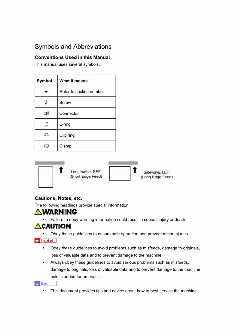
8/15/2019 Ricoh MP 4000 SM D009_D011_D012_D013 SERVICE MANUAL .pdf
http://slidepdf.com/reader/full/ricoh-mp-4000-sm-d009d011d012d013-service-manual-pdf 846/1162
Symbols and Abbreviations
Conventions Used in this ManualThis manual uses several symbols.
Symbol What it means
Refer to section number
Screw
Connector
E-ring
Clip ring
Clamp
Cautions, Notes, etc.The following headings provide special information:
Failure to obey warning information could result in serious injury or death.
Obey these guidelines to ensure safe operation and prevent minor injuries.
Obey these guidelines to avoid problems such as misfeeds, damage to originals,
loss of valuable data and to prevent damage to the machine.
Always obey these guidelines to avoid serious problems such as misfeeds,
damage to originals, loss of valuable data and to prevent damage to the machine.
bold is added for emphasis.
This document provides tips and advice about how to best service the machine.
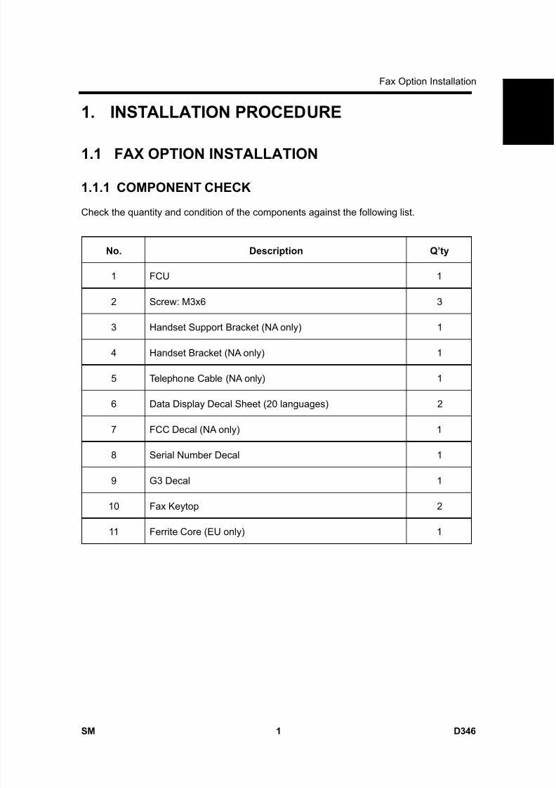
8/15/2019 Ricoh MP 4000 SM D009_D011_D012_D013 SERVICE MANUAL .pdf
http://slidepdf.com/reader/full/ricoh-mp-4000-sm-d009d011d012d013-service-manual-pdf 847/1162
Fax Option Installation
SM 1 D346
F a x
O p
t i o n
T y p e
5 0 0 0
D 3 4 6
1. INSTALLATION PROCEDURE
1.1 FAX OPTION INSTALLATION
1.1.1 COMPONENT CHECK
Check the quantity and condition of the components against the following list.
No. Description Q’ty
1 FCU 1
2 Screw: M3x6 3
3 Handset Support Bracket (NA only) 1
4 Handset Bracket (NA only) 1
5 Telephone Cable (NA only) 1
6 Data Display Decal Sheet (20 languages) 2
7 FCC Decal (NA only) 1
8 Serial Number Decal 1
9 G3 Decal 1
10 Fax Keytop 2
11 Ferrite Core (EU only) 1
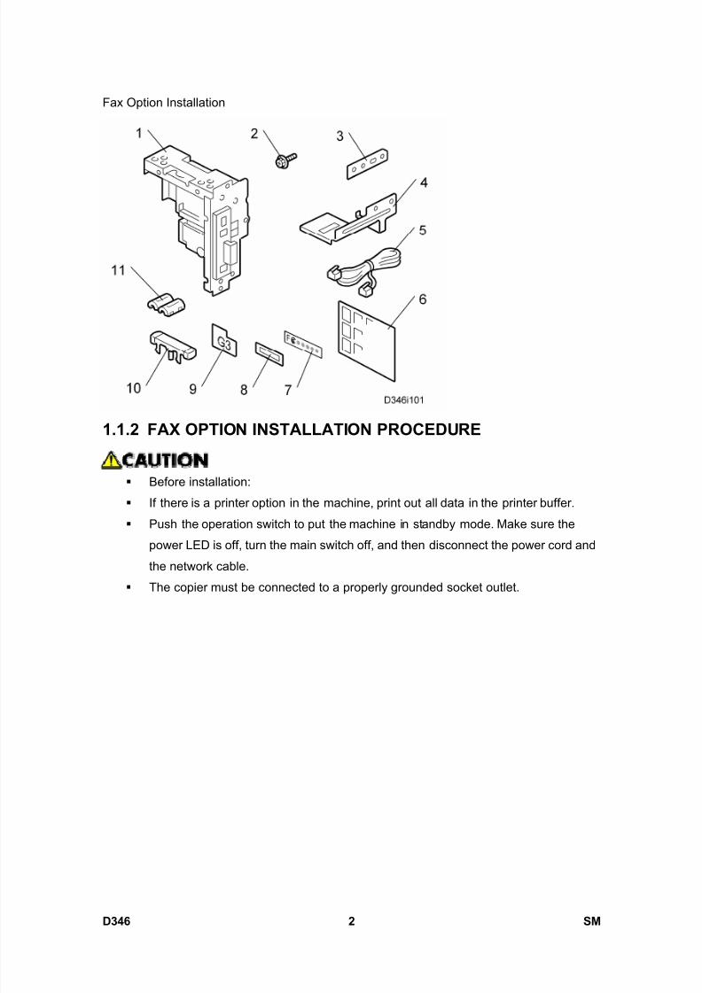
8/15/2019 Ricoh MP 4000 SM D009_D011_D012_D013 SERVICE MANUAL .pdf
http://slidepdf.com/reader/full/ricoh-mp-4000-sm-d009d011d012d013-service-manual-pdf 848/1162
Fax Option Installation
D346 2 SM
1.1.2 FAX OPTION INSTALLATION PROCEDURE
Before installation:
If there is a printer option in the machine, print out all data in the printer buffer.
Push the operation switch to put the machine in standby mode. Make sure thepower LED is off, turn the main switch off, and then disconnect the power cord and
the network cable.
The copier must be connected to a properly grounded socket outlet.
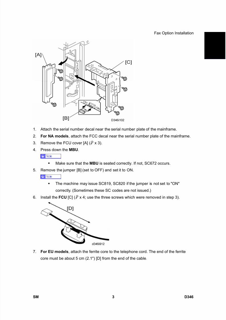
8/15/2019 Ricoh MP 4000 SM D009_D011_D012_D013 SERVICE MANUAL .pdf
http://slidepdf.com/reader/full/ricoh-mp-4000-sm-d009d011d012d013-service-manual-pdf 849/1162
Fax Option Installation
SM 3 D346
F a x
O p
t i o n
T y p e
5 0 0 0
D 3 4 6
1. Attach the serial number decal near the serial number plate of the mainframe.
2. For NA models , attach the FCC decal near the serial number plate of the mainframe.
3. Remove the FCU cover [A] ( x 3).
4. Press down the MBU .
Make sure that the MBU is seated correctly. If not, SC672 occurs.
5. Remove the jumper [B] (set to OFF) and set it to ON.
The machine may issue SC819, SC820 if the jumper is not set to "ON"
correctly. (Sometimes these SC codes are not issued.)
6. Install the FCU [C] ( x 4; use the three screws which were removed in step 3).
7. For EU models , attach the ferrite core to the telephone cord. The end of the ferrite
core must be about 5 cm (2.1") [D] from the end of the cable.
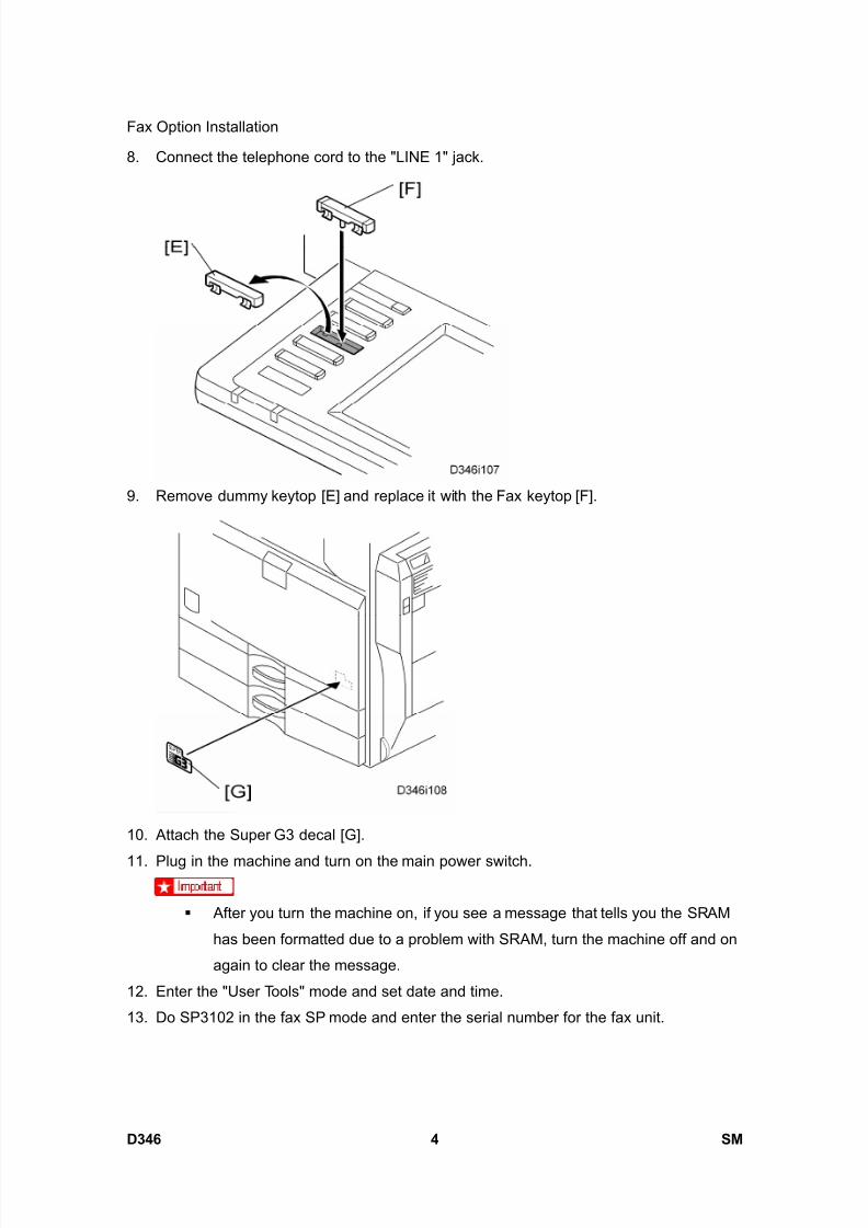
8/15/2019 Ricoh MP 4000 SM D009_D011_D012_D013 SERVICE MANUAL .pdf
http://slidepdf.com/reader/full/ricoh-mp-4000-sm-d009d011d012d013-service-manual-pdf 850/1162
Fax Option Installation
D346 4 SM
8. Connect the telephone cord to the "LINE 1" jack.
9. Remove dummy keytop [E] and replace it with the Fax keytop [F].
10. Attach the Super G3 decal [G].
11. Plug in the machine and turn on the main power switch.
After you turn the machine on, if you see a message that tells you the SRAM
has been formatted due to a problem with SRAM, turn the machine off and on
again to clear the message.
12. Enter the "User Tools" mode and set date and time.
13. Do SP3102 in the fax SP mode and enter the serial number for the fax unit.
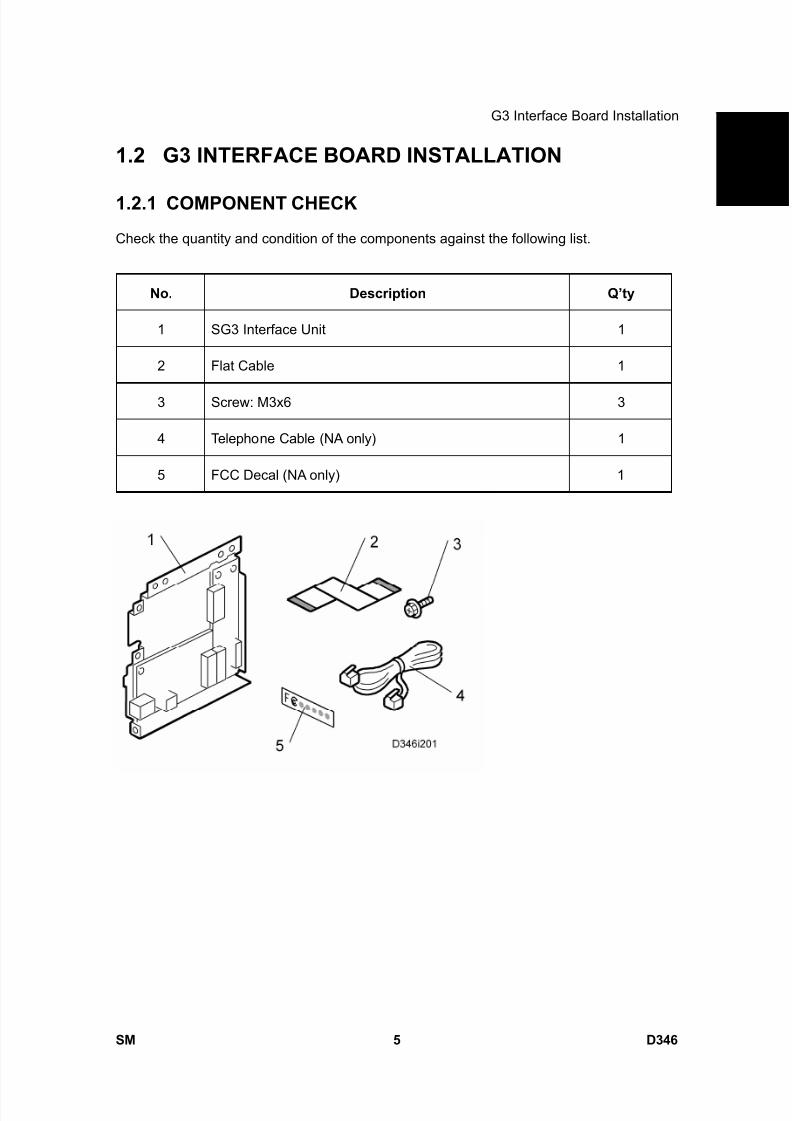
8/15/2019 Ricoh MP 4000 SM D009_D011_D012_D013 SERVICE MANUAL .pdf
http://slidepdf.com/reader/full/ricoh-mp-4000-sm-d009d011d012d013-service-manual-pdf 851/1162
G3 Interface Board Installation
SM 5 D346
F a x
O p
t i o n
T y p e
5 0 0 0
D 3 4 6
1.2 G3 INTERFACE BOARD INSTALLATION
1.2.1 COMPONENT CHECK
Check the quantity and condition of the components against the following list.
No. Description Q’ty
1 SG3 Interface Unit 1
2 Flat Cable 1
3 Screw: M3x6 3
4 Telephone Cable (NA only) 1
5 FCC Decal (NA only) 1
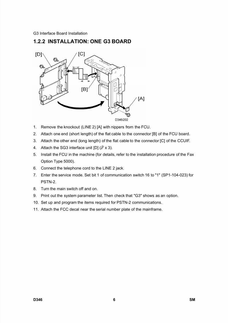
8/15/2019 Ricoh MP 4000 SM D009_D011_D012_D013 SERVICE MANUAL .pdf
http://slidepdf.com/reader/full/ricoh-mp-4000-sm-d009d011d012d013-service-manual-pdf 852/1162
G3 Interface Board Installation
D346 6 SM
1.2.2 INSTALLATION: ONE G3 BOARD
1. Remove the knockout (LINE 2) [A] with nippers from the FCU.
2. Attach one end (short length) of the flat cable to the connector [B] of the FCU board.
3. Attach the other end (long length) of the flat cable to the connector [C] of the CCUIF.
4. Attach the SG3 interface unit [D] ( x 3).
5. Install the FCU in the machine (for details, refer to the installation procedure of the Fax
Option Type 5000).
6. Connect the telephone cord to the LINE 2 jack.7. Enter the service mode. Set bit 1 of communication switch 16 to "1" (SP1-104-023) for
PSTN-2.
8. Turn the main switch off and on.
9. Print out the system parameter list. Then check that "G3" shows as an option.
10. Set up and program the items required for PSTN-2 communications.
11. Attach the FCC decal near the serial number plate of the mainframe.
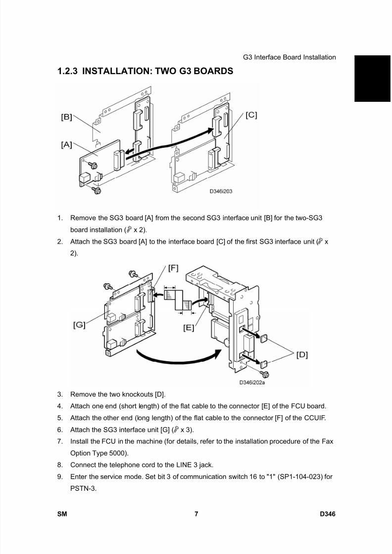
8/15/2019 Ricoh MP 4000 SM D009_D011_D012_D013 SERVICE MANUAL .pdf
http://slidepdf.com/reader/full/ricoh-mp-4000-sm-d009d011d012d013-service-manual-pdf 853/1162
G3 Interface Board Installation
SM 7 D346
F a x
O p
t i o n
T y p e
5 0 0 0
D 3 4 61.2.3 INSTALLATION: TWO G3 BOARDS
1. Remove the SG3 board [A] from the second SG3 interface unit [B] for the two-SG3
board installation ( x 2).
2. Attach the SG3 board [A] to the interface board [C] of the first SG3 interface unit ( x
2).
3. Remove the two knockouts [D].
4. Attach one end (short length) of the flat cable to the connector [E] of the FCU board.
5. Attach the other end (long length) of the flat cable to the connector [F] of the CCUIF.
6. Attach the SG3 interface unit [G] ( x 3).
7. Install the FCU in the machine (for details, refer to the installation procedure of the Fax
Option Type 5000).
8. Connect the telephone cord to the LINE 3 jack.
9. Enter the service mode. Set bit 3 of communication switch 16 to "1" (SP1-104-023) for
PSTN-3.
8/15/2019 Ricoh MP 4000 SM D009_D011_D012_D013 SERVICE MANUAL .pdf
http://slidepdf.com/reader/full/ricoh-mp-4000-sm-d009d011d012d013-service-manual-pdf 854/1162
G3 Interface Board Installation
D346 8 SM
10. Turn the main switch off and on.
11. Print out the system parameter list. Then check that "G3" shows as an option.
12. Set up and program the items required for PSTN-3 communications.13. Attach the FCC decal near the serial number plate of the mainframe.
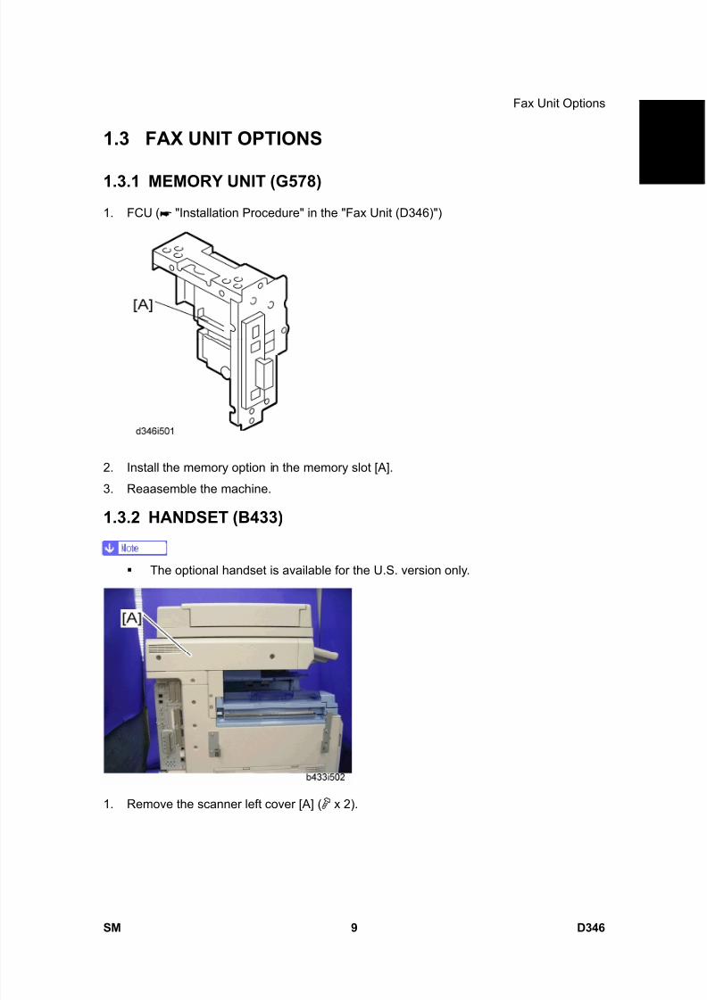
8/15/2019 Ricoh MP 4000 SM D009_D011_D012_D013 SERVICE MANUAL .pdf
http://slidepdf.com/reader/full/ricoh-mp-4000-sm-d009d011d012d013-service-manual-pdf 855/1162
Fax Unit Options
SM 9 D346
F a x
O p
t i o n
T y p e
5 0 0 0
D 3 4 6
1.3 FAX UNIT OPTIONS
1.3.1 MEMORY UNIT (G578)
1. FCU ( "Installation Procedure" in the "Fax Unit (D346)")
2. Install the memory option in the memory slot [A].
3. Reaasemble the machine.
1.3.2 HANDSET (B433)
The optional handset is available for the U.S. version only.
1. Remove the scanner left cover [A] ( x 2).
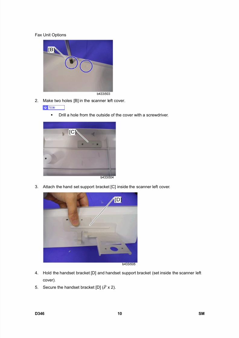
8/15/2019 Ricoh MP 4000 SM D009_D011_D012_D013 SERVICE MANUAL .pdf
http://slidepdf.com/reader/full/ricoh-mp-4000-sm-d009d011d012d013-service-manual-pdf 856/1162
Fax Unit Options
D346 10 SM
2. Make two holes [B] in the scanner left cover.
Drill a hole from the outside of the cover with a screwdriver.
3. Attach the hand set support bracket [C] inside the scanner left cover.
4. Hold the handset bracket [D] and handset support bracket (set inside the scanner left
cover).
5. Secure the handset bracket [D] ( x 2).
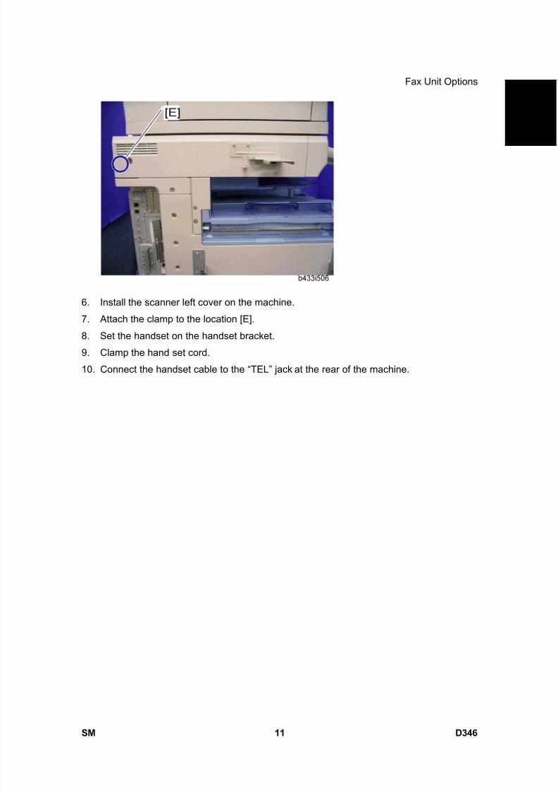
8/15/2019 Ricoh MP 4000 SM D009_D011_D012_D013 SERVICE MANUAL .pdf
http://slidepdf.com/reader/full/ricoh-mp-4000-sm-d009d011d012d013-service-manual-pdf 857/1162
Fax Unit Options
SM 11 D346
F a x
O p
t i o n
T y p e
5 0 0 0
D 3 4 6
6. Install the scanner left cover on the machine.
7. Attach the clamp to the location [E].
8. Set the handset on the handset bracket.
9. Clamp the hand set cord.
10. Connect the handset cable to the “TEL” jack at the rear of the machine.

8/15/2019 Ricoh MP 4000 SM D009_D011_D012_D013 SERVICE MANUAL .pdf
http://slidepdf.com/reader/full/ricoh-mp-4000-sm-d009d011d012d013-service-manual-pdf 858/1162
FCU
D346 12 SM
2. REPLACEMENT AND ADJUSTMENT
2.1 FCU
1. When you replace the FCU board, remove the MBU board from the old FCU board and
install it on the new FCU board.
2. Set the correct date and time with the User Tools: User Tools > System Settings >
Timer Setting > Set Date/Time.
Do not turn off the battery switch (SW1). Do SP6101 in the Fax SP to print the system parameters, and check the
settings.
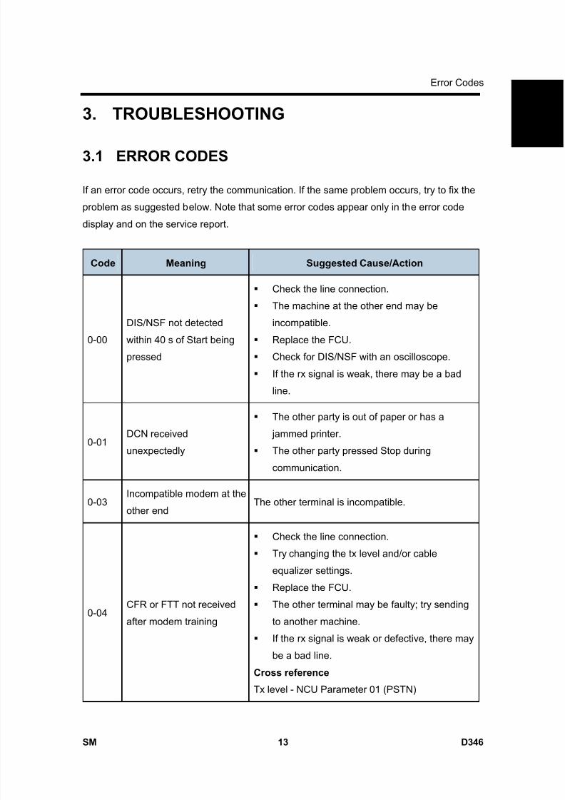
8/15/2019 Ricoh MP 4000 SM D009_D011_D012_D013 SERVICE MANUAL .pdf
http://slidepdf.com/reader/full/ricoh-mp-4000-sm-d009d011d012d013-service-manual-pdf 859/1162
Error Codes
SM 13 D346
F a x
O p
t i o n
T y p e
5 0 0 0
D 3 4 6
3. TROUBLESHOOTING
3.1 ERROR CODES
If an error code occurs, retry the communication. If the same problem occurs, try to fix the
problem as suggested below. Note that some error codes appear only in the error code
display and on the service report.
Code Meaning Suggested Cause/Action
0-00
DIS/NSF not detected
within 40 s of Start being
pressed
Check the line connection.
The machine at the other end may be
incompatible.
Replace the FCU.
Check for DIS/NSF with an oscilloscope.
If the rx signal is weak, there may be a bad
line.
0-01DCN received
unexpectedly
The other party is out of paper or has a jammed printer.
The other party pressed Stop during
communication.
0-03Incompatible modem at the
other endThe other terminal is incompatible.
0-04CFR or FTT not received
after modem training
Check the line connection.
Try changing the tx level and/or cable
equalizer settings.
Replace the FCU.
The other terminal may be faulty; try sending
to another machine.
If the rx signal is weak or defective, there may
be a bad line.
Cross reference
Tx level - NCU Parameter 01 (PSTN)
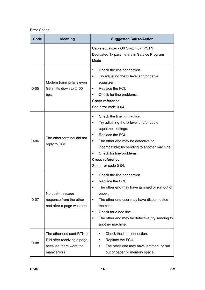
8/15/2019 Ricoh MP 4000 SM D009_D011_D012_D013 SERVICE MANUAL .pdf
http://slidepdf.com/reader/full/ricoh-mp-4000-sm-d009d011d012d013-service-manual-pdf 860/1162
Error Codes
D346 14 SM
Code Meaning Suggested Cause/Action
Cable equalizer - G3 Switch 07 (PSTN)
Dedicated Tx parameters in Service Program
Mode
0-05
Modem training fails even
G3 shifts down to 2400
bps.
Check the line connection.
Try adjusting the tx level and/or cable
equalizer.
Replace the FCU.
Check for line problems.
Cross reference See error code 0-04.
0-06The other terminal did not
reply to DCS
Check the line connection.
Try adjusting the tx level and/or cable
equalizer settings.
Replace the FCU.
The other end may be defective or
incompatible; try sending to another machine.
Check for line problems.
Cross reference
See error code 0-04.
0-07
No post-message
response from the other
end after a page was sent
Check the line connection.
Replace the FCU.
The other end may have jammed or run out of
paper.
The other end user may have disconnected
the call.
Check for a bad line.
The other end may be defective; try sending to
another machine.
0-08
The other end sent RTN or
PIN after receiving a page,
because there were too
many errors
Check the line connection.
Replace the FCU.
The other end may have jammed, or run
out of paper or memory space.

8/15/2019 Ricoh MP 4000 SM D009_D011_D012_D013 SERVICE MANUAL .pdf
http://slidepdf.com/reader/full/ricoh-mp-4000-sm-d009d011d012d013-service-manual-pdf 861/1162
Error Codes
SM 15 D346
F a x
O p
t i o n
T y p e
5 0 0 0
D 3 4 6Code Meaning Suggested Cause/Action
Try adjusting the tx level and/or cable
equalizer settings.
The other end may have a defective
modem/FCU; try sending to another
machine.
Check for line problems and noise.
Cross reference
Tx level - NCU Parameter 01 (PSTN)
Cable equalizer - G3 Switch 07 (PSTN)
Dedicated Tx parameters in Service
Program Mode
0-14
Non-standard post
message response code
received
Incompatible or defective remote terminal; try
sending to another machine.
Noisy line: resend.
Try adjusting the tx level and/or cable
equalizer settings.
Replace the FCU.
Cross reference
See error code 0-08.
0-15
The other terminal is not
capable of specific
functions.
The other terminal is not capable of accepting the
following functions, or the other terminal’s memory
is full.
Confidential rx
Transfer function
SEP/SUB/PWD/SID
0-16
CFR or FTT not detected
after modem training in
confidential or transfer
mode
Check the line connection.
Replace the FCU.
Try adjusting the tx level and/or cable
equalizer settings.
The other end may have disconnected, or it
may be defective; try calling another machine.
If the rx signal level is too low, there may be a
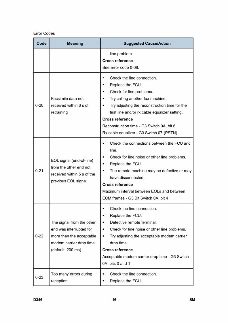
8/15/2019 Ricoh MP 4000 SM D009_D011_D012_D013 SERVICE MANUAL .pdf
http://slidepdf.com/reader/full/ricoh-mp-4000-sm-d009d011d012d013-service-manual-pdf 862/1162
Error Codes
D346 16 SM
Code Meaning Suggested Cause/Action
line problem.
Cross reference
See error code 0-08.
0-20
Facsimile data not
received within 6 s of
retraining
Check the line connection.
Replace the FCU.
Check for line problems.
Try calling another fax machine.
Try adjusting the reconstruction time for the
first line and/or rx cable equalizer setting.Cross reference
Reconstruction time - G3 Switch 0A, bit 6
Rx cable equalizer - G3 Switch 07 (PSTN)
0-21
EOL signal (end-of-line)
from the other end not
received within 5 s of the
previous EOL signal
Check the connections between the FCU and
line.
Check for line noise or other line problems.
Replace the FCU.
The remote machine may be defective or may
have disconnected.
Cross reference
Maximum interval between EOLs and between
ECM frames - G3 Bit Switch 0A, bit 4
0-22
The signal from the other
end was interrupted for
more than the acceptable
modem carrier drop time
(default: 200 ms)
Check the line connection.
Replace the FCU.
Defective remote terminal.
Check for line noise or other line problems.
Try adjusting the acceptable modem carrier
drop time.
Cross reference
Acceptable modem carrier drop time - G3 Switch
0A, bits 0 and 1
0-23Too many errors during
reception
Check the line connection.
Replace the FCU.

8/15/2019 Ricoh MP 4000 SM D009_D011_D012_D013 SERVICE MANUAL .pdf
http://slidepdf.com/reader/full/ricoh-mp-4000-sm-d009d011d012d013-service-manual-pdf 863/1162
Error Codes
SM 17 D346
F a x
O p
t i o n
T y p e
5 0 0 0
D 3 4 6Code Meaning Suggested Cause/Action
Defective remote terminal.
Check for line noise or other line problems.
Try asking the other end to adjust their tx level.
Try adjusting the rx cable equalizer setting
and/or rx error criteria.
Cross reference
Rx cable equalizer - G3 Switch 07 (PSTN)
Rx error criteria - Communication Switch 02, bits 0
and 1
0-30
The other terminal did not
reply to NSS(A) in AI short
protocol mode
Check the line connection.
Try adjusting the tx level and/or cable
equalizer settings.
The other terminal may not be compatible.
Cross reference
Dedicated tx parameters - Section 4
0-32
The other terminal sent a
DCS, which contained
functions that the receiving
machine cannot handle.
Check the protocol dump list.
Ask the other party to contact the
manufacturer.
0-33
The data reception (not
ECM) is not completed
within 10 minutes.
Check the line connection.
The other terminal may have a defective
modem/FCU.
0-52Polarity changed during
communication
Check the line connection.
Retry communication.
0-55FCU does not detect the
SG3.
FCU firmware or board defective.
SG3 firmware or board defective.
0-56
The stored message data
exceeds the capacity of the
mailbox in the SG3.
SG3 firmware or board defective.
0-70 The communication mode The other terminal did not have a compatible
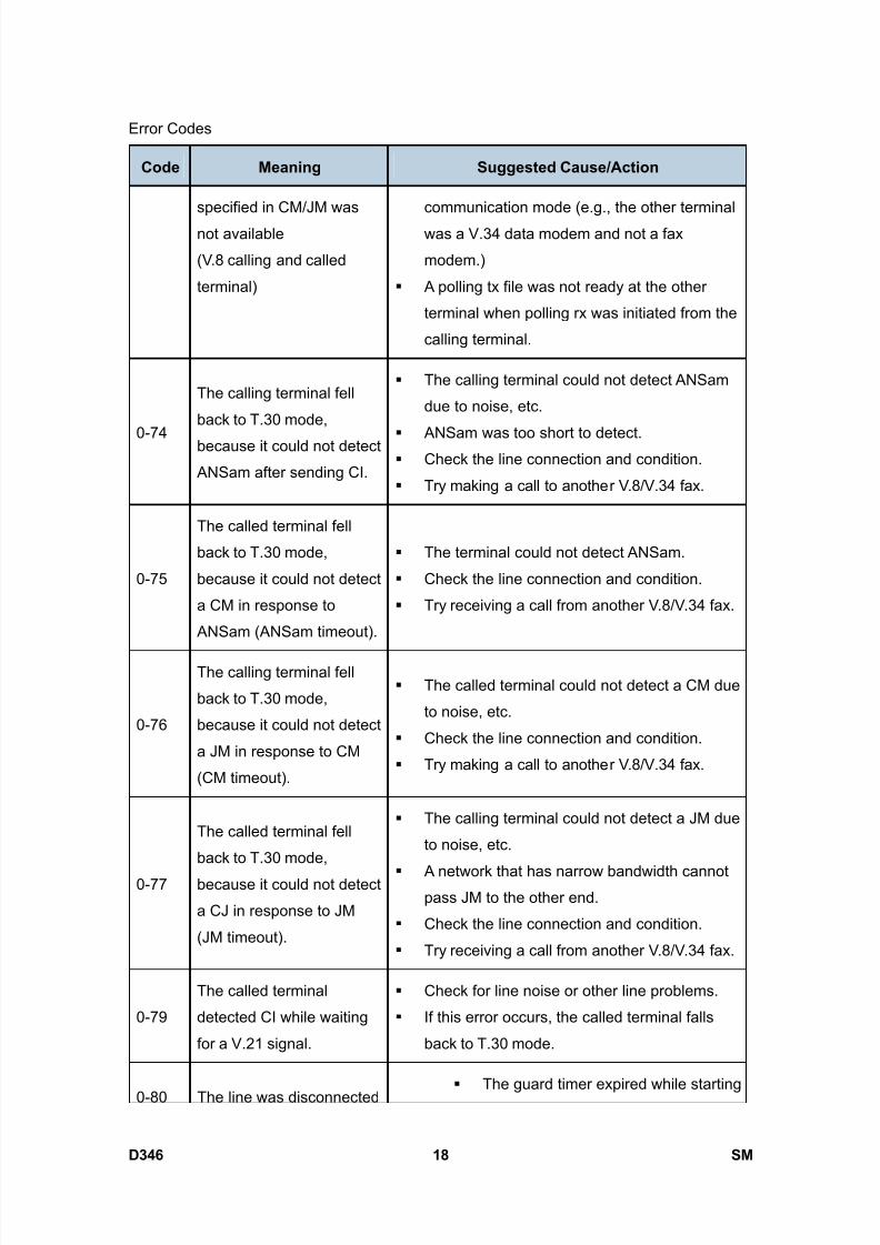
8/15/2019 Ricoh MP 4000 SM D009_D011_D012_D013 SERVICE MANUAL .pdf
http://slidepdf.com/reader/full/ricoh-mp-4000-sm-d009d011d012d013-service-manual-pdf 864/1162
Error Codes
D346 18 SM
Code Meaning Suggested Cause/Action
specified in CM/JM was
not available
(V.8 calling and called
terminal)
communication mode (e.g., the other terminal
was a V.34 data modem and not a fax
modem.)
A polling tx file was not ready at the other
terminal when polling rx was initiated from the
calling terminal.
0-74
The calling terminal fell
back to T.30 mode,
because it could not detect
ANSam after sending CI.
The calling terminal could not detect ANSam
due to noise, etc.
ANSam was too short to detect. Check the line connection and condition.
Try making a call to another V.8/V.34 fax.
0-75
The called terminal fell
back to T.30 mode,
because it could not detect
a CM in response to
ANSam (ANSam timeout).
The terminal could not detect ANSam.
Check the line connection and condition.
Try receiving a call from another V.8/V.34 fax.
0-76
The calling terminal fell
back to T.30 mode,
because it could not detect
a JM in response to CM
(CM timeout).
The called terminal could not detect a CM due
to noise, etc.
Check the line connection and condition.
Try making a call to another V.8/V.34 fax.
0-77
The called terminal fell
back to T.30 mode,
because it could not detect
a CJ in response to JM
(JM timeout).
The calling terminal could not detect a JM due
to noise, etc.
A network that has narrow bandwidth cannotpass JM to the other end.
Check the line connection and condition.
Try receiving a call from another V.8/V.34 fax.
0-79
The called terminal
detected CI while waiting
for a V.21 signal.
Check for line noise or other line problems.
If this error occurs, the called terminal falls
back to T.30 mode.
0-80 The line was disconnected The guard timer expired while starting
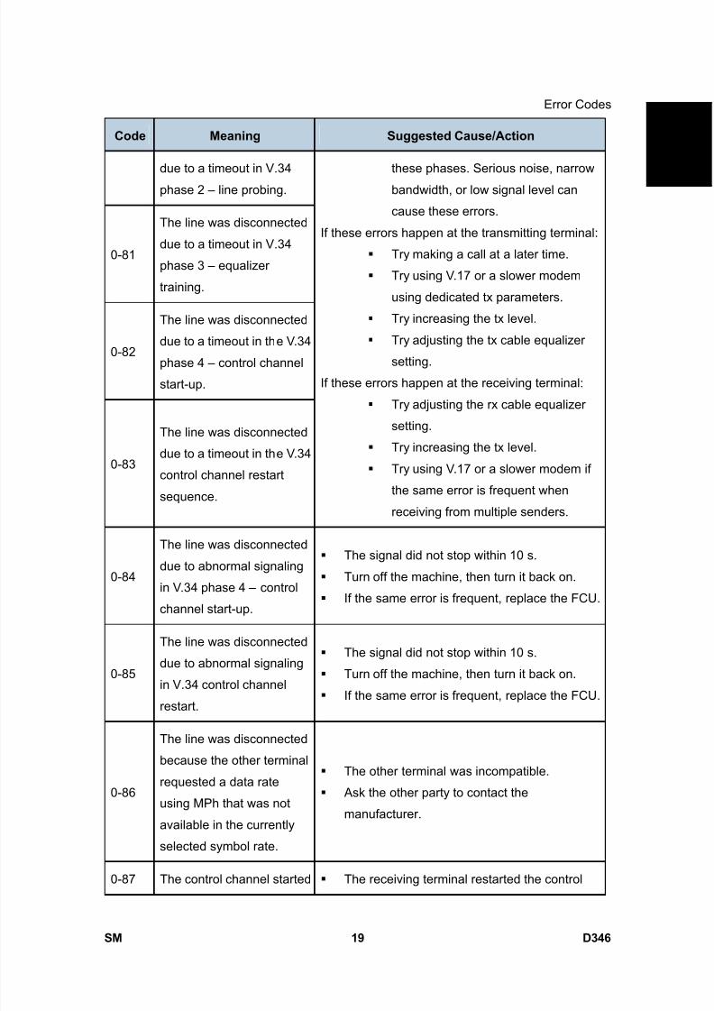
8/15/2019 Ricoh MP 4000 SM D009_D011_D012_D013 SERVICE MANUAL .pdf
http://slidepdf.com/reader/full/ricoh-mp-4000-sm-d009d011d012d013-service-manual-pdf 865/1162
Error Codes
SM 19 D346
F a x
O p
t i o n
T y p e
5 0 0 0
D 3 4 6Code Meaning Suggested Cause/Action
due to a timeout in V.34
phase 2 – line probing.
0-81
The line was disconnected
due to a timeout in V.34
phase 3 – equalizer
training.
0-82
The line was disconnected
due to a timeout in the V.34
phase 4 – control channel
start-up.
0-83
The line was disconnected
due to a timeout in the V.34
control channel restart
sequence.
these phases. Serious noise, narrow
bandwidth, or low signal level can
cause these errors.
If these errors happen at the transmitting terminal:
Try making a call at a later time.
Try using V.17 or a slower modem
using dedicated tx parameters.
Try increasing the tx level.
Try adjusting the tx cable equalizer
setting.
If these errors happen at the receiving terminal:
Try adjusting the rx cable equalizer
setting.
Try increasing the tx level.
Try using V.17 or a slower modem if
the same error is frequent when
receiving from multiple senders.
0-84
The line was disconnected
due to abnormal signaling
in V.34 phase 4 – control
channel start-up.
The signal did not stop within 10 s.
Turn off the machine, then turn it back on.
If the same error is frequent, replace the FCU.
0-85
The line was disconnected
due to abnormal signaling
in V.34 control channel
restart.
The signal did not stop within 10 s.
Turn off the machine, then turn it back on.
If the same error is frequent, replace the FCU.
0-86
The line was disconnected
because the other terminal
requested a data rate
using MPh that was not
available in the currently
selected symbol rate.
The other terminal was incompatible.
Ask the other party to contact the
manufacturer.
0-87 The control channel started The receiving terminal restarted the control
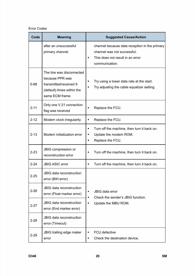
8/15/2019 Ricoh MP 4000 SM D009_D011_D012_D013 SERVICE MANUAL .pdf
http://slidepdf.com/reader/full/ricoh-mp-4000-sm-d009d011d012d013-service-manual-pdf 866/1162
Error Codes
D346 20 SM
Code Meaning Suggested Cause/Action
after an unsuccessful
primary channel.
channel because data reception in the primary
channel was not successful.
This does not result in an error
communication.
0-88
The line was disconnected
because PPR was
transmitted/received 9
(default) times within the
same ECM frame.
Try using a lower data rate at the start.
Try adjusting the cable equalizer setting.
2-11Only one V.21 connection
flag was received Replace the FCU.
2-12 Modem clock irregularity Replace the FCU.
2-13 Modem initialization error
Turn off the machine, then turn it back on.
Update the modem ROM.
Replace the FCU.
2-23JBIG compression or
reconstruction error Turn off the machine, then turn it back on.
2-24 JBIG ASIC error Turn off the machine, then turn it back on.
2-25JBIG data reconstruction
error (BIH error)
2-26JBIG data reconstruction
error (Float marker error)
2-27JBIG data reconstruction
error (End marker error)
2-28JBIG data reconstruction
error (Timeout)
JBIG data error
Check the sender’s JBIG function.
Update the MBU ROM.
2-29JBIG trailing edge maker
error
FCU defective
Check the destination device.

8/15/2019 Ricoh MP 4000 SM D009_D011_D012_D013 SERVICE MANUAL .pdf
http://slidepdf.com/reader/full/ricoh-mp-4000-sm-d009d011d012d013-service-manual-pdf 867/1162
Error Codes
SM 21 D346
F a x
O p
t i o n
T y p e
5 0 0 0
D 3 4 6Code Meaning Suggested Cause/Action
2-50
The machine resets itself
for a fatal FCU system
error
If this is frequent, update the ROM, or replacethe FCU.
2-51
The machine resets itself
because of a fatal
communication error
If this is frequent, update the ROM, or replace
the FCU.
2-53
Snd msg() in the manual
task is an error because
the mailbox for the
operation task is full.
The user did the same operation many times,
and this gave too much load to the machine.
4-01 Line current was cut
Check the line connector.
Check for line problems.
Replace the FCU.
4-10
Communication failed
because of an ID Code
mismatch (Closed
Network) or Tel. No./CSI
mismatch (Protection
against Wrong
Connections)
Get the ID Codes the same and/or the CSIsprogrammed correctly, then resend.
The machine at the other end may be
defective.
5-10 DCR timer expired Replace the FCU.
5-20
Storage impossible
because of a lack ofmemory
5-21 Memory overflow
Temporary memory shortage. Test the SAF memory.
5-23
Print data error when
printing a substitute rx or
confidential rx message
Test the SAF memory.
Ask the other end to resend the message.
5-25 SAF file access error Replace an SD card or HDD.

8/15/2019 Ricoh MP 4000 SM D009_D011_D012_D013 SERVICE MANUAL .pdf
http://slidepdf.com/reader/full/ricoh-mp-4000-sm-d009d011d012d013-service-manual-pdf 868/1162
Error Codes
D346 22 SM
Code Meaning Suggested Cause/Action
Replace the FCU.
6-00
G3 ECM - T1 time out
during reception of
facsimile data
6-01G3 ECM - no V.21 signal
was received
6-02G3 ECM - EOR was
received
Try adjusting the rx cable equalizer.
Replace the FCU.
6-04G3 ECM - RTC not
detected
Check the line connection.
Check for a bad line or defective remote
terminal.
Replace the FCU.
6-05
G3 ECM - facsimile data
frame not received within
18 s of CFR, but there was
no line fail
Check the line connection.
Check for a bad line or defective remote
terminal. Replace the FCU.
Try adjusting the rx cable equalizer
Cross reference
Rx cable equalizer - G3 Switch 07 (PSTN)
6-06G3 ECM - coding/decoding
error
Defective FCU.
The other terminal may be defective.
6-08
G3 ECM - PIP/PIN
received in reply to
PPS.NULL
The other end pressed Stop during
communication.
The other terminal may be defective.
6-09 G3 ECM - ERR received
Check for a noisy line.
Adjust the tx levels of the communicating
machines.
See code 6-05.
6-10 G3 ECM - error frames still Check for line noise.
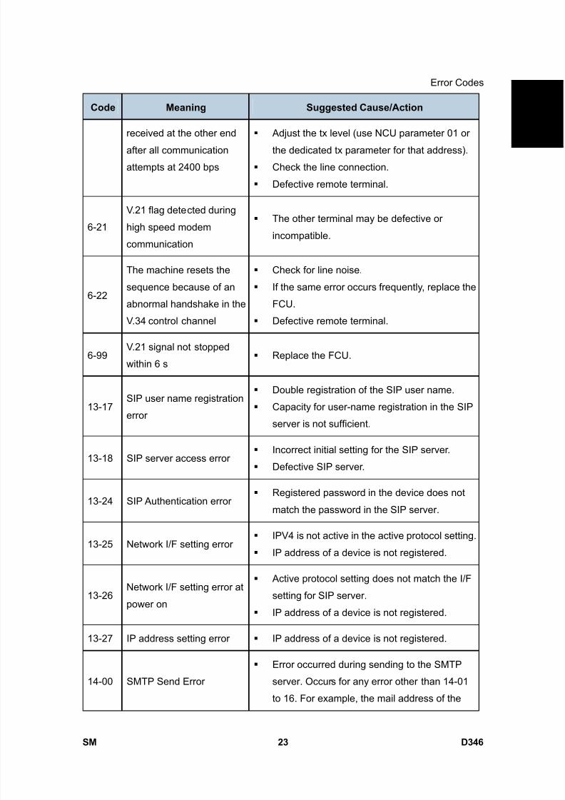
8/15/2019 Ricoh MP 4000 SM D009_D011_D012_D013 SERVICE MANUAL .pdf
http://slidepdf.com/reader/full/ricoh-mp-4000-sm-d009d011d012d013-service-manual-pdf 869/1162
Error Codes
SM 23 D346
F a x
O p
t i o n
T y p e
5 0 0 0
D 3 4 6Code Meaning Suggested Cause/Action
received at the other end
after all communication
attempts at 2400 bps
Adjust the tx level (use NCU parameter 01 or
the dedicated tx parameter for that address).
Check the line connection.
Defective remote terminal.
6-21
V.21 flag detected during
high speed modem
communication
The other terminal may be defective or
incompatible.
6-22
The machine resets the
sequence because of an
abnormal handshake in the
V.34 control channel
Check for line noise.
If the same error occurs frequently, replace the
FCU.
Defective remote terminal.
6-99V.21 signal not stopped
within 6 s Replace the FCU.
13-17SIP user name registration
error
Double registration of the SIP user name.
Capacity for user-name registration in the SIP
server is not sufficient.
13-18 SIP server access error Incorrect initial setting for the SIP server.
Defective SIP server.
13-24 SIP Authentication error Registered password in the device does not
match the password in the SIP server.
13-25 Network I/F setting error IPV4 is not active in the active protocol setting.
IP address of a device is not registered.
13-26Network I/F setting error at
power on
Active protocol setting does not match the I/F
setting for SIP server.
IP address of a device is not registered.
13-27 IP address setting error IP address of a device is not registered.
14-00 SMTP Send Error
Error occurred during sending to the SMTP
server. Occurs for any error other than 14-01
to 16. For example, the mail address of the

8/15/2019 Ricoh MP 4000 SM D009_D011_D012_D013 SERVICE MANUAL .pdf
http://slidepdf.com/reader/full/ricoh-mp-4000-sm-d009d011d012d013-service-manual-pdf 870/1162
Error Codes
D346 24 SM
Code Meaning Suggested Cause/Action
system administrator is not registered.
14-01 SMTP Connection Failed
Failed to connect to the SMTP server (timeout)
because the server could not be found.
The PC is not ready to transfer files.
SMTP server not functioning correctly.
The DNS IP address is not registered.
Network not operating correctly.
Destination folder selection not correct.
14-02No Service by SMTP
Service (421)
SMTP server operating incorrectly, or the
destination for direct SMTP sending is not
correct.
Contact the system administrator and check
that the SMTP server has the correct settings
and operates correctly.
Contact the system administrator for direct
SMTP sending and check the sending
destination.
14-03 Access to SMTP ServerDenied (450)
Failed to access the SMTP server because the
access is denied.
SMTP server operating incorrectly. Contact
the system administrator to determine if there
is a problem with the SMTP server and to
check that the SMTP server settings are
correct.
Folder send destination is incorrect. Contact
the system administrator to determine that the
SMTP server settings and path to the server
are correct.
Device settings incorrect. Confirm that the
user name and password settings are correct.
Direct SMTP destination incorrect. Contact the
system administrator to determine if there is a
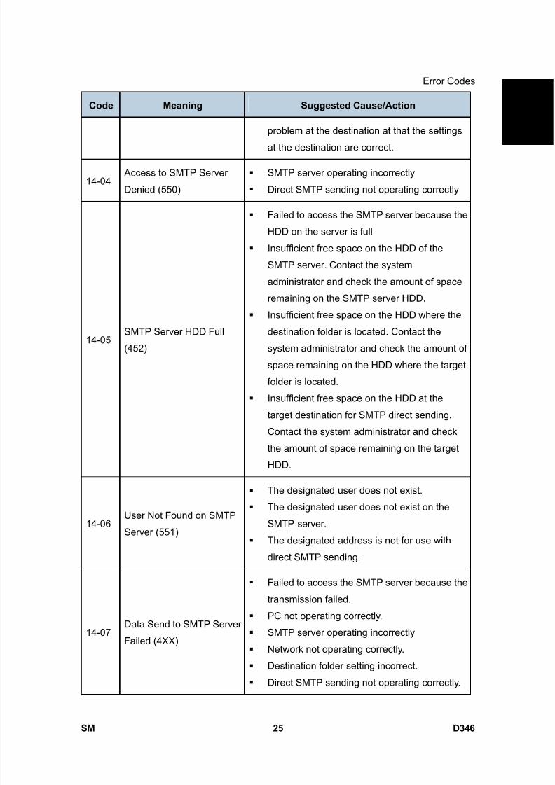
8/15/2019 Ricoh MP 4000 SM D009_D011_D012_D013 SERVICE MANUAL .pdf
http://slidepdf.com/reader/full/ricoh-mp-4000-sm-d009d011d012d013-service-manual-pdf 871/1162
Error Codes
SM 25 D346
F a x
O p
t i o n
T y p e
5 0 0 0
D 3 4 6Code Meaning Suggested Cause/Action
problem at the destination at that the settings
at the destination are correct.
14-04 Access to SMTP Server
Denied (550)
SMTP server operating incorrectly
Direct SMTP sending not operating correctly
14-05SMTP Server HDD Full
(452)
Failed to access the SMTP server because the
HDD on the server is full.
Insufficient free space on the HDD of the
SMTP server. Contact the system
administrator and check the amount of space
remaining on the SMTP server HDD.
Insufficient free space on the HDD where the
destination folder is located. Contact the
system administrator and check the amount of
space remaining on the HDD where the target
folder is located.
Insufficient free space on the HDD at the
target destination for SMTP direct sending.
Contact the system administrator and check
the amount of space remaining on the target
HDD.
14-06User Not Found on SMTP
Server (551)
The designated user does not exist.
The designated user does not exist on the
SMTP server.
The designated address is not for use with
direct SMTP sending.
14-07Data Send to SMTP Server
Failed (4XX)
Failed to access the SMTP server because the
transmission failed.
PC not operating correctly.
SMTP server operating incorrectly
Network not operating correctly.
Destination folder setting incorrect.
Direct SMTP sending not operating correctly.
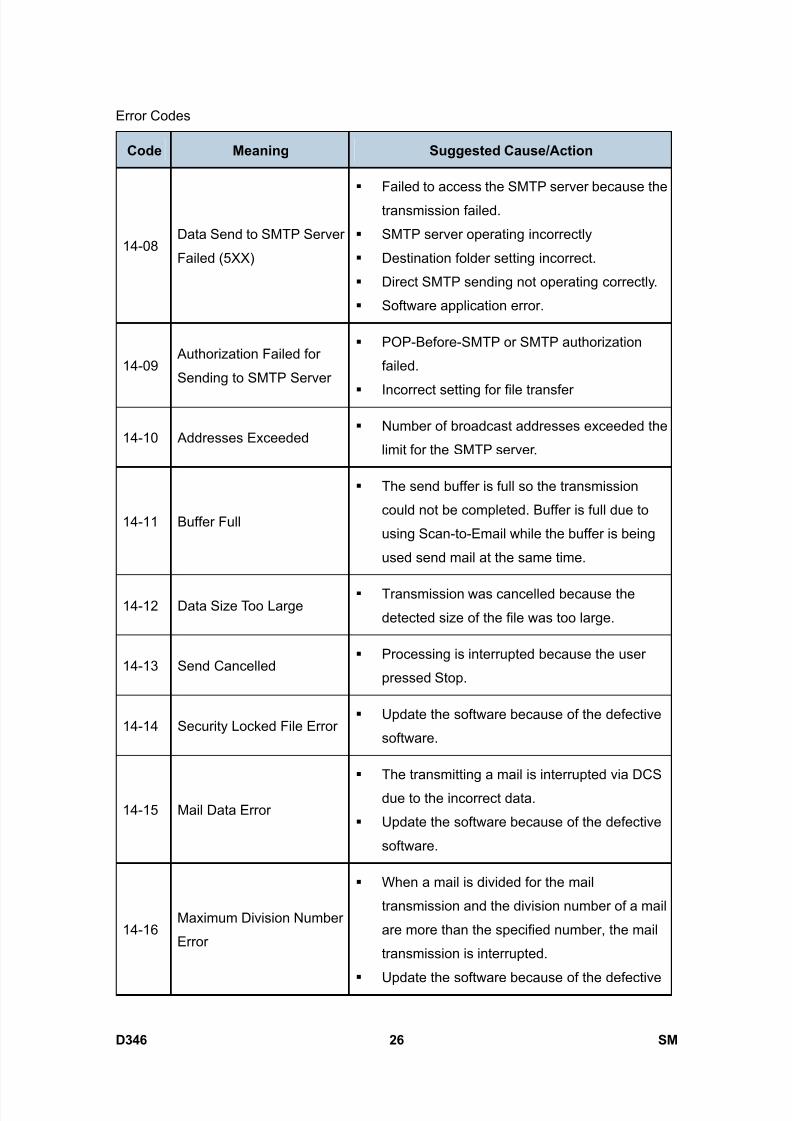
8/15/2019 Ricoh MP 4000 SM D009_D011_D012_D013 SERVICE MANUAL .pdf
http://slidepdf.com/reader/full/ricoh-mp-4000-sm-d009d011d012d013-service-manual-pdf 872/1162
Error Codes
D346 26 SM
Code Meaning Suggested Cause/Action
14-08Data Send to SMTP Server
Failed (5XX)
Failed to access the SMTP server because the
transmission failed.
SMTP server operating incorrectly
Destination folder setting incorrect.
Direct SMTP sending not operating correctly.
Software application error.
14-09 Authorization Failed for
Sending to SMTP Server
POP-Before-SMTP or SMTP authorization
failed.
Incorrect setting for file transfer
14-10 Addresses Exceeded Number of broadcast addresses exceeded the
limit for the SMTP server.
14-11 Buffer Full
The send buffer is full so the transmission
could not be completed. Buffer is full due to
using Scan-to-Email while the buffer is being
used send mail at the same time.
14-12 Data Size Too Large Transmission was cancelled because the
detected size of the file was too large.
14-13 Send Cancelled Processing is interrupted because the user
pressed Stop.
14-14 Security Locked File Error Update the software because of the defective
software.
14-15 Mail Data Error
The transmitting a mail is interrupted via DCS
due to the incorrect data.
Update the software because of the defective
software.
14-16Maximum Division Number
Error
When a mail is divided for the mail
transmission and the division number of a mail
are more than the specified number, the mail
transmission is interrupted.
Update the software because of the defective
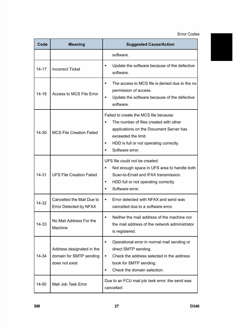
8/15/2019 Ricoh MP 4000 SM D009_D011_D012_D013 SERVICE MANUAL .pdf
http://slidepdf.com/reader/full/ricoh-mp-4000-sm-d009d011d012d013-service-manual-pdf 873/1162
Error Codes
SM 27 D346
F a x
O p
t i o n
T y p e
5 0 0 0
D 3 4 6Code Meaning Suggested Cause/Action
software.
14-17 Incorrect Ticket Update the software because of the defective
software.
14-18 Access to MCS File Error
The access to MCS file is denied due to the no
permission of access.
Update the software because of the defective
software.
14-30 MCS File Creation Failed
Failed to create the MCS file because: The number of files created with other
applications on the Document Server has
exceeded the limit.
HDD is full or not operating correctly.
Software error.
14-31 UFS File Creation Failed
UFS file could not be created:
Not enough space in UFS area to handle both
Scan-to-Email and IFAX transmission.
HDD full or not operating correctly.
Software error.
14-32Cancelled the Mail Due to
Error Detected by NFAX
Error detected with NFAX and send was
cancelled due to a software error.
14-33No Mail Address For the
Machine
Neither the mail address of the machine nor
the mail address of the network administrator
is registered.
14-34
Address designated in the
domain for SMTP sending
does not exist
Operational error in normal mail sending or
direct SMTP sending.
Check the address selected in the address
book for SMTP sending.
Check the domain selection.
14-50 Mail Job Task ErrorDue to an FCU mail job task error, the send was
cancelled:
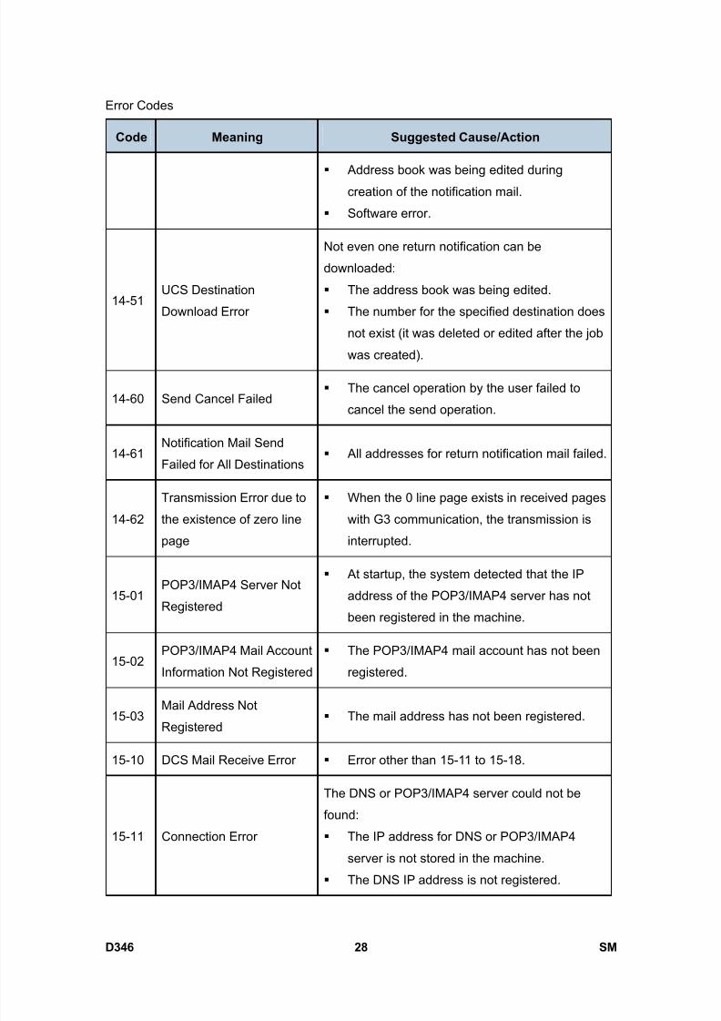
8/15/2019 Ricoh MP 4000 SM D009_D011_D012_D013 SERVICE MANUAL .pdf
http://slidepdf.com/reader/full/ricoh-mp-4000-sm-d009d011d012d013-service-manual-pdf 874/1162
Error Codes
D346 28 SM
Code Meaning Suggested Cause/Action
Address book was being edited during
creation of the notification mail.
Software error.
14-51UCS Destination
Download Error
Not even one return notification can be
downloaded:
The address book was being edited.
The number for the specified destination does
not exist (it was deleted or edited after the job
was created).
14-60 Send Cancel Failed The cancel operation by the user failed to
cancel the send operation.
14-61Notification Mail Send
Failed for All Destinations All addresses for return notification mail failed.
14-62
Transmission Error due to
the existence of zero line
page
When the 0 line page exists in received pages
with G3 communication, the transmission is
interrupted.
15-01POP3/IMAP4 Server Not
Registered
At startup, the system detected that the IP
address of the POP3/IMAP4 server has not
been registered in the machine.
15-02POP3/IMAP4 Mail Account
Information Not Registered
The POP3/IMAP4 mail account has not been
registered.
15-03Mail Address Not
Registered The mail address has not been registered.
15-10 DCS Mail Receive Error Error other than 15-11 to 15-18.
15-11 Connection Error
The DNS or POP3/IMAP4 server could not be
found:
The IP address for DNS or POP3/IMAP4
server is not stored in the machine.
The DNS IP address is not registered.
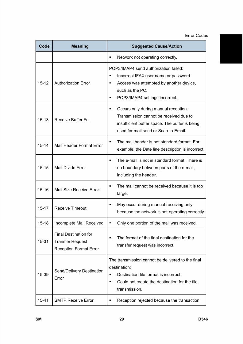
8/15/2019 Ricoh MP 4000 SM D009_D011_D012_D013 SERVICE MANUAL .pdf
http://slidepdf.com/reader/full/ricoh-mp-4000-sm-d009d011d012d013-service-manual-pdf 875/1162
Error Codes
SM 29 D346
F a x
O p
t i o n
T y p e
5 0 0 0
D 3 4 6Code Meaning Suggested Cause/Action
Network not operating correctly.
15-12 Authorization Error
POP3/IMAP4 send authorization failed:
Incorrect IFAX user name or password.
Access was attempted by another device,
such as the PC.
POP3/IMAP4 settings incorrect.
15-13 Receive Buffer Full
Occurs only during manual reception.
Transmission cannot be received due to
insufficient buffer space. The buffer is being
used for mail send or Scan-to-Email.
15-14 Mail Header Format Error The mail header is not standard format. For
example, the Date line description is incorrect.
15-15 Mail Divide Error
The e-mail is not in standard format. There is
no boundary between parts of the e-mail,
including the header.
15-16 Mail Size Receive Error The mail cannot be received because it is too
large.
15-17 Receive Timeout May occur during manual receiving only
because the network is not operating correctly.
15-18 Incomplete Mail Received Only one portion of the mail was received.
15-31
Final Destination for
Transfer RequestReception Format Error
The format of the final destination for the
transfer request was incorrect.
15-39Send/Delivery Destination
Error
The transmission cannot be delivered to the final
destination:
Destination file format is incorrect.
Could not create the destination for the file
transmission.
15-41 SMTP Receive Error Reception rejected because the transaction
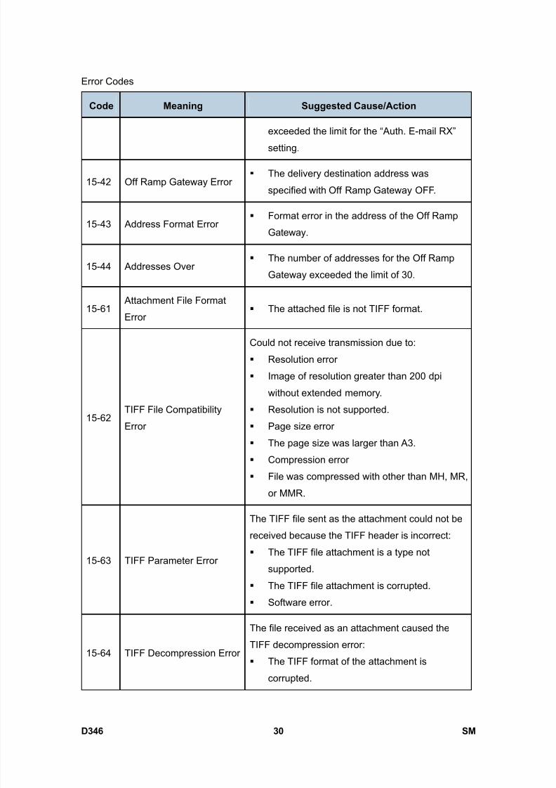
8/15/2019 Ricoh MP 4000 SM D009_D011_D012_D013 SERVICE MANUAL .pdf
http://slidepdf.com/reader/full/ricoh-mp-4000-sm-d009d011d012d013-service-manual-pdf 876/1162
Error Codes
D346 30 SM
Code Meaning Suggested Cause/Action
exceeded the limit for the “Auth. E-mail RX”
setting.
15-42 Off Ramp Gateway Error The delivery destination address was
specified with Off Ramp Gateway OFF.
15-43 Address Format Error Format error in the address of the Off Ramp
Gateway.
15-44 Addresses Over The number of addresses for the Off Ramp
Gateway exceeded the limit of 30.
15-61 Attachment File Format
Error The attached file is not TIFF format.
15-62 TIFF File CompatibilityError
Could not receive transmission due to:
Resolution error
Image of resolution greater than 200 dpi
without extended memory.
Resolution is not supported. Page size error
The page size was larger than A3.
Compression error
File was compressed with other than MH, MR,
or MMR.
15-63 TIFF Parameter Error
The TIFF file sent as the attachment could not be
received because the TIFF header is incorrect:
The TIFF file attachment is a type notsupported.
The TIFF file attachment is corrupted.
Software error.
15-64 TIFF Decompression Error
The file received as an attachment caused the
TIFF decompression error:
The TIFF format of the attachment is
corrupted.
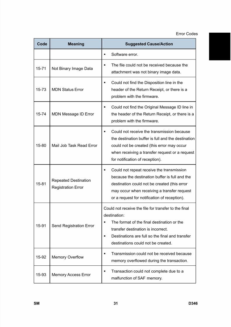
8/15/2019 Ricoh MP 4000 SM D009_D011_D012_D013 SERVICE MANUAL .pdf
http://slidepdf.com/reader/full/ricoh-mp-4000-sm-d009d011d012d013-service-manual-pdf 877/1162
Error Codes
SM 31 D346
F a x
O p
t i o n
T y p e
5 0 0 0
D 3 4 6Code Meaning Suggested Cause/Action
Software error.
15-71 Not Binary Image Data The file could not be received because the
attachment was not binary image data.
15-73 MDN Status Error
Could not find the Disposition line in the
header of the Return Receipt, or there is a
problem with the firmware.
15-74 MDN Message ID Error
Could not find the Original Message ID line in
the header of the Return Receipt, or there is aproblem with the firmware.
15-80 Mail Job Task Read Error
Could not receive the transmission because
the destination buffer is full and the destination
could not be created (this error may occur
when receiving a transfer request or a request
for notification of reception).
15-81Repeated Destination
Registration Error
Could not repeat receive the transmissionbecause the destination buffer is full and the
destination could not be created (this error
may occur when receiving a transfer request
or a request for notification of reception).
15-91 Send Registration Error
Could not receive the file for transfer to the final
destination:
The format of the final destination or the
transfer destination is incorrect. Destinations are full so the final and transfer
destinations could not be created.
15-92 Memory Overflow Transmission could not be received because
memory overflowed during the transaction.
15-93 Memory Access Error Transaction could not complete due to a
malfunction of SAF memory.
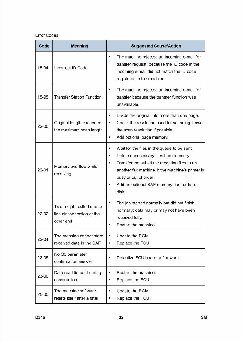
8/15/2019 Ricoh MP 4000 SM D009_D011_D012_D013 SERVICE MANUAL .pdf
http://slidepdf.com/reader/full/ricoh-mp-4000-sm-d009d011d012d013-service-manual-pdf 878/1162
Error Codes
D346 32 SM
Code Meaning Suggested Cause/Action
15-94 Incorrect ID Code
The machine rejected an incoming e-mail for
transfer request, because the ID code in the
incoming e-mail did not match the ID code
registered in the machine.
15-95 Transfer Station Function
The machine rejected an incoming e-mail for
transfer because the transfer function was
unavailable.
22-00Original length exceeded
the maximum scan length
Divide the original into more than one page.
Check the resolution used for scanning. Lower
the scan resolution if possible.
Add optional page memory.
22-01Memory overflow while
receiving
Wait for the files in the queue to be sent.
Delete unnecessary files from memory.
Transfer the substitute reception files to an
another fax machine, if the machine’s printer is
busy or out of order.
Add an optional SAF memory card or hard
disk.
22-02
Tx or rx job stalled due to
line disconnection at the
other end
The job started normally but did not finish
normally; data may or may not have been
received fully.
Restart the machine.
22-04The machine cannot store
received data in the SAF
Update the ROM
Replace the FCU.
22-05No G3 parameter
confirmation answer Defective FCU board or firmware.
23-00Data read timeout during
construction
Restart the machine.
Replace the FCU.
25-00The machine software
resets itself after a fatal
Update the ROM
Replace the FCU.

8/15/2019 Ricoh MP 4000 SM D009_D011_D012_D013 SERVICE MANUAL .pdf
http://slidepdf.com/reader/full/ricoh-mp-4000-sm-d009d011d012d013-service-manual-pdf 879/1162

8/15/2019 Ricoh MP 4000 SM D009_D011_D012_D013 SERVICE MANUAL .pdf
http://slidepdf.com/reader/full/ricoh-mp-4000-sm-d009d011d012d013-service-manual-pdf 880/1162
IFAX Troubleshooting
D346 34 SM
3.2 IFAX TROUBLESHOOTING
Use the following procedures to determine whether the machine or another part of thenetwork is causing the problem.
Communication
Route Item Action [Remarks]
1. Connection with
the LAN
Check that the LAN cable is connected to
the machine.
Check that the LEDs on the hub are lit.General LAN
2. LAN activity Check that other devices connected to theLAN can communicate through the LAN.
1. Network settings
on the PC
Check the network settings on the PC.
[Is the IP address registered in the TCP/IP
properties in the network setup correct?
Check the IP address with the administrator
of the network.]
2. Check that PC
can connect with
the machine
Use the “ping” command on the PC to
contact the machine.
[At the MS-DOS prompt, type ping then the IP
address of the machine, then press Enter.]
Between IFAX and
PC
3. LAN settings in
the machine
Check the LAN parameters
Check if there is an IP address conflict
with other PCs.
[Use the “Network” function in the User Tools.
If there is an IP address conflict, inform theadministrator.]
Between machine
and e-mail server1. LAN settings in
the machine
Check the LAN parameters
Check if there is an IP address conflict
with other PCs.
[Use the “Network” function in the User Tools.
If there is an IP address conflict, inform the
administrator.]
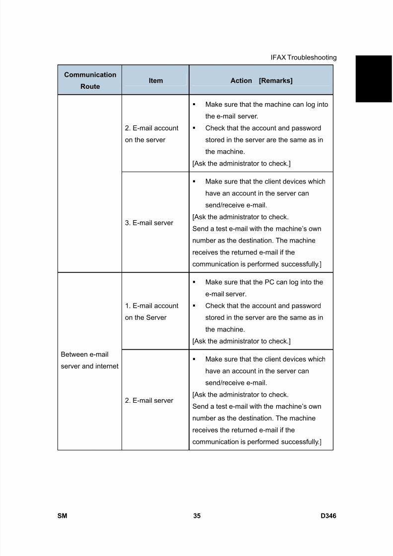
8/15/2019 Ricoh MP 4000 SM D009_D011_D012_D013 SERVICE MANUAL .pdf
http://slidepdf.com/reader/full/ricoh-mp-4000-sm-d009d011d012d013-service-manual-pdf 881/1162
IFAX Troubleshooting
SM 35 D346
F a x
O p
t i o n
T y p e
5 0 0 0
D 3 4 6Communication
Route Item Action [Remarks]
2. E-mail account
on the server
Make sure that the machine can log into
the e-mail server.
Check that the account and password
stored in the server are the same as in
the machine.
[Ask the administrator to check.]
3. E-mail server
Make sure that the client devices which
have an account in the server cansend/receive e-mail.
[Ask the administrator to check.
Send a test e-mail with the machine’s own
number as the destination. The machine
receives the returned e-mail if the
communication is performed successfully.]
1. E-mail account
on the Server
Make sure that the PC can log into the
e-mail server.
Check that the account and password
stored in the server are the same as in
the machine.
[Ask the administrator to check.]
Between e-mail
server and internet
2. E-mail server
Make sure that the client devices which
have an account in the server can
send/receive e-mail.
[Ask the administrator to check.
Send a test e-mail with the machine’s own
number as the destination. The machine
receives the returned e-mail if the
communication is performed successfully.]
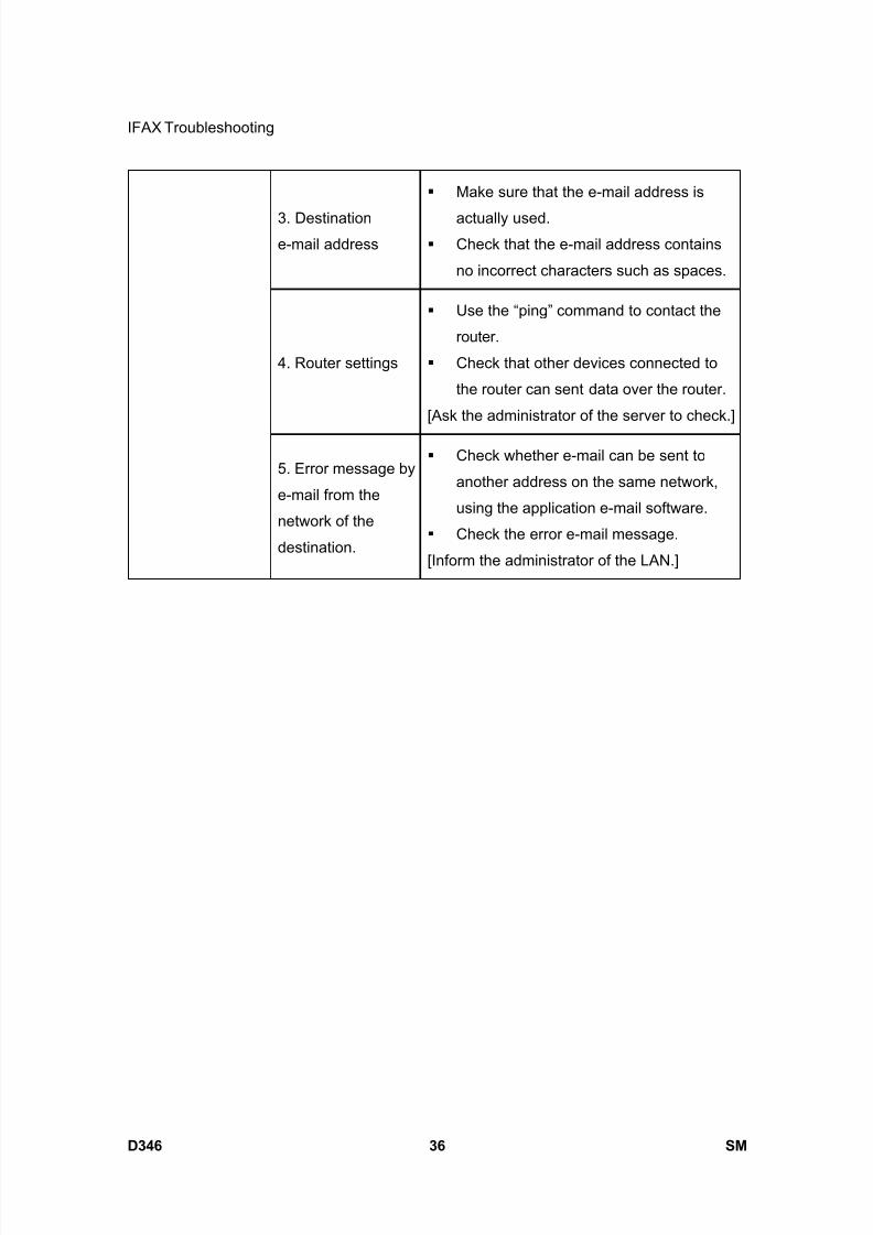
8/15/2019 Ricoh MP 4000 SM D009_D011_D012_D013 SERVICE MANUAL .pdf
http://slidepdf.com/reader/full/ricoh-mp-4000-sm-d009d011d012d013-service-manual-pdf 882/1162
IFAX Troubleshooting
D346 36 SM
3. Destinatione-mail address
Make sure that the e-mail address is
actually used. Check that the e-mail address contains
no incorrect characters such as spaces.
4. Router settings
Use the “ping” command to contact the
router.
Check that other devices connected to
the router can sent data over the router.
[Ask the administrator of the server to check.]
5. Error message by
e-mail from the
network of the
destination.
Check whether e-mail can be sent to
another address on the same network,
using the application e-mail software.
Check the error e-mail message.
[Inform the administrator of the LAN.]

8/15/2019 Ricoh MP 4000 SM D009_D011_D012_D013 SERVICE MANUAL .pdf
http://slidepdf.com/reader/full/ricoh-mp-4000-sm-d009d011d012d013-service-manual-pdf 883/1162
IP-Fax Troubleshooting
SM 37 D346
F a x
O p
t i o n
T y p e
5 0 0 0
D 3 4 6
3.3 IP-FAX TROUBLESHOOTING
3.3.1 IP-FAX TRANSMISSION
Cannot send by IP Address/Host Name
Check Point Action
1 LAN cable connected? Check the LAN cable connection.
2 Specified IP address/host name correct? Check the IP address/host name.
3 Firewall/NAT is installed?
Cannot breach the firewall. Send by
using another method (Fax, Internet
Fax)
4 Transmission sent manually? Manual sending not supported.
5 IP address of local machine registered? Register the IP address.
6Remote terminal port number setting other
than 1720?Send by specifying the port number.
7 Specified port number correct?Confirm the port number of the remote
fax.
8DNS server registered when host name
specified?Contact the network administrator.
9 Remote fax a T.38 terminal?Check whether the remote fax is a T38
terminal.
10 Remote fax switched off or busy?Check that the remote fax is switched
on.
Request the network administrator to
increase the bandwidth.11 Network bandwidth too narrow?
Raise the delay level.
IPFAX SW 01 Bit 0 to 3
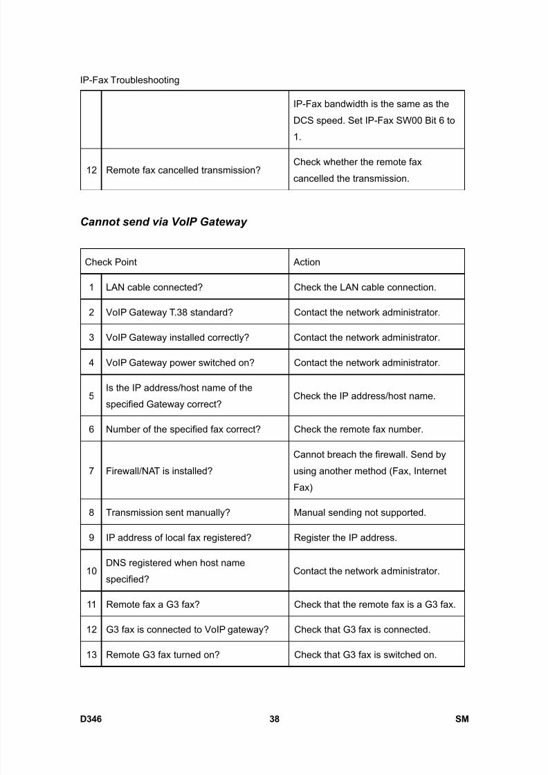
8/15/2019 Ricoh MP 4000 SM D009_D011_D012_D013 SERVICE MANUAL .pdf
http://slidepdf.com/reader/full/ricoh-mp-4000-sm-d009d011d012d013-service-manual-pdf 884/1162
IP-Fax Troubleshooting
D346 38 SM
IP-Fax bandwidth is the same as the
DCS speed. Set IP-Fax SW00 Bit 6 to
1.
12 Remote fax cancelled transmission?Check whether the remote fax
cancelled the transmission.
Cannot send via VoIP Gateway
Check Point Action
1 LAN cable connected? Check the LAN cable connection.
2 VoIP Gateway T.38 standard? Contact the network administrator.
3 VoIP Gateway installed correctly? Contact the network administrator.
4 VoIP Gateway power switched on? Contact the network administrator.
5Is the IP address/host name of the
specified Gateway correct?
Check the IP address/host name.
6 Number of the specified fax correct? Check the remote fax number.
7 Firewall/NAT is installed?
Cannot breach the firewall. Send by
using another method (Fax, Internet
Fax)
8 Transmission sent manually? Manual sending not supported.
9 IP address of local fax registered? Register the IP address.
10DNS registered when host name
specified?Contact the network administrator.
11 Remote fax a G3 fax? Check that the remote fax is a G3 fax.
12 G3 fax is connected to VoIP gateway? Check that G3 fax is connected.
13 Remote G3 fax turned on? Check that G3 fax is switched on.

8/15/2019 Ricoh MP 4000 SM D009_D011_D012_D013 SERVICE MANUAL .pdf
http://slidepdf.com/reader/full/ricoh-mp-4000-sm-d009d011d012d013-service-manual-pdf 885/1162
IP-Fax Troubleshooting
SM 39 D346
F a x
O p
t i o n
T y p e
5 0 0 0
D 3 4 6Request the network administrator to
increase the bandwidth.
Raise the network delay level.
IPFAX SW 01 Bit 0 to 314 Network bandwidth too narrow?
IP-Fax bandwidth is the same as the
DCS speed. Set IP-Fax SW00 Bit 6 to
1.
Cannot send by Alias Fax number.
Check Point Action
1 LAN cable connected? Check the LAN cable connection.
2 Number of specified Alias fax correct?Confirm the Alias of the remote fax.
Error Code: 13-14
3 Firewall/NAT installed?
Cannot breach the firewall. Send by
using another method (Fax, Internet
Fax)
4 Transmission sent manually? Manual sending not supported.
5 Gatekeeper installed correctly? Contact the network administrator.
6 Gatekeeper power switched on? Contact the network administrator.
7IP address/host name of Gatekeeper
correct?Check the IP address/host name.
8DNS server registered when Gatekeeper
host name specified?Contact the network administrator.
9 Enable H.323 SW is set to on?Check the settings.
See User Parameter SW 34 Bit 0
10 IP address of local fax registered? Register the IP address of the local fax.
11 Alias number of local fax registered? Register the Alias number of the local
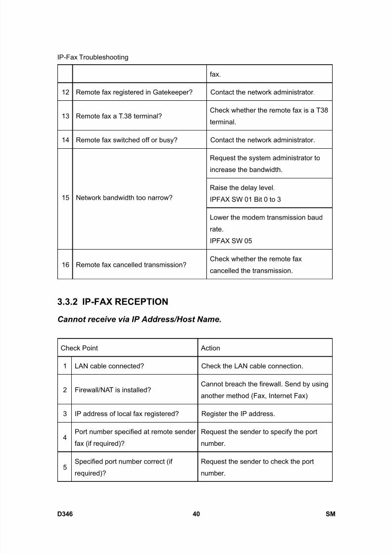
8/15/2019 Ricoh MP 4000 SM D009_D011_D012_D013 SERVICE MANUAL .pdf
http://slidepdf.com/reader/full/ricoh-mp-4000-sm-d009d011d012d013-service-manual-pdf 886/1162
IP-Fax Troubleshooting
D346 40 SM
fax.
12 Remote fax registered in Gatekeeper? Contact the network administrator.
13 Remote fax a T.38 terminal?Check whether the remote fax is a T38
terminal.
14 Remote fax switched off or busy? Contact the network administrator.
Request the system administrator to
increase the bandwidth.
Raise the delay level.
IPFAX SW 01 Bit 0 to 315 Network bandwidth too narrow?
Lower the modem transmission baud
rate.
IPFAX SW 05
16 Remote fax cancelled transmission?Check whether the remote fax
cancelled the transmission.
3.3.2 IP-FAX RECEPTION
Cannot receive via IP Address/Host Name.
Check Point Action
1 LAN cable connected? Check the LAN cable connection.
2 Firewall/NAT is installed?Cannot breach the firewall. Send by using
another method (Fax, Internet Fax)
3 IP address of local fax registered? Register the IP address.
4Port number specified at remote sender
fax (if required)?
Request the sender to specify the port
number.
5Specified port number correct (if
required)?
Request the sender to check the port
number.

8/15/2019 Ricoh MP 4000 SM D009_D011_D012_D013 SERVICE MANUAL .pdf
http://slidepdf.com/reader/full/ricoh-mp-4000-sm-d009d011d012d013-service-manual-pdf 887/1162
IP-Fax Troubleshooting
SM 41 D346
F a x
O p
t i o n
T y p e
5 0 0 0
D 3 4 6
6DNS server registered when host name
specified on sender side?
Contact the network administrator.
The sender machine displays thiserror code if the sender fax is a
Ricoh model.
Request the system administrator to
increase the bandwidth.
7 Network bandwidth too narrow?Lower the start modem reception baud
rate on the receiving side.
IPFAX SW06
8 Remote fax cancelled transmission?Check whether the remote fax cancelled
the transmission.
Cannot receive by VoIP Gateway.
Check Point Action
1 LAN cable connected? Check the LAN cable connection.
2 Firewall/NAT is installed?
Cannot breach the firewall. Request the
remote fax to send by using another
method (Fax, Internet Fax)
3 VoIP Gateway installed correctly? Contact the network administrator.
4 VoIP Gateway power switched on? Contact the network administrator.
5IP address/host name of specified VoIP
Gateway correct on sender’s side?
Request the remote fax to check the IP
address/host name.
6DNS server registered when host name
specified on sender side?Contact the network administrator.
7 Network bandwidth too narrow?Request the network administrator to
increase the bandwidth.
8 G3 fax connected? Check that G3 fax is connected.
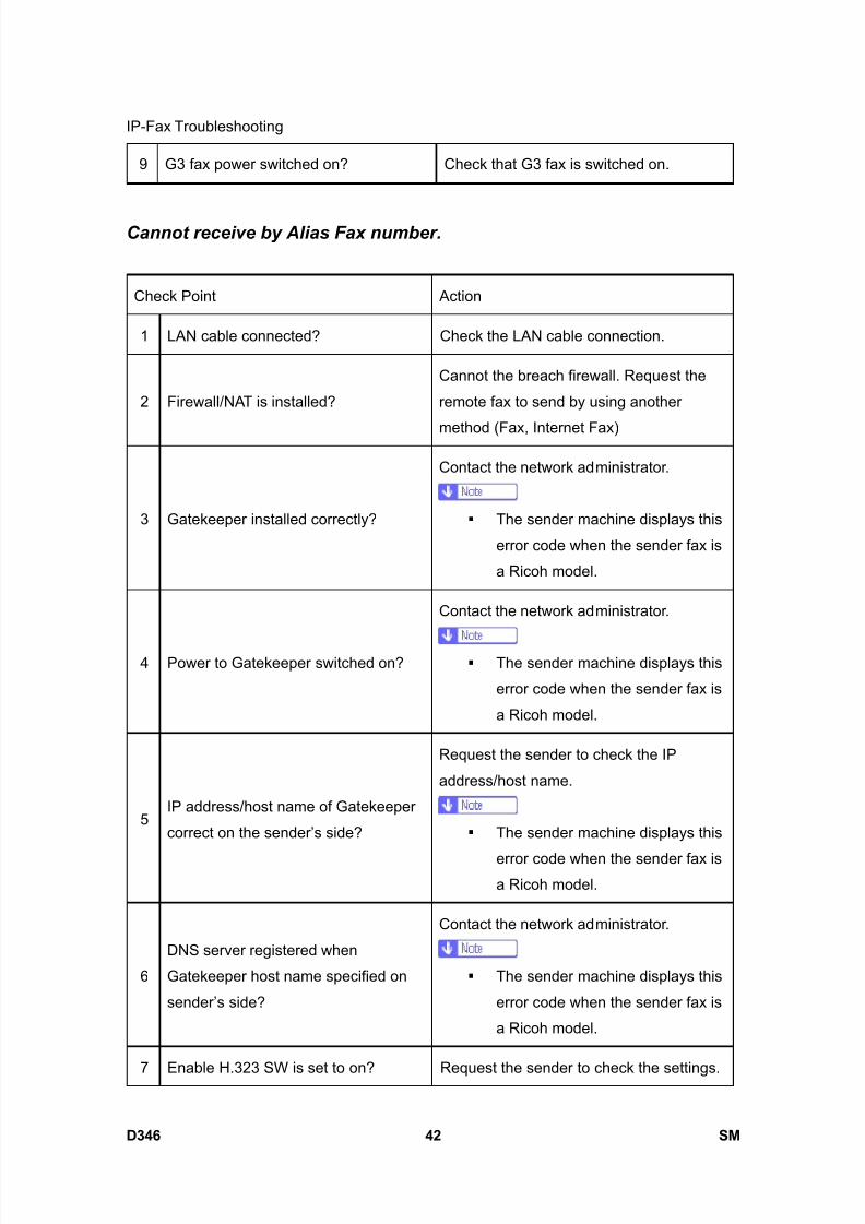
8/15/2019 Ricoh MP 4000 SM D009_D011_D012_D013 SERVICE MANUAL .pdf
http://slidepdf.com/reader/full/ricoh-mp-4000-sm-d009d011d012d013-service-manual-pdf 888/1162
IP-Fax Troubleshooting
D346 42 SM
9 G3 fax power switched on? Check that G3 fax is switched on.
Cannot receive by Alias Fax number.
Check Point Action
1 LAN cable connected? Check the LAN cable connection.
2 Firewall/NAT is installed?
Cannot the breach firewall. Request the
remote fax to send by using another
method (Fax, Internet Fax)
3 Gatekeeper installed correctly?
Contact the network administrator.
The sender machine displays this
error code when the sender fax is
a Ricoh model.
4 Power to Gatekeeper switched on?
Contact the network administrator.
The sender machine displays this
error code when the sender fax is
a Ricoh model.
5IP address/host name of Gatekeeper
correct on the sender’s side?
Request the sender to check the IP
address/host name.
The sender machine displays this
error code when the sender fax isa Ricoh model.
6
DNS server registered when
Gatekeeper host name specified on
sender’s side?
Contact the network administrator.
The sender machine displays this
error code when the sender fax is
a Ricoh model.
7 Enable H.323 SW is set to on? Request the sender to check the settings.
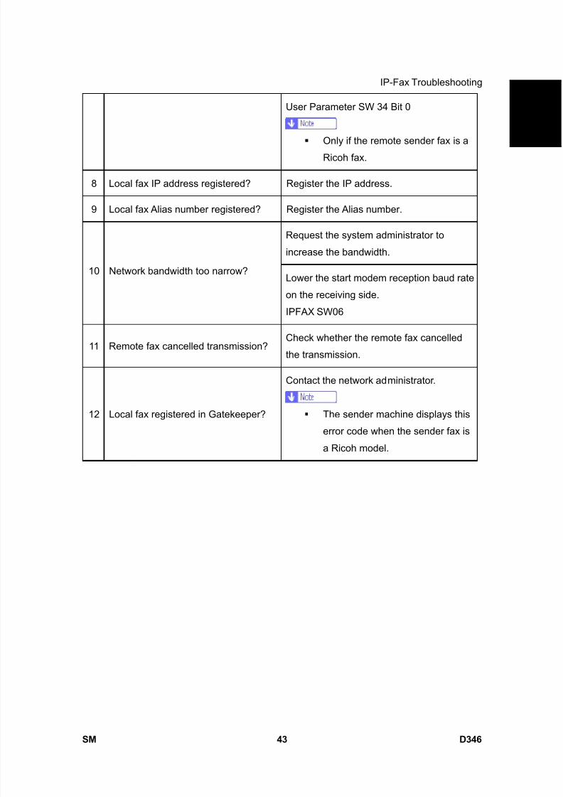
8/15/2019 Ricoh MP 4000 SM D009_D011_D012_D013 SERVICE MANUAL .pdf
http://slidepdf.com/reader/full/ricoh-mp-4000-sm-d009d011d012d013-service-manual-pdf 889/1162
IP-Fax Troubleshooting
SM 43 D346
F a x
O p
t i o n
T y p e
5 0 0 0
D 3 4 6User Parameter SW 34 Bit 0
Only if the remote sender fax is aRicoh fax.
8 Local fax IP address registered? Register the IP address.
9 Local fax Alias number registered? Register the Alias number.
Request the system administrator to
increase the bandwidth.
10 Network bandwidth too narrow?Lower the start modem reception baud rateon the receiving side.
IPFAX SW06
11 Remote fax cancelled transmission?Check whether the remote fax cancelled
the transmission.
12 Local fax registered in Gatekeeper?
Contact the network administrator.
The sender machine displays thiserror code when the sender fax is
a Ricoh model.
8/15/2019 Ricoh MP 4000 SM D009_D011_D012_D013 SERVICE MANUAL .pdf
http://slidepdf.com/reader/full/ricoh-mp-4000-sm-d009d011d012d013-service-manual-pdf 890/1162
Beforehand
D346 44 SM
4. SERVICE TABLE
4.1 BEFOREHAND
Never turn off the main power switch when the power LED is lit or flashing. To
avoid damaging the hard disk or memory, press the operation power switch to
switch the power off, wait for the power LED to go off, and then switch the main
power switch off.
The main power LED ( ) lights or flashes while the platen cover or ARDF is
open, while the main machine is communicating with a facsimile or the network
server, or while the machine is accessing the hard disk or memory for reading or
writing data.
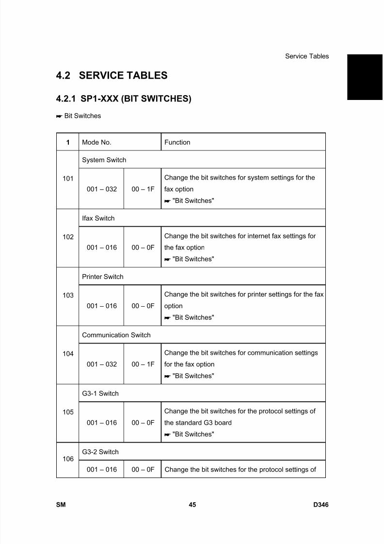
8/15/2019 Ricoh MP 4000 SM D009_D011_D012_D013 SERVICE MANUAL .pdf
http://slidepdf.com/reader/full/ricoh-mp-4000-sm-d009d011d012d013-service-manual-pdf 891/1162
Service Tables
SM 45 D346
F a x
O p
t i o n
T y p e
5 0 0 0
D 3 4 6
4.2 SERVICE TABLES
4.2.1 SP1-XXX (BIT SWITCHES)
Bit Switches
1 Mode No. Function
System Switch
101
001 – 032 00 – 1F
Change the bit switches for system settings for the
fax option "Bit Switches"
Ifax Switch
102
001 – 016 00 – 0F
Change the bit switches for internet fax settings for
the fax option
"Bit Switches"
Printer Switch
103
001 – 016 00 – 0F
Change the bit switches for printer settings for the fax
option
"Bit Switches"
Communication Switch
104
001 – 032 00 – 1F
Change the bit switches for communication settings
for the fax option
"Bit Switches"
G3-1 Switch
105
001 – 016 00 – 0F
Change the bit switches for the protocol settings of
the standard G3 board
"Bit Switches"
G3-2 Switch106
001 – 016 00 – 0F Change the bit switches for the protocol settings of
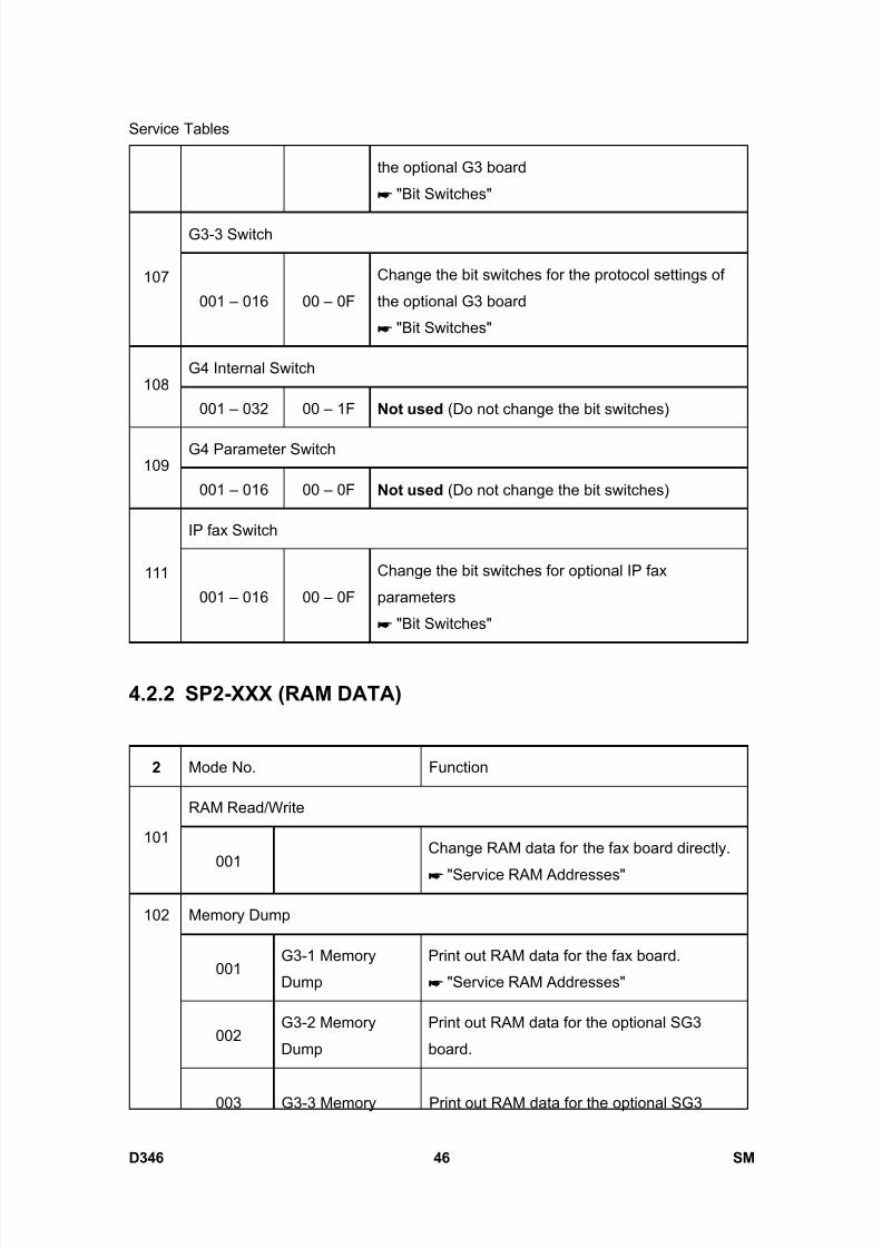
8/15/2019 Ricoh MP 4000 SM D009_D011_D012_D013 SERVICE MANUAL .pdf
http://slidepdf.com/reader/full/ricoh-mp-4000-sm-d009d011d012d013-service-manual-pdf 892/1162
Service Tables
D346 46 SM
the optional G3 board
"Bit Switches"
G3-3 Switch
107
001 – 016 00 – 0F
Change the bit switches for the protocol settings of
the optional G3 board
"Bit Switches"
G4 Internal Switch108
001 – 032 00 – 1F Not used (Do not change the bit switches)
G4 Parameter Switch109
001 – 016 00 – 0F Not used (Do not change the bit switches)
IP fax Switch
111
001 – 016 00 – 0F
Change the bit switches for optional IP fax
parameters
"Bit Switches"
4.2.2 SP2-XXX (RAM DATA)
2 Mode No. Function
RAM Read/Write
101
001Change RAM data for the fax board directly.
"Service RAM Addresses"
Memory Dump
001G3-1 Memory
Dump
Print out RAM data for the fax board.
"Service RAM Addresses"
002G3-2 Memory
Dump
Print out RAM data for the optional SG3
board.
102
003 G3-3 Memory Print out RAM data for the optional SG3

8/15/2019 Ricoh MP 4000 SM D009_D011_D012_D013 SERVICE MANUAL .pdf
http://slidepdf.com/reader/full/ricoh-mp-4000-sm-d009d011d012d013-service-manual-pdf 893/1162
Service Tables
SM 47 D346
F a x
O p
t i o n
T y p e
5 0 0 0
D 3 4 6Dump board.
004 G4 Memory Dump Not used
G3-1 NCU Parameters
103
001 – 023 CC, 01 – 22NCU parameter settings for the standard G3
board. "NCU Parameters"
G3-2 NCU Parameters
104
001 – 023 CC, 01 – 22NCU parameter settings for the optional G3
board. "NCU Parameters"
G3-3 NCU Parameters
105
001 – 023 CC, 01 – 22NCU parameter settings for the optional G3
board. "NCU Parameters"
4.2.3 SP3-XXX (TEL LINE SETTINGS)
3 Mode No. Function
Service Station
001 Fax Number Enter the fax number of the service station.101
002 Select Line Select the line type.
Serial Number102
000 Enter the fax unit’s serial number.
PSTN-1 Port Settings
001 Select Line
Select the line type setting for the G3-1 line. If
the machine is installed on a PABX line, select
“PABX”, “PABX(GND)” or “PABX(FLASH)”.
103
002PSTN Access
Number
Enter the PSTN access number for the
G3-1 line.
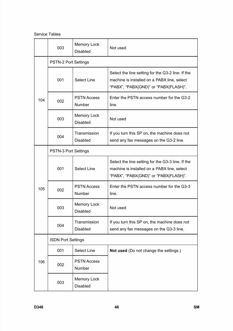
8/15/2019 Ricoh MP 4000 SM D009_D011_D012_D013 SERVICE MANUAL .pdf
http://slidepdf.com/reader/full/ricoh-mp-4000-sm-d009d011d012d013-service-manual-pdf 894/1162
Service Tables
D346 48 SM
003Memory Lock
DisabledNot used
PSTN-2 Port Settings
001 Select Line
Select the line setting for the G3-2 line. If the
machine is installed on a PABX line, select
“PABX”, “PABX(GND)” or “PABX(FLASH)”.
002PSTN Access
Number
Enter the PSTN access number for the G3-2
line.
003 Memory LockDisabled
Not used
104
004Transmission
Disabled
If you turn this SP on, the machine does not
send any fax messages on the G3-2 line.
PSTN-3 Port Settings
001 Select Line
Select the line setting for the G3-3 line. If the
machine is installed on a PABX line, select
“PABX”, “PABX(GND)” or “PABX(FLASH)”.
002PSTN Access
Number
Enter the PSTN access number for the G3-3
line.
003Memory Lock
DisabledNot used
105
004Transmission
Disabled
If you turn this SP on, the machine does not
send any fax messages on the G3-3 line.
ISDN Port Settings
001 Select Line
002PSTN Access
Number
106
003Memory Lock
Disabled
Not used (Do not change the settings.)
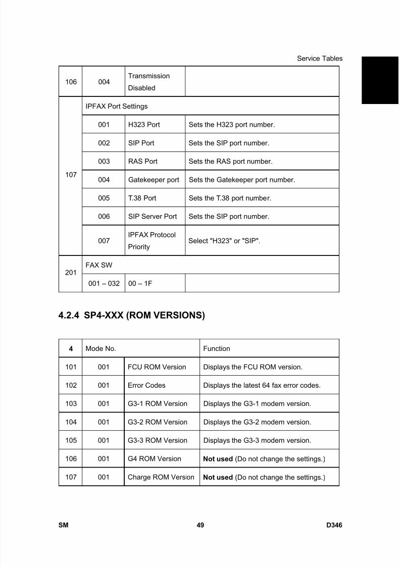
8/15/2019 Ricoh MP 4000 SM D009_D011_D012_D013 SERVICE MANUAL .pdf
http://slidepdf.com/reader/full/ricoh-mp-4000-sm-d009d011d012d013-service-manual-pdf 895/1162
Service Tables
SM 49 D346
F a x
O p
t i o n
T y p e
5 0 0 0
D 3 4 6
106 004Transmission
Disabled
IPFAX Port Settings
001 H323 Port Sets the H323 port number.
002 SIP Port Sets the SIP port number.
003 RAS Port Sets the RAS port number.
004 Gatekeeper port Sets the Gatekeeper port number.
005 T.38 Port Sets the T.38 port number.
006 SIP Server Port Sets the SIP port number.
107
007IPFAX Protocol
PrioritySelect "H323" or "SIP".
FAX SW201
001 – 032 00 – 1F
4.2.4 SP4-XXX (ROM VERSIONS)
4 Mode No. Function
101 001 FCU ROM Version Displays the FCU ROM version.
102 001 Error Codes Displays the latest 64 fax error codes.
103 001 G3-1 ROM Version Displays the G3-1 modem version.
104 001 G3-2 ROM Version Displays the G3-2 modem version.
105 001 G3-3 ROM Version Displays the G3-3 modem version.
106 001 G4 ROM Version Not used (Do not change the settings.)
107 001 Charge ROM Version Not used (Do not change the settings.)
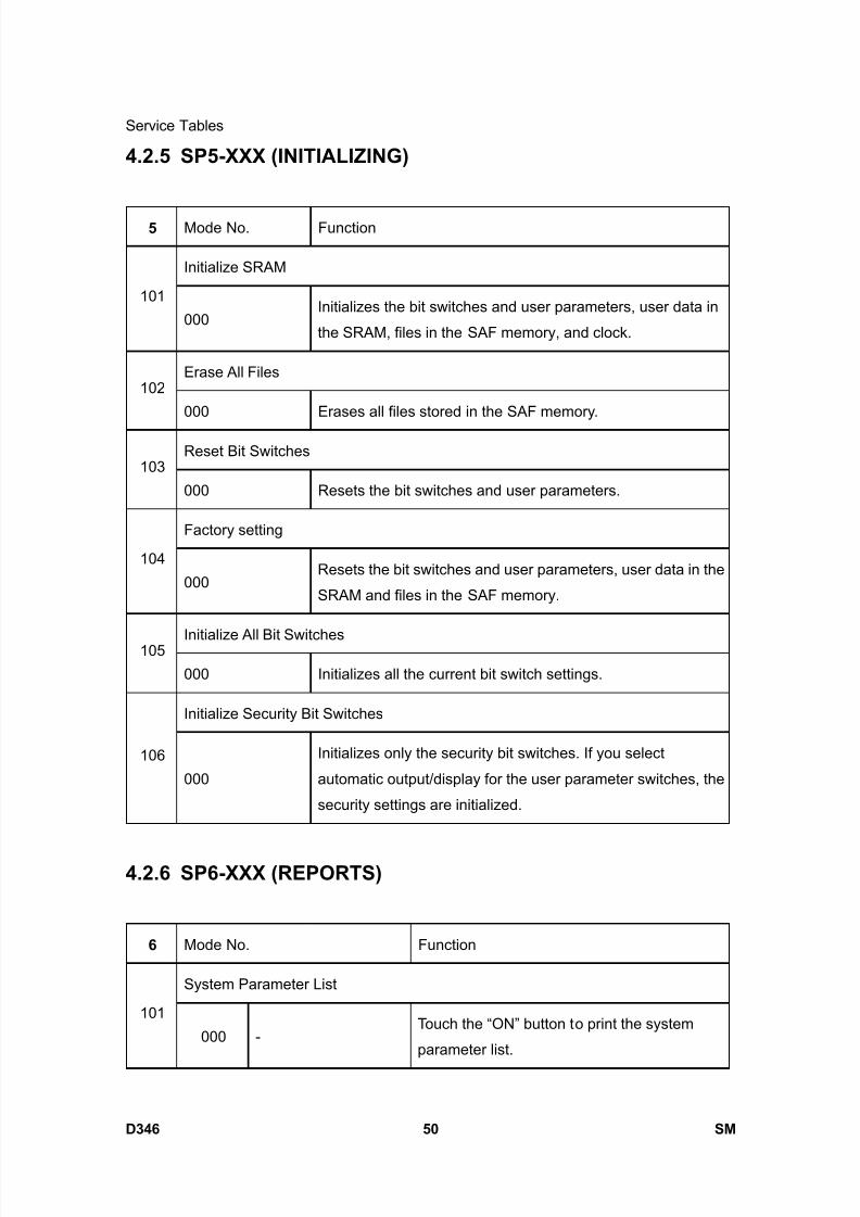
8/15/2019 Ricoh MP 4000 SM D009_D011_D012_D013 SERVICE MANUAL .pdf
http://slidepdf.com/reader/full/ricoh-mp-4000-sm-d009d011d012d013-service-manual-pdf 896/1162
Service Tables
D346 50 SM
4.2.5 SP5-XXX (INITIALIZING)
5 Mode No. Function
Initialize SRAM
101
000Initializes the bit switches and user parameters, user data in
the SRAM, files in the SAF memory, and clock.
Erase All Files102
000 Erases all files stored in the SAF memory.
Reset Bit Switches103
000 Resets the bit switches and user parameters.
Factory setting
104
000Resets the bit switches and user parameters, user data in the
SRAM and files in the SAF memory.
Initialize All Bit Switches105
000 Initializes all the current bit switch settings.
Initialize Security Bit Switches
106
000
Initializes only the security bit switches. If you select
automatic output/display for the user parameter switches, the
security settings are initialized.
4.2.6 SP6-XXX (REPORTS)
6 Mode No. Function
System Parameter List
101
000 -Touch the “ON” button to print the system
parameter list.

8/15/2019 Ricoh MP 4000 SM D009_D011_D012_D013 SERVICE MANUAL .pdf
http://slidepdf.com/reader/full/ricoh-mp-4000-sm-d009d011d012d013-service-manual-pdf 897/1162
Service Tables
SM 51 D346
F a x
O p
t i o n
T y p e
5 0 0 0
D 3 4 6Service Monitor Report
102
000 -Touch the “ON” button to print the service
monitor report.
G3 Protocol Dump List
001G3 All
Communications
Prints the protocol dump list of all
communications for all G3 lines.
002G3-1 (All
Communications)
Prints the protocol dump list of all
communications for the G3-1 line.
003G3-1
(1 Communication)
Prints the protocol dump list of the last
communication for the G3-1 line.
004G3-2
(All Communications)
Prints the protocol dump list of all
communications for the G3-2 line.
005G3-2
(1 Communication)
Prints the protocol dump list of the last
communication for the G3-2 line.
006 G3-3(All Communications)
Prints the protocol dump list of allcommunications for the G3-3 line.
103
007G3-3
(1 Communication)
Prints the protocol dump list of the last
communication for the G3-3 line.
G4 Protocol Dump List
001 Dch + Bch 1
002 Dch
003 Bch 1 Link Layer
004 Dch Link Layer
005 Dch +Bch 2
104
006 Bch 2 Link Layer
Not used (Do not change the settings.)
105 All Files print out
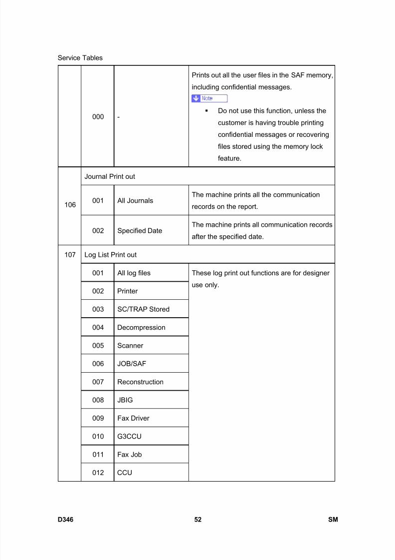
8/15/2019 Ricoh MP 4000 SM D009_D011_D012_D013 SERVICE MANUAL .pdf
http://slidepdf.com/reader/full/ricoh-mp-4000-sm-d009d011d012d013-service-manual-pdf 898/1162
Service Tables
D346 52 SM
000 -
Prints out all the user files in the SAF memory,
including confidential messages.
Do not use this function, unless the
customer is having trouble printing
confidential messages or recovering
files stored using the memory lock
feature.
Journal Print out
001 All Journals The machine prints all the communicationrecords on the report.106
002 Specified DateThe machine prints all communication records
after the specified date.
Log List Print out
001 All log files
002 Printer
003 SC/TRAP Stored
004 Decompression
005 Scanner
006 JOB/SAF
007 Reconstruction
008 JBIG
009 Fax Driver
010 G3CCU
011 Fax Job
107
012 CCU
These log print out functions are for designer
use only.

8/15/2019 Ricoh MP 4000 SM D009_D011_D012_D013 SERVICE MANUAL .pdf
http://slidepdf.com/reader/full/ricoh-mp-4000-sm-d009d011d012d013-service-manual-pdf 899/1162
Service Tables
SM 53 D346
F a x
O p
t i o n
T y p e
5 0 0 0
D 3 4 6013 Scanner Condition
IP Protocol Dump List
001 All CommunicationsPrints the protocol dump list of all
communications for the IP fax line.108
002 1 CommunicationPrints the protocol dump list of the last
communication for the IP fax line.
4.2.7 SP7-XXX (TEST MODES)
These are the test modes for PTT approval.
7 Function
101 G3-1 Modem Tests
102 G3-1 DTMF Tests
103 Ringer Test
104 G3-1 V34 (S2400baud)
105 G3-1 V34 (S2800baud)
106 G3-1 V34 (S3000baud)
107 G3-1 V34 (S3200baud)
108 G3-1 V34 (S3429baud)
109 Recorded Message Test
110 G3-2 Modem Tests
111 G3-2 DTMF Tests
112 G3-2 V34 (S2400baud)
113 G3-2 V34 (S2800baud)
114 G3-2 V34 (S3000baud)

8/15/2019 Ricoh MP 4000 SM D009_D011_D012_D013 SERVICE MANUAL .pdf
http://slidepdf.com/reader/full/ricoh-mp-4000-sm-d009d011d012d013-service-manual-pdf 900/1162
Service Tables
D346 54 SM
115 G3-2 V34 (S3200baud)
116 G3-2 V34 (S3429baud)
117 G3-3 Modem Tests
118 G3-3 DTMF Tests
119 G3-3 V34 (S2400baud)
120 G3-3 V34 (S2800baud)
121 G3-3 V34 (S3000baud)
122 G3-3 V34 (S3200baud)
123 G3-3 V34 (S3429baud)
124 IG3-1 Modem Tests - Not used
125 IG3-1 DTMF Tests - Not used
126 IG3-1 V34 (S2400baud) - Not used
127 IG3-1 V34 (S2800baud) - Not used
128 IG3-1 V34 (S3000baud) - Not used
129 IG3-1 V34 (S3200baud) - Not used
130 IG3-1 V34 (S3429baud) - Not used
131 IG3-2 Modem Tests - Not used
132 IG3-2 DTMF Tests - Not used
133 IG3-2 V34 (S2400baud) - Not used
134 IG3-2 V34 (S2800baud) - Not used
135 IG3-2 V34 (S3000baud) - Not used
136 IG3-2 V34 (S3200baud) - Not used
137 IG3-2 V34 (S3429baud) - Not used
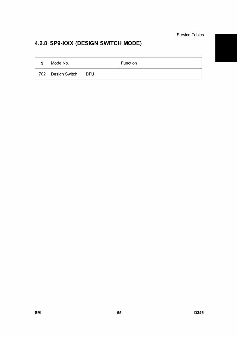
8/15/2019 Ricoh MP 4000 SM D009_D011_D012_D013 SERVICE MANUAL .pdf
http://slidepdf.com/reader/full/ricoh-mp-4000-sm-d009d011d012d013-service-manual-pdf 901/1162
Service Tables
SM 55 D346
F a x
O p
t i o n
T y p e
5 0 0 0
D 3 4 64.2.8 SP9-XXX (DESIGN SWITCH MODE)
9 Mode No. Function
702 Design Switch DFU

8/15/2019 Ricoh MP 4000 SM D009_D011_D012_D013 SERVICE MANUAL .pdf
http://slidepdf.com/reader/full/ricoh-mp-4000-sm-d009d011d012d013-service-manual-pdf 902/1162
Bit Switches
D346 56 SM
4.3 BIT SWITCHES
Do not adjust a bit switch or use a setting that is described as “Not used”, as thismay cause the machine to malfunction or to operate in a manner that is not
accepted by local regulations. Such bits are for use only in other areas, such as
Japan.
Default settings for bit switches are not listed in this manual. Refer to the System
Parameter List printed by the machine.
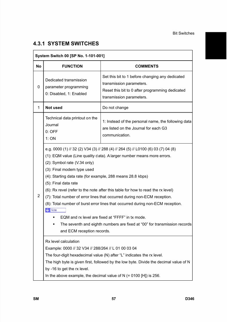
8/15/2019 Ricoh MP 4000 SM D009_D011_D012_D013 SERVICE MANUAL .pdf
http://slidepdf.com/reader/full/ricoh-mp-4000-sm-d009d011d012d013-service-manual-pdf 903/1162
Bit Switches
SM 57 D346
F a x
O p
t i o n
T y p e
5 0 0 0
D 3 4 64.3.1 SYSTEM SWITCHES
System Switch 00 [SP No. 1-101-001]
No FUNCTION COMMENTS
0
Dedicated transmission
parameter programming
0: Disabled, 1: Enabled
Set this bit to 1 before changing any dedicated
transmission parameters.
Reset this bit to 0 after programming dedicated
transmission parameters.
1 Not used Do not change
Technical data printout on the
Journal
0: OFF
1: ON
1: Instead of the personal name, the following data
are listed on the Journal for each G3
communication.
e.g. 0000 (1) // 32 (2) V34 (3) // 288 (4) // 264 (5) // L0100 (6) 03 (7) 04 (8)
(1): EQM value (Line quality data). A larger number means more errors.
(2): Symbol rate (V.34 only)
(3): Final modem type used(4): Starting data rate (for example, 288 means 28.8 kbps)
(5): Final data rate
(6): Rx revel (refer to the note after this table for how to read the rx level)
(7): Total number of error lines that occurred during non-ECM reception.
(8): Total number of burst error lines that occurred during non-ECM reception.
EQM and rx level are fixed at “FFFF” in tx mode.
The seventh and eighth numbers are fixed at “00” for transmission recordsand ECM reception records.
2
Rx level calculation
Example: 0000 // 32 V34 // 288/264 // L 01 00 03 04
The four-digit hexadecimal value (N) after “L” indicates the rx level.
The high byte is given first, followed by the low byte. Divide the decimal value of N
by -16 to get the rx level.
In the above example, the decimal value of N (= 0100 [H]) is 256.
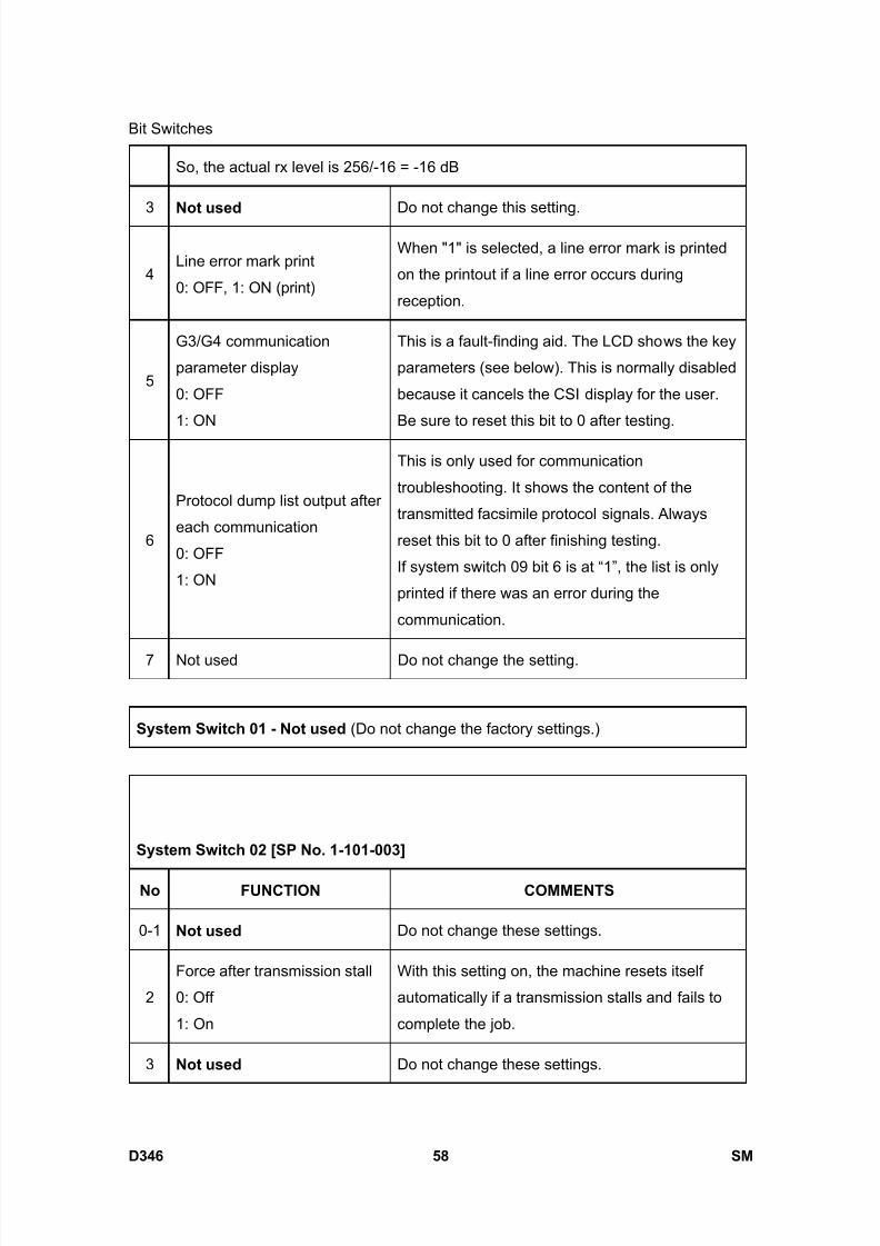
8/15/2019 Ricoh MP 4000 SM D009_D011_D012_D013 SERVICE MANUAL .pdf
http://slidepdf.com/reader/full/ricoh-mp-4000-sm-d009d011d012d013-service-manual-pdf 904/1162
Bit Switches
D346 58 SM
So, the actual rx level is 256/-16 = -16 dB
3 Not used Do not change this setting.
4Line error mark print
0: OFF, 1: ON (print)
When "1" is selected, a line error mark is printed
on the printout if a line error occurs during
reception.
5
G3/G4 communication
parameter display
0: OFF
1: ON
This is a fault-finding aid. The LCD shows the key
parameters (see below). This is normally disabled
because it cancels the CSI display for the user.
Be sure to reset this bit to 0 after testing.
6
Protocol dump list output after
each communication
0: OFF
1: ON
This is only used for communication
troubleshooting. It shows the content of the
transmitted facsimile protocol signals. Always
reset this bit to 0 after finishing testing.
If system switch 09 bit 6 is at “1”, the list is only
printed if there was an error during the
communication.
7 Not used Do not change the setting.
System Switch 01 - Not used (Do not change the factory settings.)
System Switch 02 [SP No. 1-101-003]
No FUNCTION COMMENTS
0-1 Not used Do not change these settings.
2
Force after transmission stall
0: Off
1: On
With this setting on, the machine resets itself
automatically if a transmission stalls and fails to
complete the job.
3 Not used Do not change these settings.

8/15/2019 Ricoh MP 4000 SM D009_D011_D012_D013 SERVICE MANUAL .pdf
http://slidepdf.com/reader/full/ricoh-mp-4000-sm-d009d011d012d013-service-manual-pdf 905/1162
Bit Switches
SM 59 D346
F a x
O p
t i o n
T y p e
5 0 0 0
D 3 4 6
4
File retention time
0: Depends on User
Parameter 24 [18(H)]1: No limit (until the year 2126)
1: A file that had a communication error will not be
erased unless the communication is successful.
5 Not used Do not change this setting.
6-7
Memory read/write by RDS
Bit 7: 0, Bit 6: 0
Always disabled
Bit 7: 0, Bit 6: 1
User selectable
Bit 7: 1, Bit 6: 0
User selectable
Bit 7: 1, Bit 6: 1
Always enabled
(0,0): All RDS systems are always locked out.
(0,1), (1,0): Normally, RDS systems are locked
out, but the user can temporarily switch RDS on to
allow RDS operations to take place. RDS will
automatically be locked out again after a certaintime, which is stored in System Switch 03. Note
that if an RDS operation takes place, RDS will not
switch off until this time limit has expired.
(1,1): At any time, an RDS system can access the
machine.
System Switch 03 [SP No. 1-101-004]
No FUNCTION COMMENTS
0-7
Length of time that RDS is
temporarily switched on when
bits 6 and 7 of System Switch
02 are set to “User selectable”
00 - 99 hours (BCD).
This setting is only valid if bits 6 and 7 of System
Switch 02 are set to “User selectable”.
The default setting is 24 hours.
System Switch 04 [SP No. 1-101-005]
No FUNCTION COMMENTS
0-2 Not used Do not change these settings.
3
Printing dedicated tx
parameters on Quick/Speed
Dial Lists
0: OFF
1: ON
1: Each Quick/Speed dial number on the list is
printed with the dedicated tx parameters.
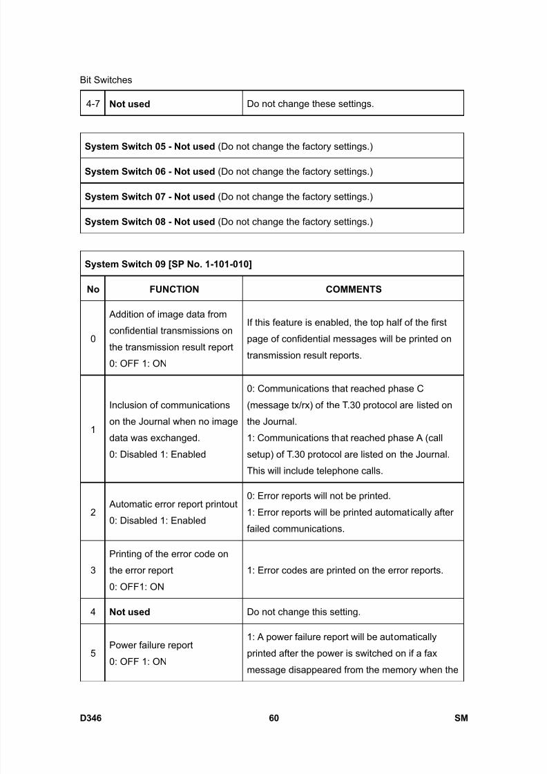
8/15/2019 Ricoh MP 4000 SM D009_D011_D012_D013 SERVICE MANUAL .pdf
http://slidepdf.com/reader/full/ricoh-mp-4000-sm-d009d011d012d013-service-manual-pdf 906/1162
Bit Switches
D346 60 SM
4-7 Not used Do not change these settings.
System Switch 05 - Not used (Do not change the factory settings.)
System Switch 06 - Not used (Do not change the factory settings.)
System Switch 07 - Not used (Do not change the factory settings.)
System Switch 08 - Not used (Do not change the factory settings.)
System Switch 09 [SP No. 1-101-010]
No FUNCTION COMMENTS
0
Addition of image data from
confidential transmissions on
the transmission result report
0: OFF 1: ON
If this feature is enabled, the top half of the first
page of confidential messages will be printed on
transmission result reports.
1
Inclusion of communicationson the Journal when no image
data was exchanged.
0: Disabled 1: Enabled
0: Communications that reached phase C
(message tx/rx) of the T.30 protocol are listed onthe Journal.
1: Communications that reached phase A (call
setup) of T.30 protocol are listed on the Journal.
This will include telephone calls.
2 Automatic error report printout
0: Disabled 1: Enabled
0: Error reports will not be printed.
1: Error reports will be printed automatically after
failed communications.
3
Printing of the error code on
the error report
0: OFF1: ON
1: Error codes are printed on the error reports.
4 Not used Do not change this setting.
5Power failure report
0: OFF 1: ON
1: A power failure report will be automatically
printed after the power is switched on if a fax
message disappeared from the memory when the
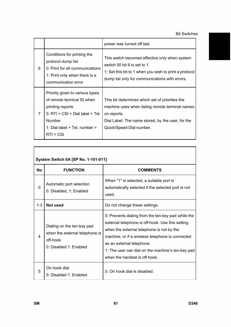
8/15/2019 Ricoh MP 4000 SM D009_D011_D012_D013 SERVICE MANUAL .pdf
http://slidepdf.com/reader/full/ricoh-mp-4000-sm-d009d011d012d013-service-manual-pdf 907/1162
Bit Switches
SM 61 D346
F a x
O p
t i o n
T y p e
5 0 0 0
D 3 4 6power was turned off last.
6
Conditions for printing the
protocol dump list
0: Print for all communications
1: Print only when there is a
communication error
This switch becomes effective only when systemswitch 00 bit 6 is set to 1.
1: Set this bit to 1 when you wish to print a protocol
dump list only for communications with errors.
7
Priority given to various types
of remote terminal ID when
printing reports
0: RTI > CSI > Dial label > Tel.Number
1: Dial label > Tel. number >
RTI > CSI
This bit determines which set of priorities the
machine uses when listing remote terminal names
on reports.Dial Label: The name stored, by the user, for the
Quick/Speed Dial number.
System Switch 0A [SP No. 1-101-011]
No FUNCTION COMMENTS
0 Automatic port selection
0: Disabled, 1: Enabled
When "1" is selected, a suitable port is
automatically selected if the selected port is not
used.
1-3 Not used Do not change these settings.
4
Dialing on the ten-key pad
when the external telephone is
off-hook
0: Disabled 1: Enabled
0: Prevents dialing from the ten-key pad while the
external telephone is off-hook. Use this setting
when the external telephone is not by themachine, or if a wireless telephone is connected
as an external telephone.
1: The user can dial on the machine’s ten-key pad
when the handset is off-hook.
5On hook dial
0: Disabled 1: Enabled0: On hook dial is disabled.

8/15/2019 Ricoh MP 4000 SM D009_D011_D012_D013 SERVICE MANUAL .pdf
http://slidepdf.com/reader/full/ricoh-mp-4000-sm-d009d011d012d013-service-manual-pdf 908/1162
Bit Switches
D346 62 SM
System Switch 0B - Not used (Do not change the factory settings.)
System Switch 0C - Not used (Do not change the factory settings.)
System Switch 0D - Not used (Do not change the factory settings.)
System Switch 0E [SP No. 1-101-015]
No FUNCTION COMMENTS
0-1 Not used Do not change the settings.
2
Enable/disable for direct
sending selection
0: Direct sending off
1: Direct sending on
Direct sending cannot operate when the capturefunction is on during sending. Setting this switch to
"1" enables direct sending without capture. Setting
this switch to "0" masks the direct sending function
on the operation panel so it cannot be selected.
3
Action when the external
handset goes off-hook
0: Manual tx and rx operation
1: Memory tx and rx operation
(the display remains the
same)
0: Manual tx and rx are possible while the external
handset is off-hook. However, memory tx is not
possible.
1: The display stays in standby mode even when
the external handset is used, so that other people
can use the machine for memory tx operation.
Note that manual tx and rx are not possible with
this setting.
4-7 Not used Do not change these settings.
System Switch 0F [SP No. 1-101-016]
No FUNCTION COMMENTS
Country/area code for functional
settings (Hex)
00: France 11: USA
0-7
01: Germany 12: Asia
This country/area code determines the
factory settings of bit switches and RAM
addresses. However, it has no effect on
the NCU parameter settings and
communication parameter RAM
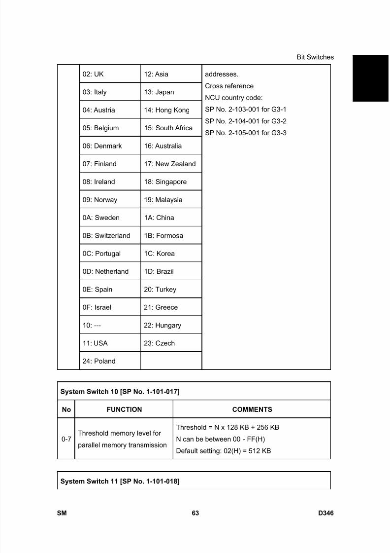
8/15/2019 Ricoh MP 4000 SM D009_D011_D012_D013 SERVICE MANUAL .pdf
http://slidepdf.com/reader/full/ricoh-mp-4000-sm-d009d011d012d013-service-manual-pdf 909/1162
Bit Switches
SM 63 D346
F a x
O p
t i o n
T y p e
5 0 0 0
D 3 4 602: UK 12: Asia
03: Italy 13: Japan
04: Austria 14: Hong Kong
05: Belgium 15: South Africa
06: Denmark 16: Australia
07: Finland 17: New Zealand
08: Ireland 18: Singapore
09: Norway 19: Malaysia
0A: Sweden 1A: China
0B: Switzerland 1B: Formosa
0C: Portugal 1C: Korea
0D: Netherland 1D: Brazil
0E: Spain 20: Turkey
0F: Israel 21: Greece
10: --- 22: Hungary
11: USA 23: Czech
24: Poland
addresses.
Cross reference
NCU country code:SP No. 2-103-001 for G3-1
SP No. 2-104-001 for G3-2
SP No. 2-105-001 for G3-3
System Switch 10 [SP No. 1-101-017]
No FUNCTION COMMENTS
0-7Threshold memory level for
parallel memory transmission
Threshold = N x 128 KB + 256 KB
N can be between 00 - FF(H)
Default setting: 02(H) = 512 KB
System Switch 11 [SP No. 1-101-018]
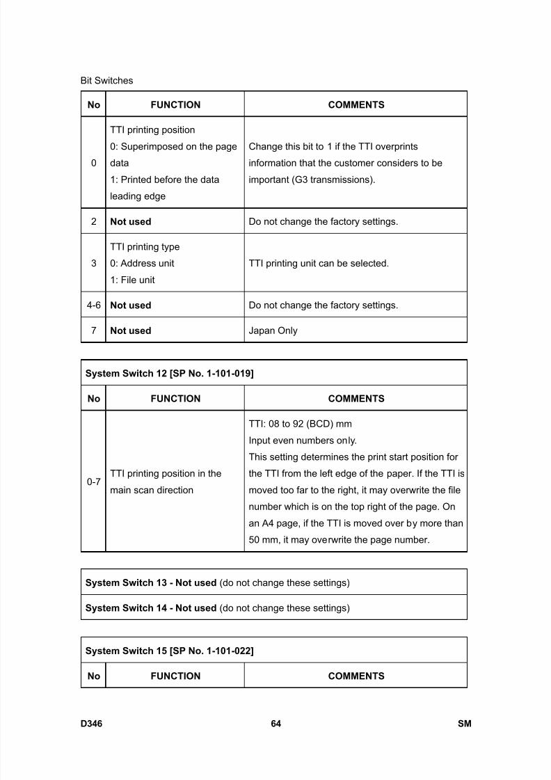
8/15/2019 Ricoh MP 4000 SM D009_D011_D012_D013 SERVICE MANUAL .pdf
http://slidepdf.com/reader/full/ricoh-mp-4000-sm-d009d011d012d013-service-manual-pdf 910/1162
Bit Switches
D346 64 SM
No FUNCTION COMMENTS
0
TTI printing position
0: Superimposed on the page
data
1: Printed before the data
leading edge
Change this bit to 1 if the TTI overprints
information that the customer considers to be
important (G3 transmissions).
2 Not used Do not change the factory settings.
3
TTI printing type
0: Address unit
1: File unit
TTI printing unit can be selected.
4-6 Not used Do not change the factory settings.
7 Not used Japan Only
System Switch 12 [SP No. 1-101-019]
No FUNCTION COMMENTS
0-7TTI printing position in the
main scan direction
TTI: 08 to 92 (BCD) mm
Input even numbers only.
This setting determines the print start position for
the TTI from the left edge of the paper. If the TTI is
moved too far to the right, it may overwrite the file
number which is on the top right of the page. On
an A4 page, if the TTI is moved over by more than
50 mm, it may overwrite the page number.
System Switch 13 - Not used (do not change these settings)
System Switch 14 - Not used (do not change these settings)
System Switch 15 [SP No. 1-101-022]
No FUNCTION COMMENTS

8/15/2019 Ricoh MP 4000 SM D009_D011_D012_D013 SERVICE MANUAL .pdf
http://slidepdf.com/reader/full/ricoh-mp-4000-sm-d009d011d012d013-service-manual-pdf 911/1162
Bit Switches
SM 65 D346
F a x
O p
t i o n
T y p e
5 0 0 0
D 3 4 60 Not used Do not change the settings.
1
Going into the Energy Saver
mode automatically
0: Enabled
1: Disabled
1: The machine will restart from the Energy Savermode quickly, because the +5V power supply is
active even in the Energy Saver mode.
2-3 Not used Do not change these settings.
4-5
Interval for preventing the
machine from entering Energy
Saver mode if there is a
pending transmission file.
Bit 5: 0, Bit 4: 0
1 min
Bit 5: 0, Bit 4: 1
30 min1
Bit 5: 1, Bit 4: 0
1 hour
Bit 5: 1, Bit 4: 1
24 hours
If there is a file waiting for transmission, the
machine does not go to Energy Saver mode
during the selected period.
After transmitting the file, if there is no file waiting
for transmission, the machine goes to the Energy
Saver mode.
6-7 Not used Do not change
System Switch 16 [SP No. 1-101-023]
No FUNCTION COMMENTS
0
Parallel Broadcasting
0: OFF1: ON
1: The machine sends messages simultaneously
using all available ports during broadcasting.
1
Priority setting for the G3 line.
0: PSTN-1 > PSTN-2 or 3
1: PSTN-2 or 3 > PSTN-1
This function allows the user to select the default
G3 line type. The optional SG3 unit(s) are required
to use the PSTN-2 or 3 setting.
4-7 Not used Do not change these settings.

8/15/2019 Ricoh MP 4000 SM D009_D011_D012_D013 SERVICE MANUAL .pdf
http://slidepdf.com/reader/full/ricoh-mp-4000-sm-d009d011d012d013-service-manual-pdf 912/1162
Bit Switches
D346 66 SM
System Switch 17 - Not used (do not change these settings)
System Switch 18 - Not used (do not change these settings)
System Switch 19 [SP No. 1-101-026]
No FUNCTION COMMENTS
0-5 Not used Do not change the settings.
6
Extended scanner page
memory after memory
option is installed
0: Disabled
1: Enabled
0: After installing the memory expansion option, the
scanner page memory is extended to 4 MB from 2
MB.
1: If this bit is set to 1 after installing the memory
expansion option, the scanner page memory is
extended to 12 MB. But the SAF memory
decreases to 18 MB.
7
Special Original mode
0: Disabled1: Enabled
1: If the customer frequently wishes to transmit a
form or letterhead which has a colored or printed
background, change this bit to “1”. “Original 1” and“Original 2” can be selected in addition to the “Text”,
“Text/Photo” and “Photo” modes.
System Switch 1A [SP No. 1-101-027]
No. FUNCTION COMMENTS
0-7LS RX memory remaining
Threshold value setting
Sets a value of 4K.
If the amount of memory remaining falls below 4K,
documents received in memory are printed to
create more space in memory.
Initial value: 0x80 (512K)
00-FF (0-1020 KB: Hex)
System Switch 1B - Not used (do not change these settings)
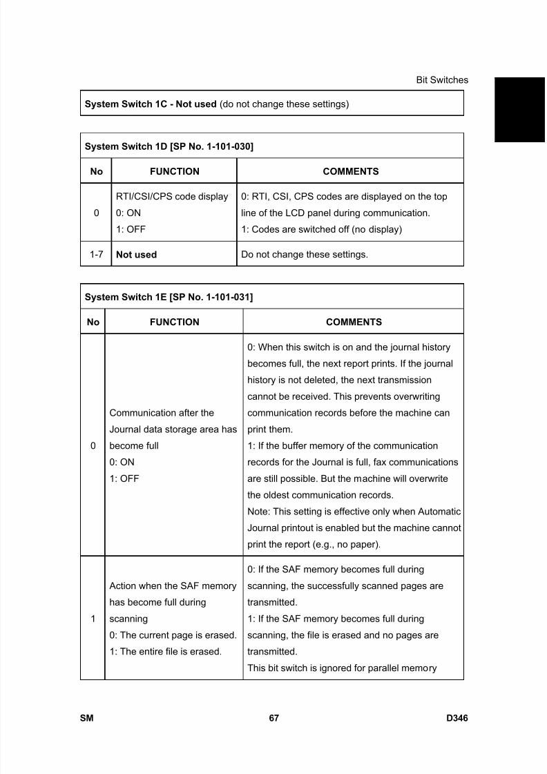
8/15/2019 Ricoh MP 4000 SM D009_D011_D012_D013 SERVICE MANUAL .pdf
http://slidepdf.com/reader/full/ricoh-mp-4000-sm-d009d011d012d013-service-manual-pdf 913/1162
Bit Switches
SM 67 D346
F a x
O p
t i o n
T y p e
5 0 0 0
D 3 4 6System Switch 1C - Not used (do not change these settings)
System Switch 1D [SP No. 1-101-030]
No FUNCTION COMMENTS
0
RTI/CSI/CPS code display
0: ON
1: OFF
0: RTI, CSI, CPS codes are displayed on the top
line of the LCD panel during communication.
1: Codes are switched off (no display)
1-7 Not used Do not change these settings.
System Switch 1E [SP No. 1-101-031]
No FUNCTION COMMENTS
0
Communication after the
Journal data storage area has
become full
0: ON
1: OFF
0: When this switch is on and the journal history
becomes full, the next report prints. If the journal
history is not deleted, the next transmission
cannot be received. This prevents overwriting
communication records before the machine can
print them.
1: If the buffer memory of the communication
records for the Journal is full, fax communications
are still possible. But the machine will overwrite
the oldest communication records.
Note: This setting is effective only when Automatic
Journal printout is enabled but the machine cannot
print the report (e.g., no paper).
1
Action when the SAF memory
has become full during
scanning
0: The current page is erased.
1: The entire file is erased.
0: If the SAF memory becomes full during
scanning, the successfully scanned pages are
transmitted.
1: If the SAF memory becomes full during
scanning, the file is erased and no pages are
transmitted.
This bit switch is ignored for parallel memory

8/15/2019 Ricoh MP 4000 SM D009_D011_D012_D013 SERVICE MANUAL .pdf
http://slidepdf.com/reader/full/ricoh-mp-4000-sm-d009d011d012d013-service-manual-pdf 914/1162
Bit Switches
D346 68 SM
transmission.
2RTI/CSI display priority0: RTI 1: CSI
This bit determines which identifier, RTI or CSI, is
displayed on the LCD while the machine is
communicating in G3 non-standard mode.
3
File No. printing
0: Enabled
1: Disabled
1: File numbers are not printed on any reports.
4
Action when authorizedreception is enabled but
authorized RTIs/CSIs are not
yet programmed
0: All fax reception is disabled
1: Faxes can be received if the
sender has an RTI or CSI
If authorized reception is enabled but the user has
stored no acceptable sender RTIs or CSIs, the
machine will not be able to receive any fax
messages.
If the customer wishes to receive messages from
any sender that includes an RTI or CSI, and to
block messages from senders that do not include
an RTI or CSI, change this bit to “1”, then enable
Authorized Reception.
Otherwise, keep this bit at “0 (default setting)”.
5-7 Not used Do not change the settings
System Switch 1F [SP No. 1-101-032]
No FUNCTION COMMENTS
0 Not used Do not change the settings.
1
Report printout after an
original jam during SAF
storage or if the SAF memory
fills up
0: Enabled
1: Disabled
0: When an original jams, or the SAF memory
overflows during scanning, a report will be printed.
Change this bit to “1” if the customer does not
want to have a report in these cases.
Memory tx – Memory storage report
Parallel memory tx – Transmission result report
2 Not used Do not change the settings.
3 Received fax print start timing 0: The machine prints each page immediately after
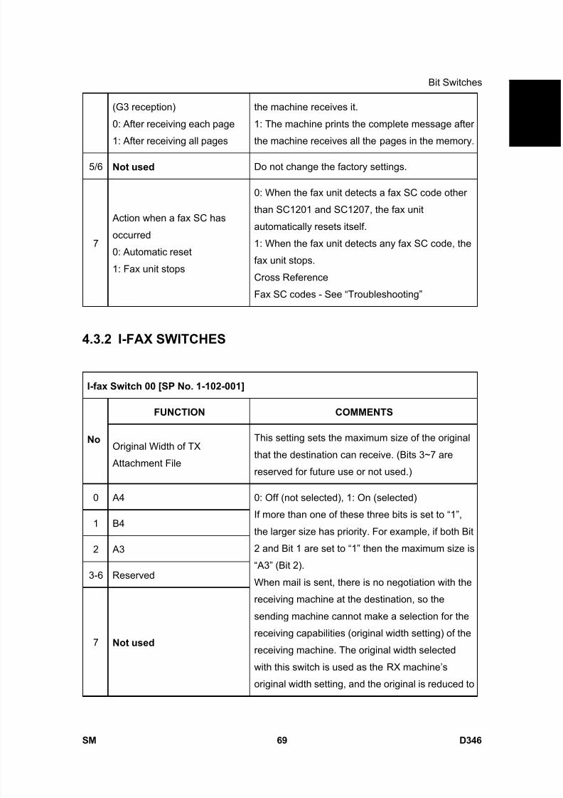
8/15/2019 Ricoh MP 4000 SM D009_D011_D012_D013 SERVICE MANUAL .pdf
http://slidepdf.com/reader/full/ricoh-mp-4000-sm-d009d011d012d013-service-manual-pdf 915/1162
Bit Switches
SM 69 D346
F a x
O p
t i o n
T y p e
5 0 0 0
D 3 4 6(G3 reception)
0: After receiving each page
1: After receiving all pages
the machine receives it.
1: The machine prints the complete message after
the machine receives all the pages in the memory.
5/6 Not used Do not change the factory settings.
7
Action when a fax SC has
occurred
0: Automatic reset
1: Fax unit stops
0: When the fax unit detects a fax SC code other
than SC1201 and SC1207, the fax unit
automatically resets itself.
1: When the fax unit detects any fax SC code, the
fax unit stops.
Cross ReferenceFax SC codes - See “Troubleshooting”
4.3.2 I-FAX SWITCHES
I-fax Switch 00 [SP No. 1-102-001]
FUNCTION COMMENTS
No Original Width of TX
Attachment File
This setting sets the maximum size of the original
that the destination can receive. (Bits 3~7 are
reserved for future use or not used.)
0 A4
1 B4
2 A3
3-6 Reserved
7 Not used
0: Off (not selected), 1: On (selected)
If more than one of these three bits is set to “1”,
the larger size has priority. For example, if both Bit
2 and Bit 1 are set to “1” then the maximum size is
“A3” (Bit 2).
When mail is sent, there is no negotiation with the
receiving machine at the destination, so the
sending machine cannot make a selection for the
receiving capabilities (original width setting) of the
receiving machine. The original width selected
with this switch is used as the RX machine’s
original width setting, and the original is reduced to
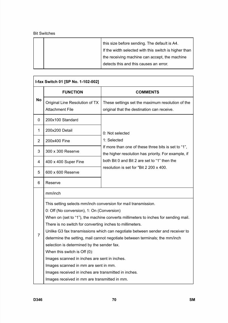
8/15/2019 Ricoh MP 4000 SM D009_D011_D012_D013 SERVICE MANUAL .pdf
http://slidepdf.com/reader/full/ricoh-mp-4000-sm-d009d011d012d013-service-manual-pdf 916/1162
Bit Switches
D346 70 SM
this size before sending. The default is A4.
If the width selected with this switch is higher than
the receiving machine can accept, the machinedetects this and this causes an error.
I-fax Switch 01 [SP No. 1-102-002]
FUNCTION COMMENTS
No Original Line Resolution of TX
Attachment File
These settings set the maximum resolution of the
original that the destination can receive.
0 200x100 Standard
1 200x200 Detail
2 200x400 Fine
3 300 x 300 Reserve
4 400 x 400 Super Fine
5 600 x 600 Reserve
6 Reserve
0: Not selected
1: Selected
If more than one of these three bits is set to “1”,
the higher resolution has priority. For example, if
both Bit 0 and Bit 2 are set to “1” then the
resolution is set for "Bit 2 200 x 400.
mm/inch
7
This setting selects mm/inch conversion for mail transmission.
0: Off (No conversion), 1: On (Conversion)
When on (set to “1”), the machine converts millimeters to inches for sending mail.
There is no switch for converting inches to millimeters.Unlike G3 fax transmissions which can negotiate between sender and receiver to
determine the setting, mail cannot negotiate between terminals; the mm/inch
selection is determined by the sender fax.
When this switch is Off (0):
Images scanned in inches are sent in inches.
Images scanned in mm are sent in mm.
Images received in inches are transmitted in inches.
Images received in mm are transmitted in mm.
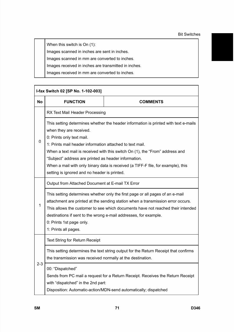
8/15/2019 Ricoh MP 4000 SM D009_D011_D012_D013 SERVICE MANUAL .pdf
http://slidepdf.com/reader/full/ricoh-mp-4000-sm-d009d011d012d013-service-manual-pdf 917/1162
Bit Switches
SM 71 D346
F a x
O p
t i o n
T y p e
5 0 0 0
D 3 4 6When this switch is On (1):
Images scanned in inches are sent in inches.
Images scanned in mm are converted to inches.Images received in inches are transmitted in inches.
Images received in mm are converted to inches.
I-fax Switch 02 [SP No. 1-102-003]
No FUNCTION COMMENTS
RX Text Mail Header Processing
0
This setting determines whether the header information is printed with text e-mails
when they are received.
0: Prints only text mail.
1: Prints mail header information attached to text mail.
When a text mail is received with this switch On (1), the “From” address and
“Subject” address are printed as header information.
When a mail with only binary data is received (a TIFF-F file, for example), this
setting is ignored and no header is printed.
Output from Attached Document at E-mail TX Error
1
This setting determines whether only the first page or all pages of an e-mail
attachment are printed at the sending station when a transmission error occurs.
This allows the customer to see which documents have not reached their intended
destinations if sent to the wrong e-mail addresses, for example.
0: Prints 1st page only.
1: Prints all pages.
Text String for Return Receipt
This setting determines the text string output for the Return Receipt that confirms
the transmission was received normally at the destination.2-3
00: “Dispatched”
Sends from PC mail a request for a Return Receipt. Receives the Return Receipt
with “dispatched” in the 2nd part:
Disposition: Automatic-action/MDN-send automatically; dispatched

8/15/2019 Ricoh MP 4000 SM D009_D011_D012_D013 SERVICE MANUAL .pdf
http://slidepdf.com/reader/full/ricoh-mp-4000-sm-d009d011d012d013-service-manual-pdf 918/1162
Bit Switches
D346 72 SM
The “dispatched” string is included in the Subject string.
01: “Displayed”
Sends from PC mail a request for a Return Receipt. Receives the Return Receiptwith “displayed” in the 2nd part:
Disposition: Automatic-action/MDN-send automatically; displayed
The “displayed” string is included in the Subject string.
10: Reserved
11: Reserved
A mail requesting a Return Receipt sent from an IFAX with this switch set to “00”
(for “dispatched”) received by Microsoft Outlook 2000 may cause an error. If any
setting other than “displayed” (01) causes a problem, change the setting to “01” toenable normal sending of the Return Receipt.
Media accept feature
4
This setting adds or does not add the media accept feature to the answer mail to
confirm a reception.
0: Does not add the media accept feature to the answer mail
1: Adds the media accept feature to the answer mail.
Use this bit switch if a problem occurs when the machine receives an answer mail,
which contains the media accept feature field.
5-6 Not Used
Image Resolution of RX Text Mail
7
This setting determines the image resolution of the received mail.
0: 200 x 200
1: 400 x 400
The “1” setting requires installation of the Function Upgrade Card in order to haveenough SAF (Store and Forward) memory to receive images at 400 x 400
resolution.
I-fax Switch 03 - Not used (do not change the settings) [ SP No. 1-102-004]
I-fax Switch 04 [SP No. 1-102-005]

8/15/2019 Ricoh MP 4000 SM D009_D011_D012_D013 SERVICE MANUAL .pdf
http://slidepdf.com/reader/full/ricoh-mp-4000-sm-d009d011d012d013-service-manual-pdf 919/1162
Bit Switches
SM 73 D346
F a x
O p
t i o n
T y p e
5 0 0 0
D 3 4 6No FUNCTION COMMENTS
Subject for Delivery TX/Memory Transfer
0
This setting determines whether the RTI/CSI registered on this machine or the
RTI/CSI of the originator is used in the subject lines of transferred documents.
0: Puts the RTI/CSI of the originator in the Subject line. If this is used, either the RTI
or CSI is used. Only one of these can be received for use in the subject line.
1: Puts the RTI/CSI registered on this machine in the Subject line.
When this switch is used to transfer and deliver mail to a PC, the information in the
Subject line that indicates where the transmission originated can be used to
determine automatically the destination folder for each e-mail.
1
Subject corresponding to mail post database
0: Standard subject
1: Mail post database subject
The standard subject is replaced by the mail post database subject in the following
three cases:
1) When the service technician sets the service (software) switch.
2) When memory sending, delivery specified by F code or SMTP reception is done.
3) With relay broadcasting (1st stage without the Schmidt 4 function).
This switch does not apply for condition 3) when the RX system is set up
for memory sending, delivery by F-code, sending with SMTP RX and when
operators are using FOL (to prevent problems when receiving
transmissions).
2-7 Not Used
I-fax Switch 05 [SP No. 1-102-006]
No FUNCTION COMMENTS
Mail Addresses of SMTP Broadcast Recipients
0Determines whether the e-mail addresses of the destinations that receive
transmissions broadcasted using SMTP protocol are recorded in the Journal.
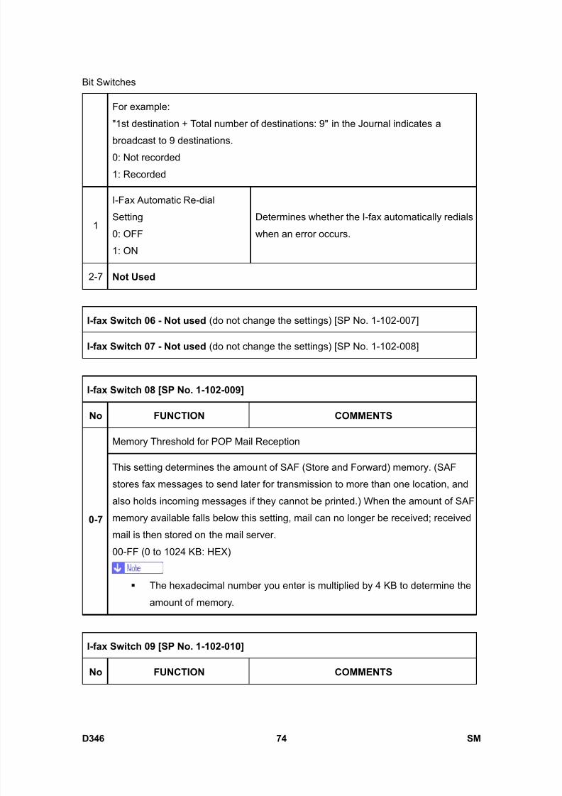
8/15/2019 Ricoh MP 4000 SM D009_D011_D012_D013 SERVICE MANUAL .pdf
http://slidepdf.com/reader/full/ricoh-mp-4000-sm-d009d011d012d013-service-manual-pdf 920/1162
Bit Switches
D346 74 SM
For example:
"1st destination + Total number of destinations: 9" in the Journal indicates a
broadcast to 9 destinations.0: Not recorded
1: Recorded
1
I-Fax Automatic Re-dial
Setting
0: OFF
1: ON
Determines whether the I-fax automatically redials
when an error occurs.
2-7 Not Used
I-fax Switch 06 - Not used (do not change the settings) [SP No. 1-102-007]
I-fax Switch 07 - Not used (do not change the settings) [SP No. 1-102-008]
I-fax Switch 08 [SP No. 1-102-009]
No FUNCTION COMMENTS
Memory Threshold for POP Mail Reception
0-7
This setting determines the amount of SAF (Store and Forward) memory. (SAF
stores fax messages to send later for transmission to more than one location, and
also holds incoming messages if they cannot be printed.) When the amount of SAF
memory available falls below this setting, mail can no longer be received; received
mail is then stored on the mail server.
00-FF (0 to 1024 KB: HEX)
The hexadecimal number you enter is multiplied by 4 KB to determine the
amount of memory.
I-fax Switch 09 [SP No. 1-102-010]
No FUNCTION COMMENTS
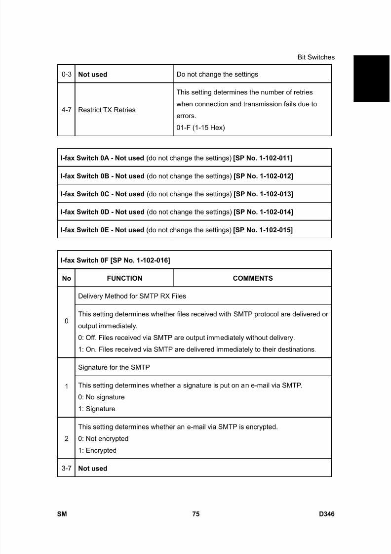
8/15/2019 Ricoh MP 4000 SM D009_D011_D012_D013 SERVICE MANUAL .pdf
http://slidepdf.com/reader/full/ricoh-mp-4000-sm-d009d011d012d013-service-manual-pdf 921/1162
Bit Switches
SM 75 D346
F a x
O p
t i o n
T y p e
5 0 0 0
D 3 4 60-3 Not used Do not change the settings
4-7 Restrict TX Retries
This setting determines the number of retries
when connection and transmission fails due to
errors.
01-F (1-15 Hex)
I-fax Switch 0A - Not used (do not change the settings) [SP No. 1-102-011]
I-fax Switch 0B - Not used (do not change the settings) [SP No. 1-102-012]
I-fax Switch 0C - Not used (do not change the settings) [SP No. 1-102-013]
I-fax Switch 0D - Not used (do not change the settings) [SP No. 1-102-014]
I-fax Switch 0E - Not used (do not change the settings) [SP No. 1-102-015]
I-fax Switch 0F [SP No. 1-102-016]
No FUNCTION COMMENTS
Delivery Method for SMTP RX Files
0This setting determines whether files received with SMTP protocol are delivered or
output immediately.
0: Off. Files received via SMTP are output immediately without delivery.
1: On. Files received via SMTP are delivered immediately to their destinations.
Signature for the SMTP
1 This setting determines whether a signature is put on an e-mail via SMTP.0: No signature
1: Signature
2
This setting determines whether an e-mail via SMTP is encrypted.
0: Not encrypted
1: Encrypted
3-7 Not used
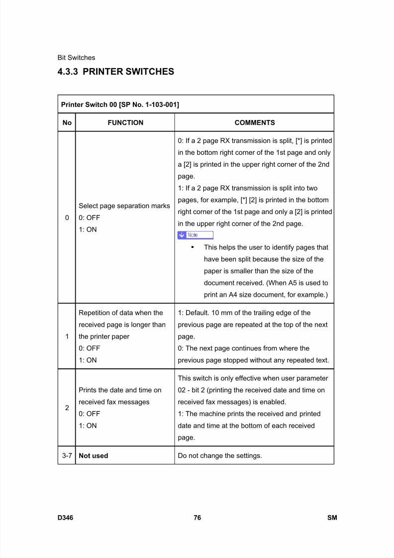
8/15/2019 Ricoh MP 4000 SM D009_D011_D012_D013 SERVICE MANUAL .pdf
http://slidepdf.com/reader/full/ricoh-mp-4000-sm-d009d011d012d013-service-manual-pdf 922/1162
Bit Switches
D346 76 SM
4.3.3 PRINTER SWITCHES
Printer Switch 00 [SP No. 1-103-001]
No FUNCTION COMMENTS
0
Select page separation marks
0: OFF
1: ON
0: If a 2 page RX transmission is split, [*] is printed
in the bottom right corner of the 1st page and only
a [2] is printed in the upper right corner of the 2nd
page.
1: If a 2 page RX transmission is split into two
pages, for example, [*] [2] is printed in the bottom
right corner of the 1st page and only a [2] is printed
in the upper right corner of the 2nd page.
This helps the user to identify pages that
have been split because the size of the
paper is smaller than the size of the
document received. (When A5 is used to
print an A4 size document, for example.)
1
Repetition of data when the
received page is longer than
the printer paper
0: OFF
1: ON
1: Default. 10 mm of the trailing edge of the
previous page are repeated at the top of the next
page.
0: The next page continues from where the
previous page stopped without any repeated text.
2
Prints the date and time onreceived fax messages
0: OFF
1: ON
This switch is only effective when user parameter
02 - bit 2 (printing the received date and time onreceived fax messages) is enabled.
1: The machine prints the received and printed
date and time at the bottom of each received
page.
3-7 Not used Do not change the settings.
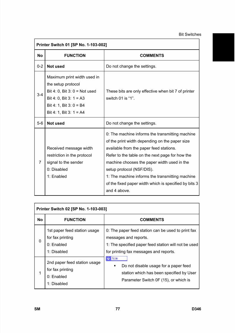
8/15/2019 Ricoh MP 4000 SM D009_D011_D012_D013 SERVICE MANUAL .pdf
http://slidepdf.com/reader/full/ricoh-mp-4000-sm-d009d011d012d013-service-manual-pdf 923/1162
Bit Switches
SM 77 D346
F a x
O p
t i o n
T y p e
5 0 0 0
D 3 4 6Printer Switch 01 [SP No. 1-103-002]
No FUNCTION COMMENTS
0-2 Not used Do not change the settings.
3-4
Maximum print width used in
the setup protocol
Bit 4: 0, Bit 3: 0 = Not used
Bit 4: 0, Bit 3: 1 = A3
Bit 4: 1, Bit 3: 0 = B4
Bit 4: 1, Bit 3: 1 = A4
These bits are only effective when bit 7 of printer
switch 01 is “1”.
5-6 Not used Do not change the settings.
7
Received message width
restriction in the protocol
signal to the sender
0: Disabled
1: Enabled
0: The machine informs the transmitting machine
of the print width depending on the paper size
available from the paper feed stations.
Refer to the table on the next page for how the
machine chooses the paper width used in the
setup protocol (NSF/DIS).
1: The machine informs the transmitting machine
of the fixed paper width which is specified by bits 3
and 4 above.
Printer Switch 02 [SP No. 1-103-003]
No FUNCTION COMMENTS
0
1st paper feed station usage
for fax printing
0: Enabled
1: Disabled
1
2nd paper feed station usage
for fax printing
0: Enabled
1: Disabled
0: The paper feed station can be used to print fax
messages and reports.
1: The specified paper feed station will not be used
for printing fax messages and reports.
Do not disable usage for a paper feed
station which has been specified by User
Parameter Switch 0F (15), or which is
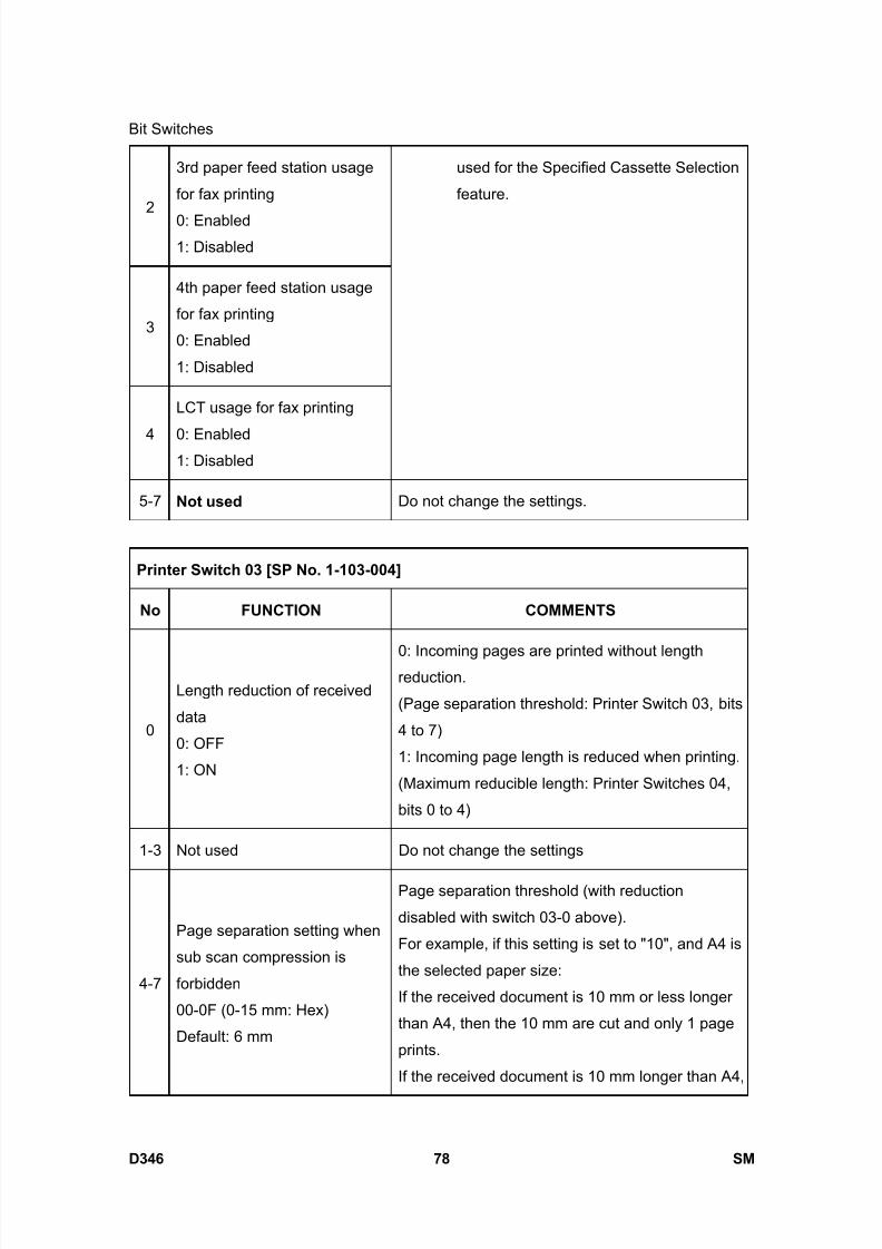
8/15/2019 Ricoh MP 4000 SM D009_D011_D012_D013 SERVICE MANUAL .pdf
http://slidepdf.com/reader/full/ricoh-mp-4000-sm-d009d011d012d013-service-manual-pdf 924/1162
Bit Switches
D346 78 SM
2
3rd paper feed station usage
for fax printing
0: Enabled1: Disabled
3
4th paper feed station usage
for fax printing
0: Enabled
1: Disabled
4
LCT usage for fax printing
0: Enabled1: Disabled
used for the Specified Cassette Selection
feature.
5-7 Not used Do not change the settings.
Printer Switch 03 [SP No. 1-103-004]
No FUNCTION COMMENTS
0
Length reduction of received
data
0: OFF
1: ON
0: Incoming pages are printed without lengthreduction.
(Page separation threshold: Printer Switch 03, bits
4 to 7)
1: Incoming page length is reduced when printing.
(Maximum reducible length: Printer Switches 04,
bits 0 to 4)
1-3 Not used Do not change the settings
4-7
Page separation setting when
sub scan compression is
forbidden
00-0F (0-15 mm: Hex)
Default: 6 mm
Page separation threshold (with reduction
disabled with switch 03-0 above).
For example, if this setting is set to "10", and A4 is
the selected paper size:
If the received document is 10 mm or less longer
than A4, then the 10 mm are cut and only 1 page
prints.
If the received document is 10 mm longer than A4,
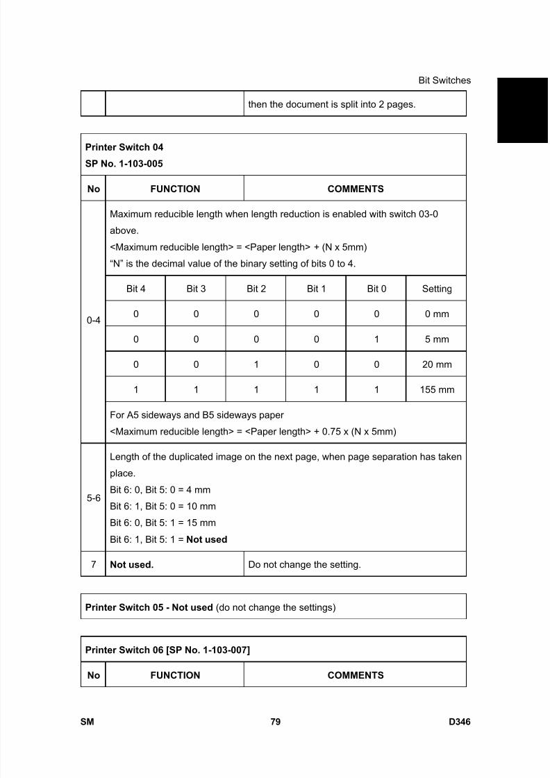
8/15/2019 Ricoh MP 4000 SM D009_D011_D012_D013 SERVICE MANUAL .pdf
http://slidepdf.com/reader/full/ricoh-mp-4000-sm-d009d011d012d013-service-manual-pdf 925/1162
Bit Switches
SM 79 D346
F a x
O p
t i o n
T y p e
5 0 0 0
D 3 4 6then the document is split into 2 pages.
Printer Switch 04
SP No. 1-103-005
No FUNCTION COMMENTS
Maximum reducible length when length reduction is enabled with switch 03-0
above.
<Maximum reducible length> = <Paper length> + (N x 5mm)
“N” is the decimal value of the binary setting of bits 0 to 4.
Bit 4 Bit 3 Bit 2 Bit 1 Bit 0 Setting
0 0 0 0 0 0 mm
0 0 0 0 1 5 mm
0 0 1 0 0 20 mm
1 1 1 1 1 155 mm
0-4
For A5 sideways and B5 sideways paper
<Maximum reducible length> = <Paper length> + 0.75 x (N x 5mm)
5-6
Length of the duplicated image on the next page, when page separation has taken
place.
Bit 6: 0, Bit 5: 0 = 4 mm
Bit 6: 1, Bit 5: 0 = 10 mm
Bit 6: 0, Bit 5: 1 = 15 mm
Bit 6: 1, Bit 5: 1 = Not used
7 Not used. Do not change the setting.
Printer Switch 05 - Not used (do not change the settings)
Printer Switch 06 [SP No. 1-103-007]
No FUNCTION COMMENTS
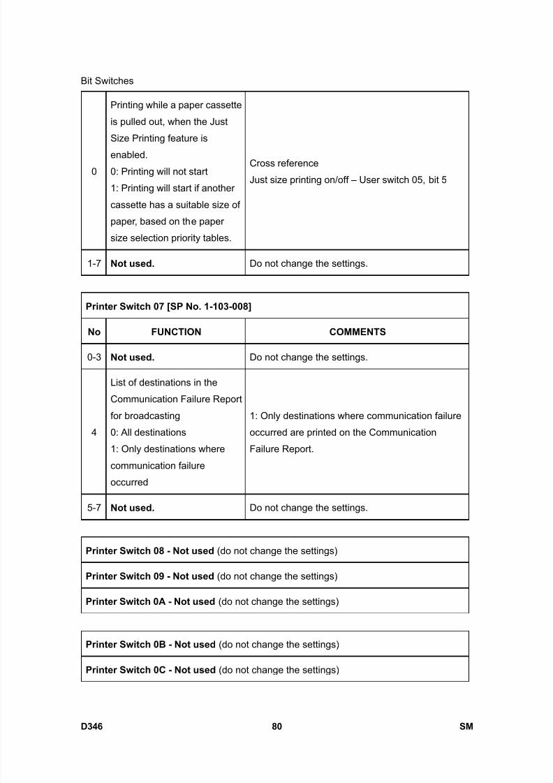
8/15/2019 Ricoh MP 4000 SM D009_D011_D012_D013 SERVICE MANUAL .pdf
http://slidepdf.com/reader/full/ricoh-mp-4000-sm-d009d011d012d013-service-manual-pdf 926/1162
Bit Switches
D346 80 SM
0
Printing while a paper cassette
is pulled out, when the Just
Size Printing feature isenabled.
0: Printing will not start
1: Printing will start if another
cassette has a suitable size of
paper, based on the paper
size selection priority tables.
Cross reference
Just size printing on/off – User switch 05, bit 5
1-7 Not used. Do not change the settings.
Printer Switch 07 [SP No. 1-103-008]
No FUNCTION COMMENTS
0-3 Not used. Do not change the settings.
4
List of destinations in the
Communication Failure Report
for broadcasting
0: All destinations
1: Only destinations where
communication failure
occurred
1: Only destinations where communication failure
occurred are printed on the Communication
Failure Report.
5-7 Not used. Do not change the settings.
Printer Switch 08 - Not used (do not change the settings)
Printer Switch 09 - Not used (do not change the settings)
Printer Switch 0A - Not used (do not change the settings)
Printer Switch 0B - Not used (do not change the settings)
Printer Switch 0C - Not used (do not change the settings)
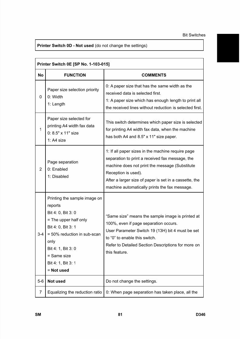
8/15/2019 Ricoh MP 4000 SM D009_D011_D012_D013 SERVICE MANUAL .pdf
http://slidepdf.com/reader/full/ricoh-mp-4000-sm-d009d011d012d013-service-manual-pdf 927/1162
Bit Switches
SM 81 D346
F a x
O p
t i o n
T y p e
5 0 0 0
D 3 4 6Printer Switch 0D - Not used (do not change the settings)
Printer Switch 0E [SP No. 1-103-015]
No FUNCTION COMMENTS
0
Paper size selection priority
0: Width
1: Length
0: A paper size that has the same width as the
received data is selected first.
1: A paper size which has enough length to print all
the received lines without reduction is selected first.
1
Paper size selected forprinting A4 width fax data
0: 8.5" x 11" size
1: A4 size
This switch determines which paper size is selected
for printing A4 width fax data, when the machine
has both A4 and 8.5" x 11" size paper.
2
Page separation
0: Enabled
1: Disabled
1: If all paper sizes in the machine require page
separation to print a received fax message, the
machine does not print the message (Substitute
Reception is used).
After a larger size of paper is set in a cassette, the
machine automatically prints the fax message.
3-4
Printing the sample image on
reports
Bit 4: 0, Bit 3: 0
= The upper half only
Bit 4: 0, Bit 3: 1
= 50% reduction in sub-scan
only
Bit 4: 1, Bit 3: 0
= Same size
Bit 4: 1, Bit 3: 1
= Not used
“Same size” means the sample image is printed at
100%, even if page separation occurs.
User Parameter Switch 19 (13H) bit 4 must be set
to “0” to enable this switch.Refer to Detailed Section Descriptions for more on
this feature.
5-6 Not used Do not change the settings.
7 Equalizing the reduction ratio 0: When page separation has taken place, all the
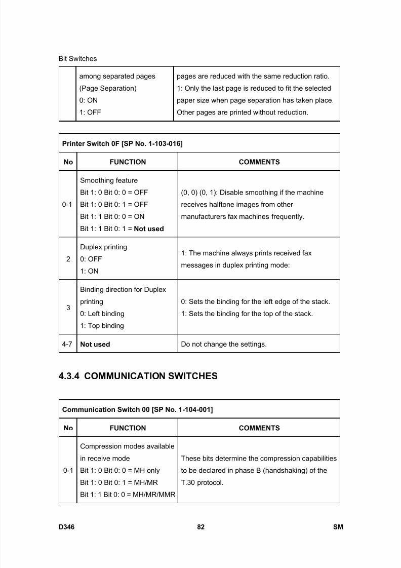
8/15/2019 Ricoh MP 4000 SM D009_D011_D012_D013 SERVICE MANUAL .pdf
http://slidepdf.com/reader/full/ricoh-mp-4000-sm-d009d011d012d013-service-manual-pdf 928/1162
Bit Switches
D346 82 SM
among separated pages
(Page Separation)
0: ON1: OFF
pages are reduced with the same reduction ratio.
1: Only the last page is reduced to fit the selected
paper size when page separation has taken place.Other pages are printed without reduction.
Printer Switch 0F [SP No. 1-103-016]
No FUNCTION COMMENTS
0-1
Smoothing feature
Bit 1: 0 Bit 0: 0 = OFF
Bit 1: 0 Bit 0: 1 = OFF
Bit 1: 1 Bit 0: 0 = ON
Bit 1: 1 Bit 0: 1 = Not used
(0, 0) (0, 1): Disable smoothing if the machine
receives halftone images from other
manufacturers fax machines frequently.
2
Duplex printing
0: OFF
1: ON
1: The machine always prints received fax
messages in duplex printing mode:
3
Binding direction for Duplex
printing
0: Left binding
1: Top binding
0: Sets the binding for the left edge of the stack.
1: Sets the binding for the top of the stack.
4-7 Not used Do not change the settings.
4.3.4 COMMUNICATION SWITCHES
Communication Switch 00 [SP No. 1-104-001]
No FUNCTION COMMENTS
0-1
Compression modes available
in receive mode
Bit 1: 0 Bit 0: 0 = MH only
Bit 1: 0 Bit 0: 1 = MH/MR
Bit 1: 1 Bit 0: 0 = MH/MR/MMR
These bits determine the compression capabilities
to be declared in phase B (handshaking) of the
T.30 protocol.

8/15/2019 Ricoh MP 4000 SM D009_D011_D012_D013 SERVICE MANUAL .pdf
http://slidepdf.com/reader/full/ricoh-mp-4000-sm-d009d011d012d013-service-manual-pdf 929/1162
Bit Switches
SM 83 D346
F a x
O p
t i o n
T y p e
5 0 0 0
D 3 4 6Bit 1: 1 Bit 0: 1
= MH/MR/MMR/JBIG
2-3
Compression modes available
in transmit mode
Bit 3: 0 Bit 2: 0 = MH only
Bit 3: 0 Bit 2: 1 = MH/MR
Bit 3: 1 Bit 2: 0 = MH/MR/MMR
Bit 3: 1 Bit 2: 1
= MH/MR/MMR/JBIG
These bits determine the compression capabilities
to be used in the transmission and to be declared
in phase B (handshaking) of the T.30 protocol.
4 Not used Do not change the settings.
5
JBIG compression method:
Reception
0: Only basic supported
1: Basic and optional both
supported
Change the setting when communication
problems occur using JBIG compression.
6
JBIG compression method:
Transmission
0: Basic mode priority
1: Optional mode priority
Change the setting when communication
problems occur using JBIG compression.
7
Closed network (reception)
0: Disabled
1: Enabled
1: Reception will not go ahead if the polling ID
code of the remote terminal does not match the
polling ID code of the local terminal. This function
is only available in NSF/NSS mode.
Communication Switch 01 [SP No. 1-104-002]
No FUNCTION COMMENTS
0ECM
0: Off 1: On
If this bit is set to 0, ECM is switched off for all
communications.
In addition, V.8 protocol and JBIG compression
are switched off automatically.
1 Not used Do not change the settings.

8/15/2019 Ricoh MP 4000 SM D009_D011_D012_D013 SERVICE MANUAL .pdf
http://slidepdf.com/reader/full/ricoh-mp-4000-sm-d009d011d012d013-service-manual-pdf 930/1162
Bit Switches
D346 84 SM
2-3
Wrong connection prevention
method
Bit 3: 0, Bit 2: 0 = OFF
Bit 3: 0, Bit 2: 1 = 8 digit CSI
Bit 3: 1, Bit 2: 0 = 4 digit CSI
Bit 3: 1, Bit 2: 1 = CSI/RTI
(0,1) - The machine will disconnect the line without
sending a fax message, if the last 8 digits of the
received CSI do not match the last 8 digits of thedialed telephone number. This does not work
when manually dialed.
(1,0) - The same as above, except that only the
last 4 digits are compared.
(1,1) - The machine will disconnect the line without
sending a fax message, if the other end does not
identify itself with an RTI or CSI.
(0,0) - Nothing is checked; transmission willalways go ahead.
This function does not work when dialing
is done from the external telephone.
4-5 Not used Do not change the setting.
6-7
Maximum printable page
length available
Bit 7: 0 Bit 6: 0 = No limit
Bit 7: 0 Bit 6: 1 = B4 (364 mm)
Bit 7: 1 Bit 6: 0 = A4 (297 mm)
Bit 7: 1 Bit 6: 1 = Not used
The setting determined by these bits is informed tothe transmitting terminal in the pre-message
protocol exchange (in the DIS/NSF frames).
Communication Switch 02 [SP No. 1-104-003]
No FUNCTION COMMENTS
If there are more consecutive error lines in the
received page than the threshold, the machine will
send a negative response. The Low and High
threshold values depend on the sub-scan
resolution, and are as follows.
100 dpi 6(L) 12(H)
0G3 Burst error threshold
0: Low 1: High
200 dpi 12(L) 24(H)

8/15/2019 Ricoh MP 4000 SM D009_D011_D012_D013 SERVICE MANUAL .pdf
http://slidepdf.com/reader/full/ricoh-mp-4000-sm-d009d011d012d013-service-manual-pdf 931/1162
Bit Switches
SM 85 D346
F a x
O p
t i o n
T y p e
5 0 0 0
D 3 4 6300 dpi 18(L) 36(H)
400 dpi 24(L) 48(H)
1 Acceptable total error line ratio
0: 5% 1: 10%
If the error line ratio for a page exceeds the
acceptable ratio, RTN will be sent to the other end.
2
Treatment of pages received
with errors during G3
reception
0: Deleted from memory
without printing
1: Printed
0: Pages received with errors are not printed.
3
Hang-up decision when a
negative code (RTN or PIN) is
received during G3 immediate
transmission
0: No hang-up, 1: Hang-up
0: The next page will be sent even if RTN or PIN is
received.
1: The machine will send DCN and hang up if it
receives RTN or PIN.
This bit is ignored for memory transmissions or if
ECM is being used.
4-7 Not used Do not change the settings.
Communication Switch 03 [SP No. 1-104-004]
No FUNCTION COMMENTS
0-7
Maximum number of page
retransmissions in a G3
memory transmission
00 - FF (Hex) times.
This setting is not used if ECM is switched on.
Default setting - 03(H)
Communication Switch 04 - Not used (do not change the settings)
Communication Switch 05 - Not used (do not change the settings)
Communication Switch 06 - Not used (do not change the settings)
Communication Switch 07 - Not used (do not change the settings)
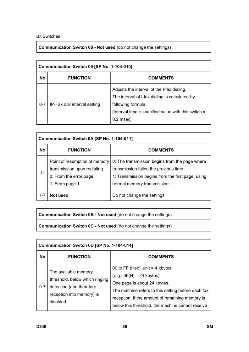
8/15/2019 Ricoh MP 4000 SM D009_D011_D012_D013 SERVICE MANUAL .pdf
http://slidepdf.com/reader/full/ricoh-mp-4000-sm-d009d011d012d013-service-manual-pdf 932/1162
Bit Switches
D346 86 SM
Communication Switch 08 - Not used (do not change the settings)
Communication Switch 09 [SP No. 1-104-010]
No FUNCTION COMMENTS
0-7 IP-Fax dial interval setting
Adjusts the interval of the I-fax dialing.
The interval of I-fax dialing is calculated by
following formula.
[Interval time = specified value with this switch x
0.2 msec]
Communication Switch 0A [SP No. 1-104-011]
No FUNCTION COMMENTS
0
Point of resumption of memory
transmission upon redialing
0: From the error page
1: From page 1
0: The transmission begins from the page where
transmission failed the previous time.
1: Transmission begins from the first page, using
normal memory transmission.
1-7 Not used Do not change the settings.
Communication Switch 0B - Not used (do not change the settings)
Communication Switch 0C - Not used (do not change the settings)
Communication Switch 0D [SP No. 1-104-014]
No FUNCTION COMMENTS
0-7
The available memory
threshold, below which ringing
detection (and therefore
reception into memory) is
disabled
00 to FF (Hex), unit = 4 kbytes
(e.g., 06(H) = 24 kbytes)
One page is about 24 kbytes.
The machine refers to this setting before each fax
reception. If the amount of remaining memory is
below this threshold, the machine cannot receive

8/15/2019 Ricoh MP 4000 SM D009_D011_D012_D013 SERVICE MANUAL .pdf
http://slidepdf.com/reader/full/ricoh-mp-4000-sm-d009d011d012d013-service-manual-pdf 933/1162
Bit Switches
SM 87 D346
F a x
O p
t i o n
T y p e
5 0 0 0
D 3 4 6any fax messages.
If this setting is kept at 0, the machine will detect
ringing signals and go into receive mode even ifthere is no memory available. This will result in
communication failure.
Communication Switch 0E [SP No. 1-104-015]
No FUNCTION COMMENTS
0-7Minimum interval between
automatic dialing attempts
06 to FF (Hex), unit = 2 s
(e.g., 06(H) = 12 s)
This value is the minimum time that the machine
waits before it dials the next destination.
Communication Switch 0F – Not used (do not change the settings.)
Communication Switch 10 [SP No. 1-104-017]
No FUNCTION COMMENTS
0-7
Memory transmission:
Maximum number of dialing
attempts to the same
destination
01 – FE (Hex) times
Communication Switch 11 – Not used (do not change the settings.)
Communication Switch 12 [SP No. 1-104-019]
No FUNCTION COMMENTS
0-7
Memory transmission: Interval
between dialing attempts to
the same destination
01 – FF (Hex) minutes

8/15/2019 Ricoh MP 4000 SM D009_D011_D012_D013 SERVICE MANUAL .pdf
http://slidepdf.com/reader/full/ricoh-mp-4000-sm-d009d011d012d013-service-manual-pdf 934/1162
Bit Switches
D346 88 SM
Communication Switch 13 – Not used (do not change the settings.)
Communication Switch 14 [SP No. 1-104-021]
No FUNCTION COMMENTS
0Inch-to-mm conversion duringtransmission
0: Disabled 1: Enabled
0: In immediate transmission, data scanned in inch
format are transmitted without conversion.
In memory transmission, data stored in the SAF
memory in mm format are transmitted without
conversion.
Note: When storing the scanned data into SAF
memory, the fax unit always converts the data into
mm format.
1: The machine converts the scanned data or
stored data in the SAF memory to the format
which was specified in the set-up protocol
(DIS/NSF) before transmission.
1-5 Not used Do not change the factory settings.
6-7
Available unit of resolution in
which fax messages are
received
Bit 7: 0, Bit 6: 0 = mm
Bit 7: 0, Bit 6: 1 = inch
Bit 7: 1, Bit 6: 0 = mm and inch
(default)
Bit 7: 1, Bit 6: 1 = Not used
For the best performance, do not change the
factory settings.
The setting determined by these bits is informed to
the transmitting terminal in the pre-message
protocol exchange (in the DIS/NSF frames).
Communication Switch 15 – Not used (do not change the settings)
Communication Switch 16 [SP No. 1-104-023]
No FUNCTION COMMENTS
0 Not used Do not change the factory settings.
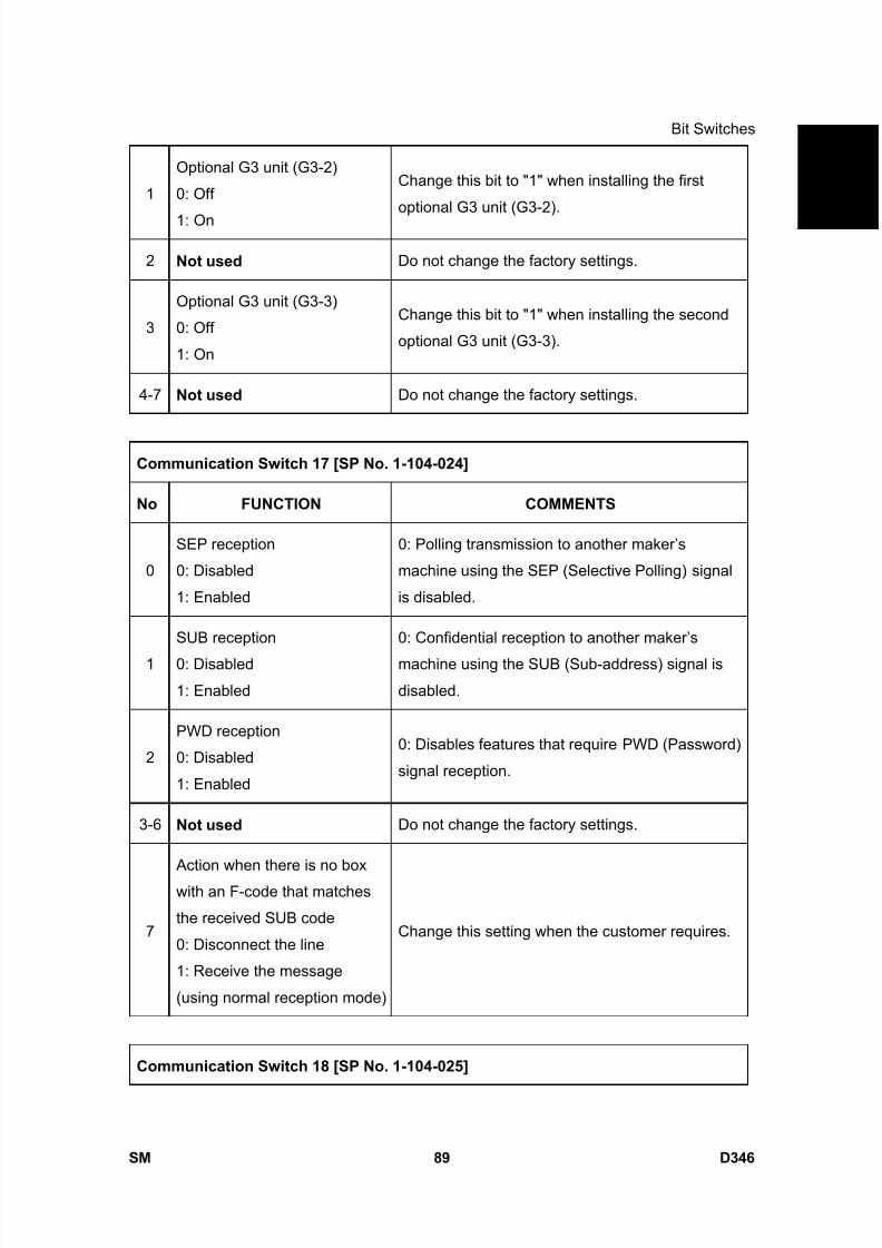
8/15/2019 Ricoh MP 4000 SM D009_D011_D012_D013 SERVICE MANUAL .pdf
http://slidepdf.com/reader/full/ricoh-mp-4000-sm-d009d011d012d013-service-manual-pdf 935/1162
Bit Switches
SM 89 D346
F a x
O p
t i o n
T y p e
5 0 0 0
D 3 4 6
1
Optional G3 unit (G3-2)
0: Off
1: On
Change this bit to "1" when installing the first
optional G3 unit (G3-2).
2 Not used Do not change the factory settings.
3
Optional G3 unit (G3-3)
0: Off
1: On
Change this bit to "1" when installing the second
optional G3 unit (G3-3).
4-7 Not used Do not change the factory settings.
Communication Switch 17 [SP No. 1-104-024]
No FUNCTION COMMENTS
0
SEP reception
0: Disabled
1: Enabled
0: Polling transmission to another maker’s
machine using the SEP (Selective Polling) signal
is disabled.
1
SUB reception
0: Disabled
1: Enabled
0: Confidential reception to another maker’s
machine using the SUB (Sub-address) signal is
disabled.
2
PWD reception
0: Disabled
1: Enabled
0: Disables features that require PWD (Password)
signal reception.
3-6 Not used Do not change the factory settings.
7
Action when there is no box
with an F-code that matches
the received SUB code
0: Disconnect the line
1: Receive the message
(using normal reception mode)
Change this setting when the customer requires.
Communication Switch 18 [SP No. 1-104-025]

8/15/2019 Ricoh MP 4000 SM D009_D011_D012_D013 SERVICE MANUAL .pdf
http://slidepdf.com/reader/full/ricoh-mp-4000-sm-d009d011d012d013-service-manual-pdf 936/1162
Bit Switches
D346 90 SM
No FUNCTION COMMENTS
0-4 Not used Do not change the factory settings.
5
IP-Fax dial-in routing selection
0: Off
1: On
1: Transfers receiving data to each IP-Fax dial-in
number.
IP-Fax dial-in number is 4 digit-number.
6-7 Not used Do not change the factory settings.
Communication Switch 19 - Not used (do not change the settings)
Communication Switch 1A - Not used (do not change the settings)
Communication Switch 1B [SP No. 1-104-028]
No FUNCTION COMMENTS
0-7
Extension access code (0 to 7)
to turn V.8 protocol On/Off0: On
1: Off
If the PABX does not support V.8/V.34 protocol
procedure, set this bit to “1” to disable V.8.
Example: If “0” is the PSTN access code, set bit 0to 1. When the machine detects “0” as the first
dialed number, it automatically disables V.8
protocol. (Alternatively, if “3” is the PSTN access
code, set bit 3 to 1.)
Communication Switch 1C [SP No. 1-104-029]
No FUNCTION COMMENTS
0-1
Extension access code (8 and
9) to turn V.8 protocol On/Off
0: On
1: Off
Refer to communication switch 1B.
Example: If “8” is the PSTN access code, set bit 0
to 1. When the machine detects “8” as the first
dialed number, it automatically disables V.8
protocol. (If “9” is the PSTN access code, use bit
1.)
2-7 Not used Do not change the settings.

8/15/2019 Ricoh MP 4000 SM D009_D011_D012_D013 SERVICE MANUAL .pdf
http://slidepdf.com/reader/full/ricoh-mp-4000-sm-d009d011d012d013-service-manual-pdf 937/1162
Bit Switches
SM 91 D346
F a x
O p
t i o n
T y p e
5 0 0 0
D 3 4 6
Communication Switch 1D - Not used (do not change the settings)
Communication Switch 1E - Not used (do not change the settings)
Communication Switch 1F - Not used (do not change the settings)
4.3.5 G3 SWITCHES
G3 Switch 00 [SP No. 1-105-001]
No FUNCTION COMMENTS
0
1
Monitor speaker during
communication (tx and rx)
Bit 1: 0, Bit 0: 0 = Disabled
Bit 1: 0, Bit 0: 1 = Up to Phase
B
Bit 1: 1, Bit 0: 0 = All the time
Bit 1: 1, Bit 0: 1 = Not used
(0, 0): The monitor speaker is disabled all through
the communication.
(0, 1): The monitor speaker is on up to phase B in
the T.30 protocol.
(1, 0): Used for testing. The monitor speaker is on
all through the communication. Make sure that you
reset these bits after testing.
2
Monitor speaker during
memory transmission
0: Disabled 1: Enabled
1: The monitor speaker is enabled during memory
transmission.
3-5 Not used Do not change the settings.
6
G3 mode selection for direct
line
0: Off
1: On
1: G3 communication through the direct line is
enabled.
7 Not used Do not change the settings.
G3 Switch 01 [SP No. 1-105-002]
No FUNCTION COMMENTS
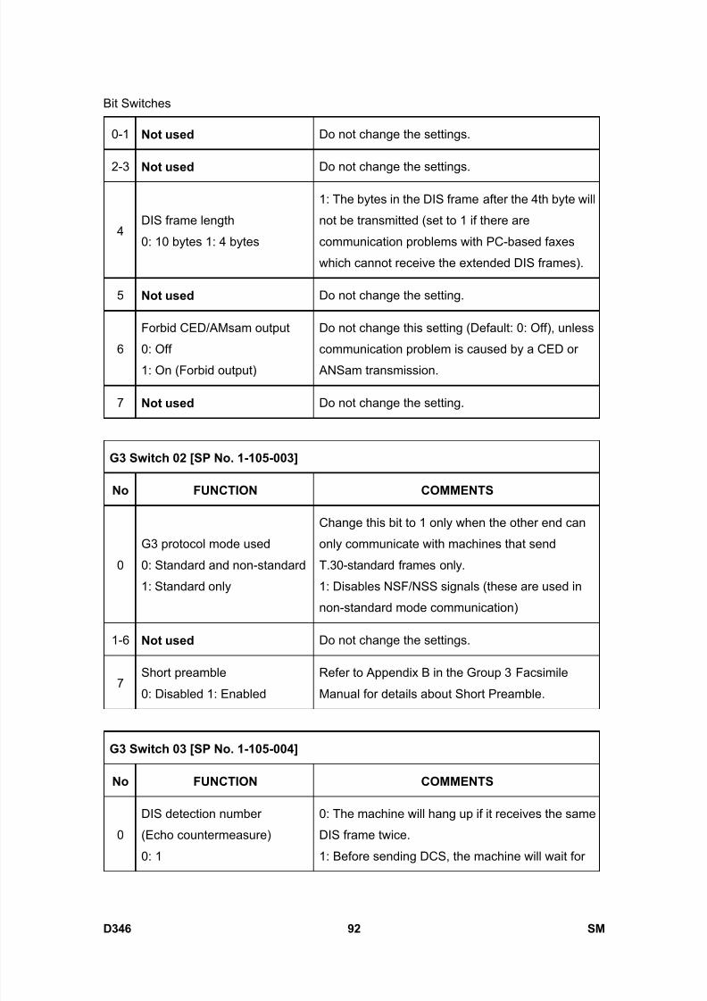
8/15/2019 Ricoh MP 4000 SM D009_D011_D012_D013 SERVICE MANUAL .pdf
http://slidepdf.com/reader/full/ricoh-mp-4000-sm-d009d011d012d013-service-manual-pdf 938/1162
Bit Switches
D346 92 SM
0-1 Not used Do not change the settings.
2-3 Not used Do not change the settings.
4DIS frame length
0: 10 bytes 1: 4 bytes
1: The bytes in the DIS frame after the 4th byte will
not be transmitted (set to 1 if there are
communication problems with PC-based faxes
which cannot receive the extended DIS frames).
5 Not used Do not change the setting.
6
Forbid CED/AMsam output
0: Off1: On (Forbid output)
Do not change this setting (Default: 0: Off), unless
communication problem is caused by a CED or ANSam transmission.
7 Not used Do not change the setting.
G3 Switch 02 [SP No. 1-105-003]
No FUNCTION COMMENTS
0
G3 protocol mode used
0: Standard and non-standard
1: Standard only
Change this bit to 1 only when the other end canonly communicate with machines that send
T.30-standard frames only.
1: Disables NSF/NSS signals (these are used in
non-standard mode communication)
1-6 Not used Do not change the settings.
7Short preamble
0: Disabled 1: Enabled
Refer to Appendix B in the Group 3 Facsimile
Manual for details about Short Preamble.
G3 Switch 03 [SP No. 1-105-004]
No FUNCTION COMMENTS
0
DIS detection number
(Echo countermeasure)
0: 1
0: The machine will hang up if it receives the same
DIS frame twice.
1: Before sending DCS, the machine will wait for

8/15/2019 Ricoh MP 4000 SM D009_D011_D012_D013 SERVICE MANUAL .pdf
http://slidepdf.com/reader/full/ricoh-mp-4000-sm-d009d011d012d013-service-manual-pdf 939/1162
Bit Switches
SM 93 D346
F a x
O p
t i o n
T y p e
5 0 0 0
D 3 4 61: 2 the second DIS which is caused by echo on the
line.
1 Not Used Do not change the settings.
2
V.8 protocol
0: Disabled
1: Enabled
0: V.8/V.34 communications will not be possible.
Note:
Do not set to 0 unless the line condition is always
bad enough to slow down the data rate to 14.4
kbps or lower.
3
ECM frame size
0: 256 bytes
1: 64 bytes
Keep this bit at “0” in most cases.
4
CTC transmission conditions
0: After one PPR signal
received
1: After four PPR signals
received (ITU-T standard)
0: When using ECM in non-standard (NSF/NSS)
mode, the machine sends a CTC to drop back the
modem rate after receiving a PPR, if the following
condition is met in communications at 14.4, 12.0,
9.6, and 7.2 kbps.
NTransmit- Number of transmitted frames
NResend- Number of frames to be retransmitted
1: When using ECM, the machine sends a CTC to
drop back the modem rate after receiving four
PPRs.
PPR, CTC: These are ECM protocol signals.
This bit is not effective in V.34 communications.
5
Modem rate used for the next
page after receiving a negative
code (RTN or PIN)
0: No change 1: Fallback
1: The machine’s tx modem rate will fall back
before sending the next page if a negative code is
received. This bit is ignored if ECM is being used.
6 Not Used Do not change the settings
7Select detection of reverse
polarity in ringing
This switch is used to prevent reverse polarity in
ringing on the phone line (applied to PSTN-G3

8/15/2019 Ricoh MP 4000 SM D009_D011_D012_D013 SERVICE MANUAL .pdf
http://slidepdf.com/reader/full/ricoh-mp-4000-sm-d009d011d012d013-service-manual-pdf 940/1162
Bit Switches
D346 94 SM
0: Off
1: On
ringing). Do not change this setting
0: No detection Outside Japan
1: Detection Inside Japan only
G3 Switch 04 [SP No. 1-105-005]
No FUNCTION COMMENTS
0-3Training error detection
threshold
0 - F (Hex); 0 - 15 bits
If the number of error bits in the received TCF is
below this threshold, the machine informs the
sender that training has succeeded.
4-7 Not used Do not change the settings.
G3 Switch 05 [SP No. 1-105-006]
No FUNCTION COMMENTS
Initial Tx modem rate
Bit 3 Bit 2 Bit 1 Bit 0 bps
0 0 0 1 2.4k
0 0 1 0 4.8k
0 0 1 1 7.2k
0 1 0 0 9.6k
0 1 0 1 12.0k
0 1 1 0 14.4k
0 1 1 1 16.8k
1 0 0 0 19.2k
0-3
1 0 0 1 21.6k
These bits set the initial starting modem rate for
transmission.
Use the dedicated transmission parameters if
you need to change this for specific receivers.
If a modem rate 14.4 kbps or slower is selected,
V.8 protocol should be disabled manually.
Cross reference
V.8 protocol on/off - G3 switch 03, bit2
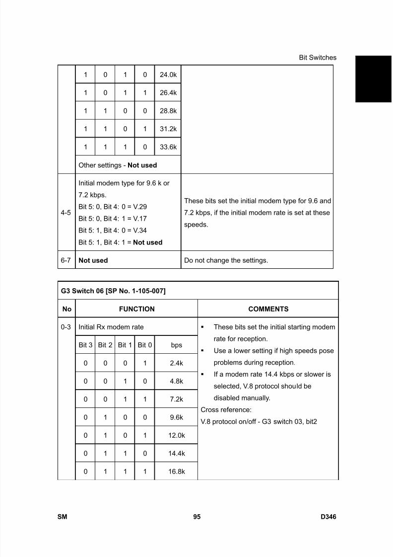
8/15/2019 Ricoh MP 4000 SM D009_D011_D012_D013 SERVICE MANUAL .pdf
http://slidepdf.com/reader/full/ricoh-mp-4000-sm-d009d011d012d013-service-manual-pdf 941/1162
Bit Switches
SM 95 D346
F a x
O p
t i o n
T y p e
5 0 0 0
D 3 4 61 0 1 0 24.0k
1 0 1 1 26.4k
1 1 0 0 28.8k
1 1 0 1 31.2k
1 1 1 0 33.6k
Other settings - Not used
4-5
Initial modem type for 9.6 k or
7.2 kbps.Bit 5: 0, Bit 4: 0 = V.29
Bit 5: 0, Bit 4: 1 = V.17
Bit 5: 1, Bit 4: 0 = V.34
Bit 5: 1, Bit 4: 1 = Not used
These bits set the initial modem type for 9.6 and
7.2 kbps, if the initial modem rate is set at these
speeds.
6-7 Not used Do not change the settings.
G3 Switch 06 [SP No. 1-105-007]
No FUNCTION COMMENTS
Initial Rx modem rate
Bit 3 Bit 2 Bit 1 Bit 0 bps
0 0 0 1 2.4k
0 0 1 0 4.8k
0 0 1 1 7.2k
0 1 0 0 9.6k
0 1 0 1 12.0k
0 1 1 0 14.4k
0-3
0 1 1 1 16.8k
These bits set the initial starting modem
rate for reception.
Use a lower setting if high speeds pose
problems during reception.
If a modem rate 14.4 kbps or slower is
selected, V.8 protocol should be
disabled manually.
Cross reference:
V.8 protocol on/off - G3 switch 03, bit2
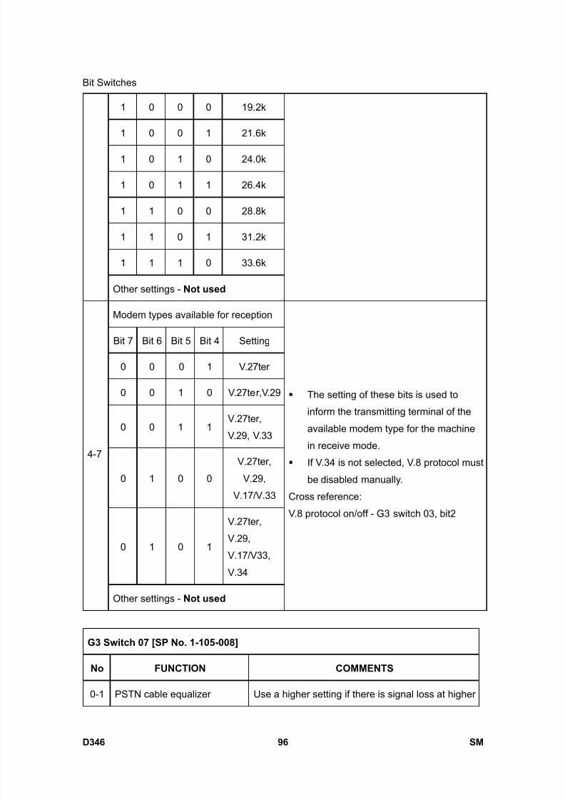
8/15/2019 Ricoh MP 4000 SM D009_D011_D012_D013 SERVICE MANUAL .pdf
http://slidepdf.com/reader/full/ricoh-mp-4000-sm-d009d011d012d013-service-manual-pdf 942/1162
Bit Switches
D346 96 SM
1 0 0 0 19.2k
1 0 0 1 21.6k
1 0 1 0 24.0k
1 0 1 1 26.4k
1 1 0 0 28.8k
1 1 0 1 31.2k
1 1 1 0 33.6k
Other settings - Not used
Modem types available for reception
Bit 7 Bit 6 Bit 5 Bit 4 Setting
0 0 0 1 V.27ter
0 0 1 0 V.27ter,V.29
0 0 1 1 V.27ter,V.29, V.33
0 1 0 0
V.27ter,
V.29,
V.17/V.33
0 1 0 1
V.27ter,
V.29,
V.17/V33,V.34
4-7
Other settings - Not used
The setting of these bits is used to
inform the transmitting terminal of the
available modem type for the machine
in receive mode.
If V.34 is not selected, V.8 protocol must
be disabled manually.
Cross reference:
V.8 protocol on/off - G3 switch 03, bit2
G3 Switch 07 [SP No. 1-105-008]
No FUNCTION COMMENTS
0-1 PSTN cable equalizer Use a higher setting if there is signal loss at higher
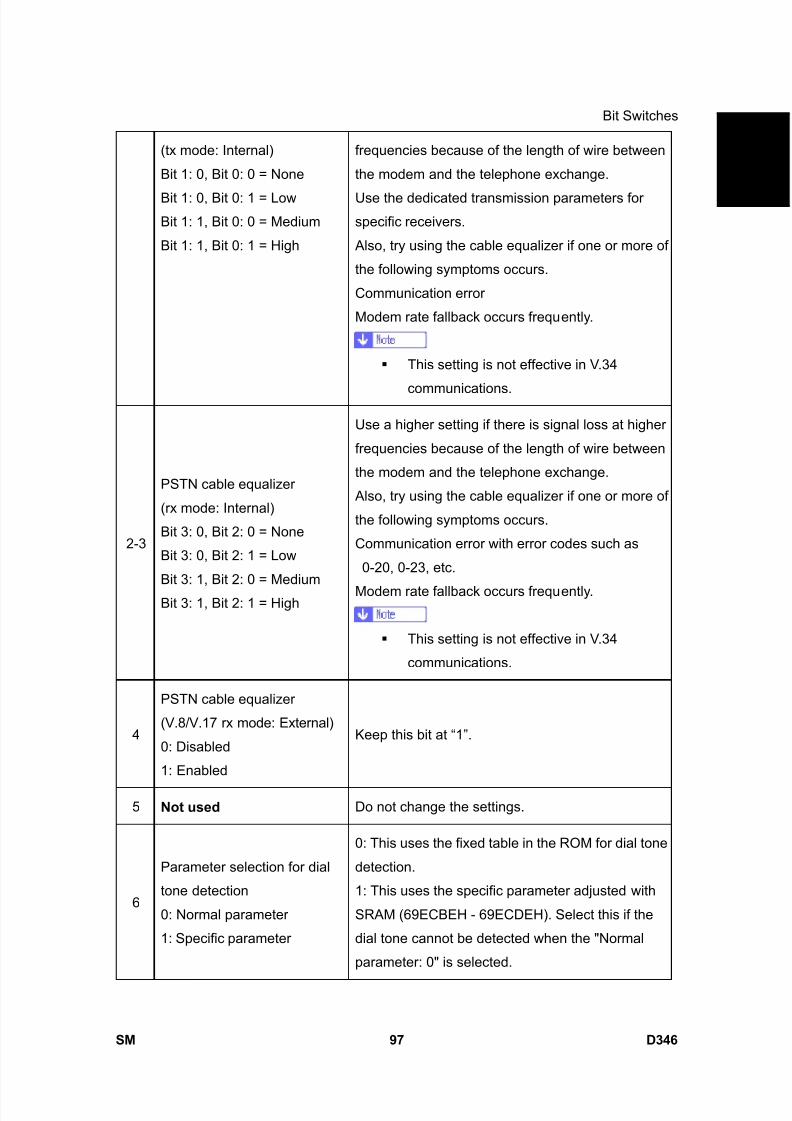
8/15/2019 Ricoh MP 4000 SM D009_D011_D012_D013 SERVICE MANUAL .pdf
http://slidepdf.com/reader/full/ricoh-mp-4000-sm-d009d011d012d013-service-manual-pdf 943/1162
Bit Switches
SM 97 D346
F a x
O p
t i o n
T y p e
5 0 0 0
D 3 4 6(tx mode: Internal)
Bit 1: 0, Bit 0: 0 = None
Bit 1: 0, Bit 0: 1 = LowBit 1: 1, Bit 0: 0 = Medium
Bit 1: 1, Bit 0: 1 = High
frequencies because of the length of wire between
the modem and the telephone exchange.
Use the dedicated transmission parameters forspecific receivers.
Also, try using the cable equalizer if one or more of
the following symptoms occurs.
Communication error
Modem rate fallback occurs frequently.
This setting is not effective in V.34
communications.
2-3
PSTN cable equalizer
(rx mode: Internal)
Bit 3: 0, Bit 2: 0 = None
Bit 3: 0, Bit 2: 1 = Low
Bit 3: 1, Bit 2: 0 = Medium
Bit 3: 1, Bit 2: 1 = High
Use a higher setting if there is signal loss at higher
frequencies because of the length of wire between
the modem and the telephone exchange.
Also, try using the cable equalizer if one or more of
the following symptoms occurs.
Communication error with error codes such as
0-20, 0-23, etc.
Modem rate fallback occurs frequently.
This setting is not effective in V.34
communications.
4
PSTN cable equalizer
(V.8/V.17 rx mode: External)
0: Disabled
1: Enabled
Keep this bit at “1”.
5 Not used Do not change the settings.
6
Parameter selection for dial
tone detection
0: Normal parameter
1: Specific parameter
0: This uses the fixed table in the ROM for dial tone
detection.
1: This uses the specific parameter adjusted with
SRAM (69ECBEH - 69ECDEH). Select this if the
dial tone cannot be detected when the "Normal
parameter: 0" is selected.
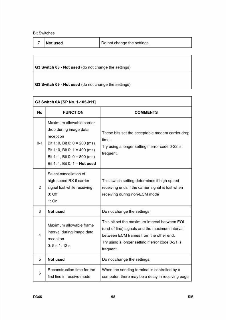
8/15/2019 Ricoh MP 4000 SM D009_D011_D012_D013 SERVICE MANUAL .pdf
http://slidepdf.com/reader/full/ricoh-mp-4000-sm-d009d011d012d013-service-manual-pdf 944/1162
Bit Switches
D346 98 SM
7 Not used Do not change the settings.
G3 Switch 08 - Not used (do not change the settings)
G3 Switch 09 - Not used (do not change the settings)
G3 Switch 0A [SP No. 1-105-011]
No FUNCTION COMMENTS
0-1
Maximum allowable carrier
drop during image data
reception
Bit 1: 0, Bit 0: 0 = 200 (ms)
Bit 1: 0, Bit 0: 1 = 400 (ms)
Bit 1: 1, Bit 0: 0 = 800 (ms)
Bit 1: 1, Bit 0: 1 = Not used
These bits set the acceptable modem carrier drop
time.
Try using a longer setting if error code 0-22 is
frequent.
2
Select cancellation of
high-speed RX if carrier
signal lost while receiving
0: Off
1: On
This switch setting determines if high-speed
receiving ends if the carrier signal is lost when
receiving during non-ECM mode
3 Not used Do not change the settings
4
Maximum allowable frame
interval during image data
reception.
0: 5 s 1: 13 s
This bit set the maximum interval between EOL
(end-of-line) signals and the maximum interval
between ECM frames from the other end.
Try using a longer setting if error code 0-21 is
frequent.
5 Not used Do not change the settings.
6Reconstruction time for the
first line in receive mode
When the sending terminal is controlled by a
computer, there may be a delay in receiving page
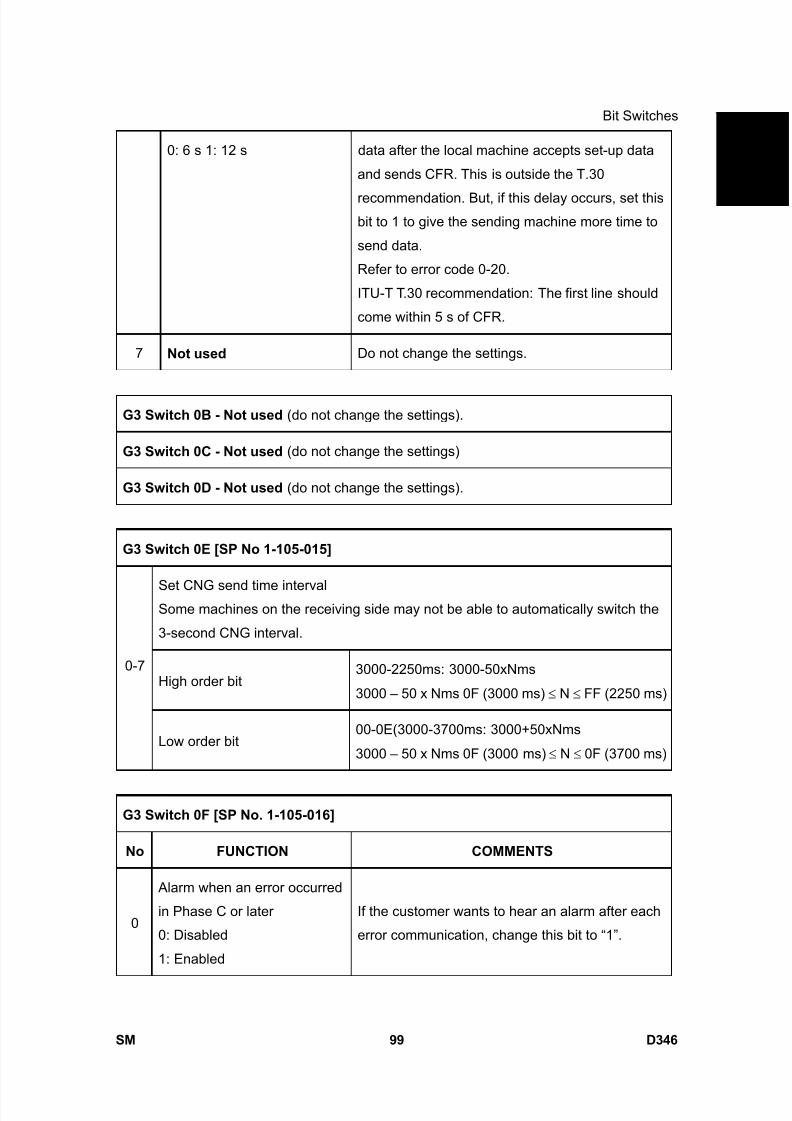
8/15/2019 Ricoh MP 4000 SM D009_D011_D012_D013 SERVICE MANUAL .pdf
http://slidepdf.com/reader/full/ricoh-mp-4000-sm-d009d011d012d013-service-manual-pdf 945/1162
Bit Switches
SM 99 D346
F a x
O p
t i o n
T y p e
5 0 0 0
D 3 4 60: 6 s 1: 12 s data after the local machine accepts set-up data
and sends CFR. This is outside the T.30
recommendation. But, if this delay occurs, set thisbit to 1 to give the sending machine more time to
send data.
Refer to error code 0-20.
ITU-T T.30 recommendation: The first line should
come within 5 s of CFR.
7 Not used Do not change the settings.
G3 Switch 0B - Not used (do not change the settings).
G3 Switch 0C - Not used (do not change the settings)
G3 Switch 0D - Not used (do not change the settings).
G3 Switch 0E [SP No 1-105-015]
Set CNG send time intervalSome machines on the receiving side may not be able to automatically switch the
3-second CNG interval.
High order bit3000-2250ms: 3000-50xNms
3000 – 50 x Nms 0F (3000 ms) ≤ N ≤ FF (2250 ms)
0-7
Low order bit00-0E(3000-3700ms: 3000+50xNms
3000 – 50 x Nms 0F (3000 ms) ≤ N ≤ 0F (3700 ms)
G3 Switch 0F [SP No. 1-105-016]
No FUNCTION COMMENTS
0
Alarm when an error occurred
in Phase C or later
0: Disabled
1: Enabled
If the customer wants to hear an alarm after each
error communication, change this bit to “1”.
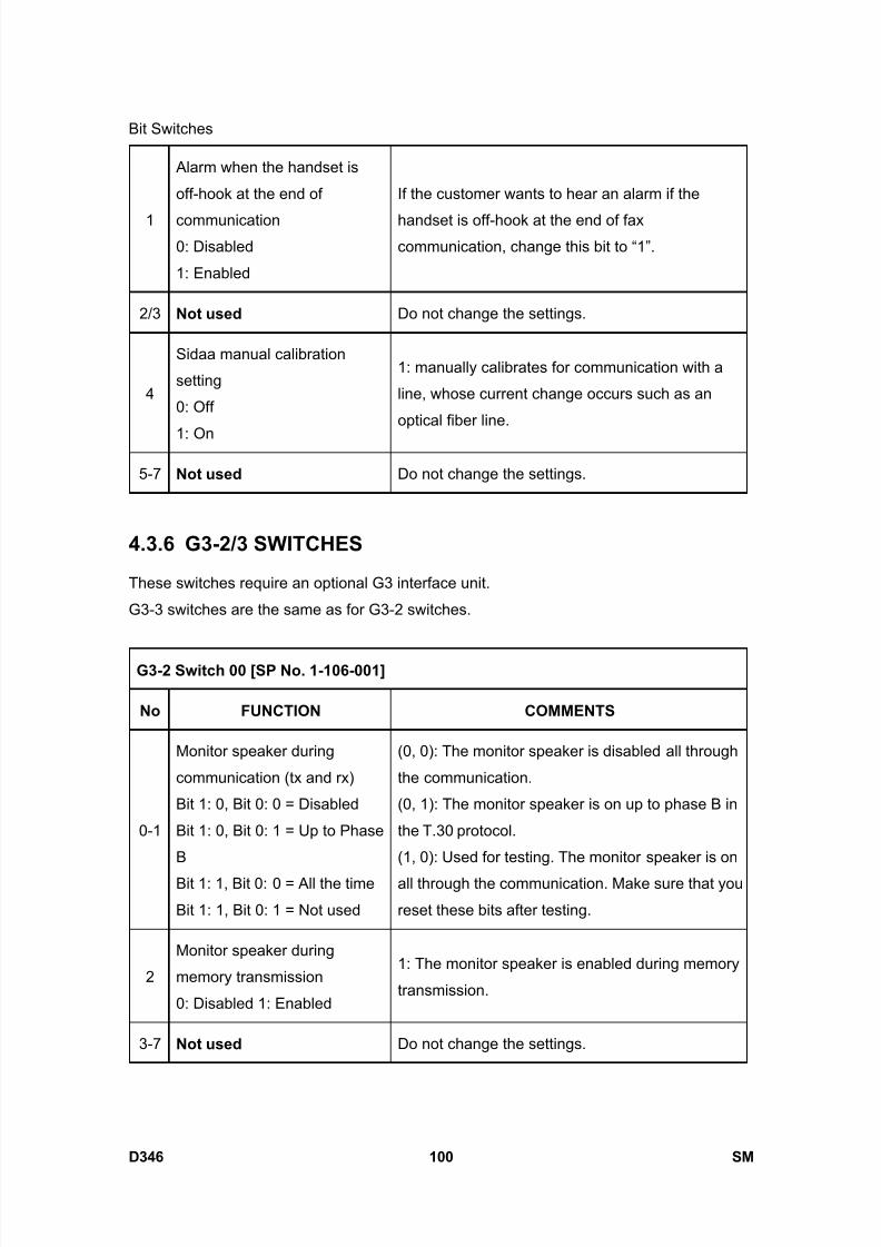
8/15/2019 Ricoh MP 4000 SM D009_D011_D012_D013 SERVICE MANUAL .pdf
http://slidepdf.com/reader/full/ricoh-mp-4000-sm-d009d011d012d013-service-manual-pdf 946/1162
Bit Switches
D346 100 SM
1
Alarm when the handset is
off-hook at the end of
communication0: Disabled
1: Enabled
If the customer wants to hear an alarm if the
handset is off-hook at the end of faxcommunication, change this bit to “1”.
2/3 Not used Do not change the settings.
4
Sidaa manual calibration
setting
0: Off
1: On
1: manually calibrates for communication with a
line, whose current change occurs such as an
optical fiber line.
5-7 Not used Do not change the settings.
4.3.6 G3-2/3 SWITCHES
These switches require an optional G3 interface unit.
G3-3 switches are the same as for G3-2 switches.
G3-2 Switch 00 [SP No. 1-106-001]
No FUNCTION COMMENTS
0-1
Monitor speaker during
communication (tx and rx)
Bit 1: 0, Bit 0: 0 = Disabled
Bit 1: 0, Bit 0: 1 = Up to Phase
B
Bit 1: 1, Bit 0: 0 = All the time
Bit 1: 1, Bit 0: 1 = Not used
(0, 0): The monitor speaker is disabled all through
the communication.
(0, 1): The monitor speaker is on up to phase B in
the T.30 protocol.
(1, 0): Used for testing. The monitor speaker is on
all through the communication. Make sure that you
reset these bits after testing.
2
Monitor speaker during
memory transmission
0: Disabled 1: Enabled
1: The monitor speaker is enabled during memory
transmission.
3-7 Not used Do not change the settings.

8/15/2019 Ricoh MP 4000 SM D009_D011_D012_D013 SERVICE MANUAL .pdf
http://slidepdf.com/reader/full/ricoh-mp-4000-sm-d009d011d012d013-service-manual-pdf 947/1162
Bit Switches
SM 101 D346
F a x
O p
t i o n
T y p e
5 0 0 0
D 3 4 6G3-2 Switch 01 [SP No. 1-106-002]
No FUNCTION COMMENTS
0-3 Not used Do not change the settings.
4DIS frame length
0: 10 bytes, 1: 4 bytes
1: The bytes in the DIS frame after the 4th byte will
not be transmitted (set to 1 if there are
communication problems with PC-based faxes
which cannot receive the extended DIS frames).
5 Not used Do not change the setting.
6
CED/ANSam transmission
0: Disabled
1: Enabled
Do not change this setting, unless the
communication problem is caused by the
CED/ANSam transmission.
7 Not used Do not change the setting.
G3-2 Switch 02 [SP No. 1-106-003]
No FUNCTION COMMENTS
0
G3 protocol mode used
0: Standard and non-standard
1: Standard only
Change this bit to 1 only when the other end can
only communicate with machines that send
T.30-standard frames only.
1: Disables NSF/NSS signals (these are used in
non-standard mode communication)
1-4 Not used Do not change the settings.
5
Use of modem rate history for
transmission using
Quick/Speed Dials
0: Disabled
1: Enabled
0: Communications using Quick/Speed Dials
always start from the highest modem rate.
1: The machine refers to the modem rate history
for communications with the same machine when
determining the most suitable rate for the current
communication.
6 Not used Do not change the settings.
7 Short preamble Refer to Appendix B in the Group 3 Facsimile

8/15/2019 Ricoh MP 4000 SM D009_D011_D012_D013 SERVICE MANUAL .pdf
http://slidepdf.com/reader/full/ricoh-mp-4000-sm-d009d011d012d013-service-manual-pdf 948/1162
Bit Switches
D346 102 SM
0: Disabled, 1: Enabled Manual for details about Short Preamble.
G3-2 Switch 03 [SP No. 1-106-004]
No FUNCTION COMMENTS
0
DIS detection number
(Echo countermeasure)
0: 1
1: 2
0: The machine will hang up if it receives the same
DIS frame twice.
1: Before sending DCS, the machine will wait for
the second DIS which is caused by echo on the
line.
1 Not used Do not change the settings.
2
V.8 protocol
0: Disabled
1: Enabled
0: V.8/V.34 communications will not be possible.
Do not set to 0 unless the line condition is
always bad enough to slow down the data
rate to 14.4 kbps or lower.
3ECM frame size0: 256 bytes
1: 64 bytes
Keep this bit at “0” in most cases.
4
CTC transmission conditions
0: After one PPR signal
received
1: After four PPR signals
received (ITU-T standard)
0: When using ECM in non-standard (NSF/NSS)
mode, the machine sends a CTC to drop back the
modem rate after receiving a PPR, if the following
condition is met in communications at 14.4, 12.0,
9.6, and 7.2 kbps.
NTransmit- Number of transmitted frames
NResend- Number of frames to be retransmitted
1: When using ECM, the machine sends a CTC to
drop back the modem rate after receiving four
PPRs.
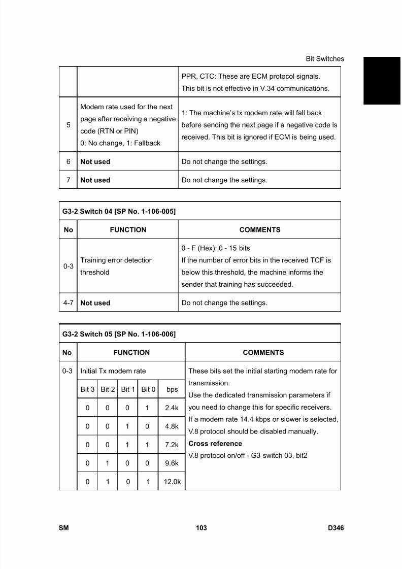
8/15/2019 Ricoh MP 4000 SM D009_D011_D012_D013 SERVICE MANUAL .pdf
http://slidepdf.com/reader/full/ricoh-mp-4000-sm-d009d011d012d013-service-manual-pdf 949/1162
Bit Switches
SM 103 D346
F a x
O p
t i o n
T y p e
5 0 0 0
D 3 4 6PPR, CTC: These are ECM protocol signals.
This bit is not effective in V.34 communications.
5
Modem rate used for the next
page after receiving a negative
code (RTN or PIN)
0: No change, 1: Fallback
1: The machine’s tx modem rate will fall back
before sending the next page if a negative code is
received. This bit is ignored if ECM is being used.
6 Not used Do not change the settings.
7 Not used Do not change the settings.
G3-2 Switch 04 [SP No. 1-106-005]
No FUNCTION COMMENTS
0-3Training error detection
threshold
0 - F (Hex); 0 - 15 bits
If the number of error bits in the received TCF is
below this threshold, the machine informs the
sender that training has succeeded.
4-7 Not used Do not change the settings.
G3-2 Switch 05 [SP No. 1-106-006]
No FUNCTION COMMENTS
Initial Tx modem rate
Bit 3 Bit 2 Bit 1 Bit 0 bps
0 0 0 1 2.4k
0 0 1 0 4.8k
0 0 1 1 7.2k
0 1 0 0 9.6k
0-3
0 1 0 1 12.0k
These bits set the initial starting modem rate for
transmission.
Use the dedicated transmission parameters ifyou need to change this for specific receivers.
If a modem rate 14.4 kbps or slower is selected,
V.8 protocol should be disabled manually.
Cross reference
V.8 protocol on/off - G3 switch 03, bit2
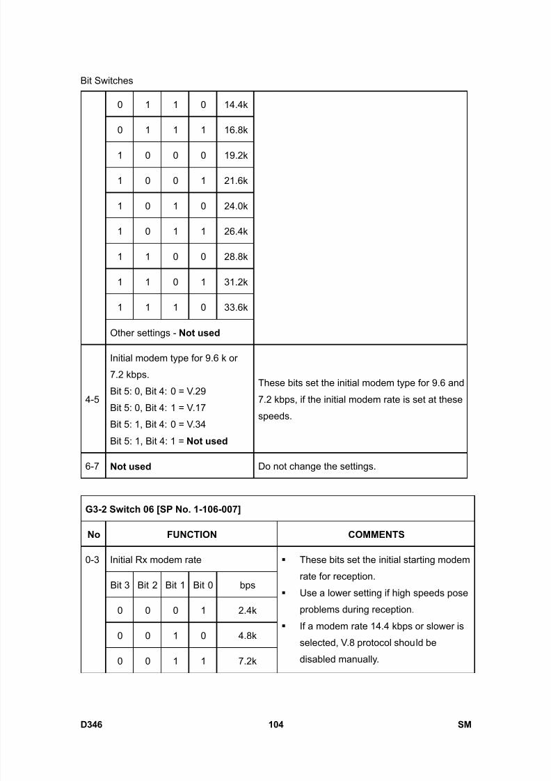
8/15/2019 Ricoh MP 4000 SM D009_D011_D012_D013 SERVICE MANUAL .pdf
http://slidepdf.com/reader/full/ricoh-mp-4000-sm-d009d011d012d013-service-manual-pdf 950/1162
Bit Switches
D346 104 SM
0 1 1 0 14.4k
0 1 1 1 16.8k
1 0 0 0 19.2k
1 0 0 1 21.6k
1 0 1 0 24.0k
1 0 1 1 26.4k
1 1 0 0 28.8k
1 1 0 1 31.2k
1 1 1 0 33.6k
Other settings - Not used
4-5
Initial modem type for 9.6 k or
7.2 kbps.
Bit 5: 0, Bit 4: 0 = V.29
Bit 5: 0, Bit 4: 1 = V.17Bit 5: 1, Bit 4: 0 = V.34
Bit 5: 1, Bit 4: 1 = Not used
These bits set the initial modem type for 9.6 and
7.2 kbps, if the initial modem rate is set at these
speeds.
6-7 Not used Do not change the settings.
G3-2 Switch 06 [SP No. 1-106-007]
No FUNCTION COMMENTS
Initial Rx modem rate
Bit 3 Bit 2 Bit 1 Bit 0 bps
0 0 0 1 2.4k
0 0 1 0 4.8k
0-3
0 0 1 1 7.2k
These bits set the initial starting modem
rate for reception.
Use a lower setting if high speeds pose
problems during reception.
If a modem rate 14.4 kbps or slower is
selected, V.8 protocol should be
disabled manually.
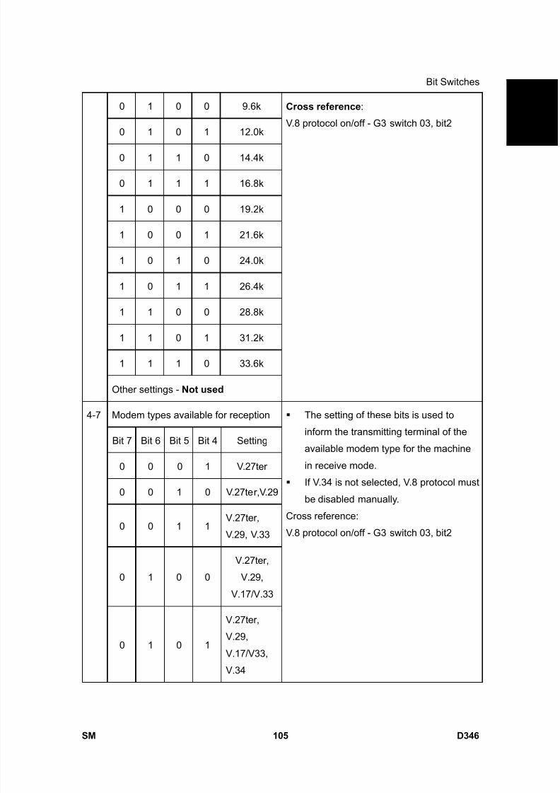
8/15/2019 Ricoh MP 4000 SM D009_D011_D012_D013 SERVICE MANUAL .pdf
http://slidepdf.com/reader/full/ricoh-mp-4000-sm-d009d011d012d013-service-manual-pdf 951/1162
Bit Switches
SM 105 D346
F a x
O p
t i o n
T y p e
5 0 0 0
D 3 4 60 1 0 0 9.6k
0 1 0 1 12.0k
0 1 1 0 14.4k
0 1 1 1 16.8k
1 0 0 0 19.2k
1 0 0 1 21.6k
1 0 1 0 24.0k
1 0 1 1 26.4k
1 1 0 0 28.8k
1 1 0 1 31.2k
1 1 1 0 33.6k
Other settings - Not used
Cross reference :
V.8 protocol on/off - G3 switch 03, bit2
Modem types available for reception
Bit 7 Bit 6 Bit 5 Bit 4 Setting
0 0 0 1 V.27ter
0 0 1 0 V.27ter,V.29
0 0 1 1V.27ter,
V.29, V.33
0 1 0 0
V.27ter,
V.29,
V.17/V.33
4-7
0 1 0 1
V.27ter,
V.29,
V.17/V33,
V.34
The setting of these bits is used toinform the transmitting terminal of the
available modem type for the machine
in receive mode.
If V.34 is not selected, V.8 protocol must
be disabled manually.
Cross reference:
V.8 protocol on/off - G3 switch 03, bit2
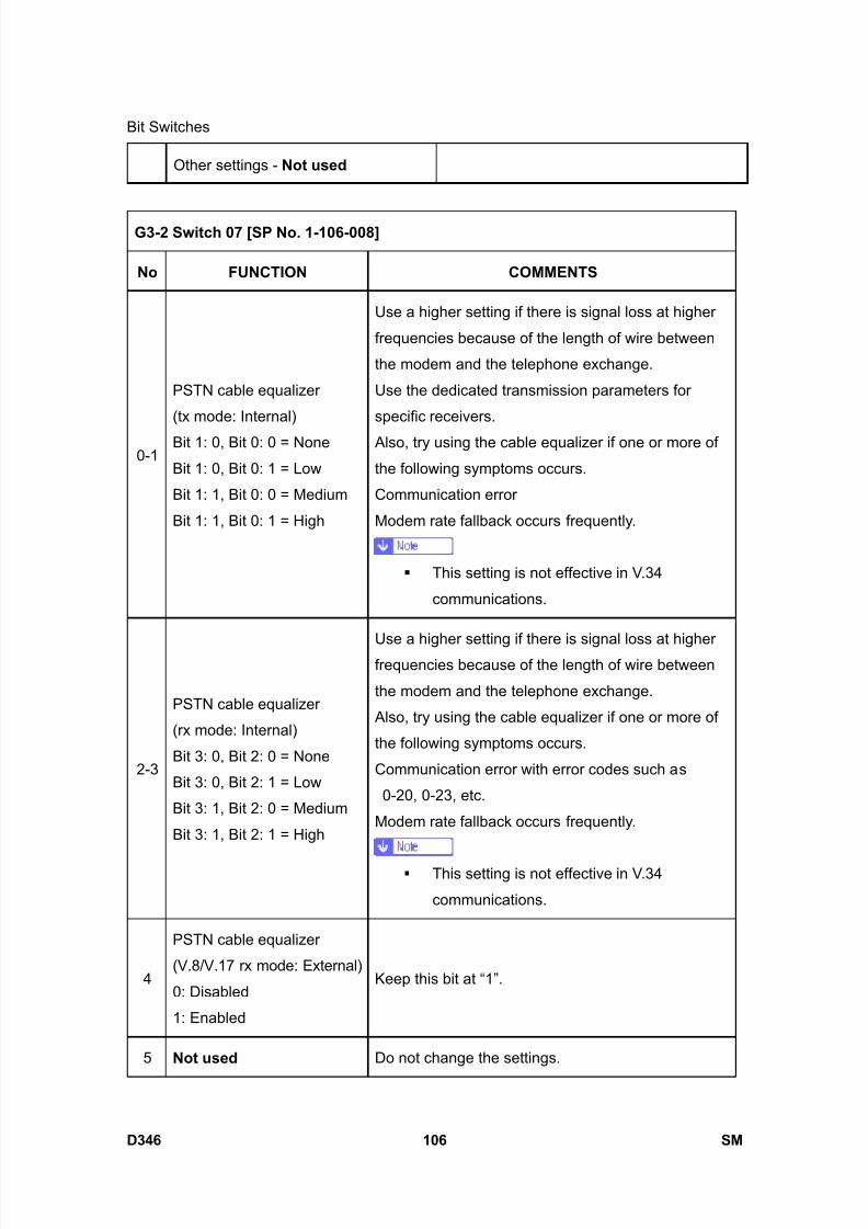
8/15/2019 Ricoh MP 4000 SM D009_D011_D012_D013 SERVICE MANUAL .pdf
http://slidepdf.com/reader/full/ricoh-mp-4000-sm-d009d011d012d013-service-manual-pdf 952/1162
Bit Switches
D346 106 SM
Other settings - Not used
G3-2 Switch 07 [SP No. 1-106-008]
No FUNCTION COMMENTS
0-1
PSTN cable equalizer
(tx mode: Internal)
Bit 1: 0, Bit 0: 0 = None
Bit 1: 0, Bit 0: 1 = Low
Bit 1: 1, Bit 0: 0 = Medium
Bit 1: 1, Bit 0: 1 = High
Use a higher setting if there is signal loss at higher
frequencies because of the length of wire between
the modem and the telephone exchange.
Use the dedicated transmission parameters for
specific receivers.
Also, try using the cable equalizer if one or more of
the following symptoms occurs.
Communication error
Modem rate fallback occurs frequently.
This setting is not effective in V.34
communications.
2-3
PSTN cable equalizer
(rx mode: Internal)
Bit 3: 0, Bit 2: 0 = None
Bit 3: 0, Bit 2: 1 = Low
Bit 3: 1, Bit 2: 0 = Medium
Bit 3: 1, Bit 2: 1 = High
Use a higher setting if there is signal loss at higherfrequencies because of the length of wire between
the modem and the telephone exchange.
Also, try using the cable equalizer if one or more of
the following symptoms occurs.
Communication error with error codes such as
0-20, 0-23, etc.
Modem rate fallback occurs frequently.
This setting is not effective in V.34
communications.
4
PSTN cable equalizer
(V.8/V.17 rx mode: External)
0: Disabled
1: Enabled
Keep this bit at “1”.
5 Not used Do not change the settings.

8/15/2019 Ricoh MP 4000 SM D009_D011_D012_D013 SERVICE MANUAL .pdf
http://slidepdf.com/reader/full/ricoh-mp-4000-sm-d009d011d012d013-service-manual-pdf 953/1162
Bit Switches
SM 107 D346
F a x
O p
t i o n
T y p e
5 0 0 0
D 3 4 6
6
Parameter selection for dial
tone detection0: Normal parameter
1: Specific parameter
0: This uses the fixed table in the ROM for dial tone
detection.
1: This uses the specific parameter adjusted withSRAM (69ECBEH - 69ECDEH). Select this if the dial
tone cannot be detected when the "Normal
parameter: 0" is selected.
7 Not used Do not change the settings.
G3-2 Switch 08 - Not used (do not change the settings)
G3-2 Switch 09 - Not used (do not change the settings)
G3-2 Switch 0A [SP No. 1-106-011]
No FUNCTION COMMENTS
0-1
Maximum allowable carrier
drop during image data
receptionBit 1: 0, Bit 0: 0 = 200 (ms)
Bit 1: 0, Bit 0: 1 = 400 (ms)
Bit 1: 1, Bit 0: 0 = 800 (ms)
Bit 1: 1, Bit 0: 1 = Not used
These bits set the acceptable modem carrier drop
time.
Try using a longer setting if error code 0-22 is
frequent.
2
Select cancellation of
high-speed RX if carrier
signal lost while receiving
0: Off1: On
This switch setting determines if high-speed
receiving ends if the carrier signal is lost when
receiving during non-ECM mode
3 Not used Do not change the settings
4
Maximum allowable frame
interval during image data
reception.
0: 5 s 1: 13 s
This bit set the maximum interval between EOL
(end-of-line) signals and the maximum interval
between ECM frames from the other end.
Try using a longer setting if error code 0-21 is
frequent.
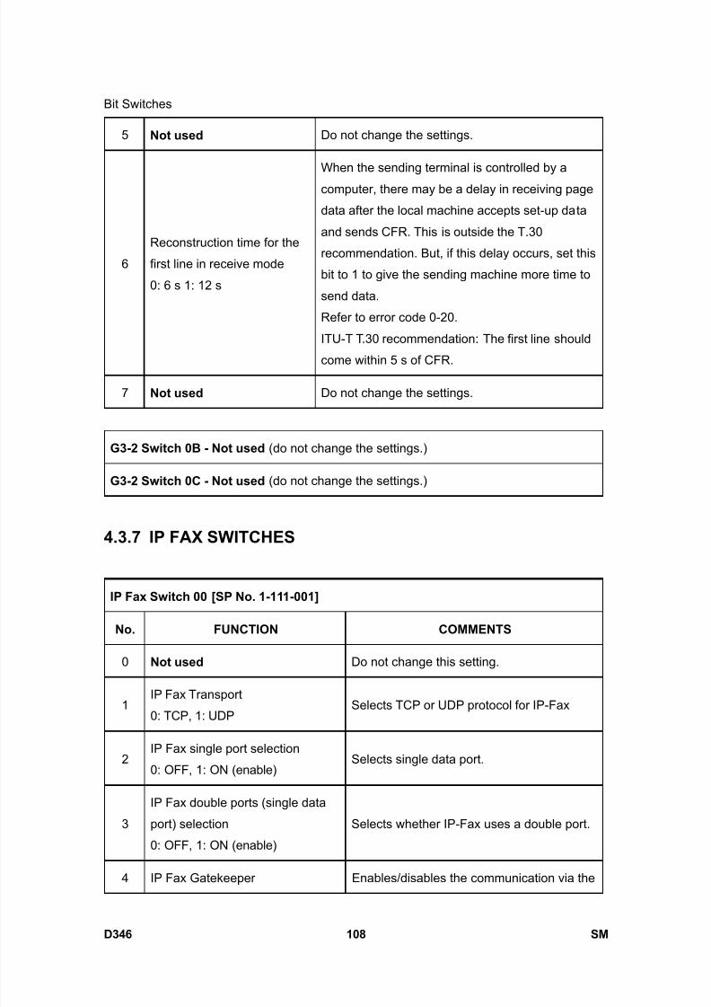
8/15/2019 Ricoh MP 4000 SM D009_D011_D012_D013 SERVICE MANUAL .pdf
http://slidepdf.com/reader/full/ricoh-mp-4000-sm-d009d011d012d013-service-manual-pdf 954/1162
Bit Switches
D346 108 SM
5 Not used Do not change the settings.
6
Reconstruction time for the
first line in receive mode
0: 6 s 1: 12 s
When the sending terminal is controlled by a
computer, there may be a delay in receiving page
data after the local machine accepts set-up data
and sends CFR. This is outside the T.30
recommendation. But, if this delay occurs, set this
bit to 1 to give the sending machine more time to
send data.
Refer to error code 0-20.
ITU-T T.30 recommendation: The first line should
come within 5 s of CFR.
7 Not used Do not change the settings.
G3-2 Switch 0B - Not used (do not change the settings.)
G3-2 Switch 0C - Not used (do not change the settings.)
4.3.7 IP FAX SWITCHES
IP Fax Switch 00 [SP No. 1-111-001]
No. FUNCTION COMMENTS
0 Not used Do not change this setting.
1IP Fax Transport
0: TCP, 1: UDP Selects TCP or UDP protocol for IP-Fax
2IP Fax single port selection
0: OFF, 1: ON (enable)Selects single data port.
3
IP Fax double ports (single data
port) selection
0: OFF, 1: ON (enable)
Selects whether IP-Fax uses a double port.
4 IP Fax Gatekeeper Enables/disables the communication via the
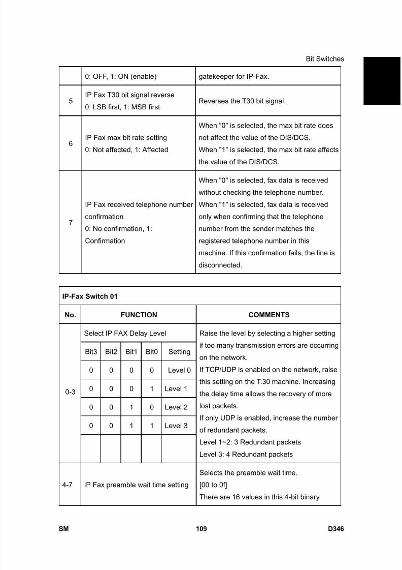
8/15/2019 Ricoh MP 4000 SM D009_D011_D012_D013 SERVICE MANUAL .pdf
http://slidepdf.com/reader/full/ricoh-mp-4000-sm-d009d011d012d013-service-manual-pdf 955/1162
Bit Switches
SM 109 D346
F a x
O p
t i o n
T y p e
5 0 0 0
D 3 4 60: OFF, 1: ON (enable) gatekeeper for IP-Fax.
5IP Fax T30 bit signal reverse
0: LSB first, 1: MSB firstReverses the T30 bit signal.
6IP Fax max bit rate setting
0: Not affected, 1: Affected
When "0" is selected, the max bit rate does
not affect the value of the DIS/DCS.
When "1" is selected, the max bit rate affects
the value of the DIS/DCS.
7
IP Fax received telephone number
confirmation
0: No confirmation, 1:
Confirmation
When "0" is selected, fax data is received
without checking the telephone number.
When "1" is selected, fax data is received
only when confirming that the telephone
number from the sender matches the
registered telephone number in this
machine. If this confirmation fails, the line is
disconnected.
IP-Fax Switch 01
No. FUNCTION COMMENTS
Select IP FAX Delay Level
Bit3 Bit2 Bit1 Bit0 Setting
0 0 0 0 Level 0
0 0 0 1 Level 1
0 0 1 0 Level 2
0 0 1 1 Level 3
0-3
Raise the level by selecting a higher setting
if too many transmission errors are occurring
on the network.
If TCP/UDP is enabled on the network, raise
this setting on the T.30 machine. Increasing
the delay time allows the recovery of more
lost packets.
If only UDP is enabled, increase the number
of redundant packets.
Level 1~2: 3 Redundant packets
Level 3: 4 Redundant packets
4-7 IP Fax preamble wait time setting
Selects the preamble wait time.
[00 to 0f]
There are 16 values in this 4-bit binary
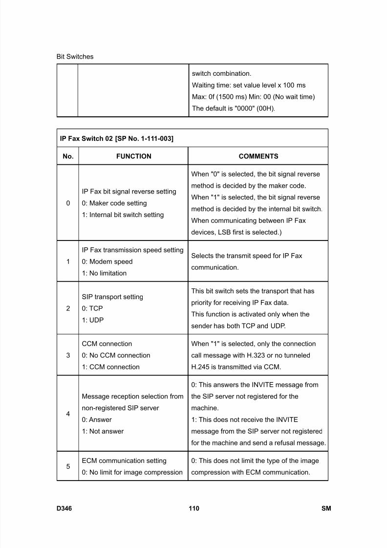
8/15/2019 Ricoh MP 4000 SM D009_D011_D012_D013 SERVICE MANUAL .pdf
http://slidepdf.com/reader/full/ricoh-mp-4000-sm-d009d011d012d013-service-manual-pdf 956/1162
Bit Switches
D346 110 SM
switch combination.
Waiting time: set value level x 100 ms
Max: 0f (1500 ms) Min: 00 (No wait time)The default is "0000" (00H).
IP Fax Switch 02 [SP No. 1-111-003]
No. FUNCTION COMMENTS
0IP Fax bit signal reverse setting0: Maker code setting
1: Internal bit switch setting
When "0" is selected, the bit signal reverse
method is decided by the maker code.
When "1" is selected, the bit signal reverse
method is decided by the internal bit switch.
When communicating between IP Fax
devices, LSB first is selected.)
1
IP Fax transmission speed setting
0: Modem speed
1: No limitation
Selects the transmit speed for IP Fax
communication.
2
SIP transport setting
0: TCP
1: UDP
This bit switch sets the transport that has
priority for receiving IP Fax data.
This function is activated only when the
sender has both TCP and UDP.
3
CCM connection
0: No CCM connection
1: CCM connection
When "1" is selected, only the connection
call message with H.323 or no tunneled
H.245 is transmitted via CCM.
4
Message reception selection from
non-registered SIP server
0: Answer
1: Not answer
0: This answers the INVITE message fromthe SIP server not registered for the
machine.
1: This does not receive the INVITE
message from the SIP server not registered
for the machine and send a refusal message.
5ECM communication setting
0: No limit for image compression
0: This does not limit the type of the image
compression with ECM communication.
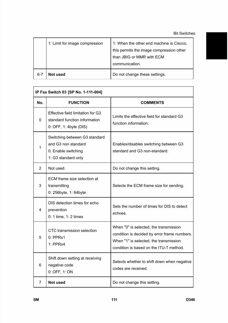
8/15/2019 Ricoh MP 4000 SM D009_D011_D012_D013 SERVICE MANUAL .pdf
http://slidepdf.com/reader/full/ricoh-mp-4000-sm-d009d011d012d013-service-manual-pdf 957/1162
Bit Switches
SM 111 D346
F a x
O p
t i o n
T y p e
5 0 0 0
D 3 4 61: Limit for image compression 1: When the other end machine is Ciscco,
this permits the image compression other
than JBIG or MMR with ECMcommunication.
6-7 Not used Do not change these settings.
IP Fax Switch 03 [SP No. 1-111-004]
No. FUNCTION COMMENTS
0Effective field limitation for G3standard function information
0: OFF, 1: 4byte (DIS)
Limits the effective field for standard G3
function information.
1
Switching between G3 standard
and G3 non standard
0: Enable switching
1: G3 standard only
Enables/disables switching between G3
standard and G3 non-standard.
2 Not used. Do not change this setting.
3
ECM frame size selection at
transmitting
0: 256byte, 1: 64byte
Selects the ECM frame size for sending.
4
DIS detection times for echo
prevention
0: 1 time, 1: 2 times
Sets the number of times for DIS to detect
echoes.
5
CTC transmission selection
0: PPRx1
1: PPRx4
When "0" is selected, the transmissioncondition is decided by error frame numbers.
When "1" is selected, the transmission
condition is based on the ITU-T method.
6
Shift down setting at receiving
negative code
0: OFF, 1: ON
Selects whether to shift down when negative
codes are received.
7 Not used Do not change this setting.
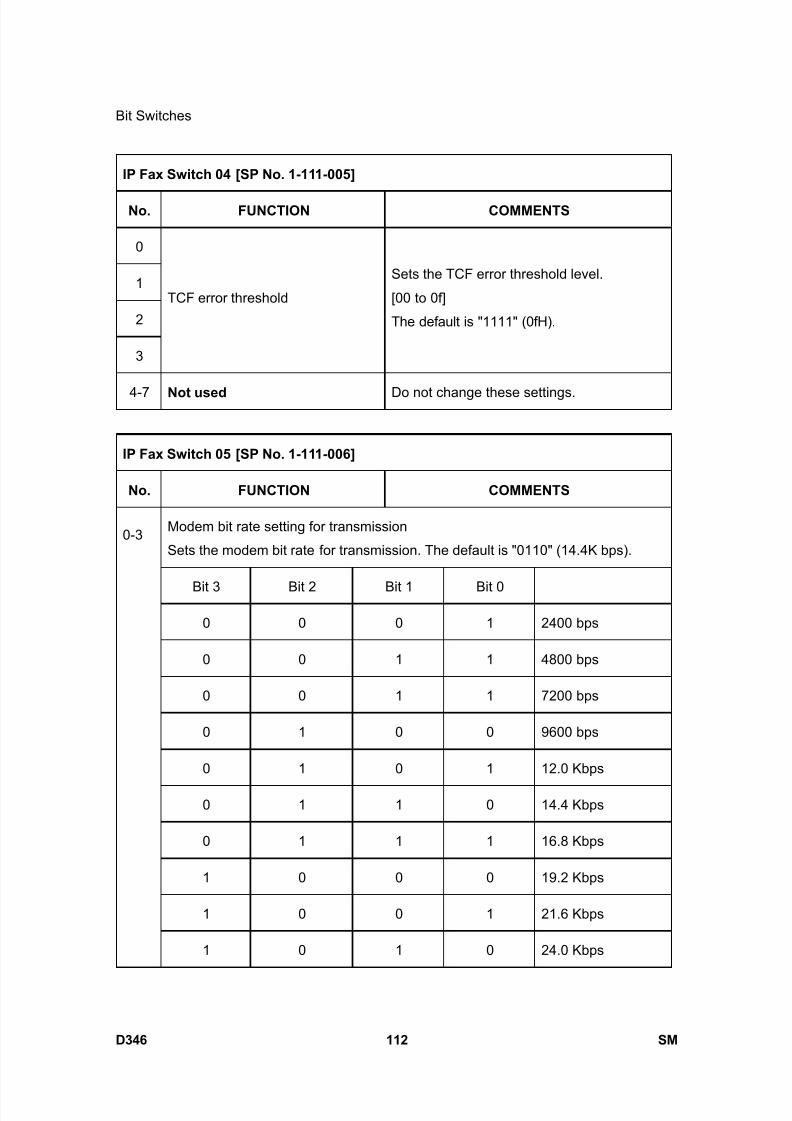
8/15/2019 Ricoh MP 4000 SM D009_D011_D012_D013 SERVICE MANUAL .pdf
http://slidepdf.com/reader/full/ricoh-mp-4000-sm-d009d011d012d013-service-manual-pdf 958/1162
Bit Switches
D346 112 SM
IP Fax Switch 04 [SP No. 1-111-005]
No. FUNCTION COMMENTS
0
1
2
3
TCF error threshold
Sets the TCF error threshold level.
[00 to 0f]
The default is "1111" (0fH).
4-7 Not used Do not change these settings.
IP Fax Switch 05 [SP No. 1-111-006]
No. FUNCTION COMMENTS
Modem bit rate setting for transmission
Sets the modem bit rate for transmission. The default is "0110" (14.4K bps).
Bit 3 Bit 2 Bit 1 Bit 0
0 0 0 1 2400 bps
0 0 1 1 4800 bps
0 0 1 1 7200 bps
0 1 0 0 9600 bps
0 1 0 1 12.0 Kbps
0 1 1 0 14.4 Kbps
0 1 1 1 16.8 Kbps
1 0 0 0 19.2 Kbps
1 0 0 1 21.6 Kbps
0-3
1 0 1 0 24.0 Kbps
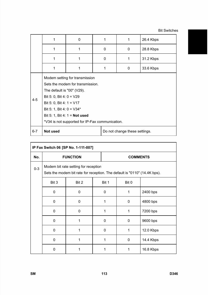
8/15/2019 Ricoh MP 4000 SM D009_D011_D012_D013 SERVICE MANUAL .pdf
http://slidepdf.com/reader/full/ricoh-mp-4000-sm-d009d011d012d013-service-manual-pdf 959/1162
Bit Switches
SM 113 D346
F a x
O p
t i o n
T y p e
5 0 0 0
D 3 4 61 0 1 1 26.4 Kbps
1 1 0 0 28.8 Kbps
1 1 0 1 31.2 Kbps
1 1 1 0 33.6 Kbps
4-5
Modem setting for transmission
Sets the modem for transmission.
The default is "00" (V29).
Bit 5: 0, Bit 4: 0 = V29
Bit 5: 0, Bit 4: 1 = V17Bit 5: 1, Bit 4: 0 = V34*
Bit 5: 1, Bit 4: 1 = Not used
*V34 is not supported for IP-Fax communication.
6-7 Not used Do not change these settings.
IP Fax Switch 06 [SP No. 1-111-007]
No. FUNCTION COMMENTS
Modem bit rate setting for reception
Sets the modem bit rate for reception. The default is "0110" (14.4K bps).
Bit 3 Bit 2 Bit 1 Bit 0
0 0 0 1 2400 bps
0 0 1 0 4800 bps
0 0 1 1 7200 bps
0 1 0 0 9600 bps
0 1 0 1 12.0 Kbps
0 1 1 0 14.4 Kbps
0-3
0 1 1 1 16.8 Kbps
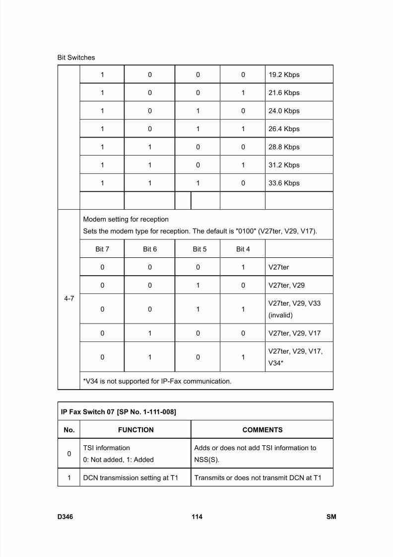
8/15/2019 Ricoh MP 4000 SM D009_D011_D012_D013 SERVICE MANUAL .pdf
http://slidepdf.com/reader/full/ricoh-mp-4000-sm-d009d011d012d013-service-manual-pdf 960/1162
Bit Switches
D346 114 SM
1 0 0 0 19.2 Kbps
1 0 0 1 21.6 Kbps
1 0 1 0 24.0 Kbps
1 0 1 1 26.4 Kbps
1 1 0 0 28.8 Kbps
1 1 0 1 31.2 Kbps
1 1 1 0 33.6 Kbps
Modem setting for reception
Sets the modem type for reception. The default is "0100" (V27ter, V29, V17).
Bit 7 Bit 6 Bit 5 Bit 4
0 0 0 1 V27ter
0 0 1 0 V27ter, V29
0 0 1 1V27ter, V29, V33
(invalid)
0 1 0 0 V27ter, V29, V17
0 1 0 1V27ter, V29, V17,
V34*
4-7
*V34 is not supported for IP-Fax communication.
IP Fax Switch 07 [SP No. 1-111-008]
No. FUNCTION COMMENTS
0TSI information
0: Not added, 1: Added
Adds or does not add TSI information to
NSS(S).
1 DCN transmission setting at T1 Transmits or does not transmit DCN at T1

8/15/2019 Ricoh MP 4000 SM D009_D011_D012_D013 SERVICE MANUAL .pdf
http://slidepdf.com/reader/full/ricoh-mp-4000-sm-d009d011d012d013-service-manual-pdf 961/1162
Bit Switches
SM 115 D346
F a x
O p
t i o n
T y p e
5 0 0 0
D 3 4 6timeout
0: Not transmitted, 1: Transmitted
timeout.
2 Not used Do not change this setting.
3
Hang up setting at DIS reception
disabled
0: No hang up
1: Hang up after transmitting DCN
Sets whether the machine disconnects after
DIS reception.
4Number of times for training
0: 1 time, 1: 2 times
Selects the number of times training is done
at the same bit rate.
5
Space CSI transmission setting at
no CSI registration
0: Not transmitted, 1: Transmitted
When "0" is selected, frame data is enabled.
When "1" is selected, the transmitted data is
all spaces.
6-7 Not used Do not change these settings.
IP Fax Switch 08 [SP No. 1-111-009]
No. FUNCTION COMMENTS
0-1
T1 timer adjustment
Adjusts the T1 timer.
The default is "00" (35 seconds).
Bit 1: 0, Bit 0: 0 = 35 sec
Bit 1: 0, Bit 0: 1 = 40 sec
Bit 1: 1, Bit 0: 0 = 50 sec
Bit 1: 1, Bit 0: 1 = 60 sec
-
2-3
T4 timer adjustment
Adjust the T4 timer.
The default is "00" (3 seconds).
Bit 3: 0, Bit 2: 0 = 3 sec
Bit 3: 0, Bit 2: 1 = 3.5 sec
Bit 3: 1, Bit 2: 0 = 4 sec
Bit 3: 1, Bit 2: 1 = 5 sec
-
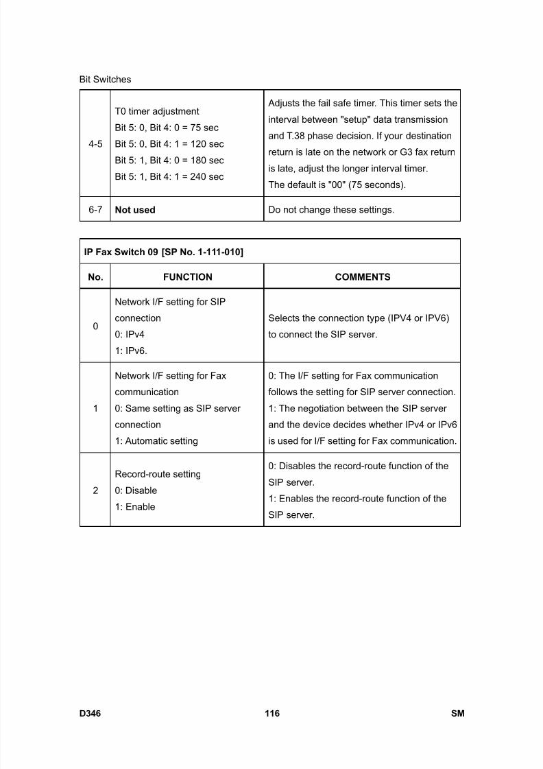
8/15/2019 Ricoh MP 4000 SM D009_D011_D012_D013 SERVICE MANUAL .pdf
http://slidepdf.com/reader/full/ricoh-mp-4000-sm-d009d011d012d013-service-manual-pdf 962/1162
Bit Switches
D346 116 SM
4-5
T0 timer adjustment
Bit 5: 0, Bit 4: 0 = 75 sec
Bit 5: 0, Bit 4: 1 = 120 sec
Bit 5: 1, Bit 4: 0 = 180 sec
Bit 5: 1, Bit 4: 1 = 240 sec
Adjusts the fail safe timer. This timer sets the
interval between "setup" data transmission
and T.38 phase decision. If your destinationreturn is late on the network or G3 fax return
is late, adjust the longer interval timer.
The default is "00" (75 seconds).
6-7 Not used Do not change these settings.
IP Fax Switch 09 [SP No. 1-111-010]
No. FUNCTION COMMENTS
0
Network I/F setting for SIP
connection
0: IPv4
1: IPv6.
Selects the connection type (IPV4 or IPV6)
to connect the SIP server.
1
Network I/F setting for Fax
communication
0: Same setting as SIP server
connection
1: Automatic setting
0: The I/F setting for Fax communication
follows the setting for SIP server connection.
1: The negotiation between the SIP server
and the device decides whether IPv4 or IPv6
is used for I/F setting for Fax communication.
2
Record-route setting
0: Disable
1: Enable
0: Disables the record-route function of the
SIP server.
1: Enables the record-route function of the
SIP server.
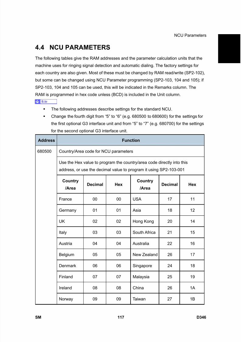
8/15/2019 Ricoh MP 4000 SM D009_D011_D012_D013 SERVICE MANUAL .pdf
http://slidepdf.com/reader/full/ricoh-mp-4000-sm-d009d011d012d013-service-manual-pdf 963/1162
NCU Parameters
SM 117 D346
F a x
O p
t i o n
T y p e
5 0 0 0
D 3 4 6
4.4 NCU PARAMETERS
The following tables give the RAM addresses and the parameter calculation units that themachine uses for ringing signal detection and automatic dialing. The factory settings for
each country are also given. Most of these must be changed by RAM read/write (SP2-102),
but some can be changed using NCU Parameter programming (SP2-103, 104 and 105); if
SP2-103, 104 and 105 can be used, this will be indicated in the Remarks column. The
RAM is programmed in hex code unless (BCD) is included in the Unit column.
The following addresses describe settings for the standard NCU.
Change the fourth digit from “5” to “6” (e.g. 680500 to 680600) for the settings for
the first optional G3 interface unit and from “5” to “7” (e.g. 680700) for the settings
for the second optional G3 interface unit.
Address Function
Country/Area code for NCU parameters
Use the Hex value to program the country/area code directly into this
address, or use the decimal value to program it using SP2-103-001
Country
/Area Decimal Hex
Country
/Area Decimal Hex
France 00 00 USA 17 11
Germany 01 01 Asia 18 12
UK 02 02 Hong Kong 20 14
Italy 03 03 South Africa 21 15
Austria 04 04 Australia 22 16
Belgium 05 05 New Zealand 26 17
Denmark 06 06 Singapore 24 18
Finland 07 07 Malaysia 25 19
Ireland 08 08 China 26 1A
680500
Norway 09 09 Taiwan 27 1B
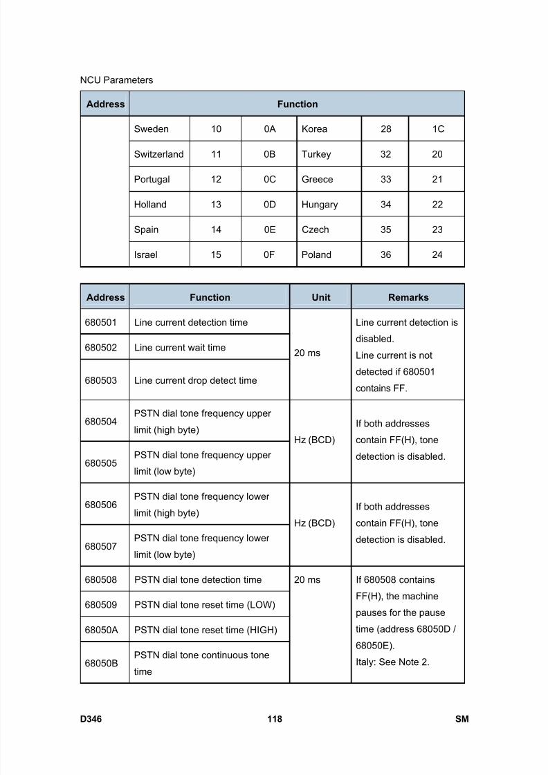
8/15/2019 Ricoh MP 4000 SM D009_D011_D012_D013 SERVICE MANUAL .pdf
http://slidepdf.com/reader/full/ricoh-mp-4000-sm-d009d011d012d013-service-manual-pdf 964/1162
NCU Parameters
D346 118 SM
Address Function
Sweden 10 0A Korea 28 1C
Switzerland 11 0B Turkey 32 20
Portugal 12 0C Greece 33 21
Holland 13 0D Hungary 34 22
Spain 14 0E Czech 35 23
Israel 15 0F Poland 36 24
Address Function Unit Remarks
680501 Line current detection time
680502 Line current wait time
680503 Line current drop detect time
20 ms
Line current detection is
disabled.
Line current is not
detected if 680501
contains FF.
680504PSTN dial tone frequency upper
limit (high byte)
680505PSTN dial tone frequency upper
limit (low byte)
Hz (BCD)
If both addresses
contain FF(H), tone
detection is disabled.
680506PSTN dial tone frequency lower
limit (high byte)
680507 PSTN dial tone frequency lowerlimit (low byte)
Hz (BCD)
If both addresses
contain FF(H), tone
detection is disabled.
680508 PSTN dial tone detection time
680509 PSTN dial tone reset time (LOW)
68050A PSTN dial tone reset time (HIGH)
68050BPSTN dial tone continuous tone
time
20 ms If 680508 contains
FF(H), the machine
pauses for the pause
time (address 68050D /
68050E).
Italy: See Note 2.
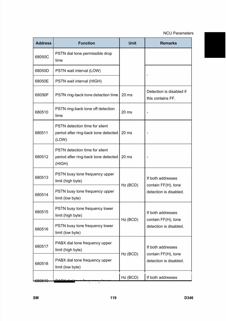
8/15/2019 Ricoh MP 4000 SM D009_D011_D012_D013 SERVICE MANUAL .pdf
http://slidepdf.com/reader/full/ricoh-mp-4000-sm-d009d011d012d013-service-manual-pdf 965/1162
NCU Parameters
SM 119 D346
F a x
O p
t i o n
T y p e
5 0 0 0
D 3 4 6Address Function Unit Remarks
68050CPSTN dial tone permissible drop
time
68050D PSTN wait interval (LOW)
68050E PSTN wait interval (HIGH)
-
68050F PSTN ring-back tone detection time 20 msDetection is disabled if
this contains FF.
680510PSTN ring-back tone off detection
time 20 ms -
680511
PSTN detection time for silent
period after ring-back tone detected
(LOW)
20 ms -
680512
PSTN detection time for silent
period after ring-back tone detected
(HIGH)
20 ms -
680513PSTN busy tone frequency upper
limit (high byte)
680514PSTN busy tone frequency upper
limit (low byte)
Hz (BCD)
If both addresses
contain FF(H), tone
detection is disabled.
680515PSTN busy tone frequency lower
limit (high byte)
680516PSTN busy tone frequency lowerlimit (low byte)
Hz (BCD)
If both addresses
contain FF(H), tone
detection is disabled.
680517PABX dial tone frequency upper
limit (high byte)
680518PABX dial tone frequency upper
limit (low byte)
Hz (BCD)
If both addresses
contain FF(H), tone
detection is disabled.
680519 PABX dial tone frequency lowerHz (BCD) If both addresses
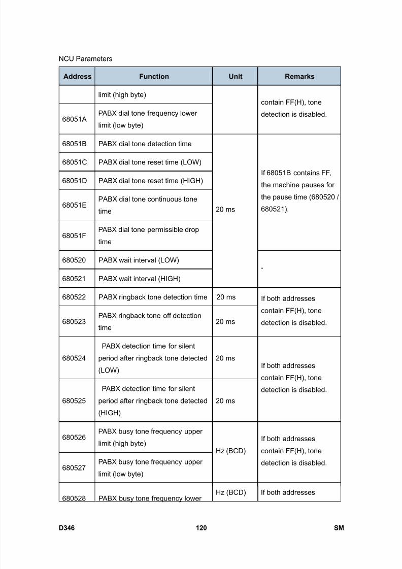
8/15/2019 Ricoh MP 4000 SM D009_D011_D012_D013 SERVICE MANUAL .pdf
http://slidepdf.com/reader/full/ricoh-mp-4000-sm-d009d011d012d013-service-manual-pdf 966/1162
NCU Parameters
D346 120 SM
Address Function Unit Remarks
limit (high byte)
68051APABX dial tone frequency lower
limit (low byte)
contain FF(H), tone
detection is disabled.
68051B PABX dial tone detection time
68051C PABX dial tone reset time (LOW)
68051D PABX dial tone reset time (HIGH)
68051E PABX dial tone continuous tonetime
68051FPABX dial tone permissible drop
time
If 68051B contains FF,
the machine pauses for
the pause time (680520 /680521).
680520 PABX wait interval (LOW)
680521 PABX wait interval (HIGH)
20 ms
-
680522 PABX ringback tone detection time 20 ms
680523PABX ringback tone off detection
time20 ms
If both addressescontain FF(H), tone
detection is disabled.
680524
PABX detection time for silent
period after ringback tone detected
(LOW)
20 ms
680525
PABX detection time for silent
period after ringback tone detected
(HIGH)
20 ms
If both addresses
contain FF(H), tone
detection is disabled.
680526PABX busy tone frequency upper
limit (high byte)
680527PABX busy tone frequency upper
limit (low byte)
Hz (BCD)
If both addresses
contain FF(H), tone
detection is disabled.
680528 PABX busy tone frequency lowerHz (BCD) If both addresses

8/15/2019 Ricoh MP 4000 SM D009_D011_D012_D013 SERVICE MANUAL .pdf
http://slidepdf.com/reader/full/ricoh-mp-4000-sm-d009d011d012d013-service-manual-pdf 967/1162
NCU Parameters
SM 121 D346
F a x
O p
t i o n
T y p e
5 0 0 0
D 3 4 6Address Function Unit Remarks
limit (high byte)
680529PABX busy tone frequency lower
limit (low byte)
contain FF(H), tone
detection is disabled.
68052A Busy tone ON time: range 1
68052B Busy tone OFF time: range 1
68052C Busy tone ON time: range 2
68052D Busy tone OFF time: range 2
68052E Busy tone ON time: range 3
20 ms
68052F Busy tone OFF time: range 3
680530 Busy tone ON time: range 4
680531 Busy tone OFF time: range 4
680532Busy tone continuous tone
detection time
20 ms
-
680533
Busy tone signal state time tolerance for all ranges, and number of cycles
required for detection (a setting of 4 cycles means that ON-OFF-ON or
OFF-ON-OFF must be detected twice).
Tolerance (±)
Bit 1: 0, Bit 0: 0 = 75% Bits 2 and 3 must always be kept at 0.
Bit 1: 0, Bit 0: 0 = 50% Bits 2 and 3 must always be kept at 0.
Bit 1: 0, Bit 0: 0 = 25%
Bit 1: 0, Bit 0: 0 = 12.5%
Bits 7, 6, 5, 4 - number of cycles required for cadence detection
680534International dial tone frequency
upper limit (high byte)
680535International dial tone frequency
upper limit (low byte)
Hz (BCD)
If both addresses
contain FF(H), tone
detection is disabled.
680536 International dial tone frequency Hz (BCD) If both addresses

8/15/2019 Ricoh MP 4000 SM D009_D011_D012_D013 SERVICE MANUAL .pdf
http://slidepdf.com/reader/full/ricoh-mp-4000-sm-d009d011d012d013-service-manual-pdf 968/1162
NCU Parameters
D346 122 SM
Address Function Unit Remarks
lower limit (high byte)
680537International dial tone frequency
lower limit (low byte)
contain FF(H), tone
detection is disabled.
680538International dial tone detection
time
680539International dial tone reset time
(LOW)
68053AInternational dial tone reset time
(HIGH)
68053BInternational dial tone continuous
tone time
68053CInternational dial tone permissible
drop time
If 680538 contains FF,
the machine pauses forthe pause time (68053D
/ 68053E).
Belgium: See Note 2.
68053D International dial wait interval(LOW)
68053EInternational dial wait interval
(HIGH)
20 ms
-
68053FCountry dial tone upper frequency
limit (HIGH)
680540Country dial tone upper frequency
limit (LOW)
If both addresses
contain FF(H), tone
detection is disabled.
680541Country dial tone lower frequency
limit (HIGH)
680542Country dial tone lower frequency
limit (LOW)
Hz (BCD)
If both addresses
contain FF(H), tone
detection is disabled.
680543 Country dial tone detection time
680544 Country dial tone reset time (LOW)
20 ms If 680543 contains FF,
the machine pauses for

8/15/2019 Ricoh MP 4000 SM D009_D011_D012_D013 SERVICE MANUAL .pdf
http://slidepdf.com/reader/full/ricoh-mp-4000-sm-d009d011d012d013-service-manual-pdf 969/1162
NCU Parameters
SM 123 D346
F a x
O p
t i o n
T y p e
5 0 0 0
D 3 4 6Address Function Unit Remarks
680545 Country dial tone reset time (HIGH)the pause time (680548 /
680549).
680546Country dial tone continuous tone
time- -
680547Country dial tone permissible drop
time
680548 Country dial wait interval (LOW)
680549 Country dial wait interval (HIGH)
20 ms -
68054A
Time between opening or closing
the DO relay and opening the OHDI
relay
1 ms
See Notes 3, 6 and 8.
SP2-103-012
(parameter 11).
68054B Break time for pulse dialing 1 ms
See Note 3.
SP2-103-013
(parameter 12).
68054C Make time for pulse dialing 1 ms
See Note 3.
SP2-103-014
(parameter 13).
68054D
Time between final OHDI relay
closure and DO relay opening or
closing
1 ms
See Notes 3, 6 and 8.
SP2-103-015
(parameter 14).
This parameter is only
valid in Europe.
68054EMinimum pause between dialed
digits (pulse dial mode)
See Note 3 and 8.
SP2-103-016
(parameter 15).
68054FTime waited when a pause is
entered at the operation panel
20 ms
SP2-103-017
(parameter 16). See
Note 3.
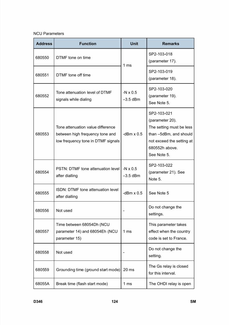
8/15/2019 Ricoh MP 4000 SM D009_D011_D012_D013 SERVICE MANUAL .pdf
http://slidepdf.com/reader/full/ricoh-mp-4000-sm-d009d011d012d013-service-manual-pdf 970/1162
NCU Parameters
D346 124 SM
Address Function Unit Remarks
680550 DTMF tone on timeSP2-103-018
(parameter 17).
680551 DTMF tone off time
1 ms
SP2-103-019
(parameter 18).
680552Tone attenuation level of DTMF
signals while dialing
-N x 0.5
–3.5 dBm
SP2-103-020
(parameter 19).
See Note 5.
680553
Tone attenuation value difference
between high frequency tone and
low frequency tone in DTMF signals
-dBm x 0.5
SP2-103-021(parameter 20).
The setting must be less
than –5dBm, and should
not exceed the setting at
680552h above.
See Note 5.
680554 PSTN: DTMF tone attenuation levelafter dialling
-N x 0.5 –3.5 dBm
SP2-103-022
(parameter 21). See
Note 5.
680555ISDN: DTMF tone attenuation level
after dialling-dBm x 0.5 See Note 5
680556 Not used -Do not change the
settings.
680557
Time between 68054Dh (NCU
parameter 14) and 68054Eh (NCU
parameter 15)
1 ms
This parameter takes
effect when the country
code is set to France.
680558 Not used -Do not change the
setting.
680559 Grounding time (ground start mode) 20 msThe Gs relay is closed
for this interval.
68055A Break time (flash start mode) 1 ms The OHDI relay is open
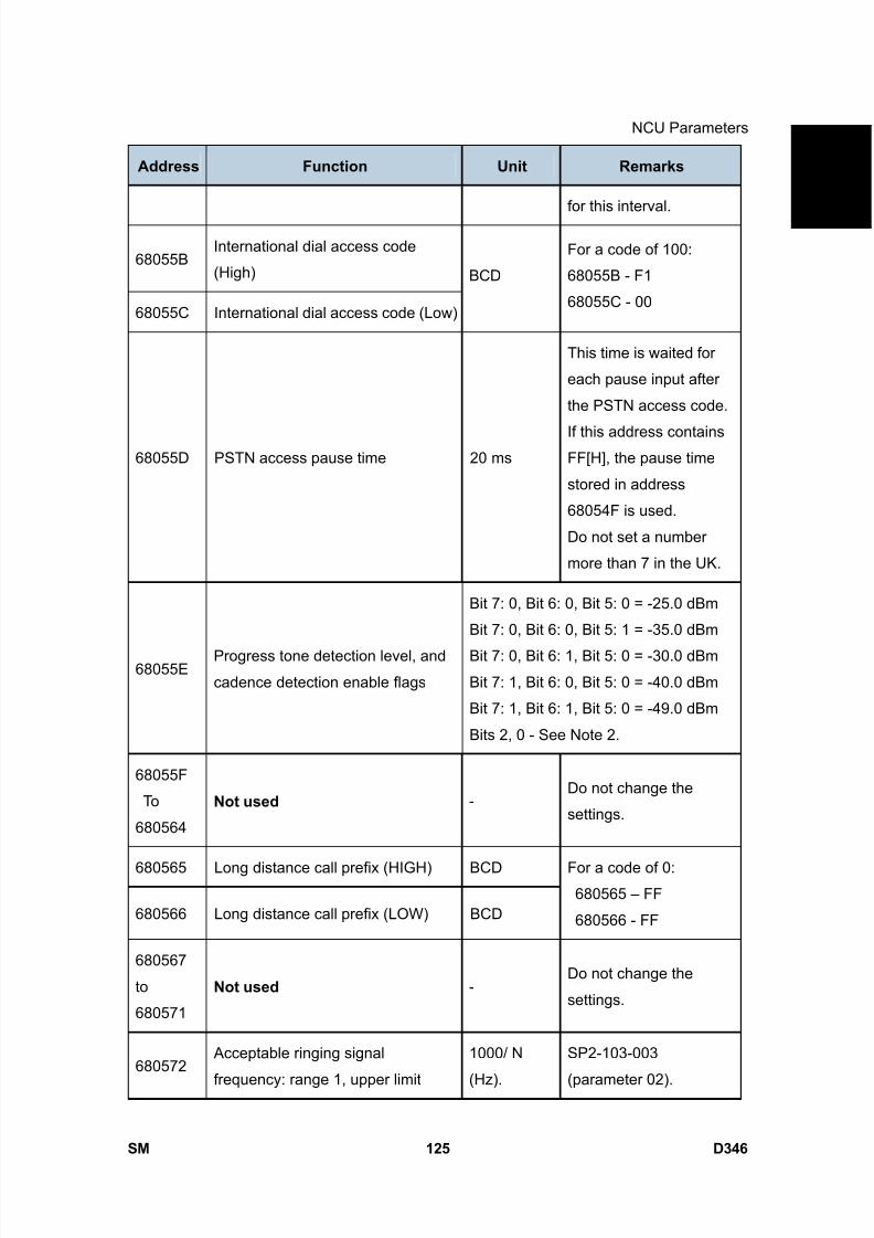
8/15/2019 Ricoh MP 4000 SM D009_D011_D012_D013 SERVICE MANUAL .pdf
http://slidepdf.com/reader/full/ricoh-mp-4000-sm-d009d011d012d013-service-manual-pdf 971/1162
NCU Parameters
SM 125 D346
F a x
O p
t i o n
T y p e
5 0 0 0
D 3 4 6Address Function Unit Remarks
for this interval.
68055BInternational dial access code
(High)
68055C International dial access code (Low)
BCD
For a code of 100:
68055B - F1
68055C - 00
68055D PSTN access pause time 20 ms
This time is waited for
each pause input after
the PSTN access code.
If this address containsFF[H], the pause time
stored in address
68054F is used.
Do not set a number
more than 7 in the UK.
68055EProgress tone detection level, and
cadence detection enable flags
Bit 7: 0, Bit 6: 0, Bit 5: 0 = -25.0 dBm
Bit 7: 0, Bit 6: 0, Bit 5: 1 = -35.0 dBm
Bit 7: 0, Bit 6: 1, Bit 5: 0 = -30.0 dBm
Bit 7: 1, Bit 6: 0, Bit 5: 0 = -40.0 dBm
Bit 7: 1, Bit 6: 1, Bit 5: 0 = -49.0 dBm
Bits 2, 0 - See Note 2.
68055F
To
680564
Not used -Do not change the
settings.
680565 Long distance call prefix (HIGH) BCD
680566 Long distance call prefix (LOW) BCD
For a code of 0:680565 – FF
680566 - FF
680567
to
680571
Not used -Do not change the
settings.
680572 Acceptable ringing signal
frequency: range 1, upper limit
1000/ N
(Hz).
SP2-103-003
(parameter 02).
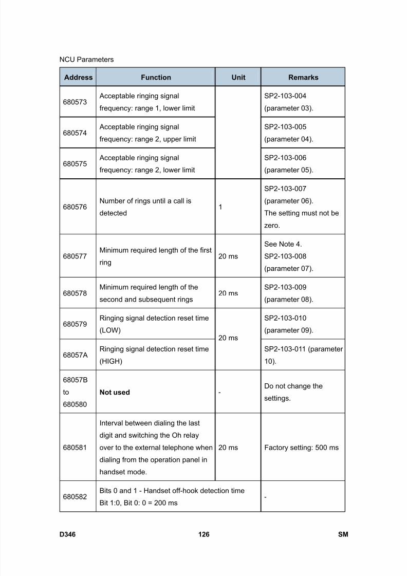
8/15/2019 Ricoh MP 4000 SM D009_D011_D012_D013 SERVICE MANUAL .pdf
http://slidepdf.com/reader/full/ricoh-mp-4000-sm-d009d011d012d013-service-manual-pdf 972/1162
NCU Parameters
D346 126 SM
Address Function Unit Remarks
680573 Acceptable ringing signal
frequency: range 1, lower limit
SP2-103-004
(parameter 03).
680574 Acceptable ringing signal
frequency: range 2, upper limit
SP2-103-005
(parameter 04).
680575 Acceptable ringing signal
frequency: range 2, lower limit
SP2-103-006
(parameter 05).
680576 Number of rings until a call isdetected
1
SP2-103-007
(parameter 06).The setting must not be
zero.
680577Minimum required length of the first
ring20 ms
See Note 4.
SP2-103-008
(parameter 07).
680578Minimum required length of the
second and subsequent rings
20 msSP2-103-009
(parameter 08).
680579Ringing signal detection reset time
(LOW)
SP2-103-010
(parameter 09).
68057ARinging signal detection reset time
(HIGH)
20 ms
SP2-103-011 (parameter
10).
68057B
to
680580
Not used -Do not change the
settings.
680581
Interval between dialing the last
digit and switching the Oh relay
over to the external telephone when
dialing from the operation panel in
handset mode.
20 ms Factory setting: 500 ms
680582Bits 0 and 1 - Handset off-hook detection time
Bit 1:0, Bit 0: 0 = 200 ms-
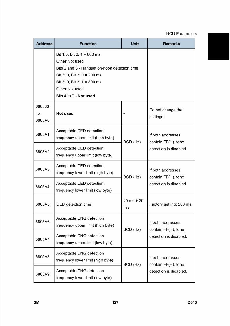
8/15/2019 Ricoh MP 4000 SM D009_D011_D012_D013 SERVICE MANUAL .pdf
http://slidepdf.com/reader/full/ricoh-mp-4000-sm-d009d011d012d013-service-manual-pdf 973/1162
NCU Parameters
SM 127 D346
F a x
O p
t i o n
T y p e
5 0 0 0
D 3 4 6Address Function Unit Remarks
Bit 1:0, Bit 0: 1 = 800 ms
Other Not used
Bits 2 and 3 - Handset on-hook detection time
Bit 3: 0, Bit 2: 0 = 200 ms
Bit 3: 0, Bit 2: 1 = 800 ms
Other Not used
Bits 4 to 7 - Not used
680583
To6805A0
Not used -Do not change the
settings.
6805A1 Acceptable CED detection
frequency upper limit (high byte)
6805A2 Acceptable CED detection
frequency upper limit (low byte)
BCD (Hz)
If both addresses
contain FF(H), tone
detection is disabled.
6805A3
Acceptable CED detection
frequency lower limit (high byte)
6805A4 Acceptable CED detection
frequency lower limit (low byte)
BCD (Hz)If both addressescontain FF(H), tone
detection is disabled.
6805A5 CED detection time20 ms ± 20
msFactory setting: 200 ms
6805A6 Acceptable CNG detection
frequency upper limit (high byte)
6805A7 Acceptable CNG detection
frequency upper limit (low byte)
BCD (Hz)
If both addresses
contain FF(H), tone
detection is disabled.
6805A8 Acceptable CNG detection
frequency lower limit (high byte)
6805A9 Acceptable CNG detection
frequency lower limit (low byte)
BCD (Hz)
If both addresses
contain FF(H), tone
detection is disabled.

8/15/2019 Ricoh MP 4000 SM D009_D011_D012_D013 SERVICE MANUAL .pdf
http://slidepdf.com/reader/full/ricoh-mp-4000-sm-d009d011d012d013-service-manual-pdf 974/1162
NCU Parameters
D346 128 SM
Address Function Unit Remarks
6805AA Not used -Do not change the
setting.
6805AB CNG on time 20 ms Factory setting: 500 ms
6805AC CNG off time 20 ms Factory setting: 3000 ms
6805ADNumber of CNG cycles required for
detection-
The data is coded in the
same way as address
680533.
6805AE Not used -Do not change the
settings.
6805AF
Acceptable AI short protocol tone
(800Hz) detection frequency upper
limit (high byte)
6805B0
Acceptable AI short protocol tone
(800Hz) detection frequency upper
limit (low byte)
Hz (BCD)
If both addresses
contain FF(H), tone
detection is disabled.
6805B1
Acceptable AI short protocol tone
(800Hz) detection frequency lower
limit (high byte)
6805B2
Acceptable AI short protocol tone
(800Hz) detection frequency lower
limit (low byte)
Hz(BCD)
If both addresses
contain FF(H), tone
detection is disabled.
6805B3Detection time for 800 Hz AI short
protocol tone20 ms Factory setting: 360 ms
6805B4 PSTN: Tx level from the modem -N – 3 dBmSP2-103-002
(parameter 01).
6805B5PSTN: 1100 Hz tone transmission
level
- N 6805B4 - 0.5N 6805B5 –3.5 (dB)
See Note 7.
6805B6 PSTN: 2100 Hz tone transmission - N6805B4 - 0.5N 6805B6 –3 (dB)
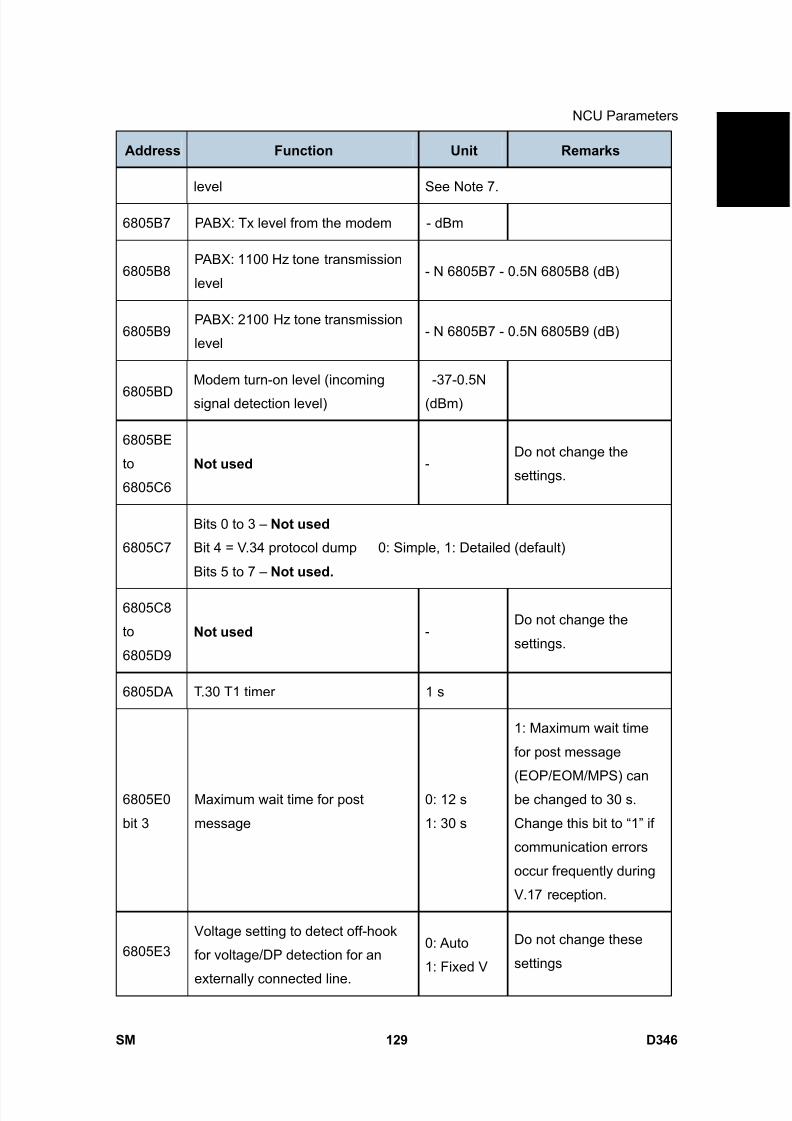
8/15/2019 Ricoh MP 4000 SM D009_D011_D012_D013 SERVICE MANUAL .pdf
http://slidepdf.com/reader/full/ricoh-mp-4000-sm-d009d011d012d013-service-manual-pdf 975/1162
NCU Parameters
SM 129 D346
F a x
O p
t i o n
T y p e
5 0 0 0
D 3 4 6Address Function Unit Remarks
level See Note 7.
6805B7 PABX: Tx level from the modem - dBm
6805B8PABX: 1100 Hz tone transmission
level- N 6805B7 - 0.5N 6805B8 (dB)
6805B9PABX: 2100 Hz tone transmission
level- N 6805B7 - 0.5N 6805B9 (dB)
6805BDModem turn-on level (incoming
signal detection level)
-37-0.5N
(dBm)
6805BE
to
6805C6
Not used -Do not change the
settings.
6805C7
Bits 0 to 3 – Not used
Bit 4 = V.34 protocol dump 0: Simple, 1: Detailed (default)
Bits 5 to 7 – Not used.
6805C8
to
6805D9
Not used -Do not change the
settings.
6805DA T.30 T1 timer 1 s
6805E0
bit 3
Maximum wait time for post
message
0: 12 s
1: 30 s
1: Maximum wait time
for post message
(EOP/EOM/MPS) can
be changed to 30 s.
Change this bit to “1” if
communication errors
occur frequently during
V.17 reception.
6805E3Voltage setting to detect off-hook
for voltage/DP detection for an
externally connected line.
0: Auto
1: Fixed V
Do not change these
settings

8/15/2019 Ricoh MP 4000 SM D009_D011_D012_D013 SERVICE MANUAL .pdf
http://slidepdf.com/reader/full/ricoh-mp-4000-sm-d009d011d012d013-service-manual-pdf 976/1162
NCU Parameters
D346 130 SM
Address Function Unit Remarks
Here is a summary of the fixed voltage settings (1:
Fixed) for an externally connected line.
Bit 7 Bit 6 Bit 5 Bit 4 -
0 0 0 0 Not used
0 0 0 1 2.75 V
0 0 1 0 5.5 V
1 0 0 0 22 V
1 1 1 1 41.25 V
0 RT=0 (Low)Bit 1
1 RT=1 (High)
0 RZ=0 (High)6805E4
Bit 1 sets the level of
the call signal, Bit 3
sets the call signal
impedance Bit 3
1RZ=1
(Composite)
-
0 AutoBit 0
1 Fixed
0 Use RDTP
Bit 0 sets the ring
detection method, Bit
1 sets the ring
detection method
when fixed.Bit 1
1 Use RDTN
Here is a summary of the voltages for thedetection of off-hook for DP detection.
Bit 7 Bit 6 Bit 5 Bit 4 -
0 0 0 0 Not used
0 0 0 1 2.75 V
6805E5
0 0 1 0 5.5 V
If any setting is changed,
select a setting that is
higher than the default
setting.
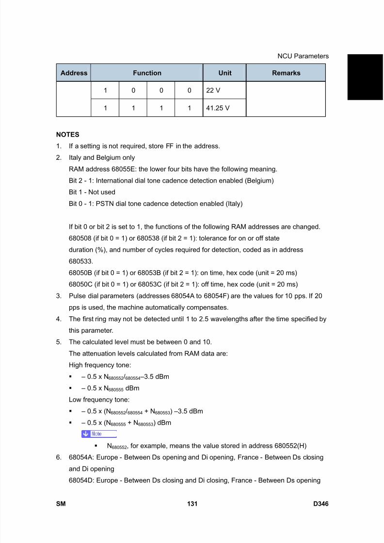
8/15/2019 Ricoh MP 4000 SM D009_D011_D012_D013 SERVICE MANUAL .pdf
http://slidepdf.com/reader/full/ricoh-mp-4000-sm-d009d011d012d013-service-manual-pdf 977/1162
NCU Parameters
SM 131 D346
F a x
O p
t i o n
T y p e
5 0 0 0
D 3 4 6Address Function Unit Remarks
1 0 0 0 22 V
1 1 1 1 41.25 V
NOTES
1. If a setting is not required, store FF in the address.
2. Italy and Belgium only
RAM address 68055E: the lower four bits have the following meaning.
Bit 2 - 1: International dial tone cadence detection enabled (Belgium)
Bit 1 - Not used
Bit 0 - 1: PSTN dial tone cadence detection enabled (Italy)
If bit 0 or bit 2 is set to 1, the functions of the following RAM addresses are changed.
680508 (if bit 0 = 1) or 680538 (if bit 2 = 1): tolerance for on or off state
duration (%), and number of cycles required for detection, coded as in address
680533.
68050B (if bit 0 = 1) or 68053B (if bit 2 = 1): on time, hex code (unit = 20 ms)
68050C (if bit 0 = 1) or 68053C (if bit 2 = 1): off time, hex code (unit = 20 ms)3. Pulse dial parameters (addresses 68054A to 68054F) are the values for 10 pps. If 20
pps is used, the machine automatically compensates.
4. The first ring may not be detected until 1 to 2.5 wavelengths after the time specified by
this parameter.
5. The calculated level must be between 0 and 10.
The attenuation levels calculated from RAM data are:
High frequency tone:
– 0.5 x N680552
/680554
–3.5 dBm
– 0.5 x N 680555 dBm
Low frequency tone:
– 0.5 x (N 680552 /680554 + N 680553 ) –3.5 dBm
– 0.5 x (N 680555 + N 680553 ) dBm
N680552 , for example, means the value stored in address 680552(H)
6. 68054A: Europe - Between Ds opening and Di opening, France - Between Ds closing
and Di opening
68054D: Europe - Between Ds closing and Di closing, France - Between Ds opening
8/15/2019 Ricoh MP 4000 SM D009_D011_D012_D013 SERVICE MANUAL .pdf
http://slidepdf.com/reader/full/ricoh-mp-4000-sm-d009d011d012d013-service-manual-pdf 978/1162
NCU Parameters
D346 132 SM
and Di closing
7. Tone signals which frequency is lower than 1500Hz (e.g., 800Hz tone for AI short
protocol) refer to the setting at 6805B5h. Tones which frequency is higher than 1500Hzrefer to the setting at 6805B6h.
8. 68054A, 68054D, 68054E: The actual inter-digit pause (pulse dial mode) is the sum of
the period specified by the RAM addresses 68054A, 68054D, and 68054E.

8/15/2019 Ricoh MP 4000 SM D009_D011_D012_D013 SERVICE MANUAL .pdf
http://slidepdf.com/reader/full/ricoh-mp-4000-sm-d009d011d012d013-service-manual-pdf 979/1162
Dedicated Transmission Parameters
SM 133 D346
F a x
O p
t i o n
T y p e
5 0 0 0
D 3 4 6
4.5 DEDICATED TRANSMISSION PARAMETERS
There are two sets of transmission parameters: Fax and E-mail
Each Quick Dial Key and Speed Dial Code has eight bytes of programmable parameters
allocated to it. If transmissions to a particular machine often experience problems, store
that terminal’s fax number as a Quick Dial or Speed Dial, and adjust the parameters
allocated to that number.
The programming procedure will be explained first. Then, the eight bytes will be described.
4.5.1 PROGRAMMING PROCEDURE
1. Set the bit 0 of System Bit Switch 00 to 1.2. Enter Address Book Management mode ([User Tools]> System Settings> Key
Operator> Address Book Management).
3. Select the address book that you want to program.
4. For the fax parameter, select "Fax Dest.", for the E-mail parameter, select "E-mail",
then press “Start”. Make sure that the LED of the Start button lights green.
5. The settings for the switch 00 are now displayed. Press the bit number that you wish to
change.
6. To scroll through the parameter switches, either:
7. Select the next switch: press “Next” or Select the previous switch: “Prev.” until the
correct switch is displayed. Then go back to step 6.
8. After the setting is changed, press “OK”.
9. After finishing, reset bit 0 of System Bit Switch 00 to 0.
4.5.2 PARAMETERS
Fax Parameters
The initial settings of the following fax parameters are all FF(H) - all the parameters are
disabled.
Switch 00
FUNCTION AND COMMENTS
ITU-T T1 time (for PSTN G3 mode)
If the connection time to a particular terminal is longer than the NCU parameter setting,
adjust this byte. The T1 time is the value stored in this byte (in hex code), multiplied by 1

8/15/2019 Ricoh MP 4000 SM D009_D011_D012_D013 SERVICE MANUAL .pdf
http://slidepdf.com/reader/full/ricoh-mp-4000-sm-d009d011d012d013-service-manual-pdf 980/1162
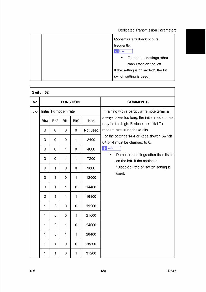
8/15/2019 Ricoh MP 4000 SM D009_D011_D012_D013 SERVICE MANUAL .pdf
http://slidepdf.com/reader/full/ricoh-mp-4000-sm-d009d011d012d013-service-manual-pdf 981/1162
Dedicated Transmission Parameters
SM 135 D346
F a x
O p
t i o n
T y p e
5 0 0 0
D 3 4 6Modem rate fallback occurs
frequently.
Do not use settings other
than listed on the left.
If the setting is “Disabled”, the bit
switch setting is used.
Switch 02
No FUNCTION COMMENTS
Initial Tx modem rate
Bit3 Bit2 Bit1 Bit0 bps
0 0 0 0 Not used
0 0 0 1 2400
0 0 1 0 4800
0 0 1 1 7200
0 1 0 0 9600
0 1 0 1 12000
0 1 1 0 14400
0 1 1 1 16800
1 0 0 0 19200
1 0 0 1 21600
1 0 1 0 24000
1 0 1 1 26400
1 1 0 0 28800
0-3
1 1 0 1 31200
If training with a particular remote terminal
always takes too long, the initial modem rate
may be too high. Reduce the initial Tx
modem rate using these bits.
For the settings 14.4 or kbps slower, Switch
04 bit 4 must be changed to 0.
Do not use settings other than listed
on the left. If the setting is
“Disabled”, the bit switch setting is
used.
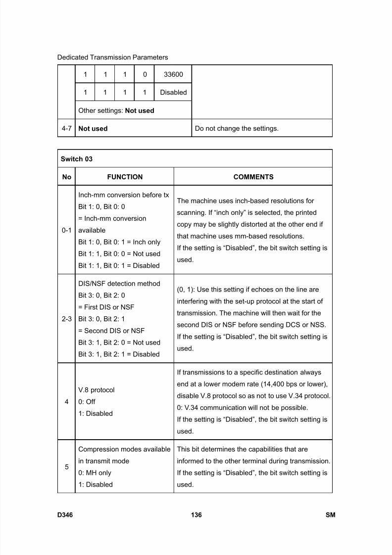
8/15/2019 Ricoh MP 4000 SM D009_D011_D012_D013 SERVICE MANUAL .pdf
http://slidepdf.com/reader/full/ricoh-mp-4000-sm-d009d011d012d013-service-manual-pdf 982/1162
Dedicated Transmission Parameters
D346 136 SM
1 1 1 0 33600
1 1 1 1 Disabled
Other settings: Not used
4-7 Not used Do not change the settings.
Switch 03
No FUNCTION COMMENTS
0-1
Inch-mm conversion before txBit 1: 0, Bit 0: 0
= Inch-mm conversion
available
Bit 1: 0, Bit 0: 1 = Inch only
Bit 1: 1, Bit 0: 0 = Not used
Bit 1: 1, Bit 0: 1 = Disabled
The machine uses inch-based resolutions for
scanning. If “inch only” is selected, the printed
copy may be slightly distorted at the other end if
that machine uses mm-based resolutions.
If the setting is “Disabled”, the bit switch setting is
used.
2-3
DIS/NSF detection method
Bit 3: 0, Bit 2: 0
= First DIS or NSF
Bit 3: 0, Bit 2: 1
= Second DIS or NSF
Bit 3: 1, Bit 2: 0 = Not used
Bit 3: 1, Bit 2: 1 = Disabled
(0, 1): Use this setting if echoes on the line areinterfering with the set-up protocol at the start of
transmission. The machine will then wait for the
second DIS or NSF before sending DCS or NSS.
If the setting is “Disabled”, the bit switch setting is
used.
4V.8 protocol0: Off
1: Disabled
If transmissions to a specific destination always
end at a lower modem rate (14,400 bps or lower),
disable V.8 protocol so as not to use V.34 protocol.
0: V.34 communication will not be possible.
If the setting is “Disabled”, the bit switch setting is
used.
5
Compression modes available
in transmit mode
0: MH only
1: Disabled
This bit determines the capabilities that are
informed to the other terminal during transmission.
If the setting is “Disabled”, the bit switch setting is
used.
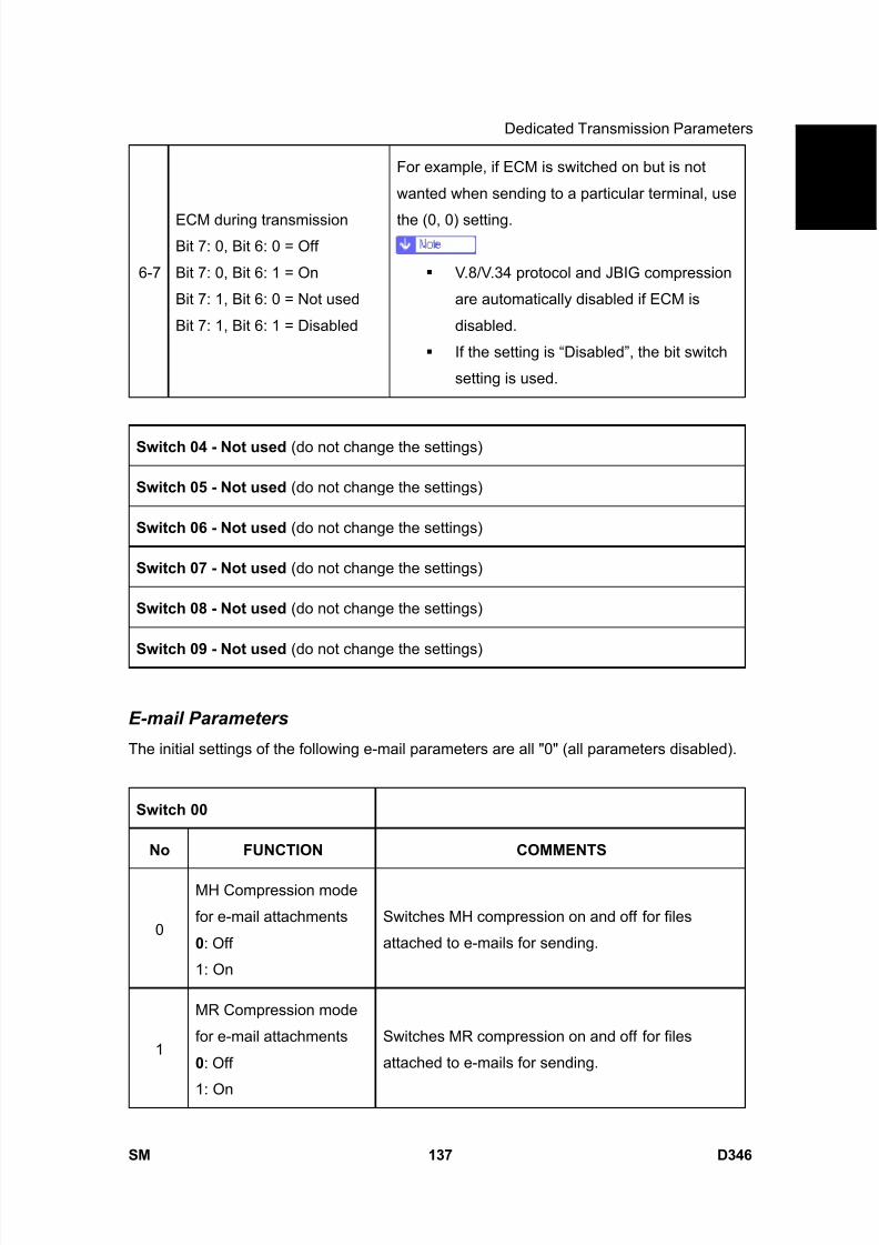
8/15/2019 Ricoh MP 4000 SM D009_D011_D012_D013 SERVICE MANUAL .pdf
http://slidepdf.com/reader/full/ricoh-mp-4000-sm-d009d011d012d013-service-manual-pdf 983/1162
Dedicated Transmission Parameters
SM 137 D346
F a x
O p
t i o n
T y p e
5 0 0 0
D 3 4 6
6-7
ECM during transmissionBit 7: 0, Bit 6: 0 = Off
Bit 7: 0, Bit 6: 1 = On
Bit 7: 1, Bit 6: 0 = Not used
Bit 7: 1, Bit 6: 1 = Disabled
For example, if ECM is switched on but is not
wanted when sending to a particular terminal, use
the (0, 0) setting.
V.8/V.34 protocol and JBIG compression
are automatically disabled if ECM is
disabled.
If the setting is “Disabled”, the bit switch
setting is used.
Switch 04 - Not used (do not change the settings)
Switch 05 - Not used (do not change the settings)
Switch 06 - Not used (do not change the settings)
Switch 07 - Not used (do not change the settings)
Switch 08 - Not used (do not change the settings)
Switch 09 - Not used (do not change the settings)
E-mail Parameters
The initial settings of the following e-mail parameters are all "0" (all parameters disabled).
Switch 00
No FUNCTION COMMENTS
0
MH Compression mode
for e-mail attachments
0: Off
1: On
Switches MH compression on and off for files
attached to e-mails for sending.
1
MR Compression mode
for e-mail attachments
0: Off
1: On
Switches MR compression on and off for files
attached to e-mails for sending.
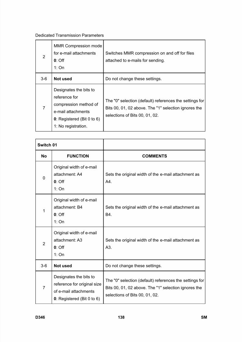
8/15/2019 Ricoh MP 4000 SM D009_D011_D012_D013 SERVICE MANUAL .pdf
http://slidepdf.com/reader/full/ricoh-mp-4000-sm-d009d011d012d013-service-manual-pdf 984/1162
Dedicated Transmission Parameters
D346 138 SM
2
MMR Compression mode
for e-mail attachments
0: Off1: On
Switches MMR compression on and off for files
attached to e-mails for sending.
3-6 Not used Do not change these settings.
7
Designates the bits to
reference for
compression method of
e-mail attachments
0: Registered (Bit 0 to 6)1: No registration.
The "0" selection (default) references the settings for
Bits 00, 01, 02 above. The "1" selection ignores the
selections of Bits 00, 01, 02.
Switch 01
No FUNCTION COMMENTS
0
Original width of e-mail
attachment: A4
0: Off
1: On
Sets the original width of the e-mail attachment as
A4.
1
Original width of e-mail
attachment: B4
0: Off
1: On
Sets the original width of the e-mail attachment as
B4.
2
Original width of e-mail
attachment: A30: Off
1: On
Sets the original width of the e-mail attachment as A3.
3-6 Not used Do not change these settings.
7
Designates the bits to
reference for original size
of e-mail attachments
0: Registered (Bit 0 to 6)
The "0" selection (default) references the settings for
Bits 00, 01, 02 above. The "1" selection ignores the
selections of Bits 00, 01, 02.

8/15/2019 Ricoh MP 4000 SM D009_D011_D012_D013 SERVICE MANUAL .pdf
http://slidepdf.com/reader/full/ricoh-mp-4000-sm-d009d011d012d013-service-manual-pdf 985/1162
Dedicated Transmission Parameters
SM 139 D346
F a x
O p
t i o n
T y p e
5 0 0 0
D 3 4 61: No registration.
Switch 02
No FUNCTION COMMENTS
0
Line resolution of e-mail
attachment: 200 x 100
0: Off
1: On
Sets the line resolution of the e-mail attachment as
200 x100.
1
Line resolution of e-mailattachment: 200 x 200
0: Off
1: On
Sets the line resolution of the e-mail attachment as
200 x 200.
2
Line resolution of e-mail
attachment: 200 x 400
0: Off
1: On
Sets the line resolution of the e-mail attachment as
200 x 400.
3 Not used Do not change these settings.
4
Line resolution of e-mail
attachment: 400 x 400
0: Off
1: On
Sets the line resolution of the e-mail attachment as
400 x 400.
5-6 Not used Do not change these settings.
7
Designates the bits toreference for original size
of e-mail attachments
0: Registered (Bit 0 to 6)
1: No registration.
The "0" selection (default) references the settings for
Bits 00, 01, 02, 04 above. The "1" selection ignores
the selections of Bits 00, 01, 02, 04.
Switch 03 - Not used (do not change the settings)
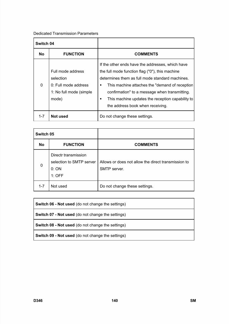
8/15/2019 Ricoh MP 4000 SM D009_D011_D012_D013 SERVICE MANUAL .pdf
http://slidepdf.com/reader/full/ricoh-mp-4000-sm-d009d011d012d013-service-manual-pdf 986/1162
Dedicated Transmission Parameters
D346 140 SM
Switch 04
No FUNCTION COMMENTS
0
Full mode address
selection
0: Full mode address
1: No full mode (simple
mode)
If the other ends have the addresses, which have
the full mode function flag ("0"), this machine
determines them as full mode standard machines.
This machine attaches the "demand of reception
confirmation" to a message when transmitting.
This machine updates the reception capability to
the address book when receiving.
1-7 Not used Do not change these settings.
Switch 05
No FUNCTION COMMENTS
0
Directr transmission
selection to SMTP server
0: ON1: OFF
Allows or does not allow the direct transmission to
SMTP server.
1-7 Not used Do not change these settings.
Switch 06 - Not used (do not change the settings)
Switch 07 - Not used (do not change the settings)
Switch 08 - Not used (do not change the settings)
Switch 09 - Not used (do not change the settings)

8/15/2019 Ricoh MP 4000 SM D009_D011_D012_D013 SERVICE MANUAL .pdf
http://slidepdf.com/reader/full/ricoh-mp-4000-sm-d009d011d012d013-service-manual-pdf 987/1162
Service RAM Addresses
SM 141 D346
F a x
O p
t i o n
T y p e
5 0 0 0
D 3 4 6
4.6 SERVICE RAM ADDRESSES
Do not change the settings which are marked as “Not used” or “Read only.”
680001 to 680004(H) - ROM version (Read only)
680001(H) - Revision number (BCD)
680002(H) - Year (BCD)
680003(H) - Month (BCD)
680004(H) - Day (BCD)
680006 to 680015(H) - Machine’s serial number (16 digits - ASCII)
680018(H) - Total program checksum (low)680019(H) - Total program checksum (high)
680020 to 68003F(H ) - System bit switches
680050 to 68005F(H) - Printer bit switches
680060 to 68007F(H) - Communication bit switches
680080 to 68008F(H) - G3 bit switches
680090 to 68009F(H) - G3-2 bit switches: Not used
6800A0 to 6800AF(H) - G3-3 bit switches: Not used
6800D0(H) - User parameter switch 00 (SWUER_00) : Not used6800D1(H) - User parameter switch 01 (SWUSR_01) : Not used
6800D2(H) - User parameter switch 02 (SWUSR_02)
Bit 0: Forwarding mark printing on forwarded messages 0: Disabled, 1: Enabled
Bit 1: Center mark printing on received copies
(This switch is not printed on the user parameter list.)
0: Disabled, 1: Enabled
Bit 2: Reception time printing
(This switch is not printed on the user parameter list.)
0: Disabled, 1: Enabled
Bit 3: TSI print on received messages 0: Disabled, 1: Enabled
Bit 4: Checkered mark printing
(This switch is not printed on the user parameter list.)
0: Disabled, 1: Enabled
Bit 5: Not used
Bit 6: Not used
Bit 7: Not used
6800D3(H) - User parameter switch 03 (SWUSR_03: Automatic report printout)
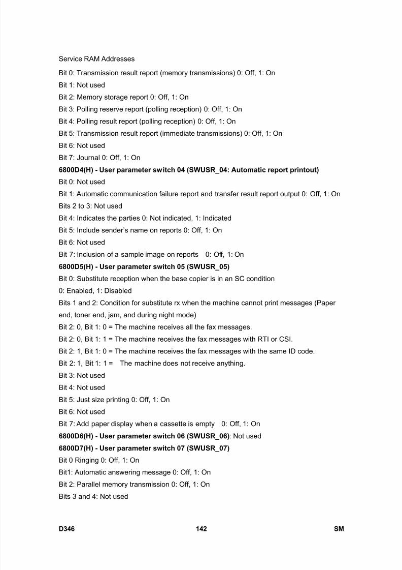
8/15/2019 Ricoh MP 4000 SM D009_D011_D012_D013 SERVICE MANUAL .pdf
http://slidepdf.com/reader/full/ricoh-mp-4000-sm-d009d011d012d013-service-manual-pdf 988/1162
Service RAM Addresses
D346 142 SM
Bit 0: Transmission result report (memory transmissions) 0: Off, 1: On
Bit 1: Not used
Bit 2: Memory storage report 0: Off, 1: OnBit 3: Polling reserve report (polling reception) 0: Off, 1: On
Bit 4: Polling result report (polling reception) 0: Off, 1: On
Bit 5: Transmission result report (immediate transmissions) 0: Off, 1: On
Bit 6: Not used
Bit 7: Journal 0: Off, 1: On
6800D4(H) - User parameter switch 04 (SWUSR_04: Automatic report printout)
Bit 0: Not used
Bit 1: Automatic communication failure report and transfer result report output 0: Off, 1: On
Bits 2 to 3: Not used
Bit 4: Indicates the parties 0: Not indicated, 1: Indicated
Bit 5: Include sender’s name on reports 0: Off, 1: On
Bit 6: Not used
Bit 7: Inclusion of a sample image on reports 0: Off, 1: On
6800D5(H) - User parameter switch 05 (SWUSR_05)
Bit 0: Substitute reception when the base copier is in an SC condition
0: Enabled, 1: Disabled
Bits 1 and 2: Condition for substitute rx when the machine cannot print messages (Paper
end, toner end, jam, and during night mode)
Bit 2: 0, Bit 1: 0 = The machine receives all the fax messages.
Bit 2: 0, Bit 1: 1 = The machine receives the fax messages with RTI or CSI.
Bit 2: 1, Bit 1: 0 = The machine receives the fax messages with the same ID code.
Bit 2: 1, Bit 1: 1 = The machine does not receive anything.
Bit 3: Not used
Bit 4: Not used
Bit 5: Just size printing 0: Off, 1: OnBit 6: Not used
Bit 7: Add paper display when a cassette is empty 0: Off, 1: On
6800D6(H) - User parameter switch 06 (SWUSR_06) : Not used
6800D7(H) - User parameter switch 07 (SWUSR_07)
Bit 0 Ringing 0: Off, 1: On
Bit1: Automatic answering message 0: Off, 1: On
Bit 2: Parallel memory transmission 0: Off, 1: On
Bits 3 and 4: Not used
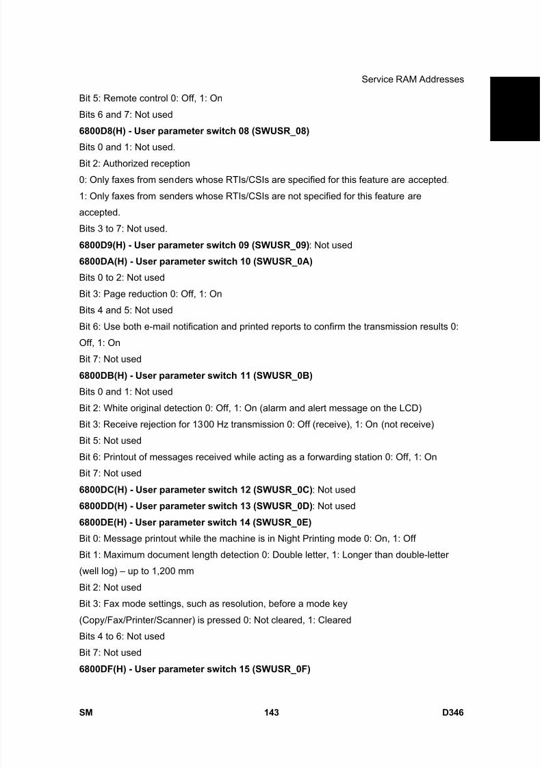
8/15/2019 Ricoh MP 4000 SM D009_D011_D012_D013 SERVICE MANUAL .pdf
http://slidepdf.com/reader/full/ricoh-mp-4000-sm-d009d011d012d013-service-manual-pdf 989/1162
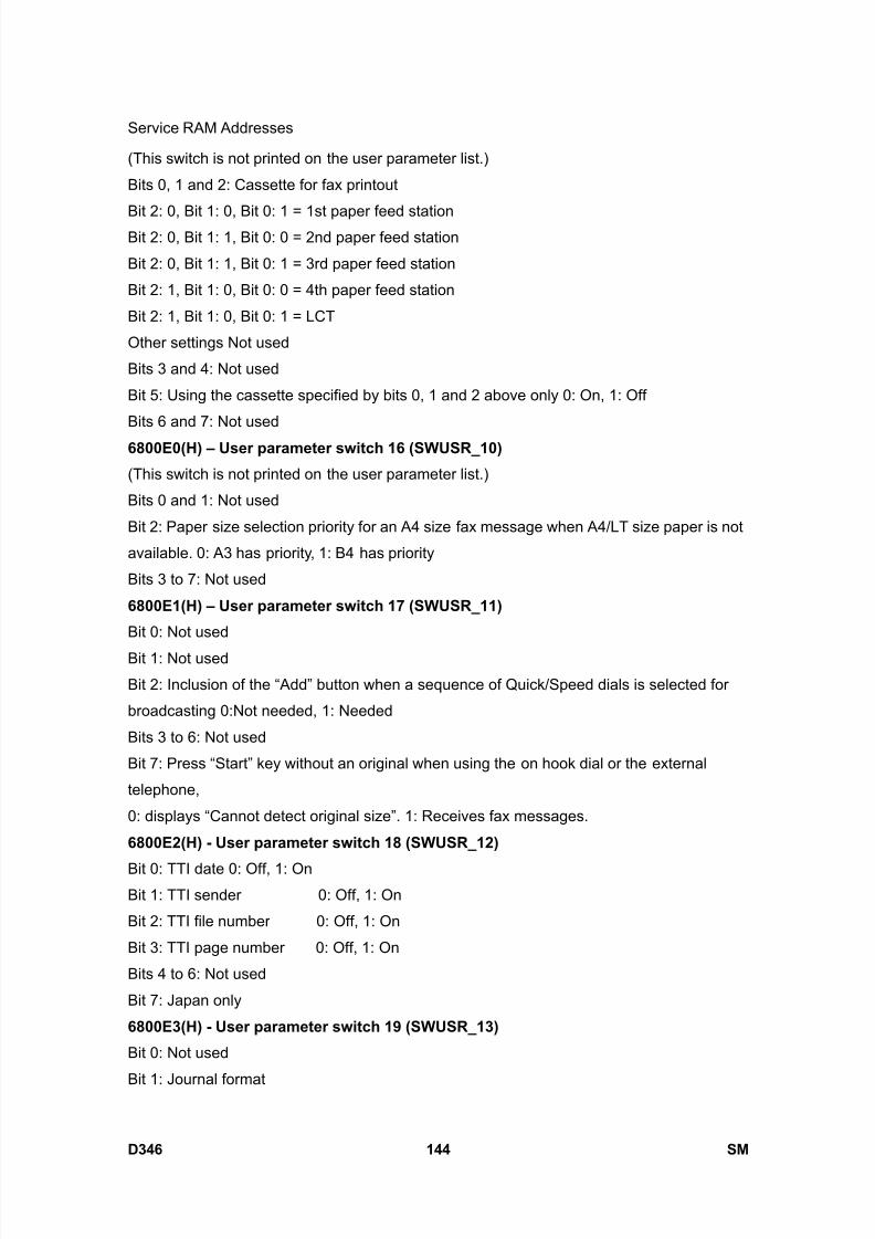
8/15/2019 Ricoh MP 4000 SM D009_D011_D012_D013 SERVICE MANUAL .pdf
http://slidepdf.com/reader/full/ricoh-mp-4000-sm-d009d011d012d013-service-manual-pdf 990/1162
Service RAM Addresses
D346 144 SM
(This switch is not printed on the user parameter list.)
Bits 0, 1 and 2: Cassette for fax printout
Bit 2: 0, Bit 1: 0, Bit 0: 1 = 1st paper feed stationBit 2: 0, Bit 1: 1, Bit 0: 0 = 2nd paper feed station
Bit 2: 0, Bit 1: 1, Bit 0: 1 = 3rd paper feed station
Bit 2: 1, Bit 1: 0, Bit 0: 0 = 4th paper feed station
Bit 2: 1, Bit 1: 0, Bit 0: 1 = LCT
Other settings Not used
Bits 3 and 4: Not used
Bit 5: Using the cassette specified by bits 0, 1 and 2 above only 0: On, 1: Off
Bits 6 and 7: Not used
6800E0(H) – User parameter switch 16 (SWUSR_10)
(This switch is not printed on the user parameter list.)
Bits 0 and 1: Not used
Bit 2: Paper size selection priority for an A4 size fax message when A4/LT size paper is not
available. 0: A3 has priority, 1: B4 has priority
Bits 3 to 7: Not used
6800E1(H) – User parameter switch 17 (SWUSR_11)
Bit 0: Not used
Bit 1: Not used
Bit 2: Inclusion of the “Add” button when a sequence of Quick/Speed dials is selected for
broadcasting 0:Not needed, 1: Needed
Bits 3 to 6: Not used
Bit 7: Press “Start” key without an original when using the on hook dial or the external
telephone,
0: displays “Cannot detect original size”. 1: Receives fax messages.
6800E2(H) - User parameter switch 18 (SWUSR_12)
Bit 0: TTI date 0: Off, 1: OnBit 1: TTI sender 0: Off, 1: On
Bit 2: TTI file number 0: Off, 1: On
Bit 3: TTI page number 0: Off, 1: On
Bits 4 to 6: Not used
Bit 7: Japan only
6800E3(H) - User parameter switch 19 (SWUSR_13)
Bit 0: Not used
Bit 1: Journal format
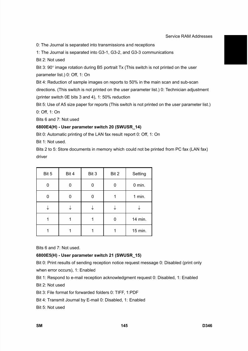
8/15/2019 Ricoh MP 4000 SM D009_D011_D012_D013 SERVICE MANUAL .pdf
http://slidepdf.com/reader/full/ricoh-mp-4000-sm-d009d011d012d013-service-manual-pdf 991/1162
Service RAM Addresses
SM 145 D346
F a x
O p
t i o n
T y p e
5 0 0 0
D 3 4 60: The Journal is separated into transmissions and receptions
1: The Journal is separated into G3-1, G3-2, and G3-3 communications
Bit 2: Not usedBit 3: 90 ° image rotation during B5 portrait Tx (This switch is not printed on the user
parameter list.) 0: Off, 1: On
Bit 4: Reduction of sample images on reports to 50% in the main scan and sub-scan
directions. (This switch is not printed on the user parameter list.) 0: Technician adjustment
(printer switch 0E bits 3 and 4), 1: 50% reduction
Bit 5: Use of A5 size paper for reports (This switch is not printed on the user parameter list.)
0: Off, 1: On
Bits 6 and 7: Not used
6800E4(H) - User parameter switch 20 (SWUSR_14)
Bit 0: Automatic printing of the LAN fax result report 0: Off, 1: On
Bit 1: Not used.
Bits 2 to 5: Store documents in memory which could not be printed from PC fax (LAN fax)
driver
Bit 5 Bit 4 Bit 3 Bit 2 Setting
0 0 0 0 0 min.
0 0 0 1 1 min.
↓ ↓ ↓ ↓ ↓
1 1 1 0 14 min.
1 1 1 1 15 min.
Bits 6 and 7: Not used.
6800E5(H) - User parameter switch 21 (SWUSR_15)
Bit 0: Print results of sending reception notice request message 0: Disabled (print only
when error occurs), 1: Enabled
Bit 1: Respond to e-mail reception acknowledgment request 0: Disabled, 1: Enabled
Bit 2: Not used
Bit 3: File format for forwarded folders 0: TIFF, 1:PDF
Bit 4: Transmit Journal by E-mail 0: Disabled, 1: Enabled
Bit 5: Not used

8/15/2019 Ricoh MP 4000 SM D009_D011_D012_D013 SERVICE MANUAL .pdf
http://slidepdf.com/reader/full/ricoh-mp-4000-sm-d009d011d012d013-service-manual-pdf 992/1162
Service RAM Addresses
D346 146 SM
Bit 6: Network error display 0: Displayed, 1: Not displayed
Bit 7: Transmit error mail notification 0: Enabled, 1: Disabled
6800E6(H) - User parameter switch 22 (SWUSR_16) (This switch is not printed on the user parameter list.)
Bit 0: Dial tone detection (PSTN 1) 0: Disabled, 1: Enabled
Bits 1 to 7: Not used
6800E7(H) – User parameter switch 23 (SWUSR_17) : Not used
6800E8(H) - User parameter switch 24 (SWUSR_18) : Not used
6800E9(H) - User parameter switch 25 (SWUSR_19)
Bit 0: Not used
Bit 1: Reception mode switch timer 0: Off, 1: On (switching Fax or Fax/Tel)
Bit 2: Mode priority switch 0: Fax first, 1: Tel first
Bit 3: Dial in function (Japan Only)
Bit 4: RDS operation 0: Not acceptable, 1: Acceptable for the limit specified by system
switch 03
This bit is only effective when RDS operation can be selected by the user
(see system switch 02).
Bits 5 to 7: Not used
6800EA(H) and 6800EB(H) - User parameter switches 26 and 27 (SWUSR_1A and 1B) :
Not used
6800EC(H) - User parameter switch 28(SWUSR_1C)
Xxxxx
6800ED(H) - User parameter switch 29(SWUSR_1D)
xxxxxx
6800EE(H) and 6800EF(H) - User parameter switches 30 and 31 (SWUSR_1E and 1F) :
Not used
6800F0(H) - User parameter switch 32 (SWUSR_20) Bit 0: Quotation priority for a destination when there is no destination of the specified type
0: Paper output priority = Priority order: 1. IP-fax destination, 2. Fax Number, 3. E-mail
address, 4. Folder
1: Electric putout order = Priority order: 1. E-mail address, 2. Folder, 3. IP-fax destination, 4.
Fax number
Bits 1 to 7: Not used
6800F1(H) - User parameter switch 33 (SWUSR_21) : Not used
6800F2(H) - User parameter switch 34 (SWUSR_22)

8/15/2019 Ricoh MP 4000 SM D009_D011_D012_D013 SERVICE MANUAL .pdf
http://slidepdf.com/reader/full/ricoh-mp-4000-sm-d009d011d012d013-service-manual-pdf 993/1162
Service RAM Addresses
SM 147 D346
F a x
O p
t i o n
T y p e
5 0 0 0
D 3 4 6Bit 0: Gatekeeper server used with IP-Fax 0: Disabled, 1: Enabled
Bit 1: SIP server used with IP-Fax 0: Disabled, 1: Enabled
Bits 2 to 7: Not used680100 to 68010F(H) - G4 Parameter Switches – Not used
680110 to 68012F(H) - G4 Internal Switches – Not used
680130 to 68016F(H) - Service Switches
680170 to 68017F(H) - IFAX Switches
680180 to 68018F(H) - IP-FAX Switches
680190 to 6801AF(H) - Service station’s fax number (SP3-101)
6801B0 to 6801B9(H) - Own fax PABX extension number
6801BA to 6801C3(H) - Own fax number (PSTN) – Not used
6801C4 to 6801D7(H) - Own fax number (ISDN G4) – Not used
6801D8 to 6801E3(H) - The first subscriber number (ISDN G3) – Not used
6801E4 to 6801EF(H) - The second subscriber number (ISDN G3) – Not used
6801F0 to 6801FB(H) - The first subscriber number (ISDN G4) – Not used
6801FC to 680207(H) - The second subscriber number (ISDN G4) – Not used
680208 to 68021B(H) - PSTN-1 RTI (Max. 20 characters - ASCII) - See the following note.
68021C to 68022F(H) - PSTN-2 RTI (Max. 20 characters - ASCII) - Not used
680230 to 680246(H) - PSTN-3 RTI (Max. 20 characters - ASCII) - Not used
680247 to 680286(H) - TTI 1 (Max. 64 characters - ASCII) - See the following note.
680287 to 6802C6(H) - TTI 2 (Max. 64 characters - ASCII) - Not used
6802C7 to 680306(H) - TTI 3 (Max. 64 characters - ASCII) - Not used
680307 to 68031A(H) - PSTN-1 CSI (Max. 20 characters - ASCII)
68031B to 68032E(H) - PSTN-2 CSI (Max.20 characters - ASCII) - Not used
68032F to 680342(H) - PSTN-3 CSI (Max.20 characters - ASCII) - Not used
680343(H) - Number of PSTN-1 CSI characters (Hex)
680344(H) - Number of PSTN-2 CSI characters (Hex) - Not used
680345(H) Number of PSTN-3 CSI characters (Hex) - Not used
If the number of characters is less than the maximum (20 for RTI, 64 for TTI), add
a stop code (00[H]) after the last character.
680380 to 680387(H) - Last power off time (Read only)
680380(H) - 01(H) - 24-hour clock, 00(H) - 12-hour clock (AM), 02(H) - 12-hour clock (PM)
680381(H) - Year (BCD)
680382(H) - Month (BCD)
680383(H) - Day (BCD)

8/15/2019 Ricoh MP 4000 SM D009_D011_D012_D013 SERVICE MANUAL .pdf
http://slidepdf.com/reader/full/ricoh-mp-4000-sm-d009d011d012d013-service-manual-pdf 994/1162
Service RAM Addresses
D346 148 SM
680384(H) – Hour
680385(H) – Minute
680386(H) – Second680387(H) - 00: Monday, 01: Tuesday, 02: Wednesday, /// , 06: Sunday
680394(H) - Optional equipment (Read only – Do not change the settings)
Bit 0: Page Memory 0: Not installed, 1: Installed
Bit 1: SAF Memory 0: Not installed, 1: Installed
Bits 2 to 7; Not used
680395(H) - Optional equipment (Read only – Do not change the settings)
Bits 0 to 3: Not used
Bit 4: G3-2 0: Not installed, 1: Installed
Bit 5: G3-3 0: Not installed, 1: Installed
Bit 6 and 7: Not used
680406 to 68040A – Option G3 board (G3-2) ROM information (Read only)
680406(H) - Suffix (BCD)
680407(H) - Version (BCD)
680408(H) - Year (BCD)
680409(H) - Month (BCD)
68040A(H) - Day (BCD)
68040B to 68040F – Option G3 board (G3-3) ROM information (Read only)
68040B(H) - Suffix (BCD)
68040C(H) - Version (BCD)
68040D(H) - Year (BCD)
68040E(H) - Month (BCD)
68040F(H) - Day (BCD)
680410(H) - G3-1 Modem ROM version (Read only)
680412(H) - G3-2 Modem ROM version (Read only)
680414(H) - G3-3 Modem ROM version (Read only)680420(H) - Number of multiple sets print (Read only)
680476(H) - Time for economy transmission (hour in 24h clock format - BCD)
680477(H) - Time for economy transmission (minute - BCD)
680492(H) - Transmission monitor volume 00 - 07(H)
680493(H) - Reception monitor volume 00 - 07(H)
680494(H) - On-hook monitor volume 00 - 07(H)
680495(H) - Dialing monitor volume 00 - 07(H)
680496(H) - Buzzer volume 00 - 07(H)

8/15/2019 Ricoh MP 4000 SM D009_D011_D012_D013 SERVICE MANUAL .pdf
http://slidepdf.com/reader/full/ricoh-mp-4000-sm-d009d011d012d013-service-manual-pdf 995/1162
Service RAM Addresses
SM 149 D346
F a x
O p
t i o n
T y p e
5 0 0 0
D 3 4 6680497(H) - Beeper volume 00 - 07(H)
6804A8(H) - Machine code (Check ram 4)
688E8E to 68918D(H) - SIP server address (Read only)688E8E(H) - Proxy server - Main (Max. 128 characters - ASCII)
688F0E(H) - Proxy server - Sub (Max. 128 characters - ASCII)
688F8E(H) - Redirect server - Main (Max. 128 characters - ASCII)
68900E(H) - Redirect server - Sub (Max. 128 characters - ASCII)
68908E(H) - Registrar server - Main (Max. 128 characters - ASCII)
68910E(H) - Registrar server - Sub (Max. 128 characters - ASCII)
68918E(H) - Gatekeeper server address - Main (Max. 128 characters - ASCII)
68920E(H ) - Gatekeeper server address - Sub (Max. 128 characters - ASCII)
68928E(H) - Arias Number (Max. 128 characters - ASCII)
68930E(H) - SIP user name (Max. 128 characters - ASCII)
68938E(H) - SIP digest authentication password (Max. 128 characters - ASCII)
68940E(H) - Gateway address information (Max. 7100 characters - ASCII)
68AFCA(H) - Stand-by port number for H.232 connection
68AFCCH) - Stand-by port number for SIP connection
68AFCE(H) - RAS port number
68AFD0(H) - Gatekeeper port number
68AFD2(H) - Port number of data waiting for T.38
68AFD4(H) - Port number of SIP server
68AFD6(H) - Priority for SIP and H.323 0: H.323, 1: SIP
68AFD7(H) - SIP function 0: Disabled, 1: Enabled
68AFD8(H) - H.323 function 0: Disabled, 1: Enabled
68AFD9(H) - SIP digest authentication function 0: Disabled, 1: Enabled
68AFDA(H) - IP-Fax backup data 00 - 600 (H)
69ECBE(H) - 69ECDE(H) - Dial tone detection parameter (Max. 11 x 3 lines)
69ECBE(H) Dial tone frequency upper limit (high byte)
69ECBF(H) Dial tone frequency upper limit (low byte)
Hz (BCD)
69ECC0(H) Dial tone frequency lower limit (high byte)
69ECC1(H) Dial tone frequency lower limit (low byte)
Hz (BCD)
69ECC2(H) Dial tone detection time (x 20 ms)
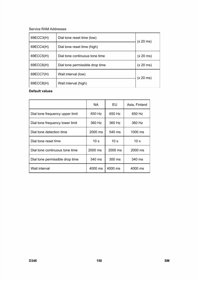
8/15/2019 Ricoh MP 4000 SM D009_D011_D012_D013 SERVICE MANUAL .pdf
http://slidepdf.com/reader/full/ricoh-mp-4000-sm-d009d011d012d013-service-manual-pdf 996/1162
Service RAM Addresses
D346 150 SM
69ECC3(H) Dial tone reset time (low)
69ECC4(H) Dial tone reset time (high)
(x 20 ms)
69ECC5(H) Dial tone continuous tone time (x 20 ms)
69ECC6(H) Dial tone permissible drop time (x 20 ms)
69ECC7(H) Wait interval (low)
69ECC8(H) Wait interval (high)
(x 20 ms)
Default values
NA EU Asia, Finland
Dial tone frequency upper limit 650 Hz 650 Hz 650 Hz
Dial tone frequency lower limit 360 Hz 360 Hz 360 Hz
Dial tone detection time 2000 ms 540 ms 1000 ms
Dial tone reset time 10 s 10 s 10 s
Dial tone continuous tone time 2000 ms 2000 ms 2000 ms
Dial tone permissible drop time 340 ms 300 ms 340 ms
Wait interval 4000 ms 4000 ms 4000 ms

8/15/2019 Ricoh MP 4000 SM D009_D011_D012_D013 SERVICE MANUAL .pdf
http://slidepdf.com/reader/full/ricoh-mp-4000-sm-d009d011d012d013-service-manual-pdf 997/1162
Overview
SM 151 D346
F a x
O p
t i o n
T y p e
5 0 0 0
D 3 4 6
5. DETAILS
5.1 OVERVIEW
The basic fax unit consists of two PCBs: an FCU and an MBU.
The FCU controls all the fax communications and fax features, in cooperation with the
controller board. The MBU contains the ROM and SRAM. Also, the FCU has an NCU
circuit.
Fax Options:
1. Extra G3 Interface option: This provides one more analog line interface. This allows full
dual access. Two extra G3 interface options can be installed.
2. Memory Expansion: This expands the SAF memory and the page memory (used for
image rotation); without this expansion, the page memory is not big enough for image
rotation at 400 dpi, so transmission at 400 dpi is not possible.

8/15/2019 Ricoh MP 4000 SM D009_D011_D012_D013 SERVICE MANUAL .pdf
http://slidepdf.com/reader/full/ricoh-mp-4000-sm-d009d011d012d013-service-manual-pdf 998/1162
Boards
D346 152 SM
5.2 BOARDS
5.2.1 FCU
The FCU (Facsimile Control Unit) controls fax communications, the video interface to the
base copier’s engine, and all the fax options.
FACE3 (Fax Application Control Engine)
CPU
Data compression and reconstruction (DCR)
DMA control
Clock generation
DRAM backup control
Modem (FAME) V.34, V33, V17, V.29, V.27ter, V.21, and V.8
DRAM
The 16 MB of DRAM is shared as follows.
SAF memory: 4MB
Working memory: 8MB
Page memory: 4MB
The SAF memory is backed up by a rechargeable battery.

8/15/2019 Ricoh MP 4000 SM D009_D011_D012_D013 SERVICE MANUAL .pdf
http://slidepdf.com/reader/full/ricoh-mp-4000-sm-d009d011d012d013-service-manual-pdf 999/1162
Boards
SM 153 D346
F a x
O p
t i o n
T y p e
5 0 0 0
D 3 4 6Memory Back-up
A Rechargeable battery backs up the SAF memory (DRAM) for 1 hour.
5.2.2 MBU
On this board, the flash ROM contains the FCU firmware, and the SRAM contains the
system data and user parameters. Even if the FCU is changed, the system data and user
parameters are kept on the MBU board.
ROM
3MB flash ROMs for system software storage
2MB (16bit x 1MB) + 1MB (16bit x 512K)
SRAM
The 256KB SRAM for system and user parameter storage is backed up by a lithium
battery.
Memory Back-up
A lithium battery backs up the system parameters and programmed items in the SRAM,
in case the base copier's main switch is turned off.
Switches
Item Description
SW1 Switches the SRAM backup battery on/off.
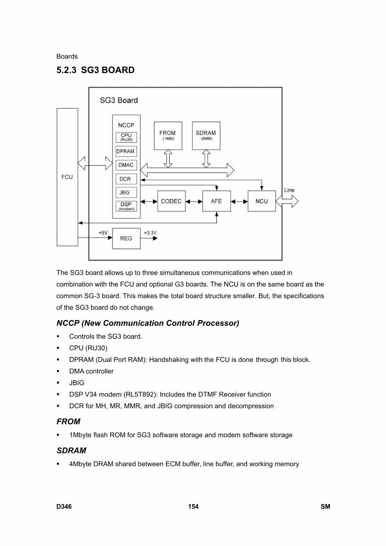
8/15/2019 Ricoh MP 4000 SM D009_D011_D012_D013 SERVICE MANUAL .pdf
http://slidepdf.com/reader/full/ricoh-mp-4000-sm-d009d011d012d013-service-manual-pdf 1000/1162
Boards
D346 154 SM
5.2.3 SG3 BOARD
The SG3 board allows up to three simultaneous communications when used in
combination with the FCU and optional G3 boards. The NCU is on the same board as thecommon SG-3 board. This makes the total board structure smaller. But, the specifications
of the SG3 board do not change.
NCCP (New Communication Control Processor)
Controls the SG3 board.
CPU (RU30)
DPRAM (Dual Port RAM): Handshaking with the FCU is done through this block.
DMA controller
JBIG DSP V34 modem (RL5T892): Includes the DTMF Receiver function
DCR for MH, MR, MMR, and JBIG compression and decompression
FROM
1Mbyte flash ROM for SG3 software storage and modem software storage
SDRAM
4Mbyte DRAM shared between ECM buffer, line buffer, and working memory

8/15/2019 Ricoh MP 4000 SM D009_D011_D012_D013 SERVICE MANUAL .pdf
http://slidepdf.com/reader/full/ricoh-mp-4000-sm-d009d011d012d013-service-manual-pdf 1001/1162
Boards
SM 155 D346
F a x
O p
t i o n
T y p e
5 0 0 0
D 3 4 6 AFE (Analog Front End)
Analog processing
CODEC (COder-DECoder)
A/D & D/A conversions for modem
REG
Generates +3.3 V from the +5V from the FCU
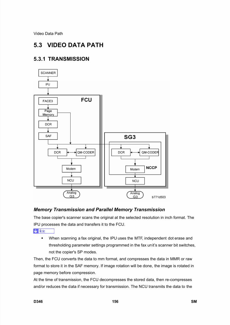
8/15/2019 Ricoh MP 4000 SM D009_D011_D012_D013 SERVICE MANUAL .pdf
http://slidepdf.com/reader/full/ricoh-mp-4000-sm-d009d011d012d013-service-manual-pdf 1002/1162
Video Data Path
D346 156 SM
5.3 VIDEO DATA PATH
5.3.1 TRANSMISSION
Memory Transmission and Parallel Memory Transmission
The base copier's scanner scans the original at the selected resolution in inch format. The
IPU processes the data and transfers it to the FCU.
When scanning a fax original, the IPU uses the MTF, independent dot erase and
thresholding parameter settings programmed in the fax unit’s scanner bit switches,
not the copier's SP modes.
Then, the FCU converts the data to mm format, and compresses the data in MMR or raw
format to store it in the SAF memory. If image rotation will be done, the image is rotated in
page memory before compression.
At the time of transmission, the FCU decompresses the stored data, then re-compresses
and/or reduces the data if necessary for transmission. The NCU transmits the data to the
8/15/2019 Ricoh MP 4000 SM D009_D011_D012_D013 SERVICE MANUAL .pdf
http://slidepdf.com/reader/full/ricoh-mp-4000-sm-d009d011d012d013-service-manual-pdf 1003/1162
Video Data Path
SM 157 D346
F a x
O p
t i o n
T y p e
5 0 0 0
D 3 4 6line.
Immediate Transmission
The base copier's scanner scans the original at the resolution agreed with the receiving
terminal. The IPU video processes the data and transfers it to the FCU.
When scanning a fax original, the IPU uses the MTF, independent dot erase and
thresholding parameter settings programmed in the fax unit’s scanner bit switches,
not the copier's SP modes.
Then the FCU stores the data in page memory, and compresses the data for transmission.
The NCU transmits the data to the line.
JBIG Transmission
Memory transmission: If the receiver has JBIG compression, the data goes from the
DCR to the QM-Coder. Then the NCU transmits the data to the line. When an optional
G3 unit (SG3) is installed and PSTN2 is selected as the line type, JBIG compression is
available, but only for the PSTN-2 line.
Immediate transmission: If the receiver has JBIG compression, the data goes from
the page memory to the QM-Coder. Then the NCU transmits the data to the line. When
an optional G3 unit (SG3) is installed and PSTN2 is selected as the line type, JBIG
compression is available, but only for the PSTN-2 line.
Adjustments
Priority for the line used for G3 transmissions (PSTN 1/PSTN 2 or 3): System switch 16 bit
1

8/15/2019 Ricoh MP 4000 SM D009_D011_D012_D013 SERVICE MANUAL .pdf
http://slidepdf.com/reader/full/ricoh-mp-4000-sm-d009d011d012d013-service-manual-pdf 1004/1162
Video Data Path
D346 158 SM
5.3.2 RECEPTION
First, the FCU stores the incoming data from either an analog line to the SAF memory. (The
data goes to the FACE3 at the same time, and is checked for error lines/frames.)
The FCU then decompresses the data and transfers it to page memory. If image rotation
will be done, the image is rotated in the page memory. The data is transferred to the IPU.
If the optional G3 unit is installed, the line that the message comes in on depends on the
telephone number dialled by the other party (the optional G3 unit has a different telephone
number from the main fax board).
JBIG Reception
When data compressed with JBIG comes in on PSTN-1 (the standard analog line), the data
is sent to the QM-CODER for decompression. Then the data is stored in the page memory,
and transferred to the IPU.
When data compressed with JBIG comes in on PSTN-2 (optional extra analog line), the
data is sent to the QM-CODER on the SG3 board for decompression.
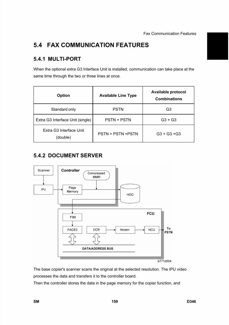
8/15/2019 Ricoh MP 4000 SM D009_D011_D012_D013 SERVICE MANUAL .pdf
http://slidepdf.com/reader/full/ricoh-mp-4000-sm-d009d011d012d013-service-manual-pdf 1005/1162
Fax Communication Features
SM 159 D346
F a x
O p
t i o n
T y p e
5 0 0 0
D 3 4 6
5.4 FAX COMMUNICATION FEATURES
5.4.1 MULTI-PORT
When the optional extra G3 Interface Unit is installed, communication can take place at the
same time through the two or three lines at once.
Option Available Line Type Available protocol
Combinations
Standard only PSTN G3
Extra G3 Interface Unit (single) PSTN + PSTN G3 + G3
Extra G3 Interface Unit
(double)PSTN + PSTN +PSTN G3 + G3 +G3
5.4.2 DOCUMENT SERVER
The base copier's scanner scans the original at the selected resolution. The IPU video
processes the data and transfers it to the controller board.
Then the controller stores the data in the page memory for the copier function, and
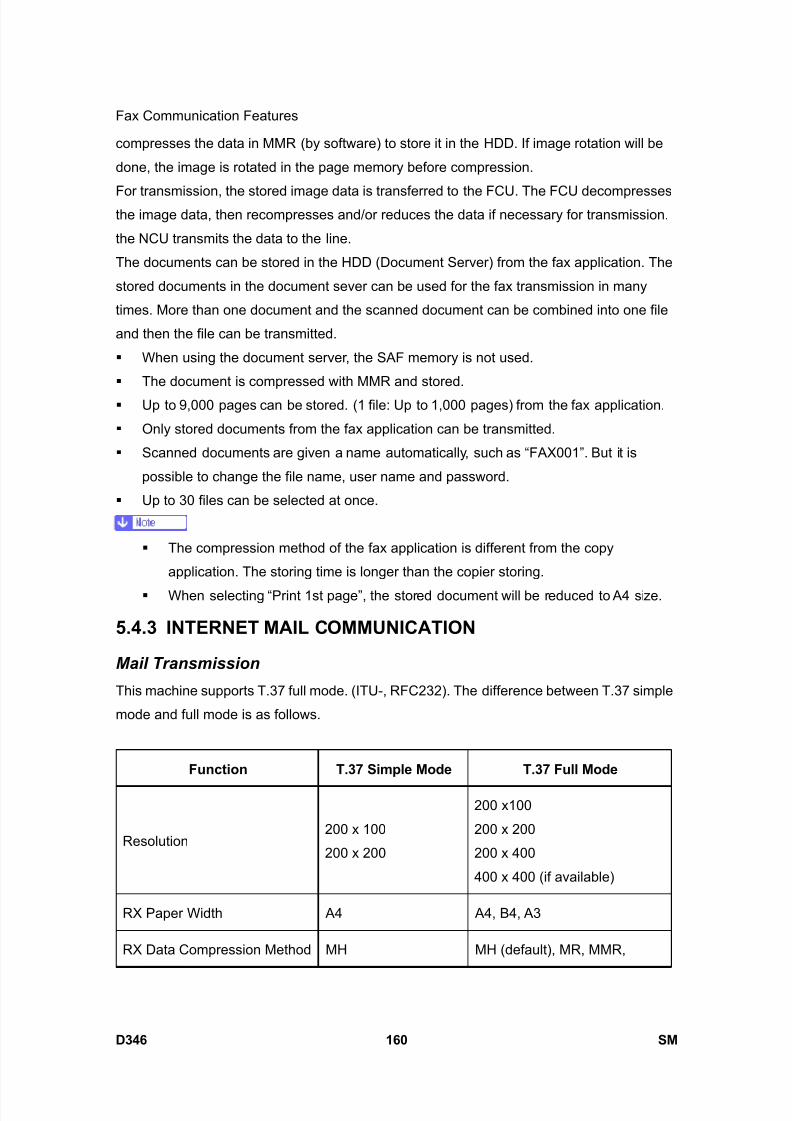
8/15/2019 Ricoh MP 4000 SM D009_D011_D012_D013 SERVICE MANUAL .pdf
http://slidepdf.com/reader/full/ricoh-mp-4000-sm-d009d011d012d013-service-manual-pdf 1006/1162
Fax Communication Features
D346 160 SM
compresses the data in MMR (by software) to store it in the HDD. If image rotation will be
done, the image is rotated in the page memory before compression.
For transmission, the stored image data is transferred to the FCU. The FCU decompressesthe image data, then recompresses and/or reduces the data if necessary for transmission.
the NCU transmits the data to the line.
The documents can be stored in the HDD (Document Server) from the fax application. The
stored documents in the document sever can be used for the fax transmission in many
times. More than one document and the scanned document can be combined into one file
and then the file can be transmitted.
When using the document server, the SAF memory is not used.
The document is compressed with MMR and stored.
Up to 9,000 pages can be stored. (1 file: Up to 1,000 pages) from the fax application.
Only stored documents from the fax application can be transmitted.
Scanned documents are given a name automatically, such as “FAX001”. But it is
possible to change the file name, user name and password.
Up to 30 files can be selected at once.
The compression method of the fax application is different from the copy
application. The storing time is longer than the copier storing.
When selecting “Print 1st page”, the stored document will be reduced to A4 size.
5.4.3 INTERNET MAIL COMMUNICATION
Mail Transmission
This machine supports T.37 full mode. (ITU-, RFC232). The difference between T.37 simple
mode and full mode is as follows.
Function T.37 Simple Mode T.37 Full Mode
Resolution200 x 100
200 x 200
200 x100
200 x 200
200 x 400
400 x 400 (if available)
RX Paper Width A4 A4, B4, A3
RX Data Compression Method MH MH (default), MR, MMR,
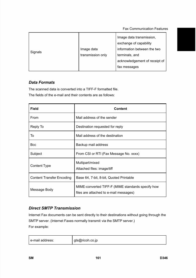
8/15/2019 Ricoh MP 4000 SM D009_D011_D012_D013 SERVICE MANUAL .pdf
http://slidepdf.com/reader/full/ricoh-mp-4000-sm-d009d011d012d013-service-manual-pdf 1007/1162
Fax Communication Features
SM 161 D346
F a x
O p
t i o n
T y p e
5 0 0 0
D 3 4 6
Signals Image datatransmission only
Image data transmission,
exchange of capability
information between the twoterminals, and
acknowledgement of receipt of
fax messages
Data Formats
The scanned data is converted into a TIFF-F formatted file.
The fields of the e-mail and their contents are as follows:
Field Content
From Mail address of the sender
Reply To Destination requested for reply
To Mail address of the destination
Bcc Backup mail address
Subject From CSI or RTI (Fax Message No. xxxx)
Content TypeMultipart/mixed
Attached files: image/tiff
Content Transfer Encoding Base 64, 7-bit, 8-bit, Quoted Printable
Message BodyMIME-converted TIFF-F (MIME standards specify how
files are attached to e-mail messages)
Direct SMTP Transmission
Internet Fax documents can be sent directly to their destinations without going through the
SMTP server. (Internet Faxes normally transmit via the SMTP server.)
For example:
e-mail address: [email protected]

8/15/2019 Ricoh MP 4000 SM D009_D011_D012_D013 SERVICE MANUAL .pdf
http://slidepdf.com/reader/full/ricoh-mp-4000-sm-d009d011d012d013-service-manual-pdf 1008/1162
Fax Communication Features
D346 162 SM
SMTP server address: gts.abcd.com
In this case this feature destination e-mail address ([email protected]) is read as the SMTP
server address "gts.abcd.com" and the transmissions bypass the SMTP server.
Selectable Options
These options are available for selection:
With the default settings, the scan resolution can be either standard or detail. Inch-mm
conversion before TX depends on IFAX SW01 Bit 7. Detail resolution will be used if
Super Fine resolution is selected, unless Fine resolution is enabled with IFAX SW01.
The requirements for originals (document size, scan width, and memory capacity) are
the same as for G3 fax memory TX.
The default compression is TIFF-F format.
IFAX SW00: Acceptable paper widths for sending
IFAX SW09: Maximum number of attempts to the same destination
Secure Internet Transmission
SMTP Authentication: User Tools> System Settings> File Transfer> SMTP
Authentication
POP Before SMTP: User Tools> System Settings> File Transfer> POP Before SMTP
Mail Reception
This machine supports three types of e-mail reception:
POP3 (Post Office Protocol Ver. 3.)
IMAP4 (Internet Messaging Access Protocol)
SMTP (Simple Mail Transfer Protocol)
For details: Core Technology Manual – Facsimile Processes – Faxing from a PC –
Internet/LAN Fax Boards – Mail Reception
POP3/IMAP4 Mail Reception Procedure
The machine automatically picks up e-mail from the server at an interval which is
adjustable in the range 2 to 1440 min. in 1-minute steps: User Tools> System Settings>
File Transfer> E-mail Reception Interval
SMTP Reception
The IFAX must be registered as an SMTP server in the MX record of the DNS server,
and the address of the received mail must specify the IFAX.
Enable SMTP reception: User Tools> System Settings> File Transfer> Reception

8/15/2019 Ricoh MP 4000 SM D009_D011_D012_D013 SERVICE MANUAL .pdf
http://slidepdf.com/reader/full/ricoh-mp-4000-sm-d009d011d012d013-service-manual-pdf 1009/1162
Fax Communication Features
SM 163 D346
F a x
O p
t i o n
T y p e
5 0 0 0
D 3 4 6Protocol
Even if the MX record on the DNS server includes the IFAX, mail cannot be received
with SMTP until SMTP reception is enabled:However, if SMTP reception is selected and the machine is not registered in the MX
record of the DNS server, then either IMAP4 or POP3 is used, depending on the
setting: User Tools> System Settings> File Transfer> Reception Protocol
Mail Delivery Conditions: Transferring Mail Received With SMTP
1. The machine must be set up for SMTP mail delivery: User Tools> Facsimile Features>
E-mail Settings> SMTP RX File Delivery Settings
2. If the user wishes to limit this feature so that the machine will only deliver mail from
designated senders, the machine’s “Auth. E-mail RX” feature must be set (User Tools>Facsimile Features> E-mail Settings> SMTP RX File Delivery Settings).
3. If the “SMTP RX File Delivery Setting” is set to 0 to prohibit SMTP receiving, and if
there is mail designated for delivery, then the machine responds with an error. (User
Tools> Facsimile Features> E-mail Settings> SMTP RX File Delivery Settings)
4. If the quick dial, speed dial, or group dial entry is incorrect, the mail transmission is lost,
and the IFAX issues an error to the SMTP server and outputs an error report.
Auth. E-mail RX
In order to limit access to mail delivery with IFAX, the addresses of senders must be limited
using the Access Limit Entry. Only one entry can be registered.
1. Access Limit Entry
For example, to limit access to @IFAX.ricoh.co.jp:
[email protected] Matches and is delivered.
[email protected] Does not match and is not delivered.
[email protected] Does not match and is not delivered.
2. Conditions
The length of the Access Limit Entry is limited to 127 characters.
If the Access Limit Entry address and the mail address of the incoming mail do not
match, the incoming mail is discarded and not delivered, and the SMTP server
responds with an error. However, in this case an error report is not output.
If the Access Limit Entry address is not registered, and if the incoming mail
specifies a delivery destination, then the mail is delivered unconditionally.
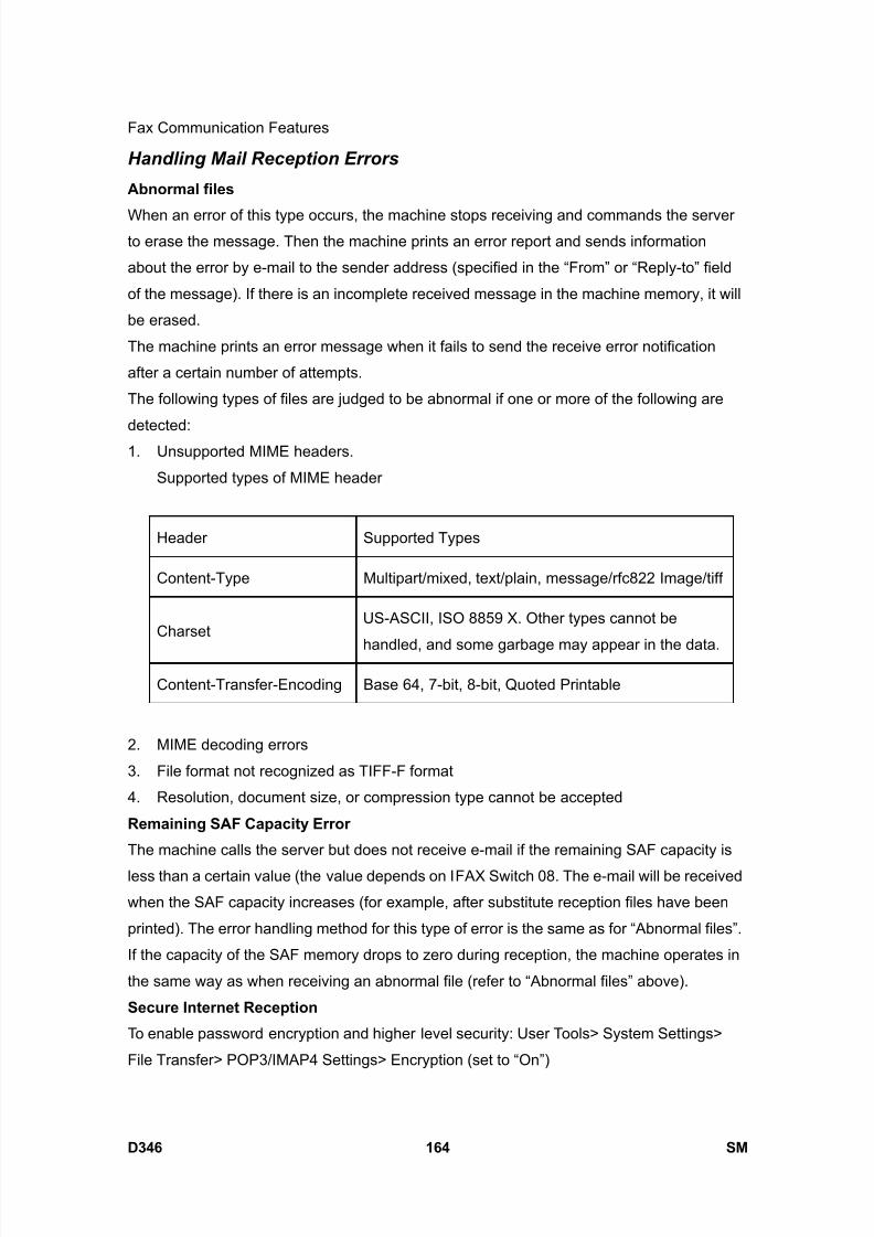
8/15/2019 Ricoh MP 4000 SM D009_D011_D012_D013 SERVICE MANUAL .pdf
http://slidepdf.com/reader/full/ricoh-mp-4000-sm-d009d011d012d013-service-manual-pdf 1010/1162
Fax Communication Features
D346 164 SM
Handling Mail Reception Errors
Abnormal files
When an error of this type occurs, the machine stops receiving and commands the serverto erase the message. Then the machine prints an error report and sends information
about the error by e-mail to the sender address (specified in the “From” or “Reply-to” field
of the message). If there is an incomplete received message in the machine memory, it will
be erased.
The machine prints an error message when it fails to send the receive error notification
after a certain number of attempts.
The following types of files are judged to be abnormal if one or more of the following are
detected:1. Unsupported MIME headers.
Supported types of MIME header
Header Supported Types
Content-Type Multipart/mixed, text/plain, message/rfc822 Image/tiff
CharsetUS-ASCII, ISO 8859 X. Other types cannot be
handled, and some garbage may appear in the data.
Content-Transfer-Encoding Base 64, 7-bit, 8-bit, Quoted Printable
2. MIME decoding errors
3. File format not recognized as TIFF-F format
4. Resolution, document size, or compression type cannot be accepted
Remaining SAF Capacity Error
The machine calls the server but does not receive e-mail if the remaining SAF capacity is
less than a certain value (the value depends on IFAX Switch 08. The e-mail will be received
when the SAF capacity increases (for example, after substitute reception files have been
printed). The error handling method for this type of error is the same as for “Abnormal files”.
If the capacity of the SAF memory drops to zero during reception, the machine operates in
the same way as when receiving an abnormal file (refer to “Abnormal files” above).
Secure Internet Reception
To enable password encryption and higher level security: User Tools> System Settings>
File Transfer> POP3/IMAP4 Settings> Encryption (set to “On”)
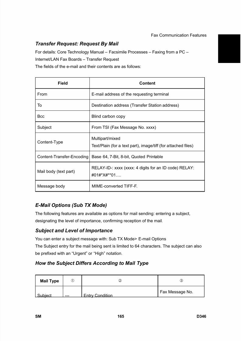
8/15/2019 Ricoh MP 4000 SM D009_D011_D012_D013 SERVICE MANUAL .pdf
http://slidepdf.com/reader/full/ricoh-mp-4000-sm-d009d011d012d013-service-manual-pdf 1011/1162
Fax Communication Features
SM 165 D346
F a x
O p
t i o n
T y p e
5 0 0 0
D 3 4 6Transfer Request: Request By Mail
For details: Core Technology Manual – Facsimile Processes – Faxing from a PC –
Internet/LAN Fax Boards – Transfer RequestThe fields of the e-mail and their contents are as follows:
Field Content
From E-mail address of the requesting terminal
To Destination address (Transfer Station address)
Bcc Blind carbon copy
Subject From TSI (Fax Message No. xxxx)
Content-TypeMultipart/mixed
Text/Plain (for a text part), image/tiff (for attached files)
Content-Transfer-Encoding Base 64, 7-Bit, 8-bit, Quoted Printable
Mail body (text part)RELAY-ID-: xxxx (xxxx: 4 digits for an ID code) RELAY:
#01#*X#**01….
Message body MIME-converted TIFF-F.
E-Mail Options (Sub TX Mode)
The following features are available as options for mail sending: entering a subject,
designating the level of importance, confirming reception of the mail.
Subject and Level of Importance
You can enter a subject message with: Sub TX Mode> E-mail OptionsThe Subject entry for the mail being sent is limited to 64 characters. The subject can also
be prefixed with an “Urgent” or “High” notation.
How the Subject Differs According to Mail Type
Mail Type
Subject --- Entry ConditionFax Message No.

8/15/2019 Ricoh MP 4000 SM D009_D011_D012_D013 SERVICE MANUAL .pdf
http://slidepdf.com/reader/full/ricoh-mp-4000-sm-d009d011d012d013-service-manual-pdf 1012/1162
Fax Communication Features
D346 166 SM
Entry
1. “CSI” (“RTI”)
2. “RTI” CSI not registered
3. “CSI” RTI not registered
No Subject
Entry
4. NoneCSI, RTI not
registered
+
File No.
1. “CSI” (“RTI”)
2. “RTI” CSI not registered
Normal:
Return Receipt
(dispatched).
You can select
“displayed” with IFAX
SW02 Bits 2 and 3.
3. “CSI” RTI not registered
Confirmation
of ReceptionFrom
4. None CSI, RTI not registered
Error:
Return Receipt
(processed/error)
RTI or CSI of
the station
designated
for delivery
Mail delivery
RTI or CSI of
sender
Mail sending from G3
memory
Mail address
of senderMemory sending
Mail delivery,
memory
transfer,
SMTP
receiving
and delivery
From
Mail address
of sender
SMTP receiving and
delivery (Off Ramp
Gateway)
Fax Message No. +
File Number
Mail error
notification--- Error Message No. xxxx From CSI (RTI)
Items of the table above are in the Subject.
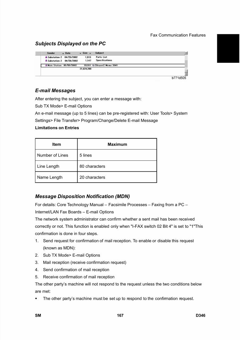
8/15/2019 Ricoh MP 4000 SM D009_D011_D012_D013 SERVICE MANUAL .pdf
http://slidepdf.com/reader/full/ricoh-mp-4000-sm-d009d011d012d013-service-manual-pdf 1013/1162
Fax Communication Features
SM 167 D346
F a x
O p
t i o n
T y p e
5 0 0 0
D 3 4 6Subjects Displayed on the PC
E-mail Messages
After entering the subject, you can enter a message with:
Sub TX Mode> E-mail Options
An e-mail message (up to 5 lines) can be pre-registered with: User Tools> System
Settings> File Transfer> Program/Change/Delete E-mail Message
Limitations on Entries
Item Maximum
Number of Lines 5 lines
Line Length 80 characters
Name Length 20 characters
Message Disposition Notification (MDN)
For details: Core Technology Manual – Facsimile Processes – Faxing from a PC –
Internet/LAN Fax Boards – E-mail Options
The network system administrator can confirm whether a sent mail has been received
correctly or not. This function is enabled only when "I-FAX switch 02 Bit 4" is set to "1"This
confirmation is done in four steps.
1. Send request for confirmation of mail reception. To enable or disable this request
(known as MDN):
2. Sub TX Mode> E-mail Options
3. Mail reception (receive confirmation request)
4. Send confirmation of mail reception
5. Receive confirmation of mail reception
The other party’s machine will not respond to the request unless the two conditions below
are met:
The other party’s machine must be set up to respond to the confirmation request.

8/15/2019 Ricoh MP 4000 SM D009_D011_D012_D013 SERVICE MANUAL .pdf
http://slidepdf.com/reader/full/ricoh-mp-4000-sm-d009d011d012d013-service-manual-pdf 1014/1162
Fax Communication Features
D346 168 SM
The other party’s machine must support MDN (Message Disposition Notification).
- Setting up the Receiving Party -
The receiving party will respond to the confirmation request if:1. The “Disposition Notification To” field is in the received mail header (automatically
inserted in the 4th line in the upper table on the previous page, if MDN is enabled), and
2. Sending the disposition notification must be enabled (User Parameter Setting SW21
(15 [H]) Bit 1 for this model). The content of the response is as follows:
Normal reception: “Return Receipt (dispatched)” in the Subject line
IFAX SW02 (Bit 2, 3) “Return Receipt (displayed)” in the Subject line
Error: “Return Receipt (processed/error)” in the Subject line
Handling Reports
1. Sending a Request for a Return Receipt by Mail
After the mail sender transmits a request for a return receipt, the mail sender’s journal
is annotated with two hyphens (--) in the Result column and a “Q” in the Mode column.
2. Mail Receipt (Request for Receipt Confirmation) and Sending Mail Receipt Response
After the mail receiver sends a response to the request for a return receipt, the mail
receiver’s journal is annotated with two hyphens (--) in the Result column and an “A” in
the Mode column.
3. Receiving the Return Receipt Mail
After the mail sender receives a return receipt, the information in the mail sender’s
journal about the receipt request is replaced, i.e. the journal is annotated with “OK”
in the Result column.
When the return receipt reports an error, the journal is annotated with an “E” in the
Result column.
The arrival of the return receipt is not recorded in the journal as a separate
communication. Its arrival is only reported by the presence of “OK” or “E” in the
Result column.
If the mail address used by the sender specifies a mailing list (i.e., a Group
destination; the machine sends the mail to more than one location. See “How to
set up Mail Delivery”), the Result column of the Journal is updated every time a
return receipt is received. For example, if the mailing list was to 5 destinations, the
Result column indicates the result of the communication with the 5th destination
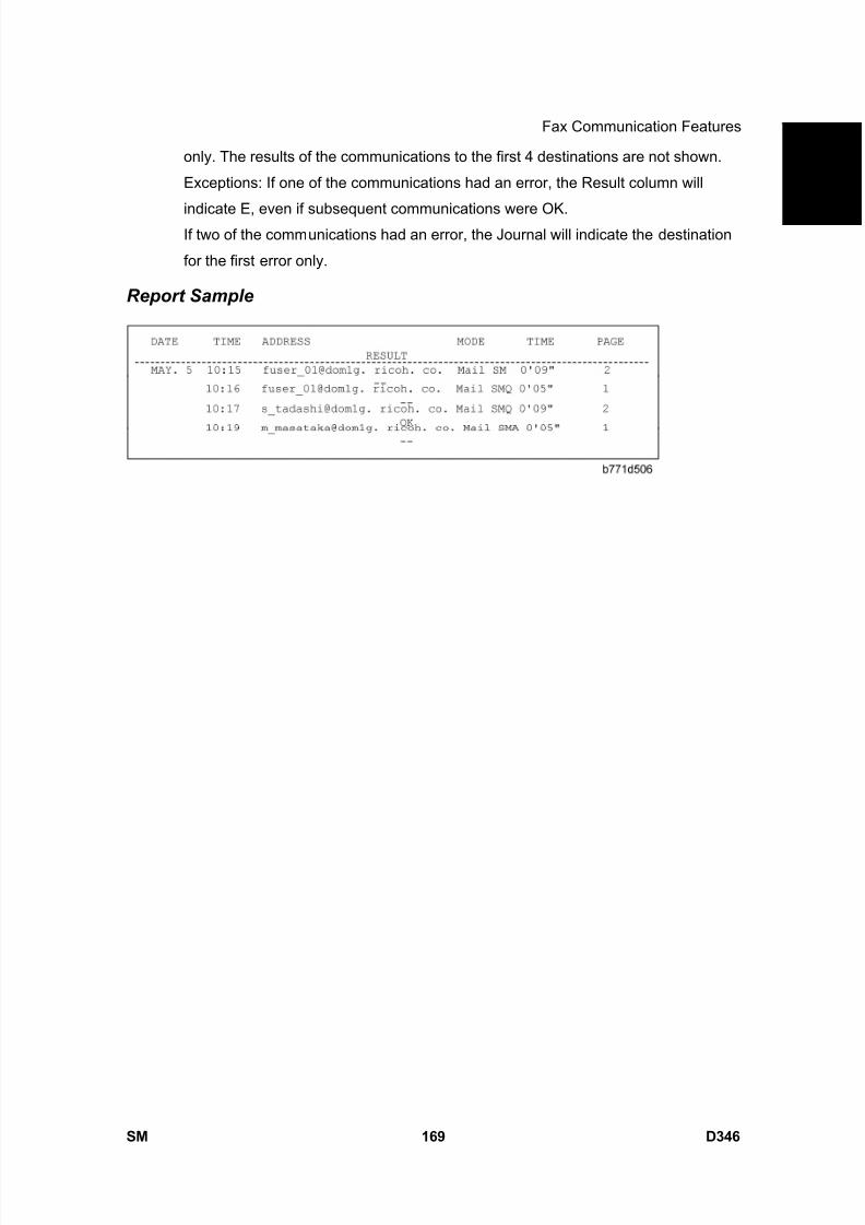
8/15/2019 Ricoh MP 4000 SM D009_D011_D012_D013 SERVICE MANUAL .pdf
http://slidepdf.com/reader/full/ricoh-mp-4000-sm-d009d011d012d013-service-manual-pdf 1015/1162
Fax Communication Features
SM 169 D346
F a x
O p
t i o n
T y p e
5 0 0 0
D 3 4 6only. The results of the communications to the first 4 destinations are not shown.
Exceptions: If one of the communications had an error, the Result column will
indicate E, even if subsequent communications were OK.If two of the communications had an error, the Journal will indicate the destination
for the first error only.
Report Sample
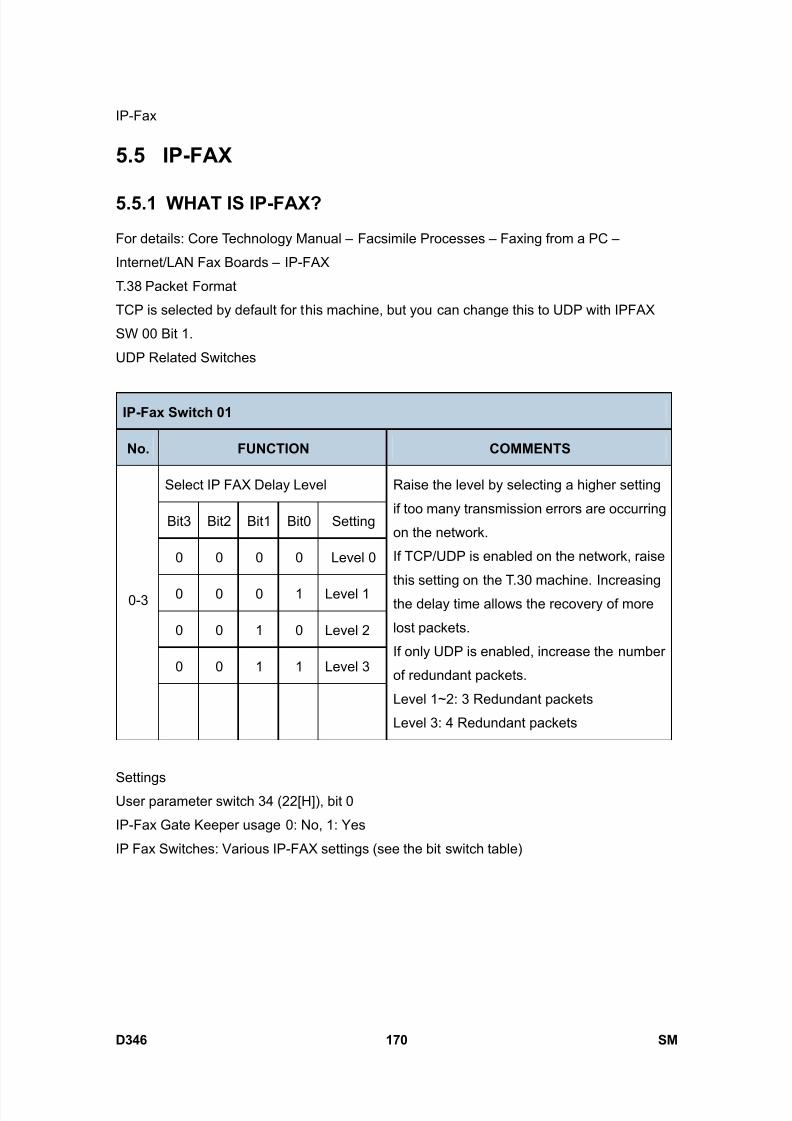
8/15/2019 Ricoh MP 4000 SM D009_D011_D012_D013 SERVICE MANUAL .pdf
http://slidepdf.com/reader/full/ricoh-mp-4000-sm-d009d011d012d013-service-manual-pdf 1016/1162
IP-Fax
D346 170 SM
5.5 IP-FAX
5.5.1 WHAT IS IP-FAX?
For details: Core Technology Manual – Facsimile Processes – Faxing from a PC –
Internet/LAN Fax Boards – IP-FAX
T.38 Packet Format
TCP is selected by default for this machine, but you can change this to UDP with IPFAX
SW 00 Bit 1.
UDP Related Switches
IP-Fax Switch 01
No. FUNCTION COMMENTS
Select IP FAX Delay Level
Bit3 Bit2 Bit1 Bit0 Setting
0 0 0 0 Level 0
0 0 0 1 Level 1
0 0 1 0 Level 2
0 0 1 1 Level 3
0-3
Raise the level by selecting a higher setting
if too many transmission errors are occurring
on the network.
If TCP/UDP is enabled on the network, raise
this setting on the T.30 machine. Increasing
the delay time allows the recovery of more
lost packets.
If only UDP is enabled, increase the number
of redundant packets.
Level 1~2: 3 Redundant packets
Level 3: 4 Redundant packets
Settings
User parameter switch 34 (22[H]), bit 0
IP-Fax Gate Keeper usage 0: No, 1: Yes
IP Fax Switches: Various IP-FAX settings (see the bit switch table)
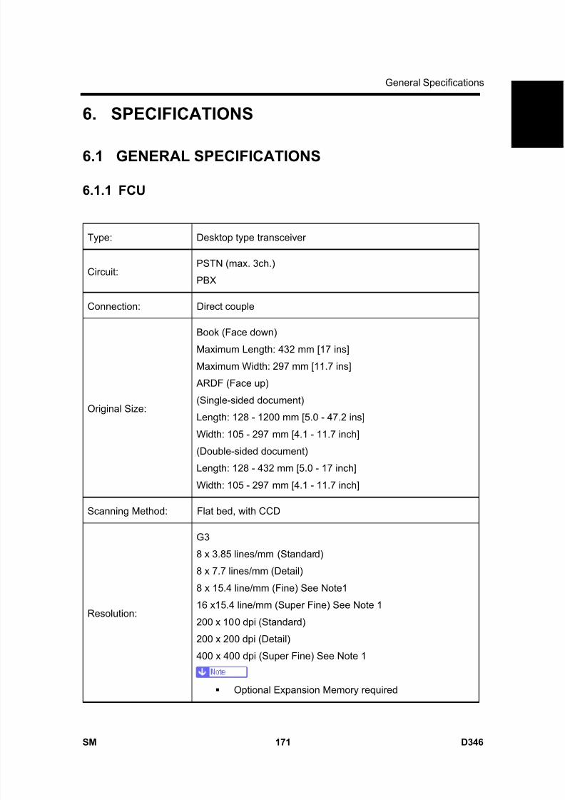
8/15/2019 Ricoh MP 4000 SM D009_D011_D012_D013 SERVICE MANUAL .pdf
http://slidepdf.com/reader/full/ricoh-mp-4000-sm-d009d011d012d013-service-manual-pdf 1017/1162
General Specifications
SM 171 D346
F a x
O p
t i o n
T y p e
5 0 0 0
D 3 4 6
6. SPECIFICATIONS
6.1 GENERAL SPECIFICATIONS
6.1.1 FCU
Type: Desktop type transceiver
Circuit:PSTN (max. 3ch.)
PBX
Connection: Direct couple
Original Size:
Book (Face down)
Maximum Length: 432 mm [17 ins]
Maximum Width: 297 mm [11.7 ins]
ARDF (Face up)
(Single-sided document)
Length: 128 - 1200 mm [5.0 - 47.2 ins]Width: 105 - 297 mm [4.1 - 11.7 inch]
(Double-sided document)
Length: 128 - 432 mm [5.0 - 17 inch]
Width: 105 - 297 mm [4.1 - 11.7 inch]
Scanning Method: Flat bed, with CCD
Resolution:
G3
8 x 3.85 lines/mm (Standard)
8 x 7.7 lines/mm (Detail)
8 x 15.4 line/mm (Fine) See Note1
16 x15.4 line/mm (Super Fine) See Note 1
200 x 100 dpi (Standard)
200 x 200 dpi (Detail)
400 x 400 dpi (Super Fine) See Note 1
Optional Expansion Memory required
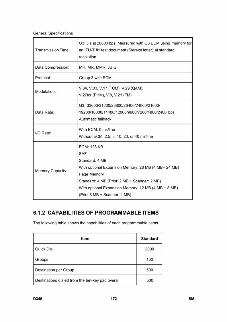
8/15/2019 Ricoh MP 4000 SM D009_D011_D012_D013 SERVICE MANUAL .pdf
http://slidepdf.com/reader/full/ricoh-mp-4000-sm-d009d011d012d013-service-manual-pdf 1018/1162
General Specifications
D346 172 SM
Transmission Time:
G3: 3 s at 28800 bps; Measured with G3 ECM using memory for
an ITU-T #1 test document (Slerexe letter) at standard
resolution
Data Compression: MH, MR, MMR, JBIG
Protocol: Group 3 with ECM
Modulation:V.34, V.33, V.17 (TCM), V.29 (QAM),
V.27ter (PHM), V.8, V.21 (FM)
Data Rate:
G3: 33600/31200/28800/26400/24000/21600/
19200/16800/14400/12000/9600/7200/4800/2400 bps Automatic fallback
I/O Rate:With ECM: 0 ms/line
Without ECM: 2.5, 5, 10, 20, or 40 ms/line
Memory Capacity:
ECM: 128 KB
SAF
Standard: 4 MB
With optional Expansion Memory: 28 MB (4 MB+ 24 MB)Page Memory
Standard: 4 MB (Print: 2 MB + Scanner: 2 MB)
With optional Expansion Memory: 12 MB (4 MB + 8 MB)
(Print 8 MB + Scanner: 4 MB)
6.1.2 CAPABILITIES OF PROGRAMMABLE ITEMS
The following table shows the capabilities of each programmable items.
Item Standard
Quick Dial 2000
Groups 100
Destination per Group 500
Destinations dialed from the ten-key pad overall 500

8/15/2019 Ricoh MP 4000 SM D009_D011_D012_D013 SERVICE MANUAL .pdf
http://slidepdf.com/reader/full/ricoh-mp-4000-sm-d009d011d012d013-service-manual-pdf 1019/1162
General Specifications
SM 173 D346
F a x
O p
t i o n
T y p e
5 0 0 0
D 3 4 6Programs 100
Auto Document 6
Communication records for Journal stored in the memory 200
Specific Senders 30
The following table shows how the capabilities of the document memory will change after
the Expansion Memory are installed.
Without theExpansion Memory
With the ExpansionMemory
Memory Transmission
file400 400
Maximum number of
page for memory
transmission
1000 1000
Memory capacity for
memory transmission
(Note1)
320 2240
Measured using an ITU-T #1 test document (Slerexe letter) at the standard
resolution, the auto image density mode and the Text mode.
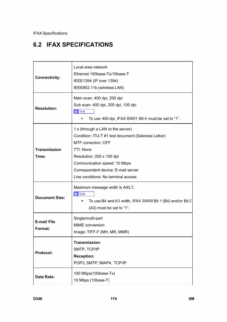
8/15/2019 Ricoh MP 4000 SM D009_D011_D012_D013 SERVICE MANUAL .pdf
http://slidepdf.com/reader/full/ricoh-mp-4000-sm-d009d011d012d013-service-manual-pdf 1020/1162
IFAX Specifications
D346 174 SM
6.2 IFAX SPECIFICATIONS
Connectivity:
Local area network
Ethernet 100base-Tx/10base-T
IEEE1394 (IP over 1394)
IEEE802.11b (wireless LAN)
Resolution:
Main scan: 400 dpi, 200 dpi
Sub scan: 400 dpi, 200 dpi, 100 dpi
To use 400 dpi, IFAX SW01 Bit 4 must be set to “1”.
Transmission
Time:
1 s (through a LAN to the server)
Condition: ITU-T #1 test document (Selerexe Letter)
MTF correction: OFF
TTI: None
Resolution: 200 x 100 dpi
Communication speed: 10 Mbps
Correspondent device: E-mail serverLine conditions: No terminal access
Document Size:
Maximum message width is A4/LT.
To use B4 and A3 width, IFAX SW00 Bit 1 (B4) and/or Bit 2
(A3) must be set to “1”.
E-mail File
Format:
Single/multi-part
MIME conversionImage: TIFF-F (MH, MR, MMR)
Protocol:
Transmission:
SMTP, TCP/IP
Reception:
POP3, SMTP, IMAP4, TCP/IP
Data Rate: 100 Mbps(100base-Tx)
10 Mbps (10base-T)

8/15/2019 Ricoh MP 4000 SM D009_D011_D012_D013 SERVICE MANUAL .pdf
http://slidepdf.com/reader/full/ricoh-mp-4000-sm-d009d011d012d013-service-manual-pdf 1021/1162
IFAX Specifications
SM 175 D346
F a x
O p
t i o n
T y p e
5 0 0 0
D 3 4 6
Authentication
Method:
SMTP-AUTH
POP before SMTP
A-POP
Remark: The machine must be set up as an e-mail client before installation.
Any client PCs connected to the machine through a LAN must also
be e-mail clients, or some features will not work (e.g. Autorouting).
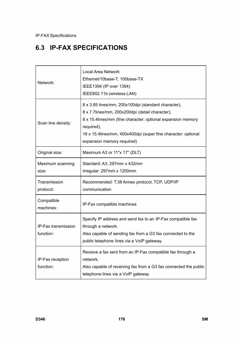
8/15/2019 Ricoh MP 4000 SM D009_D011_D012_D013 SERVICE MANUAL .pdf
http://slidepdf.com/reader/full/ricoh-mp-4000-sm-d009d011d012d013-service-manual-pdf 1022/1162
IP-FAX Specifications
D346 176 SM
6.3 IP-FAX SPECIFICATIONS
Network:
Local Area Network
Ethernet/10base-T, 100base-TX
IEEE1394 (IP over 1394)
IEEE802.11b (wireless LAN)
Scan line density:
8 x 3.85 lines/mm, 200x100dpi (standard character),
8 x 7.7lines/mm, 200x200dpi (detail character),
8 x 15.4lines/mm (fine character: optional expansion memoryrequired),
16 x 15.4lines/mm, 400x400dpi (super fine character: optional
expansion memory required)
Original size: Maximum A3 or 11"x 17" (DLT)
Maximum scanning
size:
Standard: A3, 297mm x 432mm
Irregular: 297mm x 1200mm
Transmission
protocol:
Recommended: T.38 Annex protocol, TCP, UDP/IP
communication
Compatible
machines:IP-Fax compatible machines
IP-Fax transmission
function:
Specify IP address and send fax to an IP-Fax compatible fax
through a network.
Also capable of sending fax from a G3 fax connected to the
public telephone lines via a VoIP gateway.
IP-Fax reception
function:
Receive a fax sent from an IP-Fax compatible fax through a
network.
Also capable of receiving fax from a G3 fax connected the public
telephone lines via a VoIP gateway.
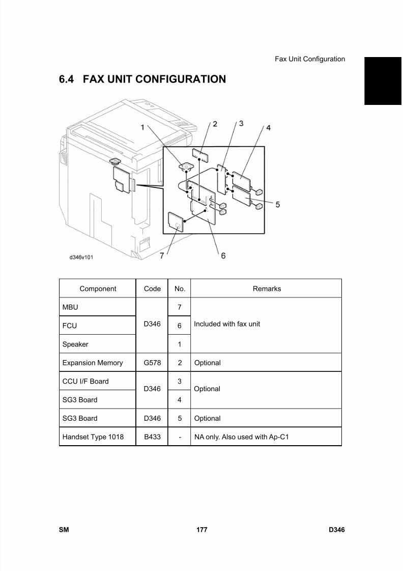
8/15/2019 Ricoh MP 4000 SM D009_D011_D012_D013 SERVICE MANUAL .pdf
http://slidepdf.com/reader/full/ricoh-mp-4000-sm-d009d011d012d013-service-manual-pdf 1023/1162
Fax Unit Configuration
SM 177 D346
F a x
O p
t i o n
T y p e
5 0 0 0
D 3 4 6
6.4 FAX UNIT CONFIGURATION
Component Code No. Remarks
MBU 7
FCU 6
Speaker
D346
1
Included with fax unit
Expansion Memory G578 2 Optional
CCU I/F Board 3
SG3 Board
D346
4
Optional
SG3 Board D346 5 Optional
Handset Type 1018 B433 - NA only. Also used with Ap-C1

8/15/2019 Ricoh MP 4000 SM D009_D011_D012_D013 SERVICE MANUAL .pdf
http://slidepdf.com/reader/full/ricoh-mp-4000-sm-d009d011d012d013-service-manual-pdf 1024/1162

8/15/2019 Ricoh MP 4000 SM D009_D011_D012_D013 SERVICE MANUAL .pdf
http://slidepdf.com/reader/full/ricoh-mp-4000-sm-d009d011d012d013-service-manual-pdf 1025/1162
PAPER FEED UNIT PB3040D351

8/15/2019 Ricoh MP 4000 SM D009_D011_D012_D013 SERVICE MANUAL .pdf
http://slidepdf.com/reader/full/ricoh-mp-4000-sm-d009d011d012d013-service-manual-pdf 1026/1162

8/15/2019 Ricoh MP 4000 SM D009_D011_D012_D013 SERVICE MANUAL .pdf
http://slidepdf.com/reader/full/ricoh-mp-4000-sm-d009d011d012d013-service-manual-pdf 1027/1162
SM i D351
PAPER FEED UNIT PB3040 (D351)TABLE OF CONTENTS
1. REPLACEMENT AND ADJUSTMENT ............................................1
1.1 REAR COVER .............................................................................................. 1
1.2 MOTORS AND CLUTCHES ......................................................................... 2
1.2.1 LIFT MOTORS..................................................................................... 2
1.2.2 UPPER AND LOWER PAPER FEED CLUTCHES.............................. 2
1.2.3 PAPER FEED MOTOR........................................................................ 3
1.3 MAIN BOARD ............................................................................................... 4 1.4 LIFT, PAPER END, AND RELAY SENSORS ............................................... 5
1.5 PAPER FEED UNIT...................................................................................... 6
1.6 PICK-UP, PAPER FEED AND SEPARATION ROLLERS............................. 7
2. DETAILS ..........................................................................................8
2.1 COMPONENT LAYOUT ............................................................................... 8
2.1.1 MECHANICAL COMPONENT LAYOUT.............................................. 8
2.1.2 ELECTRICAL COMPONENT LAYOUT ............................................... 9
2.2 PAPER FEED ............................................................................................. 10
2.3 PAPER SIZE DETECTION ......................................................................... 11
2.4 REVERSE ROLLER AND PICK-UP ROLLER RELEASE........................... 13
2.5 PAPER HEIGHT AND END DETECTION................................................... 14
2.5.1 PAPER HEIGHT DETECTION........................................................... 14
2.5.2 PAPER END AND BOTTOM PLATE ................................................. 15
2.6 PAPER LIFT ............................................................................................... 16

8/15/2019 Ricoh MP 4000 SM D009_D011_D012_D013 SERVICE MANUAL .pdf
http://slidepdf.com/reader/full/ricoh-mp-4000-sm-d009d011d012d013-service-manual-pdf 1028/1162
8/15/2019 Ricoh MP 4000 SM D009_D011_D012_D013 SERVICE MANUAL .pdf
http://slidepdf.com/reader/full/ricoh-mp-4000-sm-d009d011d012d013-service-manual-pdf 1029/1162
Read This First
Safety and Symbols
Replacement Procedure Safety
Turn off the main power switch and unplug the machine before beginning any of
the replacement procedures in this manual.
Symbols Used in this Manual
This manual uses the following symbols.
: See or Refer to
: Screws
: Connector
: Clip ring
: E-ring

8/15/2019 Ricoh MP 4000 SM D009_D011_D012_D013 SERVICE MANUAL .pdf
http://slidepdf.com/reader/full/ricoh-mp-4000-sm-d009d011d012d013-service-manual-pdf 1030/1162
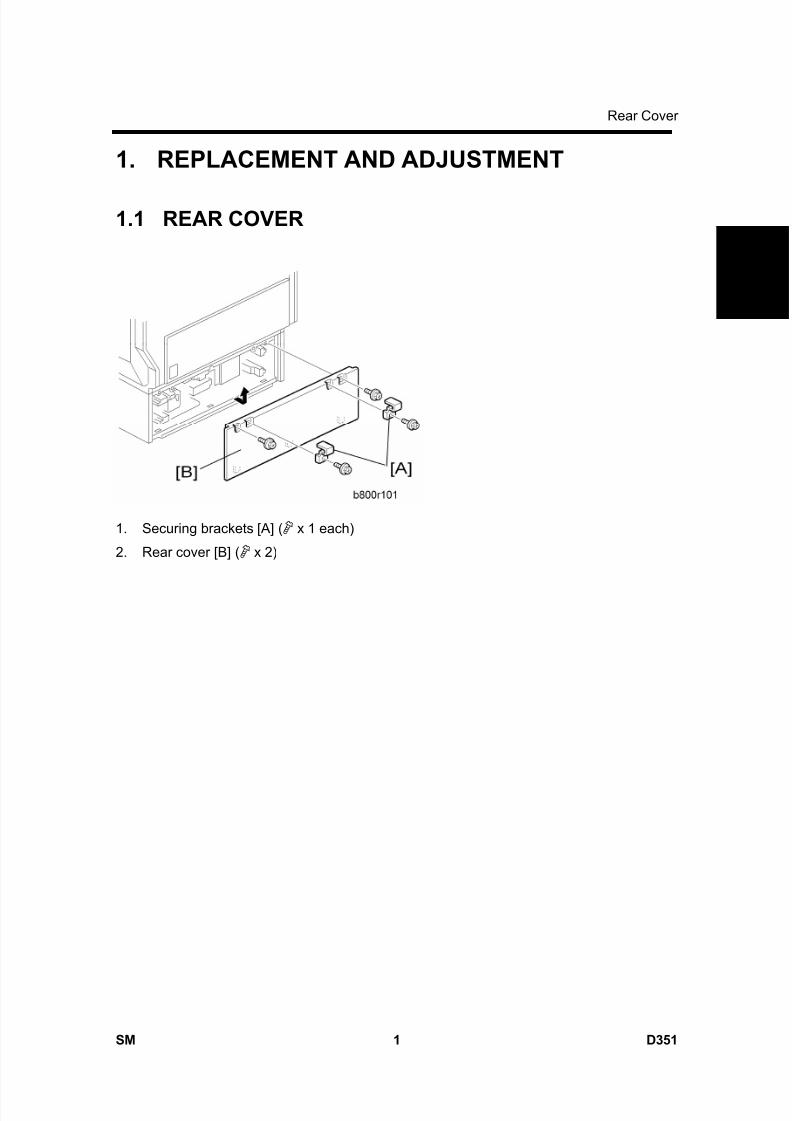
8/15/2019 Ricoh MP 4000 SM D009_D011_D012_D013 SERVICE MANUAL .pdf
http://slidepdf.com/reader/full/ricoh-mp-4000-sm-d009d011d012d013-service-manual-pdf 1031/1162
Rear Cover
SM 1 D351
P a p e r
F e e
d
U n
i t P B 3 0 4 0
D 3 5 1
1. REPLACEMENT AND ADJUSTMENT
1.1 REAR COVER
1. Securing brackets [A] ( x 1 each)
2. Rear cover [B] ( x 2)
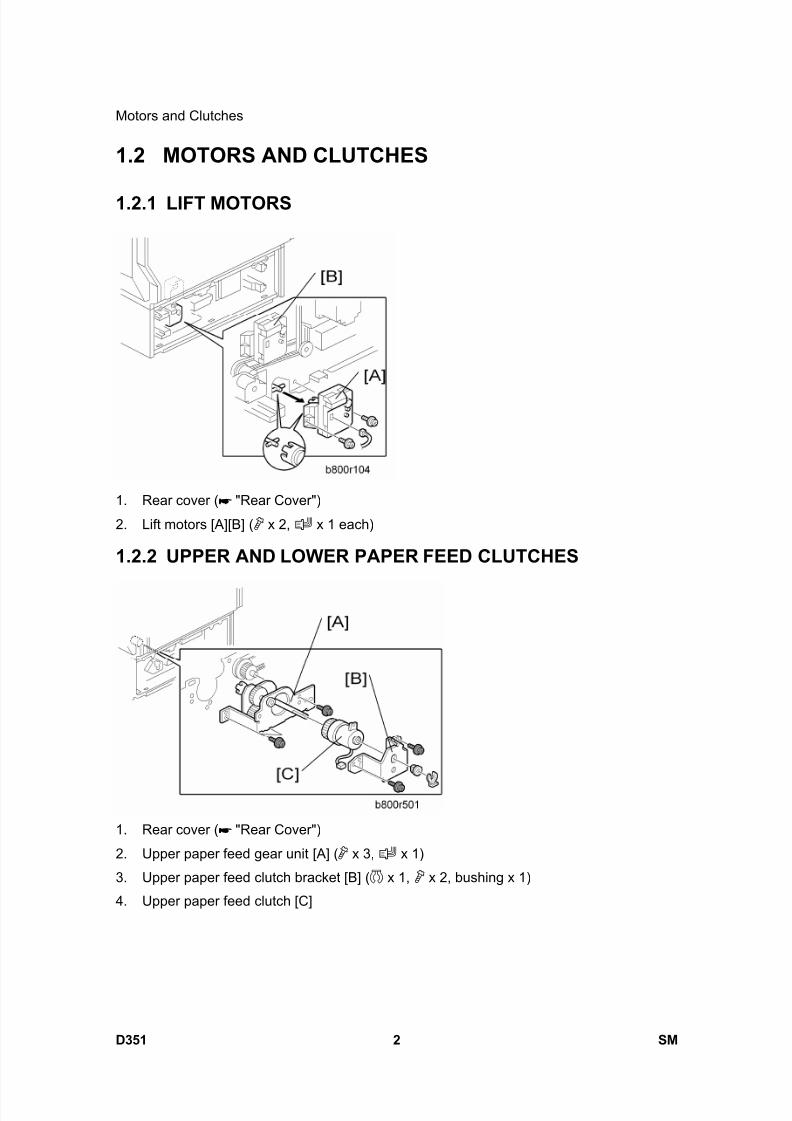
8/15/2019 Ricoh MP 4000 SM D009_D011_D012_D013 SERVICE MANUAL .pdf
http://slidepdf.com/reader/full/ricoh-mp-4000-sm-d009d011d012d013-service-manual-pdf 1032/1162
Motors and Clutches
D351 2 SM
1.2 MOTORS AND CLUTCHES
1.2.1 LIFT MOTORS
1. Rear cover ( "Rear Cover")
2. Lift motors [A][B] ( x 2, x 1 each)
1.2.2 UPPER AND LOWER PAPER FEED CLUTCHES
1. Rear cover ( "Rear Cover")
2. Upper paper feed gear unit [A] ( x 3, x 1)
3. Upper paper feed clutch bracket [B] ( x 1, x 2, bushing x 1)
4. Upper paper feed clutch [C]

8/15/2019 Ricoh MP 4000 SM D009_D011_D012_D013 SERVICE MANUAL .pdf
http://slidepdf.com/reader/full/ricoh-mp-4000-sm-d009d011d012d013-service-manual-pdf 1033/1162
Motors and Clutches
SM 3 D351
P a p e r
F e e
d
U n
i t P B 3 0 4 0
D 3 5 1
5. Lower paper feed clutch bracket [D] ( x 1, bushing x 1, x 2)
6. Lower paper feed clutch [E] ( x 1)
1.2.3 PAPER FEED MOTOR
1. Rear cover ( "Rear Cover")
2. Paper feed motor [A] ( x 1, x 2)
When installing the paper feed motor, make sure that the gear of the paper feed
motor holds the timing belt [B].
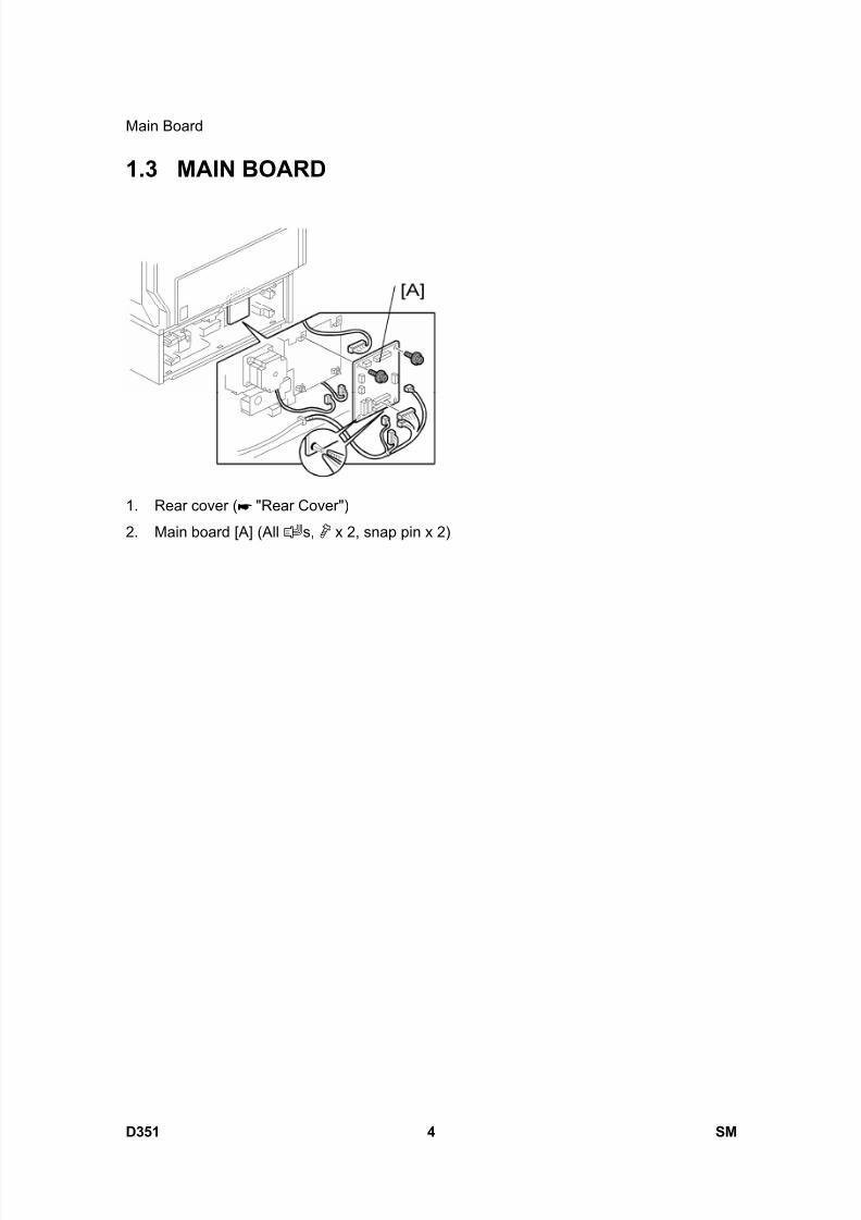
8/15/2019 Ricoh MP 4000 SM D009_D011_D012_D013 SERVICE MANUAL .pdf
http://slidepdf.com/reader/full/ricoh-mp-4000-sm-d009d011d012d013-service-manual-pdf 1034/1162
Main Board
D351 4 SM
1.3 MAIN BOARD
1. Rear cover ( "Rear Cover")
2. Main board [A] (All s, x 2, snap pin x 2)

8/15/2019 Ricoh MP 4000 SM D009_D011_D012_D013 SERVICE MANUAL .pdf
http://slidepdf.com/reader/full/ricoh-mp-4000-sm-d009d011d012d013-service-manual-pdf 1035/1162
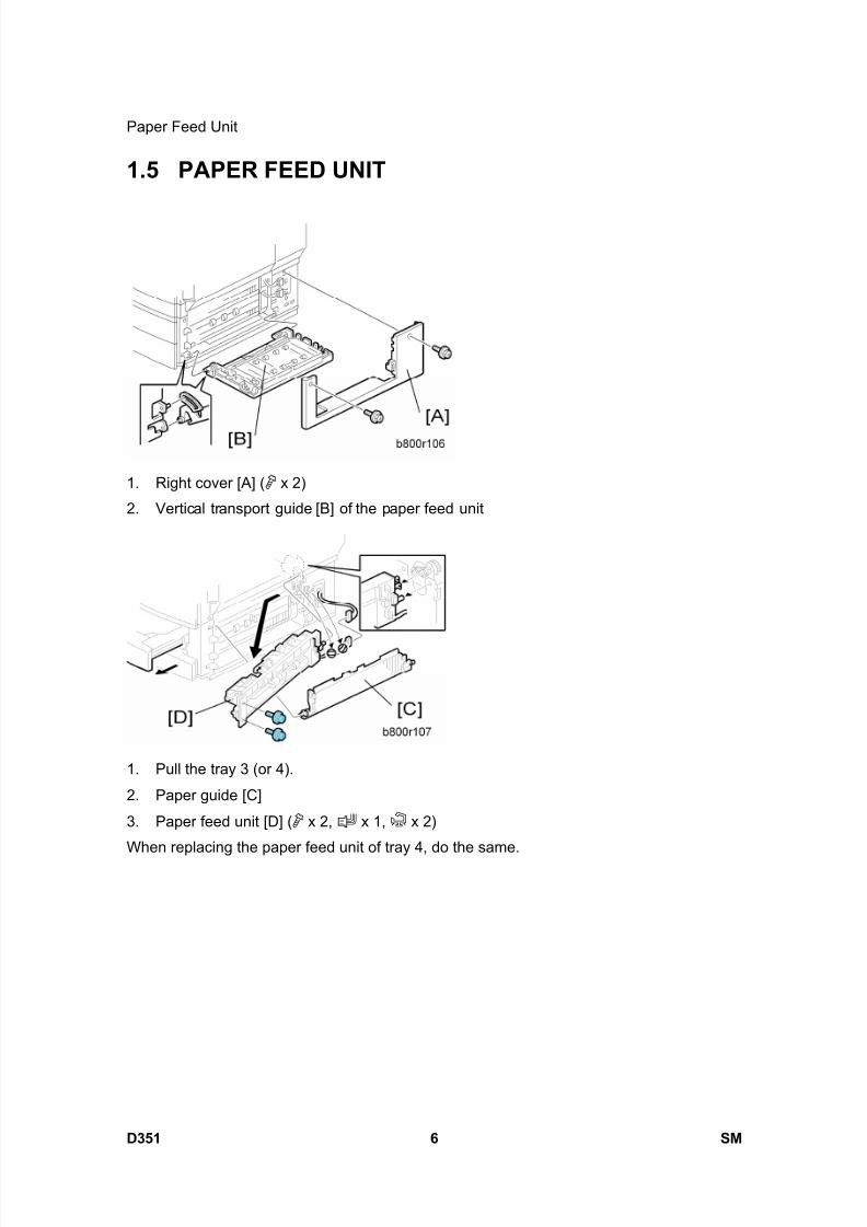
8/15/2019 Ricoh MP 4000 SM D009_D011_D012_D013 SERVICE MANUAL .pdf
http://slidepdf.com/reader/full/ricoh-mp-4000-sm-d009d011d012d013-service-manual-pdf 1036/1162
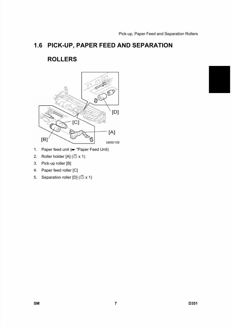
8/15/2019 Ricoh MP 4000 SM D009_D011_D012_D013 SERVICE MANUAL .pdf
http://slidepdf.com/reader/full/ricoh-mp-4000-sm-d009d011d012d013-service-manual-pdf 1037/1162
Pick-up, Paper Feed and Separation Rollers
SM 7 D351
P a p e r
F e e
d
U n
i t P B 3 0 4 0
D 3 5 1
1.6 PICK-UP, PAPER FEED AND SEPARATION
ROLLERS
1. Paper feed unit ( "Paper Feed Unit)
2. Roller holder [A] ( x 1)
3. Pick-up roller [B]
4. Paper feed roller [C]5. Separation roller [D] ( x 1)
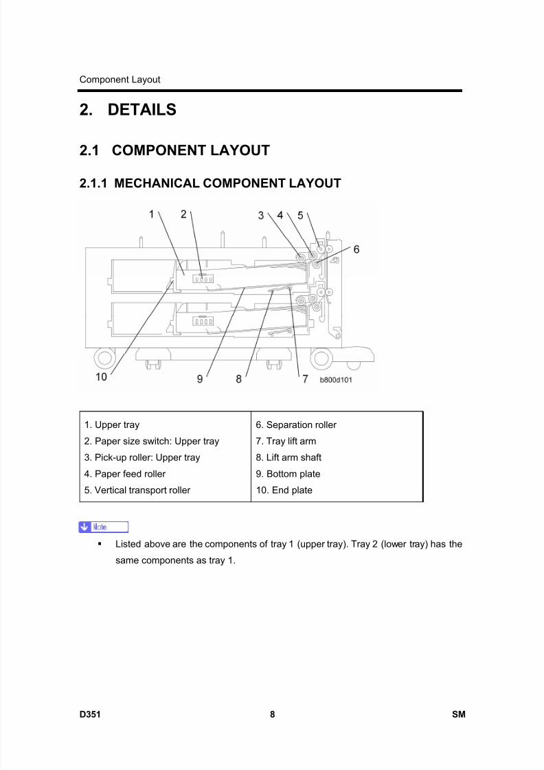
8/15/2019 Ricoh MP 4000 SM D009_D011_D012_D013 SERVICE MANUAL .pdf
http://slidepdf.com/reader/full/ricoh-mp-4000-sm-d009d011d012d013-service-manual-pdf 1038/1162
Component Layout
D351 8 SM
2. DETAILS
2.1 COMPONENT LAYOUT
2.1.1 MECHANICAL COMPONENT LAYOUT
1. Upper tray
2. Paper size switch: Upper tray
3. Pick-up roller: Upper tray
4. Paper feed roller
5. Vertical transport roller
6. Separation roller
7. Tray lift arm
8. Lift arm shaft
9. Bottom plate
10. End plate
Listed above are the components of tray 1 (upper tray). Tray 2 (lower tray) has the
same components as tray 1.
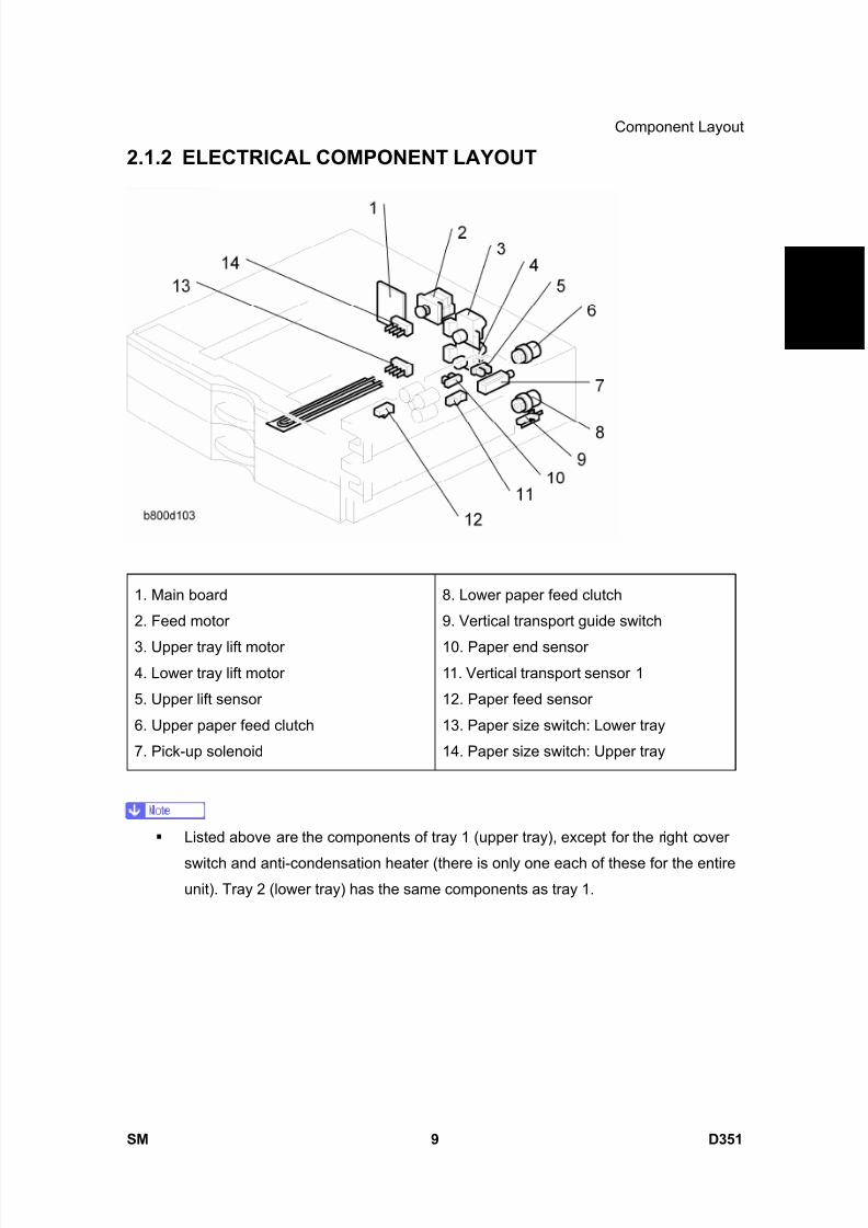
8/15/2019 Ricoh MP 4000 SM D009_D011_D012_D013 SERVICE MANUAL .pdf
http://slidepdf.com/reader/full/ricoh-mp-4000-sm-d009d011d012d013-service-manual-pdf 1039/1162
Component Layout
SM 9 D351
P a p e r
F e e
d
U n
i t P B 3 0 4 0
D 3 5 1
2.1.2 ELECTRICAL COMPONENT LAYOUT
1. Main board
2. Feed motor
3. Upper tray lift motor4. Lower tray lift motor
5. Upper lift sensor
6. Upper paper feed clutch
7. Pick-up solenoid
8. Lower paper feed clutch
9. Vertical transport guide switch
10. Paper end sensor11. Vertical transport sensor 1
12. Paper feed sensor
13. Paper size switch: Lower tray
14. Paper size switch: Upper tray
Listed above are the components of tray 1 (upper tray), except for the right cover
switch and anti-condensation heater (there is only one each of these for the entireunit). Tray 2 (lower tray) has the same components as tray 1.
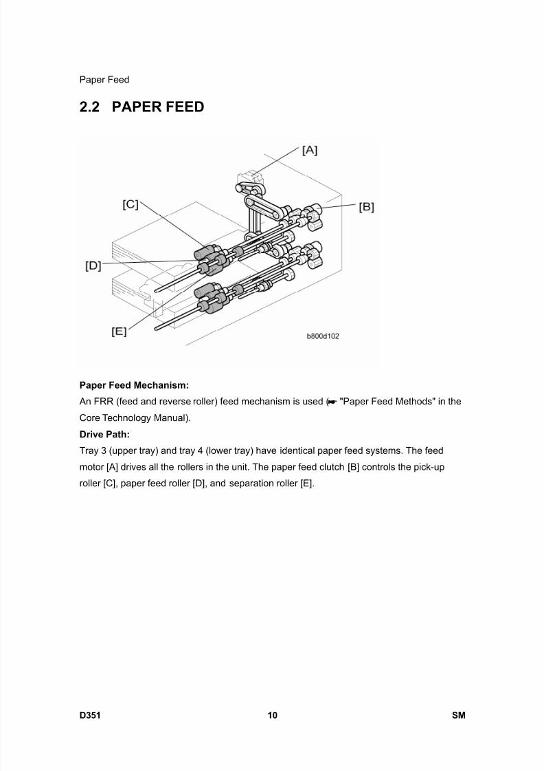
8/15/2019 Ricoh MP 4000 SM D009_D011_D012_D013 SERVICE MANUAL .pdf
http://slidepdf.com/reader/full/ricoh-mp-4000-sm-d009d011d012d013-service-manual-pdf 1040/1162
Paper Feed
D351 10 SM
2.2 PAPER FEED
Paper Feed Mechanism:
An FRR (feed and reverse roller) feed mechanism is used ( "Paper Feed Methods" in theCore Technology Manual).
Drive Path:
Tray 3 (upper tray) and tray 4 (lower tray) have identical paper feed systems. The feed
motor [A] drives all the rollers in the unit. The paper feed clutch [B] controls the pick-up
roller [C], paper feed roller [D], and separation roller [E].

8/15/2019 Ricoh MP 4000 SM D009_D011_D012_D013 SERVICE MANUAL .pdf
http://slidepdf.com/reader/full/ricoh-mp-4000-sm-d009d011d012d013-service-manual-pdf 1041/1162
Paper Size Detection
SM 11 D351
P a p e r
F e e
d
U n
i t P B 3 0 4 0
D 3 5 1
2.3 PAPER SIZE DETECTION
There are four paper size switches [A] working in combination. Switch 1 (right end) is for
tray set detection. The other three switches detect the paper size as shown in the table
below. The actuator [B] is moved by the end plate [C].
0: Not pushed, 1: Pushed
Models Switch Location
North America Europe/Asia SW4 SW3 SW2
DLT (A3) SEF*1 A3 (DLT) SEF*1 1 1 0
LG (B4) SEF*2 B4 (LG) SEF*2 1 1 1
A4 SEF A4 SEF 0 0 1
B5 SEF B5 SEF 0 0 0
LT (A4) LEF*3 A4 (LT) LEF*3 0 1 1
B5 (Exe) LEF*4 B5 (Exe) LEF*4 1 0 1
A5 LEF A5 LEF 0 1 0
*1: Detects either DLT SEF or A3 SEF, depending on the setting of SP5-181-7 or
11.
*2: Detects either LG SEF or B4 SEF, depending on the setting of SP5-181-8 or
12.

8/15/2019 Ricoh MP 4000 SM D009_D011_D012_D013 SERVICE MANUAL .pdf
http://slidepdf.com/reader/full/ricoh-mp-4000-sm-d009d011d012d013-service-manual-pdf 1042/1162
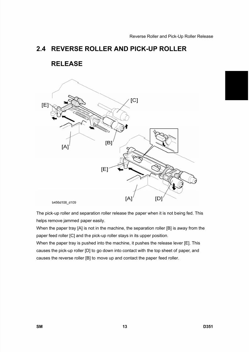
8/15/2019 Ricoh MP 4000 SM D009_D011_D012_D013 SERVICE MANUAL .pdf
http://slidepdf.com/reader/full/ricoh-mp-4000-sm-d009d011d012d013-service-manual-pdf 1043/1162
Reverse Roller and Pick-Up Roller Release
SM 13 D351
P a p e r
F e e
d
U n
i t P B 3 0 4 0
D 3 5 1
2.4 REVERSE ROLLER AND PICK-UP ROLLER
RELEASE
The pick-up roller and separation roller release the paper when it is not being fed. This
helps remove jammed paper easily.
When the paper tray [A] is not in the machine, the separation roller [B] is away from the
paper feed roller [C] and the pick-up roller stays in its upper position.
When the paper tray is pushed into the machine, it pushes the release lever [E]. This
causes the pick-up roller [D] to go down into contact with the top sheet of paper, and
causes the reverse roller [B] to move up and contact the paper feed roller.

8/15/2019 Ricoh MP 4000 SM D009_D011_D012_D013 SERVICE MANUAL .pdf
http://slidepdf.com/reader/full/ricoh-mp-4000-sm-d009d011d012d013-service-manual-pdf 1044/1162
Paper Height and End Detection
D351 14 SM
2.5 PAPER HEIGHT AND END DETECTION
2.5.1 PAPER HEIGHT DETECTION
Two paper height sensors [A] [B] and actuator [C] are built into the paper tray lift motor. The
paper height sensors, detect the amount of paper in the tray.
The actuator [C] has two semicircles, and it is engaged with the lift arm shaft via gears. The
paper height sensors detect the paper size depending on the position of the two
semicircles. The list shown below shows the detection combination of the two sensors.
The paper remaining status bar is displayed in the tray selection icon on the LCD.
Remaining paper Paper height sensor 1 [A] Paper height sensor 2 [B]
100%
(Status bar x 4)
OFF OFF
70%
(Status bar x 3)ON OFF
30%
(Status bar x 2)ON ON
10%
(Status bar x 1)OFF ON

8/15/2019 Ricoh MP 4000 SM D009_D011_D012_D013 SERVICE MANUAL .pdf
http://slidepdf.com/reader/full/ricoh-mp-4000-sm-d009d011d012d013-service-manual-pdf 1045/1162
Paper Height and End Detection
SM 15 D351
P a p e r
F e e
d
U n
i t P B 3 0 4 0
D 3 5 1
OFF: No actuator
2.5.2 PAPER END AND BOTTOM PLATE
The paper stack raises the paper end feeler [A] and the paper end sensor [B] deactivates if
there is some paper in the paper tray.
When the paper tray runs out of paper, the paper end feeler [A] drops into the cutout in the
tray bottom plate. At this time the paper end sensor [B] activates
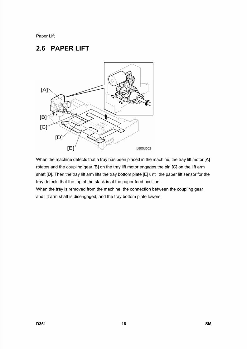
8/15/2019 Ricoh MP 4000 SM D009_D011_D012_D013 SERVICE MANUAL .pdf
http://slidepdf.com/reader/full/ricoh-mp-4000-sm-d009d011d012d013-service-manual-pdf 1046/1162
Paper Lift
D351 16 SM
2.6 PAPER LIFT
When the machine detects that a tray has been placed in the machine, the tray lift motor [A]
rotates and the coupling gear [B] on the tray lift motor engages the pin [C] on the lift arm
shaft [D]. Then the tray lift arm lifts the tray bottom plate [E] until the paper lift sensor for the
tray detects that the top of the stack is at the paper feed position.When the tray is removed from the machine, the connection between the coupling gear
and lift arm shaft is disengaged, and the tray bottom plate lowers.
8/15/2019 Ricoh MP 4000 SM D009_D011_D012_D013 SERVICE MANUAL .pdf
http://slidepdf.com/reader/full/ricoh-mp-4000-sm-d009d011d012d013-service-manual-pdf 1047/1162
LCIT PB3050D352

8/15/2019 Ricoh MP 4000 SM D009_D011_D012_D013 SERVICE MANUAL .pdf
http://slidepdf.com/reader/full/ricoh-mp-4000-sm-d009d011d012d013-service-manual-pdf 1048/1162
8/15/2019 Ricoh MP 4000 SM D009_D011_D012_D013 SERVICE MANUAL .pdf
http://slidepdf.com/reader/full/ricoh-mp-4000-sm-d009d011d012d013-service-manual-pdf 1049/1162
SM i D352
LCIT PB3050 (D352)TABLE OF CONTENTS
1. REPLACEMENT AND ADJUSTMENT ............................................1
1.1 LEFT AND RIGHT TRAY.............................................................................. 1
1.2 SENSORS .................................................................................................... 2
1.2.1 PAPER HEIGHT SENSORS ON THE PAPER STORAGE SIDE ........ 2
1.2.2 END FENCE HP SENSOR/PAPER END SENSOR 2 ......................... 2
1.3 CHANGING THE TRAY SIZE ....................................................................... 3
1.4 MAIN BOARD ............................................................................................... 4 1.5 CLUTCHES................................................................................................... 5
1.5.1 STACK TRANSPORT CLUTCH .......................................................... 5
1.5.2 PAPER FEED CLUTCH....................................................................... 5
1.6 PAPER FEED UNIT...................................................................................... 6
1.7 MOTORS ...................................................................................................... 7
1.7.1 TRAY LIFT MOTOR............................................................................. 7
1.7.2 TRAY MOTOR..................................................................................... 8
1.8 PICK-UP, FEED AND SEPARATION ROLLERS.......................................... 9 1.9 PAPER FEED, PAPER END, LIFT AND RELAY SENSORS...................... 10
1.10 PAPER FEED........................................................................................ 11
2. DETAILS ........................................................................................12
2.1 COMPONENT LAYOUT ............................................................................. 12
2.1.1 MECHANICAL COMPONENT LAYOUT............................................ 12
2.1.2 ELECTRICAL COMPONENT LAYOUT ............................................. 13
2.1.3 ELECTRICAL COMPONENT DESCRIPTIONS................................. 14
2.2 SEPARATION ROLLER AND PICK-UP ROLLER RELEASE..................... 16 2.3 TRAY LIFT .................................................................................................. 17
2.4 PAPER AMOUNT DETECTION.................................................................. 18
2.5 PAPER END DETECTION (PAPER FEED SIDE) ...................................... 19
2.6 PAPER STACK TRANSPORT.................................................................... 20

8/15/2019 Ricoh MP 4000 SM D009_D011_D012_D013 SERVICE MANUAL .pdf
http://slidepdf.com/reader/full/ricoh-mp-4000-sm-d009d011d012d013-service-manual-pdf 1050/1162

8/15/2019 Ricoh MP 4000 SM D009_D011_D012_D013 SERVICE MANUAL .pdf
http://slidepdf.com/reader/full/ricoh-mp-4000-sm-d009d011d012d013-service-manual-pdf 1051/1162
Read This First
Safety and Symbols
Replacement Procedure Safety
Turn off the main power switch and unplug the machine before beginning any of
the replacement procedures in this manual.
Symbols Used in this ManualThis manual uses the following symbols.
: See or Refer to
: Screws
: Connector
: Clip ring
: E-ring

8/15/2019 Ricoh MP 4000 SM D009_D011_D012_D013 SERVICE MANUAL .pdf
http://slidepdf.com/reader/full/ricoh-mp-4000-sm-d009d011d012d013-service-manual-pdf 1052/1162
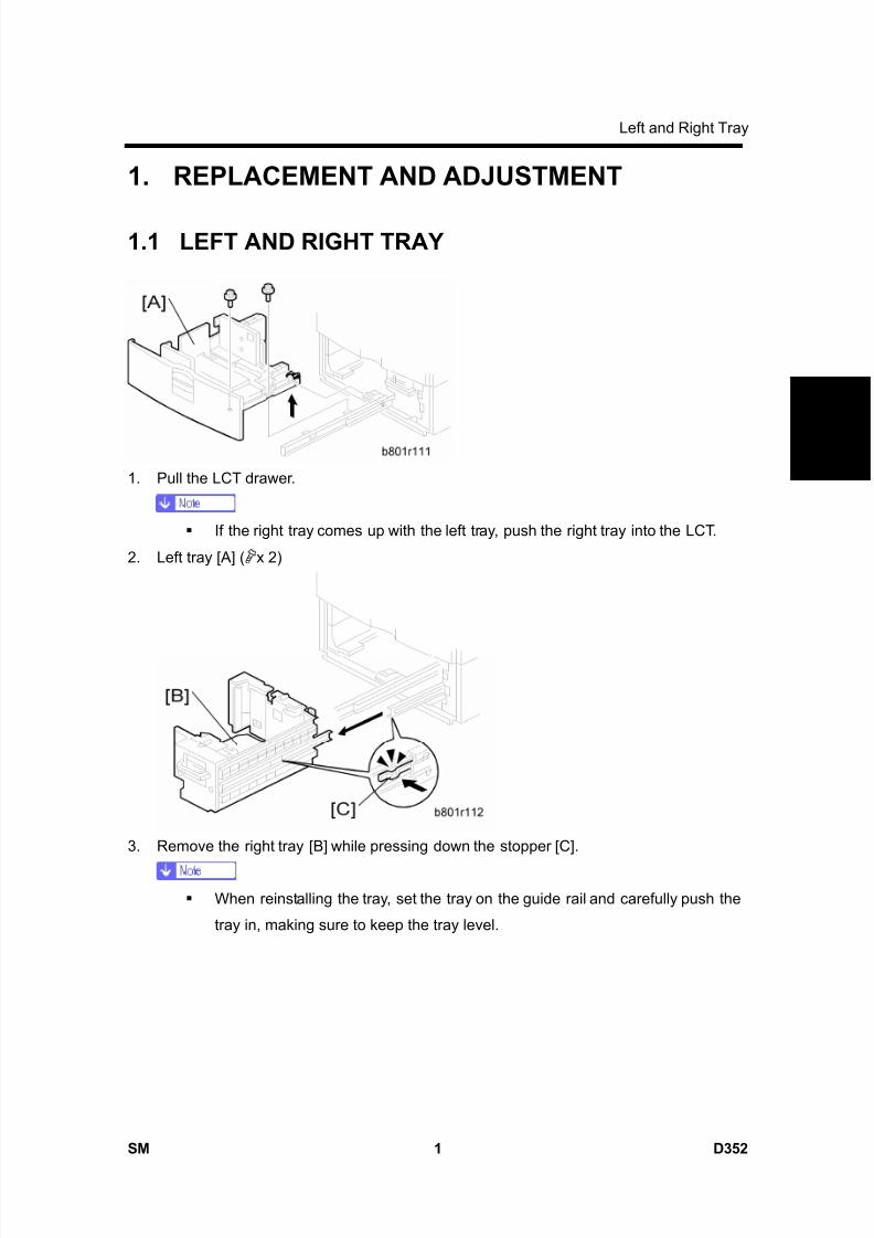
8/15/2019 Ricoh MP 4000 SM D009_D011_D012_D013 SERVICE MANUAL .pdf
http://slidepdf.com/reader/full/ricoh-mp-4000-sm-d009d011d012d013-service-manual-pdf 1053/1162
Left and Right Tray
SM 1 D352
L C T P B 3 0 5 0
D 3
5 2
1. REPLACEMENT AND ADJUSTMENT
1.1 LEFT AND RIGHT TRAY
1. Pull the LCT drawer.
If the right tray comes up with the left tray, push the right tray into the LCT.
2. Left tray [A] ( x 2)
3. Remove the right tray [B] while pressing down the stopper [C].
When reinstalling the tray, set the tray on the guide rail and carefully push the
tray in, making sure to keep the tray level.

8/15/2019 Ricoh MP 4000 SM D009_D011_D012_D013 SERVICE MANUAL .pdf
http://slidepdf.com/reader/full/ricoh-mp-4000-sm-d009d011d012d013-service-manual-pdf 1054/1162
Sensors
D352 2 SM
1.2 SENSORS
1.2.1 PAPER HEIGHT SENSORS ON THE PAPER STORAGESIDE
1. Tray ( "Left and Right Tray")
2. Rear fence [A] ( x 1)
3. Rear fence bracket [B] ( x 2)
4. Paper height sensors [C] ( x 1 each)
1.2.2 END FENCE HP SENSOR/PAPER END SENSOR 2
1. Bottom cover [D] ( x 1)
2. End fence HP sensor [E] ( x 1)
3. Paper end sensor 2 (paper storage side) [F] ( x 1)
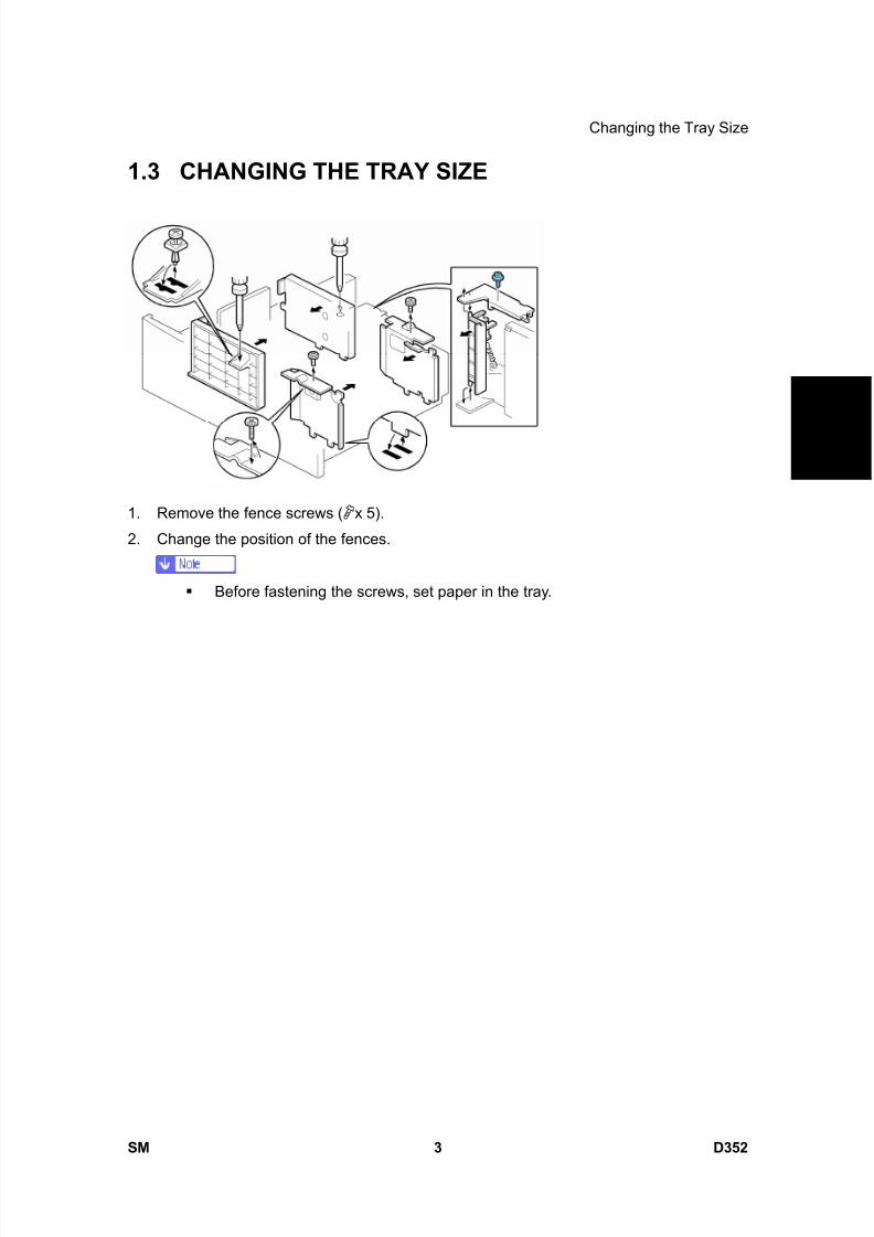
8/15/2019 Ricoh MP 4000 SM D009_D011_D012_D013 SERVICE MANUAL .pdf
http://slidepdf.com/reader/full/ricoh-mp-4000-sm-d009d011d012d013-service-manual-pdf 1055/1162
Changing the Tray Size
SM 3 D352
L C T P B 3 0 5 0
D 3
5 2
1.3 CHANGING THE TRAY SIZE
1. Remove the fence screws ( x 5).
2. Change the position of the fences.
Before fastening the screws, set paper in the tray.
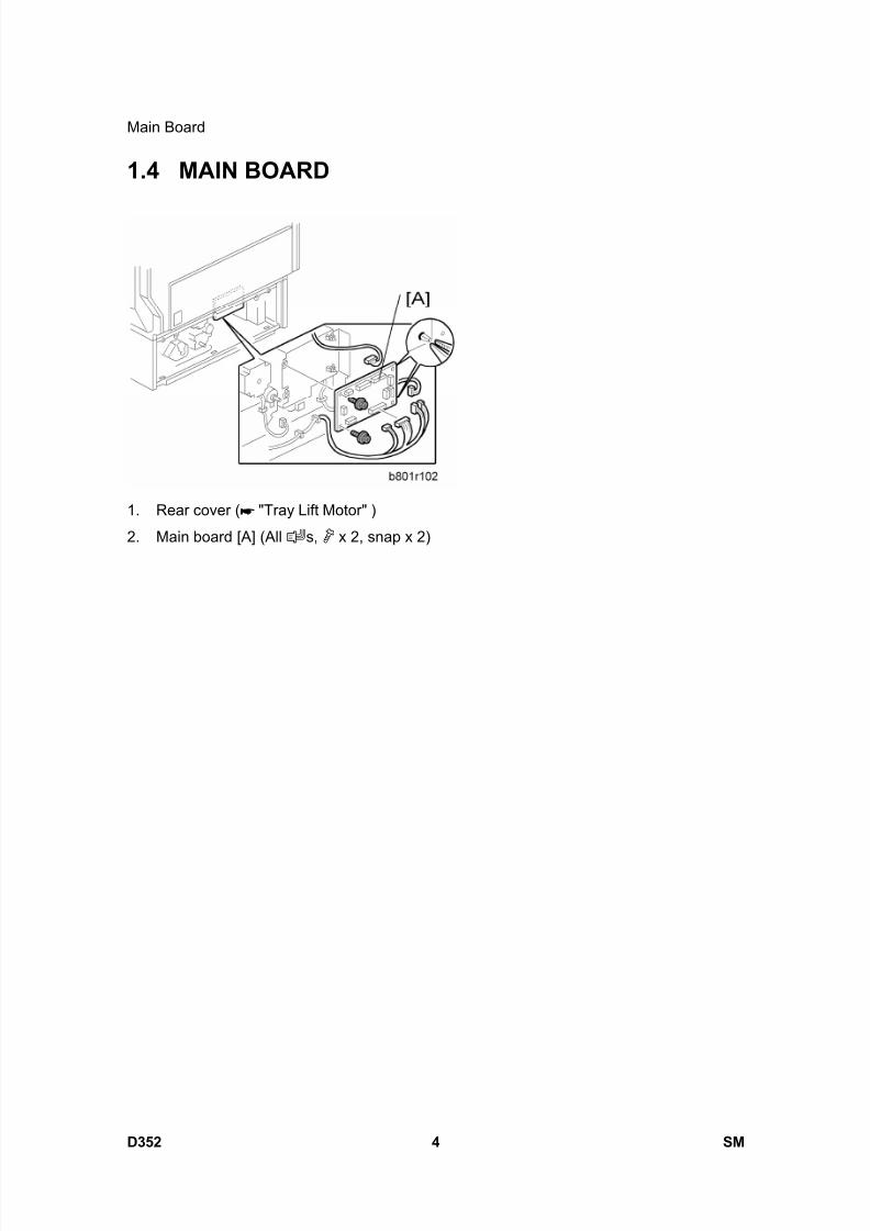
8/15/2019 Ricoh MP 4000 SM D009_D011_D012_D013 SERVICE MANUAL .pdf
http://slidepdf.com/reader/full/ricoh-mp-4000-sm-d009d011d012d013-service-manual-pdf 1056/1162
Main Board
D352 4 SM
1.4 MAIN BOARD
1. Rear cover ( "Tray Lift Motor" )
2. Main board [A] (All s, x 2, snap x 2)
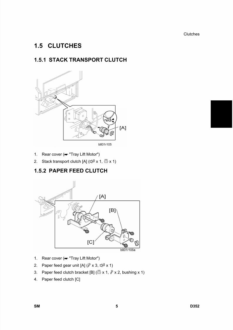
8/15/2019 Ricoh MP 4000 SM D009_D011_D012_D013 SERVICE MANUAL .pdf
http://slidepdf.com/reader/full/ricoh-mp-4000-sm-d009d011d012d013-service-manual-pdf 1057/1162
Clutches
SM 5 D352
L C T P B 3 0 5 0
D 3
5 2
1.5 CLUTCHES
1.5.1 STACK TRANSPORT CLUTCH
1. Rear cover ( "Tray Lift Motor")
2. Stack transport clutch [A] ( x 1, x 1)
1.5.2 PAPER FEED CLUTCH
1. Rear cover ( "Tray Lift Motor")
2. Paper feed gear unit [A] ( x 3, x 1)
3. Paper feed clutch bracket [B] ( x 1, x 2, bushing x 1)
4. Paper feed clutch [C]
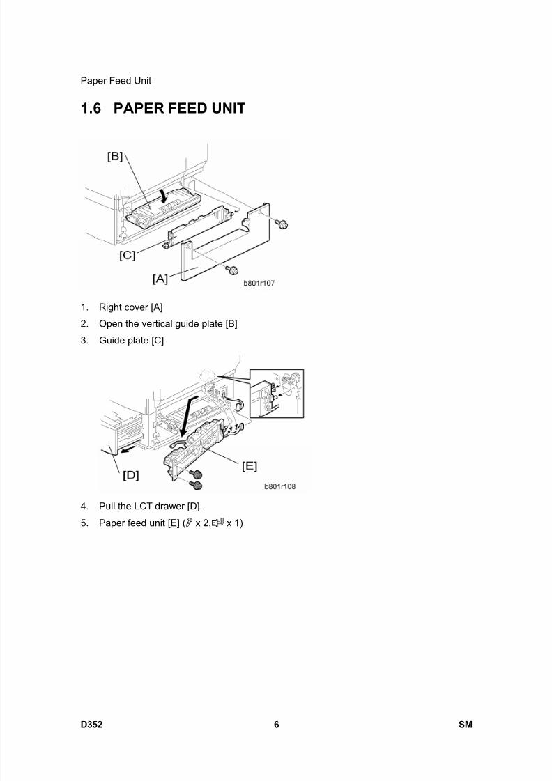
8/15/2019 Ricoh MP 4000 SM D009_D011_D012_D013 SERVICE MANUAL .pdf
http://slidepdf.com/reader/full/ricoh-mp-4000-sm-d009d011d012d013-service-manual-pdf 1058/1162
Paper Feed Unit
D352 6 SM
1.6 PAPER FEED UNIT
1. Right cover [A]
2. Open the vertical guide plate [B]
3. Guide plate [C]
4. Pull the LCT drawer [D].
5. Paper feed unit [E] ( x 2, x 1)
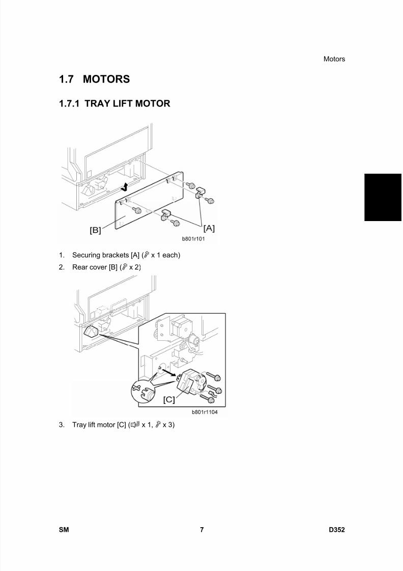
8/15/2019 Ricoh MP 4000 SM D009_D011_D012_D013 SERVICE MANUAL .pdf
http://slidepdf.com/reader/full/ricoh-mp-4000-sm-d009d011d012d013-service-manual-pdf 1059/1162
Motors
SM 7 D352
L C T P B 3 0 5 0
D 3
5 2
1.7 MOTORS
1.7.1 TRAY LIFT MOTOR
1. Securing brackets [A] ( x 1 each)
2. Rear cover [B] ( x 2)
3. Tray lift motor [C] ( x 1, x 3)
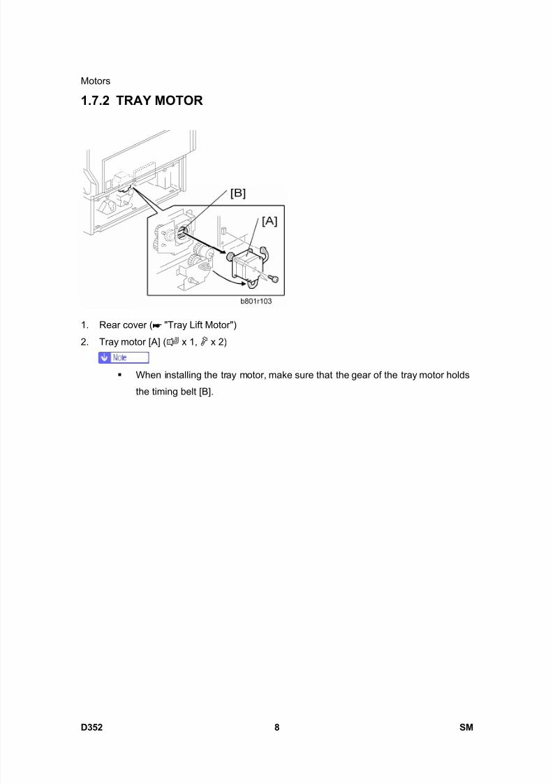
8/15/2019 Ricoh MP 4000 SM D009_D011_D012_D013 SERVICE MANUAL .pdf
http://slidepdf.com/reader/full/ricoh-mp-4000-sm-d009d011d012d013-service-manual-pdf 1060/1162
Motors
D352 8 SM
1.7.2 TRAY MOTOR
1. Rear cover ( "Tray Lift Motor")
2. Tray motor [A] ( x 1, x 2)
When installing the tray motor, make sure that the gear of the tray motor holds
the timing belt [B].

8/15/2019 Ricoh MP 4000 SM D009_D011_D012_D013 SERVICE MANUAL .pdf
http://slidepdf.com/reader/full/ricoh-mp-4000-sm-d009d011d012d013-service-manual-pdf 1061/1162
Pick-up, Feed and Separation Rollers
SM 9 D352
L C T P B 3 0 5 0
D 3
5 2
1.8 PICK-UP, FEED AND SEPARATION ROLLERS
1. Paper feed unit ( "Paper Feed Unit")
2. Separation roller [A] ( x 1)
3. Roller holder [B] ( x 1)
4. Feed roller [C] and pick-up roller [D]

8/15/2019 Ricoh MP 4000 SM D009_D011_D012_D013 SERVICE MANUAL .pdf
http://slidepdf.com/reader/full/ricoh-mp-4000-sm-d009d011d012d013-service-manual-pdf 1062/1162
Paper Feed, Paper End, Lift and Relay Sensors
D352 10 SM
1.9 PAPER FEED, PAPER END, LIFT AND RELAY
SENSORS
1. Paper feed unit ( "Paper Feed Unit")2. Vertical transport sensor bracket [A] ( x 1, x 1)
3. Relay sensor [B]
4. Paper feed sensor bracket [C]
5. Paper feed sensor [D]
6. Paper end feeler [E]
7. Paper end sensor holder [F] (hook x 3)
8. Paper end sensor [G] ( x 1, hook x 3)
9. Lift sensor [H] ( x 1, hook x 3)
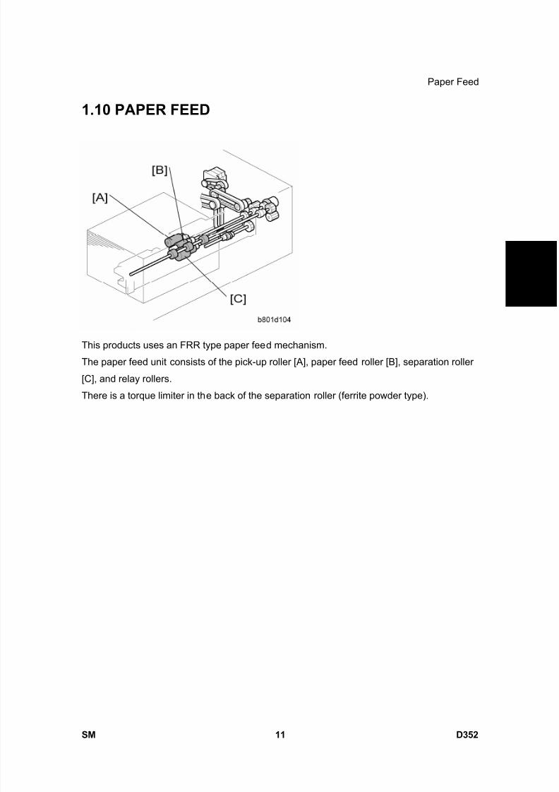
8/15/2019 Ricoh MP 4000 SM D009_D011_D012_D013 SERVICE MANUAL .pdf
http://slidepdf.com/reader/full/ricoh-mp-4000-sm-d009d011d012d013-service-manual-pdf 1063/1162
Paper Feed
SM 11 D352
L C T P B 3 0 5 0
D 3
5 2
1.10 PAPER FEED
This products uses an FRR type paper feed mechanism.
The paper feed unit consists of the pick-up roller [A], paper feed roller [B], separation roller
[C], and relay rollers.
There is a torque limiter in the back of the separation roller (ferrite powder type).

8/15/2019 Ricoh MP 4000 SM D009_D011_D012_D013 SERVICE MANUAL .pdf
http://slidepdf.com/reader/full/ricoh-mp-4000-sm-d009d011d012d013-service-manual-pdf 1064/1162
Component Layout
D352 12 SM
2. DETAILS
2.1 COMPONENT LAYOUT
2.1.1 MECHANICAL COMPONENT LAYOUT
1. Pick-up Roller
2. Paper Feed Roller
3. Relay Sensor
4. Separation Roller
5. Paper Height Sensors 1, 2, 3
6. Lower Limit Sensor
7. Paper End Sensor 2
8. End Fence HP Sensor
9. Paper Height Sensors 4, 5
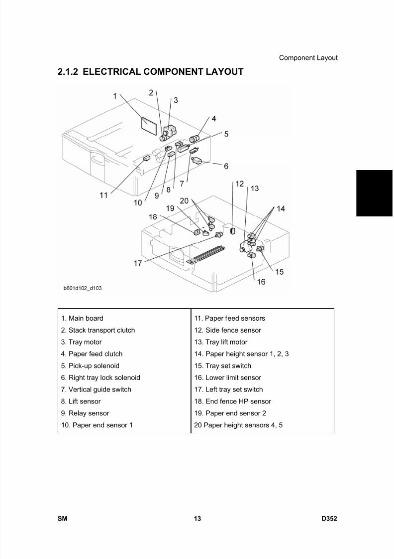
8/15/2019 Ricoh MP 4000 SM D009_D011_D012_D013 SERVICE MANUAL .pdf
http://slidepdf.com/reader/full/ricoh-mp-4000-sm-d009d011d012d013-service-manual-pdf 1065/1162
Component Layout
SM 13 D352
L C T P B 3 0 5 0
D 3
5 2
2.1.2 ELECTRICAL COMPONENT LAYOUT
1. Main board
2. Stack transport clutch
3. Tray motor
4. Paper feed clutch
5. Pick-up solenoid
6. Right tray lock solenoid
7. Vertical guide switch8. Lift sensor
9. Relay sensor
10. Paper end sensor 1
11. Paper feed sensors
12. Side fence sensor
13. Tray lift motor
14. Paper height sensor 1, 2, 3
15. Tray set switch
16. Lower limit sensor
17. Left tray set switch18. End fence HP sensor
19. Paper end sensor 2
20 Paper height sensors 4, 5
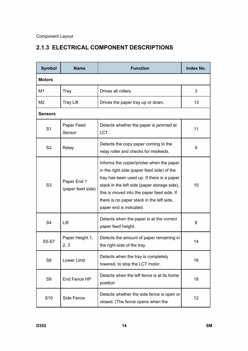
8/15/2019 Ricoh MP 4000 SM D009_D011_D012_D013 SERVICE MANUAL .pdf
http://slidepdf.com/reader/full/ricoh-mp-4000-sm-d009d011d012d013-service-manual-pdf 1066/1162
Component Layout
D352 14 SM
2.1.3 ELECTRICAL COMPONENT DESCRIPTIONS
Symbol Name Function Index No.
Motors
M1 Tray Drives all rollers. 3
M2 Tray Lift Drives the paper tray up or down. 13
Sensors
S1Paper Feed
Sensor
Detects whether the paper is jammed at
LCT.11
S2 RelayDetects the copy paper coming to the
relay roller and checks for misfeeds.9
S3Paper End 1
(paper feed side)
Informs the copier/printer when the paper
in the right side (paper feed side) of the
tray has been used up. If there is a paper
stack in the left side (paper storage side),this is moved into the paper feed side. If
there is no paper stack in the left side,
paper end is indicated.
10
S4 LiftDetects when the paper is at the correct
paper feed height.8
S5-S7Paper Height 1,
2, 3
Detects the amount of paper remaining in
the right side of the tray.14
S8 Lower LimitDetects when the tray is completely
lowered, to stop the LCT motor.16
S9 End Fence HPDetects when the left fence is at its home
position18
S10 Side FenceDetects whether the side fence is open or
closed. (The fence opens when the12
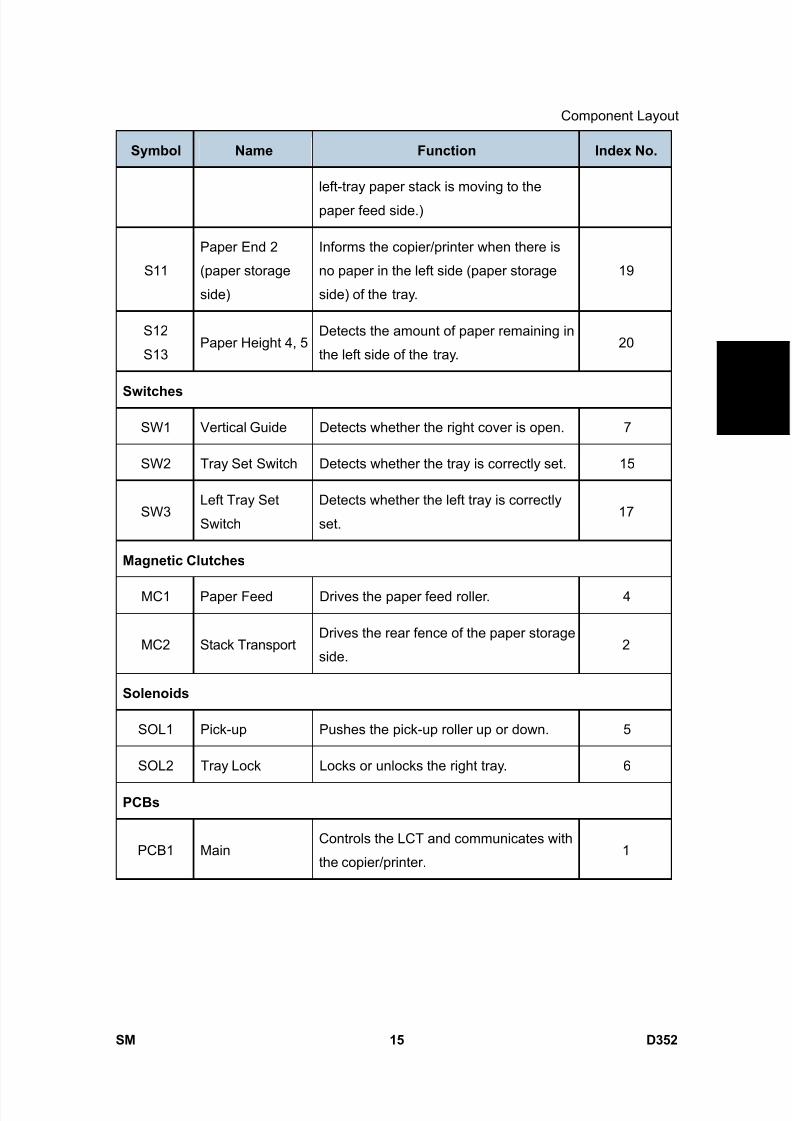
8/15/2019 Ricoh MP 4000 SM D009_D011_D012_D013 SERVICE MANUAL .pdf
http://slidepdf.com/reader/full/ricoh-mp-4000-sm-d009d011d012d013-service-manual-pdf 1067/1162
Component Layout
SM 15 D352
L C T P B 3 0 5 0
D 3
5 2
Symbol Name Function Index No.
left-tray paper stack is moving to the
paper feed side.)
S11
Paper End 2
(paper storage
side)
Informs the copier/printer when there is
no paper in the left side (paper storage
side) of the tray.
19
S12
S13Paper Height 4, 5
Detects the amount of paper remaining in
the left side of the tray.20
Switches
SW1 Vertical Guide Detects whether the right cover is open. 7
SW2 Tray Set Switch Detects whether the tray is correctly set. 15
SW3Left Tray Set
Switch
Detects whether the left tray is correctly
set.17
Magnetic Clutches
MC1 Paper Feed Drives the paper feed roller. 4
MC2 Stack TransportDrives the rear fence of the paper storage
side.2
Solenoids
SOL1 Pick-up Pushes the pick-up roller up or down. 5
SOL2 Tray Lock Locks or unlocks the right tray. 6
PCBs
PCB1 MainControls the LCT and communicates with
the copier/printer.1
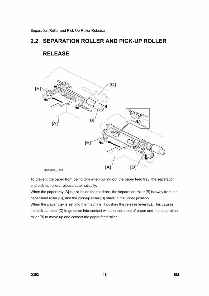
8/15/2019 Ricoh MP 4000 SM D009_D011_D012_D013 SERVICE MANUAL .pdf
http://slidepdf.com/reader/full/ricoh-mp-4000-sm-d009d011d012d013-service-manual-pdf 1068/1162
Separation Roller and Pick-Up Roller Release
D352 16 SM
2.2 SEPARATION ROLLER AND PICK-UP ROLLER
RELEASE
To prevent the paper from being torn when pulling out the paper feed tray, the separation
and pick-up rollers release automatically.
When the paper tray [A] is not inside the machine, the separation roller [B] is away from the
paper feed roller [C], and the pick-up roller [D] stays in the upper position.
When the paper tray is set into the machine, it pushes the release lever [E]. This causes
the pick-up roller [D] to go down into contact with the top sheet of paper and the separation
roller [B] to move up and contact the paper feed roller.

8/15/2019 Ricoh MP 4000 SM D009_D011_D012_D013 SERVICE MANUAL .pdf
http://slidepdf.com/reader/full/ricoh-mp-4000-sm-d009d011d012d013-service-manual-pdf 1069/1162
Tray Lift
SM 17 D352
L C T P B 3 0 5 0
D 3
5 2
2.3 TRAY LIFT
When the paper feed tray is put in the machine, the tray switch on the back turns on and
the tray lift motor [A] starts. The base plate lift shaft [B] is coupled to the lift motor at theshaft [C], so the base plate [D] of the tray is lifted. After a short while, the top of the paper
stack contacts the pick-up roller and lifts it up. Then the motor stops lifting the plate when
the upper limit sensor actuator enters the sensor ( "Electrical Component Layout").
When paper in the tray is used up, the pick-up roller is gradually lowered, and the actuator
leaves the lift sensor [E]. When this happens, the lift motor begins turning again. The tray
will then be lifted until the actuator enters the upper limit sensor again).
When the tray is removed from the copier, the coupling between the lift motor [A] and base
plate lift shaft [B] is broken and the base plate goes into a controlled free fall (using a
damper to slow the fall and prevent damage).

8/15/2019 Ricoh MP 4000 SM D009_D011_D012_D013 SERVICE MANUAL .pdf
http://slidepdf.com/reader/full/ricoh-mp-4000-sm-d009d011d012d013-service-manual-pdf 1070/1162
Paper Amount Detection
D352 18 SM
2.4 PAPER AMOUNT DETECTION
The table lists the sensors that are used to detect the amount of remaining paper.
Right Tray (Paper feed side)
Paper end sensor 1
Paper height sensor 1 to 3
Left Tray (Paper storage side)
Paper height sensor 4 and 5
Paper end sensor 2
Right Tray
Paper Height Sensor Amount of paper
1 2 3
Paper End
Sensor
Display No. of
Line
100% OFF OFF OFF ON 4
70% OFF OFF ON ON 3
30% OFF ON - ON 2
10% ON - - ON 1
Paper End - - - OFF 0
Left Tray
Paper Height Sensor Amount of paper
4 5
Paper End
Sensor
Display No. of
Line
100% OFF OFF OFF 4
70% ON OFF OFF 3
30% ON ON OFF 2
Paper End ON ON ON 0
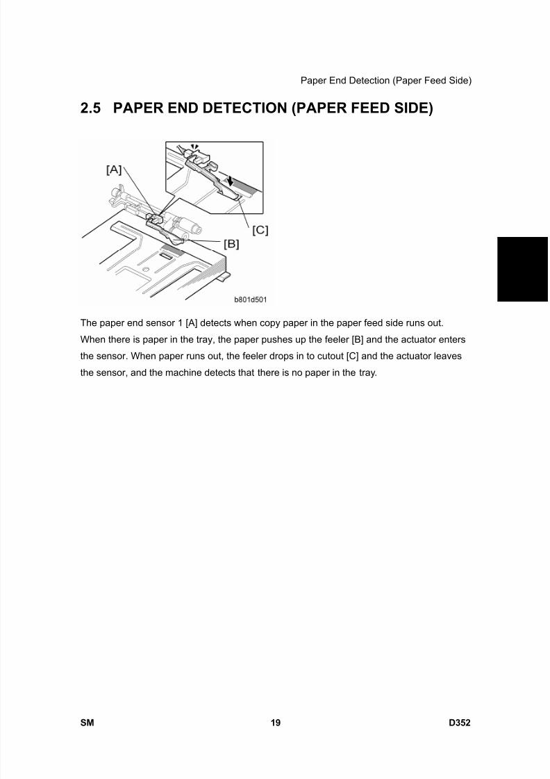
8/15/2019 Ricoh MP 4000 SM D009_D011_D012_D013 SERVICE MANUAL .pdf
http://slidepdf.com/reader/full/ricoh-mp-4000-sm-d009d011d012d013-service-manual-pdf 1071/1162
Paper End Detection (Paper Feed Side)
SM 19 D352
L C T P B 3 0 5 0
D 3
5 2
2.5 PAPER END DETECTION (PAPER FEED SIDE)
The paper end sensor 1 [A] detects when copy paper in the paper feed side runs out.
When there is paper in the tray, the paper pushes up the feeler [B] and the actuator enters
the sensor. When paper runs out, the feeler drops in to cutout [C] and the actuator leaves
the sensor, and the machine detects that there is no paper in the tray.
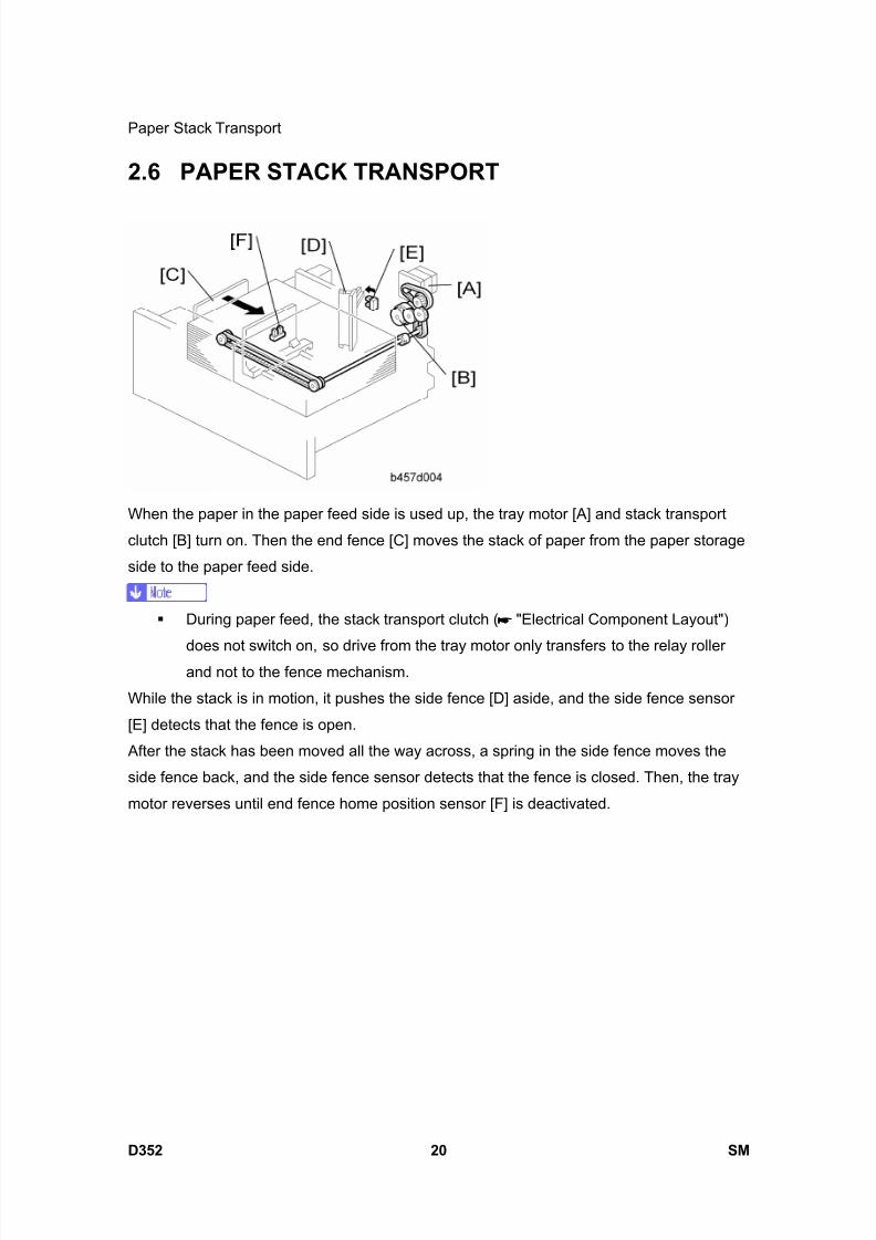
8/15/2019 Ricoh MP 4000 SM D009_D011_D012_D013 SERVICE MANUAL .pdf
http://slidepdf.com/reader/full/ricoh-mp-4000-sm-d009d011d012d013-service-manual-pdf 1072/1162
Paper Stack Transport
D352 20 SM
2.6 PAPER STACK TRANSPORT
When the paper in the paper feed side is used up, the tray motor [A] and stack transport
clutch [B] turn on. Then the end fence [C] moves the stack of paper from the paper storage
side to the paper feed side.
During paper feed, the stack transport clutch ( "Electrical Component Layout")
does not switch on, so drive from the tray motor only transfers to the relay rollerand not to the fence mechanism.
While the stack is in motion, it pushes the side fence [D] aside, and the side fence sensor
[E] detects that the fence is open.
After the stack has been moved all the way across, a spring in the side fence moves the
side fence back, and the side fence sensor detects that the fence is closed. Then, the tray
motor reverses until end fence home position sensor [F] is deactivated.
8/15/2019 Ricoh MP 4000 SM D009_D011_D012_D013 SERVICE MANUAL .pdf
http://slidepdf.com/reader/full/ricoh-mp-4000-sm-d009d011d012d013-service-manual-pdf 1073/1162
1200-SHEET LCIT RT3000D353

8/15/2019 Ricoh MP 4000 SM D009_D011_D012_D013 SERVICE MANUAL .pdf
http://slidepdf.com/reader/full/ricoh-mp-4000-sm-d009d011d012d013-service-manual-pdf 1074/1162

8/15/2019 Ricoh MP 4000 SM D009_D011_D012_D013 SERVICE MANUAL .pdf
http://slidepdf.com/reader/full/ricoh-mp-4000-sm-d009d011d012d013-service-manual-pdf 1075/1162
SM i D353
1200-SHEET LCIT RT3000(D353)TABLE OF CONTENTS
1. REPLACEMENT AND ADJUSTMENT ............................................1
1.1 COVERS....................................................................................................... 1
1.1.1 REAR COVER ..................................................................................... 1
1.1.2 RIGHT DOOR...................................................................................... 1
1.1.3 FRONT AND TOP COVERS................................................................ 2
1.2 PAPER FEED ............................................................................................... 3
1.2.1 PICK-UP, PAPER FEED AND SEPARATION ROLLERS.................... 3 1.3 DRIVE ........................................................................................................... 4
1.3.1 PAPER FEED CLUTCH....................................................................... 4
1.3.2 PAPER FEED MOTOR........................................................................ 4
1.3.3 TRAY LIFT MOTOR............................................................................. 5
1.4 ELECTRICAL COMPONENTS ..................................................................... 6
1.4.1 MAIN BOARD ...................................................................................... 6
1.4.2 LCT SET SWITCHES .......................................................................... 6
1.4.3 DOWN SWITCH .................................................................................. 7 1.4.4 PAPER FEED, PAPER END, TRAY LIFT AND RELAY SENSORS .... 7
1.4.5 STACK SENSOR................................................................................. 9
1.5 SIDE FENCE POSITION CHANGE ............................................................ 10
2. DETAILS ........................................................................................11
2.1 COMPONENT LAYOUT ............................................................................. 11
2.1.1 COMPONENT LAYOUT .................................................................... 11
2.1.2 ELECTRICAL COMPONENT LAYOUT ............................................. 12
2.1.3 ELECTRICAL COMPONENT DESCRIPTIONS................................. 12 2.1.4 DRIVE LAYOUT................................................................................. 15
2.2 PAPER FEED ............................................................................................. 16
2.2.1 PAPER FEED MECHANISM ............................................................. 16
2.2.2 TRAY LIFT MECHANISM .................................................................. 17
2.2.3 PAPER HEIGHT AND END DETECTION.......................................... 18

8/15/2019 Ricoh MP 4000 SM D009_D011_D012_D013 SERVICE MANUAL .pdf
http://slidepdf.com/reader/full/ricoh-mp-4000-sm-d009d011d012d013-service-manual-pdf 1076/1162
8/15/2019 Ricoh MP 4000 SM D009_D011_D012_D013 SERVICE MANUAL .pdf
http://slidepdf.com/reader/full/ricoh-mp-4000-sm-d009d011d012d013-service-manual-pdf 1077/1162
Read This First
Safety and Symbols
Replacement Procedure Safety
Turn off the main power switch and unplug the machine before beginning any of
the replacement procedures in this manual.
Symbols Used in this Manual
This manual uses the following symbols.
: See or Refer to
: Screws
: Connector
: Clip ring
: E-ring
: Clamp

8/15/2019 Ricoh MP 4000 SM D009_D011_D012_D013 SERVICE MANUAL .pdf
http://slidepdf.com/reader/full/ricoh-mp-4000-sm-d009d011d012d013-service-manual-pdf 1078/1162

8/15/2019 Ricoh MP 4000 SM D009_D011_D012_D013 SERVICE MANUAL .pdf
http://slidepdf.com/reader/full/ricoh-mp-4000-sm-d009d011d012d013-service-manual-pdf 1079/1162
Covers
SM 1 D353
1 2 0 0 S h e e
t
L C T R T 3 0 0 0
D 3 5 3
1. REPLACEMENT AND ADJUSTMENT
1.1 COVERS
1.1.1 REAR COVER
1. Cover [A] ( x 1)
2. Rear cover [B] ( x 3)
1.1.2 RIGHT DOOR
1. Right lower cover [A] ( x 2)
2. Right door [B] ( x 1)
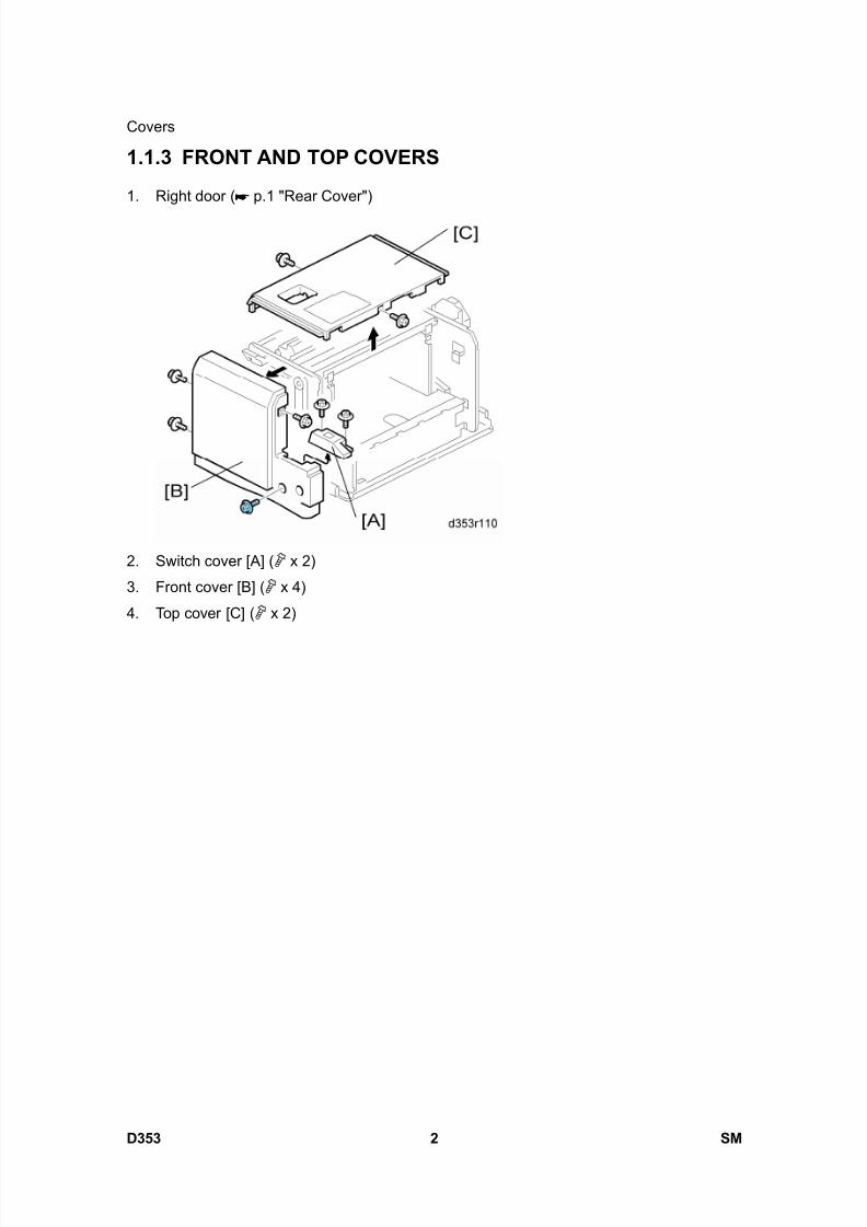
8/15/2019 Ricoh MP 4000 SM D009_D011_D012_D013 SERVICE MANUAL .pdf
http://slidepdf.com/reader/full/ricoh-mp-4000-sm-d009d011d012d013-service-manual-pdf 1080/1162
Covers
D353 2 SM
1.1.3 FRONT AND TOP COVERS
1. Right door ( p.1 "Rear Cover")
2. Switch cover [A] ( x 2)
3. Front cover [B] ( x 4)
4. Top cover [C] ( x 2)

8/15/2019 Ricoh MP 4000 SM D009_D011_D012_D013 SERVICE MANUAL .pdf
http://slidepdf.com/reader/full/ricoh-mp-4000-sm-d009d011d012d013-service-manual-pdf 1081/1162
Paper Feed
SM 3 D353
1 2 0 0 S h e e
t
L C T R T 3 0 0 0
D 3 5 3
1.2 PAPER FEED
1.2.1 PICK-UP, PAPER FEED AND SEPARATION ROLLERS
1. Open the right door.
2. Sensor bracket [A] ( x 2)
3. Rollers [B], [C], [D] ( x 1 each)
[B]: Paper feed roller
[C]: Pick-up roller
[D]: Separation roller
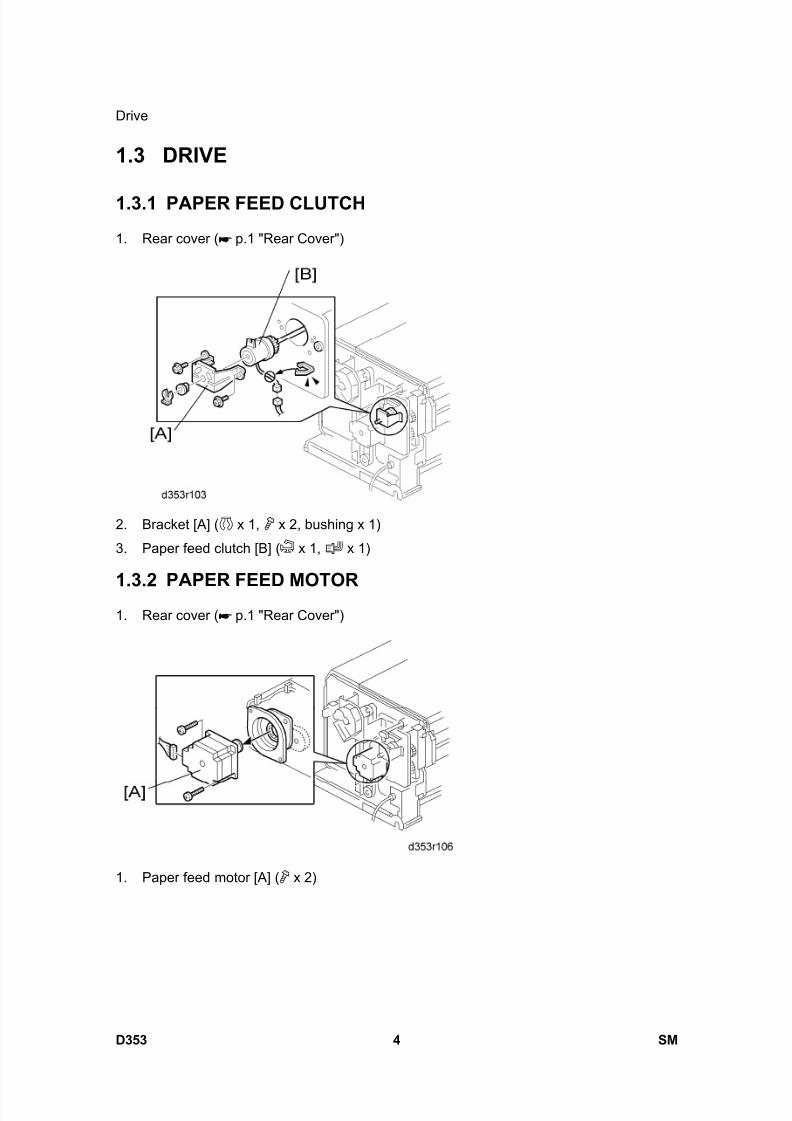
8/15/2019 Ricoh MP 4000 SM D009_D011_D012_D013 SERVICE MANUAL .pdf
http://slidepdf.com/reader/full/ricoh-mp-4000-sm-d009d011d012d013-service-manual-pdf 1082/1162
Drive
D353 4 SM
1.3 DRIVE
1.3.1 PAPER FEED CLUTCH
1. Rear cover ( p.1 "Rear Cover")
2. Bracket [A] ( x 1, x 2, bushing x 1)
3. Paper feed clutch [B] ( x 1, x 1)
1.3.2 PAPER FEED MOTOR1. Rear cover ( p.1 "Rear Cover")
1. Paper feed motor [A] ( x 2)
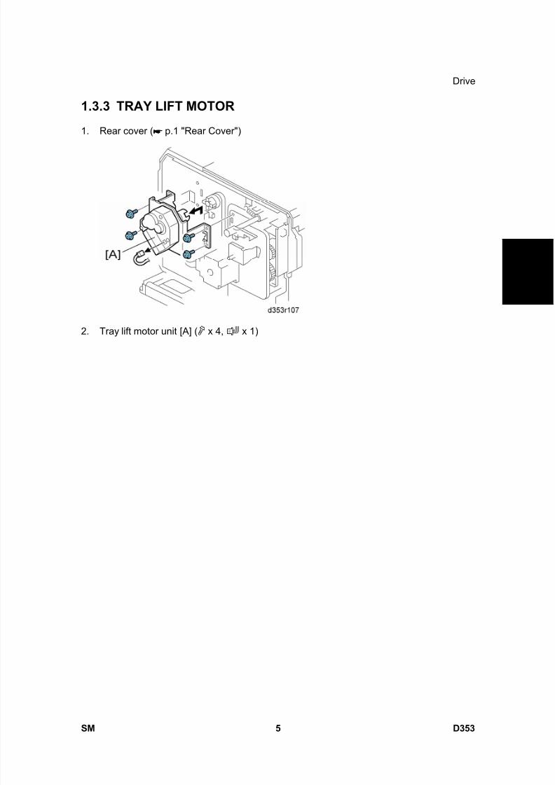
8/15/2019 Ricoh MP 4000 SM D009_D011_D012_D013 SERVICE MANUAL .pdf
http://slidepdf.com/reader/full/ricoh-mp-4000-sm-d009d011d012d013-service-manual-pdf 1083/1162
Drive
SM 5 D353
1 2 0 0 S h e e
t
L C T R T 3 0 0 0
D 3 5 3
1.3.3 TRAY LIFT MOTOR
1. Rear cover ( p.1 "Rear Cover")
2. Tray lift motor unit [A] ( x 4, x 1)
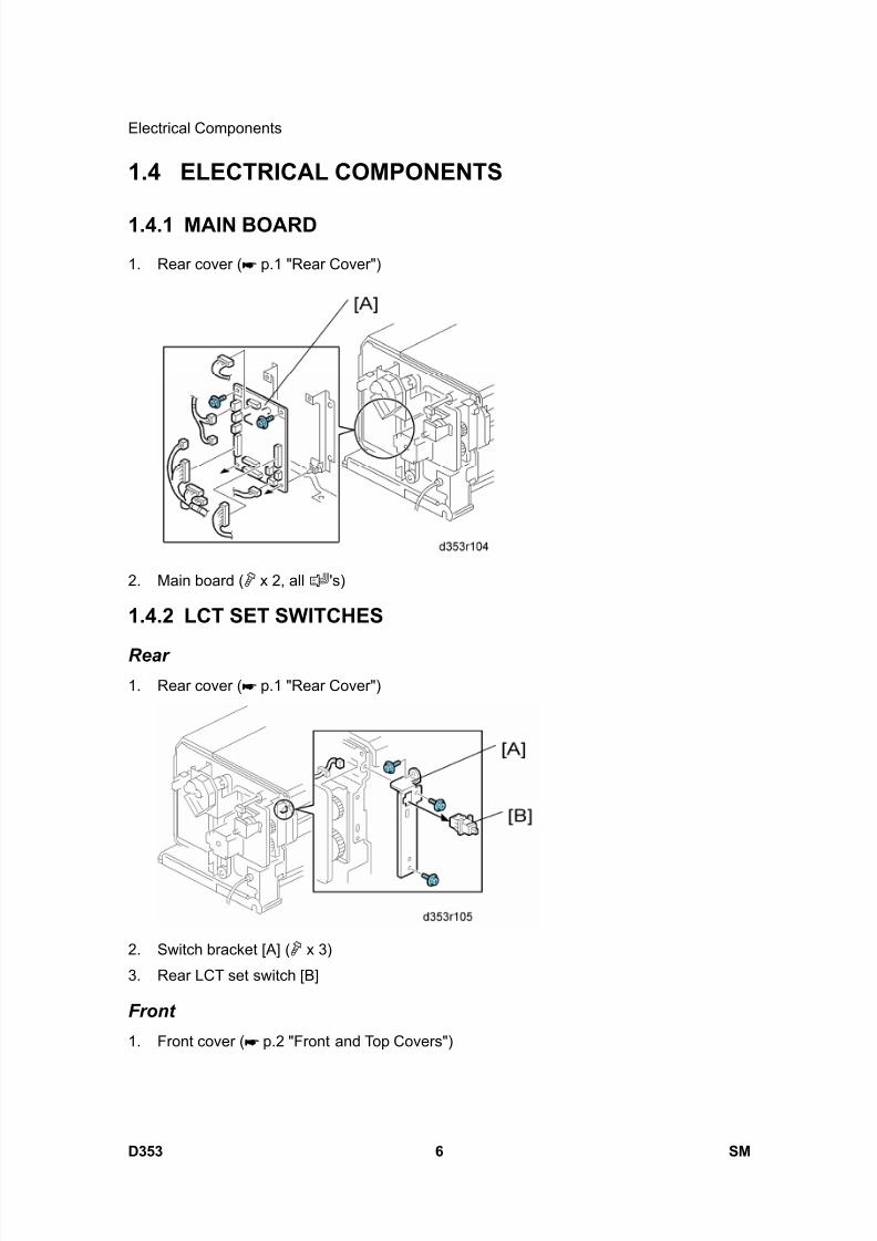
8/15/2019 Ricoh MP 4000 SM D009_D011_D012_D013 SERVICE MANUAL .pdf
http://slidepdf.com/reader/full/ricoh-mp-4000-sm-d009d011d012d013-service-manual-pdf 1084/1162
Electrical Components
D353 6 SM
1.4 ELECTRICAL COMPONENTS
1.4.1 MAIN BOARD
1. Rear cover ( p.1 "Rear Cover")
2. Main board ( x 2, all 's)
1.4.2 LCT SET SWITCHES
Rear1. Rear cover ( p.1 "Rear Cover")
2. Switch bracket [A] ( x 3)
3. Rear LCT set switch [B]
Front
1. Front cover ( p.2 "Front and Top Covers")
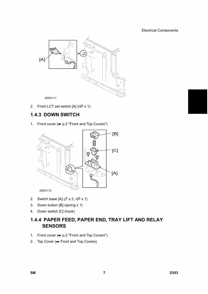
8/15/2019 Ricoh MP 4000 SM D009_D011_D012_D013 SERVICE MANUAL .pdf
http://slidepdf.com/reader/full/ricoh-mp-4000-sm-d009d011d012d013-service-manual-pdf 1085/1162
Electrical Components
SM 7 D353
1 2 0 0 S h e e
t
L C T R T 3 0 0 0
D 3 5 3
2. Front LCT set switch [A] ( x 1)
1.4.3 DOWN SWITCH
1. Front cover ( p.2 "Front and Top Covers")
2. Switch base [A] ( x 2, x 1)
3. Down button [B] (spring x 1)4. Down switch [C] (hook)
1.4.4 PAPER FEED, PAPER END, TRAY LIFT AND RELAYSENSORS
1. Front cover ( p.2 "Front and Top Covers")
2. Top Cover ( Front and Top Covers)
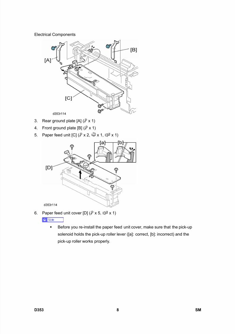
8/15/2019 Ricoh MP 4000 SM D009_D011_D012_D013 SERVICE MANUAL .pdf
http://slidepdf.com/reader/full/ricoh-mp-4000-sm-d009d011d012d013-service-manual-pdf 1086/1162
Electrical Components
D353 8 SM
3. Rear ground plate [A] ( x 1)
4. Front ground plate [B] ( x 1)
5. Paper feed unit [C] ( x 2, x 1, x 1)
6. Paper feed unit cover [D] ( x 5, x 1)
Before you re-install the paper feed unit cover, make sure that the pick-up
solenoid holds the pick-up roller lever ([a]: correct, [b]: incorrect) and thepick-up roller works properly.

8/15/2019 Ricoh MP 4000 SM D009_D011_D012_D013 SERVICE MANUAL .pdf
http://slidepdf.com/reader/full/ricoh-mp-4000-sm-d009d011d012d013-service-manual-pdf 1087/1162
Electrical Components
SM 9 D353
1 2 0 0 S h e e
t
L C T R T 3 0 0 0
D 3 5 3
7. Sensors [E], [F], [G], [H] ( x 1, hooks each)
[E]: Tray lift sensor
[F]: Relay sensor
[G]: Paper feed sensor
[H]: Paper end sensor
1.4.5 STACK SENSOR1. Open the right door
2. Paper feed unit ( p.7 "Paper Feed, Paper End, Tray Lift and Relay Sensors")
3. Sensor bracket [A] ( x 2)
4. Stack sensor [B] ( x 1)
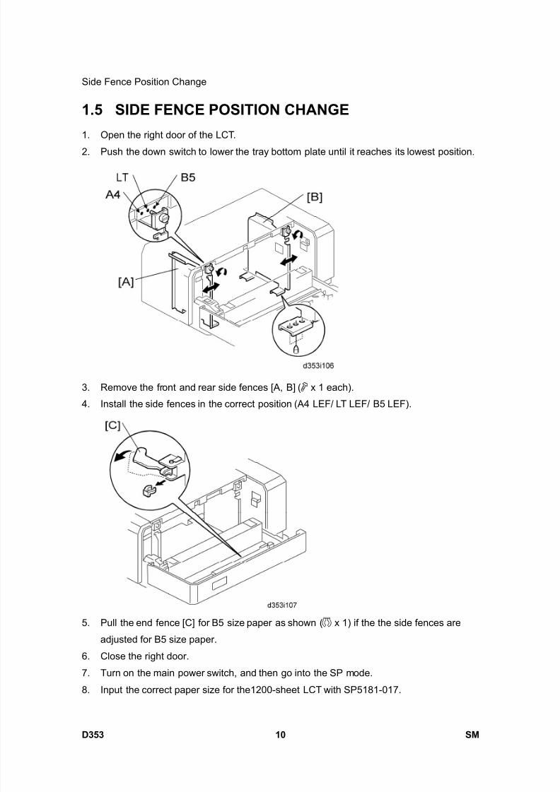
8/15/2019 Ricoh MP 4000 SM D009_D011_D012_D013 SERVICE MANUAL .pdf
http://slidepdf.com/reader/full/ricoh-mp-4000-sm-d009d011d012d013-service-manual-pdf 1088/1162
Side Fence Position Change
D353 10 SM
1.5 SIDE FENCE POSITION CHANGE
1. Open the right door of the LCT.2. Push the down switch to lower the tray bottom plate until it reaches its lowest position.
3. Remove the front and rear side fences [A, B] ( x 1 each).
4. Install the side fences in the correct position (A4 LEF/ LT LEF/ B5 LEF).
5. Pull the end fence [C] for B5 size paper as shown ( x 1) if the the side fences are
adjusted for B5 size paper.
6. Close the right door.
7. Turn on the main power switch, and then go into the SP mode.
8. Input the correct paper size for the1200-sheet LCT with SP5181-017.

8/15/2019 Ricoh MP 4000 SM D009_D011_D012_D013 SERVICE MANUAL .pdf
http://slidepdf.com/reader/full/ricoh-mp-4000-sm-d009d011d012d013-service-manual-pdf 1089/1162
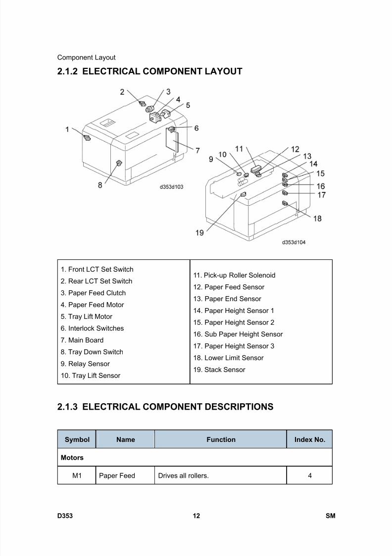
8/15/2019 Ricoh MP 4000 SM D009_D011_D012_D013 SERVICE MANUAL .pdf
http://slidepdf.com/reader/full/ricoh-mp-4000-sm-d009d011d012d013-service-manual-pdf 1090/1162
Component Layout
D353 12 SM
2.1.2 ELECTRICAL COMPONENT LAYOUT
1. Front LCT Set Switch
2. Rear LCT Set Switch
3. Paper Feed Clutch4. Paper Feed Motor
5. Tray Lift Motor
6. Interlock Switches
7. Main Board
8. Tray Down Switch
9. Relay Sensor
10. Tray Lift Sensor
11. Pick-up Roller Solenoid
12. Paper Feed Sensor
13. Paper End Sensor
14. Paper Height Sensor 1
15. Paper Height Sensor 2
16. Sub Paper Height Sensor
17. Paper Height Sensor 3
18. Lower Limit Sensor
19. Stack Sensor
2.1.3 ELECTRICAL COMPONENT DESCRIPTIONS
Symbol Name Function Index No.
Motors
M1 Paper Feed Drives all rollers. 4

8/15/2019 Ricoh MP 4000 SM D009_D011_D012_D013 SERVICE MANUAL .pdf
http://slidepdf.com/reader/full/ricoh-mp-4000-sm-d009d011d012d013-service-manual-pdf 1091/1162
Component Layout
SM 13 D353
1 2 0 0 S h e e
t
L C T R T 3 0 0 0
D 3 5 3
Symbol Name Function Index No.
M2 Tray Lift Drives the paper tray up or down. 5
Sensors
S1 Paper Feed
Detects whether the paper is jammed at
the LCT. 12
S2 RelayDetects the copy paper coming to the
relay roller and checks for misfeeds.9
S3 Paper End
Informs the mainframe when the paper in
the tray has been used up and indicates
paper end.
13
S4 Tray LiftDetects when the paper is at the correct
paper feed height.10
S5 Paper Height 1 14
S6 Paper Height 2 15
S7Sub Paper
Height16
S8 Paper Height 3
Detects the amount of paper remaining in
the tray.
17
S9 Lower LimitDetects when the tray is completely
lowered, to stop the tray lift motor.18
S10 Stack
Detects a) when the tray has moved
down to the paper supply position after
paper end, to stop the tray lift motor or b)
when the top of the paper stack has
moved down to the paper supply position,
to stop the tray lift motor after the down
switch has been pressed.
19
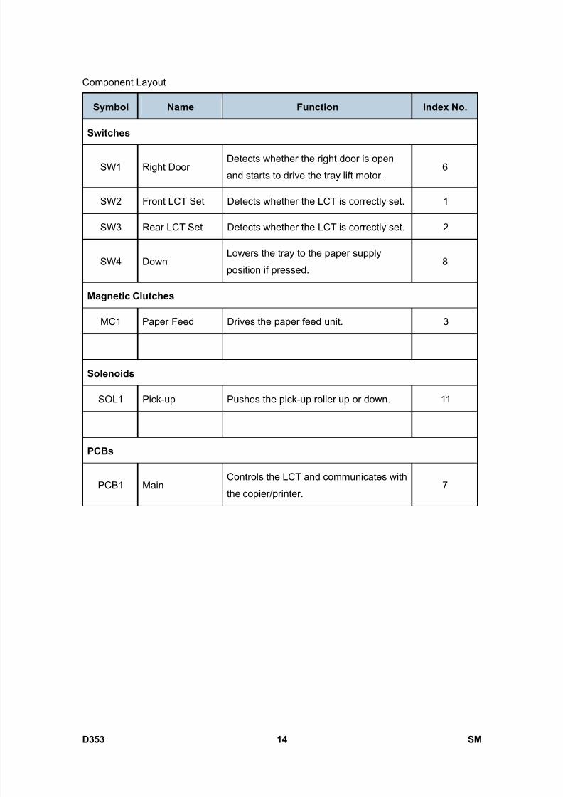
8/15/2019 Ricoh MP 4000 SM D009_D011_D012_D013 SERVICE MANUAL .pdf
http://slidepdf.com/reader/full/ricoh-mp-4000-sm-d009d011d012d013-service-manual-pdf 1092/1162
Component Layout
D353 14 SM
Symbol Name Function Index No.
Switches
SW1 Right DoorDetects whether the right door is open
and starts to drive the tray lift motor.6
SW2 Front LCT Set Detects whether the LCT is correctly set. 1
SW3 Rear LCT Set Detects whether the LCT is correctly set. 2
SW4 DownLowers the tray to the paper supply
position if pressed.8
Magnetic Clutches
MC1 Paper Feed Drives the paper feed unit. 3
Solenoids
SOL1 Pick-up Pushes the pick-up roller up or down. 11
PCBs
PCB1 MainControls the LCT and communicates with
the copier/printer.7

8/15/2019 Ricoh MP 4000 SM D009_D011_D012_D013 SERVICE MANUAL .pdf
http://slidepdf.com/reader/full/ricoh-mp-4000-sm-d009d011d012d013-service-manual-pdf 1093/1162
Component Layout
SM 15 D353
1 2 0 0 S h e e
t
L C T R T 3 0 0 0
D 3 5 3
2.1.4 DRIVE LAYOUT
1. Tray Lift Motor
2. Paper Feed Motor
3. Pick-up Roller4. Paper Feed Clutch
5. Relay Roller
6. Separation Roller
7. Tray Drive Belt
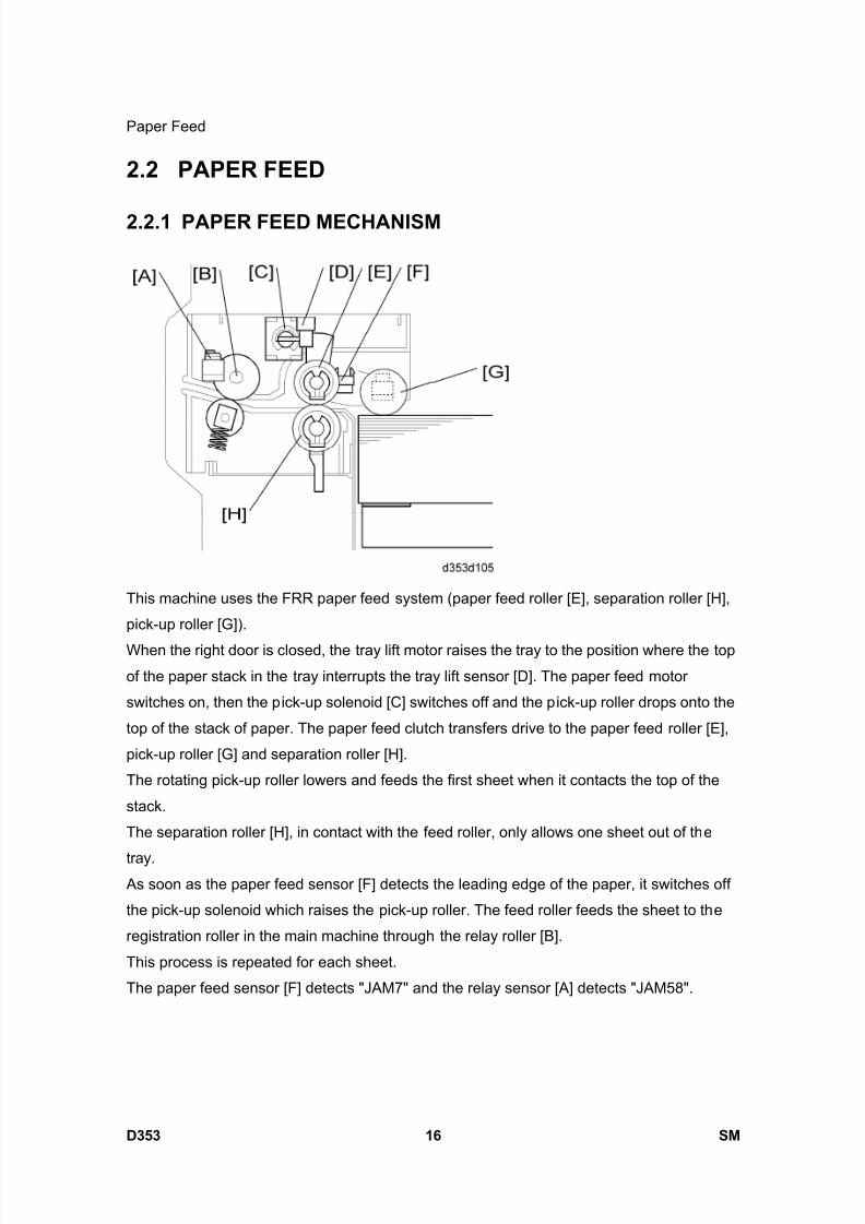
8/15/2019 Ricoh MP 4000 SM D009_D011_D012_D013 SERVICE MANUAL .pdf
http://slidepdf.com/reader/full/ricoh-mp-4000-sm-d009d011d012d013-service-manual-pdf 1094/1162
Paper Feed
D353 16 SM
2.2 PAPER FEED
2.2.1 PAPER FEED MECHANISM
This machine uses the FRR paper feed system (paper feed roller [E], separation roller [H],
pick-up roller [G]).
When the right door is closed, the tray lift motor raises the tray to the position where the top
of the paper stack in the tray interrupts the tray lift sensor [D]. The paper feed motor
switches on, then the pick-up solenoid [C] switches off and the pick-up roller drops onto the
top of the stack of paper. The paper feed clutch transfers drive to the paper feed roller [E],
pick-up roller [G] and separation roller [H].
The rotating pick-up roller lowers and feeds the first sheet when it contacts the top of the
stack.
The separation roller [H], in contact with the feed roller, only allows one sheet out of the
tray. As soon as the paper feed sensor [F] detects the leading edge of the paper, it switches off
the pick-up solenoid which raises the pick-up roller. The feed roller feeds the sheet to the
registration roller in the main machine through the relay roller [B].
This process is repeated for each sheet.
The paper feed sensor [F] detects "JAM7" and the relay sensor [A] detects "JAM58".
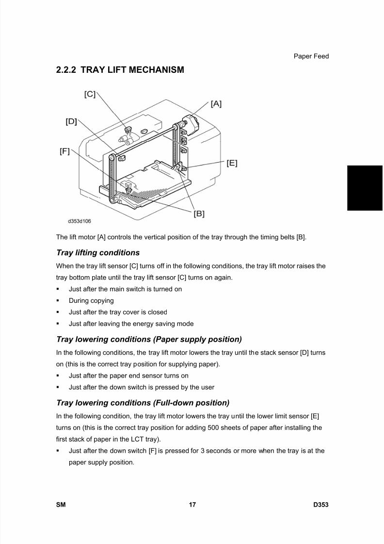
8/15/2019 Ricoh MP 4000 SM D009_D011_D012_D013 SERVICE MANUAL .pdf
http://slidepdf.com/reader/full/ricoh-mp-4000-sm-d009d011d012d013-service-manual-pdf 1095/1162
Paper Feed
SM 17 D353
1 2 0 0 S h e e
t
L C T R T 3 0 0 0
D 3 5 3
2.2.2 TRAY LIFT MECHANISM
The lift motor [A] controls the vertical position of the tray through the timing belts [B].
Tray lifting conditions
When the tray lift sensor [C] turns off in the following conditions, the tray lift motor raises the
tray bottom plate until the tray lift sensor [C] turns on again.
Just after the main switch is turned on
During copying
Just after the tray cover is closed
Just after leaving the energy saving mode
Tray lowering conditions (Paper supply position)
In the following conditions, the tray lift motor lowers the tray until the stack sensor [D] turns
on (this is the correct tray position for supplying paper).
Just after the paper end sensor turns on
Just after the down switch is pressed by the user
Tray lowering conditions (Full-down position)
In the following condition, the tray lift motor lowers the tray until the lower limit sensor [E]
turns on (this is the correct tray position for adding 500 sheets of paper after installing the
first stack of paper in the LCT tray).
Just after the down switch [F] is pressed for 3 seconds or more when the tray is at the
paper supply position.

8/15/2019 Ricoh MP 4000 SM D009_D011_D012_D013 SERVICE MANUAL .pdf
http://slidepdf.com/reader/full/ricoh-mp-4000-sm-d009d011d012d013-service-manual-pdf 1096/1162
Paper Feed
D353 18 SM
2.2.3 PAPER HEIGHT AND END DETECTION
Paper Height
The amount of the paper in the tray is detected by combination of high (1)/low (0) outputs
from three sensors (paper height sensor 1 [A], 2 [B], 3 [D] and sub paper height sensor
[C]).
Amount of paper PH S-1 PH S-2 PH S-3 Sub PH S Indicator on the
operation panel
100% 0 0 0 0 Four lines
0 0 1 -70%
0 0 0 1
Three lines
30% 0 1 - - Two lines
10% 1 - - - One line
End - - - - No line
0: No interruption (low), 1: Interruption (high), -: No checking
PH S: Paper Height Sensor
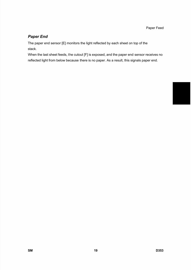
8/15/2019 Ricoh MP 4000 SM D009_D011_D012_D013 SERVICE MANUAL .pdf
http://slidepdf.com/reader/full/ricoh-mp-4000-sm-d009d011d012d013-service-manual-pdf 1097/1162
Paper Feed
SM 19 D353
1 2 0 0 S h e e
t
L C T R T 3 0 0 0
D 3 5 3
Paper End
The paper end sensor [E] monitors the light reflected by each sheet on top of the
stack.
When the last sheet feeds, the cutout [F] is exposed, and the paper end sensor receives no
reflected light from below because there is no paper. As a result, this signals paper end.

8/15/2019 Ricoh MP 4000 SM D009_D011_D012_D013 SERVICE MANUAL .pdf
http://slidepdf.com/reader/full/ricoh-mp-4000-sm-d009d011d012d013-service-manual-pdf 1098/1162

8/15/2019 Ricoh MP 4000 SM D009_D011_D012_D013 SERVICE MANUAL .pdf
http://slidepdf.com/reader/full/ricoh-mp-4000-sm-d009d011d012d013-service-manual-pdf 1099/1162
PRINTER/SCANNER OPTIONTYPE 5000
D381

8/15/2019 Ricoh MP 4000 SM D009_D011_D012_D013 SERVICE MANUAL .pdf
http://slidepdf.com/reader/full/ricoh-mp-4000-sm-d009d011d012d013-service-manual-pdf 1100/1162
8/15/2019 Ricoh MP 4000 SM D009_D011_D012_D013 SERVICE MANUAL .pdf
http://slidepdf.com/reader/full/ricoh-mp-4000-sm-d009d011d012d013-service-manual-pdf 1101/1162
SM i D381
PRINTER/SCANNER OPTION
TYPE 5000(D381)TABLE OF CONTENTS
1. INSTALLATION ...............................................................................1
1.1 OVERVIEW................................................................................................... 1
1.1.1 PRINTER/SCANNER OPTIONS.......................................................... 1
1.1.2 OTHER OPTIONS ............................................................................... 1
1.1.3 BOARD, SD CARD SLOTS ................................................................. 2 1.2 PRINTER AND P/S OPTIONS...................................................................... 5
1.2.1 OVERVIEW.......................................................................................... 5
1.2.2 KIT CONTENTS................................................................................... 6
1.2.3 PRINTER/SCANNER INSTALLATION ................................................ 8
1.2.4 PRINTER ENHANCE, SCANNER ENHANCE OPTIONS.................. 10
1.2.5 APPLICATION MERGE ..................................................................... 12
1.3 OTHER OPTIONS ...................................................................................... 14
1.3.1 OVERVIEW........................................................................................ 14 1.3.2 POSTSCRIPT 3 ................................................................................. 15
1.3.3 FILE FORMAT CONVERTER............................................................ 16
1.3.4 IEEE1284........................................................................................... 16
1.3.5 IEEE 802.11A/G, G (WIRELESS LAN) .............................................. 17
1.3.6 BLUETOOTH..................................................................................... 20
1.3.7 GIGABIT ETHERNET AND USB2.0 .................................................. 21
1.3.8 CHECK ALL CONNECTIONS............................................................ 22
2. SERVICE TABLES......................................................................23 2.1 PRINTER SERVICE TABLE ....................................................................... 23
2.1.1 SP TABLES ....................................................................................... 23
2.2 SCANNER SERVICE TABLE ..................................................................... 24
2.2.1 SP TABLES ....................................................................................... 24
3. DETAILED SECTION DESCRIPTIONS.........................................26
3.1 OVERVIEW................................................................................................. 26
3.1.1 PRINTER FEATURES ....................................................................... 26
8/15/2019 Ricoh MP 4000 SM D009_D011_D012_D013 SERVICE MANUAL .pdf
http://slidepdf.com/reader/full/ricoh-mp-4000-sm-d009d011d012d013-service-manual-pdf 1102/1162
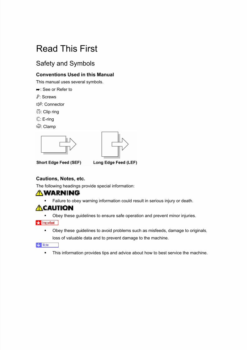
8/15/2019 Ricoh MP 4000 SM D009_D011_D012_D013 SERVICE MANUAL .pdf
http://slidepdf.com/reader/full/ricoh-mp-4000-sm-d009d011d012d013-service-manual-pdf 1103/1162
Read This First
Safety and Symbols
Conventions Used in this ManualThis manual uses several symbols.
: See or Refer to
: Screws
: Connector
: Clip ring
: E-ring
: Clamp
Cautions, Notes, etc.The following headings provide special information:
Failure to obey warning information could result in serious injury or death.
Obey these guidelines to ensure safe operation and prevent minor injuries.
Obey these guidelines to avoid problems such as misfeeds, damage to originals,
loss of valuable data and to prevent damage to the machine.
This information provides tips and advice about how to best service the machine.

8/15/2019 Ricoh MP 4000 SM D009_D011_D012_D013 SERVICE MANUAL .pdf
http://slidepdf.com/reader/full/ricoh-mp-4000-sm-d009d011d012d013-service-manual-pdf 1104/1162

8/15/2019 Ricoh MP 4000 SM D009_D011_D012_D013 SERVICE MANUAL .pdf
http://slidepdf.com/reader/full/ricoh-mp-4000-sm-d009d011d012d013-service-manual-pdf 1105/1162
Overview
SM 1 D381
P r i n
t e r /
S c a n n e r
O p
t i o n
D 3 8 1
1. INSTALLATION
1.1 OVERVIEW
This section describes the installation procedures for printer, scanner, and other options for
D009/D012 series machines.
1.1.1 PRINTER/SCANNER OPTIONS
The options listed in the table below are for D009/D012 machines only.
No. ItemSD Card
SlotMerge Options
D381 Printer/Scanner Unit Type 5000 1 DOS
D381 Printer Unit Type 5000 1 DOS, Scanner Enhance
D381 RPCS Printer Unit Type 5000 1DOS, Scanner Enhance
Printer Enhance
D381 Printer Enhance Option Type 5000 Merge: 2 → 1
D381Scanner Enhance Option Type
5000Merge: 2 → 1
1.1.2 OTHER OPTIONS
The options listed in the table below are used in both D009/D012 series machines as well
as D011/D013 series machines.
No. Item Slots
D377 File Format Converter Type E
G381 Gigabit Ethernet Type 7300
B826 Bluetooth Interface Unit Type 3245
Board Slot. Only one of these
boards can be installed at one time.

8/15/2019 Ricoh MP 4000 SM D009_D011_D012_D013 SERVICE MANUAL .pdf
http://slidepdf.com/reader/full/ricoh-mp-4000-sm-d009d011d012d013-service-manual-pdf 1106/1162
Overview
D381 2 SM
No. Item Slots
D377IEEE 802.11a/g, g Interface Unit Type
J
B679 IEEE 1284 Interface Board Type A
D381 PostScript3 Unit Type 5000 SD card slot 1
D362 Data Overwrite Security Unit Type ISD card slot 1, or merge to SD Slot
1
D377 HDD Encryption Unit Type A SD card slot 2 (Install, then remove)
D377 Browser Unit Type D SD card slot 2 (Install, then remove)
D377 VM Card Type F SD card slot 2
D362 Memory Unit Type G 256 MB Controller Board
For more details about merging applications from SD card slot 2 to 1, see "Printer
Enhance, Scanner Enhance Options" in this chapter.
1.1.3 BOARD, SD CARD SLOTS
The machine controller box has one board slot and two SD card slots. Make sure that each
board and SD card is put in the correct slot.
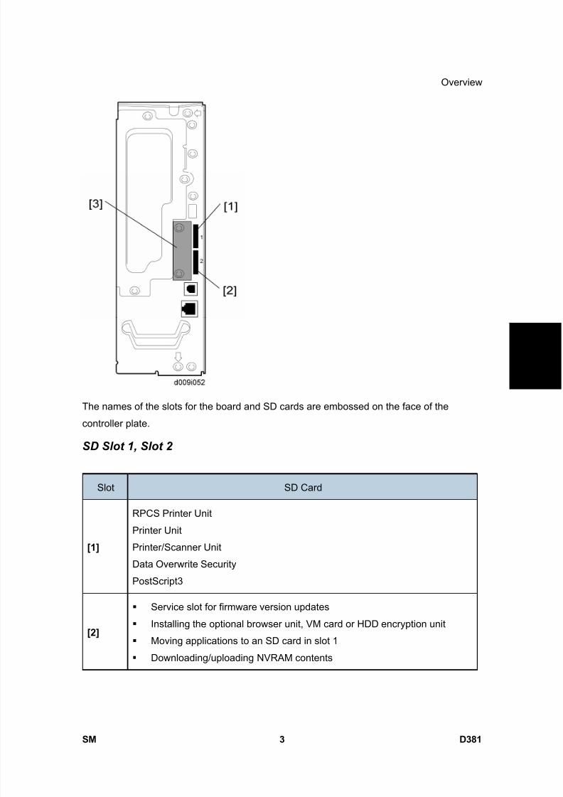
8/15/2019 Ricoh MP 4000 SM D009_D011_D012_D013 SERVICE MANUAL .pdf
http://slidepdf.com/reader/full/ricoh-mp-4000-sm-d009d011d012d013-service-manual-pdf 1107/1162
Overview
SM 3 D381
P r i n
t e r /
S c a n n e r
O p
t i o n
D 3 8 1
The names of the slots for the board and SD cards are embossed on the face of the
controller plate.
SD Slot 1, Slot 2
Slot SD Card
[1]
RPCS Printer Unit
Printer Unit
Printer/Scanner Unit
Data Overwrite Security
PostScript3
[2]
Service slot for firmware version updates
Installing the optional browser unit, VM card or HDD encryption unit
Moving applications to an SD card in slot 1
Downloading/uploading NVRAM contents

8/15/2019 Ricoh MP 4000 SM D009_D011_D012_D013 SERVICE MANUAL .pdf
http://slidepdf.com/reader/full/ricoh-mp-4000-sm-d009d011d012d013-service-manual-pdf 1108/1162
Overview
D381 4 SM
Board Slot
Slot Board
[3]
File Format Converter (MLB): D377
Bluetooth Interface Unit: B826
IEEE 802.11a/g, g: D377
IEEE 1284 Interface Board: B679
Gigabit Ethernet: G381
Only one of these boards can be installed at one time.
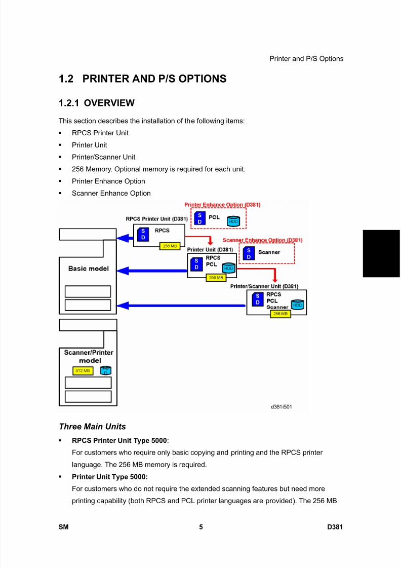
8/15/2019 Ricoh MP 4000 SM D009_D011_D012_D013 SERVICE MANUAL .pdf
http://slidepdf.com/reader/full/ricoh-mp-4000-sm-d009d011d012d013-service-manual-pdf 1109/1162
Printer and P/S Options
SM 5 D381
P r i n
t e r /
S c a n n e r
O p
t i o n
D 3 8 1
1.2 PRINTER AND P/S OPTIONS
1.2.1 OVERVIEW
This section describes the installation of the following items:
RPCS Printer Unit
Printer Unit
Printer/Scanner Unit
256 Memory. Optional memory is required for each unit.
Printer Enhance Option
Scanner Enhance Option
Three Main Units
RPCS Printer Unit Type 5000 :
For customers who require only basic copying and printing and the RPCS printer
language. The 256 MB memory is required.
Printer Unit Type 5000:
For customers who do not require the extended scanning features but need more
printing capability (both RPCS and PCL printer languages are provided). The 256 MB
8/15/2019 Ricoh MP 4000 SM D009_D011_D012_D013 SERVICE MANUAL .pdf
http://slidepdf.com/reader/full/ricoh-mp-4000-sm-d009d011d012d013-service-manual-pdf 1110/1162
Printer and P/S Options
D381 6 SM
memory is required.
Printer/Scanner Unit Type 5000:
For customers who require the full range of DS features (advanced scanning andprinting features such as "scan-to" solutions, virtual mailboxes, PCL, etc.). The 256 MB
memory unit is required.
Separate Options
There are two separate options not provided with the kits: 256 MB memory and PS3.
256 MB memory:
Not provided with any option. However, every unit (RPCS, Printer Unit, P/S unit)
requires installation of the 256 MB memory.
PostScript 3 Unit: The PS3 option can be used with the RPCS Unit, the Printer Unit, or the
Printer/Scanner Unit.
Enhance Options
There are two enhance options:
Printer Enhance Option Type 5000:
Updates the RPCS unit by adding PCL.
Scanner Enhance Option Type 5000:
Updates the RPCS unit or Printer Unit by adding the advanced scanning features.
1.2.2 KIT CONTENTS
Check the accessories and their quantities against the list below and the illustration on the
next page. This is a common list for all the kits.
Common Accessory Table
This common accessory table lists all the items of the following units and options for the
D009/D012 Series machines:
RPCS: RPCS Printer Unit
PU: Printer Unit
P/S: Printer/Scanner Unit
PEO: Printer Enhance Unit
SEO: Scanner Enhance Unit
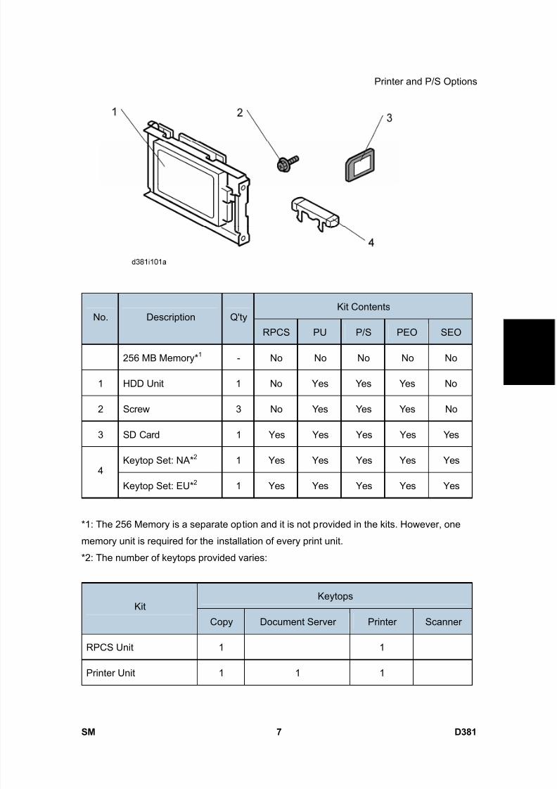
8/15/2019 Ricoh MP 4000 SM D009_D011_D012_D013 SERVICE MANUAL .pdf
http://slidepdf.com/reader/full/ricoh-mp-4000-sm-d009d011d012d013-service-manual-pdf 1111/1162
Printer and P/S Options
SM 7 D381
P r i n
t e r /
S c a n n e r
O p
t i o n
D 3 8 1
Kit ContentsNo. Description Q'ty
RPCS PU P/S PEO SEO
256 MB Memory* 1 - No No No No No
1 HDD Unit 1 No Yes Yes Yes No
2 Screw 3 No Yes Yes Yes No
3 SD Card 1 Yes Yes Yes Yes Yes
Keytop Set: NA* 2 1 Yes Yes Yes Yes Yes4
Keytop Set: EU* 2 1 Yes Yes Yes Yes Yes
*1: The 256 Memory is a separate option and it is not provided in the kits. However, one
memory unit is required for the installation of every print unit.
*2: The number of keytops provided varies:
KeytopsKit
Copy Document Server Printer Scanner
RPCS Unit 1 1
Printer Unit 1 1 1

8/15/2019 Ricoh MP 4000 SM D009_D011_D012_D013 SERVICE MANUAL .pdf
http://slidepdf.com/reader/full/ricoh-mp-4000-sm-d009d011d012d013-service-manual-pdf 1112/1162
Printer and P/S Options
D381 8 SM
KeytopsKit
Copy Document Server Printer Scanner
Printer/Scanner Unit 1 1 1 1
Printer Enhance Unit 1
Scanner Enhance Unit 1
1.2.3 PRINTER/SCANNER INSTALLATION
Turn off the main power switch and disconnect the power supply cord.
1. Remove the controller board [1] ( x 2).

8/15/2019 Ricoh MP 4000 SM D009_D011_D012_D013 SERVICE MANUAL .pdf
http://slidepdf.com/reader/full/ricoh-mp-4000-sm-d009d011d012d013-service-manual-pdf 1113/1162
Printer and P/S Options
SM 9 D381
P r i n
t e r /
S c a n n e r
O p
t i o n
D 3 8 1
2. Install the 256 MB memory DIMM [2].
3. Install a hard disk (except RPCS Printer Kit). ( HDD Installation in the Service
Manual of the Model AL-C1)
4. Reinstall the controller board.
5. Remove the SD card slot cover [3] ( x1).
6. Insert the Printer/Scanner SD card [4] in SD card slot 1.
7. Reattach the cover.
8. Connect the LAN cable to the "NIC" connection.
9. Connect the USB cable to the "USB" connection.
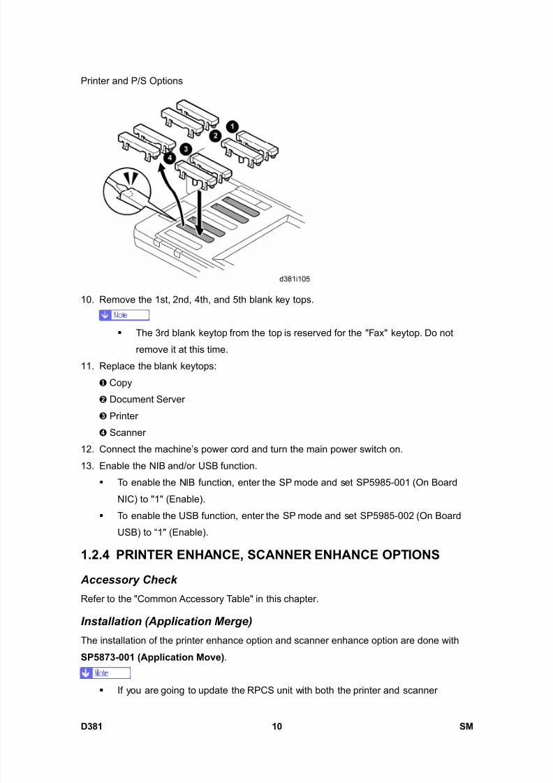
8/15/2019 Ricoh MP 4000 SM D009_D011_D012_D013 SERVICE MANUAL .pdf
http://slidepdf.com/reader/full/ricoh-mp-4000-sm-d009d011d012d013-service-manual-pdf 1114/1162
Printer and P/S Options
D381 10 SM
10. Remove the 1st, 2nd, 4th, and 5th blank key tops.
The 3rd blank keytop from the top is reserved for the "Fax" keytop. Do not
remove it at this time.
11. Replace the blank keytops:
Copy
Document Server
Printer
Scanner
12. Connect the machine’s power cord and turn the main power switch on.
13. Enable the NIB and/or USB function.
To enable the NIB function, enter the SP mode and set SP5985-001 (On Board
NIC) to "1" (Enable).
To enable the USB function, enter the SP mode and set SP5985-002 (On Board
USB) to “1" (Enable).
1.2.4 PRINTER ENHANCE, SCANNER ENHANCE OPTIONS
Accessory Check
Refer to the "Common Accessory Table" in this chapter.
Installation (Application Merge)
The installation of the printer enhance option and scanner enhance option are done with
SP5873-001 (Application Move) .
If you are going to update the RPCS unit with both the printer and scanner

8/15/2019 Ricoh MP 4000 SM D009_D011_D012_D013 SERVICE MANUAL .pdf
http://slidepdf.com/reader/full/ricoh-mp-4000-sm-d009d011d012d013-service-manual-pdf 1115/1162
Printer and P/S Options
SM 11 D381
P r i n
t e r /
S c a n n e r
O p
t i o n
D 3 8 1
enhance options, the order of execution is not important.
1. Turn off the copier.
2. Remove the cover ( x1).3. Confirm that the RPCS Unit or Printer Unit SD card is in SD card Slot 1.
4. Put the option SD Card (Printer Enhance Option or Scanner Enhance Option) in SD
card slot 2.
5. Open the front door.
6. Turn the copier on.
7. Go into the SP mode and select SP5873-001 .
8. Touch "Execute".
9. Read the instructions on the display and touch "Execute" to start.
10. When the display tells you copying is completed, touch "Exit", then turn the copier off.
11. Remove the option SD card from slot 2.
12. Turn the copier on.
13. Go into the User Tools mode and confirm that update was successful.
14. User Tools> System Settings> Administrator Tools> Firmware Version> Next
15. Turn the copier off again, then reattach the cover.
16. Return the copied SD card to the customer for safekeeping, or tape it to the faceplate
of the controller.
To undo an option update
1. Turn the main switch off.
2. Confirm that the RPCS Unit or Printer Unit SD card is in SD card Slot 1.
3. Put the original option SD card (Printer Enhance Option or Scanner Enhance Option)
in SD card slot 2.
4. Turn the main switch on.
5. Go into the SP mode and do SP5873-002 (Undo Exec).
6. Follow the messages on the operation panel to complete the procedure.
7. Turn the main switch off.
8. Remove the option SD card from Slot 2.
9. Turn the main switch on.
10. Go into the User Tools mode and confirm that undo was successful.
User Tools> System Settings> Administrator Tools> Firmware Version> Next
11. Turn the copier off again, then reattach the cover.
Important Notes about SD Cards
Here are some basic rules about merging applications on SD cards.

8/15/2019 Ricoh MP 4000 SM D009_D011_D012_D013 SERVICE MANUAL .pdf
http://slidepdf.com/reader/full/ricoh-mp-4000-sm-d009d011d012d013-service-manual-pdf 1116/1162
Printer and P/S Options
D381 12 SM
The data necessary for authentication is transferred with the application program to the
target SD card.
The SD card is the only evidence that the customer is licensed to use the applicationprogram. The service technician may occasionally need to check the SD card and its
data to solve problems. SD cards must be stored in a safe location at the work site.
Once the merge is completed, the SD card from which the application was copied
cannot be used again, but the customer must keep the card to serve as proof of
purchase.
An SD card from which an application has been moved to another SD card can be
restored to full operation with SP5873-002 (Undo).
Before storing the card from which an application has been copied, label it carefully so
that you can identify it easily if you need to do the undo procedure later.
1.2.5 APPLICATION MERGE
This machine has two SD card slots only. However, more than two optional applications are
supplied for this machine. Always keep SD card slot 2 vacant for servicing (except VM
Card Type F). Because of this, SD card merge is required if a customer wants to use many
applications.
Consider the following limitations when you try to merge SD cards.
PostScript3 cannot be moved to the other SD card. The destination SD card should have the largest memory size of all the application SD
cards. Refer to the following table for the memory size of each SD card.
SD Card Options SD Card Size Module Size
Printer/Scanner Unit Type 5000 32 MB 9.3 MB
RPCS Printer Unit Type 5000 32 MB 6.3 MB
Printer Unit Type 5000 32 MB 8.3 MB
Printer Enhance Option Type 5000 16 MB 4 MB
Scanner Enhance Option Type 5000 16 MB 3 MB
DataOverwriteSecurity Unit Type I 16 MB 4 MB
PostScript3 Unit Type 5000 64 MB 14.6 MB
8/15/2019 Ricoh MP 4000 SM D009_D011_D012_D013 SERVICE MANUAL .pdf
http://slidepdf.com/reader/full/ricoh-mp-4000-sm-d009d011d012d013-service-manual-pdf 1117/1162
Printer and P/S Options
SM 13 D381
P r i n
t e r /
S c a n n e r
O p
t i o n
D 3 8 1
Case 1: PostScript3 is not installed
Merge all applications which the customer wants to use into one SD card (Destination
Card).
The destination card should have the largest memory size of all the application SD
cards.
The VM Card Type F cannot be merged, nor moved to another SD card. This card
must be installed in slot 2.
Case 2: PostScript3 is installed
Merge all applications which the customer wants to use into the PostScript3 SD card.
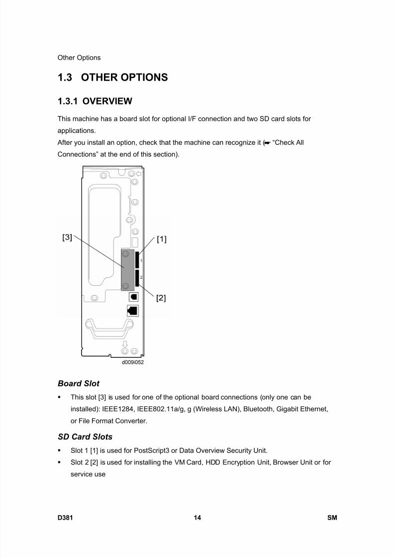
8/15/2019 Ricoh MP 4000 SM D009_D011_D012_D013 SERVICE MANUAL .pdf
http://slidepdf.com/reader/full/ricoh-mp-4000-sm-d009d011d012d013-service-manual-pdf 1118/1162
Other Options
D381 14 SM
1.3 OTHER OPTIONS
1.3.1 OVERVIEW
This machine has a board slot for optional I/F connection and two SD card slots for
applications.
After you install an option, check that the machine can recognize it ( “Check All
Connections” at the end of this section).
Board Slot
This slot [3] is used for one of the optional board connections (only one can be
installed): IEEE1284, IEEE802.11a/g, g (Wireless LAN), Bluetooth, Gigabit Ethernet,
or File Format Converter.
SD Card Slots
Slot 1 [1] is used for PostScript3 or Data Overview Security Unit.
Slot 2 [2] is used for installing the VM Card, HDD Encryption Unit, Browser Unit or for
service use

8/15/2019 Ricoh MP 4000 SM D009_D011_D012_D013 SERVICE MANUAL .pdf
http://slidepdf.com/reader/full/ricoh-mp-4000-sm-d009d011d012d013-service-manual-pdf 1119/1162
Other Options
SM 15 D381
P r i n
t e r /
S c a n n e r
O p
t i o n
D 3 8 1
1.3.2 POSTSCRIPT 3
Unplug the main machine power cord before you do the following procedure.
1. Remove the slot cover [1] ( x 1).
2. Turn the SD-card label face [2] to the rear of the machine. Then push it slowly into slot
1 until you hear a click.3. Attach the slot cover [1] ( x 1).
4. Attach the “Adobe PostScript 3” decal [3] to the front door.
5. Make sure that the machine can recognize the option ( "Check All Connections" at
the end of this section).

8/15/2019 Ricoh MP 4000 SM D009_D011_D012_D013 SERVICE MANUAL .pdf
http://slidepdf.com/reader/full/ricoh-mp-4000-sm-d009d011d012d013-service-manual-pdf 1120/1162
Other Options
D381 16 SM
1.3.3 FILE FORMAT CONVERTER
Unplug the main machine power cord before you do the following procedure.
1. Remove the slot cover [1] from the board slot ( x 2).
2. Install the file format converter into the board slot, and then fasten it with screws.
3. Plug in and turn on the main power switch.
4. Check or set the following SP codes with the values shown below.
SP No. Title Setting
SP5-836-001 Capture Function (0:Off 1:On) "1"
SP5-836-002 Panel Setting "0"
5. Check the operation.
6. Make sure that the machine can recognize the option ( "Check All Connections" at
the end of this section).
1.3.4 IEEE1284
Installation Procedure
Unplug the main machine power cord before you do the following procedure.
You can only install one of the following network interfaces at one time: (IEEE 802.11a/g, g
(Wireless LAN), IEEE1284, Bluetooth).

8/15/2019 Ricoh MP 4000 SM D009_D011_D012_D013 SERVICE MANUAL .pdf
http://slidepdf.com/reader/full/ricoh-mp-4000-sm-d009d011d012d013-service-manual-pdf 1121/1162
Other Options
SM 17 D381
P r i n
t e r /
S c a n n e r
O p
t i o n
D 3 8 1
1. Remove the slot cover [1] from the board slot ( x 2).
2. Install the interface board (Knob-screw x 2) into the board slot.
3. Make sure that the machine can recognize the option (see "Check All Connections" at
the end of this section).
1.3.5 IEEE 802.11A/G, G (WIRELESS LAN)
Installation Procedure
Unplug the main machine power cord before you do the following procedure.
You can only install one of the following network interfaces at one time: (IEEE 802.11a/g, g
(Wireless LAN), IEEE1284, Bluetooth).
1. Remove the slot cover [1] from the board slot ( x 2).
2. Install the wireless LAN board (Knob-screw x 2) into the board slot.
3. Make sure that the machine can recognize the option (see ‘Check All Connections’ at
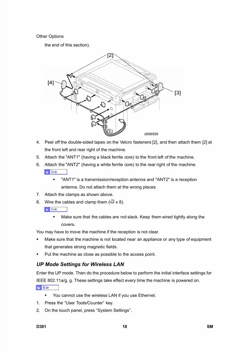
8/15/2019 Ricoh MP 4000 SM D009_D011_D012_D013 SERVICE MANUAL .pdf
http://slidepdf.com/reader/full/ricoh-mp-4000-sm-d009d011d012d013-service-manual-pdf 1122/1162
Other Options
D381 18 SM
the end of this section).
4. Peel off the double-sided tapes on the Velcro fasteners [2], and then attach them [2] at
the front left and rear right of the machine.
5. Attach the "ANT1" (having a black ferrite core) to the front left of the machine.
6. Attach the "ANT2" (having a white ferrite core) to the rear right of the machine.
"ANT1" is a transmission/reception antenna and "ANT2" is a reception
antenna. Do not attach them at the wrong places.
7. Attach the clamps as shown above.
8. Wire the cables and clamp them ( x 8).
Make sure that the cables are not slack. Keep them wired tightly along the
covers.
You may have to move the machine if the reception is not clear.
Make sure that the machine is not located near an appliance or any type of equipment
that generates strong magnetic fields. Put the machine as close as possible to the access point.
UP Mode Settings for Wireless LAN
Enter the UP mode. Then do the procedure below to perform the initial interface settings for
IEEE 802.11a/g, g. These settings take effect every time the machine is powered on.
You cannot use the wireless LAN if you use Ethernet.
1. Press the “User Tools/Counter” key.
2. On the touch panel, press “System Settings”.

8/15/2019 Ricoh MP 4000 SM D009_D011_D012_D013 SERVICE MANUAL .pdf
http://slidepdf.com/reader/full/ricoh-mp-4000-sm-d009d011d012d013-service-manual-pdf 1123/1162
Other Options
SM 19 D381
P r i n
t e r /
S c a n n e r
O p
t i o n
D 3 8 1
The Network I/F (default: Ethernet) must be set for either Ethernet or wireless
LAN.3. Select “Interface Settings”.
4. Press “Wireless LAN”. Only the wireless LAN options show.
5. Communication Mode. Select either “802.11 Ad hoc”, “Ad hoc” or “Infrastructure”.
6. SSID Setting. Enter the SSID setting. (The setting is case sensitive.)
7. Channel. You need this setting when Ad Hoc Mode is selected.
Range: 1 to 14 (default: 11)
The allowed range for the channel settings may vary for different countries.
8. WEP (Encryption) Setting. The WEP (Wired Equivalent Privacy) setting is designed to
protect wireless data transmission. The same WEP key is required on the receiving
side in order to unlock encoded data. There are 64 bit and 128 bit WEP keys.
WEP:
Selects “Active” or “Inactive”. (“Inactive” is default.)
Range of Allowed Settings:
64 bit: 10 characters
128 bit: 26 characters
9. Transmission Speed. Press the Next button to show more settings. Then select the
transmission speed for the mode: Auto, 11 Mbps, 5.5 Mbps, 2 Mbps, 1 Mbps (default:
Auto). This setting should match the distance between the closest machine or access
point. This depends on which mode is selected.
For the Ad Hoc Mode, this is the distance between the machine and the
closest PC in the network. For the Infrastructure Mode, this is the distance
between the machine and the closest access point.
11 Mbps: 140 m (153 yd.)5.5 Mbps: 200 m (219 yd.)
2 Mbps: 270 m (295 yd.)
1 Mbps: 400 m (437 yd.)
10. Press “Return to Default” to initialize the wireless LAN settings.
Press “Yes” to initialize the following settings:
Transmission mode
Channel
Transmission Speed
8/15/2019 Ricoh MP 4000 SM D009_D011_D012_D013 SERVICE MANUAL .pdf
http://slidepdf.com/reader/full/ricoh-mp-4000-sm-d009d011d012d013-service-manual-pdf 1124/1162
Other Options
D381 20 SM
WEP
SSID
WEP Key
SP Mode Settings for IEEE 802.11a/g, g Wireless LAN
The following SP commands and UP modes can be set for IEEE 802.11a/g, g.
SP No. Name Function
5840-006 Channel MAXSets the maximum range of the channel settings for the
country.
5840-007 Channel MINSets the minimum range of the channels settings
allowed for your country.
5840-011 WEP Key Select Used to select the WEP key (Default: 00).
UP mode Name Function
SSID Used to confirm the current SSID setting.
WEP Key
Used to confirm
the current WEP
key setting.
WEP Mode
Used to show
the maximum
length of the
string that can be
used for the
WEP Key entry.
1.3.6 BLUETOOTH
Unplug the main machine power cord before you do the following procedure.
You can only install one of the following network interfaces at one time: (IEEE 802.11a/g, g
(Wireless LAN), IEEE1284, IEEE1394, Bluetooth).
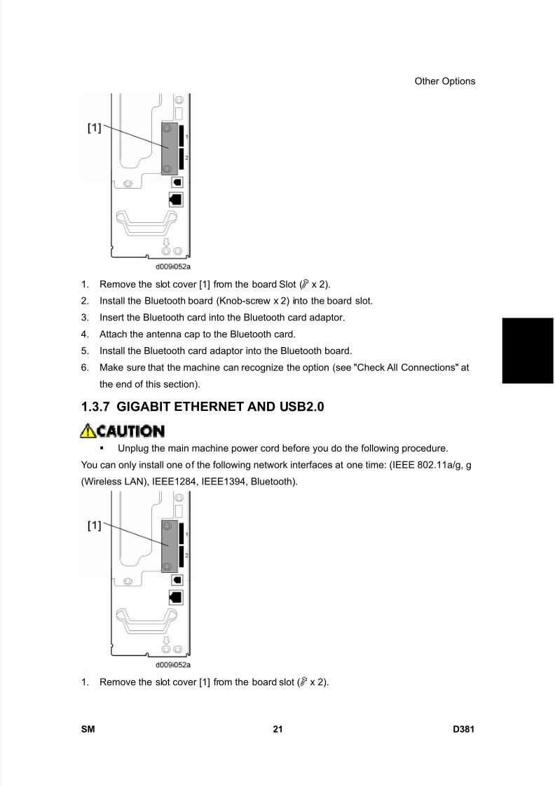
8/15/2019 Ricoh MP 4000 SM D009_D011_D012_D013 SERVICE MANUAL .pdf
http://slidepdf.com/reader/full/ricoh-mp-4000-sm-d009d011d012d013-service-manual-pdf 1125/1162
Other Options
SM 21 D381
P r i n
t e r /
S c a n n e r
O p
t i o n
D 3 8 1
1. Remove the slot cover [1] from the board Slot ( x 2).
2. Install the Bluetooth board (Knob-screw x 2) into the board slot.
3. Insert the Bluetooth card into the Bluetooth card adaptor.
4. Attach the antenna cap to the Bluetooth card.
5. Install the Bluetooth card adaptor into the Bluetooth board.
6. Make sure that the machine can recognize the option (see "Check All Connections" at
the end of this section).
1.3.7 GIGABIT ETHERNET AND USB2.0
Unplug the main machine power cord before you do the following procedure.
You can only install one of the following network interfaces at one time: (IEEE 802.11a/g, g
(Wireless LAN), IEEE1284, IEEE1394, Bluetooth).
1. Remove the slot cover [1] from the board slot ( x 2).
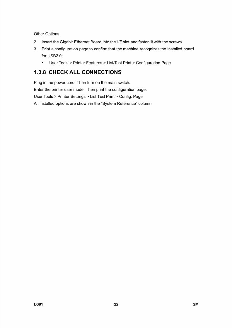
8/15/2019 Ricoh MP 4000 SM D009_D011_D012_D013 SERVICE MANUAL .pdf
http://slidepdf.com/reader/full/ricoh-mp-4000-sm-d009d011d012d013-service-manual-pdf 1126/1162
Other Options
D381 22 SM
2. Insert the Gigabit Ethernet Board into the I/F slot and fasten it with the screws.
3. Print a configuration page to confirm that the machine recognizes the installed board
for USB2.0: User Tools > Printer Features > List/Test Print > Configuration Page
1.3.8 CHECK ALL CONNECTIONS
Plug in the power cord. Then turn on the main switch.
Enter the printer user mode. Then print the configuration page.
User Tools > Printer Settings > List Test Print > Config. Page
All installed options are shown in the “System Reference” column.
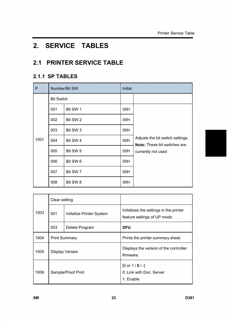
8/15/2019 Ricoh MP 4000 SM D009_D011_D012_D013 SERVICE MANUAL .pdf
http://slidepdf.com/reader/full/ricoh-mp-4000-sm-d009d011d012d013-service-manual-pdf 1127/1162
Printer Service Table
SM 23 D381
P r i n
t e r /
S c a n n e r
O p
t i o n
D 3 8 1
2. SERVICE TABLES
2.1 PRINTER SERVICE TABLE
2.1.1 SP TABLES
P Number/Bit SW Initial
Bit Switch
001 Bit SW 1 00H
002 Bit SW 2 00H
003 Bit SW 3 00H
004 Bit SW 4 00H
005 Bit SW 5 00H
006 Bit SW 6 00H
007 Bit SW 7 00H
1001
008 Bit SW 8 00H
Adjusts the bit switch settings.
Note: These bit switches are
currently not used
Clear setting
001 Initialize Printer SystemInitializes the settings in the printer
feature settings of UP mode.1003
003 Delete Program DFU
1004 Print Summary Prints the printer summary sheet.
1005 Display VersionDisplays the version of the controller
firmware.
1006 Sample/Proof Print
[0 or 1 / 0 / -]
0: Link with Doc. Server
1: Enable
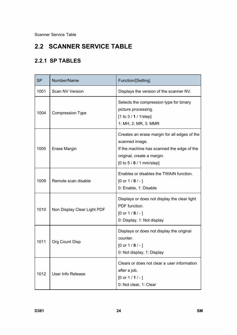
8/15/2019 Ricoh MP 4000 SM D009_D011_D012_D013 SERVICE MANUAL .pdf
http://slidepdf.com/reader/full/ricoh-mp-4000-sm-d009d011d012d013-service-manual-pdf 1128/1162
Scanner Service Table
D381 24 SM
2.2 SCANNER SERVICE TABLE
2.2.1 SP TABLES
SP Number/Name Function/[Setting]
1001 Scan NV Version Displays the version of the scanner NV.
1004 Compression Type
Selects the compression type for binary
picture processing.
[1 to 3 / 1 / 1/step]1: MH, 2: MR, 3: MMR
1005 Erase Margin
Creates an erase margin for all edges of the
scanned image.
If the machine has scanned the edge of the
original, create a margin.
[0 to 5 / 0 / 1 mm/step]
1009 Remote scan disable
Enables or disables the TWAIN function.
[0 or 1 / 0 / - ]
0: Enable, 1: Disable
1010 Non Display Clear Light PDF
Displays or does not display the clear light
PDF function.
[0 or 1 / 0 / - ]
0: Display, 1: Not display
1011 Org Count Disp
Displays or does not display the original
counter.
[0 or 1 / 0 / - ]
0: Not display, 1: Display
1012 User Info Release
Clears or does not clear a user information
after a job.
[0 or 1 / 1 / - ]
0: Not clear, 1: Clear

8/15/2019 Ricoh MP 4000 SM D009_D011_D012_D013 SERVICE MANUAL .pdf
http://slidepdf.com/reader/full/ricoh-mp-4000-sm-d009d011d012d013-service-manual-pdf 1129/1162
Scanner Service Table
SM 25 D381
P r i n
t e r /
S c a n n e r
O p
t i o n
D 3 8 1
SP Number/Name Function/[Setting]
Compression level (grayscale)
2021 These SP codes set the compression ratio for the grayscale processing mode
that can be selected with the notch settings on the operation panel.
Range: 5 (lowest ratio) 95 (highest ratio)
1 Comp 1: 5 - 95 [5 to 95 / 20 / 1 /step]
2 Comp 2: 5 - 95 [5 to 95 / 40 / 1 /step]
3 Comp 3: 5 - 95 [5 to 95 / 65 / 1 /step]
4 Comp 4: 5 - 95 [5 to 95 / 80 / 1 /step]
5 Comp 5: 5 - 95 [5 to 95 / 95 / 1 /step]
[Compression ratio of ClearLight PDF]
2024*Selects the compression ratio for clearlight PDF for the two settings that can be
selected at the operation panel.
1 Compression Ratio (Normal image) [5 to 95 / 25 / 1 /step ]
2 Compression Ratio (High comp image) [5 to 95 / 20 / 1 /step ]
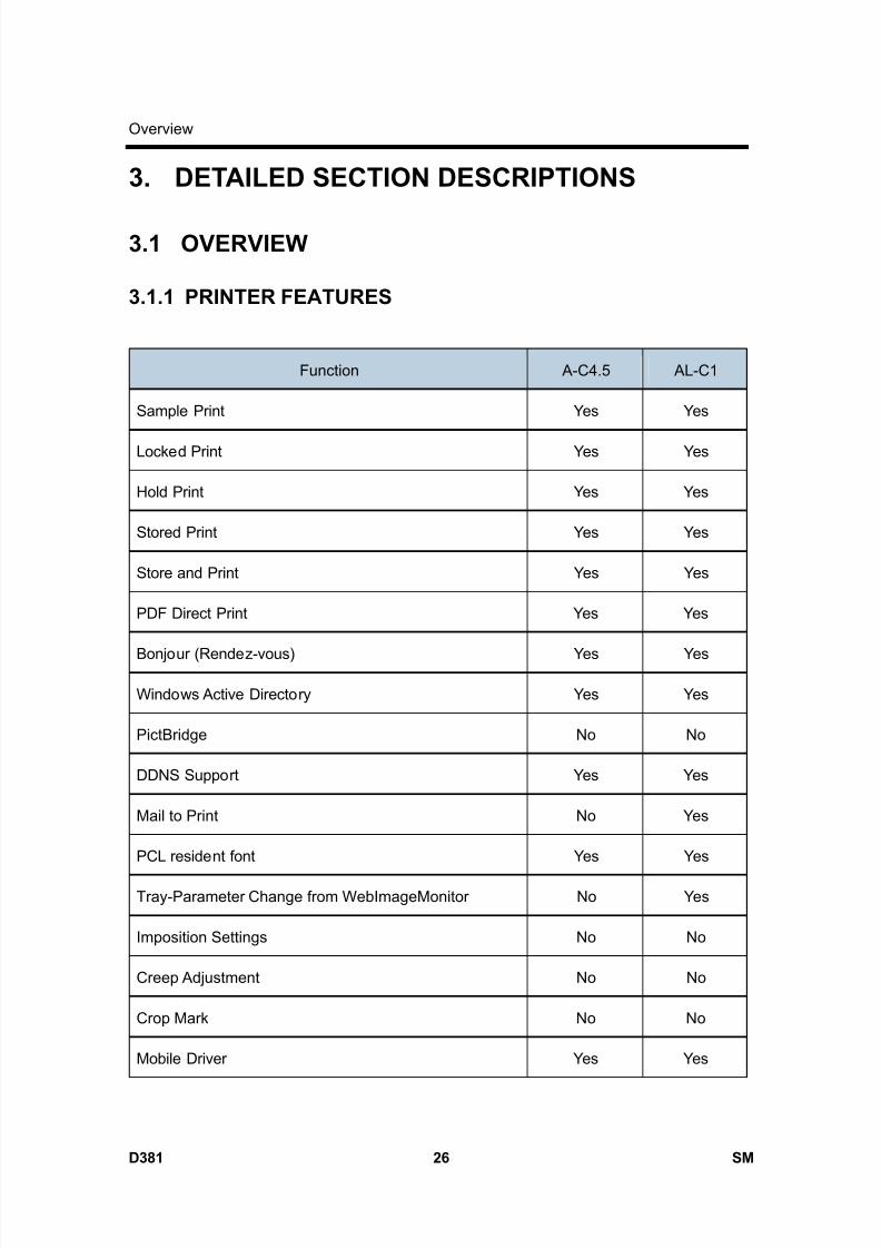
8/15/2019 Ricoh MP 4000 SM D009_D011_D012_D013 SERVICE MANUAL .pdf
http://slidepdf.com/reader/full/ricoh-mp-4000-sm-d009d011d012d013-service-manual-pdf 1130/1162
Overview
D381 26 SM
3. DETAILED SECTION DESCRIPTIONS
3.1 OVERVIEW
3.1.1 PRINTER FEATURES
Function A-C4.5 AL-C1
Sample Print Yes Yes
Locked Print Yes Yes
Hold Print Yes Yes
Stored Print Yes Yes
Store and Print Yes Yes
PDF Direct Print Yes Yes
Bonjour (Rendez-vous) Yes Yes
Windows Active Directory Yes Yes
PictBridge No No
DDNS Support Yes Yes
Mail to Print No Yes
PCL resident font Yes Yes
Tray-Parameter Change from WebImageMonitor No Yes
Imposition Settings No No
Creep Adjustment No No
Crop Mark No No
Mobile Driver Yes Yes

8/15/2019 Ricoh MP 4000 SM D009_D011_D012_D013 SERVICE MANUAL .pdf
http://slidepdf.com/reader/full/ricoh-mp-4000-sm-d009d011d012d013-service-manual-pdf 1131/1162
Overview
SM 27 D381
P r i n
t e r /
S c a n n e r
O p
t i o n
D 3 8 1
Function A-C4.5 AL-C1
Widows Vista Yes Yes
Wireless LAN interface option Yes Yes
IPv6 Yes Yes
Black Over Print - -
CLP Simulation - -
3.1.2 SCANNER FEATURES
Function A-C4.5 AL-C1
Scan to E-mail Yes Yes
E-mail message attached Yes Yes
Subject attached Yes Yes
SMTP Auth Yes Yes
POP before SMTP Yes Yes
Scan to SMB Yes Yes
Scan to FTP Yes Yes
Scan to URL Yes Yes
Scan to NCP Yes Yes
Scanned file naming Yes Yes
Reference # Setting Yes Yes
Scan file type selection Yes Yes
Single TIFF Yes Yes
Single JPEG (Gray Scale) Yes Yes
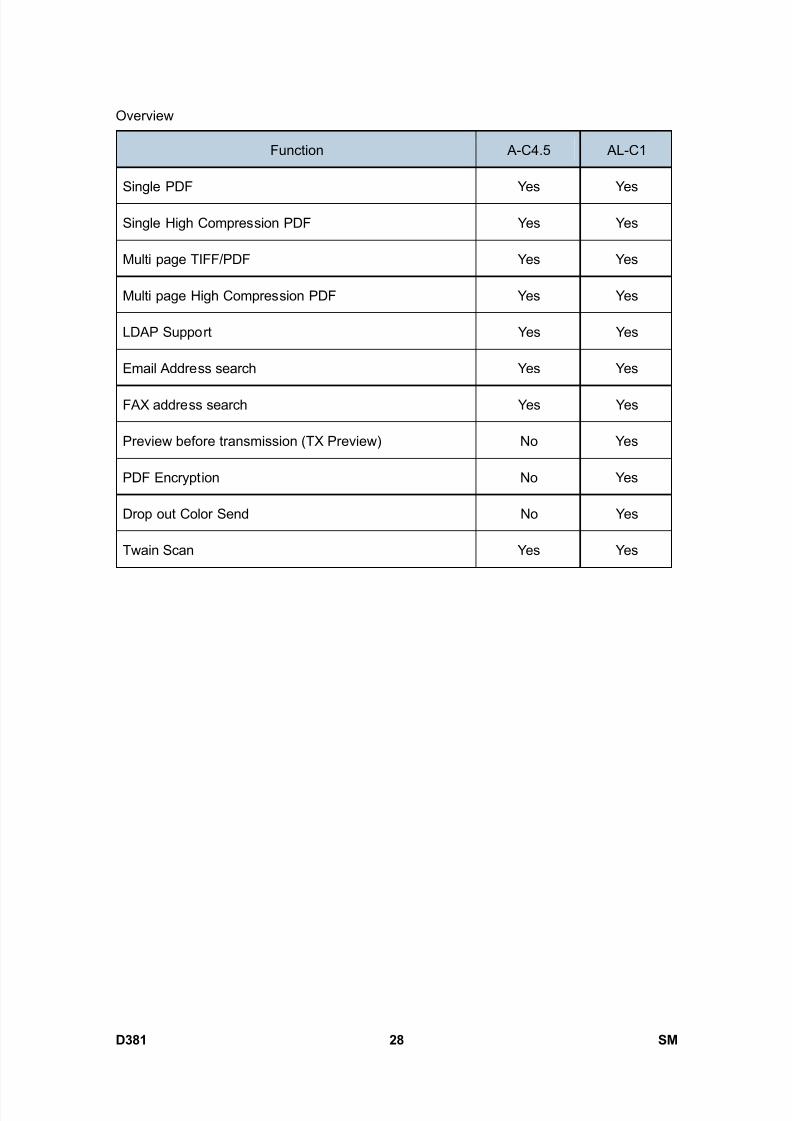
8/15/2019 Ricoh MP 4000 SM D009_D011_D012_D013 SERVICE MANUAL .pdf
http://slidepdf.com/reader/full/ricoh-mp-4000-sm-d009d011d012d013-service-manual-pdf 1132/1162
Overview
D381 28 SM
Function A-C4.5 AL-C1
Single PDF Yes Yes
Single High Compression PDF Yes Yes
Multi page TIFF/PDF Yes Yes
Multi page High Compression PDF Yes Yes
LDAP Support Yes Yes
Email Address search Yes Yes
FAX address search Yes Yes
Preview before transmission (TX Preview) No Yes
PDF Encryption No Yes
Drop out Color Send No Yes
Twain Scan Yes Yes

8/15/2019 Ricoh MP 4000 SM D009_D011_D012_D013 SERVICE MANUAL .pdf
http://slidepdf.com/reader/full/ricoh-mp-4000-sm-d009d011d012d013-service-manual-pdf 1133/1162
Printer Controller Specifications
SM 29 D381
P r i n
t e r /
S c a n n e r
O p
t i o n
D 3 8 1
4. SPECIFICATIONS
4.1 PRINTER CONTROLLER SPECIFICATIONS
4.1.1 PRINTER CONTROLLER
Printing Speed:D009/D012: Maximum 40 ppm (A4/LT LEF)
D011/D013: Maximum 50 ppm (A4/LT LEF)
Printer Languages:PCLXL/PCL5ePostScript 3 (Option)
RPCS (Refined Printing Command Stream - an original Ricoh PDL)
RPCS 200/600 dpi
PS3 300/600 dpi
PCL5e 300/600 dpi
Resolution (Driver):
PCLXL 300/600 dpi
PCL TrueType: 10, Intellifont: 35, International: 13Resident Fonts:
PS3 Option fonts PS3
Std.
Ethernet;
(RJ-45 network port: 10Base-T/100Base-TX),
USB 2.0Connectivity
Option IEEE802.11a/g, g (Wireless LAN), Bluetooth, IEEE1284(Centronics Parallel), Gigabit Ethernet
Network Protocols TCP/IP, IPX/SPX, AppleTalk (Auto Switching)
RAM:
Maximum
MS model: 512 MB (Resident 256 MB + Additional 256 MB)
CS model: 768 MB (Resident 512 MB + Additional 256 MB)
Note: Additional 256 MB is required for all printer/scanner unit and
printer units.

8/15/2019 Ricoh MP 4000 SM D009_D011_D012_D013 SERVICE MANUAL .pdf
http://slidepdf.com/reader/full/ricoh-mp-4000-sm-d009d011d012d013-service-manual-pdf 1134/1162
Printer Controller Specifications
D381 30 SM
4.1.2 USB SPECIFICATIONS
USB connectivity is built into the controller.
Interface USB 2.0
480 Mbps (high speed), 12 Mbps (full speed),
1.5 Mbps (low speed)Data rates
High speed mode is only supported by USB 2.0.
4.1.3 IEEE 802.11A/G, G
Radiofrequency Band
802.11a: 5 GHz
802.11b: 2.4 GHz
802.11g: 2.4 GHz
Data Transfer Speed
802.11a: 54 Mbps
802.11b: 11 Mbps
802.11g: 54 Mbps
Security StandardsIEEE 802.11 WEP
WPA/ WPA2 (IEEE 802.11i) Enterprise Mode
4.1.4 BLUETOOTH SPECIFICATIONS
Transmission Specifications Based on Bluetooth V1.1
Data Transfer Speed 1 Mbps
ProfileHard Copy Cable Replacement Profile (HCRP),
Serial Port Profile (SPP), BIP
Distance Between Devices10 m (The maximum distance when using outdoors,
otherwise depends on the office environment.)
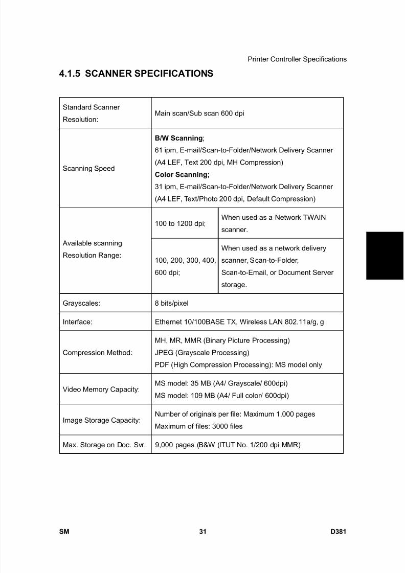
8/15/2019 Ricoh MP 4000 SM D009_D011_D012_D013 SERVICE MANUAL .pdf
http://slidepdf.com/reader/full/ricoh-mp-4000-sm-d009d011d012d013-service-manual-pdf 1135/1162
Printer Controller Specifications
SM 31 D381
P r i n
t e r /
S c a n n e r
O p
t i o n
D 3 8 1
4.1.5 SCANNER SPECIFICATIONS
Standard Scanner
Resolution:Main scan/Sub scan 600 dpi
Scanning Speed
B/W Scanning ;
61 ipm, E-mail/Scan-to-Folder/Network Delivery Scanner
(A4 LEF, Text 200 dpi, MH Compression)
Color Scanning;
31 ipm, E-mail/Scan-to-Folder/Network Delivery Scanner
(A4 LEF, Text/Photo 200 dpi, Default Compression)
100 to 1200 dpi;When used as a Network TWAIN
scanner.
Available scanning
Resolution Range:100, 200, 300, 400,
600 dpi;
When used as a network delivery
scanner, Scan-to-Folder,
Scan-to-Email, or Document Server
storage.
Grayscales: 8 bits/pixel
Interface: Ethernet 10/100BASE TX, Wireless LAN 802.11a/g, g
Compression Method:
MH, MR, MMR (Binary Picture Processing)
JPEG (Grayscale Processing)
PDF (High Compression Processing): MS model only
Video Memory Capacity:MS model: 35 MB (A4/ Grayscale/ 600dpi)
MS model: 109 MB (A4/ Full color/ 600dpi)
Image Storage Capacity:Number of originals per file: Maximum 1,000 pages
Maximum of files: 3000 files
Max. Storage on Doc. Svr. 9,000 pages (B&W (ITUT No. 1/200 dpi MMR)

8/15/2019 Ricoh MP 4000 SM D009_D011_D012_D013 SERVICE MANUAL .pdf
http://slidepdf.com/reader/full/ricoh-mp-4000-sm-d009d011d012d013-service-manual-pdf 1136/1162
Software Accessories
D381 32 SM
4.2 SOFTWARE ACCESSORIES
4.2.1 PRINTER
The printer drivers and utility software are provided on one CD-ROM. An auto-run installer
allows you to select which components to install.
4.2.2 PRINTER DRIVERS
Printer
Language
Windows
95/98/Me
Windows
NT4.0
Windows 2000, XP,
Server 2003/Vista
MacOS8.6 to 9.x,
MacOSX10.1 or
later
PCL 6 Yes Yes Yes No
PCL 5e Yes Yes Yes No
PS3 Yes Yes Yes Yes
RPCS Yes Yes Yes No
The printer drivers for Windows NT 4.0 are only for the Intel x86 platform. There is
no Windows NT 4.0 printer driver for the PowerPC, Alpha, or MIPS platforms.
The PS3 drivers are all genuine AdobePS drivers, except for Windows
2000/XP/Server 2003/Vista, which uses Microsoft PS. A PPD file for each
operating system is provided with the driver.
4.2.3 UTILITY SOFTWARE
Software Description
Agfa Monotype Font Manager 2000 (Win
95/98/Me, NT4, 2000)
A font management utility with screen fonts
for the printer.
Smart Device Monitor for Admin (Win
95/98/Me, NT4, 2000/XP/Server 2003/
Vista)
A printer management utility for network
administrators. NIB setup utilities are also
available.
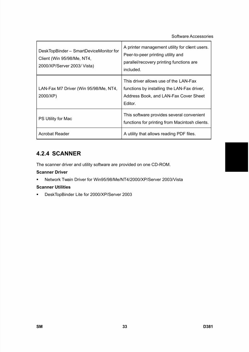
8/15/2019 Ricoh MP 4000 SM D009_D011_D012_D013 SERVICE MANUAL .pdf
http://slidepdf.com/reader/full/ricoh-mp-4000-sm-d009d011d012d013-service-manual-pdf 1137/1162
Software Accessories
SM 33 D381
P r i n
t e r /
S c a n n e r
O p
t i o n
D 3 8 1
DeskTopBinder – SmartDeviceMonitor for
Client (Win 95/98/Me, NT4,
2000/XP/Server 2003/ Vista)
A printer management utility for client users.
Peer-to-peer printing utility and
parallel/recovery printing functions areincluded.
LAN-Fax M7 Driver (Win 95/98/Me, NT4,
2000/XP)
This driver allows use of the LAN-Fax
functions by installing the LAN-Fax driver,
Address Book, and LAN-Fax Cover Sheet
Editor.
PS Utility for MacThis software provides several convenient
functions for printing from Macintosh clients.
Acrobat Reader A utility that allows reading PDF files.
4.2.4 SCANNER
The scanner driver and utility software are provided on one CD-ROM.
Scanner Driver
Network Twain Driver for Win95/98/Me/NT4/2000/XP/Server 2003/Vista
Scanner Utilities
DeskTopBinder Lite for 2000/XP/Server 2003

8/15/2019 Ricoh MP 4000 SM D009_D011_D012_D013 SERVICE MANUAL .pdf
http://slidepdf.com/reader/full/ricoh-mp-4000-sm-d009d011d012d013-service-manual-pdf 1138/1162

8/15/2019 Ricoh MP 4000 SM D009_D011_D012_D013 SERVICE MANUAL .pdf
http://slidepdf.com/reader/full/ricoh-mp-4000-sm-d009d011d012d013-service-manual-pdf 1139/1162
BRIDGE UNIT BU3030D386

8/15/2019 Ricoh MP 4000 SM D009_D011_D012_D013 SERVICE MANUAL .pdf
http://slidepdf.com/reader/full/ricoh-mp-4000-sm-d009d011d012d013-service-manual-pdf 1140/1162
8/15/2019 Ricoh MP 4000 SM D009_D011_D012_D013 SERVICE MANUAL .pdf
http://slidepdf.com/reader/full/ricoh-mp-4000-sm-d009d011d012d013-service-manual-pdf 1141/1162
SM i D386
BRIDGE UNIT BU3030 (D386)TABLE OF CONTENTS
1. REPLACEMENT AND ADJUSTMENT ............................................1
1.1 BRIDGE UNIT CONTROL BOARD............................................................... 1
1.2 BRIDGE UNIT DRIVE MOTOR..................................................................... 2
1.3 TRAY EXIT SENSOR ................................................................................... 3
1.4 RELAY SENSOR .......................................................................................... 4
2. DETAILS ..........................................................................................5 2.1 MECHANICAL COMPONENT LAYOUT ....................................................... 5
2.2 DRIVE LAYOUT............................................................................................ 6
2.3 ELECTRICAL COMPONENT LAYOUT ........................................................ 7
2.4 ELECTRICAL COMPONENT DESCRIPTION .............................................. 8
2.5 JUNCTION GATE MECHANISM .................................................................. 9

8/15/2019 Ricoh MP 4000 SM D009_D011_D012_D013 SERVICE MANUAL .pdf
http://slidepdf.com/reader/full/ricoh-mp-4000-sm-d009d011d012d013-service-manual-pdf 1142/1162
8/15/2019 Ricoh MP 4000 SM D009_D011_D012_D013 SERVICE MANUAL .pdf
http://slidepdf.com/reader/full/ricoh-mp-4000-sm-d009d011d012d013-service-manual-pdf 1143/1162
Read This First
Safety and Symbols
Replacement Procedure Safety
Turn off the main power switch and unplug the machine before beginning any of the
replacement procedures in this manual.
When taking apart the bridge unit, first take the unit out of the copier.
Symbols Used in this Manual
This manual uses the following symbols.
: See or Refer to
: Screws
: Connector
: Clip ring
: E-ring

8/15/2019 Ricoh MP 4000 SM D009_D011_D012_D013 SERVICE MANUAL .pdf
http://slidepdf.com/reader/full/ricoh-mp-4000-sm-d009d011d012d013-service-manual-pdf 1144/1162

8/15/2019 Ricoh MP 4000 SM D009_D011_D012_D013 SERVICE MANUAL .pdf
http://slidepdf.com/reader/full/ricoh-mp-4000-sm-d009d011d012d013-service-manual-pdf 1145/1162
Bridge Unit Control Board
SM 1 D386
B r i d g e
U n
i t
B U 3 0 3 0
D 3 8 6
1. REPLACEMENT AND ADJUSTMENT
1.1 BRIDGE UNIT CONTROL BOARD
1. Bridge unit ( "Installation Procedure" in the base copier manual)
2. Rear cover [A] ( x 2)
3. Bridge unit control board [B] ( x 3, x 4)
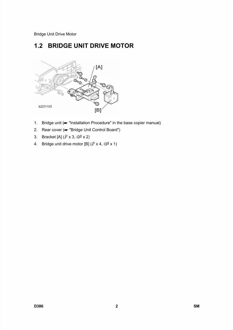
8/15/2019 Ricoh MP 4000 SM D009_D011_D012_D013 SERVICE MANUAL .pdf
http://slidepdf.com/reader/full/ricoh-mp-4000-sm-d009d011d012d013-service-manual-pdf 1146/1162
Bridge Unit Drive Motor
D386 2 SM
1.2 BRIDGE UNIT DRIVE MOTOR
1. Bridge unit ( "Installation Procedure" in the base copier manual)
2. Rear cover ( "Bridge Unit Control Board")
3. Bracket [A] ( x 3, x 2)
4. Bridge unit drive motor [B] ( x 4, x 1)
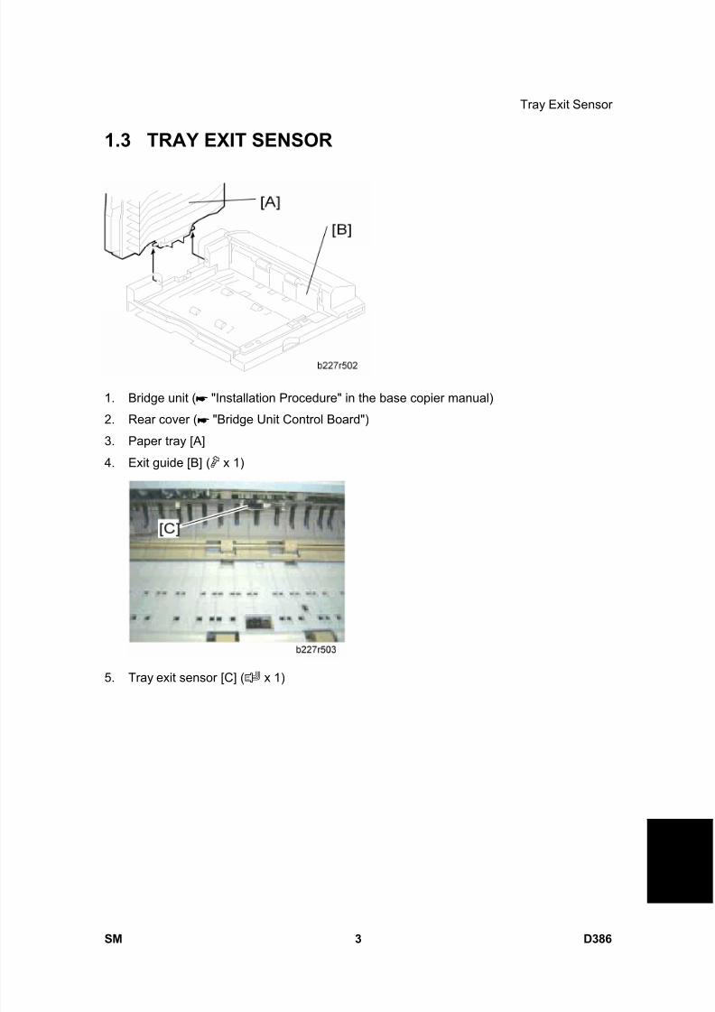
8/15/2019 Ricoh MP 4000 SM D009_D011_D012_D013 SERVICE MANUAL .pdf
http://slidepdf.com/reader/full/ricoh-mp-4000-sm-d009d011d012d013-service-manual-pdf 1147/1162
Tray Exit Sensor
SM 3 D386
B r i d g e
U n
i t
B U 3 0 3 0
D 3 8 6
1.3 TRAY EXIT SENSOR
1. Bridge unit ( "Installation Procedure" in the base copier manual)
2. Rear cover ( "Bridge Unit Control Board")
3. Paper tray [A]
4. Exit guide [B] ( x 1)
5. Tray exit sensor [C] ( x 1)
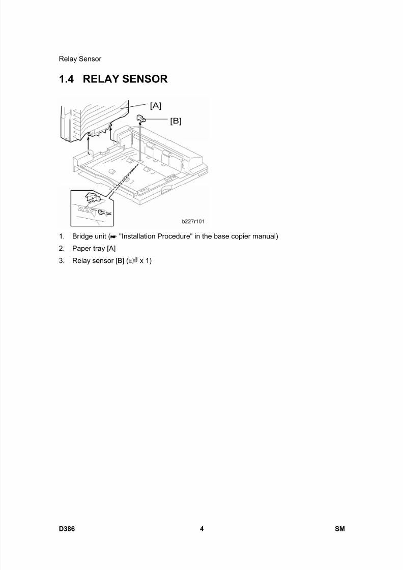
8/15/2019 Ricoh MP 4000 SM D009_D011_D012_D013 SERVICE MANUAL .pdf
http://slidepdf.com/reader/full/ricoh-mp-4000-sm-d009d011d012d013-service-manual-pdf 1148/1162
Relay Sensor
D386 4 SM
1.4 RELAY SENSOR
1. Bridge unit ( "Installation Procedure" in the base copier manual)
2. Paper tray [A]
3. Relay sensor [B] ( x 1)
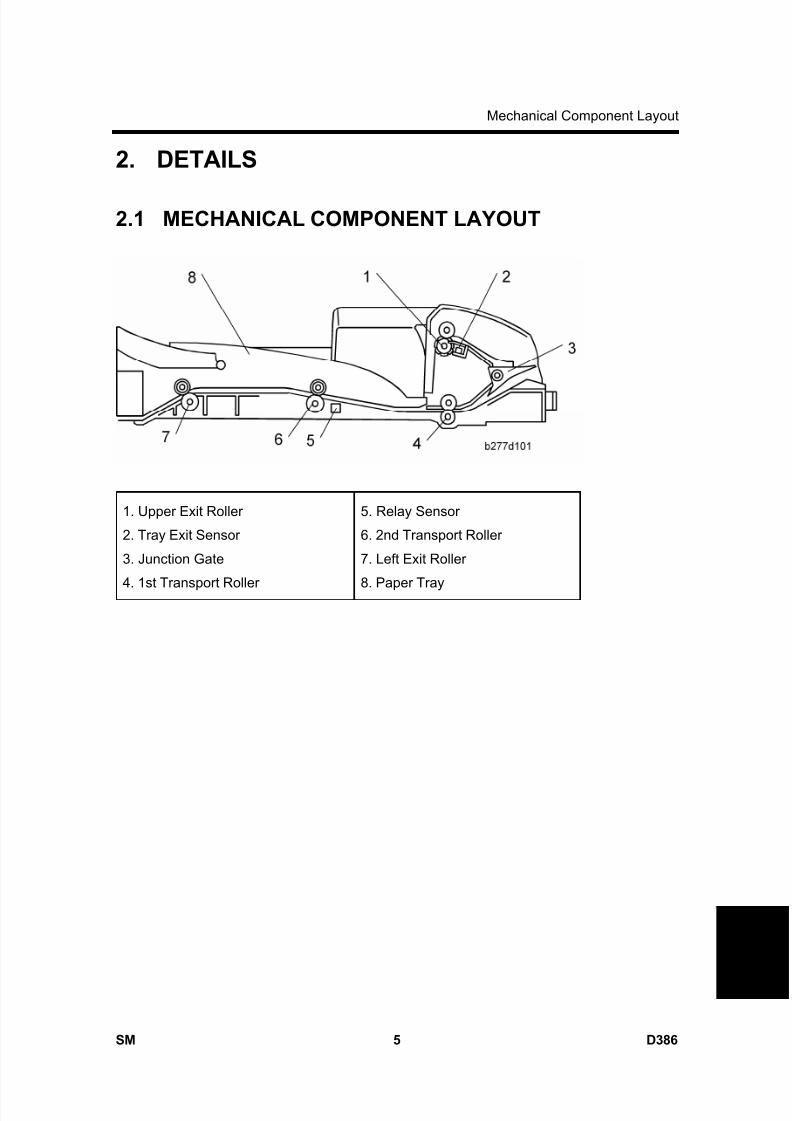
8/15/2019 Ricoh MP 4000 SM D009_D011_D012_D013 SERVICE MANUAL .pdf
http://slidepdf.com/reader/full/ricoh-mp-4000-sm-d009d011d012d013-service-manual-pdf 1149/1162
Mechanical Component Layout
SM 5 D386
B r i d g e
U n
i t
B U 3 0 3 0
D 3 8 6
2. DETAILS
2.1 MECHANICAL COMPONENT LAYOUT
1. Upper Exit Roller
2. Tray Exit Sensor
3. Junction Gate
4. 1st Transport Roller
5. Relay Sensor
6. 2nd Transport Roller
7. Left Exit Roller
8. Paper Tray
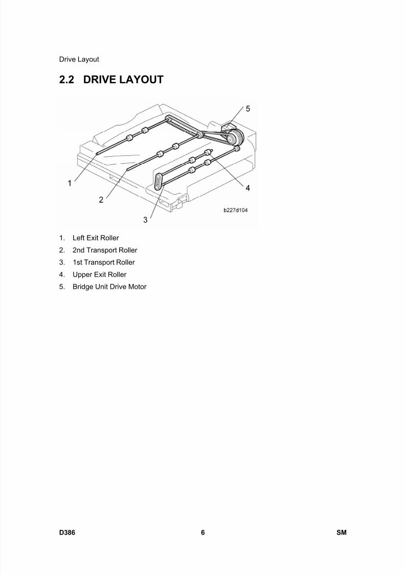
8/15/2019 Ricoh MP 4000 SM D009_D011_D012_D013 SERVICE MANUAL .pdf
http://slidepdf.com/reader/full/ricoh-mp-4000-sm-d009d011d012d013-service-manual-pdf 1150/1162
Drive Layout
D386 6 SM
2.2 DRIVE LAYOUT
1. Left Exit Roller
2. 2nd Transport Roller
3. 1st Transport Roller
4. Upper Exit Roller
5. Bridge Unit Drive Motor
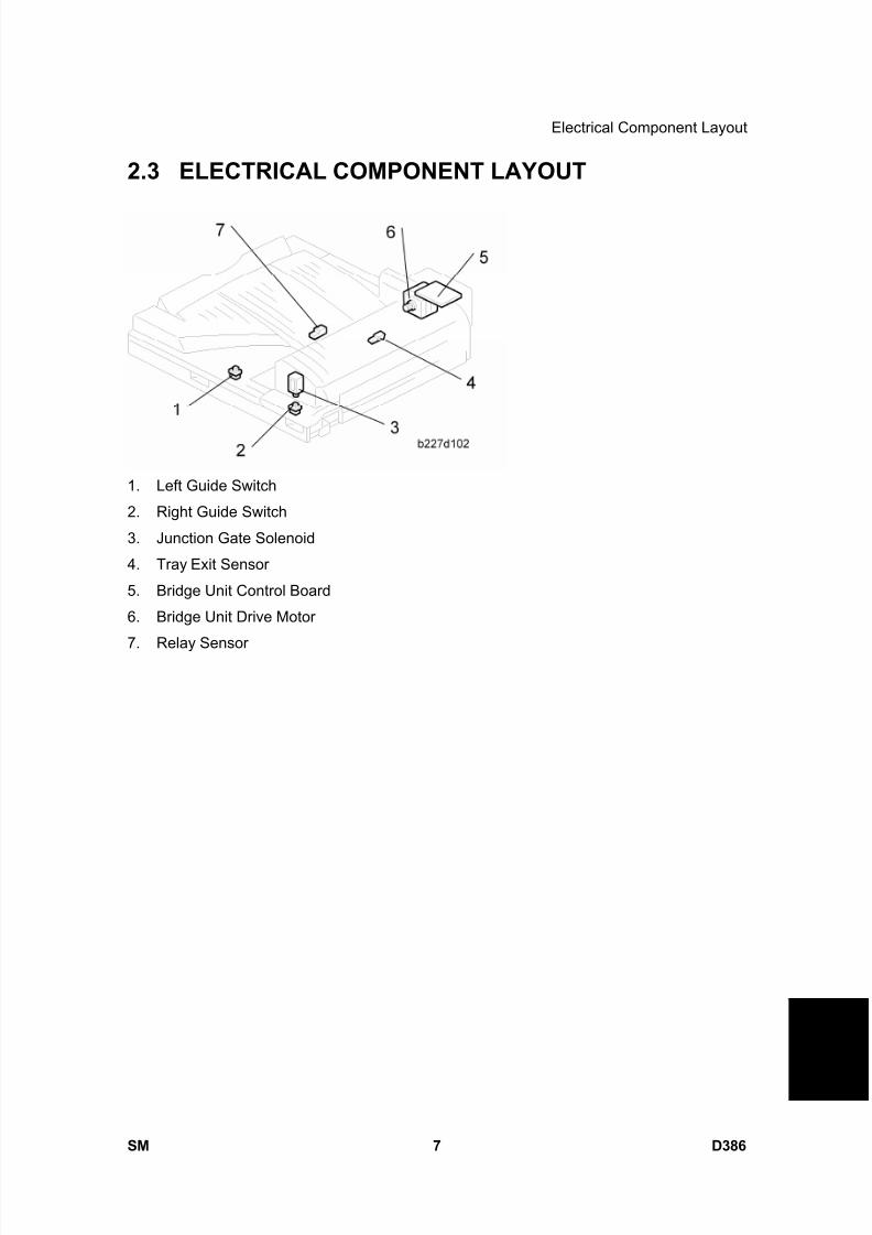
8/15/2019 Ricoh MP 4000 SM D009_D011_D012_D013 SERVICE MANUAL .pdf
http://slidepdf.com/reader/full/ricoh-mp-4000-sm-d009d011d012d013-service-manual-pdf 1151/1162
Electrical Component Layout
SM 7 D386
B r i d g e
U n
i t
B U 3 0 3 0
D 3 8 6
2.3 ELECTRICAL COMPONENT LAYOUT
1. Left Guide Switch
2. Right Guide Switch
3. Junction Gate Solenoid
4. Tray Exit Sensor
5. Bridge Unit Control Board
6. Bridge Unit Drive Motor
7. Relay Sensor
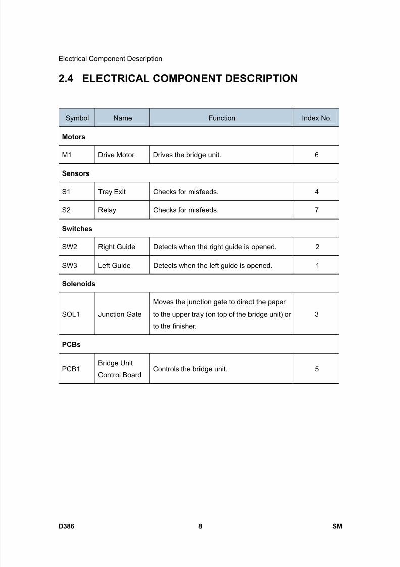
8/15/2019 Ricoh MP 4000 SM D009_D011_D012_D013 SERVICE MANUAL .pdf
http://slidepdf.com/reader/full/ricoh-mp-4000-sm-d009d011d012d013-service-manual-pdf 1152/1162
Electrical Component Description
D386 8 SM
2.4 ELECTRICAL COMPONENT DESCRIPTION
Symbol Name Function Index No.
Motors
M1 Drive Motor Drives the bridge unit. 6
Sensors
S1 Tray Exit Checks for misfeeds. 4
S2 Relay Checks for misfeeds. 7
Switches
SW2 Right Guide Detects when the right guide is opened. 2
SW3 Left Guide Detects when the left guide is opened. 1
Solenoids
SOL1 Junction Gate
Moves the junction gate to direct the paper
to the upper tray (on top of the bridge unit) or
to the finisher.
3
PCBs
PCB1Bridge Unit
Control BoardControls the bridge unit. 5

8/15/2019 Ricoh MP 4000 SM D009_D011_D012_D013 SERVICE MANUAL .pdf
http://slidepdf.com/reader/full/ricoh-mp-4000-sm-d009d011d012d013-service-manual-pdf 1153/1162
Junction Gate Mechanism
SM 9 D386
B r i d g e
U n
i t
B U 3 0 3 0
D 3 8 6
2.5 JUNCTION GATE MECHANISM
The junction gate [A] directs any paper reaching the bridge unit to either the upper tray (on
top of the bridge unit) or to the finisher, depending on which has been selected.
If the junction gate solenoid has been activated, the junction gate [A] points downward and
directs the paper to the upper tray [B] (dotted line path in illustration). When the solenoid is
off, the junction gate points upward and the paper is fed out to the finisher [C] by the
transport and left exit rollers (solid line).

8/15/2019 Ricoh MP 4000 SM D009_D011_D012_D013 SERVICE MANUAL .pdf
http://slidepdf.com/reader/full/ricoh-mp-4000-sm-d009d011d012d013-service-manual-pdf 1154/1162

8/15/2019 Ricoh MP 4000 SM D009_D011_D012_D013 SERVICE MANUAL .pdf
http://slidepdf.com/reader/full/ricoh-mp-4000-sm-d009d011d012d013-service-manual-pdf 1155/1162

8/15/2019 Ricoh MP 4000 SM D009_D011_D012_D013 SERVICE MANUAL .pdf
http://slidepdf.com/reader/full/ricoh-mp-4000-sm-d009d011d012d013-service-manual-pdf 1156/1162

8/15/2019 Ricoh MP 4000 SM D009_D011_D012_D013 SERVICE MANUAL .pdf
http://slidepdf.com/reader/full/ricoh-mp-4000-sm-d009d011d012d013-service-manual-pdf 1157/1162
SM i D389
1 BIN TRAY BN3040 (D389)TABLE OF CONTENTS
1. REPLACEMENT AND ADJUSTMENT ............................................1
1.1 ELECTRICAL COMPONENTS ..................................................................... 1
1.1.1 PAPER SENSOR................................................................................. 1
1.1.2 1-BIN CONTROL BOARD.................................................................... 2
2. DETAILS ..........................................................................................3
2.1 COMPONENT LAYOUT ............................................................................... 3 2.1.1 MECHANICAL COMPONENT LAYOUT.............................................. 3
2.1.2 ELECTRICAL COMPONENT LAYOUT ............................................... 3
2.1.3 ELECTRICAL COMPONENT DESCRIPTIONS................................... 4
2.2 BASIC OPERATION ..................................................................................... 5

8/15/2019 Ricoh MP 4000 SM D009_D011_D012_D013 SERVICE MANUAL .pdf
http://slidepdf.com/reader/full/ricoh-mp-4000-sm-d009d011d012d013-service-manual-pdf 1158/1162

8/15/2019 Ricoh MP 4000 SM D009_D011_D012_D013 SERVICE MANUAL .pdf
http://slidepdf.com/reader/full/ricoh-mp-4000-sm-d009d011d012d013-service-manual-pdf 1159/1162
Read This First
Safety and Symbols
Replacement Procedure Safety
Turn off the main power switch and unplug the machine before beginning any of
the replacement procedures in this manual.
Symbols Used in this ManualThis manual uses the following symbols.
: See or Refer to
: Screws
: Connector
: Clip ring
: E-ring

8/15/2019 Ricoh MP 4000 SM D009_D011_D012_D013 SERVICE MANUAL .pdf
http://slidepdf.com/reader/full/ricoh-mp-4000-sm-d009d011d012d013-service-manual-pdf 1160/1162
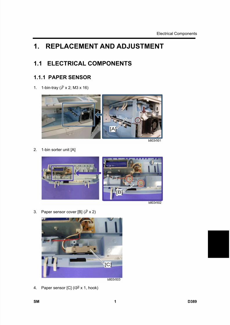
8/15/2019 Ricoh MP 4000 SM D009_D011_D012_D013 SERVICE MANUAL .pdf
http://slidepdf.com/reader/full/ricoh-mp-4000-sm-d009d011d012d013-service-manual-pdf 1161/1162
Electrical Components
SM 1 D389
1 B i n T r a y
B N 3 0 4 0
D 3 8 9
1. REPLACEMENT AND ADJUSTMENT
1.1 ELECTRICAL COMPONENTS
1.1.1 PAPER SENSOR
1. 1-bin-tray ( x 2; M3 x 16)
2. 1-bin sorter unit [A]
3. Paper sensor cover [B] ( x 2)
4. Paper sensor [C] ( x 1, hook)
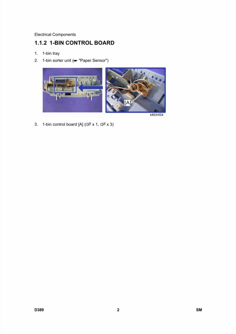
8/15/2019 Ricoh MP 4000 SM D009_D011_D012_D013 SERVICE MANUAL .pdf
http://slidepdf.com/reader/full/ricoh-mp-4000-sm-d009d011d012d013-service-manual-pdf 1162/1162
Electrical Components
1.1.2 1-BIN CONTROL BOARD
1. 1-bin tray
2. 1-bin sorter unit ( "Paper Sensor")
3. 1-bin control board [A] ( x 1, x 3)