ricketts book
TRANSCRIPT

ACKNOWLEDGEMENT
Words cannot fathom the depth of gratitude that my heart is filled
with to be associated with this prestigious institution.
“A teacher affects eternity; his influence never stops’’. Had it not been
pain taking attention to details, vigilance, guidance and constant support of
my Guide Dr N. G. Toshniwal, M.D.S. Prof and Head of the Dept. of
Orthodontics & Dentofacial Orthopaedics, Rural Dental College, Loni, my
thesis would not have seen today’s glory.
I am deeply indebted to him for his encouragement and support that
showed me the path towards perfection.
I would like to express my deep gratitude to Dr. Abhijit Misal, M.D.S.
(Orthodontics), Professor, Dept of Orthodontics, for his constant guidance
and invaluable suggestions in making of this thesis
I am also thankful to Dr. Gajanan Shanbhag (M.D.S), and Dr. Abhay
Chaudhari (M.D.S), and Dr. Shubhangi Amit (M.D.S), Lecturers, Dept. of
Orthodontics for their constant support, encouragement given to me.
I express my thanks to Dr. J. J. Doshi, Principal, Rural Dental
College, Loni, for permitting me to carry out this work in the institution.
I express my thanks to Dr. Raju Anarthe, Dr Daimi Lecturers Dept of
Orthodontics for their valuable support.
I am also grateful to Mr Tony Zakhem (Rocky Mountain Orthodontics
Denmark) without whom it would not have been possible for me to give this
treatise the shape it has today.

I am wholeheartedly thankful to my loving husband Dr. Vyankatesh
Pharande, for his unfailing support, encouragement and inspiration. I am
also grateful to Dr. Mr.Sanjay Anarse and Mrs. Yogita Anarse for giving me
a homely environment during my stay in Loni and supporting me morally.
I am also thankful to my parents who supported me in this venture
morally, physically, financially and always showered their blessings without
which I could not have dreamt of completing this project.
Lastly and above all, like my own life, the genesis if this manuscript
has been possible only because of the blessings and inspirations of my
family, my friends and my collages.
“This impossible task is made possible by God, ‘a great power of faith’ who showered his all blessings throughout my carrier and academic life.”
Shilpa…

INDEX Sr. No. Topic Page No.
1. Introduction 1
2. Memorium 3
3. Accomplishment of Dr. Ricketts 5
1950 – 1970
4. Variation of TMJ by cephalometric laminography 7
5. Inter dependence of nasal & oral capsule 26
6. Esthetics, Environment & law of lip relation 56
1970 – 1980
7. Arcial growth of mandible 65
8. Growth prediction 81
9. Four-step method to distinguish Orthodontic changes from
natural growth 97
10. Computerized Cephalometrics 109
11. Perspectives in clinical application of Cephalometrics 121
12. Bioprogressive Therapy 145
13. Utility Arch 189
14. Quad Helix Appliance 203
15. Dr. Ricketts on early treatment 209
16. Headgear 216
17. Management Umbrella & VTO 226
18. Ricketts Cephalometric Analysis 233
1980 – 1990
19. The Golden divider 242
20. Biologic Significant of Divine Proportion and Fibonacci
series and Golden divider 248
21. Radiographic evaluation of transverse discrepancies 265

1990 – 2003
22. Truth in Orthodontic Beliefs 268
23. Bioprogressive concept by Dr. Ricketts (JIOS) 281
24. Annexure I – Awards received by Dr. Ricketts 284
25. Annexure II – Honours received by Dr. Ricketts 285
26. Annexure III – Lectures, Course conducted by Dr. Ricketts 287
27. Bibliography 288
Introduction
INTRODUCTION
Blessed are those who bring a wonderful smile, for they shall be
called orthodontist. To perceive an attractive smile is no longer a luxury but
rather a necessity in lifestyle and the changing orthodontic scenario says it
all.
With the advent of 21st century, more and more people are becoming
aware and conscious of their never so perfect face. Orthodontia is that
branch which is concerned with facial perfection.
The term ‘Orthodontia’ was apparently used first by French man ‘Le
Foulon’ in 1839. Many golden hands contributed in building the field of
orthodontics, those are Dr Edward H Angle, Dr Calvin Case, Dr Martin
Dewey, Dr Tweed, Dr Andrew, and Dr Begg and so on.
In this Galaxy of names, the name of Dr. R. M. Ricketts makes a
special place for its contribution in the field of orthodontia.
He had started his contributions to the orthodontic specialty since
1950 when his attention was drawn to the clinical application of
cephalometrics. During the 1950’s Broadbent and Brodie advocated the use
of Cephalometrics for longitudinal studies rather than clinical diagnosis but
Ricketts was not satisfied with this. On going to California in the early
1950’s Ricketts was challenged by his colleagues for a direct answer to the
clinical application of Cephalometrics which can be obtained from dental
casts and oriented photographs. With the realization Ricketts then published
two papers in 1960 which gave information about the use of cephalometrics
in the clinical practice using records of 1000 cases treated by him and for the
1

Introduction
first time, he studied the possibility of growth forecasting. Then he was
engaged in a new series of computer investigations in orthodontics in 1965.
He was simultaneously involved with the evolution of new concept of
esthetics, the law of lip relations and the importance of chin point, B point
and lower incisors in planning orthodontic treatment and stability after
treatment. He introduced the new concept of occlusion, Fibonacci numbers
from Hindu-Arabic numerical system and has applied it to the knowledge of
growth biology and facial balance.
His contributions to Orthodontics are significant, and this is just an
attempt to enumerate his major contributions to the field of Orthodontics.
2

Memorium
MEMORIUM
Dr. Robert Murray Rickett’s (1920 – 2003)
Born in rural Indiana, Robert Murray Rickett’s rose to a world
renowed position as one of the world’s most prominent researchers,
educators, authors and lecturers on life sciences, surgery and orthodontics.
Ricketts wanted to become a dentist when he was a sophomore in
highschool, but at first lacked the confidence in himself to become a dentist.
As he was from a poor family, he did not receive the encouragement to seek
higher education. After a highschool education, for a year he worked as a
labour in steel mill and on an assembly line in a radio factory for a year, and
this job gave him a very great and strong motivation for higher education.
Ricketts completed his graduation course in dentistry in year1945
from University of Indiana. Then he became a Diplomate of the American
Board of Orthodontics. He taught at Loma Linda University, University of
Illinosis. UCLA, USC and dozens of University around the world. He was
the first to prescribe nutritional supplementations in the 1950s in his
orthodontic & orthopedic practice. Later, he developed a nutritional
community. This knowledge ultimately led him into the field of
microbiology and chemistry for environmental awareness and to the
development of Morganics.
Dr. Rocketts was a member of 17 professional societies and received
numerous international honors and awards.
When Dr. Ricketts passed away on June 17, 2003 we all lost a great
teacher, friend and an inspiration. He was with his children when he died
3

Memorium
and he was happy and active as he had always been. Dr. Ricketts had
significant abdominal pain and was diagnosed as ischemic bowel necrosis of
small intestine.
It was Dr. Ricketts request that his death should be celebrated by joy.
He expressed to family that he desired a black tie affair, with joyful times in
his honor.
Dr. Ricketts contributions to orthodontics are well known and have
impacted thousands of colleagues, students and patients around the world.
Ricketts Bioprogressive Philosophy and Diagnostic concepts has helped to
set the standards and the new goals of orthodontics treatment. Apart from
Orthdodontics Dr. Ricketts was also a role model for a happy, productive
and fulfilling life style
As a teacher, Dr. Ricketts emphasized experience, awarness and
discipline. He was quick to replace old knowledge with new, yet stood
strong on unchanging principles. He had made learning interesting and
inspiring, conveying knowledge with meeting and vitality. He believed that
the orthodontist of the future will be the one who gains perfection and
stability of results with the fewest appliances.
Dr. Ricketts significantly influenced many lives. He once said in a
lecture, “You wont forget me; I will live forever in your minds.” That he
will.
4


Accomplishments of Dr. Ricketts
ACCOMPLISHMENTS OF DR. RICKETTS
• Developed the first straight wire bracket 018 slot in 1970.
• Developed the first cephalometric analysis that allowed clinicians to
compare their patients with norms based on age, sex and race (Rickett’s
analysis)
• Developed the first cephalometric diagnostic system to project treatment
plus growth in treatment planning (VTO).
• Using growth studies of Bjork, Mass, Scott, Petrovic and others
developed a computer generated method for projecting growth to
maturity with mandibular archival growth method.
• Pioneered the use of composite tracings to better understand normal
growth patterns in various facial types.
• Developed computer driven cephalometric diagnosis.
• Developed 5 arch forms used to individualize treatment outcomes
(Pentamorphine arches).
• Developed “Root ratings” based upon the works of Miura and Lee to
quantify the forces necessary to move teeth in any plane of space.
• Challenged the profession to learn and understand anatomy growth and
development and their application in treatment decisions and mechanics.
• Emphasized the facial orthopedic potential and challenged our profession
to “treat faces not teeth”, promoted the use of cervical headgear only for
orthopedic correction.
• Developed with Ruel Bench and Carl Gugino new appliances systems
used by orthodontists world wide, including quad helix, utility arches,
sectionalization and orthopedic correction with cervical headgears.
5

Accomplishments of Dr. Ricketts
• Developed with Carl Gugino and Ruel Bench the Bioprogressive
Philosophy, a biological approach to diagnosis and treatment.
• Stimulated orthodontic thinking about the possibilities of treatment with
his publications of the “doctrine of limitations” in 1973.
• Recognized and used facial proportions to treat dental and skeletal
problems (the Devine Proportion).
6

Variations Of The Temporomandibular Joint As Revealed By Cephalometric Laminagraphy
VARIATIONS OF THE TEMPOROMANDIBULAR JOINT AS
REVEALED BY CEPHALOMETRIC LAMINAGRAPHY
Introduction
This study of Dr Ricketts is concerned with the dynamic aspects of the
human temporomandibular articulation and particularly with morphologic
and functional variations. Investigations in this field have been hampered by
the shortcomings of available research methods and only the recent advances
in the techniques of cephalometry and laminagraphy made this study
possible to Dr Ricketts.
The purpose of the study was threefold.
1) It was desired to test cephalometric laminagraphy as a method of
investigation.
2) Second, it was desired to study the range of normal variation in
morphology and function and to attempt to correlate certain functions
of the denture with the behavior of the temporomandibular joint.
3) Third, it was desired to investigate possible differences between
patients with Class II malocclusions and a control group of adequate
size.
Method Used In This Study By Dr Ricketts
The Head Holder and Its Application. Fig 1. — The head holder used
in the present study was designed:
1. To make true lateral exposures of either the right or the left
temporomandibular joint.
2. To make possible the taking of successive x-ray photographs
susceptible to accurate measurements so that quantitative as well as
7

Variations Of The Temporomandibular Joint As Revealed By Cephalometric Laminagraphy
qualitative data could be gathered.
3. To expose a field large enough to include joint, teeth, and certain
orienting planes of reference.
Because the laminagraph operates in a vertical position, the patient is
required to lie prone with the head turned to the side.
.
Fig. 1 Fig. 1. — Patient in head holding apparatus. Note ear posts and asselnblage supporting the nosepiece Also note incisal plaster core registering rest position which had previously been taken with patient seated upright.
Fig. 2
Fig. 2. — Frontal view of skull with stippled area showing the depth of cut and area projected on laminagraphic film. Note measurements of skull used in determining proper cut for individual patient.
8

Variations Of The Temporomandibular Joint As Revealed By Cephalometric Laminagraphy
The soft tissue was of almost the same thickness for the cranium as
for the lateral side of the condyles. It was further determined that the
condyles measured from 1.5 cm. to 2 cm. in width. An accepted distance of
1 cm. from the lateral side of the condyle was taken to bisect each condyle.
If the difference in the biparietal and the bicondylar width was 3 cm.
the distance for one side would be 1.5 cm. The added 1 cm. which was taken
to bisect the condyle thus gave a measurement of 2.5 cm. from the widest
part of the head to the center of the condyle. Since the holder platform was
approximately 1 cm. in thickness, the distance from the table top to the
center of the condyle would be 3.5 cm. (Fig. 2). As a rule, a cut at 3.5 cm.
proved adequate. However, when extremes in obesity or head form were
encountered, the cut was varied according to the measurements.
Interpretation and Tracing of Films.— In laminagraphy it must
constantly be borne in mind that all clearly visible structures lie in the same
plane and only such clearly defined structures should be traced. As per
Ricketts in the sagittal plane through the center of the condyle the entire
ramus including the coronoid process, the outer rim of the orbit, the
zygomatic ridge, the ear canal, glenoid fossa, petrotympanic fissure,
postglenoid process, articular eminence and mastoid air cells, and the
zygomaticofrontal suture provide excellent checks on the accuracy of
successive films and can be used as points for superpositioning. The
sectional plane runs slightly to the lateral of the buccal teeth, but these
structures are rendered with sufficient clarity to make them easily
discernible.
9

Variations Of The Temporomandibular Joint As Revealed By Cephalometric Laminagraphy
Points, Planes, and Angles Selected for Study. — All x-ray films
were traced on fine tracing paper (Traceofilm) and certain anatomical points
inscribed. In addition, certain lines and planes were constructed for the
purpose of making possible the analysis of movements and relationships.
Linear measurements with correctional scales as described by Adams (1940)
were made to the nearest 0.5 mm. Angular measurements were read to the
nearest 1.0° with a standard protractor.
Fig. 3 represents a basic tracing of structures and points. These were located
as follows:
Fig. 3
Fig. 3. — Tracing of laminagram showing points and planes of reference. P, porion; O, orbital, Z, zygomatic frontal suture; M, mastoid process; C, centrobuccal cusp of lower first molar; T, tip of lower canine; PO, Frankfort plane; HH', perpendicular through PO at height of eminence; CT, occlusal plane; RR', plane parallel to long axis of neck of condoyle.
Fig. 4 indicates how the details noted were employed in the first step
of the study, viz., the analysis of the closing movement of the mandible from
its resting position to full occlusion.
10

Variations Of The Temporomandibular Joint As Revealed By Cephalometric Laminagraphy
Fig. 4
Fig. 4. — Illustration of method of analysis of movement of the mandible from rest position to closure. Dotted line indicates tracing at rest and solid line denotes occlusion. Point at D is center of rotation of condyle: C1, path of closure related to Frankfort; C2, path of closure related to occlusal plane at rest, Fm, Fi, interocclusal (freeway) space at molar and canine respectively; B, angle of divergence of occlusal plane at rest.
The lines representing the Frankfort horizontal planes were
superimposed and registered at the intersection of HH'. Additional
identifying letters are to be seen on this figure, to wit:
D, The center of rotation or least movement of the lines RR'.
Fm, Interocclusal or posterior freeway space at the first permanent molar.
Fi, Interocclusal or anterior freeway space at the canine area.
B, Change of the occlusal plane from rest to closure (read in degrees).
C1, Angle formed by a line connecting the two C points with a
perpendicular to PO.
C2, Angle formed by the same line with a perpendicular to the occlusal
plane with the mandible at rest.
11

Variations Of The Temporomandibular Joint As Revealed By Cephalometric Laminagraphy
Material Used In This Study by Dr. Ricketts
The original sample taken for this study consisted of fifty individuals,
and both the right and left temporomandibular joints were studied. The
sample represented a reasonable cross section of the population and
consisted of 31 individuals possessing normal occlusion or mild
malocclusions, 13 Class I (Angle) malocclusions, 4 mild Class II (Angle)
subdivision malocclusions, and 2 mild Class III (Angle) subdivision
malocclusions. Laminagraphs were made of both the right and left joints
with the jaws at rest and in full occlusion. Of these, 55 joints were taken
with the mouth wide open in order to study the range and variation of this
movement.
Second group consisting of individuals exhibiting unquestionable
Class II relation of the molar teeth was studied. Of this sample, 24 were of
the Division 1 type (protruding incisors) and 19 were of the Division 2 type
(retruding incisors). The remaining 7 cases could not be classified as to
division. Both joints of each patient were laminagraphed at physiologic rest
position and with the teeth in occlusion, and 48 joints were taken to study
the range and variation of the wide open position.
FINDINGS
A. Size of the Condyle. — A comparison of the relative size of the condyle
to the glenoid fossa was made (Fig. 5, D) by dividing the entire sample into
five categories, viz.: very small, small, average, large, and very large.
12

Variations Of The Temporomandibular Joint As Revealed By Cephalometric Laminagraphy
Fig. 5.— A, Method of measuring angle of the eminence Ef; B, method of measuring height of eminence Hf; C, method of measuring fossa relation to Frankfort plane at S; D represents criteria for appraisal of size of condyle in comparison to fossa.
Of the 200 joints, 3 condyles appeared to be very small in relation to
the size of the fossa (Fig. 6, A) and 45 fell in the small group. Exactly one-
half of the condyles were estimated to be of average size (Fig. 6, B); of the
remaining cases, 45 were determined to he large and 7 were considered very
large (Fig. 6, C).
Fig. 6
Fig. 6. — A illustrates tracing, and laminagraph of very small condyle compared to the fossa. B represents an average-sized condyle related to the fossa. C, Case of very large condyle in comparison to the fossa. Note the postglenoid tubercle almost superior to the condyle. Note also difference in position of fossa relative to Frankfort.
13

Variations Of The Temporomandibular Joint As Revealed By Cephalometric Laminagraphy
B. Movement of The Mandibular Condyle.
The point D was found to be very stable in the control group. Fifty of
the one hundred joints failed to move enough to permit measurement (Figs.
4 and 7, A).
Fig. 7
Fig. 7. — Method employed in analysis of movement of condyle. A, No movement of point D, with rotation of mandible from rest to closure. Note molar path upward and forward. B, Movement of point D with translation of condyle and mandible. Note molar path upward and backward. C, Movement of point D anterior to plane HH' in opening.
Thirty-six showed a movement of less than 1 mm. and fourteen, less-
than 2 mm. (Fig. 8).
14

Variations Of The Temporomandibular Joint As Revealed By Cephalometric Laminagraphy
Fig. 8
Fig. 8. — Pie diagrams of movement of the condyle in the control and Class II groups. The black area corresponds to Fig. 7A. The stippled area represents behavior as seen in Fig. 7B. The lined and plain sections indicate cases in which the condyle was forward at rest position as illustrated in Fig. 15. A, Normal range of movement of condyle from rest to closure in 100 cases; B, range of movement of condyle from rest to closure in 100 cases with Class II malocclusion.
These slight movements were in different directions, the greatest
number being in upward and posterior directions (Fig. 7, B).
In the Class II group, the findings were quite different. Here the point
was found to move over a significantly greater range
Relations of the Condyle
Anteroposterior Relation of Mandibular Condyle to Eminentia
Articularis.
The method employed to measure this relationship is indicated in Fig.
10 where Gr indicates the point on the eminence that is closest to the
condyle when the mandible is at rest.
15

Variations Of The Temporomandibular Joint As Revealed By Cephalometric Laminagraphy
Fig. 10
Fig. 10. Method employed in measuring position of the condyle in relation to the eminence, the fossa, and the external auditory meatus. Gr, Distance from condyle to eminence at rest; Go, same measurement in occlusion; Kr, distance from condyle to top of fossa at rest; Ko, same measurement in occlusion, Nr, measurement from line through center of EAM to posterior surface of condyle at rest; No, same measurement in occlusion.)
The same points were transferred to the subsequent picture and the
distance between them measured to determine the change, if any, that occurs
when the teeth are occluded (Go).
Fig. 11
Fig 11. Positions of condyle at rest in the normal group. Top figures represent range of variation in Gr measurements. Middle figures represent range of Kr measurement. Lower figures represent range of Nr measurement.)
16

Variations Of The Temporomandibular Joint As Revealed By Cephalometric Laminagraphy
In the Class II group the means were 1.51 mm. for the rest position
and 1.61 mm. with the teeth in occlusion. The difference between the two
groups in the matter of this relationship was not thought to be significant.
When the Class II group was subjected to the same measurements,
certain significant differences were noted. At rest, the mean of this group
was 3.78 mm. ± 1.07 mm. When the teeth were in occlusion, the difference
between the two samples tended to disappear. Indeed, the values were
almost identical. The mean distance of the Class II sample was found to be
2.48 mm. ± 0.77.
Relation of Mandibular condyle to External Auditory Meatus.
In the control group, this measurement gave a mean of 7.4 ± 1.16 mm.
at rest with a range from 5 mm. to 10 mm. (Fig. 11). The distribution was
that of a normal curve. In occlusion, the mean was 7.2 mm. and the
distribution similar to that found at rest. This was to be expected on the basis
of the behavior of the D point.
When the same measurements were made on the Class II group, the
differences were highly significant. At rest, the mean measurement was
found to be 8.54 mm. ± 1.86, with a range of 4.5 mm. to 14 mm.
Morphologic Variation of Fossa
Angle of the Articular Eminence. This is a measure of what is
commonly called in dental terminology the "Condyle Path." The method
employed to measure it for the purposes of the present study is illustrated in
Fig. 5, A
17

Variations Of The Temporomandibular Joint As Revealed By Cephalometric Laminagraphy
Fig. 12
Fig. 12. — Range of variation in (1) angle of the eminence (top figures), (2) height of eminence (middle figures), and (3) relation of top of fossa to Frankfort plane (bottom fissures).)
Height of Eminentia Articularis. — This measure was made in the
manner indicated in Fig. 5, B. A tangent to the floor of the glenoid fossa and
parallel to the PO line was drawn to intersect a perpendicular to PO and
passing through the height of the eminence.
This measurement showed no significant difference to exist between
the two groups studied. In the control group the mean was 6.3 ± 1.3 mm. and
in the Class II group the mean was 6.2 mm. The ranges were likewise
similar, that of the control being from 4.0 mm. to 11.5 mm. and the Class II
being 4.5 mm. to 9 mm. (Fig. 12).
Relation of Roof of Glenoid Fossa to PO Line. — This
measurement was taken to test the validity of the claim that the relation
18

Variations Of The Temporomandibular Joint As Revealed By Cephalometric Laminagraphy
between the fossa and the external auditory meatus is a very constant one. It
was studied by measuring the distance between the PO plane and the most
superior point in the fossa. A value of 0 was given where the two coincided,
minus values indicated that the roof of the fossa was below the PO line, plus
values indicated that it was above (Fig. 5, C).
In the control group there was an almost even distribution from – 1.0
mm. to 6.0 mm. with a mean at 2.5 (Fig. 12). In the Class II group the
distribution ranged quite evenly from – 3 mm. With a mean of 1.4 mm.
Seventy-six per cent of the cases fell ill the 0 to 3 mm. range.
Relations of the Teeth
Variation of Cant of Occlusal Plane. — The method used in
determining this relation is seen in Fig. 3. Parallel PO and CT planes
indicate 0° value as plus values are demonstrated when point T drops below
C. Minus values are seen in cases ill which the canine is superior to the
molar. The mean value of the control was 7.5° with a range of – 6° to 16°.
The range of 2° to 13° embraced two-thirds of the sample. The curve
skewed slightly toward the higher values.
The Class II group showed a slightly longer range at – 9° to +19° but
the mean was 2° lower.
Size of Space between Upper and lower Teeth with Mandilble at
Rest (Freeway Space).
The values at the canine (T) were higher but the range was similarly
small. The mean was 2.75 ± 1.15 mm. Eighty per cent measured 3 mm. or
less, and 93 per cent, less than 4 mm.
19

Variations Of The Temporomandibular Joint As Revealed By Cephalometric Laminagraphy
When the same measurements were made on the Class II sample,
significant differences were found. The mean value of the measurement
taken at the molar was 3.56 ± 1.54 mm.
Movement of the Teeth
Direction of Path of Closure. — To study the direction in which the
mandible moved from rest to closure, i.e., upward and forward, straight
upward, or up ward and backward, the C points on the molar at its two
positions were connected and the line projected upward (Fig. 4)
The mean value of the control group was +15° (forward and upward)
and there was an even distribution on both sides of this value. The total
range was from 40° to +55° with two-thirds of the cases falling between – 6°
and +34° (Fig. 13). Ninety-one of the cases fell between – 10° and +50° but
there were 7 that yielded values below – 25°.
When the same measurements were taken from the Class II sample,
very significant differences were noted. The mean was – 3.15° (backward
and upward) with two-thirds of the cases falling between – 27° and +20°.
The total range of this sample was from – 57° to +42°.
20

Variations Of The Temporomandibular Joint As Revealed By Cephalometric Laminagraphy
Fig. 13
Fig. 13. — Range of variation in direction of movement of the lower first molar from rest position to occlusion, analyzed from the occlusal plane. Top, control: bottom, Class II.
Nature of Movement of Occlusal Plane from Resting Position to
Occlusion. — It is quite generally accepted that the movement of the
mandible from rest position to occlusion is purely rotary in an upward and
forward direction. To check this, the angle B (Fig. 4) was constructed to
projecting the CT lines backward in the two positions until they intersected
each other. A closure of the angle indicated rotation. The control sample
21

Variations Of The Temporomandibular Joint As Revealed By Cephalometric Laminagraphy
yielded a mean of 1.6° with ninety rotating from 1° to 3°. Five cases rotated
from 3° to 4.5° and five showed no rotation, i.e., the movement was of a
translatory nature.
In the Class II sample the mean was 2.75° ± 1.6°, and nine cases
showed translatory movement. Thirty-two cases rotated more than 3°. These
differences were thought to be significant.
Comparison of Certain Aspects of Division Of
Class II
Movement of Condyle.—
Division 1 showed more movement of point D with a mean of 2.1
and a range of 0 to 7 mm. than the Division 2 cases with a mean of 1.8 and a
range of 0 to 4 mm.
Interocclusal Space. —
The interocclusal (freeway) space was slightly different in the three
groups. The first group again showed tendencies toward the control. The
Division 1 was narrower at a mean of 3.3 mm. and a range of 0.5 mm. to 7
mm. than the Division 2, with a mean of 4 mm. and a range of 2 mm. to 7.5
mm. The vertical space taken at canine (anterior freeway) showed the same
tendencies although naturally larger.
Rotation of the Occlusal Plane. —
The rotation of the occlusal plane became progressively wider as the
space became larger. The mean of the unclassified Class II was 2° with a
range from 0° to 5°; the Division 1 was 2.5° with a range from 0° to 6°; the
Division 2 was 3° with a range from 0° to 7°.
22

Variations Of The Temporomandibular Joint As Revealed By Cephalometric Laminagraphy
Path of Closure. —
Contrary to common belief, the path of closure of Division 1 cases
was found to be more distal than the Division 2 cases. The mean direction of
the Division 1 from the occlusal plane was – 8° with a range of +37° to –
57°. The Division 2 cases showed a mean of +1.4° and a range of +37° to –
40°.
Conclusion
There was found to be considerable variation in the relation between
size of fossa and size of condyle. Some condyles appeared quite small for
the fossae with which they were associated and others appeared too large for
the cavity.
In Class I (Angle) occlusions the point of least movement from rest
position to occlusion was found to be situated in the neck of the condyloid
process. This was called the D point in this study and it revealed very slight
movement in any direction. In Class II malocclusions, however, the point
did move, predominantly in an upward and backward direction.
The condyle in both Class I and Class II cases tended to move forward
of the tip of the eminentia articularis during wide opening movements. The
main difference between the two classes lay in the range, that of the Class II
being slightly larger.
The relation of the condyle to the slope of the articular eminence was
quite constant. It showed less variation than any of the other measurements
and this was true in both Class I and Class II.
The relation of the top of the condyle to the roof of the fossa exhibited
considerable range, particularly at the rest position. In the Class II group
23

Variations Of The Temporomandibular Joint As Revealed By Cephalometric Laminagraphy
there was a strong tendency for the condyle to lie low in the fossa at this
position. The values, when taken with the teeth in occlusion, were almost
identical for the two samples.
The relation of the condyle was found to vary more than has been
thought in its relation to the external auditory meatus (5 to 10 mm.) with the
condyle at physiologic rest, but some of this variation is explainable on the
basis of the absolute size of the condyle. In Class II the distance between
these two structures at rest was significantly greater because the condyle
tended to be forward at this position.
The slope of the posterior surface of the articular tubercle was found
to exhibit a wide range of variation (50°) in both Class I and Class II, and no
definite difference could be established between the groups.
There did not seem to be any relation between steepness of the
condylar path and the type of occlusion when related to the occlusal plane.
Aside from a high degree of variation nothing significant was noted
about the height of the eminentia articularis and no differences were noted
between the two samples studied.
The roof of the glenoid fossa was found to vary from a position
slightly below the level of the PO line to one 6 mm. above it. That of the
Class II group was at a slightly lower level, but it should be pointed out that
this could be explainable on the basis of age, the Class II sample being
younger.
Division 1 showed a more posterior path of closure than the Division
2, but Division 2 showed wider interocclusal (freeway) space.
24

Variations Of The Temporomandibular Joint As Revealed By Cephalometric Laminagraphy
The mean values of the angle to the eminence increased with age as
the height of the eminence increased.
It seems apparent that a complete and correct analysis of the
temporomandibular joint, for either investigation or diagnostic purposes,
cannot be made unless a method is employed that reveals the true position of
mandible in both its resting and closed positions.
25

Dr. Ricketts Work On Esthetics, Environment and Ricketts Law of Lip Relationship
DR. RICKETTS WORK ON ESTHETICS, ENVIRONMENT AND
RICKETTS LAW OF LIP RELATIONSHIP
Ricketts in 1965 published two papers which dealt with some of the
functional or muscular factors involved in esthetic considerations. His work
dealt specifically with the chin, the lower alveolus and the environmental
condition. He called these three structures as the “Key stone Triad”, and
listed many other anatomic, physiologic and growth factors which should be
considered in this complex longitudinally.
He enumerated nine factors which should be considered in the
analysis of oral soft tissues and said that specific attention should be given to
the area of tongue and Lip balance.
1. The correlation of morphology and function is implicit in most
conditions of lip relations. He feels what good works looks well.
2. The tongue interacts with the lips in all functions such as
mastication, speech, and deglutition and even in tonicity at
physiologic rest.
3. Lip and tongue function is read from the cephalometric X ray
film.
4. It is recognized that the lips are influenced by the teeth or that
conversely the teeth are influenced by the lip.
5. The lips are viewed in perspective or considered in multiple
dimensions.
6. A distinction should be made between mouth disharmonies and lip
imbalances.
7. Combination of conditions are recognized in the context of
56

Dr. Ricketts Work On Esthetics, Environment and Ricketts Law of Lip Relationship
patterns as the conditions are isolated, classified and then
correlated into patterns for intelligent understanding.
8. Lip and mouth conditions are considered longitudinally because
more Lip prominence or more recessive mouth characteristic may
develop as the patient grows.
9. A flamboyant outgoing personality will frequently accept a more
prominent and forward denture and it is possible that recessive
dentures are more suitable for withdrawn persons although these
ideas are not totally applicable.
Ricketts felt that it is the job of the scientist or the purpose of the
diagnostic clinician to study the integrated pattern that combinations forms
and to fit them into the total picture of analysis in the understanding of the
individual situation.
With this in mind, Ricketts in 1953 made some preliminary attempts
of description and classification of Lip relation. A range of normal relations
instead of a single ideal was recognized. To start with, a line was drawn
from the nose to the chin simply to assist in the description of mouth
relations to adjacent structures. He called this line as the “Esthetic plane or E
line”. He recognized that the mouth should be related to the cheek bones for
a total perspective but he did not mention it quantitatively. From
publications of others and from common experience with the lay public and
with some artists he noted that most people object to lips that protrude
beyond the E plane. Lip prominence seems to be an undesirable trait and an
unacceptable situation in adults.
57

Dr. Ricketts Work On Esthetics, Environment and Ricketts Law of Lip Relationship
At the start of these scientific investigations both the upper and lower
lips were considered. Because the curl of the lower lip and its position were
determined by the upper incisors, it was considered unnecessary to measure
the upper lip. The upper lip was finally related to the lower lip as the lower
lip became the basic reference.
Ricketts found that the lower lip position was located at a mean
distance of 4 mm posterior to the E line, with a standard deviation of 3 mm.
It was also located on a plane ahead of the root of the nose or alar cartilage.
Ricketts found that the mean range was greater in males than in females and
the line from tip of the lower lip could extend backwards almost to as far as
the alar cartilage. As a working hypothesis for an objective of the lower Lip
in treatment of patients of pubertal age or for the typically finished case at
the age of 12 to 14 years. Ricketts suggested a mean of -2.0 mm with a
standard deviation of ±3 for the lower lip behind the E plane. This
hypothesis gives an orthodontic range of -5 to + 1 mm.
After many years of clinical use Ricketts brought work on E plane to
its culmination with the formulation of a law which he called the “Law of
Lip relationship”. It states as follows “In the normal white person at maturity
the lips are contained within a line from the nose to the chin, the outlines of
lips are smooth in contour, the upper lip is slightly posterior to the lower lip
when related to that line, and the mouth can be closed with no strain.
Although the law of lip relationship was adequate for consideration in
saggital plane this law was not quite complete because of the need for three
dimensional planes of concern. Subsequent to the use of esthetic plane,
Ricketts in 1958 recognized that mouth width or the frontal dimension was
58

Dr. Ricketts Work On Esthetics, Environment and Ricketts Law of Lip Relationship
also an important variable. In order to device a means of establishing
proportionality, a line was drawn through the inner and outer canthus of each
eye and by dropping perpendiculars through the pupils of the eyes, reference
lines were erected. These were called the pupil planes and was recognized
that usually the angles of the mouth fell almost halfway between this line
and the outer limits of the alar portions of the nose in faces with the most
harmonious proportions. The width of the mouth was measured from the
angles. Therefore, an interangular dimension was obtained in photographs
corrected to true life size. In patients with the narrowest mouths, the
interangular dimension approached the width of the nostrils. Wide corners of
the mouth were observed to extend to a width directly below the centers of
the pupils of the eyes. A rating scale was thus established from 1 to 5. The
most narrow mouth was rated from 1 to 3 while the widest mouth was n the
rate of 4 to 5. (Fig.2)
In order to evaluate the mouth balance completely, Ricketts
introduced a third plane which was drawn on the lateral film from cheek
prominence to the chin. This was called the “Cheek plane or C plane”.
Ricketts observed that prominent cheeks deserved more prominent lips while
recessive cheeks might be better served by flatter mouths.
Since the lip problem strike at the very heart of orthodontic analysis
the introduction of the three reference lines-
1. The esthetic plane
2. The pupil plane
3. The cheek plane
These planes serve as the basic line for observation and
communication.
59

Dr. Ricketts Work On Esthetics, Environment and Ricketts Law of Lip Relationship
Ricketts feels that the lip length or the inherent size characteristic of
the lips is a basic consideration in the evaluation of an orthodontic case. It is
easy to recognize the short and atrophic upper lip but the shortened lower lip
is frequently overlooked in this condition. In problems of this nature, facial
height must be taken in to consideration. Proportional lip length therefore is
a primary critical consideration in lip imbalances and the upper incisors may
have to be intruded to harmonize with the lip embrasure.
Another classification of lip relation suggested by Ricketts assumes
that natural adequate lip length is available. However, as a result of
protrusion of the upper incisors during function, the lips are pursed and the
angles of the mouth are drawn forward in strain. This condition may or may
not be accompanied by furrowing in the area of the lateral contour of the
nose down to the angle of mouth which Ricketts has termed as the “Caninus
Furrowing”.
The next classification suggested by Dr Ricketts was that of sucking
of the lower lip or sometimes the lower lip biting. The lower lip is pulled
under the upper incisors to create a seal during the swallow. There might
also a slight pursing of the lips but in severe types, particularly if the habit
persists, there is a contraction of the risorius muscles on each side. The
corners of the mouth also may be pulled downward and backward. These
patients frequently display deep overbites and severe overjets of the teeth,
but their molar or jaw relations may or may not be class II.
A classification that is often misdiagnosed is the “Sublabial
Contraction”. These patients usually display a prominent chin or a button.
Although one might conclude, on first inspection, that these patients possess
60

Dr. Ricketts Work On Esthetics, Environment and Ricketts Law of Lip Relationship
strong mentalis habits or that the problem is chiefly with the mentalis
muscle, the condition actually is recognized by hypertrophy of tissue in the
area immediately above the chin and below the lip. Ricketts postulates that
this condition of furrowing below the lower lip might be due to an anatomic
joining of the two quadratus labii inferioris muscle uniting across the
midline. This would form a band of tight tissue and could account for the
condition, although the exact reasons are obscure. The last classification is
that of “Perioral Contraction”. This condition of the caninus together with
sublabial furrowing is characteristic of this tongue thrust syndrome and
almost diagnostic of it. The attempt to oppose the tongue causes extensive
circumorbicularis action, and the whole complex becomes strained. The
buccinator caninus triagularis muscle complex hypertrophies. This is also
diagnostic of some cases of temporomandibular joint at normality with
atrophy of the muscles of mastication. It has been observed in patients with
poliomyelitis of the masticatory muscles for closing the mandible in the
absence of other muscles, the patient may use lip and face muscle. Complete
perioral contraction constitutes a gripping of the muscles around the entire
denture.
The lip function can not be divorced from tongue function because
they work reciprocally. The tongue and faulty deglutition were taken up by
clinicians on both sides of extraction issue. Open bite and relapse were
explained by the preservist as being due to faulty deglutition, while the
extractionist looking for answers to lapse fell upon tongue training almost as
a panacea for all orthodontic ills.
Realizing the need for a classification of the tongue thrust syndrome,
Ricketts attempted to classify the tooth apart swallow and to organize his
61

Dr. Ricketts Work On Esthetics, Environment and Ricketts Law of Lip Relationship
observations. It was recognized that all patients swallowing with the tongue
between the teeth did not do so in the same sequence, with the same degree,
frequency, or duration of the activity or from the same base. Ricketts
conducted a study in which three different types of swallowing problem
were demonstrated and a relationship between morphology and function was
suggested.
Thus Dr Ricketts concluded that;
1. Problems of the tongue and deglutition are truly primary problems in
orthodontics and in some patients appear to be acquired during
treatment. Patients refusing to settle almost always swallow with the
tongue between the teeth and slight openbites prevail in retention in
these cases.
2. Although open bite and lack of cuspid function are commonly
associated with tongue problems, posterior open bite, cross bites and
deep bite in the anterior area are also influenced by tongue conditions
and by faulty deglutition.
3. Not all deglutition problems are alike. Some patients have habitual or
chronic postural problems with tongue positions constantly occupying
the space between the teeth while others thrust the tongue forward
only intermittently but vigorously. Cases of true glossoptosis can be
observed with severe crowding of the denture, yet the patients can be
still tongue thrusters. Also the positioning of the tongue between teeth
may be acquired secondarily as a result of other primary factors.
Respiratory obstructions occur from a variety of causes and result in
the mandibles being dropped. Even pain in the teeth is lessened by the
cushioning effect of the soft tongue during deglutition. All of these
62

Dr. Ricketts Work On Esthetics, Environment and Ricketts Law of Lip Relationship
factors result in acquired tongue habits which are adaptive in nature.
4. Tongue thrusting includes a growth phenomenon. It is observed with
far greater frequency in children than in adults, but it still is found in
adults. It also extends into the retention period in orthodontic practice.
5. The inability to cope with the severe tongue thrust syndrome suggests
that the condition is related to some deep underlying structural,
neurologic or even genetic problem in some patients. For instance, the
tongue thrust in the severely dolichofacial person with short lips must
be strictly compensatory to the structural relations, which have been
called skeletal openbites. In other patients no type of treatment seems
to produce lasting results. The dominance of the kind of phenomenon
warrants a fourth class of tongue parameter which is neurologic.
Although the tongue thrust syndrome is recognized, the description
and classification of problems has been verified. The etiology of many of the
tongue problems still is not proved. The hypothesis most acceptable to those
working closest to the field has implicated respiration as a primary concern.
Under the above hypothesis, investigators have been led to another
phenomenon that is not commonly known. Important observation directed
attention to bottle feeding. Straub noted that the incidence of tongue thrust
was significantly higher in children who had been bottle fed. However,
another even greater etiologic factor is speculative, the infants sensitization
to cows milk. Communication with pediatrician is well as some preliminary
research has suggested that mild allergy or sensitization to unnatural milk is
common place and could conceivably incite a lasting phenomenon. Almost
the first systemic effects of allergy are observed in the nasal membranes and
63

Dr. Ricketts Work On Esthetics, Environment and Ricketts Law of Lip Relationship
affect breathing. Theoretically, the lower jaw tongue may acquire a forward
functioning position as a compensatory mechanism. The question remains,
could this habitually acquired condition constitute a lasting conditioned
reflex pattern for the swallow. The oral environment therefore is altered by
respiratory obstruction either directly or indirectly. The obstruction may be
chronic or of interrupted nature.
Orthodontists however emphasize on the lips and the mouth relations
in analysis and diagnosis. Ricketts attempted to organize, clarify and classify
lip conditions for analytic value. He emphasizes that however the growth,
behavioral characteristics, sex and ethnic type should be considered as the
basic etiology in the total frame of heredity and environment in a biologic
sense.
Ricketts, after a lot of research on normal values has described the law
of lip relations which includes both functional and esthetic considerations
and states that the lips of white adults are contained within a line from the
nose to the chin, the lower lip is closer to the line than the upper, the lips are
smooth in contour and the mouth is closed with no strain.
64

Arcial Growth Of Mandible
65
ARCIAL GROWTH OF MANDIBLE
Dr Robert Ricketts has explained a principle of arcial development as
a basis for explanation of mandibular growth in the human beings.
Principles in biology are extremely difficult to come by. This is true
because principles must be universally acceptable and must prove effectual
in repeated application to the related science.
In 1771, Hunter compared a series of dried mandibles and concluded
that in order to attain space for the development of permanent molar teeth,
the mandible must grow by posterior apposition of the ramus accompanied
by anterior ramal resorption. Later, Humphry in 1866 tied wires around the
mandibles of pigs and showed that the wire became embedded in the
posterior margin and were free in the anterior area of the ramus which
seemed to verify the “Hunter Hypothesis”.
Brash in 1924 following the work of Humphry in his animal
experiment, fed madder plant root to pigs which contains the red stain
alizarine and confirmed the appositional bone growth. The conclusions were
the same as reported by Hunter and Humphry.
The duplication of these studies by later scientists on the rat and the
monkeys also tended to confirm this phenomenon in other mammals.
Growth in size and position of the mandible has been studied
extensively with the method of roentgenographic cephalometrics by
Ricketts. He used a technique of body section laminagraphy for
determination of body growth.

Arcial Growth Of Mandible
66
Clinical investigations and prediction of Mandibular Growth-
The early laminographic studies of Ricketts suggested that tendencies
toward squareness, heaviness and strength of the mandibular ramus tended
to be associated with forward development of the chin and deep faces.
Obtusity, fragility and weakness of the mandible seemed to contribute to
more downward or backward development of the symphysis in the face. The
interest in determining growth factors stemed from the need for applying
basic knowledge to the correction of malocclusion and facial deformities,
particularly as growth and morphology relate in a clinical context to open
and closed bite.
Therefore on the basis of these early studies, a primary method of
prediction of development was devised by Dr Ricketts by plotting a line
through the long axis of the condyle and neck and extending it to the lower
border of the mandible, the bending of the mandibular form during growth
had been studied. Consequently findings from this method by Ricketts
suggested that the technique could serve as a working hypothesis for growth
projection for the clinical problem of prognosis of growth.
Although the Ricketts method originally described was useful for
short range predictions a method was sought whereby mandibular growth
pattern could be identified with greater certainity. The findings of Bjorks
implant studies had revealed that the lower border of the mandible was
resorbing and that the mandibular plane was not acceptable, as a reference
base for growth analysis.
The next move toward improving the method was to identify a
“central core” cephatometrically. Enlow also concluded that the mandibular

Arcial Growth Of Mandible
67
ramal surface is subject to remarkable remodeling and therefore not reliable
for reference. The attempt to overcome surface variation and to determine
central or internal structural, phenomenon resulted in the promulgation of
new reference points.
First, a point (xi) in the center of the ramus was located. The
determination of a point of reference at the ramal centroid was difficult.
Fig. 1
Fig1. One method of locating Xi Point— Center of R1, R2, R3, R4. XiPm = Corpus Axis. The corpus-condyle axis bend and its arc of behavior.
B. Note occlusal plane relation to corpus axis.)
It was recognized that Lateral roentgenographic cephalometry does
not reveal the mandibular canal with certainity. Neither was the selection of
the mental foramen certain, although frequently both the mandibular canal
and the mental foramen may be risible.
Second, a point at the superior aspect of the symphysis was selected
as suprapogonion. It was labeled Pm (for protuberance menti). This is
substantiated as a reference because it is located at approximately stress
center (Ricketts), it is the site of reversal line (Enlow); and also it is

Arcial Growth Of Mandible
68
consistent with the findings from implant studies (Bjork) which indicated
stable unchanging bone in the area of chin. Therefore, a bone crest, located
at the superior aspect of the compact bone on the anterior contour of the
symphysis, was accepted as the most stable and useful reference for anterior-
most basal bone in the mandible. Recognizing this problem the center of the
mandible was located geographically by measurement. By bisecting the
height and width of the ramus at its narrowest dimension, a geometric center
was determined and labeled “Xi” point. Investigation of normal mandibles
from twenty five dried skulls showed in every instance that this point fell in
contact with the mandibular canal.
Third a point was used which had been labeled “Dc” was a point at
the bisection of the condyle neck as high as visible in the cephalometric film
below the fossa.
Accordingly, by connecting Dc point with Xi point, a repeatable
“condyle axis” was established. Further, by connecting Xi to Pm, a “corpus
axis” was erected. Consequently, by studying linear growth on these planes
and the form change as a change in angulations between the two, an
interpretation could be gained regarding the characteristics of mandibular
growth in a given patient as well as for groups with sex and age differences.
Once values were determined for these dimensions and corrected for
biologic considerations, the changes in. magnitude and angular relations
served as a second method for predicting mandibular growth with a
projection technique. A great deal of biological emphasis still was placed on
condylar growth with this forecasting technique by employing internal lines.
This method of Dr Ricketts proved to be more accurate than the previous
method of relying on surface lines. It not only was more successful as a

Arcial Growth Of Mandible
69
method of forecasting, but also served as a catalyst for more extensive
research in mandibular growth.
The objective of research was still toward finding a method to
critically predict future form and size of the mandible over the long range as
to maturity as a basis for treating deformities in the child, and for the best
esthetic and functional equilibrium by adulthood.
Computer study
Ricketts conducted a five year growth study of mandible and lower
dental arch was conducted as a part of a large computer study of craniofacial
morphogenesis. The principle of triangulation in cephalometric points was
followed in order to eliminate or correct possible errors in measurement.
In the lateral and frontal head films, 362 measurements were
employed for the complete study. Standard deviations were studied and
every measurement was correlated with every other by the co-efficient
correlation in both time 1 (beginning) and time 2 (end). Standard deviations
of change and growth correlations also were rendered by the computer as a
comparison analysis.
The material for this primary computer study consisted of lateral and
frontal cephalometric films on forty patients. The beginning films were
made at the average age of 8 years11 the second group averaged 13 years of
age. The range was U+U2 years of the 8 years level. However, this sample was
selected to cover the transition from the mixed dentition to the development
of the permanent dentition and not to an exact chronologic time. None had
been treated orthodontically. Half of the samples were males and half were
females. Twenty were Class I and normal occlusions while the other twenty

Arcial Growth Of Mandible
70
possessed class II malocclusions. One objective of the study was to test for
any differences in growth of patients with malocclusions as compared with
individuals with normal occlusion.
It was recognized that a bending was occurring in an orderly manner
and therefore the greater the magnitude of growth, the greater the bending. It
was apparent that a growth arc was operative. After using the Pm, Xi and Dc
points as a method of depicting the cortical “core” of the mandible.
Experiments were under taken to determine a method by which the form and
size of the mandible, after a five year growth interval could be predicted
with use of only the first x ray as a reference.
The first move was the construction of an arc in the time 1 composite
through the three points Pm, Xi, DC. By extending this arc the size increase
was produced but not enough bending in form resulted.
Fig. 2
Fig.2. Experimental arc with computer composite of a 40-patient sample five years without orthodontic treatment. This arc through condyle was too open for average, but typical of Class III.
Arcial Growth Of Mandible
71
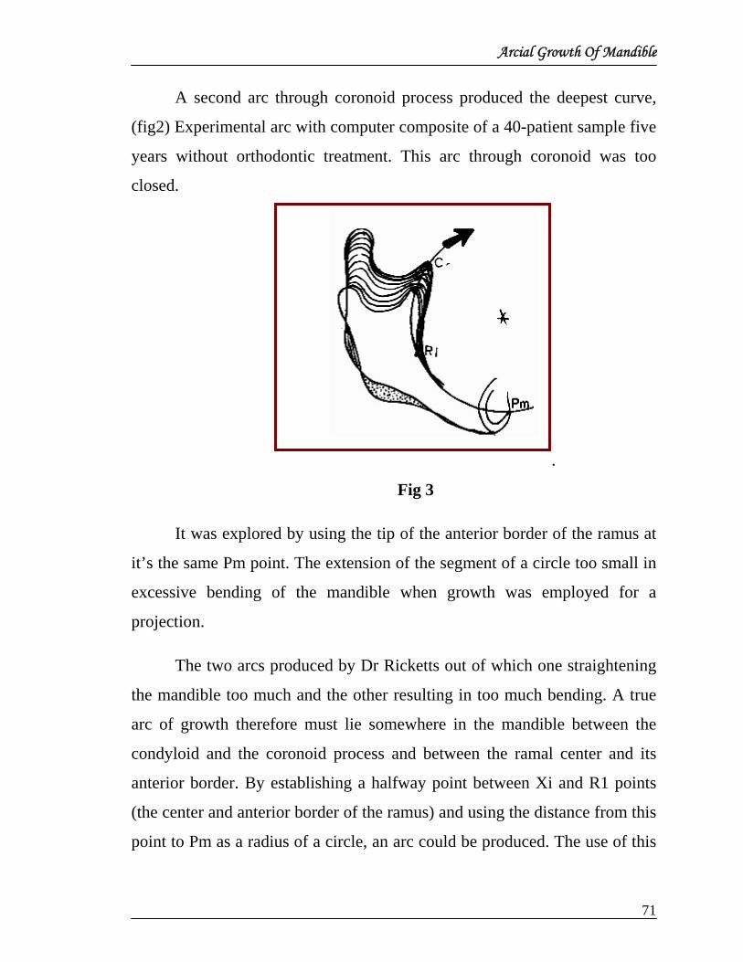
A second arc through coronoid process produced the deepest curve,
(fig2) Experimental arc with computer composite of a 40-patient sample five
years without orthodontic treatment. This arc through coronoid was too
closed.
.
Fig 3
It was explored by using the tip of the anterior border of the ramus at
it’s the same Pm point. The extension of the segment of a circle too small in
excessive bending of the mandible when growth was employed for a
projection.
The two arcs produced by Dr Ricketts out of which one straightening
the mandible too much and the other resulting in too much bending. A true
arc of growth therefore must lie somewhere in the mandible between the
condyloid and the coronoid process and between the ramal center and its
anterior border. By establishing a halfway point between Xi and R1 points
(the center and anterior border of the ramus) and using the distance from this
point to Pm as a radius of a circle, an arc could be produced. The use of this

Arcial Growth Of Mandible
72
arc still bent the mandible a fraction too much. In addition a radius selected
from this point would increase with size of the mandible and a progressive
increase or a changing arc or ultimate spiral shape would result. Growth
therefore could not be represented as a simple segment of a circle.
Ricketts thought that perhaps the stress lines of the mandible would
reveal its hidden secrets. The study of mandibular slices through the center
of the ramus failed to show definite architectural designs because the inner
and outer plates are very heavy and carry the load.
Attention therefore was directed to a mandible, alleged to be 850
years old, which had been given to Ricketts by the late W.B.Downs. This
mandible had been weathered to a state of disintegration of the
interprismatic substance of the external cortical bone, and therefore clearly
showed stress lines in the outer and inner plates. The lines thus exhibited the
design of the mandible for bracing externally. It was hoped that these
functional stress lines would also yield some clues, regarding the possible
development of the mandible, for we know that stress tend to run parallel to
bone trabeculae. The load being carried in the superstructure of a bone thus
can be analyzed. By the analysis of compression, extension, shear and
torsion, these lines begin to fit a pattern.
Close examination of mandible by Ricketts confirmed the
convergence of stress line at the protruberance menti .The stress lines
seemed to swing downward and then upward and backward through the
external oblique ridge.
However great attention was directed toward the medial side. On the
internal aspect even greater forking was noted than was seen on the lateral

Arcial Growth Of Mandible
73
side. The stresses .here followed the mylohyoid ridge upward into a thick
mass to terminate at a Y shaped bony prominence. This was almost the
center of the upward and forward quadrant of the ramus on the lingual aspect
and, in fact, might be the base of the tuberosity of mandibular growth.
Accordingly, both the inner and outer tables showed confluence at this area
of the mandible.
Experimentally, two new points (Eva and TR) were located
geometrically
Fig. 4 Fig.4. Method for construction of the arc of growth. MU and Frankfort
orientation)
When the size increase of the mandible as determined in the computer
study was incrementally added to the arc at the sigmoid notch, it was found
that the predicted mandible was almost absolutely correct in size and form
when compared with the final composite .The true average arc which closely

Arcial Growth Of Mandible
74
fits nature’s usual growth reaction (as viewed in the lateral film), and it may
or may not confirm to implants exactly.)
Fig. 5
The method as devised for K factors (constants) proved extremely
accurate.
Having become satisfied with the arc as a tool for prediction, the next
problem lied in the amount of growth to forecast on the arc. The yearly
increase from the combined studies was discovered to be almost precisely
2.5 mm. Averaged over the years of the time, it was an excellent population
constant. Cutoffs for growth were determined to be 14.5 years for females
and age 19 for males.
Next twenty longitudinal cases with a range of duration from five to
twelve years were measured. This study of Ricketts revealed that the
increases were different when measured from a point at the crossing of the
arc with the sigmoid notch. The point of crossing was labeled point MV.

Arcial Growth Of Mandible
75
The coronoid and condylar processes grow upward and outward in a
direction essentially as a function of the curve of the original arc. This
means that sigmoid notches with arcs of a small radius tended to stay small,
while widely divergent condyles and coronoid processes or notches with
wide radius tend to stay extended. As these values were determined and used
experimentally on more than 100 patients, a K factor for the coronoid
process growth came to be 0.8 mm per year.
Ricketts observed that damaged condyles did not behave normally,
nor did true prognathic types. Neither fit the principle of normal growth.
These conditions are rare and need to be identified because, as cases of this
kind are observed, the forecast becomes diagnostic of abnormal growth.
Further studies were consistent with the behavior of gonion in the
computer study.
The combined studies showed that the gonial angle drifted posteriorly
on the arc almost exactly one half the total increase in mandibular growth on
the arc.
To determine the space available for the developing mandibular third
molar at the anterior border of the ramus or the external oblique ridge the
RR point was reemployed. As the time 1 tracing is compared with the
forecast being constructed, it is assumed that stable bone is located here.
Thus with normal anatomical contouring the coronoid process is connected
to RR point, which tends to determine ramal width. Slightly below this
point, the external oblique ridge will show apposition of almost 0.4 mm per
year.

Arcial Growth Of Mandible
76
Ricketts made extensive investigations in 1955 on the treatment
behaviour of the occlusal plane. The occlusal plane was again studied
relative to more than three dozen points and other planes as well in a
nontreated sample.
Discussion of five relations seem ‘pertinent to new clinical
implications-
First:
The angle of the occlusal plane to the corpus axis tended to be regular
and orderly.
Second:
There seemed to be some functional or biologic relation to the
development of the posterior end of the occlusal plane to Xi point which
represents the mandibular foramen, while the distal end of the plane from the
true buccal occlusion dropped downward slightly with growth, a plane if
drawn through the second molar, would move it back up to its original
position. This is a biologic clue to the development of the curve of spee.
Third:
The occlusal plane tended to hold its relation to the embrasure of the
lips at the forward end.
Therefore, it seemed that the vertical development of the lower dental
arch and the occlusal plane took place naturally as a function of mandibular
growth. As the arc was growing the symphysis or chin was pushed under the
denture as the teeth erupted upward and forward. This explained chin button
development.

Arcial Growth Of Mandible
77
Fourth:
The horizontal or anteroposterior movement of the lower incisor
seems to be biologically related to the APO plane. The mean values for
lower incisors to the APO plane tend to match for malocclusions and normal
and successfully treated cases. This means that the lower incisor relates to
the convexity or facial type in all age groups. The prediction of the anterior
position of the lower incisor is, therefore, related to the prediction of change
in convexity by whatever factor is causing the change.
Fifth:
The lower molar tends to erupt upward and forward with the occlusal
plane from the mental protuberance. Given the adjustment which may occur
with leeway space in the transition stage, the molar can be predicted as a
function also of mandibular growth. This shows clearly that space for the
erupting third molar is made by upward and forward eruption of the dental
arch in front of it. If the lower arch is held backward space loss for third
molar teeth can be expected if space is created by forward movement, a
better prognosis should follow.
The arcial growth study pointed the way to the answer of the third
molar problem. Ricketts studied twenty five adult skulls exhibiting normal
occlusions with the aid of a lateral head film. From this group of skulls a
hypothesis was determined that the lower third molar must lie fifty percent
ahead of the external ridge for a fifty percent favourable prognosis for its
eruption. Theoretically, the prognosis could be one hundred percent
favorable if the molar (in cephalometric lateral view) is located completely
mesial to the ridge. Conversely the further distal (or the more it is covered
by the ridge) the poorer the prognosis for eruption.

Arcial Growth Of Mandible
78
To check this hypothesis, thirty one treated cases including a variety
of malocclusions were studied by Dr Ricketts. The head films were taken at
an average age of twenty one years.
The preliminary conclusion from the twenty five skulls and thirty one
head films seems to verify the hypothesis of the 50 percent favorable
prognosis mentioned earlier.
This would seem to verify, also another hypothesis that the third
molar can be prognosed early and should be removed if nonextraction is to
be a part of the planned treatment because 45 percent of the nonextracted
cases required third molar extraction. However these are preliminary
conclusions only and further verification is needed. It is a start to bring some
order out of this bewilding third molar issue.
It was sure by this time that mandible grows in an arc of some form.
Human mandibular growth can be reduced to a simple segment of a circle in
a lateral cephalometric image. If this arc represents the true character of
mandibular growth, the traditional viewpoint that “normal” lower molar
teeth acquire space for eruption by ramal resorption must be modified.
Rather, it is suggested from recent studies that eruption and alveolar growth
in the upward and forward direction is the process by which the space is
made available.
From the above study Ricketts has explained the findings of the
growth of mandible and its effect on orthodontic treatment and role in
retention and relapse. These can be enumerated as
1. It appears (through Superimpositioning of outlines) that the symphysis
rotates essentially during growth from a horizontal to a more vertical
inclination, and the suggestion is presented that the genial tubercles and
Arcial Growth Of Mandible
79
the lingual plate drop downward in the process. This explains the major
part of the form characteristic of the symphysis in the cephalometric film
(chin button development). Implant studies have shown that greatest
apposition takes place at the inferior margin of the symphysis ( and per-
haps the posterior side ) in the preschool years. The growth by apposition
may appear lateral to the mid line on the symphysis as bulk is needed for
bracing.
2. This phenomenon explains why reversal lines are observed at the area of
pogonion and suprapogonion.
3. It explains why the mandibular plane changes extensively in some
individuals and not in others.
4. It shows why ankylosed teeth are observed to affect occlusal plane
developement.
5. It explains how the early ankylosis of a lower molar tooth terminates with
the tooth located at the lower border of the mandible, the mandibular arc
simply continues and this tooth becomes trapped with in cortical bone
and the lower border resorbs up to it.
6. It suggest a reason why mandibular anchorage is risky in retrognathic
faces because less space is available for molar eruption due to a more
vertical eruption in that type than prognathic types.
7. It explains why the lower arches of brachyfacial or square faces can be
expanded and brought forward, and will remain stable.
8. It explains why good dentures may become progressively more crowded
in long, tapered faces and sometimes even in normal faces.
9. It explains how third molar impaction can occur by bone growth around
the molar rather than its submergence in to the ramus.

Arcial Growth Of Mandible
80
10. It offers a possibility that impaction of third molars can be prevented by
simple enucleation (at age 6 to 8 years) of the bud which lies on the
surface, not within the bone.
11. It suggests that abnormal growth or warping of the mandible can be
understood as a function of relative contribution of the coronoid and
condyoid processes.
12. It shows positioning of the roots of the lower first molar to the buccal, or
locking them under cortical bone, will prevent upward and therefore,
forward eruption of the whole lower dental arch thereby enhancing
anchorage of the lower arch.
The regularity and accuracy with which this arcial method is now
applied suggests that a principle may be operable for the phenomenon of
mandibular development.
It must be understood that the growth expressed on the arc and the
resulting mandibular effect on the face are different processes. Upward and
forward ramal mandibular growth on the arc as described would lead to an
upward and forward shift of the chin in the face. As the arc develops there
must be a downward rotation of the mandible in the face in order to maintain
the central axis of the face, or facial axis as a constant on the average. This
phenomenon tends to be keyed to the neurological bed of the face, namely,
the orientation around the branches of the trigeminal nerve. The postural
kinetic chain or neurophysical input to the muscles which position the
mandible in the face constitute other factors.
Preliminary studies as a part of this work have suggested that in the
typical orthodontic practice, with proper attention there is a likely hood of as
much as 50 % incidence of the eruption of functional 3 P
rdP molars.

DR. ROBERT M. RICKETTS: On Growth Prediction
DR. ROBERT M. RICKETTS
On Growth Prediction
• Motivation to estimate or forecast growth
RICKETTS received motivation from one of his mentors, Dr.
William Downs, from 1947 to 1952. Downs (in 1948) was originally trying
to select a group of measurements which would help him explain to his
students what he was seeing on the headplates. In his paper of 1952 he
talked about using cephalometrics as a prognostic tool regarding the “swing
of the face”. Downs was “reading the pattern” and trying to anticipate in
which direction the patient's face was going to grow on interpretation of the
morphology, but he realized it was only a hunch.
Ricketts was there on the research scene at the University of Illinois to
assist Downs in the clinic.
Ricketts studied the types he had observed and their characteristics,
and figured how these observations plus the technique of projection of the
architectural lines would influence the treatment plan. He was using the
contribution of growth to the active treatment only, but of course was
grossly estimating the future intuitively, like everyone else. “Long range
forecasting” came twenty years later.
• Determination of the exact increment of growth for each part
measured.
By establishing a mean and statistical curve of distribution for the
change in each basic reference line used. In the beginning, he started with
the cranial base triangle.
81

DR. ROBERT M. RICKETTS: On Growth Prediction
Fig.1
Fig. 1 The original planes used for prediction. The original cranial base triangle and the condyle axis (RR plane) employed to connect the base of the skull to the mandibular plane. Note Sella and Nasion, the Mandibular Notch and Menton.
Sella-Nasion and Sella-Basion were measured for cranial base growth
on a sample of patients during treatment. He attempted to determine the
differences between boys and girls at various age groups. Average values
were used for each plane on the basis of sex characteristics at puberty
He started with average values; they were added to the individual
shape and size already present. By projecting individual lines, plus
introducing physiologic mandibular rotation as a calculated result from the
anticipated correction, the total skeletal change could be plotted during
treatment, including a change, if anticipated, in the maxilla. These were put
together cybernetically (feedback) in order to derive the facial morphology
most likely at the end of treatment.
After the skeleton was set up, the balance of the denture relative to the
APO line was considered.
82

DR. ROBERT M. RICKETTS: On Growth Prediction
Fig.2
Fig.2 The use of the anterior limits of basal jaw bone (A-Po) for the | setup of the position of the denture. The peak of the curve is + 1.0 mm and one clinical deviation is 2.0 mm.
A line of reference that would express the forward or backward
position of the lower arch was needed. The stimulus that started the
investigations which ended with the recommendation of the average lower
incisor to the APO line to be 1.0 mm (and originally inclined at 22°). The
clinical deviation is ±2.0 mm representing two-thirds of cases to lie in the
range of -1 to +3 mm.
• Lateral x-ray and frontal views for case analysis.
Dimensions from the frontal headfilm are also calculated using the
computer for determining facial volume. This value is used to determine
whether a linear dimension is large or small for that individual patient. This
(plus comparisons to age, sex, and ethnic type) permits the computer to
individualize a patient.
83

DR. ROBERT M. RICKETTS: On Growth Prediction
According to Dr Ricketts the lateral headfilm is still far more critical
than the frontal because it deals with anterior-posterior change, change in
convexity, overbite and overjet change all in the sagittal and vertical planes.
The only thing left out is the horizontal plane or the transverse parameter in
the frontal film. This is critical in terms of maxillomandibular relationships
in the frontal dimension. All crossbites, all arch length problems have useful
information coming from the frontal headfilm.
Fig. 3
Fig.3 A frontal headplate analysis. Shows features measured in present analysis. The malocclusion, jaw relation, tooth locations and facial type are extracted from the tracing with the computer program.
• To obtain proper location of the essential reference points.
Dr Ricketts mentioned that to obtain proper location of reference
points first, obtain good films, well oriented. Second, increase confidence in
ability to identify anatomical structures in a headfilm. If one has a casual
attitude, he is going to make errors. Because the mandible is so critical, it is
84

DR. ROBERT M. RICKETTS: On Growth Prediction
most important to study the osteology of the mandible. Trace the same
headplate three times, one week apart and compare them later
• Popular reference points and planes which were used by Dr
Ricketts
Probably the three most common analyses include the most popular
points, and all seem to have glaring weaknesses. He stated that sella is easy
to see. Perhaps it has therefore been relied upon too heavily to be (1) Centre
for descriptive reference and (2) An unchanging reference for facial growth.
Perhaps next in popularity is Nasion, but it needs care in selection because
the frontonasal suture may slant upward and all that can be seen in some
patients is a slight depression. He found that SN is just as reliable for
reference as any other anatomy in the anterior cranial base— if you rely on
the anterior base for reference.
He found that Porion is directly above Basion and the dens and the
articular eminence directly below Sella. Orbitale is no problem if sorting out
the rim of the orbit from the lacrimal canal and infraorbital canal is done
properly. ANS and PNS are also observed, and the nasal floor sometimes
changes in form along with the fact that the nasal cavities may be
asymmetrical.
Point B is an alveolar point— plain and simple. It is not basal bone as
commonly thought, and it responds to movement of the lower incisor as does
point A. In the mandible, a basal structure is available which the mental
protuberance is. He termed this PM to differentiate from Pogonion, which is
on the most interior curvature
85

DR. ROBERT M. RICKETTS: On Growth Prediction
Fig. 4
Fig. 4 Lateral headplate of an adult with good occlusion. Note the anatomy at the pterygopalatine area, the joint and orbit. Note the distance of the ear rod from the true ear hole. Correlate with Figure 8, which is a tracing made from this x-ray.
For morphologic analysis as well as growth analysis he used the
Basion-Nasion plane as the basicranial axis. With x-ray studies of leaded
skulls, he observed that foramen Rotundum could be seen in the lateral film
(Fig. 4). By connecting the lower border of the foramen to cephalometric
Gnathion, a new more central axis was evident. Foramen Rotundum is in the
middle of the base of the pterygoid buttresses at the base of the body of the
sphenoid. He labelled the point Pt or Pterygoid Point to denote its biologic
significance.
Another line is the true or occlusal plane of the buccal occlusion
rather than the bisection of the overbite.
Dr Ricketts pointed that one must make sure that the films are of good
quality, study them, and go after the points where one would expect them to
be, allowing for the variability that may exists.
86

DR. ROBERT M. RICKETTS: On Growth Prediction
• Reference points— Xi, Eva, and Murray.
In 1963, Bjork reported in his implant studies that the gonial angle
was drifting and the lower gonial border of the mandible was actually
undergoing a remarkable resorption. When apposition did occur on the chin,
it was not very much on the anterior border, but on the lower border of the
symphysis. Bjork showed that we could no longer superimpose on the
mandibular plane as a matter of serial reference for study of growth of the
mandible or eruption of the lower teeth. So Dr Ricketts had to abandon the
mandibular plane for reference.
The area particularly above Pogonion where the mandible starts to
recede in the symphysis, or at the top border of the mental protuberance
which he labeled as Pm point
Fig. 5
Fig. 5 One method of locating Xi Point— Center of R1, R2, R3, R4. XiPm = Corpus Axis. The corpus-condyle axis bend and its arc of behavior). B. Note occlusal plane relation to corpus axis.
This was the area of least change from the implant evidence. Ricketts
could rely on Pogonion area as a stable point anteriorly, but posterior stable
point was yet to be decided.
87

DR. ROBERT M. RICKETTS: On Growth Prediction
He started to experiment at finding a useful posterior point by
measurement. He bisected the height of the ramus from the sigmoid notch
down to the lower border in a perpendicular line from FH, then bisected the
width of the mandible to see if he could find a centroid of the ramus.He
called the point Xi (Fig. 5A).
The true buccal occlusal plane went almost directly through this point
time and time again. It was an accidental finding. Using Xi point, he could
now begin to draw a line up through the condyle head to a location that was
more definite rather than arbitrary, as was previously drawn (Fig. 5B). The
position of Xi point from FH was later used as an accurate function of the
vertical growth of the ramus also to measure mandibular form from the
center of its mass rather than from the peripheral irregularities. Xi point with
laminagraphs and showed that it was the center of rotation of the mandible
in terms of both lateral excursion in chewing and in opening. Longitudinal
studies suggested that it was the key to the behavior of the occlusal plane. A
line from Pm, or mental protuberance, back to Xi point became a
representation of the body of the mandible. He called it the corpus axis (Fig.
5B). This was the beginning of the development of long range forecasting.
The mandible seemed not to be growing in straight line trajectories (Fig.
5B). It was bending on the corpus-condyle axis, and he could measure the
bending. The next move was to find the nature of the bend, how much it was
bending on the average, and where the bend was usually taking place.
• Discovery of Eva and Murray point.
First an arc was constructed through Xi point up through the centre
of the condyle head to see if that was the pattern and it opened the goinal
88

DR. ROBERT M. RICKETTS: On Growth Prediction
angle too much. Another arc was drawn through the anterior border of
the ramus and continued upward through the tip of the coronoid process.
That bent (or closed) the growth of the mandible too much. So he knew
that the true arc of growth on the average must lie some where between
the center of the mass of the ramus and the anterior border of the ramus
and somewhere between the condylar process and the coronoid process.
He experimented with an arc drawn from the center of the sigmoid
notch through a point bisecting the distance from Xi to R1 point. That
was close, but was still not correct. Finally, without going into details, a
center of the upward and forward quadrant of the ramus was determined
by bisecting R2 reference and R3. He used that distance to create a third
point in space as a true radius of the arc (TR).
He decided to name this one after his mother. Her name was Eva,
the symbol would be EV. Another reference point at the location of the
new arcs crossing the sigmoid notch and named that point after his father
Murray.
• Basion –Nasion reference line.
Basion, located on the anterior rim of foramen magnum, has been a
point used in anthropology for a long time. Having observed it there,
Ricketts studied the lateral head x-rays and fount it was visible.
Therefore, he started using it to construct a cranial base triangle.
Subsequently he related the Y axis to BaN and called it the X-Y axis. He
felt that this was an improvement in thinking in terms of the face
supported by the entire cranial base rather than Sela-Nasion alone.
89

DR. ROBERT M. RICKETTS: On Growth Prediction
Fig. 6
For another basic reference if a vertical is dropped form Frankfort
Horizontal through the base of the pterygoid plate, the coronal suture
complex is reasonably represented. Such a line tends to divide the face
from the posterior supporting skull base or buttresses. The Basion –
Nasion plane will be seen to cross the Frankfort plane very near the top
of pterygopalatine fossa.
90

DR. ROBERT M. RICKETTS: On Growth Prediction
Fig.7
Fig 7 Coordinate grid with zero benchmark at pterygoid buttress on Frankfort plane. A vertical from Frankfort through the root of the pterygoid plates tends to divide the maxillary complex from its cranial support. It also runs parallel to the general line of the coronal suture complex.
This area seems to be important because it is the location of the
entrance of the blood and nerve supply to the nasal capsule, palatal roof
and upper arch. The foramen rotundum, as well as the rostrum of the
sphenoid with its bracing support for the vomer, for the midsagittal
support of the maxilla are located in this area. By superimposing the
tracings on a polar grid, he came back again and again to a central
phenomenon of growth form this general location, as Brodie had
suggested many times.
The anterior cranial base length is measured on a perpendicular to
the Basion –Nasion Plane from the PT point. This is all part of the
sophistication of comprehensive cephalometic analysis and forecasts.
91

DR. ROBERT M. RICKETTS: On Growth Prediction
Fig. 8
Fig.8. Polar grid showing central phenomenon at base of sphenoid
• Estimation of soft tissue growth.
According to Ricketts soft tissues are the most reliable parts to
predict once you understand them. For instance, the tissue immediately
labial to Point B does not change essentially after the age of six, but it
may move upward or downward with treatment.
Two different methods of forecasting are now used. One is during
the treatment time or short term and is used for mechanical anchorage
planning. It is the projection of established architectural lines in the skull
and jaws over which are superimposed the effects of treatment.
Three conditions are taken into consideration in this procedure,
which he at one time labeled “synthesis” in order to separate it from
92

DR. ROBERT M. RICKETTS: On Growth Prediction
analysis, and which Holdaway later called the VTO, or “visualized
treatment objective”.
The primary condition to consider is natural growth of that
individual for the usual course of treatment (Two to three years.)
Secondly, the probable physiologic rotation of the mandible
resulting from the mechanics is taken into account. This is superimposed
over the natural growth that would be expected and the type of treatment
which makes a difference in the prediction. It is calculated in light of the
needed change in molar correction of overbite and overjet, convexity of
the profile after extraoral forces, by heavy intermaxillary traction or
activator treatment.
Fig. 9
Fig. 9 Steps and sequences in short route procedure of forecasting. Anterior and posterior increases are estimated.
93

DR. ROBERT M. RICKETTS: On Growth Prediction
A = 0.8 mm B = 0.8 mm C = 0.8mm D = 1.6 mm (double the C) E = is elective as decided by operator. F = soft tissue is dependent on tooth movements G = is dependent upon ANS and is 1.0 mm yearly Teeth Sequence: a-- lower incisor is + 1.0 mm to APo with CD = + 2.0 mm. b--lower molar as determined by anchorage needs of d c. c-- upper incisor change as needed from lower incisor d-- upper molar = 3.0 mm distal to lower in normal occlusion
Each type of treatment has its own share in the prognosis of the short
term skeletal change of patient.
The third factor is concerned with the actual objectives in movement
of the anterior teeth. Lip functions change with tooth movement. Tonicity
and character change remarkably with treatment. However, the original
methods for anticipation of changes that he devised in 1950 are still the same
today.
Now, long range prediction is another case. Over a period of time,
natural growth rebound and physiologic recovery are experienced after
treatment. This method reveals the anchorage available in the lower and the
tooth movement needed in the upper to determine anchorage requirements.
• Enucleation of third molar.
He has practiced lower third molar enucleation in about 100 cases.
With a long range forecast, he projected the mandible of the child all the
way to his prospective maturity. The occlusal plane and erupted position of
the lower first molar are included in the mandibular prediction. This means
that we can be relatively sure how much space is going to be available
posterior to the first molar if we do nothing.
94

DR. ROBERT M. RICKETTS: On Growth Prediction
Fig. 10
Fig. 10 Arc of growth as theory of superpositioning reveals the lower arch to develop upward and forward making space for the second and third molars. Some remodeling may take place, but average implant studies show a curve only slightly more open than shown here. Note space for lower third molar is favorable as long as as 50% of the teeth are forward of the external oblique ridge.
Problems arise clinically in the posterior area, particularly in the lower
arch during orthodontic treatment and sometimes without treatment. He
states that as we intrude lower incisors with a utility arch, we push them
downward into a stronger portion of the lower lip, and the lip resists their
forward movement. The result is the lower molars being moved backward
and over the top of a developing lower second molar. The third molar lies
over the top of the distal margin of the second molar and now traps the
second from front and back. Now, with the diagnosis from the long range
forecast and with the prospects of this kind of treatment, we arrive at the
amount of space that will be available for the second and third molar by
maturity with a given treatment, or no treatment. When the prognosis of the
95

DR. ROBERT M. RICKETTS: On Growth Prediction
third molar is less space than 50% behind the external ridge, he recommends
its removal.
The anatomy of the developing follicle of the lower third molar shows
that it is an open bony window on the lingual aspect of the mandible.
Fig. 11
Fig. 11. Two views of developing crypt for the lower third molar, showing the open follicle on the lingual side of the ramus at the retromolar recess. Development level about age 9, but this stage may come in a range from 8 to 12 commonly.
He contemplated this situation for a long time, and finally concluded
that the only thing to do was to go in and spoon out the follicle. Dr Ricketts
said that with the discovery of an arc as a working principle for the growth
of the mandible, he was coming close to the true meaning of the word
prediction.
The objective is “to foretell the future”, to master the unknown and
escape the bondage of bewilderment.
96

A Four-Step Method To Distinguish Orthodontic Changes From Natural Growth
A FOUR-STEP METHOD TO DISTINGUISH ORTHODONTIC
CHANGES FROM NATURAL GROWTH
Cephalometric setups have been used by Dr Ricketts for determining
the most appropriate objectives for each patient. By visualizing the
conceivable result beforehand, precise plans for the skeleton, teeth, and soft
tissues have been devised In addition; desirable results and certainly better
understanding are thought to be achieved through the use of “prediction”
methods. All the skeletal changes, or even the physiologic changes that
may take place during treatment, may often be referred to as “growth”.
This is because physiologic change, treatment change, or growth change
cannot be sorted out with any degree of assurance with most cephalometric
methods.
Observations of Problems in Cephalometric Planning
Due to the proximity of the upper jaw with the anterior cranial base,
and with the reliance that most clinicians place on the Sella-Nasion line,
the principal focus in diagnosis and planning has often first been the
midface. It followed directly that an attack on Point A and the maxillary
arch had the primary attention in planning. With this thinking, clinical
cephalometrics became reduced to convexity change or SNA-SNB
difference, and the alignment of teeth in the profile and mandibular
behavior were secondary, as prediction of mandibular behavior was
estimated by the extension of the cant of the mandibular plane angle. No
differentiation was taken into account between measurement from
Frankfort plane and other cranial planes with common methods. Often, not
even the same points on the mandible were selected in different analyses.
97
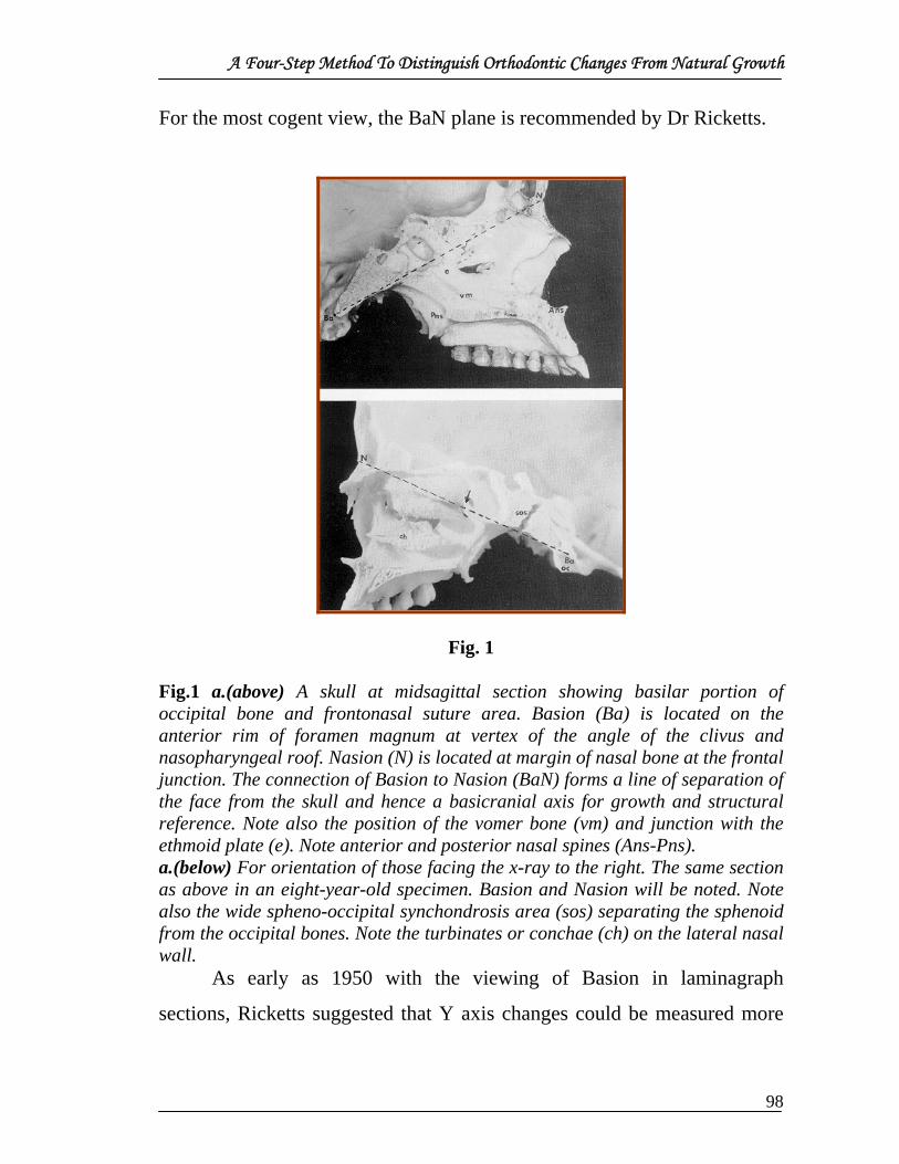
A Four-Step Method To Distinguish Orthodontic Changes From Natural Growth
For the most cogent view, the BaN plane is recommended by Dr Ricketts.
Fig. 1 Fig.1 a.(above) A skull at midsagittal section showing basilar portion of occipital bone and frontonasal suture area. Basion (Ba) is located on the anterior rim of foramen magnum at vertex of the angle of the clivus and nasopharyngeal roof. Nasion (N) is located at margin of nasal bone at the frontal junction. The connection of Basion to Nasion (BaN) forms a line of separation of the face from the skull and hence a basicranial axis for growth and structural reference. Note also the position of the vomer bone (vm) and junction with the ethmoid plate (e). Note anterior and posterior nasal spines (Ans-Pns). a.(below) For orientation of those facing the x-ray to the right. The same section as above in an eight-year-old specimen. Basion and Nasion will be noted. Note also the wide spheno-occipital synchondrosis area (sos) separating the sphenoid from the occipital bones. Note the turbinates or conchae (ch) on the lateral nasal wall.
As early as 1950 with the viewing of Basion in laminagraph
sections, Ricketts suggested that Y axis changes could be measured more
98

A Four-Step Method To Distinguish Orthodontic Changes From Natural Growth
usefully from the Basion-Nasion plane. But, it was still difficult to
determine, in some instances, whether a part of the change was a change in
the position of Sella, or actually a change in the chin. It was shown that the
cranial base angle, while constant on average, did exhibit a change of 5° in
either direction over a three-year period of time. So, at least twenty years,
there has been doubt and there has been room for skeptics with regard to
the nature of orthodontic superpositioning, and consequently with the
interpretation of results.
Position One
Three points are required for the cranial reference for this skeletal
analysis. These are Basion, Nasion, and Pterygoid Point. Basion-Nasion
super positioning has been considered to be the most trustworthy
longitudinal base line.
99
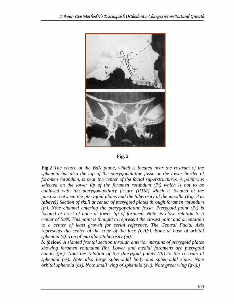
A Four-Step Method To Distinguish Orthodontic Changes From Natural Growth
Fig. 2 Fig.2 The centre of the BaN plane, which is located near the rostrum of the sphenoid but also the top of the pterygopalatine fossa or the lower border of foramen rotundum, is near the center of the facial superstructures. A point was selected on the lower lip of the foramen rotundum (Pt) which is not to be confused with the pterygomaxillary fissure (PTM) which is located at the junction between the pterygoid plates and the tuberosity of the maxilla (Fig. 2 a. (above)) Section of skull at center of pterygoid plates through foramen rotundum (fr). Note channel entering the pterygopalatine fossa. Pterygoid point (Pt) is located at crest of bone at lower lip of foramen. Note its close relation to a center of BaN. This point is thought to represent the closest point and orientation to a center of least growth for serial reference. The Central Facial Axis represents the center of the cone of the face (CAF). Bone at base of orbital sphenoid (s). Top of maxillary tuberosity (m). b. (below) A slanted frontal section through anterior margins of pterygoid plates showing foramen rotundum (fr). Lower and medial foramens are pterygoid canals (pc). Note the relation of the Pterygoid points (Pt) to the rostrum of sphenoid (rs). Note also large sphenoidal body and sphenoidal sinus. Note orbital sphenoid (os). Note small wing of sphenoid (sw). Note great wing (gw).)
100

A Four-Step Method To Distinguish Orthodontic Changes From Natural Growth
By taking the lower lip of the foramen rotundum, as seen in the
lateral film, the point has been described as pterygoid point (Pt).This point
is used as a reference center (least change) and has taken the place of point
Sella for longitudinal comparison.
A line from Pt to cephalometric gnathion (GN), selected at the intersection
of the facial plane and mandibular plane, constitutes the Central Axis
Fig. 3
Fig.3 Time 1 Case G. L., male, age 13.0 years with severe bimaxillary protrusion of the dentition. The diagnosis and treatment plan called for extraction of all first bicuspids with Grade 3 anchorage preservation on a scale of 4. Also, light anterior parietal extraoral traction was indicated by the forecast. Note Central Axis at 85° and other key reference lines for longitudinal analysis. The convexity was 9 mm. The lower lip protruded 7 mm from the E plane)
The Central Axis, for morphologic or skeletal static description,
forms almost an absolute right angle to BaN for the average of the
population as a whole. This is a very interesting fact in itself, as the clinical
deviation (CD) of morphology is ±3 degrees from the 90 degrees. It was
found to be 90 degrees. Central Axis, however, can change in the
101

A Four-Step Method To Distinguish Orthodontic Changes From Natural Growth
individual. As much as 6 degrees of change has been noted during the
transition from the mixed to the permanent.
Position Two Given the same Basion-Nasion plane, now the tracings are shifted to
Position Two (at Nasion)
Fig. 4
Fig.4 (fig4 For the maxilla) The tracings are shifted on the same BaN plane to register at Nasion. This orientation shows a backward movement of Point A of 3.0° during treatment to help reduce the convexity. Some high pull extraoral traction was employed to the anterior teeth and only moderate effect is seen in the anterior nasal spine. If extraoral cervical traction had been used. Much more effect on the palatal plane would be seen. Note the nasal bone continued to move forward slightly. With vigorous cervical traction this is also reversed.)
The Basion-Nasion-point A angle is used, which corresponds to the
SNA angle of Steiner The Ba-N-A angle is nearly an absolute constant
without treatment This angle (measuring approximately 66 degrees)
changes very little in the population growth samples, but furthermore,
changes very little in the individual. The standard variation in a five-year
period was found to be only ±1.0 degrees. As this is reduced to yearly
increments, .5 degrees becomes the practical variation for yearly
increments. Minor changes are frequently manifested by the protrusion or
102

A Four-Step Method To Distinguish Orthodontic Changes From Natural Growth
retrusion of the central incisor with local modification in the area of Point
A as the cause, rather than a change in the basal maxillary position. Given
another 0.2 degrees change for error, the hypothesis is that less than one-
half of 1.0 degree change would be expected to occur naturally.
The constancy of this angle largely says that Point A essentially behaves
with Point N. As N moves forward, A moves forward, and if N does not
move forward, A does not move forward. The behavior of Nasion on the
basal axis from PT area is 0.7° per year ±0.26°. This would seem also to
say that the protrusion of the maxilla is also consistent with a carrying
forward of the bony superstructure in the area of Nasion. Ricketts believes
this to be essentially so. At any rate, with this low standard deviation of
change, the clinician can literally take absolute credit for most change in
Point A that takes place during treatment, when measured with this method
of superpositioning. It makes little difference whether it is on a short range
or on a long range point of view. However, a distinction is needed to
determine Point A change on a local alveolar basis or complete maxillary
change by skeletal involvement which will be done later with Position
Three.
Position Two therefore depicts the position of the maxilla and serves
as a guide for diagnosis and further for treatment planning.
Position Three
Position Three employs the original method of Brodie and Downs
with no differences in technique. The ANS and PNS is superpositioned
(Palatal Plane) and registered at ANS (Fig.5 Position Three. For the upper
teeth) Tracings are superimposed on palatal plane and registered at ANS.
103

A Four-Step Method To Distinguish Orthodontic Changes From Natural Growth
Note the intrusion and backward movement of the incisor of almost 7 mm.
The incisor without treatment would continue to erupt downward and
forward about 1 mm during this time span. Remodeling of alveolar bone
will be noted in the incisor area as Point A moved backward about 2 mm to
explain major portion of convexity change. Note the upper molar almost 2
mm forward. However, the molar would have moved forward at least 1 mm
during this development with the loss of the second deciduous molar and
normal eruption.)
Fig. 5
While it has been shown that the descent of the palate is not all due
to growth at the sutures, but is also accompanied by remodeling resorption,
the palatal plane still serves as the best parameter for the assessment of
maxillary denture change. Superimposed in this manner, the upper dental
arch erupts downward and makes a slight forward gain of about 0.2 to 0.3
mm per year in terms of its position on the maxillary denture base.
With the natural tendency, and a low deviation of change of the
upper incisor, the stability is also quite remarkable. Therefore, any change
in the molar forward or backward, or the incisor forward or backward
104

A Four-Step Method To Distinguish Orthodontic Changes From Natural Growth
during the course of two years, can be claimed essentially as being effected
by the orthodontist rather than natural growth because a change of more
than 0.4 mm in two years is unlikely unless the incisors protrude between
the split in the lips.
Some minor exception can be taken to the foregoing hypothesis as
space for the missing upper second deciduous molar is encountered. This
also can be claimed to be an effect of tooth loss and is not a natural
phenomenon in the presence of a full complement of teeth. By determining
the changes in Point A from ANS, the amount of change in the maxilla can
be verified in Position Three. In the case of G. L., the upper incisor tip
moved upward and backward 6.0 mm, all of which is considered in the
method to be due to treatment. The upper molar crown moved forward
almost 2.0 mm, of which 1.0 mm was probably due to treatment.
105

A Four-Step Method To Distinguish Orthodontic Changes From Natural Growth
Position Four
Position Four will require the learning of two new points and two new planes
Fig.6
Fig. 6 Prepared skull of a mixed dentition subject showing a new method of orientation on mandibular points for the study of occlusal changes. Pm is located at crest of bone at the mental protuberance at point of start of recess on anterior contours. The centroid of ramus is selected at a common point by measuring minimum height and depth of ramus and was labeled Xi point. The connection of these two points is called the corpus axis. The occlusal plane is drawn through the plane of the buccal teeth and called the true occlusal plane. The angle between the occlusal plane and corpus axis tends to be highly stable. Note Porion and Orbitale.)
First, a point at suprapogonion (Pm— Protuberance Menti) was
found necessary because a point at Pogonion on the anterior-most border of
the symphysis cannot be depicted as a definite point in the vertical plane.
Therefore, a point was selected at the mental protuberance and termed Pm.
It was selected at a point at which the outline of the chin starts to recede in
the profile, or at the top of the crest of the bony cortex in the outline of the
symphysis in the area of the mental protuberance. This area has been
shown by numerous investigators to be a location of least change. No
106

A Four-Step Method To Distinguish Orthodontic Changes From Natural Growth
apposition or resorption or remodeling seems to take place at this site. It is
the most stable point of reference for longitudinal comparison on the chin
that the author has been able to determine.
It was found by Bjork that the lower border of the gonial angle
resorbs in the usual growth pattern. This would say that the measurement
of tooth eruption from the mandibular plane would not in fact be a measure
of eruption, but also resorption of the lower border must be taken into
account. Therefore, the mandibular plane is not a trustworthy reference for
tooth eruption or tooth change.
As an alternative, a second point which represents the centroid of the
ramus was located and labeled "Xi" point. This point was selected by-
measurement on the mandible, and is located at a halfway point between
the lowest point of the sigmoid notch and a point immediately inferior to it
on the lower border of the ramus in the Frankfort horizontal orientation
(Fig. 6). (Also midway on the minimum depth of the ramus.) The Xi point
also proved to be a strong biologic point which represents the mandibular
foramen and the center of rotation of the mandible. The connection
between Pm and Xi formed a plane and was termed the "Corpus axis".
The true occlusal plane was drawn through the bisection of the
buccal tooth overlap. Ironically, the extension of this true buccal occlusal
plane passes closely to the Xi point in a remarkably high percentage of
cases. The angle between the occlusal plane and the corpus axis was noted
to be among the highest correlated of all the measurements subjected to
computerization. This would seem to make it useful for superpositioning
(and for prediction as well). With this angle used as a yardstick, any change
107

A Four-Step Method To Distinguish Orthodontic Changes From Natural Growth
in the occlusal plane from the corpus axis would, therefore, be essentially a
change brought about by treatment. The standard variation is 0.68 degrees
each year.
The lower molar tends to erupt straight upward from the corpus axis
registered at PM at a right angle to the Frankfort horizontal as the whole
occlusal plane moves straight upward, and the occlusal-corpus angle
remains almost constant. The lower molar and lower occlusal plane erupts
about 0.8mm per year upward from the corpus axis. Likewise, the lower
incisor moves directly upward from the corpus axis as arch length changes
are not usually encountered. However, the lower incisor also seems to hold
to the APo plane on average. The loss of the lower second deciduous molar
also adds about a 1mm shift to the normal forward tendency. Therefore, a
forward or backward measurement from these points on the occlusal plane
may serve as excellent parameters for the evaluation of tooth movement in
the lower arch.
Four points of superpositioning were recommended by Dr Ricketts
for evaluation of treatment results. These four positions, based on
characteristics of natural development were presented to serve as a guide
for the methods of comparison during treatment.
108

The Evolution Of Diagnosis To Computerized Cephalometrics
THE EVOLUTION OF DIAGNOSIS TO COMPUTERIZED
CEPHALOMETRICS
In the early days of orthodontics, the patient constituted the only
record. The clinician could only observe, describe or measure directly for
records, because at that time even the plaster model had not been developed.
Progress was painfully slow; information was accumulated only with great
effort and was of questionable reliability.
The primary concern and aim of treatment was alignment of teeth in
the individual arch. This was essentially limited to the upper arch, because
that arch was the most obvious. The objective for alignment of the teeth was
caries prevention, because it was thought that broad cervical contacts of the
teeth were conducive to decay. In addition, it was recognized that
imbrication "marred" the beauty of the smile.
However, other factors began to be considered and more adequate
appraisals were needed consequently diagnosis became more involved and
better records became necessary.
Evolution of objectives
In order to explain contemporary objectives in orthodontics, Dr
Ricketts had divided orthodontic history into five general eras. It was seen
that added goals in treatment evolved in each era; hence, diagnosis for the
consideration of these objectives became more complex. The five eras were
1. Pragmatism— up to about 1875;
2. Empiricism— 1875 to 1925;
3. Experimentation— from 1925 to 1950;
4. Scientific theory— from 1950 to 1965;
109

The Evolution Of Diagnosis To Computerized Cephalometrics
5. Cybercultural communication— 1965 to the present.
Twelve objectives or considerations in orthodontics have developed
over the course of this evolution as knowledge and responsibility have
grown.
Fig. 1. Eras in orthodontics.
Pragmatism
During the early period, treatment and diagnosis were pragmatic and
two main objectives emerged.
Objective 1
Ricketts mentioned first objective as “Arch Allignment”. As mentioned
above, the aim for straight alignment was the first goal and expansion of the
arch was the procedure. As evidence of this limited objective, the earliest
appliances were characterized by Fauchard's "bandalette" and other forms of
110

The Evolution Of Diagnosis To Computerized Cephalometrics
labial arch to which the teeth were simply ligated outward. Other forms of
appliance evolved with screws or springs designed to push the teeth outward
from within.
Objective 2
“Correction of arch relation” was the second objective given by
Ricketts. Some earlier writers mentioned the need for approximation of the
arches to each other, but it was not until Kingsley gave substance to the idea
of arch correction by his bite-jumping procedure that arch relation became a
distinct diagnostic factor. Extraoral traction was recognized but was
principally employed for the purpose of upper anterior tooth retraction or for
chincaps for cases of prognathism.
Still, the patient was the only record. The era was still pragmatic, as
the ends were thought to justify the means, and the diagnosis of irregularity
and bite relation were the two basic considerations.
By the middle of the 1800's, trays had been perfected and models
were made of plaster, mostly from wax or compound impressions. Plaster
impressions also came to be employed, but the plaster cast brought with it a
simplified classification of malocclusion with the description of normal
occlusion by Angle.
Era of Empiricism
The advent of the plaster cast and the knowledge of a useful, simple
method of classification changed the course of diagnosis and treatment.
Teeth were observed to be inherited in sets and each tooth seemed to be
important to the whole to the minutest detail. Arch length became a concern
and certain indices were proposed, such as the Pont index, for the prediction
111

The Evolution Of Diagnosis To Computerized Cephalometrics
of proper arch size and form as based on tooth anatomy alone. The slow
development of knowledge and the setting of certain hypotheses yielded an
era of empiricism which was to extend through the first quarter of the
1900's.
Diagnosis came to be made from the upper molar because it was
hypothesized that this tooth was the least variable and the most stable and
reliable single entity. The art portion was formed and the model was
trimmed to stand occluded on the desk for viewing and study, usually related
to the occlusal plane. Treatment planning centered on molar occlusion, as
did most of diagnosis.
Objective 3
Ricketts mentioned third objective as “Functional equilibrium”. Time
revealed other problems and diagnosis became extended. It was found that
the arches could be aligned individually and could be corrected to each
other, but the whole mass was often functionally incompatible or occlusally
unstable. The search was on for functional equilibrium. Muscle action and
the functional realm became an added dimension. It was at this point that
orthodontics became a specialty and an independent science. Its problems in
this regard were not directly germane to dentistry in general.
The problem of diagnosis in any branch of medicine has always
stemmed from etiology. In all clinical problems, the combined elements of
heredity and environment must be considered as underlying causes. The role
of heredity continued to emerge to the orthodontic clinician, who noted the
similarity between siblings and similarities of offspring to their parents.
However, conclusions without profound investigation were loose and the
112
The Evolution Of Diagnosis To Computerized Cephalometrics
principal cause of a malocclusion was frequently claimed to be one of
abnormal function or at least in some manner connected with environment.
In fact, this whole era might be typified as the age of functional
morphologists by Ricketts.
Objective 4
Ricketts objective four was “Esthetic equilibrium”. In addition to
function and from the earliest time of concern in orthodontics, esthetics was
a question. A strictly empirical procedure was followed and most of the
decisions on facial art were value judgments. Nothing concrete in esthetics
was accomplished in this era, although scholars pressed for an acceptance of
variation. The photograph was employed loosely for diagnostic purposes.
Angle was the strongest of advocates of the preservation of the full
complement of teeth, but he held Appolo Belvedere as an ideal in facial
beauty and harmony in spite of the fact that this model possessed a "flat"
type of denture.
Case championed the cause of facial esthetics and even extended his
study to the cast of the soft tissues of the face. Case concluded that
bimaxillary protrusions existed and that the interests of esthetics were best
served by the judicious extraction of teeth in patients with delicate structure,
large teeth or tight limited musculature. At any rate, these arguments served
as a steppingstone in progress, and new dimensions were added to diagnosis.
Era of Experimentation
With the first four objectives as a background, other aspects of
diagnosis began to take shape. Because hypotheses were set and efforts to
prove a theory developed, the second quarter of the 1900's was called the era
of experimentation by Ricketts.
113

The Evolution Of Diagnosis To Computerized Cephalometrics
Objective 5
The fifth objective by Ricketts was “Orthopedic jaw relationship”.
The first movement was the growing concern of basal bone relationships.
Anthropometric measurements were obtainable but, in order to orient the
casts as observed in nature, a technique of gnathostatic orientation was
developed. This technique revealed the cant of the denture related to the
Frankfort plane and disclosed abnormal skeletal relationships. In effect, this
introduced the problem of orthopaedics because the denture was related to
the orbit and brought skeletal structures into the consciousness of the
orthodontist. Thus, orthopaedic relation became a point of direct concern in
diagnosis and treatment. The stage was therefore set for measurement of the
head with the x-ray.
Broadbent, using the principles of the anthropometric cephalostat,
constructed a cephalometer or head-positioning device. He employed ear
rods in order to obtain oriented standardised head films that were
trustworthy in accuracy and reproducible in the same patient at a later date.
As a carry-over from gnathostatics, the orbital plane was erected from the
cephalometric tracing which corresponded to the gnathostatic cast
orientation. Thus, orthopaedic relation of the jaws was describable by the x-
ray technique and facial typing became a consideration in diagnosis.
Objective 6
“Growth utilization” was the sixth objective by Ricketts. The
cephalometric method itself served as a tremendous catalyst to the
profession and among the investigators, giving rise to a dimension in
diagnosis that had formerly been only assumed growth .
114

The Evolution Of Diagnosis To Computerized Cephalometrics
Growth came under scientific scrutiny by means of capabilities of
measurement. The fourth dimension, the dynamics of induced change or
growth was added to diagnostic criteria.
Among the early hypotheses developed in this period was that of the
stability of the growth pattern by Brodie. The findings and conclusions
regarding growth led investigators to cast doubt on many of the prevailing
ideas of previous conclusions and gave heredity a strong boost as the major
etiologic factor in diagnosis. Thus, Ricketts concluded that not only the basal
relation of the jaws became a part of diagnosis, but also the base of the skull
and the housing or origins of the jaws were shown to be important.
Although proposed primarily for the study of growth, the
cephalometric x-ray method proved to be the orthodontic clinician's most
useful tool for morphologic and functional diagnosis.
By 1940 Brodie's original findings had suggested orderliness to
growth and this was interpreted as a stability of the growth pattern.
Therefore, stable morphology and proportion were expected to be present
and were thought to prevail.
Concomitant with these investigations was the clinical work of
Tweed. He recalled patients treated earlier and was disappointed with
relapses. He also focused diagnosis away from the molar and placed it on the
lower incisor, and he used the split cast to demonstrate and to teach his
clinical theory. He concluded that the lower incisor was to be placed directly
over the bone of the symphysis and, therefore, diagnosis must include the
lower incisor as a starting point. This was an important shift in diagnostic
procedure.
115

The Evolution Of Diagnosis To Computerized Cephalometrics
Objective 7
Ricketts mentioned objective seven as “Surgical application”.
Diagnosis and treatment of the orthopedic relations characterized this period.
Although principles of growth had been established, understanding of the
growth of the individual patient was still rather nebulous, and some began to
doubt the conclusions of certain studies which had emerged. In addition, a
third consideration to be reckoned with was the effect of surgery related to
orthodontics or problems of occlusion. Because it was suggested that growth
of the maxilla was altered following cleft palate surgery, the kind and extent
of the surgery itself became a factor in diagnosis. He also said that, surgical
procedures were developing for the correction of mandibular prognathism.
Diagnosis of the need and consideration of surgical osteotomies for the
treatment of Class III patients was promulgated at this time.
Ricketts noted that all three major diagnostic criteria prevalent in this
era (that is, orthopedics, growth, and surgical application) were propelled
into significance mainly through the tool of cephalometrics. Brodie
maintained the outlook for preservation of all the teeth to achieve harmony
with maturity, while Tweed influenced by the conclusions of Case and his
own personal experience, followed esthetic grounds to a much "flatter"
profile than that accepted by Brodie. The whole subject of esthetics
remained controversial.
Era of scientific theory
This was the climate for the post-World War II period. The foregoing
experimental era had brought the basis for a host of cephalometric
measurements and schemes for analysis. In that field, Downs' analysis was
the most notable, as he reduced the total skull pattern into the basal skeleton
116

The Evolution Of Diagnosis To Computerized Cephalometrics
and the denture components. He added classification of the facial structure
to the previous dental classifications of Angle. Other analyses, such as that
of Steiner, focused mainly on profile relations but included other
morphologic features. Bjork developed a concept of facial patterns following
phylogenetic and craniometric observations and discussed the implications
of growth. Theories were proposed for treatment based on cephalometric
measurements, and standards for successful orthodontic results came to be
narrowed and refined.
Objective 8
Occlusioin and temporomandibular function was the eighth objective
by Ricketts. This era was typified by the addition of three more objectives or
at least the crystallization of ideas which had been generated before. One
concern was the subject of occlusion.
Detailed impression materials, high-speed cutting and wider use of
anesthesia brought an awareness of the proper treatment and preservation of
occlusion to the forefront, and oral rehabilitation had become almost another
specialty. Bite registrations were sought, and posture of the condyle in the
fossa was investigated. Description of normal inclined plane relations had
been presented by Angle and others, but the dynamics of function and the
role of dental articulation, particularly the role of the canine became points
of inquiry. In addition, the temporomandibular joint had been a "blind spot,"
and its importance was revealed by cephalometric laminagraphy in studies
by Ricketts. The physiologic rest position, the lever action of the mandible,
pathologic changes or adaptations of the joint and terminal hinge position
were studied.
Behind this functional idea emerged the entire field of kinesiology as
117

The Evolution Of Diagnosis To Computerized Cephalometrics
applied to dentistry. Contributions of the teeth to the entire kinetic chain of
the posture of the head were recognized and emphasized by Brodie. The
denture came to be studied in all three planes of space; consequently, the
posture of the head itself was related to occlusion. The teeth were looked
upon as having a much broader purpose than simply chewing. It was no
longer an issue of anatomic occlusion it was a problem of dynamic occlusion
with proper vertical dimension and normal respect for condyle fossa
relations.
Thus, in diagnosis, areas far removed from the teeth came to be
matters of concern. Diagnosis was expanded to analysis of the muscle and
neuromuscular systems. Function of the lips came to be related to problems
in bite function.
Objective 9
Ricketts ninth objective was “Environmental control”. The scientific
theory era also brought renewed interest in the environment as an etiologic
factor. Heredity had come to be regarded as the primary and most important
factor in etiology, but it was recognized that man always will be
"bombarded" by his environment. The adverse factors in environment
became problems in diagnosis to those who studied their patients carefully.
Environment usually was considered to be involved with function alone, but
the total aggregate of environment was noted to include hormones, climate,
nutrition, disease states and psychologic states as well as the physical forces
on the teeth by function or habits. Certain of these environmental factors
which could be controlled within limits became a part of usual differential
diagnosis. Diet was important for control of caries, as well as the practice of
fluoridating the teeth. Dental hygiene was a factor in health of the soft
118

The Evolution Of Diagnosis To Computerized Cephalometrics
tissues. Prolonged systemic diseases were limited, but allergies were
common and influenced treatment and results. Psychologic states or
temperament were often a part of habit patterns and, for the most part, habits
detrimental to the development of occlusion required direct diagnosis. The
respiratory tract loomed as an important diagnostic consideration.
Particularly, the tongue and lip function constituted important factors for
concern. Mandibular posture, chewing patterns and even conditions caused
by mimicry became significant. Therefore, control of the environment as an
objective and the role of environment as a diagnostic factor emerged
strongly in a new light.
Objective 10
“Critical prognosis” tenth objective by Ricketts. Diagnosis contains an
element of prognosis because the decision reached regarding the nature of a
condition includes that which will happen if nothing is done. Developments
therefore caused a critical prognosis to be taken into consideration, which
meant extensive and complete diagnosis as a basis.
Details thus were added to cephalometric analysis. This included the
cranial base, cervical vertebrae, glenoid fossa, characteristics and locations
of the individual components of the facial complex, such as the upper and
lower jaws, together with the nasal cavity. The functional dynamics of the
mandible were considered as well as soft tissues in speech, breathing, and
deglutition. Conditions of esthetics were taken beyond strict subjectivity as
normal and abnormal lip and mouth relations were described.
Cephalometric films of patients treated with extraoral traction began
to suggest skeletal changes in the midface which were beyond the usual. Not
119

The Evolution Of Diagnosis To Computerized Cephalometrics
all cases which appeared overexpanded in treatment were observed to
relapse. Some grew better and some worsened with maturity. Because of this
variety of behavior, men began to take a closer look at the mechanisms of
growth in the face. Direct application of the vectors and gradients of growth
was sought and the idea of critical prognosis or prediction assumed utmost
importance. The tool again was cephalometrics. The behavior of the patient
had to be estimated in the light of the treatment itself.
Certainly, the orthodontic model alone was inadequate for diagnosis.
Even the description of orthopaedic relation added to model diagnosis was
inadequate for complete analysis. The projection of growth, together with
the prognosis of orthopaedic and soft-tissue change, became the frame of
reference for diagnosis and hence prognosis. The method became
controversial in view of the biologic nature of the situation.
Diagnosis was becoming involved and complicated. Many
measurements were proposed which became confusing. The tracing of films
and the erection of lines and planes of reference was time consuming. Men
failed to analyze their patients routinely. The analysis was technical, and the
tendency grew for the clinician to gloss over the details or simply to leave
detailed analysis and prognosis undone. It was obvious that help was needed
for sophistication in contemporary diagnosis. It was only natural to turn to
advances in technology in the broader spectrum of science for this kind of
assistance.
Era of Cybercultural Communication
The head film lent itself to optical scanning and graphic display for
accurate and reliable measurement. Thus, the head film (both the lateral and
the frontal views) offered a practical use for the computer. The computer had
120

The Evolution Of Diagnosis To Computerized Cephalometrics
been employed to describe, digest and store prodigious amounts of
information in the form of data. This information concerning all aspects of
diagnosis from all sources in addition to measurements from the head film,
was subjected to advanced equations and answers were supplied with
lightning speed. Once this kind of procedure was perfected, older methods
became quickly outmoded and crude by comparison. All that was needed
was for the combined disciplines to put it together.
Objective 11
Ricketts eleventh objective was “Diagnostic feedback”. Information
once was stored only in the brain of the individual clinician and was limited
to his own personal experience with treated cases. Now, through the
computer, a practical experience could be extended to virtually the total
population. Information was gained through the cooperation of orthodontists
and general dentists all over the world who would apply their patients'
records to this development of advanced technology. This meant that
knowledge or a basis for judgment was extended in manifold fashion, as the
feedback to the clinician was enormous by comparison with his limited
personal contact and private practice.
Objective 12
The last objective by Ricketts was “Biologic perspective”. Man, in
this cybercultural era, lived in a period of total involvement and instant
communication. In the cybercultural era was a need to consider man in a
total biologic perspective. Automation and computerization can supply the
professional man with information of a quality and quantity which
heretofore has not been possible to accumulate.
This frees the clinician to evaluate man in his complete needs and to
121

The Evolution Of Diagnosis To Computerized Cephalometrics
prescribe to those needs in keeping with respect for the dignity of each
individual in an age when individual identity is in serious jeopardy.
Summary
The thesis here was that orthodontics has moved beyond the
pragmatic and empirical level and has become a profound science. This
evolution was traced through twelve major objectives that have emerged
throughout orthodontic history. Progress has been and is being made by
cephalometric computation. The cephalometric x-ray is employed to
describe skeletal and denture conditions in an accurate, critical manner. In a
similar vein, statistics are employed to describe measurements and data for
improved understanding. The development of electronics has improved
processes of communication to formerly inconceivable levels. It is to our
great advantage that all of these developments in technology would
converge and be put together for man's common good in the computer.
Ricketts concluded that the clinician could benefit best from the
computer by understanding the function of statistics, the function of central
tendency, and the expressions of normal and abnormal variation. This yields
a more profound basis for judgment, increases in confidence and extends the
depth of perception in diagnosis.
122

Perspectives In The Clinical Application Of Cephalometrics
PERSPECTIVES IN THE CLINICAL APPLICATION OF
CEPHALOMETRICS
Dr Ricketts had mentioned the perspectives in the clinical
application of cephalometrics in the following phases:
First Phase
Roentgenographic cephalometry has made an increasingly notable
impact on clinical orthodontics over the past decades. The first movement
initiated by Broadbent as the method developed was for serial study alone.
This idea was embraced by Brodie and almost 30 years later, at the second
cephalometric workshop, these two still held out for its application to be
solely for longitudinal studies, rather than clinical diagnosis.
In the same era both Hofrath and Maves, who had developed
“teleroentgenography” concurrently with Broadbent, were prescribing this
for prosthetic planning and for following operative procedures. Thus,
planning of treatment and monitoring of change were inherent potentials of
the tool from the beginning and many new applications have continued to
emerge.
It is quite clear that the most significant applications of the
cephalometric radiograph have been in clinical orthodontics. Fifty years
after its inception, it is the standard procedure for the overwhelming
majority of the orthodontists.
Second Phase In Clinical Application -Points And Planes
The second major movement was a concern among investigators for
establishing reference bases for description for morphology as well as for
123

Perspectives In The Clinical Application Of Cephalometrics
longitudinal comparison. Broadbent used the Bolton Triangle with “R”
registration, while Brodie and Bjork concentrated on Sella-Nasion and the
anterior cranial base. Tracings were used by Brodie and his colleagues to
study treatment result in the 1930’s, culminating in 1938 report. Downs used
that information to choose or select that treatment for the individual pattern.
In those years Tweed and his followers were already advocating
extraction and they were bent on placing the lower incisors over basal bone.
Cephalomatrics was an obviously useful method for evaluation of the
position of the lower incisor relative to symphysis. The mandibular plane
soon became plane of reference for planning, much to the consideration of
conservative fraction.
Other objections raised were the use of lateral film on a two-
dimensional medium to represent a three dimensional object and using such
a static tool rather than one of “dynamics” which would take growth and
physiologic changes into account.
Third Major Phase -Morphologic Description And Typing
The original Downs descriptive analysis was taught to the first
reunion meeting of graduates of the University of Illiniois Orthodontic
department in 1948. This was before Steiner and Tweed had presented there
own cephalometric interpretations of there clinical ideas.
Wylie divided the dimensions along the Frankfort plane into
contributing linear components, an approach that was later expanded by
Coben measuring from point Basion. The profile describing using SNA SNB
was developed by Reidel in the 'Northwestern" analysis. All of these
concepts were applied in various pure and combined approaches.
124

Perspectives In The Clinical Application Of Cephalometrics
On going to California in the early 1950's Ricketts was challenged by
colleagues for a direct answer to the question of clinically useful information
to be derived from cephalometrics that the practitioner could not obtain from
dental casts and oriented photographs.
This key question, the practical application in terms of helping to
determine exactly what to do for the individual patient, continued through
the years as Steiner, more than anyone else, refined and thought the
application of cephalomerics to clinical problems.
In 1960 Ricketts published two clinical papers in an attempt to answer
some of those questions asked by students and clinicians. The first one was a
report on the morphologic findings in 1,000 cases consecutively seen in
clinical practice. It was an attempt to clarify application, entitled “A
Foundation for Cephalometric Communication.”
Description of morphology and dental relationship was one aspect.
The second was classification, categorizing conditions in terms of there
clinical requirements and difficulty. The third was the study of change,
comparing the morphology of single patient at different stages of
development and treatment. The fourth was its application in communication
of the first three among clinicians and patient.
The fourth application made the clinician using cephalometrics stand
above the rest. With the ability to describe and compare, came ability to
explain things and to find out new information. Above all, was the ability to
communicate with the rest of the profession in sophisticated and meaningful
language? The clinician lacking the tool of cephalometrics simply had no
sound basis of supplement conjecture in selecting treatment or analyzing
125

Perspectives In The Clinical Application Of Cephalometrics
changes.
The second 1960 publication by the Ricketts was on the analysis of
treated cases. The possibilities and the effects of treatment using
multibanded orthodontic technique and extra oral traction were explored in
depth with cephalometrics. Previous cephalometric and laminagraphic
findings published by Ricketts in 1955 used no controls. In 1960 one
hundred non-treated patients were included as controls.
Changes were measured in five different areas in logical sequence.
First were the changes in the cranial base. The second area was changes in
the lower jaw complex, the third in the upper jaw complex and the fourth in
the upper and the lower dentures. The fifth area was soft tissues changes in
the nose and lips.
The outstanding conclusions were,
1. The findings that significant orthopedic change was accomplished
2. The tooth movements possibilities and control were more
extensive than had previously been believed possible.
Fourth Phase- Growth Forecasting And Treatment Planning
The fourth major movements in cephalometrics were the attempt at
prediction of treatment results. During the previous period the subject of
growth forecasting had also been under exploration by Ricketts. This was an
outgrowth of cephalometric laminagraphy of the temporomandibular joint.
Long-term growth forecasting had not proven trustworthy with the methods
of projection used during the years of 1950 to 1965. However short term
forecasting did prove adequate for the period of actual treatment when
combined with the likely effects of the treatment. Treatment designs
126

Perspectives In The Clinical Application Of Cephalometrics
incorporating growth effects had proven to be quite appropriate and indeed
could be recommended at a clinical level for the establishment of objectives
and the planning of anchorage.
It was during the period that two other essential subjects needed to be
straightened out. First was a determination of which all of the possible points
and planes of reference were the most useful and dependable for description
and secondly, which were most useful and dependable for evaluation of
growth or treatment changes.
Some cephalometric analyses were confusing because they attempted
to combine descriptive morphology, analysis of growth and treatment
changes and establishment of treatment objectives without distinction.
Point Sella had become popular due to more of its ease of
identification than to its scientific merit or anatomical dependability. This
problem was clearly appearent from the transcript of the second
cephalometric workshop at the Bolton Foundation in 1959, in which it was
recommended that cephalometrics had no place at the clinical level. Very
little agreement was reached regarding specific reference points because no
data was available to test one against the other.
The Third Dimension and Computer Analysis
The second problem prevailing at the time was that cephalometrics at
the clinical level had not advanced beyond a two-dimensional application.
Transverse three-dimensional morphology and growth were seldom
considered.
It was apparent that all of these problems lent themselves to the
127

Perspectives In The Clinical Application Of Cephalometrics
application of computer technology. While previous attempts had already
been made, Ricketts was engaged in a new series of computer investigations
starting in 1965.
In the research over a five-year period, methods and data from most of
the material published in cephalometrics up to that time were incorporated.
The idea was to take all of the different methods and test them against each
other and arrive at an objective consensus. Correlation test were made for
each measurement with all the other measurements. Data from frontal and
lateral views of new untreated longitudinal series were used.
One half of the subjects were males. Half were class II and half were
class I or normal occlusion. All were followed through the dentition. Twenty
of the subjects were recorded from the age of the five years. The combined
review of all of the current analysis, along with the findings and the data
employed for the master computer study, provided a new level of
knowledge. This was used in reliable a composite that was then studied in
detail by Ricketts.
For the purpose of descriptive morphology, the nature of the problems
makes it useful to divide the information in the “comprehensive analysis”
into seven fields. The idea was to:
1. Locate, evaluate or assess of dysphasia.
2. Identify those areas within the complex that were treatable by
conventional methods.
3. Identify and evaluate those areas which could work against
treatment or the factors which, the clinician should take into
account in treatment.
128

Perspectives In The Clinical Application Of Cephalometrics
As a second application of the computer aimed at clinical and
practical application, twelve distinctly superior areas of superimposition
emerged for evaluation of changes in the jaws, changes in the teeth, and
changes in the smallest tissues.
Data was established to aid the clinician in differentiating that part of
the correction made by the treatment and that part of the change attributable
to growth alone.
One of these was for changes in the chin, Ba-N registered at cc.
Second was for maxillary body change, Ba-N registered at N. The third
method was not changed from the original Brodie-Downs orientation, using
the palatal plane registered at ANS for evaluating change in the upper teeth.
The fourth was for the changes in the lower teeth, Corpus Axis registered at
Pm. All were proposed as result of the computer studies of the early 1970’s.
The 6TH Phase-Increased Data and Confidence for Morphological
Interpretation
The most revealing measurements for communication of a descriptive
analysis of the skeletal and dental dysphasia were chosen by Ricketts for
each of the lateral and frontal views.
Different individuals can be assessed for their independent
characteristics rather than being compared to one standard value as was done
with the Downs, Steiner and Tweed analysis. A computer adds the capacity
for further biological correction, processing each measurement for age, sex,
racial type and actual size.
Lateral Analysis
For clinical application, the most important initial information
129

Perspectives In The Clinical Application Of Cephalometrics
pertains to chain location. Factors contributing to this information are: One
is related to basion-nasion and two to the true Frankfort horizontal based on
the location of true portion rather than the ear rod.
The Facial Axis
The most useful anatomical construction in both description and
growth analysis is a central axis of the face or the facial axis. This axis is
constructed by connecting cephalometric gnathion with cranial points “Pt”
this is related to the cranial axis.
Pt point is located at the lower border of foramen rotundum, which is
observed at the root of pterygoid plates at the lower border of the body of the
sphenoid bone. This can be a useful reference point for both singular and
serial analysis. When Pt point is difficult to identify, a template may be used,
as the maxillary nerve that exits from foramen rotundum makes its entrance
into the sphenopalatine fossa at the upward and backward curve of the
pterygopalatine outline.
As Gn is connected to Pt point and the line extended, it will cross the
Basion-Nasion line to form an intersection point called “cc” (for cranial
center). Measurements are made at cc. The angle of intersection of the facial
and cranial axis is called the facial axis angle.
The mean for the facial axis angle for the general population just
happens to be 90°. The perfect right angle is perhaps the ultimate in angular
terms. The standard deviation is only 3°. This measurement provides a frame
of reference that will indicate weather the chin is upward and forward or
downward and backward. It serves admirably as a central reference axis in
the face.
130

Perspectives In The Clinical Application Of Cephalometrics
Another convenient use of facial axis mentioned by ricketts was for
determining the overall type of pattern of the patient for whom treatment is
being considered. It was statistically verified by Ricketts to be the most
consistent growth axis of any of those proposed and studied so far. It was
understood, however, that variations in basion or nasion could occur in
extreme pathologic dysplasia. For such conditions further interpretations and
secondary methods were needed.
The Facial Angle
The facial angle is well known as the angle formed by the facial line
(N-Po) with Frankfort horizontal plane. Despite repeated publications and
extensive lecturing on this subject by ricketts and others, still use of ear rod
as a representation of portion was done, due to error in technique and
variation of the soft tissue around the ear, the ear rod has been noted to be
located well over 1 cm from the true ear hole.
With all of these consideration in view, a repeatable selection of true
portion can be made. This has been shown by clinical testing to be as
accurate and repeatable as selecting the arbitrary visual center of Sella
turcica. By bisecting two external canals and bisecting the two orbital rims
for orbital, a true Frankfort plane can be constructed.
The Facial plane was described by ricketts as a line connecting nasion
with pogonion, located on the anterior curve of the outline of the chin. The
facial plane crosses an extension of the true Frankfort to form the Facial
angle. By adulthood, in the male particularly, this angle also reaches about
90°. However, during growth it is usually less, increasing about 1° every
three years. The morphological standard deviation is 3°. The Facial angle is
the most statistically reliable descriptor of chin depth. It expresses the
131

Perspectives In The Clinical Application Of Cephalometrics
forward or backward position of the chin and is both useful and dependable
for a representation of relative mandibular prognathism.
The Mandibular Plane
A mandibular plane has been popularized in orthodontics as long as
cephalometrics has existed. Various points have been used to define the
lower border of the mandible, but the most common and most useful are the
inferior border of the angle and the menton at the middle of the symphysis,
as described by Downs.
In effect, once the symphysis position is defined by the facial axis and
the facial angle, the mandibular plane represents more than anything else,
the vertical height of the ramus. What has been typically interpreted
clinically as a high mandibular plane angle is often no more than a relatively
short vertical height of the ramus. In turn, a short ramus height is often
caused by a diseased condyle head with an altered growth potential, or by
inadequate musculature.
Low mandibular plane on the other hand, represent adequate ramus
height and are usually associated with strong healthy condylar heads and
musculature in patients with a history of good growth of the mandible. So
called “low-angle cases” are those who will more effectively resist treatment
of a deep bite by eruption of posterior teeth, while high angle cases with
"weaker mandibles" tend to open up with little resistance. "Weak" and
"Strong" mandibles are generally associated with weak and strong
musculature. These are probably the factors which have led to the wide use
of the mandibular plane as clinicians express institutive and related structure
and foundation.
132

Perspectives In The Clinical Application Of Cephalometrics
However, the angle itself as measured from any cranial base or facial
base is not the accurate predictor that many assume. Its standard deviation is
greater than those of the facial axis and facial angle. Like the facial angle,
the mandibular plane changes with age and the racial progress of growth.
Therefore, any appraisal of the mandibular plane must likewise be age and
sex-related.
The Mandibular Bend
The “mandibular bend” angle measures the angulations of the
condylar process to the body of the mandible. It is measured as the angle of
the condyle axis (Xi through the center of the condyle neck) to the posterior
extension of the corpus axis (Pm to Xi). This angle tends to increase about
three degrees every five years (0.6°/yr.) as the mandible grows, for a total
increase of about ten degrees from age three to maturity.
This change with growth is largely an effect of vertical growth of the
ramus, so the chance will be negligible with no ramus growth and above
average with large growth increments.
This change also reflects the “mandibular rotation” or “condyle
rotation” with growth, providing objective measures of that visualization.
Maxillary Dysplasia-Point A to the Facial Plane
The anterior-posterior position of the maxilla is of great clinical
significance from both functional and esthetic point of view. Because the
upper jaw is central to the profile, the simplest and best expression of the
location of the maxilla is a direct linear measurement from point A to the
Facial plane.
This is a measure of convexity, and of all the measurements in the
133

Perspectives In The Clinical Application Of Cephalometrics
face, convexity is one of the most controversial. Establishing meaningful
definitive values is the most difficult. This difficulty is compounded by the
fact that convexity can also change with age, with mandibular growth and
with treatment. Convexity is also somewhat dependent on racial type, further
challenging orthodontic objectivity.
Palatal plane to FH
The palatal plane is constructed by connecting the anterior nasal spine
and posterior nasal spine.
In the interest of vertical analysis, and in the interest of recognition of
the nasal capsule as a part of orthodontic objectivity, the palatal plane has
loomed into significant importance. This is particularly true, since the plane
is recognizably variable. When relating the nasal floor to harmony and
balance with the remainder of the face (despite its relation to the anterior
cranial base), the objective in orthodontic treatment has come to be one of a
palatal plane reasonably parallel to the Frankfort horizontal plane. The
desired value is 0° or 180°, with a standard deviation of 30.
Denture Height-The Oral Gnomon
For this contemporary measurement, two new points are required
beyond the traditional early points selected.
One of these is Xi-point, given by Dr Ricketts at the centroid of the
ramus, derived by bisecting the vertical height and the horizontal depth of
the ramus. It is a very useful and strong biologic point, almost always
located immediately over the mandibular foreman where the mandibular
nerve enters into the mandible.
134

Perspectives In The Clinical Application Of Cephalometrics
The second point is the vertical point on the symphysis called PM or
protuberance mentii. While pogonion is easily discernible on the anterior
curvature, it is not precisely defined vertically. PM is selected at the upper
termination of the heavy cortical bone of the symphysis, at the start or races
for the incisive,fossa. This essentially coincides with the lower limit of the
resorptive area above the chin. A line from PM to Xi-point represents the
corpus axis and can be taken as another measure of length of the mandible.
A useful measure clinically, particularly in open-and closed-bite
individuals, is what has come to be called oral gnomon. It is the angle made
by connecting anterior nasal spine (ANS), X and PM points. It effectively
represents the denture height, or lower facial height, or vertical relationship
between the maxilla and the chin.
Dental Relationships
In the more comprehensive analysis, the relationships of the teeth are
described in the lateral head film in both horizontal and vertical directions.
The molars, cuspids and incisors are related similar to the image that can be
extracted from viewing a dental cast.
Lower Incisor to A-Po Line
The relation of the tips of the incisors to the anterior most extensions
of the maxilla and mandible (or the A-Po line) has proven through several
decades to be a most practical method of assessing lower incisor position.
Ricketts mentioned one interesting feature of relating the lower
incisor to the A-Po line is that the mean value changes very little with
growth. The norm values changes only slightly from the deciduous dentition
right on through to maturity. Most of all the studies of normal and natural
135

Perspectives In The Clinical Application Of Cephalometrics
dentitions by Ricketts find the position of the lower incisors about 2 mm
ahead of the line A-Po line, with a standard deviation of 2 mm.
Upper molar to PTV
The assessment found for this dimension is based on a perpendicular
line from the Frankfort plane to the anterior most margin of the cranial base
of the pterygoid plates. From a point (PR) selected at the most posterior
outline of the pterygo-palatine fossa, the line drawn perpendicularly to
Frankfort is called the Pterygoid Root Vertical or PTV.
In contradiction to the measurement from lower incisor to A-Po line,
this value does not change with growth. As a rule of thumb, 3 mm plus the
patient's age is used, with an accepted deviation of 3 mm, the upper first
molar can be moved distally to the millimeter equivalent of the patient's age
with no serious increase in the risk of impaction of posterior teeth.
The Interincisal Angle
Interincisal angles of around 135° were described by Downs in his
original analysis. However that normal sample was chosen with some bias
against protrusion of anterior teeth. Most normal samples of adult Caucasian
individuals show average angles closer to 130°.
However, the interincisal angle does change with time. As the jaws
grow in height, the teeth upright slightly. As the lower incisor tends to
follow the A-Po line, the upper incisor contained by the lower lip.
In many malocclusions interincisal angles may within normal limits
and the incisor relationship still be badly deranged.
It was the Ricketts object to achieve 125 to 126 angles in therapy,
136

Perspectives In The Clinical Application Of Cephalometrics
over treating this relationship to allow for retention uprighting, which is
quite common. This lower angle quite provides a good plateau on the upper
incisor for articulation of the lower incisor and smooth incisal guidance.
Thus, three main measurements are noted in the denture: lower incisor
to A-Po for the lower arch, molar to PTV for the upper arch, and interincisal
angle for inter-arch relations.
Lower Lip to E line
The last factor in the lateral film is soft tissue, especially the
relationship of the lower lip to the esthetic plane. The problems in evaluating
esthetics are compounded by differences in racial types and the
constitutional types within the races. However, a start must be
made,somewhere to evaluate esthetic, and the lower lip to the E line (nose to
chin) has proven to be highly satisfactory in the Ricketts experience. The
labial surface of the lower lip is influenced by the both lower and the upper
incisors, while the upper lip is influenced only by the upper incisor. The
upper lip is located ideally approximately 2 mm further behind the line than
the lower lip. This tends to hold true for most patients. As the nose grows
and the chin develops, the lips gradually appear to contract into the face.
Starting with the lips slightly ahead of the esthetic line in the juvenile stages,
the lower lip has dropped behind this line by adolescence and continues to
retract in adults. This can occur especially rapidly with maturation of males
in the late teens or early twenties.
In the oriental and Black races, the nose tends to be proportionally shorter
and slightly wider and particularly in the Black, the lips are somewhat
thicker than seen in White populations, the author feels that a good objective
is easy closure of the mouth with little or no strain, pursing or excessive
137
Perspectives In The Clinical Application Of Cephalometrics
mentalis action. This will achieve a most relaxed expression and graceful,
healthy, harmonious relationship.
The Frontal Analysis
The frontal head film had been used for growth studies but until
computer research in 1968 detailed objective for the clinician was not
forthcoming. Lack of interest and experience combined with difficulty in
attaining consistently satisfactory orientation in the frontal positioning in the
head holder at the time of exposure limited progress in the frontal analysis.
Another factor was the lack of accepted reference points and the acquisition
of enough clinical data in both normal and treated patients to enable
establishment of standards for actual clinical use.
New horizons developed the need for orthodontic criteria in terms of
transverse assessment. The development of palatal widening and maxillary
orthopedics, the demonstration of mandibular posturing devices such as the
Frankel appliance, the characteristic changes occurred in the frontal
dimension with extra oral traction, and an awaking awareness of the
relationship between respiration and growth all expanded that need.
One of the primary points of interest Ricketts was width of the nasal
cavity, because of the importance of attaining normal respiration in the
orthodontic patient. These measurements of nasal width were in combination
with the palatal plane in clinical diagnosis, and while treatment changes
cannot be covered in the scope of this discussion, the nasal cavity can be
altered with extra oral traction and attention to the nasal capsule has come to
be a major concern to orthodontic clinician.
138

Perspectives In The Clinical Application Of Cephalometrics
Mandibular Width
One reason for difficulty with the frontal head film was attributable to
the continued efforts to evaluate the mandible from the gonial angles and
condyles, and the midface from the zygomatic arches. These points are all
far removed from the teeth, and there variability resulted in low correlations.
Values useful enough to be practical at a clinical level could not be derived
until points closer to the molar teeth were selected.
Basal mandibuar width is better described by points just below the
trihedral eminence, called Ag (for antegonial tubercle). This is a much more
stable area, undistorted by the muscle attachments.
Maxillary Width
Maxillary width is evaluated from the mandible, just as convexity or
maxillary relation is measured from mandible. Because there are two sides
and two maxillae, the measurement is made for each side. In order to
establish a line from which to measure, "Frontal Facial Line" (actually two
lateral lines) is constructed from inside margins of the zygomaticofrontal
sutures to the before mentioned Ag points. This is related to "J" point or
point jugale, which is defined as the crossing of the outline of the tuberosity
with that of the jugal process as viewed in the frontal film. About a 10 mm
distance from J point to the fronto-lateral facial line is desirable.
Symmetry
The next measurement in skeletal relation is the maxillary and
mandibular midlines. By relating point A Pogonion to the midsagittal plane,
symmetry of the skeletal mid-line can be assessed. A midsagittal plane is
dropped through the top of the nasal septum or crista galli, perpendicular to
139

Perspectives In The Clinical Application Of Cephalometrics
the line through the centers of the zygomatic arches. By this method,
symmetries can be located within the maxilla or the mandible, or in
combination. This information by ricketts assists in the diagnosis of
unilateral conditions and severe midline deviations.
Thus, of the ten measurements for the frontal, the skeletal parts are
represented by five, i.e. the nasal width, maxilla to mandible on each side
and midline deviations.
Denture Relations in the Frontal-Molar Width
In the denture pattern the primary interest is the lower molar width
relative to the skeleton. Just as the lower incisor was evaluated from basal
points in the upper and lower jaws, so is the molar related to basal bone near
its position. In this instance, however the lower molar measurement changes
with age. Both the right and left sides should be evaluated.
Actual Intermolar Width
In addition to the molar relation to the jaws, the intermolar width can
be measured from the buccal surface as portrayed on the radiograph. There
is a 5% to 10% enlargement which should be considered when relating the
measurement from the film to the dental cast, but this is relationship within
the radiograph.
Intercuspid Width
In addition to the width at the lower molars, the width between the
tips of the lower cuspids can also be assessed. These teeth also change
relationship during the time, of eruption, requiring the appraisal of age
effects in any evaluation.
140

Perspectives In The Clinical Application Of Cephalometrics
Denture Symmetry
Similar to basal midlines, the denture midline is assessed from points
between the upper and lower central incisor roots. The ideal is that the
central sagittal plane falls on all these midline points.
Upper to Lower Molar Relation
Width differences between upper and lower molars are useful in
identifying actual and potential crossbites as well as asymmetries. The
measurement is made at most prominent buccal contour of each tooth as
seen in the P-A view, and recorded as the buccal overjet of right and left
upper molars.
The average value is 1.0 mm + 1.0 mm. Class II malocclusion may
show a negative value suggesting a crossbite exists. This is a result of mesial
rotation and positioning of the upper molar into a region where the arch
width is narrower. Such cases require expansion in conjunction with any
retraction therapy to produce compatible arch form without crossbite.
THE 7TH PHASE-CONTEMPORARY SERIAL ANANLYSIS
While the Steiner analysis was a great step in the advancement of
cephalometry for the clinician, it still proved to be inadequate, particularly
for longer term growth analysis and specifics in the details of treatment. It
focused on changes from the anterior cranial base alone, without any central
facial axis. For analysis, broad interpretations in directions of facial
development could not be reliably made from such unstable directors as a
mandibular plane that is known to undergo extensive remodeling with
growth, and a point B that does not represent true basal bone and is
influenced by movement of the incisors.
141

Perspectives In The Clinical Application Of Cephalometrics
A more complete cranial base is preferable, one near the interface
between the face and the entire floor of the brain case. The Ba-N plane has
proven to be the most reliable longitudinal clinical reference. Ironically, the
small standard deviation of change in the facial axis (from the Pt to
Gnathion) with growth narrows the frame of reference to a point.
Again, the research with the computer by Ricketts was responsible for
the development of some of these measurements now thought to be critical
in the four position analysis discussed earlier. This may be considered a
major breakthrough for the clinician seeking confidence in the clinical use of
cephalometrics.
For simplification of analysis for changes in the mandible, maxilla,
and upper and lower teeth, pertinent data was shown in tubular form,
together with extent of change which might lead the orthodontist to suspect
that a change was accomplished by therapy. There was always rare
extremes, however, as the values were reduced to standard deviations of
change or standard variation between time one and time two.
The 8TH Phase-Biologic Growth Of The Mandible And Face
The 8th movement in cephalometrics has been the recognition of the
racial course of mandibular growth. While Moss.envisioned the growth of
the mandible as a logarithmic spiral reasonably constructed via the path of
the mandibular nerve, Ricketts found that the mandibular segment of such a
spiral is closely approximated by a circular arc. This can be easily
constructed for assistant in long-range forecasting of the size and form of the
mandible.
While data in terms of blind studies are not yet published, the arcial
142

Perspectives In The Clinical Application Of Cephalometrics
method of prediction works with uncanny accuracy and is quite trustworthy
for clinical use in the absence of growth related pathology.
In addition to superimposing on arcial forms, the location of vital
centers from which growth appears to radiate in an orderly manner is
another concept. These vertex centers seem to be identified with the growth
of other oral, nasal, and orbital capsules in the face and indeed with the brain
itself. .Thus, as an eighth move in cephalomatrics, departure from the
traditional point and planes is required for a better understanding of the
biological nature of morphology and growth*
The 9TH Phase
While the Golden Section and Phi relationships have been known to
artists and mathematicians for centuries, their direct application to the face
by ricketts from a therapeutic viewpoint has only recently come under
inspection. The Golden Section and Fibonacci numbers seem to be
compatible with both the fields of mathematics and biology. The Golden
Section is not a mere mathematical presence scientific investigations in the
field find that proportion of 1.618. or its reciprocal 0.618, as a basis of
beauty, harmony balance, unity and grace.
Several composites of normal and well treated patients all point to the
fact that in normal facial morphology there are several places where these
divine proportions can be recognized .When the skeleton and the denture are
in normal arrangement and normal function and beauty, these relations even
transcend racial differences.
These arrangement and relationships are useful for patients with
extreme dysplasia and particularly in those requiring surgical correction?"
143

Perspectives In The Clinical Application Of Cephalometrics
ugly patients are indeed made quite beautiful when the skeletal arrangement
follows this principle.
144

Bioprogressive Therapy
BIOPROGRESSIVE THERAPY
“Bioprogressive therapy” It is a highly flexible, versatile method
composed of a body of principles.
All of these developments in edgewise formed the background for the
present bioprogressive method. Bioprogressive therapy may be considered
an evolution from the edgewise technique, with features of certain light wire
methods incorporated. The development in edgewise technique formed the
background for the present Bioprogressive method. By 1950 certain
edgewise clinicians were becoming concerned with some of their results.
Some root resumption was not common. The use of round arch wire in the
leveling stage of deep bite cases seemed to be leading to the development of
protrusive dentitions. Extraction was often advocated on only therapeutic
ground. Even some patients extracted for objectives of lower incisor stability
often were found to be imbricating after treatment. This caused many
clinicians to pause and examine the prevailing trend in treatment methods
and enquire into the causes of some of the problems being observed. Certain
breaks from the edgewise full banded convention and technique were
started.
Large round headgear tubes were soldered on strips prior to banding
because the double tube setup on upper molar came to be common place.
The maxillary arch was observed to expand successfully (when permitted to
do so) with a plain 0.45 inch dental bow as the class II malocclusion was
corrected. Arch form changes in the lower arch also were noted following
treatment on upper arch only. Both Kloehn and Brodie reasoned that
145

Bioprogressive Therapy
significant environmental influences were exerted apparently through the
function of the forces of occlusion.
Another change which took place in edgewise was the departure from
the complicated use of 2nd order bends in the upper arch in the treatment of
class II patients. Straight arches with sliding hooks and methods to slide
teeth on an archwire were introduced to move buccal segments distally as
advocated by Wright in about 1949. However elongation of the upper
anterior teeth under class II intermaxillary traction still occurred, as well as
from extraoral cervical pull and J hooks of the arch. Both of these tended to
produce “Gummy” smiles in patients.
The extrusion of the lower molar and the upper incisors by
intermaxillary elastic pull was considered to be the primary factor.
Prevention of incisor interference and holding of the lower molar downward
were foreseen as factors in anchorage preservation of the entire arch as the
prevention of dumping of the occlusal plane. As the incidence of extraction
increased borderlines were unsettled. In the Storey and Smith experiments, it
was discovered that optimal translatory retraction occurred in the ranges
between 150 and 300 gins of force. This was based on the pressure
hypothesis that a tooth was being moved through cancellous bone in space
closure. However Ricketts pointed out that the influence of compact bone as
cortical plates must also be recognized in the analysis of movement.
Deliberate experiments were set up by Ricketts at the clinical chain in
attempting tooth movements through, against or around heavy plates of
compact bone with a variety of force. An effort toward the use of a lighter
force was placed in scientific protocol in order to approach the clinical range
of forces as suggested ‘by Storey’s work.
146

Bioprogressive Therapy
One of the recognized problems in all kinds of treatment was the
rotation of the mandible or the downward and backward dropping of the
chin during treatment resulting from either extraoral traction as tooth
extrusion from intermaxillary forces or even with simple bite plates.
Prevention of incisor interferences became a new problem in mechanics.
Principles of the Bioprogressive Therapy
Ten principles have been developed in an attempt to communicate an
understanding of the mechanical procedures that Bioprogressive therapy
may use in developing a treatment plan, including appliance selection and
application specific to each individual patient.
1. The use of a systems approach to diagnosis and treatment by the
application of the visual treatment objective in planning treatment,
evaluating anchorage and monitoring results.
2. Torque control throughout treatment.
3. Muscular and cortical bone anchorage.
4. Movement of all teeth in any direction with the proper application
of pressure.
5. Orthopedic alteration.
6. Treat the overbite before the overjet correction.
7. Sectional arch therapy.
8. Concept of overtreatment.
9. Unlocking the malocclusion in a progressive sequence of treatment
in order to establish or restore more function.
10. Efficiency in treatment with quality results utilizing a concept of
prefabrication of appliances.
147

Bioprogressive Therapy
Ricketts pointed out that the influence of compact bone or “cortical
plates” must also be recognized in the analysis of movement (Fig. 1).
Fig 1
The external or internal bony alveolus exerts distinctly different
qualities than cancellous bone when encountered in tooth movements, as had
been noted by many clinicians. The study of movement against or through
cortical bone therefore needed to be taken into account.
By the 1950’s many clinicians had become preoccupied with
extraction procedures or keeping teeth “over basal bone.” Studies of
anchorage, therefore, often did not pertain to other types of treatment, such
as expansion or full arch correction under the pull of intermaxillary elastics,
because it was not believed that molars could be moved distally. The amount
of arch slippage permitted in the given Class II case and the subsequent
changes in the environment attending the reciprocal correction of overbite
were often not regarded fully because it was also believed by many
clinicians that anchorage could not be estimated or predicted, even on a
cursory basis.
148

Bioprogressive Therapy
Deliberate experiments were set up by Ricketts at the clinical chair in
attempting tooth movements through, against or around heavy plates of
compact & bone with a variety of force. An effort toward the use of lighter
forces was placed in scientific protocol in order to approach the clinical
range of forces as suggested by Storey’s work
Developments toward progressive therapy
The fixed apparatus
Preformed bands
Pinching of bands required expensive, time-consuming, and
customized procedures. Work with preformed chrome alloys led to
narrowing and half-sizing of molar and incisor bands together with softening
of material for ease adaptation. During the late 1950’s premolar and canine
forms were developed. For chronologic reference, the Ricketts typodont for
the American Board examination in .1958 was in fully preformed bands for
all teeth. The work of banding was vastly reduced, and preformed banding
with the premounted brackets and tubes was demonstrated on closed-circuit
television at the 1962 meeting of the American Association of Orthodontists
in Los Angeles (Fig- 2)
149

Bioprogressive Therapy
Fig 2
Siamese 0.018 by 0.030 inch bracket
Increased mechanical efficiency was tic-sired over the staple for
rotation. One development was a rotating bracket. However, a double
purchase on the tooth was thought to provide better control for all
movements (Fig. 3).
Fig. 3
150

Bioprogressive Therapy
Two soldered brackets had been used on molars and central incisors
for great advantage in control with secondary edgewise. These were
designed by Swain to be milled into one gold bracket and were subsequently
milled in the chrome alloys as they came into use. Therefore, a wide-flanged
easy-tie 0.018 by 0.030 inch Siamese bracket was designed by Ricketts for
ease of ligating and uprighting access and flexibility of elastic attachment.
This design was an evolution from the original Steiner design. The narrow
slot was developed in consultation with Steiner and Lang. This bracket is
fabricated on bands can be bonded directly.
Background for bioprogressive designs: -
Premounting of buccal tubes on gold strips prior to pinching
ultimately led, to formulas for the mounting of all tubes and the redesign of
the tubes altogether.30 With the development of standardized preformed
bands, Ricketts, for the new therapy, advocated a bracket and band
arrangement for alignment of band edges to marginal ridges, for the “line of
occlusion” in fitting and cementation (Fig. 4).
151

Bioprogressive Therapy
Fig 4
This meant that brackets should be premounted in a standardized
manner and that formula for prewelding and bracket design should be
worked out. These moves permitted a straight-wire approach to treatment
with the exception of lower buccal torque and first-order bends.
Ricketts took two additional important factors, into account for the
designs as measurements, trial and error, and continuous feedback from
clinical results led I to certain prescriptions for the three bioprogressive
programs: First, the formulas were designed to prevent many common
problems produced during treatment with untorqued brackets and, second,
the designs were made to assist in I sufficient over treatment of the common
malocclusions.
152

Bioprogressive Therapy
Development of bioprogressive set-ups: -
Prescriptions for the fixed apparatus have been laid down for three
variations, but all still use the basic bioprogressive precepts. First is the
standard progressive setup; second is the full-torque bioprogressive
arrangement; third is the “triple-control” bioprogressive.
Much effort, time, and expense would be required to make a perfect
individual prefabricated set up in terms of torque tip and rotation for every
tooth. It would possibly be a good practice if, indeed, this were the objective
with the final appliance. However, in view of the need for buccal or labial
inclinations for anchorage the overcorrection of rotations, and the over
treatment of arch and jaw relationships, an absolutely straight wire finishing
is not necessarily the goal and arch form is also a fundamental first-order
consideration.
Considering the beauty of intraoral adjustments with the
bioprogressive therapy, particularly those of a minor nature, the gain to be
experienced with absolute torque, tip, and rotation bands, and brackets might
be questioned.
Standard bioprogressive
As mentioned before, the edgewise appliance formed the basis for
bioprogressive development. For the original bioprogressive therapy
standardized tipping was studied designed, and modified over a period of
years for clinical application (Fig. 5).
153

Bioprogressive Therapy
Fig. 5
Minor adjustments were left in the hands of the operator for individual
conditions in treatment and it was thought advisable to tap bands into place
and swage them firmly onto the teeth. This is still considered the method of
choice.
Torque was built into the upper incisors and all four canines with the
standard setup. Originally, the torquing of the lower buccal segment and step
bends in the arch for the premolars and molars were relegated to the arch
wires. Many clinicians still enjoy this setup because a series of preformed
arches was designed which, when placed into inventory, could be applied in
the individual situation. In effect, the preformed, prefabricated band,
bracket, and arch wire inventory was designed into a complete organized
approach.
154

Bioprogressive Therapy
Full Torque
The torquing of the anterior teeth had already been made, and the only
torque still to be accomplished was the lower buccal segments. Studies on
patients with normal occlusion, skulls with normal occlusion, and actual
practice and clinical experience led to the development of torque
combinations for the lower molars and premolars. While new torque designs
were made, rotation tubes were placed on the lower molars also. These were
added as a first option to the original standardized bioprogressive
arrangement (Fig. 6).
Fig. 6
This meant that near the end of treatment, if desired, untorqued wires
could be used. Lateral step bends were needed, and even the bends were
already placed in the preformed wires. In other words, all torque
155

Bioprogressive Therapy
requirements had been eliminated in the wire except for the variations
needed.
First order provisions had been avoided- because of the need for
bulking-up of the brackets, the danger of esthetic and hygienic
complications, and the need to prevent lever action against the band itself.
However, in view of requests from students and the attraction of straight
wire, designs were explored to fit the bio-Progressive technique. It meant the
need for three changes from the full torque appliance.
Triple control setup
In order to step certain teeth outward, the adjacent teeth would need to
step inward (Fig. 7).
Fig. 7
156

Bioprogressive Therapy
First, all the canine brackets would need to be raised to produce the
buccal step for the first premolars. Second, because the molar needs to he
stepped buccally from the second premolars and in order to obviate the step
in the wire, the second premolar is raised so that it will be aligned lingually.
The flaring of the upper molar tube to produce rotation of the upper molar
was thought to produce needless extension into the buccal mucosa and
complicate expansion. Many clinicians haw difficulty in placing enough
rotation and in remembering to adjust it at every appointment. The third
move was to rotate the upper molar tube.
The options for variation in treatment still need to be available,
however. For instance, if the patient has a Class II malocclusion and requires
extraction of upper premolars only, the upper first molars should not be
rotated. In this event, for best occlusion, the buccal section has no gable or
bayonet for the molar. This means that the bracket is not raised and the
rotation should not be made in the upper molar. If this is the setup in the
upper arch, for best fit of the teeth the step bend is not made in the lower
premolar area; nor is that tooth fully rotated distally. The original standard
setup is therefore superior for these unusual cases. All this means that the
individual treatment plan is needed before the orthodontist becomes
concerned with which kit of bands is to be employed. There is little
difficulty with the anterior teeth because all of that is essentially
standardized and the minor variations required can be made very simply
with intraoral adjustments. In an extraction case in the lower arch with the
first premolar missing and the second premolar moved into the position in
the arch normally occupied by the first premolar, a 7 degree torque bracket
157

Bioprogressive Therapy
would be needed on that; tooth, which means that the technique becomes
further complicated.
Standard bioprogressive (original)
Let us now list these prescriptions, together with a certain rationale of
their j use. Second-order and third-order factors are built into the bracket and
tubes A for the anterior teeth. First-order factors will be considered later.
Provisions for tipping (second-order control) : - (Figs. 5, 6 and 7)
The operator should be able in fitting, particularly with the band
driver, to angle the band on the tooth up to 3 to 4 degrees without band
distortion. The more malleable band can “draw” this much. Small
angulations are too difficult to be seen with the naked eye for premounting,
and therefore tipping of at least 5 degrees or more was recommended for
prewelds, leaving the finer detail to the ; technician at cementation.
All bands therefore receive brackets parallel to the band margin
except the following:
Upper lateral incisor 8 degrees down on distal
Upper canine 5 degrees down on distal
Lower canine 5 degrees down on distal
Lower first molar 5 degrees down on mesial
The tipping of the bracket (or tube) is a compensation for tooth
morphology and natural fit of a band oh these teeth. To reiterate, by driving,
the band can be adjusted and stretched 2 to 3 degrees of angulation.
158

Bioprogressive Therapy
Provision for torque (third-order control) : - (Figs. 5, 6 and 7)
Some changes were made from time to time in certain angulations, but
again feedback from problems in treatment and results achieved in
thousands of cases lea the following prescriptions:
For standard bioprogressive, full-torque bioprogressive, and triple-
control bioprogressive
Upper central incisor 22 degrees (root to the palatal)
Upper lateral incisor 14 degrees (root to the palatal)
Upper canines 7 degrees (root to the palatal)
Lower canines 7 degrees (root to the palatal)
For full-torque bioprogressive and triple-control bioprogressive
Lower second premolar: -14 degrees (root to the buccal except in first
premolar-extraction case;
For full-torque bioprogressive and triple-control bioprogressive
Lower second premolar: - 14 degrees (root to the buccal except in first
premolar-extraction cases)
Lower first molar: - 22 degrees (bracket or double-tube root to the buccal)
Comments on teeth
Incisors some may believe that 22 degrees of torque on the upper
central incisor is excessive. However, a study of problems in initial arch
placement in maxillary protrusion cases shows that first arch placement may
lead to forward root movement. With the 22 degree bracket, torque is
159

Bioprogressive Therapy
automatically treated if the square or rectangular wire is used throughout
treatment. Overtreatment is most often desirable, especially in Class II,
Division 2 cases, and interincisal angles at 125 degrees or less have been
found to hold most successfully. This low angle also seems to allow for
posttreatment physiologic and growth adjustments without bite closure (Fig.
8)
Fig. 8
It is well to drive the upper central incisor band downward on the
distal in final seating for two reasons: First, it has a rounded contour which
pulls the band in at the mesial call area; second, a 1 to 2 degree tilt of the
bracket ensures the slight mesial inclination to help prevent diastemas. The
lateral incisor originally was 17 degrees torque and 5 degrees tip. With
practical experience, this was changed .to 14 degrees torque and 8 degrees
tip. Again in seating, the band is driven on the distal to ensure mesial
160

Bioprogressive Therapy
contouring up to 3 degrees or ending at 10 to 11 degrees, depending on the
tooth. The entire issue is to make sure that the alignment of the bracket box
is parallel to the incisal edge for function (Fig. 8).
Canines The 7 degree torque for the canines was introduced following four
studies. First, 200 consecutive retained cases were photographed for
occlusogram analysis. All of these were treated with conventional untorqued
brackets on the canines. Thinning of labial tissue over the canines, some
early recession of gingiva, and roots that appeared too prominent was noted.
Second, studies of intercanine angles were made from 60 degree
oblique head films on normal occlusions. It was found that normal canines
canted outward and met at 130 to 140 degree intercanine angles. The face of
the crown did not possess enough curvature when the band was placed near
the center third, where it is commonly located, to supply these angles
routinely.
Third, studies of the position of canines during treatment, particularly
in; adults, indicated that buccal plate could be avoided and anchorage results
improved if the roots were contained in cancellous bone. The standard
straight bracket on the canine inclined the root too far to the labial and
proved to make root angulation more difficult in adult extraction cases. This
has also been observed in patients treated by the Begg method. This is one
feature or difference in the bioprogressive and Andrews straight-wire
arguments. Detorquing can be accomplished very easily near the end of
treatment by contracting with r00™ wire if torquing of the central incisors
or canines is considered excessive for individual case. However, in my
experience, this is quite rare.
161

Bioprogressive Therapy
The fourth study was also of normal occlusion in skulls and
cephalometric frontal tracings. The normal lower canines were slightly
inclined laterally and forward. In their proper angulation, they stress down
their long axes and therefore possibly support the corners of the mouth better
than if the roots are inclined more lingually.
The angulation is 5 degrees standard for mesial inclination of the
tooth. In the upper, driving to scat on the distal can add another 3 to 4
degrees. If individual teeth warrant it. Again, the bracket box should be
parallel to the mesial and distal contact areas to ensure final occlusion.
Lower posterior segments
In the lower arch in ideal normal occlusions, a progressive torque will
be noted. These are quite evident in a frontal head film. Studies of sectioned
normal skulls suggest that the lower first premolar crown is almost straight
upright. However, a lingual crown cant starts at the second premolar.
Experimentally and from a practical viewpoint, this angulation averaged
about 14 degrees.
The lower first molar was found to average about 20 to 25 degrees,
and a 22 degree torque for the bracket or tube was found to be acceptable.
Almost a 10 degree difference was observed between the first and second
molars. Individual occlusions were noted in which a tube placed on the
buccal surface of the third molar was 45 degrees. These torque positions of
lower molar roots are highly significant for proper anchorage with
bioprogressive therapy. The tipping of 5 degrees (down on the mesial) has
been standard and worked out well for 20 years.
162
Bioprogressive Therapy
Provision for rotation and step outs
First-order control with standard and full torque bioprogressive
It is supposed that rotations of teeth in line with the arch may be
considered 'first-order control. Certain of these provisions can be built into
the brackets: lower molar, 12 degrees (to the distal); lower molar tube, 12
degrees; all remaining, teeth, as dictated by initial rotations.
The step-out step-in provisions in rising of selected brackets were
discussed, with the full triple-control wire descriptions'. They were 0.6 mm.
steps, on the average.
Rotation of teeth
Ligation to eyelets was needed for rotation when single brackets were
used, although ligature “figure-of-eight” ties for reciprocal rotations have
always been used, if available. If slight over rotation is desired with the
Siamese bracket, one or all of four procedures may be considered:
The band may be cemented slightly off center, so that a single ligation
will cause excessive rotation. This prevents the need for anti-rotation design
on a bracket. Only one bracket need to be tied.
One bracket can be filled with an elastic or squashed shut with pliers
to produce a block or fulcrum. It can be reopened later with a pin cutter if
necessary.
Reciprocal ties or A-elastic chains can be used with Siamese as well
as single brackets.
Lingual cleats are placed throughout for counter moments or couples
of force which now can be provided from the inside of the arch. These
163
Bioprogressive Therapy
lingual cleats are highly efficient and are a strong argument for banding
instead of direct bonding only to the labial or buccal side.
Because of the lower molar form and the need for right and left
precontoured lower molar bands, it was decided to include in the lower
molar tube design also a rotation of 12 degrees. This helped to further reduce
arch wire manipulation . Again, studies of more than 100 normal and treated
ideal occlusions led to this average for the typical setup. Even with this
design, straight tubes are used or derotation must be put in the arch wire in
one-arch extraction cases. This proves that no appliance, straight-wire or
otherwise, can be completely “automatic” and that the clinician must still be
in charge.
Comments on banding of second molars
There is little question that lower second molars need to be banded,
used, and placed in their correct positions in the majority of cases, but it is
not always necessary to band these teeth. With the bioprogressive setup, no
problem is posed for picking up the second molar, as it may develop often
late in treatment. Some I techniques have employed a convertible bracket
but, because of the need for two 1 slots (or a double tube), this in itself is
complicated. Very simply, with the progressive method a band with a
bracket of choice is placed on the second molar. A separate short, straight
section or looped section is then employed to rotate or level the second
molar by entering the second tube from the distal aspect. This can be done
without rebanding of the first molar. If, of course, the second 1 molar is
available at the start, the tube is placed on the second molar for routine ideal
arch control.
164

Bioprogressive Therapy
Some orthodontists make an issue of banding second molars,
including the upper ones, in every case. Certainly, in finishing treatment of a
patient, the final occlusion of the second molar is important because the
mesiolingual cusp of the upper second molar has been seen to be involved in
cross-mouth interference, particularly in patients treated or developing to flat
occlusions or without canine or corner guidance in function. However,
studies have shown that the second molar may not reach its normal
occlusion with natural development sometimes until the age of 16 years. It is
my practice, therefore, to band the upper second molar only rarely, and this
is usually for cross-bites and Class III conditions. In many cases, banding
the second molar complicates treatment and inhibits Class II correction and
may even lead to needless extractions. Observations on thousands of
postretention cases show that this tooth will usually drop into normal
function on its own. The major exception is the presence of an impacted
upper third molar. In this event, the third molar may be removed I early or
the second molar may be removed if the third molar is large, healthy, and in
good position.
If the tooth is banded, a normal upper molar band is prepared, fitted,
and placed. The upper second molar normally inclines slightly buccally. If
Class II elastics are employed, the canting of the occlusal plane may intrude
the upper first molar. In this event, banding of the second molar is advised
routinely.
The background and philosophy for development of bioprogressive
therapy has been briefly explained. Organized studies leading to biologic
forces need and consequent wire sizes to be used have been reviewed.
165
Bioprogressive Therapy
The prefabricated fixed apparatus or bands and brackets used with
technique have been explained. Feedback from treated cases, using intraoral
photographs, study models, and particularly cephalometric analysis, has led
to the gradual development of the present schemes. The standard
bioprogressive setup, the full-torque arrangement, and the triple-control
formulas have been described.
With the availability of prefabricated bands and bracket designs,
organized in a plan together with performed arches and modules, most of the
arch-wire bending at the chair has been eliminated.
With the fixed apparatus standardized for bioprogressive therapy,
Slight individual adaptation of bands can be made to make it a very efficient
and economical procedure for routine clinical use—thus its flexibility.
Second-order (tip) and third-order (torque) control are supplied in the
bracket and tube design and their prefabrication as discussed earlier.
To reduce time-consuming arduous tasks at the chair while at the
same time producing better standardized and controllable mechanisms of
superior quality, many recommendations were made for commercial
production of arch forms and sections or for rising of certain brackets for a
triple-control arrangement
The arch sizes were organized in the bioprogressive system (fig. 9).
166

Bioprogressive Therapy
MAXILLARY ANTERIOR IDEAL ARCHES DOUBLE DELTA SPACE UTILITY ARCHES
TOROUING RETRACTOR CLOSURE ARCH LEVELS
Fig. 9
Fig. 9.. The standard wires preformed to accompany the preformed bands and prefabricated assemblies. These wires come in various sizes and the millimeter reading in that which is measured between the distal aspects of the two lateral incisors in the typical patient. The utility, the double delta, the closed helix, the .deal, and the finishing arches are common sequences employed.
In order to select an arch wire, for the individual patient, a
measurement was made from the distal margin of the lateral incisor to the
same point on the opposite side and converted to a numbered arch. The
system is standardized same numbered arch for each individual can be used
throughout treatment without changing sizes in the five continuous arch
types provided. In other wards, a No. 5 ideal arch size would be followed by
a No. 5 finishing arch. The arch types are the idea!, utility, double-delta,
closed-helix, and finishing.
Provision in the standardized ideal arch for aid in detailing (first-order
control): -
As stated before, the “ideal” arch principle is used essentially to
perfect the individual arch. As the upper arch is coordinated to the lower (the
lower is the Base) and brought together with intermaxillary traction, a
finished occlusion will allegedly result with the edgewise arch philosophy.
Ho help minimize the thickness of bulky brackets and to help simply
167

Bioprogressive Therapy
inventory and procedures, first-order control (step bends) are provided in in
performed arches. Loops and controlled activations are needed particularly
for efficient treatment. During treatment the ideal arch is employed for near-
final alignment and arch form. The essential differences between the design
offered here and the traditional edgewise may be seen in Fig. 10.
Fig. 10
Fig. 10. Throughout the evolution of edgewise therapy the edgewise arch took forms, starting with Angle in 1929 (A), described by Wright in Anderson’s textbook the 1930’s (B), by Tweed in his textbook and practice in the 1940’s and 1950’s (C) on to the bioprogressive forms as described by Ricketts in the 1960’s and 1970’s (D) The conventional patterns are fashioned following the trifocal elliptical principle of Brodes and the biparameter catenary curve of Schulhof.
The bioprogressive arch form is characterized by flattening the canine
area rather than boxing out at the canine eminence. A slight gable is used
mesial to the canines and a definite buccal step is used at the distal aspect of
the canine for the first premolar in both arches. Finally, definite step bends
(and rotations if rotation tubes are not used) are made for the molars. This
includes the lower rotation (12 degree average) as well as the upper rotations
168

Bioprogressive Therapy
(15 degrees average). With the bioprogressive method, these step bends may
be placed by the clinician technician, or assistant.41 with the triple-control
bioprogressive setup, these steps bends are essentially eliminated)
Other Preformed Arches
The utility arch. This vertically offset arch is employed for a variety
of Purpose. It is commonly a starting appliance but can be employed any
time throughout treatment.
The double-delta arch. This arch is used for integration of buccal and
anterior segments or for space closure following segmented therapy
(Fig. 11).
The vertical closed-helix arch (torquing). This arch is used for space
closure bat, used upside down in the upper arch, is very efficient for torquing
with space closure of upper incisors (Fig. 11). It may, however, be used in
the conventional (loop to the gingival side).
169

Bioprogressive Therapy
Fig.11
Fig.11. The application of integrating arches. The double-delta loop serves as a spool reducer and is used to level and integrate the arches (A). Note that the intermaxillary traction should be placed over the mesial bracket rather than over the anterior loop is anchorage problems. Too much force on the anterior loop scleroses these teeth and inhibits convenient correction. If the elastic is to the anterior teeth, it should be very light and the total force should not exceed 300 Gm. at any time. For retraction of the upper anterior teeth, 90 Gm. is sufficient for each central incisor and 70 Gm. for each lateral incisor. Intraoral photographs (B and C) before and after activation on Patient K. B. (3-week interval) shows the same setup in actual clinical experience; a “T” series can also be seen. D shows a vertical helix being used for torquing incisors.
The finishing arch (horizontal loops included). This 0.018 by 0.022
inch arch is used for space closure," torque, arch-form control, and
overtreatment at progressive debanding. This size of wire is employed
because of spaces spanned (Fig. 12).
170

Bioprogressive Therapy
Fig. 12
Fig. 12. Progressive debanding is usually employed, the goals being space closure and overtreatment. The drawings (A) show the setup for extraction and nonextraction. B and C The actual arches in the mouth; the lower loops are opened approximately 1 to 1.5 mm and finishing in Class II cases is usually accomplished by distal retraction of the upper incisors from the pull of intermaxillary elastics off the lower incisors. This will keep the upper buccal segments from jerking forward. If the buccal segments are adequately over treated,, then conditions will permit tiebacks or activation of the upper loops from the stability of the upper molars.
Other auxiliaries in prefabrication and preforming procedures. The
laser welded and plastic-covered face-bow.
The quad-helix appliances. Special application of- each of these
appliances is also needed.
171

Bioprogressive Therapy
The bumper or buccal bar. This large round wire is adaptable for
bumper are in the lower arch and can be used in the upper arch as a
traditional “E” arch, particularly for rotation, expansion, or contraction of
upper molars.
The lingual retainer bar. This 0.038 inch blue Elgiloy bar is adapted
and was assigned for making the 4/4 retainer directly in the mouth.
Birth of “utility” therapy. As a consequence, double tubes for the
lower molar were designed. The utility arch was born as a new approach to
treatment. This arch was so named with the observation that this approach
offered a wide range of usefulness and served much as a wide variety of uses
in a technique control and treatment of lower incisor overbite by intrusion,
therefore, also was introduced as a method of treatment in nonextraction
cases (Fig. 13).
Fig. 13. A diagram of common set up for a class II div 2 cases, Twin buccal tubes and the upper triple buccal tube
Deep bites could now be treated to the level of the premolars rather
than by premolar extrusion. This made anchorage appear in a different light.
The true occlusal plane was drawn through the buccal occlusion and not the
172
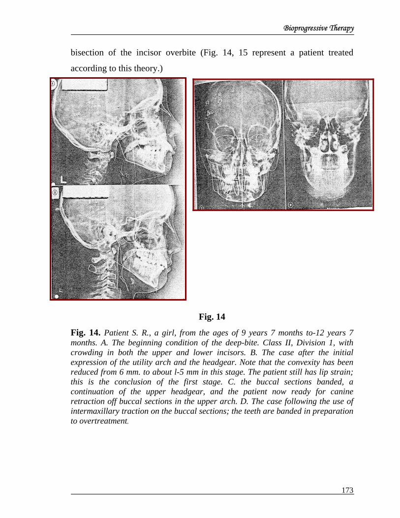
Bioprogressive Therapy
bisection of the incisor overbite (Fig. 14, 15 represent a patient treated
according to this theory.)
Fig. 14
Fig. 14. Patient S. R., a girl, from the ages of 9 years 7 months to-12 years 7 months. A. The beginning condition of the deep-bite. Class II, Division 1, with crowding in both the upper and lower incisors. B. The case after the initial expression of the utility arch and the headgear. Note that the convexity has been reduced from 6 mm. to about l-5 mm in this stage. The patient still has lip strain; this is the conclusion of the first stage. C. the buccal sections banded, a continuation of the upper headgear, and the patient now ready for canine retraction off buccal sections in the upper arch. D. The case following the use of intermaxillary traction on the buccal sections; the teeth are banded in preparation to overtreatment.
173

Bioprogressive Therapy
Fig.15 Fig.15. Patient S. R. A, The over treated stage showing the patient brought almost to an end-to-end relationship with full-banded therapy exercised; the patient is now ready for progressive debanding and space closure. Note the flattening of the denture from now to' retention. B. shows the patient wearing a fixed retainer from premolar to premolar in the lower arch. It shows an intermaxillary relationship that is holding and a convexity of 1 mm, together with the lower incisor to the APo plane of 1 mm, which is the peak of the curve of idealism in the treated orthodontic case. C, Frontal view with the nasal cavity narrowed and the upper arch narrowed. D. Frontal head film after treatment showing a good potency in the airway. The patient is holding well in retention.
Reduction of wire sizes. By this time the size of the wire was reduce
to a 0.016 inch square to be used routinely in the 0.018 by 0.030 inch
Siamese bracket. This technique and appliance provided a method for
maintaining three dimensional control at all times, especially at the very
174

Bioprogressive Therapy
beginning. A return of Angle’s original principle of three-plane controlled
forces throughout treatment was made. By employing the 0.016 by 0.016
inch blue Elgiloy utility arch with incisor depression, upper incisor extrusion
was avoided during space closure incisors traction and intermaxillary
traction.Techniques were designed to prevent the elongation of the lower
molars (just contrary to the prescribed effect of the Class II activator). In
addition, an effort to prevent some of the extrusion of the upper molars was
also made in certain open-bite or long-face cases during treatment. New
designs in the extraoral appliance were made for checking extrusion of the
maxillary molar.
Summary of bioprogressive development
Industrial technology in orthodontics led to preformed bands. With the
development of prewelds, the field gradually moved away from one simple
bracket or tube to a torque-tip rotation setup for individual teeth.
With these developments, the same general philosophy was extended into
providing preformed continuous arches, performed sections, and
predesigned modules to further eliminate work at chairside while increasing
control, efficiency and standardization.
As it was realized that orthopedic change was possible and that
maxillary alteration could be controlled, new application of the headgear
was made. The upper incisors were deliberately not banded until the later
phases of treatment. When it was observed that any of tie teeth could be
intruded, deep-bites were treated in the level of the premolars rather than
extruding the posterior teeth which rotated the mandible backward. As it was
realized that permanent expansion was possible through the premolar and
molar areas and that changes in arch depth could be quite significant to the
175

Bioprogressive Therapy
prognosis, a whole new attitude developed with regard to sophisticated
treatment planning.
Anchorage considerations
Although sixty features of this technique have been listed, for the
purpose of anchorage consideration only five major distinctive qualities are
covered here. These are orthopedic or skeletal alterations, the use of growth,
the concept of cybernetic feedback in planning, and muscle considerable.
Although cortical bone was discussed in Part I, more respect and discussion
for cortical bone is thought to be important enough to warrant further
attraction.
Extraoral traction (skeletal anchorage). The normal lower incisor
varies but balance homeostatically to both jaws (Fig. 16).
Fig.16.
Fig.16. The 13-year norm as programmed in the computer. At age 13 there is very little morphologic difference between males and females. Cut-offs for growth start at age 141/2 for girls while in boys growth continues to the average age of 19. Note that the lower incisors at -1 to -2 mm. ahead of the APo plane.
176

Bioprogressive Therapy
The incisor is conveniently measured between pogonion and point A
(the anterior limit of the denture base), from which areas the mouth muscles
originate. These points change and are changeable with treatment. Thus, the
calculation of original anchorage needs is related to two skeletal factors—
the mandible (represented by Pm) and the maxilla (represented by point A).
The essence in planning is the consideration of skeletal relations that will be
present at treatment s end and at majority together with functional
equilibrium of the lips.
A first major factor in the calculation of anchorage needs is the
determination of the tooth movement needed for the lower incisor. This
calculation starts with the amount of orthopedic change desired in point A or
a change in convexity (fig 17).
Fig.17
Fig.17. A. The composite of a group of thirty-one patients at age 8 years 8 months selected for Class II, high convexity. In comparison to the normal composite for that age the mandible is slightly shorter and reproduced and the maxilla is slightly protrusive, suggesting that class II malocclusion is a combination of both mandibular and maxillary problems. B, A cephalometric setup for the average of that group with 2 years of natural growth added to include changes for 2years. Note, for the ideal, the reduction of the convexity and the placement of the lower incisors at +1, 22 degrees to the APo plane, which satisfies the esthetic equilibrium of the soft tissues. C, The analysis of changes needed for treatment in the foregoing typical class II case. In the chin growth is downward is downward and forward 5.2 mm. and the facial axis is not changed. The upper molar is moved approximately 4 mm. downward and 2 mm. backward. Note, in b, the alteration of
177

Bioprogressive Therapy
the palatal and the movement of the upper incisor together with the palatal, as would be exhibit by the use of cervical traction in the condition. In c the before and after treatment tracings are superimposed over the corpus axis at Pm. Note that the lower incisor is introduced and brought forward; the molar is shifted forward approximately 2 mm. to account for the arch-form that usually accompanies treatment. Note also the relative change in the cant of the APo plane of point A is brought backward over the chin.
In a growing patient, however, the need for skeletal point A alteration
is first contingent upon the amount of convexity reduction caused by
mandibular behavior. The learned orthodontist is therefore obliged to make
some sort of estimate of ultimate facial morphology at maturity; whether he
calls it is prediction, a prognosis, or whatever.
The amount of change desired in the midface (point A and also the
soft tissue nose) affects the decision for the choice of direction of force, its
duration, and the timing of extraoral anchorage. Certain appliances are not
known to affect skeletal behavior; others have been shown to produce
effects. The needs decided upon affect the decision for anchorage
preparation and amount of force to be employed later with maxillary
traction. The convexity factor is to be considered even in simple Class I
extraction therapy. Therefore, a cephalometric setup – or at least, the
orthopedic thought form—is required in practically all cases for complete
sophistication (Fig. 17, B).
Natural growth as a factor in dental anchorage. Natural growth
expectancy – if understood—is a primary basis for planning. Orthodontics
involves a plan for either maintaining or moving the molar teeth. This is
obvious in Class II and Class III cases, but even in Class I eases with
178

Bioprogressive Therapy
extraction an issue may revolve around the amount of slippage forward of
molars permitted in space closure (fig 18).
Fig. 18
Fig. 18. - Patient M. F., c girl. A, At age 9 there is a Class I malocclusion with open-bite crowded dentition treated with modified secondary edgewise in 1954. B, The effects of intermaxillary elastics with slippage and elevation of the lower molar as a result of space closure and Class II traction. C, The behavior of the occlusal plane as a result of extraction and space closure. If the bite were closed, the occlusal plane would probably have tilted extensively.
Very simply, the effort was made to determine the contribution that
growth (or physiologic rotational change) can make toward the correction or
to the detraction of the case . Use of the growth forecast plus the added;
visualized treatment objective in a graphic form results in the treatment
design. From this the clinician may determine whether an arch needs to be
moved or left alone
179

Bioprogressive Therapy
Mandibular growth contributes to anchorage planning in that the jaw
movement through carries the entire arch and thereby reduces lower
anchorage need. On the other hand, unfavorable growth or behaviors
increases anchorage problems and further complicates the plan. Growth,
included in the setup, is therefore equated to mechanical anchorage and is a
very real phenomenon. A Treatment design with cephalometrics is quite
fundamental even when no growth is expected or when the patient is an
adult or a growing child with a Class I malocclusion (Figs. 19 and 20).
Fig. 19
Fig. 19. A, Renderings of Patient S. R. with the arch form and length as copies from the wax impression or the photographic processed copy of the cast as shown below. Note the 4 mm. convexity, the elevation of the lower incisor, and the excessive maxillary dental protrusion. C, A considering of the short-range forecast with the treatment design. D, The long force cut with ultimate arch form and size relationship based upon requirements of the case. Note questionable third molar space.
180

Bioprogressive Therapy
Anchorage needs are further complicated by two dental factors: the
needs of the upper arch and the needs of the lower arch.
Fig. 20, Fig. 20, A. The treatment design for Patient S. R., a girl, at age 9.54, constructed from comparisons of beginning, short-range, and long-range prognoses. The treatment alternatives on the right side will be noted, with certain findings programmed for treatment as required by patients of this kind. On the left is a comparison of the esthetics results at maturity. Note that the upper molar is to be moved backward approximately 4 mm. as the chin is growing forward and downward (in position 1). Note from position 2 that the maxilla and upper incisors are moved distally. Note also the change made from alveolar (in position 3). In position 4 the lower incisor will need to be intruded, while the lower molar needs to be stabilized. The treatment plan consisted of starting with the headgear on the upper arch and a utility on the lower arch, followed by continuing treatment with banding on the premolars in the lower and a section in the upper. This was followed, in turn, by a utility on the upper with intrusion and Class I intermaxillary fraction on the upper arch, leading up to idealization and finalization with progressive stripping. B, The actual analysis of Patient S. R. as treated, showing the strong relationship between the treatment planned by the computer and that actually produced. Compare the computer rendering to the actual changes as produced at short range (3 years as against 2 years in the plan).
181

Bioprogressive Therapy
Muscular effects on anchorage. Another major factor in anchorage
is the observation of muscular anchorage—muscle, first of all, from the
labiolingual or buccolingual complex as demonstrated by the bumper
techniques but further the kinetic chain of muscles concerned with the
opening or closing of the bite and the rotation of the mandible. Physiologic
stabilization of the mandible therefore, becomes a part of the consideration
in applying a technique for treatment.
It appeared from detailed cephalometric study that the lip was strong
enough to interference the entire dentition to a position more backward than
anticipated normally.
Later work in a series of clinical experiments led to the use of 0.045
inch wire placed around the arch and downward toward the sulcus; this was
labelled “bumper.” Observations of that technique led to the conclusion that
the lower lip alone was effective enough to move the lower molar distally,
followed by the drift of lower premolars. This was clear evidence of the
effectiveness of the perioral area not only to retract the anterior teeth but a
inhibition of forward development of the entire lower denture in anchorage
(Fig 21, A). The bumper came to be used infrequently because the utility
trades the incisors and increases arch length (Fig. 21, B)
182

Bioprogressive Therapy
Fig. 21 Fig. 21. A. The effect of a lip bumper in moving the lower molar distally. Note that the 3 mm. of space opened no between the lower second deciduous molar and the permanent molar as a result of the lip force from a 0.045 inch wire covered with and stopped at the mesial aspect of the molar and placed near the crevice third crown of the lower incisor. B, Similar effect on the lower first permanent molar in the patient treated with only the utility arch. Intrusion and advancement of the lower against the lower lip actually moved the lower molar distally, as shown on this.
Cortical anchorage as a fundamental factor. The fifth matter of
direct concern is cortical anchorage. Compact bone not only offers resistance
to the tooth movement but, conversely, it can be used for anchorage and is
recognized and employed to advantage . This is accomplished by situating
the teeth behind the heavy compact elements of bone so that the pressure of
the root is almost in direct contact with bone incapable of easy backward
resorption.
This has proved to be a main source of anchorage for intermaxillary
elastics for anchorage for retraction of teeth when it is desired that units
within the same arch be moved (Fig. 22).
183

Bioprogressive Therapy
Fig.22.
Fig.22. A, Case demonstrating the effect of cortical bone on anchorage. This was a full Class II, Division 1 case treated without banding of the premolars. Note the anchor position of the lower molar. At one time 500 Gm. on each side was exercised in intermaxillary elastic pull. B, Torque (22 degrees) double-tube design with utility engaged. C, Another case showing intermaxillary elastics used off the buccally torqued lower molar while at the some time the lower canine is being ligated downward as the upper buccal section it being reduced. D, Upper and lower utilities working to intrude the upper and lower incisors as elastics are employed to reduce the Class II malocclusion. Note that premolars are as yet not banded. E, Buccal root torque on molar also helps to prevent forward displacement during space closure in extraction case. F, Uprighting of molar will tend to occur naturally with normal forces of occlusion, but finishing should be conducted to preparation for this event.
As movements were routinely studied, teeth did not always move as
had been anticipated under usual prescriptions. In the analysis of these
situations it was discovered that the roots did not move when teeth were
brought into high pressure contact with the cortical plate of bone.
Consequently, a study was conducted in which cortical bone was
investigated at different stages of development. As the lower molar was
tipped buccally at its roots and trapped beneath the external oblique ridge of
external alveolar plate of bone in the mandible, better stability was observed
(fig.22). Anchorage, therefore, seemed to be effectively enhanced by a
184

Bioprogressive Therapy
procedure for holding or producing “buccal root torque” while at the same
are slightly expanding.
As the lower molar was tipped distally, the root seemed to be trapped
beneath buccal plate and consequently became the anchor site. The crowd
was observed to move distally by a tip-back bend on the molar at the same
time that it was buccally expanded, particularly with the utility arch free of
premolar banding (fig. 23).
Fig. 23
Fig. 23 The analysis of Patient R. V., case shown in Fig. 45, A Class reduced by elastics and no premolars banded. A, Before treatment, at age 13 years 2 months. B, after class II traction, at 13 years 11 months. C, Four years later ct 17 years 8 months. D, Analysis shows orthopedics of maxilla and only very slight displacement of molar with oral root movement during uprighting.
185

Bioprogressive Therapy
SUMMARY
While edgewise was the background, sufficient departure from
traditional edgewise therapy has been made to warrant a new label,
“bioprogressive therapy. It was so named because of the practice of
progressive banding and a planned progression of events in sequential order.
Eight steps usually form the frame of reference. Ironically, it can be applied
in the very young and in the very old.
In order to fully apply the recommendation of the proponents of this
method, mechanical forecasting, physiologic forecasting.
Size 0.016 by 0.016 inch blue Elgiloy wire is commonly but not
extensively used. Loops or forms are bent in the wire for lighter and more
continuous pressure on teeth to be moved. Soldering of auxiliaries has been
eliminated as well as the heat treating of wires. The 0.016 by 0.016 inch to
0.016 by 0.022 inch yellow. Elgiloy is used for detailing near the end of
treatment. The 0.018 by 0.022 inch is the largest wire employed, and it is
used for spanning distances between teeth in the progressive debanding
phases.
Anchor teeth are stabilized against cortical bone; hence, cortical
anchorage. In order to position and control the teeth behind or away from
cortical bone or against away from muscle or to intrude into or extrude away
from the bony alveolus three-plane control is utilized. A limited use of round
wire employed with this technique except for specific isolated conditions m
which there is place for tipping or simple alignment and rotation of teeth.
Used as a triple-control technique, the progressive method excels in proper
overtreatment and for, delivery of anchorage.
186

Bioprogressive Therapy
A continuous arc-h is broken up into segments or sections so that
movements in desired planes of space are not complicated and anchorage
can be shifted is favor of the desired move.
The technique usually involves orthopedic correction, particularly in
the maxilla, when such corrections are needed. When this technique is
combined with the activator or mandibular posturing devices, an application
can be made to provide an anchorage approach to include growth and
maxillary and mandibular orthopedics.
Muscle anchorage definitely is considered in anchorage planning and
utilized in its fullest application, even to posttreatment rebound.
The leveling of the arch by the extrusion of the premolars is
considered to be contraindicated. Thus, intrusion of anterior teeth, either
upper or lower, is a practiced art with a bioprogressive technique.
With this approach, a tremendously wide range of flexibility is possible, and
overtreatment is the byword. This flexibility permits the clinician to
overcome tooth-size discrepancies, as overtreatment of a part of the arch can
easily be attained.
Another virtue of the “progressive” approach to treatment is
particularly thought provoking: absolute standardization is not appealing and
is the aim. Rather, a body of principles has been developed. In depth
diagnosis, prognosis, and designing are advocated for patient, depending
upon his particular individual needs.
Visual objective “designing” with cephalometrics as a reference for
planning is strongly recommended, although “intuitive planning” is
187

Bioprogressive Therapy
practiced with this method as well as others. In applying specific progressive
therapy to its greater potential, however, the biologic and mechanical
principles are put together cephalometrically for each individual patient only
after his unique personal requirements are determined. In this manner, the
philosophy and science of orthodontics can be practiced with the spirit of the
artist.
188

Utility Arch
UTILITY ARCH
Every major approach to orthodontics has had one characteristic
which stands out in the minds of orthodontic clinicians universally as a
medium for describing that particular approach or technique. Probably the
most recognizable single entity in the bioprogressive therapy would be that
of the UTILITY ARCH. It forms the base unit around which the mechanics
in all types of cases can be employed. It is the catalyst which ties together all
the different types of mechanotherapy.
The utility arch was born following the observation of depressed
lower, second bicuspids in extraction cases. Following the move to lighter
forces into the range Storey’s recommendations from a studies in 1952, it
was not until about 1958 that oblique x ray studies showed, with sectional
retraction, the lower second bicuspid could not withstand the tipping force
against the first molar during unusual space closure.
It has been assumed, based on previous histological work and the
ascertains of biologists and histologists in the field, that intrusion of teeth
was impossibility. During space closure with loops, however, the canines
often tipped backward excessively, particularly with rapid closure. In
addition, the molar and bicuspid as a unit both tipped together. Actually, this
action intruded the bicuspid.
In seeking a method to maintain an upright position on the lower
molar and to thereby prevent bicuspid intrusion and the further collapse of
the bite as many had previously witnessed in extraction cases. Ricketts made
an attempt to employ the four lower incisors as anchorage in some manner.
Single tubes were still in use on the lower molars. So, a simple .016 round
189

Utility Arch
wire was formed as a continuous arch, placed under the second bicuspid
brackets and loped over the molar tubes at the end, to be locked down
behind the extension of the section retractor. This move before activation put
the forward part of the arch downward toward the sulcus and, as it was
raised and engaged in the lower incisors, it exerted an elongating affect on
the bicuspid as a lever against the molars.
Fig. 1
Fig 1 When the lower utility arch is engaged In the lower Incisors, approximately 50 to 75 grams (A) of Intrusive force should be applied. Slight labial root torque (5° to 10°) allows the lower Incisor to avoid cortical bone in its intrusive movement (B).
This set up served to keep the anchor unit upright In observing the
behaviour of this mechanical arrangement it was soon discovered that the
lower incisors tended to tilt forward, but also they were seen-to depress.
Careful examination of intraoral x-rays and cephalometric tracings
confirmed that the incisors had intruded. This rapid movement tended also to
extrude the canine and tip it distally as the sectional was employed at that
time.
Simultaneous with that development Ricketts attempted to reduce the
wire size and character together with loop designs to keep the force within
the 150 gins limit hypothesized then for cuspid retraction. The need for
190

Utility Arch
lighter wires with milder forces had suggested the need for narrower bracket
slots. A move down to the .018 bracket was made after certain experiments,
and because of the discovered need for a second wire or section to operate in
a different plane of space, the dual or double tube was initiated. Also in
order to control the flaring of the lower incisors, the force was further
reduced and a .016 x .016 blue Eligilogy was designed. Because of the span
in the arch designed. Because of the need for a longer level with lighter
force, it took the present form of the U arch. A step mesial to the molar was
made as a buccal bridge section was formed together with an anterior step to
reach up to engage incisors. In the beginning, it was only to be used together
with retraction sections in extraction cases.
However after having made the observation of intrusion of the lower
teeth, further applications of this design were made. Tipbacks against the
molars with light wires began to show also an intrusion of the lower canines.
The incisors remained in deep bite as it then became a greater problem to
intrude the lower incisors through the depressed canines without again
extruding them and tipping them distally. Obviously it was almost an
impossibility to work these teeth simultaneously in the most desired
positions in both planes of space. The utility arch then became the method of
choice as a starting appliance in deep bites or with crowded lower anterior
conditions.
Multiple loops were designed to engage the anterior teeth in crowded
cases and subsequently it was seen that a wide variety of conditions could be
handled. It could be used to gain arch length it could be used to close arch
length. The loops could be incorporated at the location of any of the bends
because the form of the arch itself constituted long vertical loops on either
191
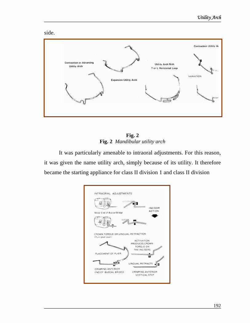
Utility Arch
side.
Fig. 2
Fig. 2 Mandibular utility arch
It was particularly amenable to intraoral adjustments. For this reason,
it was given the name utility arch, simply because of its utility. It therefore
became the starting appliance for class II division 1 and class II division
192

Utility Arch
Fig 3 Intraoral adjustments
It becomes the appliance in the mixed dentition case in order to avoid
most of the need for banding of the primary teeth.
Many clinicians tried to abuse the use of the utility as did Ricketts in
the beginning. It is hard to realize that a .016x.016 blue Elgiloy wire will
offer sufficient strength and stability to do the job for which it is proposed.
Just because the utility arch is a starting appliance, it should be understood
that it can be employed again any time during the course of treatment to
regain lest overbite due to retraction of anteriors. A wide Varity of stock
utility arches are available and can be adapted into routine daily practice.
Fig 4 Utility Arch
TYPES OF UTILITY ARCHES: -
Although many configurations for utility arches have been described
four types of arches can be defined, based on their use.
Passive Utility Arch
The Passive Utility Arch (Fig. 5) is used for stabilization or space
maintenance in either the mixed or permanent dentition. A passive utility
193

Utility Arch
arch can be used in the mixed dentition to maintain arch length during the
transition of the dentition. In many respects, the utility arch acts in the same
manner as a lingual arch because the passive utility arch prevents the mesial
migration of the molars, particularly in the lower arch. The utility arch also
may influence the eruption of the posterior teeth by holding the cheek
musculature away from erupting teeth, allowing for spontaneous arch
widening.
Fig. 5. Passive utility arch. Note that the posterior vertical segment fits snugly against the auxiliary tube of the lower molar band.
The passive utility arch also is used in the permanent dentition,
primarily for the maintenance of anchorage. In non-extraction patients, the
passive utility arch is particularly useful after molar distalization has been
completed
In many techniques (e.g., Wilson distalizing arch, NITI coils,
distalizing magnets), a large space is opened posterior to the upper second
premolars as the first permanent molar is distalized . One of the challenges
to the clinician is to maintain molar anchorage while the upper premolars are
retracted. In combination with a transpalatal arch, extraoral traction, or a
Nance holding arch, a passive utility arch can be used to incorporate the
194

Utility Arch
anterior teeth as anchor units . “Driftodontics” (i.e., tooth movement
produced without active orthodontic forces being applied) then are used to
allow the premolars to migrate posteriorly without active orthodontic
treatment.
Passive utility arches also are used as anchorage appliances in
extraction cases . Prior to canine retraction, a passive utility arch that
extends from the first molars to the incisors is placed. Canine retraction then
is initiated, using the incisors as additional anchor units.)
Activation. No activation of the passive utility arch is required.
Intrusion Utility Arch: -
The intrusion utility arch (Fig. 6) is similar in design to the passive
utility arch, but this arch is activated to intrude the anterior teeth (Otto et al.,
1980).
Fig. 6. Intrusion utility arch. A) The intrusion utility arch first is bent passively to the existing occlusion. Note that the posterior vertical segment lies at least 5 mm ahead of the auxiliary tube on the lower first molar. B) Retraction of lower incisors can be produced by grasping the distal end of the molar segment with a pair of Weingart pliers, pulling the segment posteriorly, and then turning the segment gingivally. C) Intrusive forces can be produced by using a loop-forming
195

Utility Arch
plier to place an occlusally-directed gable bend in the posterior aspect of the vestibular segment.
After activation, a light continuous force is delivered by the long lever
arm from the molars to the incisors. The utility arch should produce 60-100
gms of force on the lower incisors, a force level considered ideal for lower
incisor intrusion (Bench et al., 1978). The overall effect is intrusion and
possible torquing of the lower incisors as well as a tipping back of the lower
molars . Expansion or contraction of intermolar width can be achieved by
widening or narrowing the archwire. Molar rotation is produced by
appropriately activating the molar segments of the arch.
Activation. Two types of forces can be produced using this design:
retraction and intrusion. With a simple utility arch, a modest amount of
incisor retraction can be achieved by grasping the end of the molar segment
with a Weingart plier distal to the molar tube and then turning this segment
gingivally after pulling the wire posteriorly through the tube (Fig. 6B). Care
must be taken that the protruding end of the wire does not encroach on the
soft tissue of both the cheek and gingiva. This type of activation prevents
proclination of the lower incisors during intrusion.
Intrusion of the anterior teeth can be produced in one of two ways.
First, the utility arch can be bent passively to fit the existing occlusion, as
has been described previously. After ligating the utility arch into the anterior
brackets, an intrusive force can be produced by placing an occlusally-
directed gable bend in the posterior portion of the vestibular segment of the
archwire (Fig. 6C). A loop-forming plier, such as the 881 loop-forming plier
(Masel Orthodontics, Bristol, PA), can be used for this type of intraoral
activation. These loop-bending pliers must have a concave surface next to
196

Utility Arch
the loop-forming portion of the plier; therefore, not all loop-bending pliers,
such as omega loop-forming pliers, can be used for intraoral activation of the
utility arch.
Bench (1988) has advocated an alternative method of activation of the
utility arch to produce intrusion. This type of activation involves placing a
tip-back bend in the molar segment. The tip-back bend causes the incisal
segment of the archwire to lie in the vestibular sulcus. The intrusion force is
created by placing the incisal segment of the utility arch into the brackets of
the incisors. This activation creates a moment that allows for the long action
of the lever arm of the utility arch to intrude lower incisors. It has been our
experience that placing distal crown torque in the molar segment sometimes
leads to a posterior tipping of the first molars. Thus, activating the utility
arch by placing a gable bend in the posterior aspect of the vestibular segment
(Fig. 6C) seems to avoid unwanted molar tipping. In the case of a maxillary
utility arch, tipping of the molars also is reduced through the concurrent use
of a transpalatal arch.
Bench (Bench et al., 1978; Bench, 1988) also recommends the
placement of buccal root torque in the lower molar region to anchor the roots
of the molars in cortical bone. This type of force also produces lingual
crown torque that is counterbalanced by placing 10 mm of expansion in the
utility arch in the molar region during appliance fabrication.
Retraction Utility Arch: -
The most common type of utility arch used by the senior author is the
retraction utility arch (Fig. 7A). This type of utility arch can be used in either
the mixed or permanent dentition to achieve retraction and intrusion of the
197

Utility Arch
incisors by incorporating loops in the archwire anterior to the anterior
vestibular segment.
Retraction (Fig. 7B) and intrusion (Fig. 7C) can be produced by
activating the retraction arch in a similar fashion previously described for the
intrusion utility arch. The incorporation of the loop into the design allows for
a longer range of activation. Perhaps the most common use of the retraction
utility arch is during the final stages of comprehensive edgewise treatment.
In an extraction case in which the canines have been retracted, space opens
distal to the upper lateral incisors. In non-extraction cases, a similar but
smaller space is often open distal to the lateral incisors due to molar and
premolar rotation as well as due to Class II mechanics.
Fig. 7
Fig. 7. Sagittal view of maxillary re' action utility arch. A) Before activation. B) Retraction of the molar segment of the archwire. C) An occlusally-directed gable bend has been placed in the vestibular segment of the archwire to produce incisor intrusion.
A retrusion utility arch can be used to close this space by retracting
the upper incisors. This arch also provides the necessary intrusion that often
198

Utility Arch
must precede the retraction of anterior teeth.
The retraction utility arch is used less commonly in the mandible.
However, it may be used in cases of dentoalveolar anterior crossbite in
which there is some proclination and spacing of the lower incisors. In these
types of cases, the anterior crossbite can be corrected using a retrusion utility
arch, while the spacing between the incisors is eliminated through the use of
elastomeric chain.
Utility arches also can be combined with bonded orthopedic
appliances. For example, buccal tubes can be incorporated into a variety of
acrylic splint appliances (e.g., bonded RME, Herbst). A utility arch can be
fabricated so that it is anchored posteriorly in the buccal tubes of the bonded
appliance and then can be used to move the anterior teeth in all three planes
of space.
At this point, a 900 bend is placed with a 142 arch-bending plier. A
loop-bending plier is used to place a loop in which the end of the anterior leg
crosses behind the posterior leg. After a 5-8 mm vertical segment is formed,
another right angle bend then carries the wire across the anterior teeth. A
gentle anterior contour is placed in the wire to simulate arch form, and an
offset also is placed in the canine region.
On the other side of the arch, the anterior vertical step is created in the
interproximal area between the lateral incisor and canine. The retraction loop
is formed with the loop-bending plier and then the loop-bending plier (rather
than the arch-forming plier) is used to create the 90° bend in the horizontal
vestibular segment .The wire then extends to the posterior vertical segment
at the middle of the second premolar. In most instances, the length of the
199

Utility Arch
horizontal vestibular segment can be estimated, based on the length of the
horizontal segment on the opposite side. Care must be taken to make sure
that the utility arch does not encroach upon any fixed appliances present,
including ball hooks or Kobayashi hooks.
Activation. As with the intrusion utility arch, there are two possible
types of activation. First, a Weingart plier can be used to grasp the extension
of the utility arch posterior to the auxiliary tube. The wire is pulled 3-5 mm
posteriorly and then bent upward at an angle. Care must be taken that this
protruding end of the utility arch does not impinge on the cheek or gingiva.
Second, an occlusally-directed gable bend in the vestibular segment can be
used to produce intrusion, as has been shown previously in Fig. 7C.
Protraction Utility Arch: -
The protraction utility arch (Fig. 8) is useful for proclining and
intruding upper and lower incisors.
Fig. 8
Fig. 8. Protraction utility arch. Note that the posterior vertical segment is flush against the auxiliary molar tube. When passive, the anterior portion of the utility arch should lie approximately 2-3 mm ahead of the incisor brackets.
In the permanent dentition, it is used commonly for proclining and
intruding maxillary incisors in Class II, division 2 cases, especially in
200

Utility Arch
patients with an impinging overbite (Fig. 9).
Fig. 9.
Fig. 9. Movement of upper incisors using a protraction utility arch. A) Simple flaring. B) Protrusion and intrusion.
This archwire is used to provide clearance between the upper and
lower incisors to allow for placement of brackets on the lower dental arch.
The protraction utility arch also is used during the presurgical orthodontic
phase of treatment in patients undergoing a mandibular advancement to
decompensate the position of the upper incisors.
This type of utility arch also is used during the mixed-dentition period
prior to functional jaw orthopedic appliance therapy. In the case of Class II
patients who have retruded upper incisors, brackets can be placed on the
upper anterior teeth, and bands can be placed on the upper first molars
(perhaps supported by a transpalatal arch). A utility arch can be used to
procline and intrude the incisors as necessary. Often a simple intrusion arch
without loops is needed in the lower arch.
The anterior vertical step is usually 5-8 mm in length, depending on
patient tolerance. The incisal segment courses through the incisor brackets,
and the utility arch is completed in a similar fashion on the other side.
Activation. When the protrusive utility arch is passive, the anterior
201

Utility Arch
segment lies about 2-3 mm anterior to its ultimate position in the incisor
brackets. The protrusive force is produced by tying the anterior segment of
the utility arch into the anterior brackets. An occlusally-directed gable bend
in the posterior aspect of the vestibular segment is used to produce intrusion.
The protrusion arch is reactivated by removing the anterior segment
from the brackets, bending the posterior vertical step forward from 90° to
45° and replacing the arch wire in the brackets. Other adjustments can be
made in both the anterior and posterior vertical steps to produce further
activation.
CLINICAL PROBLEMS
By far, the major complications associated with the use of utility arch
involve the soft tissue. One of the major difficulties in fabricating the utility
arch, whether it is for the maxilla or the mandible, is in placing the
horizontal vestibular segment between the gingival and buccal tissues. If the
posterior step is made too long, or if the horizontal segment encroaches on
the gingival tissue, the wire can become embedded easily. If the horizontal
vestibular segment is placed too far laterally, tissue irritation and the buildup
of fibrous tissue along the inside of the cheek can occur; In instances in
which tissue irritation occurs in the areas adjacent to the vestibular portion
of the utility arch, clear or grey sleeving (“bumper sleeve”) may be used to
shield the tissue from the edges of the wire.
Another major area of concern is the formation of the loops of the
retraction utility arch. If these loops extend too far into the vestibular area or
protrude anteriorly, severe irritation can result and patient discomfort can
occur. The patient should be given wax at the delivery appointment to aid in
202

Utility Arch
the break-in period after the utility arch has been inserted.
203

The Quad Helix Appliance
THE QUAD HELIX APPLIANCE
(Innovation by Dr Ricketts) The quad helix appliance is an evolution from a type of vulcanite
appliance originally advocated by coffin. The plain w arch expansion palatal
type of appliance originally was used by Ricketts to treat cleft palate
conditions. It was particularly advantageous because more action could be
gained in the anterior area than in the posterior area (or the reverse could be
true depending upon the activation). Many problems were encountered in its
early use, particularly when it was made in the laboratory on the cast. Very
often the .040 gold wires employed originally would be annealed at the site
of the solder attachment and the forces of occlusion would distort the
appliance. The general form of this palatal appliance is similar in form to the
basic Crozat maxillary appliance. Also about this same time in 1947, a
button was being placed on the palate with half round tubes for the use by
Nance for holding arches. Ricketts modified this by placing loops for back
action and building in active rotation.
In the beginning it was assumed that this was simply a dental
appliance but after the advent of suture splitting, Ricketts studied many
frontal head films of patients treated with the appliance which suggested that
nasal cavity had widened more than the normal growth expectations.
In order to widen the range and yield more flexibility Ricketts
incorporated helix loops in the posterior loops at the start. Later two more
were employed in the anterior part of the palatal arch. With the advent of
preformed bands, it was decided that the appliance could be made directly,
just as it could be formed in the laboratory. Because the appliance would be
203

The Quad Helix Appliance
reactivated before insertion, it was not thought necessary, to be adapted in
the absolute manner as would be on the cast. Therefore the notion was
formed that this could be performed and prefabricated which would assist in
quality control, standardization and efficiency in operation, and it was
labeled the quad helix as descriptive of the four loops.
Fig1.The quad-helix
In the beginning, it was called two in one, three in one or four in one
appliance. Because the appliance is made with preformed bands with tubes
previously mounted, it can also be used (after it has been deactivated) for a
face bow attachment. Used passively and without activation, it can serve as a
holding appliance. However, with the arms usually expanded resting against
the lingual surface of the crowns of the upper canines or at the cervical
margins of the tooth, it is usually considered to be an expansion appliance
plus a rotation appliance.
When a palatal bar is constructed forward and bent downward in the
mouth, it also may serve as a thumb sucking habit breaking appliance. If
spikes are introduced against the anterior section and pointed downward in
the space between the teeth, it is used as a thumb appliance.
204

The Quad Helix Appliance
Fig 2. Modifications of the quad-helix appliance
If light spikes are soldered on the bar and extended downward, it can
serve as a tongue thrust appliance. It can also be used as an anterior bite
jumping appliance, or an appliance to unravel the crowding in anterior teeth
when lighter palatal wires are extended to the anterior teeth. The basic
appliance, therefore, has many uses and many forms or adaptations and is
remarkably efficient.
Recent Research-
Dr Ricketts mentioned that the quad helix appliance exerts a palatal
suture widening effect. It is slower and not as dramatic, but it separates the
suture in pace with the speed of new formation of bone. As the frontal
section of the laminograph x-rays were studied by Dr Ricketts, it appeared
that new bone remodeling took place at a slower pace.
It appeared that after six months the effects of the jackscrew and quad
helix were similar in extent of final nasal floor involvement.
One of the problem that was encountered with the use of the quad
helix appliance, particularly used with excessive expansion, was that of
tipping of the teeth outward. This could be guarded to some extent by
torquing the roots buccally.
205
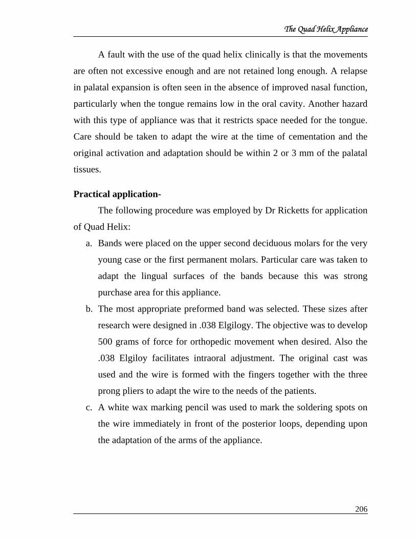
The Quad Helix Appliance
A fault with the use of the quad helix clinically is that the movements
are often not excessive enough and are not retained long enough. A relapse
in palatal expansion is often seen in the absence of improved nasal function,
particularly when the tongue remains low in the oral cavity. Another hazard
with this type of appliance was that it restricts space needed for the tongue.
Care should be taken to adapt the wire at the time of cementation and the
original activation and adaptation should be within 2 or 3 mm of the palatal
tissues.
Practical application-
The following procedure was employed by Dr Ricketts for application
of Quad Helix:
a. Bands were placed on the upper second deciduous molars for the very
young case or the first permanent molars. Particular care was taken to
adapt the lingual surfaces of the bands because this was strong
purchase area for this appliance.
b. The most appropriate preformed band was selected. These sizes after
research were designed in .038 Elgilogy. The objective was to develop
500 grams of force for orthopedic movement when desired. Also the
.038 Elgiloy facilitates intraoral adjustment. The original cast was
used and the wire is formed with the fingers together with the three
prong pliers to adapt the wire to the needs of the patients.
c. A white wax marking pencil was used to mark the soldering spots on
the wire immediately in front of the posterior loops, depending upon
the adaptation of the arms of the appliance.
206

The Quad Helix Appliance
d. A solder stick was used to flow the solder on the wire. The band was
picked up in the tongs and approximated as the low fusing solder was
flowed in to the position.
e. The amount of activation desired was placed on the wire.
f. The appliance was cemented, making sure the bands were well seated.
There is reciprocal action, so the appliance must be activated during
the cementing procedure.
g. A wide three prong pliers was used for final adaptation and activation.
Fig. 3 Initial activation of quad-helix appliance for insertion.
Clinical Management-
A six week interval was usually observed before any further activation
is needed. At the second visit, intraoral adjustments were made following
which another six week period was observed. Activation was made by
placing the pliers directly anterior to the posterior loop. The anterior arms
can be adjusted independently of the molar activation by placing the pliers
anterior to the molar.
Widening, contraction or uprighting the molars could be activated by
pinching between the anterior loops. Usually only a little activation was
made of the anterior arms and the wire is left out of contact with the anterior
teeth until molar rotation was achieved. This was one of the outstanding
features of this appliance because molar rotation is most often a problem.
207

The Quad Helix Appliance
Upper molar rotation could be gained immediately. Space was also gained
very soon for the erupting side teeth, particularly the crowded upper lateral
incisors.
Indications-
Several particular conditions thus seemed appropriate for this
appliance by Dr Ricketts
1. All cross bites in which the upper arch needs to be widened.
2. Cases needing mild expansion in the mixed or permanent dentition,
which frequently exhibit lack of space for the upper laterals and in which
the long range growth forecast is favorable.
3. Cases of class II in which the upper arch needs to be widened effectively
and the upper molar rotated distally.
4. Class III conditions in which the upper arch needs to be widened and
advanced with class II elastics.
5. Thumb sucking or tongue thrusting cases with its various modifications.
6. Cleft palate conditions either unilateral or bilateral.
Fig 4 Quad helix Appliance
208

Early Treatment
EARLY TREATMENT
Stages of Early Treatment
For teaching and organizational purposes, Ricketts divided the subject
into four phases. The first phase of treatment is called “Preventive”. The
first approach to “early treatment” is in the decidious or primary dentition, or
even earlier.
The second phase is in the mixed dentition, and called as
“Interceptive”. The interceptive label applies because the clinician is
intercepting the evelopment or eruption of the teeth during the transition
from the mixed to the permanent dentition.
The last two categories are not “Early”. The third phase is
“Corrective” in terms of having available the permanent teeth to
manipulate. This is a popular course to follow for those using multibanded
or tooth-bearing appliances. Ricketts mentioned that some orthodontists like
to wait until the 12-year molars are erupted to start treatment. When this is
the situation, the initiation of the corrective phase may be detained up to 15
or 16 years of age because patients often experience delayed eruption of the
upper second molars and very late development of the upper thirds.
The last stage is called “Rehabilitative” because it applies to the
adult. Rehabilitating a case with no growth or little potential of physiologic
change falls in this category therefore, under adult orthodontics. Adults take
a much different approach.
209

Early Treatment Interceptive Orthodontics
It is approached, particularly in the mixed dentition as space is made
for eruption of the permanent teeth or orthopaedic alteration of jaw bases is
attempted.
The youngest patient that Ricketts has ever treated was one week of
age. In some cleft palate patients a restraining device is used against the
premaxilla within the first week of life. There is a question about the
wisdom of doing this routinely, and he did not recommended it except in
very extreme cases in which inadequate lip tissue is present or want to wait
for growth to give the surgeon a better opportunity with a larger bulk of
tissue.
Patient in the Deciduous Dentition
Ricketts did not try to work with any teeth until the second deciduous
molars have erupted. This tooth usually erupts at about age two and one-
half, and the roots are fully formed at about age three. But there is another
factor which influences the clinician to delay starting patients until age four
or five years, and it involves the practical control and clinical management
of the very young patient who is quite sensitive.
Records at Start of Treatment on Such Young Patients
Frontal and lateral headfilm, laminagraphs on sides, a panoral film,
and photographs. Failure to diagnose and prognose at this age is one of the
big mistakes.
The Nasal Airway Problems and Lack of Function
Most orthodontists and researchers in growth simply haven't looked at
the nasal cavity as a vital vegetative part of the face and talk about the oral
210

Early Treatment cavity as if it is independent of the development of the first branchial arch
and independent from respiration. Biologically, the functions of mastication
and respiration have been connected with the same set of muscles and the
same set of nerve paths.
In frontal headfilms, a small nasal cavity on one side and a larger one
on the other side is seen. It may be that the patient had a unilateral
obstruction and see the whole maxilla sucked inward and upward on that
side. The best place to start is by taking routine frontal headfilms and look
for symmetry of the nasal cavity. This is one of the primary uses of the
frontal headfilm. Figure 1 demonstrates the effects of removal of adenoids,
palatal expansion, and orthopedic headgear.
Fig.1
Fig.1. A. Female, age 7.8 years, adenoid patient with bilateral lingual crossbite. Note adenoid, low tongue, and upward cant of palate. B. Note narrow nasal cavity and narrow molars and position of unerupted canines. C. Rest position, showing habitual wide space and parted lips for oral breathing. D. Same patient at age 10.2 after adenoidectomy, palatal widening, and cervical traction. Note level of palate, closed lips, and elevated tongue. E. at age 10.2, note 6 mm increase in width of nasal cavity (from 25 to 31mm) in just over 2 years. F. Patient at finishing stage of nonextraction treatment, almost 13 years. Note normal airway.
211

Early Treatment
Microrhino Dysplasia
Dr Ricketts mentioned that if the nasal cavity isn't developing
properly, the tilt of the palate will frequently be elevated in front, as if it has
been stopped in its vertical growth in the anterior part.
The lack of function in the nose seems to hold the front of the palate
upward or prevent its downward descent. In these children clinically, you
look right in their nose holes and the whole nose appears to be higher
relative to the orbits.
A microrhino case (microrhino meaning small nose or small nasal
cavity) will develop on its own from lack of function of the nose. Also the
palatal growth inhibition as a result of certain kinds of vigorous
thumbsucking in which a patient gets the whole shank of the thumb up into a
markedly open bite and actually inhibits the downward dropping of the
palate anteriorly.
The microrhino’s patient who has a thumbsucking habit is a very good
prospect for us to manage orthodontically with extraoral traction,
particularly with the Kloehn headgear. Palate can be brought down and tip
backward to correct the malocclusion .It can also be done with a skeletal
change rather than doing it by movement of the-teeth. It could come from
allergies and asthma or even potential adenoidal obstruction.
An imbalanced facial height results in the untreated child. Nose is
short, the nose tip is upward, the nostrils show, the upper facial height is
short, and the denture height is extremely long. These cases are very difficult
to treat later without surgery in the maxilla because of the extreme distance
212

Early Treatment from the anterior nasal spine to the chin, requiring a stretching of the lips
and creating unbalanced strain over that dentition. Later, with large denture
height, teeth often are extracted or held backward; and still the patient ends
up with mentalis action to compensate for the high denture height. Even with
extraction, these patients still possess gummy smiles, the denture height and
lip line do not match.
Importance of Tonsils and Adenoids
Ricketts theorized in the 50’s: adenoids could lead to an opening
growth rotation of the mandible, and dealing with not only an inhibition of
maxillary growth but also an alteration of mandibular growth in a patient
who is effectively obstructed in the nasal cavity. With this kind of
information, a very strong recommendation, particularly when patient’s x-
rays confirm the diagnosis can be done.
Recommendation in thumbsucking patient with a Class II, Division 1
protrusive malocclusion in a mixed dentition, an open bite, a tongue
thrust.
Dr Ricketts advised first to get adequate full records and study the
case in terms of arch length and in terms of an assessment of the nature of
the problem. For the history, inquire into the type of thumbsucking the
patient is doing, perhaps even talk to the parents in private with regard to
their attitude and what the child's home environment is. Then the records are
processed and after the prognosis is made, using the long-range forecast get
a frontal and lateral assessment with printouts to get a forecast of the
patient's probable growth and a visualization of what the corrected face
should look like. This then provides something to use as a feedback to make
the decisions.
213

Early Treatment
Start that patient with the quad helix appliance to which some spurs
may be added if necessary. He started the rotation of the molars, the
widening of the arch, and the Class II correction with that appliance, all at
the same time. Then, as a second objective, he would suggest that this
patient be treated skeletally so that the patient will have the opportunity to
express normal development through the mixed dentition.
Application of Headgear to Deciduous Molars
Ricketts used it on both deciduous and permanent molars. He used a
headgear on the upper second deciduous molars. If the upper second
deciduous molars are fully formed at the age of three and last until the age of
ten, we can put headgear on them just the same as we can put it on the first
permanent molars and the same orthopedic effect is achieved as later with
the first permanent molars, because the facial bones of the juvenile are more
responsive and there is a mandibular growth spurt at that level.
Headgear at about the age of four or five in a Class II malocclusion treats the
malocclusion rather rapidly.
Pressure Factors
Ricketts stated that fifty (50) grams is light, one-hundred fifty (150)
grams is considered intermediate force and five hundred (500) grams is for
orthopedic treatment. The force applied is 500 grams a side, which means
that you have 1000 grams total on the back of the neck.
Early Intervention and Early Treatment
Ricketts made a clear distinction between the goals and objectives of
early treatment versus later treatment. A distinct objective of the late
treatment in the permanent dentition is occlusal perfection. We can have the
214

Early Treatment opportunities in the mixed and in the deciduous dentition ages to make
skeletal changes and to utilize growth and to intercept habit patterns and
functional patterns that we will not have at a later stage.
Dr Ricketts made a clear distinction between the concept of setting up
the jaws at the young level rather than setting up teeth at the late level. The
permanent stage is left for refinement and finishing, rather than for the gross
treatment of malocclusion. The tissues will show the difference between the
two concepts and the stability will also be more than gratifying when
comparisons are made.
In conclusion, he believed that early treatment can save the teeth and
at the same time produce esthetics of the jaws as well as the teeth,
accomplish optimal function before its too late and achieve remarkable
stability.
215

Headgear
HEADGEAR
Headgear traction is often a primary appliance or a starting device
even at the permanent dentition level. Although a simple face bow appliance
seems simple, it is a much more complicated tool than often considered.
Great inconsistencies, differences in design and application have resulted
from the lack of knowledge of the possibilities and advantages of these
procedures.
EVOLUTION OF EXTRA-ORAL TRACTION:
The use of extraoral force is about 100 years old. The head cap” was
described by Kingsley in 1866 and Farrar in 187O’s. However its objective
was limited to retraction of upper anterior teeth as an outer brace was
attached to labial arch bow engaged in crude bands or other forms of
attachment to the anterior. The ‘caps” were formed from leather strips or
cloth.
Angle in 1888 recommended that it be worn during the sleeping
hours. Intramaxillary elastic rubber bands were used for traction by day. The
use of this appliance was limited to maxillary dental protrusion in patients
following upper first bicuspid extraction.
By 1888 Goddard formed forerunner of head gears attached to rubber
positioners currently used sometimes.
In 1898 Guilford talked about directional pull by activating rubber
strands of the “skull cap” above or below the ear and his cap designs of 1
inch strips were grossly similar to many now in use.
216

Headgear
Thus, up through the turn of the century extra-oral force was the main
source of retraction of protrusive incisors.
By 1921, Case had extended the application of extra-oral therapy.
Angle at the same time was looking more toward intra-oral or intermaxillary
traction (Bake anchorage) and preserving the upper bicuspids. Case went on
to describe three different extra-oral applications, all of which employed
“sliding buckles for least possible discomfort”. First, was the usual
directional pulls up the long axis of the maxillary anterior following
maxillary extraction. Second, was an attachment to the lower anterior, to be
used in open bites or protrusive conditions, also after lower extraction. Third
and here is the first solid mention of upper molars to be moved distally the
labial bar was extended, to the bicuspid area on the dental arch wire and
forced the molars and entire arch backward (Much like Fisher mentioned
later.) However, in the meantime, Angle had apparently won. For the next
15 years, great. emphasis was placed on intermaxillary traction and full
banding of teeth was initiated by Oppenhiem from Vienna, also in 1936.
Although Oppenhiem presented his findings in 1936. the first cephalometric
analysis of treated cases was presented by Brodie and the Illinois staff in
1938. It was determined that orthodontic treatment used at this time had little
effect on structures other than alveolus and successes could be usually
explained by holding of the maxillary dentition while growth of the
mandible occurred.
Despite the theoretical opposition work started to be exhibited to show
the effectiveness of the “head cap”. Kloehn reported at an Angle meeting in
1947 and made certain speculations from models and facial photograph
records. Nelson in 1950, and both Nelson and Jerabak in a 1952 Tweed
217
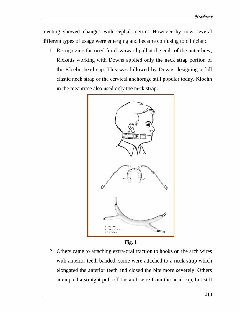
Headgear
meeting showed changes with cephalometrics However by now several
different types of usage were emerging and became confusing to clinician;.
1. Recognizing the need for downward pull at the ends of the outer bow,
Ricketts working with Downs applied only the neck strap portion of
the Kloehn head cap. This was followed by Downs designing a full
elastic neck strap or the cervical anchorage still popular today. Kloehn
in the meantime also used only the neck strap.
Fig. 1
2. Others came to attaching extra-oral traction to hooks on the arch wires
with anterior teeth banded, some were attached to a neck strap which
elongated the anterior teeth and closed the bite more severely. Others
attempted a straight pull off the arch wire from the head cap, but still
218

Headgear
used no face bow (Jarabak 1951) .Still others chose to attach a smaller
dental bow to the edgewise arch wire in the bicuspid area and used the
neck or head for anchorage , as many now use it with the full banded
appliance.
3. Finally, the full arch was banded and “high pull” was reintroduced to
intrude the upper incisors.
Fig. 2
Among all these methods, the Kloehn approach, with the neck strap
he later adopted, became the method of choice, With cervical traction only
arch length benefits even an the lower arch were appearing, Debates
occurred as to the benefits of bite plates being used in conjunction with the
headgear. Facial changes were often spectacular, but remained controversial.
All through these years the headgear appliances were being hand
made. Brass wire was wrapped around the dental and face bow contacts to
219

Headgear
act as a soldering assembly, the ends remained flexible and force applied at
the apex of the arch moved the molars sideways and contributed to arch
expansion. Beads of solder were employed as stops against the molar tubes.
In order to prevent distal tipping the outer bow was extended upward,
to the level of the tragus of the ear, This also caused molar extrusion which
aided in bite opening. A change was made from this tube set-up. However
recognizing the problem of molar extrusion, 045 tubes were switched to a
gingival location and bent bayonet stops were made with three-prong pliers.
By 1955 the face bows were being made commercially. In order to
add stability and prevent breakage, two errors were introduced. One, the
dental bow came to be made much too inflexible or rigid. Two, the dental
arch was bent on a radius too small for a normal arch. Obviously, they were
designed by men disciplined in extraction therapy and arch contraction.
Clinical research led to contraction and expansion type head gears for
specific purposes. Arch changes were observed which could not be
accounted for properly, such as spacing of the upper anteriors and width
increases in bicuspids. However, other biologic factors now entered the
picture. By 1955, Ricketts recognized maxillary change beyond the alveolar
process and started building it into the objectives and treatment plan
projection. Working with Klein, a series of cases clearly demonstrated
alterations of growth behavior of the nasal floor. These were accumulated
until 1960 when Ricketts compared 100 non-treated cases to 100 head gear
cases over a period of 30 months, and in which strong forces were
employed. The findings of Dr Ricketts study regarding behavior of the
palate and point A with head gear treatment were eleven times greater than
necessary to be statistically significant; It was no longer an argument.
220

Headgear
Careful study of the frontal and lateral headplates showed sutures
widening and in some patients an opening of the frontonasal suture was
noted with plain Kloehn face bow use. Finally, the nasal cavity was
observed to widen under the influence of cervical anchorage when the
molars were given the chance to widen and a continuous arch was not
present to inhibit maxillary separation. In addition, the palatal tipping
downward anteriorly rotated the nasal floor backward. The anterior area and
nasal spine took the soft tissue nose with it.
In order to gain space for this action in the maxilla, the lower incisors
came to be deliberately overintruded in many deep bite cases. All this time
Ricketts recommended only 14 hours of wear during non-school hours, and
no bite plates were employed.
At about the time of the foregoing observations, Schudy and others
recognized undesirable rotation of the mandible and an anti-Kloehn Moye
took place. In order to encourage forward chin behavior, the neck strap was
replaced by an oblique upward pull above the ear. This helped intrude the
molar. Ricketts had tried this approach in a few patients in 1956, but he
observed the Class II correction to be not as rapid and perhaps the patients
were not good examples, may be the force was not great enough or
continuous enough. At any rate, his results were not impressive in
prevention of severely long facial pattern growth (over a long period of
time).
Several factors, therefore, needed to be taken into account in the
design of a new Ricketts’ headgear, The features and uses are listed.
1. Observations over a period of two decades have led to the conclusion
that a neck strap force of 500 grams will produce orthopedic effects
221

Headgear
This meant a strong bow, unannealed, to prevent bending or breakage
and laser welding was introduced to control the wire properties.
2. The closer to the centroid of the root the force is applied, the less the
extrusion forces will be needed.
3. Banding the anterior teeth and placing a continuous arch tends to bind
the two halves of the maxilla together and prevents convenient
permanent expansion, If these teeth were banded, the continuous arch
wire was not to be used, as the dental bow can rest under the incisal
bracket wing. The dental bow is progressively expanded as it is light
enough to flare under tension.
4. An extra anterior elastic is not employed except on a very limited
basis because of the needless throwing of them into overbite. The
dental bow is engaged directly against the anterior teeth at the
gingival 1/3. This helps move the total maxillary complex.
In order to prevent shock on the anteriors a plastic covering of the
laser weld was designed. Esthetics was also a problem and a reason
for the plastic covering.
5. The inner bow was constructed “for center ground .05 tapered to a
.045. This insured stability of weld and provided delicacy and
flexibility and less discomfort to the molar teeth.
6. Progressive rotation of molars was needed. The dental bow material
was made ductile and capable of numerous bends without breaking.
7. The inner bow also may serve as a ‘Lateral bumper’. This meant a
larger radius for the anterior curve and also required bayonets to be
bent inward thereby keeping the dental bow outward and freeing the
buccal teeth of cheek or lip contact to permit natural development.
8. Wide variation in arch width is experienced. Two designs were made
222

Headgear
one for either deciduous or small permanent extracted arches and the
other for normal and large arches.
9. The headgear is to be worn 14 hours each day in the non-school hours,
but some day wear is permissible. This will permit physiologic
rebound during the day hours and promote less damage to anchor
teeth.
10. The outer bow needs to clear the angle of the mouth. This meant a
gentle labial step to the outer bow.
11. Some patients need prevention of upper molar extrusion These often
are patients with vertical patterns, low pain threshold. Poor
mandibular physiology or damaged condyles. A loop was placed
slightly mesial to the molars to receive a second highpull headgear
with variable pull to prevent molar elongation. While the main pull
came off the neckstrap.
12. Cleanliness of the neck strap holds down neck infections. The elastic
strap with pad is discarded when it is wornout or dirty. It is made
adjustable to the tolerance of the patient by a buckle and fixed loop.
13. The hooks are bent outward to engage the neck strap. The right hook
is shortened to lock on the strap which is permanently fixed on the
right side for ease of application and remembering by the patient.
14. The appliance may be needed later as part time retainer. The materials
are durable, capable of sterilizations and capable of long term service.
With the foregoing factors in mind, the use of extra-oral traction can
be quite versatile.
In summary, several features characterize its possible application.
1. It can be used as a tooth moving appliance when applied with light
223

Headgear
forces (200 - 300 grams).
2. Tooth movement alone is slower in Class II correction and much more
time is needed for treatment for the mandible to grow enough to make
the correction. (This is where the computer growth set-up comes in, or
at least a good manual objective forecast.).
3. It can be truly an orthopedic appliance used with heavy forces (500
grams or over). Almost two-thirds of the actual correction is made by
skeletal change in the typical case with facial convexity.
(Intermaxillary traction is used in non-orthopedic cases for reciprocal
movements.)
4. Upon initial application the dental bow is advanced only 1 to 2mm
from the incisors. As the molars start backward the incisor crowns are
engaged at the cervical 1/3 and continue to upright almost ideally with
further wearing without banding. This permits natural favorable
adjustments to occur in both arches.
5. The younger the patient the better the chance of orthopedic correction.
The young child sleeps longer and seems to adapt and cooperate
better. It is used on the deciduous second molars at preschool ages.
6. It can be overused and produce undesirable concavity to the profile.
7. It can be misused or disastrously employed in patients where molar
corrections are inadvisable from the beginning, even resorption of the
disto-buccal root. (Hence, the need for diagnosis and objective
planning.
8. Extraoral traction is best used as a biologic appliance as growth,
physiologic and eruption factors are combined with the orthopedic
qualities in the under-standing of its behavior. These constitute great
advantages in current bioprogressive therapy.
224

Headgear
9. Above all it must be recognized that changes with its use are three
dimensional and are usually permanent and stable when retention
consists of progressive release.
225

Management Umbrella And VTO
MANAGEMENT UMBRELLA AND VTO
Dr Ricketts states that management is a unique skill; it is the ability to
get other people to work with you and for you, to accomplish common
objectives. In an orthodontic practice, getting the subordinates to work with
you and for you is to treat the patient to happy ending, and to manage the
patient so that he gives full cooperation in his treatment.
Management System for Orthodontics
As per Dr Ricketts management system for orthodontists should
include the following three things;
1. Quality: This includes quality of treatment result.
2. Quantity: This includes the number of patients treated.
3. Effectiveness – This includes the effectiveness treatment design and
office management.
According to Ricketts good management system should allow the
increase of all these factors at the same time. Naturally, a system proceeds
form some basic premises, which underlie the approach selected.
The basic premises as per Dr Ricketts are as follows:
1. Primary goal in orthodontics is satisfactory outcome. Diagnosis and
treatment management is really the means to the end. Results come
first. The question is how to do we get our results.
2. The practice of orthodontics in the future may be different from what
it is today or has been in the past. Practice efficiency has always been
important but it is of the utmost importance today because of the
increasing difficulty in attracting patients, due to an increase in
226

Management Umbrella And VTO
orthodontists and decreases in the birth rate; the control of third party
programs; and the rapid acceleration of the cost of operation.
3. Orthodontics being the oldest specialty in dentistry should be the
leader in initiating true preventive procedures for the future.
4. Early treatment has to be a part of futuristic orthodontic planning
since it is essential to preventive procedures for the future.
5. The orthodontist should be an authority on occlusion, including
temporomandibular joint function.
6. Quantity is not necessarily an enemy of quality, if quality comes first.
7. The orthodontists needs better communication with patient’s parents,
dentists and the public.
8. Time is one of our most valuable asses. It is reason in itself to become
involved in a total management process.
The system which Ricketts used is the Lewis A. Allen Management
System, which is based on a simple formula to plan organize, lead and
control
1. Planning: The work performed predetermines a course of action to
be followed.
2. Organizing: The work performed to arrange and relate the tasks to
be accomplished.
3. Leading: The work performed to insure that people act in such a
way as to complete our objectives.
4. Controlling: The work performed assesses and regulate results.
227

Management Umbrella And VTO
The management Umbrella Concept by Dr Ricketts
The management of the total practice according to Ricketts ultimately
determines the degree of efficiency and effectiveness with which the
orthodontist solves individual patient problems.
Knowledge of theory and skilled application of technique provide the
basis for orthodontic practice, yet success depends on the achievement of the
additional objectives of administrative efficiency, procedural control, and
quality assurance. The methods of systems engineering, operations research
and management science when applied to Orthodontics produce innovative
practice designs and procedures that increase both the effectiveness of
service and professional satisfaction.
Diagnosis and Treatment Design
According to Ricketts the more systematized is the diagnosis and
treatment design less are the complications. In developing diagnostic and
treatment design system, the simplest things that are done every day are
thought about.
Three major objectives of orthodontic treatment:
1. Ideal functional occlusion.
2. The physiological stability of our results.
Total facial balance (cosmetics of the face and teeth)
228

Management Umbrella And VTO
Dr Ricketts listed following basic premise of Orthodontic treatment
1. Occlusion
a. Tooth to bone health
b. Intermaxillary efficiency
c. Health of TMJ
2. Functional Equilibrium
a. Tonsil and adenoid evaluation
b. Habits
c. Musculature
3. Aesthetic Equilibrium (Soft Tissue Analysis)
4. Growth and Development
Therefore the five functions of planning apply as follows
1. Forecasting the growth of the individual patient.
2. Setting the objectives through the use of V.T.O. which is like a
blueprint in building a home.
3. Program a sequence of mechanics to get the objective from visual
treatment objective.
4. Schedule an average time for these mechanics to function.
5. Budget to develop individually the cost for treating this case.
Ricketts felt that systems are necessary to develop the policies and
procedures to make this happen routinely. He briefly outlined the steps of
the diagnostic and treatment design system for Bio-Progressive Therapy,
which he referred to as diagnostic programming.
229

Management Umbrella And VTO
In superimposition Area 1 (Basion-Nasion CC), Evaluation 1 is chin
change. In this case, the objective is to allow 20 of opening of the facial axis,
to except the amount of chin growth shown, and to except that the upper
molar will grow down the facial axis.
In superimposition Area 2 (Basion –Nasion at Nasion), Evaluation 2 is
maxillary change, one of the objectives is to reduce point A only 2mm in
this case.
In superimposition Area 3 (Corpus Axis at PM), Evaluation 3 is the lower
incisors. In this case, just tipping of the lower incisors slightly is done. In
Superimposition Area 3 also have Evaluation 4, the lower molars. In this
case advancing the lower molars approximately 4mm.
In Superimposition Area 4 (Palate at ANS), Evaluation 5, the upper
molars. In this case, upper molars are held even though this is Class II
230
Management Umbrella And VTO
division 1 malocclusion. Superimposition Area 4 also includes Evaluation 6,
the upper incisor, and it is seen that the upper incisors have to be distalised.
In superimposition Area 5 (Esthetic Plane), Evaluation 7, the soft tissue
and it is observed that there is a great amount soft tissue reduction in this
case.
Dr Ricketts mentioned VTO as a blue print used in building house
visual to forecast normal growth of patient and the anticipated influences of
the treatment, to establish the individual objectives in treatment for growing
patient must be planned and directed to the face and structure that the patient
presents initially. The treatment plan should take advantage of the beneficial
aspects of growth and minimize any undesirable effects of growth possible.
The visual treatment objective permits the development of alternative
treatment plans. After setting up the teeth ideally within the anticipated or
growth facial pattern, the orthodontist must decide how far he must go with
mechanics and orthodontics to achieve them and what the alternatives.
In 1950-60 Ricketts attempted to predict treatment results and studied
the possibility of growth forecasting. This was an outgrowth of
cephalometric laminography of the temporomandibular joint. Long term
growth forecasting had not proven trustworthy with the methods of
projection used during the years of 1950 to 1965. However short term
forecasting did prove adequate for the period of actual treatment when
combined with the likely effects of the treatment. Treatment designs
incorporating growth effects had proven to be quite appropriate and indeed
could be recommended at a clinical level for the establishment of objectives
and the planning of anchorage.
231

Management Umbrella And VTO
This idea was pricked up by Holdaway and termed a Visualized
Treatment objective “, which was descriptive of the application, existing
morphology and expected growth in modular increments provided a
reference base. Superimposed on this behavior were the requirements of the
individual patient, in terms of objectives and the required tooth movement.
Desired changes in anterior teeth could be followed by the set up of the
molars, depending on the needs and estimates of anchorage and arch form
change.
Thus VTO as described by Dr Ricketts was very important for treatment planning and one of t
232

Ricketts Cephalometric Analysis
Ricketts Cephalometric Analysis
Clinical Application of Cephalometrics
In 1960 Ricketts published two clinical papers, first was a report on
the morphologic findings in 1000 cases consecutively seen in clinical
practice.
He dealt with description of morphology and dental relationship on
one hand and on the other hand he discussed classification, categorizing
conditions in terms of their clinical requirements and difficulty. The third
was the study of change, comparing the morphology of a single patient at
different stages of development or treatment. the fourth was its application
in communication of the first three among clinicians and researchers, and
between clinician and patient.
The fourth application made the clinician using cephalometrics stand
above the rest. With the ability to describe and compare came the ability to
explain things and to find out new information never before available.
Above all was the ability to communicate with -the rest of the profession in
a sophisticated and meaningful language.
The second publication of 1960 by Ricketts was on analysis of treated
cases. The possibilities and the effects of treatment using multibanded
orthodontic technique and extraoral traction, the main sources of correction
of that day, were explored in depth with cephalometrics.
Changes were measured in five different areas in a logical sequence.
First were the changes in the cranial base. The second area was changes in
the lower jaw complex, the third in the upper jaw complex and the fourth in
233

Ricketts Cephalometric Analysis
the upper and lower dentures. The fifth area was soft tissue changes in the
nose and lips.
Rickets analysis
All Cephalometric analysis involve the identification of various
craniofacial landmarks many such landmarks are traditional. Others however
may be unique to a specific analysis. The less traditional points, planes, and
axis used in Rickett’s analysis are as follows.
Fig 1
A6 Upper molar A point on the occlusal plane located
perpendicular to the distal surface of the crown
of the upper first molar.
B6 Lower molar A point on the occlusal plane located
perpendicular to the distal surface of the crwon
of the lower first molar.
234

Ricketts Cephalometric Analysis
C1 Condyle A point on the anterior curve of the soft tissue
chin tangent to the esthetic plane or E-Line.
DT Soft tissue the point on the anterior curve of the soft tissue
chin tangent to the esthetic plane or E-line
CC Center of
cranium
The point of intersection of the basion nasion
plane and the facial axis
CF Center of
cranium
The point of intersection of the pterygoid root
vertical to the Frankfort horizontal plane.
PT PT point The junction of the pterygomaxillary fissure and
the foramen rotundum: the outline of the
foramen rotudum can be located by using the
template designed for that purpose (Jacobson-
Sadowsky lip counter template, Unitek Corp) or
it can be approximated at the 10:30 (face of a
clock) position on the circular outline of the
superior border of the pterygomaxillary fissure.
DC Condyle The point in the center of condyle neck along
the Ba-N plane
En Nose A point on the soft tissue nose tangent to the
esthetic plane or e-line
Gn Gnathion A point at the intersection of the facial and the
mandibular planes (cephalometric Gn as a
opposed to anatomic Go)
PM Suprapogonion The point at which the shape of the symphysis
mentalis changes from convex to concave also
know as protuberance menti.
235

Ricketts Cephalometric Analysis
Pog Pogonion The point on the bony symphysis tangent to the
facial plane.
PO Cephalometric The intersection of the facial plane and the
corpus axis
TI TI point The point of intersection of the occlusal and the
facial planes
Xi Xi point The location of the Xi point given below .
Definition and location of Xi point
The location of the X points is keyed geometrically to the Franfort
horizontal and the pterygoid root vertical planes (PtV). The procedure
follows:
1. Locate FH and draw PtV plane prependicualr to the FH plane.
2. Construct four planes tangent to points R-1, R-2, R-3 and R-4 on the
borders of the ramus
a. R-1: Deepest point on the anterior border of the ramus, located
halfway between the superior and the inferior curves.
b. Located on the posterior border of the ramus opposite R-1
c. Deepest point of the sigmoid notch, halfway between the
anterior and the posterior curves.
d. Opposite R-3 on the inferior border of the mandible.
3. The constructed planes from a rectangle enclosing the ramus.
4. Xi points is located in the center of the rectangle at the intersection of
the diagonals.
236

Ricketts Cephalometric Analysis
Fig 2
Definition and location of planes
1. Frankfort horizontal : Extends from portion to orbitale
2. Facial plane: Extends nasion to pogonion
3. Mandibular plane :Extends from gonion to gnathion (cephalometric
landmarks previously defined)
4. PtV (Pterygoid vertical): A vertical line drawn through the distal
radiographic outline of the pterygomaxillary fissure and perpendicular
to the Frankfort horizontal.
5. Basion-nasion plane: Extends from basion to nasion; divides the face
and cranium
6. Occlusal plane : The functional occlusal plane s represented by a line
extending through the first molars and premolars.
7. A –Pog line: A line from point A to Pogonion is often to as the dental
plane.
The esthetic line or plane extending from the soft tissue tip of the nose
237

Ricketts Cephalometric Analysis
(En) to the soft tissue chinpoint (DT).
Fig 3
Definition of location of axis: Facial axis: A line extending from the foramen Rotundum (PT to Gn)
Condylar axis: Extends from DC to Xi point used to describe the
morphologic features of the mandible.
Corpus axis: Extends from X to PM used to describe the morphology
of the mandible and to evaluate dentition changes.
Interpretation chart
Chin in Space Mean values for 9 yrs
old
Age Adjustments
Facial axis 900 + 3.50 No adjustment
Facial (angle) depth 870 + 30 Adjust + 10 every 3
years
Mandibular plane 260 + 4.50 Adjust -10 every 3 years
238

Ricketts Cephalometric Analysis
Convexity of point A 2mm + 2mm Adjust -1mm every 3
years
Lower incisor to A-Pog +1mm + 2mm No adjustment
Upper molar to PtV Age + 3mm Add 1mm per year
Lower incisor to A-Pog
Profile
220 + 40 No adjustments
Lower lip to E-plane -2mm + 2mm Less protrusive with
growth
Interpretation
Chin in Space
Facial axis The angle formed between the basion nasion plane and
the plane form foramen rotundum (PT) to gnathion. On
the average this angle is 90degreees. A lesser angle
suggest a retropositioned chin, whereas an angle greater
than a right angle suggests a protrusive or forward
growing chin.
Facial (depth)
angle
The angle between the facial plane (N-Pog) and the
Frankfort horizontal. This angle provides some
indication of the horizontal position of the chin. It also
suggest whether a skeletal class-II or III pattern is due to
the position of the mandible.
Mandibular plane Measure an angle to FH. On the average, this angle is 26
degrees at 9 years of age and decreases approximately 1
degree every 3 years. A high or steep mandibular plane
angle implies that an open bite may due to the skeletal
239

Ricketts Cephalometric Analysis
morphologic charcateristics of the mandible. A low
mandibular plane suggests the opposite (e. a deep bite)
Convexity
Convexity at a
point
The convexity of the middle of the face is measured
from point A to the facial plane (N-Pog). The clinical
norm at 9 years of age is 2.0 mm and decreases 1 degree
every 5 years. High convexity implies a class-II skeletal
pattern. Negative convexity suggests a class III skeletal
pattern.
Teeth
Lower incisor to
A-Pog
The A Pog line or plane is referred to as the denture
plane and is useful reference line from which to measure
the position of the anterior teth. Ideally the lower icisor
should be located 1.0mm ahead of the A-Pog line. This
measurement is used to define the protrusion of the
lower arch.
Upper molar to
PtV
This molar measurement is the distance from the
pterygoid vertical (back of the maxilla) to the distal of
the upper molar. On average this measurement should
equal the age of the patient +3.0 mm (e.g. a patient 11
years of age has a norm of 11 + 2 = 14mm . this
measurement assists in determining whether the
malocclusion is due to the position of the upper or lower
molar. It is also useful in deciding whether extractions
are necessary.
Lower incisor The angle between the long axis of the lower incisor and
240

Ricketts Cephalometric Analysis
inclinations the A-PO plane (1 to A-PO) is measured. On the
average this angle should be 28 degrees. This
measurement provides some idea of lower incisor
procumbency.
Profile
Lower lip to E-
Plane
The distance between the lower lip and the esthetic
(nose -chin) plane is an indication of the soft tissue
balance between the lips and the profile. The average
norm for this measurement is 2.0 mm at 9 years of the
age. The positive values are those ahead of the E-line.
Fig 4
241

The Golden Divider
THE GOLDEN DIVIDER
The golden divider may be used for morphologic analysis of the teeth,
the skeleton and the soft tissues of the face
Fig. 1 The Golden Divider
Fig. 1. It is based on the "Golden Section" also called the "Divine
Proportion". Upon widening the divider, it will be noted that a short side and
a longer side will be measured off proportionally as the divider is extended
Fig. 2 Widening the divider produces two measurements in a ratio of 1:1.618.
Fig. 2. The longer side is 1.618 times the shorter side and the shorter side is
0.618 the length of the longer. In turn, the longer side is 0.618 the length of
the total outer measurement. The golden relation (1:1.618) is called Phi and
242

The Golden Divider
given the Greek symbol f. This relation is based on underlying laws of
mathematics, geometry, and physics.
The use of this instrument applies to esthetic values, because so many
relations found to be beautiful to the human eye or comforting and pleasing
to the human psyche follow these proportions. But, of greater significance
are the biologic implications, as many things in nature follow the principle in
proportionality of the golden section, the golden triangle, and the golden
rectangle. The proportion is linked to growth and it relates to optimal
function. Hence, it can be used for analysis of structural harmony and
balance, and can be applied for treatment planning of the tooth, bone, and
soft tissue relationships for all forms of dentistry, maxillofacial and plastic
surgery.
Tooth Relationships
Useful parameters for the teeth start with the lower central incisors
(Fig. 3).
Fig. 3 Occlusion to demonstrate values
Thus, the total of both lower centrals (10.8mm) is golden to both
upper centrals (17.5mm), which starts a series of harmonic units in the
occlusion . The next golden relation (across the arch, not in direct width of
243
The Golden Divider
teeth) is the measurement between the distals of the two upper lateral
incisors (28.3mm) as related to the upper centrals (17.5mm). The next
progression is the-width to the buccal surfaces of the upper first bicuspids
(45.7mm), which is golden to the width through the lateral incisors in the
normal beautiful arch. This is generally lacking in patients with
malocclusion in all three types.
Another series is observed in from the width of the lower four incisors
(on the arch) at 22.1 mm. The upper intercanine width measured at the cusp
tips at 35.75mm is found in a golden relation to the lower incisors. Finally,
the width at the mesial of the upper second molars (57.8mm) will be found
to be in the golden relation to the intercanine width in beautiful arches,
which helps in assessing arch form.. The distance between the distals of the
lower canines (31.5mm) is golden to the distance between the lower first
molars (50.2mm) at the buccal grooves.
Soft Tissue Relationships
For the face, a connection is apparent in the smile, as the intercanine
width is observed to be the same as the width of the nose at the alar rim as
seen in a glamorous model.
For the width dimensions in the soft tissue, the nose, mouth, eyes and
face are related .If the lateral rim of the nose (LN) width is taken as a unit of
1.0, progressively the mouth (CH), lateral canthus of the two eyes (LC), and
the width of the head at the level of the eyebrow (TS) is a progressive golden
series.
For vertical relations, it is best to start with the underlying skeleton as
seen in the lateral cephalometric head plate. Eight golden relations were
244

The Golden Divider
identified from composites of 30 beautiful normal male subjects with ideal
normal occlusions. For the vertical location of the lower incisor, the Point A
(at subspinale in the maxilla) and the Point Pm (at the mental protuberance
of the mandible) is used. In centric occlusion, if the distance from Point A to
lower incisor tip is taken as 1.0, the height of the lower incisor to Pm is
1.618.
For relation of A to Pm itself, a golden proportion is seen to the
Frankfort plane (porion to orbitale). If the level of orbitale (lower rim of the
orbit) to Point A is taken as 1.0, the vertical height of the denture is 1.618,
suggesting normal denture height.
Other values for surgical or orthopedic corrections are seen as the
corpus axis (Pm to Xi point) is golden to the condyle axis (Xi to Condylion)
or posterior superior aspect of the condyle head. The Xi point is the
geographic center of the ramus. Also, maxillary depth is golden to
pharyngeal depth. The cranial structures are seen to be golden in the anterior
and posterior base S-N (1.618) + SBa (1.0). Nasion to cranial center (CC), at
1.618, is golden to cranial center to articulare on the Basion-Nasion plane.
For vertical facial relation in the soft tissue, another progressive series
is seen as confirmed from composites of normal beautiful faces . Here,
starting with the larger value, the face height is taken from Trichion (at the
top of the wrinkled forehead or near the hair line in the young) to the bottom
of the chin (soft tissue menton). If the lateral canthus level to Trichion is
taken as a unit of 1.0, the height of eye to chin is in the golden proportion, if
the face is beautiful. Inversely, from chin upward, the distance of the chin to
the curve of the ala of the nose is taken as a 1.0 value and 1.6 is seen from
245

The Golden Divider
the nose to Trichion. This makes nose length (lateral canthus height to alar
height) a congruent or reciprocal area or the "center" of the face.
From the eyes downward, a golden relation is seen from the nose (1.0)
to the chin (1.618). Inversely, the bottom of the chin to the mouth at 1.0
leaves a 1.6 proportion from the mouth to the eye. Like nose length, the
upper lip length is a reciprocal or an overlapping congruent area between the
eye-nose-mouth-chin proportions.
If the alar rim to the upper lip (to stomion or lip embrasure) is taken as
1.0, the distance to the chin is 1.6 and the same distance to the eye is 1.6.
This finally shows that three equal areas of the face are very nearly the same
in beautiful faces. These are forehead to eye, eye to mouth and nose to chin.
For locating golden proportions in the profile aspect, the same limits
of vertical proportions were found useful. It appeared that the base of the ear
lobe was the posterior limit to the face. To nose tip these formed three
golden rectangles like the foregoing equal areas, i.e. Trichion-eye, eye-
mouth and nose-chin. As the horizontal nose-tragus base is studied, a golden
section falls at the lateral canthus of the eye. Taking the eye-mouth vertical
as 1.6, the canthus to nose rim is 1.0.
246

The Golden Divider
Fig. 4 Golden proportion from eye-nose-chin
Figure 4 shows the golden divider applied to the eye-nose-chin for
facial height.
Fig. 5 Golden proportion from nose-mouth-chin
Figure 5 shows the divider on the ala of the nose, lip embrasure and
chin to determine denture height and lip position.
247

ANIMALS AND GOLDEN PROPORTION

PLANTS AND FRUITS IN GOLDEN PROPORTION

MONOMENTS IN GOLDEN PROPORTION

FACES IN GOLDEN PROPORTION

HAND AND HEART BEAT IN GOLDEN
PROPORTION

SOLAR SYSTEM IN GOLDEN PROPORTION

Radiographic evaluation of transverse skeletal discrepancies
RADIOGRAPHIC EVALUATION OF TRANSVERSE
SKELETAL DISCREPANCIES
The posterior-anterior (PA) cephalogram is the most readily available
and reliable radiograph for identification and evaluation of transverse
skeletal discrepancy. A standardised PA cephalometric radiographic
technique that will allow superimposition of radiographs, comparison of
linear measurements and evaluation of radiographs over time should be
employed. Ricketts developed the Rocky Mountain Analysis and he
suggested norms and choose specific radiographic landmarks. They were
JR – Jugale right;
JL – Jugale left;
AG – Antegonion right;
GA –Antegonion left;
ZR – Zygomatic light;
ZL –Zygomatic left
Using these landmarks, the effective maxillary width, effective
mandibular width, and the frontolateral facial lines can be constructed.
The effective maxillary width defines the width of the maxilla and is the
linear measurement between the points JL and JR (bilateral points on the
jugale process at the intersection of the outline of the maxillary tuberosity
and the zygomatic buttress). The effective mandibular width defines the
265
Radiographic evaluation of transverse skeletal discrepancies
width of the mandible and is the linear measurement between the points AG
and GA (bilateral points at the lateral inferior margin of the antegonial
protuberance). The frontolateral facial lines are two lateral lines constructed
from ZR, ZL (bilateral points on the medial margins of the
zygomaticofrontal suture, at the intersection of the orbit) to points AG and
GA.
By using these landmarks, two separate differential measurements
were utilized to evaluate transverse maxillary deficiency radiographically by
Ricketts:
1. The maxillomandibular width differential
2. The maxillomandibular transverse differential index.
The maxillomandibular width differential is a measurement from the
frontolateral facial line to JL and JR respectively, along the effective
maxillary width line. This measurement is calculated independently for each
side and compared with a normal value of 10+/1.5 mm. If this radiographic
measurement is greater than 10mm, a transverse discrepancy between the
maxilla and mandible is present. The difference between the measured
distance and 10 mm summed from each of the two sides is the total
transverse deficiency. This method is useful for determining the total
discrepancy and demonstrating if there is a greater deficiency on one side or
the other. However, it is not useful for determining in which arch the
discrepancy is located.
The maxillomandibular tranverse differential index is the expected
maxillomandibular difference (an established norm for different ages) minus
the actual measured maxillomandibular difference. The expected
266
Radiographic evaluation of transverse skeletal discrepancies
maxillomandibular difference is defined as the age-appropriate expected J
Point – J point distance, the actual maxillomandibular difference is defined
as the actual AG-GA measurement minus the actual J point –J point
measurement.
If in a skeletally mature patient (15.5 years or older) the
maxillomandibular transverse differential index is greater than 5mm,
surgically assisted expansion may be indicated. If the differential index is
less than or equal to 5mm orthodontic or orthodpaedic expansion may
effectively correct or camouflage the transverse skeletal problem. This
method allows easier identification of which arch is deficient or excessive
because actual values can be compared to normal value. These normal
values were suggested for the Caucasian race and should not be considered
normal values for all races and ethnic groups.
267

Truth in Orthodontic Beliefs
TRUTH IN ORTHODONTIC BELIEFS
Ricketts addressed the following statements in the editorial of truth in
orthodontic belief.
1 “Molars do not intrude”
It was denied that the muscles of mastication can exert an intruding
effect on molars through function. In other words, Ricketts believed that
closing jaw muscles are not strong enough to exert an intruding pressure.
As the growth turgor of the mandible is expressed, and as facial
development occurs, greater intermaxillary distance is created.
Teeth erupt into the space developed as the jaws grow apart (Fig. 1).
Fig. 1 Fig. 1 Composite growth superimpositions of 73 untreated children.
Consequently, the molars continue to erupt until growth is completed (unless impeded by the tongue, as observed in posterior open bite).
268

Truth in Orthodontic Beliefs
Recent findings indicate that the lower first molar erupts from the corpus axis a mean of nearly 0.5mm per year. The upper first molar erupts a mean of 0.7mm per year from the palatal plane (Fig. 2).
Fig. 2 Fig. 2 Additional superimpositions of 73 untreated children, showing eruption patterns of upper and lower first molars.
On the mandibular growth arc, however, the whole arch moves
upward and forward. As viewed biologically, the first molar erupts about
1.2mm per year in a vertical direction (Figs. 3, 4).
269

Truth in Orthodontic Beliefs
Fig. 3 Fig. 3 Typical pattern of mandibular arcial growth
Fig. 4 Fig. 4 Eruption of lower first molar along mandibular growth arc in
sample of 73 untreated children.
Furthermore, it is clear that in longer faces, as greater-than-average
vertical development occurs, the teeth compensate by filling in the additional
space until they encounter muscle resistance to their eruptive force (Fig. 5).
270

Truth in Orthodontic Beliefs
Fig. 5 Fig. 5 Morphology of long-faced patient (Bacchus) compared to short-faced patient (Adam).
One can estimate, on the basis of animal studies and clinical findings,
that the pressure of eruption is 0.2 grams per square millimeter of enface
root surface. This would place the eruptive capacity of each of the first
molars, upper and lower in the range of 20-25g.
Theoretically, any continuous magnitude of force in this range would
essentially inhibit molar eruption. Any greater continuous pressure would
produce an intrusion, as estimated from a starting force of not more than 80g
for clinical practice. Such forces are easily within the limits of the muscles
of mastication, which is measured in kilograms.
Of great importance to this issue is the behaviour of the lower molars
during cervical traction of the upper molar in the correction of Class II
271

Truth in Orthodontic Beliefs
malocclusion. There is of course, a vertical component to cervical traction
that prevents molar tipping. If heavy, continuous forces are exerted on a 20
or more hour a day basis with cervical traction, the muscles of mastication
will often overcome. This behavior has been described as the "Wedge
effect".
However, if forces do not exceed 500g in the mixed dentition (or 350g
in the deciduous dentition) and bite plates are not used, and pain has not
been overwhelming to the patient, with extrusion of the upper molar, the
lower molar has been seen to intrude in hundreds of patients. This is not
merely an anecdotal finding.
Fig. 6 Fig. 6 Three cases in which intrusion of lower molars accompanied extrusion of upper molars from cervical traction.
In these patients, the occlusal plane, which originally was located above
Xi point, moves downward during treatment to the level of Xi point (or
preferably, below it). Measurements from the corpus axis during the period
272

Truth in Orthodontic Beliefs
of cervical traction show the lower molar to be decidedly intruded by 2mm
or more, when it should have been erupting 0.5mm per year. This occurs
with no appliance on the lower arch. When a utility arch is placed for
management of the lower arch, buccal torquing of the roots of the lower
molar will produce even further gains in lower molar intrusion or lower
molar crown height reduction during cervical traction.
The pull of the elastics, which exert a vertical force of about 50g, would
normally cause the lower molar to be extruded and the upper molar to be
intruded, as measured from the palatal plane. Upper molar intrusion from
Class II elastics would, of course, occur primarily in patients who do not
yield by lowering of the mandible. Therefore, in these patients the forces of
mastication intruded the upper molars.
In conclusion, to build an orthodontic philosophy upon the belief that a
molar cannot be intruded by the forces of mastication would be a
miscalculation.
2. "Management of the vertical growth of the alveolar processes as the
primary function of the orthodontist."
Ricketts have shown some evidence that in the short term (meaning
the one-year period of treatment), the vertical growth of the condyle at the
ramus can also be affected with cervical traction. This can be seen in a
greater increase in ramus height during treatment than would have been
expected without treatment (Fig. 6). Even more important, high-pull traction
to the upper arch can intrude the upper molar, with a resultant loss of vertical
support or even compression of the mandible, which would inhibit some
condylar and mandibular growth.
273

Truth in Orthodontic Beliefs
All of these influences with the possible exception of treatment-
induced condylar compression and damage seem to have a transitory effect.
Within three to five years after treatment, mandibular growth is usually but
not always restored to its predicted size and general form.
The next statement is, "Vertical growth of the posterior portion of the
maxilla cannot be stimulated or inhibited." It is true that it is difficult to get a
handle on the body of the maxilla from a purchase on the teeth, which are
held in the alveolar process.
Movement of the entire upper jaw complex, including the
intermediate bones, has been demonstrated beyond any shadow of a doubt
by Dr Ricketts.
Fig. 7 Fig. 7 Comparison of changes in maxillary base, measured by SNA angle, between 100 treated Class 11 cases, 10 years after treatment, and 100 untreated cases.
274

Truth in Orthodontic Beliefs
In conclusion, the assumption that control of the alveolar processes is
the sole possibility for vertical orthodontic management of the growing child
is consistent with an ideology that will eventually become a relic of the past.
3. "Lower incisors should not be intruded to level the arch in growing
patients."
Dr Ricketts mentioned that when composites are compared to controls
of normals (corrected for age, size, and sex), it is easily observed that in
most deep bites, the lower incisor is in supraversion. In deep-bite Class II
conditions with high convexity, the lower molar is near normal and all the
other teeth are in abnormal positions.
Fig. 8. Fig. 8. A. Normal sample at age 8. B. Class II, deep-bite, high-convexity sample at age 8. C. Components of the Class II condition.
He believed that the lower incisor can be successfully intruded, when
proper upper incisor position and interincisal angles are restored and when
normal function is established, the relationship will hold. Cases with lower
incisor intrusion were demonstrated to be stable 30 years ago. The utility
275

Truth in Orthodontic Beliefs
arch was developed in 1960, and many other modalities are currently used
for management of the lower incisor.
According to Ricketts the lower incisor may be difficult to manage
properly with round wires. For best long-term stability, best control of the
mandible, and best utilization of growth during treatment must be achieved
and in deep-bite cases treat to the level of the lower first premolar rather
than extruding. This provides the least disturbance to the facial pattern, and
ensures the least likelihood of post-treatment adjustment by preventing any
increase in lower face height, which increases lip tension.
In fact, it is obvious that the lower incisor, when intruded into a wider
portion of the mandibular symphysis, can be brought forward satisfactorily
and safely. Such a practice will avoid the flat mouth and the flat face. Quite
frequently, this is the method of choice when all the alternatives are
considered. Another factor not often understood is that intrusion of the lower
molar (or inhibition of eruption) is a significant factor in holding the lower
incisor upright as it is finished with the ideal arch
Fig. 9 Possible effects of lower molar height on final occlusion.
276

Truth in Orthodontic Beliefs
In Class II, division 2 cases, both the upper and lower incisors are at
fault. In these deep bites, intrusion of both the upper and lower anterior
segments is required to prevent excessive mandibular rotation.
The level of the upper incisor is an esthetic consideration related to lip
length. The divine proportion is a standard in the relationship of the upper
incisor to the lower. It should be brought in mind that the whole palate can
be tipped, taking the lip and nose with it. The smile line, or the margin of the
upper lip in the passive smile, should be approximately at the level of the
gingival crest of the upper incisor segment. Complimentary nasolabial
angles should also be a goal. All these factors must be taken into account in
establishing techniques for the management of the lower incisor.
4. "There are good reasons for extracting second bicuspids rather than first bicuspids."
Ricketts commented that form and strength of the first premolar is a
factor, but there are other reasons for upper second premolar extraction, such
as sustaining space closure distal to the canine and management of the upper
canines, which fit in the bifurcation of the roots of the upper first premolars.
In 1993, many orthodontists consider a patient who once would have been a
four-second-premolar extraction candidate now to be a nonextraction
candidate. Slippage of anchorage is often required for second premolar
extraction. Additionally, a choice can be made between premolar extraction
and early removal of the third molars.
Extraction of the lower second premolar makes it necessary to
contact the lower first premolar with the lower first molar, and the
contact at the distal of the first premolar is rather narrow. The form of
the first premolar is such that it frequently does not make good lingual
277

Truth in Orthodontic Beliefs
contact with the upper premolar. Therefore, the best choice he
suggested was to extract upper second and lower first premolars and
modify the mesiobuccal angle of the second toward the anatomy of the
first premolar.
5. "Differential anchorage is nature's way of harmonizing the
temporomandibular joint and the teeth."
The statement was made that in natural growth, the lower molars
seldom move forward appreciably in relation to the symphysis. Such an
interpretation of growth and eruption of the lower molar, as mentioned
above, is entirely dependent upon the method of superpositioning. If the
lower border of the mandible is used for reference, the impression is gained
that the lower arch does sometimes move distally. As observed with
implants, however in normal development the lower border of the mandible
is resorbed as the angle drifts on an arc upward and backward. This shows
that when the lower border of the mandible is employed as a reference, an
erroneous impression might be gained with regard to mandibular
development as well as to the eruption of the teeth. Two other references are
much better for the display of lower arch development, the corpus axis and
the arc method.
The beauty of the corpus axis is that it is based on Xi point and Pm
and thus shows a remarkable tendency to stay level with the occlusal plane,
which tends to move with Xi point. It is the best method found by Ricketts
for accurately predicting occlusal plane behavior. Studies have shown that
the lower molar tends to move at a right angle to the original corpus axis,
upward and forward at about 0.5mm per year.
278

Truth in Orthodontic Beliefs
In truth, however, as shown with the discovery of the mandibular arc,
the entire lower arch continues to move upward and forward as space is
made posteriorly for the second and third molars by the forward drift and
eruption of the lower arch. The lower molars offer more limited resistance to
forward movement unless the roots are torqued buccally and the arch is
slightly expanded in an attempt to lock them underneath the buccal cortical
plate. The upper molars move forward more easily, particularly because the
main resistance is toward the palatal root.
6, "The most important part of orthodontic treatment is the
management of the six upper anterior teeth."
Ricketts mentioned that proper angulations and torquing are difficult
to achieve without numerous archwire changes. He had prescribed three
different bracket formulas, called a "trimorphic formulation", that account
for the original malocclusion, the facial type, and the growth pattern.
Fig. 10. Distribution of interincisal angles as related to "trimorphic" bracket formulation.
279

Truth in Orthodontic Beliefs
Patients with interincisal angles of 120°-125°, with a
tendency for uprighting, are treated as the "proversion" type. Those
with interincisal angles of around 130° use the "neutroversion"
formula. The "retroversion" formula is for long faces and Class III
conditions, with interincisal angles in the range of 135°.
With these formulations, frequently only two or three
archwires are needed. In a Class II, division 2 case with retruded
upper incisors, an upside-down loop is placed mesial to the canine
so that in retraction, the action will be dispersed among the roots
rather than expressed in lingual tipping of the crowns.
280

Views of Dr. Robert M. Rickett’s on Bioprogressive Concepts
VIEWS OF DR. ROBERT M. RICKETT’S ON
BIOPROGRESSIVE CONCEPTS
In JIOS interview of Dr. Robert M. Ricketts in August 1993 and
Interviewed by Dr M.K. Prakash, Dr V. P. Jayade, Dr Sumukh Deodhar and
Dr K .M. Mistry.
• Views on Edgewise bracket designed to control teeth.
Any bracket should have five functions:
1. The first is that through a wire it will control the height. This is the
reason for accuracy in bracket placement.
2. Control of angulation (mesiodistally). The Edgewise, winning over
the Ribbon bracket was due to vertical slot’s weakness. The
vertical and angulation control was difficult and often needed an
auxiliary spring.
3. The third function of the bracket is “Torque”. This is buccolingual
or labiolingual long axis control.
4. The fourth function is first order movement or lateral control. Due
to tooth width differences, the arch wire was stepped outward for
the canines, premolars and molars. By rasing the base of the
bracket step bends were eliminated.
5. The fifth need for performance in a bracket is “rotation” this was
an original Edgewise weakness. Satisfaction of this weakness was
done by designing two brackets, or a “Siamese” bracket with two
brackets connected. The present edgewise bracket satisfies all
these requirements and with its use with a 0.018” x 0.030” slot for
lighter pressure and horizontal entry for a wire.
281

Views of Dr. Robert M. Rickett’s on Bioprogressive Concepts
• Bypass wire or utility wire:
The utility wire was a result of attempting to sustain molar
anchorage in extraction cases. He tried to use the lower incisors to
prevent forward movements of the lower molars during sectional
mechanics while retracting lower canines. It was in 1960 he started using
it in day to day orthodontics regularly.
The name utility was given by assistance in his office Marty
Lewis, in 1962 that derived the name from the baseball game.
He stated about design modification of utility arch wire and used
the standard state utility and custom utility with loops or accessories. He
further stated that when it is spanned from the molar to the incisor in the
lower arch, the wire is subjected to food during chewing. In order to
avoid distortion from function, the wire was offset to the gingival area or
to the vestibular area. But, another advantage was that it provided more
wire, made the force lighter and also formed an open loop. If a ‘Z’ or ‘S’
bend was made in standard utility it could be straightened out for arch
length increase and can also be employed for closing spaces. In very
crowded conditions, it is formed by loops between the incisors with rest
against the lower lip and acts as a bumper, to move molars distally.
The vestibular section of utility arch acts as a shield against the
pursing of the lips during swallowing. Hence, the lateral movement of
three molars occurs without direct force on that. Also, the premolar drifts
distally. They tend to flow into the area of least resistance.
282

Views of Dr. Robert M. Rickett’s on Bioprogressive Concepts
• Flexibility of utility arch wire:
He stated that flexibility together with three plane control and
lighter forces were neded. The bands could be activated directly in the
mouth easily with the new plier (i360) designed in 1992. Excellent
control in three dimensions is provided with the light square wire if it is
understood and mastered.
• Torque in the lower anterior segment of utility wire:
Straight wire and a straight bracket will plase the lower incisor 160
forward, which is about ideal so there is no need for incorporating torque.
One factor more critical was the height of molar control of the occlusal
plane. He preferred the occlusal plane to remain below Xi point. This
holds the incisors upright. The more canted the plane, the more
protrusive the incisor. This is another reason for cervical traction on
upper molars to hold the plane forward posteriorly.
If the lower incisor were inclined forward to much, the straight
bracket will upright it and vice versa. Ironically while intrusion occurs
the lower incisors with the utility wire are often uprighted too much and
we must keep opening up buccal space. The molars distalize and tend to
take the incisors lingually while intrusion occurs.
• Metapositioning:
Ricketts mentioned that a favourable change in the position of the
teeth following treatment is metapositioning. This ‘Settling in’ process is
now metapositioning, it is not relapse.
283

Awards Received By Dr Ricketts
AWARDS RECEIVED BY DR RICKETTS
1. William Gogswell Distinguished Service Award in Oral Surgery,
1974
2. Recipient of Albert H. Ketcham Award for American Association of
Orthodontist, 1975
3. John Mershon Lecture, 1976
4. Associated Journals of Europe Award, 1983 - Hinman Award
284

Honors Received By Dr. Ricketts
HONORS RECEIVED BY DR RICKETTS
1. Chairman of Orthodontic Section, American Dental Association, 1952
2. President of Western District Dental Society, 1956
3. Associate Editor of California Society State Dental Association, 1958-
62
4. Chairman Research & Education for Pacific Coast Society of
Orthodontists and Southern California State Dental Association, 1963-
66
5. Consultant to the Cleft Palate Program at St. Johns Hospital,
Veteran’s Administration Hospital,
6. Chairman, Foundation for Orthodontic research 1967
7. Professor of Occlusion, University of Southern California School of
Dentistry
8. Professor of Orthodontics, Loma Linda University School of
Dentistry, 1971-present.
9. Visiting Clinical Professor, University of Texas, Houston, 1976
Dr. Robert Ricketts has devoted his professional life to lecturing,
teaching and practicing orthodontics for over 45 years. He is the cofounder
of Bioprogressive therapy and has been a major force in the development of
computer aided diagnosis. He has developed a variety of orthodontic
products that are used throughout the world. He has published many articles
as well as Provocations and Perceptions in Cranio-Facial Orthopedics. He is
an active part of the Orthodontic Education process at University of
California at Los Angeles, Loma Linda University, University of Texas,
University of Oklahoma and University of Southern California. The
285

Honors Received By Dr. Ricketts
University of Illinois and Loma Linda University [ias set aside research
Libraries in recognition of Dr. Ricketts. He is the founder of the American
Institute of Bioprogressive Education and was instrumental in establishing
the Foundation for Orthodontic Research.
286

Lecture, Courses Conducted By Dr. Ricketts
LECTURE, COURSES CONDUCTED BY DR RICKETTS
1. Practice Management, Introduction to bioprogressive therapy and
Mechanics
2. Anatomy, Bones, Vertebrae, Cranium Introduction to Cephalometrics
3. Anatomy Mandibular Complex, Analysis Frontal/Lateral Tracing
4. Anatomy Maxillary Complex, Growth & Forecast Analysis
5. Physiology, Divine Proportion, Physiology Functional Environment
6. Mechanics Activation Mechanism, Fixed Ricketts Formula
7. Mechanics, Headgear & Quad Helix, Utility arch, Sectional
Mechanics
8. Occlusion and Finishing Straight Wire - Retention, TMJ in
Orthodontics
9. Cephalometric analysis including treatment planning forecast (short
and long term)
10. Growth prediction - Diagnosis and treatment planning with emphasis
on early treatment and interceptive orthodontics
11. Bioprogressive philosophy and differences between various straight
wire appliances
12. Bioprogressive mechanics with the five principals
1. Extraoral therapy the utilization of headgear as
orthodontic/orthopedic appliances
2. Quad helix mechanics
3. Utility arch technique
4. Segmented mechanics
5. Ricketts straight wire appliance
287

Bibliography
BIBLIOGRAPHY
1. Ricketts, R. M. Various Conditions of the Temporomandibular Joint
as Revealed by Cephalometric Laminagraphy. Angle Orthodont.
22:98-115, 1952.
2. Ricketts, R. M. The Functional Diagnosis Of Malocclusion. Trans.
Europ. Orthodont. Soc. Pp. 1-21, 1958a.
3. Ricketts R.M: A Foundation for Cephalometric Communication, Amj.
J. Orthodontics - 46: 330- 357, 1960.
4. Ricketts, R. M. Clinical Research in Orthodontics. In.: Vistas In
Orthodontics, B. S. Kraus And R. A. Riedel (Eds.), Lea And Febiger,
Philadelphia, 1962.
5. Sloan, R., R. Bench, J. Mulick, R. Ricketts, S. Brummet and J.
Westover. The Application of Cephalometrics to Cinefluorography:
Comparative Analysis of Hyoid Movement Patterns during
Deglutition in Class I and Class II Orthodontic Patients. Angle
Orthodont. 37:26-34. 1967.
6. Ricketts R. M. Respiratory Obstruction Syndrome. Amj.
Orthodontics. 54:485-514, 1968.
7. Ricketts, R. M. Esthetics, Environment and The Law of Lip Relation.
Amj. Orthodontics. 54:272-289, 1968.
8. Ricketts, R. M. Introducing Computerized Cephalometrics. Rocky Mt.
Corp. Denver, 1969
188

Bibliography
9. Ricketts R.M: The Discovery of Racial Growth of Mandible, Proc.
Found. Orthodontics. Res. 1971, Pp 31-52.
10. Ricketts, R. M, M. R. Bench, Hilgers and R. Schulhof. An Overview
of Computerized Cephalometrics. Amj. Orthodont. 61:1-28, 1972.
11. Ricketts R.M: The Value of Cephalometrics and Computerized
Technology, Angle Orthodontics, 42: 179-199, 1972.
12. Rickets R.M: An Overview of Computerized Cephalometrics Amj.
Orthodontics, 61: 1-28, 1972.
13. Ricketts, R. M. New Perspectives on Orientation and their Benefits to
Clinical Orthodontics - Part I. Angle Orthodont. 45:4, 1975.
14. Rickets R.M: A Four Step Method to Distinguish Orthodontic
Changes from Natural Growth, Jco, 9: 208- 228, 1975.
15. Rickets R.M: Jco Interview Of Dr Robert Ricketts on Growth
Prediction Jco 9: 420, 1975.
16. Ricketts, R. M. New Perspectives on Orientation and Their Benefits to
Clinical Orthodontics -- Part II. Angle Orthodont. 46:1, 1976.
17. Rickets R.M: Bioprogressive Therapy as an Answer to Orthodontic
Needs, Amj Orthodontics, 70: 241-268, 359-397, and 1976.
18. Bioprogressive Therapy: R .M. Ricketts, Ruel W. Bench, Carl F
Gugino, James Hilgers, Robert Schulhof Rocky Mountain
Orthodontics 1979.
189

Bibliography
19. Rickets R.M: Perspectives in Clinical Application of Cephalometrics,
Angle Orthodontics. 51: 115- 150, 1981.
20. Rickets R.M Et Al: Orthodontic Diagnosis and Planning. Rocky
Mountain Orthodontics Denver, 1982.
21. Rickets R.M: The Biologic Significance of Devine Proportion and
Fabonacci Series, Amj Orthodontics 81: 351-370, 1982.
22. Editorial Response " Truth In Orthodontic Belief " Robert Ricketts
JcoNov 1993
23. Robert Ricketts on Bioprogressive Therapy, JIOS Aug 1993.
190