richter - knar asme lined ball control valve iom · to asme. with v-control ball/stem unit and...
TRANSCRIPT

INSTALLATION AND OPERATING MANUAL
Keep for future use! This operating manual must be strictly observed before transport, installation, operation and maintenance Subject to change without notice. Reproduction is generally permitted with indication of the source. © Richter Chemie-Technik GmbH
9520-082-en Revision 13 Edition 07/2016
Series KNAR/F, KNARP/F KNAR-D/F, KNARP-D/F KNAR-S/F, KNARP-S/F
Control Ball Valve to ASME with V-control ball/stem unit and Richter ENVIPACK universal packing

Series Series KNAR/F, KNARP/F, KNAR-D/F, KNARP-D/F, Page 2 KNAR-S/F, KNARP-S/F ASME
9520-082-en Revision 13 TM 9549 Edition 07/2016
List of Contents List of Contents............................................... 2
Relevant documents ....................................... 2
1 Technical data ........................................... 3 1.1 Name plate, CE and body markings ........... 4 1.2 V-control ball/stem unit ................................ 4 1.3 Tightening torques ....................................... 4 1.4 Breakaway torques ...................................... 5 1.5 Cavitation coefficient z for 75% duty
(Cv/Cv100=0,75) ........................................... 5 1.6 Flow values Kv in % .................................... 5 1.7 Flow values Kv100 in m3/h .......................... 5 1.8 Pressure-temperature-diagram ................... 6
2 Notes on safety .......................................... 7 2.1 Intended use ................................................ 7 2.2 For the customer / operator ......................... 7 2.3 Improper operation ...................................... 7
3 Safety notes for applications in potentially explosive areas based on the Directive 2014/34/EU (ATEX) ..................................... 8 3.1 Intended use ................................................ 8
4 Safety note for valves, certified to German Clean Air Act (TA Luft) .............................. 9
5 Transport, storage and disposal .............. 9 5.1 Storage ........................................................ 9 5.2 Return consignments .................................. 9 5.3 Disposal ....................................................... 9
6 Installation ............................................... 10 6.1 Flange caps and gaskets ........................... 10 6.2 Direction of flow and installation position .. 10 6.3 Grounding .................................................. 10 6.4 Test pressure ............................................. 10
7 Operation ................................................. 10 7.1 Initial commissioning .................................. 10 7.2 Improper operation and their consequences
............................................................... 10 7.3 Shutdown ................................................... 11
8 Malfunctions ............................................ 11
9 Maintenance ............................................ 12 9.1 Dismantling ................................................ 12
9.1.1 Ball valve with lever ....................................... 12 9.1.2 Packing bellows............................................. 12 9.1.3 Ball valve with actuator .................................. 12
9.2 Assembly ................................................... 12 9.2.1 Packing bellows............................................. 12 9.2.2 Ball valve with lever ....................................... 12 9.2.3 Ball valve with actuator .................................. 12
9.3 Conversion from lever to actuator ............ 13
10 Drawings .................................................. 13 10.1 Legend ....................................................... 13 10.2 Sectional drawing ball valve with lever ...... 14 10.3 Sectional drawing ball valve with actuator . 15 10.4 View and section ball valve with lever ....... 16 10.5 View and section ball valve with actuator .. 16 10.6 Dimensional drawing ball valve with lever . 17 10.7 Dimensional drawing ball valve with actuator
............................................................... 18
Relevant documents Declaration of conformity acc. to the EC Pressure
Equipment Directive 2014/68/EU Manufacturer’s Declaration German Clean Air Act
(TA-Luft) Manufacturer’s Declaration SIL Form for Safety Information Concerning the
Contamination QM 0912-16-2001_en For KNARP/F, KNARP-D/F, KNARP-S/F:
Operating manual for actuator Depending on option, relevant drawing:
Double packing bonnet, Section 9520-00-3001 Dimen. 9520-00-4011 Extended stem, Section 9520-00-3003 Dimen. 9520-00-4013 Extended stem, round Section 9520-00-3010 Dimen. 9520-00-4020
Lever elevation Section 9520-00-3011 Dimen. 9520-00-4021 Limit switch IFM Section 9520-00-3005 Dimen. 9520-00-4015 Spring return unit Kinetrol Section 9520-00-3004 Dimen. 9520-00-4014 Limit switch VDE/VDI Section 9520-00-3006 Dimen. 9520-00-4016 Initiator Turck Section 9520-00-3007 Dimen. 9520-00-4017 Locking plate 9520-00-3002 Heating jacket 9520-00-3012 Change from manual operation to power operation Dimen. 9520-00-4018

Series Series KNAR/F, KNARP/F, KNAR-D/F, KNARP-D/F, Page 3 KNAR-S/F, KNARP-S/F ASME
9520-082-en Revision 13 TM 9549 Edition 07/2016
1 Technical data Manufacturer: Richter Chemie-Technik GmbH Otto-Schott-Str. 2 D-47906 Kempen Telephone: +49 (0) 2152 146-0 Fax: +49 (0) 2152 146-190 E-Mail: [email protected] Internet: http://www.richter-ct.com
Designation : Control ball valve with ball/stem unit and Richter ENVIPACK universal selfadjusting packing, two-piece body, to ASME. Series: KNAR/F Design with lever or hand gear KNARP/F Design prepared for pneumatic,
hydraulic or elecectric actuator to ISO 5211
KNAR-D/F KNAR/F with thick-walled (5mm) body lining
KNARP-D/F KNARP/F with thick-walled (5mm) body lining
KNAR-S/F Design investment cast with lever, FDA-konform wetted material
KNARP-S/F Design prepared for pneum., hydr. or electric actuator to ISO 5211
Rangeability 25:1 Certified to German Clean Air Act (TA Luft) Strength and tightness (P10, P11) of the pressure-bearing body tested to DIN EN 12266-1. Gas-tight (P12) in the seat to DIN EN 12266-1, leak rate A Face to face: ASME B16.10, Class 150 bis 6“column 19 8” column 18 Flange connecting dimensions: ASME B16.5 Class 150, raised face.
Materials : Body material: KNAR/F, KNARP/F KNAR-D/F, KNARP-D/F: Ductile cast iron EN-JS 1049 to DIN EN 1563 (0.7043 DIN 1693) and ASTM A395 KNAR-S/F, KNARP-S/F: 316 investment cast, (CF8M, 1.4408) Lining material: PFA/PTFE .../F On request: antistatic …/F-L highly permeation-resistant …/F-P
Temperature range : See pressure-temperature diagram in Section 1.8.
Operating pressure: ½“ – 6“ von Vakuum to max. 275 psig (19 bar) 8““ von Vakuum to max. 145 psig (10 bar) to ASME B16.42 See pressure-temperature diagram in Section 1.8.
Ball valve sizes in mm : KNAR/F, KNARP/F KNAR-D/F, KNARP-D/F: ½“, ¾“, 1“, 1½“, 2“, 3“, 4“, 6” 8“ with reduced bore 6“ KNAR-S/F, KNARP-S/F: 1“, 1½“, 2“
Weight, ball valve manually operated :
Nom. size ½“ ¾“ 1“ 1½“ 2“
ca. kg 5,6 6 5,6 12 14,5 ca. lbs 12.3 13.2 12.3 26.4 31.9
Nom. size 3“ 4“ 6“ 8“ ca. kg 33,5 50 91 125
ca. lbs 73.7 110 200 275 For weight of actuator, see actuator manufacturer's manual.
Installation position : Arbitrary, a direction arrow on an additional name plate indicates the direction of flow. See Sections 1.1 und 10.
Dimensions and individual parts: See sectional drawings in Section 10.
Wear parts : Seat rings Packing components V-control ball
Options : Richter ENVIPACK double packing
for particularly high safety requirements, self-adjusting. On request, monitoring and flushing connection.
Ball/stem unit extension for insolated pipes Hand lever extension depending on requirements Limit switches
for remote monitoring of hand and remote-activated ball valves.
Lockable hand lever to prevent unauthorised operation.
Stainless steel heating jacket can be retrofitted, suitable for all common heat carriers.

Series Series KNAR/F, KNARP/F, KNAR-D/F, KNARP-D/F, Page 4 KNAR-S/F, KNARP-S/F ASME
9520-082-en Revision 13 TM 9549 Edition 07/2016
1.1 Name plate, CE and body markings
The stainless steel name plate is undetachably riveted to the body. If the operator attaches his identification, it must be ensured that the valve matches the application in question.
Example of name plate with CE marking:
No CE marking is permissible for the sizes ½“ and ¾“ the name plate therefore has no CE marking. Example: Additional name plate KNAR, KNARP
Body identification : The following are visible on the body according to DIN EN 19 and AD 2000 A4: Nominal size Rated pressure Body material Manufacturer's identification Melt number/Foundry identification Cast date
1.2 V-control ball/stem unit The advantage of a single-piece v-control ball/stem unit is the play-free power transmission. This applies in particular to plastic-lined components. The end of the stem journal or flat pivot point is marked with: direction of flow flow rate Kvs and Cv lining material As viewed from above, closing is in clockwise direction.
1.3 Tightening torques All screws greased, tighten in diametrically opposite sequence! The tightening torques for pipe screws and body screws mentioned must not be exceeded. For an exception, see Section 8, Flange connection valve / pipe is leaking. The following tightening torques are recommended: Packing screws Tighten packing gland follower 503 until spring gland follower 502 is in contact without any gap. In Bei 3", 4", 6" and 8" are 2 spring gland followers 502. Pipe screws
Flange nom. size Screws Tightening torque [inch] [ASME] [in-lbs] [Nm]
½" 4 x ½“ 45 5 ¾" 4 x ½“ 55 6 1" 4 x ½“ 70 8
1½" 4 x ½“ 135 15 2" 4 x ⅝“ 220 25 3" 4 x ⅝“ 400 45 4" 8 x ⅝“ 310 35 6" 8 x ¾“ 710 80 8" 8 x ¾“ 1020 115
Body screws
Nom. Size Screws Tightening torque [inch [ISO/DIN] [Nm] [in-lbs]
½" 4 x M12 35 310 ¾" 4 x M12 35 310 1" 4 x M12 35 310
1½" 4 x M16 45 400 2" 4 x M16 45 400 3" 8 x M16 50 445 4" 8 x M16 60 531 6" 8 x M20 150 1335 8" 8 x M24 100 855
Control characteristics
Direction of flow
Flow rate kvs and cv

Series Series KNAR/F, KNARP/F, KNAR-D/F, KNARP-D/F, Page 5 KNAR-S/F, KNARP-S/F ASME
9520-082-en Revision 13 TM 9549 Edition 07/2016
1.4 Breakaway torques Test medium: water 68 °F (20 C) Higher breakaway torques may occur with other media.
DN p in psi
≤ 45 85 145 235 max. adm.
[inch]
[in-lbs] [in-lbs] [in-lbs] [in-lbs] [in-lbs]
½“ 71 71 71 89 620 ¾“ 71 71 71 89 620 1“ 106 106 106 106 620
1½“ 177 177 177 221 1990 2“ 221 221 221 266 1990 3“ 531 531 575 708 4425 4“ 708 708 797 1505 4425 6“ 1770 2213 3098 -- 19470 8““ 1770 2213 3098 -- 19913
The breakaway torque of the actuator must be at least just as high as the breakaway torque of the valve but better would be 20% higher. With highly viscous media and/or solids in the medium it may be necessary to consider other safety allowances in dimensioning the actuator. This applies in particular to non-Newtonian fluids, such as high polymer substances, suspensions, pastes, lubricants, resins, paints etc. Admissible safety allowances are in the range of 20-25% of the breakaway torque. In order to avoid damage to the valve, it is imperative to observe the max. admissible breakaway torque!
1.5 Cavitation coefficient z for 75% duty (Cv/Cv100=0,75)
There are at least 3 different V-control ball/stem units for each nominal size
DN z1 z2 z3 z4 z5 z6 ½“ 0,65 0,60 0,60 0,60 0,58 0,43 ¾“ 0,65 0,60 0,60 0,60 0,58 0,43 1“ 0,65 0,60 0,60 0,60 0,58 0,43
1½“ 0,53 0,50 0,35 2“ 0,47 0,39 0,32 3“ 0,31 0,29 0,22 4“ 0,27 0,24 0,16 6“ 0,15 0,13 0,08 8“ 0,15 0,13 0,08
XF z : non-critical conditions XF 1,4 x z : tolerable cavitation XF 1,4 x z : inadmissible cavitation
1.6 Flow values Kv in % Opening
[%] Kv [%]
Characteristics equal percentage Rangeability 1:25 Best control range 20-90% of angle of opening
10 5,5 20 7,6 30 10,5 40 14,5 50 20,0 60 27,6 70 38,1 80 52,5 90 72,5 100 100,0
1.7 Flow values Kv100 in m3/h There are 3-6 different V-control ball/stem units per nominal size
DN Cv [inch] [USgpm]
½“ 0.93 1.86 4.66 9.32 16.3 23.3 ¾“ 0.93 1.86 4.66 9.32 16.3 23.3 1“ 0.93 1.86 4.66 9.32 16.3 23.3
1½“ 18.64 29.12 46.6 2“ 18.64 29.12 46.6 69.9 3“ 46.6 93.2 139.8 186.4 4“ 69.9 116.5 186.4 291.25 6“ 186.4 291.25 466 8“ 186.4 291.25 466
XF = Differential pressure ratio
p = Differential pressure input/outlet p1 = Absolute pressure at inlet pv = Vapour pressure at operating temp.
X F
p
p pv
1

Series Series KNAR/F, KNARP/F, KNAR-D/F, KNARP-D/F, Page 6 KNAR-S/F, KNARP-S/F ASME
9520-082-en Revision 13 TM 9549 Edition 07/2016
1.8 Pressure-temperature-diagram When used in the area of application of ASME, the low temperature of ASTM A395 is limited to -20°F (-29°C). A special material is used for the ball/stem unit for operating limits under °14° F to – 76 °F (– 10 °C to – 60 °C).
When used in the minus temperature range, the regulations applicable in the country in question must be observed.
According to AD 2000
According to ASME B 16.42

Series Series KNAR/F, KNARP/F, KNAR-D/F, KNARP-D/F, Page 7 KNAR-S/F, KNARP-S/F ASME
9520-082-en Revision 13 TM 9549 Edition 07/2016
2 Notes on safety This operating manual contains fundamental information which is to be observed during installation, operation and maintenance.
It must therefore be read before installation and commissioning! For valves which are used in potentially explosive areas, see Section 3. Installation, operation and maintenance are to be performed by qualified staff. The area of responsibility, authority and supervision of the staff must be regulated by the customer.
General hazard symbol! People may be put at risk. Safety symbol! The valve and its function may be put at risk if this safety symbol is not observed.
It is imperative to observe warnings and signs attached directly to the valve and they are to be kept fully legible. Non-observance of the notes on safety may result in the loss of any and all claims for damages. For example, non-observance may involve the following hazards: Failure of important functions of the valve/plant. Risk to people from electric, mechanical and
chemical effects. Risk to the environment through leaks of hazard-
ous substances.
2.1 Intended use Ball valves are on/off valves. Richter ball valves are pressure containing compo-nents in accordance with the Pressure Equipment Directive (PED) for the passage and shut-off of fluids. The valves are suitable for vapours, gases and non-boiling liquids of group 1 according to the PED and have a corrosion-resistant plastic lining. Solids can lead to increased wear, damage to sealing surfaces or to a reduction in the service life of the valve. The operator must carefully examine in the event of operating data other than those provided whether the designs of the valve, accessories and materials are suitable for the new application (consult the manufac-turer). Ball valves of the series KNAR-S/F and KNARP-S/F are preferred for corrosive atmosphere and in clean-room conditions.
2.2 For the customer / operator If a valve is used, the operator must ensure that actuators which are retrofitted are adapted to suit
the valve hot or cold valve parts are protected by the
customer against being touched the valve has been properly installed in the pipe
system the usual flow rates are not exceeded in continu-
ous operation. This is not the manufacturer's responsibility. Loads caused by earthquakes were not allowed for in the design.
Ball valves which are used as end valves must be sealed with a blind flange at the free connection end and appropriately secured against unauthorised activation.
Fire protection to DIN EN ISO 10497 is not possible (plastic lining and plastic components).
2.3 Improper operation The operational reliability of the valve supplied is only guaranteed if it is used properly in accordance with Section 2.1 of this operating manual.
The operation limits specified on the identification plate and in the pressure-temperature diagram must under no
circumstances be exceeded.

Series Series KNAR/F, KNARP/F, KNAR-D/F, KNARP-D/F, Page 8 KNAR-S/F, KNARP-S/F ASME
9520-082-en Revision 13 TM 9549 Edition 07/2016
3 Safety notes for applications in potentially explosive areas based on the Directive 2014/34/EU (ATEX)
The valves are intended for use in a potentially explosive area and are therefore subject to the conformity assessment procedure of the directive 2014/34/EU (ATEX). As part of this conformity assessment, an ignition hazard analysis to EN 13463-1 to satisfy the fundamental safety and health requirements was conducted with the following result: The valves do not have any ignition source of
their own and can be operated both manually as well as mechanically/electrically.
The valves are not covered by the scope of application of the ATEX directive and therefore do not need to be identified accordingly.
The valves may be used in a potentially explosive area.
Supplementary notes: Electric/mechanical actuators must be
subjected to their own conformity assessment to ATEX.
It is imperative to observe the individual points of intended use for application in a potentially explosive area.
3.1 Intended use Improper operation, even for brief periods, may result in serious damage to the unit. In connection with explosion protection, potential sources of ignition (overheating, electrostatic and induced charges, mechanical and electric sparks) may result from these improper operation; their occurrence can only be prevented by adhering to the intended use. Furthermore, reference is made in this connection to the Directive 95/C332/06 (ATEX 118a) which contains the minimum regulations for improving the occupa-tional health and safety of the workers who may be at risk from an explosive atmosphere. A difference is made between two cases for the use of chargeable liquids (conductivity <10-8 S/m):
1. Chargeable liquid and non-conductive lining Charges can occur on the lining surface. As a result, this can produce discharges inside the valve. However, these discharges cannot cause ignitions if the valve is completely filled with medi-um. If the valve is not completely filled with medium, e.g. during evacuation and filling, the formation of an explosive atmosphere must be prevented, e.g. by superimposing a layer of nitrogen.
It is recommended to wait 1 hour before removing the valve from the plant in order to permit the elimination of static peak charges. This means that, to safely prevent ignitions, the valve must be completely filled with medium at all times or else a potentially explosive atmosphere must be excluded by superimposing a layer of inert gas.
2. Chargeable liquid and conductive lining No hazardous charges can occur as charges are discharged direct via the lining and shell (surface resistance 109 Ohm, leakage resistance 106 Ohm). Static discharges of non-conductive linings are only produced through the interaction with a non-conductive medium and are therefore the responsibility of the plant operator. Static discharges are not sources of ignition which stem from the valves themselves!
The temperature of the medium must not exceed the temperature of the corresponding temperature class or the maximum admissible medium temper-ature as per the operating manual.
If the valve is heated (e.g. heating jacket), it must be ensured that the temperature classes pre-scribed in the Annex are observed.
To achieve safe and reliable operation, it must be ensured in inspections at regular intervals that the unit is properly serviced and kept in technically perfect order.
Increased wear to the valve can be expected with the conveyance of liquids containing abrasive constituents. The inspection intervals are to be reduced compared with the usual times.
Actuators and electric peripherals, such as temperature, pressure and flow sensors etc., must comply with the valid safety requirements and explosion protection provisions.
The valve must be grounded. This can be achieved in the simplest way via the pipe screws using tooth lock washers. Otherwise grounding must be ensured by other action, e.g. cable bridges.
Attachments such as actuators, position control-lers, limit switches etc. must satisfy the relevant safety regulations as regards explosion protection and, if required, be designed in compliance with ATEX.
Special attention must be paid to the appropriate safety and explosion protection notes in the re-spective operating manuals.
Plastic-lined valves must not be operated with carbon disulphide.
.

Series Series KNAR/F, KNARP/F, KNAR-D/F, KNARP-D/F, Page 9 KNAR-S/F, KNARP-S/F ASME
9520-082-en Revision 13 TM 9549 Edition 07/2016
4 Safety note for valves, certified to German Clean Air Act (TA Luft)
Certificate / Manufacturer Declaration Validity is dependent on the operating instructions being read and observed.
Perform maintenance at regular intervals and check the screw connections relevant to leak-tightness and, if necessary, retighten them.
5 Transport, storage and disposal It is imperative, for all transport work, to observe generally accepted engineering practice and the accident prevention regulations. The valve is supplied with flange caps. Do not remove them until just before installation. They protect the plastic surfaces against dirt
and mechanical damage. Handle the goods being transported with care. During transport the valve must be protected against impacts and collisions. Directly after receipt of the goods, the consignment must be checked for completeness and any in-transit damage. Do not damage the external epoxy coating.
5.1 Storage If the valve is not installed immediately after delivery, it must be put into proper storage. It should be stored in a dry, vibration-free and well-ventilated room at as constant a temperature as possible. Elastomers are to be protected against UV light. In general, a storage period of 10 years should not be exceeded.
5.2 Return consignments Valves which have conveyed aggressive or toxic media must be well rinsed and cleaned before being returned to the manufacturer's works.
It is imperative to enclose a safety information sheet / general safety certificate on the field of application with the return consignment. Pre-printed forms are enclosed with the installation and operating manual. Safety precautions and decontamination measures are to be mentioned.
5.3 Disposal Parts of the valve may be contaminated with medium which is detrimental to health and the environment and therefore cleaning is not sufficient.
Risk of personal injury or damage to the environment due to the medium!
Wear protective clothing when work is performed on the valve.
Prior to the disposal of the valve: Collect any medium, etc. which has escaped
and dispose of it in accordance with the local regulations.
Neutralise any medium residues in the valve. Separate valve materials (plastics, metals, etc.)
and dispose of them in accordance with the local regulations.

Series Series KNAR/F, KNARP/F, KNAR-D/F, KNARP-D/F, Page 10 KNAR-S/F, KNARP-S/F ASME
9520-082-en Revision 13 TM 9549 Edition 07/2016
6 Installation Examine valve for in-transit damage, damaged ball
valves must not be installed. Before installation the valve and the connecting
pipe must be carefully cleaned to remove any dirt, especially hard foreign matter.
Note direction of flow! During installation, pay attention to the correct
tightening torque, aligned pipes and tension-free assembly.
Ensure that a remotely actuated actuator cannot be accidentally switched on.
6.1 Flange caps and gaskets Leave protective caps on the flanges until just prior
to installation. Where there is a particularly high risk of damage to the plastic sealing surfaces, e.g. if the mating flanges are made of metal are glass-lined, PTFE-lined gaskets with a metal inlay should be used. These gaskets are available as special accessories in the Richter range.
6.2 Direction of flow and installation position
Installation is independent of the direction of flow. A direction arrow on an additional name plate for control ball valve shows the direction of flow. See Section 1.1.
6.3 Grounding The valve must be grounded. The simplest solution is to use tooth lock washers which are placed under one pipe bolt of each flange. Otherwise grounding must be ensured by different measures e.g. a cable link. At the customer's request a setscrew M6 with a hex. nut and washer will be provided at each flange as an additional grounding connection. The V-control ball/stem unit 201 is grounded using a grounding spring washer 557.
6.4 Test pressure The test pressure PT of an open valve must not exceed the value of 1.5 x PS(PN) as per the identification of the valve.
7 Operation
7.1 Initial commissioning Normally, the valves have been tested for leaks with air or water. Prior to initial operation check body bolting. For torques see Section 1.3.
Unless otherwise agreed, there could be residual amounts of water in the flow section of the valve; this could result in a possible
reaction with the medium. To prevent leaks, all connection screws should be retightened after the initial loading of the valve with operating pressure and operating temperature. For torques see Section 1.3.
7.2 Improper operation and their consequences
Crystallisation may result in damage to the seat rings or ball/stem unit. This can be prevented by heating. In extreme cases this may cause blocking.
If the ball blocks, do not apply force as the ball/stem unit may break if the max. adm. torque is exceeded.
Operation with solids leads to increased wear. Operating during cavitation leads to increased
wear. Non-observance of the pressure-temperature
diagram can lead to damage. Do not subject the lever to heavy loads; the lever
or ball valve may be damaged. Do not use a lever extension as otherwise there is
a risk of damage.

Series Series KNAR/F, KNARP/F, KNAR-D/F, KNARP-D/F, Page 11 KNAR-S/F, KNARP-S/F ASME
9520-082-en Revision 13 TM 9549 Edition 07/2016
7.3 Shutdown The local regulations are to be observed when dismantling the valve. Prior to undoing the flange connection ensure, that the plant is depressurised and emtied. Move V-control ball/stem unit into the "half-open position".
Prior to starting any repair work, the valve is to be thoroughly cleaned. Even if the valve has been properly emtied and rinsed,
residual medium may still be found in the valve. After dismantling, immediately protect the valve flanges against mechanical damage with flange caps. See also Section 6.1.
Ensure that a remotely actuated actuator cannot be accidentally switched on.
8 Malfunctions Flange connection valve/pipe is leaking
Retighten the flange screws to a tightening torque according to Section 1.3. If this does not remedy the leak, the recommended torques may be exceeded by 10%. If this also fails to stop the leak, dismantle and inspect the valve.
Flange connection main body/body end piece is leaking Retighten body screws. See paragraph "Flange connection valve/pipe is leaking".
Packing is leaking Retighten packing nuts according to the details in Section 1.3.
Ball valve does not operate Is the actuator being supplied with power? Is any directional control valve connected correct-ly? Is there any foreign matter in the valve?
The ball no longer closes completely Is the stem deformed? Is the coupling worn? Are the sleeve nuts 512 and setscrew 904/4 tight-ened? The V-control ball/stem unit has too much play/hysteresis. With a worm gear or actuator, check whether the end stops can be re-adjusted. The operating manuals of the gear and actuator manufacturers contain accurate instructions.
Never apply force to the lever or use an extension.
1. Try to get the ball valve working again by mov-ing the lever to and from.
2. Remove the lever stop and try to switch against the normal direction of rotation.
3. If actuation is not possible with the max. admis-sible breakaway torque as per Section 1.4, dismantle ball valve and inspect individual components.
Series Series KNAR/F, KNARP/F, KNAR-D/F, KNARP-D/F, Page 12 KNAR-S/F, KNARP-S/F ASME
9520-082-en Revision 13 TM 9549 Edition 07/2016
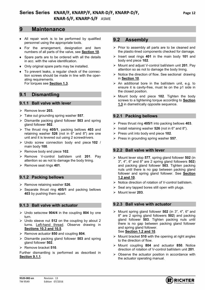
9 Maintenance All repair work is to be performed by qualified
personnel using the appropriate tools. For the arrangement, designation and item
numbers of all parts of the valve, see Section 10. Spare parts are to be ordered with all the details
in acc. with the valve identification. Only original spare parts may be installed. To prevent leaks, a regular check of the connec-
tion screws should be made in line with the oper-ating requirements. For torques see Section 1.3.
9.1 Dismantling
9.1.1 Ball valve with lever Remove lever 203. Take out grounding spring washer 557. Dismantle packing gland follower 503 and spring
gland follower 502. The thrust ring 405/1, packing bellows 403 and
retaining washer 526 (not in 6" and 8") are one unit and it is levered out using 2 screwdrivers.
Undo screw connection body end piece 102 / main body 100.
Remove body end piece 102. Remove V-control ball/stem unit 201. Pay
attention so as not to damage the body lining. Remove seat rings 401. 9.1.2 Packing bellows Remove retaining washer 526. Separate thrust ring 405/1 and packing bellows
403 by pushing them apart. 9.1.3 Ball valve with actuator Undo setscrew 904/4 in the coupling 804 by one
turn. Undo sleeve nut 512 on the coupling by about 2
turns. Left-hand thread. Observe drawing in Sections 10.3 and 10.5.
Remove actuator 850 and coupling 804. Dismantle packing gland follower 503 and spring
gland follower 502. Remove bracket 510. Further dismantling is performed as described in Section 9.1.1.
9.2 Assembly Prior to assembly all parts are to be cleaned and
the plastic-lined components checked for damage. Insert seat rings 401 in the main body 101 and
body end piece 102. Mount and adjust V-control ball/stem unit 201. Pay
attention so as not to damage the body lining. Notice the direction of flow. See sectional drawing
in Section 10. An additional bore in the ball/stem unit, e.g. to
ensure it is cavity-free, must lie on the p1 side in the closed position.
Mount body end piece 102. Tighten the body screws to a tightening torque according to Section 1.3 in diametrically opposite sequence.
9.2.1 Packing bellows Press thrust ring 405/1 into packing bellows 403. Install retaining washer 526 (not in 6" and 8"). Press unit into body end piece 102. Press in grounding spring washer 557. 9.2.2 Ball valve with lever Mount lever stop 577, spring gland follower 502 (in
3", 4", 6" and 8" are 2 spring gland followers 502) and packing gland follower 503. Tighten packing nuts until there is no gap between packing gland follower and spring gland follower. See Section 1.2 and 10.
Notice direction of rotation of V-control ball/stem. Seal any tapped bores still open with plugs. Mount lever 203. 9.2.3 Ball valve with actuator Mount spring gland follower 502 (in 3", 4", 6" and
8" are 2 spring gland followers 502) and packing gland follower 503. Tighten packing nuts until there is no gap between packing gland follower and spring gland follower. See Section 1.2 and 10.
Mount bracket 510 with the opening at right angles to the direction of flow.
Mount coupling 804 and actuator 850. Notice direction of rotation of V-control ball/stem unit 201.
Observe the actuator position in accordance with the actuator operating manual.

Series Series KNAR/F, KNARP/F, KNAR-D/F, KNARP-D/F, Page 13 KNAR-S/F, KNARP-S/F ASME
9520-082-en Revision 13 TM 9549 Edition 07/2016
Tighten setscrew 904/4 in the coupling 804. Tighten sleeve nut 512 on the coupling tight.
Attention: Left-hand thread. Observe drawing in Section 10.3 and 10.5.
9.3 Conversion from lever to actuator
Select the actuator in accordance with the instructions of the actuator manufacturer.
Remove hand lever 203.
Remove lever stop 577 and plug. Check the fits of the coupling 804, bracket 510
and actuator 850. Mount bracket 510 with the opening at right angles
to the direction of flow. Mount coupling 804 and actuator 850. While doing
so, observe direction of rotation of the v-control ball/stem unit.
Observe the actuator position in accordance with the actuator operating manual.
Tighten setscrew 904/4 in the coupling 804. Tighten sleeve nut 512 on the coupling tight.
Attention: Left-hand thread. Observe drawing in Section 10.3 and 10.5.
10 Drawings
10.1 Legend101 main body 102 body end piece 201 ball/stem unit 203 lever 401 seat ring 403 packing bellows 405/1 thrust ring 502 spring gland follower 503 packing gland follower 510 bracket 526 retaining washer (DN ½“, ¾“, 1“, 1½“, 2", 3", 4") 554/1 washer 554/5 washer (3”) 557 grounding spring washer 577 lever stop
804 coupling includes: 512 sleeve nut 904/4 setscrew 980/1 round head grooved pin
850 actuator 901/x hex. screw 902/1 stud screw 904/1 set screw 914/2 hex. socket screw (2") 918/1 threaded rod (6", 8") 920/x hex. nut 936/x toothed lock washer

Series Series KNAR/F, KNARP/F, KNAR-D/F, KNARP-D/F, Page 14 KNAR-S/F, KNARP-S/F ASME
9520-082-en Revision 13 TM 9549 Edition 07/2016
10.2 Sectional drawing ball valve with lever
Holes of the flange- and housing screws view displaced by 45°

Series Series KNAR/F, KNARP/F, KNAR-D/F, KNARP-D/F, Page 15 KNAR-S/F, KNARP-S/F ASME
9520-082-en Revision 13 TM 9549 Edition 07/2016
10.3 Sectional drawing ball valve with actuator
Holes of the flange- and housing screws view displaced by 45°

Series Series KNAR/F, KNARP/F, KNAR-D/F, KNARP-D/F, Page 16 KNAR-S/F, KNARP-S/F ASME
9520-082-en Revision 13 TM 9549 Edition 07/2016
10.4 View and section ball valve with lever
View Z
Section B – B
10.5 View and section ball valve with actuator
Section A – A Coupe B - B
Section B – B
Tighten packing gland follower 503 until spring
gland follower 502 is in contact without any
gap
Tighten packing gland follower 503 until spring gland follower 502 is in contact without any gap

Series Series KNAR/F, KNARP/F, KNAR-D/F, KNARP-D/F, Page 17 KNAR-S/F, KNARP-S/F ASME
9520-082-en Revision 13 TM 9549 Edition 07/2016
10.6 Dimensional drawing ball valve with lever
KNAR/F x x x x x x x x
KNAR-S/F x x x
DN ½" ¾" 1" 1½" 2" 3" 4" 6" 8" *
L inch [mm]
5.12 [130]
5.91 [150]
5.0 [127]
6.5 [165]
7.0 [178]
7.99 [203]
9.01 [229]
10.51 [267]
17.99 [457]
HL inch [mm]
7.05 [179]
10.24 [260]
12.32 [313]
20.27 [515]
17.13 [435]
H inch [mm]
5.12 [130]
6.1 [155]
7.09 [180]
7.68 [195]
10.43 [265]
10.63 [270]
* DN 8" with reduced bore 6" Flange connecting dimensions: ASME B16.5 Class 150, raised face

Series Series KNAR/F, KNARP/F, KNAR-D/F, KNARP-D/F, Page 18 KNAR-S/F, KNARP-S/F ASME
9520-082-en Revision 13 TM 9549 Edition 07/2016
10.7 Dimensional drawing ball valve with actuator
KNARP/F x x x x x x x x x
KNARP-S/F x x x DN ½" ¾" 1" 1½" 2" 3" 4" 6" 8" *
H1 inch [mm]
1.97 [50]
3.03 [77]
3.15 [80]
4.64 [118]
5.27 [134]
7.24 [184]
H2 inch [mm]
2.32 [60]
2.32 ** [60] **
3.15 [80]
3.94 [100]
H3 inch [mm]
H4 inch [mm]
L inch [mm]
5.12 [130]
5.91 [150]
5.0 [127]
6.5 [165]
7.0 [178]
7.99 [203]
9.01 [229]
10.51 [267]
17.99 [457]
L1 inch [mm]
Connect. dim. acc. to ISO 5211 F05 F07 F10 F12
* DN8” with reduced bore 6” ** H2 = 3.15” (80mm) if F10 or F12 on the actuator side Dimensions H3, H4, L1, L2 and L3 vary depending on the actuator manufacturer. Flange connecting dimensions ASME B16.5 Class 150, raised face


A Unit of IDX Corporation
Erstellt/Compiled: CRM/GK am/on : 14.03.2014 Seite/Page : 1 Alt: QM-Nr.: 0905-40-1022_Kugelhahn/4-05 Genehmigt/Approved: CRQ/MP am/on: 14.03.2014 von/of : 1 Neu: F722009
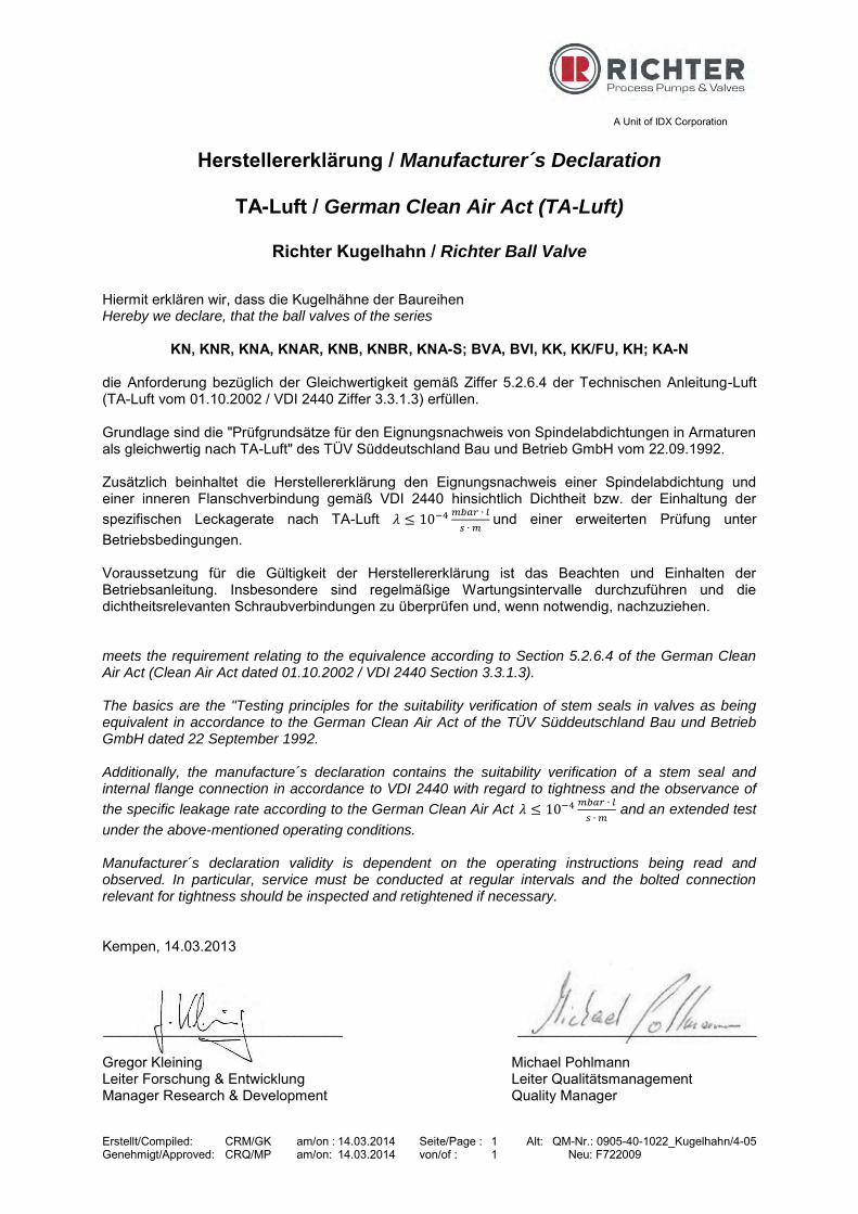
Herstellererklärung / Manufacturer´s Declaration
TA-Luft / German Clean Air Act (TA-Luft)
Richter Kugelhahn / Richter Ball Valve
Hiermit erklären wir, dass die Kugelhähne der Baureihen Hereby we declare, that the ball valves of the series
KN, KNR, KNA, KNAR, KNB, KNBR, KNA-S; BVA, BVI, KK, KK/FU, KH; KA-N die Anforderung bezüglich der Gleichwertigkeit gemäß Ziffer 5.2.6.4 der Technischen Anleitung-Luft (TA-Luft vom 01.10.2002 / VDI 2440 Ziffer 3.3.1.3) erfüllen. Grundlage sind die "Prüfgrundsätze für den Eignungsnachweis von Spindelabdichtungen in Armaturen als gleichwertig nach TA-Luft" des TÜV Süddeutschland Bau und Betrieb GmbH vom 22.09.1992. Zusätzlich beinhaltet die Herstellererklärung den Eignungsnachweis einer Spindelabdichtung und einer inneren Flanschverbindung gemäß VDI 2440 hinsichtlich Dichtheit bzw. der Einhaltung der spezifischen Leckagerate nach TA-Luft 𝜆 ≤ 10−4 𝑚𝑏𝑎𝑟 ∙ 𝑙
𝑠 ∙ 𝑚 und einer erweiterten Prüfung unter
Betriebsbedingungen. Voraussetzung für die Gültigkeit der Herstellererklärung ist das Beachten und Einhalten der Betriebsanleitung. Insbesondere sind regelmäßige Wartungsintervalle durchzuführen und die dichtheitsrelevanten Schraubverbindungen zu überprüfen und, wenn notwendig, nachzuziehen. meets the requirement relating to the equivalence according to Section 5.2.6.4 of the German Clean Air Act (Clean Air Act dated 01.10.2002 / VDI 2440 Section 3.3.1.3). The basics are the "Testing principles for the suitability verification of stem seals in valves as being equivalent in accordance to the German Clean Air Act of the TÜV Süddeutschland Bau und Betrieb GmbH dated 22 September 1992. Additionally, the manufacture´s declaration contains the suitability verification of a stem seal and internal flange connection in accordance to VDI 2440 with regard to tightness and the observance of
the specific leakage rate according to the German Clean Air Act 𝜆 ≤ 10−4 𝑚𝑏𝑎𝑟 ∙ 𝑙
𝑠 ∙ 𝑚 and an extended test
under the above-mentioned operating conditions. Manufacturer´s declaration validity is dependent on the operating instructions being read and observed. In particular, service must be conducted at regular intervals and the bolted connection relevant for tightness should be inspected and retightened if necessary. Kempen, 14.03.2013 ______________________________ ______________________________ Gregor Kleining Michael Pohlmann Leiter Forschung & Entwicklung Leiter Qualitätsmanagement Manager Research & Development Quality Manager

Erstellt/Prepared by: EQM/MP am/on: 01.03.2016 QM-Nr.//QMNo.: F722030_KN-01 Genehmigt/Released by: EQM/MP am/on: 01.03.2016
A Unit of IDEX Corporation
Kempen, 1.03.2016
SIL
Declaration by the Manufacturer
Functional Safety according to IEC 61508
We declare, that the devices
KN, KNR, KNA, KNAR, KNP, KNRP, KNAP, KNARP
are suitable for use in a safety related application, if the safety instructions and the fol-lowing parameters are observed: Device Type: A Proof Test Interval: ≤ 1 year HFT: 0 (single channel usage) λSU: 129 FIT λSD: 14 FIT λDU: 108 FIT λDD: 36 FIT SFF: 62,5 % PFDAvg: 4,73·10-4 (for TProof = 1 year) MTBF: 398 years Safety Intigrity Level: SIL 2
Usable lifetime: According to IEC 61508-2 §7.4.7.4 values of up to 10 years can be as-sumed. Different values can be used based on the experience of the user. In principle, critical applications and cases of operation (e. g. highly permeable or solid loaded media) can reduce the usable lifetime. For safe and reliable operation please follow the relevant instructions documented in the manual.
The evidence is based on proven in use combined with a FMEDA.
G. Kleining M. Pohlmann
Leiter Forschung & Entwicklung Leiter Qualitätsmanagement
Manager research & Development Quality Manager

Prepared: CRQ/Lam on: Nov. 13, 2006 Page: 1 QM No.: 0912-16-2001_en/4-07 Approved: CRQ/Zu on: Nov. 13, 2006 of : 2
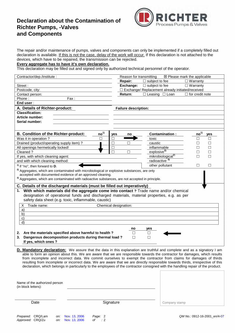
Safety Information / Declaration of No Objection Concerning the Contamination of Richter-Pumps, -Valves and Components
1 SCOPE AND PURPOSE
Each entrepreneur (operator) carries the responsibility for the health and safety of his employees. This extends also to the personnel, who implements repairs with the operator or with the contractor.
Enclosed declaration is for the information of the contractor concerning the possible
contamination of the pumps, valves and component sent in for repair. On the basis of this information for the contractor is it possible to meet the necessary preventive action during the execution of the repair.
Note: The same regulations apply to repairs on-site.
2 PREPARATION OF DISPATCH
Before the dispatch of the aggregates the operator must fill in the following declaration completely and attach it to the shipping documents. The shipping instructions indicated in the respective manual are to be considered, for example:
• Discharge of operational liquids • remove filter inserts • lock all openings hermetically • proper packing • Dispatch in suitable transport container • Declaration of the contamination fixed outside!! on the packing
Declaration about the Contamination of Richter Pumps, -Valves and Components
Prepared: CRQ/Lam on: Nov. 13, 2006 Page: 2 QM No.: 0912-16-2001_en/4-07 Approved: CRQ/Zu on: Nov. 13, 2006 of : 2
The repair and/or maintenance of pumps, valves and components can only be implemented if a completely filled out declaration is available. If this is not the case, delay of the work will occur. If this declaration is not attached to the devices, which have to be repaired, the transmission can be rejected. Every aggregate has to have it’s own declaration. This declaration may be filled out and signed only by authorized technical personnel of the operator. Contractor/dep./institute : Reason for transmitting Please mark the applicable Repair: subject to fee Warranty Street : Exchange: subject to fee Warranty Postcode, city: Exchange/ Replacement already initiated/received Contact person: Return: Leasing Loan for credit note Phone : Fax : End user : A. Details of Richter-product: Failure description: Classification: Article number: Serial number:
B. Condition of the Richter-product: no1) yes no Contamination : no1) yes Was it in operation ? toxic Drained (product/operating supply item) ? caustic All openings hermetically locked! inflammable Cleaned ? explosive2) If yes, with which cleaning agent: mikrobiological2) and with which cleaning method: radioactive 3) 1) if "no", then forward to D. other pollutant 2) Aggregates, which are contaminated with microbiological or explosive substances, are only
accepted with documented evidence of an approved cleaning. 3) Aggregates, which are contaminated with radioactive substances, are not accepted in principle.
C. Details of the discharged materials (must be filled out imperatively) 1. With which materials did the aggregate come into contact ? Trade name and/or chemical
designation of operational funds and discharged materials, material properties, e.g. as per safety data sheet (e.g. toxic, inflammable, caustic)
X Trade name: Chemical designation: a) b) c) d)
no yes
2. Are the materials specified above harmful to health ? 3. Dangerous decomposition products during thermal load ?
If yes, which ones ?
D. Mandatory declaration: We assure that the data in this explanation are truthful and complete and as a signatory I am able to form an opinion about this. We are aware that we are responsible towards the contractor for damages, which results from incomplete and incorrect data. We commit ourselves to exempt the contractor from claims for damages of thirds resulting from incomplete or incorrect data. We are aware that we are directly responsible towards thirds, irrespective of this declaration, which belongs in particularly to the employees of the contractor consigned with the handling repair of the product.
Name of the authorized person (in block letters):
Date Signature
Company stamp

Richter Chemie-Technik GmbH · Postfach 10 06 09 · D-47883 Kempen
08.01.2015
Declaration of no objection
Dear Sirs,
The compliance with laws for the industrial safety obligates all commercial enterprises to protect their employees and/or humans and environment against harmful effects while handling dangerous materials. The laws are such as: the Health and Safety at Work Act (ArbStättV), the Ordinance on Harzadous Substances (GefStoffV, BIOSTOFFV), the procedures for the prevention of accidents as well as regulations to environmental protection, e.g. the Waste Management Law (AbfG) and the Water Resources Act (WHG)
An inspection/repair of Richter products and parts will only take place, if the attached explanation is filled out correctly and completely by authorized and qualified technical personnel and is available.
In principle, radioactively loaded devices sent in, are not accepted.
Despite careful draining and cleaning of the devices, safety precautions should be necessary however, the essential information must be given.
The enclosed declaration of no objection is part of the inspection/repair order. Even if this certificate is available, we reserve the right to reject the acceptance of this order for other reasons.
Best regards RICHTER CHEMIE-TECHNIK GMBH
QM
091
2-16
-200
1an_
en/4
-03
Celebrating 30 yearsEst. 1986
Years30
South Africa Tel: 0861 103 103E-mail: [email protected]
Exports: [email protected]