riche ii. larry donnell b.s. clark altanta university
TRANSCRIPT

ABSTRACT
COMPUTER INFORMATION SCIENCE
RICHE II. LARRY DONNELL B.S. CLARK ALTANTA UNIVERSITY, 2009
THE PERFORMANCE OF HIGH-ORDER QAUDRATURE AMPLITUDE
MODULATION SCHEMES FOR BROADBAND
WIRELESS COMMUNICATIONS
SYSTEMS
Committee Chair: Khalil A. Shujaee. Ph. D.
Thesis dated July 2012
The limited amount frequency spectrum available to wireless comnmnication systems
makes it difficult to satisfy the rapidly growing demand for wireless service. Spectral
efficiency can be increased by using higher order modulation schemes. However this
come at the cost of increased probability of error. In this paper we investigate through
MATLAB simulation, the implementation of orders of Quadrature Amplitude Modulation
(QAM) more commonly used in wired networks. The BER performance of 64, 128, 256,
512, 1024, 2048, 4096, and 8192 QAM signals in the presence of Rayleigh and Rician
multipath channels with additive white Gaussian noise are simulated.

THE PERFORMANCE OF HIGH ORDER QAM MODULATION SCHEMES FOR
BROADBAND WIRELESS COMMUNICATIONS SYSTEMS
A THESIS
SUBMITTED TO THE FACULTY OF CLARK ATLANTA UNIVERSITY
IN PARTIAL FULFILLMENT OF THE REQUIRMENTS FOR
THE DEGREE OF MASTER OF SCIENCE
BY
LARRY RICHE
DEPARTMENT OF COMPUTER INFORMATION SCIENCE
ATLANTA, GEORGIA
JULY 2012

© 2012
LARRY DONNELL RICHE II
All Rights Reserved

ACKNOWLEDGMENTS
This thesis is dedicated in memory of my grandmother, Alice Kelly Ford. I thank
my parents who have provided me with immeasurable amount of guidance, support, and
unconditional love throughout my life. A true acknowledgment to them is a thesis in
itseIf one whose research is forever incomplete. Mother, there are no words to express
how much I love you. To me, you are the definition of great, and I could only dream to be
half as accomplished as you. Your strength amazes me every day that I live. Dad, I thank
you for the path you showed me, and for always pushing me to confront my fears. I once
mentioned to you my childhood goal to become “smarter” than you, and well, I think I’m
halfway there. I also thank my grandmother, sister, brother and my cousin Tiffany for
always being there when I need them. Much appreciation is given to my thesis advisor,
Dr. Khalil Shujaee for guidance and always challenging me to go further in academia and
life in general. I thank Dr. Peter Molnar for the countless number of reference letters, and
exposing me to many opportunities in computer science. I thank Dr. Roy George for
supporting me and opening doors of opportunity. Thanks to Ms. Shanna Hicks and Ms.
Mia Moore. Also, thanks to Dr. Xiao-Qian Wang and Dr. Ishard Kahn for the opportunity
to work on their research projects. Thanks to my graduate peers at Clark Atlanta
University: Olayinka Ogunro Ii, Kelvin Suggs, Chemo Kah, Duminda Samarakoon,
Chantel Nicolas, Rosi Gunasinghe, Kregg Quarles, Robert Bailey, Saeed Motevali, Mihiri
Shashikala, Brandon Larkin, and Darkeyah Reuven.
11

TABLE OF CONTENTS
ACKNOWLEDGEMENTS.ii
TABLE OF CONTENTS iii
LIST OF FIGURES v
LiST OF TABLES vi
LIST OF ABBREVIATIONS vii
Chapter
1. INTRODUCTION 1
1.1 Motivation 2
1.2 Digital Modulation Techniques 3
1.2.1 Linear Modulation 5
1.2.2 Non-Linear Modulation 6
1.3 Why Quadrature Amplitude Modulation 7
1.4 Thesis Scope and Organization 8
2. QUADRATURE AMPLITUDE MODULATION 9
2.1 Background 9
2.2 Applications 12
2.3 Mathematical Model 13
2.4 Calculating the Probability of Error 13
3. IMPLEMENTATION OF HIGH ORDER QAM SCHEMES 15
3.1 Bandwidth Efficiency 15
4. SYSTEM MODEL 17
111

4.1 Input .19
4.2 Modulation .20
4.3 Channel 22
4.4 Basic Structure 24
5. SIMULATION 25
5.1 Simulation Models 25
5.2 Results 29
6. DISCUSSION 35
6.1 Conclusion 35
6.2 Future Work 25
REFERENCES 37
iv

LIST OF FIGURES
1.1 Evolution of Wireless Communication Standards 1990-2011 2
1.2 Generation of BPSK modulated signal 6
2.1 Examples of types I, II, and III QAM constellations 10
2.2 Figure 2.2 “Optimum” 32-level constellation according to Smith ii
4.1 General communications block diagram 18
4.2 Example of Gray coding fbr 16 QAM 19
4.3 Distribution of input tuple for 64 QAM Simulation Model 20
4.4 Even constellation of 256 QAM 21
4.5 Odd constellation for 128 QAM 22
4.6 Basic QAM modem schematic 24
5.1 Simulink simulation model of 64 QAM transmission over AWGN channel 26
5.2 Simulink simulation model of 64 QAM transmission over Rayleigh flat fading
channel with AWGN 27
5.3 Simulink simulation model of 64 QAM transmission over Rician flat fading
channel with AWGN 28
5.4 MATLAB Communications Toolbox BERTooI 30
5.5 Simulated BER performance of even bit constellations in the presence of Additive
White Gaussian Noise 31
V

5.6 Simulated BER performance of odd bit symbol constellations in the presence of
Additive White Gaussian Noise 31
5.7 Simulated BER performance of even bit constellations in the presence of
Rayleigh flat fading channel with AWGN 32
5.8 Simulated BER performance of odd bit constellations in the presence of Rayleigh
flat fading channel with AWGN 33
5.9 Simulated BER performance of even bit constellations in the presence of Rician
flat fading channel with AWGN 34
5.10 Simulated BER performance of odd bit constellations in the presence of Rician
flat fading channel with additive white Gaussian noise 34
vi

LIST OF TABLES
1.1 Modulation Formats and Applications 4
1.2 Classification of Modulation Schemes 5
3.3 Quadrature Amplitude Modulation Bandwidth Efficiency 11
vii

LIST OF ABBREVIATIONS
AM Amplitude Modulation
EbNQ Energy per Bit to Noise Power Spectral Density Ratio
FM Frequency Modulation
FSK Frequency Shift Keying
LTE Long Term Evolution
OFDM Orthogonal Frequency Division Multiplexing
OFDMA Orthogonal Frequency Division Multiple Access
PM Phase Modulation
PSK Phase Shift Keying
QAM Quadrature Amplitude Modulation
QPSK Quadrature Phase Shift Keying
WiMAX Wireless Interoperability for Microwave Access
VIII

CHAPTER 1
Introduction
How we communicate plays an important role in our everyday lives. Since the
dawn of Society mankind has sought to create more efficient and effective ways to share
information. In 1897 Guglielmo Marconi invented the first radio frequency
communications system to establish continuous communication with ships across the
English Channel [1]. This was the beginnings of a new paradigm in communications in
which information could be shared over large distances at the speed of light. Since then
there has tremendous technological advances in wireless communications overcoming
greater barriers. In global positioning systems (GPS), terrestrial devices communicate
with satellites in orbit around the Earth to determine the location of the device within an
accuracy of three meters [2]. Wireless communications has experienced explosive growth
in the past 25 years, due to demand and advances in Very Large Integrated Circuit
(VLSI) and Discrete Signal Processing (DSP) technologies. It is useful to refer to mobile
cellular technology when describing the recent evolution in wireless communications,
since its market has experienced the most growth, and gives a good representation of the
capabilities of wireless technology. Figure 1.1 shows a depiction of the advancement of
wireless standards, beginning with the second generation of technology.
Cellular communications systems are perhaps the most common type of wireless
communications systems. The first generation mobile wireless communications systems

used analog modulation to carry voice over air between transmitter and receiver. In 1978
Bell Laboratories developed the Advanced Mobile Phone System (AMPS), it was the
first cellular system to be implemented in the United States. It used Frequency
Modulation (FM) over a 30 kHz channel, within the 824-894 MHz frequency band and
Frequency Division Multiple Access (FDMA) for user multiplexing.
The second generation of cellular technology began with the launch of the Global
System for Mobile (GSM) Communications [3]. The system was introduced to Europe in
1988.
2G
-
D 2.C
3C
3.5G
Figure 1.1 Evolution of Wireless Communication Standards 1990-2011
1.1 Motivation
The demand of high data rates in wireless applications continues to grow at an
exponential rate. Additionally the number of connected mobile devices is also increasing
According to Cisco, global mobile data traffic is expected to double yearly though 2016
[4]. The limited availability of frequency spectrum hinders this growth. The limited
39G [UMB]
4G

2
availability of spectrum makes achieving high data rates in wireless communications
challenging objective. High data rates are essential for demanding applications such a
real-time video streaming. High throughput is realized through tradeoffs between
bandwidth, power, and system complexity. Modulation is the process of transforming an
incoming stream of information into a format that is suitable for transmission over a
medium. There are many different types of modulation techniques choose form.
Quadrature Amplitude Modulation (QAM) has been a popular choice for implementation.
1.2 Digital Modulation Techniques
In telecommunications modulation is the process of modifying a data source into
a form more suitable for transmission over a medium [5]. The properties of a signal can
alternated to represent the differentiations in the data being transmitted. A general sine
wave can be represented as a function of time, t as follows
s(t) = A cos(a.t + )
where A is the amplitude, a 2nJ is the frequency, and is the instantaneous phase.
The choice of digital modulation scheme is crucial for mobile communications
systems. It is a key factor in determining the performance of a communications system.
There are two basic forms modulation, analog and digital. In analog modulation an
incoming data source is modulated by a continuous signal, referred to as a carrier. In
digital modulation the source signal is modulated by a discrete carrier signal. Today
mobile wireless systems are using digital modulation techniques. Table 1 .1 shows a
variety of digital modulation techniques and some of their applications. Digital signals
tend to be more robust than analog signals in terms of signal integrity. Frequency, phase,
and amplitude are the three fundamental properties of a signal which can be modulated.

4
Typical first generation wireless standards used simple analog modulation techniques,
such as amplitude, phase, and frequency modulation. Modem 4G mobile standards use
adaptive modulation schemes which adjust the modulation scheme depending on the
signal to noise ratio [6. 7]. The implementation of digital modulation techniques began
with the second generation of wireless communication standards. The shift toward digital
modulation provided more information capacity, higher security, and better quality
service as compared to analog formats. As seen in Table 1 .2 there are two major
categories of digital modulations. The first category uses a constant amplitude carrier to
carry the information in phase or frequency variations, such as frequency shift keying
(FSK) and phase shift keying (PSK). The second category conveys the information in
carrier amplitude variations, such as amplitude shift keying (ASK) and quadrature
amplitude modulation (QAM).
Table 1.1 Modulation Formats and Applications
Modulation Format ApplicationMSK, GMSK GSM, CDPDBPSK Deep telemetry, cable modemsQPSK, DQPSK Satellite, CDMA, NADC, TETRA, PHS, PDC, LMDS, DVB-S,
cable (return path), cable modems, TFTSOQPSK CDMA, satelliteFSK, GFSK DECT, paging, RAM mobile data, AMPS, CT2, ERMES, land
mobile, public safety8, 16 VSB North American digital TV (ATV), broadcast, cable8PSK Satellite, aircraft, telemetry pilots for monitoring broadband video
systems16 QAM Microwave digital radio, modems, DVB-C, DVB-T32 QAM Terrestrial microwave, DVB-T64 QAM DVB-C. modems, broadband set top boxes, MMDS256 QAM Modems, DVB-C (Europe), Digital Video (US)

Table 1.2 Classification of Modulation Schemes
ModulationLinear (Modulate A. q5) Exponential (Modulate dçS / di)
Binary Multilevel (>1 bit/symbol) FSK, MSK, GMSK, etc.ASK, BPSK M-PSK, QAM
1.2.1 Non-linear Modulation
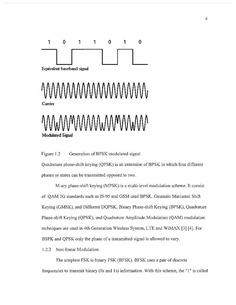
Binary phase-shift keying (BPSK) is one of the simplest modulation schemes, in
which the phase of the carrier signal is modulated with two distinct states representing
data being transmitted:
‘0’, q5=7z‘1’, ØrrO
This is shown in Figure 1.2, where the modulated signal is a product of equivalent
baseband signal and carrier frequency. BPSK has been implemented in mobile standards
since the second generation of wireless technology.
6
1 0 1
1101110Equivalent baseband signal
‘VV\N\AAJV\I\N\A/VVVV\MACarrier
VV\fWVVv\JVWWModulated Sia1
Figure 1.2 Generation of BPSK modulated signal
Quadrature phase-shift keying (QPSK) is an extension of BPSK in which four different
phases or states can be transmitted opposed to two.
M-ary phase-shift keying (MPSK) is a multi-level modulation scheme. It consist
of QAM 2G standards such as IS-95 and GSM used BPSK. Gaussain Miniumal Shift
Keying (GMSK), and Different DQPSK. Binary Phase-shift Keying (BPSK), Quadrature
Phase-shift Keying (QPSK), and Quadrature Amplitude Modulation (QAM) modulation
techniques are used in 4th Generation Wireless System, LTE and WiMAX [3] [4]. For
BSPK and QPSK only the phase of a transmitted signal is allowed to vary.
1.2.2 Non-linear Modulation
The simplest FSK is binary FSK (BFSK). BFSK uses a pair of discrete
frequencies to transmit binary (Os and Is) information. With this scheme, the “1” is called

7
the mark frequency and the “0’ is called the space frequency. The time domain of an FSK
modulated carrier is illustrated in the figures to the right.
Minimum shift keying (MSK) Minimum frequency-shift keying or minimum-shift
keying MSK is a particular spectrally efficient form of coherent FSK. In MSK the
difference between the higher and lower frequency is identical to half the bit rate.
Consequently, the waveforms used to represent a 0 and a I bit differs by exactly half a
carrier period.
Gaussian minimum shift keying (GMSK) modulation is based on MSK, which is
itself a form of continuous-phase frequency-shift keying. One of the problems with
standard forms of PSK is that sidebands extend out from the carrier. To overcome this,
MSK and its derivative GMSK can be used.
1.3 Why Quadrature Amplitude Modulation
Much research has done on the comparison of QAM with other modulation
techniques. In most cases the QAM tends to have better performance overall. For
instance, multiple papers show that QAM has better noise resistance, and is more
adaptive for channel change, and more efficient in bandwidth utilization [8-1 0]. While
PSK modulation schemes often demonstrate better BER performance than their QAM
counterparts, it may be possible to mitigate this issue with more complex hardware [9]. It
is concluded that BER performance of QPSK is better than that of I 6-QAM at the
expense of large spectral width. Alternatively, 16-QAM can carry more traffic than
QPSK at the expense of higher BER[9].

8
1.4 Thesis Scope and Organization
The objective of this thesis is to investigate the performance of higher order
modulation schemes in the presence of noise and fading channel environments. The
thesis is organized as follows.
Chapter 2 provides a brief background of advancements in research on
Quadrature Amplitude Modulation and touches on some of its applications, then proceeds
to go into a detailed description of how it is implemented including mathematical
descriptions of a QAM signal and calculating the probability that in error occurs during
transmission. Chapter 3 examines the potential gains in the implementation of higher
order QAM. We calculate the system capacities and bandwidth efficiencies of the various
QAM schemes. In Chapter 4. we detail the design of a wireless communications system
that implements QAM. Chapter 5 covers the components of the simulation, the
mythology discussed in chapter 4 are implemented in to a MATLAB SIMULINK model.
In Chapter 6, the results of the simulations are discussed and suggestions for future
research are given.
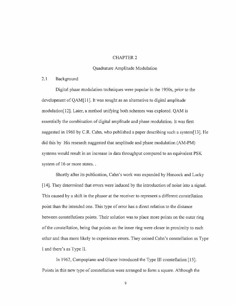
CHAPTER 2
Quadrature Amplitude Modulation
2.1 Background
Digital phase modulation techniques were popular in the 1950s. prior to the
development of QAM[ 11]. It was sought as an alternative to digital amplitude
modulation[12]. Later, a method unifying both schemes was explored. QAM is
essentially the combination of digital amplitude and phase modulation. It was first
suggested in 1960 by C.R. Cahn, who published a paper describing such a system[l3]. He
did this by His research suggested that amplitude and phase modulation (AM-PM)
systems would result in an increase in data throughput compared to an equivalent PSK
system of 16 or more states.
Shortly after its publication, Calm’s work was expanded by Hancock and Lucky
[14]. They determined that errors were induced by the introduction of noise into a signal.
This caused by a shift in the phasor at the receiver to represent a different constellation
point than the intended one. This type of error has a direct relation to the distance
between constellations points. Their solution was to place more points on the outer ring
of the constellation, being that points on the inner ring were closer in proximity to each
other and thus more likely to experience errors. They coined Cahn’s constellation as Type
I and there’s as Type II.
In 1962. Campopiano and Glazer introduced the Type III constellation [15].
Points in this new type of constellation were arranged to form a square. Although the
9

I0
acronym QAM had not yet been suggested, they described the system as “the amplitude
modulation and demodulation of two carriers that have the same frequency but are in
quadrature with each other” — the first time the combination of amplitude and phase
modulation had been refer to as amplitude modulation on quadrature carriers [1.1]. One
issue they found with their type III constellation is that non-coherent detection was not
possible, therefore it had to be used in a phase coherent mode. They concluded that while
their Type III constellation offered modest performance over a Type II system, it had the
advantage of simplicity in implementation compared to Types I and II. Examples of Type
I, II, and III constellations are shown in Figure 2.1.
Type IQAM Constellation Type UQAM Constellation
• • .
• • .
I
• I •
• I I
Q
Type ifi QAM Constellation
Figure 2.1 Examples of types I. II and III QAM constellations from [16]

II
Although much research had gone into the design of more optimal constellations,
by 1975 most interest had been centered on Type III or square QAM constellations [17-
19]. This was due to the minimal gains realized by the optimal constellations verses the
complexity of implementation. and advancements if coherent phase detection methods
[20, 21]. Up until this time the constellation shape of square QAM had only been
considered for systems with an even number of bits per symbol. In 1975 J.G Smith
suggested an idea design for odd bit per symbol constellations [22]. His work proposed
that odd bit symbol constellations be symmetric and that such systems were of equal
implementation complexity as even bit symbol constellations. An example of his idea
constellation shape for odd bit symbols is shown in Figure 2.2, where there are five bits
per symbol.
•• . .
• • • • . .
• • • • • •I
••. • • •
• • • • • •
• • • •
Q
Figure 2.2 Optimum” 32-level constellation according to Smith [22] from [16]
The first major research investigating the implementation of QAM for mobile
radio came in 1987. Sundberg, Wong. and Steele published two papers proposing QAM
for the transmission of voice over Rayleigh fading channels [23, 24]. In this paper they
used gray code mapping as a method to assign symbols to constellation points. They

12
found that certain assortments of bits constituting a symbol had different rates of error
than others. By 1990 research on QAM had become a very popular. There are many
papers that explore its implementation for mobile radio applications.
Currently 1024 and 4094 QAM are implemented in wired communication
standards. The ability of these dense forms of QAM to achieve exponential increases in
spectral efficiency makes them a prime candidate as a method to increase capacity. High
order constellations of QAM also have the advantage of increasing data throughput.
Advances in VLSI and Digital Signal Processing DSP techniques have enabled the
implementation of relatively complex forms of modulation such as QAM. It can be
expected that this trend will continue into the future.
2.2 Applications
Quadrature amplitude modulation is implemented in a variety of modern wireless
communications standards. QAM is in many radio communications and data delivery
applications. However some specific variants of QAM are used in some specific
applications and standards.
For domestic broadcast applications for example, 64 QAM and 256 QAM are
often used in digital cable television and cable modem applications. In the UK, 16 QAM
and 64 QAM are currently used for digital terrestrial television using DVB - Digital
Video Broadcasting. In the US, 64 QAM and 256 QAM are the mandated modulation
schemes for digital cable as standardized by the SCTE in the standard ANSI/SCTE 07
2000.
ln addition to this, variants of QAM are also used for many wireless and cellular
technology applications.
13
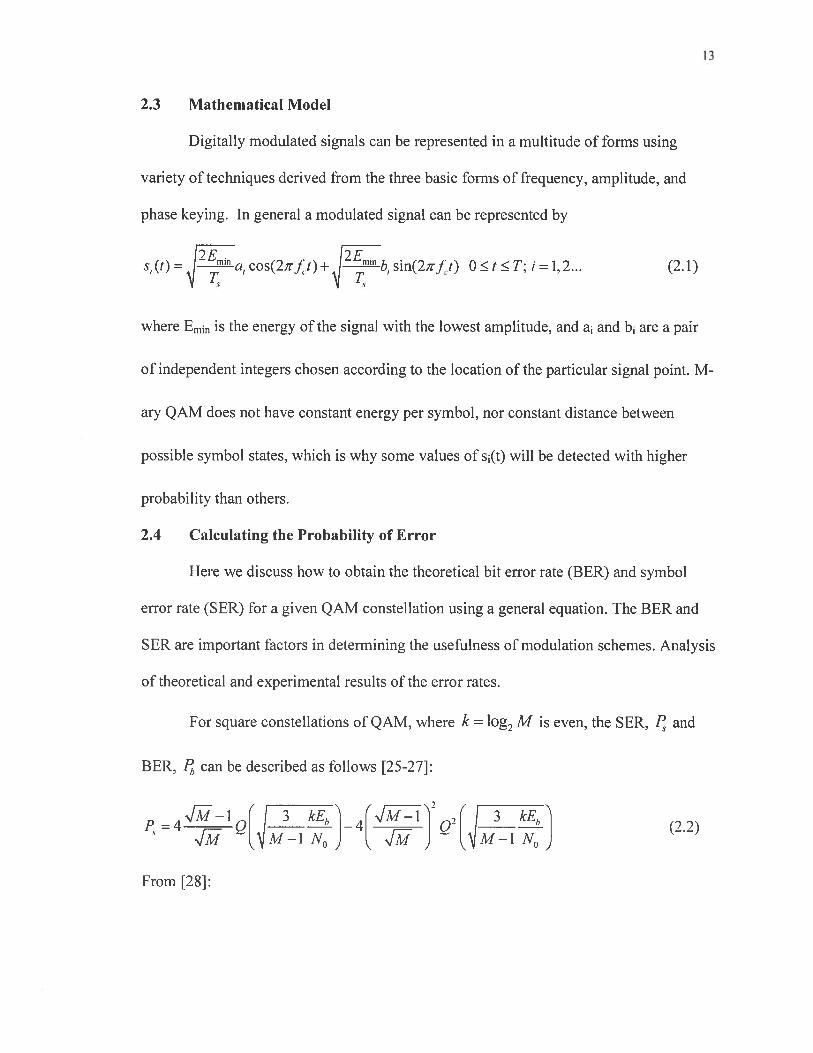
2.3 Mathematical Model
Digitally modulated signals can be represented in a multitude of forms using
variety of techniques derived from the three basic forms of frequency, amplitude, and
phase keying. In general a modulated signal can be represented by
bE bEs, (1) =
— ““ a1 cos(2irft)+ q — “
i, sin(2,rft) 0 t T; I = 1,2... (2.1)
where Emin is the energy of the signal with the lowest amplitude, and a and b1 are a pair
of independent integers chosen according to the location of the particular signal point. M
ary QAM does not have constant energy per symbol, nor constant distance between
possible symbol states, which is why some values of s(t) will be detected with higher
probability than others.
2.4 Calculating the Probability of Error
Here we discuss how to obtain the theoretical bit error rate (BER) and symbol
error rate (SER) for a given QAM constellation using a general equation. The BER and
SER are important factors in determining the usefulness of modulation schemes. Analysis
of theoretical and experimental results of the error rates.
For square constellations of QAM, where k = log2 M is even, the SER, F and
BER, F can be described as follows [25-27]:
P4_1Q I 3 kE 4M_1Q7(I 3
(72)M-1N0J ...Jf J M-1N0 -.
From [28]:

14
log (I—2 )-I I [l2kI
jI
i2’
J1og7J1H L2 _[+jQ2i+1)
/61og2ME
2(M—1) N0
(2.3)
k—I
For cross shaped QAM where k=log2M is odd, M =IxJ, 1=22 ,and
k+l
J=2 2
4LJ—21—2J ( I 61og2(IJ) Eb ___(1+IJ_I_J)Q2 61og2(IJ) E,,
M (J2+J22N
(2.4)
From [281:
IogI log.J
= 1og,(IJ)(k)+ (l)J (2.5)
where,
(1-2 4)J [ I I 2k-l1jQ(2i1q 6Iog,(IJ) Eb21 —I +— (2.6)(k)
=1 L I 2 + -2 N0
and
___
6log,(IJ) EbH2tH21- -L’’ +jQ[(2i+1)2 _2N0Jj
(2.7)P(k)=- j(_1) ‘
___ ______

CHAPTER 3
Implementation of High Order QAM Schemes
3.1 Bandwidth Efficiency
In communications the simple expression M = 2k is used to relate the symbols to
bits. Where M is the number of unique symbols and k is the number of bits transmitter
per symbol. Using Shannon’s channel capacity formula we can calculate the potential
capacity of a system using each proposed density of QAM. Shannon’s formula is
described as follows
C = Blog2 [i+i_J= Blog71+ [bit/si (3.1)
where C is the channel capacity (bits per seconds), [29-31]. 20MHz is a commonly
allocated bandwidth for channels in 4G cellular communications systems such as LTE-A
and WiMAX [32, 33]. Table 4.1 shows the increase in capacity with respect to each
QAM scheme.
The Shannon bound can be expressed as bandwidth efficiency, i = C / B, by
using (3.1)
17=log7(1+S/N) [bit/s/Hz] (3.2)
15

16
The maximum achievable bandwidth efficiency is calculated using Equation 3.2.
The results are shown in table 3.1.
Table 3.1 Quadrature Amplitude Modulation Bandwidth Efficiency
QAM Order Bits per Symbol, k Bandwidth Efficiency(per 20MHzchannel)
64 QAM 6 120 Mb/s128 QAM 7 140 Mb/s256QAM 8 160 Mb/s512 QAM 9 180 Mb/s1024 QAM 10 200 Mb/s2048 QAM I 1 220 Mb/s4096 QAM 12 240 Mb/s8192 QAM 13 260 Mb/s

CHAPTER 4
System Model
In this chapter we discuss the components of a wireless communications system,
the design and methodology of the system parameter that will be incorporated into the
simulations discussed in chapter 5. A typical communications system is shown in Figure
4.1. The components are as follows:
The data source is the origin of the message to be communicated. The message
could come in a variety of forms such as audio, video, or other data. The data source is
transformed into an electrical signal by a transducer. The resulting electrical waveform is
referred to as the baseband signal. The baseband signal is modified by the transmitter,
which prepares the signal for efficient transmission. In digital communication systems the
baseband signal is then coded into binary format using coding techniques. The modulator
is the focus of this research. Baseband signals are often not suitable for transmission over
a given channel. The modulator modifies the baseband signal to facilitate transmission.
The channel is the medium over which communication takes place, such as coaxial cable,
wire, optical fiber, or over-the-air radio link. For this study the channel is a radio link,
which we discuss further in section 4. The receiver translates the signal into its original
form. At the receiver the signal is demodulated, decoded, and processed by transducer
which converts the electrical signal back into its original form,
17

18
Data source
Received dat.
Figure 4.1 General communications block diagram.Input
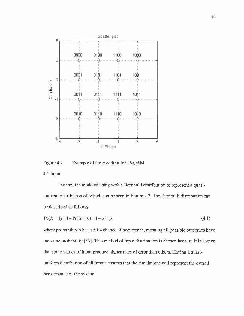
The simulation model incorporates the Gray coding the map the symbols to points
on the constellation. The bits sequence to signal mapping could be arbitrary provided that
the mapping is one-to-one. However, a method called Gray coding is commonly used in
signal assignment in QAM [34]. Gray coding assigns n-tuples with only one-bit
difference to two adjacent signals in the constellation. When an M-ary symbol error
occurs, it is more likely that the signal is detected as the adjacent signal on the
constellation, thus only one of the n input bits is in error. An example of gray coding is
shown in figure 4.2 for the case of 16 QAM.
19
Scatter plot5
ooo moo iio ioo• . •
. c•
ooI1 o11 ilOi 1oi1
0 .
- 0011 m liii 1o1
oo•o oio iiio ioo
-5-5 -3 -1 1
In-Phase
Figure 4.2 Example of Gray coding for 16 QAM
4.1 Input
The input is modeled using with a Bernoulli distribution to represent a quasi-
uniform distribution of, which can be seen in Figure 2.2. The Bernoulli distribution can
be described as follows
Pr(X=l)=1—Pr(XrrO)=1—q=p (4.1)
where probability p has a 50% chance of occurrence, meaning all possible outcomes have
the same probability [35]. This method of input distribution is chosen because it is known
that some values of input produce higher rates of error than others. Having a quasi-
uniform distribution of all inputs ensures that the simulations will represent the overall
performance of the system.

20
4.2 Distribution of input tuple for 64 QAM Simulation Model
Modulation
Here we give an overview of the types of QAM scheme that will be implemented
in the simulation. As discussed in Chapter 2, there are two constellation types of square
QAM schemes, those with even bit symbols and those with odd bit symbols. In Figure
4.3 the constellation of an even bit symbol system for the case of 256 QAM is shown.
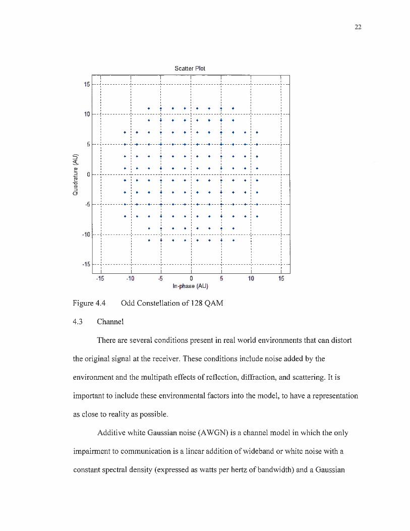
Figure 4.4 represents an odd bit symbol system for the case of 128 QAM. In both cases
the constellation can be extended to represent a higher order system of the same type by
expanding the number of points to M while maintaining the integrity of the constellations
5x 10
00 10 20 30 40 50 60
Figure
4.2
70
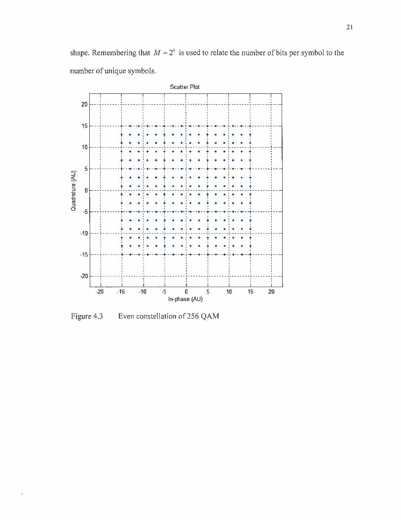
21
shape. Remembering that M = 2k is used to relate the number of bits per symbol to the
number of unique symbols.
Scatter Plot
20
15 •--“ .---.---.--.---.--4---.---.---.--.---.---.--.---.---,
+ • •:. • + • + + 4 + * + 4 + ++ + •:. • + + + • + • * + . +
10C I -I C
* S 4 * * * + + • • * + + tt + •:• • t + + + + t + + + + +
5 +---.---+--.--÷-4--+---.--.--.--4---.---.--.---.---+
* S + * 55 * * * * * *
t * •: • t * •:. + + * • + + t+ • * + • •:. + + * * + + +
-o II
t • * * + + * + + + + + I
aI.---*---+--*---t--7---*--s---*--+--4--t--.-;-+--9---I.
• * •:. • * •:. * * * •:+ •
-10 F+ + •* • • •: * + • •: +
-15 +---*---++---+----+--+-f-*--+--+---*---*+---+---
-20
-20 -16 -10 -6 0 6 10 16 20In-phase (AU)
Figure 4.3 Even constellation of 256 QAM
Scatter Plot
15
• • • * • • •10
• • • • • •
• + 4 • • • • • • •
5 .-----.----,----4----.----.-- --.----.---4-----,---+----.
• • •• • • *
• : • • • .1. • 4 • • •
. 0• • •
-U
• 4 •• • 4 ••
-5 .--:-------.----t---*----÷-t--._---.---i---*---.--:--*
* I • * 4 • .1. • * * •
• • •:• • • I-10
* • .1* * 4 •
-15 --
I I I I I I-15 -10 -5 0 5 10 15
In-phase (AU)
Figure 4.4 Odd Constellation of 128 QAM
4.3 Channel
There are several conditions present in real world environments that can distort
the original signal at the receiver. These conditions include noise added by the
environment and the multipath effects of reflection, diffraction, and scattering. It is
important to include these environmental factors into the model, to have a representation
as close to reality as possible.
Additive white Gaussian noise (AWGN) is a channel model in which the only
impairment to communication is a linear addition of wideband or white noise with a
constant spectral density (expressed as watts per hertz of bandwidth) and a Gaussian

23
distribution of amplitude. The model does not account for fading. frequency selectivity,
interference, nonlinearity or dispersion. However, it produces simple and tractable
mathematical models which are useful for gaining insight into the underlying behavior of
a system before these other phenomena are considered. The channel capacity for the
AWGN channel is given by Equation 3.1.
The Rayleigh probability distribution function is commonly used to incorporate
the multipath effects of a typical system. The Rayleigh PDF is useful in fading channel
environment of wireless communication systems, where multiple signals are scattered,
diffracted, and reflected at the receiver.
for (r 0)(4.2)
for (r<0)
•‘here u is the rms value of the received voltage signal before the envelope, o is the
time-average power of the signal before the envelope.
Rician
for (A0,r0)Pr( a2) (4.3)
for (r<0)
Where A is the peak amplitude of the dominate signal and 10(E) is the modified Bessel
function of the first kind and zero-order.
The Rician PDF is another The Rician PDF if often expressed in terms of K. It is
given by K=A2/(2o2).
0
0
24
__I(r2÷)/2a2 ( K(K+l)”A K+I’ ‘o 2r for (AO,rO)Pr(ñ A ) (4.4)
0 for(r<0)
where A is the peak amplitude of the dominate signal, and K is the defined as the ratio
between the deterministic signal power and the variance of the multipath.
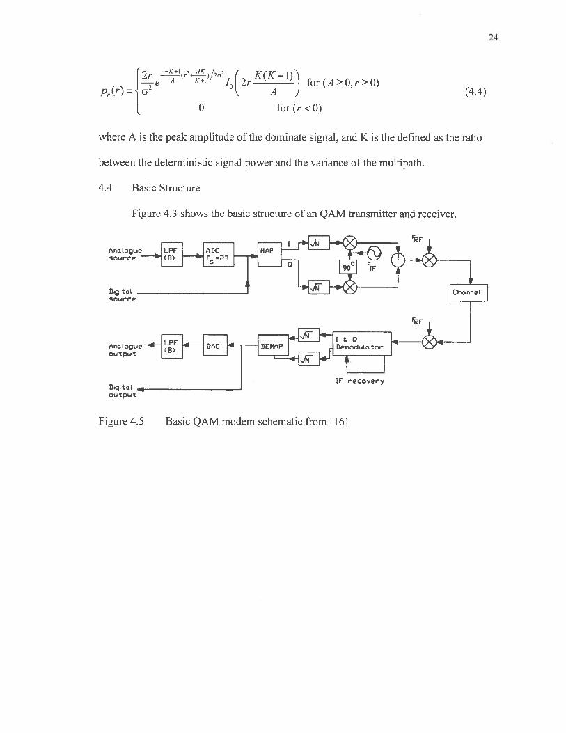
4.4 Basic Structure
Figure 4.3 shows the basic structure of an QAM transmitter and receiver.
natogLAe
sri’.rce
OL.J tput
tf rQcery
Figure 4.5 Basic QAM modem schematic from [16]

CHAPTER 5
Simulation
5.1 Simulation Models
Here we discuss the method used to create the simulation models, and discuss key
parameters. The simulation models were created using Simulink, an extension of the
MATLAB 2012 software suite [27]. The simulation model block functions are as
follows:
• The Bernoulli Binary block is used to generate a random sequence of numbers
with a Bernoulli probability distribution.
• The Rectangular QAM Modulator Baseband block, to the right of the Random
Integer Generator block, modulates the signal using baseband QAM.
• The AWGN Channel block models a noisy channel by adding white Gaussian
noise to the modulated signal.
• The Rayleigh block introduces noise in the angle of its complex input signal
• The Rician block introduces noise in the angle of its complex input signal.
• The Rectangular QAM Demodulator Baseband block, demodulates the signal.
• The Error Rate Calculation block counts symbols that differ between the
received signal and the transmitted signal
25

26
Figures 5.1-5.3 show the SIMULfNK simulation models for 64 QAM transmitted
over AWGN, Rayleigh fading + AWGN, and Rician fading + AWGN channels
respectively.
BnuIli Binary
GEnaratcr
Redan9ularM cd LA!
Baeband1
Bit Efrc Rate
r4urr Bit EITc5
Mum Bitxmitted
RetanuIac o.ArADrrdu! atc.f
Baehan d
Figure 5.1 Simulink simulation model of 64 QAM transmission over AWGN channel

27
Bemnulli BinaryGenerator
Figure 5.2fading channel with AWGN
64-QAM Transmission over Rayleigh IFlat Fadin Channel - No Diversity IPerfect Channel State Infcrrnatiorr (CSl) is assumed at the receiver.
Baebarr
RayleighCh an ii ci
Basebandi
35942e-O ii Bit Error Ratetxmn>
t6Dx1Tx
Rate
___________
215ee--a4I NLrmnBitErrors
I Mum Bits xmitted
To Wcrspace
BER
Rectangular CAMDemodulator
Simulink simulation model of 64 QAM transmission over Rayleigh flat

28
Bemnnulli BinaryGeneratcr
64-QAM Transmission over RicianFlat F Channel - No Diversity
Perfe Channel State Inftrmatjnn jCSI i auned at the recehier.
lultipath RicianChannel
RecianBulaI QAMDerncciulaft
Eaahand
Figure 5.3 Simulink simulation model of 64 QAM transmission over Rician flatfading channel with AWGN
A channel equalizer is implemented to estimate the effects of a given medium
over which a received signal is transmitted. In the case of the model the receiver has
perfect knowledge of distortions induced by the channel. This allows us to fundamental
behavior of QAM over a given channel. The equalizer in the simulated models divides
incoming signal by the gain of the channel to retrieve the original message. The equalizer
can be seen in Figure 5.1 accepting it inputs from the channel output and channel gain.
Bauebana 1
Bit Esrnr Rate
liurn Bit Errcs
Nurn Bits xrnitted
29
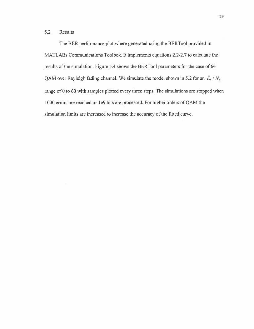
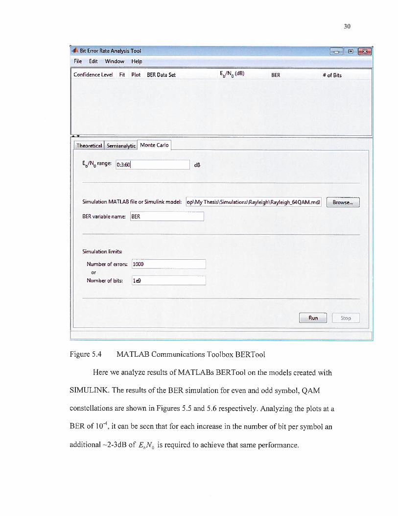
5.2 Results
The BER performance plot where generated using the BERToo1 provided in
MATLABs Communications Toolbox. It implements equations 2.2-2.7 to calculate the
results of the simulation. Figure 5.4 shows the BERToo1 parameters for the case of 64
QAM over Rayleigh fading channel. We simulate the model shown in 5.2 for an Eb / N0
range of 0 to 60 with samples plotted every three steps. The simulations are stopped when
1000 errors are reached or 1e9 bits are processed. For higher orders of QAM the
simulation limits are increased to increase the accuracy of the fitted curve.
30
i Bit Error RateAnalysisTool Jl3i1
File Edit Window Help
Confidence Level Fit Plot BER Data Set EbfN (dB) BER # of Bits
SemianaIytic riont
E!Nrange: o:3:60J
Sin,ulation MATLAB file or Simulink model: op\MyThesis\Sirnulations\Rayleigh\Rayleigh64QAM.mdl Browse..
BER variable name: BER
Simulation limits:
Number of errors: 1000 —
or
Number cf bits: 1
L_i L_J
Figure 5.4 MATLAB Communications Toolbox BERTooI
Here we analyze results of MATLABs l3ERTool on the models created with
SIMULINK. The results of the BER simulation for even and odd symbol, QAM
constellations are shown in Figures 5.5 and 5.6 respectively. Analyzing the plots at a
BER of iO, it can be seen that for each increase in the number of bit per symbol an
additional —2-3dB of EbNO is required to achieve that same performance.

31
100
+
* 64QAMM=6+ 256 QAtvl, rv18 .\..o 1024QAMM=10s> 4096 QAM M=12
15
Eb/NO (dB)20 25 30 35
Figure 5.5 Simulated BER performance of even bit symbol constellations in thepresence of Additive White Gaussian Noise
100
.z-e--._,r—t -
- -
N. : + 8L.
+:Q
+ N, :
I . s‘H
128 QAM M7
512 QAMI M=9 .
2048 QAM M1 1
8192 QAM M=13
I I
0 5 10 15 20 25 30 35
Eb/NO (dE)
Figure 5.6 Simulated BER performance of odd bit symbol constellations in thepresence of Additive White Gaussian Noise
1 o2
ccuJaD
1o6
10.80 5 10
1 o.2
ccui0]
*+
0I)

32
The BER plots of the simulation of QAM over Rayleigh fading channel with
AWGN is shown in Figures 5.7 and 5.8. Analyzing the plots it can be seen that to achieve
a BER of 1 o’ requires an additional 1 dB of Lb N0 per increase in the number of bits per
symbol to maintain performance. We also the difference in dB is relatively uniform at all
values of BER.
•10
___________________________________________________________
I
* 64 QAM, M6
-1 + 2E6QAM,M=8 110 E!HH!.H 0 1024 CAM, M=10
:::::L 0 4096 CAM, M=12 :.
10 1
io
2 7Eb/No (dB)
Figure 5.7 Simulated BER performance of even bit constellations in the presence ofRayleigh flat fading channel with additive white Gaussian noise

33
10°* 120 QAM, M7
612 QAM,M9Q’ 6
.. 0 2040 QAM, M11
:!. S192QAM,M13
11
0 10 20 30 40 60 60 70Eb/No (dEl)
Figure 5.8 simulated BER performance of odd bit constellations in the presence ofRayleigh flat fading channel with additive white Gaussian noise
The BER plots of the simulation of QAM over Rician fading channel with a K factor of 5
and AWGN is shown in Figures 5.9 and s.io. Analyzing the plots it can be seen that to
achieve a BER of 1 o requires an additional l dB of EhNO per increase in the number of
bits per symbol to maintain performance.

34
10 1:1::::::: :1:::::: 11111 1:::::::
* 64 CAM, M=6256 CAM M=8
10 ‘ C 1024Cv1M=10:::::::.::.. $096 CAM, M=12
2 .
1 0 H iHHLHç
io 1 ii n.:::
:::.:::::::::::::::::::::::.::.:::..c ::..:.c::::::.:::::::.:::::::::.iuCl]
..
10
N4
.5 .: \.
10 Hi!i HHWHH11H1HHHH111H1HH t4w ‘IHHH+
I . .
+
0 10 20 30 40 50 60 70Eb/NO (dO)
Figure 5.9 Simulated BER performance of even bit constellations in the presence ofRician flat fading chaimel with additive white Gaussian noise
10 . :.: -
WEE.HHHHE * 128CAM,M=7
1+ 512 CAM, M=9
10 Hk;ftNUHmHHHHHHW 0 2048 CAM1 Mu+
+ 8132 CAM M=13-2
10
.4..io_ .,‘?i—.l.
ci:+
io : .
:- :-
10
- .-
10
uo0 10 20 30 40 50 60 70
Eb/NO (dO)
Figure 5.10 Simulated BER performance of odd bit constellations in the presence ofRician flat fading channel with additive white Gaussian noise

CHAPTER 6
Discussion
6.1 Conclusion
In this paper, we have simulated rectangular QAM schemes of the order 64, 128.
256, 512, 1024, 2048, 4096, and 8192 over AWGN, Rayleigh. and Rician channels. We
also performed theoretical calculations to obtain maximum throughput. Our results show
that the throughput of the system is increased when transmitting more bits per symbol.
This increase in throughput comes at the expense of higher BER. which can be mitigated
by increasing the energy per bit to noise power spectral density ratio of the system. It is
clear that there has to be a compromise between higher throughput, higher BER, and the
energy output. Based on our results, it is important to further investigate the
implementation of high order QAM in wireless broadband systems. This research will be
continued to reinforce the results in this paper.
6.2 Future Work
Our results show that further investigation is needed to determine the practicality
implementing high order QAM in wireless broadband systems. In the future we will add
empirical models to the simulation. This will allow us to examine the performance of
high order QAM in the presence of large-scale path loss. Additionally, we will to
incorporate Orthogonal Frequency Division Multiplexing (OFDM), which is being highly
adopted by modem broadband communications systems. into the system
35

model to get a better idea of the perfonnance. Also, it may be interesting to investigate
the effects more optimal QAM constellations would have in our model.
36

37
REFERENCES
L Rappaport, T.S., Wireless Communications Principles and Pratice. 2nd ed.
Prentice Hall Communications Engineering and Emerging Technologies Series,
ed. T.S. Rappaport2002, Upper Saddle River, Nj 07458: Prentice Hall.
2. Global Positioning System Standard Positioning Service Performance Standard,
Defense, Editor 2008.
3. Haykin, S. and M. Moher, Modern Wireless Communications2005, Upper Saddle
River, NJ: Pearson Prentice Hall.
4. Cisco Systems mc, Cisco Visual A/etworking Index: Global Mobile Data Traffic
Forecast Update, 2011-2016, 2012: USA.
5. Lathi, B.P. and Z. Ding, Modern Digital and Analog Communication Systems. 4th
ed. Oxford Series in Electrical and Computer Engineering2009: Oxford
University Press.
6. Nuaymi, L., WiMAX Technologyfor Broadband Wireless Access2007, West
Sussex, England: John Wiley & Sons Limited.
7. Ho, S.W. Adaptive Modulation (QPSK, QAM). 2004.
8. Tan, M. and W. Chen, Performance Comparison and Analysis ofPSK QAM, in
International Conference on Wireless Communications, Networking and Mobile
Computing20 11: Wuhan, China.
9. Huang, K.C. and Z. Wang, Millimeter Wave Communication Systems20l 1: John
Wiley & Sons.

38
10. Baohong, L., W. Yanyan, and L. Tingjie, Performance Comparison ofHigh Rate
Ultra- Wideband OFDM System between Two Different Modulation Techniques,
in International Conference on Wireless Communications, Networking and
Mobile Computing. 2006: Wuhan, China.
11. Webb, W.T. and L. Hanzo, Modern Quadrature Amplitude Modulationl994,
London, England: Pentech Press Limited.
12. Cahn, C.R., Performance ofdigital phase modulation communication systems.
IRE Transactions on Communication Systems, 1959. 7(1): p. 3-6.
13. Cahn, C.R., Combined digital phase and amplitude modulation communication
system. IRE Transactions on Communication Systems 1960. 8(3): p. 150-155.
14. Hancock, J.C. and R.W. Lucky, PerfOrmance ofcombined amplitude andphase
modulated communications system. IRE Transactions on Communication
Systems, 1960. 8(4): p. 232-237.
15. Campopiano, C.N. and B.G. Glazer, A coherent digital amplitude andphase
modulation system. IRE Transactions on Communication Systems, 1962. 10(1): p.
90-95.
16. Hanzo, L.L., et al., Quadrature Amplitude Modulation: From Basics to Adaptive
Trellis-Coded, Turbo-Equalised and Space-Time Coded OFDM, CDM4 and MC
CDMA Systems. 2nd ed2004.
17. Lucky, R.W. and J.C. Hancock, On the optimum performance ofN-ary systems
having two degrees offreedom. IRE Transactions on Communication Systems,
1962. 10(2): p. 185-192.

39
18. Foschini, G., R. Gitlin. and S. Weinstein, Optimization oftwo-dimensional signal
constellations in the presence ofgaussian noise. IEEE Transactions on
Communications, 1974. 22(1): p. 28-3 8.
19. Thomas, C., M. Weidner, and S. Durrani, Digital amplitude-phase keying with M
ary alphabets. IEEE Transactions on Communications, 1974. 22(2): p. 168-180.
20. Simon, M. and J. Smith, Carrier synchronization and detection ofQASK signal
sets. IEEE Transactions on Communications, 1974. 22(2): p. 98-106.
21. Simon, M. and J. Smith, Ojfset quadrature communications with decision
feedback carrier srnchronization. IEEE Transactions on Communications, 1974.
22(10): p. 1576-1584.
22. Smith, J.G., Odd-bit quadrature amplitude-shfl keying. IEEE Transactions on
Communications, 1975. 23(3): p. 385-389.
23. Steele, R., C.-E.W. Sundberg, and W.C. Wong, Transmission of log-PCM via
QAM over Gaussian and Rayleigh Jading channels. TEE Proceedings-F
Communications, Radar, anf Signal Proceedings, 1987. 134(6): p. 539-556.
24. Sundberg, C.-E.W., W.C. Wong, and R. Steele, Logarithmic PCM weighted QAM
transmission over Gaussian and Rayleighfading channels. TEE Proceedings-F
Communications. Radar, anf Signal Proceedings, 1987. 134(6): p. 557-570.
25. Simon. M.K. and M.-S. Alouini, Digital Communication over Fading Channels.
2nd ed. Wiley Series in Telecommunications and Signal Processing2004, New
York. NY: Wiley-IEEE Press.

40
26. Proakis, J.G. and M. Salehi, Digital Communications, ed. 5th2007, New York,
NY: McGraw-Hill.
27. M4TLAB, 2012, The MathWorks Inc.: Natick, Massachusetts.
28. Cho, K., On the general BER expression ofone- and two-dimensional amplitude
modulalions. IEEE Transactions on Communications, 2002. 50(7): p. 1074-1080.
29. Shannon, C.E., A matematical theory ofcommunication. Part 1. Bell System
Technical Journal, 1948. 27: p. 379-423.
30. Shannon, C.E., A matematical theory ofcommunication. Part 2. Bell System
Technical Journal, 1948. 27: p. 623-656.
31. Shannon, C.E., Communication in the presence ofnoise, in Proceedings, Institute
ofRadio Engineersl949. p. 10-2 1.
32. IEEE, Air Interface for Broadband Wireless Access Systems, in Physical layer
(PHY)2009.
33. 3GPP, Universal Mobile Telecommunications System (UMTS), in Requirements
for Evolved UTRA (E-UTRA) and Evolved UTRAN (E-UTRAN)2010.
34. Gray, F., Pulse Code Communication, U.S.P. Office, Editor 1947: United States.
35. Freund, J.E., Mathematical Statistics with Applications, 2004, Irwin Miller:
Upperaddle River, New Jersey.