ria-79-u517 technical library vulnerability msep ... changed frcfti simply providing confidence in...
TRANSCRIPT

iJ^/s^-AD7^ 900 "^
RIA-79-U517 TECHNICAL LIBRARY
August 1979^
Electromagnetic Pulse Interaction and Coupling for the Army Multiple Systems Evaluation Program
by Robert F. Gray
U.S. Army Electronics Research and Development Command
Harry Diamond Laboratories Adelphi, MD 20783
Approved for public release; distribution unlimited.

The findings in this report are not to be construed as an official Department of the Army position unless so designated by other au^orized documents.
Citation of manufacturers' or trade names does not constitute an official indorsement or approval of the use thereof.
Destroy this report when it is no longer needed. Do not return it to the originator.

UNCLASSIFIED SECURITY CLASSIFICATION OF THIS PAGE (When Data Entarnd)
REPORT DOCUMENTATION PAGE READ INSTRUCTIONS BEFORE COMPLETING FORM
1. REPORT NUMBER
HDL-TR-1896 2. GOVT ACCESSION NO. 3. RECIPIENT'S CATALOG NUMBER
4. T1T L E fand Subll (/»;
Electromagnetic Pulse Interaction and Coupling for the Army Multiple Systems Evaluation Program
5. TYPE OF REPORT & PERIOD COVERED
Technical Report
6. PERFORMING ORG. REPORT NUMBER
7. AUTHORf»;
Robert F. Gray
8. CONTRACT OR GRANT NUMBERfsJ
DA: 1W162118AH75
9. PERFORMING ORGANIZATION NAME AND ADDRESS
Harry Diamond Laboratories 2800 Powder Mill Road Adelphi, MD 20783
10. PROGRAM ELEMENT, PROJECT, TASK AREA & WORK UNIT NUMBERS
Program Ele: 6.21.18.A
n. CONTROLLING OFFICE NAME AND ADDRESS
U.S. Army Materiel Development & Readiness Command
Alexandria, VA 22333
12. REPORT DATE
August 1979 13. NUMBER OF PAGES
27 14. MONITORING AGENCY NAME » ADDRESSf//dJtterenl from Controtlini Olllce) IS. SECURITY CLASS, (ol thie report)
UNCLASSIFIED
15«. DECLASSIFICATION/DOWNGRADING SCHEDULE
16. DISTRIBUTION STATEMENT fo/(/il» Repory
Approved for public release; distribution unlimited.
17. DISTRIBUTION STATEMENT (ot the abetract entered in Block 20, it dillerent from Report)
18. SUPPLEMENTARY NOTES
HDL Project: X755E2, DRCMS Code: 612118.11.H7500 This work was sponsored by the Department of the Army under Project No. 1W162118AH75/A-29, Multiple Systems Evaluation Program.
19. KEY WORDS (Continue on reveiae aide it neceeaary and identity by blocit number)
Coupling analysis Multiple Systems Evaluation Program System vulnerability MSEP p J ^.^j System hardening TEMPO -, / -JX^ EMP'-^ NLINE ^" AESOP FREFLD 20. ABSTRACT fCotrtfliu« Ms rmwraa afita ff Trace«eaty and Identity by block number)
The level of dependence on interaction and coupling analysis for determining Army system vulnerability has increased propor- tionately with advances in the technical capability and the applicability of the analysis. Early system analysis programs^ relied heavily on system test data for inputs to damage analysis codes. Interaction and coupling analysis during the Pershing and Lance Missile System tests was limited to field definition
E)D , FORM JAH 73 M73 EDtnON OF I HOV 65 IS OBSOLETE
UNCLASSIFIED SECURITY CLASSIFICATtOK OF THIS PAGE (Wttan Data Entered)
UNCLASSIFIED SECURITY CLASSIFICATION OF THIS PAGEfWTiMl Data EnUnd)
20. Abstract (Cont'd)
for the purpose of scaling the field test data and to investigations into the response of some basic problems, such as a vertical whip antenna and a two-wire line over an infinitely conducting ground plane.
Recent advances in the interaction and coupling areas under Army and Defense Nuclear Agency funded programs have made it possible for analytical response calculations to have a more direct role in the vulnerability assessments of Army systems. Presently, the Harry Diamond Laboratories is determining the vulnerability of 29 multichannel communications systems under the Army's Multiple Systems Evaluation Program (MSEP). Field testing of these systems has been required only for validation of analytical coupling models and circuit code models.
Three main computer codes have been applied to the coupling problems analyzed in the MSEP. These codes are "TEMPO," which contains up-to-date models of a variety of standard antennas along with a semiempirical technique for characterizing the response of more complex antennas; "NLINE," which treats multiconductor transmission lines; and "FREFLD," which is a transmission-line solution for the response of a coaxial cable. Typically, each of these codes depends on a specialized test or analysis technique to determine input parameters for the specific antenna or cable system under consideration.
This paper contains an overview of the three codes, showing the applications of the codes and techniques to particular system problems, along with the levels of confidence obtained.
UNCLASSIFIED SECURITY CLASSIFICATION OF THIS P AGEfHTien D«(« Enlerod;
FOREWORD
This paper presents an outline of the development of analytical tools and field testing for the analysis of nuclear electromagnetic pulse (EMP) in-teraction and coupling into tactical Army systems. A historical background is portrayed of the efforts of the Electromagnetic Effects Laboratory of the Harry Diamond Laboratories (previously a laboratory of the U.S. Army Mobility Equipment Research and Development Center). The advances both directly and through the guidance of technical contractors are documented in the references. This paper then brings the reader up to date on the current state of analysis in EMP interaction and coupling of tactical Army systems.
CONTENTS
Page
1. INTRODUCTION 7
2. PRIOR SYSTEMS 7
3. PRESENT SYSTEMS 8
4. PRESENT ANALYSIS 10
5. VALIDATION PROCESS 13
6. CONCLUSIONS AND RECOMMENDATIONS 19
LITERATURE CITED 20
DISTRIBUTION 23
FIGURES
1 Lance Missile System 7
2 Typical Army Communication Equipment 9
3 Manpack Portable Radio Set, AN/PRC-77 (30 to 76 MHz) 10
4 Generic Assessment Method for a Priori Hardening Systems in Vulnerability and Hardness Assessment 11
5 Preferred Prediction Method for Applying Interaction and Coupling Codes to Systems 12
6 Multiexponential Curve Fit Comparison of Radial Magnetic Field at 0, 200, and 0.5 m from Army EMP Simulator Operation (AESOP) Simulator 13
7 Validation Result for Simple System: 100-m Field Wire on Ground with System Termination on One End 14
8 Configuration for Radio Set AN/TRC-145 Field Test 15
9 External Cable Current at Test Unit for Radio Set AN/TRC-145 Pulse Code Modulation Cable at 4.6 m with ac Generator ... 16
10 Internal Current on Shields of Coaxial Cable Pair for Radio Set AN/TRC-145 Pulse Code Modulation Cable at 4.6 m with ac Generator 17
11 Current on Shields of Coaxial Cable Pair for Radio Set AN/TRC- 145 Pulse Code Modulation Cable at 4.6 m without ac Generator 17
12 Pulse Code Modulation Cable Field Test Response 19

1. INTRODUCTION
Interaction and coupling analysis has had an increasing role in recent Army systems electromagnetic pulse (EMP) vulnerability assessments. The level of reliance on predictive coupling tools has changed frcfti simply providing confidence in system level tests to using, in all current Army assessments, predicted responses that rely on system level test comparisons for confidence. This fact may best be pointed out by reviewing early Army systems, their coupling problems, and the interaction and coupling work performed dviring these programs and comparing these with v*iat is presently being accomplished under the Army's Multiple Systems Evaluation Program (MSEP).
2. PRIOR SYSTEMS
In the late 1960's and early 1970's, the Pershing Missile System and the Lance Missile System (fig. 1) were extensively tested^~^'* and analyzed"^' for vulnerability to the high-altitude EMP threat. Although Pershing is much more complex than Lance, the coupling problems presented by the two missile systems were similar. Also, essentially the same testing and analysis philosophy was used in each assessment.
Figure 1. Lance Missile System.
*Nuinbers refer to entries in the Literature Cited section.

Various types of major coupling problems in these systems also are shown in figure 1. A variety of multiconductor cables appears in these systems. The multiconductor cables that had external shields ranged in size from 8 to 26 pairs of conductors ahd in length frcxn 4 to 150 m. These cables are used to interconnect xmits mounted on the same chassis or other nearby vehicles and equipment. The unshielded multiconductor cables were typically used for power distribution and consisted of three or four conductors varying in length from 15 to 150 m.
The communication equijxnent associated with these systems employed simple whip antennas mounted on the signal shelters or vehicles and dipole antennas with coaxial feeds. The only land line used for communicaton is the WD-1/TT twisted pair of field wires which, for these systems, was limited to lengths of run up to 1.6 km. The twisted pair of field wires is the most commonly used cable in the Lance, and it is
found in nearly all Army systems.
The vulnerability assessment of these systems relied heavily on extensive simulator testing to determine the response characteristics of the cables and the antennas. There were some initial attempts to modeling the coupling to single- and two-wire lines and to some simple antennas^° such as whips. Although these solutions were not used in the damage assessments of the systems, they added confidence to the measured system data that were used as input to the circuit analysis
codes.
Another major analytical effort during this period was defining the field output of the various simulators ^^'^^ used and comparing them with the output expected from a real threat. ^^ In this way, the necessary scale factors for the system response data were determined.
In addition to the system testing being conducted at the time, many experiments were conducted on various simple coupling problems. These data proved useful in later code validation. Three computer codes that are being applied in present system studies were in their initial development stages during this period iinder funds provided by both the Army and the Defense Nuclear Agency. These codes are TEMPO, NLINE, and
FREFLD.
3. PRESENT SYSTEMS
In recent years, the Army has been concentrating on the communication equipment employed frcxn the forward edge of the battle area back to the corps level (fig. 2). Some of the coupling problems associated with these systems are very similar to those encountered in the earlier missile systems. Essentially, the scime power cabling and coaxial cable feeds for antennas are used in these systems along with the standard twisted pair of field wires.

Figure 2. Typical Army coininunication equipment.
However, cable lengths and system terminations are more varied now. In addition to the standard twisted pair of field wires, a twisted four-wire telephone cable used with some of this equijxnent may also have lengths of runs xip to 32 km.
Many of these systems have multichannel transmission capabilities either by radio link or through land lines. These land lines may be up to 64 km without a manned repeater, and the cabling may be deployed from ground level to a height of about 5 m. Unattended in-line repeaters are required every 1.6 km when long lengths of cable are used. This land line or pulse code modulation (PCM) cable consists of two coaxial cables, one for transmitting and one for receiving, which are twisted and covered by an overall braided shield.
Also, various antennas are used by this equipment. Some of the single-channel radios use a jeep-mounted center feed whip antenna, which has a preselector at the base of the antenna. The mxiltichannel equipment uses more complex antennas, such as the horn antenna with a coaxial cable feed, which allows significant coupling to the system, and the dipole antenna with a corner reflector, which may be used with
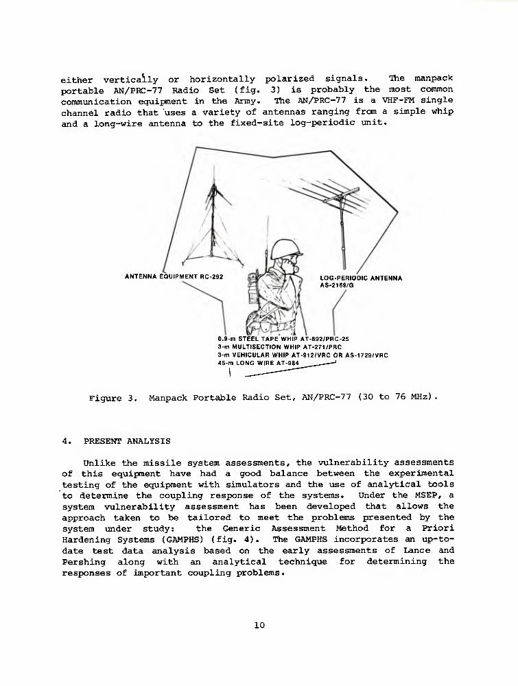
either vertically or horizontally polarized signals. Itie manpack portable AN/PRC-77 Radio Set (fig. 3) is probably the most common communication equijxnent in the Army. The AN/PRC-77 is a VHF-FM single channel radio that uses a variety of antennas ranging from a simple whip and a long-wire antenna to the fixed-site log-periodic unit.
ANTENNA EQUIPMENT RC-292 LOG-PERIODIC ANTENNA AS-2169/G
0.9-m STEEL TAPE WHIP AT-892/PRC-25 3-m MULTISECTION WHIP AT-271/PRC 3-m VEHICULAR WHIP AT-912/VRC OR AS-1729/VRC 45-m LONG WIRE AT-984
Figure 3. Manpack Portable Radio Set, AN/PRC-77 (30 to 76 MHz)
4. PRESENT ANALYSIS
Unlike the missile system assessments, the vulnerability assessments of this equipment have had a good balance between the experimental testing of the equipment with simulators and the use of cinalytical tools to determine the coupling response of the systems. Under the MSEP, a system vulnerability assessment has been developed that allows the approach taken to be tailored to meet the problems presented by the system under study: the Generic Assessment Method for a Priori Hardening Systems (GAMPHS) (fig. 4). The GAMPHS incorporates an up-to- date test data analysis based on the early assessments of Lance and Pershing along with an analytical technique for determining the responses of important coupling problems.
10

TEST APPROACH
SIMULATOR ENVIRONMENT
DIGITIZED
FIELD TEST DATA DIGITIZED
SIGNAL DATA BANK
LINT, CLINT, CSTOUT
INTERPOLATION, PRE- PROCESSING ROUTINES
SMOOTHING ROUTINE FOURIER ANALYSIS
SCALETOTMREAT LEVEL
EXOENVIRONMENTS
SINGLE MULTI GRAPH
ANALYSIS APPROACH
PROCESS DATA FOR TIME INCREMENTS
VERTICAL AND HORIZONTAL TOTAL FIELDS
ANTENNAS, APERTURES.
CABLES
± CABLE CURRENTS INTERNAL SHIELD
RESPONSE
WORST CASE
RESPONSE
CRITICAL CIRCUIT MODELS, DAMAGE PREDICTIONS, AND
HARDENING ANALYSIS
VULNERABILITY ASSESSMENT AND
HARDENING RECOMMENDATIONS
DIODE, TRANSISTOR DEVICE DATA BANK
DAMAGE CURVES. SURGE IMPEDANCES TRAC PARAMETERS
Figiire 4. Generic Assessment Method for a Priori Hardening Systems in vulnerability and hardness assessment.
Three main computer codes have been applied to the coupling problems identified for these systems:
TEMPO^^ a compilation of analytical solutions for a variety of antennas plus a semiempirical technique of treating more complex antennas.
NLINE 26
FREFLD 27
a transmission line solution for EMP coupling with a lossless multiconductor transmission line located aboveground or in free space. This code can handle up to 11 conductors.
a transmission line solution for the external and internal responses of a coaxially shielded cable due to an arbitrarily oriented field.
Each of these codes is applied to a specific system coupling problem -{fig. 5). The problem definition stage involves an investigation of the system and its various operational modes to define possible prime penetrations. Decisions are made in this stage as to what simulator
11
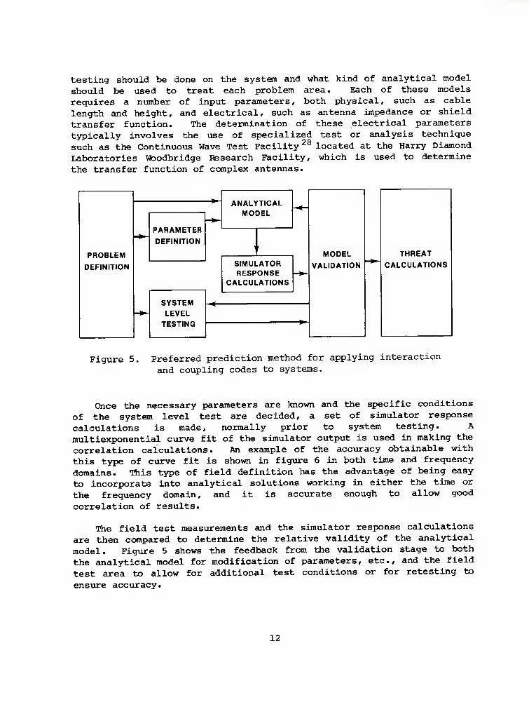
testing should be done on the system and what kind of analytical model should be used to treat each problem area. Each of these models requires a number of input parameters, both physical, such as cable length and height, and electrical, such as antenna impedance or shield transfer function. The determination of these electrical parameters typically involves the use of specialized test or analysis technique such as the Continuous Wave Test Facility ^^ located at the Harry Diamond Laboratories Woodbridge Research Facility, which is used to determine the transfer function of ccxnplex antennas.
PROBLEM
DEFINITION
MODEL
VALIDATION * THREAT
CALCULATIONS
ANALYTICAL MODEL
PARAMETER
DEFINITION ' '
SIMULATOR RESPONSE
CALCULATIONS
SYSTEM LEVEL
TESTING
Figure 5 Preferred prediction method for applying interaction and coupling codes to systems.
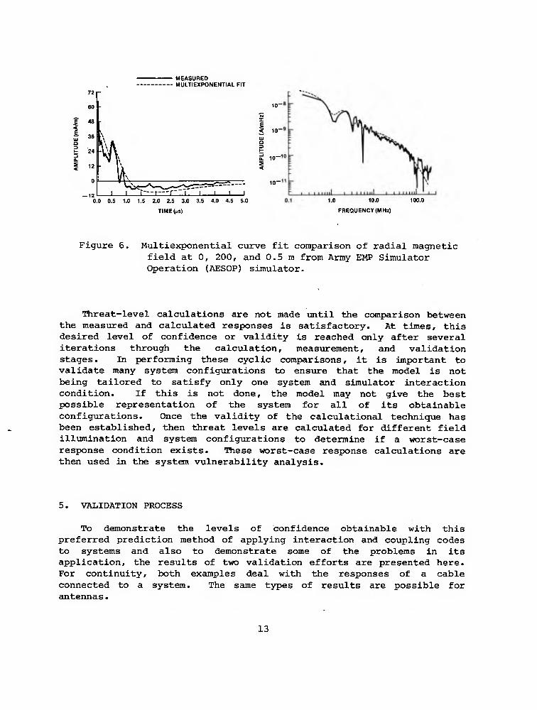
Once the necessary parameters are known and the specific conditions of the system level test are decided, a set of simulator response calculations is made, normally prior to system testing. A multiexponential curve fit of the simulator output is used in making the correlation calculations. An example of the accuracy obtainable with this type of curve fit is shown in figure 6 in both time and frequency domains. This type of field definition has the advantage of being easy to incorporate into analytical solutions working in either the time or the frequency domain, and it is accurate enough to allow good
correlation of results.
The field test measurements and the simulator response calculations are then compared to determine the relative validity of the analytical model. Figvure 5 shows the feedback from the validation stage to both the analytical model for modification of parameters, etc., and the field test area to allow for additional test conditions or for retesting to
ensure accuracy.
12
MEASURED - —- Mill T EXPONENTIAL FIT ~~" MULI
72 - 60 - ^ 10
48 ' Z E 3 10
36
vK o 3
24
^ -J O. 10-
12 - \ S < 0 ' 1 k^
1 1 "T" —r-"\" 1 1
10"
12 1 1 0 0 0.5 1.0 1.5 2.0 2.5 3.0 3.5 4.0 4.5 5.0
TIMERS)
1.0 10.0
FREQUENCY (MHz)
Figure 6, Multiexponential curve fit comparison of radial magnetic field at 0, 200, and 0.5 m from Army EMP Simulator Operation (AESOP) simulator.
Threat-level calculations are not made until the comparison between the measured and calculated responses is satisfactory. At times, this desired level of confidence or validity is reached only after several iterations through the calculation, measurement, and validation stages. In performing these cyclic comparisons, it is important to validate many system configurations to ensure that the model is not being tailored to satisfy only one system and simulator interaction condition. If this is not done, the model may not give the best possible representation of the system for all of its obtainable configurations. Once the validity of the calculational technique has been established, then threat levels are calculated for different field illumination and system configurations to determine if a worst-case response condition exists. These worst-case response calculations are then used in the system vulnerability analysis.
5. VALIDATION PROCESS
To demonstrate the levels of confidence obtainable with this preferred prediction method of applying interaction and coupling codes to systems and also to demonstrate some of the problems in its application, the results of two validation efforts are presented here. For continuity, both examples deal with the responses of a cable connected to a system. The same types of results are possible for antennas.
13
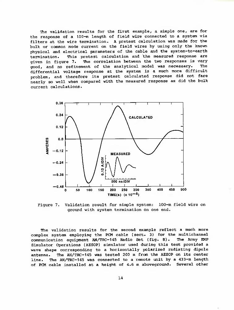
The validation results for the first example, a simple one, are for
the response of a 100-m length of field wire connected to a systen via
filters at the wire termination. A pretest calculation was made for the bulk or common mode current on the field wires by using only the known
physical and electrical parameters of the cable and the system-to-earth
termination. This pretest calculation and the measured response are
given in figure 7. Ihe correlation between the two responses is very
good, and no refinement of the analytical model was necessary. The differential voltage response at the system is a much more difficult
problem, and therefore its pretest calculated response did not fare
nearly so well when compared with the measured response as did the bulk
current calculations.
0.36
0.24 -
0.12
W 0.0 lu E UJ Q. S —0.12 <
— 0.24 -
— 0.36
—0.48
1 1 1 1 1 1 1 1
/ \ CALCULATED
1
A ^—
- \ MEASURED \. ^
-
- \ / > / s / ^ A (\ -
/ " \ 1 \/ 1
1 / d
1 1
'■ \l
1 500 ns/DIV
1 1 1 1 1
50 100 150 200 250 300 350 400 450 500 TIME(s) (X 10—8)
Figure 7. Validation result for simple system: 100-m field wire on
ground with system termination on one end.
The validation results for the second example reflect a much more complex system employing the PCM cable (sect. 3) for the multichannel
communication equipment AN/TRC-145 Padio Set (fig. 8). The Army EMP
Simulator Operations (AESOP) simulator used during this test provided a
wave shape corresponding to a horizontally polarized radiating dipole
antenna. The AN/TRC-145 was tested 200 m from the AESOP on its center line. The AN/TRC-145 was connected to a remote unit by a 433-m length
of PCM cable installed at a height of 4.6 m aboveground. Several other
14
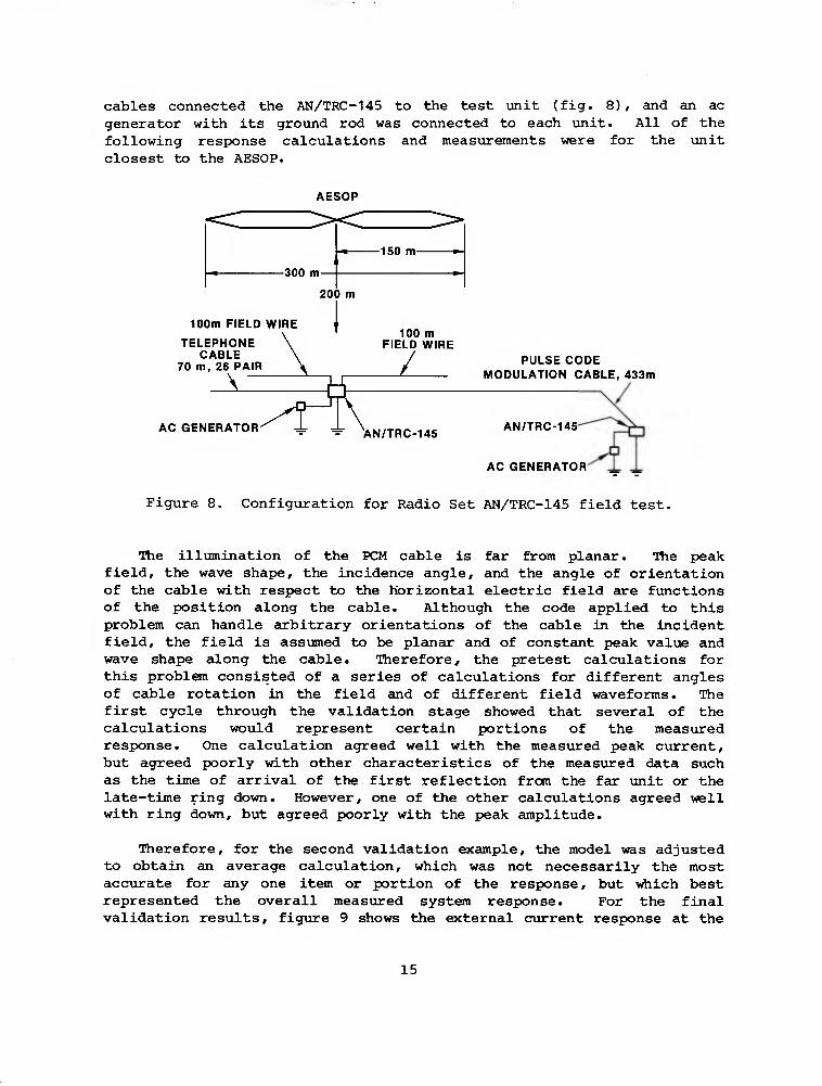
cables connected the AN/TRC-145 to the test imit (fig. 8), and an ac generator with its ground rod was connected to each unit. All of the following response calculations and measurements were for the unit closest to the AESOP.
AESOP
-300 m-
-150 m-
200 m
100m FIELD WIRE
TELEPHONE CABLE
70 m, 26 PAIR
AC GENERATO .^
100 m FIELD WIRE
L PULSE CODE MODULATION CABLE, 433m
AN/TRC-145 AN/TRC-145
AC GENERATOR
Figure 8. Configuration foj: Radio Set AN/TRC-145 field test.
The illxmination of the PCM cable is far from planar. The peak field, the wave shape, the incidence angle, and the angle of orientation of the cable with respect to the Horizontal electric field are functions of the position along the cable. Although the code applied to this problem can handle arbitrary orientations of the cable in the incident field, the field is assumed to be planar and of constant peak value and wave shape along the cable. Therefore, the pretest calculations for this problem consisted of a series of calculations for different angles of cable rotation in the field and of different field waveforms. The first cycle through the validation stage showed that several of the calculations would represent certain portions of the measured response. One calculation agreed well with the measured peak current, but agreed poorly with other characteristics of the measured data such as the time of arrival of the first reflection from the far unit or the late-time ring down. However, one of the other calculations agreed well with ring down, but agreed poorly with the peak amplitude.
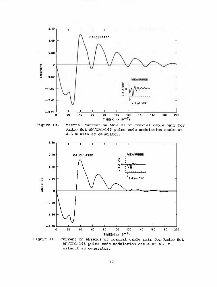
Therefore, for the second validation example, the model was adjusted to obtain an average calculation, which was not necessarily the most accurate for any one item or portion of the response, but which best represented the overall measured system response. For the final validation results, figure 9 shows the external current response at the
15

test unit, and figiire 10 shows the internal current on both of the coaxial cable shields. The general characteristics of the two measurements are close to those of the calculated responses. However, the specifics such as peak amplitudes, which differ by factors of two or three at some points, are not nearly so accurate as were obtained for the first validation example.
Since these calculations required several iterations through the validation stage, some assurance was needed that the resulting model could be applied to conditions other than those used for the field test. Therefore, an additional set of field measurements was requested that used the same cable layout (v*iich could not easily be reconfigured) due to the problems involved in accurately installing the cable for test. But the system-to-earth impedance was altered by removing the ac generators and, therefore, their grounds from the system. Ihis terminating impedance change was accounted for in the analytical model, and the resulting comparison for the current on the inner coaxial cable shields is given in figure 11. In comparing the responses without the ac generator grounds to those in figure 10 with the grounds, one should note that both the calculated and the measured responses exhibit much greater damping of the late-time response. Although this new comparison does not offer definite proof that the model will retain the same level of confidence for all other configurations, it does contribute significantly to the overall confidence in the analytical representation of the system.
— 10.0
— 20.0
2.0 (iS/DIV
20 40 60 80 100 120
TIME(S) (X 10—7)
140 160 180 200
Figure 9, External cable cxirrent at test unit for Radio Set AN/TRC-145 pulse code modulation cable at 4.6 m with ac generator.
16
2.40
1.60 -
0.80 -
III BE 111 IL
< —0.80
— 1.60
— 2.40
— 3.20
Figure 10.
CALCULATED
20 40 _L
2.0 /js/DIV
_L _L 60 80
TIME(s) (X 10—^)
100 120 140 160 180 200
Internal current on shields of coaxial cable pair for Radio Set AN/TRC-145 pulse code modulation cable at 4.6 m with ac generator. •
3.20
2.40 -
1.60 -
M 0.80 UJ oc UJ a.
— 0.80 -'
— 1.60 -
— 2.40 20 40
1 1 1 1
CALCULATED
1 1 1 1
MEASURED
1
-
^
> o < 0-
d -
1 1 1 1 t 1 1 1 1 ;
v^ 1
0 2.0 HS/DIV
\ Ai 1 1 1 1 1 1 1 1 1
60 80 100 120 140 160 180
TIME(s) (X 10~^)
200
Figure 11. Current on shields of coaxial cable pair for Radio Set AN/TRC-145 pulse code modulation cable at 4.6 m without ac generator.
17

-^'^
The validation comparisons given so far for the system with the PCM cable have been limited to the exterior current and the coupling to the shields of the two coaxial cables. Since a vulnerability analysis requires the voltage or current response of each coaxial cable, not just the current on its shield, an additional analytical model for this response had to be developed and validated.
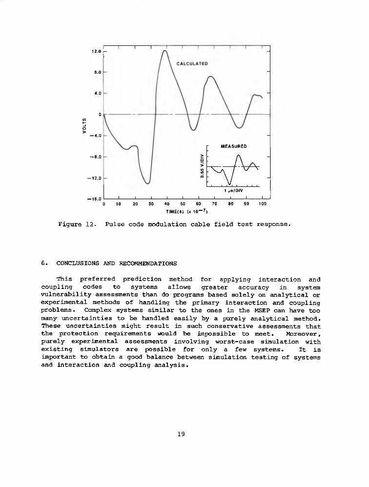
Detailed modeling of the coupling through both the external shield and one of the internal coaxial shields was not possible with the available analytical tools since code FREFLD treats only singly shielded cables. However, through shielding effectiveness testing conducted on the PCM cable, it was found that the coupling through the shield of the internal coaxial cable was essentially a resistive effect over the range of frequencies of interest. Therefore, the shield transfer impedance used for calculating the response of coaxial cables was the parallel resistance of the external shield and the two coaxial cable shields. Figure 12 compares the calculated voltage response and that measured during the system field test.
The general wave shapes agree well, but the amplitude differs by about a factor of five. At first glance, this difference may seem poor. But if one considers the approximations that had to be made in the model and the relatively poor simulation that was possible, then it seems reasonable that the calculated responses should tend to be greater.
Also, the fact that the analytical model produces a larger response than may actually occur in the event of an EMP merely makes the system assessment more conservative. The validation of the analytical model with the systCTi level test ensures that the interaction and coupling estimates are not so conservative that protecting the system to the predicted signal levels is not feasible or cost effective.
18
12.0 -
8.0
4.0
O > — 4.0
— 8.0
-12.0
— 16.0
n 1 r
- MEASURED
> 5 -
A ^ in (D - ^ ̂ / O
J I L.
1 (iS/DIV
J I 1
0 10 20 30 40 50 60 70 80 90 100
TIME(S) (X 10 — ^)
Figure 12. Pulse code modulation cable field test response.
6. CONCLUSIONS AND RECOMMENDATIONS
This preferred prediction method for applying interaction and coupling codes to systems allows greater accuracy in system vulnerability assessments than do programs based solely on analytical or experimental methods of handling the primary interaction and coupling problems. Complex systems similar to the ones in the MSEP can have too many uncertainties to be handled easily by a purely analytical method. These uncertainties might result in such conservative assessments that the protection requirements would be impossible to meet. Moreover, purely experimental assessments involving worst-case simulation with existing simulators are possible for only a few systems. It is important to obtain a good balance between simulation testing of systems and interaction and coupling analysis.
19

LITERATURE CITED
(1) Donald Dinger, R. J. Bostak, J. D. Dando, and W. Haas, White Paper on Pershing la Special Test Program (U), 3rd Ed., U.S. Army Mobility Equipment Research and Development Center, Fort Belvoir, VA (10 June 1968). (SECRET)
(2) Jere D. Dando, Pershing Special Test Program Phase I, Final Report, U.S. Army Mobility Equipment Research and Development Center, Fort Belvoir, VA (March 1969).
(3) Jere D. Dando, Guidelines for Pershing .la Special Test Program (STP) Phase II, U.S. Army Mobility Equipment Research and Development Center, Fort Belvoir, VA (13 June 1969).
(4) Jere D. Dando, Pershing Special Test Program Phase II, Final Report (U), Harry Diamond Laboratories (May 1.973). (TOP SECRET FORMERLY RESTRICTED DATA)
(5) Robert A. Pfeffer and Heinz G. Mueller, LANCE Missile System EMP Test Program (U) , Harry Diamond Laboratories HDL-TR-1756 (November 1976). (SECRET RESTRICTED DATA)
(6) Eugene J. Putzer, Ken Schwartz, and Glenn L. Brown, The Coupling of Transient Fields into Cables and Transmission Lines above a Conducting Earth, Final Report, American Nucleonics Corp., Anaheim, CA, Contract DA44-009-AMC-1463(T) (August 1970).
(7) Eugene J. Putzer, Theory of the Driven Two-Wire Transmission Line, Final Report, American Nucleonics Corp., Anaheim, CA, Contract DA44-009-AMC-1463(T) (February 1969).
(8) Carrell D. Whitescarver, Transient Electromagnetic Field Coupling with Two Wire Uniform Transmission Lines, Ph.D. Dissertation, University of Florida (1969).
(9) Werner Stark, An Analytical and Experimental Investigation of Cable Responses to a Pulsed Electromagnetic Field, Harry Diamond Laboratories HDL-TR-1618 (December 1972).
(10) Peter P. Toulios et al. Effects of EMP Environment on Military Systems Final Report, _I, ITT Research Institute, Chicago, IL, Contract DAAK02-68-C-0377 (February 1969).
20

LITERATURE CITED (Cont'd)
(11) L. D. Milliman et al, CIRCUS—A Digital Computer Program for Transient Analysis of Electronic Circuits, The Boeing Co., Seattle, WA, Contract DA-49-186-AMC-346(X) (January 1967).
(12) E. D. Johnson et al. Transient Radiation Analysis by Computer Program (TRAC), North American Rockwell Corp., Anaheim, CA, Contract DAAG39-68-C-0041 (June 1968).
(13) Janis Klebers, A Study of the Long Wire Antenna Environment Characteristics (U), U.S. Army Mobility Equipment Research and Development Center, Fort Belvoir, VA (21 October 1968). (CONFIDENTIAL)
(14) E. F. Vance, Field Mapping and Data Analysis for a Long Wire Antenna (U) , Stanford Research Institute, Menlo Park, CA, Technical Report 1, Subcontract BDM-S1-67-C-66, Prime contract DAAK-02-67C-0168 (January 1969). (SECRET)
(15) Janis Klebers and .Stanley Bukalski, A Theoretical and Experimental Evaluation of a Biconic Antenna Nuclear EMP Simulator (U), Proceedings of Army Science Conference, West Point, NY (June 1970). (SECRET)
(16) Richard L. Monroe, Approximate Step Function Response of a Horizontally Polarized Electromagnetic Wave Reflected at an Imperfectly Conducting Surface, J. Appl. Phys., _41_ (November 1970), 4820-4822.
(17) Richard L. Monroe, Approximate Step Function Response of a Vertically Polarized Electromagnetic Plane Wave Reflected at an Imperfectly Conducting Surface, J. Appl. Phys., _40^ (August 1969), 3526-3531.
(18) Janis Klebers, Time Domain Analysis of the Electromagnetic Field in the Presence of a Finitely Conducting Surface, U.S. Army Mobility Equipment Research and Development Center, Fort Belvoir, VA (29 January 1969).
(19) Nuclear Survivability Criteria for Army Tactical Equipment (U), Office of the Chief of Research, Development and Acquisition, U.S. Army Nuclear Agency ACN 04257 _ (1 August 1974). (CONFIDENTIAL RESTRICTED DATA)
21
LITERATURE CITED (Cont'd)
(20) George Gornak et al, EMP Assessment for Army Tactical Communication Systems: Transmission Systems Series No. 1: Radio Terminal Set AN/TRC-145 (U) , Harry Diamond Laboratories HDL-TR- 1746 (February 1976). (SECRET RESTRICTED DATA)
(21) George Baker and Werner Stark, EMP Vulnerability Analysis of Radio Sets AN/PRC-77, AN/VRC-64, and AN/GRC-160 (U), Harry Diamond Laboratories HDL-TR-1747 (February 1976). (SECRET RESTRICTED DATA)
(22) Ting H. Mak and Leslie Basner, EMP Assessment for Army Tactical Communications Systems: Transmission Systems Series No. 2: Radio Terminal Set AN/TRC-117 (U), Harry Diamond Laboratories HDL-TR-1769 (October 1976). (SECRET RESTRICTED DATA)
(23) Michael J. Vrabel, EMP Assessment for Army Tactical Communications Systems: Transmission Systems Series No. 3: Radio Terminal Sets AN/TRC-112 and AN/TRC-121 (U), Harry Diamond Laboratories HDL-TR-1807 (May 1977). (SECRET RESTRICTED DATA)
(24) Ting H. Mak, EMP Assessment for Army Tactical Communications Systems: Transmission Systems Series No. 4: Radio Terminal Set AN/TRC-138 (U), Harry Diamond Laboratories HDL-TR-1809 (June 1977). (SECRET RESTRICTED DATA)
(25) Werner J. Stark and David A. Clark, User's Manual for the Interaction and Coupling Code TEMPO (U) , Interim Report, Harry Diamond Laboratories (May 1977).
(26) Janis Klebers, User's Manual for the NLINE Multiconductor Transmission Line Computer Code, Harry Diamond Laboratories HDL- TR-1803 (May 1977).
(27) Robert F. Gray, Nuclear Electromagnetic Pulse Simulation by Point Source Injection Techniques for Shielded and Unshielded Penetrations, Harry Diamond Laboratories HDL-TR-1737 (December 1975).
(28) Werner J. Stark, Transient Response of a Log-Periodic Antenna Based on Broad-Band Continuous-Wave Measurements, Harry Diamond Laboratories HDL-TR-1792 (April 1977).
22

DISTRIBUTION
DEFENSE DOCUMENTATION CENTER CAMERON STATION, BUILDING 5 ALEXANDRIA, VA 22314
ATTN DDC-TCA (12 COPIES)
COMMANDER
US ARMY RSCH S STD GP (EUR) FPO NEW YORK 09510 ATTN LTC JAMES M. KENNEDY, JR
CHIEF, PHYSICS S MATH BRANCH
COMMANDER US ARMY MATERIEL DEVELOPMENT S READINESS COMMAND
5001 EISENHOWER AVENUE ALEXANDRIA, VA 22333 ATTN DRXAM-TL, HQ TECH LIBRARY ATTN DRCDE, DIR FOR DEV S ENGR ATTN DRCDE-D ATTN DRCDE-DE ATTN DRCMS-I, MR. E.-0'DONNEL
COMMANDER US ARMY ARMAMENT MATERIEL READINESS COMMAND
ROCK ISLAND, IL 61299 ATTN DRSAR-LEP-L, TECHNICAL LIBRARY
COMMANDER US ARMY MISSILE S MUNITIONS CENTER S SCHOOL
REDSTONE ARSENAL, AL 35809 ATTN ATSK-CTD-F
DIRECTOR US ARMY MATERIEL SYSTEMS ANALYSIS ACTIVITY
ABERDEEN PROVING GROUND, MD 21005 ATTN DRXSY-MP ATTN DRXSY-C ATTN DRXSY-T
DIRECTOR DEFENSE ADVANCED RESEARCH PROJECTS AGENCY
ARCHITECT BLDG 1400 WILSON BLVD ARLINGTON, VA 22209 ATTN TECH INFORMATION OFFICE ATTN DIR, STRATEGIC TECHNOLOGY OFFICE ATTN DIR, TACTICAL TECHNOLOGY OFFICE
DIRECTOR US ARMY BALLISTIC RESEARCH LABORATORY ABERDEEN PROVING GROUND, MD 21005
ATTN DRDAR-TSB-S (STINFO)
ATTN DRDAR-BLB, WEAPON AREA COORDINATORS
TELEDYNE BROWN ENGINEERING CUMMINGS RESEARCH PARK HUNTSVILLE, AL 35807 ATTN DR. MELVIN L. PRICE, MS-44
ENGINEERING SOCIETIES LIBRARY 345 EAST 47TH STREET NEW YORK, NY 10017 ATTN ACQUISITIONS DEPARTMENT
DIRECTOR
DEFENSE COMMUNICATIONS ENGINEERING CENTER 1860 WIEHLE AVENUE RESTON, VA 22090 ATTN R104, M. J. RAFFENSPERGER ATTN R800, R. E. LYONS
DIRECTOR DEFENSE INTELLIGENCE AGENCY WASHINGTON, DC 20301 ATTN DT-2, WEAPONS S SYSTEMS DIV
DIRECTOR DEFENSE NUCLEAR AGENCY WASHINGTON, DC 20305 ATTN PETER HAAS, DEP. DIR,
SCIENTIFIC TECHNOLOGY ATTN RAEV, ELECTRONIC VULNERABILITY ATTN VLWS, WEAPONS SYSTEMS DIV
UNDER SECRETARY OF DEFENSE FOR RESEARCH AND ENGINEERING
WASHINGTON, DC 20301 ATTN DEP DIR (TACTICAL WARFARE PROGRAMS) ATTN DEP DIR (TEST S EVALUATION) ATTN DEFENSE SCIENCE BOARD ATTN ASST DIR SALT SUPPORT GP
CHAIRMAN JOINT CHIEFS OF STAFF WASHINGTON, DC 20301 ATTN J-3, NUCLEAR WEAPONS BR ATTN J-3, EXER PLANS S ANALYSIS DIV ATTN J-5, NUCLEAR DIR NUCLEAR POLICY BR ATTN J-5, REQUIREMENTS S DEV BR ATTN J-6, COMMUNICATIONS-ELECTRONICS
DEPARTMENT OF DEFENSE JOINT CHIEFS OF STAFF STUDIES ANALYSIS S GAMING AGENCY WASHINGTON, DC 20301 ATTN STRATEGIC FORCES DIV ATTN GEN PURPOSE FORCES DIV ATTN TAC NUC BR ATTN SYS SUPPORT BR
23
DISTRIBUTION (Cont'd)
ASSISTANT SECRETARY OF DEFENSE PROGRAM ANALYSIS AND EVALUATION WASHINGTON, DC 20301 ATTN DEP ASST SECY (GEN PURPOSE PROG) ATTN DEP ASST SECY (REGIONAL PROGRAMS) ATTN DEP ASST SECY (RESOURCES ANALYSIS)
DEPARTMENT OF THE ARMY OFFICE, SECRETARY OF THE ARMY WASHINGTON, DC 20301 ATTN ASST SECRETARY OF THE ARMY (ISL) ATTN DEP FOR MATERIEL ACQUISITION ATTN ASST SECRETARY OF THE ARMY (RSD)
DEPARTMENT OF THE ARMY ASSISTANT CHIEF OF STAFF FOR INTELLIGENCE WASHINGTON, DC 20301 ATTN DAMI-OC ATTN DAMI-TA
DIRECTOR US ARMY SIGNALS WARFARE LABORATORY VINT HILL FARMS STATION WARRENTON, VA 22186 ATTN DELSW-OS
COMMANDER US ARMY CONCEPTS ANALYSIS AGENCY 8120 WOODMONT AVENUE BETHESDA, MD 20014 ATTN COMPUTER SUPPORT DIV ATTN WAR GAMING DIR ATTN METHODOLOGY AND RESOURCES DIR ATTN SYS INTEGRATION ANALYSIS DIR ATTN JOINT AND STRATEGIC FORCES DIR ATTN FORCE CONCEPTS AND DESIGN DIR ATTN OPERATIONAL TEST AND
EVALUATION AGENCY
DIRECTOR NATIONAL SECURITY AGENCY FORT GEORGE G. MEADE, MD 20755
COMMANDER-IN-CHIEF EUROPEAN COMMAND APO NEW YORK, NY 09128
HEADQUARTERS US EUROPEAN COMMAND APO NEW YORK, NY 09055
OFFICE, DEPUTY CHIEF OF STAFF FOR OPERATIONS S PLANS
DEPT OF THE ARMY WASHINGTON, DC 20310 ATTN DAMO-RQZ, REQUIREMENTS DIV ATTN DAMO-RQD, COMBAT DIV ATTN DAMO-SSP, STRATEGIC PLANS S POLICY DIV ATTN DAMO-SSN, NUCLEAR DIV ATTN DAMO-TCZ, TELECOM S CMD S CONTROL DIR ATTN DAMO-ZD, TECH ADVISOR
OFFICE, CHIEF OF RESEARCH DEVELOPMENT AND ACQUISITION OFFICE
DEPT OF THE ARMY WASHINGTON, DC 20301 ATTN DAMA-RAX, SYS REVIEW S ANALYSIS OFFICE ATTN DAMA-CSM, MUNITIONS DIV ATTN DAMA-WSA, AVIATION SYS ATTN DAMA-WSW, GROUND COMBAT SYS ATTN DAMA-CSC, COMMAND CONTROL
SURVEILLANCE SYS DIV ATTN DAMA-WSZ-A, DIR, WEAPONS SYS ATTN DAMA-WSM, MISSILES & AIR DEF SYS DIV ATTN DAMA-PPR, ROTE PROG S BUDGET DIV
COMMANDER BALLISTIC MISSILE DEFENSE ADVANCED TECHNOLOGY CENTER PO BOX 1500 HUNTSVILLE, AL 35807 ATTN MISSILE DIRECTORATE ATTN TECHNOLOGY ANALYSIS DIV
COMMANDER US ARMY FOREIGN SCIENCE AND TECHNOLOGY CENTER 220 SEVENTH ST, NE CHARLOTTESVILLE, VA 22901
COMMANDER US ARMY AVIATION SYSTEMS COMMAND 12TH AND SPRUCE STREETS ST. LOUIS, MO 63160 ATTN DRCPM-AAH
DIRECTOR EUSTIS DIRECTORATE US ARMY AIR MOBILITY R&D LABORATORY FORT EUSTIS, VA 23604 ATTN SAVDL-EU-MOS ATTN SAVDL-EU-TAS (TETRACORE)
DIRECTOR WEAPONS SYSTEMS EVALUATION GROUP OFFICE, SECRETARY OF DEFENSE 400 ARMY-NAVY DRIVE WASHINGTON, DC 20305 ATTN DIR, LT GEN GLENN A. KENT
COMMANDER 2D BDE, lOlST ABN DIV (AASLT) FORT CAMPBELL, KY 42223 ATTN AFZB-KB-SO
24
DISTRIBUTION (Cont'd)
COMMANDER US ARMY COMMUNICATIONS RES S DEV COMMAND FT. MONMOUTH, NJ 07703 ATTN PM, ATACS/AMCPM-ATC ATTN DRCPM-ATC-TM
ATTN PM, ARTADS/AMCPM-TDS ATTN DRCPM-TDS-TF ATTN DRCPM-TDS-TO ATTN DRCPM-TDS-FB ATTN PM, MALOR/AMCPM-MALR ATTN PM, NAVCON/AMCPM-NC ATTN PM, REMBASS/AMCPM-RBS
COMMANDER US ARMY COMMUNICATIONS S ELECTRONICS MATERIEL READINESS COMMAND
FT MONMOUTH, NJ 07703 ATTN DRSEL-TL-IR ATTN DRSEL-SA ATTN DRSEL-MA-C
COMMANDER US ARMY MISSILE MATERIEL READINESS COMMAND REDSTONE ARSENAL, AL 35809 ATTN DRSMI-FRR ATTN DRCPM-HA ATTN DRCPM-LCCX (LANCE) ATTN DRCPM-MD, (SAM-D) ATTN DRCPM-MP ATTN DRCPM-PE, (PERSHING) ATTN DRCPM-SHO ATTN DRCPM-TO ATTN DRSMI-R, RDE S MSL DIRECTORATE
COMMANDER US ARMY TANK-AUTOMOTIVE MATERIEL READINESS COMMAND
WARREN, MI 48090 ATTN DRSI-RHT ATTN DRCPM(XM-L) ATTN DRCPM-GCM-SW
PRESIDENT DA, HA, US ARMY ARMOR AND ENGINEER BOARD FORT KNOX, KY 40121 ATTN STEBB-MO, MAJ SANZOTERRA
COMMANDER 197TH INFANTRY BRIGADE FORT BENNING, GA 31905 ATTN COL WASIAK
COMMANDER US ARMY COMMUNICATIONS COMMAND FORT HUACHUCA, AZ 85613 ATTN ACC-AD-C, (EMP STUDY GP)
COMMANDER USA COMBINED ARMS COMBAT DEVELOPMENTS ACTIVITY
FT. LEAVENWORTH, KS 66027 ATTN ATCAC ATTN ATCACO-SD ATTN ATCA/COC ATTt! ATCA-CCM-F ATTN ATSW-TA-E, NUCLEAR STUDY TEAM
PROJECT MANAGER MOBILE ELECTRIC POWER 7500 BACKLICK ROAD SPRINGFIELD, VA 22150 ATTN DRCPM-MEP
COMMANDER US ARMY NUCLEAR S CHEMICAL AGENCY 7500 BACKLICK RD BLDG 2073 SPRINGFIELD, VA 22150 ATTN ATCN-W, WEAPONS EFFECTS DIV
DIRECTOR JOINT TACTICAL COMMUNICATIONS OFFICE FT. MONMOUTH, NJ 07703 ATTN TRI-TAC
CHIEF OF NAVAL OPERATIONS NAVY DEPARTMENT WASHINGTON, DC 20350 ATTN NOP-932, SYS EFFECTIVENESS DIV ATTN NOP-9860, COMMUNICATIONS BR ATTN NOP-351, SURFACE WEAPONS BR ATTN NOP-622C, ASST FOR NUCLEAR
VULNERABILITY
COMMANDER WHITE SANDS MISSILE RANGE WHITE SANDS MISSILE RANGE, NM 88002 ATTN STEWS-TE-NT, MARVIN SQUIRES
COMMANDER TRASANA SYSTEM ANALYSIS ACTIVITY WHITE SANDS, NM 88002 ATTN ATAA-TDO
COMMANDER NAVAL ELECTRONICS SYSTEMS COMMAND, HQ 2 511 JEFFERSON DAVIS HIGHWAY ARLINGTON, VA 20360 ATTN PME-117-21, SANGUINE DIV
HEADQUARTERS, NAVAL MATERIAL COMMAND STRATEGIC SYSTEMS PROJECTS OFFICE 1931 JEFFERSON DAVIS HIGHWAY ARLINGTON, VA 20390 ATTN NSP2201, LAUNCHING & HANDLING BR ATTN NSP-230, FIRE CONTROL S GUIDANCE BR ATTN NSP-2701, MISSILE BRANCH
25
DISTRIBUTION (Cont'd)
COMMANDER NAVAL SURFACE WEAPONS'CENTER WHITE OAK, MD 20910 ATTN CODE 222, ELECTRONICS S
ELECTROMAGNETICS DIV ATTN CODE 431, ADVANCED ENGR DIV
US AIR FORCE, HEADQUARTERS DCS, RESEARCH S DEVELOPMENT WASHINGTON, DC 20330 ATTN DIR OF OPERATIONAL REQUIREMENTS
S DEVELOPMENT PLANS, S/V
COMMANDER AF WEAPONS LABORATORY, AFSC KIRTLAND AFB, NM 87117 ATTN ES, ELECTRONICS DIVISION ATTN EL ATTN TECHNICAL LIBRARY ATTN D. I. LAWRY
COMMANDER AERONAUTICAL SYSTEMS DIVISION, AFSC WRIGHT-PATTERSON AFB, OH 45433 ATTN ASD/YH, DEPUTY FOR B-1
COMMANDER HQ SPACE S MISSILE SYSTEMS ORGANIZATION PC 96960 WORLDWAYS POSTAL CENTER LOS ANGELES, CA 90009 ATTN S7H, DEFENSE SYSTEMS APPL SPO ATTN XRT, STRATEGIC SYSTEMS DIV ATTN SYS, SURVIVABILITY OFC
SPACE AND MISSILE SYSTEMS ORGANIZATION NORTON AFB, CA 92409 ATTN MMH, HARD ROCK SILO DEVELOPMENT
COMMANDER AF SPECIAL WEAPONS CENTER, AFSC KIRTLAND AFB, NM 87117
COMMANDANT US ARMY COMMAND AND GENERAL STAFF COLLEGE FORT LEAVENWORTH, KS 66027
COMMANDER US ARMY COMBAT DEVELOPMENTS EXPERIMENTATION
COMMAND FORT ORD, CA 93941
COMMANDER HQ MASSTER FORT HOOD, TX 76544
COMMANDANT US ARMY AIR DEFENSE SCHOOL FORT BLISS, TX 79916 ATTN ATSA-CS
COMMANDANT US ARMY ARMOR SCHOOL FORT KNOX, KY 40121 ATTN ATSB-CTD (2 COPIES)
COMMANDER US ARMY AVIATION CENTER FORT RUCKER, AL 36350 ATTN ATST-D-MS (2 COPIES)
COMMANDER US ARMY ORDNANCE CENTER AND SCHOOL ABERDEEN PROVING GROUND, MD 21005 ATTN USAOCSS ATTN ATSL-CTD
COMMANDANT US ARMY SIGNAL SCHOOL FORT GORDON, GA 30905 ATTN ATSS-CTD (2 COPIES) ATTN AISO-CID ATTN ATST-CTD-CS ATTN.ATSO-CID-CS
COMMANDANT US ARMY ENGINEER SCHOOL FORT BELVOIR, VA 22060 ATTN ATSE-CTD (2 COPIES)
COMMANDANT US ARMY INFANTRY SCHOOL FORT BENNING, GA 31905 ATTN ATSH-CTD (2 COPIES)
COMMANDER US ARMY INTELLIGENCE CENTER AND SCHOOL FORT HUACHUCA, AZ 85613 (2 COPIES)
COMMANDANT US ARMY FIELD ARTILLERY SCHOOL FORT SILL, OK 73503 ATTN ATSF-CTD (2 COPIES)
US ARMY ELECTRONICS RESEARCH S DEVELOPMENT COMMAND ATTN WISEMAN, ROBERT S., DR., DRDEL-CT
ATTN HESS, L., PAO
HARRY DIAMOND LABORATORIES ATTN 00100, COMMANDER/TECHNICAL DIR/TSO ATTN CHIEF, DIV 10000 ATTN CHIEF, DIV 20000 ATTN CHIEF, DIV 30000 ATTN CHIEF, DIV 40000 ATTN RECORD COPY, 81200 ATTN HDL LIBRARY, 81100 (3 COPIES) ATTN HDL LIBRARY, 81100 (WOODBRIDGE) ATTN TECHNICAL REPORTS BRANCH, 81300 ATTN CHAIRMAN, EDITORIAL COMMITTEE
26
DISTRIBUTION (Cont'd)
HARRY DIAMOND LABORATORIES (Cont'd) ATTN WIMENITZ, F. N., 20240 ATTN PATRICK, E. L., 21500 ATTN SCOTT, W. J., 21500 ATTN ROSADO, J., 22000 ATTN CHASE, R., 21100 ATTN AGEE, F. J., 21100 ATTN MILETTA, J., 21100 ATTN VAULT, W., 22100 ATTN DANDO, J., 21400 ATTN CHIEF, 21000 ATTN CHIEF, 21100 ATTN CHIEF, 21200 ATTN CHIEF, 21300 (5 COPIES) ATTN CHIEF, 21400 ATTN CHIEF, 21500 ATTN GRAY, R., (20 COPIES)
27