rhapsody tutorial in c++ - florida gulf...
TRANSCRIPT
Rhapsody®
Tutorial
in C++
tutorialcpp.book Page i Thursday, April 21, 2005 4:51 PM

tutorialcpp.book Page ii Thursday, April 21, 2005 4:51 PM

Rhapsody®
tutorialcpp.book Page i Thursday, April 21, 2005 4:51 PM
Tutorial for Rhapsody in C++
Release 6.0 MR-1

tutorialcpp.book Page ii Thursday, April 21, 2005 4:51 PM
I-Logix Inc.Three Riverside DriveAndover, Massachusetts 01810
The software described in this document is furnished under a license and may be used or copied only in accordance with the terms of such license. Rhapsody software contains proprietary information, as well as trade secrets of I-Logix Inc., and is protected under copyright law. Duplication of this manual, in whole or in part, is strictly prohibited, except with the prior written consent of I-Logix Inc.
The information in this manual is subject to change without notice, and I-Logix assumes no responsibility for any errors which may appear herein. No warranties, either expressed or implied, are made regarding Rhapsody software and its fitness for any particular purpose.
Rhapsody is a registered trademark of I-Logix Inc. I-Logix, and the I-Logix logo are trademarks of I-Logix Inc. Other products mentioned may be trademarks or registered trademarks of their respective companies.
Romeo Music International provides the sounds clips used in the Radio demo:Bali.wav, Bg_Clas1.wav, Bg_Jazz.wav, Bohm.wav, Drunken.wav, Heavymtl.wav, Ireland.wav, Latingrv.wav, Russia.wav, Stabs.wav, Tarrega.wav
OMG marks and logos are trademarks or registered trademarks, service marks and/or certification marks of Object Management Group, Inc. registered in the United States.
© and (P) Copyright 1989-1997
Romeo Music International
ALL RIGHTS RESERVED
© Copyright 2005 by I-Logix, Inc. All rights reserved.
Part No. 2620
tutorialcpp.book Page iii Thursday, April 21, 2005 4:51 PM
Contents
Preface
Document Structure . . . . . . . . . . . . . . . . . . . . . . . . . . . . . . . . . . . . . . . . . . . . . . xi
Conventions . . . . . . . . . . . . . . . . . . . . . . . . . . . . . . . . . . . . . . . . . . . . . . . . . . . xii
Documentation Set. . . . . . . . . . . . . . . . . . . . . . . . . . . . . . . . . . . . . . . . . . . . . .xiiiRhapsody Documentation Set. . . . . . . . . . . . . . . . . . . . . . . . . . . . . . . . . . . . xiiiReference Documentation. . . . . . . . . . . . . . . . . . . . . . . . . . . . . . . . . . . . . . . xivGetting Started with Rhapsody . . . . . . . . . . . . . . . . . . . . . . . . . . . . . . . . . . . xvRhapsody Samples . . . . . . . . . . . . . . . . . . . . . . . . . . . . . . . . . . . . . . . . . . . . xvRebuilding the GUI Samples . . . . . . . . . . . . . . . . . . . . . . . . . . . . . . . . . . . . xviii
Contacting I-Logix . . . . . . . . . . . . . . . . . . . . . . . . . . . . . . . . . . . . . . . . . . . . . .xixUsing the Technical Support Option . . . . . . . . . . . . . . . . . . . . . . . . . . . . . . . xixUsing the Web or E-Mail . . . . . . . . . . . . . . . . . . . . . . . . . . . . . . . . . . . . . . . . xxUsing the Phone or Fax. . . . . . . . . . . . . . . . . . . . . . . . . . . . . . . . . . . . . . . . . xxi
Summary of Technical Changes . . . . . . . . . . . . . . . . . . . . . . . . . . . . . . . . . . xxii
Getting Started
Handset Model Problem Statement . . . . . . . . . . . . . . . . . . . . . . . . . . . . . . . .1-1
Using Rhapsody . . . . . . . . . . . . . . . . . . . . . . . . . . . . . . . . . . . . . . . . . . . . . . . .1-2
UML Diagrams . . . . . . . . . . . . . . . . . . . . . . . . . . . . . . . . . . . . . . . . . . . . . . . . .1-2
Creating the Handset Project . . . . . . . . . . . . . . . . . . . . . . . . . . . . . . . . . . . . .1-2Starting Rhapsody. . . . . . . . . . . . . . . . . . . . . . . . . . . . . . . . . . . . . . . . . . . . .1-3Creating a New Project . . . . . . . . . . . . . . . . . . . . . . . . . . . . . . . . . . . . . . . . .1-3Saving a Project . . . . . . . . . . . . . . . . . . . . . . . . . . . . . . . . . . . . . . . . . . . . . .1-4Project Files and Directories . . . . . . . . . . . . . . . . . . . . . . . . . . . . . . . . . . . . .1-4Opening the Handset Model . . . . . . . . . . . . . . . . . . . . . . . . . . . . . . . . . . . . .1-4
Tutorial iii
tutorialcpp.book Page iv Thursday, April 21, 2005 4:51 PM
Rhapsody User Interface . . . . . . . . . . . . . . . . . . . . . . . . . . . . . . . . . . . . . . . . 1-6Toolbars . . . . . . . . . . . . . . . . . . . . . . . . . . . . . . . . . . . . . . . . . . . . . . . . . . . . 1-6Browser . . . . . . . . . . . . . . . . . . . . . . . . . . . . . . . . . . . . . . . . . . . . . . . . . . . . 1-7Drawing Area . . . . . . . . . . . . . . . . . . . . . . . . . . . . . . . . . . . . . . . . . . . . . . . . 1-8Output Window . . . . . . . . . . . . . . . . . . . . . . . . . . . . . . . . . . . . . . . . . . . . . . 1-8Modeling Toolbars . . . . . . . . . . . . . . . . . . . . . . . . . . . . . . . . . . . . . . . . . . . . 1-8Features Dialog Box . . . . . . . . . . . . . . . . . . . . . . . . . . . . . . . . . . . . . . . . . . 1-8
Organizing the Model Using Packages . . . . . . . . . . . . . . . . . . . . . . . . . . . . 1-10
Summary . . . . . . . . . . . . . . . . . . . . . . . . . . . . . . . . . . . . . . . . . . . . . . . . . . . . 1-11
Creating Use Case Diagrams
Goals for this Lesson . . . . . . . . . . . . . . . . . . . . . . . . . . . . . . . . . . . . . . . . . . . 2-1
Overview . . . . . . . . . . . . . . . . . . . . . . . . . . . . . . . . . . . . . . . . . . . . . . . . . . . . . 2-1Use Case Diagram Elements. . . . . . . . . . . . . . . . . . . . . . . . . . . . . . . . . . . . 2-2
Creating a Use Case Diagram . . . . . . . . . . . . . . . . . . . . . . . . . . . . . . . . . . . . 2-3Use Case Diagram Toolbar . . . . . . . . . . . . . . . . . . . . . . . . . . . . . . . . . . . . . 2-4
Drawing the Functional Overview UCD. . . . . . . . . . . . . . . . . . . . . . . . . . . . . 2-4Drawing the Boundary Box . . . . . . . . . . . . . . . . . . . . . . . . . . . . . . . . . . . . . 2-5Drawing the Actors. . . . . . . . . . . . . . . . . . . . . . . . . . . . . . . . . . . . . . . . . . . . 2-5Drawing the Use Cases . . . . . . . . . . . . . . . . . . . . . . . . . . . . . . . . . . . . . . . . 2-6Selecting and Editing Model Elements . . . . . . . . . . . . . . . . . . . . . . . . . . . . 2-8Defining Use Case Features . . . . . . . . . . . . . . . . . . . . . . . . . . . . . . . . . . . . 2-9Associating Actors with Use Cases . . . . . . . . . . . . . . . . . . . . . . . . . . . . . . 2-11Drawing Generalizations . . . . . . . . . . . . . . . . . . . . . . . . . . . . . . . . . . . . . . 2-12
Adding Remarks to Model Elements and Diagrams . . . . . . . . . . . . . . . . . 2-13
Drawing the Place Call Overview UCD . . . . . . . . . . . . . . . . . . . . . . . . . . . . 2-14Creating the Place Call Overview UCD . . . . . . . . . . . . . . . . . . . . . . . . . . . 2-15Drawing the Use Cases . . . . . . . . . . . . . . . . . . . . . . . . . . . . . . . . . . . . . . . 2-15Drawing Generalizations . . . . . . . . . . . . . . . . . . . . . . . . . . . . . . . . . . . . . . 2-16
Modeling Requirements in Rhapsody. . . . . . . . . . . . . . . . . . . . . . . . . . . . . 2-17Adding Requirement Elements to the Model . . . . . . . . . . . . . . . . . . . . . . . 2-17Drawing Requirements . . . . . . . . . . . . . . . . . . . . . . . . . . . . . . . . . . . . . . . 2-19Setting the Display Options for Model Elements . . . . . . . . . . . . . . . . . . . . 2-19Drawing Dependencies . . . . . . . . . . . . . . . . . . . . . . . . . . . . . . . . . . . . . . . 2-20
iv Rhapsody in C++
tutorialcpp.book Page v Thursday, April 21, 2005 4:51 PM
Drawing the Data Call Requirements Diagram . . . . . . . . . . . . . . . . . . . . . .2-22Creating the Data Call Requirements UCD. . . . . . . . . . . . . . . . . . . . . . . . .2-23Adding Requirements . . . . . . . . . . . . . . . . . . . . . . . . . . . . . . . . . . . . . . . . .2-23Drawing and Defining the Dependencies . . . . . . . . . . . . . . . . . . . . . . . . . .2-24
Summary . . . . . . . . . . . . . . . . . . . . . . . . . . . . . . . . . . . . . . . . . . . . . . . . . . . . .2-24
Creating Structure Diagrams
Goals for this Lesson. . . . . . . . . . . . . . . . . . . . . . . . . . . . . . . . . . . . . . . . . . . .3-1
Overview . . . . . . . . . . . . . . . . . . . . . . . . . . . . . . . . . . . . . . . . . . . . . . . . . . . . . .3-2Structure Diagram Elements . . . . . . . . . . . . . . . . . . . . . . . . . . . . . . . . . . . . .3-2
Creating a Structure Diagram . . . . . . . . . . . . . . . . . . . . . . . . . . . . . . . . . . . . .3-3Structure Diagram Toolbar . . . . . . . . . . . . . . . . . . . . . . . . . . . . . . . . . . . . . .3-4
Drawing the Block Diagram. . . . . . . . . . . . . . . . . . . . . . . . . . . . . . . . . . . . . . .3-4Drawing Blocks . . . . . . . . . . . . . . . . . . . . . . . . . . . . . . . . . . . . . . . . . . . . . . .3-5Drawing Objects . . . . . . . . . . . . . . . . . . . . . . . . . . . . . . . . . . . . . . . . . . . . . .3-7Drawing Ports . . . . . . . . . . . . . . . . . . . . . . . . . . . . . . . . . . . . . . . . . . . . . . . .3-9Drawing Flows. . . . . . . . . . . . . . . . . . . . . . . . . . . . . . . . . . . . . . . . . . . . . . .3-11Specifying the Flow Items . . . . . . . . . . . . . . . . . . . . . . . . . . . . . . . . . . . . . .3-12Changing the Line Shape . . . . . . . . . . . . . . . . . . . . . . . . . . . . . . . . . . . . . .3-13Specifying the Port Contract . . . . . . . . . . . . . . . . . . . . . . . . . . . . . . . . . . . .3-13
Allocating the Functions Among Subsystems . . . . . . . . . . . . . . . . . . . . . .3-17Organizing the Subsystems Package . . . . . . . . . . . . . . . . . . . . . . . . . . . . .3-18Organizing Elements . . . . . . . . . . . . . . . . . . . . . . . . . . . . . . . . . . . . . . . . . .3-18
Drawing the Connection Management Structure Diagram. . . . . . . . . . . . .3-19Creating the Connection Management Structure Diagram . . . . . . . . . . . . .3-20Drawing Objects . . . . . . . . . . . . . . . . . . . . . . . . . . . . . . . . . . . . . . . . . . . . .3-21Drawing Ports . . . . . . . . . . . . . . . . . . . . . . . . . . . . . . . . . . . . . . . . . . . . . . .3-21Drawing Links . . . . . . . . . . . . . . . . . . . . . . . . . . . . . . . . . . . . . . . . . . . . . . .3-22
Drawing the Data Link Diagram . . . . . . . . . . . . . . . . . . . . . . . . . . . . . . . . . .3-23Creating the Data Link Diagram . . . . . . . . . . . . . . . . . . . . . . . . . . . . . . . . .3-24Drawing Objects . . . . . . . . . . . . . . . . . . . . . . . . . . . . . . . . . . . . . . . . . . . . .3-25Drawing Ports . . . . . . . . . . . . . . . . . . . . . . . . . . . . . . . . . . . . . . . . . . . . . . .3-25Drawing Links . . . . . . . . . . . . . . . . . . . . . . . . . . . . . . . . . . . . . . . . . . . . . . .3-25Specifying the Port Contract and Attributes . . . . . . . . . . . . . . . . . . . . . . . .3-25
Tutorial v
tutorialcpp.book Page vi Thursday, April 21, 2005 4:51 PM
Drawing the MM Architecture Diagram. . . . . . . . . . . . . . . . . . . . . . . . . . . . 3-26Creating the MM Architecture Diagram . . . . . . . . . . . . . . . . . . . . . . . . . . . 3-26Drawing Objects. . . . . . . . . . . . . . . . . . . . . . . . . . . . . . . . . . . . . . . . . . . . . 3-27Drawing Ports . . . . . . . . . . . . . . . . . . . . . . . . . . . . . . . . . . . . . . . . . . . . . . 3-27Drawing Links . . . . . . . . . . . . . . . . . . . . . . . . . . . . . . . . . . . . . . . . . . . . . . 3-28Specifying the Port Contract and Attributes . . . . . . . . . . . . . . . . . . . . . . . . 3-28
Summary . . . . . . . . . . . . . . . . . . . . . . . . . . . . . . . . . . . . . . . . . . . . . . . . . . . . 3-28
Creating Object Model Diagrams
Goals for this Lesson . . . . . . . . . . . . . . . . . . . . . . . . . . . . . . . . . . . . . . . . . . . 4-1
Overview . . . . . . . . . . . . . . . . . . . . . . . . . . . . . . . . . . . . . . . . . . . . . . . . . . . . . 4-1Object Model Diagram Elements . . . . . . . . . . . . . . . . . . . . . . . . . . . . . . . . . 4-2
Creating an Object Model Diagram . . . . . . . . . . . . . . . . . . . . . . . . . . . . . . . . 4-4Object Model Diagram Toolbar . . . . . . . . . . . . . . . . . . . . . . . . . . . . . . . . . . 4-5
Drawing the Subsystem Architecture OMD . . . . . . . . . . . . . . . . . . . . . . . . . 4-5Drawing Blocks . . . . . . . . . . . . . . . . . . . . . . . . . . . . . . . . . . . . . . . . . . . . . . 4-6Drawing Objects. . . . . . . . . . . . . . . . . . . . . . . . . . . . . . . . . . . . . . . . . . . . . . 4-6Drawing Links . . . . . . . . . . . . . . . . . . . . . . . . . . . . . . . . . . . . . . . . . . . . . . . 4-7
Summary . . . . . . . . . . . . . . . . . . . . . . . . . . . . . . . . . . . . . . . . . . . . . . . . . . . . . 4-8
Creating Sequence Diagrams
Goals for this Lesson . . . . . . . . . . . . . . . . . . . . . . . . . . . . . . . . . . . . . . . . . . . 5-1
Overview . . . . . . . . . . . . . . . . . . . . . . . . . . . . . . . . . . . . . . . . . . . . . . . . . . . . . 5-2Sequence Diagram Elements . . . . . . . . . . . . . . . . . . . . . . . . . . . . . . . . . . . 5-2
Creating a Sequence Diagram . . . . . . . . . . . . . . . . . . . . . . . . . . . . . . . . . . . . 5-3Sequence Diagram Toolbar . . . . . . . . . . . . . . . . . . . . . . . . . . . . . . . . . . . . . 5-5
Drawing the Place Call Request Successful Diagram. . . . . . . . . . . . . . . . . 5-5Drawing Actor Lines. . . . . . . . . . . . . . . . . . . . . . . . . . . . . . . . . . . . . . . . . . . 5-6Drawing Classifier Roles . . . . . . . . . . . . . . . . . . . . . . . . . . . . . . . . . . . . . . . 5-6Drawing Messages . . . . . . . . . . . . . . . . . . . . . . . . . . . . . . . . . . . . . . . . . . . 5-7Drawing an Interaction Occurrence . . . . . . . . . . . . . . . . . . . . . . . . . . . . . . . 5-8
Drawing the NetworkConnect Diagram. . . . . . . . . . . . . . . . . . . . . . . . . . . . . 5-9Creating the NetworkConnect Diagram . . . . . . . . . . . . . . . . . . . . . . . . . . . 5-10Drawing Messages . . . . . . . . . . . . . . . . . . . . . . . . . . . . . . . . . . . . . . . . . . 5-10
vi Rhapsody in C++
tutorialcpp.book Page vii Thursday, April 21, 2005 4:51 PM
Drawing Time Intervals . . . . . . . . . . . . . . . . . . . . . . . . . . . . . . . . . . . . . . . .5-10
Drawing the Connection Management Place Call Request Success SD .5-11Creating the Connection Management Place Call Request Success SD . .5-12Drawing the System Border . . . . . . . . . . . . . . . . . . . . . . . . . . . . . . . . . . . .5-12Drawing Classifier Roles . . . . . . . . . . . . . . . . . . . . . . . . . . . . . . . . . . . . . . .5-12Drawing Messages . . . . . . . . . . . . . . . . . . . . . . . . . . . . . . . . . . . . . . . . . . .5-13
Summary . . . . . . . . . . . . . . . . . . . . . . . . . . . . . . . . . . . . . . . . . . . . . . . . . . . . .5-15
Creating Activity Diagrams
Goals for this Lesson. . . . . . . . . . . . . . . . . . . . . . . . . . . . . . . . . . . . . . . . . . . .6-1
Overview . . . . . . . . . . . . . . . . . . . . . . . . . . . . . . . . . . . . . . . . . . . . . . . . . . . . . .6-2Activity Diagram Elements . . . . . . . . . . . . . . . . . . . . . . . . . . . . . . . . . . . . . .6-2
Creating an Activity Diagram . . . . . . . . . . . . . . . . . . . . . . . . . . . . . . . . . . . . .6-4Activity Diagram Toolbar . . . . . . . . . . . . . . . . . . . . . . . . . . . . . . . . . . . . . . . .6-5
Drawing the MMCallControl Activity Diagram . . . . . . . . . . . . . . . . . . . . . . . .6-6Drawing Swimlanes. . . . . . . . . . . . . . . . . . . . . . . . . . . . . . . . . . . . . . . . . . . .6-6Drawing Action States . . . . . . . . . . . . . . . . . . . . . . . . . . . . . . . . . . . . . . . . . .6-7Drawing a Default Connector . . . . . . . . . . . . . . . . . . . . . . . . . . . . . . . . . . . .6-8Drawing a Subactivity State . . . . . . . . . . . . . . . . . . . . . . . . . . . . . . . . . . . . .6-9Drawing Transitions. . . . . . . . . . . . . . . . . . . . . . . . . . . . . . . . . . . . . . . . . . . .6-9
Drawing the InCall Subactivity Diagram. . . . . . . . . . . . . . . . . . . . . . . . . . . .6-12Opening the InCallSubactivity Diagram. . . . . . . . . . . . . . . . . . . . . . . . . . . .6-13Drawing Action States . . . . . . . . . . . . . . . . . . . . . . . . . . . . . . . . . . . . . . . . .6-13Drawing a Default Connector . . . . . . . . . . . . . . . . . . . . . . . . . . . . . . . . . . .6-14Drawing Transitions. . . . . . . . . . . . . . . . . . . . . . . . . . . . . . . . . . . . . . . . . . .6-14Drawing a Timeout Transition . . . . . . . . . . . . . . . . . . . . . . . . . . . . . . . . . . .6-14
Drawing the RegistrationMonitor Activity Diagram . . . . . . . . . . . . . . . . . .6-15Creating the RegistrationMonitor Activity Diagram . . . . . . . . . . . . . . . . . . .6-15Drawing Action States . . . . . . . . . . . . . . . . . . . . . . . . . . . . . . . . . . . . . . . . .6-16Drawing a Default Connector . . . . . . . . . . . . . . . . . . . . . . . . . . . . . . . . . . .6-16Drawing Transitions. . . . . . . . . . . . . . . . . . . . . . . . . . . . . . . . . . . . . . . . . . .6-17Drawing a Timeout Transition . . . . . . . . . . . . . . . . . . . . . . . . . . . . . . . . . . .6-17
Tutorial vii
tutorialcpp.book Page viii Thursday, April 21, 2005 4:51 PM
Summary . . . . . . . . . . . . . . . . . . . . . . . . . . . . . . . . . . . . . . . . . . . . . . . . . . . . 6-17
Creating a Statechart
Goals for this Lesson . . . . . . . . . . . . . . . . . . . . . . . . . . . . . . . . . . . . . . . . . . . 7-1
Overview . . . . . . . . . . . . . . . . . . . . . . . . . . . . . . . . . . . . . . . . . . . . . . . . . . . . . 7-1Statechart Elements. . . . . . . . . . . . . . . . . . . . . . . . . . . . . . . . . . . . . . . . . . . 7-2
Creating a Statechart . . . . . . . . . . . . . . . . . . . . . . . . . . . . . . . . . . . . . . . . . . . 7-3Statechart Toolbar . . . . . . . . . . . . . . . . . . . . . . . . . . . . . . . . . . . . . . . . . . . . 7-5
Drawing the CallControl Statechart. . . . . . . . . . . . . . . . . . . . . . . . . . . . . . . . 7-5Drawing States. . . . . . . . . . . . . . . . . . . . . . . . . . . . . . . . . . . . . . . . . . . . . . . 7-6Drawing Nested States . . . . . . . . . . . . . . . . . . . . . . . . . . . . . . . . . . . . . . . . 7-6Drawing Default Connectors . . . . . . . . . . . . . . . . . . . . . . . . . . . . . . . . . . . . 7-7Drawing Transitions . . . . . . . . . . . . . . . . . . . . . . . . . . . . . . . . . . . . . . . . . . . 7-7Specifying an Action on a Transition . . . . . . . . . . . . . . . . . . . . . . . . . . . . . . 7-7Drawing a Timeout Transition . . . . . . . . . . . . . . . . . . . . . . . . . . . . . . . . . . . 7-9
Summary . . . . . . . . . . . . . . . . . . . . . . . . . . . . . . . . . . . . . . . . . . . . . . . . . . . . . 7-9
Animating the Model
Goals for this Lesson . . . . . . . . . . . . . . . . . . . . . . . . . . . . . . . . . . . . . . . . . . . 8-1
Preparing for Animation. . . . . . . . . . . . . . . . . . . . . . . . . . . . . . . . . . . . . . . . . 8-1Creating a Component. . . . . . . . . . . . . . . . . . . . . . . . . . . . . . . . . . . . . . . . . 8-2Creating a Configuration . . . . . . . . . . . . . . . . . . . . . . . . . . . . . . . . . . . . . . . 8-3Generating Code . . . . . . . . . . . . . . . . . . . . . . . . . . . . . . . . . . . . . . . . . . . . . 8-5Building the Model . . . . . . . . . . . . . . . . . . . . . . . . . . . . . . . . . . . . . . . . . . . . 8-6
Animating the Model. . . . . . . . . . . . . . . . . . . . . . . . . . . . . . . . . . . . . . . . . . . . 8-7Starting Animation . . . . . . . . . . . . . . . . . . . . . . . . . . . . . . . . . . . . . . . . . . . . 8-7Animation Toolbar . . . . . . . . . . . . . . . . . . . . . . . . . . . . . . . . . . . . . . . . . . . . 8-8
Viewing Animated Diagrams . . . . . . . . . . . . . . . . . . . . . . . . . . . . . . . . . . . . . 8-9Animating a Sequence Diagram . . . . . . . . . . . . . . . . . . . . . . . . . . . . . . . . . 8-9Animating a Statechart. . . . . . . . . . . . . . . . . . . . . . . . . . . . . . . . . . . . . . . . 8-12Animating an Activity Diagram. . . . . . . . . . . . . . . . . . . . . . . . . . . . . . . . . . 8-13Sending Events to Your Model . . . . . . . . . . . . . . . . . . . . . . . . . . . . . . . . . 8-14Quitting Animation . . . . . . . . . . . . . . . . . . . . . . . . . . . . . . . . . . . . . . . . . . . 8-18
viii Rhapsody in C++
tutorialcpp.book Page ix Thursday, April 21, 2005 4:51 PM
Summary . . . . . . . . . . . . . . . . . . . . . . . . . . . . . . . . . . . . . . . . . . . . . . . . . . . . .8-18
Web-Enabling the Model
Goals for this Lesson. . . . . . . . . . . . . . . . . . . . . . . . . . . . . . . . . . . . . . . . . . . .9-1
Preparing to Web-Enable the Model . . . . . . . . . . . . . . . . . . . . . . . . . . . . . . . .9-1Creating a Web-Enabled Configuration. . . . . . . . . . . . . . . . . . . . . . . . . . . . .9-1Selecting Elements to Web-Enable. . . . . . . . . . . . . . . . . . . . . . . . . . . . . . . .9-3Generating, Building, and Running the Model. . . . . . . . . . . . . . . . . . . . . . . .9-5
Connecting to the Web-Enabled Model . . . . . . . . . . . . . . . . . . . . . . . . . . . . .9-5Navigating to the Model through a Web Browser . . . . . . . . . . . . . . . . . . . . .9-5
Viewing and Controlling a Model . . . . . . . . . . . . . . . . . . . . . . . . . . . . . . . . . .9-6Sending Events to Your Model . . . . . . . . . . . . . . . . . . . . . . . . . . . . . . . . . . .9-7
Summary . . . . . . . . . . . . . . . . . . . . . . . . . . . . . . . . . . . . . . . . . . . . . . . . . . . . .9-11
Index
Tutorial ix

tutorialcpp.book Page x Thursday, April 21, 2005 4:51 PM
x Rhapsody in C++
tutorialcpp.book Page xi Thursday, April 21, 2005 4:51 PM
Preface
Welcome to the Tutorial for Rhapsody® in C++by I-Logix™ Inc. Rhapsody is the visual programming environment (VPE) of choice for real-time, embedded software developers. Rhapsody goes beyond defining requirements and designing a solution. Rhapsody implements your solution from design diagrams, automatically generating ANSI-compliant code that is optimized for the most widely used real-time, embedded target environments.
This tutorial provides step-by-step instructions on how to use Rhapsody. It describes how to model a system using a wireless telephone as an example.
Document StructureThis guide contains the following chapters:• Chapter 1, Getting Started, provides a brief introduction to Rhapsody.• Chapter 2, Creating Use Case Diagrams, provides instructions for creating use
case diagrams. A use case diagram shows the main functions of the system, and its interactions with external actors.
• Chapter 3, Creating Structure Diagrams, provides instructions for creating structure diagrams. Structure diagrams define the system structure and identify the large-scale organizational pieces of the system.
• Chapter 4, Creating Object Model Diagrams, provides instructions for creating object model diagrams. Object model diagrams show the structure of the classes, objects, and interfaces in the system and the static relationships that exist between them.
• Chapter 5, Creating Sequence Diagrams, provides instructions for creating sequence diagrams. Sequence diagrams show possible scenarios in the execution of a model. Each scenario shows how the participating objects communicate by passing messages to each other over time.
• Chapter 6, Creating Activity Diagrams, provides instructions for creating activity diagrams. Activity diagrams show the dynamic aspects of a system and the flow of control from activity to activity.
Tutorial xi
Preface
tutorialcpp.book Page xii Thursday, April 21, 2005 4:51 PM
• Chapter 7, Creating a Statechart, provides instructions for creating a statechart. Statecharts define the behavior of objects, including the various states that an object can enter into over its lifetime, and the messages or events that cause it to transition from one state to another.
• Chapter 8, Animating the Model, provides instructions on animating the model. Animation enables you to observe the running model and perform design-level debugging.
• Chapter 9, Web-Enabling the Model, provides instructions for controlling and managing the model by remotely invoking events, calling operations, and viewing the changing data.
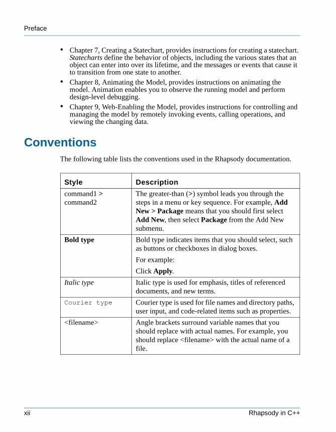
ConventionsThe following table lists the conventions used in the Rhapsody documentation.
Style Description
command1 > command2
The greater-than (>) symbol leads you through the steps in a menu or key sequence. For example, Add New > Package means that you should first select Add New, then select Package from the Add New submenu.
Bold type Bold type indicates items that you should select, such as buttons or checkboxes in dialog boxes.
For example:
Click Apply.
Italic type Italic type is used for emphasis, titles of referenced documents, and new terms.
Courier type Courier type is used for file names and directory paths, user input, and code-related items such as properties.
<filename> Angle brackets surround variable names that you should replace with actual names. For example, you should replace <filename> with the actual name of a file.
xii Rhapsody in C++
Documentation Set
tutorialcpp.book Page xiii Thursday, April 21, 2005 4:51 PM
Documentation SetTo access the Rhapsody documentation set from within Rhapsody, click Help > List of Books. The documentation set for Rhapsody includes several user guides, reference guides, and secondary documents such as release notes and readme files. Most of the documents are available online in PDF format so you can print them from the Adobe® Acrobat Reader™.
Other documents, such as the quick start and online help, are available through the Help menu within Rhapsody. To access the online help from within Rhapsody, click Help > Help Topics.
Rhapsody Documentation Set
The basic Rhapsody documentation set contains the following books:• C++ Execution Framework Reference Guide—Describes the Rhapsody
framework in detail. This guide is intended to be used by application developers as a reference guide for the framework layer classes, methods, and attributes.
• Code Generation Guide—Describes how Rhapsody generates C code from UML™ diagrams.
• COM API Reference Guide—Describes the Rhapsody Repository API, which is a set of COM interfaces supporting dual interfaces (COM and automation). This allows access from Visual Basic® for Applications and any language implemented with COM bindings.
• COM Development Guide—Describes how to use Rhapsody to develop distributed applications using the Component Object Model (COM) from Microsoft®.
• Concurrent Engineering Guide—Describes how multiple users can work together as a team on Rhapsody projects.
• CORBA Development Guide—Describes how to develop distributed CORBA applications with Rhapsody.
• Getting Started with Rhapsody—Introduces you to Rhapsody by walking you through a predefined model and a simple example step-by-step. This information is provided in both PDF and online help.
• Glossary—Provides definitions of commonly used Rhapsody terms.• Installation Guide—Describes how to install Rhapsody, and how to configure
your license.• Properties Reference Guide—Documents all the properties that enable you to
customize the Rhapsody environment, and their default values.• Release Notes—Documents the supported environment environments for
Rhapsody, its latest features, and known restrictions.
Tutorial xiii
Preface
tutorialcpp.book Page xiv Thursday, April 21, 2005 4:51 PM
• The Rhapsody Visual Application Development Platform—Describes the three packages of Rhapsody—Architect Edition, Designer Edition, and Developer Edition.
• Rhapsody in Ada Documentation—Accessed from the List of Books, this page provides links to all the documents that describe Rhapsody in Ada and its Code Generator.
• RTOS Adapter Guide—Describes how to adapt Rhapsody to use a new run-time operating system.
• Tutorial for Rhapsody in Ada—Provides step-by-step instructions on how to use Rhapsody to generate Ada code.
• Tutorial for Rhapsody in C—Provides step-by-step instructions on how to use Rhapsody to generate C code.
• Tutorial for Rhapsody in C++—Provides step-by-step instructions on how to use Rhapsody to generate C++ code.
• Tutorial for Rhapsody in J—Provides step-by-step instructions on how to use Rhapsody to generate Java code.
• Upgrade Guide—Describes the changes to the framework, properties, and code generation between versions of Rhapsody.
• User Guide—Describes how to use the features and functionality of Rhapsody to design and build a real-time, embedded application.
• Using Third-Party Tools with Rhapsody—Describes how to use DOORS™, Rational® Rose®, and Tornado® with Rhapsody.
Reference Documentation
For more information on UML and object-oriented design, refer to the following documents:• Doing Hard Time: Developing Real-Time Systems with UML, Objects,
Frameworks, and Patterns by Dr. Bruce Powel Douglass • Real-Time UML 2nd Edition: Developing Efficient Objects for Embedded
Systems by Dr. Bruce Powel Douglass• Real-Time Design Patterns: Robust Scalable Architecture for Real-Time
Systems by Dr. Bruce Powel Douglass• Rapid Object-Oriented Process for Embedded Systems by Dr. Bruce Powel
Douglass • Executable Object Modeling with Statecharts by Dr. David Harel and
Eran Gery
xiv Rhapsody in C++
Getting Started with Rhapsody
tutorialcpp.book Page xv Thursday, April 21, 2005 4:51 PM
Getting Started with Rhapsody
The getting started documentation helps you quickly get up and running with Rhapsody. It has three parts:• Guided Tour—Walks you through a prebuilt Rhapsody model.• Quickstart—Includes instructions on how to quickly get started building a
model, generating code, and animating an application.• Tutorial—Includes step-by-step instructions that describe how to create a
model of a dishwasher.
To access the getting started documentation:
1. From the Start menu, select Programs > Rhapsody in <Language> by I-Logix > Rhapsody Getting Started.
2. Select your topic and programming language.
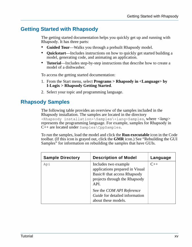
Rhapsody Samples
The following table provides an overview of the samples included in the Rhapsody installation. The samples are located in the directory <Rhapsody installation>\Samples\<lang>Samples, where <lang> represents the programming language. For example, samples for Rhapsody in C++ are located under Samples\CppSamples.
To run the samples, load the model and click the Run executable icon in the Code toolbar. (If this icon is grayed out, click the GMR icon.) See “Rebuilding the GUI Samples” for information on rebuilding the samples that have GUIs.
Sample Directory Description of Model Language
Api Includes two example applications prepared in Visual Basic® that access Rhapsody projects through the Rhapsody API.
See the COM API Reference Guide for detailed information about these models.
C++
Tutorial xv
Preface
tutorialcpp.book Page xvi Thursday, April 21, 2005 4:51 PM
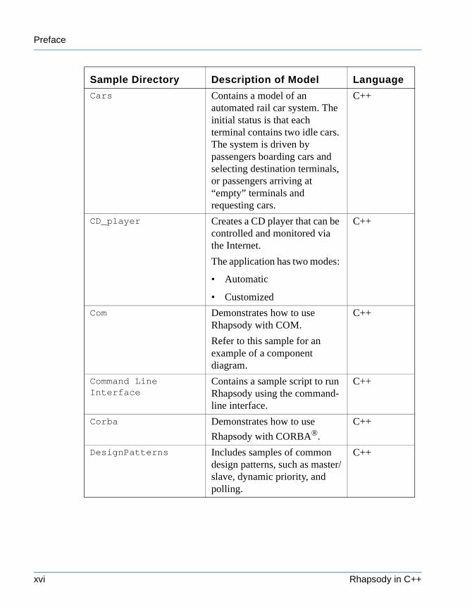
Cars Contains a model of an automated rail car system. The initial status is that each terminal contains two idle cars. The system is driven by passengers boarding cars and selecting destination terminals, or passengers arriving at “empty” terminals and requesting cars.
C++
CD_player Creates a CD player that can be controlled and monitored via the Internet.
The application has two modes:
• Automatic
• Customized
C++
Com Demonstrates how to use Rhapsody with COM.
Refer to this sample for an example of a component diagram.
C++
Command Line Interface
Contains a sample script to run Rhapsody using the command-line interface.
C++
Corba Demonstrates how to use
Rhapsody with CORBA®.
C++
DesignPatterns Includes samples of common design patterns, such as master/slave, dynamic priority, and polling.
C++
Sample Directory Description of Model Language
xvi Rhapsody in C++
Rhapsody Samples
tutorialcpp.book Page xvii Thursday, April 21, 2005 4:51 PM
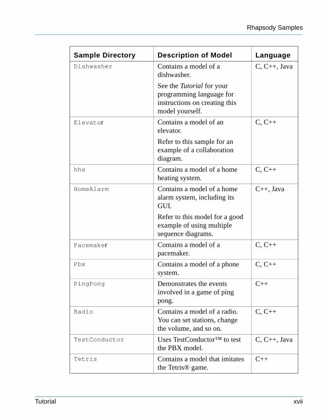
Dishwasher Contains a model of a dishwasher.
See the Tutorial for your programming language for instructions on creating this model yourself.
C, C++, Java
Elevator Contains a model of an elevator.
Refer to this sample for an example of a collaboration diagram.
C, C++
hhs Contains a model of a home heating system.
C, C++
HomeAlarm Contains a model of a home alarm system, including its GUI.
Refer to this model for a good example of using multiple sequence diagrams.
C++, Java
Pacemaker Contains a model of a pacemaker.
C, C++
Pbx Contains a model of a phone system.
C, C++
PingPong Demonstrates the events involved in a game of ping pong.
C++
Radio Contains a model of a radio. You can set stations, change the volume, and so on.
C, C++
TestConductor Uses TestConductor™ to test the PBX model.
C, C++, Java
Tetris Contains a model that imitates the Tetris® game.
C++
Sample Directory Description of Model Language
Tutorial xvii
Preface
tutorialcpp.book Page xviii Thursday, April 21, 2005 4:51 PM
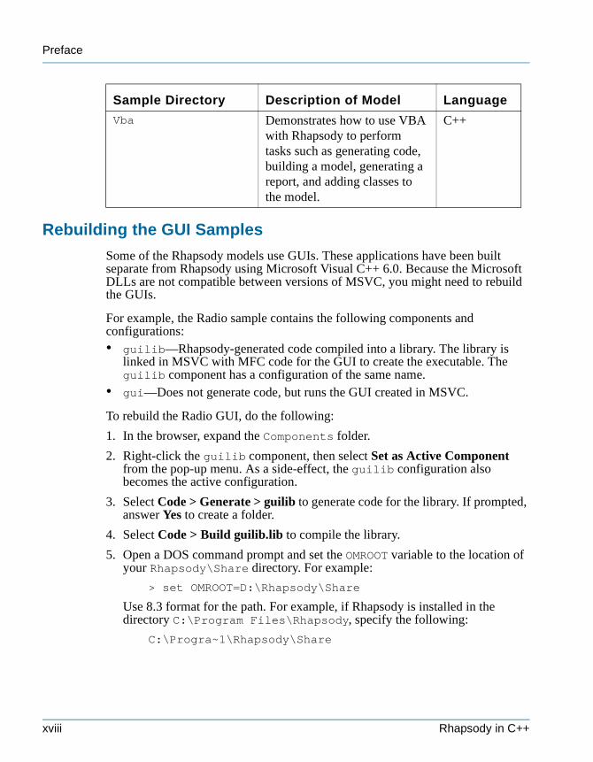
Rebuilding the GUI Samples
Some of the Rhapsody models use GUIs. These applications have been built separate from Rhapsody using Microsoft Visual C++ 6.0. Because the Microsoft DLLs are not compatible between versions of MSVC, you might need to rebuild the GUIs.
For example, the Radio sample contains the following components and configurations:• guilib—Rhapsody-generated code compiled into a library. The library is
linked in MSVC with MFC code for the GUI to create the executable. The guilib component has a configuration of the same name.
• gui—Does not generate code, but runs the GUI created in MSVC.
To rebuild the Radio GUI, do the following:
1. In the browser, expand the Components folder.
2. Right-click the guilib component, then select Set as Active Component from the pop-up menu. As a side-effect, the guilib configuration also becomes the active configuration.
3. Select Code > Generate > guilib to generate code for the library. If prompted, answer Yes to create a folder.
4. Select Code > Build guilib.lib to compile the library.
5. Open a DOS command prompt and set the OMROOT variable to the location of your Rhapsody\Share directory. For example:
> set OMROOT=D:\Rhapsody\Share
Use 8.3 format for the path. For example, if Rhapsody is installed in the directory C:\Program Files\Rhapsody, specify the following:
C:\Progra~1\Rhapsody\Share
Vba Demonstrates how to use VBA with Rhapsody to perform tasks such as generating code, building a model, generating a report, and adding classes to the model.
C++
Sample Directory Description of Model Language
xviii Rhapsody in C++
Contacting I-Logix
tutorialcpp.book Page xix Thursday, April 21, 2005 4:51 PM
6. From the command prompt, invoke MSDEV.EXE (Developer Studio). For example:
> D:\Program Files\Microsoft Visual Studio\ -Common\MSDev98\Bin\MSDEV.EXE
7. In Developer Studio, open the MFCGUI.dsw file for the sample (located in the folder radio_gui) and rebuild the project by selecting Build > Rebuild All.
8. In Rhapsody, set the active component and configuration to gui.
9. In Rhapsody, select Code > Run gui.exe to run the executable.
All the samples with GUIs are set up in a similar way. Follow the procedure described for the Radio sample, changing the names as necessary for that model.
Contacting I-LogixThe I-Logix Technical Support Help Desk provides assistance with installation, application issues, product defect reporting, and documentation questions. Technical support engineers, in conjunction with sales application engineers, assist prospective customers with product evaluations and provide timely responses to user issues to ensure maximum productivity.
Using the Technical Support Option
The easiest way to contact Technical Support is by clicking Start > Programs > Rhapsody <Version> > Email Technical Support, or by clicking Help > Email Technical Support from within Rhapsody.
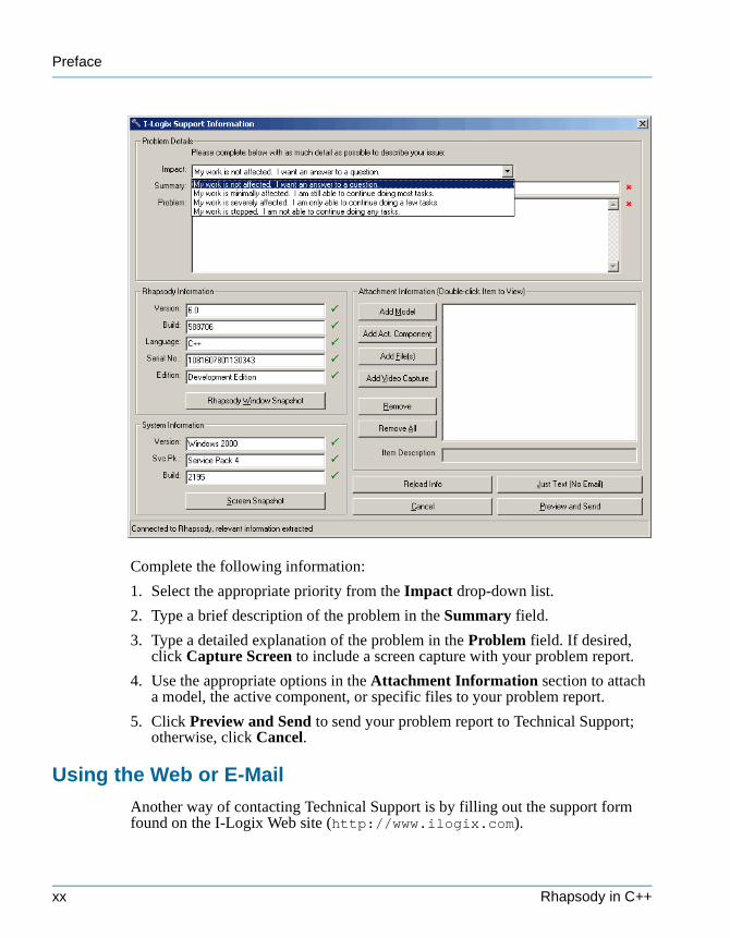
When you select this option, relevant information is extracted from Rhapsody, including what version you are using and your system information. The following figure shows the I-Logix Support Information dialog box.
Tutorial xix
Preface
tutorialcpp.book Page xx Thursday, April 21, 2005 4:51 PM
Complete the following information:
1. Select the appropriate priority from the Impact drop-down list.
2. Type a brief description of the problem in the Summary field.
3. Type a detailed explanation of the problem in the Problem field. If desired, click Capture Screen to include a screen capture with your problem report.
4. Use the appropriate options in the Attachment Information section to attach a model, the active component, or specific files to your problem report.
5. Click Preview and Send to send your problem report to Technical Support; otherwise, click Cancel.
Using the Web or E-Mail
Another way of contacting Technical Support is by filling out the support form found on the I-Logix Web site (http://www.ilogix.com).
xx Rhapsody in C++
Using the Phone or Fax
tutorialcpp.book Page xxi Thursday, April 21, 2005 4:51 PM
You can contact I-Logix via e-mail at the address [email protected]. In your message, include the following information:
Contact Information:
Your nameE-mail addressPhoneCompanyLocation
Software Information:
Version and build number of Rhapsody softwareOperating systemVersion and/or patch level or service pack appliedAny third-party tools you are using
Computer System Information:
Computer modelProcessor speedRAMFree disk space
Details of your problem:
Describe the nature of the problem, and the exact sequence of steps that caused the problem. Also note any error messages that you have received.
Using the Phone or Fax
To contact I-Logix by phone or fax, use the following numbers:
Telephone:
In the US:
In Europe:
(978)682-4884
+44(1249)467600
8:30 am to 5:30 pm EST
9:00 am to 5:30 pm UKT
Fax:
In the US:
In Europe:
(978)682-5995
+44(1249)467610
Tutorial xxi
Preface
tutorialcpp.book Page xxii Thursday, April 21, 2005 4:51 PM
Summary of Technical ChangesThis version of the tutorial contains the following changes:• The text/graphics have been updated to reflect the changes in Rhapsody 6.0.• A number of mistakes in the model-building instructions were corrected.
xxii Rhapsody in C++
tutorialcpp.book Page 1 Thursday, April 21, 2005 4:51 PM
Getting Started 1
This tutorial teaches you the basics of using Rhapsody. It provide step-by-step instructions on using the main features of Rhapsody to analyze, design, and build a model.
This chapter provides information on the following topics:• Handset Model Problem Statement, page 1-1• Using Rhapsody, page 1-2• UML Diagrams, page 1-2• Creating the Handset Project, page 1-2• Rhapsody User Interface, page 1-6• Organizing the Model Using Packages, page 1-10
Handset Model Problem StatementThis tutorial shows you how to use Rhapsody to analyze, design, and build a model of a wireless telephone. Before you begin creating this model, you need to consider the functions of the wireless telephone. Wireless telephony provides voice and data services to users placing and receiving calls. To deliver services, the wireless network must receive, set up, and direct incoming and outgoing call requests, track and maintain the location of users, and facilitate uninterrupted service when users move within and outside the network.
When the wireless user initiates a call, the network receives the request, and validates and registers the user; once registered, the network monitors the user’s location. In order for the network to receive the call, the wireless telephone must send the minimum acceptable signal strength to the network. When the network receives a call, it directs it to the appropriate registered user.
Note: To minimize the complexity of the tutorial, the operations have been simplified to focus on the function of placing a call.
Tutorial 1-1
Getting Started
tutorialcpp.book Page 2 Thursday, April 21, 2005 4:51 PM
Using RhapsodyRhapsody is a visual design tool for developing object-oriented embedded software, and performing structural and systems modeling It enables you to do the following:• Analyze—Define, analyze, and validate the system requirements.• Design—Specify and design the architecture.• Implement—Automatically generate code, then build and run it within
Rhapsody.• Model Execution—Animate the model on the local host or a remote target to
perform design-level debugging within animated views.
UML DiagramsThe UML specification includes the following diagrams:• Use case diagrams—Show the main functions of the system (use cases) and
the entities (actors) outside the system.• Structure diagrams—Show the system structure and identify the
organizational pieces of the system. • Object model diagrams—Show the structure of the system in terms of
classes, objects, and blocks, and the relationships between these structural elements.
• Sequence diagrams—Show sequences of steps and messages passed between structural elements when executing a particular instance of a use case.
• Activity diagrams—Specify a flow for classifiers (classes, actors, use cases), objects, blocks, and operations.
• Statecharts—Show the behavior of a particular classifier (class, actor, use case), object, or block over its entire life cycle.
• Collaboration diagrams—Provide the same information as sequence diagrams, emphasizing structure rather than time.
• Component diagrams—Describe the organization of the software units and the dependencies among units.
• Deployment diagrams—Show the nodes in the final system architecture and the connections between them.
Creating the Handset ProjectThis section describes how to start Rhapsody, and create, save, and open the handset project.
1-2 Rhapsody in C++
Starting Rhapsody
tutorialcpp.book Page 3 Thursday, April 21, 2005 4:51 PM
Starting Rhapsody
To start Rhapsody, do the following:
Select Start > Programs > Rhapsody Version > Rhapsody Development Edition > Rhapsody in C++.
1. Rhapsody opens with the Tip of the Day. If you want to see another tip, click Next Tip. If you prefer not to see tips on startup, clear the Show Tips on StartUp check box.
2. Click Close to dismiss the dialog box.
Creating a New Project
A Rhapsody project includes the UML diagrams, packages, and code generation configurations that define the model and the code generated from it. When you create a new project, Rhapsody creates a directory containing the project files in the specified location. The name you choose for your new project is used to name project files and directories, and appears at the top level of the project hierarchy in the Rhapsody browser. Rhapsody provides several default elements in the new project, including a default package, component, and configuration.
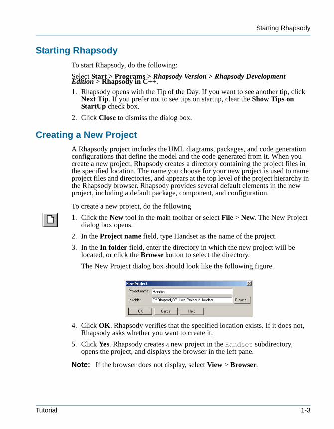
To create a new project, do the following
1. Click the New tool in the main toolbar or select File > New. The New Project dialog box opens.
2. In the Project name field, type Handset as the name of the project.
3. In the In folder field, enter the directory in which the new project will be located, or click the Browse button to select the directory.
The New Project dialog box should look like the following figure.
4. Click OK. Rhapsody verifies that the specified location exists. If it does not, Rhapsody asks whether you want to create it.
5. Click Yes. Rhapsody creates a new project in the Handset subdirectory, opens the project, and displays the browser in the left pane.
Note: If the browser does not display, select View > Browser.
Tutorial 1-3
Getting Started
tutorialcpp.book Page 4 Thursday, April 21, 2005 4:51 PM
Saving a Project
Use the Save command to save the project in its current location. The Save command saves only the modified units, reducing the time required to save large projects. To save the project to a new location, use the Save As command.
Rhapsody performs an autosave every ten minutes to back up changes made between saves. Modified units are saved in the autosave folder, along with any units that have a time stamp older than the project file.
To save the project in the current location, use one of the following methods:
• Select File > Save.
• Click the Save tool in the main toolbar.
Note: You can set a property to create backups of your model every time you save your project. This enables you to revert to a previously saved version if you encounter a problem. By default, Rhapsody does not create backups. See the User Guide for more information about creating backups.
Project Files and Directories
Rhapsody creates the following files and subdirectories in the project directory:• A project file, called <project_name>.rpy• A repository directory, called <project_name>_rpy, which contains the unit
files for the project, including UML diagrams, packages, and code generation configurations
• An event history file, called <project_name>.ehl, which contains a record of events injected during animation, and active and nonactive breakpoints
• Log files, which record when projects were loaded and saved in Rhapsody• A .vba file, called <project_name_>.vba, which contains macros or
wizards• Backup project files and directories • An _RTC directory, which holds any tests created using the Rhapsody
TestConductor™ add-on
Note: Rhapsody requires the project file (<project_name>.rpy) and the repository directory (<project_name>_rpy) to generate source code.
Opening the Handset Model
Once you have created and saved the handset model, you can open and work on it at any time.
1-4 Rhapsody in C++
Opening the Handset Model
tutorialcpp.book Page 5 Thursday, April 21, 2005 4:51 PM
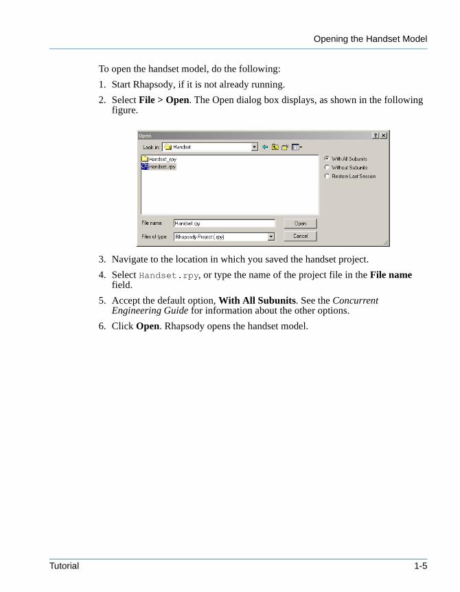
To open the handset model, do the following:
1. Start Rhapsody, if it is not already running.
2. Select File > Open. The Open dialog box displays, as shown in the following figure.
3. Navigate to the location in which you saved the handset project.
4. Select Handset.rpy, or type the name of the project file in the File name field.
5. Accept the default option, With All Subunits. See the Concurrent Engineering Guide for information about the other options.
6. Click Open. Rhapsody opens the handset model.
Tutorial 1-5
Getting Started
T
Bw
Da
Ow
Mto
tutorialcpp.book Page 6 Thursday, April 21, 2005 4:51 PM
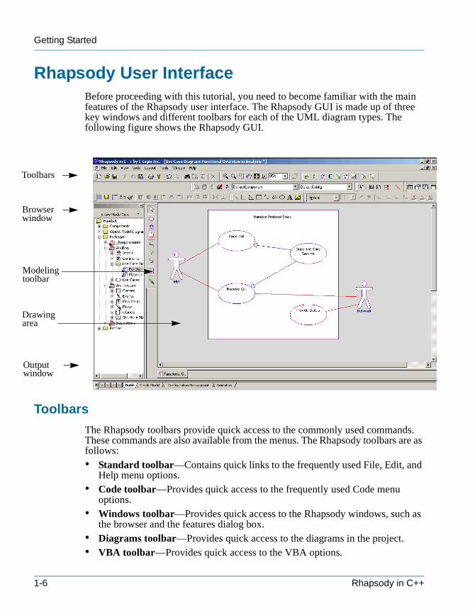
Rhapsody User InterfaceBefore proceeding with this tutorial, you need to become familiar with the main features of the Rhapsody user interface. The Rhapsody GUI is made up of three key windows and different toolbars for each of the UML diagram types. The following figure shows the Rhapsody GUI.
Toolbars
The Rhapsody toolbars provide quick access to the commonly used commands. These commands are also available from the menus. The Rhapsody toolbars are as follows: • Standard toolbar—Contains quick links to the frequently used File, Edit, and
Help menu options.• Code toolbar—Provides quick access to the frequently used Code menu
options.• Windows toolbar—Provides quick access to the Rhapsody windows, such as
the browser and the features dialog box.• Diagrams toolbar—Provides quick access to the diagrams in the project.• VBA toolbar—Provides quick access to the VBA options.
oolbars
rowser indow
rawing rea
utput indow
odeling olbar
1-6 Rhapsody in C++
Browser
tutorialcpp.book Page 7 Thursday, April 21, 2005 4:51 PM
• NetMeeting toolbar—Supports online collaboration with Microsoft® NetMeeting®.
• Animation toolbar—Provides quick access to the animation options during an animation session.
• Layout toolbar—Provides quick access to layout options such as alignment.• Modeling toolbar—Provides access to the tools used to create and edit
diagrams in the graphic editors. Each graphic editor has a unique modeling toolbar.
• Free Shapes toolbar—Provides quick access to basic drawing shapes such as lines and polygons.
• Zoom toolbar—Provides quick access to the zoom options.• Format toolbar—Provides quick access to various formatting options, such as
text formatting and line/fill options.
See the User Guide for detailed information about the toolbars.
Browser
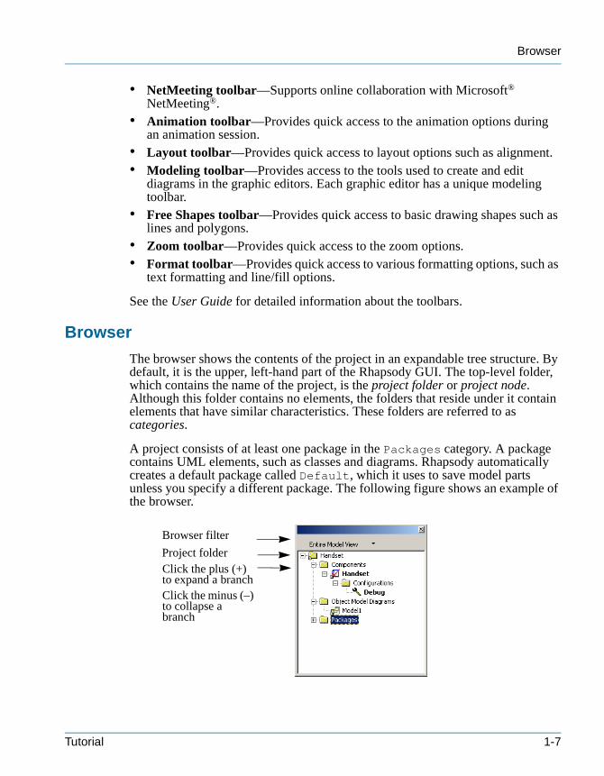
The browser shows the contents of the project in an expandable tree structure. By default, it is the upper, left-hand part of the Rhapsody GUI. The top-level folder, which contains the name of the project, is the project folder or project node. Although this folder contains no elements, the folders that reside under it contain elements that have similar characteristics. These folders are referred to as categories.
A project consists of at least one package in the Packages category. A package contains UML elements, such as classes and diagrams. Rhapsody automatically creates a default package called Default, which it uses to save model parts unless you specify a different package. The following figure shows an example of the browser.
Click the plus (+) to expand a branchClick the minus (–) to collapse a branch
Browser filter
Project folder
Tutorial 1-7
Getting Started
tutorialcpp.book Page 8 Thursday, April 21, 2005 4:51 PM
Filtering the Browser
The browser filter enables you to display only the elements relevant to your current task.
To filter the browser, open the drop-down menu at the top of the browser window, and select the desired view from the menu. See the User Guide for information on the view options.
Moving the Browser
To create more room, you can move the browser out of the Rhapsody GUI as a separate window.
To move the browser, click the browser window and move it to the desired location on your desktop.
Drawing Area
The drawing area displays the graphic editors and code editors, and is the region for drawing diagrams. By default, it is the upper, right-hand section of the Rhapsody GUI. Rhapsody displays each diagram with a tab that includes the name of the diagram and an icon that denotes the diagram type. When you make changes to a diagram, Rhapsody displays an asterisk after the name of the diagram in the title bar to indicate that you must save your changes.
Output Window
The output window displays Rhapsody messages. By default, it is the lower section of the Rhapsody GUI. It includes tabs that display the following types of messages: Build, Check Model, Configuration Management, and Animation.
Modeling Toolbars
Rhapsody displays a separate graphics toolbar for each UML diagram type. By default, Rhapsody places the graphics toolbar to the left of the diagram.
To move the toolbar, click and drag it to the desired location. The graphics toolbar used in each lesson is described at the beginning of that chapter.
Features Dialog Box
The features dialog box enables you to view and edit the features of an element in the Rhapsody model.
To open the features dialog box, do one of the following:
1-8 Rhapsody in C++
Moving the Features Dialog Box
tutorialcpp.book Page 9 Thursday, April 21, 2005 4:51 PM
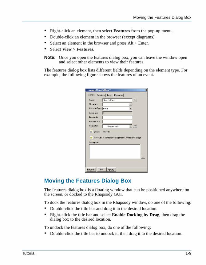
• Right-click an element, then select Features from the pop-up menu.• Double-click an element in the browser (except diagrams).• Select an element in the browser and press Alt + Enter.• Select View > Features.
Note: Once you open the features dialog box, you can leave the window open and select other elements to view their features.
The features dialog box lists different fields depending on the element type. For example, the following figure shows the features of an event.
Moving the Features Dialog Box
The features dialog box is a floating window that can be positioned anywhere on the screen, or docked to the Rhapsody GUI.
To dock the features dialog box in the Rhapsody window, do one of the following:• Double-click the title bar and drag it to the desired location.• Right-click the title bar and select Enable Docking by Drag, then drag the
dialog box to the desired location.
To undock the features dialog box, do one of the following:• Double-click the title bar to undock it, then drag it to the desired location.
Tutorial 1-9
Getting Started
tutorialcpp.book Page 10 Thursday, April 21, 2005 4:51 PM
• Right-click the title bar and clear Enable Docking by Drag, then drag the dialog box to the desired location.
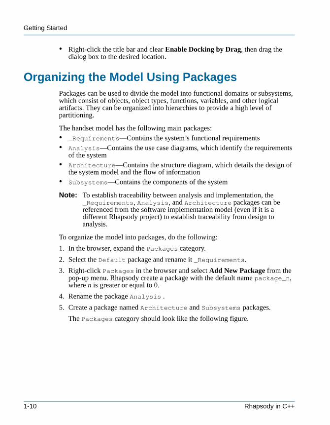
Organizing the Model Using PackagesPackages can be used to divide the model into functional domains or subsystems, which consist of objects, object types, functions, variables, and other logical artifacts. They can be organized into hierarchies to provide a high level of partitioning.
The handset model has the following main packages: • _Requirements—Contains the system’s functional requirements• Analysis—Contains the use case diagrams, which identify the requirements
of the system• Architecture—Contains the structure diagram, which details the design of
the system model and the flow of information • Subsystems—Contains the components of the system
Note: To establish traceability between analysis and implementation, the _Requirements, Analysis, and Architecture packages can be referenced from the software implementation model (even if it is a different Rhapsody project) to establish traceability from design to analysis.
To organize the model into packages, do the following:
1. In the browser, expand the Packages category.
2. Select the Default package and rename it _Requirements.
3. Right-click Packages in the browser and select Add New Package from the pop-up menu. Rhapsody create a package with the default name package_n, where n is greater or equal to 0.
4. Rename the package Analysis .
5. Create a package named Architecture and Subsystems packages.
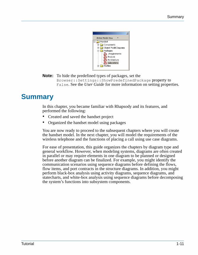
The Packages category should look like the following figure.
1-10 Rhapsody in C++
Summary
tutorialcpp.book Page 11 Thursday, April 21, 2005 4:51 PM
Note: To hide the predefined types of packages, set the Browser::Settings::ShowPredefinedPackage property to False. See the User Guide for more information on setting properties.
SummaryIn this chapter, you became familiar with Rhapsody and its features, and performed the following:• Created and saved the handset project• Organized the handset model using packages
You are now ready to proceed to the subsequent chapters where you will create the handset model. In the next chapter, you will model the requirements of the wireless telephone and the functions of placing a call using use case diagrams.
For ease of presentation, this guide organizes the chapters by diagram type and general workflow. However, when modeling systems, diagrams are often created in parallel or may require elements in one diagram to be planned or designed before another diagram can be finalized. For example, you might identify the communication scenarios using sequence diagrams before defining the flows, flow items, and port contracts in the structure diagrams. In addition, you might perform black-box analysis using activity diagrams, sequence diagrams, and statecharts, and white-box analysis using sequence diagrams before decomposing the system’s functions into subsystem components.
Tutorial 1-11

Getting Started
tutorialcpp.book Page 12 Thursday, April 21, 2005 4:51 PM
1-12 Rhapsody in C++
tutorialcpp.book Page 1 Thursday, April 21, 2005 4:51 PM
Creating Use Case Diagrams 2
Use case diagrams (UCDs) show the main functions of the system (use cases) and the entities that are outside the system (actors). They enable you to specify the requirements for the system, and show the interactions between the system and external actors.
In this lesson, you will create the following UCDs:• Functional Overview—Shows the requirements and functions of the handset• Place Call Overview—Shows the functions of placing a call• Data Call Requirements—Shows the relations among requirement elements
Goals for this LessonIn this lesson, you will perform the following:• Creating a Use Case Diagram, page 2-3• Drawing the Functional Overview UCD, page 2-4• Adding Remarks to Model Elements and Diagrams, page 2-13• Drawing the Place Call Overview UCD, page 2-14• Modeling Requirements in Rhapsody, page 2-17• Drawing the Data Call Requirements Diagram, page 2-22
OverviewUse case diagrams illustrate the system functions and the ways in which elements external to the system interface with the system. The following figure shows the Functional Overview UCD you will create in this lesson.
Tutorial 2-1

Creating Use Case Diagrams
tutorialcpp.book Page 2 Thursday, April 21, 2005 4:51 PM
Figure 2.1 Functional Overview
Use Case Diagram Elements
Use case diagrams can have the following parts:
ActorRepresents either a user of the system or an external component, which provides information to the system or uses information provided by the system.
Use CaseCaptures some user-visible function or important goal of the system.
Association LineShows the relationship between an actor and a use case.
Boundary BoxDelineates the boundary between the system under design and the external actors.
2-2 Rhapsody in C++
Creating a Use Case Diagram
tutorialcpp.book Page 3 Thursday, April 21, 2005 4:51 PM
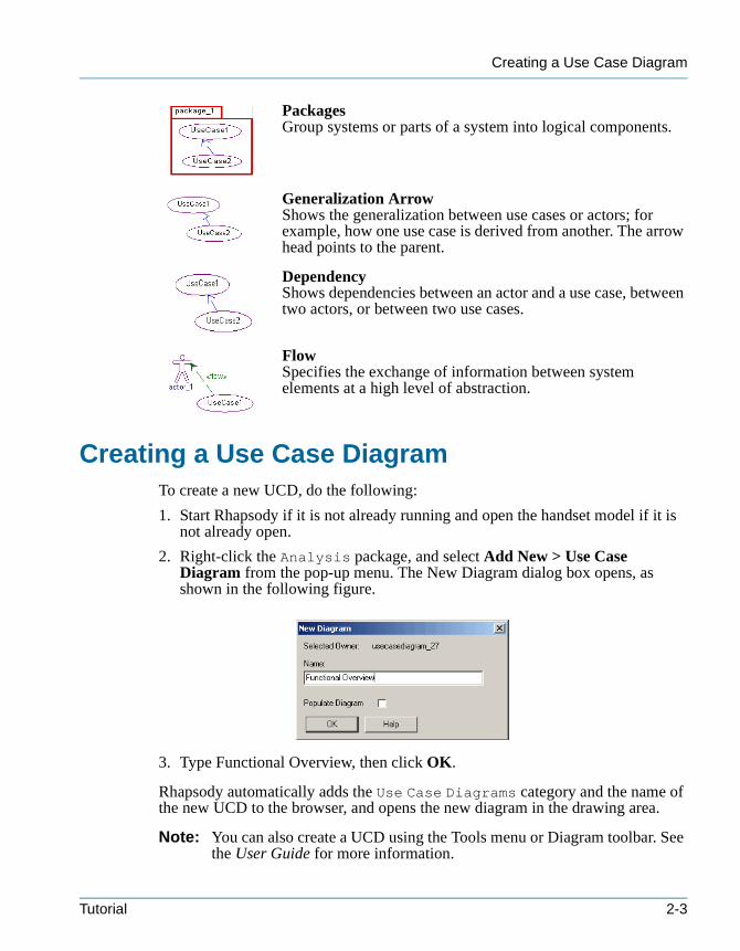
PackagesGroup systems or parts of a system into logical components.
Generalization ArrowShows the generalization between use cases or actors; for example, how one use case is derived from another. The arrow head points to the parent.
DependencyShows dependencies between an actor and a use case, between two actors, or between two use cases.
FlowSpecifies the exchange of information between system elements at a high level of abstraction.
Creating a Use Case DiagramTo create a new UCD, do the following:
1. Start Rhapsody if it is not already running and open the handset model if it is not already open.
2. Right-click the Analysis package, and select Add New > Use Case Diagram from the pop-up menu. The New Diagram dialog box opens, as shown in the following figure.
3. Type Functional Overview, then click OK.
Rhapsody automatically adds the Use Case Diagrams category and the name of the new UCD to the browser, and opens the new diagram in the drawing area.
Note: You can also create a UCD using the Tools menu or Diagram toolbar. See the User Guide for more information.
Tutorial 2-3
Creating Use Case Diagrams
tutorialcpp.book Page 4 Thursday, April 21, 2005 4:51 PM
Use Case Diagram Toolbar
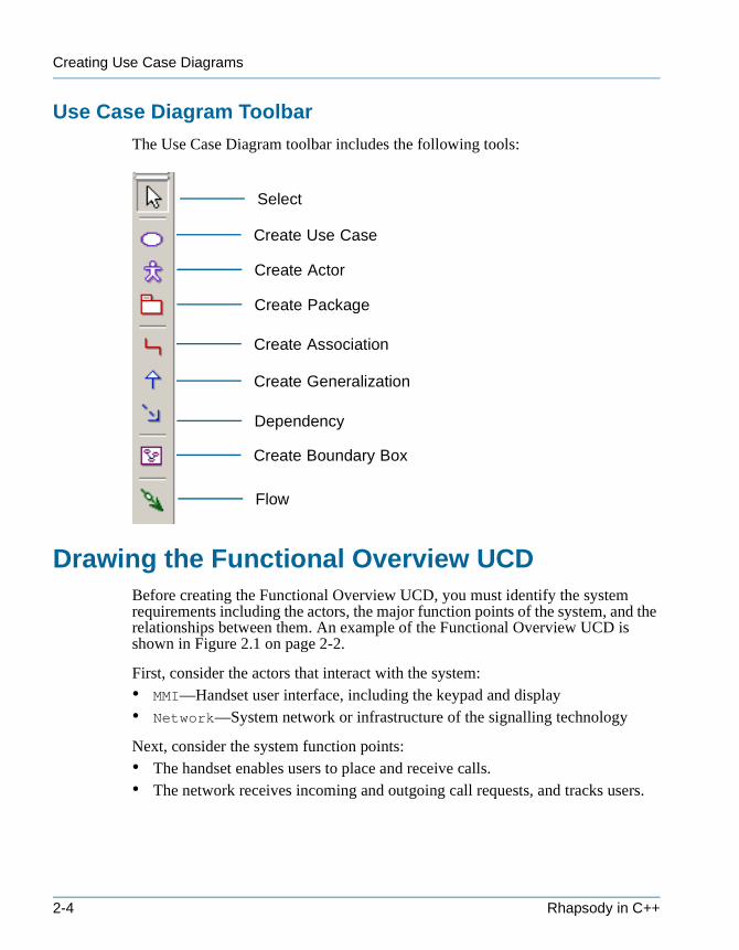
The Use Case Diagram toolbar includes the following tools:
Drawing the Functional Overview UCDBefore creating the Functional Overview UCD, you must identify the system requirements including the actors, the major function points of the system, and the relationships between them. An example of the Functional Overview UCD is shown in Figure 2.1 on page 2-2.
First, consider the actors that interact with the system: • MMI—Handset user interface, including the keypad and display• Network—System network or infrastructure of the signalling technology
Next, consider the system function points:• The handset enables users to place and receive calls. • The network receives incoming and outgoing call requests, and tracks users.
Create Use Case
Create Actor
Create Boundary Box
Create Package
Create Generalization
Create Association
Dependency
Select
Flow
2-4 Rhapsody in C++
Drawing the Boundary Box
tutorialcpp.book Page 5 Thursday, April 21, 2005 4:51 PM
The actors interact with the system in the following ways:• The MMI places and receives calls.• The network tracks users, monitors signal strength, and provides network
status and location registration.
Draw a use case diagram using the following general steps:
1. Draw the boundary box.
2. Draw the actors outside of the boundary box.
3. Draw the use cases inside the boundary box.
4. Associate the use cases with the actors.
The following sections describe each of these steps in detail.
Drawing the Boundary Box
The boundary box delineates the system under design from the external actors. Use cases are inside the boundary box; actors are outside the boundary box.
To draw the boundary box, do the following:
1. Click the Create Boundary box tool in the UCD toolbar.
2. Click in the upper, left corner of the drawing area and drag to the lower right. Rhapsody creates a boundary box, named System Boundary Box.
3. Rename the boundary box Handset Protocol Stack.
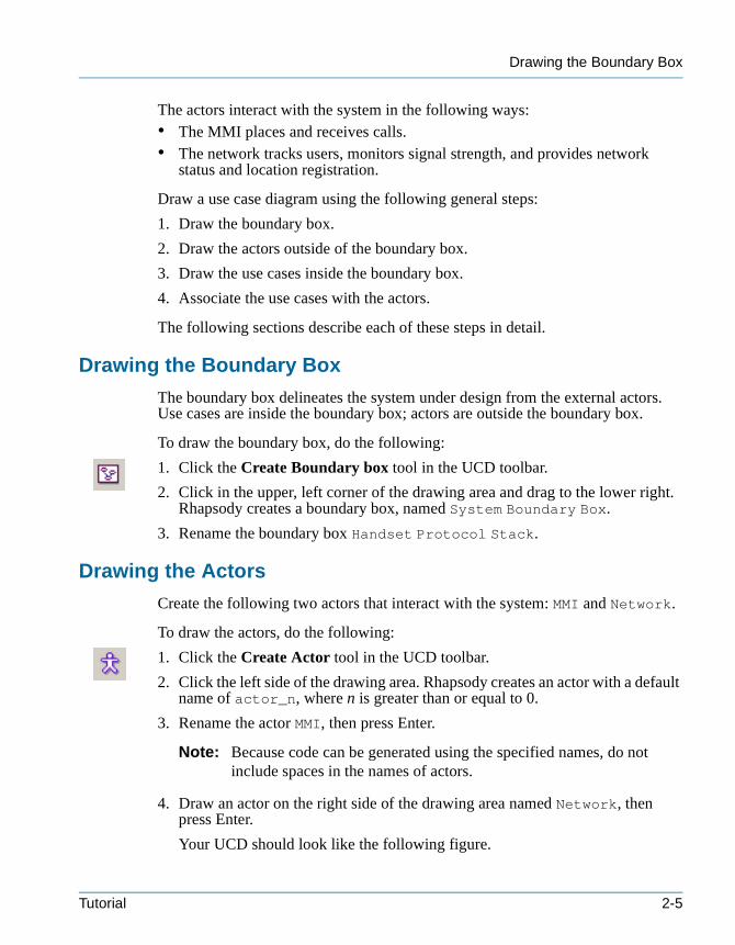
Drawing the Actors
Create the following two actors that interact with the system: MMI and Network.
To draw the actors, do the following:
1. Click the Create Actor tool in the UCD toolbar.
2. Click the left side of the drawing area. Rhapsody creates an actor with a default name of actor_n, where n is greater than or equal to 0.
3. Rename the actor MMI, then press Enter.
Note: Because code can be generated using the specified names, do not include spaces in the names of actors.
4. Draw an actor on the right side of the drawing area named Network, then press Enter.
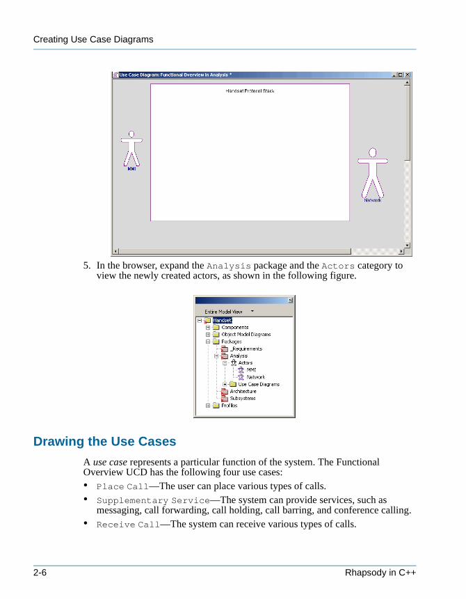
Your UCD should look like the following figure.
Tutorial 2-5
Creating Use Case Diagrams
tutorialcpp.book Page 6 Thursday, April 21, 2005 4:51 PM
5. In the browser, expand the Analysis package and the Actors category to view the newly created actors, as shown in the following figure.
Drawing the Use Cases
A use case represents a particular function of the system. The Functional Overview UCD has the following four use cases:• Place Call—The user can place various types of calls.• Supplementary Service—The system can provide services, such as
messaging, call forwarding, call holding, call barring, and conference calling.• Receive Call—The system can receive various types of calls.
2-6 Rhapsody in C++
Drawing the Use Cases
tutorialcpp.book Page 7 Thursday, April 21, 2005 4:51 PM
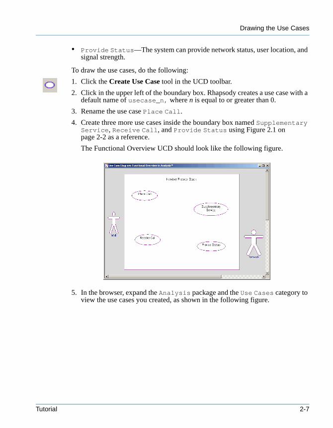
• Provide Status—The system can provide network status, user location, and signal strength.
To draw the use cases, do the following:
1. Click the Create Use Case tool in the UCD toolbar.
2. Click in the upper left of the boundary box. Rhapsody creates a use case with a default name of usecase_n, where n is equal to or greater than 0.
3. Rename the use case Place Call.
4. Create three more use cases inside the boundary box named Supplementary Service, Receive Call, and Provide Status using Figure 2.1 on page 2-2 as a reference.
The Functional Overview UCD should look like the following figure.
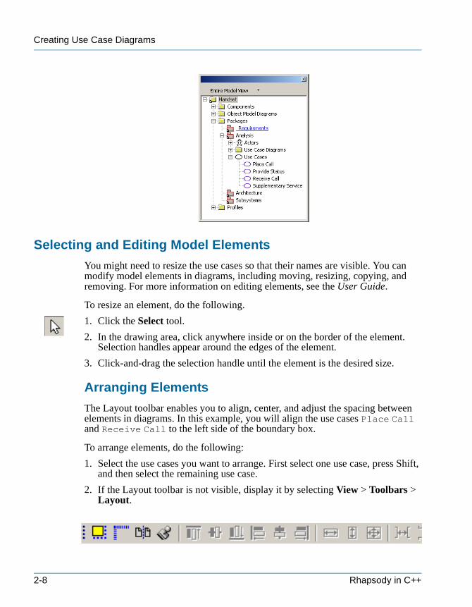
5. In the browser, expand the Analysis package and the Use Cases category to view the use cases you created, as shown in the following figure.
Tutorial 2-7
Creating Use Case Diagrams
tutorialcpp.book Page 8 Thursday, April 21, 2005 4:51 PM
Selecting and Editing Model Elements
You might need to resize the use cases so that their names are visible. You can modify model elements in diagrams, including moving, resizing, copying, and removing. For more information on editing elements, see the User Guide.
To resize an element, do the following.
1. Click the Select tool.
2. In the drawing area, click anywhere inside or on the border of the element. Selection handles appear around the edges of the element.
3. Click-and-drag the selection handle until the element is the desired size.
Arranging Elements
The Layout toolbar enables you to align, center, and adjust the spacing between elements in diagrams. In this example, you will align the use cases Place Call and Receive Call to the left side of the boundary box.
To arrange elements, do the following:
1. Select the use cases you want to arrange. First select one use case, press Shift, and then select the remaining use case.
2. If the Layout toolbar is not visible, display it by selecting View > Toolbars > Layout.
2-8 Rhapsody in C++
Resizing the System Boundary Box
tutorialcpp.book Page 9 Thursday, April 21, 2005 4:51 PM
3. Click the Align Left tool in the toolbar to align the left sides of the use cases.
See the User Guide for more information on arranging elements.
Resizing the System Boundary Box
You can resize the system boundary box without changing the size of its contents by pressing the Alt key while dragging a border or corner.
Defining Use Case Features
You can define the features of a use case, associate the use case with a different main diagram, and enter a description using the features dialog box. You can access the features dialog box from the browser or the diagram.
To define use case features, do the following:
1. In the browser, expand the Analysis package and Use Cases category. Double-click the Place Call use case, or right-click and select Features from the pop-up menu. The features dialog box opens.
or
In the Functional Overview UCD, double-click the Place Call use case, or right-click and select Features from the pop-up menu. The features dialog box opens.
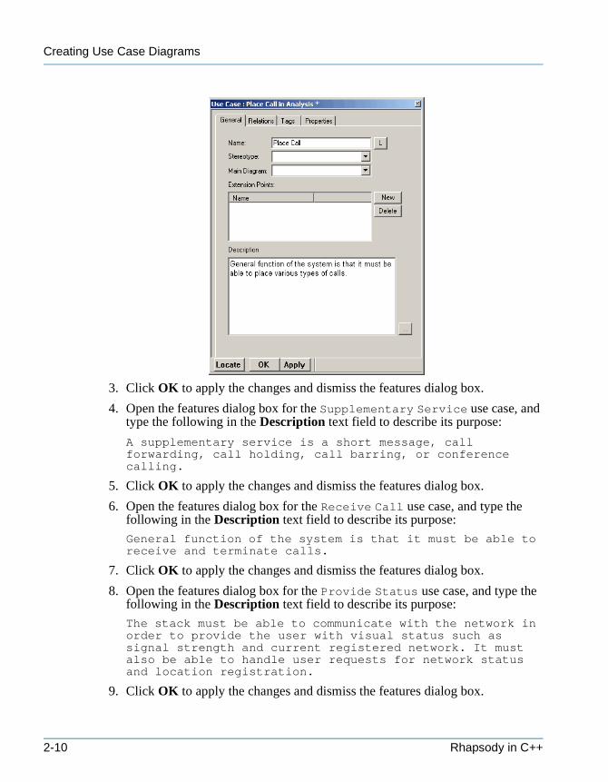
2. In the Description text field, type the following text to describe the purpose of the Place Call use case:
General function of the system is that it must be able to place various types of calls.
You can also click the ellipsis next to the Description field to use the internal text editor. When you have entered the description, click OK to dismiss the internal text editor and return to the features dialog box.
The completed features dialog box should look like the following figure.
Tutorial 2-9
Creating Use Case Diagrams
tutorialcpp.book Page 10 Thursday, April 21, 2005 4:51 PM
3. Click OK to apply the changes and dismiss the features dialog box.
4. Open the features dialog box for the Supplementary Service use case, and type the following in the Description text field to describe its purpose:
A supplementary service is a short message, call forwarding, call holding, call barring, or conference calling.
5. Click OK to apply the changes and dismiss the features dialog box.
6. Open the features dialog box for the Receive Call use case, and type the following in the Description text field to describe its purpose:
General function of the system is that it must be able to receive and terminate calls.
7. Click OK to apply the changes and dismiss the features dialog box.
8. Open the features dialog box for the Provide Status use case, and type the following in the Description text field to describe its purpose:
The stack must be able to communicate with the network in order to provide the user with visual status such as signal strength and current registered network. It must also be able to handle user requests for network status and location registration.
9. Click OK to apply the changes and dismiss the features dialog box.
2-10 Rhapsody in C++
Associating Actors with Use Cases
tutorialcpp.book Page 11 Thursday, April 21, 2005 4:51 PM
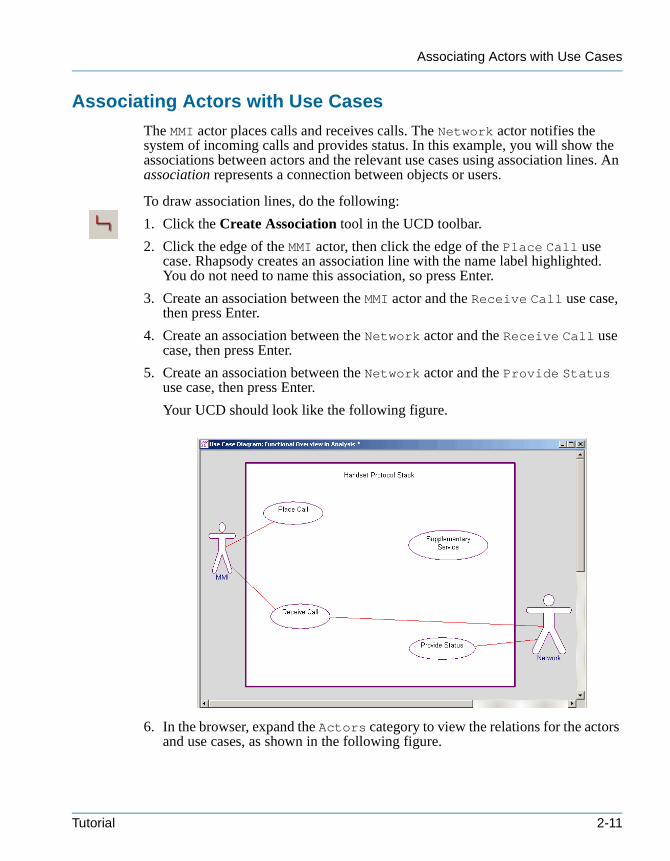
Associating Actors with Use Cases
The MMI actor places calls and receives calls. The Network actor notifies the system of incoming calls and provides status. In this example, you will show the associations between actors and the relevant use cases using association lines. An association represents a connection between objects or users.
To draw association lines, do the following:
1. Click the Create Association tool in the UCD toolbar.
2. Click the edge of the MMI actor, then click the edge of the Place Call use case. Rhapsody creates an association line with the name label highlighted. You do not need to name this association, so press Enter.
3. Create an association between the MMI actor and the Receive Call use case, then press Enter.
4. Create an association between the Network actor and the Receive Call use case, then press Enter.
5. Create an association between the Network actor and the Provide Status use case, then press Enter.
Your UCD should look like the following figure.
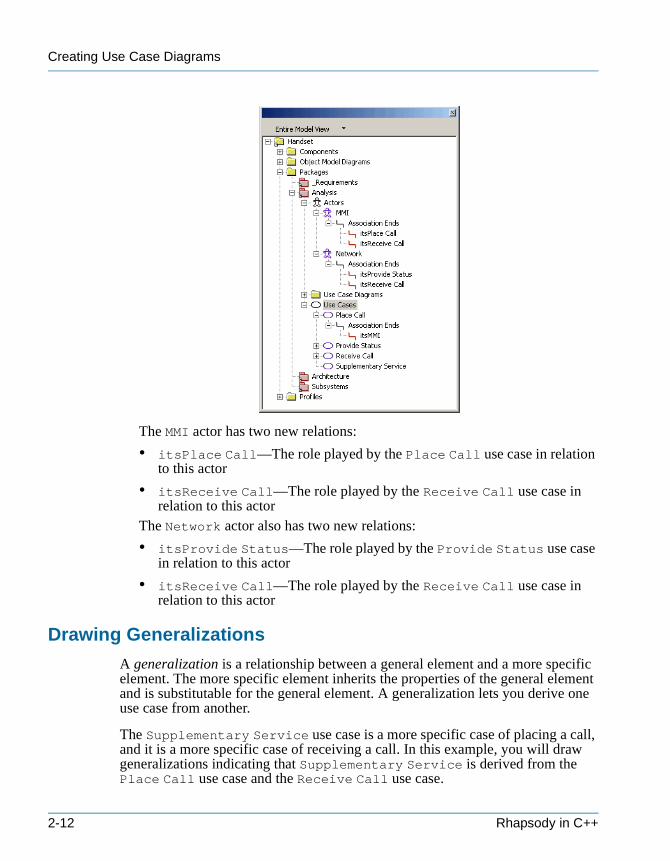
6. In the browser, expand the Actors category to view the relations for the actors and use cases, as shown in the following figure.
Tutorial 2-11
Creating Use Case Diagrams
tutorialcpp.book Page 12 Thursday, April 21, 2005 4:51 PM
The MMI actor has two new relations:
• itsPlace Call—The role played by the Place Call use case in relation to this actor
• itsReceive Call—The role played by the Receive Call use case in relation to this actor
The Network actor also has two new relations:
• itsProvide Status—The role played by the Provide Status use case in relation to this actor
• itsReceive Call—The role played by the Receive Call use case in relation to this actor
Drawing Generalizations
A generalization is a relationship between a general element and a more specific element. The more specific element inherits the properties of the general element and is substitutable for the general element. A generalization lets you derive one use case from another.
The Supplementary Service use case is a more specific case of placing a call, and it is a more specific case of receiving a call. In this example, you will draw generalizations indicating that Supplementary Service is derived from the Place Call use case and the Receive Call use case.
2-12 Rhapsody in C++
Adding Remarks to Model Elements and Diagrams
tutorialcpp.book Page 13 Thursday, April 21, 2005 4:51 PM
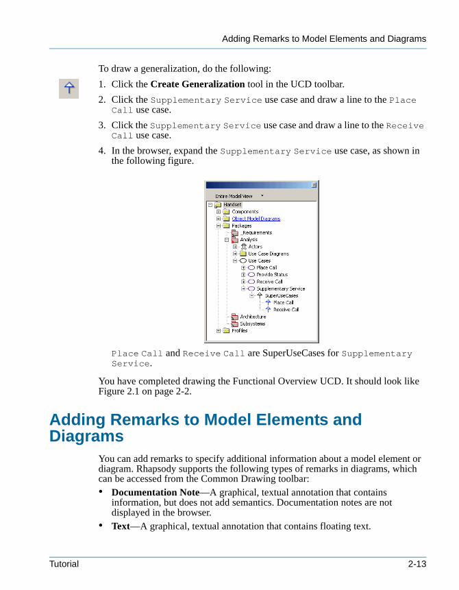
To draw a generalization, do the following:
1. Click the Create Generalization tool in the UCD toolbar.
2. Click the Supplementary Service use case and draw a line to the Place Call use case.
3. Click the Supplementary Service use case and draw a line to the Receive Call use case.
4. In the browser, expand the Supplementary Service use case, as shown in the following figure.
Place Call and Receive Call are SuperUseCases for Supplementary Service.
You have completed drawing the Functional Overview UCD. It should look like Figure 2.1 on page 2-2.
Adding Remarks to Model Elements and Diagrams
You can add remarks to specify additional information about a model element or diagram. Rhapsody supports the following types of remarks in diagrams, which can be accessed from the Common Drawing toolbar:• Documentation Note—A graphical, textual annotation that contains
information, but does not add semantics. Documentation notes are not displayed in the browser.
• Text—A graphical, textual annotation that contains floating text.
Tutorial 2-13
Creating Use Case Diagrams
tutorialcpp.book Page 14 Thursday, April 21, 2005 4:51 PM
• Constraint—A condition or restriction expressed in text. Constraints are displayed in the browser.
• Comment—A textual annotation that contains information, but does not add semantics. Comments are displayed in the browser.
• Requirement—A textual annotation that describes the intent of the element. Requirements are displayed in the browser.
• Anchor—Attaches a constraint, comment, requirement, or note to one or more elements.
In this example, you will add a comment to the Functional Overview UCD as follows:
1. Click the Comment tool in the Common Drawing toolbar.
Note: If the Common Drawing toolbar is not open, select View > Toolbars > Common Drawing.
2. Click in the top section of the diagram.
3. Type the following description:
This is a mock up solution of a generic protocol stack which handles voice and supplementary service calls. The use case diagram shows the functional requirements of the system.
Rhapsody adds the comment to the Comments category in the Analysis package.
Drawing the Place Call Overview UCDThe Place Call Overview UCD breaks down the Place Call use case, and identifies the different types of calls that can be placed as use cases. The following figure shows the Place Call Overview UCD you will create in this lesson.
2-14 Rhapsody in C++
Creating the Place Call Overview UCD
tutorialcpp.book Page 15 Thursday, April 21, 2005 4:51 PM
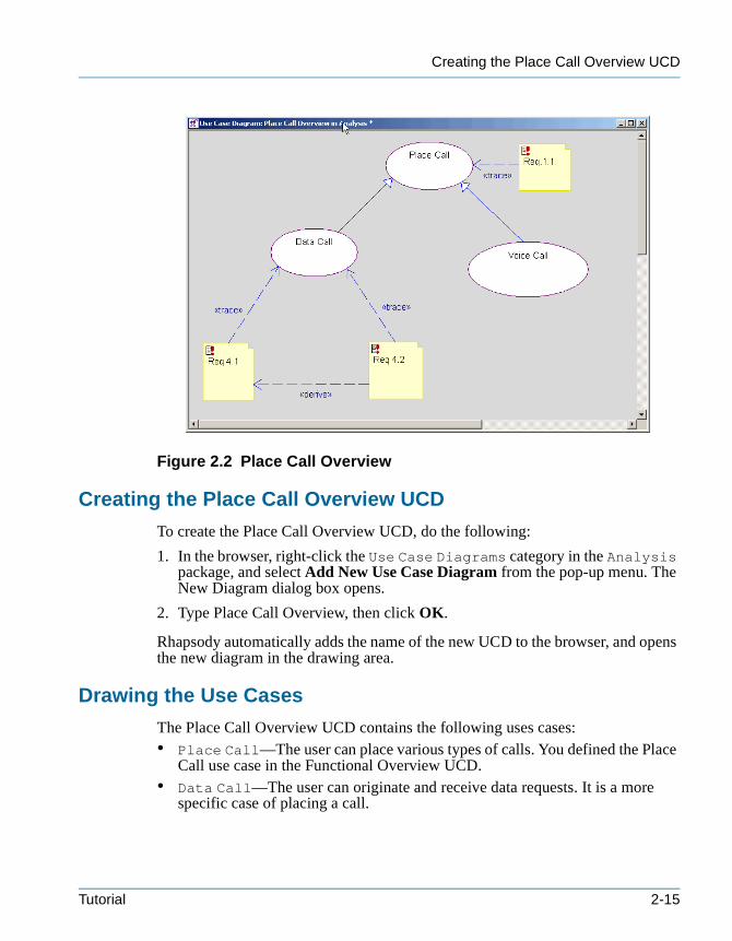
Figure 2.2 Place Call Overview
Creating the Place Call Overview UCD
To create the Place Call Overview UCD, do the following:
1. In the browser, right-click the Use Case Diagrams category in the Analysis package, and select Add New Use Case Diagram from the pop-up menu. The New Diagram dialog box opens.
2. Type Place Call Overview, then click OK.
Rhapsody automatically adds the name of the new UCD to the browser, and opens the new diagram in the drawing area.
Drawing the Use Cases
The Place Call Overview UCD contains the following uses cases:• Place Call—The user can place various types of calls. You defined the Place
Call use case in the Functional Overview UCD.• Data Call—The user can originate and receive data requests. It is a more
specific case of placing a call.
Tutorial 2-15
Creating Use Case Diagrams
tutorialcpp.book Page 16 Thursday, April 21, 2005 4:51 PM
• Voice Call—The user can place and receive voice calls, either while transmitting or receiving data, or standalone. It is a more specific case of placing a call.
To draw the use cases, do the following:
1. In the browser, expand the Analysis package and Use Cases category.
2. Select the Place Call use case and drag it to the top center of the UCD.
3. Click the Create Use Case tool in the UCD toolbar.
4. Create a use case in the lower left of the drawing area, named Data Call.
5. Create a use case in the lower right of the drawing area, named Voice Call.
Defining Use Case Features
In this example, you will add descriptions to the Data Call and Voice Call use cases as follows:
1. In the Place Call Overview UCD or browser, double-click the Data Call use case, or right-click and select Features from the pop-up menu. The features dialog box opens.
2. In the Description text field, type the following text to describe its purpose:
The stack must be able to originate and receive data requests of up to 384 kbps. Data calls can be originated or terminated while active voice calls are in progress.
3. Click OK to apply the changes and dismiss the features dialog box.
4. Double-click the Voice Call use case, or right-click and select Features from the pop-up menu. The features dialog box opens.
5. In the Description text field, type the following text to describe its purpose:
The user must be able to place or receive voice calls, either while transmitting or receiving data, or standalone. The limit of the voice calls a user can engage in at once is dictated by the conference call supplementary service.
6. Click OK to apply the changes and dismiss the features dialog box.
Drawing Generalizations
In this example, you will draw generalizations to show that the Data Call use case and the Voice Call use case derive from the Place Call use case as follows:
1. Click the Create Generalization tool in the UCD toolbar.
2-16 Rhapsody in C++
Modeling Requirements in Rhapsody
tutorialcpp.book Page 17 Thursday, April 21, 2005 4:51 PM
2. Click the edge of the Data Call use case and draw the line to the edge of the Place Call use case.
3. Click the edge of the Voice Call use case and draw the line to the edge of the Place Call use case.
In the next section, you will add the requirements elements to the model and then draw the requirements on the Place Call Overview UCD.
Modeling Requirements in RhapsodyModeling requirement elements in Rhapsody enables you to provide requirements traceability without a Requirements Management (RM) tool; it also supplements the Rhapsody to DOORs interface. Requirements traceability is the ability to describe and follow the life of a requirement, in both a forward and backward direction. It supports requirements verification and validation, prevents the introduction of unspecified features, and provides visibility to derived requirements that need to be specified and tested.
For more information on the Rhapsody interface to DOORS, see Using Third-Party Tools with Rhapsody.
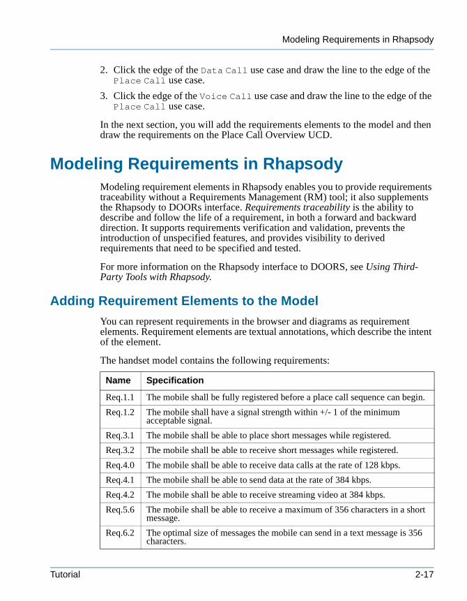
Adding Requirement Elements to the Model
You can represent requirements in the browser and diagrams as requirement elements. Requirement elements are textual annotations, which describe the intent of the element.
The handset model contains the following requirements:
Name Specification
Req.1.1 The mobile shall be fully registered before a place call sequence can begin.
Req.1.2 The mobile shall have a signal strength within +/- 1 of the minimum acceptable signal.
Req.3.1 The mobile shall be able to place short messages while registered.
Req.3.2 The mobile shall be able to receive short messages while registered.
Req.4.0 The mobile shall be able to receive data calls at the rate of 128 kbps.
Req.4.1 The mobile shall be able to send data at the rate of 384 kbps.
Req.4.2 The mobile shall be able to receive streaming video at 384 kbps.
Req.5.6 The mobile shall be able to receive a maximum of 356 characters in a short message.
Req.6.2 The optimal size of messages the mobile can send in a text message is 356 characters.
Tutorial 2-17
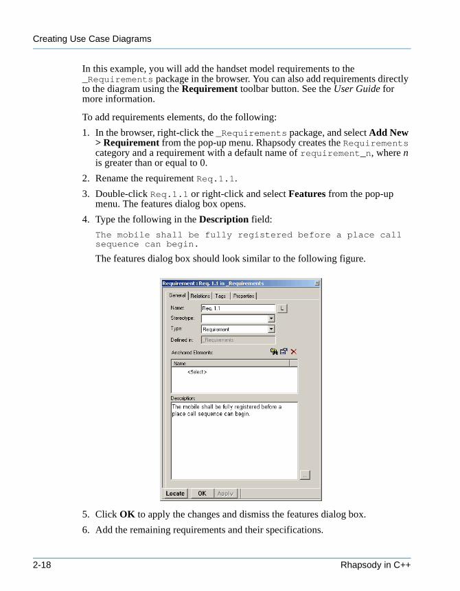
Creating Use Case Diagrams
tutorialcpp.book Page 18 Thursday, April 21, 2005 4:51 PM
In this example, you will add the handset model requirements to the _Requirements package in the browser. You can also add requirements directly to the diagram using the Requirement toolbar button. See the User Guide for more information.
To add requirements elements, do the following:
1. In the browser, right-click the _Requirements package, and select Add New > Requirement from the pop-up menu. Rhapsody creates the Requirements category and a requirement with a default name of requirement_n, where n is greater than or equal to 0.
2. Rename the requirement Req.1.1.
3. Double-click Req.1.1 or right-click and select Features from the pop-up menu. The features dialog box opens.
4. Type the following in the Description field:
The mobile shall be fully registered before a place call sequence can begin.
The features dialog box should look similar to the following figure.
5. Click OK to apply the changes and dismiss the features dialog box.
6. Add the remaining requirements and their specifications.
2-18 Rhapsody in C++
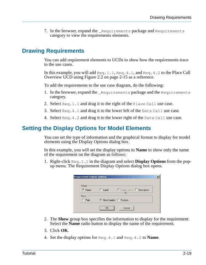
Drawing Requirements
tutorialcpp.book Page 19 Thursday, April 21, 2005 4:51 PM
7. In the browser, expand the _Requirements package and Requirements category to view the requirements elements.
Drawing Requirements
You can add requirement elements to UCDs to show how the requirements trace to the use cases.
In this example, you will add Req.1.1, Req.4.1, and Req.4.2 to the Place Call Overview UCD using Figure 2.2 on page 2-15 as a reference.
To add the requirements to the use case diagram, do the following:
1. In the browser, expand the _Requirements package and the Requirements category.
2. Select Req.1.1 and drag it to the right of the Place Call use case.
3. Select Req.4.1 and drag it to the lower left of the Data Call use case.
4. Select Req.4.2 and drag it to the lower right of the Data Call use case.
Setting the Display Options for Model Elements
You can set the type of information and the graphical format to display for model elements using the Display Options dialog box.
In this example, you will set the display options to Name to show only the name of the requirement on the diagram as follows:
1. Right-click Req.1.1 in the diagram and select Display Options from the pop-up menu. The Requirement Display Options dialog box opens.
2. The Show group box specifies the information to display for the requirement. Select the Name radio button to display the name of the requirement.
3. Click OK.
4. Set the display options for Req.4.1 and Req.4.2 to Name.
Tutorial 2-19
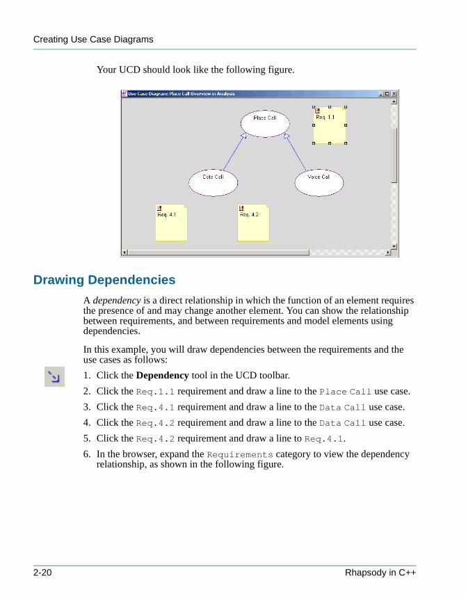
Creating Use Case Diagrams
tutorialcpp.book Page 20 Thursday, April 21, 2005 4:51 PM
Your UCD should look like the following figure.
Drawing Dependencies
A dependency is a direct relationship in which the function of an element requires the presence of and may change another element. You can show the relationship between requirements, and between requirements and model elements using dependencies.
In this example, you will draw dependencies between the requirements and the use cases as follows:
1. Click the Dependency tool in the UCD toolbar.
2. Click the Req.1.1 requirement and draw a line to the Place Call use case.
3. Click the Req.4.1 requirement and draw a line to the Data Call use case.
4. Click the Req.4.2 requirement and draw a line to the Data Call use case.
5. Click the Req.4.2 requirement and draw a line to Req.4.1.
6. In the browser, expand the Requirements category to view the dependency relationship, as shown in the following figure.
2-20 Rhapsody in C++

Defining the Stereotype of a Dependency
tutorialcpp.book Page 21 Thursday, April 21, 2005 4:51 PM
Defining the Stereotype of a Dependency
You can specify the ways in which requirements relate to other requirements and model elements using stereotypes. A stereotype is a modeling element that extends the semantics of the UML metamodel by typing UML entities. Rhapsody includes predefined stereotypes, and you can also define your own stereotypes. Stereotypes are enclosed in guillemets on diagrams, for example, «derive».
In this example, you will set the following types of dependency stereotypes:• Derive—A requirement is a consequence of another requirement.• Trace—A requirement traces to an element that realizes it.
To define the stereotype of a dependency, do the following:
1. Double-click the dependency between Req.1.1 and Place Call, or right-click and select Features from the pop-up menu. The features dialog box opens.
2. Select trace from the Stereotype pull-down list, as shown in the following figure.
Tutorial 2-21
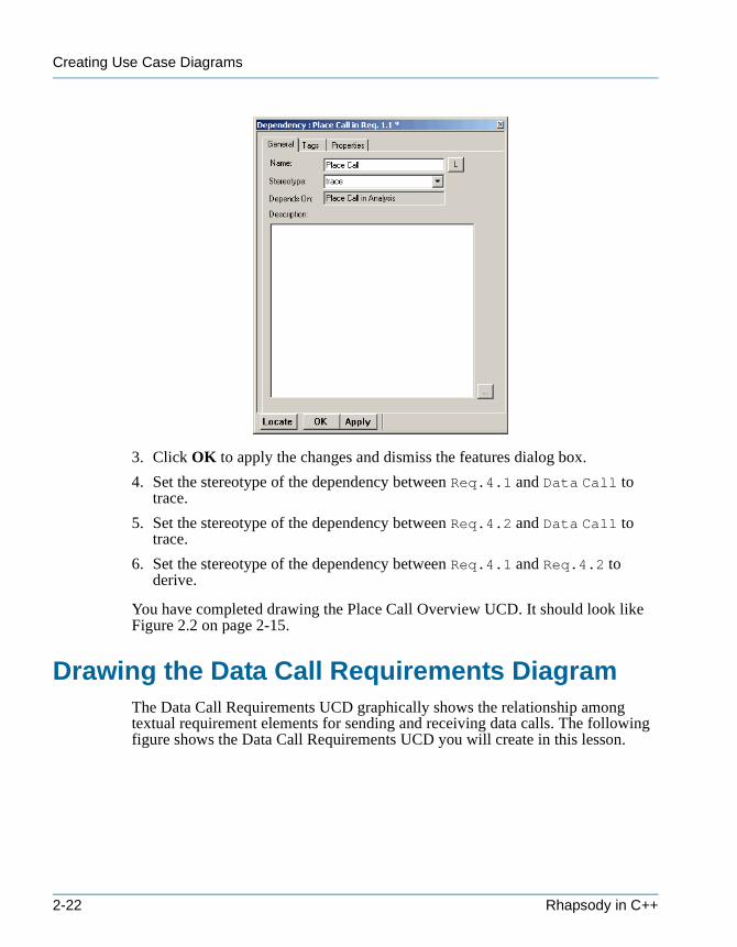
Creating Use Case Diagrams
tutorialcpp.book Page 22 Thursday, April 21, 2005 4:51 PM
3. Click OK to apply the changes and dismiss the features dialog box.
4. Set the stereotype of the dependency between Req.4.1 and Data Call to trace.
5. Set the stereotype of the dependency between Req.4.2 and Data Call to trace.
6. Set the stereotype of the dependency between Req.4.1 and Req.4.2 to derive.
You have completed drawing the Place Call Overview UCD. It should look like Figure 2.2 on page 2-15.
Drawing the Data Call Requirements DiagramThe Data Call Requirements UCD graphically shows the relationship among textual requirement elements for sending and receiving data calls. The following figure shows the Data Call Requirements UCD you will create in this lesson.
2-22 Rhapsody in C++
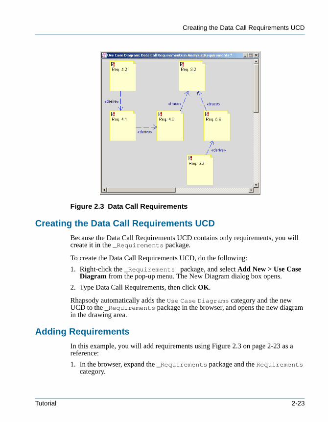
Creating the Data Call Requirements UCD
tutorialcpp.book Page 23 Thursday, April 21, 2005 4:51 PM
Figure 2.3 Data Call Requirements
Creating the Data Call Requirements UCD
Because the Data Call Requirements UCD contains only requirements, you will create it in the _Requirements package.
To create the Data Call Requirements UCD, do the following:
1. Right-click the _Requirements package, and select Add New > Use Case Diagram from the pop-up menu. The New Diagram dialog box opens.
2. Type Data Call Requirements, then click OK.
Rhapsody automatically adds the Use Case Diagrams category and the new UCD to the _Requirements package in the browser, and opens the new diagram in the drawing area.
Adding Requirements
In this example, you will add requirements using Figure 2.3 on page 2-23 as a reference:
1. In the browser, expand the _Requirements package and the Requirements category.
Tutorial 2-23
Creating Use Case Diagrams
tutorialcpp.book Page 24 Thursday, April 21, 2005 4:51 PM
2. Select Req.4.2 and drag it to the top left of the drawing area.
3. Select Req.4.1 and drag it below Req.4.2.
4. Select Req.3.2 and drag it to the top center of the drawing area.
5. Select Req.4.0 and drag it to the lower left side of Req.3.2.
6. Select Req.5.6 and drag it to the lower right side of Req.3.2.
7. Select Req.6.2 and drag it below Req.5.6.
Note: For each requirement, set the display options to Name to show the requirement name on the diagram.
Drawing and Defining the Dependencies
In this example, you will show the relationship between requirements by drawing dependencies and then setting the dependency stereotype, using Figure 2.3 on page 2-23 as a reference:
1. Click the Dependency tool.
2. Draw a dependency line from Req.4.2 to Req.4.1, then open the features dialog box and set derive as the stereotype.
3. Draw a dependency line from Req.4.1 to Req.4.0, then open the features dialog box and set derive as the stereotype.
4. Draw a dependency line from Req.4.0 to Req.3.2, then open the features dialog box and set trace as the stereotype.
5. Draw a dependency line from Req.5.6 to Req.3.2, then open the features dialog box and set trace as the stereotype.
6. Draw a dependency line from Req.6.2 to Req.5.6, then open the features dialog box and set derive as the stereotype.
The UCD should look like Figure 2.3 on page 2-23. Rhapsody automatically adds the dependency relationships to the browser.
SummaryIn this lesson, you created UCDs that show the functions and requirements of the wireless telephone and placing a call. You became familiar with the parts of a UCD and created the following:• System boundary box• Actors• Use cases
2-24 Rhapsody in C++
Summary
tutorialcpp.book Page 25 Thursday, April 21, 2005 4:51 PM
• Association lines• Dependencies• Generalizations• Requirements
You are now ready to proceed to the next lesson, where you will define the components of the system and the flow of information using structure diagrams.
Tutorial 2-25

Creating Use Case Diagrams
tutorialcpp.book Page 26 Thursday, April 21, 2005 4:51 PM
2-26 Rhapsody in C++
tutorialcpp.book Page 1 Thursday, April 21, 2005 4:51 PM
Creating Structure Diagrams 3
Structure diagrams define the system structure and identify the large-scale organizational pieces of the system. They can show the flow of information between system components, and the interface definition through ports. In large systems, the components are often decomposed into functions or subsystems.
In this lesson, you will create the following structure diagrams:• Block Diagram—Identifies the system-level components and flow of
information • Connection Management—Identifies the ConnectionManagement functions• Data Link—Identifies the DataLink functions• MM Architecture Structure—Identifies the MobilityManagement functions
For ease of presentation, this chapter includes both the system and subsystem structure diagrams. Depending on your workflow, you might identify the communication scenarios using sequence diagrams before defining the flows, flow items, and port contracts. In addition, you might perform black-box analysis using activity diagrams, sequence diagrams, and statecharts, and white-box analysis using sequence diagrams before decomposing the system’s functions into subsystem components.
Goals for this LessonIn this lesson, you will perform the following:• Creating a Structure Diagram, page 3-3• Drawing the Block Diagram, page 3-4• Allocating the Functions Among Subsystems, page 3-17• Drawing the Connection Management Structure Diagram, page 3-19• Drawing the Data Link Diagram, page 3-23• Drawing the MM Architecture Diagram, page 3-26
Tutorial 3-1
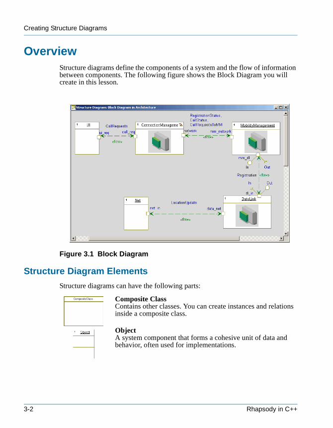
Creating Structure Diagrams
tutorialcpp.book Page 2 Thursday, April 21, 2005 4:51 PM
OverviewStructure diagrams define the components of a system and the flow of information between components. The following figure shows the Block Diagram you will create in this lesson.
Figure 3.1 Block Diagram
Structure Diagram Elements
Structure diagrams can have the following parts:
Composite ClassContains other classes. You can create instances and relations inside a composite class.
ObjectA system component that forms a cohesive unit of data and behavior, often used for implementations.
3-2 Rhapsody in C++
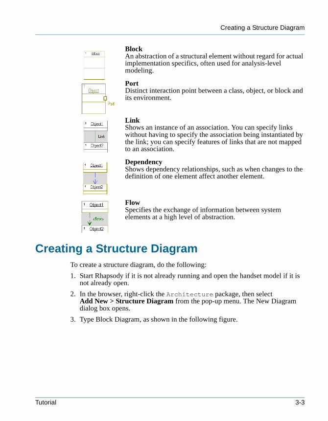
Creating a Structure Diagram
tutorialcpp.book Page 3 Thursday, April 21, 2005 4:51 PM
BlockAn abstraction of a structural element without regard for actual implementation specifics, often used for analysis-level modeling.
PortDistinct interaction point between a class, object, or block and its environment.
LinkShows an instance of an association. You can specify links without having to specify the association being instantiated by the link; you can specify features of links that are not mapped to an association.
DependencyShows dependency relationships, such as when changes to the definition of one element affect another element.
FlowSpecifies the exchange of information between system elements at a high level of abstraction.
Creating a Structure DiagramTo create a structure diagram, do the following:
1. Start Rhapsody if it is not already running and open the handset model if it is not already open.
2. In the browser, right-click the Architecture package, then select Add New > Structure Diagram from the pop-up menu. The New Diagram dialog box opens.
3. Type Block Diagram, as shown in the following figure.
Tutorial 3-3
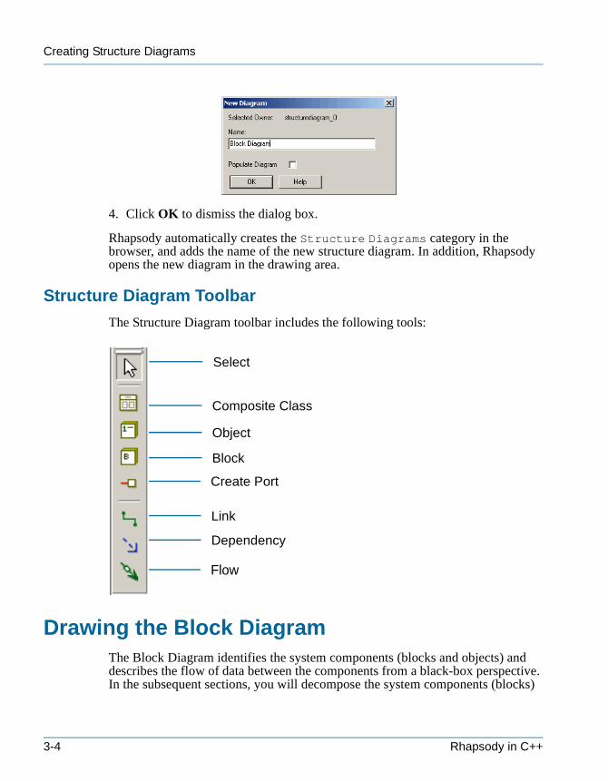
Creating Structure Diagrams
tutorialcpp.book Page 4 Thursday, April 21, 2005 4:51 PM
4. Click OK to dismiss the dialog box.
Rhapsody automatically creates the Structure Diagrams category in the browser, and adds the name of the new structure diagram. In addition, Rhapsody opens the new diagram in the drawing area.
Structure Diagram Toolbar
The Structure Diagram toolbar includes the following tools:
Drawing the Block DiagramThe Block Diagram identifies the system components (blocks and objects) and describes the flow of data between the components from a black-box perspective. In the subsequent sections, you will decompose the system components (blocks)
Select
Composite Class
Object
Block
Create Port
Link
Dependency
Flow
3-4 Rhapsody in C++
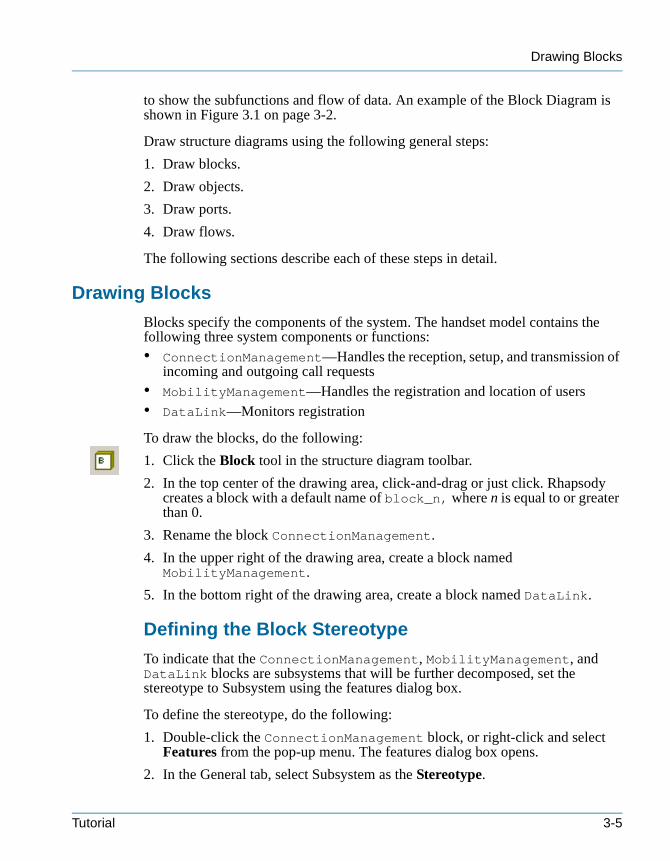
Drawing Blocks
tutorialcpp.book Page 5 Thursday, April 21, 2005 4:51 PM
to show the subfunctions and flow of data. An example of the Block Diagram is shown in Figure 3.1 on page 3-2.
Draw structure diagrams using the following general steps:
1. Draw blocks.
2. Draw objects.
3. Draw ports.
4. Draw flows.
The following sections describe each of these steps in detail.
Drawing Blocks
Blocks specify the components of the system. The handset model contains the following three system components or functions:• ConnectionManagement—Handles the reception, setup, and transmission of
incoming and outgoing call requests• MobilityManagement—Handles the registration and location of users• DataLink—Monitors registration
To draw the blocks, do the following:
1. Click the Block tool in the structure diagram toolbar.
2. In the top center of the drawing area, click-and-drag or just click. Rhapsody creates a block with a default name of block_n, where n is equal to or greater than 0.
3. Rename the block ConnectionManagement.
4. In the upper right of the drawing area, create a block named MobilityManagement.
5. In the bottom right of the drawing area, create a block named DataLink.
Defining the Block Stereotype
To indicate that the ConnectionManagement, MobilityManagement, and DataLink blocks are subsystems that will be further decomposed, set the stereotype to Subsystem using the features dialog box.
To define the stereotype, do the following:
1. Double-click the ConnectionManagement block, or right-click and select Features from the pop-up menu. The features dialog box opens.
2. In the General tab, select Subsystem as the Stereotype.
Tutorial 3-5
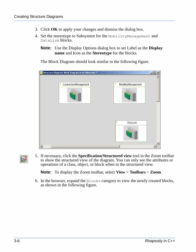
Creating Structure Diagrams
tutorialcpp.book Page 6 Thursday, April 21, 2005 4:51 PM
3. Click OK to apply your changes and dismiss the dialog box.
4. Set the stereotype to Subsystem for the MobilityManagement and DataLink blocks.
Note: Use the Display Options dialog box to set Label as the Display name and Icon as the Stereotype for the blocks.
The Block Diagram should look similar to the following figure.
5. If necessary, click the Specification/Structured view tool in the Zoom toolbar to show the structured view of the diagram. You can only see the attributes or operations of a class, object, or block when in the structured view.
Note: To display the Zoom toolbar, select View > Toolbars > Zoom.
6. In the browser, expand the Blocks category to view the newly created blocks, as shown in the following figure.
3-6 Rhapsody in C++
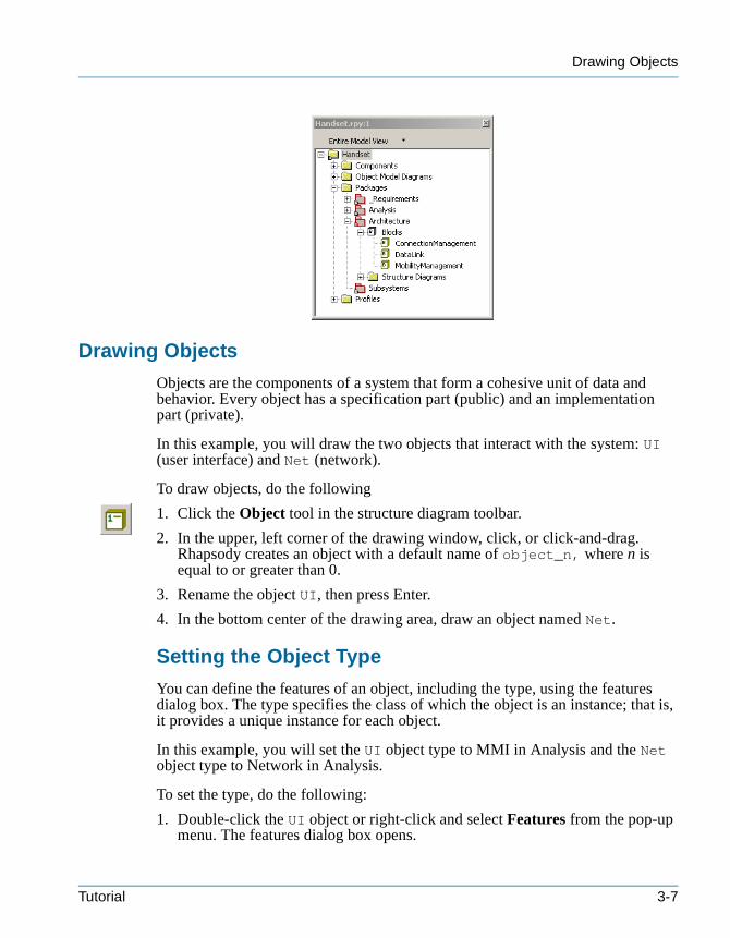
Drawing Objects
tutorialcpp.book Page 7 Thursday, April 21, 2005 4:51 PM
Drawing Objects
Objects are the components of a system that form a cohesive unit of data and behavior. Every object has a specification part (public) and an implementation part (private).
In this example, you will draw the two objects that interact with the system: UI (user interface) and Net (network).
To draw objects, do the following
1. Click the Object tool in the structure diagram toolbar.
2. In the upper, left corner of the drawing window, click, or click-and-drag. Rhapsody creates an object with a default name of object_n, where n is equal to or greater than 0.
3. Rename the object UI, then press Enter.
4. In the bottom center of the drawing area, draw an object named Net.
Setting the Object Type
You can define the features of an object, including the type, using the features dialog box. The type specifies the class of which the object is an instance; that is, it provides a unique instance for each object.
In this example, you will set the UI object type to MMI in Analysis and the Net object type to Network in Analysis.
To set the type, do the following:
1. Double-click the UI object or right-click and select Features from the pop-up menu. The features dialog box opens.
Tutorial 3-7
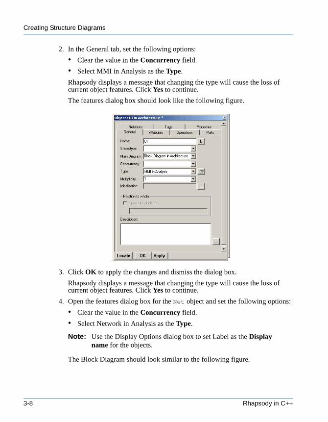
Creating Structure Diagrams
tutorialcpp.book Page 8 Thursday, April 21, 2005 4:51 PM
2. In the General tab, set the following options:
• Clear the value in the Concurrency field.
• Select MMI in Analysis as the Type.
Rhapsody displays a message that changing the type will cause the loss of current object features. Click Yes to continue.
The features dialog box should look like the following figure.
3. Click OK to apply the changes and dismiss the dialog box.
Rhapsody displays a message that changing the type will cause the loss of current object features. Click Yes to continue.
4. Open the features dialog box for the Net object and set the following options:
• Clear the value in the Concurrency field.
• Select Network in Analysis as the Type.
Note: Use the Display Options dialog box to set Label as the Display name for the objects.
The Block Diagram should look similar to the following figure.
3-8 Rhapsody in C++
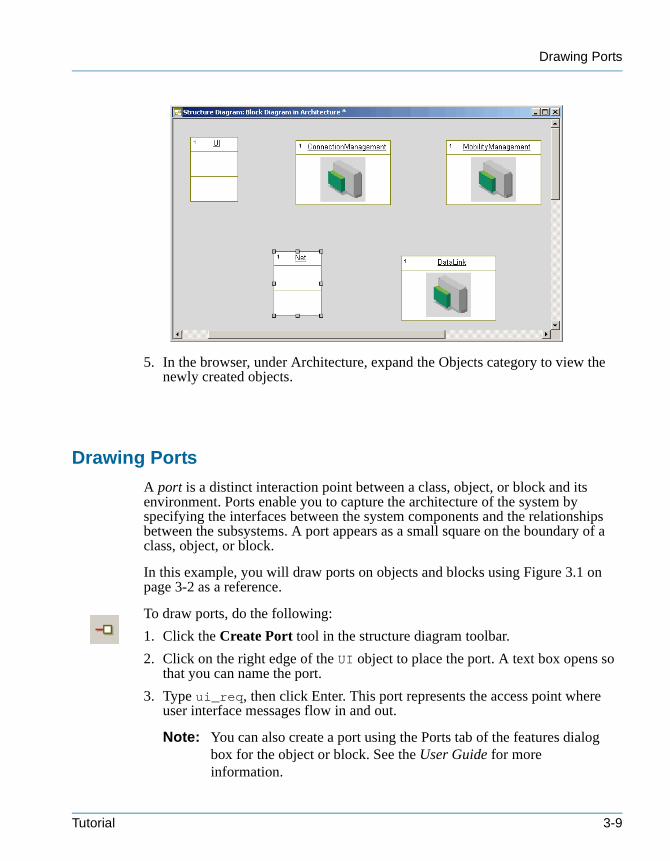
Drawing Ports
tutorialcpp.book Page 9 Thursday, April 21, 2005 4:51 PM
5. In the browser, under Architecture, expand the Objects category to view the newly created objects.
Drawing Ports
A port is a distinct interaction point between a class, object, or block and its environment. Ports enable you to capture the architecture of the system by specifying the interfaces between the system components and the relationships between the subsystems. A port appears as a small square on the boundary of a class, object, or block.
In this example, you will draw ports on objects and blocks using Figure 3.1 on page 3-2 as a reference.
To draw ports, do the following:
1. Click the Create Port tool in the structure diagram toolbar.
2. Click on the right edge of the UI object to place the port. A text box opens so that you can name the port.
3. Type ui_req, then click Enter. This port represents the access point where user interface messages flow in and out.
Note: You can also create a port using the Ports tab of the features dialog box for the object or block. See the User Guide for more information.
Tutorial 3-9
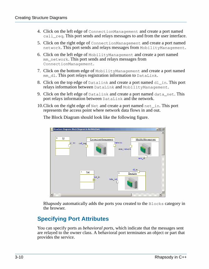
Creating Structure Diagrams
tutorialcpp.book Page 10 Thursday, April 21, 2005 4:51 PM
4. Click on the left edge of ConnectionManagement and create a port named call_req. This port sends and relays messages to and from the user interface.
5. Click on the right edge of ConnectionManagement and create a port named network. This port sends and relays messages from MobilityManagement.
6. Click on the left edge of MobilityManagement and create a port named mm_network. This port sends and relays messages from ConnectionManagement.
7. Click on the bottom edge of MobilityManagement and create a port named mm_dl. This port relays registration information to DataLink.
8. Click on the top edge of Datalink and create a port named dl_in. This port relays information between DataLink and MobilityManagement.
9. Click on the left edge of Datalink and create a port named data_net. This port relays information between DataLink and the network.
10.Click on the right edge of Net and create a port named net_in. This port represents the access point where network data flows in and out.
The Block Diagram should look like the following figure.
Rhapsody automatically adds the ports you created to the Blocks category in the browser.
Specifying Port Attributes
You can specify ports as behavioral ports, which indicate that the messages sent are relayed to the owner class. A behavioral port terminates an object or part that provides the service.
3-10 Rhapsody in C++
Drawing Flows
tutorialcpp.book Page 11 Thursday, April 21, 2005 4:51 PM
In this example, you will set the ui_req port as a behavioral port as follows:
1. Double-click the ui_req port, or right-click and select Features from the pop-up menu. The features dialog box opens.
2. In the General tab, set Behavior for the Attributes value.
3. Click OK to apply the changes and dismiss the dialog box.
Drawing Flows
Flows specify the exchange of information between system elements. They enable you to describe the flow of data and commands within a system at a very early stage, before committing to a specific design.
In this example, you will draw flows between the ports, objects, and blocks using Figure 3.1 on page 3-2 as a reference.
To draw a flow, do the following:
1. Click the Flow tool in the structure diagram toolbar.
2. Click the ui_req port, then click call_req. Press Enter.
3. Create a flow between the network port and the mm_network port, then press Enter.
4. Create a flow between the mm_dl port and the dl_in port, then press Enter.
5. Create a flow between the data_net port and the net_in port, then press Enter.
Changing the Direction of the Flow
Information can flow from one element to another or between elements in either direction. You can change the direction of the flow or make the flow bidirectional using the features dialog box.
In this example, you will change all flows to bidirectional to indicate that information can flow in either direction between system elements.
To change the direction of the flow, do the following:
1. Double-click the flow between UI and ConnectionManagement, or right-click and select Features from the pop-up menu. The features dialog box opens.
2. In the General tab, select Bidirectional from the Direction pull-down menu.
3. Click OK to apply the changes and dismiss the dialog box.
Tutorial 3-11
Creating Structure Diagrams
tutorialcpp.book Page 12 Thursday, April 21, 2005 4:51 PM
4. Set the flow between ConnectionManagement and MobilityManagement to bidirectional.
5. Set the flow between MobilityManagement and DataLink to bidirectional.
6. Set the flow between Datalink and Net to bidirectional.
Specifying the Flow Items
Once you have determined how communication occurs through flows, you can specify the information that passes over a flow using a flow item. A flow item can represent either pure data, data instantiation, or commands (events).
As the system specification evolves, such as by defining the communication scenarios using sequence diagrams, you can refine the flow items to relate to the concrete implementation and elements. See Chapter 5, Creating Sequence Diagrams for more information on defining scenarios.
To specify the flow items, do the following:
1. Double-click the flow between the ui_req port and call_req, or right-click and select Features from the pop-up menu. The Details tab of the features dialog box opens.
2. Click the <Add> row in the list of information elements and select FlowItem from the pop-up list. The flow items features dialog box opens.
3. Enter CallRequests as the Name. This flow item represents all user interface requests into the system.
4. Click OK to apply your changes and dismiss the features dialog box for the new element.
5. Click OK to apply your changes and dismiss the features dialog box for the flow.
6. Create flow items for the flow between the network port and the mm_network port, named RegistrationStatus, CallStatus, and CallRequestsToMM. These flowitems represents the relay of information between the main call control logic (ConnectionManagement), and user location (MobilityManagement).
7. Create a flow item for the flow between the mm_dl port and the dl_in port named Registration. This flow item represents network registration status information.
8. Create a flow item for the flow between the data_net port and the net_in port named LocationUpdate. This flow item represents all network information into and out of the system.
9. In the browser, expand the Flows category and the Flow Items category to view the newly created flows and flow items, as shown in the following figure.
3-12 Rhapsody in C++
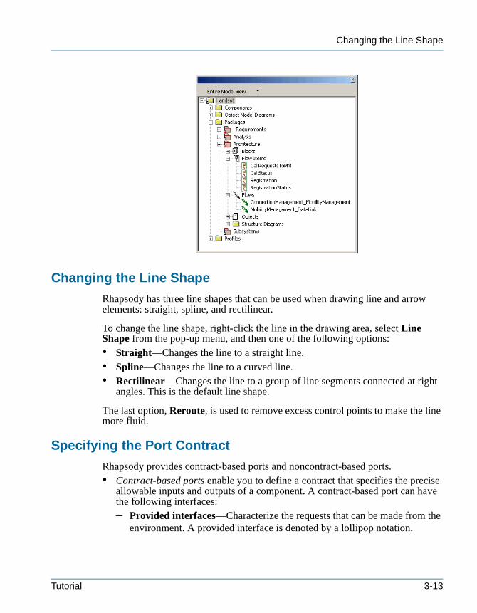
Changing the Line Shape
tutorialcpp.book Page 13 Thursday, April 21, 2005 4:51 PM
Changing the Line Shape
Rhapsody has three line shapes that can be used when drawing line and arrow elements: straight, spline, and rectilinear.
To change the line shape, right-click the line in the drawing area, select Line Shape from the pop-up menu, and then one of the following options: • Straight—Changes the line to a straight line.• Spline—Changes the line to a curved line.• Rectilinear—Changes the line to a group of line segments connected at right
angles. This is the default line shape.
The last option, Reroute, is used to remove excess control points to make the line more fluid.
Specifying the Port Contract
Rhapsody provides contract-based ports and noncontract-based ports.• Contract-based ports enable you to define a contract that specifies the precise
allowable inputs and outputs of a component. A contract-based port can have the following interfaces:– Provided interfaces—Characterize the requests that can be made from the
environment. A provided interface is denoted by a lollipop notation.
Tutorial 3-13

Creating Structure Diagrams
tutorialcpp.book Page 14 Thursday, April 21, 2005 4:51 PM
– Required interfaces—Characterize the requests that can be made from the port to its environment (external objects). A required interface is denoted by a socket notation.
Provided and required interfaces enable you to encapsulate model elements by defining the access through the port. The following figure shows an example of the port interfaces.
• Noncontract-based ports, called rapid ports, enable you to relay messages to the appropriate part of the structured class through a connector. They do not require a contract to be established initially, but allow the routing of incoming data through a port to the appropriate part.
In this example, you will specify the provided and required interfaces for the mm_dl and dl_in ports.
Note: Depending on your workflow, you might identify the communication scenarios using sequence diagrams before defining the port contracts. See Chapter 5, Creating Sequence Diagrams for more information.
To specify the port contract, do the following:
1. Double-click the mm_dl port, or right-click and select Features from the pop-up menu. The features dialog box opens.
2. Select the Contract tab.
3. Select the Provided folder icon, then click the Add button. The Add new interface dialog box opens, as shown in the following figure.
4. Select New from the pull-down list, then click OK. The class features dialog box opens.
5. In the General tab, type In as the Name.
6. In the Operations tab, click <New> and select Reception from the pop-up menu. The New Reception dialog box opens, as shown in the following figure.
Required interface
Provided interface
3-14 Rhapsody in C++
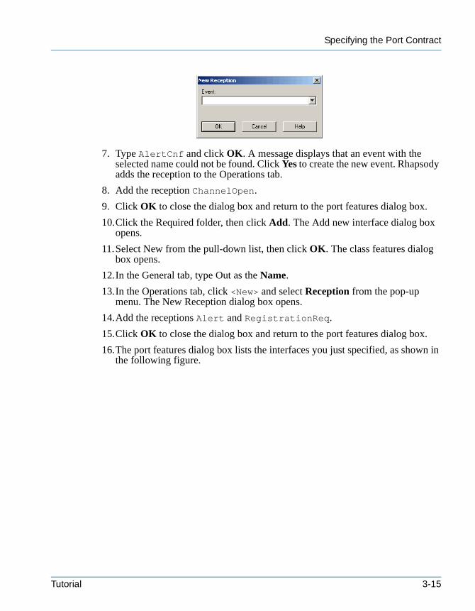
Specifying the Port Contract
tutorialcpp.book Page 15 Thursday, April 21, 2005 4:51 PM
7. Type AlertCnf and click OK. A message displays that an event with the selected name could not be found. Click Yes to create the new event. Rhapsody adds the reception to the Operations tab.
8. Add the reception ChannelOpen.
9. Click OK to close the dialog box and return to the port features dialog box.
10.Click the Required folder, then click Add. The Add new interface dialog box opens.
11.Select New from the pull-down list, then click OK. The class features dialog box opens.
12.In the General tab, type Out as the Name.
13.In the Operations tab, click <New> and select Reception from the pop-up menu. The New Reception dialog box opens.
14.Add the receptions Alert and RegistrationReq.
15.Click OK to close the dialog box and return to the port features dialog box.
16.The port features dialog box lists the interfaces you just specified, as shown in the following figure.
Tutorial 3-15
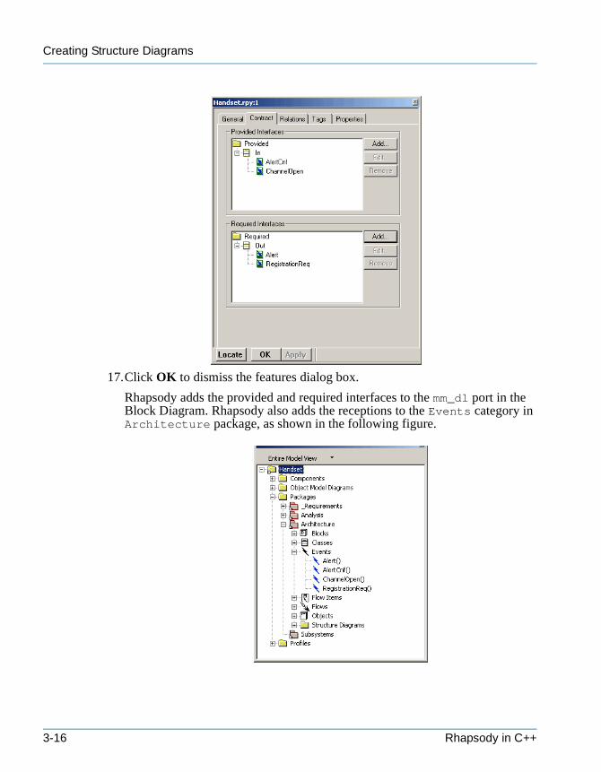
Creating Structure Diagrams
tutorialcpp.book Page 16 Thursday, April 21, 2005 4:51 PM
17.Click OK to dismiss the features dialog box.
Rhapsody adds the provided and required interfaces to the mm_dl port in the Block Diagram. Rhapsody also adds the receptions to the Events category in Architecture package, as shown in the following figure.
3-16 Rhapsody in C++
Reversing a Port
tutorialcpp.book Page 17 Thursday, April 21, 2005 4:51 PM
18.To specify the port interfaces for dl_in, double-click the dl_in port, or right-click and select Features from the pop-up menu. The features dialog box opens.
19.Select the General tab and select In from the Contract pull-down list.
20.Select the Contract tab. Rhapsody automatically adds the provided interfaces defined as In.
21.Select the Required folder icon, then click the Add button. The Add new interface dialog box opens.
22.Select Out from the pull-down list, then click OK. Rhapsody automatically adds the required interfaces defined as Out.
23.Click OK to apply the changes and dismiss the features dialog box.
Reversing a Port
You can reverse ports so that the provided interfaces become the required interfaces, and the required interfaces become the provided interfaces.
In this example, you will reverse the dl_in port as follows:
1. Open the features dialog box for the dl_in port.
2. In the General tab, set Reversed for the Attributes.
The bottom of the Contract tab displays a message in red that the contract is reversed.
3. Click OK to apply the changes and dismiss the dialog box.
You have completed drawing the Block Diagram. It should look like Figure 3.1 on page 3-2.
Allocating the Functions Among SubsystemsNow that you have captured the architectural design in the Block Diagram, you need to divide the operations of the system into its functional subsystems and allocate the activities among the subsystems.
Note: For ease of presentation, this chapter includes both the system and subsystem structure diagrams. Depending on your workflow, you might perform further black-box analysis with activity diagrams, sequence diagrams, and statecharts, and white-box analysis using sequence diagrams before decomposing the system’s functions into subsystem components.
Tutorial 3-17
Creating Structure Diagrams
tutorialcpp.book Page 18 Thursday, April 21, 2005 4:51 PM
Organizing the Subsystems Package
Packages let you divide the system into functional domains, or subsystems, which consist of objects, object types, functions, variables, and other logical artifacts. They can be organized into hierarchies to provide a high level of partitioning.
In this example, you will create the following subpackages, which represent the functional subsystems: CM_Subsystem for ConnectionManagement, DL_Subsystem for DataLink, and MM_Subsystem for MobilityManagement.
To create packages within the subsystems package, do the following:
1. In the browser, right-click Subsystems and select Add New > Package. Rhapsody create a new Packages category within Subsystems and a package with the default name package_n, where n is greater or equal to 0.
2. Rename the package CM_Subsystem.
3. Right-click Packages, select Add New Packages from the pop-up menu, and create two additional packages named DL_Subsystem and MM_Subsystem.
Organizing Elements
In this example, you will allocate the subsystem blocks from the Block Diagram in the Architecture package to their respective packages in the Subsystems package by moving the following elements:• The ConnectionManagement block to the CM_Subsystem package• The DataLink block to the DL_Subsystem package• The MobilityManagement block to the MM_Subsystem package
To organize elements, do the following:
1. In the browser, expand the Architecture package and the Blocks category.
2. Click the ConnectionManagement block and drag it into the CM_Subsystem package.
3. Click the DataLink block and drag it into the DL_Subsystem package.
4. Click the MobilityManagement block and drag it into the MM_Subsystem package.
The blocks are removed from the Architecture package and added to the Subsystem packages, as shown in the following figure.
3-18 Rhapsody in C++
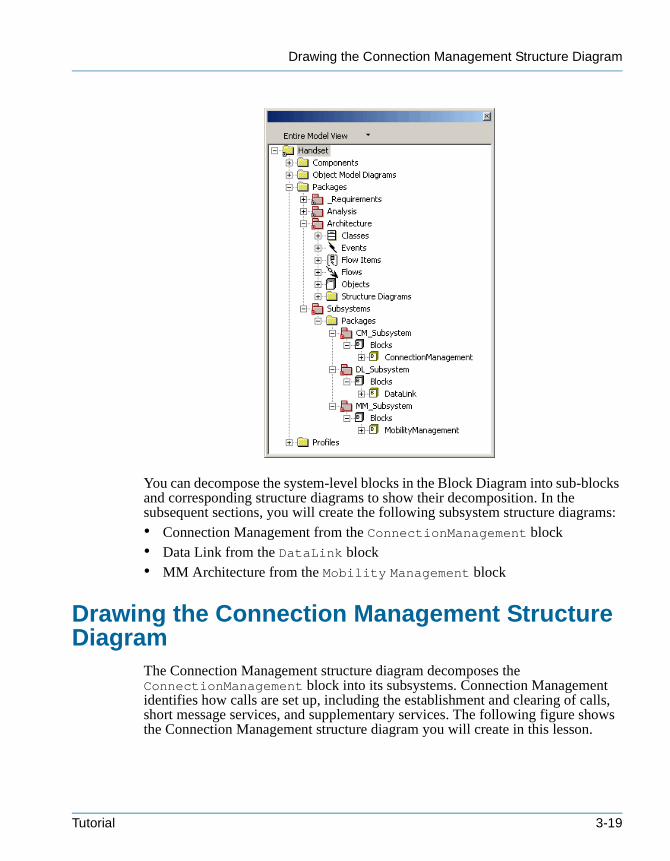
Drawing the Connection Management Structure Diagram
tutorialcpp.book Page 19 Thursday, April 21, 2005 4:51 PM
You can decompose the system-level blocks in the Block Diagram into sub-blocks and corresponding structure diagrams to show their decomposition. In the subsequent sections, you will create the following subsystem structure diagrams:• Connection Management from the ConnectionManagement block• Data Link from the DataLink block• MM Architecture from the Mobility Management block
Drawing the Connection Management Structure Diagram
The Connection Management structure diagram decomposes the ConnectionManagement block into its subsystems. Connection Management identifies how calls are set up, including the establishment and clearing of calls, short message services, and supplementary services. The following figure shows the Connection Management structure diagram you will create in this lesson.
Tutorial 3-19
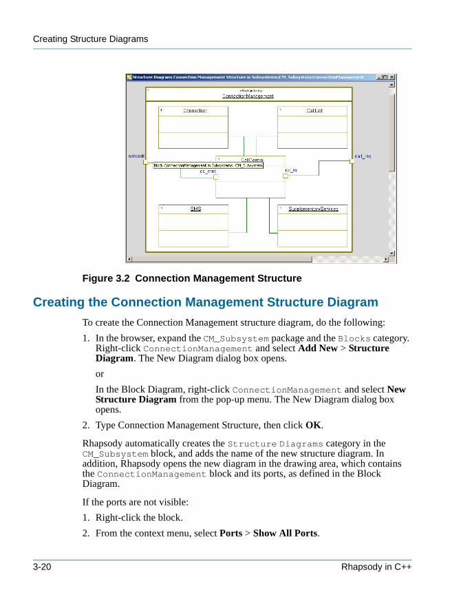
Creating Structure Diagrams
tutorialcpp.book Page 20 Thursday, April 21, 2005 4:51 PM
Figure 3.2 Connection Management Structure
Creating the Connection Management Structure Diagram
To create the Connection Management structure diagram, do the following:
1. In the browser, expand the CM_Subsystem package and the Blocks category. Right-click ConnectionManagement and select Add New > Structure Diagram. The New Diagram dialog box opens.
or
In the Block Diagram, right-click ConnectionManagement and select New Structure Diagram from the pop-up menu. The New Diagram dialog box opens.
2. Type Connection Management Structure, then click OK.
Rhapsody automatically creates the Structure Diagrams category in the CM_Subsystem block, and adds the name of the new structure diagram. In addition, Rhapsody opens the new diagram in the drawing area, which contains the ConnectionManagement block and its ports, as defined in the Block Diagram.
If the ports are not visible:
1. Right-click the block.
2. From the context menu, select Ports > Show All Ports.
3-20 Rhapsody in C++
Drawing Objects
tutorialcpp.book Page 21 Thursday, April 21, 2005 4:51 PM
Drawing Objects
In this example, you will draw the following objects, which represent the activities performed by Connection Management: • Connection—Tracks the number of valid connections• CallList—Maintains the list of currently active calls• CallControl—Manages incoming and outgoing calls• SMS—Manages the short message services.• SupplementaryServices—Manages the supplementary services, including
call waiting, holding, and barring
To draw objects, do the following:
1. Click the Object tool in the structure diagram toolbar.
2. In the upper, left corner of ConnectionManagement, click or click-and-drag. Rhapsody creates an object with a default name of object_n, where n is equal to or greater than 0.
3. Rename the object Connection, then press Enter.
4. Draw the CallList, CallControl, SMS, and SupplementaryServices objects using Figure 3.2 on page 3-20 as a reference.
Drawing Ports
To draw ports, do the following:
1. Click the Create Port tool in the structure diagram toolbar.
2. Click the left edge of the CallControl object and create a port named cc_mm. This port relays messages to and from MobilityManagement.
3. Click the right edge of the CallControl object and create a port named cc_in. This port relays messages from the user interface.
Changing the Placement of Ports
When Rhapsody adds the ConnectionManagement block to the diagram, it places the ports defined in the Block Diagram on the boundary. You can change the port placement by selecting the port and dragging it to another location on the object or block.
Using Figure 3.2 on page 3-20 as a reference, change the port placement, if necessary.
Tutorial 3-21
Creating Structure Diagrams
tutorialcpp.book Page 22 Thursday, April 21, 2005 4:51 PM
Drawing Links
A link is an instantiation of an association. You can specify links without having to specify the association being instantiated by the link; you can specify features of links that are not mapped to an association. There must be at least one association that connects one of the base classes of the type of one of the objects to a base class of the type of the second object.
In this example, you will draw links between objects and ports, using Figure 3.2 on page 3-20 as a reference, as follows:
1. Click the Link tool in the structure diagram toolbar.
2. Click the cc_mm port, then click the network port. Press Enter.
3. Click the cc_in port, then click the call_req port. Press Enter.
4. Click the CallControl object, then click the Connection object. Press Enter.
5. Click the CallControl object, then click the CallList object. Press Enter.
6. Click the CallControl object, then click the SMS object. Press Enter.
7. Click the CallControl object, then click the SupplementaryServices object. Press Enter.
8. In the browser, expand the ConnectionManagement category to view the newly created objects under the Parts category and the links under the Links category, as shown in the following figure.
3-22 Rhapsody in C++
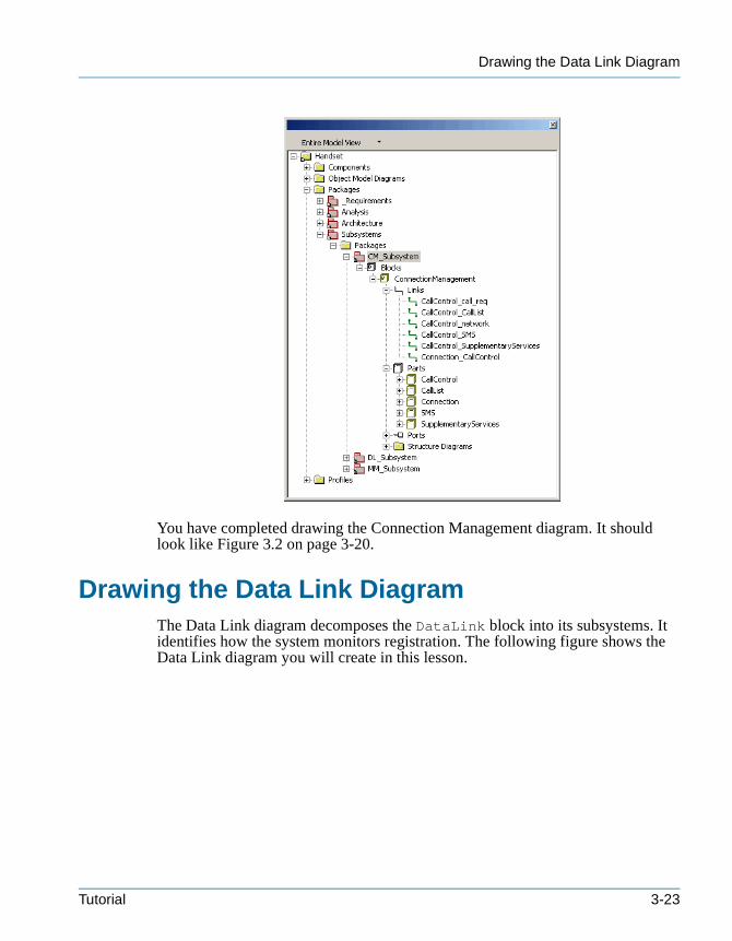
Drawing the Data Link Diagram
tutorialcpp.book Page 23 Thursday, April 21, 2005 4:51 PM
You have completed drawing the Connection Management diagram. It should look like Figure 3.2 on page 3-20.
Drawing the Data Link DiagramThe Data Link diagram decomposes the DataLink block into its subsystems. It identifies how the system monitors registration. The following figure shows the Data Link diagram you will create in this lesson.
Tutorial 3-23
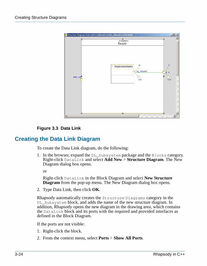
Creating Structure Diagrams
tutorialcpp.book Page 24 Thursday, April 21, 2005 4:51 PM
Figure 3.3 Data Link
Creating the Data Link Diagram
To create the Data Link diagram, do the following:
1. In the browser, expand the DL_Subsystem package and the Blocks category. Right-click DataLink and select Add New > Structure Diagram. The New Diagram dialog box opens.
or
Right-click DataLink in the Block Diagram and select New Structure Diagram from the pop-up menu. The New Diagram dialog box opens.
2. Type Data Link, then click OK.
Rhapsody automatically creates the Structure Diagrams category in the DL_Subsystem block, and adds the name of the new structure diagram. In addition, Rhapsody opens the new diagram in the drawing area, which contains the DataLink block and its ports with the required and provided interfaces as defined in the Block Diagram.
If the ports are not visible:
1. Right-click the block.
2. From the context menu, select Ports > Show All Ports.
3-24 Rhapsody in C++
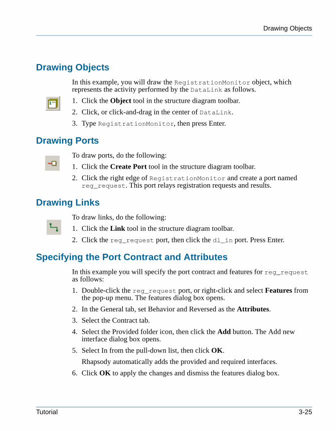
Drawing Objects
tutorialcpp.book Page 25 Thursday, April 21, 2005 4:51 PM
Drawing Objects
In this example, you will draw the RegistrationMonitor object, which represents the activity performed by the DataLink as follows.
1. Click the Object tool in the structure diagram toolbar.
2. Click, or click-and-drag in the center of DataLink.
3. Type RegistrationMonitor, then press Enter.
Drawing Ports
To draw ports, do the following:
1. Click the Create Port tool in the structure diagram toolbar.
2. Click the right edge of RegistrationMonitor and create a port named reg_request. This port relays registration requests and results.
Drawing Links
To draw links, do the following:
1. Click the Link tool in the structure diagram toolbar.
2. Click the reg_request port, then click the dl_in port. Press Enter.
Specifying the Port Contract and Attributes
In this example you will specify the port contract and features for reg_request as follows:
1. Double-click the reg_request port, or right-click and select Features from the pop-up menu. The features dialog box opens.
2. In the General tab, set Behavior and Reversed as the Attributes.
3. Select the Contract tab.
4. Select the Provided folder icon, then click the Add button. The Add new interface dialog box opens.
5. Select In from the pull-down list, then click OK.
Rhapsody automatically adds the provided and required interfaces.
6. Click OK to apply the changes and dismiss the features dialog box.
Tutorial 3-25
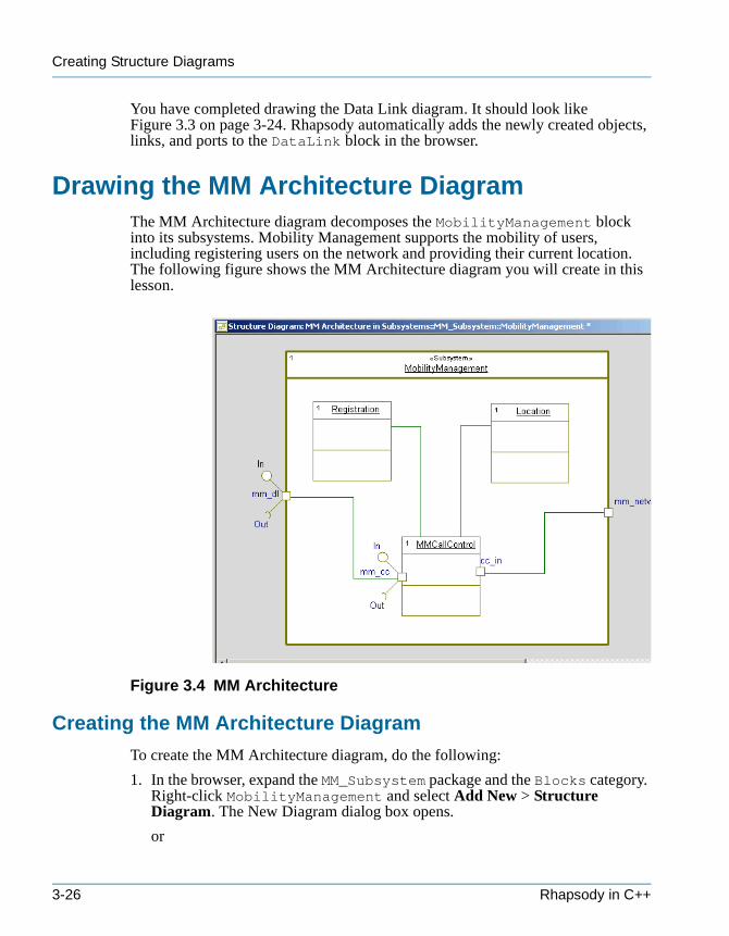
Creating Structure Diagrams
tutorialcpp.book Page 26 Thursday, April 21, 2005 4:51 PM
You have completed drawing the Data Link diagram. It should look like Figure 3.3 on page 3-24. Rhapsody automatically adds the newly created objects, links, and ports to the DataLink block in the browser.
Drawing the MM Architecture DiagramThe MM Architecture diagram decomposes the MobilityManagement block into its subsystems. Mobility Management supports the mobility of users, including registering users on the network and providing their current location. The following figure shows the MM Architecture diagram you will create in this lesson.
Figure 3.4 MM Architecture
Creating the MM Architecture Diagram
To create the MM Architecture diagram, do the following:
1. In the browser, expand the MM_Subsystem package and the Blocks category. Right-click MobilityManagement and select Add New > Structure Diagram. The New Diagram dialog box opens.
or
3-26 Rhapsody in C++
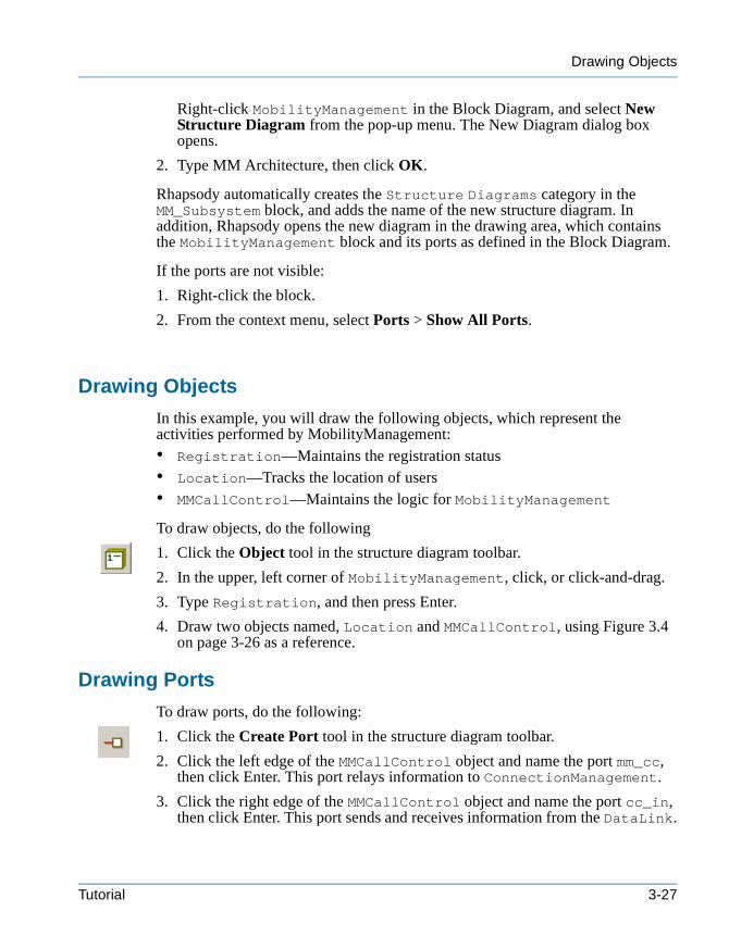
Drawing Objects
tutorialcpp.book Page 27 Thursday, April 21, 2005 4:51 PM
Right-click MobilityManagement in the Block Diagram, and select New Structure Diagram from the pop-up menu. The New Diagram dialog box opens.
2. Type MM Architecture, then click OK.
Rhapsody automatically creates the Structure Diagrams category in the MM_Subsystem block, and adds the name of the new structure diagram. In addition, Rhapsody opens the new diagram in the drawing area, which contains the MobilityManagement block and its ports as defined in the Block Diagram.
If the ports are not visible:
1. Right-click the block.
2. From the context menu, select Ports > Show All Ports.
Drawing Objects
In this example, you will draw the following objects, which represent the activities performed by MobilityManagement: • Registration—Maintains the registration status• Location—Tracks the location of users• MMCallControl—Maintains the logic for MobilityManagement
To draw objects, do the following
1. Click the Object tool in the structure diagram toolbar.
2. In the upper, left corner of MobilityManagement, click, or click-and-drag.
3. Type Registration, and then press Enter.
4. Draw two objects named, Location and MMCallControl, using Figure 3.4 on page 3-26 as a reference.
Drawing Ports
To draw ports, do the following:
1. Click the Create Port tool in the structure diagram toolbar.
2. Click the left edge of the MMCallControl object and name the port mm_cc, then click Enter. This port relays information to ConnectionManagement.
3. Click the right edge of the MMCallControl object and name the port cc_in, then click Enter. This port sends and receives information from the DataLink.
Tutorial 3-27
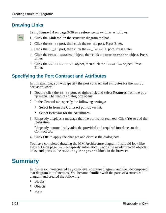
Creating Structure Diagrams
tutorialcpp.book Page 28 Thursday, April 21, 2005 4:51 PM
Drawing Links
Using Figure 3.4 on page 3-26 as a reference, draw links as follows:
1. Click the Link tool in the structure diagram toolbar.
2. Click the mm_cc port, then click the mm_dl port. Press Enter.
3. Click the cc_in port, then click the mm_network port. Press Enter.
4. Click the MMCallControl object, then click the Registration object. Press Enter.
5. Click the MMCallControl object, then click the Location object. Press Enter.
Specifying the Port Contract and Attributes
In this example, you will specify the port contract and attributes for the mm_cc port as follows:
1. Double-click the mm_cc port, or right-click and select Features from the pop-up menu. The features dialog box opens.
2. In the General tab, specify the following settings:
• Select In from the Contract pull-down list.
• Select Behavior for the Attributes.
3. Rhapsody displays a message that the port is not realized. Click Yes to add the realization.
Rhapsody automatically adds the provided and required interfaces to the Contract tab.
4. Click OK to apply the changes and dismiss the dialog box.
You have completed drawing the MM Architecture diagram. It should look like Figure 3.4 on page 3-26. Rhapsody automatically adds the newly created objects, links, and ports to the MobilityManagement block in the browser.
SummaryIn this lesson, you created a system-level structure diagram, and then decomposed that diagram into functions. You became familiar with the parts of a structure diagram and created the following:• Blocks• Objects• Ports
3-28 Rhapsody in C++
Summary
tutorialcpp.book Page 29 Thursday, April 21, 2005 4:51 PM
• Flows• Links
You are now ready to proceed to the next lesson, where you will define how the system components are interconnected using object model diagrams.
Note: Before proceeding to the next lesson, you can build and animate the parts of the model you created. This lets you determine whether the model meets the requirements, and identify defects early on in the design process. See Chapter 8, Animating the Model for more information.
Tutorial 3-29

Creating Structure Diagrams
tutorialcpp.book Page 30 Thursday, April 21, 2005 4:51 PM
3-30 Rhapsody in C++
tutorialcpp.book Page 1 Thursday, April 21, 2005 4:51 PM
Creating Object Model Diagrams 4
Object model diagrams (OMDs) specify the structure of the classes, objects, and interfaces in the system and the static relationships that exist between them. OMDs provide a graphical representation of the system structure and are also constructive. The Rhapsody code generator directly translates the elements and relationships modeled in OMDs into source code in a number of high-level languages.
In this lesson, you will create the Subsystem Architecture diagram, which shows how the system components are interconnected at the subsystem level, and identifies the port connections and the flow of information between components as links.
Goals for this LessonIn this lesson, you will perform the following:• Creating an Object Model Diagram, page 4-4• Drawing the Subsystem Architecture OMD, page 4-5
OverviewOMDs show the types of objects in the system, the attributes and operations that belong to those objects, and the static relationships that can exist between classes (types). The following diagram shows the Subsystem Architecture OMD you will create in this lesson.
Tutorial 4-1
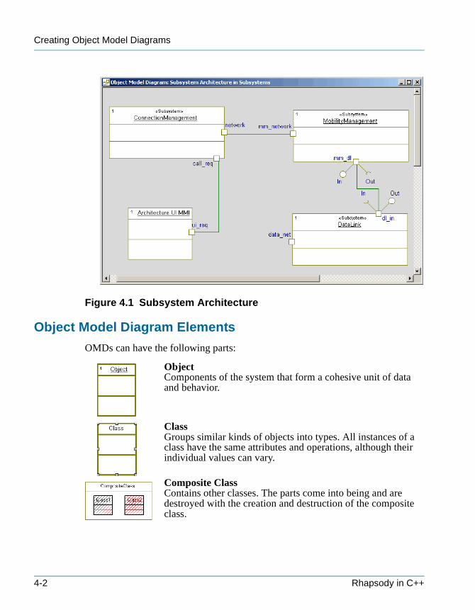
Creating Object Model Diagrams
tutorialcpp.book Page 2 Thursday, April 21, 2005 4:51 PM
Figure 4.1 Subsystem Architecture
Object Model Diagram Elements
OMDs can have the following parts:
ObjectComponents of the system that form a cohesive unit of data and behavior.
ClassGroups similar kinds of objects into types. All instances of a class have the same attributes and operations, although their individual values can vary.
Composite ClassContains other classes. The parts come into being and are destroyed with the creation and destruction of the composite class.
4-2 Rhapsody in C++
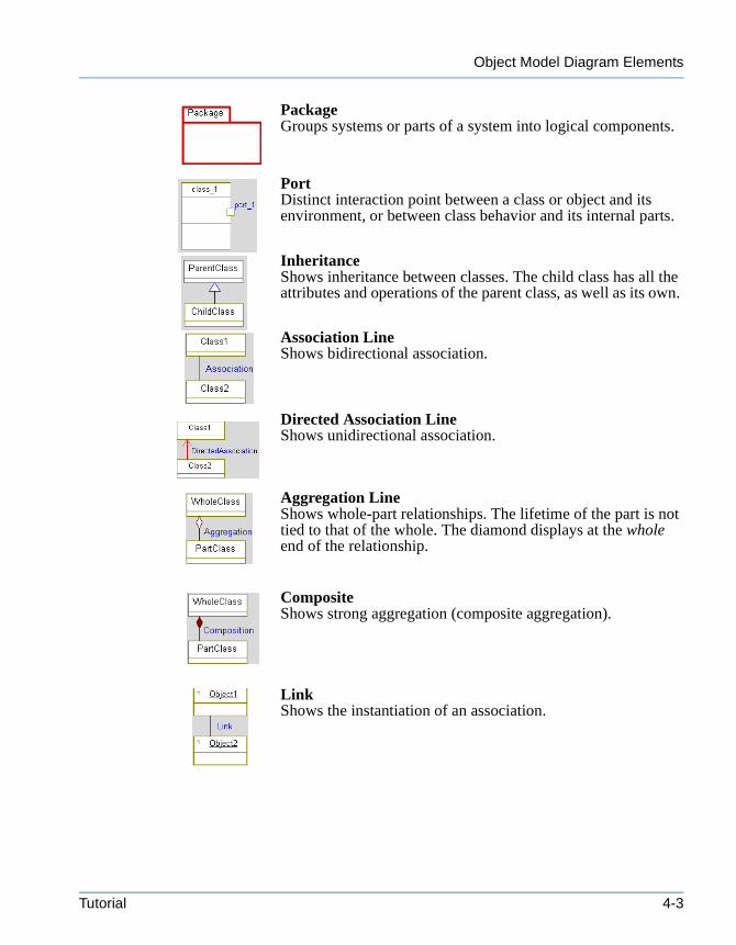
Object Model Diagram Elements
tutorialcpp.book Page 3 Thursday, April 21, 2005 4:51 PM
PackageGroups systems or parts of a system into logical components.
PortDistinct interaction point between a class or object and its environment, or between class behavior and its internal parts.
InheritanceShows inheritance between classes. The child class has all the attributes and operations of the parent class, as well as its own.
Association LineShows bidirectional association.
Directed Association LineShows unidirectional association.
Aggregation LineShows whole-part relationships. The lifetime of the part is not tied to that of the whole. The diamond displays at the whole end of the relationship.
CompositeShows strong aggregation (composite aggregation).
LinkShows the instantiation of an association.
Tutorial 4-3
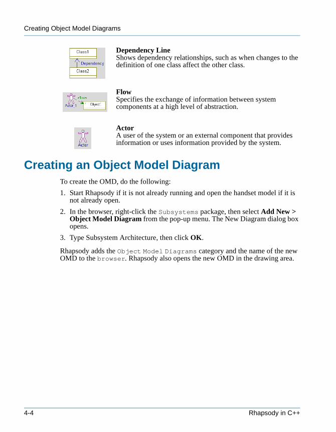
Creating Object Model Diagrams
tutorialcpp.book Page 4 Thursday, April 21, 2005 4:51 PM
Dependency LineShows dependency relationships, such as when changes to the definition of one class affect the other class.
FlowSpecifies the exchange of information between system components at a high level of abstraction.
ActorA user of the system or an external component that provides information or uses information provided by the system.
Creating an Object Model DiagramTo create the OMD, do the following:
1. Start Rhapsody if it is not already running and open the handset model if it is not already open.
2. In the browser, right-click the Subsystems package, then select Add New > Object Model Diagram from the pop-up menu. The New Diagram dialog box opens.
3. Type Subsystem Architecture, then click OK.
Rhapsody adds the Object Model Diagrams category and the name of the new OMD to the browser. Rhapsody also opens the new OMD in the drawing area.
4-4 Rhapsody in C++
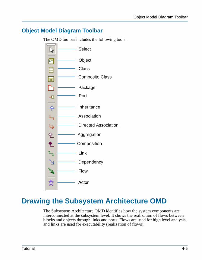
Object Model Diagram Toolbar
tutorialcpp.book Page 5 Thursday, April 21, 2005 4:51 PM
Object Model Diagram Toolbar
The OMD toolbar includes the following tools:
Drawing the Subsystem Architecture OMDThe Subsystem Architecture OMD identifies how the system components are interconnected at the subsystem level. It shows the realization of flows between blocks and objects through links and ports. Flows are used for high level analysis, and links are used for executability (realization of flows).
Select
Class
Composite Class
Package
Inheritance
Association
Directed Association
Aggregation
Dependency
Actor
Composition
Flow
Link
Port
Object
Actor
Tutorial 4-5
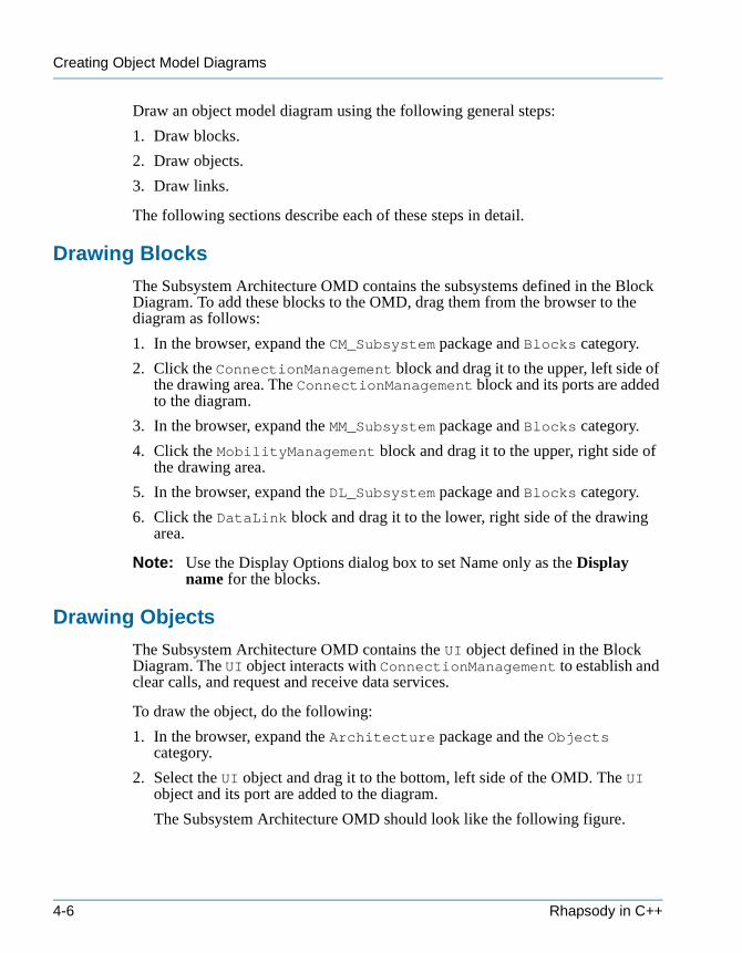
Creating Object Model Diagrams
tutorialcpp.book Page 6 Thursday, April 21, 2005 4:51 PM
Draw an object model diagram using the following general steps:
1. Draw blocks.
2. Draw objects.
3. Draw links.
The following sections describe each of these steps in detail.
Drawing Blocks
The Subsystem Architecture OMD contains the subsystems defined in the Block Diagram. To add these blocks to the OMD, drag them from the browser to the diagram as follows:
1. In the browser, expand the CM_Subsystem package and Blocks category.
2. Click the ConnectionManagement block and drag it to the upper, left side of the drawing area. The ConnectionManagement block and its ports are added to the diagram.
3. In the browser, expand the MM_Subsystem package and Blocks category.
4. Click the MobilityManagement block and drag it to the upper, right side of the drawing area.
5. In the browser, expand the DL_Subsystem package and Blocks category.
6. Click the DataLink block and drag it to the lower, right side of the drawing area.
Note: Use the Display Options dialog box to set Name only as the Display name for the blocks.
Drawing Objects
The Subsystem Architecture OMD contains the UI object defined in the Block Diagram. The UI object interacts with ConnectionManagement to establish and clear calls, and request and receive data services.
To draw the object, do the following:
1. In the browser, expand the Architecture package and the Objects category.
2. Select the UI object and drag it to the bottom, left side of the OMD. The UI object and its port are added to the diagram.
The Subsystem Architecture OMD should look like the following figure.
4-6 Rhapsody in C++
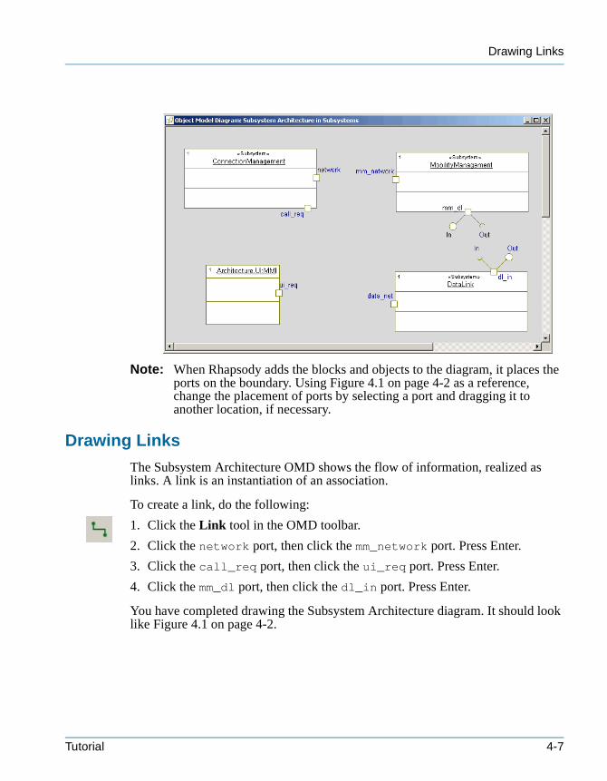
Drawing Links
tutorialcpp.book Page 7 Thursday, April 21, 2005 4:51 PM
Note: When Rhapsody adds the blocks and objects to the diagram, it places the ports on the boundary. Using Figure 4.1 on page 4-2 as a reference, change the placement of ports by selecting a port and dragging it to another location, if necessary.
Drawing Links
The Subsystem Architecture OMD shows the flow of information, realized as links. A link is an instantiation of an association.
To create a link, do the following:
1. Click the Link tool in the OMD toolbar.
2. Click the network port, then click the mm_network port. Press Enter.
3. Click the call_req port, then click the ui_req port. Press Enter.
4. Click the mm_dl port, then click the dl_in port. Press Enter.
You have completed drawing the Subsystem Architecture diagram. It should look like Figure 4.1 on page 4-2.
Tutorial 4-7

Creating Object Model Diagrams
tutorialcpp.book Page 8 Thursday, April 21, 2005 4:51 PM
SummaryIn this lesson, you created an OMD, which shows how the system components are interconnected. You became familiar with the parts of an OMD and added the following elements:• Blocks• Objects• Links
You are now ready to proceed to the next lesson, where you will define the message exchange between subsystems and subsystem functions when placing a call using sequence diagrams.
Note: Before proceeding to the next lesson, you can build and animate the parts of the model you created. This lets you determine whether the model meets the requirements, and identify defects early on in the design process. See Chapter 8, Animating the Model for more information.
4-8 Rhapsody in C++
tutorialcpp.book Page 1 Thursday, April 21, 2005 4:51 PM
Creating Sequence Diagrams 5
Sequence diagrams (SDs) describe how structural elements communicate with one another over time, and identify the required relationships and messages. SDs can be used at different levels of abstraction. At higher levels of abstractions, SDs show the interactions between actors, use cases, and blocks. At lower levels of abstraction and for implementation, SDs show the communication between classes and objects.
Sequence diagrams have an executable aspect and are a key animation tool. When you animate a model, Rhapsody dynamically builds SDs that record the object-to-object or block-to-block messaging.
In this lesson, you will create the following sequence diagrams:• Place Call Request Successful—Identifies the message exchange when
placing a call• NetworkConnect—Identifies the scenario of connecting to the network• Connection Management Place Call Request Success—Identifies the
message exchange between functions when placing a call
For ease of presentation, this chapter includes all sequence diagrams. Depending on your workflow, you might first identify the high-level communication scenario of placing a call and then refine the high-level structure diagram, before defining the communication scenarios of the functions.
Goals for this LessonIn this lesson, you will perform the following:• Creating a Sequence Diagram, page 5-3• Drawing the Place Call Request Successful Diagram, page 5-5• Drawing the NetworkConnect Diagram, page 5-9• Drawing the Connection Management Place Call Request Success SD,
page 5-11
Tutorial 5-1

Creating Sequence Diagrams
tutorialcpp.book Page 2 Thursday, April 21, 2005 4:51 PM
OverviewSequence diagrams show the interactions and relationships between classifiers or structural elements over time. The following figure shows the Place Call Request Successful diagram you will create in this lesson.
Figure 5.1 Place Call Request Successful
Rhapsody separates sequence diagrams into a names pane and a message pane. The names pane contains the name of each instance line or classifier role. The message pane contains the elements that make up the interaction.
Sequence Diagram Elements
Sequence diagrams can have the following parts:
Instance LineThe classifier or structural element participating in a scenario over time (in which time advances in a downward direction).
Message ArrowA message passed between instance lines. When realized, a message can be either a simple operation, triggered operation, or asynchronous event.
Names pane
Message pane
5-2 Rhapsody in C++
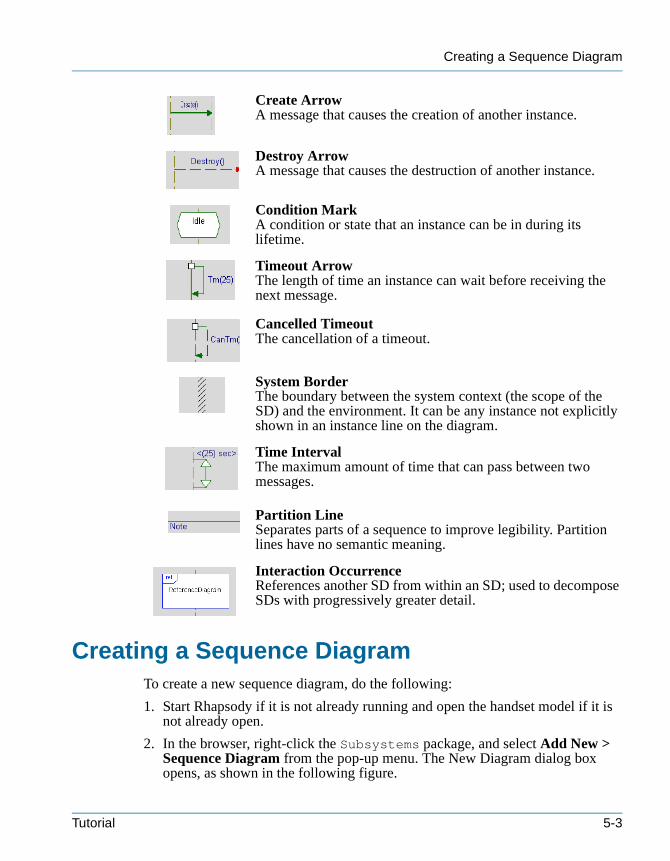
Creating a Sequence Diagram
tutorialcpp.book Page 3 Thursday, April 21, 2005 4:51 PM
Create ArrowA message that causes the creation of another instance.
Destroy ArrowA message that causes the destruction of another instance.
Condition MarkA condition or state that an instance can be in during its lifetime.
Timeout ArrowThe length of time an instance can wait before receiving the next message.
Cancelled TimeoutThe cancellation of a timeout.
System BorderThe boundary between the system context (the scope of the SD) and the environment. It can be any instance not explicitly shown in an instance line on the diagram.
Time IntervalThe maximum amount of time that can pass between two messages.
Partition LineSeparates parts of a sequence to improve legibility. Partition lines have no semantic meaning.
Interaction OccurrenceReferences another SD from within an SD; used to decompose SDs with progressively greater detail.
Creating a Sequence DiagramTo create a new sequence diagram, do the following:
1. Start Rhapsody if it is not already running and open the handset model if it is not already open.
2. In the browser, right-click the Subsystems package, and select Add New > Sequence Diagram from the pop-up menu. The New Diagram dialog box opens, as shown in the following figure.
Tutorial 5-3

Creating Sequence Diagrams
tutorialcpp.book Page 4 Thursday, April 21, 2005 4:51 PM
3. Type Place Call Request Successful.
4. Select Design for the Operation Mode.
Rhapsody enables you to create sequence diagrams in two modes:
• In analysis mode, you draw message sequences without adding elements to the model. This enables you to brainstorm your analysis and design without affecting the generated source code. Once the design is finalized, you can realize the instance lines and messages so that they display in the browser, and can have code generated for them.
• In design mode, every instance line and message you create or rename can be realized as an element (class, object, operation, or event) that appears in the browser, and for which code can be generated. When you draw a message, Rhapsody will ask if you want to realize it. Click Yes to realize the message.
5. Click OK to dismiss the dialog box.
Rhapsody automatically creates the Sequence Diagrams category in the Subsystems package, and adds the name of the new SD. In addition, Rhapsody opens the new diagram in the drawing area.
Note: You can also create a sequence diagram using the Tools menu or Diagram toolbar. See the User Guide for more information
5-4 Rhapsody in C++
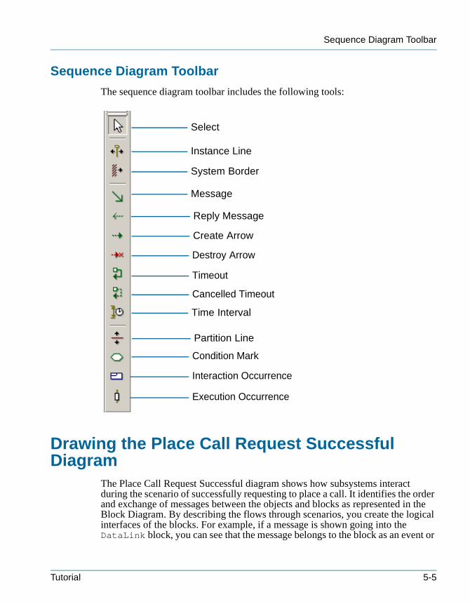
Sequence Diagram Toolbar
tutorialcpp.book Page 5 Thursday, April 21, 2005 4:51 PM
Sequence Diagram Toolbar
The sequence diagram toolbar includes the following tools:
Drawing the Place Call Request Successful Diagram
The Place Call Request Successful diagram shows how subsystems interact during the scenario of successfully requesting to place a call. It identifies the order and exchange of messages between the objects and blocks as represented in the Block Diagram. By describing the flows through scenarios, you create the logical interfaces of the blocks. For example, if a message is shown going into the DataLink block, you can see that the message belongs to the block as an event or
Select
Instance Line
System Border
Message
Create Arrow
Destroy Arrow
Timeout
Cancelled Timeout
Time Interval
Partition Line
Condition Mark
Interaction Occurrence
Reply Message
Execution Occurrence
Tutorial 5-5
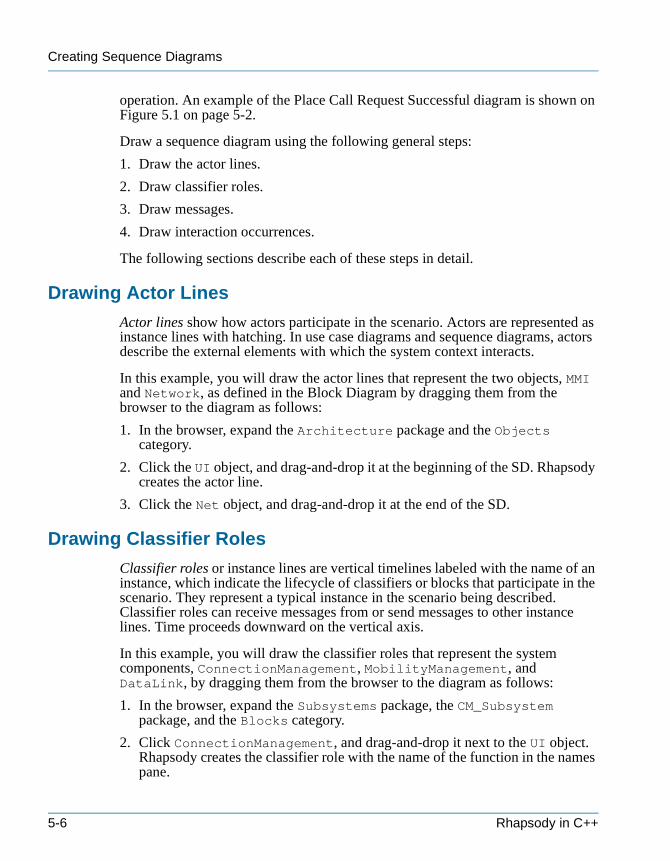
Creating Sequence Diagrams
tutorialcpp.book Page 6 Thursday, April 21, 2005 4:51 PM
operation. An example of the Place Call Request Successful diagram is shown on Figure 5.1 on page 5-2.
Draw a sequence diagram using the following general steps:
1. Draw the actor lines.
2. Draw classifier roles.
3. Draw messages.
4. Draw interaction occurrences.
The following sections describe each of these steps in detail.
Drawing Actor Lines
Actor lines show how actors participate in the scenario. Actors are represented as instance lines with hatching. In use case diagrams and sequence diagrams, actors describe the external elements with which the system context interacts.
In this example, you will draw the actor lines that represent the two objects, MMI and Network, as defined in the Block Diagram by dragging them from the browser to the diagram as follows:
1. In the browser, expand the Architecture package and the Objects category.
2. Click the UI object, and drag-and-drop it at the beginning of the SD. Rhapsody creates the actor line.
3. Click the Net object, and drag-and-drop it at the end of the SD.
Drawing Classifier Roles
Classifier roles or instance lines are vertical timelines labeled with the name of an instance, which indicate the lifecycle of classifiers or blocks that participate in the scenario. They represent a typical instance in the scenario being described. Classifier roles can receive messages from or send messages to other instance lines. Time proceeds downward on the vertical axis.
In this example, you will draw the classifier roles that represent the system components, ConnectionManagement, MobilityManagement, and DataLink, by dragging them from the browser to the diagram as follows:
1. In the browser, expand the Subsystems package, the CM_Subsystem package, and the Blocks category.
2. Click ConnectionManagement, and drag-and-drop it next to the UI object. Rhapsody creates the classifier role with the name of the function in the names pane.
5-6 Rhapsody in C++
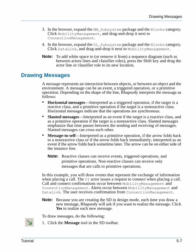
Drawing Messages
tutorialcpp.book Page 7 Thursday, April 21, 2005 4:51 PM
3. In the browser, expand the MM_Subsystem package and the Blocks category. Click MobilityManagement, and drag-and-drop it next to ConnectionManagement.
4. In the browser, expand the DL_Subsystem package and the Blocks category. Click DataLink, and drag-and-drop it next to MobilityManagement.
Note: To add white space to (or remove it from) a sequence diagram (such as between actors lines and classifier roles), press the Shift key and drag the actor line or classifier role to its new location.
Drawing Messages
A message represents an interaction between objects, or between an object and the environment. A message can be an event, a triggered operation, or a primitive operation. Depending on the shape of the line, Rhapsody interprets the message as follows:• Horizontal messages—Interpreted as a triggered operation, if the target is a
reactive class, and a primitive operation if the target is a nonreactive class. Horizontal messages indicate that the operations are synchronous.
• Slanted messages—Interpreted as an event if the target is a reactive class, and as a primitive operation if the target is a nonreactive class. Slanted messages emphasize that time passes between the sending and receiving of messages. Slanted messages can cross each other.
• Message-to-self—Interpreted as a primitive operation, if the arrow folds back to a nonreactive class or if the arrow folds back immediately; interpreted as an event if the arrow folds back sometime later. The arrow can be on either side of the instance line.
Note: Reactive classes can receive events, triggered operations, and primitive operations. Non-reactive classes can receive only messages that are calls to primitive operations.
In this example, you will draw events that represent the exchange of information when placing a call. The UI actor issues a request to connect when placing a call. Call and connect confirmations occur between MobilityManagement and ConnectionManagement. Alerts occur between MobilityManagement and DataLink. The user receives confirmation from ConnectionManagement.
Note: Because you are creating the SD in design mode, each time you draw a new message, Rhapsody will ask if you want to realize the message. Click Yes to realize each new message.
To draw messages, do the following:
1. Click the Message tool in the SD toolbar.
Tutorial 5-7
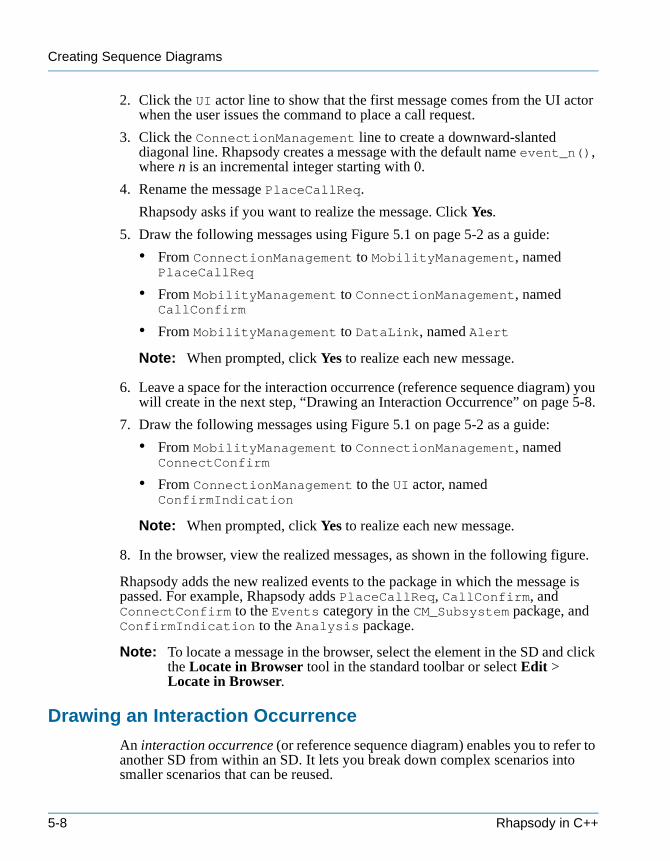
Creating Sequence Diagrams
tutorialcpp.book Page 8 Thursday, April 21, 2005 4:51 PM
2. Click the UI actor line to show that the first message comes from the UI actor when the user issues the command to place a call request.
3. Click the ConnectionManagement line to create a downward-slanted diagonal line. Rhapsody creates a message with the default name event_n(), where n is an incremental integer starting with 0.
4. Rename the message PlaceCallReq.
Rhapsody asks if you want to realize the message. Click Yes.
5. Draw the following messages using Figure 5.1 on page 5-2 as a guide:
• From ConnectionManagement to MobilityManagement, named PlaceCallReq
• From MobilityManagement to ConnectionManagement, named CallConfirm
• From MobilityManagement to DataLink, named Alert
Note: When prompted, click Yes to realize each new message.
6. Leave a space for the interaction occurrence (reference sequence diagram) you will create in the next step, “Drawing an Interaction Occurrence” on page 5-8.
7. Draw the following messages using Figure 5.1 on page 5-2 as a guide:
• From MobilityManagement to ConnectionManagement, named ConnectConfirm
• From ConnectionManagement to the UI actor, named ConfirmIndication
Note: When prompted, click Yes to realize each new message.
8. In the browser, view the realized messages, as shown in the following figure.
Rhapsody adds the new realized events to the package in which the message is passed. For example, Rhapsody adds PlaceCallReq, CallConfirm, and ConnectConfirm to the Events category in the CM_Subsystem package, and ConfirmIndication to the Analysis package.
Note: To locate a message in the browser, select the element in the SD and click the Locate in Browser tool in the standard toolbar or select Edit > Locate in Browser.
Drawing an Interaction Occurrence
An interaction occurrence (or reference sequence diagram) enables you to refer to another SD from within an SD. It lets you break down complex scenarios into smaller scenarios that can be reused.
5-8 Rhapsody in C++

Drawing the NetworkConnect Diagram
tutorialcpp.book Page 9 Thursday, April 21, 2005 4:51 PM
To draw an interaction occurrence, do the following:
1. Click the Interaction Occurrence tool in the SD toolbar.
2. Draw the interaction occurrence below the Alert message and across the MobilityManagement instance line and the Net actor line. The interaction occurrence appears as a box with the ref label in the top corner.
3. Type NetworkConnect. You will draw the NetworkConnect diagram in the next section, “Drawing the NetworkConnect Diagram” on page 5-9.
You have completed drawing the Place Call Request Successful SD. It should look like Figure 5.1 on page 5-2.
Drawing the NetworkConnect DiagramThe NetworkConnect SD shows the scenario of connecting to the network when placing a call. It is a generic interaction that can be reused within voice, data, supplementary services, and short message services. The following figure shows the NetworkConnect SD you will create in this lesson.
Figure 5.2 NetworkConnect
Tutorial 5-9
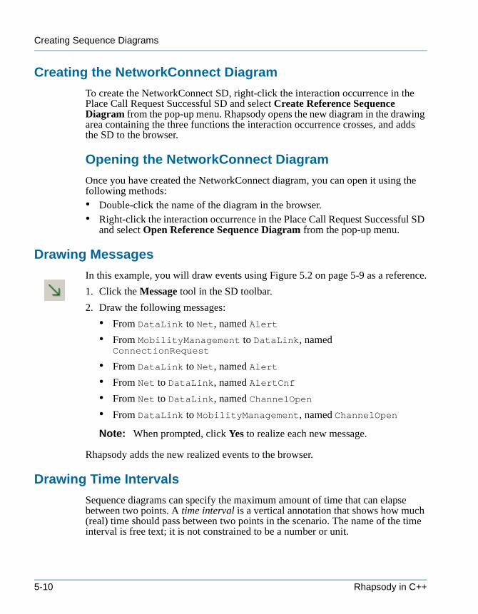
Creating Sequence Diagrams
tutorialcpp.book Page 10 Thursday, April 21, 2005 4:51 PM
Creating the NetworkConnect Diagram
To create the NetworkConnect SD, right-click the interaction occurrence in the Place Call Request Successful SD and select Create Reference Sequence Diagram from the pop-up menu. Rhapsody opens the new diagram in the drawing area containing the three functions the interaction occurrence crosses, and adds the SD to the browser.
Opening the NetworkConnect Diagram
Once you have created the NetworkConnect diagram, you can open it using the following methods:• Double-click the name of the diagram in the browser.• Right-click the interaction occurrence in the Place Call Request Successful SD
and select Open Reference Sequence Diagram from the pop-up menu.
Drawing Messages
In this example, you will draw events using Figure 5.2 on page 5-9 as a reference.
1. Click the Message tool in the SD toolbar.
2. Draw the following messages:
• From DataLink to Net, named Alert
• From MobilityManagement to DataLink, named ConnectionRequest
• From DataLink to Net, named Alert
• From Net to DataLink, named AlertCnf
• From Net to DataLink, named ChannelOpen
• From DataLink to MobilityManagement, named ChannelOpen
Note: When prompted, click Yes to realize each new message.
Rhapsody adds the new realized events to the browser.
Drawing Time Intervals
Sequence diagrams can specify the maximum amount of time that can elapse between two points. A time interval is a vertical annotation that shows how much (real) time should pass between two points in the scenario. The name of the time interval is free text; it is not constrained to be a number or unit.
5-10 Rhapsody in C++
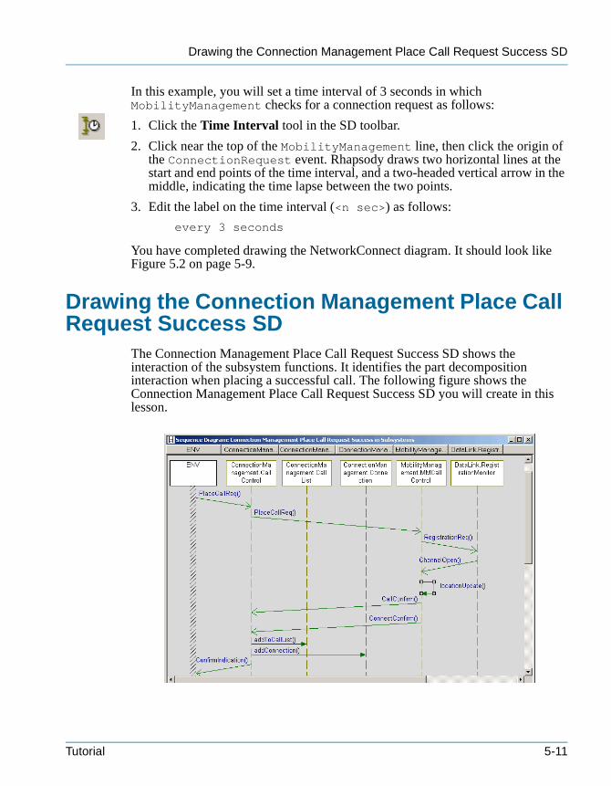
Drawing the Connection Management Place Call Request Success SD
tutorialcpp.book Page 11 Thursday, April 21, 2005 4:51 PM
In this example, you will set a time interval of 3 seconds in which MobilityManagement checks for a connection request as follows:
1. Click the Time Interval tool in the SD toolbar.
2. Click near the top of the MobilityManagement line, then click the origin of the ConnectionRequest event. Rhapsody draws two horizontal lines at the start and end points of the time interval, and a two-headed vertical arrow in the middle, indicating the time lapse between the two points.
3. Edit the label on the time interval (<n sec>) as follows:
every 3 seconds
You have completed drawing the NetworkConnect diagram. It should look like Figure 5.2 on page 5-9.
Drawing the Connection Management Place Call Request Success SD
The Connection Management Place Call Request Success SD shows the interaction of the subsystem functions. It identifies the part decomposition interaction when placing a successful call. The following figure shows the Connection Management Place Call Request Success SD you will create in this lesson.
Tutorial 5-11
Creating Sequence Diagrams
tutorialcpp.book Page 12 Thursday, April 21, 2005 4:51 PM
Figure 5.3 Connection Management Place Call Request Success
Creating the Connection Management Place Call Request Success SD
Because the Connection Management Place Call Request Success SD identifies how the modules communicate, you will create it in the Modules package as follows.
1. In the browser, expand the Subsystems package, then right-click Sequence Diagrams and select Add New Sequence Diagram from the pop-up menu. The New Diagram dialog box opens.
2. Type Connection Management Place Call Request Success.
3. Select Design for the Operation Mode.
4. Click OK to dismiss the dialog box.
Rhapsody creates the Sequence Diagrams category, and adds the name of the new SD. In addition, Rhapsody opens the new diagram in the drawing area.
Drawing the System Border
The system border represents the environment and is shown as a column of diagonal lines. Events or operations that do not come from instance lines are drawn from the system border. You can place a system border anywhere an instance line can be placed; the most usual locations are the left or right side of the SD.
To draw the system border, do the following:
1. Click the System border tool in the SD toolbar.
2. Click on the left side of the diagram to place the border.
Drawing Classifier Roles
In this example, you will draw the classifier roles that represent the internal functions of the subsystems by dragging elements from the browser to the SD as follows:
1. In the browser, expand the ConnectionManagement block and the Parts category.
2. Click CallControl and drag-and-drop it next to the system border. Rhapsody creates the classifier role with the name of the function in the names pane.
3. Click CallList and drag-and-drop it next to CallControl.
5-12 Rhapsody in C++

Drawing Messages
tutorialcpp.book Page 13 Thursday, April 21, 2005 4:51 PM
4. Click Connection and drag-and-drop it next to CallList.
5. In the browser, expand the MobilityManagement block and the Parts category.
6. Click MMCallControl and drag-and-drop it next to Connection.
7. In the browser, expand the DataLink block and the Parts category.
8. Click RegistrationMonitor and drag-and-drop it next to MMCallControl.
The Connection Management Place Request Success SD should look like the following figure.
Names that are too long to fit in the pane continue past the divider, and behind the lower pane. To view the names, enlarge the size of the names pane or change the font or font size.
Drawing Messages
When the system receives a request to place a call, it validates and registers the user; once registered, it monitors the user’s location. The call and connection are confirmed, the connection is set up, and confirmation is provided.
In this example, you will draw events using slanted lines, and primitive operations using horizontal lines and messages-to-self using Figure 5.3 on page 5-12 as a reference. When prompted, click Yes to realize each new message.
To draw messages, do the following:
1. Click the Message tool in the SD toolbar.
2. Draw the following events using slanted lines:
• From the system border to the CallControl line, named PlaceCallReq
Tutorial 5-13
Creating Sequence Diagrams
tutorialcpp.book Page 14 Thursday, April 21, 2005 4:51 PM
• From CallControl to MMCallControl, named PlaceCallReq
• From MMCallControl to RegistrationMonitor, named RegistrationReq
• From RegistrationMonitor to MMCallControl, named ChannelOpen
3. Draw a message-to-self on the MMCallControl instance line, named locationUpdate.
Note: Message names are case-sensitive.
4. Draw the following events:
• From MMCallControl to CallControl, named CallConfirm
• From MMCallControl to CallControl, named ConnectConfirm
5. Draw the following primitive operations using horizontal lines:
• From CallControl to CallList, named addToCallList
• From CallControl to Connection, named addConnection
6. Draw an event from CallControl to the system border, named ConfirmIndication.
Rhapsody adds the new realized events and primitive operations to the part to which the message is passed. For example, Rhapsody adds locationUpdate to the Operations category in the MMCallControl part.
Setting the Features of locationUpdate
In this example, you will set the return type and implementation for locationUpdate as follows:
1. Double-click locationUpdate, or right-click and select Features from the pop-up menu. The features dialog box opens.
2. Click the features button next to the Realization field. The Primitive Operations dialog box opens.
3. In the Returns group box, clear Use existing type and type bool as the C++ Declaration, as shown in the following figure.
5-14 Rhapsody in C++
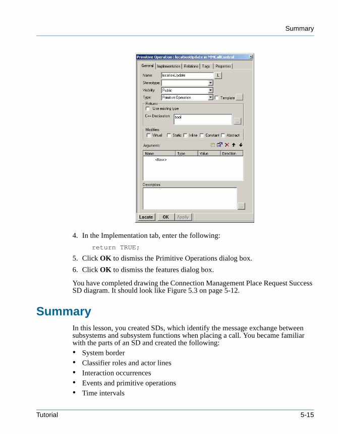
Summary
tutorialcpp.book Page 15 Thursday, April 21, 2005 4:51 PM
4. In the Implementation tab, enter the following:
return TRUE;
5. Click OK to dismiss the Primitive Operations dialog box.
6. Click OK to dismiss the features dialog box.
You have completed drawing the Connection Management Place Request Success SD diagram. It should look like Figure 5.3 on page 5-12.
SummaryIn this lesson, you created SDs, which identify the message exchange between subsystems and subsystem functions when placing a call. You became familiar with the parts of an SD and created the following:• System border• Classifier roles and actor lines• Interaction occurrences• Events and primitive operations• Time intervals
Tutorial 5-15
Creating Sequence Diagrams
tutorialcpp.book Page 16 Thursday, April 21, 2005 4:51 PM
• Timeouts
You are now ready to proceed to the next lesson, where you will identify the functional flow of users placing a call and registering users on the network using activity diagrams.
Note: Before proceeding to the next lesson, you can generate code and animate the parts of the model you have created. This lets you determine whether the model meets the requirements, and identify defects early on in the design process. See Chapter 8, Animating the Model for more information.
5-16 Rhapsody in C++
tutorialcpp.book Page 1 Thursday, April 21, 2005 4:51 PM
Creating Activity Diagrams 6
Activity diagrams show the dynamic aspects of a system and the flow of control from activity to activity. They describe the essential interactions between the system and the environment, and the interconnections of behaviors for which the subsystems or components are responsible. They can also be used to model an operation or the details of a computation. In addition, you can animate activity diagrams to verify the functional flow.
In this lesson, you will create the following activity diagrams:• MMCallControl—Identifies the functional flow of users placing a call, which
includes registering users on the network, providing their current location, and obtaining an acceptable signal strength
• InCall—Identifies the flow of information once the system connects the call • RegistrationMonitor—Identifies the functional flow of registering users on
the network, which includes monitoring registration requests and sending received requests to the network
Goals for this LessonIn this lesson, you will perform the following:• Creating an Activity Diagram, page 6-4• Drawing the MMCallControl Activity Diagram, page 6-6• Drawing the InCall Subactivity Diagram, page 6-12• Drawing the RegistrationMonitor Activity Diagram, page 6-15
Tutorial 6-1
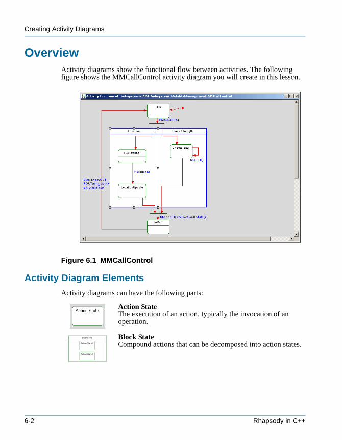
Creating Activity Diagrams
tutorialcpp.book Page 2 Thursday, April 21, 2005 4:51 PM
OverviewActivity diagrams show the functional flow between activities. The following figure shows the MMCallControl activity diagram you will create in this lesson.
Figure 6.1 MMCallControl
Activity Diagram Elements
Activity diagrams can have the following parts:
Action StateThe execution of an action, typically the invocation of an operation.
Block StateCompound actions that can be decomposed into action states.
6-2 Rhapsody in C++
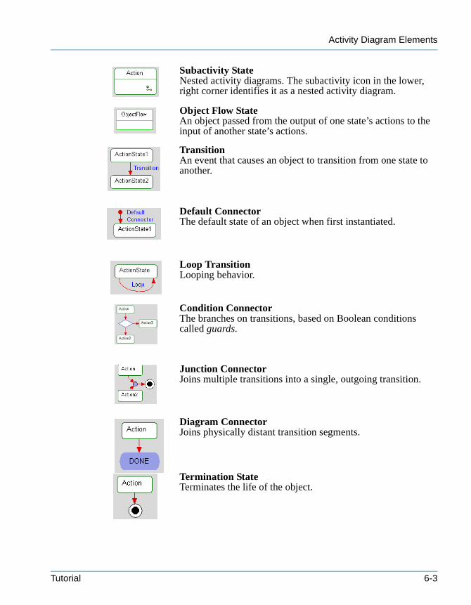
Activity Diagram Elements
tutorialcpp.book Page 3 Thursday, April 21, 2005 4:51 PM
Subactivity StateNested activity diagrams. The subactivity icon in the lower, right corner identifies it as a nested activity diagram.
Object Flow StateAn object passed from the output of one state’s actions to the input of another state’s actions.
TransitionAn event that causes an object to transition from one state to another.
Default ConnectorThe default state of an object when first instantiated.
Loop TransitionLooping behavior.
Condition ConnectorThe branches on transitions, based on Boolean conditions called guards.
Junction ConnectorJoins multiple transitions into a single, outgoing transition.
Diagram ConnectorJoins physically distant transition segments.
Termination StateTerminates the life of the object.
Tutorial 6-3
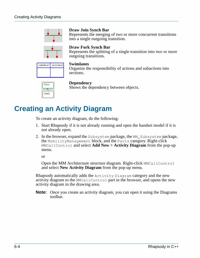
Creating Activity Diagrams
tutorialcpp.book Page 4 Thursday, April 21, 2005 4:51 PM
Draw Join Synch BarRepresents the merging of two or more concurrent transitions into a single outgoing transition.
Draw Fork Synch BarRepresents the splitting of a single transition into two or more outgoing transitions.
SwimlanesOrganize the responsibility of actions and subactions into sections.
DependencyShows the dependency between objects.
Creating an Activity DiagramTo create an activity diagram, do the following:
1. Start Rhapsody if it is not already running and open the handset model if it is not already open.
2. In the browser, expand the Subsystem package, the MM_Subsystem package, the MobilityManagement block, and the Parts category. Right-click MMCallControl and select Add New > Activity Diagram from the pop-up menu.
or
Open the MM Architecture structure diagram. Right-click MMCallControl and select New Activity Diagram from the pop-up menu.
Rhapsody automatically adds the Activity Diagram category and the new activity diagram to the MMCallControl part in the browser, and opens the new activity diagram in the drawing area.
Note: Once you create an activity diagram, you can open it using the Diagrams toolbar.
6-4 Rhapsody in C++
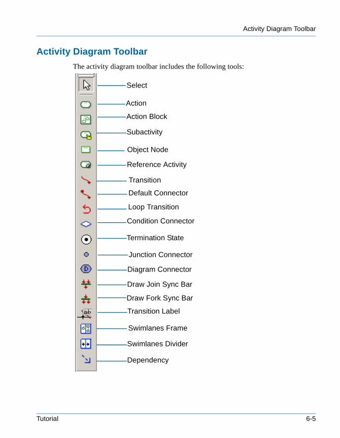
Activity Diagram Toolbar
tutorialcpp.book Page 5 Thursday, April 21, 2005 4:51 PM
Activity Diagram Toolbar
The activity diagram toolbar includes the following tools:
Select
Action
Action Block
Default Connector
Object Node
Condition Connector
Reference Activity
Loop Transition
Junction Connector
Diagram Connector
Draw Join Sync Bar
Draw Fork Sync Bar
Transition Label
Termination State
Dependency
Swimlanes Divider
Swimlanes Frame
Subactivity
Transition
Tutorial 6-5
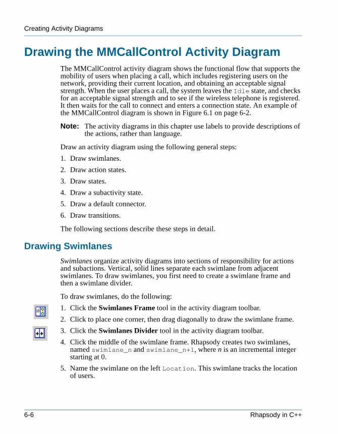
Creating Activity Diagrams
tutorialcpp.book Page 6 Thursday, April 21, 2005 4:51 PM
Drawing the MMCallControl Activity DiagramThe MMCallControl activity diagram shows the functional flow that supports the mobility of users when placing a call, which includes registering users on the network, providing their current location, and obtaining an acceptable signal strength. When the user places a call, the system leaves the Idle state, and checks for an acceptable signal strength and to see if the wireless telephone is registered. It then waits for the call to connect and enters a connection state. An example of the MMCallControl diagram is shown in Figure 6.1 on page 6-2.
Note: The activity diagrams in this chapter use labels to provide descriptions of the actions, rather than language.
Draw an activity diagram using the following general steps:
1. Draw swimlanes.
2. Draw action states.
3. Draw states.
4. Draw a subactivity state.
5. Draw a default connector.
6. Draw transitions.
The following sections describe these steps in detail.
Drawing Swimlanes
Swimlanes organize activity diagrams into sections of responsibility for actions and subactions. Vertical, solid lines separate each swimlane from adjacent swimlanes. To draw swimlanes, you first need to create a swimlane frame and then a swimlane divider.
To draw swimlanes, do the following:
1. Click the Swimlanes Frame tool in the activity diagram toolbar.
2. Click to place one corner, then drag diagonally to draw the swimlane frame.
3. Click the Swimlanes Divider tool in the activity diagram toolbar.
4. Click the middle of the swimlane frame. Rhapsody creates two swimlanes, named swimlane_n and swimlane_n+1, where n is an incremental integer starting at 0.
5. Name the swimlane on the left Location. This swimlane tracks the location of users.
6-6 Rhapsody in C++
Drawing Action States
tutorialcpp.book Page 7 Thursday, April 21, 2005 4:51 PM
6. Name the swimlane on the right SignalStrength. This swimlane tracks the signal strength of users.
Drawing Action States
Action states represent function invocations with a single exit transition when the function completes. In this example, you will draw the action states that represent the functional processes, and then add names to the action states.
Note: You add names to action states using the features dialog box. When you draw an action state and type a name in the action state on the diagram, that name becomes the action, not the name of the action.
To draw action states, do the following:
1. Click the Action tool in the activity diagram toolbar.
2. In the top section of the drawing area, click or click-and-drag to create an action state, then press Ctrl+Enter.
3. Click the action state, or right-click and select Features from the pop-up menu. The features dialog box opens.
4. Type Idle in the Name field. This indicates that no call is in progress.
5. Click OK to apply the changes and dismiss the features dialog box.
Note: For each action state, set the display options to Name to show the action state name on the diagram.
6. In the lower section of the Location swimlane, draw an action state, then press Ctrl+Enter.
7. Double-click the action state, or right-click and select Features from the pop-up menu. The features dialog box opens.
8. Type LocationUpdate in the Name field. Then click OK.
9. In the SignalStrength swimlane draw an action state, then press Ctrl+Enter.
10.Double-click the action state, or right-click and select Features from the pop-up menu. The features dialog box opens.
11.Type CheckSignal in the Name field. Then click OK.
12.Click the Action tool.
13.Click or click-and-drag above LocationUpdate in the Location swimlane.
14.Type Registering, then press Ctrl+Enter.
Tutorial 6-7

Creating Activity Diagrams
tutorialcpp.book Page 8 Thursday, April 21, 2005 4:51 PM
Defining an Action
To define an action, do the following:
1. Double-click the Registering action state, or right-click and select Features from the pop-up menu. The features dialog box opens.
2. Type the following in the Action field:
OUT_PORT(mm_cc)->GEN(RegistrationReq);
This command sends an asynchronous message out the mm_cc port for registration requests.
The features dialog box should look like the following figure.
3. Click OK to apply the changes and close the dialog box.
Drawing a Default Connector
One of an object’s states must be the default state. This is the initial state of the object. Idle is in the default state as it waits for call requests.
To draw a default connector, do the following:
1. Click the Default connector tool in the activity diagram toolbar.
2. Click to the right of the Idle action state, then click its edge. Press Ctrl+Enter.
6-8 Rhapsody in C++
Drawing a Subactivity State
tutorialcpp.book Page 9 Thursday, April 21, 2005 4:51 PM
Drawing a Subactivity State
A subactivity state represents the execution of a non-atomic sequence of steps nested within another activity. It looks like an action state with a subactivity icon in its lower, right corner, depicting a nested activity diagram.
In this example, you will draw the InCall subactivity state, which indicates that the call has been established, as follows:
1. Click the Subactivity State tool in the activity diagram toolbar.
2. In the bottom section of the drawing area, click or click-and-drag.
3. Type InCall, then press Ctrl+Enter.
In the subsequent section, “Drawing the InCall Subactivity Diagram” on page 6-12, you will open and draw the InCall subactivity diagram.
Drawing Transitions
Transitions represent the response to a message in a given state. They show what the next state will be. In this example, you will draw the following transitions:• Transitions between states• Fork and join transitions• Timeout transition
Note: To change the line shape of a transition, right-click the line, select Line Shape from the pop-up menu, and then Straight, Spline, Rectilinear, or Reroute.
Drawing Transitions Between States
In this example, you will draw two transitions: one named Disconnect, and one with the label Registering.
To draw transitions between states, do the following:
1. Click the Transition tool in the toolbar.
2. Click the InCall subactivity state, then click the Idle state.
3. Type the name Disconnect, then press Ctrl+Enter.
4. Draw a transition from Registering to LocationUpdate, then press Ctrl+Enter.
Tutorial 6-9
Creating Activity Diagrams
tutorialcpp.book Page 10 Thursday, April 21, 2005 4:51 PM
Labeling Elements
Rhapsody enables you to assign a descriptive label to an element. A labeled element does not have any meaning in terms of generated code, but enables you to easily reference and locate elements in diagrams and dialog boxes. A label can have any value and does not need to be unique.
In this example, you will label the transition between Registering and LocationUpdate as follows:
1. Double-click the transition between Registering and LocationUpdate or right-click and select Features from the pop-up menu. The features dialog box opens.
2. Click the L button next to the Name field. The Name and Label dialog box opens.
3. Type Registering in the Label field.
4. Click OK to dismiss the Name and Label dialog box.
5. Click OK to dismiss the features dialog box.
Note: To display the label, right-click the transition and select Display Options > Show Label from the pop-up menu.
Drawing a Fork Synchronization
A fork synchronization represents the splitting of a single flow into two or more outgoing flows. It is shown as a bar with one incoming transition and two or more outgoing transitions.
To draw a fork synchronization bar, do the following:
1. Click the Draw Fork Synch Bar tool in the activity diagram toolbar.
2. Click or click-and-drag between the Idle action state and the swimlanes. Rhapsody adds the fork synchronization bar.
3. Click the Transition tool, and draw a single incoming transition from Idle to the synchronization bar. Type PlaceCallReq, then press Ctrl+Enter. This transition indicates that the interface has initiated a call request.
4. Draw the following outgoing transitions from the synchronization bar:
• To the Registering state, then press Ctrl+Enter
• To the CheckSignal action state, then press Ctrl+Enter
6-10 Rhapsody in C++
Drawing a Join Synchronization
tutorialcpp.book Page 11 Thursday, April 21, 2005 4:51 PM
Drawing a Join Synchronization
A join synchronization represents the merging of two or more concurrent flows into a single outgoing flow. It is shown as a bar with two or more incoming transitions and one outgoing transition.
To draw a join synchronization bar, do the following:
1. Click the Draw Join Synch Bar tool in the activity diagram toolbar.
2. Click or click-and-drag between the swimlanes and InCall. Rhapsody adds the join synchronization bar.
3. Click the Transition tool, and draw the following incoming transitions to the synchronization bar:
• From LocationUpdate, then press Ctrl+Enter
• From CheckSignal, then press Ctrl+Enter
4. Draw one outgoing transition from the synchronization bar to InCall. Type ChannelOpen, then press Ctrl+Enter. This transition indicates that the channel is open and the call can be established.
Drawing a Timeout Transition
A timeout transition causes an object to transition after a specified amount of time has passed. It is an event with the form tm(n), where n is the number of milliseconds the object should wait before making the transition.
In this example, you will draw a timeout transition that monitors the signal strength of transmissions every three seconds as follows:
1. Click the Transition tool in the toolbar.
2. Draw a transition originating and ending with CheckSignal.
3. Type tm(3000), then press Ctrl+Enter.
Specifying an Action on a Transition
In this example, you will specify actions for Disconnect and ChannelOpen as follows:
1. Double-click the Disconnect transition, or right-click and select Features from the pop-up menu. The features dialog box opens.
2. In the Action field, type the following code:
3. In the Action field, type the following code:
OUT_PORT(mm_cc)->GEN(Disconnect);
Tutorial 6-11
Creating Activity Diagrams
tutorialcpp.book Page 12 Thursday, April 21, 2005 4:51 PM
This command sends an asynchronous message out the mm_cc port when disconnecting.
4. Click OK to apply the changes and dismiss the features dialog box. Rhapsody displays the transition name with the action command.
5. Double-click the ChannelOpen transition, or right-click and select Features from the pop-up menu. The features dialog box opens.
6. In the Action field, type the following code:
locationUpdate();
7. Click OK to apply the changes and dismiss the features dialog box. Rhapsody displays the transition name with the action command.
Note: To display the transition name without the action, type the transition name as the label using the features dialog box. Then right-click the transition and select Display Options > Show Label from the pop-up menu.
You have completed drawing the MMCall Control diagram. It should look like Figure 6.1 on page 6-2. Rhapsody automatically adds the action states, states, and transitions to the MMCallControl part in the browser.
Drawing the InCall Subactivity DiagramSubactivity states represent nested activity diagrams. The InCall subactivity diagram shows the flow of information once the system connects the call. The system monitors the signal strength for voice data every 15 seconds. The following figure shows the InCall subactivity diagram you will create in this lesson.
6-12 Rhapsody in C++
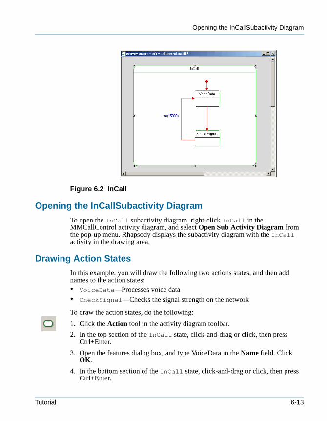
Opening the InCallSubactivity Diagram
tutorialcpp.book Page 13 Thursday, April 21, 2005 4:51 PM
Figure 6.2 InCall
Opening the InCallSubactivity Diagram
To open the InCall subactivity diagram, right-click InCall in the MMCallControl activity diagram, and select Open Sub Activity Diagram from the pop-up menu. Rhapsody displays the subactivity diagram with the InCall activity in the drawing area.
Drawing Action States
In this example, you will draw the following two actions states, and then add names to the action states:• VoiceData—Processes voice data• CheckSignal—Checks the signal strength on the network
To draw the action states, do the following:
1. Click the Action tool in the activity diagram toolbar.
2. In the top section of the InCall state, click-and-drag or click, then press Ctrl+Enter.
3. Open the features dialog box, and type VoiceData in the Name field. Click OK.
4. In the bottom section of the InCall state, click-and-drag or click, then press Ctrl+Enter.
Tutorial 6-13
Creating Activity Diagrams
tutorialcpp.book Page 14 Thursday, April 21, 2005 4:51 PM
5. Open the features dialog box, and type CheckSignal in the Name field. Click OK.
Note: For each action state, set the display options to Name to show the name on the diagram.
Defining an Action
Define an action for VoiceData as follows:
1. Double-click VoiceData, or right-click and select Features from the pop-up menu. The features dialog box opens.
2. Type the following in the Action field:
OUT_PORT(cc_in)->GEN(CallConfirm);
OUT_PORT(cc_in)->GEN(ConnectConfirm);
These commands send asynchronous messages out the cc_in port.
3. Click OK to apply the changes and close the dialog box.
Drawing a Default Connector
The subactivity diagram must have an initial state. Execution begins with the initial state when an input transition to the subactivity state is triggered.
To draw the default connector, do the following:
1. Click the Default Connector tool in the activity diagram toolbar.
2. Click above VoiceData, then click VoiceData. Press Ctrl+Enter.
Drawing Transitions
Draw a transition between Voice Data and Check Signal as follows:
1. Click the Transition tool in the toolbar.
2. Draw a transition from VoiceData to CheckSignal. Press Ctrl+Enter.
Drawing a Timeout Transition
Draw a timeout transition to check for voice data every 15 seconds as follows:
1. Click the Transition tool in the toolbar.
2. Draw a transition from CheckSignal to VoiceData.
3. Type tm(15000), then press Ctrl+Enter.
6-14 Rhapsody in C++
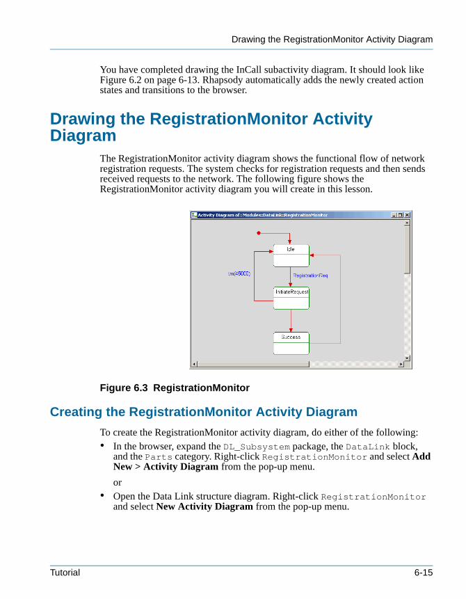
Drawing the RegistrationMonitor Activity Diagram
tutorialcpp.book Page 15 Thursday, April 21, 2005 4:51 PM
You have completed drawing the InCall subactivity diagram. It should look like Figure 6.2 on page 6-13. Rhapsody automatically adds the newly created action states and transitions to the browser.
Drawing the RegistrationMonitor Activity Diagram
The RegistrationMonitor activity diagram shows the functional flow of network registration requests. The system checks for registration requests and then sends received requests to the network. The following figure shows the RegistrationMonitor activity diagram you will create in this lesson.
Figure 6.3 RegistrationMonitor
Creating the RegistrationMonitor Activity Diagram
To create the RegistrationMonitor activity diagram, do either of the following:• In the browser, expand the DL_Subsystem package, the DataLink block,
and the Parts category. Right-click RegistrationMonitor and select Add New > Activity Diagram from the pop-up menu.
or • Open the Data Link structure diagram. Right-click RegistrationMonitor
and select New Activity Diagram from the pop-up menu.
Tutorial 6-15
Creating Activity Diagrams
tutorialcpp.book Page 16 Thursday, April 21, 2005 4:51 PM
Rhapsody adds the Activity Diagram category and the new activity diagram to the RegistrationMonitor part in the browser, and opens the new activity diagram in the drawing area.
Drawing Action States
In this example, you will draw three actions states and then add names to the action states as follows:
1. Click the Action tool in the activity diagram toolbar.
2. In the upper section of the drawing window, create an action state, then press Ctrl + Enter.
3. Open the features dialog box for this action state, and type Idle in the Name field. Click OK.
4. Create an action state below Idle, then press Ctrl + Enter.
5. Open the features dialog box, and type InitiateRequest in the Name field. Click OK.
6. Create an action state below InitiateRequest, then press Ctrl + Enter.
7. Open the features dialog box, and type Success in the Name field. Click OK.
Note: For each action state, set the display options to Name to show the name on the diagram.
Defining an Action
In this example, you will specify an action for the InitiateRequest action state as follows:
1. Double-click InitiateRequest or right-click and select Features from the pop-up menu. The features dialog box opens.
2. Type the following in the Action field:
OUT_PORT(reg_request)->GEN(ChannelOpen);
This command sends an asynchronous message out the reg_request port when the channel is open.
3. Click OK to apply the changes and close the features dialog box.
Drawing a Default Connector
Draw a default connector as follows:
1. Click the Default Connector tool in the activity diagram toolbar.
2. Click above Idle, then click Idle. Press Ctrl+Enter.
6-16 Rhapsody in C++
Drawing Transitions
tutorialcpp.book Page 17 Thursday, April 21, 2005 4:51 PM
Drawing Transitions
Draw transitions between actions states as follows:
1. Click the Transition tool in the toolbar.
2. Draw a transition from Idle to InitiateRequest. Type RegistrationReq, then press Ctrl+Enter.
3. Draw a transition from InitiateRequest to Success. Press Ctrl+Enter.
4. Draw a transition from Success to Idle. Press Ctrl+Enter.
Drawing a Timeout Transition
Draw a timeout transition to return to the Idle state after 45 seconds if no response is received from the network as follows:
1. Click the Transition tool in the toolbar.
2. Draw a transition from InitiateRequest to Idle.
3. Type the transition label tm(45000), then press Ctrl+Enter.
You have completed drawing the RegistrationMonitor diagram. It should look like Figure 6.3 on page 6-15. Rhapsody automatically adds the newly created action states and transitions to the RegistrationMonitor part in the browser.
SummaryIn this lesson, you created activity diagrams and a subactivity diagram, which show the functional flow of placing a call and registering users. You became familiar with the parts of an activity diagram and created the following:• Swimlanes• Action states• Subactivity states• Default connectors• Transitions and timeout transitions• Fork synchronization bar and join synchronization bar
You are now ready to proceed to the next lesson, where you will identify the state-based behavior when the system receives call requests and connects calls using a statechart.
Note: Before proceeding to the next lesson, you can generate code and animate the parts of the model you have created. This lets you determine whether the model meets the requirements, and identify defects early on in the
Tutorial 6-17

Creating Activity Diagrams
tutorialcpp.book Page 18 Thursday, April 21, 2005 4:51 PM
design process. See Chapter 8, Animating the Model for more information.
6-18 Rhapsody in C++

tutorialcpp.book Page 1 Thursday, April 21, 2005 4:51 PM
Creating a Statechart 7
Statecharts (SCs) define the behavior of classifiers (actors, use cases, or classes), objects, and blocks, including the states that they can enter over their lifetime and the messages, events, or operations that cause them to transition from state to state.
Statecharts are a key animation tool used to verify the functional flow and moding. Statecharts can be animated to view the design level of abstraction and graphically show dynamic behavior.
In this lesson, you will create the CallControl statechart, which identifies the state-based behavior when the system receives call requests and connects calls.
Goals for this LessonIn this lesson, you will perform the following:• Creating a Statechart, page 7-3• Drawing the CallControl Statechart, page 7-5
OverviewStatecharts define state-based behavior. The following figure shows the CallControl statechart you will create in this lesson.
Tutorial 7-1
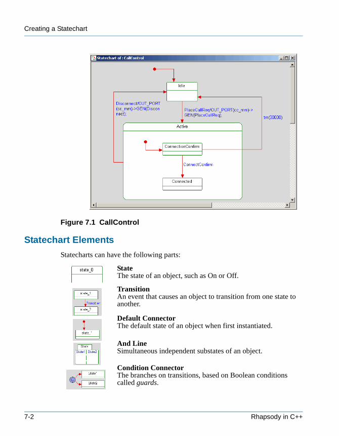
Creating a Statechart
tutorialcpp.book Page 2 Thursday, April 21, 2005 4:51 PM
Figure 7.1 CallControl
Statechart Elements
Statecharts can have the following parts:
StateThe state of an object, such as On or Off.
TransitionAn event that causes an object to transition from one state to another.
Default ConnectorThe default state of an object when first instantiated.
And LineSimultaneous independent substates of an object.
Condition ConnectorThe branches on transitions, based on Boolean conditions called guards.
7-2 Rhapsody in C++
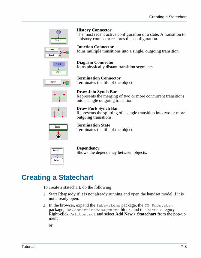
Creating a Statechart
tutorialcpp.book Page 3 Thursday, April 21, 2005 4:51 PM
History ConnectorThe most recent active configuration of a state. A transition to a history connector restores this configuration.
Junction ConnectorJoins multiple transitions into a single, outgoing transition.
Diagram ConnectorJoins physically distant transition segments.
Termination ConnectorTerminates the life of the object.
Draw Join Synch BarRepresents the merging of two or more concurrent transitions into a single outgoing transition.
Draw Fork Synch BarRepresents the splitting of a single transition into two or more outgoing transitions.
Termination StateTerminates the life of the object.
DependencyShows the dependency between objects.
Creating a StatechartTo create a statechart, do the following:
1. Start Rhapsody if it is not already running and open the handset model if it is not already open.
2. In the browser, expand the Subsystems package, the CM_Subsystem package, the ConnectionManagement block, and the Parts category. Right-click CallControl and select Add New > Statechart from the pop-up menu.
or
Tutorial 7-3
Creating a Statechart
tutorialcpp.book Page 4 Thursday, April 21, 2005 4:51 PM
Open the Connection Management structure diagram. Right-click CallControl and select New Statechart from the pop-up menu.
Rhapsody adds the Statechart category and the new statechart to the CallControl part in the browser, and opens the new statechart in the drawing area.
Note: Once you create a statechart, you can open it using the Diagrams toolbar.
7-4 Rhapsody in C++
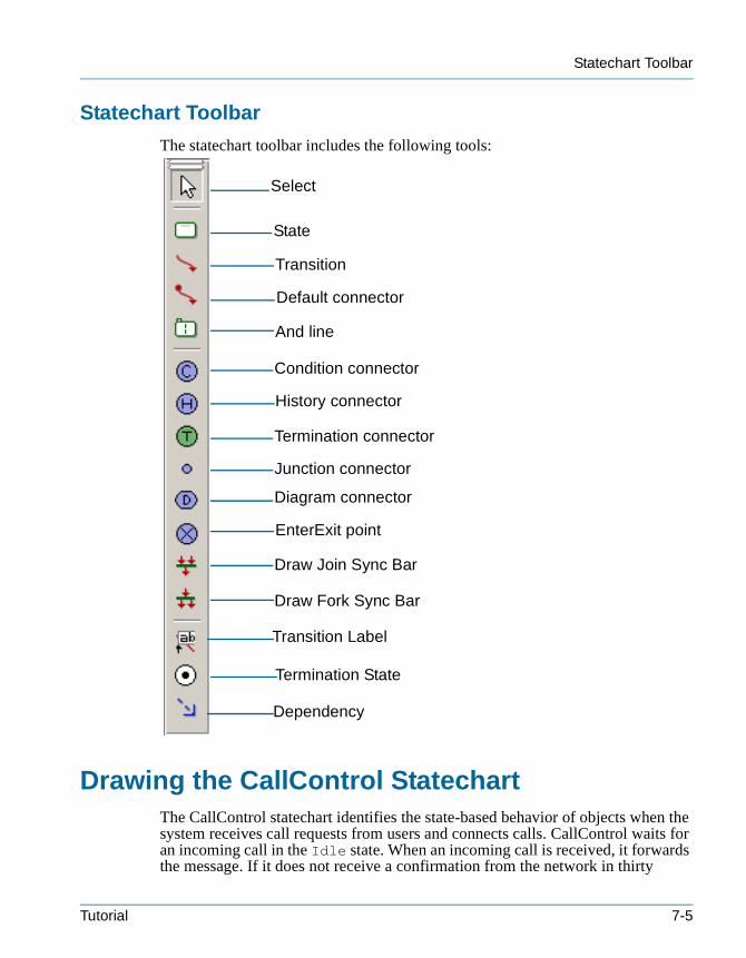
Statechart Toolbar
tutorialcpp.book Page 5 Thursday, April 21, 2005 4:51 PM
Statechart Toolbar
The statechart toolbar includes the following tools:
Drawing the CallControl StatechartThe CallControl statechart identifies the state-based behavior of objects when the system receives call requests from users and connects calls. CallControl waits for an incoming call in the Idle state. When an incoming call is received, it forwards the message. If it does not receive a confirmation from the network in thirty
Select
State
Transition
Default connector
And line
Condition connector
History connector
Termination connector
Junction connector
Diagram connector
EnterExit point
Draw Join Sync Bar
Draw Fork Sync Bar
Transition Label
Termination State
Dependency
Tutorial 7-5
Creating a Statechart
tutorialcpp.book Page 6 Thursday, April 21, 2005 4:51 PM
seconds, it returns to the Idle state. If it receives a confirmation, the call connects, and remains connected until it receives a message to disconnect.
Draw statecharts using the following general steps:
1. Draw states and nested states.
2. Draw default connectors.
3. Draw transitions and specify actions on transitions.
4. Draw timeout transitions.
The following sections describe these steps in detail.
Drawing States
A state is a graphical representation of the status of an object. It typically reflects a certain set of its internal data (attributes) and relations.
In this example, you will draw two states, Idle and Active, as follows:
1. Click the State tool in the statechart toolbar.
2. In the top section of the drawing area, click or click-and-drag. Rhapsody create a state with a default name of state_n, where n is equal to or greater than 0.
3. Type Idle, then press Enter. This state indicates that no call is in progress.
4. In the center of the drawing area, draw a larger state named Active. This state indicates that the call is being set up or is in progress.
Drawing Nested States
In this example, you will draw the following states nested inside the Active state:• ConnectionConfirm—Waits for a connection and then confirms the
connection• Connected—Connects as a voice or data call
To draw nested states, do the following:
1. Click the State tool in the statechart toolbar.
2. In the top section of the Active state, draw a state named ConnectionConfirm.
3. In the bottom section of the Active state, draw a state named Connected.
7-6 Rhapsody in C++
Drawing Default Connectors
tutorialcpp.book Page 7 Thursday, April 21, 2005 4:51 PM
Drawing Default Connectors
One of an object’s states must be the default state, that is, the state in which the object finds itself when it is first instantiated. Idle is in the default state as it waits for call requests, and Active is in the default state before it confirms the connection.
To draw default connectors, do the following:
1. Click the Default connector tool in the statechart toolbar.
2. Click to the right of the Idle state, then click Idle. Press Ctrl+Enter.
3. Draw a default connector to ConnectionConfirm. Press Ctrl+Enter.
Drawing Transitions
Transitions represent the response to a message in a given state. They show what the next state will be. A transition can have an optional trigger, guard, or action. In this example, you will draw transitions with triggers.
To draw transitions, do the following:
1. Click the Transition tool in the statechart toolbar.
2. Click the Idle state, then click the Active state.
3. In the label box, type PlaceCallReq, then press Ctrl+Enter.
4. Create a transition from ConnectionConfirm to Connected named ConnectConfirm, then press Ctrl+Enter.
5. Create a transition from the Active state to the Idle state named Disconnect, then press Ctrl+Enter. This transition indicates that the user has disconnected or the network has terminated the call.
Note: To change the line shape, right-click the line, select Line Shape from the pop-up menu, and then Straight, Spline, Rectilinear, or Reroute.
Specifying an Action on a Transition
You can specify that an object execute a specific action when it transitions from one state to another.
In this example, you will specify an action for PlaceCallReq and Disconnect as follows:
1. Double-click the PlaceCallReq transition, or right-click and select Features from the pop-up menu. The features dialog box opens.
Tutorial 7-7
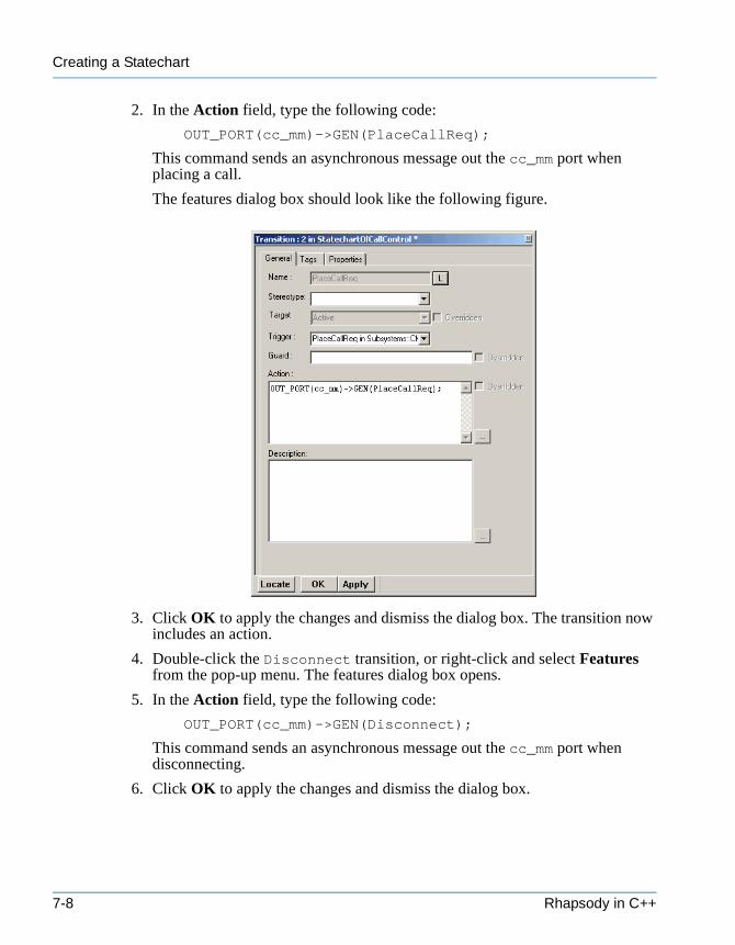
Creating a Statechart
tutorialcpp.book Page 8 Thursday, April 21, 2005 4:51 PM
2. In the Action field, type the following code:
OUT_PORT(cc_mm)->GEN(PlaceCallReq);
This command sends an asynchronous message out the cc_mm port when placing a call.
The features dialog box should look like the following figure.
3. Click OK to apply the changes and dismiss the dialog box. The transition now includes an action.
4. Double-click the Disconnect transition, or right-click and select Features from the pop-up menu. The features dialog box opens.
5. In the Action field, type the following code:
OUT_PORT(cc_mm)->GEN(Disconnect);
This command sends an asynchronous message out the cc_mm port when disconnecting.
6. Click OK to apply the changes and dismiss the dialog box.
7-8 Rhapsody in C++
Drawing a Timeout Transition
tutorialcpp.book Page 9 Thursday, April 21, 2005 4:51 PM
Drawing a Timeout Transition
A timeout transition causes an object to transition to the next state after a specified amount of time has passed. It is an event with the form tm(n), where n is the number of milliseconds the object should wait before making the transition.
In this example, you will draw a timeout transition in which ConnectionConfirm waits thirty seconds before returning to the Idle state if a connect confirmation is not made as follows:
1. Click the Transition tool in the statechart toolbar.
2. Draw a transition from ConnectionConfirm to Idle.
3. Type tm(30000), then press Ctrl+Enter.
You have completed drawing the CallControl statechart. It should look like Figure 7.1 on page 7-2. Rhapsody automatically adds the newly created states and transitions to the CallControl part in the browser.
SummaryIn this lesson, you created a statechart, which identifies the state-based behavior when the system receives call requests and connects calls. You became familiar with the parts of a statechart and created the following:• States and nested states• Default connectors• Transitions and timeout transitions
You have completed the handset model. You are now ready to proceed to the next lesson, where you will animate the model.
Tutorial 7-9

Creating a Statechart
tutorialcpp.book Page 10 Thursday, April 21, 2005 4:51 PM
7-10 Rhapsody in C++
tutorialcpp.book Page 1 Thursday, April 21, 2005 4:51 PM
Animating the Model 8
Rhapsody enables you to animate the model using model execution, rather than just simulating it. Animation is the execution of behaviors and associated definitions in the model. Rhapsody animates the model by executing the code generated with instrumentation for classes, operations, and associations. Once you animate the model, you can open animated diagrams, which let you observe the model as it is running and perform design-level debugging. You can step through the model, set and clear breakpoints, inject events, and generate an output trace.
It is good practice to incrementally test the model using model execution. You can animate pieces of the model as it is developed. This enables you to determine whether the model meets the requirements and find defects early on. Then you can test the entire model. In this way, you iteratively build the model, and then with each iteration perform an entire model validation.
Goals for this LessonIn this lesson, you will perform the following:• Preparing for Animation, page 8-1• Animating the Model, page 8-7• Viewing Animated Diagrams, page 8-9
Preparing for AnimationTo run animation, follow these general steps:
1. Create a component.
2. Create a configuration for your component.
3. Generate component code.
4. Build the component application.
Tutorial 8-1
Animating the Model
tutorialcpp.book Page 2 Thursday, April 21, 2005 4:51 PM
5. Run the component application.
The following sections describe these steps in detail.
Creating a Component
A component is a level of organization that names an application, and which enables you to build executables or libraries. Each component contains configuration and file specification categories, which are used to generate, build, and run the executable model.
Each project contains a default component, named DefaultComponent. You can use the default component or create a new component. In this example, you will rename the default component Simulate, and then use the Simulate component to animate the model.
To use the default component, do the following:
1. In the browser, expand the Components category.
2. Select DefaultComponent and rename it Simulate.
Setting the Component Features
Once you have created the component, you must set its features.
To set the component features:
1. In the browser, double-click Simulate or right-click and select Features from the pop-up menu. The Component dialog box opens.
2. Set Executable as the Type.
3. Set Selected Elements as the Scope.
4. Set Analysis, Architecture, and Subsystems as the Selected Elements.
These are the packages for which you will generate code. Do not select the _Requirements package because you will not generate code for it.
8-2 Rhapsody in C++
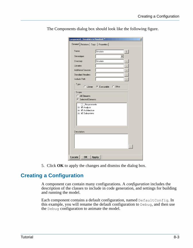
Creating a Configuration
tutorialcpp.book Page 3 Thursday, April 21, 2005 4:51 PM
The Components dialog box should look like the following figure.
5. Click OK to apply the changes and dismiss the dialog box.
Creating a Configuration
A component can contain many configurations. A configuration includes the description of the classes to include in code generation, and settings for building and running the model.
Each component contains a default configuration, named DefaultConfig. In this example, you will rename the default configuration to Debug, and then use the Debug configuration to animate the model.
Tutorial 8-3
Animating the Model
tutorialcpp.book Page 4 Thursday, April 21, 2005 4:51 PM
To use the default configuration, do the following:
1. In the browser, expand the Simulate component and the Configurations category.
2. Select DefaultConfig and rename it Debug.
Setting the Configuration Features
Once you have created the Debug configuration, you must set the values for animating the model as follows:
1. In the browser, double-click Debug or right-click and select Features from the pop-up menu. The Configuration features dialog box opens.
2. Select the Initialization tab and set the following values:
• For the Initial instances field, select Explicit to include the classes which have relations to the selected elements.
• Select Generate Code for Actors.
3. Select the Settings tab, and set the following values:
• Select Animation from the Instrumentation Mode pull-down list. This adds instrumentation code, which enables you to animate the model.
• Select Real (for real time) as the Time Model.
• Select Flat as the Statechart Implementation. Rhapsody implements states as simple, enumerated-type variables.
Rhapsody fills in the Environment Settings, based on the compiler settings you configured during installation.
The following figure shows the completed Settings tab.
8-4 Rhapsody in C++
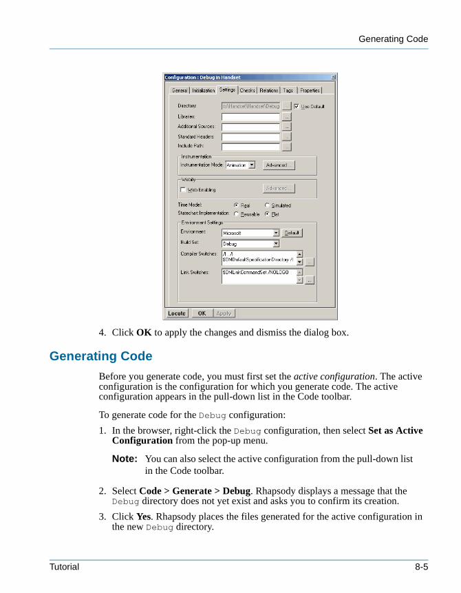
Generating Code
tutorialcpp.book Page 5 Thursday, April 21, 2005 4:51 PM
4. Click OK to apply the changes and dismiss the dialog box.
Generating Code
Before you generate code, you must first set the active configuration. The active configuration is the configuration for which you generate code. The active configuration appears in the pull-down list in the Code toolbar.
To generate code for the Debug configuration:
1. In the browser, right-click the Debug configuration, then select Set as Active Configuration from the pop-up menu.
Note: You can also select the active configuration from the pull-down list in the Code toolbar.
2. Select Code > Generate > Debug. Rhapsody displays a message that the Debug directory does not yet exist and asks you to confirm its creation.
3. Click Yes. Rhapsody places the files generated for the active configuration in the new Debug directory.
Tutorial 8-5
Animating the Model
tutorialcpp.book Page 6 Thursday, April 21, 2005 4:51 PM
Rhapsody generates the code and displays output messages in the Build tab of the Output window. The messages inform you of the code generation status, including:• Success or failure of internal checks for the correctness and completeness of
your model. These checks are performed before code generation begins.• Names of files generated for classes and packages in the configuration.• Names of files into which the main() function is generated.• Location of the generated make file.• Completion of code generation.
Note: If you receive code generation errors, double-click the error in the Output window to go to the error source. The source of the error appears as a highlighted element.Reinstall Rhapsody if it does not find the compiler during code generation. If this does not work, contact I-Logix Technical Support.
To examine any of the generated source files, go to the \Simulate\Debug directory of the handset project.
Building the Model
Once you generate code without any errors, you are ready to build the model.
To build the model, do one of the following.• Select Code > Build Simulate.exe.• Click the Make tool in the Code toolbar.
Rhapsody builds the model, by performing the following tasks:• Executes the make file that it generated for the configuration.• Sets up the environment for the compiler.• Starts the compiler and linker, which run on the generated code. Once the code
is compiled and linked, Rhapsody displays the message Build Done in the Output window.
Note: If you receive errors, double-click the error message in the Output window to go to the error source. The source of the error appears as a highlighted element. Once you fix the problem, regenerate the code, and rebuild the application until there are no error messages.
Any time you make changes to the model, you need to regenerate and rebuild the model before animating it.
8-6 Rhapsody in C++
Animating the Model
tutorialcpp.book Page 7 Thursday, April 21, 2005 4:51 PM
Animating the ModelAnimation is the execution of behaviors and associated definitions in the model. Rhapsody animates the model by executing the code generated with instrumentation for classes, operations, and associations.
Note: When animation starts, it connects to the Rhapsody application via a TCP/IP socket whose number is set in the rhapsody.ini file.
Once you animate the model, you can open the following animated diagrams from the Tools menu:• Animated sequence diagram• Animated statechart• Animated activity diagram
These diagrams and the browser (which becomes animated automatically), graphically show the execution of the model. The Call Stack and Event Queue windows provide supporting information to help you understand what is happening in the animated views.
Starting Animation
To start animation, do one of the following:• Select Code > Run Simulate.exe.• Click the Run executable tool.
Rhapsody starts animation and performs the following tasks:• Runs the application to main().• Displays the animation toolbar, which enables you to control the animation
process. See “Animation Toolbar” on page 8-8 for a description of the animation tools.
• Displays a console window, which provides input to and output from the model. You can position and resize the console and Rhapsody windows so both are visible.
• Displays the following two output panes: – Call Stack—Shows the logical call stack of the executing model at the
design level, rather than the code level
– Event Queue—Shows the events waiting on the event queue of the executing process
Note: If the output panes are not displayed, select View > Call Stack or View > Event Queue. The output panes are dockable, so you can
Tutorial 8-7
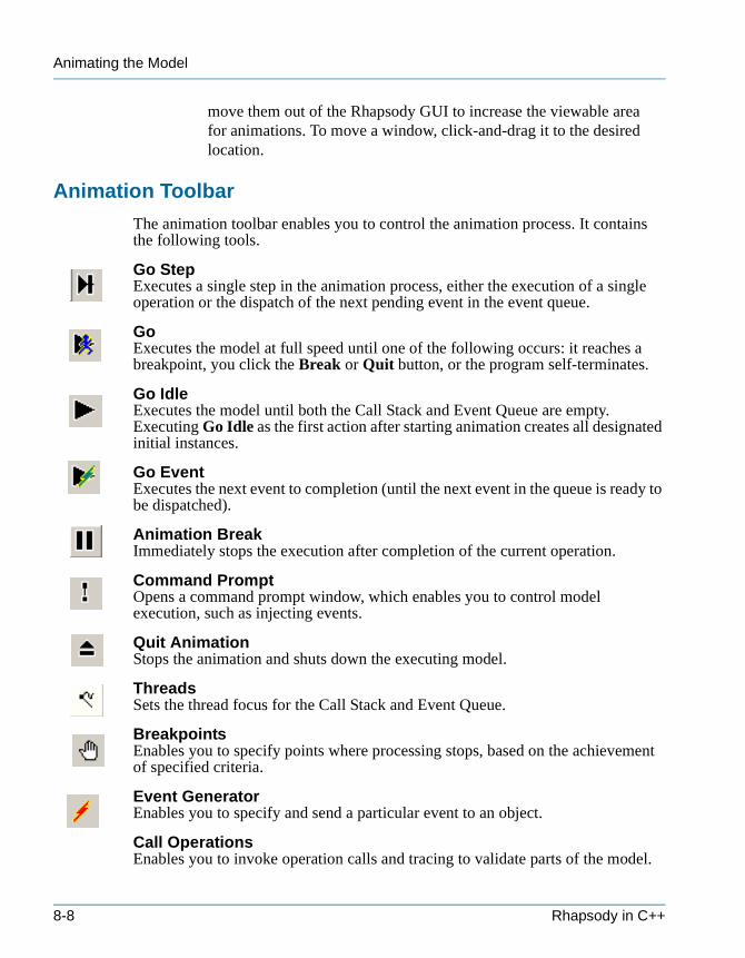
Animating the Model
tutorialcpp.book Page 8 Thursday, April 21, 2005 4:51 PM
move them out of the Rhapsody GUI to increase the viewable area for animations. To move a window, click-and-drag it to the desired location.
Animation Toolbar
The animation toolbar enables you to control the animation process. It contains the following tools.
Go StepExecutes a single step in the animation process, either the execution of a single operation or the dispatch of the next pending event in the event queue.
GoExecutes the model at full speed until one of the following occurs: it reaches a breakpoint, you click the Break or Quit button, or the program self-terminates.
Go IdleExecutes the model until both the Call Stack and Event Queue are empty. Executing Go Idle as the first action after starting animation creates all designated initial instances.
Go EventExecutes the next event to completion (until the next event in the queue is ready to be dispatched).
Animation BreakImmediately stops the execution after completion of the current operation.
Command PromptOpens a command prompt window, which enables you to control model execution, such as injecting events.
Quit AnimationStops the animation and shuts down the executing model.
ThreadsSets the thread focus for the Call Stack and Event Queue.
BreakpointsEnables you to specify points where processing stops, based on the achievement of specified criteria.
Event GeneratorEnables you to specify and send a particular event to an object.
Call OperationsEnables you to invoke operation calls and tracing to validate parts of the model.
8-8 Rhapsody in C++
Viewing Animated Diagrams
tutorialcpp.book Page 9 Thursday, April 21, 2005 4:51 PM
For example, you can drive transitions with triggered operations. See the User Guide for more information.
Watch-Display Continuous UpdateEnables you to toggle between the two animation modes at any break or when idle:• Update on Break mode—Runs at near-production speed until it reaches a
breakpoint. This is also called Silent mode.• Watch mode—Enables you to continually update animation information in
normal step-by-step operation using the Go buttons. This is the default mode.
Viewing Animated DiagramsAnimated diagrams enable you to observe the model as it runs, and perform design-level debugging.
In this example, you will animate the following diagrams, and then send events to the model and view the resulting behavior:• Connection Management Place Call Request Success sequence diagram• CallControl statechart• MMCallControl activity diagram
Animating a Sequence Diagram
Animated sequence diagrams (ASDs) show how objects pass messages while the model is executing. You do not manually add messages to an ASD—the animation process adds them for you while the model is running. This enables you to observe the communication taking place in the system. You can then compare the message sequence to the nonanimated sequence diagrams to see whether the model is behaving correctly.
In this example, you will animate the Connection Management Place Call Request Success SD you created in Chapter 5, Creating Sequence Diagrams.
Note: If the SD is already open, Rhapsody automatically creates an animated sequence diagram.
To animate the sequence diagram:
1. Select Tools > Animated Sequence Diagram. The Open Sequence Diagram dialog box displays, as shown in the following figure.
Tutorial 8-9
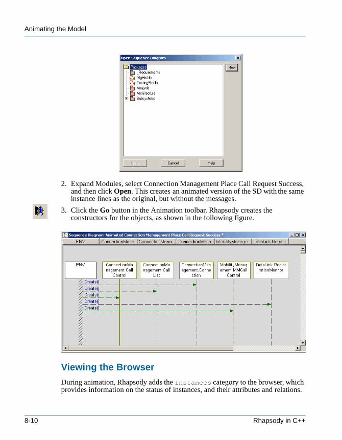
Animating the Model
tutorialcpp.book Page 10 Thursday, April 21, 2005 4:51 PM
2. Expand Modules, select Connection Management Place Call Request Success, and then click Open. This creates an animated version of the SD with the same instance lines as the original, but without the messages.
3. Click the Go button in the Animation toolbar. Rhapsody creates the constructors for the objects, as shown in the following figure.
Viewing the Browser
During animation, Rhapsody adds the Instances category to the browser, which provides information on the status of instances, and their attributes and relations.
8-10 Rhapsody in C++
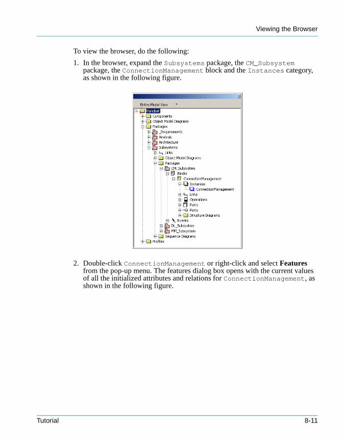
Viewing the Browser
tutorialcpp.book Page 11 Thursday, April 21, 2005 4:51 PM
To view the browser, do the following:
1. In the browser, expand the Subsystems package, the CM_Subsystem package, the ConnectionManagement block and the Instances category, as shown in the following figure.
2. Double-click ConnectionManagement or right-click and select Features from the pop-up menu. The features dialog box opens with the current values of all the initialized attributes and relations for ConnectionManagement, as shown in the following figure.
Tutorial 8-11
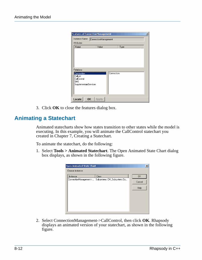
Animating the Model
tutorialcpp.book Page 12 Thursday, April 21, 2005 4:51 PM
3. Click OK to close the features dialog box.
Animating a Statechart
Animated statecharts show how states transition to other states while the model is executing. In this example, you will animate the CallControl statechart you created in Chapter 7, Creating a Statechart.
To animate the statechart, do the following:
1. Select Tools > Animated Statechart. The Open Animated State Chart dialog box displays, as shown in the following figure.
2. Select ConnectionManagement->CallControl, then click OK. Rhapsody displays an animated version of your statechart, as shown in the following figure.
8-12 Rhapsody in C++
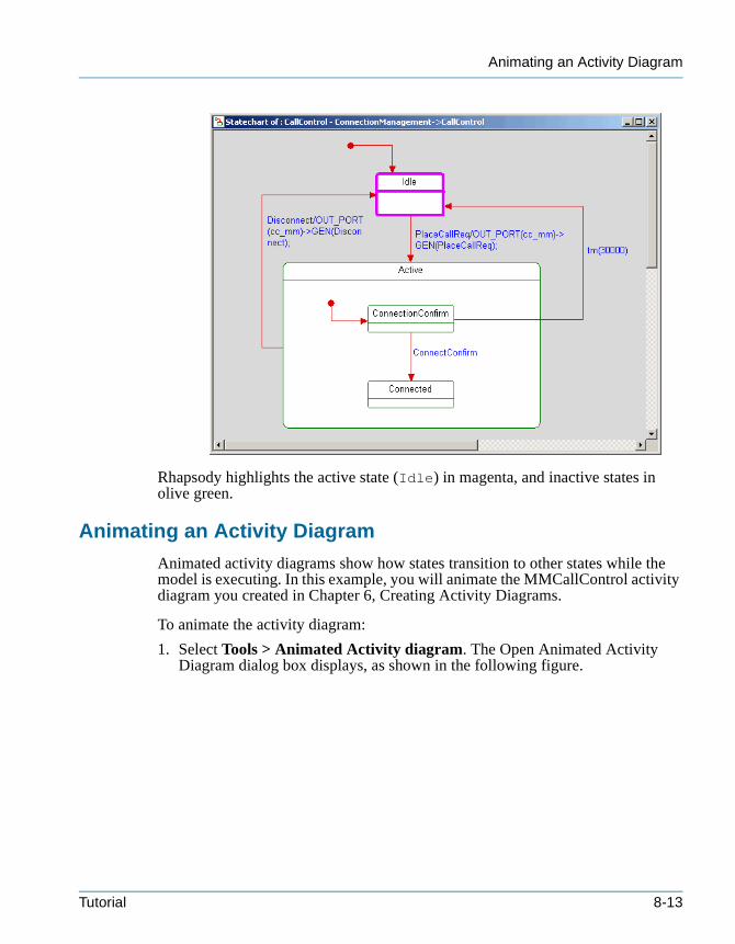
Animating an Activity Diagram
tutorialcpp.book Page 13 Thursday, April 21, 2005 4:51 PM
Rhapsody highlights the active state (Idle) in magenta, and inactive states in olive green.
Animating an Activity Diagram
Animated activity diagrams show how states transition to other states while the model is executing. In this example, you will animate the MMCallControl activity diagram you created in Chapter 6, Creating Activity Diagrams.
To animate the activity diagram:
1. Select Tools > Animated Activity diagram. The Open Animated Activity Diagram dialog box displays, as shown in the following figure.
Tutorial 8-13
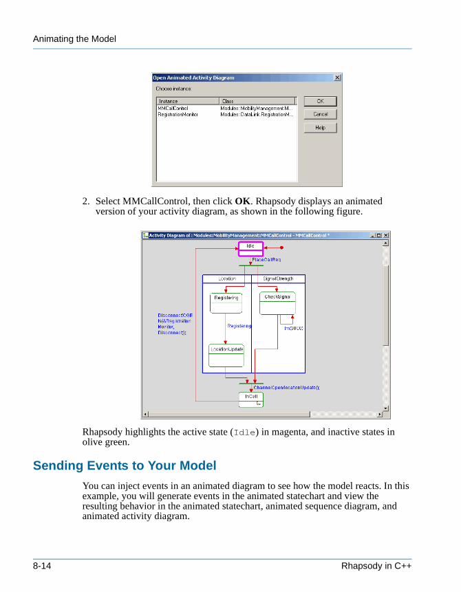
Animating the Model
tutorialcpp.book Page 14 Thursday, April 21, 2005 4:51 PM
2. Select MMCallControl, then click OK. Rhapsody displays an animated version of your activity diagram, as shown in the following figure.
Rhapsody highlights the active state (Idle) in magenta, and inactive states in olive green.
Sending Events to Your Model
You can inject events in an animated diagram to see how the model reacts. In this example, you will generate events in the animated statechart and view the resulting behavior in the animated statechart, animated sequence diagram, and animated activity diagram.
8-14 Rhapsody in C++
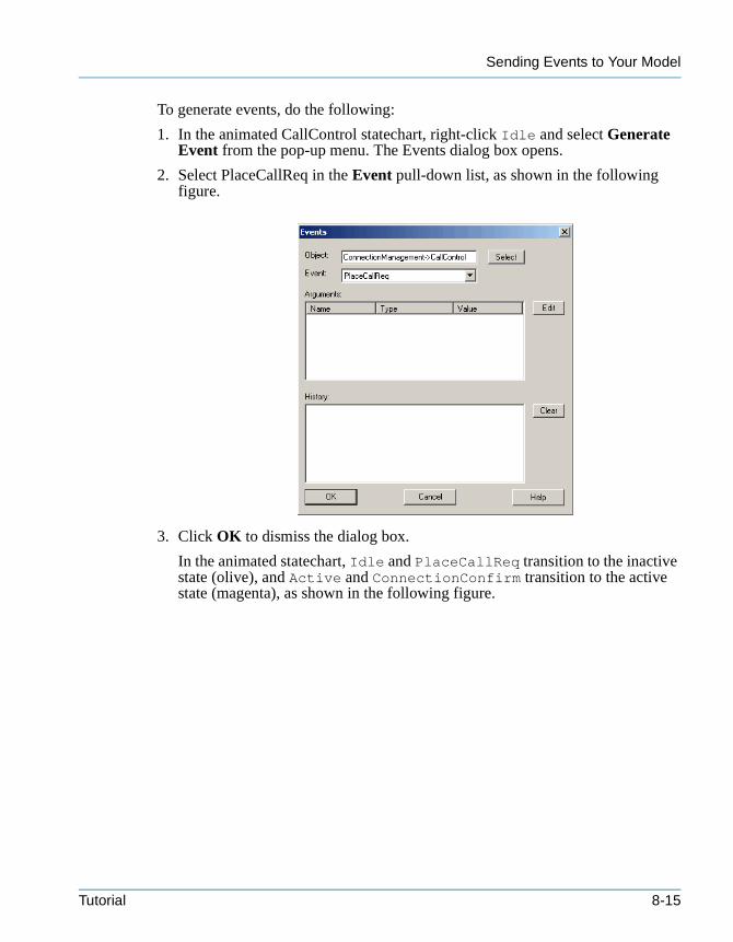
Sending Events to Your Model
tutorialcpp.book Page 15 Thursday, April 21, 2005 4:51 PM
To generate events, do the following:
1. In the animated CallControl statechart, right-click Idle and select Generate Event from the pop-up menu. The Events dialog box opens.
2. Select PlaceCallReq in the Event pull-down list, as shown in the following figure.
3. Click OK to dismiss the dialog box.
In the animated statechart, Idle and PlaceCallReq transition to the inactive state (olive), and Active and ConnectionConfirm transition to the active state (magenta), as shown in the following figure.
Tutorial 8-15
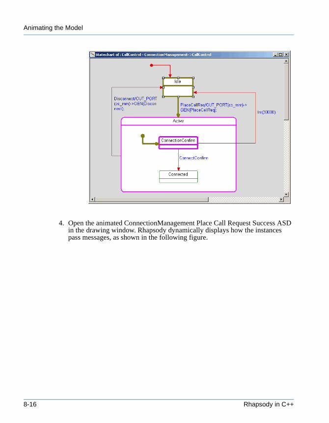
Animating the Model
tutorialcpp.book Page 16 Thursday, April 21, 2005 4:51 PM
4. Open the animated ConnectionManagement Place Call Request Success ASD in the drawing window. Rhapsody dynamically displays how the instances pass messages, as shown in the following figure.
8-16 Rhapsody in C++
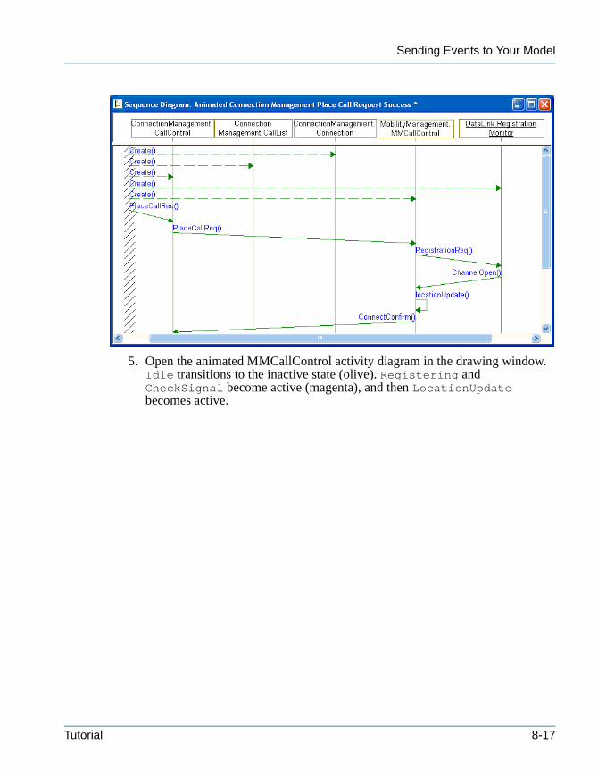
Sending Events to Your Model
tutorialcpp.book Page 17 Thursday, April 21, 2005 4:51 PM
5. Open the animated MMCallControl activity diagram in the drawing window. Idle transitions to the inactive state (olive). Registering and CheckSignal become active (magenta), and then LocationUpdate becomes active.
Tutorial 8-17
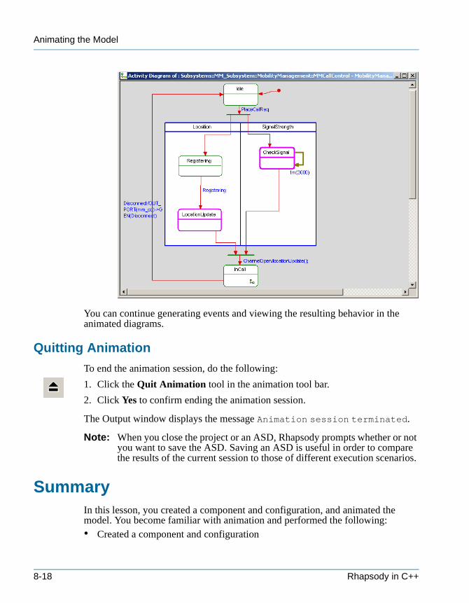
Animating the Model
tutorialcpp.book Page 18 Thursday, April 21, 2005 4:51 PM
You can continue generating events and viewing the resulting behavior in the animated diagrams.
Quitting Animation
To end the animation session, do the following:
1. Click the Quit Animation tool in the animation tool bar.
2. Click Yes to confirm ending the animation session.
The Output window displays the message Animation session terminated.
Note: When you close the project or an ASD, Rhapsody prompts whether or not you want to save the ASD. Saving an ASD is useful in order to compare the results of the current session to those of different execution scenarios.
SummaryIn this lesson, you created a component and configuration, and animated the model. You become familiar with animation and performed the following:• Created a component and configuration
8-18 Rhapsody in C++
Summary
tutorialcpp.book Page 19 Thursday, April 21, 2005 4:51 PM
• Generated, built, and ran the component• Animated the sequence diagram• Animated the statechart• Animated the activity diagram• Sent events to the model and saw it progress through states and pass messages
You are now ready to proceed to the next lesson, where you will use Rhapsody Webify to remotely control and manage the model.
Tutorial 8-19

Animating the Model
tutorialcpp.book Page 20 Thursday, April 21, 2005 4:51 PM
8-20 Rhapsody in C++
tutorialcpp.book Page 1 Thursday, April 21, 2005 4:51 PM
Web-Enabling the Model 9
Rhapsody Webify lets you control and manage the model by remotely invoking events, calling operations, and viewing the changing data. It automatically generates and hosts a Web site that serves as a graphic interface and which accesses the components of the model through a built-in Web server. By using the interactive functionality of this interface, you can remotely prototype, test, and collaborate to demonstrate the model’s behavior.
Goals for this LessonIn this lesson, you will perform the following:• Preparing to Web-Enable the Model, page 9-1• Connecting to the Web-Enabled Model, page 9-5• Viewing and Controlling a Model, page 9-6
Preparing to Web-Enable the ModelThe first step in Web-enabling a working Rhapsody model is to set its configuration and elements as Web-manageable, and then generate, build, and run the model.
Creating a Web-Enabled Configuration
In this example, you will create a new configuration and then set its features as follows:
1. In the browser, expand Components and Simulate.
2. Right-click the Configurations category and select Add New Configuration from the pop-up menu.
3. Type Panel.
Tutorial 9-1
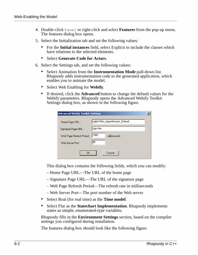
Web-Enabling the Model
tutorialcpp.book Page 2 Thursday, April 21, 2005 4:51 PM
4. Double-click Panel or right-click and select Features from the pop-up menu. The features dialog box opens.
5. Select the Initialization tab and set the following values:
• For the Initial instances field, select Explicit to include the classes which have relations to the selected elements.
• Select Generate Code for Actors.
6. Select the Settings tab, and set the following values:
• Select Animation from the Instrumentation Mode pull-down list. Rhapsody adds instrumentation code to the generated application, which enables you to animate the model.
• Select Web Enabling for Webify.
• If desired, click the Advanced button to change the default values for the Webify parameters. Rhapsody opens the Advanced Webify Toolkit Settings dialog box, as shown in the following figure.
This dialog box contains the following fields, which you can modify:
– Home Page URL—The URL of the home page
– Signature Page URL—The URL of the signature page
– Web Page Refresh Period—The refresh rate in milliseconds
– Web Server Port—The port number of the Web server
• Select Real (for real time) as the Time model.
• Select Flat as the Statechart Implementation. Rhapsody implements states as simple, enumerated-type variables.
Rhapsody fills in the Environment Settings section, based on the compiler settings you configured during installation.
The features dialog box should look like the following figure.
9-2 Rhapsody in C++
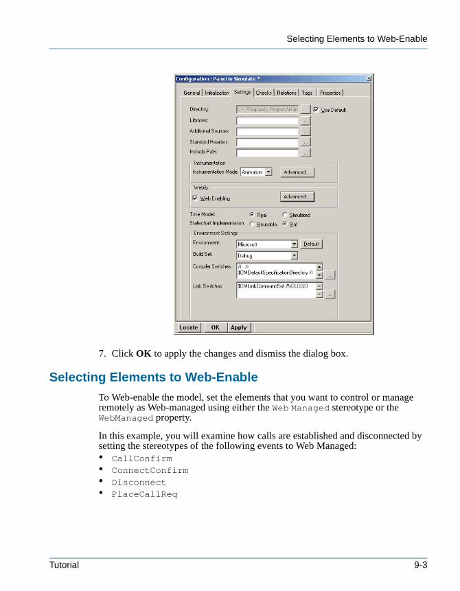
Selecting Elements to Web-Enable
tutorialcpp.book Page 3 Thursday, April 21, 2005 4:51 PM
7. Click OK to apply the changes and dismiss the dialog box.
Selecting Elements to Web-Enable
To Web-enable the model, set the elements that you want to control or manage remotely as Web-managed using either the Web Managed stereotype or the WebManaged property.
In this example, you will examine how calls are established and disconnected by setting the stereotypes of the following events to Web Managed:• CallConfirm• ConnectConfirm• Disconnect• PlaceCallReq
Tutorial 9-3
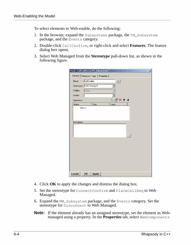
Web-Enabling the Model
tutorialcpp.book Page 4 Thursday, April 21, 2005 4:51 PM
To select elements to Web-enable, do the following:
1. In the browser, expand the Subsystems package, the CM_Subsystem package, and the Events category.
2. Double-click CallConfirm, or right-click and select Features. The feature dialog box opens.
3. Select Web Managed from the Stereotype pull-down list, as shown in the following figure.
4. Click OK to apply the changes and dismiss the dialog box.
5. Set the stereotype for ConnectConfirm and PlaceCallReq to Web Managed.
6. Expand the MM_Subsystem package, and the Events category. Set the stereotype for Disconnect to Web Managed.
Note: If the element already has an assigned stereotype, set the element as Web-managed using a property. In the Properties tab, select WebComponents
9-4 Rhapsody in C++
Generating, Building, and Running the Model
tutorialcpp.book Page 5 Thursday, April 21, 2005 4:51 PM
as the subject, then set the value of the WebManaged property within the appropriate metaclasses to True.
Generating, Building, and Running the Model
You can incrementally generate, build, and run the model or perform all three tasks in one step.
To generate, build, and run the Web-enabled model, do the following:
1. In the browser, right-click Panel and select Set as Active Configuration from the pop-up menu.
2. To incrementally generate the code and makefile, build the target, and run the application, do the following:
• Select Code > Generate > Panel.
• Select Code > Build Simulate.exe, or click the Make tool in the Code toolbar.
• Select Code > Run Simulate.exe, or click the Run tool in the Code toolbar.
To generate the code and makefile, build the target, and run the application all in one step, do either of the following:
• Select Code > Generate/Make/Run.
• Click the Generate/Make/Run tool in the Code toolbar.
Connecting to the Web-Enabled ModelRhapsody includes a collection of default pages that serve as a client-side GUI to the remote model. When you run a Web-enabled model, the Rhapsody Web server automatically generates a Web site, complete with a file structure and interactive capability. This site contains a default collection of generated on-the-fly pages that refreshes each element when it changes.
Note: You can also customize the Web interface by creating your own pages, or by referencing the collection of pages that come with Rhapsody. See the User Guide for more information on customizing the Web interface.
Navigating to the Model through a Web Browser
You can access a Web-enabled model running on your local machine or on a remote machine. In this example, you will connect to the model on your local machine. See the User Guide for more information on connecting to the model on a remote machine.
Tutorial 9-5
Web-Enabling the Model
tutorialcpp.book Page 6 Thursday, April 21, 2005 4:51 PM
To connect to the Web-enabled model on your local machine, do the following:
1. Open Internet Explorer.
2. In the address field, type the following URL:
http://localhost
Other users on the same network can connect to your local model using the IP address or machine name in place of localhost.
If you changed the Web server port using the Advanced Webify Toolkit Settings dialog box, type the following:
http://<localhost>:<port number>
In this URL, <localhost> is localhost (or the machine name or IP address of the local machine running the handset model), <port number> is the port specified in the Advanced Webify Toolkit Settings dialog box.
By default, the Objects Navigation page of the Rhapsody Web GUI opens.
Note: If you cannot view the right-hand frame, in Internet Explorer, go to Tools > Internet Options > Advanced, and uncheck the option Use Java xx for <applet>.
Viewing and Controlling a ModelThe Objects Navigation page provides easy navigation to the Web Managed elements in the model by displaying a hierarchical view of model elements, starting from the top level aggregate. By navigating to, and selecting, an aggregate in the left frame of this page, you can monitor and control your model in the aggregate table displayed in the right frame. The following figure shows an example of the Objects Navigation page of the Rhapsody Web GUI.
9-6 Rhapsody in C++
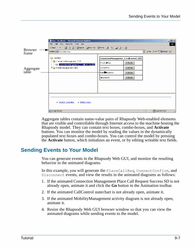
Sending Events to Your Model
tutorialcpp.book Page 7 Thursday, April 21, 2005 4:51 PM
Aggregate tables contain name-value pairs of Rhapsody Web-enabled elements that are visible and controllable through Internet access to the machine hosting the Rhapsody model. They can contain text boxes, combo-boxes, and Activate buttons. You can monitor the model by reading the values in the dynamically populated text boxes and combo-boxes. You can control the model by pressing the Activate button, which initializes an event, or by editing writable text fields.
Sending Events to Your Model
You can generate events in the Rhapsody Web GUI, and monitor the resulting behavior in the animated diagrams.
In this example, you will generate the PlaceCallReq, ConnectConfirm, and Disconnect events, and view the results in the animated diagrams as follows:
1. If the animated Connection Management Place Call Request Success SD is not already open, animate it and click the Go button in the Animation toolbar.
2. If the animated CallControl statechart is not already open, animate it.
3. If the animated MobilityManagement activity diagram is not already open, animate it.
4. Resize the Rhapsody Web GUI browser window so that you can view the animated diagrams while sending events to the model.
Browser frame
Aggregate table
Tutorial 9-7
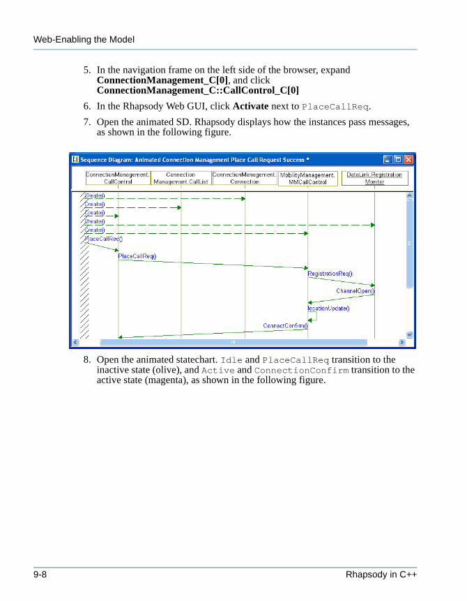
Web-Enabling the Model
tutorialcpp.book Page 8 Thursday, April 21, 2005 4:51 PM
5. In the navigation frame on the left side of the browser, expand ConnectionManagement_C[0], and click ConnectionManagement_C::CallControl_C[0]
6. In the Rhapsody Web GUI, click Activate next to PlaceCallReq.
7. Open the animated SD. Rhapsody displays how the instances pass messages, as shown in the following figure.
8. Open the animated statechart. Idle and PlaceCallReq transition to the inactive state (olive), and Active and ConnectionConfirm transition to the active state (magenta), as shown in the following figure.
9-8 Rhapsody in C++
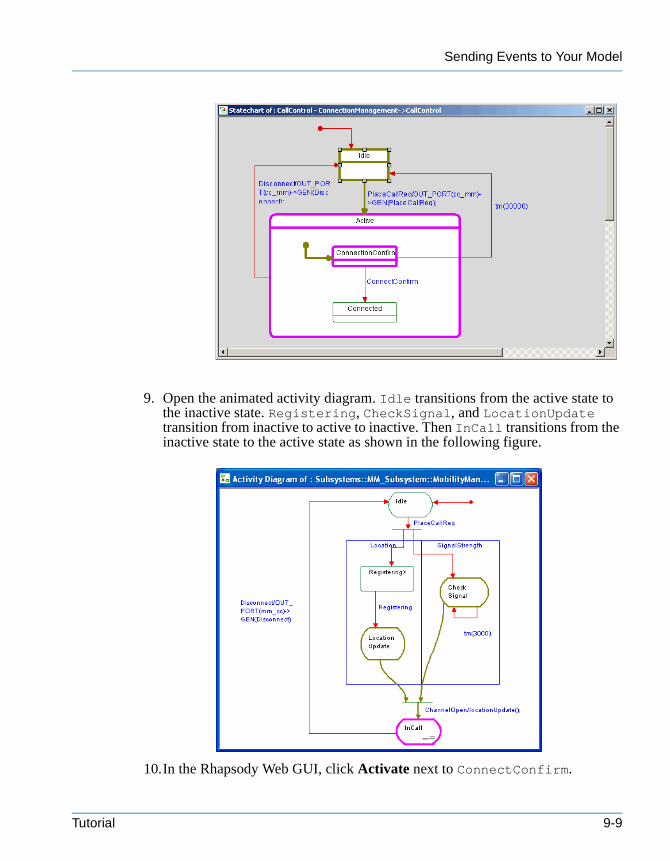
Sending Events to Your Model
tutorialcpp.book Page 9 Thursday, April 21, 2005 4:51 PM
9. Open the animated activity diagram. Idle transitions from the active state to the inactive state. Registering, CheckSignal, and LocationUpdate transition from inactive to active to inactive. Then InCall transitions from the inactive state to the active state as shown in the following figure.
10.In the Rhapsody Web GUI, click Activate next to ConnectConfirm.
Tutorial 9-9
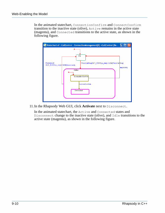
Web-Enabling the Model
tutorialcpp.book Page 10 Thursday, April 21, 2005 4:51 PM
In the animated statechart, ConnectionConfirm and ConnectConfirm transition to the inactive state (olive), Active remains in the active state (magenta), and Connected transitions to the active state, as shown in the following figure.
11.In the Rhapsody Web GUI, click Activate next to Disconnect.
In the animated statechart, the Active and Connected states and Disconnect change to the inactive state (olive), and Idle transitions to the active state (magenta), as shown in the following figure.
9-10 Rhapsody in C++
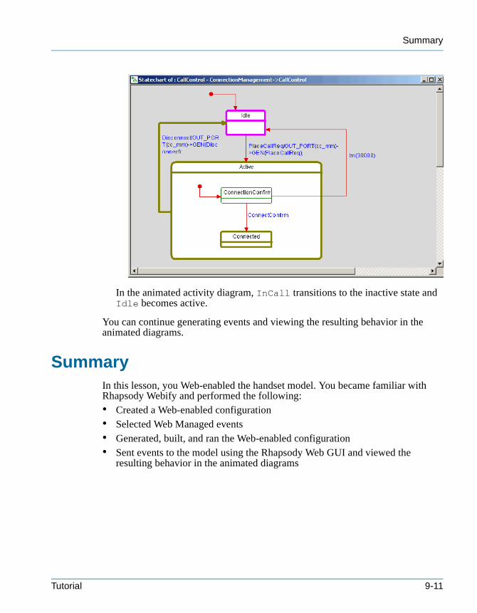
Summary
tutorialcpp.book Page 11 Thursday, April 21, 2005 4:51 PM
In the animated activity diagram, InCall transitions to the inactive state and Idle becomes active.
You can continue generating events and viewing the resulting behavior in the animated diagrams.
SummaryIn this lesson, you Web-enabled the handset model. You became familiar with Rhapsody Webify and performed the following:• Created a Web-enabled configuration• Selected Web Managed events• Generated, built, and ran the Web-enabled configuration• Sent events to the model using the Rhapsody Web GUI and viewed the
resulting behavior in the animated diagrams
Tutorial 9-11

Web-Enabling the Model
tutorialcpp.book Page 12 Thursday, April 21, 2005 4:51 PM
9-12 Rhapsody in C++
tutorialcpp.book Page 1 Thursday, April 21, 2005 4:51 PM
Index
AAction
on entry 6-8on transition 7-7
Action statedescription 6-2drawing 6-7
Activity diagramanimating 8-13creating 6-15drawing
action state 6-7default connector 6-8fork synch bar 6-10join synch bar 6-11subactivity state 6-9swimlanes 6-6timeout transition 6-11transition 6-9
elementsaction state 6-2block state 6-2condition connector 6-3default connector 6-3dependency 6-4diagram connector 6-3fork synch bar 6-4join synch bar 6-4junction connector 6-3loop transition 6-3object flow state 6-3subactivity state 6-3swimlanes 6-4termination state 6-3transition 6-3
openingsubactivity diagram 6-13
overview 6-2
toolbar 6-5Actor
associating with use cases 2-11description
object model diagram 4-4use case diagram 2-2
drawing 2-5Actor line
drawing 5-6Aggregation line
description 4-3Anchor 2-14And state
description 7-2Animated activity diagram 8-13Animated browser 8-10Animated sequence diagrams 8-9Animated statechart 8-12Animation
animated activity diagram 8-13animated browser 8-10animated sequence diagrams 8-9animated statecharts 8-12Call Stack window 8-7configuration 8-3Event Queue window 8-7generating code 8-5injecting events 8-14output panes 8-7quitting 8-18sending events 8-14starting 8-7toolbar 8-8
Animation breakdescription 8-8
Association linedescription
object model diagram 4-3use case diagram 2-2
Tutorial Index–1
tutorialcpp.book Page 2 Thursday, April 21, 2005 4:51 PM
Autosave 1-4
BBehavioral port 3-10Block
adding stereotype 3-5description
activity diagram 6-2structure diagram 3-3
drawingobject model diagram 4-6structure diagram 3-5
Boundary boxdescription 2-2drawing 2-5resizing 2-9
Breakpointsdescription 8-8
Browseranimating 8-10description 1-7editing use cases 2-9filtering 1-8moving 1-8
CCall operations
description 8-8Call stack 8-7Cancelled timeout
description 5-3Class
description 4-2Classifier role
drawing 5-12Code generation
debugging 8-6description 8-5source files 8-6
Command promptdescription 8-8
Comment 2-14Component
configurationscreating 8-3
creating 8-2default
description 8-2
definition 8-2features 8-2
Compositedescription 4-3
Composite classdescription
object model diagram 4-2structure diagram 3-2
Condition connectordescription
activity diagram 6-3statechart 7-2
Condition markdescription 5-3
Configurationcreating
animation 8-3Web-enabled 9-1
default 8-3definition 8-3features 8-4
Constraint 2-14Contract-based port
description 3-13Create
activity diagram 6-15component 8-2configuration
animation 8-3Web-enabled 9-1
handset project 1-2sequence diagram 5-3statechart 7-3structure diagram 3-3use case diagram 2-3
Create arrowdescription 5-3
Create portdescription 3-3
DDefault component
description 8-2modifying 8-2
Default configurationdescription 8-3modifying 8-3
Default connectordescription
Tutorial Index–2
tutorialcpp.book Page 3 Thursday, April 21, 2005 4:51 PM
activity diagram 6-3statechart 7-2
drawingactivity diagram 6-8statechart 7-7
Dependencyadding stereotype 2-21description
activity diagram 6-4statechart 7-3structure diagram 3-3use case diagram 2-3
Dependency linedescription 4-4
Destroy arrowdescription 5-3
Diagram connectordescription
activity diagram 6-3statechart 7-3
Directed association linedescription 4-3
Display options 2-19Documentation note 2-13Drawing area 1-8
Eehl file 1-4Elements
adding remarks 2-13arranging 2-8display options 2-19editing 2-8labeling 6-10organizing 3-18selecting to Web-enable 9-3
Event Generatordescription 8-8
Event Queue window 8-7
FFeatures dialog box
moving 1-9opening 1-8
Flowchanging the direction 3-11description
object model diagram 4-4
structure diagram 3-3use case diagram 2-3
drawing 3-11specifying flow items 3-12
Flow itemdescription 3-12specifying 3-12
Fork synch bardescription
activity diagram 6-4statechart 7-3
drawing 6-10Fork synchronization 6-10
GGeneralization arrow
description 2-3Generate code
animation 8-5Go
description 8-8Go Event
description 8-8Go Idle
description 8-8Go Step
description 8-8
HHandset
activity diagram 6-1animating 8-1creating 1-2object model diagram 4-1opening 1-4sequence diagram 5-1statechart 7-1structure diagram 3-1use case diagram 2-1Web-enabling 9-1
History connectordescription 7-3
IInheritance
description 4-3
Tutorial Index–3
tutorialcpp.book Page 4 Thursday, April 21, 2005 4:51 PM
Instance area 5-2Instance line
description 5-2drawing 5-12
Interaction occurrencedescription 5-3drawing 5-8
JJoin synch bar
descriptionactivity diagram 6-4statechart 7-3
drawing 6-11Join synchronization 6-11Junction connector
descriptionactivity diagram 6-3statechart 7-3
LLabeling elements 6-10Line shapes
changing 3-13Link
descriptionobject model diagram 4-3structure diagram 3-3
drawing 3-22, 4-7Locate in Browser 5-8Loop transition
description 6-3
MMessage
drawing 5-7Message area 5-2Message arrow
description 5-2Message pane 5-2
NNames pane 5-2Nested state
drawing 7-6
Noncontract-based port 3-14
OObject
descriptionobject model diagram 4-2structure diagram 3-2
drawing 3-7object model diagram 4-6
Object flow statedescription 6-3
Object model diagramdrawing
block 4-6link 4-7object 4-6
elementsactor 4-4aggregation line 4-3association line 4-3class 4-2composite 4-3composite class 4-2dependency line 4-4directed association line 4-3flow 4-4inheritance 4-3link 4-3object 4-2package 4-3port 4-3
overview 4-1toolbar 4-5
Objects Navigation page 9-6Open
project 1-4Rhapsody 1-3
Output windowCall Stack 8-7description 1-8Event Queue window 8-7
PPackage
description 4-3Packages
description 2-3organizing the model 1-10
Tutorial Index–4
tutorialcpp.book Page 5 Thursday, April 21, 2005 4:51 PM
Partition linedescription 5-3
Portbehavioral 3-10changing the placement 3-21description 4-3drawing 3-9reversing 3-17specifying port contract 3-13
Port contract 3-13Project
creating 1-2files and directories 1-4opening 1-4saving 1-4
Provided interfaces 3-13
QQuit animation
description 8-8quitting 8-18
RRapid port 3-14Rectilinear line 3-13Required interfaces 3-14Requirement 2-14Requirements elements
adding 2-17Rhapsody
autosave 1-4browser 1-7drawing area 1-8output window 1-8starting 1-3tips 1-3toolbars 1-6UML tools 1-2
rhapsody.ini file 8-7rpy file 1-4
SSequence diagram
animating 8-9creating 5-3drawing
actor line 5-6classifier role 5-12interaction occurrence 5-8message 5-7system border 5-12
elementscancelled timeout 5-3condition mark 5-3create arrow 5-3destroy arrow 5-3instance line 5-2interaction occurrence 5-3message arrow 5-2partition line 5-3system border 5-3time interval 5-3timeout arrow 5-3
instance area 5-2message area 5-2messages
types of 5-7operation mode 5-4time interval
specifying 5-10toolbar 5-5
Source files 8-6Spline line 3-13State
descriptionstatechart 7-2
nested 7-6Statechart
animating 8-12drawing
action on transition 7-7default connector 7-7nested state 7-6timeout transition 7-9transition 7-7
elementsand state 7-2condition connector 7-2default connector 7-2dependency 7-3diagram connector 7-3fork synch bar 7-3history connector 7-3join synch bar 7-3junction connector 7-3state 7-2
Tutorial Index–5
tutorialcpp.book Page 6 Thursday, April 21, 2005 4:51 PM
termination connector 7-3termination state 7-3transition 7-2
toolbar 7-5Stereotype
dependency 2-21subsystem 3-5
Straight line 3-13Structure diagram
creating 3-3drawing
block 3-5flow 3-11link 3-22objects 3-7port 3-9
elementsblock 3-3composite class 3-2dependency 3-3flow 3-3links 3-3object 3-2port 3-3
overview 3-2specifying flow items 3-12toolbar 3-4
Subactivity diagramopening 6-13
Subactivity statedescription 6-3drawing 6-9
Swimlanesdescription 6-4drawing 6-6
System borderdescription 5-3drawing 5-12
TTermination connector
description 7-3Termination state
descriptionactivity diagram 6-3statechart 7-3
Text 2-13Thread
description 8-8
Time intervaldescription 5-3specifying 5-10
Timeout arrowdescription 5-3
Timeout transitiondrawing
activity diagram 6-11statechart 7-9
Tip 1-3Toolbar
activity diagram 6-5animation 8-8object model diagram 4-5sequence diagram 5-5statechart 7-5structure diagram 3-4use case diagram 2-4
Transitionaction on 7-7description
activity diagram 6-3statechart 7-2
drawingactivity diagram 6-9statechart 7-7
specifying action 6-11timeout 7-9
UUML diagrams 1-2Use case
associating with actors 2-11description 2-2drawing 2-6editing
using the browser 2-9features 2-9
Use case diagramcreating 2-3drawing 2-4
actors 2-5boundary box 2-5dependencies 2-20requirements 2-19use cases 2-6
elementsactor 2-2association line 2-2
Tutorial Index–6

tutorialcpp.book Page 7 Thursday, April 21, 2005 4:51 PM
boundary box 2-2dependency 2-3flow 2-3generalization arrow 2-3packages 2-3use cases 2-2
toolbar 2-4
WWatch-Display Continuous Update
description 8-9Web-enabled
building 9-5configuration 9-1connecting to model 9-5generating 9-5injecting events 9-7Objects Navigation page 9-6running 9-5selecting elements 9-3
Tutorial Index–7
tutorialcpp.book Page 8 Thursday, April 21, 2005 4:51 PM
Tutorial Index–8