rgb for zx spectrum 128, +2, +2a, +3
TRANSCRIPT

� 2001 Paul Farrow http://www.fruitcake.plus.com/Sinclair/Spectrum128/SCARTCable
- 1 -
RGB for ZX Spectrum 128, +2, +2A, +3
Introduction ........................................................................................................................ 2
Video Circuitry................................................................................................................... 3
Audio Circuitry .................................................................................................................. 8
Lead Wiring ....................................................................................................................... 9
Testing The Lead.............................................................................................................. 11
Spectrum +2A/+3 RGB Differences ................................................................................ 12
Circuitry Calculations ...................................................................................................... 16

� 2001 Paul Farrow http://www.fruitcake.plus.com/Sinclair/Spectrum128/SCARTCable
- 2 -
Introduction
The Spectrum 128 improves upon the display quality provided by the 48K Spectrum by having a dedicated socket that outputs both composite video and RGB signals. The composite video output measures 1.2V pk-pk at 75 ohm and is almost suitable for direct connection to the VIDEO IN pin of a TV's SCART socket. The Spectrum 128 also provides RGB outputs at 5V TTL level. However, since they are TTL signals, they are either at 0V for no colour or 5V for colour on. As a result, the two shades of each colour available from the Spectrum 128 are not generated. To overcome this drawback, the Spectrum 128 outputs another TTL signal that indicates whether the colour being output should be shown at bright or normal intensity. Separating the BRIGHT signal from the red, green and blue components allows the Spectrum 128 to drive a monitor that accepts TTL level RGB input s, albeit with a loss of the two shades of each colour. In order to connect the Spectrum 128 to a TV with a SCART socket additional circuitry must be implemented to convert the signal levels. Further circuitry can combine the BRIGHT signal with the colour signals to generate the two shades of each colour. Fortunately, this circuitry is very simple and this web page describes how to construct a suitable lead.
It should be noted that a video cable designed for the Spectrum +2A or +3 is not suitable for use with the Spectrum 128 or +2. When Amstrad released the Spectrum +2A and +3 they kept the same style of monitor socket but altered the signals output by each pin. The +2A/+3 socket now outputs RGB signals suitable for direct connection to a TV with a SCART socket. The BRIGHT signal is no longer available as it is now combined with the red, green and blue signals internally. The composite video signal provided on the Spectrum 128 is no longer available on the Spectrum +2A or +3. See the Spectrum +2A/+3 RGB Differences section for further details.

� 2001 Paul Farrow http://www.fruitcake.plus.com/Sinclair/Spectrum128/SCARTCable
- 3 -
Video Circuitry
The ULA in the Spectrum 128 outputs TTL level red, green, blue and sync signals and from these a TEA2000 Encoder video chip produces a composite video signal. The TTL level signals are taken to the monitor socket via 68 ohm resistors and the composite video signal is taken to the monitor socket via a 75 ohm resistor, as shown in the diagram below.
� 2001 Paul Farrow http://www.fruitcake.plus.com/Sinclair/Spectrum128/SCARTCable
- 4 -
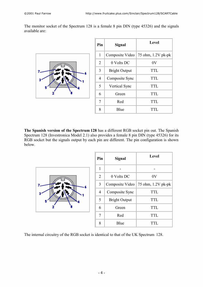
The monitor socket of the Spectrum 128 is a female 8 pin DIN (type 45326) and the signals available are:
Pin Signal Level
1 Composite Video 75 ohm, 1.2V pk-pk
2 0 Volts DC 0V
3 Bright Output TTL
4 Composite Sync TTL
5 Vertical Sync TTL
6 Green TTL
7 Red TTL
8 Blue TTL
The Spanish version of the Spectrum 128 has a different RGB socket pin out. The Spanish Spectrum 128 (Investronica Model 2.1) also provides a female 8 pin DIN (type 45326) for its RGB socket but the signals output by each pin are different. The pin configuration is shown below.
Pin Signal Level
1 - -
2 0 Volts DC 0V
3 Composite Video 75 ohm, 1.2V pk-pk
4 Composite Sync TTL
5 Bright Output TTL
6 Green TTL
7 Red TTL
8 Blue TTL
The internal circuitry of the RGB socket is identical to that of the UK Spectrum 128.
� 2001 Paul Farrow http://www.fruitcake.plus.com/Sinclair/Spectrum128/SCARTCable
- 5 -
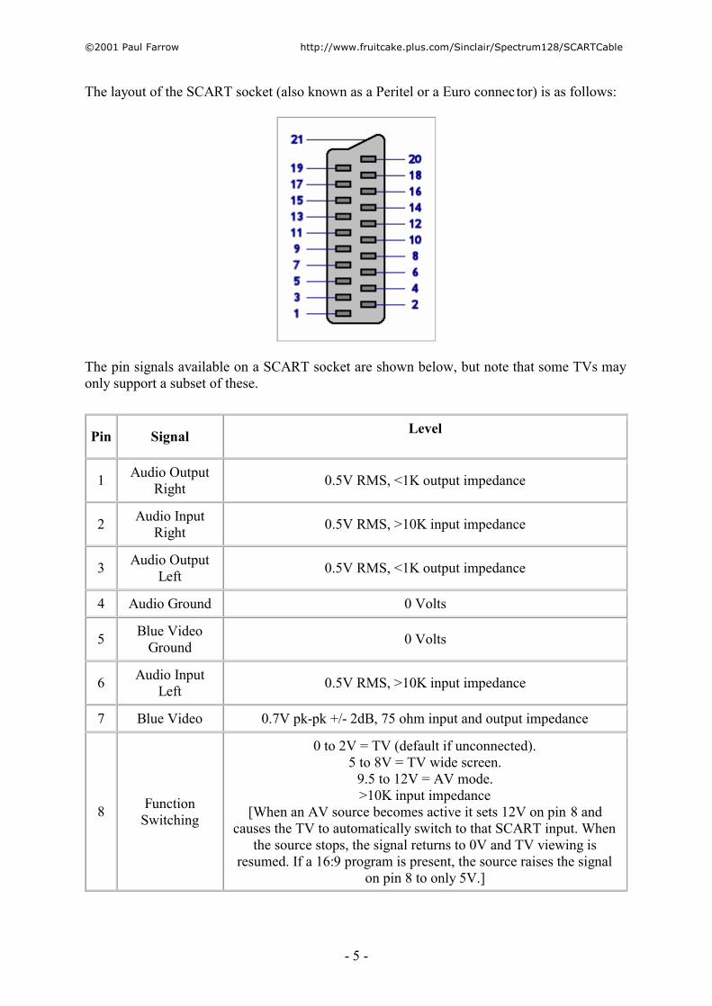
The layout of the SCART socket (also known as a Peritel or a Euro connec tor) is as follows:
The pin signals available on a SCART socket are shown below, but note that some TVs may only support a subset of these.
Pin Signal Level
1 Audio Output Right 0.5V RMS, <1K output impedance
2 Audio Input Right 0.5V RMS, >10K input impedance
3 Audio Output Left 0.5V RMS, <1K output impedance
4 Audio Ground 0 Volts
5 Blue Video Ground 0 Volts
6 Audio Input Left 0.5V RMS, >10K input impedance
7 Blue Video 0.7V pk-pk +/- 2dB, 75 ohm input and output impedance
8 Function Switching
0 to 2V = TV (default if unconnected). 5 to 8V = TV wide screen.
9.5 to 12V = AV mode. >10K input impedance
[When an AV source becomes active it sets 12V on pin 8 and causes the TV to automatically switch to that SCART input. When
the source stops, the signal returns to 0V and TV viewing is resumed. If a 16:9 program is present, the source raises the signal
on pin 8 to only 5V.]
� 2001 Paul Farrow http://www.fruitcake.plus.com/Sinclair/Spectrum128/SCARTCable
- 6 -
9 Green Video Ground 0 Volts
10 Comms Data Line 2 This signal allows devices to communicate serial data
11 Green Video 0.7V pk-pk +/- 2dB, 75 ohm input and output impedance
12 Comms Data Line 1 This signal allows devices to communicate serial data
13 Red Video Ground 0 Volts
14 Comms Data Ground 0 Volts
15 Red Video 0.7V pk-pk +/- 2dB, 75 ohm input and output impedance
16 Blanking
75 ohm input and output impedance. 0V to 0.4V: TV is driven by the composite video input signal on pin
20 (default if unconnected). 1V to 3V: TV is driven by the Red, Green, Blue signals and
composite sync signal on pin 20.
17 Video Ground 0 Volts
18 Blanking Ground 0 Volts
19 Video Output 1V pk-pk including sync, +/- 2dB, 75 ohm output impedance
20 Video Input 1V pk-pk including sync, +/- 2dB, 75 ohm input impedance
21 Common Ground 0 Volts
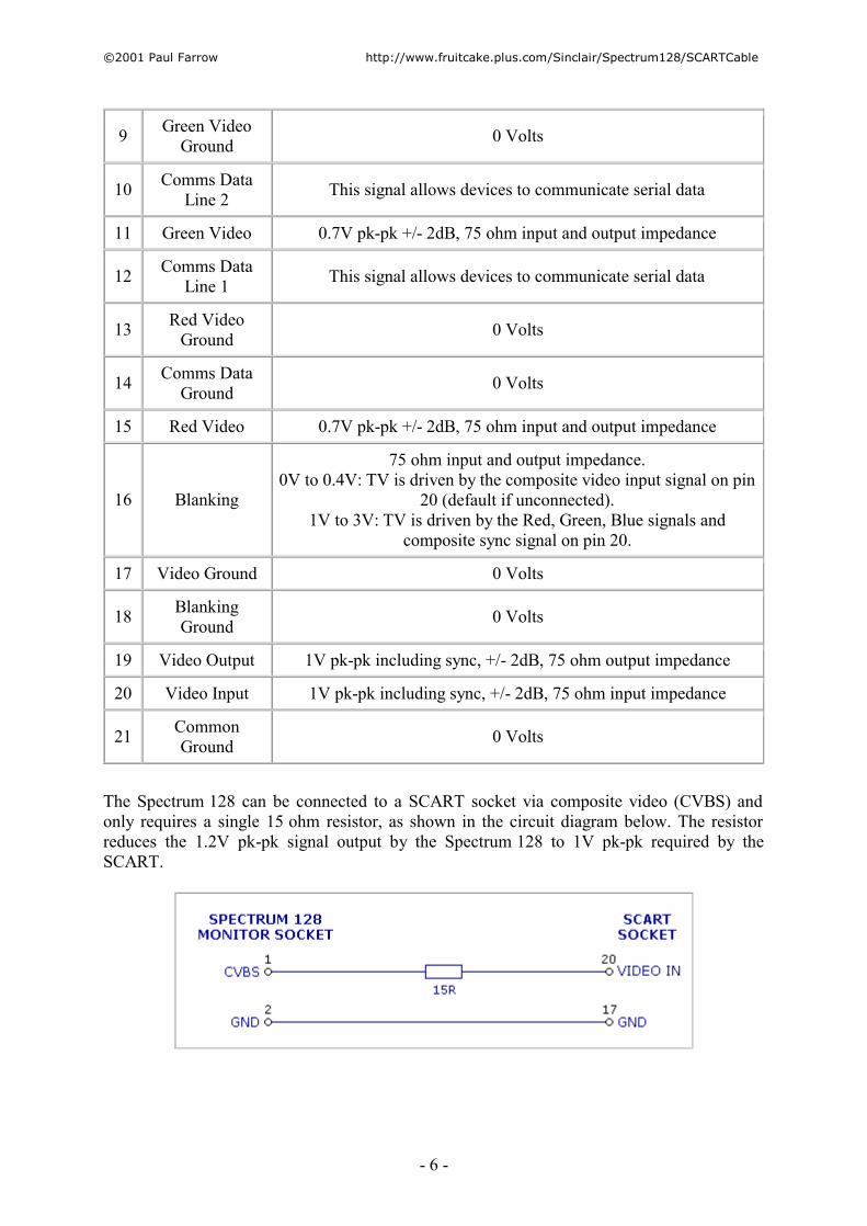
The Spectrum 128 can be connected to a SCART socket via composite video (CVBS) and only requires a single 15 ohm resistor, as shown in the circuit diagram below. The resistor reduces the 1.2V pk-pk signal output by the Spectrum 128 to 1V pk-pk required by the SCART.
� 2001 Paul Farrow http://www.fruitcake.plus.com/Sinclair/Spectrum128/SCARTCable
- 7 -
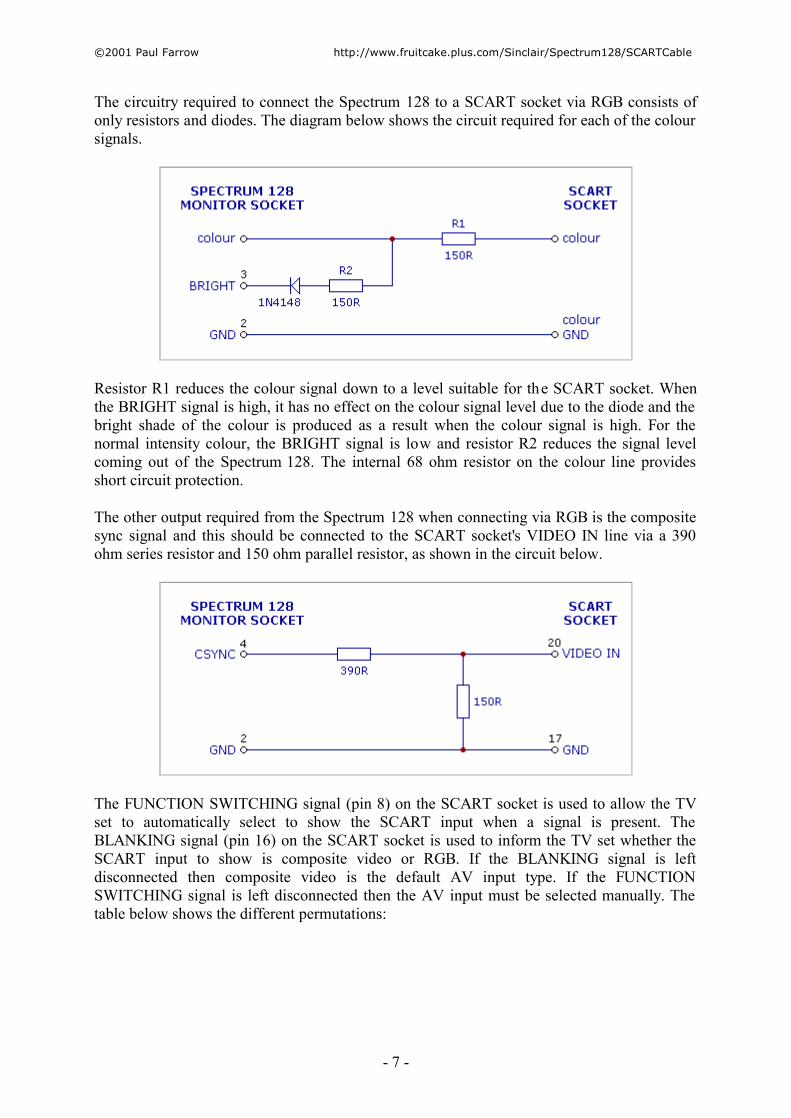
The circuitry required to connect the Spectrum 128 to a SCART socket via RGB consists of only resistors and diodes. The diagram below shows the circuit required for each of the colour signals.
Resistor R1 reduces the colour signal down to a level suitable for the SCART socket. When the BRIGHT signal is high, it has no effect on the colour signal level due to the diode and the bright shade of the colour is produced as a result when the colour signal is high. For the normal intensity colour, the BRIGHT signal is low and resistor R2 reduces the signal level coming out of the Spectrum 128. The internal 68 ohm resistor on the colour line provides short circuit protection.
The other output required from the Spectrum 128 when connecting via RGB is the composite sync signal and this should be connected to the SCART socket's VIDEO IN line via a 390 ohm series resistor and 150 ohm parallel resistor, as shown in the circuit below.
The FUNCTION SWITCHING signal (pin 8) on the SCART socket is used to allow the TV set to automatically select to show the SCART input when a signal is present. The BLANKING signal (pin 16) on the SCART socket is used to inform the TV set whether the SCART input to show is composite video or RGB. If the BLANKING signal is left disconnected then composite video is the default AV input type. If the FUNCTION SWITCHING signal is left disconnected then the AV input must be selected manually. The table below shows the different permutations:

� 2001 Paul Farrow http://www.fruitcake.plus.com/Sinclair/Spectrum128/SCARTCable
- 8 -
FUNCTION SWITCHING (Pin 8)
BLANKING (Pin 16)
TV Mode
0V - 2V 0V - 0.4V Composite Video, Manual Selection
0V - 2V 1V - 3V RGB, Manual Selection
9.5V - 12V 0V - 2V Composite Video, Automatic Selection
9.5V - 12V 1V - 3V RGB, Automatic Selection
For TV sets that allow manual selection of the SCART socket's composite video and RGB inputs, the FUNCTION SWITCHING and BLANKING signals can be left disconnected. For TV sets that allow manual selection of the SCART input but not whether the input should be composite video or RGB, then leaving the BLANKING pin disconnected will cause the composite video input to be selected. To specify that the input should be RGB, it is necessary to connect the BLANKING pin to 1V - 3V. The Spectrum 128's RGB socket does not provide a +5V or a +12V output, which would have been useful when connecting the FUNCTION SWITCHING and BLANKING pins. Instead, power must be taken from either the RS232 socket, the KEYPAD socket or the edge connector and converted down to the appropriate voltage. If either the BLANKING or FUNCTION SWITCHING pins are connected then the BLANKING GND (pin 18) should be connected to 0V at the Spectrum 128.
Audio Circuitry
A drawback of the monitor socket on the Spectrum 128 is that it does not provide a sound output, unlike the Spectrum +2A and +3. It is therefore necessary to obtain the sound signal from the MIC cassette port via a 3.5mm Jack plug. The SCART socket has separate connections for left and right audio channels and so these must be wired together. The voltage from the Spectrum 128's MIC socket is typically 200mV and this is suitable for directly driving the SCART's audio inputs since these can accept up to 0.5V rms.

� 2001 Paul Farrow http://www.fruitcake.plus.com/Sinclair/Spectrum128/SCARTCable
- 9 -
Lead Wiring
The complete circuitry and wiring of a SCART lead for the Spectrum 128 is shown below.
The SCART socket's audio ground can either be connected to the video grounds inside the SCART plug or to the ground signal from the MIC socket. If the audio ground is connected to the video grounds inside to TV set then the MIC ground connection should not be made a s this would cause a ground loop.
Note that in the diagram above the composite video signal (CVBS) has been used instead of the composite sync signal. This yields the added benefit that the same lead can be used to link up to a TV either via an RGB connection or via a composite video connection, and is useful as not all TV sets support an RGB connection. The composite video signal contains all the synchronising information present in the composite sync signal and so this method relies on the TV set discarding the picture information. If problems are encountered then it is best to construct two leads, one for each connection type. The 470 ohm and 150 ohm resistor

� 2001 Paul Farrow http://www.fruitcake.plus.com/Sinclair/Spectrum128/SCARTCable
- 10 -
combination required when the composite sync signal is used needs to be replaced with a 15 ohm resistor when the composite video signal is used.
The FUNCTION SWITCHING and BLANKING pins have not been connected in the diagram above but may be required on some TV sets. In the unlikely event that manual AV selection is not available for a TV set then +12V must be obtained from either the RS232 socket, the KEYPAD socket or the edge connector and connected directly to the FUNCTION SWITCHING input. If the BLANKING pin needs to be connected in order to select the SCART's RGB input then +12V or +5V must be obtained from either the RS232 socket, KEYPAD socket or the edge connector and converted down to the appropriate voltage.
Full circuitry calculations can be found be here.
The audio signal from the MIC socket can be taken into the DIN plug and simply routed down the cable to the SCART plug, although it should ideally be separately screened to minimise cross talk with the video signals. The lead I constructed houses all of the circuitry in the SCART plug and is shown below.
� 2001 Paul Farrow http://www.fruitcake.plus.com/Sinclair/Spectrum128/SCARTCable
- 11 -
Testing The Lead
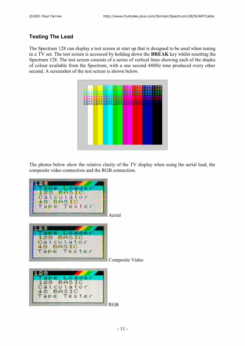
The Spectrum 128 can display a test screen at start up that is designed to be used when tuning in a TV set. The test screen is accessed by holding down the BREAK key whilst resetting the Spectrum 128. The test screen consists of a series of vertical lines showing each of the shades of colour available from the Spectrum, with a one second 440Hz tone produced every other second. A screenshot of the test screen is shown below.
The photos below show the relative clarity of the TV display when using the aerial lead, the composite video connection and the RGB connection.
Aerial
Composite Video
RGB
� 2001 Paul Farrow http://www.fruitcake.plus.com/Sinclair/Spectrum128/SCARTCable
- 12 -
Spectrum +2A/+3 RGB Differences
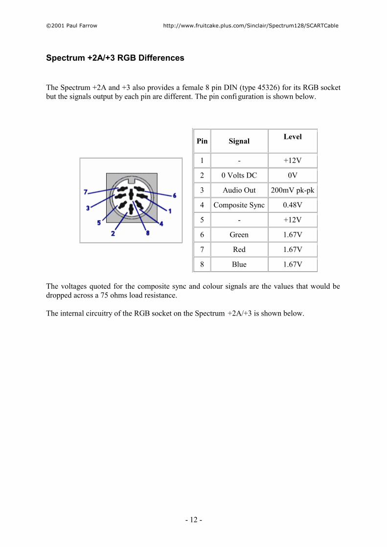
The Spectrum +2A and +3 also provides a female 8 pin DIN (type 45326) for its RGB socket but the signals output by each pin are different. The pin configuration is shown below.
Pin Signal Level
1 - +12V
2 0 Volts DC 0V
3 Audio Out 200mV pk-pk
4 Composite Sync 0.48V
5 - +12V
6 Green 1.67V
7 Red 1.67V
8 Blue 1.67V
The voltages quoted for the composite sync and colour signals are the values that would be dropped across a 75 ohms load resistance.
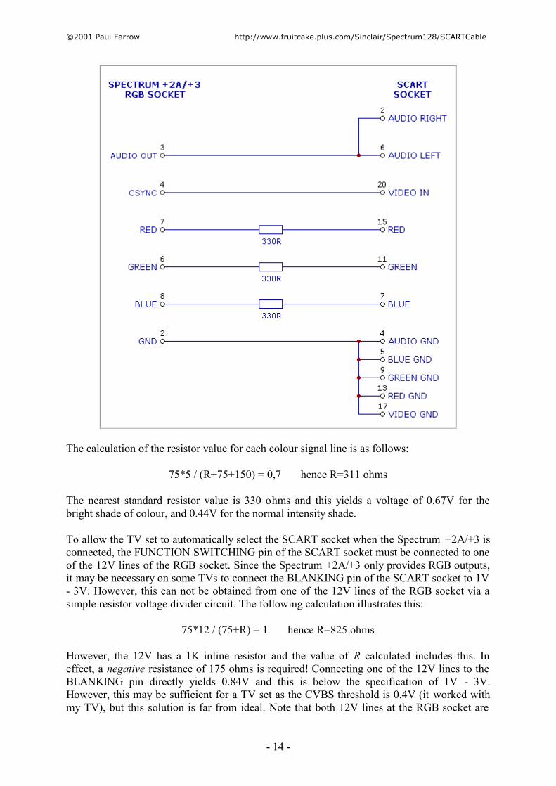
The internal circuitry of the RGB socket on the Spectrum +2A/+3 is shown below.

� 2001 Paul Farrow http://www.fruitcake.plus.com/Sinclair/Spectrum128/SCARTCable
- 13 -
The resistors on the red, green and blue lines are 150 ohms instead of 68 ohms as on the Spectrum 128. The composite sync (CSYNC) signal has an inline 470 ohms resistor with 150 ohms resistor to ground, where as the Spectrum 128 just has an inline 68 ohms resistor. The BRIGHT signal is combined with the colour signals internally via 150 ohm resistors and signal diodes. The BRIGHT, composite video (CVBS) and vertical sync (VSYNC) signals are no longer output at the RGB socket, but are replaced with AUDIO OUT and two +12V lines. These +12V lines are delivered through a 1K resistor.
Spectrum +2A/+3 RGB colour outputs require additional resistors. Without them the bright circuitry is not effective and the voltage levels into the SCART socket are too high. The circuitry required is shown below. Note that the Spectrum +2A and +3 TTL outputs do not drop with low value loads connected as happens on the Spectrum 128.
� 2001 Paul Farrow http://www.fruitcake.plus.com/Sinclair/Spectrum128/SCARTCable
- 14 -
The calculation of the resistor value for each colour signal line is as follows:
75*5 / (R+75+150) = 0,7 hence R=311 ohms
The nearest standard resistor value is 330 ohms and this yields a voltage of 0.67V for the bright shade of colour, and 0.44V for the normal intensity shade.
To allow the TV set to automatically select the SCART socket when the Spectrum +2A/+3 is connected, the FUNCTION SWITCHING pin of the SCART socket must be connected to one of the 12V lines of the RGB socket. Since the Spectrum +2A/+3 only provides RGB outputs, it may be necessary on some TVs to connect the BLANKING pin of the SCART socket to 1V - 3V. However, this can not be obtained from one of the 12V lines of the RGB socket via a simple resistor voltage divider circuit. The following calculation illustrates this:
75*12 / (75+R) = 1 hence R=825 ohms
However, the 12V has a 1K inline resistor and the value of R calculated includes this. In effect, a negative resistance of 175 ohms is required! Connecting one of the 12V lines to the BLANKING pin directly yields 0.84V and this is below the specification of 1V - 3V. However, this may be sufficient for a TV set as the CVBS threshold is 0.4V (it worked with my TV), but this solution is far from ideal. Note that both 12V lines at the RGB socket are

� 2001 Paul Farrow http://www.fruitcake.plus.com/Sinclair/Spectrum128/SCARTCable
- 15 -
connected directly together and so if one is connected to the BLANKING pin then the other will also drop to 0.84V. As a result, it will no longer be able to properly drive the FUNCTION SWITCHING pin. An alternative 12V source could be obtained from the RS232 socket, the AUX socket or the edge connector and the calculations when using these are as given for the Spectrum 128. If either the BLANKING or FUNCTION SWITCHING pins are connected then the BLANKING GND (pin 18) should be connected to 0V at the Spectrum +3.

� 2001 Paul Farrow http://www.fruitcake.plus.com/Sinclair/Spectrum128/SCARTCable
- 16 -
Circuitry Calculations
The Spectrum 128's RGB socket outputs a composite video signal (CVBS) at 1.2V pk-pk and must be converted down to 1V pk-pk via a series resistor. The value of this resistor is calculated by:
75*1,2 / (R+75) = 1 hence R=15 ohms
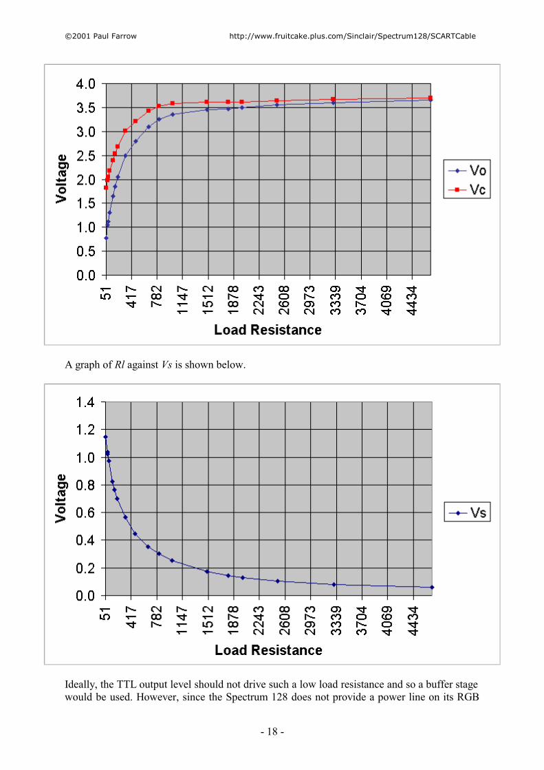
The other signals from the Spectrum 128's RGB socket are at TTL level and must be attenuated so that they are suitable for the SCART socket. In theory, this should be a straight forward matter of using voltage divider circuitry, but things turn out to be a little more complex. To divide 5V such that 0.7V is dropped acrossed the SCART socket's 75 ohms input would require a dividing resistor of 390 ohms in series with the internal 68 ohm resistor. Therefore the total load resistance is only 533 ohms, and this is slow low that it becomes significant with regard to the colour signal circuitry's output imped ance. As a result the TTL high level drops as the total load resistance decreases, and this relationship is not linear. In the diagram below, the colour signal output circuitry is represented by a simple voltage divider. This output is denoted as Vc and in series with this is the internal 68 ohm resistor. The load resistance Rl is then connected between the 68 ohm resistor and ground. The voltage dropped across the last 75 ohms of Rl would be the voltage applied to the SCART socket. The relationship between load resistance (Rl) and voltage out (Vo) can be determined by connecting different load resistances to one of the colour lines and measuring the corresponding output voltage.
Since that the internal 68 ohm resistor is in series with the load resistance, extrapolation can be used to calculate the voltage that is being output by the TTL logic ( Vc). Voltage divider
� 2001 Paul Farrow http://www.fruitcake.plus.com/Sinclair/Spectrum128/SCARTCable
- 17 -
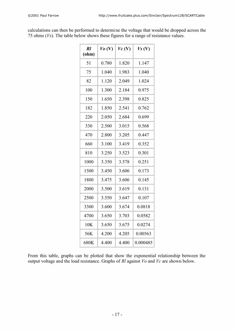
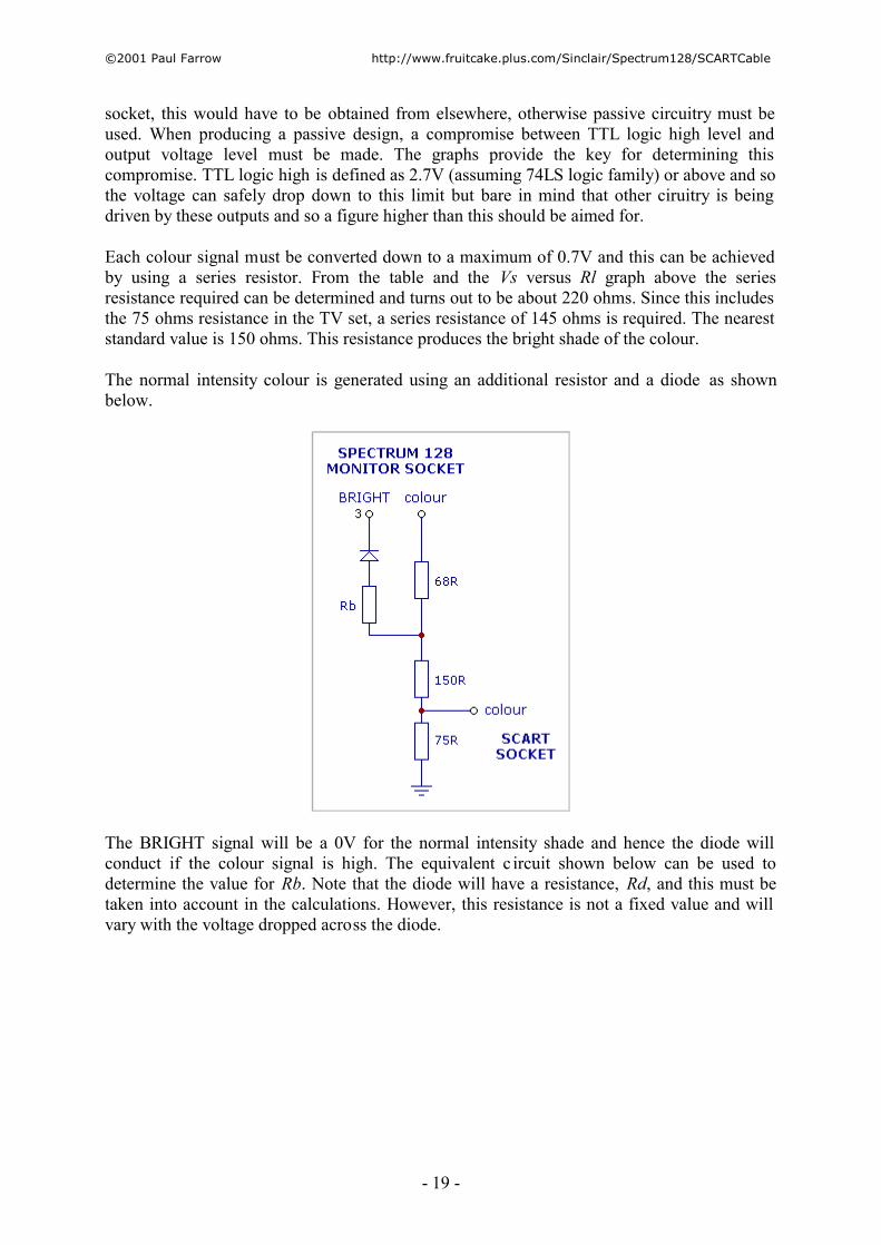
calculations can then be performed to determine the voltage that would be dropped across the 75 ohms (Vs). The table below shows these figures for a range of resistance values.
Rl (ohm)
Vo (V) Vc (V) Vs (V)
51 0.780 1.820 1.147
75 1.040 1.983 1.040
82 1.120 2.049 1.024
100 1.300 2.184 0.975
150 1.650 2.398 0.825
182 1.850 2.541 0.762
220 2.050 2.684 0.699
330 2.500 3.015 0.568
470 2.800 3.205 0.447
660 3.100 3.419 0.352
810 3.250 3.523 0.301
1000 3.350 3.578 0.251
1500 3.450 3.606 0.173
1800 3.475 3.606 0.145
2000 3.500 3.619 0.131
2500 3.550 3.647 0.107
3300 3.600 3.674 0.0818
4700 3.650 3.703 0.0582
10K 3.650 3.675 0.0274
56K 4.200 4.205 0.00563
680K 4.400 4.400 0.000485
From this table, graphs can be plotted that show the exponential relationship between the output voltage and the load resistance. Graphs of Rl against Vo and Vc are shown below.
� 2001 Paul Farrow http://www.fruitcake.plus.com/Sinclair/Spectrum128/SCARTCable
- 18 -
A graph of Rl against Vs is shown below.
Ideally, the TTL output level should not drive such a low load resistance and so a buffer stage would be used. However, since the Spectrum 128 does not provide a power line on its RGB
� 2001 Paul Farrow http://www.fruitcake.plus.com/Sinclair/Spectrum128/SCARTCable
- 19 -
socket, this would have to be obtained from elsewhere, otherwise passive circuitry must be used. When producing a passive design, a compromise between TTL logic high level and output voltage level must be made. The graphs provide the key for determining this compromise. TTL logic high is defined as 2.7V (assuming 74LS logic family) or above and so the voltage can safely drop down to this limit but bare in mind that other ciruitry is being driven by these outputs and so a figure higher than this should be aimed for.
Each colour signal must be converted down to a maximum of 0.7V and this can be achieved by using a series resistor. From the table and the Vs versus Rl graph above the series resistance required can be determined and turns out to be about 220 ohms. Since this includes the 75 ohms resistance in the TV set, a series resistance of 145 ohms is required. The nearest standard value is 150 ohms. This resistance produces the bright shade of the colour.
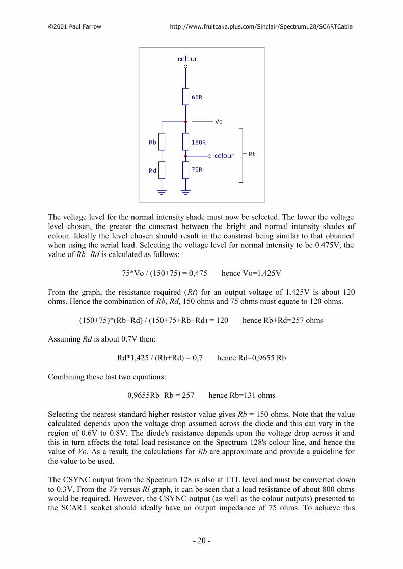
The normal intensity colour is generated using an additional resistor and a diode as shown below.
The BRIGHT signal will be a 0V for the normal intensity shade and hence the diode will conduct if the colour signal is high. The equivalent c ircuit shown below can be used to determine the value for Rb. Note that the diode will have a resistance, Rd, and this must be taken into account in the calculations. However, this resistance is not a fixed value and will vary with the voltage dropped across the diode.
� 2001 Paul Farrow http://www.fruitcake.plus.com/Sinclair/Spectrum128/SCARTCable
- 20 -
The voltage level for the normal intensity shade must now be selected. The lower the voltage level chosen, the greater the constrast between the bright and normal intensity shades of colour. Ideally the level chosen should result in the constrast being similar to that obtained when using the aerial lead. Selecting the voltage level for normal intensity to be 0.475V, the value of Rb+Rd is calculated as follows:
75*Vo / (150+75) = 0,475 hence Vo=1,425V
From the graph, the resistance required (Rt) for an output voltage of 1.425V is about 120 ohms. Hence the combination of Rb, Rd, 150 ohms and 75 ohms must equate to 120 ohms.
(150+75)*(Rb+Rd) / (150+75+Rb+Rd) = 120 hence Rb+Rd=257 ohms
Assuming Rd is about 0.7V then:
Rd*1,425 / (Rb+Rd) = 0,7 hence Rd=0,9655 Rb
Combining these last two equations:
0,9655Rb+Rb = 257 hence Rb=131 ohms
Selecting the nearest standard higher resistor value gives Rb = 150 ohms. Note that the value calculated depends upon the voltage drop assumed across the diode and this can vary in the region of 0.6V to 0.8V. The diode's resistance depends upon the voltage drop across it and this in turn affects the total load resistance on the Spectrum 128's colour line, and hence the value of Vo. As a result, the calculations for Rb are approximate and provide a guideline for the value to be used.
The CSYNC output from the Spectrum 128 is also at TTL level and must be converted down to 0.3V. From the Vs versus Rl graph, it can be seen that a load resistance of about 800 ohms would be required. However, the CSYNC output (as well as the colour outputs) presented to the SCART scoket should ideally have an output impedance of 75 ohms. To achieve this
� 2001 Paul Farrow http://www.fruitcake.plus.com/Sinclair/Spectrum128/SCARTCable
- 21 -
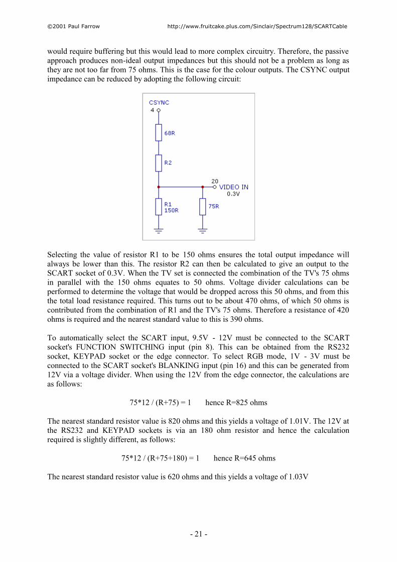
would require buffering but this would lead to more complex circuitry. Therefore, the passive approach produces non-ideal output impedances but this should not be a problem as long as they are not too far from 75 ohms. This is the case for the colour outputs. The CSYNC output impedance can be reduced by adopting the following circuit:
Selecting the value of resistor R1 to be 150 ohms ensures the total output impedance will always be lower than this. The resistor R2 can then be calculated to give an output to the SCART socket of 0.3V. When the TV set is connected the combination of the TV's 75 ohms in parallel with the 150 ohms equates to 50 ohms. Voltage divider calculations can be performed to determine the voltage that would be dropped across this 50 ohms, and from this the total load resistance required. This turns out to be about 470 ohms, of which 50 ohms is contributed from the combination of R1 and the TV's 75 ohms. Therefore a resistance of 420 ohms is required and the nearest standard value to this is 390 ohms.
To automatically select the SCART input, 9.5V - 12V must be connected to the SCART socket's FUNCTION SWITCHING input (pin 8). This can be obtained from the RS232 socket, KEYPAD socket or the edge connector. To select RGB mode, 1V - 3V must be connected to the SCART socket's BLANKING input (pin 16) and this can be generated from 12V via a voltage divider. When using the 12V from the edge connector, the calculations are as follows:
75*12 / (R+75) = 1 hence R=825 ohms
The nearest standard resistor value is 820 ohms and this yields a voltage of 1.01V. The 12V at the RS232 and KEYPAD sockets is via an 180 ohm resistor and hence the calculation required is slightly different, as follows:
75*12 / (R+75+180) = 1 hence R=645 ohms
The nearest standard resistor value is 620 ohms and this yields a voltage of 1.03V