rfp 380-20 general specifications
TRANSCRIPT

“DESIGN, PROCUREMENT, INSTALLATION AND COMMISSIONING OF TELECOMMUNICATIONS, LOW
VOLTAGE AND CONTROL SYSTEMS IN THE THESSALONIKI METRO EXTENSION TO
KALAMARIA”
GENERAL SPECIFICATIONS
RFP- 380/20
GENERAL SPECIFICATIONS Page 1 of 125
GENERAL SPECIFICATIONS

“DESIGN, PROCUREMENT, INSTALLATION AND COMMISSIONING OF TELECOMMUNICATIONS, LOW
VOLTAGE AND CONTROL SYSTEMS IN THE THESSALONIKI METRO EXTENSION TO
KALAMARIA”
GENERAL SPECIFICATIONS
RFP- 380/20
GENERAL SPECIFICATIONS Page 2 of 125
TABLE OF CONTENTS
GS0080 GENERAL SPECIFICATIONS - INTRODUCTION ................................... 3
GS0090 GLOSSARY OF THE PROJECT .............................................................. 6
GS0120 ELECTROMAGNETIC COMPATIBILITY CONTROL PLAN ................... 13
GS0130 CLASSIFICATION OF DRY - WET AREAS FOR E/M INSTALLATIONS .............................................................................................................. 25
GS0140 RELIABILITY, AVAILABILITY, MAINTAINABILITY AND SAFETY (RAMS) .................................................................................................. 27
GS0150 PROJECT MAINTENANCE MANDATORY PERIOD ............................ 40
GS0200 DESIGN REQUIREMENTS .................................................................... 42
GS0400 PROJECT MEETINGS ........................................................................... 67
GS0410 TRAINING .............................................................................................. 71
GS0420 TESTING AND COMMISSIONING ........................................................ 74
GS0430 SPARE PARTS ...................................................................................... 81
GS0450 CLEANING WORKS .............................................................................. 83
GS0460 WORKSITE RECORD DOCUMENTS ................................................... 84
GS0470 MATERIAL HANDLING, GRATING, STORAGE AND PROTECTION AT THE WORKSITES ................................................................................. 85
GS0510 PLANNING AND PROGRESS REPORTS ............................................. 90
GS0600 QUALITY ASSURANCE ......................................................................... 91
GS0650 QUALITY CONTROL ........................................................................... 103
GS0750 HEALTH & SAFETY SPECIFICATIONS .............................................. 108
GS0800 MANAGEMENT INFORMATION SYSTEM (PMIS) .............................. 117
GS0900 ORGANIZATION, MANAGEMENT AND COORDINATION OF DESIGNS AND INTERFACES ............................................................................. 122
GS1592 TEMPORARY ATTIKO METRO WORKSITE OFFICES AND EQUIPMENT ....................................................................................... 125

“DESIGN, PROCUREMENT, INSTALLATION AND COMMISSIONING OF TELECOMMUNICATIONS, LOW
VOLTAGE AND CONTROL SYSTEMS IN THE THESSALONIKI METRO EXTENSION TO
KALAMARIA”
GENERAL SPECIFICATIONS
RFP- 380/20
GENERAL SPECIFICATIONS Page 3 of 125
GS0080 GENERAL SPECIFICATIONS - INTRODUCTION
This document covers issues related to General Specifications of Telecommunications, Low voltage and Control Systems of the Thessaloniki Metro Extension to Kalamaria not included in the scope of the main Contractor of the Project; it is further connected with the Design, Performance, Materials and Workmanship Specifications – specifying the requirements of each system, with the Conditions of Contract (CC) and with the remaining Contractual Documents.
Moreover, this document covers supplementary requirements, organization and procedures related to the Final Design, the Detailed Final Design, coordination, procurement, installation, management of worksites, testing and commissioning, personnel training, spare parts etc. of specific Telecommunications and Low voltage Systems. The implementation of the aforesaid issues shall follow the internationally accepted contemporary good practice and methodologies, in full compliance with Quality and Safety Procedures and all applicable Standards.
This contract shall be implemented based on close cooperation between the Contractor and the main contractor of Kalamaria Extension, who is responsible for the overall coordination of designs and works in the Project.
1 PROJECT TECHNICAL REQUIREMENTS
1.1 Standards – Specifications – Codes – Regulations
1.1.1 The Contractor is obligated to prepare the designs and execute the Project in accordance with the technical specifications of the Project, as these are specified in the contractual documents (General Specifications, E/M and Railway Systems Specifications, Design Specifications for Civil Works, Material and Workmanship Specifications for Civil Works), in any case meeting, at least, the requirements of the applicable Greek legislation.
1.1.2 Where, in the Contractual documents, reference is made to Standards, Specifications, Codes, Regulations, Technical Recommendations etc. applicable shall be their latest version one month prior to the expiry of the deadline for the submission of offers for the subject Tender.
In line with the stipulations of Law 4412/2016 (FEK 147 A’/08.08.2016), the order of precedence of the Normative References shall be as follows:
• Greek standards transposing European Standards
• European technical approvals
• Common technical specifications
• International standards
• Other technical reference systems established by European standardization organizations.
or, lack thereof:

“DESIGN, PROCUREMENT, INSTALLATION AND COMMISSIONING OF TELECOMMUNICATIONS, LOW
VOLTAGE AND CONTROL SYSTEMS IN THE THESSALONIKI METRO EXTENSION TO
KALAMARIA”
GENERAL SPECIFICATIONS
RFP- 380/20
GENERAL SPECIFICATIONS Page 4 of 125
• Greek standards
• National technical approvals
• National technical specifications.
For any other issue, applicable shall be the content of article 282 of Law 4412/2016.
1.1.3 The new Regulations, Specifications, Codes, Provisions etc. or new versions or modifications of the already used ones to be in force during the Project, shall be applicable both during the preparation of designs and during the construction of the Project, provided that they are obligatory as of their establishment, otherwise, following AM’s requirement, the Contractor shall be obligated to comply with this requirement. In case of financial difference, additional amounts shall be paid to the Contractor.
1.2 UNITS
If not otherwise specified elsewhere, the International System (SI) of units shall be used in all activities of the present Project.
1.3 SUITABILITY OF PURPOSE
The Project shall be so designed, installed and commissioned to meet their specified use. The design shall facilitate inspection, cleaning, maintenance, as well as for operation in which continuity of service is a critical consideration.
AM shall provide to the Contractor all necessary data, operation rules and procedures as regards the current Metro network, and shall organize on site meetings – if requested by the Contractor – in order to acquire a complete picture of the existing Metro system, due to:
• The Project’s proximity to parts of the operating network.
• The need for Kalamaria Extension trains to travel to Pylea Depot for maintenance reasons.
All materials used shall be new, of excellent quality and of the class most indicative for operating under the conditions specified and shall withstand the environmental conditions without distortion, deterioration or undue stresses in any part, and also without affecting the strength and suitability of the various interfacing parts.
The design shall incorporate every necessary feature to ensure the safety of the persons involved in the operation and maintenance of the Systems.
1.4 METHODOLOGIES RECOMMENDED BY MANUFACTURERS / SUPPLIERS
Unless otherwise specified, all Project materials and equipment shall be handled and incorporated strictly in accordance with the manufacturer’s/supplier’s recommendations/methodologies and by the

“DESIGN, PROCUREMENT, INSTALLATION AND COMMISSIONING OF TELECOMMUNICATIONS, LOW
VOLTAGE AND CONTROL SYSTEMS IN THE THESSALONIKI METRO EXTENSION TO
KALAMARIA”
GENERAL SPECIFICATIONS
RFP- 380/20
GENERAL SPECIFICATIONS Page 5 of 125
experienced and suitably trained personnel, under ATTIKO METRO S.A’s approval.
The Contractor shall ensure that his staff and cooperating third parties and / or specialised work crews shall use special tools and protective equipment - recommended by the manufacturers - for the installation and use of their materials and equipment.
2 ENVIRONMENTAL CONDITIONS
General
The design of Project shall take account, among other, of the climatic conditions and operating conditions as specified in this document and the Project Specifications.
The Project’s installations and equipment shall be designed and manufactured so that the Project operates as per the contractual requirements in the particular environmental conditions (winds, temperature, humidity, vibration, noise, air and water pollution etc.).
Climatic Conditions
The general meteorological conditions in the Project’s wider area are mentioned in paragraph 8.2.1 of the Environmental Impact Assessment Study for the Project, and are attached to the documents of this tender.
Detailed figures per project location must be obtained on a per case basis from the Greek Meteorological Services.

“DESIGN, PROCUREMENT, INSTALLATION AND COMMISSIONING OF TELECOMMUNICATIONS, LOW
VOLTAGE AND CONTROL SYSTEMS IN THE THESSALONIKI METRO EXTENSION TO
KALAMARIA”
GENERAL SPECIFICATIONS
RFP- 380/20
GENERAL SPECIFICATIONS Page 6 of 125
GS0090 GLOSSARY OF THE PROJECT
1. Glossary
The glossary shall be applicable to the entire project. In case of individual documents other definitions and abbreviations are expressed, these definitions and abbreviations shall be valid only to these documents and on condition that they do not contradict the provisions of the Conditions of Contract.
To ensure a common understanding, a Glossary for defining the elements of the System including definitions and abbreviations is to set up in the Project and shall be used throughout the Project.
1.1 Standards to be applied
The following terms shall be referred to
IEC 60050 901: International Electrotechnical Vocabulary
2. ABBREVIATIONS
2.1 General Technical and Project Management Terms
Abbreviation Term
A/C Air Conditioning
ac or AC Alternating Current
ACD Advanced Concept Design
AFC Automatic Fare Collection
ATC Automatic Train Control
ATIM Automatic Ticket Issuing Machine
ATO Automatic Train Operation
ATP Automatic Train Protection
ATS Automatic Train Supervision system
BACS Building Automation Control System
CCR Central Control Room
CCTV Closed Circuit Television
CW Civil Works
dc or DC Direct Current
DFD Detailed Final Design
ECR Emergency Control Centre

“DESIGN, PROCUREMENT, INSTALLATION AND COMMISSIONING OF TELECOMMUNICATIONS, LOW
VOLTAGE AND CONTROL SYSTEMS IN THE THESSALONIKI METRO EXTENSION TO
KALAMARIA”
GENERAL SPECIFICATIONS
RFP- 380/20
GENERAL SPECIFICATIONS Page 7 of 125
ECS Environmental Control System
FAI First Article for Inspection
FAM Fire Alarm Management
FAT Factory Acceptance Test
FB Fireman’s Box
FCR Field Change Request
FCU Fan Coil Unit
FMECA Failure Modes, Effects and Criticality Analysis
FO Fibre Optics
FRP Fire Resistance Period
GFD Final Design
GS General Specifications
HV High Voltage
HVAC Heating, Ventilation, Air Conditioning
LAS Lighting and Auxiliaries Substation
LV Low Voltage
MDT Maintainability Demonstration Testing
DFD Detailed Final Design
MMI Man Machine Interface
MSS Material Submittal Sheet
MTBF Mean Time Between Failures
MTBSF Mean Time Between Service Failures
MTTR Mean Time To Repair
MV Medium Voltage
NCR Non Conformance Report
NTP Notice to Proceed
OCC Operations Control Centre
PA Public Address
PIS Passenger Information System
PLC Programmable Logic Controller
PPE Personal Protective Equipment

“DESIGN, PROCUREMENT, INSTALLATION AND COMMISSIONING OF TELECOMMUNICATIONS, LOW
VOLTAGE AND CONTROL SYSTEMS IN THE THESSALONIKI METRO EXTENSION TO
KALAMARIA”
GENERAL SPECIFICATIONS
RFP- 380/20
GENERAL SPECIFICATIONS Page 8 of 125
PRCS Power Remote Control System
PS Power Supply
PSAT Partial Stand Alone Test
PSATC Partial Stand Alone Test Certificate
PSN Persons with Special Needs
QA Quality Assurance
QC Quality Control
RAMS Reliability, Availability, Maintainability and Safety
RC Remote Control
RDP RAM Demonstration Plan
RDT Reliability Demonstration Testing
RM Remote Monitoring
RS Rolling Stock OR Rectifier Substation
SAP System Assurance Plan
SAT Stand Alone Test
SATC Stand Alone Test Certificate
SCADA Supervisory Control and Data Acquisition
SE Structure Earth
SIL Safety Integrity Level
SIT System Integration Test
SM Station Master
SMR Station Master Room
SPT System Performance Tests
TCR Traction Current Removal
TE Traction Earth
TETRA Terrestrial Trunked Radio
TOR Top of Rail
TRT Trial Running Tests
TVC Ticket Validator / Canceller
TW Trackwork
UPS Uninterruptible Power Supply
VDU Visual Display Unit

“DESIGN, PROCUREMENT, INSTALLATION AND COMMISSIONING OF TELECOMMUNICATIONS, LOW
VOLTAGE AND CONTROL SYSTEMS IN THE THESSALONIKI METRO EXTENSION TO
KALAMARIA”
GENERAL SPECIFICATIONS
RFP- 380/20
GENERAL SPECIFICATIONS Page 9 of 125
3. DEFINITIONS
This section defines terms used in this document and subsequent specifications.
Term Definition
Application Safety Case
Builds on the Generic Safety Case, justifying that the design of the system and its physical realization, including installation and test phases, for a specific class of application, meet safety requirements.
Availability The ability of a product / system to be in a state to perform a required function under given conditions at a given instant of time or over a given time interval, assuming that the required external resources are provided.
Console A desk with a concentration of controls and indications from which an operator can supervise operations and give commands. These controls and indications may be mounted on a number of panels located on the console.
Data Acquisition A general term for the capture of data from various sensors and the processing of the data for presentation to the operator in the form of VDU displays, printed logs, charts etc.
Electromagnetic Compatibility (EMC)
The ability of equipment to function in a satisfactory manner in its electromagnetic environment, without causing an unacceptable level of electromagnetic disturbance to another equipment item in the same environment.
Equipment Any apparatus or fixed installation.
Device Any finished appliance or combination thereof made commercially available as a single functional unit, intended for the end user.
Fixed Installation A particular combination of several types of apparatus and, where applicable, other devices, which are assembled, installed and intended to be used permanently at a predefined location.
Electromagnetic Disturbance (EMI)
Any electromagnetic phenomenon which may degrade the performance of equipment. An electromagnetic disturbance may be electromagnetic noise, an unwanted signal or a change in the propagation medium itself.
Immunity The ability of equipment to perform as intended without degradation in the presence of an electromagnetic disturbance.

“DESIGN, PROCUREMENT, INSTALLATION AND COMMISSIONING OF TELECOMMUNICATIONS, LOW
VOLTAGE AND CONTROL SYSTEMS IN THE THESSALONIKI METRO EXTENSION TO
KALAMARIA”
GENERAL SPECIFICATIONS
RFP- 380/20
GENERAL SPECIFICATIONS Page 10 of 125
Electromagnetic Environment
All electromagnetic phenomena observable in a given location.
Harmonized Standard
Harmonized standard, as set under article 2, point 1, case c, of (EU) regulation 1025/2012.
Factory Acceptance Tests (FAT)
Tests performed by the Contractor at the facilities of the manufacturer of the materials/ items/ equipment/ rolling stock, prior to shipment for use in the project to verify compliance with the contractual requirements and the applicable standards / specifications.
Failure Rate The failure rate of an item is the ratio of the total number of independent item failures to the total item operating hours.
Stand Alone Tests (SAT)
On-site tests performed by the Contractor to verify proper installation and operation of equipment and subsystems.
Functional Design The design of the functional units of a system restricted to its functional aspects as opposed to the physical ones.
Headway The time separation between two trains travelling in the same direction on the same track.
Interrupt A suspension of a process caused by an event external to that process and performed in such a way that the process can be resumed.
Isolation The electrical separation of two or more circuits by the use of isolating devices such as isolating transformers or optical couplers. Usually employed as a safety feature for the protection of circuit components or as a means of increasing the common mode voltage tolerance of a circuit.
Maintainability The ease with which maintenance of a functional unit can be performed in accordance with prescribed requirements.
Maintenance Action Any type of maintenance activity (preventive or repairing).
Maintenance The combination of all technical and corresponding administrative actions intended to retain an item in or restore it to, a state in which it can perform its required functions, for which it is designed.
Network An interconnected grouping of partially independent units or subsystems.
Operating System Software for controlling the execution of computer programs and that may provide scheduling, debugging, input-output control, accounting, storage, data

“DESIGN, PROCUREMENT, INSTALLATION AND COMMISSIONING OF TELECOMMUNICATIONS, LOW
VOLTAGE AND CONTROL SYSTEMS IN THE THESSALONIKI METRO EXTENSION TO
KALAMARIA”
GENERAL SPECIFICATIONS
RFP- 380/20
GENERAL SPECIFICATIONS Page 11 of 125
management and related operations.
Performance The functional effectiveness obtained by a component, system, person, team, or other entity, as specified.
Preventive Maintenance
The maintenance carried out at predetermined intervals or corresponding to prescribed criteria, and intended to reduce the probability of failure or the performance degradation of an item.
Provisions Future functions/requirements not needed at the initial phase of the project (compatibility, software, cut-outs, spaces, wiring etc.) which will be required at a possible future development of the system.
Qualification Test A test performed by the Contractor or by independent certified / notified bodies prior to production to verify that the components proposed meets the requirements of the Contract.
Metro Railway System
The natural area, the buildings and any kind of installations and systems in use for the operation of the Metro, as well as ancillary areas including station accesses and forecourts if these are owned by AM. It also includes the extensions from the trial running date of the initial section.
Relay An electric device that is designed to interpret input conditions in a prescribed manner and after specified conditions are met, to respond to cause contact operation or similar instant operation in associated electric control circuits.
Reliability The probability that an equipment item or system can perform a required function under given conditions for a given time interval.
Remote Control Control of equipment from a remote location.
Response Time The time required between the arrival of a stimulus to a system and the start of its response.
Safety Case The documented demonstration that the product complies with the specified safety requirements.
Service AM (Attiko Metro S.A.)
Signal Bond A conductor of low resistance placed around rail joints, crossings and switch points to ensure continuity of track circuits.
Sub-system A sub-system of a system or vehicle, as specified on a per case basis.
Systems Design The process of defining the hardware and software architecture, components, modules, interfaces and data for a system to satisfy specified requirements.
“DESIGN, PROCUREMENT, INSTALLATION AND COMMISSIONING OF TELECOMMUNICATIONS, LOW
VOLTAGE AND CONTROL SYSTEMS IN THE THESSALONIKI METRO EXTENSION TO
KALAMARIA”
GENERAL SPECIFICATIONS
RFP- 380/20
GENERAL SPECIFICATIONS Page 12 of 125
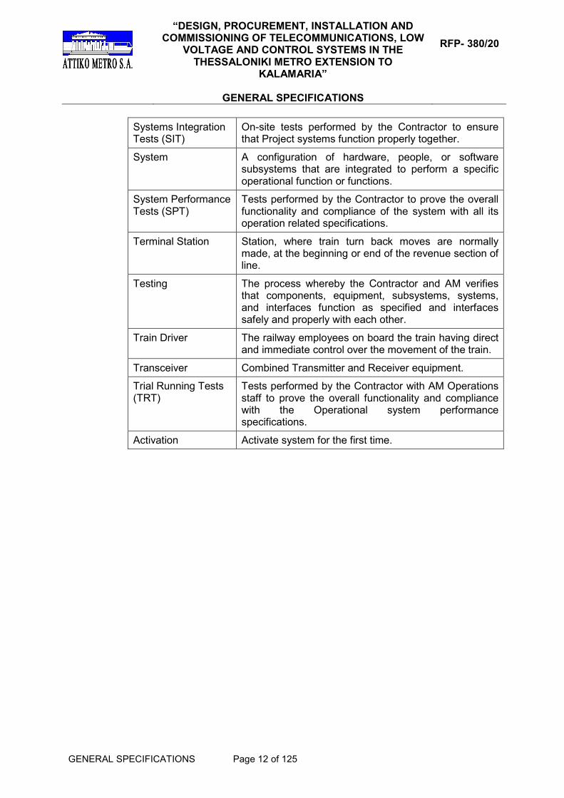
Systems Integration Tests (SIT)
On-site tests performed by the Contractor to ensure that Project systems function properly together.
System A configuration of hardware, people, or software subsystems that are integrated to perform a specific operational function or functions.
System Performance Tests (SPT)
Tests performed by the Contractor to prove the overall functionality and compliance of the system with all its operation related specifications.
Terminal Station Station, where train turn back moves are normally made, at the beginning or end of the revenue section of line.
Testing The process whereby the Contractor and AM verifies that components, equipment, subsystems, systems, and interfaces function as specified and interfaces safely and properly with each other.
Train Driver The railway employees on board the train having direct and immediate control over the movement of the train.
Transceiver Combined Transmitter and Receiver equipment.
Trial Running Tests (TRT)
Tests performed by the Contractor with AM Operations staff to prove the overall functionality and compliance with the Operational system performance specifications.
Activation Activate system for the first time.

“DESIGN, PROCUREMENT, INSTALLATION AND COMMISSIONING OF TELECOMMUNICATIONS, LOW
VOLTAGE AND CONTROL SYSTEMS IN THE THESSALONIKI METRO EXTENSION TO
KALAMARIA”
GENERAL SPECIFICATIONS
RFP- 380/20
GENERAL SPECIFICATIONS Page 13 of 125
GS0120 ELECTROMAGNETIC COMPATIBILITY CONTROL PLAN
1. GENERAL
The regime and conformity requirements in relation to electromagnetic compatibility are set out in Directive 2014/30/EU (EMCD) and in its harmonization in the Greek Legislation through Ministerial Decision OIK. 37764/873/Φ342 (ΦΕΚ 1602/Β/7-6-2016).
It is the Contractor's responsibility to ensure that the Telecommunications, Low voltage and Control Systems and equipment comply with an adequate level of electromagnetic compatibility1.
2. ESSENTIAL REQUIREMENTS General Requirements
In line with Annex I, item 1 of the EMCD Directive, the equipment shall be so designed and manufactured, having regard to the state of the art, as to ensure that:
a) the electromagnetic disturbance generated does not exceed the level above which radio and telecommunications equipment or other equipment cannot operate as intended;
b) it has a level of immunity to the electromagnetic disturbance to be expected in its intended use which allows it to operate without unacceptable degradation of its intended use.
Specific requirements for fixed installations In line with Annex I, item 2 of the EMCD Directive, a fixed installation shall be laid applying good engineering practices and respecting the information on the intended use of its components, with a view to meeting the essential requirements set out in point I, item 1 of the EMCD Directive. The Telecommunications, Low voltage and Control Systems in the Kalamaria Extension are fixed installations in terms of electromagnetic compatibility2.
3. EQUIPMENT REQUIREMENTS FOR FIXED INSTALLATIONS
At the Contractor’s responsibility, apparatus available in the market for
incorporation into a fixed installation shall meet all pertinent provisions on apparatus, as these are specified under the EMCD Directive3.
The requirements of the EMCD Directive shall not be compulsory in the case of apparatus which is intended for incorporation into a particular fixed installation and is otherwise not made available on the market. In such cases,
1 Article 1 of the EMCD Directive
2 Article 3 of the EMCD Directive and of the EMCD Guide, paragraph 1.6.1
3 Article 19 of the EMCD Directive

“DESIGN, PROCUREMENT, INSTALLATION AND COMMISSIONING OF TELECOMMUNICATIONS, LOW
VOLTAGE AND CONTROL SYSTEMS IN THE THESSALONIKI METRO EXTENSION TO
KALAMARIA”
GENERAL SPECIFICATIONS
RFP- 380/20
GENERAL SPECIFICATIONS Page 14 of 125
the accompanying documentation that the Contractor shall provide shall identify the fixed installation and its electromagnetic compatibility characteristics and shall indicate the precautions to be taken for the incorporation of the apparatus into the fixed installation in order not to compromise the conformity of that installation4. The good electromechanical practices referred to in point 2 of Annex I of the EMCD Directive shall be documented by the Contractor and the documentation shall be held by the person (Project Owner) or persons responsible at the disposal of the relevant national authorities for inspection for as long as the fixed installation is in operation. Radio equipment is not regulated under the EMCD Directive. However, radio equipment should comply with Directive 2014/53/EC (RED) and its adaptation to the Greek Legislation through Presidential Decree 98/2017 (FEK, volume A 139/20.09.2017)5. Article 3.1b of the RED Directive states that radio equipment should be manufactured in such a way so that an adequate level of electromagnetic compatibility as set out in the EMCD Directive is ensured. Moreover, the EMCD Directive does not apply to equipment the inherent nature of the physical characteristics of which is such that6:
(i) it is incapable of generating or contributing to electromagnetic emissions which exceed a level allowing radio and telecommunication equipment and other equipment to operate as intended and
(ii) it operates without unacceptable degradation in the presence of the electromagnetic disturbance normally consequent upon its intended use.
The Guide for the EMCD7 provides detailed references to equipment inherently benign in terms of electromagnetic compatibility, such as batteries, cables, transformers, induction motors, relays without electronic parts and other electromechanical apparatus and accessories.
4. EMC CONTROL MANAGEMENT
The Contractor is responsible for the implementation, monitoring and coordination of all EMC activities.
Due to the significant number of systems’ interdependencies, an overall
assessment of the operational performance and the EMC performance of the individual systems and equipment shall be performed. The assessment shall be effected by the Contractor in a structured manner in view of meeting the following main targets:
• Setting of limits and interfaces of the Telecommunications, Low voltage and Control Systems
4 Articles 6 to 12 and 14 to 18 of the EMCD Directive
5 Article 2, paragraph 2, item a of the EMCD Directive
6 Article 2, paragraph 2, item d of the EMCD Directive
7 Guide for the EMCD, paragraph 1.4.4

“DESIGN, PROCUREMENT, INSTALLATION AND COMMISSIONING OF TELECOMMUNICATIONS, LOW
VOLTAGE AND CONTROL SYSTEMS IN THE THESSALONIKI METRO EXTENSION TO
KALAMARIA”
GENERAL SPECIFICATIONS
RFP- 380/20
GENERAL SPECIFICATIONS Page 15 of 125
• Establishment of the individual EMC requirements and their application in subsystems/ equipment/ apparatus.
• Proof of compliance with the EMC requirements and the individual detailed technical specifications.
If the above are not fully met, the Contractor shall:
• Identify non compliance with or deviation from the overall or individual targets of the system.
• Provide an assessment on the impact that non compliance with the targets entails.
• Propose measures for restricting disturbance and protection measures.
• Propose corrective actions necessary for meeting the main targets specified above.
The Contractor shall develop and provide EMC documents for the project in the form of an EMC management plan. The EMC management plan shall establish the process to ensure that the electromagnetic compatibility of the delivered system, within itself and with the operating environment, is achieved. The EMC management plan shall include:
• Organization and deliverables for EMC.
• List of EMC related systems.
• Analysis of electromagnetic environment and immunity of the systems involved.
• EMC risk analysis.
• EMC interfaces table/matrix.
• Applicable standards.
• Protection measures against electromagnetic interference and disturbance.
• Necessary tests for verifying planning in line with EMCD Directive.
• EMC operation and maintenance instructions.
The EMC management plan is a document prepared and issued during the initial design phase. It shall be submitted to ATTIKO METRO S.A. within a period of up to six (6) months upon contract signing. The subject plan shall be updated during each design phase and whenever required by AM. The document shall be updated throughout the phases of the Project’s life cycle.
Moreover, the Contractor shall provide, control and verify the necessary documentation proving compliance with the EMCD directive separately for each Telecommunications, Low voltage and Control Systems he is responsible for. The documentation shall include the following items. Namely:
• EMC estimation and risk analysis.
• Identification of electromagnetic disturbances and level of immunity.

“DESIGN, PROCUREMENT, INSTALLATION AND COMMISSIONING OF TELECOMMUNICATIONS, LOW
VOLTAGE AND CONTROL SYSTEMS IN THE THESSALONIKI METRO EXTENSION TO
KALAMARIA”
GENERAL SPECIFICATIONS
RFP- 380/20
GENERAL SPECIFICATIONS Page 16 of 125
• Applicable EMC standards.
• EMC Certificates/ test reports.
• Plans and reports of EMC on site tests, if required.
5. EMC ENVIRONMENT
The electromagnetic environment and electromagnetic disturbances for the Kalamaria Extension systems are set in the following:
(a) Series EN 50121 standards on E/M systems installed inside a tunnel, at station platforms, traction recesses and at the rectifier sub-stations.
(b) EN 61000-6-2 and EN-61000-6-4 general standards on the E/M
systems installed inside technical rooms except for rectifier substations and traction recesses.
(c) EN 61000-6-1 and EN-61000-6-3 general standards on the E/M
systems installed at the Operations Control Centre (OCC), the Station Master Room (SMR) and at the public areas, except for the station platforms.
6. EMC ESTIMATION AND RISK ANALYSIS
The Contractor shall assess the electromagnetic compatibility of the
equipment based on the relevant phenomena, in view of meeting the essential requirements set out in Annex I, point 1 of the EMCD Directive.
In the framework of the estimation of the electromagnetic compatibility,
consideration shall be made of operation under all normal conditions foreseen. If the equipment can be configured in various ways, the assessment of the electromagnetic compatibility shall verify that the equipment meets the essential requirements set in Annex I, point 1 of the EMCD Directive under all possible configurations that the Contractor deems representative of the equipment’s foreseen use.
The Contractor shall perform an Electromagnetic Interference risk analysis at
all design stages and shall compile a Table of EMI Interface points in order to identify the EMI sources affecting the equipment of other systems and shall propose protection measures for the EMC. These analyses shall serve as the bases for the preparation of reports.
7. CONFORMITY OF EQUIPMENT In case it is requested by AM, the Contractor shall submit the related test
certificates / test results. The Contractor shall ensure that critical equipment has undergone the type
tests foreseen in the EMC related standard in line with the following table:

“DESIGN, PROCUREMENT, INSTALLATION AND COMMISSIONING OF TELECOMMUNICATIONS, LOW
VOLTAGE AND CONTROL SYSTEMS IN THE THESSALONIKI METRO EXTENSION TO
KALAMARIA”
GENERAL SPECIFICATIONS
RFP- 380/20
GENERAL SPECIFICATIONS Page 17 of 125
System &
Equipment
EMC Standards
Railway-related General Equipment-related
Integrated Central Communications Control System (ICCS)
ΕΝ 61000-6-2 ΕΝ 61000-6-4
Fiber Optics Network (FOCC) ΕΝ 61000-6-2 ΕΝ 61000-6-4
Structured Cabling (SC) ΕΝ 61000-6-2 ΕΝ 61000-6-4
Digital Transmission system (DTS)
ΕΝ 50121-48
ΕΝ 61000-6-2 ΕΝ 61000-6-4
Safety and Protection System (SMS), including the following sub-systems: Access Control System/Intrusion Detection System (ACC/IDS)
ΕΝ 50121-4 9
ΕΝ 61000-6-2 ΕΝ 61000-6-4
ΕΝ 50130-4
Passenger Information System (PIS)
ΕΝ 61000-6-2 ΕΝ 61000-6-4
ΕΝ 55032 ΕΝ 55035
Public Announcement (PA) System
ΕΝ 61000-6-2 ΕΝ 61000-6-4
ΕΝ 55032 ΕΝ 55035
Closed Circuit Television System (CCTV)
ΕΝ 61000-6-2 ΕΝ 61000-6-4
ΕΝ 55032 ΕΝ 55035
Radio Communication System (TETRA)
ΕΝ 61000-6-2 ΕΝ 61000-6-4
Uninterruptible Power Supply (UPS) Systems
ΕΝ 61000-6-2 ΕΝ 61000-6-4
EN 62040-2
Power Remote Control System (PRCS)
ΕΝ 61000-6-1 ΕΝ 61000-6-2 ΕΝ 61000-6-3 ΕΝ 61000-6-4
ΕΝ 5503210
ΕΝ 55024
EN 55011 11
EN 61131-2
Programmable Logic Controllers (PLC)
ΕΝ 61000-6-2 ΕΝ 61000-6-4
ΕΝ 55011 12
EN 61131-2
Servers, routers, network switches, screens, PC workstations
ΕΝ 61000-6-1 ΕΝ 61000-6-3
ΕΝ 55011 13
EN 55024
Radio-communication & radio equipment
Directive RED 14
8 The thresholds specified in ΕΝ 61000-6-2 apply in line with note 1, table 1 of ΕΝ 50121-4
9 The thresholds specified in ΕΝ 61000-6-2 apply in line with note 1, table 1 of ΕΝ 50121-4
10 Class A
11 Class A
12 Class A
13 Class A
14 EMC Standards based on the RED Directive

“DESIGN, PROCUREMENT, INSTALLATION AND COMMISSIONING OF TELECOMMUNICATIONS, LOW
VOLTAGE AND CONTROL SYSTEMS IN THE THESSALONIKI METRO EXTENSION TO
KALAMARIA”
GENERAL SPECIFICATIONS
RFP- 380/20
GENERAL SPECIFICATIONS Page 18 of 125
8. EMC SITE TESTS
All EMC related activities and documents listed in this section shall be agreed with AM during the design phase and shall be traceable in the EMC related Design Submission Schedules.
All site tests shall be incorporated into the EMC management plan.
The Contractor shall carry out Site Testing including the Integrated Tests with other Systems to demonstrate that the specified EMC requirements of E/M Systems are met, if required by the EMC assessment and the risk analysis for the Telecommunications, Low voltage and Control systems.
All specifications, schedules/plans and test reports shall be produced accordingly and submitted to AM for approval. The Contractor shall also make the foreseen arrangements for AM to witness tests.
The Contractor shall demonstrate by these tests that electromagnetic interference levels do not exceed the applicable thresholds, as defined in the harmonized standards. In addition, the Contractor shall demonstrate by test that his equipment does not interfere with any of the Metro systems.
Should testing prove that the Contractor’s equipment interferes with any of the Metro systems, as judged by AM and the system supplier, the Contractor shall make all appropriate modifications to the equipment to bring it into compliance with this requirement.
All documents and data for EMC/EMI management shall be entered in the Project Database and be accessible to AM.
At least the following tests shall be provided:
Pre-delivery Testing
• Either existing test certificates shall be used or EMC testing shall be carried out, on all items of equipment identified in this EMC specification as contributing in a decisive manner in the configuration of the EMC levels.
Test reports shall be submitted, for approval by AM, prior to delivery. The test reports shall contain the following information:
o Objectives
o Testing Method
o Expected results
o Pass / fail criteria (equipment performance)
o Test results with comparisons to expected results and pass / fail criteria
o Conclusion
o Recommendations
Post-delivery Testing
• Tests shall be carried out on the installed equipment to confirm that the specified level of EMC has been achieved. The tests shall be co-ordinated with between the respective subsystems.

“DESIGN, PROCUREMENT, INSTALLATION AND COMMISSIONING OF TELECOMMUNICATIONS, LOW
VOLTAGE AND CONTROL SYSTEMS IN THE THESSALONIKI METRO EXTENSION TO
KALAMARIA”
GENERAL SPECIFICATIONS
RFP- 380/20
GENERAL SPECIFICATIONS Page 19 of 125
• It shall be the responsibility of the Contractor to implement corrective actions to rectify any EMC problems identified during testing.
• Test results shall be documented in the test report and submitted to AM.
9. MEASUREMENTS OF RADIO DISTURBANCE (EMI)
Measurement of conducted and radiated disturbance emissions as provided for in series EN 50121 standards or the general standards, applicable each time, is not required, since electromagnetic interference is limited in the environment of Kalamaria Extension and has no impact on the outer environment contrary to the open railway network. The impact of radio disturbance (EMI) in the inner environment of Kalamaria Extension is addressed by ensuring the Telecommunications, Low Voltage and Control systems immunity.
10. IMMUNITY TESTING
Immunity testing of conducted and radiated disturbance as provided for in series EN 50121 standards or the general standards, applicable each time, shall be carried out if they concern facilities and equipment the compliance of which does not ensue from the documentation accompanying the equipment (certificates or test reports) and if special conditions apply (e.g. cabling between systems) or of they concern safety functions. Compliance of the equipment with the requirements of the testing standards shall include confirmation of the operation of the tested equipment (EUT) on the basis of its special operation characteristics and performance criteria.
11. EQUIPMENT PERFORMANCE CRITERIA IN EMC
The general standards on immunity EN 61000-6-1 and EN 61000-6-2 set out the criteria for testing the performance and operation of the equipment in electromagnetic disturbance. These criteria apply also to Telecommunications, Low voltage and Control systems equipment of Kalamaria Extension, as stated in standard EN 50121-115. Criterion A:
The equipment shall continue operating as foreseen. Reduced performance or loss of operation under a certain performance level or an allowable loss of operation, specified by the manufacturer, is not allowed. This criterion applies to continually present phenomena, such as disturbance with RF frequency fields (immunity testing in RF fields through conductivity and radiation).
15
Standard EN 50121-1, paragraph 4

“DESIGN, PROCUREMENT, INSTALLATION AND COMMISSIONING OF TELECOMMUNICATIONS, LOW
VOLTAGE AND CONTROL SYSTEMS IN THE THESSALONIKI METRO EXTENSION TO
KALAMARIA”
GENERAL SPECIFICATIONS
RFP- 380/20
GENERAL SPECIFICATIONS Page 20 of 125
Criterion B:
The equipment shall continue operating as foreseen after testing. Reduced performance or loss of operation under a certain performance level or an allowable loss of operation, specified by the manufacturer, is not allowed. During testing reduced equipment performance is allowed. Nevertheless, a change of the current operation mode or of the stored data is not allowed. This criterion applies to transitional phenomena, such as electrostatic discharge (ESD), electrical fast transients (EFT), impulse overvoltage. Criterion C:
Provisional loss of operation is allowed on condition that this loss can be reinstated automatically or through the activation of certain switches. This criterion applies in cases of power supply interruption or disturbance.
12. MEASURES FOR LIMITING ELECTROMAGNETIC DISTURBANCES
COUPLING
EN 50121-1 specifies five methods for EM disturbances coupling in E/M systems, namely:
a) Electrostatic coupling when a protected circuit is discharged through a protection circuit.
b) Spatial coupling when a variable voltage in a protected circuit causes
voltage changes to the protection circuit through mutual capacitance. c) Inductive coupling when a variable magnetic field generated by current
in a circuit inducts a voltage at the victim circuit through mutual conductivity.
d) Conductive coupling when the protected circuit and the protection circuit
share a mutual conductive branch. e) Electrical (E) radiation and magnetic (M) radiation when the elements of
the circuits act as energy emission and reception antennas. The Contractor shall take all necessary measures to limit the coupling of electromagnetic disturbance, as described in detail in the standards of series EN 61000-5. Measures include equipment EMC shielding and zoning, the use of EMC filters, parallel earthing conductors (PEC), equipotential connections, grouping of cables, cable routing and separation, cable ducts and cable shielding.
13. EMC OF LOW VOLTAGE ELECTRICAL SWITCHBOARDS
The Contractor shall ensure that assembled LV switchboards for E/M systems shall comply with Standard EN 61439-1.

“DESIGN, PROCUREMENT, INSTALLATION AND COMMISSIONING OF TELECOMMUNICATIONS, LOW
VOLTAGE AND CONTROL SYSTEMS IN THE THESSALONIKI METRO EXTENSION TO
KALAMARIA”
GENERAL SPECIFICATIONS
RFP- 380/20
GENERAL SPECIFICATIONS Page 21 of 125
EMC testing for assembled LV switchboard is not required if the following conditions are met16:
a. Integrated equipment complies with the EMC requirements in line with the relevant product standards for EMC.
b. The interior facility and cabling have been performed in line with the
manufacturer’s instructions (layout that takes into consideration interfaces, cables, shielding, earthing etc.).
14. EMC AND SAFETY Electromagnetic compatibility and the safety of the E/M facilities in Kalamaria
Extension have common characteristics, such as earthing, equipotential connections and protection against overvoltage.
In case of contradiction likely to occur between safety and electromagnetic compatibility requirements, such as earth leakage due to EMI feed-through filters, the Contractor shall introduce on a priority basis the safety measures and shall seek alternative measures for electromagnetic compatibility.
15. EMC AND SAFETY FUNCTIONS
Safety function is achieved by a total of the equipment intended to reduce risks entailed by an eventual hazardous condition (safety loop). The aim of the safety function is to ensure automatic transition from a process to a safe condition in case of violation of certain conditions and to allow safe continuation of a process when specific conditions allow so or to take action in order to minimize the impact of a risk. The safety function is characterized by the Safety Integrity Level (SIL), as specified in Standard EN 50129. The Contractor shall ensure that the SIL of the safety function is not downgraded in the electromagnetic environment, as specified in series EN 50121 standards or the general standards, applicable each time.
16. PROTECTION MEASURES FROM ELECTROMAGNETIC FIELDS
The EMCD Directive does not provide for protection measures for passengers and employees in Kalamaria Extension against electromagnetic fields. The Contractor shall ensure that the Telecommunications, Low voltage and Control Systems in Kalamaria Extension shall comply with the Greek Legislation on the protection against electromagnetic fields. The antenna and the radio-communication apparatus installed in the areas of Kalamaria Extension must comply with the threshold values set in Ministerial Decision 53571/3839 (FEK 1105/B/6-9-2000).
16
Annex J.9.4.2, Standard EN 61439-1.

“DESIGN, PROCUREMENT, INSTALLATION AND COMMISSIONING OF TELECOMMUNICATIONS, LOW
VOLTAGE AND CONTROL SYSTEMS IN THE THESSALONIKI METRO EXTENSION TO
KALAMARIA”
GENERAL SPECIFICATIONS
RFP- 380/20
GENERAL SPECIFICATIONS Page 22 of 125
The Contractor shall implement a magnetic fields measurement plan in the area with frequencies 0-20kHZ, in trains, station platforms, inside the tunnel, inside traction recesses and at rectifier, lighting, auxiliary power substations in line with Standard EN 50500. Safety levels with respect to human exposure to low frequency electromagnetic fields must be adhered to, as these are set in Ministerial Decision 3060 (ΦΟΡ) 238 (FEK 512/B/25-4-2002). Moreover, the results of the measurements must be lower than the immunity limits in magnetic fields set in standard EN 45502-2-1 so as not to cause any problem whatsoever to passengers with pacemakers. If the measurements plan does not cover the worst case scenario, the Contractor shall execute additional calculations or a simulation of magnetic fields with the maximum anticipated values of traction current. 17
17. GREEK AND EUROPEAN LEGISLATION
• Directive 2014/30/EU of the European Parliament and of the Council of 26 February 2014 on the harmonisation of the laws of the Member States relating to electromagnetic compatibility.
• Joint Ministerial Decision OIK 37764/873/F342/2016, Electromagnetic Compatibility. Adaptation of the Greek Legislation to Directive 2014/30/EU of the European Parliament and of the Council of 26 February 2014.
• Directive 2014/53/EU, Directive 2014/53/EU of the European Parliament and of the Council of 16 April 2014 on the harmonisation of the laws of the Member States relating to the making available on the market of radio equipment and repealing Directive 1999/5/EC.
• Presidential Decree 98/2017, Harmonization of the Greek Legislation to Directive 2014/53/EU of the European Parliament and of the Council of 16 April 2014 (EU L 153/22.05.2014) relating to the making available on the market of radio equipment and repealing Directive 1999/5/EC.
• 90/385/EEC, Council Directive 90/385/EEC of 20 June 1990 on the approximation of the laws of the Member States relating to active implantable medical devices.
• Ministerial Decision 3060 (ΦΟΡ) 238, Measures for the protection of the public against the operation of appliances emitting low frequency electromagnetic fields.
• Ministerial Decision 53571/3839, Measures for the protection of the public against the operation of land antennae.
18. STANDARDS
If not otherwise specified in the respective Performance Specifications, the following standards are applicable while consideration shall be made of the most recent versions of the standard in force:
17
Standard EN 50500, paragraph 4.3.4

“DESIGN, PROCUREMENT, INSTALLATION AND COMMISSIONING OF TELECOMMUNICATIONS, LOW
VOLTAGE AND CONTROL SYSTEMS IN THE THESSALONIKI METRO EXTENSION TO
KALAMARIA”
GENERAL SPECIFICATIONS
RFP- 380/20
GENERAL SPECIFICATIONS Page 23 of 125
Harmonized standards relating to EMCD18
• EN 50121-1 E4, Railway Applications – Electromagnetic Compatibility. General.
• EN 50121-2 E4, Railway Applications – Electromagnetic Compatibility. Emission of the whole railway system to the outside world.
• EN 50121-4 A1 Railway applications. Electromagnetic Compatibility. Standard for Emissions and Immunity of the Signalling and Telecommunications Apparatus.
• EN 50130-4+Α1, Alarm systems. Electromagnetic compatibility. Product family standard: Immunity requirements for components of fire, intruder, hold up, CCTV, access control and social alarm systems.
• EN 55011+Α1, Industrial, scientific and medical equipment. Radio-frequency disturbance characteristics. Limits and methods of measurement.
• EN 55035, Electromagnetic compatibility of multimedia equipment. Immunity requirements.
• EN 55032/A11, Electromagnetic compatibility of multimedia equipment. Emission Requirements.
• EN 60255-26 E3, Measuring relays and protection equipment. Electromagnetic compatibility requirements.
• EN 61000-3-2 E5, Electromagnetic compatibility (EMC). Limits. Limits for harmonic current emissions (equipment input current ≤ 16 A per phase).
• EN 61000-3-3/A1, Electromagnetic compatibility (EMC). Limits. Limitation of voltage changes, voltage fluctuations and flicker in public low-voltage supply systems, for equipment with rated current ≤ 16 A per phase and not subject to conditional connection.
• EN 61000-3-11 E2, Electromagnetic compatibility (EMC). Limits. Limitation of voltage changes, voltage fluctuations and flicker in public low-voltage supply systems. Equipment with rated voltage current ≤ 75 A and subject to conditional connection.
• EN 61000-3-12 E2, Electromagnetic compatibility (EMC). Limits. Limits for harmonic currents produced by equipment connected to public low-voltage systems with input current > 16 A and ≤ 75 A per phase.
• EN 61000-6-1 E3, Electromagnetic compatibility (EMC). Generic standards. Immunity for residential, commercial and light-industrial environments.
• EN 61000-6-2 E3, Electromagnetic compatibility (EMC). Generic standards. Immunity for industrial environments.
• EN 61000-6-3+Α1, Electromagnetic compatibility (EMC). Generic standards. Emission standard for residential, commercial and light-industrial environments.
• EN 61000-6-4 E3, Electromagnetic compatibility (EMC). Generic standards. Emission standard for industrial environments.
18
Last publication on the Official Journal of the European Union (2016/C293/03)

“DESIGN, PROCUREMENT, INSTALLATION AND COMMISSIONING OF TELECOMMUNICATIONS, LOW
VOLTAGE AND CONTROL SYSTEMS IN THE THESSALONIKI METRO EXTENSION TO
KALAMARIA”
GENERAL SPECIFICATIONS
RFP- 380/20
GENERAL SPECIFICATIONS Page 24 of 125
• EN 61131-2 E3, Programmable controllers. Equipment requirements and tests.
• EN 61326-1 E2, Electrical equipment for measurement, control and laboratory use. EMC requirements. General requirements.
• EN 62040-2 E2, Uninterruptible power systems (UPS). Electromagnetic compatibility (EMC) requirements.
Harmonized standards with the Directive on active implantable medical devices (AIMD) 19
• EN 45502-2-1, Active implantable medical devices. Particular requirements for active implantable medical devices intended to treat bradyarrhythmia (cardiac pacemakers).
Other standards / technical specifications
• EN 50500+Α1 Measurement procedures of magnetic field levels generated by electronic and electrical apparatus in the railway environment with respect to human exposure.
• IEC 61000-5-1, Electromagnetic compatibility (EMC). Installation and mitigation guidelines. General considerations. Basic EMC publication.
• IEC 61000-5-2, Electromagnetic compatibility (EMC). Installation and mitigation guidelines. Earthing and cabling.
• IEC 61000-5-6, Electromagnetic compatibility (EMC). Installation and mitigation guidelines. Mitigation of external EM influences.
• EN 61000-5-7, Electromagnetic compatibility (EMC). Installation and mitigation guidelines. Degrees of protection provided by enclosures against electromagnetic disturbances (EM code).
• EN 55024:2010+A1. Information technology equipment. Immunity characteristics. Limits and methods of measurement.
• EN 61439-1 Low-voltage switchgear and controlgear assemblies. General rules.
• EN 50129 Railway applications. Communication, signaling and processing systems. Safety related electronic systems for signaling.
• Guide for the EMCD (Directive 2014/30/EU) March 2018 20
19
Last publication on the Official Journal of the European Union (2017/C389/02) 20
https://ec.europa.eu/docsroom/documents/28323

“DESIGN, PROCUREMENT, INSTALLATION AND COMMISSIONING OF TELECOMMUNICATIONS, LOW
VOLTAGE AND CONTROL SYSTEMS IN THE THESSALONIKI METRO EXTENSION TO
KALAMARIA”
GENERAL SPECIFICATIONS
RFP- 380/20
GENERAL SPECIFICATIONS Page 25 of 125
GS0130 CLASSIFICATION OF DRY - WET AREAS FOR E/M INSTALLATIONS
1.1 All areas inside buildings and structures are divided into two categories depending on the presence of water – moisture in the environment.
1.2 This classification is made so that the architectural, E/M and Railway systems installations within these areas can be designed based on the corresponding provisions and protection against water – moisture (e.g. in electrical switchboards, lighting fixtures etc.). This classification is independent from the waterproofing protection required for structures.
1.3 In detail, the above areas are classified as follows:
• Class 1: “Dry areas”
- All buildings’ and structures’ indoor areas above ground.
- Public and personnel areas in stations and shafts, with the exception of platforms (e.g. concourse level, transfer level etc.).
- Passenger Access galleries from street level.
- Underground tunnels connecting new and existing stations.
- Access staircases, in general.
- Lift and Escalator Pits.
- Storage Rooms, in general, and Auxiliary Rooms.
- Interior car parking areas.
- Technical Rooms in Depots.
- Technical equipment rooms, in general, with the exception of category 2 exceptions.
• Class 2: “Wet areas”
- Exposed Outdoor Structures and Items
- Equipment Ventilation Shafts and Access Shafts (in general)
- Railway Tunnels, in general
- Electric Equipment Recesses in Tunnels
- Public Areas at Platform Level (*)
- In general, all areas under platform level (*)
- Tunnel ventilation plant rooms in stations and shafts (*)
- Pumping rooms, in general
- Stormwater, Sewage Sumps
- Corrosive materials and wet type battery storage rooms
- Waste water/Sewage Treatment Plants
- Diaphragm Walls Gaps.
(*) applicable only as regards the installation of fixing anchors.

“DESIGN, PROCUREMENT, INSTALLATION AND COMMISSIONING OF TELECOMMUNICATIONS, LOW
VOLTAGE AND CONTROL SYSTEMS IN THE THESSALONIKI METRO EXTENSION TO
KALAMARIA”
GENERAL SPECIFICATIONS
RFP- 380/20
GENERAL SPECIFICATIONS Page 26 of 125
1.4 The Contractor ought to take into consideration the aforementioned classification in the designs and the selection of the Telecommunications, Low Voltage and Control systems, as well as in their installation.

“DESIGN, PROCUREMENT, INSTALLATION AND COMMISSIONING OF TELECOMMUNICATIONS, LOW
VOLTAGE AND CONTROL SYSTEMS IN THE THESSALONIKI METRO EXTENSION TO
KALAMARIA”
GENERAL SPECIFICATIONS
RFP- 380/20
GENERAL SPECIFICATIONS Page 27 of 125
GS0140 RELIABILITY, AVAILABILITY, MAINTAINABILITY AND SAFETY (RAMS)
1. General
The technical approach concerning Reliability, Availability, Maintainability and Safety (RAMS) aims to identify the characteristics of the system’s long term operation and is based on the application of internationally accepted Engineering approaches, Methods, Tools and Techniques throughout the lifecycle of the system. The RAMS of a system can be characterized as a Qualitative and Quantitative Indicator of the degree that the system, or the sub-systems and components comprising that system, can be relied upon to function as specified and to be available and safe. System RAMS is a combination of Reliability, Availability, Maintainability and Safety.
The Contractor, under the scope of this contract, shall make all the necessary analyses and shall undertake all the necessary tests to prove to AM that the Systems delivered meet the RAMS requirements of AM.
The Contractor shall formulate and document Reliability and Availability related targets criteria to satisfy the requirements for the systems assurance through all phases of the Project.
The Contractor shall document instances where evaluations or analyses indicate an unresolved problem area. The Contractor shall formulate appropriate improvement related recommendations as well as maintain records, which shall prove that follow-up action has been taken to resolve the problem.
The Contractor shall develop predictions to judge the adequacy of the proposed design to meet quantitative maintainability requirements and shall identify design features requiring corrective action during early stages of design and development.
The Contractor may submit existing analyses that are properly documented and verifiable for plant and applications, which are identical or obviously similar.
1.1 Safety Organization The Contractor’s safety organization shall comply with the requirements of
para. 5.3.3 of standard EN 50129.
2. Standards
Standards and documents to be used for reference shall be:
• EN 50126
Specification and Demonstration of Reliability, Availability, Maintainability and Safety.
• EN 50128/A1

“DESIGN, PROCUREMENT, INSTALLATION AND COMMISSIONING OF TELECOMMUNICATIONS, LOW
VOLTAGE AND CONTROL SYSTEMS IN THE THESSALONIKI METRO EXTENSION TO
KALAMARIA”
GENERAL SPECIFICATIONS
RFP- 380/20
GENERAL SPECIFICATIONS Page 28 of 125
Communication, signalling and processing systems - Software for railway control and protection systems.
• EN 61709 E3
Electrical components – Reliability - Reference Conditions for Failure Rates and Stress Models for Conversion.
• IEC 61025
Fault Tree Analysis.
• IEC 60812
Analysis techniques for System Reliability – Procedure for failure mode and effect analysis (FMEA).
• IEC 61078
Failure modes and effects analysis (FMEA and FMECA).
• IEC 61508
Functional Safety of electrical/electronic/programmable electronic safety-related systems.
3. Reliability, Availability, Maintainability & Safety requirements
All system availability and reliability and system down times shall be recorded and analysed during the Demonstration Time of the RAMS targets (RDT) phase.
3.1 Availability Requirements
The technical availability shall be measured as follows:
Da = 1 -
Da = Technical Availability
T Reference period = reporting period of 1 week during trial run and 1 month, 3 month, 1 year and 2 years during the reminder of the RDT period.
The required technical availability for the core systems shall be at least 98% of the target availability rates for at least one week at the end of the trial run in order to permit start of revenue service.
The availability rates to be achieved as regards core systems shall comply at least with the following values:
T Reference period of train service
∑ System downtime during the reference period

“DESIGN, PROCUREMENT, INSTALLATION AND COMMISSIONING OF TELECOMMUNICATIONS, LOW
VOLTAGE AND CONTROL SYSTEMS IN THE THESSALONIKI METRO EXTENSION TO
KALAMARIA”
GENERAL SPECIFICATIONS
RFP- 380/20
GENERAL SPECIFICATIONS Page 29 of 125
System/Equipment – System wide -
Minimum Availability (Percent)
Power Remote Control System (PRCS) 99.98
Radio Communication System (TETRA) 99.98
Digital Transmission System (DTS) 99.98
Integrated Central Communications Control System (ICCS) for Telecommunications
99.98
UPS per unit 99.00
Safety and Protection Management System (SMS), along with the sub-systems, to include:
• Intrusion Detection System (IDS) and
• Access and Control System (ACC)
99.90
Closed Circuit Television (CCTV) 99.90
Public Address System (PA) 99.90
3.2 General Reliability Requirements
The equipment / systems shall achieve the following minimum reliability. In the event this reliability cannot be achieved, the Contractor must notify AM.
System/Equipment Minimum Reliability
Protection Relay 99.95
PC & PLC 99.97
3.3 General Maintainability Requirements
In the case minimum maintainability requirements are not specified in the system specifications, the maintainability requirements for each equipment/system shall be as follows:
a) No routine inspection work shall be required on any component at more frequent intervals than monthly and no maintenance more frequently than bi-monthly, except for maintenance/replacement of filters.
b) All units or sub-systems requiring inspection, routine replacement or adjustment shall be arranged for easy access in less than 10 minutes without having to remove any unrelated equipment.
c) No item of equipment shall require general overhaul at intervals less than five years.
The system shall be designed, installed and constructed to enhance the ease of its maintenance. The Contractor shall implement maintainability criteria which shall include the following features:
1. All systems shall be properly designed to minimise the amount of maintenance tasks required to ensure that any maintenance work can be easily and quickly carried out.

“DESIGN, PROCUREMENT, INSTALLATION AND COMMISSIONING OF TELECOMMUNICATIONS, LOW
VOLTAGE AND CONTROL SYSTEMS IN THE THESSALONIKI METRO EXTENSION TO
KALAMARIA”
GENERAL SPECIFICATIONS
RFP- 380/20
GENERAL SPECIFICATIONS Page 30 of 125
2. The design of electronic circuits and sub-systems shall be Line Replaceable Units (LRU).
3. Equipment that has to be disassembled must not weight more than 25 kg if to be handled by one person or more than 50kg if to be handled by two persons.
4. Equipment will allow for easy access for maintenance and cleaning purposes to the authorized personnel. However, it will not allow for easy access to unauthorized personnel and passengers.
5. Self-test facilities by means of built-in-test equipment or circuits shall be provided for start-up and normal operation where applicable.
3.4 Safety requirements
The Contractor shall ensure that, by design or procedures or other effective means, his equipment is safe for manufacturing, installation, commissioning, operation and maintenance.
The software for safety critical railway control and protection systems shall be developed in compliance with EN 50128. The Contractor shall identify safety-critical operations and shall set safety targets in the Risk Analysis which will be submitted to AM for review and approval. Any future modification shall be subject to AM’s approval.
As a general rule: It shall apply that, in case of failure, all systems enter the safe mode.
The Contractor shall proceed to the design and shall propose the anticipated safety levels, which must be agreed upon with AM based on the practice followed in similar systems or in other metro networks.
3.5 Cases to be excluded for calculation of Service Performance:
These are cases that exceed the design criteria and capacity at which Operator is prevented from normal operation of railway service.
As the causes of these events occur outside the jurisdiction of the Operator, the service definition under normal circumstances shall cease to be applicable.
The exemption events shall consist of:
• War
• Internal rioting
• Mandatory modification, which may materially affect the operation of essential equipment
• Natural disasters, e.g. earthquake, hurricane, flooding and tidal waves
• Terrorism attacks
• Strikes
• Loss of external power supplies
• Passenger actions, e.g. suicide
• Actions of authorities outside the Service’s jurisdiction, e.g. police measures.

“DESIGN, PROCUREMENT, INSTALLATION AND COMMISSIONING OF TELECOMMUNICATIONS, LOW
VOLTAGE AND CONTROL SYSTEMS IN THE THESSALONIKI METRO EXTENSION TO
KALAMARIA”
GENERAL SPECIFICATIONS
RFP- 380/20
GENERAL SPECIFICATIONS Page 31 of 125
3.6 Failure Definition
Failure calculation shall exclude those incidents due to loss of external inputs (e.g. loss of external power supply) or failures that are due to external influences e.g. flooding, passenger misbehaviour or staff errors. Repetitive Systematic Failures are not counted more than once for availability and reliability demonstration, provided that the Contractor has presented a satisfactory solution to the cause, which has been approved by AM and the corrective action has been proven as effective.
3.7 Design Failures
A failure shall be deemed to be a design failure if the number of failures occurring up to the approval of the Final Acceptance Protocol is:
i) Failure to operate, perform or comply as specified
not due to component failure : 5 identical failures
ii) Failure of identical components : 0.3% fail
The Contractor shall then effectively remedy such failures free of cost to AM. More specifically, the Contractor shall submit a corrective actions plan, to be approved by AM, and shallot be implemented in order to eliminate failures in materials, components or systems, as required. The remedy shall include modification to designs – if required – and, subsequently, corrective activities on the parts concerned and any associated removal and re-installation work, and the general application of the remedy to such other like parts throughout the Project, wherever this is necessary.
4. Service Performance Index (SPI)
The service performance indices presented here-below shall constitute the basis for demonstrating the performance of the RAMS system:
• Availability of systems
• Reliability of systems The definitions related to the availability and reliability values, as set forth in AM’s Specifications, shall be confirmed at the RDT (Reliability Demonstration Testing) phase.
5. DOCUMENTATION AND DEMONSTRATION OF RAMS TARGETS 5.1 Initial Phase – Final Design
5.1.1 SYSTEMS ASSURANCE PLAN (SAP)
The Contractor shall prepare and submit to AM the Project Preliminary Systems Assurance Plan (SAP), within 3 months after signature of the Contract. The SAP shall be updated during each design phase and when requested by AM.

“DESIGN, PROCUREMENT, INSTALLATION AND COMMISSIONING OF TELECOMMUNICATIONS, LOW
VOLTAGE AND CONTROL SYSTEMS IN THE THESSALONIKI METRO EXTENSION TO
KALAMARIA”
GENERAL SPECIFICATIONS
RFP- 380/20
GENERAL SPECIFICATIONS Page 32 of 125
These requirements shall be also applied to subcontractors and/or work crews and suppliers and shall be carried out during the design, installation, testing and commissioning of the works.
The SAP shall delineate the Contractor’s approach, procedures and schedules for conduct of safety engineering, reliability engineering and maintenance engineering. Human factors engineering is an integral part of systems assurance and shall be considered and reflected in the framework of SAP.
The SAP Procedures shall constitute part of the Contractor’s Quality Assurance System and shall be subject to audits by AM.
The SAP shall include Reliability, Availability and Maintainability analysis, which shall ensure a high degree of failure-free operation and minimise downtime during routine maintenance and failure repair.
The Contractor shall provide Estimates of Potential Reliability and Availability Performance for comparison with the targets specified by the Contractor to identify potential deficiencies during the initial design stage.
The Contractor shall make use of the results of the Reliability Prediction to identify the unreliable subsystems. The Contractor shall implement corrective actions or changes in the design to improve the identified potential deficiencies.
The Contractor shall update the Reliability Prediction until all potential deficiencies are addressed and the specified targets are met before production.
The Contractor shall provide Estimates of Maintainability Performance for comparison with the specified targets to identify potential deficiencies during early design stages.
In-service MTTR data shall be used. If it is not available, the Contractor shall estimate the MTTR with consideration of AM’s operating environment or quote from other published data handbooks.
The Contractor shall implement corrective actions or changes in the design to improve the identified potential deficiencies.
5.1.2 PRELIMINARY SAFETY PLAN (SP)
During the Final Design stage, the Contractor shall prepare and submit to AM for review and approval the preliminary Safety Plan (SP), which shall be updated during the subsequent phases of the project. The Safety Plan shall be submitted at the latest 6 months after the signature of the Contract. The Contractor shall develop the preliminary Safety Case according to EN 50126, and shall include description of the system, details of the structure of his safety organisation, the safety targets that he will achieve, the safety assessment process, the safety related submissions he will provide etc.
5.1.3 PRELIMINARY RAM DEMONSTRATION PLAN (RDT)
The Contractor shall submit a Preliminary Reliability, Availability and Maintainability Demonstration Test Plan and Procedures no later than 12 months after signature of the Contract and the final RTP including procedures ninety (90) days prior to the start of the demonstration.

“DESIGN, PROCUREMENT, INSTALLATION AND COMMISSIONING OF TELECOMMUNICATIONS, LOW
VOLTAGE AND CONTROL SYSTEMS IN THE THESSALONIKI METRO EXTENSION TO
KALAMARIA”
GENERAL SPECIFICATIONS
RFP- 380/20
GENERAL SPECIFICATIONS Page 33 of 125
5.2 DETAILED FINAL DESIGN PHASE
5.2.1 RELIABILITY AND AVAILABILITY ANALYSES
The Contractor shall undertake the Reliability and Availability Analyses using verifiable actual in–service failure data for identical or similar equipment or calculations to demonstrate achievement of the reliability and availability targets specified in the Contract.
The standards used or the source of field data shall be identified. If it is not available, generic failure rates from relevant suppliers, Standards or other published databases shall be quoted or used.
The Contractor shall apportion the System Reliability Targets for the System sub-systems or components as appropriate.
The Contractor shall identify the possible System Failures that will result in overall service failures, and predict the frequency of such incidents per year for the System.
The Contractor shall calculate the inherent System Availability for the whole System, as part of the Reliability Prediction and for use in the Reliability and Safety Analyses. Inherent availability shall be calculated, and submitted to AM, from Mean Time Between Failure (MTBF) and Mean Time To Repair (MTTR) using the following equation:
Inherent Availability = MTBF/ (MTTR+MTBF)
Failure Modes, Effects and Criticality Analysis (FMECA)
a. The Contractor shall produce a FMECA to analyse the high level failure modes of the subsystems in order to assess the criticality of the failure consequences on the Kalamaria Extension Metro systems.
b. The Contractor shall carry out Prediction of the System Availability and System Reliability. The Contractor shall submit a copy in electronic format (in CD too) of the FMECA and other reliability analyses work with the RAM Analysis Report to AM. The FMECA shall include the analysis for single failures inside the Contractor supplied System and interfaces to external Systems.
The Contractor shall plan and carry out the System Reliability Targets Demonstration for all Telecommunications, Low Voltage and Control Systems as defined in the approved System Assurance Plan.
5.2.2 MAINTAINABILITY ANALYSIS
The Contractor shall submit to AM a complete list of Preventive Maintenance Tasks and periodicities and spares requirements for all equipment supplied under the Contract. The Contractor shall also indicate support equipment required for preventive maintenance work.
The Contractor shall propose a Maintenance Concept for the requirements identified during RAM analyses to AM for review and approval. Reliability Focussed Maintenance shall be considered.

“DESIGN, PROCUREMENT, INSTALLATION AND COMMISSIONING OF TELECOMMUNICATIONS, LOW
VOLTAGE AND CONTROL SYSTEMS IN THE THESSALONIKI METRO EXTENSION TO
KALAMARIA”
GENERAL SPECIFICATIONS
RFP- 380/20
GENERAL SPECIFICATIONS Page 34 of 125
Quantitative Maintainability Assessments to all significant functional levels of each system, subsystems or plant shall be allocated. Maintainability analyses during design, development and testing shall be used to evaluate the degree of achievement of the maintainability requirements. The Contractor shall identify the standards by which these allocations are made.
5.2.3 RECOVERY ANALYSES
The Contractor shall conduct the necessary Recovery Analyses, in conjunction with Operation and Maintenance during the detailed design stage to determine the appropriate design and configuration of the System to facilitate speedy recovery of the system under various conditions in the installation and operational stages.
5.2.4 SAFETY ANALYSES
The Contractor shall demonstrate during the design stages achievement of the portion of risk criteria allocated to each System. These Risk Criteria shall be agreed with AM.
5.2.5 RISK IDENTIFICATION AND MITIGATION
(1) The Contractor shall conduct risk identification exercises, in order to ensure that all relevant risks have been systematically identified. The risks shall be ranked using the risk matrix.
(2) Risk mitigation strategy
All risks within his System classified on the basis of EN 50126 principles at risk index R1 (intolerable) and R2 (undesirable) must be dealt with by the Contractor by design measures and, if necessary, operating or maintenance procedures to reduce the risk index R3 (tolerable) or R4 (negligible) level.
The Contractor shall propose the risk evaluation and acceptance criteria, which shall be approved by AM.
Use of operating or maintenance procedures, provision of appropriate training by the Contractor, the Operations Company operating or maintenance staff etc., shall only be used after no practical design solutions can be found.
5.2.6 RISK ANALYSES
The Safety Integrity Level (SIL) for safety related subsystems shall be confirmed before the design is finalised. Any subsequent amendment shall be subject to the approval of AM.
All Risk Analyses related to design, interfaces, installation, operating and maintaining shall be completed and finalised during DFD design phase and all follow-up actions shall be verified and updated in the testing and commissioning stage. Any new risks arising after shall be included and highlighted in the risk analysis reports. The Risk Analysis Report shall be

“DESIGN, PROCUREMENT, INSTALLATION AND COMMISSIONING OF TELECOMMUNICATIONS, LOW
VOLTAGE AND CONTROL SYSTEMS IN THE THESSALONIKI METRO EXTENSION TO
KALAMARIA”
GENERAL SPECIFICATIONS
RFP- 380/20
GENERAL SPECIFICATIONS Page 35 of 125
updated on a regular basis during the installation and testing and commissioning stages.
All results shall be documented in the risk log, including all assumptions made, testing and verification actions to be verified during testing and commissioning stage. The Contractor shall make use of the softcopy of the Risk Log in Microsoft Excel / Access or any other agreed format and submit their Risk Log in softcopy and hardcopy. Corrective Actions Requests (CAR) shall be identified and followed up by the Contractor.
All documents and data for Safety Configuration Items, which shall be included in the Risk Log, shall be entered in a Configuration Management Database and shall be made accessible by AM at all times.
Hazard elimination – The Contractor shall regularly review the progress of the hazard resolutions in the hazard log with AM. Moreover:
(1) All known R1 and R2 risks must be resolved before the commencement of the relevant works in the next phase.
(2) All operational risks requiring specific operating and maintenance procedures must be identified by the Contractor in a timely manner to enable AM to eliminate such risks with the appropriate procedures before the System is allowed to operate. This category of hazard must be resolved and agreed with AM jointly. The necessary procedures shall be drafted and proposed by the Contractor and approved and implemented by AM.
(3) Eliminations or reduction of the level of the identified risks shall be recorded in the respective CARs in the framework of verification.
5.2.7 SAFETY CASE
The Design/System Safety Case shall include the following:
• A schedule of all the identified safety risks and the strategy for their mitigation.
• An evaluation of R1 and R2 hazards, design options and their consequential construction safety risks.
• Details of the risk criteria proposed to each main system and a demonstration of achievement of these criteria.
• Set up a process for monitoring the implementation of the risk mitigation measures and determining the residual risk after all reasonably practicable mitigation measures have been taken in the design.
• Explanations of the techniques to be employed for detailed RAMS Studies.
• A list of residual risks, which cannot be eliminated through design, for which operational procedures are required to minimise the potential consequences.

“DESIGN, PROCUREMENT, INSTALLATION AND COMMISSIONING OF TELECOMMUNICATIONS, LOW
VOLTAGE AND CONTROL SYSTEMS IN THE THESSALONIKI METRO EXTENSION TO
KALAMARIA”
GENERAL SPECIFICATIONS
RFP- 380/20
GENERAL SPECIFICATIONS Page 36 of 125
5.2.8 DESIGN/SYSTEMS SAFETY CASE (GENERIC SAFETY CASE AS PER EN 50126)
The Design/Systems Safety Case shall be submitted at the beginning of the design phase according to the individual Work Schedule as agreed by AM, to confirm that identified safety hazards related to aspects of the Design of the Contract’s Systems have been comprehensively validated and properly addressed.
5.2.9 QUANTITATIVE RISK ANALYSIS
The Contractor shall develop a Quantified Risk Assessment for all safety related systems.
5.2.10 ENGINEERING SAFETY VALIDATION
All the following requirements shall be applicable for the Telecommunications, Low Voltage and Control Systems.
The Engineering Safety Validation Plan shall include:
• The scope of activities to be carried out during the Testing and Commissioning period, including all static and system tests, integrated tests and dynamic tests and commissioning and covering all safety critical functions.
• The health and safety of all those persons participating in testing and commissioning activities.
• The segregation of all testing and commissioning activities from residual construction activities.
• The procedures required to conduct all testing and commissioning activities safely, including where necessary, the protection measures for any part of the Metro which may be in operation.
• The processes to be implemented to validate the safety critical points of software installation and testing.
• The processes required to control and validate the safety implications of modifications carried out during the period of Testing and Commissioning.
• The processes required to assess the safety implications of the results of tests and inspections carried out during the period of Testing and Commissioning.
• The arrangements to record report and investigate accidents and incidents together with the systems necessary to formulate and implement measures to prevent reoccurrence.

“DESIGN, PROCUREMENT, INSTALLATION AND COMMISSIONING OF TELECOMMUNICATIONS, LOW
VOLTAGE AND CONTROL SYSTEMS IN THE THESSALONIKI METRO EXTENSION TO
KALAMARIA”
GENERAL SPECIFICATIONS
RFP- 380/20
GENERAL SPECIFICATIONS Page 37 of 125
5.3 Testing and Commissioning Phase
5.3.1 RAM Demonstration
The Contractor shall submit the RAM targets to be met by the demonstration at least 6 months before start of trial running to ATTIKO METRO for approval. The Contractor shall propose to AM for approval the apportionment of the RAM target of his subsystems and components in compliance with the general RAM target defined in the Contract documents.
AM shall establish a committee, called “RAM co-ordination Committee”, which shall follow up all the RAM demonstration activities. The RAM co-ordination committee shall review test results, establish and monitor improvement actions and monitor the progress of the RAM demonstration starting from the Trial Run and extending up to the success of RAM Demonstration of the operational system installed.
Maintainability Demonstration shall be performed starting with the Factory Acceptance Tests (FAT) and during Personnel Training and Trial Run of the system.
If during the RAM Demonstration Period, any failure is found due to design or installation problems, that requires substantial design modification, the Contractor shall submit a proposal for AM’s approval describing the design changes, the technical and program impacts and all necessary actions to clear the failure.
The Contractor shall also estimate the earliest possible date for restarting the RAM demonstration from the beginning and carrying out the RAM demonstration in the same time period.
The Contractor shall submit a RAM Demonstration Plan (RDP) to include as a minimum the following:
• Organization and key personnel
• Responsibilities (RAM Coordination Committee and Contractor)
• RAM objectives to be achieved during demonstration
• Proposed Demonstration method, Required Form and Process
• Techniques and Methods to be utilized, including the burn-in period of the system and reliability development
• Clear definition of the pass-fail criteria.
5.3.1.1 Demonstration Requirements
Operation demonstration shall be carried out under normal operating conditions - full system capability - without special equipment and testing procedures. AM shall provide the system’s maintenance in line with the procedures described in the approved Operation and Maintenance Manuals.
If during the RAM demonstration period a failure is ascertained, attributable to problems related with the design or construction, necessitating an essential modification of the design, the Contractor shall submit a proposal for approval

“DESIGN, PROCUREMENT, INSTALLATION AND COMMISSIONING OF TELECOMMUNICATIONS, LOW
VOLTAGE AND CONTROL SYSTEMS IN THE THESSALONIKI METRO EXTENSION TO
KALAMARIA”
GENERAL SPECIFICATIONS
RFP- 380/20
GENERAL SPECIFICATIONS Page 38 of 125
by AM and shall describe any changes to the design, the impact on technical system and the impact on the plan, as well as all necessary troubleshooting actions.
The Contractor shall also calculate the earliest possible date for the RAM demonstration to commence a new and for the RAM demonstration to be held for the same time period.
5.3.1.2 Demonstration Records
• The Contractor shall keep records and all evidence related to failures occurring during the demonstration period.
Every recorded failure shall include the following data. Namely:
• Date and time when the failure was identified/reported, arrival at the worksite of the maintenance personnel, commencement and completion of the reinstatement works.
• Short description of the failure, any corrective actions implemented and identification of the causes of the failure (bad assembly, defective component).
• The delay in the train service – if any (based on the briefing provided by the Operations Company Personnel).
• The turnaround time for repair at the repair workshop.
5.3.2 Reliability, Availability, Maintainability Demonstration Testing (RDT)
All Telecommunications, Low Voltage and Control Systems, sub-systems and equipment shall be included in the RDT and shall be fully operational. The Contractor shall perform, based on AM’s test events records, failure/incident data analyses, component analyses and provide corrective action designs and possible additional tests.
The RDT tests shall be carried out in two phases. The first phase shall cover the trial running period. The second period shall cover a period of 2 years starting 6 months after start of revenue service.
The Contractor shall submit weekly status reports during trial run and monthly status reports during the entire reporting period, which shall include as a minimum a list of failures, list of failures management, and achieved MTBF for each subsystem.
At the end of the two-year RDT period, in the framework of which the Contractor shall be responsible for all works, analyses and reporting, the entire documentation, PC software tools and hardware shall be delivered to AM.
5.3.3 Maintainability Demonstration Testing (MDT)
MDT shall be conducted on assemblies, components, and sub-systems jointly selected by AM and the Contractor.

“DESIGN, PROCUREMENT, INSTALLATION AND COMMISSIONING OF TELECOMMUNICATIONS, LOW
VOLTAGE AND CONTROL SYSTEMS IN THE THESSALONIKI METRO EXTENSION TO
KALAMARIA”
GENERAL SPECIFICATIONS
RFP- 380/20
GENERAL SPECIFICATIONS Page 39 of 125
AM reserves the right to decide upon any disputes in the selection of sub-systems to be tested. The MDT shall be carried out from the commencement of the Trial Running period and be completed over a period of not less than a total 12 months to fully demonstrate all aspects of maintainability.
5.3.4 EMC/EMI testing
EMC/EMI testing shall be carried out as agreed with AM for all appropriate elements of the system, to ensure that the requirements of AM are met. The EMC/EMI testing shall be carried out from the commencement of the System Integration test period and shall be completed by the end of the System Performance Test period.
5.3.5 Final Test Report
The Contractor shall submit a Final Test Report, which contains the reliability, maintainability and systems safety demonstration test results. This report shall include test data, test log summaries and, in the event of a reject decision, corrective action recommendations. This report shall be submitted prior to the Final Acceptance review.
5.3.6 Recording of Incident Data
The Contractor shall develop the appropriate software tool for the analysis of the Failure Reporting, Analysis, and Corrective Action System (FRACAS) and shall train the personnel of Operations Company in handling, monitoring and analysing the data in question.
5.3.7 Acceptance of the System
The Contractor shall provide to AM for approval:
• All documents as required to close the Safety Case Plan (as per EN 50126) for all systems provided under his Contract.
• Results of validation of all safety related systems.
• Results of validation of RAMS criteria.
• Results of demonstrations and tests to prove compliance with acceptance criteria.

“DESIGN, PROCUREMENT, INSTALLATION AND COMMISSIONING OF TELECOMMUNICATIONS, LOW
VOLTAGE AND CONTROL SYSTEMS IN THE THESSALONIKI METRO EXTENSION TO
KALAMARIA”
GENERAL SPECIFICATIONS
RFP- 380/20
GENERAL SPECIFICATIONS Page 40 of 125
GS0150 PROJECT MAINTENANCE MANDATORY PERIOD
1. GENERAL
For the project maintenance mandatory period Article 171 of Law 4412/16 applies.
2. WARRANTY PERIOD
2.1 The warranty period in which the Contractor is contractually liable for the proper operation of the telecommunications, low voltage & control systems is set to three (3) years from the final acceptance of the entire scope of the contract.
During the warranty period, the Contractor’s obligations are as follows:
a) Repair, reconstruction, rectification of defects, poor workmanship, faults, constructional deficiencies or other deficiencies that may occur in the Project.
The spare parts, materials, equipment and the works that are required for the correction of the defects and poor workmanship ensuring sound operation of the system during the warranty period shall be provided by and constitute the responsibility of the Contractor, who shall also bear their cost.
b) The technical support, which shall consist in the constant presence locally of at least one (1) Graduate Engineer of the Contractor possessing experience of ten (10) years in the maintenance of Low Voltage Systems, as well as of at least one (1) experienced assistant possessing experience of six (6) years in the maintenance of Low Voltage Systems. This Technical Expert and his Assistant shall rectify the failures that may emerge to the system, to the software and the hardware during the three (3)-year guarantee period. The aforementioned Technical Experts of the Contractor shall possess the required experience and skills, enabling them to troubleshoot faults to the equipment and rectify them as regards the system itself, its equipment related to the OCC, the ECR and the Stations, to restore operation in case of irregularities.
c) During the first twelve (12) months of the revenue operation, the Contractor is obliged to provide AM, via the suitable personnel, the availability required, for supporting the latter on operation issues pertaining all OCC tasks and the Emergency Control Centre (ECR). The operation support shall be available during hours that the Metro is open, as well as when it is out of service, assisting thus in the execution of the preparatory and maintenance works.
2.2 For the spare parts, materials and equipment of the systems or parts of the Project that have either been replaced or repaired during the warranty period,

“DESIGN, PROCUREMENT, INSTALLATION AND COMMISSIONING OF TELECOMMUNICATIONS, LOW
VOLTAGE AND CONTROL SYSTEMS IN THE THESSALONIKI METRO EXTENSION TO
KALAMARIA”
GENERAL SPECIFICATIONS
RFP- 380/20
GENERAL SPECIFICATIONS Page 41 of 125
a six-month extension of the Good Performance Guarantee is granted starting from the date when the warranty period has expired.
2.3 AM and the Contractor shall inspect the Project during the warranty period at regular time intervals that would not exceed three (3) months.
AM may call the Contractor to perform extraordinary inspection at any other time.
2.4 The procedure of defect and fault repairs, as well as the other cases mentioned before, occurring during the entire warranty period is as follows:
a) AM shall be issuing a failure report, accompanied by a work order concerning the repair of the involved fault/defect, where the details of the fault-defect shall be stated along with a detailed description of the problem, the place, the time, the Operation Company / Agency assessment as to the cause of the fault/defect and the corrective actions required. AM and the Operation Company / Agency shall sign the failure report.
b) The Contractor, upon receipt of the work order, which in extraordinary cases can be also given via telephone by AM or the Operations Company / Agency, shall proceed immediately with the necessary actions and works for the repair of the fault and the provision of the required spare parts-materials and personnel etc.
2.5 The Contractor shall be exclusively responsible for the immediate availability of the spare parts and materials required for the project’s maintenance during the warranty period. The available spare parts stock during the warranty period shall meet the Project needs for a minimum period of one (1) year.

“DESIGN, PROCUREMENT, INSTALLATION AND COMMISSIONING OF TELECOMMUNICATIONS, LOW
VOLTAGE AND CONTROL SYSTEMS IN THE THESSALONIKI METRO EXTENSION TO
KALAMARIA”
GENERAL SPECIFICATIONS
RFP- 380/20
GENERAL SPECIFICATIONS Page 42 of 125
GS0200 DESIGN REQUIREMENTS
1. GENERAL
This Specification analyses the design requirements to be needed in the framework of the Project. The level of the designs to be prepared by the Contractor upon the contract signing shall be as follows:
• Final Design – GFD
• Detailed Final Design - DFD
The designs shall cover all sections and scopes of the Project to be included in this contract. The designs shall be prepared taking into consideration the requirements of:
• the Design Specifications for each scope of works,
• the Technical Description,
• the Contractor’s Technical Offer,
• the remaining contractual documents.
2. Design Categories The scope of works that have to be considered and analyzed in the framework
of the designs can be classified as follows:
2.1 Telecommunications, Low Voltage and Control Systems Designs
1. Closed Circuit Television (CCTV)
2. Public Address (PA)
3. Digital Transmission System (DTS)
4. Safety Management System (SMS)
5. Intrusion Detection System (IDS)
6. Access Control System (ACC)
7. Radio Communication System (TETRA)
8. Passenger Information System (PIS)
9. Integrated Central Communication Control System (ICCS)
10. Power Remote Control System (PRCS)
11. Reliability, Availability, Maintainability, Safety (RAMS)
12. Electromagnetic Compatibility (EMC)
2.2 Operation and Maintenance Designs
The Operation and Maintenance Design shall be prepared in order to ensure the smooth operation and maintenance of the aforementioned Systems, in

“DESIGN, PROCUREMENT, INSTALLATION AND COMMISSIONING OF TELECOMMUNICATIONS, LOW
VOLTAGE AND CONTROL SYSTEMS IN THE THESSALONIKI METRO EXTENSION TO
KALAMARIA”
GENERAL SPECIFICATIONS
RFP- 380/20
GENERAL SPECIFICATIONS Page 43 of 125
line with requirements of the Contract Documents, in combination with the information data related to the interconnection with the Basic Metro Project.
3. Design Submission and Review Procedures The design submission and review procedures are as follows: 3.1 Copies of the Design
Each design shall be submitted in five (5) copies. All copies (with the eventual exception of the original – for the Contractor’s convenience) of the Design Documents, Calculation Notes, Technical Reports etc. shall be submitted in double-side printouts. Each design (drawings and documents) shall be submitted in electronic format too (CD or DVD) in two (2) copies in a form to be notified by AM. The electronic format of the files shall include both the Autocad (dwg) and the pdf versions. Especially for the designs of the Telecommunications Systems, the design drawings shall be exclusively submitted in A3.
With regard to the remaining submissions described in the paragraphs below (e.g. para. 4.5, 4.6), the following requirements shall also apply although, not directly relevant with designs:
• The Field Changes shall be submitted in five (5) copies
• Construction Methodologies and Testing Procedures shall be submitted in four (4) copies plus two (2) more additional first pages for stamping-approval.
• The Material Submission Sheets (MSSs) shall be submitted in five (5) copies. The monthly and weekly reports and the Health and Safety reports, as well as the factory tests results shall be submitted in three (3) copies.
3.2 Time for the Submission and Review of the Designs The designs (Design Reports, Work Methodologies, Drawings, Material Submittal Sheets, Construction Methodologies, testing and commissioning Procedures, operation and maintenance Manuals and Instructions, equipment and spare part lists etc.) shall be submitted in accordance with the approved Design Submittal Plan, which is referred to in paragraph 3.4. The designs shall be submitted in due time so that their contractually scheduled final approval may be effected prior to the foreseen -in accordance with the Contractor’s approved time schedule of works- commencement of works.

“DESIGN, PROCUREMENT, INSTALLATION AND COMMISSIONING OF TELECOMMUNICATIONS, LOW
VOLTAGE AND CONTROL SYSTEMS IN THE THESSALONIKI METRO EXTENSION TO
KALAMARIA”
GENERAL SPECIFICATIONS
RFP- 380/20
GENERAL SPECIFICATIONS Page 44 of 125
The review on each submitted design shall be completed within thirty (30) calendar days and shall be transmitted to the Contractor with a Review Code, in line with paragraph 3.3. Within thirty (30) calendar days as of the receipt of a design coded 2 “APPROVED WITH COMMENTS” or 3 “REVISION AND RESUBMISSION”, the Contractor shall submit the revision of the design to AM.
In view of expediting the design submission approval time, up to two (2) design revisions shall be accepted for each design. If further to the second revision, approval of the subject design has failed to be ensured, then a meeting shall be held between representatives of the Managing Department of the Project, the Projects Engineering Department or any other AM Departments concerned and the corresponding representatives of the Contractor, so that an agreement may be reached on all pending items followed by the immediate final submission and approval of the subject design. The agenda of the meeting shall be communicated to the parties involved by the Managing Department at least two (2) days prior to the meeting. A List of Participants shall be held and the Minutes of Meeting shall be copied to the Contractor in an official manner.
3.3 Design Review Codes The design review codes shall be as follows:
• Code 1 “APPROVED” or “APPROVED AS NOTED”: The design is approved. In case of Detailed Design the works may be
executed if the comments (if any) are incorporated in the “As Built” documents. In case of resubmission is required, the revised design shall be resubmitted.
• Code 2 “APPROVED WITH COMMENTS”: The design is approved with comments. The design shall be re-submitted
for approval in order to be upgraded to code 1. At DFD level, the works can be executed, on condition that the Contractor takes into account the comments and incorporates them into the construction as well as the “As Built” documents.
• Code 3 “REVISION and RESUBMISSION”: It is not allowed for the works to be executed. The design must be revised and resubmitted, taking into account AM’s
comments, corrections and notes.
• Code 4 “NO CHECK IS REQUIRED”: There is no reason for any design review.

“DESIGN, PROCUREMENT, INSTALLATION AND COMMISSIONING OF TELECOMMUNICATIONS, LOW
VOLTAGE AND CONTROL SYSTEMS IN THE THESSALONIKI METRO EXTENSION TO
KALAMARIA”
GENERAL SPECIFICATIONS
RFP- 380/20
GENERAL SPECIFICATIONS Page 45 of 125
3.4 Submission of the Design Submittal Plan
The Contractor shall submit for approval the Design Submittal Plan (DSP) of the project within two (2) months upon contract signing. This shall include all Design Reports, Methodologies, Drawings and all items contained in paragraph 4, which shall be prepared during the execution of the Project, along with the scheduled submission dates; the plan shall also include submittals concerning Testing Procedures for all E/M and railway scopes. In particular, the analysis of the design submission schedule shall also cover the basic scopes (not the individual breakdown) of Tables 4.2 / 4.4 of this Specification and per geographical location, with reference to the scheduled date of their submission. The design submittal schedule shall be in agreement with the Project time schedule and shall be harmonized with the following requirements, in accordance with article GS 0500:
• The scheduled sequence of construction and installations.
• The related requirements to design submissions as described in the Design, Performance, Material and Workmanship Specifications.
• The times required for at least one (1) revision/resubmission of the designs, as well as their reviews by AM.
• The logic sequence for the submission of designs, so that there are no designs submitted at times significantly earlier than the corresponding works (e.g. submission of MSS for cables at the beginning of the Project) or no submissions are made which need as a prerequisite the approval or at least the submission and review of other design documents, which are considered as prerequisite for the submission of the submission under review.
• Each submitted design/group of designs included in the list of the Design Submittal Plan must include a clear reference to the corresponding design activity of the Time Schedule and refer to its “Activity ID”.
The Contractor’s design submittal plan to be submitted to AM for approval shall include a more detailed breakdown – list of his intended submittals for each technical scope, as they are specified and broken down in the Tables of paragraphs 4.2, 4.4 (without dates or time schedule or geographical unit) in order to ensure a logical volume for each design (see also the following paragraph 3.5.3) as well as the required scheduling on the part of both sides (AM and Contractor). AM’s approval of the submittal breakdown / list does not deprive AM of its right to request additional designs when necessary. The Contractor shall ensure (through his cooperation with AM) the approval of the designs submission plan within 30 days upon its submission. Once a year, the plan for the submission of designs shall be revised and resubmitted if modified. The plan for the submission of designs can be revised and re-submitted at shorter intervals, if it has to be updated.

“DESIGN, PROCUREMENT, INSTALLATION AND COMMISSIONING OF TELECOMMUNICATIONS, LOW
VOLTAGE AND CONTROL SYSTEMS IN THE THESSALONIKI METRO EXTENSION TO
KALAMARIA”
GENERAL SPECIFICATIONS
RFP- 380/20
GENERAL SPECIFICATIONS Page 46 of 125
3.5 Designs Review Procedure
Through formal correspondence, the Contractor shall submit for review, the required designs in accordance with the requirements of the present General Specification, the relevant individual design specifications (and the relevant Performance Specifications, Material and Workmanship Specifications) for each scope and based on the particular requirements of the Project. AM shall review the submissions and shall return them for approval and commenting in line with the review codes (see para. 3.3), the deadlines (see para. 3.2) and the following preconditions:
1. The Designs Submission Plan shall have been approved; otherwise the
submittal shall be returned with not review. This requirement does not include the designs relating to the works that are scheduled for the first 5-month period of the project based on the time schedule of the project.
2. All designs (each document and drawing) shall be signed by the
corresponding approved Project designers. In case of documents incorporating a number of drawings (usually in A4 or A3 size), the name/logo of the designer, as well as the names of the people who prepared the drawings must be shown on the drawing, in line with the requirements of the Design Quality Programs, which are of mandatory application (FEK 928/B/4.07.2003: DIPAD/OIK/501), or the corresponding procedures of the Contractor’s Quality Management Plan complying with the relevant legislative requirement and the relevant standards.
3. Moreover, the designs must be submitted with the proper thematic
content (i.e. designs, MSS, method statements, procedures etc. should be clearly distinct), while they should also be diligently structured in terms of volume and contents (splitting designs in several individual submittals or on the contrary submitting several designs under the same submittal should be avoided), rendering, thus, design review practically impossible within the time period due. This requirement is correlated to the detailed submittal breakdown list mentioned earlier in para. 3.4. As regards the time sequence for the submission of designs for the various scopes of the Project, the following shall be applicable as a general principle: for the submission of a Detailed Final Design for a specific part of the Project, the respective Final Design should have already been approved.
4. As regards the MSSs, these shall include the following materials: Equipment related to Telecommunications, Low Voltage and Control Systems. For example, materials such as cables, pipes, any kind of supports, cameras, loudspeakers etc. The MSSs shall not include integrated systems, such as CCTV, PA system, telecommunication systems etc. especially when parts thereof are provided by different manufacturers. In this case, separate MSSs shall be provided for the

“DESIGN, PROCUREMENT, INSTALLATION AND COMMISSIONING OF TELECOMMUNICATIONS, LOW
VOLTAGE AND CONTROL SYSTEMS IN THE THESSALONIKI METRO EXTENSION TO
KALAMARIA”
GENERAL SPECIFICATIONS
RFP- 380/20
GENERAL SPECIFICATIONS Page 47 of 125
individual parts, such as cameras, loudspeakers etc. In the case of integrated Systems, as stated above, all the MSSs for the individual items shall be submitted concurrently in view of ensuring the overall supervision of their implementation. The above items must be submitted in addition to the corresponding design in the same or another submittal.
The following shall be also valid: 5. If, further to the first general review, the submitted designs are insufficient
or deficient to a great extent or are based on erroneous data or have not been signed by the approved project designer or are submitted on a time period which is not compatible with the design sequence, then AM may return these designs to the Contractor as unacceptable without reviewing them. The Contractor should resubmit them corrected and revised, based on the contractual requirements.
6. In case of inadequate or incomplete designs, AM reserves the right to
request replacement of the designer. 7. Certain designs or design sections for specialized technical scopes (such
as materials, equipment, work methodologies etc.) any special analyses,, prepared by foreign firms, if drafted in English, may be checked and approved in this language. Upon their approval and if required by AM, they should also be submitted in Greek. Similarly, with regard to certain submittals of the Contractor on specialized technical scope of works, AM may also provide its comments in English.
8. It is noted that the completeness and correctness of the submitted
designs are decisive factors for the smooth preparation and progress of the Project Designs and for the evolution of the Project works within the contractual time schedule.
9. An approved design may be resubmitted with modifications even during
its implementation in the Project if significant reasons dictate so, such as design failure, change of regulations, coordination requirements, worksite restrictions, non-availability of materials or equipment etc. Such amendments may be requested by AM or be proposed by the Contractor and accepted by AM.
10. If the Contractor intends to propose new materials or items of equipment
of improved technology in a specific system, technologically advanced as compared to the specified (e.g. state-of-the-art cables, electronic components or individual items of equipment etc., but not entire systems), which shall satisfy as a minimum the Specifications and the remaining requirements of the contractual documents, as well as the technical, operational and qualitative requirements of the Project without having a negative impact on other sections or systems thereof, then he shall submit them for review and approval without being obliged to file a Request for Technical Deviation and without any alteration to the Lump Sum Price.

“DESIGN, PROCUREMENT, INSTALLATION AND COMMISSIONING OF TELECOMMUNICATIONS, LOW
VOLTAGE AND CONTROL SYSTEMS IN THE THESSALONIKI METRO EXTENSION TO
KALAMARIA”
GENERAL SPECIFICATIONS
RFP- 380/20
GENERAL SPECIFICATIONS Page 48 of 125
4. Description of the scope of the designs 4.1 Introduction
In order to give a better understanding with regard to the scope of the Contractor’s designs and the level of detail depending on the design phase (GFD and DFD) and the scope, certain lists with the deliverable drawings and the contents of the technical reports for each design are given below.
It is clarified that the purpose of presenting the following drawings and contents of the reports is to depict the organization of the general framework for preparing and presenting the designs. The requirements of chapter 4 constitute the minimum deliverables and do not constitute a complete list exhausting the Contractor’s obligations for each design level. In this sense, there might be some differentiations related to the number of the required drawings or their scale or subject matter and content of the individual deliverables (drawings or reports) if this is necessary in order to provide better understanding and presentation of the results of the designs.
It is especially stressed that the present Specification does not make any extensive reference to the content of the Calculation Notes which are included in the Contractor’s design deliverables. The calculation note, as required, shall be prepared in accordance with the stipulations of the Project’s Design Specifications. No design drawings shall be submitted to AM for review without the respective calculation notes and design reports.
In any case, the Contractor should refer to the documents of specifications for each scope as regards the requirements and the contents of the designs.
If AM requests the submission of additional information or drawings or clarifications for the better understanding of the designs and the facilitation of work, then the Contractor is obliged to provide same.
4.2 Design Drawings
In the framework of the preparation of the GFD and the DFD, the following drawings shall be required per scope, as these are presented in the following table. The drawing scales presented in the following tables can be amended by the designer upon his justified proposal and on AM’s approval.

“DESIGN, PROCUREMENT, INSTALLATION AND COMMISSIONING OF TELECOMMUNICATIONS, LOW VOLTAGE AND CONTROL SYSTEMS
IN THE THESSALONIKI METRO EXTENSION TO KALAMARIA”
GENERAL SPECIFICATIONS
RFP- 380/20
GENERAL SPECIFICATIONS Page 49 of 125
DESIGN DRAWINGS
No. SCOPE FINAL DESIGN DETAILED FINAL DESIGN
Earthing and stray current protection
• 1 schematic earthing diagram per location (e.g. station, shaft, building etc.), covering all systems of the contract, taking into consideration the earthing system that has been installed by the main contractor of the Extension.
• Detailed electrical earthing diagram per location (e.g. station, shaft, building etc.), covering all systems of the contract, taking into consideration the earthing system that has been installed by the main Contractor of the Extension.
• Drawings of the final routing of all earthing cabling to be installed by this Contractor, which shall be provided to the main Contractor of the Extension in order to be included in the final coordination drawings of the Project at each location.
Closed Circuit Television System (CCTV)
• 1 schematic diagram per station
• 1 layout drawing per level for each station, showing the locations of equipment (scales 1:200 or 1:100)
• Drawing showing the cable routing of the equipment, where required, taking into account the existing LV trays that have been installed by the main Contractor of the Extension, ensuring EMC.
• Logic sequence diagram for the application software, in combination with the existing one of the Base Project to which it shall be connected.
• 1 detailed schematic diagram for each station Final coordinated drawing showing the layout per level for each station, indicating the locations of the equipment (scales 1:200 or 1:100)
• Final coordinated drawing showing the cable routing of the equipment, where required, ensuring the electromagnetic cable compatibility, taking into account the existing LV trays that have been installed by the main Contractor of the Extension to Kalamaria.
• Detailed schematic diagram showing the equipment connection, including connection with similar systems that

“DESIGN, PROCUREMENT, INSTALLATION AND COMMISSIONING OF TELECOMMUNICATIONS, LOW VOLTAGE AND CONTROL SYSTEMS
IN THE THESSALONIKI METRO EXTENSION TO KALAMARIA”
GENERAL SPECIFICATIONS
RFP- 380/20
GENERAL SPECIFICATIONS Page 50 of 125
have been installed by the main Contractor of the Extension to Kalamaria.
Public Address System (PA)
• 1 schematic diagram per station.
• 1 layout drawing per level for each station, showing the equipment locations (scales 1:200 or 1:100)
• Drawing showing the cable routing of the equipment, where required, taking into account the existing LV trays that have been installed by the main contractor of the Extension, ensuring EMC.
• Logic sequence diagram for the application software, in combination with the existing one of the Base Project to which it shall be connected.
• 1 detailed schematic diagram for each station.
• Final coordinated drawing showing the layout per level for each station, indicating the locations of the equipment (scales 1:200 or 1:100).
• Final coordinated drawing showing the cable routing of the equipment, where required, ensuring the electromagnetic cable compatibility, taking into account the existing LV trays that have been installed by the main Contractor of the Extension.
• Detailed schematic diagram showing the equipment connection, including connection with similar systems that have been installed by the main Contractor of the Extension to Kalamaria.
Digital Transmission System (DTS)
• 1 schematic diagram of the new equipment at stations, crossovers, shafts, OCC and the Emergency Control Centre (ECR).
• 1 layout drawing per level for each station, showing the locations of the DTS equipment (scales 1:200 or 1:100).
• Drawing showing the cable routing of the DTS equipment, where required,
• For each station, shaft, crossover, tunnel, the OCC and the Emergency Control Centre (ECR), the following are required:
• Detailed single-line diagrams of the DTS system.
• Detailed schematic diagrams of the DTS system.
• Final coordinated drawing showing the

“DESIGN, PROCUREMENT, INSTALLATION AND COMMISSIONING OF TELECOMMUNICATIONS, LOW VOLTAGE AND CONTROL SYSTEMS
IN THE THESSALONIKI METRO EXTENSION TO KALAMARIA”
GENERAL SPECIFICATIONS
RFP- 380/20
GENERAL SPECIFICATIONS Page 51 of 125
ensuring EMC.
• Brief diagram showing the interconnection of the equipment for the entire extension and its connection to the Base Project.
• Logic sequence diagram for the application software, in combination with the existing one of the Base Project to which it shall be connected.
• Typical diagram for the interconnection of the DTS equipment with the individual telecommunications systems.
layout of the equipment per level at stations, shafts, crossovers etc. indicating the locations of the DTS equipment (scales 1:200 or 1:100)
• Final coordinated drawing showing the cable of the DTS equipment, where required, ensuring the electromagnetic cable compatibility.
• Detailed schematic diagram showing the DTS equipment connection with the individual telecommunications routing systems, along with the Extension, as well as with the Base Project.
Safety (and Protection) Management System (SMS), along with the sub-systems, to include:
• Intrusion Detection System (IDS)
• Access and Control System (ACC)
• 1 schematic diagram of the new equipment at stations, crossovers, shafts, OCC and the Emergency Control Centre (ECR).
• 1 layout drawing per level for each station, showing the locations of the SMS/IDS/ACC equipment (scales 1:200 or 1:100).
• Drawing showing the cable routing of the IDS/ACC equipment, where required, ensuring EMC.
• Brief diagram showing the interconnection of the equipment for the entire extension and its connection to the Base Project
• Logic sequence diagram for the application software, in combination
• For each station, shaft, crossover and tunnel, the following are required:
• Detailed single-line diagrams of the SMS/IDS/ACC system.
• Final coordinated drawing showing the layout of the equipment per level, indicating locations of the SMS/IDS/ACC equipment (scales 1:200 or 1:100).
• Final coordinated drawing showing the cable routing of the SMS/IDS/ACC equipment, where required, ensuring the electromagnetic cable compatibility.
• Detailed schematic diagram showing the equipment connection of the SMS/IDS/ACC systems.

“DESIGN, PROCUREMENT, INSTALLATION AND COMMISSIONING OF TELECOMMUNICATIONS, LOW VOLTAGE AND CONTROL SYSTEMS
IN THE THESSALONIKI METRO EXTENSION TO KALAMARIA”
GENERAL SPECIFICATIONS
RFP- 380/20
GENERAL SPECIFICATIONS Page 52 of 125
with the existing one of the Base Project to which it shall be connected.
• Typical diagram for the interconnection of the SMS/IDS/ACC equipment.
Radio Communication System (TETRA)
• 1 schematic diagram of the entire extension and 1 typical schematic diagram for the station.
• 1 layout drawing per level for each station, showing the locations of the equipment (scales 1:200 or 1:100).
• Ensuring EMC.
• Preparatory drawings showing the routing trays, ducting etc..
• Logic sequence diagram for the application software.
• 1 detailed schematic diagram at each station, crossover, shaft and tunnel.
• Final coordinated drawing showing the layout of the equipment per level, for each station, crossover, shaft and tunnel indicating locations of the equipment (scales 1:200 or 1:100).
• Final coordinated drawing showing the cable routing of the equipment, where required, ensuring the electromagnetic cable compatibility.
• Detailed schematic diagram showing the equipment connection at each station, crossover, shaft and tunnel.

“DESIGN, PROCUREMENT, INSTALLATION AND COMMISSIONING OF TELECOMMUNICATIONS, LOW VOLTAGE AND CONTROL SYSTEMS
IN THE THESSALONIKI METRO EXTENSION TO KALAMARIA”
GENERAL SPECIFICATIONS
RFP- 380/20
GENERAL SPECIFICATIONS Page 53 of 125
Passenger Information System (PIS)
• 1 schematic diagram per station.
• 1 layout drawing per level for each station, showing the locations of the equipment (scales 1:200 or 1:100).
• Drawing showing the equipment cable routing, as required.
• Ensuring EMC.
• Schematic diagram for the connection with the ATC.
• 1 detailed schematic diagram at each station.
• Final coordinated drawing showing the layout of the equipment per level, for each station, indicating locations of the equipment (scales 1:200 or 1:100).
• Final coordinated drawing showing the cable routing of the equipment, where required, ensuring the electromagnetic cable compatibility.
• Detailed schematic diagram showing the equipment connection.
Integrated Central Communication Control System (ICCS)
• 1 schematic diagram per station, OCC and the Emergency Control Centre (ECR), including connections to all systems duly served.
• 1 layout drawing in rooms 3.4t and the SMR (2.3) for each station, showing the locations of the equipment (scales 1:200 or 1:100).
• Drawing showing the cable routing of the equipment, where required, ensuring EMC.
• Logic sequence diagram for the application software.
• 1 detailed schematic diagram at each station, OCC and the Emergency Control Centre (ECR), including connections to all systems duly served.
• Final coordinated drawing showing the layout of the equipment in rooms 3.4t and the SMR (2.3) for each station, showing the locations of the equipment (scales 1:200 or 1:100).
• Final coordinated drawing showing the cable routing of the equipment, where required, ensuring the electromagnetic cable compatibility.
• Detailed schematic diagram showing the equipment connection.

“DESIGN, PROCUREMENT, INSTALLATION AND COMMISSIONING OF TELECOMMUNICATIONS, LOW VOLTAGE AND CONTROL SYSTEMS
IN THE THESSALONIKI METRO EXTENSION TO KALAMARIA”
GENERAL SPECIFICATIONS
RFP- 380/20
GENERAL SPECIFICATIONS Page 54 of 125
Power Remote Control System (PRCS)
• 1 schematic diagram for the Power Remote Control System (Control Centre, local terminal units in technical rooms for equipment remote control and surveillence purposes)
• 1 schematic diagram per station of the Power Remote Control System (interconnection of the equipment with the local terminal units).
• Logic diagram of automatic back-feeding of the 20KV network in the stations.
• Logic and flow diagrams.
• Schematic layout of the modifications to the OCC and the ECR. Layout of the PRCS equipment in stations, crossovers, shafts etc.
• Detailed electrical drawings, lists of terminal blocks, cable lists, cable connection drawings etc.
• All basic technical data of the equipment shall be shown on the drawings.
• Detailed schematic layout of the equipment at station / crossover / shaft level.
• Detailed schematic layout of the modifications to the OCC and the ECR.
• Drawings showing the layout of the PRCS equipment in the rooms at station, crossover, shaft, OCC and ECR level, including cable routing.
Coordination
Drawings • The Contractor shall submit all
information and GFD drawings required on the basis of the system he will install, for them to be transferred to the main Contractor of the extension, who is responsible for the overall coordination of the designs of the Project.
• The Contractor shall submit all information and DFD drawings required by the systems he will install in order to transfer them to the main contractor of the extension who is responsible for the overall coordination of the designs of the Project.
• Project (scale 1:200 or 1:100).

“DESIGN, PROCUREMENT, INSTALLATION AND COMMISSIONING OF TELECOMMUNICATIONS, LOW
VOLTAGE AND CONTROL SYSTEMS IN THE THESSALONIKI METRO EXTENSION TO
KALAMARIA”
GENERAL SPECIFICATIONS
RFP- 380/20
GENERAL SPECIFICATIONS Page 55 of 125
4.3 Presentation of Design Drawings 4.3.1 General
The drawings numbering and configuration shall be performed based on Specification GS0100 «Metro Works Drawing Office and Codification Manual», which shall be provided to the Contractor.
Any possible effort will be made to achieve uniformity in the submitted drawings with regard to their size (e.g. Α0 or Α1). In addition, all drawings, sketches and diagrams needed to be printed in color for better understanding shall be also submitted in color.
4.3.2 Final Design (GFD) As regards the Final Design, all drawings shall be grouped as follows:
Schematic diagrams, single-line diagrams and plan view drawings for all systems and for all scopes as described in part 4.2
4.3.3 Detailed Final Design (DFD)
For all design stages, the drawings shall be presented per scope in full detail allowing the construction of works or the installation and commissioning of the equipment with all the relevant details.
Specifically, it will be required to provide the drawings and information related to the Contract systems for the preparation of all final co-ordination drawings in DFD level, by the main contractor of the project, including all aforementioned systems with the finally selected equipment.
As soon as co-ordination drawings are finalized, following their approval by AM, they shall be the final approved drawings for the construction of works and the installation of the equipment.
Special reference should be made to the preparation of typical details for the installation of the systems. Typical details shall be prepared for the entire project and shall apply at any location, as required, without any modifications, in order to ensure technical solution uniformity.
4.3.4 Coordination Drawings
The necessary information must be provided to the main Contractor of the Project for him to prepare the coordination drawings in accordance with the detailed stipulations in GS0900 - “DESIGN ORGANIZATION, MANAGEMENT AND COORDINATION - INTERFACE MANAGEMENT PLAN” and the respective clause of Table 4.2 in this document.

“DESIGN, PROCUREMENT, INSTALLATION AND COMMISSIONING OF TELECOMMUNICATIONS, LOW
VOLTAGE AND CONTROL SYSTEMS IN THE THESSALONIKI METRO EXTENSION TO
KALAMARIA”
GENERAL SPECIFICATIONS
RFP- 380/20
GENERAL SPECIFICATIONS Page 56 of 125
4.3.5 “As-built” drawings
Upon completion of the Project works and/or completion of each individual self-standing section thereof, it will be required to submit for review and approval the “as-built” drawings for each one of the project design scopes.
These drawings will be the drawings of the DFD, including all changes and modifications made during the construction of works and the installation of the equipment complying perfectly with the final form of structures and installations. Paragraphs 3 and 4 of this Specification describe the method of submission and the number of copies of the “as-built” drawings to be submitted for each one of the project design scopes.

“DESIGN, PROCUREMENT, INSTALLATION AND COMMISSIONING OF TELECOMMUNICATIONS, LOW VOLTAGE AND CONTROL
SYSTEMS IN THE THESSALONIKI METRO EXTENSION TO KALAMARIA”
GENERAL SPECIFICATIONS
RFP- 380/20
GENERAL SPECIFICATIONS Page 57 of 125
4.4 Design Reports
Within the framework of the Final Design and the Detailed Final Design, the following issues shall be included in the respective reports per design scope, as listed in the table below:
DESIGN REPORTS
SCOPE FINAL DESIGN DETAILED FINAL DESIGN
Closed Circuit Television (CCTV)
• Description of equipment, functional characteristics and operation.
• Brief description of the existing system to which it will be connected and connection needs.
• Requirements for power supply and control.
• Ensuring electromagnetic compatibility.
• List of interfaces with other systems.
• Finalization of all design parameters, final dimensioning and selection of equipment.
• Detailed description of the equipment and the operation of the system, including software.
• Detailed analysis of interfaces with other systems.
• Description of systems redundancy.
• Detailed Technical Specification of the equipment and each individual part thereof.
• List of standards.
• Description of software and its potentials, characteristics, limitations, safety and use.
• CCTV coverage 3D simulation.
Public Address (PA) System
• Description of equipment, functional characteristics and operation.
• Brief description of the existing system to which it will be connected and connection needs.
• Requirements for power supply and control.
• Ensuring electromagnetic compatibility.
• List of interfaces with other systems.
• Finalization of all design parameters, final dimensioning and selection of equipment.
• Detailed description of the equipment and the operation of the system, including software.
• Detailed analysis of interfaces with other systems.
• Description of systems redundancy.
• Detailed Technical Specification of the equipment and each individual part thereof.

“DESIGN, PROCUREMENT, INSTALLATION AND COMMISSIONING OF TELECOMMUNICATIONS, LOW VOLTAGE AND CONTROL
SYSTEMS IN THE THESSALONIKI METRO EXTENSION TO KALAMARIA”
GENERAL SPECIFICATIONS
RFP- 380/20
GENERAL SPECIFICATIONS Page 58 of 125
• List of standards.
• Description of software and its potentials, characteristics, limitations, safety and use.
• Acoustic Design - Simulation.
Digital Transmission System (DTS)
• Description of equipment, functional characteristics and operation.
• Brief description of the existing system to which it will be connected and connection needs.
• List of systems served.
• Requirements for power supply and control.
• Ensuring electromagnetic compatibility.
• List of interfaces with other systems.
• Finalization of all design parameters, final dimensioning and selection of equipment.
• Detailed description of the equipment and the operation of the system, including software.
• Detailed analysis of interfaces with other systems.
• Description of systems redundancy.
• Calculations of network capacity and speed.
• Detailed Technical Specification of the equipment and each individual part thereof.
• Description of its connection and communication with all systems served, protocols, limitations, safety.
• Description of its connection and communication with the central existing system to which it will be connected, protocols, limitations, safety.
• List of Standards.
• Description of software and its potentials, characteristics, limitations, safety and use.
Safety (and Protection) Management System (SMS), along with the sub-systems, to include:
• Intrusion Detection System (IDS)
• Access and Control
• Description of equipment, functional characteristics and operation.
• Brief description of the existing system to which it will be connected and connection needs.
• List of rooms to be served by the IDS and ACC systems.
• Requirements for power supply and control.
• Finalization of all design parameters, final dimensioning and selection of equipment.
• Detailed description of the equipment and the operation of the system, including software.
• Detailed analysis of interfaces with other systems.
• Description of systems redundancy.
• Detailed Technical Specification of the equipment and

“DESIGN, PROCUREMENT, INSTALLATION AND COMMISSIONING OF TELECOMMUNICATIONS, LOW VOLTAGE AND CONTROL
SYSTEMS IN THE THESSALONIKI METRO EXTENSION TO KALAMARIA”
GENERAL SPECIFICATIONS
RFP- 380/20
GENERAL SPECIFICATIONS Page 59 of 125
System (ACC)
• Ensuring electromagnetic compatibility.
• List of interfaces with other systems.
each individual part thereof.
• List of standards.
• Description of software and its potentials, characteristics, limitations, safety and use.
Radio Communication System (TETRA)
• Description of equipment, functional characteristics and operation.
• Brief description of the existing system to which it will be connected and connection needs.
• Requirements for power supply and control.
• Ensuring electromagnetic compatibility.
• List of interfaces with other systems.
• Finalization of all design parameters, final dimensioning and selection of equipment.
• Detailed description of the equipment and the operation of the system, including software.
• Detailed analysis of interfaces with other systems.
• Description of systems redundancy.
• Detailed Technical Specification of the equipment and each individual part thereof.
• List of standards.
• Description of software and its potentials, characteristics, limitations, safety and use.
Passenger Information System (PIS)
• Description of equipment, functional characteristics and operation.
• Brief description of the existing system, including the ATC system to which it will be connected and connection needs.
• Requirements for power supply and control.
• Ensuring electromagnetic compatibility.
• List of interfaces with other systems.
• Finalization of all design parameters, final dimensioning and selection of equipment.
• Detailed description of the equipment and the operation of the system, including software.
• Detailed analysis of interfaces with other systems.
• Detailed Technical Specification of the equipment and each individual part thereof.
• List of standards.
• Description of software and its potentials, characteristics, limitations, safety and use.
Integrated Central Communication Control
• Description of equipment, functional characteristics and operation.
• Finalization of all design parameters, final dimensioning and selection of equipment.

“DESIGN, PROCUREMENT, INSTALLATION AND COMMISSIONING OF TELECOMMUNICATIONS, LOW VOLTAGE AND CONTROL
SYSTEMS IN THE THESSALONIKI METRO EXTENSION TO KALAMARIA”
GENERAL SPECIFICATIONS
RFP- 380/20
GENERAL SPECIFICATIONS Page 60 of 125
System (ICCS) • Brief description of the existing system to which it will be connected and connection needs.
• Requirements for power supply and control.
• Ensuring electromagnetic compatibility.
• List of interfaces with other systems.
• Detailed description of the equipment and the operation of the system, including software.
• Detailed analysis of interfaces with other systems.
• Description of systems redundancy.
• Detailed Technical Specification of the equipment and each individual part thereof.
• List of standards.
• Description of software and its potentials, characteristics, limitations, safety and use.
Power Remote Control System (PRCS)
• Basic principles of equipment installation.
• Description of operation and flow diagrams of functions, data acquisition and processing.
• Calculation of time for operation and data processing from the equipment at stations to/from the OCC.
• Description of equipment, functional characteristics and operation.
• List of interfaces with other systems.
• Lists of main equipment.
• Power related requirements and energy consumption.
• Finalization of all design parameters, detailed calculations, dimensioning and final selection of equipment.
• Detailed technical description of the equipment and software for the Control Centre and the equipment remote control and surveillance local terminal units in the technical rooms and the central control rooms in stations.
• Input/output and other signal lists from / to several items of equipment with the Power Remote Control System (Control Centre and stations).
• Software Quality Assurance Program.
• Software Development Plan.
• Software Development Program.
• Software Management Plan.
• System’s Design and Functional Analysis.
• Description of Operators’ Work Stations in the OCC and the ECR.

“DESIGN, PROCUREMENT, INSTALLATION AND COMMISSIONING OF TELECOMMUNICATIONS, LOW VOLTAGE AND CONTROL
SYSTEMS IN THE THESSALONIKI METRO EXTENSION TO KALAMARIA”
GENERAL SPECIFICATIONS
RFP- 380/20
GENERAL SPECIFICATIONS Page 61 of 125
• RAMS Analysis.
• Detailed list of equipment.
• Hardware Specification.
• Software Specification.
• Operation principles
• Network and Communication Protocols.
• List of commands, indications, alarms etc.
• Calculations for energy requirements and consumption.
• Layout of screens, graphic symbols etc. of the work stations, maintenance stations, temporary screens and the Power Supply System’s VCP large screens.
• Determination of all interfaces between fittings and sub-systems and determination of interfaces with other systems.
• Other documents that are required to fully understand the systems and are needed for the description, identification and clarification of several issues.
Reliability, Availability, Maintainability, Safety (RAMS)
• Systems Assurance Plan (SAP).
• Preliminary Safety Plan (SP).
• Preliminary Plan of Reliability, Availability and Maintainability Demonstration Testing.
• Safety Analysis.
• Risk Analyses.
• Safety Plan.
• Design Safety Plan.
• Reliability and Availability Analyses.
• Maintainability Analyses.
• Safety Analysis.
• Failure Mode, Effects & Criticality Analysis (FMECA).
• Reinstatement Analyses.
• Plan for validating the implementation of Safety.
• System Assurance Inspection.
• RAM Demonstration Plan (RDP) and tests.

“DESIGN, PROCUREMENT, INSTALLATION AND COMMISSIONING OF TELECOMMUNICATIONS, LOW VOLTAGE AND CONTROL
SYSTEMS IN THE THESSALONIKI METRO EXTENSION TO KALAMARIA”
GENERAL SPECIFICATIONS
RFP- 380/20
GENERAL SPECIFICATIONS Page 62 of 125
Electromagnetic Compatibility (EMC)
See the respective EMC specification in GS 0120. See the respective EMC specification, in GS0120.
Coordination Drawings Management Program and Project Interfaces’ Log. -
Operation and Maintenance
Operation and Maintenance Manuals.

“DESIGN, PROCUREMENT, INSTALLATION AND COMMISSIONING OF TELECOMMUNICATIONS, LOW VOLTAGE AND CONTROL
SYSTEMS IN THE THESSALONIKI METRO EXTENSION TO KALAMARIA”
GENERAL SPECIFICATIONS
RFP- 380/20
GENERAL SPECIFICATIONS Page 63 of 125
4.5 Other Design Report Issues
Each design report shall also cover the following topics:
• The designs shall take into consideration the coordination of the designs in combination with other Contractors, as required.
• The preparation of designs shall ensure compatible interconnection between Kalamaria Extension Project and the existing Metro network – Base Project.
• Ensuring the functional coordination of all E/M and railway systems of the Contract.
In the location where the line is connected to the already operating line, the methodology and the nature of the connection works or anything else required in order to have the interconnection executed, tested and set into operation.
• In the framework of the DFDs, the following items should be submitted by the Contractor for each individual scope of the project:
(1) Material Submittal Sheets (MSS) (2) Method Statement and Safe Work method as per GS 0750
(3) Manuals and instructions for the installation of the equipment for all
systems (4) Inspection and testing procedures (all phases of inspections and tests,
as specified in the contractual documents and Specifications - FAT – IT - SAT – SIT - SPT)
(5) Procedures concerning commissioning and trial runs for each of the
systems
(6) Maintenance and operation manuals and instructions for each of the
systems (7) Lists of equipment per individual scope
(8) List of spare parts required for each of systems.
(9) Detailed bills of quantities for each one of the systems (10) Training Programs of the involved Personnel
• It shall be required to prepare a Reliability, Availability, Maintainability and
Safety (RAMS) design, in line with the respective specification.
• It shall be required to prepare the relevant Health & Safety Plan (HSP) and Health & Safety File (HSF), as per the applicable legislation and GS 0750.

“DESIGN, PROCUREMENT, INSTALLATION AND COMMISSIONING OF TELECOMMUNICATIONS, LOW VOLTAGE AND CONTROL
SYSTEMS IN THE THESSALONIKI METRO EXTENSION TO KALAMARIA”
GENERAL SPECIFICATIONS
RFP- 380/20
GENERAL SPECIFICATIONS Page 64 of 125
• Especially, as regards the Material Submittal Sheets (MSSs), if the submissions are incomplete or if additional data or clarifications are required, then AM shall request the Contractor all information required aiming at supplementing each initial submission; upon the submission of the information required, AM shall approve the pertinent MSS.
• Moreover, especially, as regards the Material Submittal Sheets (MSSs), it is stressed that AM possesses a Data Base containing approved materials from previous projects or projects in progress and the relevant list shall be available to the Contractor. If the MSSs submitted are already in the Data Base, then the approval procedure shall be quite shorter.
4.6 Field Change
The Field Change is determined as a local and technically equivalent action due to deviation from the approved DFD, which the Contractor intends to implement during the installation of the Systems related works, at no impact on the Project Cost or Time Schedule. Field Changes are usually required for construction or practical purposes on site of the Project which could not have been foreseen at the project’s design phase. Further to the Contractor’s request, it shall be submitted through standardized form to AM’s Integrated Managing System (see Metro Works Drawing Office and Codification Manual) at the worksite, as well as through the official correspondence addressed to AM. Field Changes shall be executed further to the approval of the respective Contractor’s requests by AM. The Field Change shall always be accompanied by a justification regarding the necessity of the specific change, a documentation technical report, the possibly required relevant calculations along with the respective drawings/sketches, any other technical information deemed necessary, depending on the nature of the proposed change, as well as the Designer’s view, if required, regarding the efficiency and completeness of the change, in relation to the construction item, as well as the long-term safety of the entire Project. All Field Changes shall be incorporated into the “As Built” drawings. In any case, all Field Changes in a Project shall be recorded in a relevant log bearing the required codification (per location, etc., see Metro Works Drawing Office and Codification Manual in General Specifications – Volume II). It is noted that the last update of the aforementioned form, as it will be configured by AM, should be properly incorporated in the Contractor’s Quality Management System.
4.7 Non-Conformance Report The Non-Conformance Report (NCR) is the Report submitted by the Contractor
through a standardized form to AM’s Integrated Management Plan (see Metro Works Drawing Office and Codification Manual) at the worksite and through the

“DESIGN, PROCUREMENT, INSTALLATION AND COMMISSIONING OF TELECOMMUNICATIONS, LOW VOLTAGE AND CONTROL
SYSTEMS IN THE THESSALONIKI METRO EXTENSION TO KALAMARIA”
GENERAL SPECIFICATIONS
RFP- 380/20
GENERAL SPECIFICATIONS Page 65 of 125
official correspondence to AM. The subject report shall be prepared by the Contractor either on his initiative or further to the Supervising Engineer’s suggestion in case there is improper utilization/not utilization of non approved materials / equipment in the worksite as required, or in case of defective work, which is not in compliance with the Project Specifications or with the already approved designs of the Project. Moreover, the Non-Conformance Report refers to deviation, defect or to negligence, in general, as compared to the Contract, Standards, Regulations and possible instructions given by the Service. In the framework of the Non-Conformance Reports, the impact of the work quality is evaluated, the required corrective actions that the Contractor must implement are indicated, and the prescribed remedy deadline along with the person in charge to apply same are indicated. The NCR shall be accepted for specific technical reasons by the Service or shall be justifiably rejected, due to further required actions (e.g. additional corrective measures) and/or settlement on the basis of the contract.
The Contractor is responsible to issue and submit a Non-Conformance Report
whenever AM requested so and for any reason whatsoever within one-week. In any case, all Non-Conformance Reports in a Project shall be recorded in a
relevant log bearing the required codification (per location, etc., based on the Metro Works Drawing Office and Codification Manualof the General Specifications – Volume II).
It is noted that the last update of the aforementioned form, as it will be made by AM, should be properly incorporated in the Contractor’s Quality Management System.
4.8 Technical Deviation Technical Deviation means the deviation from the contractually foreseen Design,
Materials and Workmanship Specifications or the Performance Specifications that the Contractor may propose further to the submission of the relevant request in the standardized form to AM’s Integrated Management System (based on the Metro Works Drawing Office and Codification Manual of the General Specifications – Volume II). Technical Deviations can be submitted in the event of ascertained inconstructibility, failure to find materials, means/equipment, laboratories etc., in line with the provisions of the contract or due to the revision of the applicable specifications/ standards.
The Request for Technical Deviation (RTD) shall be accompanied by a report to include the following: sufficient documentation of the reasons for the failure to comply with the provisions of the contract; comparative technical report between the proposed solution and the solution foreseen by the contract (clear advantages or at least, its equivalence, as compared to the contractual requirement); reference to the adequacy and completeness of the proposed solution, its compliance with the remaining specifications of the Project and its compatibility with the entire Project. The RDT shall also include analysis and documentation of the cost difference between the proposed solution and the solution foreseen by the contract, if any, as well as impact of the proposed solution on the Project Time Schedule.

“DESIGN, PROCUREMENT, INSTALLATION AND COMMISSIONING OF TELECOMMUNICATIONS, LOW VOLTAGE AND CONTROL
SYSTEMS IN THE THESSALONIKI METRO EXTENSION TO KALAMARIA”
GENERAL SPECIFICATIONS
RFP- 380/20
GENERAL SPECIFICATIONS Page 66 of 125
Prior to its implementation, the RTD is subject to AM’s review and approval. The Technical Deviation must be submitted and approved prior to the submission of the (corresponding) Detailed Final Design and shall not concern design assumptions. For the submittals falling under the stipulations of paragraph 3.5.10, no Request for Technical Deviation is required.
In any case, all the Technical Deviations in a Project shall be recorded on the relevant log bearing the necessary codifications (per location, etc. based on the Metro Works Drawing Office and Codification Manual of the General Specifications – Volume II).
It is noted that the last update of the aforementioned form, as it will be made by AM, should be properly incorporated in the Contractor’s Quality Management System.

“DESIGN, PROCUREMENT, INSTALLATION AND COMMISSIONING OF TELECOMMUNICATIONS, LOW VOLTAGE AND CONTROL
SYSTEMS IN THE THESSALONIKI METRO EXTENSION TO KALAMARIA”
GENERAL SPECIFICATIONS
RFP- 380/20
GENERAL SPECIFICATIONS Page 67 of 125
GS0400 PROJECT MEETINGS
1. GENERAL
1.1 This Article describes the project meetings procedures. The meetings scheduled by AM for discussion and resolution of issues related to the Project shall be attended by representatives of AM, the Contractor, Agencies/Organizations and/or other involved Services, and/or other AM Contractors, as required each time and according to the stipulations of the following paragraphs.
1.2 The meetings shall be called and chaired by AM. The agenda shall be communicated by AM to the parties involved at least 2 days prior to the execution of each meeting. A List of Attendants shall be kept, while the Minutes of Meeting shall be copied to the Contractor officially. The Minutes of Meeting shall be drafted by AM. They shall be signed by AM’s representative, the Contractor’s Project Manager or Managers of Electromechanical Works and representatives of other Organizations, Bodies, Services or other AM Contractors, if required. In relation to Health and Safety Meetings, applicable shall be the requirements of the respective specification of this document.
1.3 The meetings shall be held at the Contractor’s Site Office, unless otherwise specified by AM.
1.4 The purpose of these meetings is to resolve technical and procedural matters and, thus, any reference to contractual issues does not establish any obligation for AM and clearly does not amend the Contract. The positions concerning contractual issues shall be communicated through regular mail.
2. INITIAL MEETING
After receipt of the required signed Contract Documents AM will schedule the initial meeting to be held at its premises. The purpose of this meeting is to introduce AM representatives for Health and Safety, quality assurance, quality control, construction management, time schedule, engineering etc. to the Contractor’s counterparts, his representatives, get acquainted with them and establish lines of communication among these representatives.
3. INITIAL CONSTRUCTION MEETING
3.1 AM shall schedule an initial construction meeting within 15 days after the Contract signing date to be held at its premises.
3.2 Participants
The meeting shall be attended by:
• Contractor’s representatives:
o The Chief of works related to Telecommunications, low voltage and Control systems.
o The Chief of engineering works.
o The Safety Coordinator, the Worksite Managers and any other personnel deemed necessary.

“DESIGN, PROCUREMENT, INSTALLATION AND COMMISSIONING OF TELECOMMUNICATIONS, LOW VOLTAGE AND CONTROL
SYSTEMS IN THE THESSALONIKI METRO EXTENSION TO KALAMARIA”
GENERAL SPECIFICATIONS
RFP- 380/20
GENERAL SPECIFICATIONS Page 68 of 125
• AM representatives.
• Representatives of other Agencies, Organizations, Services involved in the Project, if deemed necessary.
3.3 Items for discussion:
• Introduction of attendees and description of their responsibilities.
• Time Schedule (Submission of the Project Time Schedule, deadlines of other submissions in line with the contract documents, Design Submissions Plan, commencement of the execution of works etc.).
• Issuance of any kinds of permits.
• Worksite areas, worksite offices and installations.
• Coordination between representatives of AM, the Contractor, and other Agencies/Services or other AM Contractor’s for the execution of other works.
• Quality Control, Quality Assurance, Health and Safety.
• Procedures for the preparation and submission of Project Payment Certificates.
• Project Data Management System.
• Other issues, as required on a per case basis.
4. PROGRESS MEETINGS
Progress meetings shall be classified in:
i. Construction Progress Meetings
ii. Progress Meetings of the Managing Department
4.1 Construction Progress Meetings
The Construction Progress meetings shall be held every two weeks. The representatives mentioned in para. 3.2, whose presence is required based on the Agenda, shall attend those meetings. The subject meetings will be held at the Contractor’s central worksite office. AM may call additional meetings.
4.1.1 The Agenda for construction progress meetings shall be prepared by AM and shall include, indicatively but however being limited to, the following:
• Introduction of attendees and fields of responsibility.
• Review of minutes of previous meetings, amendment of minutes if necessary, and acceptance of minutes.
• Review of the approved Time Schedule of the Project (progress of executed works per location or per system of the Project, adherence to the contractual deadlines, comparison with the approved time schedule, slippage, impact of any changes, presentation by the Contractor of measures for the recovery of delays, delivery of equipment, Designs Submission Plan etc.).

“DESIGN, PROCUREMENT, INSTALLATION AND COMMISSIONING OF TELECOMMUNICATIONS, LOW VOLTAGE AND CONTROL
SYSTEMS IN THE THESSALONIKI METRO EXTENSION TO KALAMARIA”
GENERAL SPECIFICATIONS
RFP- 380/20
GENERAL SPECIFICATIONS Page 69 of 125
• Preparation by the Contractor and distribution to the attendees of a rolling detailed time schedule of works extending over a period of 4 weeks (one week overlapping) and discussion on this issue.
• Any issues related to Quality, Environment, Health and Safety and methods related to their management.
• Construction, engineering related issues, assessment of the progress made towards their resolution and pending items, if any.
• Other issues as required on a per case basis.
4.1.2 Each of the inquiries and issues raised during these meetings shall be answered, when possible, during the meeting; those not answered during the meeting shall be resolved after the close of the meeting.
4.1.3 The minutes of construction progress meeting shall be prepared by the AM and signed by the Contractor’s and the Managing Department’s Representatives.
4.2 Progress Meetings of the Managing Department
The Contractor shall attend the progress meetings of the Managing Department, which are held as a minimum on a monthly basis at a location and time defined by AM.
The frequency of the said meetings shall be modified when deemed necessary by AM. These meetings shall be attended by the representatives mentioned in paragraph 3.2.
5. HEALTH AND SAFETY MEETINGS
With regard to Health & Safety issues, meetings shall take place as per the article GS0750 “HEALTH & SAFETY SPECIFICATION” of this document.
6. CO-ORDINATION MEETINGS
6.1 Coordination meetings shall be called by AM whenever deemed necessary. During these meetings, any issues related to designs and works of all agencies involved in the execution of the Project (Contractors of other AM related works, Services/Agencies/Organizations etc.) shall be discussed, coordinated and settled with a in order to ensure smooth execution of all Project works in line with the approved time schedule.
6.2 Attendees
The meetings shall be attended by:
• Representatives of the Contractor: The Project Manager, the Worksite Managers or their authorized representatives, Engineers and any other persons whose presence is required as per the Agenda.
• AM representatives.
• Representatives of other Agencies/Services involved in the Project, if deemed necessary.

“DESIGN, PROCUREMENT, INSTALLATION AND COMMISSIONING OF TELECOMMUNICATIONS, LOW VOLTAGE AND CONTROL
SYSTEMS IN THE THESSALONIKI METRO EXTENSION TO KALAMARIA”
GENERAL SPECIFICATIONS
RFP- 380/20
GENERAL SPECIFICATIONS Page 70 of 125
6.3 The Agenda for the Co-Ordination Meetings shall be prepared by AM and shall include, indicatively but however being limited to, the following:
• Introduction of attendees and fields of responsibility.
• Review of minutes of previous meetings, amendment of minutes if necessary and acceptance of minutes.
• Identification of interfaces, co-ordination of design, coordination of works and time schedule and review of design submittals, schedules. The Contractor shall make available an updated detailed time schedule showing all interfaced activities related with and subject to coordination.
• Discussion of upcoming work phases.
• Other issues as necessary, on a per case basis.
• Scheduling of subsequent meeting, as required.
Each of the inquiries and issues raised during the meetings shall be answered, when possible during the meeting; those not answered during the meeting shall be resolved, after the close of the meeting.
7. MEETINGS ON ENGINEERING ISSUES
The Meetings on Engineering Issues shall be held at a place and time specified by AM. The frequency of these meetings is related to the engineering issues that arise and shall be held as deemed necessary by AM.
They serve as a communication channel among the designer engineers and their purpose is to solve any engineering issues and provide coordination of designs necessitating the participation/coordination of additional competent sections in order to ensure smooth execution of all works.
7.1 Attendees
The meetings shall be attended by the Representatives of the Contractor:
• The Head of engineering works.
• Design Engineers.
• Other representatives of the Contractor whose presence is required on the
basis of the Agenda.
• The respective AM representatives.

“DESIGN, PROCUREMENT, INSTALLATION AND COMMISSIONING OF TELECOMMUNICATIONS, LOW VOLTAGE AND CONTROL
SYSTEMS IN THE THESSALONIKI METRO EXTENSION TO KALAMARIA”
GENERAL SPECIFICATIONS
RFP- 380/20
GENERAL SPECIFICATIONS Page 71 of 125
GS0410 TRAINING
1. TRAINING REQUIREMENTS
The Contractor shall train the authorized Personnel of Thessaloniki Metro Company/Operations Agency on the operation and maintenance of the systems installed at Kalamaria extension, in the OCCs, in the ECR and where required.
This authorized personnel shall include the Operation/Maintenance instructors and personnel, Operation Control Centre (OCC) and ECR staff, Station Masters, Technical Supervisors, System Engineers, Line Operators and the entire personnel who will require training in operational, technical matters according to their duties.
2. TRAINING OBJECTIVES
The content and duration of the training programme shall be such that personnel trained by the Contractor will be able to operate and maintain the equipment and systems as designed and installed with maximum availability, reliability and safety in an economical manner.
Training objectives shall be clearly defined by the Contractor, for each trainee post, including the instructors. The contractor shall develop a pass-fail criterion for each person receiving training in his or her respective discipline. It shall be the contractor’s responsibility to ensure perfect training to all participants.
3. SELECTION OF TRAINEES
3.1 The Contractor shall submit for the approval of AM the numbers of staff per field, including each System Instructors, for whom training is suggested.
3.2 The Contractor shall submit measurable criteria for each trainee post, indicating the respective required qualifications to cover this post, such as, indicatively:
a) Level of education.
b) Skills and knowledge, skills and any special aptitudes.
c) Oral and written proficiency etc.
3.3 Based on the above criteria, AM will select the candidates to be trained and shall communicate their names to the Contractor not less than one month before the start of their training.
4. METHODS, TOPICS, LOCATIONS/MEANS, PERSONNEL AND PROGRAM OF TRAINING
4.1 The training shall be planned and carried out in the appropriate manner for each work position and shall consist of:
a) Off -the-job, classroom theory and practice.
b) Practical on-the-job training in operator and equipment rooms, in technical rooms as well as in tunnels and in the Depot.
c) Each trainee shall be granted a certificate after passing an evaluation examination certifying that he/she is properly trained. In case of critical

“DESIGN, PROCUREMENT, INSTALLATION AND COMMISSIONING OF TELECOMMUNICATIONS, LOW VOLTAGE AND CONTROL
SYSTEMS IN THE THESSALONIKI METRO EXTENSION TO KALAMARIA”
GENERAL SPECIFICATIONS
RFP- 380/20
GENERAL SPECIFICATIONS Page 72 of 125
activities for the safe operation of the System, AM can request a training certificate from an independent notified Railway agency.
4.2 The Contractor shall submit for the approval of AM six (6) months prior to commissioning, program and syllabus of training and procedures for monitoring the progress of the training program and the individual performance. The program shall clearly specify the commencement and completion dates and number of trainees for each training course. The program shall clearly identify whether the training is performed in a classroom (off the job) or in the equipment room (on-the-job).
Syllabus shall clearly indicate as minimum the following:
a) Course title and objectives.
b) Course content.
c) Location of training course.
d) Methods of training.
Methods for monitoring training progress shall consist of:
a) Theoretical tests.
b) Practical tests.
c) Progress reports.
The training program shall be coordinated with the testing, commissioning and trial run schedule.
4.3 Records of trainee’s progress shall be kept up-to-date and made available to AM discipline supervisor and his representative for examination when required to do so.
4.4 Copies of individual trainee’s records showing all test results and reports of progress shall be transmitted to AM on final completion of each training course or attachment.
5. CONTRACTOR’S TRAINING STAFF
5.1 For all training, both theoretical and practical, the Contractor shall ensure that qualified staff has been employed as instructors to train AM’s staff and future trainers. CV’s of the proposed trainers of the Contractor shall be sent at latest three (3) months prior to the start of the training to AM for approval.
5.2 Where trainees are assigned to the Contractor (or his Subcontractors) for the purposes of job related training, all such trainees shall be properly supervised and monitored by a qualified training supervisor to ensure that each trainee has the best opportunity to benefit from the theoretical and practical training.
6. TRAINING LOCATIONS
6.1 The training shall be carried out at such locations where the greatest benefit for trainees may be gained. This may be in Greece or abroad, at places of manufacture, assembly or testing, or at such other locations as may be necessary. All locations of training shall have been previously approved by AM.

“DESIGN, PROCUREMENT, INSTALLATION AND COMMISSIONING OF TELECOMMUNICATIONS, LOW VOLTAGE AND CONTROL
SYSTEMS IN THE THESSALONIKI METRO EXTENSION TO KALAMARIA”
GENERAL SPECIFICATIONS
RFP- 380/20
GENERAL SPECIFICATIONS Page 73 of 125
6.2 The Contractor shall foresee dedicated accommodation for training within the Metro environment of a type suitable for use as a classroom or lecture room. Facilities shall include, but not be limited to:
a) Sufficient number of classrooms or temporary classrooms throughout the training period.
b) Sufficient desks and chairs per class room.
c) Large table and chairs for lecturers.
d) Visual aids, including video player/monitor, overhead projector/screen, large white board, flip chart easel etc.
The use of the planned training facilities will be acceptable to AM provided that safe access and adequate environmental conditions are ensured.
For certain training courses the Contractor might be requested by AM to carry out the training abroad at the Suppliers premises or at Metro networks where similar systems are in operation.
7. TRAINING EQUIPMENT
7.1 In general, the Contractor shall use installations specifically set aside for training purposes. However, he may use subject to AM approval, existing installation, tested or commissioned for the training of the Operation Company/Agency (mainly at Pylea Depot), when no other such Plant is available. The Contractor shall not use for this purpose spare parts that are to be delivered to AM.
7.2 The Contractor shall provide such written or other training material, samples, models, sections of equipment items, slides, films and other instructional material as may be necessary for training. Such materials shall remain with AM at the end of the training program.
7.3 The supply of equipment and materials by the Contractor shall be sufficient throughout the training course for its successful implementation.
8. EVALUATION
8.1 The Contractor shall:
a) Be responsible for the successful completion of the training course, ensuring the delivery of the best possible training to the personnel to be trained.
b) Submit for AM’s approval the procedures for the evaluation and certification of the trainees’ knowledge and skills in relation to the requirements of the training scope.
9. TRAINING DURATION
Duration of each training course shall be proposed by the Contractor according to the requirements of the training scope and shall be approved by AM. During System Integration Tests, Trial Run and during the first year of revenue service, the Contractor shall perform training courses in the Metro system areas and installations regarding system trouble shouting and maintenance work, depending on its requirements.

“DESIGN, PROCUREMENT, INSTALLATION AND COMMISSIONING OF TELECOMMUNICATIONS, LOW VOLTAGE AND CONTROL
SYSTEMS IN THE THESSALONIKI METRO EXTENSION TO KALAMARIA”
GENERAL SPECIFICATIONS
RFP- 380/20
GENERAL SPECIFICATIONS Page 74 of 125
GS0420 TESTING AND COMMISSIONING
1. General
The Contractor shall perform all necessary testing, including operation tests, in order to ensure satisfactory operation of the completed system and compliance with the requirements of the Performance Specifications.
All Inspections, Testing and Commissioning with reference to the on site presence of representatives of the Contractor and AM, the inspection criteria and the control points shall be clearly identified in the Project Quality Plan. The Contractor shall submit the Project Quality Plan to AM for approval.
The Contractor shall carry out all tests in the presence of AM’s representatives in accordance with the approved Quality Plan for the specific equipment of the Project.
The Contractor shall give to AM not less than three (3) working days advance notice (in writing) for tests to be carried out in Greece and ten (10) working days for tests to be carried out abroad prior to any inspection, testing and/or commissioning for AM representatives to witness the subject tests. If the Contractor fails to adhere to this requirement, AM may at its own discretion request repetition of the test in its presence, while the relevant expenses shall be borne by the Contractor.
Testing procedures shall be in accordance with the requirements of this section, the Performance Specifications and the applicable Standards, as deemed necessary, to ensure satisfactory system performance.
Regarding the requirements for inspection and testing of the equipment, whether at the place of manufacture or on site, AM shall liaise with the Contractor regarding the timing of the tests and the necessary arrangements to be made for their implementation and their eventual interface with other associated systems.
Tests at places of manufacture shall be witnessed by AM inspectors and shall be grouped together, so that as many tests as possible can be witnessed during each visit. Factory acceptance tests outside Greece require at least two (2) weeks advance notice.
The Contractor shall submit for approval by AM a detailed travel schedule of the inspectors, including proposed hours of departure and return, as well as a detailed schedule of the factory inspection procedures.
It is noted that airlines selected for the transportation of the representatives of the Contractor and AM must be included in IATA’s list for safety reasons, while the shortest itinerary must be proposed.
All testing related expenses shall be borne by the Contractor, including any re-checking expenses necessary due to defects or failure of equipment, in view of meeting the requirements of the Contract.
All tests shall be conducted on site of the Project and shall be carried out based on the direct cooperation among the Contractor and the main Contractor of Kalamaria extension, with any other eventual Contractors, as required (e.g. Contractor of the fare collection system, new rolling stock) and AM.

“DESIGN, PROCUREMENT, INSTALLATION AND COMMISSIONING OF TELECOMMUNICATIONS, LOW VOLTAGE AND CONTROL
SYSTEMS IN THE THESSALONIKI METRO EXTENSION TO KALAMARIA”
GENERAL SPECIFICATIONS
RFP- 380/20
GENERAL SPECIFICATIONS Page 75 of 125
2. Contractor’s Organization
The Commissioning Team shall coordinate all test and commissioning activities between the Contractor’s various disciplines, the training activities and other related activities, if any. The Commissioning Chief shall lead the Commissioning Team and shall coordinate test and commissioning activities in cooperation with AM.
The Contractor and the representative of AM’s responsible Managing Department as regards commissioning shall participate in periodical meetings organized by AM and in any other meeting requested by AM. The Contractor shall submit weekly progress reports on the progress of all test and commissioning activities and shall notify AM on all problems discovered during the tests.
The Contractor’s Commissioning Team shall include one Security Team to ensure safety of the persons involved during testing and commissioning until the end of Trial Run.
As regards on site access during testing and commissioning of energized systems, a strict access control system shall be implemented by the Contractor in cooperation with the main Contractor of Kalamaria extension Project.
The representative of the responsible Managing Department on commissioning shall coordinate, on behalf of AM, the testing phases with regard to the performance and the commissioning of the system.
3. Schedule of Tests
Three (3) months prior to the execution of any test whatsoever, the Contractor shall submit to AM for approval a Plan of Tests with the details of the tests required as per the contract documents.
No later than four (4) months prior to commissioning, the Contractor shall submit to AM for approval the Commissioning Time Schedule which will comply with the approved Time Schedule of the Project and shall ensure that completion, testing, and commissioning of the system is carried out without hindrance and in a safe and satisfactory manner. The Time Schedule for Commissioning shall be in accordance with the respective Time Schedule of the main Contractor of the extension, who shall coordinate all testing related activities on site of the Project.
The Test Schedule shall be periodically updated, if required, and shall contain all test activities from the commencement of Factory Acceptance Tests (FAT) until Trial Run (TR).
Together with the procedures and based on the approved Time Schedule, the Contractor shall submit four (4) copies of the Contractor's detailed Commissioning Schedule showing testing and commissioning of the system. The Contractor's Commissioning Schedule shall show in detail the interfaces of the system and the training activities.

“DESIGN, PROCUREMENT, INSTALLATION AND COMMISSIONING OF TELECOMMUNICATIONS, LOW VOLTAGE AND CONTROL
SYSTEMS IN THE THESSALONIKI METRO EXTENSION TO KALAMARIA”
GENERAL SPECIFICATIONS
RFP- 380/20
GENERAL SPECIFICATIONS Page 76 of 125
4. Test Procedures
All test procedures shall be submitted at least three (3) months prior to the performance of any tests. Test procedures shall clearly present the extent of testing covered by each submission, the method of testing, acceptance criteria, the relevant drawing status and the relevant test location.
The Contractor shall provide for AM’s approval up to five (5) copies of his proposed testing and commissioning procedures.
No tests shall be carried out without an approved test procedure. The Contractor shall be fully responsible for all consequences arising in the event of delayed performance of tests due to non timely submission of test procedures.
The procedures shall be properly subdivided as regards the various parts of the System provided under the Contract documents and shall cover all electrical and mechanical tests.
5. Test Instrumentation
All test instruments used during the testing and commissioning phases shall have been accredited by independent accreditation laboratories.
Calibration test certificates shall be submitted to AM for approval in the framework of the testing procedures.
All test instrumentation shall carry a self-adhesive calibration identification label, clearly identifying the accreditation date, the serial number of the equipment and the accreditation expiry date.
6. Commissioning Lots
Due to the geographical extent and the significant volume of the Project equipment, it shall be allowable, if required for commissioning purposes, to divide the primary systems into a specified number of functional sub divisions called “Commissioning Lots”.
A commissioning lot is subject to the following constraints:
a) Interfaces with other Lots: The commissioning lot should be as independent as possible and have the least possible interfaces with other lots.
b) Geographic Location: A commissioning lot shall occupy a restricted geographical area, which is relatively small compared to the size of the primary system to which it is attached.
c) Time Schedule for the Installation of the Equipment: The size of the commissioning lot is partially determined by the progress of the systems installation.
Each commissioning lot shall have a unique identification code, which shall be entered onto every testing and commissioning sheet.

“DESIGN, PROCUREMENT, INSTALLATION AND COMMISSIONING OF TELECOMMUNICATIONS, LOW VOLTAGE AND CONTROL
SYSTEMS IN THE THESSALONIKI METRO EXTENSION TO KALAMARIA”
GENERAL SPECIFICATIONS
RFP- 380/20
GENERAL SPECIFICATIONS Page 77 of 125
7. Testing and Commissioning Phases
For commissioning purposes, the following phases must be delineated:
a) Factory Acceptance Tests (FAT): These tests are to be performed at the manufacturing plants of the various equipment items before shipping for further use in the Project.
b) Installation Tests (IT): Visual inspection of all equipment, cables and earthing tests to demonstrate that the equipment has been installed in accordance with the approved design and is safe to be energized with permanent power.
c) Stand Alone Tests (SAT): Test of entire systems separately to prove functionality and compliance with the Performance Specifications.
d) System Integration Tests (SIT): Tests to prove functionality of the different systems together, with emphasis on the technical interfaces between the different primary systems of the Contractor. The SIT phase includes tests with train movements at low speed.
e) System Performance Tests (SPT): Test to prove the overall functionality of all independent systems already commissioned. This includes proof of compliance with the entire performance specifications system for all systems involved. The time period to carry out the System Performance Tests is called System Performance Test Phase. The duration of the System Performance Test Phase shall be submitted by the Contractor to AM for approval.
f) Trial Running Tests (TRT): Tests to prove the overall functionality of the entire Metro as a system. This includes proof of compliance with the operational system performance and RAMS specifications. The time period to carry out the Trial Running Tests is called Trial Running Phase. This period should be at least one (1) month long, it shall be executed During the normal operation hours and with predetermined headways. with no passengers on board.
All tests to be executed on site of the Project, i.e. falling under categories b) to f) above, shall be carried out based on the direct cooperation among the Contractor, the main contractor of the extension, any other contractors if required (e.g. contractor of the fare collection system, new rolling stock) and AM, as regards their scheduling and execution.
At the end of the identified test phases, the test results will be formally reviewed with AM. At this review stage, the formal punch list shall be created, which shall identify any deficiencies and/or deviations from the approved detailed design for the installation, testing and performance of the equipment and/or system.
The Contractor shall set up and maintain a database, which shall contain the punch lists per geographical section (e.g. station, shaft etc.) and technical scope. As a minimum, each punch list shall have a unique identification code compatible with the codification of the contract documents, a full description of each punch list item, the date that it has been created, the responsible person for its clearance and clearance date once the punch list item has been cleared.
The Contractor shall be responsible for the preparation of testing and commissioning procedures and reports, and the performance of Systems

“DESIGN, PROCUREMENT, INSTALLATION AND COMMISSIONING OF TELECOMMUNICATIONS, LOW VOLTAGE AND CONTROL
SYSTEMS IN THE THESSALONIKI METRO EXTENSION TO KALAMARIA”
GENERAL SPECIFICATIONS
RFP- 380/20
GENERAL SPECIFICATIONS Page 78 of 125
Integration Tests and Systems Performance Tests for those systems included in his contract.
8. System Integration Tests
In the period of the SITs, the Contractor, in cooperation with the main contractor of the extension project as well as other contractors of the Project, if required, shall perform all required tests to ensure that all interface related problems between Project systems have been successfully solved and that the Metro system can operate smoothly. The Contractor shall rectify any deficiencies and faults identified during tests.
The SITs shall focus on demonstrating that the various systems of the Project can properly operate together.
The individual tests to be undertaken in the framework of the SIT shall demonstrate proper and safe functionality, including the interfaces of each system, e.g. correct power supply and data transmission between systems shall be confirmed.
The System Integrated Test shall test all the functional modes of systems and equipment, including, as a minimum Normal Operation, Degraded Mode Operation and Emergency Operation (without damage of the equipment).
Additional tests shall be performed in order to demonstrate compliance with the defined electromagnetic compatibility criteria.
After every successful SIT and prior to the commencement of Performance Testing, all safety related faults shall have been rectified; the Contractor shall submit to AM the Systems Integrated Test Certificate for countersignature for the systems included in this Contract.
The person responsible for the coordination of the necessary actions, the scheduling and execution of SIT tests shall be the main Contractor of Kalamaria extension. The Contractor of this contract shall have the obligation to provide every necessary information and resources to assist in the execution of the subject tests to the extent of his responsibility. The appropriate representatives of the Contractor of this Contract shall be present during all SIT tests and shall transmit, upon completion of the subject tests, any related information and report requested by them concerning their systems, to the main contractor of the Kalamaria extension responsible for coordination.
9. System Performance Tests
During the System Performance Tests, the Contractor shall perform all required tests to ensure the performances of the entire system and every subsystem as regards reliability, availability and smooth operation of the Metro System. The Contractor shall rectify any deficiencies or faults to arise during tests.
The Performance Test shall focus on certifying that the performances of the various systems of the Project and the entire system can ensure proper and reliable operation and that they are sufficient regarding Trial Run.
The person responsible for the coordination of the necessary actions, the scheduling and execution of SPT tests shall be the main contractor of Kalamaria

“DESIGN, PROCUREMENT, INSTALLATION AND COMMISSIONING OF TELECOMMUNICATIONS, LOW VOLTAGE AND CONTROL
SYSTEMS IN THE THESSALONIKI METRO EXTENSION TO KALAMARIA”
GENERAL SPECIFICATIONS
RFP- 380/20
GENERAL SPECIFICATIONS Page 79 of 125
extension. The Contractor of this Contract shall have the obligation to provide every necessary information and resources to assist in the execution of the subject tests to the extent of his responsibility. The appropriate representatives of the Contractor of this Contract shall be present during all SPT tests and shall transmit, upon completion of the subject tests, any related information and report requested by them concerning their systems, to the main contractor of the Kalamaria extension responsible for coordination.
10. Trial Run
During Trial Run, the Contractor shall certify that the entire system and every subsystem of this Contract is acceptable for revenue service and meets the requirements regarding reliability, availability and operability and that the Metro system can operate in compliance with the operation procedures provided by the Contractor for the scopes of work included in this Contract.
During Trial Run, normal operation and emergency operation adequacy shall be demonstrated and security drills shall be performed.
The Contractor shall demonstrate the maintainability of the system during off-service hours of the Metro operation (Engineering Hours) in compliance with the provided maintenance procedures.
The person responsible for the coordination of the necessary actions, the scheduling and execution of the TR shall be the main contractor of Kalamaria extension. The Contractor of this Contract shall have the obligation to provide every necessary information and resources to assist in the execution of the subject tests to the extent of his responsibility. The appropriate representatives of the Contractor of this Contract shall be present throughout the TR and shall transmit, upon completion of the subject tests, any related information and report requested by them concerning their systems, to the main contractor of Kalamaria extension responsible for coordination.
At the end of the Trial Run period, AM together with the Contractor and the main contractor shall decide whether the system is ready for revenue service or an extension of the Trial Run period is required. An extension of the Trial Run period will be required in case:
• The system has not been demonstrated as sufficiently safe, available or reliable.
• The system has not been demonstrated as sufficiently maintainable.
• The Trial Run has been interrupted for more than 8 hours.
11. Test Reports
During the execution of the tests, the Contractor shall prepare the relevant reports and shall keep the required records of design, installation and testing, as these may be required, in order to demonstrate that the respective Specifications have been met, that the statutory requirements have been achieved, and that approval has been given for the operation of all parts of the System. Such reports or records shall be adequate to enable each part of the System to be commissioned

“DESIGN, PROCUREMENT, INSTALLATION AND COMMISSIONING OF TELECOMMUNICATIONS, LOW VOLTAGE AND CONTROL
SYSTEMS IN THE THESSALONIKI METRO EXTENSION TO KALAMARIA”
GENERAL SPECIFICATIONS
RFP- 380/20
GENERAL SPECIFICATIONS Page 80 of 125
and must meet the requirements of the regulations and the relevant requirements for approval by AM.
The Contractor shall prepare and forward to AM an original and three (3) copies of a Test Report within fifteen (15) days upon completion of each test.
If AM accepts that the tests have been carried out in accordance with the Contract and the approved test procedure, AM’s representative will sign for this part of the test on the appropriate test sheet. Once the relevant signatures of AM are obtained for all parts of the test, then the test is considered successful and the Contractor shall issue and submit to AM the appropriate test report.
Before commencement of SPT and TRT tests, the Contractor shall set up a file entitled “System Tests & Commissioning” for each system falling under this Contract, which shall contain as a minimum the following required information:
1. List of Commissioning Lot Numbers (by Location).
2. Diagram of Commissioning Lot Logic.
3. Installation Test Reports (IT) (by Lot).
4. Stand Alone Test Reports (SAT) (by Lot).
5. System Integration Test Report (SIT).
6. Punch list.
7. Log of Field Change Requests (FCR’s).
8. Log of Non Conformance Reports (NCR’s).
9. Log of all Requests for Technical Deviation.
10. Log of all Planned Preventative Maintenance (PPM) including Repair Log.
11. List of all “As-Built” Drawings, Specifications and Material Submittal Sheets (MSS).
12. List of Spare parts to be delivered by the Contractor.
13. List of all Special Tools to be delivered by the Contractor.
14. List of Operation & Maintenance Manuals.
When the “System Tests & Commissioning” file is complete, the Contractor shall submit to AM five (5) copies within one (1) month upon completion of the tests.
The Contractor shall prepare a separate “Performance Tests and Trial Run” file for the SPT and TRT phases for the scopes of work included in this contract.

“DESIGN, PROCUREMENT, INSTALLATION AND COMMISSIONING OF TELECOMMUNICATIONS, LOW VOLTAGE AND CONTROL
SYSTEMS IN THE THESSALONIKI METRO EXTENSION TO KALAMARIA”
GENERAL SPECIFICATIONS
RFP- 380/20
GENERAL SPECIFICATIONS Page 81 of 125
GS0430 SPARE PARTS
1. PROJECT CAPITAL SPARE PARTS
The scope of the Contract includes the supply of the capital spare parts concerning the entire scope of the contract, as these are specified in the “Technical Description” and the “Design, Performance, Materials and Worksmanship Specifications”. The delivery of the capital spare parts of the supply contract shall take place and be completed proportionally before commencement of the trial operation of each independent part of the Project.
2. WARRANTY PERIOD CAPITAL SPARE PARTS
Warranty period capital spare parts are the spare parts required for repair of defects, faults, poor workmanship and other deficiencies due to the Contractor and falling under his contractual obligations throughout the three-year warranty period of the Project and which are included in the Lump Sum Price (LSP).The Contractor shall be responsible for the expenditure of storage for those spare parts and for their availability.
3. CONSUMABLE SPARE PARTS AND MATERIALS
Consumable spare parts and materials are the equipment parts and materials undergoing wear during the normal use of the Project and, therefore, requiring replacement at predetermined time intervals for normal operation of the systems installed and set into operation.
The consumable spare parts and materials are defined in the Maintenance Manuals of each system as they are to be submitted by the Contractor and approved by AM and concern, indicatively, Fuses, Indicator lamps etc.
4. REQUIREMENTS FOR SPARE PARTS AND SPECIAL TOOLS
Prior to the commencement of the Project’s Trial Run, the Contractor shall submit to AM a list of proposed spare parts covering the operation of the Project for a period starting with the project’s commissioning until up to three (3) years after the end of the warranty period. This list shall cover capital and consumable spare parts with reference to the longest warranted delivery time from the day an order has been placed.
The three-year warranty period of the Project shall cover the total quantity of the spare parts stored in AM’s storage areas. Any spare part found defective or proven to be defective during its use shall be immediately replaced by the Contractor.
For all categories of spare parts the Contractor shall organize his list, in such a way as to allow the Company/Operations Agency to use the codification of the spare parts on the basis of an electronic spare part management system available to him. AM shall provide the related information.
The Contractor shall warrant that all Manufacturers/Suppliers of the equipment to be used in the Project can provide the necessary spare parts for a period of fifteen (15) years after the end of the warranty period of the Project as a whole.

“DESIGN, PROCUREMENT, INSTALLATION AND COMMISSIONING OF TELECOMMUNICATIONS, LOW VOLTAGE AND CONTROL
SYSTEMS IN THE THESSALONIKI METRO EXTENSION TO KALAMARIA”
GENERAL SPECIFICATIONS
RFP- 380/20
GENERAL SPECIFICATIONS Page 82 of 125
The Contractor shall provide the special tools required to carry out maintenance and repair of the systems that he has installed.

“DESIGN, PROCUREMENT, INSTALLATION AND COMMISSIONING OF TELECOMMUNICATIONS, LOW VOLTAGE AND CONTROL
SYSTEMS IN THE THESSALONIKI METRO EXTENSION TO KALAMARIA”
GENERAL SPECIFICATIONS
RFP- 380/20
GENERAL SPECIFICATIONS Page 83 of 125
GS0450 CLEANING WORKS
1. GENERAL 1.1 Description of Work The Contractor shall be responsible for performing operations necessary for
cleanup during the execution of equipment installation works, as well as the final cleaning of the facilities and work sites prior to the acceptance of the Project by AM. The above include cleaning all worksites from his materials, his debris due to the execution of works and waste both at ground floor / ground level as well as at other levels of the stations, shafts and tunnels. The works include provision of all manpower, materials and equipment for cleaning and clearing waste -to the extent of his responsibility- from the area due to many different Contractors involved in the Project, at every worksite.
2. EXECUTION 2.1 Clean up during Construction Each worksite shall be kept in a neat and orderly condition. The Contractor shall
provide a general daily cleanup and disposal service for removal of waste and rubbish away from the job site(s) to the extent of his responsibility. This shall include emptying of waste skips and baskets located in the areas used by him at the site(s). Waste and material shall not be allowed to accumulate in any area, particularly in work areas’ access points, in shafts and tunnels.
2.1.2 Cleared materials and rubbish shall be removed from the worksite(s), and burying
and/or burning the above is not permitted. The Contractor shall take all necessary precautions to protect features forbidden to be removed/destroyed and which are inside or adjacent to the area of the worksite(s) where cleaning works are being performed. Salvaged materials etc. shall be stored in a secure location, approved by AM.
2.1.3 Disposal of waste, solid waste, debris and excavation spoil shall be in a safe,
acceptable manner, in accordance with applicable laws and ordinances. All hazardous waste shall be removed and disposed of in accordance with all pertinent laws/ordinances to approved disposal sites.
2.1.4 AM may, at any time during construction, order a general cleanup of the site(s) as
a part of the Work. 2.2 Final Cleaning of Facilities and worksites Upon completion of works and tests, the Contractor shall thoroughly clean the
facilities where works have been completed. All waste and/or non-used materials, debris etc. shall be removed from the worksite(s). All spots, marks, dust, debris, handprints and defacements of every sort, including graffitis due to vandalisms shall be removed using professional cleaning compounds that do not damage the construction, where necessary.

“DESIGN, PROCUREMENT, INSTALLATION AND COMMISSIONING OF TELECOMMUNICATIONS, LOW VOLTAGE AND CONTROL
SYSTEMS IN THE THESSALONIKI METRO EXTENSION TO KALAMARIA”
GENERAL SPECIFICATIONS
RFP- 380/20
GENERAL SPECIFICATIONS Page 84 of 125
GS0460 WORKSITE RECORD DOCUMENTS
1. GENERAL
1.1 Description
The Contractor shall set up an operational and efficient log for the Project data and documents, which will be kept at each individual section (Worksite) of the Project. In particular, the Contractor shall organize files, as well as documents and drawings filing system, so that all contents of the log be kept in independent files with chronological order at appropriate conditions ensuring accessibility at all times for inspection by AM.
1.2 Contents of Worksite Log
The worksite log shall include the following documents and items:
• Contract Documents
• Approved Installation Drawings and Material Submission Sheets (MSSs)
• Installation Method Statements
• Work Orders
• Project Diary, Safety Measures Diary, Diary of Works on a Cost Plus Basis
• Inspection Reports
• Field Test Records, Table showing contractually required tests and executed tests
• Non Conformance Reports, Technical Deviations, Changes on site of the project
• Works progress photos / video recordings
• Project Quality Plan, Health & Safety Plan, Health & Safety File, SODAYE
• Project correspondence
2. WORKSITE LOG DRAWINGS
During the course of construction, the Contractor shall incorporate any deviations from the Detailed Design (DFD) drawings identifying the actual locations to scale on the Detailed Design drawings of the Project Record for the required routings, installed features on walls, or otherwise embedded or concealed. Main routings of pipes and ducts shall be indicated using dimensions and elevations. Any change in the construction elements or any change in the construction related elements deriving from any Field Change as per the stipulations of the Design Requirements GS0200 of this Document or from AM’s instruction shall be surveyed and recorded by the Contractor in the Project Record Drawings. Changes in drawings shall be presented in detail, while the Contractor shall follow the procedure regarding the updating of the electronic drawings, which will constitute the Worksite Record and will be documented based on the respective Field Changes.

“DESIGN, PROCUREMENT, INSTALLATION AND COMMISSIONING OF TELECOMMUNICATIONS, LOW VOLTAGE AND CONTROL
SYSTEMS IN THE THESSALONIKI METRO EXTENSION TO KALAMARIA”
GENERAL SPECIFICATIONS
RFP- 380/20
GENERAL SPECIFICATIONS Page 85 of 125
GS0470 MATERIAL HANDLING, GRATING, STORAGE AND PROTECTION AT THE WORKSITES
1. GENERAL
1.1 Description
This article includes specifications regarding general requirements of materials and equipment of the Project systems, including their management, transportation and storing.
1.2 Quality of materials
1.2.1 The materials supplied shall be new. Materials and equipment shall be manufactured, managed and incorporated in the Project ensuring that the final product is in accordance with the Contract requirements.
1.2.2 The materials which are to be used shall be of the indicative category and quality for the performance of the works under the prevailing conditions for installation purposes and shall be resistant to changes of environmental conditions during the works and during operation, without distortion or deterioration of any quality or part and without affecting the areas of the Project where they are intended to be used.
2. LABELS
2.1 Permanent labels indicating the manufacturer / type and all other necessary technical features must be placed on visible areas, in view of identifying the materials/equipment and their proper operation and maintenance. Labels for advertising reasons must not be placed in visible areas.
3. SOURCES OF THE MATERIALS
3.1 AM shall be notified on the proposed sources which will supply all materials and equipment, as specified in the Contractual Documents.
3.2 As regards materials/systems requiring testing, following their approval but no later than thirty (30) days before any test AM shall be informed accordingly in writing.
4. CONSTRUCTION MATERIALS
4.1 Materials shall comply with the standardization requirements shown in paragraph 1.1 of GS0080.
5. METHODOLOGY OF MATERIAL MANAGEMENT
5.1 Unless otherwise stipulated, all the materials and the equipment to be incorporated shall be treated and installed mandatorily according to the manufacturers’ instructions. Moreover, they shall be handled and incorporated by specialized workers, who shall have previous experience related to the relevant

“DESIGN, PROCUREMENT, INSTALLATION AND COMMISSIONING OF TELECOMMUNICATIONS, LOW VOLTAGE AND CONTROL
SYSTEMS IN THE THESSALONIKI METRO EXTENSION TO KALAMARIA”
GENERAL SPECIFICATIONS
RFP- 380/20
GENERAL SPECIFICATIONS Page 86 of 125
equipment and materials and who shall have been properly trained / certified, where necessary.
5.2 The Contractor shall ensure that only the special tools proposed by the manufacturers for the incorporation of the materials and the equipment are used by the personnel.
6. COMPLIANCE CERTIFICATES
6.1 The materials shall be accompanied by the certificates that are required by the regulations, e.g. EN 10204, CE-mark, reports of accredited laboratories, type approvals etc.
Hazardous materials (paints, solvents etc) shall be necessarily accompanied by a detailed Material Safety Data Sheet prepared in Greek language.
6.2 ATTIKO METRO shall demand certificates of compliance with the specifications for any material intended to be incorporated in the Project, as required according to the European and Greek legislation and the Regulations. AM retains the right to demanding a specific class certificate for each kind of materials.
6.3 Materials or equipment that do not fall within the aforementioned categories must be accompanied by a documentation of the Manufacturing firm proving compliance with the contractual documents.
6.4 Samples of materials that constitute the object of compliance certificates shall be subjected to tests by AM at any time. AM maintains the right to verify the indicated properties for materials falling under the compliance procedures per CE at any time. The fact that the materials are accompanied by certificates does not release the Contractor from his obligation to carry out any foreseen in situ worksite tests.
7. DISPATCH OF MATERIALS AND EQUIPMENT
7.1 The dispatch of materials and equipment supplied by the Contractor for the Project shall be made at dates that ensure adherence to the Contract Time Schedule. When the dispatch of a material precedes the prescribed dates, then this shall be stored by the Contractor, in a way that its protection against poor weather conditions, damage and risks can be ensured.
7.2 Where AM supplies the Contractor with materials or parts of same for the Project, these shall be generally sent to the Work Site by AM at a date that would allow adherence to the Contract Time Schedule.
8. MANAGEMENT AND TRANSPORTATION
8.1 The materials and equipment shall be protected against braking or increased pressure. Their protruding parts shall be protected with pieces of wood, supports or other approved methods. Materials and equipment shall be protected against dirt and damp by wrapping material or other approved methods. Small pieces should be packed in boxes, palettes or barrels to prevent dispersing and losses. Each package shall, without fail, have a list describing its content.

“DESIGN, PROCUREMENT, INSTALLATION AND COMMISSIONING OF TELECOMMUNICATIONS, LOW VOLTAGE AND CONTROL
SYSTEMS IN THE THESSALONIKI METRO EXTENSION TO KALAMARIA”
GENERAL SPECIFICATIONS
RFP- 380/20
GENERAL SPECIFICATIONS Page 87 of 125
8.2 Loading, transportation, unloading and storing of materials and equipment shall be done in a way ensuring that they would be preserved clean and damage-proof. Dispatches of materials and equipment shall be scheduled in accordance with the Project Time Schedule and shall be coordinated in a way ensuring that they are compatible with the current works and worksite conditions. The materials shall be sent undamaged, in the manufacturer’s packing material (where required), with their indicative labels complete and legible.
9. PACKAGING
9.1 Every case, box or packaging hereinafter called “box” should be resistant to decomposition and impenetrable to insects, of robust construction and suitable for the intended purpose of use. The contents of each box shall be protected against water ingress through application of a heavy-duty watertight membrane.
9.2 Each box shall have a legible and indelible label in capital letters showing the address, the Contract No. and the international signs, signs on the eventual hazards of the materials, opening points and other necessary signs enabling easy reading and handling of the materials during their transport and delivery in the worksite area.
9.3 Each box shall have an item list showing the number, label, size, weight and content, as well as any other relevant drawings. A second copy of the aforementioned list shall be included in a watertight enclosure at the exterior side of each box.
9.4 Moreover, each box shall have the appropriate labels showing the gross and net weight, the lifting points and other loading-transfer-storage instructions.
9.5 Supporting brackets, belts and safety bolts should be provided, where required, so as to avoid movement of the equipment inside the boxes. Loose item bags shall be packaged into cases and shall be clearly labeled with properly secured steel signs where the quantity and the name of the spare part and its serial number or its manufacturer number on the item list shall be engraved.
9.6 Any materials fragile to fall and impact must bear a label and the package against fall/impact.
10. STORING AND PROTECTION
10.1 Materials shall be stored in a way that would ensure that their quality and suitability for the Project is preserved, that they can be easily checked and that any fire risk is minimized.
10.2 A sheltered area equipped with the necessary fire fighting means shall be provided for storing purposes providing protection against weather conditions (humidity, ambient temperature), as required for materials and equipment vulnerable to corrosion and rust.
10.3 Industrial materials shall be stored in accordance with the varied instructions of their manufacturers with their relevant labels complete and legible.
10.4 Platforms, palettes or wedges shall be provided for the equipment and the materials that could be damaged when coming into contact with earth or floor.

“DESIGN, PROCUREMENT, INSTALLATION AND COMMISSIONING OF TELECOMMUNICATIONS, LOW VOLTAGE AND CONTROL
SYSTEMS IN THE THESSALONIKI METRO EXTENSION TO KALAMARIA”
GENERAL SPECIFICATIONS
RFP- 380/20
GENERAL SPECIFICATIONS Page 88 of 125
Distances from neighboring surfaces shall be ensured for stored materials that require natural ventilation when they are stored.
10.5 Materials that are packed shall be stored in their initial boxes or containers intact.
10.6 Materials and equipment shall be protected against damage in the process of their being stored. Spare parts shall be properly packed for storage over prolonged periods without deterioration. Delicate items or equipment shall be properly protected.
10.7 Periodic inspections shall be arranged to ensure that the stored materials are preserved in accordance with the conditions prescribed by their manufacturer and that they have not suffered any damage or harm.
10.8 Industrial materials must bear on their packaging clearly and in an easily recognizable manner their date of manufacturing and expiry.
10.9 Materials with an expiry date should be stored based on FIFO method (First in – First out).
10.10 Cable ends and cable entry points into equipment or other similar terminations and openings, including piping ends, shall be thoroughly cleaned and then sealed or blanked off to prevent the harmful ingress of dirt, moisture, insects and provide protection against damage.
10.11 The Contractor at his cost shall remove all empty boxes from the Site on regular base after these have been emptied.
11. MATERIALS AND EQUIPMENT SUPPLIED BY AM
11.1 AM shall make arrangements in order to send to the Worksite all materials it shall supply for use in the execution of the Project.
The Contractor shall inform AM on the date that the materials should be sent, thus ensuring adherence to the Project Time Schedule.
11.2 Materials and equipment which are supplied by AM shall be accepted, unloaded, managed and stored by the Contractor in the worksite. Any materials that are damaged as a result of their handling by the Contractor shall replaced by the Contractor. Repairs shall be permitted only following AM’s approval.
11.3 If the Contractor’s examination of the materials and equipment supplied by AM and sent to the Worksite shows evidence of losses or damage, the Contractor should immediately inform AM accordingly. If the Contractor does not inform AM of such losses or damage within five (5) calendar days from their delivery at the worksite, it will be assumed that he has accepted the materials without any losses or damage.
11.4 The Contractor shall be responsible and shall indemnify AM for all losses or damage of materials supplied by AM, including all defects and deficiencies that could be revealed during their checking performed by the Contractor, five (5) calendar days after the transmittal to the worksite and for all the costs that will be required for the replacement of such materials.
11.5 The cost for the loss of materials provided by AM due to their insufficient guarding by the Contractor shall be borne by the Contractor.

“DESIGN, PROCUREMENT, INSTALLATION AND COMMISSIONING OF TELECOMMUNICATIONS, LOW VOLTAGE AND CONTROL
SYSTEMS IN THE THESSALONIKI METRO EXTENSION TO KALAMARIA”
GENERAL SPECIFICATIONS
RFP- 380/20
GENERAL SPECIFICATIONS Page 89 of 125
11.6 Materials and equipment that will be supplied by AM shall not be used for purposes other than those of the Project.
12. ASSEMBLY MARKS
12.1 All machinery, equipment and fittings to be assembled at the Contractor's premises, on Site or elsewhere shall have stamped part numbers in accordance with the Contractor's approved practice. Care shall be taken to differentiate between marks for the component parts of identical assemblies. Engraved stamping shall not be permitted on any stress-bearing part.
12.2 Marks and any other identification markings concerning the assembly and future maintenance of each item shall be legibly applied in two (2) places and shall be of a durable nature.
12.3 Galvanized or plated parts shall be stamped prior to treatment. Care shall be taken to ensure that markings are not obliterated by galvanizing or painting and do not deface finished surfaces and/or damage equipment.
12.4 Principal assembly drawings shall, wherever practicable, indicate the form and positions of part numbers.

“DESIGN, PROCUREMENT, INSTALLATION AND COMMISSIONING OF TELECOMMUNICATIONS, LOW VOLTAGE AND CONTROL
SYSTEMS IN THE THESSALONIKI METRO EXTENSION TO KALAMARIA”
GENERAL SPECIFICATIONS
RFP- 380/20
GENERAL SPECIFICATIONS Page 90 of 125
GS0510 PLANNING AND PROGRESS REPORTS
1. GENERAL
1.1 Every month, the Contractor shall prepare and submit to AM four (4) copies of the Monthly Report of the Project’s progress. The report shall be submitted within the first five (5) days of each month and shall cover the execution of the Works of the
preceding month. The report will be prepared in a form which may be defined by AM and shall include, without however being limited to, the following:
a) Updated approved Time Schedule of the Project (in electronic editable form based on PRIMAVERA software).
b) Summary presentation of work progress percentages for each geological location and type of work, based on the project sectionalization.
c) Updated contract drawing list and progress report concerning the submittal of designs specified by the contract.
d) Corrective actions to be taken by the Contractor in order to maintain the deadlines and the intermediate completion dates.
e) Labor resources per type of work for the period being reported and planned for the next period.
f) Contractor’s equipment and materials for the period being reported and planned for the next period.
g) Equipment and Materials of the Contractor ordered during the period being reported and confirmed/unconfirmed delivery dates.
h) Descriptive planning of the works for the following period based on the activities of the time schedule, as well as information required by AM during the next period.
1.2 The Contractor shall attend Progress Meetings of the Managing Department at monthly intervals, at a time and place to be determined by AM.
1.3 The Contractor shall attend Design meetings, convened by AM, so that he may be able to participate in discussions and ensure that designs are correctly prepared.
1.4 The Contractor shall attend construction progress meetings held on site where installation related issues, safety issues, the progress of the 4(four)-week detailed schedule and other issues will be discussed and resolved.
1.5 The Contractor shall attend Construction and Design Co-ordination Meetings along with other AM Contractors and other State Agencies/Services at time intervals to be defined by AM, aiming at the detailed scheduling and organization of the execution of works, the areas where works are being executed, co-ordination etc., so as to ensure the smooth execution of all works.
1.6 The aforementioned meetings stated in points 1.2 – 1.5 shall be held in accordance with Specification GS0400 “Project Meetings”. The frequency of these meetings can be changed after communication, as deemed necessary by AM or the Contractor.

“DESIGN, PROCUREMENT, INSTALLATION AND COMMISSIONING OF TELECOMMUNICATIONS, LOW VOLTAGE AND CONTROL
SYSTEMS IN THE THESSALONIKI METRO EXTENSION TO KALAMARIA”
GENERAL SPECIFICATIONS
RFP- 380/20
GENERAL SPECIFICATIONS Page 91 of 125
GS0600 QUALITY ASSURANCE
1. DEFINITIONS
1.1 Quality System Assurance:
The organizational structure, responsibilities, procedures, controls and resources for the Quality Assurance of the generated product or service.
1.2 Quality Assurance:
All scheduled and systematic activities executed within the framework of the quality system and considered necessary in order to ensure that a product or service will meet the given quality requirements.
1.3 Quality Control:
Part of the Quality Assurance System focused on the techniques and activities used in order to meet the quality requirements.
1.4 Quality Inspection:
The systematic, independent and documented conformity control of the activities related to the quality and planned in advance in relation to their effective implementation and suitability for the achievement of the relevant objectives.
2. GENERAL
2.1 All AM projects, which are constructed in a Quality Management environment based on the rationale of Standard ISO 9001:2015 for the Quality System and the Legislation governing the development and application of Project Quality Plans (as per article 158, Law 4412/2016, as applicable). The above shall be also in accordance with the contractual documents.
2.2 Within sixty (60) calendar days as of the Contract signing, the Contractor shall submit to AM two (2) copies of the Quality Management System (QMS) and the Project Quality Plan (PQP), which shall include the provisions of ISO 9001:2015 and the Legislation.
2.3 Within the framework of submission of the aforementioned documents, the Contractor shall submit to AM for approval the curriculum vitae of the executive who will fill in the position of the person in Charge of the Quality Management.
2.4 Within ten (10) working days, AM shall return the QMS and the PQP to the Contractor with any comments that may arise, which the Contractor shall incorporate in the revised versions of the QMS and the PQP. These shall be submitted to AM for review and approval within twenty (20) calendar days as of the receipt of AM’s response.
2.5 In case the Contractor is a Consortium, the Quality Management System and the Project Quality Plan shall constitute universal application documents and shall determine all quality procedures and objectives set by the Contracting Consortium.
The Consortium shall be represented by a mutually accepted Person in Charge of the Quality Management, as specified in the CC. The individual participating Companies of the Contracting Consortium may appoint Quality Management

“DESIGN, PROCUREMENT, INSTALLATION AND COMMISSIONING OF TELECOMMUNICATIONS, LOW VOLTAGE AND CONTROL
SYSTEMS IN THE THESSALONIKI METRO EXTENSION TO KALAMARIA”
GENERAL SPECIFICATIONS
RFP- 380/20
GENERAL SPECIFICATIONS Page 92 of 125
Assistant Engineers to be instructed by the Person in Charge of the Quality Management of the Consortium.
2.6 In case the Contractor awards a part of the construction works to a Sub-Contractor adhering to the provisions of Law 4412/2016, the Sub-Contractor is obligated to meet the approved Quality Management System of the Contractor.
2.7 Any modifications to QMS and PQP documents proposed by AM must be implemented. Any acceptance of the QMS by AM does not release the Contractor from any modifications proposed at a later stage, arising due to adaptation to the applicable law or due to the necessity for revision recorded through the Quality Inspection. Every provision of the final QMS and PQP versions must be in full compliance with the Contract.
2.8 The distribution of the final approved quality documents (QMS & PQP) shall be under control and one out of the checked documents shall be delivered to AM, while the Contractor shall monitor its completeness.
2.9 Documents will be formatted and codified as to the Quality Management system and the Project Quality Plan under AM’s instructions.
3. ORGANIZATION CHART OF THE CONTRACTOR – JOB DESCRIPTION SHEETS
3.1 The Organization Chart of the Contractor submitted based on the above shall be detailed and shall define, through Job Description Sheets, the Responsibilities, Chain of command and Scope of Works of the personnel.
3.2 In the Organization Chart of the Contractor specific reference should be made to the particular obligations in personnel, according to the stipulations of CC.
3.3 The resumes of all the aforementioned executives, as well as of others to be requested as per AM’s judgment and considered crucial for the Project, should be submitted to AM for approval.
3.4 All the above shall be in agreement with the stipulations of the CC.
4. QUALITY MANAGEMENT SYSTEM
4.1 The finally approved Quality Management System (QMS) should include the following:
• Defined Quality Policy and Objectives, explicitly specifying the Contractor’s commitment to have the works completed on a Quality Management basis.
• Description of the interfaces between the various procedures of the Quality system and references to the applicable quality forms.
• Organization Chart and Job Description Sheets. The Organization Chart should be the one, which was finally approved by AM.
• Analytical Operational Procedures provided for by ISO 9001:2015, as developed in paragraph 4.3 of this document. In addition, Work Instructions may be also included where required.

“DESIGN, PROCUREMENT, INSTALLATION AND COMMISSIONING OF TELECOMMUNICATIONS, LOW VOLTAGE AND CONTROL
SYSTEMS IN THE THESSALONIKI METRO EXTENSION TO KALAMARIA”
GENERAL SPECIFICATIONS
RFP- 380/20
GENERAL SPECIFICATIONS Page 93 of 125
• The supporting documents ensuring the effective operation of all QMS procedures and proving its substantial control through systematic recordings.
4.2 The structure of QMS and Operational Procedures should cover, through documentation, the following issues, as a minimum:
• Quality Management Procedures with reference to the QMS Review by the Management, the Development of QMS Documents, Interior Inspections, Corrective Actions, Risk Management and Management of Changes, Personnel Training, interior communication, personnel hiring and evaluation and the interior Non-Conformance Reports.
• Procedures related to the Project Management with reference to the Contract Management, the Worksite Installation and Organization, the Organization of the Project Files, the Project Planning and the Design Control and Monitoring and the Construction Methodologies. Particular emphasis will be placed on the used Measurement Sheet Forms, Account and Protocol Forms, so that these may conform to the Legislation requirements. In order to facilitate the preparation of the Project Deliverables, the traceability files shall be based on the code of the individually measured distinct part of the Project. All critical documents concerning the control of installation works will bear the above code and will be filed accordingly. In view of the safe service of the requirements of AM, the Operational Procedure related to the development and revision of the QMS documents should provide for the automatic acceptance of AM’s suggestions for the revisions of documents and forms related to the monitoring of the installation works.
It is stressed that documents concerning the Project Management and are standardized in AM’s Integrated Management System, shall be given to the Contractor and shall be obligatorily integrated in the Project Management Procedures in the framework of submission of the QMS.
• Quality Control Procedures with reference to the Control and Testing Schedule, the Management of the Control and Testing Equipment, the Maintenance and Calibration of the Instruments.
• Procedures related to the Management of Health and Safety issues as stipulated in article GS0750.
• Procedures concerning Suppliers – Subcontractors and Associated Third Parties, with reference to the Evaluation of the Suppliers and Associated Third Parties in Installation Works, the Accomplishment and Checking of the Supplies and Accepted Services, as well as the Relation and Control of Subcontractors. It is clarified that the role of “Subcontractor” is the one defined in article 165 of Law 4412/2016. The remaining persons co-operating with the Contractor in Construction Works shall be addressed in the same way as the Associated Third Parties according to ISO 9001:2015.
4.3 In general, the Quality Management System (QMS) should be in accordance with the requirements of the Law and the contractual documents, the respective QMS of AM and should take into consideration AM’s suggestions.

“DESIGN, PROCUREMENT, INSTALLATION AND COMMISSIONING OF TELECOMMUNICATIONS, LOW VOLTAGE AND CONTROL
SYSTEMS IN THE THESSALONIKI METRO EXTENSION TO KALAMARIA”
GENERAL SPECIFICATIONS
RFP- 380/20
GENERAL SPECIFICATIONS Page 94 of 125
5. PROJECT QUALITY PLAN
5.1 The Project Quality Plan constitutes a part of the Quality Management System and is applied in all activities of a specific Project, aiming at ensuring the requirements of the specific contract.
5.2 The structure of the Project Quality Plan should be in compliance with the one indicated in YPEHODE’s decision No. ∆ΙΠΑ∆/οικ/611/24-07-01, Government’s Gazette 1013Β/02.08.01, as applicable. In particular, it includes the following:
• Brief Description of the Project, Quality Policy Statement, Quality Objectives and Action Plans.
• Construction Methodologies, which should be in accordance with the contractual documents and the Project designs.
• Executed Checking and Tests with reference to the Frequency of execution, the applicable Greek and International Standards, the Acceptance Criteria, the Independent Associated Laboratories. Executed Checking and Tests against the Contractually Required ones, with reference to the requirements of the Contract, the Legislation and the European, Greek and International Standards.
• Time Schedule of Works responding to the contract and including all Action Plans.
• Human Resources with the respective Organization Chart, the positions of Executives and the required qualifications in order to cover the positions.
• Approved Suppliers and Subcontractors with reference to the evaluation procedure, their Control and Inspection methods, as well as the methods of Acceptance of the delivered Goods and Services.
• Main Electromechanical Equipment required for the implementation of the Project within the limits of the Time Schedule and Measuring Equipment for the needs of the Quality Control and other Controls.
• Document Management Methods with corresponding Lists, as well as methods for their filing in order to ensure the easy search for information and Project Deliverables.
• Non - Conformance / Corrective and Preventive Actions. It defines the method of management of non-conformance that may be identified during the execution of the Project and the corrective actions to prevent its re-occurrence. It also defines the procedure related to the verification of the effectiveness of the measures.
• Quality Inspections. Their definition is given in paragraph 1.4. The PQP defines the implementation method, its frequency and connection with the work phases.
• Action Plans. For every Installation Phase they describe the individual actions required for its completion, the Person(s) in charge, the Checking Points of every action, which are classified in Approval Hold Points by AM and in Attendance Points, the applicable Specifications, Regulations and Standards, the Recording Forms and the Control Agencies.

“DESIGN, PROCUREMENT, INSTALLATION AND COMMISSIONING OF TELECOMMUNICATIONS, LOW VOLTAGE AND CONTROL
SYSTEMS IN THE THESSALONIKI METRO EXTENSION TO KALAMARIA”
GENERAL SPECIFICATIONS
RFP- 380/20
GENERAL SPECIFICATIONS Page 95 of 125
• Approval Hold Points concerning construction works are the points where the presence of AM aiming at the issuance of a Permit for the Continuation of the Work is deemed obligatory. Similarly, Attendance Points are defined as the points where the presence of AM is not obligatory; however, they constitute important self-control points of the Contractor, aiming at the optimum technical performance of the construction work and ensuring the acceptable preparation of the Approval Hold Points.
6. DESIGN MANAGEMENT
6.1 The Contractor should include in the Quality Management System various procedures related to the management of the designs and the requirements of the quality plans concerning Project designs, in accordance with YPEHODE decision No. ∆ΙΠΑ∆ / Οικ/ 501/ 1-7-2003 (Government’s Gazette 928/b/04.07.2003), as applicable, such that they may cover the following:
• The activities related to the selection and award of preparation of the Design. These activities shall cover the Contractor’s personnel, Independent Associates and engineering firms.
• The review, verification and validation activities of the Design.
• The management and co-ordination of various groups involved in the designs, ensuring an effective communication and allocation of duties.
• The above shall be also in accordance with the contractual documents and the legislative framework governing the design and construction of Public Works.
6.2 Any changes or modifications to the design, which are approved by AM, should be addressed through the QMS procedures in order to identify any impact of these modifications on the interfaces with other designs, as well as on other parts of the Project already constructed or under construction. All Null and Void or non-Valid design Versions should be kept in the log file in a safe and clearly distinct way.
6.3 The controlled distribution of valid design versions appointing the respective engineers responsible for them should be ensured through a documented way.
6.4 In all AM worksites, both in the Contractor’s premises and the premises of the Supervising Authority, a List of Approved Designs and Project Drawings shall be made available and be updated after every modification that may arise.
7. COSTS AND TIME SCHEDULING MANAGEMENT
7.1 The satisfactory Cost and Time Scheduling Management is compatible with the requirements of ISO Standard 10005:2018 and constitutes, in combination with other QMS procedures, both an item of Design and Acknowledgement of the Identification and Traceability of the partial parts of the Project.
7.2 The Contractor, in co-operation with AM, shall prepare and submit during the kick-off meeting of the Project, the Individual Measured Parts through a Hierarchical Analysis of the Works (Segmentation). The Segmentation codes shall constitute the basic traceability item of the Project Files. The above code

“DESIGN, PROCUREMENT, INSTALLATION AND COMMISSIONING OF TELECOMMUNICATIONS, LOW VOLTAGE AND CONTROL
SYSTEMS IN THE THESSALONIKI METRO EXTENSION TO KALAMARIA”
GENERAL SPECIFICATIONS
RFP- 380/20
GENERAL SPECIFICATIONS Page 96 of 125
should appear in all documents of the Project deliverables, so that their filing in separate files may be facilitated.
7.3 The Contractor is obligated to implement a monitoring system of the Cost and Time Scheduling based on the aforementioned Project Segmentation, and use the appropriate software and Forms compatible with the legislation requirements. Actions to be provided for in the QMS, within the framework of monitoring of the Cost and Time Scheduling, are as follows:
• Conducting acceptances of deliveries with the participation of AM’s representatives.
• Checking of the Accuracy and Recording of acceptance protocol data.
• Data categorization based on the applied monitoring system of the Individual Measured Parts.
• Software Adjustment for the Time and Financial Scheduling of the Project, by preparing similar Reports.
• Data process through the use of software programs.
• Submission of Measurements and Accounts.
• Production of standardized Reports related to the Cost and the Implementation of the Time Schedule.
7.4 In case the Contractor uses a Management Information System, this System should be compatible with the requirements of the Legislation for Public Works and should be submitted to AM for approval prior to its implementation.
7.5 As regards the Project Time Schedule, the pertinent requirements are referred to in article GS0500.
8. QUALITY CONTROL MANAGEMENT
8.1 As far as the Quality Control of the Structures is concerned, the stipulations of AM’s contractual documents shall be valid.
The Quality Control, as a partial fundamental procedure of the Quality Management System, should have characteristics which are, indicatively, as follows:
• Adherence to the Control and Testing Schedule in a controlled way.
• Development of a Sample Codification System.
• Development of Recording Forms of the test results.
• Development of a System for Keeping Quality Control Books and Files.
• Keeping a Library of Technical Specifications in a Controlled Form.
• Verifications and Calibrations of Measurement and Control Devices.
8.2 The Control and Testing Program is submitted for approval by AM and should implement the checking requirements provided for in all contractual documents, according to the type of works included in the Contract. The said Program will

“DESIGN, PROCUREMENT, INSTALLATION AND COMMISSIONING OF TELECOMMUNICATIONS, LOW VOLTAGE AND CONTROL
SYSTEMS IN THE THESSALONIKI METRO EXTENSION TO KALAMARIA”
GENERAL SPECIFICATIONS
RFP- 380/20
GENERAL SPECIFICATIONS Page 97 of 125
include every checking and test performed at accredited associated certified Laboratories, or is executed on site the Project. The meaning of controls and tests includes tests of incorporated materials requiring possible use of Independent Accredited Laboratories. In addition, they include on site material and system tests, as well as the trial operation of completed systems. The Program should be strictly monitored and communicated on a daily basis to the Project Supervising Authority through written notification for pre-announced tests.
8.3 The basic data recorded in every pre-announced test is the code of the self-measured distinct part where the test is performed, the information on the related location, the date and laboratory that carried out the test, if required.
8.4 The forms for the recording of results should facilitate the recording of all measured sizes during the test and show in an appropriate manner the inter-relations governing the result with the individual measured sizes. Reference should be also made to the used Standards and Specifications, while the measured sizes should be compatible with them. In addition, they should include the code of the self-measured distinct part where the test was performed, the date of execution of the test, the signature area in order to confirm the test, the report of the laboratory (if required) which carried out the test, the characterization of the result as acceptable or not and the corrective actions in case of failure.
8.5 The test results shall be submitted immediately to AM’s Supervising Engineer and at least once a month to the AM. The submission of the results shall be accompanied, where required, by statistic analyses and a technical assessment report. The test results constitute supporting documents of the intermediate and final payments. Acceptable results of such controls shall not release the Contractor from his responsibility related to the quality of the Project, according to the Contractual Documents.
8.6 The results’ Filing System should ensure their traceability, based on the recorded code of the self-measured distinct part where the test was performed. The Quality Control records, which are kept, constitute a part of the Project deliverables.
8.7 The Technical Library shall be kept under the responsibility and expenses of the Contractor in a way that ensures updating with the valid versions of the Standards and Specifications. Concurrently, the Standards and specifications should be distributed to the executives in a guided and controlled way.
8.8 The Measurements and Calibrations of the Measurement and Control Devices shall be carried out by independent accredited agencies, except in cases where the Contractor has the appropriate equipment and personnel to perform them. All expenses due to the Measurement and Calibration procedure shall be borne exclusively by the Contractor. The measurement and calibration certificates shall include, inter alia, the code of the instrument, which is calibrated, the Standard based on which the calibration was performed, the acceptable divergences and the date of the next calibration. The Contractor is obligated to keep a List of the Measurement and Testing Instrumentation with reference to the Instrument code, the date of its calibration and the date of the subsequent calibration. Similarly, every Measurement and Testing Device shall bear a label showing information included in the aforementioned List of Instrumentation.

“DESIGN, PROCUREMENT, INSTALLATION AND COMMISSIONING OF TELECOMMUNICATIONS, LOW VOLTAGE AND CONTROL
SYSTEMS IN THE THESSALONIKI METRO EXTENSION TO KALAMARIA”
GENERAL SPECIFICATIONS
RFP- 380/20
GENERAL SPECIFICATIONS Page 98 of 125
9. CONSTRUCTION METHODOLOGIES
9.1 In all construction works, the Contractor should submit a Construction Methodology for approval promptly and in a time period considered sufficient for any required preparation. The construction methodologies should be in accordance with the contractual documents and drawings. They should take into consideration the approved Time Schedule, make reference to the respective applicable design versions, the standards and specifications that determine, inter
alia, the preliminary works, the equipment to be used, the scientific and labour personnel, its training needs, the possible means considered necessary to be provided by AM. In addition, these construction methodologies should provide for and describe the consecutive phases by presenting the Approval Hold points and the Attendance Points. The developed Work Control Forms, which constitute forms of the Project Quality Plans, shall be based on the analysis of the construction methodologies.
9.2 The construction methodologies required for the Project should be provided for and included in the initial submission of the Project Quality Plans. Their method of development should be clearly defined in the same submission. All construction methodologies developed at a later stage should be submitted to AM for approval.
Any approval of the construction methodology shall not release the Contractor from his responsibility to implement the design based on technical perfection and produce work, which meets the requirements of the rules of Art and Workmanship.
10. REQUIREMENTS CONCERNING THE SUPPLIERS OF MATERIALS AND SERVICES
10.1 The management of the Installation Materials and Services accepted and to be incorporated into the Project should be clearly defined in detail at the Contractor’s Quality Management System. This management includes the evaluation of the Suppliers by the Contractor, the submission and approval by AM, the handling of purchases and contracts with the suppliers and their inspection before and after the delivery.
10.2 Under the responsibility of the Person in Charge of the Quality Management of the Contractor, a record shall be kept including all acceptable suppliers/manufacturers and data related to the supplying/co-operation capability, as well as data of any previous co-operation. Based on this specific record, a “List of Acceptable Suppliers” is formed and updated at regular intervals. The evaluation of the Acceptable Suppliers/Manufacturers is performed based on specific criteria, which include, inter alia, the following:
• Certified Quality Management System according to the ISO 9000 series of standards.
• Background for the long-standing presence in the market.
• Recommendations and magnitude of the supplier/manufacturer.
• Visit for the evaluation of the supplier/manufacturer.
• Previous co-operation results between the Contractor/AM and the supplier/manufacturer.

“DESIGN, PROCUREMENT, INSTALLATION AND COMMISSIONING OF TELECOMMUNICATIONS, LOW VOLTAGE AND CONTROL
SYSTEMS IN THE THESSALONIKI METRO EXTENSION TO KALAMARIA”
GENERAL SPECIFICATIONS
RFP- 380/20
GENERAL SPECIFICATIONS Page 99 of 125
In particular, with regard to the Suppliers of Constructing Services co-operating in
the construction of minor parts of the Project, the evaluation may be based mainly on data concerning previous experience and performance in similar structures.
10.3 The selection of each supplier/manufacturer of material or system incorporated in the Project shall be subject to final approval by AM, following a respective submission of data concerning the Material and the Supplier/Manufacturer. The minimum required criteria for the approval of incorporated materials are as follows:
• Provision of the material in the Project designs and the contractual documents.
• Certified system of Quality Management in accordance with the series of standards ISO 9000.
• Quality Control Certificates of the product (material) issued either by the Quality Control system of the Supplier/Manufacturer and/or an independent acknowledged testing or certification agency, according to the requirements of the contractual documents and the National and European standardization legislation.
• Results of a previous Inspection of the Supplier/Manufacturer’s facilities by AM.
Based on the aforementioned approvals, the Contractor keeps a “List of Approved Materials of the Project”, which has a unilateral validity for specific parts of the Project or specific applications and cannot be used as a basis for other AM work contracts. The list of Approved Materials includes, inter alia, a report of the approval document and constitutes an accompanying item of the already performed payments, as well as an item concerning the Project deliverables.
10.4 The Contractor shall ensure that the purchases are made in a way that it excludes non-conformance of purchases due to erroneous data and specifications during the communication with the suppliers. For this reason, all purchases should be made based on a specific procedure and through the use of a standardized QMS document. The same are applicable and valid for long-term purchase agreements or agreements for the Provision of Services; in this case, special contracts are signed including all the aforementioned data.
Concurrently, where necessary, controls and inspections shall be performed in order to ensure that the purchased goods meet the requirements agreed upon. A record of these controls and inspections is kept by the Person in Charge of the Quality Management of the Contractor.
10.5 Within the framework of the Quality Inspections performed by AM, Inspections of the Supplier/Manufacturer’s installations may be also included either before and/or after their approval. Any non-conformance identified during the above Inspections is also recorded as Interior Non Conformance of the Contractor’s System and is monitored through the method provided for by the QMS.
10.6 During the acceptance of the material batches at the Project, the Contractor submits to AM’s Committee, which is appointed further to para. 1, article 159, Law 4412/2016, the quality certificates of the batches in a traceable form with the respective bills of loading (shipping notes etc.). AM reserves the right to order additional quality controls of materials considered critical for the Project.

“DESIGN, PROCUREMENT, INSTALLATION AND COMMISSIONING OF TELECOMMUNICATIONS, LOW VOLTAGE AND CONTROL
SYSTEMS IN THE THESSALONIKI METRO EXTENSION TO KALAMARIA”
GENERAL SPECIFICATIONS
RFP- 380/20
GENERAL SPECIFICATIONS Page 100 of 125
10.7 In case it is identified that there is a divergence of the material batch characteristics from the specifications, the batch as a whole is recorded as non-compliant and the respective procedure related to its handling is followed, as provided for by the QMS and the legislation.
11. QUALITY INSPECTIONS
11.1 According to ISO 9001:2015, the implementation of the QMS is also checked, inter alia, through Interior Quality Inspections. The interior inspections of the Contractor will be executed during pre-determined regular intervals, where it is checked whether the QMS is in accordance with the requirements of the contract specifications for the construction of the Project, the requirements of the standard, as well as the requirements set by the Contractor himself with regard to the quality objectives. During the preparation of the interior inspection program, various data are taken into consideration, such as the current situation, the areas to be checked and the results of previous checkings. In addition, the criteria, the application field, the frequency and the methods used are also determined.
The inspections should be performed in an appropriate way, in order to ensure the objectivity and impartiality, which are achieved through the proper selection of Supervisors who should not check the field of their own responsibility.
11.2 As a minimum requirement, the Contractor shall issue an Interior Inspections Program for every semester, which shall include all sections and procedures provided for in the QMS. The trends of the identified Non-Conformances should constitute a basic incoming document in the QMS Reviews by the Management.
11.3 AM reserves the right to inspect the Contractor’s Quality Management Control systems and the application of the PQP. If AM deems necessary to carry out inspections of the initial Review and/or application of the QMS for Suppliers and/or Manufacturers of the Project at the production plants, the relevant cost shall be borne by the Contractor.
These controls include, as a minimum requirement, the following:
• Initial QMS Review, which aims mainly in the identification of any omissions related to the covering of all requirements of ISO 9001:2015, the contractual documents and the legislation.
• QMS Implementation Inspections, during which a checking is performed at regular intervals with regard to the implementation of the initially approved QMS of the Contractor through scheduled quality inspections based on the following methodology:
1. Issuance of an annual program
2. Preparation of a List of Inspection Points
3. Preparation of an Inspection Report
4. Issuance of Non Conformance Reports (if required)
5. Scheduling of Re-Inspection in order to check the progress of the corrective actions agreed upon
6. Report concerning the completion of corrective actions / Non Conformance Reports

“DESIGN, PROCUREMENT, INSTALLATION AND COMMISSIONING OF TELECOMMUNICATIONS, LOW VOLTAGE AND CONTROL
SYSTEMS IN THE THESSALONIKI METRO EXTENSION TO KALAMARIA”
GENERAL SPECIFICATIONS
RFP- 380/20
GENERAL SPECIFICATIONS Page 101 of 125
• Initial Review of the QMS and Inspections for the QMS Implementation of the suppliers and/or manufacturers of the Project at the production plants, when deemed necessary, in view of ensuring the compliance of the suppliers/manufacturers’ Quality Management System with the Contractor’s Quality Management System and of the products/services produced with the contractual and regulatory requirements.
• Inspections related to Works using a methodology equivalent to the one developed above. These Inspections are oriented towards the checking of implementation of the Lists of Checking Points, focusing on the method of implementation of the Approval Hold Points by AM.
With regard to the Hold Points, they are focused on the evaluation of the effective monitoring of the project implementation. The Work Inspections will be carried out once before, during and after the completion of implementation of a distinct part of the Project.
• Quality Control Adequacy Inspections, during which the checking is focused on the following points:
1. Checking of the adequacy of the associated laboratories in relation to the installations, the personnel, the equipment and the recording data. During this checking, the verification and calibration certificates of the equipment are concurrently checked.
2. Checking of the incorporated materials and equipment through Inspections carried out at the batch plants, where necessary or when provided for by the Contract, or through the review of the quality certificates of the Supplier and/or Manufacturer, in combination with the quality control test certificates.
3. Checking of implementation of the standards, specifications, regulations etc. provided for on a case-by-case basis during the execution of the quality control.
12. OTHER PROVISIONS
12.1 During the execution and upon completion of the E/M installations, at his own responsibility and cost, in the presence of AM Supervising Authority, the Contractor shall execute the necessary tests in order to prove the proper operation and performance of the installations, based on the Specifications. The number and type of tests concerning E/M installations is the one defined in the Contractual Documents. Where there is no provision for the above, these shall be proposed by the Contractor and approved by AM’s Supervising Authority.
12.2 In case that, during the tests, it is identified that there is an overall or partial damage, defect, poor material quality etc. in all installations or part of them, the Contractor shall repair, supplement, replace immediately and then repeat the tests until the results are considered satisfactory with the contract provisions..
12.3 The same control procedure, in the presence of AM’s Supervising Authority, shall be also carried out at the end of the guarantee period concerning the mandatory maintenance of the Project, in order to prove the proper operation of the installations. The Contractor will be also responsible for works related to the repair of damage.

“DESIGN, PROCUREMENT, INSTALLATION AND COMMISSIONING OF TELECOMMUNICATIONS, LOW VOLTAGE AND CONTROL
SYSTEMS IN THE THESSALONIKI METRO EXTENSION TO KALAMARIA”
GENERAL SPECIFICATIONS
RFP- 380/20
GENERAL SPECIFICATIONS Page 102 of 125
12.4 It is pointed out that, in case AM’s Supervising Authority discovers any obvious deviations from Regulations or Specifications or obvious defective works, it has the right to implement the provisions on “defective works” of article 159 of Law 4412/16, as valid each time.
12.5 The Services concerned of the European Union, which co-funds the Project, reserve their right to execute quality controls.
12.6 Particular attention is paid to the relevant paragraph 4, Article 4 of Law 2372/96, which refers to quality controls executed for works constructed with the co-funding of the European Union by a Consultant hired based on a decision of the Ministry of Finance, following the execution of a relevant tender; the Contractor and AM ought to provide to this Consultant data and information in order to facilitate his work and his free access to all areas of the Project and the material receipt sources, as well as the unobstructed performance of samplings.
12.7 The provisions of the relevant legislation (article 159 of Law 4412/16) are valid, as regards non-conformance of materials and works, as applicable each time.

“DESIGN, PROCUREMENT, INSTALLATION AND COMMISSIONING OF TELECOMMUNICATIONS, LOW VOLTAGE AND CONTROL
SYSTEMS IN THE THESSALONIKI METRO EXTENSION TO KALAMARIA”
GENERAL SPECIFICATIONS
RFP- 380/20
GENERAL SPECIFICATIONS Page 103 of 125
GS0650 QUALITY CONTROL
1 GENERAL
1.1 The Quality Control of integrated materials, systems and completed structures of the Project is performed by virtue of the Contractual Documents and Specifications, as well as based on the applicable regulations, specifications and relevant circulars governing the Project.
1.2 The Contractor, within sixty (60) days of Contract signing, shall submit to AM, the Controls and Test Plans to be executed in the framework of the Project Quality Plan, together with the Project Quality Plan.
1.3 Within the framework of the submittal of the aforementioned documents, the Contractor shall also include the CV of the executive to fill in the position of the Quality Control Engineer in charge.
2 CONTRACTOR’S ORGANIZATION CHART
2.1 The Contractor’s Organization Chart submitted as per the stipulations of the CC, shall be detailed and shall define based on Job Descriptions, the Responsibilities, the chain of command and the Scope of Works of the Quality Control Personnel.
3 QUALITY CONTROL CATEGORIES
Quality Control of materials and constructions is classified into:
3.1 Controls carried out by the Contractor
These controls are carried out by the Contractor, AM being aware of this. These controls constitute the minimum means of proof that the materials used, the materials application method and the structures erected meet the specifications of the Project. AM has the right to attend the performance of controls, but it can also intervene and request implementation of the specified quality of controls and execution of additional controls as well.
The time needed for the performance of controls is defined, in order to minimize the risk of bad workmanship accumulation and, in addition, to facilitate and render more effective the improving reforms.
The results of the said controls are evidence of the intermediate and final payments, as well as integrated parts of the final measurement documents of the contract work (Non-Apparent Work Acceptance Protocol etc.).
With regard to these controls, the stipulations of paragraph 4 of this Specification are applicable.
3.2 Controls carried out by AM
These controls are carried out at the care of AM. They aim at checking materials and constructions, either by way of precaution or as a complement, in relation to the controls carried out by the Contractor, on the entire construction in order to identify whether there is compliance with the requirements of Regulations/Specifications.

“DESIGN, PROCUREMENT, INSTALLATION AND COMMISSIONING OF TELECOMMUNICATIONS, LOW VOLTAGE AND CONTROL
SYSTEMS IN THE THESSALONIKI METRO EXTENSION TO KALAMARIA”
GENERAL SPECIFICATIONS
RFP- 380/20
GENERAL SPECIFICATIONS Page 104 of 125
The Contractor without invoking any pretext whatsoever shall assist AM in performing such controls, as well as assist in sampling through his personnel in sampling, where required.
With regard to these controls, the stipulations of paragraph 5 of this Specification are applicable.
3.3 Controls of incoming materials
These controls refer to the control of incoming materials and prefabricated parts as to their geometry and their physical/mechanical properties.
These controls aim at identifying adherence to the approved designs, drawings, materials and determined tolerances.
In case AM observes any obvious deviations from Regulations/ Specifications or obvious bad workmanship, it has the right to instruct immediate stoppage of works and execution of the controls described above. In case controls demonstrate defective materials or constructions, the Contractor ought to fully repair the defective constructions and is not entitled to time extension.
With regard to these controls, the stipulations of paragraph 6 of this Specification are applicable.
4 CONTROLS CARRIED OUT BY THE CONTRACTOR
4.1 Responsibility for the performance of controls and request procedure
The request for performing such controls is made by the Contractor and applies to all necessary controls and tests, as these are described in the Contractual Documents, the Standards, the applicable Legislation etc. In case of negligence demonstrated by the Contractor, AM may request the execution of controls, or the interruption of the works’ execution until such controls are conducted, at the Contractor’s responsibility.
In any case, the request form filled in by the Contractor and copied to AM should include information specifying the scope of control, sampling location, the part of the Project concerned, test laboratory, sampling inception time and the time needed to perform the laboratory tests.
Representatives of AM and the Contractor should attend both sampling procedure and laboratory tests. In case no representative of AM attends, the control schedule shall not be suspended. In case control is not conducted, any delay in the execution of control and any involved delay in the execution of works, do not form grounds for approval of deadline extension, nor for non-imposing penalty clauses.
Request for control should precede by at least five (5) working days the day of commencement of control, in order to notify AM on time so that its representative could attend the control procedure.
4.2 General Control Schedule, specialized personnel and means of the Contractor – Detailed control schedules
4.2.1 The Contractor ought to submit along with the construction time schedule, a general control schedule and a design related to the organization of control phases accompanied by a personnel table.

“DESIGN, PROCUREMENT, INSTALLATION AND COMMISSIONING OF TELECOMMUNICATIONS, LOW VOLTAGE AND CONTROL
SYSTEMS IN THE THESSALONIKI METRO EXTENSION TO KALAMARIA”
GENERAL SPECIFICATIONS
RFP- 380/20
GENERAL SPECIFICATIONS Page 105 of 125
4.2.2 Detailed control schedules shall be submitted to AM at least two (2) months before the commencement of the relevant works.
4.3 Control Laboratories
The tests shall be performed at Accredited Laboratories. The external Accredited Laboratory used by the Contractor shall be different than the Laboratory that may be used by AM to carry out controls.
4.4 Frequency of controls carried out by the Contractor
The minimum number of controls which are carried out by the Contractor, are described in paragraph 4.7 below, per work category.
AM reserves the right to increase the frequency of controls as follows:
• To the extent required by the specifications, in case of deviation from the desirable results.
• Up to 20% of the overall number of tests/controls.
4.5 Log of controls carried out by the Contractor
All data concerning the quality control carried out by the Contractor will be kept at the care of the Contractor at the Controls’ Log of the Contractor. As a minimum, these data will comprise:
1) Copy of the General Schedule, as per paragraph 4.2.
2) Copy of the control request form.
3) Copies of the records of sampling, as per paragraph 4.6.
4) Copies of the results of the tests.
5) Any other data deemed advisable by AM or the Contractor.
The Contractor’s Control Log will be kept at the worksite office of the Contractor. AM may keep a copy of the above. The Contractor’s Control Log should ensure traceability of the results, as described in article GS0600 “Quality Assurance”.
Data included in the Contractor’s Control Log will correlate with measurement data in a two-way and bi-unique manner.
4.6 Test Sampling Records
For all required controls and tests, the Contractor shall prepare a sampling record. For all controls carried out, when in-situ sampling is needed, AM will indicate the sample.
The sampling record will be signed by the Contractor and by AM’s representative, in case he/she is present representative during sampling period.

“DESIGN, PROCUREMENT, INSTALLATION AND COMMISSIONING OF TELECOMMUNICATIONS, LOW VOLTAGE AND CONTROL
SYSTEMS IN THE THESSALONIKI METRO EXTENSION TO KALAMARIA”
GENERAL SPECIFICATIONS
RFP- 380/20
GENERAL SPECIFICATIONS Page 106 of 125
4.7 Minimum Frequency of Controls carried out by the Contractor
The minimum number of controls/tests to be carried out per work category is provided for in the corresponding specifications. The Contractor shall prepare a Table of Contractually Foreseen Controls and Tests and shall submit it to AM for approval in the framework of the submission of the Project Quality Plan. The table of Contractually Foreseen Controls and Tests shall be filled in during the execution of the Project and shall include any controls and tests that have been carried out shall be submitted to AM.
5 CONTROLS CARRIED OUT BY AM
5.1. AM Rights and Contractor Responsibilities
AM has the right to carry out controls/tests on any work, material and part of the structure.
The Contractor has the obligations mentioned below:
a. To conduct the described controls in line with paragraph 4.7 of this Specification.
b. To make his equipment and personnel available for the performance of controls/tests requested by AM.
c. To assist AM and the independent laboratory, which AM may be contracted with in the execution of controls/tests.
d. To attend sampling and tests in case AM requests so, according to the procedure stipulated in paragraph 4.1.
5.2 Notification of the Contractor for the execution of controls
With regard to controls carried out by AM, the Contractor is not required to be notified accordingly unless his assistance is requested (personnel, equipment, transport of samples etc.). In this case, the procedure described in paragraph 4.1 of this Specification will be adhered to.
The notification to the Contractor of the results of the controls carried out at materials and works falls within the obligations of AM, irrespective of the outcome. The notification of the results will be effected immediately and depending on the outcome, the respective measures will be taken.
6 CONTROLS FOR INCOMING MATERIALS
6.1 Control of incoming materials or systems is classified into:
a. Control related to quality, natural and mechanical properties of the materials, as per the Contractual Technical Specifications, the applicable Standards / Regulations / Specifications and the approved designs.
b. Checking of the correct dimensions / tolerances of the structures and their compliance with the approved design.
6.2 With regard to controls related to the category and the materials, metal elements, electrical material and any other kind of material to be incorporated in the construction of the Project, the following steps should be taken at the care of the Contractor:

“DESIGN, PROCUREMENT, INSTALLATION AND COMMISSIONING OF TELECOMMUNICATIONS, LOW VOLTAGE AND CONTROL
SYSTEMS IN THE THESSALONIKI METRO EXTENSION TO KALAMARIA”
GENERAL SPECIFICATIONS
RFP- 380/20
GENERAL SPECIFICATIONS Page 107 of 125
a. Set into implementation the procedure related to AM’s notification as per paragraph 4.1 of this Specification, upon completion and submittal of the Material Submittal Sheet by the Contractor.
b. Checking of attached certificates as per EN 10204, CE, laboratory tests in accredited laboratories etc. With regard to all materials which are required to bear the CE marking, AM reserves the right to verify their performance characteristics as these have been declared to an agent that AM will select and will notify to the Contractor, while all expenses shall be borne by the Contractor.
c. Elaborate the outcome of the controls and prepare a protocol of control mentioning as a minimum:
• The type and manufacturer of materials, the place of their provisional storage
• Date of control
• The names of the representatives of AM and the Contractor
• The quantity of the batch that has been checked and/or the number of the samples that have been checked
• The results of the measurements per measured unit
• The average and typical deviation
d. Keep a Log of Materials’ Control based on the above minutes of meeting in compliance with the provisions of paragraph 4.6 of this Specification.
7 QUALITY CONTROL AND RESPONSIBILITY OF THE CONTRACTOR AS TO THE QUALITY AND PERFECTION OF THE MATERIALS AND STRUCTURES OF THE PROJECT
7.1 Any type of Quality Control of the Project does not release the Contractor from any responsibility as it ensures from being solely and fully responsible for the quality and perfection of the materials and structures of the Project, as well as for the safety.
7.2 In case the results to arise from Quality Control do not meet the requirements of the specifications, a procedure related to the rejection of defective works will be initiated as per the applicable legislation and the terms of the Contract Documents.
7.3 For any case stated in paragraph 7.2 of this Specification, the Contractor is obliged to keep a record of controls similar to the one stated in paragraph 4.5 and this log constitutes necessary documentation attached to the Provisional Acceptance Protocol of the Project.

“DESIGN, PROCUREMENT, INSTALLATION AND COMMISSIONING OF TELECOMMUNICATIONS, LOW VOLTAGE AND CONTROL
SYSTEMS IN THE THESSALONIKI METRO EXTENSION TO KALAMARIA”
GENERAL SPECIFICATIONS
RFP- 380/20
GENERAL SPECIFICATIONS Page 108 of 125
GS0750 HEALTH & SAFETY SPECIFICATIONS
NOTE: Safety means Health and Safety at Work 1. GENERAL The Contractor is exclusively and irrevocably responsible before ATTIKO METRO
A.E. (AM) to ensure that the workers, work crews, consultants, representatives, his suppliers, self-employed, visitors, third parties, throughout the time period that they are involved in Thessaloniki Metro extension to Kalamaria Project for the execution of this contract shall comply in all respects with the Applicable Legislation, the present Contract, the provisions and the regulations concerning safety, health and fire safety, as well as with AM’s regulations. In case the pertinent Greek Law or the Law of the European Union does not exist, the best current practice shall apply.
2. BASIC REQUIREMENTS
The Contractor shall be exclusively responsible for adhering to the rules regarding Health and Safety of his Employees, the persons engaged in any way whatsoever in the Project under any type of relationship, any subcontractors/work crews of the Contractor and their personnel, AM personnel, any persons authorized by AM and any third party, in the areas where Project related works are being executed.
The Contractor shall execute his works so as to always ensure the safety of his employees, AM and third party employees.
AM shall bear no responsibility whatsoever for labor accidents to the Contractor’s workers. The Contractor is exclusively responsible for labor accidents or damage to third party property caused by/due to his own activities or omissions.
The Contractor shall report immediately to AM any incident causing injury to his personnel or third parties or any damage to property, irrespective of severity or significance, as well as any hazardous incidents caused by his own activities or omissions.
The Contractor shall keep detailed records of events and shall submit the related statistical data via a Monthly Report on Health and Safety at Work (see paragraph 5.3).
Should the Contractor receive a notification for inspection or a notification of violations further to the inspection carried out by AM’s Department concerned or by any State Authority, he shall immediately notify AM by transmitting copies of the relevant notifications (unless the notification has been issued by AM) and shall proceed with all necessary corrective actions, in line with the relevant requirements of AM’s Department concerned or any State Authority.
AM reserves the right to request stoppage of works, removal of the Contractor’s Personnel and Equipment and/or expulsion of Work Crews if it is substantiated that the Safety measures provided for by the Contract and foreseen by the Legislation are not adhered to. AM can require that any person who systematically violates the safety procedures, in AM’s substantiated opinion, be removed from the work area. This person cannot return to the work area without AM’s prior written consent.

“DESIGN, PROCUREMENT, INSTALLATION AND COMMISSIONING OF TELECOMMUNICATIONS, LOW VOLTAGE AND CONTROL
SYSTEMS IN THE THESSALONIKI METRO EXTENSION TO KALAMARIA”
GENERAL SPECIFICATIONS
RFP- 380/20
GENERAL SPECIFICATIONS Page 109 of 125
Should an act or omission of the Contractor results in the imposition of fines to AM by any State Authority or this act or omission burdens AM with expenses related to the implementation of the applicable legislation concerning Safety, then the Contractor shall pay and/or compensate AM for all the relevant costs and expenses. Administrative fines imposed by State Authorities due to non-compliance of the Contractor, his work crews or his Suppliers to comply with the above, shall be exclusively borne by the Contractor.
The entire equipment of the Contractor should be as specified by the European Legislation and bear the CE marking, as dictated by the relevant Legislation, as well as the relevant documents (e.g. maintenance manuals) proving ability of the equipment to operate safely. It is pointed out that the mechanical equipment to be used in underground works is proposed to be preferably electrically powered. If it is fitted with a thermal motor, then this motor should necessarily be equipped with a catalytic converter. The Contractor shall ensure that the equipment shall undergo all safety tests, measurements and inspections foreseen by the Law. Copies of the certificates shall be made available to AM upon request.
The Contractor shall deliver to AM the “Safety Data Sheet - SDS” for all hazardous materials to be (eventually) used in the subject PROJECT. The relevant approvals must be obtained for each material included in this category, every time such a material is used in the PROJECT.
The Contractor shall provide all employees at worksites with reflective work clothing labeled with the Contractor’s name.
All Personal Protection Equipment (PPE) to be provided to the Contractor’s employees shall be in accordance with the respective specifications/EN standards.
The Contractor shall be exclusively responsible to implement his employees health monitoring systems.
The Contractor shall provide properly equipped hygiene, cleaning, lunch, first aid and locker rooms.
The Contractor shall provide full access to all relevant files (e.g. investigations of various events, statistics of various events, omission reports, disciplinary violations etc.) and documentation (training, minutes of internal safety meetings, certificates, measurements, evaluations, maintenance manuals, Safety Coordinator and/or Safety Technicians contracts etc.) and shall duly assist AM in monitoring the implementation and performance of the Organization and Management System for Safety and Health at Work (SODAYE). AM reserves the right to carry out onsite inspections or detailed checks whenever deemed advisable.
The Contractor shall prepare the relevant SODAYE, Health and Safety Plan (HSP) and Health and Safety File (HSF).
All expenses related to the implementation of the safety provisions, the costs of the measures, means, certificates, measurements, systems and organization required for meeting the aforementioned obligations and responsibilities of the Contractor shall be borne by the Contactor and should have been taken into consideration when preparing his offer and included therein in a converted form.
All Contractor’s obligations are transferred unchanged and apply to the Contractor’s work crews that may be engaged in the Project.

“DESIGN, PROCUREMENT, INSTALLATION AND COMMISSIONING OF TELECOMMUNICATIONS, LOW VOLTAGE AND CONTROL
SYSTEMS IN THE THESSALONIKI METRO EXTENSION TO KALAMARIA”
GENERAL SPECIFICATIONS
RFP- 380/20
GENERAL SPECIFICATIONS Page 110 of 125
3. ORGANIZATION AND MANAGEMENT SYSTEM FOR SAFETY AND HEALTH AT WORK (SODAYE)
The Contractor shall develop his own “Organization and Management System for
Safety and Health at Work” (SODAYE) for the specific Project in accordance with the provisions of the decision No. ∆ΙΠΑ∆/οικ/889/14.01.2003 and the instructions of ELOT 1801 Standard. SODAYE shall present in detail the way in which persons (employees and others), property and procedures are protected against any risks to arise from the Contractor’s activities.
SODAYE shall include the policy, organization chart, check systems (training programs, certifications, risk analysis, risk assessment, procedures), measurement / monitoring methods and the relevant revision programs (See Annex 1).
SODAYE shall be an autonomous and independent system, while it shall not be part or annex of another system e.g. quality system, environmental system etc.
Thirty (30) working days prior to the commencement of the works, the Contractor shall submit to AM the initial SODAYE in a printed and electronic format. If AM is not satisfied with the submitted SODAYE (presenting its relevant justification in a complete and reasonable manner within fifteen (15) working days), the Contractor must revise, modify and resubmit the revised SODAYE within a reasonable time frame and, in any case, not later than seven (7) working days after his official notification.
4. HEALTH AND SAFETY PLAN (HSP) AND HEALTH AND SAFETY FILE (HSF) The Contractor shall prepare the Health and Safety Plan (HSP) for this specific
project as well as the corresponding Health and Safety File (HSF) in line with the provisions of PD 305/96 and the relevant Ministerial Decisions.
At least thirty (30) working days prior to the commencement of the works, the Contractor shall submit to AM the Health and Safety Plan (HSP) and the Health and Safety File (HSF) in a printed and electronic format. AM shall review the above within a period of fifteen (15) working days.
Any additional modifications or additions to the HSP must be submitted prior to the commencement of works presupposing the submission and acceptance of these additions and modifications. Should, at any given time, the HSP is considered insufficient, based on AM’s reasonable and substantiated opinion, or revision or modification thereof is required for ensuring safe execution of works or protection of all employees, third parties and visitors, then AM can instruct the Contractor to revise and resubmit the HSP to AM for review within seven (7) working days.
The Contractor shall implement the principles and the procedures provided for in the HSP, as well as any modification or additions to it which have been accepted by AM and shall ensure that the proper personnel shall undertake its implementation.
The Contractor is obliged to update the HSF with all necessary data for the file to be complete. Upon completion of the Contracting Works, the Contractor shall

“DESIGN, PROCUREMENT, INSTALLATION AND COMMISSIONING OF TELECOMMUNICATIONS, LOW VOLTAGE AND CONTROL
SYSTEMS IN THE THESSALONIKI METRO EXTENSION TO KALAMARIA”
GENERAL SPECIFICATIONS
RFP- 380/20
GENERAL SPECIFICATIONS Page 111 of 125
revise the HSF to include the actual, “as built” data concerning the Contracting Works. The completeness and accuracy of the HSF constitutes an integral part in view of the acceptance of the Project by AM, in accordance with the relevant Ministerial Decisions.
5. SPECIAL REQUIREMENTS 5.1 ORGANIZATION FOR SAFETY AT WORK BY THE CONTRACTOR 5.1.1 The Contractor shall notify the name of the Safety Coordinator during
construction to the Labour Inspectorate (SEPE) concerned prior to the commencement of the works, further to AM’s approval, in accordance with the provisions of PD 305/96. The employment hours of the Safety Coordinator shall be at least three times higher than the employment hours of the Safety Technician and shall be uniformly allocated throughout the Project duration. The Safety Coordinator shall necessarily be a member of the Technical Chamber of Greece (TEE) with at least five (5) years of proven experience on safety related matters – in the framework of a relevant scope of works – certainly exclusively engaged in the project and not working on a part-time or occasional basis. The relevant experience shall be proven through the submission of the relevant employers’ certificates and announcements made to SEPE with a reference number. If the Safety Coordinator comes from an Independent Protection and Prevention Service (ΕΞΥΠΠ), then he shall meet the aforementioned preconditions.
5.1.2 The Contractor shall announce the name of a representative to SEPE to act as Safety Technician as per Law 1568/85, Law 3850/2010 and Presidential Decree 17/96. The Safety Technician shall necessarily be a member of the Technical Chamber of Greece (TEE), with at least five (5) years of proven experience on safety related matters – certainly in a relevant scope of works - exclusively engaged in the project and not working on a part-time or occasional basis. The employment hours of the Safety Technician shall be calculated in accordance with the provisions of the Legislation. The relevant experience shall be proven through the submission of the relevant employers’ certificates and announcements made to SEPE with a reference number. If the Safety Coordinator comes from an Independent Protection and Prevention Service (ΕΞΥΠΠ), then he shall meet the aforementioned preconditions. The announcement to the local Labour Inspection Authority of the assignment of duties to the Safety Technician shall be made prior to the commencement of the works by the Contractor and further to AM’s approval. The Safety Technicians shall be notified to SEPE (according to Ministerial Decision No. 50067/28 (Government’s Gazette 3952/B/10.11.17) for category A field of activity.
5.1.3 The Contractor shall appoint Safety Officer(s). The Safety Officer(s) supports the Project Manager, the Safety Coordinator and the Safety Technician on safety related matters. The Safety Officer substitutes for the aforementioned persons on safety related matters whenever and wherever they cannot be present. The Safety Officer is entitled to intervene and interrupt all works he/she considers to be hazardous. Other duties may also be assigned to the Safety Officer.

“DESIGN, PROCUREMENT, INSTALLATION AND COMMISSIONING OF TELECOMMUNICATIONS, LOW VOLTAGE AND CONTROL
SYSTEMS IN THE THESSALONIKI METRO EXTENSION TO KALAMARIA”
GENERAL SPECIFICATIONS
RFP- 380/20
GENERAL SPECIFICATIONS Page 112 of 125
5.1.4 All work crews/employers shall appoint - following AM’s approval – Safety Technician(s) in line with the provisions of the legislation exclusively for category A activity field (Law 1568/85, Law 3850/10 and PD 17/96).
5.1.5 All work crews/employers shall appoint - following AM’s approval – an Occupational Doctor in line with the provisions of the legislation (Law 1568/85, Law 3850/10 and PD 17/96).
5.1.6 All employers/work crews shall keep a medical record for all employees, irrespective of whether an occupational doctor is available or not.
5.1.7 All employers/work crews shall appoint Safety Officer(s) to be present at the worksite during the execution of the Contracting Works.
5.1.8 The Contractor must always ensure (in terms of both location and time) – based on the written assessment of the Occupational Doctor and/or the Project Manager – the availability of first aid by specialized assistants of the Occupational Doctor as well as of the appropriate equipment. This written assessment shall be officially submitted to AM for approval.
5.1.9 The Contractor shall cooperate with and shall coordinate his works with the other Contractors of the Project, provided that he shares with them the same work spaces, in view of executing his works in a safe and proper manner.
5.2 EQUIPMENT – MATERIALS
5.2.1 It is strictly prohibited to use wooden stairs constructed at the worksite.
5.2.2 Where it is required to perform work at height, safe scaffolding will be provided in line with the applicable legislation. This scaffolding shall mandatorily be equipped with full work platforms, interior access ladder and a hatch.
5.2.3 All lifting work platforms shall be certified.
5.2.4 The certification control of the lifting capacity of lifting machinery shall be performed only after AM’s briefing in writing, at least two (2) working days before the subject control. Control without prior written notice will not be accepted and should be repeated.
5.2.5 The entire load suspension equipment (any item between the crane hook and the load) shall be certified.
5.2.6 The minimum Safety Coefficient for Load Lifting shall be 2.
5.2.7 All important lifting of loads shall be accompanied by load lifting plan/calculations.
5.2.8 All staircases shall be standardized as per the respective Standards.
5.3 MONTHLY REPORT ON HEALTH AND SAFETY AT WORK (ΜΑΑΥΕ)
The Contractor shall submit to AM the Monthly Report within the first ten days of the following month at the latest. This report shall be prepared by the Safety Coordinator and shall be signed by the Project Manager.
The Monthly Report on Health and Safety at Work (ΜΑΑΥΕ) shall be drafted in a standardized form according to AM’s instructions/samples to be made available to

“DESIGN, PROCUREMENT, INSTALLATION AND COMMISSIONING OF TELECOMMUNICATIONS, LOW VOLTAGE AND CONTROL
SYSTEMS IN THE THESSALONIKI METRO EXTENSION TO KALAMARIA”
GENERAL SPECIFICATIONS
RFP- 380/20
GENERAL SPECIFICATIONS Page 113 of 125
the Contractor twenty (20) calendar days as a minimum prior to the commencement of the works.
5.4 SAFETY MEETINGS
The Safety Meetings between the Contractor and AM shall be performed –if required- on a monthly basis depending on the nature and the progress of the works, in accordance with the procedure to be made available to the Contractor by AM, at least twenty (20) calendar days prior to the commencement of the works.
5.5 METHOD STATEMENTS – SAFE WORK METHODS
When provided for by the legislation, other articles of the Contract or when foreseen by the HSP -related to the design or the installation – (e.g. works executed at height, works executed in tunnels, special lifting/hoisting etc.), the Contractor must prepare Method Statements and the corresponding Safe Work Methods and submit them in due time to AM for approval. Actually, the Safe Work Methods constitute the Detailed Final Design in Safety issues. Safe work methods accompany the method statements and are not presented a posteriori.
5.6 SAFETY MEASURES LOG (SML)
The Contractor shall communicate in writing to AM the responsible engineers (Civil Engineer / Mechanical Engineer / Electrical Engineer) who shall be advised of the entries made on the SML upon signing of the relevant documents when required by the Law. Moreover, the subject engineers shall respond in due time and shall sign the comments/notes about the measures to be implemented.

“DESIGN, PROCUREMENT, INSTALLATION AND COMMISSIONING OF TELECOMMUNICATIONS, LOW VOLTAGE AND CONTROL
SYSTEMS IN THE THESSALONIKI METRO EXTENSION TO KALAMARIA”
GENERAL SPECIFICATIONS
RFP- 380/20
GENERAL SPECIFICATIONS Page 114 of 125
ANNEX 1 1. BASIC DATA – SODAYE 1.1. SAFETY POLICY This is a declaration signed by high-ranking employee of the Contractor officially
stating his commitment to the health and safety of the employees and any third parties affected by his activities.
The Safety Policy must cover the general intentions, trends and aims of the Contractor, as well as the criteria and principles on which his actions/reactions are based.
1.2 ORGANIZATION: DUTIES & RESPONSIBILITIES
In order to achieve the Safety Policy targets, it is essential to define the management structure and the allocation of the safety related duties and responsibilities at all company levels.
This part of the SODAYE must include the following, namely:
• Organization Chart
This organization chart presents the structure of the Contractor per level, including highest and medium management, safety specialists and workers.
• Duties
The safety related roles and duties of the personnel with administrative and executive tasks must be defined and substantiated, so that each member of this personnel is aware of his/her obligations.
• Other arrangements, Such as the appointment of the Safety Coordinator, the Safety Technician, Safety Officers, the Occupational Doctor etc., acknowledgment of Safety matters, training on Safety issues etc.
1.3 PLANNING & IMPLEMENTATION: RISK IDENTIFICATION AND CHECKS
For implementing the Safety Policy, a structured and systematic approach is required. The purpose is to identify risks, assess their hazardousness and set priorities for their minimization and reduction. Performance standards are established and are used for assessing the targets.
This part of the SODAYE must include as a minimum the following, namely:
• List of activities This list must cover all activities required for the safe execution of the contracting works. The description of the activities should include data, such as equipment & machinery, materials, special procedures etc.
• Anticipated risks per activity The risks and the persons exposed to them must be identified and systematically examined.
• Safety measures implemented for reducing risks
Implemented measures may be collective (guards, signs etc.), personal (provision of Personal Protection Means), organizational (procedures, supervision, training)

“DESIGN, PROCUREMENT, INSTALLATION AND COMMISSIONING OF TELECOMMUNICATIONS, LOW VOLTAGE AND CONTROL
SYSTEMS IN THE THESSALONIKI METRO EXTENSION TO KALAMARIA”
GENERAL SPECIFICATIONS
RFP- 380/20
GENERAL SPECIFICATIONS Page 115 of 125
or combination of the above. The procedures stated herein should be included at the Safety Procedures Manual. (ANNEX 2)
1.3.1 PERFORMANCE MEASUREMENT: SAFETY MONITORING It is required to carry out performance measurements, as compared to agreed
targets, through active and a posteriori monitoring in order to define when and where improvement is needed. Active monitoring shows how effective is the operation of the safety management system, while the a posteriori observation reveals the causes of the system failures.
This section should include any tools and systematic frameworks for monitoring,
as well as the following as a minimum: • Safety inspections • Incident Investigation and Analysis • Safety Meetings
1.3.2 REVIEW & REVISION This final element helps the Contractor to capitalize on the entire experience and
to implementing this knowledge. The commitment for continuous improvement requires constant development of policies, systems and risk control techniques.
The minimum requirement for this part of SODAYE is the procedure related to the revision of the submitted text.

“DESIGN, PROCUREMENT, INSTALLATION AND COMMISSIONING OF TELECOMMUNICATIONS, LOW VOLTAGE AND CONTROL
SYSTEMS IN THE THESSALONIKI METRO EXTENSION TO KALAMARIA”
GENERAL SPECIFICATIONS
RFP- 380/20
GENERAL SPECIFICATIONS Page 116 of 125
ANNEX 2 SAFETY MANUAL
The Safety Manual must constitute part of the submitted documentation concerning SODAYE/HSP.
The said procedures must be standardized and must include apart from the numbering/codification the following:
Purpose – Field of Application - Definitions – References to the applicable legislation - Duties / Description of procedure (clearly defined roles and actions (who is doing what, when and how)) – Forms / Check Lists (a documentation method must be foreseen in all Safety Procedures).
The list of the Safety Manual – to be constantly updated with any procedures to
arise / to be required based on the analyses of activities/corresponding risks and written risk assessments – includes as a minimum the following:
� Accident report and analysis
� Dealing with Emergencies
� Personal Protection Means (PPM)
� Training of Personnel on Safety related matters
� Employee’s medical examinations
� Disciplinary Procedure
� Checking and Maintenance of Machinery
� Written assessment of professional risk
� Fire Safety
� Safety Meetings
� First Aid
� Management of Work Crews/Sub-Contractors.
The above list will be supplemented whenever AM justifiably requires it.

“DESIGN, PROCUREMENT, INSTALLATION AND COMMISSIONING OF TELECOMMUNICATIONS, LOW VOLTAGE AND CONTROL
SYSTEMS IN THE THESSALONIKI METRO EXTENSION TO KALAMARIA”
GENERAL SPECIFICATIONS
RFP- 380/20
GENERAL SPECIFICATIONS Page 117 of 125
GS0800 MANAGEMENT INFORMATION SYSTEM (PMIS)
1 GENERAL - SCOPE OF WORK
The Contractor shall develop and use a Project Management Information System (PMIS). The Contractor shall propose a system to AM based on the minimum requirements as described below. The system shall need to be approved before implementation. The system shall have two main purposes. Firstly, it shall facilitate the design process and implementation of the Project and secondly, after the Project completion it shall provide a useful tool for the operation and maintenance personnel.
The main purposes of this system shall be the following:
• All documents generated by the Contractor and transmitted to the AM shall be organised in a safe electronic database for use by all the parties involved in the implementation of the project either from the Contractor or the AM side.
• All documents generated by any involved party shall be electronically stored at the database and can be retrieved and used according to need, electronically or in hard copy, in the process of the Project engineering designs and Project implementation. Upon completion of a Project design phase, all the relevant approved documentation shall be available for retrieval and use.
• Upon completion of the Project and incorporation of field changes in the detailed design drawings, the resulting As-Built set of drawings and other files and reports shall be stored centrally and be available through the data transmission system and telecommunications network installed in all parts and sections of the system, for retrieval and use by the operations and maintenance personnel of the system, during the subsequent years of operation.
• All technical and contractual correspondence between all involved parties shall be accessed easily, throughout the Project duration as well as for the subsequent phases of verification of the proper operation of the Project as well as into the Project operation phase.
• Due to the fact that AM has already installed a similar system in the framework of the Thessaloniki Metro Base Project and Kalamaria Extension Project, the Contractor of that Project must, as a minimum, use a form and software compatible with the aforementioned information system, so that upon completion of that Project, the new data base be connected to the data base of the Base Project\Kalamaria Extension Project and form an integrated data base under the same management system.
The Contractor shall:
• Enable simultaneous access to the PMIS system for at least ten (10) of the AM’s Project management personnel via LAN/WAN/Modem connections plus the users of the Contractor.

“DESIGN, PROCUREMENT, INSTALLATION AND COMMISSIONING OF TELECOMMUNICATIONS, LOW VOLTAGE AND CONTROL
SYSTEMS IN THE THESSALONIKI METRO EXTENSION TO KALAMARIA”
GENERAL SPECIFICATIONS
RFP- 380/20
GENERAL SPECIFICATIONS Page 118 of 125
• Transfer the entire system (in case it will be the Contractor’s system), hardware software (including the source code) and documentation including the necessary licenses of all applied software to the AM at a date to be agreed during the warranty period.
• Maintain the system (in case it will be the Contractor’s system), until handing over to the AM.
• The Contractor shall propose the specifications for the PMIS system to the AM for approval within sixty (60) days after award of the Contract. The System shall be fully operational during the first semester of the project.
• All documents, drawings, letters etc., for which the system was not available in time, shall be keyed in or scanned and integrated into the PMIS system by the Contractor immediately after commissioning of the subject system.
2 SYSTEM GENERAL PRINCIPLES
The following principles shall be followed in the system structure and operation:
• The system will be a WEB based application accessed by a common browser (IE or/and NETSCAPE).
• Access to the system shall be controlled through various levels of hierarchy and access control as necessary. All documents in the database shall be protected from unauthorised modifications.
• The system shall have a primary and a back-up electronic storage facility, updated daily. The back-up facility shall be installed at the AM’s premises with protected access.
• The system shall be managed by the Contractor, who shall also have the responsibility of its proper operation until its delivery to the AM upon completion of the Project.
• Coding of the documentation including all drawings shall follow the Contract Drawing Office Manual. It is especially important for all system users to follow the “codification” and “layering” names for the drawings as proposed by the Drawing Office Manual, Analyses of Project Works and Equipment Codification. Coding of the exchange of correspondence shall be proposed by the Contractor and agreed by AM.
• Both the Contractor and AM shall have their own separate document control mechanisms for internal mailing which shall be independent of the above-described PMIS.
• The above system shall be used for facilitating the project implementation. However, the legally valid version of all documentation, covering all design, procurement, installation, testing, commissioning and all other contractual processes shall be the hard copy – paper correspondence version of the documents.
3 DATABASE CONTENTS
The database shall contain the following as a minimum:

“DESIGN, PROCUREMENT, INSTALLATION AND COMMISSIONING OF TELECOMMUNICATIONS, LOW VOLTAGE AND CONTROL
SYSTEMS IN THE THESSALONIKI METRO EXTENSION TO KALAMARIA”
GENERAL SPECIFICATIONS
RFP- 380/20
GENERAL SPECIFICATIONS Page 119 of 125
• Letters of correspondence between Contractor and AM.
• Design reports.
• Operating & Maintenance Procedures.
• Drawings.
• Spare parts lists.
• Design review comments and responses to design review comments.
• Contractual documentation of the project, exchanged between Contractor and AM.
• Time schedules, costing documents, payment certificates.
• After the project operation start, various operational figures and statistics from the operation as well as data related to maintenance, shall be stored in the system, for the verification of the RAMS and facilitation of the operation and maintenance of the project.
• The format of the documents and drawings shall need to be agreed between the Contractor and AM.
• The database and all entries shall be in either Greek or English language, but at least the title of each document shall be entered in both languages. The system shall need to have the capability to handle entries in both languages.
4 DESCRIPTION OF INFORMATION DATA
The minimum level of information data that will accompany a document or drawing shall include among the others (indicatively but not limited to):
• Τhe document title (e.g. 20 KV routing – Concourse level - Kalamaria Station)
• Τhe document code number, including revision status
• Τhe status of the drawing (i.e. submitted, approved etc.)
• Τhe type of document (for this item please refer to the Drawing Office Manual) (e.g. GFD design, DFD design, test procedure, time schedule, costing etc.), which is indirectly indicated in the document’s code
• Τhe author (company or individual)
• Τhe date
• Τhe responsible engineer for the document
5 SYSTEM FUNCTIONALITY - CAPABILITIES FOR USERS The system functionality shall cover as a minimum the following requirements:
• Immediate electronic retrieval of any document or drawing locally and remotely.
• Execution of ad hoc search queries for retrieval of specific documents or drawings or categories or sets of documents / drawings covering any one of the above or any combination of the above listed information elements. [e.g. routing drawings 20 KV in a specific station (e.g. Kalamaria) at the GFD level]. This functionality should be available either as a brief report, full report or a screen enquiry as well as export in EXCEL format.
• Enable the monitoring of the status of a specific document or a set of documents as they have been submitted, approved, modified etc. The

“DESIGN, PROCUREMENT, INSTALLATION AND COMMISSIONING OF TELECOMMUNICATIONS, LOW VOLTAGE AND CONTROL
SYSTEMS IN THE THESSALONIKI METRO EXTENSION TO KALAMARIA”
GENERAL SPECIFICATIONS
RFP- 380/20
GENERAL SPECIFICATIONS Page 120 of 125
system shall also enable to track or follow design review comments, responses to review comments, intermediate approvals, codes status of documents. This functionality should be available either as a brief report, full report or a screen enquiry as well as export in EXCEL format. All revisions of documents shall be stored.
• The system should be available to unspecified number of PC users running MS Windows XP Professional. All remote enquirers, upon system access clearance via passwords, shall have the ability to see and/or download searched documents or drawings for further use. Adequate security should allow different levels of users to review and/or add information remotely. As the system develops, it should also be possible to have access across a wide area network (WAN) based on Ethernet technology.
• The system shall contain a user - friendly organised index for browsing through the system or making the enquiries for locating the required document or creating ad hoc queries using common operators (AND, OR etc.) that can be stored under certain name for future use. Hard copies of searched documents or drawings could be printed upon request.
• All document and drawing transmittals to/from the system shall be recorded using a formal Document Transmittal Note (DTN) procedure. Each transmittal should be logged with a unique number and entered into the drawing database. One DTN may cover a single document or drawing or several dependent upon the nature of the transfer. A complete series of drawings can also be included but a mechanism must be provided so that an individual drawing in that series can still be tracked.
6 ELECTRONIC DELIVERABLES - FORMATS
All the Contract deliverables throughout the duration of the Project, until the final project acceptance by AM must be delivered also in electronic form and according to the following guidelines:
• All the items described in the Article entitled “Project File” after the Project completion shall be submitted to AM in electronic form (CD for volume of files up to 640Mb, DVD for larger volume of files or via FTP server).
• The deliverables that have to be delivered in electronic form, as well as the electronic format in which these are to be delivered, are as indicatively, but not limited to, described below:
� The Project time schedules in PRIMAVERA Project files.
� The photographs in with low compression and high quality jpeg files.
� The videos in good quality mpeg files.
� Texts of any nature (reports, letters etc.) in MICROSOFT Word 2003 or newer version files.
� Tables of any nature (reports, statistics, diagrams) in MICROSOFT Excel 2003 or newer version files.
� Drawings of any kind in dwg files (AutoCAD 2004 or newer version).

“DESIGN, PROCUREMENT, INSTALLATION AND COMMISSIONING OF TELECOMMUNICATIONS, LOW VOLTAGE AND CONTROL
SYSTEMS IN THE THESSALONIKI METRO EXTENSION TO KALAMARIA”
GENERAL SPECIFICATIONS
RFP- 380/20
GENERAL SPECIFICATIONS Page 121 of 125
� Draft drawings, logical diagrams or any other kind of drawings except construction drawings in MICROSOFT Visio 2003 files or newer version.
Other formats must be approved by AM.
• Designs or special calculations, as long as they are obtained from the use of specialized software, should also be delivered in electronic form.
• If the Contractor uses software which is not used by AM but it is a software that can produce files in a software format used by AM, then he shall have to deliver in that format.
• Where the Contractor does not use in any form software compatible with that of AM’s or if he does not use software at all, then the files may be sent to “PDF” form, or sent only in paper form, but an entry shall be made in the electronic system recording this document.
7. COMPATIBILITY WITH EXISTING PMIS SYSTEM As mentioned briefly in chapter 1, the Contractor of Thessaloniki Metro Base Project
and the Contractor of the Extension to Kalamaria have already installed in a common electronic platform a similar system with the same specifications, which is in full operation. The system to be installed by the Contractor of this Contract should be compatible (in software, format, storage, usage etc.) with the aforementioned existing system, so that, in the future, the integration of the data bases that both systems utilize (upon completion of this project) be feasible, for it to be used by AM and by the Operation Company of Thessaloniki Metro for the operation, maintenance, upgrading etc. To this end, AM will make available to the Contractor of this contract the overall technical and functional data of the operating PMIS system installed by the Thessaloniki Metro Base Project and the Kalamaria Extension Project Contractors.

“DESIGN, PROCUREMENT, INSTALLATION AND COMMISSIONING OF TELECOMMUNICATIONS, LOW VOLTAGE AND CONTROL
SYSTEMS IN THE THESSALONIKI METRO EXTENSION TO KALAMARIA”
GENERAL SPECIFICATIONS
RFP- 380/20
GENERAL SPECIFICATIONS Page 122 of 125
GS0900 ORGANIZATION, MANAGEMENT AND COORDINATION OF DESIGNS AND INTERFACES
1. General
In the framework of the Project Contract, the Contractor shall ensure the following:
• Organization and management of the preparation and submittal to AM of the designs included in this Contract, as well as the resolution of the relevant interfaces between designs and construction for the entire Kalamaria extension Project.
• Complete co-ordination of all designs for the systems of this Contract which must be physically and operationally compatible with each other and, as required, with the respective systems and subsystems provided for in the Base Project, in full satisfaction of the requirements of the specifications.
• His cooperation and exchange of information with the main Contractor of Kalamaria extension Project, who plays the lead role in the design coordination for the entire Project, while he designs and constructs the Civil Works (CW), the architectural and many electromechanical systems of the extension Project, including also the related telecommunications and low voltage systems not included in this contract. In this framework, this Contractor shall provide to the main Contractor all the designs that he is preparing, and which are deemed necessary for the area planning co-ordination and operational co-ordination of the designs for the entire Project.
• His cooperation and exchange of information with the Base Project Contractor, who has designed and is installing the equipment of the respective Telecommunication, Low Voltage and Control systems in the Base Project, including also OCC and the ECR, to which the systems provided for in this Contract must be connected in terms of operation.
• His cooperation and exchange of information with other Contractors of Kalamaria extension Project, to the degree required, as regards the ATC, the BACS and the AFC systems, and all 15 new trains.
• The continuous AM updating about the progress of the Design preparation and coordination procedure via Monthly Reports to be submitted.
It is pointed out that design management and co-ordination, as well as interface management, constitute a central organizational activity and essentially serves at the same time as a control tool to ensure the design quality and adherence to the Time Schedule, as far as designs are concerned. This specification is directly related to and must be read in conjunction with the General Specifications GS0200.
2. Design Organization, Management and Co-Ordination
Throughout the execution of the Project, the Contractor shall be responsible for the following:
• Organization, management and monitoring of design preparation at the Final Design and the Detailed Final Design levels by the approved Design Group of the Contractor.

“DESIGN, PROCUREMENT, INSTALLATION AND COMMISSIONING OF TELECOMMUNICATIONS, LOW VOLTAGE AND CONTROL
SYSTEMS IN THE THESSALONIKI METRO EXTENSION TO KALAMARIA”
GENERAL SPECIFICATIONS
RFP- 380/20
GENERAL SPECIFICATIONS Page 123 of 125
• Management of interfaces among the systems foreseen in this Contract and the works and systems of other Contractors involved in Kalamaria extension Project and in the Base Project.
• Spatial and operational co-ordination of the designs between the scopes of the Contract and the related scopes of the main Contractor with other scopes of other Contractors related to the designs of systems foreseen in this Contract, taking into account that the central coordination of the Project designs is undertaken by the main Contractor of Kalamaria extension.
• Ensuring the time sequence and consistency of the designs with the Time Schedule, as required, according to the Design Submittal Plan.
• Ensuring the design quality control before they are submitted to AM as to their completeness, correctness and compliance with the specifications.
• Cooperation and exchange of information (through AM) between the Contractor and the other Contractors, as required.
• Ensuring documentation at design and contractual level of all Technical Deviations and Field Changes, as they are generated by the local conditions at the worksites or by other reasons, as well as ensuring their incorporation in the latest revision of designs and drawings.
• Issuance and submittal of the MSSs, test procedures and installation methodologies, where required.
• Resolution of design related problems that occur during the installation of systems.
• Preparation of the “AS BUILT” drawings.
3. Interface Management Plan
The Contractor shall prepare and submit to AM for approval the Project’s Interface Management Plan and Registry within sixty (60) calendar days following the signing of the Contract.
The Management Plan shall establish the methods and procedures to ensure formal, accountable channels of communication for the exchange of technical information and the way this information will be utilized during the preparation and the elaboration of the Project designs, as regards the interfaces among the various design scopes.
The Resistry shall include, at least, the interfaces between the design scopes (a) of this Contract, (b) of any other Contractors involved in the Project and (c) of the Base Project.
4. Co-ordination drawings
Throughout the development of the Project’s designs, at the Final Design and the Detailed Final Design levels, the Contractor shall provide (via AM) the drawings that he prepares for each system of the Contract to the main contractor of the Kalamaria extension, who bears the overall responsibility for the production of the coordination drawings.

“DESIGN, PROCUREMENT, INSTALLATION AND COMMISSIONING OF TELECOMMUNICATIONS, LOW VOLTAGE AND CONTROL
SYSTEMS IN THE THESSALONIKI METRO EXTENSION TO KALAMARIA”
GENERAL SPECIFICATIONS
RFP- 380/20
GENERAL SPECIFICATIONS Page 124 of 125
It is stressed that the installation in the framework of the Project of many of the systems foreseen in this Contract (for example loudspeakers and cameras on the false ceilings of the stations’ concourse level, radio repeaters in station areas, cable routings at the stations, radio communication cable in the tunnels etc.) shall require the final coordinated drawings at DFD level with the cooperation of all contractors involved.

“DESIGN, PROCUREMENT, INSTALLATION AND COMMISSIONING OF TELECOMMUNICATIONS, LOW VOLTAGE AND CONTROL
SYSTEMS IN THE THESSALONIKI METRO EXTENSION TO KALAMARIA”
GENERAL SPECIFICATIONS
RFP- 380/20
GENERAL SPECIFICATIONS Page 125 of 125
GS1592 TEMPORARY ATTIKO METRO WORKSITE OFFICES AND EQUIPMENT
The Contractor shall see to the provision of the appropriate fully equipped site Offices proportionally to the personnel that he will engage for the implementation of the Project. The site Offices shall have the appropriate dimensions, suitable exterior and interior surfaces, shall ensure waterproofing against rain and shall have watertight frames (windows and doors), shall be thermally insulated and shall have floors covered with resilient flooring material. Moreover, they shall be equipped with water supply, sewage, electric power supply, lighting, A/C, telephone communication and radio transmission facilities, as well as furniture (desks, book-cases, chairs etc.).
It shall be foreseen to install these offices at two (2) locations -at least- of station worksites throughout the Project. These offices shall be positioned in cooperation with the main Contractor of the Project.
The site offices shall be maintained and cleaned by the Contractor daily, during the project construction activities and until the completion of the Project. At regular intervals, insect killing and mice killing activities shall be performed at the care of the Contractor, when all employees working in the areas in question are absent.
The Contractor shall cover all expenses related to the supply, use and removal of telephone, water supply, power supply and sewage networks.
The Contractor shall see to locking the Site Offices upon completion of the daily work and shall provide security and guarding measures for these Site Offices, while he shall be responsible for immediate repair of any damage or thefts.
The Contractor shall remove or dispose of his Site Offices at the appropriate time so that, if required, the works of the main Contractor of the Project can be smoothly completed at street level, with eventual re-configuration of spaces. If deemed necessary in the course of the works and in cooperation with the main Contractor of the extension, once approved by AM, the site offices can be transferred to another work site location on the responsibility of the Contractor.
Upon completion of the Project, the final removal of the worksite offices shall be made following cooperation and shall be subject to AM’s relevant approval.