rfi filter units for frequency inverters fr-f700 and fr-a700
TRANSCRIPT

Mitsubishi Electric Europe B.V. /// FA - European Business Group ///Germany /// Tel.: +49(0)2102-4860 /// Fax: +49(0)2102-4861120 /// www.mitsubishi-automation.com
FrequencyInverters
RFI Filter Units for Frequency Inverters FR-F700 and FR-A700Art-no.: 205680 ENG, Version A, 03042007
Safety Information
For qualified staff only
This manual is only intended for use by properly trained and qualified electri-cal technicians who are fully acquainted with automation technology safetystandards. All work with the hardware described, including system design,installation, setup, maintenance, service and testing, may only be performedby trained electrical technicians with approved qualifications who are fullyacquainted with the applicable automation technology safety standards andregulations.
Proper use of equipment
The frequency inverters of the FR-F700 and FR-A700 series are only intendedfor the specific applications explicitly described in this manual and the manu-als listed below. Please take care to observe all the installation and operatingparameters specified in the manuals. Only accessories and peripherals specifi-cally approved by MITSUBISHI ELECTRIC may be used. Any other use or appli-cation of the products is deemed to be improper.
Relevant safety regulations
All safety and accident prevention regulations relevant to your specific appli-cation must be observed in the system design, installation, setup, mainte-nance, servicing and testing of these products.In this manual special warnings that are important for the proper and safe useof the products are clearly identified as follows:
Further information
The following manuals contain further information about the module:
● Manual for frequency inverters and EMC● Instruction manuals of the frequency inverters FR-A700 and FR-F700● Beginners manual of the frequency inverters FR-S500, FR-E500, FR-A700,
and FR-F700● Installation manuals of the frequency inverters FR-A700 and FR-F700
These manuals are available free of charge through the internet (www.mitsubishi-automation.com).
If you have any questions concerning the programming and operation of theequipment described in this manual, please contact your relevant sales officeor department.
Installation NotesPlease read the following installation notes carefully to use the filter unit to its option.
MountingCheck the inverter type. The filter should be used only in combination with inver-ters described in the table below.
NOTEThe FR-F700 EC and FR-A700 EC series is equipped with built-in filters. The filters canprovide conformity with the limits of the conducted noise voltages defined for the socalled Environment 2 up to 100A with motor cable lenght up to 5m.
FunctionThe filters described in this document are designed to reduce conducted noisevoltages to comply with the limits defined for Environments 1 and 2.The FFR-BS-SF100 can provide conformity with the limits for Environment 1(unrestricted distribution/category C1) with motor cable lengths of up to 20m(shielded) and for Environment 1 (restricted distribution/category C2) withmotor cable lengths of up to 100m (shielded), and thus also with the 100Alimits of Environment 2 with motor cable lengths of up to 100m.The filters FFR-BS-SF100 comply with the same limits as the filters FFR-A540-SF100of the peceding series.The FN 3359 filters can provide conformity with the limits for Environment 1(restricted distribution/category C2) with motor cable lengths of up to 100m(shielded), and thus also with the limits defined for Environment 2 up to thesame motor cable length.
Mounting of filters type FFR-BS-SF100Fix the inverter to the top panel of the filter and secure it with the screws provided.
To fix the filter-inverter unit on the back of the cabinet use the mounting boltsprovided with the filter. For correct filter performance the filter mounting boltsshould electrically bond to the cabinet back panel wich is connected to earth.If this is not possible, the paint should be removed from the cabinet directlyunder the filter footprint.
Mounting of filters type FN 3359The filters type FN3359 and the according inverters are mounted side by sideon the back of the cabinet. For correct filter performance the filter mountingbolts should electrically bond to the cabinet back panel wich is connected toearth. If this is not possible, the paint should be removed from the cabinetdirectly under the filter footprint.
WiringFor electrical installation follow the wiring procedure shown in the picturebelow. The maximum wiring lenght of the motor cable should be within thespecified values.
All cables must be shielded and earthed at both ends in order to reduce cableradiation. Earth motor, bond to filters.For environmental conditions and mounting position please note the instructionsin the operation manual for the frequency inverter FR-F700 EC or FR-A700 EC res-pectively.
Specifications
PDANGER:
Personnel health and injury warnings. Failure to observe the precautions described here can resultin serious health and injury hazards.
ECAUTION:
Equipment and property damage warnings.Failure to observe the precautions described here can resultin serious damage to the equipment or other property.
E CAUTION
● The RFI filter units described in this reference sheet are designed exclusi-vely for use with Mitsubishi Electric inverter types FR-F700 and FR-A700.
● These filters are necessary to comply with limits for conducted noisevoltages defined by the EN 61800-3 standard. The 180 A filter unitsare suitable for complying with the limits for Environment 1 (unrestric-ted and restricted distribution) and Environment 2. The > 180 A filterunits are suitable for complying with the limits for Environment 1(restricted distribution) and Environment 2. It is possible to that youmay experience different results in practice, particularly if you do notcompletely and correctly follow the accepted EMC procedures for pro-per installation of filters and routing the power and control lines.
● These filters are NOT designed for use in IT networks.● When the noise filters are operated leakage currents are discharged to
earth. This can trigger upstream protective devices (as RCDs), particu-larly when there are unbalanced mains voltages, mains phase failuresor switching activities on the input side of the filter.
● The values of the power loss and leakage current in the following tab-les are typical values in a steady and error-free state. Depending onthe power supply voltage, the power supply frequency and the filterused they may vary slightly.
● Please note, that the appearance and wiring mechanics of the noise fil-ters may differ from the figures shown in this short reference. Safefunctioning as well as the grade of the radio frequency protection donot take affect of this.
● For further details please refer to the Mitsubishi Electric manual forFrequency Inverters and EMC, which contains detailed informationabout EMC conforming installation.
FilterFrequency inverter performance category
FR-F/A740 EC FR-F720
FFR-BS-00126-18A-SF100 00023–00126 00030–00110
FFR-BS-00250-30A-SF100 00170/00250 00175
FFR-BS-00380-55A-SF100 00310/00380 00240
FFR-BS-00620-75A-SF100 00470/00620 00330/00460
FFR-BS-00770-95A-SF100 00770 00610
FFR-BS-00930-120A-SF100 00930 00760
FFR-BS-01800-180A-SF100 00930/01800 00900/01150
FN 3359/250/28 02160–02600 —
FN 3359/400/99 03250–04320 —
FN 3359/600/99 04810–06100 —
FN 3359/1000/99 06830–09620 —
FN 3359/1600/99 10940–12120 —
L2 L3L1 E
L2’ L3’L3’L1’ E
Hz MON
MITSUBISHI
PUREV
REV
SET
EXT
PUEXT
STOPRESET
NET
FWD
FWD
MODE
P.RUN
FR-DU07
FR–F740–2.2K
DANGER: Risk of injury and electric shock
CAUTION: Risk of fire
Read the manual and follow the safety instructions before use.
Isolate from supply and wait 10 minutes before removing this cover.
Ensure proper earth connection
Mount the inverter on a non-combustible surface.
AV
F R E Q RO L - F 7 0 0
400V
!
!
Filter
Inverter
Hz MON
PUREV
REV
SET
EXT
PUEXT
STOPRESET
NET
FWD
FWD
MODE
P.RUN
FR-DU07
AV
Filter
Inverter
Cabinet back panel
SpecificationsFiltertyp
FFR-BS-SF100 FN 3359
Rated voltage Max. 3~ 480V AC Max. 3~ 500V AC
Frequency 50/60Hz 50/60Hz
Rated and leakage current
See the following tables
See the following tables
Power loss See the following tables
See the following tables
Ambient temperature range –25–85°C –25–85°C
Ambient humidity 90% 90%
Vibration 10–200Hz; 1,8g 10–200Hz; 1,8g
L1 L2 L3 E L3’L2’L1’E L1 L2 L3 U V W PE
Supply terminals of the filter
Output terminals of the filter
Power terminals of the frequency inverter
Power supply(3 phase)
Motor

Mitsubishi Electric Europe B.V. /// FA - European Business Group ///Germany /// Tel.: +49(0)2102-4860 /// Fax: +49(0)2102-4861120 /// www.mitsubishi-automation.com
Frequenzumrichter
Funkentstörfilter für Frequenzumrichter FR-F700 und FR-A700Art.-Nr.: 205680 GER, Version A, 03042007
Sicherheitshinweise
Nur für qualifizierte Elektrofachkräfte
Diese Installationsanleitung richtet sich ausschließlich an anerkannt ausgebil-dete Elektrofachkräfte, die mit den Sicherheitsstandards der Automatisierung-stechnik vertraut sind. Projektierung, Installation, Inbetriebnahme, Wartungund Prüfung der Geräte dürfen nur von einer anerkannt ausgebildeten Elek-trofachkraft, die mit den Sicherheitsstandards der Automatisierungstechnikvertraut ist, durchgeführt werden.
Bestimmungsgemäßer Gebrauch
Die Frequenzumrichter der Serien FR-F700 und FR-A700 sind nur für die Ein-satzbereiche vorgesehen, die in der vorliegenden Installationsanleitung oderden unten aufgeführten Handbüchern beschrieben sind. Achten Sie auf dieEinhaltung aller in den Handbüchern angegebenen Kenndaten. Es dürfen nurvon MITSUBISHI ELECTRIC empfohlene Zusatz- bzw. Erweiterungsgeräte ver-wendet werden. Jede andere darüber hinausgehende Verwendung oderBenutzung gilt als nicht bestimmungsgemäß.
Sicherheitsrelevante Vorschriften
Bei der Projektierung, Installation, Inbetriebnahme, Wartung und Prüfung derGeräte müssen die für den spezifischen Einsatzfall gültigen Sicherheits- undUnfallverhütungsvorschriften beachtet werden. In dieser Installationsanleitung befinden sich Hinweise, die für den sachgere-chten und sicheren Umgang mit dem Gerät wichtig sind. Die einzelnen Hin-weise haben folgende Bedeutung:
Weitere Informationen
Die folgenden Handbücher enthalten weitere Informationen zu den Geräten:
● Handbuch Frequenzumrichter und EMV● Bedienungsanleitungen zu den Frequenzumrichtern FR-F700 und FR-A700● Einsteigerhandbuch zu den Frequenzumrichtern FR-S500, FR-E500, FR-F700
und FR-A700● Installationsbeschreibungen zu den Frequenzumrichtern FR-F700 und FR-A700
Diese Handbücher stehen Ihnen im Internet kostenlos zur Verfügung(www.mitsubishi-automation.de).
Sollten sich Fragen bezüglich Installation und Betrieb der in dieser Installation-sanleitung beschriebenen Geräte ergeben, zögern Sie nicht, Ihr zuständigesVerkaufsbüro oder einen Ihrer Vertriebspartner zu kontaktieren.
InstallationshinweiseBitte beachten Sie die folgenden Installationshinweise, um sicherzustellen,dass das Funkentstörfilter korrekt eingesetzt wird.
MontageÜberprüfen Sie, um welchen Frequenzumrichtertyp es sich handelt. Die fol-gende Tabelle zeigt die Zuordnung zwischen Frequenzumrichter und Funk-entstörfilter.
HINWEISDie Baureihen FR-F700 EC und FR-A700 EC verfügen über integrierte Filter. Mit ihnenist die Einhaltung der für die sogenannte zweite Umgebung bis 100 A definiertenGrenzwerte der leitungsgebundenen Funkstörspannungen bis 5 m Motorleitungs-länge möglich.
FunktionDie hier beschriebenen Filter wurden konstruiert, um die leitungsgebundenen Störspannungen auf die für die erste und zweite Umgebung definiertenGrenzwerte zu reduzieren.Dabei ermöglichen die Filter FFR-BS-SF100 die Einhaltung der Grenzwerte derersten Umgebung (allgemeine Erhältlichkeit/Kategorie C1) bis 20 m Motorlei-tungslänge (geschirmt) und der ersten Umgebung (eingeschränkte Erhältlich-keit/Kategorie C2) bis 100 m Motorleitungslänge (geschirmt) und damit auchdie Einhaltung der 100-A-Grenzwerte der zweiten Umgebung bis 100 m Motor-leitungslänge (geschirmt).Die Filter FFR-BS-SF100 halten die gleichen Grenzwerte ein wie die Filter FFR-A540-SF100 der vorhergehenden Serie.Die Filter FN 3359 ermöglichen die Einhaltung der Grenzwerte der erstenUmgebung (eingeschränkte Erhältlichkeit/Kategorie C2) bis 100 m Motorlei-tungslänge (geschirmt) und damit auch die Einhaltung der für die zweiteUmgebung definierten Grenzwerte bis zu dieser Motorleitungslänge.
Montage von Filtern des Typs FFR-BS-SF100Setzen Sie den Frequenzumrichter auf die Oberseite des Funkentstörfilters auf undverschrauben Sie diesen fest mit dem Filter. Zur Verschraubung verwenden Sie diemitgelieferten Montageschrauben, die in der umseitigen Tabelle aufgeführt sind.
Die Einheit aus Filter und Frequenzumrichter wird nun mit der Montageplattedes Schaltschrankes verschraubt. Um eine optimale Filterwirkung zu erzielen,ist es notwendig, dass das Gehäuse des Funkentstörfilters und die geerdeteMontageplatte elektrisch leitend verbunden sind. Dies geschieht in der Regeldurch das Verschrauben von Filter und Montageplatte. Gegebenenfalls ist dieLackierung der Montageplatte an den entsprechenden Stellen zu entfernen.
Montage von Filtern des Typs FN 3359Filter des Typs FN 3359 und die dazu gehörenden Frequenzumrichter werdenauf der Montageplatte des Schaltschranks nebeneinander montiert. Um eineoptimale Filterwirkung zu erzielen, ist es notwendig, dass die Gehäuse desFunkentstörfilters und des Frequenzumrichters mit der geerdeten Montage-platte elektrisch leitend verbunden sind. Dies geschieht in der Regel durch dasVerschrauben mit der Montageplatte. Gegebenenfalls ist die Lackierung derMontageplatte an den entsprechenden Stellen zu entfernen.
VerdrahtungDer elektrische Anschluss ist nach folgendem Anschlussschaltbild vorzuneh-men. Dabei dürfen die angegebenen maximalen Motorkabellängen nichtüberschritten werden.
Alle Leitungen, insbesondere die Leitung zwischen Frequenzumrichter undMotor, sind zwecks Reduzierung der Funkstörstrahlung geschirmt auszufüh-ren. Der Schirm der Motorleitung ist motor- und filterseitig großflächig aufzu-legen. Motor und Funkentstörfilter sind gut leitend zu erden.Für die Umgebungsbedingungen und die Einbauposition sind die Hinweise inder Bedienungsanleitung zum Frequenzumrichter FR-F700 EC bzw. FR-A700 ECzu beachten.
Technische Daten
PGEFAHR:
Warnung vor einer Gefährdung des AnwendersNichtbeachtung der angegebenen Vorsichtsmaßnahmenkann zu einer Gefahr für das Lebens oder die Gesundheit desAnwenders führen.
EACHTUNG:
Warnung vor einer Gefährdung von GerätenNichtbeachtung der angegebenen Vorsichtsmaßnahmenkann zu schweren Schäden am Gerät oder anderen Sachw-erten führen.
E ACHTUNG
● Die hier beschriebenen Funkentstörfilter sind ausschließlich für denEinsatz mit den Frequenzumrichtern der Mitsubishi Electric-BaureihenFR-F700 und FR-A700 vorgesehen.
● Der Zweck dieser Funkentstörfilter ist die Einhaltung der in der Pro-duktnorm EN 61800-3 definierten Störaussendungs-Grenzwerte derleitungsgebundenen Störspannungen. Die Filter 180 A eignen sichzur Einhaltung der festgelegten Grenzwerte der ersten Umgebung (all-gemeine und eingeschränkte Erhältlichkeit) und der zweiten Umge-bung, die Filter > 180 A zur Einhaltung der festgelegten Grenzwerteder ersten Umgebung (eingeschränkte Erhältlichkeit) und der zweitenUmgebung. In der Praxis können sich abweichende Ergebnisse einstel-len, insbesondere wenn die allgemein anerkannten Regeln für dieEMV-mäßig korrekte Montage der Filter und Führung der Leistungs-und Steuerleitungen nicht oder nur ungenügend eingehalten werden.
● Die Filter sind NICHT für den Betrieb in IT-Netzen ausgelegt.● Durch den Einsatz der Funkentstörfilter werden betriebsmäßig Ableit-
ströme nach Erde erzeugt. Daher kann es zum Ansprechen vorgeschal-teter Schutzorgane kommen, insbesondere bei unsymmetrischenNetzspannungen, Netzphasenausfall oder Schalthandlungen vor demFilter.
● Bei den in den nachstehenden Tabellen angegebenen Werten für Ver-lustleistungen und Ableitströme der Filter handelt es sich um typischeWerte im eingeschwungenen und fehlerfreien Zustand. Diese Wertekönnen in Abhängigkeit von der Netzspannung, der Netzfrequenzsowie dem eingesetzten Filter leicht streuen.
● Bitte beachten Sie, dass die Funkentstörfilter hinsichtlich ihres Ausse-hens sowie der verwendeten Anschlusstechnik von den hier gezeigtenAbbildungen abweichen können. Die Funktionssicherheit sowie dieGüte der Funkentstörung sind hiervon nicht berührt.
● Weiterführende Hinweise entnehmen Sie bitte dem Mitsubishi ElectricHandbuch für Frequenzumrichter und EMV, das detaillierte Angabenzur EMV-gerechten Installation enthält.
FilterFrequenzumrichter-Leistungsklasse
FR-F/A740 EC FR-F720
FFR-BS-00126-18A-SF100 00023–00126 00030–00110
FFR-BS-00250-30A-SF100 00170/00250 00175
FFR-BS-00380-55A-SF100 00310/00380 00240
FFR-BS-00620-75A-SF100 00470/00620 00330/00460
FFR-BS-00770-95A-SF100 00770 00610
FFR-BS-00930-120A-SF100 00930 00760
FFR-BS-01800-180A-SF100 00930/01800 00900/01150
FN 3359/250/28 02160–02600 —
FN 3359/400/99 03250–04320 —
FN 3359/600/99 04810–06100 —
FN 3359/1000/99 06830–09620 —
FN 3359/1600/99 10940–12120 —
L2 L3L1 E
L2’ L3’L3’L1’ E
Hz MON
MITSUBISHI
PUREV
REV
SET
EXT
PUEXT
STOPRESET
NET
FWD
FWD
MODE
P.RUN
FR-DU07
FR–F740–2.2K
DANGER: Risk of injury and electric shock
CAUTION: Risk of fire
Read the manual and follow the safety instructions before use.
Isolate from supply and wait 10 minutes before removing this cover.
Ensure proper earth connection
Mount the inverter on a non-combustible surface.
AV
F R E Q RO L - F 7 0 0
400V
!
!
Filter
Frequenz-umrichter
Hz MON
PUREV
REV
SET
EXT
PUEXT
STOPRESET
NET
FWD
FWD
MODE
P.RUN
FR-DU07
AV
Filter
Frequenz-umrichter
Montageplatte des Schaltschranks
Technische DatenFiltertyp
FFR-BS-SF100 FN 3359
Nennspannung Max. 3~ 480 V AC Max. 3~ 500 V AC
Frequenz 50/60 Hz 50/60 Hz
Nenn- und Ableitstrom Siehe nachstehende Tabellen
Siehe nachstehende Tabellen
Verlustleistung Siehe nachstehende Tabellen
Siehe nachstehende Tabellen
Umgebungstemperatur –25 bis +85°C –25 bis +85°C
Zul. rel. Luftfeuchtigkeit 90 % 90 %
Vibration 10 bis 200 Hz; 1,8g 10 bis 200 Hz; 1,8g
L1 L2 L3 E L3’L2’L1’E L1 L2 L3 U V W PE
Eingangsklemmen des Filters
Ausgangsklemmen des Filters
Leistungsanschluss des Frequenzumrichters
Netzanschluss(3-phasig)
Motor

Mitsubishi Electric Europe B.V. /// FA - European Business Group ///Germany /// Tel.: +49(0)2102-4860 /// Fax: +49(0)2102-4861120 /// www.mitsubishi-automation.com
Variateurs de fréquence
Filtre antiparasite pour les variateurs de fréquence FR-F700 et FR-A700N°. art: 205680 FRA, Version A, 03042007
Informations de sécurité
Groupe cible
Ce manuel est destiné uniquement à des électriciens qualifiés et ayant reçusune formation reconnue par l'état et qui se sont familiarisés avec les standardsde sécurité de la technique d'automatisation. Tout travail avec le matérieldécrit, y compris la planification, l'installation, la configuration, la mainte-nance, l'entretien et les tests doit être réalisé uniquement par des électriciensformés et qui se sont familiarisés avec les standards et prescriptions de sécuritéde la technique d'automatisation applicable.
Utilisation correcte
Les appareils de la série FR-A700 et FR-F700 répondent exclusivement auxapplications décrites dans ce manuel ou les manuels mentionnés ci-après.Veillez à respecter toutes les caractéristiques indiquées dans ce manuel. Seulsles accessoires et appareils périphériques recommandés par MITSUBISHIELECTRIC doivent être utilisés. Tout autre emploi ou application des produitssera considéré comme non conforme.
Prescriptions de sécurité importantes
Toutes les prescriptions de sécurité et de prévention d'accident importantespour votre application spécifique doivent être respectées lors de la planifica-tion, l'installation, la configuration, la maintenance, l'entretien et les tests deces produits. Dans ce manuel, les avertissements spéciaux importants pour l'utilisation cor-recte et sûre des produits sont indentifiés clairement comme suit :
Autres informations
Les manuels suivants comportent d'autres informations sur les modules :
● Manuel du variateur de fréquence et CEM● Instructions de service des variateurs de fréquence FR-A700 et FR-F700● Manuel d’initiation des variateurs de fréquence FR-S500, FR-E500, FR-A700
et FR-F700● Guides d’installation des variateurs de fréquence FR-A700 et FR-F700
Ces manuels sont disponibles gratuitement sur (www.mitsubishi-automation.fr).
Si vous avez des questions concernant la programmation et le fonctionne-ment du matériel décrit dans ce manuel, contactez votre bureau de vente res-ponsable ou votre distributeur.
Consignes d’installationVeuillez tenir compte des consignes d’installation suivantes pour garantirl’installation correcte du filtre antiparasite.
MontageVérifiez de quel type de variateur de fréquence il s’agit. Le tableau suivant pré-sente l’affectation entre le variateur de fréquence et le filtre antiparasite.
NOTELes séries FR-F700 EC et FR-A700 EC disposent d’un filtre intégré. Avec ces filtres, lerespect des valeurs limites des tensions perturbatrices liées aux lignes définies pour lesoi-disant deuxième environnement jusqu’à 100 A, est possible jusqu’à deslongueurs des lignes du moteur de 5 m.
FonctionnementLes filtres décrits ici ont été construits pour réduire les tensions perturbatricesliées aux lignes aux valeurs limites définies pour le premier et le deuxièmeenvironnement.Les filtres FFR-BS-SF100 permettent le respect des valeurs limites du premierenvironnement (disponibilité générale/catégorie C1) jusqu’à des longueursdes lignes du moteur (blindées) de 20 m et du premier environnement (dispo-nibilité limitée/catégorie C2) jusqu’à des longueurs des lignes du moteur (blin-dées) de 100 m et permettent donc également le respect des valeurs limites100 A du deuxième environnement jusqu’à des longueurs des lignes du moteur(blindées) de 100 m.Les filtres FFR-BS-SF100 respectent les mêmes valeurs limites que les filtresFFR-A540-SF100 de la série précédente.Les filtres FN 3359 permettent le respect des valeurs limites du premier envi-ronnement (disponibilité limitée/catégorie C2) jusqu’à des longueurs des lig-nes du moteur (blindées) de 100 m et donc également le respect des valeurslimites définies pour le deuxième environnement jusqu’à ces longueurs deslignes du moteur.
Montage des filtres de type FFR-BS-SF100Placez le variateur de fréquence sur la face supérieure du filtre antiparasite et vissezle à fond avec le filtre. Utilisez pour le vissage les vis de montage fournies mention-nées dans le tableau au verso.
L’unité filtre et variateur de fréquence est ensuite vissée avec la plaque demontage de l’armoire de distribution. Il est nécessaire pour atteindre un résul-tat de filtrage optimal, que le carter du filtre antiparasite et la plaque de mon-tage mise à la terre soient reliés électriquement. Ceci est en général obtenu envissant le filtre et la plaque de montage. Le cas échéant, le vernis de la plaquede montage doit être enlevé à l’endroit correspondant.
Montage des filtres de type FN 3359Le filtre du type FN 3359 et le variateur de fréquence associé sont montés l’unà côté de l’autre sur la plaque de montage de l’armoire de distribution. Il estnécessaire pour atteindre un résultat de filtrage optimal, que le carter du filtreantiparasite et le carter du variateur de fréquence soient reliés électriquementavec la plaque de montage mise à la terre. Ceci est en général obtenu avec levissage avec la plaque de montage. Le cas échéant, le vernis de la plaque demontage doit être enlevé à l’endroit correspondant.
CâblageLe raccordement électrique doit être réalisé selon le schéma des connexionssuivant. Les longueurs maximales indiquées des câbles du moteur ne doiventpas être dépassées.
Toutes les lignes, en particulier la ligne entre le variateur de fréquence et lemoteur doivent être blindées afin de réduire le rayonnement parasite. Le blin-dage de la ligne du moteur doit être posé du côté du moteur et du côté dufiltre relativement grand. Le moteur et le filtre antiparasite doivent être correc-tement reliés à la terre du point de vue électroconducteur.Pour les conditions ambiantes et la position de montage, les consignes menti-onnées dans les instructions de service des variateurs de fréquence FR-F700 ECou FR-A700 EC doivent être respectées.
Données techniques
PDANGER :
Avertissements de dommage corporel. Le non-respect des précautions décrites ici peut entraînerdes dommages corporels et des risques de blessure.
EATTENTION :
Avertissements d'endommagement du matériel et desbiens. Le non-respect des précautions décrites ici peut ent-raîner de graves endommagements du matériel ou d'autresbiens.
E ATTENTION
● Les filtres antiparasites décrits sont conçus exclusivement pour la miseen œuvre avec les variateurs de fréquence des séries Mitsubishi ElectricFR-F700 et FR-A700.
● Le but de ces filtres antiparasites est le respect des valeurs limitesd’émission de parasites des tensions parasites liées aux lignes définiesdans la norme de produit EN 61800-3. Les filtres 180 A sont appropriéspour le respect des valeurs limites définies du premier environnement(disponibilité générale et limitée) et du deuxième environnement, lesfiltres > 180 A sont appropriés pour le respect des valeurs limites défi-nies du premier environnement (disponibilité limitée) et du deuxièmeenvironnement.En pratique, des résultats divergents peuvent apparaître, en particuliersi les règles générales reconnues pour le montage correct et conformeà la CEM des filtres et le câblage des lignes de puissance et de com-mande ne sont pas respectées ou seulement insuffisamment.
● Les filtres ne sont PAS prévus pour le fonctionnement dans des réseaux IT.● Les courants de fuite dus au fonctionnement sont évacués grâce à l’uti-
lisation des filtres antiparasites vers la terre. Cela peut donc entraînerun déclenchement des organes de protection placés en amont, en par-ticulier lors de tensions de réseau asymétriques, lors de défaillances dephase du réseau ou d’actions de commutation avant le filtre.
● Les valeurs des pertes en puissance et des courants de fuite des filtresindiquées dans le tableau ci-dessous sont des valeurs typiques enrégime permanent et sans défauts. Ces valeurs peuvent légèrementdiverger en fonction de la tension du réseau, de la fréquence du réseauainsi que du filtre mis en œuvre.
● Veuillez prendre note que les filtres antiparasites peuvent dévier en cequi concerne leur apparence ainsi que la technique de raccordementutilisée des figures présentées ici. La sécurité de fonctionnement ainsique la qualité de l’antiparasitage n’en sont pas affectées.
● Vous trouverez d’autres remarques dans le manuel Mitsubishi Electricpour les variateurs de fréquence et la CEM qui comporte des indica-tions détaillées sur l’installation compatible CEM.
FiltreClasse de puissance du variateur de fréquence
FR-F/A740 EC FR-F720
FFR-BS-00126-18A-SF100 00023–00126 00030–00110
FFR-BS-00250-30A-SF100 00170/00250 00175
FFR-BS-00380-55A-SF100 00310/00380 00240
FFR-BS-00620-75A-SF100 00470/00620 00330/00460
FFR-BS-00770-95A-SF100 00770 00610
FFR-BS-00930-120A-SF100 00930 00760
FFR-BS-01800-180A-SF100 00930/01800 00900/01150
FN 3359/250/28 02160–02600 —
FN 3359/400/99 03250–04320 —
FN 3359/600/99 04810–06100 —
FN 3359/1000/99 06830–09620 —
FN 3359/1600/99 10940–12120 —
L2 L3L1 E
L2’ L3’L3’L1’ E
Hz MON
MITSUBISHI
PUREV
REV
SET
EXT
PUEXT
STOPRESET
NET
FWD
FWD
MODE
P.RUN
FR-DU07
FR–F740–2.2K
DANGER: Risk of injury and electric shock
CAUTION: Risk of fire
Read the manual and follow the safety instructions before use.
Isolate from supply and wait 10 minutes before removing this cover.
Ensure proper earth connection
Mount the inverter on a non-combustible surface.
AV
F R E Q RO L - F 7 0 0
400V
!
!
Filtre
Variateur de fréquence
Hz MON
PUREV
REV
SET
EXT
PUEXT
STOPRESET
NET
FWD
FWD
MODE
P.RUN
FR-DU07
AV
Filtre
Variateur de fréquence
Plaque de monta-ge de l’armoire de distribution
Données techniquesType de filtre
FFR-BS-SF100 FN 3359
Tension nominale Max. 3~ 480 V AC Max. 3~ 500 V AC
Fréquence 50/60 Hz 50/60 Hz
Courant nominal et courant de fuite
Voir les tableaux suivants
Voir les tableaux suivants
Puissance dissipée Voir les tableaux suivants
Voir les tableaux suivants
Température ambiante –25–85°C –25–+85°C
Humidité admissible 90 % 90 %
Résistance aux vibrations 10–200 Hz; 1,8g 10–200 Hz; 1,8g
L1 L2 L3 E L3’L2’L1’E L1 L2 L3 U V W PE
Bornes d’entrée du filtre
Bornes de sortie du filtre
Raccordement puissance du variateur de fréquence
Raccordementau réseau (triphasé)
Moteur

m Dimensions of the filters FFR-BS-SF100
D Abmessungen der Filter FFR-BS-SF100
F Dimensions du filtre FFR-BS-SF100
Filter/Filter/Filtre
Inverter/Frequenzumrichter/
Variateur de fréquence A B C D E F G H
Mounting screws/
Montage-schrauben/
Vis demontage
Weight/Gewicht/
Masse [kg]
Power loss/Verlust-
leistung/Variateur puissance dissipée
[W]
Leakage current/Ableit-strom/
Courant de fuite [mA] �
Rated current/
Nenn-strom/
Courant nominal
[A]FR-F/A740 FR-F720
FFR-BS-00126-18A-SF100 00023–00126 00030–00110 150 260 315 50 110 300 295 70 4 x M5 1,25 11,6
< 30
18
FFR-BS-00250-30A-SF100 00170/00250 00175 220 260 315 60 180 300 295 125 4 x M5 1,8 15,8 30
FFR-BS-00380-55A-SF100 00310/00380 00240 221,5 300 360 80 180 345 — — 4 x M5 2,42 27,1 55
FFR-BS-00620-75A-SF100 00470/00620 00330/00460 251,5 400 476 80 210 457 — — 4 x M5/4 x M8 4,25 43,9 75
FFR-BS-00770-95A-SF100 00770 00610 340 550 626 90 280 607 — — 4 x M8/4 x M8 6,7 45,8 95
Filter/Filter/Filtre
Inverter/Frequenzumrichter/
Variateur de fréquence A B C D E F
Mounting screws/
Montage-schrauben/
Vis demontage
Weight/Gewicht/
Masse[kg]
Power loss/Verlust-
leistung/Variateur puissance dissipée
[W]
Leakage current/Ableit-strom/
Courant de fuite [mA] �
Rated current/
Nenn-strom/
Courant nominal
[A]FR-F/A740 FR-F720
FFR-BS-00930-120A-SF100 00930 00760 450 550 636 120 380 617 4 x M8/4 x M10 10,0 44,9< 30
120
FFR-BS-01800-180A-SF100 00930/01800 00900/01150 450 550 652 120 380 633 4 x M8/4 x M10 12,0 60,7 180
H
E
A
FC G B
D
E
A
BFC
D
m Dimensions of the filters FN 3359
D Abmessungen der Filter FN 3359
F Dimensions du filtre FN 3359
Filter/Filter/Filtre
Inverter/Frequenzumrichter/
Variateur de fréquence
A B C D E F
Weight/Gewicht/
Masse [kg]
Power loss/Verlustleistung/
Variateur puissance dissipée
[W]
Leakage current/Ableitstrom/
Courant de fuite [mA] �
Rated current/Nennstrom/
Courant nominal
[A]
FN 3359/250/28 02160–02600 230 205 360 300 120 125 7 38 < 6 250
Filter/Filter/Filtre
Inverter/Frequenzumrichter/
Variateur de fréquence
A B C D E F
Weight/Gewicht/
Masse [kg]
Power loss/Verlustleistung/
Variateur puissance dissipée
[W]
Leakage current/
Ableitstrom/Courant de fuite [mA] �
Rated current/Nennstrom/
Courant nominal
[A]
FN 3359/400/99 03250–04320 260 235 386 300 120 115 10,5 51
< 6
400
FN 3359/600/99 04810–06100 260 235 386 300 120 135 11 65 600
FN 3359/1000/99 06830–09620 280 255 456 350 145 170 18 84 1000
FN 3359/1600/99 10940–12120 300 275 586 400 170 160 27 130 1600
A
FB
C D
EE
F
A
B
C D
EE
FFR-BS-00930-120A-SF100–FFR-BS-01800-180A-SF100
� m The values shown are for the leakage currents in a balanced 400V 50Hz mains network under normal conditions. Higher leakage currents can occur briefly in the event of phase failures and when systems are powered on.
D Die Werte geben die im Normalzustand fließenden Ableitströme bei einem symmetrischen Netz von 400 V, 50 Hz wieder. Bei Phasenausfall oder im Einschaltmoment können kurzzeitig größere Ableitströme auftreten.
F Les valeurs reproduisent les courants de fuite circulant en régime normal pour un réseau symétrique de 400 V, 50 Hz. Lors de défaillance de phase ou à l’instant de démarrage, des courants de fuite plus grands peuvent temporairement apparaître.
FFR-BS-00126-18A-SF100–FFR-BS-00770-95A-SF100 FN 3359/250/28
FN 3359/400/99–FN 3359/1600/99

Mitsubishi Electric Europe B.V. /// FA - European Business Group ///Germany /// Tel.: +49(0)2102-4860 /// Fax: +49(0)2102-4861120 /// www.mitsubishi-automation.com
Convertitori di frequenza
Filtri antiradiodisturbi per convertitori di frequenza FR-F700 e FR-A700Art-no.: 205680 ITA, Version A, 19022007
Avvertenze di sicurezza
Solo per personale elettrico qualificato
Il presente manuale d’installazione è destinato esclusivamente a personaleelettrico qualificato, che abbia familiarità con le norme di sicurezza delle tec-niche di automazione. La progettazione, l’installazione, la messa in funzione, lamanutenzione e il controllo degli apparecchi possono essere effettuati solo dapersonale elettrico qualificato, che abbia familiarità con le norme di sicurezzadelle tecniche di automazione.
Impiego conforme alla destinazione d'uso
I convertitori di frequenza delle serie FR-F700 ed FR-A700 sono destinati soloai campi di impiego descritti nel presente manuale d’installazione o nei manu-ali sotto elencati. Rispettare tutti i dati caratteristici riportati nei manuali. Sipossono utilizzare solo gli apparecchi ausiliari e di espansione raccomandatida MITSUBISHI ELECTRIC. Qualsiasi altro tipo di utilizzo o applicazione è con-siderato non conforme.
Norme rilevanti per la sicurezza
Nella progettazione, installazione, messa in funzione, manutenzione e col-laudo delle apparecchiature si devono osservare le norme di sicurezza e pre-venzione valide per il caso d'utilizzo specifico.Nel presente manuale d'installazione troverete indicazioni importanti per unacorretta e sicura gestione dell'apparecchio. Le singole indicazioni hanno il seg-uente significato:
Ulteriori informazioni
I seguenti manuali contengono ulteriori informazioni sugli apparecchi:
● Manuale convertitori di frequenza e compatibilità elettromagnetica● Manuali d’istruzioni per i convertitori di frequenza FR-F700 ed FR-A700● Manuale per principianti per i convertitori di frequenza FR-S500, FR-E500,
FR-A700 ed FR-F700● Descrizioni dell’installazione per i convertitori di frequenza FR-A700 ed FR-F700
Questi manuali sono gratuitamente disponibili in Internet (www.mitsubishi-automation.it).
In caso di domande relative all’installazione e al funzionamento degli apparec-chi descritti nel presente manuale d’installazione, non esitare a contattarel’ufficio vendite competente o uno dei partner commerciali.
Istruzioni per l’installazionePer un’installazione corretta del filtro antiradiodisturbi attenersi alle istruzioniseguenti.
MontaggioVerificare di che tipo di convertitore di frequenza si tratta. La tabella seguenteillustra l’assegnazione dei filtri antiradiodisturbi ai convertitori di frequenza.
NOTALe serie FR-F700 EC e FR-A700 EC sono provviste di filtri integrati. Questi filtri garan-tiscono il mantenimento dei valori limite delle tensioni di disturbo dovute ai condut-tori, definiti fino a 100 A, per il cosiddetto “secondo ambiente”, con lunghezza delcavo del motore fino a 5 m.
FunzioniI filtri qui descritti sono stati progettati per ridurre le tensioni di disturbo dovuteai conduttori fino ai valori limite definiti per il primo e per il secondo ambiente.I filtri FFR-BS-SF100 permettono di mantenere i valori limite del primo ambi-ente (distribuzione illimitata/categoria C1) per lunghezze del cavo del motore(schermato) fino a 20 m e del primo ambiente (distribuzione limitata/categoria C2)per lunghezze del cavo del motore (schermato) fino a 100 m, e quindi di man-tenere i valori limite di 100 A del secondo ambiente fino a 100 m di lunghezzadel cavo del motore (schermato). I filtri FFR-BS-SF100 mantengono gli stessivalori limite dei filtri FFR-A540-SF100 della serie precedente.I filtri FN 3359 permettono di mantenere i valori limite del primo ambiente (dis-tribuzione limitata/categoria C2) per lunghezze del cavo del motore (scher-mato) fino a 100 m e quindi di mantenere i valori limite definiti per il secondoambiente fino a questa lunghezza del cavo del motore.
Montaggio dei filtri di tipo FFR-BS-SF100Posizionare il convertitore di frequenza sul lato superiore del filtro antiradio-disturbi e fissare saldamente il convertitore al filtro con viti. Per il montaggio,utilizzare le viti fornite, indicate nella tabella sul retro.
L’unità costituita dal filtro e dal convertitore di frequenza può essere quindi fis-sata con viti alla piastra di montaggio dell’armadio elettrico. Per ottenereun’azione ottimale del filtro, è necessario eseguire il collegamento conduttivodell’alloggiamento del filtro e della piastra di montaggio collegata a terra.Questo si ottiene di norma fissando il filtro con viti alla piastra di montaggio.Rimuovere eventualmente la vernice dalla piastra di montaggio nei punti cor-rispondenti.
Montaggio dei filtri di tipo FN 3359I filtri di tipo FN 3359 e i relativi convertitori di frequenza vengono montati unoaccanto all’altro sulla piastra di montaggio dell’armadio elettrico. Per ottenereun’azione ottimale del filtro, è necessario eseguire il collegamento conduttivodell’alloggiamento del filtro e del convertitore di frequenza alla piastra di mon-taggio collegata a terra. Questo si ottiene di norma attraverso il fissaggio conviti alla piastra di montaggio. Rimuovere eventualmente la vernice dalla pias-tra di montaggio nei punti corrispondenti.
CollegamentoIl collegamento elettrico deve essere eseguito secondo lo schema seguente.Non devono essere superate le lunghezze massime dei cavi del motore indicate.
Tutti i conduttori, in particolare quello tra il convertitore di frequenza e ilmotore, devono essere schermati per ridurre i radiodisturbi. La schermaturadel cavo del motore deve essere ampia sul lato del motore e sul lato del filtro.Deve essere garantita una buona conduzione a terra del motore e del filtroantiradiodisturbi.Per le condizioni ambientali e la posizione di installazione, seguire le indicazi-oni riportate nelle istruzioni per l’uso dei convertitori di frequenza FR-F700 ECe FR-A700 EC.
Dati tecnici
PPERICOLO:
Indica un rischio per l'utilizzatoreL'inosservanza delle misure di prevenzione indicate puòmettere a rischio la vita o l'incolumità dell'utilizzatore.
EATTENZIONE:
Indica un rischio per le apparecchiature.L'inosservanza delle misure di prevenzione indicate puòportare a seri danni all'apparecchio o ad altri beni.
E ATTENZIONE
● I filtri antiradiodisturbi qui descritti sono destinati esclusivamenteall’impiego con i convertitori di frequenza Mitsubishi Electric delle serie FR-F700 e FR-A 700.
● Questi filtri antiradiodisturbi mantengono le tensioni di disturbodovute ai conduttori entro i valori limite definiti nella norma di pro-dotto EN 61800-3. I filtri £ 180 A si prestano al mantenimento deivalori limite stabiliti del primo ambiente (distribuzione illimitatae limitata) e del secondo ambiente; i filtri > 180 A si prestano al mante-nimento dei valori limite stabiliti del primo ambiente (distribuzionelimitata) e del secondo ambiente.Nella pratica, i risultati possono essere diversi, soprattutto quandonon vengono rispettate, o non in misura sufficiente, le regole generaliper il corretto montaggio del filtro e per la posa dei cavi di potenza e dicomando, secondo i principi della compatibilità elettromagnetica.
● I filtri NON sono progettati per l’impiego in reti IT.● L’applicazione dei filtri antiradiodisturbi genera correnti di dispersi-
one verso terra che possono causare la risposta di organi di protezioneinseriti a monte, soprattutto in presenza di tensioni di rete asimmetri-che, mancanza di fase o inserzioni/disinserzioni prima del filtro.
● I valori relativi alla dissipazione di potenza e alle correnti di dispersi-one dei filtri riportati nelle tabelle seguenti, sono valori tipici riferibiliallo stato stazionario in assenza di guasti. Questi valori possono pre-sentare un certa variabilità in funzione della tensione di rete, della fre-quenza di rete e del filtro utilizzato.
● L’aspetto dei filtri antiradiodisturbi e la tecnica di connessione utiliz-zata possono non corrispondere alle immagini qui riportate. Tali diffe-renze non influiscono tuttavia sulla sicurezza funzionale e sullaqualità di soppressione dei disturbi.
● Per ulteriori informazioni, consultare il manuale Mitsubishi ElectricConvertitori di frequenza ed EMC, che fornisce istruzioni dettagliateper una corretta installazione secondo i principi della compatibilitàelettromagnetica.
FiltroClasse di potenza del convertitore di frequenza
FR-F/A740 EC FR-F720
FFR-BS-00126-18A-SF100 00023–00126 00030–00110
FFR-BS-00250-30A-SF100 00170/00250 00175
FFR-BS-00380-55A-SF100 00310/00380 00240
FFR-BS-00620-75A-SF100 00470/00620 00330/00460
FFR-BS-00770-95A-SF100 00770 00610
FFR-BS-00930-120A-SF100 00930 00760
FFR-BS-01800-180A-SF100 00930/01800 00900/01150
FN 3359/250/28 02160–02600 —
FN 3359/400/99 03250–04320 —
FN 3359/600/99 04810–06100 —
FN 3359/1000/99 06830–09620 —
FN 3359/1600/99 10940–12120 —
L2 L3L1 E
L2’ L3’L3’L1’ E
Hz MON
MITSUBISHI
PUREV
REV
SET
EXT
PUEXT
STOPRESET
NET
FWD
FWD
MODE
P.RUN
FR-DU07
FR–F740–2.2K
DANGER: Risk of injury and electric shock
CAUTION: Risk of fire
Read the manual and follow the safety instructions before use.
Isolate from supply and wait 10 minutes before removing this cover.
Ensure proper earth connection
Mount the inverter on a non-combustible surface.
AV
F R E Q RO L - F 7 0 0
400V
!
!
Filtro
Convertitori di frequenza
Hz MON
PUREV
REV
SET
EXT
PUEXT
STOPRESET
NET
FWD
FWD
MODE
P.RUN
FR-DU07
AV
Filtro
Convertitoridi frequenza
Piastra di montaggiodell’armadio elettrico
Dati tecniciTipo di filtro
FFR-BS-SF100 FN 3359
Tensione nominale Max. 3~ 480 V AC Max. 3~ 500 V AC
Frequenza 50/60 Hz 50/60 Hz
Corrente nominale e di dis-persione
Vedere tabelleseguenti
Vedere tabelleseguenti
Dissipazione di potenza Vedere tabelleseguenti
Vedere tabelleseguenti
Temperatura ambiente –25–85°C –25–85°C
Umidità aria consentita 90 % 90 %
Resistenza alle vibrazioni 10–200 Hz; 1,8g 10–200 Hz; 1,8g
L1 L2 L3 E L3’L2’L1’E L1 L2 L3 U V W PE
Morsetti d’ingresso del filtro
Morsetti d’uscita del filtro
Collegamento di potenza del convertitore di frequenza
Collegamentodi rete (trifase)
Motore

Mitsubishi Electric Europe B.V. /// FA - European Business Group ///Germany /// Tel.: +49(0)2102-4860 /// Fax: +49(0)2102-4861120 /// www.mitsubishi-automation.com
Variador defrecuencia
Filtros antiparasitarios para variadores de frecuencia FR-F700 y FR-A700Nro. Art.: 205680 ESP, Versión A, 03042007
Indicaciones de seguridad
Sólo para electricistas profesionales debidamente cualificados
Estas instrucciones de instalación están dirigidas exclusivamente a electricis-tas profesionales reconocidos que estén familiarizados con los estándares deseguridad de la técnica de automatización. La proyección, la instalación, lapuesta en servicio, el mantenimiento y el control de los dispositivos tienen queser llevados a cabo exclusivamente por electricistas profesionales reconocidosque estén familiarizados con los estándares de seguridad de la técnica deautomatización.
Empleo reglamentario
Los variadores de frecuencia de las series FR-A700 y FR-F700 han sido diseña-dos exclusivamente para los campos de aplicación que se describen en las pre-sentes instrucciones de instalación o en los manuales aducidos más abajo. Hayque respetar la totalidad de los datos característicos indicados en los manu-ales. Sólo se permite el empleo de los dispositivos adicionales o de ampliaciónrecomendados por MITSUBISHI ELECTRIC. Todo empleo o aplicación distintoo más amplio del indicado se considerará como no reglamentario.
Normas relevantes para la seguridad
Al realizar trabajos de proyección, instalación, puesta en servicio, manten-imiento y control de los dispositivos, hay que observar las normas de seguri-dad y de prevención de accidentes vigentes para la aplicación específica. Enestas instrucciones de instalación hay una serie de indicaciones importantespara el manejo seguro y adecuado del dispositivo. A continuación se recoge elsignificado de cada una de las indicaciones:
Otras informaciones
Los manuales siguientes contienen más información acerca de los dispositivos:
● Manual variadores de frecuencia y CEM● Instrucciones de empleo de los variadores de frecuencia FR-A700 y FR-F700● Manual introductorio de los variadores de frecuencia FR-S500, FR-E500, FR-A700
y FR-F700● Descripciones de instalación de los variadores de frecuencia FR-A700 y FR-F700
Estos manuales están a su disposición de forma gratuita en Internet (www.mitsubishi-automation.es).
Si se le presentaran dudas acerca de la instalación y la operación de los apara-tos descritos en estas instrucciones, no dude en ponerse en contacto con suoficina de ventas o con su vendedor autorizado.
Indicaciones para la instalaciónTenga en cuenta las siguientes indicaciones de instalación con objeto degarantizar el empleo correcto del filtro antiparasitario.
MontajeCompruebe el tipo de variador de frecuencia de que se trata. La tabla siguientemuestra las correspondencias entre variadores de frecuencia y filtros antipara-sitarios.
INDICACIÓNLas series FR-F700 EC y FR-A700 EC disponen de filtros integrados. Con ellos es posi-ble el mantenimiento de los valores límite hasta 100 A definidos para el segundoentorno de las tensiones parásitas de línea hasta una longitud de 5 m de la línea delmotor.
FunciónLos filtros aquí descritos han sido construidos para reducir las tensiones parási-tas de línea a los valores límites definidos para el primer y el segundo entorno. Así, los filtros FFR-BS-SF100 permiten el mantenimiento de los valores límitepara el primer entorno (disponibilidad general/categoría C1) hasta línea demotor de 20 m (blindada) y del primer entorno (disponibilidad limitada/cate-goría C2) hasta línea de motor de 100 m (blindada), y con ello también el man-tenimiento de los valores límite 100 A del segundo entorno hasta una longitudde línea de motor de 100 m (blindada). Los filtros FFR-BS-SF100 mantienen losmismos valores límite que los filtros FFR-A540-SF100 de la serie anterior.Los filtros FN 3359 permiten el mantenimiento de los valores límite para el pri-mer entorno (disponibilidad general/categoría C2) hasta línea de motor de100 m (blindada) con ello también el mantenimiento de los valores límite defi-nidos para el segundo entorno hasta esta longitud de línea de motor.
Montaje de los filtros del tipo FFR-BS-SF100Coloque el variador de frecuencia sobre el lado superior del filtro antiparasitarioy atorníllelo firmemente con el mismo. Para el atornillamiento hay que emplear lostornillos de motor adjuntos que se aducen en la tabla de la página siguiente.
La unidad de filtro y de variador de frecuencia se atornilla ahora a la placa demontaje del armario de distribución. Con objeto de obtener un efecto de des-parasitaje óptimo es necesario que la carcasa del filtro antiparasitario estéunida eléctricamente con la placa de montaje con puesta a tierra. Normal-mente esto se logra atornillando sencillamente el filtro a la placa de montaje.Pero puede ser que la pintura represente un obstáculo. Dado el caso hay queretirar la pintura de la placa de montaje en los lugares correspondientes.
Montaje de los filtros del tipo FN 3359Los filtros del tipo FN 3359 y los variadores de frecuencia correspondientes semontan juntos (el uno al lado del otro) en la placa de montaje del armario dedistribución. Con objeto de obtener un efecto de desparasitaje óptimo esnecesario que las carcasas del filtro antiparasitario y del variador de frecuenciaestén unidas eléctricamente con la placa de montaje con puesta a tierra. Nor-malmente esto se logra atornillándolas sencillamente a la placa de montaje.Pero puede ser que la pintura represente un obstáculo. Dado el caso hay queretirar la pintura de la placa de montaje en los lugares correspondientes.
CableadoLa conexión eléctrica hay que realizarla conforme al siguiente esquema deconexiones. No se debe exceder las longitudes máximas indicadas de loscables de motor.
Con objeto de reducir el parasitaje, todas las líneas tienen que estar blindadas,en especial la línea entre el variador de frecuencia y el motor. El blindaje de lalínea del motor tiene que tener una gran superficie tanto del lado del motorcomo del lado del filtro. El motor y el filtro antiparasitario tienen que tener unabuena puesta a tierra.En lo relativo a las condiciones ambientales y a la posición de montaje, hay queobservar las indicaciones de las instrucciones de manejo del variador de frecu-encia FR-F700 EC o del FR-A700 EC, respectivamente.
Datos técnicos
PPELIGRO:
Advierte de un peligro para el usuarioLa no observación de las medidas de seguridad indicadaspuede tener como consecuencia un peligro para la vida o lasalud del usuario.
EATENCIÓN:
Advierte de un peligro para el dispositivo u otros aparatosLa no observancia de las medidas de seguridad indicadaspuede tener como consecuencia graves daños en el disposi-tivo o en otros bienes materiales.
E ATENCIÓN
● Los filtros antiparasitarios aquí descritos han sido diseñados exclusiva-mente para el empleo con variadores de frecuencia Mitsubishi Electricde las series FR-F700 y FR-A700.
● La finalidad de estos filtros antiparasitarios consiste en el manteni-miento de los valores límite de emisión de interferencias de las tensio-nes parasitarias de las líneas conforme a lo definido en la norma deproductos EN 61800-3. Los filtros £ 180 A son apropiados para el man-tenimiento de los valores límite determinados para el primer entorno(disponibilidad general y limitada) y el segundo entorno, los filtros >180 A para el mantenimiento de los valores límite determinados den-tro del primer entorno (disponibilidad limitada) y del segundoentorno. En la práctica pueden producirse resultados divergentes,especialmente cuando no se respetan - o lo son de forma insuficiente -las reglas CEM generalmente reconocidas para el montaje correcto delos filtros para el tendido de las líneas de potencia y de control.
● Los filtros no han sido diseñados para el funcionamiento en redes IT.● Mediante el empleo de filtros antiparasitarios se generan, conforme al
funcionamiento, corrientes de descarga a la tierra. Por ello puedenreaccionar los órganos de protección previamente conectados, enespecial en caso de tensiones de red asimétricas, fallo de fases de redo conmutaciones antes del filtro.
● Con los valores indicados en la tabla que viene a continuación parapotencias perdidas y corrientes de descarga de los filtros, se trata devalores típicos en estado estabilizado y sin errores. Estos valores pue-den diferir ligeramente en función de la tensión y de la frecuencia dered, así como del filtro empleado.
● Tenga en cuenta que tanto el aspecto externo como la técnica de cone-xión empleada de los filtros antiparasitarios pueden ser diferentesque las figuras aquí mostradas. Ni la seguridad de funcionamiento nila calidad del desparasitaje resultan afectados por ello.
● Para informaciones más detalladas al respecto consulte el manualMitsubishi Electric dedicado a los variadores de frecuencia y CEM, elcual contiene informaciones detalladas acerca de una instalación con-forme a CEM.
FiltroVariador de frecuencia – clase de potencia
FR-F/A740 EC FR-F720
FFR-BS-00126-18A-SF100 00023–00126 00030–00110
FFR-BS-00250-30A-SF100 00170/00250 00175
FFR-BS-00380-55A-SF100 00310/00380 00240
FFR-BS-00620-75A-SF100 00470/00620 00330/00460
FFR-BS-00770-95A-SF100 00770 00610
FFR-BS-00930-120A-SF100 00930 00760
FFR-BS-01800-180A-SF100 00930/01800 00900/01150
FN 3359/250/28 02160–02600 —
FN 3359/400/99 03250–04320 —
FN 3359/600/99 04810–06100 —
FN 3359/1000/99 06830–09620 —
FN 3359/1600/99 10940–12120 —
L2 L3L1 E
L2’ L3’L3’L1’ E
Hz MON
MITSUBISHI
PUREV
REV
SET
EXT
PUEXT
STOPRESET
NET
FWD
FWD
MODE
P.RUN
FR-DU07
FR–F740–2.2K
DANGER: Risk of injury and electric shock
CAUTION: Risk of fire
Read the manual and follow the safety instructions before use.
Isolate from supply and wait 10 minutes before removing this cover.
Ensure proper earth connection
Mount the inverter on a non-combustible surface.
AV
F R E Q RO L - F 7 0 0
400V
!
!
Filtro
Variador de frecuencia
Hz MON
PUREV
REV
SET
EXT
PUEXT
STOPRESET
NET
FWD
FWD
MODE
P.RUN
FR-DU07
AV
Filtro
Variador de frecuencia
Montaje del armario de distribución
Datos técnicosTipo de filtro
FFR-BS-SF100 FN 3359
Tensión nominal Max. 3~ 480 V AC Max. 3~ 500 V AC
Frecuencia 50/60 Hz 50/60 Hz
Corriente nominal y de descarga
Ver las tablas siguientes
Ver las tablas siguientes
Potencia perdida Ver las tablas siguientes
Ver las tablas siguientes
Temperatura ambiente –25–85°C –25–85°C
Humedad del aire admisible 90 % 90 %
Vibración 10–200 Hz; 1,8g 10–200 Hz; 1,8g
L1 L2 L3 E L3’L2’L1’E L1 L2 L3 U V W PE
Bornes de entrada del filtro
Bornes de salida del filtro
Conexión de potencia del variador de frecuencia
Conexión de red (trifásica)
Motor
Mitsubishi Electric Europe B.V. /// FA - European Business Group ///Germany /// Tel.: +49(0)2102-4860 /// Fax: +49(0)2102-4861120 /// www.mitsubishi-automation.com
Преобразователичастоты
Помехоподавляющий фильтр для преобразователей частоты FR-F700 и FR-A700Кат. №.: 205680 RUS, Версия A, 03042007
Указания по безопасности
Только для квалифицированных электриков
Эти руководство по установке предназначено только для квалифициро-ванных электриков, получивших признанное образование и знающихстандарты безопасности в технике автоматизации. Проектировать, уста-навливать, вводить в эксплуатацию, обслуживать и проверять приборыразрешается только электрику признанной квалификации, знающемустандарты безопасности в технике автоматизации.
Использование по назначению
Приборы серий FR-A700 и FR-F700 предназначены только для тех облас-тей применения, которые описаны в этом “Руководстве по установке” илиниженазванных руководствах. Обращайте внимание на соблюдение всеххарактеристик, содержащихся в руководствах. Разрешается использоватьтолько дополнительные или расширительные приборы, рекомендуемыефирмой MITSUBISHI ELECTRIC. Любое иное применение или использова-ние, выходящие за рамки названного, считается использованием не поназначению.
Предписания, относящиеся к безопасности
При проектировании, установке, вводе в эксплуатацию, техническомобслуживании и проверке аппаратуры должны соблюдаться предписанияпо технике безопасности и охране труда, относящиеся к специфическомуслучаю применения. В этом руководстве содержатся указания, важные для правильного и без-опасного обращения с прибором. Отдельные указания имеют следующеезначение:
Дополнительная информация
Дополнительная информация о приборах имеется в следующих руководствах:
● Pуководство “Преобразователь частоты и ЭМС”● Pуководства по эксплуатации преобразователей частоты FR-A700 и FR-F700● Пособие для начинающего пользователя преобразователей частоты
FR-S500, FR-E500, FR-A700 и FR-F700● Oписания установки преобразователей частоты FR-A700 и FR-F700
Эти руководства бесплатно предоставлены в ваше распоряжении в интер-нете (www.mitsubishielectric.ru).
Если у вас имеются вопросы по монтажу и эксплуатации приборов, описы-ваемых в этом “Руководстве по установке”, без колебаний обратитесьв ваше региональное торговое представительство или к региональномуторговому партнеру Mitsubishi Electric.
Указания по монтажуДля правильного использования помехоподавляющего фильтра соблюдайтеследующие указания по монтажу.
МонтажВыясните используемый тип преобразователя частоты. В следующей таблицеуказаны соответствия между преобразователем и помехоподавляющимфильтром.
ПРИМЕЧАНИЕПреобразователи типов FR-F700 EC и FR-A700 EC имеют встроенныефильтры. Эти фильтры позволяют выдержать пределы напряженийрадиопомех в проводных линиях, установленные для так называемойвторой зоны при токах до 100 A и длине кабеля двигателя до 5 м.
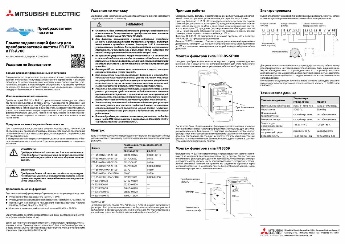
Принцип работыОписанные здесь фильтры сконструированы с целью уменьшения напря-жений помех до пределов, установленных для первой и второй зоны.При этом фильтры FFR-BS-SF100 позволяют соблюдать пределы для первойзоны (общая доступность, категория C1) при длине (экранирофильтрван-ного) кабеля двигателя до 20 м, и для первой зоны (ограниченная доступ-ность, категория C2) при длине (экранированного) кабеля двигателя до100 м. Таким образом, соблюдаются также 100-амперные пределы второйзоны при длине (экранированного) кабеля до 100 м.Фильтры FFR-BS-SF100 соблюдают те же самые пределы, что и фильтрыFFR-A540-SF100 предшествующей серии.Фильтры FN 3359 позволяют соблюдать пределы для первой зоны (ограниченнаядоступность, категория C2) при длине (экранированного) кабеля двигателядо 100 м и, тем самым, также пределы для второй зоны до этой длины кабелядвигателя.
Монтаж фильтров типа FFR-BS-SF100Насадите преобразователь частоты на верхнюю сторону помехоподавляю-щего фильтра и соедините его с фильтром винтами. Для этого применяйтеприлагаемые монтажные винты, указанные в таблице на обороте листа.
После этого блок, образованный из фильтра и преобразователя, крепитсявинтами на монтажной панели распределительного шкафа. Для достиже-ния оптимального фильтрующего действия необходимо, чтобы корпусфильтра имел электропроводящее соединение с заземленной монтажнойпанелью. Как правило, это соединение образуется через винты крепленияфильтра на монтажной панели. Если необходимо, удалить эмаль в соответ-ствующих местах монтажной панели.
Монтаж фильтров типа FN 3359Фильтры типа FN 3359 и соответствующие преобразователи частоты монти-руются на монтажной панели шкафа рядом друг с другом. Для достиженияоптимального фильтрующего действия необходимо, чтобы корпуса фильтраи преобразователя частоты имели электропроводящее соединение с зазем-ленной монтажной панелью. Как правило, это соединение образуется черезвинты для крепления на монтажной панели. Если необходимо, удалить эмальв соответствующих местах монтажной панели.
ЭлектропроводкаВыполнить электрическое подключение по следующей схеме. При этом нельзяпревышать указанную максимальную длину кабеля электродвигателя.
Для уменьшения помехоэмиссии все провода (в частности, кабель междупреобразователем частоты и двигателем) должны быть экранированы.Экран кабеля двигателя со стороны двигателя и со стороны фильтра сле-дует наложить с как можно большей контактной поверхностью. Двигательи помехоподавляющий фильтр следует заземлить с как можно меньшимсопротивлением.В отношении окружающих условий и места монтажа соблюдать указанияиз руководств по эксплуатации преобразователей частоты FR-F700 EC илиFR-A700 EC.
Технические данные
PОПАСНОСТЬ:
Предупреждение об опасности для пользователя.Несоблюдение указанных мер предосторожностиможет создать угрозу для жизни или здоровья пользо-вателя.
EВНИМАНИЕ:
Предупреждение об опасности для аппаратуры.Несоблюдение указанных мер предосторожности можетпривести к серьезным повреждениям аппаратуры илииного имущества.
E ВНИМАНИЕ
● Описанные здесь помехоподавляющие фильтры предназначеныисключительно для применения с преобразователями частотыMitsubishi Electric серий FR-F700 и FR-A700.
● Эти фильтры применяются с целью соблюдения стандартаEN 61800-3, устанавливающего определенные пределы для напря-жений помех в проводных линиях. Фильтры Ј 180 A отвечаютустановленным пределам для первой зоны (общая и ограниченнаядоступность) и второй зоны, а фильтры >180 A – пределам дляпервой зоны (ограниченная доступность) и второй зоны.
● На практике результаты могут отличаться – в частности,если не соблюдаются или недостаточно соблюдаются обще-признанные правила электромагнитной совместимости примонтаже фильтров и прокладывании силовой и управляющейпроводки.
● Фильтры НЕ рассчитаны на использование в сетях с изолиро-ванной нейтралью (сетях типа IT).
● При применении помехоподавляющих фильтров в производст-венных условиях возникают токи утечки на землю. От этогомогут срабатывать предшествующие защитные устройства,в частности, в случае несимметричных сетевых напряжений,выпадения сетевой фазы или коммутаций перед фильтром.
● Указанные в нижеследующих таблицах мощности потерь и токиутечки фильтров представляют собой типичные значенияв установившемся режиме и при отсутствии неисправностей.В зависимости от сетевого напряжения, частоты сети и приме-няемого фильтра возможен небольшой разброс этих значений.
● Учитывайте, что внешний вид помехоподавляющего фильтраи используемая в нем техника соединений могут отличатьсяот иллюстраций этого документа. Это не влияет на функци-ональную надежность фильтров и добротность подавлениярадиопомех.
● Более подробные указания по правильному монтажу с соблюде-нием норм ЭМС можно найти в руководстве Mitsubishi Electric“Преобразователи частоты и ЭМС”.
ФильтрКласс мощности преобразователя частоты
FR-F/A740 EC FR-F720
FFR-BS-00126-18A-SF100 00023–00126 00030–00110
FFR-BS-00250-30A-SF100 00170/00250 00175
FFR-BS-00380-55A-SF100 00310/00380 00240
FFR-BS-00620-75A-SF100 00470/00620 00330/00460
FFR-BS-00770-95A-SF100 00770 00610
FFR-BS-00930-120A-SF100 00930 00760
FFR-BS-01800-180A-SF100 00930/01800 00900/01150
FN 3359/250/28 02160–02600 —
FN 3359/400/99 03250–04320 —
FN 3359/600/99 04810–06100 —
FN 3359/1000/99 06830–09620 —
FN 3359/1600/99 10940–12120 —
L2 L3L1 E
L2’ L3’L3’L1’ E
Hz MON
MITSUBISHI
PUREV
REV
SET
EXT
PUEXT
STOPRESET
NET
FWD
FWD
MODE
P.RUN
FR-DU07
FR–F740–2.2K
DANGER: Risk of injury and electric shock
CAUTION: Risk of fire
Read the manual and follow the safety instructions before use.
Isolate from supply and wait 10 minutes before removing this cover.
Ensure proper earth connection
Mount the inverter on a non-combustible surface.
AV
F R E Q RO L - F 7 0 0
400V
!
!
Фильтр
Преобразователичастоты
Hz MON
PUREV
REV
SET
EXT
PUEXT
STOPRESET
NET
FWD
FWD
MODE
P.RUN
FR-DU07
AV
Фильтр
Преобразователи частоты
Монтажная панель шкафа
Технические данныеТип фильтра
FFR-BS-SF100 FN 3359
Номинальное напряжение макс. 3~ 480 В пер. макс. 3~ 500 В пер.
Частота сети 50/60 Гц 50/60 Гц
Номинальный ток и ток утечки
см. таблицы ниже см. таблицы ниже
Мощность потерь см. таблицы ниже см. таблицы ниже
Температура окружающей среды
–25 до +85°C –25 до +85°C
Влажность окружающей среды
максимум 90 % максимум 90 %
Вибростойкость 10 до 200 Гц; 1,8g 10 до 200 Гц; 1,8g
L1 L2 L3 E L3’L2’L1’E L1 L2 L3 U V W PE
Входные клеммы фильтра
Выходные клеммы фильтра
Силовое подключение преобразователя частоты
Подключение к сети (3-фазной)
Электродвигатель

I Dimensioni dei filtri FFR-BS-SF100
E Dimensiones de los filtros FFR-BS-SF100
Размеры фильтров FFR-BS-SF100
Filtro/Filtro/Фильтр
Convertitori di frequenza/
Variador de frecuencia/Преобразователи
частотыA B C D E F G H
Viti di montaggio/Tornillos de
montaje/Монтажные
винты
Peso/Peso/
Вес[kg, кг]
Dissipazione di potenza/
Potencia perdida/
Мощность потерь [W, Вт]
Corrente di dispersione/Corriente de
descarga/Ток утечки [mA, мА]�
Corrente nominale/Corriente nominal/
Номиналь-ный ток
[A]FR-F/A740 FR-F720
FFR-BS-00126-18A-SF100 00023–00126 00030–00110 150 260 315 50 110 300 295 70 4 x M5 1,25 11,6
< 30
18
FFR-BS-00250-30A-SF100 00170/00250 00175 220 260 315 60 180 300 295 125 4 x M5 1,8 15,8 30
FFR-BS-00380-55A-SF100 00310/00380 00240 221,5 300 360 80 180 345 — — 4 x M5 2,42 27,1 55
FFR-BS-00620-75A-SF100 00470/00620 00330/00460 251,5 400 476 80 210 457 — — 4 x M5/4 x M8 4,25 43,9 75
FFR-BS-00770-95A-SF100 00770 00610 340 550 626 90 280 607 — — 4 x M8/4 x M8 6,7 45,8 95
Filtro/Filtro/Фильтр
Convertitori di frequenza/
Variador de frecuencia/Преобразователи
частотыA B C D E F
Viti di montaggio/Tornillos de
montaje/Монтажные
винты
Peso/Peso/
Вес[kg, кг]
Dissipazione di potenza/
Potencia perdida/
Мощность потерь [W, Вт]
Corrente di dispersione/Corriente de
descarga/Ток утечки [mA, мА] �
Corrente nominale/Corriente nominal/
Номиналь-ный ток
[A]FR-F/A740 FR-F720
FFR-BS-00930-120A-SF100 00930 00760 450 550 636 120 380 617 4 x M8/4 x M10 10,0 44,9< 30
120
FFR-BS-01800-180A-SF100 00930/01800 00900/01150 450 550 652 120 380 633 4 x M8/4 x M10 12,0 60,7 180
H
E
A
FC G B
D
E
A
BFC
D
I Dimensioni dei filtri FN 3359
E Dimensiones de los filtros FN 3359
Размеры фильтров FN 3359
Filtro/Filtro/Фильтр
Convertitori di frequenza/
Variador de frecuencia/Преобразователи
частоты
A B C D E F
Peso/Peso/
Вес[kg, кг]
Dissipazione di potenza/
Potencia perdida/Мощность потерь
[W, Вт]
Corrente di dispersione/
Corriente de descarga/Ток утечки [mA, мА]�
Corrente nominale/Corriente nominal/
Номиналь-ный ток
[A]
FN 3359/250/28 02160–02600 230 205 360 300 120 125 7 38 < 6 250
Filter/Filter/Filtre
Inverter/Frequenzumrichter/
Variateur de fréquence
Преобразователи частоты
A B C D E F
Peso/Peso/
Вес[kg, кг]
Dissipazione di potenza/
Potencia perdida/Мощность потерь
[W, Вт]
Corrente di dispersione/
Corriente de descarga/Ток утечки [mA, мА]�
Corrente nominale/Corriente nominal/
Номиналь-ный ток
[A]
FN 3359/400/99 03250–04320 260 235 386 300 120 115 10,5 51
< 6
400
FN 3359/600/99 04810–06100 260 235 386 300 120 135 11 65 600
FN 3359/1000/99 06830–09620 280 255 456 350 145 170 18 84 1000
FN 3359/1600/99 10940–12120 300 275 586 400 170 160 27 130 1600
A
FB
C D
EE
F
A
B
C D
EE
FFR-BS-00930-120A-SF100–FFR-BS-01800-180A-SF100
� I I valori rappresentano le correnti di dispersione circolanti in condizioni normali in una rete simmetrica da 400 V, 50 Hz. In caso di mancanza di fase o nel momento dell’inserzione, possono presentarsi brevemente correnti di dispersione più intense.
E Los valores representan las corrientes de descarga que fluyen en estado normal con una red simétrica de 400 V, 50 Hz. En caso de interrupción de fase o en el momento de conexión es posible que se presenten brevemente corrientes de descarga mayores.
Эти значения даны для токов утечки в нормальном состоянии при симметричной сети 400 В, 50 Гц. При выпадении одной из фаз или в момент включения могут на короткое время возникать более высокие токи утечки.
FFR-BS-00126-18A-SF100–FFR-BS-00770-95A-SF100 FN 3359/250/28
FN 3359/400/99–FN 3359/1600/99

Mitsubishi Electric Europe B.V. /// FA - European Business Group ///Germany /// Tel.: +49(0)2102-4860 /// Fax: +49(0)2102-4861120 /// www.mitsubishi-automation.com
PrzetworniceCzęstotliwości
Fi ltry typu RFI do przetwornice częstotliwości FR-F700 i FR-A700Nr art.: 205680 PL, Wersja A, 03042007
Informacje związane z bezpieczeństwem
Tylko dla wykwalifikowanego personelu
Niniejsza instrukcja przeznaczona jest do użytku wyłącznie przez odpowied-nio wykwalifikowanych techników elektryków, którzy doskonale znają wszyst-kie normy i przepisy bezpieczeństwa, właściwe dla technologii związanejz automatyzacją. Cała praca wykonywana z opisanym sprzętem, włączniez projektem systemu, instalacją, konfiguracją, konserwacją, serwisem i testow-aniem wyposażenia, może być wykonywana wyłącznie przez wyszkolonychtechników elektryków posiadających stosowne kwalifikacje, którzy doskonaleznają wszystkie normy i przepisy bezpieczeństwa, właściwe dla technologiizwiązanej z automatyzacją.
Poprawne wykorzystywanie sprzętu
Przetwornice częstotliwości z serii FR-F700 i FR-A700 przeznaczone są do konkret-nych zastosowań, wyraźnie opisanych w niniejszej instrukcji i w podręcznikachwymienionych poniżej. Prosimy o uważne przestrzeganie wszystkich para-metrów instalacyjnych i eksploatacyjnych, wymienionych w tych dokumentach.Mogą być używane tylko akcesoria i sprzęt peryferyjny, specjalnie zatwierdzoneprzez MITSUBISHI ELECTRIC. Każde inne wykorzystanie lub zastosowanie tychproduktów, uznawane jest za niewłaściwe.
Stosowne regulacje bezpieczeństwa
Przy projektowaniu systemu, jego instalacji, konfiguracji, obsłudze, serwisow-aniu i testowaniu tych produktów, muszą być przestrzegane wszystkie,właściwe dla określonych zastosowań przepisy bezpieczeństwa oraz przepisyzwiązane z zapobieganiem wypadkom. Występujące w niniejszej instrukcji specjalne ostrzeżenia, ważne do właści-wego i bezpiecznego używania produktów, są wyraźnie wyróżnione w nastę-pujący sposób:
Dodatkowa informacja
Dodatkowe informacje na temat tych urządzeń zawarte są w następującychpodręcznikach:
● Podręcznik do przetwornic częstotliwości i EMC● Instrukcja obsługi przetwornic częstotliwości FR-A700 i FR-F700● Podręcznik do przetwornic częstotliwości FR-S500, FR-E500, FR-A700, i FR-F700● Instrukcja instalacji przetwornic częstotliwości FR-A700 i FR-F700
Podręczniki te dostępne są bezpłatnie poprzez Internet (www.mitsubishi-automation.pl).
Jeśli pojawią się jakiekolwiek pytania związane z programowaniem i działaniemsprzętu opisanego w tym podręczniku, prosimy o skontaktowanie się z właści-wym biurem handlowym lub oddziałem Mitsubishi Electric.
Uwagi dotyczące instalacjiChcąc używać filtrów zgodnie z ich przeznaczeniem, należy uważnie przeczytaćponiższe uwagi na temat instalacji.
MontowanieSprawdzić typ przetwornicy. Filtr powinien być używany tylko w połączeniuz przetwornicami opisanymi w poniższej tabeli.
UWAGAPrzetwornice serii FR-F700 EC oraz FR-A700 EC wyposażone są we wbudowane filtry,które mogą zapewnić ograniczenie napięcia zakłóceń przewodzonych do 100 Az kablem silnika o długości do 5 m, zgodnie z wymaganiami Środowiska 2.
FunkcjaOpisane w niniejszym dokumencie filtry, zostały zaprojektowane w celu zre-dukowania napięcia zakłóceń przewodzonych i spełnienia ograniczeń zdefi-niowanych dla Środowiska 1 i 2.Filtry FFR-BS-SF100 te mogą zapewnić zgodność z wymaganiami Środowiska 1(dystrybucja ograniczona/kategoria C1) przy długości ekranowanego kablasilnikowego do 20 m oraz dla Środowiska 1 (dystrybucja ograniczona/katego-ria C2) przy długości ekranowanego kabla silnikowego dochodzącej do 100 m.W ten sposób mogą również zapewnić zgodność z wymaganiami Środowiska2 przy ograniczeniach 100 A, dla kabla silnikowego o długości do 100 m.Filtry FFR-BS-SF100 spełniają te same ograniczeniom, co filtry poprzedniej seriiFFR-A540-SF100.Filtry Fn 3359 mogą zapewnić zgodność z ograniczeniami Środowiska 1 (dystry-bucja ograniczona/kategoria C2) przy długości kabla silnika do 100 m (kabelekranowany), a więc również z ograniczeniami określonymi dla Środowiska 2, ażdo tej samej długości kabla silnikowego.
Montaż filtrów typu FFR-BS-SF100Ustawić przetwornicę na wierzchniej płycie filtru i przymocować ją za pomocądostarczonych śrub.
Zespół złożony z filtra i przetwornicy należy zamocować do pleców szafki roz-dzielczej przy pomocy śrub montażowych, dostarczonych wraz z filtrem. Abyfiltr mógł poprawnie funkcjonować, śruby montażowe powinny mieć dobrykontakt elektryczny z tylną płytą szafki, która połączona jest z uziemieniem.Jeśli nie jest to możliwe, należy usunąć farbę z obszaru bezpośredniego stykupłyty montażowej z obudową filtru.
Montaż filtrów typu FN 3359Filtry typu FN3359 i odpowiednie falowniki montowane są obok siebie na tyl-nej ścianie rozdzielnicy. Aby fi ltr mógł poprawnie funkcjonować, śrubymontażowe powinny mieć dobry kontakt elektryczny z tylną płytą szafki, którapołączona jest z uziemieniem. Jeśli nie jest to możliwe, należy usunąć farbęz obszaru bezpośredniego styku płyty montażowej z obudową filtru.
PodłączaniePrzy wykonywaniu instalacji elektrycznej, należy przestrzegać proceduryłączenia, pokazanej na poniższym rysunku. Maksymalna długość kabla do sil-nika powinna zawierać się w określonych granicach.
W celu zredukowania promieniowania kabla, należy wszystkie kable ekranować,a ekrany uziemić na obu końcach. Uziemienie silnika należy złączyć z filtrami.W sprawie warunków środowiskowych oraz pozycji montażowej prosimy zwrócićuwagę na wskazówki w instrukcji obsługi przetwornicy częstotliwości FR-F700 EClub FR-A700 EC.
Dane techniczne
PNIEBEZPIECZEŃSTWO:
Ostrzeżenia dotyczące zdrowia i obrażeń personelu.Nieprzestrzeganie opisanych tutaj środków ostrożności,może doprowadzić do poważnych obrażeń i utraty zdrowia.
EUWAGA:
Ostrzeżenia dotyczące uszkodzenia sprzętu i mienia. Nieprzestrzeganie opisanych tutaj środków ostrożności,może spowodować poważne uszkodzenie sprzętu lub innejwłasności.
E UWAGA
● Opisane w niniejszych materiałach informacyjnych filtry RFI, zostałyzaprojektowane wyłącznie do stosowania z przetwornicami MitsubishiElectric typu FR-F700 i FR-A700.
● Filtry te są niezbędne dla zapewnienia zgodności z ograniczeniamiemisji zakłóceń zawartymi w normie EN61800-3. Filtry 180 A sąodpowiednie dla spełnienia ograniczeń Środowiska 1 (dystrybucjaograniczona i nieograniczona) oraz Środowiska 2. Filtry >180 A sąodpowiednie dla ograniczeń Środowiska 1 (dystrybucja ograniczona)oraz Środowiska 2. W praktyce można uzyskać inne rezultaty, szc-zególnie wtedy, gdy przyjęte procedury EMC określające właściwąinstalację filtrów i zasady prowadzenia linii zasilających orazsterujących, nie są właściwie i pod każdym względem przestrzegane.
● Filtry te NIE są zaprojektowane do zastosowania w sieciach IT.● Podczas pracy filtru przeciwzakłóceniowego, prądy upływu rozładow-
ywane są do uziemienia. Może to wyzwolić urządzenia zabezpieczająceznajdujące się bliżej źródła zasilania, jak np. wyłączniki różnicowo –prądowe, zwłaszcza przy niesymetrycznych napięciach sieci zasilającej,uszkodzeniach fazy zasilającej lub działaniach o charakterze przełączającym,wykonywanych po stronie wejściowej filtru.
● Wartości stratymocy iprąduupływupodanewkolejnychtabelach, są warto-ściami typowymi dla stanu ustalonego i wolnego od usterek. Wzależnościod napięcia zasilającego, częstotliwości napięcia zasilania i zastosow-anego filtru, wartości te mogą się nieznacznie zmieniać.
● Należy zauważyć, iż wygląd i konstrukcja okablowania filtrów przeci-wzakłóceniowych, może odbiegać od rysunków pokazanych w niniejszejskróconej karcie informacyjnej. Nie wpływa to na bezpieczne działaniejak również na stopień ochrony przed częstotliwościami radiowymi.
● Więcej szczegółów znajduje się w podręczniku Mitsubishi Electric doprzetwornic częstotliwości i EMC, który zawiera szczegółowe infor-macje nt. instalacji spełniającej wymagania EMC.
FiltrKategoria wydajności przetwornic częstotliwości
FR-F/A740 EC FR-F720
FFR-BS-00126-18A-SF100 00023–00126 00030–00110
FFR-BS-00250-30A-SF100 00170/00250 00175
FFR-BS-00380-55A-SF100 00310/00380 00240
FFR-BS-00620-75A-SF100 00470/00620 00330/00460
FFR-BS-00770-95A-SF100 00770 00610
FFR-BS-00930-120A-SF100 00930 00760
FFR-BS-01800-180A-SF100 00930/01800 00900/01150
FN 3359/250/28 02160–02600 —
FN 3359/400/99 03250–04320 —
FN 3359/600/99 04810–06100 —
FN 3359/1000/99 06830–09620 —
FN 3359/1600/99 10940–12120 —
L2 L3L1 E
L2’ L3’L3’L1’ E
Hz MON
MITSUBISHI
PUREV
REV
SET
EXT
PUEXT
STOPRESET
NET
FWD
FWD
MODE
P.RUN
FR-DU07
FR–F740–2.2K
DANGER: Risk of injury and electric shock
CAUTION: Risk of fire
Read the manual and follow the safety instructions before use.
Isolate from supply and wait 10 minutes before removing this cover.
Ensure proper earth connection
Mount the inverter on a non-combustible surface.
AV
F R E Q RO L - F 7 0 0
400V
!
!
Filtr
Przetwornica
Hz MON
PUREV
REV
SET
EXT
PUEXT
STOPRESET
NET
FWD
FWD
MODE
P.RUN
FR-DU07
AV
Filtr
Przetwornica
Tylna płyta szafki
Dane techniczneTyp filtru
FFR-BS-SF100 FN 3359
Napięcie znamionowe Maks. 3~ 480 V AC Maks. 3~ 500 V AC
Częstotliwość 50/60 Hz 50/60 Hz
Prąd znamionowy i prąd upływu
Zob. w następnych tabelach
Zob. w następnych tabelach
Strata mocy Zob. w następnych tabelach
Zob. w następnych tabelach
Zakres temperatury otoczenia –25–85°C –25–85°C
Wilgotność otoczenia 90% 90%
Drgania 10–200 Hz; 1,8g 10–200 Hz; 1,8g
L1 L2 L3 E L3’L2’L1’E L1 L2 L3 U V W PE
Zaciski zasilające filtru
Zaciski wyjściowe filtru
Zaciski mocy przetwornicyczęstotliwości
Napięcie zasilania (trójfazowe)
Silnik

Mitsubishi Electric Europe B.V. /// FA - European Business Group ///Germany /// Tel.: +49(0)2102-4860 /// Fax: +49(0)2102-4861120 /// www.mitsubishi-automation.com
Frekvenci aváltó
RFI szűrőegységek FR-F700 és FR-A700 sorozatú frekvenci aváltókhozRend. sz. 205680 HUN, A változat, 03042007
Biztonsági tudnivalók
Csak szakemberek számára
Ez az útmutató kizárólag megfelelően képzett és megfelelő gyakorlattal ren-delkező elektromos szakemberek számára készült, akik tisztában vannak azautomatizálási technológia biztonsági szabványaival. Minden az ismertetetthardverrel történő munkát a rendszertervezést, felszerelést, beállítást, karban-tartást, szervizt és tesztelést is beleértve csak jóváhagyott minősítéssel rendel-kező, szakképzett elektromos szakemberek végezhetik, akik tisztában vannakaz alkalmazandó automatizálási technológiára vonatkozó biztonsági szab-ványokkal és előírásokkal.
A berendezés rendeltetésszerű használata
Az FR-F700 és FR-A700 sorozatú frekvenciaváltók kizárólag az ebben a felsze-relési útmutatóban és az alább felsorolt útmutatókban leírt sajátságos célokrahasználhatók. Vegye figyelembe az útmutatókban található, a felszerelésre ésüzemeltetésre vonatkozó valamennyi paramétert. Kizárólag a MITSUBISHIELECTRIC által kifejezetten jóváhagyott tartozékok és perifériák használhatók.A termékek minden ettől eltérő használata nem rendeltetésszerűnek minősül.
Vonatkozó biztonsági előírások
A termékekkel kapcsolatos rendszertervezés, felszerelés, beállítás, karbantar-tás, szervizelés és tesztelés során figyelembe kell venni valamennyi, az adottalkalmazásra vonatkozó biztonsági és balesetelhárítási előírást.A termék megfelelő és biztonságos használatával kapcsolatos fontos speciálisfigyelmeztetések jelölése az útmutatóban következőképpen történik:
További információk
A következő dokumentumok további információkat tartalmaznak az eszkö-zökkel kapcsolatban:
● EMC útmutató frekvenciaváltókhoz● Kezelési utasítás az FR-F700 és FR-A700 frekvenciaváltóhoz● Útmutató kezdők részére az FR-S500, FR-E500, FR-F700 és FR-A700 frekven-
ciaváltókra vonatkozóan● Felszerelési útmutató az FR-F700 és FR-A700 frekvenciaváltóhoz
Ezek az útmutatók az interneten (www.mitsubishi-automation.com) térítésmentesen állnak rendelkezésre.
Az ebben kézikönyvben ismertetett berendezés programozásával és kezelé-sével kapcsolatos kérdésekkel forduljon a területileg illetékes kereskedelmiképviselethez vagy részleghez.
A felszereléssel kapcsolatos megjegyzésekAz opcionális szűrőegység használatához olvassa el figyelmesen a következő,a felszereléssel kapcsolatos tudnivalókat.
SzerelésEllenőrizze a frekvenciaváltó típusát. A szűrő csak az alábbi táblázatban ismer-tetett frekvenciaváltókkal kombinálva használható.
MEGJEGYZÉSEKAz FR-F700 EC és az FR-A700 sorozat tagjai beépített szűrővel vannak ellátva.A szűrővel teljesíthetők az ún. 2. sz. környezet vezetett zavarfeszültségekre vonat-kozó előírásai legfeljebb 100 A áramerősségig és 5 m motorvezeték-hosszig.
FunkcióAz ezen dokumentumban ismertetett szűrők feladata a vezetett zajfeszültségcsökkentése az 1. és 2. környezetekben meghatározott határértékek teljesítésecéljából.A FFR-BS-SF100 szűrők kielégítik az 1. környezetre (nem korlátozott terjedés/C1 kategória) vonatkozó határértékeket maximálisan 20 m hosszúságú (árnyé-kolt) motorkábelekkel és az 1. környezetre (korlátozott terjedés/C2 kategória)vonatkozó határértékeket maximálisan 100 m hosszúságú (árnyékolt) motor-kábelekkel, valamint a 2. környezet 100 A-es határértékét maximálisan 100 mhosszúságú motorkábelekkel.Az FFR-BS-SF100 szűrőre ugyanazok a határértékek vonatkoznak, mint a korá-bbi sorozat FFR-A540-SF100 szűrőjére. Az FN 3359 szűrővel egészen 100 m-es(árnyékolt) motorvezeték-hosszig teljesíthetők az 1. sz. környezet (korlátozottelérhetőség/C2 kategória) határértékei, és ezzel a második környezet ugyan-ekkora motorvezeték-hosszra vonatkozó határértékei is.
Az FFR-BS-SF100 típusú szűrők beszereléseRögzítse a frekvenciaváltót a szűrő felső paneljéhez és biztosítsa a rendelkezésreálló csavarokkal.
A szűrő-frekvenciaváltó egység szekrény hátuljára rögzítéséhez használjaa szűrővel együtt szállított szerelőcsavarokat. A szűrő megfelelő teljesítőké-pességéhez a szűrő szerelőcsavarjait elektromosan össze kell kötni a szekrényföldelt hátlapjával. Ha ez nem lehetséges, akkor a szűrő felfekvésének helyénel kell távolítani a festéket a szekrényről.
Az FN 3359 típusú szűrők beszereléseAz FN 3359 típusú szűrők és a hozzá tartozó frekvenciaváltók a kapcsolósze-krény szerelvénylapján, egymás mellett helyezhetők el. A szűrő megfelelő tel-jesítőképességéhez a szűrő szerelőcsavarjait elektromosan össze kell kötnia szekrény földelt hátlapjával. Ha ez nem lehetséges, akkor a szűrő felfekvésé-nek helyén el kell távolítani a festéket a szekrényről.
VezetékezésAz elektromos szerelést az alábbi ábrán látható módon végezze. A motorkábelmaximális hossza a megadott értékeken belül legyen.
A kábelek sugárzásának csökkentésére azokat árnyékolni és mindkét végükönföldelni kell. Földelje a motort és kösse össze a szűrőkkel.A környezeti feltételeket és a felszerelési pozíciót illetően vegye figyelembe azFR-F700 EC vagy FR-A700 EC.
Specifikációk
PVESZÉLY:
Személyek egészségére és sérülésére vonatkozó figyelmez-tetések. Az itt ismertetett óvintézkedések figyelmen kívül hagyásasúlyos egészségi kockázatot és sérülésveszélyt idézhet elő.
EVIGYÁZAT:
Berendezés- és dologi károkra vonatkozó figyelmeztetések.Az itt ismertetett óvintézkedések figyelmen kívül hagyásaa berendezés súlyos sérüléséhez vagy más dologi károkhozvezethet.
E VIGYÁZAT
● Az ebben a dokumentumban ismertetett RFI szűrőegységek kizárólaga Mitsubishi Electric FR-F700 és FR-A700 típusú frekvenciaváltóval tör-ténő használatra készültek.
● A szűrőknek teljesíteniük kell az EN 61800-3 szabványban megha-tározott, vezetett zajra vonatkozó határértékeket. A 180 A áramúszűrőegységek kielégítik az 1. környezetre (nem korlátozott és kor-látozott terjedés) és a 2. környezetre vonatkozó határértékeket.A > 180 A áramú szűrőegységek teljesítik az 1. környezetre (korláto-zott terjedés) és a 2. környezetre vonatkozó határértékeket. A gyakor-latban a szűrők nem megfelelő felszerelése, valamint az erőátviteli ésa vezérlővezetékek nem megfelelő vonalvezetése esetén eltérő ered-mény is tapasztalható.
● Ezek a szűrők NEM alkalmasak IT hálózatokban történő használatra.● Zajszűrők alkalmazása esetén a hibaáramok kisülnek a föld felé. Ez
a védőeszközök (pl. RCD-k) kioldását idézheti elő, különösen haa hálózati feszültség kiegyensúlyozatlan, ha hálózati fázishibák állnakfenn vagy kapcsolási események történnek a szűrő bemeneti oldalán.
● Az alábbi táblázatokban látható teljesítményveszteség- és hibaáram-értékek állandósult és hibamentes állapotra vonatkozó tipikus értékek.A tápfeszültségtől, a tápáramforrás frekvenciájától és a használtszűrőtől függően az értékek kissé eltérhetnek.
● Vegye figyelembe, hogy a zajszűrő megjelenése és bekötésének elren-dezése eltérhet az ebben a rövid dokumentumban látható ábráktól.A biztonságos működést és a rádiófrekvenciás védettség fokát ez azeltérés nem befolyásolja.
● A további részletek a Mitsubishi Electric frekvenciaváltókra és EMC-revonatkozó útmutatójában találhatók, amely részletesen ismerteti azEMC előírásoknak megfelelő felszerelést.
SzűrőFrekvenciaváltó teljesítményosztálya
FR-F/A740 EC FR-F720
FFR-BS-00126-18A-SF100 00023–00126 00030–00110
FFR-BS-00250-30A-SF100 00170/00250 00175
FFR-BS-00380-55A-SF100 00310/00380 00240
FFR-BS-00620-75A-SF100 00470/00620 00330/00460
FFR-BS-00770-95A-SF100 00770 00610
FFR-BS-00930-120A-SF100 00930 00760
FFR-BS-01800-180A-SF100 00930/01800 00900/01150
FN 3359/250/28 02160–02600 —
FN 3359/400/99 03250–04320 —
FN 3359/600/99 04810–06100 —
FN 3359/1000/99 06830–09620 —
FN 3359/1600/99 10940–12120 —
L2 L3L1 E
L2’ L3’L3’L1’ E
Hz MON
MITSUBISHI
PUREV
REV
SET
EXT
PUEXT
STOPRESET
NET
FWD
FWD
MODE
P.RUN
FR-DU07
FR–F740–2.2K
DANGER: Risk of injury and electric shock
CAUTION: Risk of fire
Read the manual and follow the safety instructions before use.
Isolate from supply and wait 10 minutes before removing this cover.
Ensure proper earth connection
Mount the inverter on a non-combustible surface.
AV
F R E Q RO L - F 7 0 0
400V
!
!
Szűrő
Frekven-ciaváltó
Hz MON
PUREV
REV
SET
EXT
PUEXT
STOPRESET
NET
FWD
FWD
MODE
P.RUN
FR-DU07
AV
Szűrő
Frekven-ciaváltó
A szekrény hátlapja
SpecifikációkSzűrőtípus
FFR-BS-SF100 FN 3359
Névleges feszültség Max. 3~ 480 V AC Max. 3~ 500 V AC
Frekvencia 50/60 Hz 50/60 Hz
Névleges és hibaáram Lásd a következő táblázatokat
Lásd a következő táblázatokat
Teljesítményveszteség Lásd a következő táblázatokat
Lásd a következő táblázatokat
Környezeti hőmérséklet-tartomány –25–+85°C –25–+85°C
Megengedett páratartalom 90 % 90 %
Vibráció 10–200 Hz; 1,8g 10–200 Hz; 1,8g
L1 L2 L3 E L3’L2’L1’E L1 L2 L3 U V W PE
A szűrő tápkapcsai A szűrő kimeneti kapcsai A frekvenciaváltó tápkapcsai
Tápellátás(háromfázisú)
Motor

Mitsubishi Electric Europe B.V. /// FA - European Business Group ///Germany /// Tel.: +49(0)2102-4860 /// Fax: +49(0)2102-4861120 /// www.mitsubishi-automation.com
Frekvenční měnič
Jednotka vysokofrekvenčního (RFI) fi ltru pro frekvenční měnič FR-F700 a FR-A700Č. výr. 205680 CZ, Verze A, 03042007
Bezpečnostní pokyny
Pouze pro osoby s elektrotechnickou kvalifikací
Tento návod k instalaci je určen výhradně pro prokazatelně vyškolené pracovníkys elektrotechnickou kvalifikací, kteří jsou obeznámeni s bezpečnostními stand-ardy v automatizační technice. Projektování, instalaci, uvádění do provozu,údržbu a kontroly přístrojů mohou provádět pouze prokazatelně vyškolení pra-covníci s elektrotechnickou kvalifikací, kteří byli seznámeni s bezpečnostnímistandardy v automatizační technice.
Použití v souladu se stanoveným určením
Frekvenční měniče řady FR-A700 a FR-F700 jsou určeny jen pro ty oblasti pou-žití, které jsou popsány v tomto návodu k instalaci nebo v níže uvedenýchpříručkách. Dodržujte všechny parametry a charakteristické údaje uvedenév těchto příručkách. Jako doplňkové a rozšiřující přístroje se mohou používatpouze výrobky, které byly doporučeny firmou MITSUBISHI ELECTRIC. Jakákolivjiná aplikace nebo využití jdoucí nad rámec nasazení popsaného v tomtonávodu bude považováno za použití odporující stanovenému určení.
Bezpečnostní předpisy
Při projektování, instalaci, uvádění do provozu, údržbě a kontrole přístrojů jenezbytné dodržovat bezpečnostní předpisy a předpisy pro předcházení úrazůmplatné pro daný případ nasazení. V tomto návodu k instalaci jsou obsažena upozornění, která jsou důležitá prosprávné a bezpečné zacházení s přístrojem. Jednotlivá upozornění mají násle-dující význam:
Další informace
Následující příručky obsahují další informace o těchto přístrojích:
● Příručka pro frekvenční měniče a EMC● Návod k obsluze frekvenčního měniče FR-A700 a FR-F700● Příručka pro začátečníky k frekvenčním měničům FR-S500, FR-E500, FR-A700
a FR-F700● Návod k instalaci frekvenčního měniče FR-A700 a FR-F700
Tyto příručky jsou bezplatně k dispozici na internetu(www.mitsubishi-automation-cz.com).
S vašimi dotazy k instalaci a provozu přístrojů popsaných v tomto návoduk instalaci se bez váhání obracejte na příslušné prodejní místo nebo na někte-rého z vašich distributorů.
Pokyny k instalaciDodržujte prosím následující pokyny k instalaci, aby byla zajištěna správnáaplikace odrušovacího filtru.
MontážZkontrolujte, o jaký typ frekvenčního měniče se jedná. V následující tabulce jeuvedeno přiřazení mezi frekvenčními měniči a odrušovacími filtry.
UPOZORNĚNÍSérie FR-F700 EC a FR-A700 EC jsou vybaveny integrovaným filtry. S nimi je možnédodržet limity výkonově vázaných rušivých napětí pro druhé prostředí do 100 A prodélku motorového kabelu do 5 m.
FunkceZde popsané filtry byly zkonstruovány k omezení rušivých napětí šířených povedení na mezní hodnoty definované pro první a druhé prostředí. Tyto filtryFFR-BS-SF100 umožňují dodržet mezní hodnoty prvního prostředí (neomezo-vaná distribuce/kategorie C1) až do délky 25 m motorového kabelu (stíněný)a hodnoty prvního prostředí (omezovaná distribuce/kategorie C2) až do délky100 m motorového kabelu (stíněný), a tím také dodržet mezní hodnoty 100 Apro druhé prostředí do délky 100 m motorového kabelu.Filtry FFR-BS-SF100 dodržují stejné limity jako filtry FFR-A540-SF100 předchozísérie. Fi ltry FN 3359 umožňují dodržování prvního prostředí (omezenědostupné/kategorie C2) do 100 m délky motorového kabelu (stíněné) a tímtaké dodržování limitů definovaných pro druhé prostředí až do této délkymotorového kabelu.
Montáž filtrů typu FFR-BS-SF100Frekvenční měnič nasaďte na horní plochu odrušovacího filtru a pevně jej sešrou-bujte s filtrem. K sešroubování použijte dodané montážní šrouby, které jsou uve-deny v tabulce na druhé straně.
Komplet vytvořený z filtru a frekvenčního měniče se nyní přišroubuje na mon-tážní desku rozvaděče. K zajištění optimálního filtračního účinku je nutné, abybyl kryt odrušovacího filtru elektricky vodivě spojen s uzemněnou montážnídeskou. Spojení je zpravidla zabezpečeno sešroubováním filtru a montážnídesky. Případně je nutné na příslušných místech montážní desky odstranitlakování.
Montáž filtrů typu FN 3359Filtry typu FN 3359 a příslušné frekvenční měniče se instalují na montážnídesku rozvaděče vedle sebe. Pokud instalujete filtr a frekvenční měnič vedlesebe, pak filtr umístěte vždy vlevo od frekvenčního měniče tak, abyste zabrá-nili vazbě s motorovými vodiči. K zajištění optimálního filtračního účinku jenutné, aby byl kryt odrušovacího filtru elektricky vodivě spojen s frekvenčnímměničem na uzemněné montážní desce. Spojení je zpravidla zabezpečenosešroubováním s montážní deskou. Případně je nutné na příslušných místechmontážní desky odstranit lakování.
Kabelové propojeníElektrické připojení se provede podle následujícího schématu zapojení. Přitomnesmíte překročit uvedené maximální délku motorového kabelu.
Všechny vodiče, zvláště pak vodiče mezi frekvenčním měničem a motorem,musí být s ohledem na rušivé vyzařování ve stíněném provedení. Stínění moto-rových vodičů je nutné na straně motoru a měniče připojit k zemi. Motor a odru-šovací filtr je třeba dobře uzemnit.Dodržujte pokyny pro vnější vlivy a montážní polohu, které jsou uvedenyv Návodu k obsluze frekvenčního měniče FR-F700 EC a FR-A700 EC.
Technické údaje
PNEBEZPEČÍ:
Varování před ohrožením uživatele Zanedbání uvedených preventivních opatření může véstk ohrožení života nebo zdraví uživatele.
EVÝSTRAHA:
Varování před ohrožením přístrojů Zanedbání uvedených preventivních opatření může vést k těž-kým škodám na přístroji nebo jiným věcným škodám.
E VÝSTRAHA
● Zde popsané odrušovací filtry jsou určeny výhradně pro nasazení s frek-venčními měniči Mitsubishi Electric z konstrukční řady FR-F700 a FR-A700.
● Cílem aplikace těchto odrušovacích filtrů je dodržení mezních hodnotrušivého napětí šířeného vedením definovaných ve výrobkové norměEN 61800-3. Filtry 180 A jsou vhodné k dosažení povolených mezníchhodnot pro první prostředí (neomezovaná a omezovaná třída dis-tribuce) a pro druhé prostředí, filtry > 180 A k dodržení povolenýchmezních hodnot pro první prostředí (omezovaná třída distribuce)a pro druhé prostředí. V praxi však můžete dojít k různým výsledkům,zvláště pak, pokud byly nedostatečně anebo vůbec nebyly dodrženyvšeobecně uznávané postupy pro správnou montáž filtrů a vedenísilových a řídicích vodičů z hlediska EMC.
● Tyto filtry NEJSOU konstruovány pro provoz v IT sítích.● Při nasazení odrušovacích filtrů jsou svodové proudy za provozu svá-
děny na zem. Přitom však mohou reagovat předřazené ochrannéprvky, zvláště pak při nesymetrickém síťovém napětí, výpadcíchsíťové fáze nebo spínacích pochodech na vstupní straně filtru.
● Hodnoty pro ztrátové výkony a svodové proudy filtrů udávané v násle-dujících tabulkách jsou typické hodnoty v ustáleném stavu nezatí-ženém žádnou poruchou. Tyto hodnoty mohou v závislosti na síťovémnapětí, síťovém kmitočtu a také na použitém typu filtru vykazovatnepatrné odchylky.
● Všimněte si, prosím, že se vzhled i způsob zapojení odrušovacích filtrůmohou odlišovat od zde uváděných vyobrazení. Funkční spolehlivosta úroveň vysokofrekvenčního odrušení však tím není ovlivněna.
● Další podrobnější pokyny naleznete v příručce Mitsubishi Electric proFrekvenční měniče a EMC, která také obsahuje podrobnější údajek instalaci splňující všechny požadavky EMC.
FiltrVýkonová třída frekvenčního měniče
FR-F/A740 EC FR-F720
FFR-BS-00126-18A-SF100 00023–00126 00030–00110
FFR-BS-00250-30A-SF100 00170/00250 00175
FFR-BS-00380-55A-SF100 00310/00380 00240
FFR-BS-00620-75A-SF100 00470/00620 00330/00460
FFR-BS-00770-95A-SF100 00770 00610
FFR-BS-00930-120A-SF100 00930 00760
FFR-BS-01800-180A-SF100 00930/01800 00900/01150
FN 3359/250/28 02160–02600 —
FN 3359/400/99 03250–04320 —
FN 3359/600/99 04810–06100 —
FN 3359/1000/99 06830–09620 —
FN 3359/1600/99 10940–12120 —
L2 L3L1 E
L2’ L3’L3’L1’ E
Hz MON
MITSUBISHI
PUREV
REV
SET
EXT
PUEXT
STOPRESET
NET
FWD
FWD
MODE
P.RUN
FR-DU07
FR–F740–2.2K
DANGER: Risk of injury and electric shock
CAUTION: Risk of fire
Read the manual and follow the safety instructions before use.
Isolate from supply and wait 10 minutes before removing this cover.
Ensure proper earth connection
Mount the inverter on a non-combustible surface.
AV
F R E Q RO L - F 7 0 0
400V
!
!
Filtr
Frekvenční měnič
Hz MON
PUREV
REV
SET
EXT
PUEXT
STOPRESET
NET
FWD
FWD
MODE
P.RUN
FR-DU07
AV
Filtr
Frekvenční měnič
Montážní deskarozvaděče
Technické údajeTyp filtru
FFR-BS-SF100 FN 3359
Jmenovité napětí Max. 3~ 480 V AC Max. 3~ 500 V AC
Frekvence 50/60 Hz 50/60 Hz
Jmenovitý a svodový proud Viz následující tabulku
Viz následující tabulku
Ztrátový výkon Viz následující tabulku
Viz následující tabulku
Okolní teplota –25–+85°C –25–+85°C
Dovol. relativní vlhkost vzduchu 90 % 90 %
Vibrace 10–200 Hz; 1,8g 10–200 Hz; 1,8g
L1 L2 L3 E L3’L2’L1’E L1 L2 L3 U V W PE
Vstupní svorky filtru Výstupní svorky filtru Silové svorky frekvenčního měniče
Síťový přívod(trojfázový)
Motor

P Wymiary filtra FFR-BS-SF100
H A szűrő méretei FFR-BS-SF100
Rozměry filtru FFR-BS-SF100
Filtr/Szűrő/Filtr
Przetwornice częstotliwości/
Frekvenciaváltó/Frekvenční měnič A B C D E F G H
Śruby mon-tażowe/
Szerelőcsa-varok/
Montážní šrouby
Ciężar/Súly/
Hmot-nost[kg]
Strata mocy/Teljesítmé-
nyveszteség/Ztrátový
výkon[W]
Prąd upływu/
Hibaáram/Svodový
proud[mA] �
Prąd zna-mionowy/Névleges
áram/Jmeno-
vitý proud[A]
FR-F/A740 FR-F720
FFR-BS-00126-18A-SF100 00023–00126 00030–00110 150 260 315 50 110 300 295 70 4 x M5 1,25 11,6
< 30
18
FFR-BS-00250-30A-SF100 00170/00250 00175 220 260 315 60 180 300 295 125 4 x M5 1,8 15,8 30
FFR-BS-00380-55A-SF100 00310/00380 00240 221,5 300 360 80 180 345 — — 4 x M5 2,42 27,1 55
FFR-BS-00620-75A-SF100 00470/00620 00330/00460 251,5 400 476 80 210 457 — — 4 x M5/4 x M8 4,25 43,9 75
FFR-BS-00770-95A-SF100 00770 00610 340 550 626 90 280 607 — — 4 x M8/4 x M8 6,7 45,8 95
Filtr/Szűrő/Filtr
Przetwornice częstotliwości/
Frekvenciaváltó/Frekvenční měnič A B C D E F
Śruby mon-tażowe/
Szerelőcsa-varok/
Montážní šrouby
Ciężar/Súly/
Hmot-nost[kg]
Strata mocy/Teljesítmény-
veszteség/Ztrátový
výkon[W]
Prąd upływu/
Hibaáram/Svodový
proud[mA] �
Prąd znamionowy/
Névleges áram/
Jmenovitý proud
[A]FR-F/A740 FR-F720
FFR-BS-00930-120A-SF100 00930 00760 450 550 636 120 380 617 4 x M8/4 x M10 10,0 44,9< 30
120
FFR-BS-01800-180A-SF100 00930/01800 00900/01150 450 550 652 120 380 633 4 x M8/4 x M10 12,0 60,7 180
H
E
A
FC G B
D
E
A
BFC
D
P Wymiary filtra FN 3359
H A szűrő méretei FN 3359
Rozměry filtru FN 3359
Filtr/Szűrő/Filtr
Przetwornice częstotliwości/
Frekvenciaváltó/Frekvenční měnič
A B C D E F
Ciężar/Súly/
Hmotnost[kg]
Strata mocy/Teljesítmény-
veszteség/Ztrátový výkon
[W]
Prąd upływu/Hibaáram/
Svodový proud [mA] �
Prąd znamionowy/
Névleges áram/Jmenovitý
proud[A]
FN 3359/250/28 02160–02600 230 205 360 300 120 125 7 38 < 6 250
Filtr/Szűrő/Filtr
Przetwornice częstotliwości/
Frekvenciaváltó/Frekvenční měnič
A B C D E F
Ciężar/Súly/
Hmotnost[kg]
Strata mocy/Teljesítmény-
veszteség/Ztrátový výkon
[W]
Prąd upływu/Hibaáram/
Svodový proud [mA] �
Prąd znamionowy/
Névleges áram/Jmenovitý
proud[A]
FN 3359/400/99 03250–04320 260 235 386 300 120 115 10,5 51
< 6
400
FN 3359/600/99 04810–06100 260 235 386 300 120 135 11 65 600
FN 3359/1000/99 06830–09620 280 255 456 350 145 170 18 84 1000
FN 3359/1600/99 10940–12120 300 275 586 400 170 160 27 130 1600
A
FB
C D
EE
F
A
B
C D
EE
FFR-BS-00930-120A-SF100–FFR-BS-01800-180A-SF100
� P Pokazane wartości prądów upływu odnoszą się do normalnych warunków pracy symetrycznej sieci zasilającej 400 V 50 Hz. W przypadku uszkodzenia fazy lub podczas włączania zasilania systemów, mogą chwilowo wystąpić wyższe prądy upływu.
H A feltüntetett hibaáramok kiegyensúlyozott 400 V 50 Hz-es hálózatra vonatkoznak normál feltételek mellett. Rövid időre nagyobb hibaáramok fordulhatnak elő fázishibák esetén, illetve a rendszer bekapcsolásakor.
Hodnoty se vztahují k svodovým proudům protékajícím v normálním stavu při symetrickém napájení napětím 400 V, 50 Hz. Při výpadku fáze nebo při zapnutí mohou krátkodobě vznikat větší svodové proudy.
FFR-BS-00126-18A-SF100–FFR-BS-00770-95A-SF100 FN 3359/250/28
FN 3359/400/99–FN 3359/1600/99