rf simulation basics - keysight · (transmission line, capacitor, transistor, etc..) reacts to rf...
TRANSCRIPT
RF Simulation Basics
Andy Howard
Applications Engineer
Keysight Technologies

Page Agenda
– Introduction
–Applications
–S-Parameter Simulations – a closer look
–Models: The building blocks for effective
simulations
–Simulation Engines
2

Introduction
3
Page
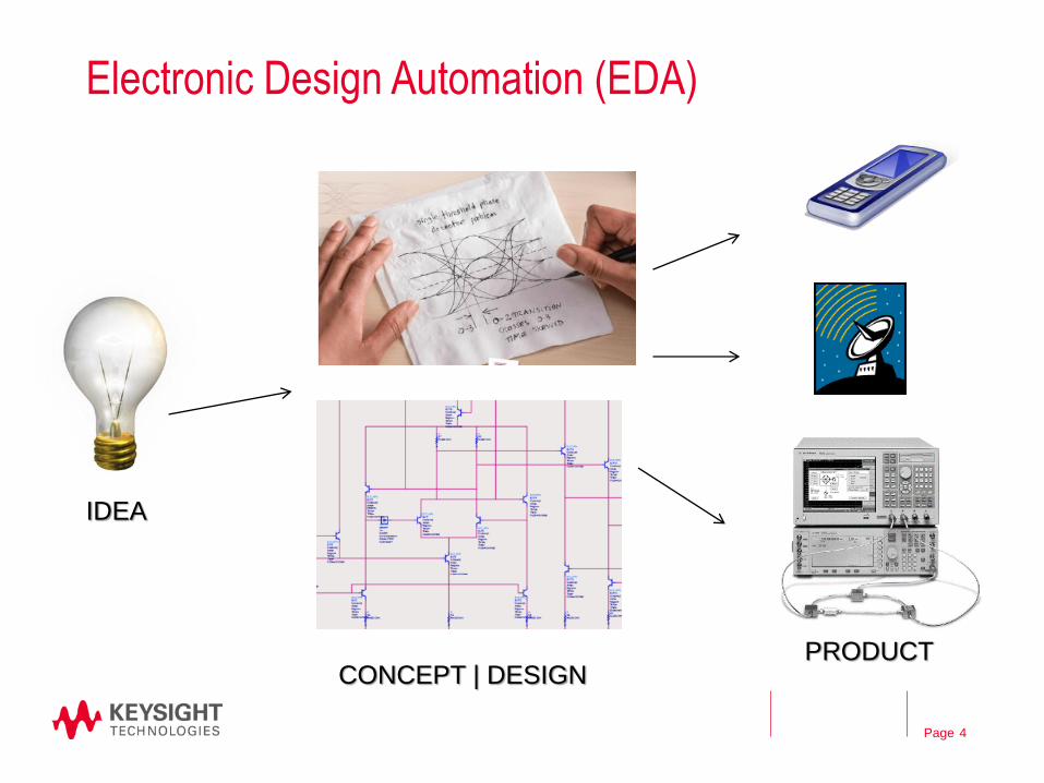
Electronic Design Automation (EDA)
4
IDEA
CONCEPT | DESIGN PRODUCT
Page
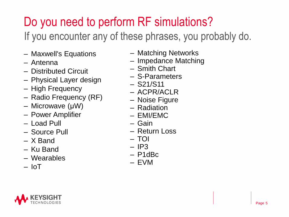
Do you need to perform RF simulations?
– Maxwell's Equations
– Antenna
– Distributed Circuit
– Physical Layer design
– High Frequency
– Radio Frequency (RF)
– Microwave (μW)
– Power Amplifier
– Load Pull
– Source Pull
– X Band
– Ku Band
– Wearables
– IoT
5
If you encounter any of these phrases, you probably do.
– Matching Networks – Impedance Matching – Smith Chart – S-Parameters – S21/S11 – ACPR/ACLR – Noise Figure – Radiation – EMI/EMC – Gain – Return Loss – TOI – IP3 – P1dBc – EVM
Applications
What could you achieve if you could do RF simulations?
6

Page
RF System performance
7
Simulating your car’s FM radio
DB
M[G
IM3
P], D
B[S
DR
]
-200
-160
-120
-80
-40
0
40
80
120
160
200
DB
M[II
P3
], P
RIM
3
-30
-24
-18
-12
-6
0
6
12
18
24
30
Node
1 5 6 16 9 10 17 7 8 4
Intermodulation & Compression
R IL
R IL
DBM[IIP3]
DBM[GIM3P]
DB[SDR]
PRIM3
Page
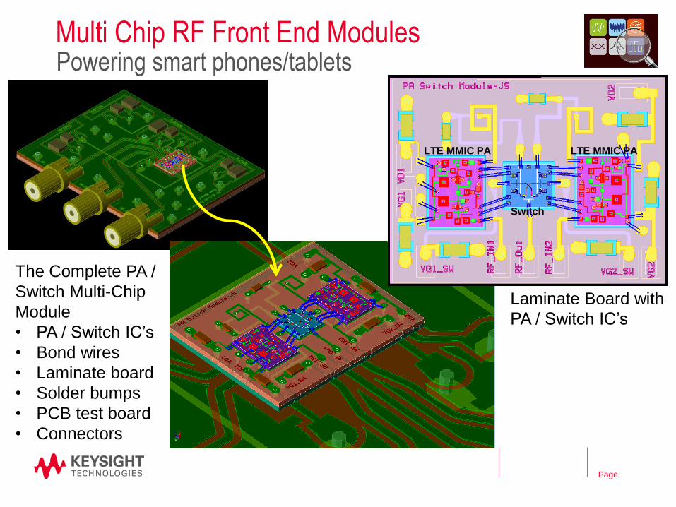
Multi Chip RF Front End Modules Powering smart phones/tablets
The Complete PA /
Switch Multi-Chip
Module
• PA / Switch IC’s
• Bond wires
• Laminate board
• Solder bumps
• PCB test board
• Connectors
Laminate Board with
PA / Switch IC’s
LTE MMIC PA LTE MMIC PA
Switch
Page
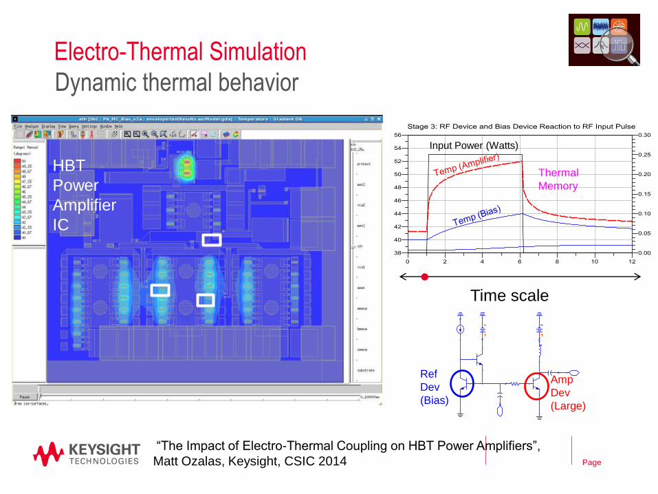
Electro-Thermal Simulation
Dynamic thermal behavior
Time scale
Ref
Dev
(Bias)
Amp
Dev
(Large)
Input Power (Watts)
Thermal
Memory
HBT
Power
Amplifier
IC
“The Impact of Electro-Thermal Coupling on HBT Power Amplifiers”,
Matt Ozalas, Keysight, CSIC 2014

Page
Electromagnetic Analysis
10
Signal Propagation in arbitrary structures

Page
Electronic Warfare / Aerospace
3D Scenario Modeling – Model multiple moving TX and RX platforms
including clutter and environment
Phased Array Degradations – Model beamforming & jamming performance at the system level
PA AWGN
channel BER/FER/PER
Throughput TX
RX
“software fading”
Atmospheric, Terrain, Doppler,
Delay
RF/MW CIRCUITS
MEASURED X,S-PARAMS
DVB-S2, QAM, APSK, etc.
Satcom Dynamic Channel Modeling

Page
DDR4 Memory Signal Integrity and Power Integrity
12
VCC1V2_FPGA Power Net
on Layer 9 and 10
GND Net
Kintex
FPGA
Sync
50x scaled
VRM
S-Parameter Simulations
A closer look
13
Page
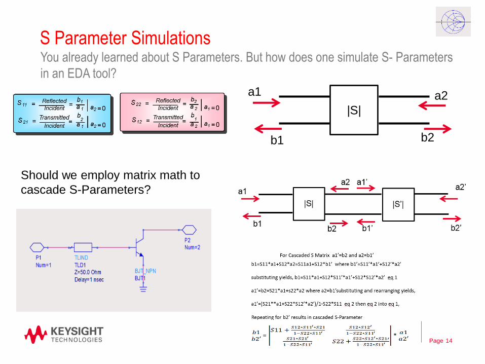
S Parameter Simulations
14
You already learned about S Parameters. But how does one simulate S- Parameters
in an EDA tool?
|S|
a1
b1
a2
b2
Should we employ matrix math to
cascade S-Parameters?

Page
S-Parameter Simulation
– Matrix math runs out of steam if you have bigger complicated designs.
– Modern Simulators actually behave similar to Network analyzers. Excite
one “end” of the circuit (at certain frequencies) and measure incident
and reflected waves at the same “end” and also at other “ends”.
– Then compute ratios and get S-Parameters.
– For this to work, the EDA tool needs to know how each device
(transmission line, capacitor, transistor, etc..) reacts to RF excitation.
– EDA tools contain built-in models to represent the most common
devices. (More on device models later)
– And you can supplement the built-in models with measurement based
models too.
15

Page
S-Parameter Simulation
16

Page
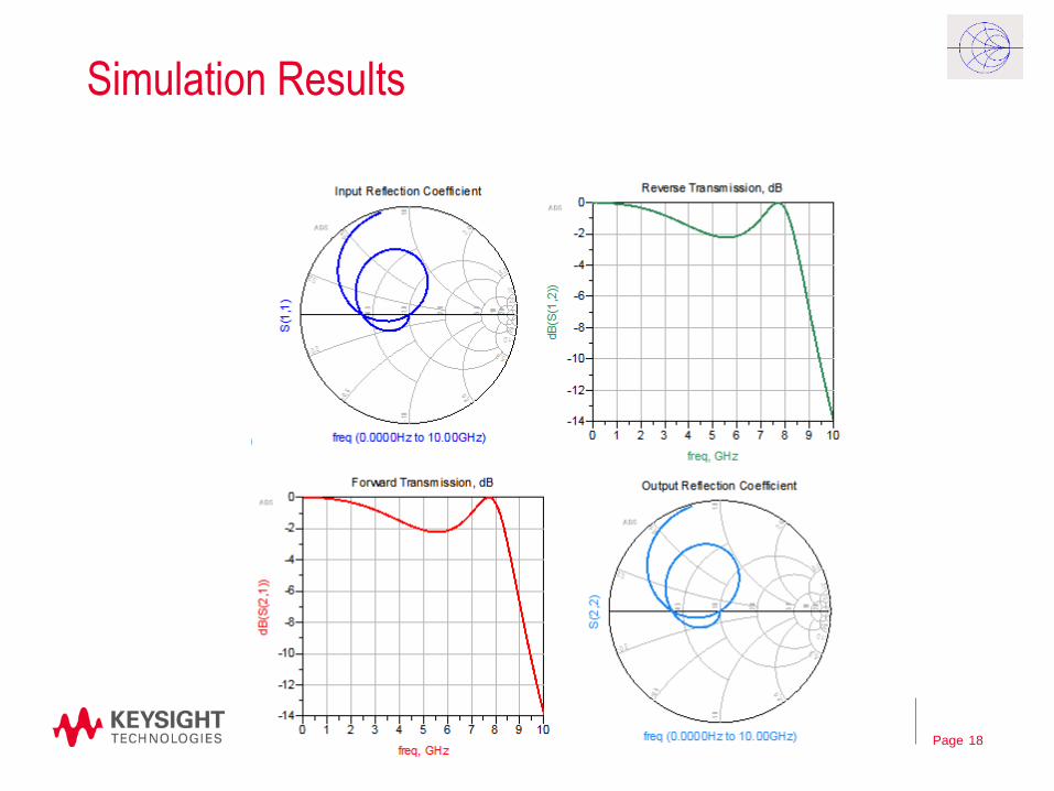
S-Parameter Simulation
17
Port Count is not limited
No Calibration needed
Impedance can be any value
Page
Simulation Results
18

Page
Tune & Optimize– What if scenarios
19

Models
The building blocks for effective simulations
20

Page
Models
– Previously we saw that “models” are required to represent
transmission lines, transistors, capacitors etc.
– Devices that are linear in nature (resistors, transmission lines) have
linear models.
– Devices that are non linear in nature (diodes, transistors) have both
linear and non-linear models.
– Models can be ideal or more realistic
21
Page
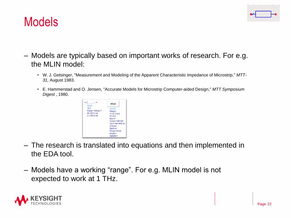
Models
– Models are typically based on important works of research. For e.g.
the MLIN model:
• W. J. Getsinger, "Measurement and Modeling of the Apparent Characteristic Impedance of Microstrip," MTT-
31, August 1983.
• E. Hammerstad and O. Jensen, "Accurate Models for Microstrip Computer-aided Design," MTT Symposium
Digest , 1980.
– The research is translated into equations and then implemented in
the EDA tool.
– Models have a working “range”. For e.g. MLIN model is not
expected to work at 1 THz.
22
Page
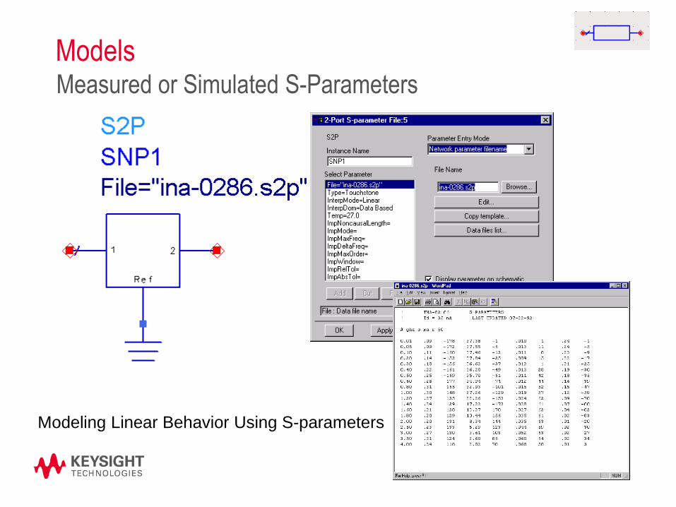
Models
23
Measured or Simulated S-Parameters
Modeling Linear Behavior Using S-parameters

Page
Models
– Non linear models are based on complex differential equations.
Research groups (e.g. BSIM group at University of California,
Berkeley) develop these models and share with the industry.
– By feeding the right parameter values into the model “card” you can
match the software model to a real world device.
– The parameter values are typically obtained by measurements and
“fitting” algorithms.
– Typically takes several PhDs to do this right.
24
Nonlinear models for transistors
https://en.wikipedia.org/wiki/BSIM
Page
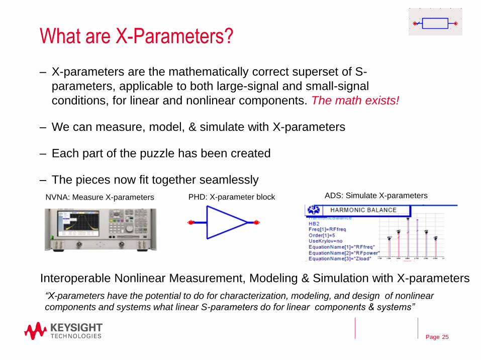
What are X-Parameters?
– X-parameters are the mathematically correct superset of S-
parameters, applicable to both large-signal and small-signal
conditions, for linear and nonlinear components. The math exists!
– We can measure, model, & simulate with X-parameters
– Each part of the puzzle has been created
– The pieces now fit together seamlessly
25
Interoperable Nonlinear Measurement, Modeling & Simulation with X-parameters
“X-parameters have the potential to do for characterization, modeling, and design of nonlinear
components and systems what linear S-parameters do for linear components & systems”
NVNA: Measure X-parameters PHD: X-parameter block ADS: Simulate X-parameters

Simulation Engines
Analyze your RF design
Page
Simulation Types
– Frequency vs Time
– Linear vs Non-Linear
– Circuit vs System
– Circuit vs EM
– Multi-Physics (Electrical Circuit + Thermal)
27

Page
Simulation Engines
• DC
• AC
• S-Parameter
• Harmonic Balance
• Transient (High Frequency Spice)
Channel Sim
• Circuit Envelope
28
• EM Simulation
MoM
FEM
FDTD
• Spectral
• Data Flow
• ElectroThermal

Page
Harmonic Balance Setup
29

Page
Harmonic Balance Results
30
Page
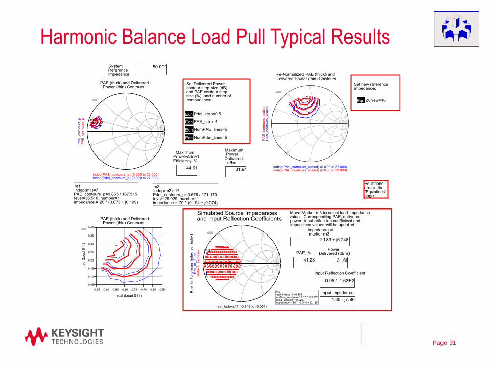
Harmonic Balance Load Pull Typical Results
31
Page
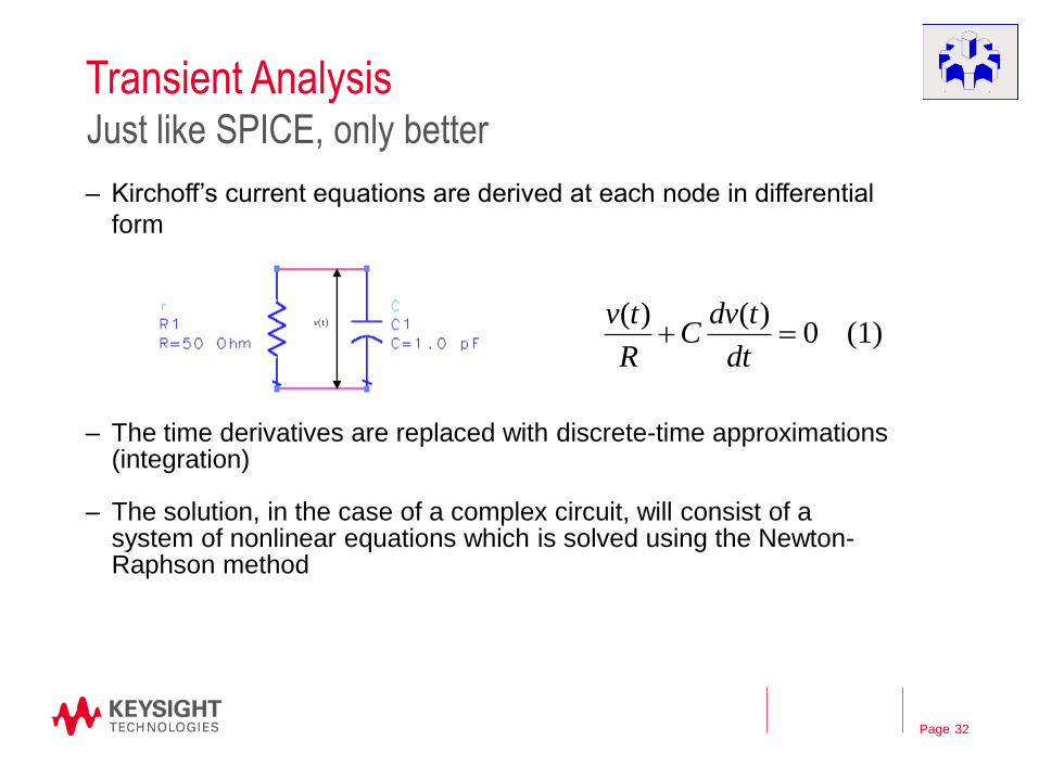
Transient Analysis
– Kirchoff’s current equations are derived at each node in differential
form
– The time derivatives are replaced with discrete-time approximations (integration)
– The solution, in the case of a complex circuit, will consist of a system of nonlinear equations which is solved using the Newton-Raphson method
32
Just like SPICE, only better
(1) 0)()(
dt
tdvC
R
tvv(t)

Page
Transient Simulation
33

Page
Circuit Envelope
– Time samples the modulation envelope (not carrier)
– Compute the spectrum at each time sample
– Output a time-varying spectrum
– Use equations on the data
– Faster than HB or Spice in many cases
– Integrates with System Simulations & Keysight’s Ptolemy
34
Beyond CW and onto Modulated signals.
Page
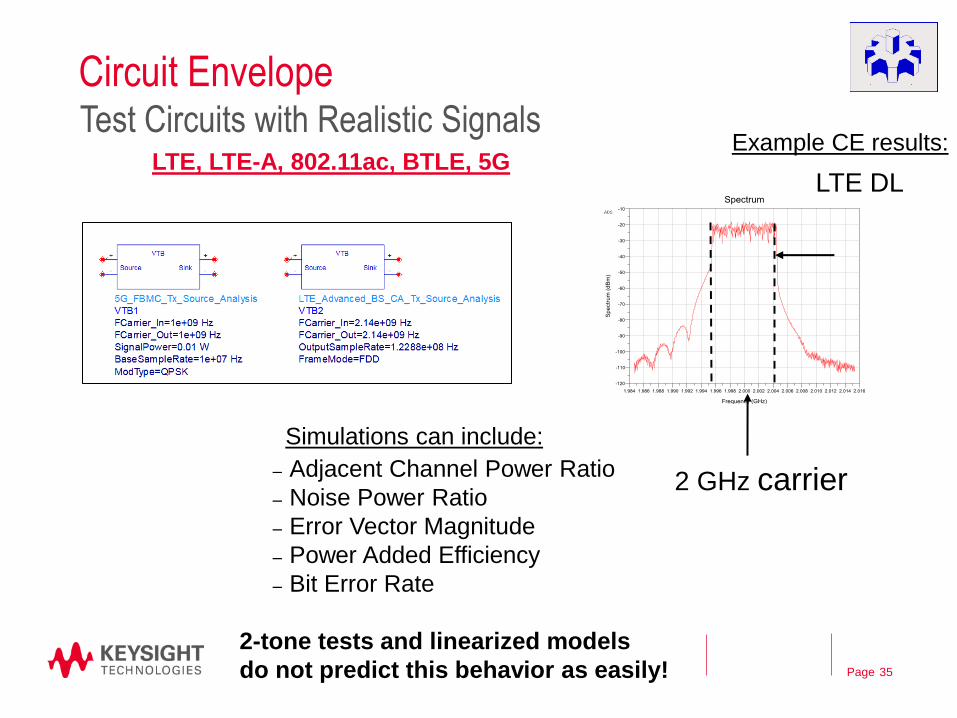
Circuit Envelope
35
Test Circuits with Realistic Signals
– Adjacent Channel Power Ratio
– Noise Power Ratio
– Error Vector Magnitude
– Power Added Efficiency
– Bit Error Rate
2-tone tests and linearized models
do not predict this behavior as easily!
LTE, LTE-A, 802.11ac, BTLE, 5G LTE DL
2 GHz carrier
Simulations can include:
Example CE results:
Page
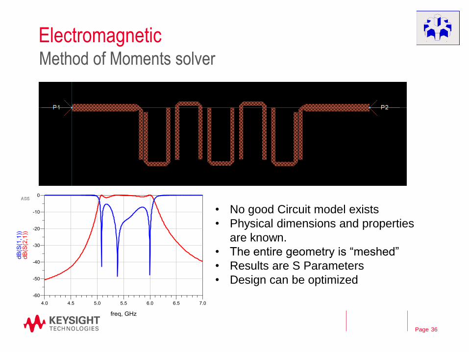
Electromagnetic
36
Method of Moments solver
• No good Circuit model exists
• Physical dimensions and properties
are known.
• The entire geometry is “meshed”
• Results are S Parameters
• Design can be optimized
Page
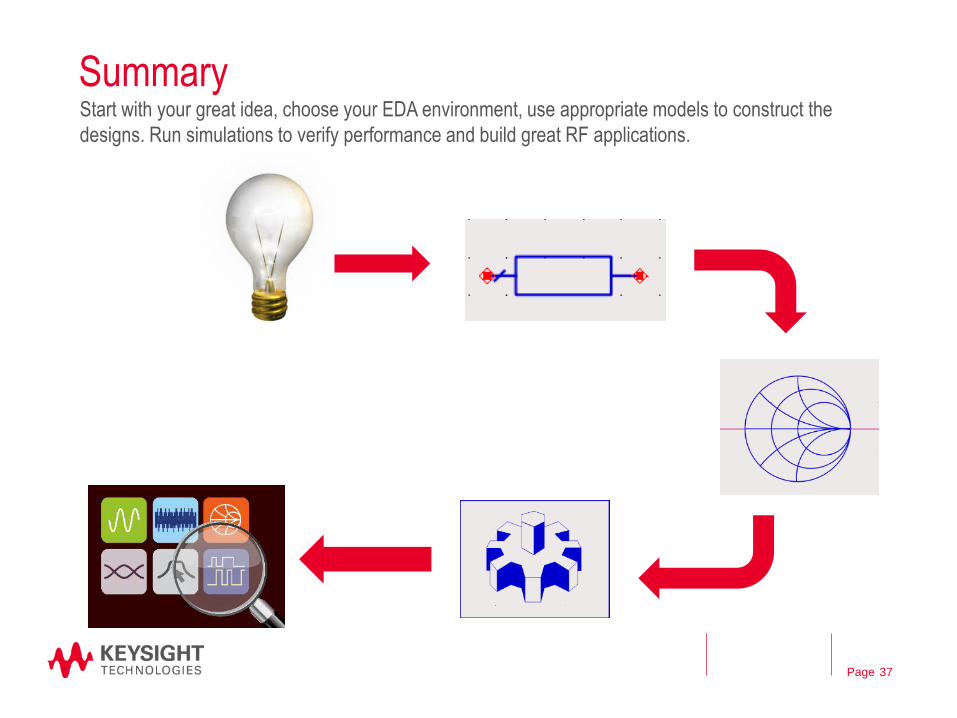
Summary
37
Start with your great idea, choose your EDA environment, use appropriate models to construct the
designs. Run simulations to verify performance and build great RF applications.

Page
Learn more about RF Simulations
– How to Design an RF Power Amplifier and other How-to videos:
https://www.youtube.com/playlist?list=PLtq84kH8xZ9HIYgBYDsP7TbqBpftidzI8
– For More Information www.keysight.com/find/eesof-ads-info
– ADS on www.keysight.com/find/eesof-ads-videos
–
– Genesys on
https://www.youtube.com/playlist?list=PLtq84kH8xZ9E8S_y5dmCXtJFPo14NsCtt
38