rf aperture architectures
TRANSCRIPT

RF APERTURE ARCHITECTURES
11 Nov. 08
Dr. Thomas MurpheySpace Vehicles Directorate

2
Mitigating Structural Deformations
• Mitigating structural deformations in large apertures:
– There is always a trade between ACTIVE TECHNOLOGIES (shape correction, metrology and electronic compensation, etc.) and PASSIVE STRUCTURAL TECHNOLOGIES (structural hierarchy, material dimensional stability, deployment)
– This trade is a specific function of how electromagnetic energy behaves and what about it is being sensed
– It is not always as simple as “keep RMS surface errors less then λ/30”
• This presentation investigates this relation and derives RF system architecture development recommendations from it

3
Scope
• Developed for multi-element RF systems that transmit and receive (phased arrays, phased arrays with reflectors)
– Radar
• Imaging, tracking, 3D terrain
– Communications
• Applicable to receive only systems as well
• Many sources of system errors
– Thermal stability, dynamic stability, electronic stability
• Under consideration here:
– Only structural dynamic deformations
– Only one dimensional apertures
• Infinite knowledge of structural deformations is assumed when needed
– Challenges of obtaining this information through metrology or other techniques are not addressed here.

4
Phase Measurement
• Goal is to adjust phase of incoming/ outgoing radiation over entire aperture for coherent beam
– Assume the sensor (or some element in the optical path) is moving and changing the phase (time delay) of the radiation
– Assume the motion is sinusoidal (derived from vibrations due to low order structural mode)
– Consider three levels of phase shift (time delay) adjustment of the sensor to correct for the motions
• 1) No change
• 2) Adjust time-delay, updated regularly
• 3) Also adjust rate of change of time-delay (equivalent to frequency shift), updated regularly
• Can this be translated into structural requirements?
• Can structural requirements be translated into deployable structure architectures?

5
Structural Dynamic Excitations
• Two excitation methods
– Structure is torqued by CMG or reaction wheel placed at center of aperture
– Forces from thrusters placed at ends of aperture
• Moment actuation, force actuation and vibrations all have similar though not identical shapes
• Bang-bang control scheme employed to slew system 90 degrees
– Actuators turned on to accelerated aperture, reversed to decelerate it, no coasting period

6
Actuation Methods Only Excite a Single Mode
• Power spectral density plots for post actuation vibrations along aperture length
– Normalized so that maximum is 1
• Mode described in last slide is only mode significantly excited
– Not the first mode
– Force actuation spreads energy among modes more significantly, but most is still in one mode

7
Estimate Stiffness and Deformation
• Excited structural mode frequency:
• Rotational acceleration due to moment and force actuation:
• Quasi-static deflection due to constant rotational acceleration:
• Observations:
– Equations can be used to determine minimum stiffness for a maximum deformation requirement
– Force actuation results in 4.7 times less structural deformation
– Deflections decrease with the square of frequency
2
2, 3.9266
2
EIf
ml
λλ
π= =
33M
mlα =
23F
mlα =
511120M
mlEIα
δ =3 411
, 33 120F
Fl wl Fw
EI EI lδ = − =
4
2 2
11
480M
l
f
α λδ
π=
4
2 2
7
1440F
l
f
α λδ
π=
8
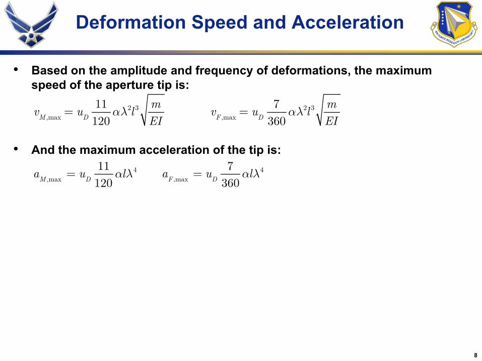
Deformation Speed and Acceleration
• Based on the amplitude and frequency of deformations, the maximum speed of the aperture tip is:
• And the maximum acceleration of the tip is:
2 3,max
11120M D
mv u l
EIαλ= 2 3
,max
7360F D
mv u l
EIαλ=
4,max
11120M D
a u lα λ= 4,max
7360F D
a u lα λ=

9
Three Compensation Strategies
1) No compensation– Deformations must be less than some fraction of wavelength– Stiffness requirement derived from quasi-static deflection– δ < coherence requirement
2) Adjust time-delay, updated regularly– Element must not move more than the allowable coherence
error between updates– Reduces to a velocity requirement– Deformation Speed < (coherence requirement)/(update interval)
3) Also adjust rate of change of time-delay (equivalent to frequency shift), updated regularly
– Difference between true element position and position predicted by constant velocity assumption must be less than coherence requirement
511120D
M
mlEI u
αδ
=57
360DF
mlEI u
αδ
=
2 3,max
11120M D
mv u l
EIαλ= 2 3
,max
7360F D
mv u l
EIαλ=
252
2
11sin
60 2i
M D
tml EIu
EI ml
λα ⎛ ⎞⎟⎜ ⎟⎜Δ = ⎟⎜ ⎟⎜ ⎟⎜⎝ ⎠
252
2
7sin
180 2i
F D
tml EIu
EI ml
λα ⎛ ⎞⎟⎜ ⎟⎜Δ = ⎟⎜ ⎟⎜ ⎟⎜⎝ ⎠

10
3) Time Delay and Frequency Compensation
• Error asymptotes to a limit as stiffness decreases
– Structures with extremely small stiffness perform just as good as a very stiff structures, below a specific rotational acceleration
– Allows definition of a maximum rotational acceleration, below which any structure will suffice
4,max
11120M D
a u lα λ=4
,max
7360F D
a u lα λ=
252
2
11sin
60 2i
M D
tml EIu
EI ml
λα ⎛ ⎞⎟⎜ ⎟⎜Δ = ⎟⎜ ⎟⎜ ⎟⎜⎝ ⎠
252
2
7sin
180 2i
F D
tml EIu
EI ml
λα ⎛ ⎞⎟⎜ ⎟⎜Δ = ⎟⎜ ⎟⎜ ⎟⎜⎝ ⎠
2 4,max 0
11lim
240M M D iEIu ltα λ
→Δ = Δ = 2 4
,max 0
7lim
720F F D iEIu ltα λ
→Δ = Δ =
2max
12 iatΔ =
max 2
2
i
at
Δ=
2 4
24011M
D iu lt
αλ
Δ=
2 4
7207F
D iu lt
αλ
Δ=

11
ISAT GRD
• Innovative Space-based Radar Antenna Technology (ISAT) Program
– DARPA Funded, AFRL Executed, ended early 2007
– Program for 300 m deployable radar system with 100:1 compaction ratio
• Government Reference Design (GRD)
– Used for analytical calculations in this presentation
– Three longeron tubular truss structure with bending stiffness of EI=7.546·107 N-m2 and linear mass of 1.841 kg/m
– X-band radar panels with a linear mass of 10.0 kg/m were distributed evenly along the length of the truss for a system linear mass of m=11.841 kg/m
– The bus and center of gravity were coincident and located at the mid length of the antenna. While the total antenna length is 300 m, the half length of the system, l=150 m, is used in all equations
– Bus inertia is neglected because it is much smaller than the antenna inertia (the bus rotational inertia is 0.023% of the antenna)
– Half system rotational inertia is 13.32·106 kg-m2
– Vibration mode excited by a slew has a frequency of 0.2753 Hz (3.632 s period). 1% of critical damping is assumed and implemented as material damping in Abaqus.
• Slew maneuver:
– The model was subjected to a 90 deg yaw maneuver actuated with either a 300 N-m (M=150 N-m) moment applied to the system center of gravity or F=1 N tip thrusters for force actuation
– Both actuation methods result in the same actuation moment, acceleration (1.126·10-5 rad/s2) and time to slew (12.45 min)

12
Stiffness Results for GRD

13
• Loads are due to steady-state and vibrations deformations:
• Steady-state deformations are:
• Maximum moment is not always at root:
Estimate Bending Loads
, ,M ss M D vib MM M u M= +
, ,F ss F D vib FM M u M= +
( )( )2,2
6ss M
mM l x l x
α= + − ( )( ), 6ss F
mM x l x l x
α= + −
3, ,max
1
9 3ss FM mlα=
10.577
3
xl= =

14
Estimate Bending Loads
• Vibration mode shape is:
• Substitute in deflection and stiffness relations:
• With amplification factors of 3 (due to actuator reversal), maximum moments are:
( )( )
2
2
cos cosh sin sinh, 1 , 1.000777
cos 2 cosh sin sinhvib
EI xM
ll
λ φ φ σ φ σ φδφ λ σ
λσ λ λ σ λ λ λ
⎛ ⎞− − + ⎟⎜ ⎟= = − =⎜ ⎟⎜ ⎟⎜− + + − ⎝ ⎠
( )( )
2
3,
cos cosh sin sinh11120 cos 2 cosh sin sinhvib M
M mlλ φ φ σ φ σ φ
αλσ λ λ σ λ λ λ
− − +=
− + + −
( )( )
2
3,
cos cosh sin sinh7360 cos 2 cosh sin sinhvib F
M mlλ φ φ σ φ σ φ
αλσ λ λ σ λ λ λ
− − +=
− + + −
3,max
1.00828 at 0.38261M
xM ml
lα= =
3,max
0.242089 at 0.44666F
xM ml
lα= =

15
Bending Strength
3,max
1.00828MM mlα=
3,max
0.242089FM mlα=

16
Truss Structural Performance
• Bending stiffness and strength per mass requirements drive structural architecture choices
– Extremely stiff and low mass requirements lead to extreme mechanical complexity to achieve increased hierarchy
– Relaxed stiffness and mass requirements lead to simpler deployable structures
– This relationship can be investigated with structural performance metrics
• Important to consider both strength and stiffness

17
Truss Structural Performance Metrics
• Two ways to increase structural performance:– Materials– Hierarchy (geometry)
Specific Structural Performance
Bending Stiffness
Bending Strength
Mass Per LengthMaterial Index
Geometry Indices-Truss architecture-Longeron architecture-Number of longerons
Require-ments
Murphey, “Chapter 1: Booms and Trusses” in Recent Advances in Gossamer Spacecraft, Ed. Jenkins, AIAA 2005

18
Truss Structural Performance Metrics
• Metric captures both stiffness and strength requirement• 1/5 and 2 powers correctly mass normalize metric– Mass does not scale linearly or the same with stiffness and strength
• Correctly captures constant mass trade between stiffness and strength– As truss radius (R) is increased without changing strut cross sections,
stiffness increases while strength decreases
Murphey, “Chapter 1: Booms and Trusses” in Recent Advances in Gossamer Spacecraft, Ed. Jenkins, AIAA 2005

19
Steeper slope represents increased performance per mass
Increasing Mass Efficiency

20
Combined Stiffness and Strength Requirements
• Requirements plummet below a certain rotational acceleration• Above this limit:– Limiting total deformations is nearly as good as time delay and frequency
compensation– Better to forgo active systems for passive structural stability in high dynamic
excitation systems• Below this limit:– Time delay and frequency compensation allow extremely low requirements– Time delay compensation has significantly lower requirements than no
compensation

21
Comparing Architectures
SR937
TS11,702
TS23,532 Hypothetical Booms
FM STT
FM ISO
FM TT
DECSMAR

22
Development of RF Systems
• Ideal case is when both time delay and frequency compensation are feasible
– Stiffness requirement can be greatly reduced
– Caution: deformations become very large and still impose significant design constraint
– Update rate must increase to allow more precision operations
– Some operational modes may require integration times much larger than ti
• Electronics/processing/software technology development may be required to enable updates during integration period
4
24011i
D M
tu lα λ
Δ=

23
Structural Architectures
• Assertion: tensioned structures require the same structural stiffness as bending based architectures
• Tensioned architectures offer fewer benefits when the structural requirements are extreme
• When structural requirements can be reduced, through time-delay and frequency compensation, tensioned architectures are most advantageous

24
Comments on Tensioned Architectures
• Tension adds stiffness to a structure through two mechanisms– Tensioned element axial stiffness (k=EA/L)• Approach of ‘tension truss’ architectures
– Tension induces transverse stiffness (k=T/L)• Approach of blanket solar arrays, ‘tension aligned’ architectures
• Bending structures rely purely on material stiffness and stability• Extremely different material requirements– General tension truss and aligned structures: Material must be stiff, able to
support loads for extended periods of time without stress relaxation and able to be packaged and deployed without length changes• Aperture shape depends on internal stress distribution. Stress relaxation
/dimensional changes alter the stress distribution and antenna shape– Flat tension aligned structures• Material stiffness and dimensional stability requirements greatly reduced• Aperture flatness does not depend material stability, aperture stiffness
depends on element tension, not stiffness• Large phased array architectures are easier than large shaped apertures
– Bending structures• Material must be stiff, but does not necessarily need to carry constant loads
over time (not sensitive to creep)

25
Closing Remarks
• The relationship between antenna deformation compensation methods and structural requirements was investigated
• Shown that time-delay and frequency compensation, when performed at a sufficiently high rate, can dramatically reduce structural requirements
• Reduced structural requirements allow new structural architectures
– Flat tensioned architectures (appropriate for phased arrays) are very promising
• Most of this material has been submitted for publication in:
– T. W. Murphey, E. M. Cliff, and S. A. Lane, “Matching Space Antenna Deformation Electronic Compensation Strategies to Support Structure Architectures,” Submitted for publication in IEEE Transactions on Aerospace & Electronic Systems