revision 12 - downloads.spwales.comdownloads.spwales.com/tpncubex50-installation-guide.pdf ·...
TRANSCRIPT

DOC-MC950-INS-0001-12 MultiCube 350/650/950 mV Installation Guide Page 1
MultiCube350/650/950 mV
Installation Guide Revision 12
1 Safety This document gives details of safe installation and operation of the MultiCube electricity meter. Labels on each meter give details of equipment ratings for safe operation. Take time to examine all labels before commencing installation. Safety symbols on the meter have specific meanings as:
Caution Risk of Danger Refer to Instructions
Danger Risk of Electric Shock
Safety may be impaired if the instructions are not followed or the meter is used in a manner not specified by the manufacturer.
Contains no user serviceable parts. Field wiring and commissioning should only be carried out by qualified personnel, in compliance with applicable national regulations.
e.g. National Electrical Code (NEC) for US; Canadian Electrical Code for Canada
For further Information contact the manufacturer: Address: Northern Design (Electronics) Ltd: 228 Bolton Road, Bradford, West Yorkshire, BD3 0QW. (UK) Web: http://www.ndmeter.co.uk
2 Maintenance The equipment should be maintained in good working order. Damaged equipment must be sent to the manufacturer (or his authorised agent) for repair. The meter may be cleaned by wiping lightly with a soft cloth. No solvents or cleaning agents should be used. All inputs and supplies must be isolated before cleaning any part of the equipment.
3 Intended Use The MultiCube is a precision multi-function electricity monitor which measures system power parameters, including kW, Volts and Amps and displays them on an LCD. Measured parameters may be sent to remote systems for storage or
display using an optional communications interface (e.g. Modbus RTU RS485, Ethernet or M-Bus). The MultiCube is intended for indoor use, mounting in the faceplate (panel) of an electrical enclosure with only the front keypad/display panel remaining accessible to an operator after installation. Panels should be 1mm to 4mm (0.04” to 0.16”) thick with a square cut-out of 92mm (+0.8/-0.0mm) (3.62” +0.03” -0”). Insert the meter from the front of the panel, slide the panel clips from the rear of the case and push firmly against the panel ensuring even pressure on each clip.
The safety of any system containing the meter as a component remains the responsibility of the system manufacturer. After installation in a system, the ratings of the overall system, which reflect the ratings of the meter, must be visible to the user.
A suitably located and easily reached switch or circuit breaker must be included as part of the installation. This could, for example, be a safety-interlocking device on the door/front panel of the electrical enclosure. This switch/circuit breaker must be marked as the disconnecting device for the equipment and must comply with the relevant requirements of IEC 60947-1 and IEC 60947-3.
Disconnect / Isolate all supplies before commencing installation.

DOC-MC950-INS-0001-12 MultiCube 350/650/950 mV Installation Guide Page 2
4 Standard Connections
4.1 Current Transducers
Only current transducers which meet the manufacturer’s specifications should be used.
Current Transducer (CT) connections are not galvanically isolated from the voltage inputs and must therefore not be accessible to the operator after installation. Installed CT cables and any extensions to these, must not be accessible to the operator.
Minimum Current Transducer Specification: Input Current Range: 0 to 1.2 In (In = nominal rated current in amps) Output Voltage: 0.333Vac (at nominal current) Insulation: 2.2kV Case to Secondary
If long current transducer secondary cables are used care must be taken to avoid pickup of electrical interference. With suitable low capacitance screened cables, the cable can be extended to 100m (328ft) or more.
4.2 Current Transducer Connections
4.2.1 RJ12 Current Cables
Connection between the meter and each 3-Phase set of current transducers is made using o RJ12 to RJ12, 6P6C cable: o Crossover Type PIN 1-6; 2-5; 3-4; 4-3; 5-2, 6-1.
Current cables must be rated for safe use in the electrical enclosure which houses the meter
(e.g. UL1015) and must meet the following minimum specification: Temperature: 105C
(221F); Insulation 300Vac.
4.2.2 Current Transducers
Only current transducers supplied by the manufacturer may be used in conjunction with MultiCube meters. The following list of UL & CE recognised current transducers has been approved for use.
Part Number Primary Current (XXX) Secondary Window Size
XFR/S0142/XXX 5, 10, 30, 50, 75, 100, 150, 200Amps 0.333Vac 19.1 x 19.1mm(0.75” x 0.75”)
XFR/S0152/XXX 75, 100, 150, 200, 300, 400, 600Amps 0.333Vac 31.8 x 31.8mm (1.25” x 1.25”)
XFR/S0162/XXX 100, 200, 300, 600, 800, 1000, 1500Amps 0.333Vac 50.8 x 50.8mm (2.0” x 2.0”)
XFR/S1142/XXX 5, 10, 30, 50, 70, 100, 150, 200Amps 0.333Vac 19.1 x 19.1mm(0.75” x 0.75”)
XFR/S1152/XXX 50, 70, 100, 150, 200, 250, 300, 400, 600Amps 0.333Vac 31.8 x 31.8mm (1.25” x 1.25”)
XFR/S1162/XXX 100, 200, 300, 400, 600, 800, 1000, 1200, 1500Amps 0.333Vac 50.8 x 50.8mm (2.0” x 2.0”)
XFR/S1172/XXX1 400, 600, 800, 1000, 2000, 3000Amps 0.333Vac 127.0 x 76.2mm (5.0” x 3.0”)
4.2.3 Current Transducer connection.
The current transducers should be connected to the instrument before the power is applied. The auto detect mechanism detects the transducer on power up of the instrument.
4.2.4 Current Transducer auto detect.
The instrument is designed to automatically recognise the primary current, and other characteristics, of approved current transducers.

DOC-MC950-INS-0001-12 MultiCube 350/650/950 mV Installation Guide Page 3
4.3 Voltage Connections
4.3.1 Voltage Cables
Voltage cables must be rated for safe use in the electrical enclosure which houses the meter
(e.g. UL1015) and must meet the following minimum specification: Temperature: 105C
(221F); Insulation 300Vac.
To maintain proper insulation from the mains supply, the neutral wire should only be used in power networks where the system neutral is protectively earthed.
4.3.2 Auxiliary Mains Supply
The meter is powered from an auxiliary mains supply which is required to energise the metering circuit and display. This can be connected in parallel with one of the measurement phase voltages if it is rated correctly.
Ensure the auxiliary mains supply L-N is powered from a correctly rated and fused AC source as specified on the meter label.
4.3.3 Voltage Terminals
Voltage: Terminals L-N (1-2) - 240Vac Terminals Ln-L1 (3-4) Ln-L2 (3-5) Ln-L3 ( 3-6) – 277Vac Terminals L1-L2; L2-L3. (4-5, 5-6) - 480Vac See section “7 Specification” for absolute limits Cable: 30-14 AWG, Stripped 5.5 to 6.5mm (0.2” to 0.25”) Torque: 0.5Nm (4.4in lb)
4.3.4 Voltage Fuses
Fuses (US/Canada)
Rated Voltage Type Rupture In (A) Standards
500Vac Fast 1.0A UL248 (US) C22.2 No. 248 (CAN)
Fuses (Other Countries)
Rated Voltage Type Rupture In (A) Standards
500Vac Fast 1.0A IEC 60269 - 2
4.3.5 Auxiliary Mains Fuses
Fuses (US/Canada)
Rated Voltage Type Rupture In (A) Standards
250Vac Fast 0.1A UL248 (US) C22.2 No. 248 (CAN)
Fuses (Other Countries)
Rated Voltage Type Rupture In (A) Standards
250Vac Fast 0.1A IEC 60269 - 2

DOC-MC950-INS-0001-12 MultiCube 350/650/950 mV Installation Guide Page 4
4.4 Meter Types The MultiCube is available as MultiCube350mV with 3 current channels, MultiCube650mV with 6 current channels and the MultiCube950mV with 9 current input channels. Each 3-Phase meter in a MultiCube has 3 current channels which feed into a single RJ12 socket. Each 3-Phase meter in a MultiCube can be configured, by the user, to measure a single 3-phase load or 3 x single phase loads.
Meter Type 3-Phase Meters
Current Channels
Voltage Channels
Possible Load Configurations
3-Phase Single Phase
MultiCube950mV 3 9 3
3 x 3Ph 0 x 1Ph
2 x 3Ph 3 x 1Ph
1 x 3Ph 6 x 1Ph
0 x 3Ph 9 x 1Ph
MultiCube650mV 2 6 3
2 x 3Ph 0 x 1Ph
1 x 3Ph 3 x 1Ph
0 x 3Ph 6 x 1Ph
MultiCube350mV 1 3 3 1 x 3Ph 0 x 1Ph
0 x 3Ph 3 x 1Ph
Table 1 – Meter Types and User Selectable Configurations
Each 3-Phase Meter in a MultiCube shares a single set of voltage inputs The phase voltage associated with each CT input, for each meter is fixed (CT1-L1, CT2-L2 and CT3-L3). This is not configurable even when a meter is configured to measure 3 x single phase loads. This is shown in Table 2 below
3-Phase Meter Voltage Input MultiCube950mV MultiCube650mV MultiCube350mV
Meter 1
L1 Current 1 Current 1 Current 1
L2 Current 2 Current 2 Current 2
L3 Current 3 Current 3 Current 3
Meter 2
L1 Current 1 Current 1
L2 Current 2 Current 2
L3 Current 3 Current 3
Meter 3
L1 Current 1
L2 Current 2
L3 Current 3
Table 2 – Voltages Associated with input Currents

DOC-MC950-INS-0001-12 MultiCube 350/650/950 mV Installation Guide Page 5
4.5 Typical Connections The connection diagrams shown here are for a MultiCube950mV. For MultiCube650mV and Cube350mV ignore the unused current inputs.
3 x 3-Phase 4 Wire Connection1
3 x 3-Phase 3 Wire Connection

DOC-MC950-INS-0001-12 MultiCube 350/650/950 mV Installation Guide Page 6
1 x 3-Phase + 6 Single Phase Loads
9 Single Phase Loads (Single Phase Feed) NOTE 1 – The auxiliary mains supply to the meter may be fed from any suitably rated AC source.

DOC-MC950-INS-0001-12 MultiCube 350/650/950 mV Installation Guide Page 7
4.6 Communications Options Specific wiring schematics for each communications option are provided in a separate installation guide for each option. Communications outputs are safety isolated from the measurement voltages at a minimum of 3.5kV.
Communications cables running within an electrical enclosure may come close to high voltages and therefore must be insulated to the following minimum specification:
Safety Compliant: e.g UL1015; Operating Temperature: 105C (221F); Insulation 300Vac
4.6.1 RS485 Output Terminals (Optional)
Voltage: Maximum RS485 Voltage (any pair) = 30Vdc Cable: 30-14 AWG, Stripped 5.5 to 6.5mm (0.2” to 0.25”) Torque: 0.5Nm (4.4in lb)
4.6.2 Ethernet Output (Optional)
Connection: RJ45 Cable: Cat5e FTP (Foil screened)
4.6.3 M-Bus Output Terminals (Optional)
Voltage: Maximum M-Bus Voltage (any pair) = 50Vdc Cable: 30-14 AWG, Stripped 4.5 to 5.5mm (0.18” to 0.22”) Torque: 0.5Nm (4.4in lb)
4.7 Pulse/Alarm Outputs
Pulse/Alarm output cables running within an electrical enclosure may come close to high voltages and therefore must be insulated to the following minimum specification:
Safety Compliant: e.g UL1015; Operating Temperature: 105C (221F); Insulation 300Vac
4.7.1 Pulse/Alarm Connections
Voltage: 100Vac (any pair) Cable: 30-14 AWG, Stripped 6.0 to 7.0mm Torque: 0.5Nm (4.4in lb)
4.7.2 Pulse/Alarm Facility
The MultiCubex50 mV has 4 isolated digital outputs that each takes the form of a volt free contact (solid state relay) as shown in the diagram above. Each output may be independently programmed to provide Pulse or Alarm output functionality. Details on changing the function of each output are provided in Section 5.7. The default configuration for these outputs is as follows:
OUTPUT PIN
Default Output Type
Default Function
MultiCube950 MultiCube650 MultiCube350
Common c
A1 Alarm Event 1 Event 1 Event 1
P1 Pulse Meter 1 3-Phase kWh Meter 1 3-Phase kWh Meter 1 3-Phase kWh
P2 Pulse Meter 2 3-Phase kWh Meter 2 3-Phase kWh Meter 1 3-Phase kWh
P3 Pulse Meter 3 3-Phase kWh Meter 1 3-Phase kWh Meter 1 3-Phase kWh

DOC-MC950-INS-0001-12 MultiCube 350/650/950 mV Installation Guide Page 8
5 Meter Setup

DOC-MC950-INS-0001-12 MultiCube 350/650/950 mV Installation Guide Page 9
5.1 Navigating the Setup Menus To change one or more setup values use the following sequence:
Enter Configuration (Hold both keys together for 5 seconds)
Enter Password1, 2
Done
Prev Digit Next Digit
DOWN UP
Next/Previous Sub-Menu
Enter Setup Sub Menu (from Main Setup Menu)
Change Value (fast) (Select Next/Previous Value From Fast List)
Change Value (fine) (Increment/Decrement Value)
Next Sub Menu Page (from Sub-Menu)
Select Store/No Store (Store Sub Menu Changes)
Return to Main Setup Menu (from Select Store/No Store Page)
Go to Finish Setup Page (from Main Setup Menu)
Exit Config (from Finish Setup Page)
Notes: 1: Should the password be forgotten, contact the meter manufacturer. See Section 1 for contact information. 2: The factory configured default password is 0000.
5.2 Finish Configuration To exit the Configuration mode navigate to the Configuration Main Menu - Finish Configuration Page and press enter:
Enter
Enter to Quit Configuration Menu and return to
normal metering mode

DOC-MC950-INS-0001-12 MultiCube 350/650/950 mV Installation Guide Page 10
5.3 Configure Factory Defaults The configuration of the MultiCube meter may be reset to factory defaults as follows:
Setting Factory Default MultiCube950 MultiCube650 MultiCube350
Meters 3 x 3 Phase 2 x 3 Phase 1 x 3 Phase
System Voltage 480/277 480/277 480/277
Potential Transformer Ratio Not Fitted (1.0) Not Fitted (1.0) Not Fitted (1.0)
CT Auto Direction ON ON ON
Voltage Average Time 1 minute 1 minute 1 minute
Current Average Time 1 minute 1 minute 1 minute
Power average Time 30 minutes 30 minutes 30 minutes
Pulse 1 Meter 1 kWh Meter 1 kWh Meter 1 kWh
Pulse 2 Meter 2 kWh Meter 2 kWh Meter 1 kWh
Pulse 3 Meter 3 kWh Meter 1 kWh Meter 1 kWh
Alarm 1 Not configured Not configured Not configured
Enter
Sub Menu
Enter from Main Menu to access the Sub-Menu
Hold Reset Keys
Abort Reset
Press and Hold Reset Keys to start countdown.
Enter to SKIP factory reset function
Hold Reset Keys
Hold Reset Keys during a 5 Second Countdown to Factory-Reset
Release Keys

DOC-MC950-INS-0001-12 MultiCube 350/650/950 mV Installation Guide Page 11
5.4 Configure Meter Inputs The meter input configuration may be configured as follows: Setting Selection Options
Meter Types Set the Number of 3-Phase Meters. The remaining current channels are assigned as single phase.
CT Direction Auto – Per phase auto-correction for CTs reversed on the primary cable OFF – Full 4-Quadrant measurement enabled including import/export power and energy. Note: This setting applies to all current channels in the meter.
CT Phase Reverse
Ph 1-2-3 – Forward Current Phase Rotation (default) Ph 3-2-1 – Reverse Current Phase Rotation The Ph3-2-1 setting may be used if a 3-Phase CT is incorrectly mounted upside down (I1 flows through CT3 and I3 flows through CT1).
System Voltage Fast List – 110, 208, 400, 480V L-L Fine Adjust - ±1V
PT Ratio Fast List – ‘no Pt’, 10, 100, 200, 300, 400, 500, 600, 700, 800, 900, 1000 Fine Adjust ±1
Enter
Sub Menu
Enter from Main Menu to access the Sub-Menu.
List Select
and to select number of 3-Phase and 1-Phase
meters required.
Enter to accept the selected value
List Select
and to select CT Direction method Auto or
OFF.
Enter to accept the selected value
List Select
5A to mV Converter, and 3-phase block CT’s, Only and to select Meter 1 CT Primary Current
Enter to accept the selected value
List Select
Fine Adjust
and to select system Voltage from a list
and to adjust system Voltage (steps of 1)
Enter to accept the selected value
List Select
Fine Adjust
and to select PT Ratio (or No PT) from a
list
and to adjust PT Ratio (steps of 1)
Enter to accept the selected value
Select Store
No Store
Main Menu
Use and to select Store Changes or No
Store Changes before exiting to main menu.
Enter to store/abort and exit to Main Menu

DOC-MC950-INS-0001-12 MultiCube 350/650/950 mV Installation Guide Page 12
5.5 Configure Rolling Average Times The MultiCube monitors the average readings of current, voltage and power over user defined time periods using the rolling window method. The average time periods may be programmed as follows:
Setting Selection Options
Average Voltage Period
This single setting applies equally to the time based averages on all voltage channels. Fast List – 10, 30, 60, 300, 600, 900, 1800, 3600 seconds Fine Adjust - 1..60 (in 1s steps), then 300..3600 (in 300s steps)
Average Current Period
This single setting applies equally to the time based averages on all current channels. Fast List – 10, 30, 60, 300, 600, 900, 1800, 3600 seconds Fine Adjust - 1..60 (in 1s steps), then 300..3600 (in 300s steps)
Average Power Period
This single setting applies equally to the time based averages on all 1Ph and 3Ph power values. Fast List – 10, 30, 60, 300, 600, 900, 1800, 3600 seconds Fine Adjust - 1..60 (in 1s steps), then 300..3600 (in 300s steps)
Enter
Sub Menu
Enter from Main Menu to access the Sub-Menu.
List Select
Fine Adjust
and Select Voltage Ave Period from a list
and to adjust Voltage Ave Period (steps of 1
or 300)
Enter to accept the selected value
List Select
Fine Adjust
and Select Current Ave Period from a list
and to adjust Current Ave Period (steps of 1
or 300)
Enter to accept the selected value
List Select
Fine Adjust
and Select Power Ave Period from a list
and to adjust Power Ave Period (steps of 1
or 300)
Enter to accept the selected value
Select Store
No Store
Main Menu
Use and to select Store Changes or No
Store Changes before exiting to main menu.
Enter to store/abort and exit to Main Menu

DOC-MC950-INS-0001-12 MultiCube 350/650/950 mV Installation Guide Page 13
5.6 Configure Events A normal event channel monitors a single input parameter and records when a pre-set value is exceed. A virtual event channel records when more than one normal event channels are triggered simultaneously. The MultiCube has 3 normal event channels and 1 Virtual Event channel which may be configured as follows:
Setting Select Option
Event Channel Number
Select Which Event to Configure Channel 1-3 = Normal Events Channel 4 = Virtual Event
Input Meter Select the Event Input – Meter 1-3 or Virtual Meter 4
Input Phase Select the Event Input – Phase 1 to 3 or Sys
Input Parameter Select the Event Input – Parameter (Volts, Amps, THD Volts, THD Amps, kW, kVA, kvar, PF, Frequency)
Event Type Trigger when – Over, Under
Trigger Value The Event Triggers when this value is exceeded (Over or Under as above)
Release Value A Triggered Event is released when the input value returns beyond this number
Event Delay An event is only triggered if the condition is True for this period of time without breaks. (0-20 seconds)
Virtual Event Logic Select from OR, AND, NOR NAND
Virtual Event Channels
Select Event Channel Set (1, 2 and 3); (1 and 2); (1 and 3), (2 and 3) For example Logic=OR, SET=(1 and 2) Event 4 Triggered if Channel 1 or Channel 2 is Triggered
Configure Virtual Event Channel 4
Enter
Sub Menu
Enter from Main Menu to access the
Sub-Menu.
List Select
and Select Virtual Channel 4
Enter to accept the selected value
List Select
and Select The Channels Logic Type
Enter to accept the selected value
List Select
and Select The Events Channel Set
Enter to accept the selected value
Fast Adjust
Fine Adjust
and or and to set the delay in
seconds
Enter to accept the selected value
Select Store
No Store
Main Menu
Use and to select Store Changes or No
Store Changes before exiting to main menu.
Enter to store/abort and exit to Main Menu

DOC-MC950-INS-0001-12 MultiCube 350/650/950 mV Installation Guide Page 14
Configure A Normal Event Channel
Enter
Sub Menu
Enter from Main Menu to access the Sub-Menu.
List Select
and Select Normal Event Channel 1-3
Enter to accept the selected value
List Select
and Select An Input Meter to Trigger the
Event (Note Meter 4 is the Virtual Meter)
Enter to accept the selected value
List Select
and Select An Input Parameter
(For THD select “Harmonic”)
Enter to accept the selected value
List Select
and Select the Input Phase (or Sys for
System parameters where available)
Enter to accept the selected value
List Select
and Select Event Type OVER or UNDER
Enter to accept the selected value
Fast Adjust
Fine Adjust
and Set the Trigger point (Steps of 10
digits)
and Set the Trigger point (Steps of 1 digit)
Enter to accept the selected value
Fast Adjust
Fine Adjust
and Set the Release point (Steps of 10
digits)
and Set the Release point (Steps of 1 digit)
Enter to accept the selected value
Fast Adjust
Fine Adjust
and or and to set the delay in
seconds
Enter to accept the selected value
Select Store
No Store
Main Menu
Use and to select Store Changes or No
Store Changes before exiting to main menu.
Enter to store/abort and exit to Main Menu
DOC-MC950-INS-0001-12 MultiCube 350/650/950 mV Installation Guide Page 15
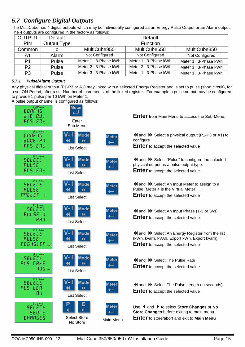
5.7 Configure Digital Outputs The MultiCube has 4 digital outputs which may be individually configured as an Energy Pulse Output or an Alarm output. The 4 outputs are configured in the factory as follows:
OUTPUT PIN
Default Output Type
Default Function
Common c MultiCube950 MultiCube650 MultiCube350
A1 Alarm Not Configured Not Configured Not Configured
P1 Pulse Meter 1 3-Phase kWh Meter 1 3-Phase kWh Meter 1 3-Phase kWh
P2 Pulse Meter 2 3-Phase kWh Meter 2 3-Phase kWh Meter 1 3-Phase kWh
P3 Pulse Meter 3 3-Phase kWh Meter 1 3-Phase kWh Meter 1 3-Phase kWh
5.7.1 Pulse/Alarm Output
Any physical digital output (P1-P3 or A1) may linked with a selected Energy Register and is set to pulse (short circuit), for a set ON-Period, after a set Number of Increments, of the linked register. For example a pulse output may be configured to provide 1 pulse per 10 kWh on Meter 1. A pulse output channel is configured as follows:
Enter
Sub Menu
Enter from Main Menu to access the Sub-Menu.
List Select
and Select a physical output (P1-P3 or A1) to
configure
Enter to accept the selected value
List Select
and Select “Pulse” to configure the selected
physical output as a pulse output type.
Enter to accept the selected value
List Select
and Select An Input Meter to assign to a
Pulse (Meter 4 is the Virtual Meter)
Enter to accept the selected value
List Select
and Select An Input Phase (1-3 or Sys)
Enter to accept the selected value
List Select
and Select An Energy Register from the list
(kWh, kvarh, kVAh, Export kWh, Export kvarh)
Enter to accept the selected value
List Select
and Select The Pulse Rate
Enter to accept the selected value
List Select
and Select The Pulse Length (in seconds)
Enter to accept the selected value
Select Store
No Store
Main Menu
Use and to select Store Changes or No
Store Changes before exiting to main menu.
Enter to store/abort and exit to Main Menu

DOC-MC950-INS-0001-12 MultiCube 350/650/950 mV Installation Guide Page 16
5.7.2 Alarm Output
Any physical digital output (P1-P3 or A1) may be linked with an Event Channel and its contacts will close (short circuit) while the Event Condition Result is TRUE.
Enter
Sub Menu
Enter from Main Menu to access the Sub-Menu.
List Select
and Select Physical Output (P1-P3 or A1) to
Configure
Enter to accept the selected value
List Select
and Select An Event Channel to configure
the selected physical output as an alarm output type linked with a specific Event channel.
Enter to accept the selected value
Select Store
No Store
Main Menu
Use and to select Store Changes or No
Store Changes before exiting to main menu.
Enter to store/abort and exit to Main Menu

DOC-MC950-INS-0001-12 MultiCube 350/650/950 mV Installation Guide Page 17
5.8 Configure Serial Port (Modbus Option) If the Modbus option is fitted (Meter Models - MultiCubex50mV-MODBUS) then the serial communications parameters may be configured as follows:
Setting Selection Options
Modbus ID
Set the Range of Modbus IDs The user sets the first ID and the MultiCube automatically assigns the correct number of consecutive IDs required (see below). The maximum start ID is 245 minus the total number of ID’s required by the instrument (see table below)
Baud Rate Select the baud rate from: 4800, 9600, 19200, 38400
Parity Select the parity from: NONE, EVEN, ODD
A number of Modbus IDs need to be reserved for each MultiCube, depending on how many meter points it can measure as follows:
Meter Type Modbus IDs Required
Meter Points Virtual Meter Main Unit Total
MultiCube350mV-Modbus 1 N/A N/A 1
MultiCube650mV-Modbus 2 N/A 1 3
MultiCube950mV-Modbus 3 0 (1 optional) 1 4 (5)
Enter
Sub Menu
Enter from Main Menu to access the Sub-Menu.
Fast Adjust
Fine Adjust
and Select Modbus ID Range (Steps of 5
IDs)
and Select Modbus ID Range (Steps of 1
ID)
Enter to accept the selected value
List Select
and Select Baud Rate
Enter to accept the selected value
List Select
and Select Parity
Enter to accept the selected value
Select Store
No Store
Main Menu
Use and to select Store Changes or No
Store Changes before exiting to main menu.
Enter to store/abort and exit to Main Menu

DOC-MC950-INS-0001-12 MultiCube 350/650/950 mV Installation Guide Page 18
5.9 Configure TCP-IP (Option) If the Ethernet (MultiCube-IP) option is fitted to the meter the basic TCP-IP communications parameters may be configured as follows:
Setting Selection Options
TCP-IP Addressing Mode
Select DHCP for automatic network assigned addresses Select Static IP addressing mode for manually assigned TC-IP addressing
Static IP Address Set the static IP address (this page is shown in DHCP Mode but the value may not be changed)
Default Gateway Set the Default Gateway address
Subnet Mask Set the Subnet mask Address
Enter
Sub Menu
Enter from Main Menu to access the Sub-Menu.
Select
and Select Addressing Mode
Enter to accept the selected value
Select Byte
Change Value
and Select Byte to Edit (Shown on left of
LCD)
and Increment/Decrement selected byte
Enter to accept the selected value
List Select
Fine Adjust
and Select Byte to Edit (Shown on left of
LCD)
and Increment/Decrement selected byte
Enter to accept the selected value
Hold Reset
Keys
Fine Adjust
and Select Byte to Edit (Shown on left of
LCD)
and Increment/Decrement selected byte
Enter to accept the selected value
Select Store
No Store
Main Menu
Use and to select Store Changes or No
Store Changes before exiting to main menu.
Enter to store/abort and exit to Main Menu

DOC-MC950-INS-0001-12 MultiCube 350/650/950 mV Installation Guide Page 19
5.10 Configure the Virtual/Residual Meter (optional1) The multicube950mV can optionally provide an set of metered readings based on a calculation made from its multiple meter inputs. Two type of configuration are possible for this Virtual Meter:
Virtual Summation Meter o Adds selected 3-Phase Meters to create measurements of TOTAL METERED LOAD
VIRTUAL SUM = METER1 + METER2 + METER3 Note individual meters may be selected/deselected for the sum
Residual Meter o Used to subtract sub-metered loads from an incoming supply measurement. This provides an accurate
measurement of TOTAL UN-METERED loads. METER1 must measure the 3-Phase incoming load METER2, METER3 are wired as sub-meters RESIDUAL = METER1 – (METER2+METER3)
The Virtual Sum or Residual meter displays multiple meter parameters, as a normal multi-function meter (harmonics and THD are not available)
Setting Selection Options
Calculation Select Between: VIRTUAL SUM or RESIDUAL LOAD
Meter 1 Include/Ignore
Select Include to add this meter to the summated readings of the Virtual Meter Select Ignore if this meter is NOT required in the summated readings of the Virtual Meter
Meter 2 Include/Ignore
Select Include to add this meter to the summated readings of the Virtual Meter Select Ignore if this meter is NOT required in the summated readings of the Virtual Meter
Meter 3 Include/Ignore
Select Include to add this meter to the summated readings of the Virtual Meter Select Ignore if this meter is NOT required in the summated readings of the Virtual Meter
Enter
Sub Menu
Enter from Main Menu to access the Sub-Menu.
List Select
and Select to calculation type – Virtual/Residual
Enter to accept the selected value
List Select
and Select to Include/Ignore Meter 1 in the
Virtual meter calculations
Enter to accept the selected value
List Select
and Select to Include/Ignore Meter 2 in the
Virtual meter calculations
Enter to accept the selected value
List Select
and Select to Include/Ignore Meter 3 in the
Virtual meter calculations
Enter to accept the selected value
Select Store
No Store
Main Menu
Use and to select Store Changes or No Store
Changes before exiting to main menu.
Enter to store/abort and exit to Main Menu
Note 1: This option is only available on the MultiCube 950mV

DOC-MC950-INS-0001-12 MultiCube 350/650/950 mV Installation Guide Page 20
5.11 Reset Stored Parameters It is possible to reset stored peak values and energy registers as follows:
Setting Selection Options
Reset Energies Reset all energy registers simultaneously to zero
Reset Peak Hold Reset all peak hold values simultaneously to zero
Reset Ave Peak Reset all peak average values simultaneously to zero
Reset All Reset Energies, Peak Hold and Peak Averages
Enter
Sub Menu
Enter from Main Menu to access the Sub-Menu
Hold Reset Keys
Hold Reset Keys during a 5 Second Countdown to Reset All Values Simultaneously
Release Keys
Hold Reset Keys
Abort Reset
Press and Hold Reset Keys to start countdown.
Enter to SKIP Reset Energy function
Hold Reset Keys
Hold Reset Keys during a 5 Second Countdown to Reset Energy
Release Keys
Hold Reset Keys
Abort Reset
Press and Hold Reset Keys to start countdown.
Enter to SKIP Reset Peak Hold function
Hold Reset Keys
Hold Reset Keys during a 5 Second Countdown to Reset Peak Hold
Release Keys

DOC-MC950-INS-0001-12 MultiCube 350/650/950 mV Installation Guide Page 21
Hold Reset Keys
Abort Reset
Press and Hold Reset Keys to start countdown.
Enter to SKIP Reset Peak Average function
Hold Reset Keys
Hold Reset Keys during a 5 Second Countdown to Reset Peak Average
Release Keys
Select Store
No Store
Main Menu
and to select Store Changes or No Store
Changes before exiting to main menu.
Enter to store/abort and exit to Main Menu

DOC-MC950-INS-0001-12 MultiCube 350/650/950 mV Installation Guide Page 22
5.12 Configure Password The configuration setup menus can be password protected. This menu allows the password to be changed.
Password value
Notes
0000
(factory default)
Setting the password to 0000, removes the requirement for a password to be entered before accessing the setup configuration menus.
0001 – 9999 A password is requested before access to setup configuration menus is granted.
Enter
Sub Menu
Enter from Main Menu to access the Sub-Menu.
Select Digit
Change Value
and Select digit to edit, indicated by
flashing cursor beneath.
and Increment/Decrement selected digit.
Enter to accept the selected value
Select Store
No Store
Main Menu
Use and to select Store Changes or No
Store Changes before exiting to main menu.
Enter to store/abort and exit to Main Menu

DOC-MC950-INS-0001-12 MultiCube 350/650/950 mV Installation Guide Page 23
6 Parameter Displays
6.1 Keypad
6.2 LCD Layout
3-Phase meter mode 1-Phase meter mode
Key Range Description Meter Number 1 to 9 Use Meter Key to select a meter to display
Transducer 1 to 3 Parameters are displayed, associated with this current transducer input socket on rear
Phase 1 to 3 Parameters are displayed associated with this voltage phase and individual transducer
Meter Type 1 or 3-Ph Displayed meter is configured as Single or 3-Phase
Legends various Measurement units of displayed parameters
Measurement Mode
various None = Instantaneous “Max Hold” = Largest instantaneous value recorded “Avg” = Time averaged value “Avg Max” = Largest average value recorded “Avg Min” = Smallest average value recorded
6.3 Front Panel LEDs In normal operation the front panel LEDs P1-P3 are linked with the physical isolated digital outputs P1-P3 which may be configured as pulse outputs or Alarms as described in Section 5.7.

DOC-MC950-INS-0001-12 MultiCube 350/650/950 mV Installation Guide Page 24
6.4 Selecting a Metered Load The MultiCube is configured during commissioning to measure a combination of Single and 3-Phase loads. The Meter key is used to switch between meters, for each configuration, as follows
3 x 3-Phase Meters 9 x 1-Phase Meters 1 x 3-Phase Meters 6 x 1-Phase Meters
Note: When the virtual meter is configured to calculate a residual load the top legend “” is replaced by “”

DOC-MC950-INS-0001-12 MultiCube 350/650/950 mV Installation Guide Page 25
6.5 Current/Voltage Display Pages
Voltage & Current Page Selection Key
3-Phase Meter 1-Phase Meter Virtual/Residual Meter
Phase Currents Amps, Volts, Power Factor Phase Currents
Phase Volts
Phase Volts
Line-Line Volts
Line-Line Volts
Amps – 3-Ph Ave, Total & Neutral
Note: When the virtual meter is configured to calculate a residual load the top legend “” is replaced by “”

DOC-MC950-INS-0001-12 MultiCube 350/650/950 mV Installation Guide Page 26
6.6 Power Display Pages
Power Page Selection Key
3-Phase Meter 1-Phase Meter Virtual/Residual Meter
System kW1, kVA, kvar
2 kW
1, kVA, kvar
2 System kW
1, kVA, kvar
2
Per Phase kW1 Frequency, Power Factor
2 Per Phase kW
1
Per Phase Power Factor2
Per Phase Power Factor
2
Per Phase kvar1,2
Per Phase kvar1,2
Per Phase kVA
Per Phase kVA
Frequency, System Power Factor
2
Frequency, System Power Factor
2
Note: When the virtual meter is configured to calculate a residual load the top legend “” is replaced by “”

DOC-MC950-INS-0001-12 MultiCube 350/650/950 mV Installation Guide Page 27
6.7 Energy Display Pages
Energy Page Selection Key
3-Phase Meter 1-Phase Meter Virtual/Residual Meter
System Energy (Import) Single Phase Energy (Import) System Energy (Import)
System Energy (Export) Single Phase Energy (Export) System Energy (Export)
Note: When the virtual meter is configured to calculate a residual load the top legend “” is replaced by “”

DOC-MC950-INS-0001-12 MultiCube 350/650/950 mV Installation Guide Page 28
6.8 Display Modes
Select alternate display mode (depends on parameter).
Example - Amps Display Modes
Instantaneous Display updates every second
Maximum Hold Largest Instantaneous Value Stored
Time Averaged Time Avearged Instantaneous Value
User Set - Rolling Window Time Period
Maximum Time Averaged Largest Time Averaged Value Stored
Minimum Time Averaged Smallest Time Averaged Value Stored

DOC-MC950-INS-0001-12 MultiCube 350/650/950 mV Installation Guide Page 29
Power Quality Phase Volts and Amps Only
Total Harmonic Distortion (PQ Mode - Remembered Harmonic Page)
Next Harmonic Page (Loops at 63
rd and 2
nd Harmonics)
Return to THD Page
Power Quality Phase Volts and Amps Only
Individual Harmonic Pages (2nd
-63rd
)
(Harmonic Page Remembered Here)
Instantaneous Display updates every second
NOTE: When a new parameter page is selected, Instantaneous Display Mode, is automatically selected.
DOC-MC950-INS-0001-12 MultiCube 350/650/950 mV Installation Guide Page 30
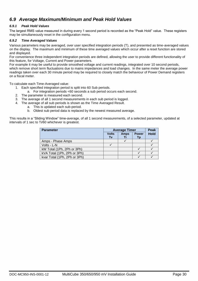
6.9 Average Maximum/Minimum and Peak Hold Values
6.9.1 Peak Hold Values
The largest RMS value measured in during every 1 second period is recorded as the “Peak Hold” value. These registers may be simultaneously reset in the configuration menu.
6.9.2 Time Averaged Values
Various parameters may be averaged, over user specified integration periods (T), and presented as time-averaged values on the display. The maximum and minimum of these time averaged values which occur after a reset function are stored and displayed. For convenience three independent integration periods are defined, allowing the user to provide different functionality of this feature, for Voltage, Current and Power parameters. For example it may be useful to provide smoothed voltage and current readings, integrated over 10 second periods, which remove short term fluctuations due to mains impedances and load changes. In the same meter the average power readings taken over each 30 minute period may be required to closely match the behaviour of Power Demand registers on a fiscal meter. To calculate each Time-Averaged value:
1. Each specified integration period is split into 60 Sub periods. a. For integration periods <60 seconds a sub period occurs each second.
2. The parameter is measured each second. 3. The average of all 1 second measurements in each sub period is logged. 4. The average of all sub periods is shown as the Time Averaged Result.
a. This is updated each sub-period. b. Oldest sub period data is replaced by the newest measured average.
This results in a “Sliding Window” time-average, of all 1 second measurements, of a selected parameter, updated at intervals of 1 sec to Ti/60 whichever is greatest.
Parameter Average Timer Peak Hold Volts
Tv Amps
Ti Power
Tp
Amps - Phase Amps
Volts - L-N
kW Total (1Ph, 2Ph or 3Ph)
kVA Total (1Ph, 2Ph or 3Ph)
kvar Total (1Ph, 2Ph or 3Ph)

DOC-MC950-INS-0001-12 MultiCube 350/650/950 mV Installation Guide Page 31
6.10 Meter Settings Preview Menu A summary of the meter configuration may be conveniently previewed in the Meter Settings Preview Menu.
Press the Setup Keys and hold for 5 seconds to Enter the Meter Settings Preview Menu.
Factory Data Serial Number 12345678
Product number, Firmware version Product name
System Setup Nominal System Volts System Connection
PT Scaling (No PT = 1.0)
CT Setup Meter 1 CT Auto Detected = 400A Meter 2 CT Auto Detected = 150A Meter 3 CT Auto Detected = 200A
CT Setup CT Auto Rotate Enabled CT Secondary Type mV
CT Reverse – CT1 CT2 CT3 (1=Reversed)
Installation Aid (Section 6.10.2) Voltage Phase Sequence = 1-2-3
Meter1 CT Phase Sequence=1-2-3 (Inductive Load) Meter1 CT Phase Sequence=1-2-3 (Capacitive Load)
Meter3 – Current <5% In
Virtual Meter Setup Meter 1 – Included/Ignored in Virtual Meter Meter 2 – Included/Ignored in Virtual Meter Meter 3 – Included/Ignored in Virtual Meter
Setup Average Time Voltage = 1800 Seconds Current = 600 Seconds Power = 1800 Seconds
Event 1 Under Alarm – Meter 3 Phase 1 Amps
Trigger 150.0A Release 155.0A
Event 2 Over Alarm – Meter 1 Phase 2 Volts
Trigger 240.0V Release 238.0V
Event 3 Over Alarm – Meter 1 Phase 2 kW
Trigger 150.0 kW Release 149.0kW

DOC-MC950-INS-0001-12 MultiCube 350/650/950 mV Installation Guide Page 32
Event 4 Logical OR
Trigger Event if either Event 1, 2 or 3 Triggered Zero Seconds Delay
Digital Pulse Output 1 Pulse Output
1 Pulse Every 0.1kWh, Pulse Length 0.1 seconds Pulse on Meter 1, 3-Phase kWh
Digital Pulse Output 2 Pulse Output
1 Pulse Every 0.1kWh, Pulse Length 0.1 seconds Pulse on Meter 2, 3-Phase kWh
Digital Pulse Output 3 Pulse Output
1 Pulse Every 0.1kWh, Pulse Length 0.1 seconds Pulse on Meter 3, 3-Phase kWh
Digital Pulse Output 4, Alarm 1 Set to Event 1
6.10.1 Modbus Connection Information (Option)
The following setup information page is shown if the Modbus option is fitted.
Modbus Serial Port (Option) Modbus RTU Protocol
ID Range (4 Addresses) Baud Rate
Modbus Communication Test page Received Count (Valid packets addressed for this meter) Error Count (Number of errors since entering this page)
Last Error Code
Error Codes Meaning
000 No Modbus Error
010 Serial Packet Framing Error
028 Incomplete Modbus Packet
030 Checksum Error
040 Invalid Modbus Packet
DOC-MC950-INS-0001-12 MultiCube 350/650/950 mV Installation Guide Page 33
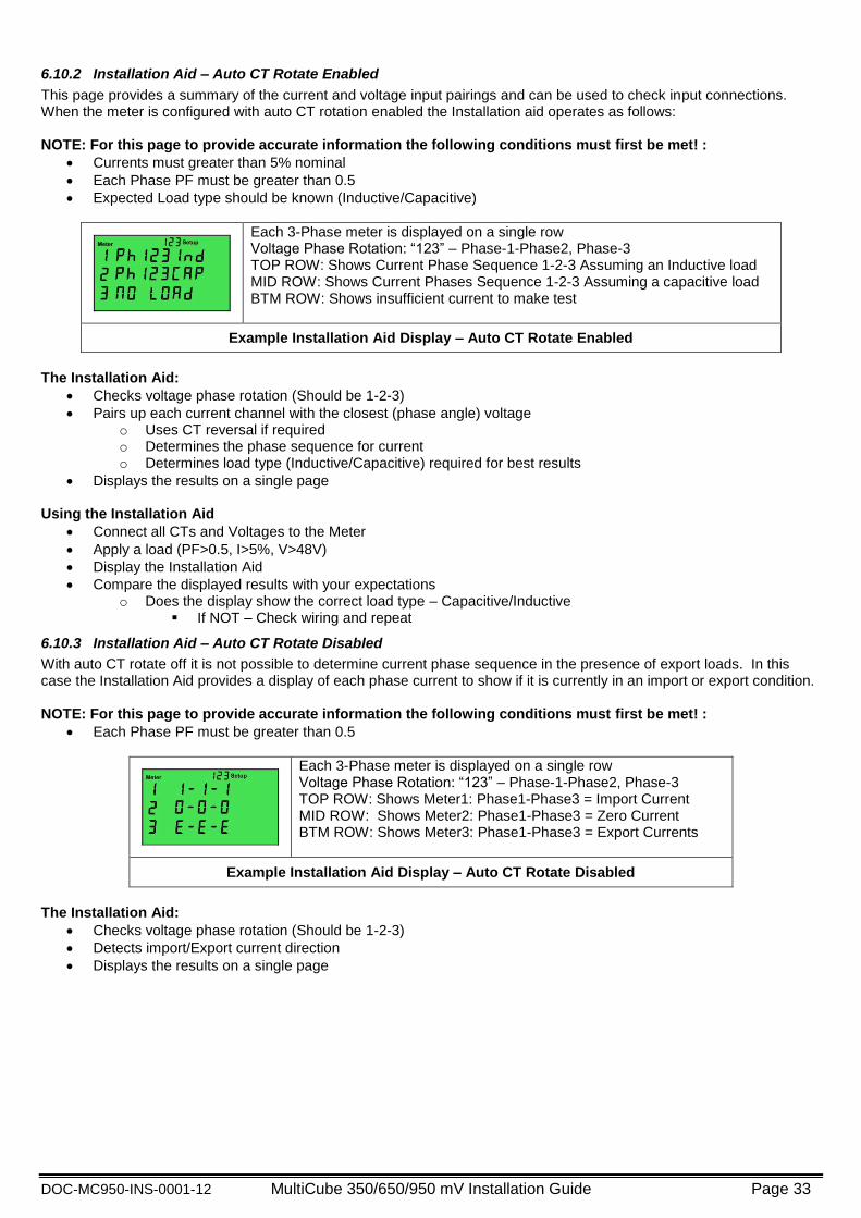
6.10.2 Installation Aid – Auto CT Rotate Enabled
This page provides a summary of the current and voltage input pairings and can be used to check input connections. When the meter is configured with auto CT rotation enabled the Installation aid operates as follows: NOTE: For this page to provide accurate information the following conditions must first be met! :
Currents must greater than 5% nominal
Each Phase PF must be greater than 0.5
Expected Load type should be known (Inductive/Capacitive)
Each 3-Phase meter is displayed on a single row Voltage Phase Rotation: “123” – Phase-1-Phase2, Phase-3 TOP ROW: Shows Current Phase Sequence 1-2-3 Assuming an Inductive load MID ROW: Shows Current Phases Sequence 1-2-3 Assuming a capacitive load BTM ROW: Shows insufficient current to make test
Example Installation Aid Display – Auto CT Rotate Enabled
The Installation Aid:
Checks voltage phase rotation (Should be 1-2-3)
Pairs up each current channel with the closest (phase angle) voltage o Uses CT reversal if required o Determines the phase sequence for current o Determines load type (Inductive/Capacitive) required for best results
Displays the results on a single page Using the Installation Aid
Connect all CTs and Voltages to the Meter
Apply a load (PF>0.5, I>5%, V>48V)
Display the Installation Aid
Compare the displayed results with your expectations o Does the display show the correct load type – Capacitive/Inductive
If NOT – Check wiring and repeat
6.10.3 Installation Aid – Auto CT Rotate Disabled
With auto CT rotate off it is not possible to determine current phase sequence in the presence of export loads. In this case the Installation Aid provides a display of each phase current to show if it is currently in an import or export condition. NOTE: For this page to provide accurate information the following conditions must first be met! :
Each Phase PF must be greater than 0.5
Each 3-Phase meter is displayed on a single row Voltage Phase Rotation: “123” – Phase-1-Phase2, Phase-3 TOP ROW: Shows Meter1: Phase1-Phase3 = Import Current MID ROW: Shows Meter2: Phase1-Phase3 = Zero Current BTM ROW: Shows Meter3: Phase1-Phase3 = Export Currents
Example Installation Aid Display – Auto CT Rotate Disabled
The Installation Aid:
Checks voltage phase rotation (Should be 1-2-3)
Detects import/Export current direction
Displays the results on a single page

DOC-MC950-INS-0001-12 MultiCube 350/650/950 mV Installation Guide Page 34
7 Specification INPUTS
System 3 Phase 3 or 4 Wire Unbalanced Load or Single Phase Voltage Un 480/277. 3 Phase 3 or 4 Wire. Others to order. Current In 0.33V From Custom Smart CTs
Measurement Range 45-65Hz
Voltage 20% to 120% Un Current 0.2% to 120%
Frequency Range Fundamental 45 to 65Hz Harmonics Up to 80th harmonic at 50Hz Individual to the 63
rd
Burden Voltage <0.1VA per phase Overload Voltage x4 for 1 hour
Current x2 Continuous
DISPLAY Type Custom, Supertwist, LCD Data Retention 10 years min. Stores kWh & Meter set-up Format 3 Rows x 8 Digits + Legends Scaling CT Primary Auto Detected from 5A to 25kA
PT Scaling Factor from 1 to 1000 Legends Wh, kWh, MWh etc. depending on user settings
AUXILIARY SUPPLY Input 100-240Vac (+/-10%) Frequency 45-65Hz Load 4 Watt Max.
METER ACCURACY All errors ± 1 digit kWh Better than Class 0.5 per EN 62053-22 & BS 8431 Kvarh Better than Class 1 per EN 62053-24 & BS 8431 kW & kVA Better than Class 0.25 IEC 60688 kvar Better than Class 0.5 IEC 60688 Amps & Volts Class 0.1 IEC 60688 (0.01In – 1.2In or 0.1Un – 1.2Un) PF ±0.2° (0.05In – 1.2In and 0.2Un – 1.2Un) Neutral Current Class 0.5 IEC 60688 (0.05In – 1.2In)

DOC-MC950-INS-0001-12 MultiCube 350/650/950 mV Installation Guide Page 35
PULSE OUTPUTS Function 1 Pulse per unit of energy Scaling Settable between 1 & 1000 counts of energy register Pulse Period 0.1 sec. default; Settable between 0.1 and 20 sec Rise & Fall Time < 2.0ms
Type N/O Volt free contact. Optically isolated BiFET Contacts 100mA ac/dc max ; 100V ac/dc max ; 5W maximum load Isolation 3.5kV 50Hz 1 minute
MODBUS® Serial Comms (Option)
Bus Type RS485 2 wire + 0v. ½ Duplex, ¼ unit load
Protocol MODBUS® RTU with 16 bit CRC
Baud Rate 4800, 9600, 19,200 or 38,400 User settable
Address 1 – 244 User settable
Latency Reply within 250ms max.
Command Rate New command within 5ms of previous one
Isolation 3.5kV
GENERAL Temperature Operating -10°C to +55°C (14°F to 131°F)
Storage -25°C to +70°C (-13°F to 158°F) Humidity < 75% non-condensing Environment IP54 (when correctly mounted, as described, in a panel) – Indoor Use Only
Altitude <2000m (6561ft)
MECHANICAL Terminals Rising Cage. 4mm
2 (12 AWG) cable max.
Enclosure DIN 43700 96 x 96 Material Mablex® with fire protection to UL94-V-O. Self extinguishing Dimensions 96 x 96 mm x 83.5 mm (72 mm behind panel)
3.78” x 3.78” x 3.29” (2.83” behind the panel) Weight ~ 250 gms
SAFETY Conforms to EN 61010-1 Ed3 2010
Transient Overvoltage Category III Pollution Degree 2 Also BS 8431
E. & O. E. © Northern Design (Electronics) Ltd, July 2015