revised navigator technical paper -...
TRANSCRIPT

Revised NAVIGATOR Technical Paper Technical Paper for DARPA Grand Challenge
Disclaimer: “The views, opinions, and/or findings contained in this paper are those of the participating team and should not be interpreted as representing the official policies,
either expressed or implied, of the Defense Advanced Research Projects Agency or the Department of Defense. DARPA and DoD cannot guarantee the accuracy or reliability of the information in this paper. The paper is published by DARPA as a service to those who seek
additional technical information concerning the DARPA Grand Challenge of March 2004.”
Team CIMAR
1. System Description a. Mobility
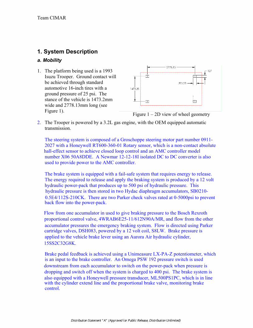
1. The platform being used is a 1993 Isuzu Trooper. Ground contact will be achieved through standard automotive 16-inch tires with a ground pressure of 25 psi. The stance of the vehicle is 1473.2mm wide and 2778.13mm long (see Figure 1).
Figure 1 – 2D view of wheel geometry
2. The Trooper is powered by a 3.2L gas engine, with the OEM equipped automatic transmission. The steering system is composed of a Groschoppe steering motor part number 0911-2027 with a Honeywell RT600-360-01 Rotary sensor, which is a non-contact absolute hall-effect sensor to achieve closed loop control and an AMC controller model number X06 50A8DDE. A Newmar 12-12-18I isolated DC to DC converter is also used to provide power to the AMC controller. The brake system is equipped with a fail-safe system that requires energy to release. The energy required to release and apply the braking system is produced by a 12 volt hydraulic power-pack that produces up to 500 psi of hydraulic pressure. This hydraulic pressure is then stored in two Hydac diaphragm accumulators, SB0210-0.5E4/112S-210CK. There are two Parker check valves rated at 0-5000psi to prevent back flow into the power-pack. Flow from one accumulator in used to give braking pressure to the Bosch Rexroth proportional control valve, 4WRAB6E25-11/612N90A/MR, and flow from the other accumulator pressures the emergency braking system. Flow is directed using Parker cartridge valves, DSH083, powered by a 12 volt coil, S8LW. Brake pressure is applied to the vehicle brake lever using an Aurora Air hydraulic cylinder, 15SS2C32G8K. Brake pedal feedback is achieved using a Unimeasure LX-PA-Z potentiometer, which is an input to the brake controller. An Omega PSW 192 pressure switch is used downstream from each accumulator to switch on the power-pack when pressure is dropping and switch off when the system is charged to 400 psi. The brake system is also equipped with a Honeywell pressure transducer, ML500PS1PC, which is in line with the cylinder extend line and the proportional brake valve, monitoring brake control.
Team CIMAR
Revised NAVIGATOR Technical Paper 2 February 27, 2004
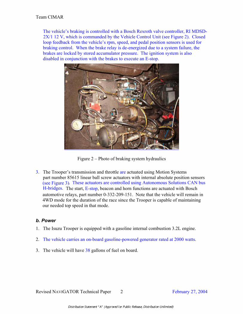
The vehicle’s braking is controlled with a Bosch Rexroth valve controller, RI MDSD-2X/1 12 V, which is commanded by the Vehicle Control Unit (see Figure 2). Closed loop feedback from the vehicle’s rpm, speed, and pedal position sensors is used for braking control. When the brake relay is de-energized due to a system failure, the brakes are locked by stored accumulator pressure. The ignition system is also disabled in conjunction with the brakes to execute an E-stop.
Figure 2 – Photo of braking system hydraulics
3. The Trooper’s transmission and throttle are actuated using Motion Systems part number 85615 linear ball screw actuators with internal absolute position sensors (see Figure 3). These actuators are controlled using Autonomous Solutions CAN bus H-bridges. The start, E-stop , beacon and horn functions are actuated with Bosch automotive relays, part number 0-332-209-151. Note that the vehicle will remain in 4WD mode for the duration of the race since the Trooper is capable of maintaining our needed top speed in that mode.
b. Power 1. The Isuzu Trooper is equipped with a gasoline internal combustion 3.2L engine. 2. The vehicle carries an on-board gasoline-powered generator rated at 2000 watts. 3. The vehicle will have 38 gallons of fuel on board.

Team CIMAR
Revised NAVIGATOR Technical Paper 3 February 27, 2004
TThhrroottttllee HH--BBrriiddggee
TThhrroottttllee AAccttuuaattoorr
Figure 3 – Throttle System
c. Processing
1. Computing Systems (Hardware) NAVIGATOR uses a network of four single board computers, a PhyCore MPC565 PowerPC microcontroller, a military ruggedized Itronix GoBook II notebook computer, and a D.Module.C6713 Digital Signal Processor (DSP) to distribute the processing and intelligence required for the Grand Challenge. Some of the computers are connected to peripheral sensor and actuator devices while others are simply used for focused processing power. Figure 4 represents each physical computer by a unique color, where each physical computer is a collection of the logical components discussed in the next section. Note: a full page rendering of Figure 4 is included as Appendix A. Each single board computer is equipped with 128-512MB of RAM and an onboard 1GB compact flash drive for nonvolatile memory storage. The solid-state flash cards are used to increase vehicle ruggedness by eliminating the poor shock and vibration tolerance of ordinary hard drives. Three single boards (along with a digital signal processor) are part of the Smart Sensor System (blue gradients in Figure 4) and the forth single board is the World Modeler (brown). The Smart Sensor System determines traversability relative to the local reference frame of the NAVIGATOR. This is a very computationally expensive estimation, thus multiple computing systems are required to support the individual sensors. Stereo Vision is input to one single board, a fixed SICK LADAR and a camera input to another, and two cameras input to the final single board in the Smart Sensor System. Details on how the data is used for intelligent road-finding and obstacle detection and avoidance can be found in later sections. A 32-bit D.Module.C6713 Digital Signal Processor (DSP) with a 100Base-TX / 10Base-T Ethernet controller and Real-Time Clock is used to process incoming data from a rotating SICK LADAR at 500 kbaud. This 3D representation of
Team CIMAR
Revised NAVIGATOR Technical Paper 4 February 27, 2004
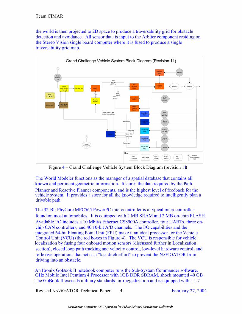
the world is then projected to 2D space to produce a traversability grid for obstacle detection and avoidance. All sensor data is input to the Arbiter component residing on the Stereo Vision single board computer where it is fused to produce a single traversability grid map.
WirelessCommunication
Link
PrimitiveDriver
a priori data
RDDF(CDROM)
World Model(static ROM) Global
PositionSensor
Velocity StateSensor
Local GridMap
Grand Challenge Vehicle System Block Diagram (Revision 11)
GPSs /INS /
Encoder
StereoVision
Actuators
Raster data
Path
DarpaRemote
Kill
Vehicle
2
Key:JAUS
Component JAUS Node InputDevice
OutputDevice
InputData
#
DarpaRemote Kill
2
PathSegment
Driver
Path Segment(0.1-1Hz)
VelState
(20Hz)Pose
(20Hz)
Local GridMap
Local GridMap
SpinningLADAR
LADAR
Raster dataRaster data
Fused Raster Data(scaled traversability)
ReflexiveDriver RADARs
Local GridMap
Raster data
Cameras
SystemCommander
(Mobius)Path Planner PEKS
ReactivePlanner
Arbiter
Local GridMap
Long-range
RADAR
Raster data
Figure 4 – Grand Challenge Vehicle System Block Diagram (revision 11)
The World Modeler functions as the manager of a spatial database that contains all known and pertinent geometric information. It stores the data required by the Path Planner and Reactive Planner components, and is the highest level of feedback for the vehicle system. It provides a store for all the knowledge required to intelligently plan a drivable path. The 32-Bit PhyCore MPC565 PowerPC microcontroller is a typical microcontroller found on most automobiles. It is equipped with 2 MB SRAM and 2 MB on-chip FLASH. Available I/O includes a 10 Mbit/s Ethernet CS8900A controller, four UARTs, three on-chip CAN controllers, and 40 10-bit A/D channels. The I/O capabilities and the integrated 64-bit Floating Point Unit (FPU) make it an ideal processor for the Vehicle Control Unit (VCU) (the red boxes in Figure 4). The VCU is responsible for vehicle localization by fusing four onboard motion sensors (discussed further in Localization section), closed loop path tracking and velocity control, low-level hardware control, and reflexive operations that act as a “last ditch effort” to prevent the NAVIGATOR from driving into an obstacle. An Itronix GoBook II notebook computer runs the Sub-System Commander software.
The GoBook II exceeds military standards for ruggedization and is equipped with a 1.7 GHz Mobile Intel Pentium 4 Processor with 1GB DDR SDRAM, shock mounted 40 GB
Team CIMAR
Revised NAVIGATOR Technical Paper 5 February 27, 2004
ruggedized removable hard disk drive, and a wireless LAN. The System Commander is responsible for processing the waypoint corridor data provided by the World Modeler and for planning and managing the NAVIGATOR’S path. In the event that the NAVIGATOR has to be shutdown at night and restarted in the morning, the System Commander is responsible for storing the remaining path for continuation on startup the next morning. Communications between computers is achieved through UDP/IP and EIA/TIA-232. All wireless capabilities will be disabled prior to the initiation of a DARPA event.
2. Sensor Data Interpretation, Route Planning, Vehicle Control, Object Classification, Macro Route Planning, Reactive Obstacle Avoidance and Vehicle Control The system is built on the DoD Joint Architecture for Unmanned Systems (JAUS) and consists of both accepted and experimental JAUS component.....s. The methodology for system control including interpretation of sensor data, route planning, vehicle control, and obstacle avoidance is illustrated in Figure 4.. A description of the diagram follows. First, the Route Definition Date File (RDDF) is input to the World Modelwhere it converts the RDDF into a waypoint corridor. A-priori data stored in the World Model database (including known obstacles, roads, and previously driven roads) is intersected with the waypoint corridor to produce a road network contained within the corridor. The waypoint corridor, obstacles, and road network are transmitted to the System commander to plan a sequence of path segments (lines and arcs) from the current position of the NAVIGATOR to each successive waypoint in the RDDF such that the NAVIGATOR stays within the waypoint corridor while attempting to follow roads and avoid a priori known obstacles. At QID and event start, the sequence of path segments is then inserted into the Planning Element Knowledge Store (PEKS). Once PEKS receives path segments, it notifies the Path Segment Driver (PSD) that path segments are available and ready to drive. The PSD queries the first two path segments in PEKS and then begins performing closed loop position and velocity control to move along the given path segment. As path segments are completed, the PSD deletes them from PEKS. The output of the PSD is a Wrench command sent to the Primitive Driver (PD) where the steering, throttle and brake actuators are controlled to navigate the path. The Global Pose Sensor (GPOS) provides position feedback to the Path Segment Driver. It fuses position data from a NavCom Starfire GPS unit, a Garmin GPS unit, a Smiths Industries’ IMU, and a shaft encoder to provide the PSD with high accuracy position and velocity data. The NAVIGATOR perception system generates information on region traversability based on the presence/absence of obstacles, the slope of the down-range terrain and the visual similarity of the down-range terrain to that of a known road. The system consists of a suite of sensor hardware including a fixed SICK LADER, a 3D SICK LADAR, three (3)

Team CIMAR
Revised NAVIGATOR Technical Paper 6 February 27, 2004
video cameras, three (3) short range radar units, a long range radar unit, and a Videre Design stereo vision system. Each sensor’s functionality is decomposed into individual Smart Sensor components that use the data provided by their physical sensors to produce a local raster traversability grid. While the Smart Sensors all differ in implementing the method by which they generate their traversability metric, they do, however, all share the same messaging interface as defined by the NAVIGATOR Smart Sensor Interface Control Document (ICD). To assure that all grid positions are synchronized to the same geodetic position, all GPOS information is channeled through the reactive planner. The reactive planner subsequently passes this GPOS information down the chain to the Smart Sensor Arbiter and then to the Smart Sensors. When the Smart Sensors transmit changes to their local traversability grid, a GPOS stamp is attached to the cell change messages. This permits asynchronous updating and registration of the data in the Arbiter’s fused grid map. The format of this GPOS data messages is defined in the Smart Sensor ICD. The three cameras and fixed LADAR make up the sensors for the path finding capability. This set of sensors is responsible for keeping the NAVIGATOR in the center of a road, as described in section 1e. Due to their limited 26-foot range, the three short-range radar units will act collectively as a virtual bumper switch providing a last line of defense to prevent the NAVIGATOR from colliding with obstacles in its path. Two radar units are mounted on the front right and left sides on the bumper and the third is located on the back of the NAVIGATOR to provide limited obstacle detection while backing up.
The long-range radar unit provides additional information to the arbiter on free or blocked space. The PRECO Preview long range RADAR system provides range data at distances up to 100 feet. Because of the wide field of view of the RADAR system and the limited range resolution, the RADAR system will be used as a “free space” detector. The RADAR system’s data will be converted to a local raster traversability grid as is done with all Smart Sensors. Since the system is a low resolution object detector, the values that it can place in its traversability grid will be limited to the range of 127 to 255, representing the range of unknown to completely traversable as defined in the NaviGATOR Smart Sensor ICD. The Smart Sensor Arbiter will fuse this data in the same manner that data are fused from the other Smart Sensors.
The 3D LADAR is a continuously rotating SICK laser that provides data to the DSP at 500 kbaud. It creates a 3D representation of the world that is orthogonally projected into a 2D space. Positive and negative obstacles as well as drivable and non-drivable slopes are calculated based on the data. The Videre Design stereo vision system is an all-digital IEEE 1394 based system. This wide-baseline system and its software API provide a three-dimensional representation of the ego-sphere of the vehicle. This representation, while not as dense as that provided by the 3D LADAR system, does provide a sufficient amount of information to calculate region traversability. Once the region traversability metric is established for each local

Team CIMAR
Revised NAVIGATOR Technical Paper 7 February 27, 2004
raster traversability cell, updated values are transmitted to the Smart Arbiter component using the method defined in the NAVIGATOR Smart Sensor ICD. The Smart Sensor Arbiter component provides a central point for fusing all smart sensor data. The Smart Sensor architecture was defined in such a way that all sensors and the arbiter use the same message interface. The benefits of doing this are two-fold. First it allows the option of having the Smart Sensors share code for the core Smart Sensor functionality. This reduces development time by allowing the core code to be rigorously tested and debugged while each sensor developer works on their sensor data processing. The second benefit of this architecture is that it allows the systems to be completely modular. This modularity allows Smart Sensors to be added to or removed from the Smart Sensor network at any time. The Smart Sensors can also be used individually as input to the Smart Sensor Arbiter allowing the sensors to be tested and debugged with the Reactive Planner component individually. Per the NAVIGATOR Smart Sensor ICD, the Smart Sensors’ traversability metric is represented by a value ranging from 0 – 255. A value of 127 represents an unknown traversability value for a cell. As cell values increase from 127 to 255, they proportionately represent how traversable the area is. Likewise, as cell values decrease from 127 to 0, they proportionately represent how non-traversable the area is. The traversability grid data are provided to the Smart Sensor Arbiter component through a 100 Mega bit per second UDP/IP connection. The synergy of all of the Smart Sensor components provides a best estimate of the traversability of the terrain local to the NAVIGATOR. The traversability grid data are provided to the Reactive Planner component through a 100 Mega bit per second UDP/IP connection. The Reactive Planner component checks the current path in PEKS to determine if any portion of the planned path intersects a non-traversable region of the local grid. If an intersection is detected, a new path is planned to avoid the obstruction and return to the original path plan. When this occurs, the Reactive Planner inserts the new modified path segments into PEKS and deletes the obstructed path segments from PEKS. The PSD is continuously querying the first path segments in PEKS, so a modification will not affect the PSD. As the NAVIGATOR progresses, path segments are popped off the queue until it reaches the final waypoint.
d. Internal Databases The NAVIGATOR vehicle will employ an open-source database solution consisting of PostgreSQL and the PostGIS spatial extensions. This combination will give the vehicle capabilities to query and analyze graphical data in a fashion similar to other commercially available geographic information systems (GIS). The PostgreSQL and PostGIS solution was chosen because it represents an open-source solution to the complex spatial database task and runs under the team’s desired operating system, Linux.
Team CIMAR
Revised NAVIGATOR Technical Paper 8 February 27, 2004
The NAVIGATOR vehicle will have available to it a variety of geospatial data including roads, railroads,etc.. This data will be constructed from the data sets made publiclyavailable by the United States Geological Survey (USGS). The specific data sets to be used include Digital Line Graphs (DLG), which will be used at 1:24,000 scale, along with data collected and processed by the team.
Data collected from these sources will be fused in the spatial database allowing the NAVIGATOR to query for areas of travel. The RDDF provided by DARPA will also be loaded into the database as polygonal areas where the NAVIGATOR is
e. Environment Sensing The environmental sensors that will be used on the NAVIGATOR will be both a rotating and a fixed laser range sensor,,,stereo vision, three additional cameras, three short-range and one long-range RADAR units. Like the human visual system, artificial stereo vision systems detect the visible light energy already present in the environment. As such, stereo vision systems are inherently passive. The stereo vision system will be the three dimensional sensor used on the NAVIGATOR. Its primary purpose will be to provide a dense, albeit noisy, cloud of three dimensional sensor data to our fusion algorithms at a high rate. While the data may in fact be noisy, it will provide valuable information about the presence of objects of interest at distances and elevations outside the field of view of the LADAR system. The sensing horizon, or field of view, of the stereo vision system is a function of the focal length of the lenses used. The stereo vision system that will be used on the NAVIGATOR is manufactured by Videre Design. With the 12.5 mm focal length lenses that we are using, the horizontal and vertical fields of view are 50 degrees and 38 degrees, respectively. Image data are transferred via an IEEE1394 interface to a single board computer. The single board computer utilizes SRI International’s Small Vision System to handle image rectification, correlation, and ultimately extraction of three-dimensional data. Laser range sensors are used for terrain and obstacle sensing. Each sensor is an LMS 200-30106 from SICK and is an active sensor. An infrared laser beam is generated by the scanner’s internal diode. If the beam strikes an object, the scanner receives the reflection and the distance is calculated based on the time of flight. The pulsed laser beam is reflected by an internal rotating mirror so that a fan shaped scan is made of the surrounding area. The sensor scans a single plane with a horizontal field of view of 180 degrees. One sensor is mounted on a rotating mechanism that
is allowed to travel.

Team CIMAR
Revised NAVIGATOR Technical Paper 9 February 27, 2004
enables it to scan multiple lines to produce a 3 dimensional data representation of the terrain. The other sensor is fixed and is tuned for estimating the slope of terrain in front of the vehicle. The laser range is up to 30 meters without using any supplementary reflectors. The data is transferred in real time via a serial interface to a single board computer. A series of three stationary cameras are used to obtain additional information about the terrain. The camera system provides the Arbiter with information about the path on which the vehicle is currently traveling. A combination of adaptive color filtering and frequency information is used to extract the road from the surrounding environment. The color and frequency information extracted from the images are used to create a model of the road or path. Then, this model is used to hypothesize the properties of the current road or path. All three cameras are forward facing and provide several perspectives of the environment in front of the vehicle. The hypothesized road or path is translated to a local grid map. The update process for the local grid map merges previous and current grid map data with position and orientation information to provide a robust assumption of the road or path. The synergy of these very different sensor modalities will yield a more accurate model of the NAVIGATOR’s environment. The resulting data will be used to support long range re-planning and reactive system behaviors.
f. State Sensing 1. There are several sensors to sense the vehicle state. Transmission gear state is
measured with the feedback on the Motion Systems linear ball screw actuator. The ground speed is read by the OEM anti-lock brake speed sensors. The Throttle state is read by the corresponding actuator senor. The throttle response is measured with the OEM RPM sensor. Honeywell pressure transducers read the brake pressure to confirm the brake actuator positioning and the previously mentioned OEM speed sensors provide feedback to the braking control system. The steering system is equipped with a Honeywell rotary sensor that reports steering angle to the controller. In addition, the Pose Sensor and Velocity State Sensor components provide instantaneous information with regard to the vehicle’s position/orientation and velocity state.
2. Sensor data will be used to ensure safe operation of the vehicle. The speed sensor
feedback will be used to limit the allowable steering angle to prevent rollovers at high speeds. Each actuated system will use the feedback described above, in a PID controller to achieve the setpoint commanded by the on board processor.
g. Localization
1. Determination of geolocation with respect to the Challenge Route NAVIGATOR determines its geolocation by filtering and fusing a combination of sensor data. The sensors used include a NavCom Starfire 2050 GPS, a Garmin WAAS GPS, a quadrature shaft encoder, and a Smiths Industries Northfinding Module, an

Team CIMAR
Revised NAVIGATOR Technical Paper 10 February 27, 2004
inertial/magnetic orientation sensor. Once a global solution, i.e., the vehicle’s latitude, longitude and true course heading, is determined, the heading error and cross track error with respect to the planned path are calculated. These values can then be used to navigate the vehicle on course. It is the responsibility of the System. Commander to ensure that the planned path is within the given challenge route, and to take action if the vehicle is approaching the challenge corridor boundary.
2. Handling of GPS outages The GPS’s are the only sensors onboard capable of calculating the geolocation of the vehicle. If the GPS signals drop out, the vehicle’s global position becomes uncertain. To overcome this problem, the positioning filter algorithm will continue to calculate a global position during GPS outages by extrapolating a dead reckoning solution based on the shaft encoder and vehicle orientation sensor data. This will allow the vehicle to continue on course for a short period of time; however the solution will gradually drift and the accuracy of the position system will steadily decrease as long as the GPS outage continues. Eventually the error in the system will build up to the point where the vehicle can no longer continue on course with any confidence and the vehicle will have to stop and wait for a GPS reacquisition.
3. Boundary Processing In order to stay within the Challenge Route boundaries, the system uses a global path-planning algorithm that computes a continuous, collision-free, non-holonomic path within a specified boundary that may contain obstacles. The boundary specified in the RDDF data file will be used by the Path Planner to generate an admissible trajectory that takes into consideration sufficient lateral clearance to account for any vehicular drift. In the event that the vehicle encounters unexpected obstacles, a new admissible trajectory will be generated by the Path Planner, taking into account the unexpected obstacles and the boundary information. “Out of Bounds” grid cells are marked as absolutely non-drivable in the composite traversability grid and thus will be treated as an inviolable obstacle.
h. Communications 1. NAVIGATOR does not broadcast any information-containing signals. Its only
emissions are the allowable spurious emissions from on-board equipment, The allowable transmission of sensor source stimuli, e.g., the LADAR signals, and any emissions from the DARPA-Supplied E-Stop and Tracking Systems.
2. NAVIGATOR receives only a standard GPS signal and the mandatory e-stop signals.
Prior to the QID and Challenge event , the on-board systems will also benefit from a wireless TCP/IP network connection, but this will be disabled once the RDDF has been uploaded to the vehicle.
i. Autonomous Servicing 1. NAVIGATOR will not be attempting to refuel during the race. 2. NAVIGATOR will not be performing any other servicing activities.

Team CIMAR
Revised NAVIGATOR Technical Paper 11 February 27, 2004
j. Non-autonomous control NAVIGATOR is equipped with manual operator controls that allow an operator to sit in the vehicle and drive. There is an auto/manual switch in the cab to override autonomous control and enable the manual driving systems. The fail-safe brake override is clearly marked in the cab. The vehicle also supports teleoperation control over the wireless data link; but, since the wireless devices will have been removed for the competition, teleoperation will not be possible.
2. System Performance a. Previous Tests The Center for Intelligent Machines and Robotics (CIMAR) at the University of Florida
has been successfully developing autonomous vehicles for over a decade. In 1992 CIMAR developed an outdoor, ground based, autonomous vehicle named the Mule. The Mule was on the cutting edge of technology for its time capable of planning an optimal path from a given start point to a given goal point while avoiding all known obstacles. The Mule would then autonomously navigate the planned path to within 1 meter using a combination of GPS and inertial navigation systems. Later in 1993, both sonar and a stereo vision system from JPL were added to the system to perform obstacle detection and avoidance at speeds up to 5 mph. From1995-1998 the Mule was used to develop the MAX architecture, a modular scalable architecture built on components with standard interfaces that provided a means for interoperability. The MAX architecture has since formed the basis of the DoD Joint Architecture for Unmanned System (JAUS). Over the past 10 years the technology from the Mule has been spun off and applied to numerous other systems along the way including a John Deere Excavator (RRR), D7 bulldozer (JAMC), John Deere six wheeler (SOCS), K2A, ARTS, AMRADS, ANDROS, Eliminator (AUVSI, 2002), and TailGator (AUVSI, 2003). The NAVIGATOR’s key components take advantage of the knowledge and experience gained over CIMAR’s long history of autonomous systems development where various key components have been developed and tested in many forms over the years. The NAVIGATOR system also benefits greatly from the unique partnership with Autonomous Solutions, Inc. (ASI) and their similar background in autonomous systems development. ASI has been building unmanned vehicles since 1995. The software components (Primitive Driver, Path Planner, Path Manager, Planning Element Knowledge Store, Reactive Planner ) and vehicle conversion that ASI is in charge of have been implemented, tested, and proven to be safe and reliable on numerous vehicles currently in use around the world. This includes multiple autonomous tractors at 24 hour testing facilities located in Texas and Germany, Triton Predators used by INEEL for plutonium testing, an autonomous Gator used as an R&D platform at John Deere facilities, and many other prototype vehicles being used by various ASI customers. The combination of these two successful programs holds great promise for the development of a NAVIGATOR system capable of completing the Grand Challenge.

Team CIMAR
Revised NAVIGATOR Technical Paper 12 February 27, 2004
b. Planned Tests Four different integration tests will be conducted on the NAVIGATOR. The first test will measure the system’s ability to track a known path trajectory in a controlled environment. This will be done by having the vehicle autonomously drive on an NHRA road course in Gainesville. For this test, the centerline of the course track will be mapped in GPS coordinates, and this known path data will be uploaded to the vehicle. The system will then attempt to navigate its way around the course, while recording its position and orientation. The recorded data will then be post-processed and measurements such as average heading error and cross track error will be used to analyze the path tracking performance of the vehicle. This test will be repeated several times; the first runs conducted at low speeds and then gradually increased to full system capability. Between each test, adjustments to onboard controllers will be made as necessary to modify and improve the system performance. The next main test will focus on the NAVIGATOR’s ability to autonomously plan a path using a priori USGS data and then autonomously execute that planned path. This test will be conducted in a remote off-road area containing a negligible amount of obstacles. Any known obstacles will be uploaded to the World Model before the test, thus allowing the Path Planner to avoid them during the run. The vehicle will then be given a set of waypoints and, using only a priori data and an onboard position orientation system, the vehicle will have to navigate its way to the goal point. This test will measure the vehicle’s ability to navigate, at a reasonable speed, through off-road terrain, the quality and accuracy of a priori data, and the robustness of the path planner. Obstacle avoidance and terrain traversability will be accomplished using the last components integrated into the system. It will be tested in a controlled environment where the size, shape, type and location of obstacles and terrain challenges can be varied. In this test, the Reactive Planner/, and -System Commander will be monitored to ensure that the vehicle is actively detecting and planning its way around obstacles. The fourth and final test will again be conducted off-road in an OHV area near Barstow, CA , where the vehicle will have to plan its way through a set of waypoints, in spite of obstacles that are not known to the World Model, and then navigate through the planned path at high speed, while simultaneously re-planning the path around detected obstacles. In essence this test will be a scaled down version of the Grand Challenge. It will be conducted several times, to allow for fine-tuning of all onboard components, so that the overall system will be able to perform successfully for the Grand Challenge event.
3. Safety and Environmental Impact a. NAVIGATOR Top Speed Since NAVIGATOR is built using a standard Isuzu Trooper, its top speed is on the order of 90 mph. However, the realized top speed will be limited to 40-50mph (depending on field testing results) in the governing software to ensure safety and stability.
Team CIMAR
Revised NAVIGATOR Technical Paper 13 February 27, 2004
b. NAVIGATOR Maximum Range The NAVIGATOR has a range of greater than 300 miles.
c. NAVIGATOR On-board Safety Equipment: 1. The vehicle uses DOT approved fuel tanks with roll over valves to prevent fuel
leakage in the event of a rollover. 2. A Halon Fire extinguisher will be prominently mounted and marked to aid in fire
suppression, should a fire occur. 3. The vehicle will be equipped with a beacon, horn, and other warning indicators that
comply with DARPA’s official rules.
d. E-Stops 1. After the vehicle receives the normal E-stop signal from the DARPA receiver, the
onboard processor will transition into an emergency state, thereby, commanding the vehicle to throttle down, apply the brakes and shift to park, in that order. When the signal is cleared, the emergency state will be cleared. The onboard processor will resume its previous course by enabling the warning indicators as per DARPA rules (to indicate autonomous operation), shift into gear, remove the brake and throttle up. The disable E-stop from the DARPA receiver will directly command two fail-safe configured redundant relays which will disable the vehicle fuel supply and ignition, and apply the emergency brake system. These systems are controlled independent of the on board processors.
2. On the exterior of the vehicle, there are mounted six emergency stop buttons that
are wired in series with the disable E-stop circuit described above. These buttons will be clearly marked in English and Spanish.
3. To place the vehicle in neutral, the driver will switch the well-marked switch to
manual control, and then shift the shift lever (also well marked) into neutral. If the vehicle has not been severely damaged the driver will be able to drive to a safe location. If the vehicle is severely damaged, the vehicle can be safely towed using a conventional automobile tow truck, after the driver performs the sequence above.
e. Radiators
1. EM Radiant Devices Because the stereo vision system is completely passive, no energy is being radiated into the environment. Specifications of the Laser EM energy radiation:
Output frequency: The wavelength of the laser beam is 905 nanometers Output Power: 7.21 µwatts measured at a distance of 100 mm Output Energy: 28.48 nanojoules per pulse measured at a distance of 100mm.

Team CIMAR
Revised NAVIGATOR Technical Paper 14 February 27, 2004
2. Eye or Ear Safety Hazards (and their OSHA classification level) The vehicle is maintained with its OEM muffler/exhaust system, thus avoiding any impingement upon OSHA noise thresholds due to the operation of the vehicle itself. OSHA classification for Laser:
Laser protection class 1: Class 1 lasers are ‘eye safe’ and cannot produce hazard under normal operating conditions.
3. Radiator Safety Measures and/or Procedures As previously stated, the only sensor system that emits radiation is the Laser range sensor. Since this system has been classified as eye-safe, no additional radiator safety measures or procedures are required.
f. Environmental Impact 1. There are no extreme characteristics that will damage the roadways. 2. The maximum vehicle dimensions are over-all length is 183.5 inches, over-all width
is 68.7 inches, and over-all height is 72.2 inches. The vehicle weighs 4210 lbs. 3. The area of the footprint is 168.4 square inches. The maximum ground pressure is 25
psi.
Summary Team CIMAR looks forward to the opportunity to participate in the autonomous navigation challenge. The combination of students, faculty, and alumni of the University of Florida with engineers from Autonomous Solutions, Inc. represents a cohesive group of researchers. The group aims to advance the current state-of-the-art of unmanned ground vehicles in support of national goals and objectives.

Team CIMAR
Revised NAVIGATOR Technical Paper 15 February 27, 2004
Appendix A
Full Page Rendering of Figure 2

Team CIMAR
February 27, 2004
WirelessCommunication
Link
PrimitiveDriver
a priori data
RDDF(CDROM)
World Model(static ROM) Global
PositionSensor
Velocity StateSensor
Local GridMap
Grand Challenge Vehicle System Block Diagram (Revision 11)
GPSs /INS /
Encoder
StereoVision
Actuators
Raster data
Path
DarpaRemote
Kill
Vehicle
2
Key:JAUS
Component JAUS Node InputDevice
OutputDevice
InputData
#
DarpaRemote Kill
2
PathSegment
Driver
Path Segment(0.1-1Hz)
VelState
(20Hz)Pose
(20Hz)
Local GridMap
Local GridMap
SpinningLADAR
LADAR
Raster dataRaster data
Fused Raster Data(scaled traversability)
ReflexiveDriver RADARs
Local GridMap
Raster data
Cameras
SystemCommander
(Mobius)Path Planner PEKS
ReactivePlanner
Arbiter
Local GridMap
Long-range
RADAR
Raster data