review on design and manufacturing of dual mass flywheel · review on design and manufacturing of...
TRANSCRIPT
255 | P a g e
REVIEW ON DESIGN AND MANUFACTURING
OF DUAL MASS FLYWHEEL
Swapnil Lokhande1, Prof. D.P.Sonawane
2, Prof. B.C.Londhe
3,
1M.E. Scholar,
2,3Assistant Professor Mechanical Dept.,
SNDCOE& RC, Babhulgaon, Yeola, Nashik
ABSTRACT
The Dual Mass Flywheel (DMF) is mainly used for dampening of oscillations in automotive power trains and to
prevent gearbox rattling. We explain the DMF mechanics along with its application and components.
Afterwards a detailed initial model of the DMF dynamics is prepared. This mainly includes a model for the two
arc springs in the DMF and their friction behavior. in cooperation centrifugal effects and redirection forces act
radially on the arc spring which induces friction. An experimental the DMF model is compared to
measurements for model validation. Finally the observation of the engine torque using the DMF is discussed.
For this function the DMF is manufactured and done experiment or testing to see the results. And then results
are comparing with the conventional flywheel. The objective when developing the Dual Mass Flywheel was
therefore to isolate torsional vibration from the drive train as much as possible caused by the engine’s rotating
mass. Due to its integral spring/damper system, the Dual Mass Flywheel almost entirely absorbs this torsional
vibration. The result is Very good vibration damping. Flywheel inertia is stored when you rev the engine
slightly before letting the clutch out - this minute amount of extra power helps in getting the motorcycle
underway with minimal effort. By “borrowing” power for a few seconds, the engine has to develop less to move
from a standing start. Once the clutch is fully engaged, inertia can no longer be borrowed - the motorcycle can
only use what it produces in “real time”
I. INTRODUCTION
The rapid development of vehicle technology over the last few decades has brought ever higher-performance
engines paralleled by an increased demand for driver comfort. Weight-saving vehicle concepts and wind tunnel
optimized bodies now allow other sources of noise to be perceptible to the driver. In addition, lean concepts,
extremely low-speed engines and new generation gear-boxes using light oils contribute to this. Since the middle
of the 1980s, this advancement has pushed the classic torsion damper as an integral part of the clutch driven
plate to its limits. With the same or even less installation space available, the classic torsion damper has proved
inadequate to outbalance constantly increasing engine torques. Extensive development in this field resulted in a
simple, but very effective solution – the dual mass flywheel (DMF) a new torsion damper concept for the drive
train. All the referred papers refer to various regeneration methods of flywheel by which we can produce power
and store in battery for further use, or method and implements to reduce the weight of the flywheel using
composite materials. In our case using the two spring two mass system to produce useful vibrations which will
be employed to increase the inertia of the system and thereby enable us to either reduce the weight of existing
256 | P a g e
flywheel or increase power output using existing weight of flywheel also we will be able to improve
acceleration characteristic of given system.
In today's world power train control systems need accurate torque information to perform various tasks. These
tasks include for example the clutch actuation in automated manual transmissions (AMTs) and dual-clutch
transmissions (DCTs) as well as the control of electric motors in hybrid power trains. Indirect torque estimation
is needed because the direct measurement of the transmitted torque using strain gages cannot be done in volume
production cars for economic reasons. One source for power train torque estimation is the engine itself.
However, the torque estimation provided by the internal combustion engine is based on complex
thermodynamic models. The periodic combustion cycles of a 4-stroke engine produce torque fluctuations which
excite torsional vibration to be passed down the drive train. The resulting noise and vibration, such as gear rattle,
body boom and load change vibration, result in poor noise behavior and driving comfort. Thus engine models
tend not to be reliable in all situations. Because of rotational vibrations created due to variation in torque this
variation results from the discrete piston combustion cycle of the engine as a function of the ignition frequency.
Here the possibility of torque estimation using the Dual Mass Flywheel is analyzed. Such that DMF is used to
detect engine misfire which is similar to power train torque observation. The objective when developing the
Dual Mass Flywheel was therefore to isolate torsional vibration from the drive train as much as possible caused
by the engine‟s rotating mass. Owing to its integral spring/damper system, the Dual Mass Flywheel almost
entirely absorbs this torsional vibration. The result is Very good vibration damping.
1.1 Problem Statement
1.1.1 Problem Definition
The engine„s ignition-induced rotational speed irregularity causes torsional vibration in the vehicle„s driveline.
At a given speed the ignition frequency is equal to the natural frequency of the driveline so that extremely high
vibrations amplitudes occur that causes transmission rattle and body boom. Also more mass increases the cost of
DMF.
1.1.2 Finding
In the planetary dual mass flywheel, the planetary gear and the torsional damper are incorporated into the
flywheel. For this purpose, the flywheel is divided into a primary and a secondary mass, hence the name exists
planetary “dual mass flywheel”. Rattle and booming noise are now a thing of the past which is rectified by
DMF. Again By reducing the mass and keeping the Inertia factor same we will be able to optimize the Dual
mass flywheel giving the better results than that of conventional flywheel.
1.1.3 Objectives
1. Development of mathematical model for optimization of flywheel mass to derive stipulated output power
2. Design and development of inertia augmentation mechanism
3. Design & Development of Optimized flywheel using inertia augmentation technique
4. Test & Trial on optimized flywheel using Test rig.
5. Plot Performance Characteristic Curves.
257 | P a g e
II. LITERATURE REVIEW
Ulf Schaper, Oliver Sawodny, Tobias Mahl and Uti Blessing(2009)-They explains the DMF along with its
application and components. Afterwards a detailed model of the DMF dynamics is presented. This mainly
includes a model for the two arc springs in the DMF and their friction behaviour. Both centrifugal effects and
redirection forces act radially on the arc spring which induces friction. The numerical method is used to measure
model validation.[1]
1) Bjorn Bolund, Hans Bernhoff, Mats Leijon(2007)-This paper explains the use of flywheel. Nowadays
flywheels are complex construction where energy is stored mechanically and transferred to and from the
flywheel by an integrated motor or generator. The wheel has been replaced by a steel or composite rotor
and magnetic bearings have been introduced. By increasing the voltage, current losses are decreased and
otherwise necessary transformer steps become redundant.[2]
2) Jordan Firth, Jonathan Black(2012)-This paper explains the vibration interaction in a multiple flywheel
system. Flywheels can be used for kinetic energy storage. In this paper one unstudied problem with
vibration interaction between multiple unbalanced wheels. This paper uses a linear state space dynamics
model to study the impact of vibration interaction. Specifically, imbalanced induced vibration inputs in
one flywheel rotor are used to cause a resonant whirling vibration in another rotor. Vibration is most
severe when both rotors are spinning in the same direction.[3]
3) Paul D. Walker, Nong Zhang(2013)-In this paper, Popular methods for simulation of shift control in dual
clutch transmissions rely on two assumptions, (1 )the application of minimal degrees of freedom for the
power train model, and (2) the use of mean torque engine models to describe engine torque. To study the
influence of engine torque harmonics, model degrees of freedom, and dual mass flywheels on the transient
response of a vehicle power train equipped with a dual clutch transmission two power train models are
presented. Four degree of freedom and 15 degree of freedom models are compared using free vibration
analysis and shift transient simulations. Models are then extended to include an engine model with torque
harmonics resulting from piston-by-piston firing of the engine with and without the addition of a dual mass
flywheel to study the impact on power train response. Results indicate that degrees of freedom, engine
model, and flywheel model all contribute significantly to variance in power train response under each
configuration.[4]
4) Li Quan Song, Li Ping Zeng, Shu Ping Zhang, Jian Dong Zhou, Hong En Niu(2014)-In this paper new
model or structure of dual mass flywheel with continuously variable stiffness is proposed based on
compensation principle in order to release the impact produced by the step changes of stiffness. By
theoretical as well as experimental. The proposed structure and design involved are proved to be feasible
for reducing the torsional vibration of the power transmission system for automobile with large power and
high torque engine. The natural characteristics of the vehicle power transmission system carrying the dual
mass flywheel are analysed to investigate the influence of torsional stiffness stiffness on the first order and
the second order speed. The result show that this new dual mass flywheel can lower the idle speed of the
engine, realize high torque at a large torsional angle, and avoid the impact due to the abrupt changes of
stiffness. An inertia balance mechanism is proposed to eliminate the inertia forces produced by moving
parts of the device, which can successfully put the torque compensation theory into engineering practice.[5]
258 | P a g e
5) Manuel Olivares, Pedro Albertos(2014)-In this paper the authors explained how to achieve global stability.
The flywheel inverted pendulum is an under actuated mechanical system with a nonlinear model but
admitting a linear approximation around the unstable equilibrium point in the upper position. Although
under actuated systems usually require nonlinear controllers, the easy tuning and understanding of linear
controllers make them more attractive for designers and users. In a recent paper, a simple PID controller
was proposed by the authors, leading to an internally unstable controlled plant. To achieve global stability,
two options are developed here: First by introducing an internal stabilizing controller and second by
replacing the PID controller by an observer-based state feedback control. Simulation and experimental
results show the effectiveness of the design.[6]
6) Andrew C. Arvin, Charles E, Bakis(2006)-This paper gives the design of press-fitted, cylindrical, filament
wound composite flywheel rotor rims using two-dimensional planes stress anisotropic elasticity solution
and an optimization method based on simulated annealing. A method of accounting for residual stresses in
press-fitted composite rims is proposed and demonstrated. The starting point for the designs is an open
core rotator motor or generator with pre-determined, fixed pair of concentric rotor rings, upon which
several carbon rings with different structural properties are press-fitted. Optimal design are determined
with the objective of maximizing specific energy of the rotor subject to defined by expected speeds and
temperature as well as material strengths.[7]
7) Sung K. Seong J. Kim, Sana U. Sang C. Han(2012)-This paper discusses three different rim design cases
of a hybrid composite flywheel rotor using strength ratio optimization. The rotor is composed of four
hybrid composite rims. These rims are made from carbon glass with carrying volume fraction of hoop
wound reinforcements. Optimization is performed to reduce the maximum strength ratio during two states:
stationary and the maximum allowable rotational speed. The input specifications for optimization are:
maximum useable energy, rotational speed, height and inner radius. In the first case, the rims are wound
simultaneously by continuous winding. However, in the second case, the rims are wound separately, and
interference is incorporated for their assembly by press fit. In the third case, a hybrid version of the first
two cases is used, whereby two pairs of rims are wound at the same time, and in a secondary operation, the
first pair is press fitted to the second pair. Each case has different fabrication costs and different strength
ration. The third case rotor has been successfully manufactured by filament winding with in situ curing,
followed by press fit assembly of machine rims.[8]
8) J G Bai, X Z Zhang, L M Wang(2012)-In this paper flywheel energy storage system (FESS) uses a high
speed spinning mass (rotor) to store kinetic energy. The energy is input or output by a dual-direction
motor/generator. To maintain it in a high efficiency, the flywheel works within a vacuum chamber. Active
magnetic bearings (AMB) utilize magnetic force to support rotor‟s rotating shaft without mechanical
friction. It also makes the rotor more dynamically controllable. A prototype of FESS with AMBs was
developed. Dynamical model is obtained and analyzed for the rotor-bearing system. Control method is
determined in accord with the dynamical characteristics of the flywheel. AMB‟s parameters are obtained
by parameter identification. Influences of the magnetic force on the nutation and procession of the
flywheel rotor, and of the controller to the stability of the dynamical system were analysed. Experiment
has been undertaken. The flywheel has steadily past through its flexible critical speed and reached to the

259 | P a g e
rotating speed of 28500RPM. Maximum tip speed is 450m/s. Maximum electrical discharge power reaches
40W. Discharge duration is 100 minutes.[9]
9) Govinda A., Dr. Annamalai K.(2014)-In this paper, Dual mass flywheel is a multi-clutch device which is
used to dampen vibration that occurs due to the slight twist in the crankshaft during the power stroke. The
torsional frequency is defined as the rate at which the torsional vibration occurs. When the torsional
frequency of the crankshaft is equal to the transaxles torsional frequency an effect known as the torsional
resonance occurs. When the operating speed of the engine is low, vibration occurs due to the torsional
resonance and this can be avoided using dual mass flywheel. This work is carried out to study the effect of
arc springs on the dual mass flywheel. The main aim is to increase durability of the arc spring and to
elimination of gear rattle. A three dimensional model of a single arc spring, hard-soft spring combination
and single mass with arc springs are optimized by modal analysis and fatigue analysis using ANSYS.[10]
III. DESIGN METHODOLOGIES
In our attempt to design a special purpose device we have adopted a very a very careful approach, the total
design work has been divided into two parts mainly;
System design
Mechanical design
System design mainly concerns with the various physical constraints and ergonomics, space requirements,
arrangement of various components on the main frame of machine no of controls position of these controls ease
of maintenance scope of further improvement; height of m/c from ground etc. In Mechanical design the
components are categories in two parts.
Design parts
Parts to be purchased.
For design parts detail design is done and dimensions thus obtained are compared to next highest dimension
which are readily available in market this simplifies the assembly as well as post production servicing work.
The various tolerances on work pieces are specified in the manufacturing drawings. The process charts are
prepared & passed on to the manufacturing stage .The parts are to be purchased directly are specified &selected
from standard catalogues
3.1 Project Relevance
There are two schools of thought concerning light flywheels. The first is that they do not contribute to power
output. The second is that they do. Which thought is correct? In fact both, in a way, are correct.
If we measured the power output of an engine first with light flywheel and then again with the standard part on
an engine dyno, no change in power will be seen to occur. At first it appears that the light flywheel has done
nothing and was a total waste of cash. This is not the case. A dyno that shows max power at constant revs does
not demonstrate what happens to an engine's power output in real life situations - like acceleration. If an engine
is accelerated on a dyno (we are talking about a rate of around 2000rpm a second) it would show a power output
of around 20%-25% less than at the constant rev state. The reason for this is that when accelerating a vehicle the
engine not only has to push the total mass of the car but the internal components of the engine need to be
260 | P a g e
accelerated also. This tends to absorb more power as the extra power is used accelerating the internal mass of
the engine components and is why a motor accelerating on a dyno will produce less power than at constant revs.
Also it must be remembered that the rate of acceleration on the engine internals is much greater that the rest of
the car. This would then suggest that by lightening the flywheel, less power would be required to accelerate it
and therefore more power would be available to push the car along.
All engines have flywheels or weighted crankshafts that balance out compression and power strokes, maintain
idle, aid starting and reduce component wear. If the flywheel is too light the motorcycle requires more effort to
start, idles badly, and is prone to stalling. Weight is not the important factor here, but inertia. Inertia is stored
energy, and is not directly proportional to flywheel weight. It‟s possible to have a light flywheel with much
more inertia than a heavier flywheel. Any power the motor develops must accelerate the flywheels before
leaving the sprocket shaft, and any used in bringing the flywheel up to speed is not available at the rear wheel.
This will not show up on a steady-state or rear wheel dyno or simple desk-top dyno program, but is detectable in
a transient dyno that accelerates the engine at a specific rate (300 or 600 RPM per second are common).
Flywheel inertia is stored when you rev the engine slightly before letting the clutch out - this small amount of
extra power helps in getting the motorcycle underway with minimal effort. By “borrowing” power for a few
seconds, the engine has to develop less to move from a standing start. Once the clutch is completely engaged,
inertia can no longer be borrowed - the motorcycle can only use what it produces in “real time”. In any event,
except for when the clutch is slipped all flywheel weight reduces acceleration. There is no engine speed or other
condition where extra flywheel weight helps.
The amount of power a motor develops is NOT RELATED to flywheel weight. Heavy flywheels do NOT
“make more torque”, this is completely fictional. The power is merely stored by the flywheels, and they only
have what is diverted from the primary drive.
Obviously, there‟s a certain minimum amount of flywheel inertial that should be present for several reasons:
1. Idle stability
2. Tolerance of high compression, cam overlap, etc
3. Better clutch operation for low speed and traffic
operation
4. Fewer load reversals on the driveline during low
speed
5. Better traction
6. The carburetor‟s accelerator pump and off-idle
circuit settings are closer to “real world”
7. Damps vibration out some
8. Oil pressure is more consistent
Lighter flywheel offers the following advantages:
1. Improves acceleration
2. Improves braking
3. Better suspension compliance in non-IRS where
flywheel gyro wraps up the spring under brakes
4. Reduced overall weight
On the other hand lighter flywheel leads to following problems:
1. Is harder to kick through
2. Requires slightly higher idle speed screw setting
for stable idle
3. Is more likely to stall when cold/out of tune
4. Is easier to shift
5. Has better braking (unless you disconnect the
motor by pulling the clutch in while
braking)
6. Requires more delicate touch with the clutch in
traffic
261 | P a g e
7. Harder on the primary chain 8. Less tolerant of “walking speed” in gear
Thus it is safe to interpret from above discussion that the flywheel inertia plays a major role in vehicle optimized
performance and by suitable modifying the flywheel mass of flywheel can be reduced by still maintaining the
inertia.
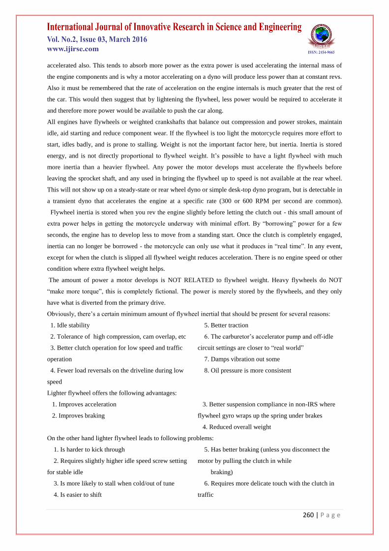
The arrangement of the dual mass flywheel is a suitable answer to the above problem statement where in the
inertia is increased using two set of masses phased opposite to each other. The arrangement of the dual mass
flywheel is best explained by the mathematical model below, the model is a two spring two mass model
graphically represented as below:
Fig. no. 3.1. Two Spring Two Mass Model Graphically Represented Fig. no. 3.2. Schematic Representation of Dual Mass Flywheel
The figure shows free un-damped vibrations set up of two mass- two spring system. As shown in the figure the
input to the system is in the form of an low energy intermittent input from any power source (excitation) , this
results in free un-damped vibrations are set up in the system resulting in the free to and fro motion of the mass
(m1)& (m2) , this motion is assisted by gravity and will continue until resonance occurs, ie, the systems will
continue to work long after the input (which is intermittent) has ceased Hence the term free energy is used.
From the above figure it is clear that in addition to the mass of the flywheel, the couple owing to the centrifugal
and centripetal forces keeps the flywheel into motion for longer time thereby increasing the work done by the
system hence the output from the given system increases.
This, mathematical model will be modified in construction to do away with the gear train arrangement.
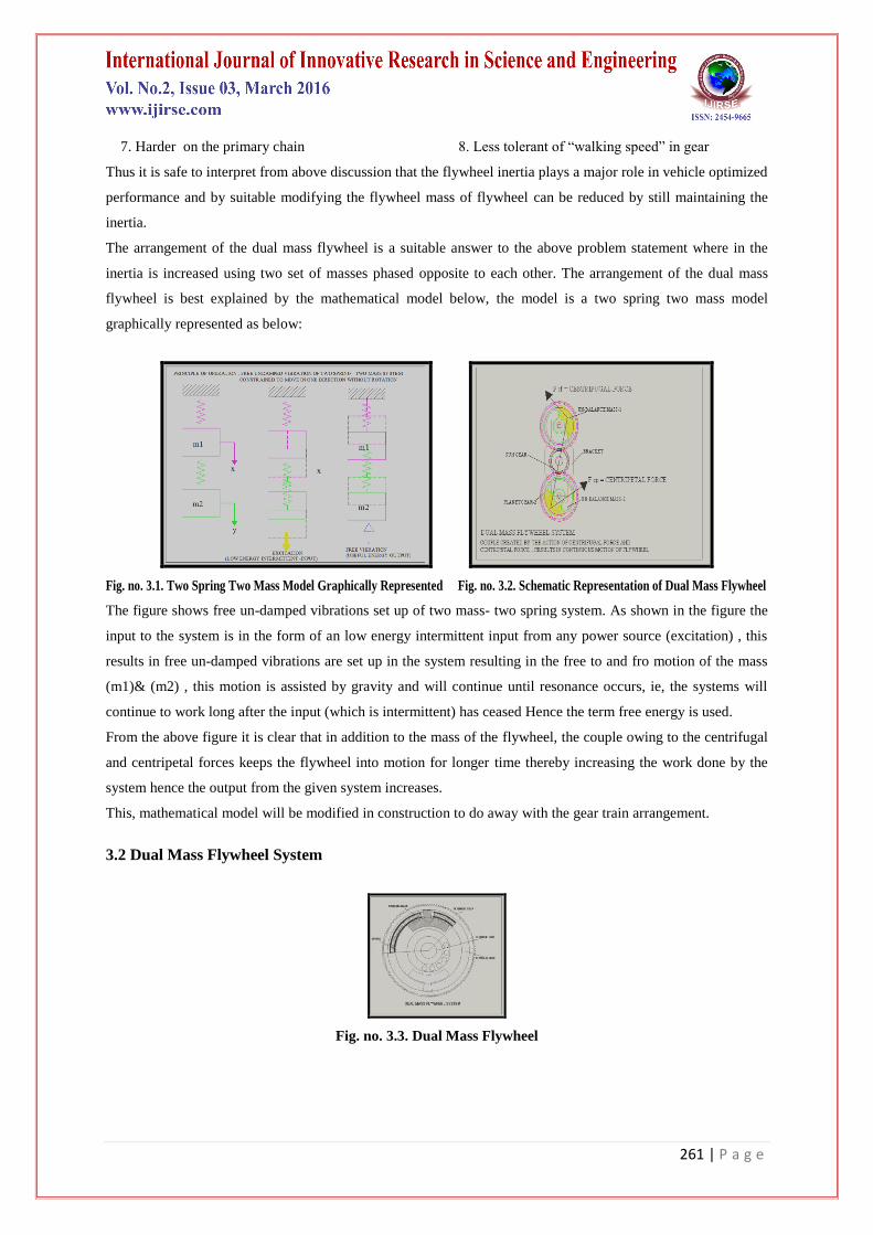
3.2 Dual Mass Flywheel System
Fig. no. 3.3. Dual Mass Flywheel

262 | P a g e
Fig (a) Fig (b)
Fig. No.3 4. Filtered Engine Torque Plotted (A) Against Crankshaft Angle And (B) Against Time For Two Different Engine Speeds (Measurement Data:
GETRAG)
The dual mass flywheel system is as shown above. The flywheel comprises of the flywheel hub which is keyed
to the engine shaft,. Hub carries the flywheel body, on which the flywheel gear ring is mounted. The flywheel
body is recessed at the rim inner side to receive the spring. Two springs and two masses are used hence the
flywheel has dual masses …from which the name of the flywheel originates.
As the engine power is delivered to the flywheel, the jerk applied will set the flywheel into motion, so also the
jerk is applied to the masses, and as explained in the two spring two mass system the two masses oscillate to
generate the „free energy‟ as explained earlier. The motion of the masses gives extra impetus to the flywheel
body due to which we get extra revolutions from the same jerk as applied to the conventional flywheel. Thus it
is able to achieve more inertia with same mass of flywheel with the dual mass flywheel arrangement.
3.3 Purpose of The Dmf
Piston engines do not generate a constant torque but a time-varying torque Teng (t). The shape of this torque
function depends mainly on the engine speed φeng and the number of cylinders. In Fig (a), the engine torque is
plotted over the crankshaft angle using two different levels of engine speed. The illustrated torque behavior is
not directly applicable to a gearbox as it would cause heavy rattling due to the gearwheel teeth clashing back
and forth. The torque progress within two engine rotations can be seen in Fig (a). Each of the six cylinders
contributes initially a significant negative torque during its compression stroke. Afterwards, each cylinder
returns a positive torque within its power stroke. At higher engine speed levels (such as 4000 rpm) inertial
forces become more and more significant. As any piston has to be accelerated and decelerated twice within one
engine cycle the mass forces have a higher frequency than the gas pressure cycles from the combustion process.
The effect of the mass forces can be seen in the 4000 rpm plot of Fig (a). Another more obvious impact of the
engine speed is the frequency of the combustion cycle itself. At a higher rotation rate, all strokes are faster.
Therefore, the frequency of the torque oscillations also rises (see time plot in Fig (b)). The crankshaft and other
mechanical parts of the engine will only dampen high frequency oscillations in the engine torque by themselves.
Therefore, low frequencies which occur at low engine speeds have to be dampened by additional design
elements, which in this case it will be DMF. In most cars a solid flywheel is used as a damper.
263 | P a g e
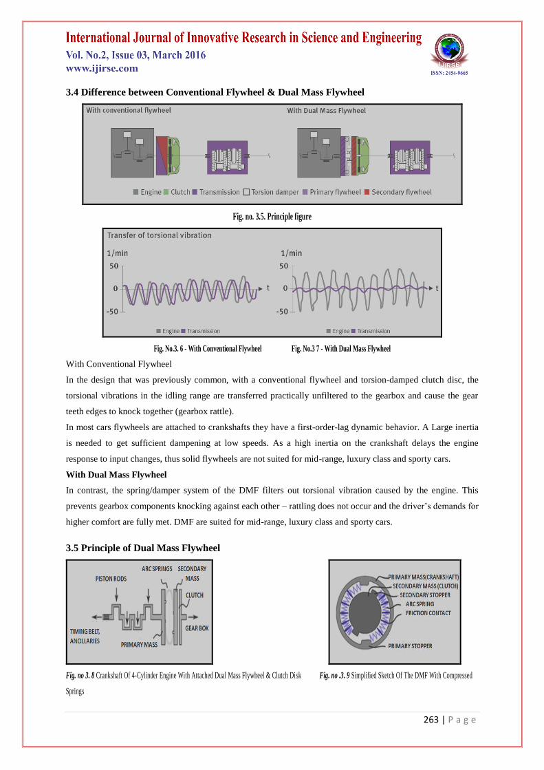
3.4 Difference between Conventional Flywheel & Dual Mass Flywheel
Fig. no. 3.5. Principle figure
Fig. No.3. 6 - With Conventional Flywheel Fig. No.3 7 - With Dual Mass Flywheel
With Conventional Flywheel
In the design that was previously common, with a conventional flywheel and torsion-damped clutch disc, the
torsional vibrations in the idling range are transferred practically unfiltered to the gearbox and cause the gear
teeth edges to knock together (gearbox rattle).
In most cars flywheels are attached to crankshafts they have a first-order-lag dynamic behavior. A Large inertia
is needed to get sufficient dampening at low speeds. As a high inertia on the crankshaft delays the engine
response to input changes, thus solid flywheels are not suited for mid-range, luxury class and sporty cars.
With Dual Mass Flywheel
In contrast, the spring/damper system of the DMF filters out torsional vibration caused by the engine. This
prevents gearbox components knocking against each other – rattling does not occur and the driver‟s demands for
higher comfort are fully met. DMF are suited for mid-range, luxury class and sporty cars.
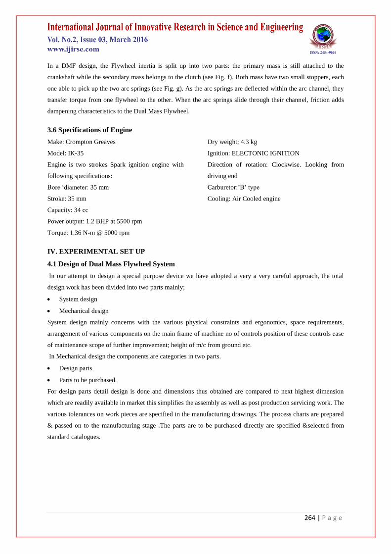
3.5 Principle of Dual Mass Flywheel
Fig. no 3. 8 Crankshaft Of 4-Cylinder Engine With Attached Dual Mass Flywheel & Clutch Disk Fig. no .3. 9 Simplified Sketch Of The DMF With Compressed
Springs
264 | P a g e
In a DMF design, the Flywheel inertia is split up into two parts: the primary mass is still attached to the
crankshaft while the secondary mass belongs to the clutch (see Fig. f). Both mass have two small stoppers, each
one able to pick up the two arc springs (see Fig. g). As the arc springs are deflected within the arc channel, they
transfer torque from one flywheel to the other. When the arc springs slide through their channel, friction adds
dampening characteristics to the Dual Mass Flywheel.
3.6 Specifications of Engine
Make: Crompton Greaves
Model: IK-35
Engine is two strokes Spark ignition engine with
following specifications:
Bore „diameter: 35 mm
Stroke: 35 mm
Capacity: 34 cc
Power output: 1.2 BHP at 5500 rpm
Torque: 1.36 N-m @ 5000 rpm
Dry weight; 4.3 kg
Ignition: ELECTONIC IGNITION
Direction of rotation: Clockwise. Looking from
driving end
Carburetor:‟B‟ type
Cooling: Air Cooled engine
IV. EXPERIMENTAL SET UP
4.1 Design of Dual Mass Flywheel System
In our attempt to design a special purpose device we have adopted a very a very careful approach, the total
design work has been divided into two parts mainly;
System design
Mechanical design
System design mainly concerns with the various physical constraints and ergonomics, space requirements,
arrangement of various components on the main frame of machine no of controls position of these controls ease
of maintenance scope of further improvement; height of m/c from ground etc.
In Mechanical design the components are categories in two parts.
Design parts
Parts to be purchased.
For design parts detail design is done and dimensions thus obtained are compared to next highest dimension
which are readily available in market this simplifies the assembly as well as post production servicing work. The
various tolerances on work pieces are specified in the manufacturing drawings. The process charts are prepared
& passed on to the manufacturing stage .The parts are to be purchased directly are specified &selected from
standard catalogues.

265 | P a g e
Fig No.4.1 Test Rig For Test & Trial Of The Dual Mass Flywheel Fig No.4.2 Test Rig For Test & Trial Of The Conventional Flywheel
4.2 Prime Mover Selection
Make: Crompton Greaves
Model: Ik-35
Engine is two strokes Spark ignition engine with following specifications:
Bore „diameter: 35 mm
Stroke: 35 mm
Capacity: 34 cc
Power output: 1.2 BHP at 5500 rpm
Torque: 1.36 N-m @ 5000 rpm
Dry weight; 4.3 kg
Ignition: ELECTONIC IGNITION
Direction of rotation: Clockwise..Looking from
driving end
Carburetor:‟B‟ type
Cooling: Air Cooled engine
4.3 Design Of Engine Shaft
Material Selection: -Ref: - PSG (1.10 & 1.12) + (1.17)
Designation- EN 24 Ultimate Tensile Strength N/mm2 =800, Yield Strength N/mm
2=680
ASME Code for Design of Shaft.
Since the loads on most shafts in connected machinery are not constant, it is necessary to make proper
allowance for the harmful effects of load fluctuations
According to ASME code permissible values of shear stress may be calculated from various relations.
fs max = 0.18 fult
= 0.18 x 800
= 144 N/mm2
OR
fs max = 0.3 fyt
=0.3 x 680
=204 N/mm2
Considering minimum of the above values;
fs max = 144 N/mm2
Shaft is provided with key way; this will reduce its strength. Hence reducing above value of allowable stress by
25%
fs max = 108 N/mm2
This is the allowable valve of shear stress that can be induced in the shaft material for safe operation.
T design = 1.36 x 10³ N.mm.
CHECK FOR TORSIONAL SHEAR FAILURE OF SHAFT.
266 | P a g e
Engine shaft is provided with M8 x 1.2 pitch threads at the output side hence the diameter of shaft to be checked
in torsional failure is 6.8 mm
d = 6.8 mm
Td = /16 x fs act x d3
fs act = 16 x Td
x d 3
= 16 x 1.36 x 10 3
x (6.8) 3
fs act = 22 N/mm2
As fs act < fs all
Engine shaft is safe under torsional load
4.4 Design of Coupling Shaft
Material Selection: -Ref: - PSG (1.10 & 1.12) + (1.17)
Designation- EN 24 Ultimate Tensile Strength N/mm2 =800, Yield Strength N/mm
2=680
ASME Code for Design of Shaft.
Since the loads on most shafts in connected machinery are not constant , it is necessary to make proper
allowance for the harmful effects of load fluctuations
According to ASME code permissible values of shear stress may be calculated form various relation.
fs max = 0.18 fult
= 0.18 x 800
= 144 N/mm2
OR
fs max = 0.3 fyt
=0.3 x 680
=204 N/mm2
Considering minimum of the above values;
fs max = 144 N/mm2
Shaft is provided with key way; this will reduce its strength. Hence reducing above value of allowable stress
by 25%
fs max = 108 N/mm2
This is the allowable valve of shear stress that can be induced in the shaft material for safe operation.
T design = 1.36 x 10³ N.mm.
CHECK FOR TORSIONAL SHEAR FAILURE OF SHAFT.
Coupling haft is provided with M8 x 1.2 pitch threads at the engine side where as it is hollow at the flywheel
shaft end hence the coupling shaft is to be checked in torsional failure as hollow shaft
Inner diameter ( di ) = 16mm
Outer diameter (do) = 36
267 | P a g e
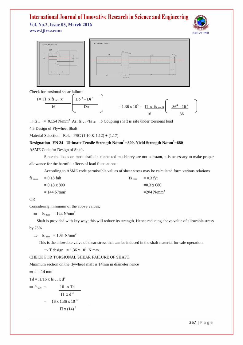
Check for torsional shear failure:-
T= x fs act x Do 4 – Di
4
16 Do = 1.36 x 103 = x fs act x 36
4 – 16
4
16 36
fs act = 0.154 N/mm2
As; fs act <fs all Coupling shaft is safe under torsional load
4.5 Design of Flywheel Shaft
Material Selection: -Ref: - PSG (1.10 & 1.12) + (1.17)
Designation- EN 24 Ultimate Tensile Strength N/mm2 =800, Yield Strength N/mm
2=680
ASME Code for Design of Shaft.
Since the loads on most shafts in connected machinery are not constant, it is necessary to make proper
allowance for the harmful effects of load fluctuations
According to ASME code permissible values of shear stress may be calculated form various relations.
fs max = 0.18 fult
= 0.18 x 800
= 144 N/mm2
OR
fs max = 0.3 fyt
=0.3 x 680
=204 N/mm2
Considering minimum of the above values;
fs max = 144 N/mm2
Shaft is provided with key way; this will reduce its strength. Hence reducing above value of allowable stress
by 25%
fs max = 108 N/mm2
This is the allowable valve of shear stress that can be induced in the shaft material for safe operation.
T design = 1.36 x 10³ N.mm.
CHECK FOR TORSIONAL SHEAR FAILURE OF SHAFT.
Minimum section on the flywheel shaft is 14mm in diameter hence
d = 14 mm
Td = /16 x fs act x d3
fs act = 16 x Td
x d 3
= 16 x 1.36 x 10 3
x (14) 3

268 | P a g e
fs act = 2.52 N/mm2
As fs act < fs all
Engine shaft is safe under torsional load
V. CONCLUSION
In this study, we have taken the factor „Torque‟ below consideration in case of „The Dual Mass Flywheel
(DMF)‟ which is mostly used for dampening of oscillations in automotive power trains and to prevent gearbox
rattling. On this particular topic DMF a lot of study has been done but I am going to perform the mathematical
calculation of Torque under the different conditions of load on DMF. From this calculation it is prove that as
load is not increased in much more quantity the torque increases rapidly which is very much important. For this,
the design of DMF is taken from the different research papers have referred.
REFERENCES
[1] Ulf Schaper, Oliver Sawodny, Tobias Mahl And Uti Blessing, "Modeling And Torque Estimation Of An
Automotive Dual Mass Flywheel", American Control Conference, 2009.
[2] Bjorn Bolund, Hans Bernhoff, Mats Leijon, "Flywheel Energy And Power Storage Systems", Renewable
And Sustainable Energy Reviews, 11(2007) PP235-258.
[3] Jordan Firth, Jonathan Black, "Vibration Interaction In A Multiple Flywheel System", Journal Of Sound
And Vibration, 331(2012) PP1701-1714.
[4] Paul D. Walker⁎, Nong Zhang, "Modelling Of Dual Clutch Transmission Equipped Powertrains For
Shift Transient Simulations", Mechanism And Machine Theory, 60 (2013) PP47-59.
[5] Li Quan Song, Li Ping Zeng, Shu Ping Zhang, Jian Dong Zhou, Hong En Niu, "Design And Analysis Of
Dual Mass Flywheel With Continuously Variable Stiffness Based On Compensation Principle",
Mechanism And Machine Theory, 79(2014) PP124-140.
[6] Manuel Olivaresa, Pedro Albertosb "Linear Control Of The flywheel Inverted Pendulum", ISA
Transactions 53(2014) PP1396-1403.
[7] Andrew C. Arvin, Charles E. Bakis "Optimal Design Of Press-Fitted Filament Wound Composite
Flywheel Rotors", Composite Structure 72(2006) PP47-57.
[8] Sung K. Ha, Seong J. Kim, Sana U. Nasir, Sang C. Han. "Design Optimization And Fabrication Of
Hybrid Composite Flywheel Rotor", Composite Structure 94(2012) PP3290-3299.
[9] J G Bai, X Z Zhang, L M Wang. "A Flywheel Energy Storage System With Active Magnetic Bearings",
Energy Procedia 16 (2012) PP1124 – 1128.
[10] Govinda, A, Dr. Annamalai, K. "Design And Analysis Of Arc Springs Used In Dual Mass Flywheel",
International Journal Of Engineering & Technology Research Volume-2, Issue-1, January-February,
2014.