review of residential ventilation technologies · review of residential ventilation technologies...
TRANSCRIPT

1
LBNL 57730
ERNEST ORLANDO LAWRENCE BERKELEY NATIONAL LABORATORY
Review of Residential Ventilation Technologies Marion Russell, Max Sherman and Armin Rudd August 2005
LBNL-57730

2
Disclaimer While this document is believed to contain correct information, neither the United States Government nor any agency thereof, nor The Regents of the University of California, nor any of their employees, nor any other sponsor of this work makes any warranty, express or implied, or assumes any legal responsibility for the accuracy, completeness, or usefulness of any information, apparatus, product, or process disclosed, or represents that its use would not infringe privately owned rights. Reference herein to any specific commercial product, process, or service by its trade name, trademark, manufacturer, or otherwise, does not necessarily constitute or imply its endorsement, recommendation, or favoring by the United States Government or any agency thereof, or The Regents of the University of California or any other sponsor. The views and opinions of authors expressed herein do not necessarily state or reflect those of the United States Government or any agency thereof, or The Regents of the University of California or any other sponsor. This report does not necessarily represent the views of the California Energy Commission, its employees, or the State of California. The Energy Commission, the State of California, its employees, contractors, and subcontractors make no warranty, express or implied, and assume no legal liability for the information in this report, nor does any party represent that the use of this information will not infringe upon privately owned rights. This report has not been approved or disapproved by the Energy Commission nor has the Energy Commission passed upon the accuracy or adequacy of the information in this report.
Ernest Orlando Lawrence Berkeley National Laboratory is an equal opportunity employer.
LBNL-57730

3
Abstract This paper reviews current and potential ventilation technologies for residential buildings with particular emphasis on North American climates and construction. The major technologies reviewed include a variety of mechanical systems, natural ventilation, and passive ventilation. Key parameters that are related to each system include operating costs, installation costs, ventilation rates, heat recovery potential. It also examines related issues such as infiltration, duct systems, filtration options, noise, and construction issues. This report describes a wide variety of systems currently on the market that can be used to meet ASHRAE Standard 62.2. While these systems generally fall into the categories of supply, exhaust or balanced, the specifics of each system are driven by concerns that extend beyond those in the standard and are discussed. Some of these systems go beyond the current standard by providing additional features (such as air distribution or pressurization control). The market will decide the immediate value of such features, but ASHRAE may wish to consider related modifications to the standard in the future. Acknowledgements This report was jointly produced by the Building Science Corporation and the Lawrence Berkeley National Laboratory. This project was funded in part through ARTI-21CR Work Statement – Project SI/IEQ-30090: Whole-House Vent : Evaluation of Whole-house Mechanical Ventilation System Options – Phase I Simulation Study:
This report was also supported in part by work sponsored by the California Energy Commission under contract 500-04-005 This work was also supported by the Assistant Secretary for Energy Efficiency and Renewable Energy, Building Technologies Program, of the U.S. Department of Energy under contract No. DE-AC02-05CH11231.
LBNL-57730

4
Table of Contents Abstract.................................................................................................................3 Introduction ...........................................................................................................5 Mechanical Whole-house Ventilation ....................................................................6
Continuous exhaust...........................................................................................6 Single-point exhaust systems ........................................................................7 Multi-point exhaust systems...........................................................................8
Intermittent exhaust...........................................................................................8 Exhaust with make-up air inlets.........................................................................9 Local exhaust with make-up air integrated in HVAC system ...........................10 Continuous supply...........................................................................................10
Single-point Supply......................................................................................11 Multi-point supply.........................................................................................11
Intermittent supply with inlet in return side of HVAC System...........................11 Combined exhaust and supply (Balanced)......................................................12
Supply integrated into HVAC system with continuous exhaust....................13 Supply integrated into HVAC system with intermittent exhaust ...................13
Houses Without Forced-Air Distribution Systems............................................13 Sustainable Ventilation .......................................................................................14
Tradition: Infiltration with operable windows....................................................14 Passive Stack Ventilation ................................................................................16 Solar Chimney.................................................................................................18 Hybrid Systems ...............................................................................................19
Incidental Ventilation...........................................................................................19 Infiltration.........................................................................................................20 Operable Windows ..........................................................................................20 Local exhaust fans ..........................................................................................21
Real World Factors .............................................................................................21 Construction and Installation Issues................................................................21 Energy and Costs............................................................................................22 Controls...........................................................................................................24 Distribution Systems........................................................................................24 Indoor Air Quality.............................................................................................25
Dilution Ventilation .......................................................................................25 Filtration.......................................................................................................25
Summary ............................................................................................................27 References .........................................................................................................28 Other Relevant Literature Sources......................................................................34
LBNL-57730

5
Introduction The purpose of ventilation is to provide fresh (or at least outdoor) air for comfort and to ensure healthy indoor air quality by diluting contaminants. Historically people have ventilated buildings to provide source control for both combustion products and objectionable odors (Sherman, 2004). Currently, a wide range of ventilation technologies is available to provide ventilation in dwellings including both mechanical systems and sustainable technologies. Most of the existing housing stock in the U.S. uses infiltration combined with window opening to provide ventilation, sometimes resulting in over-ventilation with subsequent energy loss; sometimes resulting in under-ventilation and poor indoor air quality. Based on the work of Sherman and Dickerhoff (1998), Sherman and Matson (2002) have shown that recent residential construction has created tighter, energy-saving building envelopes that create a potential for under-ventilation. Infiltration rates in these new homes average 3 to 4 times less than rates in existing stock. As a result, new homes often need provided ventilation systems to meet current ventilation standards. McWilliams and Sherman (2005) have reviewed such standards and related factors. According to ASHRAE standard 62.2-2004, published by the American Society of Heating, Refrigeration and Air-conditioning Engineers (ASHRAE, 2004), single, detached residential buildings are required to meet a whole house ventilation rate based on the number of bedrooms in the house, the number of occupants, plus an infiltration credit (3 cfm per 100 sq. ft plus 7.5 cfm per additional occupant which includes a 2 cfm per 100 sq. ft allowance for infiltration). There are a variety of ways to meet this standard either through mechanical systems or via natural forces. According to Home Energy Magazine May/June 2000, “good ventilation system should:• • • •
• • • • • • •
• • • •
Provide a controlled amount of unpolluted outdoor air for both comfort and dilution Have at least a 15 year life Be acceptable to operate by occupants (low noise, low cost) Not detract from the safety and durability of the house.”
This paper will review both mechanical and sustainable ventilation technologies and the factors that affect their effectiveness. Mechanical technologies must include:
Continuous exhaust systems Intermittent exhaust systems Exhaust with make-up air inlets Intermittent or continuous local exhaust with make-up air from inlet in return Continuous supply Intermittent supply with inlet in return side of HVAC System Combined exhaust and supply (Balanced)
Sustainable technologies, which are those whose motive forces are principally temperature difference and wind, are reviewed in the second section and include:
Infiltration with operable windows Passive Stack Ventilation Solar Chimney Hybrid Systems
LBNL-57730

6
The effects of incidental ventilation provided by infiltration and operable windows are discussed. Finally, a variety of factors that can affect the ventilation effectiveness are discussed in the third section including cost and energy use, air cleaning and filtration, construction quality, control systems, and duct systems. Mechanical Whole-house Ventilation There are a variety of mechanical whole-house ventilation systems including exhaust, supply and balanced systems. Any of these may be in continuous operation or operate intermittently, they may be single-port or multi-port, or the system may be integrated into an existing HVAC system. Mechanical ventilation strategies provided more uniform ventilation rates than natural ventilation (Hekmat, Feustel and Modera, 1986). Properly designed mechanical systems provide good control over ventilation rates when compared to most other ventilation systems; however, additional energy is required to operate the system. Holton, J.K., M.J. Kokayko, and T.R. Beggs (1997) compared ventilation systems in new production built homes and found infiltration rates ranging from 0.1 to 0.07 air changes per hour in the summer and 0.35 to 0.15 ACH in the winter. As a result, they recommend modern houses include a mechanical ventilation system. Researchers have studied various configurations of exhaust, supply, and balanced ventilation systems, with and without whole-house re-circulation by the central heating and cooling air handler fan. Continuous exhaust A continuous whole-house exhaust system provides ventilation by using a single-point or multi-point central fan to remove air from the building (Concannon, 2002). Supply air enters the building envelope through gaps or provided vents (see Figure 1). If the building envelope is tight, there is a possibility that negative pressure can be created inside the building leading to back drafts from combustion (open flue) appliances. Often these systems incorporate a pressure relief damper to alleviate pressure imbalances. Supply air enters the building in an uncontrolled manner and may be pulled in from relatively undesirable areas such as garages, musty basements (or crawlspaces) or dusty attics (Barley, 2002). Whole-house exhaust systems may not be appropriate in areas where levels of outside environmental contaminants are high. In the case of radon, researchers have found that exhaust systems may actually increase the indoor levels of contaminants. (Bonnefous, Gadgil, and Fisk, 1992). In severe climates, very cold supply air may create drafts, while in moist humid climate zones, exhaust only systems can cause moisture damage to the building structure. Filtration cannot be sensibly added to an exhaust only ventilation system, unless one considers the building envelope as part of the filtration system. Heat recovery can be added to exhaust systems. Passively, the building envelope itself can provide some heat recovery (Walker and Sherman, 2003), and is also partially effective at removing ozone. More actively, an exhaust air heat pump can be used to recover the energy in the exhaust air stream. The Home Ventilating Institute(HVI) lists a large variety of fans that can meet current ASHRAE standards for ventilation rates if properly installed. However, several factors
LBNL-57730

7
(such as the tightness of the building envelope, size, quality of ductwork, and placement of ducting, among others) can have a significant effect on whether the installed fan can provide the indicated ventilation rate. These fans can potentially provide ventilation rates from 50 to over 5000 cfm. Most of the operating costs result from conditioning the supply air rather than the energy to operate the fan. The HVI directory lists the energy use for only a small percentage of the fans, with typical power consumption of about 3.5 cfm/W. Wray (2000) found that from most perspectives exhaust-only mechanical ventilation systems are the most inexpensive of mechanical systems to operate .
Supply air entersthrough gaps in theenvelope.
Stale air isexhausted frombuilding.
Figure 1. Mechanical exhaust system with supply air entering through the building fabric in an uncontrolled manner. Single-point exhaust systems A single point exhaust system is often an upgraded bathroom fan (e.g. Figure 2). Construction and installation costs are the lowest of mechanical systems. (Concannon, 2002) Only one fan and possibly some simple ducting are required to exhaust the air to the outside. In some cases, the fan can be installed in an exterior wall eliminating the need for extensive ductwork. Single-point ventilation systems suffer from a non-uniform distribution of fresh air especially to closed rooms. (Rudd, A. 2000.) In an evaluation of five mechanical ventilation systems, Reardon and Shaw (1997) found local exhaust only strategies that depended on kitchen and bathroom fans to provide whole-house ventilation provided only marginally better performance than infiltration alone. This simple system suffered from a poor distribution of supply air; the lower room received all the supply air while the upstairs rooms (bedrooms) did not receive enough air to meet the applicable ventilation code. Standard 62.2, however, has no distribution requirement; so this is not an issue for a minimally compliant system, but it is nevertheless a consideration.
LBNL-57730

8
Figure 2. Example of a single-point local exhaust system with makeup air inlets (Oikos Green Building Source, 1995). Air inlets are needed only for tight building envelopes. Multi-point exhaust systems Multi-point exhaust systems are an improvement over single-port exhaust systems in that they improve the room-to-room uniformity of the whole-house ventilation, but there is the extra cost of installing the ductwork (Rudd, 1999). One exhaust fan is ducted to many rooms of the house and may be remotely installed to reduce noise levels. In a comparison of ventilation systems, Reardon and Shaw (1997) found that if a centralized exhaust system is used with pick-up grilles in each room of the house instead of a local exhaust system, air was distributed evenly throughout the house even to closed bedrooms. Intermittent exhaust An intermittent exhaust system is installed similar to a continuous exhaust system; generally it consists of one central fan to remove stale air from the building, but may also incorporate several fans in areas of high sources (i.e. bathrooms and kitchens). In this case, the fan(s) runs only part of the time at a higher rate and are sized to provide the necessary ventilation. The rate of ventilation when the system is operated intermittently must be larger than if it were operating continuously (Sherman, 2004). There are several advantages for using intermittent ventilation systems. The occupant can reduce the amount of outdoor air entering the building during periods of the day when the outdoor air quality is poor. Peak load concerns may make it advantageous to reduce ventilation for certain periods of the day. When the ventilation system is integrated with the heating and cooling system, cyclic operation may also make more sense. A timer can be used to control the fan which usually has a switch for the occupant to turn on when needed. The disadvantage here is that the occupant controls the ventilation and
LBNL-57730

9
must be relied on to know when ventilation is needed. If the fan is noisy1, the occupant may chose not to operate the system, which could result in under-ventilation. Many systems use a timer to automatically run the fan for a certain amount of time each day so that the occupant is not relied on to sense when ventilation is needed. However, the occupant often has control over a switch to turn the fan on high when extra ventilation is needed. More sophisticated (and costly) control systems are available including: CO2 sensors, occupant sensors and humidity sensors. CO2 and occupant controlled systems do not meet the current 62.2 unless those features are used to raise the ventilation over and above the minimum rates required by 62.2. Our own experience has shown that installation and operating costs are similar to the continuous exhaust systems, but may exceed them if sophisticated control systems are installed. As with continuous exhaust systems, most of the energy requirements are for conditioning the supply air rather then fan operation. The potential exists to reduce energy consumption when compared to the continuous exhaust system if the intermittent system is used in conjunction with natural driving forces to provide adequate ventilation while reducing the energy required to condition outside air. For example, running the fan at night could reduce cooling costs. Also, the fan could be programmed to run during times when outside pollutant levels are low or alternatively to shut down the system when outside particulate or ozone levels are high. If time-of-use utility rates are locally in use, it may be possible to reduce operating costs by ventilating more during low-cost periods to allow reduced or even zero ventilation during high-cost periods. Exhaust with make-up air inlets This ventilation system uses fans as described above, but controls the entry of supply air into the dwelling by providing openings specifically for air supply (see Figure 3).
Figure 3. Inline exhaust fan with make-up trickle vents. (Oikos Green Building Source, 1995.) Trickle vents are needed when the building envelope is tight. 1 If the system is Standard 62.2 compliant, ventilation fans should meet sound requirements and noise should not be a substantial issue.
LBNL-57730

10
These trickle vents or louvers can be located in rooms that need extra ventilation such as the bathroom. Again, filtration of the supply air is not possible with this system; however the entry point of the supply air can be controlled to provide cleaner air by installing trickle vents away from polluted areas such as garages, musty basements or dusty attics. Trickle vents are not necessary to meet 62.2 per se, but may be needed in exceptionally tight construction to reduce depressurization and related issues. They are commonly used as part of European systems both because of the tight construction and to assure that habitable rooms have individual air supplies. Local exhaust with make-up air integrated in HVAC system This method builds on the exhaust systems described above, but uses an air inlet in the return duct system of the air-handling unit of the HVAC system. This would use the existing duct system to extract air from individual areas of the building. Because existing ductwork would be used, marginal installation costs can be kept very low. This system can provide uniform ventilation throughout the house and may be operated intermittently or continuously. There is the added operating expense running the central fan when heating or cooling is not needed, which depends on climate and system sizing. From the perspective of Standard 62.2 it is usually the exhaust system which is intended to comply with the standard. The make-up air system is intended to supply air distribution and reduce depressurization—both of which are beyond the minimum requirements of 62.2, but are often desirable. In principle, however, the make-up air system could be designed to meet 62.2 and the exhaust system used as a source control enhancement. Continuous supply Air is supplied by a central fan ducted to some or all of the rooms of the dwelling forcing stale air out through leaks in the building envelope. Continuous supply systems allow the occupant to control the location of the supply air to maximize air quality and give the occupant the option of filtering and/or conditioning the supply air (Building Science Corporation). This system creates a positive pressure inside the building, which has both advantages and disadvantages. The size of the pressure depends on the supply flow and the tightness of the envelope. A positive pressure prevents outside contaminants from entering the building, but it also can force moisture-laden air through the building fabric. In cold climates the moist air may condense in the walls of the building creating an environment for mold growth. Various studies have considered the use of whole house fans to provide night ventilation for cooling purposes (Santamouris, 2005). In these systems, air conditioning loads may be reduced up to 56% depending on the thermal preferences of the occupants. Because outdoor air is often not in the thermal comfort zone, the temperature of supply air is a design concern for supply systems. Supply systems need to address this concern by conditioning or tempering the air in some way, during the periods when it would be perceived as unacceptable. One method, for example, is to mix the supply air with indoor
LBNL-57730

11
air before it reaches the occupants. Standard 62.2, however, has no requirements for tempering. Single-point Supply In this strategy a supply fan provides fresh air via a small amount of ducting to a main room of the house. The air is distributed about the house by natural process. Often there is a return duct in a separate room. This system has low equipment costs; only the fan and a small amount of ducting are needed. However, the system suffers from a poor distribution of supply air especially to closed rooms in the house (Rudd, 2000) even compared to single-point exhaust. Tempering or conditioning of this air is almost always needed, if one wishes to avoid comfort complaints. Multi-point supply The multi-port system having the advantage of improving ventilation uniformity throughout the house, but with the extra installation cost of the ductwork. Because each supply is of a lower flow the needs for tempering or conditioning may be reduced. From the perspective of 62.2, however, there are no differences between single and multi-point supply systems. Intermittent supply with inlet in return side of HVAC System This system uses the existing central forced air system to supply fresh air in a distributed manner through the building’s ducting. An inlet is placed in the return of the HVAC system to allow fresh air to enter when the air handler fan operates (see Figure 4). Integrating the supply air into the existing HVAC system provides a low cost option to supply and distribute fresh air through the existing duct system and is the ventilation system most acceptable to large production home builders (Rudd and Lstiburek, 2001). All mechanical ventilation systems benefited from intermittent operation of the central fan. This resulted in more uniformity of ventilation air distribution among the various rooms of the house (Rudd and Lstiburek, 2000). By operating the system intermittently as opposed to continuously, Rudd (1999) estimated a 28% annual savings in total energy use. Computer modeling studies showed the cost-effectiveness of this system when compared to a separate supply ventilation system as well as the marginal costs of operation compared to no mechanical ventilation ($3 to $27 per year) (Rudd, 1998). They estimated it would take 10 years to recover the initial costs of a separately ducted supply ventilation system. The continuous and intermittent simulated systems had average outside air exchange rates of between 40 and 50 cfm, including the combined effects of ventilation and infiltration. These rates met 62-89, but would not meet the 62.2-2004. These systems can create positive pressure in the house, so a pressure relief vent is often included. We (Rudd) more often see pressure relief achieved through the backdraft dampers of bathroom and kitchen exhaust fan ducting, as well as incidental leakage sites around windows and doors or other building enclosure penetrations. It is possible to add filtration to the supply air to remove contaminants. Installation costs are minimal for the
LBNL-57730

12
return inlet itself; only a small amount of extra ducting and possibly a damper are required. Depending on the design, extra costs may be incurred for control devices and/or dampers. Heat recovery potential for intermittent supply is low since heat exchange only occurs as the exhaust air exits via exfiltration through the building fabric. Currently available air handler fans are available to meet air flow rate standards in an energy efficient manner. Simple control systems are available to operate the system when the HVAC system is heating or cooling or to operate the system on a timer so that fresh air is supplied when heating or cooling are not required. (Walker and Sherman, 2003.) Energy efficiency is maximized when the entire air distribution system is airtight and located in a conditioned space (Rudd, 1998).
Coo
ling
Coi
l
Hea
ting
Coi
lCentral SystemSupply Air
Outside Air Filter("Hog-Hair" type)
Main Return Duct
Gable End Wall
Fan and DamperCycling Control
Manual Damper(to adjust flow rate)
Outside Air DuctInsulated Flex-ductCentral Return Box
Return Grille and FilterGypsum Ceiling
WallCap
Metal Clipsto hold filter
Extended Collar
Thermostat
Motorized Damper(to control open time)
Figure 4. Example of supply ventilation integrated into the return side of an existing HVAC system (Building Science Corporation). Combined exhaust and supply (Balanced) A balanced ventilation system uses two fans with separate ducting systems, one to supply fresh air and one to remove stale air from the building (see figure 5). The system should not affect the pressure balance of the interior space unless the return path between the supply and exhaust is blocked. This ventilation strategy can be used effectively in any climate. It is possible to include a heat exchanger (or heat pump) to recover heat from the exhaust air and use it to precondition the supply air. Extensive ducting is used to supply
LBNL-57730

13
fresh air to living and sleeping rooms, while a separate exhaust system removes stale often moist air from the kitchen and bathrooms. Advantages include pre-filtration of the supply air and energy savings from the heat recovery of the exhaust air. Some disadvantages include installation costs, maintenance costs (because there are multiple fans) and fan noise—for fans not meeting 62.2 noise requirements. Noise generated from the fan(s) and ducting system can be transmitted to each room of the house and reach 30 to 40dB. Veld. and Passlack-Zwaans (1998) describe various strategies for soundproofing including insulating ducts and preventing fan vibrations. Reducing noise from ventilation systems has a positive impact on indoor air quality by reducing the likelihood that occupants will block vents or turn off the system.
Figure 5. A Balanced ventilation system (Oikos Green Building Source, 1995). Supply integrated into HVAC system with continuous exhaust If the house has an existing central forced air system, it is possible to save on installation costs by integrating the supply inlet into the return of the HVAC system. A separate exhaust fan would run continuously to remove the stale air. This system can sometimes be problematic in humid climates where moist air is injected into cool supply air ducts resulting in condensation and independent humidity control may be required. Supply integrated into HVAC system with intermittent exhaust In this strategy (similar to the above) the exhaust fan would operate intermittently. Advanced control strategies can in principle be used to operate the exhaust fan only as needed to supplement the supply air to the return. Houses Without Forced-Air Distribution Systems Most new homes in the U.S. are built with forced-air systems, but not all. Houses with radiant, hydronic and/or baseboard systems may not have any central air distribution
LBNL-57730

14
system and cannot use any of the HVAC-integrated systems discussed above. Any of the other systems, however, can be used to meet 62.2. If air distribution is a concern, however, some systems may perform better than others for houses without forced air systems. If the building envelope is tight an exhaust system with trickle vents/air inlets can be used to assure that each room gets some outdoor air. Supply or balanced approaches require a dedicated distribution system (i.e. multipoint supply) in order to get good air distribution. Sustainable Ventilation Most of the systems described above focus on a mechanical ventilation solution. ASHRAE Standard 62.2 does not mention any other way to provided ventilation to new construction, but it does allow (section 4.1.2) alternative approaches if approved by a licensed design professional. There are, a variety of potential ventilation options that do not require fans. Here we examine such sustainable technologies with the understanding that they do not meet 62.2-2004, but they allow advanced solutions in the future. Tradition: Infiltration with operable windows Many existing homes rely on infiltration through a porous building envelope for background ventilation with operable windows to provide increased ventilation when needed. Natural climatic forces create differences in air pressure between the outside and inside of the building that can ventilate a building. Pressure differences depend on changes in temperature and wind speed. Wind causes a positive pressure on the windward side of the building and a negative pressure on the leeward side of the building (see figure 6). The resulting amount of ventilation is dependent on the placement and number of openings in the building envelope and on wind direction and speed. This makes the ventilation rate unpredictable and uncontrollable since the driving mechanism is variable over the year and the flow paths are diffused over the building envelope. (Allard, F. and Ghiaus, C. 2005.) The average ventilation rate my be predictable, but the average ventilation rate itself is not the key factor. Sherman and Matson (1997) have shown that typical existing homes have an annual average air change rate of over one air change an hour due to infiltration; and this high rate can satisfy existing ventilation standards so that many existing homes do not need any extra ventilation system. Dwellings in cold, harsher climates and new residential construction are 3 to 4 times tighter, creating a tight building envelope and the potential for under-ventilation. (Sherman, M. and Matson, 2001.) . This most basic ventilation system has no extra construction costs or explicit operating costs; however, there is poor control over ventilation rates when the envelope is leaky. The energy implications are almost exclusively from the need to condition the outdoor air. The system relies on the occupants to open and close windows to provide adequate ventilation when the envelope is tight. The lack of control can result in energy loss due to high air change rates especially in winter when temperature differences and wind speeds
LBNL-57730

15
are high. Alternatively, the system may under-ventilate during the hot summer months. When climatic conditions are favorable, natural ventilation can be used for cooling and can replace air conditioning systems for part of the year.
Winddirection
Positivepressure region
Negativepressure region
Figure 6. Wind speed/direction on a building creates positive and negative pressures. But in urban settings there are considerable limitations to such an open ventilation system including noise, security, and pollution. (Santamouris, M. 2005.) Additional limitations arise from the unique climatic conditions of cities. Both the higher temperatures (the heat island effect) and the decreased wind speeds in urban canyons can decrease the potential of natural ventilation systems. Geros et. al. (2001) studied the reduction of air flow in naturally ventilated buildings in ten urban canyons in Athens and found that because of the reduced wind speed, the air flow through the buildings decreased up to 90 %. A few strategies exist for reducing noise in buildings using operable windows and they are capable of reducing traffic noise by 7.5 to 8.5 dB without compromising the airflow path resistance. (Oldham et.al., 2004) Since climate plays an important factor in the effectiveness of natural ventilation, many groups have analyzed the suitability of various climatic conditions. The potential of natural ventilation depends not only of the outdoor climate, but also the building site and the design of the building site. Yang et. al. (2005) have created a model to evaluate the potential of a particular site to provide the natural forces necessary to meet ventilation standards with only natural ventilation. It is clear that many climates are too harsh for infiltration to be used as a primary source of ventilation. Conversely there are climates where the driving forces are too weak for infiltration to be a practical source of primary ventilation. All of which leads Wilson and Walker (1992) to conclude “There is no hole for all seasons.”
LBNL-57730

16
Infiltration does provide ventilation automatically without using any transport energy; but it almost always requires more space conditioning energy to supply the equivalent ventilation as a constant mechanical system. Infiltration can provide some heat recovery and filtration through the building envelope, but unless it is well designed (e.g. the “dynamic insulation” used in Scandinavia) it is not likely to provide much. Infiltration depends on whether so there is no “right” amount of air leakage. Infiltration will always provide more ventilation than is needed during extreme periods in order to meet average demands. For more information on operable windows and infiltration, see the “Incidental Ventilation” section below. Passive Stack Ventilation Passive stack ventilation is designed to provide more control over ventilation rates than natural ventilation by incorporating one or more stacks or towers into the building structure to extract stale air while fresh air enters through provided openings such as trickle vents or louvers. Passive stack air flows are created from a combination of two climatic forces: differences between the inside and outside temperature and wind. The negative pressure at the stack top is often the critical factor. (Wind pressures are mostly negative on the sides of buildings rather than the “leeward” side in many situations; see figure 7).The combination of pressures from warmer indoor air and negative wind pressure at the top of the stack result in air being exhausted from the stacks.
Windspeed
Supply air entersthrough louvers
Stale air is exhaustedthrough stacks
Tlow
Thigh
(+ +) (--)
(-- --)
(+)
Figure 7. Stack forces are created with both wind speed and indoor/outdoor temperature differences.
LBNL-57730

17
Although rare in the United States, passive ventilation systems are widely used in the European Union. Axley (2001, in AIVC TN 54) found that in England 90%, and in the Netherlands most single-family dwellings use passive ventilation (90% and 65% respectively). Emmerich and Dols (2003) have used some of Axley’s approach to create a passive ventilation design and analysis tool for use in a multizone environment. Stack height and position are important in maintaining a negative pressure at the stack terminus and preventing back flows into the building. A taller stack is less sensitive to wind speed and wind direction. Installation guidelines and building codes reflect the importance of stack position relative to the roof2 A variety of terminal caps are available that are designed and located to provide consistently negative pressures (independent of wind direction) at the stack exit. (Axley, J. W. 2001.) Stacks need to have a larger diameter than mechanical ducting systems to reduce flow resistance for low pressure drop conditions. Ventilation flow rates can vary significantly from room to room. Upper, leeward rooms in particular may be under ventilated and can easily have not outdoor air. Careful design measures can be taken to control and distribute flow rates. Typically systems are designed with trickle vents or louvers which can be manually adjusted to control the flow rate, but these work best when uncontrolled infiltration rates are low (and building envelopes are tight). Each room must have a transfer grill or vent to allow free distribution of the air. While these same criteria are relevant for mechanical ventilation, the issue is often more critcal for passive ventilation because of the lower driving forces. Many anecdotal cases indicate that passive ventilation systems have shown the capability of providing adequate long term ventilation, but fall short when required to provide short term high ventilation during peak episodes of contaminant production (i.e. bathing or cooking). Because they are similarly designed as mechanical systems, but without mechanical components, passive stack ventilation systems can reduce construction and operating costs of residential buildings. Careful design of internal spaces should be considered during the construction to allow air to flow between the rooms of the building and from the supply openings through the exhaust spaces. Relatively larger ducts are required than a mechanical system should flow resistance be an issue. Operating (air transport) costs are non-existent; however, there are usually some days of the year when weather conditions (low wind speed and/or small indoor/outdoor temperature differences) create insufficient airflow. There is inherently some uncertainty in any system performance that is dependent on natural driving forces. Under ventilation or over ventilation can be expected at certain times of the year. (Yoshino, H., Liu, J., et. al., 2003.) Wilson and Walker (1992) showed
2 At present there is insufficient information to recommend specific minimum or maximum values for performance parameters, but there are references worth considering including those in the AIVC database and IP 13/94 Passive stack ventilation systems: design and installation by R K Stephen, L M Parkins, M Woolliscroft; 1994] A draft European Standard for testing cowls and roof outlets is in preparation (prEN 131415).
LBNL-57730

18
that even with several large passive ventilation openings, single family residences could not be adequately ventilated (relative to 62-89) during periods of light winds (less than 10 km/h) or small temperature differences (∆10°C). These conditions are common in the spring and fall. At these times proper ventilation may only be attained if the occupant opens a window or otherwise supplements the system. Usually natural forces are highest on cold days creating over-ventilation, cold draughts and energy loss. Self-regulating vents are available that can reduce or control over-ventilation. Pressure sensitive ventilators are available that can provide constant ventilation rates over a wide range of pressures, but these passive control units are relatively scarce (Axley, 2001 in AIVC Tech Note 54).
Passive Stack
Subfloor inlet vent
Stale air is exhaustedthrough stacks
Winddirection
Transfer grills
Figure8. Using sub-floor inlet vents can temper cold supply air and provide some heat recovery. Passive systems fall short when compared to mechanical systems in the areas of filtration and heat recovery. Filtration of the supply air in not feasible and heat recovery is also relatively uncommon. Shao et. al. (1998) has shown that heat pipes can be used with a 50% heat recovery efficiency. Another strategy for heat recovery is to install inlet vents into the sub-floor (See figure 8.). This strategy will temper cold supply air and help avoid cold drafts and will also reduce the sensitivity of the ventilation rate to wind direction (Hayashi and Yamada, 1996). Solar Chimney A solar chimney is a passive stack system fitted with a solar collection panel (or often glazed walls on the south side of the building) used to heat the air in the stack resulting in an increased buoyancy of the air in the stack. By increasing the temperature differential between the inside and outside of the stack, ventilation rates are substantially improved on warm sunny days with low wind speeds. (Bansal et. al., 1994.) This would increase the year round effectiveness of the passive stack ventilation system. Airflow rates can be increased 20% over passive stacks without solar chimneys. (Jaros, M., Charvat, K. 2004.)
LBNL-57730

19
Khedari et al, (2003) studied the performance of solar chimneys in air conditioned buildings and reported that the solar chimney could reduce the load on the air conditioning system, using ventilative cooling, resulting in an average electrical savings of 10-20 %. The advantages of this system are the increase in reliability of the passive stack system and, also the system is silent and transparent to the occupant. The disadvantages are the extra design, installation and cost of the solar glazed panels. This system would be most appropriate for a sunny, warm climate. Hybrid Systems Hybrid systems are passive systems with a low-power fan to boost the flow of air through the stacks or vents thus combining the advantages of a passive system with the reliability of a mechanical system. The combination of the two systems improves the indoor air quality while reducing energy demand through an intelligent controller. (Heiselberg, 2005.) There are a number of ways the two systems may be combined. The building may have two independent systems linked by a controller to switch from one to the other (a mechanical exhaust fan for the summer and winter and natural ventilation for the moderate seasons, for example). Another combination is fan-assisted natural ventilation where the main ventilation is provided by natural forces, but a low power fan can be switched on to assist ventilation during periods of weak natural forces. A third similar strategy is to include a small fan in a passive stack system to assist in creating optimal pressure differences in the stack. Yoshino et. al. (2003) has shown that a hybrid system can provide adequate ventilation rates even when weather conditions created poor ventilation in the passive system. By using a fan to boost stack ventilation during times of low wind speed under ventilation was prevented. And by using damper control at the vents, over ventilation was pre-vented when temperature differences were large. Often, these systems incorporate the use of sophisticated control systems such as CO2 sensors, room temperature, air flow sensors, motorized windows and even a weather station. Filtration of supply air is not common. The main disadvantage of hybrid systems is the complex control system. They add an extra cost to the installation in terms of expensive parts and trained personnel to install them. Most occupants feel comfortable with (or prefer) a simpler user interface. Incidental Ventilation Incidental (or adventitious) ventilation refers to features or effects that were not designed to provide whole-house ventilation, but in fact may. When they are truly incidential one does not “count” them in the ventilation design, but one may need to take account of them in order to determine the actual energy and indoor climate impacts of a specific design. For example, an air-to-air heat exchanger can only recover the energy of the air that goes through it. If the building is leaky and a significant fraction of the actual ventilation air by-passes the exchange energy performance will be severely compromised. By contrast
LBNL-57730

20
the performance of an exhaust air heat pump is less dependent on envelope air tightness, although not completely independent. Infiltration Air leakage through the building envelope can have a detrimental effect on ventilation effectiveness regardless of the ventilation system. Infiltration rates are not constant since they are dependent on the weather. Both mechanical and passively ventilated leaking homes will lose energy when infiltration rates are high during the heating season. Very little heat recovery occurs in the building envelope (Walker and Sherman, 2003) which generally results in a loss of energy used to condition the infiltrating air. Balanced ventilation systems will also suffer a reduction in performance when air by-passes the heat recovery unit. However, buildings that are too tight may also suffer from a reduction in indoor air quality. Mechanical exhaust systems can create a negative pressure inside the dwelling when infiltration is low. This can lead to back drafts from combustion appliances, poor indoor air quality, and high fan power requirements. There are several methods available to measure leakage of the building envelope (Sherman 1990, Sherman and Chan 2004, Ask 2003, Dorer 2004). Ideally a building would leak no more than the air required for healthy indoor air. The amount of infiltration will depend on the air tightness of the building, the difference in indoor and outdoor temperatures, and the wind pressure. A tight building envelope will provide very little ventilation from infiltration and will require a provided ventilation system. Infiltration rates need to be taken into consideration when designing a HVAC system. Sherman (1995) has created a map of infiltration zones required to meet ASHRAE 62-89 ventilation standards based on the climate data of each zone. In mild climates (such as the coast of California) infiltration alone is not enough to provide adequate ventilation in newer well-insulated homes. While in harsher climates, infiltration rates may be so high as to cause over ventilation, energy loss and comfort issues due to draughts. This zone would require the tightest home construction. Operable Windows Most homes are required to have operable windows in each room of the house. Occupants are more likely to feel comfortable when they have control over the ventilation system and windows provide a familiar system of ventilation. If used on a daily basis, windows can provide the ventilation necessary to meet current codes. Liddament (2001) reviewed several studies on occupant behavior and ventilation, and found that windows were most likely to be opened under the following conditions: sunny days, higher occupant density, higher outdoor temperature, low wind speed, during cleaning or cooking activities, and when smoking. However, there are many circumstances when opening a window is not practical such as noise, rain or high winds, outdoor pollutants, cold drafts, privacy, security and safety issues, energy loss, or the window may be difficult to operate. These observations suggest that window opening or closing is not always in response to ventilation needs.
LBNL-57730

21
Local exhaust fans Local exhaust fans are often used in rooms with high moisture to provide source control when needed—most commonly kitchens and bathrooms, but laundries, utility rooms and lavatories may also have local exhaust fans. Local exhausts fans are not intended to dilute contaminants, but rather to remove them while they are still concentrated. As such, they are source control measure rather than ventilation in the normal sense. While doing their source removal job, they may also increase the overall ventilation of the building and in that sense are incidental ventilation. For example, a high capacity kitchen exhaust of 400 cfm assures that the overall ventilation rate will be (temporarily) at least 400 cfm which is well above minimum 62.2 rates. Because the duty cycle of these local exhaust fans is determined by the occupants and presumably related to a source-generating activity, one cannot count on them towards meeting minimum ventilation requirements. A notable exception to that last statement is the “double duty” bath fan. In this design a continuously operating local exhaust fan simultaneously meets the need for local exhaust and also whole-house ventilation. Provided the fan meets the appropriate requirements (e.g. sizing, noise) 62.2 allows this approach. Real World Factors Standard 62.2—or any other ventilation standard or code—is a set of minimum requirements that, if followed, will provide a certain minimum level of indoor air quality. In deciding how to apply such requirements, however, a variety of real-world factors need to be considered. Often these decisions are determined by the needs of the client (or builder) more so than the requirements of the standard. (Rudd and Lstiburek, 2001) Construction and Installation Issues A potential problem exists when technologies are not properly installed or designed (Dorer, 1998). Any ventilation system will not reach its performance potential if components are poorly manufactured or installed improperly. In 2001 a group of recently constructed homes in Minnesota were examined for various performance measures. Sheltersource, Inc., (2002) found that the average measured bathroom fan exhaust capacity was only 71 to 75% of the total rated capacity. Several factors contributed to poor performance including long duct lengths. Compression in flexible ducts can also increase pressure drops up to a factor of nine. This resulted in a loss of ventilation rate and a significant increase in power and energy consumption by the HVAC system. (Abushakra, Walker, and Sherman, 2003). Building air tightness is another area where the quality of the construction and the design of the building are as important as the materials in determining the desirable air tightness of the building envelope (Sherman and Chan, 2004).
LBNL-57730

22
Energy and Costs Ventilation requires energy to move the air and to condition the supply air. Plus, it requires costs for purchasing designing and installing the equipment. Energy use for ventilation and infiltration is significant and can account for one third to one half of the total space conditioning energy (Sherman and Matson, 1993). Building energy uses account for approximately 40% of total primary energy use in developed countries. Of this, the residential sector uses 60 to 70% for space conditioning (Orme, 1998). Practical measures can be taken to conserve energy while still providing healthy ventilation rates. These include avoiding unnecessary air changes (due to leaky buildings), using good control strategies (not opening windows during periods of heating and cooling), and optimizing fan and equipment efficiencies. Orme (2001) has indicated that energy losses from air change are as important as conduction and equipment losses. Sherman and Matson (1993) estimated that 2.1 EJ per year could be saved by tightening the existing US housing stock. Most of the US housing stock uses infiltration as the ventilation system. The average ventilation rate has been estimated at more than 1 air change an hour with an estimated energy load of 4EJ annually. If the existing housing stock was tightened and a continuous mechanical ventilation system was installed to provide an national average air change rate of 0.52 ACH, the researchers estimated the energy load to be 1.8EJ with a cost savings of $2.4 billion (Sherman and Matson, 1997). Mechanical ventilation systems can save energy used to condition supply air if the building envelope is tight and infiltration is limited. Energy consumption can be reduced 9 to 21% by installing a mechanical ventilation system with heat recovery (Hekmat, Feustel, and Modera, 1986). There is the extra cost of purchasing, installing, and operating the equipment. Table 1 (Rudd, 2005) summarized the costs for various supply and exhaust mechanical systems. All systems are run continuously, but a cost estimate is made for running the central fan for mixing purposes if this would be an option for some houses. The results show that a single port exhaust system is the least expensive to purchase and install with an estimated cost of $70. This is supported by Wray et al. (2002) who also found a mechanical exhaust system to be the least expensive to operate. While a 4 point energy recovery ventilation system would be the most expensive to purchase and install ($1720), the benefits of improved air distribution, filtration opportunities and energy savings may outweigh the initial costs. As expected, retrofitting an existing house is more expensive than new construction and multi-point distribution systems were more expensive than a single point system. If the house has an existing central fan system, than it need not be cost prohibitive to integrate a supply ventilation system with a single point exhaust.
LBNL-57730

23
Table 1. Equipment and installation costs for new and retrofit mechanical ventilation systems (Rudd, 2005).
Ventilation System Description
Central fan use*
Equipment Costs ($US)
Installation Costs ($US)
Total Costs ($US)
Off 70 0 70 Single-point Exhaust, new construction 10min/hr 125 20 145
Off 100 200 300 Single-point Exhaust, retrofit 10min/hr 155 240 395 Off 140 0 140 Multi-point Exhaust, new
construction, 2 bath fans 10min/hr 195 20 215 3 points, 400 850 Multi-point Exhaust, new
construction, remote fan Off 450
4 points, 500 950 3 points, 800 1250 Multi-point Exhaust, retrofit,
remote fan Off 450
4 points, 1000 1450 Off 350 350 700 Single-point Supply, new
construction, remote fan 10min/hr 405 370 775 3 points, 550 900 Multi-point Supply, new
construction, remote fan Off 350
4 points, 650 1000 Off 800 550 1350 Single-point HRV, new
construction 10min/hr 800 570 1370 3 points, 750 1550 Multi-point HRV, new
construction Off 800
4 points, 770 1570 Off 800 550 1350 Single-point ERV, new
construction 10min/hr 800 570 1370 3 points, 750 1700 Multi-point ERV, new
construction Off 950
4 points, 770 1720 Off 125 100 225
15min/hr 125 100 225 Central-fan integrated supply with continuous single-point exhaust 15min/hr
with damper 180 120 300
Off 160 100 260 Central-fan-integrated supply with intermittent single-point exhaust
15min/hr 160 100 260
*The central fan was used to mix and distribute the air. Even though such cost estimates are available, they are not necessarily sufficient to enable optimal selection of the ventilation system. Individual users may place high values on criteria that were not considered or heavily weighted. To optimize such a multi-objective system sometime requires exotic optimization approaches. For example, Roberson, et.al., (1998) developed such an unusual optimization for overall cost effectiveness (which included considerations for installation costs, operating costs, distribution effectiveness, and the potential for depressurization and for condensation) a multi-point supply system was found to be the best system overall. In cold climates, the group recommended a balanced system (mult-port supply with single-port exhaust) to prevent moisture problems in the building walls. In most of these cases, however, a simple continuous exhaust system would have proven to be more cost effective if the only objective were meeting Standard 62.2 Climate can have a large impact on energy use. In hot, humid climates dehumidification is necessary in houses with controlled ventilation systems. According to Rudd et.al.
LBNL-57730

24
(2003), mechanical ventilation with a separate dehumidification system provided the best overall value, including humidity control, installation costs, and operating costs. Some key factors contributing to the energy savings were locating the ducts inside the conditioned space, using insulation and installing high-performance windows. Controls A variety of control systems from the simple to the complex are available to adjust the ventilation rate to achieve comfort and energy savings. A variety of systems are available including timers, occupant sensors, CO2 sensors, outside temperature, or humidity sensors. The least reliable system is relying on the occupant to open and/or close windows. The occupant will respond to odors, drafts, noise or a need for privacy rather than the need for a certain ventilation rate. The area of residential ventilation controls will continue to grow as users wish to take advantage of intermittent ventilation options, to have pollutant or weather sensitive mechanical systems, etc. Distribution Systems A distribution system provides uniform ventilation and is an important component of all ventilation systems. In general, central exhaust systems, natural and passive ventilation systems do not distribute the fresh air as well as a multi-point supply system, or a mechanical system that uses the ductwork of an existing HVAC system (Rudd and Lstiburek, 2000). These systems allow the supply air to enter the building envelope in a rather uncontrolled manner and inevitably some rooms don’t receive enough air while others are over ventilated. The distribution system is an integral part of many mechanical ventilation systems. The distribution system can have a significant effect on the ventilation rate and efficiency of a building. Leaky ducts are a source of energy loss, ventilation rate loss, and in the case of return ducts, a source of indoor pollution (Delmotte, 2003). In particular the location of the ductwork is important. Modera (1993) has shown an energy loss of 30 to 40% when ductwork installed in unconditioned spaces. He also showed through field testing and modeling that leakage through the average duct system was 37% higher than infiltration through the building envelope. Houses with leaky ductwork and air handlers located outside the conditioned space are at risk for increased infiltration rates especially in hot, humid climates This has large impacts on the actual ventilation rate found in the average house. The ventilation rate in many houses may not meet ASHRAE standards even though the equipment was designed to provide adequate ventilation since leaky duct-work can prevent effective distribution of the supply air. One strategy to save conditioning energy is to close the registers or grilles in rooms that are not being used. This strategy can increase the pressure in the entire duct system and increases the leakage rate in the ducts. A recent study found that the energy saved due to conditioning the air was only partially offset by increased duct system losses (Walker, 2003).
LBNL-57730

25
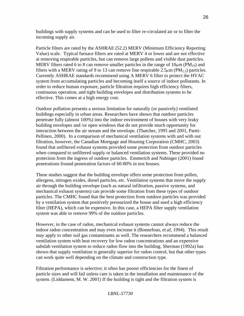
Indoor Air Quality Exposure to indoor pollutants can pose a serious health risk especially for sensitive populations such as the young, asthmatic, or elderly. (Sherman and Hodgson, 2004 and Seppanen, 2004.) Indoor pollution originates from both indoor and outdoor sources and may be in the form of suspended particulates, volatile organic chemicals (VOCs), human bio-effluents and microbiological contaminants. Occupant activities such as cooking, bathing, smoking, vacuuming, using cleaning products, painting, as well as chemical emissions from building materials, electrical equipment and appliances are all examples of indoor sources. Outdoor sources primarily result from vehicle exhaust, but also agricultural activities, construction, manufacturing activities, ground sources (radon), and allergens (Levin, 2004). The most effective method for controlling pollutants is by reducing or eliminating the source of the emission, but this is not always possible for some pollutants (Sherman and Matson, 2003, Levin, 2004). A number of strategies exist for improving indoor air quality including increasing ventilation rates to dilute the pollutant, filtration to remove particulates, or air cleaning to capture VOCs, or a combination of all three strategies. Diluting pollutants with more fresh air has historically been the function of ventilation; however, it is not a pollutant specific strategy and not all pollutants can be treated the same way. Proper maintenance and operation of the ventilation system, appropriate building design to limit sources of pollution, avoiding excessive depressurization, providing local ventilation at sources that produce pollution (combustion appliances) and moisture control are all important strategies in controlling indoor air quality (Hadlich and Grimsrud, 1999). Dilution Ventilation Appropriate whole house ventilation can dilute the level of indoor pollutants with fresh outdoor air (assuming the outdoor air in not more contaminated than the indoor air). Almost all of the ventilation technologies described can provide the necessary ventilation rates for effective dilution. For natural ventilation and/or passive systems there is some inherent lack of control of ventilation rates which may result in times when indoor pollution is high. Although these systems may provide an annual average acceptable ventilation rate, they cannot effectively deal with peak periods of pollution (Sherman and Wilson, 1986). On the other hand, all mechanical systems offer high levels of ventilation rate control so that indoor pollutants can always be diluted. Plus, many mechanical systems also include local fans in areas where production of pollutants is high, such as bathrooms and kitchens, in order to minimize the spread of pollutants into other parts of the house. Also, ventilation rates required to dilute VOCs, such as formaldehyde, is more than that needed to control human bio-effluents, such as CO2 (Sherman and Hodgson, 2004). Filtration Sherman and Matson (2003) have shown that dilution ventilation is not always effective at reducing particle concentrations. Effective filtration can reduce the concentration of particulates that can not be reduced at the source; this can also reduce the need for ventilation dilution. Filtration is most commonly used in mechanically ventilated
LBNL-57730
26
buildings with supply systems and can be used to filter re-circulated air or to filter the incoming supply air. Particle filters are rated by the ASHRAE (52.2) MERV (Minimum Efficiency Reporting Value) scale. Typical furnace filters are rated at MERV 4 or lower and are not effective at removing respirable particles, but can remove large pollens and visible dust particles. MERV filters rated 6 to 8 can remove smaller particles in the range of 10µm (PM10) and filters with a MERV rating of 9 to 13 can remove fine respirable 2.5µm (PM2.5) particles. Currently ASHRAE standards recommend using A MERV 6 filter to protect the HVAC system from accumulating particles and becoming itself a source of indoor pollutants. In order to reduce human exposure, particle filtration requires high efficiency filters, continuous operation, and tight building envelopes and distribution systems to be effective. This comes at a high energy cost. Outdoor pollution presents a serious limitation for naturally (or passively) ventilated buildings especially in urban areas. Researchers have shown that outdoor particles penetrate fully (almost 100%) into the indoor environment of houses with very leaky building envelopes and /or open windows that do not provide much opportunity for interaction between the air stream and the envelope. (Thatcher, 1995 and 2001, Partti-Pellinen, 2000). In a comparison of mechanical ventilation systems with and with out filtration, however, the Canadian Mortgage and Housing Corporation (CMHC, 2003) found that unfiltered exhaust systems provided some protection from outdoor particles when compared to unfiltered supply or balanced ventilation systems. These provided no protection from the ingress of outdoor particles. Emmerich and Nabinger (2001) found penetrations fround penetration factors of 60-80% in test houses. These studies suggest that the building envelope offers some protection from pollen, allergens, nitrogen oxides, diesel particles, etc. Ventilation systems that move the supply air through the building envelope (such as natural infiltration, passive systems, and mechanical exhaust systems) can provide some filtration from these types of outdoor particles. The CMHC found that the best protection from outdoor particles was provided by a ventilation system that positively pressurized the house and used a high efficiency filter (HEPA), which can be expensive. In this case, a HEPA filter supply ventilation system was able to remove 99% of the outdoor particles. However, in the case of radon, mechanical exhaust systems cannot always reduce the indoor radon concentration and may even increase it (Bonnefous, et.al, 1994). This result may apply to other soil gas contaminants as well. The researchers recommend a balanced ventilation system with heat recovery for low radon concentrations and an expensive subslab ventilation system to reduce radon flow into the building. Sherman (1992a) has shown that supply ventilation is generally superior for radon control, but that other types can work quite well depending on the climate and construction type. Filtration performance is selective; it often has poorer efficiencies for the finest of particle sizes and will fail unless care is taken in the installation and maintenance of the system. (Liddament, M. W. 2001) If the building is tight and the filtration system is
LBNL-57730

27
maintained, there is a potential to reduce both indoor particulate levels and ingress of outdoor particulates into the indoor environment. According to Sherman and Matson (2003) a MERV 11 filter installed in a supply ventilation system can reduce cat and dust mite allergens 30 to 40%); they recommend installing a MERV 9 to 12 filter and reducing duct leaks, preventing filter by-pass reducing infiltration, and running the fan continuously to maximize the filtration efficiency. For comparison ASHRAE 62.2 requires a MERV 6 filter. Particulates can be reduced by filtration, electrostatic precipitators, and simply by deposition that occurs in the HVAC system. Wallace, et.al. (2004) showed that the use of a central fan in a forced air system alone could reduce the whole-house particle concentration (PM2.5) by 14% and that installing an in-duct mechanical filter could reduce the levels of particles by 23%. An electrostatic precipitator could reduce particles especially fine particles, by 51%, but these are more expensive than mechanical filters and require maintenance. Thatcher, et.al.(1995) have shown that the shell of the building offers little if any filtration of total particles and that indoor particle concentrations are significantly impacted by the activity level of the residents in the house. Even light activity, such as walking, can significantly increase the suspended particulate concentration for supermicron particles. Since residential HVAC systems operate cyclically, filters used as part of the HVAC system perform better when the fraction run-time is high. Fugler and Bowser (2002) showed that high-efficiency furnace filters have a minimal effect on indoor particulate (PM10) levels when the occupants are active, but during low activity times (sleeping), PM10 could be reduced 70%. Summary In this report we have reviewed the literature and used our expertise to evaluate technologies for meeting residential ventilation requirements. Our principle focus was on meeting ASHRAE Standard 62.2, but in doing so we found that there are a lot of other issues that influence the actual decisions about what gets installed in houses. There are a wide variety of systems currently on the market that can be used to meet ASHRAE Standard 62.2. While these systems generally fall into the categories of supply, exhaust or balanced, the specifics of each system are driven by concerns that extend beyond those in the standard. Some of these systems go beyond the current standard by providing additional features (such as air distribution or pressurization control). The market will decide the immediate value of such features, but ASHRAE may wish to consider relevant modifications to the standard in the future. ASHRAE may also wish to consider expanding the standard to allow sustainable technologies—that is, passive or hybrid technologies that principally rely on natural driving forces rather than fans to transport the air. Such systems have been used for millennia and are currently used in Europe to satisfy ventilation requirements. R&D is necessary to develop such systems for the US, but they have great potential for green buildings.
LBNL-57730
28
References Abushakra, B., Walker, I., and Sherman, M. 2003. “A Study of Pressure Losses in Residential Air Distribution Systems.” LBNL Report-49700. Lawrence Berkeley Laboratory. Berkeley, CA. Allard, F. and Ghiaus, C. 2005. “Natural Ventilation in Urban Environment.” AIVC – State of the Art in Ventilation. ASHRAE. 2004. “ASHRAE Standard 62.2-2004 - Ventilation and Acceptable Indoor Air Quality in Low-Rise Residential Buildings.” American Society of Heating Refrigerating and Air-Conditioning Engineers, Inc. Atlanta, GA. Ask, A. 2003. “Ventilation and Air Leakage,” ASHRAE Journal. American Society of Heating Refrigerating and Air-Conditioning Engineers. November, 2003. pp.28-34. Axley, J. W. 2001. “Residential Passive Ventilation Systems: Evaluation and Design.” AIVC Technical Note 58, Air Infiltration and Ventilation Center. Bansal, N.K., Mathur, R., and Bhandari, M.S. 1994. “A Study of Solar Chimney Assisted Wind Towed System for Natural Ventilation in Buildings.” Building and Environment. Vol. 29. pp. 495-500. Barley, C. D. 2002. “Barriers to Improved Ventilation in Production Housing.” Proceedings of Indoor Air 2002 (9th International Conference on Indoor Air Quality and Climate). Monterey, Ca. Vol. 2. pp. 896-901. Bonnefous, Y.C., A.J. Gadgil, and W.J. Fisk. 1994. Energy and Buildings vol. 21 (1). pp.15-22. LBL-33795. and 1992."Impact of Subslab Ventilation Technique on Residential Ventilation Rate and Energy Costs." In Proceedings, 13th AIVC Conference: Ventilation for Energy Efficiency and Optimum Indoor Air Quality, Coventry, Great Britain: Air Infiltration and Ventilation Centre. pp. 431-439. Building Science Corporation. Westford, MA. http://www.buildingscience.com/resources/mechanical/default.htm Concannon, P. 2002. “Residential Ventilation.” AIVC Technical Note 57, Air Infiltration and Ventilation Center. CMHC. 2003. “Penetration of Outdoor Particles into a Residence.” Research Highlights. June 2003. Canadian Mortgage and Housing Corporation. http://www.cmhc.ca/ Delmotte, C. 2003. “Airtightness of Ventilation Ducts.” Ventilation Information Paper No. 1, AIVC. Air Infiltration and Ventilation Center. Dorer, V. Breer, D. 1998. “Residential Mechanical Ventilation Systems: Performance Criteria and Evaluations.” Energy and Buildings. Vol. 27. pp. 247-255.
LBNL-57730

29
Dorer, V., Pfeiffer, A. and Weber, A. 2004. “Parameters for the Design of Demand Controlled Hybrid Ventilation Systems for Residential Buildings.” Air Infiltration and Ventilation Centre. (RESHYVENT). Dorer, V., Tanner, C. and Weber, A. 2004. “Airtightness of Buildings.” Ventilation Information Paper No. 8, AIVC. Air Infiltration and Ventilation Center. Emmerich, S.J, Dols, W.S., “LoopDA: A Natural Ventilation System Design and Analysis Tool,” pp. 291-298 Proc 8th Int. IPBSA Conf. (2003) Emmerich S.J. Nabinger, S. J. “Measurement and Simulation of The IAQ Impact of Particle Air Cleaners in a Single-Zone Building,” pp. 223-244 Vol 7 (3), HVAC&R Research J. ASHRAE, Atlanta, GA, 2001. Fugler, D., Bowser, D. 2002. “Reducing Particulate Levels in Houses.” Indoor Air 2002: Proceedings of the 9th International Conference on Indoor Air Quality and Climate. Monterey, California. Geros V, Santamouris M, Papanikolaou N and Guarraccino G. 2001. “Night Ventilation in Urban Environments.” Proc. AIVC Conference. Bath, UK, 2001. Grimsrud, D.T. and Hadlich, D.E. 1999. “Residential Pollutants and Ventilation Strategies: Volatile Organic Compounds and Radon.” ASHRAE Transactions,.Vol. 105, Pt. 2. Hadlich, D.E. and D.T. Grimsrud. 1999. “Residential Pollutants and Ventilation Strategies: Moisture and Combustion Products.” ASHRAE Transactions. Vol. 105, Pt. 2. Hayashi, M. and Yamada, H. 1996. “Performance of a passive Ventilation System Using Beam space as a Fresh Air Chamber. Indoor Air 1996: 7th International cnoference on Indoor air Quality and Climate, Nagoya, Japan. Heiselberg, P. 2005. “Hybrid Ventilation.” in "Ventilation: A State of the Art Review" [James & James]. Air Infiltration and Ventilation Center 2005. Hekmat, D., H.E. Feustel, and M.P. Modera. 1986."Ventilation Strategies and their Impacts on the Energy Consumption and Indoor Air Quality in Single-Family Residences," Energy and Buildings. Vol. 9. pp. 239-251. LBL-19376. Holton, J.K., M.J. Kokayko, and T.R. Beggs. 1997. “Comparative Evaluation of Ventilation Systems.” ASHRAE Transactions. Vol. 103, Pt. 1. HVI 2005. “Certified Home Ventilating Products Directory”. Home Ventilating Institute. Arlington Heights, Illinois. (http://www.hvi.org/directory/). Jaros, M., Charvat, K. 2004. “Solar Chimneys for Residential Ventilation.” AIVC 25th Conference. pp. 19-24.
LBNL-57730

30
Khedari, J., Rachapradit, N., and Hirunlabh, J. 2003. “Field Study of Performance of Solar Chimney with Air-conditioned Building.” Energy. Vol. 28. Pp. 1099-1114. Levin, H. 2004. “Indoor Air Pollutants Part 2: Description of Pollutants and Control/Mitigation Measures.” AIVC Ventilation and Information Paper No. 7. Air Infiltration and Ventilation Centre. Li, Y. and Heiselberg P. 2003. “Analysis Methods for Natural and Hybrid Ventilation – A Critical Literature Review and Recent Developments.” International Journal of Ventilation. Vol.1. pp. 3-20. Liddament, M. W. 2001. “Occupant Impact on Ventilation.” AIVC Technical Note 53. Air Infiltration and Ventilation Center. McKone, T. and Sherman, M. 2003. “Residential Ventilation Standards Scoping Study.” LBNL-53800. Lawrence Berkeley National Laboratory, Berkeley, California. McWilliams, J. and Sherman, M.H. 2005. “A Review of Literature Related to Residential Ventilation Requirements.” LBNL-57236. Lawrence Berkeley National Laboratory, Berkeley, California. Modera, M. 1993. “Characterizing the Performance of Residential Air Distribution Systems.” Energy and Buildings. Vol. 20. pp. 65-75. Oikos Green Building Source. 1995. “Controlled Ventilation Options for Builders.” Energy Source Builder Newsletter. No. 39. http://oikos.com/esb/index.html - 39 . Oldham, D. J., de Salis, M. H., and Sharples, D. J. 2004. “Reducing the Ingress of Urban Noise through Natural Ventilation Openings.” Indoor Air. Vol. 14. Suppl 8. pp. 118-126. Orme, M. 1998. “Energy Impact of Ventilation: Estimates for the Service and Residential Sectors.” AIVC Technical Note 49. Air Infiltration and Ventilation Center. Orme, M. 2001. “Estimates of the Energy Impact of Ventilation and Associated Financial Expenditures.” Energy and Buildings. Vol. 33. pp.199-205. Partti-Pellinen, K. Marttila, O. et.al. 2000. “Penetration of Nitrogen Oxides and Particles from Outdoor into Indoor Air and Removal of the Pollutants through Filtration of Incoming Air.” Indoor Air. Vol. 10. pp. 126-132. Reardon, J. and Shaw, C. 1997. “Evaluation of Five Simple Ventilation Strategies Suitable for Houses Without forced-Air Heating.” ASHRAE Transactions. Vol. 103(1). pp. 731-744. Roberson, J.A., Brown, R.E., Koomey J.G., et.al. 1998. “Ventilation Strategies for Energy-Efficient Production Homes.” LBNL-Report- 40378 Lawrence Berkeley National Laboratory, Berkeley, CA. Rudd, A. 2005. Table 1. Cost estimates for mechanical ventilation systems. Rudd, A. 1999. “Air Distribution Fan and Outside Air Damper Recycling Control.” Heating Air Conditioning and Refrigeration News. 5 July 1999. pp. 45.
LBNL-57730

31
Rudd, A., Lstiburek, J. and Ueno, K. 2003. “Residential Dehumidification and Ventilation Systems Research for Hot, Humid Climates.” AIVC 24th Conference and BETEC Conference – Ventilation, Humidity Control, and Energy. pp.355-360. Rudd, A, Lstiburek J, 2001. “Clean Breathing in Production Homes.” Home Energy Magazine, May/June, Energy Auditor & Retrofiter, Inc., Berkeley, CA. Rudd, A. and Lstiburek, J. 2000. “Measurement of Ventilation and Interzonal Distribution in Single Family Houses.” Proceedings of ASHRAE Annual Meeting. June 24-28, 2000. Minneapolis, MN. Rudd, A. and Lstiburek, J. 1998. “Design/Sizing Methodology and Economic Evaluation of Central-Fan-Integrated Supply Ventilation Systems.” Proceedings of the 1998 ACEEE Summer Study on Energy Efficiency in Buildings. 23-28 August 1998. Pacific Grove, California. American Council for an Energy Efficient Economy. Washington, D.C. Santamouris, M. 2005. “Ventilation for Cooling and Comfort.” published in "Ventilation: A State of the Art Review", James & James 2005. Seppanen, O. 2004. “Effect of Ventilation on Health and other Human Responses.” published in "Ventilation: A State of the Art Review", [ames & James, 2005. Seppanen, O. and Fisk, W. 2004. “Summary of Human Responses to Ventilation.” Indoor Air. Vol. 14(7), pp. 102-118. Shao, L., Riffiat, S. B., and Gan, G. 1998 “Heat Recovery with Low Pressure Loss for Natural Ventilation.” Energy in Buildings. Vol. 28, pp. 179-184. Sheltersource Inc. 2002. “Evaluating Minnesota Homes – A Final Report.” Minnesota Department of Commerce. Sherman, M.H. 1990. "Air Infiltration Measurement Techniques." In Proceedings, 10th AIVC Conference: Progress and Trends in Air Infiltration and Ventilation Research. Vol. 1. Conventry, Great Britain: Air Infiltration and Ventilation Centre. pp. 63-87. LBL-27656. Sherman, M.H 1992. “Superposition in Infiltration Modelling.” Indoor Air. Vol. 2. Pp. 101-114. Sherman M.H., “Simplified Modeling for Infiltration and Radon Entry”, Proc. ASHRAE/ DOE/BTECC Conference, Thermal Performance of the Exterior Envelopes of Buildings Conference V (addendum), Clearwater Beach, FL, American Society of Heating, Refrigerating and Air-conditioning Engineers, 1992a. [LBL-31305] Sherman, M.H. 1995. “The Use of Blower-Door Data.” Indoor Air. Vol. 5. pp.215-224. Sherman, M.H 2004. “Efficacy of Intermittent Ventilation for Providing Acceptable Indoor Air Quality.” LBNL-56292. Lawrence Berkeley National Laboratory, Berkeley, CA.
LBNL-57730

32
Sherman, M.H. 2004."ASHRAE & Residential Ventilation." ASHRAE Journal. Vol.46(1). pp. S149-156. Lawrence Berkeley Laboratory Report LBNL-53776. Sherman, M.H., and Chan W. R. 2004. "Building Airtightness: Research and Practice" published in "Ventilation: A State of the Art Review" James & James. 2005. Lawrence Berkeley Laboratory Report No 53356. Sherman, M. and Dickerhoff, D. 1998. “Air Tightness of U.S. Dwellings.” ASHRAE Transactions. Vol. 104. pp.1359-1367. Sherman, M. H. and Hodgson A.T.. 2004."Formaldehyde as a Basis for Residential Ventilation Rates." Indoor Air. Vol. 14 (1). pp. 2-8. (LBNL-49577). Sherman, M.H. and N. Matson. 1993."Ventilation-Energy Liabilities in U.S. Dwellings." In Proceedings 14th AIVC Conference: Energy Impact of Ventilation and Air Infiltration, Coventry, Great Britain:Air Infiltration and Ventilation Centre. pp. 23-39. LBL-33890. Sherman, M.H. and Matson, N.E, 1997."Residential Ventilation and Energy Characteristics." ASHRAE Transactions. Vol. 103(1). pp.717-730. LBL-39036. Sherman, M.H and Matson, N.E., 2002. “Air Leakage in New U.S. Housing.” LBNL Report LBNL-48671. Lawrence Berkeley National Laboratory, Berkeley, California. Sherman, M.H. and Matson, N.E, 2003. “Reducing Indoor Residential Exposures to Outdoor Pollutants.” Technical Note AIVC 58. Air Infiltration and Ventilation Centre. Sherman, M.H. and McWilliams, J.A. 2005. “Report on Applicability of Residential Ventilation Standards in California.” LBNL-56292. Lawrence Berkeley National Laboratory, Berkeley, California. Sherman, M.H. and Wilson D.J. 1986. "Relating Actual and Effective Ventilation in Determining Indoor Air Quality." Building and Environment. Vol. 21 (3/4). pp. 135-144. LBL-20424. Thatcher, T. and Layton, D. 1995. “Deposition, Resuspension, and Penetration of Particles within a Residence.” Atmospheric and Environment. Vol. 29. Pp. 1487-1497. Thatcher, T., McKone, T., et.al. 2001. “Factors Effecting the Concentrations of Outdoor Particles Indoors (COPI): Identification of Data Needs and Existing Data.” Lawrence Berkeley National Laboratory Report - 49321. Veld, P. O. and Passlack-Zwaans, C. 1998. “IEA ANNEX 27: Evaluation and Demonstration of Domestic Ventilation Systems. Assessments on Noise.” Energy and Buildings. Vol. 27. pp. 263-273. Walker, I. 2003. “Register Closing Effects on Forced Air Heating System Performance.” LBNL Report-54005. Lawrence Berkeley National Laboratory, Berkeley, CA.
LBNL-57730

33
Walker, I.S., and Sherman, M.H. 2003. “Ventilation Technologies Scoping Study.” LBNL-53811. Lawrence Berkeley National Laboratory, Berkeley, CA. Walker, I.S. and Sherman, M.H. 2003. “Heat Recovery in Building Envelopes.” Proc. AIVC BETEC 2003 Conference. Washington DC. LBNL 53484. Wallace, L. A., Emmerich, S. J., and Howard-Reed, C. 2004. “Effect of Central Fans and In-duct Filters on Deposition Rates of Ultrafine Particles in an Occupied Townhouse.” Atmospheric Environment. Vol. 38. pp. 405-413. Wilson, D.J., and Walker, I.S. 1992. "Feasibility of Passive Ventilation by Constant Area Vents to Maintain Indoor Air Quality in Houses." Proc. Indoor Air Quality. ASHRAE/ACGIH/AIHA Conference. San Francisco, California. October 1992. ASHRAE, Atlanta, GA. Wray, C., Matson, N., Sherman, M. 2000. “Selecting Whole-House Ventilation Strategies to meet proposed ASHARAE standard 62.2: Energy Cost considerations.” LBNL-44479. Lawrence Berkeley National Laboratory, Berkeley, CA. Yang, L. et. al. 2005. “Investigating potential of Natural Driving Forces for Ventilation in Four Major Cities in China.” Building and Environment. Vol. 40. pp. 738-746. Yoshino, H., Liu, J., et. al. 2003. “Performance analysis on hybrid ventilation system for residential buildings using a test house.” Indoor Air. Vol. 13. p. 28.
LBNL-57730
34
Other Relevant Literature Sources Bonnefous, Y.C., A.J. Gadgil, and F. Allard. 1992. "Comparison of Effectiveness of Sub-Slab Ventilation Systems for Indoor Radon Mitigation: A Numerical Study," In Proceedings of the Fifth International Jacques Cartier Conference, Montreal, Canada. LBL-32280. Bonnefous, Y.C., A.J. Gadgil, K.L. Revzan, W.J. Fisk, and W.J. Riley. 1993. "Impacts of a Sub-Slab Aggregate Layer and a Sub-Aggregate Membrane on Radon Entry Rate: A Numerical Study," In Indoor Air '93, Proceedings of the 6th International Conference on Indoor Air Quality and Climate, Vol. 4. Helsinki, Finland:Indoor Air '93. pp. 569-574. LBL-33687. Cano-Ruiz, J.A., M.P. Modera, and W.W. Nazaroff. 1992."Indoor Ozone Concentrations: Ventilation Rate Impacts and Mechanisms of Outdoor Concentration Attenuation," In Proceedings, 13th AIVC Conference: Ventilation for Energy Efficiency and Optimum Indoor Air Quality, Coventry, Great Britain:Air Infiltration and Ventilation Centre. pp. 217-232. LBL-32639. Cano-Ruiz, J.A., D. Kong, R.B. Balas, and W.W. Nazaroff. 1993."Removal of reactive gases at indoor surfaces: Combining mass transport and surface kinetics," Atmospheric Environment. Vol. 27A. pp.2039-2050. CMHC. 1992. “Barriers to the use of Energy Efficient Residential Ventilation.” Research Division, Canada Mortgage and Housing Corporation. Ottawa, Canada. CMHC. 1993. “Efficient and Effective Residential Air Handling devices.” Research Division, Canada Mortgage and Housing Corporation. Ottawa, Canada. Dumortier, D. and M.P. Modera.1987. "A Model for Predicting Air Flows Through Two Combustion Appliances Vented by a Single Chimney," Published by Royal Institute of Technology. LBL-23151. Feustel, H.E., Ch. Zuercher, R.C. Diamond, J.B. Dickinson, D.T. Grimsrud, and R.D. Lipschutz. 1985."Air Flow Pattern in a Shaft-Type Structure," Energy and Buildings. Vol. 8 (2). Feustel, H.E. 1992."Annex 23 Multizone Airflow Modeling - An International Effort," In Proceedings International Symposium, Air Flow in Multizone Structures, Budapest. Feustel, H.E. 1998. "COMIS - An International Multizone Air Flow and Contaminant Transport Model." August 1998. LBNL-42182 Feustel, H.E. 1990. "The COMIS Air Flow Model - A Tool for Multizone Applications," In Indoor Air '90, Proceedings of the 5th International Conference in Indoor Air Quality and Climate, Vol. 4, Ottawa, Canada: International Conference on Indoor Air Quality and Climate. pp. 121-126.
LBNL-57730

35
Feustel, H.E., F. Allard, V.B. Dorer, M. Grosso, M. Herrlin, L. Mingsheng, J.C. Phaff, Y. Utsumi, and H. Yoshino. 1989. "The COMIS Infiltration Model," In Proceedings, Building Simulation 89, Vancouver, Canada. LBL-27996. Feustel, H.E. 1989. "Mathematical Modeling of Infiltration and Ventilation," In Proceedings, 10th AIVC Conference: Progress and Trends in Air Infiltration and Ventilation Research, Vol. 1, Conventry, Great Britain:Air Infiltration and Ventilation Centre. pp.157-179. LBL-27995. Feustel, H.E. and M.H. Sherman. 1987. "A Simplified Model for Predicting Air Flow in Multizone Structures," Energy and Buildings. LBL-22325. Feustel, H.E., M.P. Modera, and A.H. Rosenfeld. 1986."Ventilation Strategies for Different Climates," LBL-20364. Also in Proceedings of IAQ '86: Managing Indoor Air for Health and Energy Conservation, Atlanta, Georgia. ASHRAE. pp. 342-363. Feustel, H.E. 1988. "Ventilation Strategies for Non-Residential Buildings." LBL-26252. Grimsrud, D.T. 1987. "Chairman's Summary, Session III, Characterization of Sources and Emissions in Field Studies," Atmospheric Environment 21 359-360. LBL-22478. Grimsrud, D.T., W.W. Nazaroff, K.L. Revzan, and A.V. Nero. 1983. "Continuous Measurements of Radon Entry in a House," In Proceedings of the 76th Annual Meeting of the Air Pollution Control Association, Atlanta, GA, Paper No. 83-9.8, Atlanta, GA. APCA, LBL-15839. Grimsrud, D.T., B.H. Turk, R.J. Prill, J. Harrison, and K.L. Revzan. 1987. "Effects of House Weatherization on Indoor Air Quality," In Indoor Air '87, Proceedings of the 4th International Conference on Indoor Air Quality and Climate, Vol. 2. Berlin, West Germany: Institute for Water, Soil, and Air Hygiene. pp. 208-212. LBL-23138. Grimsrud, D.T., R.F. Szydlowski, and B.H. Turk. 1986. "Field Study of Exhaust Fans for Mitigating Indoor Air Quality Problems." LBL-22281. Grimsrud, D.T., R.D. Lipschutz, and J.R. Girman. 1983. "Indoor Air Quality in Energy Efficient Residences." In Indoor Air Quality, Chapter 5, eds. P.J. Walsh and C.S. Dudney, Boca Raton: CRC Press. LBL-14795. Grimsrud, D.T. 1984."Tracer Gas Measurements of Ventilation in Occupied Office Spaces," Ann. Am. Conf. Gov. Ind. Hyg. Vol.10. pp. 69-76. Harrje, D.T., R.N. Dietz, M.H. Sherman, D.L. Bohac, T.W. D'Ottavio, and D.J. Dickerhoff. 1990. "Tracer Gas Measurement Systems Compared in a Multifamily Building." In Air Change Rate and Airtightness in Buildings, ed. M.H. Sherman, Philadelphia: ASTM. pp. 5-20.
LBNL-57730

36
Hekmat, D. 1986. "Estimates of Impacts of Ventilation Air Heat Recovery on Energy Use for Water Heating." LBL-18562. Matson, N.E., H.E. Feustel, J.L. Warner, and J. Talbott. 1994. "Climate-based Analysis of Residential Ventilation Systems." In Proceedings, 15th AIVC Conference: The Role of Ventilation, Vol. 2. Conventry, Great Britain:Air Infiltration and Ventilation Centre. pp. 673-686. McWilliams, J.A.. 2002. "Review of Airflow Measurement Techniques." LBNL-49747. Modera, M.P. and M.H. Sherman. 1987."Methods and Apparatus for Measuring the Tightness of Enclosures." U.S. Patent #4 635, 469. Offermann, F.J., J.B. Dickinson, W.J. Fisk, D.T. Grimsrud, C.D. Hollowell, D.L. Krinkel, G.D. Roseme, R.M. Desmond, J.A. DeFrees, and M.C. Lints. 1982. "Residential Air-Leakage and Indoor Air Quality in Rochester, New York," Lawrence Berkeley Laboratory. LBL-13100. Palmiter, L. and M.H. Sherman. 1993. "Measured Airflows in Multifamily Buildings." In Special Technical Publications, Airflow Performance American Society for Testing & Materials, Philadelphia, PA. LBL-32116. Sextro, R.G., H.E. Feustel, M.P. Modera, K.L. Revzan, and M.H. Sherman. 1993. "A Coupled Multizone Flow and Radon Transport Model of Radon Entry and Concentrations in a Crawl Space House." In Indoor Air '93. Proceedings of the 6th International Conference on Indoor Air Quality and Climate, Vol. 4. Helsinki, Finland: Indoor Air '93. pp. 663-668. LBL-33682. Sherman, M.H., ed. 1990."Air Change Rate and Airtightness in Buildings." Philadelphia: ASTM. Sherman, M. 1999. "ASHRAE's Proposed Residential Ventilation Standard" LBNL-42975. Sherman, M.H. and D.T. Grimsrud. 1982."A Comparison of Alternative Ventilation Strategies," In Proceedings, Third AIC Conference: Energy Efficient Domestic Ventilation Systems for Achieving Acceptable Indoor Air Quality, Bracknell, Berkshire, Great Britain: Air Infiltration Centre. pp. 7.1-7.23. LBL-13678. Sherman, M.H. and M.P. Modera. 1986."Comparison of Measured and Predicted Infiltration Using the LBL Infiltration Model." In Measured Air Leakage of Buildings, eds. H.R. Trechsel and P.L. Lagus, Philadelphia: ASTM. pp. 325-347. LBL-17001. Sherman, M.H. 1987. "Estimation of Infiltration from Leakage and Climate Indicators." Energy and Buildings. Vol.10. pp. 81-86. LBL-21463.
LBNL-57730

37
Sherman, M.H. and D.J. Wilson.1989. "Ventilation Effectiveness and Distribution in Naturally Ventilated Buildings." Lawrence Berkeley Laboratory, LBL-21057. Sherman, M.H. 1989. "On Estimation of Multizone Ventilation Rates from Tracer Gas Measurements." Building and Environment. Vol. 24. pp. 355-362. LBL-25772. Sherman, M.H. 1989. "Analysis of Errors Associated with Passive Ventilation Measurement Techniques." Building and Environment. Vol. 24 (No. 2). pp.131-139. LBL-23088. Sherman, M.H. 1990. "Tracer Gas Techniques for Measuring Ventilation in a Single Zone." Building and Environment. Vol. 25 (No. 4). pp.365-374. LBL-29328. Sherman, M.H. and M.P. Modera. 1986. "Low Frequency Measurement of the Leakage of Enclosures." Review of Scientific Instruments. Vol.57 (7). LBL-20121. Sherman, M.H. and D.J. Dickerhoff. 1994. "Monitoring Ventilation and Air Leakage in a Low-Rise Commercial Building." In International Solar Energy Conference. ASME. LBL-34562. Sherman, M.H. and D.J. Dickeroff. 1989."A Multigas Tracer System for Multizone Air Flow Measurements." In Proceedings, Thermal Performance of the Exterior Envelopes of Buildings IV, Atlanta, GA:ASHRAE. pp. 417-432. LBL-26087. Sherman, M.H. 1990. "A Multitracer System for Multizone Ventilation Measurements." Review of Scientific Instruments. LBL-29010. Sherman, M.H. and J.B. Dickinson. 1985. "The Prediction of Air Infiltration." In CLIMA 2000 Conference, Copenhagen, Denmark. LBL-19040. Sherman, M.H. 1992. "Simplified Modeling for Infiltration and Radon Entry." In Proceedings, Thermal Performance of the Exterior Envelopes of Buildings Conference V(addendum). Atlanta, GA. ASHRAE. LBL-31305. Sherman, M.H., H.E. Feustel, and D.J. Dickerhoff. 1989."Description of a System for Measuring Interzonal Air Flows Using Multiple Tracer Gasses." In Proceedings of the XXI Symposium of the International Centre for Heat and Mass Transfer (ICHMT). Dubrovnik, Yugoslavia. pp. 781-790. LBL-26538. Sherman, M.H. 1989. "Uncertainty in Air Flow Calculations Using Tracer Gas Measurements." Building and Environment. Vol. 24. pp. 347-354. LBL-25415. Sherman M.H.,. Matson M.E., “Air Tightness in New U.S. Housing” Proc. 22
nd AIVC
Conference, Air Infiltration and Ventilation Centre; Sept 2001. [LBNL-48671]
LBNL-57730

Sherman, M. 2004."ASHRAE's First Residential Ventilation Standard." Proc. Buildings IX Conference. Clearwater FL. LBNL-54331. Sherman, M.H. 1986. "Infiltration Degree-Days: A Statistic for Quantifying Infiltration-Related Climate.'' ASHRAE Transactions. Vol. 92 (2A). pp. 161-181. LBL-19237. Sherman, M. and Dickerhoff D."Air Tightness of U.S. Dwellings" LBL-35700. Skaaret, E. and H.M. Mathisen. 1983. "Ventilation Effectiveness - A Guide to Efficient Ventilation." In Proceedings of the 1983 ASHRAE Annual Meeting, June 26-30, Washington, DC:ASHRAE, Atlanta, GA, LBL-16155. Emmerich, S. J. and A. K. Persily. 1995. “Multizone Modeling of Three Residential Indoor Air Quality Control Options.” Proceedings of Building Simulation ’95. Lubliner, M., D.T. Stevens, and B. Davis. 1997. “Mechanical Ventilation in HUD-Code Manufactured Housing in the Pacific Northwest.”ASHRAE Transactions. Vol. 103, Pt. 1. Persily. 1999. “Ventilation, Energy and IAQ Impacts of Mechanical Ventilation in a U.S. Dwelling.” Proceedings of Indoor Air ’99. Persily, A.K. and S. Martin. 2000. “Modeling Study of Ventilation in Manufactured Houses.” NISTIR 6455, National Institute of Standards and Technology. Walker, I.S. and Mingee, M.D. 2003. “Reducing Air Handler Electricity Use: More than Just a Better Motor.” Home Energy. Vol.20 (6). Berkeley, CA. Walker, I.S, Mingee, D.M., Brenner, D., and Dickerhoff, D.J. 2003. “Improving Air Handler Efficiency in Residential HVAC Applications.” LBNL 53606. Lawrence Berkeley National Laboratory, Berkeley, CA.
LBNL-57730