review of recent techniques of heat transfer … 2015, volume 2, issue 2 jetir (issn-2349-5162)...
TRANSCRIPT

February 2015, Volume 2, Issue 2 JETIR (ISSN-2349-5162)
JETIR1502033 Journal of Emerging Technologies and Innovative Research (JETIR) www.jetir.org 349
Review of Recent Techniques of Heat Transfer
Enhancement and Validation of Heat Exchanger 1Ramnaresh R. Prajapati,
2Pravin A. Mane,
3Mrs. Seema Mane,
4Dattatray Gaikwad
1Department of Mechanical Engineering, W.C.E, Sangli - 416415, Maharashtra, India
2P.V.P.I.Technology, Budhagaon, Sangli.
Abstract—Heat exchangers have several industrial and engineering applications. The design procedure of heat exchangers
is quite complicated, as it needs exact analysis of heat transfer rate and pressure drop estimations apart from issues such
as long-term performance and the economic aspect of the equipment. Whenever inserts are used for the heat transfer
enhancement, along with the increase in the heat transfer rate, the pressure drop also increases. This increase in pressure
drop increases the pumping cost. Therefore any augmentation device should optimize between the benefits due to the
increased heat transfer coefficient and the higher cost involved because of the increased frictional losses. Heat transfer
augmentation techniques (passive, active or a combination of passive and active methods) are commonly used in areas
such as process industries, heating and cooling in evaporators, thermal power plants, air-conditioning equipment,
refrigerators, radiators for space vehicles, automobiles, etc. Passive techniques, where inserts are used in the flow passage
to augment the heat transfer rate, are advantageous compared with active techniques, because the insert manufacturing
process is simple and these techniques can be easily employed in an existing heat exchanger
Index Terms— Active Technique, Passive Technique, Compound Technique, Heat exchanger ________________________________________________________________________________________________________
I. INTRODUCTION
Heat exchangers have several industrial and engineering applications. The design procedure of heat exchangers is quite
complicated, as it needs exact analysis of heat transfer rate and pressure drop estimations apart from issues such as long-term
performance and the economic aspect of the equipment. To make the equipment compact and achieve a high heat transfer rate
using minimum pumping power.
Techniques for heat transfer augmentation are relevant to several engineering applications. In recent years, the high cost of
energy and material has resulted in an increased effort aimed at producing more efficient heat exchange equipment.
Furthermore, sometimes there is a need for miniaturization of a heat exchanger in specific applications, such as space application,
through an augmentation of heat transfer. Therefore, an increase in the efficiency of the heat exchanger through an augmentation
technique may result in a considerable saving in the material cost.
In some specific applications, such as heat exchangers dealing with fluids of low thermal conductivity (gases and oils) and
desalination plants, there is a need to Increase the heat transfer rate. The heat transfer rate can be improved by introducing a
disturbance in the fluid flow (breaking the viscous and thermal boundary layers), but in the process pumping power may increase
significantly and ultimately the pumping cost becomes high. Therefore, to achieve a desired heat transfer rate in an existing heat
exchanger at an economic pumping power, several techniques have been proposed in recent years and are discussed in the
following sections.
II. IMPORTANT DEFINATIONS
In this section a few important terms commonly used in heat transfer augmentation work are defined.
A. Thermohydraulic performance-
For a particular Reynolds number, the thermohydraulic performance of an insert is said to be good if the heat transfer
coefficient increases significantly with a minimum increase in friction factor. Thermohydraulic performance estimation is
generally used to compare the performance of different inserts such as twisted tape, wire coil, etc., under a particular fluid flow
condition.
B. Overall enhancement ratio-
The overall enhancement ratio is defined as the ratio of the heat transfer enhancement ratio to the friction factor ratio. This
parameter is also used to compare different passive techniques and enables a comparison of two different methods for the same
pressure drop. The friction factor is a measure of head loss or pumping power.
C. Nusselt number-
The Nusselt number is a measure of the convective heat transfer occurring at the surface and is defined as hd/k, where h is
the convective heat transfer coefficient, d is the diameter of the tube and k is the thermal conductivity
D. Prandtl number-
The Prandtl number is defined as the ratio of the molecular diffusivity of momentum to the molecular diffusivity of heat.
E. Pitch
Pitch is defined as the distance between two points that are on the same plane, measured parallel to the axis of a twisted tape.

February 2015, Volume 2, Issue 2 JETIR (ISSN-2349-5162)
JETIR1502033 Journal of Emerging Technologies and Innovative Research (JETIR) www.jetir.org 350
F. Twist ratio, y
The twist ratio is defined as the ratio of pitch to inside diameter of the tube y ¼ H/di, where H is the twist pitch length and d is
the inside diameter of the tube
III. HEAT TRANSFER AUGMENTATION
Classification of Augmentation Techniques:
They are broadly classified into three different categories:
1. Passive Techniques
2. Active Techniques
3. Compound Techniques.
1. Passive Techniques: These techniques do not require any direct input of external power; rather they use it from the system itself which ultimately
leads to an increase in fluid pressure drop. They generally use surface or geometrical modifications to the flow channel by
incorporating inserts or additional devices. They promote higher heat transfer coefficients by disturbing or altering the existing
flow behavior except for extended surfaces. Heat transfer augmentation by these techniques can be achieved by using;
i. Treated Surfaces: Such surfaces have a fine scale alteration to their finish or coating which may be continuous or
discontinuous. They are primarily used for boiling and condensing duties.
ii. Rough surfaces: These are the surface modifications that promote turbulence in the flow field in the wall region,
primarily in single phase flows, without increase in heat transfer surface area.
iii. Extended surfaces: They provide effective heat transfer enlargement. The newer developments have led to modified
finned surfaces that also tend to improve the heat transfer coefficients by disturbing the flow field in addition to increasing the
surface area.
iv. Displaced enhancement devices: These are the inserts that are used primarily in confined forced convection, and they
improve energy transport indirectly at the heat exchange surface by displacing the fluid from the heated or cooled surface of the
duct with bulk fluid from the core flow.
v. Swirl flow devices: They produce and superimpose swirl flow or secondary recirculation on the axial flow in a channel.
These include helical strip or cored screw type tube inserts, twisted tapes. They can be used for single phase and two-phase flows.
vi. Coiled tubes: These lead to relatively more compact heat exchangers. It produces secondary flows and vortices which
promote higher heat transfer coefficients in single phase flows as well as in most regions of boiling.
vii. Surface tension devices: These consist of wicking or grooved surfaces, which direct and improve the flow of liquid to
boiling surfaces and from condensing surfaces.
viii. Additives for liquids: These include the addition of solid particles, soluble trace additives and gas bubbles in single phase
flows and trace additives which usually depress the surface tension of the liquid for boiling systems.
ix. Additives for gases: These include liquid droplets or solid particles, which are introduced in single-phase gas flows
either as dilute phase (gas-solid suspensions) or as dense phase (fluidized beds).
2. Active Techniques: In these cases, external power is used to facilitate the desired flow modification and the concomitant improvement in the rate
of heat transfer.
Augmentation of heat transfer by this method can be achieved by
(i) Mechanical Aids: Such instruments stir the fluid by mechanical means or by rotating the surface. These include rotating
tube heat exchangers and scrapped surface heat and mass exchangers.
(ii) Surface vibration: They have been applied in single phase flows to obtain higher heat transfer coefficients.
(iii) Fluid vibration: These are primarily used in single phase flows and are considered to be perhaps the most practical type
of vibration enhancement technique.
(iv) Electrostatic fields: It can be in the form of electric or magnetic fields or a combination of the two from dc or ac
sources, which can be applied in heat exchange systems involving dielectric fluids. Depending on the application, it can also
produce greater bulk mixing and induce forced convection or electromagnetic pumping to enhance heat transfer.
(v) Injection: Such a technique is used in single phase flow and pertains to the method of injecting the same or a different
fluid into the main bulk fluid either through a porous heat transfer interface or upstream of the heat transfer section.
(vi)Suction: It involves either vapor removal through a porous heated surface in nucleate or film boiling, or fluid
withdrawal through a porous heated surface in single-phase flow.
(vii) Jet impingement: It involves the direction of heating or cooling fluid perpendicularly or obliquely to the heat transfer surface.
3) Compound Techniques: When any two or more of these techniques are employed simultaneously to obtain enhancement in heat transfer that is greater
than that produced by either of them when used individually, is termed as compound enhancement. This technique involves
complex design and hence has limited applications.
February 2015, Volume 2, Issue 2 JETIR (ISSN-2349-5162)
JETIR1502033 Journal of Emerging Technologies and Innovative Research (JETIR) www.jetir.org 351
1] PASSIVE METHODS-
These techniques do not require any direct input of external power; rather they use it from the system itself which
ultimately leads to an increase in fluid pressure drop.
Brief descriptions of these methods follow:
a) TREATED SURFACES:
These are primarily applicable in two phase heat transfer and they consist of a variety of structured surfaces (continuous
or discontinuous integral surface roughness or alterations) and coatings. Though the treatment provides a roughness to the surface,
it is not large enough to influence single phase heat transfer.
Boiling: Different types of treated surfaces used are
Machined or grooved surfaces
Formed or modified low-fin surfaces
Multilayered surfaces
Coated surfaces
The principle of providing treated surfaces for enhanced boiling is to produce a large number of stable vapor traps or
nucleation sites on the surface. This is applicable for highly wetting fluids like refrigerants, organic liquids, cryogens and alkali
liquid metals where the normal cavities present on the heated surfaces tend to experience sub-cooled liquid flooding. For less
wetting or relatively higher surface tension fluids, coatings of non-wetting material (eg.teflon) on either the heated surface or its
pits and cavities have been found to improve stable nucleation and reduce the required wall super
When the stainless steel surface along with Teflon is spread to create spots of the no-wetting material on the heated surface it was
found to promote nucleate boiling in water with relatively low wall super heat and three to four times higher heat transfer
coefficients, was proposed by Young and Hummel(1965). In a more recent study of boiling of alcohols (methanol, ethanol and
isopropanol) at atmospheric and sub-atmospheric pressures on a horizontal brass tube coated with poly-tetra-fluoro-ethylene
(PTFE), Vijaya Vittala et al. (2001), found a significant enhancement in heat transfer.
Condensing:
Vapor space condensation heat transfer coefficients can be enhanced primarily by treated surfaces that promote drop
wise condensation. The intent here is to prevent surface wetting and break up the condensate film into droplets which lends to
better drainage and more effective vapor renewal at the cold heat transfer interface. This technique had been found to enhance the
heat transfer by a factor of 10 to 100 in comparison with that in film wise condensation proposed by Bergles, (1998). Non-wetting
coatings of an inorganic compound or a noble metals or an organic polymer have been used effectively. Among these, organic
coatings have been used considerably in steam systems. Glicksman et al. (1973) have been found out that, by placing strips of
Teflon or other non-wetting material in a helical or axial arrangement around the circumference of horizontal tubes, the average
condensation heat transfer coefficients of steam on horizontal tubes can be improved by 20 to 50%. The application of
hydrophobic coatings of self-assembled monolayers, formed by chemisorptions of alkylthiols on metallic surfaces, to promote
drop wise condensation has been proposed by Das et al. (2000). It was found that steam condensation on coated corrugated tubes
with gold and copper-nickel alloy surfaces under atmospheric and subatmospheric pressure conditions with wall sub-cooling of
about 16°C and 6°C respectively showed that condensation heat transfer coefficients increased by factors of 2.3 to 3.6 compared
to those for un-coated tubes.
b) ROUGH SURFACES:
Single Phase Flow:
The use of surface roughness in turbulent single phase flow is one of the simplest and highly effective techniques; small
scale roughness has little effect in laminar flows. It essentially disturbs the viscous laminar sub-layer near the wall to promote
higher momentum and heat transport. Surface roughness can be introduced in the form of wire-coiled type inserts or it may be
integral to the surface.
Rough surfaces have been employed to enhance heat transfer in single phase flows both inside tubes and outside tubes.
Dong et al. (2001) developed a new set of analogy based friction factor and Nusselt number correlations for turbulent flows of
water and oil in spirally corrugated tubes. Adopting an empirical approach, combined with a statistical analysis of a fairly large
database for heat transfer coefficients and friction factors for various roughness shown above, Ravigururajan and Bergles (1996)
proposed correlations for Nusselt number and fanning factor as: By Bergles, (1998) found to increase the heat transfer coefficient
and critical heat flux (CHF) in once through boiling of water. Commercially structured rough surfaces in the form of corrugated
tubing have extensively employed in refrigerant evaporators. Withers and Habdas (1974) have reported up to 100% increase in
the heat transfer coefficient and up to 200% enhancement in critical heat flux (CHF) in bulk boiling, in helically corrugated tubes.
Artificial roughness in the form of longitudinal ribs or grooves has been applied in gravity driven, horizontal tube evaporators.
Though these types of surfaces promote turbulence, it tends to impede film drainage proposed by Bergles (1998).Cox et al. (1969)
found that three-dimensional rough surfaces tend to promote turbulence as well as the liquid spreading thereby increasing the heat
transfer coefficient as much as 100%.
Condensing: Corrugated tubes have been extensively used for enhancement of vapor space condensation. Rough surfaces also
improve in-tube forced convective condensation. The overall heat transfer coefficient with forced convection condensation inside
and spray film evaporation outside could be improved by using spirally indented and V-grooved tubes. Thomas (1967) attached
axial wires around the periphery of vertical smooth tubes, which facilitated better surface tension driven condensate film drainage
to produce three to four fold enhancement in heat transfer. He further proposed that square profiled wires were more effective
than circular ones of the same roughness height. In steam condensation on horizontal helically corrugated tubes, Mehta and Raja

February 2015, Volume 2, Issue 2 JETIR (ISSN-2349-5162)
JETIR1502033 Journal of Emerging Technologies and Innovative Research (JETIR) www.jetir.org 352
Rao (1979) and Zimparov et. al. (1991), Webb (1994), Das et al. (2000) have reported about 1.1 to 1.4 times increase in heat
transfer coefficient. Dreitser et al. (1988) have reported 1.8 to 2.0 times higher steam condensation heat transfer coefficients on
horizontal tubes with transverse grooves.
c) EXTENDED SURFACES:
Extended or finned surfaces are most widely used techniques which include finned tube for shell & tube exchangers,
plate fins for compact heat exchanger and finned heat sinks for electronic cooling.
Single-Phase Flow: Enhanced heat transfer from finned surfaces for buoyancy driven natural or free convection has been
considered primarily for cooling of electrical and electronic devices and for hot water baseboard room heaters. The use of
extended surfaces for cooling electronic devices is not restricted to the natural convection heat transfer regime but also can be
used for forced convective heat transfer. By using segmented or interrupted longitudinal fins inside circular tubes, heat transfer
can be increased by periodically disrupting and restarting the boundary layer on the finned surface and perturbing the bulk flow
field. Plate fin or tube and plate fin type of compact heat exchangers, where the finned surfaces provide a very large surface area
density, are used increasingly in many automotive, waste heat recovery, refrigeration and air conditioning , cryogenic, propulsion
system and other heat recuperative applications.
A variety of finned surfaces typically used, include offset strip fins, louvered fins, perforated fins and wavy fins.
Fig. 3.1: (Tubes with Circumferential and strip fins on their outer surface)
Kelkar and Patankar (1990) considered in-line segmented fins which had half the fin surface area of staggered or
continuous fins, were found to perform better with 6% higher Nusselt number and 22% lower friction factor.
Boiling:
Internal finned tubes are widely used in refrigerant evaporators and for flow boiling. In pool-boiling, finned tubes have
higher heat transfer coefficients compared with the performance of equivalent smooth tubes. In most heat exchangers for
refrigeration and air-conditioning systems, micro finned tubes are extensively used. Bergeles (2000) pointed out that by using fin
structures, the heat transfer coefficients can be increased up to 200%.
Condensing: Extended surfaces that include a variety of large, medium and micro sized fins are used extensively for condensation
heat transfer enhancement in power, process, and air conditioning and refrigeration applications. The heat exchangers in these
duties involve both horizontal and vertical tube condensers with fins on the inside or outside surfaces of tubes. For integral fin
tubes, besides the increased surface area, high heat transfer coefficients are obtained because a relatively thin condensate film
tends to be formed near the fin tubes and surface tension forces pull the condensate into the inter fin grooved spaces, there by
promoting better drainage and reduction of liquid film resistance.

February 2015, Volume 2, Issue 2 JETIR (ISSN-2349-5162)
JETIR1502033 Journal of Emerging Technologies and Innovative Research (JETIR) www.jetir.org 353
(Notched fins) (Serrated-tip micro fins)
Fig. 3.2: Three-dimensional finned surfaces for enhanced condensation
Chandran and Watson (1976) found that by using circular pin fins, average heat transfer coefficient can be increased to 20% more
than those for a smooth tube. Itoh et al. (1997) had shown that micro fins with serrated tips (as shown above) provide 30 to 60%
improvements in the heat transfer coefficients over same sized conventional micro fin tubes.
d) DISPLACED ENHANCEMENT DEVICES:
Single-Phase Flow: Several types of inserts which are categorized as displaced enhancement devices include static
mixer elements (e.g. Kenics, Sulzer), metallic mesh, discs, wire matrix inserts, rings or balls which tend to displace the fluid from
the core of the channel to its heated or cooled wall and vice versa, keeping the heat transfer surface unaltered. Rings and round
balls have comparable heat transfer improvements, but the friction factors are exorbitantly high. Most of the devices are effective
only in laminar flows, as in turbulent flows, the pressure drop penalties are extremely high as reported by Bergles (1998). The
applications of static mixers are generally restricted to chemical processing with heat transfer, where fluid mixing is the primary
need. Spiral brush inserts in short channels with turbulent flows and high wall heat flux have been shown by Megerlin et al.
(1974) and found out that heat transfer coefficient can be improved as much as 8.5 times that in a smooth tube, but pressure drop
was exorbitantly high; which restricted its use in practical applications. P. Promvonge (2007), conducted experiments by inserting
several conical rings as turbulators over a test tube. Conical rings with three different diameter ratios of the ring to the diameter
(d/D = 0.5, 0.6, 0.7) were introduced in the tests and for each ratio, the rings were placed with three different arrangements
(Converging conical Ring-CR, Diverging conical Ring-DR, Converging Diverging conical Ring-CDR). Cold air at ambient air
temperature was passed through the tube. He found out that such inserts lead to a higher heat transfer rates than plane tubes and
DR yielded better heat transfer than the others. The Nusselt number was found to increase by 197%, 333%, 237% in case of CR,
DR and CDR array respectively. It leads to a substantial increase in friction factor.
a:- Diverging Ring
b:- Converging Ring
c:- Converging and Diverging Rings
Fig. 3.3: Conical Ring inserts in circular tubes.

February 2015, Volume 2, Issue 2 JETIR (ISSN-2349-5162)
JETIR1502033 Journal of Emerging Technologies and Innovative Research (JETIR) www.jetir.org 354
e) SWIRL FLOW DEVICES:
Swirl flow devices generally consist of a variety of tube inserts, geometrically varied flow arrangements and duct geometry
modifications that produce flows. These techniques include twisted tape inserts, periodic tangential fluid injection and helically
twisted tubes.
Fig 3.4: Example of (a) full-length twisted tape, (b) regularly spaced twisted tape and (c) smoothly varying (gradually decreasing)
pitch full-length twisted tape
Single-Phase flows: Twisted tape inserts are the most widely used swirl flow device for single-phase flows. These inserts increase the heat
transfer coefficient significantly with a relatively small pressure drop penalty as reported by Smithberg and Landis (1964); Lopina
and Bergles (1969); Date and Singham (1972); Manglik and Bergles (1992); Manglik and Yera (2002). Twisted tapes can be used
in the existing shell and tube heat exchangers to upgrade their heat duties or when employed in a new exchanger for a specified
heat duty, significant reduction in size can be achieved. The ease of fitting multiple bundles with tape inserts and their removal
makes them useful in fouling situations, where frequent tube-side cleaning may be required. When swirl flow devices are placed
inside a circular tube, the flow field gets altered in several ways like an increase in axial velocity and wetted perimeter due to the
blockage and partitioning of the flow cross-section, longer effective flow length in the helically twisting partitioned duct and
tape’s helical curvature induces secondary fluid circulation or swirl. Swirl generation is the most dominant mechanism which
effects transverse fluid transport across the tape partitioned duct, thereby promoting greater fluid mixing and higher heat transfer.
P.Sivashanmugam and S.Suresh (2006) conducted experimental investigation of heat transfer and friction factor characteristics of
circular tube fitted with full length helical screw element of different twist ratio (1.95, 2.93, 3.91, 4.89), and helical screw inserts
with spacer length 100, 200, 300 and 400 mm as shown above with uniform heat flux under turbulent flow condition. The friction
factor for helical twist insert with spacer length 100 mm was found to be very close to the value of that of full length helical twist

February 2015, Volume 2, Issue 2 JETIR (ISSN-2349-5162)
JETIR1502033 Journal of Emerging Technologies and Innovative Research (JETIR) www.jetir.org 355
for all Reynolds number and decreases by 5% for each 100 mm increment space length indicating that there is no much reduction
in pumping power. The increase in Nusselt number from twist ratio 4.89 to 1.95 is nearly 30 to 40% for all Reynolds number for
full length helical twist whereas the decrease in friction factor is about 40 to 45% for various spacer lengths. They developed
empirical equations for Nusselt number and friction factor:
Nu = 0.258 (Re) 0.254
(Pr) (Y)-0.242
(1+S/Dh)-0.042
f = (Re)-0.384
(Y)-0.852
(1+S/Dh)-0.047
Boiling:
The heat transfer enhancement due to the tape inserts is reflected in the reduced wall temperature along the tube length in
a single phase liquid, sub-cooled boiling, bulk boiling and dispersed film boiling. The primary enhancement mechanism is the
tape induced swirl, which tend to increase vapor removal and wetting of the heated surface.
f) ADDITIVES FOR LIQUIDS:
Single-Phase flow: This technique for single-phase liquid flows has focused primarily on drag reducing consequences
on the additives. The lowering of frictional losses has the indirect effect of providing heat transfer enhancement when evaluated
on a fixed pressure drop or pumping power basis. In the case of soluble polymeric additives in water, where the solution has a
shear thinning rheology, the non-Newtonian effects lead to a significant reduction in frictional loss as well as a modest increase in
the heat transfer coefficient as reported by Joshi and Bergles (1982), Prusa and Manglk (1995), Hartnett and Cho (1998), Chhabra
and Richardson (1999), Manglik and Fang (2002). With polymeric additives that imparts a viscoelastic character to the solution,
the heat transfer has been found to be further enhanced in rectangular ducts due to a viscoelasticity driven secondary circulation
that is imposed over the bulk flow (Hartnett and Kostic, 1985; Hartnett, 1992; Hartnett and Cho, 1998). Some of the additives
used are polystyrene spheres suspension in oil and injection of gas bubbles. By injecting air bubbles at the base of a heated
vertical wall, Tamari and Nishikawa (1976) found up to 400% higher free convection heat transfer coefficient in water and
ethylene glycol. In a turbulent flow of water, Kenning and Kao (1972) obtained upto 50% increase in heat transfer by injecting
nitrogen bubbles.
Boiling: The use of various additives like surfactants, polymers, etc. that lower the surface tension of the solution and binary
mixtures of liquid (wetting agents, alcohols) have been found to enhance pool boiling substantially. Nucleate boiling heat transfer
coefficient increases up to 20 to 160% in surfactant solutions depending on their concentrations (Tzan and Yang, 1990;
Ammerman and You, 1996; Wu et al., 1998; Manglik, 1998; Hetsroni et al., 2000; Wasekar and Manglik, 2002) and 20 to 40% in
binary liquid mixtures with wetting agents or alcohols.The improved thermal performance is strongly depended on the type and
concentration of the surfactant additive, its chemistry (ionic nature, molecular and chemical composition and structure) and the
diffusion kinetics at the dynamic liquid interface. The lowering of the solution’s surface tension promotes nucleation of smaller
bubbles, with a clustered activation of nucleation sites which depart at much higher frequencies than seen in pure water.
2} COMPOUND ENHANCEMENT: Compound techniques are slowly emerging area of enhancement that hold promise for practical applications, since heat
transfer coefficients can usually be increased above each of the several techniques acting alone. Some examples that have been
studied are as follows:
1. Rough tube wall with twisted-tape inserts
2. Rough cylinder with acoustic vibrations
3. Internally finned tube with twisted-tape insert
4. Finned tubes in fluidized beds
5. Externally finned tubes subjected to vibrations
6. Rib-roughened passage being rotated
7. Gas-solid suspension with an electrical field
8. Fluidized bed with pulsations of air
9. Rib-roughened channel with longitudinal vortex regeneration.
One may consider the use of augmentation techniques to satisfy any of the following thermal-hydraulic objectives: (1) to reduce
prime surface area, (2) to increase heat transfer capacity, (3) to reduce the approach temperature difference for the process
streams, or (4) to reduce pumping power.
IV. EXPERIMENTAL SETUP
The setup of heat exchanger is used validation purpose. The setup was suitable for the water as a working fluid.
The basic idea for experimental is taken from Omkar Shewale’s thesis.
Specifications--
Inner pipe ID = 22mm
Inner pipe OD=25mm
Outer pipe ID =53mm
Outer pipe OD=61mm
Heat transfer length= 2.43m
February 2015, Volume 2, Issue 2 JETIR (ISSN-2349-5162)
JETIR1502033 Journal of Emerging Technologies and Innovative Research (JETIR) www.jetir.org 356
Procedure:
i. Heaters are switched “ON” and fluid is heated to required temperature.
ii. After achieving the desired temperature level of the hot fluid, valve of the cold fluid is opened. The flow of cold fluid is adjusted
by using the valve and Rota meter which is calibrated.
iii. Pump is switched “ON” to circulate the hot fluid and flow rate is adjusted by using the ball valve and by-pass valve arrangement
provided to the pump assembly also Rota meter which is calibrated.
iv. Inlet and outlet temperatures of hot and cold fluids are recorded as steady state is reached.
v. After completion of first set of readings, the procedure is repeated for the different flow rate of the cold fluid.
SAMPLE CALCULATIONS
A. Pressure Drop and Friction Factor Calculation-
Ac = π/4 × di2
V = m / (Ac × ρw)
ΔP = (ρccl4 – ρw) × g × h
fa = ΔP × di / (2 × ρ × Lp × V2)
μ = 0.85 cP
Re = 4 × m / (π × di × μ)
fo= 0.046 × Re-0.2
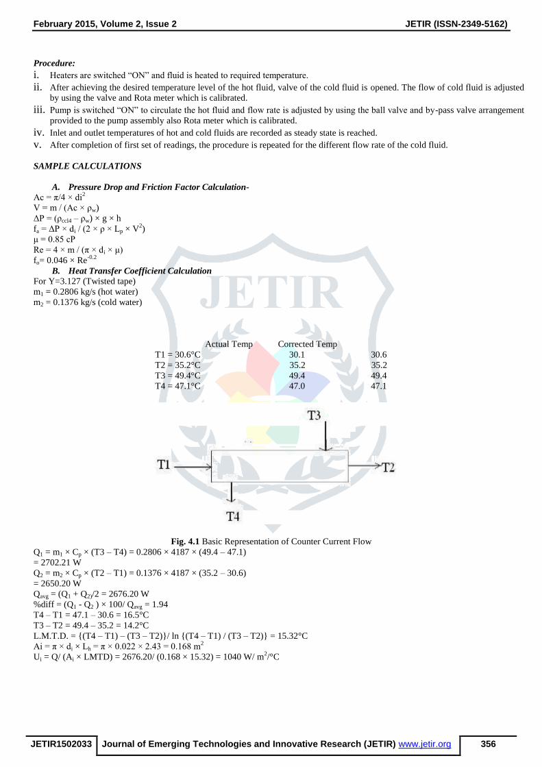
B. Heat Transfer Coefficient Calculation
For Y=3.127 (Twisted tape)
m1 = 0.2806 kg/s (hot water)
m2 = 0.1376 kg/s (cold water)
Actual Temp Corrected Temp
T1 = 30.6°C 30.1 30.6
T2 = 35.2°C 35.2 35.2
T3 = 49.4°C 49.4 49.4
T4 = 47.1°C 47.0 47.1
Fig. 4.1 Basic Representation of Counter Current Flow
Q1 = m1 × Cp × (T3 – T4) = 0.2806 × 4187 × (49.4 – 47.1)
= 2702.21 W
Q2 = m2 × Cp × (T2 – T1) = 0.1376 × 4187 × (35.2 – 30.6)
= 2650.20 W
Qavg = (Q1 + Q2)/2 = 2676.20 W
%diff = (Q1 - Q2 ) × 100/ Qavg = 1.94
T4 – T1 = 47.1 – 30.6 = 16.5°C
T3 – T2 = 49.4 – 35.2 = 14.2°C
L.M.T.D. = {(T4 – T1) – (T3 – T2)}/ ln {(T4 – T1) / (T3 – T2)} = 15.32°C
Ai = π × di × Lh = π × 0.022 × 2.43 = 0.168 m2
Ui = Q/ (Ai × LMTD) = 2676.20/ (0.168 × 15.32) = 1040 W/ m2/°C

February 2015, Volume 2, Issue 2 JETIR (ISSN-2349-5162)
JETIR1502033 Journal of Emerging Technologies and Innovative Research (JETIR) www.jetir.org 357
Fig. 4.2: Relationship between Viscosity & Temperature
μ = 10-11
× T4 - 5 × 10-09
× T3 + 7 × 10-07
× T2 - 5 × 10-05
×T + 0.0018 = 0.000746
Where, T = (T1 + T2)/2 = 32.90°C
Re = 4 × m / (π× di × μ) = 10672
Fig. 4.3: Relationship between Pr & Temperature
Pr = 10-07
× T4 - 4 × 10-05
× T3 + 0.0062 × T2 - 0.4134T + 13.28
= 5.0828 1
𝑈𝑖=
1
ℎ𝑖+
𝑑𝑖
𝑑𝑜 × ℎ𝑜+
𝑋𝑤 × 𝑑𝑖
𝑘𝑤 × 𝑑𝐿+ 𝑅𝑚
This reduces to 1
𝑈𝑖=
1
(ℎ𝑖)𝑒𝑥𝑝+ 𝐾 =
1
𝑐(𝑅𝑒)^0.8+ 𝐾
K is to be found from the Wilson Chart as the intercept on the y-axis

February 2015, Volume 2, Issue 2 JETIR (ISSN-2349-5162)
JETIR1502033 Journal of Emerging Technologies and Innovative Research (JETIR) www.jetir.org 358
Fig. 4.4: Wilson chart for twisted tape insert
K=0.000606 m °C/W
1/ha = (1/Ui) – K = (1/1040) - 0.000606 = 0.0003556
ha = 2811 W/m2/°C
Fig. 4.5: Relationship between kw and Temperature
kw = -9 ×10⁻⁶ × T2+.0021 T+.5568=0.6161 W/m/°C (at T = 32.9°C)
ho = 0.023 × Re0.8
× Pr0.4
× (k/di) = 2061 W/m2/°C
R1 = ha/ ho = 2811/2061 = 1.36
V. RESULTS AND DISCUSSION
From Fig. 5.1 it is observed that hi (expt) and hi (theo) are almost the same in turbulent region. It is also found that from Fig. 5.2,
Nu increases with an increase in Re.

February 2015, Volume 2, Issue 2 JETIR (ISSN-2349-5162)
JETIR1502033 Journal of Emerging Technologies and Innovative Research (JETIR) www.jetir.org 359
Fig 5.1 Heat Transfer Coefficient
Fig 5.2 Nusselt Number
CONCLUSIONS
1. The experimental values of the Nu and h are compared with that of obtained from standard Dittus-Boelter equation. The
graphs shows that, as Re increases the Nu and h increases.
2. Comparing experimental and Dittus-Boelter values of heat transfer coefficient it finds that the difference between these two
values goes on increasing with Reynolds number because at higher flow rate less time is available for heat transfer. VI. NOMENCLATURE:-
Ai -Inside heat transfer surface area, m2
Ac -Cross sectional area, m2
Cp -Specific heat of fluid, J/kg K
di -Inside diameter of the tube, m
0
500
1000
1500
2000
2500
0 2000 4000 6000 8000 10000 12000
h W
/M2
K
Re
Grap h h Vs Re
h_Dittus Boelter h_experimental
0
500
1000
1500
2000
2500
3000
3500
4000
0 2000 4000 6000 8000 10000 12000
Nu
Re
Grap h o f Nu Vs Re
Nu_Dittus Boelter Nu_experimental
February 2015, Volume 2, Issue 2 JETIR (ISSN-2349-5162)
JETIR1502033 Journal of Emerging Technologies and Innovative Research (JETIR) www.jetir.org 360
Gz- Graetz number, dimensionless
h -Difference in level of CCl4 in the manometer, m
hi -Inside htc, W / m2 o C
ha -(expt) Experimental inside htc, W / m2o
C
hi -(theo) Theoretical inside htc, W / m2.o C
ho -Heat transfer coefficient for smooth tube, W / m2 o C
ha -Augmented value of heat transfer coefficient, W / m2 o C
H- Linear distance of the tape for 180° rotation, m.
kw -Thermal conductivity of the tube wall, w/ m °C
Lh -Heat transfer length, m
L.M.T.D- Log mean temperature difference, K
m -Mass flow rate, kg/s
Nu -Nusselt number, dimensionless
Pr -Prandtl number, dimensionless
ΔP -Pressure drop, N/m2
Q -Heat transfer rate, W
Re -Reynolds number
R1- Performance evaluation criteria (ratio of augmented value of heat transfer coefficient to smooth tube heat transfer coefficient
i.e., ha/ho), Dimensionless T Temperature in °C
Ui -Overall htc based on the inside surface area, W / m2.
o C
V -Velocity of water, m/s
Wt- Weight of water taken, kg
Greek letters
ρ- Fluid density in kg/m3
VII. REFERENCES:-
[1] Omkar Shewale, Pravin Mane “Experimental investigation of double pipe heat exchanger with helical fins on the inner
rotating tube” 2014, IJRET, eISSN: 2319-1163 | pISSN: 2321-7308 [2] Proc. Institution of Mechanical Engineers Vol. 218 Part A: Journal of Power and Energy.
[3] Bejan Adrian and Krans Allan. Heat Transfer Handbook.
[4] Bergles, A.E. “Techniques to augment heat transfer.” In Handbook of Heat Transfer Applications (Ed.W.M. Rosenhow),
1985, Ch.3 (McGraw-Hill, NewYork).
[5] Saha, S. K. and Dutta, A. “Thermo-hydraulic study of laminar swirl flow through a circular tube fitted with twisted
tapes.” Trans. ASME, J. Heat Transfer, 2001, 123, 417–421.
[6] Manglik, R. M. and Bergles, A. E. “Heat transfer and pressure drop correlations for twisted tape insert in isothermal
tubes.” Part 1: laminar flows. Trans. ASME, J. Heat Transfer, 1993, 116, 881–889.
[7] AGARWAL, S. K. and RAJA RAO, M. “Heat transfer augmentation for the flow of a viscous liquid in circular tubes
using twisted tape inserts.” Int. J. Heat Mass Tranffer. 1996, 39, 3547-3557.
[8] Promvonge, P. “Heat transfer behaviors in round tube with conical ring inserts” Energ Convers Manage, 2007.
[9] Sivashanmugam, P. and Suresh, S. “Experimental studies on heat transfer and friction factor characteristics of turbulent
flow through a circular tube fitted with regularly spaced helical screw tape inserts”, Advances in Energy Research, 2006.
[10] Douglas W. P. smith, “United States patent- High Viscous Fluid Heat Exchanger”, Patent no. 5,165,469, date of patent:
Nov. 24, 1992.
[11] Eissa M., Ahmad S., “Forced convection heat transfer of Robertson–Stiff fluid between two coaxial rotating cylinders”,
International Communications in Heat and Mass Transfer 26 (1999) 695–704.
[12] Khellaf K., Lauriat G., “Numerical study of heat transfer in a non-Newtonian Carreau-fluid between rotating concentric
vertical cylinders”, Journal of Non-Newtonian Fluid Mechanics 89 (2000) 45–61.
[13] Zhengguo Zhang, Dabin Ma, Xiaoming Fang, Xuenong Gao, “Experimental and numerical heat transfer in a helically
baffled heat exchanger combined with one three-dimensional finned tube”, Chemical Engineering and Processing 47
(2008) 1738–1743, 2008.
[14] Hans Georg Zimmermann, Wiesbaden Biebrich, Dolf Schafer, “Screw Heat Exchanger”, United State Patent (Patent No.
3255814), June 1966.
[15] A. Dewan, P. Mahanta, K. Sumithra Raju, P. Suresh Kumar, Review of passive heat transfer augmentation techniques, J.
Power Energy 218 (2004) 509–525.
[16] Amoura M., Zeraibi N., Smati A., gareche M., “Finite element study of mixed convection for non-Newtonian fluid
between two coaxial rotating cylinders”, International Communications in Heat and Mass Transfer 33 (2006) 780-789.
[17] Nobari M.R.H., Gharali K., “A numerical study of flow and heat transfer in internally finned rotating straight pipes and
stationary curved pipes”, International journal of and Mass Transfer 49 (2006) 1158-1194.
[18] S. Eiamsa-ard, C. Thianpong, P. Promvonge, Experimental investigation of heat transfer and flow friction in a circular
tube fitted with regularly spaced twisted tape elements, Int. Commun. Heat Mass Transfer 33 (2006) 1225–1233.
[19] Herbert Ocker, “Screw Type Heat Exchanger”, United State Patent (Patent No. 3688837), Sept. 1972.

February 2015, Volume 2, Issue 2 JETIR (ISSN-2349-5162)
JETIR1502033 Journal of Emerging Technologies and Innovative Research (JETIR) www.jetir.org 361
[20] Haifa El-Sadi, Nabil Esmail, Andreas K. Athienitis, “High Viscous Liquids as a Source in Micro-Screw Heat Exchanger:
Fabrication, Simulation and Experiments”, Microsystem Technologies, Vol. 13, 11-12, pp. 1581-1587, 2007
[21] Li Zhang, Hongmei Guo, Jianhua Wu, Wenjuan Du, “Compound Heat Transfer Enhancement for Shell Side of Double-
Pipe Heat Exchanger by Helical Fins and Vortex Generators”, Heat Mass Transfer, Vol. 48, pp. 1113 – 1124, 2012.
[22] M. Hojjat, S. Gh. Etemad, R. Bagheri, J. Thibault, “Convective Heat Transfer ofNon-Newtonian Nano fluids Through a
Uniformly Heated Circular Tube”, International Journal of Thermal Sciences, Vol. 50, pp. 525-531, 2011.