review of raaf procedures for qualifying bonded repair technicians · similar mechanical properties...
TRANSCRIPT
Review of RAAF Procedures for Qualifying Bonded
Repair Technicians
Andrew Rider, Roger Vodicka, Gary Mathys* and Ivan Stoyanovski
Air Vehicles Division
*Maritime Platforms Division
Defence Science and Technology Organisation
DSTO-TR-1876
ABSTRACT
DSTO has recently undertaken a review of procedures employed by the Royal Australian Air Force (RAAF) Bonded Structures and Testing Team (BSTT) during testing and requalification of technicians who undertake bonded repairs on ADF aircraft. Currently, technicians are required to produce a bonded wedge test under examination from BSTT staff and, based on adherence to the current RAAF Engineering Standard, will be considered competent to undertake bonded repairs. From December 2001 to January 2004 a notable deterioration in the quality of the bonded wedge tests produced through qualification testing was observed and an audit of processes was undertaken to determine if any areas in the bonding and requalification testing may have been leading to the deterioration in quality. Based on an audit of the processes and subsequent experimental testing at DSTO, recommendations on improvements to bonding procedures have been made.
RELEASE LIMITATION
Approved for public release
Published by DSTO Defence Science and Technology Organisation 506 Lorimer St Fishermans Bend, Victoria 3207 Australia Telephone: (03) 9626 7000 Fax: (03) 9626 7999 © Commonwealth of Australia 2006 AR-013-677 June 2006 APPROVED FOR PUBLIC RELEASE
Review of RAAF Procedures for Qualifying
Bonded Repair Technicians
Executive Summary The Bonded Structures Testing Team (BSTT) at the Royal Australian Air Force (RAAF) base Amberley are responsible for training and qualifying all technicians who perform bonded repairs on Australian Defence Force (ADF) aircraft using RAAF engineering standard DEFAUST 9005-A and the associated document AAP 7021.016-2. Qualification of bonding technicians involves the technician performing a wedge test under supervision from BSTT staff, who observe each of the steps in the surface treatment of the Al-2024T3 clad plates bonded with FM-300 adhesive. In the early part of 2003 it became apparent that although a number of technicians were correctly following the procedures detailed in AAP 7021.016-2, the wedge test results were not passing examination. They were exceeding the crack growth and cohesive failure limits specified in the standard. BSTT and ASI requested that DSTO investigate the bonding procedures employed during qualification to determine if there was a discernible cause for the deterioration in the wedge test results. DSTO staff have undertaken a number of investigations since October 2003. The investigations have included a visit to the BSTT bonding facility to review procedures and infrastructure. Additionally, post-failure examination of available wedge test specimens from BSTT qualification testing was carried out from December 2001 to January 2004. This report details the findings of the investigations of the BSTT bonding operations and wedge samples from BSTT qualification testing and provides a number of recommendations that will assist in improving the quality control of the current surface treatment procedures being employed. It is anticipated that recommendations will be incorporated in the RAAF engineering standard and, together with development of statistical analysis procedures, should provide a more robust system for maintaining the quality of bonded repairs performed by the RAAF and other areas of defence. It is also anticipated that implementation of ongoing statistical analysis of wedge test qualification will provide rapid feedback for RAAF on any deviations from optimum performance and enable short response times to remedy problems that can develop in bonding operations. Amongst the recommendations of the report are the implementation of a quality control tool that monitors wedge test quality and provides a plot of wedge test results with time, the use of a gloss meter to measure grit-blast quality objectively and the use of epoxy silane kits to reduce the risks of contamination and incorrect mixing ratios of chemicals during surface treatment.
Authors Andrew Rider Air Vehicles Division Andrew Rider joined DSTO in 1988. He has a PhD in Physical Chemistry from the University of New South Wales and is currently employed as a Senior Research Scientist with Air Vehicles Division. He is involved in research to support RAAF maintenance of bonded structure and application of composite repairs used on ADF aircraft.
________________________________________________ Roger Vodicka Air Vehicles Division
Roger Vodicka graduated BSc. (Hons.) from Monash University and joined DSTO in 1990. He currently works in the area of life cycle costing, assessing the main cost drivers in maintenance of current fleets and estimating costs associated with future acquisitions.
________________________________________________ Gary Mathys Maritime Platforms Division Gary Mathys graduated with a Bachelor of Applied Science from Deakin University in 1980. He also has completed an Associate Diploma of Engineering (Plastics) at the Royal Melbourne Institute of Technology. In 1980 he joined the Platforms Sciences Laboratory and is involved in the characterisation of organic materials of defence significance. He currently is managing the molecular spectroscopy (infrared, raman and UV-Visible spectroscopy) and thermal analysis facility.
________________________________________________ Ivan Stoyanovski Air Vehicles Division
Ivan Stoyanovski currently is a Senior Technician in the Composites Group within Air Vehicles Division. He has extensive experience in composite manufacturing and has applied several bonded composite repairs to military aircraft.
________________________________________________

Contents GLOSSARY
1. INTRODUCTION ............................................................................................................... 1
2. SURFACE TREATMENT AND WEDGE TESTING .................................................... 1 2.1 Surface treatment ...................................................................................................... 1 2.2 Wedge test preparation and testing....................................................................... 2 2.3 Failure analysis and wedge test inspection ......................................................... 4
2.3.1 Wedge Test Inspection and Data Collection.......................................... 4 2.3.2 Grit-blast surface inspection .................................................................... 7 2.3.3 Surface analysis of failed BSTT wedge samples.................................... 8
2.4 Quality control .......................................................................................................... 8 2.4.1 Quality control of grit-blasting................................................................ 8 2.4.2 Fourier transform infra-red analysis of epoxy silane ........................... 9 2.4.3 Epoxy silane kits for transport, control and improved sensitivity..... 9
2.5 BSTT bonding facility site visit by DSTO......................................................... 10 2.6 Surface treatment sensitivity studies .................................................................. 11
3. RESULTS 11 3.1 BSTT qualification- wedge test inspection........................................................ 11 3.2 Surface analysis of failed wedge samples.......................................................... 16
3.2.1 XPS analysis ............................................................................................. 16 3.3 Quality control of metal surface treatments ...................................................... 18
3.3.1 Colour meter measurements for grit-blast severity............................ 18 3.3.2 Gloss-meter measurements for grit-blast severity.............................. 19 3.3.3 Wedge test performance resulting from use of epoxy silane kits..... 20
3.4 BSTT bonding facility site visit by DSTO......................................................... 22 3.4.1 Bonding facilities ..................................................................................... 22 3.4.2 Environment............................................................................................. 23 3.4.3 Sample collection..................................................................................... 24 3.4.4 Wedge test manufacture and observations of BSTT and DSTO bonding procedures................................................................................................ 24
3.5 Infrared analysis of epoxy silane ( γ-GPS) ......................................................... 27 3.6 Wedge test sensitivity studies .............................................................................. 28
4. DISCUSSION..................................................................................................................... 30 4.1 BSTT Qualification- wedge test inspection....................................................... 30
4.1.1 Failure rates and effects of grit-blast and adhesive age ..................... 30 4.1.2 Failure analysis ........................................................................................ 32 4.1.3 Quality control ......................................................................................... 32 4.1.4 BSTT bonding facility site visit .............................................................. 33 4.1.5 Wedge test sensitivity studies ............................................................... 35
5. CONCLUSIONS ................................................................................................................ 37
6. RECOMMENDATIONS .................................................................................................. 38
7. REFERENCES..................................................................................................................... 40

APPENDIX A: INFRARED ANALYSIS OF EPOXY SILANE (γ-GPS) ...................... 41
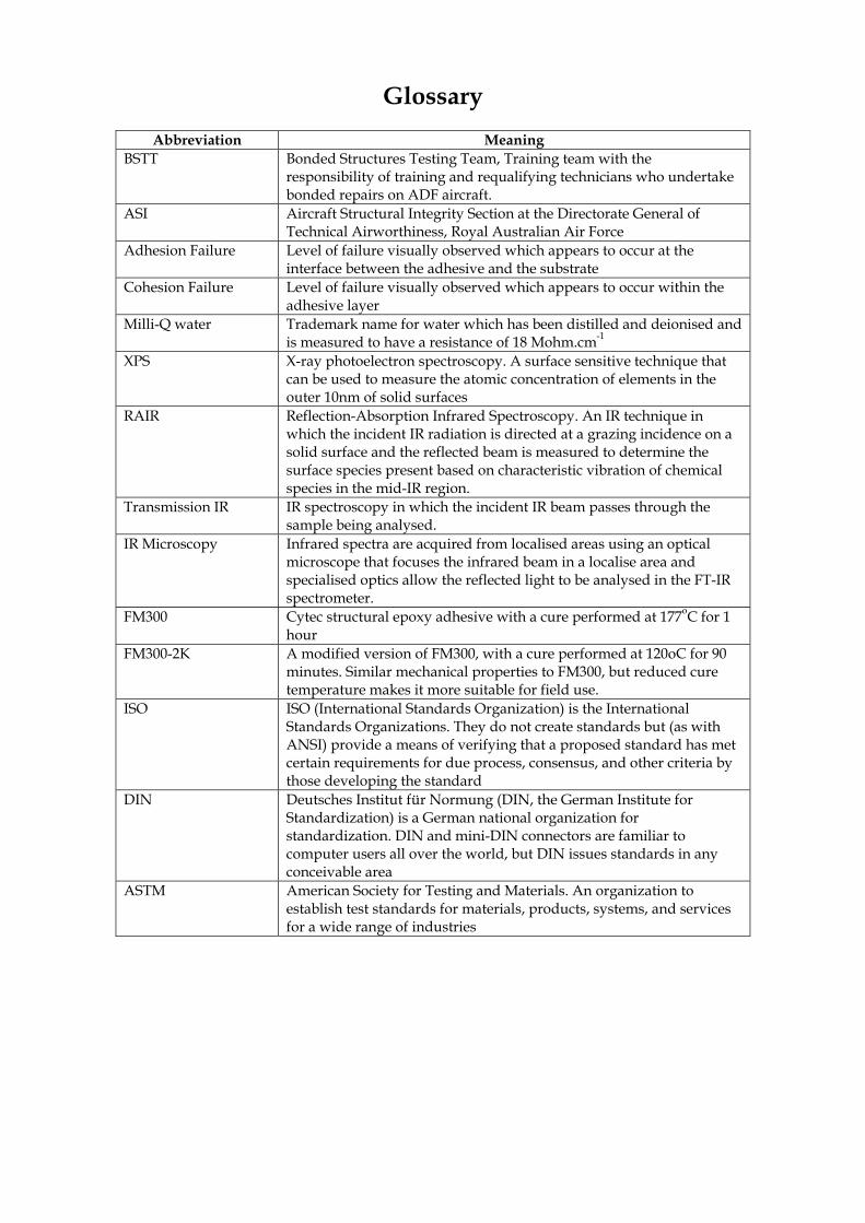
Glossary
Abbreviation Meaning BSTT Bonded Structures Testing Team, Training team with the
responsibility of training and requalifying technicians who undertake bonded repairs on ADF aircraft.
ASI Aircraft Structural Integrity Section at the Directorate General of Technical Airworthiness, Royal Australian Air Force
Adhesion Failure Level of failure visually observed which appears to occur at the interface between the adhesive and the substrate
Cohesion Failure Level of failure visually observed which appears to occur within the adhesive layer
Milli-Q water Trademark name for water which has been distilled and deionised and is measured to have a resistance of 18 Mohm.cm-1
XPS X-ray photoelectron spectroscopy. A surface sensitive technique that can be used to measure the atomic concentration of elements in the outer 10nm of solid surfaces
RAIR Reflection-Absorption Infrared Spectroscopy. An IR technique in which the incident IR radiation is directed at a grazing incidence on a solid surface and the reflected beam is measured to determine the surface species present based on characteristic vibration of chemical species in the mid-IR region.
Transmission IR IR spectroscopy in which the incident IR beam passes through the sample being analysed.
IR Microscopy Infrared spectra are acquired from localised areas using an optical microscope that focuses the infrared beam in a localise area and specialised optics allow the reflected light to be analysed in the FT-IR spectrometer.
FM300 Cytec structural epoxy adhesive with a cure performed at 177oC for 1 hour
FM300-2K A modified version of FM300, with a cure performed at 120oC for 90 minutes. Similar mechanical properties to FM300, but reduced cure temperature makes it more suitable for field use.
ISO ISO (International Standards Organization) is the International Standards Organizations. They do not create standards but (as with ANSI) provide a means of verifying that a proposed standard has met certain requirements for due process, consensus, and other criteria by those developing the standard
DIN Deutsches Institut für Normung (DIN, the German Institute for Standardization) is a German national organization for standardization. DIN and mini-DIN connectors are familiar to computer users all over the world, but DIN issues standards in any conceivable area
ASTM American Society for Testing and Materials. An organization to establish test standards for materials, products, systems, and services for a wide range of industries

DSTO-TR-1876
1
1. Introduction
The Bonded Structures Testing Team (BSTT) at the Royal Australian Air Force (RAAF) base Amberley are responsible for training and qualifying all technicians who perform bonded repairs on ADF aircraft using RAAF engineering standard DEFAUST 9005-A [1] and the associated document AAP 7021.016-2 [2]. Qualification of bonding technicians involves performing a wedge test under supervision from BSTT staff, who observe each of the steps involved in the surface treatment of the Al-2024T3 clad plates bonded with FM-300 adhesive. In the early part of 2003 it became apparent that a number of technicians were correctly following the procedures detailed in AAP 7021.016-2, however, the wedge test results were not passing, based on the crack growth and cohesive failure limits specified in the standard. BSTT and ASI requested that DSTO investigate the bonding procedures employed during qualification to determine if there was a discernible cause for the deterioration in the wedge test results. DSTO staff have undertaken a number of investigations since October 2003. The investigations have included a visit to the BSTT bonding facility to review procedures and infrastructure. Additionally, post -failure examination of available wedge test specimens from BSTT qualification testing was carried out from December 2001 to January 2004. The following report details the findings of the investigations of the BSTT bonding operations and wedge samples from BSTT qualification testing and provides a number of recommendations that will assist in improving the quality control of the current surface treatment procedures being employed. It is anticipated that recommendations be incorporated in the RAAF engineering standard and, together with development of statistical analysis procedures, should provide a more robust system for maintaining the quality of bonded repairs performed by RAAF and other areas of defence. It is also anticipated that implementation of ongoing statistical analysis of wedge test qualification will provide rapid feedback for RAAF on any deviations from optimum performance and enable short response times to remedy problems that can develop in the bonding operations.
2. Surface treatment and wedge testing
2.1 Surface treatment
The recommended surface treatment for epoxy adhesive bonding to aluminium is detailed in AAP 7021.016-2 [2]. The procedure involves the following:
1) solvent wiping: single wiping of the aluminium surface using methyl ethyl ketone (MEK) soaked lanoline and lint free tissues. A fresh tissue is used after each pass. Single wiping is conducted along the grain direction and at 900 relative to the grain until no observable debris or staining of the tissue can be observed,

DSTO-TR-1876
2
2) Scotchbrite® abrasion with MEK: following solvent wiping the surface is abraded with the Scotchbrite® pad soaked in MEK along the grain direction and at 900 relative to the grain until a uniform surface appearance is observed. Single wiping of the aluminium surface then uses MEK soaked lanoline and lint free tissues. A fresh tissue is used after each pass. Wiping is conducted in the direction of the abrasion until no presence of debris or staining of the tissue can be observed.
3) Scotchbrite® abrasion with deionised water: following step 2, the surface is abraded with the Scotchbrite® pad soaked in deionised water along the grain direction and at 900 relative to the grain until a uniform surface appearance is observed. Single wiping of the aluminium surface then uses deionised water soaked lanoline and lint free tissues. A fresh tissue is used after each pass. Wiping is conducted in the direction of the abrasion until no presence of debris or staining of the tissue can be observed.
4) Water-break testing: The surface is water-break tested by thoroughly wetting the surface prepared in 3) with deionised water and observing that no areas are free of water. The surface is then gradually dried using a hot air gun and moisture should evaporate in a uniform manner without any water-breaks. If water-break areas are present steps 1)-3) must be repeated.
5) Drying: The surface is dried in an oven at 1100C for 5 minutes prior to grit-blasting,
6) Grit-blasting: uniform grit-blasting of the surface employs 50 μm alumina grit and dry nitrogen propellant with a pressure of 450kPa and a working distance of 15 to 20cm
7) Silane treatment: a 1% aqueous solution of γ-glycidoxypropyltrimethoxysilane (γ-GPS) is stirred for 1 hour prior to commencing the surface pre-treatment steps listed above. Distilled water is used to prepare the silane solution. The grit-blasted aluminium surface is “immersed” in the silane solution for 15 minutes by applying the solution regularly to the aluminium surface from clean lanoline and lint free tissues. The surface is then allowed to drain free of excess solution, followed by drying in an 1100C oven for 60 minutes.
2.2 Wedge test preparation and testing
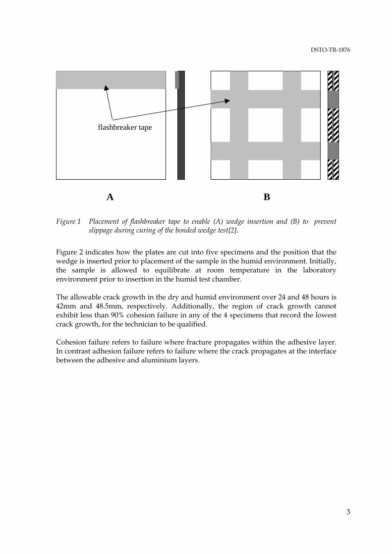
Wedge tests are constructed from 0.125 inch Al-2024 T3 clad alloy using FM300 adhesive in a configuration shown in Figure 1 [2]. FM300 is placed between two plates prepared using the method described in section 2.1 and cured at 177oC for 90 minutes using a ramp rate of 3oC per minute. The vacuum of 30 inches of mercury is reduced to 10 inches of mercury when the heat-up temperature reaches 130oC.
DSTO-TR-1876
3
B A
flashbreaker tape
Figure 1 Placement of flashbreaker tape to enable (A) wedge insertion and (B) to prevent slippage during curing of the bonded wedge test[2].
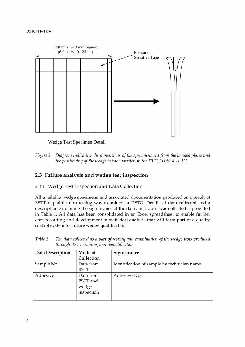
Figure 2 indicates how the plates are cut into five specimens and the position that the wedge is inserted prior to placement of the sample in the humid environment. Initially, the sample is allowed to equilibrate at room temperature in the laboratory environment prior to insertion in the humid test chamber. The allowable crack growth in the dry and humid environment over 24 and 48 hours is 42mm and 48.5mm, respectively. Additionally, the region of crack growth cannot exhibit less than 90% cohesion failure in any of the 4 specimens that record the lowest crack growth, for the technician to be qualified. Cohesion failure refers to failure where fracture propagates within the adhesive layer. In contrast adhesion failure refers to failure where the crack propagates at the interface between the adhesive and aluminium layers.
DSTO-TR-1876
4
Wedge Test Specimen Detail
Pressure Sensitive Tape
150 mm +/- 3 mm Square (6.0 in. +/- 0.125 in.)
Figure 2 Diagram indicating the dimensions of the specimens cut from the bonded plates and the positioning of the wedge before insertion in the 50oC, 100% R.H. [2].
2.3 Failure analysis and wedge test inspection
2.3.1 Wedge Test Inspection and Data Collection
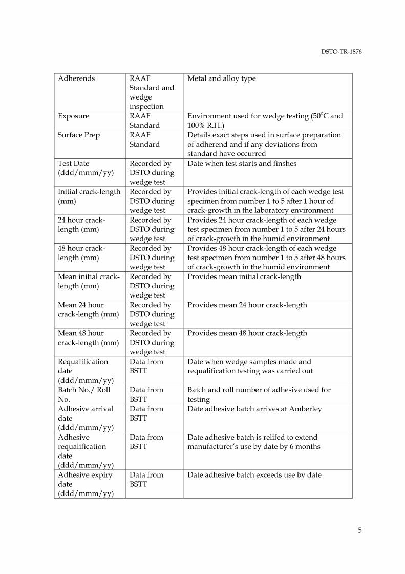
All available wedge specimens and associated documentation produced as a result of BSTT requalification testing was examined at DSTO. Details of data collected and a description explaining the significance of the data and how it was collected is provided in Table 1. All data has been consolidated in an Excel spreadsheet to enable further data recording and development of statistical analysis that will form part of a quality control system for future wedge qualification.
Table 1 The data collected as a part of testing and examination of the wedge tests produced through BSTT training and requalification
Data Description Mode of Collection
Significance
Sample No Data from BSTT
Identification of sample by technician name
Adhesive Data from BSTT and wedge inspection
Adhesive type
DSTO-TR-1876
5
Adherends RAAF Standard and wedge inspection
Metal and alloy type
Exposure RAAF Standard
Environment used for wedge testing (50oC and 100% R.H.)
Surface Prep RAAF Standard
Details exact steps used in surface preparation of adherend and if any deviations from standard have occurred
Test Date (ddd/mmm/yy)
Recorded by DSTO during wedge test
Date when test starts and finshes
Initial crack-length (mm)
Recorded by DSTO during wedge test
Provides initial crack-length of each wedge test specimen from number 1 to 5 after 1 hour of crack-growth in the laboratory environment
24 hour crack-length (mm)
Recorded by DSTO during wedge test
Provides 24 hour crack-length of each wedge test specimen from number 1 to 5 after 24 hours of crack-growth in the humid environment
48 hour crack-length (mm)
Recorded by DSTO during wedge test
Provides 48 hour crack-length of each wedge test specimen from number 1 to 5 after 48 hours of crack-growth in the humid environment
Mean initial crack-length (mm)
Recorded by DSTO during wedge test
Provides mean initial crack-length
Mean 24 hour crack-length (mm)
Recorded by DSTO during wedge test
Provides mean 24 hour crack-length
Mean 48 hour crack-length (mm)
Recorded by DSTO during wedge test
Provides mean 48 hour crack-length
Requalification date (ddd/mmm/yy)
Data from BSTT
Date when wedge samples made and requalification testing was carried out
Batch No./ Roll No.
Data from BSTT
Batch and roll number of adhesive used for testing
Adhesive arrival date (ddd/mmm/yy)
Data from BSTT
Date adhesive batch arrives at Amberley
Adhesive requalification date (ddd/mmm/yy)
Data from BSTT
Date adhesive batch is relifed to extend manufacturer’s use by date by 6 months
Adhesive expiry date (ddd/mmm/yy)
Data from BSTT
Date adhesive batch exceeds use by date

DSTO-TR-1876
6
Silane Batch No. Data from BSTT
Epoxy silane coupling agent batch number from manufacturer
Water break drying temperature
Data from BSTT
Temperature metal plates dried at after water break testing
Silane Drying Temperature
Data from BSTT
Temperature metal plates dried at after being treated with the 1% epoxy silane solution
Temperature (oC) Data from BSTT
Temperature in Bonding facility during wedge test manufacturing
Humidity (%) Data from BSTT
Relative Humidity in Bonding facility during wedge test manufacturing
Cohesion (%) Recorded by DSTO during wedge test
Percentage of cohesion failure observed visually on the fracture surfaces of the wedge test specimens from number 1 to 5 by technician examining failure surfaces
Grouping Recorded by DSTO during wedge test
The group number based on the date of receipt and testing of wedge samples from BSTT at DSTO.
Supervisor Data from BSTT
Name of the BSTT Supervisor examining the technicians during wedge test requalification
Unit Data from BSTT
Location of company or unit of technician being tested
Organisation Data from BSTT
Affiliation of technician
Course Data from BSTT
Course number attended by technician for training prior to wedge qualification
Service No. Data from BSTT
Service number of technician be tested
Test Site Data from BSTT
Location at which the testing occurred
Name Data from BSTT
Full name and rank (if applicable) of technician being tested
Pass/Fail Recorded by DSTO during wedge test
Pass or fail of the wedge samples as determined by the technician testing BSTT specimens
Grit-blast level Recorded by DSTO during wedge test
Assessment of the quality of the grit-blast based on 10X digital image acquired from non-bonded area of wedge sample
Large Void (%) Recorded by DSTO during wedge test
Provides visual assessment of area of each wedge test specimen from number 1 to 5 containing largely voided regions
Small Voids (%) Recorded by DSTO during wedge test
Provides visual assessment of area of each wedge test specimen from number 1 to 5 containing sub-millimetre voided regions

DSTO-TR-1876
7
Adhesion Failure1 (%)
Recorded by DSTO during wedge test
Percentage of adhesion failure observed visually on the fracture surfaces of the wedge test specimens from number 1 to 5 by DSTO scientist examining failure surfaces
Comments Recorded by DSTO during wedge test
Unique elements of wedge test sample or group that distinguish or clarify results
2.3.2 Grit-blast surface inspection
All wedge samples recovered from BSTT were photographed using a Cannon EOS D60 digital camera with a 100mm macro lens, operating with aperture priority (AE) mode and an aperture setting of 16 to provide sufficient depth of field for the grit-blasted images being examined. Exposure time, using the natural fluorescent lighting of the laboratory, was typically 6 seconds.
6mm
0 1 2
3 4
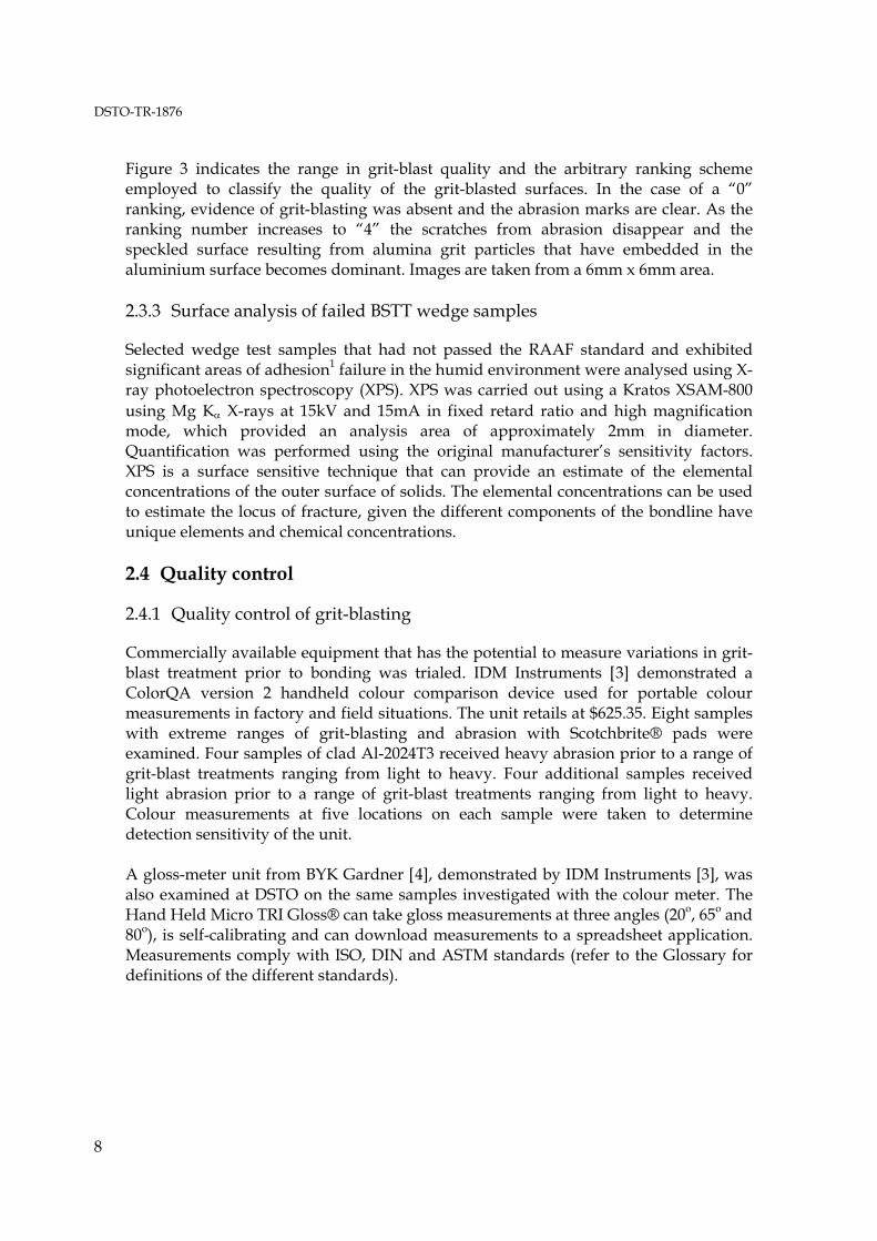
Figure 3 Grit-blast images indicating the scale used to grade the quality of grit-blast achieved on the BSTT requalification wedge test samples, where 0 is poor and 4 is satisfactory
1 Refer to Glossary for description of Adhesion and Cohesion failure.
DSTO-TR-1876
8
Figure 3 indicates the range in grit-blast quality and the arbitrary ranking scheme employed to classify the quality of the grit-blasted surfaces. In the case of a “0” ranking, evidence of grit-blasting was absent and the abrasion marks are clear. As the ranking number increases to “4” the scratches from abrasion disappear and the speckled surface resulting from alumina grit particles that have embedded in the aluminium surface becomes dominant. Images are taken from a 6mm x 6mm area. 2.3.3 Surface analysis of failed BSTT wedge samples
Selected wedge test samples that had not passed the RAAF standard and exhibited significant areas of adhesion1 failure in the humid environment were analysed using X-ray photoelectron spectroscopy (XPS). XPS was carried out using a Kratos XSAM-800 using Mg Kα X-rays at 15kV and 15mA in fixed retard ratio and high magnification mode, which provided an analysis area of approximately 2mm in diameter. Quantification was performed using the original manufacturer’s sensitivity factors. XPS is a surface sensitive technique that can provide an estimate of the elemental concentrations of the outer surface of solids. The elemental concentrations can be used to estimate the locus of fracture, given the different components of the bondline have unique elements and chemical concentrations. 2.4 Quality control
2.4.1 Quality control of grit-blasting
Commercially available equipment that has the potential to measure variations in grit-blast treatment prior to bonding was trialed. IDM Instruments [3] demonstrated a ColorQA version 2 handheld colour comparison device used for portable colour measurements in factory and field situations. The unit retails at $625.35. Eight samples with extreme ranges of grit-blasting and abrasion with Scotchbrite® pads were examined. Four samples of clad Al-2024T3 received heavy abrasion prior to a range of grit-blast treatments ranging from light to heavy. Four additional samples received light abrasion prior to a range of grit-blast treatments ranging from light to heavy. Colour measurements at five locations on each sample were taken to determine detection sensitivity of the unit. A gloss-meter unit from BYK Gardner [4], demonstrated by IDM Instruments [3], was also examined at DSTO on the same samples investigated with the colour meter. The Hand Held Micro TRI Gloss® can take gloss measurements at three angles (20o, 65o and 80o), is self-calibrating and can download measurements to a spreadsheet application. Measurements comply with ISO, DIN and ASTM standards (refer to the Glossary for definitions of the different standards).

DSTO-TR-1876
9
2.4.2 Fourier transform infra-red analysis of epoxy silane
Aluminium treated with a 1% aqueous solution of epoxy silane (γ-GPS) was analysed using Reflection-Absorption Infrared2 (RAIR). Spectra were collected using a grazing angle bench that enabled the beam to be focussed on the sample at 800 relative to the surface normal. The reflected beam was recorded with a 4cm-1 resolution and averaged over 256 scans. Transmission infrared2 spectra of neat γ-GPS were also recorded using a long path length cell. γ-GPS was analysed from three batches. A batch received from BSTT Amberley that was being used in current wedge test qualifications, a fresh sample purchased from Sigma-Aldrich chemical company and an aged sample that was at least 6 years old and hand been stored in a laboratory environment. RAIR studies required that the Al-2024 T3 clad aluminium sample be polished metallographically to a 1μm finish, followed by treatment for 15 minutes in a 65oC chromic acid etch (CAE) solution, followed by tap and de-ionised water rinsing. The CAE solution had the following composition (g dm-3): Na2Cr2O7.2H2O (60), H2SO4 (318), Al-2024 T3 aluminium (1.3), de-ionised water (balance) [5]. Following rinsing the sample was dipped in the 1% aqueous γ-GPS solution for 10 minutes, removed and blown dry with a stream of high purity nitrogen and analysed in the spectrometer. A CAE treated Al-2024 T3 clad aluminium sample was also analysed to provide the spectrum that was used for background subtraction. 2.4.3 Epoxy silane kits for transport, control and improved sensitivity
Kits containing epoxy silane, 0.1% acetic acid and distilled deionised water were prepared to determine if RAAF could implement a central store for dispensing epoxy silane in a form that would improve traceability of the chemicals used in the process. It was also hoped that the kits would reduce the amount of equipment and material needed to be transported by BSTT when travelling to ADF bases for requalification testing. Acetic acid was incorporated into the kits to ensure the pH of the silane solution was acidic and, therefore, optimised for hydrolysis of the silane. Hydrolysis is critical for successful deposition of the silane films as it ensures that silanol groups can form and then react with the metal substrate and/or cross-link to form a hydrolytically stable film. Experiments involved cleaning and the measuring out of epoxy-silane, acetic acid and distilled and deionised water into Nalgene containers as detailed below: Water-Nalgene® 500mL Wide Mouth HDPE Bottles (Catalogue No. 21040016)
• Rinse with AR grade MEK (attach lid and shake) • Rinse with distilled water (attach lid and shake) • Fill with boiling distilled water and empty (attach lid and shake)
2 Refer Glossary for definition of RAIR and transmission IR.
DSTO-TR-1876
10
• Fill with Milli-Q3 water (490mL) Epoxy Silane-Nalgene® 15mL LDPE Dropper Bottles (Catalogue No. 21040016)
• Rinse with AR grade MEK • Rinse with distilled water • Fill with 80oC distilled water and empty • Dry in oven at 70oC (upside down to sure all moisture drains) for 1 hour • Allow to cool to room temperature • Pipette out 5g of epoxy silane into the dropper bottle using a micro-balance.
0.1% Acetic Acid-Nalgene® 15mL LDPE Dropper Bottles (Catalogue No. 21040016)
• In a clean 2L beaker, measure out 1L of Milli-Q water • Add 50g of Glacial Acetic Acid and mix using magnetic stirrer • Pipette out 10mL into the cleaned dropper bottles using a micro-balance.
Aging Studies of Nalgene Containers
• Place water, epoxy silane and acetic acid containers in oven at 50oC and remove at 1 week, 1 month, 3 months, 6 months and 12 months and produce a wedge test using the grit-blast and silane process (sec. 2.1) and FM-300 adhesive. Also analyse epoxy silane using the techniques detailed in section 2.4.2.
Additionally, a kit of epoxy silane was posted to BSTT for trial. Feedback regarding use of the kit was provided to DSTO and a wedge test specimen fabricated at BSTT using the kit was tested to verify laboratory results. 2.5 BSTT bonding facility site visit by DSTO
Ivan Stoyanovski from DSTO visited BSTT at RAAF base Amberley to review facilities and procedures at the bonding facility. The major objectives of the visit were to:
1) identify any variations in the bonding procedures conducted at BSTT with those at DSTO
2) assess the bonding facilities and storage and identify any variations from specifications detailed in AAP 7021.016-2
3) determine if any significant changes in processes or materials may have occurred around the period when wedge test failures increased
4) manufacture a wedge test alongside a BSTT instructor and examine results. 5) Collect samples of materials used in the bonding operations and analyse for
potential contaminants at DSTO
3 Refer to Glossary for definition of Milli-Q water
DSTO-TR-1876
11
2.6 Surface treatment sensitivity studies
A series of wedge tests were manufactured at DSTO, Melbourne, to examine the influence of extreme deviations in process and the crack-growth levels expected. The wedge tests examined the influence of silicone contaminant in the bonding environment, absence of grit-blast, Scotcbrite abrasion and detritus removal after abrasion on crack growth and failure modes. The results are intended to provide an indication of which steps in the bonding process have the biggest effect on crack growth and failure mode. All wedges were manufactured using Al-2024T3 clad aluminium and FM-300.
3. Results
3.1 BSTT qualification- wedge test inspection
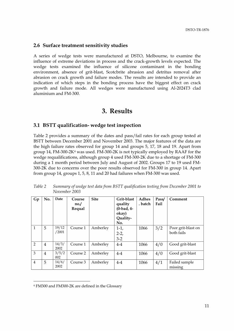
Table 2 provides a summary of the dates and pass/fail rates for each group tested at BSTT between December 2001 and November 2003. The major features of the data are the high failure rates observed for group 14 and groups 5, 17, 18 and 19. Apart from group 14, FM-300-2K4 was used. FM-300-2K is not typically employed by RAAF for the wedge requalifications, although group 4 used FM-300-2K due to a shortage of FM-300 during a 1 month period between July and August of 2002. Groups 17 to 19 used FM-300-2K due to concerns over the poor results observed for FM-300 in group 14. Apart from group 14, groups 1, 5, 8, 11 and 20 had failures when FM-300 was used.
Table 2 Summary of wedge test data from BSTT qualification testing from December 2001 to November 2003
Gp No. Date Course no./
Requal
Site Grit-blast quality (0-bad, 4-okay) Quality- No.
Adhes. batch
Pass/Fail
Comment
1 5 19/12/2001
Course 1 Amberley 1-1, 2-2, 3-2
1066 3/2 Poor grit-blast on both fails
2 4 14/3/2002
Course 1 Amberley 4-4 1066 4/0 Good grit-blast
3 4 3/5/2002
Course 2 Amberley 4-4 1066 4/0 Good grit-blast
4 5 14/6/2002
Course 3 Amberley 4-4 1066 4/1 Failed sample missing
4 FM300 and FM300-2K are defined in the Glossary

DSTO-TR-1876
12
5 4 25/7/2002
Course 4 Amberley 3-3 N/A 1/3 FM300-2K used
6 4 5/9/2002
Course 5 Amberley 4-4 1082 4/0 Good grit-blast
7 3 17/10/2002
Course 6 Amberley 3-1 4-2
1082 3/0 grit-blast okay
8 4 31/10/2002
requal Amberley 0-1 3-1 4-2
1082 3/1 Bad grit-blast on failed sample
9 18 13-28 /11/ 2002
3 from Course 7, remainder requal
Amberley 3-4 4-15
1082 19/0 3 tests marginal pass
10 2 15/1/2003
requal Amberley 4-2 1082 2/0 Good grit-blast
11 3 27/2/2003
Course 8 Amberley 2-2 4-1
1082 1/2 poor grit-blast on failed samples
12 9 1-10 /4/ 2003
requal Nowra and William-town
3-4 4-5
1082 9/0 Good group, very low adhesive failure
13 4 22-5-2003
Course 9 Amberley 4-4 1082 4/0 Good grit-blast, low adhesion failure
14 13 11-18 /6/2003
requal Edinburgh 1-2 3-1 4-10
1082 6/7 2 failures associated with bad grit-blasting. 4 failures had good grit-blast Low voiding may suggest light abrade
15 4 16/7/2003
Course 10 Amberley 3-2 4-2
1082 4/0 Grit-blast okay, no adhesion failure
16 3 13/8/2003
requal Tindal 3-3 1082? 3/0 1 result marginal pass, with high adhesion failure. Low voiding may suggest light abrade
17 3 15/9/2003
requal Townsville 3-1 4-2
N/A 1/2 FM300-2K used
18 4 25/9/2003
Course 11 Amberley 4-4 N/A 1/3 FM300-2K used
19 6 21-22 /10/2003
requal Williamtown
4-6 N/A 3/3 FM300-2K used

DSTO-TR-1876
13
20a 2 17/11/03
Inspection visit
Amberley 4-2 1112/ 0022A
2/0 New batch of FM-300, Ivan Stoyanovski and Dave Sowden during DSTO visit to assess operation
20 14 11-19 /11/2003
Requal Amberley 3-3 4-11
1112/ 0022A
13/1 1 failure and other marginal result both tested on the same day. Grit-blast okay, no obvious reason for failure
21 5 19/11/2003
Course 12 and
1 requal
Amberley 3-1 4-4
1112/ 0022A
5/0 Grit-blast okay
Further analysis of the data indicates that FM-300 exhibited a failure rate of 13% compared to 65% when FM-300-2K adhesive was used (Table 3). Of the 14 failed samples that used FM-300, 50% of these had grit-blast treatments at levels of 2 or less (Figure 3). FM-300-2K samples did not indicate any obvious deficiencies in grit-blast treatment. Table 3 also indicates that, when FM-300 was used, there were fewer failures when testing was performed as a part of training course examination, compared to requalification of technicians. FM-300-2K showed no significant difference in requalification or course testing failure.
Table 3 Summary of Failure Rate and Grit-blast quality for BSTT Requalification testing
FM-300 FM-300-2K Tests 107 17 Failed (No.) 14 11 Failed (%) 13.1 64.7 Poor Grit-blast (No.) 7 0 Poor Grit-blast (%) 6.5 0 Poor Grit-blast associated with failed tests (%)
50 0
Failures after course 5 6 Failures after requalification 9 5
Failure rate for each site where wedge tests were manufactured is provided in Table 4 for FM-300 and FM-300-2, indicating poor results for Edinburgh when FM-300 was used. Pass rates for FM-300-2K are poor for all sites.

DSTO-TR-1876
14
Table 4 Pass rates for FM-300 and FM-300-2K based on manufacturing location.
FM-300 FM-300-2K Location Pass Fail Pass (%) Pass Fail Pass (%)
Amberley 75 7 91.5 2 6 25.0 Williamtown 7 0 100.0 3 3 50.0 Nowra 2 0 100.0 --- --- --- Edinburgh 6 7 46.2 --- --- --- Tindal 3 0 100.0 --- --- --- Townsville --- --- --- 1 2 33.3 Table 5 indicates the failure rates based on organisation and group classification. The high failure rate observed for 10 and 11 Squadron is due in part to the high failure rates observed for group 14 (Table 2), where the testing was performed at Edinburgh. It should be noted, however, that the other groups from RAO and 24 Squadron tested at the same time passed. For the two organisations performing the most number of requalification testing, Boeing Amberley and RAAF, the RAAF pass rate is almost 15% lower than Boeing. In the case of Army, 2 of the 3 failures are known to have been caused by bad grit-blasting and occurred when the same BSTT supervisor was present. The third failure cause is unknown as the specimen was unavailable. This essentially leaves the failures for RAAF the most difficult to explain, given, one of the Boeing Amberley failures can be attributed to poor grit-blasting.
Table 5 Failure rates for different groups and organisations tested during qualification by wedge test using FM-300.
FM-300 Organ-isation
Group Pass Fail Pass(%) Pass(%)
excluding bad gb (no.)
RAAF 1 SQN 2 0 100 3SQN 5 0 100 6SQN 4 0 100 10SQN 4 4 50 67(2) 11SQN 4 3 57 57(0) 24SQN 1 0 100 37SQN 3 1 75 100(1) 75SQN 4 0 100 77SQN 1 0 100 161SQN 2 0 100 162SQN 1 0 100 Amberley 1 0 100 BSTT 2 1 67 100(1) 2OCU 2 0 100 RAO 2 0 100 TOTAL 38 9 80.9 88.4
DSTO-TR-1876
15
Table 5 con’t Failure rates for different groups and organisations tested during qualification by wedge test using FM-300.
Organ-isation
Group Pass Fail Pass(%) Pass(%) excluding bad gb
(no.)
ARMY 1AVN 0 1 0 (1) 5AVN 4 1 80 80(0) ASGW 5 1 83 ? TOTAL 9 3 75.0 ?
NAVY 815SQN 1 0 100 816SQN 2 0 100 TOTAL 3 0 100.0
COMM. Boeing
Amberley 36 2 94.7 97.3(1)
Helitech Brisbane
2 0 100
ASGW, Helitech
1 0 100
Hunter, Nowra
2 0 100
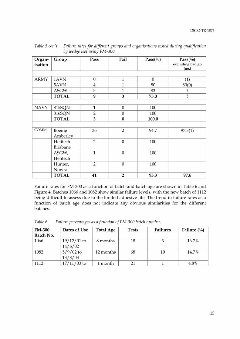
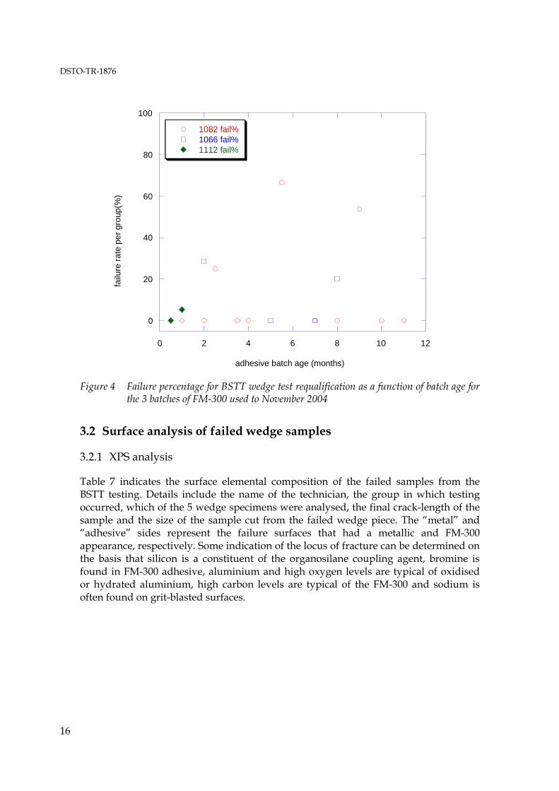
TOTAL 41 2 95.3 97.6 Failure rates for FM-300 as a function of batch and batch age are shown in Table 6 and Figure 4. Batches 1066 and 1082 show similar failure levels, with the new batch of 1112 being difficult to assess due to the limited adhesive life. The trend in failure rates as a function of batch age does not indicate any obvious similarities for the different batches.
Table 6 Failure percentages as a function of FM-300 batch number.
FM-300 Batch No.
Dates of Use Total Age Tests Failures Failure (%)
1066 19/12/01 to 14/6/02
8 months 18 3 16.7%
1082 5/9/02 to 13/8/03
12 months 68 10 14.7%
1112 17/11/03 to 1 month 21 1 4.8%
DSTO-TR-1876
16
0
20
40
60
80
100
0 2 4 6 8 10 12
1082 fail%1066 fail%1112 fail%
failu
re ra
te p
er g
roup
(%)
adhesive batch age (months)
Figure 4 Failure percentage for BSTT wedge test requalification as a function of batch age for the 3 batches of FM-300 used to November 2004
3.2 Surface analysis of failed wedge samples
3.2.1 XPS analysis
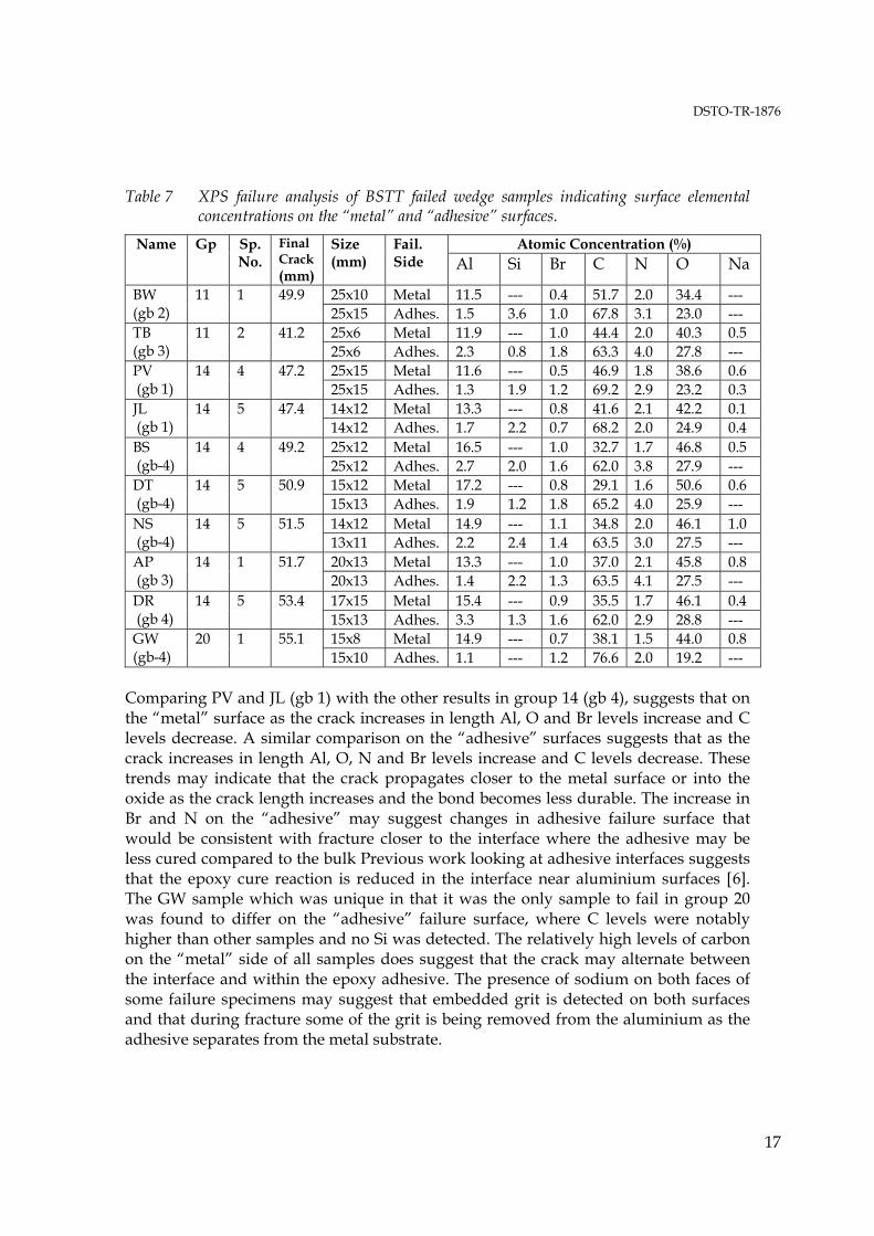
Table 7 indicates the surface elemental composition of the failed samples from the BSTT testing. Details include the name of the technician, the group in which testing occurred, which of the 5 wedge specimens were analysed, the final crack-length of the sample and the size of the sample cut from the failed wedge piece. The “metal” and “adhesive” sides represent the failure surfaces that had a metallic and FM-300 appearance, respectively. Some indication of the locus of fracture can be determined on the basis that silicon is a constituent of the organosilane coupling agent, bromine is found in FM-300 adhesive, aluminium and high oxygen levels are typical of oxidised or hydrated aluminium, high carbon levels are typical of the FM-300 and sodium is often found on grit-blasted surfaces.
DSTO-TR-1876
17
Table 7 XPS failure analysis of BSTT failed wedge samples indicating surface elemental concentrations on the “metal” and “adhesive” surfaces.
Atomic Concentration (%) Name Gp Sp.No.
Final Crack (mm)
Size (mm)
Fail. Side Al Si Br C N O Na
25x10 Metal 11.5 --- 0.4 51.7 2.0 34.4 --- BW (gb 2)
11 1 49.9 25x15 Adhes. 1.5 3.6 1.0 67.8 3.1 23.0 --- 25x6 Metal 11.9 --- 1.0 44.4 2.0 40.3 0.5 TB
(gb 3) 11 2 41.2
25x6 Adhes. 2.3 0.8 1.8 63.3 4.0 27.8 --- 25x15 Metal 11.6 --- 0.5 46.9 1.8 38.6 0.6 PV
(gb 1) 14 4 47.2
25x15 Adhes. 1.3 1.9 1.2 69.2 2.9 23.2 0.3 14x12 Metal 13.3 --- 0.8 41.6 2.1 42.2 0.1 JL
(gb 1) 14 5 47.4
14x12 Adhes. 1.7 2.2 0.7 68.2 2.0 24.9 0.4 25x12 Metal 16.5 --- 1.0 32.7 1.7 46.8 0.5 BS
(gb-4) 14 4 49.2
25x12 Adhes. 2.7 2.0 1.6 62.0 3.8 27.9 --- 15x12 Metal 17.2 --- 0.8 29.1 1.6 50.6 0.6 DT
(gb-4) 14 5 50.9
15x13 Adhes. 1.9 1.2 1.8 65.2 4.0 25.9 --- 14x12 Metal 14.9 --- 1.1 34.8 2.0 46.1 1.0 NS
(gb-4) 14 5 51.5
13x11 Adhes. 2.2 2.4 1.4 63.5 3.0 27.5 --- 20x13 Metal 13.3 --- 1.0 37.0 2.1 45.8 0.8 AP
(gb 3) 14 1 51.7
20x13 Adhes. 1.4 2.2 1.3 63.5 4.1 27.5 --- 17x15 Metal 15.4 --- 0.9 35.5 1.7 46.1 0.4 DR
(gb 4) 14 5 53.4
15x13 Adhes. 3.3 1.3 1.6 62.0 2.9 28.8 --- 15x8 Metal 14.9 --- 0.7 38.1 1.5 44.0 0.8 GW
(gb-4) 20 1 55.1
15x10 Adhes. 1.1 --- 1.2 76.6 2.0 19.2 --- Comparing PV and JL (gb 1) with the other results in group 14 (gb 4), suggests that on the “metal” surface as the crack increases in length Al, O and Br levels increase and C levels decrease. A similar comparison on the “adhesive” surfaces suggests that as the crack increases in length Al, O, N and Br levels increase and C levels decrease. These trends may indicate that the crack propagates closer to the metal surface or into the oxide as the crack length increases and the bond becomes less durable. The increase in Br and N on the “adhesive” may suggest changes in adhesive failure surface that would be consistent with fracture closer to the interface where the adhesive may be less cured compared to the bulk Previous work looking at adhesive interfaces suggests that the epoxy cure reaction is reduced in the interface near aluminium surfaces [6]. The GW sample which was unique in that it was the only sample to fail in group 20 was found to differ on the “adhesive” failure surface, where C levels were notably higher than other samples and no Si was detected. The relatively high levels of carbon on the “metal” side of all samples does suggest that the crack may alternate between the interface and within the epoxy adhesive. The presence of sodium on both faces of some failure specimens may suggest that embedded grit is detected on both surfaces and that during fracture some of the grit is being removed from the aluminium as the adhesive separates from the metal substrate.

DSTO-TR-1876
18
3.3 Quality control of metal surface treatments
3.3.1 Colour meter measurements for grit-blast severity
Table 8 indicates the colour measurements using the ColorQA version 2 handheld unit for the Scotchbrite® abraded and grit-blasted samples. Heavy, medium and light grit-blasted surfaces represent “4”, “3” and “2”, respectively, in Figure 3. All three colours show similar trends and for a heavily abraded surface there is a difference of approximately 30 units from 150 to 120 as the grit-blast approaches a standard level. There is a difference of approximately 70 units from 190 to 120 as the grit-blast approaches a standard level for surfaces that are abraded lightly.
Table 8 Red, green and blue colour values (0-255) for samples subjected to varying degrees of grit-blasting and Scotchbrite® abrasion.
Scotchbrite Grit-blast Position Red Green Blue Heavy None 1 146 143 139 2 158 160 153 3 157 157 150 4 144 142 137 5 148 148 139 Average 151 150 144 Heavy Light 1 134 136 129 2 150 157 148 3 148 153 145 4 139 139 134 5 157 166 153 Average 146 150 142 Heavy Medium-Light 1 136 137 132 2 138 139 133 3 133 135 128 4 152 156 148 5 149 154 147 Average 142 144 138 Heavy Medium 1 118 122 117 2 119 122 118 3 126 126 121 4 118 123 115 5 112 117 111 Average 119 122 116 Heavy Heavy 1 92 92 88 2 92 93 88 Average 92 93 88

DSTO-TR-1876
19
Table 8 con’t Red, green and blue colour values (0-255) for samples subjected to varying degrees of grit-blasting and Scotchbrite® abrasion.
Scotchbrite Grit-blast Position Red Green Blue Light None 1 194 200 190 2 201 203 193 3 225 235 216 4 184 179 175 5 177 172 166 Average 196 198 188 Light 1 180 179 175 2 166 163 160 3 166 164 160 4 178 186 178 5 178 186 171 Average 174 176 169 Medium-Light 1 148 153 142 2 144 145 135 3 138 144 134 4 135 134 129 5 145 146 139 Average 142 144 136 Medium 1 121 124 118 2 119 123 116 3 125 130 126 4 120 126 118 Average 121 126 120 Heavy 1 83 85 80 3.3.2 Gloss-meter measurements for grit-blast severity
Table 9 indicates the range of gloss unit values obtained using the Hand Held Mirror TRI Gloss®. For a heavily abraded surface there is a difference of approximately 7 units from 12 to 5 as the grit-blast approaches a level around “4”. There is a difference of approximately 18 units from 23 to 5 as the grit-blast approaches a standard level of “4” for surfaces that are abraded lightly. In absolute percentage terms the gloss units show significantly greater discrimination than the colour meter measurements. Further work at all three angles will be needed to clearly establish the best angle to use for discriminating the levels of abrasion and grit-blasting.

DSTO-TR-1876
20
Table 9 Gloss-meter measurements for grit-blast and Scotchbrite® abraded samples subjected to varying degrees of abrasion and grit-blasting.
Gloss Units (mean, std. devn.) Scotchbrite Grit-blast 20o 60o 85o
Heavy None --- --- 12 ( 0.5) Light --- --- 9.9 (0.3) Medium-Light --- --- 9.2 (0.2) Medium 0.9 2.5 4.9 (0.1)
Light None 4.2 16.6 22.8 (1.3) Light --- --- 15.4 (1.6) Medium-Light --- --- 11.6 (0.4) Medium --- --- 4.9 (0.2)
3.3.3 Wedge test performance resulting from use of epoxy silane kits
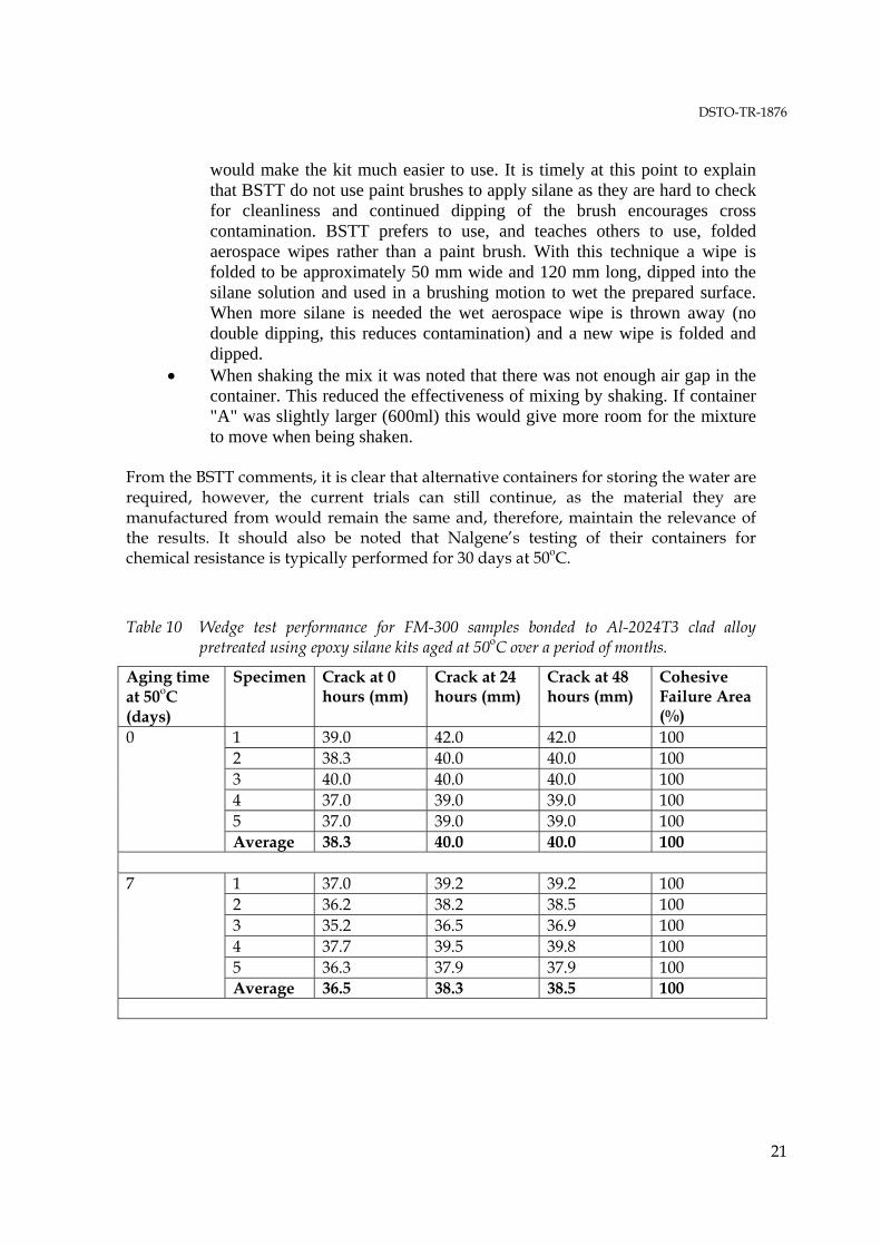
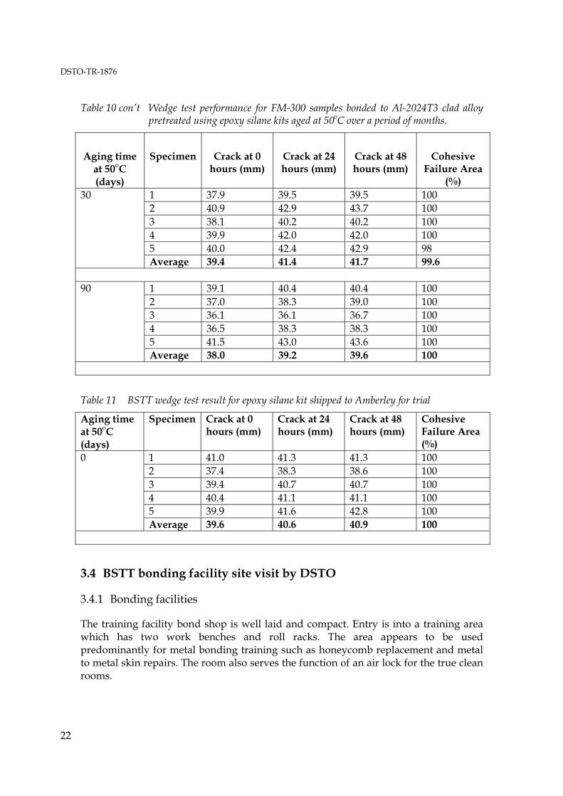
Table 10 indicates the wedge test performance for samples produced using the grit-blast and epoxy silane treatment (sec. 2.1) using the epoxy silane kits described in section 2.4.3. The epoxy silane kits were artificially aged by placing the containers of water, epoxy silane and 0.1% acetic acid in a 50oC oven for periods up to several months. It is apparent that after 3 months little aging has occurred and wedge test results still pass the criteria specified in the engineering standard [2]. Table 11 indicates that the wedge test manufactured at BSTT using the epoxy silane kit performed satisfactorily. Feedback from BSTT included the following comments:
• The silane kit was simple and convenient to use. • The instructions were clear and easy to understand. • This kit would be a great improvement on the current method for mixing
silane, as everything required is in the kit. • There is less chance of introducing contamination as there is no need to
clean beakers and measuring equipment. As this kit does not require a magnetic stirrer, it would simplify use out in the field or on flight line.
• The inclusion of MSDS was good as it emphasises the importance of correct PPE and handling procedures.
• When receiving the kit it was found that the packaging was more than adequate.
• When the kit was trialed it was found that container "A" was difficult to use. This was due to the size of its mouth and the need for the technician to repeatedly dip aerospace wipes into the container without touching the edge. As the level of silane mix decreased the user had to reach further down with the wipe. Without a lot of care the wipe or gloves could touch the edge of the container. It is suggested that the dimensions of container "A" be changed to something that was shorter and wider with a larger opening. This
DSTO-TR-1876
21
would make the kit much easier to use. It is timely at this point to explain that BSTT do not use paint brushes to apply silane as they are hard to check for cleanliness and continued dipping of the brush encourages cross contamination. BSTT prefers to use, and teaches others to use, folded aerospace wipes rather than a paint brush. With this technique a wipe is folded to be approximately 50 mm wide and 120 mm long, dipped into the silane solution and used in a brushing motion to wet the prepared surface. When more silane is needed the wet aerospace wipe is thrown away (no double dipping, this reduces contamination) and a new wipe is folded and dipped.
• When shaking the mix it was noted that there was not enough air gap in the container. This reduced the effectiveness of mixing by shaking. If container "A" was slightly larger (600ml) this would give more room for the mixture to move when being shaken.
From the BSTT comments, it is clear that alternative containers for storing the water are required, however, the current trials can still continue, as the material they are manufactured from would remain the same and, therefore, maintain the relevance of the results. It should also be noted that Nalgene’s testing of their containers for chemical resistance is typically performed for 30 days at 50oC.
Table 10 Wedge test performance for FM-300 samples bonded to Al-2024T3 clad alloy pretreated using epoxy silane kits aged at 50oC over a period of months.
Aging time at 50oC (days)
Specimen Crack at 0 hours (mm)
Crack at 24 hours (mm)
Crack at 48 hours (mm)
Cohesive Failure Area (%)
1 39.0 42.0 42.0 100 2 38.3 40.0 40.0 100 3 40.0 40.0 40.0 100 4 37.0 39.0 39.0 100 5 37.0 39.0 39.0 100
0
Average 38.3 40.0 40.0 100
1 37.0 39.2 39.2 100 2 36.2 38.2 38.5 100 3 35.2 36.5 36.9 100 4 37.7 39.5 39.8 100 5 36.3 37.9 37.9 100
7
Average 36.5 38.3 38.5 100
DSTO-TR-1876
22
Table 10 con’t Wedge test performance for FM-300 samples bonded to Al-2024T3 clad alloy pretreated using epoxy silane kits aged at 50oC over a period of months.
Aging time at 50oC (days)
Specimen Crack at 0 hours (mm)
Crack at 24 hours (mm)
Crack at 48 hours (mm)
Cohesive Failure Area
(%) 1 37.9 39.5 39.5 100 2 40.9 42.9 43.7 100 3 38.1 40.2 40.2 100 4 39.9 42.0 42.0 100 5 40.0 42.4 42.9 98
30
Average 39.4 41.4 41.7 99.6
1 39.1 40.4 40.4 100 2 37.0 38.3 39.0 100 3 36.1 36.1 36.7 100 4 36.5 38.3 38.3 100 5 41.5 43.0 43.6 100
90
Average 38.0 39.2 39.6 100
Table 11 BSTT wedge test result for epoxy silane kit shipped to Amberley for trial
Aging time at 50oC (days)
Specimen Crack at 0 hours (mm)
Crack at 24 hours (mm)
Crack at 48 hours (mm)
Cohesive Failure Area (%)
1 41.0 41.3 41.3 100 2 37.4 38.3 38.6 100 3 39.4 40.7 40.7 100 4 40.4 41.1 41.1 100 5 39.9 41.6 42.8 100
0
Average 39.6 40.6 40.9 100 3.4 BSTT bonding facility site visit by DSTO
3.4.1 Bonding facilities
The training facility bond shop is well laid and compact. Entry is into a training area which has two work benches and roll racks. The area appears to be used predominantly for metal bonding training such as honeycomb replacement and metal to metal skin repairs. The room also serves the function of an air lock for the true clean rooms.

DSTO-TR-1876
23
Upon entering, the first room to the right is an office space, which doubles as a curing area. Novatech HBC 43 Hot Bonders are used for this; two are set up in the corner of the room. Adjacent to the Office/Curing Room area is a Lay-Up room containing the grit-blaster, curing ovens, epoxy silane coupling agent, lay-up table & PPE lockers. The Lay-Up room can be considered the first of the clean rooms. Temperature and humidity control and monitoring provides a suitable environment for adhesive thawing and application to the bonding substrate. The last room of interest is the Solvent Cleaning room, accessed though the Lay-Up room. Both Lay-Up and Solvent Cleaning rooms have the air-conditioning interconnected, which potentially may effect temperature and humidity control, particularly in the Lay-Up room where moisture can lead to voiding during vacuum cure (refer section 3.4.2). The Solvent Cleaning room contains two Laminar Flow benches; a safety shower and solvent squeeze bottles (MEK) and is used to surface prepare the aluminium substrates. 3.4.2 Environment
As the wedge test specimens were surface prepared in the Solvent Cleaning (SC) room and were assembled in the Lay-Up (LU) room, the investigation was centred on these two rooms. On the day of the visit the rooms were clean and tidy and it was obvious the instructors had a good housekeeping regime in place. Nobody was permitted entry without putting on fresh disposable overalls and personal protective equipment (PPE), which was mandatory. The personnel who required solvents used butyl rubber gloves to protect themselves and surgical gloves over the butyl rubber gloves to protect the wedge test substrates from contamination; the surgical gloves were worn for a maximum of five minutes. The laminar flow benches effectively removed the solvent fumes, although the make-up air was not conditioned The rooms in question were strictly used for training and re-qualification purposes and were generally not used for production. During the time of the visit an oven in the lay-up room was used to cure a production component due to problems with the production oven. The lay-up table was covered with fresh teflon coated glass and this was changed at regular intervals or when contamination was suspected. In addition to the teflon coated glass, all working surfaces were covered with fresh brown kraft paper to prevent cross contamination. Brown kraft paper was also placed under the wedge test substrates during the surface preparation stage; this was changed at each step and whenever the trainee suspected contamination. The LU and SC rooms had an interconnected air conditioning system and on the day of the visit the rooms were 23°C and the relative humidity 59.9%, as measured by equipment located on a wall of the LU room. This was marginally over the recommended range prescribed in DEF(AUST)9005 Issue A [1]. An explanation suggested that the make-up air for the laminar flow benches put the room out of

DSTO-TR-1876
24
specification. The numbers observed were not a cause for great concern but prolonged use of the laminar flow benches may cause problems. The consumables were stored out of the way on a rack in the metal to metal repair area and it is recommended that the addition of a dust cover would be appropriate. The contents of the bins were examined with only two inappropriate items being found; a milk carton in the metal to metal repair area and food wrappers in the curing/office space. This highlighted the problem of having offices effectively inside a bond shop. Food should not be permitted in the bond shop for obvious reasons. Generally, the quality and maintenance of the bonding facilities were considered to be of a very high standard and there were no obvious indications of deviations from prescribed standards nor clear cases that may be linked to the deterioration in bond quality observed with the wedge testing. 3.4.3 Sample collection
A range of samples were collected from the bonding facilities, mainly from the LU and SC rooms where the critical surface cleaning and bonding operations occured. The samples included 1) the brown kraft paper used as a barrier layer on most benches and for wedge test preparation, (2) swabs from benches, beakers and general equipment used in bond preparation and (3) samples of Scotchbrite®, tissues and surgical gloves. A sample of the epoxy silane was also received from BSTT prior to the visit and analysed by infrared spectroscopy as detailed in section 3.5. Infrared analysis of items collected from BSTT was initially restricted to the brown kraft paper used in bonding operations, due to evidence from BSTT staff that the supplier for this item had changed during the period that wedge test results appeared to have deteriorated. FT-IR microscopy5 of the brown kraft paper suggested small differences in the chemistry, however, both samples were essentially cellulose with silica incorporated in the shiny side of the paper. There was no evidence of silicone type contamination for the paper. 3.4.4 Wedge test manufacture and observations of BSTT and DSTO bonding procedures
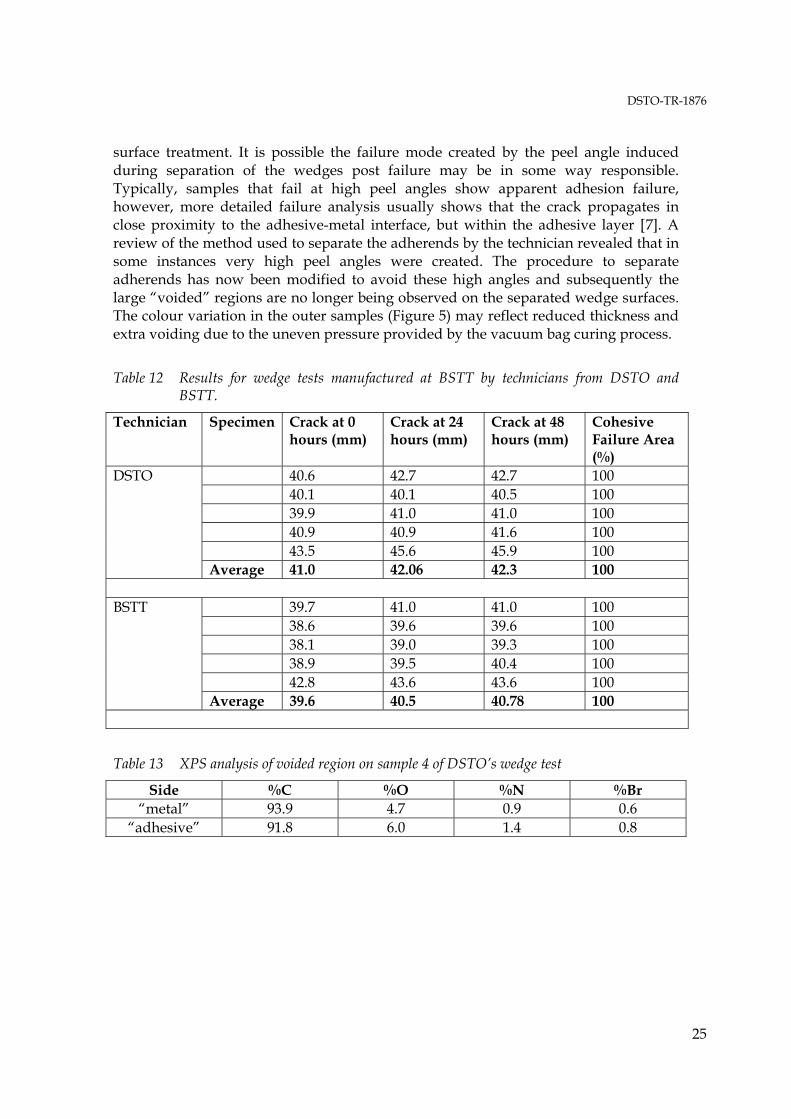
DSTO and BSTT technicians both prepared wedge tests in the BSTT bonding facility on 13/11/03. Subsequent testing of the specimens at DSTO revealed both passed, with no adhesion1 failure observed in the crack-growth region and crack-growth being far below the levels defined in the RAAF standard [2]. Results are detailed in Table 12. BSTT wedge failure surfaces revealed much lower voiding levels of the sub-millimetre dimension compared to DSTO. DSTO’s wedges also had large voided areas on samples 2, 3 and 4 (Figure 5). XPS analysis of the large voided area is shown in Table 13. The two surfaces look to be similar in composition and there was no silicon or aluminium detected, suggesting that the metallic side was covered in epoxy adhesive. This suggests that the voided regions on the metallic sides were not a result of inadequate 5 Refer to the Glossary for a definition of IR microscopy.
DSTO-TR-1876
25
surface treatment. It is possible the failure mode created by the peel angle induced during separation of the wedges post failure may be in some way responsible. Typically, samples that fail at high peel angles show apparent adhesion failure, however, more detailed failure analysis usually shows that the crack propagates in close proximity to the adhesive-metal interface, but within the adhesive layer [7]. A review of the method used to separate the adherends by the technician revealed that in some instances very high peel angles were created. The procedure to separate adherends has now been modified to avoid these high angles and subsequently the large “voided” regions are no longer being observed on the separated wedge surfaces. The colour variation in the outer samples (Figure 5) may reflect reduced thickness and extra voiding due to the uneven pressure provided by the vacuum bag curing process.
Table 12 Results for wedge tests manufactured at BSTT by technicians from DSTO and BSTT.
Technician Specimen Crack at 0 hours (mm)
Crack at 24 hours (mm)
Crack at 48 hours (mm)
Cohesive Failure Area (%)
40.6 42.7 42.7 100 40.1 40.1 40.5 100 39.9 41.0 41.0 100 40.9 40.9 41.6 100 43.5 45.6 45.9 100
DSTO
Average 41.0 42.06 42.3 100
39.7 41.0 41.0 100 38.6 39.6 39.6 100 38.1 39.0 39.3 100 38.9 39.5 40.4 100 42.8 43.6 43.6 100
BSTT
Average 39.6 40.5 40.78 100
Table 13 XPS analysis of voided region on sample 4 of DSTO’s wedge test
Side %C %O %N %Br “metal” 93.9 4.7 0.9 0.6
“adhesive” 91.8 6.0 1.4 0.8

DSTO-TR-1876
26
Figure 5 Images of DSTO’s wedge samples after testing and separation. Samples are
numbered from 1 to 5 from right to left. Samples 2, 3 and particularly 4 show large voided areas. XPS analysis of the voided region in 4 was performed on the samples produced from the cut regions.

DSTO-TR-1876
27
During wedge test manufacture and observation of technicians being qualified by the BSTT examiners, the processes being implemented by DSTO and BSTT were observed. It should be noted that the differences do not imply deficiencies in either of the methods applied, rather changes that occur in processes over time due to a wide range of factors. The major points observed for the BSTT and DSTO wedge preparations included the following:
1) BSTT staff may employ a wipe cloth to the epoxy silane wetted surface to remove excess solution and facilitate the even drying of the surface
2) BSTT supervision is intense and any deviations from the prescribed methods are noted and the technician would be failed if any step isn’t done exactly as specified
3) BSTT staff are strictly implementing the Engineering standard for training and qualification and to the highest quality
4) BSTT trained technicians will apply the silane with wipe cloths soaked in solution compared to DSTO technicians who employ cleaned paint brushes for the same process.
5) The standard of technicians being qualified on the days during the visit was of the highest order
6) BSTT trained technicians use far less pressure and time in the Scotchbrite abrasion steps compared with DSTO
7) BSTT trained technicians prepare the wedge test in a faster time than DSTO technicians
8) BSTT use vacuum bag pressure and heater blankets for adhesive curing of the wedge test plates, compared with positive pressure from a platen press at DSTO.
3.5 Infrared analysis of epoxy silane ( γ-GPS)
Appendix A includes the RAIR spectra of the epoxy silane (γ-GPS) acquired from BSTT Amberley and Sigma-Aldrich (Figure A8). The spectra show that the peak intensity of both samples at 1105 cm-1 (due to Si-O-Si vibration in the cross-linked film) is about 0.005 absorbance units, indicating a very thin film of approximately 3nm thickness. In contrast, the spectrum acquired for the film produced by the aged γ-GPS (Figure A9) shows a peak intensity of 0.12 absorbance units and clearly substantially thicker than the films produced by the fresh γ-GPS. The aged γ-GPS film also shows a substantial peak due to carbonyl vibration (1731cm-1) and the peak at 825cm-1 is due to methoxy species present from unhydrolysed γ-GPS. The transmission infrared spectra of the fresh and aged epoxy silanes in Figure A10 clearly indicate differences in the peaks at 3513 and 1730cm-1, due to hydroxyl and carbonyl vibrations, respectively. The aged silane shows that carbonyl and hydroxyl impurities increase substantially and show that both the transmission and RAIR spectra can be used to identify epoxy silane age and purity.
DSTO-TR-1876
28
3.6 Wedge test sensitivity studies
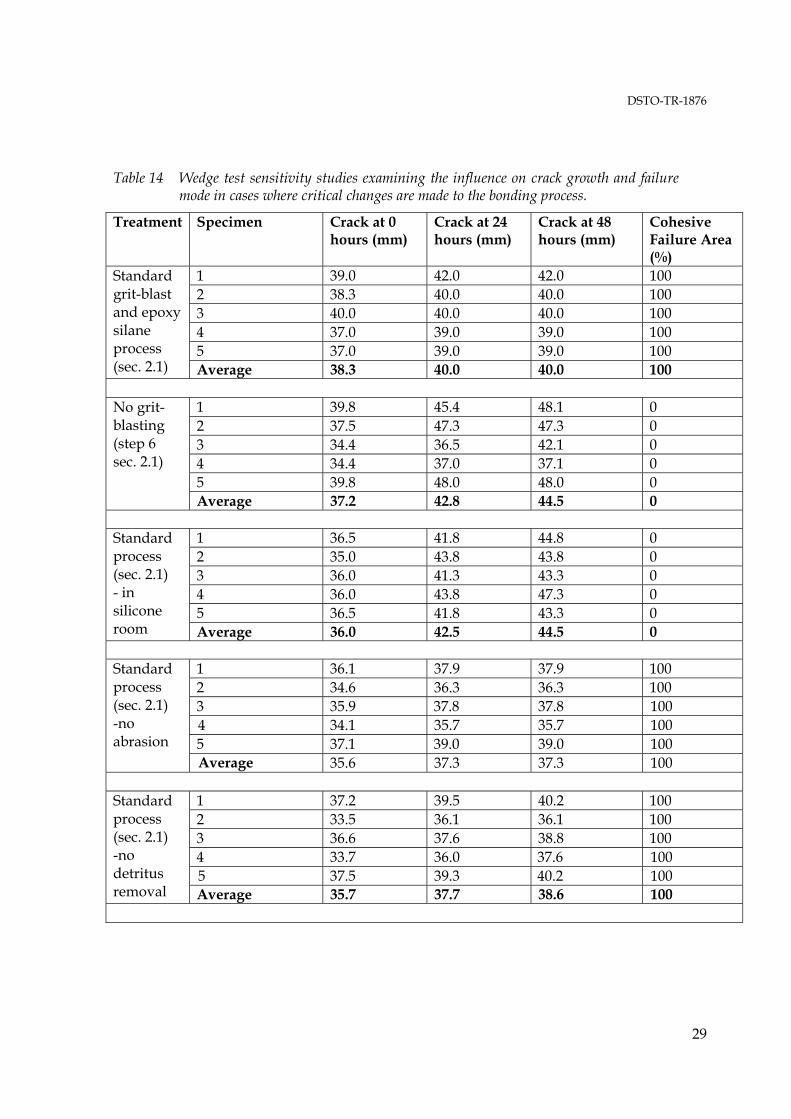
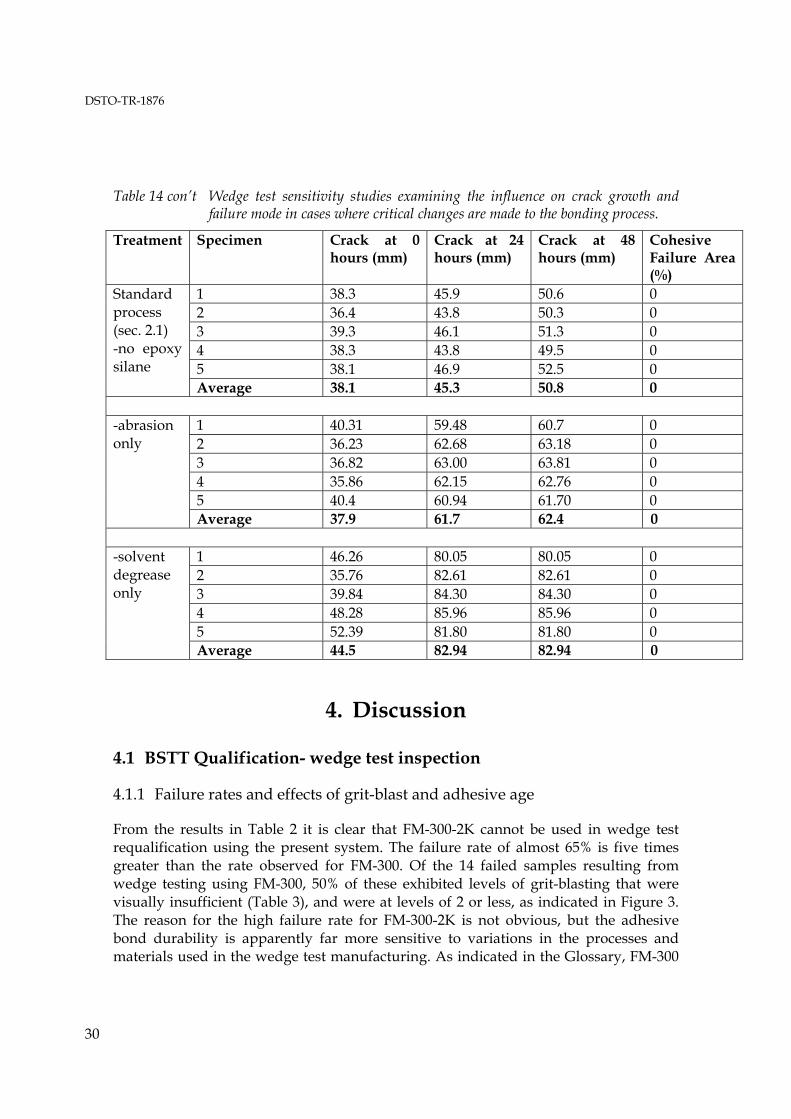
Table 14 indicates wedge test results for the basic grit-blast and epoxy silane treatment for examples where critical changes are made to the process or process environment. It can be seen that the absence of grit-blasting leads to a greater variation in final crack growth values at 48 hours. There is also a clear increase in the average crack length value at 24 and 48 hours and the failure mode becomes 100% adhesion. Very similar trends are observed for the wedge manufactured in the silicone environment, representing the influence of surface contaminant. The increase in crack length and large adhesion failure observed for the samples that were not grit-blasted are very similar to values observed for the wedge test specimens that failed in Table 2 and were identified as having inadequately grit-blasted surfaces. A disturbing aspect of the wedge test manufactured in the silicone room environment was the lack of sensitivity of the water break test currently being used to identify the presence of surface contaminant. Given the clear reduction in quality of the wedge test results, silicone contaminant was obviously present. This indicates improvement in the methods to identify surface contamination are required if the wedge test results are to become more reliable. Not surprisingly, the absence of epoxy silane in the treatment step results in the largest crack-growth observed for all treatment variations and 100% adhesion failure, clearly indicating the importance of correct application of the epoxy silane. The final average crack length is similar to the worst cases observed for the BSTT wedge qualification samples (Table 2). The absence of abrasion or careful detritus removal after abrasion, unexpectedly, had no influence on wedge test performance with both these tests providing acceptable crack growth and 100% cohesion failure. This result indicates the grit-blasting step is crucial to overall performance of the treatment. Possibly, grit-blasting consolidates the surface debris and reduces the potential of a weak boundary layer forming.
DSTO-TR-1876
29
Table 14 Wedge test sensitivity studies examining the influence on crack growth and failure mode in cases where critical changes are made to the bonding process.
Treatment Specimen Crack at 0 hours (mm)
Crack at 24 hours (mm)
Crack at 48 hours (mm)
Cohesive Failure Area (%)
1 39.0 42.0 42.0 100 2 38.3 40.0 40.0 100 3 40.0 40.0 40.0 100 4 37.0 39.0 39.0 100 5 37.0 39.0 39.0 100
Standard grit-blast and epoxy silane process (sec. 2.1) Average 38.3 40.0 40.0 100
1 39.8 45.4 48.1 0 2 37.5 47.3 47.3 0 3 34.4 36.5 42.1 0 4 34.4 37.0 37.1 0 5 39.8 48.0 48.0 0
No grit-blasting (step 6 sec. 2.1)
Average 37.2 42.8 44.5 0
1 36.5 41.8 44.8 0 2 35.0 43.8 43.8 0 3 36.0 41.3 43.3 0 4 36.0 43.8 47.3 0 5 36.5 41.8 43.3 0
Standard process (sec. 2.1) - in silicone room Average 36.0 42.5 44.5 0
1 36.1 37.9 37.9 100 2 34.6 36.3 36.3 100 3 35.9 37.8 37.8 100 4 34.1 35.7 35.7 100 5 37.1 39.0 39.0 100
Standard process (sec. 2.1) -no abrasion
Average 35.6 37.3 37.3 100
1 37.2 39.5 40.2 100 2 33.5 36.1 36.1 100 3 36.6 37.6 38.8 100 4 33.7 36.0 37.6 100 5 37.5 39.3 40.2 100
Standard process (sec. 2.1) -no detritus removal Average 35.7 37.7 38.6 100
DSTO-TR-1876
30
Table 14 con’t Wedge test sensitivity studies examining the influence on crack growth and failure mode in cases where critical changes are made to the bonding process.
Treatment Specimen Crack at 0 hours (mm)
Crack at 24 hours (mm)
Crack at 48 hours (mm)
Cohesive Failure Area (%)
1 38.3 45.9 50.6 0 2 36.4 43.8 50.3 0 3 39.3 46.1 51.3 0 4 38.3 43.8 49.5 0 5 38.1 46.9 52.5 0
Standard process (sec. 2.1) -no epoxy silane
Average 38.1 45.3 50.8 0
1 40.31 59.48 60.7 0 2 36.23 62.68 63.18 0 3 36.82 63.00 63.81 0 4 35.86 62.15 62.76 0 5 40.4 60.94 61.70 0
-abrasion only
Average 37.9 61.7 62.4 0
1 46.26 80.05 80.05 0 2 35.76 82.61 82.61 0 3 39.84 84.30 84.30 0 4 48.28 85.96 85.96 0 5 52.39 81.80 81.80 0
-solvent degrease only
Average 44.5 82.94 82.94 0
4. Discussion
4.1 BSTT Qualification- wedge test inspection
4.1.1 Failure rates and effects of grit-blast and adhesive age
From the results in Table 2 it is clear that FM-300-2K cannot be used in wedge test requalification using the present system. The failure rate of almost 65% is five times greater than the rate observed for FM-300. Of the 14 failed samples resulting from wedge testing using FM-300, 50% of these exhibited levels of grit-blasting that were visually insufficient (Table 3), and were at levels of 2 or less, as indicated in Figure 3. The reason for the high failure rate for FM-300-2K is not obvious, but the adhesive bond durability is apparently far more sensitive to variations in the processes and materials used in the wedge test manufacturing. As indicated in the Glossary, FM-300
DSTO-TR-1876
31
cures at 177oC for 60 minutes, whereas FM-300-2K cures for 90 minutes at 120oC. It may be that the lower curing temperature reduces the ability of FM-300-2K to displace contaminants present on the metal surface and is, therefore, more sensitive to variations in surface cleanliness. If it was assumed that the inadequate grit-blasting observed in 50% of the failed FM-300 samples could have been prevented through implementation of surface roughness measurements using tools described in section 2.4.1, then the overall failure rate for the FM-300 samples would be reduced from 13% to 6.5%. Group 14 was responsible for 50% of all failures recorded for FM-300, however, only 2 of those samples exhibited inadequate grit-blasting, leaving 70% of the failed samples for this group unexplained. The only obvious differences between group 14 and other groups was the Edinburgh test location in South Australia and the first shipment of FM-300 sent to the test location from Amberley may have been exposed to extended storage at room temperature. Despite the concern with the first adhesive shipment, failures occurred at similar rates for the first and second shipments and on adequately grit-blasted surfaces. Potential explanations for failure not related to inadequate grit-blasting may include the period between training and requalification or adhesive aging. Table 3 indicates that more failure for FM-300 occurred in requalification than directly after training. This may suggest that if personnel are not regularly involved in bonding operations various aspects of the wedge test manufacture that are not directly examined during requalification testing may be overlooked or forgotten. The high failure rate in group 14, however, distorts the data and more information would be needed to support this case. Boeing-Amberley, however, has a relatively higher rate of success with only 1 failure in 38 not being explained. A large number of bonded repairs to F-111 honeycomb panels are performed by Boeing Amberley technicians. The higher RAAF failure rate includes results from over 15 different units and it may be expected regular involvement in bonding would not occur for all those involved in requalification. The conclusion that regular practical application of bonding skills may be needed is an indication that the current process applied by RAAF may have limitations. It may require improvements to increase the failure rate to acceptable levels, if the wedge test result was to be used as the sole criterion for qualification of bonding technicians. The adhesive age as a function of failure rate shown in Figure 4 suggests no obvious trends. In contrast, the similar failure rates observed for the first two batches of adhesive used may suggest that the failure rates are a result of the process being applied and would imply inadequacies in the present controls being implemented. Another variable that should be considered is the adhesive batch being used. Figure 6 indicates that the average crack length after 48 hours has increased with respect to the mean crack growth for the three adhesive batches used. This trend either indicates deterioration in the adhesive being supplied from the manufacturer or a gradual decline in the quality of the adhesive bonding processes.

DSTO-TR-1876
32
35
36
37
38
39
40
41
42
43
1066 1082 1112
crac
k-le
ngth
(mm
)
Batch
Mean crack-length
Figure 6 48 hour crack length for FM-300 for the three batches used compared with the mean
crack growth for all specimens tested.
4.1.2 Failure analysis
XPS analysis of the specimens from groups 11, 14 and 20 (Table 7) reveal that no silicon is detected on the metallic failure surface for any samples. There is evidence from the results in Table 7 that as the final crack length after 48 hours of humid exposure increases (i.e. the bond becomes less durable) the crack propagates closer to the adhesive and aluminium interface. The absence of silicon would suggest that the epoxy silane coupling agent is not retained on the metallic surface and the hydrolytic stability of the interfacial region deteriorates as the bond becomes less durable. It is possible that some variation in the current manufacturing process that is not being monitored has the potential to reduce the bond stability between the epoxy silane and grit-blasted aluminium surface in a humid environment. 4.1.3 Quality control
Examination of the Colour and Gloss meter units in sections 3.3.1 and 3.3.2 clearly indicate commercially available units are capable of discriminating between different levels of grit-blasting on clad Al-2024 T3 surfaces. Whilst the Gloss meter is significantly more costly, the improved discrimination and data down-loading capacity would make it the preferred candidate, particularly, when the wedge sensitivity
DSTO-TR-1876
33
studies (section 3.6) confirm the critical nature of the grit-blasting step in the overall bonding process. Trialing of epoxy silane kits has proven to be successful to date (section 2.4.3). The ability to package epoxy silane, water and acetic acid in ready-to-mix kits offers advantages in transport, traceability and quality control. Small improvements to the prototype can be made by altering the dimensions and volume of water stored in the largest container and by adding the diluted acetic acid to the water during packaging. The aging studies to date have shown no deterioration in wedge test results for 90 days in 50oC, which is three times longer than the maximum time used by the container manufacturer in assessing their chemical resistance. Development of infrared spectroscopic techniques (section 2.4.2) has now provided a method of qualifying the epoxy silane on a batch-to-batch basis and enabling identification of changes that may be detrimental to the bonding operation. The technique developed uses standard infrared equipment available in most analytical laboratories and surface treatments that are within the capability of basic metallurgical facilities. In combination with the epoxy silane kits there will now be a capability to trace the quality of the batch that has been used in any requalification or bonded repair operation by RAAF. The water break test has indicated some limitations in identifying silicone contaminant on the prepared aluminium surface at levels that can degrade the adhesive bond durability. Alternative and more reliable quality control tools are required to analyse the bonding surface. Presently, infrared spectroscopic techniques have potential in this area [8], however, their application relies to some extent on the skill of the operator employing the technique. The equipment used to measure the infrared spectrum of a metallic surface is also generally restricted to laboratory environments and modifications to standard equipment would be required to adapt the process to field or production environments similar to those experienced at BSTT, Amberley [8]. Work by Dr David Arnott and co-workers at DSTO several years ago identified a unit called the SQM-200 for measuring surface contaminant [9]. The unit works on the basis of shining ultraviolet light at a metal surface and detecting the electrons stimulated by the radiation. The flux of optically stimulated electrons relies on the metal surface’s work function and is affected by monolayer levels of contaminant. Previous research has indicated the high sensitivity of the equipment and it would be sensible to attempt to implement it for quality control monitoring in wedge test fabrication. 4.1.4 BSTT bonding facility site visit
Inspection of the BSTT bonding facility by DSTO indicated very high standards are being maintained. Minor transgressions were observed, however, these were not considered to be significant in terms of the problem that had developed with wedge test quality. Some concerns were raised about humidity and temperature control being slightly outside limits and is an issue that would need to be considered, particularly
DSTO-TR-1876
34
when using a vacuum bag arrangement to cure the wedge test specimens. Previous work at DSTO has highlighted the effect that high humidity levels can have on void development in the adhesive during cure [10]. Despite a range of possible materials potentially being the cause for problems in bonding, only the epoxy silane and the brown “kraft” paper could be identified as having changed supplier or batch during the period when bonding began to deteriorate. As detailed in section 3.5, analysis of the BSTT epoxy silane showed no significant variation with the fresh batch received from Aldrich and indicated this wasn’t a likely source of the problem. Infrared analysis also indicated that little variation in the paper had occurred and would not have contributed to the deteriorating bonding performance. Wedge tests manufactured by BSTT and DSTO during the DSTO visit, both passed the criteria defined in the RAAF standard, however, differences in the processes were observed. Generally, BSTT was faster at completing the surface preparation tasks, which was mainly the result of reduced time on the abrasion steps and more efficient detritus wiping. The wedge test sensitivity studies (Table 14) suggest that reduced abrasion is not likely to be a significant factor affecting bond durability, however, in practical bonding situations where thick oxide and contaminant layers may be present the step is still highly important. Whilst the sensitivity studies provide a good indication of possible variations, additional testing is required to establish a reliable indication of result variation. Variations in process between the two organisations also involved the application and drying of the epoxy silane. BSTT preferred to employ aerospace wipes to apply the silane as well as remove excess moisture from the surface to prevent pooling of solution during drying. DSTO typically employ cleaned brushes and use these to remove excess solution prior to drying. In either case it was clear that the RAAF standard failed to provide detailed instructions on the preferred drying procedures, although the use of aerospace wipes to apply the silane solution is now utilised by BSTT as it avoids contamination issues involved with cleaning paint brushes. It is unlikely that the variations observed were likely to reduce the durability of adhesive bonds prepared with the grit-blast and silane method. Measurement of the pH of the 1% aqueous silane solution produced at BSTT indicated a value around 7, compared with 4-5 for solutions prepared at DSTO. The neutral pH value would increase the time required for hydrolysis of the epoxy silane molecule [11] Hydrolysis of the silane produces reactive silanol groups, which bond directly with the metallic surface, and is a critical step in the silane film formation process. At a pH of 4-5 the hydrolysis process is optimised and the minimum of 1 hour solution stirring is adequate to insure hydrolysis has proceeded. At a pH of 7, 1 hour may be insufficient time to achieve the required level of hydrolysis. The implementation of silane kits with the acetic acid will ensure the acidic conditions for accelerated hydrolysis are achieved and should help to minimise variation in the silane film quality. The only other obvious variation between BSTT and DSTO is the curing procedure. DSTO uses a positive pressure platen press, whereas BSTT employ a vacuum bag arrangement. As referred to above, the vacuum bag set-up will be far more sensitive to
DSTO-TR-1876
35
humidity and moisture levels on the surface and the adhesive and will be more prone to voiding during cure. Potentially, concerns over voiding have influenced BSTT procedures and the manner in which abrasion and grit-blasting is conducted. By ensuring that the surface is not over grit-blasted and lightly abraded the capacity to trap volatiles in the bondline can be reduced [10]. Unfortunately, light grit-blasting, as is demonstrated in Table 3 can lead to notable deterioration in bond durability. Interestingly, the large voiding and micro-voiding observed for the DSTO wedge sample prepared at Amberley was not observed for the BSTT produced sample (Figure 5). As indicated in section 3.4.4, investigation of the process to separate the wedge test samples after testing revealed that high peeling angles were responsible for inducing peel failure modes close to the adhesive and metal interface. These high peel angles were responsible for the apparent large voids in the DSTO sample. The increased level of micro-voiding in the DSTO sample may suggest that greater abrasion contributes to the retention of moisture. Reducing voiding by altering severity of abrasion and grit-blasting is fraught with danger, however, and every effort to minimise moisture retention on the mating surfaces should be attempted through drying procedures as a first attempt. Having said that, it is often a substantial task to minimise adherend moisture levels in the high humidity regions of Northern Australia. 4.1.5 Wedge test sensitivity studies
The wedge test sensitivity studies (Figure 7 and Table 14) provided a range of predictable and unpredictable results. As anticipated, the absence of grit-blasting results in increased crack growth and 100% adhesion failure, supporting the conclusion that inadequate grit-blasting observed for 50% of the BSTT data that used FM-300 adhesive was responsible for wedge tests failing. Surprisingly, however, absence of abrasion or removing the detritus after abrasion had little influence on bond performance, suggesting that a satisfactory grit-blast can minimise the impact of these steps in the bonding process. The presence of silicone contaminant also, whilst degrading bonding and producing 100% adhesion failure in the cracking zone, did not produce the highest crack growth of all samples manufactured. A major concern was the inability of the water-break test to identify the silicone present on the bonding surface at levels that clearly degraded the bond quality. As indicated above, the use of alternative quality control tools to monitor surface contamination should be examined. Clearly, the absence of epoxy silane had the greatest impact on the bond durability. The crack-length of over 50mm was similar to the worst wedge test results observed from the BSTT requalification data and may imply that effective silane film formation may not have been achieved in these cases. As described in section 4.1.4, the variation in solution pH is a possible contributor to variation in silane film properties. Efforts to control and monitor solution pH should be considered in increasing the reliability of the bonding process. The two worst results were achieved when silane and grit-blasting was absent from the treatment or when no abrasion or grit-blasting was used. The results clearly indicate

DSTO-TR-1876
36
that surface roughening is critical to the overall performance and that if the surface isn’t adequately prepared the epoxy silane will have no effect. The results will be valuable in defining response parameters for a regression model that will be developed as a part of a risk and reliability approach to certifying adhesive bond durability.
30
40
50
60
70
80
90
0
20
40
60
80
100
Stan
dard
No
abra
de
No
detr
itus
rem
oval
Silic
one
room
No
grit-
blas
t
No
sila
ne
No
grit-
blas
t or s
ilane
degr
ease
+ s
ilane
crack-0hr (mm)crack-24hr (mm)crack-48hr (mm) cohesive%
crac
k le
ngth
(mm
) cohesive failure (%
)
Figure 7 Crack-length as a function of standard grit-blast and epoxy silane process for cases where steps are removed or environment is altered.

DSTO-TR-1876
37
5. Conclusions
Examination of 124 wedge test samples (or 620 individual test pieces producing 1240 failure surfaces) and their associated details provided a number of indicators to assist in explaining the wedge test failures observed during qualification testing by BSTT, Amberley. FM 300-2K cannot be used for qualification testing if the current RAAF standard criteria are used to pass or fail technicians. The adhesive exhibits very high failure rates and is clearly very sensitive to process variations inherent in the grit-blast and epoxy silane treatment currently favoured by RAAF. Fifty percent of all samples that failed when FM-300 adhesive was used could be directly linked to inadequate grit-blasting. Wedge test sensitivity studies confirmed that inadequate grit-blasting leads to higher crack growth and 100% adhesion failure. Assessment of commercially available colour and gloss-meter units indicates that the units are capable of discriminating between the different levels of grit-blasting and would be a valuable tool in maintaining quality of the surface treatment process. Seven of the total fourteen failures using FM-300 occurred for requalification testing conducted at RAAF Base Edinburgh. Despite two cases of poor grit-blasting, the remaining failures could not be readily explained by visual inspection. Surface analysis of failed samples, however, revealed the absence of epoxy silane on the aluminium surface, suggesting there could be some problems with the hydrolytic stability of the deposited film. Indirect evidence suggests that the experience of the technician and regular application of the skills required in adhesive bonding to metallic structure has an influence on the pass rate for the wedge test. Boeing Amberley technicians exhibited a pass rate almost fifteen percent higher than RAAF technicians. Whilst Boeing technicians are involved in regular bonding operations, RAAF qualification covered fifteen different units where the opportunity to apply the bonding skills learnt through training would vary considerably. The age and batch of FM-300 adhesive were also examined as factors. The results indicate that whilst failure rates for the two oldest batches were similar, average crack growth measurements have successively increased for each of the three batches employed for qualification testing. There is no clear reason for the gradual increase in the average crack length of wedge samples produced during BSTT testing and requalification. Review of BSTT bonding procedures and facilities indicated operations were performed to a high level and in strict accordance with the RAAF Engineering

DSTO-TR-1876
38
Standard. No obvious sources of contamination that may have contributed to the increase in wedge failure rates were identified, however, particular attention should be paid to ensuring temperature and humidity levels in the bonding facility are maintained well within limits identified in the standard. Minor variations in the DSTO and BSTT surface treatment methods were observed. The variations included reduced time involved in abrasion and detritus removal, however, wedge sensitivity studies indicated this was unlikely to lead to substantial differences in results. DSTO and BSTT also employed different methods to apply and remove epoxy silane solution from the metallic surface prior to oven drying. Both techniques can prevent pooling of solution, however, the RAAF standard does not provide detail of the correct process to apply. Epoxy silane kits that were trialed and received accelerated aging indicated potential in improving the quality of the surface treatment process by minimising contamination sources and errors with mixing. Additionally, the inclusion of acetic acid or some other means to control the solution pH should assist in maintaining the quality of epoxy silane films formed on the metallic substrates. Wedge sensitivity studies carried out in a silicone room environment showed that the water break test currently employed to monitor surface cleanliness during the surface treatment did not detect contaminant levels that were sufficient to degrade the bond quality. Previous DSTO research suggests that a commercially available unit may be required to improve the quality of the surface monitoring during the bonding process.
6. Recommendations
Based on the findings contained in this report, DSTO recommends the following items be addressed by RAAF in order to improve the quality of the current bonding procedures used for requalification of technicians by BSTT, Amberley : A quality control tool should be implemented to statistically monitor the wedge test results in real time and highlight deviations in crack-growth from the average trend. This will enable rapid identification of problems with the bonding operation and enable the problems to be solved in a satisfactory time frame. The wedge test requalification database could be maintained by the Aircraft Forensic Engineering (AFE) group in Air Vehicles Division (AVD), DSTO. This will require BSTT to provide AFE with all the information recorded during the wedge testing examination. Additionally, the technician currently sub-contracted by BSTT through
DSTO-TR-1876
39
AVD to test the wedge samples will have to provide AFE with measurement details and specimens. Commercially available units such as the Hand Held Micro TRI Gloss® gloss-meter from BYK Gardner should be used to monitor grit-blast quality during wedge requalification testing. Some preliminary development work (currently underway) will be required prior to insertion in the BSTT facility. The SQM-200 from Photoemission Technology should be used to monitor surface cleanliness during surface treatment of the metal surface used for wedge test manufacture. Some preliminary development work (currently underway) will be required prior to insertion in the BSTT facility. Epoxy Silane kits should be implemented for all bonding operations using the RAAF surface treatment detailed in AAP7021.016-2. This will provide a traceable batch number, improve quality control and provide logistical advantages for BSTT staff when travelling to different bases for requalification testing. Alternative dimensions and volume for the water storage container need to be examined to improve ease of use. Careful monitoring of adhesive batches throughout their usage life should be considered, including development of spectroscopic or chemical techniques to identify obvious changes in quality.
DSTO-TR-1876
40
7. References
1 DEF(AUST)9005 Issue A, “Composite Materials and Adhesive Bonded Repairs”, Australian Defence Standard, Australian Department of Defence, Commonwealth of Australia. 2 Australian Air Publication 7021.016-2, “Composite and Adhesive Bonded Repairs, Repair Fabrication and Application Procedures”, Royal Australian Air Force, 9 April, 2003 3 IDM Instruments, 6 Carmen Street Dandenong, Victoria, 3175, Australia. Phone 03 9706 7837. www.idminstruments.com.au. 4 BYK Gardner, Lausitzer Strasse 8, 82538 Geretsried, Germany. Phone 49-8171-3493-0. Fax 49-8171-3493140. www.micro-gloss.com 5 Marceau, JA. In: Thrall EW, Shannon RW (editors), Adhesive Bonding of Aluminium Alloys , Chap. 4. New York: Marcell-Dekker, 1985. 6 A. N. Rider, N. Brack, S. Andres and P. J. Pigram, “ The influence of hydroxyl group concentration on epoxy-aluminium bond durability”, J. Adhesion Sci. Technol., 18(10), 1123-1152, 2004. 7 Andrew Rider, Richard Callinan, Eudora Yeo and Gary Mathys, “Environmental Durability of Bonds formed between Dyad 606 and FM300-2K Adhesive”, DSTO-TR-1721, May 2005. 8 H. Bley, S. Behrning, “Methods for Qualitative and Quantitative Analysis of Lubricants and Contamination Formed on Surfaces”, Proceedings of the 6th Conference on Sheet Metal, Vol. 1, Enschede, The Netherlands,1998, S343-353. 9 C. L. Olsson-Jacques, D. R. Arnott, L. T. Lambrianidis, A. R. Wilson, M. R. Kindermann, and G. Theodossiou “Toward Quality Monitoring of Adherend Surfaces Prior to Adhesive Bonding in Aircraft Repairs”, The International Aerospace Congress 1997, 7th Australian Aeronautical Conference, pp. 511-520. 10 D. R. Arnott, A. N. Rider and J. Mazza, in “Advances in Bonded Composite Repair of Metallic Aircraft Structure”, Ed. A.A Baker, L. R. F. Rose, R. Jones, Vol 1, Chapter 3, pp. 41-86, Elsevier, United Kingdom, 2002. 11 ER Pohl, FD Osterholtz,. In H Ishida, G Kumar (editors), Molecular Characterisation of Composite Interfaces, pp. 157-170. New York: Plenum, 1985.
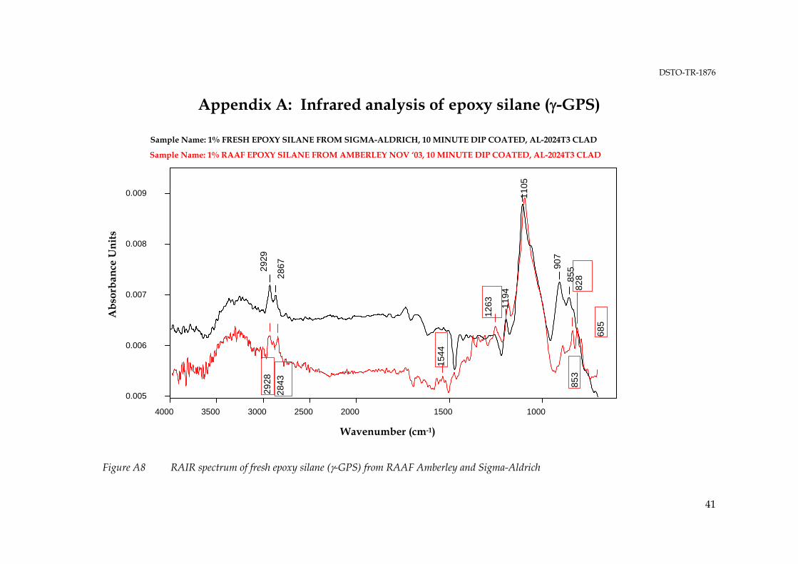
DSTO-TR-1876
41
Appendix A: Infrared analysis of epoxy silane (γ-GPS)
2929
2867
1194
1105
907
855
10001500 2000250030003500 4000
0.005
0.006
0.007
0.008
0.009
Abs
orba
nce
Uni
ts
2928
28
43
1544
1263
853
828
685
Sample Name: 1% FRESH EPOXY SILANE FROM SIGMA-ALDRICH, 10 MINUTE DIP COATED, AL-2024T3 CLAD
Sample Name: 1% RAAF EPOXY SILANE FROM AMBERLEY NOV ‘03, 10 MINUTE DIP COATED, AL-2024T3 CLAD
Wavenumber (cm-1)
Figure A8 RAIR spectrum of fresh epoxy silane (γ-GPS) from RAAF Amberley and Sigma-Aldrich

DSTO-TR-1876
42
Sample Name: 1% OLD EPOXY SILANE, 10 MINUTE DIP COATED, AL-2024 T3 CLAD
3364
2942
28
41
1731
1457
1344
1254
11
9711
10
912
825
1000 1500 2000 2500 3000 3500 4000
Wavenumber (cm-1)
0.08
0.10
0.12
0.14
0.16
0.18
0.20
0.22 A
bsor
banc
e U
nits
Figure A9 RAIR spectrum of aged epoxy silane (γ-GPS) from laboratory storage after 6 years.
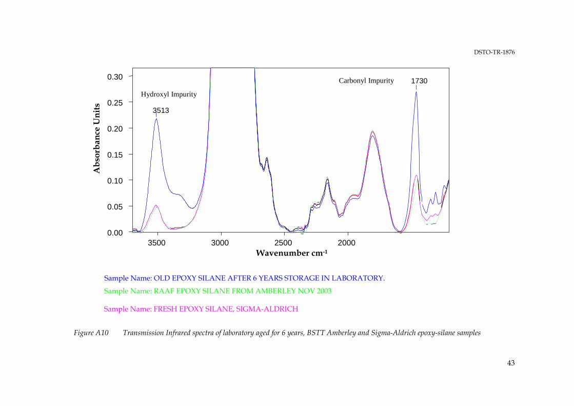
DSTO-TR-1876
43
Sample Name: OLD EPOXY SILANE AFTER 6 YEARS STORAGE IN LABORATORY.
Sample Name: FRESH EPOXY SILANE, SIGMA-ALDRICH
3513
1730
2000 2500 3000 3500 Wavenumber cm-1
0.00
0.05
0.10
0.15
0.20
0.25
0.30
Abs
orba
nce
Uni
ts
Hydroxyl Impurity
Carbonyl Impurity
Sample Name: RAAF EPOXY SILANE FROM AMBERLEY NOV 2003
Figure A10 Transmission Infrared spectra of laboratory aged for 6 years, BSTT Amberley and Sigma-Aldrich epoxy-silane samples

DSTO-TR-1876
DISTRIBUTION LIST
Review of RAAF Bonding Procedures for Qualifying Bonded Repair Technicians
Andrew Rider, Roger Vodicka, Gary Mathys and Ivan Stoyanovski
AUSTRALIA
DEFENCE ORGANISATION No. of copies
Task Sponsor ASI-4A ASI-4D
1 Printed 1 PDF 1 Printed
S&T Program Chief Defence Scientist 1 Deputy Chief Defence Scientist Policy 1 AS Science Corporate Management 1 Director General Science Policy Development 1 Counsellor Defence Science, London Doc Data Sheet Counsellor Defence Science, Washington Doc Data Sheet Scientific Adviser to MRDC, Thailand Doc Data Sheet Scientific Adviser Joint 1 Navy Scientific Adviser Doc Data Sht & Dist List Scientific Adviser – Army 1 Doc Data Sht & Dist List Scientific Adviser to the DMO Doc Data Sht & Dist List Deputy Chief Defence Scientist Aerospace
Doc Data Sht & Exec Summary
Chief of Air Vehicles Division Doc Data Sht & Dist List RL-AM 1 Printed Andrew Rider 1 Printed
1 PDF Roger Vodicka 1 PDF Ivan Stoyanovski 1 PDF Gary Mathys 1 PDF DSTO Library and Archives
Library Fishermans Bend Doc Data Sht Library Edinburgh 1 printed Defence Archives 1 printed Capability Development Group
Director General Maritime Development Doc Data Sheet Director General Capability and Plans Doc Data Sheet
DSTO-TR-1876
Assistant Secretary Investment Analysis Doc Data Sheet Director Capability Plans and Programming Doc Data Sheet Chief Information Officer Group
Director General Australian Defence Simulation Office Doc Data Sheet AS Information Strategy and Futures Doc Data Sheet Director General Information Services Doc Data Sheet Strategy Group Director General Military Strategy Doc Data Sheet Assistant Secretary Governance and Counter-Proliferation Doc Data Sheet Navy
Maritime Operational Analysis Centre, Building 89/90 Garden Island Sydney NSW Deputy Director (Operations) Deputy Director (Analysis)
Doc Data Sht & Dist List
Director General Navy Capability, Performance and Plans, Navy Headquarters
Doc Data Sheet
Director General Navy Strategic Policy and Futures, Navy Headquarters
Doc Data Sheet
Air Force
SO (Science) - Headquarters Air Combat Group, RAAF Base, Williamtown NSW 2314
Doc Data Sht & Exec Summary
Army
ABCA National Standardisation Officer Land Warfare Development Sector, Puckapunyal
Doc Data Sheet
SO (Science) - Land Headquarters (LHQ), Victoria Barracks NSW Doc Data Sht & Exec Summary
SO (Science), Deployable Joint Force Headquarters (DJFHQ) (L), Enoggera QLD
Doc Data Sheet
Joint Operations Command
Director General Joint Operations Doc Data Sheet Chief of Staff Headquarters Joint Operations Command Doc Data Sheet Commandant ADF Warfare Centre Doc Data Sheet Director General Strategic Logistics Doc Data Sheet COS Australian Defence College Doc Data Sheet Intelligence and Security Group
AS Concepts, Capability and Resources 1 DGSTA , Defence Intelligence Organisation 1 Manager, Information Centre, Defence Intelligence Organisation 1 Director Advanced Capabilities Doc Data Sheet Defence Materiel Organisation
Deputy CEO Doc Data Sheet Head Aerospace Systems Division Doc Data Sheet

DSTO-TR-1876
Head Maritime Systems Division Doc Data Sheet Program Manager Air Warfare Destroyer Doc Data Sheet CDR Joint Logistics Command Doc Data Sheet Guided Weapon & Explosive Ordnance Branch (GWEO) Doc Data Sheet OTHER ORGANISATIONS
National Library of Australia 1 NASA (Canberra) 1 UNIVERSITIES AND COLLEGES
Australian Defence Force Academy Library Head of Aerospace and Mechanical Engineering
1 1
Hargrave Library, Monash University Doc Data Sheet OUTSIDE AUSTRALIA
INTERNATIONAL DEFENCE INFORMATION CENTRES
US Defense Technical Information Center 1 UK Dstl Knowledge Services 1 Canada Defence Research Directorate R&D Knowledge & Information Management (DRDKIM)
1
NZ Defence Information Centre 1 ABSTRACTING AND INFORMATION ORGANISATIONS
Library, Chemical Abstracts Reference Service 1 Engineering Societies Library, US 1 Materials Information, Cambridge Scientific Abstracts, US 1 Documents Librarian, The Center for Research Libraries, US 1 INFORMATION EXCHANGE AGREEMENT PARTNERS
National Aerospace Laboratory, Japan 1 National Aerospace Laboratory, Netherlands 1 James Mazza, Air Force Research Laboratory, Manufacturing and Logistics
1 Printed
SPARES Total number of copies: Printed: 12 PDF: 24
5 Printed

Page classification: UNCLASSIFIED
DEFENCE SCIENCE AND TECHNOLOGY ORGANISATION
DOCUMENT CONTROL DATA 1. PRIVACY MARKING/CAVEAT (OF DOCUMENT)
2. TITLE Review of RAAF Procedures for Qualifying Bonded Repair Technicians
3. SECURITY CLASSIFICATION (FOR UNCLASSIFIED REPORTS THAT ARE LIMITED RELEASE USE (L) NEXT TO DOCUMENT CLASSIFICATION) Document (U) Title (U) Abstract (U)
4. AUTHOR(S) Andrew Rider, Roger Vodicka, Gary Mathys and Ivan Stoyanovski
5. CORPORATE AUTHOR DSTO Defence Science and Technology Organisation 506 Lorimer St Fishermans Bend Victoria 3207 Australia
6a. DSTO NUMBER DSTO-TR-1876
6b. AR NUMBER AR-013-677
6c. TYPE OF REPORT Technical Report
7. DOCUMENT DATE June 2006
8. FILE NUMBER 2006/ 1066409
9. TASK NUMBER AIR 04/ 291
10. TASK SPONSOR DGTA
11. NO. OF PAGES 43
12. NO. OF REFERENCES 11
13. URL on the World Wide Web http://www.dsto.defence.gov.au/corporate/reports/DSTO-TR-1876.pdf
14. RELEASE AUTHORITY Chief, Air VehiclesDivision
15. SECONDARY RELEASE STATEMENT OF THIS DOCUMENT
Approved for public release OVERSEAS ENQUIRIES OUTSIDE STATED LIMITATIONS SHOULD BE REFERRED THROUGH DOCUMENT EXCHANGE, PO BOX 1500, EDINBURGH, SA 5111 16. DELIBERATE ANNOUNCEMENT No Limitations 17. CITATION IN OTHER DOCUMENTS Yes 18. DSTO RESEARCH LIBRARY THESAURUS Adhesives, adhesive bonding, surface treatment, bonded composite repairs, maintenance standards 19. ABSTRACT DSTO has recently undertaken a review of procedures employed by the Royal Australian Air Force (RAAF) Bonded Structures and Testing Team (BSTT) during testing and requalification of technicians who undertake bonded repairs on ADF aircraft. Currently, technicians are required to produce a bonded wedge test under examination from BSTT staff and, based on adherence to the current RAAF Engineering Standard, will be considered competent to undertake bonded repairs. From December 2001 to January 2004 a notable deterioration in the quality of the bonded wedge tests produced through qualification testing was observed and an audit of processes was undertaken to determine if any areas in the bonding and requalification testing may have been leading to the deterioration in quality. Based on an audit of the processes and subsequent experimental testing at DSTO, recommendations on improvements to bonding procedures have been made.
Page classification: UNCLASSIFIED