review of fluid structure interaction methods application
TRANSCRIPT

63
International Journal of Fluid Machinery and Systems DOI: http://dx.doi.org/10.5293/IJFMS.2018.11.1.063
Vol. 11, No. 1, January-March 2018 ISSN (Online): 1882-9554
Original Paper
Review of Fluid Structure Interaction Methods Application to
Floating Wave Energy Converter
Mohammed Asid Zullah1, Young-Ho Lee2
1Geoscience, Energy and Maritime Division, Pacific Community,
Private Mail Bag, Suva, Fiji, [email protected] 2Division of Mechanical Engineering, College of Engineering, Korea Maritime and Ocean University, 727
Taejong-ro, Yeongdo-Gu, Busan 49112, South Korea, [email protected]
Abstract
Computational fluid dynamics (CFD) is a highly efficient paradigm that is used extensively in marine renewable
energy research studies and commercial applications. The CFD paradigm is ideal for simulating the complex dynamics
of Fluid-Structure Interactions (FSI) and can capture all kinds of nonlinear fluid motions. While nonlinear simulations
are considered more expensive and resource intensive compared to the frequency domain approaches, they are much
more accurate and ideal for commercial applications. This review study presents a comprehensive overview of the
computation fluid dynamics paradigm in context of wave energy converter (WEC) and highlights different CFD tools
that are available today for commercial and research applications. State-of-the-art CFD codes such as ANSYS CFX that
are highly ideal for WEC simulation problems are highlighted and aspects such as time and frequency domains are also
thoroughly discussed along with efficacy of the nonlinear simulations compared to the linear models. The paper presents
a comparative evaluation of different WEC modelling codes available today and illustrates the code framework of
different CFD simulation software suites.
Keywords: CFD, FSI, Navier-Stokes equation, WEC, nonlinear, simulations.
1. Introduction
The concept of modern computational fluid dynamics first took shape in the early seventies when it essentially represented a
conglomeration of domains such as physics, mathematics and computer science used for the purpose of simulating fluid flow dynamics
[1]. A study carried out by Kopal (1947) is probably the very first significant example of CFD where he deduced supersonic flow
values that flowed over geometrical cone structures [2]. With the development of fast mainframes in the late fifties and sixties the first
generation of computational fluid dynamics solutions started becoming available. Computational fluid dynamic solutions that came
next started implementing governing equations such as the Navier–Stokes equations to solve fluid hydrodynamic problems.
Today, the relevance of computational fluid dynamics with regards to hydrodynamic problem solving and simulations has become very
high and with the progress in computational technology the stature of CFD is defined as a third dimension in the area of fluid dynamics
[1]. In the recent years researchers have extensively used the CFD (Computational Fluid Dynamics) paradigm to understand the
underlying hydrodynamic properties of WECs. In a recent study, researchers used CFD to analyze the impact of chamber-duct on the
inner water surface amplitude and nozzle air flow [3]. Another CFD study conducted in 2012 focused on an experiment carried out by a
group of researchers in 2007 and reported that there has been an overestimation of efficiency by up to 30% because the several aspects
such as complicated variations in pressure were never taken into account [4][5]. The experiment carried out by Thomas et al. (2007)
was further repeated by Kamath et al. (2015) where they carried out complicated computational fluid dynamics simulations to
understand if there is any effect on the operational efficiency of wave energy converters such as the Oscillating Water Column device
mediated by power take-off damping [5][6]. In essence, researchers today fully appreciate the efficacy and applicability of the
computational fluid dynamics paradigm for oceanic wave energy research and for better understanding of the interaction of oceanic
waves with the wave energy converters in a simulated environment. A common apprehension regarding the usage of computation fluid dynamics in marine engineering is that it is not very cost-
effectiveness and for that reason many commercial organizations prefer to go for the tried and tested frequency-based methods. As a
matter of fact, setting up massive turbines to capture energy from tidal streams could be very difficult [7]. However, given the broad
applicability and efficacy of computational fluid dynamics it is definitely a more desirable option compared to the traditional methods.
Computational fluid dynamics offer a highly detailed overview of the interaction between oceanic waves and structure and is definitely
not restricted to the linear motions alone unlike the traditional frequency-based methods. Computational fluid dynamics can also be
Received December 12 2016; revised January 9 2017; accepted for publication Agust 10 2017: Review conducted by Abdus Samad.
(Paper number O16042K)
Corresponding author: Young-ho Lee, [email protected]

64
used to simulate the physics and the dynamics of waves breaking and overtopping and given the exceptional pace of development in
computational technologies more robust algorithms are being conceptualized and developed, making them highly ideal for sectors such
as marine engineering and wave energy conversions [8]. Algorithms implementing computational fluid dynamics executes the Navier-
Stokes equations that can handle both non-linear and rotational dynamics. This make that highly intensive computationally and their
implementation becomes extremely resource intensive. However this can definitely be considered an acceptable trade-off because
computational fluid dynamics allow simulation of analysis of complex aspects such as wave drag, viscosity and other forces that are
entirely non-linear in nature. Furthermore, numerical simulations can be carried out at minimal costs and are almost entirely risk-free.
They can be excellent tools to ascertain the impact of the tidal stream turbines on the environment and can also be very instrumental in
the modelling of the turbine blades [9, 10]. Other options that can be very useful for offsetting the high computation costs of CFD
applications are the nonlinear model-reduction methods that are projection-based [11, 12]. These projection-based approaches are very
ideal for systems that are linear and essentially time-invariant and also for those systems that are linear and stationary [13, 14]. The
projection based model reduction paradigms are also ideal for nonlinear systems based on quadratic nonlinearities and to solve
problems of structural dynamics [15, 16, 17]. These paradigms function by approximating a functional model with minimal dimension
and are highly ideal for aerodynamic problem solving [18,19,20,21,22]. As a result, the project-based models become ideal for
applications that are highly time-sensitive such as flow control, optimization of structure designs and estimation of structure
uncertainties [23,24,25]. The projection-based methods have also been found to be effective for problem solving in the aero elasticity
domain. [26,27,28].
In the recent times a wide range of studies have used complex computational fluid dynamics for device simulation in experimental
tanks. A recent study by Bhinder et al. (2011) successfully used computational fluid dynamics to calculate the viscous drag coefficients
of wave energy conversion devices [29]. Similarly multiple research studies are currently underway to further streamline the
applicability of computational fluid dynamics in wave energy conversion array problems and establish the efficacy of the same [30].
2. The Core of CFD: Reynolds-Averaged Navier-Stokes Equations
In any given engineering problem scenario, substantial fluctuations can be seen in the fluid flow levels, both in the time and
space domain. These fluctuations are mediated largely by turbulence but it needs to be noted that the fluctuation values are stable
and stays within a fixed range. The Reynolds averaged Navier-Stokes equations utilize the average fluid flow quantities and
properly address the influence or the effect of turbulence. The average flow quantities are deduced in Reynold’s averaged
quantities and this allows expression of every dependent variable. Each dependent variable is made up of average time value and
the value of the fluctuating component [31]. Advanced computational fluid dynamics address the engineering problem of fluid
flow by executing the governing Reynolds averaged Navier-Stokes equations shown below.
(1)
(2)
In the above governing equations, u stands for the average velocity value over a specific time period t. The fluid density value is
represented by ρ and the pressure is represented by p. The fluid kinematic viscosity value is represented by ν and the eddy
viscosity is represented by νt. Finally, the fluid acceleration due to the gravitational pull is represented by g [6]. To analyze the
effects of diverse hydrodynamic forces during any kind of wave energy converter simulation, it is important that factors such as
turbulence, overtopping and oceanic wave breaking are properly taken into consideration. All of these are not possible to account
for using the standard potential flow paradigm and that is one of the main reasons why researchers prefer the Navier-Stoke
equation methods [32].
While implementing CFD approaches based on Navier-Stokes equations to simulate hydrodynamic models of floating
structures such as wave energy convertors, the free surface values are deduced for a numerical wave tank along with the
simulation of the flow turbulence. There are two main ways or methods to calculate the free surface values called the surface
tracking method and the interface-capturing method. The surface tracking method considers the free surface as a clear and distinct
boundary and carries out regular updating of the same in progressive time points [33]. However, this method is not capable of
taking into consideration other important factors such as overtopping and oceanic wave breaking. The second method called the
interface-capturing method involves a grid-based simulation where both air and water phases are taken into consideration. With
regards to the interface-capturing methods the most common choices that are available are Volume Of Fluid (VOF) method, the
level set approach and the Marker-and-Cell (MAC) method [34][35][36 ][37]. Majority of the computational fluid dynamics
paradigms that are commercially available utilize the Volume Of Fluid method for interface capturing and a highly detailed
analysis of all the above methods and their utilization in the simulation of the oceanic wave hydrodynamics can be found in two
separate studies carried out by Ferziger & Peric and Lin & Liu [38][39].Computational fluid dynamics paradigms that implement
the Navier-Stokes equations also routinely use the artificial damping layer method during wave-structure interaction studies as
seen in a study carried out by Lara et al. (2006). In this study, the researchers used two methods called the sponge-layer method
and the internal-wave maker method together to simulate the dynamics of the interaction between wave and structure [39].
There are four major numerical methods to simulate wave turbulence flow called the direct numerical simulations, large eddy
simulations, Reynolds-averaged Navier-Stokes methods and detached eddy simulations. While direct numerical simulations
method implement the Navier-Stokes equations to give a thorough description of wave turbulence, it is extremely intensive with
regards to computational resources. For this reason the direct numerical simulations method is not significant from a commercial
perspective but very ideal for research purposes [40]. The large eddy simulation method on the other hand is less resource
intensive compared to the direct numerical simulations method and can account for large as well as small wave turbulence [41].
None the less, the large eddy simulation method is still expensive from a commercial perspective when it comes to the simulation

65
of the hydrodynamic properties of floating structures such as wave energy convertors and the best method from all aspects is the
Reynolds-averaged Navier-Stokes method, when it comes to simulation of wave flow turbulence. Moctar et al. used a the
Reynolds-averaged Navier-Stokes model to analyze load of waves on a structure platform where the Volume Of Fluid (VOF)
method was utilized for evaluating the stress on the structure and calculate the free-surface values [42]. This study clearly
indicated that efficacy of the Reynolds-averaged Navier-Stokes model that thoroughly took into account the stress values of wave
run-up and wave loads on the structure.
3. Computational Fluid Dynamics and WEC Design, Simulation And Implementation
During the design process of wave energy converters few critical aspects such as the hydrodynamic properties of the convertor,
mooring and power take-off needs to be thoroughly evaluated together to ensure that they do not influence the dynamics of one
another. It is also important that the time domain is properly taken into consideration for any type of modelling during wave
energy convertor studies and also for analyzing the wave-structure interaction processes that are nonlinear in nature. A study
carried out by Cummins involved the determination of impulse response functions for the purpose of frequency coefficient
conversions in the time domain [43]. The impulse response function allows evaluation and analysis of the system behavior and
response following the first impulse and it can also be used to formulate the equation of motions in the time domain. The use of
impulse response function allows the simulation of the irregular oceanic state but when multiple wave impulses are taken into
consideration together, aspects such as irrotational fluid flow and dynamics of the linear theory may get overlooked. In essence,
when large wave-structure interactions are considered it may be possible that the inherent frequency of the wave almost becomes
identical to the frequency of the wave energy convertor and this could lead to massive structural body movements due to non-
consideration of factors such as friction and viscosity induced drag or loss [8]. Furthermore, it has been observed that a proper
evaluation of the hydrodynamic properties of the interaction between wave and structure is not entirely possible, ideal or accurate
with linear theory and requires the use of non-linear numerical paradigms. In this context, implementation of the Navier-Stokes
equations can lead to thorough evaluation and understanding of the hydrodynamic properties of the interaction between wave and
structure.
As already mentioned earlier, computational fluid dynamics execute the Navier-Stokes equations and it commonly uses surface
capturing methods such as the VOF surface capture method. While doing so, the algorithm also takes into consideration the effect
of water volume in the given simulated cell. An approach such as this was successfully used by a group of researchers who tried to
simulate the movement of ships in massive oceanic waves [44]. The traditional approach that is adopted to evaluate and analyze
wave energy convertors involve the implementation of the linear potential flow theory where the time and frequency domain
parameters are deduced based on tiny amplitude oscillations. However, when seen from a real-world or practical perspective,
these small amplitude assumptions that sustain linearity are not adequate for wave energy convertors and the aspect of nonlinear
influences also become a problem. With the availability of sophisticated computational fluid dynamics paradigms, the time
domain parameters are properly addressed and the iterative implementation of the Navier–Stokes equations further allows
consideration of nonlinear power-take off process in a wave energy convertor [45]. During the analysis of wave energy convertors
linear hydrodynamic model approaches are necessary to take into account factors such as wave motions, wave loads and power
generation from the convertors. Navier-Stokes model that utilizes the Volume of Fluid (VOF) method have indicated that results
obtained from linear hydrodynamic models with regards to estimation of power production could be erroneous. In essence,
researchers have observed that linear models overestimate power production from WECs compared to the Navier-Stokes Volume
of Fluid (VOF) method [46] [47]. Another aspect that makes nonlinear approaches such as the Navier-Stokes Volume Of Fluid
(VOF) method more ideal compared to linear hydrodynamic models is during power estimation from WECs installed near the
shoreline. Close to the shoreline, nonlinear dynamic forces are more evident in the waves and standard linear hydrodynamic
model approaches are not capable to account for the same [48]. Table 1 below presents an overview of the different open-source
and commercially distributed CFD software tools that are available today. The different software tools are categorized as CFD
solvers, grid generators and those ideal for visualization. It however needs to be noted that this list is not exhaustive [49].
Simulation of the hydrodynamic properties of wave energy convertors is dependent on factors such as the cost-effectiveness of
the approach and its ability to describe every physical aspect of the fluid flow and its interaction with the structure. Table 2 below
highlights different approaches to carry out hydrodynamic modelling where the boundary integral equation method and the
Navier-Stokes equation method are ideal for more complex hydrodynamic modeling. The Morrison approach along with the
analytical approach on the other hand are more suitable for simple dynamics.
The hydrodynamic properties of wave energy convertors are also influenced by the mooring systems made up of mooring lines,
connectors and anchors that connect structures such as floating devices to the sea bed. A wide range of studies have been carried
out that that connect the wave energy convertors with the mooring systems in the time and frequency domains. Studies such as
that of Emmanuel B. A. et al. have simulated through commercial software the behavior of other devices that extract energy from
waves, such as buoys. In their research they used the COMET software to create the model that tries to describe the behavior of
the device, that device can be used in pattern form, such as wind turbines [50]. In essence, the governing equations of such
simulations take into account the behavior of the mooring devices as they withstand different forces such as viscous drag. A study
carried out by Johanning et al. demonstrates how the mooring systems behave under viscous effect and in order to provide an
accurate approximation of a wave energy convertor connected to a mooring device, a nonlinear time domain model becomes
necessary [51]. Fitzgerald & Bergdahl also studied the damping behavior of a mooring system connected to a structure (wave
energy convertor) by constructing a frequency map of the mooring system behavior [52]. This involved linearization of the
standard nonlinear equations and the resulting frequency map was then used to study the behavior of the wave energy device not
connected to a mooring system. This approach is highly resource intensive from a computing perspective but when carried out in
the frequency domain instead of the time domain, the computational cost can come down substantially.

66
Table 1 Open-source and commercially distributed CFD software tools
Distribution CFD solvers Grid generation Visualization
Open source COOLFluiD Engrid COVISE
Open source Dolfyn GMSH DISLIN
Open source Dune SALOME GMV
Open source Edge NETGEN DISLIN
Open source ELMER TETGEN Mayavi
Open source HiFlow Triangle Tioga
Open source Gerris Flow Solver TwinMesh VAPOR
Open source MFIX Delaundo Vigie
Open source OpenLB Visit
Open source OpenFVM vtk
Open source TYCHO COVISE
Commercial AcuSolve BOXERMesh Fieldview
Commercial ADINA-FSI Cubit Tecplot
Commercial ANANAS GridPro HyperView
Commercial CFD2000 HyperMesh ViewZ
Commercial CharLES ANSA ADINA-AUI
Commercial COMSOL
Multiphysics
SolidMesh CFView
Commercial EasyCFD TwinMesh CFX-Post
Commercial FluSol Harpoon Fieldview
Commercial NOGRID HyperMesh EnSight
Commercial SHIPFLOW ICEM CFD VU
Commercial SPLASH
Commercial TURBOcfd
Table 2 Different hydrodynamic modelling approaches
Analytical
method
Morison
method
Boundary
integral
equation
method
(Frequency
domain
Boundary
integral
equation
method (Time
domain)
Navier-Stokes
equation method
Viscosity
dynamics
Not accounted
but can be
integrated as
an input
Accounted
Not accounted
but can be
integrated as
an input
Not accounted
but can be
integrated as
an input
Accounted
Fluid-structure
interactions
Linear in
nature
No effect of the
structure
movement
Weak
Nonlinear
Nonlinear in
the time
domain
Robustly nonlinear
Wave-breaking None None None None
Accounted using
the Volume of
Fluid method
Accuracy of
the method in
general
Very
inaccurate
Acceptable
with the
modification of
the
hydrodynamic
coefficients
Very
inaccurate
Acceptable
results
Very accurate
results
Accuracy
under
resonance
effect
Very
inaccurate
Acceptable
with the
modification of
the
hydrodynamic
coefficients
Very
inaccurate
Acceptable
results
Very accurate
results
67
Yassir et al. adopted another interesting approach to analyze the mooring system behavior but it is applicable when nonlinear
aspects such as damping of mooring systems are linear in nature [51][53][54]. The benefits of wave energy are clearly defined in
researches such as W. B Wan Nik et al. [55], which highlights the main energy, economic and geographical aspects of the wave.
These researchers also highlight the advantages of this type of energy in a comparative criticism against the other renewable
energy sources [55]. Studies such as those of Masami Suzuki et al. show models of wave energy converters with different
configurations, emphasizing the profiles of the blades and how these profiles influence the efficiency of the converter [56]. There
are several devices that can extract energy from the waves, in a study conducted by Sangyoon K. et al., we can verify the
operation of a cross-flow turbine [57]. An advantage of this type of energy against hydroelectric power is the possibility of using
turbines that extract energy from the waves through the compression and expansion of the air in a chamber that expands and
contracts with the movement of waves, thus generating power in two phases [55]. Vicente et al. presented another study where
they analyzed the hydrodynamic properties of wave energy convertors along with factors such as power take-off damping for
different linear mooring configurations [58]. Though this approach can be directly applied to evaluate the hydrodynamics of wave
energy convertors, it is linear in nature and will not nonlinear effects such as viscous drag effect.
The CFD analysis of aerodynamic and hydrodynamic flows and their interaction with structure (WEC, rotor blades) is either a
nonlinear approach in the time domain or the frequency domain. Within the time domain paradigm the fluid flow equations are
represented in terms of a computational grid. The solution to the flow equations are then forwarded from one time point strata to
another using standard computational dynamics paradigms. This field of study is very open, there are even studies that explain
how to carry out an analysis using ANSYS CFX as a tool [59]. The hydrodynamic properties of wave energy advantages of this
approach in the sense that it is relatively straightforward to implement and can model nonlinear as well as linear disturbances.
However, a trade-off with this approach is that the computational processing periods could be quite large in order to ensure
accuracy [60]. The practical research carried out by C. Windt et al. is another very important point of these systems i.e. fatigue
loading. Using a FSI-based methodology and practical experiments, it shows that it is possible to bring this complex system to an
FEA. The accuracy of the results is relatively low, however the researchers note that there are other methods that could achieve
greater accuracy, however these methods have a higher computational cost, which is prohibitive. For that reason resorting to
obtain the data for its analysis of experimental tests [61].
The frequency domain on the other hand are linearized for time and involves deduction of the time-mean flow value. The
deduction of the time-mean flow value involves deduction of the steady-flow equations through standard computational fluid
dynamic paradigms. The governing frequency domain equations can be solved using minimal computational resources but they
are not able to model any nonlinear hydrodynamic properties [60]. In a recent study, Lin (2016) proposed a frequency domain
hydro elastic Boundary Element Method model that is ideal for studying wave-structure interaction dynamics [60]. The model
works well for offshore structures such as wave energy convertors but the waves becomes rough or large a nonlinear model
approach becomes necessary. For this reason the time domain hydro elastic Boundary Element Method model becomes more ideal
and easier to implement, especially when accounting for wave-structure dynamics under large waves.
A wide range of modelling tools are available today for the purpose of simulating wave energy conversion systems. These state-
of-the-art codes utilize the multimode dynamic paradigms in the time domain to simulate and model WEC movements and to
simulate the different hydrodynamic forces experienced by the structure, the codes make use of the hydrodynamic coefficients.
The past few years have witnessed a massive surge in the development and availability of software utilities that are specifically
designed for the simulation of the hydrodynamics of the wave energy convertors. These codes are well-equipped to model the
complex interactions that take place between fluid and structure and also the dynamics of power take off systems within a
simulated environment. Some of the codes that are specifically designed for the modelling of the WEC dynamics are discussed
below.
ProteusDS: This is a sophisticated software tool that specifically targets the offshore and marine applications and come with a
highly intuitive GUI. The software utility allows excellent 3D rendering of WEC simulations and it utilizes the multi-body
dynamic paradigms in the time domain to simulate and model WEC movements, making it ideal for the marine renewable energy
sector [63]. ProteusDS can be effectively used to simulate the effect of extreme forces such as wind and oceanic waves on virtual
WEC structures and ascertain their structural integrity. The software can be used to scale the risks and optimize the WEC structure
before its implementation in the real world and a major benefit with ProteusDS is its high computational efficiency. [64]. The
software is fully compatible with boundary element method paradigms, making it highly ideal for simulation and modelling of
structures exposed to forces such as oceanic waves and currents. The inherent physics model of ProteusDS has been the subject of
numerous studies and is well-validated for commercial and research implementations [65, 66, 67, 68].The software utility can
account for a wide range of aspects such as power-takeoff dynamics, fluid viscosity strains on the structure, moorings and hull
connections. Furthermore, Table 3 below presents a comparison of the features present in different WEC simulation/modelling
codes [78].
InWave: This is another software tool that utilizes the multibody dynamic paradigms in the time domain for modelling WEC
interactions. InWave is entirely nonlinear in nature and strongly connected to a linear flow solver, allowing it to account for all the
hydrodynamic interactions of fluid and structure [69]. The software package integrates with itself a range of solver codes such as
boundary element method, power take off and moorings in dedicated modules and they can all be programmed to run in a
sequential manner. Figure 1 below presents the organization of the InWave software suite [70].
WEC-Sim: WEC-Sim or Wave Energy Converter SIMulator is a MATLAB/SIMULINK based utility that utilizes the
multibody dynamic paradigms for modeling. The tool is highly ideal for modelling of rigid structures in the time domain and
simulation involves the use of the Cummins's paradigm for solving the governing wave energy converter equations [71]. Figure 2
below illustrates the schema of the WEC-Sim code [72].
WaveDyn is a fully coupled simulation tool designed for wave energy. It allows you to simulate the performance and loading on
a wave energy device. It enables you to model hydrodynamics calculations, and control and power take-off systems. Developed by

68
DNV-GL specifically for evaluating WEC performance. The software allows a user to construct a numerical representation of a
WEC by connecting structural, hydrodynamic, power take-off (PTO) and mooring components using a flexible user interface.
Single machines may be modeled in isolation, or a user may choose to build a multiple WEC simulation model for a known array
layout. The hydrodynamics module in its most basic form is a quasi-linear formulation based on a boundary element method
(BEM), potential flow solver such as WAMIT. Diffraction, radiation, hydrostatic and viscous effects are included in the model.
WaveDyn has already been subject to a number of validation campaigns against experimental measurements on various device
types, scales, in isolation or in array [73, 74, 75].
ANSYS: One of the most sophisticated and robust computational fluid dynamics software suite available today is ANSYS and
it is highly ideal for the simulation and modelling of phenomena such as fluid structure interactions and fluid flow. The software
suite offers extensive analytical capabilities with regards to fluid flow and interaction simulations and is highly ideal for
optimization of virtual structures before installation as well as fault rectification with the existing installations. The software suite
packs in utilities such as ANSYS CFX and ANSYS Fluent that allows simulation and modelling of a very wide range of physical
phenomenon [76]. ANSYS CFX is highly ideal for simulation of WEC interactions and can handle almost all kinds of fluid flow
movements and fluid structure interactions. ANSYS CFX implements a robust solver paradigm that offers a wide range of models
to simulate almost every kind of fluid flow interactions and phenomena. The ANSYS CFX comes with a user-friendly graphical
interface and it allows extensive customization and adaptation. When ANSYS CFX is coupled with the ANSYS platform the user
gets access to powerful CAD utilities that allows simulation and modelling of all kinds of fluid structure interaction problems [77,
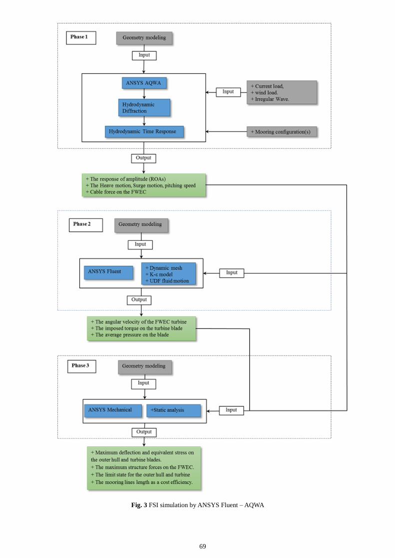
114]. An example is shown in Figure 3.
Fig. 1 Organization of the Inwave software suite
Fig. 2 WEC-SIM code framework
69
Fig. 3 FSI simulation by ANSYS Fluent – AQWA

70
4. Fluid Structure Interaction Simulation
Evaluation, analysis and mathematical deduction of fluid structure interaction dynamics with state-of-the-art computational
fluid dynamic paradigms are becoming increasingly common in the recent years [79][80]. A major reason behind this is due to the
fact that approaches such as finite volume methods and tools such as equation solvers (linear/nonlinear) have become more
powerful and cost-effective from a commercial perspective. To arrive upon a conclusion and accurate deduction of fluid-structure
interaction problems two main approaches could be adopted. The first approach is more common with regards to its usage and
involves the fluid aspect handled using a Lagrangian–Eulerian formulation and the structure aspect, handled using a Lagrangian
formulation [79] [80][81] [82]. The second approach involves a standard Eulerian formulation along with a fixed fluid mesh for
the fluid aspect and the Lagrangian formulation for the structure aspect [79] [80]. A wide range of engineering simulations and
applications require that the fluid flow that is estimated is high accurate and holds ground in a practical scenario. With regards to
the simulation of the fluid flows that is three dimensional in nature, the computational load could be very high but the fluid
meshes can be highly efficient. This would in turn necessitate the grading of the fluid mesh which is directly dependent on the
dynamics of the fluid flow. For this reason the fluid structure interaction procedures that facilitates effective grading of the fluid
mesh in an adaptive manner are extremely ideal for application. For the benefit of scientific studies that focuses on fluid structure
interactions, it is important that such tools or solutions are implemented that can concurrently handle complex computation fluid
dynamics and fluid structure interaction problems at the same time [83]. Any complex fluid structure interaction problems could
involve fluid flows such as incompressible fluid flows or the compressible fluid flows and considering the structural deformations
that can take place in the structure, they can get strongly affected by the fluid flows (incompressible or compressible) [79]
[80][81][83].
When fluid structure interactions undergo computer simulation the structure and the fluid state are rendered mathematically
discrete and the algebraic equations need to be deduced together or one after the other. As mentioned earlier, deduction of fluid-
structure interaction problems can be through two main approaches involving the fluid and structure (solid) domains. However,
for the sake of clarity, a typical fluid structure interaction solver adds a third domain called the interface to the already existing
fluid and structure (solid) domains [84]. This extended approach is capable of accounting for other deductions such as traction
force transfer values and other kinematic information. The fluid structure interaction solver with the three domains (fluid,
structure and interface) is illustrated in figure 4 below [84].
Table 3 Different hydrodynamic modelling approaches
Code Name InWave WaveDyn ProteusDS WEC-Sim v1.0
Code Developer INNOSEA/ECN DNV GL DSA NREL/SNL
Multibody
Mechanics
Relative coordinate
algorithm
Proprietary
multibody
method
Articulated Body
Algorithm SimMechanics
Hydrodynamics
Linear potential,
Nonlinear Froude-
Krylov
Linear potential,
Nonlinear
Froude-Krylov
Linear potential,
Nonlinear
Froude-Krylov
Linear potential,
Nonlinear Froude-
Krylov
BEM Solver Integrated
(NEMOH)
Multiple options
(inc. WAMIT and
AQWA)
Multiple options
(inc. WAMIT and
SHIPMO3D)
Multiple options (inc.
WAMIT, AQWA, and
NEMOH)
Hydro-Mechanics
Coupling
Relative
coordinates
Generalized
coordinates
Generalized
coordinates
Generalized
coordinates
Hydrostatics Linear,
Nonlinear
Linear,
Nonlinear
Linear,
Nonlinear
Linear,
Nonlinear
Body-to-Body
Hydrodynamic
Interactions
Yes Yes Yes Yes
Viscous Drag
Formulation
Morison elements
with relative
velocity
Morison elements
with relative
velocity
Morison elements
with relative
velocity
Quadratic damping
using body velocity,
Morison elements
with relative velocity
Mooring (Linear
Stiffness/Quasi-
Static/Dynamic)
Yes/Yes/No Yes/Yes/No Yes/No/Yes Yes/No/No
PTO and Control
Linear,
Look-up table, and
API
Linear and API
Linear,
PID control, and
API
User-defined in
MATLAB/Simulink
License Commercial Commercial Commercial Apache 2.0
External Software None None None MATLAB, Simulink,
SimMechanics

71
Fig. 4 Fluid Structure Interaction Solver Structure
In the fluid structure interaction solver, ui stands for the kinematic degrees of freedom of the interface and uf stands for the
degrees of freedom of the fluid domain that involves fluid velocity and fluid pressure. Furthermore, xf stands for the degrees of
freedom of the fluid mesh and ds stands for the degrees of freedom of the structure (solid) [84]. The governing equations for the
fluid structure interaction paradigm (with fluid, structure and interface domains) described above are given as follows:
rf (uf , ui) = 0; Representing the Fluid domain.
gf (uf , ui) + gs(ds, ui) = 0; Representing the interface domain.
rs(ds, ui) = 0 ; Representing the structure (solid) domain.
For every time point corresponding to ui, uf and ds, the three governing equations are solved. Also seen in the above
equations are two vectors, rf and rs that defines the residual forces on the solid and fluid domains and the vectors gf and gs defines
the traction experience by the interface between the fluid and the structure (solid) phase. These governing equations implement
the Newton-Raphson paradigms and are deduced together or in concurrent steps. The interface domain between the fluid and
structure (solid) phases are formulated using two main approaches called interface capturing and interface tracking. Interface
capturing involves sliding of the fluid and the structure mesh over each other and this approach is primarily used with Eulerian
fluid mesh. The approach does not have any limitations with regards to the degree of rotations but is not very accurate. Interface
tracking involves the fluid and the structure domains moving together instead of sliding and is more accurate than interface
capturing. A trade-off with Interface tracking is that it is not suitable when the degree of rotations or deformations are large [84].
The fluid structure interaction solvers can be categorized into four main types as illustrated in figure 5 below.
Fig. 5 Categorization of Fluid Structure Interaction Solvers (Dettmer, 2012)
The Newton-Raphson solvers in the above figure are highly robust and accurate but are highly resource intensive because the
equations for the fluid, structure, interface and mesh are combined to form a single matrix equation. The Gauß-Seidel iteration and
the staggered schemes on the other hand handle the domains separately and does not involve formation of any single matrix
equation. There are separate equations for each domain and they are deduced separately as independent equations making the
solvers fact and less resource intensive [84].
The FSI analysis have a very significant practical use, allowing to optimize the efficiency in turbo machines and thermal
machines. An example of this is the optimization study carried out by Hyun-Su and Youn-Jea Kim on a high-power centrifugal
compressor, where, thanks to the application of a FSI one-way coupling analysis, it was possible to increase its efficiency by 1%
[85]. Fluid Structure Interaction (FSI) is a part of a coupled-field analysis where various independent fields combine and interact
together to solve a global engineering problem with the result of one field dependent on the other. The coupling can either be
oneway or two-way. In one-way coupling, the effect of one field is imposed on the other but not the vice versa. A two-way
coupling is needed when the coupling between any two fields acquires significant response from each other. The coupling can be
addressed by one of the two methods-direct or iterative. In the direct method, a single set of monolithic equation is assembled,

72
leading to an increase in degrees of freedom of equations to be solved [86].
Other researchers have demonstrated through Francis turbine modal analysis, tested with air and water that the FEM methods
agree the experimental data, particularly the frequency reduction rates derived from the simulation. Based on these results, the
critical frequencies were identified, and these data were then used to perform a country based on the harmonic response. Finally,
they showed that the data obtained serve as a basis for the structural design based on the time of life [87]. Another research
indicates that current studies of CFD are not taking into account the deformation of turbine blades, caused by the force exerted by
the fluid on them, based on this fact, the researchers tested a model called "Two-way coupled FSI Simulations" in the
development of the study are left to see the shortcomings of the current tools in the FEA and the level of difficulty that this type of
analysis faces with the use of this methodology. This study suggests that to accurately predict the performance of hydraulic
machines in low head applications, an accurate representation of the physical phenomenon is essential [88]. The existing research
for unsteady flow field and the corresponding flow induced vibration analysis of centrifugal pump are mainly carried out
respectively without considering the interaction between fluid and structure. The ignorance of fluid structure interaction (FSI)
means that the energy transfer between fluid and structure is neglected. The average of total head with FSI was larger than the
total head without FSI. Therefore, the effect of FSI should be taken into account when the external characteristic of pump was
predicated by numerical simulation [89]
Other domains where Fluid structure interactions have also been applied for the purpose of simulation and problem solving
include aerodynamics, air/fluid turbulence, and sedimentation and particle assembly [90- 97]. Researchers have also found fluid
structure interactions to be effective to simulate the dynamics of complex flows in irregular domains, hydro-dynamics and
simulation of magneto-hydrodynamic flows [98, 99, 100, 101, 102]. Researchers have demonstrated the modelling of fluid
structure interaction problems based on fluid dynamic theory and the fluid structure interaction problem solving and simulation in
context of marine engineering have also been very well explored and presented [103,104]. Implementation of fluid structure
interaction approaches that are based on immersed boundary formulation paradigms have also be successfully demonstrated along
with boundary problem solving through fluid structure approaches [105, 106]. Another group of researchers also demonstrated the
efficacy of fluid structure interaction approaches by modelling the piston chamber in an enclosed gas chamber [107]. Fluid
structure interaction problems pertaining to the aspects such as fluid motion, traction movement and structure distortion have not
yet been adequately explored. Having said that, researchers have been very successful in modelling and simulating the
hydrodynamics of ships by concurrently using two approaches such as volume-of-fluid technique and immersed boundary
formulation [109, 110, and 111]. The same combination of approaches have also been used to model wave movement over
submerged oceanic structures and generation of waves [111]. Similarly, the level set approach conceived by Osher et al. has been
successfully integrated with a computation tool based on the Reynolds-averaged Navier-Stokes (RANS) model and also to model
and represent the free surface [112, 113].
5. Conclusion
It has become evident that the investigation of the hydrodynamic properties of devices such as wave energy convertors mainly
involve the linear potential flow theory. However, studies have clearly indicated that they have limitations associated with
ancillary assumptions of factors such as inviscid fluid, irrotational fluid flows, wave amplitudes and other structure movements.
These are critical limitations considering the fact that in a practical scenario the wave energy convertors would withstand massive
motions, wave drag forces and large wave amplitudes. All these aspects can be accommodated through the implementation of
the Navier-Stokes governing equations deduced by state-of-the-art computational fluid dynamic paradigms available today. A
sophisticated computational fluid dynamics model will encompass all forms of fluid structure interactions and forces such as
overtopping, massive structure/fluid motions and wave drag forces and can provide highly accurate simulations. Accurate
simulation results can go a long way in correct evaluation of hydrodynamic properties and estimation of other factors such as
power generation and structure survivability. Computational fluid dynamic approaches are nonlinear in nature and are considered
computationally intensive and not very cost-effective from a commercial perspective. However, it needs to be noted that unlike
linear frequency domain paradigms, the computational fluid dynamic paradigms can accommodate or account for every aspect of
wave structure interactions and given the rapid progress in computational technologies they are increasingly becoming cost
effective with fast. The use of computational fluid dynamics to study the wave-structure interactions is more common when
assumptions such as irrational fluid flow and small structure motions are not taken into consideration. During such computational
fluid dynamics modelling, a wide range of information with regards to the wave-structure interaction hydrodynamics become
available and the efficacy of the modelling process should ideally be weighed in light of the computational costs and the
executability of the CFD model. From an overall perspective, modern CFD solutions are the most ideal for the simulation of wave
energy convertors and evaluation of the wave structure interaction dynamics. Given the rate at which computational processing
speeds are increasing, the apprehensions surrounding CFD as being very resource intensive are also fast disappearing.
References
[1] J. Blazek, 2007, “Computational fluid dynamics,” Elsevier, Oxford.
[2] Kopal, Z., 1947, “Tables of Supersonic Flow Around Cones, Depart of Electrical Engineering,” Center of Analysis,
Massachusetts Institute of Technology, Cambridge.
[3] Liu Z., Hyun B. and Hong K, 2008, “Application of numerical wave tank to owc air chamber for wave energy conversion,”
Proceedings of the, 18th International Offshore and Polar Engineering Conference, Vancouver.
[4] Zhang Y., Zou QP. and Greaves D, 2012, “Air-Water two phase flow modelling of hydrodynamic performance of an oscillating

73
water column device,” Renewable Energy, 41, 159-170.
[5] Morris-Thomas MT., Irvin RJ. and Thiagarajan KP, 2006, “An investigation into the hydrodynamic efficiency of an oscillating
water column,” Journal of Offshore Mechanics and Arctic Engineering, 129, 273-278.
[6] Kamath, A,Bihs, H, and Arntsen, 2015, “THREE DIMENSIONAL CFD MODELING OF FLOW AROUND AN OWC WAVE
ENERGY CONVERTER,” E-proceedings of the 36th IAHR World Congress 28 June – 3 July, The Hague,
the Netherlands
[7] Willis, M., Masters, I., Thomas, S., Gallie, R., Loman, J., Cook, A., Ahmadian, R., Falconer, R., Lin, B., Gao, G.,Cross, M.,
Croft, N., Williams, A., Muhasilovic, M., Horsfall, I., Fidler, R., Wooldridge, C., Fryett, I., Evans, P., O'Doherty, T., O'Doherty D
and Mason-Jones, A, 2010, “Tidal Turbine Deployment in the Bristol Channel - A Case Study,” in: Proceedings of the Institution
of Civil Engineers.
[8] J. Westphalen, D. M. Greaves, A. Raby, Z. Hu, D. Causon, C. Mingham, P. Omidvar, P. Stansby and B. D. Rogers,2014,
“Investigation of Wave-Structure Interaction Using State of the Art CFD Techniques,” OJFD, vol. 04, no. 01, pp.18-43.
[9] S. Neill, J. Jordan and S. Couch, 2012, “Impact of tidal energy converter (TEC) arrays on the dynamics of headland sand
banks,” Renewable Energy, vol. 37, no. 1, pp. 387-397.
[10] T. O’Doherty, D. Egarr, A. Mason-Jones and D. O’Doherty, 2009, “An assessment of axial loading on a five-turbine array,”
Proceedings of the Institution of Civil Engineers - Energy, vol. 162, no. 2, pp. 57-65.
[11] A. C. Antoulas, 2005 “Approximation of Large-Scale Dynamical Systems,” Society for Industrial and Applied Mathematics,
Philadelphia, PA.
[12] D. Amsallem, J. Cortial, K. Carlberg and C. Farhat, 2009, “A method for interpolating on manifolds structural dynamics
reduced-order models,” International Journal for Numerical Methods in Engineering, vol. 80, no. 9, pp. 1241-1258.
[13] C. Prud’homme, D. Rovas, K. Veroy, L. Machiels, Y. Maday, A. Patera and G. Turinici, 2002, “Reliable Real-Time Solution
of Parametrized Partial Differential Equations: Reduced-Basis Output Bound Methods,” Journal of Fluids Engineering, vol.
124, no. 1, p. 70.
[14] G. Rozza, D. Huynh and A. Patera, 2008 “Reduced Basis Approximation and a Posteriori Error Estimation for Affinely
Parametrized Elliptic Coercive Partial Differential Equations,” Arch Computat Methods Eng, vol. 15, no. 3, pp. 229-275.
[15] K. Veroy, C. Prud’homme, D. V. Rovas, A. T. Patera, 2003 “A posteriori error bounds for reduced-basis approximation of
parametrized noncoercive and nonlinear elliptic partial differential equations,” AIAA Paper 2003-3847, 16th AIAA Computational
Fluid Dynamics Conference, Orlando, FL.
[16] N. C. Nguyen, K. Veroy, A. T. Patera, 2005, “Certified real-time solution of parametrized partial differential equations,”
Kluwer Academic Publishing, Dordrecht, pp. 1529–1564.
[17] K. Veroy and A. Patera, 2005, “Certified real-time solution of the parametrized steady incompressible Navier-Stokes
equations: rigorous reduced-basisa posteriori error bounds,” International Journal for Numerical Methods, Fluids, vol. 47, no. 8-9,
pp. 773-788.
[18] K. C. Hall, J. P. Thomas, E. H. Dowell, 1999, “Reduced-order modelling of unsteady small-disturbance flows using a
frequency domain proper orthogonal decomposition technique,” in: AIAA Paper 99-16520.
[19] P. A. LeGresley, J. J. Alonso, 2000, “Airfoil design optimization using reduced order models based on proper orthogonal
decomposition,” in: AIAA Paper 2000-25450, Fluids 2000 Conference and Exhibit, Denver, CO.
[20] K. C. Hall, J. P. Thomas, E. H. Dowell, 2002 “Proper orthogonal decomposition technique for transonic unsteady
aerodynamic flows,” AIAA Journal, vol. 38 pp. 1853–1862.
[21] W. K., J. Peraire, 2002, “Balanced model reduction via the proper orthogonal decomposition,” AIAA Journal, vol. 40,
pp.2323–2330.
[22] B. I. Epureanu, 2003, “A parametric analysis of reduced order models of viscous flows in turbomachinery,” Journal of Fluids
and Structures, vol 17, pp. 971–982.
[23] J. P. Thomas, E. H. Dowell, K. C. Hall, 2003 “Three-dimensional transonic aeroelasticity using proper orthogonal
decomposition-based reduced order models,” Journal of Aircraft, vol. 40, pp. 544–551.
[24] T. Kim, M. Hong, K. B. Bhatia, G. SenGupta, 2005 “Aeroelastic model reduction for affordable computational fluid
dynamics-based flutter analysis,” AIAA Journal, vol. 43, pp. 2487–2495.
[25] T. Lieu, C. Farhat, M. Lesoinne, 2006 “Reduced-order fluid/structure modeling of a complete aircraft
configuration,” Computer Methods in Applied Mechanics and Engineering, vol. 195, pp. 5730–5742.
[26] T. Lieu, C. Farhat, 2007 “Adaptation of aeroelastic reduced-order models and application to an F-16 configuration", AIAA
Journal, vol. 45, pp. 1244–1269.
[27] D. Amsallem, C. Farhat, 2008 “An interpolation method for adapting reduced-order models and application to aeroelasticity,”
AIAA Journal, vol. 46, pp. 1803–1813.
[28] D. Amsallem, J. Cortial, C. Farhat, 2010 “Toward real-time CFD-based aeroelastic computations using a database of
reduced-order information,” AIAA Journal, vol. 48, pp. 2029–2037.
[29] M. A. Bhinder, A. Babarit, L. Gentaz, and P. Ferrant, , 2011, “Assessment of viscous damping via 3D-CFD modelling of a
floating wave energy device,” in Proceedings of the 9th European Wave 1 Tidal Energy Conference, Southampton, UK.
[30] M. Folley and T. Whittaker, 2011, “The adequacy of phase-averaged models for modelling wave farms,” in ASME2011 30th
International Conference on Ocean, Oshore 1 Arctic Engineering (OMAE2011) June 19-24, 2011 , Rotterdam,The Netherlands.
[31] 2001, “Comet v.2 user manual,” CCM GmbH Germany
[32] Y. Li and Y. Yu, 2012 “A synthesis of numerical methods for modeling wave energy converter-point absorbers,” Renewable
and Sustainable Energy Reviews, vol. 16, no. 6, pp. 4352-4364.
[33] Gentaz, L., Alessandrini, B., and Delhommeau, G., 1999, “2D nonlinear diffraction around free surface piercing body in a
viscous numerical wave tank,” in Proceedings of 9th Int. Offshore and Polar Eng. Conf., vol. 3, pp. 420-426.[34] Harlow, F. and

74
Welch, J. , 1965, “Numerical calculation of time-dependent viscous incompressible flow of fluid with free surface,” Physics of
fluids, vol. 8, no. 12, p. 2182.
[35] Hirt, C. and Nichols, B., 1981, “Volume of fluid (VOF) method for the dynamics of free boundaries,” Journal of
Computational Physics, vol. 39, no. 1, pp. 201-225.
[36] Sussman, M., Smereka, P., and Osher, S., 1994, “A level set approach for computing solutions to incompressible two-phase
flow,” Journal of Computational Physics, vol. 114, no. 1, pp. 146-159.
[37] Sethian, J. and Smereka, P., 2003, “Level set methods for fluid interfaces,” University of California, Berkeley, California and
University of Michigan, Ann Arbor, Michigan.
[38] Ferziger, J. H. and Peric, M., 2002, “Computational methods for fluid dynamics,”
[39] Lin, P. and Liu, P. L.-F., 1999, “Free surface tracking methods and their applications to wave hydrodynamics,” Advances
in Coastal and Ocean Engineering, vol. 5, pp. 213-240.
[40] Moin, P. and Mahesh, K., 1998, “Direct numerical simulation: a tool in turbulence research,” Annual Review of Fluid
Mechanics, vol. 30, no. 1, pp. 539-578.
[41] Lesieur, M. and Métais, O., 1996, “New Trends in Large-Eddy Simulations of Turbulence,” Annu. Rev. Fluid Mech, vol. 28,
pp. 45-82.
[42] El Moctar, O., Schellin, T., Jahnke, T., and Peric, M. , 2009, “Wave Load and Structural Analysis for a Jack-Up Platform in
Freak Waves,” Journal of Offshore Mechanics and Arctic Engineering, vol. 131, p. 021602.
[43] Cummins, W.E. , 1962, “Impulse response function and ship motion,” Symposium on ship theory, University of Hamburg,
25-27, January.
[44] I. Hadžić, J. Hennig, M. Perić and Y. Xing-Kaeding, 2005, “Computation of flow-induced motion of floating bodies,”
Applied Mathematical Modelling, vol. 29, no. 12, pp. 1196-1210.
[45] E. Agamloh, A. Wallace and A. von Jouanne, 2008, “Application of fluid–structure interaction simulation of an ocean wave
energy extraction device,” Renewable Energy, vol. 33, no. 4, pp. 748-757.
[46] M. von Scheven and E. Ramm, 2010, “Strong coupling schemes for interaction of thin-walled structures and
incompressible ows. International Journal of Numerical Methods in Engineering, 87(1-5):214 231.
[47] W.A.Wall and E. Ramm, 1998, “Fluid-structure interaction based upon a stabilized element method,” In S.R Idelsohn,
E.O~nate, and E.N Dvorkin,editors, Computational Mechanics - New Trends and Applications.
[48] Claes Eskilsson, Johannes Palm, Allan Peter Engsig-Karup, Umberto Bosi, Mario Ricchiuto, 2015, “Wave Induced Motions
of Point-Absorbers: a Hierarchical Investigation of Hydrodynamic Models,” 11th European Wave and Tidal Energy Conference
(EWTEC), Sep 2015, Nantes, France.
[49] “Codes - CFD-Wiki, the free CFD reference,” Cfd-online.com, [Online]. Available: http://www.cfd-online.com/Wiki/Codes.
[Accessed: 22- Jul- 2016].
[50] Emmanuel B. Agamloh, Alan K. Wallace and Annette von Jouanne, 2008, “Application of fluid–structure interaction
simulation of an ocean wave energy extraction device,” School of Electrical Engineering and Computer Science, Oregon State
University, Corvallis, OR 97331, USA.
[51] Johanning, L., Smith, G. H., & Wolfram, J., 2007 “Measurements of static and dynamic mooring line damping and their
importance for floating WEC devices,” Ocean Engineering, 34, 1918-1934.
[52] Fitzgerald, J., & Bergdahl, L., 2008 “Including moorings in the assessment of a generic offshore wave energy converter: A
frequency domain approach,” Marine Structures, 21, 23-46.
[53] Yassir, M., Kurian, V., Indra, S., & Nabilah, A., 2010, “Parametric Study on Multi-component Catenary Mooring lines for
Offshore Floating Structures,” Kuala Lumpur: Asian-Pacific-Offshore Conference.
[54] Kreuzer, E., & Wilke, U., 2003, “Dynamics of mooring systems in ocean engineering,” Applied Mechanics, 73, 270-281
[55] W. B. Wan Ni k, A. M. Muzathik, K. B. Samo and M. Z. Ibrahim, 2009, “A Review of Ocean Wave Power Extraction; the
primary interface,” International Journal of Fluid Machinery and Systems, Vol. 2, No. 2.
[56] Masami Suzuki and Chuichi Arakawa, 2008, “Influence of Blade Profiles on Flow around Wells Turbine,” International
Journal of Fluid Machinery and Systems, Vol. 1, No. 1.
[57] Sangyoon Kim, Byungha Kim, Joji Wata and Young-Ho Lee, 2016, “Hydraulic Model Test of a Floating Wave Energy
Converter with a Cross-flow Turbine,” International Journal of Fluid Machinery and Systems, Vol. 9, No. 3.
[58] Vicente, P. C., Falcao, A. F., & Justino, P. A, 2011, “Slack-chain mooring configuration analysis of a floating wave energy
converter”, IDMEC, Instituto Superior Técnico, Technical University of Lisbon, Lisboa, Portugal.
[59] Finnegan W., Goggins J., 2012, “Numerical simulation of linear water waves and wave-structure interaction,” Ocean
Engineering 43 (2012) 23–31.
[60] K. Hall, J. Thomas and W. Clark, 2002, “Computation of unsteady nonlinear flows in cascades using a harmonic
balance technique,” AIAA Journal, vol. 40, pp. 879-886.
[61] Windt, C., Schmitt, P., Nicholson, J., & Elsaesser, B., 2014, “Development and validation of Fluid Structure Interaction
Methods for an Oscillating Wave Surge Converter,” Paper presented at International Conference on Renewable Energies Offshore,
Lisbon, Portugal.
[62] Lin, F., 2016, “Hydroelasticity Analysis in Frequency Domain and Time Domain,” Journal of Shipping and Ocean
Engineering 6, pp. 65-81.
[63] R. S. Nicoll, C. F. Wood, and A. R. Roy, 2012, "Comparison of physical model tests with a time domain simulation model of
a wave energy converter,” in ASME 2012 31st International Conference on Ocean, Offshore and Arctic Engineering, pp. 507–516.
[64] R. Featherstone, 2014, “Rigid body dynamics algorithms,” Springer Science+Business Media .
[65] M.-A. Kerbiriou, M. Prevosto, C. Maisondieu, A. Clement, A. Babarit, 2007, “Influence of sea-states description on wave
energy production assessment,” in: Proceedings of the 7th European Wave and Tidal Energy Conference, Porto, Portugal, Sept.
75
[66] R.S. Nicoll, D.M. Steinke, J. Attia, A. Roy, B.J. Buckham, 2011, “Simulation of a highenergy finfish aquaculture site using a
finite element net model,” in: ASME 2011 30th International Conference on Ocean, Offshore and Arctic Engineering.
[67] D. Steinke, R. Nicoll, T. Thompson, B. Paterson, 2013 “Design Methodology and Numerical Analysis of a Cable Ferry,”
Society of Naval Architects and Marine Engineers Transactions.
[68] B. Robertson, H. Bailey, D. Clancy, J. Ortiz and B. Buckham, 2016, “Influence of wave resource assessment methodology on
wave energy production estimates,” Renewable Energy, vol. 86, pp. 1145-1160.
[69] A. Babarit and G. Delhommeau, 2015, “Theoretical and numerical aspects of the open source BEM solver NEMOH,” in Proc.
Of the 11th European Wave and Tidal Energy Conference, Nantes, France.
[70] A. Combourieu, M. Philippe, F. Rongère and A. Babarit, 2014, “INWAVE: A NEW FLEXIBLE DESIGN TOOL
DEDICATED TO WAVE ENERGY CONVERTERS,” in: Proceedings of the ASME 2014 33rd International Conference on
Ocean, Offshore and Arctic Engineering OMAE2014, June 8-13, San Francisco, California, USA.
[71] Cummins, WE, 1962, “The Impulse Response Function and Ship Motions,” David Taylor Model Basin-DTNSRDC.
[72] "WEC-Sim Aims to Bring New Wave Energy Devices to the Surface of an Emerging Industry", 2016, nrel.gov,. [Online].
Available: http://www.nrel.gov/tech_deployment/news/2014/14380.html [Accessed: 30- Jul- 2016].
[73] E. B. L. Mackay, J. Cruz, M. Livingstone, and P. Arnold, 2013, “Validation of a Time-Domain Modelling Tool for Wave
Energy Converter Arrays,” in European Wave and Tidal Energy Conference, Aalborg, Denmark.
[74] E. Mackay, J. Cruz, C. Retzler, P. Arnold, E. Bannon, and R. Pascal, 2012, “Validation of a new wave energy converter
design tool with large scale single machine experiments,” in 1st Asian Wave and Tidal Conference Series.
[75] J. Lucas, M. Livingstone, M. Vuorinen, and J. Cruz, 2012, “Development of a wave energy converter (WEC) design tool–
application to the WaveRoller WEC including validation of numerical estimates,” in 4th International Conference on Ocean
Energy, vol. 17.
[76] "Computational Fluid Dynamics: ANSYS CFX and FLUENT CFD Software", 2016, caeai.com, [Online]. Available:
https://caeai.com/ansys-software-support/ansys-software/computational-fluid-dynamics-ansys-cfx-and-fluent-cfd-software
[Accessed: 29- Jul- 2016]
[77] "Fluid Dynamics Solution,s," 2016, mallett.com, [Online]. Available: HYPERLINK "http://www.mallett.com/ansys-
products/fluid-dynamics-solutions/"http://www.mallett.com/ansys-products/fluid-dynamics-solutions/ [Accessed: 29- Jul- 2016]
[78] A. Combourieu et al., 2015, “WEC3: Wave Energy Converter Code Comparison Project,” in Proceedings of the 11th
European Wave and Tidal Energy Conference, Nantes, France.
[79] Bathe KJ, editor, 2007, “Proceedings of the fourth M.I.T. conference on computational fluid and solid mechanics,” Elsevier
Science.
[80] Wang X, 2008, “Fluid–solid interaction,” Elsevier Science.
[81] Rugonyi S, Bathe KJ, 2001 “On finite element analysis of fluid flows fully coupled with structural interactions,” Comput
Model Eng Sci 2, pp:195–212.
[82] P. Ryzhakov, R. Rossi, S. Idelsohn and E. Oñate, 2010, “A monolithic Lagrangian approach for fluid–structure interaction
problems,” Computational Mechanics, vol. 46, no. 6, pp. 883-899.
[83] Bathe KJ, Zhang H, 2004, “Finite element developments for general fluid flows with structural interactions,” Int J Numer
Meth Eng,60, pp:213–32.
[84] W.G. Dettmer, 2012, “Fluid-structure interaction. Lecture notes,” MSc in Computational Mechanics, Swansea University.
[85] Hyun-Su Kang and Youn-Jea Kim, 2016, “A Study on the Multi-Objective Optimization of Impeller for High-Power
Centrifugal Compressor,” International Journal of Fluid Machinery and Systems, Vol. 9, No. 2.
[86] Sailesh Chitrakar, Michel Cervantes and Biraj Singh Thapa, 2014, “Fully coupled FSI analysis of Francis turbines exposed to
sediment erosion,” International Journal of Fluid Machinery and Systems, Vol. 7, No. 3.
[87] Stefan Lais, Quanwei Liang, Urs Henggeler, Thomas Weiss, Xavier Escaler and Eduard Egusquiza., 2009, “Dynamic
Analysis of Francis Runners – Experiment and Numerical Simulation,” International Journal of Fluid Machinery and Systems, Vol.
2, No. 4.
[88] Hannes Schmucker, Felix Flemming and Stuart Coulson., 2010, “Two-Way Coupled Fluid Structure Interaction Simulation of
a Propeller Turbine,” International Journal of Fluid Machinery and System, Vol. 3 No. 4.
[89] Xu Huan, Liu Houlin, Tan Minggao and Cui Jianbao., 2013, “Fluid-Structure Interaction Study on Diffuser Pump With a
Two-Way Coupling Method,” International Journal of Fluid Machinery and Systems, Vol . 6,
[90] P. MUCHA, S. TEE, D. WEITZ, B. SHRAIMAN and M. BRENNER, 2004, “A model for velocity fluctuations in
sedimentation,” J. Fluid Mech., vol. 501, pp. 71-104.
[91] A. Tornberg and B. Engquist, 2004, “Numerical approximations of singular source terms in differential equations,” Journal of
Computational Physics, vol. 200, no. 2, pp. 462-488.
[92] J. Wang and A. Layton, 2009, “Numerical simulations of fiber sedimentation in Navier-Stokes flows,” Communications in
Computational Physics, Vol. 5, No. 1, pp. 61-83.
[93] W. Liu, D. Kim and S. Tang, 2005, “Mathematical foundations of the immersed finite element method,” Computational
Mechanics, vol. 39, no. 3, pp. 211-222.
[94] W. Haase, 2001, “Unsteady aerodynamics including fluid/structure interaction,” Air & Space Europe, vol. 3, no. 3-4, pp. 83-
86.
[95] L. Zhang and M. Gay, 2007, “Immersed finite element method for fluid-structure interactions,” Journal of Fluids and
Structures, vol. 23, no. 6, pp. 839-857.
[96] G. Kaligzin and G. Iaccarino, 2003, “Toward immersed boundary simulation of high Reynolds number flows,” Annual
Research Briefs, Center for Turbulence Research, Stanford University, pp. 369-378.
[97] J. Yang and E. Balaras, 2006, “An embedded-boundary formulation for large-eddy simulation of turbulent flows interacting

76
with moving boundaries,” Journal of Computational Physics, vol. 215, no. 1, pp. 12-40.
[98]E. Fadlun, R. Verzicco, P. Orlandi and J. Mohd-Yusof, 2000, “Combined Immersed-Boundary Finite-Difference Methods for
Three-Dimensional Complex Flow Simulations,” Journal of Computational Physics, vol. 161, no. 1, pp. 35-60.
[99] H. Udaykumar, R. Mittal, P. Rampunggoon and A. Khanna, 2001, “A Sharp Interface Cartesian Grid Method for Simulating
Flows with Complex Moving Boundaries,” Journal of Computational Physics, vol. 174, no. 1, pp. 345-380.
[100] H. Udaykumar, W. Shyy and M. Rao, 1996, “Elafint: A Mixed Eulerian-Lagrangian Method for Fluid Flows With Complex
and Moving Boundaries,” International Journal for Numerical Methods in Fluids, vol. 22, no. 8, pp. 691-712.
[101] J. Hoburg and J. Melcher, 1976, “Internal electrohydrodynamic instability and mixing of fluids with orthogonal field and
conductivity gradients", J. Fluid Mech., vol. 73, no. 02, p. 333.
[102] D. Grigoriadis, S. Kassinos and E. Votyakov, 2009, “Immersed boundary method for the MHD flows of liquid metals,”
Journal of Computational Physics, vol. 228, no. 3, pp. 903-920.
[103] E.H. Dowell and K.C. Hall, 2001, “Modeling of fluid-structure interaction,” Annual Review of Fluid Mechanics, Vol. 33, pp.
445-490.
[104] S.K. Chakrabarti (Ed.), 2005, “Numerical Models in Fluid Structure Interaction,” Advances in Fluid Mechanics, Vol. 42,
WIT Press.
[105] R. Mittal and G. Iaccarino, 2005, “Immersed boundary methods,” Annual Review of Fluid Mechanics, Vol. 37, pp. 239-261.
[106] W. Shyy, H.S. Udaykumar, M. M. Rao and R.W. Smith, 2007, “Computational Fluid Dynamics with Moving Boundaries,”
Dover Publications.
[107] E. Lefrancois and J.P. Boufflet, 2010, “An Introduction to Fluid-Structure Interaction: Application to the Piston Problem,”
SIAM Review, Vol. 52, pp. 747-767.
[108]. G. Weymouth, 2008, “Physics and Learning Based Computational Models for Breaking Bow Waves Based on New
Boundary Immersion Approaches,” Ph.D. Dissertation, MIT.
[109]. G. Weymouth, D.G. Dommermuth, K. Hendrickson and D.K.P Yue, 2006, “Advances in Cartesian-grid Methods for
Computational Ship Hydrodynamics,” 26th Symposium on Naval Hydrodynamics, Rome, Italy.
[110] C.W. Hirt and B.D. Nichols, 1981, “Volume of fluid (VOF) method for dynamics of free boundaries,” Journal of
Computational Physics, Vol. 39, pp. 201-225.
[111] L. Shen and E.S. Chan, 2008, “Numerical simulation of fluid-structure interaction using a combined volume of fluid and
immersed boundary method,” Ocean Engineering, Vol. 35, pp. 939-952.
[112] S. Osher and J.A. Sethian, 1988, “Fronts propagating with curvature-dependent speed: Algorithms based on Hamilton-
Jacobi formulations,” Journal of Computational Physics, Vol. 79, pp. 12-49.
[113] J. Sanders, J. Dolbow, P. Mucha and T. Laursen, 2010, “A new method for simulating rigid body motion in incompressible
two-phase flow", International Journal for Numerical Methods in Fluids, vol. 67, no. 6, pp. 713-732.
[114] M. A. Zullah, Y. H. Lee, 2016, “Fluid-structure interaction simulation of a floating wave energy convertor with water-
turbine driven power generation”, Journal of the Korean Society of Marine Engineering, Vol. 40, pp. 710-720.