review - lawrence livermore national laboratory · april 1995 university of california lawrence...
TRANSCRIPT

■ April 1995
University of California Lawrence Livermore National LaboratoryUniversity of California Lawrence Livermore National Laboratory
CreatingMicrosphereTargets forInertialConfinementFusionExperiments
E&TR’s Tw
entie
th
Annive
rsar
y
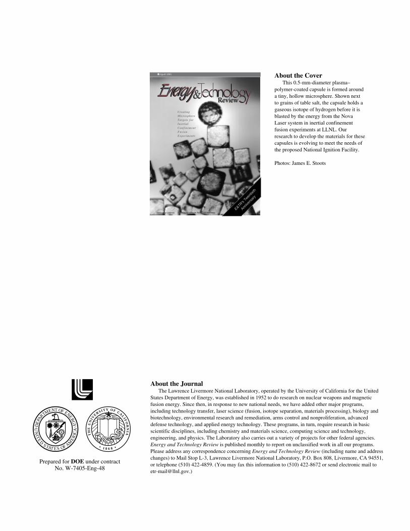
About the CoverThis 0.5-mm-diameter plasma–
polymer-coated capsule is formed arounda tiny, hollow microsphere. Shown nextto grains of table salt, the capsule holds agaseous isotope of hydrogen before it isblasted by the energy from the NovaLaser system in inertial confinementfusion experiments at LLNL. Ourresearch to develop the materials for thesecapsules is evolving to meet the needs ofthe proposed National Ignition Facility.
Photos: James E. Stoots
About the JournalThe Lawrence Livermore National Laboratory, operated by the University of California for the United
States Department of Energy, was established in 1952 to do research on nuclear weapons and magneticfusion energy. Since then, in response to new national needs, we have added other major programs,including technology transfer, laser science (fusion, isotope separation, materials processing), biology andbiotechnology, environmental research and remediation, arms control and nonproliferation, advanceddefense technology, and applied energy technology. These programs, in turn, require research in basicscientific disciplines, including chemistry and materials science, computing science and technology,engineering, and physics. The Laboratory also carries out a variety of projects for other federal agencies.Energy and Technology Review is published monthly to report on unclassified work in all our programs.Please address any correspondence concerning Energy and Technology Review (including name and addresschanges) to Mail Stop L-3, Lawrence Livermore National Laboratory, P.O. Box 808, Livermore, CA 94551,or telephone (510) 422-4859. (You may fax this information to (510) 422-8672 or send electronic mail to [email protected].)
Prepared for DOE under contractNo. W-7405-Eng-48
M
O
CR
F
T N
PR
N F
GY
M EE O
ERAE
D
T
D
ITU
NE
A
EI
A
AST STE 1• 8 •68
LET
THE
E BR
E
L IGH T
TH
EU
NIV
ERS I T Y O F CALIF
OR
NIA

Feature ArticlesCreating Microsphere Targets for Inertial Confinement 1Fusion ExperimentsAt the heart of inertial confinement fusion (ICF) experiments are tiny, hollow microspheres used as targets. Their size, materials of construction, production methods, and structural characteristics have evolved to meet the demands of doing experiments at the Nova laser facility at Livermore.
E&TR Celebrates 20 Years 10Energy and Technology Review celebrates its 20th Anniversary in this April 1995 issue of the publication.
Research HighlightsLaser Fabrication of Beryllium Components 19The Kinetic Energy Interceptor: Shooting a Bullet with a Bullet 22
Patents 25
Abstracts 26
Review&■ April 1995
SCIENTIFIC EDITOR
William A. Bookless
PUBLICATION EDITOR
Sue Stull
WRITERS
Kevin Gleason, Dale Sprouse, Dean Wheatcraft
ISSUE COORDINATORS
Paul Harding, George Kitrinos
DESIGNERS
Paul Harding, George Kitrinos
GRAPHIC ARTIST
Treva Carey
COMPOSITOR
Louisa Cardoza
PROOFREADER
Catherine M. Williams
This document was prepared as an accountof work sponsored by an agency of the UnitedStates Government. Neither the United StatesGovernment nor the University of California norany of their employees makes any warranty,expressed or implied, or assumes any legalliability or responsibility for the accuracy,completeness, or usefulness of any information,apparatus, product, or process disclosed, orrepresents that its use would not infringe privatelyowned rights. Reference herein to any specificcommercial product, process, or service by tradename, trademark, manufacturer, or otherwise does not necessarily constitute or imply itsendorsement, recommendation, or favoring by theUnited States Government or the University ofCalifornia. The views and opinions of authorsexpressed herein do not necessarily state or reflectthose of the United States Government or theUniversity of California and shall not be used foradvertising or product endorsement purposes.
Printed in the United States of AmericaAvailable from
National Technical Information ServiceU.S. Department of Commerce
5285 Port Royal RoadSpringfield, Virginia 22161
UCRL-52000-95-4Distribution Category UC-700
April 1995


HEN heavy isotopes ofhydrogen are fused to create
energy, the nuclei of the isotopesmust be confined as a plasma for aperiod of time, depending on thedensity and temperature of theplasma. In a star, this confinement isaccomplished by the force of thestar’s gravity. In the laboratory, two approaches are being pursuedcurrently. In magnetic fusion, strongmagnetic fields are used to containrelatively low-density plasmas for afew seconds. In inertial confinementfusion (ICF), the confinement timesare no longer than 100 picoseconds(1 ps = 1 trillionth of a second), but
containing the fuel is only about ahalf millimeter in diameter. Thesuccess of each ICF experiment usingthis large, complex machine dependsgreatly on the structure and ourcharacterization of these tiny targets.Their size, structure, and materials ofconstruction must be perfectly suitedto the particular ICF experiment forwhich they are used so that theresulting data can be appropriatelyinterpreted. For more than 20 years,therefore, research concerning thedesign, structure, production, andperformance of these capsules has been an integral part of theLaboratory’s Laser Program.
the plasma densities achieved can begreater than the density of lead.
At Lawrence Livermore NationalLaboratory, these high-plasmadensities are achieved bysymmetrically depositing severalkilojoules of energy from thepowerful Nova laser system on asmall plastic capsule containing thegaseous isotopes of hydrogen—deuterium (D2) or deuterium–tritium(DT)—over a period of a nanosecond(1 ns = 1 billionth of a second). Thedeposited energy ablates the capsulewall, and the rocketlike blowoff ofthe hot surface material compressesthe interior fuel. Although the lasersystem that provides the energy is aslarge as a football field, the target
Creating MicrosphereTargetsfor Inertial Confinement
Fusion Experiments
At the heart of inertial confinement fusion (ICF) experimentsare tiny, hollow microspheres used as targets. Their size,
materials of construction, production methods, and structuralcharacteristics have evolved to meet the demands of doing
experiments on high-powered lasers such as Nova.
1
W

ICF Target History
Targets for the first ICFexperiments at LLNL were glassshells produced from an aqueous glass solution. Small droplets of thissolution were dried in a heated droptower to form hollow shells. These
glass targets, 70 micrometers (µm) indiameter, offered the advantages ofhigh strength, low gas permeability,easy doping with diagnostic atoms,and excellent symmetry and surfacefinish. As the laser drivers improved,larger and higher quality glass shellswere fabricated. However, the high
density and atomic mass of glasslimited the variety of possibleexperiments, and so an alternativematerial with a lower atomic masswas sought.
Polyvinyl alcohol (PVA) shellsappeared to be an excellent alternativeto glass. These shells were alsoprepared using heated drop-towertechnology. Droplets of PVA solutionabout 200 µm in diameter withinternal argon bubbles 100 µm indiameter were generated using a dual-orifice system. In the heated drop-tower column, these hollow dropletsdry to form high-quality shells withdiameters up to about 250 µm. PVA,unlike most other polymers, isparticularly well suited as a capsulematerial because it is an outstandingdiffusion barrier to the hydrogenisotopes that fill the targets to fuel ICFexperiments. However, attempts toextend the size range of PVA shells tomeet the needs of Nova experimentswere unsuccessful, and so yet anothermaterial was sought.
Current Target Capsules
The current ICF target capsule isbuilt around a roughly one-half-millimeter-diameter polystyrene (PS)microshell and is composed of threelayers (Figure 1). The innermost PSmicroshell is produced by the solutiondrop-tower technique illustrated inFigure 2. The process begins with a4.5 wt% solution of monodisperse PS (molecular weight = 98,500) indichloromethane that contains 3.0 wt% 2-propanol. The dropletgenerator provides uniform drops withdiameters of about 400 µm. The dropsfall through a 4-m-high towercomposed of nine individually heatedsubunits. The first eight are heated toabout 200°C; the bottom unit is keptat room temperature to cool the shells.Several thousand 400- to 500-µm-diameter shells are typically made in a run lasting a few minutes.
ICF Microspheres E&TR April 1995
2
Plasma-polymerablator ~50 µm thick
Polystyrene microshellwall thickness ~3 µm
Polyvinyl alcohol permeation barrier coating ~3 µm thick
Deuterium ordeuterium-tritium
gas fuel
0.5 mm
Droplet generator
Inde
pend
ently
con
trol
led
heat
ing
units
0.15 m
4 m
223° C
203° C
203° C
201° C
205° C
210° C
194° C
193° C
25° C
Polystyrene
Figure 2. Diagram of the heated drop tower (not to scale) used toproduce the microshells. Droplets of polystyrene (PS) solution 400 µmin diameter fall down a 4-m-high column whose temperature profile iscontrolled by nine independent heating units. Several thousand shells400 to 500 µm in diameter can be produced in just a few minutes.
Figure 1. A typical ICF capsule, which isbuilt around a thin polystyrene microshell.This microshell is first coated with a thinpolyvinyl alcohol (PVA) layer, which servesas a permeation barrier to the gaseous fuelfill. A relatively thick ablator layer is appliedusing plasma polymerization techniques.These composite capsules are then filledwith a precise amount of deuterium ordeuterium–tritium by placing the capsule incontact with the fill gas at high pressure andelevated temperature.
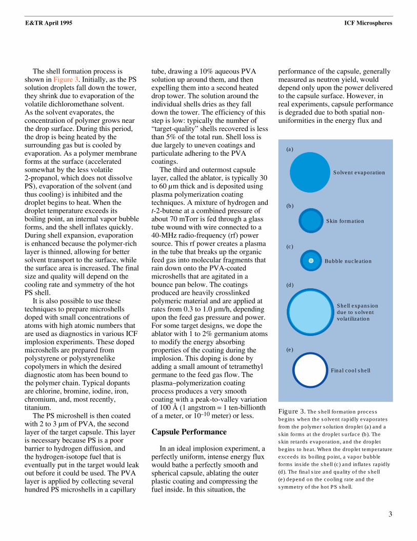
The shell formation process isshown in Figure 3. Initially, as the PSsolution droplets fall down the tower,they shrink due to evaporation of thevolatile dichloromethane solvent. As the solvent evaporates, theconcentration of polymer grows nearthe drop surface. During this period,the drop is being heated by thesurrounding gas but is cooled byevaporation. As a polymer membraneforms at the surface (acceleratedsomewhat by the less volatile 2-propanol, which does not dissolvePS), evaporation of the solvent (andthus cooling) is inhibited and thedroplet begins to heat. When thedroplet temperature exceeds itsboiling point, an internal vapor bubbleforms, and the shell inflates quickly.During shell expansion, evaporationis enhanced because the polymer-richlayer is thinned, allowing for bettersolvent transport to the surface, whilethe surface area is increased. The finalsize and quality will depend on thecooling rate and symmetry of the hotPS shell.
It is also possible to use thesetechniques to prepare microshellsdoped with small concentrations ofatoms with high atomic numbers thatare used as diagnostics in various ICFimplosion experiments. These dopedmicroshells are prepared frompolystyrene or polystyrenelikecopolymers in which the desireddiagnostic atom has been bound to the polymer chain. Typical dopantsare chlorine, bromine, iodine, iron,chromium, and, most recently,titanium.
The PS microshell is then coatedwith 2 to 3 µm of PVA, the secondlayer of the target capsule. This layeris necessary because PS is a poorbarrier to hydrogen diffusion, and the hydrogen-isotope fuel that iseventually put in the target would leakout before it could be used. The PVAlayer is applied by collecting severalhundred PS microshells in a capillary
tube, drawing a 10% aqueous PVAsolution up around them, and thenexpelling them into a second heateddrop tower. The solution around theindividual shells dries as they falldown the tower. The efficiency of thisstep is low: typically the number of“target-quality” shells recovered is lessthan 5% of the total run. Shell loss isdue largely to uneven coatings andparticulate adhering to the PVAcoatings.
The third and outermost capsulelayer, called the ablator, is typically 30to 60 µm thick and is deposited usingplasma polymerization coatingtechniques. A mixture of hydrogen andt-2-butene at a combined pressure ofabout 70 mTorr is fed through a glasstube wound with wire connected to a40-MHz radio-frequency (rf) powersource. This rf power creates a plasmain the tube that breaks up the organicfeed gas into molecular fragments thatrain down onto the PVA-coatedmicroshells that are agitated in abounce pan below. The coatingsproduced are heavily crosslinkedpolymeric material and are applied atrates from 0.3 to 1.0 µm/h, dependingupon the feed gas pressure and power.For some target designs, we dope theablator with 1 to 2% germanium atomsto modify the energy absorbingproperties of the coating during theimplosion. This doping is done byadding a small amount of tetramethylgermane to the feed gas flow. Theplasma–polymerization coatingprocess produces a very smoothcoating with a peak-to-valley variationof 100 Å (1 angstrom = 1 ten-billionthof a meter, or 10–10 meter) or less.
Capsule Performance
In an ideal implosion experiment, aperfectly uniform, intense energy fluxwould bathe a perfectly smooth andspherical capsule, ablating the outerplastic coating and compressing thefuel inside. In this situation, the
performance of the capsule, generallymeasured as neutron yield, woulddepend only upon the power deliveredto the capsule surface. However, inreal experiments, capsule performanceis degraded due to both spatial non-uniformities in the energy flux and
E&TR April 1995 ICF Microspheres
3
Solvent evaporation
Bubble nucleation
Skin formation
Shell expansion due to solvent volatilization
Final cool shell
(a)
(b)
(c)
(d)
(e)
Figure 3. The shell formation processbegins when the solvent rapidly evaporatesfrom the polymer solution droplet (a) and askin forms at the droplet surface (b). The skin retards evaporation, and the dropletbegins to heat. When the droplet temperatureexceeds its boiling point, a vapor bubbleforms inside the shell (c) and inflates rapidly(d). The final size and quality of the shell (e) depend on the cooling rate and thesymmetry of the hot PS shell.

capsule imperfections. In very simpleterms, the basic principle is that thesmoother and more symmetric theenergy flux or capsule, the more even and efficient the implosion.Conversely, the more uneven theenergy flux or rougher the capsulesurface, the greater the targetperformance degradation, becausehydrodynamic instabilities in thecapsule during the ablation phase ofthe implosion lead to nonuniform andinefficient compression.
Because it is impossible to producea capsule that is perfectly smooth andperfectly spherical, we are working toverify our understanding of theeffects of capsule imperfections onICF implosions through current Novaexperiments. This verification isimportant to strengthen our case thatwe can produce a capsule that willignite under the conditions plannedfor the National Ignition Facility(NIF). From the capsule point ofview, these experiments haverequired us to develop the capabilityof making very precise measurementsof what the capsule surfaceirregularities actually are. Thesemeasurements, which we call surfacemaps, provide the input data for thetheories that predict capsule
performance and allow us to compareexperimental results with theoreticalunderstanding.
Before we discuss how we measurecapsule surface roughness and use thisinformation to predict capsuleperformance, we need to understandthe nature of the hydrodynamicinstability mentioned above.Technically it is called Rayleigh–Taylor instability, after LordRayleigh, who investigated it morethan 100 years ago, and Taylor, whoinvestigated it experimentally in the1950s. The basic phenomenon issimple (Figure 4). Imagine a situationin which we very carefully create alayer of dense fluid on top of a lighter,less dense fluid. For the purposes ofthis example, think of the light fluiduniformly pushing against the densefluid and holding it up. As long as theinterface between the fluids isperfectly flat and horizontal, the fluidscan remain in place. However, if asmall perturbation is created at theinterface, the system becomesunstable and the amplitude of theperturbation will grow, allowing themore dense fluid to flow down as thelighter fluid pushes up through it.
An analogous situation existsduring the ablation phase of an ICF
implosion. In this case, the less denseplasma created during ablation ispushing against the dense capsulesurface. Perturbations on the surfacegrow during this process (Figure 5).That growth can lead to a degradationof the capsule performance becausecompression efficiency is lost and thegrowing perturbations cause the innercapsule surface to mix with the fueland cool it.
The degree of growth ofperturbations on a capsule surfacedepends upon their “mode number.”To understand this concept, supposewe trace Earth’s surface, starting at thenorth pole, passing through the southpole, and returning to the north pole.This trace looks like a circle. A morecareful measurement, however, showsthat the diameter of this circle is alittle less if measured between thepoles than if measured at the equator. This type of asymmetry is called a “mode 2” feature, because it has twocycles per circumference.
ICF capsules also generally have amode 2 asymmetry that can have anamplitude of a few micrometers, orabout 1% of the capsule radius.Although this is by far the largestamplitude asymmetry in a capsule, it is relatively stable during the
ICF Microspheres E&TR April 1995
4
Heavy, dense fluid
(a)
Light, less dense fluid
Heavy, dense fluid
Instabilitygrowth
(b)
Light, less dense fluid
Heavy, dense fluid
Light, less dense fluid
Figure 4. Illustration of the concept of the Rayleigh–Taylor instability that degrades ICF capsule performance. (a) As long as the interfacebetween a heavy, dense fluid and a light, less dense fluid is perfectly flat and horizontal, the fluids can remain in place. (b) However, if a smallperturbation is created at the interface, the system becomes unstable and the amplitude of the perturbation will grow, allowing the more densefluid to flow down as the lighter fluid pushes up through it. In an ICF implosion, low-density ablated plasma is pushing against the dense capsulesurface; thus surface perturbations at the capsule surface are Rayleigh–Taylor unstable and grow as illustrated in Figure 5.

implosion and does not growappreciably.
Consider again our trace of Earth.If we look very carefully over veryshort distances along the trace, we seesmall bumps with amplitudes up to afew hundred feet due to trees andhouses, and over even shorterdistances, smaller bumps due topeople, stones, and blades of grass.This manifestation of surfaceroughness in the Earth trace representsextremely high mode numbers butrelatively low amplitudes. High modedefects of this kind are also present on ICF capsules, but they also do not grow appreciably during thecompression. Intermediate betweenthe very low mode features and thehigh mode features are modal featuresbetween, say, mode 10 and 100 (atlength scales between one-tenth and one-hundredth of the tracecircumference). In our example of the Earth trace, these are features likecontinents or mountain ranges oncontinents. The amplitudes of thesefeatures would be from one to severalmiles (approximately 0.025% to 0.1%of Earth’s radius), much less than the amplitude of Earth’s mode 2asymmetry and much greater than he amplitudes of the higher modefeatures.
ICF capsules also have surfaceroughness in this modal range, atlateral length scales between a fewtens to a few hundreds of micrometersand amplitudes up to approximately0.025% of the capsule radius. It turnsout that the amplitudes of these modesgrow the most during the implosion,and thus control of surface roughnessover these modes is extremelyimportant.
Mapping the Capsule Surface
To understand, and thus predict, theeffects of capsule surface roughnesson performance, we have had to
develop ways of mapping capsulesurface roughness, particularly inthose modal regions that lead to the maximum growth during theimplosion.
Because of the sensitivity of theRayleigh–Taylor instability to modenumber, it is important to be able to characterize the capsule surfaceasymmetries over lateral length scales
up to hundreds of micrometers with a vertical resolution of about 10 Å. At LLNL, we have developed ameasuring device called a “SphereMapper,” based on an atomic-forcemicroscope (AFM) (Figure 6). Thecapsule is supported on a vacuumchuck connected to an air-bearingrotor. Its equator is positioned nextto a stand-alone AFM head, and the
E&TR April 1995 ICF Microspheres
5
Final perturbation
Initial perturbation
AFM tip
deflection
recorder
Air-bearing
rotor
Vacuum chuck
Atomic-forcemicroscope tip
Capsule
Figure 6. Schematic diagram (not to scale) of the Sphere Mapper, which is used tocharacterize the capsule surface finish. As the capsule is rotated, an atomic force microscope(AFM) records variations in the capsule radius to a precision of about 10 Å. Typically, threeorthogonal sets of three traces are taken, as shown in Figure 7.
Figure 5. During an implosion, small amplitudeperturbations on the capsule surfacecan grow by factorsof 100 or more,depending upon thespecific details of theperturbation and theimplosion. This canlead to a degradationof capsuleperformance.

capsule is rotated while the AFMrecords height measurements at 3600 evenly spaced points. Generallythree sets of equatorial traces aretaken: the Sphere Mapper takestraces at the equator and at 20 µmabove and below it; then the capsuleis rotated 90 degrees and the processrepeated; one additional 90-degreerotation gives us three orthogonal setsof three traces, as shown in Figure 7.
For comparison, typical trace datafor a 1000-µm-diameter precisionball bearing made of silicon nitride
and for a 435-µm-diametertitanium-doped microshell areshown in Figure 8. Note that thevertical scale is in tenths ofmicrometers while the horizontalscale is in degrees of rotation. Thetranslational distance per degree isshown as an inset in each plot.Thus, the apparently sharp spikesin Figure 8a are in reality severalmicrometers wide. In the data inFigure 8b, the small bump at about160 degrees is about 0.025 µmhigh and 60 µm wide.
Note that the ball bearing isextremely spherical but relativelyrough on a short-length scale. Incontrast, the capsule shows a significant(by comparison) mode 2 asymmetry butis locally extremely smooth. Alsonotable on this capsule are someintermediate-length scale perturbations,20 µm to approximately 100 µm inbreadth, with amplitudes of 0.01 to0.1 µm. These are the kind of surfaceperturbations associated with largeRayleigh–Taylor instability growth, i.e.,degradation of implosion performance,
ICF Microspheres E&TR April 1995
6
–0.2
µm
360315
(b) Titanium-doped microshell
270225180Degrees
13590450
–0.1
0
0.1
0.2
–0.2
µm
–0.1
0
0.1
0.2(a) Silicon nitride ball bearing
1 degree = 3.8 µm
1 degree = 8.7 µm
Figure 7. The Sphere Mapper takes threeorthogonal sets of three traces to characterizethe surface finish of ICF capsules. Exampletrace data are shown in Figure 8.
Figure 8. Typical trace data from (a) asilicon nitride ball bearing and (b) a titanium-doped microshell. Note that the horizontalaxis is in degrees of rotation. Thetranslational distance along the capsulesurface associated with 1 degree of rotationis given on each plot and is much greaterthan the displayed vertical scale. Therelatively shallow, intermediate-length-scaleperturbations of the microshell surface areassociated with the largest Rayleigh–Taylorgrowth during an ICF implosion.

while the mode 2 asymmetry with anamplitude of about 0.3-µm has littleeffect on an ICF implosion.
Surface Modification
To determine the effects of capsulesurface finish on capsule performance,we developed controlled ways ofvarying the outer capsule topography.Initially we made use of the fact thatthe plasma–polymer coating isconformal, and that deliberateperturbations on the surface of the
PVA layer would manifest themselvesin perturbations on the outside of thefinished capsule. Our approach toroughening the PVA layer prior toplasma polymer coating was toinclude 2- to 4-µm-diameter solidpolystyrene microspheres in the PVAcoating solution. These microsphereswere thus incorporated into the PVAcoating, producing a bumpy surfaceon the completed capsule as shown inthe sketch at the left in Figure 9b.
In these experiments, incorporationof dopants in the polystyrene
E&TR April 1995 ICF Microspheres
7
Em
issi
on in
tens
ity
Energy, keV
Chlorinelines
Argonlines
2.8 3.0 3.2 3.4
Em
issi
on in
tens
ity
Energy, keV
Chlorinelines
Argonlines
2.8 3.0 3.2 3.4
Polyvinyl alcohol
Polystyrene plus1% chlorine
Plasma-polymer
Deuterium fuelwith 1% argon
Mix causeschlorineto emit
(a) Smooth surface
(b) Bumpy surface
Polyvinyl alcoholroughened with
polystyrenemicrospheres
Polystyrene plus1% chlorine
Plasma-polymer
Deuterium fuel with 1% argon
Figure 9. On the left are sketches of (a) a smooth and (b) a bumpy capsule. Onthe right are the emission spectra obtainedduring the implosion of these capsules. Thebumpy capsule (b) leads to more mix andthus a more intense chlorine signal thandoes the smooth surface (a). Data fromexperiments with modified targets such asthis enable us to validate theoretical modelsof target performance.

microshell and the gaseous fuelallowed spectroscopic diagnosis of thedegree of “mix” of the inner capsulewall with the fuel due to the growth ofsurface perturbations. (CompareFigure 9a and 9b.) For a smoothcapsule (Figure 9a), there was littlemix, and the inner wall was kept welloutside of the hot central fuel region,resulting in only a small chlorineemission in comparison to theemission from the argon dopant in the fuel. For the rough capsule (Figure 9b), however, the growth ofsurface perturbations resulted in a
much greater chlorine emission signalwhen compared with the signal fromthe fuel argon dopant, indicating asignificant mixing of the inner capsulewall with the hot fuel.
The use of polystyrene seeds in the PVA layer as a mechanism toproduce roughened capsule surfacesoffered only modest control over thedegree of roughness. Recently wehave developed the capability of usinga laser to precisely carve pits withdepths from 0.1 to 3 µm and widths up to 100 µm on capsule surfaces. InFigure 10, the photo shows a0.5-mm-diameter plasma–polymer-coated capsule with 200 randomlyplaced pits, each roughly 75 µm indiameter and 1 µm deep. The coverphoto shows a capsule withsymmetrically placed pits. The successof this technique for rougheningcapsules to a predetermined extent isproving extremely valuable indeveloping our understanding ofRayleigh–Taylor hydrodynamicinstabilities during an implosion due to capsule surface perturbations.
Future ICF Needs
As the ICF community developsmore powerful laser drivers, thecapsules used in these experimentswill need to be larger. The OmegaUpgrade ICF facility at the Universityof Rochester’s Laboratory for LaserEnergetics will come on-line in thespring of 1995 and will requirecapsules that are roughly 1 mm indiameter. The National IgnitionFacility (NIF), with a plannedcompletion date shortly after the year2000, will require 2-mm-diametercapsules. The production of these
capsules will depend on thedevelopment of new technology,because our solution drop-towermethods are limited to approximately0.5-mm capsules, due largely to thelarge heat and mass transfersnecessary.
A number of alternativetechnologies, however, hold promisefor delivering larger capsules. The most widely developed ismicroencapsulation. In this method, a water droplet is encapsulated by apolymer solution and then suspendedin an aqueous phase. The organicsolvent containing the polymer slowlydissipates into the aqueous phase,leaving behind a polymer shell. Thisapproach to shell manufacture hasbeen used for a number of years at the Institute for Laser Engineering atOsaka University and also at theUniversity of Rochester. In bothcases, the typical polystyrene shellsproduced for ICF targets have beensignificantly less than 1 mm indiameter. Work is in progress toextend this technology to 1- to 2-mmcapsules suitable for Omega and NIFICF experiments.
The target fabrication group at theLebedev Institute in Moscow hashistorically made plastic shells forRussian ICF experiments by heateddrop-tower techniques using particlesof solid polymer infused with smallamounts of volatile organic solventthat inflate the particles when they aremelted in the drop tower. Thisapproach is useful for larger shellsbecause much less mass and heattransfer is necessary compared tosolution drop-tower techniques. Usingthis technique, the Lebedev group hasbeen able to routinely prepare 1-mmcapsules with good symmetry andsurface finish. For larger shells, thereis concern that the hydrodynamicinteraction of the falling molten
ICF Microspheres E&TR April 1995
8
Figure 10. A 0.5-mm-diameterplasma–polymer-coated capsule with 200randomly placed ablated pits, each about75 µm in diameter and 1 µm deep. Thiscapsule was intentionally roughened to apredetermined extent to study how surfaceperturbations affect capsule performanceduring an implosion.
capsule with the surroundingatmosphere will lead to distortions.To remedy this problem, as well as to maximize heat transfer in theminimum drop-tower height, theyhave developed the concept of a“Ballistic Furnace.” The polymerparticles are injected up into thecolumn so that they inflate to becomehollow shells at the trajectory apex,when the hydrodynamic interactionswith the surrounding media are at aminimum.
A route to larger shells as well asunique capsules for current ICFexperiments is being developed atLLNL based on the use ofdecomposable solid or hollowmandrels. Briefly, the method makes use of the fact that poly(α-methylstyrene) thermallydecomposes to a gas at a relativelylow temperature. It is possible toprepare very symmetric and smoothsolid beads or hollow shells of thispolymer at sizes up to severalmillimeters, overcoat them with alayer of plasma polymer, and thenheat them to decompose the poly(α-methylstyrene) mandrel,leaving a symmetric shell of thedesired size. The method may also beuseful for preparing capsules withprescribed inner surface roughness byusing the laser ablation technologydiscussed earlier to roughen thepoly(α-methylstyrene) mandrelbefore overcoating. In this way, therough contours of the mandrel will bereproduced on the inside surface ofthe shell remaining after thermaltreatment.
Future ICF target designs for boththe Omega and NIF facilities call forcryogenic targets in which a 100-µm-thick, symmetric, solid or liquid D2or DT fuel layer is present on theinside of the capsule wall. One routeto accomplishing this is to prepare
capsules with a low-density organicfoam liner to hold the fuel inside thefull-density plastic shell. Capsules ofthis type have been developed atOsaka University and at LLNL usingmicroencapsulation techniques. Themethod involves microencapsulatinga droplet of water or oil by a100-µm-thick layer of an oil or waterphase, respectively, which containsabout 5% polymerizablecomponents. This layered droplet is suspended in the same phase as the inner droplet. By initiatingpolymerization of the dilutemonomer in the layer, a solid butlow-density foam structure can form.This foam shell can then beovercoated with a full-density layerand finally dried to produce thedesired foam-lined capsule.
Summary
The production of ICF capsules,with their very stringent symmetryand surface finish requirements, and the characterization of themrepresent major materials sciencechallenges. The quality of thecapsule is largely dependent upon the quality of the thin-walled plasticmicroshell around which it is built.The characterization requirements for the capsules have led to thedevelopment of new and uniquecapabilities for measuring theirsurface topology. The scientificinterest in studying the effects ofsurface topology on the implosiondynamics has led to methods ofprecisely modifying the capsulesurface finish. Future ICF targets will require larger capsules, andtechnologies designed to meet thisneed are now being developed.
Key Words: drop-tower technology; inertialconfinement fusion (ICF) target capsules;microshell; microsphere; mode growth;National Ignition Facility (NIF); Nova laser;Rayleigh–Taylor hydrodynamic instability;Sphere Mapper.
Notes and ReferencesThis article is based on a paper delivered byinvitation to the 1994 Symposium of theMaterials Research Society in Boston,Massachusetts, November 28–December 2,1994: Production of Microspheres for InertialConfinement Fusion Experiments, LawrenceLivermore National Laboratory, Livermore,California, UCRL-JC-117389, 1994. The paperwill also be reprinted in “Hollow and SolidSpheres and Microspheres—Science andTechnology Associated with their Fabricationand Application,” Materials Research SocietySymposium Proceedings, Vol. 372, ISBN: 1-55899-274-X, 1995.
Robert Cook wishes to acknowledge thecontributions of Russell Wallace, RandallMcEachern, and other members of the ICFProgram at LLNL who have contributed to the work described here.
E&TR April 1995 ICF Microspheres
9
For furtherinformationcontact Robert Cook (510) 422-3117,[email protected].

“Today, a journal that brings theLaboratory’s R&D expertise intofocus for the scientific community,funding sponsors, and the public iseven more essential,” says retiredAssociate Director Carl Haussmann,who helped nurture E&TR during itsformative and pre-teen years.
“There is such a wealth ofcompeting information and, in somesense, competing institutions that
NERGY and Technology Reviewcelebrates its 20th anniversary
this month as a public showcase forthe quality and diversity of LLNLscience and technology. LLNL’stechnical diversification in the late1960s and early 1970s and the need to communicate with newprogrammatic sponsors were amongthe factors that led to E&TR’screation.
E&TR Celebrates 20 YearsReporting LLNL’sScientific and TechnicalAccomplishments
10
E

E&TR April 1995 20th Anniversary
11
you want to project your work asmuch as possible,” said Haussmann.“It also is important to get a realitycheck with the world; communicatingyour work to the public and privatesectors is one way to do that.”
Agreeing with Haussmann is BobBarker, assistant to the director andprogram manager of the LLNL’sDepartment of Defense activities. “As its customer base diversifies,”said Barker, “LLNL finds itselfdealing with more people who don’t understand the breadth of theLaboratory’s capabilities.”
“E&TR’s broad coverage of theLab’s technical capabilities providesan ideal mechanism for making newpotential customers aware of what wecould do,” said Barker, who has hadthe Director’s Office oversightresponsibility for E&TR since 1993.
E&TR debuted in April 1975 toreport on the Laboratory’s growingand relatively young programs—inenergy, the environment, lasers,atmospheric sciences, andbioscience—that were added to the
1975 1976 1977 1979 1981
1983 1987 1989 1990 1994
Make E&TR so visually appealingthat a reader can’t resist wanting toread the articles: That has long beenone of the primary marching ordersfor the graphics staff of Energy &Technology Review.
In response to that direction,E&TR has gone from a relatively staidblack and white report to a journalthat uses the most modern graphicstools to foster comprehension ofLLNL’s scientific and technologicalaccomplishments.
Instead of simply using author-provided photographs, graphs, anddiagrams, the E&TR graphics staffoften develop completely newillustrations or have photos taken that will help convey the author’smessage.
Issues have featured 3-D computergraphics, illustrations of complexexperiments not yet built, and evenrenderings of phenomena that cannotbe seen by the human eye, as was thecase in a recent article about an
astronomical experiment to detectmassive compact halo objects, orMACHOS.
While use of color, cover design,and publication layout all evolved inresponse to each Scientific Editor’spreferences or goals, now-retiredAssociate Director Carl Haussmannwas a key figure during the graphicsmakeover in the early 1980s.
“Carl was always interested in theappearance and quality of the report,and was always pushing for the use of color,” said Lyle Cox, who was amember of Haussmann’s staff at the time.
Haussmann said he wanted E&TRto successfully compete with otherpublications for a reader’s attention.“If the content of your document isgood—and I thought the content ofE&TR was already pretty good—thenthe name of the game is to have yourdocument picked up because of itsmode of presentation.”
Design Changes Over the Years

20th Anniversary E&TR April 1995
12
original missions of nuclear weaponsR&D and magnetic fusion energyresearch.
The chief reporting vehicle priorto E&TR’s creation was a classifiedmonthly report, Research Monthly(renamed National Security Scienceand Technology Review in 1993),that for nearly two decades had beenprepared for the Atomic EnergyCommission’s (AEC’s) Office ofMilitary Application. Its focus wason the Lab’s classified nuclearweapons research activities.
Research Monthly traces its rootsto the LLNL monthly externalprogress report, first issued at theend of September 1952, the monththe Laboratory opened. “Thathumble report consisted of ninetypewritten pages, with nary a figureor table, and was stapled inside anordinary file folder and hand-stamped with the appropriateclassification markings,” said BobBerlo of the Technical InformationDepartment (TID).
Berlo, who was a general editoron Research Monthly at the timeE&TR was born, said copy for theclassified report was written byLaboratory scientists and did notbegin to receive extensive editinguntil 1964. By 1968, a team of two
to three TID editors was assigned tohandle the growing publication. Asthe Lab’s research mix changed in the1970s, so did the classified monthly’scontent. On some occasions, half ofResearch Monthly containedunclassified articles.
Haussmann remembers a meeting in which Mort Mendelsohn,then head of Biomedical andEnvironmental Sciences, arguedstrongly for an unclassifiedcompanion to the classified journal.Said Haussmann: “It was clear thatthe director and the associatedirectors thought it was a good idea,so we proceeded.”
The job of rounding upcontributors for the first E&TR fell toPhil Coyle, then a young mechanicalengineer who, in 1974, had beenappointed to the term position ofScientific Editor for ResearchMonthly. Each Scientific Editor sinceCoyle has had responsibility for thescientific content of both theclassified and unclassified journals.
Coyle was enthusiastic about theidea of an unclassified publicationthat publicly shared Laboratoryscience and technology, and“deserves a lot of the credit forE&TR’s creation,” said Lyle Cox,who, along with Jim Frank, has beena central member of the Director’sOffice “monthlies” team. Coyle, as
(E&TR November 1976 ) The lunar surfacemagnetometer deployed at the Apollo 16landing site. The boot prints indicate scale. The golden ribbon is a power andsignal cable. Together with an orbitingmagnetometer aboard Explorer 35, this andother instruments provided a continuousrecord of changes in the magnetic field onthe Moon over many months. (NASA Apollo photo.)
(E&TR February 1976) Janus, LLNL’s firsttwo-arm laser system, consisted of a dye-mode-locked oscillator, preamplifiers, beam-shaping optics, and a series of neodymium-doped, glass disk amplifiers with opticalisolators. Most components were the sameas in our single-arm Cyclops system. Thislaser drove our first successful inertialconfinement fusion experiments in 1974.

E&TR April 1995 20th Anniversary
13
Principal Laboratory AssociateDirector, eventually inherited theE&TR and Research Monthlyoversight roles from Haussmann.Coyle retired in 1993 and is nowDirector of Operational Test andEvaluation in the Office of theSecretary of Defense.
E&TR was oriented initiallytoward two audiences—theLaboratory itself (primarily thescientific and technical staff), and itsnew sponsoring agency, the EnergyResearch and DevelopmentAdministration (ERDA, which wascreated to replace the AEC; theDepartment of Energy succeededERDA in 1977). An additionalaudience—the nation’s academicand industrial communities—wasalso expected to have a stronginterest in the Laboratory’s technicalachievements. Frank undertook thejob of creating E&TR’s externaldistribution list. By the end of thesecond year, the list had grown to370 individual recipients.
Articles in the first E&TRaddressed research in astrophysics,lasers, and fossil, solar, andmagnetic fusion energy. Titlesranged from “Shallow Solar Ponds:An Economic Approach toIndustrial Process Heat” to “AnOverview of the LLL In Situ CoalGasification Program.”
The Laboratory’s “mirror reactor”approach to magnetic fusion energydiscussed in the inaugural E&TR hassince given way to an internationaleffort focusing on tokamaks.“LLNL’s solar pond and coalgasification research, both of whichwere continuing when E&TRcelebrated its 10th anniversary, havedeveloped into semicommercialprojects,” said Bob Schock, actingAssociate Director for Energy. “TheArmy installed solar ponds at onebase, and several companiessuccessfully implemented UCG(underground coal gasification). Bothprograms were very much ahead oftheir time and were victims of thefalling price of oil as much asanything else.”
A reading of the E&TR index for20 years reveals the history of otherLLNL programs that continue toregister technical achievements. TheLaser Program is a good example.From the July 1975 article on“Progress in the Calculation ofLaser–Plasma Coupling,” E&TR hastracked the evolution of inertialconfinement fusion research, fromShiva to the planned NationalIgnition Facility. And it has followedthe development of atomic vaporlaser isotope separation, from concept
(E&TR July 1981) The “State of theLaboratory” issue illustrated the status ofweapon designs for the U.S. stockpile. Hereis shown one LLNL warhead project thenunder development. The W84 ground-launched cruise missile, authorized inOctober 1976, was in the productionengineering phase.
(E&TR November 1981) Computer-graphicmodeling of a double helix of 20 basepairs of DNA.

20th Anniversary E&TR April 1995
14
E&TR’s Scientific EditorsSince Research Monthly has had
scientific editors, beginning in 1960,the LLNL Director’s Office hasviewed appointment to the position as an opportunity to provide a“broadening experience” to a (usually)younger member of the Laboratory’stechnical staff—someone who displayspotential for future leadership.
“If you look at the careers of thepeople who have held the job, you’llsee they have benefited from theexperience,” said Carl Haussmann,Associate Director Emeritus. “It is oneof the most notable opportunities atthe Laboratory—being given the job offinding out what is going on, andmaking sure that it gets reported.”
The list of scientific editorsincludes Director Bruce Tarter; BobBarker, currently assistant to theDirector; and retired AssociateDirector Phil Coyle, now Director ofOperational Test and Evaluation in theOffice of the Secretary of Defense.
The editorial tenures of Tarter andBarker came before the creation ofEnergy and Technology Review. Bothfilled the position during a periodwhen the scientific editor focused his attention exclusively on theLaboratory’s classified journal.Beginning with Coyle, the scientificeditor was given responsibility forguiding the unclassified Energy andTechnology Review and its classifiedcompanion.
For Ron Carr, E&TR’s secondscientific editor, the greatestsatisfaction during his tenure “was theopportunity to see many different partsof the Lab, and to learn a lot about thedifferent programs and technologies.”
Former scientific editors SteinWeissenberger (1980–81), GordonStruble (1984–85) and Alan Burnham(1989–90) share Carr’s views aboutthe richness of the experience.
“The positive experience certainly,I think, outweighed the pain andheartache in pulling articles together,”said Weissenberger, an electronics
engineer who now is a program co-leader in Transportation Technologies.“Clearly there could be no better way to get exposed to what was going on in the Lab. In that sense the job wasextremely rewarding.”
Said Struble, who at the time of hisappointment was a Nuclear Chemistrygroup leader and is now deputy directorof the Laboratory Directed Researchand Development Program: “I came inwith a very parochial view and learneda lot about the Laboratory.”
Added Burnham, who was amember of Chemistry and MaterialsScience when he was tapped for thejob: “I was struck by the vast diversityof high-quality work being done, andI’m convinced that no one even withinthe Lab truly understands all we arecapable of doing.” Burnham iscurrently a program leader in EnergyTechnology.
Although the Director customarilyprovides guidance to the scientificeditor on the technical thrust of thejournal, Tarter has displayed a muchgreater personal interest in E&TR, saidLyle Cox. “I think it is because he had agood experience himself as a scientificeditor,” Cox observed.
Since the 1960s, Cox and hisassociate, Jim Frank, have handled a variety of Director’s Officeassignments for the Laboratory’sexternal publications. In 1984, bothfilled in on an interim basis afterscientific editor Frank Morrison died ina traffic accident. Cox also has servedas a Director’s Office “scout” forcandidates for the position of scientificeditor.
In the late 1960s, said Cox, he wasasked by Haussmann to handle thebackground work on prospects for theposition of scientific editor. “Since thenI’ve been doing the annual beating ofthe bushes for a potential editor. It hasbeen an enjoyable experience. Many ofthese people have gone on to becomedivision leaders, which was the originalcheckpoint.”
Appointed by the Director, ascientific editor serves for a year to 18 months. In addition to selectingtopics and convincing scientists tobreak away from their day-to-daybench assignments to write articlesabout their work, a scientific editorworks closely with the TIDpublications team to scope out eachissue and shepherds article reviews.Sometimes the scientific editor mustarbitrate differences between authorsand general editors.
“Normally the TID editors dealdirectly with the author over the detailsof editing,” remembers Weissenberger.“But in one case the author was sodemanding and difficult that I wasbrought into the process. It was one ofthose interesting life experiences whereyou discover how personality, science,and politics can complicate your life.”
Carr recalls how he used to get busyscientists to write articles. “Theyalways had some excuse as to why theycouldn’t make the schedule. So I wouldget information on the topic they weretrying to write and do the articlemyself. Since I did not have thebackground for the article, it would be technically and every other waywrong—and I knew it. I would give thearticle to the ‘author’ and say I wasgoing to print it as shown. This got animmediate response—and a goodarticle.”
Weissenberger said one of his“fondest memories” relates to hisexperiences with Cox and Frank duringthe Director’s Office review cycle.
“Lyle and Jim have two completelydifferent personalities, but between thetwo you can cover the various parts ofthe publishing process,” Weissenbergersaid. “Lyle is infinitely patient andsensitive to high-level issues, whereasJim is certainly one of the mostmeticulous readers I have ever known.You can always count on him to goover a paper or draft with amicroscope.”

E&TR April 1995 20th Anniversary
15
to creation of an independent quasi-government corporation that willindustrialize the technology. Alsounfolded through the pages of E&TRhas been LLNL’s development oflaser applications to the manufactureof integrated circuits.
E&TR’s audiences have learnedabout Livermore biosciencedevelopments in cell-sortingtechnology, the makeup of the human genome, and biotechnology.They have read about revolutions in microtechnology andmicroengineering, the significance ofLivermore-developed materials suchas aerogels and seagels, and the waysour R&D is helping the nation regainits once-dominant economic position.
E&TR also has provided readerswho don’t have authorized access to National Security Science andTechnology Review (formerlyResearch Monthly) with anunclassified look at the Laboratory’sachievements in the national defensearena. Articles have ranged from nuclear weapons R&D and techniques for verifying armscontrol treaties to emerging nuclearproliferation issues and post-ColdWar nuclear weapons dismantlementactivities.
E&TR introduced its first themedissue in August 1977 with an all-Laser Program edition. Later
dedicated issues focused on areassuch as computer graphics,astrophysics, high-pressure physics,accelerator mass spectrometry, andmaterials by computer design. Onefocused issue has recurred annually,the State of the Laboratory edition.
Kent Johnson, the scientificeditor from September 1990 toSeptember 1991, said he wassurprised by the popularity of twoE&TR issues under his tenure that“walked one step away from directscientific results” and addressedtopics “that had a little more flair.”One was a dedicated issue on theLaboratory’s educational outreachactivities; the other containedseveral articles on cold fusion,which reported negative results.
Since E&TR’s beginning, thescientific editor and the LaboratoryDirector, or his representative, havedecided what areas of Livermoreresearch should be featured in thejournal. The scientific editor thensolicits articles from members of thescientific and technical staff andworks closely with E&TR’spublication team—TechnicalInformation Department (TID)editors, writers, graphic designers,photographers, and other productionteam members.
(E&TR February 1985) The Nova targetchamber, a massive aluminum sphere 4.6 min diameter with walls almost 13 cm thick.The large flanges carry the frequency-conversion arrays and the final focusinglenses with their positioning mechanisms.
(E&TR July–August 1989) The RockyMountain underground-coal-gasificationtest facility near Hanna, Wyoming. There we investigated ways to extract energyotherwise not exploitable. Coal was partiallyburned underground, and the gas producedcould be upgraded to pipeline quality orused as a synthesis gas for liquid fuels.
20th Anniversary E&TR April 1995
16
“It takes a considerable number ofpeople to turn out these publicationsout,” said Haussmann. “There are alot of in-the-trench workers, peoplewhose behind-the-scenes effortsmake these things happen. The TIDpeople—publication editors, writers,designers—have been majorcontributors over the years. Thequality of their work has beenimpressive.”
Helping an author shape an articleinto one that can be comprehendedby people with dissimilar technical
E&TR’s Scientific Editors: Where Are They Today?
Scientific editor Editorial tenure Current assignment
William A. Bookless 1994–present Project Leader, Nuclear Weapons Information ProjectWilliam J. Quirk 1993–1994 Primary Design and Intelligence AnalystJoseph A. Sefcik 1991–1993 Program Manager, A DivisionKent C. Johnson 1990–1991 Assistant Associate Director, Advanced Projects Office, Defense and Nuclear
TechnologiesAlan K. Burnham 1989–1990 Program Leader, Energy Technology ProgramAndrew J. Poggio 1988–1989 Deputy Division Leader, Engineering Research DivisionRichard D. Lear 1987–1988 Associate Program Leader, B DivisionHriar S. Cabayan 1986–1987 Manager, RF Weapons Effects ProgramGordon L. Struble 1984–1985 Deputy Director, Laboratory Directed Research and Development ProgramLyle A. Cox 1984 Staff to the DirectorJames Frank 1984 PhysicistFrank A. Morrison 1983–1984 Deceased 1984Paul S. Brown 1982–1983 Assistant Associate Director for Arms Control, Defense, and Nuclear
TechnologiesIrving F. Stowers 1981–1982 Science and Technology Advisor, Energy, Materials, Transportation
Technologies ProgramStein Weissenberger 1980–1981 Program Co-Leader, Transportation Technologies Energy DirectorateErik Storm 1979–1980 Deputy Associate Director, Laser ProgramsRobert C. Haight 1978–1979 Technical Staff Member, Los Alamos National LaboratoryHenry D. Shay 1977–1978 Senior Staff, Computation OrganizationRobert W. Selden 1976–1977 Assoc. Director of Lab Development (ret.), Los Alamos National LaboratoryRonald B. Carr 1975–1976 ME Division Leader for Laser Program (ret.); now Lab Associate serving
DoD Office of the Secretary of DefensePhilip E. Coyle 1974–1975 Director of Operational Test and Evaluation, Office of the Secretary of Defense
Editor’s note: Scientific Editors also have responsibility for E&TR’s classified companion, National Security Science and TechnologyReview. Scientific Editors before the debut of E&TR were: V. Alan Mode, 1973; C. Bruce Tarter, 1972; Robert B. Barker, 1971; George G.Staehle, 1970; Jim Kane, 1969; Richard Wagner, 1968; Van Hudson, 1967; George F. Bing, 1966; Bill Grayson, 1966; John W. Kury, 1965;Russ Duff, 1964; Harlan Zodtner, 1960–1963.
Ever ready withadvice andenthusiasm (from left to right)Jim Frank, Carl Haussmann,and Lyle Cox have played animportant role inE&TR since itsbeginning in 1975.

E&TR April 1995 20th Anniversary
17
For two decades, Energy andTechnology Review has played a vitalcommunication role for the Laboratory.By reporting on the Laboratory’sscientific and technologicalaccomplishments, E&TR has helped itsaudience foster an understanding of thesignificance of our R&D contributions to the nation and the world.
Before E&TR’s creation, theLaboratory reported monthly to the Atomic Energy Commission through
what evolved into the classified journal, Research Monthly(renamed National Security Science and Technology Reviewin 1993). The focus of Research Monthly, for which I had the pleasure to serve as Scientific Editor in 1972, was on theLaboratory’s classified defense activities. In April 1975,E&TR debuted as Research Monthly’s unclassifiedcompanion, addressing growing programs in energy,biomedicine, and the environment, and the unclassifiedelements of the nuclear weapons program.
Significantly, the birth of E&TR came amidst a time ofchange, one similar to what we are experiencing today. Newavenues of communication were required in the 1970s,necessitated in part by Congress’ decision to abolish the AEC and create the Energy Research and DevelopmentAdministration (itself replaced by the Department of Energyin 1977). For us at the Lab, that meant making our capabilitiesknown to many people who were not intimately familiar withour record of technical success and R&D contributions to thenation—program people who joined ERDA from other
organizations and Congressional representatives on newoversight committees.
Today, E&TR provides a communication link withgreater significance between the Laboratory and theoutside world. We find ourselves interacting with an evenwider spectrum of individuals and organizations who arenot well acquainted with LLNL and the other DOElaboratories. Those in this category include the newCongressional leadership and their staffs; employees offederal, state, and local organizations with whom we havegrowing interactions; representatives of industry andconsortia seeking to partner in areas of mutual benefit; andmembers of the general public who are curious about therole that national laboratories, particularly those withhistorically defense missions, can play in the post-ColdWar world.
The Laboratory is committed to ensuring that weprovide these new audiences with an understanding ofwhat the Laboratory does and why. As part of thiscommitment, we have been looking at ways to positionthe publication for an even stronger communication role.We have taken two steps to further the commitment. First,we decided to rename the journal Science and TechnologyReview (S&TR) to better reflect the Laboratory’s currentmission. Second, we are implementing improvements thatrange from new features and special sections on Labscience and technology to increase the journal’saccessibility by making it available on the Internet. Thesechanges will occur in the July issue, after a two-monthpublication hiatus. We are confident that S&TR will havea bright future: E&TR paved the way.
backgrounds can turn into ademanding assignment, sayscientific and general editors. Someauthors, the editors say, are reluctantto have their writing red-penciled,feeling the editing process might—as Johnson puts it—“dumb downtheir work.”
TID editor Lauren de Vore, anE&TR editor from 1980 to 1994,tells the story of one colleague whoworked with a scientist who was“painstakingly helpful during thewriting and editing process, but was
(E&TR November 1989) The Laboratory’s HighExplosives ApplicationsFacility’s (HEAF’s)cylindrical steelcontainment vessel, 3.6 min diameter and 12 m long,shown prior to installation.It is used in experimentswith a 100-mm-bore gunand for detonations of upto 5 kg of high explosives(TNT equivalent), but willbe upgraded to withstanddetonations of up to 10 kg.
C. Bruce TarterDirector
Bruce Tarter on E&TR’s 20th Anniversary

20th Anniversary E&TR April 1995
18
(E&TR July 1992) Effective, rapid removalof underground hydrocarbon spills can bedone with dynamic underground stripping.Workers are drilling a steam injection andelectrical heating test well that will be usedfor controlled extraction of contaminantsand associated groundwater from spillssuch as a leaking diesel fuel tank.
(E&TR April–May 1992) A flow sorterdesigned and built at LLNL for high-speedsorting of human chromosomes in ourHuman Genome Center. This sorterfeatures three lasers, state-of-the-artoptics, and the latest computer technology,which together produce a versatile andpowerful research tool for measuring thelevel of genetic injury in human cells.
never quite pleased. The author/scientist indicated that because thearticle was so clear and readilyunderstandable, he felt like we hadtrivialized his life’s work,” said de Vore.
“Most authors I have run acrossthink they need no help whatsoeverinitially,” said Haussmann, talkingabout reaction to the TID editingsupport and the pre-publicationDirector’s Office review. “Mysuspicion is that when they (theauthors) are done, they realize theybenefited from the process.”
As Haussmann sees it, the payoff to the author—and the Laboratory—ismore than having a scientificallyaccurate, technically defensible articlethat can be understood by a widespectrum of readers. The E&TRediting and review process also helpsscientists develop into well-roundedcommunicators—a skill that hasbecome increasingly valuable in an erawhen science is under close scrutinyfrom the public and Congress andexplanation becomes a way of life.
During the 1970s and early to mid-1980s, articles tended to be fairlyshort (four to six pages). In the late1980s and early 1990s, they typically
ran 10 to 12 pages, as moreexplanatory material and detailedillustrations were added so readerscould understand more fully thesignificance of the accomplishment.Today, however, articles are shorterand more sharply focused toaccommodate E&TR’s interested,educated, but non-expert readerswho say they are too busy to spendtime reading lengthy articles.
Electronic publishing is anadditional feature for the technicallyrigorous reader who demands detail.As the Information Superhighwaymatures and extends its reach,E&TR will also be publishedelectronically. Soon, in fact, E&TRreaders will be able to click ontoelectronic links that will access anarticle’s references to supportingdocuments, illustrations, and videos.
“When we do that, the wholeworld can tap into E&TR if theywant. It will become available toeverybody,” explained Haussmann,who, although retired, maintains afatherly interest in the publication he helped launch. ObservedHaussmann: “In this era of greatlyincreased information flow, E&TR,both in paper and electronic form,has the potential of having moreimpact than ever.”

19
ISTORICALLY, beryllium metal has been usedchiefly for a relatively small number of parts in
weapons and guidance systems and in a very fewcommercial applications. Beryllium’s benefits more thanoffset the high cost and difficulty of fabricating parts; infact, beryllium components often represent only a smallportion of the total cost of the systems in which thecomponents were used. Several new applications, involvingsmall parts and high production rates, show that berylliummetal and alloys would clearly be the superior materialswere it not for fabrication costs. Beryllium and berylliumalloys have several properties—low density, high modulusof elasticity, high mechanical damping capacity, and high-frequency resonance—that make them ideal for applicationsinvolving sheet product such as computer memory devices.Use of beryllium in drive arms and disk storage wouldallow more compact designs, leading to smaller, lighterdisk drives and increased storage capacity.
Problems and SolutionsEven when great care is used, conventional machining
can damage these hard, low-ductility materials,significantly impairing their mechanical performance.Moreover, there is no nondestructive method of detectingsuch machining damage. Competing materials can bestamped out of sheet product at a high rate, but to dateberyllium cannot be stamped with any degree ofcommercial success.
Welding this low-ductility metal also presentsproblems. Conventional welding processes require use of a filler metal, that is, a different alloy from the metalbeing welded. Use of a filler is not desirable for someapplications, but autogenous welding—welding without a filler—has been nearly impossible with beryllium.
Researchers at LLNL have found laser alternatives tothe conventional methods of cutting and welding
beryllium. We have been working with Brush WellmanInc. (Elmore, Ohio), the only basic supplier of berylliumoutside the former Soviet Union, on commercialapplications and are using prototype parts. Wedemonstrated that lasers provide a high-speed, low-costmethod of cutting beryllium metal, beryllium alloys, andberyllium/ beryllium oxide composites. In a separateproject with Nuclear Metals Inc. (Concord, Massachusetts)and Space Power Inc. (San Jose, California), wedeveloped laser welding processes for commercialstructural grades of beryllium that require no filler.
Laser CuttingFor unique LLNL applications, we succeeded in cutting
thin, high-purity beryllium foil long ago. Although lasercutting of structural sheet material containing significantamounts of beryllium oxide and impurities had never beentried, we proposed that lasers be used to cut commercialstructural grades of beryllium sheet and, further, lasersmight do so faster than conventional methods. Of severallasers at LLNL approved for use with beryllium, we chosetwo for our initial study: a 400-W pulsed YAG (yttrium-aluminum-garnet) laser and a 1000-W continuous-wavecarbon dioxide (CO2) laser. In fact, our attempts werehighly successful.
Both lasers easily produced acceptable surface finishesof the cut edges of beryllium parts. The alloy AlBeMet(from Brush Wellman Inc.) and beryllium/beryllium oxidecomposite sheet material were cut at thicknesses from 0.5 mm (0.020 in.) up to approximately 2.0 mm. The 0.5-mm sheet was cut at speeds up to 2.54 m/min., andthicknesses of 1.8 to 2.0 mm were cut at speeds of 0.5 to0.8 m/min. The photo above shows a typical genericprototype part cut from a large, 0.5-mm-thick beryllium
LaserFabricationof BerylliumComponents
H
RESEARCH HIGHLIGHTS
Generic beryllium disk-
drive componentcut by laser from0.5-mm berylliumsheet in less than
20 seconds.
Image enlarged 360%

20
Research Highlights
sheet. The part’s outline and six holes were cut in 18 s.Most of this time was spent on relocating the part forcutting, rather than the cutting itself. On a microscopicscale, the cut edges were acceptable, and the part easilymet tolerance requirements. In laser cutting, beam sizedetermines the minimum radius possible, which is in therange of 25 µm for our equipment. The smallest holes inthe part shown have 1.0-mm radii.
Laser cutting presents other benefits as well. First, the cut width created by material removal (the kerf) isnarrow. Thus, the parts can be laid out very efficiently toyield more parts per sheet, and just as important, there isless beryllium waste for disposal. Second, there is nomachining damage, as we determined by microscopicexamination. We further confirmed this by cutting tensilespecimens from the same structural beryllium sheet, and,with no further treatment after laser cutting, pulled themto failure. The mechanical properties (specifically,elongation to failure and ultimate strength) easily met andexceeded specifications. Third, for large-scale production,a more powerful laser could be used and the beam split to
cut several parts from a sheet at the same time. Fourth, alaser beam might be piped into a single designated roomfor beryllium cutting operations, reducing both thenumber of beryllium workers and the possible exposureof personnel to beryllium particulate.
Autogenous Laser WeldingWhere possible, autogenous welding of metals is
usually preferred to welding with fillers. Autogenouswelding is a simpler process and results in a morehomogenous junction of the two pieces being welded. Inaddition, operating temperatures may militate against theuse of filler metal with a lower melting point. However,many metals and alloys do not lend themselves toautogenous welding, which is basically a complicatedhigh-speed casting process.
Low-strength, ingot-grade beryllium has been weldedautogenously for more than 30 years. For specializedapplications that gave the welding metallurgist freedomin designing the weld, we have autogenously welded thinsheets of ingot beryllium with a laser. We also once
autogenously welded structuralberyllium using an electron beam.However, the more useful high-strength structural beryllium grades(powder-origin) have not beenamenable to autogenous weldingwithout severe cracking.
Several times over the past fewyears, we have been asked to make ordesign various specialized berylliumparts for satellites. Whether used fordetecting signals from deep space oroperating the satellite, these partscould have no foreign material—nofiller material in the form of a weld or braze alloy. In the past, wesuccessfully finessed the requirementby making very thin braze joints,usually with aluminum or analuminum alloy. Recently, however,an application came to our attentionin which even a thin braze line with a minimum of filler was notsatisfactory.
Autogenous laser weld in commercial structural beryllium. (Left) View of weldbead 25.4 µm in diameter. (Right) Metallurgical cross section of a fusion zone(original magnification 100 ¥).

Research Highlights
21
Through Nuclear Metals Inc., we learned that SpacePower Inc. (SPI) needed beryllium caps joined toberyllium cylinders to encapsulate a nontoxic hydride.The cylinder would eventually be a component in a powersource for a satellite, and the beryllium had to be thehigher-strength structural grade. There were two reasonsthat the weld had to be autogenous. First, an element ofhigher atomic weight would harm the performance of theunit. Second, the cylinder operating temperature was morethan 600°C, which is above the melting temperature ofvirtually all welding filler alloys for beryllium. Any fillermetal would violate one or both of these requirements.Researchers at a commercial U.S. firm attempted to weldthe cylinders using electron-beam-welding procedures butproduced severe cracking. SPI obtained welded berylliumcylinders from Russia, but they leaked at temperaturesabove about 500°C.
With our experience, albeit very limited, inautogenously welding beryllium, we offered to try laserwelding the components. The cylinder was to contain aninert cover gas. Laser welding would serve well here,because the cylinder could be placed in a sealed chambercontaining the gas and the cap welded to the cylinder by a laser beam passing through a glass port. For thedevelopment tests, the cover gas was not required, so wedid not use the technique. We knew autogenous weldingwould be difficult because the required circumferentialweld results in substantial residual stress, to whichberyllium is not amenable. After considerableexperimentation to determine the exact weld design andlaser parameters, we succeeded in autogenously weldingthe cap on the 25.4-mm-diameter cylindrical component.Because of our experience in laser cutting, we preferredthe pulsed YAG laser for our welding experiments, butthe continuous wave CO2 laser has promise, as well. The left-hand photo on page 20 shows what a typical
laser-weld fusion zone looks like; each individual ridgereflects the individual laser pulse. The right-hand photoshows some columnar epitaxial grain growth in the fusionzone. This growth is not desirable, but refining thewelding parameters and slightly modifying the welddesign should improve the microstructure.
The sealed cylinder containing the hydride wasdelivered to SPI, where it is providing excellent resultswith no leaking above 600°C. This is the first successfulapplication of autogenous laser welding of structuralgrades of beryllium.
SummaryBeryllium metal, beryllium alloy sheet, and
beryllium/beryllium oxide composite sheets are allsuperior materials for use in various advancedtechnological applications, such as for improvingcomputer speed and memory capacities. However,conventional machining techniques of these materialsimpose costs that make their use in commercialapplications uneconomical. We have demonstrated thatlasers can remove this economic barrier. Lasers can cutcomponents to size at high speeds, with high tolerancesand small radii without introducing machining damage,thus yielding high material efficiencies.
We have also shown that lasers allow beryllium to beused in applications requiring autogenous welding. Wehave autogenously welded commercial structural gradesof beryllium.
For further informationcontact James E. Hanafee(510) 422-6928, [email protected] Terry J. Ramos (510) 422-9938, [email protected].

LTHOUGH the Cold War has ended, the threat of proliferation with chemical, biological, and nuclear
warheads continues. Two factors further increase thethreat from these weapons of mass destruction: knowledgeof missile technology has spread extensively, and, inrecent years, many countries—some of them unfriendly to the U.S. and its allies—have obtained short- andintermediate-range missiles. The threat posed by suchmissiles was amply demonstrated during the Gulf War.Thus, the need to protect U.S. and allied forces from theseweapons has never been greater.
When nuclear-tipped defensive missiles, such as Sprintand Spartan, were phased out years ago, the U.S. turnedfor its defense to kinetic-energy “kill” interceptors—missiles that destroy an enemy missile by striking it withlethal force and accuracy at some point in its trajectory.The Patriot missile is probably the best-known kinetic-energy (KE) interceptor in the U.S. defensive arsenal. ThePatriot, however, is a short-range interceptor. Withcontinuing threats from various sources, the U.S. is alsodeveloping long-range KE interceptors.
To counter the spreading threat of proliferation, LLNLand other laboratories have been participating in a jointprogram funded by the Ballistic Missile DefenseOrganization (BMDO), within the Department of Defense,to develop defensive missile systems. Participants aredesigning, testing, and certifying KE interceptors todefend against current and future missile threats.
The Joint Lethality Working GroupThe main criterion for a kinetic-energy interceptor is its
lethality—its ability to destroy a threat missile withoutharm to the threat’s target and with no collateral harm.(The destructive coupling of the defensive interceptor’skinetic energy into the incoming nuclear warhead hasbeen likened to shooting a bullet with a bullet.) Within theBMDO program, the Joint Lethality Working Groupfocuses on the issues related to lethality. In addition toLLNL, the working group includes among its participants
A the U.S. Army, Air Force, Defense Nuclear Agency, Los Alamos National Laboratory, Sandia NationalLaboratories, and various government contractors.
The Joint Lethality Working Group is pursuing aprogram that combines experimentation with computersimulation and code development. Its goal is to designinterceptors that are lethal to warheads that exist in presentenemy or proliferant nations’ stockpiles or are likely to bedeveloped. Working group participants collaborate on thedesign of each experiment or series of experiments. Theydevise an interceptor design, a threat warhead design totest it against, and the particulars of the test—for example,relative velocities of the threat and interceptor at impact,location of impact on the threat, and angle of impact.
The Interceptor Test ProgramWhile participants collaborate on test design, each
separate participant assumes particular responsibilities.LLNL has several tasks within the group. Our chief tasksare to design, fabricate, test, and evaluate models of thenuclear warheads that intelligence reports indicate arewithin the technological capabilities of various foreignpowers—those designs that U.S. interceptors mightsomeday need to destroy in combat. In addition todesigning targets, LLNL participates in establishing anddefining the experiments in which interceptors are testedagainst targets. The challenge is to choose experimentalparameters, such as projectile weight, closing speed,direction, and angle of incidence that will maximize thereturn of useful experimental data. To do that, we performpretest code calculations to establish a test matrix to decidewhat we will do in a test and determine what results toexpect. Then our post-test calculations give us the fidelityof our modeling. This computer-intensive approach toexperiment design is a legacy of our practice inunderground nuclear tests and helps to ensure a goodreturn on the dollars spent in these experiments.
Test warheads contain no actual nuclear materials, butin other important respects warheads and projectiles alike
The Kinetic EnergyInterceptor:Shooting a Bulletwith a Bullet
RESEARCH HIGHLIGHTS
22
A simulated impact ofa KE interceptor (blue)on a threat target. Testlimitations required theuse of a simple plasticcylinder to model theinterceptor.
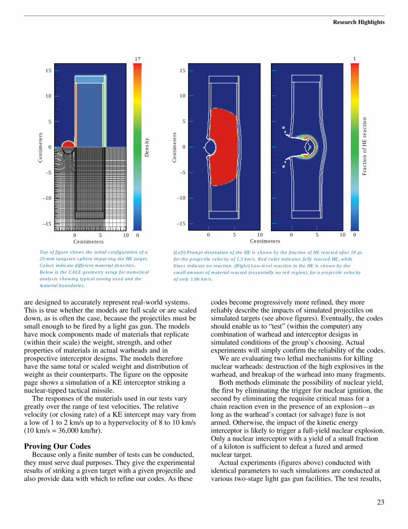
are designed to accurately represent real-world systems.This is true whether the models are full scale or are scaleddown, as is often the case, because the projectiles must besmall enough to be fired by a light gas gun. The modelshave mock components made of materials that replicate(within their scale) the weight, strength, and otherproperties of materials in actual warheads and inprospective interceptor designs. The models thereforehave the same total or scaled weight and distribution ofweight as their counterparts. The figure on the oppositepage shows a simulation of a KE interceptor striking anuclear-tipped tactical missile.
The responses of the materials used in our tests varygreatly over the range of test velocities. The relativevelocity (or closing rate) of a KE intercept may vary froma low of 1 to 2 km/s up to a hypervelocity of 8 to 10 km/s(10 km/s = 36,000 km/hr).
Proving Our CodesBecause only a finite number of tests can be conducted,
they must serve dual purposes. They give the experimentalresults of striking a given target with a given projectile andalso provide data with which to refine our codes. As these
codes become progressively more refined, they morereliably describe the impacts of simulated projectiles onsimulated targets (see above figures). Eventually, the codesshould enable us to “test” (within the computer) anycombination of warhead and interceptor designs insimulated conditions of the group’s choosing. Actualexperiments will simply confirm the reliability of the codes.
We are evaluating two lethal mechanisms for killingnuclear warheads: destruction of the high explosives in thewarhead, and breakup of the warhead into many fragments.
Both methods eliminate the possibility of nuclear yield,the first by eliminating the trigger for nuclear ignition, thesecond by eliminating the requisite critical mass for achain reaction even in the presence of an explosion—aslong as the warhead’s contact (or salvage) fuze is notarmed. Otherwise, the impact of the kinetic energyinterceptor is likely to trigger a full-yield nuclear explosion.Only a nuclear interceptor with a yield of a small fractionof a kiloton is sufficient to defeat a fuzed and armednuclear target.
Actual experiments (figures above) conducted withidentical parameters to such simulations are conducted atvarious two-stage light gas gun facilities. The test results,
Research Highlights
23
0 5 10 0
–15
–10
–5
0
Cen
timet
ers
Den
sity
Centimeters
5
10
15
17
0 5 10
–15
–10
–5
0
Cen
timet
ers
Frac
tion
of H
E r
eact
ion
Centimeters
5
10
15
0 5 10 0
1
Top of figure shows the initial configuration of a25-mm tungsten sphere impacting the HE target.Colors indicate different material densities.Below is the CALE geometry setup for numericalanalysis showing typical zoning used and thematerial boundaries.
(Left) Prompt detonation of the HE is shown by the fraction of HE reacted after 18 µsfor the projectile velocity of 1.3 km/s. Red color indicates fully reacted HE, whileblues indicate no reaction. (Right) Low-level reaction in the HE is shown by thesmall amount of material reacted (essentially no red region), for a projectile velocityof only 1.06 km/s.

together with 2D and 3D hydrodynamic code analyses,are used to interpret the tests and establish the lethalityof the KE interceptor. One of the codes used extensivelyfor analyses of the intercepts is CALE (an ArbitraryLagrangian Eulerian code written in the language C),which implements our ignition and growth reactive flowmodel.1 CALE enables us to calculate how most types of high explosive (HE) of interest for application incounterproliferation respond when impacted by a KEprojectile of given properties. The mesh in the figure ontop left of page 23 shows the CALE setup geometry fornumerical analysis of a projectile impacting an HE targetand the density of a 25-mm tungsten spherical projectileimpacting the HE target. The HE figure shows the resultsof impacts at two relative velocities: at 1.3 km/s, the
impact produces a prompt detonation at 15 µs in the HE; at 1.06 km/s, the projectile penetrates into the HE,but at 60 µs has only produced a low-level reaction. The graph (at left) shows a comparison of our analysiswith experimental results for Composition-B HE, ourbenchmark HE used in studies of our ignition growthmodel. Simulations run on our 2D and 3D codes haveshown excellent agreement with experimental results,giving us confidence in their ability to reliably expandthe range of test parameters.
Projected WorkFor the purpose of studying the effectiveness of
warhead interceptors, we have simulated a simplenuclear warhead concept that we believe represents whataggressively proliferant nations might devise. We havebuilt a generic model target for lethality testing andconducted two half-scale tests. We are now building full-scale targets for testing on a sled track at Holliman AirForce Base in New Mexico, where an actual interceptorvehicle will be fired into a target. We will evaluate thelethality of the systems being fielded against this target.
References1. E. L. Lee and C. M. Tarver, “Phenomenological Model of Shock Initiation
in Heterogeneous Explosives,” Phys. Fluids 23 (12), December 1980, pp. 2362–2372.
24
3
2
1
10
Pro
ject
ile v
eloc
ity, k
m/s
Projectile diameter, mm20 30
Tested Comp-BComputed Comp-BExperimental detonationExperimental nondetonaton
Comparison of theCALE calculations forthe Composition-B HEinitiation with theresults of experimentsat the Naval ResearchLaboratory, showingthe range betweendetonation andnondetonation. Thecalculations showexcellent agreementwith the test results.CalculatedComposition-B density was 1.7 g/cm3;tested density was1.63 g/cm3.
For further information contact Glenn W. Pomykal(510) 422-4728, [email protected].
Research Highlights
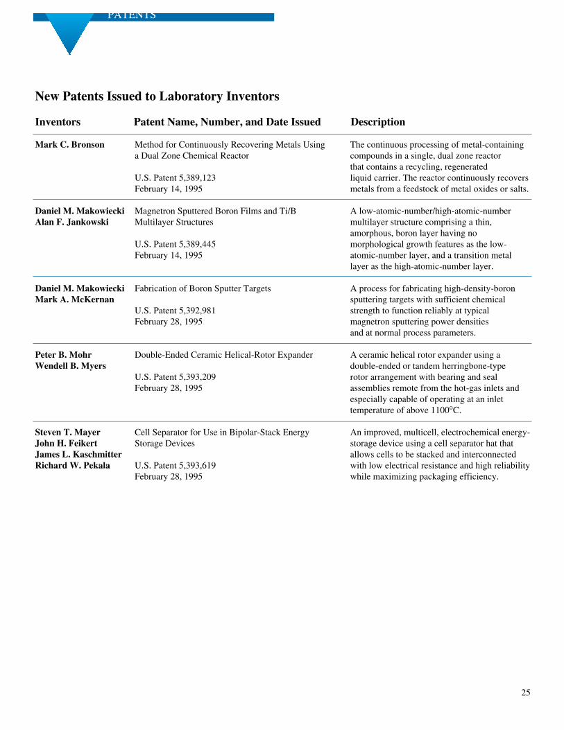
25
PATENTS
New Patents Issued to Laboratory Inventors
Inventors Patent Name, Number, and Date Issued Description
Mark C. Bronson Method for Continuously Recovering Metals Using The continuous processing of metal-containing a Dual Zone Chemical Reactor compounds in a single, dual zone reactor
that contains a recycling, regenerated U.S. Patent 5,389,123 liquid carrier. The reactor continuously recovers February 14, 1995 metals from a feedstock of metal oxides or salts.
Daniel M. Makowiecki Magnetron Sputtered Boron Films and Ti/B A low-atomic-number/high-atomic-number Alan F. Jankowski Multilayer Structures multilayer structure comprising a thin,
amorphous, boron layer having no U.S. Patent 5,389,445 morphological growth features as the low- February 14, 1995 atomic-number layer, and a transition metal
layer as the high-atomic-number layer.
Daniel M. Makowiecki Fabrication of Boron Sputter Targets A process for fabricating high-density-boron Mark A. McKernan sputtering targets with sufficient chemical
U.S. Patent 5,392,981 strength to function reliably at typical February 28, 1995 magnetron sputtering power densities
and at normal process parameters.
Peter B. Mohr Double-Ended Ceramic Helical-Rotor Expander A ceramic helical rotor expander using a Wendell B. Myers double-ended or tandem herringbone-type
U.S. Patent 5,393,209 rotor arrangement with bearing and seal February 28, 1995 assemblies remote from the hot-gas inlets and
especially capable of operating at an inlet temperature of above 1100°C.
Steven T. Mayer Cell Separator for Use in Bipolar-Stack Energy An improved, multicell, electrochemical energy- John H. Feikert Storage Devices storage device using a cell separator hat that James L. Kaschmitter allows cells to be stacked and interconnected Richard W. Pekala U.S. Patent 5,393,619 with low electrical resistance and high reliability
February 28, 1995 while maximizing packaging efficiency.

26
Creating Microsphere Targets for InertialConfinement Fusion Experiments
The targets used in inertial confinement fusion (ICF)experiments at the Lawrence Livermore NationalLaboratory are plastic capsules roughly half a millimeterin diameter. This article reviews the fabrication of thesecapsules, focusing on the production of the thin-walledpolystyrene microshell around which the capsule is built.The relationship between the capsule characteristics,especially surface finish, and capsule performance isdiscussed, as are the methods of surface characterizationand modification necessary for experiments designed tostudy the effects of surface roughness on implosiondynamics. Targets for the next generation of ICF facilitiesusing more powerful laser drivers will have to be largerwhile meeting the same or even more stringent symmetryand surface finish requirements. Some of the technologiesfor meeting these needs are discussed briefly.Contact: Robert Cook (510) 422-3117.
E&TR Celebrates 20 YearsEnergy and Technology Review celebrates its 20th
Anniversary in this April 1995 issue of the publication.With quotes from influential contributors, the articlehighlights the publication’s changes in focus, widecoverage of Laboratory science, experiences of scientificeditors, and graphic design changes over the years. Alsoin the article are the whereabouts of past scientific editorsand a statement by Laboratory Director C. Bruce Tarter.
ABSTRACTS