review: fifty years plus of accelerometer history for
TRANSCRIPT
197
Review: Fifty years plus of accelerometerhistory for shock and vibration (1940–1996)
Patrick L. WalterEngineering Department, Texas Christian University,Box 298640, Fort Worth, TX 76129, USA
Received 7 December 1998
Revised 9 June 1999
This article summarizes the history of accelerometer devel-opment and the subsequent evolution of the commercial ac-celerometer industry. The focus is primarily on piezoelectricand piezoresistive accelerometers, although early resistance-bridge-type accelerometers are also described. The pioneeraccelerometer manufacturing companies are identified and achronology of technology development through today is pre-sented.Keywords: Accelerometer, calibration, ferroelectric, piezo-electric, piezoresistive, strain gage
1. Historical background
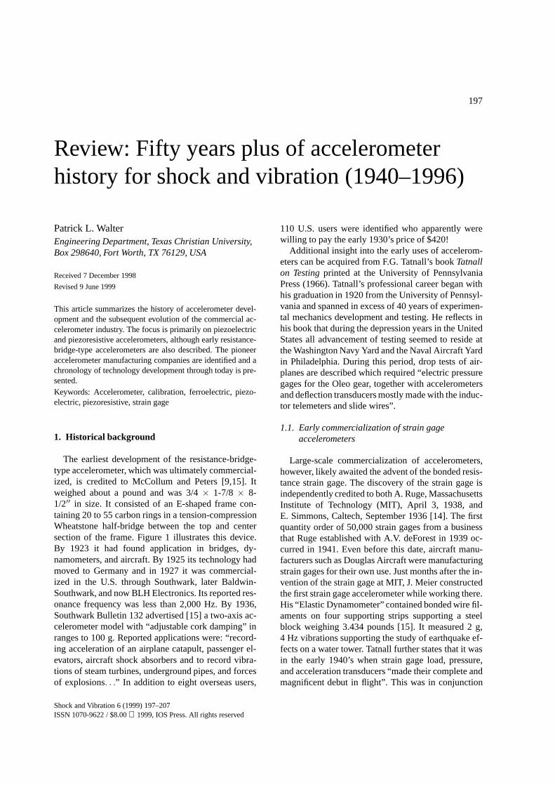
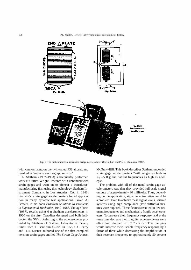
The earliest development of the resistance-bridge-type accelerometer, which was ultimately commercial-ized, is credited to McCollum and Peters [9,15]. Itweighed about a pound and was 3/4× 1-7/8 × 8-1/2′′ in size. It consisted of an E-shaped frame con-taining 20 to 55 carbon rings in a tension-compressionWheatstone half-bridge between the top and centersection of the frame. Figure 1 illustrates this device.By 1923 it had found application in bridges, dy-namometers, and aircraft. By 1925 its technology hadmoved to Germany and in 1927 it was commercial-ized in the U.S. through Southwark, later Baldwin-Southwark, and now BLH Electronics. Its reported res-onance frequency was less than 2,000 Hz. By 1936,Southwark Bulletin 132 advertised [15] a two-axis ac-celerometer model with “adjustable cork damping” inranges to 100 g. Reported applications were: “record-ing acceleration of an airplane catapult, passenger el-evators, aircraft shock absorbers and to record vibra-tions of steam turbines, underground pipes, and forcesof explosions. . .” In addition to eight overseas users,
110 U.S. users were identified who apparently werewilling to pay the early 1930’s price of $420!
Additional insight into the early uses of accelerom-eters can be acquired from F.G. Tatnall’s bookTatnallon Testingprinted at the University of PennsylvaniaPress (1966). Tatnall’s professional career began withhis graduation in 1920 from the University of Pennsyl-vania and spanned in excess of 40 years of experimen-tal mechanics development and testing. He reflects inhis book that during the depression years in the UnitedStates all advancement of testing seemed to reside atthe Washington Navy Yard and the Naval Aircraft Yardin Philadelphia. During this period, drop tests of air-planes are described which required “electric pressuregages for the Oleo gear, together with accelerometersand deflection transducers mostly made with the induc-tor telemeters and slide wires”.
1.1. Early commercialization of strain gageaccelerometers
Large-scale commercialization of accelerometers,however, likely awaited the advent of the bonded resis-tance strain gage. The discovery of the strain gage isindependently credited to both A. Ruge, MassachusettsInstitute of Technology (MIT), April 3, 1938, andE. Simmons, Caltech, September 1936 [14]. The firstquantity order of 50,000 strain gages from a businessthat Ruge established with A.V. deForest in 1939 oc-curred in 1941. Even before this date, aircraft manu-facturers such as Douglas Aircraft were manufacturingstrain gages for their own use. Just months after the in-vention of the strain gage at MIT, J. Meier constructedthe first strain gage accelerometer while working there.His “Elastic Dynamometer” contained bonded wire fil-aments on four supporting strips supporting a steelblock weighing 3.434 pounds [15]. It measured 2 g,4 Hz vibrations supporting the study of earthquake ef-fects on a water tower. Tatnall further states that it wasin the early 1940’s when strain gage load, pressure,and acceleration transducers “made their complete andmagnificent debut in flight”. This was in conjunction
Shock and Vibration 6 (1999) 197–207ISSN 1070-9622 / $8.00 1999, IOS Press. All rights reserved
198 P.L. Walter / Review: Fifty years plus of accelerometer history
Fig. 1. The first commercial resistance-bridge accelerometer (McCollum and Peters, photo date 1936).
with cannon firing on the twin-tailed P38 aircraft andresulted in “miles of oscillograph records”.
L. Statham (1907–1983) subsequently performedwork at Curtiss-Wright Research with unbonded wirestrain gages and went on to pioneer a transducer-manufacturing firm using this technology, Statham In-strument Company, in Los Angeles, CA, in 1943.Statham’s strain gage accelerometers found applica-tion in many dynamic test applications. Given A.Brewer, in his bookPractical Solutions to Problemsin Experimental Mechanics, 1940–1985, Vantage Press(1987), recalls using 6 g Statham accelerometers in1950 on the first Canadian designed and built heli-copter, the SGVI. Referring to the accelerometer pro-vided by Statham of Statham Laboratories: “everytime I used it I sent him $5.00”. In 1955, C.C. Perryand H.R. Lissner authored one of the first completetexts on strain gages entitledThe Strain Gage Primer,
McGraw-Hill. This book describes Statham unbondedstrain gage accelerometers “with ranges as high as+/−500 g and natural frequencies as high as 4,500cps”.
The problem with all of the metal strain gage ac-celerometers was that they provided full-scale signaloutputs of approximately 30 millivolts. Thus, depend-ing on the application, signal to noise ratios could bea problem. Even to achieve these signal levels, seismicsystems using high compliance (low stiffness) flex-ures were required. These flexures resulted in low res-onant frequencies and mechanically fragile accelerom-eters. To increase their frequency response, and at thesame time decrease their fragility, accelerometers wereoften fluid damped to 0.707 critical. This dampingwould increase their useable frequency response by afactor of three while decreasing the amplification attheir resonant frequency to approximately 50 percent

P.L. Walter / Review: Fifty years plus of accelerometer history 199
of their zero frequency value. However, the penalty as-sessed by the introduction of this fluid damping wasto make the frequency response of the accelerome-ter highly temperature dependent when operated morethan+/−20 or 30◦F from room ambient conditions.
The frequency constraints associated with theseearly strain gage accelerometers limited their applica-tion in measuring high frequency vibration and there-fore short duration shocks. D.E. Weiss reports in a1947 paper [16] on testing of Naval aircraft struc-tures at the Naval Air Experimental Station (NAES),Philadelphia: “accelerometers are required for the fol-lowing types of tests; pull-outs and other flight maneu-vers; normal and arrested landings; catapult launch-ings”. Weiss describes accelerometers developed atNAES patterned after units built at Douglas Air-craft Company. Also described are Statham units withranges from+/−12 g to +/−40 g and natural fre-quencies ranging from 400 to 500 Hz. Weight of theStatham 12 G unit was “approximately 2 ounces”.Weiss’ paper models the response of an accelerometerto both a step function and triangular pulse for variousdamping values. It concludes “While much more math-ematical analysis remains to be done in determiningthe response of accelerometers to pulses, it is evidentthat high natural frequencies are required to recordtransients”. At the same conference where Weiss pre-sented this paper, W.P. Welch, Westinghouse ResearchLaboratories, presented a second paper [17] on a pro-posed new shock-measuring instrument. This paper ab-stract starts: “No very suitable instrument now existsfor the measurement of mechanical shock on field tests.This includes measurements made on ships, airplanes,and other vehicles”. Welch used a Westinghouse Tran-sient Analyzer to study accelerometer transient re-sponse to four types of simple shock motion. Thisincreasing emphasis on shock measurement encour-aged Levy and Kroll, in 1951, to perform an analyticalstudy [8] at the National Bureau of Standards concern-ing accelerometer response to transient accelerations.This study investigated accelerometer response to half-sine, triangular, and square pulses. The controlled ac-celerometer parameters were damping ratio and ratioof accelerometer natural period to pulse duration. TheNavy through the Bureau of Aeronautics also fundedthis work.
2. Piezoelectric accelerometer industry
The solution to the transient response problemsidentified in the above-described studies of Messrs.
Weiss, Welch, and Levy and Kroll came as a resultof the introduction of the piezoelectric accelerometerinto the transducer market place. The piezoelectric ma-terials used had high moduli. In addition, their self-generating responses produced wide dynamic signalranges. Both of these properties combined to enablethe design of accelerometers with high resonant fre-quencies. These high resonant frequencies eliminatedthe need for damping to extend the accelerometer’suseable flat frequency response. Phase shift over theuseable frequency range of the accelerometer also waseliminated. This large dynamic signal range also al-lowed size reduction of piezoelectric accelerometersrelative to strain gage accelerometers while providingmuch higher g capability. As proof of the improvedproperties of piezoelectric accelerometers for vibra-tion measurements, one can assess National Bureau ofStandards reports 6907 and 7066 [6,7] which surveyedthe performance of representative piezoelectric andbonded and unbonded strain gage accelerometers man-ufactured sometime prior to 1960. None of the straingage accelerometers had flat frequency response above200 Hz while the piezoelectric accelerometers pro-vided flat response to 10,000 Hz. As Statham Instru-ments and other transducer companies owe their exis-tence to the development of the strain gage, a plethoraof accelerometer manufacturers owe their existence tothe integration of piezoelectric technology into trans-ducers.
The late 1940s and early 1950s were an excitingtime as numerous manufacturers of piezoelectric ac-celerometers came into existence. The piezoelectricmaterials used included ferroelectric and nonferroelec-tric (e.g., quartz). The early ferroelectric ceramics usedwere primarily barium titanate. Piezoelectric transduc-ers, which are basically ac coupled high pass circuitsat low frequencies, originally utilized cathode followervacuum tube signal conditioning. Charge amplifierswere next developed and subsequently a two wire in-tegrated (FET) circuit was incorporated into the ac-celerometer itself. The charge amplifier eliminated thevoltage dividing effect of the cable capacitance both-ersome to the cathode follower circuit. The placementof integrated circuit technology within the accelerom-eter, which is today’s principal technology, eliminatedmuch of the triboelectric-based cable noise bothersometo the charge circuit. Accelerometers with integratedcircuits are typically sealed units capable of operatingover long lines in various harsh environments.
The status of accelerometer development in 1953is summarized in [11]. This reference describes a

200 P.L. Walter / Review: Fifty years plus of accelerometer history
May 14–15, 1953 Symposium on Barium Titanate Ac-celerometers. This symposium focused on the increas-ing importance of shock and vibration measurementsto military requirements. Four half-day sessions dealtwith (1) the properties of barium titanate (a relativelynew piezoelectric ceramic material): methods of polar-ization, dependence of charge sensitivity with crystalsize, material stability, material and piezoelectric con-stants; (2) the design factors and performance tests ofbarium titanate accelerometers including construction,calibration, frequency response, linearity, temperatureand pressure effects, and cable noise; and (3) the instru-mentation associated with the accelerometers. A NavalResearch Lab accelerometer Type C-4 one inch highand weighing five ounces was reported on as operatingto 7000 g. An NBS Type OBI-14 accelerometer weigh-ing 7.4 gms with a 90 kHz resonance was described!Gulton had a large array of accelerometers: Models A-312, A-314, A-320, A-403, A-413, A-410, and A-500.Weights from 2.5 to 52 gms were reported with reso-nant frequencies to 35 kHz.
2.1. Corporate pioneers
The principal early corporate pioneers and theirfirst locations included Bruel and Kjaer (Denmark),Columbia Research Laboratories (Woodlyn, PA), En-devco (Pasadena, CA), Gulton Manufacturing (Metu-chen, NJ), and Kistler Instruments (Buffalo, NY). It isinteresting to note that all of these companies are stillin existence today. Columbia Research Laboratoriesand Gulton Manufacturing (now Gulton-Statham) havebecome broad based transducer houses so that piezo-electric accelerometer development is no longer theircentral focus. Bruel and Kjaer is currently focused as asystems house, transducers being one part, with abouthalf of its product line directed towards shock and vi-bration. Kistler Instruments has split since its initialfounding with the portion maintaining the Kistler namehaving a broad piezoelectric accelerometer line and ahistorical focus on force and pressure measurement.The significant company emerging from Kistler wasPCB Piezotronics. PCB is a rapidly growing companywith an increasing focus on piezoelectric accelerome-ters, particularly in the modal and industrial areas. En-devco has maintained a consistent focus on shock andvibration measurements and in addition to a piezoelec-tric accelerometer line has evolved an extensive sili-con micromachined accelerometer line. Wilcoxon Re-search, although not founded until 1960 and a “jobshop” facility for many years, is mentioned because
of its early ties to the David Taylor Model Basin andits pioneering work in mechanical impedance heads.A brief history of all of these companies and some oftheir accomplishments follow. The amount of cover-age provided to each is dependent on the duration oftheir corporate existence, the history they contain in ac-celerometer development for shock and vibration, andthe amount of their product focus on shock and vibra-tion measurements over the years. It is in no mannerjudgmental on the company or their products.
2.1.1. Bruel and KjaerBruel and Kjaer (B&K) is located in Naerum, Den-
mark, specializing in sound and vibration measure-ments. B&K began in 1942 in a small town north ofCopenhagen, Denmark. Per V. Bruel and Viggo Kjaer,recent university graduates, started a product line witha voltmeter which expanded to now include over 200instruments and transducers.
B&K designed its first piezoelectric accelerome-ters in 1943 made from Rochelle salt crystals (water-soluble) mounted as square bender plates with a corneror one side free and sometimes loaded with clampedweights. Their sensitivities were 35–50 mV/g and theirresonant frequencies were 2–3 kHz. The device shownin Fig. 2 (photo date estimated 1945–1948) proba-bly represents the first commercial piezoelectric ac-celerometer. Ceramic elements replaced the Rochellesalt crystals in the early 1950’s. As a result, accelerom-eter sensitivity was approximately doubled and theresonance increased to 5 kHz. Compression type ac-celerometers were introduced into B&K’s product linein the late 1950s with design modifications in 1964 re-sulting in a new series with reduced susceptibility tocase loading and base strain. From 1968 to 1975 fur-ther improvements were made in the compression de-sign. In 1958, B&K’s U.S. presence increased with theopening of their Cleveland, OH facility.
Their first shear accelerometer (Type 8307) evolvedin 1972. Their DeltaShearR© design emerged in 1974consisting of three masses and piezoelectric elementsarranged around a triangular center post to furtherminimize base strain and thermal coupling. This de-sign was further standardized for interchangability(UniGainR©) and subsequently, in the1990s, incorpo-rated integrated circuits (DeltaTronR©). ThetaShearR©
accelerometers are currently a low cost version ofthis integrated circuit accelerometer for volume ap-plications. B&K’s 100,000 g accelerometer model isthe 8309. Their transducer development for soundand vibration continues with an increased focus oncomplete systems. B&K probably currently represents

P.L. Walter / Review: Fifty years plus of accelerometer history 201
Fig. 2. The first commercial piezoelectric accelerometer (B&K, about 1943).
the most turnkey system house of manufacturers dis-cussed. They also maintain a focus on accelerometercalibration systems. B&K remained a family run busi-ness until 1992 when the company was purchased byAGIV, a German based company.
2.1.2. Columbia Research LaboratoriesColumbia Research Laboratories was founded in
1955 by V.F. Alibert and his sister Olive as a part-timeoperation to build high temperature strain gages de-veloped at the Philadelphia Naval Shipyard. In 1959their brother joined the business and applied his back-ground in physics and environmental testing to developa product line of ferroelectric ceramic shock and vibra-tion accelerometers. Columbia’s facility has remainedin Woodlyn, PA throughout its existence. Alibert leftthe company in 1981.
In 1964 Columbia won a major contract for vi-bration monitoring on the Apollo program. Represen-tative piezoelectric products have included those forthe USAF’s ICBM program, fuse applications for Pi-catinny Arsenal, differential piezoelectric accelerome-ters/charge amplifiers for nuclear power plant opera-tions, and airborne vibration measurements using hy-
brid assemblies. Their current catalog envelops shockaccelerometers (e.g., Model 5004) to 100,000 g andpiezoelectric accelerometers using both charge and in-tegrated circuit technology. Their main focus today,however, is on applying numerous types of transduc-tion technologies to the industrial marketplace.
2.1.3. Gulton ManufacturingL.K. Gulton founded Gulton Manufacturing in the
early 1940s in Metuchen, NJ as a chemical company.In 1946, G. Howatt joined Gulton from the MIT Lab-oratory having patented the formulation of sheet bar-ium titanate as the first man made replacement for nat-ural piezoelectric crystals. Glenco Corp. was set upafter Howatt’s arrival and ultimately became part ofGulton Industries. Barium titanate was first applied tosonar applications and A. Dranetz, who arrived at Gul-ton in 1948, along with Howatt, made the first prac-tical commercial piezoelectric vibration accelerome-ters in the U.S. in 1949. Prior to that time, Brush In-struments (which became Clevite) had made only acrude ADP based piezoelectric accelerometer whichweighed about three ounces. Clevite chose, however, tofocus primarily on piezoelectric material development

202 P.L. Walter / Review: Fifty years plus of accelerometer history
and never became a significant accelerometer manu-facturer.
In the late 1950s Gulton was principally makingcompression and bender type accelerometers from fer-roelectric ceramics under the trade name of Glennite(named after Howatt). The bender design possessedless spurious effects due to base strain and acous-tic coupling into the accelerometer than did the com-pression design. In low g ranges, this bender designwas fluid damped and was the only piezoelectric ac-celerometer to accomplish this.
In 1964, Gulton bought Electra-Scientific (founded1960) in Fullerton, CA, primarily to attain rights totheir bolted shear piezoelectric accelerometer design.They consolidated all their piezoelectric operations inFullerton in 1965. The bolted shear design addressedthe base strain sensitivity issue and allowed stacking ofelements for temperature compensation.
In the mid 1960s Gulton developed a proprietarypiezoceramic (G-1900) enabling manufacture of theAQB 4901 accelerometer (patent award 1969) and thenothers for engine vibration monitoring to 1000◦F. In1967 they consolidated with their Servonics Division,a general purpose transducer capability, to becomeGulton Servonics in Costa Mesa, CA. Mark IV in-dustries acquired them (1986) and the remainder ofStatham’s original company (1992), to form Gulton-Statham. Gulton-Statham produces charge and inte-grated circuit (w/gain since 1980s) accelerometers to-day with a decreased emphasis on shock and vibration.Their current focus is on various types of transducersfor broad based applications.
2.1.4. Kistler InstrumentsKistler Instrument Company began operations in
America in 1954 and was incorporated in January1957. W. Kistler started to develop piezoelectric mea-suring instruments in 1944 while at the Swiss Locomo-tive and Machine Works. In the early 1950s, while anengineer at Bell Aerosystems in Buffalo, NY, Kistlerselectively marketed the Swiss Locomotive and Ma-chine Works transducers in the U.S.
After performing further product development andleaving Bell, in 1962 Kistler built a facility in Clarence,NY. Kistler Instruments was next acquired by Sund-strand Corporation in 1968 and moved to Redmond,WA in 1970. Subsequently, they were acquired byKistler Instrumente AG, Switzerland (which had beena Swiss counterpart since 1958) in 1979 and movedto Amherst, NY (present location). Kistler’s consistentfocus has been on quartz transducers, principally forforce and pressure measurements. Kistler was granted
a Swiss patent for a charge amplifier June 16, 1950,and Kistler Instruments received a U.S. patent in 1960.
Kistler’s first quartz accelerometer and vibrationcalibration standards were patented in 1962. Kistleroriginated the concept of incorporating a two-wireintegrated circuit (a FET) within a piezoelectric ac-celerometer. This was in the 1963–1965 time framewith patent (PIEZOTRONR©) filed July 8, 1968. Fig-ure 3 shows the Model 818, the first Kistler PIEZO-TRON in a two-wire version. This is likely the firstcommercial two wire FET-based accelerometer.
Quartz is an extremely linear piezoelectric mate-rial with a reasonably high temperature capability.Quartz accelerometers tend not to zero shift as dosome of the soft ferroelectric ceramics due to smallchanges in their remnant polarization vector due toshock loading [5]. Since quartz has a smaller com-pression piezoelectric constant and less capacitancethan most ferroelectric ceramics, the early quartz ac-celerometers used preloaded crystal stacks mechani-cally in series and electrically in parallel. Under severeshock loading, the crystals might inadvertently expe-rience relative motion within the stacks and producezero shifts for reasons not associated with the piezo-electric properties of quartz. The compression modedesign was also susceptible to base strain effects sim-ilar to compression designs of other manufacturers.Kistler’s 805A was the first (about 1966) 100,000 gquartz accelerometer introduced to the market and its805B (about 1970) was the first 100,000 g single crys-tal quartz accelerometer. At present, the U.S. portion ofKistler’s operations principally manufactures numer-ous accelerometer types including quartz shear. Thecombined Kistler operations have approximately 450employees.
2.1.5. PCBPCB split from Kistler in 1967 as an independent
U.S. company founded by R.W. Lally and J. Lally andis now larger than the U.S. portion of its parent. Lally’shistory with Kistler dates back to its original 1950’sfounding and much of the technology that Lally wasinvolved with at Kistler moved with him to PCB.
PCB is the company most responsible for the com-mon acceptance of integrated circuit technology(ICPR©) in piezoelectric transducers and today is theworld’s largest manufacturer of this technology. PCBfirst placed ICP technology in a 100,000 g shockaccelerometer in 1971. PCB’s early focus was, asKistler’s, on force and pressure transducers. Their ICPtechnology moved them into the industrial accelerome-ter market (e.g., machinery health monitoring) with as-

P.L. Walter / Review: Fifty years plus of accelerometer history 203
Fig. 3. The first commercial two-wire piezoelectric accelerometer with contained FET (Kistler, about 1963).
Fig. 4. The first modally tuned impulse hammer (PCB, 1972).
sociated large quantity applications. The first PCB in-dustrial grade ICP accelerometer (Model 308A04) wasdeveloped in 1973. The large volume industrial marketcreated a subsequent demand for low cost accelerom-eters and PCB’s automatic manufacturing capability isaddressing that challenge.
Experimental modal analysis evolved from the Uni-versity of Cincinnati’s Structural Dynamics ResearchLaboratory as a technique to extract modal parame-ters (vibratory mode shapes, resonant frequencies, anddamping) from structural systems to enhance the mod-eling process. In 1972, PCB worked with the Univer-sity to develop a “Modally Tuned” impulse hammer
with integral force transducer to provide structural sys-tem excitation. This Impulse Hammer design broughtPCB lasting fame and a 1983 IR-100 award. Figure 4shows such a modally tuned impulse hammer.
Capitalizing on this entry into the rapidly emerg-ing experimental modal analysis technology, PCB de-veloped a Structcel Modal Array Sensing System in1983 that addressed sensor installation, orientation, ca-bling, signal conditioning, and end-to-end calibration.Its 1984 Data Harvester focused on accommodatinglarge numbers of accelerometer channels. Modal test-ing can routinely involve hundreds of accelerometers.To encourage modal testing, PCB developed easily im-

204 P.L. Walter / Review: Fifty years plus of accelerometer history
plemented system dynamic calibration techniques. ItsModel 963A Gravimetric Calibrator (1973) enabledsingle channel amplitude and phase calibration, and itsModel 9090C Accelerometer Array Calibrator (1986)enabled up to 128 modal accelerometers to be cali-brated simultaneously for amplitude and phase basedon rigid body mechanics. PCB moved into structuredshear quartz accelerometers in 1986 and now workswith many other piezoelectric accelerometer crystaltypes including the ferroelectric ones. PCB is markedtoday by continued rapid growth and an increasing fo-cus on accelerometer design.
2.1.6. EndevcoEndevco was originated as a company in 1947 by
H.D. Wright, an instrument manufacturer’s representa-tive, in Pasadena, CA, and moved to San Juan Capis-trano, CA in 1974. Endevco manufactured its firstaccelerometer in 1951. Endevco presently has divi-sions in several countries and is operated by MeggittAerospace. Wright retired as president in 1964. En-devco is one of the oldest piezoelectric accelerometermanufacturers, is currently the largest U.S. manufac-turer and is the only piezoelectric accelerometer de-veloper that has maintained a consistent product fo-cus on shock and vibration. Since Endevco is uniquein manufacturing both piezoelectric and silicon basedaccelerometers for shock and vibration, as well as itsown piezoelements, its study provides somewhat of acomprehensive history in accelerometer development.
Endevco’s principal accelerometer technology areashave been microminiature, high shock, high tempera-ture, and calibration development (discussed below).They evolved their first charge amplifier in 1959. Theirfirst 100,000 g piezoelectric (PE) accelerometer wasmarketed in 1965. The first attempt at developing apiezoresistive (PR) accelerometer for the shock andvibration measurement community occurred in 1962using a patented butterfly bulk semiconductor gage.In 1961, a Solid State Laboratory to support PR ac-celerometer development was set up and now residesin Sunnyvale, CA. By 1966 a 10,000 g PR shock ac-celerometer was in the marketplace.
The first line diffused semiconductor gages were de-veloped in 1967 enabling the radiation hardened 2266series of accelerometers to evolve in ranges to 20,000g by 1968. An analogous configuration to the 2266 ina non- radiation hardened version was developed aboutthis same time in ranges to 50,000 g. In April 1974studies were performed for a 100,000 g sculptured sili-con accelerometer with a freed gage design. The resul-tant product (7270A/weight= 1.5 gm, see Fig. 5(a))
was marketed in 1983 in ranges to 200,000 g with a1.2 MHz resonant frequency. These PR accelerometeraccomplishments were all firsts.
Returning to PE accelerometer development, an an-nular shear series of accelerometers was developedwith patent application filed in 1959. This led to theevolution of their microminiature product line (e.g., a0.14 gm PE with 10,000 Hz frequency response wasdeveloped in 1972, a 0.85 gm three axis version mar-keted in 1973, and 0.2 gm low impedance integralelectronics single axis version marketed in 1984). Fig-ure 5(b) shows a microminiature triaxial accelerom-eter with integral electronics providing some insightinto the state-of-the-art of accelerometer technology asit exists today. A 1.3 gm 100,000 g PE accelerometerwith a 250,000 Hz resonance was developed in 1969.The 7255B continued the evolution of high shock PEproducts in 1988 with the incorporation of integratedcircuit technology and a built-in mechanical filter forpyroshock measurements. A 2270 back to back “pig-gyback” calibration standard was developed in 1965.These accomplishments again represent firsts.
Endevco entered the high temperature market witha 750◦F quartz accelerometer in 1961. Subsequently,an accelerometer (2273) with this same 750◦F tem-perature specification but a ferroelectric bismuth ti-tanate sensor was released. In 1969 testing was per-formed on two different PE accelerometer models foraircraft engine monitoring at temperatures of 900◦Fand 1200◦F. The 6237M70 was released with a tem-perature capability of 1200◦F in 1981. A model 6240tourmaline based accelerometer, in development in theearly 1980s, was released as the 6240 in 1988 with anoperating specification of 1400◦F.
2.1.7. Wilcoxon ResearchThe final company discussed, Wilcoxon Research
Incorporated, was formed by K. Wilcoxon, A. Sykes,and F. Schloss in 1960. Schloss was an acoustical noisephysicist at David Taylor Model Basin (DTMB) sincethe early 1950s. Schloss invented the self-driven Me-chanical Impedance Head. This head was developed tosupport studies of noise damping characteristics of vi-bration isolation mounts for shipboard machinery. Thehead required a piezoelectric force transducer and ac-celerometer and a controllable vibration generator. TheHead was patented October 13, 1959 (#3,070,996).DTMB originally built the heads and transferred themto other Navy customers.
The requirement for studies supported by the headwas intensified by the U.S. nuclear submarine pro-gram. The Navy subsequently approved a technology

P.L. Walter / Review: Fifty years plus of accelerometer history 205
Fig. 5a. The first high-g (200,000 g) sculptured silicon accelerometer (Endevco, 1983).
Fig. 5b. The smallest triaxial piezoelectric accelerometer with integral electronics (Endevco, about 1985).
transfer of the head to Wilcoxon. Soon after its form-ing, Sykes sold his shares in Wilcoxon Research toWilcoxon and Schloss did the same in 1979. In 1979the company was also transferred to Wilcoxon’s sons.Today the company is located in Gaithersburg, MD. Itprimarily works in the industrial accelerometer mar-ketplace using lessons learned in making instrumenta-tion “sailorproof”.
3. Accelerometer calibration capabilitydevelopment
While accelerometer development occurred primar-ily in private industry, calibration capabilities develop-
ment for shock and vibration evolved in governmentfacilities, Endevco, and B&K. The National Bureau ofStandards (NBS), now The National Institute of Stan-dards and Technology (NIST), became involved in ac-celerometer calibration in the early 1950s. In 1956,S. Levy applied the reciprocity theory to accelerometercalibration and R. Bouche did the experimental workto redesign existing electrodynamic shakers. This re-sulted in a vibration calibration service (started 1956)at NBS from 10–2000 Hz. The hiring of Bouche fromNBS focused Endevco’s interest in calibration. In theearly 1960s, T. Dimoff developed the NBS air bearingshakers extending the range of electrodynamic shakersto 10–10,000 Hz with improved calibration accuracy.

206 P.L. Walter / Review: Fifty years plus of accelerometer history
These are in use today and the reciprocity method isused for shaker calibration.
In the early 1950s S. Edelman at NBS developed op-tical tools to measure the motion of piezoelectric shak-ers, first from 100 to 10,000 Hz, and later to 20,000 Hz.This interferometric method measures dynamic mo-tion based on the wavelength of light. In the 1950sand 1960s the light source was a mercury vapor lampwhich was replaced in the 1970s with a helium neonlaser. The laser interferometer was also applied to lowfrequency calibrations, from 1 to 200 Hz, in the early1970s.
Today, all accelerometer manufacturers offer NISTtraceable calibrations. Endevco manufactured a Ling-Endevco calibration system about 1970 with a tenpound force shaker. The Bouche shaker, developed byR. Bouche at Endevco, which uses the Dimoff air bear-ing and guides a beryllium armature, followed thisshaker. This latter shaker is incorporated in the Vibra-con/Bouche calibration system. Endevco’s AutomatedAccelerometer Calibration System (AACS) was mar-keted in the early 1990s to support vibration calibrationand subsequently shock calibration. This system alsoincorporates the Bouche shaker. B&K has also main-tained a consistent focus on vibration calibration. Their9610 system replaced (late 1980s) their old 9559 sys-tem. All of these are comparison calibration systemsto 5–10 kHz and resonant survey systems to 50 kHz.B&K’s Type 9636 is the only commercial primary sys-tem using laser light as an absolute reference to 5 kHz.
A significant challenge has always existed in thearea of shock accelerometer calibration where NBS/NIST has devoted less effort than in vibration calibra-tion. A shock calibration service was in place at NBSin the late 1960s or early 1970s and was discontinuedin 1976. A 1974 NBS publication [12] describes com-parison calibration on a hydraulic pull down shock ma-chine, using a FFT algorithm, to 1,500 g at 0.7 ms.By 1987 a shock calibration service was again oper-ating at NBS, modeled on the technique in the 1974report, to levels of 5,000 g at 0.3 ms. Continuing up-grades, including the addition of a ball drop shock gen-erator, resulted in the expansion of the NIST capabil-ity to 10,000 g at 0.1 ms by 1995. This capability iscurrently advertised as a “Special Test” at NIST.
Because user needs ran ahead of NBS/NIST capabil-ity, both other government agencies and private indus-try evolved shock accelerometer evaluation/calibrationhardware. Bouche developed the Drop Ball Calibra-tor [3] at Endevco in 1960 with a maximum g capabil-ity of 15,000 with 50µs duration. Photocells provided
a velocity reference. Butler, Dove, and Duggin [4] de-veloped a small-bore gas gun at Sandia National Labo-ratories in the 1964–1965 time frame which generatedpulses to 100,000 g with 100µs duration. An array ofphotodiodes provided a velocity reference.
A “Zatter” was developed [10] at Sandia NationalLaboratories in the 1963–1966 time frame using elec-tromagnetic energy to propel a small aluminum projec-tile. A Kistler 912 load cell provided a force to accel-eration reference. Calibration pulses were attainable to100,000 g and 200µsec duration. Bell [2], as part ofhis development of the Model 2291 accelerometer atEndevco, designed in 1969 a large exponential bar thatcould easily generate 100,000 g pulse trains. Sill [13] atEndevco commercialized a Hopkinson bar calibrationtechnique in 1984. Bateman, Brown, and Davie [1] atSandia National Laboratories applied a laser vibrome-ter to a Hopkinson bar as a calibration reference stan-dard to 70,000 g and claimed+/−5% resultant ac-curacy. Unreported work with laser vibrometer refer-ences has also occurred at NIST.
4. Conclusions
Since its inception, the accelerometer marketplacehas greatly expanded. In addition to the aforemen-tioned pioneers, newer manufacturer entries includeAnalog Devices (airbag accelerometer), Dytran (PCBspin-off), EG&G IC Sensors, Entran Devices (Kulitespin-off), Kulite Semiconductor (early 1970’s diffusedsilicon beam accelerometer), Vibra-Metrics, and oth-ers. The current rate of technology advancement in mi-crosensors and microelectronics indicates that futureexpansion in accelerometer manufacturers and capabil-ities will occur at an even faster pace than in the past.
Acknowledgments
This article contains some additional information,but only minor corrections, to an article published in50Years of Shock and Vibration Technology, Shock andVibration Information Analysis Center (SAVIAC, Ar-lington, VA, 1966). A session on Accelerometer His-tory for the 67th Shock and Vibration Symposium,Monterey, CA, November 1996, organized at the re-quest of SAVIAC, also complimented this work. Theproceedings of this session, in SAVIAC’s:The Shockand Vibration Bulletin-Part II, include detailed his-tories by the pioneers in this industry and the presi-

P.L. Walter / Review: Fifty years plus of accelerometer history 207
dents and CEOs of today’s thriving companies. Thegenerous gathering and sharing of information by thefollowing individuals, along with my own (P. Wal-ter) archives and recollections, made this paper possi-ble: B. Brown (B&K), J. Kubler/M. Murphy/S. Wende(Kistler), B. Clark/L. Maier/B. Whittier (Endevco), J.Lally (PCB), J. Hayer (Kulite Semiconductor/formerGulton), B. Payne (NIST), H.E. Roberts (Columbia),E. Hazleton (Gulton-Statham), and P. Stein (Stein En-gineering). The documented stories brought to the 67thShock and Vibration Symposium byThe Pioneers–Bouche (former National Bureau of Standards and En-devco), Dranetz (former Gulton), Stein (Stein Engi-neering), and Kistler (former Kistler Instruments) –will serve as invaluable references for future genera-tions. F. Schloss, one of the Wilcoxon founders andformerly with David Taylor Model Basin, also addedsignificantly to the history included in this paper.
References
[1] V.I. Bateman, F.A. Brown and N.T. Davie, The use of a beryl-lium bar to characterize a piezoresistive accelerometer in shockenvironments, in:Proceedings Institute of Environmental Sci-ences, Orlando, FL, May 1996.
[2] R.L Bell, Development of 100,000 g test facility,Shock andVibration Bulletin(December 1969), 205–214.
[3] R.R Bouche,Calibration of Shock and Vibration MeasuringTransducers, Monograph SVM-11, SAVIAC, Arlington, VA,1979.
[4] R.I. Butler, R.C. Dove and B.W. Duggin, Calibration and eval-uation of accelerometers in the 10,000 g to 100,000 g range,Instrument Society of America, Preprint 17.3-1-65, October1965.
[5] D.B Davis, Error sources in transducer crystals, in:7th Trans-ducer Workshop Proc., Range Commanders Council, WSMR,NM, April 1985, pp. 147–160.
[6] J.S Hilten, Performance tests on two piezoelectric accelerome-ters, National Bureau of Standards, Report 7066, U.S. Dept. ofCommerce, October 1960.
[7] P.S. Lederer, General characteristics of strain gage accelerom-eters used in telemetry, National Bureau of Standards, Report6907, U.S. Dept. of Commerce, July 1960.
[8] S. Levy and W.D. Kroll, Response of accelerometers to tran-sient accelerations,J. of Research of the National Bureau ofStandards45(4), Research Paper 2138 (October 1950).
[9] B. McCullom and O.S. Peters, A new electric telemeter,Tech-nology Papers National Bureau of Standards17(247) (January4, 1924).
[10] T.F. Meagher, The conversion of electromagnetic energy inshock pulses, Instrument Society of America, Preprint 49.4.61,September 1963.
[11] T.A. Perls, Proc. of Symposium on Barium Titanate Ac-celerometers, National Bureau of Standards, Report 2654, Au-gust 1953.
[12] J.D. Ramboz and C. Federman, Evaluation of mechanicalshock accelerometers by comparison methods, National Bu-reau of Standards, NBSIR 74-480, March 1974.
[13] R.D. Sill, Shock calibration of accelerometers at amplitudesto 100,000 g using compression waves,Endevco TP 283, SanJuan Capistrano, CA, February 1984.
[14] J.E. Starr, J. Dorsey and C.C. Perry, 50 years of the bondedresistance strain gage – an American perspective, PreprintsIMEKO TC3 and TC15, IMEKO XI World Congress, Houston,TX, October 1988, pp. 259–279.
[15] P.K. Stein, The early strain gage accelerometers: The inven-tors and their times,The Shock and Vibration Bulletin, Part II,Shock and Vibration Information Analysis Center (SAVIAC),67th Shock and Vibration Symposium, Part II, Monterrey, CA,November 1996.
[16] D.E. Weiss, Design and application of accelerometers,Proc.Society of Experimental Stress Analysis(now Society of Exper-imental Mechanics)4(2) (1947), 89–99.
[17] W.P. Welch, A proposed new shock measuring instrument,Proc. Society of Experimental Stress Analysis(now Society ofExperimental Mechanics)4(2) (1947), 39–51.

International Journal of
AerospaceEngineeringHindawi Publishing Corporationhttp://www.hindawi.com Volume 2010
RoboticsJournal of
Hindawi Publishing Corporationhttp://www.hindawi.com Volume 2014
Hindawi Publishing Corporationhttp://www.hindawi.com Volume 2014
Active and Passive Electronic Components
Control Scienceand Engineering
Journal of
Hindawi Publishing Corporationhttp://www.hindawi.com Volume 2014
International Journal of
RotatingMachinery
Hindawi Publishing Corporationhttp://www.hindawi.com Volume 2014
Hindawi Publishing Corporation http://www.hindawi.com
Journal ofEngineeringVolume 2014
Submit your manuscripts athttp://www.hindawi.com
VLSI Design
Hindawi Publishing Corporationhttp://www.hindawi.com Volume 2014
Hindawi Publishing Corporationhttp://www.hindawi.com Volume 2014
Shock and Vibration
Hindawi Publishing Corporationhttp://www.hindawi.com Volume 2014
Civil EngineeringAdvances in
Acoustics and VibrationAdvances in
Hindawi Publishing Corporationhttp://www.hindawi.com Volume 2014
Hindawi Publishing Corporationhttp://www.hindawi.com Volume 2014
Electrical and Computer Engineering
Journal of
Advances inOptoElectronics
Hindawi Publishing Corporation http://www.hindawi.com
Volume 2014
The Scientific World JournalHindawi Publishing Corporation http://www.hindawi.com Volume 2014
SensorsJournal of
Hindawi Publishing Corporationhttp://www.hindawi.com Volume 2014
Modelling & Simulation in EngineeringHindawi Publishing Corporation http://www.hindawi.com Volume 2014
Hindawi Publishing Corporationhttp://www.hindawi.com Volume 2014
Chemical EngineeringInternational Journal of Antennas and
Propagation
International Journal of
Hindawi Publishing Corporationhttp://www.hindawi.com Volume 2014
Hindawi Publishing Corporationhttp://www.hindawi.com Volume 2014
Navigation and Observation
International Journal of
Hindawi Publishing Corporationhttp://www.hindawi.com Volume 2014
DistributedSensor Networks
International Journal of