reveal fit instructions - premium retractable screens for doors, windows … · 2018-12-17 · when...
TRANSCRIPT

Wizard Screens 1-888-949-3667 www.wizardscreens.comWizard Screens 1-888-949-3667 www.wizardscreens.com
Reveal Fit Instructions

Installation Diagrams
Reveal-Fit
The following procedure is for REVEAL-FIT installations
When choosing a reveal fit the blind will be installed inside the window frame oropening, resulting in a flush or recessed finish. Unlike a face fit there are no protrudingparts, however it does sacrafice some of the opening dimension to achieve this. Forsmall windows, or where this is undesirable then a face fit may be a prefered alternative.(see "Smartblind Installation-FACE FIT.pdf" for more info.)
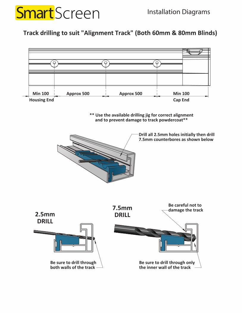
Drill all 2.5mm holes initially then drill7.5mm counterbores as shown below
** Use the available drilling jig for correct alignmentand to prevent damage to track powdercoat**
2.5mmDRILL
7.5mmDRILL
Be careful not todamage the track
Min 100 Approx 500 Approx 500 Min 100 Housing End Cap End
Track drilling to suit "Alignment Track" (Both 60mm & 80mm Blinds)
Be sure to drill throughboth walls of the track
Be sure to drill through onlythe inner wall of the track
Page .19.
Installation Diagrams
Assemble the "Fixed Track"& "Alignment Track"
Mark the ends to identify later
Drill right throughboth tracks 3.5mm
Remove "Alignment Track"& drill right through"Fixed Track" only 7.5mm
Min 100 Approx 500 Approx 500 Min 100 Cap EndHousing End
Drilling procedure for "Alignment Track"(for 60mm blinds - see note)
NOTE: For 80 & 120 Blinds only the"Alignment Track" need be drilled.
No need to drill the "fixed track"
Page .18.
HEIG
HT-b
otto
m o
f tra
ck to
top
of h
ousi
ng, o
r han
ger i
f use
d
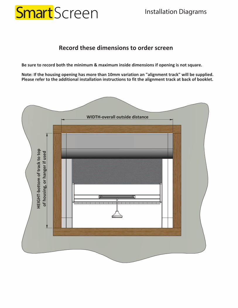
WIDTH-overall outside distance
Be sure to record both the minimum & maximum inside dimensions if opening is not square.
Note: If the housing opening has more than 10mm variation an "alignment track" will be supplied.Please refer to the additional installation instructions to fit the alignment track at back of booklet.
Record these dimensions to order screen
Page .1.

Installation Diagrams
SMB1-ASSEM-Lock-01
Step-1-Push lock into drawbar grooveuntil it snaps into place
1
2Step-2-Slide key into lock grooveto secure it in drawbar
Page .16.
Step-3-Mark location of lock-pin & drillM5 hole through track. Multipleholes can be drilled at desiredlocations along the track as needed
ITEM PART NUMBER QTY.1 SMB1-Lock-01 12 SMB1-Lock Key-01 1
28 28
SMB1-ASSEM-80-01
2 3
41
89
83
38
Page .3.
ITEM PART NUMBER QTY.1 SMB1-ASSEM-Housing-80-01 12 SMB1-ASSEM-Track-A-01 13 SMB1-ASSEM-Track-B-01 14 SMB1-ASSEM-Drawbar-01 1

Installation Diagrams
35.50mm (at motor end)Specify LH or RH motorwhen ordering screen
28
SMB1-ASSEM-80M-01
2 3
41
89
83
38
Page .4.
ITEM PART NUMBER QTY.1 SMB1-ASSEM-Housing-80M-01 12 SMB1-ASSEM-Track-A-03 13 SMB1-ASSEM-Track-B-02 14 SMB1-ASSEM-Drawbar-02 1
With the screen now assembled, spray a small amount of silicone spray intothe zipper tracks. Be careful not to spray the outer tracks or braking surface.
Run the drawbar up & down to check the blind operates smoothly & locksinto the "track caps" correctly. For windy areas, or areas with uneven ground
the "drawbar locks" can be fitted. Refer fitting instructions herein.
Drawbar locks
Check the blind operation
Page .15.

Installation Diagrams
2 Use a small screwdriver to compress the brake allowing the drawbar to swing into place
1 Push Drawbar toward the assembled track to compress the brake against the "fixed rail"
Position & secure "Drawbar" in tracks
3 Once correctly positioned complete "Track Assembly" shown on previous page
Bottom (sectioned) View
Page .14.
35.50 35.50
14
2 3
SMB1-ASSEM-120M-01
123
129
38
Page .5.
ITEM PART NUMBER QTY.1 SMB1-ASSEM-Housing-120M-01 12 SMB1-ASSEM-Track-A-03 13 SMB1-ASSEM-Track-B-03 14 SMB1-ASSEM-Drawbar-02 1

Installation Diagrams
Drill all 3.5mm holes initially then drill7.5mm counterbores as shown below
Be sure to drill throughboth walls of the track
3.5mmDRILL
Be sure to drill through onlythe inner wall of the track
7.5mmDRILL
Be careful not todamage the track
Min 100 Approx 500 Approx 500 Min 100 Cap EndHousing End
Drill "Fixed Track" as shown
Page .6.
1- Rotate Zipper Track into position
1
Ensure the "Drawbar" is correctly located within the track as shown
2- Ensure the flexible wing is fully seated
2
3
3- Align the "inner track" as shown 4- Press firmly ensuring it clicks into place
4
5- Align the "track retainer" as shown
5
6- Press firmly or soft mallet until seated
6
Complete the "Track" assembly for one side only
Page .13.

Installation Diagrams
Feed the zipper into track
Pull the "Drawbar" down 50cm or more to make it easierto feed the zipper into the tracks. Repeat for both sides
Feed mesh edge into "Zip Track"
Page .12.
8mm countersink
3.5mm drill
Drill & countersink holes (staggered) as shown above
Approx 100
Approx 500
Approx 500
Approx 500
Approx 500
Approx 100
Drill "Housing Hanger" (for 80 & 120 screens only)
Page .7.

Installation Diagrams
Use packers if needed to ensure housing hanger ismounted both level & flat across it's entire length
83mm Setback (for flush finish)(123mm for the 120 screen)
Use appropriate fluff in this channel if gap ispresent due to packers being used (not shown)
Mount "Housing Hanger" (for 80 & 120 screens only)
Page .8.
Ensure tracks are both parallel & vertical
Fit "Housing"& "Fixed Tracks" (for 60mm Screen)1- Slide both "Fixed Tracks" onto the lugs on the housing "End Caps"2- Position the entire assembly into the window recess. Take extreme care to keep tracks
pependicular to the housing while positioning or damage to the "End Cap" lugs may occur.3- Use a level to check tracks are vertical, then insert top screws both sides.4- Continue to insert remaining screws while checking for parallel, add packing if required.
Handle can swing out of the way to fit screws
Ensure "Track Caps" are flush with sill
Page .11.

Installation Diagrams
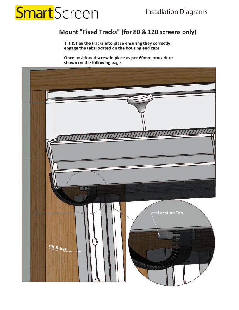
Tilt & flex
Mount "Fixed Tracks" (for 80 & 120 screens only)Tilt & flex the tracks into place ensuring they correctlyengage the tabs located on the housing end caps
Once positioned screw in place as per 60mm procedureshown on the following page
Location Tab
Page .10.
Lift & support the housing locating the prongsinto hanger opening. Ensure it remains firmlyagainst the underside on the hanger, thenstarting at one end push the housing towardthe wall, working your way along the entirelength to engage the securing clip.
Slide "housing lock"into hanger &press firmly until it clips into place
Ensure this clip is engagedbefore fitting the "housing lock"
Mount "Housing" (for 80 & 120 screens only)
Page .9.
Installation Diagrams
Tilt & flex
Mount "Fixed Tracks" (for 80 & 120 screens only)Tilt & flex the tracks into place ensuring they correctlyengage the tabs located on the housing end caps
Once positioned screw in place as per 60mm procedureshown on the following page
Location Tab
Page .10.
Lift & support the housing locating the prongsinto hanger opening. Ensure it remains firmlyagainst the underside on the hanger, thenstarting at one end push the housing towardthe wall, working your way along the entirelength to engage the securing clip.
Slide "housing lock"into hanger &press firmly until it clips into place
Ensure this clip is engagedbefore fitting the "housing lock"
Mount "Housing" (for 80 & 120 screens only)
Page .9.

Installation Diagrams
Feed the zipper into track
Pull the "Drawbar" down 50cm or more to make it easierto feed the zipper into the tracks. Repeat for both sides
Feed mesh edge into "Zip Track"
Page .12.
8mm countersink
3.5mm drill
Drill & countersink holes (staggered) as shown above
Approx 100
Approx 500
Approx 500
Approx 500
Approx 500
Approx 100
Drill "Housing Hanger" (for 80 & 120 screens only)
Page .7.

Installation Diagrams
Drill all 3.5mm holes initially then drill7.5mm counterbores as shown below
Be sure to drill throughboth walls of the track
3.5mmDRILL
Be sure to drill through onlythe inner wall of the track
7.5mmDRILL
Be careful not todamage the track
Min 100 Approx 500 Approx 500 Min 100 Cap EndHousing End
Drill "Fixed Track" as shown
Page .6.
1- Rotate Zipper Track into position
1
Ensure the "Drawbar" is correctly located within the track as shown
2- Ensure the flexible wing is fully seated
2
3
3- Align the "inner track" as shown 4- Press firmly ensuring it clicks into place
4
5- Align the "track retainer" as shown
5
6- Press firmly or soft mallet until seated
6
Complete the "Track" assembly for one side only
Page .13.

Installation Diagrams
2 Use a small screwdriver to compress the brake allowing the drawbar to swing into place
1 Push Drawbar toward the assembled track to compress the brake against the "fixed rail"
Position & secure "Drawbar" in tracks
3 Once correctly positioned complete "Track Assembly" shown on previous page
Bottom (sectioned) View
Page .14.
35.50 35.50
14
2 3
SMB1-ASSEM-120M-01
123
129
38
Page .5.
ITEM PART NUMBER QTY.1 SMB1-ASSEM-Housing-120M-01 12 SMB1-ASSEM-Track-A-03 13 SMB1-ASSEM-Track-B-03 14 SMB1-ASSEM-Drawbar-02 1

Installation Diagrams
35.50mm (at motor end)Specify LH or RH motorwhen ordering screen
28
SMB1-ASSEM-80M-01
2 3
41
89
83
38
Page .4.
ITEM PART NUMBER QTY.1 SMB1-ASSEM-Housing-80M-01 12 SMB1-ASSEM-Track-A-03 13 SMB1-ASSEM-Track-B-02 14 SMB1-ASSEM-Drawbar-02 1
With the screen now assembled, spray a small amount of silicone spray intothe zipper tracks. Be careful not to spray the outer tracks or braking surface.
Run the drawbar up & down to check the blind operates smoothly & locksinto the "track caps" correctly. For windy areas, or areas with uneven ground
the "drawbar locks" can be fitted. Refer fitting instructions herein.
Drawbar locks
Check the blind operation
Page .15.

Installation Diagrams
SMB1-ASSEM-Lock-01
Step-1-Push lock into drawbar grooveuntil it snaps into place
1
2Step-2-Slide key into lock grooveto secure it in drawbar
Page .16.
Step-3-Mark location of lock-pin & drillM5 hole through track. Multipleholes can be drilled at desiredlocations along the track as needed
ITEM PART NUMBER QTY.1 SMB1-Lock-01 12 SMB1-Lock Key-01 1
28 28
SMB1-ASSEM-80-01
2 3
41
89
83
38
Page .3.
ITEM PART NUMBER QTY.1 SMB1-ASSEM-Housing-80-01 12 SMB1-ASSEM-Track-A-01 13 SMB1-ASSEM-Track-B-01 14 SMB1-ASSEM-Drawbar-01 1

Installation Diagrams
28 28
SMB1-ASSEM-60-01
1
3
4
2
60
60
38
Page .2.
ITEM PART NUMBER QTY.1 SMB1-ASSEM-Housing-60-01 12 SMB1-ASSEM-Track-A-01 13 SMB1-ASSEM-Track-B-01 14 SMB1-ASSEM-Drawbar-01 1
31
48.30
SMB1-Track Alignment-01(for 60 & 80 blinds)
38.
50
48.30
SMB1-Track Alignment-02(for 80M & 120 blinds)
To install "Alignment Track" (when required)
Additional Instructions
Page .17.

Installation Diagrams
Assemble the "Fixed Track"& "Alignment Track"
Mark the ends to identify later
Drill right throughboth tracks 3.5mm
Remove "Alignment Track"& drill right through"Fixed Track" only 7.5mm
Min 100 Approx 500 Approx 500 Min 100 Cap EndHousing End
Drilling procedure for "Alignment Track"(for 60mm blinds - see note)
NOTE: For 80 & 120 Blinds only the"Alignment Track" need be drilled.
No need to drill the "fixed track"
Page .18.
HEIG
HT-b
otto
m o
f tra
ck to
top
of h
ousi
ng, o
r han
ger i
f use
d
WIDTH-overall outside distance
Be sure to record both the minimum & maximum inside dimensions if opening is not square.
Note: If the housing opening has more than 10mm variation an "alignment track" will be supplied.Please refer to the additional installation instructions to fit the alignment track at back of booklet.
Record these dimensions to order screen
Page .1.
Installation Diagrams
Reveal-Fit
The following procedure is for REVEAL-FIT installations
When choosing a reveal fit the blind will be installed inside the window frame oropening, resulting in a flush or recessed finish. Unlike a face fit there are no protrudingparts, however it does sacrafice some of the opening dimension to achieve this. Forsmall windows, or where this is undesirable then a face fit may be a prefered alternative.(see "Smartblind Installation-FACE FIT.pdf" for more info.)
Drill all 2.5mm holes initially then drill7.5mm counterbores as shown below
** Use the available drilling jig for correct alignmentand to prevent damage to track powdercoat**
2.5mmDRILL
7.5mmDRILL
Be careful not todamage the track
Min 100 Approx 500 Approx 500 Min 100 Housing End Cap End
Track drilling to suit "Alignment Track" (Both 60mm & 80mm Blinds)
Be sure to drill throughboth walls of the track
Be sure to drill through onlythe inner wall of the track
Page .19.
Installation Diagrams
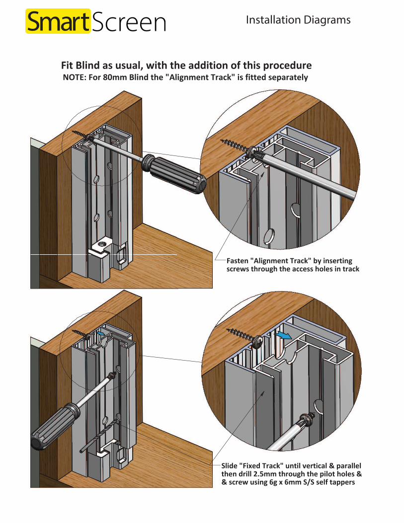
Fasten "Alignment Track" by insertingscrews through the access holes in track
NOTE: For 80mm Blind the "Alignment Track" is fitted separately Fit Blind as usual, with the addition of this procedure
Slide "Fixed Track" until vertical & parallelthen drill 2.5mm through the pilot holes && screw using 6g x 6mm S/S self tappers
Page .20.

Wizard Screens 1-888-949-3667 www.wizardscreens.comWizard Screens 1-888-949-3667 www.wizardscreens.com