rev.05.26.20 #2.0 page 1 csu800 series
TRANSCRIPT

©2021 Advanced Energy Industries, Inc.1
CSU800AP Series
AT A GLANCE
Total Power
800 Watts
Input Voltage
90 to 264 Vac
180 to 300 Vdc
# of Outputs
Single
ARTESYNCSU800AP-3-600 SERIES 800 Watts Distributed Power System
SPECIAL FEATURES
800W output power
High power and short form factor
1U power supply
High density design: 25W/in3
Active power factor correction
EN61000-3-2 harmonic compliance
Inrush current control
80 PLUS® Platinum efficiency
N+M redundant N+M ≤ 4
Hot-pluggable
Active current sharing
Full digital control
PMBusTM compliant
Accurate input power reporting
EN61000-4-5 surge level ±1KV/±2KV DM/CM
Cold redundancy
Reserve airflow option Conducted/Radiated EMI class A
SAFETY
UL/cUL
TUV + CB Report
CE Mark
CCC
BSMI
KC
BIS
EAC
TYPICAL APPLICATIONS
Industrial
PRODUCT DESCRIPTION
Advanced Energy's Artesyn CSU800AP power supply is housed in a 1U high rack-mount enclosure measuring just 2.89 x 7.28 in (73.5 x 185.0 mm). This form factor is significantly narrower and shorter than that of similarly rated earlier generation power supplies —freeing up valuable system space — and is achieved by use of the latest power switching technology and high density component packaging techniques. This form factor conforms to the standard market's Common Redundant Power Supplies.
TECHNICAL REFERENCE NOTE

2advancedenergy.com
CSU800AP Series
Rev. 09.07.21_#1.3
OptionsOptionsOptionsOptions
None
MODEL NUMBERS
StandardOutput Voltage
Minimum LoadMaximum Load
Stand-BySupply
Air Flow Direction
CSU800AP-3-600 12.2 Vdc 1 A 66.7 A 12 Vdc@3 ANormal
(DC connector to handle)
CSU800AP-3-601 12.2 Vdc 1 A 66.7 A 12 Vdc@3 AReversed
(Handle to DC connector)

3advancedenergy.com
CSU800AP Series
Rev. 09.07.21_#1.3
Absolute Maximum Ratings
Stress in excess of those listed in the “Absolute Maximum Ratings” may cause permanent damage to the power supply. These are stress ratings only and functional operation of the unit is not implied at these or any other conditions above those given in the operational sections of this TRN. Exposure to any absolute maximum rated condition for extended periods may adversely affect the power supply’s reliability.
Table 1. Absolute Maximum Ratings
Parameter Models Symbol Min Typ Max Unit
Input VoltageAC continuous operationDC continuous operation
All modelsAll models
VIN,AC
VIN,DC
90180
--
264300
VacVdc
Maximum Output Power All models PO,max - - 800 W
Isolation VoltageInput to output All models - - 4242 Vdc
Ambient Operating Temperature1 All models TA 0 - 55 OC
Storage Temperature All models TSTG -40 - 70 OC
Humidity (non-condensing)Operating
Non-operatingAll modelsAll models
00
--
9095
%%
AltitudeOperating
Non-operatingAll modelsAll models
--
--
5,00015,200
mm
MTBFTelcordia Method 1 Case
Nominal Line and 50OCAll models 750 - - KHours
Operating Life100% load
50OC operating temperatureNormal input voltage
All models - 5 - Years
Note 1 - The maximum operating temperature (55OC) is to be derated by 1OC per 300 m above 2000 m.
ELECTRICAL SPECIFICATIONS

4advancedenergy.com
CSU800AP Series
Rev. 09.07.21_#1.3
Input Specifications
ELECTRICAL SPECIFICATIONS
Table 2. Input Specifications
Parameter Condition Symbol Min Typ Max Unit
Operating Input Voltage, AC All VIN,AC 90 115/230 264 Vac
Operating Input Voltage, DC All VIN,DC 180 - 300 Vdc
Input AC Frequency All fIN,AC 47 50/60 63 Hz
AC Turn On Voltage1 All 79 - 89 Vac
AC Turn Off Voltage1 All 75 - 85 Vac
AC Input Over Voltage Protection All 285 - 300 Vac
AC Input Recovery All 275 - 285 Vac
Maximum Input Current(IO = IO,max, ISB = ISB,max)
VIN,AC = 90 Vac / 60 HzIIN,max
- - 11.7 A
VIN,AC = 180 Vac / 50 Hz - - 5.8 A
No Load Input Power(VO = On, IO = 0 A, ISB = 0 A)
All PIN,no-load - - 5 W
Harmonic Line Currents All THD Per EN 61000-3-2
Power Factor IO > 10% IO,max PF 0.90 - -
Startup Surge Current (Inrush) @ 25OC VIN,AC = 240 Vac IIN,surge - - 35 Apk
Input FuseInternal, L
5x20 mm, Quick Acting 12.5 A, 400 Vdc
- - 12.5 A
Leakage Current to Earth GroundVIN,AC = 264 Vac
fIN,AC = 50 Hz- - 1.75 mA
Operating Efficiency2 @ 25OC
VIN,AC = 230 VacfIN,AC = 50 Hz
IO = 10% IO,max
IO = 20% IO,max
IO = 50% IO,max
IO = 100% IO,max
ŋ87909491
----
----
%%%%
System StabilityPhase Margin 45 - - Ø
Gain Margin -6 - - dB
Note 1 - Turn on/off hysteresis is ≥ 5 V.Note 2 - Measured excluding fan power.

5advancedenergy.com
CSU800AP Series
Rev. 09.07.21_#1.3
Output Specifications
ELECTRICAL SPECIFICATIONS
Table 3. Output Specifications
Parameter Condition Symbol Min Typ Max Unit
Output RegulationInclusive of set-point, temperature change,
warm-up drift.
VO 11.8 12.2 12.6Vdc
VSB 11.4 12.0 12.6
Output Ripple, pk-pk
Measure with a 0.1 μFceramic capacitor in parallel with a 10 μF
tantalum capacitor, 10 to 20 MHz bandwidth
VO - - 120
mVPK-PK
VSB - - 120
Output CurrentAll IO 1 - 66.7
AAll ISB 0 - 3
Output Current Share Accuracy20% to 100% IO10% to 20% IO
--
--
510
% IO
Output Voltage Minimum Current Share Loading All 10 - - % IO,max
Number of Parallel Units1 Main output “12 V load share” connected
- - 4
Load Capacitance
Main output start up, stability, cold redundancy
and dynamic load2200 - 25000 uF
Standby output start up 100 - 3100 uF
VO Dynamic Response2
Peak Deviation
60% load change, slew rate = 0.5 A/us
VO 11.6 - 12.8 V
1A load change,slew rate = 0.5 A/us
VSB 11.4 - 12.8 V
Note 1 - VSB output does not use active current sharing. On paralleled units, the maximum current on VSB output rail can not exceed the current of one unit.Note 2 - Recommend to test with 2200 uF capacitive load at the Vo output and 1000 uF at VSB output. 1 A minimum current for transient load response
testing only.

6advancedenergy.com
CSU800AP Series
Rev. 09.07.21_#1.3
System Timing Specifications
ELECTRICAL SPECIFICATIONS
Table 4. System Timing Specifications
Label Parameter Min Typ Max Unit
T1 Delay from AC being applied to VSB being within regulation. - - 1500 mSec
T2Delay from AC being applied to all output voltages being within regulation.
- - 3000 mSec
T3 Output voltage rise time for 12 V from 10 % to within regulation limits. - - 25 mSec
T4Delay from output voltages within regulation limits to PWOK asserted high at turn on.
100 - 500 mSec
T5 Delay from loss of AC to de-assertion of PWOK. 10 - - mSec
T6Delay from PWOK de-asserted to output voltages dropping out of regulation limits.
1 - - mSec
T7Hold up time - time output voltages stay within regulation after the loss of AC at 100 % load.*The hold-up time will be >20 ms at 50 % load.
11 - - mSec
T8Delay from standby voltage in regulation to output voltage in regulation at AC turn on.
50 - 1000 mSec
T9Duration of PWOK being in the de-asserted state during an off/on cycle using AC or the PSON signal.
100 - - mSec
T10 Delay from PSON active to output voltages within regulation limits. 5 - 400 mSec
T11 Delay from PSON deactive to PWOK de-asserted low. - - 5 mSec
T12Hold up time - time standby voltages stay within regulation after the loss of AC.
70 - - mSec
T13 Delay from PSON de-asserted to power supply turning off. - - 5 mSec
T14 Output voltage rise time for 12VSB from 10% to within regulation limits. - - 70 mSec

7advancedenergy.com
CSU800AP Series
Rev. 09.07.21_#1.3
System Timing Diagram
ELECTRICAL SPECIFICATIONS
8advancedenergy.com
CSU800AP Series
Rev. 09.07.21_#1.3
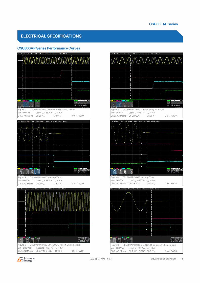
CSU800AP Series Performance Curves
ELECTRICAL SPECIFICATIONS
Figure 1: CSU800AP-3-600 Turn-on delay via AC mains
Vin = 90 Vac Load: IO = 66.7 A ISB = 3 A
Ch 1: AC Mains Ch 2: VSB Ch 3: VO Ch 4: PWOK
Figure 2: CSU800AP-3-600 Turn-on delay via PSON
Vin = 90 Vac Load: IO = 66.7 A ISB = 3 A
Ch 1: AC Mains Ch 2: PSON Ch 3: VO Ch 4: PWOK
Figure 4: CSU800AP-3-600 Hold-up Time
Vin = 264 Vac Load: IO = 66.7 A ISB = 3 A
Ch 1: AC Mains Ch 2: PSON Ch 3: VO Ch 4: PWOK
Figure 5: CSU800AP-3-600 VIN_GOOD Assert Characteristic
Vin = 230 Vac Load: Io = 66.7 A ISB = 3 A
Ch 1: AC Mains Ch 2: VIN_GOOD Ch 3: VO Ch 4: PWOK
Figure 3: CSU800AP-3-600 Hold-up Time
Vin = 90 Vac Load: IO = 66.7 A ISB = 3 A
Ch 1: AC Mains Ch 2: VSB Ch 3: VO Ch 4: PWOK
Figure 6: CSU800AP-3-600 VIN_GOOD De-assert Characteristic
Vin = 230 Vac Load: Io = 66.7 A ISB = 3 A
Ch 1: AC Mains Ch 2: VIN_GOOD Ch 3: VO Ch 4: PWOK

9advancedenergy.com
CSU800AP Series
Rev. 09.07.21_#1.3
75.00
80.00
85.00
90.00
95.00
6.67 13.34 20.01 26.68 33.35 40.02 46.69 53.36 60.03 66.7
Output Current (A)
CSU800AP-3-600 Efficiency Curve
CSU800AP Series Performance Curves
Note 1 - All waveforms and data are tested on CSU800AP-3-400.
ELECTRICAL SPECIFICATIONS
Figure 8: CSU800AP-3-600 Ripple and Noise Measurement
Load: IO = 66.7 A ISB = 3 A
Ch 3: VO
Figure 10: CSU800AP-3-600 Transient Response - VO Deviation
40% to 100% load change 0.5 A/uS slew rate Vin = 230 Vac
Ch 1: VO Ch 2: IO
Figure 7: CSU800AP-3-600 Output Voltage Startup Characteristic
Vin = 90 Vac Load: IO = 66.7 A ISB = 3 A
Ch 3: VO
Eff
icie
nc
y (%
)
x
Figure 9: CSU800AP-3-600 Turn Off Characteristic via PSON
Load: IO = 66.7 A ISB = 3 A
Ch 1: PSON Ch 2: VO Ch 3: PWOK
Figure 11: CSU800AP-3-600 Transient Response - VO Deviation
100% to 40% load change 0.5 A/uS slew rate Vin = 230 Vac
Ch 1: VO Ch 2: IO
Figure 12: CSU800AP-3-600 Efficiency Curve @ 25OC
90 Vac 115 Vac 230 Vac 264 Vac
Loading: Io_main = 10% Io,max increment to 66.7 A, ISB = 3 A (12 V)

10advancedenergy.com
CSU800AP Series
Rev. 09.07.21_#1.3
Protection Function Specifications
Input Fuse
CSU800AP series is equipped with an internal non user serviceable 12.5 A High Rupturing Capacity (HRC) 400 Vdc fuse to IEC 127 for fault protection on Line input.
Over Voltage Protection (OVP)
The power supply over voltage protection will be locally sensed. The power supply will shut down and latch off after an over voltage condition occurs. This latch will be cleared by toggling the PSON signal or by an AC power interruption. The values are measured at the output of the power supply’s connector. The voltage will never exceed the maximum level when measured at the power connectors of the power supply’s connector during any single point of failure. The voltage will never trip any lower than the minimum level when measured at the power connector. +12 V standby output will be auto-recovered after removing the OVP limit.
Over Temperature Protection (OTP)
The power supply will be protected against over temperature conditions caused by loss of fan cooling or excessive ambient temperature. In an OTP condition, the PSU will shut down. When the power supply temperature drops to within specified limits,the power supply will restore power automatically, while the +12 V standby output remains always on. The OTP circuit has built in the margin such that the power supply will not oscillate on and off due to temperature recovering condition. The OTP trip level has a minimum of 4OC of ambient temperature margin.
Over Current Protection (OCP)
The power supply has a current limit to prevent the outputs from exceeding the values shown in the table on the next page. If the current limits are exceeded, the power supply will shut down and latch off. The latch will be cleared by toggling the PSON signal or by an AC power interruption. The power supply will not be damaged from repeated power cycling in this condition. +12 V standby output will be auto-recovered after removing the OCP limit.
The over current protection for the main output is divided to three stages.
The first stage is the Over Current Warning (OCW). When the output current is within this range and lasts for longer than 20 Sec, the SMB Alert will assert within the 20 to 20.1 Sec and the power supply will shut down after the assertion of SMB Alert for longer than 1 Sec.
The second stage is the Over Current Protection (OCP). When the output current is within this range, the SMB Alert will assert within the 10 mSec and the power supply will shut down after the assertion of SMB Alert for longer than 5 mSec.
The third stage is the Over Power Protection (OPP). When the output current is within this range, the SMB Alert will assert in 100 µSec and the power supply will shut down after the assertion of SMB Alert for longer than 80 µSec.
ELECTRICAL SPECIFICATIONS
Parameter Min Nom Max Unit
Main Output Overvoltage 13.5 / 15 V
Standby Output Overvoltage 13.5 / 15 V

11advancedenergy.com
CSU800AP Series
Rev. 09.07.21_#1.3
ELECTRICAL SPECIFICATIONS
ParameterThresholds Timing
Protection ModeMin Nom Max Min Max
VO Output Overcurrent Warning 67 A 73.5 A 80 A - 20 S SMB Alert Assertion
VO Output Overcurrent Protection 80 A 90 A 100 A - 10 mS Shut Down and Latch
VO Output Overpower Protection 100 A 110 A 120 A - 100 uS Shut Down and Latch
VSB Output Overcurrent Protection 4 A - 5 A - - Auto-recover

12advancedenergy.com
CSU800AP Series
Rev. 09.07.21_#1.3
Mechanical Outlines (unit: mm)
The physical size of the power supply enclosure is 39/40 mm x 73.5 mm x 185 mm.The power supply contains a single 40 mm fan with normal airflow direction or reversed airflow direction.The power supply has an identical card edge output that interfaces with a 2x25 card edge connector in the system. The AC plugs directly into the external face of the power supply. Refer to the following figure. All dimensions are nominal.
MECHANICAL SPECIFICATIONS

13advancedenergy.com
CSU800AP Series
Rev. 09.07.21_#1.3
Connector Definitions
AC Input Connector
Pin 1 – L
Pin 2 – N
Pin 3 – Earth Ground
Output Connector - Power Blades
A1-A9 – Main Output Return
A10-A18 – Main Output (VO)
B1-B9 – Main Output Return
B10-B18 – Main Output (VO)
Output Connector - Control Signals
A19 – SDA
A20 – SCL
A21 – PSON
A22 – SMB Alert
A23 – -VSENSE
A24 – +VSENSE
A25 – PWOK
B19 – A0 (SMBus Address)
B20 – A1 (SMBus Address)
B21 – 12VSB
B22 – CR_BUS
B23 – 12V Load Share
B24 – Present
B25 – VIN_GOOD
MECHANICAL SPECIFICATIONS
View from power supply output connector end

14advancedenergy.com
CSU800AP Series
Rev. 09.07.21_#1.3
Power / Signal Mating Connectors and Pin Types
MECHANICAL SPECIFICATIONS
Table 5. Mating Connectors for CSU800AP Series
Reference On Power Supply Mating Connector or Equivalent
AC Input Connector IEC320-C14 IEC320-C13
Output Connector Card-edge
Right AngleFCI Amphenol GPCEF4361411HHRFCI Amphenol 10035388VerticalFCI Amphenol HPG36P14SVP011T P2PFCI Amphenol 10147875-111LF

15advancedenergy.com
CSU800AP Series
Rev. 09.07.21_#1.3
LED Indicator Definitions
One bi-color (green/amber) LED at the power supply
front provides the status signal. The status LED conditions are shown on the following table.
MECHANICAL SPECIFICATIONS
Conditions LED Status
Normal work. Green
No AC power to all power supplies. Off
PSU standby state AC present / Only 12 VSB on or PSU in a cold standby state or always standby state. 1Hz Blink Green
AC cord unplugged with a second power supply in parallel still with AC input power. Amber
Power supply critical event causing a shutdown.(Failure, over current, short circuit, over voltage, fan failure, over temperature)
Amber
Power supply warning events where the power supply continues to operate.(High temp, high power, high current, slow fan)
1Hz Blink Amber
Power supply firmware updating. 2Hz Blink Green
Status LED
16advancedenergy.com
CSU800AP Series
Rev. 09.07.21_#1.3
Weight
The CSU800AP series weight is 864.5 g/1.91 lbs.
MECHANICAL SPECIFICATIONS

17advancedenergy.com
CSU800AP Series
Rev. 09.07.21_#1.3
EMC Immunity
CSU800AP series power supply is designed to meet the following EMC immunity specifications.
ENVIRONMENTAL SPECIFICATIONS
Table 6. Environmental Specifications
Document Description
Class A of CISPR22 (EN55032) and FCC Part 15
Conducted and Radiated EMI Limits
IEC/EN61000-3-2 Class A Harmonics
IEC/EN61000-3-3 Voltage Fluctuations
IEC/EN61000-4-2 Electromagnetic Compatibility (EMC) - Testing and measurement techniques -Electrostatic discharge immunity test: +/-15 KV air, +/-8 KV contact discharge. Performance - Criteria A
IEC/EN61000-4-3 Electromagnetic Compatibility (EMC) - Testing and measurement techniques -Radiated, radio-frequency, electromagnetic field immunity test. Performance - Criteria A
IEC/EN61000-4-4 Electromagnetic Compatibility (EMC) - Testing and measurement techniques -Electrical fast transient/burst immunity test: +/-2 KV for AC power port. Performance - Criteria A
IEC/EN61000-4-5 Electromagnetic Compatibility (EMC) - Testing and measurement techniques - Surge test: +/-2 KV common mode and +/-1 KV differential mode for AC ports. Performance - Criteria A
IEC/EN61000-4-11 Electromagnetic Compatibility (EMC) - Testing and measurement techniques -Voltage dips and interruptions: Criteria B: >95% reduction for 10 mS; Criteria C: 30% reduction for 500 mS, or >95% reduction for 500 mS.Performance - Criteria C
EN55024: 2010 Information technology equipment-immunity characteristics, limits and method of measurements

18advancedenergy.com
CSU800AP Series
Rev. 09.07.21_#1.3
Safety Certifications
The CSU800AP series power supply is intended for inclusion in other equipment and the installer must ensure that it is in compliance with all the requirements of the end application. This product is only for inclusion by professional installers within other equipment and must not be operated as a stand-alone product.
ENVIRONMENTAL SPECIFICATIONS
Table 7. Safety Certifications for CSU800AP Series Power Supply System
Standard Agency Description
UL 60950-1, 2nd Edition, 2014-10-14; CAN/CSA C22.2 No. 60950-1-07, 2nd Edition, 2014-10
UL + CUL US and Canada Requirements
EN 62368-1:2014+A11:2017 CE European Requirements
EN 62368-1:2014/A11:2017IEC 62368-1:2014
CB Scheme International Electrotechnical Commission
CHINA CCC Approval China Requirements
IS 13252 (PART 1):2010 / IEC 60950-1:2005 BIS India Requirements

19advancedenergy.com
CSU800AP Series
Rev. 09.07.21_#1.3
EMI Emissions
The CSU800AP series has been designed to comply with the Class A limits of EMI requirements of FCC Part 15 and CISPR 32 (EN 55032) for emissions and relevant sections of EN 55032:2011 for immunity. The unit is enclosed inside a metal box, tested at800 W using resistive load with the cooling fan.
Conducted Emissions
The applicable standard for conducted emissions is EN 55032 (FCC Part 15). Conducted noise can appear as both differential mode and common mode noise currents. Differential mode noise is measured between the two input lines, with the major components occurring at the supply fundamental switching frequency and its harmonics. Common mode noise, a contributor to both radiated emissions and input conducted emissions, is measured between the input lines and system ground and can be broadband in nature.
The CSU800AP series power supply has internal EMI filters to ensure the convertors’ conducted EMI levels comply with EN 55032 (FCC Part 15) Class A limits. The EMI measurements are performed with resistive loads at maximum rated loading.
Sample of EN 55032 Conducted EMI Measurement at 110 Vac Input
Note: Red Line refers to Artesyn Quasi Peak margin, which is 6 dB below the CISPR international limit. Pink Line refers to the Artesyn Average margin, which is 6 dB below the CISPR international limit.
Conducted EMI emissions specifications of the CSU800AP series:
ENVIRONMENTAL SPECIFICATIONS
Parameter Model Symbol Min Typ Max Unit
FCC Part 15, class A All Margin 6 - - dB
CISPR 32 (EN55032), class A All Margin 6 - - dB

20advancedenergy.com
CSU800AP Series
Rev. 09.07.21_#1.3
Radiated Emissions
Unlike conducted EMI, radiated EMI performance in a system environment may differ drastically from that in a stand-alone power supply. The shielding effect provided by the system enclosure may bring the EMI level from Class A to Class B. It is thus recommended that radiated EMI be evaluated in a system environment. The applicable standard is EN 55032 Class A (FCC Part 15). Testing AC-DC converters as a stand-alone component to the exact requirements of EN 55032 can be difficult because the standard calls for 1m lead to be attached to the input and outputs and aligned such as to maximize the disturbance. In such a set-up, it is possible to form a perfect dipole antenna that very few AC-DC converters could pass. However, the standard also states that an attempt will be made to maximize the disturbance consistent with the typical application by varying the configuration of the test sample.
ENVIRONMENTAL SPECIFICATIONS

21advancedenergy.com
CSU800AP Series
Rev. 09.07.21_#1.3
Operating Temperature
The CSU800AP series power supply will start and operate within stated specifications at an ambient temperature from 0OC to 55OC. The maximum operating temperature (55OC) is to be de-rated by 1OC per 300 m above 2000 m.
Forced Air Cooling
The CSU800AP series power supply includes internal cooling fans as part of the power supply assembly to provide forced air-cooling to maintain and control the temperature of devices and ambient temperature in the power supply to appropriate levels.The standard direction of airflow is from the DC connector end to the AC connector end of the power supply.
Below is the typical fan speed at various load conditions.
ENVIRONMENTAL SPECIFICATIONS
Loading 1A 10% 20% 30% 40% 50% 60% 70% 80% 90% 100%
Speed (RPM)
2176 2176 2176 2176 2176 2176 5856 10494 14752 19008 21760

22advancedenergy.com
CSU800AP Series
Rev. 09.07.21_#1.3
Storage and Shipping Temperature
The CSU800AP series power supply can be stored or shipped at temperatures between -40OC to +70OC and relative humidity up to 95% non-condensing.
Altitude
The CSU800AP series power supply will operate within specifications at altitudes up to 5,000 meters above sea level. The power supply will not be damaged when stored at altitudes of up to 15,200 meters above sea level.
Humidity
The CSU800AP series power supply will operate within specifications when subjected to a relative humidity up to 90% non-condensing. The CSU800AP series power supply can be stored in a relative humidity from up to 95% non-condensing.
Vibration
The CSU800AP series power supply will pass the following vibration specifications:
Non-Operating Random Vibration
Operating Random Vibration
ENVIRONMENTAL SPECIFICATIONS
AccelerationAccelerationAccelerationAcceleration 3.13 gRMS
Frequency RangeFrequency RangeFrequency RangeFrequency Range 5 to 500 Hz
DurationDurationDurationDuration 10 Mins
DirectionDirectionDirectionDirection 3 mutually perpendicular axis
PSD ProfilePSD ProfilePSD ProfilePSD Profile
FREQ (Hz)FREQ (Hz)FREQ (Hz)FREQ (Hz) SLOPE (SLOPE (SLOPE (SLOPE (dbdbdbdb////octoctoctoct)))) PSD (gPSD (gPSD (gPSD (g²/Hz)/Hz)/Hz)/Hz)
5 / 0.000025
10 to 50 / 0.0004
100 / 0.000025
AccelerationAccelerationAccelerationAcceleration 3.13 gRMS
Frequency RangeFrequency RangeFrequency RangeFrequency Range 5 to 500 Hz
DurationDurationDurationDuration 10 Mins
DirectionDirectionDirectionDirection 3 mutually perpendicular axis
PSD ProfilePSD ProfilePSD ProfilePSD Profile
FREQ (Hz)FREQ (Hz)FREQ (Hz)FREQ (Hz) SLOPE (SLOPE (SLOPE (SLOPE (dbdbdbdb////octoctoctoct)))) PSD (gPSD (gPSD (gPSD (g²/Hz)/Hz)/Hz)/Hz)
5 / 0.01
20 to 500 / 0.02

23advancedenergy.com
CSU800AP Series
Rev. 09.07.21_#1.3
Shock
The CSU800AP series power supply will pass the following vibration specifications:
Non-Operating Half-Sine Shock
Operating Half-Sine Shock
ENVIRONMENTAL SPECIFICATIONS
AccelerationAccelerationAccelerationAcceleration 30 G
DurationDurationDurationDuration 11 mSec
PulsePulsePulsePulse Half-Sine
Number of ShockNumber of ShockNumber of ShockNumber of Shock 3 shocks in each of 6 directions
AccelerationAccelerationAccelerationAcceleration 4 G
DurationDurationDurationDuration 22 mSec
PulsePulsePulsePulse Half-Sine
Number of ShockNumber of ShockNumber of ShockNumber of Shock 3 shocks in each of 6 directions

24advancedenergy.com
CSU800AP Series
Rev. 09.07.21_#1.3
AC Input Connector
This connector supplies the AC mains to the CSU800AP series power supply.
Pin 1 – LPin 2 – NPin 3 – Earth Ground
Output Connector – Power Blades
These pins provide the main output for the CSU800AP series power supply. The + Main Output (VO) and the Main Output Return pins are the positive and negative rails, respectively, of the VO main output of the CSU800AP series power supply. The Main Output (VO) is electrically isolated from the power supply chassis.
A1-A9 – Main Output Return A10-A18 – Main Output (VO) B1-B9 – Main Output Return B10-B18 – Main Output (VO)
Output Connector – Control Signals
The CSU800AP series contains a 14 pins control signal header providing an analogue control interface, standby power and I2C interface signal connections.
PSON PSON PSON PSON ---- (Pin A21)(Pin A21)(Pin A21)(Pin A21)
This signal input pin controls the normal turn on and off of the main output of the CSU800AP series power supply. The power supply main output (VO) will be enabled when this signal is pulled low below 1.0V. The power supply output (except VSB output) will be disabled when this input is driven higher than 2.0V, or left open-circuited. The source current is 4mA maximum when VPSON
is low.
POWER AND CONTROL SIGNAL DESCRIPTIONS
Enables/disables the main output at system side
Power supply side Customer system side
PSON

25advancedenergy.com
CSU800AP Series
Rev. 09.07.21_#1.3
SMBALERT SMBALERT SMBALERT SMBALERT ---- (Pin A22)(Pin A22)(Pin A22)(Pin A22)
This signal indicates that the power supply is experiencing a problem that the user should investigate. The signal will activate in the case of critical component temperature reached a warning threshold, general failure, over-current, over-voltage, under-voltage, failed fan. This signal also indicates the power supply is reaching its end of life or is operating in an environment exceeding the specified limits. The signal will be asserted low below 0.4 V due to critical events or warning events and will be asserted highbelow 3.46 V when the status of power supply is normal. The sink current is 4 mA maximum when the signal is low and is 50 uAmaximum when the signal is high. The rise time and fall time of the signal is 100 uS maximum. This signal is also to be asserted in parallel with LED turning solid amber or blink amber.
+VSENSE & VSENSE & VSENSE & VSENSE & ----VSENSE VSENSE VSENSE VSENSE ---- (Pins A23, A24)(Pins A23, A24)(Pins A23, A24)(Pins A23, A24)
+VSENSE and -VSENSE are the remote sense signals for 12 V main output voltage.
PWOK PWOK PWOK PWOK ---- (Pin A25)(Pin A25)(Pin A25)(Pin A25)
The PWOK is an output signal driven high above 2.4 V by the power supply to indicate that all outputs are valid. If any of the power supply outputs fails below its regulation limits, this signal will be driven low below 0.4 V. The sink current is 400 uAmaximum when the signal is low and is 2 mA maximum when the signal is high. The rise time and fall time of the signal is 100 uSmaximum. The PWOK delay (Output in regulation to PWOK in regulation) is 100 ms minimum, 500 ms maximum. The power-down delay (PWOK out of regulation to output out of regulation) is 1 ms minimum.
CR_BUS CR_BUS CR_BUS CR_BUS ---- (Pin B22)(Pin B22)(Pin B22)(Pin B22)
There is an additional signal defined supporting cold redundancy. This is connected to a bus shared between the power supplies and CR_BUS. This is a tri-state output signal of the power supply used to communicate a fault or Vout under-voltage level has occurred in one of the power supplies. This is used to power on all the power supplies in the system via the CR_BUS. When thesignal is pulled high, it allows all power supplies in cold standby mode to go into cold standby state when the load share voltage is below the VCR_ON level. When the signal is left open on all power supplies, it forces all cold standby power supplies into the ON. The cold redundancy section showing the logic state of the CR_BUS signal depending upon the programmed configuration of the power supply in D0h, the operating state of the power supply, and the power supply fault status.
POWER AND CONTROL SIGNAL DESCRIPTIONS
Indicate that main output voltage is within regulation range at system side
PWOK
Power supply side Customer system side

26advancedenergy.com
CSU800AP Series
Rev. 09.07.21_#1.3
12V Load Share 12V Load Share 12V Load Share 12V Load Share ---- (Pin B23)(Pin B23)(Pin B23)(Pin B23)
12V load share is a single wire bus signal used to help equalize the output current from two or more power supplies connected toa common load. 12V load share must be taken that with two or more power supplies sharing current, the percentage is the combined current for all power supplies, not one. The voltage on the 12V load share line represents the percentage of the rated output current each supply is providing. 0 V is equivalent to 0% load, 4 V is equivalent to 50% load, and 8 V is equivalent to 100% load. 12V load share transients during hot insertion or removal will not cause the supply output to go out of regulation.
Present Present Present Present ---- (Pin B24)(Pin B24)(Pin B24)(Pin B24)
This signal is used to indicate to the system that a power supply is inserted in the power bay. This pin is internally pulled down to the standby return in the power supply with a 100 ohms resistor. The recommended pull-up resistor to 12 VSB is 8.2 kohms with a 3.0 kohms pull down to ground. A 100 pF decoupling capacitor is also recommended.
• Low - PS is present
• High - PS is removed from system
VIN_GOOD VIN_GOOD VIN_GOOD VIN_GOOD ---- (Pin B25)(Pin B25)(Pin B25)(Pin B25)
VIN_GOOD is a fast-acting signal that indicates the state of the input voltage. During an initial start-up, and at any line condition, VIN_GOOD will go high above 2.4 V whenever the input voltage is within the operating range. The VIN_GOOD signal will also assert within 8 mS of an input recovery right after a missing cycle.
POWER AND CONTROL SIGNAL DESCRIPTIONS
+12VSB
8.2K
Power supply side Customer system side
3.0K100 pF
Rsys
RsysC

27advancedenergy.com
CSU800AP Series
Rev. 09.07.21_#1.3
I2C Bus Signals
CSU800AP series power supply contains enhanced monitor and control functions implemented via the I2C bus. The CSU800AP series I2C functionality (PMBusTM and FRU data) can be accessed via the output connector control signals. The communication bus is powered either by the internal 3.3 V supply or from an external power source connected to the standby output (i.e. accessing an unpowered power supply as long as the standby output of another power supply connected in parallel is on).
If units are connected in parallel or in redundant mode, the standby outputs must be connected together in the system. Otherwise, the I2C bus will not work properly when a unit is inserted into the system without the DC source connected.
Note: PMBusTM functionality can be accessed only when the PSU is powered-up. Guaranteed communication I2C speed is 100 KHz.
A0, A1 (IA0, A1 (IA0, A1 (IA0, A1 (I2222C Address Signals) C Address Signals) C Address Signals) C Address Signals) ---- (Pins B19, B20)(Pins B19, B20)(Pins B19, B20)(Pins B19, B20)
These input pins are the address lines A0 and A1 to indicate the slot position the power supply occupies in the power bay anddefine the power supply addresses for FRU data and PMBusTM data communication. This allows the system to assign different addresses for each power supply. During I2C communication between the system and power supplies, the system will be the master and the power supplies will be the slave.
They are internally pulled up to internal 3.3 V supply with a 10 Kohm resistor.
SDA, SCL (ISDA, SCL (ISDA, SCL (ISDA, SCL (I2222C Data and Clock Signals) C Data and Clock Signals) C Data and Clock Signals) C Data and Clock Signals) ---- (Pins A19, A20)(Pins A19, A20)(Pins A19, A20)(Pins A19, A20)
I2C serial data and clock bus - these pins are internally pulled up to internal 3.3 V supply with a 10 Kohm resistor. These pins must be pulled-up by a 2K-10K ohm resistor to 3.3 V or 5 V at the system side.
I2C Bus Communication Interval
The interval between two consecutive I2C communications to the power supply must be at least 15 mS to ensure proper monitoring functionality.
I2C Bus Signal Integrity
The noise on the I2C bus (SDA, SCL lines) due to the power supply will be less than 300 mV peak-to-peak. This noise measurement should be made with an oscilloscope bandwidth limited to 100 MHz. Measurements must be made at the power supply output connector with 10 Kohm resistors pulled up to standby output and 47 pF ceramic capacitors to standby output return.
COMMUNICATION BUS DESCRIPTIONS

28advancedenergy.com
CSU800AP Series
Rev. 09.07.21_#1.3
I2C Bus Internal Implementation, Pull-ups and Bus Capacitances
I2C Bus - Recommended external pull-ups
Electrical and interface specifications of I2C signals (referenced to standby output return pin, unless otherwise indicated):
COMMUNICATION BUS DESCRIPTIONS
SystemBackplaneProcessor
SYSTEMSYSTEMSYSTEMSYSTEMBACKPLANEBACKPLANEBACKPLANEBACKPLANE
POWER SUPPLY SIDEPOWER SUPPLY SIDEPOWER SUPPLY SIDEPOWER SUPPLY SIDESystem 3.3 V (Internal Secondary Logic Supply)System 3.3 V (Internal Secondary Logic Supply)System 3.3 V (Internal Secondary Logic Supply)System 3.3 V (Internal Secondary Logic Supply)
10
K
10
K
10
K
10
K
PSU MonitorFunction
PSU MicroController
SDA SDA
SCL SCL
A1 A1
A0 A0
FRUDATAEEPROM
GND
InterconnectInterconnectInterconnectInterconnect
47
47
S_INTS_INT
Parameter Condition Symbol Min Type Max Unit
SDA, SCL Internal Pull-up Resistor Rint - 10 - Kohm
SDA, SCL Internal Bus Capacitance Cint - 10 - pF
Recommended External Pull-up Resistor 1 to 4 PSU Rext - 2.2 - Kohm

29advancedenergy.com
CSU800AP Series
Rev. 09.07.21_#1.3
Logic Levels
CSU800AP series power supply I2C communication bus will respond to logic levels as per below:
Logic High: 3.3 V nominal (Spec is 2.1 V to 5.5 V)**Logic Low: 500 mV nominal (Spec is 800 mV max)**
**Note: Artesyn 73-769-001 I2C adapter was used.
Timings
COMMUNICATION BUS DESCRIPTIONS
Parameter SymbolStandard-Mode Specs
Actual Measured UnitMin Max
SCL clock frequency fSCL 0 100 90.9 KHz
Hold time (repeated) START condition tHD;STA 4.0 - 4.74 uS
LOW period of SCL clock tLOW 4.7 - 4.86 uS
HIGH period of SCL clock tHIGH 4.0 - 4.84 uS
Setup time for repeated START condition tSU;STA 4.7 - 4.884 uS
Data hold time tHD;DAT 0 3.65 0.2416 uS
Data setup time tSU;DAT 250 - 4887 nS
Rise time tr - 1000 SCL = 669.6 SDA = 710.4 nS
Fall time tf - 300 SCL = 156.8 SDA = 146 nS
Setup time for STOP condition tSU;STO 4.0 - 5.02 uS
Bus free time between a STOP and START condition
tBUF 4.7 - 95*** uS
***Note: Artesyn 73-769-001 I2C adapter (USB-to-I2C) and Universal PMBusTM GUI software was used.

30advancedenergy.com
CSU800AP Series
Rev. 09.07.21_#1.3
Device Addressing
The CSU800AP series power supply will respond to supported commands on the I2C bus that are addressed according to A1 and A0 pins of output connector.
Address pins are held HIGH by default via pulled up to internal 3.3 V supply with a 10 Kohm resistor. To set the address as “0”, the corresponding address line needs be pulled down to logic ground level. Below tables show the address of the power supply with A0 and A1 pins set to either “0” or “1”.
COMMUNICATION BUS DESCRIPTIONS
PSU SlotSlot ID Bits
PMBusTM Address EEPROM (FRU)A1 A0
1 0 0 0xB0/B1 0xA0/A1
2 0 1 0xB2/B3 0xA2/A3
3 1 0 0xB4/B5 0xA4/A5
4 1 1 0xB6/B7* 0xA6/A7*
*Note: Default PMBusTM address when A0 and A1 are left open.

31advancedenergy.com
CSU800AP Series
Rev. 09.07.21_#1.3
I2C Clock Synchronization
The CSU800AP series power supply applies clock stretching. An addressed slave power supply holds the clock line (SCL) low after receiving (or sending) a byte, indicating that it is not yet ready to process more data. The system master that is communicating with the power supply will attempt to raise the clock to transfer the next bit but must verify that the clock line was actually raised. If the power supply is clock stretching, the clock line will still be low (because the connections are open-drain).
The maximum time-out condition for clock stretching for CSU800AP series is 35 milliseconds.
COMMUNICATION BUS DESCRIPTIONS

32advancedenergy.com
CSU800AP Series
Rev. 09.07.21_#1.3
Cold Redundancy
The CSU800AP series power supply supports capabilities for cold redundancy. This capability helps improve the efficiency and iTHD of the power subsystem when more than one power supply is used in a system. Cold redundancy uses the PMBusTM
manufacturer specific command area to define commands for the system to configure the power supplies for cold redundancy.
Overview
A system in 1+1, 2+1, 3+1 or 2+2 redundant mode configuration may not be operated at the optimum efficiency especially when the load is <50% of each power supply's capacity. The cold redundancy mode addresses this condition, where certain power supplies in a system can go into "cold standby" mode, thereby consuming the least amount of power and still be redundant.
Each power supply in this system will have a preprogrammed threshold for output current by which that power supply may determine whether to be actively providing power to the system, or be in cold standby state. A CR_BUS signal that connects all power supplies in the system, also indicates whether it is safe for power supplies in cold redundant mode to enter into cold standby state. The CR_BUS signal prevents power supplies from going into cold standby mode whenever there isn't any active power supply.
The following table shows the state of the power supplies programmed for cold standby mode based on the condition of the CR_BUS signal and the load share bus voltage.
Logic Matrix for Cold Standby Power Supplies:
When CR_BUS is asserted (or goes low), all power supplies in the system should go active and immediately provide power to thesystem.
SMBus Commands for Cold Redundancy
Configuring Cold Redundancy with Cold_Redundancy_Config (D0h)
The PMBusTM manufacturer specific command MFR_SPECIFIC_00 is used to configure the operating state of the power supply related to cold redundancy. This command for Cold_Redundancy_Config is D0h. The table below shows the configuration of the power supply based on the value in the Cold_Redundancy_Config register. PEC is used for read/write of this register.
COMMUNICATION BUS DESCRIPTIONS
CR_BUS Load Share Cold Standby Power Supply State (s)
High < VCR_ON Cold Standby
Low < VCR_ON Active
High > VCR_ON Active
Low > VCR_ON Active
Note: VCR_ON is the voltage threshold set inside the power supplies configured for cold standby which tells them to power downinto cold standby state when the load share voltage is less than VCR_ON.

33advancedenergy.com
CSU800AP Series
Rev. 09.07.21_#1.3
Cold Redundancy Configuration Table
When the CR_BUS transitions from a high to a low state; each PSU programmed to be in cold standby state shall be put into standard redundancy mode (Cold_Redundancy_Config = 00h). For the power supplies to enter cold redundancy mode the system must re-program the power supplies using the Cold_Redundancy_Config command.
Cold Redundant Signal (CR_BUS)
There is an additional signal defined supporting cold redundancy. This is connected to a bus shared between the power supplies’ CR_BUS. This is a tri-state output signal of the power supply used to communicate a fault or Vout under-voltage level has occurred in one of the power supplies. This is used to power on all the power supplies in the system via the CR_BUS. When thesignal is pulled high, it allows all power supplies in cold standby mode to go into cold standby state when the load share voltage is below the VCR_ON level. When the signal is left open on all power supplies, it forces all cold standby power supplies into the ON. Below is a table showing the logic state of the CR_BUS signal depending upon the programmed configuration of the power supply in D0h, the operating state of the power supply, and the power supply fault status.
Cold Redundancy State Table
COMMUNICATION BUS DESCRIPTIONS
Cold_Redundancy_Config (D0h)
Value State Description
00hStandard Redundancy
(Default Power on State)
Turns the power supply into standard redundant load sharing mode. The power supply’s CR_BUS signal shall be OPEN but still pull the bus low if a fault occurs.
01h Cold Redundant ActiveDefines this power supply to be the one that is always ON in a cold redundancy configuration.
02h Cold Standby 1Defines the power supply that is the first to turn on in a cold redundant configuration as the load increases. This powersupply usually has the lowest current threshold.
03h Cold Standby 2Defines the power supply that is the second to turn on in a cold redundant configuration as the load increases.
04h Cold Standby 3Defines the power supply that is the third to turn on in a cold redundant configuration as the load increases.
05h Always Cold StandbyDefines this power supply to be always in cold redundant configuration no matter what the load condition.
06h-FFh Reserved
Cold Redundant Config Operating State Power Supply Fault Status CR_Bus#
Active On OK High
Cold Standby 1,2,3 On OK Open
Cold Standby 1,2,3 Cold Standby OK Open
Active Off Fault Low
Cold Standby 1,2,3 On Fault Low
Cold Standby 1,2,3 Cold Standby Fault Low

34advancedenergy.com
CSU800AP Series
Rev. 09.07.21_#1.3
The CR_Status input is based on both the Cold_Redundancy_Config register as well as the fault state of the power supply. The resulting output is a tri-state output. The output is low when there is a fault in any power supply or when cold redundancy is disabled. The output is high only when a power supply is programmed for the cold redundancy active mode and it is functioningOK. The output is open only when the power supply is programmed for cold redundant standby mode and is functioning OK. This means that there needs to be one good power supply programmed for active cold redundant mode to allow power supply to function in cold standby mode; otherwise, all power supplies will power ON and come out of cold redundant mode.
CR_BUS Signal Characteristic
BMC Requirements
The BMC uses the Cold_Redundancy_Config command to configure the power supply’s roll in cold redundancy and to enabled/disable cold redundancy. It is recommended that the BMC schedules a rolling change for which PSU is the Active, Cold Stby 1, Cold Stby 2, and Cold Stby 3 power supply. This allows for equal loading across power supply over their life.
COMMUNICATION BUS DESCRIPTIONS
Signal TypeActive: Tri-State Output Cold Standby: Input Signal
Min Max
Logic Level Low (Power Supply ON) 0 V 0.4 V
Logic Level High (Power Supply OFF) 2.4 V 3.46 V
Source Current, Cold Amber = High 2 mA -
Sink Current, Cold Amber = Low 400 μA -
Cold Amber Fault Delay - 10 uS
Cold Amber Turn On Delay - 100 uS

35advancedenergy.com
CSU800AP Series
Rev. 09.07.21_#1.3
Black Box
The power supply can store PMBus and other data into non-volatile memory upon a critical failure that caused the power supply to shut down. The data can be accessed via the PMBus interface by applying power to the 12VSB pins. No AC power needs to be applied to the power supply.
Data is saved to the black box for the following fault events:
• General fault
• Over voltage on output
• Over current on output
• Loss of AC input
• Input voltage fault
• Fan failure
• Over temperature
Black Box Process:
1) System writes system tracking data to the power supply RAM at power ON.
2) System writes the real time clock data to the PSU RAM once every ~5 minutes.
3) Power supply tracks the number of PSON and AC power cycles in FLASH.
4) Power supply tracks ON time in FLASH.
5) Power supply loads warning and fault event counter data from FLASH into RAM.
6) Upon a warning event, the PSU will increment the associated counter in RAM.
7) Upon and fault event, the PSU will increment the associated counter in RAM.
8) Upon a fault event that causes the PSU to shut down, all event data in the PSU’s RAM is saved to event data location N in the power supply’s FLASH. This data includes the real time clock, the number of AC & PSON power cycles, PSU ON time, warning event counters and fault event counters.
COMMUNICATION BUS DESCRIPTIONS

36advancedenergy.com
CSU800AP Series
Rev. 09.07.21_#1.3
Commands:
Name: MFR_BLACKBOXFormat: Read Block with PEC (238 bytes)Code: DCh
COMMUNICATION BUS DESCRIPTIONS
Item Number of Bytes Description
System tracking data
System top assembly number
10The system will write its Intel part number for the system top assembly to the power supply when it is powered ON. This is 9 ASCII characters.
System serial number 10The system will write the system serial number to the power supply when it is powered ON. This includes the serial number and date code.
Motherboard assembly number
10The system will write the motherboard Intel part number for the assembly to the power supply when it is powered ON. This is 9 ASCII characters.
Motherboard serial number
10The system will write the motherboard’s serial number to the power supply when it is powered ON. This includes the serial number and date code.
Present total PSU ON time
3Total on time of the power supply with PSONasserted in minutes. LSB = 1 minute.
Present number of AC power cycles
2
Total number of times the power supply powered OFF then back ON due to loss of AC power. This is only counted when the power supply’s PSON signal is asserted. This counter will stay at FFFFh once the max is reached.
Present number of PSON power cycles
2
Total number of times the power supply is powered OFF then back ON due to the PSON signal de-asserting. This is only counted when AC power is present to the power supply. This counter will stay at FFFFh once the max is reached.
Power supply event data (N)
38 Most recent occurrence of saved black box data.
Time stamp
The power supply will track these time and power cycle counters in RAM. When the a black box event occurs thedata is saved into the black box.
Power supply total power on time
3Total on time of the power supply in minutes.LSB = 1 minute.
Real time clock data from system(Reserved for future use)
4
This time stamp does not need to generated by the power supply. The system rights a real time clock value periodically to the power supply using the MFR_REAL_TIME command.Format is based on IPMI 2.0. Time is an unsigned 32-bit value representing the local time as the number of seconds from 00:00:00, January 1, 1970. This format is sufficient to maintain time stamping with 1 second resolution past the year 2100. This is based on a long standing UNIX-based standard for time keeping, which represents time as the number of seconds from 00:00:00, January 1, 1970 GMT. Similar time formats are used in ANSI C.
Number of AC power cycles
2
Number of times the power supply powered OFF then back ON due to loss of AC power at the time of the event. This is only counted when the power supply’s PSON signal is asserted.
Number of PSON power cycles
2
Number of times the power supply is powered OFF then back ON due to the PSON signal de-asserting at the time of the event. This is only counted when AC power is present to the power supply.

37advancedenergy.com
CSU800AP Series
Rev. 09.07.21_#1.3
COMMUNICATION BUS DESCRIPTIONS
Item Number of Bytes Description
PMBus
The power supply will save these PMBus values into the black box when a black box event occurs. Fast events may be missed due to the filtering effects of the PMBus sensors.
STATUS_WORD 2
STATUS_IOUT 1
STATUS_INPUT 1
STATUS_TEMPERTATURE 1
STATUS_FAN_1_2 1
READ_VIN 2
READ_IIN 2
READ_IOUT 2
READ_TEMPERATURE_1 2
READ_TEMPERATURE_2 2
READ_FAN_SPEED_1 2
READ_PIN 2
READ_VOUT 2
Event counters
The power supply will track the total number for each of the following events. These value will be saved to the black box when a black box event occurs. Once a value has reached 15, it will stay at 15 and not reset.
AC shutdown due to under voltage on input
Lower ½
The power supply will save a count of these critical events to non-volatile memory each time they occur. The counters will increment each time the associated STATUS bit is asserted.
Thermal shutdown Upper ½
Over current or over power shutdown on output
Lower ½
General failure shutdown Upper ½
Fan failure shutdown Lower ½
Shutdown due to over voltage on output
Upper ½
Input voltage warning; no shutdown
Lower ½The power supply will save into RAM a count of these warning events. Events are count only at the initial assertion of the event/bit. If the event persists without clearing the bit the counter will not be incremented. When the power supply shuts down it will save these warning event counters to non-volatile memory. The counters will increment each time the associated STATUS bit is asserted.
Thermal warning; no shutdown Upper ½
Output current power warning; no shutdown
Lower ½
Fan slow warning; no shutdown
Upper ½
Power supply event data (N-1) 38
Power supply event data (N-2) 38
Power supply event data (N-3) 38
Power supply event data (N-4) 38

38advancedenergy.com
CSU800AP Series
Rev. 09.07.21_#1.3
Name: MFR_REAL_TIME_BLACK_BOXFormat: Write/Read Block with PEC (4 bytes)Code: DDh
The system will use this command to periodically write the real time clock data to the power supply.
Format is based on IPMI 2.0. Time is an unsigned 32-bit value representing the local time as the number of seconds from 00:00:00, January 1, 1970. This format is sufficient to maintain time stamping with 1 second resolution past the year 2100.
This is based on a long standing UNIX-based standard for time keeping, which represents time as the number of seconds from 00:00:00, January 1, 1970 GMT. Similar time formats are used in ANSI C.
Name: MFR_SYSTEM_BLACK_BOXFormat: Write/Read Block with PEC (40 bytes). Low byte first.Code: DEh
The system uses this command to write the following data to the PSU.
Name: MFR_BLACKBOX_CONFIGFormat: Read/Write Byte with PECCode: DFh
Name: MFR_CLEAR_BLACKBOXFormat: Send Byte with PECCode: E0h
The MFR_CLEAR_BLACKBOX command is used to clear all black box records simultaneously. This command is write only. There is no data byte for this command.
COMMUNICATION BUS DESCRIPTIONS
Item Bytes
System top assembly number 1–10 Low bytes
System serial number 11–20
Motherboard assembly number 21–30
Motherboard serial number 31–40 High bytes
Bit Value Description
00 = disable black box function1 = enable black box function
Writing a ‘1’ enables the power supply with black box function.Writing a ‘0’ disables the power supply black box function.The state of MFR_BLACKBOX_CONFIG will be saved in non-volatile memory so that it is not lost during power cycling.Intel will receive the power supply with the black box functionenabled; bit 0 = ‘1’.

39advancedenergy.com
CSU800AP Series
Rev. 09.07.21_#1.3
FRU (EEPROM) Data
The FRU (Field Replaceable Unit) data format is compliant with the Intel IPMI v1.0 specification.
The CSU800AP series power supply uses 1 page of EEPROM for FRU purpose. A page of EEPROM contains up to 256 byte-sized data locations.
Where: OFFSET -The OFFSET denotes the address in decimal format of a particular data byte within CSU800AP series power supply EEPROM.
VALUE -The VALUE details data written to a particular memory location of the EEPROM.
DEFINITION -The contents DEFINITION refers to the definition of a particular data byte.
CSU800AP-3-600 FRU (EEPROM) Data:
COMMUNICATION BUS DESCRIPTIONS
OFFSET DEFINITION SPEC VALUE
(DEC) (HEX) (REMARKS) (DEC) (HEX)
COMMON HEADER, 8 BYTES
0 00 FORMAT VERSION NUMBER FORMAT VERSION NUMBER FORMAT VERSION NUMBER FORMAT VERSION NUMBER (Common Header) 7:4 - Reserved, write as 0000b3:0 - Format version number = 1h for this specification
1 01
1 01 INTERNAL USE AREA OFFSET INTERNAL USE AREA OFFSET INTERNAL USE AREA OFFSET INTERNAL USE AREA OFFSET (Not required, do not reserve) 0 00
2 02 CHASSIS INFO AREA OFFSET CHASSIS INFO AREA OFFSET CHASSIS INFO AREA OFFSET CHASSIS INFO AREA OFFSET (Not required, do not reserve) 0 00
3 03 BOARD INFO AREA OFFSET BOARD INFO AREA OFFSET BOARD INFO AREA OFFSET BOARD INFO AREA OFFSET (Not required, do not reserve) 0 00
4 04 PRODUCT INFO AREA OFFSETPRODUCT INFO AREA OFFSETPRODUCT INFO AREA OFFSETPRODUCT INFO AREA OFFSET 1 01
5 05 MULTI RECORD AREA OFFSETMULTI RECORD AREA OFFSETMULTI RECORD AREA OFFSETMULTI RECORD AREA OFFSET 10 0A
6 06 PADPADPADPAD (Not required, do not reserve) 0 00
7 07 ZERO CHECK SUM ZERO CHECK SUM ZERO CHECK SUM ZERO CHECK SUM (256 - (Sum of bytes 0 to 6)) 244 F4
PRODUCT INFORMATION AREA, 72 BYTES
8 08 FORMAT VERSION NUMBER FORMAT VERSION NUMBER FORMAT VERSION NUMBER FORMAT VERSION NUMBER (Product Info Area)7:4 - Reserved, write as 0000b3:0 - Format version number = 1h for this specification
1 01
9 09 PRODUCT INFO AREA LENGTH PRODUCT INFO AREA LENGTH PRODUCT INFO AREA LENGTH PRODUCT INFO AREA LENGTH (In multiples of 8 bytes) 9 09
10 0A Language Language Language Language (English) 25 19
11 0B MANUFACTURER NAME MANUFACTURER NAME MANUFACTURER NAME MANUFACTURER NAME Type/Length (C7H)7:6 - (11)b, 8-bit ASCII + Latin 1,5:0 - (000111)b, 7-byte allocation
199 C7
12131415161718
0C0D0E0F101112
MANUFACTURER'S NAME MANUFACTURER'S NAME MANUFACTURER'S NAME MANUFACTURER'S NAME 7 bytes sequence“A”= 41h“R”= 52h“T”= 54h“E”= 45h“S”= 53h“Y”= 59h“N”= 4Eh
65828469838978
4152544553594E
19 13 PRODUCT NAME PRODUCT NAME PRODUCT NAME PRODUCT NAME Type/Length (D0H)Type = “ASCII+Latin 1” = (11)b length = 16 bytes = (010000)b
208 D0

40advancedenergy.com
CSU800AP Series
Rev. 09.07.21_#1.3
CSU800AP-3-600 FRU (EEPROM) Data:
COMMUNICATION BUS DESCRIPTIONS
OFFSET DEFINITION SPEC VALUE
(DEC) (HEX) (REMARKS) (DEC) (HEX)
20212223242526272829303132333435
1415161718191A1B1C1D1E1F20212223
Product Name, Product Name, Product Name, Product Name, 16 bytes sequence“CRPS800W”“CRPS800W”“CRPS800W”“CRPS800W”In Decimal = 067d, 082d, 080d, 083d, 056d, 048d, 048d, 087d, 032d, 032d, 032d, 032d, 032d, 032d, 032d, 032dIn Hex = 43H, 52H, 50H, 53H, 38H, 30H, 30H, 57H, 20H, 20H, 20H, 20H, 20H, 20H, 20H, 20H
67828083564848873232323232323232
43525053383030572020202020202020
36 24 PRODUCT PART/MODEL NUMBER PRODUCT PART/MODEL NUMBER PRODUCT PART/MODEL NUMBER PRODUCT PART/MODEL NUMBER Type/Length (CFH)Type = “ASCII+Latin 1” = (11)b length = 15 bytes = (001111)b
207 CF
373839404142434445464748495051
25262728292A2B2C2D2E2F30313233
Part / Model NumberPart / Model NumberPart / Model NumberPart / Model Number“CSU800AP“CSU800AP“CSU800AP“CSU800AP----3333----600”600”600”600”In Decimal = 067d, 083d, 085d, 056d, 048d, 048d, 065d, 080d, 045d, 051d, 045d, 054d, 048d, 048d, 032dIn Hex = 43H, 53H, 55H, 38H, 30H, 30H, 41H, 50H, 2DH, 33H, 2DH, 36H, 30H, 30H, 20H
678385564848658045514554484832
43535538303041502D332D36303020
52 34 PRODUCT VERSION NUMBER PRODUCT VERSION NUMBER PRODUCT VERSION NUMBER PRODUCT VERSION NUMBER Type/Length (C2h)Type = “ASCII+Latin 1” = (11)b length = 2 bytes = (000010)b
194 C2
5354
3536
PRODUCT VERSION NUMBER BYTES, PRODUCT VERSION NUMBER BYTES, PRODUCT VERSION NUMBER BYTES, PRODUCT VERSION NUMBER BYTES, 2 bytes sequence‘’XX‘’
XXXX
XXXX
55 37 PRODUCT SERIAL NUMBER PRODUCT SERIAL NUMBER PRODUCT SERIAL NUMBER PRODUCT SERIAL NUMBER Type/LengthType = “ASCII+Latin 1” = (11)b length = 13 bytes = (001101)b
205 CD
56575859606162636465666768
38393A3B3C3D3E3F4041424344
PRODUCT SERIAL NUMBER BYTES, PRODUCT SERIAL NUMBER BYTES, PRODUCT SERIAL NUMBER BYTES, PRODUCT SERIAL NUMBER BYTES, 13 bytes sequence‘’XXXXXXXXXXXXX‘’
XXXXXXXXXXXXXXXXXXXXXXXXXX
XXXXXXXXXXXXXXXXXXXXXXXXXX
69 45 Asset Tag Asset Tag Asset Tag Asset Tag Type/LengthType = “ASCII+Latin 1” = (11)b length = 0 byte = (000000)b
192 C0
70 46 FRU File ID FRU File ID FRU File ID FRU File ID Type/LengthType = “ASCII+Latin 1” = (11)b length = 0 byte = (000000)b
192 C0

41advancedenergy.com
CSU800AP Series
Rev. 09.07.21_#1.3
CSU800AP-3-600 FRU (EEPROM) Data:
COMMUNICATION BUS DESCRIPTIONS
OFFSET DEFINITION SPEC VALUE
(DEC) (HEX) (REMARKS) (DEC) (HEX)
7172
4748
C1hC1hC1hC1h (Type/Length byte encoded to indicate no more info fields)00h00h00h00h - Any remaining unused space
1930
C100
737475767778
494A4B4C4D4E
00h00h00h00h - Any remaining unused space
000000
000000000000
79 4F ZERO CHECK SUM ZERO CHECK SUM ZERO CHECK SUM ZERO CHECK SUM (256 - (sum of bytes 8 to 78)) per unitZero Check Sum: should follow check sum calculation as per IPMI v1.3 specs
Multi Record Area, 72 Bytes
80818283
84
50515253
54
Power Supply Record HeaderPower Supply Record HeaderPower Supply Record HeaderPower Supply Record HeaderRecord type = 00 for power supplyEnd of list / Record format version numberRecord length of power supply recordRecord CHECKSUM of power supply record (256 - (sum of bytes 85 to 108))Header CHECKSUM of power supply record header (256 - (sum of bytes 80 to 83))
02
24
000218
Power Supply Record
8586
5556
Overall Capacity of the Power Supply Overall Capacity of the Power Supply Overall Capacity of the Power Supply Overall Capacity of the Power Supply 2 bytes sequence CSU800AP-3 = 800W800W = 0320H(LSB First)
323
2003
8788
5758
Peak VA, 1500VA Peak VA, 1500VA Peak VA, 1500VA Peak VA, 1500VA = 05DCH2 bytes sequence
2205
DC05
89 59Inrush Current,Inrush Current,Inrush Current,Inrush Current, 35AIn Decimal = 35 In Hex = 23H 35 23
90 5AInrush Interval, Inrush Interval, Inrush Interval, Inrush Interval, 5mSIn Decimal = 5 In Hex = 05H 5 05
9192
5B5C
Low End Input Voltage Range 1(10mV), Low End Input Voltage Range 1(10mV), Low End Input Voltage Range 1(10mV), Low End Input Voltage Range 1(10mV), (90V / 10mV) 9000 = 2328H2 bytes sequenceIn Decimal = 40 In Hex = 28HIn Decimal = 35 In Hex = 23H
4035
2823
9394
5D5E
High End Input Voltage Range 1(10mV), High End Input Voltage Range 1(10mV), High End Input Voltage Range 1(10mV), High End Input Voltage Range 1(10mV), (264V/10mV) 26400= 6720H2 bytes sequenceIn Decimal = 32 In Hex = 20HIn Decimal = 103 In Hex = 67H
32103
2067
9596
5F60
Low End Input Voltage Range 2(10mV), Low End Input Voltage Range 2(10mV), Low End Input Voltage Range 2(10mV), Low End Input Voltage Range 2(10mV), (Zero if single range) (signed)
00
0000
9798
6162
High End Input Voltage Range 2(10mV),High End Input Voltage Range 2(10mV),High End Input Voltage Range 2(10mV),High End Input Voltage Range 2(10mV),(Zero if single range) (signed)
00
0000
99100
6364
Low End Input Frequency Range, Low End Input Frequency Range, Low End Input Frequency Range, Low End Input Frequency Range, 47Hz = 2FHLow End Input Frequency Range, Low End Input Frequency Range, Low End Input Frequency Range, Low End Input Frequency Range, 63Hz = 3FH
4763
2F3F
101 65 AC Dropout Tolerance in AC Dropout Tolerance in AC Dropout Tolerance in AC Dropout Tolerance in msmsmsms, , , , 10mS= 0AH 10 0A

42advancedenergy.com
CSU800AP Series
Rev. 09.07.21_#1.3
CSU800AP-3-600 FRU (EEPROM) Data:
COMMUNICATION BUS DESCRIPTIONS
OFFSET DEFINITION SPEC VALUE
(DEC) (HEX) (REMARKS) (DEC) (HEX)
102 66 Binary Flags: For each of the following binary flags No = 0, Yes = 1.Binary Flags: For each of the following binary flags No = 0, Yes = 1.Binary Flags: For each of the following binary flags No = 0, Yes = 1.Binary Flags: For each of the following binary flags No = 0, Yes = 1.Bits 7-5: RESERVED,WRITE AS 000BBit 4: Tachometer pulses per rotation / Predictive fail polarityBIT = 0Bit 3: Hot swap / Redundancy supportBIT = 1Bit 2: Auto switch supportBIT = 1Bit 1: Power factor correction supportBIT = 1Bit 0: Predictive fail supportBIT = 0
14 0E
103104
6768
Peak Wattage and Sustained Time, Peak Wattage and Sustained Time, Peak Wattage and Sustained Time, Peak Wattage and Sustained Time, (Set for 960 Watts / 15 Sec)Bits 15:12 - Hold up time in secondsBits 11:0 - Peak capacity (watts) (LSB First) [FFFh = unspecified]In Decimal = 192 In Hex = C0H (LSB First)In Decimal = 243 In Hex = F3H
192243
C0F3
105106107
696A6B
Combined Wattage, Combined Wattage, Combined Wattage, Combined Wattage,
No combined voltages for power supply
000
000000
108 6C Predictive Fail Tachometer Lower Threshold, Predictive Fail Tachometer Lower Threshold, Predictive Fail Tachometer Lower Threshold, Predictive Fail Tachometer Lower Threshold, not applicable.Predictive failure is not supported.
0 00
12V DC OUTPUT RECORD HEADER
109110111112
113
6D6E6F70
71
Record type = 09 for dc output recordEnd of list / Record format version number for 12V DC output recordRecord length of 12V DC output recordRecord CHECKSUM of 12V DC output record (256 - (sum of bytes 114 to 126))Header CHECKSUM of 12V DC output record header (256 - (sum of bytes 109 to 112))
92
13
09020D
12V DC OUTPUT RECORD
114 72 Output Information, Output Information, Output Information, Output Information, 001 = 01HBit 7: Standby information = 0BBits 6-5: Reserved, write as 00BBit 4: Current units, 0b = 10 mA,Bits 3-0: Output number 1 = 001B
1 1
115116
7374
Nominal Voltage (10mV), Nominal Voltage (10mV), Nominal Voltage (10mV), Nominal Voltage (10mV), (12.00V / 10 mV => 1200 = 04B0H)2 bytes sequenceIn Decimal = 176 In Hex = B0HIn Decimal = 4 In Hex = 04H
1764
B004
117118
7576
Maximum Negative Voltage Deviation (10 mV), Maximum Negative Voltage Deviation (10 mV), Maximum Negative Voltage Deviation (10 mV), Maximum Negative Voltage Deviation (10 mV), (11.40 V / 10 mV => 1140 = 0474H)2 bytes sequenceIn Decimal = 116 In Hex = 74HIn Decimal = 4 In Hex = 04H
1164
7404
119120
7778
Maximum Positive Voltage Maximum Positive Voltage Maximum Positive Voltage Maximum Positive Voltage DeviationDeviationDeviationDeviation (10 mV), (10 mV), (10 mV), (10 mV), (12.60 V / 10 mV => 1260 = 04ECH)2 bytes sequenceIn Decimal = 236 In Hex = ECHIn Decimal = 4 In Hex = 04H
2364
EC04

43advancedenergy.com
CSU800AP Series
Rev. 09.07.21_#1.3
CSU800AP-3-600 FRU (EEPROM) Data:
COMMUNICATION BUS DESCRIPTIONS
OFFSET DEFINITION SPEC VALUE
(DEC) (HEX) (REMARKS) (DEC) (HEX)
121122
797A
Ripple and Noise Ripple and Noise Ripple and Noise Ripple and Noise pkpkpkpk----pkpkpkpk (mV), (mV), (mV), (mV), 120 = 78H2 bytes sequenceIn Decimal = 120 In Hex = 78HIn Decimal = 0 In Hex = 00H
1200
7800
123124
7B7C
Minimum Current Draw (10 mA), Minimum Current Draw (10 mA), Minimum Current Draw (10 mA), Minimum Current Draw (10 mA), 0 mA = 00H2 bytes sequenceIn Decimal = 0 In Hex = 00HIn Decimal = 0 In Hex = 00H
00
0000
125126
7D7E
Maximum Current Draw (10 mA), Maximum Current Draw (10 mA), Maximum Current Draw (10 mA), Maximum Current Draw (10 mA), (66.7 A / 10 mA => 6670 = 1A0EH)2 bytes sequenceIn Decimal = 14 In Hex = 0EHIn Decimal = 26 In Hex = 1AH
1426
0E1A
12VSB OUTPUT RECORD HEADER
127128129130
131
7F808182
83
Record typeRecord typeRecord typeRecord type = 01 for DC output recordEnd of list /record format version number for 12 VSB output recordRecord length of 12VSB output recordRecord CHECKSUM of 12 VSB output record (256 - (sum of bytes 132 to 144)Header CHECKSUM of 12 VSB output record header (256 - (sum of bytes 127 to 130)
113013
01820D
12VSB OUTPUT RECORD
132 84 Output Information, Output Information, Output Information, Output Information, 130 = 82HBit 7: Standby information = 1BBits 6-4: Reserved, write as 000BBits 3-0: Output number 2 = 0010B
132 82
133134
8586
Nominal Voltage (10 mV), Nominal Voltage (10 mV), Nominal Voltage (10 mV), Nominal Voltage (10 mV), (12.00 V / 10 mV => 1200 = 04B0H)2 bytes sequenceIn Decimal = 176 In Hex = B0HIn Decimal = 4 In Hex = 04H
1764
B004
135136
8788
Maximum Negative Voltage Deviation (10 mV),Maximum Negative Voltage Deviation (10 mV),Maximum Negative Voltage Deviation (10 mV),Maximum Negative Voltage Deviation (10 mV),(11.40 V / 10 mV => 1140 = 0474H)2 bytes sequenceIn Decimal = 116 In Hex = 74HIn Decimal = 4 In Hex = 04H
1164
7404
137138
898A
Maximum Positive Voltage Maximum Positive Voltage Maximum Positive Voltage Maximum Positive Voltage DeviationDeviationDeviationDeviation (10 mV), (10 mV), (10 mV), (10 mV), (12.60 V / 10 mV => 1260 = 04ECH)2 bytes sequenceIn Decimal = 236 In Hex = ECHIn Decimal = 4 In Hex = 04H
2364
EC04
139140
8B8C
Ripple and Noise Ripple and Noise Ripple and Noise Ripple and Noise pkpkpkpk----pkpkpkpk (mV), (mV), (mV), (mV), 120 = 78H2 bytes sequenceIn Decimal = 120 In Hex = 78HIn Decimal = 0 In Hex = 00H
1200
7800
141142
8D8E
Minimum Current Draw (mA), Minimum Current Draw (mA), Minimum Current Draw (mA), Minimum Current Draw (mA), 0 mA = 00H2 bytes sequenceIn Decimal = 0 In Hex = 00HIn Decimal = 0 In Hex = 00H
00
0000
143144
8F90
Maximum Current Draw (mA), Maximum Current Draw (mA), Maximum Current Draw (mA), Maximum Current Draw (mA), (3 A / 1 mA => 3000 = 0BB8H)2 bytes sequenceIn Decimal = 184 In Hex = B8HIn Decimal = 11 In Hex = 0BH
18411
B80B

44advancedenergy.com
CSU800AP Series
Rev. 09.07.21_#1.3
CSU800AP-3-600 FRU (EEPROM) Data:
COMMUNICATION BUS DESCRIPTIONS
OFFSET DEFINITION SPEC VALUE
(DEC) (HEX) (REMARKS) (DEC) (HEX)
145146147148149150151
91929394959697
Reserved. Default value is 0.Reserved. Default value is 0.Reserved. Default value is 0.Reserved. Default value is 0.Reserved. Default value is 0.Reserved. Default value is 0.Reserved. Default value is 0.
0000000
00000000000000
152153154155156157158159160161162163164165166167168169170171172173174175176177178179180181182183184185186187188189190191192193194195196197198199200201202
98999A9B9C9D9E9FA0A1A2A3A4A5A6A7A8A9AAABACADAEAFB0B1B2B3B4B5B6B7B8B9BABBBCBDBEBFC0C1C2C3C4C5C6C7C8C9CA
(98h-FFh is reserved. Default value is 0.) 000000000000000000000000000000000000000000000000000
000000000000000000000000000000000000000000000000000000000000000000000000000000000000000000000000000000

45advancedenergy.com
CSU800AP Series
Rev. 09.07.21_#1.3
CSU800AP-3-600 FRU (EEPROM) Data:
COMMUNICATION BUS DESCRIPTIONS
OFFSET DEFINITION SPEC VALUE
(DEC) (HEX) (REMARKS) (DEC) (HEX)
203204205206207208209210211212213214215216217218219220221222223224225226227228229230231232233234235236237238239240241242243244265246247248249250251252253254255
CBCCCDCECFD0D1D2D3D4D5D6D7D8D9DADBDCDDDEDFE0E1E2E3E4E5E6E7E8E9EAEBECEDEEEFF0F1F2F3F4F5F6F7F8F9FAFBFCFDFEFF
(98h-FFh is reserved. Default value is 0.) 00000000000000000000000000000000000000000000000000000
0000000000000000000000000000000000000000000000000000000000000000000000000000000000000000000000000000000000

46advancedenergy.com
CSU800AP Series
Rev. 09.07.21_#1.3
The CSU800AP series is compliant with the industry standard PMBusTM protocol for monitoring and control of the power supply via the I2C interface port.
CSU800AP Series PMBusTMGeneral Instructions
Equipment Setup
The following is typical I2C communication setup:
I2C Reading Accuracy
PMBusTMSPECIFICATIONS
Output Load Input Voltage Input Current Input PowerOutput Voltage
Output Current
Output Power
Temperature
20% to 30% ±3% ±3% ±2% ±3% ±3% ±3% ±3OC
30% to Full load ±2% ±2% ±2% ±2% ±2% ±2% ±3OC
Voltmeter
CSU800AP Series
I2C MasterI2C
AdaptorE-Load
AC Source

47advancedenergy.com
CSU800AP Series
Rev. 09.07.21_#1.3
The CSU800AP Series Supported PMBusTM Command List:
PMBusTMSPECIFICATIONS
Command Code
Command Name Default ValueAccess Type
Data BytesData Format
Description
00h PAGE 00 R 1 Hex Valid input: 00h
01h OPERATION 80 R/W 1 Bitmapped Used to turn the unit ON/OFF in conjunction with the input PSON pin.
b7:6 10 00 - Immediate turn OFF (No sequencing)01 - Soft turn OFF (With sequencing)10 - PSU ON
b5:4 00 Reserved
b3:2 00 Reserved
b1:0 00 Reserved
02h ON_OFF_CONFIG 1D R/W 1 Bitmapped The ON_OFF_CONFIG command configures the combination of CONTROL pin input and serial bus commands needed to turn the unit on and off.
03h CLEAR_FAULTS 00 S N/A Send byte w/PEC
05h PAGE_PLUS_WRITE BW Used with STATUS_INPUT,STATUS_TEMPERATURE, STATUS_IOUT
06h PAGE_PLUS_READ BR/BW Used with STATUS_INPUT,STATUS_TEMPERATURE, STATUS_IOUT,STATUS_WORD
19h CAPABILITY 90 R 1 Bitmapped Provides a way for the hosts system to determine some key capabilities of a PMBusTM device.
b7 - Packet Error Checking 1 0 - PEC not supported1 - PEC supported
b6:5 - Maximum Bus Speed 00 00 - Maximum supported bus speed, 100 KHz01 - Maximum supported bus speed, 400 KHz
b4 - SMBALERT# 1 0 - SMBus Alert Pin not supported1 - SMBus Alert Pin supported
b3 - Numeric Format 0 0 - Linear11, Ulinear16, Slinear16, or Direct1 - IEEE half precision floating point format
b2 - AVSBus 0 0 - AVSBus not supported1 - AVSBus supported
b1:0 00 Reserved
1Ah QUERY - BR/BW N/A Used to determine if the PSU supports a specific command; It should return the proper information about any commands listed.

48advancedenergy.com
CSU800AP Series
Rev. 09.07.21_#1.3
The CSU800AP Series Supported PMBusTM Command List:
PMBusTMSPECIFICATIONS
Command Code
Command Name Default ValueAccess Type
Data BytesData Format
Description
1Bh SMBALERT_MASK - BR/BW N/A Default masks per Intel spec: Page 00:STATUS_VOUT = FFhSTATUS_IOUT = FFhSTATUS_INPUT = FFhSTATUS_TEMP = FFhSTATUS_CML = FFhPage 01:STATUS_VOUT = FFhSTATUS_IOUT = DFhSTATUS_INPUT = EFhSTATUS_TEMP = BFhSTATUS_CML = FFhNon-paged:STATUS_FANS_1_2 = FFh
20h VOUT_MODE 17 R 1 Bitmapped Specifies the mode and parameters of output voltage related data formats.
30h COEFFICIENTS - BR/BW 5 Hex Use to retrieve the m, b and R coefficients, needed for DIRECT data format.
byte 5 00 R byte
byte 4:3 0000 b low byte, b high byte
byte 2:1 0001 m low byte, m high byte
3Ah FAN_CONFIG_1_2 90 R 1 Bitmapped
b7 1 0 - No fan is installed in position 11 - Fan is installed in position 1
b6 0 0 - Fan is commanded in duty cycle1 - Fan is commanded in RPM
b5:4 01 00 - 1 pulse per revolution01 - 2 pulses per revolution10 - 3 pulses per revolution11 - 4 pulses per revolution
b3:0 0000 Reserved
3Bh FAN_COMMAND_1 0000 R/W 2 Linear Adjusts the operation of the fans. The device may override the command, if it requires higher value, to maintain proper device temperature. Duty cycle control - Commands speeds from 0 to 100%
4Ah IOUT_OC_WARN_LIMIT EA4C R/W 2 Linear Sets the over current warning threshold in Amps. (73.50 A)
51h OT_WARN_LIMIT 0055 R/W 2 Hex Secondary ambient temperature warning threshold, in degree C. Operating limit (85 degC)

49advancedenergy.com
CSU800AP Series
Rev. 09.07.21_#1.3
The CSU800AP Series Supported PMBusTM Command List:
PMBusTMSPECIFICATIONS
Command Code
Command Name Default ValueAccess Type
Data BytesData Format
Description
79h STATUS_WORD - R 2 Bitmapped Summary of units fault and warning status.
b15 - VOUT An output voltage fault or warning has occurred.
b14 - IOUT An output current or power fault or warning has occurred.
b13 - INPUT An input voltage, current or power fault or warning as occurred.
b11 - POWER_GOOD# The POWER_GOOD signal is de-asserted.
b10 - FANS A fan or airflow fault or warning has occurred.
b7 - BUSY A fault was declared because the device was busy and unable to respond.
b6 - OFF Unit is OFF.
b5 - VOUT_OV_FAULT Output over-voltage fault has occurred.
b4 - IOUT_OC_FAULT Output over-current fault has occurred.
b3 - VIN_UV_FAULT An input under-voltage fault has occurred.
b2 - TEMPERATURE A temperature fault or warning has occurred.
b1 - CML A communication, memory or logic fault has occurred.
b0 - NONE OF THE ABOVE
7Ah STATUS_VOUT - R 1 Bitmapped
b7 - VOUT Overvoltage Fault VOUT Overvoltage Fault
b4 - VOUT Under-voltage Fault
VOUT Under-voltage Fault
7Bh STATUS_IOUT - R 1 Bitmapped
b7 - IOUT Overcurrent Fault IOUT Overcurrent Fault
b5 - IOUT Overcurrent Warning
IOUT Overcurrent Warning
b1 - POUT_OP_FAULT POUT_OP_FAULT
b0 - POUT_OP_WARNING POUT_OP_WARNING
7Ch STATUS_INPUT - R 1 Bitmapped Input related faults and warnings
b5 - VIN_UV_WARNING VIN Under-voltage Warning
b4 - VIN_UV_FAULT VIN Under-voltage Fault
b3 - Unit Off for Low Input Voltage
Unit is OFF for insufficient input voltage.
b1 - IIN_OC_WARNING IIN Overcurrent Warning
b0 - PIN_OP_WARNING PIN Overpower Warning
7Dh STATUS_TEMPERATURE - R 1 Bitmapped Temperature related faults and warnings
b7 - Over temperature Fault Over Temperature Fault
b6 - Over temperature Warning
Over Temperature Warning

50advancedenergy.com
CSU800AP Series
Rev. 09.07.21_#1.3
The CSU800AP Series Supported PMBusTM Command List:
PMBusTMSPECIFICATIONS
Command Code
Command Name Default ValueAccess Type
Data BytesData Format
Description
7Eh STATUS_CML - R 1 Bitmapped Communications, logic and memory
b7 - Invalid_CMD Invalid or unsupported command received
b6 - Invalid_DATA Invalid or unsupported data received
b5 - PEC Packet error check failed
80h STATUS_MFR_SPECIFIC 01 R 1
81h STATUS_FANS_1_2 00 R 1 Bitmapped
b7 - Fan1 Fault Fan1 fault
b5 - Fan1 Warning Fan1 warning
b3 - Fan1 Speed Overridden Fan1 speed overridden
86h READ_EIN BR 6 Direct Returns the accumulated input power over time.
87h READ_EOUT BR 6 Direct Returns the accumulated output power over time.
88h READ_VIN R 2 Linear Returns input voltage in Volts AC.
89h READ_IIN R 2 Linear Returns input current in Amperes.
8Bh READ_VOUT R 2 Linear Returns the actual, measured voltage in Volts.
8Ch READ_IOUT R 2 Linear Returns the output current in Amperes.
8Dh READ_TEMPERATURE_1 (Ambient)
R 2 Linear Returns the ambient temperature in degree Celsius.
8Eh READ_TEMPERATURE_2 (Hot Spot)
R 2 Linear Returns the hot pot temperature in degree Celsius.
8Fh READ_TEMPERATURE_3 (Pri-Spot)
R 2 Linear
90h READ_FAN_SPEED_1 R 2 Linear Speed of fan 1
96h READ_POUT R 2 Linear Returns the output power in Watts.
97h READ_PIN R 2 Linear Returns the input power in Watts.
98h PMBUS_REVISION 22 R 1 Bitmapped Reads the PMBus revision number.
b7:4 0010 Part 1 Revision 0000 - Revision 1.00001 - Revision 1.10010 - Revision 1.2
b3:0 0010 Part 2 Revision0000 - Revision 1.00001 - Revision 1.10010 - Revision 1.2
99h MFR_ID ARTESYN######## (0x41 52 54 45 53 59 4E 23 23 23 23 23
23 23 23)
BR 15 ASCII Abbrev or symbol of manufacturers name, ASCII format.
9Ah MFR_MODEL CSU800AP-3##### (0x43 53 55 38 30 30 41 50 2D 33 23
23 23 23 23)
BR 15 ASCII Manufacturers model number, ASCII format.
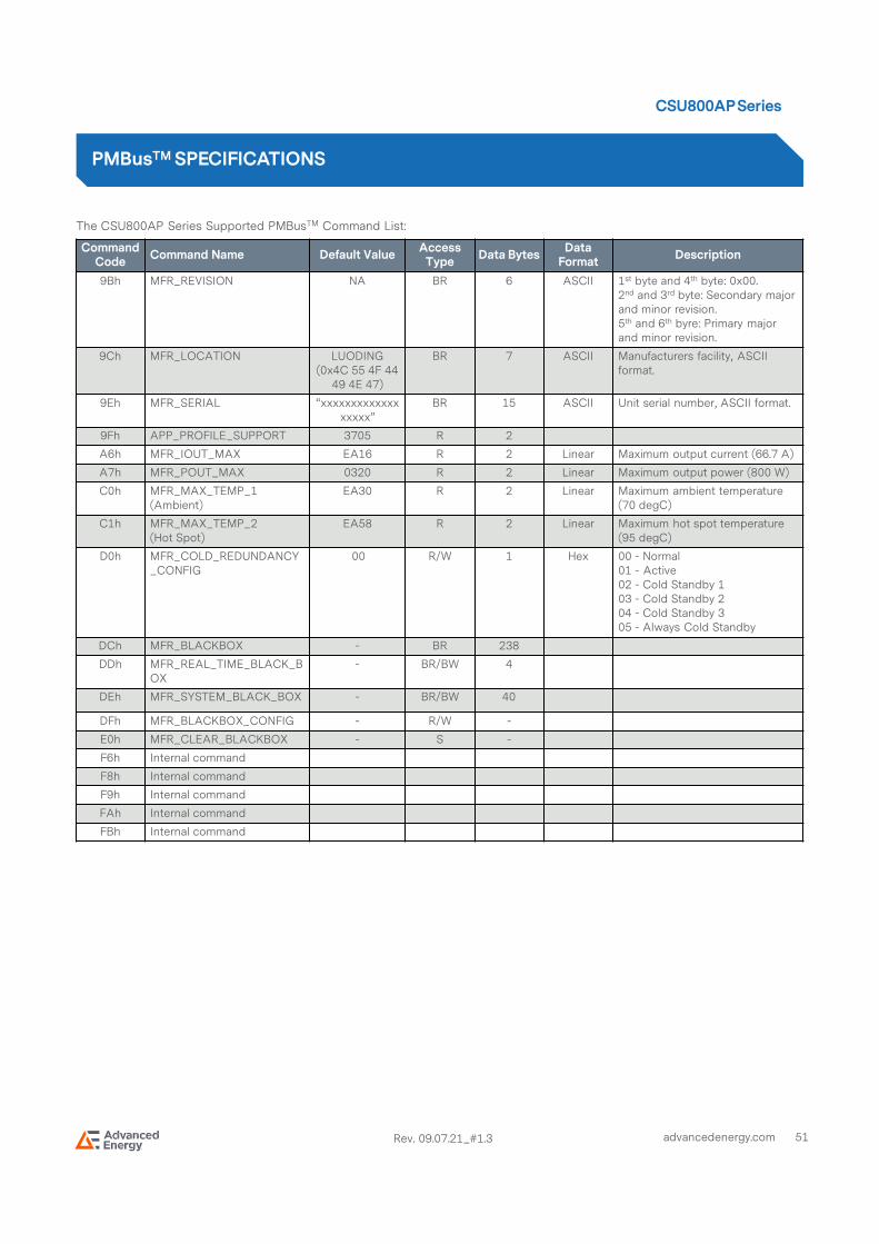
51advancedenergy.com
CSU800AP Series
Rev. 09.07.21_#1.3
The CSU800AP Series Supported PMBusTM Command List:
PMBusTMSPECIFICATIONS
Command Code
Command Name Default ValueAccess Type
Data BytesData Format
Description
9Bh MFR_REVISION NA BR 6 ASCII 1st byte and 4th byte: 0x00.2nd and 3rd byte: Secondary major and minor revision.5th and 6th byre: Primary major and minor revision.
9Ch MFR_LOCATION LUODING (0x4C 55 4F 44
49 4E 47)
BR 7 ASCII Manufacturers facility, ASCII format.
9Eh MFR_SERIAL “xxxxxxxxxxxxxxxxxx”
BR 15 ASCII Unit serial number, ASCII format.
9Fh APP_PROFILE_SUPPORT 3705 R 2
A6h MFR_IOUT_MAX EA16 R 2 Linear Maximum output current (66.7 A)
A7h MFR_POUT_MAX 0320 R 2 Linear Maximum output power (800 W)
C0h MFR_MAX_TEMP_1 (Ambient)
EA30 R 2 Linear Maximum ambient temperature (70 degC)
C1h MFR_MAX_TEMP_2 (Hot Spot)
EA58 R 2 Linear Maximum hot spot temperature (95 degC)
D0h MFR_COLD_REDUNDANCY_CONFIG
00 R/W 1 Hex 00 - Normal 01 - Active02 - Cold Standby 103 - Cold Standby 204 - Cold Standby 305 - Always Cold Standby
DCh MFR_BLACKBOX - BR 238
DDh MFR_REAL_TIME_BLACK_BOX
- BR/BW 4
DEh MFR_SYSTEM_BLACK_BOX - BR/BW 40
DFh MFR_BLACKBOX_CONFIG - R/W -
E0h MFR_CLEAR_BLACKBOX - S -
F6h Internal command
F8h Internal command
F9h Internal command
FAh Internal command
FBh Internal command

52advancedenergy.com
CSU800AP Series
Rev. 09.07.21_#1.3
The CSU800AP Series Firmware Update Command List:The power supply uses the following commands during the boatload process.
PMBusTMSPECIFICATIONS
Command Code
Command Name Default ValueAccess Type
Data Bytes Description
D4h MFR_HW_COMPATIBILITY - R - This is a COMPATIBILITY value used to tell if there are any changes in the FW that create an incompatibility with the FW. This value only changes when the PSU HW is changed creating an incompatibility with older versions of FW.
D5h MFR_FWUPLOAD_CAPABILITY
- R - The system can read the power supply’s FW upload mode capability using this command. For any given power supply, more than one FW upload mode may be supported. The supported FW upload mode(s) must support updating all available FW in the power supply.This power supply supports FW uploading in standby mode only.Bit 0: “1” FW uploading in standby mode onlyAll other bits configurations are not supported.
D6h MFR_FWUPLOAD_MODE - R/W - Writing a “1” puts the power supply into firmware upload mode and gets it ready to receive the first image block via the MFR_FW_UPLOAD command. The system can use this command at any time to restart sending the FW image.Writing a “0” puts the power supply back into normal operating mode.Writing a “1” restart.This command will put the PSU into standby mode if the PSU supports FW update in standby mode only.If the power supply image passed to the PSU is corrupt the power supply will stay in firmware upload mode even if the system requested the PSU to exit the FW upload mode.Value:0 = Exit firmware upload mode 1 = Firmware upload mode
D7h MFR_FWUPLOAD - BW - Command used to send each block of the FW image.
D8h MFR_FWUPLOAD_STATUS - R 2 At any time during or after the firmware image upload the system can read this command to determine status of the firmware upload process.All bits get reset to “0” when the power supply enters FW upload mode.Bit 0: “1” full image receivedBit 1: “1” full image not received. This remains asserted until the full image is receivedBit 2: “1” bad or corrupt image receivedBit 3: For future useBit 4: “1” FW image is not supported and not receivedBit 5-15: Reserved

53advancedenergy.com
CSU800AP Series
Rev. 09.07.21_#1.3
The CSU800AP Series Firmware Update Command List:The power supply uses the following commands during the boatload process.
PMBusTMSPECIFICATIONS
Command Code
Command Name Default ValueAccess Type
Data Bytes Description
D9h MFR_FW_REVISION NA BR 3 Describes revisions of the FW.Block Read with PEC (3 bytes)Byte 0: 0-255 minor revision, secondaryByte 1: 0-255 minor revision, primaryByte 3: 0-255Bit 7: “1” down grading of PSU FW has to be avoided; “0” no restriction in downgrading the PSU FW.Bit 0-6: Major revision
Note: While the PSU FW image is being updated the PSU will blink the green LED at a 2 Hz rate.

54advancedenergy.com
CSU800AP Series
Rev. 09.07.21_#1.3
Firmware Update Process
PMBusTMSPECIFICATIONS

55advancedenergy.com
CSU800AP Series
Rev. 09.07.21_#1.3
PSU Flow During Powering ON
PMBusTMSPECIFICATIONS

56advancedenergy.com
CSU800AP Series
Rev. 09.07.21_#1.3
Current Sharing
The CSU800AP series power supply main output VO is equipped with current sharing capability. This will allow up to 4 power supplies to be connected in parallel for higher power application. Current share accuracy is typically 5% when the load is larger than 20%. When supplying light loads between 10% and 20% of its rated load, the power supplies will share within 10% accuracy. Below 10% total loading, there is no guarantee of output current sharing.
APPLICATION NOTES
Vo
+VSENSE
12V Load Share
CR_BUS-VSENSE
Vo Return
LOAD
Vo
+VSENSE
12V Load Share
CR_BUS-VSENSE
Vo Return
CSU800APCSU800APCSU800APCSU800AP----3333----600600600600 CSU800APCSU800APCSU800APCSU800AP----3333----600600600600

57advancedenergy.com
CSU800AP Series
Rev. 09.07.21_#1.3
Output Ripple and Noise Measurement
The setup outlined in the diagram below has been used for output voltage ripple and noise measurements on the CSU800AP series power supply. When measuring output ripple and noise, a scope jack in parallel with a 0.1 uF ceramic chip capacitor, and a 10 uF tantalum capacitor will be used. Oscilloscope can be set to 20 MHz bandwidth for this measurement.
APPLICATION NOTES

58advancedenergy.com
CSU800AP Series
Rev. 09.07.21_#1.3
RECORD OF REVISION AND CHANGES
Issue Date Description Originators
1.0 12.29.2020 First Issue C. Liu
1.1 02.24.2021 Update the back cover C. Liu
1.2 05.28.2021 Add the VIN_GOOD characteristics in the performance curve A. Zhang
1.3 09.07.2021 Update PWOK signal for customer system side C. Liu

AIF06ZPFC
CSU800AP - Rev.09.07.21_#1.3
For international contact information,
visit advancedenergy.com.
[email protected] (Sales Support)
[email protected] (Technical Support)
+1 888 412 7832
ABOUTADVANCEDENERGY
Advanced Energy (AE) has devoted more than three
decades to perfecting power for its global customers. AE
designs and manufactures highly engineered, precision
power conversion, measurement and control solutions for
mission-critical applications and processes.
Our products enable customer innovation in complex
applications for a wide range of industries including
semiconductor equipment, industrial, manufacturing,
telecommunications, data center computing, and medical.
With deep applications know-how and responsive service
and support across the globe, we build collaborative
partnerships to meet rapid technological developments,
propel growth for our customers, and innovate the future
of power.
Specifications are subject to change without notice. Not responsible
for errors or omissions. ©2020 Advanced Energy Industries, Inc. All rights
reserved. Advanced Energy®, and AE® are U.S. trademarks
of Advanced Energy Industries, Inc.