rev. 01/04 - pego electrical boards · if the installation procedure does not start automatically...
TRANSCRIPT

1
REV. 01/04
Use and maintenance manual
ELECTRICAL BOARDS FOR REFRIGERATING INSTALLATIONS Rel. 01-17 ENG Telenet release 2017.5.1 DB release 2017.03.01

3 INSTALLAZIONE HARDWARE

3
1 INDEX
1 INTRODUCTION
Pag. 5 1.1 TELENET OVERVIEW Pag. 6 1.2 CLIENT SERVER STRUCTURE Pag. 7 1.3 SYSTEM REQUIREMENTS Pag. 7 1.4 SOFTWARE RELEASE AND UPDATES
2 SOFTWARE INSTALLATION
Pag. 8 2.1 TYPES OF INSTALLATION Pag. 8 2.2 COMPLETE INSTALLATION Pag. 9 2.3 LAN INSTALLATION: SERVER Pag. 10 2.4 LAN INSTALLATION: CLIENT
3 HARDWARE INSTALLATION
Pag. 11 3.1 2TWRS485 INTERFACE Pag. 12 3.2 LICENCED USB HARDWARE KEY Pag. 12 3.3 INSTRUMENTS CONNECTIONS
4 ACCESS
Pag. 13 4.1 FIRST ACCESS
5 GENERAL INFORMATIONS
Pag. 14 5.1 MAIN INTERFACE Pag. 15 5.2 MENU Pag. 16 5.3 KEYS AND ICONS Pag. 18 5.4 USERS CONFIGURATION Pag. 20 5.5 NODE/INSTRUMENT ADMINISTRATOR
6 TELENET CONFIGURATION
Pag. 22 6.1 GENERAL PARAMETERS (Company, Tele.NET, Language and audio, Server, Backup and DB maintenance, Mail, Mail Alive Setup, Update Tele.NET, Publish
data, Web Server) 7 SECURE DIGITAL CONTROL
Pag. 31 7.1 INTRODUCTION Pag. 32 7.2 DATA IMPORT Pag. 35 7.3 SDC CONTROL Pag. 36 7.4 MANAGEMENT AND GRAPHS 8 NET CONFIGURATION
Pag. 39 8.1 NODE CONFIGURATION

4
1 INDEX
9 DEVICE CONFIGURATION
Pag. 42 9.1 NEW DEVICE Pag. 44 9.2 AMEND INSTRUMENT 10 TPC (TOTAL PANEL CONTROL) CONFIGURATION
Pag. 46 10.1 TPC CONFIGURATION 11 MONITORING
Pag. 49 11.1 MONITORING ENABLE Pag. 50 11.2 MONITORING READING Pag. 51 11.3 DEVICE PROPERTIES Pag. 52 11.4 DEVICE PROGRAMMING Pag. 53 11.5 HISTORICAL INSTRUMENT AND GRAPHICS Pag. 53 11.6 HACCP SETUP Pag. 53 11.7 TELENET CONTROLS FROM CONTROL LINE 12 ALARMS
Pag. 54 12.1 ALARMS VIEW Pag. 55 12.2 ALARMS BASIC CONFIGURATION Pag. 56 12.3 ALARMS MANAGEMENT ON DISPLAY Pag. 58 12.4 LOCAL ALARMS MANAGEMENT Pag. 60 12.5 REMOTELY CONTROLLED ALARMS MANAGEMENT 13 ALARM NAVIGATOR
Pag. 61 13.1 ALARM NAVIGATOR 14 AUTOMATIC CYCLES
Pag. 64 14.1 CYCLES MANAGEMENT Pag. 66 14.2 CYCLE PLANNING 15 HISTORY
Pag. 69 15.1 HISTORY DATA ANALYSIS Pag. 71 15.2 DATA EXPORT Pag. 72 15.3 HACCP
16 PROBLEMS AND SOLUTIONS
Pag. 73 16.1 PROBLEMS AND SOLUTIONS
Pag. 73 16.2 TELENET UNINSTALLATION

5
2 SOFTWARE INSTALLATION
TeleNET is an application for supervision and monitoring of refrigeration and conditioning systems controlled by Pego electronic instruments. The network of instruments channels the data onto a personal computer where it possible to display and print reports, manage alarms, modify operating parameters and monitor the whole system.
Applications:
Monitoring and supervision of refrigeration and conditioning systems. Automatic control of work cycles. Recording of physical parameters (temperature, humidity, pressure, CO2). Industrial cooling, storage, seasoning systems. Registration and consultation of data saved on Secure Digital card (for Pego electrical panel
PLUS Expert series) or on USB key (for Pego electrical panel PLUSR Expert series)
Packaging contents: n° 1 software and manual installation CD-ROM n° 1 USB key for software protection (until September 2015)* n° 1 2TWRS485 desk interface n° 1 USB connection cable TeleNET SD packaging contents: Only for TeleNET software application for recording download of PLUS EXPERT / PLUSR EXPERT panels series it's provided only the installation CD-ROM. (please refer to chapters 4, 5, 6, 7) *For interfaces 2TWRS bought on or after September 2015 the USB key for software protection is replaced by a chip inside the interface.
1.1 TELENET OVERVIEW

6
2 SOFTWARE INSTALLATION
TeleNET is a client/server type application that facilitates configuration on local LAN and Internet ambient. It identifies: Server: PC where the database belongs. All informations on instruments and history are stored in a unique SQL database. Client Node: PC which is connected the 2TWRS485 interface for instruments chain and USB hardware protection key (until September 1, 2015). With a single TeleNET license is possible to manage only one client node Typical examples of installations are the following:
1) Complete installation on a single PC (Server + Client Node)
2) Local LAN installation with server on a dedicated PC and one or more Client connected. In this case, the database is stored in a server, while the instrument network is connected to one or more PCs with client Telenet in local network with the server. Clients on PC with connected instruments require a hardware key to enable their monitoring and control. A client on PC can be connected to the DB on the server, even only for consulting data (protection key not required).
1.2 CLIENT/SERVER STRUCTURE
DB Telenet + Client + Nodo
Lan
DB TeleNET
Client + Nodo
Client + Nodo
Client

7
2 SOFTWARE INSTALLATION
Minimum requirements for TeleNET utilization are:
o Server Operating system o Windows® 7
o Windows® 8 o Windows® Server 2008 o Windows® 10
Memory RAM 4 GB
Hard disk 10 GB available space
o Client
Operating system o Windows® 7 o Windows® 8 o Windows® Server 2008 o Windows® 10
Memory RAM 4 GB
Hard disk 10 GB available space
Display Resolution 1024x 768 24 bit min. Recommended 1280x1024 32 bit
Mouse Microsoft Mouse or compatible peripherals
Others Install most recent service pack and Windows critical updates available on Windows Update website
Attention: The necessary system resources increase with the increasing number of monitored instruments.
After the installation it's possible to verify software release both for Client and Database always on the upper part of the window. Here you can also verify the presence of the licence:
Full Mode: monitoring with USB hardware protection key connected. Ensures the connection of interface 2TWRS485.
Client Mode: monitoring without USB hardware protection key. Does not ensure the connection of interface 2TWRS485.
NB: The interfaces bought on or after September 1, 2015 are always active in Full Mode.
Verify software release for communications during assistance or to verify updates availability on www.pego.it website. See chapter 6 on how to update the program.
1.4 SOFTWARE RELEASE AND UPDATES
1.3 SYSTEM REQUIREMENTS

8
2 SOFTWARE INSTALLATION
The program can be installed using the CD-ROM provided, or by downloading it from the
www.pego.it website.
For interfaces bought before September 1, 2015, it is important that the USB hardware protection
key provided is not inserted during installation.
If the installation procedure does not start automatically when the CD-ROM is inserted or the
program was downloaded from the www.pego.it website, run the Setup.exe file manually to start
the installation process. Installation must be carried out with an Administrator account.
There are two different types of software installation available:
1) Complete installation (TeleNET Database and client+node on the same PC)
2) Separate installation (TeleNET Database on server and client+node on other PC/s)
Separate installation is essential in order to create client/server structures with several nodes.
IMPORTANT NOTE: You will be asked to select the installation language: set the same language as
the Operating System in use.
If you want to install both the database and the client+node on the same PC, select “Setup All”.
The button is used to cancel the installation process. During the installation process you will be prompted to restart the PC, which is recommended.
2.2 COMPLETE INSTALLATION
2.1 TYPES OF INSTALLATION

9
2 SOFTWARE INSTALLATION
Once the restart is complete, you will need to run the Setup.exe file again to proceed with installation. Therefore, reselect “Setup All” and follow the installation procedure instructions. When prompted to install the USB hardware protection key Drivers: select YES if you have the key and it has never been inserted in the PC; if you do not have the key or if instead it has already been inserted previously in the PC, or if the interface was bought after 01/9/09/2015, select NO. Please note that the USB hardware protection key must not be inserted during the installation procedure.
When installation is finished TeleNET icon is created on Desktop and the USB hardware protection key can be inserted (for interfaces bought before September 1, 2015).
If you want to install the database and the client+node on different PCs, the server must be installed first.
Select “Setup Server” to start installation process. The server setup installs only the database that will include configurations and registered data. Follow the indication until installation completing
The key allows to cancel installation process. You will be asked to select the installation language: set the same language as the Operating System in use. During the installation process you will be prompted to restart the PC, which is recommended.
Server installation
2.3 LAN INSTALLATION: SERVER

10
2 SOFTWARE INSTALLATION
Once the restart is complete, you will need to run the Setup.exe file again to proceed with installation. Then select "Setup Server" again and follow the installation procedure instructions. Write down the name of the server installed.
When the server has been installed, client installation can be carried out on each PC used as client or client+node.
Select “Setup Client” to start the installation process. Client installation only installs the client.
The button is used to cancel the installation process. You will be asked to select the installation language: set the same language as the Operating System in use. When prompted to install the USB hardware protection key Drivers: select YES if you have the key and it has never been inserted in the PC; select NO if you do not have the key or if it has already been inserted in the PC, or if the interface has been bought after September 1, 2015. Please note that the USB hardware protection key must not be inserted during the installation procedure.
When installation is complete, the TeleNET icon is created on the Desktop and the USB hardware protection key can be inserted (for interfaces antecedent to September 1, 2015). When the client is started for the first time, the name of the server in which the database is installed is requested.
Client installation
2.4 LAN INSTALLATION: CLIENT

11
3 HARDWARE INSTALLATION
2TWRS485 interface is the connecting device between Pego instruments chain and computer. It allows the connection up to 32 instruments for each RS485 line. In addition it's possible to connect up to 9 TWM3IO modules. Position the interface near the computer and make the electrical connections. Starting from September 1, 2015, it is equipped with a chip that replaces the hardware protection key USB.
Connections :
1. USB : Connect, using cable provided with the package, to an USB socket on computer. When it is connected, wait for the automatic initialisation of the Drivers. If it is not successful, disconnect and reconnect the USB cable, or download the most updated Drivers available from the www.pego.it website. In operational system device management, check the numbers of the COM ports used for the interface. Path: Control panel -> System and safety -> System -> Device management -> COM and LPT ports COM ports refer to the two ports with removable terminals installed in the interface. Each terminal can be connected to up to 32 instruments. To verify the correspondence between the COM and the ports, it is recommended to select one and check which LED lights up on the interface. If the USB cable is disconnected and reconnected to another USB port, the COM port may change and it must therefore be verified again.
2. RS485 A B: Connect line from the instruments. Please refer to instrument user manual to find the connection of lines A and B.
Note: it's possible to order additional 2TWRS485 interfaces to increase the number of connectable instruments (each interface will add 32 or 64 instruments), up to a maximum of 128 instruments.
3.1 2TWRS485 INTERFACE

12
3 HARDWARE INSTALLATION
On Client Node, that is the PC where one or more 2TWRS485 interfaces will be connected with instruments net, is necessary to connect USB hardware protection key provided with package. The key insertion in one USB free slot can be done also after software installation, but it is necessary for first node and instruments configurations. In case of a driver installation request, it's enough to indicate installation cd-rom path on the request mask. The drivers are also available on the ww.pego.it website. NB. The key must keep being inserted on USB port during TeleNET functioning. For interfaces bought on or after September 2015 the USB key is replaced by a chip inside the interface.
Refer to the manual of each instrument for the connection of RS-485 serial line and configuration of net addresses. RS-485 line must be done with a connection from the interface to the first instrument, form first to second instrument and so on until the last instruments where the line ends. Do not make connections with embranchments, y-connection or circle connections. Connection example:
Maximum net length is around 500m Please use twisted pairs wire suitable for RS485 signal transmission with min. section 0,5 mm2 (i.e. Belden 8762 cable) Do not wire together with power cables.
3.2 LICENCED USB HARDWARE KEY
3.3 INSTRUMENTS CONNECTIONS

13
4 ACCESS
To open the program use TeleNET icon on the Desktop. On the access mask insert the following default data:
Login: adminlogin
Password:
NB: on first access leave the field password blank and proceed pressing the key Default language is English. To change language refer to chapter 6 “TeleNET configuration”.
4.1 FIRST ACCESS

14
5 GENERAL INFORMATIONS
The following image shows TeleNET operating interface. Section on the left is the one with instruments net tree (Network) and interactive menu for the various configurations. Section on the right is the operating part of Total Panel Control and windows related to the selected menus.
5.1 MAIN INTERFACE
Interactive menu
Instruments net (Network)
Total panel control
Status icons

15
5 GENERAL INFORMATIONS
Main menu allows to configure instruments net (Network) and users. The menu is divided in two dedicated menus for the Network or for SD card / USB key section To activate Network menu select Network
Basing on the selected item on Network, the interactive menu shows the possible selectable options.
Interactive menu
To activate SD Card / USB key menu, select SD Card
Select Network to open the related menu
5.2 MENU
16
5 GENERAL INFORMATIONS
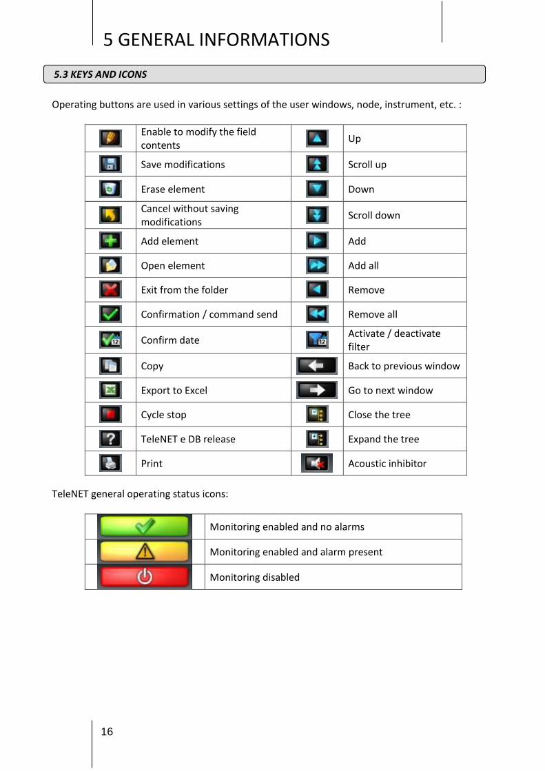
Operating buttons are used in various settings of the user windows, node, instrument, etc. : TeleNET general operating status icons:
Enable to modify the field contents Up
Save modifications Scroll up
Erase element Down
Cancel without saving modifications Scroll down
Add element Add
Open element Add all
Exit from the folder Remove
Confirmation / command send Remove all
Confirm date Activate / deactivate filter
Copy Back to previous window
Export to Excel Go to next window
Cycle stop Close the tree
TeleNET e DB release Expand the tree
Acoustic inhibitor
Monitoring enabled and no alarms
Monitoring enabled and alarm present
Monitoring disabled
5.3 KEYS AND ICONS
17
5 GENERAL INFORMATIONS
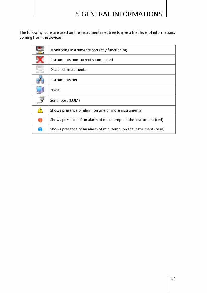
The following icons are used on the instruments net tree to give a first level of informations coming from the devices:
Monitoring instruments correctly functioning
Instruments non correctly connected
Disabled instruments
Instruments net
Node
Serial port (COM)
Shows presence of alarm on one or more instruments
Shows presence of an alarm of max. temp. on the instrument (red)
Shows presence of an alarm of min. temp. on the instrument (blue)

18
5 GENERAL INFORMATIONS
Users configuration is allowed only to users with ADMINISTRATOR authorization associated. The users with this level of authorization can display the users tree:
To add a new user select Users and then New user
The user folder is made by two areas: User info and User permission
Users
New user
5.4 USERS CONFIGURATION
Users

19
5 GENERAL INFORMATIONS
Depending on the assigned authorization level the following operations are allowed to the specified user:
Administrator Allows users administration
Node/Instrument Administrator (to be used only for maintenance)
Allows: - accessing all nodes/instruments of the network and their removal; - assigning an existing node to the PC, in case Telenet is installed on a new machine and restoring of a backup.
Command Monitoring and control of the instruments
Nodes configurator Allows to configure the node and the instruments
Monitoring Only instruments monitoring
Once the informations are in please click on the icon to save data.
(save or cancel the modifications)
User info
User permission

20
5 GENERAL INFORMATIONS
In case nodes and instruments (even remote) should be removed or one of the nodes of the network be associated to the PC, a new user name must be created having 'Node/Instrument Administrator' authorisation; subsequently close and restart TeleNET, logging in with the data of this user. At this point the following warning will be displayed:
Press on OK to access the following display:
If a node/instrument should be removed, select it and press “Delete node”.
Complete the operation by clicking on the basket icon .
5.5 NODE/INSTRUMENT ADMINISTRATOR

21
5 GENERAL INFORMATIONS
If a new node should be assigned to the PC, select Network and press “Clone node”. At this point the following window will be displayed:
With keys and , bring the desired node to the right and confirm pressing . Only one node can be assigned to the PC.

22
6 TELENET CONFIGURATION
Select Network and then Setup on the TeleNET setup menu to access the general configuration parameters. In case the USB protection hardware key is not present, in Instrument Net (Network), Network does not appear and SD Card must be selected for configuration.
It’s possible to configure the following parameters:
Company Tele.NET Language and audio Server Backup and DB
maintenance Mail Setup Mail Alive Update Tele.NET Publish data Web Server
To be able to insert or edit the data inside the menu, act on button and subsequently on
button to save settings. To make the amendments effective, Telenet will be closed and must be subsequently re-started.
CAP. 6 - Diagnostica
6.1 GENERAL PARAMETERS
Setup
Network

23
6 TELENET CONFIGURATION
Selecting it's possible to read TeleNET software and database release (to use during assistance call).
The same information is contained in the main bar of the TeleNET window.
Company Menu: Allows inserting the company data, used subsequently in the printouts headed paper and in the sending of alarm e-mails
Tele.NET Menu: Allows to configure the SD card settings for data import and default of the historical displaying period inside the instrument.
Fields description: SD Card Enables: Enables / disables the displaying of the SD card / USB key in instrument
network. SD Card Path file: Default path for searching Data to import files. Default historical period: Number of days prior today’s date for the default display of the
date in the historical and in alarm navigator.

24
6 TELENET CONFIGURATION
Language and audio Menu: Is used to select the program language and to enable/disable the buzzer.
Server Menu: Database SQL Server parameters (usually not to be modified) Note: it could be necessary to modify the password in case SQL server was previously installed with a different password for SA administrator (please contact the system administrator to use the correct password)
DB Back-up and maintenance Menu: Allows programming a daily backup of the DB Telenet in a specified path or restore a previously performed backup. Note: The restoring of a Backup must be carried out on a Telenet with the same release of the recovered DB. No path (backup or restore pathfile) must contain spaces. The last part of this menu allows to permanently eliminate all data prior to set date.

25
6 TELENET CONFIGURATION
Mail Menu: Allows to configure service for sending of alarms via e-mail. It is possible to receive alarm warnings using a computer or a mobile telephone enabled for receiving e-mails. Before filling in the fields, create an e-mail account or use an existing one and find the configuration information from your own e-mail provider.
Fields description :
From: fill in with mail account (i.e. [email protected]) of the sender
Server mail: write server name for outgoing email (SMTP)
Request aut.: specify if it's necessary or not to make the service provider access procedure to SMTP server
User: fill with user mail account [email protected] (the same used in the “From” field)
Password: password assigned by service provider.
Mail port: port to be used for the mail service (default 25).
Secure connection (SSL): ensures the activation of the cryptographic security protocol.
Set mail handler node: allows to select the node which will manage the email. In case of more than one node only one will manage the e-mails. The computer associated to the manager node must have a permanent Internet connection. It's necessary to create first the node (par. 8.1) before proceeding with the configuration (in case there is chance to save the settings made and modify them later).
Mail handler node: shows the chosen node to manage the e-mail service Once completely filled in the fields save the informations and restart TeleNET for the modifications to take effect.

26
6 TELENET CONFIGURATION
At next step will be possible to insert the receivers
Fields description:
E-mail destination: insert e-mail address of the receiver of alarm warnings (several receivers can be added). To delete a recipient, select it and press the Delete key.
Alarm start alert: flag the square to send the alarm warning.
Alarm stop alert: flag the square to send the alarm stop warning.
Exclusion hour start: start of timeframe where no alarms are sent.
Exclusion hour stop: start of timeframe where no alarms are sent. mon...sun: shows the days when the exclusion alarm sending range is enabled.
NB: When configuring for the first time, remove the grey ticks by clicking on them with the mouse, before indicating the exclusions with another click.
By leaving the “Disabling time” field blank, emails will be sent throughout the 24 hours. We suggest, once configured the service, to make some test of mail sending using the ‘Test Mail’ key. Mail Alive Setup Menu: This is used to configure the transmission of automatic emails, selecting the days and times, to check that the monitoring system is working properly. Fields description:
Active: the function is activated by ticking the box. Subject: write the subject of the automatic emails (e.g.: cell monitoring active). Mail text: write the text of the automatic emails (e.g.: automatic email - system active). Sending hours: tick the boxes relating to the times at which the automatic email is to be
sent. Sending days: tick the boxes relating to the days in which the automatic email is to be sent. Receiver: enter the email address or addresses to which the automatic emails are to be
sent.

27
6 TELENET CONFIGURATION
We suggest, once configured the service, to make some test of mail sending using the ‘Test Mail’ key. Update Tele.NET Menu: Allows verifying the presence of any updates of the Telenet program on the PEGO site and install them. An internet connection is requested for this function.
Publish data Menu: The possibility to publish information relating to the instruments monitored on an external database is given (SQL or ACCESS) on which it is possible to query and export data that can be used by other software. The information is updated in real time and depends from the query speed of the instruments. The new data replaces and deletes the previous data.
To publish a new database, select the type (DB SQL or DB Access) and subsequently tick the “Publish data” box. (The operation must be performed with monitoring at a stop).

28
6 TELENET CONFIGURATION
The position and the name of the database are predefined by the TeleNET system; however, it is possible to assign a different position by clicking on "no" when the above window appears. In case the selected path (pathfile) requests particular authorisations, the user will be warned to choose a different path. In case the “Publish data” box is deselected, you will be asked if wanting to eliminate the previously created DB data exchange. The selection of the sizes and parameters to publish for each instrument happens with monitoring at a stand still by entering the “Modify device” menu of each instrument and selecting the "Published data” bar (see paragraph 9.1 and 9.2).

29
6 TELENET CONFIGURATION
Description of the table in Published data Description: Description of the variable.
ID: Only identification of the variable relating to an instrument. The ID is created when
creating a new instrument on TeleNET. In case of eliminating an instrument and creating it again, the ID would change. The ID can be read, verified and copied in the TeleNET page during amendment of the instrument.
Publish: Selection box to enable the publication of the variable.
With monitoring started, the previously created TELENET_DBSHARED database is filled with the data of the selected variables and constantly updated. In case an instrument is disabled, the database rows relating to its published variables are deleted; they will reappear on its requalification. In case an instrument stops communicating (no link) its published variables have the “null” value (Val column) until its reconnection. TELENET_DBSHARED database structure
Field name Description Data type Field size
ID Only ID of a size relating to an instrument. Numerical
NodeName Node name (paragraph 8.1) Text 255
COM Serial port on which interface 2TWRS485 is connected (paragraph 9.1)
Text 10
Address Address assigned to the instrument (paragraph 9.1) Numerical Whole long
InstrumentType Type of instrument (paragraph 9.1) Text 100
InstrumentDescri Instrument description (paragraph 9.1) Text 255
ParName Namen of parameter Text 100
UoM Unit of measure Text 10
Val Value Numerical Double precision
Example:
30
6 TELENET CONFIGURATION
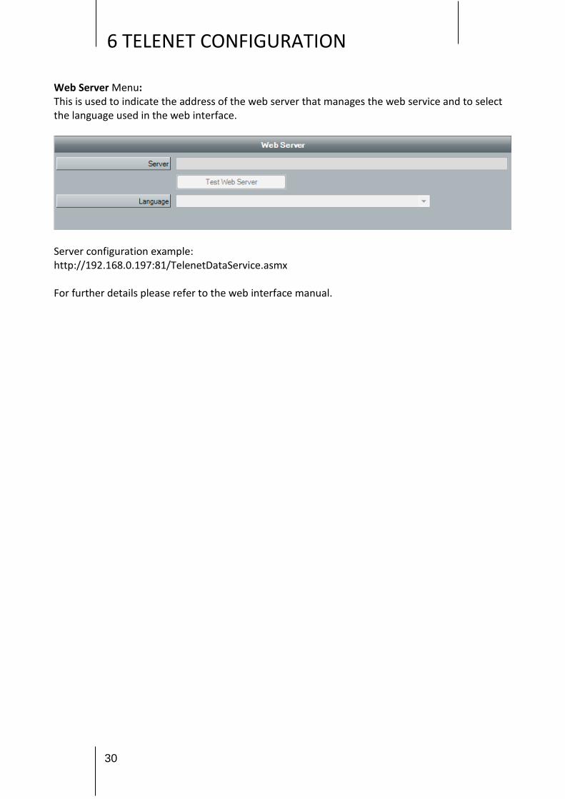
Web Server Menu: This is used to indicate the address of the web server that manages the web service and to select the language used in the web interface.
Server configuration example: http://192.168.0.197:81/TelenetDataService.asmx For further details please refer to the web interface manual.
31
7 SECURE DIGITAL CONTROL
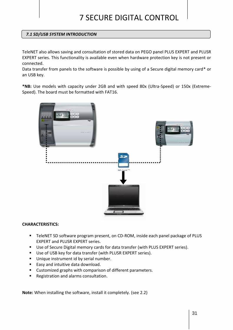
TeleNET also allows saving and consultation of stored data on PEGO panel PLUS EXPERT and PLUSR EXPERT series. This functionality is available even when hardware protection key is not present or connected. Data transfer from panels to the software is possible by using of a Secure digital memory card* or an USB key. *NB: Use models with capacity under 2GB and with speed 80x (Ultra-Speed) or 150x (Extreme-Speed). The board must be formatted with FAT16. CHARACTERISTICS:
TeleNET SD software program present, on CD-ROM, inside each panel package of PLUS EXPERT and PLUSR EXPERT series.
Use of Secure Digital memory cards for data transfer (with PLUS EXPERT series). Use of USB key for data transfer (with PLUSR EXPERT series). Unique instrument id by serial number. Easy and intuitive data download. Customized graphs with comparison of different parameters. Registration and alarms consultation.
Note: When installing the software, install it completely. (see 2.2)
7.1 SD/USB SYSTEM INTRODUCTION

32
7 SECURE DIGITAL CONTROL
Below are the steps to follow to set the data downloaded on to SD memory card or from USB key
from the PLUS EXPERT and PLUSR EXPERT series boards.
There are two possible importing methods: Automatic Import: allows selecting and importing the last saved data of every individual instrument. The instruments are recognised univocally thanks to an internal serial number and only the last progressive saving is pre-selected and proposed for import. Manual Import: allows selecting and importing any data saved for any instrument, indifferently from date and progressive. The user must previously select the files to import. During import of new files, any data already present in the database is ignored because previous imported.
7.2 DATA IMPORT FROM SD/USB key
Automatic import
Manual import

33
7 SECURE DIGITAL CONTROL
Once the importing method has been selected, the SD Card / USB key Path must be inserted by
pressing the button and subsequently pressing the button to continue the importing procedure.
Attention: Do not amend or rename the data files or the automatic finding and their importing by the Telenet program will no longer be possible.
Path SD card /USB key
Close Button
Path SD card or USB key
selection
Continue button
Cancel Button

34
7 SECURE DIGITAL CONTROL Shown below is the data import in the Automatic import method we recommend using for its simplicity.
Once imported, the files are automatically deleted from the SD/USB key by default, to avoid its
filling in time. Deselect the flag in case of wanting to exclude this option.
The advancing of the import in progress is displayed with a percentage bar that advances, and
upon its completion, a window is displayed indicating procedure complete.
Instrument name
Date last data
Serial number
Date first data
File to import selection flag
File name
Back Button Start import button
Imported files deletion enabling flag
Cancel Button

35
7 SECURE DIGITAL CONTROL
SDC Control represents the summary where all PLUS EXPERT and PLUSR EXPERT series boards
where the data was imported from are displayed. They are identified from their own UNIVOCAL
series number and by the description assigned by the user (see chapter 9.2 to amend description).
The first registration data and the last registration data are also present in the database relating to
every instrument, useful for checking its updating status.
By selecting the instrument with a double click from the SDC Control window or from the Network (Instrument network), access is gained to the historical that will display, by default, the registrations of the 24 hours prior to the current date. To configure the default settings relating to the SD/USB key, see in chapter 6.1 “Tele.NET Menu”.
7.3 SDC CONTROL
Instrument description
Univocal series number
Date first data
Date last data

36
7 SECURE DIGITAL CONTROL
By setting the dates in the "From” and "To” boxes and confirming issuing with the button , it is possible to display the data of any time period. The window menu allows selecting the following types of display:
Graph: displays the graph of the measures registered during the selected period Events: displays in table form the alarms during the selected period Monitoring: displays in table form the measures registered during the selected period
For each of these methods it is possible to print and for those in table format it is also
possible to export the data in Excel format. The Back button allows access to the measures selection page to be displayed and the colours to be used in the graph.
Graphic:
Legend
Go back button
Instrument description
Start date
End date
Selected date confirmation button
7.4 HISTORICAL INSTRUMENT AND GRAPHICS

37
7 SECURE DIGITAL CONTROL
Events: Select this card to access a list of alarms, indicating time of start and end of monitoring registered in the period selected, with relative hour, description and notice of email sent.
Monitoring: The PLUS EXPERT DL3 instrument allows analysing more data compared to other equipment; in particular, for every of the three available channels, the registration temperature, the channel temperature alarm, the probe error, the stand-by and the digital input can be displayed. To personalize descriptions of recorded data, see Chapter 9.2 .
It is also possible to filter their displaying for a determined record, thanks to the button

38
7 SECURE DIGITAL CONTROL In the displaying in table format of the registered temperature, a colour code of the rows is present, allowing to immediately identify status and anomalies. Grey= channel stand-by Orange= Temperature alarm or channel probe error
Black= Registration temperature with no problem
The PLUSR EXPERT DL3 instrument has the same characteristics of the PLUS EXPERT DL3, but the registration is on an USB key. The PLUSR EXPERT DL8 instrument has eight available channels to display the registration temperature, the channel temperature alarm, the probe error, the stand-by and the digital input. The registration is on an USB key. Each channel is displayed as a stand-alone instrument.

39
8 NET CONFIGURATION
First step is the instrument network and node creation. The node identifies computer where one or more 2TWRS485 interfaces will be connected. Select Network and then New node
Node configuration indicates the timing whereby node is polling the instruments, saving data on database, managing alarms. Configuration of the node is subdivided into tree sections that can be selected from the bar menu: Node info, alarms and debug.
8.1 NODE CONFIGURATION
Network
New node

40
8 NET CONFIGURATION
Node info Menu: Allows inserting and configuring the main node data:
Field description: Name: node name (it will be shown on the network tree) Description: node internal description Slow events time: refresh range of processes not directly linked to the monitoring Fast events time: interval in seconds between a monitoring cycle and the next one. Saving time: minutes passed between two monitoring saving of the instruments physically
connected to the node; Refresh time: seconds passed between two monitoring data refresh of the instruments
physically connected to the node, included into database; Reply wait time: seconds waited for the answer to a request sent to an instruments
physically connected to the node; Polling lapse (ms): interval between two consecutive instruments polling Enabled: flag it to enable node
Node info

41
8 NET CONFIGURATION
Alarms Menu: The TWM3 IO module (if present) is configured in this section for the activation of the alarm relay.
Field description: TWMA Port: serial port where is connected the 2TWRS485 interface to which the TWM3
IO is connected TWMA address: refer to the manual of the TWM3 IO module Excites relay in event of alarm: flag here to enable TWM3 IO relay activation. With the
TEST key is possible to simulate an alarm intervention and verify correct relay functioning. Relay activation delay: delay in minutes between an alarm signalling on TeleNET and the
relay activation on TWM3 IO. Debug Menu: Allows disabling the Break message warning that appears when, in certain instruments like the ECP200 Expert or ECP200 Base, the serial RS485 are not correctly configured. In case the problem is not due to the instruments but a disturbance on the RS485 line, it is possible to disable the warning.
At the end of settings please save the informations. It will be request to restart the program Afterwards it will be possible to modify node informations selecting it and clicking on "Modify node"
Alarms

42
9 DEVICE CONFIGURATION
To insert a new device on monitoring system, select the node (on the example NODO PEGO) and afterwards select New device
On working area of main interface will be displayed the folder containing informations related to the new device. This window is initially subdivided into two bar menus: Info Menu: Allows configuration of the connected instrument.
Field meaning:
Module: select the type of instrument, specifying the product identification code, shown on the instrument operating manual;
Node: indication of node where device is physically connected (by default it's the selected node on instruments tree and it cannot be modified);
9.1 NEW DEVICE
New device
Node

43
9 DEVICE CONFIGURATION
Port: serial port where 2TWRS485 interface is physically connected. If the data needs to be modified, the program must be restarted;
Address: device address that can be a value between 0 and 31. In case the instrument is a TWM3 IO, the address can be a value between 32 and 40. It’s verifiable on the instrument, by consulting the variable "Ad" in the programming level;
Description: description of device shown on the instruments tree;
Enabled: flag here to enable the device to monitoring. If it's chosen to not use the instrument it could be disabled. Disabling the device it's possible to exclude it from the monitoring and keep the configurations ready for a future re-enabling.
After having inserted the data of the new instrument from the Info menu and having saved them, depending on the type of instrument and the configuration of the Telenet, additional bar menus will appear.
Alarm - no link Menu: It contains informations related to alarm relay excites time following a no-link situation regarding the instrument
Alarms Menu: Contains the timing relating to the activation of software alarms following the permanence of a determined alarm situation. The alarms menu differs from the type of instrument and contains the specific alarms for that particular instrument.

44
9 DEVICE CONFIGURATION
Publish data Menu: Allows selecting the sizes and parameters to publish for each instrument. The amendments to the items in this menu can only be carried out with monitoring at stand still. For the use and correct configuration of this menu, see in chapter 6.1 Publish data Menu.
HACCP Setup Menu: For the selected instrument, it is used to enable/disable the HACCP function and to select which quantities are to be monitored.
To amend an instrument it must be selected from the Instrument network tree:
9.2 AMEND INSTRUMENT
Select the instrument
Amend instrument
Instrument network tree

45
9 DEVICE CONFIGURATION
The window containing information relating to the instrument is displayed in the work area of the main interface.
By pressing the amendment button the editable fields become active. (the Module and Node fields in the Info menu are disabled as they cannot be amended).
Once the amendments have been made, press the save button to memorise the changes.
For dataloggers it is also available the Setup menu, which allows you to customize descriptions of recorded data:
By pressing the amendment button the editable fields become active.
Once the amendments have been made, press the save button to memorise the changes. Deleting an instrument: To be able to delete an instrument, this must be disabled (remove the flag from the Enabled field and save the information).
Subsequently, it is possible to delete it by clicking on the basket icon .
Attention: the deletion of an instrument entails the deletion from database of all registrations. A second safety message will request confirmation to delete the instrument.

46
10 TPC CONFIGURATION
Total Panel Control is the working area where the instruments are shown with main informations related to the available measure units, status of main inputs and outputs, and to disabled, normal, cycling or alarm status
Instrument representation on Total Panel Control
Device general status icons
no icon monitoring disabled
grey instruments disabled
green monitoring enabled and device active
yellow pre-alarm
red alarm
light blue automatic cycle in progress
10.1 TPC (TOTAL PANEL CONTROL) CONFIGURATION
Measured unit
Position on TPC
Instrument general status Device
description
inputs/outputs status icons
Total panel control
TPC Configuration

47
10 TPC CONFIGURATION From main menu Total Panel Control can be configured. TPC configuration allows to organize the instruments choosing the order of appearance, if they can be displayed and which physical units to show First step is to add and delete instruments on TPC. select the desired instrument and use the scrolling keys in the middle of the two sections
In this example one instrument was deleted from TPC

48
10 TPC CONFIGURATION On the next section can be chosen the measure unit to be shown for each device and move the order of appearance selecting the instrument and using the scrolling arrows on the upper left side
At the end of configuration confirm with the key .

49
11 MONITORING
Selecting Network the menu below is activated:
1. Enable monitoring; 2. Access data; 3. HACCP; 4. Alarms Navigator; 5. Handle cycle.
"Enable monitoring" command on the menu above shown, enable TeleNET to monitor the instruments physically connected to the node by serial interface. After monitoring activation, on the menu above shown "Enable monitoring" command become "Disable monitoring". TeleNET monitoring activity stops selecting the command Disable monitoring. On the upper right side there are icons of general status.
ATTENTION: to record the data, the computer must remain switched on with the program active and the monitoring enabled.
Monitoring enabled and no alarms
Monitoring enabled and alarm present
Monitoring disabled
11.1 MONITORING ENABLE

50
11 MONITORING
During monitoring it's possible to visualize on network tree all connected devices and a summary of instrument status and values of the measured units.
Summary of network tree icons
Device monitoring and correctly functioning
Device not correctly connected
Device disabled
Network of instruments
Node
Serial port (COM)
Shows presence of alarm on one or more instruments
Shows presence of an alarm of max. temp. on the instrument (red)
Shows presence of an alarm of min. temp. on the instrument (blue)
11.2 MONITORING READING

51
11 MONITORING
If the user needs to have the detail of all the informations from the instrument, selecting the device on the tree, the device properties folder is shown.
Device properties folder allows user to arrange informations for every column on the folder; this can be done by clicking on the column title where it's needed to make the sorting.
11.3 DEVICE PROPERTIES

52
11 MONITORING
TeleNET allows user to send a command to the device modifying the configuration (i.e. min. and/or max. temperature limit, stand-by, defrost activation, ...). To send a command to instruments, access Command area on the device properties folder, where are shown the configuration informations that can be modified. In particular the second-last column contains current value and last one contains the desired value to set for the device. At the end of this desired values setting, sending to the instruments can be done clicking key "Confirm". The key "Cancel" reset the settings to current values of the instrument.
11.4 DEVICE PROGRAMMING

53
11 MONITORING
Setting the dates in boxes "From” and "To” and confirm pressing , data of any period can be
displayed. The tab menu allows selecting the following kinds of display:
Graphic: displays the graphic of the registered measures in the selected period
Events: displays in table form the alarms in the selected period
Monitoring: displays in table form the registered measures in the selected period
For each of these modes, can be printed and for those in table form, data can be exported in
Excel format . The go back key allows accessing the selection page of measures to be
displayed and colours to be used for the graphic.
By setting the date in the "Date" box and confirming the entry with the button , it is possible
to display, print and save the maximum and minimum daily temperature values as well as the hourly
averages, in excel format. (also refer to chap. 15.3)
Telenet allows the execution of instructions from control line. STRING OF CONTROL INTRODUCTION: Telenet.exe [-U<nomeutente>] [-P<pswutente>] [-A] CONTROL OPTIONS: -U[nomeutente] user to log-in -P[pswutente] user password -A monitoring automatic start Examples: C:\Programmi\PEGO\Telenet\TeleNet.exe -Uadminlogin -P -A C:\Programmi\PEGO\Telenet\TeleNet.exe -Umassimo -Pmypassword -A Thanks to this function, it is possible to automatically carry out at every Windows start-up, the Telenet with a determined user and the monitoring started.
11.7 TELENET CONTROLS FROM CONTROL LINE
11.5 HISTORICAL INSTRUMENT AND GRAPHICS
11.6 HACCP Setup

54
12 ALARMS
TeleNET is an application for the monitoring and supervision of the cooling and air-conditioning systems, controlled by Pego electronic equipment. The instruments network sends the data on to personal computers from which it is possible to display and print reports, manage alarms, amend operational parameters, monitor the entire system. This chapter illustrates how to configure the system for a correct management of the alarms and how they are communicated to the operator. The alarms signal possibilities given by the TeleNET system are three:
ALARMS MANAGEMENT ON SCREEN: Signal through status icons and error messages. Alarms display in real time, alarms historical consultation.
LOCAL ALARMS MANAGEMENT:
TWM3 IO module (optional) for external device control which acoustic signal, luminous signal or EXPERT GSM phone dialer.
REMOTELY CONTROLLED ALARMS MANAGEMENT: Multiple sending of e-mails to mobile telephones and computer with detailed description of the alarm event. Sending of e-mail of restored alarm. Alarms sending exclusion time bands.
12.1 ALARMS VIEW
Typical TeleNET installation example with Alarms management:
TeleNET 2TWRS485
TeleNET RS-485 TWM3 IO (Optional)
Internet
e-mail on smartphone
e-mail on PC
Light signaling
Acustic signaling
phone dialer EXPERT GSM
Alarms to video

55
12 ALARMS
TeleNET envisions a default configuration for the settings relating to the alarms that makes it operational on first start-up. We recommend controlling that these basic settings are in accordance with your requirements. Every instrument envisions one or more alarms delay configuration screens. It is possible to access said configuration either during creation of a new instrument or after its selection in "Network" (instrument network), by pressing the "Modify device" button in the interactive menu.
1. Alarm area – no link-, window containing information relating to the excitation times of
the alarm relay following the detection of a no link situation regarding the instrument. This window is always present in every instrument.
2. Alarms area, window containing timing relating to the activation of software alarms following the permanence of a determined alarm situation. The alarm area differs from the type of instrument and contains the specific alarms for the particular instrument.
The alarm settings for the exceeding of a detected measure (temperature, humidity, pressure alarm etc.) with minimum and maximum threshold setting, are present on the "instrument window” in the "Command" area. With the measure outside the set range, the alarm status will be signalled after the delay times. In particular, the second last column contains the current value and the last the value to be set for the instrument. Once setting of the wanted values is complete, sending to the instrument happens
12.2 ALARMS BASIC CONFIGURATION

56
12 ALARMS but clicking the Confirmation key. Whereas, the Cancel key resets the settings at the current values of the instrument.
TeleNET envisions a series of display signals that allow to immediately verify the present of alarms and the checking of their origin.
1. Alarm main icon. The presence of an alarm is easily detected by the presence of a yellow
attention triangle in the top right area of TeleNET
Monitoring enabled and no alarm
Monitoring enabled and alarm present
Monitoring disabled
Alarms set minimum and maximum
ambient temperature
Present set value
New value you want to set
Cancel
12.3 ALARMS MANAGEMENT ON DISPLAY
Confirm

57
12 ALARMS 2. Alarms represented on Network. On the instrument tree (Network) the alarm signal with
a yellow attention triangle is recalled. The instrument in alarm is searched by opening the Network branch. The time highlighted at the side of the instrument indicates how long the alarm has been active for.
If when setting the node the sound signal has been enabled at every alarm, an acoustic alarm is given using the sound window of the computer, together with icon
.
An acoustic alarm inhibitor is also present in the top right corner
3. Instrument alarm icon. In the Total panel control each instrument has a status icon that highlights the alarm status.
Instrument representation on the total panel control:
Instrument main status icons
no icon monitoring disabled
grey instrument disabled
green
monitoring nabled and instrument active
yellow pre-alarm
red alarm
blue automatic cycle in progress Measured unit
Position on TPC
Instrument general status Device
description
inputs/outputs status icons

58
12 ALARMS 4. Alarms historical. It is possible to search the alarms in the events section in the
registration history.
The TWM3 IO optional module is made of a 6DIN module, with a relay on board that, once configured, activates in the presence of an alarm. With this it is in fact possible to act on an external device which light signaling, acustic signaling or EXPERT GSM phone dialer to warn the operator in the most appropriate manner. The TWM3 IO module must be inserted and configured in “Network” (instrument network) like all TWM modules. Select the node (NODO PEGO in the example) and subsequently select New device.
12.4 LOCAL ALARMS MANAGEMENT
New instrument
Node

59
12 ALARMS The window containing the information relating to the new instrument is displayed in the main interface work area. This window is initially subdivided into two bar menus: Info Menu: Allows to configure the connected instrument.
Fields description: Module: select the type of instrument; in case of TWM3 IO select TWMIO Node: indication of node to which the instrument is physically connected (by
default it coincides with the node selected in the instrument tree and cannot be amended);
Port: serial port to which the 2TWRS485 interface is physically connected; Address: instrument address that can assume a value between 32 and 40; Description: description of the instrument displayed in the instrument tree; Enabled: insert the flag to enable the instrument to the monitoring.
no link alarm Menu: Contains information relating to the excitation times of the alarm relay following the detection of a no link situation regarding the instrument

60
12 ALARMS Once module TWM3 IO has been configured in “instrument network” it must be linked to the Node. Select the node and subsequently press “Modify device”; therefore select the “Alarms” bar present in the right area.
Module TWM3 IO (if present) is configured in this section to activate the alarm relay
Fields description: TWMA Port: serial port to which interface 2TWRS485 is connected to which TWM3 IO is
connected; TWMA Address: refer to the manual of the TWM3 IO module Excites relay in event of alarm: insert flag in the box to enable the activation of the relay
on TWM3 IO. It is possible to simulate the intervention of an alarm and verify the functioning of the relay by pressing the Test button;
Relay activation delay: delay in minutes between alarm signal on TeleNET and the activation of the TWM3 IO relay.
Once setting is complete save the information. Program re-start will be requested.
TeleNET envisions the sending of alarm signals via e-mail. The computer must be connected to the Internet network and have an e-mail account to use for sending e-mails. For configuration refer to chapter 6.1 "Mail Menu".
Alarms
12.5 REMOTELY CONTROLLED ALARMS MANAGEMENT
61
13 NAVIGATORE ALLARMI
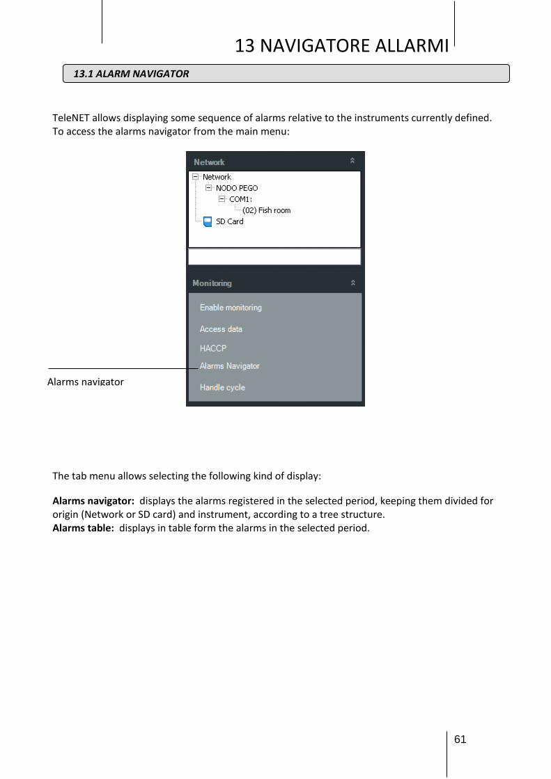
TeleNET allows displaying some sequence of alarms relative to the instruments currently defined. To access the alarms navigator from the main menu:
The tab menu allows selecting the following kind of display:
Alarms navigator: displays the alarms registered in the selected period, keeping them divided for origin (Network or SD card) and instrument, according to a tree structure. Alarms table: displays in table form the alarms in the selected period.
13.1 ALARM NAVIGATOR
Alarms navigator
62
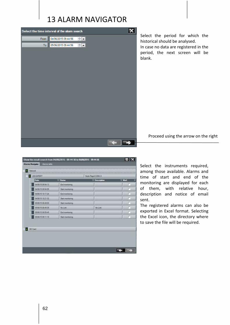
13 ALARM NAVIGATOR
Proceed using the arrow on the right
Select the period for which the historical should be analysed. In case no data are registered in the period, the next screen will be blank. Select the instruments required, among those available. Alarms and time of start and end of the monitoring are displayed for each of them, with relative hour, description and notice of email sent. The registered alarms can also be exported in Excel format. Selecting the Excel icon, the directory where to save the file will be required.

63
13 ALARM NAVIGATOR
The “Alarms table” card contains the same information described in “Alarms navigator”, but in table form. Besides the export in Excel format, registered alarms can be printed.
Export and print
64
14 AUTOMATIC CYCLES
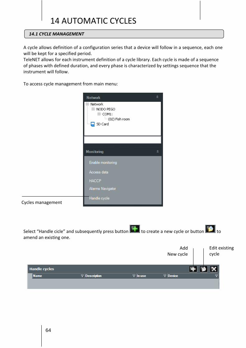
A cycle allows definition of a configuration series that a device will follow in a sequence, each one will be kept for a specified period. TeleNET allows for each instrument definition of a cycle library. Each cycle is made of a sequence of phases with defined duration, and every phase is characterized by settings sequence that the instrument will follow. To access cycle management from main menu:
Select “Handle cicle” and subsequently press button to create a new cycle or button to amend an existing one.
Cycles management
Edit existing cycle
Add New cycle
14.1 CYCLE MANAGEMENT

65
14 AUTOMATIC CYCLES
This folder is made of two defined areas:
1. Heading of cycle containing Name and Description of the cycle. The field Module is significant, and has the function to indicate device which will follow the cycle (can be modified only for a new cycle).
2. Cycle detail, divided into two levels: a. Phase: heading with the indication of phase duration b. Phase detail: definition of single settings that characterized the phase.
For deleting a whole phase or part of contained set up, to use delete key.

66
14 AUTOMATIC CYCLES
TeleNET allows to plan a cycle execution for a device, and display his course. To plan, displaying cycle status, access Cycles area on device properties folder.
14.2 CYCLE PLANNING
Cycles

67
14 AUTOMATIC CYCLES
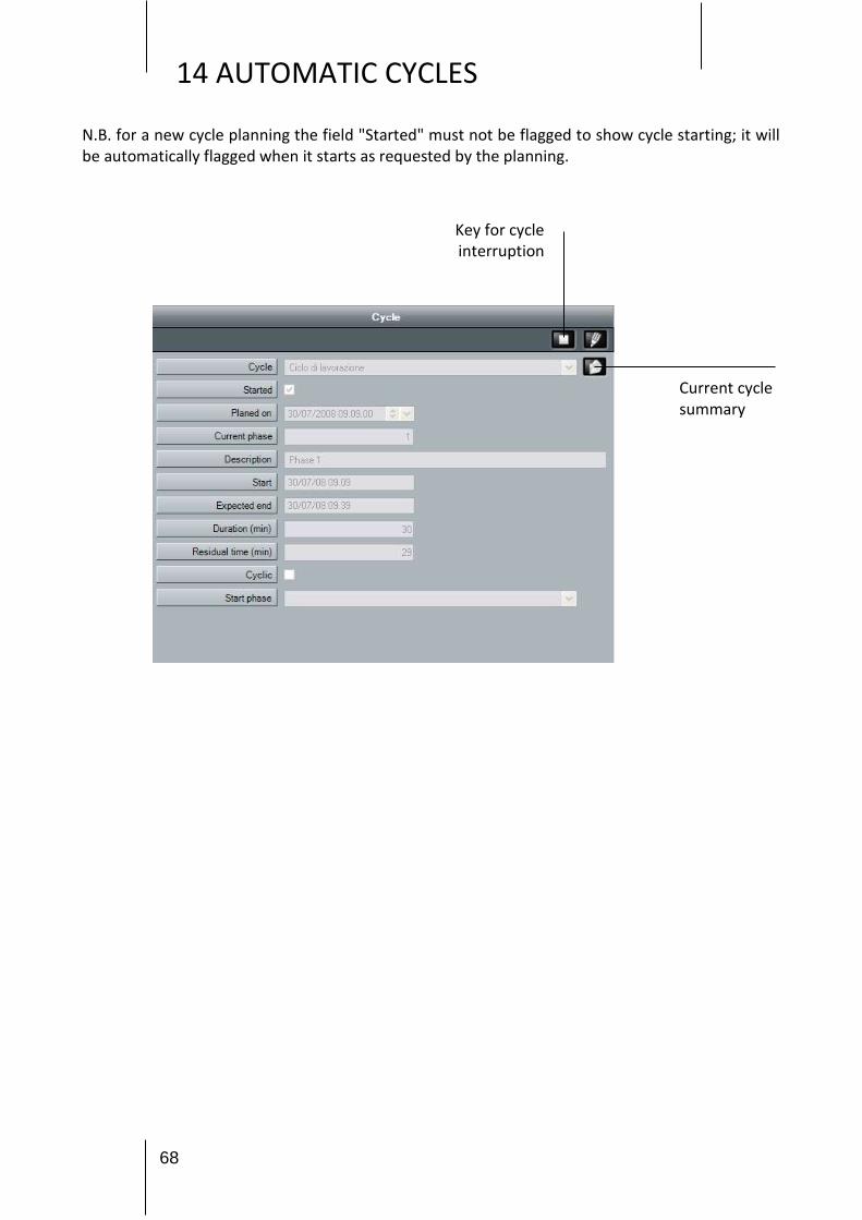
Field meaning: Cycle: contains cycle to be planned (that is started) chosen from cycles available for the
selected device; Started: shows cycle start status (flag automatically appears when cycle is started). Cycle
start is keynoted by the "blue" colour of device status icon Planed on: date and hour for cycle start; Current phase: cycle phase actually running (only reading); Description: description of cycle phase actually running (only reading); Start: date and hour for phase start (only reading); Expected end: date and hour for phase end (only reading); Duration: phase duration, in minutes (only reading); Residual time: time remaining to phase end, in minutes (only reading); Cyclic: shows if the sequence is cyclic that means after the last phase it starts automatically
again from phase 1. Start phase: allows to start a phase different than the first one
68
14 AUTOMATIC CYCLES
N.B. for a new cycle planning the field "Started" must not be flagged to show cycle starting; it will be automatically flagged when it starts as requested by the planning.
Key for cycle interruption
Current cycle summary

69
15 HISTORY
To display data monitored it's available a simple wizard for the user to guide on the searching of data to be displayed. To display the history select Access data from main menu.
Select the device which history analysis is needed (it's possible to select up to 4 instruments at the same time, in case a comparison is requested).
15.1 HISTORY DATA ANALYSIS
Proceed with the right arrow
Access history

70
15 HISTORY
Select the historical time period to be analysed. In case of no registered data during that period, the following screen will be empty.
Procedere con la freccia a destra
Select, choosing from the ones available the desired measured units. It's possible to associate a different colours to each of these units.
Proceed with the right arrow
Proceed with the right arrow

71
15 HISTORY
From menus "Events" and "Monitoring" it's possible to print the registered data or export them in Excel format. Selecting Excel icon it will be directly asked the path where to save the file.
15.2 DATA EXPORT
Data export and print
Visualizations: Graph Events Monitoring
Legend

72
15 HISTORY
The HACCP or Hazard Analysis and Critical Control Points is a protocol aimed at preventing food contamination hazards. Telenet is used to display, print and save the maximum and minimum daily temperature values as well as the hourly averages, in excel format, for the relevant tools, on a specific date that can be selected by the user.
IMPORTANT NOTE: This function is not available for the following tools: PEV, SC600, DIN3RK, TWMIO. To use the function, on the Configure TeleNet menu select HACCP and then use the tools for which you wish to display the data.
Select the date and click on to confirm.
You can now print and export the data in Excel format . The "go back" button is
used to access the tool selection page in order to perform a new analysis on different tools.
In order to perform a new analysis on the same tools but on a different date, the date at the top to
the left can be changed, confirming by clicking on .
The data will be updated on the selected date.
IMPORTANT NOTE: in order to use this function, it must be enabled in the “Configure HACCP” menu in Modify tool. (Chap. 9.1)
15.3 HACCP

73
16 PROBLEMS AND SOLUTIONS
PROBLEM POSSIBLE CAUSE SOLUTION
A "path too long” error appears when manually running the Setup.exe file.
The folder containing the installation file is in a sub-folder with an
excessively long path.
Move the folder to the local hard drive C to make the path shorter.
An "Access Denied” error appears when launching installation.
The installed antivirus is blocking installation.
Momentarily disable the antivirus and launch installation again.
A Generic Error 26 window - "Server not found or not accessible” appears
when launching TeleNET
PC name changed or SQL instance not installed or launched properly.
Refer to paragraph 16.3
Incorrect username and password Password forgotten Contact Pego assistance
The monitoring process does not start USB protection key not inserted in the
PC.
Close TeleNET, insert the USB protection key in the PC and restart
TeleNET.
Open "Programs and Features" from the Control Panel and select Telenet. Click on "Uninstall" and confirm the uninstallation procedure. Once the procedure is complete, you must manually remove the Telenet folder, which can be identified with the following path: Computer -> C -> Programs -> PEGO.
If the SQL instance is installed, you must uninstall it. Open "Programs and Features” from the Control Panel. Select "Microsoft SQL Server 2008 R2" and click on the "Uninstall/Change" button:
16.1 PROBLEMS AND SOLUTIONS
16.2 TELENET UNINSTALLATION

74
16 PROBLEMS AND SOLUTIONS
Select "Remove" in the following window.
The uninstallation procedure will run a check, at the end of which you must click on OK. At this point, you can select the TELENET_PEGOWISE instance from the dropdown menu and click on Next.

75
16 PROBLEMS AND SOLUTIONS
You will be prompted to select the features to be removed: select “Database Engine Services” and the relative feature will also be selected automatically. Confirm by clicking on Next.
A check will be carried out, at the end of which you must click on Next to proceed. The procedure is now ready for uninstallation. Click on Remove to proceed.
At the end of the procedure, uninstallation is complete.

76
16 PROBLEMS AND SOLUTIONS
Solution A: the PC name has been changed If the PC name was changed, you must update this data in the TeleNET database configuration. Launch TeleNET and close the error message by clicking on "OK". The following window will open:
Click on “Yes” to update the name of the PC in the Server Name field.
The first part of the Server Name is the name of the PC and this is the data you need to update. Do not change the second part.
Click on the icon to save the change and launch TeleNET. If the problem persists, go to Solution B.
Solution B: SQL instance not installed or not launched properly First of all, you must check whether the SQL instance is installed.
16.3 GENERAL ERROR 26 “Server not found or not accessible”

77
16 PROBLEMS AND SOLUTIONS
From the START menu -> All programs look for the Microsoft SQL Server 2008 R2 folder.
No folder: the SQL instance is not installed; therefore, you must uninstall the Client (see 16.2) and proceed with Complete Installation (see chap.2.2).
Folder present: open it and open "SQL Server Configuration Manager" in the "Configuration Tools" sub-folder:
The following window will open, from which you can check the status of the "SQL Server (TELENET_PEGOWISE)” instance.
1. SQL Server (TELENET_PEGOWISE) instance missing Only the Client was installed and, therefore, the instance was not installed. Uninstall the Client (see 16.2) and then proceed with Complete Installation (see Chap.2.2).
2. Status = Running The Client was not installed successfully. Uninstall it (see 16.2) and run Complete Installation (see Chap.2.2).
3. Status = Stopped Right-click on the SQL instance and select "Start". If it does not launch or if the problem persists, go on to the following solution. Right-click on the SQL instance and select "Properties”. In the "Log On" tab, the "Built-in account" parameter has three accounts you can select from a dropdown menu.

78
16 PROBLEMS AND SOLUTIONS
Select one and click on "OK". If the problem persists, select another account. If the problem persists with every account, you must uninstall the Client and then remove the SQL instance (see 16.2). Once uninstalled, launch Complete Installation (see Chap.2.2).

79
Windows e Microsoft are registered trademarks.
Every effort has been made to ensure that the information in this manual is accurate.
Pego is not responsible for printing or clerical errors. Pego makes available the last manual release.
Please carefully read the license during installation of TeleNET software.

80
16 PROBLEMS AND SOLUTIONS
PEGO S.r.l. Via Piacentina, 6/b
45030 Occhiobello ROVIGO – ITALY Tel. +39 0425 762906 Fax +39 0425 762905
[email protected] www.pego.it
Allegati / Appendices