retrieving and interpreting data from ford powertrain...
TRANSCRIPT
Retrieving and Interpreting Data from Ford Powertrain Control Modules using the Bosch Crash Data Retrieval Tool Bruce F. McNally McNally & Associates Accident Reconstruction Services, LLC Background In the fourth quarter of 2007, Bosch released its Version 3.0 software update and made new hardware available to its Crash Data Retrieval Tool users. This particular update included the new ability for the CDR Tool user to retrieve data from certain Ford powertrain control modules (PCM). The added ability to download crash-related data from PCM’s was significant, as previous data from Ford’s restraint control modules (RCM) did not include pre-collision data, such as that found on many General Motors airbag control modules. 1 With the addition of the Ford PCM data, we are now able to evaluate the pre-impact conditions of many newer Ford vehicles. The currently accessible Ford PCM’s record sixteen (16) data fields, including vehicle speed, brake switch status, ABS status, and engine speed. The data is recorded at a sample rate of 5 Hz, or one sample every .2 seconds. The majority of the supported modules record about 25 seconds of data, but some record more than 6 minutes of data. This paper will present methods to use in order to safely retrieve the data contained in the currently supported Ford PCM’s and methodologies used to interpret the retrieved data. Ford Powertrain Control Module Information In 2003, the first Ford vehicle models equipped with Electronic Throttle Control (ETC) were introduced to the market – the Ford Thunderbird and the Lincoln LS. Because of the necessity to integrate ETC within the powertrain control module, a newly designed PCM was warranted. In the process of developing the new PCM for the Thunderbird and the LS, Ford decided to include a data recording device. As more Ford vehicles were introduced to the market equipped with ETC, more Ford models included the capability
to record crash-related data. By 2007, approximately 70 percent of Ford models contained a PCM capable of recording crash-related data. In general, all Ford PCM’s record data at a rate of 5 Hz, or one sample every .2 seconds. All of the currently supported PCM’s record sixteen (16) different data parameters, some of which are particularly helpful in the reconstruction of collisions. For specific data collected by the various supported Ford PCM’s, see Appendix A. During normal operation of the vehicle, the PCM continuously records data from various electronic components related to the vehicle’s powertrain. This recording begins when the vehicle’s ignition switch is turned to the “on” position and continues until the ignition switch is turned “off” or there is a power failure on the vehicle. The data is recorded in a circular buffer of either 2K or 32K, depending upon the model PCM. In a circular buffer, data is recorded sequentially until the buffer is full, whereupon the first information is overwritten and the process repeats. 2 Unlike some airbag control modules, where crash-related data can be stored in non-deployment events, it is not until a moderate to severe collision that the Ford PCM is likely to function as an event data recorder. In a collision of sufficient severity to produce a deployment of the vehicle’s airbag system or seatbelt pretensioners, the vehicle’s Restraint Control Module (RCM) is designed to send a Restraint Deployment Signal (RDS) to the PCM. Once the PCM receives the Restraint Deployment Signal via the vehicle’s communication network, the PCM is designed to record five (5) additional seconds of data and then stop recording new data. For instance, in vehicles equipped with a PCM capable of recording 25 seconds of data, once the Restraint Deployment Signal is received by the PCM, the data buffer will contain 20 seconds of pre-deployment data and 5 seconds of post-deployment data. In those PCM’s that record more than six minutes of data, much more pre-deployment data is stored, while the device still only stores 5 seconds of post-deployment data. Ford PCM Interface Kit Prior to any attempt at retrieving data from a Ford vehicle equipped with a supported PCM, one must ensure that the necessary hardware is available to safely perform the data retrieval. Failure to follow the correct procedure will likely result in a failure to retrieve the data or, more importantly, result in the spoliation of the crash-related data contained on the PCM. The Ford PCM Interface Kit currently in use with Bosch software includes three direct-to-module interface cables and the Ford PCM Adapter. The Ford PCM Adapter must be used in both Diagnostic Link Connector (DLC) and direct-to-module connections. The Ford PCM Adapter serves two primary functions in the data retrieval process – it
provides sufficient power to the PCM for data retrieval and it sends a signal to the PCM, placing the PCM in “diagnostic” mode. Attempting to use the PCM Interface Cables or the OBD II Vehicle Interface Cable without the PCM Adapter will result in the PCM being powered in the “run” mode, which may result in an overwrite of the data contained on the PCM if the data is not locked. 3 Use of the new CDR Power Supply Kit will help ensure that sufficient power is supplied to the PCM during the download process. The new OBD II Vehicle Interface Cable includes additional connections within the cable that will allow the Ford PCM Adapter to communicate properly with the PCM. Use of the old OBD II Vehicle Interface Cable (Part Number 02002837) with the Ford PCM Adapter will result in failed communications with the PCM, and may result in spoliation of the PCM data. It is recommended that the old OBD II Vehicle Interface Cable be removed from the CDR Tool Kit and replaced with the new OBD II Vehicle Interface Cable so that inadvertent use of the old cable is averted. 4 Retrieving PCM Data The primary methodology recommended by Bosch to retrieve data from a PCM is to connect to the module through the DLC. Prior to attempting to retrieve data from a Ford vehicle, one should first check the CDR Tool Help File in order to determine which modules (RCM/PCM) are currently supported by the latest software version. If it is determined that the vehicle has a currently supported PCM, or has both RCM and PCM data, one should use the methodology described in the CDR Help Files to safely retrieve that data. Prior to attempting to perform a retrieval of the PCM data, check the vehicle’s power system in order to determine if there is sufficient battery power to perform the download. It should be noted that the PCM download requires at least 9 volts of power in order for the PCM to power-up in the diagnostic mode. A voltage drop below 9 volts will result in the PCM resetting, and a potential loss of crash-related data. It is recommended that the download be performed with a full 12-volt battery charge, since it is possible to quickly drain a battery on a damaged vehicle during the download process. While checking the vehicle’s electrical system, do not turn the ignition key to the “on” position. Turning the ignition key to the on position may result in an overwrite of the data contained on the PCM if the data on the PCM is not “locked” by the Restraint Deployment Signal and the Ford PCM Adapter is not yet plugged into the DLC. It is important to understand that it is possible that the vehicle may have sustained damage to its electrical system during the collision. If the communication wiring between the vehicle’s DLC and the PCM is compromised, it is possible for the Ford PCM
Adapter to emit a green ‘ready’ light, but not be communicating the diagnostic mode signal to the PCM. In cases where there is unlocked data on the PCM, the data will begin to be overwritten as soon as the ignition key is turned to the run position. If there is any question about the integrity of the vehicle’s electrical system, one should not attempt data retrieval through the DLC, and instead connect directly to the PCM for the download. While the Bosch Help Files indicate that the preferred manner in which to retrieve PCM data is via the Diagnostic Link Connector, the data may also be safely retrieved by connecting directly to the PCM. In cases where the electrical system of the vehicle is compromised, and in cases where the vehicle damage otherwise prevents a DLC connection, a direct-to-module, or “bench download,” is possible. The direct-to-module connection can be performed either while the PCM is still mounted in the vehicle, or after the module has been removed from the vehicle. There are three general types of powertrain control modules that can be currently queried using the CDR Tool – each requiring a different cable if a direct-to-module query is attempted. The CDR Help File will indicate which cable must be used for the given module type, and which of the three available wiring harness receptacles on the given module is used with that interface cable. Interpretation of “Locked” PCM Data Once the Bosch CDR Tool is used to retrieve data from the PCM, the data must be interpreted by the reconstructionist in order to determine if it is related to the collision. In cases where the PCM received a Restraint Deployment Signal (RDS) from the RCM after deployment, the CDR software will alert the user that the PCM data is locked, and will automatically sort the data file so that the pre-RDS data is listed prior to the post-RDS data. This data sorting occurs in both the tabular and graphical output formats in the CDR software. While the CDR Tool can display the data retrieved from the PCM in both tabular and graphical format, it is many times helpful to use a spreadsheet to display the data for interpretation purposes. In the spreadsheet, the analyst can look for unusual data readings in all of the available fields and make notations within the data for later reference. The use of the spreadsheet also allows the analyst to add additional fields to the data, such as calculating elapsed distance over a specific time frame. This type of analysis is helpful in correlating the PCM data to the physical evidence collected at the crash scene.
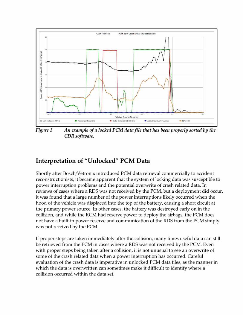
Figure 1 An example of a locked PCM data file that has been properly sorted by the CDR software. Interpretation of “Unlocked” PCM Data Shortly after Bosch/Vetronix introduced PCM data retrieval commercially to accident reconstructionists, it became apparent that the system of locking data was susceptible to power interruption problems and the potential overwrite of crash related data. In reviews of cases where a RDS was not received by the PCM, but a deployment did occur, it was found that a large number of the power interruptions likely occurred when the hood of the vehicle was displaced into the top of the battery, causing a short circuit at the primary power source. In other cases, the battery was destroyed early on in the collision, and while the RCM had reserve power to deploy the airbags, the PCM does not have a built-in power reserve and communication of the RDS from the PCM simply was not received by the PCM. If proper steps are taken immediately after the collision, many times useful data can still be retrieved from the PCM in cases where a RDS was not received by the PCM. Even with proper steps being taken after a collision, it is not unusual to see an overwrite of some of the crash related data when a power interruption has occurred. Careful evaluation of the crash data is imperative in unlocked PCM data files, as the manner in which the data is overwritten can sometimes make it difficult to identify where a collision occurred within the data set.
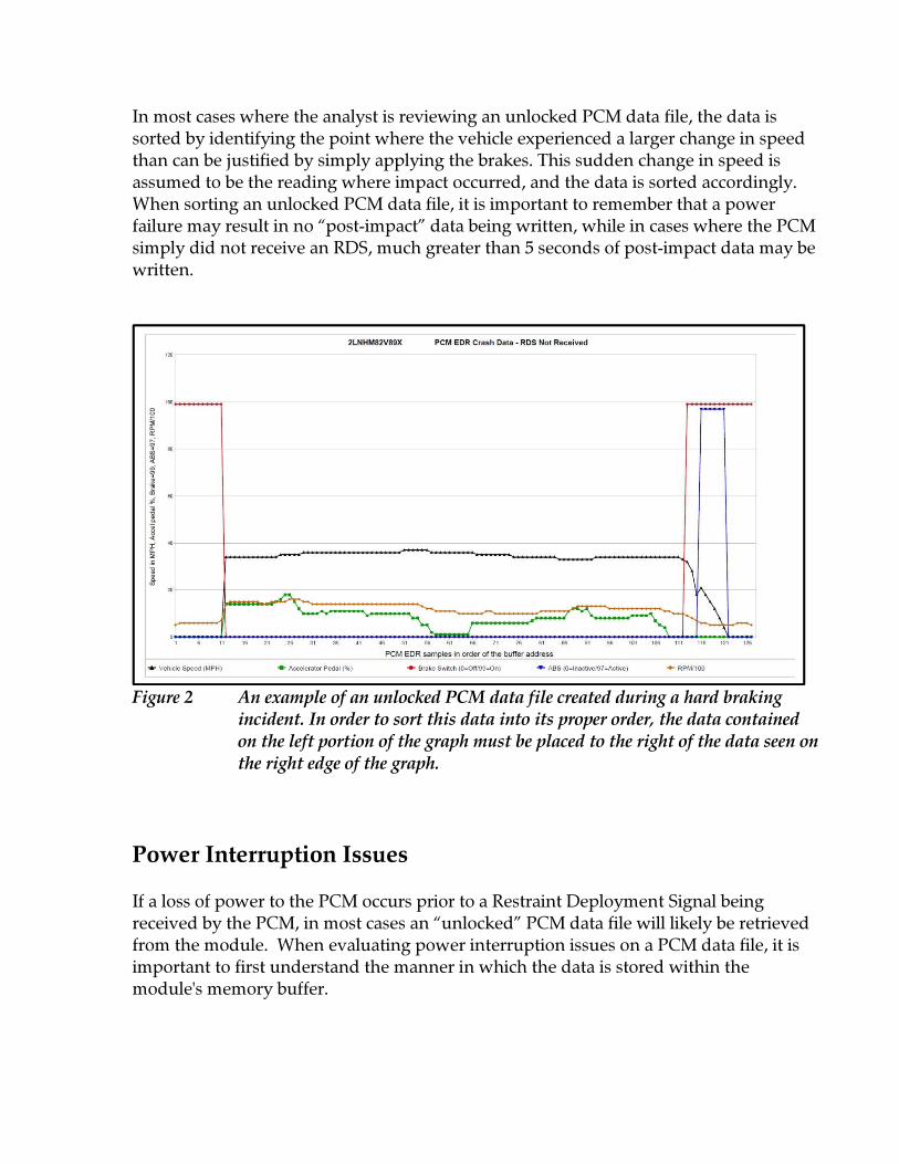
In most cases where the analyst is reviewing an unlocked PCM data file, the data is sorted by identifying the point where the vehicle experienced a larger change in speed than can be justified by simply applying the brakes. This sudden change in speed is assumed to be the reading where impact occurred, and the data is sorted accordingly. When sorting an unlocked PCM data file, it is important to remember that a power failure may result in no “post-impact” data being written, while in cases where the PCM simply did not receive an RDS, much greater than 5 seconds of post-impact data may be written.
Figure 2 An example of an unlocked PCM data file created during a hard braking incident. In order to sort this data into its proper order, the data contained on the left portion of the graph must be placed to the right of the data seen on the right edge of the graph. Power Interruption Issues If a loss of power to the PCM occurs prior to a Restraint Deployment Signal being received by the PCM, in most cases an “unlocked” PCM data file will likely be retrieved from the module. When evaluating power interruption issues on a PCM data file, it is important to first understand the manner in which the data is stored within the module's memory buffer.

During a power-up of the PCM, data is continually stored in the circular buffer of the PCM. The first memory address used in the circular buffer is identified in the PCM data file as EA000010. In a 25-second PCM data file, the memory addresses range from EA000010 to EA0007F0, for 127 lines of data. Each line of data within that range represents the information recorded by the PCM every .2 seconds (5 Hz). It has been suggested that in an unlocked PCM data file, an application of power to the PCM for more than about 25 seconds will result in a complete overwrite of collision-related data. While this statement is correct, the uninformed investigator might conclude that as long as the overwrite was some time period less than 25 seconds, the data at or near the time of the collision will still be stored on the module. This is simply not the case. It is important to understand that when the PCM loses power, it does not simply begin to record data where it previously left off in the circular buffer. Each time the PCM reboots, it begins to record at memory address EA000010. In an unlocked PCM, losing power will likely result in the data file being split, causing a loss of contiguous data. For instance, if the collision happened to have occurred at EA000050, a single reboot of the module and one second of power application will result in an overwrite of the last second of pre-crash data.
Figure 3 An example of an overwrite of data caused by turning on the ignition switch without first attaching the PCM Power Adapter. Note that the overwrite has occurred at the beginning of the memory buffer and continues for several seconds before the ignition was turned off.
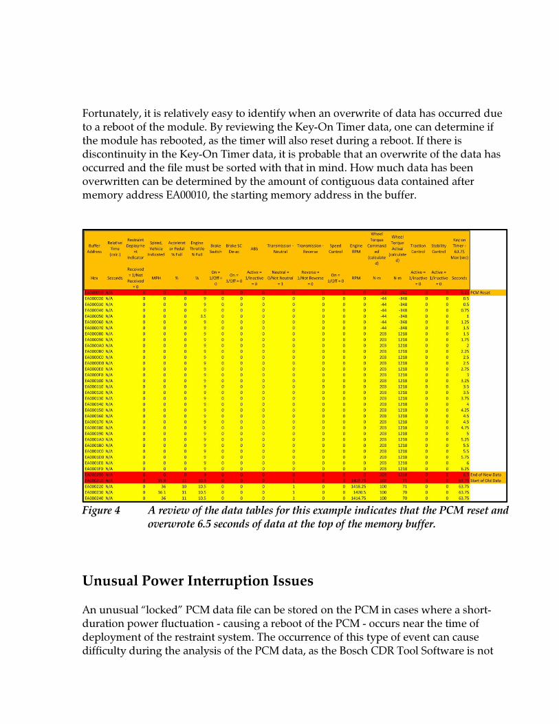
Fortunately, it is relatively easy to identify when an overwrite of data has occurred due to a reboot of the module. By reviewing the Key-On Timer data, one can determine if the module has rebooted, as the timer will also reset during a reboot. If there is discontinuity in the Key-On Timer data, it is probable that an overwrite of the data has occurred and the file must be sorted with that in mind. How much data has been overwritten can be determined by the amount of contiguous data contained after memory address EA00010, the starting memory address in the buffer.
Figure 4 A review of the data tables for this example indicates that the PCM reset and overwrote 6.5 seconds of data at the top of the memory buffer. Unusual Power Interruption Issues An unusual “locked” PCM data file can be stored on the PCM in cases where a short-duration power fluctuation - causing a reboot of the PCM - occurs near the time of deployment of the restraint system. The occurrence of this type of event can cause difficulty during the analysis of the PCM data, as the Bosch CDR Tool Software is not
designed to analyze the data contained in the file to identify that a power fluctuation has occurred. In a “Locked-Reboot” data file, power to the PCM has dropped below 9 volts for a short time period, causing the PCM to reboot. This reboot is almost immediately followed by a RDS being received from the RCM, which is not as susceptible to power fluctuations due to its onboard capacitors. Since the PCM has rebooted before receiving the RDS from the RCM, when power is restored to the PCM, it begins to overwrite the data, starting at memory address EA000010. Meanwhile, the RCM continues to send the RDS to the PCM for as much as .6 or .8 seconds after deployment occurs. Once the RDS is received by the PCM, five additional seconds of data is recorded by the PCM before it stops compiling data in the memory buffer. 5 The CDR Tool Software has an automatic sorting feature - recognizing when a retrieved PCM file contains a RDS – placing the PCM in its “proper” order with the post-RDS data at the end of the list. In most situations, this feature of the software streamlines the analysis of the data file, as the reconstructionist does not have to initially sort the data manually. Although a “Locked-Reboot” data file will be sorted so that the post-RDS data is at the end of the file, it is almost certain that the data is incorrectly sorted. The automatic sorting function of the software may result in the uninformed analyst misinterpreting the data file. There are three data fields that must be examined in order to properly identify a “Locked Reboot” data file; the Key-On Timer, the RDS Signal, and Buffer Address. If the RDS Signal was initially received by the PCM in Buffer Addresses EA000010 to EA000030, and the Key-On Timer starts counting upward from .25 seconds at Memory Address EA000010, you most-likely have identified a “Locked-Reboot” data file. Once the data file has been properly identified, the process of sorting the data into its proper time-line can be accomplished. The PCM data depicted in Figure 5 has been identified as a “Locked-Reboot” data file. A simple review of the graph provided by the CDR Tool Software clearly shows that the vehicle experienced a significant impact that has been sorted so that it appears relatively early on in the pre-impact data. While the graph indicates that the collision event is clearly included in the PCM data file, the data file must be manually sorted so that it appears in the proper chronological order.
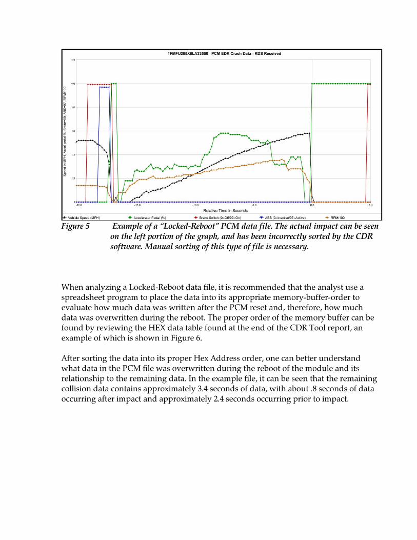
Figure 5 Example of a “Locked-Reboot” PCM data file. The actual impact can be seen on the left portion of the graph, and has been incorrectly sorted by the CDR software. Manual sorting of this type of file is necessary. When analyzing a Locked-Reboot data file, it is recommended that the analyst use a spreadsheet program to place the data into its appropriate memory-buffer-order to evaluate how much data was written after the PCM reset and, therefore, how much data was overwritten during the reboot. The proper order of the memory buffer can be found by reviewing the HEX data table found at the end of the CDR Tool report, an example of which is shown in Figure 6. After sorting the data into its proper Hex Address order, one can better understand what data in the PCM file was overwritten during the reboot of the module and its relationship to the remaining data. In the example file, it can be seen that the remaining collision data contains approximately 3.4 seconds of data, with about .8 seconds of data occurring after impact and approximately 2.4 seconds occurring prior to impact.

Figure 6 Hex Data information included near the back of a CDR Report. The top three blocks of data include the VIN, the PCM Part Number and the PCM Calibration Level. The first and last lines of recorded data are EA000010 and EA0007F0, respectively. In this example, because of the reboot of the PCM just prior to it receiving the RDS, there is approximately 5.2 seconds of pre-impact data that was overwritten. The overwritten data includes that which would have told us what was occurring on the vehicle in the time frame between 2.6 and 7.8 seconds prior to impact. Because of the gap in pre-impact data that must be included in the analysis, the final sorting of data
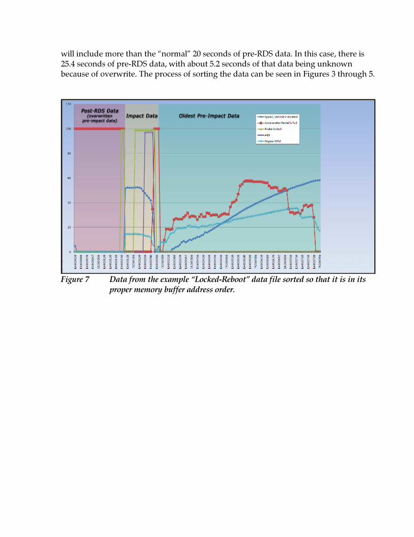
will include more than the “normal” 20 seconds of pre-RDS data. In this case, there is 25.4 seconds of pre-RDS data, with about 5.2 seconds of that data being unknown because of overwrite. The process of sorting the data can be seen in Figures 3 through 5.
Figure 7 Data from the example “Locked-Reboot” data file sorted so that it is in its proper memory buffer address order.
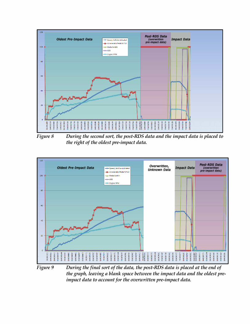
Figure 8 During the second sort, the post-RDS data and the impact data is placed to the right of the oldest pre-impact data.
Figure 9 During the final sort of the data, the post-RDS data is placed at the end of the graph, leaving a blank space between the impact data and the oldest pre- impact data to account for the overwritten pre-impact data.
Summary The process of retrieving data from a supported Ford PCM is a relatively straightforward and simple process, but there is a very real potential for evidence spoliation if the procedures outlined in the Bosch CDR Help Files are not followed. Although retrieval of the data contained on the PCM is almost always easily accomplished, interpretation and proper sorting of that data is sometimes complicated by power interruptions that occur as a result of the collision, or communication interruptions between the RCM and the PCM that results in the PCM not receiving a Restraint Deployment Signal. Knowing how the PCM records data – particularly the issues that arise when a power interruption occurs – will assist the analyst in understanding what data was likely overwritten in an unlocked data file. This process can be as simple as a single cut-and-paste when using a spreadsheet, but can become much more complicated if the actual collision data is overwritten, or in the relatively uncommon occurrence of a “Locked-Reboot” data file.
References 1 Wheelock, Robert J. (Bob), Presentation: "Current Ford Event Data Recorders," SAE Government/Industry Meeting, May 15, 2007. 2 Espanol, et al. v. Ford Motor Company, et al., Case No. BC345611, County of San Mateo, California, Deposition of James J. Engle, January 24, 2007. 3 Robert Bosch, LLC U.S.A., CDR Version 3.3 Software CD, 2009. 4 Ibid. 5 Ruth, Richard R., Personal correspondence to Bruce McNally, July 23, 2008. Acknowledgements I would like to thank Mr. Richard Ruth, of Ruth Consulting, for his assistance in explaining the issues regarding a “Locked-Reboot” PCM data file. I would also like to thank Wade Bartlett, of Mechanical Forensic Engineering Services, for his assistance during testing of unlocked PCM data files.
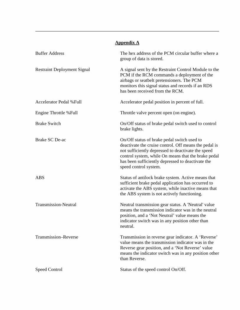
Appendix A Buffer Address The hex address of the PCM circular buffer where a group of data is stored. Restraint Deployment Signal A signal sent by the Restraint Control Module to the PCM if the RCM commands a deployment of the airbags or seatbelt pretensioners. The PCM monitors this signal status and records if an RDS has been received from the RCM. Accelerator Pedal %Full Accelerator pedal position in percent of full. Engine Throttle %Full Throttle valve percent open (on engine). Brake Switch On/Off status of brake pedal switch used to control brake lights. Brake SC De-ac On/Off status of brake pedal switch used to deactivate the cruise control. Off means the pedal is not sufficiently depressed to deactivate the speed control system, while On means that the brake pedal has been sufficiently depressed to deactivate the speed control system. ABS Status of antilock brake system. Active means that sufficient brake pedal application has occurred to activate the ABS system, while inactive means that the ABS system is not actively functioning. Transmission-Neutral Neutral transmission gear status. A 'Neutral' value means the transmission indicator was in the neutral position, and a ‘Not Neutral’ value means the indicator switch was in any position other than neutral. Transmission–Reverse Transmission in reverse gear indicator. A ‘Reverse’ value means the transmission indicator was in the Reverse gear position, and a ‘Not Reverse’ value means the indicator switch was in any position other than Reverse. Speed Control Status of the speed control On/Off.
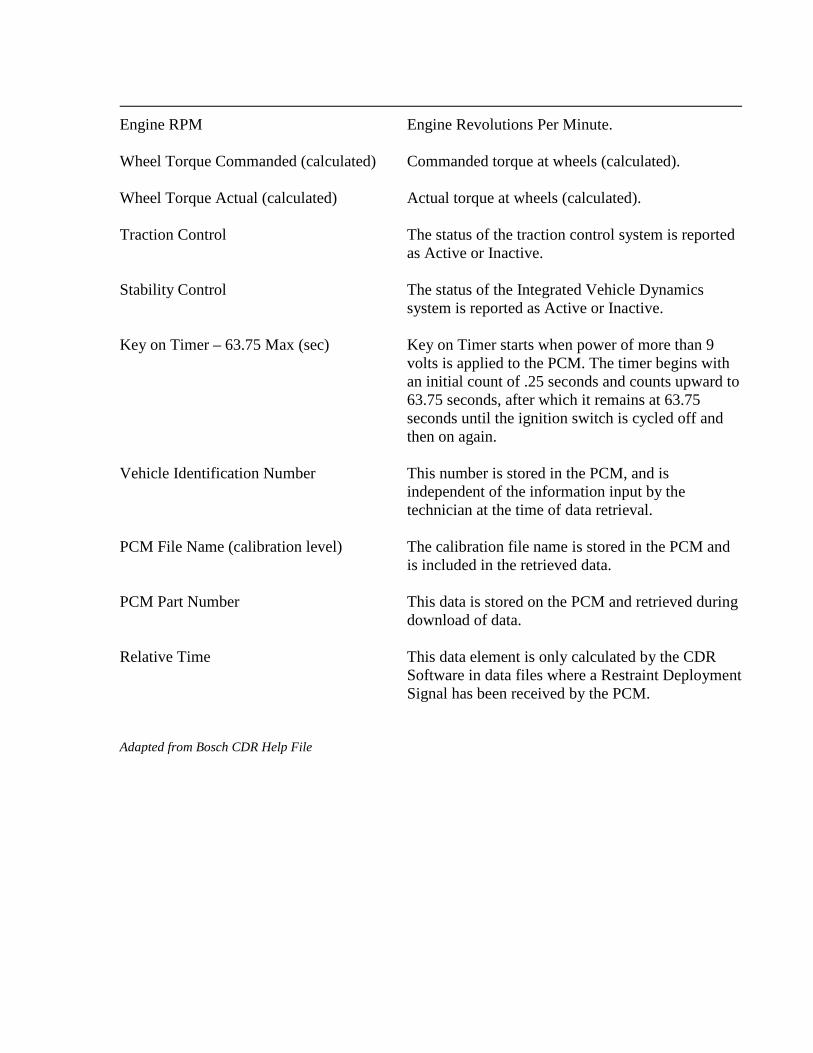
Engine RPM Engine Revolutions Per Minute. Wheel Torque Commanded (calculated) Commanded torque at wheels (calculated). Wheel Torque Actual (calculated) Actual torque at wheels (calculated). Traction Control The status of the traction control system is reported as Active or Inactive. Stability Control The status of the Integrated Vehicle Dynamics system is reported as Active or Inactive. Key on Timer – 63.75 Max (sec) Key on Timer starts when power of more than 9 volts is applied to the PCM. The timer begins with an initial count of .25 seconds and counts upward to 63.75 seconds, after which it remains at 63.75 seconds until the ignition switch is cycled off and then on again. Vehicle Identification Number This number is stored in the PCM, and is independent of the information input by the technician at the time of data retrieval. PCM File Name (calibration level) The calibration file name is stored in the PCM and is included in the retrieved data. PCM Part Number This data is stored on the PCM and retrieved during download of data. Relative Time This data element is only calculated by the CDR Software in data files where a Restraint Deployment Signal has been received by the PCM. Adapted from Bosch CDR Help File