retank® systemcontainmentsolutions.com/assets/retank-installation... · 2019-03-20 · (936)...
TRANSCRIPT

Publication No. MAN 4033BEffective Date September 1, 2013
RETANK® SYSTEM I N S TA L L AT I O N I N S T R U C T I O N S
F O R U P G R A D I N G S I N G L E - W A L L F I B E R G L A S S TA N K S T O D O U B L E - W A L L F I B E R G L A S S TA N K S
2
1. Introduction ................................................................................2
2. Pre-Installation Guidelines ..........................................................2
3. Contractor Preparatory Work ................................................. 2-3
4. Containment Solutions Inspection ..............................................3
5. ReTank® Installation ................................................................ 3-4
6. Leak Testing .................................................................................4
7. Wrap Up ......................................................................................4
1. INTRODUCTION
1.1. The purpose of this manual is to provide specifiers, owners, contractors, and their employees with detailed instructions for installing a Containment Solutions (CSI) ReTank® System in an existing single-wall fiberglass underground storage tank.
Note: ReTank® installation is a very specialized procedure. Containment Solutions is the only trained, authorized installer of the ReTank® System.
1.2. Safety
1.2.1. These instructions should not be interpreted in any way to put one's health at risk, or to harm property and/or the environment.
1.2.2. The following definitions will serve as a guide when reading this manual:
1.3. Important Information
1.3.1. Proper installation and operation of each ReTank® installation is essential to ensure the safety of all individuals involved in the ReTank® installation and startup, and to prevent tank damage and/or failure which could lead to environmental contamination.
1.3.2. Follow all OSHA, Federal, State, Local or Provincial safety and environmental codes and regulations.
Indicates a potentially hazardous situation, which if not avoided could result in death or serious injury.
Indicates a potentially hazardous situation, which if not avoided may result in minor or moderate injury.
Indicates a potentially hazardous situation, which if not avoided may result in property damage.
Technical SupportConroe, Texas
(877) 274-8265(936) 756-7731
Field Service Dept.Mt. Union, Pennsylvania
(800) 822-1997(814) 542-8520
1.4. Before You Begin
1.4.1. Read, understand and follow these instructions.
1.4.2. Barricade the ReTank® area until job is completed.
1.4.3. If you have questions on other installation details, contact Field Service at 800-822-1997 or Technical Support at 800-537-4730.
1.4.4. This procedure applies only to fiberglass underground storage tanks manufactured by:
• Owens-Corning Fiberglass
• O/C Tanks
• Containment Solutions, Inc.
2. PRE-INSTALLATION GUIDELINES
2.1. The ReTank® candidate tank is inspected subject to the following criteria:
2.1.1. The water table must be maintained at or below the bottom of the tank.
2.1.2. The candidate tank must have passed a recent precision test before beginning the ReTank® installation.
2.1.3. Deflection of the existing tank does not exceed 3%of the original diameter as determined by measuring the vertical diameter of the tank through a fitting.
2.1.4. Minimum vertical tank diameter is 89” for a 92” diameter fiberglass tank.
3. CONTRACTOR PREPARATORY WORK
3.1. The contractor fills out and submits a “ReTank® Job Site Survey” form to Containment Solutions at least 2 weeks before proceeding with preparations for the ReTank® operation.
3.2. The contractor removes backfill, piping, and electrical connections from the top of the tank.
3.3. The contractor arranges for/provides equipment necessary to unload ReTank® equipment and supplies. (Note: This includes pallets and/or 55 gallon drums. It may also include a large sealed container — 8’ x 8’ x 20’ Sea-Train).
3.4. The tank is then triple-washed, cleaned and defumed, under the direction of a local contractor (designated as “The Contractor”) and in accordance with API Standards 2015 Safe Entry And Cleaning Of Petroleum Storage Tanks, and RP 1631, Interior Lining Of Underground Storage Tanks. Also follow OSHA Regulation 29 CFR Parts 1910, Confined Space Entry Procedures, as well as any applicable local safety regulations.
ASPHYXIATION FIRE EXPLOSION
Do not enter tank unless following OSHA guidelines for confined space entry. Failure to follow OSHA guidelines could result in death or serious injury.

3
3.5. The contractor is also responsible for providing a backhoe and operator for a period of time to assist with the insertion of ReTank® parts. (Note: The period of time for heavy equipment assistance is typically no more than 2 days after CSI approves the interior condition of the tank).
3.6. The contractor is responsible for maintaining security barriers around the job site.
4. CONTAINMENT SOLUTIONS INSPECTION
4.1. The tank is tested for benzene and explosive vapor levels prior to CSI personnel entry.
4.2. The tank is then continuously vented and monitored for oxygen and flammable vapor levels. The tank may be entered when the oxygen level is greater than 19.5% and the flammable vapor level is less than 10% of the Lower Explosive Limit.
4.3. The ReTank® candidate tank is inspected internally subject to the following guidelines:
4.3.1. Indentions or other surface discontinuities are less than 1/2" high.
Note: Surface irregularities outside of these guidelines will require review by CSI personnel and may require special repair procedures before the ReTank® process can be performed.
5. RETANK® INSTALLATION
5.1. Entry openings are typically cut in one endcap and at each manway location (see Figure 5-1).
5.2. Tripods may be installed over the manway hole cutouts. Chain hoists may be attached to the tripods in order to raise the tri-fold panels into position.
5.3. The endcap opposite the entry hole is installed in 3 pieces and held in place with jacks until the permanent fiberglass seams are applied (see Figure 5-2).
5.4. Prefabricated panels are hinged together in groups of 3 (designated as tri-folds), folded together, and secured with straps.
Note: The panels are sized so that each tri-fold covers half of the circumference of the tank.
5.5. A tri-fold is lifted by the backhoe and inserted through the opening in the end cap and guided into place by CSI personnel.
5.6. The tri-fold is opened covering the bottom 180 degrees of the tank circumference (see Figure 5-3).
5.7. When the tank length requires multiple panels, additional bottom tri-folds are installed in the same manner.
5.8. The top tri-folds are inserted into the tank and lowered to the tank bottom in a similar manner.
5.9. The top tri-fold is attached to the chain hoists connected to the tripods and raised into position at the top of the tank.
5.10. The top tri-fold is opened covering the top 180 degrees of the tank circumference and is held in position temporarily by jacks (see Figure 5-4).
5.11. When the tank length requires multiple panels, additional tri-folds are installed in the same manner.
5.12. Field adjustments to the final panel lengths may be required. If necessary, the panels will be cut to a shorter length by the CSI technician before or after the panels are installed in the existing fiberglass tank.
5.13. All of the installed panels and end cap joints are bonded together per CSI ReTank® specifications.
5.14. All manways, fittings and other accessories are installed according to factory specifications.
Figure 5-1
Figure 5-2
Figure 5-3
Figure 5-4
4
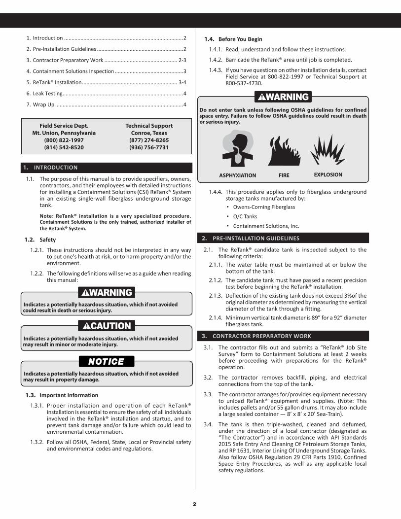
5.15. The remaining endcap is installed and bonded together in the same manner as the first end cap (see Figure 5-5).
6. LEAK TESTING
6.1. The interstitial space of the new double-wall tank is filled with a dyed brine leak detection fluid.
6.2. The interior of the ReTank® is visually inspected for any trace of a leak as evidenced by the presence of dyed brine.
6.3. The brine level in the reservoir is also inspected.
Figure 5-5
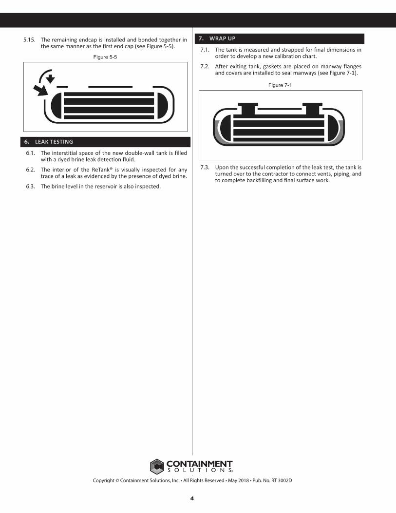
Figure 7-1
Copyright © Containment Solutions, Inc. • All Rights Reserved • May 2018 • Pub. No. RT 3002D
7. WRAP UP
7.1. The tank is measured and strapped for final dimensions in order to develop a new calibration chart.
7.2. After exiting tank, gaskets are placed on manway flanges and covers are installed to seal manways (see Figure 7-1).
7.3. Upon the successful completion of the leak test, the tank is turned over to the contractor to connect vents, piping, and to complete backfilling and final surface work.