retaining rings - huyett
TRANSCRIPT
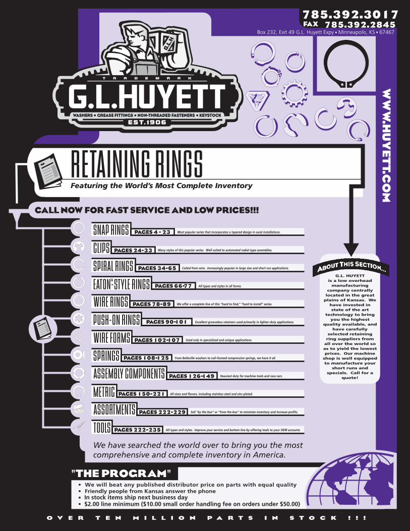
RETAINING RINGS
SNAP RINGS PAGES 4 - 23 Most popular series that incorporates a tapered design in axial installations.
CLIPS Many styles of this popular series. Well suited to automated radial-type assemblies.
SPIRAL RINGS Coiled from wire. Increasingly popular in large size and short run applications.
All types and styles in all forms.
WIRE RINGS We offer a complete line of this "hard to find," "hard to install" series.
Excellent grooveless retainers used primarily in lighter-duty applications.
Used only in specialized and unique applications.
SPRINGS From Belleville washers to coil-formed compression springs, we have it all.
Heaviest duty for machine tools and race cars.
METRIC All sizes and flavors, including stainless steel and zinc plated.
Sell "by the box" or "from the box" to minimize inventory and increase profits.
TOOLS All types and styles. Improve your service and bottom line by offering tools to your OEM accounts.
We have searched the world over to bring you the mostcomprehensive and complete inventory in America.
785.392.3017w
ww
.hu
yet
t.co
m785.392.2845FAX
Box 232, Exit 49 G.L. Huyett Expy Minneapolis, KS 67467
PAGES 24-33
PAGES 34-65
PAGES 66-77
PAGES 78-89
PAGES 90-101
PAGES 102-107
PAGES 108-125
PAGES 126-149
PAGES 150-221
PAGES 222-229
PAGES 222-235
EATON-STYLE RINGS
PUSH-ON RINGS
ASSEMBLY COMPONENTS
WIRE FORMS
ASSORTMENTS
TM
$2.00 line minimum ($10.00 small order handling fee on orders under $50.00)In stock items ship next business day

BOX 232 • MINNEAPOLIS, KS • 67467 REVISED 09-04
785•392•3017 FAX 785.392.2845
MOST SIZES AVAILABLE IMMEDIATELY • $2 LINE REQUESTED • CALL PLANT FOR QUANTITY DISCOUNTS
All manufacturer names and numbers are for identification purposes only. In no way are we implying that our parts were made by the manufacturers listed above.Prices, materials, tolerances, and grades subject to change without notice. © G.L. Huyett 2004
www.huyett.com
HOW TO USE THIS CATALOGOne of the basic principles of our literature is to make information “User Friendly.” We believe that our catalog should be an educational tool that assists distributors in the sale of our products. OEMs may use this guide in order to construct, refine, or confirm component selection. Look for this catalog on the World Wide Web and CD-ROM in the near future!
Our part numbers are listed in the far left column on each page; however, feel free to order by the same part numbers you use now. We can cross-reference to most industry nomenclatures, including Rotor Clip™; Waldes Truarc™; IRR™; Anderton™; Spirolox™; Smalley™; Eaton™; and Bossard™. A complete manufacturer cross reference is located on pages 236-237.
Special orders and short runs are gladly welcomed. We have a complete machine shop. Use the back cover to make special order requests. We pledge to return most quotes on a “same day” or “next day” basis. Our parts will be on time and competitively priced.
Metric sizes are on pages 150-221. We are aggressively expanding our metric manufacturing capabilities. Call if you need a commodity that is not listed.
Assortments begin on page 222. We can put together custom arrangements if needed. All products can be shipped in a standard container or with bar codes.
Most parts are available from stock. In stock items ship next business day. There are a myriad of possibilities with tolerance, material, and finish, thus there will be times when we will run your parts to order. Please call in advance when in a crisis situation.
DIN
RUSH
N5000-125H
FOR THE TABLE OF CONTENTS FOR THIS CATALOG, SEE PAGES 2-3.
We offer to beat published prices in all of our product groups. We offer low prices to minimize your costs in time, phone, and fax charges. Competition can always “cherry pick” this type of pricing. We hope you consider the cost advantages of doing business with us on a low cost basis all the time, versus the “trick and cherry pick” approach.
This is our statement to you that we will offer the best prices and service available.
We hope your experience with us is pleasant and efficient. G.L. Huyett wants the sale of retaining rings to be more profitable for you. We hope we have accomplished this task.
MOST SIZES AVAILABLE IMMEDIATELY • $2 LINE REQUESTED • CALL PLANT FOR QUANTITY DISCOUNTS
All manufacturer names and numbers are for identification purposes only. In no way are we implying that our parts were made by the manufacturers listed above.Prices, materials, tolerances, and grades subject to change without notice.
BOX 232 • MINNEAPOLIS, KS • 67467ABOUT THE COMPANYREVISED 09-04
785•392•3017 FAX 785.392.2845
© G.L. Huyett 2004
www.huyett.com
FOR THE TABLE OF CONTENTS FOR THIS CATALOG, TURN THE PAGE.
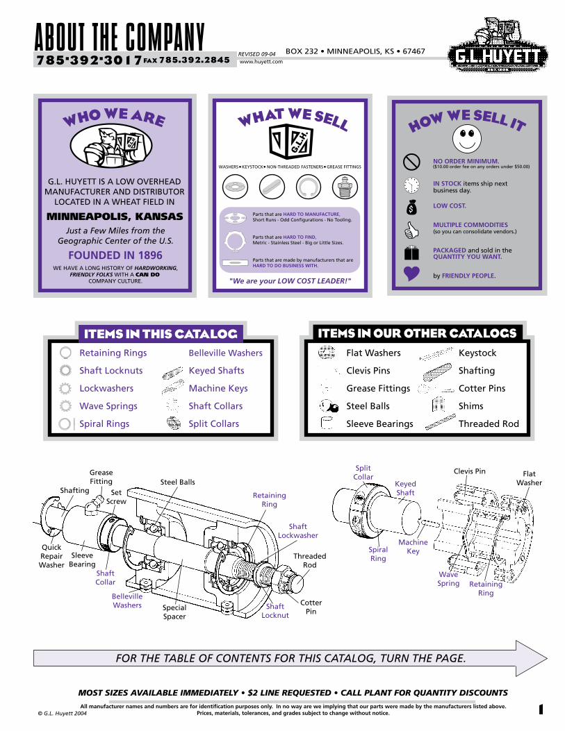
Machine Key
SplitCollar
Keyed Shaft
Flat Washer
Clevis Pin
SpiralRing
Wave Spring Retaining
Ring
Quick Repair Washer
Grease Fitting
Sleeve Bearing
Shaft Collar
Steel Balls
Belleville Washers Cotter
Pin
Shaft Lockwasher
Shaft Locknut
Threaded Rod
Shafting
Special Spacer
SetScrew
RetainingRing
Retaining Rings
Shaft Locknuts
Lockwashers
Wave Springs
Spiral Rings
Belleville Washers
Keyed Shafts
Machine Keys
Shaft Collars
Split Collars
ITEMS IN THIS CATALOG
1
Keystock
Shafting
Cotter Pins
Shims
Threaded Rod
Flat Washers
Clevis Pins
Grease Fittings
Steel Balls
Sleeve Bearings
ITEMS IN OUR OTHER CATALOGS
what we sell
WASHERS KEYSTOCK NON-THREADED FASTENERS GREASE FITTINGS
Parts that are HARD TO MANUFACTURE,Short Runs - Odd Configurations - No Tooling.
Parts that are HARD TO FIND,Metric - Stainless Steel - Big or Little Sizes.
Parts that are made by manufacturers that are HARD TO DO BUSINESS WITH.
"We are your LOW COST LEADER!"
($10.00 order fee on any orders under $50.00)
IN STOCK items ship next business day.

TABLE OF CONTENTSREVISED 09-04
MOST SIZES AVAILABLE IMMEDIATELY • $2 LINE REQUESTED • CALL PLANT FOR QUANTITY DISCOUNTS
2
785•392•3017 FAX 785.392.2845
All manufacturer names and numbers are for identification purposes only. In no way are we implying that our parts were made by the manufacturers listed above.Prices, materials, tolerances, and grades subject to change without notice. © G.L. Huyett 2004
www.huyett.com
RGpage 27
Radial Grip
REpage 27
Epage 26
BasicE-Clip
SHpage 6
Basic External
SHRpage 9
Heavy Duty External
SHIpage 10
Inverted External
BSHpage 11
Bowed External
PO(L)page 30
Poodle Clip
A15page 29
BEpage 28
Bowed E-Clip
VSHpage 12
Beveled External
SHFpage 14
Grooveless SHMpage 15
Tamper-Proof
HOpage 16
Basic Internal
ELpage 33
Prong Locked E-Clip
Cpage 32
LCpage 31
InterlockingHOIpage 19
Inverted Internal
BHOpage 20
Bowed Internal
VVHpage 21
Double Beveled Internal
VHOpage 22
Beveled Internal
Reinforced E-Clip
Mutant E-Clips
BasicC-Clip
USpage 36
External Light Duty
RSpage 38
External Medium Duty
RSTpage 42
External Medium Heavy
RSNpage 44
External Heavy Duty
URpage 50
Internal Light Duty
KSpage 47
External Self-Locking
MSpage 48
External Dished
SSNpage 49
External Tabbed
RRpage 52
Internal Medium Duty
RRTpage 56
Internal Medium Heavy
RRNpage 58
Internal Heavy Duty
KRpage 61
Internal Self-Locking
MRpage 62
Internal Dished
SRNpage 63
Internal Tabbed
BRpage 64
Internal Balanced
USHpage 71
Notched External
XDpage 70
USCpage 68
Basic External
A10page 87
Round Ex-ternal Light Duty
TRCpage 88
Rectangular External
AARpage 88 CrimpedUHO
page 76Notched Internal
NDpage 74
UHBpage 72
Basic Internal
XSOpage 80
Square External (Radial)
XSCpage 82
Square External (Axial)
XROpage 84
Round External (Radial)
XRCpage 86
Round External (Axial)
Light-Duty External
Light-Duty Internal
SNAP RINGS CLIPS
WIRE RINGS
BEGINS PAGE 4. BEGINS PAGE 24.
BEGINS PAGE 34.SPIRAL RINGS
Eaton RINGSt mBEGINS PAGE 66. BEGINS PAGE 78.
METRIC SIZES BEGIN ON PAGE 182.
METRIC SIZES BEGIN ON PAGE 190.
METRIC SIZES BEGIN ON PAGE 198. METRIC SIZES BEGIN ON PAGE 202.
METRIC SIZES BEGIN ON PAGE 152.

BOX 232 • MINNEAPOLIS, KS • 67467
MOST SIZES AVAILABLE IMMEDIATELY • $2 LINE REQUESTED • CALL PLANT FOR QUANTITY DISCOUNTS
3All manufacturer names and numbers are for identification purposes only. In no way are we implying that our parts were made by the manufacturers listed above.Prices, materials, tolerances, and grades subject to change without notice.© G.L. Huyett 2004
30/70page 138 page 140
MachineKeys
Wpage 141
Standard Lockwasher
WSpage 142
Stainless Lockwasher
WHpage 143
Heavy Duty Lockwasher
WIpage 144
WTpage 144
Fine Thread Lockwasher
ETRpage 145
External Tooth Retainer
SCpage 128
Solid Collar
SC1page 129
Single Split Collar
SC2page 129
Double Split Collar
N/ANpage 132
Standard Locknut
NHpage 133
Heavy Duty Locknut
NIpage 134
Fine Thread Locknut
NLpage 135
Left Hand Locknut
NTpage 136
Thin Section Locknut
SSpage 146
Support Washer DIN 988 page 147
Shim Ring DIN 988
TWpage 148
Thrust Washer
SRpage 149
Slitted Shim
PS
TRpage 97
Triangle Push-On page 97
Triangle Screw-On
NPRpage 98
Basic Rectangular
NPOpage 99
Basic Round
BRRpage 100
Internal Toothed
T99page 101
Basic Grooveless
TYpage 92
Basic External
TXpage 92
Reinforced External
TIpage 93
Basic Internal
ITRpage 94
Internal Toothed
STRpage 96
High Speed Strip
WRRpage 96
Wide Rim Slotted
NTR S Seriespage 105
Piston Rings page 106
Hair Pin Type
A12page 104
External “C” Style D25
page 104
Internal “D” Style
BPXZ
BWpage 110
Disc Spring
PSWpage 112
Shoulder Washer
FSpage 112
Finger Washer
WSEpage 114
External Wave Spring
WSIpage 115
Internal Wave Spring
WSGpage 116
Standard Gap Style
WSNpage 118
Narrow Section - Split
CMLpage 120
CompressionLight Duty
CMMpage 122
CompressionMedium Duty
CMHpage 124
CompressionHeavy Duty
PUSH-ON RINGS WIRE FORMS
SPRINGS
ASSEMBLY COMPONENTS
BEGINS PAGE 102.
page 224Kits & Special PacksDISP
ASSORTMENTS
PRpage 226
Pliers RRApage 232
Applicators
TOOLS
METRIC TABLE OF CONTENTS ON PAGE 150.
PART # INDEX ON PAGE 236.
BEGINS PAGE 222.
BEGINS PAGE 222.
BEGINS PAGE 90.
BEGINS PAGE 108.
BEGINS PAGE 126.
METRIC SIZES BEGIN ON PAGE 212.
METRIC SIZES BEGIN ON PAGE 214.
METRIC SIZES BEGIN ON PAGE 218.
KF Keyed Shafts
Thin Section Lockwasher
SNAP RINGSREVISED 09-04
MOST SIZES AVAILABLE IMMEDIATELY • $2 LINE REQUESTED • CALL PLANT FOR QUANTITY DISCOUNTS
4
785•392•3017 FAX 785.392.2845
All manufacturer names and numbers are for identification purposes only. In no way are we implying that our parts were made by the manufacturers listed above.Prices, materials, tolerances, and grades subject to change without notice. © G.L. Huyett 2004
www.huyett.com
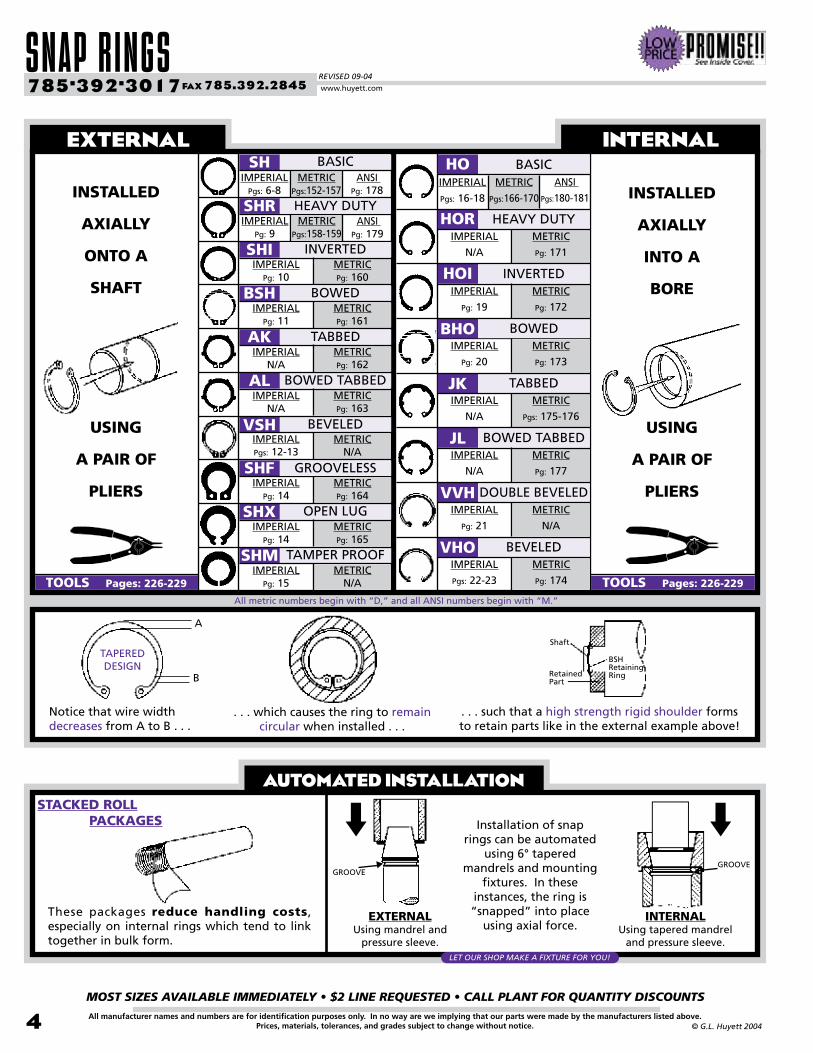
STACKED ROLL PACKAGES
These packages reduce handling costs, especially on internal rings which tend to link together in bulk form.
Installation of snap rings can be automated
using 6° tapered mandrels and mounting
fixtures. In these instances, the ring is “snapped” into place
using axial force.
Notice that wire width decreases from A to B . . .
. . . which causes the ring to remain circular when installed . . .
. . . such that a high strength rigid shoulder forms to retain parts like in the external example above!
EXTERNALUsing mandrel and
pressure sleeve.
INTERNALUsing tapered mandrel
and pressure sleeve.
AUTOMATED INSTALLATION
EXTERNAL INTERNALSH
METRICPgs:152-157
IMPERIALPgs: 6-8
SHR
SHIIMPERIAL
Pg: 10
BSHIMPERIAL
Pg: 11
AKIMPERIAL
N/A
ALIMPERIAL
N/A
IMPERIALPgs: 12-13
SHFIMPERIAL
Pg: 14
SHXIMPERIAL
Pg: 14
SHMIMPERIAL
Pg: 15
INSTALLED
AXIALLY
ONTO A
SHAFT
USING
A PAIR OF
PLIERS
TOOLS Pages: 226-229
INSTALLED
AXIALLY
INTO A
BORE
USING
A PAIR OF
PLIERS
TOOLS Pages: 226-229
HO
HORIMPERIAL
N/A
HOIIMPERIAL
Pg: 19
BHOIMPERIAL
Pg: 20
JKIMPERIAL
N/A
JLIMPERIAL
N/A
VVHIMPERIAL
Pg: 21
VHOIMPERIAL
Pgs: 22-23
VSH
BASIC
METRICPg: 160
METRICPg: 161
METRICPg: 162
METRICPg: 163
METRICN/A
METRICPg: 164
METRICPg: 165
METRICN/A
HEAVY DUTY
INVERTED
BOWED
TABBED
BOWED TABBED
BEVELED
GROOVELESS
OPEN LUG
TAMPER PROOF
BASIC
METRIC
Pg: 171
HEAVY DUTY
METRIC
Pg: 172
INVERTED
METRIC
Pg: 173
BOWED
METRIC
Pgs: 175-176
TABBED
METRIC
Pg: 177
BOWED TABBED
METRIC
N/A
DOUBLE BEVELED
METRIC
Pg: 174
BEVELED
TAPERED DESIGN
A
B
ANSI Pg: 178
METRICPgs:158-159
IMPERIALPg: 9
ANSI Pg: 179
METRIC
Pgs:166-170
IMPERIAL
Pgs: 16-18
ANSI
Pgs:180-181
All metric numbers begin with “D,” and all ANSI numbers begin with “M.”
BSHRetainingRing
Shaft
RetainedPart
GROOVEGROOVE
LET OUR SHOP MAKE A FIXTURE FOR YOU!
BOX 232 • MINNEAPOLIS, KS • 67467
MOST SIZES AVAILABLE IMMEDIATELY • $2 LINE REQUESTED • CALL PLANT FOR QUANTITY DISCOUNTS
5All manufacturer names and numbers are for identification purposes only. In no way are we implying that our parts were made by the manufacturers listed above.Prices, materials, tolerances, and grades subject to change without notice.© G.L. Huyett 2004
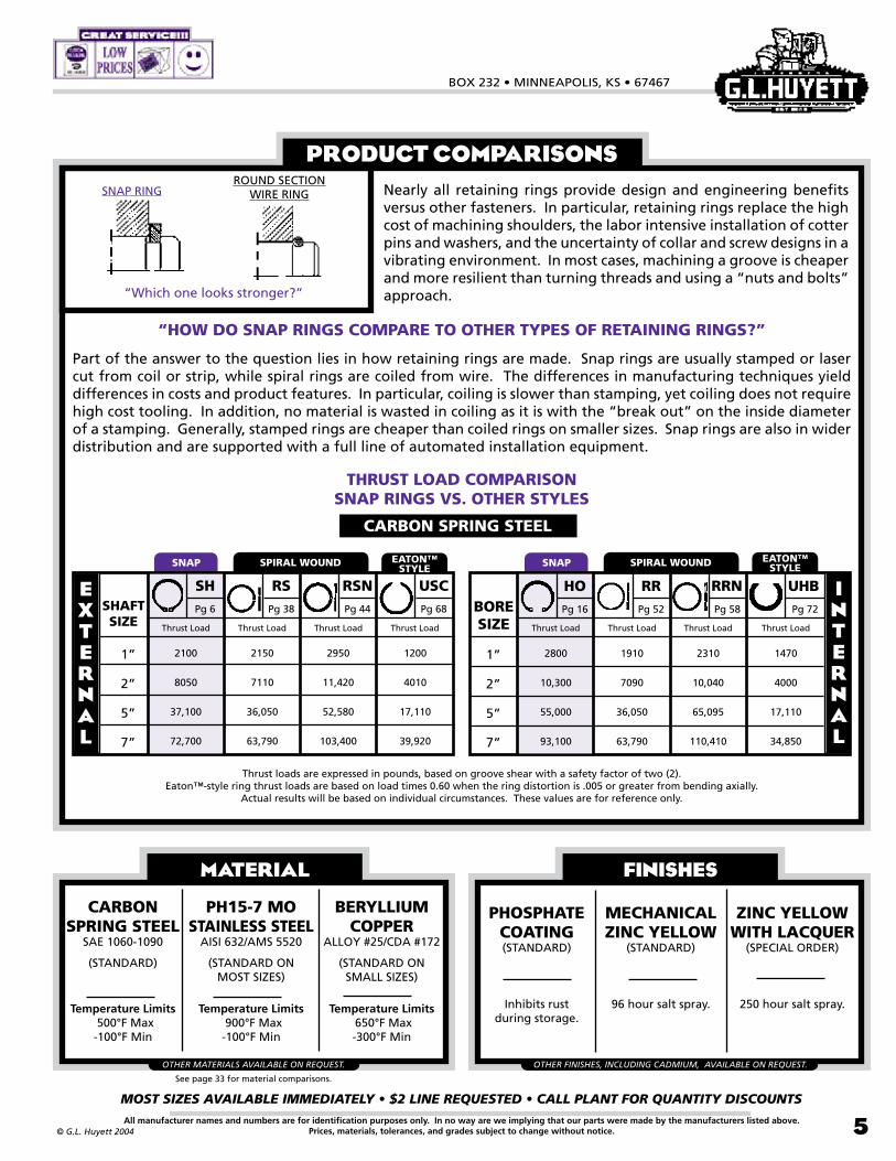
Nearly all retaining rings provide design and engineering benefits versus other fasteners. In particular, retaining rings replace the high cost of machining shoulders, the labor intensive installation of cotter pins and washers, and the uncertainty of collar and screw designs in a vibrating environment. In most cases, machining a groove is cheaper and more resilient than turning threads and using a “nuts and bolts” approach.
PRODUCT COMPARISONS
Thrust loads are expressed in pounds, based on groove shear with a safety factor of two (2). Eaton™-style ring thrust loads are based on load times 0.60 when the ring distortion is .005 or greater from bending axially.
Actual results will be based on individual circumstances. These values are for reference only.
ROUND SECTIONWIRE RING
“Which one looks stronger?”
SNAP SPIRAL WOUND SNAP SPIRAL WOUND
BORESIZE
RRPg 52
Thrust Load
Pg 58
Thrust Load
UHBPg 72
Thrust Load
1”
2”
5”
7”
1910
7090
36,050
63,790
2310
10,040
65,095
110,410
1470
4000
17,110
34,850
RRN INTERNAL
HOPg 16
Thrust Load
2800
10,300
55,000
93,100
EATON™ STYLE
RSPg 38
Thrust Load
RSNPg 44
Thrust Load
USCPg 68
Thrust Load
2150
7110
36,050
63,790
2950
11,420
52,580
103,400
1200
4010
17,110
39,920
EXTERNAL
SHAFTSIZE
1”
2”
5”
7”
SHPg 6
Thrust Load
2100
8050
37,100
72,700
EATON™ STYLE
CARBON SPRING STEEL
FINISHES
PHOSPHATECOATING(STANDARD)
Inhibits rust during storage.
MECHANICALZINC YELLOW
(STANDARD)
96 hour salt spray.
ZINC YELLOWWITH LACQUER
(SPECIAL ORDER)
250 hour salt spray.
OTHER FINISHES, INCLUDING CADMIUM, AVAILABLE ON REQUEST.
See page 33 for material comparisons.
MATERIAL
CARBON SPRING STEEL
SAE 1060-1090
(STANDARD)
Temperature Limits 500°F Max-100°F Min
PH15-7 MOSTAINLESS STEEL
AISI 632/AMS 5520
(STANDARD ON MOST SIZES)
Temperature Limits 900°F Max-100°F Min
BERYLLIUM COPPER
ALLOY #25/CDA #172
(STANDARD ON SMALL SIZES)
Temperature Limits 650°F Max-300°F Min
OTHER MATERIALS AVAILABLE ON REQUEST.
SNAP RING
“HOW DO SNAP RINGS COMPARE TO OTHER TYPES OF RETAINING RINGS?”
Part of the answer to the question lies in how retaining rings are made. Snap rings are usually stamped or laser cut from coil or strip, while spiral rings are coiled from wire. The differences in manufacturing techniques yield differences in costs and product features. In particular, coiling is slower than stamping, yet coiling does not require high cost tooling. In addition, no material is wasted in coiling as it is with the “break out” on the inside diameter of a stamping. Generally, stamped rings are cheaper than coiled rings on smaller sizes. Snap rings are also in wider distribution and are supported with a full line of automated installation equipment.
THRUST LOAD COMPARISONSNAP RINGS VS. OTHER STYLES

EXTERNAL SNAP RINGSREVISED 09-04
MOST SIZES AVAILABLE IMMEDIATELY • $2 LINE REQUESTED • CALL PLANT FOR QUANTITY DISCOUNTS
�
785•392•3017 FAX 785.392.2845
All manufacturer names and numbers are for identification purposes only. In no way are we implying that our parts were made by the manufacturers listed above.Prices, materials, tolerances, and grades subject to change without notice. © G.L. Huyett 2004
www.huyett.com
Stainless “-SS”
+.004/-.000
+/-.004
BASIC EXTERNALMANUFACTURER CROSS-REFERENCE
Free Inside
Dia. (Df)Decimal
(Ds)Fraction
(Ds)
Radial Wall (S) Thickness
(T)Diameter
(Dg)Depth
(d)SpringSteel
.125
.156
.188
.197
.219
.236
.250
.276
.281
.312
.344
.354
.375
.394
.406
.438
.469
.500
.551
.562
.594
.625
.672
.688
.750
.781
.812
.844
.875
.938
.9841.0001.0231.062
1/85/323/165mm7/3215/641/4
7mm9/325/1611/329mm3/8
10mm13/327/1615/321/2
14mm9/1619/325/8
43/6411/163/4
25/3213/16
21.4mm7/8
15/1663/64
126mm1-1/16
.112
.142
.168
.179
.196
.215
.225
.250
.256
.281
.309
.320
.338
.354
.366
.395
.428
.461
.509
.521
.550
.579
.621
.635
.693
.722
.751
.780
.810
.867
.910
.925
.946
.982
.117
.146
.175
.185
.205
.222
.230
.255
.261
.290
.321
.330
.352
.369
.382
.412
.443
.468
.519
.530
.559
.588
.631
.646
.704
.733
.762
.791
.821
.882
.926
.940
.961
.998
SHAFT RING TOOL
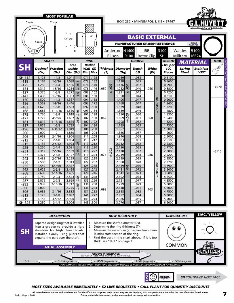
SH
Tapered-design ring that is installed into a groove to provide a rigid shoulder for high thrust loads. Installed axially using pliers that expand the part over the shaft.
1. Measure the shaft diameter (Ds).2. Determine the ring thickness (T).3. Measure the maximum (S max) and minimum
(S min) cross section of the ring.4. Find the part in the chart above. If it is too
thick, see “SHR” on page 9.
SH SHI (Page 10) RSN (Page 44) USH (Page 71)
ZINC/YELLOW
COMMONAXIAL ASSEMBLY
SH-012* -015* -018* -019* -021* -023*-025-027-028-031-034-035-037-039-040-043-046-050-055-056-059-062-066-068-075-078-081-084-087-093-098-100-102
SH-106
Width(W)
.012
+/-
.002
+/-.0
01
.025
.035
+.0
02/-
.005
MaxMin
-E023-S-E023-M
GROOVE
.011
.016
.016
.016
.017
.019
.025
.024
.025
.026
.0265
.029
.0305
.031
.033
.033
.035
.040
.036
.041
.043
.045
.043
.048
.051
.052
.054
.057
.057
.063
.064
.065
.066
.069
.018
.026
.025
.026
.028
.030
.035
.035
.038
.040
.042
.046
.050
.052
.054
.055
.060
.065
.053
.072
.076
.080
.082
.084
.092
.094
.096
.100
.104
.110
.114
.116
.118
.122
SSN (Page 49)
.004
.005
.006
.006
.007
.007
.010
.010
.010
.011
.011
.012
.012
.012
.012
.013
.013
.016
.016
.016
.017
.018
.020
.021
.023
.024
.025
.026
.027
.028
.029
.030
.031
.032.050 .056
.029
.010
*May be beryllium copper instead of carbon steel.
NOTAVAILABLE
SH CONTINUED NEXT PAGE.
Waldes3100IRRN1400AndertonMilitarySHRotor Clip9100Ellison
WEIGHTLbs. per
100Pieces
PERFORMANCE RESULTS VARY. YOUR RING SELECTION SHOULD BE MADE BASED ON INDIVIDUAL APPLICATION.
0.00180.00370.00590.00630.00740.00860.02100.02300.02400.02700.03100.03500.03900.04200.04300.05000.05400.09100.09000.11000.12000.13000.14000.18000.21000.22000.25000.27000.28000.31000.35000.36000.39000.4800
GROOVE INTERCHANGEUSE ANY OF THESE PARTS IN THE SAME SIZED GROOVE.
510016624
MOST POPULAR
Df
Dg
T
d
WDs
S max
S min
DESCRIPTION HOW TO IDENTIFY GENERAL USE
SHSTACKED/roll pack
DSH
METRICPage 152
DIN471
.018
+.0
02/-
.000
+/-
.001
5
.015
.039
.046.042
+.0
03/-
.000
+/-
.002
MATERIAL+
.002
/-.0
04+
.005
/-.0
10
INDEX PAGE 236.
+/-
.003
-E023-L
-E038
-E047
-E070
TOO
L D
ESC
RIP
TIO
NS
ON
PA
GES
226
, 228
, & 2
29.
+.010/-.015
BOX 232 • MINNEAPOLIS, KS • 67467
MOST SIZES AVAILABLE IMMEDIATELY • $2 LINE REQUESTED • CALL PLANT FOR QUANTITY DISCOUNTS
7All manufacturer names and numbers are for identification purposes only. In no way are we implying that our parts were made by the manufacturers listed above.Prices, materials, tolerances, and grades subject to change without notice.© G.L. Huyett 2004
BASIC EXTERNALMANUFACTURER CROSS-REFERENCE
Free Inside
Dia. (Df)Decimal
(Ds)Fraction
(Ds)
Radial Wall (S) Thickness
(T)Diameter
(Dg)Depth
(d)SpringSteel
1.1251.1881.2501.3121.3751.4381.5001.5621.6251.6881.7501.7721.8121.8751.9692.0002.0622.1252.1562.2502.3122.3752.4382.5002.5592.6252.6882.7502.8752.9383.0003.0623.1253.1563.250
1-1/81-3/161-1/41-5/161-3/81-7/161-1/21-9/161-5/8
1-11/161-3/4
45mm1-13/161-7/8
1-31/322
2-1/162-1/82-5/322-1/42-5/162-3/82-7/162-1/2
65mm2-5/8
2-11/162-3/42-7/8
2-15/163
3-1/163-1/83-5/323-1/4
1.0411.0981.1561.2141.2721.3331.3871.4461.5031.5601.6181.6371.6751.7351.8191.8501.9061.9641.9932.0812.1392.1972.2552.3132.3772.4282.4852.5432.6592.7172.7752.8322.8922.9203.006
1.0591.1181.1761.2321.2911.3501.4061.4681.5291.5891.6501.6691.7081.7691.8571.8861.9462.0032.0322.1202.1782.2392.2992.3602.4192.4813.5412.6022.7212.7792.8382.8982.9572.9863.076
SHAFT RING TOOL
SH
Tapered-design ring that is installed into a groove to provide a rigid shoulder for high thrust loads. Installed axially using pliers that expand the part over the shaft.
1. Measure the shaft diameter (Ds).2. Determine the ring thickness (T).3. Measure the maximum (S max) and minimum
(S min) cross section of the ring.4. Find the part in the chart above. If it is too
thick, see “SHR” on page 9.
ZINC/YELLOW
COMMONAXIAL ASSEMBLY
SH-112-118-125-131-137-143-150-156-162-168-175-177-181-187-196-200-206-212-215-225-231-237-243-250-255-262-268-275-287-293-300-306-312-315
SH-325
Width(W)
+.0
04/-
.000
+.0
05/-
.000
.033
.035
.037
.040
.042
.044
.047
.047
.048
.049
.050
.051
.052
.053
.056
.057
.058
.061
.062
.065
.067
.068
.069
.070
.070
.072
.073
.074
.077
.079
.081
.082
.084
.085
.087
+/-
.005
+/-
.006
+/-
.004
+/-
.002
+/-
.003
.050
.062
.078
+.0
10/-
.015
+.0
13/-
.020
+.0
15/-
.025
+.0
20/-
.030
MaxMin
GROOVE
.071
.072
.076
.076
.082
.086
.091
.093
.097
.099
.101
.102
.102
.104
.106
.108
.111
.113
.113
.116
.118
.119
.120
.122
.125
.127
.129
.131
.133
.136
.138
.131
.141
.143
.145
.128
.132
.140
.146
.152
.160
.168
.172
.180
.184
.188
.190
.192
.196
.200204.208.212.212.220.222.224.228.232.238.242.246.248.256.260.264.252.272.274.300
SH SHI (Page 10) RSN (Page 44) USH (Page 71) SSN (Page 49)
.093
.056
.068
.086
.103
Waldes 51003100IRRN1400AndertonMilitary 16624SHRotor Clip9100Ellison
MATERIAL
-E070
-E115
MOST POPULAR
Stainless “-SS”
Lbs. per 100
Pieces
WEIGHT
PERFORMANCE RESULTS VARY. YOUR RING SELECTION SHOULD BE MADE BASED ON INDIVIDUAL APPLICATION.
TOO
L D
ESC
RIP
TIO
NS
ON
PA
GES
226
, 228
& 2
29.
0.51000.56000.59000.68000.72000.81000.90001.24001.32001.48001.53001.54001.62001.73001.80001.90002.50002.61002.63002.77002.80002.92002.95002.97003.39003.50003.60004.25004.85005.00005.20004.75005.80005.90006.2000
GROOVE INTERCHANGEUSE ANY OF THESE PARTS IN THE SAME SIZED GROOVE.
INDEX PAGE 236.
Df
Dg
T
d
WDs
S max
S min
DESCRIPTION HOW TO IDENTIFY GENERAL USE
SH
SH CONTINUED NEXT PAGE.
DSH
METRICPage 152
DIN471

EXTERNAL SNAP RINGSREVISED 09-04
MOST SIZES AVAILABLE IMMEDIATELY • $2 LINE REQUESTED • CALL PLANT FOR QUANTITY DISCOUNTS
8
785•392•3017 FAX 785.392.2845
All manufacturer names and numbers are for identification purposes only. In no way are we implying that our parts were made by the manufacturers listed above.Prices, materials, tolerances, and grades subject to change without notice. © G.L. Huyett 2004
www.huyett.com
1. Measure the shaft diameter (Ds).2. Determine the ring thickness (T).3. Measure the maximum (S max) and minimum
(S min) cross section of the ring.4. Find the part in the chart above. If it is too
thick, see “SHR” on page 9.
ZINC/YELLOW
COMMONAXIAL ASSEMBLY
SH SHI (Page 10) RSN (Page 44) USH (Page 71) SSN (Page 49)
Tapered-design ring that is installed into a groove to provide a rigid shoulder for high thrust loads. Installed axially using pliers that expand the part over the shaft.
Free Inside
Dia. (Df)Decimal
(Ds)Fraction
(Ds)
Radial Wall (S) Thickness
(T)Diameter
(Dg)Depth
(d)SpringSteel
3.3463.4383.5003.5433.6253.6883.7503.8753.9384.0004.2504.3754.5004.7505.0005.2505.5005.7506.0006.2506.5006.7507.0007.2507.5007.7508.0008.2508.5008.7509.0009.2509.5009.750
10.000
3-11/323-7/163-1/2
90mm3-5/8
3-11/163-3/43-7/8
3-15/164
4-1/44-3/84-1/24-3/4
55-1/45-1/25-3/4
66-1/46-1/26-3/4
77-1/47-1/27-3/4
88-1/48-1/28-3/4
99-1/49-1/29-3/4
10
3.0923.1793.2373.2773.3523.4103.4683.5843.6423.7003.9894.1064.2234.4584.6924.9275.1625.3965.6315.8666.1006.3356.5706.7757.0097.2437.4787.7127.9478.1818.4158.6508.8859.1209.355
3.1663.2573.3163.3573.4353.4933.5523.6733.7343.7924.0654.1904.3104.5504.7905.0305.2655.5055.7455.9856.2256.4656.7056.9427.1807.4207.6607.9008.1408.3808.6208.8609.1009.3389.575
SHAFT RING GROOVE TOOL
SHSH-334
-343-350-354-362-368-375-387-393-400-425-437-450-475-500-525-550-575-600-625-650-675-700-725-750-775-800-825-850-875-900-925-950-975
SH-1000
Width(W)
+.0
05/-
.000
+.00
6/-.0
00
+/-
.006
+/-
.007
+/-
.003
+/-
.004
.109
.125
.156
+.0
20/-
.030
+.02
0/-.0
40+.
020/
-.050
MaxMin
.147
.148
.148
.149
.153
.156
.160
.163
.163
.163
.176
.181
.185
.136
.194
.211
.209
.220
.171
.176
.236
.246
.256
.267
.277
.285
.294
.304
.314
.322
.333
.341
.350
.358
.367
.300
.292
.285
.288
.296
.302
.310
.318
.318
.318
.342
.318
.405
.303
.360
.372
.390
.408
.381
.396
.438
.456
.474
.490
.507
.523
.540
.556
.573
.591
.609
.625
.642
.658
.675
.090
.090
.092
.093
.095
.097
.099
.101
.102
.104
.092
.092
.095
.100
.105
.110
.117
.122
.127
.132
.137
.142
.147
.154
.160
.165
.170
.175
.180
.185
.190
.195
.200
.206
.212
.120
.139
.174+
.008
/-.0
00
.209
+/-
.008
+.0
50/-
.130
.187
+/-
.005
.093 .103
NOTAVAILABLE
BASIC EXTERNALMANUFACTURER CROSS-REFERENCE
Anderton Waldes 51003100IRRN1400Military 16624SHRotor Clip9100Ellison
MATERIAL
-E115
MOST POPULAR
Stainless “-SS”
-E120-X
-E170
WEIGHTLbs. per
100Pieces
Df
PERFORMANCE RESULTS VARY. YOUR RING SELECTION SHOULD BE MADE BASED ON INDIVIDUAL APPLICATION.
-E035-E045
6.40006.60007.20007.30007.60008.00008.30008.80009.5000
10.100011.200011.500013.200011.300014.900019.000020.250022.000021.000028.200033.000035.600037.100051.000053.400054.500064.000066.500069.200071.200073.700076.000078.500084.500091.0000
GROOVE INTERCHANGEUSE ANY OF THESE PARTS IN THE SAME SIZED GROOVE.
INDEX PAGE 236.
Dg
T
d
WDs
S max
S min
TOO
L D
ESC
RIP
TIO
NS
ON
PA
GES
226
, 228
& 2
29.
DESCRIPTION HOW TO IDENTIFY GENERAL USE
SHSTACKED/roll pack
DSH
METRICPage 152
DIN471

BOX 232 • MINNEAPOLIS, KS • 67467
MOST SIZES AVAILABLE IMMEDIATELY • $2 LINE REQUESTED • CALL PLANT FOR QUANTITY DISCOUNTS
9All manufacturer names and numbers are for identification purposes only. In no way are we implying that our parts were made by the manufacturers listed above.Prices, materials, tolerances, and grades subject to change without notice.© G.L. Huyett 2004
HEAVY-DUTY EXTERNALMANUFACTURER CROSS-REFERENCE
Free Inside
Dia. (Df)Decimal
(Ds)Fraction
(Ds)
Radial Wall (S) Thickness
(T)Diameter
(Dg)Depth
(d)SpringSteel
.394
.428
.473
.500
.591
.625
.669
.750
.787
.875
.9841.0001.0621.1251.1811.1881.2501.3121.3751.3781.5001.5621.5751.7501.7721.9381.9692.000
10mm10.9mm12mm
1/215mm
5/817mm
3/420mm
7/863/64
11-1/161-1/8
30mm1-3/161-1/41-5/161-3/8
35mm1-1/21-9/1640mm1-3/4
45mm1-15/161-31/32
2
.362
.394
.435
.460
.543
.575
.616
.689
.689
.804
.906
.906
.9781.0361.0871.0871.1501.2081.2681.2681.3801.4371.4371.6081.6081.7821.7821.840
.368
.402
.444
.468
.555
.588
.629
.704
.740
.821
.925
.938
.9981.0591.1111.1111.1741.2341.2911.2911.4061.4681.4801.6501.6691.8261.8501.880
SHAFT RING GROOVE TOOL
SHR
Extra-thick version of the SH that is stronger and yields higher thrust loads. Installed axially using the same tools. Note that the SHR will require a wider groove than the SH.
1. Measure the shaft diameter (Ds).2. Determine the ring thickness (T).3. Measure the maximum (S max) and minimum
(S min) cross section of the ring.4. Find the part in the chart above. If it is too
thin, see “SH” beginning on page 6.
ZINC/YELLOW
COMMONAXIAL ASSEMBLY
SHR-039-042-047-050-059-062-066-075-075-087-098-098-106-112-118-118-125-131-137-137-150-156-156-175-175-193-193
SHR-200
Width(W)
+.0
05/-
.000
+.0
06/
-.00
0
+.0
01/-
.002
+.0
01/-
.003
+.0
02/-
.004
+.0
03/-
.004
+/-
.002
+/-
.003
.042
.050
.093
.125
+.00
3/-.0
08+
.005
/-.0
10+
.010
/-.0
15+
.013
/-.0
20
MaxMin
.013
.013
.015
.016
.018
.019
.020
.023
.024
.027
.030
.031
.032
.033
.035
.038
.038
.039
.042
.044
.047
.047
.048
.050
.052
.056
.060
.060
.039
.043
.053
.050
.057
.059
.062
.077
.077
.083
.084
.084
.090
.095
.098
.098
.103
.106
.110
.110
.123
.127
.127
.140
.140
.154
.154
.160
.068
.076
.088
.090
.102
.106
.112
.127
.127
.148
.151
.151
.161
.169
.176
.176
.185
.192
.200
.200
.218
.228
.228
.254
.254
.280
.280
.290
.035
.109
.078
.046
.056
.103
.139
.039
.120
.086+/
-.004
+.0
03/
-.00
0+
.004
/-.0
00
THICKER THAN SH
NOTAVAILABLE
Military 3217SHRRotor ClipN1460Anderton5160Waldes7200IRR
MATERIAL
-E047
-E038
-E070
Stainless “-SS”
-E093
-E108
-E120-X
Lbs. per 100
Pieces
WEIGHT
0.07000.08600.14000.16000.22000.23000.26000.56000.56000.75000.78000.78001.15001.25001.35001.35001.49001.60001.78001.78002.70003.10003.10003.34003.34004.80004.80005.0600
INDEX PAGE 236.
W
S minT
DsDg
d
DfS max
TOO
L D
ESC
RIP
TIO
NS
ON
PA
GES
226
, 228
& 2
29.
DESCRIPTION HOW TO IDENTIFY GENERAL USE
SHRSTACKED/ROLL PACK
DSH
R
METRICPage 158
EXTERNAL SNAP RINGSREVISED 09-04
MOST SIZES AVAILABLE IMMEDIATELY • $2 LINE REQUESTED • CALL PLANT FOR QUANTITY DISCOUNTS
10
785•392•3017 FAX 785.392.2845
All manufacturer names and numbers are for identification purposes only. In no way are we implying that our parts were made by the manufacturers listed above.Prices, materials, tolerances, and grades subject to change without notice. © G.L. Huyett 2004
www.huyett.com
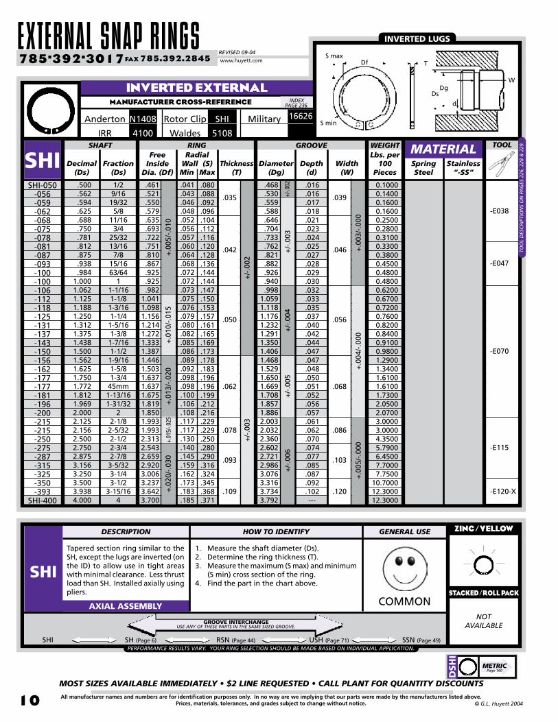
Tapered section ring similar to the SH, except the lugs are inverted (on the ID) to allow use in tight areas with minimal clearance. Less thrust load than SH. Installed axially using pliers.
1. Measure the shaft diameter (Ds).2. Determine the ring thickness (T).3. Measure the maximum (S max) and minimum
(S min) cross section of the ring.4. Find the part in the chart above.
ZINC/YELLOW
COMMONAXIAL ASSEMBLY
SHI SH (Page 6) RSN (Page 44) USH (Page 71) SSN (Page 49)
NOTAVAILABLE
INVERTED EXTERNALMANUFACTURER CROSS-REFERENCE
Military 16626SHIRotor ClipN1408Anderton
5108Waldes4100IRR
INVERTED LUGS
PERFORMANCE RESULTS VARY. YOUR RING SELECTION SHOULD BE MADE BASED ON INDIVIDUAL APPLICATION.
GROOVE INTERCHANGEUSE ANY OF THESE PARTS IN THE SAME SIZED GROOVE.
INDEX PAGE 236.
T
WDg
d
Df
Ds
S max
S min
DESCRIPTION HOW TO IDENTIFY GENERAL USE
SHISTACKED/roll pack
DSH
I
METRICPage 160
Free Inside
Dia. (Df)Decimal
(Ds)Fraction
(Ds)
Radial Wall (S) Thickness
(T)Diameter
(Dg)Depth
(d)SpringSteel
.500
.562
.594
.625
.688
.750
.781
.812
.875
.938
.9841.0001.0621.1251.1881.2501.3121.3751.4381.5001.5621.6251.7501.7721.8121.9692.0002.1252.1562.5002.7502.8753.1563.2503.5003.9384.000
1/29/1619/325/8
11/163/4
25/3213/167/8
15/1663/64
11-1/161-1/81-3/161-1/41-5/161-3/81-7/161-1/21-9/161-5/81-3/4
45mm1-13/161-31/32
22-1/82-5/322-1/22-3/42-7/83-5/323-1/43-1/2
3-15/164
.461
.521
.550
.579
.635
.693
.722
.751
.810
.867
.925
.925
.9821.0411.0981.1561.2141.2721.3331.3871.4461.5031.6371.6371.6751.8191.8501.9931.9932.3132.5432.6592.9203.0063.2373.6423.700
.468
.530
.559
.588
.646
.704
.733
.762
.821
.882
.926
.940
.9981.0591.1181.1761.2321.2911.3501.4061.4681.5291.6501.6691.7081.8571.8862.0032.0322.3602.6022.7212.9863.0763.3163.7343.792
SHAFT RING GROOVE TOOL
SHISHI-050
-056-059-062-068-075-078-081-087-093-100-100-106-112-118-125-131-137-143-150-156-162-177-177-181-196-200-215-215-250-275-287-315-325-350-393
SHI-400
Width(W)
+.0
03/-
.000
+.0
04/-
.000
+/-
.003
+/-
.004
+/-
.005
+/-
.002
+/-
.003
.035
.042
.050
.062
+.0
05/-
.010
+.0
10/-
.015
+.0
13/-
.020
+.01
5/-.0
25MaxMin
.041
.043
.046
.048
.052
.056
.057
.060
.064
.068
.072
.072
.073
.075
.076
.079
.080
.082
.085
.086
.089
.092
.098
.098
.100
.106
.108
.117
.117
.130
.140
.145
.159
.162
.173
.183
.185
.080
.088
.092
.096
.104
.112
.116
.120
.128
.136
.144
.144
.147
.150
.153
.157
.161
.165
.169
.173
.178
.183
.196
.196
.199
.212
.216
.229
.229
.250
.280
.290
.316
.324
.345
.368
.371
.016
.016
.017
.018
.021
.023
.024
.025
.027
.028
.029
.030
.032
.033
.035
.037
.040
.042
.044
.047
.047
.048
.050
.051
.052
.056
.057
.061
.062
.070
.074
.077
.085
.087
.092
.102---
+.0
20/-
.030
.078
.109
.093
.039
.046
.056
.068
.086
.120
.103
+/-
.006
+/-.0
02
+.0
05/-
.000
MATERIAL
-E038
-E047
-E070
-E115
Stainless “-SS”
-E120-X
Lbs. per 100
Pieces
WEIGHT
TOO
L D
ESC
RIP
TIO
NS
ON
PA
GES
226
, 228
& 2
29.
0.1000 0.1400 0.1600 0.1600 0.2500 0.2800 0.3100 0.3300 0.3800 0.4500 0.4800 0.4800 0.6200 0.6700 0.7200 0.7600 0.8200 0.8400 0.9100 0.9800 1.2900 1.3400 1.6100 1.6100 1.7300 2.0500 2.0700 3.0000 3.0000 4.3500 5.7900 6.4500 7.7000 7.750010.700012.300012.3000
BOX 232 • MINNEAPOLIS, KS • 67467
MOST SIZES AVAILABLE IMMEDIATELY • $2 LINE REQUESTED • CALL PLANT FOR QUANTITY DISCOUNTS
11All manufacturer names and numbers are for identification purposes only. In no way are we implying that our parts were made by the manufacturers listed above.Prices, materials, tolerances, and grades subject to change without notice.© G.L. Huyett 2004
BOWED EXTERNALMANUFACTURER CROSS-REFERENCE
Free Inside
Dia. (Df)Decimal
(Ds)Fraction
(Ds)
Radial Wall (S) Thickness
(T)Diameter
(Dg)Depth
(d)Spring Steel
.188
.219
.236
.250
.276
.281
.312
.344
.354
.375
.394
.406
.438
.469
.500
.551
.562
.594
.625
.669
.688
.750
.781
.812
.875
.938
.9841.0001.0231.0621.1251.1881.2501.3121.3751.5001.6251.750
3/167/3215/641/4
7mm9/325/1611/329mm3/8
10mm13/327/1615/321/2
14mm9/1619/325/8
17mm11/163/4
25/3213/167/8
15/1663/64
126mm1-1/161-1/81-3/161-1/41-5/161-3/81-1/21-5/81-3/4
.168
.196
.215
.225
.250
.256
.281
.309
.320
.338
.354
.366
.395
.428
.461
.509
.521
.550
.579
.621
.635
.693
.722
.751
.810
.867
.910
.925
.946
.9821.0411.0981.1561.2141.2721.3871.5031.618
.175
.205
.222
.230
.255
.261
.290
.321
.330
.352
.369
.382
.412
.443
.468
.519
.530
.559
.588
.629
.646
.704
.733
.762
.821
.882
.926
.940
.961
.9981.0591.1181.1761.2321.2911.4061.5291.650
SHAFT RING GROOVE TOOL
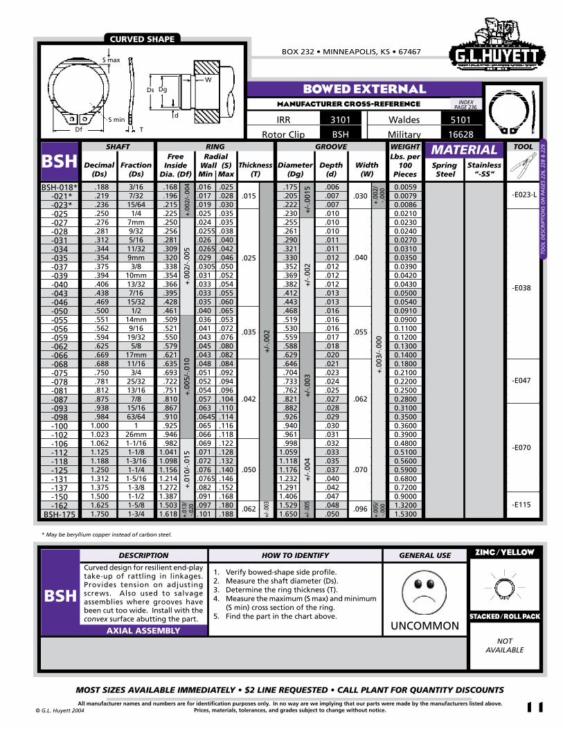
BSH
Curved design for resilient end-play take-up of rattling in linkages. Provides tension on adjusting screws. Also used to salvage assemblies where grooves have been cut too wide. Install with the convex surface abutting the part.
1. Verify bowed-shape side profile.2. Measure the shaft diameter (Ds).3. Determine the ring thickness (T).4. Measure the maximum (S max) and minimum
(S min) cross section of the ring.5. Find the part in the chart above.
ZINC/YELLOW
UNCOMMONAXIAL ASSEMBLY
BSH-018* -021* -023*
-025-027-028-031-034-035-037-039-040-043-046-050-055-056-059-062-066-068-075-078-081-087-093-098-100-102-106-112-118-125-131-137-150-162
BSH-175
Width(W)
+.0
02/
-.00
0+
.003
/-.0
00
.030
.040
.006
.007
.007
.010
.010
.010
.011
.011
.012
.012
.012
.012
.013
.013
.016
.016
.016
.017
.018
.020
.021
.023
.024
.025
.027
.028
.029
.030
.031
.032
.033
.035
.037
.040
.042
.047
.048
.050
+/-
.001
5+
/-.0
02+
/-.0
03+
/-.0
04
+/-
.002
+/-.0
03
+.0
02/-
.004
+.0
02/-
.005
+.0
05/-
.010
+.0
10/-
.015
MaxMin
.025
.028
.030
.035
.035
.038
.040
.042
.046
.050
.052
.054
.055
.060
.065
.053
.072
.076
.080
.082
.084
.092
.094
.096
.104
.110
.114
.116
.118
.122
.128
.132
.140
.146
.152
.168
.180
.188
.016
.017
.019
.025
.024
.0255
.026
.0265
.029
.0305
.031
.033
.033
.035
.040
.036
.041
.043
.045
.043
.048
.051
.052
.054
.057
.063
.0645
.065
.066
.069
.071
.072
.076
.0765
.082
.091
.097
.101
.055
.062
.070
.096
.015
.025
.035
.042
.050
.062
+.01
3/-.0
20
+/-.0
05
+.00
5/-.0
00
NOTAVAILABLE
CURVED SHAPE
Military 16628BSHRotor Clip
5101Waldes3101IRR
-E070
-E115
-E047
-E038
-E023-L
MATERIALStainless
“-SS”
Lbs. per 100
Pieces
WEIGHT
* May be beryllium copper instead of carbon steel.
0.00590.00790.00860.02100.02300.02400.02700.03100.03500.03900.04200.04300.05000.05400.09100.09000.11000.12000.13000.14000.18000.21000.22000.25000.28000.31000.35000.36000.39000.48000.51000.56000.59000.68000.72000.90001.32001.5300
INDEX PAGE 236.
Df T
S min
Ds Dg
d
W
S max
DESCRIPTION HOW TO IDENTIFY GENERAL USE
BSHSTACKED/roll pack
TOO
L D
ESC
RIP
TIO
NS
ON
PA
GES
226
, 228
& 2
29.

EXTERNAL SNAP RINGSREVISED 09-04
MOST SIZES AVAILABLE IMMEDIATELY • $2 LINE REQUESTED • CALL PLANT FOR QUANTITY DISCOUNTS
12
785•392•3017 FAX 785.392.2845
All manufacturer names and numbers are for identification purposes only. In no way are we implying that our parts were made by the manufacturers listed above.Prices, materials, tolerances, and grades subject to change without notice. © G.L. Huyett 2004
www.huyett.com
Free Inside Dia.
(Df)Decimal
(Ds)Fraction
(Ds)
Radial Wall(S) Diameter
(Dg)Depth
(d)SpringSteel
1.0001.0231.0621.1251.1881.2501.3121.3751.4381.5001.5621.6251.6881.7501.7721.8121.8751.9692.0002.0622.1252.1562.2502.3122.3752.4382.5002.5592.6252.6882.7502.8752.9383.000
126mm1-1/161-1/81-3/161-1/41-5/161-3/81-7/161-1/21-9/161-5/8
1-11/161-3/4
45mm1-13/161-7/8
1-31/322
2-1/162-1/82-5/322-1/42-5/162-3/82-7/162-1/2
65mm2-5/8
2-11/162-3/42-7/8
2-15/163
.925
.946
.9821.0411.0981.1561.2141.2721.3331.3871.4461.5031.5601.6181.6371.6751.7351.8191.8501.9061.9641.9932.0812.1392.1972.2552.3132.3772.4282.4852.5432.6592.7172.775
.930
.951
.9921.0511.1081.1661.2241.2821.3431.3971.4591.5161.5731.6311.6501.6881.7481.8321.8631.9211.9792.0082.0962.1542.2122.2702.3282.3972.4482.5052.5632.6792.7372.795
SHAFT RING TOOL
VSH
A 15° bevel on the inside diameter, when fitted to a 15° bevel on the load-bearing groove wall, yields rigid end-play take-up of manufacturing tolerances or wear on the retained part. Used in greasy and oily environments.
1. Verify the presence of a bevel along the outside diameter of the part.
2. Measure the shaft diameter (Ds).3. Determine the ring thickness (T).4. Measure the maximum (S max) and minimum
(S min) cross section of the ring.5. Find the part in the chart above.
ZINC/YELLOW
COMMONAXIAL ASSEMBLY
VSH-100-102-106-112-118-125-131-137-143-150-156-162-168-175-177-181-187-196-200-206-212-215-225-231-237-243-250-255-262-268-275-287-293
VSH-300
Width(W)
+.0
02/-
.000
+.0
025/
-.00
0
.035
.036
.035
.037
.040
.042
.044
.046
.047
.051
.051
.054
.057
.059
.061
.062
.063
.068
.068
.070
.073
.074
.077
.079
.081
.084
.086
.081
.088
.091
.093
.098
.100
.102
+.00
0/-.0
03+
.000
/-.0
04+
.000
/-.0
05
+/-
.002
+/-
.003
.042
.050
.062
+.00
5/-.0
10+
.010
/-.0
15+
.013
/-.0
20+
.015
/-.0
25MaxMin
GROOVE
.065
.066
.069
.071
.072
.076.0765.082.086.091.093.097.099.101.102.102.104.106.108.111.113.113.116.118.119.120.122.125.127.129.131.133.136.138
.116
.118
.122
.128
.132
.140
.146
.152
.160
.168
.172
.180
.184
.188
.190
.192
.196
.200
.204
.208
.212
.212
.220
.222
.224
.228
.232
.238
.242
.246
.248
.256
.260
.264
.078
+.0
00/-
.006
Wall Thick-ness(T)
.093
.037
.036
.044
.044
.044
.043
.042
.042
.042
.041
.053
.053
.052
.052
.052
.052
.052
.051
.051
.067
.067
.067
.066
.065
.065
.065
.064
.064
.064
.064
.079
.078
.078
.077
+.0
20/-
.030
NOTAVAILABLE
VSH CONTINUED NEXT PAGE.
VSHRotor Clip5102Waldes1402Anderton
MATERIAL
-E070
-E115
BEVELED EXTERNAL
WEDGES INTO GROOVE
MANUFACTURER CROSS-REFERENCE
Lbs. per100
Pieces
WEIGHT
0.36000.39000.48000.51000.56000.59000.68000.72000.81000.90001.24001.32001.48001.53001.54001.62001.73001.80001.90002.50002.61002.63002.77002.80002.92002.95002.97003.39003.50003.60004.70004.85005.00005.2000
INDEX PAGE 236.
d
Ds
DgW
T
Df Smax
S min
DESCRIPTION HOW TO IDENTIFY GENERAL USE
VSHSTACKED/ROLL PACK
16630Military
TOO
L D
ESC
RIP
TIO
NS
ON
PA
GES
226
, 228
& 2
29.

BOX 232 • MINNEAPOLIS, KS • 67467
MOST SIZES AVAILABLE IMMEDIATELY • $2 LINE REQUESTED • CALL PLANT FOR QUANTITY DISCOUNTS
13All manufacturer names and numbers are for identification purposes only. In no way are we implying that our parts were made by the manufacturers listed above.Prices, materials, tolerances, and grades subject to change without notice.© G.L. Huyett 2004
BEVELED EXTERNALMANUFACTURER CROSS-REFERENCE
1. Verify the presence of a bevel along the outside diameter of the part.
2. Measure the shaft diameter (Ds).3. Determine the ring thickness (T).4. Measure the maximum (S max) and minimum
(S min) cross section of the ring.5. Find the part in the chart above.
ZINC/YELLOW
COMMONAXIAL ASSEMBLY
A 15° bevel on the inside diameter, when fitted to a 15° bevel on the load-bearing groove wall, yields rigid end-play take-up of manufacturing tolerances or wear on the retained part. Used in greasy and oily environments.
Free Inside Dia.
(Df)Decimal
(Ds)Fraction
(Ds)
Radial Wall(S) Diameter
(Dg)Depth
(d)SpringSteel
3.0623.1253.1563.2503.3463.4383.5003.5433.6253.6883.7503.8753.9384.0004.2504.3754.5004.7505.0005.2505.5005.7506.0006.2506.5006.7507.0007.5008.0008.5009.0009.500
10.000
3-1/163-1/83-5/323-1/4
3-11/323-7/163-1/2
90mm3-5/8
3-11/163-3/43-7/8
3-15/164
4-1/44-3/84-1/24-3/4
55-1/45-1/25-3/4
66-1/46-1/26-3/4
77-1/2
88-1/2
99-1/2
10
2.8322.8922.9203.0063.0923.1793.2373.2773.3523.4103.4683.5843.6423.7003.9894.1064.2234.4584.6924.9275.1625.3965.6315.8666.1006.3356.5707.0397.5087.9778.4458.9159.385
2.8522.9122.9403.0263.1123.1993.2573.2973.3723.4303.4883.6043.6623.7204.0094.1264.2434.4784.7124.9475.1825.4165.6515.8866.1206.3556.5907.0597.5287.9978.4658.9359.405
SHAFT RING TOOL
VSHVSH-306
-312-315-325-334-343-350-354-362-368-375-387-393-400-425-437-450-475-500-525-550-575-600-625-650-675-700-750-800-850-900-950
VSH-1000
Width(W)
+.0
00/-
.006
+.0
00/-
.007
+/-
.003
+/-
.004
.109
.156
.125
+.0
20/-
.030
+.0
20/-
.040
+.0
20/-
.050
MaxMin
GROOVE
.131
.141
.143
.145
.147
.148
.148
.149
.153
.156
.160
.163
.163
.163
.176
.181
.185
.136
.194
.211
.209
.220
.171
.176
.236
.246
.256
.277
.294
.314
.333
.350
.367
.252
.272
.274
.280
.300
.292
.285
.288
.296
.302
.310
.318
.318
.318
.318
.318
.405
.303
.360
.372
.390
.408
.381
.396
.438
.456
.474
.507
.540
.573
.609
.642
.675
Wall Thick-ness(T)
.105
.106
.108
.112
.117
.119
.121
.123
.126
.129
.131
.135
.138
.140
.120
.124
.128
.136
.144
.151
.159
.167
.174
.182
.190
.197
.205
.220
.236
.251
.267
.282
.297
.077
.076
.076
.076
.075
.075
.091
.091
.090
.090
.089
.089
.088
.088
.094
.094
.094
.092
.091
.105
.104
.103
.102
.132
.131
.130
.129
.158
.157
.154
.153
.150
.148
+.0
03/-
.000
+.0
00/-
.008
.187
+.0
20/-
.060
+/-
.005
+.0
025/
-.00
0
.093
MATERIAL
VSHRotor Clip5102Waldes1402Anderton
-E115
WEDGES INTO GROOVE
-E170
-E120-X
Lbs. per 100
Pieces
WEIGHT
-E045
4.7000 5.8000 5.9000 6.2000 6.4000 6.6000 7.2000 7.3000 7.6000 8.0000 8.3000 8.8000 9.500010.100011.200011.500013.200011.300014.900019.000020.100019.900021.000028.200033.000035.600038.800053.400062.800070.000075.700082.000096.4000
INDEX PAGE 236.
d
Ds
DgW
T
Df S
S min
DESCRIPTION HOW TO IDENTIFY GENERAL USE
VSHTO
OL
DES
CR
IPTI
ON
S O
N P
AG
ES 2
26, 2
28 &
229
.
16630Military

EXTERNAL SNAP RINGSREVISED 09-04
MOST SIZES AVAILABLE IMMEDIATELY • $2 LINE REQUESTED • CALL PLANT FOR QUANTITY DISCOUNTS
14
785•392•3017 FAX 785.392.2845
All manufacturer names and numbers are for identification purposes only. In no way are we implying that our parts were made by the manufacturers listed above.Prices, materials, tolerances, and grades subject to change without notice. © G.L. Huyett 2004
www.huyett.com
GROOVELESSMANUFACTURER CROSS-REFERENCE
Free Inside
Dia. (Df)From(Ds)
To(Ds)
Thickness(T)
Diameter(Dg)
Depth(d)
SpringSteel
.058
.078
.092
.116
.123
.154
.185
.195
.234
.248
.274
.310
.373
.434
.497
.587
.622
.745
.060
.080
.096
.120
.127
.158
.189
.199
.238
.252
.278
.316
.379
.440
.503
.593
.628
.755
.055
.074
.089
.112
.120
.150
.181
.187
.224
.238
.264
.298
.354
.412
.470
.570
.593
.706
.228
.240-
.303
.361
.419
.478-
.599
.718
SHAFT RING TOOL
SHF
Reusable tapered section ring for grooveless shafts like plastics, tubes, and castings, or where adjustable ring placement is desired (like progressively tightening a compression spring). Installed using pliers. See page 91.
1. Measure the shaft diameter (Ds).2. Determine the ring thickness (T).3. Find the part in the chart above.
ZINC/YELLOW
COMMONAXIAL ASSEMBLY
SHF-006-007-009-011-012-015-018-019-023-025-027-031-037-043-050-059-062
SHF-075
Width(W)
+.0
03/-
.000.004
.005-
.005
.007
.009
.011-
.013
.016
+.00
05/-.
0015
+.0
01/-
.002
+/-
.002
+.0
02/-
.003
+.00
2/-.0
04
GROOVE
.21
.24
.26
.29
.33
.36
.44
.43
.48
.49
.55
.68
.74
.81
.901.031.061.32
Assembled Diameter
.041
.041-
.048
.048
.056
.056-
.069
.069
.015
.025
.025
.024
.025
.025
.035
.032
.035
.035
.039
.042
.042
.050
.050
.059
.062
.062
+.002/-.004
+.00
3/-.0
05
+/-.005
+/-.0
03
+.004/-.006
+.00
4/-.0
06
+/-.0
04+
/-.0
03
+.002/-.003
+.0
04/-
.000
NOTAVAILABLE
MATERIAL
Military SHFRotor ClipN1440Anderton5555Waldes7100IRR
-E040
-E047-X
-E034
ADJUSTABLE AND REMOVABLE
Stainless “-SS”
WEIGHTLbs.
per 100 Pieces
SHF RG (Page 27) TX (Page 92) TY (Page 92) T99 (Page 101)PERFORMANCE RESULTS VARY. YOUR RING SELECTION SHOULD BE MADE BASED ON INDIVIDUAL APPLICATION.
GROOVELESS - OPEN LUGMANUFACTURER CROSS-REFERENCE
SHFRotor ClipM1440Anderton5555Waldes7100IRR
AVAILABLE AS A SPECIAL ORDER
0.00300.00800.0100
-0.02400.03000.05500.04500.07600.0740
- 0.13900.17200.26100.2910
-0.57000.6880
-E070-X
Not recommended for use with grooves.
SEE PAGE 165.
GROOVELESSUSE ANY OF THESE PARTS ON THE SAME SIZED SHAFT.
INDEX PAGE 236.
INDEX PAGE 236.
Dg
d
T
W
Df
Ds
DESCRIPTION HOW TO IDENTIFY GENERAL USE
SHFSTACKED/roll pack
DSH
X
METRICPage 165
DSH
F
METRICPage 164
TOO
L D
ESC
RIP
TIO
NS
ON
PA
GE
226.
+/-.004

BOX 232 • MINNEAPOLIS, KS • 67467
MOST SIZES AVAILABLE IMMEDIATELY • $2 LINE REQUESTED • CALL PLANT FOR QUANTITY DISCOUNTS
15All manufacturer names and numbers are for identification purposes only. In no way are we implying that our parts were made by the manufacturers listed above.Prices, materials, tolerances, and grades subject to change without notice.© G.L. Huyett 2004
TAMPER-PROOFMANUFACTURER CROSS-REFERENCE
Free Inside
Dia. (Df)Decimal
(Ds)Fraction
(Ds)
Radial Wall (S) Thickness
(T)Diameter
(Dg)Depth
(d)SpringSteel
.101
.125
.134
.156
.188
.203
.219
.250
.266
.312
.328
.375
-1/8-
5/323/1613/647/321/4
17/645/1621/643/8
.090
.112
.120
.140
.168
.180
.200
.224
.240
.284
.300
.340
.093
.115
.124
.144
.174
.189
.205
.232
.248
.292
.308
.351
SHAFT RING TOOL
SHM
Miniature tapered section ring without lugs that provides a tamper-proof shoulder. Also known as the “wedding ring,” SHM’s must be destroyed for removal. Thick cross section.
1. Measure the shaft diameter (Ds).2. Determine the ring thickness (T).3. Measure the maximum (S max) and minimum
(S min) cross section of the ring.4. Find the part in the chart above.
ZINC/YELLOW
UNCOMMONAXIAL ASSEMBLY
SHM-010-012-013-015-018-020-022-025-026-031-032
SHM-037
Width(W)
+.0
02/-
.000
+/-
.001
+/-
.001
5+/-
.002
.020
.025
+/-
.002
+/-
.003
MaxMin
GROOVE
.017
.018
.019
.027
.032
.030
.036
.037
.037
.050
.050
.058
.027
.028
.029
.045
.052
.046
.058
.063
.065
.078
.080
.090
.035
.042
.024
.029
.039
.046
+.0
03/-
.000
+/-.002
+/-
.001
+/-
.001
5
NOTAVAILABLE
MATERIAL
SHMRotor Clip
5560Waldes
SEE BE-LOW
Stainless “-SS”
Lbs. per 100 Pieces
WEIGHT
SHM INSTALLATION
Start with a hollowed taper pin and sleeve . . .. . . or design a taper
into the assembly.
Place taper pin over end with assembly mounted in work piece . . .
. . . install part using sleeve.
Finished!
0.00360.00500.00590.01220.01790.01670.03340.03860.04160.06260.06880.1035
REMOVE USING EXPLOSIVES
LET OUR SHOP MANUFACTURE A BUSHING AND TAPERED PIN FOR YOU!
PinDia.(A)
InsideDia.(ID)
OutsideDia.(OD)
TipDia.
Ref. (B)
SLEEVE TAPERED PIN
SHM Length(C)
.104
.128
.137
.159
.191
.206
.223
.254
.270
.316
.332
.379
.102
.126
.135
.157
.189
.204
.221
.252
.268
.314
.330
.377
.036
.059
.069
.078
.110
.125
.129
.101
.176
.223
.238
.286
-010-012-013-015-018-020-022-025-026-031-032-037
+/-
.005
3/8
1/2
+.0
00/-
.001
5
5/8
+.0
02/-
.000
.750
.875
1.000
ID OD
B
A
C
WE CAN MAKE THESE TOOLS FOR YOU!
INDEX PAGE 236.
T
d
DsDg W
S min
S max Df
.004
.005
.006
.007
.009
.010
.012
DESCRIPTION HOW TO IDENTIFY GENERAL USE
SHMSTACKED/roll pack
INTERNAL SNAP RINGSREVISED 09-04
MOST SIZES AVAILABLE IMMEDIATELY • $2 LINE REQUESTED • CALL PLANT FOR QUANTITY DISCOUNTS
1�
785•392•3017 FAX 785.392.2845
All manufacturer names and numbers are for identification purposes only. In no way are we implying that our parts were made by the manufacturers listed above.Prices, materials, tolerances, and grades subject to change without notice. © G.L. Huyett 2004
www.huyett.com
Free Outside
Dia. (Dr)Decimal
(Db)Fraction
(Db)
Radial Wall (S) Thickness
(T)Diameter
(Dg)Depth
(d)SpringSteel
.250
.312
.375
.438
.453
.500
.512
.562
.625
.688
.750
.777
.812
.866
.875
.901
.9381.0001.0231.0621.1251.1811.1881.2501.2591.3121.3751.3781.4381.4561.5001.5621.5751.6251.6531.688
1/45/163/87/1629/641/2
13mm9/165/8
11/163/4
19.7mm13/1622mm
7/822.9mm
15/161
26mm1-1/161-1/8
30mm1-3/161-1/4
32mm1-5/161-3/8
35mm1-7/1637mm1-1/21-9/1640mm1-5/8
42mm1-11/16
.280
.346
.415
.482
.498
.548
.560
.620
.694
.763
.831
.859
.901
.961
.9711.0001.0411.1111.1361.1801.2491.3191.3191.3881.3881.4561.5261.5261.5961.6161.6601.7341.7341.8041.8351.874
.268
.330
.397
.461
.477
.530
.542
.596
.665
.732
.796
.825
.862
.920
.931
.9591.0001.0661.0911.1301.1971.2551.2621.3301.3391.3961.4611.4641.5281.5481.5941.6581.6711.7251.7551.792
BORE RING GROOVE
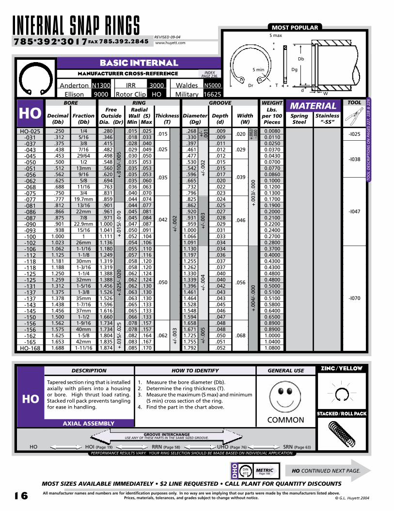
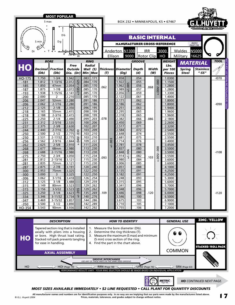
HO
Tapered section ring that is installed axially with pliers into a housing or bore. High thrust load rating. Stacked roll pack prevents tangling for ease in handling.
1. Measure the bore diameter (Db).2. Determine the ring thickness (T).3. Measure the maximum (S max) and minimum
(S min) cross section of the ring.4. Find the part in the chart above.
ZINC/YELLOW
COMMONAXIAL ASSEMBLY
HO-025-031-037-043-045-050-051-056-062-068-075-077-081-086-087-090-093-100-102-106-112-118-118-125-125-131-137-137-143-145-150-156-156-162-165
HO-168
Width(W)
+.00
2/-.0
00+
.003
/-.0
00
+/-
.003
+/-
.004
+/-
.005
+/-
.001
+/-
.002
+.0
10/-
.005
+.0
15/-
.010
+.0
25/-
.020
+.0
35/-
.025
MaxMin
.009
.009
.011
.012
.012
.015
.015
.017
.020
.022
.023
.024
.025
.027
.028
.029
.031
.033
.034
.034
.036
.037
.037
.040
.040
.042
.043
.043
.045
.046
.047
.048
.048
.050
.051
.052
.025
.033
.040
.049
.050
.053
.053
.053
.060
.063
.070
.074
.077
.081
.084
.087
.091
.104
.106
.110
.116
.120
.120
.124
.124
.130
.130
.130
.133
.133
.133
.157
.157
.164
.167
.170
.015
.018
.028
.029
.030
.035
.035
.035
.035
.036
.040
.044
.044
.045
.045
.047
.050
.052
.054
.055
.057
.058
.058
.062
.062
.062
.063
.063
.065
.065
.066
.078
.078
.082
.083
.085
.020
.029
.039
.046
.056
.068
.015
.025
.035
.042
.050
.062
+/-
.002
+/-
.003
+.0
04/-
.000
HO HOI (Page 19) RRN (Page 58) UHO (Page 76) SRN (Page 63)
HO CONTINUED NEXT PAGE.
BASIC INTERNALMANUFACTURER CROSS-REFERENCE
MATERIAL
Waldes N50003000IRRN1300AndertonMilitary 16625HORotor Clip9000Ellison
-I025
-I038
-I047
-I070
MOST POPULAR
Stainless “-SS”
TOO
L D
ESC
RIP
TIO
NS
ON
PA
GES
227
, 228
& 2
29.
Lbs. per 100 Pieces
WEIGHT
PERFORMANCE RESULTS VARY. YOUR RING SELECTION SHOULD BE MADE BASED ON INDIVIDUAL APPLICATION.
0.00800.01100.02500.03700.04300.07000.07700.08600.10000.12000.13000.17000.19000.20000.21000.22000.24000.27000.28000.37000.40000.43000.43000.48000.48000.50000.51000.51000.58000.64000.65000.89000.89001.00001.04001.0800
GROOVE INTERCHANGEUSE ANY OF THESE PARTS IN THE SAME SIZED GROOVE.
INDEX PAGE 236.
T
S min Dg
Db
dW
Dr
S max
TOOL
DESCRIPTION HOW TO IDENTIFY GENERAL USE
HOSTACKED/ROLL PACK
DH
O
METRICPage 166
DIN472
BOX 232 • MINNEAPOLIS, KS • 67467
MOST SIZES AVAILABLE IMMEDIATELY • $2 LINE REQUESTED • CALL PLANT FOR QUANTITY DISCOUNTS
17All manufacturer names and numbers are for identification purposes only. In no way are we implying that our parts were made by the manufacturers listed above.Prices, materials, tolerances, and grades subject to change without notice.© G.L. Huyett 2004
BASIC INTERNALMANUFACTURER CROSS-REFERENCE
Free Outside
Dia. (Dr)Decimal
(Db)Fraction
(Db)
Radial Wall (S) Thickness
(T)Diameter
(Dg)Depth
(d)SpringSteel
1.7501.8121.8501.8751.9382.0002.0472.0622.1252.1652.1882.2502.3122.3752.4402.5002.5312.5622.6252.6772.6882.7502.8122.8352.8752.9533.0003.0623.1253.1493.1563.2503.3463.4693.5003.543
1-3/41-13/1647mm1-7/8
1-15/162
52mm2-1/162-1/8
55mm2-3/162-1/42-5/162-3/82-7/162-1/2
2-17/322-9/162-5/8
68mm2-11/162-3/4
2-13/1672mm2-7/8
75mm3
3-1/163-1/8
80mm3-5/323-1/4
3-11/323-15/323-1/2
90mm
1.9422.0122.0542.0722.1412.2102.2802.2802.3502.4152.4152.4902.5352.6302.7022.7752.7752.8442.9102.9802.9803.0503.1213.1213.1913.3253.3253.4183.4883.5233.5233.6233.7343.8573.8903.936
1.8581.9221.9621.9892.0562.1222.1712.1862.2512.2952.3182.3822.4502.5172.5842.6482.6812.7142.7812.8372.8482.9142.9803.0063.0513.1353.1823.2483.3153.3413.3483.4463.5463.6753.7103.755
BORE RING GROOVE
HO
Tapered section ring that is installed axially with pliers into a housing or bore. High thrust load rating. Stacked roll pack prevents tangling for ease in handling.
1. Measure the bore diameter (Db).2. Determine the ring thickness (T).3. Measure the maximum (S max) and minimum
(S min) cross section of the ring.4. Find the part in the chart above.
ZINC/YELLOW
COMMONAXIAL ASSEMBLY
HO-175-181-185-187-193-200-206-206-212-218-218-225-231-237-244-250-250-256-262-268-268-275-281-281-287-300-300-306-312-315-315-325-334-347-350
HO-354
Width(W)
+.0
05/-
.000
+/-
.003
+.0
35/-
.025
+.0
40/-
.030
+/-
.055
MaxMin
-I070.171.170.170.170.170.170.186.186.195.199.199.203.206.207.209.210.210.222.226.230.230.234.230.230.240.250.250.254.259.262.262.269.276.286.289.292
.083
.084
.085
.085
.085
.085
.091
.091
.096
.098
.098
.099
.100
.102
.103
.103
.103
.109
.111
.113
.113
.115
.115
.115
.120
.122
.122
.126
.129
.129
.129
.135
.140
.144
.142
.142
.054
.055
.056
.057
.059
.061
.062
.062
.063
.065
.065
.066
.069
.071
.072
.074
.075
.076
.078
.080
.080
.082
.084
.085
.088
.091
.091
.093
.095
.096
.096
.098
.100
.103
.105
.106
.062
.078
.093
.109
.068
.086
.103
.120
+/-.
005
+.00
4/-.
000
+/-
.006
HO HOI (Page 19) RRN (Page 58) UHO (Page 76) SRN (Page 63)
MATERIAL
Waldes N50003000IRRN1300AndertonMilitary 16625HORotor Clip9000Ellison
-I090
MOST POPULAR
Stainless “-SS”
-I120
TOO
L D
ESC
RIP
TIO
NS
ON
PA
GES
227
, 228
& 2
29.
Lbs. per 100 Pieces
WEIGHT
PERFORMANCE RESULTS VARY. YOUR RING SELECTION SHOULD BE MADE BASED ON INDIVIDUAL APPLICATION.
1.03001.15001.28001.28001.33001.40001.80001.80001.94001.96001.96002.18002.26002.32002.54002.55002.55003.40003.45003.50003.50003.55003.60003.60004.10004.25004.25005.30005.60005.70005.70006.00006.50006.90007.10007.2000
-I108
GROOVE INTERCHANGEUSE ANY OF THESE PARTS IN THE SAME SIZED GROOVE.
INDEX PAGE 236.
T
S min Dg
Db
dW
Dr
S max
TOOL
DESCRIPTION HOW TO IDENTIFY GENERAL USE
HOSTACKED/ROLL PACK
HO CONTINUED NEXT PAGE.
DH
O
METRICPage 166
DIN472

INTERNAL SNAP RINGSREVISED 09-04
MOST SIZES AVAILABLE IMMEDIATELY • $2 LINE REQUESTED • CALL PLANT FOR QUANTITY DISCOUNTS
18
785•392•3017 FAX 785.392.2845
All manufacturer names and numbers are for identification purposes only. In no way are we implying that our parts were made by the manufacturers listed above.Prices, materials, tolerances, and grades subject to change without notice. © G.L. Huyett 2004
www.huyett.com
BASIC INTERNALMANUFACTURER CROSS-REFERENCE
Tapered section ring that is installed axially with pliers into a housing or bore. High thrust load rating. Stacked roll pack prevents tangling for ease in handling.
1. Measure the bore diameter (Db).2. Determine the ring thickness (T).3. Measure the maximum (S max) and minimum
(S min) cross section of the ring.4. Find the part in the chart above.
ZINC/YELLOW
COMMONAXIAL ASSEMBLY
HO HOI (Page 19) RRN (Page 58) UHO (Page 76) SRN (Page 63)
Free Outside
Dia. (Dr)Decimal
(Db)Fraction
(Db)
Radial Wall (S) Thickness
(T)Diameter
(Dg)Depth
(d)SpringSteel
3.5623.6253.7403.7503.8753.9384.0004.1254.2504.3314.5004.6254.7244.7505.0005.2505.3755.5005.7506.0006.2506.5006.6256.7507.0007.2507.5007.7508.0008.2508.5008.7509.0009.2509.5009.750
10.000
3-9/163-5/8
95mm3-3/43-7/8
3-15/164
4-1/84-1/4
110mm4-1/24-5/8
120mm4-3/4
55-1/45-3/85-1/25-3/4
66-1/46-1/26-5/86-3/4
77-1/47-1/27-3/4
88-1/48-1/28-3/4
99-1/49-1/29-3/4
10
3.9364.0244.1574.1574.2914.3584.4244.5584.6914.7564.9405.0765.2135.2135.4855.7705.9106.0666.3366.6206.8957.1707.3087.4457.7207.9958.2708.5458.8209.0959.2859.5589.830
10.10210.37510.64810.920
3.7763.8413.9643.9744.1074.1744.2404.3654.4904.5714.7404.8654.9694.9955.2605.5205.6505.7706.0206.2706.5306.7906.9257.0557.3157.5757.8408.1008.3608.6208.8809.1459.4059.6689.930
10.19010.450
BORE RING GROOVE
HOHO-354
-362-375-375-387-393-400-412-425-433-450-462-475-475-500-525-537-550-575-600-625-650-662-675-700-725-750-775-800-825-850-875-900-925-950-975
HO-1000
Width(W)
+/-
.006
+/-
.007
+/-
.003
+/-
.065
+/-
.080
MaxMin
.142
.150
.155
.155
.160
.161
.166
.171
.180
.180
.181
.183
.183
.183
.186
.198
.198
.198
.198
.198
.211
.219
.221
.224
.232
.238
.247
.255
.262
.270
.277
.286
.294
.299
.304
.309
.315
.292
.299
.309
.309
.319
.324
.330
.330
.335
.343
.351
.360
.370
.370
.390
.408
.408
.408
.408
.435
.423
.438
.447
.456
.474
.489
.507
.523
.540
.558
.573
.591
.609
.625
.642
.658
.675
.107
.108
.112
.112
.116
.118
.120
.120
.120
.120
.120
.120
.122
.122
.130
.135
.135
.135
.135
.135
.140
.145
.150
.152
.157
.162
.170
.175
.180
.185
.190
.197
.202
.109
.215
.220
.225
.109
.125
.156
.120
.139
.174
+/-
.004
+.0
05/-
.000
+.0
06/-
.000
+/-
.008
.187 .209
+.0
08/-
.000
+/-
.055
+/-
.090
+/-
.005
MATERIAL
Waldes N50003000IRRN1300AndertonMilitary 16625HORotor Clip9000Ellison
MOST POPULAR
Stainless “-SS”
-I120
-I120-X
-I150
Lbs. per 100 Pieces
WEIGHT
PERFORMANCE RESULTS VARY. YOUR RING SELECTION SHOULD BE MADE BASED ON INDIVIDUAL APPLICATION.
7.2000 7.3000 7.8000 7.8000 8.7000 8.8000 9.3000 9.700010.100010.500011.100011.700012.400012.400013.600017.400017.900018.300019.200020.210026.600028.100030.500032.500034.400042.800048.500052.000055.500060.300063.400065.300073.200076.700080.300083.300086.3000
DH
O METRICPage 166
DIN472
GROOVE INTERCHANGEUSE ANY OF THESE PARTS IN THE SAME SIZED GROOVE.
INDEX PAGE 236.
T
S min Dg
Db
dW
Dr
S max
TOOL
DESCRIPTION HOW TO IDENTIFY GENERAL USE
HOSTACKED/ROLL PACK
TOO
L D
ESC
RIP
TIO
NS
ON
PA
GES
227
, 228
& 2
29.

BOX 232 • MINNEAPOLIS, KS • 67467
MOST SIZES AVAILABLE IMMEDIATELY • $2 LINE REQUESTED • CALL PLANT FOR QUANTITY DISCOUNTS
19All manufacturer names and numbers are for identification purposes only. In no way are we implying that our parts were made by the manufacturers listed above.Prices, materials, tolerances, and grades subject to change without notice.© G.L. Huyett 2004
INVERTED INTERNALMANUFACTURER CROSS-REFERENCE
Free Outside
Dia. (Dr)Decimal
(Db)Fraction
(Db)
Radial Wall (S) Thickness
(T)Diameter
(Dg)Depth
(d)SpringSteel
.625
.750
.812
.875
.9381.0001.0621.1251.1881.2501.3121.3751.4381.5001.5621.6251.6881.7501.8752.0002.0622.1252.3752.4382.5002.6252.7502.8122.8352.8753.0003.1563.2503.3463.5003.5624.000
5/83/4
13/167/8
15/161
1-1/161-1/81-3/161-1/41-5/161-3/81-7/161-1/21-9/161-5/8
1-11/161-3/41-7/8
22-1/162-1/82-3/82-7/162-1/22-5/82-3/4
2-13/1672mm2-7/8
33-5/323-1/4
3-11/323-1/23-9/16
4
.675
.808
.877
.9441.0151.0811.1501.2171.2831.3511.4181.4861.5521.6221.6881.7561.8231.8912.0252.1602.2242.2952.5672.6342.7002.8402.9753.0633.0633.1053.2453.4083.5093.6113.7803.8504.350
.665
.796
.862
.9311.0001.0661.1301.1971.2621.3301.3961.4611.5281.5941.6581.7251.7921.8581.9892.1222.1862.2512.5172.5842.6482.7812.9142.9803.0063.0513.1823.3483.4463.5463.7103.7764.240
BORE RING GROOVE
HOI
Inverted lugs seat into the groove for better clearance and a cleaner appearance. Good for shielded bearings that pass tightly through the bore or housing. Installed axially using pliers.
1. Measure the bore diameter (Db).2. Determine the ring thickness (T).3. Measure the maximum (S max) and minimum
(S min) cross section of the ring.4. Find the part in the chart above.
ZINC/YELLOW
COMMONAXIAL ASSEMBLY
HOI-062-075-081-087-093-100-106-112-118-125-131-137-143-150-156-162-168-175-187-200-206-212-237-243-250-262-275-283-283-287-300-315-325-334-350-356
HOI-400
Width(W)
+.0
03/-
.000
+.0
04/-
.000
+/-
.003
+/-
.004
+/-
.005
+/-
.006
+/-.0
02
+/-
.002
+/-
.003
+.0
10/-
.005
+.0
15/-
.010
+.0
20/-
.013
+.0
25/-
.015
MaxMin
.036
.042
.044
.047
.051
.054
.057
.059
.060
.061
.063
.065
.069
.070
.074
.077
.079
.082
.090
.100
.106
.108
.115
.117
.120
.128
.134
.139
.139
.139
.143
.149
.151
.155
.154
.155
.161
.072
.085
.092
.099
.106
.113
.120
.123
.126
.129
.132
.135
.144
.148
.158
.162
.166
.170
.188
.208
.218
.223
.243
.248
.254
.266
.278
.286
.286
.290
.302
.314
.318
.321
.324
.326
.338
.020
.023
.025
.028
.031
.033
.034
.036
.037
.040
.042
.043
.045
.047
.048
.050
.052
.054
.057
.061
.062
.063
.071
.072
.074
.078
.082
.084
.086
.088
.091
.096
.098
.100
.105
.107
.120
.025
.035
.042
.050
.062
.078
.093
.109
.029
.039
.046
.056
.068
.086
.103
.120
+.0
30/-
.020
+.0
05/-
.000
HOI HO (Page 19) RRN (Page 58) UHO (Page 76) SRN (Page 63)
MATERIALWaldes 50084000IRR
N1308Anderton Military 16627HOIRotor Clip
-I047
-I070
-I025
-I090
-I038
INVERTED LUGS
Stainless “-SS”
-I120
PERFORMANCE RESULTS VARY. YOUR RING SELECTION SHOULD BE MADE BASED ON INDIVIDUAL APPLICATION.
Lbs. per 100 Pieces
WEIGHT
0.07000.13000.20000.22000.28000.29000.38000.44000.49000.50000.53000.59000.63000.68000.89001.04001.19001.18001.48001.74002.32002.43002.86003.06003.21004.56004.78004.95004.95005.01005.26006.94007.26007.56008.02008.24009.7400
DH
OI
METRICPage 172
-I108
GROOVE INTERCHANGEUSE ANY OF THESE PARTS IN THE SAME SIZED GROOVE.
INDEX PAGE 236.
Dg
Db
dW
T
S max
S min
Dr
TOOL
DESCRIPTION HOW TO IDENTIFY GENERAL USE
HOISTACKED/ROLL PACK
TOO
L D
ESC
RIP
TIO
NS
ON
PA
GES
227
, 228
& 2
29.

INTERNAL SNAP RINGSREVISED 09-04
MOST SIZES AVAILABLE IMMEDIATELY • $2 LINE REQUESTED • CALL PLANT FOR QUANTITY DISCOUNTS
20
785•392•3017 FAX 785.392.2845
All manufacturer names and numbers are for identification purposes only. In no way are we implying that our parts were made by the manufacturers listed above.Prices, materials, tolerances, and grades subject to change without notice. © G.L. Huyett 2004
www.huyett.com
BOWED INTERNALMANUFACTURER CROSS-REFERENCE
Free Outside
Dia. (Dr)Decimal
(Db)Fraction
(Db)
Radial Wall (S) Thickness
(T)Diameter
(Dg)Depth
(d)SpringSteel
.250
.312
.375
.438
.453
.500
.512
.562
.625
.688
.750
.777
.812
.866
.875
.901
.9381.0001.0231.0621.1251.1811.1881.2501.2591.3121.3751.3781.4381.4561.5001.5621.5751.6251.750
1/45/163/87/1629/641/2
13mm9/165/8
11/163/4
19.7mm13/1622mm
7/822.9mm
15/161
26mm1-1/161-1/8
30mm1-3/161-1/4
32mm1-5/161-3/8
35mm1-7/1637mm1-1/21-9/1640mm1-5/81-3/4
.280
.346
.415
.482
.498
.548
.560
.620
.694
.763
.831
.859
.901
.961
.9711.0001.0411.1111.1361.1801.2491.3191.3191.3881.3881.4561.5261.5261.5961.6161.6601.7341.7341.8041.942
.268
.330
.397
.461
.477
.530
.542
.596
.665
.732
.796
.825
.862
.920
.931
.9591.0001.0661.0911.1301.1971.2551.2621.3301.3391.3961.4611.4641.5281.5481.5941.6581.6711.7251.858
BORE RING TOOL
BHO
Curved design for resilient end-play take-up of rattling in linkages. Provides tension on adjusting screws. Also used to salvage assemblies where grooves have been cut too wide. Install with the convex surface abutting the part.
1. Verify bowed-shape side profile.2. Measure the bore diameter (Db).3. Determine the ring thickness (T).4. Measure the maximum (S max) and minimum
(S min) cross section of the ring.5. Find the part in the chart above.
ZINC/YELLOW
UNCOMMONAXIAL ASSEMBLY
BHO-025-031-037-043-045-050-051-056-062-068-075-077-081-086-087-090-093-100-102-106-112-118-118-125-125-131-137-137-143-145-150-156-156-162
BHO-175
Width(W)
+.00
2/-.0
00+
.003
/-.0
00
+/-
.002
+/-
.003
+/-.0
01
+/-
.002
+/-
.003
+/-
.010
+/-
.015
+/-
.025
+.0
35/-
.025
MaxMin
GROOVE
.015
.018
.028
.029
.030
.035
.035
.035
.035
.036
.040
.044
.044
.045
.045
.047
.050
.052
.054
.055
.057
.058
.058
.062
.062
.062
.063
.063
.065
.065
.066
.078
.078
.082
.083
.025
.033
.040
.049
.050
.053
.053
.053
.060
.063
.070
.074
.077
.081
.084
.087
.091
.104
.106
.110
.116
.120
.120
.124
.124
.130
.130
.130
.133
.133
.133
.157
.157
.164
.171
+/-
.004
.009
.009
.011
.012
.012
.015
.015
.017
.020
.022
.023
.024
.025
.027
.028
.029
.031
.033
.034
.034
.036
.037
.037
.040
.040
.042
.043
.043
.045
.046
.047
.048
.048
.050
.054
.015
.025
.035
.042
.050
.062
.030
.040
.055
.062
.070
.100
+/-
.005
+.0
05/-
.000
MATERIALMilitary 16629BHORotor Clip
N5001WaldesIRR 3001
-I025
-I038
-I070
-I047
CURVED SHAPE
Stainless “-SS”
Lbs. per 100 Pieces
WEIGHT
0.00800.01100.02500.03700.04300.07000.07700.08600.10000.12000.13000.17000.19000.20000.21000.22000.24000.27000.28000.37000.40000.43000.43000.48000.48000.50000.51000.51000.58000.64000.65000.89000.89001.00001.0300
TOO
L D
ESC
RIP
TIO
NS
ON
PA
GES
227
, 228
& 2
29.
INDEX PAGE 236.
d
Dg DbS min
S max
TDr
W
DESCRIPTION HOW TO IDENTIFY GENERAL USE
BHO
DBH
O
METRICPage 173

BOX 232 • MINNEAPOLIS, KS • 67467
MOST SIZES AVAILABLE IMMEDIATELY • $2 LINE REQUESTED • CALL PLANT FOR QUANTITY DISCOUNTS
21All manufacturer names and numbers are for identification purposes only. In no way are we implying that our parts were made by the manufacturers listed above.Prices, materials, tolerances, and grades subject to change without notice.© G.L. Huyett 2004
MANUFACTURER CROSS-REFERENCE
Identical to the VHO (pages 22-23), except that the 15° bevel is located on both sides of the outside diameter. The double bevel eliminates the need for orienting the ring prior to assembly.
1. Verify that a bevel exists on both sides of the outside diameter of the part.
2. Measure the bore diameter (Db).3. Determine the ring thickness (T).4. Measure the maximum (S max) and minimum
(S min) cross section of the ring.5. Find the part in the chart above. WEIRDAXIAL ASSEMBLY
N5003Waldes
VVH VHO (Page 22)
DOUBLE BEVELED INTERNAL
NO ORIENTATION NEEDED DURING ASSEMBLY
Free Outside
Dia. (Dr)Decimal
(Db)Fraction
(Db)
Radial Wall(S) Diameter
(Dg)Depth
(d)SpringSteel
1.5621.6251.6531.6881.7501.8121.8501.8751.9382.0002.0622.1252.1882.2502.3122.3752.4402.5002.5312.5622.6252.6882.7502.812
1-9/161-5/8
42mm1-11/161-3/4
1-13/1647mm1-7/8
1-15/162
2-1/162-1/82-3/162-1/42-5/162-3/82-7/162-1/2
2-17/322-9/162-5/8
2-11/162-3/4
2-13/16
1.7341.8041.8351.8741.9422.0122.0542.0542.1412.2102.2802.3502.4152.4902.5352.6302.7022.7752.7752.8442.9102.9803.0503.121
1.6741.7431.7731.8101.8781.9441.9842.0112.0822.1442.2102.2792.3502.4202.4842.5522.6182.6842.7172.7502.8202.8872.9553.020
BORE RING
VVHVVH-156
-162-165-168-175-181-187-187-193-200-206-212-218-225-231-237-244-250-250-256-262-268-275
VVH-281
Width(W)
+.0
05/-
.000
+.0
06/-
.000
+.0
05/-
.000
+.0
06/-
.000
+/-
.003
+/-
.004
+.0
35/-
.025
+.0
40/-
.030
MaxMin
GROOVE
.078
.082
.083
.085
.083
.084
.085
.085
.085
.085
.091
.096
.098
.099
.102
.102
.103
.103
.103
.109
.111
.113
.115
.115
.157
.164
.167
.170
.171
.170
.170
.170
.170
.170
.186
.195
.199
.203
.209
.207
.209
.210
.210
.222
.226
.230
.234
.230
Wall Thickness
(T)
.056
.059
.060
.061
.064
.066
.067
.068
.072
.072
.074
.077
.081
.085
.086
.089
.089
.092
.093
.094
.097
.099
.102
.104
.053
.052
.068
.082
.052
.050
.065
.062
.076
MATERIAL
-I070
-I090
Lbs. per 100 Pieces
WEIGHT
0.76000.85000.89000.92000.86000.96001.07001.07001.12001.17001.57001.69001.71001.89001.96002.01002.20002.21002.21003.00003.04003.09003.13003.1700
PERFORMANCE RESULTS VARY. YOUR RING SELECTION SHOULD BE MADE BASED ON INDIVIDUAL APPLICATION.TO
OL
DES
CR
IPTI
ON
S O
N P
AG
E 22
7.
GROOVE INTERCHANGEUSE ANY OF THESE PARTS IN THE SAME SIZED GROOVE.
INDEX PAGE 236.
Smax
Dr
DbDg
d
W
TS min
SPECIAL FINISHES AND PACKAGING AVAILABLE
UPON REQUEST.
TOOL
DESCRIPTION HOW TO IDENTIFY GENERAL USE
VVH
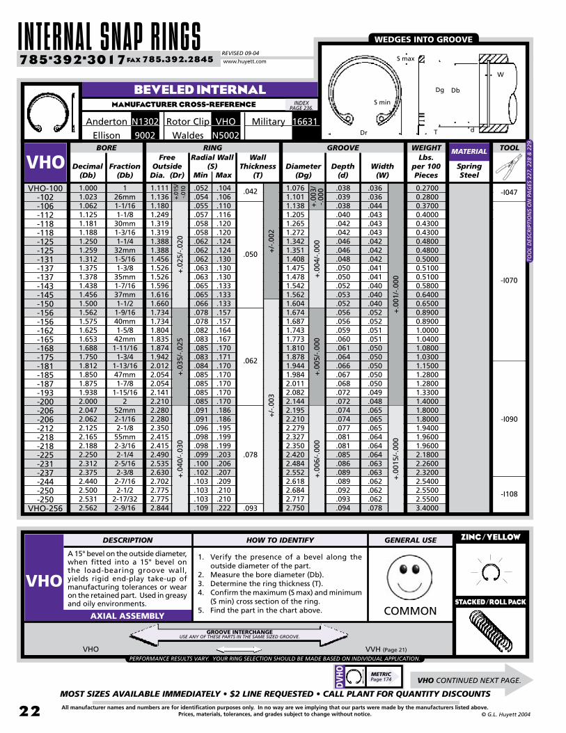
INTERNAL SNAP RINGSREVISED 09-04
MOST SIZES AVAILABLE IMMEDIATELY • $2 LINE REQUESTED • CALL PLANT FOR QUANTITY DISCOUNTS
22
785•392•3017 FAX 785.392.2845
All manufacturer names and numbers are for identification purposes only. In no way are we implying that our parts were made by the manufacturers listed above.Prices, materials, tolerances, and grades subject to change without notice. © G.L. Huyett 2004
www.huyett.com
BEVELED INTERNALMANUFACTURER CROSS-REFERENCE
Free Outside
Dia. (Dr)Decimal
(Db)Fraction
(Db)
Radial Wall(S) Diameter
(Dg)Depth
(d)SpringSteel
1.0001.0231.0621.1251.1811.1881.2501.2591.3121.3751.3781.4381.4561.5001.5621.5751.6251.6531.6881.7501.8121.8501.8751.9382.0002.0472.0622.1252.1652.1882.2502.3122.3752.4402.5002.5312.562
126mm1-1/161-1/8
30mm1-3/161-1/4
32mm1-5/161-3/8
35mm1-7/1637mm1-1/21-9/1640mm1-5/8
42mm1-11/161-3/4
1-13/1647mm1-7/8
1-15/162
52mm2-1/162-1/8
55mm2-3/162-1/42-5/162-3/82-7/162-1/2
2-17/322-9/16
1.1111.1361.1801.2491.3191.3191.3881.3881.4561.5261.5261.5961.6161.6601.7341.7341.8041.8351.8741.9422.0122.0542.0542.1412.2102.2802.2802.3502.4152.4152.4902.5352.6302.7022.7752.7752.844
1.0761.1011.1381.2051.2651.2721.3421.3511.4081.4751.4781.5421.5621.6041.6741.6871.7431.7731.8101.8781.9441.9842.0112.0822.1442.1952.2102.2792.3272.3502.4202.4842.5522.6182.6842.7172.750
BORE RING
VHO
A 15° bevel on the outside diameter, when fitted into a 15° bevel on the load-bearing groove wall, yields rigid end-play take-up of manufacturing tolerances or wear on the retained part. Used in greasy and oily environments.
1. Verify the presence of a bevel along the outside diameter of the part.
2. Measure the bore diameter (Db).3. Determine the ring thickness (T).4. Confirm the maximum (S max) and minimum
(S min) cross section of the ring.5. Find the part in the chart above.
ZINC/YELLOW
COMMONAXIAL ASSEMBLY
VHO-100-102-106-112-118-118-125-125-131-137-137-143-145-150-156-156-162-165-168-175-181-185-187-193-200-206-206-212-218-218-225-231-237-244-250-250
VHO-256
Width(W)
+.0
015/
-.00
0
+.0
04/-
.000
+.0
05/-
.000
+.0
06/-
.000
+.0
03/
-.00
0
+/-
.002
+/-
.003
+.01
5/-.0
10+
.025
/-.0
20+
.035
/-.0
25+
.040
/-.0
30MaxMin
GROOVE
.052
.054
.055
.057
.058
.058
.062
.062
.062
.063
.063
.065
.065
.066
.078
.078
.082
.083
.085
.083
.084
.085
.085
.085
.085
.091
.091
.096
.098
.098
.099
.100
.102
.103
.103
.103
.109
.104
.106
.110
.116
.120
.120
.124
.124
.130
.130
.130
.133
.133
.133
.157
.157
.164
.167
.170
.171
.170
.170
.170
.170
.170
.186
.186
.195
.199
.199
.203
.206
.207
.209
.210
.210
.222
Wall Thickness
(T)
.038
.039
.038
.040
.042
.042
.046
.046
.048
.050
.050
.052
.053
.052
.056
.056
.059
.060
.061
.064
.066
.067
.068
.072
.072
.074
.074
.077
.081
.081
.085
.086
.089
.089
.092
.093
.094
.042
.050
.062
.078
.093
.036
.036
.044
.043
.043
.043
.042
.042
.042
.041
.041
.040
.040
.040
.052
.052
.051
.051
.050
.050
.050
.050
.050
.049
.048
.065
.065
.065
.064
.064
.064
.063
.063
.062
.062
.062
.078
VHO CONTINUED NEXT PAGE.
MATERIAL
Military 16631VHORotor ClipN1302Anderton
N5002Waldes9002Ellison
VHO VVH (Page 21)
+.0
01/-
.000
-I047
-I070
-I090
WEDGES INTO GROOVE
PERFORMANCE RESULTS VARY. YOUR RING SELECTION SHOULD BE MADE BASED ON INDIVIDUAL APPLICATION.
Lbs. per 100 Pieces
WEIGHT
0.27000.28000.37000.40000.43000.43000.48000.48000.50000.51000.51000.58000.64000.65000.89000.89001.00001.04001.08001.03001.15001.28001.28001.33001.40001.80001.80001.94001.96001.96002.18002.26002.32002.54002.55002.55003.4000
-I108
DVH
O
METRICPage 174
GROOVE INTERCHANGEUSE ANY OF THESE PARTS IN THE SAME SIZED GROOVE.
INDEX PAGE 236.
d
S max
S min
Dr
Dg Db
W
T
TOOL
DESCRIPTION HOW TO IDENTIFY GENERAL USE
VHOSTACKED/ROLL PACK
TOO
L D
ESC
RIP
TIO
NS
ON
PA
GES
227
, 228
& 2
29.

BOX 232 • MINNEAPOLIS, KS • 67467
MOST SIZES AVAILABLE IMMEDIATELY • $2 LINE REQUESTED • CALL PLANT FOR QUANTITY DISCOUNTS
23All manufacturer names and numbers are for identification purposes only. In no way are we implying that our parts were made by the manufacturers listed above.Prices, materials, tolerances, and grades subject to change without notice.© G.L. Huyett 2004
Free Outside
Dia. (Dr)Decimal
(Db)Fraction
(Db)
Radial Wall(S) Diameter
(Dg)Depth
(d)SpringSteel
2.6252.6772.6882.7502.8122.8352.8752.9533.0003.0623.1253.1493.1563.2503.3463.4693.5003.5433.5623.6253.7403.7503.8753.9384.0004.1254.2504.3314.5004.6254.7244.7505.0005.2505.3755.5005.7506.0006.2506.5006.6256.7507.0007.2507.5007.7508.0008.2508.5008.7509.0009.2509.5009.750
10.000
2-5/868mm2-11/162-3/4
2-13/1672mm2-7/8
75mm3
3-1/163-1/8
80mm3-5/323-1/4
3-11/323-15/323-1/2
90mm3-9/163-5/8
95mm3-3/43-7/8
3-15/164
4-1/84-1/4
110mm4-1/24-5/8
120mm4-3/4
55-1/45-3/85-1/25-3/4
66-1/46-1/26-5/86-3/4
77-1/47-1/27-3/4
88-1/48-1/28-3/4
99-1/49-1/29-3/4
10
2.9102.9802.9803.0503.1213.1213.1913.3253.3253.4183.4883.5233.5233.6233.7343.8573.8903.9363.9364.0244.1574.1574.2914.3584.4244.5584.6914.7564.9405.0765.2135.2135.4855.7705.9106.0666.3366.6206.8957.1707.3087.4457.7207.9958.2708.5458.8209.0959.2859.5589.830
10.10210.37510.64810.920
2.8202.8762.8872.9553.0203.0433.0853.1783.2253.2903.3553.3813.3883.4893.5913.7263.7603.8063.8303.9004.0304.0404.1714.2364.3024.4334.5624.6474.8244.9555.0605.0865.3465.6125.7395.8646.1206.3746.6426.9087.0427.1747.4417.7087.9748.2408.5078.7739.0409.3079.5739.838
10.10610.37210.639
BORE RING
VHOVHO-262
-268-268-275-281-281-287-295-300-306-312-315-315-325-334-347-350-354-354-362-375-375-387-393-400-412-425-433-450-462-475-475-500-525-537-550-575-600-625-650-662-675-700-725-750-775-800-825-850-875-900-925-950-975
VHO-1000
Width(W)
+.0
02/-
.000
+.0
06/-
.000
+/-
.003
+/-
.004
+.0
40/-
.030
+/-
.055
+/-
.065
MaxMin
GROOVE
.111
.113
.113
.115
.115
.115
.120
.122
.122
.126
.129
.129
.129
.135
.140
.144
.142
.142
.142
.150
.155
.155
.160
.161
.166
.171
.180
.180
.181
.183
.183
.183
.186
.198
.198
.198
.198
.198
.211
.219
.221
.224
.232
.238
.247
.255
.262
.270
.277
.286
.294
.299
.304
.309
.315
.226
.230
.230
.234
.230
.230
.240
.250
.250
.254
.259
.262
.262
.269
.276
.286
.289
.292
.292
.299
.309
.309
.319
.324
.330
.330
.335
.343
.351
.360
.370
.370
.390
.408
.408
.408
.408
.435
.423
.438
.447
.456
.474
.489
.507
.523
.540
.558
.573
.591
.609
.625
.642
.658
.675
+.0
07/-
.000
Wall Thickness
(T)
.097
.099
.099
.102
.104
.104
.105
.112
.112
.114
.115
.116
.116
.119
.122
.128
.130
.132
.134
.137
.145
.145
.148
.149
.151
.154
.156
.158
.162
.165
.168
.168
.173
.181
.182
.182
.185
.187
.196
.204
.208
.212
.220
.229
.237
.245
.253
.261
.270
.278
.286
.294
.303
.311
.319
.093
.109
.125 .102
.089
.074
.076
.187
.159
.155
.151
.147
+/-
.090
.077
+.0
08/-
.000
+/-
.080
.156
+/-
.005 +
.003
/-.0
00
.128
BEVELED INTERNALMANUFACTURER CROSS-REFERENCE
MATERIAL
Military 16631VHORotor ClipN1302AndertonN5002Waldes9002Ellison
.129
-I108
-I120
-I120-X
-I150
WEDGES INTO GROOVE
Lbs. per 100 Pieces
WEIGHT
3.4500 3.5000 3.5000 3.5500 3.6000 3.6000 4.1000 4.25004.2500
5.3000 5.6000 5.7000 5.7000 6.0000 6.5000 6.9000 7.1000 7.2000 7.2000 7.3000 7.8000 7.8000 8.7000 8.8000 9.3000 9.700010.100010.500011.100011.700012.400012.400013.600017.400017.900018.300019.200020.100026.600028.100030.500032.500034.400042.800048.500052.000055.500060.300063.400065.300073.200076.700080.300083.300086.3000
+.0
015/
-.00
0
TOO
L D
ESC
RIP
TIO
NS
ON
PA
GES
227
, 228
& 2
29.
INDEX PAGE 236.
d
S max
S min
Dr
Dg Db
W
T
TOOL

CLIPSREVISED 09-04
MOST SIZES AVAILABLE IMMEDIATELY • $2 LINE REQUESTED • CALL PLANT FOR QUANTITY DISCOUNTS
24
785•392•3017 FAX 785.392.2845
All manufacturer names and numbers are for identification purposes only. In no way are we implying that our parts were made by the manufacturers listed above.Prices, materials, tolerances, and grades subject to change without notice. © G.L. Huyett 2004
www.huyett.com
E
RE
RG
BE
A15
PO
POL
ST
JE
EBS
INSTALLED
RADIALLY
ONTO A
SHAFT
USING
AN
APPLICATOR
TOOLS Pages: 232-234
AUTOMATED INSTALLATION
EXTERNAL
IMPERIALPg: 27
IMPERIALPg: 28
IMPERIALPg: 29
IMPERIALPg: 30
IMPERIALPg: 30
IMPERIALN/A
IMPERIALN/A
IMPERIALN/A
CONTACT PLANT FOR DESIGN AND INSTALLATION ASSISTANCE.
Most types available in a roll pack for reduced handling costs. For use with an applicator.
Automated “staple gun” equipment is available as a
special order.Use common items from your toolbox.
Higher strength variation of the Basic E-Clip.
Bowed design for end-play take-up.
Heavy duty with highest load ratings.
For easy removal using a screwdriver.
British Specification.
BASIC E-CLIP
REINFORCED E-CLIP
METRICN/A
RADIAL GRIP RING
METRICN/A
BOWED E-CLIP
METRICN/A
MUTANTS
METRICN/A
POODLE RING
METRICN/A
LIGHT DUTY POODLE RING
METRICPg: 183
SLOTTED E-CLIP
METRICPg: 184
JAPANESE E-CLIP
METRICPg: 184
BRITISH STANDARD E-CLIP
LCIMPERIAL
Pg: 31METRICPg: 187
INTERLOCKING
CLow profile. Light duty.
BASIC C-CLIP
ELIMPERIAL
Pg: 33METRICPg: 187
PRONG LOCK
METRICPg: 182
IMPERIALPg: 26
ANSI Pg: 188
METRICPg: 183
IMPERIALPg: 27
ANSI Pg: 188
METRICPg: 186
IMPERIALPg: 32
ANSI Pg: 189
All metric numbers begin with “D” and all ANSI numbers begin with “M.”
Aftermarket and short runs. For original equipment manufacturing.
Most common clip. Large shoulder.
Japanese Industrial Specification (JIS).
Two-piece balanced design for high rotational speeds.
Hybrid design for end-play take-up and high rotational speeds.
Grooveless for light duty applications.
Application specific by special order.
Fits in standard E-Clip grooves.
Slide roll pack on rail.
Remove label.
Ready to go!
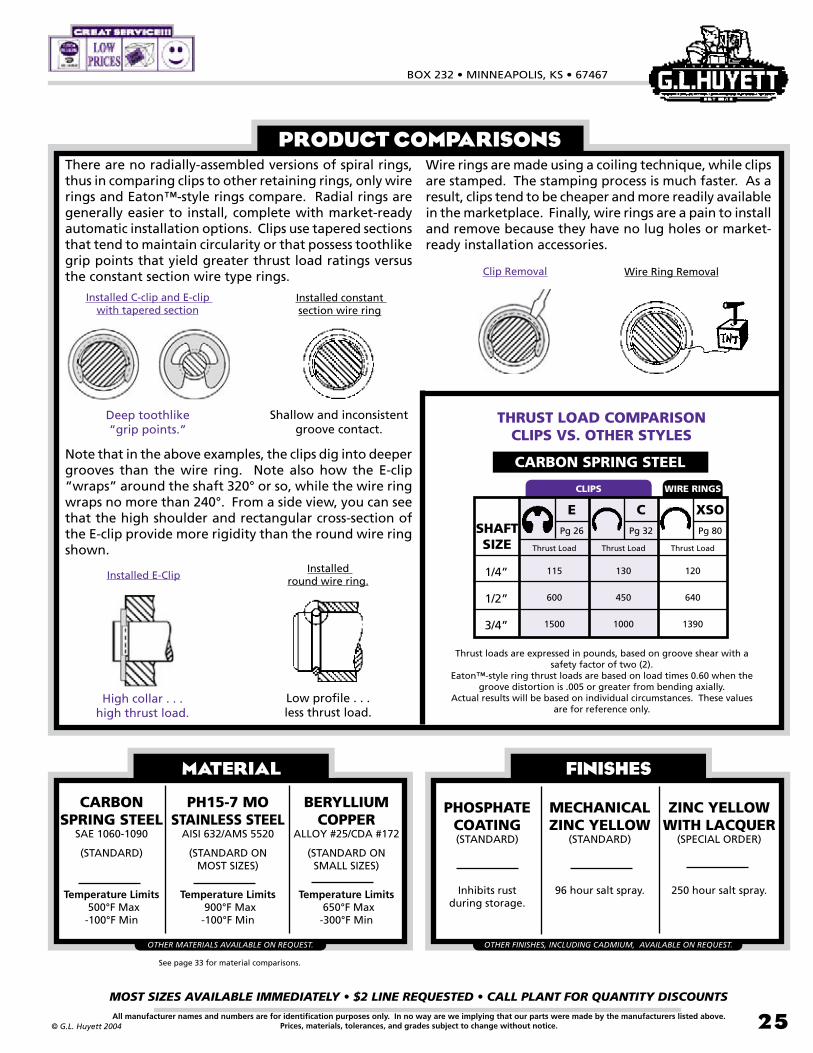
BOX 232 • MINNEAPOLIS, KS • 67467
MOST SIZES AVAILABLE IMMEDIATELY • $2 LINE REQUESTED • CALL PLANT FOR QUANTITY DISCOUNTS
25All manufacturer names and numbers are for identification purposes only. In no way are we implying that our parts were made by the manufacturers listed above.Prices, materials, tolerances, and grades subject to change without notice.© G.L. Huyett 2004
There are no radially-assembled versions of spiral rings, thus in comparing clips to other retaining rings, only wire rings and Eaton™-style rings compare. Radial rings are generally easier to install, complete with market-ready automatic installation options. Clips use tapered sections that tend to maintain circularity or that possess toothlike grip points that yield greater thrust load ratings versus the constant section wire type rings.
PRODUCT COMPARISONS
Thrust loads are expressed in pounds, based on groove shear with a safety factor of two (2).
Eaton™-style ring thrust loads are based on load times 0.60 when the groove distortion is .005 or greater from bending axially.
Actual results will be based on individual circumstances. These values are for reference only.
Note that in the above examples, the clips dig into deeper grooves than the wire ring. Note also how the E-clip “wraps” around the shaft 320° or so, while the wire ring wraps no more than 240°. From a side view, you can see that the high shoulder and rectangular cross-section of the E-clip provide more rigidity than the round wire ring shown.
Wire rings are made using a coiling technique, while clips are stamped. The stamping process is much faster. As a result, clips tend to be cheaper and more readily available in the marketplace. Finally, wire rings are a pain to install and remove because they have no lug holes or market- ready installation accessories.
THRUST LOAD COMPARISONCLIPS VS. OTHER STYLES
CARBON SPRING STEEL
CLIPS WIRE RINGS
Installed E-Clip
High collar . . . high thrust load.
Low profile . . . less thrust load.
Installed round wire ring.
Clip Removal Wire Ring Removal
Installed C-clip and E-clip with tapered section
Installed constant section wire ring
Deep toothlike“grip points.”
Shallow and inconsistent groove contact.
MATERIAL
CARBON SPRING STEEL
SAE 1060-1090
(STANDARD)
Temperature Limits 500°F Max-100°F Min
PH15-7 MOSTAINLESS STEEL
AISI 632/AMS 5520
(STANDARD ON MOST SIZES)
Temperature Limits 900°F Max-100°F Min
BERYLLIUM COPPER
ALLOY #25/CDA #172
(STANDARD ON SMALL SIZES)
Temperature Limits 650°F Max-300°F Min
OTHER MATERIALS AVAILABLE ON REQUEST.
See page 33 for material comparisons.
FINISHES
PHOSPHATECOATING(STANDARD)
Inhibits rust during storage.
MECHANICALZINC YELLOW
(STANDARD)
96 hour salt spray.
ZINC YELLOWWITH LACQUER
(SPECIAL ORDER)
250 hour salt spray.
OTHER FINISHES, INCLUDING CADMIUM, AVAILABLE ON REQUEST.
XSOPg 80
Thrust Load
120
640
1390
SHAFTSIZE
1/4”
1/2”
3/4”
EPg 26
Thrust Load
115
600
1500
CPg 32
Thrust Load
130
450
1000
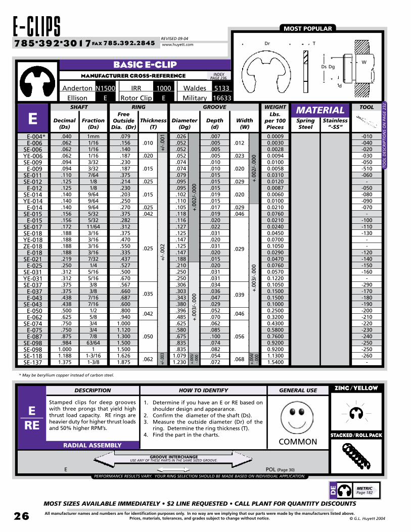
E-CLIPSREVISED 09-04
MOST SIZES AVAILABLE IMMEDIATELY • $2 LINE REQUESTED • CALL PLANT FOR QUANTITY DISCOUNTS
2�
785•392•3017 FAX 785.392.2845
All manufacturer names and numbers are for identification purposes only. In no way are we implying that our parts were made by the manufacturers listed above.Prices, materials, tolerances, and grades subject to change without notice. © G.L. Huyett 2004
www.huyett.com
Free Outside
Dia. (Dr)Decimal
(Ds)Fraction
(Ds)Thickness
(T)Diameter
(Dg)Depth
(d)SpringSteel
.040
.062
.062
.062
.094
.094
.110
.125
.125
.140
.140
.140
.156
.156
.172
.188
.188
.188
.188
.219
.250
.312
.312
.375
.375
.438
.438
.500
.625
.750
.750
.875
.9841.0001.1881.375
1mm1/161/161/163/323/327/641/81/89/649/649/645/325/3211/643/163/163/163/167/321/45/165/163/83/87/167/161/25/83/43/47/8
63/641
1-3/161-3/8
.079
.156
.140
.187
.230
.187
.375
.214
.230
.203
.250
.270
.375
.282
.312
.375
.470
.550
.335
.437
.527
.500
.670
.567
.660
.687
.600
.800
.9401.0001.1201.3001.5001.5001.6261.875
.026
.052
.052
.052
.074
.074
.079
.095
.095
.102
.110
.105
.118
.116
.127
.125
.147
.125
.147
.188
.210
.250
.250
.306
.303
.343
.380
.396
.485
.625
.580
.675
.835
.8351.0791.230
SHAFT RING
E
Stamped clips for deep grooves with three prongs that yield high thrust load capacity. RE rings are heavier duty for higher thrust loads and 50% higher RPM’s.
1. Determine if you have an E or RE based on shoulder design and appearance.
2. Confirm the diameter of the shaft (Ds).3. Measure the outside diameter (Dr) of the
ring. Determine the ring thickness (T).4. Find the part in the charts.
ZINC/YELLOW
COMMONRADIAL ASSEMBLY
E-004* E-006SE-006YE-006SE-009 E-009SE-011SE-012 E-012SE-014YE-014 E-014SE-015 E-015SE-017SE-018YE-018ZE-018 E-018SE-021 E-025SE-031YE-031SE-037 E-037 E-043SE-043 E-050 E-062SE-074 E-075 E-087SE-098SE-098SE-118SE-137
Width(W)
+.0
02/-
.000
+.0
03/-
.000
+.0
02/-
.000
+.0
03/-
.000
+/-
.001
+/-
.002
-010-040-020-030-050-510-060
--050-080-090-070
--100-110-130
--
-120-140-150-160
--290-170-180-190-200-210-220-230-240-250-250-260
-+.00
5/-.0
00
.007
.005
.005
.005
.010
.010
.015
.015
.015
.019
.015
.017
.019
.020
.022
.031
.020
.031
.020
.015
.020
.031
.031
.034
.036
.047
.029
.052
.070
.062
.085
.100
.074
.082
.054
.072
.010 .012
.020 .023
.025 .029
.042 .046
.025 .029
.035 .039
.015 .020
.015 .020
.025 .029
.042 .046
.050 .056
.062 .068
+/-.0
03
+.00
4/-.0
00
BASIC E-CLIPMANUFACTURER CROSS-REFERENCE
Waldes 51331000IRRN1500AndertonMilitary 16633ERotor ClipEEllison
MATERIALGROOVE
E POL (Page 30)
MOST POPULAR
Stainless“-SS”
* May be beryllium copper instead of carbon steel.
Lbs. per 100 Pieces
WEIGHT
PERFORMANCE RESULTS VARY. YOUR RING SELECTION SHOULD BE MADE BASED ON INDIVIDUAL APPLICATION.
0.00090.00300.00280.00940.01000.00580.03100.01200.00870.00600.01000.02100.07600.02100.02400.04500.07000.10500.02900.04700.07600.05700.12200.10500.15000.15000.10000.25000.32000.43000.58000.76000.92000.92001.13001.5400
DE METRIC
Page 182
TOO
L D
ESC
RIP
TIO
NS
ON
PA
GE
232.
GROOVE INTERCHANGEUSE ANY OF THESE PARTS IN THE SAME SIZED GROOVE.
INDEX PAGE 236.
TDr
Ds DgW
d
TOOL
DESCRIPTION HOW TO IDENTIFY GENERAL USE
ERE
STACKED/ROLL PACK

BOX 232 • MINNEAPOLIS, KS • 67467
MOST SIZES AVAILABLE IMMEDIATELY • $2 LINE REQUESTED • CALL PLANT FOR QUANTITY DISCOUNTS
27All manufacturer names and numbers are for identification purposes only. In no way are we implying that our parts were made by the manufacturers listed above.Prices, materials, tolerances, and grades subject to change without notice.© G.L. Huyett 2004
REINFORCED E-CLIPMANUFACTURER CROSS-REFERENCE
Free Outside
Dia. (Dr)Decimal
(Ds)Fraction
(Ds)Thickness
(T)Diameter
(Dg)Depth
(d)SpringSteel
.094
.125
.156
.188
.219
.250
.312
.312
.375
.438
.500
.562
3/321/85/323/167/321/45/165/163/87/161/29/16
.206
.270
.335
.375
.446
.516
.588
.588
.660
.746
.810
.870
.074
.095
.116
.147
.188
.210
.250
.250
.303
.343
.396
.437
SHAFT RING
RE
Grip rings are stamped grooveless retainers that are radially applied using an applicator. Because there is no groove, the part may be adjusted on the shaft to take up end-play. Load capacity will be reduced if the part is reused.
1. Confirm the diameter of the shaft (Ds).2. Measure the free inside diameter (Df) of the
part.3. Calculate the ring thickness (T).4. Find the part in the chart above.
ZINC/YELLOW
UNCOMMONRADIAL ASSEMBLY
RE-009-012-015-018-021-025-031
-031A-037-043-050
RE-056
Width(W)
+.00
2/-.0
00
+/-
.003
+/-.0
02
+/-
.002
.015
.035
.042
-080-520-120-130-140-160-500-TC-2-170-270-200-280
GROOVE
.010
.015
.020
.020
.015
.020
.031
.031
.036
.047
.052
.062
.025
.039
.046
.029
+.00
2/-.0
00
+.0
03/-
.000
Military 3215RERotor ClipN1540Anderton5144Waldes1200IRR
MATERIAL
RADIAL GRIP RINGMANUFACTURER CROSS-REFERENCE
RGRotor Clip5135Waldes
.020
RG SHF (Page 14) TX (Page 92) TY (Page 92) T99 (Page 101)
HEAVY DUTY
ADJUSTABLE
Stainless “-SS”
PERFORMANCE RESULTS VARY. YOUR RING SELECTION SHOULD BE MADE BASED ON INDIVIDUAL APPLICATION.
Lbs. per 100 Pieces
WEIGHT
Ds
DaT
S max
Df
0.00700.01300.03100.03900.05400.07100.08500.08500.15000.19000.32000.3500
TOO
L D
ESC
RIP
TIO
NS
ON
PA
GE
232.
DR
E METRICPage 183
GROOVELESSUSE ANY OF THESE PARTS ON THE SAME SIZED SHAFT.
INDEX PAGE 236.
INDEX PAGE 236.
TDr
Ds DgW
d
From(Ds)
Thickness(T)
SpringSteel
.092
.123
.154
.185
.248
.310
.373
RGRG-009
-012-015-018-025-031
RG-037
+/-
.002
Free Inside Dia.
(Df)To
(Ds)Fraction
(Ds)
Max. RadialWall Width
(S)
Assembled Outside
Dia. (Da)
SHAFT RING TOOL
.096
.127
.158
.189
.252
.316
.379
3/321/85/323/161/45/163/8
.089
.119
.149
.179
.238
.298
.356
.045
.054
.078
.085
.100
.114
.130
.300
.340
.380
.440
.540
.660
.760
MATERIALLbs. per
100Pieces
WEIGHT
-RG009-RG012-RG015-RG018-RG025-RG031-RG037
0.01400.01900.02700.04500.07400.11000.1500
.025
.035
.042
TOOL
DESCRIPTION HOW TO IDENTIFY GENERAL USE
RGSTACKED/ROLL PACK

E-CLIPSREVISED 09-04
MOST SIZES AVAILABLE IMMEDIATELY • $2 LINE REQUESTED • CALL PLANT FOR QUANTITY DISCOUNTS
28
785•392•3017 FAX 785.392.2845
All manufacturer names and numbers are for identification purposes only. In no way are we implying that our parts were made by the manufacturers listed above.Prices, materials, tolerances, and grades subject to change without notice. © G.L. Huyett 2004
www.huyett.com
BOWED E-CLIPMANUFACTURER CROSS-REFERENCE
Curved shape for resilient end-play take-up. Install with the concave surface abutting the part. BE’s are not recommended for use as a shoulder against rotating parts. For such applications, use the prong-locked EL’s on page 33.
1. Verify bowed shape side profile.2. Measure the diameter of the shaft (Ds).3. Measure the outside diameter (Dr) of the ring.
Determine the ring thickness (T).4. Find the part in the chart above.
ZINC/YELLOW
UNCOMMONRADIAL ASSEMBLY
Military 16634BERotor ClipN1501Anderton
5131Waldes1001IRR
CURVED SHAPE
W
DsDg
d
Hb
TDr
INDEX PAGE 236.
Free Outside
Dia. (Dr)Decimal
(Ds)Fraction
(Ds)
Bow Height (Hb) Thickness
(T)Diameter
(Dg)Depth
(d)SpringSteel
.094
.110
.125
.140
.140
.156
.172
.188
.188
.219
.250
.312
.375
.438
.438
.500
.625
.744
.750
.750
.875
.9841.0001.8121.375
3/327/641/89/649/645/3211/643/163/167/321/45/163/87/167/161/25/8
18.9mm3/43/47/8
63/641
1-3/161-3/8
-.375.230.203.270.282.312.335.375.437.527.500.660.687.600.800.940
1.0001.0001.1201.3001.500 1.5001.6261.875
.074
.079
.095
.102
.105
.116
.127
.147
.125
.188
.210
.250
.303
.343
.380
.396
.485
.625
.625
.580
.675
.835
.8351.0791.230
SHAFT RING
BEBE-009
BSE-011BE-012
BSE-014BE-014BE-015
BSE-017BE-018
BSE-018BSE-021BE-025
BSE-031BE-037BE-043
BSE-043BE-050BE-062
BSE-074BSE-074BE-075BE-087
BSE-098BSE-098BSE-118BSE-137
Width(W)
+.0
03/-
.000
+.00
4/-
.000
+.0
02/-
.000
+.0
03/-
.000
+.0
05/
-.000
+/-
.002
+/-.0
03
MaxMin
--550-551-553-552-554-555-556-557-558-559-560-561-562-563-564-565-566-566-567-568-569-569
--
GROOVE
.025
.025
.025
.022
.028
.030
.032
.033
.038
.043
.050
.050
.060
.060
.060
.075
.080
.090
.090
.090
.090
.088
.088
.109
.109
.035
.035
.035
.032
.038
.040
.042
.043
.048
.058
.065
.065
.076
.076
.076
.093
.098
.110
.110
.110
.110
.112
.112
.139
.139
-.015.015.019.017.020.022.020.031.015.020.031.036.047.029.052.070.060.062.085.100.074
---
.045
.022
.022
.019
.025
.027
.029
.030
.035
.040
.047
.047
.060
.060
.057
.073
.077
.085
.085
.085
.085
.085
.085
.107
.107
+/-.002
+/-
.001
MATERIALStainless
“-SS”
Lbs. per 100 Pieces
WEIGHT
-0.00200.00600.00400.01300.01300.01600.01700.02700.02800.07600.05700.15000.15000.10000.25000.32000.43000.43000.58000.76000.9380 0.93801.05001.5200
TOO
L D
ESC
RIP
TIO
NS
ON
PA
GE
233.
.020
.010
.015
.025
.035
.042
.050
.062
TOOL
DESCRIPTION HOW TO IDENTIFY GENERAL USE
BE

BOX 232 • MINNEAPOLIS, KS • 67467
MOST SIZES AVAILABLE IMMEDIATELY • $2 LINE REQUESTED • CALL PLANT FOR QUANTITY DISCOUNTS
29All manufacturer names and numbers are for identification purposes only. In no way are we implying that our parts were made by the manufacturers listed above.Prices, materials, tolerances, and grades subject to change without notice.© G.L. Huyett 2004
MUTANT E-CLIPSMANUFACTURER CROSS-REFERENCE
Free Outside Dia.
(Dr)Decimal
(Ds)Thickness
(T)Diameter
(Dg)SpringSteel
.110
.125
.172
.218
.343
.426
.374
.500
.688
.780
.078
.095
.125
.187
.281
SHAFT RING
A15U
1. Look at the silhouette of the part and decide if you have a “C”, “U”, or “S” version.
2. Get it? It spells CUS.3. Measure the free outside diameter (Dr).4. Find the part in the charts above.5. Verify the correct material thickness.
WEIRDRADIAL ASSEMBLY
A15U-078-095-125-187
A15U-281
Width(W)
+.0
03/-
.000
.023
+.0
02/-
.000
+/-
.001
5
.020
-80-4B-6B-29-10A
InstalledOutside
Diameter
GROOVE
Free Outside Dia.
(Dr)Decimal
(Ds)Thickness
(T)Diameter
(Dg)Spring Steel
.110
.156
.156
.218
.218
.312
.282
.320
.406
.500
.430
.625
.086
.120
.124
.175
.181
.249
SHAFT RING TOOL
A15CA15C-086
-120-124-175-181
A15C-249
Width(W)
+.0
02/-
.000
+.0
02/-
.000+/
-.002 -413
-120-7A-9A-140-16A
InstalledOutside
Diameter
GROOVE
Free Outside Dia.
(Dr)Decimal
(Ds)Thickness
(T)Diameter
(Dg)SpringSteel
.078
.078
.125
.125
.156
.188
.468
.250
.295
.281
.376
.310
.350
.687
.052
.062
.091
.102
.120
.126
.389
SHAFT RING TOOL
A15SA15S-052
-062-091-102-120-126
A15S-389
Width(W)
+.0
02/-
.000
+.00
3/-.0
00+
.002
/-.0
00
+/-
.001
5
InstalledOutside
Diameter
GROOVE
.430
.380
.510
.700
.790
.297
.336
.422
.517
.447
.642
.265
.305
.291
.391
.336
.365
.705
.025
.027
.017
.017
.031
.017
.017
.028
.025
.017
.027
.027
.031
.022
.024
.015
.015
.028
.015
.015
.025
.022
.025
.024
.024
.028
+/-.002
+/-
.001
5
+/-.0015
+.00
3/-.0
00
+/-.0
02
+.0
40/
-.00
0+.
100/
-.000
+.0
40/-
.000
+.0
30/
-.00
0+
.060
/-.
000
+.07
5/-.0
00
Anderton A1500
MATERIAL
MATERIAL
MATERIAL
Standard E-clips subjected to radioactive waste at a secret government test site that alters the genetic make-up in ways that cause the parts to grow extra limbs and teeth. These extras yield design characteristics that only a mutant engineer can understand.
-090-100-4B-060-120-AM56-12A
SPECIAL FINISHES AND PACKAGING AVAILABLE
UPON REQUEST.
CA
LL F
OR
TO
OL
INFO
RM
ATI
ON
.
u c s
Dr Dr Dr
Ds Dg
W
T
INDEX PAGE 236.
CA
LL F
OR
TO
OL
INFO
RM
ATI
ON
.C
ALL
FO
R T
OO
L IN
FOR
MA
TIO
N.
RRA
RRA
TOOL
DESCRIPTION HOW TO IDENTIFY GENERAL USE
A15UA15CA15S
+.100/-.000

HEAVY DUTY E-CLIPSREVISED 09-04
MOST SIZES AVAILABLE IMMEDIATELY • $2 LINE REQUESTED • CALL PLANT FOR QUANTITY DISCOUNTS
30
785•392•3017 FAX 785.392.2845
All manufacturer names and numbers are for identification purposes only. In no way are we implying that our parts were made by the manufacturers listed above.Prices, materials, tolerances, and grades subject to change without notice. © G.L. Huyett 2004
www.huyett.com
POODLE CLIP RINGMANUFACTURER CROSS-REFERENCE
Free Outside
Dia. (Dr)Decimal
(Ds)Fraction
(Ds)Thickness
(T)Diameter
(Dg)Depth
(d)SpringSteel
.156
.188
.250
.312
.375
.438
.500
.625
.7501.0001.2501.5001.7502.000
5/323/161/45/163/87/161/25/83/41
1-1/41-1/21-3/4
2
.320
.400
.482
.588
.680
.752
.826
.9661.0951.4151.8002.0502.3002.650
.120
.148
.210
.272
.331
.390
.440
.531
.632
.8601.0901.3171.4801.730
SHAFT RING
PO
Radially-assembled heavy duty ring with large shoulders (“ears”) and thicker material than E-clips. Install using an applicator or standard pliers and screwdriver. The POL will interchange into standard E-clip grooves.
1. Note that the POL is thinner than the PO.2. Measure the diameter of the shaft (Ds).3. Measure the outside diameter (Dr) of the
ring. Determine the ring thickness (T).4. Find the part in the charts above.
ZINC/YELLOW
UNCOMMONRADIAL ASSEMBLY
PO-015-018-025-031-037-043-050-062-075-100-125-150-175
PO-200
Width(W)
+/-
.006
+/-
.006
+/-
.015
+/-.005
+/-
.002
-815-818-825-831-837-843-850
-------
GROOVE
.035
.035
.035
.042
.042
.050
.050
.050
.062
.078
.093
.109
.125
.125
.018
.020
.020
.020
.022
.024
.030
.047
.059
.070
.080
.091
.135
.135
.039
.039
.039
.046
.046
.056
.056
.056
.068
.086
.103
.120
.139
.139+/-.0
04+
/-.0
03
+/-
.010
+/-.004
+/-
.008
+/-
.010
+/-
.008
MATERIAL
POL REPLACES E-CLIPS
POL E (Page 26)
Stainless “-SS”
PERFORMANCE RESULTS VARY. YOUR RING SELECTION SHOULD BE MADE BASED ON INDIVIDUAL APPLICATION.
dDr T
WDg
Ds
Lbs. per 100 Pieces
WEIGHT
PO/POL ASSEMBLYPO and POL rings can be assembled quickly and
economically with a variety of tools, including the applicators
shown on page 233.
The rings can be installed easily with a pair of pliers . . .
. . . and removed quickly with a screwdriver. The ring is
reusable after disassembly.
0.04200.06300.08400.14600.19200.26600.33000.46500.63501.26502.52003.63005.30006.9200
TOO
L D
ESC
RIP
TIO
NS
ON
PA
GE
233.
PO/POLRotor Clip5304/T5304
GROOVE INTERCHANGEUSE ANY OF THESE PARTS IN THE SAME SIZED GROOVE.
Waldes
INDEX PAGE 236.
Free Outside Dia.(Dr)
Decimal(Ds)
Fraction(Ds)
Thickness(T)
Diameter(Dg)
Depth(d)
Spring Steel
.156
.188
.250
.312
.375
.438
.500
.625
.7501.000
5/323/161/45/163/87/161/25/83/41
- .400.482.588.680.752.826.966
1.0951.415
.120
.148
.210
.272
.331
.390
.440
.531
.632
.860
SHAFT RING TOOL
POLPOL-015
-018-025-031-037-043-050-062-075
POL-100
Width(W)
+/-
.006
+/-.0
10+
/-.0
08+/-
.002
-915-918-925-931-937-943-950
---
GROOVE
.018
.020
.020
.020
.022
.024
.030
.047
.059
.070
+/-.005
+/-
.006
+/-.004
+/-.0
08MATERIAL
Stainless “-SS”
Lbs. per 100 Pieces
WEIGHT
0.0300 0.0450 0.0600
0.0870 0.16000.1860
0.2770 0.3650 0.5350 0.8600
TOO
L D
ESC
RIP
TIO
NS
ON
PA
GE
233.
RRA
.025
.035
.042
.050
.029
.039
.046
.056
TOOL
DESCRIPTION HOW TO IDENTIFY GENERAL USE
POPOL
STACKED/ROLL PACK

BOX 232 • MINNEAPOLIS, KS • 67467
MOST SIZES AVAILABLE IMMEDIATELY • $2 LINE REQUESTED • CALL PLANT FOR QUANTITY DISCOUNTS
31All manufacturer names and numbers are for identification purposes only. In no way are we implying that our parts were made by the manufacturers listed above.Prices, materials, tolerances, and grades subject to change without notice.© G.L. Huyett 2004
Two-part radially-assembled ring with semicircular halves held together by interlocking prongs. Symmetrical shape “balances” the part to withstand high rotational speeds. Attractive appearance for exposed applications.
1. Confirm the diameter of the shaft (Ds).2. Measure the free diameter (Df).3. Determine the thickness (T).4. Find the part in the chart above.
ZINC/YELLOW
UNCOMMONRADIAL ASSEMBLY
Free Inside Dia.(Df)
Decimal(Ds)
Fraction(Ds)
Thickness(T)
Diameter(Dg)
Depth(d)
SpringSteel
.469
.500
.594
.625
.669
.750
.781
.875
.9841.0001.1251.1881.2501.3751.5001.5621.6251.7501.7721.8751.9692.0002.1252.1562.2502.3752.5002.6252.7502.8753.0003.2503.375
15/321/2
19/325/8
17mm3/4
25/327/8
63/641
1-1/81-3/161-1/41-3/81-1/21-9/161-5/81-3/4
45mm1-7/8
1-31/322
2-1/82-5/322-1/42-3/82-1/22-5/82-3/42-7/8
33-1/43-3/8
.414
.459
.538
.569
.593
.673
.703
.796
.863
.8631.0021.0641.1261.2501.3741.4121.4741.5971.5971.7211.7791.8091.9331.9332.0572.1802.3042.4282.5182.6422.7543.0133.114
.640
.680
.766
.797
.886
.967
.9981.0921.2731.2731.4201.4801.5401.6701.7901.9101.9702.1002.1002.2202.3702.4002.5202.5202.6502.7702.9003.0203.2503.3703.5003.7503.990
SHAFT RING
LCLC-046-050-059-062-066-075-078-087-098-098-112-118-125-137-150-156-162-175-175-187-196-200-212-212-225-237-250-262-275-287-300-325
LC-337
Width(W)
+.0
03/-
.000
+.0
04/-
.000
+/-
.001
5+
/-.0
02+
/-.0
03
+/-
.002
+/-
.003
+/-
.002
+/-
.003
+/-
.004
+/-
.005
GROOVE
+/-
.005
TOOLAssembled
Outside Diameter
.419
.464
.544
.575
.599
.680
.711
.805
.872
.8721.0131.0751.1381.2631.3881.4271.4891.6141.6141.7391.7971.8281.9531.9532.0782.2032.3282.4532.5442.6692.7943.0443.145
.035
.042
.050
.062
.078
.109
.093
.039
.046
.056
.068
.086
.120
.103
+/-
.006
+/-
.008
+/-
.006
+.0
05/-
.000
INTERLOCKING RINGMANUFACTURER CROSS-REFERENCE
LCRotor Clip
5107Waldes
MATERIAL
BALANCED FOR HIGH SPEED ROTATION
SEE PAGE
32.
NOTAVAILABLE
Lbs. per 100 Pieces
WEIGHT
0.13600.15000.17400.18200.31000.35000.36000.38000.73000.73000.79000.85000.89000.96001.06001.64001.75001.84001.84002.08003.10003.16003.42003.42003.73003.89003.97004.39006.32006.84007.04007.76009.4000
LC INSTALLATION ON PAGE 32.
T
DfW
d
DgDs
INDEX PAGE 236.
.025
.018
.025
.035
.056
.064
.056
.068
.078
.068
.086
.101
.086
.103
.115
DESCRIPTION HOW TO IDENTIFY GENERAL USE
LCSTACKED/ROLL PACK
DLC METRIC
Page 187

C-CLIPSREVISED 09-04
MOST SIZES AVAILABLE IMMEDIATELY • $2 LINE REQUESTED • CALL PLANT FOR QUANTITY DISCOUNTS
32
785•392•3017 FAX 785.392.2845
All manufacturer names and numbers are for identification purposes only. In no way are we implying that our parts were made by the manufacturers listed above.Prices, materials, tolerances, and grades subject to change without notice. © G.L. Huyett 2004
www.huyett.com
BASIC C-CLIP
Free Outside Dia.(Dr)
Decimal(Ds)
Fraction(Ds)
Diameter(Dg)
Depth(d)
SpringSteel
.125
.156
.188
.219
.236
.250
.281
.312
.375
.406
.438
.500
.562
.625
.688
.750
.812
.875
.9381.0001.1251.2501.3751.5001.6251.7502.000
1/85/323/167/3215/641/49/325/163/8
13/327/161/29/165/8
11/163/4
13/167/8
15/161
1-1/81-1/41-3/81-1/21-5/81-3/4
2
.165
.205
.244
.275
.295
.311
.346
.376
.448
.486
.517
.581
.653
.715
.784
.845
.915
.9911.0581.1301.2671.4151.5551.6911.8531.9752.257
.106
.135
.165
.193
.208
.220
.247
.276
.335
.364
.393
.450
.507
.563
.619
.676
.732
.789
.843
.9001.0131.1261.2371.3501.4831.5761.800
SHAFT RING
C
Radially-assembled part that uses circular deformation for retention. Narrow section height provides good clearance capabilities. Absence of teeth and deep set means lower thrust load ratings than E-clips. Install using an applicator.
1. Confirm the diameter of the shaft (Ds).2. Measure the outside diameter (Dr) of the
ring. 3. Determine the ring thickness (T).4. Find the part in the chart above.
ZINC/YELLOW
COMMONRADIAL ASSEMBLY
C-012-015-018-021-023-025-028-031-037-040-043-050-056-062-068-075-081-087-093-100-112-125-137-150-162-175
C-200
Width(W)
+.0
02/
-.00
0+
.003
/-.0
00
.020
.029
+.0
00/
-.00
15+
.000
/-.0
02+
.000
/-.0
03
Thickness(T)
-300-080-090-310-320-330-340-350-360-370-380-290-390-400-410-280-420-430-440-450-460-470-480-490
---
GROOVE
+.0
00/-
.002
+.0
00/
-.00
3
Assembled Outside
Diameter
.18
.22
.25
.29
.31
.33
.36
.39
.47
.50
.53
.60
.67
.74
.80
.87
.941.011.081.151.301.441.581.721.882.012.30
.0095
.0105
.011
.013
.014
.015
.017
.018
.020
.021
.022
.025
.028
.031
.034
.037
.040
.043
.047
.050
.056
.062
.069
.075
.071
.087
.100
.039
.046
.056
.068
.015
.025
.035
.042
.050
.062
+.00
0/-.0
04+
.000
/-.
005
+.0
04/-
.000
Waldes 51032000IRRN1800Anderton
Military 16632CRotor ClipEllison
MATERIALStainless
“-SS”
MANUFACTURER CROSS-REFERENCE
LOW PROFILE
Lbs. per 100 Pieces
WEIGHT
0.00300.00520.00620.01200.01500.01570.01900.02260.03000.03520.03590.06710.07100.09370.13000.15000.17000.20000.23000.27000.40000.51000.61000.76001.10001.29001.6200
TOO
L D
ESC
RIP
TIO
NS
ON
PA
GE
232.
W
DsDg
d
Dr T
Make LC installation easier by building a V-block fixture like the one at the left, or let our shop build a fixture for you!
Tapping Block
LC/DLC ringShaft Diameter
Groove Diameter
CONTINUED FROM PAGE 31.
LC/DLC INSTALLATION
INDEX PAGE 236.
9103TOOL
DESCRIPTION HOW TO IDENTIFY GENERAL USE
CSTACKED/ROLL PACK
DC METRIC
Page 186

BOX 232 • MINNEAPOLIS, KS • 67467
MOST SIZES AVAILABLE IMMEDIATELY • $2 LINE REQUESTED • CALL PLANT FOR QUANTITY DISCOUNTS
33All manufacturer names and numbers are for identification purposes only. In no way are we implying that our parts were made by the manufacturers listed above.Prices, materials, tolerances, and grades subject to change without notice.© G.L. Huyett 2004
PRONG LOCKED E-CLIPMANUFACTURER CROSS-REFERENCE
ELRotor Clip5139Waldes
Decimal(Ds)
Fraction(Ds)
Thickness(T)
Diameter(Dg)
Depth(d)
Spring Steel
.092
.125
.156
.188
.250
.312
.375
.438
3/321/85/323/161/45/163/87/16
.063
.086
.108
.130
.172
.234
.280
.340
.050
.050
.055
.060
.070
.095
.130
.130
EL
Radially-installed part functions as both a shoulder and spring due to its curved shape and prongs. High thrust load capacity and unique design make this a good retainer against rotating parts. Install using an applicator or screwdriver.
1. Measure the diameter of the shaft (Ds).2. Determine the gap size (A).3. Measure the thickness (T) and bow height
(Hb).4. Find the part in the chart above.
ZINC/YELLOW
UNCOMMONRADIAL ASSEMBLY
EL-009-012-015-018-025-031-037
EL-043
Width(W)
+.0
05/-
.000
.010
.020
+/-
.002
+/-
.003
+/-
.001
+/-
.004
+/-
.010
Gap (A)
-091-112-115-118-125-131-371-143
Bow Height
(Hb)
SHAFT RING GROOVE
.061
.082
.104
.124
.165
.228
.270
.327
.016
.021
.026
.032
.042
.042
.052
.055
.035
.035
.040
.045
.055
.080
.095
.105+/-.010
+/-
.005 .015
+/-
.002
+/-.001+/-
.0015+/-.0
02+
/-.0
03
MATERIAL
FOR ROTATING PARTS
TOO
LS O
N P
AG
E 23
3.
Lbs. per 100 Pieces
WEIGHT
HOW TO DETERMINE IF A PART IS SPRING STEEL OR STAINLESS STEELThe way dorks do it . . .
Hold the part with a pliers andplace it on a grinding wheel.
Place a drop of 20% nitric acid solution on a cleaned portion of the ring.
The fun way . . .
Stainless steel will make curved tails.
Spring steel will look like fireworks.
Spring steel will turn dark.
Stainless steel will remain unstained.
WARNING: PLEASE PERFORM THESE TESTS WHILE UNDER ADULT SUPERVISION!
0.02300.0190
-0.04700.07700.13000.2200
-
W
d
DgDs
T
Hb
A
Ring Ring
INDEX PAGE 236.
TOOL
DESCRIPTION HOW TO IDENTIFY GENERAL USE
EL
DEL
METRICPage 187

SPIRAL RINGSREVISED 09-04
MOST SIZES AVAILABLE IMMEDIATELY • $2 LINE REQUESTED • CALL PLANT FOR QUANTITY DISCOUNTS
34
785•392•3017 FAX 785.392.2845
All manufacturer names and numbers are for identification purposes only. In no way are we implying that our parts were made by the manufacturers listed above.Prices, materials, tolerances, and grades subject to change without notice. © G.L. Huyett 2004
www.huyett.com 785•392•3017 FAX 785.392.2845 785•392•3017 FAX 785.392.2845
Spiral rings are coiled from wire with minimal wasted material and using less expensive dies. . .
. . . vs. snap rings which are stamped from a sheet using special dies and tooling . . .
EXTERNAL INTERNAL
AUTOMATED INSTALLATION
EXTERNAL INTERNALUS
METRIC
Pgs: N/A
IMPERIAL
Pgs: 36-37
RSIMPERIAL
Pgs: 38-41
RSTIMPERIAL
Pgs: 42-43
RSNIMPERIAL
Pgs: 44-46
KSIMPERIAL
Pg: 47
MSIMPERIAL
Pg: 48
IMPERIAL
Pg: 49
ASIMPERIAL
N/A
INSTALLED
AXIALLY
ONTO A
SHAFT
BY WINDING
THE PART INTO
A GROOVE.
URIMPERIALPgs: 50-51
SSN
LIGHT DUTY
METRIC
Pgs: N/A
METRIC
Pgs: N/A
METRIC
Pgs: N/A
METRIC
N/A
METRIC
N/A
METRIC
N/A
METRIC
Pgs: 192-193
MEDIUM DUTY
MEDIUM HEAVY
HEAVY DUTY
SELF-LOCKING
DISHED
TABBED
METRIC AEROSPACE
METRICPgs: N/A
LIGHT DUTY
INSTALLED
AXIALLY
INTO A
BORE
BY WINDING
THE PART INTO
A GROOVE.
RRIMPERIALPgs: 52-55
METRICPgs: N/A
MEDIUM DUTY
RRTIMPERIALPgs: 56-57
METRICPgs: N/A
MEDIUM HEAVY
RRNIMPERIALPgs: 58-60
METRICPgs: N/A
HEAVY DUTY
KRIMPERIAL
Pg: 61METRIC
N/A
SELF-LOCKING
MRIMPERIAL
Pg: 62METRIC
N/A
DISHED
SRNIMPERIAL
Pg: 63METRIC
N/A
TABBED
BRIMPERIALPgs: 64-65
METRICN/A
BALANCED
AHIMPERIAL
N/AMETRIC
Pgs: 196-197
METRIC AEROSPACE
Assembly fixture for external applications uses a tapered plug to expand the ring and a plunger to push the ring into position.
Assembly fixture for internal applications uses a tapered sleeve to contract the ring and a plunger to push the ring into position.
. . . which means that spiral rings have a
All metric numbers begin with “D”.
GROOVE GROOVE
LET OUR SHOP MAKE A FIXTURE FOR YOU!
Waste
circular grain structure for highstrength with lower tooling costs.

BOX 232 • MINNEAPOLIS, KS • 67467
MOST SIZES AVAILABLE IMMEDIATELY • $2 LINE REQUESTED • CALL PLANT FOR QUANTITY DISCOUNTS
35All manufacturer names and numbers are for identification purposes only. In no way are we implying that our parts were made by the manufacturers listed above.Prices, materials, tolerances, and grades subject to change without notice.© G.L. Huyett 2004
Retaining rings provide design and engineering benefits versus other fasteners. Spiral rings, in particular, use standard tools and are easier to install than cotter pins and washers. With a 360° abutment, spiral rings are more resilient in vibrating environments than standard threaded fastener combinations. With no lugs, spiral rings achieve these results while maintaining a low profile, such as in the drawing at the left.
PRODUCT COMPARISONS
Thrust loads are expressed in pounds, based on groove shear with a safety factor of two (2). Eaton™-style ring thrust loads are based on load times 0.60 when the ring distortion is .005 or greater from bending axially.
Actual results will be based on individual circumstances. These values are for reference only.
LOW PROFILE / HIGH STRENGTH
SNAP RINGSPIRAL RINGS SNAP RINGSPIRAL RINGS
BORESIZE
UHBPg 72
Thrust Load
1”
2”
5”
7”
1470
4000
17,110
34,950
INTERNAL
HOPg 16
Thrust Load
2800
10,300
55,000
93,100
EATON™ RING
USCPg 68
Thrust Load
1200
4010
17,110
39,920
EXTERNAL
SHAFTSIZE
1”
2”
5”
7”
SHPg 6
Thrust Load
2100
8050
37,100
72,700
EATON™ RING
CARBON SPRING STEEL COMPARISON ON PAGE 5.
RSPg 38
Thrust Load
RSNPg 44
Thrust Load
2150
7110
36,050
63,790
2950
11,470
52,560
103,400
RRPg 52
Thrust Load
Pg 58
Thrust Load
1910
7090
36,050
63,790
2310
10,040
65,095
110,410
RRN
STAINLESS STEEL
See page 33 for material comparisons.
FINISHES
OTHER FINISHES AVAILABLE ON REQUEST.
BLACK OXIDE
(SPECIAL ORDER)
CADMIUM
(SPECIAL ORDER)
PHOSPHATE
(SPECIAL ORDER)
PASSIVATE
(SPECIAL ORDER)
OILDIPPED
(STANDARD)
MATERIAL
OTHER MATERIALS AVAILABLE ON REQUEST.
STAINLESS STEEL 316
(SPECIAL ORDER)
CARBON STEEL
(STANDARD)
BERYLLIUM COPPER
(SPECIAL ORDER)
INCONEL X-75°(SPECIAL ORDER)
ALLOY A-286(SPECIAL ORDER)
STAINLESS STEEL 302
(STANDARD)
“HOW DO SPIRAL RINGS STACK UP AGAINST OTHER RETAINING RING DESIGNS?”
An important element to the answer lies in how spiral rings are made. Spiral rings are coiled from wire, which means that there is no wasted “break out” like you have in stampings. More importantly, there is no special tooling. Each ring is precision cut, end-to end, using dies that are used on many different sizes, thus the cost is amortized over a much wider product line. In short, spiral rings possess cost advantages on large diameter and special material parts and prototypes. While not as common as snap rings, they offer some technical benefits that warrant consideration. The chart below compares an assortment of stainless steel retaining rings.
THRUST LOAD COMPARISONSPIRAL RINGS VERSUS OTHER TYPES

EXTERNAL SPIRAL RINGSREVISED 09-04
MOST SIZES AVAILABLE IMMEDIATELY • $2 LINE REQUESTED • CALL PLANT FOR QUANTITY DISCOUNTS
3�
785•392•3017 FAX 785.392.2845
All manufacturer names and numbers are for identification purposes only. In no way are we implying that our parts were made by the manufacturers listed above.Prices, materials, tolerances, and grades subject to change without notice. © G.L. Huyett 2004
www.huyett.com
EXTERNAL LIGHT DUTYMANUFACTURER CROSS-REFERENCE
Light-duty single turn rings used in low clearance applications. Also used as a positioning point for light loads. Radius notch on one end for removal. Narrow radial wall yields moderate thrust loads.
1. Verify shaft diameter (Ds).2. Measure the free inside diameter (Df) of the
ring.3. Determine the ring thickness (T) and radial
wall (S).4. Find the part in the chart above.
UNCOMMONAXIAL ASSEMBLY
US CONTINUED NEXT PAGE.
CEAssoc. Spring
USRamsey
SINGLE TURN
RADIUS REMOVAL NOTCH ON END.
VSSmalley
Free Inside
Dia. (Df)Decimal
(Ds)Fraction
(Ds)Thickness
(T)Diameter
(Dg)Depth
(d)Spring Steel
.500
.562
.625
.687
.750
.812
.875
.9371.0001.0621.1251.1871.2501.3121.3751.4371.5001.5621.6251.6871.7501.8121.8751.9372.0002.0622.1252.1872.2502.3122.3752.4372.5002.562
1/29/165/8
11/163/4
13/167/8
15/161
1-1/161-1/81-3/161-1/41-5/161-3/81-7/161-1/21-9/161-5/8
1-11/161-3/4
1-13/161-7/8
1-15/162
2-1/162-1/82-3/162-1/42-5/162-3/82-7/162-1/22-9/16
.467
.529
.591
.652
.715
.762
.825
.886
.9491.0081.0711.1321.1941.2551.3181.3791.4421.4881.5501.6121.6741.7361.7981.8591.9221.9632.0262.0872.1492.2112.2732.3352.3972.458
SHAFT RING
USUS-050
-056-062-068-075-081-087-093-100-106-112-118-125-131-137-143-150-156-162-168-175-181-187-193-200-206-212-218-225-231-237-243-250
US-256
Width(W)
+.0
02/-
.000
+.0
03/-
.000
+/-
.003
+/-
.004
+/-
.005
+/-
.002
+.0
00/-
.013
+.0
00/-
.015
+.0
00/-
.020
+.0
00/-
.025
GROOVE
+/-
.006
+/-
.001
5+
/-.0
02
RadialWall(S)
.472
.534
.597
.659
.722
.770
.833
.895
.9581.0181.0811.1431.2061.2681.3311.3931.4561.5051.5681.6301.6931.7551.8181.8801.9431.9862.0492.1112.1742.2362.2992.3612.4242.486
.045
.065
.088
.118
.158
.018
.021
.025
.031
.014
.021
.022
.029
.038
.022
.026
.031
.039
+/-
.004
MATERIALStainless “-S02”
WEIGHTLbs.
per 100 Pieces
0.03200.03600.04000.04400.04800.09000.09800.10500.11200.19400.20600.21700.22900.24100.25200.26400.27600.48600.50600.52500.54500.56400.58400.60300.62300.86000.88600.91200.93800.96400.99001.01701.04301.0680
Df
TSW
d
DgDs
NO TOOLS NEEDED
TO INSTALL.
INDEX PAGE 236.
DESCRIPTION HOW TO IDENTIFY GENERAL USE
US
USSpirolox
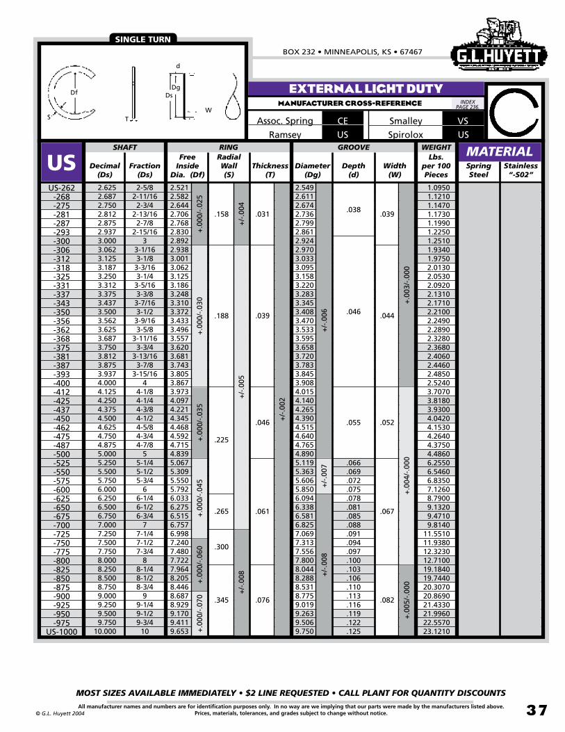
BOX 232 • MINNEAPOLIS, KS • 67467
MOST SIZES AVAILABLE IMMEDIATELY • $2 LINE REQUESTED • CALL PLANT FOR QUANTITY DISCOUNTS
37All manufacturer names and numbers are for identification purposes only. In no way are we implying that our parts were made by the manufacturers listed above.Prices, materials, tolerances, and grades subject to change without notice.© G.L. Huyett 2004
EXTERNAL LIGHT DUTYMANUFACTURER CROSS-REFERENCE
CEAssoc. Spring
USRamsey
SINGLE TURN
VSSmalley
Free Inside
Dia. (Df)Decimal
(Ds)Fraction
(Ds)Thickness
(T)Diameter
(Dg)Depth
(d)SpringSteel
2.6252.6872.7502.8122.8752.9373.0003.0623.1253.1873.2503.3123.3753.4373.5003.5623.6253.6873.7503.8123.8753.9374.0004.1254.2504.3754.5004.6254.7504.8755.0005.2505.5005.7506.0006.2506.5006.7507.0007.2507.5007.7508.0008.2508.5008.7509.0009.2509.5009.750
10.000
2-5/82-11/162-3/4
2-13/162-7/8
2-15/163
3-1/163-1/83-3/163-1/43-5/163-3/83-7/163-1/23-9/163-5/8
3-11/163-3/4
3-13/163-7/8
3-15/164
4-1/84-1/44-3/84-1/24-5/84-3/44-7/8
55-1/45-1/25-3/4
66-1/46-1/26-3/4
77-1/47-1/27-3/4
88-1/48-1/28-3/4
99-1/49-1/29-3/4
10
2.5212.5822.6442.7062.7682.8302.8922.9383.0013.0623.1253.1863.2483.3103.3723.4333.4963.5573.6203.6813.7433.8053.8673.9734.0974.2214.3454.4684.5924.7154.8395.0675.3095.5505.7926.0336.2756.5156.7576.9987.2407.4807.7227.9648.2058.4468.6878.9299.1709.4119.653
SHAFT RING
USUS-262
-268-275-281-287-293-300-306-312-318-325-331-337-343-350-356-362-368-375-381-387-393-400-412-425-437-450-462-475-487-500-525-550-575-600-625-650-675-700-725-750-775-800-825-850-875-900-925-950-975
US-1000
Width(W)
+.0
00/-
.030
+.0
00/-
.035
GROOVERadialWall(S)
2.5492.6112.6742.7362.7992.8612.9242.9703.0333.0953.1583.2203.2833.3453.4083.4703.5333.5953.6583.7203.7833.8453.9084.0154.1404.2654.3904.5154.6404.7654.8905.1195.3635.6065.8506.0946.3386.5816.8257.0697.3137.5567.8008.0448.2888.5318.7759.0199.2639.5069.750
.188
.225
.265
.039
.046
.046
.055
.066
.069
.072
.075
.078
.081
.085
.088
.091
.094
.097
.100
.103
.106
.110
.113
.116
.119
.122
.125
.044
.052
+/-
.006
+/-
.007
+.0
03/-
.000
+/-
.005
+.0
00/-
.070
+.0
00/-
.025
+/-
.004
+.0
00/-
.045
+/-
.002
.300
.345
.061
.076
.067
.082
+.0
00/-
.060
+/-
.008
+.0
04/-
.000
+/-
.008
+.0
05/-
.000
.158 .031 .039.038
MATERIALStainless “-S02”
WEIGHTLbs.
per 100 Pieces
1.0950 1.1210 1.1470 1.1730 1.1990 1.2250 1.2510 1.9340 1.9750 2.0130 2.0530 2.0920 2.1310 2.1710 2.2100 2.2490 2.2890 2.3280 2.3680 2.4060 2.4460 2.4850 2.5240 3.7070 3.8180 3.9300 4.0420 4.1530 4.2640 4.3750 4.4860 6.2550 6.5460 6.8350 7.1260 8.7900 9.1320 9.4710 9.814011.551011.938012.323012.710019.184019.744020.307020.869021.433021.996022.557023.1210
Df
TSW
d
DgDs
INDEX PAGE 236.
USSpirolox

EXTERNAL SPIRAL RINGSREVISED 09-04
MOST SIZES AVAILABLE IMMEDIATELY • $2 LINE REQUESTED • CALL PLANT FOR QUANTITY DISCOUNTS
38
785•392•3017 FAX 785.392.2845
All manufacturer names and numbers are for identification purposes only. In no way are we implying that our parts were made by the manufacturers listed above.Prices, materials, tolerances, and grades subject to change without notice. © G.L. Huyett 2004
www.huyett.com
Very popular series that will accommodate light and medium bearing ser ies thrust loads. Available in military and aerospace specifications.
1. Verify shaft diameter (Ds).2. Measure free inside diameter (Df) of the
ring.3. Determine the ring thickness (T) and radial
wall (S).
COMMONAXIAL ASSEMBLY
Free Inside
Dia. (Df)Decimal
(Ds)Fraction
(Ds)Thickness
(T)Diameter
(Dg)Depth
(d)Spring Steel
.500
.531
.551
.562
.594
.625
.656
.669
.687
.718
.750
.781
.812
.843
.875
.906
.937
.968
.9841.0001.0231.0311.0621.0931.1251.1561.1881.2181.2501.2811.3121.3431.3751.4061.4371.4681.500
1/217/3214mm9/1619/325/8
21/3217mm11/1623/323/4
25/3213/1627/327/8
29/3215/1631/3263/64
126mm1-1/321-1/161-3/321-1/81-5/321-3/161-7/321-1/41-9/321-5/161-11/321-3/8
1-13/321-7/161-15/321-1/2
.467
.498
.518
.529
.561
.585
.617
.629
.647
.679
.710
.741
.771
.803
.828
.860
.889
.916
.930
.946
.968
.9781.0071.0401.0701.1021.1271.1591.1881.2211.2511.2821.3081.3401.3701.4021.433
SHAFT RING
RSRS-050-053-055-056-059-062-065-066-068-071-075-078-081-084-087-090-093-096-098-100-102-103-106-109-112-115-118-121-125-128-131-134-137-140-143-146
RS-150
Width(W)
+/-
.002
+/-
.003
+/-
.004
+.0
00/-
.013
+.0
00/-
.015
GROOVE
+/-
.002
RadialWall(S)
.474
.505
.525
.536
.569
.594
.625
.638
.656
.687
.719
.750
.781
.812
.838
.869
.900
.925
.941
.957
.980
.9881.0201.0511.0831.1141.1401.1701.2021.2331.2641.2951.3231.3541.3851.4161.448
.045
.055
.065
.075
.085
.095
.025
.031
.037
.043
.030
.036
.042
.048
.013
.016
.019
.021
.024
.026
+.0
03/-
.000
+.0
04/-
.000
+/-
.004
RS CONTINUED NEXT PAGE.
EXTERNAL MEDIUM DUTYMANUFACTURER CROSS-REFERENCE
MATERIAL
AEAssoc. Spring
RSRamsey
RS KS (Page 47)
GROOVE INTERCHANGEUSE ANY OF THESE PARTS IN THE SAME SIZED GROOVE.
MOST POPULAR
Stainless “-S02”
WS
RSSpirolox MIL-R-27426A1
Aerospace
PERFORMANCE RESULTS VARY. YOUR RING SELECTION SHOULD BE MADE BASED ON INDIVIDUAL APPLICATION.
WEIGHTLbs.
per 100 Pieces
ROUGHLY TWICE THE
THRUST CAPABILITY
OF “US” SERIES AND TWO-THIRDS
OF “RST” SERIES.
0.04400.04800.05000.05100.05400.07000.07400.07500.07700.08100.12700.13200.13800.14300.14800.15300.15700.22600.23100.23400.23900.24100.24800.25600.26400.27100.35200.36200.37100.38000.43500.44600.45500.46600.47600.48700.4970
INDEX PAGE 236.
DESCRIPTION HOW TO IDENTIFY GENERAL USE
RS
AS3218
Military
Smalley RS-050/ RS-150
RS-156and up
Df
W
d
DgDs
TS

BOX 232 • MINNEAPOLIS, KS • 67467
MOST SIZES AVAILABLE IMMEDIATELY • $2 LINE REQUESTED • CALL PLANT FOR QUANTITY DISCOUNTS
39All manufacturer names and numbers are for identification purposes only. In no way are we implying that our parts were made by the manufacturers listed above.Prices, materials, tolerances, and grades subject to change without notice.© G.L. Huyett 2004
EXTERNAL MEDIUM DUTYMANUFACTURER CROSS-REFERENCE
Very popular series that will accommodate light and medium bearing ser ies thrust loads. Available in military and aerospace specifications.
1. Verify shaft diameter (Ds).2. Measure free inside diameter (Df) of the
ring.3. Determine the ring thickness (T) and radial
wall (S).
COMMONAXIAL ASSEMBLY
Free Inside
Dia. (Df)Decimal
(Ds)Fraction
(Ds)Thickness
(T)Diameter
(Dg)Depth
(d)SpringSteel
1.5621.5751.6251.6871.7501.7711.8131.8751.9381.9692.0002.0622.1252.1562.1652.1882.2502.3122.3622.3752.4372.5002.5592.5622.6252.6882.7502.8132.8752.9372.9523.0003.0623.1253.1493.1873.250
1-9/1640mm1-5/8
1-11/161-3/4
44.9mm1-13/161-7/8
1-15/161-31/32
22-1/162-1/82-5/3255mm1-3/162-1/42-5/16
59.9mm2-3/82-7/162-1/2
64.9mm2-9/162-5/8
2-11/162-3/4
2-13/162-7/8
2-15/1674.9mm
33-1/163-1/8
79.9mm3-3/163-1/4
1.4901.5031.5491.6101.6731.6901.7301.7891.8441.8821.9091.9712.0292.0602.0702.0922.1532.2112.2612.2732.3312.3942.4492.4522.5142.5722.6352.6962.7552.8172.8312.8772.9383.0003.0233.0613.121
SHAFT RING
RSRS-156-157-162-168-175-177-181-187-193-196-200-206-212-215-216-218-225-231-236-237-243-250-255-256-262-268-275-281-287-293-295-300-306-312-314-318
RS-325
Width(W)
+.0
04/-
.000
+.0
05/-
.000
+/-
.005
+.0
00/-
.020
+.0
00/-
.025
+.0
00/-
.030
GROOVE
+/-
.006
+/-
.003
RadialWall(S)
1.5071.5201.5661.6281.6911.7081.7491.8081.8611.9021.9291.9922.0512.0822.0912.1132.1762.2342.2842.2972.3552.4182.4732.4762.5392.5972.6602.7222.7812.8432.8582.9042.9663.0273.0513.0893.150
.118
.128
.138
.148
.158
.168
.178.061
.049.056
.068
.030
.032
.034
.035
.037
.039
.041
.043
.045
.047
.048
.049
.050
+/-
.004
+/-
.005
ASSORTMENTS
PAGE 225
.108.028
RS CONTINUED NEXT PAGE.
MATERIAL
RS KS (Page 47)
MOST POPULAR
Stainless “-S02”
AEAssoc. Spring
RSRamsey
Smalley
RS MIL-R-27426A1
Aerospace
PERFORMANCE RESULTS VARY. YOUR RING SELECTION SHOULD BE MADE BASED ON INDIVIDUAL APPLICATION.
WEIGHTLbs.
per 100 Pieces
0.71100.71700.73800.84200.87400.88200.90201.01701.04101.06201.07701.11101.14201.25501.26101.27401.31001.34501.37401.38101.52501.56401.59901.59701.63701.79301.83602.00302.04502.09002.10002.66602.72102.95102.97203.00903.0660
METRIC AEROSPACE
ON PAGE 192.
RS-050/ RS-150
RS-156and up
Df
W
d
DgDs
TS
GROOVE INTERCHANGEUSE ANY OF THESE PARTS IN THE SAME SIZED GROOVE.
INDEX PAGE 236.
DESCRIPTION HOW TO IDENTIFY GENERAL USE
RS
AS3218
MilitarySpirolox
WS
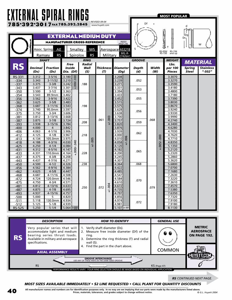
EXTERNAL SPIRAL RINGSREVISED 09-04
MOST SIZES AVAILABLE IMMEDIATELY • $2 LINE REQUESTED • CALL PLANT FOR QUANTITY DISCOUNTS
40
785•392•3017 FAX 785.392.2845
All manufacturer names and numbers are for identification purposes only. In no way are we implying that our parts were made by the manufacturers listed above.Prices, materials, tolerances, and grades subject to change without notice. © G.L. Huyett 2004
www.huyett.com
Very popular series that will accommodate light and medium bearing ser ies thrust loads. Available in military and aerospace specifications.
1. Verify shaft diameter (Ds).2. Measure free inside diameter (Df) of the
ring.3. Determine the ring thickness (T) and radial
wall (S).4. Find the part in the chart above.
COMMONAXIAL ASSEMBLY
Free Inside
Dia. (Df)Decimal
(Ds)Fraction
(Ds)Thickness
(T)Diameter
(Dg)Depth
(d)SpringSteel
3.3123.3433.3753.4373.5003.5433.5623.6253.6873.7403.7503.8123.8753.9384.0004.0634.1254.1344.1884.2504.3124.3314.3754.4374.5004.5624.6254.6874.7244.7504.8124.8754.9375.0005.1185.1255.250
3-5/163-11/32
3-3/83-7/163-1/2
89.9mm3-9/163-5/8
3-11/1695.0mm
3-3/43-13/163-7/8
3-15/164
4-1/164-1/8
105.0mm4-3/164-1/44-5/16
110.0mm4-3/84-7/164-1/24-9/164-5/8
4-11/16120.0mm
4-3/44-13/164-7/8
4-15/165
130.0mm5-1/85-1/4
3.1803.2103.2423.3013.3633.4023.4223.4833.5433.5973.6063.6683.7243.7843.8423.9063.9673.9754.0304.0844.1474.1644.2084.2714.3264.3844.4474.5084.5464.5714.6334.6954.7574.8204.9344.9395.064
SHAFT RING
RSRS-331-334-337-343-350-354-356-362-368-374-375-381-387-393-400-406-412-413-418-425-431-433-437-443-450-456-462-468-472-475-481-487-493-500-511-512
RS-525
Width(W)
+.0
00/-
.040
GROOVERadialWall(S)
3.2083.2393.2713.3313.3943.4333.4523.5153.5753.6283.6383.7003.7573.8203.8763.9394.0004.0104.0584.1204.1824.2004.2454.3074.3644.4224.4854.5474.5844.6104.6724.7354.7974.8564.9744.9815.107
.198
.208
.218
.228
.238
.250 .072
.061
.079
.068
.055
.056
.059
.062
.065
.068
.070
.072
+/-
.005
+.000/-.050
+/-
.006
.053
.052.188
+.0
00/-
.030
+.0
05/-
.000
+/-
.003
+/-
.004
RS CONTINUED NEXT PAGE.
EXTERNAL MEDIUM DUTYMANUFACTURER CROSS-REFERENCE
MATERIAL
RS KS (Page 47)
MOST POPULAR
Stainless “-S02”
AEAssoc. Spring
RSRamsey
WSSmalley
RSSpirolox MIL-R-27426A1
Aerospace
PERFORMANCE RESULTS VARY. YOUR RING SELECTION SHOULD BE MADE BASED ON INDIVIDUAL APPLICATION.
WEIGHTLbs.
per 100 Pieces
3.30703.32703.35903.41803.48003.71803.73903.80303.86703.92403.93303.99904.27404.34004.62804.70304.76204.77104.83505.13505.21205.23205.28605.36205.68007.07007.16807.26307.32207.36107.45707.53807.63507.73207.91007.91808.1130
METRIC AEROSPACE
ON PAGE 192.
RS-050/ RS-150
RS-156and up
Df
W
d
DgDs
TS
GROOVE INTERCHANGEUSE ANY OF THESE PARTS IN THE SAME SIZED GROOVE.
INDEX PAGE 236.
DESCRIPTION HOW TO IDENTIFY GENERAL USE
RS
AS3218
Military
+/-.007

BOX 232 • MINNEAPOLIS, KS • 67467
MOST SIZES AVAILABLE IMMEDIATELY • $2 LINE REQUESTED • CALL PLANT FOR QUANTITY DISCOUNTS
41All manufacturer names and numbers are for identification purposes only. In no way are we implying that our parts were made by the manufacturers listed above.Prices, materials, tolerances, and grades subject to change without notice.© G.L. Huyett 2004
EXTERNAL MEDIUM DUTYMANUFACTURER CROSS-REFERENCE
Very popular series that will accommodate light and medium bearing ser ies thrust loads. Available in military and aerospace specifications.
1. Verify shaft diameter (Ds).2. Measure free inside diameter (Df) of the
ring.3. Determine the ring thickness (T) and radial
wall (S).4. Find the part in the chart above.
COMMONAXIAL ASSEMBLY
Free Inside
Dia. (Df)Decimal
(Ds)Fraction
(Ds)Thickness
(T)Diameter
(Dg)Depth
(d)SpringSteel
5.3755.5005.5115.6255.7505.8755.9056.0006.1256.2506.2996.3756.5006.6256.7506.8757.0007.1257.2507.3757.5007.6257.7507.8758.0008.2508.5008.7509.0009.2509.5009.750
10.00010.25010.50010.75011.000
5-3/85-1/2
140.0mm5-5/85-3/45-7/8
150.0mm6
6-1/86-1/4
158.8mm6-3/86-1/26-5/86-3/46-7/8
77-1/87-1/47-3/87-1/27-5/87-3/47-7/8
88-1/48-1/28-3/4
99-1/49-1/29-3/4
1010-1/410-1/210-3/4
11
5.1875.3085.3205.4335.5505.6745.7055.7985.9036.0266.0766.1526.2746.3906.5136.6386.7616.8776.9997.1257.2507.3637.4867.6117.7347.9728.2208.4598.7078.9459.1949.4329.6809.918
10.16610.40510.653
SHAFT RING
RSRS-537-550-551-562-575-587-590-600-612-625-629-637-650-662-675-687-700-712-725-737-750-762-775-787-800-825-850-875-900-925-950-975
-1000 -1025 -1050 -1075RS-1100
Width(W)
+.0
00/-
.060
GROOVERadialWall(S)
5.2285.3535.3645.4785.5975.7225.7525.8475.9536.0786.1276.2036.3286.4436.5686.6936.8186.9337.0587.1837.3087.4237.5487.6737.7988.0388.2888.5288.7789.0189.2689.5089.7589.998
10.24810.48810.738
.312
.086
.091
.096
.101
.106+
.006
/-.0
00
+.0
00/-
.070
+/-
.004
.375
.086 .094
.111
.116
.121
.126
.131
+/-
.008
+/-
.006
+.0
00/-
.050
.250 .072
.077
.074
.079
+/-
.005
+/-
.007
+.0
05/-
.000
MATERIAL
RS KS (Page 47)
MOST POPULAR
Stainless “-S02”
AEAssoc. Spring
RSRamsey
WSSmalley
RSSpiroloxMIL-R-
27426A1
Aerospace
PERFORMANCE RESULTS VARY. YOUR RING SELECTION SHOULD BE MADE BASED ON INDIVIDUAL APPLICATION.
WEIGHTLbs.
per 100 Pieces
ROUGHLY TWICE THE
THRUST CAPABILITY
OF “US” SERIES AND TWO-THIRDS
OF “RST” SERIES.
8.3040 8.4920 8.5100 8.6940 8.8690 9.0610 9.1100 9.254014.249014.446014.564014.740015.024015.293015.580015.870016.156016.472016.756017.050017.341017.604017.891018.182018.376022.929023.624024.293024.988025.654026.351027.018027.713028.379029.073029.744030.4380
RS-050/ RS-150
RS-156and up
Df
W
d
DgDs
TS
GROOVE INTERCHANGEUSE ANY OF THESE PARTS IN THE SAME SIZED GROOVE.
INDEX PAGE 236.
DESCRIPTION HOW TO IDENTIFY GENERAL USE
RS
AS3218
Military

EXTERNAL SPIRAL RINGSREVISED 09-04
MOST SIZES AVAILABLE IMMEDIATELY • $2 LINE REQUESTED • CALL PLANT FOR QUANTITY DISCOUNTS
42
785•392•3017 FAX 785.392.2845
All manufacturer names and numbers are for identification purposes only. In no way are we implying that our parts were made by the manufacturers listed above.Prices, materials, tolerances, and grades subject to change without notice. © G.L. Huyett 2004
www.huyett.com
Originally designed to fit NAS 50-51 grooves, RST is a common OEM specification. Two and three turn designs are easier to install than the RSN because of multiple turn design.
1. Verify shaft diameter (Ds).2. Measure the free inside diameter (Df) of the
ring.3. Determine the ring thickness (T) and radial
wall (S).4. Find the part in the chart above.
RST USC (Page 68)
UNCOMMONAXIAL ASSEMBLY
Free Inside
Dia. (Df)Decimal
(Ds)Fraction
(Ds)Thickness
(T)Diameter
(Dg)Depth
(d)SpringSteel
.469
.500
.551
.562
.594
.625
.669
.688
.750
.781
.812
.875
.938
.9841.0001.0231.0621.1251.1881.2501.3121.3751.4381.5001.5621.6251.6871.7501.7711.8121.8751.9692.0002.0622.125
15/321/2
14.0mm9/1619/325/8
17.0mm11/163/4
25/3213/167/8
15/1663/64
126.0mm1-1/161-1/81-3/161-1/41-5/161-3/81-7/161-1/21-9/161-5/8
1-11/161-3/4
44.9mm1-13/161-7/8
1-31/322
2-1/162-1/8
.436
.469
.518
.529
.559
.590
.630
.648
.708
.738
.768
.827
.886
.934
.947
.9691.0051.0641.1261.1841.2401.2981.3591.4191.4761.5371.5981.6571.6761.7141.7741.8641.8941.9552.012
SHAFT RING
RSTRST-046
-050-055-056-059-062-066-068-075-078-081-087-093-098-100-102-106-112-118-125-131-137-143-150-156-162-168-175-177-181-187-196-200-206
RST-212
Width(W)
+.0
03/-
.000
+.0
04/-
.000
+/-
.003
+/-
.004
+/-.0
02
+.0
00/-
.013
+.0
00/-
.015
+.0
00/-
.020
+.00
0/-
.025
GROOVE
+/-
.006
+/-
.002
+/-
.003
RadialWall(S)
.443
.474
.524
.535
.565
.596
.638
.655
.715
.745
.776
.835
.894
.940
.955
.9771.0151.0751.1351.1951.2501.3101.3701.4301.4901.5501.6101.6701.6891.7301.7901.8791.9101.9702.027
.045
.055
.065
.075
.088
.093
.098
.103
.113
.118
.123
.128
.141
.024
.035
.042
.050
.062
.078
.028
.039
.046
.056
.068
.086
+/-
.004
.013
.013
.014
.014
.015
.015
.016
.017
.018
.018
.018
.020
.022
.022
.023
.023
.024
.025
.027
.028
.031
.033
.034
.035
.036
.038
.039
.040
.041
.041
.043
.045
.045
.046
.049
+/-
.005
+.00
5/-.0
00
RST CONTINUED NEXT PAGE.
EXTERNAL MEDIUM HEAVYMANUFACTURER CROSS-REFERENCE
MATERIAL
AMEAssoc. SpringRSTRamsey
EASIER TO INSTALL
Stainless “-S02”
WSTSmalley
WEIGHTLbs.
per 100 Pieces
ASSORTMENTS
PAGE 225PERFORMANCE RESULTS VARY. YOUR RING SELECTION SHOULD BE MADE BASED ON INDIVIDUAL APPLICATION.
0.04200.06400.07100.07200.07600.10000.10700.15500.16900.17600.18300.22800.24400.25600.26000.26600.39300.41500.43800.48800.54000.59500.61800.64600.88001.00701.04501.08201.14401.16901.20801.26701.34301.93501.9890
FITS NAS 50-51 GROOVES.
GROOVE INTERCHANGEUSE ANY OF THESE PARTS IN THE SAME SIZED GROOVE.
Df
Wd
Dg
Ds
T
S
RST- 046/RST- 150
RST- 156/RST- 600
RST- 625& up
INDEX PAGE 236.
DESCRIPTION HOW TO IDENTIFY GENERAL USE
RST
RSTSpirolox

BOX 232 • MINNEAPOLIS, KS • 67467
MOST SIZES AVAILABLE IMMEDIATELY • $2 LINE REQUESTED • CALL PLANT FOR QUANTITY DISCOUNTS
43All manufacturer names and numbers are for identification purposes only. In no way are we implying that our parts were made by the manufacturers listed above.Prices, materials, tolerances, and grades subject to change without notice.© G.L. Huyett 2004
EXTERNAL MEDIUM HEAVYMANUFACTURER CROSS-REFERENCE
Free Inside
Dia. (Df)Decimal
(Ds)Fraction
(Ds)Thickness
(T)Diameter
(Dg)Depth
(d)SpringSteel
2.1562.2502.3122.3752.4372.5002.5592.6252.6872.7502.8752.9373.0003.0623.1253.1563.2503.3443.4373.5003.5433.6253.6873.7503.8753.9384.0004.2504.3754.5004.7505.0005.2505.5005.7506.0006.2506.5006.7507.0007.2507.5007.7508.0008.2508.5008.7509.0009.2509.5009.750
10.000
2-5/322-1/42-5/162-3/82-7/162-1/2
64.9mm2-5/8
2-11/162-3/42-7/8
2-15/163
3-1/163-1/83-5/323-1/4
3-11/323-7/163-1/2
89.9mm3-5/8
3-11/163-3/43-7/8
3-15/164
4-1/44-3/84-1/24-3/4
55-1/45-1/25-3/4
66-1/46-1/26-3/4
77-1/47-1/27-3/4
88-1/48-1/28-3/4
99-1/49-1/29-3/4
10
SHAFT RING
RSTRST-215
-225-231-237-243-250-255-262-268-275-287-293-300-306-312-315-325-334-343-350-354-362-368-375-387-393-400-425-437-450-475-500-525-550-575-600-625-650-675-700-725-750-775-800-825-850-875-900-925-950-975
RST-1000
Width(W)
+.00
0/-.0
25+
.000
/-.0
30
GROOVERadialWall(S)
2.0572.1452.2052.2652.3252.3852.4512.5052.5652.6252.7422.8012.8602.9202.9803.0103.1003.1903.2803.3403.3813.4583.5173.5773.6963.7563.8154.0654.1904.3104.5504.7905.0305.2655.5055.745 5.9856.2256.4656.7056.9427.1807.4207.6607.9008.1408.3838.6208.8609.1009.3389.575
2.0412.1292.1882.2482.3072.3662.4322.4852.5452.6042.7222.7802.8382.8972.9572.9863.0753.1643.2543.3153.3563.4333.4833.5503.6703.7303.7874.0374.1624.2804.5154.7554.9955.2295.4665.7055.9386.1826.4206.6586.8947.1307.3687.6077.8458.0838.3218.5608.7989.0369.2739.508
.188
.078
.093
.086
.103
.050
.053
.054
.055
.056
.058
.058
.060
.061
.063
.067
.068
.070
.071
.073
.073
.075
.077
.079
.080
.081
.084
.085
.087
.090
.091
.093
.093
.093
.095
.100
.105
.110
.118
.123
.128
.133
.138
.143
.148
.154
.160
.165
.170
.175
.180
.184
.190
.195
.200
.206
.213
+.00
0/-.0
60+.
000/
-.070 +/-
.005
+/-
.008
+.00
8/-.
000
.312
.375
.165
.189
.174
.209
+/-
.004
.141
+.0
05/-
.000
+.00
6/-.0
00
+/-
.006
+.0
00/-
.040
+/-
.007
+/-
.003
+/-
.004
.250
.375
.111
.127
.120
.139
+/-
.005
+/-
.006
+.00
0/-.0
50
MATERIAL
AMEAssoc. SpringRSTRamsey
EASIER TO INSTALL
Stainless “-S02”
WSTSmalley
WEIGHTLbs.
per 100 Pieces
2.0160 2.1000 2.1570 2.2140 2.2700 3.1610 3.2450 3.3130 3.3890 4.0790 4.2570 4.3440 4.4310 4.5200 4.6100 4.6540 4.7880 4.9220 5.0570 8.3660 8.4400 8.6250 8.7450 8.9060 9.1940 9.3380 9.475010.075010.375010.658011.223011.726021.705022.673023.652024.641026.593027.694028.768029.842037.487044.509045.988047.474048.954050.433051.910053.395054.873056.351057.822059.2810
Df
Wd
Dg
Ds
T
S
RST- 046/RST- 150
RST- 156/RST- 600
RST- 625& up
INDEX PAGE 236.
RSTSpirolox

EXTERNAL SPIRAL RINGSREVISED 09-04
MOST SIZES AVAILABLE IMMEDIATELY • $2 LINE REQUESTED • CALL PLANT FOR QUANTITY DISCOUNTS
44
785•392•3017 FAX 785.392.2845
All manufacturer names and numbers are for identification purposes only. In no way are we implying that our parts were made by the manufacturers listed above.Prices, materials, tolerances, and grades subject to change without notice. © G.L. Huyett 2004
www.huyett.com
Heavy duty design for use in NAS 669-670 deep grooves in applications like double row and tapered roller bearings. Requires no tools for removal.
1. Verify shaft diameter (Ds).2. Measure free inside diameter (Df) of the
ring.3. Determine the ring thickness (T) and radial
wall (S).4. Find the part in the chart above.
COMMONAXIAL ASSEMBLY
Free Inside
Dia. (Df)Decimal
(Ds)Fraction
(Ds)Thickness
(T)Diameter
(Dg)Depth
(d)SpringSteel
.469
.500
.551
.562
.594
.625
.669
.688
.750
.781
.812
.875
.938
.9841.0001.0231.0621.1251.1881.2501.3121.3751.4381.5001.5621.6251.6871.7501.7711.8121.8751.9692.0002.0622.1252.156
15/321/2
14.0mm9/1619/325/8
17.0mm11-16
3/425/3213/167/8
15/1663/64
126.0mm1-1/161-1/81-3/161-14
1-5/161-3/81-7/161-1/21-5/161-5/8
1-11/161-3/4
44.9mm1-13/161-7/8
50mm2
2-1/162-1/82-5/32
.439
.464
.514
.525
.554
.583
.623
.641
.698
.727
.756
.814
.875
.919
.932
.953
.9861.0471.1051.1631.2181.2771.3361.3851.4531.5131.5731.6331.6511.6901.7511.8381.8671.9321.9892.018
SHAFT RING
RSNRSN-046
-050-055-056-059-062-066-068-075-078-081-087-093-098-100-102-106-112-118-125-131-137-143-150-156-162-168-175-177-181-187-196-200-206-212
RSN-215
Width(W)
+.0
03/-
.000
+.0
04/-
.000
+/-
.002
+/-
.003
+/-
.004
+/-
.004
+/-
.005
+.0
00/-
.013
+.0
00/-
.020
GROOVE
+/-
.002
+/-
.003
RadialWall(S)
.443
.468
.519
.530
.559
.588
.629
.646
.704
.733
.762
.821
.882
.926
.940
.961
.9981.0591.1181.1761.2321.2911.3501.4061.4681.5291.5891.6501.6691.7081.7691.8571.8861.9462.0032.032
.045
.050
.055
.065
.075
.085
.103
.118
.128
.158
.168
.025
.035
.042
.050
.062
.078
.029
.039
.046
.056
.068
.086
.013
.016
.016
.016
.018
.019
.020
.021
.023
.024
.025
.027
.028
.029
.030
.031
.032
.033
.035
.037
.040
.042
.044
.047
.047
.048
.049
.050
.051
.052
.053
.056
.057
.058
.061
.062+.0
00/
-.02
5
+/-
.005
+/-
.006
+.0
05/
-.00
0
RSN SH (Page 6) SHI (Page 10) USH (Page 71) SSN (Page 49)
RSN CONTINUED NEXT PAGE.
EXTERNAL HEAVY DUTYMANUFACTURER CROSS-REFERENCE
MATERIAL
AHEAssoc. Spring
RSNRamsey
INTERCHANGEABLE WITH SNAP RINGS
Stainless “-S02”
FITS INTO THE SAME GROOVE AS SNAP
RINGS.
WSMSmalley
RSNSpirolox MIL-R-27426A2
Aerospace
WEIGHTLbs.
per 100 Pieces
PERFORMANCE RESULTS VARY. YOUR RING SELECTION SHOULD BE MADE BASED ON INDIVIDUAL APPLICATION.
0.04200.07100.07800.08000.08500.09900.10600.15300.16600.17300.18000.22400.24100.28900.29300.29900.45800.48500.51100.53600.65000.67900.70400.72901.04101.08201.12301.16401.17701.20301.56201.63601.66002.31002.37402.4070
GROOVE INTERCHANGEUSE ANY OF THESE PARTS IN THE SAME SIZED GROOVE.
RSN-046/RSN-066
RSN-068& up
Df
Wd
Dg
Ds
T
S
INDEX PAGE 236.
DESCRIPTION HOW TO IDENTIFY GENERAL USE
RSN
AS3216
Military

BOX 232 • MINNEAPOLIS, KS • 67467
MOST SIZES AVAILABLE IMMEDIATELY • $2 LINE REQUESTED • CALL PLANT FOR QUANTITY DISCOUNTS
45All manufacturer names and numbers are for identification purposes only. In no way are we implying that our parts were made by the manufacturers listed above.Prices, materials, tolerances, and grades subject to change without notice.© G.L. Huyett 2004
Heavy duty design for use in NAS 669-670 deep grooves in applications like double row and tapered roller bearings. Requires no tools for removal.
1. Verify shaft diameter (Ds).2. Measure free inside diameter (Df) of the
ring.3. Determine the ring thickness (T) and radial
wall (S).4. Find the part in the chart above.
COMMONAXIAL ASSEMBLY
Free Inside
Dia. (Df)Decimal
(Ds)Fraction
(Ds)Thickness
(T)Diameter
(Dg)Depth
(d)SpringSteel
2.2502.3122.3752.4372.5002.5592.6252.6872.7502.8752.9373.0003.0623.1253.1563.2503.3443.4373.5003.5433.6253.6873.7503.8753.9384.0004.2504.3754.5004.7505.0005.2505.5005.7506.0006.250
2-1/42-5/162-3/82-7/162-1/2
64.9mm2-5/8
2-11/162-3/42-7/8
2-15/163
3-1/163-1/83-5/323-1/4
3-11/323-7/163-1/2
89.9mm3-5/8
3-11/163-3/43-7/8
3-15/164
4-1/44-3/84-1/24-3/4
55-1/45-1/25-3/4
66-1/4
2.1052.1632.2232.2832.3432.4022.4642.5232.5842.7022.7602.8182.8782.9362.9653.0543.1443.2343.2933.3333.4113.4693.5273.6473.7083.7654.0374.1614.2804.5184.7564.9955.2285.4665.7055.938
SHAFT RING
RSNRSN-225
-231-237-243-250-255-262-268-275-287-293-300-306-312-315-325-334-343-350-354-362-368-375-387-393-400-425-437-450-475-500-525-550-575-600
RSN-625
Width(W)
+.0
05/-
.000
+/-
.005
+/-
.006
+.00
0/-.0
25+
.000
/-.0
30+
.000
/-.0
35+.
000/
-.050
$ 47.41$47.89$76.57$91.08$76.84$91.08$81.86$81.93$87.81$94.81$95.61$90.40$96.41$96.41$96.41$91.01$96.77
$100.68$112.19$134.92$132.04$143.66$123.91$144.91$148.28$143.52$169.21$205.86$183.25$195.85$197.54$242.08$259.01$279.47$254.69$453.35
GROOVE
+/-
.003
+/-
.004
RadialWall(S)
2.1202.1782.2392.2992.3602.4192.4812.5412.6022.7212.7792.8382.8982.9572.9863.0763.1663.2573.3163.3573.4353.4933.5523.6733.7343.7924.0654.1904.3104.5504.7905.0305.2655.5055.7455.985
.200
.225
.270
.350
.418
.078
.093
.111
.127
.156
.086
.103
.120
.139
.174
.065
.067
.068
.069
.070
.070
.072
.073
.074
.077
.079
.081
.082
.084
.085
.087
.089
.090
.092
.093
.095
.097
.099
.101
.102
.104
.093
.093
.095
.100
.105
.110
.118
.123
.128
.133+/-.007+.000/-.060
+/-.005
+/-
.006
+/-
.007
+/-.008
+.00
6/-.0
00
+.008/-.000
RSN SH (Page 6) SHI (Page 10) USH (Page 71) SSN (Page 49)
.168
EXTERNAL HEAVY DUTYMANUFACTURER CROSS-REFERENCE
MATERIAL
INTERCHANGEABLE WITH SNAP RINGS
Stainless “-S02”
AHEAssoc. Spring
RSNRamsey
WSMSmalley
RSNSpiroloxMIL-R-
27426A2
Aerospace
WEIGHTLbs.
per 100 Pieces
PERFORMANCE RESULTS VARY. YOUR RING SELECTION SHOULD BE MADE BASED ON INDIVIDUAL APPLICATION.
2.5060 2.5720 3.1860 3.2670 3.3490 3.4280 3.5120 3.5920 4.9130 5.1250 5.2300 5.3340 5.4420 5.5470 5.5990 5.7590 5.9210 6.0830 9.0300 9.1080 9.3100 9.4600 9.6100 9.922010.080010.228010.933011.254011.563012.180012.719020.162021.060021.979022.901035.2260
ASSORTMENTS
PAGE 225
FITS NAS 669-670
GROOVES.
GROOVE INTERCHANGEUSE ANY OF THESE PARTS IN THE SAME SIZED GROOVE.
RSN-046/RSN-066
RSN-068& up
Df
Wd
Dg
Ds
T
S
INDEX PAGE 236.
DESCRIPTION HOW TO IDENTIFY GENERAL USE
RSN
RSN CONTINUED NEXT PAGE.
AS3216
Military

EXTERNAL SPIRAL RINGSREVISED 09-04
MOST SIZES AVAILABLE IMMEDIATELY • $2 LINE REQUESTED • CALL PLANT FOR QUANTITY DISCOUNTS
4�
785•392•3017 FAX 785.392.2845
All manufacturer names and numbers are for identification purposes only. In no way are we implying that our parts were made by the manufacturers listed above.Prices, materials, tolerances, and grades subject to change without notice. © G.L. Huyett 2004
www.huyett.com
EXTERNAL HEAVY DUTYMANUFACTURER CROSS-REFERENCE
Heavy duty design for use in NAS 669-670 deep grooves in applications like double row and tapered roller bearings. Requires no tools for removal.
1. Verify shaft diameter (Ds).2. Measure the free inside diameter (Df) of the
ring.3. Determine the ring thickness (T) and radial
wall (S).4. Find the part in the chart above.
COMMONAXIAL ASSEMBLY
RSN SH (Page 6) SHI (Page 10) USH (Page 71) SSN (Page 49)
Free Inside
Dia. (Df)Decimal
(Ds)Fraction
(Ds)Thickness
(T)Diameter
(Dg)Depth
(d)Spring
Steel
6.5006.7507.0007.2507.5007.7508.0008.2508.5008.7509.0009.2509.5009.750
10.00010.25010.50010.75011.00011.25011.50011.75012.00012.25012.50012.75013.00013.25013.50013.75014.00014.25014.50014.75015.000
6-1/26-3/4
77-1/47-1/27-3/4
88-1/48-1/28-3/4
99-1/49-1/29-3/4
1010-1/410-1/210-3/4
1111-1/411-1/211-3/4
1212-1/412-1/212-3/4
1313-1/413-1/213-3/4
1414-1/414-1/214-3/4
15
6.1816.4106.6486.8917.1307.3687.6067.8458.0838.3248.5608.7989.0369.2759.5089.7459.984
10.22110.45910.69210.93411.17111.41011.64711.88512.12412.36112.59812.83713.07413.31113.54813.78714.02414.262
SHAFT RING
RSNRSN-650
-675-700-725-750-775-800-825-850-875-900-925-950-975
-1000 -1025 -1050 -1075 -1100 -1125 -1150 -1175 -1200 -1225 -1250 -1275 -1300 -1325 -1350 -1375 -1400 -1425 -1450 -1475
RSN-1500
Width(W)
+/-
.008
+/-
.010
+/-
.007
+.0
00/-
.070
+.0
00/-
.090
GROOVERadialWall(S)
6.2256.4656.7056.9427.1807.4207.6607.9008.1408.3838.6208.8609.1009.3389.5759.814
10.05410.29310.53310.77211.01111.25011.49011.72911.96912.20812.44812.68712.92713.16613.40513.64413.88414.12314.363
.437
.500
.562
.138
.143
.148
.154
.160
.165
.170
.175
.180
.184
.190
.195
.200
.206
.213
.218
.223
.229
.234
.239
.245
.250
.255
.261
.266
.271
.276
.282
.287
.292
.298
.303
.308
.314
.319
+.0
08/-
.000
+/-
.012+
.015
/-.0
10
+.0
00/-
.110
+/-
.005
.662
.750
.209.187
+.0
00/
-.06
0
.418 .156 .174
MATERIAL
INTERCHANGEABLE WITH SNAP RINGS
Stainless “-S02”
RSN-046/RSN-066
RSN-068& up
Df
Wd
Dg
Ds
T
S
FITS INTO THE SAME GROOVE AS SNAP
RINGS.
AHEAssoc. Spring
RSNRamsey
WSMSmalley
RSNSpiroloxMIL-R-
27426A2
Aerospace
WEIGHTLbs.
per 100 Pieces
PERFORMANCE RESULTS VARY. YOUR RING SELECTION SHOULD BE MADE BASED ON INDIVIDUAL APPLICATION.
36.5990 37.8950 39.2370 42.4520 53.0980 54.7990 56.4990 58.2080 59.9090 61.6330 72.9660 74.9110 76.8570 78.8140 80.7190 82.0020 83.9590 85.8970 88.5790 89.7470103.6740105.8520108.0480110.2290112.4200114.2440138.2250140.7940143.3790145.9450148.5120151.0810175.1770178.0840181.0040
GROOVE INTERCHANGEUSE ANY OF THESE PARTS IN THE SAME SIZED GROOVE.
INDEX PAGE 236.
DESCRIPTION HOW TO IDENTIFY GENERAL USE
RSN
AS3216
Military
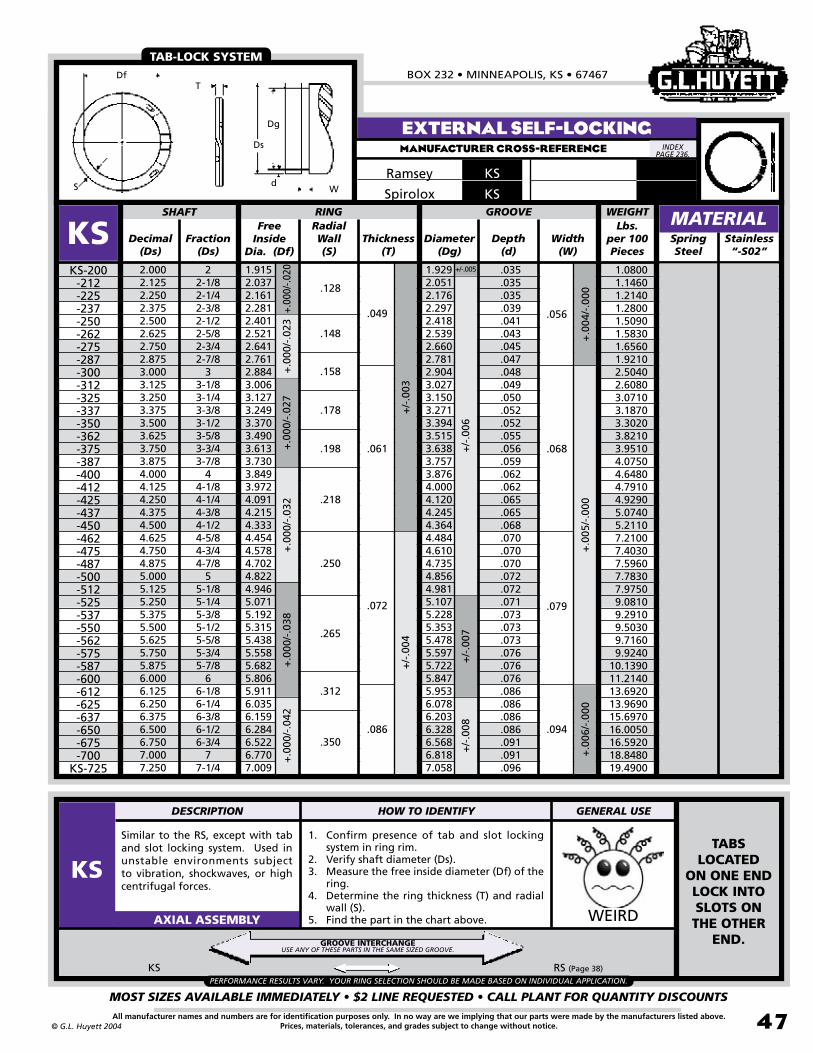
BOX 232 • MINNEAPOLIS, KS • 67467
MOST SIZES AVAILABLE IMMEDIATELY • $2 LINE REQUESTED • CALL PLANT FOR QUANTITY DISCOUNTS
47All manufacturer names and numbers are for identification purposes only. In no way are we implying that our parts were made by the manufacturers listed above.Prices, materials, tolerances, and grades subject to change without notice.© G.L. Huyett 2004
Similar to the RS, except with tab and slot locking system. Used in unstable environments subject to vibration, shockwaves, or high centrifugal forces.
1. Confirm presence of tab and slot locking system in ring rim.
2. Verify shaft diameter (Ds).3. Measure the free inside diameter (Df) of the
ring.4. Determine the ring thickness (T) and radial
wall (S).5. Find the part in the chart above. WEIRDAXIAL ASSEMBLY
EXTERNAL SELF-LOCKINGMANUFACTURER CROSS-REFERENCE
KSRamsey
KS RS (Page 38)
TAB-LOCK SYSTEM
KSSpirolox
Free Inside
Dia. (Df)Decimal
(Ds)Fraction
(Ds)Thickness
(T)Diameter
(Dg)Depth
(d)SpringSteel
2.0002.1252.2502.3752.5002.6252.7502.8753.0003.1253.2503.3753.5003.6253.7503.8754.0004.1254.2504.3754.5004.6254.7504.8755.0005.1255.2505.3755.5005.6255.7505.8756.0006.1256.2506.3756.5006.7507.0007.250
22-1/82-1/42-3/82-1/22-5/82-3/42-7/8
33-1/83-1/43-3/83-1/23-5/83-3/43-7/8
44-1/84-1/44-3/84-1/24-5/84-3/44-7/8
55-1/85-1/45-3/85-1/25-5/85-3/45-7/8
66-1/86-1/46-3/86-1/26-3/4
77-1/4
1.9152.0372.1612.2812.4012.5212.6412.7612.8843.0063.1273.2493.3703.4903.6133.7303.8493.9724.0914.2154.3334.4544.5784.7024.8224.9465.0715.1925.3155.4385.5585.6825.8065.9116.0356.1596.2846.5226.7707.009
SHAFT RING
KSKS-200
-212-225-237-250-262-275-287-300-312-325-337-350-362-375-387-400-412-425-437-450-462-475-487-500-512-525-537-550-562-575-587-600-612-625-637-650-675-700
KS-725
Width(W)
+.0
04/-
.000
+.0
05/-
.000
+/-.005
+/-
.006
+/-
.007
+.00
0/-.0
20+
.000
/-.0
23+
.000
/-.0
27+
.000
/-.0
32
GROOVE
+/-
.008
+/-
.003
RadialWall(S)
1.9292.0512.1762.2972.4182.5392.6602.7812.9043.0273.1503.2713.3943.5153.6383.7573.8764.0004.1204.2454.3644.4844.6104.7354.8564.9815.1075.2285.3535.4785.5975.7225.8475.9536.0786.2036.3286.5686.8187.058
.035
.035
.035
.039
.041
.043
.045
.047
.048
.049
.050
.052
.052
.055
.056
.059
.062
.062
.065
.065
.068
.070
.070
.070
.072
.072
.071
.073
.073
.073
.076
.076
.076
.086
.086
.086
.086
.091
.091
.096
.128
.148
.049
.061
.072
.086
.056
.068
.079
.094
+.0
00/-
.038
+.0
00/-
.042
+.0
06/-
.000
MATERIAL
.350
.312
.265
.250
.218
.198
.178
.158
Stainless “-S02”
WEIGHTLbs.
per 100 Pieces
PERFORMANCE RESULTS VARY. YOUR RING SELECTION SHOULD BE MADE BASED ON INDIVIDUAL APPLICATION.
TABS LOCATED
ON ONE END LOCK INTO SLOTS ON THE OTHER
END.
1.0800 1.1460 1.2140 1.2800 1.5090 1.5830 1.6560 1.9210 2.5040 2.6080 3.0710 3.1870 3.3020 3.8210 3.9510 4.0750 4.6480 4.7910 4.9290 5.0740 5.2110 7.2100 7.4030 7.5960 7.7830 7.9750 9.0810 9.2910 9.5030 9.7160 9.924010.139011.214013.692013.969015.697016.005016.592018.848019.4900
GROOVE INTERCHANGEUSE ANY OF THESE PARTS IN THE SAME SIZED GROOVE.
INDEX PAGE 236.
T
Dg
Ds
dS
Df
W
DESCRIPTION HOW TO IDENTIFY GENERAL USE
KS
+/-
.004

EXTERNAL SPIRAL RINGSREVISED 09-04
MOST SIZES AVAILABLE IMMEDIATELY • $2 LINE REQUESTED • CALL PLANT FOR QUANTITY DISCOUNTS
48
785•392•3017 FAX 785.392.2845
All manufacturer names and numbers are for identification purposes only. In no way are we implying that our parts were made by the manufacturers listed above.Prices, materials, tolerances, and grades subject to change without notice. © G.L. Huyett 2004
www.huyett.com
Standard ring formed into a conical shape that is designed to take up end-play. Best results occur when ring is installed in a non-loaded condition.
1. Verify conical shape of part.2. Confirm shaft diameter (Ds).3. Measure the free inside diameter (Df) of the
ring.4. Determine the ring thickness (T) and radial
wall (S).5. Find the part in the chart above. WEIRDAXIAL ASSEMBLY
EXTERNAL DISHEDMANUFACTURER CROSS-REFERENCE
MSRamsey
DISHED SHAPE FOR END-PLAY TAKE UP
CONICAL SHAPE FOR END-PLAY TAKE-UP.
MSSpirolox
Free Inside Dia.
(Df)Decimal
(Ds)Fraction
(Ds)Thickness
(T)Diameter
(Dg)Depth
(d)SpringSteel
1.0001.1251.2501.3751.5001.6251.7501.8752.0002.1252.2502.3752.5002.6252.7502.8753.0003.1253.2503.3753.5003.6253.7503.8754.0004.1254.2504.5004.7505.000
11-1/81-1/41-3/81-1/21-5/81-3/41-7/8
22-1/82-1/42-3/82-1/22-5/82-3/42-7/8
33-1/83-1/43-3/83-1/23-5/83-3/43-7/8
44-1/84-1/44-1/24-3/4
5
.9261.0431.1581.2711.3851.5061.6251.7421.8581.9732.0882.1832.3002.4192.5372.6532.7902.9053.0203.1353.2553.3723.4873.6063.7233.8483.9914.2324.4684.704
MSMS-100
-112-125-137-150-162-175-187-200-212-225-237-250-262-275-287-300-312-325-337-350-362-375-387-400-412-425-450-475
MS-500
Width(W)
+/-
.004
+/-
.005
+/-
.004
+.0
00/-
.013
+.0
00/-
.020
+.0
00/-
.025
+.0
00/-
.030
+/-
.002
+/-
.003
Radial Wall(S)
.020
.020
.027
.032
.037
.045
.042
.044
.047
.057
.055
.060
.065
.065
.070
.070
.098
.098
.105
.105
.086
.085
.096
.096
.102
.102
.119
.119
.117
.120
+/-
.006
Dish Height
(Hd)
SHAFT RING GROOVE
.9401.0591.1761.2911.4061.5291.6501.7691.8862.0032.1202.2392.3602.4812.6022.7212.8382.9573.0763.1923.3163.4353.5523.6733.7923.9194.0654.3104.5504.790
.030
.033
.037
.042
.047
.048
.050
.053
.057
.061
.065
.068
.070
.072
.074
.077
.081
.084
.087
.090
.092
.095
.099
.101
.104
.102
.092
.095
.100
.105
.095
.108
.128
.128
.148
.158
.168
.178
.188
.198
.218
.228
.238
.248
.248
.258
.312
.312
.312
.312
.350
.350
.350
.350
.375
.375
.375
.375
.437
.460
.043
.062
.072
.086
.048
.068
.079
.094
+/-.003
+/-
.006
+.0
00/-
.040
+/-.003
+/-
.004
+/-
.005
+/-
.005
+/-
.006
MATERIAL
.050 .056
Stainless “-S02”
Lbs. per 100 Pieces
WEIGHT
0.3360 0.4920 0.6200 0.7070 0.8590 1.0020 1.4810 1.6900 1.8960 2.1180 2.4770 2.7050 2.9720 3.2540 3.3960 4.4360 5.5610 5.7640
6.3480 6.5630 8.1730
8.4360 9.2730 9.5570
10.608010.929012.129013.419014.794016.3900
INDEX PAGE 236.
TTTTTTT
Dg
dWS
DfHd
Ds
T
DESCRIPTION HOW TO IDENTIFY GENERAL USE
MS
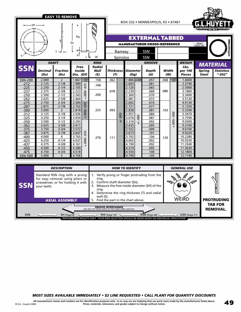
BOX 232 • MINNEAPOLIS, KS • 67467
MOST SIZES AVAILABLE IMMEDIATELY • $2 LINE REQUESTED • CALL PLANT FOR QUANTITY DISCOUNTS
49All manufacturer names and numbers are for identification purposes only. In no way are we implying that our parts were made by the manufacturers listed above.Prices, materials, tolerances, and grades subject to change without notice.© G.L. Huyett 2004
Standard RSN ring with a prong for easy removal using pliers or screwdriver, or for holding it with your teeth.
1. Verify prong or finger protruding from the ring.
2. Confirm shaft diameter (Ds).3. Measure the free inside diameter (Df) of the
ring.4. Determine the ring thickness (T) and radial
wall (S).5. Find the part in the chart above. WEIRDAXIAL ASSEMBLY
SSN SH (Page 6) SHI (Page 10) RSN (Page 44) USH (Page 71)
EXTERNAL TABBEDMANUFACTURER CROSS-REFERENCE
SSNRamsey
EASY TO REMOVE
PROTRUDING TAB FOR
REMOVAL.
SSNSpirolox
Free Inside
Dia. (Df)Decimal
(Ds)Fraction
(Ds)Thickness
(T)Diameter
(Dg)Depth
(d)SpringSteel
2.0002.1252.2502.3752.5002.6252.7502.8753.0003.1253.2503.5003.6253.7503.8754.0004.2504.3754.5004.7505.000
22-1/82-1/42-3/82-1/22-5/82-3/42-7/8
33-1/83-1/43-1/23-5/83-3/43-7/8
44-1/44-3/84-1/24-3/4
5
1.8671.9892.1052.2232.3432.4642.5842.7022.8182.9363.0543.2933.4113.5723.6473.7654.0374.1614.2804.5184.756
SHAFT RING
SSNSSN-200
-212-225-237-250-262-275-287-300-312-325-350-362-375-387-400-425-437-450-475
SSN-500
Width(W)
+/-
.006
+.000/-.020
+.0
00/-
.025
+.0
00/-
.030
GROOVE
+/-
.003
RadialWall(S)
1.8862.0032.1202.2392.3602.4812.6022.7212.8382.9573.0763.3163.4353.5523.6733.7924.0654.1904.3104.5504.790
.057
.061
.065
.068
.070
.072
.074
.077
.081
.084
.087
.092
.095
.099
.101
.104
.092
.092
.095
.100
.105
.158
.168
.200
.225
.270
.068.062
.111 .120
+.0
00/-
.035
+/-.005 +.004/-.000
+.0
05/-
.000
.086
.103
.078
.093
MATERIALStainless “-S02”
WEIGHTLbs.
per 100 Pieces
PERFORMANCE RESULTS VARY. YOUR RING SELECTION SHOULD BE MADE BASED ON INDIVIDUAL APPLICATION.
1.6600 2.3740 2.5060 3.1860 3.3490 3.5120 4.9130 5.1250 5.3340 5.5470 5.7590 9.0300 9.3100 9.6100 9.922010.228010.933011.254011.563012.180012.7190
GROOVE INTERCHANGEUSE ANY OF THESE PARTS IN THE SAME SIZED GROOVE.
INDEX PAGE 236.
Df
Ds
Dg
dWS
T
DESCRIPTION HOW TO IDENTIFY GENERAL USE
SSN
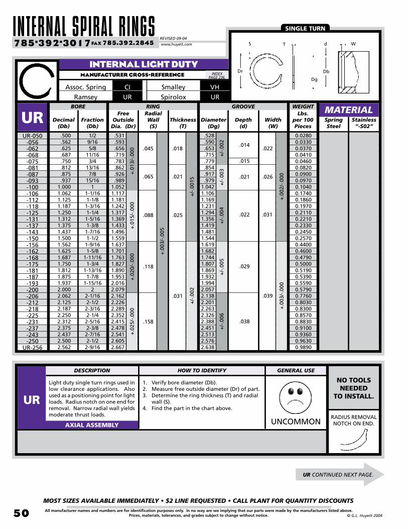
INTERNAL SPIRAL RINGSREVISED 09-04
MOST SIZES AVAILABLE IMMEDIATELY • $2 LINE REQUESTED • CALL PLANT FOR QUANTITY DISCOUNTS
50
785•392•3017 FAX 785.392.2845
All manufacturer names and numbers are for identification purposes only. In no way are we implying that our parts were made by the manufacturers listed above.Prices, materials, tolerances, and grades subject to change without notice. © G.L. Huyett 2004
www.huyett.com
INTERNAL LIGHT DUTYMANUFACTURER CROSS-REFERENCE
Light duty single turn rings used in low clearance applications. Also used as a positioning point for light loads. Radius notch on one end for removal. Narrow radial wall yields moderate thrust loads.
1. Verify bore diameter (Db).2. Measure free outside diameter (Dr) of part.3. Determine the ring thickness (T) and radial
wall (S).4. Find the part in the chart above.
UNCOMMONAXIAL ASSEMBLY
Dr
S T d
Dg
Db
W
UR CONTINUED NEXT PAGE.
CIAssoc. Spring
URRamsey
SINGLE TURN
RADIUS REMOVAL NOTCH ON END.
VHSmalley
Free Outside
Dia. (Dr)Decimal
(Db)Fraction
(Db)Thickness
(T)Diameter
(Dg)Depth
(d)SpringSteel
BORE RING
UR Width(W)
GROOVERadialWall(S)
.500
.562
.625
.687
.750
.812
.875
.9371.0001.0621.1251.1871.2501.3121.3751.4371.5001.5621.6251.6871.7501.8121.8751.9372.0002.0622.1252.1872.2502.3122.3752.4372.5002.562
1/29/165/8
11/163/4
13/167/8
15/161
1-1/161-1/81-3/161-1/41-5/161-3/81-7/161-1/21-9/161-5/8
1-11/161-3/4
1-13/161-7/8
1-15/162
2-1/162-1/22-3/162-1/42-5/162-3/82-7/162-1/22-9/16
.531
.593
.656
.719
.783
.862
.926
.9891.0521.1171.1811.2421.3171.3691.4331.4961.5591.6371.7011.7631.8271.8901.9532.0162.0792.1622.2262.2892.3522.4152.4782.5412.6052.667
.528
.590
.653
.715
.779
.854
.917
.9791.0421.1061.1691.2311.2941.3561.4191.4811.5441.6191.6821.7441.8071.8691.9321.9942.0572.1382.2012.2632.3262.3882.4512.5132.5762.638
UR-050-056-062-068-075-081-087-093-100-106-112-118-125-131-137-143-150-156-162-168-175-181-187-193-200-206-212-218-225-231-237-243-250
UR-256
+.0
02/-
.000
+.0
03/-
.000
+/-
.003
+/-
.004
+/-
.005
+/-
.006
+/-
.002
+/-
.001
5+
/-.0
02
+.0
13/-
.000
+.0
15/-
.000
+.0
20/-
.000
+.0
25/-
.000
.022
.029
.038
.022
.026
.014
.015
.021
.031
.018
.021
.025
.031
.045
.065
.088
.118
.158
.039
+.0
03/-
.005
MATERIALStainless “-S02”
WEIGHTLbs.
per 100 Pieces
0.02800.03300.03700.04100.04600.08200.09000.09700.10400.17400.18600.19700.21100.22100.23300.24500.25700.44000.46000.47900.50000.51900.53900.55900.57900.77600.80300.83000.85700.88300.91000.93600.96300.9890
NO TOOLS NEEDED
TO INSTALL.
INDEX PAGE 236.
DESCRIPTION HOW TO IDENTIFY GENERAL USE
UR
URSpirolox
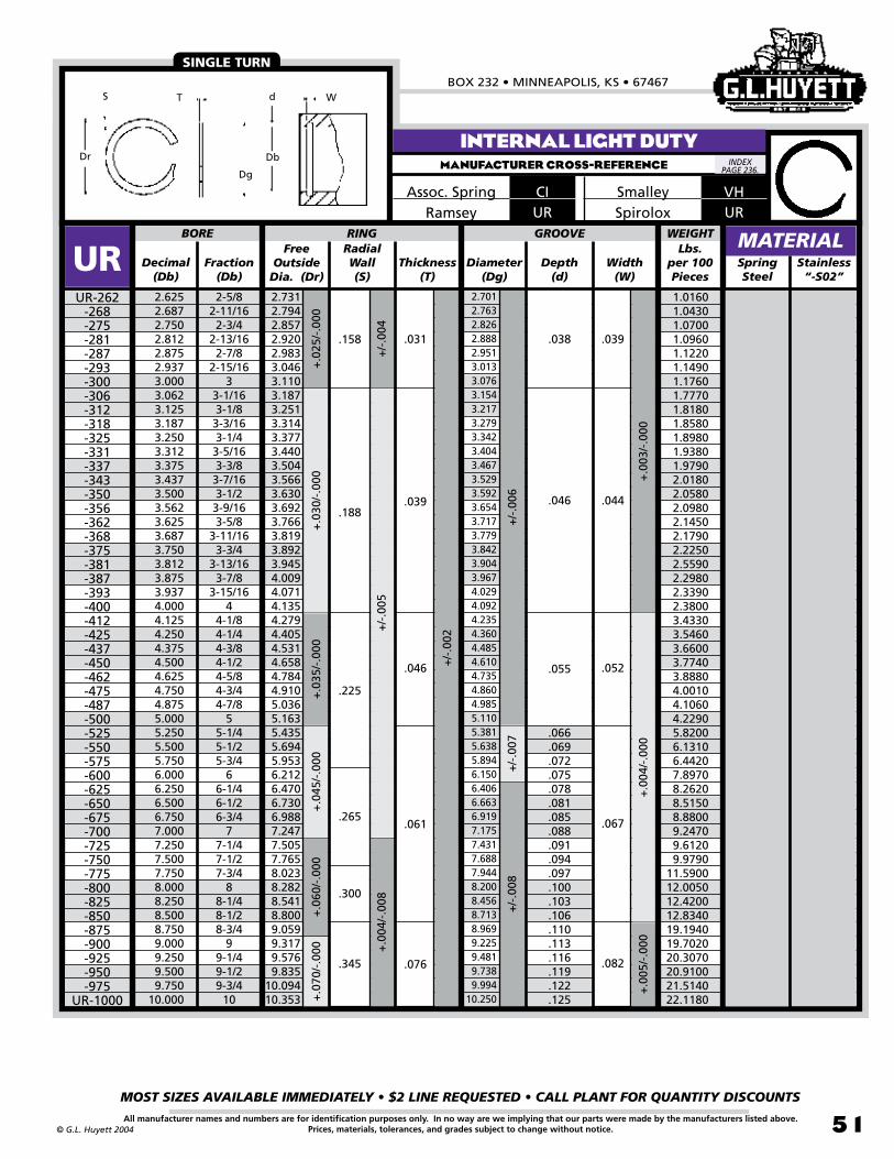
BOX 232 • MINNEAPOLIS, KS • 67467
MOST SIZES AVAILABLE IMMEDIATELY • $2 LINE REQUESTED • CALL PLANT FOR QUANTITY DISCOUNTS
51All manufacturer names and numbers are for identification purposes only. In no way are we implying that our parts were made by the manufacturers listed above.Prices, materials, tolerances, and grades subject to change without notice.© G.L. Huyett 2004
Dr
S T d
Dg
Db
W
INTERNAL LIGHT DUTYMANUFACTURER CROSS-REFERENCE
CIAssoc. SpringURRamsey
SINGLE TURN
VHSmalley
Free Outside
Dia. (Dr)Decimal
(Db)Fraction
(Db)Thickness
(T)Diameter
(Dg)Depth
(d)SpringSteel
2.6252.6872.7502.8122.8752.9373.0003.0623.1253.1873.2503.3123.3753.4373.5003.5623.6253.6873.7503.8123.8753.9374.0004.1254.2504.3754.5004.6254.7504.8755.0005.2505.5005.7506.0006.2506.5006.7507.0007.2507.5007.7508.0008.2508.5008.7509.0009.2509.5009.750
10.000
2-5/82-11/162-3/4
2-13/162-7/8
2-15/163
3-1/163-1/83-3/163-1/43-5/163-3/83-7/163-1/23-9/163-5/8
3-11/163-3/4
3-13/163-7/8
3-15/164
4-1/84-1/44-3/84-1/24-5/84-3/44-7/8
55-1/45-1/25-3/4
66-1/46-1/26-3/4
77-1/47-1/27-3/4
88-1/48-1/28-3/4
99-1/49-1/29-3/4
10
2.7312.7942.8572.9202.9833.0463.1103.1873.2513.3143.3773.4403.5043.5663.6303.6923.7663.8193.8923.9454.0094.0714.1354.2794.4054.5314.6584.7844.9105.0365.1635.4355.6945.9536.2126.4706.7306.9887.2477.5057.7658.0238.2828.5418.8009.0599.3179.5769.835
10.09410.353
BORE RING
URUR-262
-268-275-281-287-293-300-306-312-318-325-331-337-343-350-356-362-368-375-381-387-393-400-412-425-437-450-462-475-487-500-525-550-575-600-625-650-675-700-725-750-775-800-825-850-875-900-925-950-975
UR-1000
Width(W)
+.0
03/-
.000
+/-
.006
+.0
30/-
.000
+.0
35/-
.000
GROOVE
+/-
.007
RadialWall(S)
.225
.039
.046
.044
.052
.046
.055
.066
.069
.072
.075
.078
.081
.085
.088
.091
.094
.097
.100
.103
.106
.110
.113
.116
.119
.122
.125
.076.345 .082
+.0
70/-
.000
+.0
04/-
.000
+/-
.005
+.0
45/-
.000
+/-
.002
.265.061 .067
+.0
60/-
.000
+/-
.008
+.0
04/-
.008
+.0
05/-
.000
.300
+.0
25/-
.000
+/-
.004
.158 .031 .039.038
MATERIALStainless “-S02”
WEIGHTLbs.
per 100 Pieces
.188
2.7012.7632.8262.8882.9513.0133.0763.1543.2173.2793.3423.4043.4673.5293.5923.6543.7173.7793.8423.9043.9674.0294.0924.2354.3604.4854.6104.7354.8604.9855.1105.3815.6385.8946.1506.4066.6636.9197.1757.4317.6887.9448.2008.4568.7138.9699.2259.4819.7389.994
10.250
1.0160 1.0430 1.0700 1.0960 1.1220 1.1490 1.1760 1.7770 1.8180 1.8580 1.8980 1.9380 1.9790 2.0180 2.0580 2.0980 2.1450 2.1790 2.2250 2.5590 2.2980 2.3390 2.3800 3.4330 3.5460 3.6600 3.7740 3.8880 4.0010 4.1060 4.2290 5.8200 6.1310 6.4420 7.8970 8.2620 8.5150 8.8800 9.2470 9.6120 9.979011.590012.005012.420012.834019.194019.702020.307020.910021.514022.1180
INDEX PAGE 236.
URSpirolox
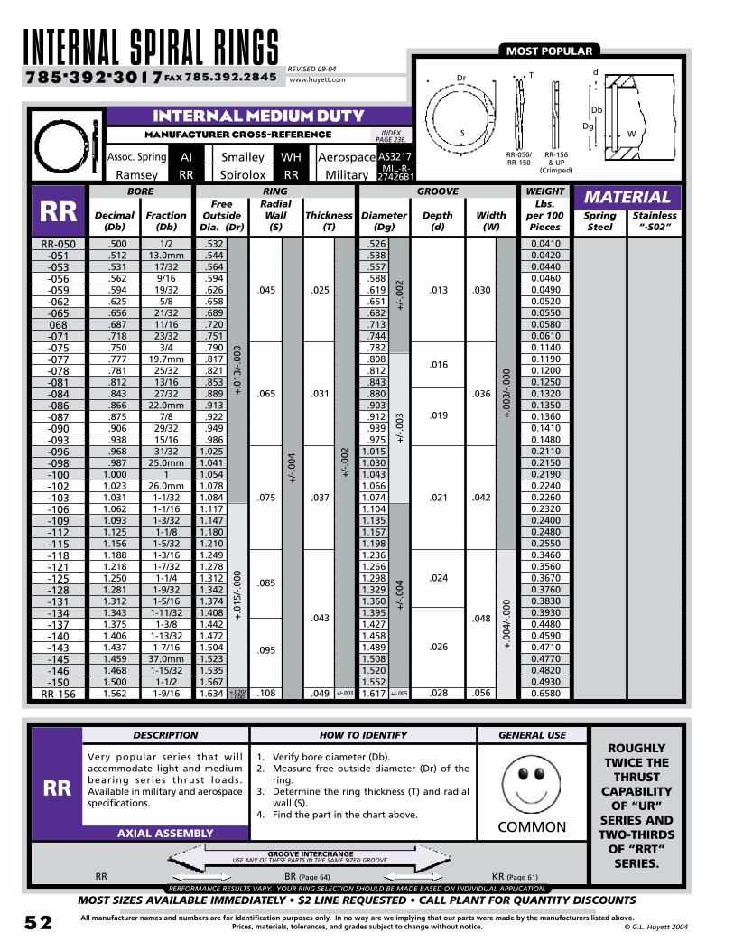
INTERNAL SPIRAL RINGSREVISED 09-04
MOST SIZES AVAILABLE IMMEDIATELY • $2 LINE REQUESTED • CALL PLANT FOR QUANTITY DISCOUNTS
52
785•392•3017 FAX 785.392.2845
All manufacturer names and numbers are for identification purposes only. In no way are we implying that our parts were made by the manufacturers listed above.Prices, materials, tolerances, and grades subject to change without notice. © G.L. Huyett 2004
www.huyett.com
Very popular series that will accommodate light and medium bearing ser ies thrust loads. Available in military and aerospace specifications.
1. Verify bore diameter (Db).2. Measure free outside diameter (Dr) of the
ring.3. Determine the ring thickness (T) and radial
wall (S).4. Find the part in the chart above.
RR BR (Page 64) KR (Page 61)
COMMONAXIAL ASSEMBLY
INTERNAL MEDIUM DUTYMANUFACTURER CROSS-REFERENCE
AIAssoc. Spring WHSmalley
MOST POPULAR
RRSpiroloxMIL-R-
27426B1
Aerospace
PERFORMANCE RESULTS VARY. YOUR RING SELECTION SHOULD BE MADE BASED ON INDIVIDUAL APPLICATION.
RRRamsey
Free Outside
Dia. (Dr)Decimal
(Db)Fraction
(Db)Thickness
(T)Diameter
(Dg)Depth
(d)Spring Steel
.532
.544
.564
.594
.626
.658
.689
.720
.751
.790
.817
.821
.853
.889
.913
.922
.949
.9861.0251.0411.0541.0781.0841.1171.1471.1801.2101.2491.2781.3121.3421.3741.4081.4421.4721.5041.5231.5351.5671.634
BORE RING
RRRR-050
-051-053-056-059-062-065068-071-075-077-078-081-084-086-087-090-093-096-098-100-102-103-106-109-112-115-118-121-125-128-131-134-137-140-143-145-146-150
RR-156
Width(W)
+.0
03/-
.000
+/-
.002
+/-
.003
+.0
13/-
.000
+.020/-.000
GROOVE
+/-
.002
RadialWall(S)
.526
.538
.557
.588
.619
.651
.682
.713
.744
.782
.808
.812
.843
.880
.903
.912
.939
.9751.0151.0301.0431.0661.0741.1041.1351.1671.1981.2361.2661.2981.3291.3601.3951.4271.4581.4891.5081.5201.5521.617
.045
.065
.075
.085
.108
.025
.031
.037
.043
.049 .056
.048
.042
.036
.030.013
.016
.019
.021
.024
.026
.028
+/-
.004
+/-
.004
+/-.005
.500
.512
.531
.562
.594
.625
.656
.687
.718
.750
.777
.781
.812
.843
.866
.875
.906
.938
.968
.9871.0001.0231.0311.0621.0931.1251.1561.1881.2181.2501.2811.3121.3431.3751.4061.4371.4591.4681.5001.562
1/213.0mm
17/329/1619/325/8
21/3211/1623/323/4
19.7mm25/3213/1627/32
22.0mm7/8
29/3215/1631/32
25.0mm1
26.0mm1-1/321-1/161-3/321-1/81-5/321-3/161-7/321-1/41-9/321-5/161-11/321-3/8
1-13/321-7/16
37.0mm1-15/321-1/21-9/16 +/-.003
+.0
04/-
.000
+.0
15/-
.000
MATERIALStainless “-S02”
WEIGHTLbs.
per 100 Pieces
.095
ROUGHLY TWICE THE
THRUST CAPABILITY
OF “UR” SERIES AND TWO-THIRDS
OF “RRT” SERIES.
0.04100.04200.04400.04600.04900.05200.05500.05800.06100.11400.11900.12000.12500.13200.13500.13600.14100.14800.21100.21500.21900.22400.22600.23200.24000.24800.25500.34600.35600.36700.37600.38300.39300.44800.45900.47100.47700.48200.49300.6580
Dr
S
T
Dg
Db
d
W
RR-050/RR-150
RR-156& UP
(Crimped)
INDEX PAGE 236.
GROOVE INTERCHANGEUSE ANY OF THESE PARTS IN THE SAME SIZED GROOVE.
DESCRIPTION HOW TO IDENTIFY GENERAL USE
RR
AS3217
Military
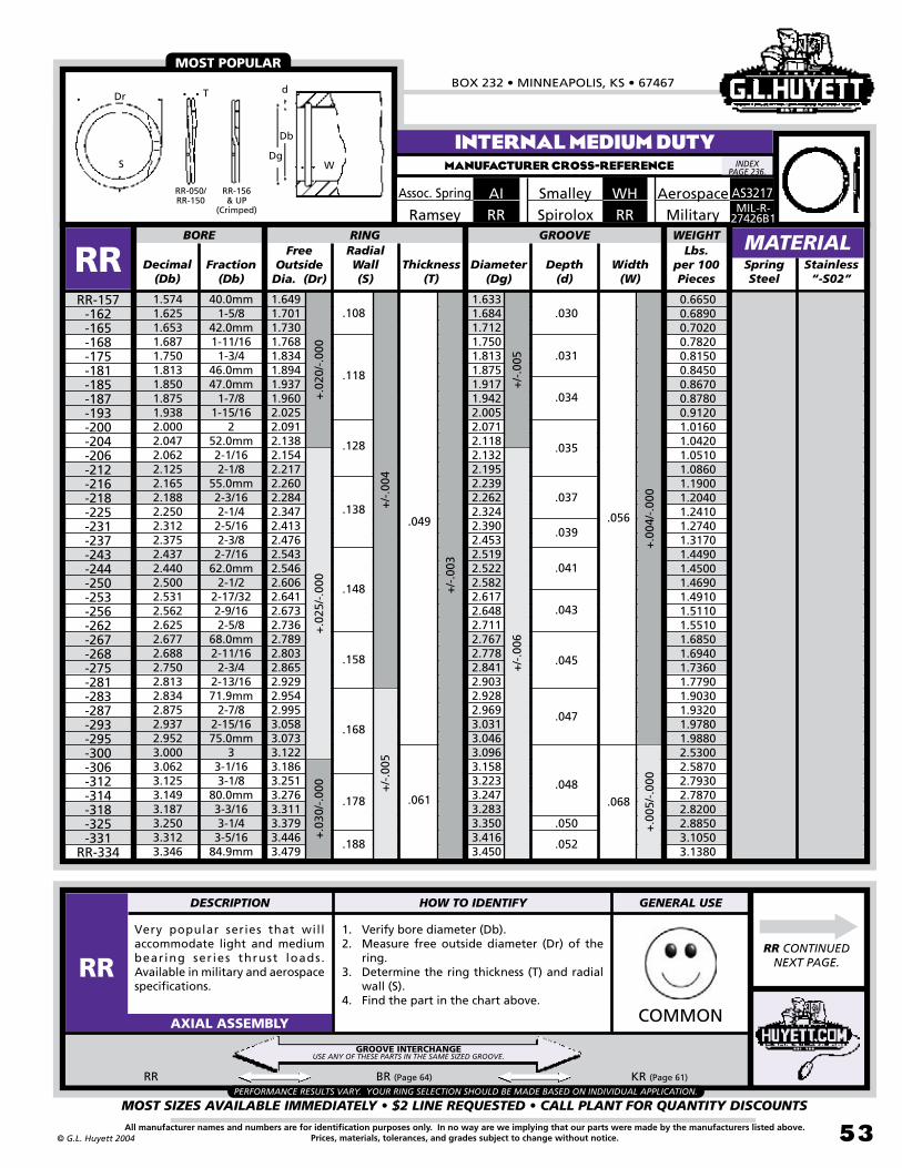
BOX 232 • MINNEAPOLIS, KS • 67467
MOST SIZES AVAILABLE IMMEDIATELY • $2 LINE REQUESTED • CALL PLANT FOR QUANTITY DISCOUNTS
53All manufacturer names and numbers are for identification purposes only. In no way are we implying that our parts were made by the manufacturers listed above.Prices, materials, tolerances, and grades subject to change without notice.© G.L. Huyett 2004
INTERNAL MEDIUM DUTYMANUFACTURER CROSS-REFERENCE
Very popular series that will accommodate light and medium bearing ser ies thrust loads. Available in military and aerospace specifications.
1. Verify bore diameter (Db).2. Measure free outside diameter (Dr) of the
ring.3. Determine the ring thickness (T) and radial
wall (S).4. Find the part in the chart above.
COMMONAXIAL ASSEMBLY
Free Outside
Dia. (Dr)Decimal
(Db)Fraction
(Db)Thickness
(T)Diameter
(Dg)Depth
(d)SpringSteel
40.0mm1-5/8
42.0mm1-11/161-3/4
46.0mm47.0mm
1-7/81-15/16
252.0mm2-1/162-1/8
55.0mm2-3/162-1/42-5/162-3/82-7/16
62.0mm2-1/2
2-17/322-9/162-5/8
68.0mm2-11/162-3/4
2-13/1671.9mm
2-7/82-15/1675.0mm
33-1/163-1/8
80.0mm3-3/163-1/43-5/16
84.9mm
1.6491.7011.7301.7681.8341.8941.9371.9602.0252.0912.1382.1542.2172.2602.2842.3472.4132.4762.5432.5462.6062.6412.6732.7362.7892.8032.8652.9292.9542.9953.0583.0733.1223.1863.2513.2763.3113.3793.4463.479
BORE RING
RRRR-157
-162-165-168-175-181-185-187-193-200-204-206-212-216-218-225-231-237-243-244-250-253-256-262-267-268-275-281-283-287-293-295-300-306-312-314-318-325-331
RR-334
Width(W)
+.0
04/-
.000
+/-
.005
+/-
.004
+.0
20/-
.000
+.0
25/-
.000
GROOVE
+/-
.006
+/-
.003
RadialWall(S)
1.6331.6841.7121.7501.8131.8751.9171.9422.0052.0712.1182.1322.1952.2392.2622.3242.3902.4532.5192.5222.5822.6172.6482.7112.7672.7782.8412.9032.9282.9693.0313.0463.0963.1583.2233.2473.2833.3503.4163.450
.034
.052
.108
.118
.128
.138
.148
.158
.168
.178
.188
.049
.061 .068
.056
+.0
30/-
.000
1.5741.6251.6531.6871.7501.8131.8501.8751.9382.0002.0472.0622.1252.1652.1882.2502.3122.3752.4372.4402.5002.5312.5622.6252.6772.6882.7502.8132.8342.8752.9372.9523.0003.0623.1253.1493.1873.2503.3123.346
+/-
.005
+.0
05/-
.000
RR CONTINUED NEXT PAGE.
MATERIAL
Assoc. Spring AI WHSmalley
.039
.030
.050
.048
.031
.047
.045
.043
.041
.037
.035
MOST POPULAR
Stainless “-S02”
Spirolox RR MIL-R-27426B1
Aerospace
WEIGHTLbs.
per 100 Pieces
RR BR (Page 64) KR (Page 61)
PERFORMANCE RESULTS VARY. YOUR RING SELECTION SHOULD BE MADE BASED ON INDIVIDUAL APPLICATION.
Ramsey RR
Dr
S
T
Dg
Db
d
W
RR-050/RR-150
RR-156& UP
(Crimped)
0.66500.68900.70200.78200.81500.84500.86700.87800.91201.01601.04201.05101.08601.19001.20401.24101.27401.31701.44901.45001.46901.49101.51101.55101.68501.69401.73601.77901.90301.93201.97801.98802.53002.58702.79302.78702.82002.88503.10503.1380
INDEX PAGE 236.
GROOVE INTERCHANGEUSE ANY OF THESE PARTS IN THE SAME SIZED GROOVE.
DESCRIPTION HOW TO IDENTIFY GENERAL USE
RR
Military
AS3217

INTERNAL SPIRAL RINGSREVISED 09-04
MOST SIZES AVAILABLE IMMEDIATELY • $2 LINE REQUESTED • CALL PLANT FOR QUANTITY DISCOUNTS
54
785•392•3017 FAX 785.392.2845
All manufacturer names and numbers are for identification purposes only. In no way are we implying that our parts were made by the manufacturers listed above.Prices, materials, tolerances, and grades subject to change without notice. © G.L. Huyett 2004
www.huyett.com
Very popular series that will accommodate light and medium bearing ser ies thrust loads. Available in military and aerospace specifications.
1. Verify bore diameter (Db).2. Measure free outside diameter (Dr) of the
ring.3. Determine the ring thickness (T) and radial
wall (S).4. Find the part in the chart above.
COMMONAXIAL ASSEMBLY
Free Outside
Dia. (Dr)Decimal
(Db)Fraction
(Db)Thickness
(T)Diameter
(Dg)Depth
(d)SpringSteel
3.3753.4373.5003.5433.5623.6253.6873.7403.7503.8123.8753.9384.0004.0634.1254.1884.2504.3124.3304.3754.4374.5004.5274.5624.6254.6874.7244.7504.8124.8754.9214.9375.0005.1185.1255.2505.3755.5005.5115.625
3-3/83-7/163-1/2
89.9mm3-9/163-5/8
3-11/1695.0mm
3-3/43-13/163-7/8
3-15/164
4-1/164-1/84-3/164-1/44-5/16
109.9mm4-3/84-7/164-1/2
115.0mm4-9/164-5/8
4-11/16120.0mm
4-3/44-13/164-7/8
125.0mm4-15/16
5129.9mm
5-1/85-1/45-3/85-1/2
139.9mm5-5/8
3.5093.5743.6363.6843.7033.7693.8323.8853.8943.9634.0254.0894.1574.2224.2844.3474.4164.4794.4974.5434.6114.6744.7014.7374.8034.8674.9034.9304.9935.0555.1025.1225.1855.3045.3115.4365.5665.6935.7035.818
BORE RING
RRRR-337
-343-350-354-356-362-368-374-375-381-387-393-400-406-412-418-425-431-433-437-443-450-452-456-462-468-472-475-481-487-492-493-500-511-512-525-537-550-551
RR-562
Width(W)
+/-
.006
+.0
30/-
.000
+.0
35/-
.000
GROOVE
+/-
.007
+/-
.003
+/-
.004
RadialWall(S)
3.4793.5433.6063.6533.6723.7373.7993.8523.8623.9303.9934.0564.1244.1874.2494.3114.3804.4424.4604.5054.5734.6364.6634.6984.7657.8274.8644.8904.9525.0155.0615.0815.1445.2625.2695.3935.5225.6475.6585.772
.188
.198
.208
.218
.228
.238
.250
.061
.072 .079
.068
.052
.059
.065
.070
.072
.074
+/-
.005
+.0
45/-
.000
+.0
05/-
.000
RR BR (Page 64) KR (Page 61)
ASSORTMENTS
PAGE 225
RR CONTINUED NEXT PAGE.
INTERNAL MEDIUM DUTYMANUFACTURER CROSS-REFERENCE
MATERIAL
AIAssoc. Spring WHSmalley
.053
.056
.062
.068
.055
MOST POPULAR
Stainless “-S02”
RRSpiroloxMIL-R-
27426B1
Aerospace
WEIGHTLbs.
per 100 Pieces
PERFORMANCE RESULTS VARY. YOUR RING SELECTION SHOULD BE MADE BASED ON INDIVIDUAL APPLICATION.
RRRamsey
3.16803.23303.29503.51003.53103.60103.66703.72303.73303.98704.02104.09304.35704.43304.50504.57804.86004.93704.95905.01505.30905.38905.42305.46906.78606.80506.86106.90307.00107.09807.17107.20207.30007.48607.49707.69107.89408.09208.10708.2860
Dr
S
T
Dg
Db
d
W
RR-050/RR-150
RR-156& UP
(Crimped)
INDEX PAGE 236.
GROOVE INTERCHANGEUSE ANY OF THESE PARTS IN THE SAME SIZED GROOVE.
DESCRIPTION HOW TO IDENTIFY GENERAL USE
RR
AS3217
Military

BOX 232 • MINNEAPOLIS, KS • 67467
MOST SIZES AVAILABLE IMMEDIATELY • $2 LINE REQUESTED • CALL PLANT FOR QUANTITY DISCOUNTS
55All manufacturer names and numbers are for identification purposes only. In no way are we implying that our parts were made by the manufacturers listed above.Prices, materials, tolerances, and grades subject to change without notice.© G.L. Huyett 2004
INTERNAL MEDIUM DUTYMANUFACTURER CROSS-REFERENCE
Very popular series that will accommodate light and medium bearing ser ies thrust loads. Available in military and aerospace specifications.
1. Verify bore diameter (Db).2. Measure free outside diameter (Dr) of the
ring.3. Determine the ring thickness (T) and radial
wall (S).4. Find the part in the chart above.
COMMONAXIAL ASSEMBLY
Free Outside
Dia. (Dr)Decimal
(Db)Fraction
(Db)Thickness
(T)Diameter
(Dg)Depth
(d)Spring Steel
5.7085.7505.8755.9056.0006.1256.2506.2996.3756.5006.6256.6926.7506.8757.0007.0867.1257.2507.3757.4807.5007.6257.7507.8758.0008.2508.2678.4648.5008.7508.8589.0009.0559.2509.4489.5009.750
10.00010.50011.000
145.0mm5-3/45-7/8
149.9mm6
6-1/86-1/4
160.0mm6-3/86-1/26-5/8
170.0mm6-3/46-7/8
7180.0mm
7-1/87-1/47-3/8
190.0mm7-1/27-5/87-3/47-7/8
88-1/4
210.0mm215.0mm
8-1/28-3/4
225.0mm9
230.0mm9-1/4
240.0mm9-1/29-3/4
1010-1/2
11
5.9095.9506.0776.1066.2026.3496.4746.5246.6016.7266.8636.9316.9877.1147.2397.3377.3767.5017.6287.7347.7547.8908.0148.1318.2668.5288.5468.7448.7809.0419.1519.2939.3599.5559.7559.806
10.06810.32010.83411.347
BORE RING
RRRR-570
-575-587-590-600-612-625-629-637-650-662-669-675-687-700-708-712-725-737-748-750-762-775-787-800-825-826-846-850-875-885-900-905-925-944-950-975
-1000 -1050
RR-1100
Width(W)
+.0
05/-
.000
+/-
.007
+/-
.005
+.0
45/-
.000
+.0
55/-
.000
GROOVE
+/-
.008
+/-
.004
RadialWall(S)
.250
.312
.375
.072
.086 .094
.086
.091
.096
.101
.106
.116
.111
.121
.126
.131
+.0
65/-
.000
5.8615.9036.0286.0586.1536.2976.4226.4716.5476.6726.8076.8746.9327.0577.1827.2787.3177.4427.5677.6727.6927.8277.9528.0778.2028.4628.4798.6768.7128.9729.0809.2229.2879.4829.6809.7329.992
10.24210.75211.262
+.0
06/-
.000
+/-
.006
MATERIAL
AIAssoc. Spring WHSmalley
MOST POPULAR
Stainless “-S02”
RRSpiroloxMIL-R-
27426B1
Aerospace
WEIGHTLbs.
per 100 Pieces
RR BR (Page 64) KR (Page 61)
PERFORMANCE RESULTS VARY. YOUR RING SELECTION SHOULD BE MADE BASED ON INDIVIDUAL APPLICATION.
.079.077
RRRamsey
ROUGHLY TWICE THE
THRUST CAPABILITY
OF “UR” SERIES AND TWO-THIRDS
OF “RRT” SERIES.
Dr
S
T
Dg
Db
d
W
RR-050/RR-150
RR-156& UP
(Crimped)
8.3630 8.4280 8.6250 8.6710 8.820013.408013.699013.816013.996014.287014.607014.765014.896015.193015.484015.544015.635015.926016.222016.470016.517016.831017.123017.396017.712021.845021.897022.451022.552023.284023.330023.728023.915024.464025.025025.168025.902026.609028.050029.4880
INDEX PAGE 236.
GROOVE INTERCHANGEUSE ANY OF THESE PARTS IN THE SAME SIZED GROOVE.
DESCRIPTION HOW TO IDENTIFY GENERAL USE
RR
AS3217
Military

INTERNAL SPIRAL RINGSREVISED 09-04
MOST SIZES AVAILABLE IMMEDIATELY • $2 LINE REQUESTED • CALL PLANT FOR QUANTITY DISCOUNTS
5�
785•392•3017 FAX 785.392.2845
All manufacturer names and numbers are for identification purposes only. In no way are we implying that our parts were made by the manufacturers listed above.Prices, materials, tolerances, and grades subject to change without notice. © G.L. Huyett 2004
www.huyett.com
Originally designed to fit NAS 50-51 grooves, RRT is a common OEM specification. Two and three turn designs are easier to install than RRN because of multiple turn design.
1. Verify bore diameter (Db).2. Measure the free outside diameter (Dr) of the
ring.3. Determine the ring thickness (T) and radial
wall (S).4. Find the part in the chart above.
RRT UHB (Page 72)
UNCOMMONAXIAL ASSEMBLY
Free Outside
Dia. (Dr)Decimal
(Db)Fraction
(Db)Thickness
(T)Diameter
(Dg)Depth
(d)Spring Steel
.500
.512
.562
.625
.688
.750
.777
.812
.866
.875
.901
.9381.0001.0231.0621.1251.1881.2501.3121.3751.4381.4561.5001.5621.6251.6531.6881.7501.8121.8501.8751.9382.0002.0622.1252.1882.2502.3122.3752.440
1/213.0mm
9/165/8
11/163/4
19.7mm13/16
22.0mm7/8
22.9mm15/16
126.0mm1-1/161-1/81-3/161-1/41-5/161-3/81-7/16
37.0mm1-1/21-9/161-5/8
42.0mm1-11/161-3/4
1-13/1647.0mm
1-7/81-15/16
22-1/162-1/82-3/162-1/42-5/162-3/8
61.9mm
.529
.541
.597
.665
.730
.796
.825
.864
.919
.929
.957
.9971.0631.0871.1291.1951.2601.3301.3951.4611.5261.5461.5911.6591.7271.7571.7931.8531.9231.9631.9842.0542.1252.1902.2552.3212.3862.4572.5222.588
BORE RING
RRTRRT-050
-051-056-062-068-075-077-081-086-087-090-093-100-102-106-112-118-125-131-137-143-145-150-156-162-165-168-175-181-185-187-193-200-206-212-218-225-231-237
RRT-244
Width(W)
+.0
03/-
.000
+.0
04/-
.000
+/-
.003
+/-
.004
+/-.002
+/-
.004
+.0
13/-
.000
+.0
15/-
.000
+.0
20/-
.000
GROOVE
+/-
.005
+/-
.002
+/-
.003
RadialWall(S)
.524
.536
.592
.659
.724
.790
.819
.857
.912
.922
.950
.9891.0551.0791.1201.1851.2501.3201.3851.4501.5151.5351.5801.6471.7151.7451.7801.8451.9101.9491.9752.0402.1102.1752.2402.3052.3702.4402.5052.570
.045
.055
.065
.075
.078
.093
.108
.113
.118
.123
.128
.141
.188
.012
.012
.015
.017
.018
.020
.021
.023
.023
.024
.025
.026
.028
.028
.029
.030
.031
.035
.037
.038
.039
.040
.040
.043
.045
.046
.046
.048
.049
.050
.050
.051
.055
.027
.058
.059
.060
.064
.065
.065
.035
.042
.050
.062
.078
.039
.046
.056
.068
.086
+/-
.006
+.0
05/-
.000
+/-
.005
+.0
25/-
.000
ASSORTMENTS
PAGE 225
INTERNAL MEDIUM HEAVYMANUFACTURER CROSS-REFERENCE
MATERIAL
AMIAssoc. Spring
RRTRamsey
.098
.103
EASIER TO INSTALL
Stainless “-S02”
WEIGHTLbs.
per 100 Pieces
PERFORMANCE RESULTS VARY. YOUR RING SELECTION SHOULD BE MADE BASED ON INDIVIDUAL APPLICATION.
.138
.088
WHTSmalley
0.05700.05900.06700.07600.10100.11200.16100.17000.18300.18500.19100.22900.24700.25300.32600.34700.39100.46200.48800.53600.58900.62500.64600.87600.91700.97400.99701.03401.12101.13301.19001.28301.38001.84501.90701.91702.03302.74102.82302.9070
FITSNAS 50-51GROOVES.
INDEX PAGE 236.
GROOVE INTERCHANGEUSE ANY OF THESE PARTS IN THE SAME SIZED GROOVE.
DESCRIPTION HOW TO IDENTIFY GENERAL USE
RRT
RRTSpirolox
Dr
S Dg
Db
d
W
T
RRT-050/RRT-150
RRT-156/RRT-600
(Crimped)
RRT-625& UP
(Crimped)
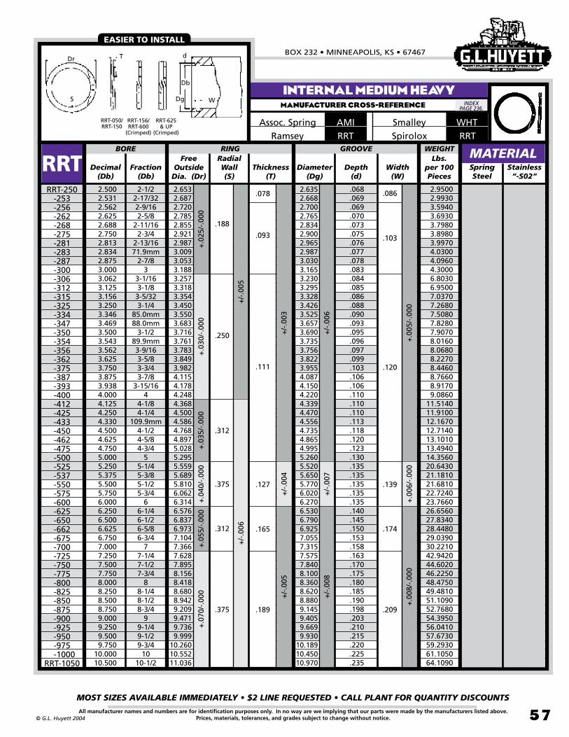
BOX 232 • MINNEAPOLIS, KS • 67467
MOST SIZES AVAILABLE IMMEDIATELY • $2 LINE REQUESTED • CALL PLANT FOR QUANTITY DISCOUNTS
57All manufacturer names and numbers are for identification purposes only. In no way are we implying that our parts were made by the manufacturers listed above.Prices, materials, tolerances, and grades subject to change without notice.© G.L. Huyett 2004
INTERNAL MEDIUM HEAVYMANUFACTURER CROSS-REFERENCE
Free Outside
Dia. (Dr)Decimal
(Db)Fraction
(Db)Thickness
(T)Diameter
(Dg)Depth
(d)SpringSteel
2.5002.5312.5622.6252.6882.7502.8132.8342.8753.0003.0623.1253.1563.2503.3463.4693.5003.5433.5623.6253.7503.8753.9384.0004.1254.2504.3304.5004.6254.7505.0005.2505.3755.5005.7506.0006.2506.5006.6256.7507.0007.2507.5007.7508.0008.2508.5008.7509.0009.2509.5009.750
10.00010.500
2-1/22-17/322-9/162-5/8
2-11/162-3/4
2-13/1671.9mm
2-7/83
3-1/163-1/83-5/323-1/4
85.0mm88.0mm
3-1/289.9mm3-9/163-5/83-3/43-7/8
3-15/164
4-1/84-1/4
109.9mm4-1/24-5/84-3/4
55-1/45-3/85-1/25-3/4
66-1/46-1/26-5/86-3/4
77-1/47-1/27-3/4
88-1/48-1/28-3/4
99-1/49-1/29-3/4
1010-1/2
2.6532.6872.7202.7852.8552.9212.9873.0093.0533.1883.2573.3183.3543.4503.5503.6833.7163.7613.7833.8493.9824.1154.1784.2484.3684.5004.5864.7684.8975.0285.2955.5595.6895.8106.0626.314 6.5766.8376.9737.1047.3667.6287.8958.1568.4188.6808.9429.2099.4719.7369.999
10.26010.55211.036
BORE RING
RRTRRT-250
-253-256-262-268-275-281-283-287-300-306-312-315-325-334-347-350-354-356-362-375-387-393-400-412-425-433-450-462-475-500-525-537-550-575-600-625-650-662-675-700-725-750-775-800-825-850-875-900-925-950-975
-1000RRT-1050
Width(W)
+/-
.005
+.0
25/-
.000
+.0
30/-
.000
+.0
35/-
.000
+.0
40/-
.000
GROOVE
+/-
.003
+/-
.004
RadialWall(S)
2.6352.6682.7002.7652.8342.9002.9652.9873.0303.1653.2303.2953.3283.4263.5253.6573.6903.7353.7563.8223.9554.0874.1504.2204.3394.4704.5564.7354.8654.9955.2605.5205.6505.7706.0206.2706.5306.7906.9257.0557.3157.5757.8408.1008.3608.6208.8809.1459.4059.6699.930
10.18910.45010.970
.188
.250
.312
.375
.068
.069
.069
.070
.073
.075
.076
.077
.078
.083
.084
.085
.086
.088
.090
.093
.095
.096
.097
.099
.103
.106
.106
.110
.110
.110
.113
.118
.120
.123
.130
.135
.135
.135
.135
.135
.140
.145
.150
.153
.158
.163
.170
.175
.180
.185
.190
.198
.203
.210
.215
.220
.225
.235
.078
.093
.111
.127
.086
.103
.120
.139
+/-
.006
+/-
.007
+.0
05/-
.000
+.0
06/-
.000
+.0
55/-
.000
+.0
70/-
.000 +
/-.0
05
+/-
.008
+.0
08/-
.000
.312 .165 .174
.375 .189 .209
+/-
.006
MATERIAL
Assoc. Spring AMIRRTRamsey
EASIER TO INSTALL
Stainless “-S02”
WEIGHTLbs.
per 100 Pieces
2.9500 2.9930 3.5940 3.6930 3.7980 3.8980 3.9970 4.0300 4.0960 4.3000 6.8030 6.9500 7.0370 7.2680 7.5080 7.8280 7.9070 8.0160 8.0680 8.2270 8.4460 8.7660 8.9170 9.086011.514011.910012.167012.714013.101013.494014.356020.643021.181021.681022.724023.766026.656027.834028.448029.039030.221042.942044.602046.225048.475049.481051.109052.768054.395056.041057.673059.293061.105064.1090
WHTSmalley
INDEX PAGE 236.
RRTSpirolox
Dr
S Dg
Db
d
W
T
RRT-050/RRT-150
RRT-156/RRT-600
(Crimped)
RRT-625& UP
(Crimped)

INTERNAL SPIRAL RINGSREVISED 09-04
MOST SIZES AVAILABLE IMMEDIATELY • $2 LINE REQUESTED • CALL PLANT FOR QUANTITY DISCOUNTS
58
785•392•3017 FAX 785.392.2845
All manufacturer names and numbers are for identification purposes only. In no way are we implying that our parts were made by the manufacturers listed above.Prices, materials, tolerances, and grades subject to change without notice. © G.L. Huyett 2004
www.huyett.com
INTERNAL HEAVY DUTYMANUFACTURER CROSS-REFERENCE
Heavy-duty design for use in NAS 669-670 deep grooves in applications like double row and tapered roller bearings. Requires no tools for removal.
1. Verify bore diameter (Db).2. Measure free outside diameter (Dr) of the
ring.3. Determine the ring thickness (T) and radial
wall (S).4. Find the part in the chart above.
COMMONAXIAL ASSEMBLY
Free Outside
Dia. (Dr)Decimal
(Db)Fraction
(Db)Thickness
(T)Diameter
(Dg)Depth
(d)SpringSteel
.500
.512
.562
.625
.688
.750
.777
.812
.866
.875
.901
.9381.0001.0231.0621.1251.1881.2501.3121.3751.4391.4561.5001.5621.6251.6531.6881.7501.8121.8501.8751.9382.0002.0622.1252.1882.2502.312
1/213.0mm
9/165/8
11/163/4
19.7mm13/16
22.0mm7/8
22.9mm15/16
126.0mm1-1/161-1/81-3/161-1/41-5/161-3/81-7/16
37.0mm1-1/21-9/161-5/8
42.0mm1-11/161-3/4
1-13/1647.0mm
1-7/81-15/16
22-1/162-1/82-3/162-1/42-5/16
.538
.550
.605
.675
.743
.807
.836
.873
.931
.943
.9721.0131.0801.1051.1381.2051.2711.3391.4061.4711.5391.5591.6051.6751.7421.7721.8101.8761.9401.9812.0082.0752.1422.2012.2672.3342.3992.467
BORE RING
RRNRRN-050
-051-056-062-068-075-077-081-086-087-090-093-100-102-106-112-118-125-131-137-143-145-150-156-162-165-168-175-181-185-187-193-200-206-212-218-225
RRN-231
Width(W)
+.0
03/-
.000
+.0
04/-
.000
+/-
.002
+/-
.004
+/-
.005
+/-
.004
+/-
.005
+.0
13/-
.000
+.0
20/-
.000
GROOVE
+/-
.006
+/-
.002
+/-
.003
RadialWall(S)
.530
.542
.596
.665
.732
.796
.825
.862
.920
.931
.9591.0001.0661.0911.1301.1971.2621.3301.3961.4611.5281.5481.5941.6581.7251.7551.7921.8581.9221.9621.9892.0562.1222.1862.2512.3182.3822.450
.055
.103
.118
.128
.200
.042
.050
.062
.078
.039
.046
.056
.068
.086
.015
.015
.017
.020
.022
.023
.024
.025
.027
.028
.029
.031
.033
.034
.034
.036
.037
.040
.042
.043
.045
.046
.047
.048
.050
.051
.052
.054
.055
.056
.057
.059
.061
.062
.063
.065
.066
.069+.0
25/-
.000
+.0
05/-
.000
RRN HO (Page 16) HOI (Page 19) UHO (Page 76) SRN (Page 63)
ASSORTMENTS
PAGE 225
MATERIAL
AHIAssoc. Spring WHMSmalley
+/-
.003
.045
.075
.085
.158
.168
.065
INTERCHANGEABLE WITH SNAP RINGS
Stainless “-S02”
S
Db
WDg
TDr
d
S
Db
WDg
TDr
d
RRNSpiroloxMIL-R-
27426B2
Aerospace
WEIGHTLbs.
per 100 Pieces
PERFORMANCE RESULTS VARY. YOUR RING SELECTION SHOULD BE MADE BASED ON INDIVIDUAL APPLICATION.
.035
RRNRamsey
RRN-050/RRN-075
RRN-077& UP
(Crimped)
0.05700.05900.08000.09200.11900.13200.18400.19400.21000.23900.24700.26000.27900.28600.42300.45200.48200.51100.61200.64500.67400.68400.70700.98601.03201.05201.07901.12401.16701.45001.47301.53001.57802.18102.25602.33202.40602.9130
RRN CONTINUED NEXT PAGE.
FITSNAS 669-670
GROOVES.
INDEX PAGE 236.
GROOVE INTERCHANGEUSE ANY OF THESE PARTS IN THE SAME SIZED GROOVE.
DESCRIPTION HOW TO IDENTIFY GENERAL USE
RRN
AS3215
Military
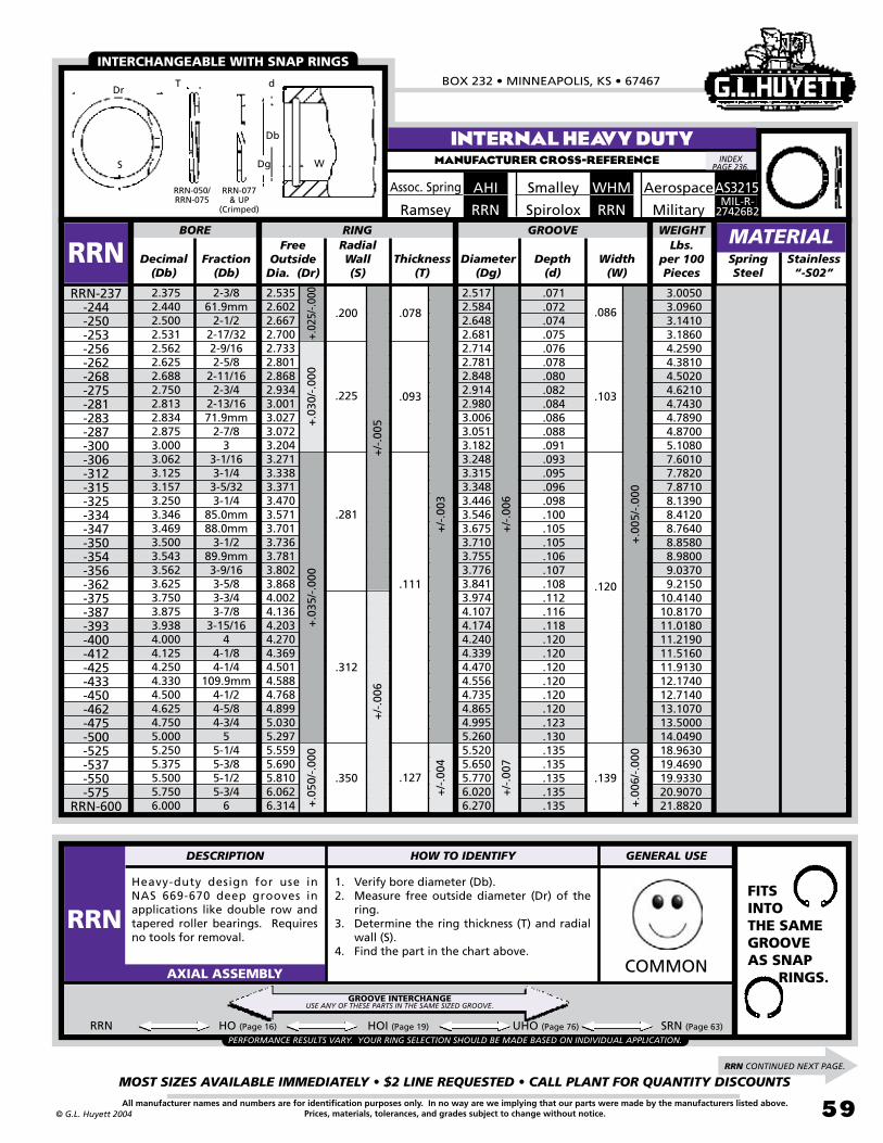
BOX 232 • MINNEAPOLIS, KS • 67467
MOST SIZES AVAILABLE IMMEDIATELY • $2 LINE REQUESTED • CALL PLANT FOR QUANTITY DISCOUNTS
59All manufacturer names and numbers are for identification purposes only. In no way are we implying that our parts were made by the manufacturers listed above.Prices, materials, tolerances, and grades subject to change without notice.© G.L. Huyett 2004
Heavy-duty design for use in NAS 669-670 deep grooves in applications like double row and tapered roller bearings. Requires no tools for removal.
1. Verify bore diameter (Db).2. Measure free outside diameter (Dr) of the
ring.3. Determine the ring thickness (T) and radial
wall (S).4. Find the part in the chart above.
COMMONAXIAL ASSEMBLY
Free Outside
Dia. (Dr)Decimal
(Db)Fraction
(Db)Thickness
(T)Diameter
(Dg)Depth
(d)Spring Steel
2.3752.4402.5002.5312.5622.6252.6882.7502.8132.8342.8753.0003.0623.1253.1573.2503.3463.4693.5003.5433.5623.6253.7503.8753.9384.0004.1254.2504.3304.5004.6254.7505.0005.2505.3755.5005.7506.000
2-3/861.9mm
2-1/22-17/322-9/162-5/8
2-11/162-3/4
2-13/1671.9mm
2-7/83
3-1/163-1/43-5/323-1/4
85.0mm88.0mm
3-1/289.9mm3-9/163-5/83-3/43-7/8
3-15/164
4-1/84-1/4
109.9mm4-1/24-5/84-3/4
55-1/45-3/85-1/25-3/4
6
2.5352.6022.6672.7002.7332.8012.8682.9343.0013.0273.0723.2043.2713.3383.3713.4703.5713.7013.7363.7813.8023.8684.0024.1364.2034.2704.3694.5014.5884.7684.8995.0305.2975.5595.6905.8106.0626.314
BORE RING
RRNRRN-237
-244-250-253-256-262-268-275-281-283-287-300-306-312-315-325-334-347-350-354-356-362-375-387-393-400-412-425-433-450-462-475-500-525-537-550-575
RRN-600
Width(W)
+/-
.005
+/-
.006
+.0
30/-
.000
+.0
35/-
.000
+.0
50/-
.000
GROOVE
+/-
.003
+/-
.004
RadialWall(S)
2.5172.5842.6482.6812.7142.7812.8482.9142.9803.0063.0513.1823.2483.3153.3483.4463.5463.6753.7103.7553.7763.8413.9744.1074.1744.2404.3394.4704.5564.7354.8654.9955.2605.5205.6505.7706.0206.270
.200
.071
.072
.074
.075
.076
.078
.080
.082
.084
.086
.088
.091
.093
.095
.096
.098
.100
.105
.105
.106
.107
.108
.112
.116
.118
.120
.120
.120
.120
.120
.120
.123
.130
.135
.135
.135
.135
.135
+/-
.006
+/-
.007
+.0
05/-
.000
+.0
06/-
.000
RRN HO (Page 16) HOI (Page 19) UHO (Page 76) SRN (Page 63)
.127.350
.312
.281
.225
.111
.093
.139
.120
.103
+.02
5/-.0
00
INTERNAL HEAVY DUTYMANUFACTURER CROSS-REFERENCE
MATERIAL
AHIAssoc. Spring WHMSmalley
INTERCHANGEABLE WITH SNAP RINGS
Stainless “-S02”
S
Db
WDg
TDr
d
S
Db
WDg
TDr
d
RRNSpiroloxMIL-R-
27426B2
Aerospace
WEIGHTLbs.
per 100 Pieces
PERFORMANCE RESULTS VARY. YOUR RING SELECTION SHOULD BE MADE BASED ON INDIVIDUAL APPLICATION.
.078 .086
RRNRamsey
RRN-050/RRN-075
RRN-077& UP
(Crimped)
3.00503.09603.14103.18604.25904.38104.50204.62104.74304.78904.87005.10807.60107.78207.87108.13908.41208.76408.85808.98009.03709.2150
10.414010.817011.018011.219011.516011.913012.174012.714013.107013.500014.049018.963019.469019.933020.907021.8820
RRN CONTINUED NEXT PAGE.
FITS INTO THE SAME GROOVE AS SNAP
RINGS.
INDEX PAGE 236.
GROOVE INTERCHANGEUSE ANY OF THESE PARTS IN THE SAME SIZED GROOVE.
DESCRIPTION HOW TO IDENTIFY GENERAL USE
RRN
AS3215
Military
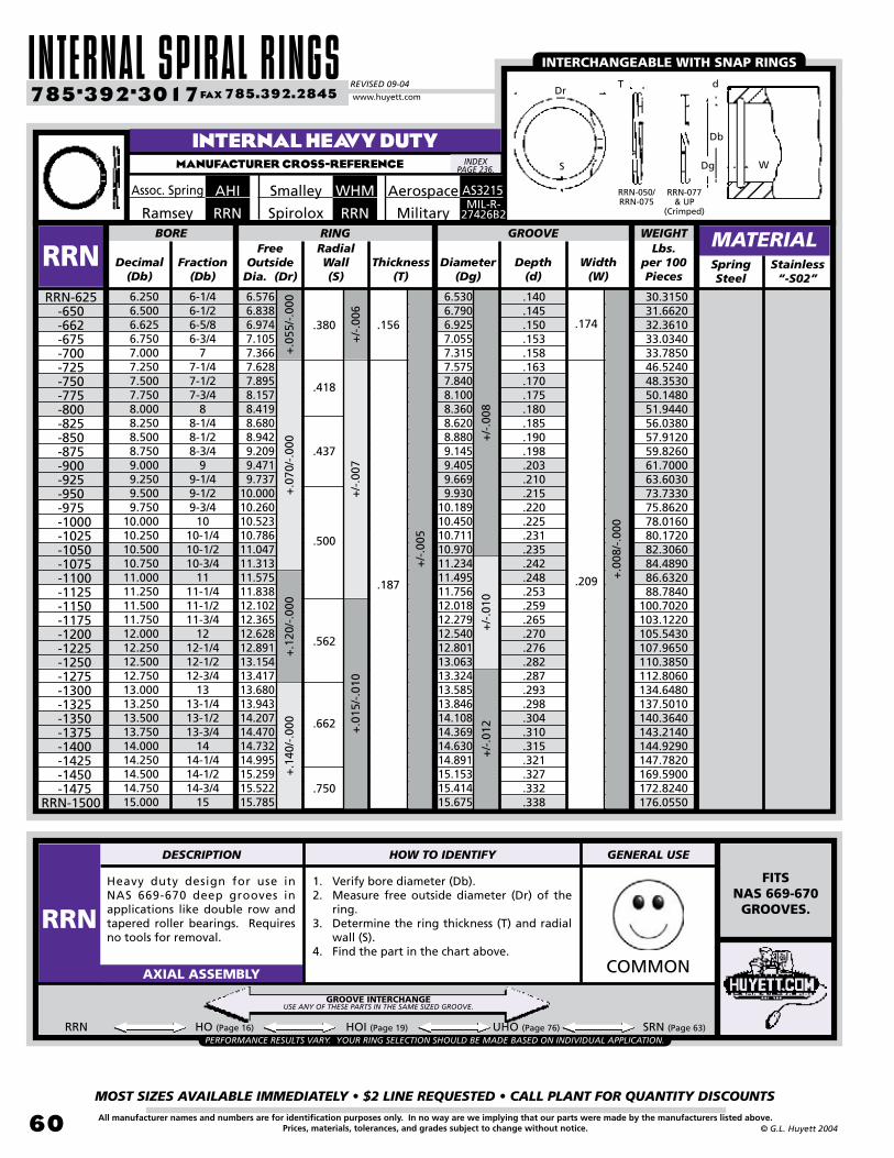
INTERNAL SPIRAL RINGSREVISED 09-04
MOST SIZES AVAILABLE IMMEDIATELY • $2 LINE REQUESTED • CALL PLANT FOR QUANTITY DISCOUNTS
�0
785•392•3017 FAX 785.392.2845
All manufacturer names and numbers are for identification purposes only. In no way are we implying that our parts were made by the manufacturers listed above.Prices, materials, tolerances, and grades subject to change without notice. © G.L. Huyett 2004
www.huyett.com
INTERNAL HEAVY DUTYMANUFACTURER CROSS-REFERENCE
Heavy duty design for use in NAS 669-670 deep grooves in applications like double row and tapered roller bearings. Requires no tools for removal.
1. Verify bore diameter (Db).2. Measure free outside diameter (Dr) of the
ring.3. Determine the ring thickness (T) and radial
wall (S).4. Find the part in the chart above.
COMMONAXIAL ASSEMBLY
RRN HO (Page 16) HOI (Page 19) UHO (Page 76) SRN (Page 63)
Free Outside
Dia. (Dr)Decimal
(Db)Fraction
(Db)Thickness
(T)Diameter
(Dg)Depth
(d)SpringSteel
6-1/46-1/26-5/86-3/4
77-1/47-1/27-3/4
88-1/48-1/28-3/4
99-1/49-1/29-3/4
1010-1/410-1/210-3/4
1111-1/411-1/211-3/4
1212-1/412-1/212-3/4
1313-1/413-1/213-3/4
1414-1/414-1/214-3/4
15
6.5766.8386.9747.1057.3667.6287.8958.1578.4198.6808.9429.2099.4719.737
10.00010.26010.52310.78611.04711.31311.57511.83812.10212.36512.62812.89113.15413.41713.68013.94314.20714.47014.73214.99515.25915.52215.785
BORE RING
RRNRRN-625
-650-662-675-700-725-750-775-800-825-850-875-900-925-950-975
-1000 -1025 -1050 -1075 -1100 -1125 -1150 -1175 -1200 -1225 -1250 -1275 -1300 -1325 -1350 -1375 -1400 -1425 -1450 -1475
RRN-1500
Width(W)
+/-
.008
+/-
.010
+.0
70/-
.000
+.1
20/-
.000
GROOVERadialWall(S)
6.5306.7906.9257.0557.3157.5757.8408.1008.3608.6208.8809.1459.4059.6699.930
10.18910.45010.71110.97011.23411.49511.75612.01812.27912.54012.80113.06313.32413.58513.84614.10814.36914.63014.89115.15315.41415.675
.140
.145
.150
.153
.158
.163
.170
.175
.180
.185
.190
.198
.203
.210
.215
.220
.225
.231
.235
.242
.248
.253
.259
.265
.270
.276
.282
.287
.293
.298
.304
.310
.315
.321
.327
.332
.338
.418
.437
.500
.562
+/-
.007
6.2506.5006.6256.7507.0007.2507.5007.7508.0008.2508.5008.7509.0009.2509.5009.750
10.00010.25010.50010.75011.000 11.25011.50011.75012.00012.25012.50012.75013.00013.25013.50013.75014.00014.25014.50014.75015.000
+.0
08/-
.000
+/-
.012
+.1
40/-
.000
+/-
.005
.662
.750
.187 .209
+.0
15/-
.010
+.0
55/-
.000
+/-
.006
.380 .156 .174
MATERIAL
AHIAssoc. Spring WHMSmalley
INTERCHANGEABLE WITH SNAP RINGS
Stainless “-S02”
RRNSpiroloxMIL-R-
27426B2
Aerospace
WEIGHTLbs.
per 100 Pieces
PERFORMANCE RESULTS VARY. YOUR RING SELECTION SHOULD BE MADE BASED ON INDIVIDUAL APPLICATION.
RRNRamsey
30.3150 31.6620 32.3610 33.0340 33.7850 46.5240 48.3530 50.1480 51.9440 56.0380 57.9120 59.8260 61.7000 63.6030 73.7330 75.8620 78.0160 80.1720 82.3060 84.4890 86.6320 88.7840100.7020103.1220105.5430107.9650110.3850112.8060134.6480137.5010140.3640143.2140144.9290147.7820169.5900172.8240176.0550
FITSNAS 669-670
GROOVES.
INDEX PAGE 236.
GROOVE INTERCHANGEUSE ANY OF THESE PARTS IN THE SAME SIZED GROOVE.
S
Db
WDg
TDr
d
RRN-050/RRN-075
RRN-077& UP
(Crimped)
DESCRIPTION HOW TO IDENTIFY GENERAL USE
RRN
AS3215
Military
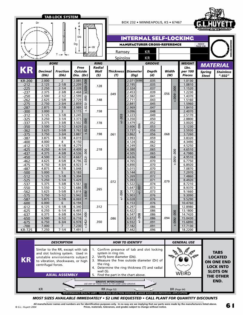
BOX 232 • MINNEAPOLIS, KS • 67467
MOST SIZES AVAILABLE IMMEDIATELY • $2 LINE REQUESTED • CALL PLANT FOR QUANTITY DISCOUNTS
�1All manufacturer names and numbers are for identification purposes only. In no way are we implying that our parts were made by the manufacturers listed above.Prices, materials, tolerances, and grades subject to change without notice.© G.L. Huyett 2004
Similar to the RR, except with tab and slot locking system. Used in unstable environments subject to vibration, shockwaves, or high centrifugal forces.
1. Confirm presence of tab and slot locking system in ring rim.
2. Verify bore diameter (Db).3. Measure the free outside diameter (Dr) of
the ring.4. Determine the ring thickness (T) and radial
wall (S).5. Find the part in the chart above. WEIRDAXIAL ASSEMBLY
Free Outside
Dia. (Dr)Decimal
(Db)Fraction
(Db)Thickness
(T)Diameter
(Dg)Depth
(d)Spring Steel
2.0002.1252.2502.3752.5002.6252.7502.8753.0003.1253.2503.3753.5003.6253.7503.8754.0004.1254.2504.3754.5004.6254.7504.8755.0005.1255.2505.3755.5505.6255.7505.8756.0006.1256.2506.3756.5006.7507.0007.250
22-1/82-1/42-3/82-1/22-5/82-3/42-7/8
33-1/83-1/43-3/83-1/23-5/83-3/43-7/8
44-1/84-1/44-3/84-1/24-5/84-3/44-7/8
55-1/85-1/45-3/85-1/25-5/85-1/25-7/8
66-1/86-1/46-3/86-1/26-3/4
77-1/4
2.0852.2092.3392.4682.5992.7292.8592.9893.1153.2453.3733.5023.6293.7623.8874.0194.1504.2794.4094.5364.6674.7964.9235.0485.1835.3045.4295.5615.6865.8185.9426.0696.1946.3406.4656.5946.7166.9787.2307.491
BORE RING
KRKR-200
-212-225-237-250-262-275-287-300-312-325-337-350-362-375-387-400-412-425-437-450-462-475-487-500-512-525-537-550-562-575-587-600-612-625-637-650-675-700
KR-725
Width(W)
+.0
04/-
.000
+.0
05/-
.000
+/-.005
+/-
.006
+/-
.007
+.02
0/-.0
00+
.027
/-.0
00+
.032
/-.0
00
GROOVE
+/-
.008
+/-
.003
+/-
.004
RadialWall(S)
2.0712.1952.3242.4532.5822.7112.8412.9693.0963.2233.3503.4793.6063.7373.8623.9934.1244.2494.3804.5054.6364.7654.8905.0155.1445.2695.3935.5225.6475.7725.9036.0286.1536.2976.4226.5476.6726.9327.1827.442
.035
.035
.037
.039
.041
.043
.045
.047
.048
.049
.050
.052
.053
.056
.056
.059
.062
.062
.065
.065
.068
.070
.070
.070
.072
.072
.071
.074
.073
.073
.076
.076
.076
.086
.086
.086
.086
.091
.091
.096
.128
.148
.158
.178
.198
.218
.250
.265
.312
.350
.049
.061
.072
.086
.056
.068
.079
.094
+.0
38/-
.000
+.0
23/-
.000
+.0
06/-
.000
KR RR (Page 52) BR (Page 64)
+.0
42/-
.000
INTERNAL SELF-LOCKINGMANUFACTURER CROSS-REFERENCE
MATERIAL
KRRamsey
TAB-LOCK SYSTEM
Stainless “-S02”
Dr
S
Dg
T
Db
d
W
WEIGHTLbs.
per 100 Pieces
PERFORMANCE RESULTS VARY. YOUR RING SELECTION SHOULD BE MADE BASED ON INDIVIDUAL APPLICATION.
KRSpirolox
TABS LOCATED
ON ONE END LOCK INTO SLOTS ON THE OTHER
END.
1.0130 1.0810 1.1520 1.2230 1.4370 1.5160 1.5960 1.8410 2.4070 2.5170 2.8800 3.0020 3.1230 3.5930 3.7260 3.8320 4.3490 4.5250 4.6510 4.7980 4.9510 6.7750 6.8920 7.0870 7.2970 7.4860 8.4920 8.7210 8.9370 9.1660 9.3090 9.529010.476012.898013.180014.742015.043015.689017.713018.2200
INDEX PAGE 236.
GROOVE INTERCHANGEUSE ANY OF THESE PARTS IN THE SAME SIZED GROOVE.
DESCRIPTION HOW TO IDENTIFY GENERAL USE
KR

INTERNAL SPIRAL RINGSREVISED 09-04
MOST SIZES AVAILABLE IMMEDIATELY • $2 LINE REQUESTED • CALL PLANT FOR QUANTITY DISCOUNTS
�2
785•392•3017 FAX 785.392.2845
All manufacturer names and numbers are for identification purposes only. In no way are we implying that our parts were made by the manufacturers listed above.Prices, materials, tolerances, and grades subject to change without notice. © G.L. Huyett 2004
www.huyett.com
INTERNAL DISHEDMANUFACTURER CROSS-REFERENCE
Standard ring formed into a conical shape that is designed to take up end-play. Best results occur when ring is installed in a non-loaded condition.
1. Confirm conical shape of part.2. Verify bore diameter (Db).3. Measure the free outside diameter (Dr) of the
ring.4. Determine the ring thickness (T) and radial
wall (S).5. Find the part in the chart above. WEIRDAXIAL ASSEMBLY
Free Outside
Dia. (Dr)Decimal
(Db)Fraction
(Db)Thickness
(T)Diameter
(Dg)Depth
(d)SpringSteel
1.0001.1251.2501.3751.5001.6251.7501.8752.0002.1252.2502.3752.5002.6252.7502.8753.0003.1253.2503.3753.5003.6253.7503.8754.0004.1254.2504.5004.7505.000
11-1/81-1/41-3/81-1/21-5/81-3/41-7/8
22-1/82-1/42-3/82-1/22-5/82-3/42-7/8
33-1/83-1/43-3/83-1/23-5/83-3/43-7/8
44-1/84-1/44-1/24-3/4
5
1.0811.2151.3491.4821.6151.7501.8842.0162.1512.2822.4162.5532.6852.8202.9543.0933.2283.3613.4863.6213.7533.8854.0214.1544.2904.3884.5224.7795.0445.313
MRMR-100
-112-125-137-150-162-175-187-200-212-225-237-250-262-275-287-300-312-325-337-350-362-375-387-400-412-425-450-475
MR-500
Width(W)
+.0
04/-
.000
+.0
05/-
.000
+/-
.005
+/-
.006
+.013/-.000
+.0
25/-
.000
+.0
30/-
.000
+.0
35/-
.000
+/-
.002
+/-
.003
Radial Wall(S)
.012
.015
.016
.018
.019
.022
.020
.024
.026
.029
.029
.028
.029
.029
.028
.029
.028
.029
.029
.032
.033
.032
.036
.039
.039
.045
.044
.047
.048
.047
+/-
.003
+/-
.004
Dish Height
(Hd)
BORE RING GROOVE
.095
.103
.118
.128
.148
.148
.158
.178
.188
.198
.198
.208
.218
.228
.238
.248
.248
.265
.265
.265
.312
.312
.312
.350
.350
.350
.350
.375
.375
.375
1.0661.1971.3301.4611.5941.7251.8581.9892.1222.2512.3822.5172.6482.7812.9143.0513.1823.3153.4463.5793.7103.8413.9744.1074.2404.3394.4704.7354.9955.260
.033
.036
.040
.043
.047
.050
.054
.057
.061
.063
.066
.071
.074
.078
.082
.088
.091
.095
.098
.102
.105
.108
.112
.116
.120
.107
.110
.117
.122
.130
.043
.050
.062
.072
.086
.048
.056
.068
.079
.094
+.045/-.000
+.01
5/-.0
00+.
020/
-.000
+/-.003
+/-
.004
+.0
06/-
.000
CONICAL SHAPE FOR END PLAY TAKE-UP.
MATERIAL
MRRamsey
DISHED SHAPE FOR END-PLAY TAKE UP
Stainless “-S02”
Dr
S
Dg
T
Db
dW
Hd
MRSpirolox
Lbs. per 100 Pieces
WEIGHT
0.3160 0.4420 0.5400 0.6470 0.8560 0.9190 1.3230 1.5370 1.7370 1.9910 2.1210 2.3710 2.6170 2.8790 3.1510 3.4400 4.2300 4.6900 5.1700 5.4930 5.8580 6.2720 7.9560 8.6800 8.9900 9.717010.044011.493012.153012.8920
INDEX PAGE 236.
DESCRIPTION HOW TO IDENTIFY GENERAL USE
MR

BOX 232 • MINNEAPOLIS, KS • 67467
MOST SIZES AVAILABLE IMMEDIATELY • $2 LINE REQUESTED • CALL PLANT FOR QUANTITY DISCOUNTS
�3All manufacturer names and numbers are for identification purposes only. In no way are we implying that our parts were made by the manufacturers listed above.Prices, materials, tolerances, and grades subject to change without notice.© G.L. Huyett 2004
Standard RSN ring with prong for easy removal using pliers or screwdriver, or for holding it with your teeth.
1. Verify prong or finger protruding from the ring.
2. Confirm bore diameter (Db).3. Measure the free outside diameter (Dr) of
the ring.4. Determine the ring thickness (T) and radial
wall (S).5. Find the part in the chart above. WEIRDAXIAL ASSEMBLY
Free Outside
Dia. (Dr)Decimal
(Db)Fraction
(Db)Thickness
(T)Diameter
(Dg)Depth
(d)SpringSteel
2.0002.1252.2502.3752.5002.6252.7502.8753.0003.1253.2503.5003.6253.7503.8754.0004.1254.2504.5004.6254.7505.000
22-1/82-1/42-3/82-1/22-5/82-3/42-7/8
33-1/83-1/43-1/23-5/83-3/43-7/8
44-1/84-1/44-1/24-5/84-3/4
5
2.1422.2672.3992.5352.6672.8012.9343.0723.2043.3343.4703.7363.8684.0024.1364.2704.3694.5014.7684.8995.0305.297
BORE RING
SRNSRN-200
-212-225-237-250-262-275-287-300-312-325-350-362-375-387-400-412-425-450-462-475
SRN-500
Width(W)
+.0
05/-
.000
+/-
.006
+.020/-.000
+.0
35/-
.000
+.03
0/-.0
00
GROOVE
+/-
.003
RadialWall(S)
2.1222.2512.3822.5172.6482.7812.9143.0513.1823.3153.4463.7103.8413.9744.1074.2404.3394.4704.7354.8654.9955.260
.061
.063
.066
.071
.074
.078
.082
.088
.091
.095
.098
.105
.108
.112
.116
.120
.107
.110
.117
.120
.122
.130
.062
.078
.111
.068
.120
+.02
5/-.0
00
+/-.005 +.004/-.000
.093
SRN HO (Page 16) HOI (Page 19) RRN (Page 58) UHO (Page 76)
PROTRUDING TAB FOR
REMOVAL.
INTERNAL TABBEDMANUFACTURER CROSS-REFERENCE
MATERIAL
SRNRamsey
.086
.103
EASY TO REMOVE
Stainless “-S02”
Dr
ST
W
d
Db
Dg
WEIGHTLbs.
per 100 Pieces
PERFORMANCE RESULTS VARY. YOUR RING SELECTION SHOULD BE MADE BASED ON INDIVIDUAL APPLICATION.
SRNSpirolox
1.5780 2.2560 2.4060 3.0050 3.1410 4.3810 4.6210 4.8700 5.1080 7.7820 8.1390 8.8580 9.215010.414010.817011.219011.516011.913012.714013.107013.500014.0490
INDEX PAGE 236.
GROOVE INTERCHANGEUSE ANY OF THESE PARTS IN THE SAME SIZED GROOVE.
.158
.168
.200
.225
.281
.312
DESCRIPTION HOW TO IDENTIFY GENERAL USE
SRN

INTERNAL SPIRAL RINGSREVISED 09-04
MOST SIZES AVAILABLE IMMEDIATELY • $2 LINE REQUESTED • CALL PLANT FOR QUANTITY DISCOUNTS
�4
785•392•3017 FAX 785.392.2845
All manufacturer names and numbers are for identification purposes only. In no way are we implying that our parts were made by the manufacturers listed above.Prices, materials, tolerances, and grades subject to change without notice. © G.L. Huyett 2004
www.huyett.com
INTERNAL BALANCEDMANUFACTURER CROSS-REFERENCE
Similar to the RR, except a series of slots opposite the ring gap balance the part for high RPM applications. Tab and slot locking system provides locking benefits.
1. Confirm the presence of slots and tab lock system.
2. Verify bore diameter (Db).3. Measure the free outside diameter (Dr) of
the ring.4. Determine the ring thickness (T) and radial
wall (S).5. Find the part in the chart above. WEIRDAXIAL ASSEMBLY
Free Outside
Dia. (Dr)Decimal
(Db)Fraction
(Db)Thickness
(T)Diameter
(Dg)Depth
(d)SpringSteel
2.0002.0622.1252.1872.2502.3122.3752.4372.5002.5622.6252.6872.7502.8132.8752.9373.0003.0623.1253.1873.2503.3123.3753.4373.5003.5623.6253.6873.7503.8123.8753.9374.0004.0634.1254.1874.2504.3124.3754.437
22-1/162-1/82-3/162-1/42-5/162-3/82-7/162-1/22-9/162-5/8
2-11/162-3/4
2-13/162-7/8
2-15/163
3-1/163-1/83-3/163-1/43-5/163-3/83-7/163-1/23-9/163-5/8
3-11/163-3/4
3-13/163-7/8
3-15/164
4-1/164-1/84-3/164-1/44-5/164-3/84-7/16
2.0912.1542.2172.2842.3472.4032.4762.5432.6062.6732.7362.8032.8652.9292.9953.0583.1223.1863.2513.3113.3793.4463.5093.5743.6363.7033.7693.8323.8943.9634.0254.0894.1574.2224.2844.3474.4164.4794.5434.611
BORE RING
BRBR-200
-206-212-218-225-231-237-243-250-256-262-268-275-281-287-293-300-306-312-318-325-331-337-343-350-356-362-368-375-381-387-393-400-406-412-418-425-431-437
BR-443
Width(W)
+.0
04/-
.000
+/-.005+.020/-.000
+.0
25/-
.000
+.0
30/-
.000
GROOVE
+/-
.003
RadialWall(S)
2.0712.1322.1952.2622.3242.3902.4532.5192.5822.6842.7112.7782.8412.9032.9693.0313.0963.1583.2233.2833.3503.4163.4793.5433.6063.6723.7373.7993.8623.9303.9934.0564.1244.1874.2494.3114.3804.4424.5054.573.238
.049
.061
.056
.068
BR RR (Page 52) KR (Page 61)
+.0
35/-
.000
+/-
.006
+.0
05/-
.000
MATERIAL
BRRamsey
TAB-LOCK SYSTEM
.128
.138
.148
.158
.168
.178
.188
.198
.208
.218
.228
Stainless “-S02”
WEIGHTLbs.
per 100 Pieces
PERFORMANCE RESULTS VARY. YOUR RING SELECTION SHOULD BE MADE BASED ON INDIVIDUAL APPLICATION.
BRSpirolox
CONTACT US FOR DESIGN
ASSISTANCE.
0.97701.01101.04501.16701.20301.24201.27901.39901.43901.48101.52001.66801.71101.75301.89601.94002.48402.53902.71702.77402.83703.06303.12603.19003.25303.49503.56303.62903.69503.95504.02504.09504.36804.44104.51304.58504.80604.88204.95905.2600
Dr d
Db
DgW
T
S
INDEX PAGE 236.
GROOVE INTERCHANGEUSE ANY OF THESE PARTS IN THE SAME SIZED GROOVE.
.035
.037
.036
.039
.041
.043
.045
.047
.048
.049
.048
.050
.052
.053
.055
.056
.059
.062
.065
.068
DESCRIPTION HOW TO IDENTIFY GENERAL USE
BR
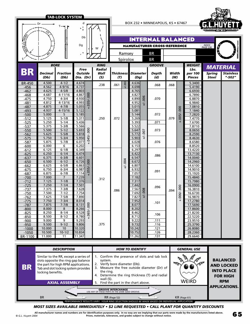
BOX 232 • MINNEAPOLIS, KS • 67467
MOST SIZES AVAILABLE IMMEDIATELY • $2 LINE REQUESTED • CALL PLANT FOR QUANTITY DISCOUNTS
�5All manufacturer names and numbers are for identification purposes only. In no way are we implying that our parts were made by the manufacturers listed above.Prices, materials, tolerances, and grades subject to change without notice.© G.L. Huyett 2004
Similar to the RR, except a series of slots opposite the ring gap balance the part for high RPM applications. Tab and slot locking system provides locking benefits.
1. Confirm the presence of slots and tab lock system.
2. Verify bore diameter (Db).3. Measure the free outside diameter (Dr) of
the ring.4. Determine the ring thickness (T) and radial
wall (S).5. Find the part in the chart above. WEIRDAXIAL ASSEMBLY
Free Outside
Dia. (Dr)Decimal
(Db)Fraction
(Db)Thickness
(T)Diameter
(Dg)Depth
(d)Spring Steel
4.5004.5624.6254.6874.7504.8124.8754.9375.0005.1255.2505.3755.5005.6255.7505.8756.0006.1256.2506.3756.5006.6256.7506.8757.0007.1257.2507.3757.5007.6257.7507.8758.0008.2508.5009.0009.500
10.00010.50011.000
4-1/24-9/164-5/8
4-11/164-3/4
4-13/164-7/8
4-15/165
5-1/85-1/45-3/85-1/25-5/85-3/45-7/8
66-1/86-1/46-3/86-1/26-5/86-3/46-7/8
77-1/87-1/47-3/87-1/27-5/87-3/47-7/8
88-1/48-1/2
99-1/2
1010-1/2
11
4.6744.7374.8034.8674.9304.9935.0555.1225.1855.3115.4365.5665.6935.8185.9506.0776.2026.3496.4746.6016.7266.8636.9877.1147.2397.3767.5017.6287.7547.8908.0148.1318.2668.5288.7809.2939.806
10.32010.83411.347
BORE RING
BRBR-450
-456-462-468-475-481-487-493-500-512-525-537-550-562-575-587-600-612-625 -637-650-662-675-687-700-712-725-737-750-762-775-787-800-825-850-900-950
-1000 -1050
BR-1100
Width(W)
+.0
05/-
.000
+/-
.006
+/-
.007
+.0
35/-
.000
+.0
45/-
.000
+.0
55/-
.000
GROOVE
+/-
.008
+/-.0
03+
/-.0
04
RadialWall(S)
4.6364.6984.7654.8274.8904.9525.0155.0815.1445.2695.3935.5225.6475.7725.9036.0286.1536.2976.4226.5476.6726.8076.9327.0577.1827.3177.4427.5677.6927.8277.9528.0778.2028.4628.7129.2229.732
10.24210.75211.262
.238
.250
.312
.375
.061
.072
.068
BR RR (Page 52) KR (Page 61)
+.0
65/-
.000
+.0
06/-
.000
INTERNAL BALANCEDMANUFACTURER CROSS-REFERENCE
MATERIAL
BRRamsey
.086 .094
.079
TAB-LOCK SYSTEM
Stainless “-S02”
W
WEIGHTLbs.
per 100 Pieces
PERFORMANCE RESULTS VARY. YOUR RING SELECTION SHOULD BE MADE BASED ON INDIVIDUAL APPLICATION.
BRSpirolox
BALANCED AND LOCKED INTO PLACE FOR HIGH
RPM APPLICATIONS.
5.3400 5.4190 6.6930 6.7890 6.8870 6.9840 7.0810 7.1840 7.2820 7.4770 7.6700 7.8710 8.0650 8.2590 8.4630 8.6580 8.852013.422013.713014.004014.296014.610014.901015.192015.484015.798016.090016.381016.673016.987017.278017.569017.860021.823022.522023.951025.379026.808028.236029.6640
Dr d
Db
Dg
T
S
INDEX PAGE 236.
GROOVE INTERCHANGEUSE ANY OF THESE PARTS IN THE SAME SIZED GROOVE.
.068
.070
.072
.071
.073
.076
.086
.091
.096
.101
.106
.111
.116
.121
.126
.131
DESCRIPTION HOW TO IDENTIFY GENERAL USE
BR

EATON -STYLE RINGSREVISED 09-04
MOST SIZES AVAILABLE IMMEDIATELY • $2 LINE REQUESTED • CALL PLANT FOR QUANTITY DISCOUNTS
��
785•392•3017 FAX 785.392.2845
All manufacturer names and numbers are for identification purposes only. In no way are we implying that our parts were made by the manufacturers listed above.Prices, materials, tolerances, and grades subject to change without notice.
TM
© G.L. Huyett 2004
www.huyett.com
AUTOMATED INSTALLATION
EXTERNAL INTERNALUSC
METRIC
Pg: 198
IMPERIAL
Pgs: 68-69
XDIMPERIAL
Pg: 70
USHIMPERIAL
Pg: 71
INSTALLED
AXIALLY
ONTO A
SHAFT
USING
PLIERS.
BASIC
METRIC
N/A
METRIC
N/A
LIGHT DUTY
NOTCHED
INSTALLED
AXIALLY
INTO A
BORE
USING
PLIERS.
UHBMETRIC
Pgs: 200-201
IMPERIAL
Pgs: 72-73
NDIMPERIAL
Pg: 74
UHOIMPERIAL
Pgs: 76-77
BASIC
METRIC
N/A
METRIC
N/A
LIGHT DUTY
NOTCHED
TOOLS Pages: 226-231 TOOLS Pages: 226-231
Wire width is the same at A and B . . .
. . . but yields a low profile in the groove versus lug-style snap rings.
Use pliers . . . . . . a screwdriver . . . . . . or a tapered mandrel design depending on your application.
#4 gapSTANDARD
#11 gapOPTIONAL
#34 gapOPTIONAL
#14 gapOPTIONAL
#6 gapSTANDARD
#11 gapOPTIONAL
#34 gapOPTIONAL
#14 gapOPTIONAL
#36 gapSTANDARD
on “USH” rings
#1 gapOPTIONAL
#35 gapSTANDARD
on “UHO” rings
OPTIONAL GAP STYLES AVAILABLE AS A SPECIAL ORDER
GROOVEGROOVE
EXTERNAL INTERNAL
. . . which causes a radial kink so that the part is “out of round” after installation . . .
STANDARD GAP STYLESEXTERNAL INTERNAL
EXTERNAL INTERNAL
LET OUR SHOP MAKE A FIXTURE FOR YOU!
For special orders, see page 75.
A
B
CONSTANTSECTION

BOX 232 • MINNEAPOLIS, KS • 67467
MOST SIZES AVAILABLE IMMEDIATELY • $2 LINE REQUESTED • CALL PLANT FOR QUANTITY DISCOUNTS
�7All manufacturer names and numbers are for identification purposes only. In no way are we implying that our parts were made by the manufacturers listed above.Prices, materials, tolerances, and grades subject to change without notice.© G.L. Huyett 2004
EatonTM-style rings are a class of retaining rings popularized by the EatonTM Corporation, a huge industrial conglomerate. These rings are wire formed and based on designs established by the automotive and industrial marketplace. EatonTM began manufacturing these rings as an attempt at vertical consolidation. Because the ring business was such a small part of the company’s total revenues, little attention was paid to marketing and distribution. As a result, these rings are very limited in supply, and prices for the parts tend to be high in comparison to thrust loads. EatonTM has recently sold off their ring division to concentrate on other markets.
MOST OF THE RINGS IN THIS SECTION HAVE NOT BEEN MANUFACTURED BY THE EATONTM CORPORATION.
EatonTM-style rings are wire formed. Wire forming provides some product benefits on large and specialty rings because tooling costs are lower than for stamped snap rings, and there is minimal material waste from breakout. In addition, the grain of the material is circular, which provides excellent strength with a low profile.
THRUST LOAD COMPARISONEATONTM-STYLE RINGS VS. OTHER RETAINING RINGS
PRODUCT COMPARISONS
Thrust loads are expressed in pounds, based on groove shear with a safety factor of two (2). Eaton™-style ring thrust loads are based on load times 0.60 when the ring distortion is .005 or greater from bending axially.
Actual results will be based on individual circumstances. These values are for reference only.
FINISHES
OIL DIPPED(STANDARD)
Inhibits rust during handling.
ZINC PLATE(STANDARD)
Up to 96 hours salt spray.
OTHERS PER QUOTE . . .BLACK OXIDE
BRASSBRONZE
CADMIUMCHROMECOPPER
PARKERIZE
MATERIAL
CARBON SPRING STEEL
SAE 1060-1090RC 42/53
(STANDARD)
500°F Max100°F Min
OTHER MATERIALS AVAILABLE ON REQUEST.
OPTIONAL CROSS SECTIONS AS SPECIAL ORDER:
HI COLLAR(Standard)
ROUND(Standard)
STEPSQUARE(Standard)
DOUBLEBEVEL
TAPER
CHAMFER ROUND EDGE FLAT
RADIUS CORNER
TONGUE SQUAREEDGE
MILLEDGE
CARBON SPRING STEEL
SNAP RING SPIRAL RINGS SNAP RING SPIRAL RINGS
BORESIZE
RRPg 16
Thrust Load
Pg 52
Thrust Load
Pg 58
Thrust Load
1”
2”
5”
7”
1910
7090
36,050
63,790
RRN INTERNAL
HOPg 72
Thrust Load
2800
10,300
55,000
93,100
EATON™ RING
UHB
1470
4000
17,110
34,850
2310
10,040
65,095
110,410
RSPg 38
Thrust Load
RSNPg 44
Thrust Load Thrust Load
2150
7110
36,050
63,790
2950
11,470
52,580
103,400
EXTERNAL
SHAFTSIZE
1”
2”
5”
7”
SHPg 6
2100
8050
37,100
72,700
EATON™ RING
Thrust Load
USCPg 68
1200
4010
17,110
39,920
COILED FROM WIRE

EXTERNAL EATON -STYLE RINGSREVISED 09-04
MOST SIZES AVAILABLE IMMEDIATELY • $2 LINE REQUESTED • CALL PLANT FOR QUANTITY DISCOUNTS
�8
785•392•3017 FAX 785.392.2845
All manufacturer names and numbers are for identification purposes only. In no way are we implying that our parts were made by the manufacturers listed above.Prices, materials, tolerances, and grades subject to change without notice.
TM
© G.L. Huyett 2004
www.huyett.com
USC
Wire formed spring steel ring installed using special pliers or with tapered plug and bushing (see page 66).
1. Confirm the shaft diameter (Ds).2. Measure the free inside diameter (Df) of the
ring.3. Determine the ring thickness (T) and radial
wall (S).4. Find the part in the chart above.
USC RST (Page 42)
COMMONAXIAL ASSEMBLY
Free Inside Dia.
(Df)Decimal
(Ds)Fraction
(Ds)Thickness
(T)Diameter
(Dg)Depth
(d)SpringSteel
.312
.344
.354
.375
.393
.406
.438
.469
.500
.551
.562
.594
.625
.669
.688
.750
.781
.812
.875
.938
.9841.0001.0231.0621.1251.1881.2501.3121.3751.4381.5001.5621.6251.6871.7501.7711.8121.875
5/1611/32
8.99mm3/8
9.98mm13/327/1615/321/2
14mm9/1619/325/8
17mm11/163/4
15/3213/167/8
15/1663/64
125.98mm
1-1/161-1/81-3/161-1/41-5/161-3/81-7/161-1/21-9/161-5/8
1-11/161-3/4
44.98mm1-13/161-7/8
.281
.312
.320
.341
.359
.372
.402
.433
.464
.514
.524
.555
.586
.630
.644
.703
.733
.764
.820
.881
.925
.941
.9621.0001.0601.1211.1791.2321.2911.3511.4081.4671.5271.5811.6401.6571.6981.759
SHAFT RING
USCUSC-031
-034-035-037-039-040-043-046-050-055-056-059-062-066-068-075-078-081-087-093-098-100-102-106-112-118-125-131-137-143-150-156-162-168-175-177-181
USC-187
Width(W)
+.0
03/-
.000
+.0
04/-
.000
+/-
.002
+/-
.003
+/-
.003
+/-
.005
+.0
00/-
.015
+.0
00/-
.020
+.0
00/-
.025
+.0
00/-
.031
GROOVE
+/-
.002
RadialWall(S)
TOOL
.290
.322
.330
.351
.369
.382
.412
.443
.474
.524
.534
.566
.597
.640
.656
.716
.745
.776
.835
.896
.940
.956
.9771.0161.0751.1361.1941.2501.3091.3701.4301.4901.5511.6111.6701.6871.7281.789
.011
.011
.012
.012
.012
.012
.013
.013
.013
.013
.014
.014
.014
.015
.016
.017
.018
.018
.020
.021
.022
.022
.023
.023
.025
.026
.028
.031
.033
.034
.035
.036
.038
.038
.040
.042
.042
.043
.025
.042
.050
.062
.035
.028
.046
.056
.068
.039
.040
.048
.062
.093
.109
.141
.156
.125
.078
+.0
00/-
.046 +
/-.0
04
This style only on USC-031 through -043.
MATERIAL
USCRotor ClipXANEaton
BASIC EXTERNALMANUFACTURER CROSS-REFERENCE
Standard #4 Gap
-E015R
-E047R
PERFORMANCE RESULTS VARY. YOUR RING SELECTION SHOULD BE MADE BASED ON INDIVIDUAL APPLICATION.
Td
DgDsDf
SW
CO
NTA
CT
PLA
NT
FOR
TO
OL
INFO
RM
ATI
ON
.
USC CONTINUED NEXT PAGE.
GROOVE INTERCHANGEUSE ANY OF THESE PARTS IN THE SAME SIZED GROOVE.
INDEX PAGE 236.
DESCRIPTION HOW TO IDENTIFY GENERAL USE

BOX 232 • MINNEAPOLIS, KS • 67467
MOST SIZES AVAILABLE IMMEDIATELY • $2 LINE REQUESTED • CALL PLANT FOR QUANTITY DISCOUNTS
�9All manufacturer names and numbers are for identification purposes only. In no way are we implying that our parts were made by the manufacturers listed above.Prices, materials, tolerances, and grades subject to change without notice.© G.L. Huyett 2004
Free Inside Dia.
(Df)Decimal
(Ds)Fraction
(Ds)Thickness
(T)Diameter
(Dg)Depth
(d)SpringSteel
1.9692.0002.0622.1252.1562.2502.3122.3752.4372.5002.5592.6252.6872.7502.8752.9373.0003.0623.1253.1563.2503.3443.4373.5003.5433.6253.6873.7503.8753.9384.0004.2504.3754.5004.7505.0005.2505.5005.7505.9006.0006.2506.5006.7507.0007.2507.5008.0008.5009.0009.2509.500
10.000
1-31/322
2-1/162-1/82-5/322-1/42-5/162-3/82-7/162-1/2
65mm2-5/8
2-11/162-3/42-7/8
2-15/163
3-1/163-1/83-5/323-1/4
3-11/323-7/163-1/2
90mm3-5/8
3-11/163-3/43-7/8
3-15/164
4-1/44-3/84-1/24-3/4
55-1/45-1/25-3/4
149.86mm6
6-1/46-1/26-3/4
77-1/47-1/2
88-1/2
99-1/49-1/2
10
1.8491.8801.9361.9972.0262.1162.1742.2352.2952.3562.4132.4752.5352.5942.7132.7712.8302.8902.9512.9803.0703.1603.2513.3053.3463.4233.4823.5413.6573.7133.7714.0164.1414.2554.4954.7304.9705.2065.4465.6005.6875.9166.1516.3866.6216.8407.0907.5608.0508.5458.8009.0409.535
SHAFT RING
USCUSC-196
-200-206-212-215-225-231-237-243-250-255-262-268-275-287-293-300-306-312-315-325-334-343-350-354-362-368-375-387-393-400-425-437-450-475-500-525-550-575-590-600-625-650-675-700-725-750-800-850-900-925-950
USC-1000
Width(W)
+.0
05/-
.000
.078
+.0
00/-
.046
+.0
00/-
.062
+.0
00/-
.078
+.0
00/-
.093
GROOVERadialWall(S)
TOOL
1.8791.9101.9662.0272.0562.1462.2042.2652.3252.3862.4432.5052.5652.6242.7432.8012.8602.9202.9813.0103.1003.1903.2813.3403.3813.4583.5173.5763.6973.7583.8164.0664.1914.3104.5504.7905.0305.2665.5065.6565.7465.9866.2266.4666.7066.9307.1807.6608.1608.6608.9109.1609.660
.045
.045
.048
.049
.050
.052
.054
.055
.056
.057
.058
.060
.061
.063
.066
.068
.070
.071
.072
.073
.075
.077
.078
.080
.081
.083
.085
.087
.089
.090
.092
.092
.092
.095
.100
.105
.110
.117
.122
.122
.127
.132
.137
.142
.147
.160
.160
.170
.170
.170
.170
.170
.170
.156
.187
.218
.250
.281
.312
.093
.109
.086
.103
.120
+.0
00/-
.156
.437 .156 .174
.500 .187 .209
.062 .068
+/-.0
04
+.00
4/-
.000
+/-
.002
.375 .125 .139
+.0
00/-
.125
+/-
.005
+/-
.006
+.0
06/-
.000
+/-
.008
+.0
08/-
.000
BASIC EXTERNALMANUFACTURER CROSS-REFERENCE
MATERIAL
USCRotor Clip
XANEaton
-E047R
-E601R
-E602R
-
T d
DgDsDf
SW
CO
NTA
CT
PLA
NT
FOR
TO
OL
INFO
RM
ATI
ON
.
INDEX PAGE 236.

EXTERNAL EATON -STYLE RINGSREVISED 09-04
MOST SIZES AVAILABLE IMMEDIATELY • $2 LINE REQUESTED • CALL PLANT FOR QUANTITY DISCOUNTS
70
785•392•3017 FAX 785.392.2845
All manufacturer names and numbers are for identification purposes only. In no way are we implying that our parts were made by the manufacturers listed above.Prices, materials, tolerances, and grades subject to change without notice.
TM
© G.L. Huyett 2004
www.huyett.com
LIGHT-DUTY EXTERNALMANUFACTURER CROSS-REFERENCE
Generally this part is thinner than the USC but has a wider radial wall. Used in needle bearings and other lighter-weight applications.
1. Confirm the shaft diameter (Ds).2. Measure the free inside diameter (Df) of the
ring.3. Determine the ring thickness (T) and radial
wall (S).4. Find the part in the chart above.
WEIRDAXIAL ASSEMBLY
Free Inside Dia.
(Df)Decimal
(Ds)Fraction
(Ds)Thickness
(T)Diameter
(Dg)Depth
(d)SpringSteel
.500
.625
.750
.8751.0001.1251.1871.2501.3121.3751.4371.5001.6251.6871.7501.9372.0002.1872.2502.3752.5002.7502.9373.0003.1253.2503.3753.5003.7504.0004.5004.5004.7505.0005.5006.0006.5007.0007.5008.000
1/25/83/47/81
1-1/81-3/161-1/41-5/161-3/81-7/161-1/21-5/8
1-11/161-3/4
1-15/162
2-3/162-1/42-3/82-1/22-3/4
2-15/163
3-1/83-1/43-3/83-1/23-3/4
44-1/44-1/24-3/4
55-1/2
66-1/2
77-1/2
8
.465
.587
.704
.823
.9441.0651.1201.1791.2321.2891.3491.4101.5201.5821.6451.8321.8952.0822.1452.2702.3902.5962.7832.8462.9653.0903.2153.3403.5703.8204.0704.3204.5604.8005.2805.7756.2706.7657.2457.740
SHAFT RING
XDXD-050
-062-075-087-100-112-118-125-131-137-143-150-162-168-175-193-200-218-225-237-250-275-293-300-312-325-337-350-375-400-425-450-475-500-550-600-650-700-750
XD-800
Width(W)
+.0
03/-
.000
+.0
04/-
.000
.035
+/-
.002
+/-
.003
+/-
.004
+/-
.003+.0
00/
-.02
5+
.000
/-.0
31+
.000
/-.0
62+
.000
/-.0
78
GROOVE
+/-
.006
+/-
.002
RadialWall(S)
X.474.597.716.833.954
1.0771.1351.1941.2521.3091.3691.4301.5451.6071.6701.8571.9202.1072.1702.2952.4202.6262.8132.8763.0003.1253.2503.3753.6103.8604.1104.3604.6104.8605.3405.8406.3406.8407.3207.820
.093
.125
.156
.187
.218
.250
.281
.048
.062
.078
.042
.062
.078
.093
.109
.039
.046
.068
.086
.103
.120
.040
.062
.070
.080
.090
.013
.014
.017
.021
.023
.024
.026
.028
.030
.033
.034
.035
+.0
00/-
.125
+.0
00/-
.093
+/-
.008
+.0
05/-
.000
+/-
.005
This style only on XD-050 and -062.
MATERIAL
XDEaton
Standard #4 Gap
-E047R
-E601R
CO
NTA
CT
PLA
NT
FOR
TO
OL
INFO
RM
ATI
ON
.
INDEX PAGE 236.
Df
S
Ds
Dg
d
WT
TOOL
DESCRIPTION HOW TO IDENTIFY GENERAL USE
XD
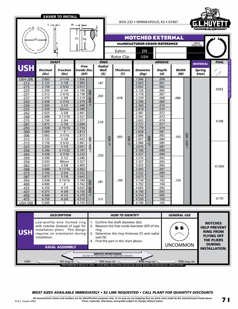
BOX 232 • MINNEAPOLIS, KS • 67467
MOST SIZES AVAILABLE IMMEDIATELY • $2 LINE REQUESTED • CALL PLANT FOR QUANTITY DISCOUNTS
71All manufacturer names and numbers are for identification purposes only. In no way are we implying that our parts were made by the manufacturers listed above.Prices, materials, tolerances, and grades subject to change without notice.© G.L. Huyett 2004
Low-profile wire formed ring with notches (instead of lugs) for installation pliers. This design requires no orientation during installation.
1. Confirm the shaft diameter (Ds).2. Measure the free inside diameter (Df) of the
ring.3. Determine the ring thickness (T) and radial
wall (S).4. Find the part in the chart above.
UNCOMMONAXIAL ASSEMBLY
Free Inside Dia.
(Df)Decimal
(Ds)Fraction
(Ds)Thickness
(T)Diameter
(Dg)Depth
(d)SpringSteel
2.0622.1252.1562.2502.3122.3752.4382.5002.5592.6252.6882.7502.8752.9383.0003.0623.1253.1563.2503.3463.4383.5003.5433.6253.6883.7503.8753.9384.0004.2504.3754.5004.7505.000
2-1/162-1/82-5/322-1/42-5/162-3/82-7/162-1/2
65mm2-5/8
2-11/162-3/42-7/8
2-15/163
3-1/163-1/83-5/323-1/4
3-11/323-7/163-1/2
90mm3-5/8
3-11/163-3/43-7/8
3-15/164
4-1/44-3/84-1/24-3/4
5
1.9261.9832.0122.1002.1582.2192.2792.3402.3992.4612.5212.5772.6962.7542.8132.8732.9322.9613.0513.1413.2323.2863.3273.4053.4633.5223.6433.7043.7624.0254.1504.2704.5104.750
SHAFT RING
USHUSH-206
-212-215-225-231-237-243-250-255-262-268-275-287-293-300-306-312-315-325-334-343-350-354-362-368-375-387-393-400-425-437-450-475
USH-500
Width(W)
+.0
05/-
.000
.187
+/-
.006
+/-
.005
+.0
00/-
.060
+.0
00/-
.080
+.0
00/-
.093
GROOVE
.078
+/-
.002
RadialWall(S)
1.9462.0032.0322.1202.1782.2392.2992.3602.4192.4812.5412.6022.7212.7792.8382.8982.9572.9863.0763.1663.2573.3163.3573.4353.4933.5523.6733.7343.7924.0654.1904.3104.5504.790
.058
.061
.062
.065
.067
.068
.069
.070
.070
.072
.073
.074
.077
.079
.081
.082
.084
.085
.087
.090
.090
.092
.093
.095
.097
.099
.101
.102
.104
.092
.092
.095
.100
.105
.218
.250
.281
.312
.203
.093
.109
.086
.103
.120
USH SH (Page 6) SHI (Page 10) RSN (Page 44) SSN (Page 49)
NOTCHED EXTERNALMANUFACTURER CROSS-REFERENCE
MATERIAL
USHRotor Clip
ENEaton
EASIER TO INSTALL
-E093
-E108
-E120X
-E170
PERFORMANCE RESULTS VARY. YOUR RING SELECTION SHOULD BE MADE BASED ON INDIVIDUAL APPLICATION.
NOTCHES HELP PREVENT
RING FROM FLYING OFF THE PLIERS
DURING INSTALLATION.
TOO
L D
ESC
RIP
TIO
NS
ON
PA
GE
226.
GROOVE INTERCHANGEUSE ANY OF THESE PARTS IN THE SAME SIZED GROOVE.
INDEX PAGE 236.
Dsd
WT
SDf Dg
TOOL
DESCRIPTION HOW TO IDENTIFY GENERAL USE
USH

INTERNAL EATON -STYLE RINGSREVISED 09-04
MOST SIZES AVAILABLE IMMEDIATELY • $2 LINE REQUESTED • CALL PLANT FOR QUANTITY DISCOUNTS
72
785•392•3017 FAX 785.392.2845
All manufacturer names and numbers are for identification purposes only. In no way are we implying that our parts were made by the manufacturers listed above.Prices, materials, tolerances, and grades subject to change without notice.
TM
© G.L. Huyett 2004
www.huyett.com
BASIC INTERNALMANUFACTURER CROSS-REFERENCE
Wire formed spring steel ring installed using special pliers or with a plug and tapered bushing (see page 66).
1. Confirm the bore diameter (Db).2. Measure the free outside diameter (Dr) of
the ring.3. Determine the ring thickness (T) and radial
wall (S).4. Find the part in the chart above.
UHB RRT (Page 56)
COMMONAXIAL ASSEMBLY
Decimal(Db)
Diameter(Dg)
Spring Steel
.375
.438
.500
.512
.562
.625
.688
.750
.777
.812
.875
.901
.9381.0001.0231.0621.1251.1881.2501.3121.3751.4381.4561.5001.5621.6251.6531.6881.7501.8121.8501.8751.9381.9682.0002.0622.1252.1882.2502.312
3/87/161/2
13mm9/165/8
11/163/4
19.74mm13/167/8
22.88mm15/16
125.98mm
1-1/161-1/81-3/161-1/41-5/161-3/81-7/16
36.08mm1-1/21-9/161-5/8
41.99mm1-11/161-3/4
1-13/1647mm1-7/8
1-15/161-31/32
22-1/162-1/82-3/162-1/42-5/16
.395
.462
.524
.536
.590
.657
.720
.786
.813
.852
.919
.945
.9861.0521.0751.1141.1811.2481.3141.3801.4471.5101.5321.5761.6421.7091.7371.7761.8421.9041.9461.9732.0382.0682.1002.1662.2292.2962.3582.424
BORE RING
UHBUHB-037
-043-050-051-056-062-068-075-077-081-087-090-093-100-102-106-112-118-125-131-137-143-145-150-156-162-165-168-175-181-185-187-193-196-200-206-212-218-225
UHB-231
Depth(d)
+/-
.003
+/-
.003
Free Outside Dia.
(Dr)
+.02
0/
-.000
+.0
25/-
.000
+.0
31/-
.000
+.0
46/-
.000
GROOVE
Width(W)
Fraction(Db)
+.0
03/-
.000
+.0
04/-
.000
+/-
.002
Thickness(T)
Radial Wall(S)
.400
.467
.530
.542
.600
.670
.733
.799
.827
.867
.934
.9611.0031.0701.0941.1341.2021.2701.3371.4041.4721.5351.5571.6071.6681.7361.7651.8041.8701.9331.9752.0002.0682.0982.1312.1972.2602.3312.3932.459
.010
.012
.012
.012
.014
.016
.016
.018
.018
.020
.022
.022
.024
.024
.026
.026
.028
.030
.032
.034
.036
.036
.038
.038
.040
.042
.042
.044
.046
.046
.048
.048
.050
.050
.050
.052
.052
.054
.054
.056
.035
.040
.048
.062
.093
.109
.125
.141
.078
.156
.171
.025
.035
.050
.062
.042
.078
.028
.039
.056
.068
.046
.086
+/-
.006
+.0
05/-
.000
+/-
.005
+/-
.005
Standard Gap Profile at Manufacturer’s option.
This style only on UHB-037
through -075.
MATERIAL
UHBRotor Clip
NANEaton
#6
#10
Db
d WDr
TS
Dg
PERFORMANCE RESULTS VARY. YOUR RING SELECTION SHOULD BE MADE BASED ON INDIVIDUAL APPLICATION.
GROOVE INTERCHANGEUSE ANY OF THESE PARTS IN THE SAME SIZED GROOVE.
INDEX PAGE 236.
DESCRIPTION HOW TO IDENTIFY GENERAL USE
UHB

BOX 232 • MINNEAPOLIS, KS • 67467
MOST SIZES AVAILABLE IMMEDIATELY • $2 LINE REQUESTED • CALL PLANT FOR QUANTITY DISCOUNTS
73All manufacturer names and numbers are for identification purposes only. In no way are we implying that our parts were made by the manufacturers listed above.Prices, materials, tolerances, and grades subject to change without notice.© G.L. Huyett 2004
Decimal(Db)
Diameter(Dg)
Spring Steel
2.3752.4402.5002.5312.5622.6252.6882.7172.7502.8132.8342.8753.0003.0623.1253.1563.2503.3463.4693.5003.5433.5623.6253.7503.8753.9384.0004.1254.2504.3304.4364.5004.6254.7505.0005.2505.3755.5005.7506.0006.2506.5006.6256.7507.0007.2507.5008.0008.2508.5008.7509.0009.0559.5009.840
10.000
2-3/861.98mm
2-1/22-17/322-9/162-5/8
2-11/1668.83mm
2-3/42-13/1672mm2-7/8
33-1/163-1/83-5/323-1/4
85mm3-15/323-1/2
90mm3-9/163-5/83-3/43-7/8
3-15/164
4-1/84-1/4
110mm4-7/164-1/24-5/84-3/4
55-1/45-3/85-1/25-3/4
66-1/46-1/26-5/86-3/4
77-1/47-1/2
88-1/48-1/28-3/4
9230mm
9-1/29-27/32
10
2.4872.5562.6162.6512.6862.7502.8162.8422.8782.9452.9663.0113.1363.2023.2653.2963.3943.4903.6133.6483.6913.7103.7733.9024.0274.0944.1564.2854.4104.4904.5964.6644.7954.9265.1805.4355.5655.6965.9506.2046.4586.7126.8456.9707.2207.5007.7508.2508.5408.7909.0809.3309.3849.830
10.17010.330
BORE RING
UHBUHB-237
-244-250-253-256-262-268-271-275-281-283-287-300-306-312-315-325-334-346-350-354-356-362-375-387-393-400-412-425-433-443-450-462-475-500-525-537-550-575-600-625-650-662-675-700-725-750-800-825-850-875-900-905-950-984
UHB-1000
Depth(d)
+/-
.006
+/-
.007
Free Outside Dia.
(Dr)
+.0
46/-
.000
+.0
62/-
.000
+.0
78/-
.000
+.0
93/-
.000
GROOVE
Width(W)
Fraction(Db)
+.0
05/-
.000
Thickness(T)
Radial Wall(S)
2.5232.5922.6532.6882.7262.7902.8562.8822.9182.9853.0063.0563.1813.2473.3113.3423.4423.5393.6633.7003.7453.7663.8313.9624.0894.1564.2214.3554.4854.5654.6704.7444.8755.0115.2655.5305.6605.7966.0506.3096.5686.8326.9757.1007.3507.6307.8908.4008.6658.9159.2059.4559.5099.955
10.29510.455
.056
.058
.058
.060
.062
.062
.062
.064
.064
.066
.066
.068
.068
.070
.070
.070
.072
.072
.072
.074
.074
.074
.074
.076
.076
.078
.078
.080
.080
.080
.080
.082
.085
.088
.090
.092
.095
.098
.100
.102
.104
.106
.110
.110
.110
.125
.125
.125
.145
.145
.165
.165
.165
.165
.165
.165
.171
.187
.218
.250
.281
.312
.093
.109
.125
.078
.120
.139
.086
.103
+/-
.008
+.1
56/-
.000
+.1
87/-
.000
+.0
06/-
.000
+/-
.002
+.1
25/-
.000
+/-
.005
.343
.375
.437
.500
.156
.187
.174
.209
BASIC INTERNALMANUFACTURER CROSS-REFERENCE
MATERIAL
UHBRotor Clip
NANEaton
Db
d WDr
TS
DgINDEX
PAGE 236.

INTERNAL EATON -STYLE RINGSREVISED 09-04
MOST SIZES AVAILABLE IMMEDIATELY • $2 LINE REQUESTED • CALL PLANT FOR QUANTITY DISCOUNTS
74
785•392•3017 FAX 785.392.2845
All manufacturer names and numbers are for identification purposes only. In no way are we implying that our parts were made by the manufacturers listed above.Prices, materials, tolerances, and grades subject to change without notice.
TM
© G.L. Huyett 2004
www.huyett.com
Generally this part is thinner than the UHB but has a wider radial wall. Used in needle bearings and other lighter-weight applications.
1. Confirm the bore diameter (Db).2. Measure the free outside diameter (Dr) of
the ring.3. Determine the ring thickness (T) and radial
wall (S).4. Find the part in the chart above.
WEIRDAXIAL ASSEMBLY
Decimal(Db)
Diameter(Dg)
Spring Steel
1.1251.2501.3751.5001.6251.7501.8752.0002.0622.1872.3122.4372.5623.0003.2503.5003.7504.0004.2504.5004.7505.0005.2505.7506.0006.5007.0007.2507.5008.000
1-1/81-1/41-3/81-1/21-5/81-3/41-7/8
22-1/162-3/162-5/162-7/162-9/16
33-1/43-1/23-3/4
44-1/44-1/24-3/4
55-1/45-3/4
66-1/2
77-1/47-1/2
8
1.1811.3101.4351.5801.7051.8301.9652.0902.1522.2772.4022.5272.6523.1243.3743.6243.8744.1254.3944.6444.8945.1445.3945.8946.1606.6607.1607.4107.6608.160
NDND-112
-125-137-150-162-175-187-200-206-218-231-243-256-300-325-350-375-400-425-450-475-500-525-575-600-650-700-725-750
ND-800
Depth(d)
+/-
.005
+/-
.006
+/-
.007
+/-
.003
+/-
.005
+/-
.008
Free Outside Dia.
(Dr)
+.0
31/-
.000
+.0
62/-
.000
+.0
78/-
.000
+.0
93/-
.000
Width(W)
Fraction(Db)
+.0
03/-
.000
+.0
04/-
.000
+/-
.002
Thickness(T)
Radial Wall(S)
BORE RING GROOVE
1.1961.3301.4601.6001.7251.8551.9902.1152.1772.3022.4322.5572.6823.1543.4043.6543.9044.1554.4294.6794.9295.1845.4345.9346.2206.7307.2407.5007.7608.285
.093
.125
.156
.187
.218
.250
.042
.062
.078
.093
.046
.068
.086
.103
.030
.040
.045
.062
.072
.080
.028
+.1
87/
-.00
0+
.125
/-.
000
+.0
05/-
.000
LIGHT-DUTY INTERNALMANUFACTURER CROSS-REFERENCE
MATERIAL
NDEaton
Db
d WDr
TS Dg
INDEX PAGE 236.
Standard Gap Profile at Manufacturer’s option.
#6
#10
DESCRIPTION HOW TO IDENTIFY GENERAL USE
ND
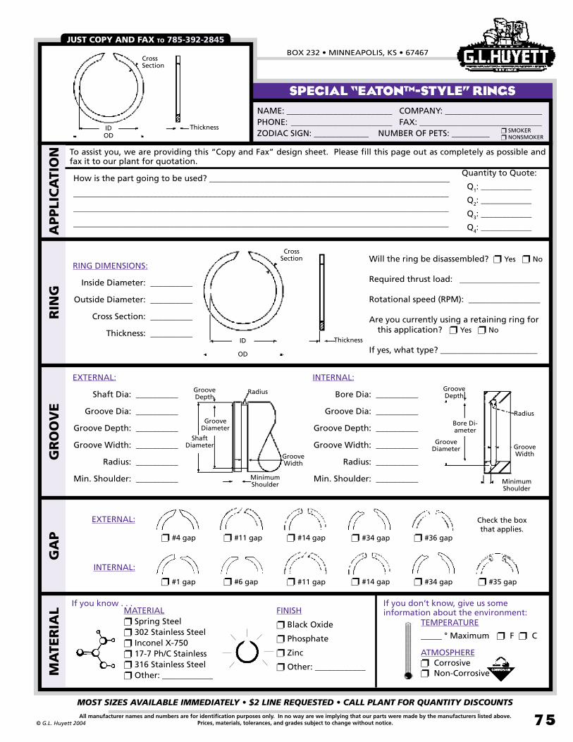
BOX 232 • MINNEAPOLIS, KS • 67467
MOST SIZES AVAILABLE IMMEDIATELY • $2 LINE REQUESTED • CALL PLANT FOR QUANTITY DISCOUNTS
75All manufacturer names and numbers are for identification purposes only. In no way are we implying that our parts were made by the manufacturers listed above.Prices, materials, tolerances, and grades subject to change without notice.© G.L. Huyett 2004
SPECIAL “EATONTM-STYLE” RINGS
JUST COPY AND FAX TO 785-392-2845
NAME: _________________________ COMPANY: _______________________PHONE: ________________________ FAX: _____________________________ZODIAC SIGN: _____________ NUMBER OF PETS: _________
SMOKER NONSMOKER
MATERIAL Spring Steel 302 Stainless Steel Inconel X-750 17-7 Ph/C Stainless 316 Stainless Steel Other: ____________
FINISH
Black Oxide
Phosphate
Zinc
Other: ____________MA
TER
IAL
GA
PG
RO
OV
ER
ING
How is the part going to be used? _________________________________________________________
_________________________________________________________________________________________
_________________________________________________________________________________________
_________________________________________________________________________________________
Quantity to Quote:
Q1: ____________
Q2: ____________
Q3: ____________
Q4: ____________
To assist you, we are providing this “Copy and Fax” design sheet. Please fill this page out as completely as possible and fax it to our plant for quotation.
APPLI
CA
TIO
N
TEMPERATURE
_____ ° Maximum F C
ATMOSPHERE Corrosive Non-Corrosive
If you know . . . If you don’t know, give us some information about the environment:
#4 gap #11 gap #34 gap #14 gap #36 gap
#6 gap #11 gap #34 gap #14 gap #1 gap #35 gap
EXTERNAL:
INTERNAL:
EXTERNAL:
Shaft Dia: __________
Groove Dia: __________
Groove Depth: __________
Groove Width: __________
Radius: __________
Min. Shoulder: __________
INTERNAL:
Bore Dia: __________
Groove Dia: __________
Groove Depth: __________
Groove Width: __________
Radius: __________
Min. Shoulder: __________
Groove Diameter
Bore Di-ameter
MinimumShoulder
Groove Depth
Groove Width
Radius
Shaft Diameter
GrooveDiameter
MinimumShoulder
Groove Depth
Groove Width
Radius
ID
OD
Thickness
Cross Section
RING DIMENSIONS:
Inside Diameter: __________
Outside Diameter: __________
Cross Section: __________
Thickness: __________
Will the ring be disassembled? Yes No
Required thrust load: ___________________
Rotational speed (RPM): _________________
Are you currently using a retaining ring for this application? Yes No
If yes, what type? _______________________
IDOD
Thickness
Cross Section
Check the box that applies.

INTERNAL EATON -STYLE RINGSREVISED 09-04
MOST SIZES AVAILABLE IMMEDIATELY • $2 LINE REQUESTED • CALL PLANT FOR QUANTITY DISCOUNTS
7�
785•392•3017 FAX 785.392.2845
All manufacturer names and numbers are for identification purposes only. In no way are we implying that our parts were made by the manufacturers listed above.Prices, materials, tolerances, and grades subject to change without notice.
TM
© G.L. Huyett 2004
www.huyett.com
Low-profile wire formed ring with notches (instead of lugs) for installation pliers. This design requires no orientation during installation.
1. Confirm the bore diameter (Db).2. Measure the free outside diameter (Dr) of
the ring.3. Determine the ring thickness (T) and radial
wall (S).4. Find the part in the chart above.
UNCOMMONAXIAL ASSEMBLY
Free Outside
Dia. (Dr)Decimal
(Db)Fraction
(Db)Thickness
(T)Diameter
(Dg)Depth
(d)SpringSteel
1.7501.8121.8501.8751.9382.0002.0472.0622.1252.1652.1882.2502.3122.3752.4402.5002.5312.5622.6252.6772.6882.7502.8122.8352.8752.9533.0003.0623.1253.1493.1563.2503.3463.4693.5003.5433.562
1-3/41-13/1647mm1-7/8
1-15/162
2-3/642-1/162-1/8
55mm2-3/162-1/42-5/162-3/8
61.98mm2-1/2
2-17/322-9/162-5/8
68mm2-11/162-3/4
2-13/1672mm2-7/8
75mm3
3-1/163-1/8
79.98mm3-5/163-1/4
3-11/323-15/323-1/2
90mm3-9/16
1.8781.9421.9822.0142.0812.1472.2012.2012.2712.3382.3382.4022.4702.5372.6042.6732.7062.7392.8062.8682.8682.9443.0253.0253.0863.1753.2223.2883.3533.3883.3883.4883.5903.7213.7603.8053.805
UHOUHO-175
-181-185-187-193-200-204-206-212-216-218-225-231-237-244-250-253-256-262-267-268-275-281-283-287-295-300-306-312-314-315-325-334-347-350-354
UHO-356
Width(W)
+.0
04/-
.000
+.0
05/-
.000
+/-
.005
+/-
.006
+.0
70/-
.000
+.0
80/-
.000 +
/-.0
02
RadialWall(S)
BORE RING GROOVE
1.8581.9221.9621.9892.0562.1222.1712.1862.2512.2952.3182.3822.4502.5172.5842.6482.6812.7142.7812.8372.8482.9142.9803.0053.0513.1353.1823.2483.3153.3413.3483.4463.5463.6753.7103.7553.776
.054
.055
.056
.057
.059
.061
.062
.062
.063
.065
.065
.066
.069
.071
.072
.074
.075
.076
.078
.080
.080
.082
.084
.085
.088
.091
.091
.093
.095
.096
.096
.098
.100
.103
.105
.106
.107
.156
.171
.188
.234
.203
.218
.062
.078
.093
.109
.068
.086
.103
.120
+.1
00/-
.000
+/-
.005
UHO HO (Page 16) HOI (Page 19) RRN (Page 58) SRN (Page 63)
UHO CONTINUED NEXT PAGE.
NOTCHED INTERNALMANUFACTURER CROSS-REFERENCE
MATERIAL
INEaton
EASIER TO INSTALL
UHORotor ClipDr
DbDg
S
T
Wd
-I070
-I090
-I108
-I120
PERFORMANCE RESULTS VARY. YOUR RING SELECTION SHOULD BE MADE BASED ON INDIVIDUAL APPLICATION.
NOTCHES HELP PREVENT
RING FROM FLYING OFF THE PLIERS
DURING INSTALLATION.
TOO
L D
ESC
RIP
TIO
NS
ON
PA
GE
227
& 2
28.
GROOVE INTERCHANGEUSE ANY OF THESE PARTS IN THE SAME SIZED GROOVE.
INDEX PAGE 236.
TOOL
DESCRIPTION HOW TO IDENTIFY GENERAL USE
UHO

BOX 232 • MINNEAPOLIS, KS • 67467
MOST SIZES AVAILABLE IMMEDIATELY • $2 LINE REQUESTED • CALL PLANT FOR QUANTITY DISCOUNTS
77All manufacturer names and numbers are for identification purposes only. In no way are we implying that our parts were made by the manufacturers listed above.Prices, materials, tolerances, and grades subject to change without notice.© G.L. Huyett 2004
Low-profile wire formed ring with notches (instead of lugs) for installation pliers. This design requires no orientation during installation.
1. Confirm the bore diameter (Db).2. Measure the free outside diameter (Dr) of
the ring.3. Determine the ring thickness (T) and radial
wall (S).4. Find the part in the chart above.
UNCOMMONAXIAL ASSEMBLY
Free Outside
Dia. (Dr)Decimal
(Db)Fraction
(Db)Thickness
(T)Diameter
(Dg)Depth
(d)Spring Steel
3.6253.7403.7503.8753.9384.0004.1254.2504.3314.5004.6254.7244.7505.0005.2505.3755.5005.7506.0006.2506.5006.6256.7507.0007.2507.5007.7508.0008.2508.5008.7509.0009.2509.5009.750
10.000
3-5/895mm3-3/43-7/8
3-15/164
4-1/84-1/4
110mm4-1/24-5/8
120mm4-3/4
55-1/45-3/85-1/25-3/4
66-1/46-1/26-5/86-3/4
77-1/47-1/27-3/4
88-1/48-1/28-3/4
99-1/49-1/29-3/4
10
3.8954.0304.0304.1654.2344.3004.4304.5554.6414.8154.9405.0705.0705.3405.6005.7355.8606.1206.3806.6406.9057.0457.1807.4457.7057.9758.2408.5058.7709.0359.3059.5649.833
10.10010.36510.630
UHOUHO-362
-374-375-387-393-400-412-425-433-450-462-472-475-500-525-537-550-575-600-625-650-662-675-700-725-750-775-800-825-850-875-900-925-950-975
UHO-1000
Width(W)
RadialWall(S)
BORE RING GROOVE
3.8413.9643.9744.1074.1744.2404.3654.4904.5714.7404.8654.9694.9955.2605.5205.6505.7706.0206.2706.5306.7906.9257.0557.3157.5757.8408.1008.3608.6208.8809.1449.4049.6689.930
10.19010.450
.108
.112
.112
.116
.118
.120
.120
.120
.120
.120
.120
.122
.122
.130
.135
.130
.135
.135
.135
.140
.145
.150
.152
.157
.162
.170
.175
.180
.185
.190
.197
.202
.209
.215
.220
.225
UHO HO (Page 16) HOI (Page 19) RRN (Page 58) SRN (Page 63)
+/-
.005
+.1
00/-
.000
+.1
20/-
.000
+.1
50/-
.000
+.1
80/
-.00
0
+/-
.002
.250
.281
.312
.343
.375
.437
.500
.109
.125
.156
.187
+.2
20/-
.000
+.0
05/-
.000
+.0
06/-
.000
+/-
.006
+/-
.007
+/-
.008
.120
.139
.174
.209+
.008
/-.0
00
.234
NOTCHED INTERNALMANUFACTURER CROSS-REFERENCE
MATERIAL
UHORotor Clip
INEaton
EASIER TO INSTALL
Dr
DbDg
S
T
Wd
-I120
-I120X
-I150
-I045
PERFORMANCE RESULTS VARY. YOUR RING SELECTION SHOULD BE MADE BASED ON INDIVIDUAL APPLICATION.
GOOD INTERIOR
CLEARANCE WITH NO
PROTRUSIONS.
TOO
L D
ESC
RIP
TIO
NS
ON
PA
GE
227
& 2
28.
GROOVE INTERCHANGEUSE ANY OF THESE PARTS IN THE SAME SIZED GROOVE.
INDEX PAGE 236.
TOOL
DESCRIPTION HOW TO IDENTIFY GENERAL USE
UHO
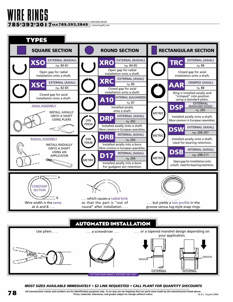
WIRE RINGSREVISED 09-04
MOST SIZES AVAILABLE IMMEDIATELY • $2 LINE REQUESTED • CALL PLANT FOR QUANTITY DISCOUNTS
78
785•392•3017 FAX 785.392.2845
All manufacturer names and numbers are for identification purposes only. In no way are we implying that our parts were made by the manufacturers listed above.Prices, materials, tolerances, and grades subject to change without notice. © G.L. Huyett 2004
www.huyett.com
AUTOMATED INSTALLATION
types
SQUARE SECTION ROUND SECTION RECTANGULAR SECTION
Pgs: 84-85
EXTERNAL (RADIAL)
Open gap for radial installation onto a shaft.
XRO
Pg: 86
EXTERNAL (AXIAL)
Closed gap for axialinstallation onto a shaft.
XRC
Pg: 87
EXTERNAL (GALVANIZED)
Installed axiallyonto a shaft.
A10
EXTERNAL (AXIAL)
Installed axially onto a shaft.More common in European assemblies.
DRP
INTERNAL (AXIAL)
Installed axially into a bore.More common in European assemblies.
DRB
INTERNAL (AXIAL)
Installed axially into a bore.For gudgeon pin retention.
D17
Pg: 88
EXTERNAL (AXIAL)
Closed gap for axialinstallation onto a shaft.
TRC
Pg: 88
CRIMPED (AXIAL)
Ring is installed axially and“crimped” into positionusing a standard pliers.
AAR
EXTERNAL (RADIUSED EDGE)
Installed axially onto a shaft.More common in European assemblies.
DSP
EXTERNAL (AXIAL)
Installed axially onto a shaft.Used for bearing retention.
DSW
INTERNAL (AXIAL)
Open gap for installation onto
a shaft. Used for bearing retention.
DSB
Pgs: 80-81
EXTERNAL (RADIAL)
Open gap for radialinstallation onto a shaft.
XSO
Pgs: 82-83
EXTERNAL (AXIAL)
Closed gap for axialinstallation onto a shaft.
XSC
Pg: 202
Pg: 203
Pg: 204
Pg: 205
Pgs: 206-207
Pgs: 208-211
DIN7993A
DIN7993B
METRICMETRIC
METRIC
METRIC
Wire width is the same at A and B . . .
. . . but yields a low profile in the groove versus lug-style snap rings.
. . . which causes a radial kink so that the part is “out of round” after installation . . .
Use pliers . . . . . . a screwdriver . . . . . . or a tapered mandrel design depending on your application.
GROOVEGROOVE
EXTERNAL INTERNAL
AXIAL ASSEMBLY
RADIAL ASSEMBLY
INSTALL AXIALLY ONTO A SHAFT USING PLIERS
INSTALL RADIALLY ONTO A SHAFT
USING AN APPLICATOR
A
B
CONSTANTSECTION
LET OUR SHOP MAKE A FIXTURE FOR YOU!

BOX 232 • MINNEAPOLIS, KS • 67467
MOST SIZES AVAILABLE IMMEDIATELY • $2 LINE REQUESTED • CALL PLANT FOR QUANTITY DISCOUNTS
79All manufacturer names and numbers are for identification purposes only. In no way are we implying that our parts were made by the manufacturers listed above.Prices, materials, tolerances, and grades subject to change without notice.© G.L. Huyett 2004
Shaft locknuts (see pages 132-137) were the dominant form of retaining devices in the early part of the century. Machined from steel and screwed onto shafts, locknuts provided high strength shoulders for heavy-duty and precision applications. Innovators like Henry Ford and Cyrus McCormick began to look for ways to automate the assembly of durable goods so that unit costs could drop to more affordable levels. The locking wire ring emerged as a retaining device during this time. Lock rings were mostly coiled from round cross-sections because mills were unable to roll and shape higher-strength forms that are used today.
During World War II, Allied troops captured a German tank which was disassembled. It was discovered that German engineers had perfected new and innovative ring designs using rectangular-shaped wire, complete with lug holes and curved shapes. These designs were reverse engineered, and production was organized to support the Allied War effort.
New engineering and designs resulted in the successful origination of today’s retaining ring manufacturers, including Waldes and Rotor Clip in the United States and Anderton in the United Kingdom. Today’s retaining rings have been transformed into “application specific” devices that are generations ahead of their predecessors.
“WHY ARE LOCK RINGS STILL USED?”
It is difficult to get engineers to change old habits. Some engineers continue to use old designs because of corporate inertia. Wire rings do possess a couple of advantages for some applications, including: -Low profile for minimal clearance -Less precise groove requirements -Ready access to a multitude of different materials -Permanent retention with no removability -Automated assembly
Most wire rings are used in the automotive industry for internal engine and transmission components. Wire rings are found in pistons, on gudgeon pins, and in needle roller bearings where removability is not an important benefit. Automated installation and reduced piece cost prevail as engineering considerations. Upon installation, wire rings are difficult, if not impossible, to remove. Wire rings are not reusable and are difficult to identify because of deformation during use and removal.
G.L. Huyett has worked to assemble a broad inventory of the more popular styles. We regularly make special parts to print on request. Please feel free to forward your specifications.
PRODUCT COMPARISONS
LOW PROFILE
FINISHES
OIL DIPPED(STANDARD)
Inhibits rust during handling.
ZINC PLATE(STANDARD)
Up to 96 hours salt spray.
OTHERS PER QUOTE . . .
. . . CALL FOR PRICE AND
AVAILABILITY.
OTHER FINISHES, INCLUDING CADMIUM, AVAILABLE ON REQUEST.
MATERIAL
CARBON SPRING STEEL
SAE 1060-1090RC 42/53
(STANDARD)
500°F Max100°F Min
OTHER MATERIALS AVAILABLE ON REQUEST.
OPTIONAL CROSS SECTIONS AS SPECIAL ORDER:
HI COLLAR ROUND STEPSQUARE DOUBLEBEVEL
TAPER
CHAMFER ROUND EDGE FLAT
RADIUS CORNER
TONGUE SQUAREEDGE
MILLEDGE

SQUARE SECTION WIRE RINGSREVISED 09-04
MOST SIZES AVAILABLE IMMEDIATELY • $2 LINE REQUESTED • CALL PLANT FOR QUANTITY DISCOUNTS
80
785•392•3017 FAX 785.392.2845
All manufacturer names and numbers are for identification purposes only. In no way are we implying that our parts were made by the manufacturers listed above.Prices, materials, tolerances, and grades subject to change without notice. © G.L. Huyett 2004
www.huyett.com
EXTERNAL (RADIAL)MANUFACTURER CROSS-REFERENCE
Decimal(Ds)
Diameter(Dg)
.125
.156
.219
.281
1/85/32
7/32
9/32
.115
.146
.178
.176
.207
.238
.234
.265
.296
.292
.357
.351
.417
.409
.476
.468
.530
.526
.597
.585
.659
.647
.718
.704
.780
.766
.839
.821
.901
.883
SHAFT RING
XSO
Low clearance wire formed ring with limited range. Open gap style allows radial installation. Difficult to remove. Parts are sized for external shaft applications.
1. Verify square cross section and open gap style.
2. Measure the shaft diameter (Ds).3. Determine the wire cross section (T).4. Find the part in the chart above.
COMMONRADIAL ASSEMBLY
XSO-211 -2125
-212-213
-2135-214-215
-2155-216-217-218-219-220-221-222-223-224-225-226-227-228-229-230-231-232-233-234-235-236
XSO-237
Depth(d)
+.0
03/-
.000
+/-
.003
Free Inside Dia.
(Df)
+.0
00/-
.020
+.0
00/-
.025
+.0
00/-
.035
GROOVE
Width(W)
Fraction(Ds)
WireCross
Section (T)
+/-
.002
+.0
00/-
6%+
.000
/-5%
Gap(A)
.114
.145
.175
.173
.203
.236
.232
.261
.293
.289
.353
.347
.413
.405
.471
.463
.525
.521
.591
.579
.653
.641
.712
.697
.773
.759
.831
.813
.893
.875
.020
.020
.020
.025
.025
.025
.031
.031
.031
.039
.035
.046
.039
.055
.046
.062
.062
.071
.055
.078
.055
.078
.062
.093
.062
.093
.071
.109
.071
.109
.101
.128
.154
.153
.179
.208
.205
.230
.258
.255
.311
.305
.364
.357
.414
.408
.463
.460
.521
.511
.576
.565
.628
.615
.682
.669
.732
.717
.787
.771
.005
.005
.005
.006
.006
.006
.008
.008
.008
.010
.009
.012
.010
.014
.012
.016
.016
.018
.014
.020
.014
.020
.016
.023
.016
.023
.018
.027
.018
.027
.024
.024
.024
.029
.029
.030
.036
.036
.036
.045
.041
.052
.045
.062
.052
.069
.069
.078
.062
.085
.062
.085
.069
.100
.069
.100
.078
.117
.078
.117
+/-
.002
A
T
Df
Ds Dg
d
W
XSO CONTINUED NEXT PAGE.
XSO XSC (Page 82)
MATERIAL
A0600Anderton 400 SeriesEaton
OPEN STYLE
.188 3/16
.250 1/4
.312 5/16
.375 3/8
.438 7/16
.500 1/2
.562 9/16
.625 5/8
11/16.688
3/4.750
13/16.812
7/8.875
15/16.938
WEIGHTLbs. per
100 Pieces
PERFORMANCE RESULTS VARY. YOUR RING SELECTION SHOULD BE MADE BASED ON INDIVIDUAL APPLICATION.
INSTALLATION TOOLS
AVAILABLE AS A SPECIAL
ORDER.
SpringSteel
0.00300.00400.00500.00700.00800.00900.01400.01600.01800.02900.02800.04900.03300.08100.06400.11800.13100.17300.11400.23200.12400.25400.17700.39600.18600.42800.26400.63600.28200.6790
XSOArcon National
GROOVE INTERCHANGEUSE ANY OF THESE PARTS IN THE SAME SIZED GROOVE.
INDEX PAGE 236.
DESCRIPTION HOW TO IDENTIFY GENERAL USE
XSO

BOX 232 • MINNEAPOLIS, KS • 67467
MOST SIZES AVAILABLE IMMEDIATELY • $2 LINE REQUESTED • CALL PLANT FOR QUANTITY DISCOUNTS
81All manufacturer names and numbers are for identification purposes only. In no way are we implying that our parts were made by the manufacturers listed above.Prices, materials, tolerances, and grades subject to change without notice.© G.L. Huyett 2004
Low clearance wire formed ring with limited range. Open gap style allows radial installation. Difficult to remove. Parts are sized for external shaft applications.
1. Verify square cross section and open gap style.
2. Measure the shaft diameter (Ds).3. Determine the wire cross section (T).4. Find the part in the chart above.
COMMONRADIAL ASSEMBLY
A
T
Df
Ds Dg
d
W
Decimal(Ds)
Diameter(Dg)
SpringSteel
.960
.9381.0221.0001.0791.0551.1411.1171.1961.1721.2581.2341.3151.2891.3771.3511.4381.4061.5631.5311.6721.6401.9061.8742.1562.1242.3742.3442.8752.844
SHAFT RING
XSOXSO-238
-239-240-241-242-243-244-245-246 -247 -248-249-250-251-252-253-254-255-256-257-258-259-260-261-262-263-264-265-266
XSO-267
Depth(d)
Free Inside Dia.
(Df)
GROOVE
Width(W)
Fraction(Ds)
Wire Cross
Section (T)Gap(A)
.950
.9291.012.990
1.0681.0441.1301.1061.1841.1601.2461.2221.3041.2761.3641.3381.4241.3921.5471.5161.6571.6241.8871.8552.1342.1032.3502.3212.8452.816
.078
.125
.078
.125
.093
.140
.093
.140
.109
.156
.109
.156
.120
.172
.120
.172
.125
.187
.125
.187
.156
.218
.187
.250
.187
.250
.250
.312
.250
.312
.838
.819
.893
.873
.940
.921
.997
.9751.0441.0231.0991.0781.1501.1251.2031.1801.2561.2281.3641.3371.4611.4321.6641.6361.8821.8552.0732.0472.5102.483
.020
.031
.020
.031
.023
.035
.023
.035
.027
.039
.027
.039
.030
.043
.030
.043
.031
.047
.031
.047
.039
.055
.047
.063
.047
.063
.063
.078
.063
.078
.085
.133
.085
.133
.100
.148
.100
.148
.117
.164
.117
.164
.128
.180
.128
.180
.133
.195
.133
.195
.164
.227
.195
.260
.195
.260
.265
.327
.265
.327
+/-
.003
+.0
00/-
.046
+.0
00/-
.062
+.0
00/-
.078
+/-
.003
+.0
00/-
4%
+/-
.002
+/-
.004
+.0
00/
-5%
+/-
.002
+.0
00/-
.035
XSO XSC (Page 82)
EXTERNAL (RADIAL)MANUFACTURER CROSS-REFERENCE
MATERIAL
A0600Anderton 400 SeriesEaton
OPEN STYLE
11.000
1.063 1-1/16
1.125 1-1/8
1-3/161.188
1-1/41.250
1-5/161.312
1-3/81.375
1-7/161.438
1-1/21.500
1-5/81.625
1-3/41.750
22.000
2-1/42.250
2-1/22.500
33.000
WEIGHTLbs. per
100 Pieces
PERFORMANCE RESULTS VARY. YOUR RING SELECTION SHOULD BE MADE BASED ON INDIVIDUAL APPLICATION.
AFTER INSTALLATION
RING WILL NOT
NECESSARILY MAINTAIN
CONTACT IN GROOVE DUE TO UNEVEN STRESSES.
0.3630 0.9550 0.3850 1.0100 0.5840 1.3470 0.6140 1.4180 0.8920 1.8600 0.9370 1.8810 1.2180 2.4870 1.2400 2.5930 1.4040 3.2050 1.5180 3.4520 2.5630 5.0830 4.2120 7.6410 4.7120 8.5400 9.431014.940011.230017.7400
XSOArcon National
GROOVE INTERCHANGEUSE ANY OF THESE PARTS IN THE SAME SIZED GROOVE.
INDEX PAGE 236.
DESCRIPTION HOW TO IDENTIFY GENERAL USE
XSO

SQUARE SECTION WIRE RINGSREVISED 09-04
MOST SIZES AVAILABLE IMMEDIATELY • $2 LINE REQUESTED • CALL PLANT FOR QUANTITY DISCOUNTS
82
785•392•3017 FAX 785.392.2845
All manufacturer names and numbers are for identification purposes only. In no way are we implying that our parts were made by the manufacturers listed above.Prices, materials, tolerances, and grades subject to change without notice. © G.L. Huyett 2004
www.huyett.com
EXTERNAL (AXIAL)MANUFACTURER CROSS-REFERENCE
Decimal(Ds)
Diameter(Dg)
SpringSteel
.125
.156
.219
.281
1/85/32
7/32
9/32
.115
.146
.178
.176
.207
.238
.234
.265
.296
.292
.357
.351
.417
.409
.476
.468
.530
.526
.597
.585
.659
.647
.718
.704
.780
.766
.839
.821
.901
.883
SHAFT RING
XSC
Low clearance wire formed ring with limited range. Closed gap style requires axial assembly, with more contact and thrust load ratings versus open style.
1. Verify square cross section and closed gap style.
2. Measure the shaft diameter (Ds).3. Determine the wire cross section (T).4. Find the part in the chart above.
COMMONAXIAL ASSEMBLY
XSC-111 -1125
-112-113
-1135-114-115
-1155-116-117-118-119-120-121-122-123-124-125-126-127-128-129-130-131-132-133-134-135-136
XSC-137
Depth(d)
+.0
03/-
.000
+/-
.003
Free Inside Dia.
(Df)
+.0
00/-
.020
+.0
00/-
.025
+.0
00/-
.035
GROOVE
Width(W)
Fraction(Ds)
Wire Cross
Section (T)
.114
.145
.175
.173
.203
.236
.232
.261
.293
.289
.353
.347
.413
.405
.471
.463
.525
.521
.591
.579
.653
.641
.712
.697
.773
.759
.831
.813
.893
.875
.005
.005
.005
.006
.006
.006
.008
.008
.008
.010
.009
.012
.010
.014
.012
.016
.016
.018
.014
.020
.014
.020
.016
.023
.016
.023
.018
.027
.018
.027
.020
.020
.020
.025
.025
.025
.031
.031
.031
.039
.035
.046
.039
.055
.046
.062
.062
.071
.055
.078
.055
.078
.062
.093
.062
.093
.071
.109
.071
.109
.024
.024
.024
.029
.029
.030
.036
.036
.036
.045
.041
.052
.045
.062
.052
.069
.069
.078
.062
.085
.062
.085
.069
.100
.069
.100
.078
.117
.078
.117
+/-
.002
+/-
.002
XSC CONTINUED NEXT PAGE.
XSC XSO (Page 80)
MATERIAL
A0700Anderton 300 SeriesEaton
CLOSED STYLE
3/16.188
1/4.250
5/16.312
3/8.375
7/16.438
1/2.500
9/16.562
5/8.625
11/16.688
3/4.750
13/16.812
7/8.875
15/16.938
WEIGHTLbs. per
100Pieces
PERFORMANCE RESULTS VARY. YOUR RING SELECTION SHOULD BE MADE BASED ON INDIVIDUAL APPLICATION.
INSTALLATION TOOLS
AVAILABLE AS A SPECIAL
ORDER.
0.00500.00600.00700.01100.01200.01400.02200.02400.02800.04400.04200.07400.05100.12300.09700.17900.20000.26400.17300.35400.18900.38700.26300.60400.28400.65200.40200.96900.43001.0340
WDf
T
d
DgDs
XSCArcon National
GROOVE INTERCHANGEUSE ANY OF THESE PARTS IN THE SAME SIZED GROOVE.
INDEX PAGE 236.
DESCRIPTION HOW TO IDENTIFY GENERAL USE
XSC

BOX 232 • MINNEAPOLIS, KS • 67467
MOST SIZES AVAILABLE IMMEDIATELY • $2 LINE REQUESTED • CALL PLANT FOR QUANTITY DISCOUNTS
83All manufacturer names and numbers are for identification purposes only. In no way are we implying that our parts were made by the manufacturers listed above.Prices, materials, tolerances, and grades subject to change without notice.© G.L. Huyett 2004
Low clearance wire formed ring with limited range. Closed gap style requires axial assembly, with more contact and thrust load ratings versus open style.
1. Verify square cross section and closed gap style.
2. Measure the shaft diameter (Ds).3. Determine the wire cross section (T).4. Find the part in the chart above.
COMMONAXIAL ASSEMBLY
Decimal(Ds)
Diameter(Dg)
SpringSteel
.960
.9381.0221.0001.0791.0551.1411.1171.1961.1721.2581.2341.3151.2891.3771.3511.4381.4061.5631.5311.6721.6401.9061.8742.1562.1242.3742.3442.8752.844
SHAFT RING
XSCXSC-138
-139-140-141-142-143-144-145-146-147-148-149-150-151-152-153-154-155-156-157-158-159-160-161-162-163-164-165-166
XSC-167
Depth(d)
Free Inside Dia.
(Df)
GROOVE
Width(W)
Fraction(Ds)
Wire Cross
Section (T)
.950
.9291.012.990
1.0681.0441.1301.1061.1841.1601.2461.2221.3041.2761.3641.3381.4241.3921.5471.5161.6571.6241.8871.8552.1342.1032.3502.3212.8452.816
.020
.031
.020
.031
.023
.035
.023
.035
.027
.039
.027
.039
.030
.043
.030
.043
.031
.047
.031
.047
.039
.055
.047
.063
.047
.063
.063
.078
.063
.078
.078
.125
.078
.125
.093
.140
.093
.140
.109
.156
.109
.156
.120
.172
.120
.172
.125
.187
.125
.187
.156
.218
.187
.250
.187
.250
.250
.312
.250
.312
.085
.133
.085
.133
.100
.148
.100
.148
.117
.164
.117
.164
.128
.180
.128
.180
.133
.195
.133
.195
.164
.227
.195
.260
.195
.260
.265
.327
.265
.327
+/-
.003
+/-
.004
+.0
00/-
.046
+/-
.003
+/-
.002
+.0
00/-
.078
+.0
00/-
.062
+.0
00/-
.035
+/-
.002
XSC XSO (Page 80)
EXTERNAL (AXIAL)MANUFACTURER CROSS-REFERENCE
MATERIAL
A0700Anderton 300 SeriesEaton
CLOSED STYLE
11.000
1-1/161.063
1-1/81.125
1-3/161.188
1-1/41.250
1-5/161.312
1-3/81.375
1-7/161.438
1-1/21.500
1-5/81.625
1-3/41.750
22.000
2-1/42.250
2-1/22.500
33.000
WEIGHTLbs. per
100Pieces
PERFORMANCE RESULTS VARY. YOUR RING SELECTION SHOULD BE MADE BASED ON INDIVIDUAL APPLICATION.
0.5530 1.4550 0.5870 1.5410 0.8880 2.0530 0.9360 2.1610 1.3590 2.8340 1.4280 2.9670 1.8560 3.7890 1.8900 3.9510 2.1400 4.8850 2.3120 5.2680 3.9040 7.7440 6.416011.6400 7.181013.010014.380022.760017.110027.0300
AFTER INSTALLATION
RING WILL NOT
NECESSARILY MAINTAIN
CONTACT IN GROOVE DUE TO UNEVEN STRESSES.
Df
T
W
d
DgDs
XSCArcon National
GROOVE INTERCHANGEUSE ANY OF THESE PARTS IN THE SAME SIZED GROOVE.
INDEX PAGE 236.
DESCRIPTION HOW TO IDENTIFY GENERAL USE
XSC

ROUND SECTION WIRE RINGSREVISED 09-04
MOST SIZES AVAILABLE IMMEDIATELY • $2 LINE REQUESTED • CALL PLANT FOR QUANTITY DISCOUNTS
84
785•392•3017 FAX 785.392.2845
All manufacturer names and numbers are for identification purposes only. In no way are we implying that our parts were made by the manufacturers listed above.Prices, materials, tolerances, and grades subject to change without notice. © G.L. Huyett 2004
www.huyett.com
Decimal(Ds)
Diameter(Dg)
SpringSteel
.125
.156
.188
.219
.250
.281
1.000
1/85/323/167/321/49/32
1
.111
.142
.174
.205
.232
.263
.298
.290
.357
.349
.415
.405
.474
.464
.534
.524
.593
.581
.655
.643
.714
.698
.776
.760
.831
.813
.893
.875
.948
SHAFT RING
XRO
Low clearance wire formed ring with limited range. Open gap style allows radial installation. Difficult to remove. Parts are sized for external shaft applications.
1. Verify round cross section and open gap style.
2. Measure the shaft diameter (Ds).3. Determine the wire cross section (T).4. Find the part in the chart above.
COMMONRADIAL ASSEMBLY
XRO-411-412-413-414-415
-4155-416-417-418-419-420-421-422-423-424-425-426-427-428-429-430-431-432-433-434-435-436-437
XRO-438
Depth(d)
+.0
03/-
.000
+/-
.002
+/-
.003
Free Inside Dia.
(Df)
+.0
00/-
6%+
.000
/-5%
GROOVE
Width(W)
Fraction(Ds)
Wire Cross
Section (T)
+.0
00/-
6%+
.000
/-5%
Gap(A)
.110
.140
.172
.202
.230
.260
.296
.288
.353
.345
.412
.402
.468
.458
.529
.518
.587
.575
.649
.637
.706
.690
.769
.753
.823
.804
.885
.867
.938
.007
.007
.007
.007
.009
.009
.007
.011
.009
.013
.011
.016
.013
.018
.014
.019
.016
.022
.016
.022
.018
.026
.018
.026
.022
.031
.022
.031
.026
.022
.022
.022
.022
.029
.029
.022
.035
.029
.043
.035
.051
.043
.059
.045
.062
.051
.071
.051
.071
.059
.085
.059
.085
.071
.100
.071
.100
.085
.024
.024
.024
.024
.031
.031
.024
.037
.031
.045
.037
.053
.045
.061
.047
.064
.053
.073
.053
.073
.061
.087
.061
.087
.073
.102
.073
.102
.087
.097
.123
.152
.178
.203
.229
.261
.254
.322
.304
.363
.355
.412
.404
.467
.457
.518
.507
.572
.562
.623
.609
.678
.664
.726
.709
.780
.764
.827
XRO CONTINUED NEXT PAGE.
XRO XRC (Page 86)
EXTERNAL (RADIAL)MANUFACTURER CROSS-REFERENCE
MATERIAL
200 SeriesEaton
OPEN STYLE
5/16.312
3/8.375
7/16.438
1/2.500
9/16.562
5/8.625
11/16.688
3/4.750
13/16.812
7/8.875
15/16.938
WEIGHTLbs. per
100Pieces
+/-
.004
PERFORMANCE RESULTS VARY. YOUR RING SELECTION SHOULD BE MADE BASED ON INDIVIDUAL APPLICATION.
INSTALLATION TOOLS
AVAILABLE AS A SPECIAL
ORDER.
0.00300.00400.00500.00600.01000.01200.00700.01800.01400.03300.02600.05300.04300.08200.05300.10200.07500.14800.08300.16800.12100.25500.13100.27600.20500.41200.22000.43100.3450
Arcon National XRO
GROOVE INTERCHANGEUSE ANY OF THESE PARTS IN THE SAME SIZED GROOVE.
INDEX PAGE 236.
Dg
W
d
TA
Df
Ds
DESCRIPTION HOW TO IDENTIFY GENERAL USE
XRO

BOX 232 • MINNEAPOLIS, KS • 67467
MOST SIZES AVAILABLE IMMEDIATELY • $2 LINE REQUESTED • CALL PLANT FOR QUANTITY DISCOUNTS
85All manufacturer names and numbers are for identification purposes only. In no way are we implying that our parts were made by the manufacturers listed above.Prices, materials, tolerances, and grades subject to change without notice.© G.L. Huyett 2004
EXTERNAL (RADIAL)MANUFACTURER CROSS-REFERENCE
Low clearance wire formed ring with limited range. Open gap style allows radial installation. Difficult to remove. Parts are sized for external shaft applications.
1. Verify round cross section and open gap style.
2. Measure the shaft diameter (Ds).3. Determine the wire cross section (T).4. Find the part in the chart above.
COMMONRADIAL ASSEMBLY
Decimal(Ds)
Diameter(Dg)
Spring Steel
1.000 1 .9261.010.988
1.0631.0451.1251.1071.1761.1621.2381.2241.2951.2771.3571.3391.4121.3921.5371.5171.6421.6241.8741.8562.1242.1062.3562.3442.8562.844
SHAFT RING
XROXRO-439
-440-441-442-443-444-445-446-447-448-449-450-451-452-453-454-455-456-457-458-459-460-461-462-463-464-465-466
XRO-467
Depth(d)
Free Inside Dia.
(Df)
GROOVE
Width(W)
Fraction(Ds)
Wire Cross
Section (T)Gap(A)
.9171.000.979
1.0511.0341.1141.0961.1641.1501.2261.2121.2811.2641.3441.3261.3981.3781.5221.5021.6261.6081.8551.8372.1032.0852.3322.3212.8272.816
.118
.085
.118
.100
.130
.100
.130
.118
.140
.118
.140
.130
.156
.130
.156
.140
.172
.140
.172
.172
.203
.203
.232
.203
.232
.232
.250
.232
.250
.809
.882
.863
.927
.912
.983
.9671.0271.0141.0811.0691.1301.1151.1851.1701.2331.2151.3421.3251.4341.4181.6361.6201.8551.8392.0572.0472.4942.483
.037
.026
.037
.031
.040
.031
.040
.037
.044
.037
.044
.040
.049
.040
.049
.044
.054
.044
.054
.054
.063
.063
.072
.063
.072
.072
.078
.072
.078
.120
.087
.120
.102
.132
.102
.132
.120
.142
.120
.142
.132
.158
.132
.158
.142
.174
.142
.174
.174
.205
.205
.234
.205
.234
.234
.252
.234
.252
+/-
.003
+/-
.004
+/-
.002
+.0
00/-
4%
+.0
00/-
4%
+.000/-5%
+.000/-5%
XRO XRC (Page 86)
MATERIAL
200 SeriesEaton
OPEN STYLE
1-1/81.125
1-1/161.063
1-3/161.188
1-1/41.250
1-5/161.312
1-3/81.375
1-7/161.438
1-1/21.500
1-5/81.625
1-3/41.750
22.000
2-1/42.250
2-1/22.500
33.000
WEIGHTLbs. per
100 Pieces
PERFORMANCE RESULTS VARY. YOUR RING SELECTION SHOULD BE MADE BASED ON INDIVIDUAL APPLICATION.
0.65700.45000.69600.52500.89700.55400.94500.77701.15300.85301.20801.08701.57501.13601.64301.37502.09101.48502.25802.42503.40403.86705.09704.33405.68806.28907.32207.50908.7320
AFTER INSTALLATION
RING WILL NOT
NECESSARILY MAINTAIN
CONTACT IN GROOVE DUE TO UNEVEN STRESSES.
Arcon National XRO
GROOVE INTERCHANGEUSE ANY OF THESE PARTS IN THE SAME SIZED GROOVE.
INDEX PAGE 236.
Dg
W
d
TA
Df
Ds
DESCRIPTION HOW TO IDENTIFY GENERAL USE
XRO

ROUND SECTION WIRE RINGSREVISED 09-04
MOST SIZES AVAILABLE IMMEDIATELY • $2 LINE REQUESTED • CALL PLANT FOR QUANTITY DISCOUNTS
8�
785•392•3017 FAX 785.392.2845
All manufacturer names and numbers are for identification purposes only. In no way are we implying that our parts were made by the manufacturers listed above.Prices, materials, tolerances, and grades subject to change without notice. © G.L. Huyett 2004
www.huyett.com
EXTERNAL (AXIAL)MANUFACTURER CROSS-REFERENCE
Decimal(Ds)
Diameter(Dg)
Spring Steel
.125
.156
.188
.219
.250
.281
.312
.312
.375
.375
.438
.438
.500
.500
.562
.562
.625
.625
.688
.688
.750
.750
.812
.812
.875
.875
.938
.9381.0001.0001.0631.0631.1251.1251.1881.1881.2501.2501.3121.3121.3751.3751.4381.4381.5001.5001.6251.6251.7501.7502.0002.2502.5003.000
1/85/323/167/321/49/325/165/163/83/87/167/161/21/29/169/165/85/8
11/1611/163/43/4
13/1613/167/87/8
15/1615/16
11
1-1/161-1/161-1/81-1/81-3/161-3/161-1/41-1/41-5/161-5/161-3/81-3/81-7/161-7/161-1/21-1/21-5/81-5/81-3/41-3/4
22-1/42-1/2
3
.111
.142
.174
.205
.232
.263
.298
.290
.357
.349
.415
.405
.474
.464
.534
.524
.593
.581
.655
.643
.714
.698
.776
.760
.831
.813
.893
.875
.948
.9261.010.988
1.0631.0451.1251.1071.1761.1621.2381.2241.2951.2771.3571.3391.4121.3921.5371.5171.6421.6241.8562.1062.3442.844
SHAFT RING
XRCXRC-311
-312-313-314-315
-3155-316-317-318-319-320-321-322-323-324-325-326-327-328-329-330-331-332-333-334-335-336-337-338-339-340-341-342-343-344-345-346-347-348-349-350-351-352-353-354-355-356-357-358-359 -361 -363 -365
XRC-367
Depth(d)
+.0
03/-
.000
+/-
.004
Free Inside Dia.
(Df)
+.0
00/-
6%+
.000
/-5%
GROOVE
Width(W)
Fraction(Ds)
Wire Cross
Section (T)
.110
.140
.172
.202
.230
.260
.296
.288
.353
.345
.412
.402
.468
.458
.529
.518
.587
.575
.649
.637
.706
.690
.769
.753
.823
.804
.885
.867
.938
.9171.000.979
1.0511.0341.1141.0961.1641.1501.2261.2121.2811.2641.3441.3261.3981.3781.5221.5021.6261.6081.8372.0852.3212.816
.007
.007
.007
.007
.009
.009
.007
.011
.009
.013
.011
.016
.013
.018
.014
.019
.016
.022
.016
.022
.018
.026
.018
.026
.022
.031
.022
.031
.026
.037
.026
.037
.031
.040
.031
.040
.037
.044
.037
.044
.040
.049
.040
.049
.044
.054
.044
.054
.054
.063
.072
.072
.078
.078
.022
.022
.022
.022
.029
.029
.022
.035
.029
.043
.035
.051
.043
.059
.045
.062
.051
.071
.051
.071
.059
.085
.059
.085
.071
.100
.071
.100
.085
.118
.085
.118
.100
.130
.100
.130
.118
.140
.118
.140
.130
.156
.130
.156
.140
.172
.140
.172
.172
.203
.232
.232
.250
.250
.024
.024
.024
.024
.031
.031
.024
.037
.031
.045
.037
.053
.045
.061
.017
.064
.063
.073
.053
.073
.061
.087
.061
.087
.073
.102
.073
.102
.087
.120
.087
.120
.102
.132
.102
.132
.120
.142
.120
.142
.132
.158
.132
.158
.142
.174
.142
.174
.174
.205
.234
.234
.252
.252
+.0
00/-
4%
+/-
.002
+/-
.003
+/-
.004
MATERIAL
A0900Anderton Eaton 100 Series
CLOSED STYLE
WEIGHTLbs. per
100Pieces
0.0040 0.0050 0.0070 0.0090 0.0150 0.0170 0.0110 0.0270 0.0220 0.0500 0.0380 0.0820 0.0660 0.1250 0.0820 0.1550 0.1150 0.2260 0.1270 0.2480 0.1850 0.3890 0.2000 0.4210 0.3130 0.6280 0.3350 0.6720 0.5260 1.0010 0.6860 1.0610 0.8000 1.3670 0.8440 1.4400 1.2400 1.7570 1.3000 1.8410 1.6560 2.4010 1.7310 2.5060 2.0950 3.1860 2.2630 3.4410 3.6960 5.1850 7.7380 8.665011.160013.3200
XRCArcon National
INDEX PAGE 236.
Dg
Ds
W
dTDf
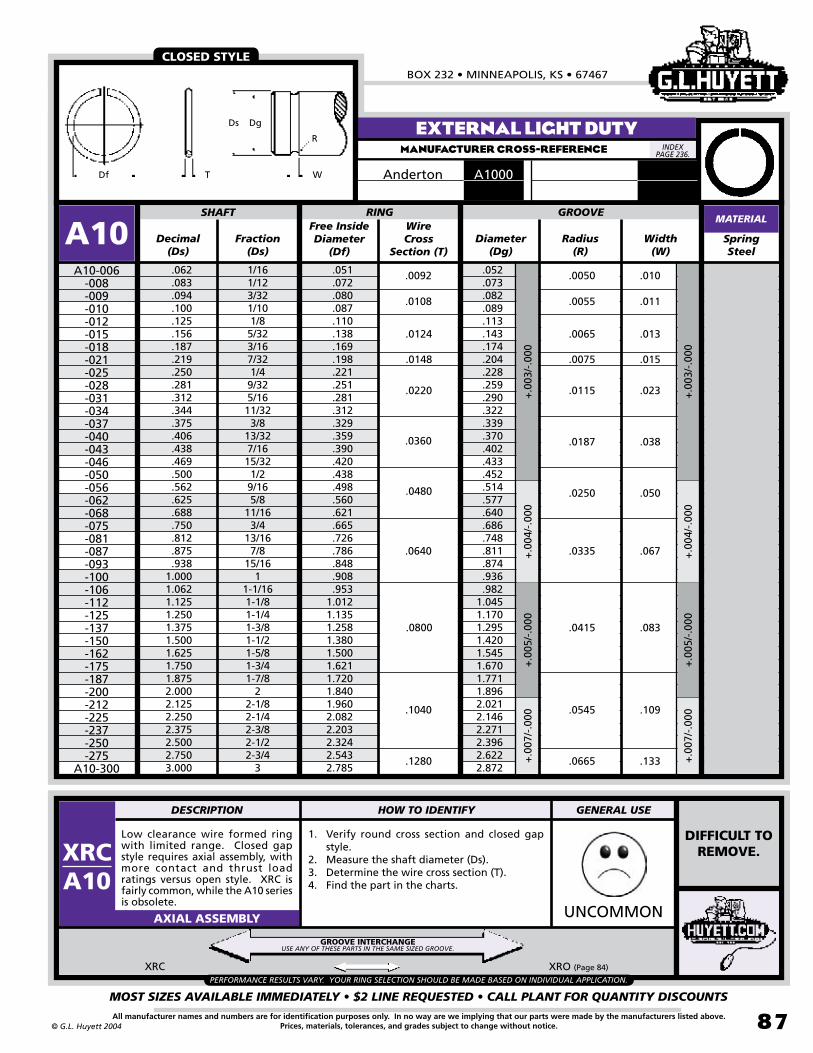
BOX 232 • MINNEAPOLIS, KS • 67467
MOST SIZES AVAILABLE IMMEDIATELY • $2 LINE REQUESTED • CALL PLANT FOR QUANTITY DISCOUNTS
87All manufacturer names and numbers are for identification purposes only. In no way are we implying that our parts were made by the manufacturers listed above.Prices, materials, tolerances, and grades subject to change without notice.© G.L. Huyett 2004
EXTERNAL LIGHT DUTYMANUFACTURER CROSS-REFERENCE
Low clearance wire formed ring with limited range. Closed gap style requires axial assembly, with more contact and thrust load ratings versus open style. XRC is fairly common, while the A10 series is obsolete.
UNCOMMONAXIAL ASSEMBLY
Decimal(Ds)
Diameter(Dg)
SpringSteel
.062
.083
.094
.100
.125
.156
.187
.219
.250
.281
.312
.344
.375
.406
.438
.469
.500
.562
.625
.688
.750
.812
.875
.9381.0001.0621.1251.2501.3751.5001.6251.7501.8752.0002.1252.2502.3752.5002.7503.000
1/161/123/321/101/85/323/167/321/49/325/1611/323/8
13/327/1615/321/29/165/8
11/163/4
13/167/8
15/161
1-1/161-1/81-1/41-3/81-1/21-5/81-3/41-7/8
22-1/82-1/42-3/82-1/22-3/4
3
.052
.073
.082
.089
.113
.143
.174
.204
.228
.259
.290
.322
.339
.370
.402
.433
.452
.514
.577
.640
.686
.748
.811
.874
.936
.9821.0451.1701.2951.4201.5451.6701.7711.8962.0212.1462.2712.3962.6222.872
SHAFT RING
A10A10-006
-008-009-010-012-015-018-021-025-028-031-034-037-040-043-046-050-056-062-068-075-081-087-093-100-106-112-125-137-150-162-175-187-200-212-225-237-250-275
A10-300
Radius(R)
+.0
03/-
.000
+.0
04/-
.000
+.0
05/-
.000
+.0
07/-
.000
Free InsideDiameter
(Df)
GROOVE
Width(W)
Fraction(Ds)
Wire Cross
Section (T)
+.0
03/-
.000
+.0
04/-
.000
.0050
.0065
.0115
.0187
.0250
.0335
.0415
.0545
.0665
.0055
.0075
.010
.013
.023
.038
.050
.067
.083
.109
.133
.011
.015
.0092
.0124
.0220
.0360
.0480
.0640
.0800
.1040
.1280
.0108
.0148
+.0
07/-
.000
+.0
05/-
.000
XRC XRO (Page 84)
MATERIAL
A1000Anderton
CLOSED STYLE
Df
R
Ds Dg
T W
PERFORMANCE RESULTS VARY. YOUR RING SELECTION SHOULD BE MADE BASED ON INDIVIDUAL APPLICATION.
DIFFICULT TO REMOVE.
1. Verify round cross section and closed gap style.
2. Measure the shaft diameter (Ds).3. Determine the wire cross section (T).4. Find the part in the charts.
GROOVE INTERCHANGEUSE ANY OF THESE PARTS IN THE SAME SIZED GROOVE.
INDEX PAGE 236.
DESCRIPTION HOW TO IDENTIFY GENERAL USE
XRCA10
.051 .072 .080 .087 .110 .138 .169 .198 .221 .251 .281 .312 .329 .359 .390 .420 .438 .498 .560 .621 .665 .726 .786 .848 .908 .953 1.012 1.135 1.258 1.380 1.500 1.621 1.720 1.840 1.960 2.082 2.203 2.324 2.543 2.785

RECTANGULAR WIRE RINGSREVISED 09-04
MOST SIZES AVAILABLE IMMEDIATELY • $2 LINE REQUESTED • CALL PLANT FOR QUANTITY DISCOUNTS
88
785•392•3017 FAX 785.392.2845
All manufacturer names and numbers are for identification purposes only. In no way are we implying that our parts were made by the manufacturers listed above.Prices, materials, tolerances, and grades subject to change without notice. © G.L. Huyett 2004
www.huyett.com
Rectangular section ring used in place of SH-style snap ring where space is very limited. Same groove width as SH. (See page 6 for SH rings.)
1. Verify rectangular cross section and closed gap style.
2. Measure the shaft diameter (Ds).3. Determine the ring thickness (T) and radial
wall (S).4. Find the part in the chart above.
UNCOMMONAXIAL ASSEMBLY
Decimal(Ds)
Thickness(T)
Spring Steel
.188
.219
.250
.281
.312
.344
.375
.406
.438
.469
.500
.562
.594
.625
.688
.750
.812
.875
.9381.000
3/167/321/49/325/1611/323/8
13/327/1615/321/29/1619/325/8
11/163/4
13/167/8
15/161
SHAFT RING
TRCTRC-018
-021-025-028-031-034-037-040-043-046-050-056-059-062-068-075-081-087-093
TRC-100
Diameter(Dg)
+/-
5%+
/-4%
Free Inside Dia.
(Df)
+.0
00/-
6%+
.000
/-5%
Width(W)
Fraction(Ds)
Radial Wall(S)
.176
.205
.230
.261
.290
.322
.351
.382
.412
.443
.474
.534
.565
.596
.656
.715
.776
.833
.896
.955
.226
.255
.300
.331
.370
.402
.431
.472
.502
.533
.570
.630
.685
.716
.776
.855
.916
.9731.0581.117
.025
.040
.045
.060
.070
.081
.048
.035
.015
.025
.042
.035
GROOVE
.017
.028
.046
.039
EXTERNALMANUFACTURER CROSS-REFERENCE
MATERIAL
A0500Anderton
EXTERNAL CRIMPEDMANUFACTURER CROSS-REFERENCE
CLOSED STYLE
AVAILABLE AS A SPECIAL ORDER
WEIGHTLbs. per
100Pieces
REMOVE USING
PLASTIC EXPLOSIVES.
0.00700.00800.02000.02300.02900.03200.03500.04200.04500.04800.07800.09000.12000.13000.17000.21000.22000.23000.29000.3000
Da
S
ADs
d
T W
ID
TRCArcon National
INDEX PAGE 236.
INDEX PAGE 236.
AARArcon National
DgDsDf
ST
W
DESCRIPTION HOW TO IDENTIFY GENERAL USE
TRC
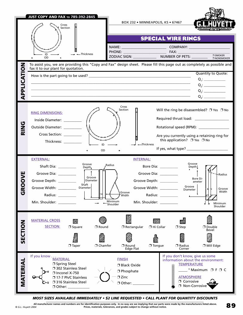
BOX 232 • MINNEAPOLIS, KS • 67467
MOST SIZES AVAILABLE IMMEDIATELY • $2 LINE REQUESTED • CALL PLANT FOR QUANTITY DISCOUNTS
89All manufacturer names and numbers are for identification purposes only. In no way are we implying that our parts were made by the manufacturers listed above.Prices, materials, tolerances, and grades subject to change without notice.© G.L. Huyett 2004
SPECIAL WIRE RINGS
JUST COPY AND FAX TO 785-392-2845
NAME: _________________________ COMPANY: _______________________PHONE: ________________________ FAX: _____________________________ZODIAC SIGN: _____________ NUMBER OF PETS: _________
❐SMOKER❐NONSMOKER
MATERIAL❐ Spring Steel❐ 302 Stainless Steel❐ Inconel X-750❐ 17-7 Ph/C Stainless❐ 316 Stainless Steel❐ Other: ____________
FINISH
❐ Black Oxide
❐ Phosphate
❐ Zinc
❐ Other: ____________MA
TER
IAL
SEC
TIO
NG
RO
OV
ER
ING
How is the part going to be used? _________________________________________________________
_________________________________________________________________________________________
_________________________________________________________________________________________
_________________________________________________________________________________________
Quantity to Quote:
Q1: ____________
Q2: ____________
Q3: ____________
Q4: ____________
To assist you, we are providing this “Copy and Fax” design sheet. Please fill this page out as completely as possible and fax it to our plant for quotation.
APPLI
CA
TIO
N
TEMPERATURE
_____ ° Maximum ❐ F ❐ C
ATMOSPHERE❐ Corrosive❐ Non-Corrosive
If you know . . . If you don’t know, give us some information about the environment:
❐Square ❐Round ❐Hi Collar❐Rectangular ❐Step
❐Chamfer ❐Round Edge Flat
❐Radius Corner
❐Tongue❐Taper ❐Mill Edge
MATERIAL CROSS
SECTION:
RING DIMENSIONS:
Inside Diameter: __________
Outside Diameter: __________
Cross Section: __________
Thickness: __________
Will the ring be disassembled? ❐Yes ❐No
Required thrust load: ___________________
Rotational speed (RPM): _________________
Are you currently using a retaining ring for this application? ❐Yes ❐No
If yes, what type? _______________________
IDOD
Thickness
Cross Section
ID
OD
Thickness
Cross Section
❐Double Bevel
EXTERNAL:
Shaft Dia: __________
Groove Dia: __________
Groove Depth: __________
Groove Width: __________
Radius: __________
Min. Shoulder: __________
INTERNAL:
Bore Dia: __________
Groove Dia: __________
Groove Depth: __________
Groove Width: __________
Radius: __________
Min. Shoulder: __________
Groove Diameter
Bore Di-ameter
MinimumShoulder
Groove Depth
Groove Width
Radius
Shaft Diameter
GrooveDiameter
MinimumShoulder
Groove Depth
Groove Width
Radius

PUSH-ON RINGSREVISED 09-04
MOST SIZES AVAILABLE IMMEDIATELY • $2 LINE REQUESTED • CALL PLANT FOR QUANTITY DISCOUNTS
90
785•392•3017 FAX 785.392.2845
All manufacturer names and numbers are for identification purposes only. In no way are we implying that our parts were made by the manufacturers listed above.Prices, materials, tolerances, and grades subject to change without notice. © G.L. Huyett 2004
www.huyett.com
Installed in an axial direction on grooveless shafts or inside bores.
AUTOMATED INSTALLATION
TYMETRIC
N/AIMPERIAL
Pg: 92
BASIC EXTERNAL
TXMETRICPg: 212
IMPERIALPg: 92
REINFORCED EXTERNAL
TIMETRICPg: 212
IMPERIALPg: 93
BASIC INTERNAL
ITRMETRIC
N/AIMPERIALPgs: 94-95
INTERNAL TOOTHED
STRMETRIC
N/AIMPERIAL
Pg: 96
HIGH SPEED STRIP
WRRMETRIC
N/AIMPERIAL
Pg: 96
WIDE RIM SLOTTED
TRMETRICPg: 213
IMPERIALPg: 97
TRIANGLE PUSH-ON
NTRMETRIC
N/AIMPERIAL
Pg: 97
TRIANGLE SCREW-ON
NPRMETRIC
N/AIMPERIAL
Pg: 98
BASIC RECTANGULAR
NPOMETRIC
N/AIMPERIAL
Pg: 99
BASIC ROUND
BRRMETRIC
N/AIMPERIAL
Pg: 100
INTERNAL TOOTHED BEARING RETAINER
T99METRIC
N/AIMPERIAL
Pg: 101
BASIC GROOVELESS
Push-on rings are installed onto grooveless shafts by sliding the ring in an opposite direction from the prongs. The prongs provide resistance to removal by digging into the shaft material. The best way to automate production is to build fixtures that are size and depth preset to the installed product. Tubes work well in external applications, while plugs assist in internal installation.
TYPES
LET OUR SHOP MAKE A FIXTURE FOR YOU!
Tool
Ring
Shaft
Retained Part
Finished!
Place the ring in the tool and push down on the shaft as shown at the left.
Ring
Available in Spring Steel and Stainless
Steel.
Heavier-duty version. Available in metric sizes.
Available in Spring Steel and Stainless
Steel.
Bowed shape resists
back-off pressure.
Strip formfor quick
installation.
Wide rim for increased peripheral abutment.
Heavy duty options
available in many sizes.
Heavy duty options
available in many sizes.
Available in seven forms.Also in round version (NPO).
Available in five forms.
Also in rectangular
version (NPR).
Allow for bearing rotation.
Available in flat and Belleville
styles.
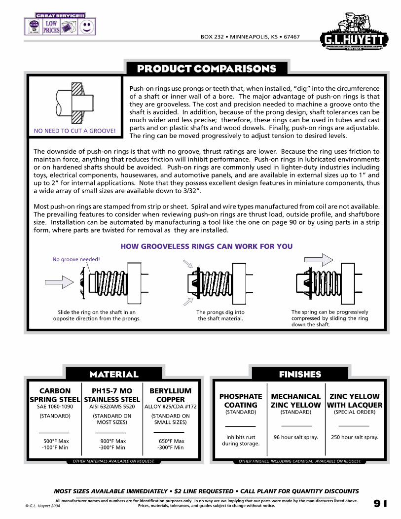
BOX 232 • MINNEAPOLIS, KS • 67467
MOST SIZES AVAILABLE IMMEDIATELY • $2 LINE REQUESTED • CALL PLANT FOR QUANTITY DISCOUNTS
91All manufacturer names and numbers are for identification purposes only. In no way are we implying that our parts were made by the manufacturers listed above.Prices, materials, tolerances, and grades subject to change without notice.© G.L. Huyett 2004
PRODUCT COMPARISONS
NO NEED TO CUT A GROOVE!
Push-on rings use prongs or teeth that, when installed, “dig” into the circumference of a shaft or inner wall of a bore. The major advantage of push-on rings is that they are grooveless. The cost and precision needed to machine a groove onto the shaft is avoided. In addition, because of the prong design, shaft tolerances can be much wider and less precise; therefore, these rings can be used in tubes and cast parts and on plastic shafts and wood dowels. Finally, push-on rings are adjustable. The ring can be moved progressively to adjust tension to desired levels.
The downside of push-on rings is that with no groove, thrust ratings are lower. Because the ring uses friction to maintain force, anything that reduces friction will inhibit performance. Push-on rings in lubricated environments or on hardened shafts should be avoided. Push-on rings are commonly used in lighter-duty industries including toys, electrical components, housewares, and automotive panels, and are available in external sizes up to 1” and up to 2” for internal applications. Note that they possess excellent design features in miniature components, thus a wide array of small sizes are available down to 3/32”.
Most push-on rings are stamped from strip or sheet. Spiral and wire types manufactured from coil are not available. The prevailing features to consider when reviewing push-on rings are thrust load, outside profile, and shaft/bore size. Installation can be automated by manufacturing a tool like the one on page 90 or by using parts in a strip form, where parts are twisted for removal as they are installed.
HOW GROOVELESS RINGS CAN WORK FOR YOU
Slide the ring on the shaft in an opposite direction from the prongs.
The prongs dig into the shaft material.
FINISHES
PHOSPHATECOATING(STANDARD)
Inhibits rust during storage.
MECHANICALZINC YELLOW
(STANDARD)
96 hour salt spray.
ZINC YELLOWWITH LACQUER
(SPECIAL ORDER)
250 hour salt spray.
OTHER FINISHES, INCLUDING CADMIUM, AVAILABLE ON REQUEST.
The spring can be progressively compressed by sliding the ring down the shaft.
MATERIAL
CARBON SPRING STEEL
SAE 1060-1090
(STANDARD)
500°F Max-100°F Min
PH15-7 MOSTAINLESS STEEL
AISI 632/AMS 5520
(STANDARD ON MOST SIZES)
900°F Max-300°F Min
OTHER MATERIALS AVAILABLE ON REQUEST.
BERYLLIUMCOPPER
ALLOY #25/CDA #172
(STANDARD ON SMALL SIZES)
650°F Max-300°F Min
No groove needed!

PUSH-ON RINGSREVISED 09-04
MOST SIZES AVAILABLE IMMEDIATELY • $2 LINE REQUESTED • CALL PLANT FOR QUANTITY DISCOUNTS
92
785•392•3017 FAX 785.392.2845
All manufacturer names and numbers are for identification purposes only. In no way are we implying that our parts were made by the manufacturers listed above.Prices, materials, tolerances, and grades subject to change without notice. © G.L. Huyett 2004
www.huyett.com
BASIC EXTERNALMANUFACTURER CROSS-REFERENCE
From(Ds)
Thickness(T)
Spring Steel
.093
.124
.155
.187
.218
.239
.249
.311
.374
.437
.498
.560
.623
.748
.873
.998
TY-009-012-015-018-021-024-025-031-037-043-050-056-062-075-087
TY-100
+/-
.001
OutsideDiameter
(OD)
+/-
.005
+/-
.010
To(Ds)
Fraction(Ds)
min Distance from face of part to end of shaft (F)
No. of Prongs
.095
.126
.157
.189
.220
.241
.251
.313
.376
.439
.502
.564
.627
.752
.8771.002
.250
.325
.356
.387
.418
.460
.450
.512
.575
.638
.750
.812
.8751.0001.1251.250
PRICE
+/-
.002
+/-
.001
+/-.002
.010
.015
.010
.015
.040
.060
.040
.060
TYRotor Clip
5105Waldes6100IRR
TYSHAFT RING MATERIAL
TY / TX TECHNICAL INFORMATION NEXT PAGE.
4
6
10
Stainless “-SS”
Ds
F
T
OD
Lbs. per 100 Pieces
WEIGHT
3
78
0.00900.01400.01700.02000.02100.03500.02300.02600.02700.04700.07200.07500.08200.09700.11000.1200
3/321/85/323/167/32
6.1mm1/45/163/87/161/29/165/83/47/81
REINFORCED EXTERNALMANUFACTURER CROSS-REFERENCE
AndertonRotor Clip
N1465TX
Waldes 5115
From(Ds)
Thickness(T)
SpringSteel
.091
.121
.152
.184
.246
.308
.371
.432
.495
.557
.620
.745
.870
.995
TX-009-012-015-018-025-031-037-043-050-056-062-075-087
TX-100
+/-
.001
OutsideDiameter
(OD)
+/-
.005
+/-
.010
To(Ds)
Fraction(Ds)
min Distance from face of part to end of shaft (F)
No. of Prongs
.097
.129
.160
.192
.254
.316
.379
.442
.505
.567
.630
.755
.8801.005
3/321/85/323/161/45/163/87/161/29/165/83/47/81
.326
.366
.397
.444
.522
.584
.645
.737
.828
.889
.9511.0761.2031.327
.058
.062
.074
.090
.108
+/-
.002
SHAFT RING MATERIALTX
.010
Stainless“-SS”
T F
ODDs
Lbs. per 100 Pieces
WEIGHT
3
141618
4
6
8
10
12.015
0.01600.01900.02200.02700.05500.06400.07400.09600.12700.13800.14700.16500.19600.2290
INDEX PAGE 236.
INDEX PAGE 236.
DTX METRIC
Page 212

BOX 232 • MINNEAPOLIS, KS • 67467
MOST SIZES AVAILABLE IMMEDIATELY • $2 LINE REQUESTED • CALL PLANT FOR QUANTITY DISCOUNTS
93All manufacturer names and numbers are for identification purposes only. In no way are we implying that our parts were made by the manufacturers listed above.Prices, materials, tolerances, and grades subject to change without notice.© G.L. Huyett 2004
Axially-applied grooveless rings that provide good retention, particularly on par t s w i th d imens iona l variations. Installed with a tube or plunger. The TX is a heavier-duty version, with a wider and thicker rim, and more prongs.
1. Verify the correct shaft size (Ds).2. Measure the part thickness (T).3. Count the number of prongs on the part.4. Determine the outside diameter (OD) of the
part.5. Find the part in the charts on the previous
page.
ZINC/YELLOW
COMMONAXIAL ASSEMBLY
BASIC INTERNALMANUFACTURER CROSS-REFERENCE
Internal self-locking ring for axial application into housings and bores. Low cost design with an easy grooveless installation using a plunger. Not reusable.
1. Verify correct bore size (Db).2. Measure the part thickness (T).3. Count the number of prongs on the part.4. Determine the inside diameter (ID) of the
part.5. Find the part in the chart above.
ZINC/YELLOW
COMMONAXIAL ASSEMBLY
From(Db)
Thickness(T)
SpringSteel
.311
.374
.437
.440
.498
.560
.623
.638
.748
.873
.936
.9981.1231.2481.3711.4361.4981.7481.998
TITI-031-037-043-044-050-056-062-063-075-087-093-100-112-125-137-143-150-175
TI-200
InsideDiameter
(ID)
+/-
.005
To(Db)
Fraction(Db)
min Distance from face of part to end of bore (F)
No. of Prongs
.313
.376
.439
.442
.502
.564
.627
.640
.752
.877
.9401.0021.1271.2521.3791.4401.5021.7522.002
5/163/87/16
11.2mm1/29/165/8
16.233/47/8
15/161
1-1/81-1/41-3/81-7/161-1/21-3/4
2
.136
.175
.237
.258
.258
.312
.390
.390
.500
.625
.687
.750
.813
.9381.0501.1171.1881.4381.600
+/-
.001
.010 .040
.015 .060
AndertonIRR
TIRotor ClipN13055005Waldes6000
+/-
.010
+/-
.002
BORE RING MATERIAL
NOTAVAILABLE
TY and TX SHF (Page 14) RG (Page 27) T99 (Page 101)
Stainless “-SS”
ID
T
Db
F
6
8
10
16
12
14
Lbs. per 100 Pieces
WEIGHT
PERFORMANCE RESULTS VARY. YOUR RING SELECTION SHOULD BE MADE BASED ON INDIVIDUAL APPLICATION.
0.01100.01600.02000.01800.02400.02900.03000.03200.06200.07500.08500.09100.13000.15000.21000.17300.18000.21000.3000
GROOVELESSUSE ANY OF THESE PARTS ON THE SAME SIZED SHAFT.
INDEX PAGE 236.
DESCRIPTION HOW TO IDENTIFY GENERAL USE
TI
DESCRIPTION HOW TO IDENTIFY GENERAL USE
TYTX
(PAGE 92)
STACKED/ROLL PACK
DTI METRIC
Page 212

PUSH-ON RINGSREVISED 09-04
MOST SIZES AVAILABLE IMMEDIATELY • $2 LINE REQUESTED • CALL PLANT FOR QUANTITY DISCOUNTS
94
785•392•3017 FAX 785.392.2845
All manufacturer names and numbers are for identification purposes only. In no way are we implying that our parts were made by the manufacturers listed above.Prices, materials, tolerances, and grades subject to change without notice. © G.L. Huyett 2004
www.huyett.com
INTERNAL TOOTHEDMANUFACTURER CROSS-REFERENCE
Grooveless external retainer for axial assembly. Slips over unthreaded shafts for lighter-duty uses like toys, housewares, and plastic applications.
1. Measure outside diameter (OD) of the part.2. Verify shaft size.3. Confirm material thickness (Tm).4. Find the part in the charts above.
COMMONAXIAL ASSEMBLY
ITR TX (Page 92) TY (Page 92) STR (Page 96) WRR (Page 96)
SpringSteel
.0780
.0870
.0940
.0940
.0940
.1120
.1120
.1200
.1250
.1350
.1450
.1560
.1560
.1560
.1560
.1620
.1620
.1750
.1810
.1870
.1870
.1870
.2050
.2180
.2200
.2360
.2380
.2380
.2500
.2500
.2500
.2500
.2500
.2500
.2500
.2500
.2500
.2650
.2650
.2650
.2760
.0730
.0800
.0850
.0860
.0880
.1070
.1050
.1150
.1180
.1270
.1400
.1510
.1500
.1510
.1520
.1570
.1550
.1660
.1700
.1800
.1780
.1810
.1980
.2070
.2200
.2260
.2360
.2360
.2440
.2390
.2390
.2440
.2420
.2440
.2440
.2400
.2350
.2500
.2550
.2500
.2700
SHAFT RING
ITRITR-00710 -00812 -00910 -00910-01 -00910-T -01110 -01110-01 -01210 -01210-01 -01310 -01415 -01510 -01510-T -01512 -01512-01 -01610 -01620 -01710 -01810 -01810-01 -01810-02 -01815-T -02010 -02113 -02215 -02314 -02315 -02315-01 -02510 -02510-01 -02515-T -02515 -02520 -02520-01 -02520-02 -02525 -02525-01 -02606 -02613 -02615ITR-02712
Nominal Shaft
Outside DiameterNominal
(OD)
Inside Diameter(ID)
Max.Min.
MaterialThickness
(Tm)
.2200
.1800
.1800
.2650
.3940
.2580
.2580
.2650
.2650
.2630
.2810
.3320
.3940
.3320
.3560
.3320
.3330
.3320
.3330
.3320
.3320
.3940
.3330
.4020
.5310
.5310
.4600
.4750
.4720
.4730
.4620
.4720
.5150
.6250
.7340
.4720
.4770
.3890
.4720
.4720
.6200
.0680
.0770
.0810
.0810
.0850
.1020
.1020
.1100
.1130
.1220
.1330
.1460
.1460
.1460
.1470
.1520
.1510
.1640
.1740
.1760
.1730
.1770
.1940
.2020
.2050
.2200
.2280
.2280
.2390
.2340
.2340
.2390
.2380
.2390
.2390
.2350
.2400
.2440
.2500
.2440
.2650
.0100
.0120
.0100
.0100
.0100
.0100
.0100
.0100
.0100
.0100
.0150
.0100
.0100
.0120
.0120
.0100
.0200
.0100
.0100
.0100
.0100
.0150
.0100
.0130
.0150
.0140
.0150
.0150
.0100
.0100
.0150
.0150
.0200
.0200
.0200
.0250
.0250
.0060
.0130
.0150
.0120
+/-
.002
MATERIAL
PERFORMANCE RESULTS VARY. YOUR RING SELECTION SHOULD BE MADE BASED ON INDIVIDUAL APPLICATION.
OD
ID
Tm
UNIQUE TO SPECIFIC
APPLICATIONS.
GROOVELESSUSE ANY OF THESE PARTS ON THE SAME SIZED SHAFT.
INDEX PAGE 236.
DESCRIPTION HOW TO IDENTIFY GENERAL USE
ITR
8063ITW Shakeproof

BOX 232 • MINNEAPOLIS, KS • 67467
MOST SIZES AVAILABLE IMMEDIATELY • $2 LINE REQUESTED • CALL PLANT FOR QUANTITY DISCOUNTS
95All manufacturer names and numbers are for identification purposes only. In no way are we implying that our parts were made by the manufacturers listed above.Prices, materials, tolerances, and grades subject to change without notice.© G.L. Huyett 2004
Grooveless external retainer for axial assembly. Slips over unthreaded shafts for lighter-duty uses like toys, housewares, and plastic applications.
1. Measure outside diameter (OD) of the part.
2. Verify shaft size.3. Confirm material thickness (Tm).4. Find the part in the charts above.
COMMONAXIAL ASSEMBLY
INTERNAL TOOTHEDMANUFACTURER CROSS-REFERENCE
ITR TX (Page 92) TY (Page 92) STR (Page 96) WRR (Page 96)
Spring Steel
.3110
.3120
.3120
.3120
.3120
.3120
.3120
.3240
.3300
.3430
.3750
.3750
.3750
.4000
.4030
.4210
.4370
.4370
.4750
.4950
.5000
.5000
.5520
.6250
.6250
.6250
.6250
.6400
.6590
.6690
.6750
.7030
.7030
.7500
.7500
.8000
.85001.00001.00001.12501.1350
.3010
.3040
.3050
.2920
.3040
.3020
.2920
.3160
.3230
.3330
.3550
.3650
.3420
.3940
.3940
.4100
.4320
.4320
.4620
.4840
.4980
.4900
.5460
.6140
.6150
.6180
.6150
.6310
.6570
.6600
.6690
.6890
.6930
.7400
.7400
.7900
.84001.0450.9800
1.08501.1250
SHAFT RING
ITR-03120 -03112 -03115 -03115-T -03115-01 -03120 -03125 -03224 -03313 -03410 -03715-T -03715 -03715-01 -04012 -04014 -04214-01 -04310 -04310-01 -04717 -04915 -05010 -05017-T -05520 -06215 -06220 -06220-01 -06240 -06415 -06520 -06618 -06729 -07013 -07029 -07510 -07520 -08025 -08525 -10012 -10015 -11215 ITR-11315
Nominal Shaft
Outside DiameterNominal
(OD)
Inside Diameter(ID)
Max.Min.
MaterialThickness
(Tm)
.6260
.4730
.5100
.5980
.6030
.5400
.5980
.6800
.4720
.6870
.6800
.6870
.7800
.7810
.6250
.7810
.6870
.7810
.7810
.6870
.7810
.77001.0000.9510.9680
1.0830.9680.8750
1.08301.07201.29901.08201.2500.9650
1.25001.37501.19201.62501.37502.00001.5730
.2950
.2990
.2950
.2880
.2990
.2980
.2880
.3120
.3180
.3180
.3280
.3600
.3340
.3900
.3900
.4000
.4270
.4270
.4670
.4780
.4930
.4830
.5410
.6100
.6100
.6080
.6100
.6250
.6470
.6530
.6590
.6810
.6860
.7350
.7350
.7800
.83501.0400.9700
1.07501.1200
.0200
.0120
.0150
.0150
.0150
.0200
.0250
.0240
.0130
.0100
.0150
.0150
.0150
.0120
.0140
.0140
.0100
.0100
.0170
.0150
.0100
.0170
.0200
.0150
.0200
.0200
.0400
.0150
.0200
.0180
.0295
.0130
.0290
.0100
.0200
.0250
.0250
.0120
.0150
.0150
.0150
+/-
.002
MATERIALITR
PERFORMANCE RESULTS VARY. YOUR RING SELECTION SHOULD BE MADE BASED ON INDIVIDUAL APPLICATION.
OD
ID
Tm
MINIMUM PRODUCTION
RUNS SOMETIMES NECESSARY.
GROOVELESSUSE ANY OF THESE PARTS ON THE SAME SIZED SHAFT.
INDEX PAGE 236.
DESCRIPTION HOW TO IDENTIFY GENERAL USE
ITR
8063ITW Shakeproof

PUSH NUTSREVISED 09-04
MOST SIZES AVAILABLE IMMEDIATELY • $2 LINE REQUESTED • CALL PLANT FOR QUANTITY DISCOUNTS
9�
785•392•3017 FAX 785.392.2845
All manufacturer names and numbers are for identification purposes only. In no way are we implying that our parts were made by the manufacturers listed above.Prices, materials, tolerances, and grades subject to change without notice. © G.L. Huyett 2004
www.huyett.com
HIGH SPEED STRIPMANUFACTURER CROSS-REFERENCE
STR
High speed installation in strip form using automated equipment. Individual parts are twisted or punched for removal.
1. Confirm that the part is from a strip by finding the “breakout” on the outer rim.
2. Determine the shaft size size design.3. Find the part in the chart above.
WEIRDAXIAL ASSEMBLY
WIDE RIM SLOTTEDMANUFACTURER CROSS-REFERENCE
Shaft Size Design
Height(H)
SpringSteel
.158
.236
.311
.055
.072
.071
SHAFT RING
WRRWRR-015
-023WRR-031
$
OutsideDiameter
(OD)
MaterialThickness
(T)
Inside Diameter(ID)
Max.
Wide rim provides increased peripheral abutment. Large profile eases hand-installation and adjustment.
1. Verify the size of the shaft that the part is used on.
2. Measure the material thickness (T).3. Determine the outside diameter (OD).4. Find the part in the chart above.
WEIRDAXIAL ASSEMBLY
Min.
.472
.531
.626
.142
.220
.295
.148
.226
.301
.012
.017
.020
STR ITR (Page 94) TX (Page 92) TY (Page 92) NPR (Page 98)
WRR T99 (Page 101) ITR (Page 94)
MATERIAL
Material Thickness
(T)
.125
.187
.250
122
STR-012-018
STR-025
StripLength
Shaft Size Design
Parts perStripForm
Inside Diameter
(ID)Height
(H)
Outside Diameter
(OD)
DESIGN PART DIMENSIONS STRIP
.365
.500
.500
.116
.175
.234
.048 Ref.
.051 Ref.
.063 Ref.
5.50013.50013.500
142525
STR Spring Steel
MATERIAL
.015
PERFORMANCE RESULTS VARY. YOUR RING SELECTION SHOULD BE MADE BASED ON INDIVIDUAL APPLICATION.
PERFORMANCE RESULTS VARY. YOUR RING SELECTION SHOULD BE MADE BASED ON INDIVIDUAL APPLICATION.
CUSTOM SIZES
AVAILABLEPER
QUOTE.
OD ID
HT
HIGHER PRODUCTION MINIMUMS SOMETIMES REQUIRED.
GROOVELESSUSE ANY OF THESE PARTS ON THE SAME SIZED SHAFT.
GROOVELESSUSE ANY OF THESE PARTS ON THE SAME SIZED SHAFT.
INDEX PAGE 236.
INDEX PAGE 236.
Form 1 Form 2
ID
T
OD
H
ID
H
OD
T
DESCRIPTION HOW TO IDENTIFY GENERAL USE
WRR
8065ITW Shakeproof
USES HOW TO IDENTIFY GENERAL USE

BOX 232 • MINNEAPOLIS, KS • 67467
MOST SIZES AVAILABLE IMMEDIATELY • $2 LINE REQUESTED • CALL PLANT FOR QUANTITY DISCOUNTS
97All manufacturer names and numbers are for identification purposes only. In no way are we implying that our parts were made by the manufacturers listed above.Prices, materials, tolerances, and grades subject to change without notice.© G.L. Huyett 2004
TRIANGLE PUSH-ONMANUFACTURER CROSS-REFERENCE
Waldes 5305
TRIANGLE SCREW-ONMANUFACTURER CROSS-REFERENCE
Waldes 5300
Large triangular shoulder grips better than round rings like the TX and TY. NTR is a push nut that is turned onto the shaft. Unusual shape has made the part nearly extinct. Last seen holding a leg tag onto a passenger pigeon.
1. Find one in existence.2. Determine if the ring is a push on (TR) or
screw on (NTR).3. Locate the ring in the chart above based on
thickness (T), shaft diameter (Ds), and height (Hr).
WEIRDAXIAL ASSEMBLY
Height(Hr)
SpringSteel
NTRNTR-0632 -0632-H -0832 -0832-H -1024 -1024-H -1420 -1420-H -1032 -1032-H -1428NTR-1428-H
Lbs. per100
PiecesClearance
(C)ThreadSeries
Width(Wr)
THREAD RING
.38
.53
.46
.64
.58
.811.221.49.58.81
1.181.45
MATERIALThickness-
Light Version (T)
.015
.020
.015
.020
.015
.020
.020
.025
.015
.020
.020
.025
+/-
.010
+/-
.010
6-32
8-32
10-24
1/4-20
10-32
1/4-28
+/-
.005
+/-
.005
.376
.416
.467
.587
.467
.587
.434
.481
.538
.677
.538
.677
SEE TX AND TY SERIES
ON PAGE 92 FOR MORE COMMON
VARIATIONS.
WEIGHT
From(Ds)
Height(Hr)
SpringSteel
.185
.246
.308
.371
.191
.254
.316
.379
TRTR-006 -006-H -009 -009-H -012 -012-H -013 -013-H -014 -014-H -015 -015-H -018 -025 -031 -037 -043TR-043Hex
Fraction(Ds)
+/-
.005
$
Lbs. per 100PiecesClearance
(C)To
(Ds)
+/-
.005
Width(Wr)
SHAFT RING
3/161/45/163/8
MATERIAL
Thickness (T)
.010
.015
.010
.015
.010
.015
.010
.015
.010
.015
.010
.015
.015
.015
.015
.020
.025
.025
+/-
.010
+/-
.010
.060 .064
.092 .096
.122 .128
.132 .138
.142 .148
.153 .159
.434 .442
1/16
3/32
1/8
5/32
7/16
.315
.376
.416
.467
.587
.640
.725
.804
.363
.434
.481
.538
.677
.738
.835
.928
-
WEIGHT
.40
.48
.52
.98
.58
.73
.80
.89
0.01300.01800.02500.03600.02500.03600.02500.03600.03200.04600.03200.04600.05400.08700.09200.16600.23200.2320
0.03800.05300.04600.06400.05800.08100.12200.14900.05800.08100.11800.1450
If you really need one of these, a production
minimum may apply.
INDEX PAGE 236.
INDEX PAGE 236.
T
Wr
C
Hr
DESCRIPTION HOW TO IDENTIFY GENERAL USE
TRNTR
DTR METRIC
Page 213
Ds

PUSH NUTSREVISED 09-04
MOST SIZES AVAILABLE IMMEDIATELY • $2 LINE REQUESTED • CALL PLANT FOR QUANTITY DISCOUNTS
98
785•392•3017 FAX 785.392.2845
All manufacturer names and numbers are for identification purposes only. In no way are we implying that our parts were made by the manufacturers listed above.Prices, materials, tolerances, and grades subject to change without notice. © G.L. Huyett 2004
www.huyett.com
BASIC RECTANGULARMANUFACTURER CROSS-REFERENCE
Push nuts engage an unthreaded shaft on two sides for greater strength. Notched prongs deflect providing a strut that resists back pressure.
1. Is the OD round (NPO) or rectangular (NPR)?
2. Confirm the form using the diagram on page 99.
3. Verify the stud size.4. Find the part in the charts above using length
(L) and width (W) dimensions. UNCOMMONAXIAL ASSEMBLY
ASpringSteel
1/161/161/161/16
-----
3/323/323/323/32
----
1/81/81/81/81/81/85/325/325/323/163/163/161/41/41/41/4--
5/16--
31/641/2
.012
.012
.018
.015
.015
.012
.018
.018
.018
.012
.015
.018
.012
.015
.015
.015
.015
.012
.015
.015
.018
.012
.015
.012
.015
.012
.015
.022
.015
.010
.018
.018
.012
.012
.012
.018
.012
.015
.012
.020
STUD RING
NPR-650375-650400-650402-650350-650401-658320-659850-650500-650850-650896-650897-650900-650925-651002-651050-651000-651001-651410-651415-651400-651455-658300-651450-650365-650360-650361-652700-652701-652900-653399-653445-653410-653425-653500-653550-653525-653555-654100-659475
NPR-654105
Length(L)
STYLE
FormsWidth
(W)
MaterialThickness
(T) B C D E F G
.391
.391
.391
.625
.875
.6251.250.391.391.453.453.453.797.453.578.453.453.312.312.906.906.578.906.562.562.562.625.625.625.625.641.984
1.000.625.625
1.000.625
1.250.922
1.250
.187
.219
.219
.375
.312
.250
.562
.219
.219
.234
.234
.234
.334
.234
.250
.234
.234
.250
.250
.250
.312
.344
.500
.375
.375
.375
.375
.375
.375
.438
.438
.625
.562
.438
.500
.687
.500
.875
.750
.875
• •••• •••• •• •• • ••••• • •• •• •• •• •• •• •• •••••• •• •• •• •• •••• •• • •• •• •• • •• •• •• • •• •
MATERIAL
NPR/NPO ITR (Page 94) WRR (Page 96)
T
L
W
PERFORMANCE RESULTS VARY. YOUR RING SELECTION SHOULD BE MADE BASED ON INDIVIDUAL APPLICATION.
Decimal Fraction
.062
.062
.062
.062
.070.080 x .250.080 x .720
.081
.081
.093
.093
.093
.093
.100
.100
.102
.107
.125
.125
.125
.125
.125
.125
.156
.156
.156
.187
.187
.187
.250
.250
.250
.250
.271
.308
.312
.365
.440
.484
.500
PRODUCTION MINIMUMSMAY APPLY.
Form A
GROOVELESSUSE ANY OF THESE PARTS ON THE SAME SIZED SHAFT.
INDEX PAGE 236.
DESCRIPTION HOW TO IDENTIFY GENERAL USE
NPR
POITW Shakeproof
NPR

BOX 232 • MINNEAPOLIS, KS • 67467
MOST SIZES AVAILABLE IMMEDIATELY • $2 LINE REQUESTED • CALL PLANT FOR QUANTITY DISCOUNTS
99All manufacturer names and numbers are for identification purposes only. In no way are we implying that our parts were made by the manufacturers listed above.Prices, materials, tolerances, and grades subject to change without notice.© G.L. Huyett 2004
Decimal ASpring Steel
-1/163/323/32
---
1/81/8----
3/163/167/32
--
1/41/49/325/165/165/163/8-
STUD RING
NPO
Push nuts engage an unthreaded shaft on two sides for greater strength. Notched prongs deflect providing a strut that resists back pressure.
1. Is the OD round (NPO) or rectangular (NPR)?
2. Confirm the form using the diagram on page 99.
3. Verify the stud size.4. Find the part in the charts above using length
(L) and width (W) dimensions. UNCOMMONAXIAL ASSEMBLY
NPO-659150-658947-659151-655125-655100-655920-655950-656000-656010-656005-656250-656300-656325-656440-656442-656800-656450-656850-656900-656910-657000-657075-657027-657029-659149
NPO-659460
Length(L)
STYLE
FormsWidth
(W)
MaterialThickness
(T) B C D E F G
.375
.500
.500
.500
.281
.375
.375
.375
.500
.375
.375
.375
.562
.500
.500
.500
.562
.562
.562
.812
.875
.750
.875
.875
.875
.906
.344-
.344
.344-
.344
.344
.344-
.344
.344
.344-----
.437-
.563-
.625---
.625
.012
.012
.012
.012
.012
.012
.012
.012
.018
.012
.012
.012
.012
.012
.015
.012
.018
.012
.012
.022
.022
.018
.012
.018
.018
.012
• •• •• •• ••• •• •• •• •
•• •• •• •• •• •• •• •• •• ••• • •• • •• • •• • •• • •• •
BASIC ROUNDMANUFACTURER CROSS-REFERENCE
MATERIAL
NPR/NPO ITR (Page 94) WRR (Page 96)
TL
W
PERFORMANCE RESULTS VARY. YOUR RING SELECTION SHOULD BE MADE BASED ON INDIVIDUAL APPLICATION.
Fraction
.050
.062
.093
.093
.102
.107
.122
.125
.125
.148
.152
.164
.175
.187
.187
.218
.225
.235
.250
.250
.281
.312
.312
.312
.375
.472
VERIFY STOCK PRIOR
TO ORDER.
Form B Form C Form D Form E Form F Form G
Note: The form applies to the tooth design on the inside of the part, as well as to ring curvature. If you are uncertain, please ask for a print or submit a sample.
Form A
GROOVELESSUSE ANY OF THESE PARTS ON THE SAME SIZED SHAFT.
INDEX PAGE 236.
DESCRIPTION HOW TO IDENTIFY GENERAL USE
NPO
POITW Shakeproof
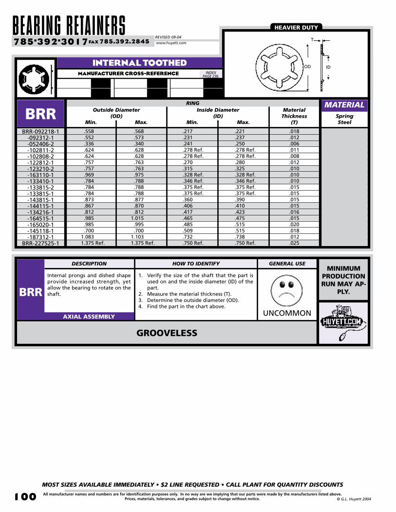
BEARING RETAINERSREVISED 09-04
MOST SIZES AVAILABLE IMMEDIATELY • $2 LINE REQUESTED • CALL PLANT FOR QUANTITY DISCOUNTS
100
785•392•3017 FAX 785.392.2845
All manufacturer names and numbers are for identification purposes only. In no way are we implying that our parts were made by the manufacturers listed above.Prices, materials, tolerances, and grades subject to change without notice. © G.L. Huyett 2004
www.huyett.com
INTERNAL TOOTHEDMANUFACTURER CROSS-REFERENCE
SpringSteel
.558 .552 .336 .624 .624 .757 .757 .969 .784 .784 .784 .873 .867 .812 .985 .985 .7001.0831.375 Ref.
.221
.237
.250
.278 Ref.
.278 Ref.
.280
.325
.328 Ref.
.346 Ref.
.375 Ref.
.375 Ref.
.390
.410
.423
.475
.515
.515
.738
.750 Ref.
RING
BRR
Internal prongs and dished shape provide increased strength, yet allow the bearing to rotate on the shaft.
1. Verify the size of the shaft that the part is used on and the inside diameter (ID) of the part.
2. Measure the material thickness (T).3. Determine the outside diameter (OD).4. Find the part in the chart above.
UNCOMMONAXIAL ASSEMBLY
BRR-092218-1-092312-1-052406-2-102811-2-102808-2-122812-1-123210-2-163110-1-133410-1-133815-2-133815-1-143815-1-144115-1-134216-1-164515-1-165020-1-145118-1-187312-1
BRR-227525-1
Inside Diameter(ID)
Max.Min.
MaterialThickness
(T)
Outside Diameter(OD)
Max.Min.
.568 .573 .340 .628 .628 .763 .763 .975 .788 .788 .788 .877 .870 .8121.015 .995 .7001.1031.375 Ref.
.217
.231
.241
.278 Ref.
.278 Ref.
.270
.315
.328 Ref.
.346 Ref.
.375 Ref.
.375 Ref.
.360
.406
.417
.465
.485
.509
.732
.750 Ref.
.018
.012
.006
.011
.008
.012
.010
.010
.010
.015
.015
.015
.015
.016
.015
.020
.018
.012
.025
MATERIAL
GROOVELESS
OD ID
T
MINIMUM PRODUCTION RUN MAY AP-
PLY.
HEAVIER DUTY
INDEX PAGE 236.
DESCRIPTION HOW TO IDENTIFY GENERAL USE
BRR

BOX 232 • MINNEAPOLIS, KS • 67467
MOST SIZES AVAILABLE IMMEDIATELY • $2 LINE REQUESTED • CALL PLANT FOR QUANTITY DISCOUNTS
101All manufacturer names and numbers are for identification purposes only. In no way are we implying that our parts were made by the manufacturers listed above.Prices, materials, tolerances, and grades subject to change without notice.© G.L. Huyett 2004
.046
.050
.058
.060
.062
.076
.076
.078
.093
.093
.093
.093
.098
.117
.117
.117
.125
.125
.125
.125
.125
.125
.125
.125
.130
.130
.143
.156
.162
.173
.175
.175
.187
.187
.187
.187
.187
.2168
.088
.125
.125
.178
.150
.150
.375
.178
.218
.245
.250
.325
.218
.200
.245
.245
.194
.210
.245
.245
.250
.305
.312
.325
.245
.325
.260
.260
.437
.312
.312
.375
.2875
.315
.325
.375
.750
.437
T99
Large surface area for low cost reusable retention on steel, plastic, or ceramic shafts. Especially effective in limited access locations. Production minimum may apply.
1. Verify style “A” (Flat) or “B” (Belleville).2. Confirm shaft size (Ds).3. Find the part in the chart above based on
outside diameter (OD), height (Hr), and thickness (T).
UNCOMMONAXIAL ASSEMBLY
Decimal(Ds)
OutsideDia.(OD)
Thickness(T)
.017
.020
.020
.020
.016
.025
.025
.025
.030
.030
.030
.025
.035
.030
.030
.030
.030
.025
.025
.025
.025
.025
.025
.025
.025
.025
.025
.025
.040
.025
.025
.025
.025
.025
.025
.030
.025
.030
Height(Hr) Style
T99T99-097-SS
-079-SS-090-SS-144-SS-080-SS-082-SS-092-SS-104-SS-137-SS-147-SS-106-SS-118-SS-145-SS-064-SS-078-SS-158-SS-131-SS-141-SS-160-SS-161-SS-108-SS-134-SS-132-SS-114-SS-127-SS-115-SS-091-SS-152-SS-130-SS-122-SS-150-SS-101-SS-139-SS-129-SS-088-SS-120-SS
T99-100-SS
Decimal(Ds)
OutsideDia.(OD)
Thickness(T)
Height(Hr) Style
SHAFT RING SHAFT RING
.006
.006
.006
.006
.006
.006
.006
.006
.008
.008
.008
.006
.008
.010
.010
.008
.012
.006
.006
.008
.008
.006
.010
.006
.006
.006
.008
.008
.015
.010
.008
.008
.006
.006
.008
.012
.008
.010
.325
.375
.437
.750
.312
.312
.395
.437
.625
.437
.437
.500
.437
.437
.437
.437
.500
.564
.562
.500
.625
.750
.562
.500
.625
.500
.625
.590
.625
.625
.655
.625
.610
.625
.750
.750
.750
.008
.006
.010
.010
.006
.010
.010
.010
.010
.010
.010
.020
.008
.010
.015
.017
.010
.015
.031
.010
.010
.015
.010
.010
.010
.010
.010
.010
.010
.010
.020
.010
.010
.010
.008
.010
.015
.025
.020
.030
.030
.025
.025
.045
.050
.030
.030
.030
.060
.030
.030
.035
.040
.030
.035
.070
.035
.040
.045
.030
.035
.030
.030
.030
.030
.030
.030
.040
.030
.030
.025
.025
.025
.045
.220
.234
.237
.248
.250
.250
.250
.250
.250
.265
.298
.300
.309
.312
.312
.312
.312
.312
.315
.315
.315
.318
.343
.372
.372
.375
.375
.375
.406
.430
.437
.446
.451
.462
.462
.500
.624
BASIC GROOVELESSMANUFACTURER CROSS-REFERENCE
T99220Eaton
MATERIALMATERIAL
T99 TX (Page 92) TY (Page 92) ITR (Page 94) RG (Page 27)
Hr
Style A(Flat) OD
Hr
DsDs
TT
Style B(Belleville)
PERFORMANCE RESULTS VARY. YOUR RING SELECTION SHOULD BE MADE BASED ON INDIVIDUAL APPLICATION.
T99-125-SS-110-SS-095-SS-156-SS-128-SS-105-SS-136-SS-093-SS-060-SS-075-SS-085-SS-087-SS-069-SS-165-SS-083-SS-067-SS-167-SS-094-SS-058-SS-096-SS-107-SS-103-SS-111-SS-074-SS-077-SS-123-SS-153-SS-066-SS-086-SS-146-SS-073-SS-089-SS-164-SS-068-SS-072-SS-126-SS-121-SS
T99-151-SS
B
B
A
A
A
B
A
A
StainlessSteel
StainlessSteel
ALSO AVAILABLE
IN COIL OR STRIP
FORM FOR HIGH SPEED ASSEMBLY.GROOVELESS
USE ANY OF THESE PARTS ON THE SAME SIZED SHAFT.
INDEX PAGE 236.
DESCRIPTION HOW TO IDENTIFY GENERAL USE
T99
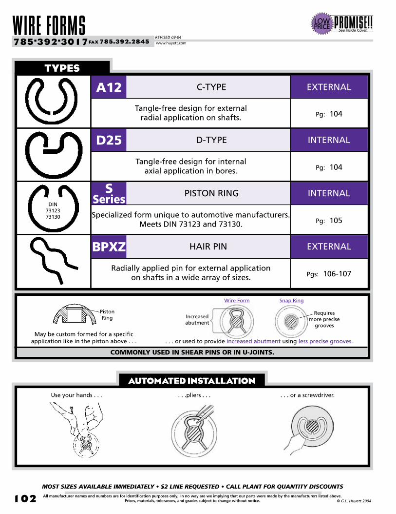
WIRE FORMSREVISED 09-04
MOST SIZES AVAILABLE IMMEDIATELY • $2 LINE REQUESTED • CALL PLANT FOR QUANTITY DISCOUNTS
102
785•392•3017 FAX 785.392.2845
All manufacturer names and numbers are for identification purposes only. In no way are we implying that our parts were made by the manufacturers listed above.Prices, materials, tolerances, and grades subject to change without notice. © G.L. Huyett 2004
www.huyett.com
AUTOMATED INSTALLATION
types
A12 C-TYPE
. . . or used to provide increased abutment using less precise grooves.
Use your hands . . . . . .pliers . . . . . . or a screwdriver.
Pg: 104Tangle-free design for external
radial application on shafts.
D25 D-TYPE
Pg: 104Tangle-free design for internal
axial application in bores.
S Series PISTON RING
Pg: 105Specialized form unique to automotive manufacturers.
Meets DIN 73123 and 73130.
BPXZ HAIR PIN
Pgs: 106-107Radially applied pin for external application
on shafts in a wide array of sizes.
May be custom formed for a specific application like in the piston above . . .
COMMONLY USED IN SHEAR PINS OR IN U-JOINTS.
Wire Form Snap Ring
Increasedabutment
Requires more precise
grooves
PistonRing
EXTERNAL
EXTERNAL
INTERNAL
INTERNALDIN
7312373130

BOX 232 • MINNEAPOLIS, KS • 67467
MOST SIZES AVAILABLE IMMEDIATELY • $2 LINE REQUESTED • CALL PLANT FOR QUANTITY DISCOUNTS
103All manufacturer names and numbers are for identification purposes only. In no way are we implying that our parts were made by the manufacturers listed above.Prices, materials, tolerances, and grades subject to change without notice.© G.L. Huyett 2004
OTHER WIRE FORMSCONTACT OUR PLANT FOR QUOTATIONS ON OTHER TYPES OF WIRE FORMS.
COTTER PINSTEE HEAD
COTTER PINSHAMMER LOCKCOTTER PINS
SELF-LOCKINGCOTTER PINS
BRIDGE PINSSPECIAL
BRIDGE PINS SPECIAL HAIR PINS SAFETY PINS
S-HOOKS D-RINGS RING COTTERS UNIQUE DESIGNS
NOSE RINGSSPECIAL
WIRE FORMS BOW COTTERS EARRINGS
WE DO BODY PIERCING!

WIRE FORMSREVISED 09-04
MOST SIZES AVAILABLE IMMEDIATELY • $2 LINE REQUESTED • CALL PLANT FOR QUANTITY DISCOUNTS
104
785•392•3017 FAX 785.392.2845
All manufacturer names and numbers are for identification purposes only. In no way are we implying that our parts were made by the manufacturers listed above.Prices, materials, tolerances, and grades subject to change without notice. © G.L. Huyett 2004
www.huyett.com
EXTERNAL “C” STYLEMANUFACTURER CROSS-REFERENCE
Free Outside Diameter
(approx.) (Dr)Decimal
(Ds)Thickness
(T)Diameter
(Dg)SpringSteel
.125
.156
.188
.188
.219
.219
.219
.250
.250
.250
.266
.281
.313
.375
.500
.563
.625
.310
.360
.450
.400
.510
.510
.480
.480
.480
.480
.540
.560
.570
.690
.8701.0301.120
.075
.115
.130
.140
.150
.150
.170
.195
.200
.200
.210
.220
.255
.330
.435
.500
.560
A12
Lighter duty radially-installed external (A12) or axially-installed internal (D25) rings that tolerate wide groove tolerances. Easily fitted and removed using a standard hand tool or applicator.
1. Determine wire cross section (round, square, or rectangle).
2. Measure thickness (T).3. Measure the ring diameter (Dr).4. Find the part in the charts above.
WEIRDRADIAL / AXIAL ASSEMBLY
A12-007-011-013-014-015
-015R-017-019-021
-021R-022-023-025-034-043-052
A12-057
Width(W)
+.0
03/-
.000
+.0
05/
-.00
0+
.010
/-.0
05
-40-41-42-43-44-44-45-46-47-47-48-49-50-51-52-53A-54A
AssembledOutside
Dia. (Da)
+/-
.002
SHAFT RING TOOLGROOVE
.032 dia.
.032 sq.
.036 dia.
.032 sq.
.048 sq.
.048 dia.
.032 sq.
.040 sq.
.032 sq.
.032 dia.
.040 sq.
.048 dia.
.040 sq.
.040 sq.
.056 sq.
.064 sq.
.064 sq.
.036
.036
.040
.036
.052
.052
.036
.044
.036
.036
.044
.052
.044
.044
.060
.068
.068
.340
.390
.490
.440
.550
.550
.530
.540
.540
.540
.590
.610
.630
.740
.9401.1001.200 +
.004
/-.
000
+.01
5/
-.010
MATERIAL
A1200Anderton
MM(Db)
Thickness(T)
SpringSteel
242730
26.330.132.7
21.524.427.0
BORE RING
D25D25-024
-027D25-030
Diameter(Dg)
+.0
80/
-.00
0
+.0
00/
-.03
0
+.0
60/
-.10
0
Width(W)
Radial Wall(S)
+.1
40/
-.00
0Height
(approx.)(Hr)
Diameter(approx.)
(Dr)
2.02.42.4
25.228.231.2
GROOVE
INTERNAL “D” STYLEMANUFACTURER CROSS-REFERENCE
MATERIAL
Anderton
Ds Dg
W
T
DaDr
Dr
DbDg
W
T
Hr
S
TANGLE-FREE DESIGN
GENERALLY THESE RINGS
ARE INFERIOR IN PERFORMANCE
TO THEIR STAMPED
COUNTERPARTS (SEE SH ON PAGE
6 AND HO ON PAGE 16).
CO
NTA
CT
PLA
NT
FOR
TO
OL
INFO
RM
ATI
ON
.
WIRE SECTION VARIES BY DIAMETER.
INDEX PAGE 236.
INDEX PAGE 236.
1.61.5
M2500
DESCRIPTION HOW TO IDENTIFY GENERAL USE
A12D25

BOX 232 • MINNEAPOLIS, KS • 67467
MOST SIZES AVAILABLE IMMEDIATELY • $2 LINE REQUESTED • CALL PLANT FOR QUANTITY DISCOUNTS
105All manufacturer names and numbers are for identification purposes only. In no way are we implying that our parts were made by the manufacturers listed above.Prices, materials, tolerances, and grades subject to change without notice.© G.L. Huyett 2004
PISTON RINGSMANUFACTURER CROSS-REFERENCE
MM(Db)
SpringSteel
101214151820222425262830323510121525101214151820222425262830323510121525
11.313.616.017.120.522.724.827.228.229.431.434.036.039.011.813.917.227.811.313.616.017.120.522.724.827.228.229.431.434.036.039.011.813.917.227.8
S
Unique wire-formed rings used in high volume automated assemblies. Generally found in the automotive industry only.
1. Verify form (C or A).2. Determine wire section (S).3. Measure free outside diameter (Dr).4. Find the part in the chart above while paying
particular attention to section (for SK or SR).
WEIRDAXIAL ASSEMBLY
SKA-010-012-014-015-018-020-022-024-025-026-028-030-032
SKA-035SRA-010
-012-015
SRA-025SKC-010
-012-014-015-018-020-022-024-025-026-028-030-032
SKC-035SRC-010
-012-015
SRC-025
Free Outside Dia.
(Dr)
+/-.0
1+/
-.015
+/-
.025
+/-
.015
Radius Max.(R)
Wire Cross-Section
(S)Diameter
(Dg)Lug Length
(L)Width
(W)
BORE RING GROOVE
+.5
/-.0
+1.
0/-.
0
10.812.815.116.119.521.723.725.726.727.729.732.434.437.411.113.216.326.810.812.815.116.119.521.723.725.726.727.729.732.434.437.411.113.216.326.8
+/-.03
+/-
.02
+.0
/-1.
0
+.2
/-.0
+.1
/-.0
MATERIAL
S SERIES
K: Standard
R: Heavy
C: Cut Ends
A: Radiused Ends
FOR
MW
IRE
+.5
/-.0
+1.0/-.0
+.5
/-.0
+1.
0/-.
0+
.5/-
.0
+1.0/-.0
+/-.02
+/-.0
1+/
-.015
+/-.03
+/-
.02
+/-
.025
+/-.02
+/-
.015
.8
1.0
1.3
1.5
2.0
1.0
1.21.6
.8
1.0
1.3
1.5
2.0
1.0
1.21.6
1.2
1.3
1.6
2.1
1.3
1.6
_
3
5
7
8
3
57
_
.9
1.1
1.4
1.6
2.1
1.1
1.31.7
.9
1.1
1.4
1.6
2.1
1.1
1.31.7
SRA, SRCSeeger
73123DIN
INDEX PAGE 236.
SKA, SKC
73130
“S” is for the series; “K” or “R” is the wire size; “C” or “A” shows end configuration; and the number gives you the bore size in mm. Example: SKA-018 is a standard duty wire with radiused ends for an 18mm bore.
DESCRIPTION HOW TO IDENTIFY GENERAL USE
SSERIES
DIN73123
L
Dr
R
W
DbDg
S
Dr
S
C A
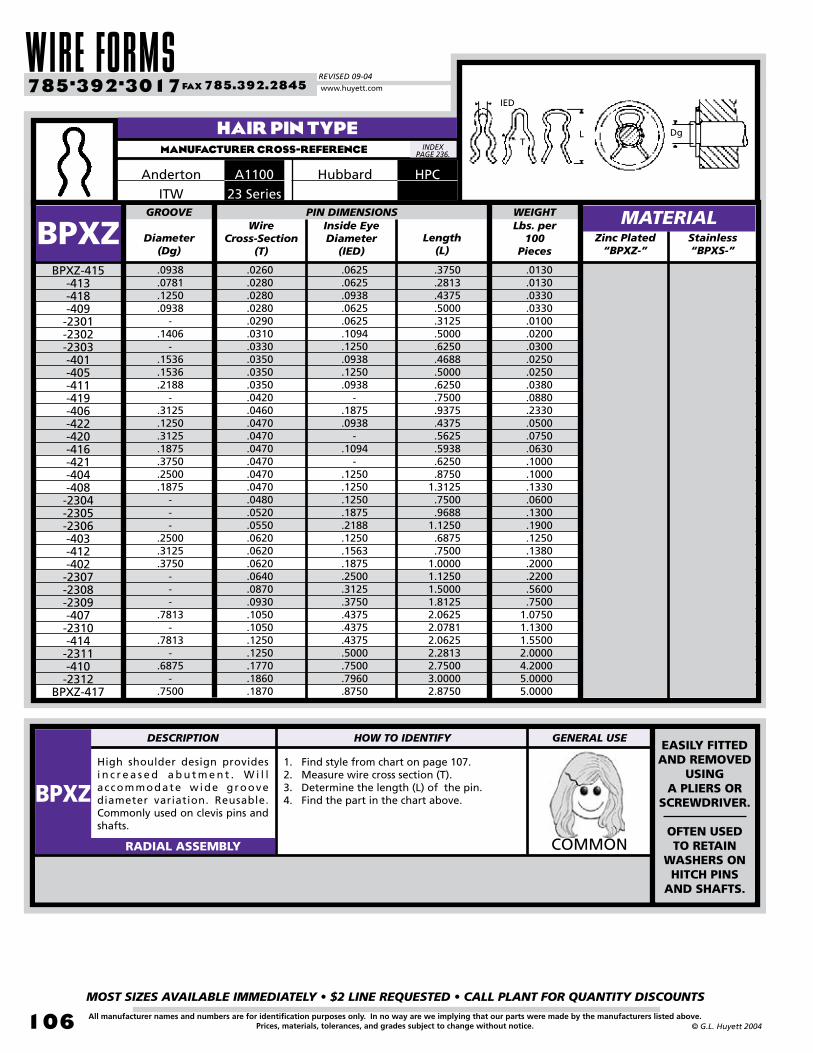
WIRE FORMSREVISED 09-04
MOST SIZES AVAILABLE IMMEDIATELY • $2 LINE REQUESTED • CALL PLANT FOR QUANTITY DISCOUNTS
10�
785•392•3017 FAX 785.392.2845
All manufacturer names and numbers are for identification purposes only. In no way are we implying that our parts were made by the manufacturers listed above.Prices, materials, tolerances, and grades subject to change without notice. © G.L. Huyett 2004
www.huyett.com
Diameter(Dg)
Length(L)
.0130
.0130
.0330
.0330
.0100
.0200
.0300
.0250
.0250
.0380
.0880
.2330
.0500
.0750
.0630
.1000
.1000
.1330
.0600
.1300
.1900
.1250
.1380
.2000
.2200
.5600
.75001.07501.13001.55002.00004.20005.00005.0000
BPXZ
High shoulder design provides i n c r e a s e d a b u t m e n t . W i l l a ccommodate wide groove diameter variation. Reusable. Commonly used on clevis pins and shafts.
1. Find style from chart on page 107.2. Measure wire cross section (T).3. Determine the length (L) of the pin.4. Find the part in the chart above.
COMMONRADIAL ASSEMBLY
BPXZ-415-413-418-409-2301-2302-2303-401-405-411-419-406-422-420-416-421-404-408-2304-2305-2306-403-412-402-2307-2308-2309-407-2310-414-2311-410-2312
BPXZ-417
Wire Cross-Section
(T)
Inside Eye Diameter
(IED)
.0260
.0280
.0280
.0280
.0290
.0310
.0330
.0350
.0350
.0350
.0420
.0460
.0470
.0470
.0470
.0470
.0470
.0470
.0480
.0520
.0550
.0620
.0620
.0620
.0640
.0870
.0930
.1050
.1050
.1250
.1250
.1770
.1860
.1870
.0625
.0625
.0938
.0625
.0625
.1094
.1250
.0938
.1250
.0938-
.1875
.0938-
.1094-
.1250
.1250
.1250
.1875
.2188
.1250
.1563
.1875
.2500
.3125
.3750
.4375
.4375
.4375
.5000
.7500
.7960
.8750
.3750
.2813
.4375
.5000
.3125
.5000
.6250
.4688
.5000
.6250
.7500
.9375
.4375
.5625
.5938
.6250
.87501.3125.7500.9688
1.1250.6875.7500
1.00001.12501.50001.81252.06252.07812.06252.28132.75003.00002.8750
HAIR PIN TYPEMANUFACTURER CROSS-REFERENCE
MATERIAL
A1100Anderton23 SeriesITW
HPCHubbard
GROOVE PIN DIMENSIONS WEIGHTLbs. per
100Pieces
.0938
.0781
.1250
.0938-
.1406-
.1536
.1536
.2188-
.3125
.1250
.3125
.1875
.3750
.2500
.1875---
.2500
.3125
.3750---
.7813-
.7813-
.6875-
.7500
Zinc Plated“BPXZ-”
L DgT
IED
EASILY FITTED AND REMOVED
USING A PLIERS OR
SCREWDRIVER.
OFTEN USED TO RETAIN
WASHERS ON HITCH PINS
AND SHAFTS.
INDEX PAGE 236.
Stainless“BPXS-”
DESCRIPTION HOW TO IDENTIFY GENERAL USE
BPXZ

BOX 232 • MINNEAPOLIS, KS • 67467
MOST SIZES AVAILABLE IMMEDIATELY • $2 LINE REQUESTED • CALL PLANT FOR QUANTITY DISCOUNTS
107All manufacturer names and numbers are for identification purposes only. In no way are we implying that our parts were made by the manufacturers listed above.Prices, materials, tolerances, and grades subject to change without notice.© G.L. Huyett 2004
BPXZ-422 BPXZ-420 BPXZ-416 BPXZ-421 BPXZ-404 BPXZ-408 BPXZ-403 BPXZ-412 BPXZ-402
BPXZ-415 BPXZ-413 BPXZ-418 BPXZ-409 BPXZ-401 BPXZ-405 BPXZ-411 BPXZ-419 BPXZ-406
BPXZ-410 BPXZ-417
HAIR PIN DESIGNS
Shaft Size
.352
.491
.600
.838
.9581.1401.2641.5251.8082.0062.2433.000
BPXZ-2301-2302-2303-2304-2305-2306-2307-2308-2309-2310-2311
BPXZ-2312
.029
.031
.033
.048
.052
.055
.064
.087
.093
.105
.125
.186
1/87/321/45/163/81/29/165/83/47/87/8-
1/321/161/85/325/323/163/169/325/1613/321/2-
1/83/161/45/163/87/161/25/83/47/811
WireDiameter A B C D E FPart #
BPXZ-407 BPXZ-414
1/167/641/81/83/167/321/45/163/87/161/25/64
5/649/647/321/45/163/87/1617/3221/3225/327/8
51/64
1/87/321/45/163/87/161/25/83/47/81-
APP
RO
XIM
ATE
AC
TUA
L SI
ZE.
APP
RO
XIM
ATE
AC
TUA
L SI
ZE.
APP
RO
XIM
ATE
AC
TUA
L SI
ZE.
Overall LengthEye Diameter
DIAGRAMS AREAPPROXIMATEACTUAL SIZE.A B E
FD
C

SPRINGSREVISED 09-04
MOST SIZES AVAILABLE IMMEDIATELY • $2 LINE REQUESTED • CALL PLANT FOR QUANTITY DISCOUNTS
108
785•392•3017 FAX 785.392.2845
All manufacturer names and numbers are for identification purposes only. In no way are we implying that our parts were made by the manufacturers listed above.Prices, materials, tolerances, and grades subject to change without notice. © G.L. Huyett 2004
www.huyett.com
TYPES
US
IMPERIALPgs: 110-111
IMPERIALPg: 112
IMPERIALPg: 112
IMPERIALN/A
IMPERIALPg: 114
IMPERIALPg: 115
METRICPgs: 214-215
METRICN/A
METRICN/A
METRICPgs: 216-217
METRICN/A
METRICN/A
IMPERIALPgs: 116-117
IMPERIALPg: 118
IMPERIALPgs: 120-121
IMPERIALPgs: 122-123
IMPERIALPgs: 124-125
METRICN/A
METRICN/A
METRICN/A
METRICN/A
METRICN/A
When selecting a spring, there are several design issues to consider:
BW BELLEVILLE DISC SPRING
PSW SHOULDER WASHER
FS FINGER WASHER
WSE
WSI
WSG
WSN
CML
CMM
CMH
DWS STANDARD METRICWAVE SPRING
WAVE SPRING EXTERNAL
WAVE SPRING INTERNAL
STANDARD GAP WAVE SPRING
NARROW SECTIONWAVE SPRING
COMPRESSION SPRINGLIGHT DUTY
COMPRESSION SPRINGMEDIUM DUTY
COMPRESSION SPRINGHEAVY DUTY
ENVELOPEThis is the “cylinder” of space within which the spring operates. Springs will tend to expand slightly as they compress.
LOAD AND DEFLECTIONLoad is the measurement of a spring when flattened, while deflection is the distance the spring compresses.
WORKING DEFLECTIONAfter initial set, a spring develops working deflection as it expends stored energy from heat and friction.
PERFORMANCEDifferent styles of springs will yield different results over time.
LOA
D
INITIAL LOAD
UNLOAD
WORKINGDEFLECTION
INITIALSET
DEFLECTION
FLA
T
LOAD
DEF
LEC
TIO
N
BELLEVILLE-CONICAL
LOA
D
DEFLECTION
MULTI-WAVE
SINGLE WAVE
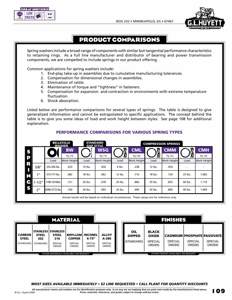
BOX 232 • MINNEAPOLIS, KS • 67467
MOST SIZES AVAILABLE IMMEDIATELY • $2 LINE REQUESTED • CALL PLANT FOR QUANTITY DISCOUNTS
109All manufacturer names and numbers are for identification purposes only. In no way are we implying that our parts were made by the manufacturers listed above.Prices, materials, tolerances, and grades subject to change without notice.© G.L. Huyett 2004
Spring washers include a broad range of components with similar but tangential performance characteristics to retaining rings. As a full line manufacturer and distributor of bearing and power transmission components, we are compelled to include springs in our product offering.
Common applications for spring washers include: 1. End-play take-up in assemblies due to cumulative manufacturing tolerances. 2. Compensation for dimensional changes in assemblies. 3. Elimination of rattle. 4. Maintenance of torque and “tightness” in fasteners. 5. Compensation for expansion and contraction in environments with extreme temperature fluctuation. 6. Shock absorption.
Listed below are performance comparisons for several types of springs. The table is designed to give generalized information and cannot be extrapolated to specific applications. The concept behind the table is to give you some ideas of load and work height between styles. See page 108 for additional explanation.
PRODUCT COMPARISONS
Actual results will be based on individual circumstances. These values are for reference only.
PERFORMANCE COMPARISONS FOR VARIOUS SPRING TYPES
SPRI
NGS
5/8”
1”
1-1/2”
2”
LoadLoadLoad Load Load
Pg 110 Pg 116 Pg 120 Pg 122 Pg 124
255-345 lbs.
573-777 lbs.
1190-1610lbs.
2048-2772 lbs.
.053
.082
.121
.160
10 lbs.
18 lbs.
26 lbs.
34 lbs.
.050
.062
.078
.093
6 lbs.
12 lbs.
20 lbs.
25 lbs.
.238
.710
.866
.490
12 lbs.
18 lbs.
35 lbs.
50 lbs.
.454
.720
.835
.800
-
25 lbs.
60 lbs.
90 lbs.
-
1.083
1.119
1.069
Work Height Work Height Work Height Work Height Work Height
COMPRESSION SPRINGS
CMHCMMCML
STANDARDGAP STYLE
WSGBW
BELLEVILLE WASHER
MATERIAL
OTHER MATERIALS AVAILABLE ON REQUEST.
STAINLESS STEEL 316
(SPECIAL ORDER)
CARBON STEEL
(STANDARD)
BERYLLIUM COPPER
(SPECIAL ORDER)
INCONEL X-75®
(SPECIAL ORDER)
ALLOY A-286(SPECIAL ORDER)
STAINLESS STEEL 302
(STANDARD)
FINISHES
OTHER FINISHES AVAILABLE ON REQUEST.
BLACK OXIDE
(SPECIAL ORDER)
CADMIUM
(SPECIAL ORDER)
PHOSPHATE
(SPECIAL ORDER)
PASSIVATE
(SPECIAL ORDER)
OILDIPPED
(STANDARD)
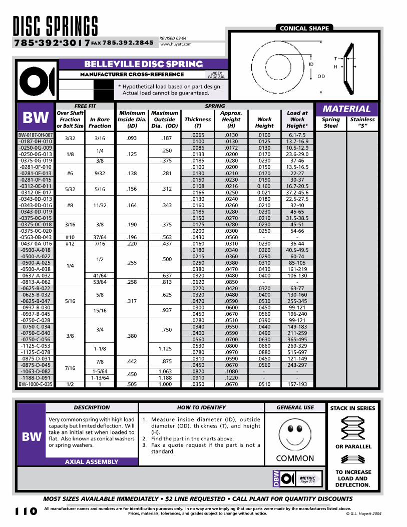
DISC SPRINGSREVISED 09-04
MOST SIZES AVAILABLE IMMEDIATELY • $2 LINE REQUESTED • CALL PLANT FOR QUANTITY DISCOUNTS
110
785•392•3017 FAX 785.392.2845
All manufacturer names and numbers are for identification purposes only. In no way are we implying that our parts were made by the manufacturers listed above.Prices, materials, tolerances, and grades subject to change without notice. © G.L. Huyett 2004
www.huyett.com
BELLEVILLE DISC SPRINGMANUFACTURER CROSS-REFERENCE
Very common spring with high load capacity but limited deflection. Will take an initial set when loaded to flat. Also known as conical washers or spring washers.
1. Measure inside diameter (ID), outside diameter (OD), thickness (T), and height (H).
2. Find the part in the charts above.3. Fax a quote request if the part is not a
standard.COMMONAXIAL ASSEMBLY
MinimumInside Dia.
(ID)Thickness
(T)Work
HeightSpringSteel
.0065
.0100
.0086
.0133
.0185
.0100
.0130
.0150
.0108
.0166
.0130
.0160
.0185
.0150
.0175
.0200
.0430
.0160
.0180
.0215
.0250
.0380
.0320
.0620
.0220
.0320
.0470
.0300
.0450
.0280
.0340
.0400
.0560
.0530
.0780
.0310
.0450
.0820
.0910
.0350
BWBW-0187-0H-007-0187-0H-010-0250-0G-009-0250-0G-013-0375-0G-019-0281-0F-010-0281-0F-013-0281-0F-015-0312-0E-011-0312-0E-017-0343-0D-013-0343-0D-016-0343-0D-019-0375-0C-015-0375-0C-018-0375-0C-020-0563-0B-043-0437-0A-016-0500-A-018-0500-A-022-0500-A-025-0500-A-038-0637-A-032-0813-A-062-0625-B-022-0625-B-032-0625-B-047-0937-B-030-0937-B-045-0750-C-028-0750-C-034-0750-C-040-0750-C-056-1125-C-053-1125-C-078-0875-D-031-0875-D-045-1063-D-082-1188-D-091
BW-1000-E-035
In BoreFraction
MaximumOutside
Dia. (OD)
Approx.Height
(H)
FREE FIT SPRING
.0130
.0130
.0172
.0200
.0280
.0200
.0210
.0230
.0216
.0250
.0240
.0260
.0280
.0270
.0280
.0300
.0560
.0310
.0340
.0360
.0380
.0470
.0480
.0850
.0420
.0480
.0590
.0600
.0670
.0510
.0550
.0590
.0700
.0800
.0970
.0590
.0670
.1080
.1220
.0670
6.1-7.513.7-16.910.5-12.923.6-29.0
37-4613.5-16.5
22-2730-37
16.7-20.537.2-45.622.5-27.5
32-4045-65
31.5-38.545-5154-66
-36-44
40.5-49.560-7485-105161-219106-130
-63-77
130-160255-34599-121196-24099-121149-183211-259365-495269-329515-697121-149243-297
--
157-193
.0100
.0125
.0130
.0170
.0230
.0150
.0170
.01900.1600.021.0180.0210.0230.0210.0230.0250
-.0230.0260.0290.0310.0430.0400
-.0320.0400.0530.0450.0560.0390.0440.0490.0630.0660.0880.0450.0560
--
.0510
.450
.196
.220
.255
.258
.317
.380
.442
.505
.190
.156
.138
.093
.125
.164
.875
.750
.937
.625
.500
.312
.281
.375
.250
.187
1.0631.1881.000
.343
.563
.437
.375
1.125
.637
.813
MATERIALStainless
“S”
CONICAL SHAPE
STACK IN SERIES
OR PARALLEL
TO INCREASE LOAD AND
DEFLECTION.
H
T
OD
ID
Over Shaft Fraction
or Bolt Size
3/32 3/16
1/81/4
3/8
#6 9/32
5/32 5/16
#8 11/32
3/16 3/8
#10#12
37/647/16
1/41/2
5/165/8
41/6453/64
15/16
3/83/4
1-1/8
7/167/8
1-5/641-13/64
11/2
INDEX PAGE 236.
DB
W
METRICPage 214
DESCRIPTION HOW TO IDENTIFY GENERAL USE
BW
* Hypothetical load based on part design. Actual load cannot be guaranteed.
Load at Work
Height*
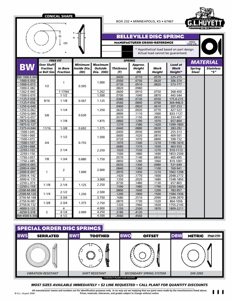
BOX 232 • MINNEAPOLIS, KS • 67467
MOST SIZES AVAILABLE IMMEDIATELY • $2 LINE REQUESTED • CALL PLANT FOR QUANTITY DISCOUNTS
111All manufacturer names and numbers are for identification purposes only. In no way are we implying that our parts were made by the manufacturers listed above.Prices, materials, tolerances, and grades subject to change without notice.© G.L. Huyett 2004
SPECIAL ORDER DISC SPRINGS
MinimumInside Dia.
(ID)Thickness
(T)Work
HeightSpringSteel
.0430
.0500
.0730
.0820
.0600
.0700
.0380
.0560
.0400
.0620
.0890
.0570
.0860
.1270
.0440
.0450
.0600
.0720
.1070
.0680
.1020
.1500
.0570
.0850
.0650
.0840
.0970
.1420
.1350
.0730
.1590
.0800
.1200
.1680
.0870
.1320
.1250
.3180
.3560
BWBW-1000-E-043
-1000-E-050-1000-E-073-1000-E-082-1262-E-060-1500-E-070-1125-F-038-1125-F-056-1250-G-040-1250-G-062-1250-G-089-1875-G-057-1875-G-086-1875-G-127-1375-H-044-1500-I-045-1500-I-060-1500-I-072-1500-I-107-2250-I-068-2250-I-102-2250-I-150-1750-J-057-1750-J-085-2000-K-065-2000-K-084-2000-K-097-2000-K-142-3000-K-135-2250-L-073-2250-L-159-2500-M-080-2500-M-120-3750-M-168-2750-N-087-2750-N-132-4000-S-125-4250-S-318
BW-4500-S-356
In BoreFraction
MaximumOutside
Dia. (OD)
Approx.Height
(H)
FREE FIT
.0710
.0750
.0910
.0980
.0910
.1040
.0730
.0840
.0820
.0920
.1110
.1150
.1290
.1580
.0880
.0930
.1020
.1070
.1340
.1370
.1530
.1880
.1140
.1280
.1300
.1360
.1450
.1770
.2020
.1480
.1980
.1600
.1800
.2510
.1730
.1960
.2500
.4120
.4560
225-275306-374573-777
-368-450445-544
175.0-215364-446.0207-253427-523833-1127333-407657-804
1399-1893283-292255-313409-501598-732
1190-1610463-553910-11131853-2509405-495819-1001531-649769-941
1062-12982048-27721548-1893657-803
2250-3460783-957
1584-19362348-2870864-10561755-21451809-2211
--
.0570
.0620
.0820-
.0750
.0870
.0550
.0700
.0610
.0770
.1000
.0850
.1070
.1420
.0650
.0690
.0810
.0890
.1210
.1030
.1270
.1690
.0850
.1060
.0980
.1100
.1210
.1600
.1680
.1130
.1790
.1200
.1500
.2090
.1320
.1650
.1870--
0.505
0.567
0.630
0.692
0.755
0.880
1.000
1.125
1.250
1.375
2.000
1.000
1.2621.500
1.125
1.250
1.875
1.375
1.500
2.250
1.750
2.000
SPRING
3.000
2.250
2.500
3.750
2.750
4.0004.2504.500
BELLEVILLE DISC SPRINGMANUFACTURER CROSS-REFERENCE
MATERIALStainless
“S”
CONICAL SHAPE
TOOTHED OFFSET METRICSERRATED
H
T
OD
ID
BWS BWT BWO DBW
VIBRATION RESISTANT SHIFT RESISTANT SECONDARY SPRING SYSTEM DIN 2093CONTACT PLANT FOR QUOTE.
Over Shaft Fraction
or Bolt Size
1/21
1-17/641-1/2
9/16 1-1/8
5/8
1-1/4
11/16 1-3/8
1-7/8
3/4
1-1/2
2-1/4
7/8 1-3/4
12
3
1-1/8 2-1/4
1-1/4 2-1/2
3-3/4
1-3/8 2-3/4
44-1/44-1/2
2
(Page 214)
INDEX PAGE 236.
* Hypothetical load based on part design. Actual load cannot be guaranteed.
Load at Work
Height*

SPRING WASHERSREVISED 09-04
MOST SIZES AVAILABLE IMMEDIATELY • $2 LINE REQUESTED • CALL PLANT FOR QUANTITY DISCOUNTS
112
785•392•3017 FAX 785.392.2845
All manufacturer names and numbers are for identification purposes only. In no way are we implying that our parts were made by the manufacturers listed above.Prices, materials, tolerances, and grades subject to change without notice. © G.L. Huyett 2004
www.huyett.com
SHOULDER WASHERMANUFACTURER CROSS-REFERENCE
Decimal(Ds)
Thickness(T)
SpringSteel
.250
.375
.500
.625
.053
.053
.065
.065
PSWPSW-025
-037-050
PSW-062
+/-
.003
Free Inside Dia.
(Df)
+/-
.002
Fraction(Ds)
Width at Top
(W)
SHAFT RING TOOLGROOVE
Diameter(Dg)
Depth(d)
+/-
.003
+/-
.002
1/43/81/25/8
.254
.380
.505
.630
.050
.050
.062
.062
.204
.321
.434
.547
.023
.027
.033
.039+/-
.003
5590Waldes
MATERIAL
The PSW serves as a shoulder on small shafts. Please don’t buy it. The FS is more popular. The external fingers balance pressure evenly for use as a ball bearing retainer.
1. Confirm general format.2. Determine shaft size.3. Find the part in the charts above based on
material thickness (T).
UNCOMMONAXIAL ASSEMBLY
FINGER WASHERMANUFACTURER CROSS-REFERENCE
Decimal(OD) Decimal
SpringSteel
.595
.728
.846
.846
.926
.9261.0041.0041.1641.1641.1641.2401.2401.2401.3601.3601.5551.5551.8302.022
15.1118.4921.4921.4923.5223.5225.5025.5029.5729.5729.5731.5031.5031.5034.5434.5439.5039.5046.4851.36
.6299
.7480
.8661
.8661
.9449
.94491.02361.02361.18111.18111.18111.25981.25981.25981.37801.37801.57481.57481.85042.0472
OUTSIDE DIAMETER
FSFS-0595-010-0728-006-0846-006-0846-008-0926-007-0926-010-1004-006-1004-007-1164-009-1164-010-1164-018-1240-008-1240-009-1240-010-1360-011-1360-014-1555-014-1555-018-1830-016
FS-2022-019
For use withBearing OD
MMMM(OD)
Material Thickness
(T)
.312
.344
.453
.453
.453
.344
.516
.516
.688
.406
.688
.688
.563
.688
.814
.814
.9711.0001.1891.359
7.927.74
11.5111.5111.518.74
13.1113.1117.4810.3117.4817.4814.3017.4820.6820.6824.6625.4030.2034.52
0.3 to 1.0 4 to 83 to 79 to 136 to 1022 to 285 to 98 to 129 to 1315 to 2160 to 7510 to 1415 to 2115 to 2111 to 1517 to 2515 to 2131 to 3917 to 2317 to 23
1.33-4.4517.79-35.613.34-31.140.0-57.826.7-44.597.9-124.622.2-40.035.6-53.440.0-57.866.7-93.4267-33444.5-62.366.7-93.466.7-93.4
48.93-66.7275.6-111.266.7-93.4138-17475.6-10275.6-102
.010
.006
.006
.008
.007
.010
.006
.007
.009
.010
.018
.008
.009
.010
.011
.014
.014
.018
.016
.019
16.019.022.022.024.024.026.026.030.030.030.032.032.032.035.035.040.040.047.052.0
INSIDE DIAMETER LOAD
Decimal(ID)
MM(ID)
Load at Height of
.062”
Load at Height of 1.57mm
MATERIAL
ID OD
T
CONTACTPLANT
MINIMUM PRODUCTION RUNS MAY BE
REQUIRED.
INDEX PAGE 236.
INDEX PAGE 236.
Df
T
W
d
Dg
Ds
DESCRIPTION HOW TO IDENTIFY GENERAL USE
PSWFS
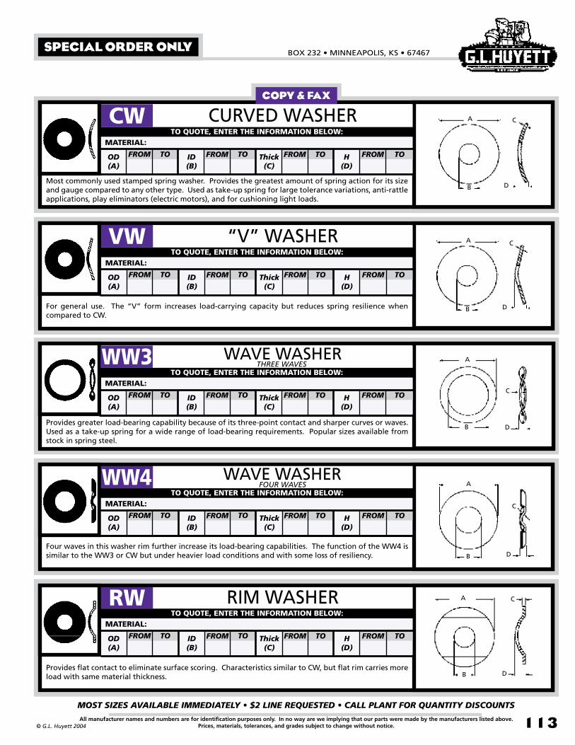
BOX 232 • MINNEAPOLIS, KS • 67467
MOST SIZES AVAILABLE IMMEDIATELY • $2 LINE REQUESTED • CALL PLANT FOR QUANTITY DISCOUNTS
113All manufacturer names and numbers are for identification purposes only. In no way are we implying that our parts were made by the manufacturers listed above.Prices, materials, tolerances, and grades subject to change without notice.© G.L. Huyett 2004
COPY & FAX
B
A
D
C
B
A
D
C
B
A
D
C
B
A
D
C
B
A
D
C
B
A
D
C
B
A
D
C
B
A
D
C
B
A
D
C
SPECIAL ORDER ONLY
CW CURVED WASHER
Most commonly used stamped spring washer. Provides the greatest amount of spring action for its size and gauge compared to any other type. Used as take-up spring for large tolerance variations, anti-rattle applications, play eliminators (electric motors), and for cushioning light loads.
TO QUOTE, ENTER THE INFORMATION BELOW:
FROM TOOD(A)
FROM TOID(B)
FROM TOThick(C)
FROM TOH(D)
MATERIAL:
“V” WASHER
For general use. The “V” form increases load-carrying capacity but reduces spring resilience when compared to CW.
VWTO QUOTE, ENTER THE INFORMATION BELOW:
FROM TOOD(A)
FROM TOID(B)
FROM TOThick(C)
FROM TOH(D)
MATERIAL:
WAVE WASHER
Provides greater load-bearing capability because of its three-point contact and sharper curves or waves. Used as a take-up spring for a wide range of load-bearing requirements. Popular sizes available from stock in spring steel.
WW3 THREE WAVESTO QUOTE, ENTER THE INFORMATION BELOW:
FROM TOOD(A)
FROM TOID(B)
FROM TOThick(C)
FROM TOH(D)
MATERIAL:
WAVE WASHER
Four waves in this washer rim further increase its load-bearing capabilities. The function of the WW4 is similar to the WW3 or CW but under heavier load conditions and with some loss of resiliency.
FOUR WAVESTO QUOTE, ENTER THE INFORMATION BELOW:
FROM TOOD(A)
FROM TOID(B)
FROM TOThick(C)
FROM TOH(D)
MATERIAL:
WW4
RIM WASHER
Provides flat contact to eliminate surface scoring. Characteristics similar to CW, but flat rim carries more load with same material thickness.
RWTO QUOTE, ENTER THE INFORMATION BELOW:
FROM TOOD(A)
FROM TOID(B)
FROM TOThick(C)
FROM TOH(D)
MATERIAL:

WAVE SPRINGSREVISED 09-04
MOST SIZES AVAILABLE IMMEDIATELY • $2 LINE REQUESTED • CALL PLANT FOR QUANTITY DISCOUNTS
114
785•392•3017 FAX 785.392.2845
All manufacturer names and numbers are for identification purposes only. In no way are we implying that our parts were made by the manufacturers listed above.Prices, materials, tolerances, and grades subject to change without notice. © G.L. Huyett 2004
www.huyett.com
WAVE SPRING - EXTERNALMANUFACTURER CROSS-REFERENCE
Similar to a standard retaining ring, except the axial wave form yields to compressibility. Pressure is applied in two directions to eliminate “play.” If the part is stamped, see page 113.
1. Verify that the part is for an external application by checking the end per the drawing above.
2. Count the waves “peak to peak.”3. Determine thickness (T).4. Verify free height (H).5. Find the part in the chart above. UNCOMMONAXIAL ASSEMBLY
WSWSmalley
Theoretical Spring Rate
Decimal(Ds)
Thickness(T)
Diameter(Dg)
SpringSteel
.750
.8751.0001.1251.2501.3751.5001.6251.7501.8752.0002.1252.2502.3752.5002.6252.7502.8753.0003.1253.2503.5003.6253.7503.8754.0004.1254.2504.5004.7505.000
.115
.131
.129
.137
.145
.130
.126
.138
.137
.140
.145
.170
.175
.175
.171
.181
.217
.217
.225
.230
.225
.245
.250
.258
.255
.268
.263
.248
.256
.253
.259
WSEWSE-075
-087-100-112-125-137-150-162-175-187-200-212-225-237-250-262-275-287-300-312-325-350-362-375-387-400-412-425-450-475
WSE-500
WidthMin.(W)
Max. Free Height
(H)
25 30 34 3840455055606365707580848894 97
100103106115117121126130134140150160170
Number of Waves
SHAFTRadial Wall(S)
Load at Work
Height (Hw)
GROOVE
1250130411721727400030003333423135292864250046673947333329712514427337313333294326784423403436673073302327358235681857145000
.704
.821
.9401.0591.1761.2911.4061.5291.6501.7691.8862.0032.1202.2392.3602.4812.6022.7212.8382.9573.0763.3163.4353.5523.6733.7923.9194.0654.3104.5504.790
.120
.136
.134
.142
.150
.135
.131
.143
.142
.145
.150
.175
.180
.180
.176
.190
.222
.222
.230
.235
.230
.250
.255
.263
.260
.273
.268
.253
.261
.258
.264
.065
.075
.085
.128
.158
.188
.225
.281
.042
.062
.093
.111
.050
.078
3
4
5
SPRING MATERIAL
@ .085
@ .110
@ .130
@ .170
@ .185
@ .100
S
Ds Dg
WHw
H
T
Stainless “-SS”
TECHNICAL BENEFITS
ARE MAKING THIS SPRING
MORE POPULAR ALL THE TIME!
INDEX PAGE 236.
DESCRIPTION HOW TO IDENTIFY GENERAL USE
WSE

BOX 232 • MINNEAPOLIS, KS • 67467
MOST SIZES AVAILABLE IMMEDIATELY • $2 LINE REQUESTED • CALL PLANT FOR QUANTITY DISCOUNTS
115All manufacturer names and numbers are for identification purposes only. In no way are we implying that our parts were made by the manufacturers listed above.Prices, materials, tolerances, and grades subject to change without notice.© G.L. Huyett 2004
UNCOMMONAXIAL ASSEMBLY
WAVE SPRING - INTERNALMANUFACTURER CROSS-REFERENCE
WHWSmalley
Similar to a standard retaining ring, except the axial wave form yields to compressibility. Pressure is applied in two directions to eliminate “play.” If the part is stamped, see page 113.
1. Verify that the part is for an internal application by checking the end per the drawing above.
2. Count the waves “peak to peak.”3. Determine thickness (T).4. Verify free height (H).5. Find the part in the chart above.
Theoretical Spring Rate
Decimal(Db)
Thickness(T)
Diameter(Dg)
SpringSteel
.750
.8751.0001.1251.2501.3751.5001.6251.7501.8752.0002.1252.2502.3752.5002.6252.7502.8753.0003.1253.2503.5003.6253.7503.8754.0004.1254.2504.5004.7505.000
.114
.110
.120
.125
.135
.125
.135
.135
.140
.141
.150
.170
.175
.180
.183
.220
.229
.225
.230
.250
.250
.245
.250
.255
.260
.255
.258
.264
.250
.252
.247
WSIWSI-075
-087-100-112-125-137-150-162-175-187-200-212-225-237-250-262-275-287-300-312-325-350-362-375-387-400-412-425-450-475
WSI-500
WidthMin.(W)
Max. Free Height
(H)
25 3034384045505560636570758084889497
100103106115117121
126130
Number of Waves
BORERadial Wall(S)
Load at Work
Height (Hw)
GROOVE
1042200013602533200037503333550042863316270853854688381032315867494742173704735766255000450048404200371435263182833369566017
.796
.9311.0661.1971.3301.4611.5941.7251.8581.9892.1222.2512.3822.5172.6482.7812.9143.0513.1823.3153.4463.7103.8413.9744.1074.2404.3654.4904.7404.9955.260
.119
.115
.125
.130
.140
.130
.140
.140
.145
.146
.155
.175
.180
.185
.188
.225
.234
.230
.235
.255
.255
.250
.250
.260
.265
.260
.263
.269
.255
.257
.252
.312
.281
.085
.188
.065
.158
.128
.225
.111
.093
.078
.062
.042
.050
.035
5
3
4
SPRING MATERIAL
@ .080
@ .085
@ .100
@ .110
@ .130
@ .170
@ .185
S
Db Dg
WHw
H
T
Stainless “-SS”
CIRCUMFERENTIAL MOVEMENT
OF ENDS DURING
COMPRESSION YIELDS PRECISE
ENVELOPE OF MOTION.
INDEX PAGE 236.
DESCRIPTION HOW TO IDENTIFY GENERAL USE
WSI

WAVE SPRINGSREVISED 09-04
MOST SIZES AVAILABLE IMMEDIATELY • $2 LINE REQUESTED • CALL PLANT FOR QUANTITY DISCOUNTS
11�
785•392•3017 FAX 785.392.2845
All manufacturer names and numbers are for identification purposes only. In no way are we implying that our parts were made by the manufacturers listed above.Prices, materials, tolerances, and grades subject to change without notice. © G.L. Huyett 2004
www.huyett.com
STANDARD GAP WAVE SPRINGMANUFACTURER CROSS-REFERENCE
Flat wire design yields many benefits vs. compression springs: reduced operating height, precise load deflections, and lower cost. Precise envelope of motion.
1. Count the waves “peak to peak.”2. Measure the thickness (T) and radial wall
(S).3. Determine free height (H).4. Find the part in the chart above.
COMMONAXIAL ASSEMBLY
Thickness(T)
Spring Steel
.50
.62
.75
.871.001.121.251.371.501.621.751.872.002.122.252.372.502.622.752.873.003.123.253.373.503.623.753.874.004.124.254.374.504.624.754.875.00
.40
.48
.50
.62
.78
.84
.961.091.171.311.441.561.681.801.931.992.122.242.342.472.592.712.752.843.003.123.253.373.503.623.743.863.994.114.244.374.49
7101416182022242628303234363840424446485052545658606264666769707273757678
.085
.095
.160
.130
.160
.130
.150
.190
.170
.200
.140
.150
.140
.150
.170
.160
.170
.190
.170
.180
.190
.210
.200
.220
.230
.240
.260
.300
.190
.200
.210
.210
.230
.270
.310
.290
.310
WSGWSG-050*
-062* -075* -087* -100* -112* -125* -137* -150* -162*
-175-187-200-212-225-237-250-262-275-287-300-312-325-337-350-362-375-387-400-412-425-437-450-462-475-487
WSG-500
RadialWall(S)
Load(Lbs.)
Work Height(Hw)
FreeHeight
(H)Numberof Waves
SIZE
.050
.093
.109
.125
.062
.078
3
4
5
WAVE SPRING MATERIAL
SSRSmalley
TRSpirolox
WSG CONTINUED NEXT PAGE.
.008
.010
.012
.016
.018
.040
.058
.078
.094
.133
.143
.024
.150
.178
.030
.188
.233
Bore ØMin.(OD)
Stainless “-SS”
NICE COMPACT DESIGN!
ID
OD HwH
ST
* WSG-050 through WSG-162 overlap slightly at the ends rather than having a gap.
Shaft ØMax.(ID)
INDEX PAGE 236.
DESCRIPTION HOW TO IDENTIFY GENERAL USE
WSG

BOX 232 • MINNEAPOLIS, KS • 67467
MOST SIZES AVAILABLE IMMEDIATELY • $2 LINE REQUESTED • CALL PLANT FOR QUANTITY DISCOUNTS
117All manufacturer names and numbers are for identification purposes only. In no way are we implying that our parts were made by the manufacturers listed above.Prices, materials, tolerances, and grades subject to change without notice.© G.L. Huyett 2004
Flat wire design yields many benefits vs. compression springs: reduced operating height, precise load deflections, and lower cost. Precise envelope of motion.
1. Count the waves “peak to peak.”2. Measure the thickness (T) and radial wall
(S).3. Determine free height (H).
COMMONAXIAL ASSEMBLY
Thickness(T)
Spring Steel
5.125.255.375.505.625.755.876.006.126.256.376.506.757.007.257.507.758.008.258.508.759.009.50
10.0010.5011.0011.5012.0012.5013.0013.5014.0014.5015.0015.5016.00
4.614.744.864.995.115.245.365.495.615.735.865.986.236.166.446.696.947.197.447.687.938.188.689.179.67
10.1710.6611.1611.6612.1612.6513.1513.6514.1314.6415.14
80828486889092949698100102104106108110114118122126130134142150158166174182190198206214221230239248
WSGWSG-512
-525-537-550-562-575-587-600-612-625-637-650-675-700-725-750-775-800-825-850-875-900-950
-1000 -1050 -1100 -1150 -1200 -1250 -1300 -1350 -1400 -1450 -1500 -1550
WSG-1600
RadialWall(S)
Load(Lbs.)
Work Height(Hw)
FreeHeight
(H)Numberof Waves
SIZE
.340
.370
.380
.250
.270
.280
.300
.300
.310
.340
.350
.390
.420
.320
.350
.360
.380
.390
.430
.340
.340
.290
.240
.290
.310
.350
.360
.440
.350
.410
.430
.300
.320
.350
.310
.340
7
6
10
9
8
WAVE SPRING
STANDARD GAP WAVE SPRINGMANUFACTURER CROSS-REFERENCE
MATERIAL
SSRSmalley
TRSpirolox
.125
13
12
5
NARROWSECTION
NEXT PAGE.
.030 .233
.032 .375
Bore ØMin.(OD)
Shaft ØMax.(ID)
Stainless “-SS”
PRECISE LOAD DEFLECTION
CHARACTERISTICS!
ID
OD HwH
ST
INDEX PAGE 236.
DESCRIPTION HOW TO IDENTIFY GENERAL USE
WSG

WAVE SPRINGSREVISED 09-04
MOST SIZES AVAILABLE IMMEDIATELY • $2 LINE REQUESTED • CALL PLANT FOR QUANTITY DISCOUNTS
118
785•392•3017 FAX 785.392.2845
All manufacturer names and numbers are for identification purposes only. In no way are we implying that our parts were made by the manufacturers listed above.Prices, materials, tolerances, and grades subject to change without notice. © G.L. Huyett 2004
www.huyett.com
NARROW SECTION - SPLITMANUFACTURER CROSS-REFERENCE
Precision narrow wire section (S) with gap to eliminate binding and minimize radial expansion. Compact working envelope.
1. Count the waves “peak to peak.”2. Measure the thickness (T) and radial wall
(S).3. Determine free height (H).4. Find the part in the chart above.
WEIRDAXIAL ASSEMBLY
SpringSteel
3.253.373.503.623.753.874.004.124.254.374.504.624.754.875.005.125.255.375.505.625.755.876.006.126.256.376.506.757.007.257.507.75
2.822.943.073.193.323.443.573.693.823.944.074.194.324.444.574.694.824.945.075.195.325.445.575.695.825.946.076.326.486.736.987.23
54565860626466676970727375767880828486889092949698100102104106108110114
.20
.22
.26
.27
.28
.31
.20
.20
.24
.21
.28
.27
.32
.32
.35
.35
.36
.44
.28
.29
.34
.34
.34
.28
.28
.30
.30
.30
.32
.33
.36
.38
WSNWSN-325
-337-350-362-375-387-400-412-425-437-450-462-475-487-500-512-525-537-550-562-575-587-600-612-625-637-650-675-700-725-750
WSN-775
Thickness(T)
Numberof Waves
RadialWall(S)
FreeHeight
(H)
WorkHeight(Hw)
Load(Lbs.)
.156
.125
.109
7
6
5
4
.030
.233
.188
WAVE SPRING MATERIAL
Smalley SSR-N
SIZEBore ØMin.(OD)
Shaft ØMax.(ID)
Stainless “-SS”
NARROW DESIGN
FOR TIGHTER
WORKING SPACES.
COPY AND FAX SPECIAL SPRING QUOTATION NEEDS
ID
OD HwH
ST
INDEX PAGE 236.
DESCRIPTION HOW TO IDENTIFY GENERAL USE
WSN

BOX 232 • MINNEAPOLIS, KS • 67467
MOST SIZES AVAILABLE IMMEDIATELY • $2 LINE REQUESTED • CALL PLANT FOR QUANTITY DISCOUNTS
119All manufacturer names and numbers are for identification purposes only. In no way are we implying that our parts were made by the manufacturers listed above.Prices, materials, tolerances, and grades subject to change without notice.© G.L. Huyett 2004
SPECIAL WAVE SPRINGS
JUST COPY AND FAX TO 785-392-2845
NAME: _________________________ COMPANY: _______________________PHONE: ________________________ FAX: _____________________________ZODIAC SIGN: _____________ NUMBER OF PETS: _________
❐SMOKER❐NONSMOKER
Shaft
Bore
SpringPilot ID
OD
Free Height
ENVELOPEOperates in _______ Bore to Clear _______ Shaft size sizeSpring Pilot: ❐ Bore ❐ Shaft
_______ O.D. Maximum
_______ I. D. Minimum
# of Waves ”Peak to Peak“ _______
Maximum Free Height _______
SPRINGRATE
Refers to the progressively greater load required to
compress the spring at de-
creasing work heights.
SPRING RATE
_______ Lbs./In. at
_______ Work Height
Minimum Load (1): ________
At Work Height of ________ Inches
Minimum Load (2): ________
At Work Height of ________ Inches
PERMITTED LOAD RANGE(Tolerances of Spring Rate)
Min: ________ Lbs. to Max: ________ Lbs.
At Work Height: ________ Inches
❐ Fixed Load
Check One:❐ Up To 10,000 Cycles ❐ Up To 100,000 Cycles❐ Up To 1 Million Cycles❐ Above 1 Million Cycles
❐ Cyclical Load ❐ I’m Loaded
Part does not cycle. Part moves up and down. Call us for assistance.
MATERIAL❐ Spring Steel❐ 302 Stainless Steel❐ Inconel X-750❐ 17-7 Ph/C Stainless❐ 316 Stainless Steel❐ Other: ____________
FINISH
❐ Black Oxide
❐ Phosphate
❐ Other: ____________
ID
OD 1Peak
Free Height
MA
TER
IAL
LOA
DU
SA
GE
SIZ
ING
How is the part going to be used? ___________________________________________
___________________________________________________________________________
___________________________________________________________________________
Quantity to Quote:
Q1: ____________ Q3: ____________
Q2: ____________ Q4: ____________
There are thousands of wave spring applications, the peculiarities of which are limited only by your imagination. Wave springs are manufactured using an edge winding process, which is a precise method that requires minimal tooling modifications. As a result, we can offer customized parts, even in prototype or repair quantities, at a fairly reasonable cost. To assist you, we are providing this “Copy and Fax” design sheet. Please fill this page out as completely as possible and fax it to our plant for quotation.
APPLI
CA
TIO
N
TEMPERATURE
_____ ° Maximum ❐ F ❐ C
ATMOSPHERE❐ Corrosive❐ Non-Corrosive
If you know . . . If you don’t know, give us some information about the environment:
Load Range
Lbs.(MAX)Lbs.
(MIN)
#1
#2
1Peak
Load
Max. Load (Flat)
Defl
ectio
n
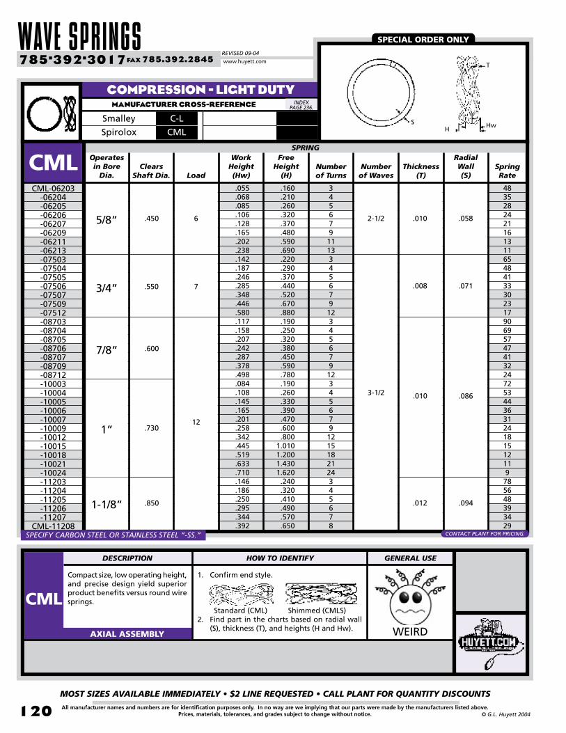
WAVE SPRINGSREVISED 09-04
MOST SIZES AVAILABLE IMMEDIATELY • $2 LINE REQUESTED • CALL PLANT FOR QUANTITY DISCOUNTS
120
785•392•3017 FAX 785.392.2845
All manufacturer names and numbers are for identification purposes only. In no way are we implying that our parts were made by the manufacturers listed above.Prices, materials, tolerances, and grades subject to change without notice. © G.L. Huyett 2004
www.huyett.com
COMPRESSION - LIGHT DUTYMANUFACTURER CROSS-REFERENCE
Compact size, low operating height, and precise design yield superior product benefits versus round wire springs.
1. Confirm end style.
Standard (CML) Shimmed (CMLS)2. Find part in the charts based on radial wall
(S), thickness (T), and heights (H and Hw). WEIRDAXIAL ASSEMBLY
Operates in Bore
Dia.
RadialWall(S)
Spring Rate
Clears Shaft Dia.
Work Height(Hw)
Free Height
(H)Numberof Turns
Thickness(T)
.160
.210
.260
.320
.370
.480
.590
.690
.220
.290
.370
.440
.520
.670
.880
.190
.250
.320
.380
.450
.590
.780
.190
.260
.330
.390
.470
.600
.8001.0101.2001.4301.620.240.320.410.490.570.650
SPRING
CMLCML-06203
-06204-06205-06206-06207 -06209 -06211-06213-07503-07504-07505-07506-07507-07509-07512-08703-08704-08705-08706-08707-08709-08712-10003-10004-10005-10006-10007-10009-10012-10015-10018-10021-10024-11203-11204-11205-11206-11207
CML-11208
Numberof Waves
48352824211613116548413330231790695747413224725344363124181512119785648393429
.055
.068
.085
.106
.128
.165
.202
.238
.142
.187
.246
.285
.348
.446
.580
.117
.158
.207
.242
.287
.378
.498
.084
.108
.145
.165
.201
.258
.342
.445
.519
.633
.710
.146
.186
.250
.295
.344
.392
Load
345679111334567912345679123456791215182124345678
5/8” .450 6
3/4” .550 7
7/8” .600
1” .73012
1-1/8” .850
2-1/2 .010 .058
3-1/2
.008 .071
.010 .086
.012 .094
SPECIAL ORDER ONLY
S
T
HwH
SmalleySpirolox
C-LCML
SPECIFY CARBON STEEL OR STAINLESS STEEL “-SS.” CONTACT PLANT FOR PRICING.
INDEX PAGE 236.
DESCRIPTION HOW TO IDENTIFY GENERAL USE
CML

BOX 232 • MINNEAPOLIS, KS • 67467
MOST SIZES AVAILABLE IMMEDIATELY • $2 LINE REQUESTED • CALL PLANT FOR QUANTITY DISCOUNTS
121All manufacturer names and numbers are for identification purposes only. In no way are we implying that our parts were made by the manufacturers listed above.Prices, materials, tolerances, and grades subject to change without notice.© G.L. Huyett 2004
COMPRESSION - LIGHT DUTYMANUFACTURER CROSS-REFERENCE
Operates in Bore
Dia.
RadialWall(S)
Spring Rate
Clears Shaft Dia.
Work Height(Hw)
Free Height
(H)Numberof Turns
Thickness(T)
.8101.0801.3301.670.230.310.400.460.550.620.790
1.0301.2501.570.250.330.420.510.590.680.840
1.1101.3601.710.250.320.410.490.580.660.830
1.0901.3401.670.310.410.520.620.730.830
1.0401.2601.4601.680.340.450.570.680.800.910
1.1401.3601.5901.820
SPRING
CMLCML-11210
-11213-11216-11220-12503-12504-12505-12506-12507-12508-12510-12513-12516-12520-13703-13704-13705-13706-13707-13708-13710-13713-13716-13720-15003-15004-15005-15006-15007-15008-15010-15013-15016-15020-17503-17504-17505-17506-17507-17508-17510-17512 -17514-17516-20003-20004-20005-20006-20007-20008-20010-20012-20014
CML-20016
Numberof Waves
2319151256423428242117131196750403429252016131011785705750433527221811483695750433429252289665444383326221917
.488
.659
.8071.017.084.113.149.172.207.227.301.395.467.591.075.099.129.155.179.206.256.341.424.530.129.164.213.247.301.337.430.565.694.866.155.200.265.310.367.415.523.638.737.844.094.120.158.179.217.243.306.365.433.490
Load
101316203456781013162034567810131620345678101316203456781012141634567810121416
1-1/8” .850
1-1/4” 1.000
12
1-3/8” 1.030 15
1-1/2” 1.140 20
1-3/4” 1.340
25
2” 1.600
3-1/2
.012
.094
.122
.016 .133
.018 .143
SPECIAL ORDER ONLY
S
T
HwH
SmalleySpirolox
C-LCML
SPECIFY CARBON STEEL OR STAINLESS STEEL “-SS.” CONTACT PLANT FOR PRICING.
INDEX PAGE 236.

WAVE SPRINGSREVISED 09-04
MOST SIZES AVAILABLE IMMEDIATELY • $2 LINE REQUESTED • CALL PLANT FOR QUANTITY DISCOUNTS
122
785•392•3017 FAX 785.392.2845
All manufacturer names and numbers are for identification purposes only. In no way are we implying that our parts were made by the manufacturers listed above.Prices, materials, tolerances, and grades subject to change without notice. © G.L. Huyett 2004
www.huyett.com
COMPRESSION - MEDIUM DUTYMANUFACTURER CROSS-REFERENCE
Heavier gauge wire with 2-3 times the spring rate versus CML. Nice compact design, complete with precise design yield characteristics.
AXIAL ASSEMBLY
Operates in Bore
Dia.
Radial Wall(S)
Spring Rate
Clears Shaft Dia.
Work Height(Hw)
Free Height
(H)Number of Turns
Thickness(T)
.150
.190
.250
.300
.350
.450
.550
.650
.220
.290
.380
.440
.520
.670
.900
.190
.250
.320
.380
.450
.580
.770
.190
.250
.320
.380
.450
.580
.770
.9701.1701.3701.540.260.340.440.520.620.700
SPRING
CMMCMM-06203
-06204-06205-06206-06207-06209-06211-06213-07503-07504-07505-07506-07507-07509-07512-08703-08704-08705-08706-08707-08709-08712-10003-10004-10005-10006-10007-10009-10012-10015-10018-10021-10024-11203-11204-11205-11206-11207
CMM-11208
Numberof Waves
158109967869544437143100887064503714810889766650381108267554938282319161414310187716354
.104
.130
.175
.206
.246
.317
.386
.454
.159
.203
.270
.314
.381
.489
.649
.124
.164
.214
.252
.296
.385
.509
.087
.113
.148
.175
.212
.276
.360
.452
.549
.650
.720
.160
.202
.270
.318
.381
.427
Load
345679111334567912345679123456791215182124345678
5/8” .450 12
3/4” .550 13
7/8” .600
1” .730
18
1-1/8” .850 20
.010
.058
3-1/2
.078
.094
.012
.015
SPECIAL ORDER ONLY
S
T
HwH
SmalleySpirolox
C-MCMM
SPECIFY CARBON STEEL OR STAINLESS STEEL “-SS.” CONTACT PLANT FOR PRICING.
INDEX PAGE 236.
1. Confirm end style.
Standard (CMM) Shimmed (CMMS)2. Find part in the charts based on radial wall
(S), thickness (T), and heights (H and Hw).
DESCRIPTION HOW TO IDENTIFY GENERAL USE
CMM
UNCOMMON
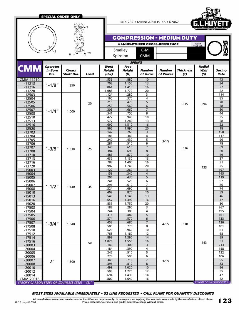
BOX 232 • MINNEAPOLIS, KS • 67467
MOST SIZES AVAILABLE IMMEDIATELY • $2 LINE REQUESTED • CALL PLANT FOR QUANTITY DISCOUNTS
123All manufacturer names and numbers are for identification purposes only. In no way are we implying that our parts were made by the manufacturers listed above.Prices, materials, tolerances, and grades subject to change without notice.© G.L. Huyett 2004
COMPRESSION - MEDIUM DUTYMANUFACTURER CROSS-REFERENCE
Operates in Bore
Dia.
RadialWall(S)
Spring Rate
Clears Shaft Dia.
Work Height(Hw)
Free Height
(H)Numberof Turns
Thickness(T)
.8801.1501.4101.770.280.370.470.560.660.750.940
1.2401.5101.890.260.340.430.510.610.690.870
1.1301.4001.740.260.340.430.520.610.690.870
1.1401.3901.750.290.380.480.570.680.770.960
1.1601.3601.550.300.390.510.590.710.810
1.0201.2201.4301.640
SPRING
CMMCMM-11210
-11213-11216-11220-12503-12504-12505-12506-12507-12508-12510-12513-12516-12520-13703-13704-13705-13706-13707-13708-13710-13713-13716-13720-15003-15004-15005-15006-15007-15008-15010-15013-15016-15020-17503-17504-17505-17506-17507-17508-17510-17512-17514-17516-20003-20004-20005-20006-20007-20008-20010-20012-20014
CMM-20016
Numberof Waves
4334272211485705850443528221815811796786960493731251971451199786745946373026719516113312010181685951213158132106958366554742
.536
.708
.8611.088.124.165.215.253.303.341.427.577.692.866.142.186.240.281.340.384.486.632.788.982.122.158.206.241.291.324.409.540.657.835.188.244.315.374.452.505.629.768.899
1.026.140.184.245.278.345.395.498.593.694.800
Load
101316203456781013162034567810131620345678101316203456781012141634567810121416
1-1/8” .850
1-1/4” 1.000
20
1-3/8” 1.030 25
1-1/2” 1.140 35
1-3/4” 1.340
50
2” 1.600
3-1/2
.015 .094
.016
.133
.018
.143
4-1/2
3-1/2
SPECIAL ORDER ONLY
S
T
HwHSmalleySpirolox
C-MCMM
SPECIFY CARBON STEEL OR STAINLESS STEEL “-SS.” CONTACT PLANT FOR PRICING.
INDEX PAGE 236.

WAVE SPRINGSREVISED 09-04
MOST SIZES AVAILABLE IMMEDIATELY • $2 LINE REQUESTED • CALL PLANT FOR QUANTITY DISCOUNTS
124
785•392•3017 FAX 785.392.2845
All manufacturer names and numbers are for identification purposes only. In no way are we implying that our parts were made by the manufacturers listed above.Prices, materials, tolerances, and grades subject to change without notice. © G.L. Huyett 2004
www.huyett.com
COMPRESSION - HEAVY DUTYMANUFACTURER CROSS-REFERENCE
Nearly twice the spring rate of CMM. Nice compact design, complete with precise design yield characteristics.
AXIAL ASSEMBLY
Operates in Bore
Dia.
RadialWall(S)
Spring Rate
Clears Shaft Dia.
Work Height(Hw)
Free Height
(H)Numberof Turns
Thickness(T)
.220
.280
.370
.430
.510
.670
.890
.220
.290
.370
.440
.530
.680
.890
.220
.290
.380
.450
.530
.680
.9001.1401.3501.5901.800.250.330.420.500.590.660.830
1.1001.3401.830
SPRING
CMHCMH-07503
-07504-07505-07506-07507-07509-07512-08703-08704-08705-08706-08707-08709-08712-10003-10004-10005-10006-10007-10009-10012-10015-10018-10021-10024-11203-11204-11205-11206-11207-11208-11210-11213-11216
CMH-11220
Numberof Waves
272186175133124987329821018014513310478210157132107957354453632272461751521201089174584738
.169
.215
.291
.335
.405
.526
.699
.166
.214
.278
.327
.395
.510
.670
.131
.174
.227
.266
.319
.406
.541
.688
.813
.9571.083.178.229.303.350.421.470.593.787.956
1.103
Load
3456791234567912345679121518212434567810131620
3/4” .550 22
7/8” .600
1” .730
25
1-1/8” .850 30
3-1/2
.013 .079
.015
.094
.018
SPECIAL ORDER ONLY
S
T
HwH
SmalleySpirolox
C-HCMH
SPECIFY CARBON STEEL OR STAINLESS STEEL “-SS.” CONTACT PLANT FOR PRICING.
INDEX PAGE 236.
1. Confirm end style.
Standard (CMH) Shimmed (CMHS)2. Find part in the charts based on radial wall
(S), thickness (T), and heights (H and Hw).
GETTING MORE
POPULAR ALL THE TIME!
DESCRIPTION HOW TO IDENTIFY GENERAL USE
CMH
UNCOMMON

BOX 232 • MINNEAPOLIS, KS • 67467
MOST SIZES AVAILABLE IMMEDIATELY • $2 LINE REQUESTED • CALL PLANT FOR QUANTITY DISCOUNTS
125All manufacturer names and numbers are for identification purposes only. In no way are we implying that our parts were made by the manufacturers listed above.Prices, materials, tolerances, and grades subject to change without notice.© G.L. Huyett 2004
COMPRESSION - HEAVY DUTYMANUFACTURER CROSS-REFERENCE
Operates in Bore
Dia.
RadialWall(S)
Spring Rate
Clears Shaft Dia.
Work Height(Hw)
Free Height
(H)Numberof Turns
Thickness(T)
1.690.270.350.453.540.640.720.900
1.1901.460.250.330.420.500.590.670.840
1.1001.3501.700.240.310.400.480.560.640.800
1.0501.2901.610.300.410.530.630.740.840
1.0501.2701.4801.700.310.410.520.620.730.830
1.0401.2401.4801.680
SPRING
CMHCMH-12503
-12504-12505-12506-12507-12508 -12510-12513-12516-12520-13703-13704-13705-13706-13707-13708-13710-13713-13716-13720-15003-15004-15005-15006-15007-15008-15010-15013-15016-15020-17503-17504-17505-17506-17507-17508-17510-17512-17514-17516-20003-20004-20005-20006-20007-20008-20010-20012-20014
CMH-20016
Numberof Waves
210158132107958265514233232166138112988569544335448326270221194168135105856862948441733630725820617314913250637230724922218915312511197
1.202.158.210.272.320.384.433.538.717.878.149.189.247.287.343.390.490.646.793
1.000.166.216.278.329.390.443.555.726.890
1.119.232.314.409.482.577.651.813.980
1.1471.317.197.258.332.389.465.525.661.781.941
1.069
Load
2034567810131634567810131620345678101316203456781012141634567810121416
1-1/4” 1.000 30
1-3/8” 1.030 35
1-1/2” 1.140 60
1-3/4” 1.340
90
2” 1.600
3-1/2
.019 .094
.018 .133
4-1/2
.024 .148
3-1/2
SPECIAL ORDER ONLY
S
T
HwH
SmalleySpirolox
C-HCMH
SPECIFY CARBON STEEL OR STAINLESS STEEL “-SS.” CONTACT PLANT FOR PRICING.
INDEX PAGE 236.

ASSEMBLY COMPONENTSREVISED 09-04
MOST SIZES AVAILABLE IMMEDIATELY • $2 LINE REQUESTED • CALL PLANT FOR QUANTITY DISCOUNTS
12�
785•392•3017 FAX 785.392.2845
All manufacturer names and numbers are for identification purposes only. In no way are we implying that our parts were made by the manufacturers listed above.Prices, materials, tolerances, and grades subject to change without notice. © G.L. Huyett 2004
www.huyett.com
AUTOMATED INSTALLATION
TYPESSC
METRICPg: 218
IMPERIALPg: 128, 130
SC1
SC2IMPERIAL
Pg: 129-130
N/ANIMPERIAL
Pg: 132
NHIMPERIAL
Pg: 133
NIIMPERIAL
Pg: 134
IMPERIALPg: 135
NTIMPERIAL
Pg: 136
30/70IMPERIAL
Pg: 138-139
IMPERIALPg: 140
NL
SOLID SHAFT COLLAR
METRICN/A
METRICPg: 220 (KM)
METRICN/A
METRICN/A
METRICN/A
METRICN/A
METRICPg: 219
METRICPg: 218
SINGLE SPLIT SHAFT COLLAR
DOUBLE SPLIT SHAFT COLLAR
STANDARD LOCKNUT
HEAVY DUTY LOCKNUT
FINE THREAD LOCKNUT
LEFT HAND LOCKNUT
THIN SECTION LOCKNUT
MACHINE KEYS
KEYED SHAFTS
METRICN/A
IMPERIALPg: 129, 131
KF
WMETRIC
Pg: 221 (MB)IMPERIAL
Pg: 141
WS
WHIMPERIAL
Pg: 143
WIIMPERIAL
Pg: 144
WTIMPERIAL
Pg: 144
ETRIMPERIAL
Pg: 145
IMPERIALPg: 146
PSIMPERIAL
Pg: 147
TWIMPERIAL
Pg: 148
IMPERIALPg: 149
SS
STANDARD LOCKWASHER
METRICN/A
METRICN/A
METRICN/A
METRICN/A
METRICN/A
METRICN/A
METRICN/A
METRICN/A
STAINLESS LOCKWASHER
HEAVY DUTY LOCKWASHER
FINE THREAD LOCKWASHER
THIN SECTION LOCKWASHER
EXTERNAL TOOTH RETAINER
SUPPORT WASHER DIN 988
SHIM RING DIN 988
THRUST WASHER
SLITTED SHIM
METRICN/A
IMPERIALPg: 142
SR
Black Oxide, Zinc Plated,
Stainless, or Nylon.
Black Oxide, Stainless,
Aluminum, Threaded.
Black Oxide,
Stainless, or Nylon.
NS - Stainless
KM - Metric
Thickerand more precise.
Allimperial
dimensions.
For high rotational
speeds.
Light-weight version.
Alsoavailable
instainless.
Partial keyways
also available.
Most common
lockwasher.
Stainless version of “W” Series.
Thicker version.
Imperialdimensions.
Smaller OD than
“W” Series.
For light duty
bearing retention.
Wide bearing
abutment surface.
For taking up slack
on shafts.
Equalize load on bearing.
For taking up slack
on shafts.
SHAFT LOCKNUTS
Use assembly sockets coupled with powered drive wrenches to automate
locknut assembly.
2”Clearance
SquareDrive
Notches match standard locknut keyways
CONTACT PLANT FOR SOCKET INFORMATION.

BOX 232 • MINNEAPOLIS, KS • 67467
MOST SIZES AVAILABLE IMMEDIATELY • $2 LINE REQUESTED • CALL PLANT FOR QUANTITY DISCOUNTS
127All manufacturer names and numbers are for identification purposes only. In no way are we implying that our parts were made by the manufacturers listed above.Prices, materials, tolerances, and grades subject to change without notice.© G.L. Huyett 2004
PRODUCT COMPARISONS
LOCKNUTS“THE VERY BEST IN BEARING RETENTION”
Locknuts were the original and most popular form of bearing retention in the early part of the century. As wire forming technology improved, retaining rings gradually replaced locknuts because of their lower unit cost and reduced manufacturing costs. Locknuts also require more time during assembly.
Retaining rings are less precise and have less holding power than shaft locknuts, so in certain applications, there is still a place for locknuts. Locknuts are manufactured to very close and exacting tolerances, particularly when you consider their heavy duty design. In addition, locknuts are adjustable so that manufacturing tolerances for adjacent components can be compensated for by loosening or tightening the locknut.
The most common causes of bearing failure are poorly fitted parts from the sum total of allowable manufacturing tolerances; shock loading as the components are used; misalignment; and excessive vibration which amplifies these factors. In the example above, proper fit and alignment are very important because two bearings must be assembled properly together. Locknuts possess precision threads and ground faces. The locknut can be torqued correctly against the bearing wall, with perfect alignment from precision threading. The retaining ring design magnifies manufacturing tolerances that exist in groove, shaft, and ring construction. Retaining rings do not allow you to adjust torque. The result is that the ring design introduces several potential causes of bearing failure.
Locknuts are much more expensive; however, if the application requires precision and shock resistance, a designer may elect to use higher cost locknuts that extend bearing life. Examples of these applications are machine tools, medical and technological instruments, and other durable goods exposed to harsh and unstable environments. The next time you are in a machine shop that is still using BridgeportTM mills from 1942, you’ll know why -- shaft locknuts!
Bearing
Same assembly, redesigned using a shaft locknut.
Locknut can be adjusted progressively to take up slack & manufacturing tolerances
TIGHTEN
Assembly using retainingrings for retention.
Retaining Ringis not adjustable
Manufacturing Tolerances exist on: - Groove - Ring Thickness - Bearing Face
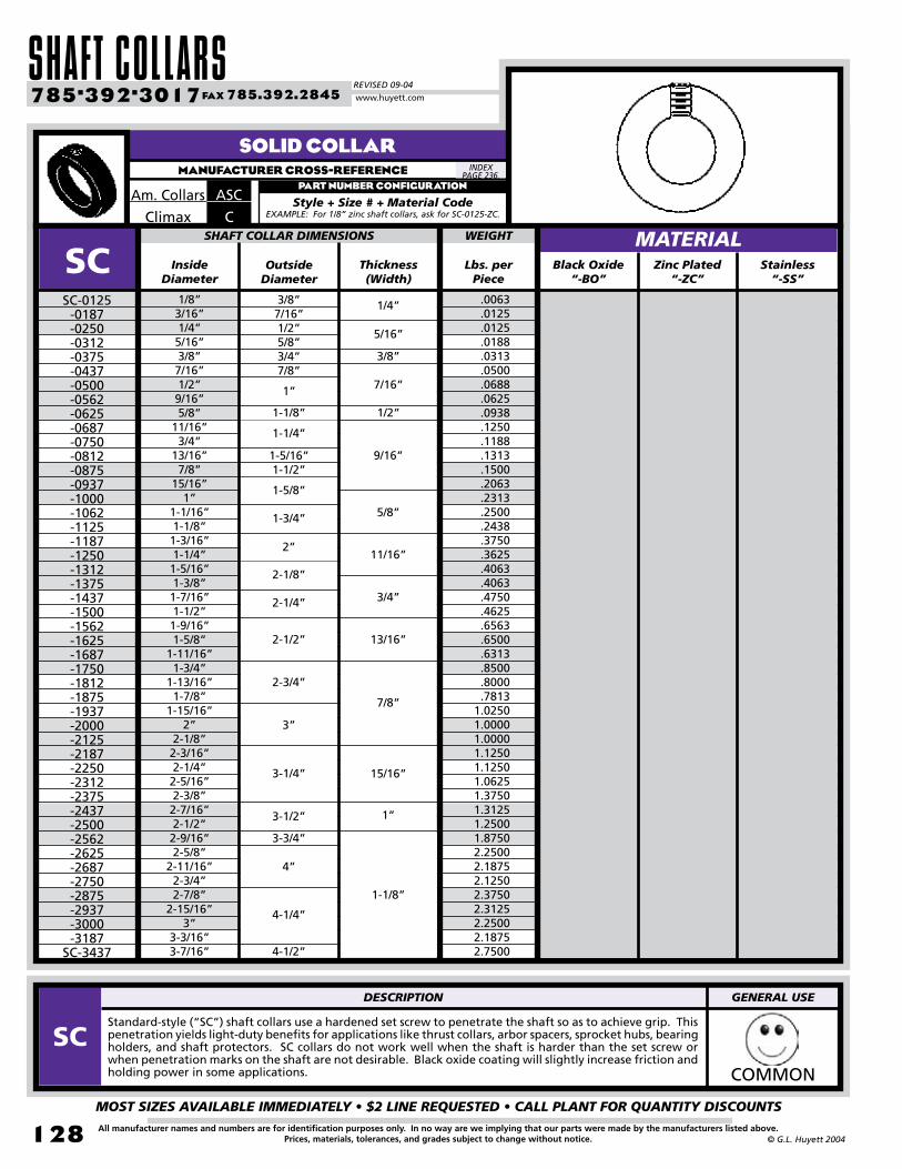
SHAFT COLLARSREVISED 09-04
MOST SIZES AVAILABLE IMMEDIATELY • $2 LINE REQUESTED • CALL PLANT FOR QUANTITY DISCOUNTS
128
785•392•3017 FAX 785.392.2845
All manufacturer names and numbers are for identification purposes only. In no way are we implying that our parts were made by the manufacturers listed above.Prices, materials, tolerances, and grades subject to change without notice. © G.L. Huyett 2004
www.huyett.com
SOLID COLLARMANUFACTURER CROSS-REFERENCE
1/8”3/16”1/4”5/16”3/8”7/16”1/2”9/16”5/8”
11/16”3/4”
13/16”7/8”
15/16”1”
1-1/16”1-1/8”1-3/16”1-1/4”1-5/16”1-3/8”1-7/16”1-1/2”1-9/16”1-5/8”
1-11/16”1-3/4”
1-13/16”1-7/8”
1-15/16”2”
2-1/8”2-3/16”2-1/4”2-5/16”2-3/8”2-7/16”2-1/2”2-9/16”2-5/8”
2-11/16”2-3/4”2-7/8”
2-15/16”3”
3-3/16”3-7/16”
SC-0125-0187-0250-0312-0375-0437-0500-0562-0625-0687-0750-0812-0875-0937-1000-1062-1125-1187-1250-1312-1375-1437-1500-1562-1625-1687-1750-1812-1875-1937-2000-2125-2187-2250-2312-2375-2437-2500-2562-2625-2687-2750-2875-2937-3000-3187
SC-3437
Outside Diameter
InsideDiameter
Thickness(Width)
3/8”7/16”1/2”5/8”3/4”7/8”
.0063
.0125
.0125
.0188
.0313
.0500
.0688
.0625
.0938
.1250
.1188
.1313
.1500
.2063
.2313
.2500
.2438
.3750
.3625
.4063
.4063
.4750
.4625
.6563
.6500
.6313
.8500
.8000
.78131.02501.00001.00001.12501.12501.06251.37501.31251.25001.87502.25002.18752.12502.37502.31252.25002.18752.7500
SHAFT COLLAR DIMENSIONS
SC Zinc Plated“-ZC”
Lbs. per Piece
WEIGHT
Stainless“-SS”
1”
1-1/8”
1-1/4”
1-5/16”1-1/2”
1-5/8”
1-3/4”
2”
2-1/8”
2-1/4”
2-1/2”
2-3/4”
3”
3-1/4”
3-1/2”
3-3/4”
4”
4-1/4”
4-1/2”
1/4”
5/16”
3/8”
7/16”
1/2”
9/16”
5/8”
11/16”
3/4”
13/16”
7/8”
15/16”
1”
Standard-style (“SC”) shaft collars use a hardened set screw to penetrate the shaft so as to achieve grip. This penetration yields light-duty benefits for applications like thrust collars, arbor spacers, sprocket hubs, bearing holders, and shaft protectors. SC collars do not work well when the shaft is harder than the set screw or when penetration marks on the shaft are not desirable. Black oxide coating will slightly increase friction and holding power in some applications. COMMON
1-1/8”
ASCAm. Collars
CClimax
PART NUMBER CONFIGURATION
Style + Size # + Material CodeEXAMPLE: For 1/8” zinc shaft collars, ask for SC-0125-ZC.
INDEX PAGE 236.
MATERIALBlack Oxide
“-BO”
DESCRIPTION GENERAL USE
SC

BOX 232 • MINNEAPOLIS, KS • 67467
MOST SIZES AVAILABLE IMMEDIATELY • $2 LINE REQUESTED • CALL PLANT FOR QUANTITY DISCOUNTS
129All manufacturer names and numbers are for identification purposes only. In no way are we implying that our parts were made by the manufacturers listed above.Prices, materials, tolerances, and grades subject to change without notice.© G.L. Huyett 2004
SPLIT COLLARMANUFACTURER CROSS-REFERENCE
1/8”3/16”1/4”5/16”3/8”7/16”1/2”9/16”5/8”
11/16”3/4”
13/16”7/8”
15/16”1”
1-1/16”1-1/8”1-3/16”1-1/4”1-5/16”1-3/8”1-7/16”1-1/2”1-9/16”1-5/8”
1-11/16”1-3/4”1-7/8”
1-15/16”2”
2-1/8”2-3/16”2-1/4”2-3/8”2-7/16”2-1/2”2-5/8”
2-11/16”2-3/4”2-7/8”
2-15/16”3”
3-3/16”3-7/16”
-0125*-0187*-0250*-0312-0375-0437-0500-0562-0625-0687-0750-0812-0875-0937-1000-1062-1125-1187-1250-1312-1375-1437-1500-1562-1625-1687-1750-1875**-1937-2000-2125-2187-2250-2375-2437-2500-2625-2687-2750-2875-2937-3000-3187-3437
Outside Diameter
InsideDiameter
Thickness(Width)
0.01880.01880.01880.03130.05000.05000.08130.13130.11880.18130.18130.20000.20000.21250.20000.23750.23750.23130.26880.36880.36880.35000.40000.40000.37500.66880.66880.70000.70000.73130.93750.86880.83751.01250.98131.51881.61251.65001.66251.85001.76881.71251.82501.7500
SHAFT COLLAR DIMENSIONS
MATERIALSC1SC2 Black Oxide
“-BO”
Lbs. per Piece
DOUBLE SPLIT
Stainless“-SS”
WEIGHTMATERIALBlack Oxide
“-BO”
Lbs. per Piece
SINGLE SPLIT
Stainless“-SS”
WEIGHT
0.02690.02440.02380.02130.04440.04750.07880.12500.11250.17500.16250.19380.17690.21250.19380.22940.21880.28130.26380.36880.35630.32690.37880.35060.58190.61630.68750.65380.72310.68750.93750.87500.81880.95000.95631.39381.50001.56251.50001.81251.65631.61251.76881.9375
5/8”
11/16”7/8”
15/16”1-1/8”
1-5/16”
1-1/2”
1-5/8”
1-3/4”
1-7/8”
2-1/16”
2-1/4”
2-3/8”
2-5/8”
2-3/4”
3”
3-1/4”
3-3/4”3-7/8”
4”
4-1/4”
4-1/2”4-3/4”
3-1/2”
5/16”
3/8”
13/32”
7/16”
1/2”
9/16”
11/16”
3/4”
7/8”
* Stainless Steel sizes 012 through 025 have an 11/16” O.D. (Single and Double split)** Stainless Steel size 187 has a 2-7/8” O.D. (Double split only)
Single split collars (SC1) use friction to provide grip on bars and shafts. This method is generally considered to be more sturdy than the set screw design of SC collars. Double split collars (SC2) allow installation without disassembling machinery. SC2 collars provide superior grip action.
COMMON
SC1 SC2ASPAm. Collars
1C/2CClimax
PART NUMBER CONFIGURATION
Style + Size # + Material CodeEXAMPLE: For 1/8” stainless double split collars, ask for SC2-0125-SS.
INDEX PAGE 236.
DESCRIPTION GENERAL USE
SC1SC2

SHAFT COLLARSREVISED 09-04
MOST SIZES AVAILABLE IMMEDIATELY • $2 LINE REQUESTED • CALL PLANT FOR QUANTITY DISCOUNTS
130
785•392•3017 FAX 785.392.2845
All manufacturer names and numbers are for identification purposes only. In no way are we implying that our parts were made by the manufacturers listed above.Prices, materials, tolerances, and grades subject to change without notice. © G.L. Huyett 2004
www.huyett.com
NYLON SOLID COLLARMANUFACTURER CROSS-REFERENCE
Nylon“-NY”
1-7/161-1/21-5/81-3/41-7/8
1-15/162
2-3/162-1/42-7/162-1/22-3/4
SCSC-1437-1500-1625-1750-1875-1937-2000-2187-2250-2437-2500
SC-2750
OutsideDiameter
Thickness(Width)
2-1/42-1/42-1/22-5/82-3/4
33
3-1/43-1/43-1/23-1/2
4
InsideDiameter
SHAFT COLLAR DIMENSIONS MATERIAL
NYLON DOUBLE SPLIT COLLARMANUFACTURER CROSS-REFERENCE
Nylon“-NY”
1/45/163/87/161/29/165/83/47/81
1-3/161-1/41-3/8
SC2SC2-0250
-0312-0375-0437-0500-0562-0625-0750-0875-1000-1187-1250
SC2-1375
OutsideDiameter
Thickness(Width)
11
1-1/41-1/41-3/81-3/81-5/81-3/4
22-1/82-5/162-3/82-1/2
InsideDiameter
Nylon“-NY”
1-7/161-1/21-5/81-3/41-7/8
1-15/162
2-3/162-1/42-7/162-1/22-3/4
3
SC2SC2-1437
-1500-1625-1750-1875-1937-2000-2187-2250-2437-2500-2750
SC2-3000
OutsideDiameter
Thickness(Width)
2-5/82-5/8
33-1/83-1/43-1/43-3/83-5/83-5/84-1/84-1/84-3/84-1/2
InsideDiameter
SHAFT COLLAR DIMENSIONS SHAFT COLLAR DIMENSIONS MATERIALMATERIAL
INDEX PAGE 236.
Nylon“-NY”
1/45/163/87/161/29/165/83/47/81
1-3/161-1/41-3/8
SCSC-0250-0312-0375-0437-0500-0562-0625-0750-0875-1000-1187-1250
SC-1375
OutsideDiameter
Thickness(Width)
1/25/83/47/811
1-1/81-1/41-1/21-5/8
22
2-1/8
InsideDiameter
SHAFT COLLAR DIMENSIONS MATERIAL
5/16
3/8
7/16
1/2
9/16
5/8
11/16
3/4
3/4
13/16
7/8
15/16
1
1-1/8
3/8
1/2
9/16
5/8
3/4
3/4
15/16
1-1/8
NSCBoston Gear
2NSCBoston Gear
INDEX PAGE 236.

BOX 232 • MINNEAPOLIS, KS • 67467
MOST SIZES AVAILABLE IMMEDIATELY • $2 LINE REQUESTED • CALL PLANT FOR QUANTITY DISCOUNTS
131All manufacturer names and numbers are for identification purposes only. In no way are we implying that our parts were made by the manufacturers listed above.Prices, materials, tolerances, and grades subject to change without notice.© G.L. Huyett 2004
SPLIT THREADED COLLARMANUFACTURER CROSS-REFERENCE
10-321/4-201/4-285/16-185/16-243/8-163/8-241/2-131/2-205/8-115/8-183/4-103/4-167/8-97/8-14
1-81-14
1-1/8-121-1/4-71-1/4-121-3/8-121-1/2-61-1/2-12
2-12
-0.02500.02560.02500.02500.00310.00290.00550.0055
-0.00780.01130.01090.20000.19500.21500.21880.23750.29380.2875
-0.41880.41250.7375
SHAFT COLLAR DIMENSIONS WEIGHT
SCT1-0010-32-0250-20-0250-28-0312-18-0312-24-0375-16-0375-24-0500-13-0500-20-0625-11-0625-18-0750-10-0750-16-0875-09-0875-14-1000-08-1000-14-1125-12-1250-07-1250-12-1375-12-1500-06-1500-12
SCT1-2000-12
InsideDiameter
OutsideDiameter
Lbs. per100 PiecesThickness
Black Oxide“-BO”
MATERIALSCT
INDEX PAGE 236.
Stainless“-SS”
5/8
11/16
7/8
1-1/8
1-5/16
1-1/2
1-5/8
1-3/4
1-7/8
2-1/16
2-1/42-3/82-1/2
31/2
11/16
5/16
3/8
13/32
7/16
1/2
9/16
ALUMINUM SPLIT COLLARMANUFACTURER CROSS-REFERENCE INDEX
PAGE 236.
Lbs. per 100 Pieces
1/83/161/45/163/81/25/83/47/81
1-1/81-1/41-3/8
SC1SC1-0125
-0187-0250-0312-0375-0500-0625-0750-0875-1000-1125-1250
SC1-1375
Outside Dia.
Thickness(Width)
Inside Dia.
SHAFT COLLAR DIMENSIONS MATERIAL
Aluminum“-AL”
1/25/8
11/1611/167/8
1-1/81-5/161-1/21-5/81-3/41-7/82-1/162-1/4
1/45/165/165/163/8
13/327/161/21/21/21/21/29/16
--
0.02500.02250.04380.08130.11250.16880.18500.2063
-0.2750
-
WEIGHT
1/2
5/16
Lbs. per 100 Pieces
1-1/21-5/81-3/41-7/8
22-1/82-1/42-3/82-1/22-5/82-3/42-7/8
3
SC1SC1-1500
-1625-1750-1875-2000-2125-2250-2375-2500-2625-2750-2875
SC1-3000
Outside Dia.
Thickness (Width)
Inside Dia.
SHAFT COLLAR DIMENSIONS MATERIAL
Aluminum“-AL”
2-3/82-5/82-3/42-7/8
33-1/43-1/43-1/23-3/43-7/8
44-1/44-1/4
9/16 0.3938-
0.63750.68130.7250
--------
WEIGHT
11/16
3/4
7/8
ISTCClimax
CSCBoston Gear
H1CClimax
CASBoston Gear

SHAFT LOCKNUTSREVISED 09-04
MOST SIZES AVAILABLE IMMEDIATELY • $2 LINE REQUESTED • CALL PLANT FOR QUANTITY DISCOUNTS
132
785•392•3017 FAX 785.392.2845
All manufacturer names and numbers are for identification purposes only. In no way are we implying that our parts were made by the manufacturers listed above.Prices, materials, tolerances, and grades subject to change without notice. © G.L. Huyett 2004
www.huyett.com
STANDARDMANUFACTURER CROSS-REFERENCE
Most commonly used locknuts. Require a lockwasher and keyway in the shaft. “AN” series were for an old specification (11 threads per inch) and should be avoided.
1. Confirm the outside diameter (OD) of the part.
2. Measure the thickness (T) of the part.3. Verify the nut face diameter (Dc).4. Find the part in the chart above.
COMMONAXIAL ASSEMBLY
FOR TAPERED ROLLER BEARINGS IT IS BEST TO USE OUR HIGHER PRECISION “PN” SERIES (SEE PAGE 137).
AVAILABLE IN STAINLESS STEEL
REQUIRES A KEYWAY.
LET OUR SHOP CUT IT FOR YOU!
Min. Max. Min.
.3937
.4724
.5906
.6693
.7874
.98431.18111.31251.37801.57481.77171.96852.16542.36222.55912.75592.95283.14963.34653.54333.74023.93704.13394.33074.72445.11815.51185.90556.29926.69297.08667.48037.87408.6614
3/47/81
1-1/81-3/81-9/161-3/42-1/162-1/162-1/4
2-17/322-11/162-31/323-5/323-3/83-5/83-7/84-5/324-13/324-21/324-15/165-3/165-7/165-23/326-1/86-3/47-3/327-11/168-1/168-21/329-1/169-15/329-27/32
11
N-00-01-02-03-04-05-06
-065-07-08-09-10-11-12-13
N-14AN-15
-16-17-18-19-20-21-22-24-26-28-30-32-34-36-38
AN-40N-44
Max.Threads per Inch
.209
.303
.303
.334
.365
.396
.396
.428
.428
.428
.428
.490
.490
.521
.553
.553
.584
.584
.615
.678
.709
.735
.735
.766
.798
.860
.923
.9541.0161.0481.0791.1101.1731.230
MatingLockwasher
Bearing Bore Nominal (N)
Outside Dia. (OD)+.005/-.015
Nut FaceDiameter (Dc)
Thickness(T)
10121517202530
33-1/335404550556065707580859095100105110120130140150160170180190200220
.229
.323
.323
.354
.385
.416
.416
.448
.448
.448
.448
.510
.510
.541
.573
.573
.604
.604
.635
.698
.729
.760
.760
.791
.823
.885
.948
.9791.0411.0731.1041.1351.1981.260
.605
.699
.793
.9181.1051.2611.4801.7931.7931.9802.2612.4182.6362.8243.0433.2833.5333.8144.0014.2514.5334.7834.9705.2515.6586.1586.5017.0337.3987.9918.3358.7419.1169.803
.625
.719
.813
.9381.1251.2811.5001.8131.8132.0002.2812.4382.6562.8443.0633.3133.5633.8444.0314.2814.5634.8135.0005.2815.6886.1886.5317.0637.4388.0318.3758.7819.1569.841
W-00-01-02-03-04-05
W-06WH-065
W-07-08-09-10-11-12-13-14-15-16-17-18-19-20-21-22-24-26-28-30-32-34-36-38-40
W-44
LOCKNUT DIMENSIONS MATERIALNAN Decimal MM
Low Carbon
BORE
32
18
8
12
Stainless(NS-)
Lbs. per 100 Pieces
WEIGHT
1.2500 3.1250 3.7500 5.6250 8.7500
11.2500 13.7500 22.5000 20.0000 23.1250 28.7500 33.7500 41.2500 46.8750 53.7500 62.5000 77.5000 92.5000
105.0000 130.0000 155.0000 181.2500 190.0000 223.7500 260.0000 350.0000 387.5000 487.5000 550.0000 687.5000 725.0000 787.5000 868.7500
1175.0000
SEE PAGE 140.
Standard Locknut N/ANWhittet-Higgins N/AN
MA
TIN
G L
OC
KW
ASH
ER D
ESC
RIP
TIO
NS
ON
PA
GE
141.
INDEX PAGE 236.
ODDc N
T
DESCRIPTION HOW TO IDENTIFY GENERAL USE
NAN
W LOCKWASHERPage 143

BOX 232 • MINNEAPOLIS, KS • 67467
MOST SIZES AVAILABLE IMMEDIATELY • $2 LINE REQUESTED • CALL PLANT FOR QUANTITY DISCOUNTS
133All manufacturer names and numbers are for identification purposes only. In no way are we implying that our parts were made by the manufacturers listed above.Prices, materials, tolerances, and grades subject to change without notice.© G.L. Huyett 2004
Designed with greater thread length for greater strength. Tighter tolerances make this a common part for tapered roller bearings.
1. Confirm the outside diameter (OD) of the part.
2. Measure the thickness (T) of the part.3. Verify the nut face diameter (Dc).4. Find the part in the chart above.
COMMONAXIAL ASSEMBLY
HEAVY DUTYMANUFACTURER CROSS-REFERENCE
THE OBSOLETE NE SERIES (11 THREADS PER INCH) IS AVAILABLE AS ASPECIAL ORDER FOR FIELD REPLACEMENT AND REPAIR APPLICATIONS.
ODDc N
T
THICKER AND MORE PRECISE
Min. Max. Min.Low
Carbon
2-1/42-17/322-11/162-31/323-5/323-3/83-5/83-7/84-5/324-13/324-21/324-15/165-3/165-7/165-23/326-1/86-3/47-3/327-11/168-1/168-21/329-1/169-15/329-27/32
NH-08-09-10-11-12-13-14-15-16-17-18-19-20-21-22-24-26-28-30-32-34-36-38
NH-40
Max.Threads per Inch
.5525
.5525
.6150
.6150
.6462
.7087
.7087
.7400
.7400
.7712
.8650
.8962
.9275
.9275
.95871.02121.08371.17751.24001.27121.33371.39621.39621.4900
MatingLockwasher
LOCKNUT DIMENSIONSBearing Bore
Nominal (N)Outside
Dia. (OD)+.005/-.015
Nut FaceDiameter (Dc)
Thickness(T)
404550556065707580859095100105110120130140150160170180190200
.5725
.5725
.6350
.6350
.6663
.7287
.7287
.7600
.7600
.7913
.8850
.9163
.9475
.9475
.97881.04131.10381.19751.26001.29131.35381.41631.41631.5100
1.9802.2612.4182.6362.8243.0433.2833.5333.8144.0014.2514.5334.7834.9705.2515.6586.1586.5017.0337.3987.9918.3358.7419.116
2.0002.2812.4382.6562.8443.0633.3133.5633.8444.0314.2814.5634.8135.0005.2815.6886.1886.5317.0637.4388.0318.3758.7819.156
WH-08-09-10-11-12-13-14-15-16-17-18-19-20-21-22-24-26-28-30-32-34-36-38
WH-40
MATERIAL
NHBORE
1.57481.77171.96852.16542.36222.55912.75592.95283.14963.34653.54333.74023.93704.13394.33074.72445.11815.51185.90556.29926.69297.08667.48037.8740
Decimal MM
12
18
8
WEIGHTLbs. per
100Pieces
30.000037.500042.500052.500057.5000 72.5000 82.5000
100.0000117.5000135.0000175.0000200.0000237.5000250.0000287.5000337.5000437.5000500.0000637.5000693.7500881.2500956.8750
1000.00001125.0000
EXTREMELY PRECISE
RUNOUT AND PARALLELISM
ON THE SURFACES.
Standard Locknut NHEWhittet-Higgins NH
MA
TIN
G L
OC
KW
ASH
ER D
ESC
RIP
TIO
NS
ON
PA
GE
143.
INDEX PAGE 236.
DESCRIPTION HOW TO IDENTIFY GENERAL USE
NH
LOCKWASHERPage 143W
H

SHAFT LOCKNUTSREVISED 09-04
MOST SIZES AVAILABLE IMMEDIATELY • $2 LINE REQUESTED • CALL PLANT FOR QUANTITY DISCOUNTS
134
785•392•3017 FAX 785.392.2845
All manufacturer names and numbers are for identification purposes only. In no way are we implying that our parts were made by the manufacturers listed above.Prices, materials, tolerances, and grades subject to change without notice. © G.L. Huyett 2004
www.huyett.com
Used by manufacturers who prefer not to use SAE-AFBMA metric modified series. These babies are “all English.” Dimensions are based on the good king’s foot.
1. Confirm the outside diameter (OD) of the part.
2. Measure the thickness (T) of the part.3. Verify the nut face diameter (Dc).4. Find the part in the chart above, which is
based entirely on an old king’s foot.UNCOMMONAXIAL ASSEMBLY
FINE THREADMANUFACTURER CROSS-REFERENCE
ODDc N
T
FRACTIONAL INCH BORES
REQUIRES A KEYWAY.
LET OUR SHOP CUT IT FOR YOU!
STAMPING CUTTING TURNING HARDCHROME
LASER BENDING CENTERLESSGRINDING
THREADING MILLING GRINDING
WE HAVE A COMPLETE MACHINE SHOP
FAX YOUR QUOTE REQUEST!!!
SEE PAGE 140.
Standard Locknut NINWhittet-Higgins NI
INDEX PAGE 236.
Min. Max. Min.Spring Steel
1-1/21-5/81-3/41-7/8
22-1/42-1/42-1/22-5/82-3/4
33-1/43-1/23-3/4
NI-01-02-03-04-05-06-07-08-09-10-11-12-13
NI-14
Max.Threads per Inch
MatingLockwasher
Bearing BoreNominal (N)
Outside Dia. (OD)+.005/-.015
Nut FaceDiameter (Dc)
Thickness(T)
3/47/81
1-1/81-1/41-3/81-1/21-5/81-3/41-7/8
22-1/42-1/22-3/4
1.1681.2931.4181.5431.6681.9181.9182.1682.2932.4182.6682.8553.1053.345
1.1881.3131.4381.5631.6881.9381.9382.1882.3132.4382.6882.8753.1253.375
WI-01-02-03-04-05-06-07-08-09-10-11-12-13
WI-14
MATERIALLOCKNUT DIMENSIONS
NIBORE
.750
.8751.0001.1251.2501.3751.5001.6251.7501.8752.0002.2502.5002.750
Decimal Fraction
16
WEIGHTLbs. per
100Pieces
MA
TIN
G L
OC
KW
ASH
ER D
ESC
RIP
TIO
NS
ON
PA
GE
144.
11.250012.500013.750015.625023.750031.250026.875035.000038.125040.000048.750068.125075.000080.6250
.365
.490
.615
.385
.510
.635
DESCRIPTION HOW TO IDENTIFY GENERAL USE
NI
LOCKWASHERPage 144W
I

BOX 232 • MINNEAPOLIS, KS • 67467
MOST SIZES AVAILABLE IMMEDIATELY • $2 LINE REQUESTED • CALL PLANT FOR QUANTITY DISCOUNTS
135All manufacturer names and numbers are for identification purposes only. In no way are we implying that our parts were made by the manufacturers listed above.Prices, materials, tolerances, and grades subject to change without notice.© G.L. Huyett 2004
Left -hand threads for h igh rotational speeds or as an opposite to a standard right-hand part for ease in tightening and loosening.
1. Confirm the outside diameter (OD) of the part.
2. Measure the thickness (T) of the part.3. Verify the nut face diameter (Dc).4. Find the part in the chart above.
UNCOMMONAXIAL ASSEMBLY
LEFT-HAND THREADMANUFACTURER CROSS-REFERENCEOD
Dc N
T
Min. Max. Min.SpringSteel
.3937
.4724
.5906
.6693
.7874
.98431.18111.37801.57481.77171.96852.16542.36222.55912.75592.95283.14963.34653.54333.74023.93704.13394.3307
.209
.303
.303
.334
.365
.396
.396
.428
.428
.428
.490
.490
.521
.553
.553
.584
.584
.615
.678
.709
.735
.735
.766
NL-00-01-02-03-04-05-06-07-08-09-10-11-12-13-14-15-16-17-18-19-20-21
NL-22
Max.
LOCKNUT DIMENSIONS
W-00-01-02-03-04-05-06-07-08-09-10-11-12-13-14-15-16-17-18-19-20-21
W-22
Mating Lockwasher
Outside Dia. (OD)+.005/-.015
Nut FaceDiameter (Dc)
Bearing Bore Nominal (N)
Thickness(T)Threads
per Inch
MA
TIN
G L
OC
KW
ASH
ER D
ESC
RIP
TIO
NS
ON
PA
GE
141.
3/47/81
1-1/81-3/81-9/161-3/42-1/162-1/4
2-17/322-11/162-31/323-5/323-3/83-5/83-7/84-5/324-13/324-21/324-15/165-3/165-7/165-23/32
.229
.323
.323
.354
.385
.416
.416
.448
.448
.448
.510
.510
.541
.573
.573
.604
.604
.635
.698
.729
.760
.760
.791
.605
.699
.793
.9181.1051.2611.4801.7931.9802.2612.4182.6362.8243.0433.2833.5333.8144.0014.2514.5334.7834.9705.251
.625
.719
.813
.9381.1251.2811.5001.8132.0002.2812.4382.6562.8443.0633.3133.5633.8444.0314.2814.5634.8135.0005.281
MATERIAL
NLDecimal MM
BORE
1012151720253035404550556065707580859095100105110
32
18
12
WEIGHTLbs. per
100Pieces
1.87503.12503.7500 5.6250
8.7500 11.2500 13.1250 20.6250 22.5000 28.7500 33.7500 41.2500 46.2500 55.0000 62.5000 77.5000 90.0000103.7500133.7500153.7500177.5000192.5000226.2500
FOR HIGH ROTATIONAL SPEEDS
USED IN RACING
VEHICLES AND
EQUIPMENT DRIVES.
Standard Locknut NL
Whittet-Higgins NL
INDEX PAGE 236.
DESCRIPTION HOW TO IDENTIFY GENERAL USE
NLW LOCKWASHER
Page 144
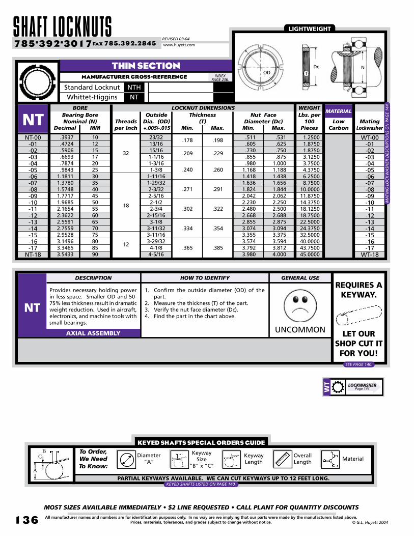
SHAFT LOCKNUTSREVISED 09-04
MOST SIZES AVAILABLE IMMEDIATELY • $2 LINE REQUESTED • CALL PLANT FOR QUANTITY DISCOUNTS
13�
785•392•3017 FAX 785.392.2845
All manufacturer names and numbers are for identification purposes only. In no way are we implying that our parts were made by the manufacturers listed above.Prices, materials, tolerances, and grades subject to change without notice. © G.L. Huyett 2004
www.huyett.com
Provides necessary holding power in less space. Smaller OD and 50-75% less thickness result in dramatic weight reduction. Used in aircraft, electronics, and machine tools with small bearings.
1. Confirm the outside diameter (OD) of the part.
2. Measure the thickness (T) of the part.3. Verify the nut face diameter (Dc).4. Find the part in the chart above.
UNCOMMONAXIAL ASSEMBLY
ODDc N
T
REQUIRES A KEYWAY.
LET OUR SHOP CUT IT FOR YOU!
LIGHTWEIGHT
SEE PAGE 140.
KEYED SHAFTS SPECIAL ORDERS GUIDETo Order, We Need To Know:
Overall Length
PARTIAL KEYWAYS AVAILABLE. WE CAN CUT KEYWAYS UP TO 12 FEET LONG.
Diameter“A”
Keyway Length
Keyway Size
“B” x “C”Material
A
CB
KEYED SHAFTS LISTED ON PAGE 140.
THIN SECTIONMANUFACTURER CROSS-REFERENCE
Min. Max. Min.Low
Carbon
.3937
.4724
.5906
.6693
.7874
.98431.18111.37801.57481.77171.96852.16542.36222.55912.75592.95283.14963.34653.5433
NT-00-01-02-03-04-05-06-07-08-09-10-11-12-13-14-15-16-17
NT-18
Max.
LOCKNUT DIMENSIONS
WT-00-01-02-03-04-05-06-07-08-09-10-11-12-13-14-15-16-17
WT-18
Mating Lockwasher
Nut FaceDiameter (Dc)
Bearing Bore Nominal (N)
Thickness(T)Threads
per Inch
MA
TIN
G L
OC
KW
ASH
ER D
ESC
RIP
TIO
NS
ON
PA
GE
144.
23/3213/1615/161-1/161-3/161-3/8
1-11/161-29/322-3/322-5/162-1/22-3/4
2-15/163-1/8
3-11/323-11/163-29/324-1/84-5/16
.511
.605
.730
.855
.9801.1681.4181.6361.8242.0422.2302.4802.6682.8553.0743.3553.5743.7923.980
.531
.625
.750
.8751.0001.1881.4381.6561.8442.0622.2502.5002.6882.8753.0943.3753.5943.8124.000
MATERIAL
NTBORE
10121517202530354045505560657075808590
Decimal MM
32
18
12
OutsideDia. (OD)+.005/-.015
WEIGHTLbs. per
100Pieces
1.25001.87501.87503.12503.75004.37506.25008.7500
10.000011.875014.375018.125018.750022.500024.375032.500040.000043.750045.0000
Standard Locknut NTHWhittet-Higgins NT
INDEX PAGE 236.
.178
.209
.240
.271
.365
.302
.334
.198
.229
.260
.385
.291
.322
.354
DESCRIPTION HOW TO IDENTIFY GENERAL USE
NT
LOCKWASHERPage 144W
T

BOX 232 • MINNEAPOLIS, KS • 67467
MOST SIZES AVAILABLE IMMEDIATELY • $2 LINE REQUESTED • CALL PLANT FOR QUANTITY DISCOUNTS
137All manufacturer names and numbers are for identification purposes only. In no way are we implying that our parts were made by the manufacturers listed above.Prices, materials, tolerances, and grades subject to change without notice.© G.L. Huyett 2004
HIGH PRECISIONVERSION
HIGH PRECISION WITH SELF-LOCKING FEATURES
N / AN
Pg: 132 Better surfaces, closer tolerances, and more locking positions. Fully interchangeable with N and AN series locknuts.
Uses a bone fibre collar with better machine tolerances for self-locking nuts. No keyway or lockwasher needed.
BHPN
Pg: 132
Pg: 133
Pg: 134
Pg: 135
Pg: 136
Pg: 220
PS
PL
NS
NH
NI
NL
NT
KM
Special order only. All stainless steel locknuts are passivated for uncontaminated installation.
Fully interchangeable with left-hand threaded NL series. Precision manufacturing assures longer life and extra security.
Super high precision version to replace NT in aircraft, computer, and electronics industries.
303 stainless with nylon insert for self-locking (up to 250°F). Passivated to remove impurities.
“All new” self-locking version of the NI with all imperial dimensions.
BHI
Bone fibre collar for self-locking eliminates the need for a keyway or lockwasher. Left-hand threads.
BHL
BM
BHSS
Manufactured in accordance with ISO-2982 as an all-metric, self-locking nut.
BHH
PT
Has a hex configuration with a nylon collar. Provides some advantages in automated assembly.
OTHER TYPES AND STYLES
Metric standard listed in the metric section of this catalog on page 220.
Hardened self-locking variation for Government and Military uses (like $500 toilet seats).
Lightweight small dimensional series to AFBMA standard for large shafts and adaptor sleeves (up to 37”).
Hardened phosphate coated parts that are subjected to magnetic particle inspection to aeronautical standards.
Manufactured of low-carbon steel and inspected using magnetic particle inspection for compliance to Department of Defense MS-19068-001.
BASE TYPE
Metric
ThinSection
Left-HandThread
FineThread
HeavyDuty
StainlessSteel
Standard STANDARD HIGH PRECISION STANDARD SELF-LOCKING
STAINLESS HIGH PRECISION STAINLESS SELF-LOCKING
HEX WITH NYLON COLLAR
FINE THREAD SELF-LOCKING
LEFT-HAND HIGH PRECISION LEFT-HAND SELF-LOCKING
THIN SECTION HIGH PRECISION
METRIC SELF-LOCKING
IN THIS CATALOG
METRIC STANDARD
HARDENED SELF-LOCKING
LIGHTWEIGHT
AERONAUTIC SPECIFICATION
MILITARY STANDARD
ISO-2982
MS-19068
MS-172236/259
N-000
BHM
CONTACT PLANT FOR PRICING CONTACT PLANT FOR PRICING
SPECIAL ORDER SPECIAL ORDER
LOCKWASHERSPages 141-144
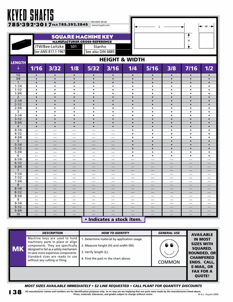
KEYED SHAFTSREVISED 09-04
MOST SIZES AVAILABLE IMMEDIATELY • $2 LINE REQUESTED • CALL PLANT FOR QUANTITY DISCOUNTS
138
785•392•3017 FAX 785.392.2845
All manufacturer names and numbers are for identification purposes only. In no way are we implying that our parts were made by the manufacturers listed above.Prices, materials, tolerances, and grades subject to change without notice. © G.L. Huyett 2004
www.huyett.com
LENGTH
MANUFACTURER CROSS-REFERENCESQUARE MACHINE KEY
ITW/Bee-Leitzke 501 StanhoSee ANSI B17.1-1967 See also DIN 6885
•••••••••••••••------------------------------------------------------------------------
•••••••••••••••------------------------------------------------------------------------
•••••••••••••••------------------------------------------------------------------------
•••••••••••••••------------------------------------------------------------------------
•••••••••••••••------------------------------------------------------------------------
•••••••••••••••••••••••------------------------------------------------
1/23/41
1-1/41-1/21-3/4
22-1/42-1/22-3/4
33-1/43-1/23-3/4
44-1/44-1/24-3/4
55-1/45-1/25-3/4
66-1/46-1/26-3/4
77-1/47-1/27-3/4
88-1/48-1/28-3/4
99-1/49-1/29-3/4
10
3/32 1/8 5/32 3/16 1/4 5/16 3/8 7/16 1/2•••••••••••••••••••••••------------------------------------------------
•••••••••••••••••••••••------------------------------------------------
•••••••••••••••••••••••------------------------------------------------
•••••••••••••••••••••••------------------------------------------------
1/16
HEIGHT & WIDTH
Machine keys are used to hold machinery parts in place or align components. They are specifically designed to fail as a safety mechanism to save more expensive components. Standard sizes are ready to use without any cutting or filing.
1. Determine material by application usage.
2. Measure height (H) and width (W).
3. Verify length (L).
4. Find the part in the chart above.COMMON
AVAILABLE IN MOST
SIZES WITH SQUARED,
ROUNDED, OR CHAMFERED ENDS. CALL, E-MAIL, OR FAX FOR A
QUOTE!
DESCRIPTION HOW TO IDENTIFY GENERAL USE
MK
• Indicates a stock item.
H
L W
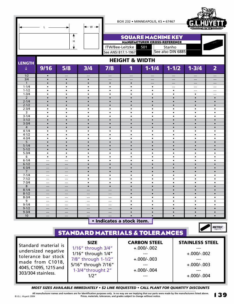
BOX 232 • MINNEAPOLIS, KS • 67467
MOST SIZES AVAILABLE IMMEDIATELY • $2 LINE REQUESTED • CALL PLANT FOR QUANTITY DISCOUNTS
139All manufacturer names and numbers are for identification purposes only. In no way are we implying that our parts were made by the manufacturers listed above.Prices, materials, tolerances, and grades subject to change without notice.© G.L. Huyett 2004
METRICPage 219
MANUFACTURER CROSS-REFERENCESQUARE MACHINE KEY
ITW/Bee-Leitzke 501 StanhoSee ANSI B17.1-1967
•••••••••••••••••••••••------------------------------------------------
---••••••••••••••••••••••------------------------------------------------
---••••••••••••••••••••••••••••••------------------------
------•••••••••••••••••••••••••••••------------------------
1/23/41
1-1/41-1/21-3/4
22-1/42-1/22-3/4
33-1/43-1/23-3/4
44-1/44-1/24-3/4
55-1/45-1/25-3/4
66-1/46-1/26-3/4
77-1/47-1/27-3/4
88-1/48-1/28-3/4
99-1/49-1/29-3/4
10
5/8------•••••••••••••••••••••••••••••••••••••
3/4 7/8 1 1-1/4 1-1/2 1-3/4 2---------••••••••••••••••••••••••••••••••••••
------------•••••••••••••••••••••••••••••••••••
---------------••••••••••••••••••••••••••••••••••
------------------•••••••••••••••••••••••••••••••••
9/16
See also DIN 6885
HEIGHT & WIDTHLENGTH
Standard material is undersized negative tolerance bar stock made from C1018, 4045, C1095, 1215 and 303/304 stainless.
STANDARD MATERIALS & TOLERANCESSIZE
1/16” through 3/4”1/16” through 1/4”7/8” through 1-1/2”5/16” through 7/16”1-3/4”throught 2”
1/2”
CARBON STEEL+.000/-.002
---+.000/-.003
---+.000/-.004
---
STAINLESS STEEL---
+.000/-.002---
+.000/-.003---
+.000/-.004
H
L W
• Indicates a stock item.

LOCKWASHERSREVISED 09-04
MOST SIZES AVAILABLE IMMEDIATELY • $2 LINE REQUESTED • CALL PLANT FOR QUANTITY DISCOUNTS
140
785•392•3017 FAX 785.392.2845
All manufacturer names and numbers are for identification purposes only. In no way are we implying that our parts were made by the manufacturers listed above.Prices, materials, tolerances, and grades subject to change without notice. © G.L. Huyett 2004
www.huyett.com
Diameter(A)
Width(B)
Lbs. perFoot
Depth(C)
Carbon Steel
0.67001.04001.25001.50002.04002.35002.67003.01003.38003.77004.17004.60005.05005.52006.01007.05007.60008.18009.3900
10.020010.680012.780015.870016.690023.040024.040026.040027.120028.200030.360031.560032.640035.040037.560041.400042.720048.120051.000052.560054.0000
BAR KEYWAY
KFKF-0500
-0625-0687-0750-0875-0937-1000-1062-1125-1187-1250-1312-1375-1437-1500-1625-1687-1750-1875-1937-2000-2187-2437-2500-2937-3000-3125-3187-3250-3375-3437-3500-3625-3750-3937-4000-4250-4375-4437
KF-4500
6’
WEIGHT
KEYED SHAFTSMANUFACTURER CROSS-REFERENCE
MATERIALStainless Steel
3’ 6’3’
1/2”5/8”
11/16”3/4”7/8”
15/16”1”
1-1/16”1-1/8”1-3/16”1-1/4”1-5/16”1-3/8”1-7/16”1-1/2”1-5/8”
1-11/16”1-3/4”1-7/8”
1-15/16”2”
2-3/16”2-7/16”2-1/2”
2-15/16”3”
3-1/8” 3-3/16”3-1/4”3-3/8”3-7/16”3-1/2”3-5/8”3-3/4”
3-15/16”4”
4-1/4”4-3/8”4-7/16”4-1/2”
1/16”1/8”
3/32”3/16”
1/8”1/4”
5/32”5/16”
3/16”3/8”
1/4”1/2”
5/16”5/8”
3/8”3/4”
7/16”7/8”
1/2”1”
Fully keyed shafting that provides a good fit between the key and the keyway. Partial keyways and other materials are available, including turned and polished, and medium carbon steel (suitable to heat treat). See the special orders guide on page 136.
1. Confirm the diameter of the shaft (A).2. Determine the keyway width (B) and depth
(C).3. Choose a length of 3’ or 6’. Other lengths
are available. Contact plant for quote.4. Find the part in the chart above.
COMMON
Note: There is some variance in length on this product (+/- 2”) due to the nature of its manufacture. Please specify “Exact Size” if you need a precise length.
LENGTHS OVER 3’ MAY BE SUBJECT
TO APACKAGING
CHARGE.
INDEX PAGE 236. A
C
B
DESCRIPTION HOW TO IDENTIFY GENERAL USE
KF

BOX 232 • MINNEAPOLIS, KS • 67467
MOST SIZES AVAILABLE IMMEDIATELY • $2 LINE REQUESTED • CALL PLANT FOR QUANTITY DISCOUNTS
141All manufacturer names and numbers are for identification purposes only. In no way are we implying that our parts were made by the manufacturers listed above.Prices, materials, tolerances, and grades subject to change without notice.© G.L. Huyett 2004
Most commonly used and least expensive. Note that the key is bent in the opposite direction of the tangs.
1. Verify the face diameter (Dc) of the part.2. Confirm the (ID) of the part.3. Measure the thickness (T).4. Find the part in the chart above.
COMMONAXIAL ASSEMBLY
FOR THICKER VERSION, SEE “WH” ON PAGE 143.
USE WITH N/AN
AND NL LOCKNUTS.
SpringSteel
.3937
.4724
.5906
.6693
.7874
.98431.18111.37801.57481.77171.96852.16542.36222.55912.75592.95283.14963.34653.54333.74023.93704.13394.33074.72445.11815.51185.90556.29926.69297.08667.48037.87408.6614
W-00-01-02-03-04-05-06-07-08-09-10-11-12-13-14-15-16-17-18-19-20-21-22-24-26-28-30-32-34-36-38-40
W-44
LOCKWASHER DIMENSIONS
N-00-01-02-03-04-05-06-07-08-09-10-11-12-13
N-14AN-15
-16-17-18-19-20-21-22-24-26-28-30-32-34-36-38
AN-40N-44
Mating Locknut
Free Outside Dia.
+0/-1/16” (OD)
Bearing Bore Nominal(N)
Inside Dia.(ID)
Min./Max.
Thickness(T)
Min./Max.
Face Dia.(Dc)
Min./Max.
.406/.421
.484/.499
.601/.616
.679/.694
.801/.816.989/1.0091.193/1.2131.396/1.4161.583/1.6031.792/1.8171.992/2.0172.182/2.2072.400/2.4252.588/2.6132.791/2.8162.973/3.0033.177/3.2073.395/3.4253.582/3.6123.800/3.8303.988/4.0184.192/4.2224.395/4.4254.801/4.8315.191/5.2265.582/5.6175.983/6.0186.389/6.4246.764/6.7997.171/7.2067.577/7.6127.982/8.0178.701/8.736
.625/.640
.719/.734
.813/.827
.938/.9531.125/1.1401.281/1.2961.500/1.5151.813/1.8272.000/2.0302.281/2.3112.438/2.4682.656/2.6862.844/2.8743.063/3.0933.313/3.3433.563/3.5933.844/3.8744.031/4.0614.281/4.3264.563/4.6074.813/4.8585.000/5.0455.281/5.3265.688/5.7336.188/6.2336.531/6.5767.063/7.1237.438/7.4988.031/8.0918.375/8.4358.781/8.8419.156/9.2169.875/9.930
7/81-1/641-5/321-21/641-17/321-23/321-59/642-1/4
2-15/322-47/642-59/643-7/643-11/323-37/643-53/644-7/644-3/84-5/8
4-15/165-7/325-1/2
5-45/646-1/166-15/327-1/327-7/168-1/168-7/169-1/169-7/169-7/8
10-5/1611-7/16
WMATERIAL
Number of Tangs
BORE
Decimal MM
1012151720253035404550556065707580859095100105110120130140150160170180190200220
.038/.046
.046/.054
.053/.063
.058/.064
.067/.077
.088/.100
.118/.132
.148/.164
9
11
13
15
17
19
Lbs. per 100 Pieces
WEIGHT
0.37500.50000.62500.87501.12501.56251.87502.50003.75004.37504.37505.31255.46906.25006.8750
10.625012.187512.812518.437520.312521.875024.062534.375040.000050.000051.250075.000077.500092.5000
100.0000102.5000110.0000131.2500
DESCRIPTION HOW TO IDENTIFY GENERAL USE
W
LOCKNUTPage 132N
STANDARDMANUFACTURER CROSS-REFERENCE
Standard Locknut WWhittet-Higgins W
INDEX PAGE 236.
MA
TIN
G L
OC
KN
UT
DES
CR
IPTI
ON
S O
N P
AG
E 13
2.
OD DcID NT

LOCKWASHERSREVISED 09-04
MOST SIZES AVAILABLE IMMEDIATELY • $2 LINE REQUESTED • CALL PLANT FOR QUANTITY DISCOUNTS
142
785•392•3017 FAX 785.392.2845
All manufacturer names and numbers are for identification purposes only. In no way are we implying that our parts were made by the manufacturers listed above.Prices, materials, tolerances, and grades subject to change without notice. © G.L. Huyett 2004
www.huyett.com
Stainless steel version of “W” Series. Passivated to remove impurities.
1. Verify the face diameter (Dc) of the part.2. Confirm the (ID) of the part.3. Measure the thickness (T).4. Find the part in the chart above.
COMMONAXIAL ASSEMBLY
Decimal MM
.3937
.4724
.5906
.6693
.7874
.98431.18111.37801.57481.77171.96852.16542.36222.55912.75592.95283.14963.34653.54333.74023.93704.13394.33074.7244
WS-00-01-02-03-04-05-06-07-08-09-10-11-12-13-14-15-16-17-18-19-20-21-22
WS-24
LOCKWASHER DIMENSIONS
NS-00-01-02-03-04-05-06-07-08-09-10-11-12-13-14-15-16-17-18-19-20-21-22
NS-24
Mating Locknut
Free Outside Dia.
+0/-1/16”(OD)
Bearing Bore Nominal (N)
Inside Dia.(ID)
Min./Max.
Thickness(T)
Min./Max.
Face Dia.(Dc)
Min./Max.
.406/.421
.484/.499
.601/.616
.679/.694
.801/.816.989/1.0091.193/1.2131.396/1.4161.583/1.6031.792/1.8171.992/2.0172.182/2.2072.400/2.4252.588/2.6132.791/2.8162.973/3.0033.177/3.2073.395/3.4253.582/3.6123.800/3.8303.988/4.0184.192/4.2224.395/4.4254.801/4.831
.625/.640
.719/.734
.813/.827
.938/.9531.125/1.1401.281/1.2961.500/1.5151.813/1.8272.000/2.0302.281/2.3112.438/2.4682.656/2.6862.844/2.8743.063/3.0933.313/3.3433.563/3.5933.844/3.8744.031/4.0614.281/4.3264.563/4.6074.813/4.8585.000/5.0455.281/5.3265.688/8.733
7/81-1/641-5/321-21/641-17/321-23/321-59/642-1/4
2-15/322-47/642-59/643-7/643-11/323-37/643-53/644-7/644-3/84-5/8
4-15/165-7/325-1/2
5-45/646-1/166-15/32
WSMATERIAL
Number of Tangs
BORE
1012151720253035404550556065707580859095100105110120
.038/.046
.046/.054
.053/.063
.058/.068
.067/.077
.088/.100
.118/.132
9
11
13
15
17
19
StainlessSteel
USE WITH NS AND
ANS LOCKNUTS.
Lbs. per 100 Pieces
WEIGHT
0.37500.50000.62500.75001.25001.56251.87502.65633.90634.53134.68754.84385.46906.25006.8750
10.938012.500012.813017.812519.375022.000023.125034.000040.0000
DESCRIPTION HOW TO IDENTIFY GENERAL USE
WS
LOCKNUTPage 132N
S
STANDARD STAINLESS STEELMANUFACTURER CROSS-REFERENCE
Standard Locknut WSWhittet-Higgins WS
INDEX PAGE 236.
OD DcID
NT
MA
TIN
G L
OC
KN
UT
DES
CR
IPTI
ON
S O
N P
AG
E 13
2.

BOX 232 • MINNEAPOLIS, KS • 67467
MOST SIZES AVAILABLE IMMEDIATELY • $2 LINE REQUESTED • CALL PLANT FOR QUANTITY DISCOUNTS
143All manufacturer names and numbers are for identification purposes only. In no way are we implying that our parts were made by the manufacturers listed above.Prices, materials, tolerances, and grades subject to change without notice.© G.L. Huyett 2004
Heavier duty, thicker version with the key bent in the same direction as the tangs.
1. Verify the face diameter (Dc) of the part.2. Confirm the (ID) of the part.3. Measure the thickness (T).4. Find the part in the chart above.
UNCOMMONAXIAL ASSEMBLY
FOR THINNER VERSION, SEE “W” ON PAGE 141.
Decimal MMSpringSteel
.133/.147
.406/.421
.484/.499
.601/.616
.679/.694
.801/.816.989/1.0091.193/1.2131.333/1.3531.396/1.4161.583/1.6031.792/1.8171.992/2.0172.182/2.2072.400/2.4252.588/2.6132.791/2.8162.973/3.0033.177/3.2073.395/3.4253.582/3.6123.800/3.8303.988/4.0184.192/4.2224.395/4.4254.801/4.8315.191/5.2265.582/5.6175.983/6.0186.389/6.4246.764/6.7997.171/7.2067.577/7.6127.982/8.017
WH-00-01-02-03-04-05-06
-065-07-08-09-10-11-12-13-14-15-16-17-18-19-20-21-22-24-26-28-30-32-34-36-38
WH-40
Thickness(T)
Min./Max.MatingLocknut
LOCKWASHER DIMENSIONSBearing Bore Nominal
(N)Free Outside
Dia.+0/-1/16”(OD)
Inside Dia.(ID)
Min./Max.
.3937
.4724
.5906
.6693
.7874
.98431.18111.31251.37801.57481.77171.96852.16542.36222.55912.75592.95283.14963.34653.54333.74023.93704.13394.33074.72445.11815.51185.90556.29926.69297.08667.48037.8740
.625/.640
.719/.734
.813/.827
.938/.9531.125/1.1401.281/1.2961.500/1.5151.813/1.8271.813/1.8272.000/2.0302.281/2.3112.438/2.4682.656/2.6862.844/2.8743.063/3.0933.313/3.3433.563/3.5933.844/3.8744.031/4.0614.281/4.3264.563/4.6074.813/4.8585.000/5.0455.281/5.3265.688/5.7336.188/6.2336.531/6.5767.063/7.1237.438/7.4988.031/8.0918.375/8.4358.781/8.8419.156/9.216
57/641-1/321-5/321-11/321-9/161-45/641-61/642-15/642-1/4
2-31/642-23/322-59/643-3/323-21/643-9/163-13/164-3/644-25/644-5/8
4-61/645-15/645-31/645-45/64
66-17/327-3/647-7/168-1/168-29/649-5/649-7/169-55/6410-13/32
NH-00-01-02-03-04-05-06
-065-07-08-09-10-11-12-13-14-15-16-17-18-19-20-21-22-24-26-28-30-32-34-36-38
NH-40
Face Dia.(Dc)
Min./Max.WH
MATERIAL
Number of Tangs
10121517202530
33-1/335404550556065707580859095100105110120130140150160170180190200
.038/.046
.053/.063
.057/.067
.067/.077
.077/.087
.089/.101
.118/.132
.157/.173
.194/.212
9
11
13
15
17
19
Lbs. per 100 Pieces
WEIGHT
0.37500.50000.93751.25001.71902.14292.18753.39293.21434.44405.20835.35705.71436.96408.21439.1667
12.187515.625016.563024.583027.083030.000031.388938.750051.250066.250067.500096.8750
100.0000120.0000127.5000132.5000140.0000
USE WITH NH
LOCKNUTS.
DESCRIPTION HOW TO IDENTIFY GENERAL USE
WH
LOCKNUTPage 133N
H
HEAVY DUTYMANUFACTURER CROSS-REFERENCE
Standard Locknut TW
Whittet-Higgins WH
INDEX PAGE 236.
OD DcID N
T
MA
TIN
G L
OC
KN
UT
DES
CR
IPTI
ON
S O
N P
AG
E 13
3.

LOCKWASHERSREVISED 09-04
MOST SIZES AVAILABLE IMMEDIATELY • $2 LINE REQUESTED • CALL PLANT FOR QUANTITY DISCOUNTS
144
785•392•3017 FAX 785.392.2845
All manufacturer names and numbers are for identification purposes only. In no way are we implying that our parts were made by the manufacturers listed above.Prices, materials, tolerances, and grades subject to change without notice. © G.L. Huyett 2004
www.huyett.com
FINE THREADMANUFACTURER CROSS-REFERENCE
OD DcID
NT
SpringSteel
.750
.8751.0001.1251.2501.3751.5001.6251.7501.8752.0002.2502.5002.750
WIWI-01
-02-03-04-05-06-07-08-09-10-11-12-13
WI-14
LOCKWASHER DIMENSIONS
NI-01-02-03-04-05-06-07-08-09-10-11-12-13
NI-14
Mating Locknut
Free Outside Diameter
+0/-1/16”(OD)
Bearing Bore Nom.
(N)
Inside Dia.(ID)
Min./Max.
Thickness(T)
Min./Max.
MA
TIN
G L
OC
KN
UT
DES
CR
IPTI
ON
S O
N P
AG
E 13
4.
Face Dia.(Dc)
Min./Max.
.797/.828
.922/.9531.047/1.0781.172/1.2031.297/1.3281.422/1.4531.547/1.5781.672/1.7031.797/1.8281.922/1.9532.047/2.0782.297/2.3282.547/2.5782.797/2.828
1.188/1.2031.313/1.3281.438/1.4531.563/1.5781.688/1.7031.938/1.9531.938/1.9532.188/2.2032.313/2.3282.438/2.4532.688/2.7032.875/2.8903.125/3.1403.375/3.390
1.5631.6881.8132.0002.1252.3752.3752.6252.7502.8753.1253.4383.6883.938
MATERIAL
Number of Tangs
BORE
.046/.054
.058/.068
9
11
13
15
17
Lbs. per 100
Pieces
WEIGHT
1.25001.87501.87502.50002.50002.50002.50004.37505.00005.00005.62506.25006.87507.5000
Standard Locknut WINWhittet-Higgins WI
INDEX PAGE 236.
Decimal MMSpringSteel
.3937
.4724
.5906
.6693
.7874
.98431.18111.37801.57481.77171.96852.16542.36222.55912.75592.95283.14963.34653.5433
WT-00-01-02-03-04-05-06-07-08-09-10-11-12-13-14-15-16-17
WT-18
LOCKWASHER DIMENSIONS
NT-00-01-02-03-04-05-06-07-08-09-10-11-12-13-14-15-16-17
NT-18
Mating Locknut
Free Outside Dia.
+0/-1/16”(OD)
Bearing Bore Nominal (N)
Inside Dia. (ID)
Min./Max.
Thickness(T)
Min./Max.
MA
TIN
G L
OC
KN
UT
DES
CR
IPTI
ON
S O
N P
AG
E 13
6.
Face Dia.(Dc)
Min./Max.
.406/.421
.484/.499
.601/.616
.679/.694
.801/.816 .989/1.0091.193/1.2131.396/1.4161.583/1.6031.792/1.8171.992/2.0172.182/2.2072.400/2.4252.588/2.6132.791/2.8162.973/3.0033.177/3.2073.395/3.4253.582/3.612
.531/.551
.625/.645
.750/.770
.875/.8951.000/1.0201.188/1.2081.438/1.4581.656/1.6761.844/1.8642.062/2.0822.250/2.2702.500/2.5202.688/2.7082.875/2.8953.094/3.1143.375/3.3953.594/3.6143.812/3.8324.000/4.020
53/6459/641-3/321-13/641-3/81-9/161-55/642-5/642-1/42-1/2
2-11/162-61/643-3/163-3/8
3-19/323-59/644-9/644-23/644-35/64
MATERIAL
WT Number of Tangs
BORE
10121517202530354045505560657075808590
.036/.044
.046/.054
.058/.068
9
13
15
17
19
Lbs. per 100 Pieces
WEIGHT
11
0.625000.625000.625000.625001.250001.250001.875001.875002.500003.125003.125003.750004.375004.375005.000006.875007.500007.500008.12500
OD DcID NTTHIN SECTION
MANUFACTURER CROSS-REFERENCE
Standard Locknut WTH
Whittet-Higgins WT
INDEX PAGE 236.
LOCKNUTPage 136N
T
LOCKNUTPage 134N
I

BOX 232 • MINNEAPOLIS, KS • 67467
MOST SIZES AVAILABLE IMMEDIATELY • $2 LINE REQUESTED • CALL PLANT FOR QUANTITY DISCOUNTS
145All manufacturer names and numbers are for identification purposes only. In no way are we implying that our parts were made by the manufacturers listed above.Prices, materials, tolerances, and grades subject to change without notice.© G.L. Huyett 2004
EXTERNAL TOOTH RETAINERMANUFACTURER CROSS-REFERENCE
SpringSteel
.3750
.5800
.6250
.6500
.7400
.7500
.7500
.7500
.8120
.8120
.8950
.90001.09501.12501.33502.11502.37503.0000
.1900
.3540
.3940
.4250
.5560
.5050
.5420
.5430
.5400
.1970
.7090
.6250
.8660
.87501.06301.65301.88002.3850
DESIGN DIMENSIONS
ETR
Serves as spacer or retaining collar when used in bores. Teeth flex and resist pullout pressure.
1. Determine the outside diameter (OD) of the part.
2. Confirm the inside diameter (ID).3. Measure the material thickness (T).4. Find the part in the chart above.
WEIRDAXIAL ASSEMBLY
ETR-03712-05812-06210-06515-07415-07515
-07515-01-07536-08110-08130-08915-09015-10915-11215-13315-21115-23715
ETR-30020
Hole SizeDesign
Inside DiameterNominal
(ID)+
/-.0
02
Outside Diameter(OD)
Max.Min.
MaterialThickness
(T)
.3780
.5960
.6360
.6690
.7500
.7530
.7630
.7630
.8250
.8180
.9050
.90801.26801.13001.36002.13002.38203.0100
.3830
.6040
.6400
.6730
.7600
.7630
.7680
.7680
.8350
.8310
.9150
.92001.27201.13701.37002.14602.38703.0180
.0120
.0120
.0100
.0150
.0150
.0150
.0150
.0360
.0100
.0300
.0150
.0150
.0150
.0150
.0150
.0150
.0150
.0200
MATERIAL
ODID
T
FOR OTHER
VERSIONS, SEE
PAGES 90-101.
DESCRIPTION HOW TO IDENTIFY GENERAL USE
ETR
INDEX PAGE 236.
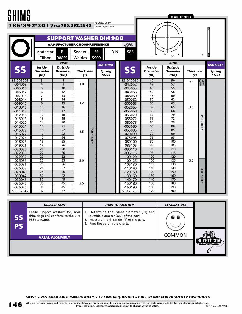
SHIMSREVISED 09-04
MOST SIZES AVAILABLE IMMEDIATELY • $2 LINE REQUESTED • CALL PLANT FOR QUANTITY DISCOUNTS
14�
785•392•3017 FAX 785.392.2845
All manufacturer names and numbers are for identification purposes only. In no way are we implying that our parts were made by the manufacturers listed above.Prices, materials, tolerances, and grades subject to change without notice. © G.L. Huyett 2004
www.huyett.com
SUPPORT WASHER DIN 988MANUFACTURER CROSS-REFERENCE
These support washers (SS) and shim rings (PS) conform to the DIN 988 standards.
1. Determine the inside diameter (ID) and outside diameter (OD) of the part.
2. Measure the thickness (T) of the part.3. Find the part in the charts.
COMMONAXIAL ASSEMBLY
SpringSteel
34567891011121314151516171819202222252526283032353637
SSSS-003006-004008-005010-006012-007013-008014-009015-010016-011017-012018-013019-014020-015021-015022-016022-017024-018025-019026-020028-022030-022032-025035-025036-026037-028040-030042-032045-035045-036045
SS-037047
OutsideDiameter
(OD)Thickness
(T)
6810121314151617181920212222242526283032353637404245454547
InsideDiameter
(ID)
+.0
00/-
.050
SpringSteel
4042454548505052555656606365707580859095100100105110120130140150160170
SSSS-040050-042052-045055-045056-048060-050062-050063-052065-055068-056070-056072-060075-063080-065085-070090-075095-080100-085105-090110-095115-100120-100125-105130-110140-120150-130160-140170-150180-160190
SS-170200
OutsideDiameter
(OD)Thickness
(T)
50525556606263656870727580859095100105110115120125130140150160170180190200
InsideDiameter
(ID)
+.00
0/
-.050
+.0
00/-
.060
+.0
00/-
.080
RING RING
1.0
1.2
1.5
2.0
2.5
2.5
3.0
3.5
SSSeegerRAnderton
5900Waldes988SSEllison
MATERIALMATERIAL
IDOD T
988DIN
HARDENED
INDEX PAGE 236.
DESCRIPTION HOW TO IDENTIFY GENERAL USE
SSPS

BOX 232 • MINNEAPOLIS, KS • 67467
MOST SIZES AVAILABLE IMMEDIATELY • $2 LINE REQUESTED • CALL PLANT FOR QUANTITY DISCOUNTS
147All manufacturer names and numbers are for identification purposes only. In no way are we implying that our parts were made by the manufacturers listed above.Prices, materials, tolerances, and grades subject to change without notice.© G.L. Huyett 2004
3456789101112131415151617181920222526283032353637404245485050525556606365707580859095100105110120130140150160170
PSPS-003006-004008-005010-006012-007013-008014-009015-010016-011017-012018-013019-014020-015021-015022-016022-017024-018025-019026-020028-022032-025035-026037-028040-030042-032045-035045-036045-037047-040050-042052-045055-048060-050062-050063-052065-055068-056072-060075-063080-065085-070090-075095-080100-085105-090110-095115-100120-105130-110140-120150-130160-140170-150180-160190
PS-170200
Inside DiameterMM (ID) -0.03 -0.04 -0.04 -0.04 -0.05 -0.05 -0.05 -0.07 -0.07 -0.07
Outside DiameterMM (OD)
0.1 0.15 0.2 0.25 0.3 0.5 1.0 1.2 1.5 2.0
6810121314151617181920212222242526283235374042454545475052556062636568727580859095100105110115120130140150160170180190200
THICKNESS / THICKNESS TOLERANCE MMRING
IDOD T
SHIM RING DIN 988MANUFACTURER CROSS-REFERENCE
988SSEllisonRAnderton
SSSeegerBossard
988DIN
INDEX PAGE 236.
•••••••••••••••••••••••••••••••••••••••••••••••••••••••
••••••••••••••••••••••••••••••••••••••------•••••••••••••••
•••••••••••••••••••••••••••••••••••••••••••••••••••••••
------------••••---•---•••••••••••••••••••••••••••---••••••••••••••••
•••••••••••••••••••••••••••••••••••••••••••••••••••••••
•••••••••••••••••••••••••••••••••••••••••••••••••••••••
•••••••••••••••••••••••••••••••••••••••••••••••••••••••
------------------------------•••••••••••••••••••••••••••••••••••••------------------------
------------------------------------------------------•••••••••••••••••••••••••••••------------------------
---------------------------------------------------------------------••••••••••••••••••••••••------------------------
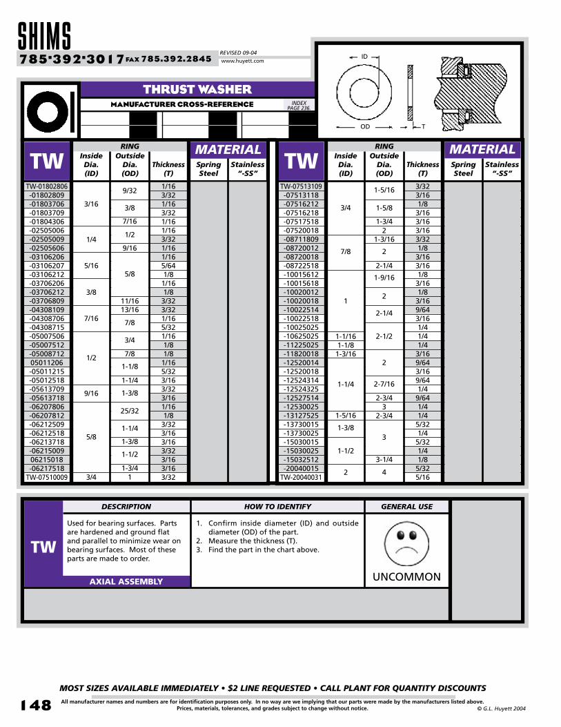
SHIMSREVISED 09-04
MOST SIZES AVAILABLE IMMEDIATELY • $2 LINE REQUESTED • CALL PLANT FOR QUANTITY DISCOUNTS
148
785•392•3017 FAX 785.392.2845
All manufacturer names and numbers are for identification purposes only. In no way are we implying that our parts were made by the manufacturers listed above.Prices, materials, tolerances, and grades subject to change without notice. © G.L. Huyett 2004
www.huyett.com
Used for bearing surfaces. Parts are hardened and ground flat and parallel to minimize wear on bearing surfaces. Most of these parts are made to order.
1. Confirm inside diameter (ID) and outside diameter (OD) of the part.
2. Measure the thickness (T).3. Find the part in the chart above.
UNCOMMONAXIAL ASSEMBLY
THRUST WASHERMANUFACTURER CROSS-REFERENCE
OD T
ID
SpringSteel
TWTW-01802806-01802809-01803706-01803709-01804306-02505006-02505009-02505606-03106206-03106207-03106212-03706206-03706212-03706809-04308109-04308706-04308715-05007506-05007512-0500871205011206-05011215-05012518-05613709-05613718-06207806-06207812-06212509-06212518-06213718-0621500906215018-06217518
TW-07510009
OutsideDia.(OD)
Thickness(T)
InsideDia.(ID)
RING
SpringSteel
TWTW-07513109-07513118-07516212-07516218-07517518-07520018-08711809-08720012-08720018-08722518-10015612-10015618-10020012-10020018-10022514-10022518-10025025-10625025-11225025-11820018-12520014-12520018-12524314-12524325-12527514-12530025-13127525-13730015-13730025-15030015-15030025-15032512-20040015
TW-20040031
OutsideDia.(OD)
Thickness(T)
InsideDia.(ID)
RING MATERIALStainless
“-SS”Stainless
“-SS”
1/163/321/163/321/161/163/321/161/165/641/81/161/83/323/321/165/321/161/81/81/165/323/163/323/161/161/83/323/163/163/323/163/163/32
3/323/161/83/163/163/163/321/83/163/161/83/161/83/169/643/161/41/41/43/169/643/169/641/49/641/41/45/321/45/321/41/85/325/16
3/16
1/4
5/16
3/8
7/16
1/2
9/16
5/8
3/4 11-3/4
1-1/2
1-3/8
1-1/4
25/32
1-3/8
1-1/4
1-1/8
7/8
3/4
7/8
13/1611/16
5/8
9/16
1/2
7/16
3/8
9/32
4
3-1/4
3
2-3/43
2-3/4
2-7/16
2
2-1/2
2-1/4
2
1-9/16
2-1/4
2
1-3/162
1-3/4
1-5/8
1-5/16
3/4
7/8
1
1-1/161-1/81-3/16
1-1/4
1-5/16
1-3/8
1-1/2
2
INDEX PAGE 236.
MATERIAL
DESCRIPTION HOW TO IDENTIFY GENERAL USE
TW

BOX 232 • MINNEAPOLIS, KS • 67467
MOST SIZES AVAILABLE IMMEDIATELY • $2 LINE REQUESTED • CALL PLANT FOR QUANTITY DISCOUNTS
149All manufacturer names and numbers are for identification purposes only. In no way are we implying that our parts were made by the manufacturers listed above.Prices, materials, tolerances, and grades subject to change without notice.© G.L. Huyett 2004
Often used with wave springs to adjust load or as a backup plate for soft metal housings.
1. Determine the outside diameter (OD) of the part.
2. Measure the radial wall (S) and thickness (T) of the part.
3. Find the part in the chart above.
UNCOMMONAXIAL ASSEMBLY
SpringSteel
.750
.8751.0001.1251.2501.3751.5001.6251.7501.8752.0002.1252.2502.3752.5002.6252.7502.8753.0003.1253.2503.3753.5003.6253.7503.8754.0004.1254.2504.3754.5004.6254.7504.8755.0005.125
SRSR-075-087-100-112-125-137-150-162-175-187-200-212-225-237-250-262-275-287-300-312-325-337-350-362-375-387-400-412-425-437-450-462-475-487-500
SR-512
Radial Wall(S)
Thickness(T)
OutsideDiameter
(OD)
RING
+.0
00/-
.020
+.0
00/-
.025
+.0
00/-
.030
+.0
00/-
.015
+.0
00/-
.035
SpringSteel
5.2505.3755.5005.6255.7505.8756.0006.1256.2506.3756.5006.7507.0007.2507.5007.7508.0008.2508.5008.7509.0009.500
10.00010.50011.00011.50012.00012.50013.00013.50014.00014.50015.00015.50016.000
SRSR-525-537-550-562-575-587-600-612-625-637-650-675-700-725-750-775-800-825-850-875-900-950
-1000 -1050 -1100 -1150 -1200 -1250 -1300 -1350 -1400 -1450 -1500 -1550SR-1600
Radial Wall(S)
Thickness(T)
OutsideDiameter
(OD)
RING
+.00
0/
-.035
+.0
00/-
.070
+.0
00/-
.080
+.0
00/-
.045
+.0
00/-
.090
.093
.103
.138
.150
.178
.188
.233
.233
.375
.024
.030
.030
.032
+.0
00/-
.060
SLITTED SHIMMANUFACTURER CROSS-REFERENCE
SSRSSmalley
MATERIALMATERIAL
S
OD
T
Stainless “-SS”
Stainless “-SS”
INDEX PAGE 236.
DESCRIPTION HOW TO IDENTIFY GENERAL USE
SR

METRIC TABLE OF CONTENTSREVISED 09-04
MOST SIZES AVAILABLE IMMEDIATELY • $2 LINE REQUESTED • CALL PLANT FOR QUANTITY DISCOUNTS
150
785•392•3017 FAX 785.392.2845
All manufacturer names and numbers are for identification purposes only. In no way are we implying that our parts were made by the manufacturers listed above.Prices, materials, tolerances, and grades subject to change without notice. © G.L. Huyett 2004
www.huyett.com
Basic External
DSHpage 152
Heavy Duty External
DSHRpage 158
Inverted External
DSHIpage 160
Bowed External
DBSHpage 161
Tabbed External
DAKpage 162
Bowed Tabbed External
DALpage 163 GroovelessDSHF
page 164GroovelessOpen Lug
DSHXpage 165
INTERNAL snap rings
Basic Internal
DHOpage 166
Heavy Duty Internal
DHORpage 171
Inverted Internal
DHOIpage 172
Bowed Internal
DBHOpage 173
Beveled Internal
DVHOpage 174
Tabbed Internal
DJKpage 175
Bowed Tabbed Internal
DJLpage 177
MHOpage 180
Basic InternalANSI
MSHRpage 179
Heavy Duty External ANSI
MSHpage 178
Basic ExternalANSI
MCpage 189
BasicC-Clip
MREpage 188
Reinforced E-Clip
MEpage 188
BasicE-Clip
EBSpage 184
BritishSpec
DCpage 186
BasicC-Clip
DEL Prong Locked E-Clip
DLCpage 187
Interlocking Ringpage 187
page 170MSHR
page 177DE
page 182Basic E-Clip
DREpage 183
Reinforced E-Clip
DSTpage 183
Slotted E-Clip
JEpage 184
Japanese Industrial Spec
Basic External
DSpage 190
External Aerospace
DASpage 192
Basic Internal
DHpage 194
InternalAerospace
DAHpage 196
Basic External
DUSCpage 198
Basic Internal
DUHBpage 200
external snap rings
CLIPS
Spiral rings
ANSI Clips
ANSI snap rings
IMPERIAL SIZES BEGIN ON PAGE 16.
IMPERIAL SIZES BEGIN ON PAGE 24.
IMPERIAL SIZES BEGIN ON PAGE 66.IMPERIAL SIZES BEGIN ON PAGE 34.
DIN471
DIN471
DIN983
DIN472
DIN472
DIN984
DIN6799
DIN471
DIN472
IMPERIAL SIZES BEGIN ON PAGE 4.
BEGINS PAGE 152.
BEGINS PAGE 166.
BEGINS PAGE 182.BEGINS PAGE 178.
BEGINS PAGE 188.
BEGINS PAGE 190. EATONTM ringsBEGINS PAGE 198.

BOX 232 • MINNEAPOLIS, KS • 67467
MOST SIZES AVAILABLE IMMEDIATELY • $2 LINE REQUESTED • CALL PLANT FOR QUANTITY DISCOUNTS
151All manufacturer names and numbers are for identification purposes only. In no way are we implying that our parts were made by the manufacturers listed above.Prices, materials, tolerances, and grades subject to change without notice.© G.L. Huyett 2004
PUSH-ON RINGS Springs
WIRE RINGS
ReinforcedExternal
DTXpage 212
Basic Internal
DTIpage 212
Shaft Retention Washer
DKSpage 213
Triangular Push-On
DTRpage 213
Belleville Disc Spring
DBWpage 214
Standard Wave Spring
DWSpage 216
Round Section External
DRPpage 202
Round Section Internal
DRBpage 203
Round Section Internal
D17page 204
External Radiused Edge
DSPpage 205
Rectangular Section External
DSWpage 206
Rectangular Section Internal
DSBpage 208
Shaft CollarSCMpage 218
Keyed ShaftsKFMpage 218
Shaft Keys32page 219
KMpage 220
Standard Lockwasher
MBpage 221
Standard Locknut
ASSORTMENTS/TOOLS
Standard,Custom
DISPpage 224
PliersPRSpage 226
ApplicatorsRRApage 232
ASSEMBLY COMPONENTS
IMPERIAL SIZES BEGIN ON PAGE 222.
IMPERIAL SIZES BEGIN ON PAGE 126.
IMPERIAL SIZES BEGIN ON PAGE 108.
IMPERIAL SIZES BEGIN ON PAGE 78.
IMPERIAL SIZES BEGIN ON PAGE 90.
Huyett Part # Page #
DSHDSHRDAKDHO
DHORDJKDEDE9DSDHDRPDRBDBW
Machine Keys
471471 Heavy Duty
983472
472 Heavy Duty
98467999133471472
7993A7993B20936885
152158162166171175182185190194202203214219
DIN CROSS REFERENCE
DIN7993A
DIN7993B
DIN 6885
DIN #
BEGINS PAGE 202.
BEGINS PAGE 212. BEGINS PAGE 214.
BEGINS PAGE 218.
BEGINS PAGE 222.
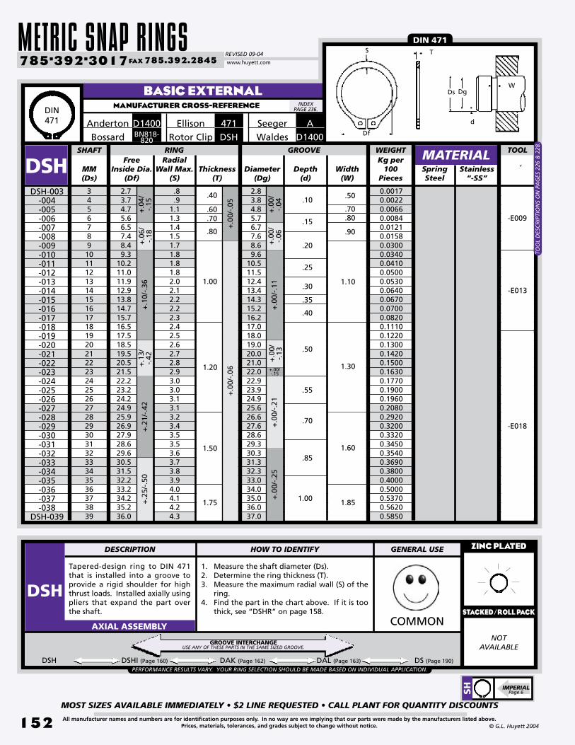
METRIC SNAP RINGSREVISED 09-04
MOST SIZES AVAILABLE IMMEDIATELY • $2 LINE REQUESTED • CALL PLANT FOR QUANTITY DISCOUNTS
152
785•392•3017 FAX 785.392.2845
All manufacturer names and numbers are for identification purposes only. In no way are we implying that our parts were made by the manufacturers listed above.Prices, materials, tolerances, and grades subject to change without notice. © G.L. Huyett 2004
www.huyett.com
BASIC EXTERNALMANUFACTURER CROSS-REFERENCE
Free Inside Dia.
(Df)MM(Ds)
Radial Wall Max.
(S)Thickness
(T)Diameter
(Dg)Depth
(d)SpringSteel
2.73.74.75.66.57.48.49.3
10.211.011.912.913.814.715.716.517.518.519.520.521.522.223.224.224.925.926.927.928.629.630.531.532.233.234.235.236.0
.8
.91.11.31.41.51.71.81.81.82.02.12.22.22.32.42.52.62.72.82.93.03.03.13.13.23.43.53.53.63.73.83.94.04.14.24.3
2.83.84.85.76.77.68.69.6
10.511.512.413.414.315.216.217.018.019.020.021.022.022.923.924.925.626.627.628.629.330.331.332.333.034.035.036.037.0
SHAFT RING
DSH
Tapered-design ring to DIN 471 that is installed into a groove to provide a rigid shoulder for high thrust loads. Installed axially using pliers that expand the part over the shaft.
1. Measure the shaft diameter (Ds).2. Determine the ring thickness (T).3. Measure the maximum radial wall (S) of the
ring.4. Find the part in the chart above. If it is too
thick, see “DSHR” on page 158.
ZINC PLATED
NOTAVAILABLE
COMMONAXIAL ASSEMBLY
DSH-003-004-005-006-007-008-009-010-011-012-013-014-015-016-017-018-019-020-021-022-023-024-025-026-027-028-029-030-031-032-033-034-035-036-037-038
DSH-039
Width(W)
+.0
0/-.
11+
.00/
-.13
+.00/-.15
+.0
0/-.
04
+.0
0/-.
05+
.00/
-.06
GROOVE
+.0
0/-.
21
+.0
4/-.
15+
.10/
-.36
+.1
3/-.
42+
.25/
-.50
3456789101112131415161718192021222324252627282930313233343536373839
.60
.70
.40.10
.15
.20
.25
.35
.55
.70
1.00
.50
.70
1.85
+.0
6/-.
18+
.21/
-.42
+.0
0/-.
25+
.00/
-.06
.40
DSH DSHI (Page 160) DAK (Page 162) DAL (Page 163) DS (Page 190)
MATERIAL
Anderton Seeger A471EllisonD1400DSHRotor ClipBN818-
820Bossard
Stainless “-SS”
.80
1.20
1.50
.30
.50
.85
.80
1.10
.90
1.30
1.60
PERFORMANCE RESULTS VARY. YOUR RING SELECTION SHOULD BE MADE BASED ON INDIVIDUAL APPLICATION.
WEIGHTKg per
100Pieces
DIN 471
0.00170.00220.00660.00840.01210.01580.03000.03400.04100.05000.05300.06400.06700.07000.08200.11100.12200.13000.14200.15000.16300.17700.19000.19600.20800.29200.32000.33200.34500.35400.36900.38000.40000.50000.53700.56200.5850
-E009
-E013
-E018
D1400Waldes
1.00
1.75
TOO
L D
ESC
RIP
TIO
NS
ON
PA
GES
226
& 2
28.
GROOVE INTERCHANGEUSE ANY OF THESE PARTS IN THE SAME SIZED GROOVE.
DIN471
INDEX PAGE 236.
TS
Df
WDg
d
Ds
SH IMPERIAL
Page 6
TOOL
DESCRIPTION HOW TO IDENTIFY GENERAL USE
DSHSTACKED/ROLL PACK
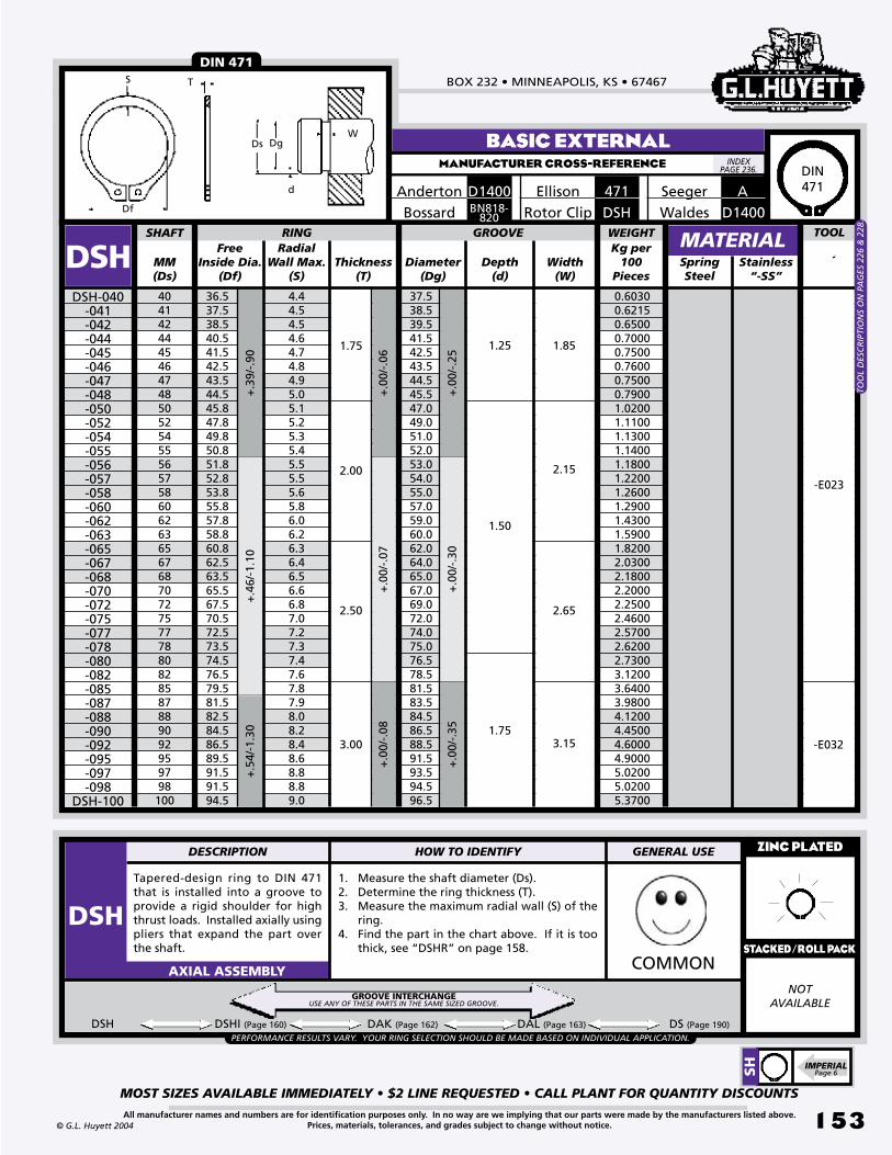
BOX 232 • MINNEAPOLIS, KS • 67467
MOST SIZES AVAILABLE IMMEDIATELY • $2 LINE REQUESTED • CALL PLANT FOR QUANTITY DISCOUNTS
153All manufacturer names and numbers are for identification purposes only. In no way are we implying that our parts were made by the manufacturers listed above.Prices, materials, tolerances, and grades subject to change without notice.© G.L. Huyett 2004
BASIC EXTERNALMANUFACTURER CROSS-REFERENCE
Free Inside Dia.
(Df)MM(Ds)
Radial Wall Max.
(S)Thickness
(T)Diameter
(Dg)Depth
(d)SpringSteel
404142444546474850525455565758606263656768707275777880828587889092959798100
36.537.538.540.541.542.543.544.545.847.849.850.851.852.853.855.857.858.860.862.563.565.567.570.572.573.574.576.579.581.582.584.586.589.591.591.594.5
4.44.54.54.64.74.84.95.05.15.25.35.45.55.55.65.86.06.26.36.46.56.66.87.07.27.37.47.67.87.98.08.28.48.68.88.89.0
37.538.539.541.542.543.544.545.547.049.051.052.053.054.055.057.059.060.062.064.065.067.069.072.074.075.076.578.581.583.584.586.588.591.593.594.596.5
SHAFT RING
DSH
Tapered-design ring to DIN 471 that is installed into a groove to provide a rigid shoulder for high thrust loads. Installed axially using pliers that expand the part over the shaft.
1. Measure the shaft diameter (Ds).2. Determine the ring thickness (T).3. Measure the maximum radial wall (S) of the
ring.4. Find the part in the chart above. If it is too
thick, see “DSHR” on page 158.
ZINC PLATED
NOTAVAILABLE
COMMONAXIAL ASSEMBLY
DSH-040-041-042-044-045-046-047-048-050-052-054-055-056-057-058-060-062-063-065-067-068-070-072-075-077-078-080-082-085-087-088-090-092-095-097-098
DSH-100
Width(W)
+.0
0/-.
25+
.00/
-.30
+.0
0/-.
35
+.0
0/-.
06
GROOVE+
.39/
-.90
+.4
6/-1
.10
+.5
4/-1
.30
1.75
2.00
2.50
3.00
1.25
1.50
1.75
1.85
2.15
2.65
3.15
+.0
0/-.
07+
.00/
-.08
DSH DSHI (Page 160) DAK (Page 162) DAL (Page 163) DS (Page 190)
MATERIAL
Seeger471EllisonD1400AndertonDSHRotor ClipBossard
A
Stainless “-SS”
PERFORMANCE RESULTS VARY. YOUR RING SELECTION SHOULD BE MADE BASED ON INDIVIDUAL APPLICATION.
BN818-820
WEIGHTKg per
100Pieces
DIN 471
0.60300.62150.65000.70000.75000.76000.75000.79001.02001.11001.13001.14001.18001.22001.26001.29001.43001.59001.82002.03002.18002.20002.25002.46002.57002.62002.73003.12003.64003.98004.12004.45004.60004.90005.02005.02005.3700
-E023
-E032
D1400Waldes
TOO
L D
ESC
RIP
TIO
NS
ON
PA
GES
226
& 2
28.
GROOVE INTERCHANGEUSE ANY OF THESE PARTS IN THE SAME SIZED GROOVE.
DIN471
INDEX PAGE 236.
TS
Df
WDg
d
Ds
SH IMPERIAL
Page 6
TOOL
DESCRIPTION HOW TO IDENTIFY GENERAL USE
DSHSTACKED/ROLL PACK
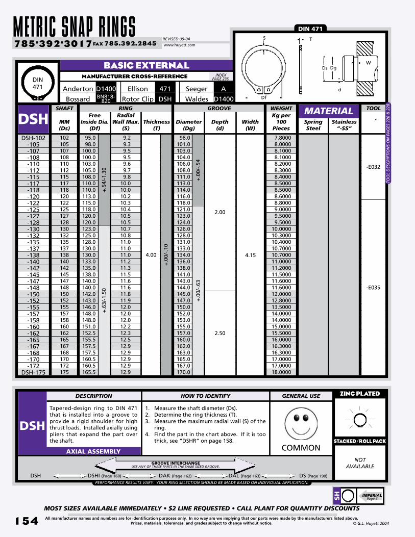
METRIC SNAP RINGSREVISED 09-04
MOST SIZES AVAILABLE IMMEDIATELY • $2 LINE REQUESTED • CALL PLANT FOR QUANTITY DISCOUNTS
154
785•392•3017 FAX 785.392.2845
All manufacturer names and numbers are for identification purposes only. In no way are we implying that our parts were made by the manufacturers listed above.Prices, materials, tolerances, and grades subject to change without notice. © G.L. Huyett 2004
www.huyett.com
BASIC EXTERNALMANUFACTURER CROSS-REFERENCE
Free Inside Dia.
(Df)MM(Ds)
Radial Wall Max.
(S)Thickness
(T)Diameter
(Dg)Depth
(d)SpringSteel
102105107108110112115117118120122125127128130132135137138140142145147148150152155157158160162165167168170172175
95.098.0
100.0100.0103.0105.0108.0110.0110.0113.0115.0118.0120.0120.0123.0125.0128.0130.0130.0133.0135.0138.0140.0140.0142.0143.0146.0148.0148.0151.0152.5155.5157.5157.5160.5160.5165.5
9.29.39.59.59.69.79.8
10.010.010.210.310.410.510.510.710.811.011.011.011.211.311.511.611.611.811.912.012.012.012.212.312.512.912.912.912.912.9
98.0101.0103.0104.0106.0108.0111.0113.0114.0116.0118.0121.0123.0124.0126.0128.0131.0133.0134.0136.0138.0141.0143.0144.0145.0147.0150.0152.0153.0155.0157.0160.0162.0163.0165.0167.0170.0
SHAFT RING
DSH
Tapered-design ring to DIN 471 that is installed into a groove to provide a rigid shoulder for high thrust loads. Installed axially using pliers that expand the part over the shaft.
1. Measure the shaft diameter (Ds).2. Determine the ring thickness (T).3. Measure the maximum radial wall (S) of the
ring.4. Find the part in the chart above. If it is too
thick, see “DSHR” on page 158.
ZINC PLATED
NOTAVAILABLE
COMMONAXIAL ASSEMBLY
DSH-102-105-107-108-110-112-115-117-118-120-122-125-127-128-130-132-135-137-138-140-142-145-147-148-150-152-155-157-158-160-162-165-167-168-170-172
DSH-175
Width(W)
+.0
0/-.
63+
.00/
-.54
GROOVE+
.54/
-1.3
0+
.63/
-1.5
0
4.00
2.00
2.50
4.15
+.0
0/-.
10
DSH DSHI (Page 160) DAK (Page 162) DAL (Page 163) DS (Page 190)
MATERIAL
Seeger A471EllisonD1400Anderton
DSHRotor ClipBN818-820Bossard
Stainless “-SS”
PERFORMANCE RESULTS VARY. YOUR RING SELECTION SHOULD BE MADE BASED ON INDIVIDUAL APPLICATION.
WEIGHTKg per
100Pieces
DIN 471
7.8000 8.0000 8.1000 8.1000 8.2000 8.3000 8.4000 8.5000 8.5000 8.6000 8.8000 9.0000 9.5000 9.500010.000010.300010.400010.700010.700011.000011.200011.500011.600011.600012.000012.800013.500014.000014.000015.000015.500016.000016.300016.300017.000017.000018.0000
-E032
-E035
D1400Waldes
TOO
L D
ESC
RIP
TIO
NS
ON
PA
GES
226
& 2
28.
GROOVE INTERCHANGEUSE ANY OF THESE PARTS IN THE SAME SIZED GROOVE.
DIN471
INDEX PAGE 236.
TS
Df
WDg
d
Ds
SH IMPERIAL
Page 6
TOOL
DESCRIPTION HOW TO IDENTIFY GENERAL USE
DSHSTACKED/ROLL PACK
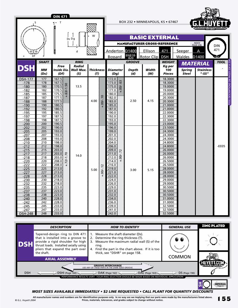
BOX 232 • MINNEAPOLIS, KS • 67467
MOST SIZES AVAILABLE IMMEDIATELY • $2 LINE REQUESTED • CALL PLANT FOR QUANTITY DISCOUNTS
155All manufacturer names and numbers are for identification purposes only. In no way are we implying that our parts were made by the manufacturers listed above.Prices, materials, tolerances, and grades subject to change without notice.© G.L. Huyett 2004
MANUFACTURER CROSS-REFERENCE
Free Inside Dia.
(Df)MM(Ds)
Radial Wall Max.
(S)Thickness
(T)Diameter
(Dg)Depth
(d)SpringSteel
177178180182185187188190192195197198200202205207208210212215217218220222225227228230232235237238240242245247248
167.5167.5170.5170.5175.5177.5177.5180.5180.5185.5187.5187.5190.5190.0193.0193.0193.0198.0198.0203.0203.0203.0208.0208.0213.0213.0213.0218.0218.0223.0223.0223.0228.0228.0233.0233.0233.0
172.0173.0175.0177.0180.0182.0183.0185.0187.0190.0192.0193.0195.0196.0199.0201.0202.0204.0206.0209.0211.0212.0214.0216.0219.0221.0222.0224.0226.0229.0231.0232.0234.0236.0239.0241.0242.0
SHAFT RING
DSH
Tapered-design ring to DIN 471 that is installed into a groove to provide a rigid shoulder for high thrust loads. Installed axially using pliers that expand the part over the shaft.
1. Measure the shaft diameter (Ds).2. Determine the ring thickness (T).3. Measure the maximum radial wall (S) of the
ring.4. Find the part in the chart above. If it is too
thick, see “DSHR” on page 158.
ZINC PLATED
COMMONAXIAL ASSEMBLY
DSH-177-178-180-182-185-187-188-190-192-195-197-198-200-202-205-207-208-210-212-215-217-218-220-222-225-227-228-230-232-235-237-238-240-242-245-247
DSH-248
Width(W)
+.0
0/-.
10+
.00/
-.12
GROOVE+
.72/
-1.7
0
4.00
5.00
14.0
2.50
3.00
4.15
5.15
DSH DSHI (Page 160) DAK (Page 162) DAL (Page 163) DS (Page 190)
MATERIAL
BASIC EXTERNAL
Seeger471EllisonD1400Anderton
DSHRotor ClipBN818-820Bossard
A
Stainless “-SS”
13.5
+.6
3/-1
.50
+.0
0/-.
63
PERFORMANCE RESULTS VARY. YOUR RING SELECTION SHOULD BE MADE BASED ON INDIVIDUAL APPLICATION.
+.0
0/-.
72
WEIGHTKg per
100Pieces
DIN 471
18.300018.300019.000019.000020.000020.300020.300021.000021.000022.000022.300022.300023.000023.500024.300024.300024.300024.800024.800026.000026.000026.000026.500026.500028.000028.000028.000029.000029.000030.500030.500030.500031.000031.000032.500032.500032.5000
-E035
D1400Waldes
TOO
L D
ESC
RIP
TIO
NS
ON
PA
GES
226
& 2
28.
GROOVE INTERCHANGEUSE ANY OF THESE PARTS IN THE SAME SIZED GROOVE.
DIN471
INDEX PAGE 236.
TS
Df
WDg
d
Ds
SH IMPERIAL
Page 6
TOOL
DESCRIPTION HOW TO IDENTIFY GENERAL USE
DSH

METRIC SNAP RINGSREVISED 09-04
MOST SIZES AVAILABLE IMMEDIATELY • $2 LINE REQUESTED • CALL PLANT FOR QUANTITY DISCOUNTS
15�
785•392•3017 FAX 785.392.2845
All manufacturer names and numbers are for identification purposes only. In no way are we implying that our parts were made by the manufacturers listed above.Prices, materials, tolerances, and grades subject to change without notice. © G.L. Huyett 2004
www.huyett.com
BASIC EXTERNALMANUFACTURER CROSS-REFERENCE
Free Inside Dia.
(Df)MM(Ds)
Radial Wall Max.
(S)Thickness
(T)Diameter
(Dg)Depth
(d)SpringSteel
250252255257258260262265267268270272275277278280282285278288290292295297298300305310315320325330335340345350355
238.0238.0240.0240.0240.0245.0245.0250.0250.0250.0255.0255.0260.0260.0260.0265.0265.0270.0270.0270.0275.0275.0280.0280.0280.0285.0288.0293.0298.0303.0308.0313.0318.0323.0328.0333.0338.0
244.0244.0247.0249.0250.0252.0254.0257.0259.0260.0262.0264.0267.0269.0270.0272.0274.0277.0279.0280.0282.0284.0287.0289.0290.0292.0295.0300.0305.0310.0315.0320.0325.0330.0335.0340.0345.0
SHAFT RING
DSH
Tapered-design ring to DIN 471 that is installed into a groove to provide a rigid shoulder for high thrust loads. Installed axially using pliers that expand the part over the shaft.
1. Measure the shaft diameter (Ds).2. Determine the ring thickness (T).3. Measure the maximum radial wall (S) of the
ring.4. Find the part in the chart above. If it is too
thick, see “DSHR” on page 158.
ZINC PLATED
NOTAVAILABLE
COMMONAXIAL ASSEMBLY
DSH-250-252-255-257-258-260-262-265-267-268-270-272-275-277-278-280-282-285-287-288-290-292-295-297-298-300-305-310-315-320-325-330-335-340-345-350
DSH-355
Width(W)
+.0
0/-.
81
+.0
0/-.
12+
.00/
-.15
-E035
GROOVE
+.0
0/-.
89
+.8
1/-2
.00
+.9
0/-2
.00
3.00
5.00
14.0
20.0
5.00
6.00
5.15
6.20
DSH DSHI (Page 160) DAK (Page 162) DAL (Page 163) DS (Page 190)
MATERIAL
Seeger A471EllisonD1400Anderton
DSHRotor ClipBN818-820
Stainless “-SS”
+.7
2/-1
.70
4.0016.0
+.0
0/-.
72
PERFORMANCE RESULTS VARY. YOUR RING SELECTION SHOULD BE MADE BASED ON INDIVIDUAL APPLICATION.
WEIGHTKg per
100Pieces
Bossard
DIN 471
33.500033.500034.800034.800034.800035.500035.500037.000037.000037.000037.500037.500039.000039.000039.000039.800039.800041.000041.000041.000041.800041.800043.000043.000043.000044.000073.800075.000076.000077.000078.700080.000082.600084.000084.500085.000086.5000
-E045
D1400Waldes
TOO
L D
ESC
RIP
TIO
NS
ON
PA
GES
226
& 2
28.
GROOVE INTERCHANGEUSE ANY OF THESE PARTS IN THE SAME SIZED GROOVE.
DIN471
INDEX PAGE 236.
TS
Df
WDg
d
Ds
SH IMPERIAL
Page 6
TOOL
DESCRIPTION HOW TO IDENTIFY GENERAL USE
DSHSTACKED/ROLL PACK

BOX 232 • MINNEAPOLIS, KS • 67467
MOST SIZES AVAILABLE IMMEDIATELY • $2 LINE REQUESTED • CALL PLANT FOR QUANTITY DISCOUNTS
157All manufacturer names and numbers are for identification purposes only. In no way are we implying that our parts were made by the manufacturers listed above.Prices, materials, tolerances, and grades subject to change without notice.© G.L. Huyett 2004
MANUFACTURER CROSS-REFERENCE
Tapered-design ring to DIN 471 that is installed into a groove to provide a rigid shoulder for high thrust loads. Installed axially using pliers that expand the part over the shaft.
1. Measure the shaft diameter (Ds).2. Determine the ring thickness (T).3. Measure the maximum radial wall (S) of the
ring.4. Find the part in the chart above. If it is too
thick, see “DSHR” on page 158.
ZINC PLATED
NOTAVAILABLE
COMMONAXIAL ASSEMBLY
DSH DSHI (Page 160) DAK (Page 162) DAL (Page 163) DS (Page 190)
BASIC EXTERNAL
Seeger471EllisonD1400Anderton
DSHRotor ClipBN818-820Bossard
A
Free Inside Dia.
(Df)MM(Ds)
Radial Wall Max.
(S)Thickness
(T)Diameter
(Dg)Depth
(d)SpringSteel
3603653703753803853903954004104204304404504604704804905005105205305405505605705805906006507007508008509009501000
343.0348.0353.0358.0363.0368.0373.0378.0383.0390.0400.0410.0420.0430.0440.0450.0460.0470.0480.0485.0495.0505.0515.0525.0535.0545.0555.0565.0575.0620.0670.0715.0765.0810.0860.0900.0950.0
350.0355.0360.0365.0370.0375.0380.0385.0390.0398.0408.0418.0428.0438.0448.0458.0468.0478.0488.0496.0506.0516.0526.0536.0546.0556.0566.0576.0586.0634.0684.0732.0782.0830.0880.0928.0978.0
SHAFT RING
DSHDSH-360
-365-370-375-380-385-390-395-400-410-420-430-440-450-460-470-480-490-500-510-520-530-540-550-560-570-580-590-600-650-700-750-800-850-900-950
DSH-1000
Width(W)
GROOVE MATERIALStainless
“-SS”
+.0
0/-1
.00
+.0
0/-.
15+
.00/
-.20
+1.
00/-
2.00
+1.
50/-
3.00
+2.0
0/-4
.00
8.00
9.00
26.0
34.0
6.00
7.00
7.20
8.20
9.2010.00
11.00
8.00
9.00
7.00
+.9
0/-2
.00
20.0 5.00 6.206.00
+.0
0/-.
89
PERFORMANCE RESULTS VARY. YOUR RING SELECTION SHOULD BE MADE BASED ON INDIVIDUAL APPLICATION.
DIN 471
-E045
-048
WEIGHTKg per
100Pieces
88.0000 88.5000 89.0000 91.0000 93.0000 94.0000 95.0000 99.0000104.0000132.0000136.0000139.0000142.0000145.0000152.0000159.0000166.0000172.5000179.0000230.0000235.0000240.0000244.5000249.0000258.0000267.0000276.0000284.0000292.0000377.0000407.0000464.0000533.0000603.0000664.0000726.0000813.0000
TS
Df
WDg
d
Ds
D1400Waldes
TOO
L D
ESC
RIP
TIO
NS
ON
PA
GES
226
& 2
28.
GROOVE INTERCHANGEUSE ANY OF THESE PARTS IN THE SAME SIZED GROOVE.
DIN471
INDEX PAGE 236.
SH IMPERIAL
Page 6
TOOL
DESCRIPTION HOW TO IDENTIFY GENERAL USE
DSHSTACKED/ROLL PACK

METRIC SNAP RINGSREVISED 09-04
MOST SIZES AVAILABLE IMMEDIATELY • $2 LINE REQUESTED • CALL PLANT FOR QUANTITY DISCOUNTS
158
785•392•3017 FAX 785.392.2845
All manufacturer names and numbers are for identification purposes only. In no way are we implying that our parts were made by the manufacturers listed above.Prices, materials, tolerances, and grades subject to change without notice. © G.L. Huyett 2004
www.huyett.com
Extra-thick version of the DIN 471 DSH that is stronger and yields higher thrust loads. Installed axially using the same tools. Note that the DSHR will require a wider groove than the DSH.
1. Measure the shaft diameter (Ds).2. Determine the ring thickness (T).3. Measure the maximum radial wall (S) of the
ring.4. Find the part in the chart above. If it is too
thin, see “DSH” on page 152.UNCOMMONAXIAL ASSEMBLY
HEAVY DUTY EXTERNALMANUFACTURER CROSS-REFERENCE
EXTEllisonD1460Anderton
BN821Bossard
DIN 471 - HEAVY DUTY TYPE
ASSeeger
Free Inside Dia.
(Df)MM(Ds)
Thickness(T)
Diameter(Dg)
Depth(d)
SpringSteel
SHAFT RING
DSHR Width(W)
+.0
0/-.
11+
.00/
-.15
+.1
0/-.
36GROOVE
+.0
0/-.
06
-E013-E018-E013-E018
RadialWall Max.
(S)
1.50
1.75
2.00
1.60
1.85
2.15
MATERIALWEIGHTKg per
100Pieces
-E013
-E018
-E023
-E018
DSHR-012-015
-015B -015C
-016 -016A -016B
-017 -017B
-018 -018A
-019 -019B
-020 -020B -020C
-022 -022A
-023-024
-024A-025
-025A-026-027-028
-028A-029
-029A-030
-030B-032-033
-033A-034
-034A-035
-035A-036
DSHR-036A
+.2
1/-.
42
2.50
+.0
0/-.
07
2.65
+.0
0/-.
21+
.00/
-.25 -E023
12151515161616171718181919202020222223242425252627282829293030323333343435353636
11.013.813.813.714.714.714.615.715.716.516.317.517.518.518.318.420.520.321.322.222.023.223.023.624.725.925.526.926.927.927.629.631.330.531.531.332.232.033.233.0
1.82.42.02.4 2.52.32.52.62.32.72.42.82.53.03.02.63.13.23.23.23.23.43.43.33.43.53.53.83.54.13.74.14.04.04.24.24.24.1 4.24.2
11.514.314.214.215.215.215.116.216.017.016.818.017.819.018.818.921.020.821.822.922.723.723.724.425.526.626.427.627.628.628.330.331.331.332.132.133.032.834.033.8
.25
.35
.40
.40
.40
.40
.45
.40
.50
.50
.60
.50
.60
.50
.60
.55
.50
.60
.60
.55
.65
.65
.65
.80
.75
.70
.80
.70
.70
.70
.85
.85
.85
.85
.95
.951.001.101.001.10
+.2
5/-.
50
0.07500.12000.12000.11400.12000.12000.10800.12400.12400.15400.15400.14500.14500.22500.23100.22500.23000.24000.26000.27000.27000.33500.24000.36500.38500.39000.39000.43000.40700.50000.45000.54000.52000.52000.68000.68000.71000.70000.75000.7500
2.001.50
DIN471
INDEX PAGE 236.
T d
W
Df
S
DsDg
DSHR CONTINUED NEXT PAGE.
TOOL
DESCRIPTION HOW TO IDENTIFY GENERAL USE
DSHR
TOO
L D
ESC
RIP
TIO
NS
ON
PA
GE
226
& 2
28.

BOX 232 • MINNEAPOLIS, KS • 67467
MOST SIZES AVAILABLE IMMEDIATELY • $2 LINE REQUESTED • CALL PLANT FOR QUANTITY DISCOUNTS
159All manufacturer names and numbers are for identification purposes only. In no way are we implying that our parts were made by the manufacturers listed above.Prices, materials, tolerances, and grades subject to change without notice.© G.L. Huyett 2004
Extra-thick version of the DIN 471 DSH that is stronger and yields higher thrust loads. Installed axially using the same tools. Note that the DSHR will require a wider groove than the DSH.
1. Measure the shaft diameter (Ds).2. Determine the ring thickness (T).3. Measure the maximum radial wall (S) of the
ring.4. Find the part in the chart above. If it is too
thin, see “DSH” on page 152.UNCOMMONAXIAL ASSEMBLY
HEAVY DUTY EXTERNALMANUFACTURER CROSS-REFERENCE
EXTEllisonD1460Anderton
BN821Bossard
DIN 471 - HEAVY DUTY TYPE
ASSeeger
Free Inside Dia.
(Df)MM(Ds)
Thickness(T)
Diameter(Dg)
Depth(d)
SpringSteel
38384042444548505255586065707580859095
100105110115120125130135140145150155160165170175180185190195200
35.235.036.538.540.5 41.544.545.847.850.853.855.860.865.570.574.579.584.589.594.598.0
103.0108.0113.0118.0123.0128.0133.0138.0142.0146.0151.0155.5160.5165.5170.5175.5180.5185.5190.5
4.34.54.44.54.54.75.05.15.25.45.65.86.36.67.07.47.88.28.69.09.39.69.8
10.210.410.711.011.211.511.812.012.212.512.912.913.513.514.014.014.0
DSHR
DSHR-038 -038A
-040-042-044-045-048-050-052-055-058-060-065-070-075-080-085-090-095-100-105-110-115-120-125-130-135-140-145-150-155-160-165-170-175-180-185-190-195
DSHR-200
Width(W)
RadialWall Max.
(S)
SHAFT RING GROOVE
36.035.837.539.541.542.545.547.049.052.055.057.062.067.072.076.581.586.591.596.5
101.0106.0111.0116.0121.0126.0131.0136.0141.0145.0150.0155.0160.0165.0170.0175.0180.0185.0190.0195.0
MATERIAL
+.0
0/-.
30+.
00/
-.35
+.00
/-.54
+.4
6/-1
.10
+.0
0/-.
103.00
4.00
3.15
4.15
1.50
1.75
2.00
+.00
/-.08
+.2
5/-.
50
2.50
+.00
/-.07
+.0
0/-.
25
1.252.65
WEIGHTKg per
100Pieces
-E023
+.3
9/-.
90+
.63/
-1.5
0+
.54/
-1.3
0+
.72/
-1.7
0
5.00
+.0
0/-.
12
5.15
+.0
0/-.
72+
.00/
-.63
1.001.10
2.50
-E035
0.80000.80000.82000.96001.04001.08001.22001.48001.54001.70001.94002.00003.10003.22003.98004.24004.70005.56006.12007.2000
10.000010.200010.500010.700011.200012.500013.000013.700014.300015.000016.900018.700020.000021.300022.500023.800025.000026.300027.500028.8000
-E032
DIN471
INDEX PAGE 236.
T d
W
Df
S
DsDg
IMPERIALPage 9
SHR
TOOL
DESCRIPTION HOW TO IDENTIFY GENERAL USE
DSHR
TOO
L D
ESC
RIP
TIO
NS
ON
PA
GE
226
& 2
28.

METRIC SNAP RINGSREVISED 09-04
MOST SIZES AVAILABLE IMMEDIATELY • $2 LINE REQUESTED • CALL PLANT FOR QUANTITY DISCOUNTS
1�0
785•392•3017 FAX 785.392.2845
All manufacturer names and numbers are for identification purposes only. In no way are we implying that our parts were made by the manufacturers listed above.Prices, materials, tolerances, and grades subject to change without notice. © G.L. Huyett 2004
www.huyett.com
INVERTED EXTERNALMANUFACTURER CROSS-REFERENCE
Tapered section ring similar to the DSH, except the lugs are inverted (on the ID), to allow use in tight areas with minimal clearance. Less thrust load than DSH. Installed axially using pliers.
1. Measure the shaft diameter (Ds).2. Determine the ring thickness (T).3. Measure the maximum radial wall (S).4. Find the part in the chart above.
UNCOMMONAXIAL ASSEMBLY
MM(Ds)
Diameter(Dg)
SpringSteel
101213141516171820212223242526283032343538404245474850555860657072758082858790100
DSHIDSHI-010
-012-013-014-015-016-017-018-020-021-022-023-024-025-026-028-030-032-034-035-038-040-042-045-047-048-050-055-058-060-065-070-072-075-080-082-085-087-090
DSHI-100
+.0
0/-.
25
Free Inside Dia.
(Df)+.00/-.05
+.0
0/-.
06+
.00/
-.07
+.00
/-.08
Depth(d)
Width(W)
SHAFT RING
Thickness(T)
Radial Wall Max.
(S)
GROOVE+
.10/
-.36
+.13
/-.42
+.2
1/-.
42+
.46/
-1.1
0
9.211.011.912.913.814.715.716.518.519.3520.521.522.223.224.225.927.929.631.532.234.536.538.541.543.544.545.850.853.855.860.865.567.570.574.576.579.581.584.594.5
1.82.12.12.12.22.32.42.62.82.83.03.13.23.43.53.83.94.03.54.24.54.74.74.75.05.25.25.85.85.86.06.56.56.57.07.07.47.47.48.0
9.511.512.413.414.315.216.217.019.020.021.022.022.923.924.926.628.630.332.333.035.837.539.542.544.545.547.052.055.057.062.067.069.072.076.578.581.583.586.596.5
+/-
.1+
/-.2
+/-
.3
.60
1.00
1.20
1.50
1.75
2.00
2.50
3.00
.70
1.10
1.30
1.60
1.85
2.15
2.65
3.15
.35
1.001.10+
.25/
-.50
+.3
9/-.
90+
.54/
-1.3
0
+.0
0/-.
11+
.00/
-.21
+.0
0/-.
15+
.00/
-.30
+.00
/-.35
DSHI DSH (Page 152) DAK (Page 162) DAL (Page 163) DS (Page 190)
MATERIAL
EXTVEllisonM1408Anderton
BN829Bossard
INVERTED LUGS
..25
..30
..40
..50
..55
..70
..85
.1.25
.1.50
.1.75
PERFORMANCE RESULTS VARY. YOUR RING SELECTION SHOULD BE MADE BASED ON INDIVIDUAL APPLICATION.
WEIGHTKg per
100Pieces
0.02500.05000.05600.05800.06600.07200.08100.11400.14300.15300.16300.17800.19000.21000.21800.31800.35800.38800.36000.45300.55000.64900.65100.78000.80900.84800.98401.14201.30001.38002.07502.37002.47002.75002.89002.96503.95004.00004.19204.9920
-E009
-E013
-E018
-E023
AVSeeger
-E032
GROOVE INTERCHANGEUSE ANY OF THESE PARTS IN THE SAME SIZED GROOVE.
INDEX PAGE 236.
Dg
d
TS
Df
Ds
W
IMPERIALPage 10
SHI
TOOL
DESCRIPTION HOW TO IDENTIFY GENERAL USE
DSHI
TOO
L PR
ICES
AN
D D
ESC
RIP
TIO
NS
ON
PA
GE
226.
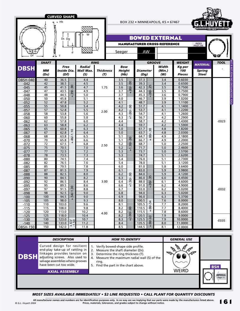
BOX 232 • MINNEAPOLIS, KS • 67467
MOST SIZES AVAILABLE IMMEDIATELY • $2 LINE REQUESTED • CALL PLANT FOR QUANTITY DISCOUNTS
1�1All manufacturer names and numbers are for identification purposes only. In no way are we implying that our parts were made by the manufacturers listed above.Prices, materials, tolerances, and grades subject to change without notice.© G.L. Huyett 2004
Free Inside Dia.
(Df)MM(Ds)
Thickness(T)
Diameter(Dg)
SpringSteel
40424547485052555758606263656768707275777880828587889092959798100105110115120125130140150
36.538.541.543.544.545.847.850.852.853.855.857.858.860.862.863.865.867.570.572.573.574.576.579.581.582.584.586.589.591.592.594.598.0
103.0108.0113.0118.0123.0133.0142.0
4.44.54.74.95.05.15.25.45.55.65.86.06.26.36.46.56.66.87.07.27.37.47.67.87.98.08.28.48.68.89.09.09.39.69.8
10.210.410.711.211.8
SHAFT RING
DBSH
1. Verify bowed-shape side profile.2. Measure the shaft diameter (Ds).3. Determine the ring thickness (T).4. Measure the maximum radial wall (S) of the
ring.5. Find the part in the chart above.
WEIRDAXIAL ASSEMBLY
DBSH-040-042-045-047-048-050-052-055-057-058-060-062-063-065-067-068-070-072-075-077-078-080-082-085-087-088-090-092-095-097-098-100-105-110-115-120-125-130-140
DBSH-150
+1.
00/-
.00
+1.
30/-
.00
+.8
0/-.
00
+.3
9/-.
90+
.46/
-1.1
0+
.54/
-1.3
0
GROOVE
+1.
50/-
.00
Radial Wall Max.
(S)
Width(Min.)
(W)
Bow Height
(Hb)
3.53.53.63.73.74.04.14.24.24.34.34.44.45.05.05.15.15.25.25.35.35.45.46.06.16.26.36.46.66.76.86.98.08.18.28.28.28.38.48.5
37.339.342.344.345.346.748.751.753.754.756.758.759.761.763.764.766.768.771.773.774.776.078.081.083.084.086.088.091.093.094.096.0
100.5105.5110.5115.5120.5125.5135.5144.5
3.43.43.53.53.63.93.94.14.14.14.24.24.24.84.84.94.95.05.05.05.15.15.15.85.95.96.06.16.26.26.36.37.67.77.77.87.97.98.08.1
Curved design for resilient end-play take-up of rattling in linkages provides tension on adjusting screws. Also used to salvage assemblies where grooves have been cut too wide.
+.0
0/-.
25+
.00/
-.30
+.0
0/-.
35+.
00/-.
54
1.75
2.00
2.50
3.00
4.00
+2.
00/-
.00
+.00
/-.63
BOWED EXTERNALMANUFACTURER CROSS-REFERENCE
MATERIAL
AWSeeger
+.6
3/-1
.50
CURVED SHAPE
WEIGHTKg per
100Pieces
-E023
-E032
-E035
0.6030 0.6500 0.7500 0.7500 0.7900 1.0200 1.1100 1.1400 1.2200 1.2600 1.2900 1.4300 1.5900 1.8200 2.0300 2.1800 2.2000 2.2500 2.4600 2.5700 2.6200 2.7300 3.1200 3.6400 3.9800 4.1200 4.4500 4.6000 4.9000 5.0200 5.0200 5.3700 8.0000 8.2000 8.4000 8.6000 9.0000 10.0000 11.0000 12.0000
INDEX PAGE 236.
T
W
Df
S
Ds Dg
d
Hb
IMPERIALPage 11
BSH
TOOL
DESCRIPTION HOW TO IDENTIFY GENERAL USE
DBSH
TOO
L D
ESC
RIP
TIO
NS
ON
PA
GE
226
& 2
28.

METRIC SNAP RINGSREVISED 09-04
MOST SIZES AVAILABLE IMMEDIATELY • $2 LINE REQUESTED • CALL PLANT FOR QUANTITY DISCOUNTS
1�2
785•392•3017 FAX 785.392.2845
All manufacturer names and numbers are for identification purposes only. In no way are we implying that our parts were made by the manufacturers listed above.Prices, materials, tolerances, and grades subject to change without notice. © G.L. Huyett 2004
www.huyett.com
External tabs are concentrically positioned for positioning in a concealed assembly. Tabs act as spacers for securing machine components. Conforms to DIN 983.
1. Verify the presence of tabs on the ring periphery.
2. Measure the shaft diameter (Ds).3. Determine the ring thickness (T).4. Measure the maximum radial wall (S) of the
ring.5. Find the part in the chart above. UNCOMMONAXIAL ASSEMBLY
Free Inside Dia.
(Df)MM(Ds)
Thickness(T)
Diameter(Dg)
SpringSteel
1617181920222324252628293032343537384042454748505557586062656768708090100110120130140
14.715.716.517.518.520.521.522.223.224.225.926.927.929.631.532.234.235.236.538.541.543.544.545.850.852.853.855.857.860.862.563.565.574.584.594.5
103.0113.0123.0133.0
2.32.42.52.62.62.82.93.03.03.13.33.43.43.63.83.84.04.14.24.54.64.84.95.05.45.65.75.85.96.26.46.56.67.48.29.09.6
10.110.711.2
SHAFT RING
DAKDAK-016
-017-018-019-020-022-023-024-025-026-028-029-030-032-034-035-037-038-040-042-045-047-048-050-055-057-058-060-062-065-067-068-070-080-090-100-110-120-130
DAK-140
+.0
0/-.
11+
.00/
-.15
+.0
0/-.
30
+.10
/-.36
+.2
5/-.
50+
.39/
-.90
+.4
6/-1
.10GROOVE
+.0
0/-.
25
+.0
0/-.
06+.
00/
-.10
Radial Wall Max.
(S)Depth
(d)Width
(W)
15.216.217.018.019.021.022.022.923.924.926.627.628.630.332.333.035.036.037.539.542.544.545.547.052.054.055.057.059.062.064.065.067.076.586.596.5
106.0116.0126.0136.0
1.00
1.20
1.50
1.75
2.00
2.50
3.00
4.00
1.10
1.30
1.60
1.85
2.15
2.65
3.15
4.15
.40
.50
.55
.70
.85
1.00
1.25
1.50
1.75
2.00
+.5
4/-1
.30
+.2
1/-.
42+.
13/-.
42
+.0
0/-.
07+
.00/
-.08
+.0
0/-.
54+
.00/
-.63
+.0
0/-.
35+
.00/
-.21
DAK DSH (Page 152) DSHI (Page 160) DAL (Page 163) DS (Page 190)
TABBED EXTERNALMANUFACTURER CROSS-REFERENCE
MATERIAL
AKSeegerD2100Anderton
983Ellison
PERFORMANCE RESULTS VARY. YOUR RING SELECTION SHOULD BE MADE BASED ON INDIVIDUAL APPLICATION.
WEIGHTKg per
100Pieces
DIN 983
0.0820 0.0930 0.1240 0.1350 0.1450 0.1770 0.1840 0.1980 0.2120 0.2180 0.3150 0.3350 0.3650 0.4000 0.4150 0.4380 0.6300 0.6500 0.7000 0.7500 0.8500 0.8700 0.8900 1.1550 1.2990 1.4000 1.4300 1.4800 1.5900 2.1700 2.2600 2.3500 2.5100 3.0750 4.7700 5.6600 8.4600 8.970010.500011.5000
-E013
-E018
-E023
-E032
-E035
SAMESIZING AS
DSH,BUT WITH EXTERNAL
TABS.GROOVE INTERCHANGE
USE ANY OF THESE PARTS IN THE SAME SIZED GROOVE.
DIN983
Ds
T
S
Df Dg
d
W
INDEX PAGE 236.
TOOL
DESCRIPTION HOW TO IDENTIFY GENERAL USE
DAK
983DIN
TOO
L D
ESC
RIP
TIO
NS
ON
PA
GES
226
& 2
28.
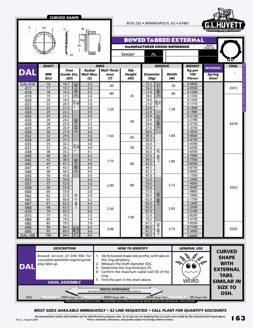
BOX 232 • MINNEAPOLIS, KS • 67467
MOST SIZES AVAILABLE IMMEDIATELY • $2 LINE REQUESTED • CALL PLANT FOR QUANTITY DISCOUNTS
1�3All manufacturer names and numbers are for identification purposes only. In no way are we implying that our parts were made by the manufacturers listed above.Prices, materials, tolerances, and grades subject to change without notice.© G.L. Huyett 2004
BOWED TABBED EXTERNALMANUFACTURER CROSS-REFERENCE
Bowed version of DIN 983 for concealed assemblies requiring end-play take-up.
1. Verify bowed-shape side profile, with tabs on the ring periphery.
2. Measure the shaft diameter (Ds).3. Determine the ring thickness (T).4. Confirm the maximum radial wall (S) of the
ring.5. Find the part in the chart above. WEIRDAXIAL ASSEMBLY
DAL DSH (Page 152) DSHI (Page 160) DAK (Page 162) DS (Page 190)
ALSeeger
Free Inside Dia.
(Df)MM(Ds)
Diameter(Dg)
SpringSteel
1617181920222324252628293032343537384042454748505557586062656768707580859095100
14.715.716.517.518.520.521.522.223.224.225.926.927.929.631.532.234.235.236.538.541.543.544.545.850.852.853.855.857.860.862.563.565.570.574.579.584.589.594.5
2.32.42.52.62.62.82.93.03.03.13.33.43.43.63.83.84.04.14.24.54.64.84.95.05.45.65.75.85.96.26.46.56.67.07.47.88.28.69.0
SHAFT
DALDAL-016
-017-018-019-020-022-023-024-025-026-028-029-030-032-034-035-037-038-040-042-045-047-048-050-055-057-058-060-062-065-067-068-070-075-080-085-090-095
DAL-100
+.10
/-.36
+.1
3/-.
42+
.39/
-.90
+.4
6/-1
.10
TabHeight
(Ht)
Radial Wall Max.
(S)
Wall Thick-ness(T)
Width(W)
RING GROOVE
15.216.217.018.019.021.022.022.923.924.926.627.628.630.332.333.035.036.037.539.542.544.545.547.052.054.055.057.059.062.064.065.067.072.076.581.586.591.596.5
+.00
/-.11
+.0
0/-.
25+
.00/
-.30
+.00
/-.54
.60
.80
1.20
1.50
1.75
2.00
2.50
3.00
.70
.90
1.30
1.60
1.85
2.15
2.65
3.15
.35
.40
.45
.50
.60
.80
1.00
+.2
5/-.
50+
.21/
-.42
+.5
4/-1
.30
+.0
0/-.
15+
.00/
-.21
MATERIAL
CURVED SHAPE
PERFORMANCE RESULTS VARY. YOUR RING SELECTION SHOULD BE MADE BASED ON INDIVIDUAL APPLICATION.
WEIGHTKg per
100Pieces
Ht
S Df W
Ds
Dg
T
-E013
-E018
-E023
TOO
L D
ESC
RIP
TIO
NS
ON
PA
GES
226
& 2
28.
0.0820 0.0930 0.1240 0.1350 0.1450 0.1770 0.1840 0.1980 0.2120 0.2180 0.3150 0.3350 0.3650 0.4000 0.4150 0.4380 0.6300 0.6500 0.7000 0.7500 0.8500 0.8700 0.8900 1.1550 1.2990 1.4000 1.4300 1.4800 1.5900 2.1700 2.2600 2.3500 2.5100 2.8200 3.0750 3.9500 4.7700 5.3000 5.6600
CURVED SHAPE WITH
EXTERNAL TABS.
SIMILAR IN SIZE TO
DSH.
-E032
GROOVE INTERCHANGEUSE ANY OF THESE PARTS IN THE SAME SIZED GROOVE.
INDEX PAGE 236.
TOOL
DESCRIPTION HOW TO IDENTIFY GENERAL USE
DAL

METRIC SNAP RINGSREVISED 09-04
MOST SIZES AVAILABLE IMMEDIATELY • $2 LINE REQUESTED • CALL PLANT FOR QUANTITY DISCOUNTS
1�4
785•392•3017 FAX 785.392.2845
All manufacturer names and numbers are for identification purposes only. In no way are we implying that our parts were made by the manufacturers listed above.Prices, materials, tolerances, and grades subject to change without notice. © G.L. Huyett 2004
www.huyett.com
Reusable tapered section ring for grooveless shafts like plastics, tubes, and castings, or where adjustable ring placement is desired (like progressively tightening a compression spring). Installed using pliers.
WEIRDAXIAL ASSEMBLY
GROOVELESSMANUFACTURER CROSS-REFERENCE
GASeeger
DSHF DSHX (Page 165) DTX (Page 212) DTR (Page 213) DKS (Page 213)
1. Measure the shaft diameter (Ds).2. Determine the ring thickness (T).3. Find the part in the chart above.
Note: In metric applications, the DSHX (page 165) seems to be more popular.
ADJUSTABLE AND REMOVABLE
Free Inside Dia.
(Df)MM(Ds)
Thickness(T)
SpringSteel
689111213151617
5.707.708.65
10.6011.6012.5514.5015.4016.35 1.75
SHAFT RING
DSHFDSHF-006
-008-009-011-012-013-015-016
DSHF-017
+/-
.130
Assembled Outside
Diameter
Radial Wall Max.(S)
Lug Height Max.(H)
12.216.016.419.821.423.226.428.030.2
2.53.03.34.24.65.05.65.96.3
3.03.93.64.34.34.75.35.56.5
+/-
.090
+/-.130
MATERIAL
1.00
1.20
1.50
PERFORMANCE RESULTS VARY. YOUR RING SELECTION SHOULD BE MADE BASED ON INDIVIDUAL APPLICATION.
WEIGHTKg per
100Pieces
-ZGG1-ZGG2
-ZGG1
-ZGG2
-ZGG3
0.0410 0.0530 0.0794 0.1230 0.1484 0.1726 0.2836 0.3110 0.4350
H
METRIC VERSION OF AMERICAN
DESIGN.
TOO
LS O
N P
AG
E 22
6.
GROOVELESSUSE ANY OF THESE PARTS ON THE SAME SIZED SHAFT.
INDEX PAGE 236.
S
DfDs
T
TOOL
DESCRIPTION HOW TO IDENTIFY GENERAL USE
DSHF
SH
F
IMPERIALPage 14
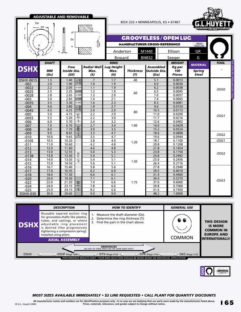
BOX 232 • MINNEAPOLIS, KS • 67467
MOST SIZES AVAILABLE IMMEDIATELY • $2 LINE REQUESTED • CALL PLANT FOR QUANTITY DISCOUNTS
1�5All manufacturer names and numbers are for identification purposes only. In no way are we implying that our parts were made by the manufacturers listed above.Prices, materials, tolerances, and grades subject to change without notice.© G.L. Huyett 2004
GROOVELESS/OPEN LUGMANUFACTURER CROSS-REFERENCE
Reusable tapered section ring for grooveless shafts like plastics, tubes, and castings, or where adjustable r ing placement is desired (like progressively tightening a compression spring). Installed using pliers.
1. Measure the shaft diameter (Ds).2. Determine the ring thickness (T).3. Find the part in the chart above.
COMMONAXIAL ASSEMBLY
GREllisonM1440Anderton
BN832Bossard
DSHX DSHF (Page 164) DTX (Page 212) DTR (Page 213) DKS (Page 213)
S
Da
Df
H
Ds
T
Free Inside Dia.
(Df)MM(Ds)
Thickness(T)
SpringSteel
1.52.02.22.52.83.03.54.04.55.05.56.07.08.09.010.010.511.012.013.013.814.015.016.717.018.020.022.024.025.030.0
1.401.902.052.352.652.853.303.804.254.755.205.706.707.708.659.65
10.2010.6011.6012.5513.3013.5014.5015.4016.3517.3019.3021.2023.1524.1529.00
.40
SHAFT RING
DSHXDSHX-0015
-002 -0022 -0025 -0028-003
-0035-004
-0045-005
-0055-006-007-008-009-010
-0105-011-012-013
-0138-014-015-016-017-018-020-022-024-025
DSHX-030
+/-
.130
+/-.0
75+
/-.0
90
Assembled Outside Dia.
(Da)
Radial Wall Max.(S)
Lug Height Max.(H)
.71.01.11.21.31.41.61.82.02.22.22.42.73.03.33.53.84.24.65.05.45.45.65.86.26.67.17.47.88.29.0
5.16.06.26.57.07.48.39.610.511.011.712.614.015.218.619.618.720.821.823.824.825.026.427.829.531.434.437.039.841.648.2
1.71.91.91.92.02.12.32.72.92.93.03.23.43.54.74.74.04.84.85.35.15.15.15.66.06.16.16.66.66.69.0
+/-
.060
+/-
.020
+/-.030
+/-.040
+/-.025
+/-.035
+/-.050
+/-
.110
MATERIAL
.60
.80
1.00
1.20
1.50
1.75
PERFORMANCE RESULTS VARY. YOUR RING SELECTION SHOULD BE MADE BASED ON INDIVIDUAL APPLICATION.
WEIGHTKg per
100Pieces
ADJUSTABLE AND REMOVABLE
0.00130.00360.00380.00450.00570.00650.00810.01540.01730.02000.02160.04020.04280.05240.08080.09440.11000.12080.14540.17500.24920.24560.27160.29400.40100.44600.52700.60600.70000.74501.0000
-ZGG0
-ZGG1
-ZGG2
-ZGG1
-ZGG2
-ZGG3
GSeeger
THIS DESIGNIS MORE
COMMON IN EUROPE AND
INTERNATIONALLY.
GROOVELESSUSE ANY OF THESE PARTS ON THE SAME SIZED SHAFT.
INDEX PAGE 236.
TOOL
DESCRIPTION HOW TO IDENTIFY GENERAL USE
DSHX
SH
X
IMPERIALPage 14
TOO
L D
ESC
RIP
TIO
NS
ON
PA
GE
226.

METRIC SNAP RINGSREVISED 09-04
MOST SIZES AVAILABLE IMMEDIATELY • $2 LINE REQUESTED • CALL PLANT FOR QUANTITY DISCOUNTS
1��
785•392•3017 FAX 785.392.2845
All manufacturer names and numbers are for identification purposes only. In no way are we implying that our parts were made by the manufacturers listed above.Prices, materials, tolerances, and grades subject to change without notice. © G.L. Huyett 2004
www.huyett.com
BASIC INTERNALMANUFACTURER CROSS-REFERENCE
Free Outside
Dia. (Dr)MM(Db)
Radial Wall Max.
(S)Thickness
(T)Diameter
(Dg)Depth
(d)SpringSteel
89101112131415161718192021222324252627282930313233343536373839404142434445
8.79.8
10.811.813.014.115.116.217.318.319.520.521.522.523.524.625.926.927.929.130.131.132.133.434.435.536.537.838.839.840.842.043.544.545.546.547.548.5
1.11.31.41.51.71.81.82.02.02.12.22.22.32.42.52.52.62.72.82.92.93.03.03.13.23.33.33.43.53.63.73.83.94.04.14.24.24.3
8.49.4
10.411.412.513.614.615.716.817.819.020.021.022.023.024.125.226.227.228.429.430.431.432.733.734.735.737.038.039.040.041.042.543.544.545.546.547.5
BORE RING
DHO
Tapered section ring to DIN 472 that is installed axially with pliers into a housing or bore. High thrust load rating. Stacked roll pack prevents tangling for ease in handling.
1. Measure the bore diameter (Db).2. Determine the ring thickness (T).3. Measure the maximum radial wall (S) of the
ring.4. Find the part in the chart above.
ZINC PLATED
COMMONAXIAL ASSEMBLY
DHO-008-009-010-011-012-013-014-015-016-017-018-019-020-021-022-023-024-025-026-027-028-029-030-031-032-033-034-035-036-037-038-039-040-041-042-043-044
DHO-045
Width(W)
+.0
9/
-.00
+.1
1/-.
00+
.13/
-.00
+.00
/-.0
5
GROOVE
+.2
1/-.
00
+.3
6/-.
10+
.42/
-.13
+.4
2/-.
21+
.50/
-.25
.80
1.00
1.20
1.50
1.75
.20
.60
.50
.40
.30
.90
1.25
1.00
.85
.70
.25
.35
.55
1.85
1.60
1.30
1.10
+.9
0/-.
39
+.2
5/-.
00
DHO DHOI (Page 172) DJK (Page 175) DH (Page 194) DJL (Page 177)
MATERIAL
Seeger J472EllisonD1300AndertonDHORotor ClipBN822-
823Bossard
+.0
0/-.
06
Stainless “-SS”
PERFORMANCE RESULTS VARY. YOUR RING SELECTION SHOULD BE MADE BASED ON INDIVIDUAL APPLICATION.
WEIGHTKg per
100Pieces
DIN 472
0.01000.01300.02600.03100.03700.04200.05200.05600.06000.06500.07400.08300.09000.10000.11000.13400.14200.15000.16000.17500.18000.18800.20600.21000.22100.24000.32000.35400.37000.37400.39000.40000.47000.51000.54000.56000.58000.6000
-I009
-I011
-I018
D1300Waldes
-I023
TOO
L D
ESC
RIP
TIO
NS
ON
PA
GES
227
& 2
28.
GROOVE INTERCHANGEUSE ANY OF THESE PARTS IN THE SAME SIZED GROOVE.
DIN472
INDEX PAGE 236.
HO IMPERIAL
Page 16
TOOL
Dg
Db
T
S
Dr dW
DESCRIPTION HOW TO IDENTIFY GENERAL USE
DHOSTACKED/ROLL PACK

BOX 232 • MINNEAPOLIS, KS • 67467
MOST SIZES AVAILABLE IMMEDIATELY • $2 LINE REQUESTED • CALL PLANT FOR QUANTITY DISCOUNTS
1�7All manufacturer names and numbers are for identification purposes only. In no way are we implying that our parts were made by the manufacturers listed above.Prices, materials, tolerances, and grades subject to change without notice.© G.L. Huyett 2004
BASIC INTERNALMANUFACTURER CROSS-REFERENCE
Seeger J472EllisonD1300AndertonDHORotor ClipBN822-
823Bossard
Free Outside
Dia. (Dr)MM(Db)
Radial Wall Max.
(S)Thickness
(T)Diameter
(Dg)Depth
(d)SpringSteel
464748505152535455565758606263646567687072757778808182838587889092959798100102105107108110112115117118120122125127128130132135
49.550.551.554.255.256.257.258.259.260.261.262.264.266.267.268.269.271.572.574.576.579.582.582.585.586.587.588.590.593.593.595.597.5
100.5103.5103.5105.5108.0112.0115.0115.0117.0119.0122.0125.0125.0127.0129.0132.0135.0135.0137.0139.0142.0
4.44.44.54.64.74.74.95.05.05.15.15.25.45.55.65.75.86.06.16.26.46.66.86.87.07.07.07.07.27.47.47.67.88.18.38.38.48.58.78.98.99.09.19.39.69.69.79.8
10.010.010.210.210.310.5
48.549.550.553.054.055.056.057.058.059.060.061.063.065.066.067.068.070.071.073.075.078.080.081.083.584.585.586.588.590.591.593.595.598.5
100.5101.5103.5106.0109.0111.0112.0114.0116.0119.0121.0122.0124.0126.0129.0131.0132.0134.0136.0139.0
BORE RING
DHODHO-046
-047-048-050-051-052-053-054-055-056-057-058-060-062-063-064-065-067-068-070-072-075-077-078-080-081-082-083-085-087-088-090-092-095-097-098-100-102-105-107-108-110-112-115-117-118-120-122-125-127-128-130-132
DHO-135
Width(W)
GROOVE MATERIALStainless
“-SS”
+.3
0/-.
00+
.35/
-.00
+.0
0/-.
06+
.00/
-.07
+1.
10/-
.46
+1.
30/-
.54
2.00
2.50
3.00
4.00
1.50
1.75
2.00
2.15
2.65
3.15
4.15
+.0
0/-.
08+
.00/
-.10
+.5
4/-.
00
+.90/-.39
1.75 +.2
5/-.
00
1.25 1.85
+1.
50/-
.63
+.6
3/-.
00
WEIGHTKg per
100 Pieces
DIN 472
0.60500.61000.67000.73000.77500.82000.82200.82500.83000.88000.94001.05001.11001.12001.24001.24501.43001.60001.60001.65001.81001.88002.04002.04002.20002.30002.40002.50002.53003.10003.10003.30003.50003.70004.10004.10004.20005.50005.60006.00006.00006.45007.20007.45007.55007.55007.70007.80007.90008.11008.11008.20008.30008.4000
-I023
-I032
-I035
D1300Waldes
TOO
L D
ESC
RIP
TIO
NS
ON
PA
GES
227
& 2
28.
DIN472
INDEX PAGE 236.
TOOL
Dg
Db
T
S
Dr dW

METRIC SNAP RINGSREVISED 09-04
MOST SIZES AVAILABLE IMMEDIATELY • $2 LINE REQUESTED • CALL PLANT FOR QUANTITY DISCOUNTS
1�8
785•392•3017 FAX 785.392.2845
All manufacturer names and numbers are for identification purposes only. In no way are we implying that our parts were made by the manufacturers listed above.Prices, materials, tolerances, and grades subject to change without notice. © G.L. Huyett 2004
www.huyett.com
BASIC INTERNALMANUFACTURER CROSS-REFERENCE
Free Outside
Dia. (Dr)MM(Db)
Radial Wall Max.
(S)Thickness
(T)Diameter
(Dg)Depth
(d)SpringSteel
137138140142145147148150152155157158160162165167168170172175177178180182185187188190192195197198200202205207208210
145.0145.0147.0149.0152.0155.0155.0158.0161.0164.0167.0167.0169.0171.5174.5177.5177.5179.5181.5184.5187.5187.5189.5191.5194.5197.5197.5199.5201.5204.5207.5207.5209.5214.0217.0217.0222.0222.0
141.0142.0144.0146.0149.0151.0152.0155.0157.0160.0162.0163.0165.0167.0170.0172.0173.0175.0177.0180.0182.0183.0185.0187.0190.0192.0193.0195.0197.0200.0202.0203.0205.0208.0211.0213.0214.0216.0
BORE RING
DHO
Tapered section ring to DIN 472 that is installed axially with pliers into a housing or bore. High thrust load rating. Stacked roll pack prevents tangling for ease in handling.
1. Measure the bore diameter (Db).2. Determine the ring thickness (T).3. Measure the maximum radial wall (S) of the
ring.4. Find the part in the chart above.
ZINC PLATED
COMMONAXIAL ASSEMBLY
DHO-137-138-140-142-145-147-148-150-152-155-157-158-160-162-165-167-168-170-172-175-177-178-180-182-185-187-188-190-192-195-197-198-200-202-205-207-208
DHO-210
Width(W)
+.6
3/-.
00
GROOVE+
1.50
/-.6
3+
1.70
/-.7
2
4.00
2.00
10.610.610.710.810.911.111.111.211.311.411.511.511.611.711.812.112.112.212.512.712.912.913.213.513.713.813.813.813.813.814.014.014.014.014.014.014.014.0
2.50
4.15
+.0
0/-.
10
+.7
2/-.
00
DHO DHOI (Page 172) DJK (Page 175) DH (Page 194) DJL (Page 177)
MATERIAL
Seeger J472EllisonD1300AndertonDHORotor ClipBN822-
823Bossard
Stainless “-SS”
5.00
+.0
0/-.
12
3.00 5.15
PERFORMANCE RESULTS VARY. YOUR RING SELECTION SHOULD BE MADE BASED ON INDIVIDUAL APPLICATION.
WEIGHTKg per
100Pieces
DIN 472
8.6000 8.6000 8.7500 8.9000 9.300010.000010.000010.500010.600010.700010.900010.900011.000011.800012.500013.500013.500014.000014.500015.000016.200016.200016.500016.800017.000017.400017.400017.500017.800018.300019.000019.000019.500021.000022.500022.500027.000027.0000
-I035
D1300Waldes
GROOVE INTERCHANGEUSE ANY OF THESE PARTS IN THE SAME SIZED GROOVE.
DIN472
INDEX PAGE 236.
HO IMPERIAL
Page 16
TOOL
Dg
Db
T
S
Dr dW
DESCRIPTION HOW TO IDENTIFY GENERAL USE
DHOSTACKED/ROLL PACK
TOO
L D
ESC
RIP
TIO
NS
ON
PA
GES
227
& 2
28.
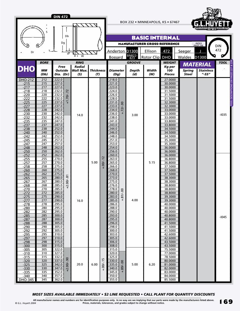
BOX 232 • MINNEAPOLIS, KS • 67467
MOST SIZES AVAILABLE IMMEDIATELY • $2 LINE REQUESTED • CALL PLANT FOR QUANTITY DISCOUNTS
1�9All manufacturer names and numbers are for identification purposes only. In no way are we implying that our parts were made by the manufacturers listed above.Prices, materials, tolerances, and grades subject to change without notice.© G.L. Huyett 2004
BASIC INTERNALMANUFACTURER CROSS-REFERENCE
Seeger J472EllisonD1300Anderton
DHORotor ClipBN822-823Bossard
Free Outside
Dia. (Dr)MM(Db)
Radial Wall Max.
(S)Thickness
(T)Diameter
(Dg)Depth
(d)SpringSteel
212215217218220222225227228230232235237238240242245247248250252255257258260262265267268270272275277278280282285287288290292295297298300305310315320325330335340345
222.0227.0227.0232.0232.0232.0237.0237.0242.0242.0242.0247.0247.0252.0252.0252.0257.0257.0262.0262.0262.0270.0270.0275.0275.0275.0280.0280.0285.0285.0285.0290.0290.0295.0295.0295.0300.0300.0305.0305.0305.0310.0310.0315.0315.0322.0327.0332.0337.0342.0347.0352.0357.0362.0
218.0221.0223.0224.0226.0228.0231.0233.0234.0236.0238.0241.0243.0244.0246.0248.0251.0253.0254.0256.0260.0263.0265.0266.0268.0270.0273.0275.0276.0278.0280.0283.0285.0286.0288.0290.0293.0295.0296.0298.0300.0303.0305.0306.0308.0315.0320.0325.0330.0335.0340.0345.0350.0355.0
BORE RING TOOL
DHODHO-212
-215-217-218-220-222-225-227-228-230-232-235-237-238-240-242-245-247-248-250-252-255-257-258-260-262-265-267-268-270-272-275-277-278-280-282-285-287-288-290-292-295-297-298-300-305-310-315-320-325-330-335-340
DHO-345
Width(W)
+.7
2/-.
00
GROOVE+
1.70
/-.7
2
14.0 3.00
MATERIALStainless
“-SS”
16.0
5.00
4.00
5.15
20.0 6.00 5.00 6.20
+2.
00/-
.81
+2.
00/-
.90
+.0
0/-.
12+
.00/
-.15
+.8
1/-.
00+
.89/
-.00
WEIGHTKg per
100Pieces
DIN 472
27.000030.000030.000031.500031.500031.500032.300032.300033.000033.000033.000033.800033.800034.500034.500034.500035.300035.300036.000036.000036.000036.800036.800037.500037.500037.500038.300038.300038.800038.800038.800039.300039.300040.000040.000040.000040.800040.800041.500041.500041.500042.600042.600043.500043.500075.500077.000078.500080.000081.000082.000083.000084.000085.5000
-I035
-I045
D1300Waldes
TOO
L D
ESC
RIP
TIO
NS
ON
PA
GES
227
& 2
28.
DIN472
INDEX PAGE 236.
Dg
Db
T
S
Dr dW
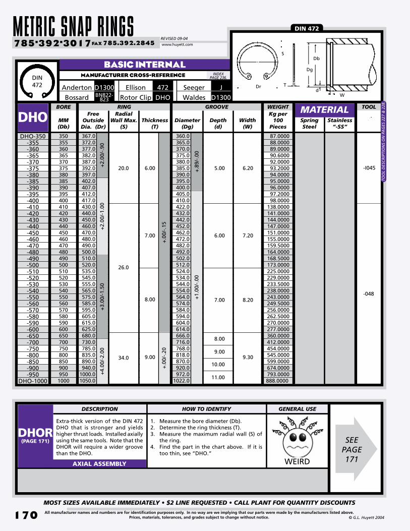
METRIC SNAP RINGSREVISED 09-04
MOST SIZES AVAILABLE IMMEDIATELY • $2 LINE REQUESTED • CALL PLANT FOR QUANTITY DISCOUNTS
170
785•392•3017 FAX 785.392.2845
All manufacturer names and numbers are for identification purposes only. In no way are we implying that our parts were made by the manufacturers listed above.Prices, materials, tolerances, and grades subject to change without notice. © G.L. Huyett 2004
www.huyett.com
BASIC INTERNALMANUFACTURER CROSS-REFERENCE
Free Outside
Dia. (Dr)MM(Db)
Radial Wall Max.
(S)Thickness
(T)Diameter
(Dg)Depth
(d)SpringSteel
3503553603653703753803853903954004104204304404504604704804905005105205305405505605705805906006507007508008509009501000
367.0372.0377.0382.0387.0392.0397.0402.0407.0412.0417.0430.0440.0450.0460.0470.0480.0490.0500.0510.0520.0535.0545.0555.0565.0575.0585.0595.0605.0615.0625.0680.0730.0785.0835.0890.0940.0
1000.01050.0
360.0365.0370.0375.0380.0385.0390.0395.0400.0405.0410.0422.0432.0442.0452.0462.0472.0482.0492.0502.0512.0524.0534.0544.0554.0564.0574.0584.0594.0604.0614.0666.0716.0768.0818.0870.0920.0972.0
1022.0
BORE RING TOOL
DHO
Extra-thick version of the DIN 472 DHO that is stronger and yields higher thrust loads. Installed axially using the same tools. Note that the DHOR will require a wider groove than the DHO.
1. Measure the bore diameter (Db).2. Determine the ring thickness (T).3. Measure the maximum radial wall (S) of
the ring.4. Find the part in the chart above. If it is
too thin, see “DHO.”
WEIRDAXIAL ASSEMBLY
DHO-350-355-360-365-370-375-380-385-390-395-400-410-420-430-440-450-460-470-480-490-500-510-520-530-540-550-560-570-580-590-600-650-700-750-800-850-900-950
DHO-1000
Width(W)
+.8
9/-.
00
GROOVE+
2.00
/-.9
0+
2.00
/-1.
00
20.0
26.0
6.00
7.00
5.00
6.00
6.20
7.20
+1.
00/-
.00
MATERIAL
Seeger J472EllisonD1300Anderton
DHORotor ClipBN822-823Bossard
+.0
0/-.
15
Stainless “-SS”
+3.
00/-
1.50
+4.
00/-
2.00
+.0
0/-.
20
34.0
8.00
9.00
7.00 8.20
8.00
9.3010.00
11.00
9.00
WEIGHTKg per
100Pieces
DIN 472
87.0000 88.0000 89.0000 90.6000 92.0000 93.2000 94.0000 95.0000 96.0000 97.2000 98.0000138.0000141.0000144.0000147.0000151.0000155.0000159.5000164.0000168.5000173.0000225.0000229.0000233.5000238.0000243.0000249.5000256.0000262.5000270.0000277.0000360.0000412.0000454.0000545.0000599.0000674.0000793.0000888.0000
-I045
-048
D1300Waldes
DIN472
INDEX PAGE 236.
Dg
Db
T
S
Drd
W
SEEPAGE171
DESCRIPTION HOW TO IDENTIFY GENERAL USE
DHOR(PAGE 171)
TOO
L D
ESC
RIP
TIO
NS
ON
PA
GES
227
& 2
28.
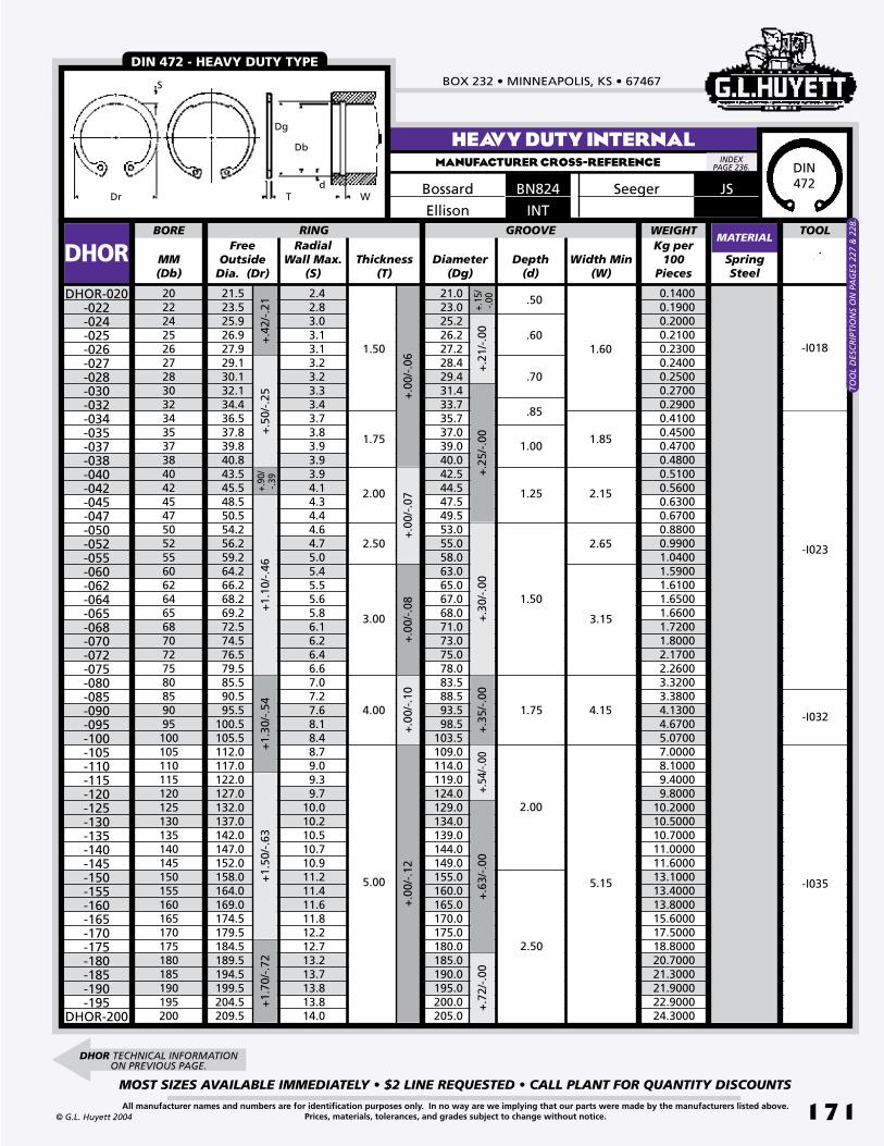
BOX 232 • MINNEAPOLIS, KS • 67467
MOST SIZES AVAILABLE IMMEDIATELY • $2 LINE REQUESTED • CALL PLANT FOR QUANTITY DISCOUNTS
171All manufacturer names and numbers are for identification purposes only. In no way are we implying that our parts were made by the manufacturers listed above.Prices, materials, tolerances, and grades subject to change without notice.© G.L. Huyett 2004
HEAVY DUTY INTERNALMANUFACTURER CROSS-REFERENCE
BN824Bossard
INTEllisonDr
Dg
Db
dWT
S
Free Outside
Dia. (Dr)MM(Db)
Thickness(T)
Diameter(Dg)
Depth(d)
SpringSteel
2022242526272830323435373840424547505255606264656870727580859095100105110115120125130135140145150155160165170175180185190195200
21.523.525.926.927.929.130.132.134.436.537.839.840.843.545.548.550.554.256.259.264.266.268.269.272.574.576.579.585.590.595.5
100.5105.5112.0117.0122.0127.0132.0137.0142.0147.0152.0158.0164.0169.0174.5179.5184.5189.5194.5199.5204.5209.5
2.42.83.03.13.13.23.23.33.43.73.83.93.93.94.14.34.44.64.75.05.45.55.65.86.16.26.46.67.07.27.68.18.48.79.09.39.7
10.010.210.510.710.911.211.411.611.812.212.713.213.713.813.814.0
BORE RING
DHOR Width Min(W)
+.2
1/-.
00+
.25/
-.00
GROOVE
+.3
0/-.
00
+.0
0/-.
06+
.00/
-.07
TOOLRadial
Wall Max.(S)
21.023.025.226.227.228.429.431.433.735.737.039.040.042.544.547.549.553.055.058.063.065.067.068.071.073.075.078.083.588.593.598.5
103.5109.0114.0119.0124.0129.0134.0139.0144.0149.0155.0160.0165.0170.0175.0180.0185.0190.0195.0200.0205.0
1.50
1.75
2.00
2.50
3.00
4.00
.50
.60
.70
.85
1.00
1.25
1.50
1.75
1.60
1.85
2.15
2.65
3.15
4.15
+.0
0/-.
08+
.00/
-.10
+.4
2/-.
21+
.50/
-.25
+.90
/-.3
9+
1.10
/-.4
6+
1.30
/-.5
4
+.3
5/-.
00+.
54/-.
00+.
15/
-.00DHOR-020
-022-024-025-026-027-028-030-032-034-035-037-038-040-042-045-047-050-052-055-060-062-064-065-068-070-072-075-080-085-090-095-100-105-110-115-120-125-130-135-140-145-150-155-160-165-170-175-180-185-190-195
DHOR-200
MATERIAL
5.00
2.00
5.15
2.50
+1.
50/-
.63
+1.
70/-
.72
+.0
0/-.
12
+.6
3/-.
00+
.72/
-.00
DHOR TECHNICAL INFORMATION ON PREVIOUS PAGE.
WEIGHTKg per
100Pieces
0.1400 0.1900 0.2000 0.2100 0.2300 0.2400 0.2500 0.2700 0.2900 0.4100 0.4500 0.4700 0.4800 0.5100 0.5600 0.6300 0.6700 0.8800 0.9900 1.0400 1.5900 1.6100 1.6500 1.6600 1.7200 1.8000 2.1700 2.2600 3.3200 3.3800 4.1300 4.6700 5.0700 7.0000 8.1000 9.4000 9.800010.200010.500010.700011.000011.600013.100013.400013.800015.600017.500018.800020.700021.300021.900022.900024.3000
-I018
-I023
-I032
-I035
JSSeeger
DIN 472 - HEAVY DUTY TYPE
DIN472
INDEX PAGE 236.
TOO
L D
ESC
RIP
TIO
NS
ON
PA
GES
227
& 2
28.
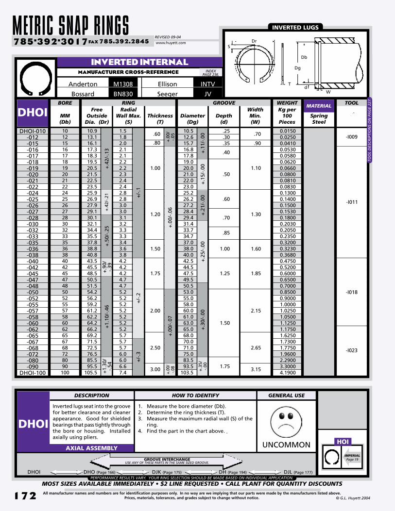
METRIC SNAP RINGSREVISED 09-04
MOST SIZES AVAILABLE IMMEDIATELY • $2 LINE REQUESTED • CALL PLANT FOR QUANTITY DISCOUNTS
172
785•392•3017 FAX 785.392.2845
All manufacturer names and numbers are for identification purposes only. In no way are we implying that our parts were made by the manufacturers listed above.Prices, materials, tolerances, and grades subject to change without notice. © G.L. Huyett 2004
www.huyett.com
Inverted lugs seat into the groove for better clearance and cleaner appearance. Good for shielded bearings that pass tightly through the bore or housing. Installed axially using pliers.
1. Measure the bore diameter (Db).2. Determine the ring thickness (T).3. Measure the maximum radial wall (S) of the
ring.4. Find the part in the chart above.
UNCOMMONAXIAL ASSEMBLY
MM(Db)
Diameter(Dg)
SpringSteel
101215161718192021222425262728303233353638404245474850525557586062656768728090100
DHOIDHOI-010
-012-015-016-017-018-019-020-021-022-024-025-026-027-028-030-032-033-035-036-038-040-042-045-047-048-050-052-055-057-058-060-062-065-067-068-072-080-090
DHOI-100
+.1
1/-.
00+
.15/
-.00
Free Outside
Dia. (Dr)
+.0
0/-.
05+
.00/
-.06
+.0
0/-.
07
Thickness(T)
RadialWall Max.
(S)
BORE RING TOOLGROOVEWidthMin.(W)
Depth(d)
10.913.116.117.318.319.520.521.522.523.525.926.927.929.130.132.134.435.537.838.840.843.545.548.550.551.554.256.259.261.262.264.266.269.271.572.576.585.595.5
105.5
1.51.82.02.12.12.22.22.32.42.42.82.83.03.03.13.23.33.33.43.63.84.24.24.24.74.75.25.25.25.25.25.25.25.75.75.76.06.06.67.4
10.512.615.716.817.819.020.021.022.023.025.226.227.228.429.431.433.734.737.038.040.042.544.547.549.550.553.055.058.060.061.063.065.068.070.071.075.083.593.5
103.5
.60
.80
1.00
1.20
1.50
1.75
2.00
2.50
3.00
.25
.30
.35
.40
.50
.60
.70
.85
1.00
1.25
1.50
1.75
.70
.90
1.10
1.30
1.60
1.85
2.15
2.65
3.15
+/-
.1+
/-.2
+/-
.3
+.4
2/-.
13+
.42/
-.21
+.5
0/-.
25+
.90/
-.39
+1.
10/-
.46
+1.
30/
-.54
+.2
1/-.
00+
.25/
-.00
+.3
0/-.
00+
.35/
-.00
+.00
/-.0
8
DHOI DHO (Page 166) DJK (Page 175) DH (Page 194) DJL (Page 177)
INVERTED INTERNALMANUFACTURER CROSS-REFERENCE
MATERIAL
INTVEllisonM1308Anderton
BN830BossardWEIGHTKg per
100Pieces
PERFORMANCE RESULTS VARY. YOUR RING SELECTION SHOULD BE MADE BASED ON INDIVIDUAL APPLICATION.
0.01500.02500.04100.05300.05800.06200.06600.08000.08100.08300.13000.14000.15000.15300.18000.20300.20500.23500.32000.32300.36800.47500.52000.60000.65000.70000.85000.90001.00001.02501.05001.12501.17501.62501.73001.77501.96002.29003.30004.1900
-I009
-I011
-I018
-I023
JVSeeger
INVERTED LUGS
GROOVE INTERCHANGEUSE ANY OF THESE PARTS IN THE SAME SIZED GROOVE.
INDEX PAGE 236.
Dr
Dg
Db
dW
T
S
IMPERIALPage 19
HOI
DESCRIPTION HOW TO IDENTIFY GENERAL USE
DHOI
TOO
L D
ESC
RIP
TIO
NS
ON
PA
GE
227.

BOX 232 • MINNEAPOLIS, KS • 67467
MOST SIZES AVAILABLE IMMEDIATELY • $2 LINE REQUESTED • CALL PLANT FOR QUANTITY DISCOUNTS
173All manufacturer names and numbers are for identification purposes only. In no way are we implying that our parts were made by the manufacturers listed above.Prices, materials, tolerances, and grades subject to change without notice.© G.L. Huyett 2004
Free Outside
Dia. (Dr)MM(Db)
Thickness(T)
Diameter(Dg)
SpringSteel
40424547485052555758606263656768707275777880828587889092959798100105110115120130140145150
43.545.548.550.551.554.256.259.261.262.264.266.267.269.271.572.574.576.579.581.582.585.587.590.592.593.595.597.5
100.5102.5103.5105.5112.0117.0122.0127.0137.0147.0152.0158.0
3.94.14.34.44.54.64.75.05.15.25.45.55.65.86.06.16.26.46.66.76.87.07.07.27.37.47.67.88.18.28.38.48.79.09.39.7
10.210.710.911.2
BORE RING
DBHO
Curved design for resilient end-play take-up of rattling in linkages. Provides tension on adjusting screws. Also used to salvage assemblies where grooves have been cut too wide. Install with the convex surface abutting the part.
1. Verify bowed-shape side profile.2. Measure the bore diameter (Db).3. Determine the ring thickness (T).4. Measure the maximum radial wall (S) of
the ring.5. Find the part in the chart above.
WEIRDAXIAL ASSEMBLY
DBHO-040-042-045-047-048-050-052-055-057-058-060-062-063-065-067-068-070-072-075-077-078-080-082-085-087-088-090-092-095-097-098-100-105-110-115-120-130-140-145
DBHO-150
Width(W)
GROOVE TOOLRadial
Wall Max.(S)
Bow Height
(Hb)
42.744.747.749.750.753.355.358.360.361.363.365.366.368.370.371.373.375.378.380.381.384.086.089.091.092.094.096.099.0
101.0102.0104.0109.5114.5119.5124.5134.5144.5149.5155.5
1.75
2.00
2.50
3.00
4.00
3.43.43.53.53.63.93.94.14.14.24.24.24.84.84.94.95.05.05.05.15.15.15.85.95.96.06.16.26.26.86.98.08.18.18.28.28.38.48.48.5
+.9
0/-.
39+
1.10
/-.4
6+
1.30
/-.5
4+
1.50
/-.6
3
+.2
5/-.
00+
.35/
-.00
+.5
4/-.
00+
.30/
-.00
3.53.53.63.73.74.04.14.24.24.34.34.44.45.05.05.15.15.25.25.35.35.45.46.06.16.26.36.46.66.76.86.98.08.18.18.28.38.48.48.5
+.8
/-.0
+1.
3/-.
0+
1.5/
-.0
+1.
0/-.
0+
2.0/
-.0
+.6
3/-.
00
BOWED INTERNALMANUFACTURER CROSS-REFERENCE
MATERIAL
JWSeeger
WEIGHTKg per
100Pieces
-I023
-I032
-I035
0.47000.54000.60000.61000.67000.73000.82000.83000.94001.05001.11001.12001.24001.43001.53001.60001.65001.81001.88002.04002.04002.20002.40002.53003.10003.10003.30003.50003.70004.10004.10004.20005.60006.45007.45007.70008.20008.75009.3000
10.5000
CURVED SHAPE
TOO
L D
ESC
RIP
TIO
NS
ON
PA
GES
227
& 2
28.
INDEX PAGE 236.
Dr
Dg Db
W
T
S
Hb
IMPERIALPage 20
BHO
DESCRIPTION HOW TO IDENTIFY GENERAL USE
DBHO

METRIC SNAP RINGSREVISED 09-04
MOST SIZES AVAILABLE IMMEDIATELY • $2 LINE REQUESTED • CALL PLANT FOR QUANTITY DISCOUNTS
174
785•392•3017 FAX 785.392.2845
All manufacturer names and numbers are for identification purposes only. In no way are we implying that our parts were made by the manufacturers listed above.Prices, materials, tolerances, and grades subject to change without notice. © G.L. Huyett 2004
www.huyett.com
A 15° bevel on the outside diameter, when fitted into a 15° bevel on the load-bearing groove wall, yields rigid end-play take-up of manufacturing tolerances or wear on the retained part. Used in greasy and oily environments.
1. Verify the presence of a bevel along the outside diameter of the part.
2. Measure the bore diameter (Db).3. Determine the ring thickness (T).4. Confirm the maximum radial wall (S) of the
ring.5. Find the part in the chart above. WEIRDAXIAL ASSEMBLY
Free Outside Dia.
(Dr)MM(Db)
Thickness(T)
Diameter(Dg)
SpringSteel
404142434446474851525456576062636567687072788082858890929598100102105108110115118120127140
44.045.846.647.649.351.152.252.656.157.959.761.363.266.868.670.572.273.975.777.579.386.889.592.094.898.0
100.0102.2105.6109.0110.7112.4115.8119.2120.8125.5128.9132.4139.3154.1
4.04.04.24.34.34.34.34.34.34.74.95.05.25.35.25.35.65.76.05.95.86.56.76.87.07.47.47.77.88.18.18.48.48.58.68.98.99.19.9
10.4
BORE RING
DVHODVHO-040
-041-042-043-044-046-047-048-051-052-054-056-057-060-062-063-065-067-068-070-072-078-080-082-085-088-090-092-095-098-100-102-105-108-110-115-118-120-127
DVHO-140
Width(W)
+.0
25/-
.000
+.0
38/-
.000
+.0
0/-.
15
+.0/-.2
TOOLRadial Wall
Max.(S)
42.844.045.046.047.249.450.451.554.655.757.960.161.564.566.567.769.871.973.175.277.383.786.088.191.294.696.899.0
102.1105.5107.6109.7112.8116.1118.0123.2126.3128.6135.8149.2
1.65
2.05
2.45
2.85
3.25
1.30
1.27
1.22
1.65
1.63
1.60
1.57
1.98
1.96
1.93
2.26
2.59
+.9
/-.6
+1.
00/-
.75
+/-
1.4
+/-
1.65
+.1
3/-.
00+
.15/
-.00
+.0
51/-
.000
GROOVE
BEVELED INTERNALMANUFACTURER CROSS-REFERENCE
MATERIAL
EJBEllison
JBSeeger
W
WEIGHTKg per
100Pieces
0.01800.02000.02000.02000.02000.02300.02300.02300.02300.02300.02500.02500.02500.02800.03000.03000.03000.03300.03300.03600.03600.03800.03800.04100.04100.04300.04600.04000.04800.05100.05300.05300.05300.05300.05300.05600.05600.05800.05800.0610
-I018
-I023
-I032
WEDGES INTO GROOVE
TOO
L D
ESC
RIP
TIO
NS
ON
PA
GE
227.
INDEX PAGE 236.
Dr
DgDb
T
S
IMPERIALPage 22
VHO
DESCRIPTION HOW TO IDENTIFY GENERAL USE
DVHO

BOX 232 • MINNEAPOLIS, KS • 67467
MOST SIZES AVAILABLE IMMEDIATELY • $2 LINE REQUESTED • CALL PLANT FOR QUANTITY DISCOUNTS
175All manufacturer names and numbers are for identification purposes only. In no way are we implying that our parts were made by the manufacturers listed above.Prices, materials, tolerances, and grades subject to change without notice.© G.L. Huyett 2004
TABBED INTERNALMANUFACTURER CROSS-REFERENCE
Internal tabs are concentrically positioned for a concealed assembly. Tabs act as spacers for securing machine components. Conforms to DIN 984.
1. Verify the presence of tabs on the inside rim of the ring.
2. Measure the bore diameter (Db).3. Determine the ring thickness (T).4. Confirm the maximum radial wall (S) of the
ring.5. Find the part in the chart above. UNCOMMONAXIAL ASSEMBLY
Free Outside
Dia. (Dr)MM(Db)
Thickness(T)
Diameter(Dg)
Depth(d)
SpringSteel
16171819202122232425262728303132333435363840424445474850525557586062656768707275
17.318.319.520.521.522.523.524.625.926.928.529.130.132.133.434.435.536.537.838.840.843.545.547.548.550.551.554.256.259.261.262.264.266.269.271.572.574.576.579.5
2.12.22.32.32.42.42.62.62.62.82.82.93.03.23.23.33.33.43.63.63.84.04.14.24.34.54.54.74.75.15.25.35.55.65.86.06.16.26.46.6
BORE RING
DJKDJK-016
-017-018-019-020-021-022-023-024-025-026-027-028-030-031-032-033-034-035-036-038-040-042-044-045-047-048-050-052-055-057-058-060-062-065-067-068-070-072
DJK-075
Width Min.(W)
+.1
5/-.
00+
.21/
-.00
+.2
5/-.
00+.
11/
-.00
GROOVE
+.3
0/-.
00
+.0
0/-.
06+
.00/
-.07
TOOLRadial Wall
Max.(S)
16.817.819.020.021.022.023.024.125.226.227.228.429.431.432.733.734.735.737.038.040.042.544.546.547.549.550.553.055.058.060.061.063.065.068.070.071.073.075.078.0
1.00
1.20
1.50
1.75
2.00
2.50
.40
.50
.60
.70
.85
1.00
1.25
1.50
.55
1.10
1.30
1.60
1.85
2.65
+.4
2/-.
13+
.42/
-.21
+.5
0/-.
25+
.90/
-.39
+1.
10/-
.46
DJK DHO (Page 166) DHOI (Page 172) DH (Page 194) DJL (Page 177)
MATERIAL
JKSeegerD2000Anderton
984Ellison
d
Db
Dg
T
S
Dr
W
PERFORMANCE RESULTS VARY. YOUR RING SELECTION SHOULD BE MADE BASED ON INDIVIDUAL APPLICATION.
WEIGHTKg per
100Pieces
DIN 984
0.07200.08000.09000.09900.10600.11700.12800.14800.16000.17200.20000.20000.21000.23500.24200.25000.26500.38000.40000.41500.44000.53000.60000.64500.66000.69000.75000.85000.94000.97501.16501.20001.27001.27501.67001.86001.93002.02002.12002.2600
-I018
-I011
-I023
SAME SIZING AS DHO,BUT WITH INTERNAL
TABS.
GROOVE INTERCHANGEUSE ANY OF THESE PARTS IN THE SAME SIZED GROOVE.
DIN984
INDEX PAGE 236.
DJK CONTINUED NEXT PAGE.
DESCRIPTION HOW TO IDENTIFY GENERAL USE
DJK
984DIN
2.15
TOO
L D
ESC
RIP
TIO
NS
ON
PA
GES
227
& 2
28.
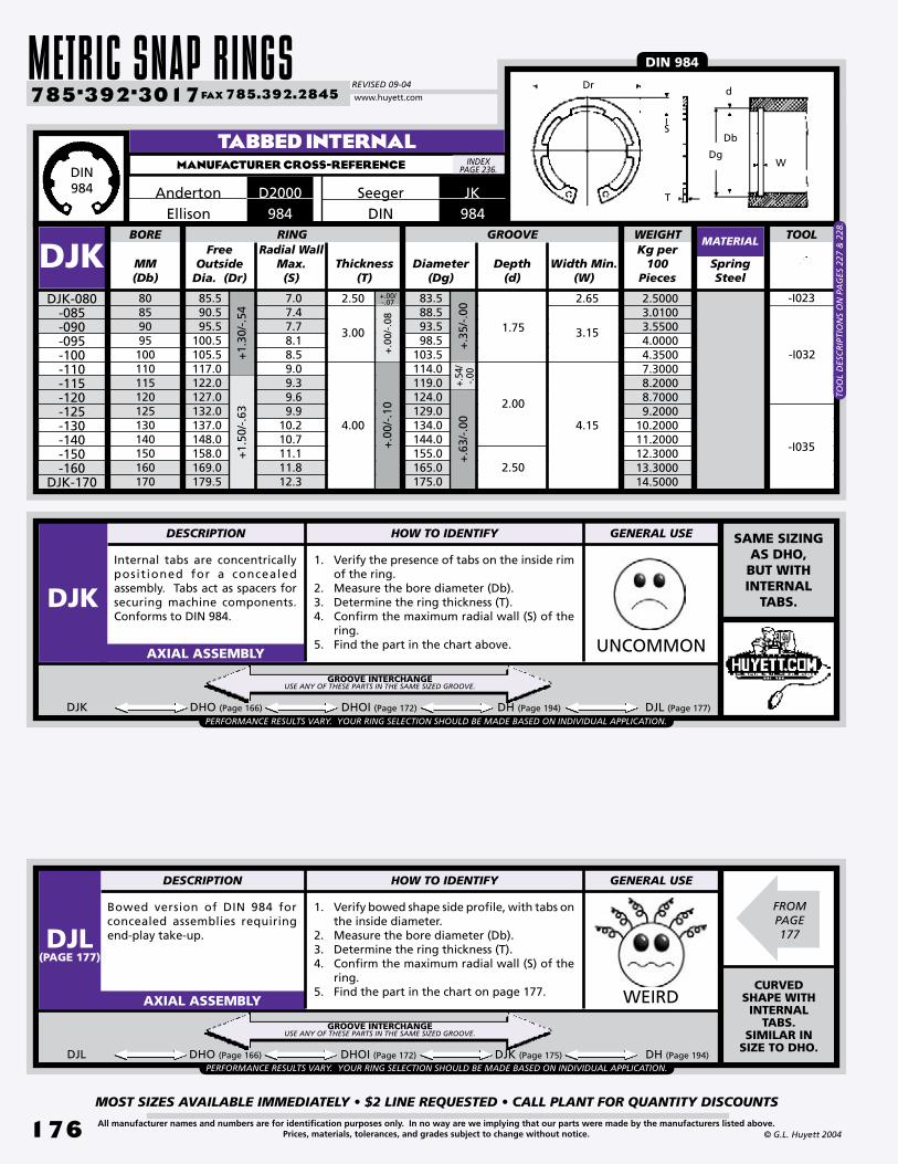
METRIC SNAP RINGSREVISED 09-04
MOST SIZES AVAILABLE IMMEDIATELY • $2 LINE REQUESTED • CALL PLANT FOR QUANTITY DISCOUNTS
17�
785•392•3017 FAX 785.392.2845
All manufacturer names and numbers are for identification purposes only. In no way are we implying that our parts were made by the manufacturers listed above.Prices, materials, tolerances, and grades subject to change without notice. © G.L. Huyett 2004
www.huyett.com
Internal tabs are concentrically posit ioned for a concealed assembly. Tabs act as spacers for securing machine components. Conforms to DIN 984.
1. Verify the presence of tabs on the inside rim of the ring.
2. Measure the bore diameter (Db).3. Determine the ring thickness (T).4. Confirm the maximum radial wall (S) of the
ring.5. Find the part in the chart above. UNCOMMONAXIAL ASSEMBLY
Free Outside
Dia. (Dr)MM(Db)
Thickness(T)
Diameter(Dg)
Depth(d)
SpringSteel
80859095100110115120125130140150160170
85.590.595.5
100.5105.5117.0122.0127.0132.0137.0148.0158.0169.0179.5
7.07.47.78.18.59.09.39.69.9
10.210.711.111.812.3
BORE RING
DJKDJK-080
-085-090-095-100-110-115-120-125-130-140-150-160
DJK-170
Width Min.(W)
+.54
/ -.0
0+
.63/
-.00
+.3
5/-.
00
GROOVE TOOLRadial Wall
Max.(S)
83.588.593.598.5
103.5114.0119.0124.0129.0134.0144.0155.0165.0175.0
2.50
3.00
4.00
1.75
2.00
2.50
3.15
2.65
4.15
+1.
30/-
.54
+1.
50/-
.63
+.0
0/-.
08+
.00/
-.10
+.00/-.07
DJK DHO (Page 166) DHOI (Page 172) DH (Page 194) DJL (Page 177)
TABBED INTERNALMANUFACTURER CROSS-REFERENCE
MATERIAL
Anderton JKSeegerD2000984Ellison
d
Db
Dg
T
S
Dr
W
Bowed version of DIN 984 for concealed assemblies requiring end-play take-up.
1. Verify bowed shape side profile, with tabs on the inside diameter.
2. Measure the bore diameter (Db).3. Determine the ring thickness (T).4. Confirm the maximum radial wall (S) of the
ring.5. Find the part in the chart on page 177. WEIRDAXIAL ASSEMBLY
DJL DHO (Page 166) DHOI (Page 172) DJK (Page 175) DH (Page 194)
PERFORMANCE RESULTS VARY. YOUR RING SELECTION SHOULD BE MADE BASED ON INDIVIDUAL APPLICATION.
PERFORMANCE RESULTS VARY. YOUR RING SELECTION SHOULD BE MADE BASED ON INDIVIDUAL APPLICATION.
WEIGHTKg per
100Pieces
DIN 984
2.5000 3.0100 3.5500 4.0000 4.3500 7.3000 8.2000 8.7000 9.200010.200011.200012.300013.300014.5000
-I023
-I032
-I035
SAME SIZING AS DHO,BUT WITH INTERNAL
TABS.
CURVED SHAPE WITH INTERNAL
TABS. SIMILAR IN
SIZE TO DHO.
GROOVE INTERCHANGEUSE ANY OF THESE PARTS IN THE SAME SIZED GROOVE.
GROOVE INTERCHANGEUSE ANY OF THESE PARTS IN THE SAME SIZED GROOVE.
DIN984
INDEX PAGE 236.
FROM PAGE177
DESCRIPTION HOW TO IDENTIFY GENERAL USE
DJK
DESCRIPTION HOW TO IDENTIFY GENERAL USE
DJL(PAGE 177)
984DIN
TOO
L D
ESC
RIP
TIO
NS
ON
PA
GES
227
& 2
28.

BOX 232 • MINNEAPOLIS, KS • 67467
MOST SIZES AVAILABLE IMMEDIATELY • $2 LINE REQUESTED • CALL PLANT FOR QUANTITY DISCOUNTS
177All manufacturer names and numbers are for identification purposes only. In no way are we implying that our parts were made by the manufacturers listed above.Prices, materials, tolerances, and grades subject to change without notice.© G.L. Huyett 2004
BOWED TABBED INTERNALMANUFACTURER CROSS-REFERENCE
JLSeeger
Free Outside
Dia. (Dr)MM(Db)
Diameter(Dg)
SpringSteel
1617181920212223242526272830313233343536384042444547485052555758606265676870727580859095100
17.318.319.520.521.522.523.524.625.926.928.529.130.132.133.434.435.536.537.838.840.843.545.547.548.550.551.554.256.259.261.262.264.266.269.271.572.574.576.579.585.590.595.5
100.5105.5
2.12.22.32.32.42.42.62.62.62.82.82.93.03.23.23.33.33.43.63.63.84.04.14.24.34.54.54.74.75.15.25.35.55.65.86.06.16.26.46.67.07.47.78.18.5
BORE RING
DJLDJL-016
-017-018-019-020-021-022-023-024-025-026-027-028-030-031-032-033-034-035-036-038-040-042-044-045-047-048-050-052-055-057-058-060-062-065-067-068-070-072-075-080-085-090-095
DJL-100
Width(W)
+.1
5/-.
00+
.21/
-.00
+.2
5/-.
00+.
11/
-.00
+.4
2/-.
13+
.42/
-.21
+.5
0/-.
25+
.90/
-.39
GROOVE
+.3
0/-.
00
TOOLRadial Wall
Max.(S)
TabHeight
(Ht)
WallThickness
(T)
16.817.819.020.021.022.023.024.125.226.227.228.429.431.432.433.734.735.737.038.040.042.544.546.547.549.550.553.055.058.060.061.063.065.068.070.071.073.075.078.083.588.593.598.5
103.5
.60
.80
1.00
1.20
1.50
1.75
2.00
.25
.35
.45
.55
.65
.70
.90
1.10
1.30
1.60
1.85
2.15
+1.
10/-
.46
MATERIAL
+1.
30/-
.54
2.50
3.00
.90
+.3
5/-.
00
2.65
3.15
DJL TECHNICAL INFORMATION ON PREVIOUS PAGE.
DbDg
T
S
Dr
W
Ht
WEIGHTKg per
100 Pieces
-I011
-I018
-I023
-I032
0.0720 0.0800 0.0900 0.0990 0.1060 0.1170 0.1280 0.1480 0.1600 0.1720 0.2000 0.2000 0.2100 0.2350 0.2420 0.2500 0.2650 0.3800 0.4000 0.4150 0.4400 0.5300 0.6000 0.6450 0.6600 0.6900 0.7500 0.8500 0.9400 0.9750 1.1650 1.2000 1.2700 1.2750 1.6700 1.8600 1.9300 2.0200 2.1200 2.2600 2.5000 3.0100 3.5500 4.0000 4.3500
TOO
L D
ESC
RIP
TIO
NS
ON
PA
GES
227
& 2
28.
INDEX PAGE 236.

ANSI METRIC SNAP RINGSREVISED 09-04
MOST SIZES AVAILABLE IMMEDIATELY • $2 LINE REQUESTED • CALL PLANT FOR QUANTITY DISCOUNTS
178
785•392•3017 FAX 785.392.2845
All manufacturer names and numbers are for identification purposes only. In no way are we implying that our parts were made by the manufacturers listed above.Prices, materials, tolerances, and grades subject to change without notice. © G.L. Huyett 2004
www.huyett.com
BASIC EXTERNAL - ANSIMANUFACTURER CROSS-REFERENCE
Rotor Clip
MM(Ds)
Thickness(T)
SpringSteel
456789101112131415161718192021222324252628303234353638404243454648505455586062656870727578808285889095100
MSHMSH-004*
-005* -006*-007-008-009-010-011-012-013-014-015-016-017-018-019-020-021-022-023-024-025-026-028-030-032-034-035-036-038-040-042-043-045-046-048-050-054-055-058-060-062-065-068-070-072-075-078-080-082-085-088-090-095
MSH-100
Free Inside
Dia. (Df)
+.0
0/-.
08
+/-
.06
SHAFT RING TOOLGROOVE
Diameter(Dg)
Depth(d)
Width(W)
Radial Wall(S)
Max.Min.
3.604.555.456.357.158.159.00
10.0010.8511.9012.9013.8014.7015.7516.6517.6018.3519.4020.3021.2522.2023.1024.0525.8027.9029.6031.4032.3033.2535.2036.7538.8039.6541.6042.5544.4046.2049.9050.6053.6055.8057.3060.4063.1064.6066.6069.0072.0074.2076.4078.6081.4083.2088.1092.50
.40
.40
.50
.60
.65
.75
.80
.85
.90
.951.001.051.151.151.251.301.351.401.501.601.601.701.701.801.801.902.002.102.202.302.302.402.502.602.602.602.702.902.903.003.003.003.103.303.303.303.403.403.603.703.803.903.904.104.10
3.804.755.706.607.508.459.40
10.3511.3512.3013.2514.1515.1016.1017.0017.9518.8519.8020.7021.6522.6023.5024.5026.4028.3530.2032.0032.9033.8535.8037.7039.6040.5042.4043.3045.2047.2051.0051.8054.7056.7058.6061.6064.5066.4068.3071.2074.0075.9077.8080.6083.5085.4090.2095.20
.65
.65
.75
.901.001.151.301.401.501.601.701.802.052.102.252.352.402.502.702.802.902.903.003.203.303.603.803.904.104.304.404.604.704.804.905.005.105.405.405.605.705.806.006.206.306.406.606.607.007.107.307.507.507.908.00
.25
.40
.60
.90
1.10
1.30
1.60
.32
.50
.70
1.00
1.20
1.40
1.75
.10
.13
.15
.20
.25
.28
.30
.33
.33
.35
.38
.43
.45
.45
.50
.53
.58
.60
.65
.67
.70
.75
.75
.80
.83
.901.001.051.061.101.151.201.251.301.351.401.401.501.601.651.651.701.701.751.801.851.902.002.052.102.202.252.302.402.42
+/-.05
+.0
0/-.
30+
.00/
-.20
+.0
0/-.
15+
.00/
-.12
+.05/-.00
+.1
0/-.
00+
.15/
-.00
+.0
5/-.
15+
.05/
-.10
+.2
5/-.
40+
.15/
-.25
MATERIAL+
.35/
-.65
+.5
0/-.
75
2.00
2.40
2.80
+/-
.08
+.0
0/-.
40
2.15
2.55
2.95
+.2
0/-.
00
+.0
0/-.
10
WEIGHTKg per
100Pieces
Df
TS max
0.0017 0.00290.00400.01000.01200.01500.01900.02300.02400.04400.0490 0.0540 0.0590 0.0640 0.0920 0.0950 0.1000 0.1100 0.1300 0.1400 0.1500 0.1600 0.1800 0.2300 0.2500 0.28000.3100 0.3300 0.3600 0.4000 0.5600 0.6300 0.6700 0.7000 0.7300 0.7700 0.8200 1.1800 1.1900 1.2600 1.3200 1.3400 1.5400 1.6300 1.9300 2.0600 2.2600 2.1500 2.6800 2.8100 2.9000 3.2200 3.3100 3.76004.3100
ANSI METRIC DIMENSIONS
-E023-M
-E023-L
-E038
-E047
-E070
-E115
TOO
L D
ESC
RIP
TIO
NS
ON
PA
GE
226.
INDEX PAGE 236.
*May be beryllium copper instead of carbon
Dg
d
WDs
S min
MSH
ANSI B27.7-

BOX 232 • MINNEAPOLIS, KS • 67467
MOST SIZES AVAILABLE IMMEDIATELY • $2 LINE REQUESTED • CALL PLANT FOR QUANTITY DISCOUNTS
179All manufacturer names and numbers are for identification purposes only. In no way are we implying that our parts were made by the manufacturers listed above.Prices, materials, tolerances, and grades subject to change without notice.© G.L. Huyett 2004
Tapered-design ring to ANSI metric dimensions that is installed into a groove to provide a rigid shoulder for high thrust loads. Installed axially using pliers that expand the part over the shaft.
1. Measure the shaft diameter (Ds).2. Determine the ring thickness (T).3. Measure the radial wall (S) of the ring.4. Find the part in the chart on page 178. If it
is too thick, see “MSHR” above.
WEIRDAXIAL ASSEMBLY
Extra-thick version of the ANSI metric MSH that is stronger and yields higher thrust loads. Installed axially using the same tools. Note that the MSHR will require a wider groove than the MSH.
1. Measure the shaft diameter (Ds).2. Determine the ring thickness (T).3. Measure the radial wall (S) of the ring.4. Find the part in the chart above. If it is too
thin, see “MSH” on page 178.
WEIRDAXIAL ASSEMBLY
HEAVY DUTY EXTERNAL - ANSIMANUFACTURER CROSS-REFERENCE
MSRRotor Clip
SPECIALFINISHES ANDPACKAGINGAVAILABLE
UPON REQUEST.
MSH ON PREVIOUS PAGE.
ANSI METRIC DIMENSIONS
INDEX PAGE 236.
Free Inside Dia.
(Df)MM(Ds)
Thickness(T)
Diameter(Dg)
Depth(d)
SpringSteel
10111213141516171819202225272830323538404550
9.2010.0011.0511.8012.8013.8014.7015.6516.5517.5018.4520.4023.1024.8525.7027.6029.3532.2035.0536.7041.1045.50
1.71.92.22.32.42.62.72.83.03.23.43.83.84.14.34.54.75.15.55.86.57.1
SHAFT
MSHR
MSHR-010-011-012-013-014-015-016-017-018-019-020-022-025-027-028-030-032-035-038-040-045
MSHR-050
Width(W)
+.0
0/-.
15+
.00/
-.10
+.0
0/-.
08+
.00/
-.20
+.2
0/-.
00+
.15/
-.00
+/-
.06
+/-
.08
TOOLRadial
Wall Max.(S)
RING GROOVE
9.4010.3011.3012.2013.1514.1015.0015.9516.8517.8018.7520.7023.5025.4026.3028.2030.0032.8035.6037.5042.2047.00
.30
.35
.35
.40
.43
.45
.50
.53
.58
.60
.63
.65
.75
.80
.85
.901.001.101.201.251.401.50
+.08
/ -.
20+
.13/
-.25
+.2
5/-.
40+
.35/
-.50
+/-.10 +.25/-.00
MATERIALWEIGHTKg per
100Pieces
0.0320 0.0390 0.0630 0.0720 0.0800 0.1000 0.1040 0.1200 0.1900 0.2500 0.2800 0.3400 0.3500 0.5200 0.5600 0.6100 0.6800 0.8100 1.2200 1.4100 1.5100 2.1800
-E108
-E038
-E047
-E070
-E093
-E120-X
1.00
1.20
1.40
1.75
2.15
2.55
2.95
3.40
.9
1.1
1.3
1.6
2.0
2.4
2.8
3.2
Dg
T
W
Ds
S
d
Df
DIN 471PAGES
152-157.
DESCRIPTION HOW TO IDENTIFY GENERAL USE
MSHR
DESCRIPTION HOW TO IDENTIFY GENERAL USE
MSH(PAGE 178)
B27.8M-3DM1ANSI
TOO
L D
ESC
RIP
TIO
NS
ON
PA
GES
226
& 2
28.
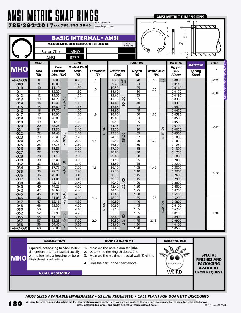
ANSI METRIC SNAP RINGSREVISED 09-04
MOST SIZES AVAILABLE IMMEDIATELY • $2 LINE REQUESTED • CALL PLANT FOR QUANTITY DISCOUNTS
180
785•392•3017 FAX 785.392.2845
All manufacturer names and numbers are for identification purposes only. In no way are we implying that our parts were made by the manufacturers listed above.Prices, materials, tolerances, and grades subject to change without notice. © G.L. Huyett 2004
www.huyett.com
Tapered section ring to ANSI metric dimensions that is installed axially with pliers into a housing or bore. High thrust load rating.
1. Measure the bore diameter (Db).2. Determine the ring thickness (T).3. Measure the maximum radial wall (S) of the
ring.4. Find the part in the chart above.
WEIRDAXIAL ASSEMBLY
Free Outside
Dia. (Dr)MM(Db)
Thickness(T)
Diameter(Dg)
Depth(d)
SpringSteel
891011121314151617181920212223242526272830323435363738404245464748505255575860
8.8010.0011.1012.2013.3014.2515.4516.6017.7018.9020.0521.1022.2523.3024.4025.4526.5527.7528.8529.9531.1033.4035.3537.7538.7540.0041.0542.1544.2546.6049.9551.0552.1553.3055.3557.9061.1063.2564.4066.80
0.851.251.301.301.351.351.601.651.701.701.801.802.002.102.102.202.302.602.702.802.903.003.103.203.303.403.403.404.004.204.304.304.304.504.604.705.105.205.305.30
BORE RING
MHOMHO-008
-009-010-011-012-013-014-015-016-017-018-019-020-021-022-023-024-025-026-027-028-030-032-034-035-036-037-038-040-042-045-046-047-048-050-052-055-057-058
MHO-060
Width Min.(W)
+.10/-.00
+.1
5/-.
00
+.06
/-.0
0+
.10/
-.00
+.1
5/-.
00
GROOVE
+.2
0/-.
00
+/-
.06
+/-
.08
TOOLRadial Wall
Max.(S)
8.409.45
10.5011.6012.6513.7014.8015.8516.9018.0019.0520.1021.1522.2023.3024.3525.4026.6027.7028.8029.8031.9033.9036.1037.2038.3039.3040.4042.4044.5047.6048.7049.8050.9053.1055.3058.4060.5061.6063.80
.20
.23
.25
.30
.33
.35
.40
.43
.45
.50
.53
.55
.57
.60
.65
.67
.70
.80
.85
.90
.90
.95
.951.051.101.151.151.201.201.251.301.351.401.451.551.651.701.751.801.90
1.3
.4
.6
.9
1.1
1.6
2.0
.50
.70
1.00
1.20
1.40
1.75
2.15
+.3
0/-.
00
+.2
0/-.
00
+.2
5/-.
13+
.40/
-.25
+.6
5/-.
50+
.90/
-.65
+1.
00/-
.75
BASIC INTERNAL - ANSIMANUFACTURER CROSS-REFERENCE
MATERIAL
MHORotor Clip
WEIGHTKg per
100Pieces
0.00500.01100.01400.01700.01900.03500.03900.04200.04700.05200.05800.05900.07000.08200.09000.10000.10900.12600.13000.17000.18000.20000.22000.23000.23000.26000.29000.30000.40000.47000.51000.52000.58000.61000.62000.81000.89000.99001.01001.0500
-I038
-I047
-I070
SPECIALFINISHES ANDPACKAGINGAVAILABLE
UPON REQUEST.
ANSI METRIC DIMENSIONS
-I025
-I090
INDEX PAGE 236.
d
DbS
Dr W
Dg
T
TOO
L D
ESC
RIP
TIO
NS
ON
PA
GE
227.
DESCRIPTION HOW TO IDENTIFY GENERAL USE
MHO
B27.7-ANSI

BOX 232 • MINNEAPOLIS, KS • 67467
MOST SIZES AVAILABLE IMMEDIATELY • $2 LINE REQUESTED • CALL PLANT FOR QUANTITY DISCOUNTS
181All manufacturer names and numbers are for identification purposes only. In no way are we implying that our parts were made by the manufacturers listed above.Prices, materials, tolerances, and grades subject to change without notice.© G.L. Huyett 2004
Tapered section ring to ANSI metric dimensions that is installed axially with pliers into a housing or bore. High thrust load rating.
1. Measure the bore diameter (Db).2. Determine the ring thickness (T).3. Measure the maximum radial wall (S) of the
ring.4. Find the part in the chart above.
WEIRDAXIAL ASSEMBLY
Free Outside
Dia. (Dr)MM(Db)
Thickness(T)
SpringSteel
62636568707275788082858890929598100102105108110115120125130135140145150155160170180190200210220230240250
68.6069.9072.2075.7077.5079.6083.3086.8089.1091.1094.4097.90
100.00102.20105.60109.00110.70112.40115.80119.20120.80126.00132.40137.10142.50148.50154.10159.50164.50168.80175.10185.60196.60207.70217.80230.30240.50251.40262.30273.30
5.305.405.605.805.805.806.206.506.706.907.007.307.407.607.808.108.208.408.408.508.708.909.409.509.80
10.4010.4010.6010.8010.8010.9011.4012.0012.9013.3014.2015.0015.5016.3016.70
BORE RING
MHO Width Min.(W)
+.2
0/-.
00
GROOVE TOOLRadial Wall
Max.(S)
2.0
2.8
3.2
4.0
4.8
2.15
2.55
2.95
3.40
4.25
5.10
+1.
00/-
.75
+/-
1.40
+/-
1.65
+/-
2.05
+/-
2.30
Diameter(Dg)
Depth(d)
+.3
0/-.
00+
.40/
-.00
+/-
.08
+/-
.10
65.8066.9069.0072.2074.4076.5079.7082.8085.0087.2090.4093.6095.7097.80
101.00104.20106.30108.40111.50114.60116.70121.90127.00132.10137.20142.30147.40152.50157.60162.70167.80178.00188.40198.80209.00219.40230.00240.60251.00261.40
1.901.952.002.102.202.252.352.402.502.602.702.802.852.903.003.103.153.203.253.303.353.453.503.553.603.653.703.753.803.853.904.004.204.404.504.705.005.305.505.70
+/-
.12
+.5
0/-.
00
MHO-062-063-065-068-070-072-075-078-080-082-085-088-090-092-095-098-100-102-105-108-110-115-120-125-130-135-140-145-150-155-160-170-180-190-200-210-220-230-240
MHO-250
BASIC INTERNAL - ANSIMANUFACTURER CROSS-REFERENCE
MATERIAL
Rotor Clip MHO
+.2
5/-.
00
2.4
WEIGHTKg per
100Pieces
1.1500 1.1600 1.5400 1.5900 1.6100 1.6300 1.9300 2.4000 2.5900 2.7200 2.9500 3.1300 3.2600 3.3100 3.5400 3.9400 3.9900 4.2200 4.4000 4.5800 4.7600 5.0300 5.6200 6.0000 6.3500 7.9000 8.3000 8.7000 8.9000 9.100012.100013.800015.600022.000023.500027.500028.500033.000036.500037.5000
-I108
-I035
TOO
L D
ESC
RIP
TIO
NS
ON
PA
GE
227.
ANSI METRIC DIMENSIONS
-I090
-I045
INDEX PAGE 236.
DbS
Dr
d
W
Dg
T
DIN 472PAGES
166-170.
DESCRIPTION HOW TO IDENTIFY GENERAL USE
MHO
ANSI B27.7-
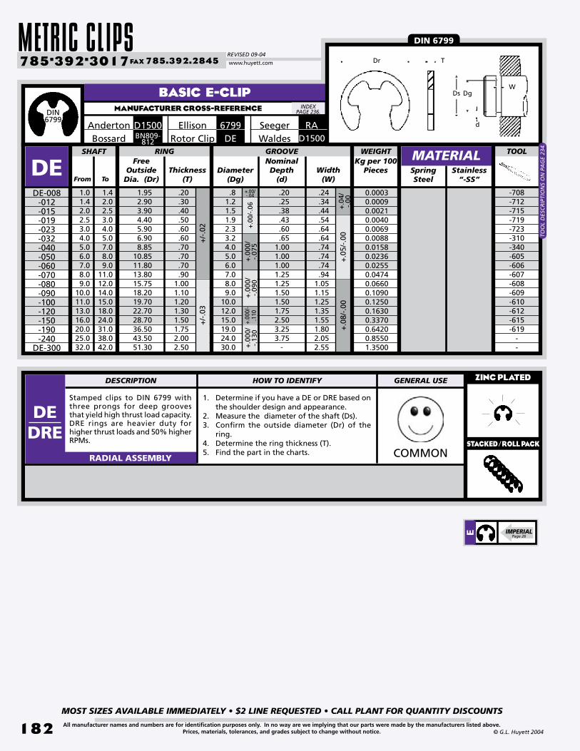
METRIC CLIPSREVISED 09-04
MOST SIZES AVAILABLE IMMEDIATELY • $2 LINE REQUESTED • CALL PLANT FOR QUANTITY DISCOUNTS
182
785•392•3017 FAX 785.392.2845
All manufacturer names and numbers are for identification purposes only. In no way are we implying that our parts were made by the manufacturers listed above.Prices, materials, tolerances, and grades subject to change without notice. © G.L. Huyett 2004
www.huyett.com
BASIC E-CLIPMANUFACTURER CROSS-REFERENCE
SpringSteel
.81.21.51.92.33.24.05.06.07.08.09.0
10.012.015.019.024.030.0
DE
Stamped clips to DIN 6799 with three prongs for deep grooves that yield high thrust load capacity. DRE rings are heavier duty for higher thrust loads and 50% higher RPMs.
1. Determine if you have a DE or DRE based on the shoulder design and appearance.
2. Measure the diameter of the shaft (Ds).3. Confirm the outside diameter (Dr) of the
ring.4. Determine the ring thickness (T).5. Find the part in the charts.
ZINC PLATED
COMMONRADIAL ASSEMBLY
DE-008-012-015-019-023-032-040-050-060-070-080-090-100-120-150-190-240
DE-300
-708-712-715-719-723-310-340-605-606-607-608-609-610-612-615-619
- -
Thickness(T)
SHAFT RING TOOL
Diameter(Dg)
Width(W)
GROOVE
.24
.34
.44
.54
.64
.64
.74
.74
.74
.941.051.151.251.351.551.802.052.55
.20
.30
.40
.50
.60
.60
.70
.70
.70
.901.001.101.201.301.501.752.002.50
+/-
.03
+.0
0/-.
06
+.0
5/-.
00+/-
.02
+.00/ -.04
+.0
4/-.
00
+.0
00/
-.07
5+.
000/
-.1
10+
.000
/-.
090
+.0
00/
-.13
0 +.0
8/-.
00
MATERIAL
Seeger RA6799EllisonD1500AndertonDERotor ClipBN809-
812Bossard
NominalDepth
(d)
Kg per 100 Pieces
WEIGHTFree
Outside Dia. (Dr)
.20
.25
.38
.43
.60
.651.001.001.001.251.251.501.501.752.503.253.75
1.952.903.904.405.906.908.85
10.8511.8013.8015.7518.2019.7022.7028.7036.5043.5051.30 -
DIN 6799
Stainless“-SS”
0.00030.00090.00210.00400.00690.00880.01580.02360.02550.04740.06600.10900.12500.16300.33700.64200.85501.3500
D1500Waldes
DIN6799
INDEX PAGE 236.
TDr
Ds DgW
d
From
DESCRIPTION HOW TO IDENTIFY GENERAL USE
DEDRE
STACKED/ROLL PACK
E IMPERIALPage 26
To
1.01.42.02.53.04.05.06.07.08.09.0
10.011.013.016.020.025.032.0
1.42.02.53.04.05.07.08.09.0
11.012.014.015.018.024.031.038.042.0
TOO
L D
ESC
RIP
TIO
NS
ON
PA
GE
234.

BOX 232 • MINNEAPOLIS, KS • 67467
MOST SIZES AVAILABLE IMMEDIATELY • $2 LINE REQUESTED • CALL PLANT FOR QUANTITY DISCOUNTS
183All manufacturer names and numbers are for identification purposes only. In no way are we implying that our parts were made by the manufacturers listed above.Prices, materials, tolerances, and grades subject to change without notice.© G.L. Huyett 2004
REINFORCED E-CLIPMANUFACTURER CROSS-REFERENCE
Variant of standard DIN 6799 E-clip with a slotted ID. Slot yields a pivot point for removal using a screwdriver.
1. Confirm the presence of a slot on inside diameter of the ring.
2. Measure the diameter of the shaft (Ds).3. Measure the free outside diameter (Dr) of
the ring.4. Determine the ring thickness (T).5. Find the part in the chart above. WEIRDRADIAL ASSEMBLY
SLOTTED E-CLIPMANUFACTURER CROSS-REFERENCE
Dr
WDgDs
T
HEAVY DUTY
DRE TECHNICAL INFORMATION ON PREVIOUS PAGE.
INDEX PAGE 236.
INDEX PAGE 236.
TDr
Ds DgW
d
Slot yields a pivot point for removal using a screwdriver.
MM(Ds)
Diameter(Dg)
Spring Steel
456789101112131415
.50
.57
.57
.80
.80
.951.101.101.251.401.401.60
DREDRE-004
-005-006-007-008-009-010-011-012-013-014
DRE-015+.
00/
-.05 -120
-130-140-160-500
--170-270
--200-280
-
Depth(d)
Thickness(T)
FreeOutside Dia.
(Dr)
SHAFT RING TOOLGROOVE
Width(W)
8.509.50
11.3513.1014.9515.7016.7518.9519.6020.5522.1023.20
3.003.854.855.406.407.107.808.809.5010.211.211.8
+.1
5/-.
00
+/-
.06
+.00
/ -.1
0+
.00/
-.15
MATERIAL
Rotor Clip
WEIGHTKg per
100Pieces
0.01400.01800.02400.03200.03600.06000.06800.08600.12000.14500.16000.1750
TOO
L D
ESC
RIP
TIO
NS
ON
PA
GE
234.
MRE
.6
.9
1.1
.7
1.0
1.2
From(Ds)
SpringSteel
345678910
2.33.24.05.06.07.08.09.0
DSTDST-003
-004-005-006-007-008-009
DST-010
+.0
0/-.
05
Free Outside Dia.
(Dr)
+.0
00/-
.075
To(Ds)
SHAFT RING
Diameter(Dg)
GROOVEWidthMin.(W)
+.00
/ -.0
6
4567891011
5.07.08.5
10.011.013.014.017.0 +
.000
/ -.
090
MATERIAL
STSeeger
Thickness(T)
Kg per100
Pieces
WEIGHT
0.00700.01000.01500.02000.02900.04100.05400.0900
.6
.7
.8
1.0
.64
.74
.85
1.05
DESCRIPTION HOW TO IDENTIFY GENERAL USE
DST
RE IMPERIAL
Page 27

METRIC CLIPSREVISED 09-04
MOST SIZES AVAILABLE IMMEDIATELY • $2 LINE REQUESTED • CALL PLANT FOR QUANTITY DISCOUNTS
184
785•392•3017 FAX 785.392.2845
All manufacturer names and numbers are for identification purposes only. In no way are we implying that our parts were made by the manufacturers listed above.Prices, materials, tolerances, and grades subject to change without notice. © G.L. Huyett 2004
www.huyett.com
Free Outside Dia.
(Dr)Decimal
(Ds)Thickness
(T)Diameter
(Dg)SpringSteel
.062
.094
.110
.125
.125
.140
.156
.188
.188
.188
.188
.188
.188
.219
.250
.312
.156
.187
.375
.230
.230
.203
.282
.310
.310
.375
.375
.335
.335
.437
.527
.500
.052
.074
.079
.095
.095
.102
.116
.125
.125
.125
.125
.147
.147
.188
.210
.250
SHAFT RING TOOL
EBSEBS-052
-074-079-095
-095A-102-116-125
-125A -125B -125C
-147 -147A
-188-210
EBS-250
Width(W)
+.0
025/
-.00
00
+.0
02/-
.000
5+
.002
/-.0
01
+.0
30/
-.00
0+
.040
/-.
000
-021A-002B-006B-003B-003D-017B-004B-004A-004D-006B-060-005A-005C-008B-009C-009C
InstalledOutside
Diameter
+/-
.002
GROOVE
.015
.020
.020
.020
.025
.020
.020
.015
.020
.020
.015
.020
.032
.030
.035
.035
.019
.024
.024
.024
.029
.024
.024
.019
.024
.024
.019
.024
.037
.034
.040
.040
.165
.200
.390
.240
.240
.215
.295
.330
.330
.395
.395
.350
.350
.450
.540
.520
+.0
50/-
.000
+.06
0/
-.000
+.1
00/-
.000
+.0
04/-
.000
BRITISH SPECIFICATIONMANUFACTURER CROSS-REFERENCE
MATERIAL
B1500Anderton
Free Inside Dia.
(Df)From(Ds)
To(Ds)
Gap(A)
Diameter(Dg)
SpringSteel
1.01.42.02.53.24.05.06.07.08.09.0
10.011.013.016.020.025.0
1.42.02.53.24.05.07.08.09.0
11.012.014.015.018.024.031.038.0
.81.21.52.02.53.04.05.06.07.08.09.0
10.012.015.019.024.0
.71.01.31.72.12.63.54.35.26.16.97.88.7
10.413.016.520.8
SHAFT
JEJE-0008 -0012 -0015
-002 -0025-003-004-005-006-007-008-009-010-012-015-019
JE-024
Width(W)
+/-
.1+
/-.2
+/-
.06
+/-.05
+/-
.09
Thickness(T)
TOOL
----
-050-070-340-605-606-607-608
--
-612---
InstalledOutside
Diameter
.2
.3
.4
.4
.4
.6
.6
.6
.8
.8
.8
.81.01.01.51.52.0
234567911121416182023293744
.81.21.52.02.53.04.05.06.07.08.09.0
10.012.015.019.024.0
.30
.40
.50
.50
.50
.70
.70
.70
.90
.90
.90
.901.151.151.651.652.20
+/-
.05
+/-
.10
+.0
0/-.
45
+.00/-.50
+.0
0/-.
30+
.00/
-.35
+.0
0/-.
25
+/-
.075
+/-
.13
+/-
.11
+/-
.04
+.0
0/-.
12
+/-
.03
+/-.02+/-.025
+.00/-.08
+.0
0/-.
09
+/-
.14+/-
.3
+.0
0/-.
15+.
00/
-.18
+.00
/-.2
1
+/-
.05
+/-
.07
+/-.06
RING GROOVE
JAPANESE INDUSTRIAL SPEC (JIS)MANUFACTURER CROSS-REFERENCE
MATERIAL
JERotor Clip
CO
NTA
CT
PLA
NT
FOR
TO
OL
INFO
RM
ATI
ON
.
DgDs
W
TA
Df
DsW
TDr
Dg
CO
NTA
CT
PLA
NT
FOR
TO
OL
INFO
RM
ATI
ON
.

BOX 232 • MINNEAPOLIS, KS • 67467
MOST SIZES AVAILABLE IMMEDIATELY • $2 LINE REQUESTED • CALL PLANT FOR QUANTITY DISCOUNTS
185All manufacturer names and numbers are for identification purposes only. In no way are we implying that our parts were made by the manufacturers listed above.Prices, materials, tolerances, and grades subject to change without notice.© G.L. Huyett 2004
GERMAN STANDARDMANUFACTURER CROSS-REFERENCE
9133Ellison
DIN 9133
U-CLIPMANUFACTURER CROSS-REFERENCE
UBenzing
BOWED SLOTTED E-CLIPMANUFACTURER CROSS-REFERENCE
ASBenzing
BN815Bossard
BN814Bossard
CLIP WASHERMANUFACTURER CROSS-REFERENCE
STSBenzing
DIN9133
German-engineered e-clip that conforms to DIN 9133. Used for various applications, including automotive engineering, electrical engineering, and precision mechanical devices.
U-shaped clips for radial application into grooves on shafts. Slot yields a pivot point for removal using a screwdriver. Some sizes available in a stacked roll pack for automated installation.
Bowed slotted e-clips with curved shape for resilient end-play take-up. Install with the concave surface abutting the part. Slots in the ring serve to make the part lighter, decrease stiffness, and aid in removal.
Clip washer for radial assembly into grooves on shafts. Bevel allows for take-up of play on axial tolerances. Easily installed by hand using the perpendicular tab at the top of the ring.
DE9
DU
DBS
DSTS
INDEX PAGE 236.
INDEX PAGE 236.
INDEX PAGE 236.
SPECIAL ORDER ONLY

METRIC CLIPSREVISED 09-04
MOST SIZES AVAILABLE IMMEDIATELY • $2 LINE REQUESTED • CALL PLANT FOR QUANTITY DISCOUNTS
18�
785•392•3017 FAX 785.392.2845
All manufacturer names and numbers are for identification purposes only. In no way are we implying that our parts were made by the manufacturers listed above.Prices, materials, tolerances, and grades subject to change without notice. © G.L. Huyett 2004
www.huyett.com
BASIC C-CLIPMANUFACTURER CROSS-REFERENCE
Radially-assembled part that uses circular deformation for retainage. Narrow section height provides good clearance capabil it ies . Absence of teeth and deep set mean less thrust load ratings than E-clips. Install using an applicator.
1. Confirm the diameter of the shaft (Ds).2. Measure the outside diameter (Dr) of the
ring. 3. Determine the ring thickness (T).4. Find the part in the chart above.
ZINC PLATED
COMMONRADIAL ASSEMBLY
MM(Ds)
Diameter(Dg)
SpringSteel
3456
6.57891011121314151617181920222324252628303235363840424548505255
.35
.40
.50
.50
.35
.50
.50
.50
.50
.50
.55
.60
.65
.70
.75
.80
.85
.90
.951.051.101.151.201.251.401.501.601.751.801.902.002.102.252.402.502.502.50
DCDC-003
-004-005-006
-0065-007-008-009-010-011-012-013-014-015-016-017-018-019-020-022-023-024-025-026-028-030-032-035-036-038-040-042-045-048-050-052
DC-055
+.0
0/-.
07+
.00/
-.09
-03-04-05-06-
-07-08-09-10-11-12-13-14-15-16-17-18-19-20-22-23-24-25-26-------------
Installed Outside
DiameterThickness
(T)
FreeOutside
Dia. (Dr)
SHAFT RING TOOLGROOVE
Depth(d)
WidthMin.(W)
3.985.006.207.408.208.60
10.0011.2012.1513.2014.3515.4016.3017.4018.5019.4020.4021.5022.6525.0026.0027.1028.3029.4031.6033.7036.1039.4040.5042.6045.0047.2050.6054.1056.4058.6061.50
4.15.26.47.68.48.8
10.211.412.413.614.715.816.717.818.919.920.922.023.225.526.627.728.930.032.234.436.840.141.243.445.848.051.555.057.459.663.0
2.33.24.05.05.86.07.08.09.0
10.010.911.812.713.614.515.416.317.218.119.920.821.722.623.525.227.028.831.532.434.236.037.840.543.245.047.050.0
1.00
1.20
1.50
1.75
2.00
1.10
1.30
1.60
1.85
2.15
+.0
0/-.
05+
.00/
-.06
+.0
0/-.
07
+.0
0/-.
11+
.00/
-.21
+.0
0/-.
25
.80
.70
.60
.40
.85
.64
.74
.44
MATERIAL
BN831BossardM1800Anderton HEllison
WEIGHTKg per
100Pieces
0.00200.00400.00800.01100.01200.01300.01700.02200.02600.02900.03200.03600.04000.04600.05400.06400.07200.08000.08700.11000.11500.15200.17400.18800.23200.24300.30200.33000.44000.46200.50500.54600.59800.78200.88500.93301.0400
DCRotor ClipHSeeger
LOW PROFILE
INDEX PAGE 236.
C IMPERIALPage 32
W
DsDg
d
Dr T
DESCRIPTION HOW TO IDENTIFY GENERAL USE
DCSTACKED/ROLL PACK
TOO
L D
ESC
RIP
TIO
NS
ON
PA
GE
234.
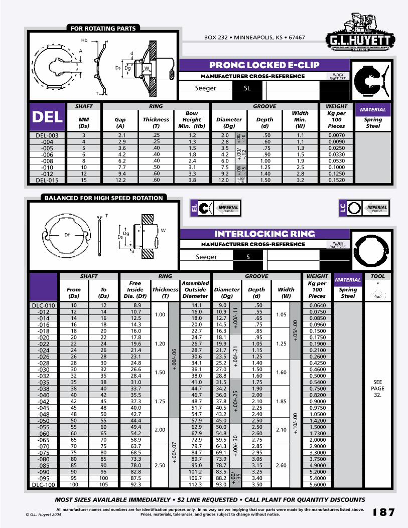
BOX 232 • MINNEAPOLIS, KS • 67467
MOST SIZES AVAILABLE IMMEDIATELY • $2 LINE REQUESTED • CALL PLANT FOR QUANTITY DISCOUNTS
187All manufacturer names and numbers are for identification purposes only. In no way are we implying that our parts were made by the manufacturers listed above.Prices, materials, tolerances, and grades subject to change without notice.© G.L. Huyett 2004
Bow Height
Min. (Hb)MM(Ds)
Diameter(Dg)
Depth(d)
SpringSteel
34568101215
2.12.93.64.26.27.79.4
12.2
1.21.31.51.82.43.13.33.8
SHAFT RING
DELDEL-003
-004-005-006-008-010-012
DEL-015
+.0
0/-.
12+.
00/
-.10
GROOVE
Thickness(T)
Gap(A)
WidthMin.(W)
.25
.25
.40
.40
.40
.50
.60
.60
2.02.83.54.26.07.59.2
12.0
.50
.60
.75
.901.001.251.401.50
1.11.11.31.51.92.52.83.2
+.00
/-.1
5
+.00/-.18
PRONG LOCKED E-CLIPMANUFACTURER CROSS-REFERENCE
MATERIAL
Seeger SL
INTERLOCKING RINGMANUFACTURER CROSS-REFERENCE
Free Inside
Dia. (Df)From(Ds)
To(Ds)
Thickness(T)
Diameter(Dg)
Depth(d)
SpringSteel
10121416182022242628303235384042454850556065707580859095100
121416182022242628303235384042454850556065707580859095100105
8.910.712.514.316.017.819.621.423.124.826.628.431.033.735.537.340.042.744.449.454.258.963.768.573.378.082.887.592.3
DLC-010-012-014-016-018-020-022-024-026-028-030-032-035-038-040-042-045-048-050-055-060-065-070-075-080-085-090-095
DLC-100
Width(W)
14.116.018.020.022.724.726.728.730.634.136.138.041.044.746.748.751.754.757.962.967.972.979.784.789.795.0
101.2106.7112.3
SHAFT GROOVE TOOL
+.0
5/-.
00+
.10/
-.00
+.0
0/-.
11+
.00/
-.21
+.0
0/-.
25
+.0
0/-.
06+
.00/
-.07
+.0
0/-.
30
Assembled Outside
Diameter
9.010.912.714.516.318.119.921.723.525.227.028.831.534.236.037.840.543.245.050.054.859.564.369.173.978.783.588.293.0
.50
.55
.65
.75
.85
.951.051.151.251.401.501.601.751.902.002.102.252.402.502.502.602.752.852.953.053.153.253.403.50
1.00
1.20
1.50
1.75
2.00
2.50
1.05
1.25
1.60
1.85
2.10
2.60
+.0
0/-.
35
RINGMATERIAL
SSeeger
FOR ROTATING PARTS
BALANCED FOR HIGH SPEED ROTATION
W
d
DgDs
T
Hb
A
WEIGHTKg per
100Pieces
WEIGHTKg per
100Pieces
0.00700.00900.02500.03300.05300.10000.12500.1520
0.06400.07500.08500.09600.15000.17500.19000.21000.26000.42500.46000.50000.54000.75000.82000.90000.97501.05001.42001.50001.73002.00002.90003.30003.75004.90005.20005.40005.6000
SEEPAGE
32.
INDEX PAGE 236.
INDEX PAGE 236.
T
DfW
d
DgDs
EL IMPERIAL
Page 33 LC IMPERIALPage 31

ANSI METRIC CLIPSREVISED 09-04
MOST SIZES AVAILABLE IMMEDIATELY • $2 LINE REQUESTED • CALL PLANT FOR QUANTITY DISCOUNTS
188
785•392•3017 FAX 785.392.2845
All manufacturer names and numbers are for identification purposes only. In no way are we implying that our parts were made by the manufacturers listed above.Prices, materials, tolerances, and grades subject to change without notice. © G.L. Huyett 2004
www.huyett.com
Stamped clips to ANSI metric dimensions with three prongs for deep grooves that yield high thrust load capacity. MRE rings are heavier duty for higher thrust loads, and 50% higher RPM’s.
1. Determine if you have a ME or MRE based on the shoulder design and appearance.
2. Measure the diameter of the shaft (Ds).3. Confirm the free outside diameter (Dr) of the
ring. Determine the ring thickness (T).4. Find the part in the charts above.
WEIRDRADIAL ASSEMBLY
ANSI METRIC DIMENSIONS
ANSI METRIC DIMENSIONS
TDr
Ds DgW
d
TDr
Ds DgW
d
MM(Ds)
Thickness(T)
Diameter(Dg)
Depth(d)
SpringSteel
2345689101215162025
4.05.67.28.5
11.114.615.816.818.622.823.830.037.1
SHAFT RING
MEME-002
-003-004-005-006-008-009-010-012-015-016-020
ME-025
Width(W)
+.00/-.05
+.0
0/-.
08+
.00/
-.10
+.0
0/-.
15
+/-.05
+/-
.06
GROOVE TOOL
-040-050-100-120-140-290-608-290-609-612-210
- -
Free Outside
Dia. (Dr)
.079
.118
.157
.197
.236
.315
.354
.393
.472
.591
.630
.787
.984
1.452.303.103.904.856.407.208.009.60
11.8012.5016.0020.00
.28
.35
.45
.55
.58
.80
.901.001.201.601.752.002.50+
.00/
-.20
+.1
5/-.
00
+.10/-.00
Decimal(Ds)
BASIC E-CLIP - ANSIMANUFACTURER CROSS-REFERENCE
MATERIAL
MERotor Clip
+.05/-.00
WEIGHTKg per
100Pieces
CO
NTA
CT
PLA
NT
FOR
TO
OL
INFO
RM
ATI
ON
.
0.00140.00360.00950.01300.02100.03500.05800.06800.10000.14000.14500.28000.4200
INDEX PAGE 236.
.25
.40
.60
.90
1.10
1.30
.32
.50
.70
1.00
1.20
1.40
REINFORCED E-CLIP - ANSIMANUFACTURER CROSS-REFERENCE
MM(Ds)
Diameter(Dg)
Spring Steel
45689101215
.50
.57
.57
.80
.951.101.251.60
MREMRE-004
-005-006-008-009-010-012
MRE-015
+.00
/ -.0
5 -120-130-140-500
--170
--
Depth(d)
Thickness(T)
FreeOutside
Dia. (Dr)
SHAFT RING TOOLGROOVE
Width(W)
8.509.50
11.3514.9515.7016.7519.6023.20
3.003.854.856.407.107.809.5011.8
+.1
5/-.
00
+/-
.06
+.00/-.10
+.0
0/-.
15
MATERIAL
Rotor Clip MRE
WEIGHTKg per
100Pieces
0.01400.01800.02400.03600.06000.06800.12000.1750
INDEX PAGE 236.
.6
.9
1.1
.7
1.0
1.2C
ON
TAC
T PL
AN
T FO
R T
OO
L IN
FOR
MA
TIO
N.
DIN 6799PAGE182.
DESCRIPTION HOW TO IDENTIFY GENERAL USE
MEMRE
B27.7-3CM1ANSI
ANSI B27.8M-3EM1

BOX 232 • MINNEAPOLIS, KS • 67467
MOST SIZES AVAILABLE IMMEDIATELY • $2 LINE REQUESTED • CALL PLANT FOR QUANTITY DISCOUNTS
189All manufacturer names and numbers are for identification purposes only. In no way are we implying that our parts were made by the manufacturers listed above.Prices, materials, tolerances, and grades subject to change without notice.© G.L. Huyett 2004
Radially-assembled part to ANSI metric dimensions that uses circular deformation for retainage. Narrow section height provides good clearance capabilities. Absence of teeth and deep set mean less thrust load ratings than E-clips. Install using an applicator.
1. Confirm the diameter of the shaft (Ds).2. Measure the free outside diameter (Dr) of
the ring. 3. Determine the ring thickness (T).4. Find the part in the chart above.
WEIRDRADIAL ASSEMBLY
MM(Ds)
Diameter(Dg)
SpringSteel
34567891011121314151617181920222324252628303235363840424548505255
.35
.40
.50
.50
.50
.50
.50
.50
.50
.55
.60
.65
.70
.75
.80
.85
.90
.951.051.101.151.201.251.401.501.601.751.801.902.002.102.252.402.502.502.50
MCMC-003
-004-005-006-007-008-009-010-011-012-013-014-015-016-017-018-019-020-022-023-024-025-026-028-030-032-035-036-038-040-042-045-048-050-052
MC-055
+.00/-.05
+.0
0/-.
07
--080
--320
--350
-------
-400--
-280---------
-480---------
+/-
.06
+/-
.08
Depth(d)
Thickness(T)
FreeOutside Dia.
(Dr)
SHAFT GROOVE TOOLRING
Width(W)
3.985.006.207.408.60
10.0011.2012.1513.2014.3515.4016.3017.4018.5019.4020.4021.5022.6525.0026.0027.1028.3029.4031.6033.7036.1039.4040.5042.6045.0047.2050.6054.1056.4058.6061.50
2.33.24.05.06.07.08.09.0
10.010.911.812.713.614.515.416.317.218.119.920.821.722.623.525.227.028.831.532.434.236.037.840.543.245.047.050.0
.6
1.0
1.2
1.6
2.0
.70
1.10
1.30
1.75
2.15
+.1
5/-.
00+
.20/
-.00
+.1
0/-.
00
+.0
0/-.
10+
.00/
-.20
+.0
0/-.
25
+/-
.06
+/-
.08
+/-
.09
+/-
.18
+/-
.21
+/-
.25
+/-
.39
.4 .50
BASIC C-CLIP - ANSIMANUFACTURER CROSS-REFERENCE
MCRotor Clip
MATERIALWEIGHTKg per
100Pieces
0.00190.00250.00550.00720.00900.01200.01300.01500.01700.02000.03900.04200.05000.05100.05500.06700.08500.08500.10700.11500.12000.14000.15000.25000.26000.32000.35000.41000.43000.47000.50000.54000.71000.89000.93001.0400
SPECIALFINISHES ANDPACKAGINGAVAILABLE
UPON REQUEST.
ANSI METRIC DIMENSIONS
INDEX PAGE 236.
W
DsDg
d
Dr T
CO
NTA
CT
PLA
NT
FOR
TO
OL
INFO
RM
ATI
ON
.
DESCRIPTION HOW TO IDENTIFY GENERAL USE
MC
B27.8M-3SM1ANSI

METRIC SPIRAL RINGSREVISED 09-04
MOST SIZES AVAILABLE IMMEDIATELY • $2 LINE REQUESTED • CALL PLANT FOR QUANTITY DISCOUNTS
190
785•392•3017 FAX 785.392.2845
All manufacturer names and numbers are for identification purposes only. In no way are we implying that our parts were made by the manufacturers listed above.Prices, materials, tolerances, and grades subject to change without notice. © G.L. Huyett 2004
www.huyett.com
Popular series for metric applications that will accommodate light and medium bearing series thrust loads. For aerospace, see page 192. Fits same grooves but does not conform to DIN 471.
1. Verify shaft diameter (Ds).2. Measure the free inside diameter (Df) of the
ring.3. Determine thickness (T) and radial wall (S).4. Find the part in the charts.
UNCOMMONAXIAL ASSEMBLY
MM(Ds)
Thickness(T)
SpringSteel
13141516171819202122232425262728293032333435363840424546474850525455565860626365
DSDS-013
-014-015-016-017-018-019-020-021-022-023-024-025-026-027-028-029-030-032-033-034-035-036-038-040-042-045-046-047-048-050-052-054-055-056-058-060-062-063
DS-065
Radial Wall(S)
FreeInside Dia.
(Df)
SHAFT RING
12.2713.2614.1515.0416.0416.8317.8318.8219.7920.7821.7722.6623.6524.6425.3426.3427.3328.3230.0030.9931.9832.6633.6535.6437.1139.0942.0643.0544.0445.0346.5348.5150.5051.4952.4854.4356.4258.4259.3961.39
12.413.414.315.216.217.018.019.020.021.022.022.923.924.925.626.627.628.630.331.332.333.034.036.037.539.542.543.544.545.547.049.051.052.053.055.057.059.060.062.0
GROOVE
Diameter(Dg)
Depth(d)
Width(W)
.99
1.14
1.44
1.69
1.93
.3
.5
.7
1.0
1.5
1.3
.9
.4
.6
+.0
0/-.
33+
.00/
-.38
+.0
0/-.
51+
.00/
-.63
+.0
0/-.
11+
.00/
-.13
+.0
0/-.
21+
.00/
-.25
+/-
.05
+/-
.08
+.1
4/-.
00
1.10
1.30
1.60
1.85
2.15
+.0
0/-.
30
1.27-1.48
1.52-1.73
1.78-1.98
2.03-2.24
2.26-2.46
3.12-3.33
3.89-4.09
4.93-5.18
DS DSH (Page 152) DSHI (Page 160) DAK (Page 162) DAL (Page 163)
BASIC EXTERNALMANUFACTURER CROSS-REFERENCE
MATERIAL
DNSSmalley
Stainless “-SO2”
Df
S
T
Ds
Dg
d
W
2.41 2.65
PERFORMANCE RESULTS VARY. YOUR RING SELECTION SHOULD BE MADE BASED ON INDIVIDUAL APPLICATION.
0.04700.05000.05300.06700.07100.10000.10600.11100.11600.12100.12700.15000.15600.16200.16700.24300.25200.26000.38400.39500.40600.41400.62900.66300.68700.72000.77000.78600.80300.81901.24701.29401.34201.36601.39001.43701.48501.53401.55702.0050
Kg per100
Pieces
WEIGHT
DIN METRIC SERIES
FITS INTO THE SAME GROOVE AS DIN 471 GROOVE INTERCHANGE
USE ANY OF THESE PARTS IN THE SAME SIZED GROOVE.
DIN471
GROOVES
INDEX PAGE 236.
DESCRIPTION HOW TO IDENTIFY GENERAL USE
DS
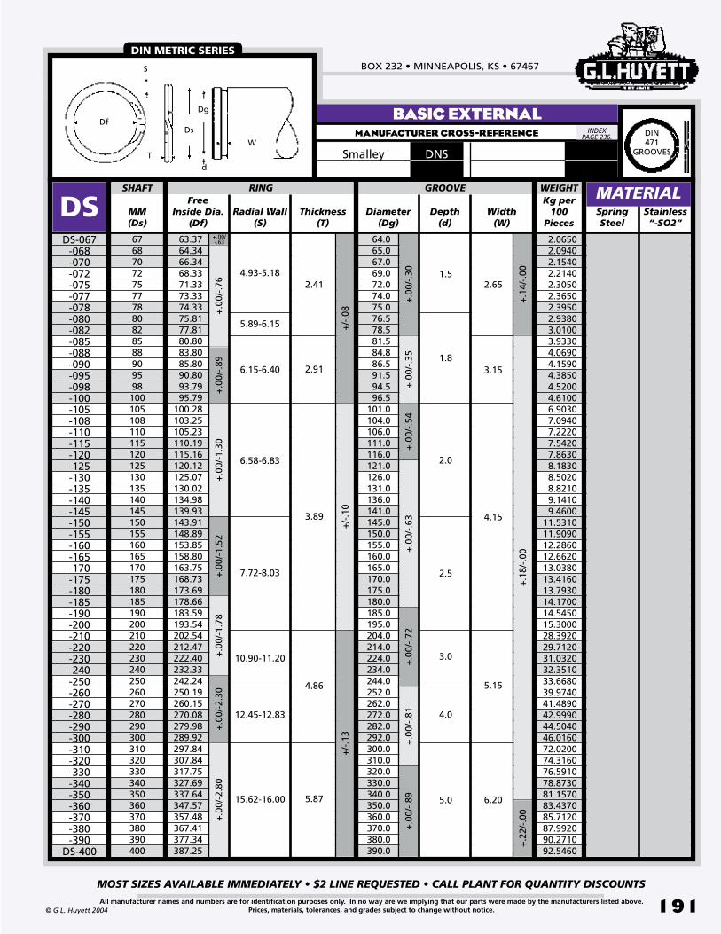
BOX 232 • MINNEAPOLIS, KS • 67467
MOST SIZES AVAILABLE IMMEDIATELY • $2 LINE REQUESTED • CALL PLANT FOR QUANTITY DISCOUNTS
191All manufacturer names and numbers are for identification purposes only. In no way are we implying that our parts were made by the manufacturers listed above.Prices, materials, tolerances, and grades subject to change without notice.© G.L. Huyett 2004
BASIC EXTERNALMANUFACTURER CROSS-REFERENCE
DNSSmalley
Df
S
T
Ds
Dg
d
W
MM(Ds)
Thickness(T)
SpringSteel
6768707275777880828588909598100105108110115120125130135140145150155160165170175180185190200210220230240250260270280290300310320330340350360370380390400
DSDS-067
-068-070-072-075-077-078-080-082-085-088-090-095-098-100-105-108-110-115-120-125-130-135-140-145-150-155-160-165-170-175-180-185-190-200-210-220-230-240-250-260-270-280-290-300-310-320-330-340-350-360-370-380-390
DS-400
Radial Wall(S)
FreeInside Dia.
(Df)
SHAFT RING
63.3764.3466.3468.3371.3373.3374.3375.8177.8180.8083.8085.8090.8093.7995.79
100.28103.25105.23110.19115.16120.12125.07130.02134.98139.93143.91148.89153.85158.80163.75168.73173.69178.66183.59193.54202.54212.47222.40232.33242.24250.19260.15270.08279.98289.92297.84307.84317.75327.69337.64347.57357.48367.41377.34387.25
64.065.067.069.072.074.075.076.578.581.584.886.591.594.596.5
101.0104.0106.0111.0116.0121.0126.0131.0136.0141.0145.0150.0155.0160.0165.0170.0175.0180.0185.0195.0204.0214.0224.0234.0244.0252.0262.0272.0282.0292.0300.0310.0320.0330.0340.0350.0360.0370.0380.0390.0
GROOVE
Diameter(Dg)
Depth(d)
Width(W)
+.0
0/-.
76+
.00/
-.89
+.0
0/-1
.30
+.0
0/-.
30+
.00/
-.35
+.0
0/-.
54+
.00/
-.63
+/-
.08
+/-
.10
+.1
4/-.
00
2.41
2.91
3.89
+.0
0/-1
.78
+.0
0/-1
.52
+.0
0/-.
72
1.5
1.8
2.0
2.5
3.0
3.15
4.15
4.93-5.18
5.89-6.15
6.15-6.40
6.58-6.83
7.72-8.03
10.90-11.20
2.65
MATERIALStainless “-SO2”
+.00/-.63
+.0
0/-2
.30
+.0
0/-2
.80
12.45-12.83
15.62-16.00
4.86
5.87
+/-
.13
+.0
0/-.
81+
.00/
-.89
4.0
5.0
5.15
6.20
+.1
8/-.
00+
.22/
-.00
2.0650 2.0940 2.1540 2.2140 2.3050 2.3650 2.3950 2.9380 3.0100 3.9330 4.0690 4.1590 4.3850 4.5200 4.6100 6.9030 7.0940 7.2220 7.5420 7.8630 8.1830 8.5020 8.8210 9.1410 9.460011.531011.909012.286012.662013.038013.416013.793014.170014.545015.300028.392029.712031.032032.351033.668039.974041.489042.999044.504046.016072.020074.316076.591078.873081.157083.437085.712087.992090.271092.5460
Kg per 100
Pieces
WEIGHT
DIN METRIC SERIES
INDEX PAGE 236. DIN
471GROOVES

METRIC SPIRAL RINGSREVISED 09-04
MOST SIZES AVAILABLE IMMEDIATELY • $2 LINE REQUESTED • CALL PLANT FOR QUANTITY DISCOUNTS
192
785•392•3017 FAX 785.392.2845
All manufacturer names and numbers are for identification purposes only. In no way are we implying that our parts were made by the manufacturers listed above.Prices, materials, tolerances, and grades subject to change without notice. © G.L. Huyett 2004
www.huyett.com
Standard metric series produced to metric aerospace specifications. Fits into grooves designed for two turn spiral rings in light and medium duty applications.
1. Verify shaft diameter (Ds).2. Measure the free inside diameter (Df) of the
ring.3. Determine thickness (T) and radial wall (S).4. Find the part in the charts.
WEIRDAXIAL ASSEMBLY
MM(Ds)
Thickness(T)
SpringSteel
12131415161718192021222324252627282930313234353637384042454647485052535455
.36
.38
.41
.46
.49
.49
.54
.57
.62
.64
.69
.72
.74
.79
.79
.83
.85
.87
.88
.92
.961.051.101.131.171.171.231.281.381.431.351.481.48.93.93.93.93
DASDAS-012
-013-014-015-016-017-018-019-020-021-022-023-024-025-026-027-028-029-030-031-032-034-035-036-037-038-040-042-045-046-047-048-050-052-053-054
DAS-055
+/-
.060
+/-
.075
+/-
.050
+/-
.075
+/-
.080
Radial Wall(S)
FreeInside Dia.
(Df)
SHAFT RING
11.1812.1313.0613.9814.9015.8216.8017.7318.6219.5720.4521.3922.3523.2524.2125.0426.0026.9527.9228.8429.7731.5432.4433.4034.2435.1837.1539.0241.7742.6743.8144.4846.6949.6250.6251.6252.62
11.2912.2413.1914.0915.0216.0216.9217.8718.7719.7220.6221.5722.5223.4224.4225.3526.3027.2728.2529.1730.0931.9032.8033.7534.6735.6637.5539.4542.2543.1544.3145.0547.0550.1551.1552.1553.15
GROOVE
Diameter(Dg)
Depth(d)
Width(W)
+.0
00/-
.330
+.0
00/-
.510
+.0
00/
-.63
0
+.0
80/-
.000
+.1
00/-
.000
1.25
1.57
1.27
1.07
.89
.60
+/-
.100
+/-
.150
1.42
1.75
1.40
1.20
1.00
.70
3.38-3.58
3.12-3.33
3.89-4.09
3.12-3.33
2.87-3.07
2.49-2.69
2.03-2.24
1.78-1.98
1.52-1.73
1.27-1.48
1.14-1.35
1.02-1.22
EXTERNAL AEROSPACEMANUFACTURER CROSS-REFERENCE
MATERIAL
ESSmalley
Stainless “-SO2”
MA4016AerospaceWEIGHTKg per
100Pieces
0.03100.03300.03500.03800.04000.04300.07400.07800.08200.08600.10500.11000.11500.13800.14200.21600.22400.23200.23900.24700.25400.31300.32100.32900.33800.34500.49200.51600.55100.56300.72600.74100.76900.46200.47900.49600.5200
FOR METRIC SERIES FOR
DIN 471 GROOVES, SEE PAGES 190-191.
METRIC AEROSPACE
T
Df
S
Ds
Dg
d
W
DAS-012/DAS-019
DAS-020& up
INDEX PAGE 236.
DESCRIPTION HOW TO IDENTIFY GENERAL USE
DAS

BOX 232 • MINNEAPOLIS, KS • 67467
MOST SIZES AVAILABLE IMMEDIATELY • $2 LINE REQUESTED • CALL PLANT FOR QUANTITY DISCOUNTS
193All manufacturer names and numbers are for identification purposes only. In no way are we implying that our parts were made by the manufacturers listed above.Prices, materials, tolerances, and grades subject to change without notice.© G.L. Huyett 2004
EXTERNAL AEROSPACEMANUFACTURER CROSS-REFERENCE
Smalley ES
MM(Ds)
Thickness(T)
SpringSteel
565859606162636465666768697071727578808285889095100105110115120125130135140145150155160165170175180185190195200210220230240250260270280
.931.001.001.001.051.051.051.051.101.111.151.151.151.151.151.181.201.231.251.281.331.351.401.431.501.581.661.731.781.781.831.871.881.921.922.202.202.202.302.302.402.402.402.502.502.702.802.802.903.103.203.303.40
DASDAS-056
-058-059-060-061-062-063-064-065-066-067-068-069-070-071-072-075-078-080-082-085-088-090-095-100-105-110-115-120-125-130-135-140-145-150-155-160-165-170-175-180-185-190-195-200-210-220-230-240-250-260-270
DAS-280
+/-
.150
+/-
.175
+/-
.080
Radial Wall(S)
FreeInside Dia.
(Df)
SHAFT RING
53.6255.4356.4357.4358.3659.3060.3061.2562.2063.1664.1665.0866.0667.0868.0469.0071.9374.8476.8078.7281.6284.5386.4391.3796.10
100.94105.75110.59115.49120.44125.34130.20135.14140.00145.00149.33154.31159.23164.00169.00173.78178.70183.70188.43193.43202.93212.65222.60232.32241.83251.57261.30271.04
54.1556.0157.0158.0158.9159.9160.9161.9162.8163.7964.7165.7166.7167.7168.7169.6572.6175.5577.5179.4582.3585.3187.2192.1597.01
101.85106.69111.55116.45121.45126.35131.27136.25141.17146.17150.60155.60160.60165.40170.40175.20180.20185.20190.00195.00204.60214.40224.40234.20243.80253.60263.40273.20
GROOVE
Diameter(Dg)
Depth(d)
Width(W)
+.0
00/-
.630
+.0
00/-
.760
+.0
00/-
1.00
0
+.1
00/-
.000
+.1
30/-
.000
1.83
1.55
1.25
2.00
1.73
1.42
+.0
00/
-1.3
00
6.20-6.45
5.13-5.385.38-5.645.64-5.895.89-6.15
4.88-5.13
4.62-4.88
4.37-4.62
4.11-4.37
3.89-4.09
3.63-3.84
3.38-3.58
MATERIALStainless “-SO2”
+/-
.100
+.1
50/-
.000
+.0
00/-
1.52
0
2.18
+/-
.200
2.40
7.72-8.03
+.0
00/-
1.78
0
9.32-9.63
Aerospace MA4016WEIGHTKg per
100Pieces
0.5300 0.5800 0.5820 0.5850 0.6050 0.6250 0.6450 0.6680 0.6900 0.7070 0.7240 0.7400 0.7500 0.7600 0.7800 0.8000 0.8700 1.1300 1.2100 1.2700 1.3400 1.4300 1.4900 1.6200 1.7800 1.9700 2.1400 2.3200 3.3500 3.5000 3.6400 3.8000 3.9000 4.0600 4.2000 6.5000 6.7500 6.9200 7.1500 7.3400 7.5700 7.7000 8.0000 8.2000 8.350010.600011.300011.500012.100012.400013.100013.600014.0000
METRIC AEROSPACE
T
Df
S
Ds
Dg
d
W
DAS-012/DAS-019
DAS-020& up
INDEX PAGE 236.

METRIC SPIRAL RINGSREVISED 09-04
MOST SIZES AVAILABLE IMMEDIATELY • $2 LINE REQUESTED • CALL PLANT FOR QUANTITY DISCOUNTS
194
785•392•3017 FAX 785.392.2845
All manufacturer names and numbers are for identification purposes only. In no way are we implying that our parts were made by the manufacturers listed above.Prices, materials, tolerances, and grades subject to change without notice. © G.L. Huyett 2004
www.huyett.com
BASIC INTERNALMANUFACTURER CROSS-REFERENCE
Popular series for metric applications that will accommodate light and medium bearing series thrust loads. For aerospace, see page 196. Fits into same grooves but does not conform to DIN 472.
1. Verify bore diameter (Db).2. Measure the free outside diameter (Dr) of
the ring.3. Determine thickness (T) and radial wall (S).4. Find the part in the charts.
WEIRDAXIAL ASSEMBLY
MM(Db)
Thickness(T)
SpringSteel
13141516171819202122232425262728293031323334353637384041424547485051525556575860
DHDH-013
-014-015-016-017-018-019-020-021-022-023-024-025-026-027-028-029-030-031-032-033-034-035-036-037-038-040-041-042-045-047-048-050-051-052-055-056-057-058
DH-060
+.1
1/-.
00+
.13/
-.00
+/-
.05
+/-
.08
Radial Wall(S)
FreeOutside Dia.
(Dr)
BORE RING
13.7214.7515.8516.9717.9819.1820.1921.2122.2323.2324.3325.4526.4527.4828.6829.6930.7131.7133.0234.0435.0536.0737.3838.3939.4040.4142.9343.9444.9647.9849.9951.0053.5454.5455.5558.5759.5960.6061.6263.63
13.614.615.716.817.819.020.021.022.023.024.125.226.227.228.429.430.431.432.733.734.735.737.038.039.040.042.543.544.547.549.550.553.054.055.058.059.060.061.063.0
GROOVE
Diameter(Dg)
Depth(d)
Width(W)
+.3
3/-.
00+
.38/
-.00
+.5
1/-.
00+
.63/
-.00
+.1
4/-.
00
1.93
1.69
1.44
1.14
.99
+.2
1/-.
00+
.25/
-.00
+.3
0/-.
00
2.15
1.85
1.60
1.30
1.10
1.27-1.48
1.52-1.73
1.78-1.98
2.03-2.24
2.26-2.46
3.12-3.33
3.89-4.09
4.93-5.18
DH DHO (Page 166) DHOI (Page 172) DJK (Page 175) DJL (Page 177)
1.5
1.3
1.0
.9
.7
.6
.5
.4
.3
MATERIAL
DNHSmalley
Stainless “-SO2”
PERFORMANCE RESULTS VARY. YOUR RING SELECTION SHOULD BE MADE BASED ON INDIVIDUAL APPLICATION.
Dr
Db
Dg
d
W
T
S
WEIGHTKg per
100Pieces
0.04200.04500.04900.06200.06600.08000.08500.09000.09400.09900.14700.15500.16100.16800.19500.20200.21000.21800.22700.23500.24300.37900.39400.40500.41700.42900.65000.66700.68400.73500.76800.78501.10701.13001.15301.22101.24501.26701.29101.3360
DIN METRIC SERIES
FITS INTO THE SAME GROOVE AS DIN 472 SNAP RINGS.GROOVE INTERCHANGE
USE ANY OF THESE PARTS IN THE SAME SIZED GROOVE.
DIN472
GROOVES
INDEX PAGE 236.
DESCRIPTION HOW TO IDENTIFY GENERAL USE
DH
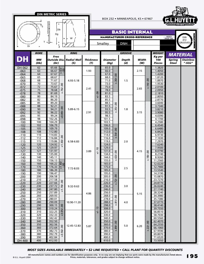
BOX 232 • MINNEAPOLIS, KS • 67467
MOST SIZES AVAILABLE IMMEDIATELY • $2 LINE REQUESTED • CALL PLANT FOR QUANTITY DISCOUNTS
195All manufacturer names and numbers are for identification purposes only. In no way are we implying that our parts were made by the manufacturers listed above.Prices, materials, tolerances, and grades subject to change without notice.© G.L. Huyett 2004
BASIC INTERNALMANUFACTURER CROSS-REFERENCE
DNHSmalley
MM(Db)
Thickness(T)
SpringSteel
6263646568707275788082858890929598100102105108110112115120125127130140150160170180190200210220230240250260270280290300310320330340350360370380390400
DHDH-062
-063-064-065-068-070-072-075-078-080-082-085-088-090-092-095-098-100-102-105-108-110-112-115-120-125-127-130-140-150-160-170-180-190-200-210-220-230-240-250-260-270-280-290-300-310-320-330-340-350-360-370-380-390
DH-400
+.3
0/-.
00+
.35/
-.00
+/-
.08
+/-
.10
Radial Wall(S)
FreeOutside Dia.
(Dr)
BORE RING
65.066.067.068.071.073.075.078.081.083.585.588.591.593.595.598.5
101.5103.5106.0109.0112.0114.0116.0119.0124.0129.0131.0134.0144.0155.0165.0175.0185.0195.0205.0216.0226.0236.0246.0256.0268.0278.0288.0298.0308.0320.0330.0340.0350.0360.0370.0380.0390.0400.0410.0
GROOVE
Diameter(Dg)
Depth(d)
Width(W)
+.7
6/-.
00+
0.89
/-.0
0+
1.30
/-.0
0
+.1
4/-.
00
65.6666.6767.6768.6771.6773.6775.6778.6881.6984.1986.2089.2092.2194.2196.2299.24
102.26104.29106.79109.79112.80114.83116.84119.86124.92129.97131.97135.00145.11156.13166.22176.33186.39196.47206.58217.58227.66237.72247.80257.89269.93280.01290.09300.15310.24322.25332.33342.42352.50362.56372.64382.73392.79402.84412.93
+1.
40/
-.00
1.93
2.41
2.91
3.89
+.5
4/-.
00+
.63/
-.00
1.5
1.8
2.0
2.5
4.15
3.15
2.65
2.15
7.72-8.03
6.58-6.83
5.89-6.15
4.93-5.18
+.6
3/-.
00
MATERIALStainless “-SO2”
+1.
78/-
.00
+3.
05/-
.00
+3.
56/-
.00
9.32-9.63
10.90-11.20
12.45-12.83
4.86
5.87
+/-
.13
+.7
2/-.
00+
.81/
-.00
+.8
9/-.
00
3.0
4.0
5.0
5.15
6.20
+.1
8/-.
00+
.22/
-.00
Dr
Db
Dg
d
W
T
S
WEIGHTKg per
100Pieces
1.38201.40501.42001.81201.89701.95302.01002.09502.18102.80502.87703.60403.73403.82103.90804.03904.17004.25806.45406.64806.84206.97307.10307.29707.62407.95008.07908.27408.9260
11.256012.022012.790013.554014.319015.087023.727024.877026.024027.174028.324034.398035.738037.077038.414039.755056.851058.703060.556062.407064.255066.106067.959069.807071.652073.5050
DIN METRIC SERIES
INDEX PAGE 236. DIN
472GROOVES

METRIC SPIRAL RINGSREVISED 09-04
MOST SIZES AVAILABLE IMMEDIATELY • $2 LINE REQUESTED • CALL PLANT FOR QUANTITY DISCOUNTS
19�
785•392•3017 FAX 785.392.2845
All manufacturer names and numbers are for identification purposes only. In no way are we implying that our parts were made by the manufacturers listed above.Prices, materials, tolerances, and grades subject to change without notice. © G.L. Huyett 2004
www.huyett.com
Standard metric series produced to metric aerospace specifications. Fits into grooves designed for two turn spiral rings in light and medium duty applications.
1. Verify bore diameter (Db).2. Measure the free outside diameter (Dr) of
the ring.3. Determine thickness (T) and radial wall (S).4. Find the part in the charts.
WEIRDAXIAL ASSEMBLY
MM(Db)
Thickness(T)
SpringSteel
121314151617181920212223242526272829303132343536373840424546474850525355565859
.35
.38
.43
.45
.48
.53
.55
.59
.61
.64
.69
.71
.74
.84
.89
.94
.94
.981.001.031.001.101.151.201.201.251.251.301.351.401.451.501.60.90.90.93.93.93.97
DAHDAH-012
-013-014-015-016-017-018-019-020-021-022-023-024-025-026-027-028-029-030-031-032-034-035-036-037-038-040-042-045-046-047-048-050-052-053-055-056-058
DAH-059
+/-
.050
+/-
.075
+/-
.050
+/-
.075
+/-
.080
Radial Wall(S)
FreeOutside Dia. (Dr)
BORE RING
12.8913.9515.0716.1417.1518.3219.3920.4821.5122.5623.6524.6925.7327.0328.0729.1130.1031.2132.2833.3234.2336.4637.5538.6839.6040.7742.9145.0148.1349.2850.3251.4653.6654.3055.3257.3858.4060.4361.54
12.7013.7514.8515.9016.9518.0519.1020.1721.2222.2723.3724.4225.4726.6727.7728.8729.8730.9532.0033.0534.0036.2037.3038.4039.4040.5042.5044.6047.7048.8049.9051.0053.2053.7954.7956.8557.8559.8560.93
GROOVE
Diameter(Dg)
Depth(d)
Width(W)
+.3
50/-
.000
+.5
10/-
.000
+.6
30/
-.00
0
+.0
80/-
.000
+.1
00/-
.000
+.50
0/
-.000
3.38-3.58
3.12-3.33
3.89-4.09
3.12-3.33
2.87-3.07
2.49-2.69
2.03-2.24
1.78-1.98
1.52-1.73
1.27-1.47
1.02-1.22 .60
.89
1.07
1.27
1.57
1.25
+/-
.100
+/-
.125
+/-
.150 1.42
1.75
1.40
1.20
1.00
.70
INTERNAL AEROSPACEMANUFACTURER CROSS-REFERENCE
MATERIAL
EHSmalley
Stainless “-SO2”
MA4017Aerospace Dr
Db
Dg
d
W
S T
DAH-012/DAH-019
DAH-020& up
WEIGHTKg per
100Pieces
0.03000.03300.04000.04300.04600.05800.06200.06600.09400.10000.10500.12400.13000.13600.14200.20900.21800.22700.23600.24400.25300.30600.31600.32400.33500.34500.48700.51300.55300.56700.70700.72500.75900.46000.48000.52000.53000.54000.5550
METRIC AEROSPACE
FOR METRIC SERIESDIN 472
GROOVES, SEE PAGES 194-195.
INDEX PAGE 236.
DESCRIPTION HOW TO IDENTIFY GENERAL USE
DAH
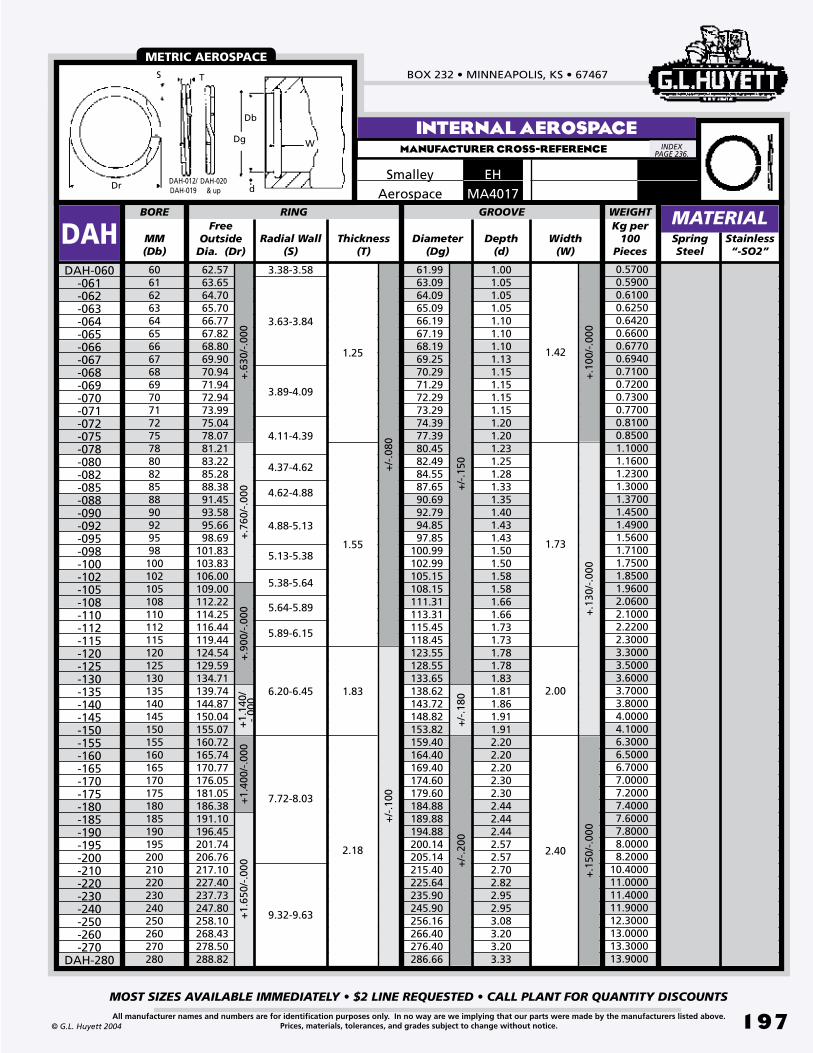
BOX 232 • MINNEAPOLIS, KS • 67467
MOST SIZES AVAILABLE IMMEDIATELY • $2 LINE REQUESTED • CALL PLANT FOR QUANTITY DISCOUNTS
197All manufacturer names and numbers are for identification purposes only. In no way are we implying that our parts were made by the manufacturers listed above.Prices, materials, tolerances, and grades subject to change without notice.© G.L. Huyett 2004
INTERNAL AEROSPACEMANUFACTURER CROSS-REFERENCE
EHSmalley
MM(Db)
Thickness(T)
SpringSteel
6061626364656667686970717275788082858890929598100102105108110112115120125130135140145150155160165170175180185190195200210220230240250260270280
1.001.051.051.051.101.101.101.131.151.151.151.151.201.201.231.251.281.331.351.401.431.431.501.501.581.581.661.661.731.731.781.781.831.811.861.911.912.202.202.202.302.302.442.442.442.572.572.702.822.952.953.083.203.203.33
DAHDAH-060
-061-062-063-064-065-066-067-068-069-070-071-072-075-078-080-082-085-088-090-092-095-098-100-102-105-108-110-112-115-120-125-130-135-140-145-150-155-160-165-170-175-180-185-190-195-200-210-220-230-240-250-260-270
DAH-280
+/-
.150
+/-
.180
+/-
.080
Radial Wall(S)
FreeOutside
Dia. (Dr)
BORE RING
62.5763.6564.7065.7066.7767.8268.8069.9070.9471.9472.9473.9975.0478.0781.2183.2285.2888.3891.4593.5895.6698.69
101.83103.83106.00109.00112.22114.25116.44119.44124.54129.59134.71139.74144.87150.04155.07160.72165.74170.77176.05181.05186.38191.10196.45201.74206.76217.10227.40237.73247.80258.10268.43278.50288.82
61.9963.0964.0965.0966.1967.1968.1969.2570.2971.2972.2973.2974.3977.3980.4582.4984.5587.6590.6992.7994.8597.85
100.99102.99105.15108.15111.31113.31115.45118.45123.55128.55133.65138.62143.72148.82153.82159.40164.40169.40174.60179.60184.88189.88194.88200.14205.14215.40225.64235.90245.90256.16266.40276.40286.66
GROOVE
Diameter(Dg)
Depth(d)
Width(W)
+.6
30/-
.000
+.7
60/-
.000
+.9
00/-
.000
+.1
00/-
.000
+.1
30/-
.000
6.20-6.45
5.89-6.15
5.64-5.89
5.38-5.64
5.13-5.38
4.88-5.13
4.62-4.88
4.37-4.62
4.11-4.39
3.89-4.09
3.63-3.84
1.83
1.55
1.25
2.00
1.73
1.42
MATERIALStainless “-SO2”
+/-
.100
+1.
140/
-.00
0
+.1
50/-
.000
7.72-8.03
2.18
+/-
.200
2.40
3.38-3.58
+1.
400/
-.00
0+
1.65
0/-.
000
9.32-9.63
MA4017AerospaceWEIGHTKg per
100Pieces
0.57000.59000.61000.62500.64200.66000.67700.69400.71000.72000.73000.77000.81000.85001.10001.16001.23001.30001.37001.45001.49001.56001.71001.75001.85001.96002.06002.10002.22002.30003.30003.50003.60003.70003.80004.00004.10006.30006.50006.70007.00007.20007.40007.60007.80008.00008.2000
10.400011.000011.400011.900012.300013.000013.300013.9000
Dr
Db
Dg
d
W
S T
DAH-012/DAH-019
DAH-020& up
METRIC AEROSPACE
INDEX PAGE 236.

METRIC EATON -STYLE RINGSREVISED 09-04
MOST SIZES AVAILABLE IMMEDIATELY • $2 LINE REQUESTED • CALL PLANT FOR QUANTITY DISCOUNTS
198
785•392•3017 FAX 785.392.2845
All manufacturer names and numbers are for identification purposes only. In no way are we implying that our parts were made by the manufacturers listed above.Prices, materials, tolerances, and grades subject to change without notice.
TM
© G.L. Huyett 2004
www.huyett.com
Metric wire formed external retaining ring for use with SAE standard bearings. See the bearing cross reference chart on page 199 for bearing numbers.
1. Confirm the shaft diameter (Ds).2. Measure the free inside diameter (Df) of
the ring.3. Determine the ring thickness (T) and radial
wall (S).4. Find the part in the chart above.
UNCOMMONAXIAL ASSEMBLY
EXTERNAL METRICMANUFACTURER CROSS-REFERENCE
Df T W
S
DgDs
d
Free Inside Dia.
(Df)Decimal
(Ds)MM(Ds)
Thickness(T)
Diameter(Dg)
Depth(d)
SpringSteel
.4724
.5906
.6693
.7874
.98431.18111.37801.57481.77171.96852.16542.36222.55912.75592.95283.14963.34653.54333.74023.93704.13394.3307
12151720253035404550556065707580859095100105110
.421
.538
.616
.710
.9101.0931.2651.4521.6251.8201.9952.1872.3592.5562.7502.9463.1393.3083.5003.6973.8884.080
SHAFT RING
DUSCDUSC-0584
-0594-0614
-0639R -0698R -0740R
-0823 -0916R -0974R -1065R -1129R
-1185-1258
-1308R-1378
-1407R -1468R -1517R -1551R -1572R -2919R
DUSC-1625R
.062
Width(W)
+.003/-.000
+.0
04/-
.000
.108
+/-
.002
+/-
.004
+/-
.006
+/-
.003
+/-
.005
+.000/-.020
+.0
00/
-.02
5+.
000/
-.062
GROOVE
+/-
.002
RadialWall(S)
TOOL
.062
.078
.078
.093
.109
.125
.156
.156
.188
.188
.218
.218
.250
.250
.250
.250
.250
.312
.312
.312
.312
.312
.436
.550
.629
.731
.9241.1111.2881.4651.6481.8442.0152.2122.3892.5862.7832.9793.1763.3433.5403.7373.9344.131
.093
.125
.156
.109 .075
.085
.100
.018
.028
.030
.035
.045
.055
.120
.139
.174
+.0
05/-
.000
+.0
08/
-.00
0+
.006
/-.0
00
+.0
00/
-.07
8+
.000
/-.0
46+.
000/
-.031
MATERIAL
.047
.062
.042
.075
.020
.046
.053
.068
.085
-E015R
-E047R
-E601R
-E602R
CO
NTA
CT
PLA
NT
FOR
TO
OL
INFO
RM
ATI
ON
.
INDEX PAGE 236.
SEE BEARING CROSS
REFERENCE CHART ON PAGE 201.
DESCRIPTION HOW TO IDENTIFY GENERAL USE
DUSCU
SC
IMPERIALPage 68
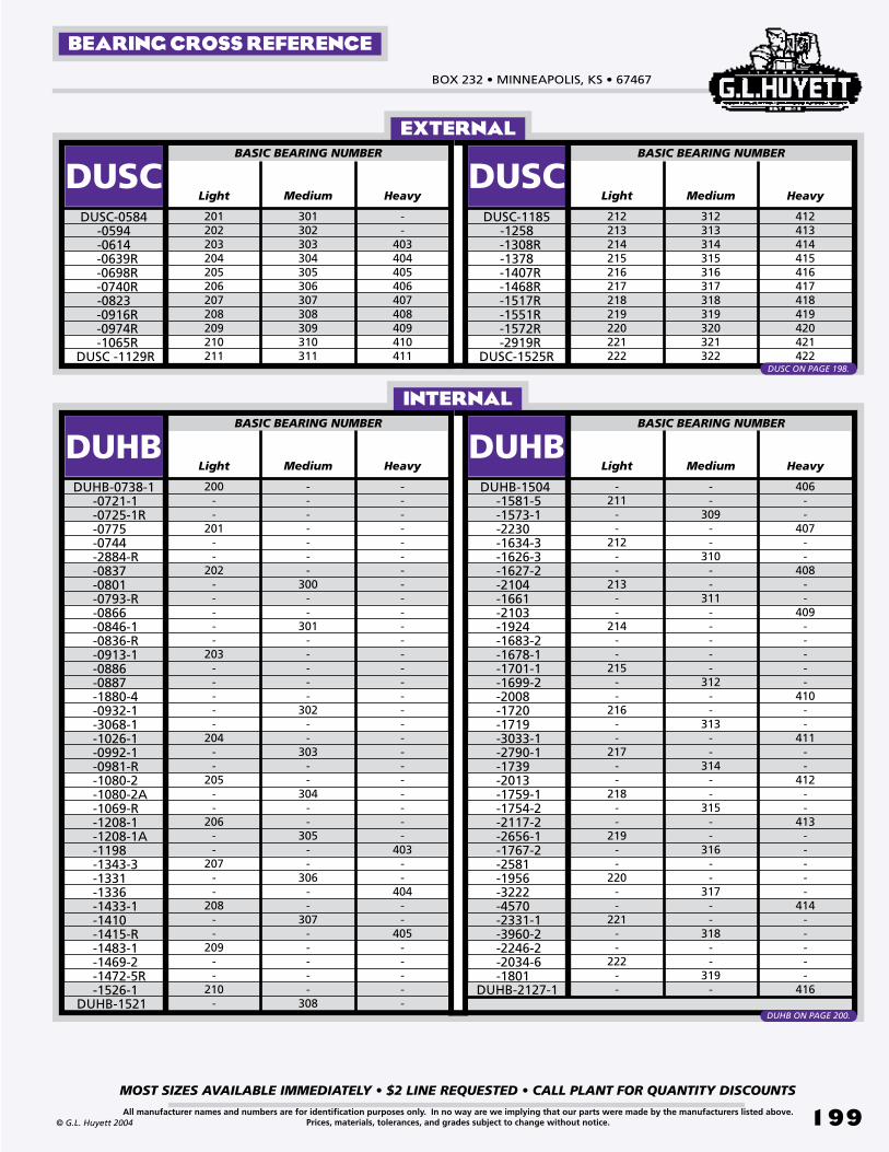
BOX 232 • MINNEAPOLIS, KS • 67467
MOST SIZES AVAILABLE IMMEDIATELY • $2 LINE REQUESTED • CALL PLANT FOR QUANTITY DISCOUNTS
199All manufacturer names and numbers are for identification purposes only. In no way are we implying that our parts were made by the manufacturers listed above.Prices, materials, tolerances, and grades subject to change without notice.© G.L. Huyett 2004
Medium
201202203204205206207208209210211
DUSCDUSC-0584
-0594-0614
-0639R -0698R -0740R
-0823 -0916R -0974R -1065R
DUSC -1129R
Light
BASIC BEARING NUMBER
Medium
212213214215216217218219220221222
DUSCDUSC-1185
-1258 -1308R
-1378 -1407R -1468R -1517R -1551R -1572R -2919R
DUSC-1525R
Light
BASIC BEARING NUMBER
Heavy Heavy
EXTERNAL
INTERNAL
301302303304305306307308309310311
312313314315316317318319320321322
--
403404405406407408409410411
412413414415416417418419420421422
Medium
200--
201--
202-----
203-----
204--
205--
206--
207--
208--
209--
210-
DUHBDUHB-0738-1 -0721-1 -0725-1R -0775 -0744 -2884-R -0837 -0801 -0793-R -0866 -0846-1 -0836-R -0913-1 -0886 -0887 -1880-4 -0932-1 -3068-1 -1026-1 -0992-1 -0981-R -1080-2 -1080-2A -1069-R -1208-1 -1208-1A -1198 -1343-3 -1331 -1336 -1433-1 -1410 -1415-R -1483-1 -1469-2 -1472-5R -1526-1 DUHB-1521
Light
BASIC BEARING NUMBER
Medium
-211
--
212--
213--
214--
215--
216--
217--
218--
219--
220--
221--
222--
DUHB DUHB-1504 -1581-5 -1573-1 -2230 -1634-3 -1626-3 -1627-2 -2104 -1661 -2103 -1924 -1683-2 -1678-1 -1701-1 -1699-2 -2008 -1720 -1719 -3033-1 -2790-1 -1739 -2013 -1759-1 -1754-2 -2117-2 -2656-1 -1767-2 -2581 -1956 -3222 -4570 -2331-1 -3960-2 -2246-2 -2034-6 -1801DUHB-2127-1
Light
BASIC BEARING NUMBER
Heavy Heavy
-------
300--
301-----
302--
303--
304--
305--
306--
307-----
308
--
309--
310--
311-----
312--
313--
314--
315--
316--
317--
318--
319-
--------------------------
403--
404--
405-----
406--
407--
408--
409-----
410--
411--
412--
413-----
414-----
416
BEARING CROSS REFERENCE
DUSC ON PAGE 198.
DUHB ON PAGE 200.

METRIC EATON -STYLE RINGSREVISED 09-04
MOST SIZES AVAILABLE IMMEDIATELY • $2 LINE REQUESTED • CALL PLANT FOR QUANTITY DISCOUNTS
200
785•392•3017 FAX 785.392.2845
All manufacturer names and numbers are for identification purposes only. In no way are we implying that our parts were made by the manufacturers listed above.Prices, materials, tolerances, and grades subject to change without notice.
TM
© G.L. Huyett 2004
www.huyett.com
METRIC SAE BEARINGSMANUFACTURER CROSS-REFERENCE
Metric wire formed internal retaining ring for use with SAE standard bearings. See the bearing cross reference chart on page 199 for bearing numbers.
1. Confirm the bore diameter (Db).2. Measure the free outside diameter (Dr) of
the ring.3. Determine the ring thickness (T) and radial
wall (S).4. Find the part in the charts above.
UNCOMMONAXIAL ASSEMBLY
S
Dr
Db
Dg d
T W
Decimal(Db)
Diameter(Dg)
Spring Steel
1.2431.2531.2511.3211.3311.3291.4401.4501.4581.5181.5281.5361.6541.6681.6681.7331.7471.7471.9301.9441.9512.1372.1412.1482.5302.5442.5652.9342.9592.9593.2493.2743.2743.4463.4713.4713.6433.668
BORE RINg
DUHBDUHB-0738-1 -0721-1 -0725-1R -0775 -0744 -2884-R -0837 -0801 -0793-R -0866 -0846-1 -0836-R -0913-1 -0886 -0887 -1880-4 -0932-1 -3068-1 -1026-1 -0992-1 -0981-R -1080-2 -1080-2A -1069-R -1208-1 -1208-1A -1198 -1343-3 -1331 -1336 -1433-1 -1410 -1415-R -1483-1 -1469-2 -1472-5R -1526-1DUHB-1521
Depth(d)
+/-
.005
+/-
.006
Free Outside Dia.
(Dr)
+.0
31/-
.000
+.0
46/-
.000
+.0
62/-
.000
+.09
3/
-.000
gROOVE
Width(W)
MM(Db)
+.0
04/-
.000
+/-
.002
Thickness(T)
Radial Wall(S)
1.2651.2651.2711.3491.3431.3651.4681.4681.4861.5461.5461.5641.6871.7031.7031.7651.7811.7811.9681.9681.9762.1712.1712.1792.5622.5622.5932.9682.9843.0003.2813.2963.3123.4843.5003.5003.6873.703
.031
.036
.035
.031
.036
.035
.031
.036
.040
.031
.036
.040
.040
.047
.047
.040
.047
.047
.040
.047
.050
.045
.047
.050
.045
.052
.062
.050
.062
.062
.050
.062
.062
.050
.062
.062
.050
.062
.100
.125
.109
.100
.125
.109
.100
.125
.140
.100
.125
.140
.125
.156
.156
.125
.156
.156
.125
.156
.172
.156
.156
.172
.156
.156
.187
.156
.187
.187
.156
.187
.218
.156
.187
.218
.156
.187
.035
.046
.068
.035
.046
.068
.035
.046
.068
.035
.046
.068
.046
.046
.068
.046
.046
.062
.046
.046
.068
.046
.046
.068
.068
.068
.103
.068
.068
.103
.068
.068
.103
.068
.068
.103
.103
.103
.031
.042
.062
.031
.042
.062
.031
.042
.062
.031
.042
.062
.042
.042
.062
.042
.042
.062
.042
.042
.062
.042
.042
.062
.062
.062
.093
.062
.062
.093
.062
.062
.093
.062
.062
.093
.093
.093
+/-
.005
MATERIAL
1.1811
1.2598
1.3780
1.4567
1.5748
1.6535
1.8504
2.0472
2.4409
2.8346
3.1496
3.3465
3.5433
29.93
31.93
34.92
36.92
39.91
41.90
46.89
51.88
61.86
71.83
79.82
84.81
89.79
INDEX PAGE 236.
SEE BEARING CROSS
REFERENCE CHART ON PAGE 199.
DESCRIPTION HOW TO IDENTIFY gENERAL USE
DUHB
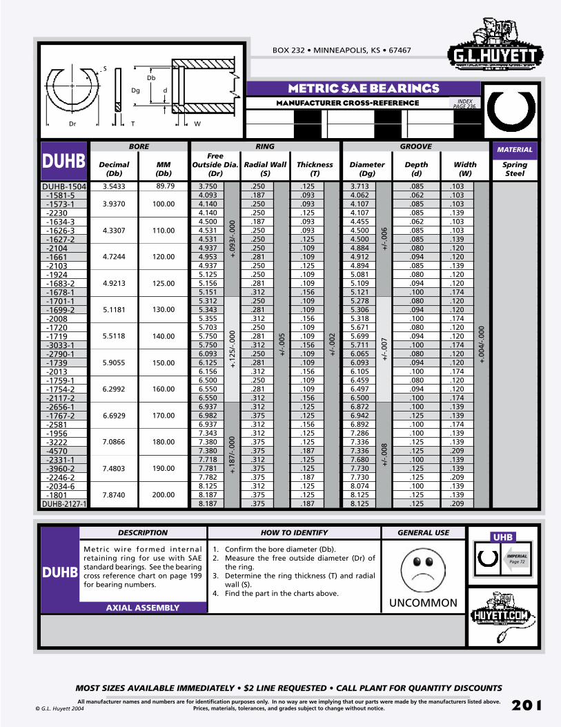
BOX 232 • MINNEAPOLIS, KS • 67467
MOST SIZES AVAILABLE IMMEDIATELY • $2 LINE REQUESTED • CALL PLANT FOR QUANTITY DISCOUNTS
201All manufacturer names and numbers are for identification purposes only. In no way are we implying that our parts were made by the manufacturers listed above.Prices, materials, tolerances, and grades subject to change without notice.© G.L. Huyett 2004
Metric wire formed internal retaining ring for use with SAE standard bearings. See the bearing cross reference chart on page 199 for bearing numbers.
1. Confirm the bore diameter (Db).2. Measure the free outside diameter (Dr) of
the ring.3. Determine the ring thickness (T) and radial
wall (S).4. Find the part in the charts above.
UNCOMMONAXIAL ASSEMBLY
S
Dr
Db
Dg d
T W
METRIC SAE BEARINGSMANUFACTURER CROSS-REFERENCE
Decimal(Db)
Diameter(Dg)
Spring Steel
3.7134.0624.1074.1074.4554.5004.5004.8844.9124.8945.0815.1095.1215.2785.3065.3185.6715.6995.7116.0656.0936.1056.4596.4976.5006.8726.9426.8927.2867.3367.3367.6807.7307.7308.0748.1258.125
BORE RINg
DUHBDUHB-1504 -1581-5 -1573-1 -2230 -1634-3 -1626-3 -1627-2 -2104 -1661 -2103 -1924 -1683-2 -1678-1 -1701-1 -1699-2 -2008 -1720 -1719 -3033-1 -2790-1 -1739 -2013 -1759-1 -1754-2 -2117-2 -2656-1 -1767-2 -2581 -1956 -3222 -4570 -2331-1 -3960-2 -2246-2 -2034-6 -1801DUHB-2127-1
Depth(d)
Free Outside Dia.
(Dr)
gROOVE
Width(W)
MM(Db)
Thickness(T)
Radial Wall(S)
3.7504.0934.1404.1404.5004.5314.5314.9374.9534.9375.1255.1565.1515.3125.3435.3555.7035.7505.7506.0936.1256.1566.5006.5506.5506.9376.9826.9377.3437.3807.3807.7187.7817.7828.1258.1878.187
.085
.062
.085
.085
.062
.085
.085
.080
.094
.085
.080
.094
.100
.080
.094
.100
.080
.094
.100
.080
.094
.100
.080
.094
.100
.100
.125
.100
.100
.125
.125
.100
.125
.125
.100
.125
.125
.250
.187
.250
.250
.187
.250
.250
.250
.281
.250
.250
.281
.312
.250
.281
.312
.250
.281
.312
.250
.281
.312
.250
.281
.312
.312
.375
.312
.312
.375
.375
.312
.375
.375
.312
.375
.375
.103
.103
.103
.139
.103
.103
.139
.120
.120
.139
.120
.120
.174
.120
.120
.174
.120
.120
.174
.120
.120
.174
.120
.120
.174
.139
.139
.174
.139
.139
.209
.139
.139
.209
.139
.139
.209
.125
.093
.093
.125
.093
.093
.125
.109
.109
.125
.109
.109
.156
.109
.109
.156
.109
.109
.156
.109
.109
.156
.109
.109
.156
.125
.125
.156
.125
.125
.187
.125
.125
.187
.125
.125
.187
MATERIAL
+.0
93/-
.000
+.1
25/-
.000
+.1
87/-
.000
+/-
.006
+/-
.007
+/-
.008
+/-
.005
+/-
.002
+.0
04/-
.000
3.5433
3.9370
4.3307
4.7244
4.9213
5.1181
5.5118
5.9055
6.2992
6.6929
7.0866
7.4803
7.8740
89.79
100.00
110.00
120.00
125.00
130.00
140.00
150.00
160.00
170.00
180.00
190.00
200.00
INDEX PAGE 236.
IMPERIALPage 72
UHBDESCRIPTION HOW TO IDENTIFY gENERAL USE
DUHB
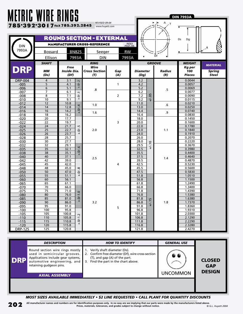
METRIC WIRE RINGSREVISED 09-04
MOST SIZES AVAILABLE IMMEDIATELY • $2 LINE REQUESTED • CALL PLANT FOR QUANTITY DISCOUNTS
202
785•392•3017 FAX 785.392.2845
All manufacturer names and numbers are for identification purposes only. In no way are we implying that our parts were made by the manufacturers listed above.Prices, materials, tolerances, and grades subject to change without notice. © G.L. Huyett 2004
www.huyett.com
Round section wire rings mostly used in semicircular grooves. Applications include gear systems, automotive engineering, and retaining gudgeon pins.
1. Verify shaft diameter (Ds).2. Confirm free diameter (Df), wire cross-section
(T), and gap (A) of the part.3. Find the part in the chart above.
UNCOMMONAXIAL ASSEMBLY
MM(Ds)
Diameter(Dg)
SpringSteel
456781012141618202224252628303235384042454850556065707580859095100105110115120125
3.24.25.26.27.29.2
11.013.014.416.418.020.022.023.024.026.028.029.532.535.537.539.542.545.547.551.856.861.866.871.876.881.886.891.896.8
101.8106.8111.8116.8121.8
SHAFT RINg
DRPDRP-004
-005-006-007-008-010-012-014-016-018-020-022-024-025-026-028-030-032-035-038-040-042-045-048-050-055-060-065-070-075-080-085-090-095-100-105-110-115-120
DRP-125
+/-
.05
+/-
.10
Free Inside Dia.
(Df)+
.0/-
.2+
.0/-
.3+
.0/-
.4+
.0/-
.5
gROOVE
Radius(R)
Wire Cross Section
(T)gap(A)
3.14.15.16.17.19.1
10.812.814.216.217.719.721.722.723.725.727.729.132.135.137.139.042.045.047.051.156.161.166.071.076.081.086.091.095.8
100.8105.8110.8115.8120.8
.6
.9
1.1
1.4
1.8
.5
1
2
3
4
5
1.0
1.6
2.0
2.5
3.2
.8
+.0
/-.8
+.0
/-1.
2+
.0/-
.6+
.0/-
1.0
+/-
.15
ROUND SECTION - EXTERNALMANUFACTURER CROSS-REFERENCE
MATERIAL
BN825Bossard
7993AEllison
A
Df
R
DgDs
T
DIN 7993A
WEIgHTKg per
100Pieces
0.00440.00570.00690.00770.00900.01150.02100.02500.07400.08300.14500.16000.17800.18400.19100.20700.22200.36700.39800.44000.46400.48700.52300.56000.58301.05101.15001.24901.34001.43901.53801.63801.73701.83601.93102.03002.12902.22902.32802.4270
DIN7993A
INDEX PAGE 236.
RWSeeger
DESCRIPTION HOW TO IDENTIFY gENERAL USE
DRP CLOSED GAP
DESIGN
7993ADIN

BOX 232 • MINNEAPOLIS, KS • 67467
MOST SIZES AVAILABLE IMMEDIATELY • $2 LINE REQUESTED • CALL PLANT FOR QUANTITY DISCOUNTS
203All manufacturer names and numbers are for identification purposes only. In no way are we implying that our parts were made by the manufacturers listed above.Prices, materials, tolerances, and grades subject to change without notice.© G.L. Huyett 2004
Round section wire rings mostly used in semicircular grooves. Applications include gear systems, automotive engineering, and retaining gudgeon pins.
1. Verify bore diameter (Ds).2. Confirm free diameter (Df), wire cross-section
(T), and gap (A) of the part.3. Find the part in the chart above.
UNCOMMONAXIAL ASSEMBLY
MM(Db)
Diameter(Dg)
Spring Steel
781012141618202224252628303235384042454850556065707580859095100105110115120125
7.88.8
10.813.015.017.619.622.024.026.027.028.030.032.034.537.540.542.544.547.550.552.558.263.268.273.278.283.288.293.298.2
103.2108.2113.2118.2123.2128.2
BORE RINg
DRBDRB-007
-008-010-012-014-016-018-020-022-024-025-026-028-030-032-035-038-040-042-045-048-050-055-060-065-070-075-080-085-090-095-100-105-110-115-120
DRB-125
+/-
.05
+/-
.10
+/-
.15
Tole
ran
ce p
er B
DIN
207
6.
Free OutsideDiameter
(Dr)
+.3/
-.0+
.4/-
.0+
.5/-
.0+
.6/-
.0
Radius(R)
Wire Cross Section
(S)gap(A)
7.98.9
10.913.215.217.819.822.324.326.327.328.330.332.334.937.940.942.945.048.851.053.058.963.968.974.079.084.089.094.099.0
104.2109.2114.2119.2124.2129.2
.8
1.0
1.6
2.0
2.5
3.2
4
6
8
10
12
16
20
25
32
.5
.6
.9
1.1
1.4
1.8
+.8
/-.0
+1.
0/-.
0+
1.2/
-.0
gROOVE
ROUND SECTION - INTERNALMANUFACTURER CROSS-REFERENCE
MATERIAL
BN826Bossard
7993BEllison
Dg Db
R
Dr
S
A
DIN 7993B
WEIgHTKg per
100Pieces
0.00710.00830.01080.01960.02340.07060.08040.13200.14700.16300.17000.17900.19400.21000.34700.38500.42000.44300.45400.48900.52400.55100.97701.07601.17501.24401.34301.44201.54101.64001.73901.79801.89801.99702.09602.19502.2940
DIN7993B
INDEX PAGE 236.
RBSeeger
DESCRIPTION HOW TO IDENTIFY gENERAL USE
DRB OPENGAP
DESIGN
7993BDIN

METRIC WIRE RINGSREVISED 09-04
MOST SIZES AVAILABLE IMMEDIATELY • $2 LINE REQUESTED • CALL PLANT FOR QUANTITY DISCOUNTS
204
785•392•3017 FAX 785.392.2845
All manufacturer names and numbers are for identification purposes only. In no way are we implying that our parts were made by the manufacturers listed above.Prices, materials, tolerances, and grades subject to change without notice. © G.L. Huyett 2004
www.huyett.com
ROUND SECTION - INTERNALMANUFACTURER CROSS-REFERENCE
Round section wire formed ring for internal application. Used to retain gudgeon pins. This ring type is gradually becoming obsolete.
1. Verify shaft diameter (Ds).2. Confirm free diameter (Df), wire cross-section
(T), and gap (A) of the part.3. Find the part in the chart above.
WEIRDAXIAL ASSEMBLY
MM(Db)
Diameter(Dg)
Spring Steel
101212.5131415161717.51819202122242528303234
11.813.914.414.916.117.118.119.320.020.521.522.523.724.727.027.931.133.135.137.1
8.910.811.311.812.613.614.615.315.816.317.318.319.120.121.922.925.727.729.731.7
D17D17-010
-012-0125-013-014-015-016-017-0175-018-019-020-021-022-024-025-028-030-032
D17-034
+.1
5/-.
00
Free OutsideDiameter Min.
(Dr)
+.0
8/-.
04+.
10/-.
05
Width(W)
gap Min.(A)
Wire Cross Section
(T)
+.0
8/-.
00+.
10/-.
00
Assembled Inside Dia.
(Da)
BORE RINg gROOVE
11.0513.1313.6414.1515.3416.3617.3518.5419.0519.5620.5521.5422.7623.7525.9626.9530.1532.1534.1536.17
7.0
7.5
9.0
9.5
10.0
11.0
8.0
1.1
1.3
1.5
1.7
1.9
2.1
1.0
1.0
1.2
1.4
1.6
1.8
2.0
.9
MATERIAL
M1700Anderton
DbDg Da
WT
Dr
A
FOR GUDGEON PIN RETENTION
INDEX PAGE 236.
SPECIALORDERONLY.
DESCRIPTION HOW TO IDENTIFY gENERAL USE
D17
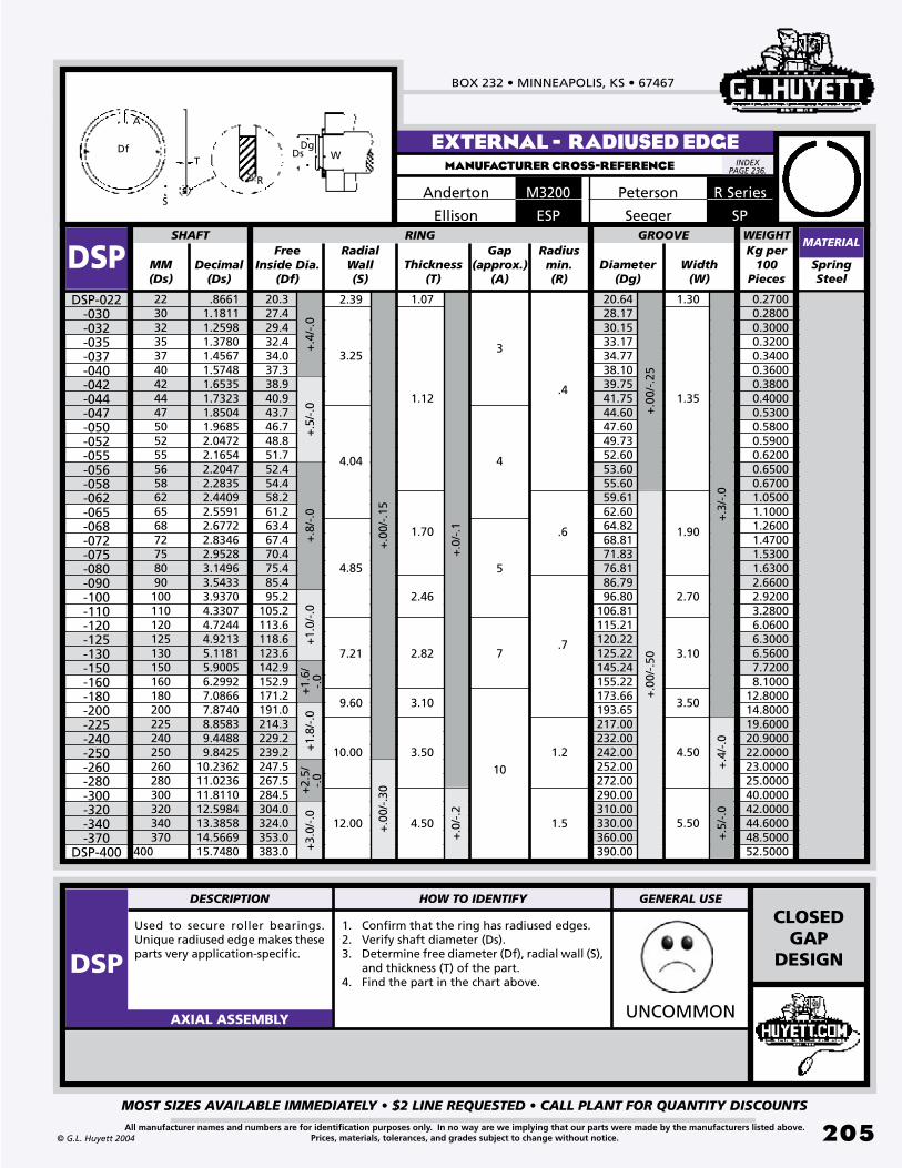
BOX 232 • MINNEAPOLIS, KS • 67467
MOST SIZES AVAILABLE IMMEDIATELY • $2 LINE REQUESTED • CALL PLANT FOR QUANTITY DISCOUNTS
205All manufacturer names and numbers are for identification purposes only. In no way are we implying that our parts were made by the manufacturers listed above.Prices, materials, tolerances, and grades subject to change without notice.© G.L. Huyett 2004
Used to secure roller bearings. Unique radiused edge makes these parts very application-specific.
1. Confirm that the ring has radiused edges.2. Verify shaft diameter (Ds).3. Determine free diameter (Df), radial wall (S),
and thickness (T) of the part.4. Find the part in the chart above.
UNCOMMONAXIAL ASSEMBLY
MM(Ds)
Diameter(Dg)
SpringSteel
223032353740424447505255565862656872758090100110120125130150160180200225240250260280300320340370
400
.86611.18111.25981.37801.45671.57481.65351.73231.85041.96852.04722.16542.20472.28352.44092.55912.67722.83462.95283.14963.54333.93704.33074.72444.92135.11815.90056.29927.08667.87408.85839.44889.8425
10.236211.023611.811012.598413.385814.566915.7480
20.6428.1730.1533.1734.7738.1039.7541.7544.6047.6049.7352.6053.6055.6059.6162.6064.8268.8171.8376.8186.7996.80
106.81115.21120.22125.22145.24155.22173.66193.65217.00232.00242.00252.00272.00290.00310.00330.00360.00390.00
SHAFT RINg
DSPDSP-022
-030-032-035-037-040-042-044-047-050-052-055-056-058-062-065-068-072-075-080-090-100-110-120-125-130-150-160-180-200-225-240-250-260-280-300-320-340-370
DSP-400
+.0
0/-.
25+
.00/
-.50
Free Inside Dia.
(Df)
+.4
/-.0
+.5
/-.0
+.8
/-.0
+1.
0/-.
0
Width(W)
Decimal(Ds)
RadialWall(S)
+.3
/-.0
gap (approx.)
(A)
Radius min.(R)
+.0
/-.1
Thickness(T)
20.327.429.432.434.037.338.940.943.746.748.851.752.454.458.261.263.467.470.475.485.495.2
105.2113.6118.6123.6142.9152.9171.2191.0214.3229.2239.2247.5267.5284.5304.0324.0353.0383.0
1.07
1.12
1.70
2.46
2.82
3.10
1.30
1.35
1.90
2.70
3.10
3.50
7.21
9.60
4.85
4.04
3.25
2.39
.4
.6
.7
1.2
7
10
5
4
3
+.0
0/-.
15
+1.
6/-.
0+
1.8/
-.0
gROOVE
EXTERNAL - RADIUSED EDGEMANUFACTURER CROSS-REFERENCE
MATERIAL
R SeriesPetersonM3200Anderton
SPSeegerESPEllison
DgDs WT
Df
S
R
A
10.00
12.00
3.50
4.50 1.5
4.50
5.50
+2.
5/-.
0+
3.0/
-.0
+.0
0/-.
30
+.0
/-.2
+.4
/-.0
+.5
/-.0
WEIgHTKg per
100Pieces
0.2700 0.2800 0.3000 0.3200 0.3400 0.3600 0.3800 0.4000 0.5300 0.5800 0.5900 0.6200 0.6500 0.6700 1.0500 1.1000 1.2600 1.4700 1.5300 1.6300 2.6600 2.9200 3.2800 6.0600 6.3000 6.5600 7.7200 8.100012.800014.800019.600020.900022.000023.000025.000040.000042.000044.600048.500052.5000
INDEX PAGE 236.
DESCRIPTION HOW TO IDENTIFY gENERAL USE
DSP
CLOSEDGAP
DESIGN

METRIC WIRE RINGSREVISED 09-04
MOST SIZES AVAILABLE IMMEDIATELY • $2 LINE REQUESTED • CALL PLANT FOR QUANTITY DISCOUNTS
206
785•392•3017 FAX 785.392.2845
All manufacturer names and numbers are for identification purposes only. In no way are we implying that our parts were made by the manufacturers listed above.Prices, materials, tolerances, and grades subject to change without notice. © G.L. Huyett 2004
www.huyett.com
RECTANGULAR SECTION - EXTERNALMANUFACTURER CROSS-REFERENCE
Small radial width. Applications include gear systems, securing needle bearings, and use as spacers.
1. Verify shaft diameter (Ds).2. Determine free diameter (Df), radial wall (S),
and thickness (T) of the part.3. Find the part in the chart above.
UNCOMMONAXIAL ASSEMBLY
MM(Ds)
Diameter(Dg)
Spring Steel
45678910111213141516171819202122242526272829303235373840424345474850525558
3.84.85.76.77.68.69.6
10.511.512.513.514.415.416.417.418.419.220.221.223.024.025.026.027.028.029.030.833.835.836.838.540.541.543.545.546.548.550.553.556.5
SHAFT RINg
DSWDSW-004
-005-006-007-008-009-010-011-012-013-014-015-016-017-018-019-020-021-022-024-025-026-027-028-029-030-032-035-037-038-040-042-043-045-047-048-050-052-055
DSW-058
+.0
0/-.
09+
.00/
-.11
+.0
0/-.
13+
.00/
-.16
Max. Free Inside Dia.
(Df)
gROOVE
Width min.(W)
+.0
/-.1
Thickness(T)
Radial Wall(S)
3.74.75.66.57.48.49.4
10.211.212.213.114.015.016.017.017.918.719.720.722.523.524.525.526.527.528.530.233.235.236.237.839.840.842.844.845.847.849.852.655.6
.5
1.0
1.2
.7
1.5
.6
1.1
1.3
.8
1.6
1.30
1.75
2.30
1.50
.801.001.101.20
+.0
/-.1
MATERIAL
SWSeegerM2400Anderton
ESWEllison
FOR BEARING RETENTION
+.0
0/-.
19
WEIgHTKg per
100Pieces
0.00200.00500.00900.01200.02000.02400.02500.02900.03000.03400.05000.06600.06900.07200.07500.08000.08400.08700.09100.09900.10000.11000.20000.21100.22000.23300.24100.25100.27200.28300.29100.31000.32500.33900.34800.36000.37300.39200.41100.4400
DgDs
W
TDf
S
INDEX PAGE 236.
DESCRIPTION HOW TO IDENTIFY gENERAL USE
DSW SEE DIN 7993 ON PAGES 202-203

BOX 232 • MINNEAPOLIS, KS • 67467
MOST SIZES AVAILABLE IMMEDIATELY • $2 LINE REQUESTED • CALL PLANT FOR QUANTITY DISCOUNTS
207All manufacturer names and numbers are for identification purposes only. In no way are we implying that our parts were made by the manufacturers listed above.Prices, materials, tolerances, and grades subject to change without notice.© G.L. Huyett 2004
RECTANGULAR SECTION - EXTERNALMANUFACTURER CROSS-REFERENCE
SWSeegerM2400Anderton
ESWEllison
MM(Ds)
Diameter(Dg)
SpringSteel
606365687072737580859095100105110115120125130135140145150155160165170175180185190195200210220230240250260265270280285290300305310320330340350360380400460
58.561.563.566.268.270.271.273.278.283.088.093.098.0
102.7107.7112.7117.7122.7127.7132.4137.4142.4147.4154.4157.4162.4167.4172.4177.0182.0187.0192.0197.0207.0217.0227.0237.0247.0255.0260.0265.0275.0280.0285.0295.0300.0305.0315.0325.0335.0345.0355.0375.0395.0455.0
SHAFT RINg
DSWDSW-060
-063-065-068-070-072-073-075-080-085-090-095-100-105-110-115-120-125-130-135-140-145-150-155-160-165-170-175-180-185-190-195-200-210-220-230-240-250-260-265-270-280-285-290-300-305-310-320-330-340-350-360-380-400
DSW-460
+.0
0/-.
19+
.00/
-.22
+.0
0/-.
25+
.00/
-.29
Max. Free Inside Dia.
(Df)
gROOVE
Width min.(W)
Thickness(T)
Radial Wall(S)
57.660.662.665.467.469.470.472.477.482.087.092.097.0
101.7106.6111.6116.5121.5126.4131.1136.0141.0145.9150.9155.8160.8165.7170.7175.2180.2185.1190.1196.0204.9214.8224.7234.6244.5252.4257.4262.3272.2277.2282.1292.1297.1302.0311.9321.8331.7341.6351.5371.4391.2449.5
1.5
2.0
2.5
3.0
1.6
2.2
2.7
3.2
2.3
2.8
3.4
4.0
5.0
MATERIAL
FOR BEARING RETENTION
7.5 4.0 4.2
12.0 4.5 4.8
+.0
/-.1
+.0
/-.1
+.0
0/-.
32+
.00/
-.36
WEIgHTKg per
100Pieces
0.4550 0.4580 0.4640 0.8590 0.8710 0.8800 0.8900 0.9320 0.9670 1.6000 1.6000 1.8200 1.8900 2.0700 2.0900 2.2100 2.4100 2.5100 2.6600 3.0200 3.1100 3.2600 3.2800 3.4700 3.6600 3.7400 3.8500 3.9400 6.1200 6.3900 6.5900 6.7500 6.8400 7.2000 7.6300 7.9800 8.1700 8.650017.900018.520019.770019.870019.950020.530021.420021.940022.310022.530022.860023.930025.120025.310026.580028.110058.2000
DgDs
W
TDf
S
INDEX PAGE 236.

METRIC WIRE RINGSREVISED 09-04
MOST SIZES AVAILABLE IMMEDIATELY • $2 LINE REQUESTED • CALL PLANT FOR QUANTITY DISCOUNTS
208
785•392•3017 FAX 785.392.2845
All manufacturer names and numbers are for identification purposes only. In no way are we implying that our parts were made by the manufacturers listed above.Prices, materials, tolerances, and grades subject to change without notice. © G.L. Huyett 2004
www.huyett.com
RECTANGULAR SECTION - INTERNALMANUFACTURER CROSS-REFERENCE
Small radial width. Applications include gear systems, securing needle bearings, and use as spacers.
1. Verify bore diameter (Db).2. Determine free diameter (Df), radial wall (S),
and thickness (T) of the part.3. Find the part in the chart above.
UNCOMMONAXIAL ASSEMBLY
MM(Db)
Diameter(Dg)
Spring Steel
7891011121314151617181920212223242526272829303132333435373839404243
7.38.39.3
10.411.412.413.514.515.516.517.518.519.620.621.622.623.624.825.826.827.828.829.831.032.033.034.035.036.038.239.240.241.243.244.2
BORE RINg
DSBDSB-007
-008-009-010-011-012-013-014-015-016-017-018-019-020-021-022-023-024-025-026-027-028-029-030-031-032-033-034-035-037-038-039-040-042
DSB-043
+.09
/-.00
+.1
1/-.
00+
.13/
-.00
+.1
6/-.
00
Free OutsideDiameter Max. (Dr)
gROOVE
Width Min.(W)
Thickness(T)
Radial Wall(S)
7.58.59.5
10.611.612.713.814.815.816.817.818.919.921.022.023.024.025.226.227.228.229.230.231.432.433.434.435.436.438.839.840.841.843.844.8
1.00
1.75
2.30
1.30
1.101.20
.8
1.2
1.5
1.0
.9
1.3
1.6
1.1
Dr T
W
S
Dg Db
+.00
/-.10
+.00
/-.10
MATERIAL
SBSeegerM2300Anderton
ESBEllison
FOR BEARING RETENTION
WEIgHTKg per
100Pieces
0.00900.01000.01300.01500.02100.02500.02800.03100.03400.05300.05500.06800.07200.07600.07900.08100.08800.09000.09100.09800.11100.11300.11500.20000.20300.21100.22600.23400.23600.25300.26100.26700.28000.29200.3030
INDEX PAGE 236.
DESCRIPTION HOW TO IDENTIFY gENERAL USE
DSB CLOSED GAP
DESIGN

BOX 232 • MINNEAPOLIS, KS • 67467
MOST SIZES AVAILABLE IMMEDIATELY • $2 LINE REQUESTED • CALL PLANT FOR QUANTITY DISCOUNTS
209All manufacturer names and numbers are for identification purposes only. In no way are we implying that our parts were made by the manufacturers listed above.Prices, materials, tolerances, and grades subject to change without notice.© G.L. Huyett 2004
Small radial width. Applications include gear systems, securing needle bearings, and use as spacers.
1. Verify bore diameter (Db).2. Determine free diameter (Df), radial wall (S),
and thickness (T) of the part.3. Find the part in the chart above.
UNCOMMONAXIAL ASSEMBLY
MM(Db)
Diameter(Dg)
SpringSteel
4445464748505253555758606263656870727374767879808182838586889092939597
45.246.247.248.249.251.253.554.556.558.559.561.563.564.566.569.571.573.874.875.877.879.880.881.882.883.884.886.887.890.092.094.095.097.099.0
BORE RINg
DSBDSB-044
-045-046-047-048-050-052-053-055-057-058-060-062-063-065-068-070-072-073-074-076-078-079-080-081-082-083-085-086-088-090-092-093-095
DSB-097
+.1
9/-.
00+
.22/
-.00
Free OutsideDiameter Max. (Dr)
gROOVE
Width Min.(W)
Radial Wall(S)
Thickness(T)
45.846.847.848.849.851.854.355.357.359.360.362.364.365.367.370.372.374.675.676.678.680.681.682.683.684.685.687.688.691.093.095.096.098.0
100.0
2.30
2.80
3.40
1.5
2.0
2.5
1.6
2.2
2.7
Dr T
W
S
Dg Db
+.0
0/-.
10
+.0
0/-.
10
RECTANGULAR SECTION - INTERNALMANUFACTURER CROSS-REFERENCE
MATERIAL
SBSeegerM2300Anderton
ESBEllison
+.1
6/-.
00
FOR BEARING RETENTION
WEIgHTKg per
100Pieces
0.31100.32500.32800.32900.34500.35700.35800.38200.39300.41200.41300.42800.44200.45000.47200.49000.49300.84900.85200.86000.88900.90500.90700.92200.93100.94500.96300.98100.99101.54001.56001.66001.68001.69001.7100
INDEX PAGE 236.
DESCRIPTION HOW TO IDENTIFY gENERAL USE
DSB SEE DIN 7993 ON PAGES 202-203

METRIC WIRE RINGSREVISED 09-04
MOST SIZES AVAILABLE IMMEDIATELY • $2 LINE REQUESTED • CALL PLANT FOR QUANTITY DISCOUNTS
210
785•392•3017 FAX 785.392.2845
All manufacturer names and numbers are for identification purposes only. In no way are we implying that our parts were made by the manufacturers listed above.Prices, materials, tolerances, and grades subject to change without notice. © G.L. Huyett 2004
www.huyett.com
RECTANGULAR SECTION - INTERNALMANUFACTURER CROSS-REFERENCE
Small radial width. Applications include gear systems, securing needle bearings, and use as spacers.
1. Verify bore diameter (Db).2. Determine free diameter (Df), radial wall (S),
and thickness (T) of the part.3. Find the part in the chart above.
UNCOMMONAXIAL ASSEMBLY
Dr T
W
S
Dg Db
SBSeegerM2300Anderton
ESBEllison
MM(Db)
Diameter(Dg)
Spring Steel
98100102103105107108110112113115117118120123125127130133135137140143150153160163165170173175180183190
100.0102.0104.3105.3107.3109.3110.3112.3114.3115.3117.3119.3120.3122.3125.3127.3129.3132.3135.3137.3139.3142.6145.6152.6155.6162.6165.6167.6172.6175.6177.6182.6185.6193.0
BORE RINg
DSBDSB-098
-100-102-103-105-107-108-110-112-113-115-117-118-120-123-125-127-130-133-135-137-140-143-150-153-160-163-165-170-173-175-180-183
DSB-190
+.2
5/-.
00+
.29/
-.00
Free OutsideDiameter Max. (Dr)
gROOVE
Width Min.(W)
Thickness(T)
Radial Wall(S)
101.0103.0105.3106.3108.3110.3111.3113.4115.4116.4118.4120.4121.4123.5126.5128.5130.5133.6136.6138.6140.6144.0147.0154.1157.1164.2167.2169.2174.3177.3179.3184.5187.5194.9
3.4
4.0
5.0
2.5
3.0
2.7
3.2
+.0
0/-.
10
+.0
0/-.
10
MATERIAL
+.2
2/-.
00
FOR BEARING RETENTION
WEIgHTKg per
100Pieces
1.75001.79001.84001.85001.87001.91001.93001.98002.03002.05002.06002.08002.11002.14002.20002.25002.30002.34002.44002.50002.53002.93003.01003.19003.26003.44003.46003.49003.62003.71003.73003.83004.10006.1300
INDEX PAGE 236.
DESCRIPTION HOW TO IDENTIFY gENERAL USE
DSB

BOX 232 • MINNEAPOLIS, KS • 67467
MOST SIZES AVAILABLE IMMEDIATELY • $2 LINE REQUESTED • CALL PLANT FOR QUANTITY DISCOUNTS
211All manufacturer names and numbers are for identification purposes only. In no way are we implying that our parts were made by the manufacturers listed above.Prices, materials, tolerances, and grades subject to change without notice.© G.L. Huyett 2004
Small radial width. Applications include gear systems, securing needle bearings, and use as spacers.
1. Verify bore diameter (Db).2. Determine free diameter (Df), radial wall (S),
and thickness (T) of the part.3. Find the part in the chart above.
UNCOMMONAXIAL ASSEMBLY
Dr T
W
S
Dg Db RECTANGULAR SECTION - INTERNALMANUFACTURER CROSS-REFERENCE
SBSeegerM2300Anderton
ESBEllison
MM(Db)
Diameter(Dg)
SpringSteel
195200205210215220225230240250260270280290300310320325330340350355360370375380390395400410415420430440
198.0203.0208.0213.0218.0223.0228.0233.0243.0253.0265.0275.0285.0295.0305.0315.0325.0330.0335.0345.0355.0360.0365.0375.0380.0385.0395.0400.0405.0415.0420.0425.0435.0445.0
BORE RINg
DSBDSB-195
-200-205-210-215-220-225-230-240-250-260-270-280-290-300-310-320-325-330-340-350-355-360-370-375-380-390-395-400-410-415-420-430
DSB-440
Free OutsideDiameter Max. (Dr)
Width Min.(W)
Radial Wall(S)
Thickness(T)
199.9205.0210.0215.1220.1225.2230.2235.3245.4255.5267.6277.7287.8297.9307.9318.0328.1333.1338.2348.3358.4363.4368.5378.5383.5388.6398.7403.7408.9419.0424.0429.1439.2449.3
gROOVE MATERIAL
+.3
6/-.
00+
.40/
-.00
7.5 4.0 4.2
+.0
0/-.
10
+.0
0/-.
10
+.2
9/-.
00+
.32/
-.00
5.0 3.0 3.2
FOR BEARING RETENTION
WEIgHTKg per
100Pieces
6.1600 6.4500 6.6400 6.8800 6.9500 7.2400 7.2900 7.5200 8.0900 8.420016.500017.400018.400019.000019.600020.000020.300020.600020.900021.900022.900023.100023.300023.600024.000024.200025.300025.700026.000026.600027.300027.700028.500029.4000
INDEX PAGE 236.
DESCRIPTION HOW TO IDENTIFY gENERAL USE
DSB SEE DIN 7993 ON PAGES 202-203
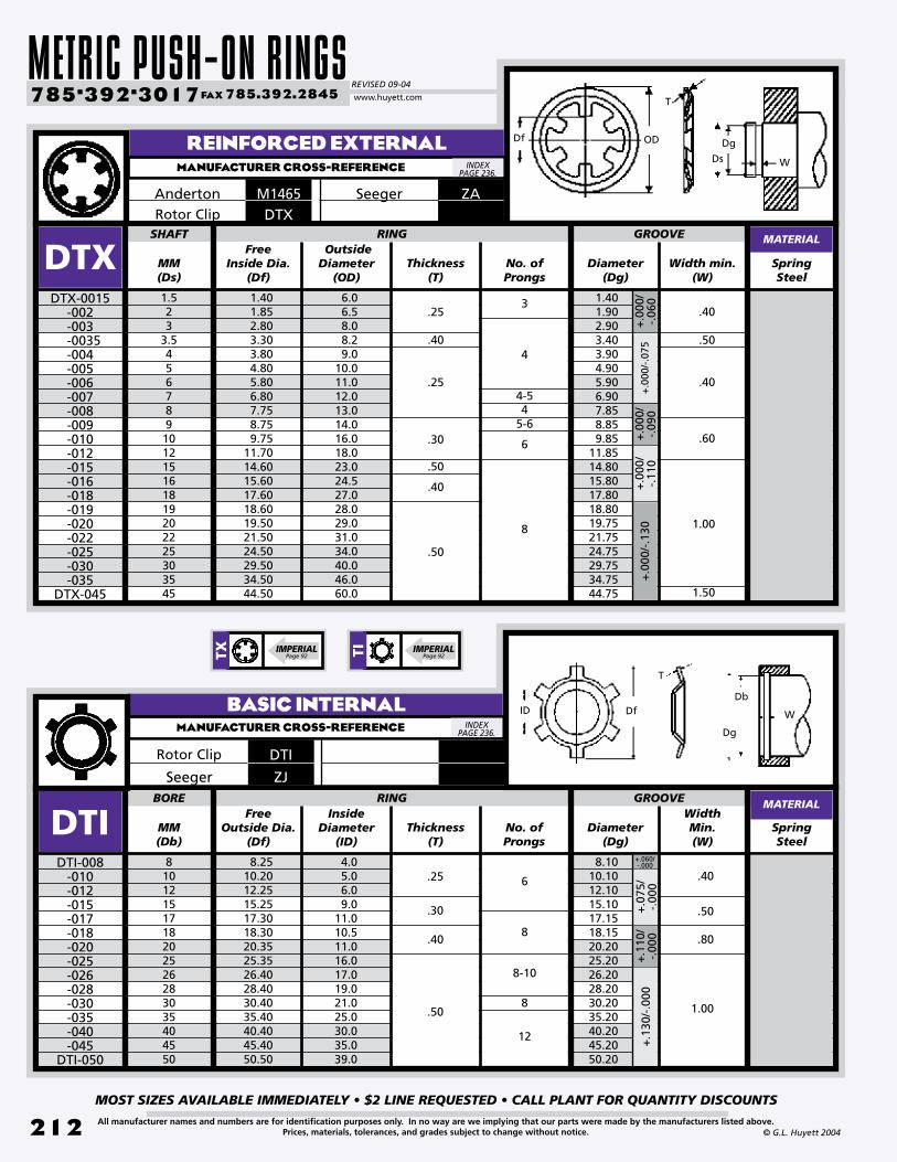
METRIC PUSH-ON RINGSREVISED 09-04
MOST SIZES AVAILABLE IMMEDIATELY • $2 LINE REQUESTED • CALL PLANT FOR QUANTITY DISCOUNTS
212
785•392•3017 FAX 785.392.2845
All manufacturer names and numbers are for identification purposes only. In no way are we implying that our parts were made by the manufacturers listed above.Prices, materials, tolerances, and grades subject to change without notice. © G.L. Huyett 2004
www.huyett.com
BASIC INTERNALMANUFACTURER CROSS-REFERENCE
MM(Db)
SpringSteel
81012151718202526283035404550
8.2510.2012.2515.2517.3018.3020.3525.3526.4028.4030.4035.4040.4045.4050.50
BORE RINg
DTIDTI-008
-010-012-015-017-018-020-025-026-028-030-035-040-045
DTI-050
Diameter(Dg)
Free Outside Dia.
(Df)
+.0
75/
-.00
0
Thickness(T)
Inside Diameter
(ID)No. ofProngs
WidthMin.(W)
4.05.06.09.0
11.010.511.016.017.019.021.025.030.035.039.0
8.1010.1012.1015.1017.1518.1520.2025.2026.2028.2030.2035.2040.2045.2050.20
.25
.30
.50
.40
.50
.80
1.00
+.1
30/-
.000
+.1
10/
-.00
0
+.060/ -.000
gROOVE
Rotor Clip DTI
Seeger ZJ
MATERIAL
ID W
Db
Dg
T
Df
.40
MM(Ds)
SpringSteel
1.523
3.5456789101215161819202225303545
1.401.852.803.303.804.805.806.807.758.759.75
11.7014.6015.6017.6018.6019.5021.5024.5029.5034.5044.50
SHAFT RINg
DTXDTX-0015
-002-003
-0035-004-005-006-007-008-009-010-012-015-016-018-019-020-022-025-030-035
DTX-045
Diameter(Dg)
+.0
00/
-.06
0
Free Inside Dia.
(Df)Width min.
(W)Thickness
(T)
Outside Diameter
(OD)No. ofProngs
6.06.58.08.29.0
10.011.012.013.014.016.018.023.024.527.028.029.031.034.040.046.060.0
1.401.902.903.403.904.905.906.907.858.859.85
11.8514.8015.8017.8018.8019.7521.7524.7529.7534.7544.75
.25
.40
.25
.30
.50
.50
.40
.50
.40
.60
1.00
1.50
+.0
00/-
.075
+.0
00/
-.09
0+
.000
/-.
110
+.0
00/-
.130
gROOVE
REINFORCED EXTERNALMANUFACTURER CROSS-REFERENCE
Anderton ZASeegerM1465DTXRotor Clip
MATERIAL
Dg
T
WDs
ODDf
.40
3
4
4-54
5-6
6
12
8
8-10
8
6
8
INDEX PAGE 236.
INDEX PAGE 236.
TX IMPERIALPage 92 TI IMPERIAL
Page 92

BOX 232 • MINNEAPOLIS, KS • 67467
MOST SIZES AVAILABLE IMMEDIATELY • $2 LINE REQUESTED • CALL PLANT FOR QUANTITY DISCOUNTS
213All manufacturer names and numbers are for identification purposes only. In no way are we implying that our parts were made by the manufacturers listed above.Prices, materials, tolerances, and grades subject to change without notice.© G.L. Huyett 2004
MM(Ds)
Width(W)
SpringSteel
1.52.03.04.05.06.07.08.09.0
11.0
SHAFT
DTR
Axially-applied grooveless rings installed with a tube or plunger. Available for external (DTX) and internal (DTI) applications.
1. Determine whether you need an external (DTX) or internal (DTI) ring.
2. Confirm the shaft diameter (Ds) or bore diameter (Db).
3. Measure the thickness (T) of the part.4. Verify the number of prongs.5. Find the part in the charts on page 212. UNCOMMONAXIAL ASSEMBLY
DTR-0015-002-003-004-005-006-007-008-009
DTR-011
Thickness(T)
Height(Hr)
Edge MarginMin.
Outside Diameter
(OD)
.25
.40
.50
RINg
TRIANGULAR PUSH-ONMANUFACTURER CROSS-REFERENCE
DSeeger
MATERIAL
Ds
T
W
OD
Hr
SHAFT RETENTION WASHERMANUFACTURER CROSS-REFERENCE
Ds
T
ID
M
OD
INDEX PAGE 236.
INDEX PAGE 236.
GROOVELESS DESIGN
MAKES THESE RINGS MORE POPULAR ALL
THE TIME.
MM(Ds) No. of Prongs
SpringSteel
1.52.02.53.03.54.05.06.07.08.09.0
10.0
SHAFT
DKSDKS-0015
-002 -0025-003
-0035-004-005-006-007-008-009
DKS-010
Free Inside Dia.
(ID)
+.0
00/
-.02
5+
.000
/-.
030
Free Outside Dia.
(OD)Thickness
(T)
Edge MarginMin.(M)
RINg
1.301.802.302.803.253.754.755.756.757.758.759.75
6.007.008.25
10.0011.5013.0015.0016.5018.0019.5021.0022.00
+.0
00/
-.03
6
KSSeeger
MATERIAL
545
3
6
.25
.30
.40
.50
.60
.70
.80
2.5
3.0
3.5
4.0
4.5
9.8
11.0
14.7
17.2
20.8
23.2
8
9
12
14
17
19
9.3
10.5
14.0
16.2
19.6
22.0
2.8
2.9
3.5
4.5
5.0
6.0
DESCRIPTION HOW TO IDENTIFY gENERAL USE
DTXDTI
(PAGE 212)
TR IMPERIALPage 97
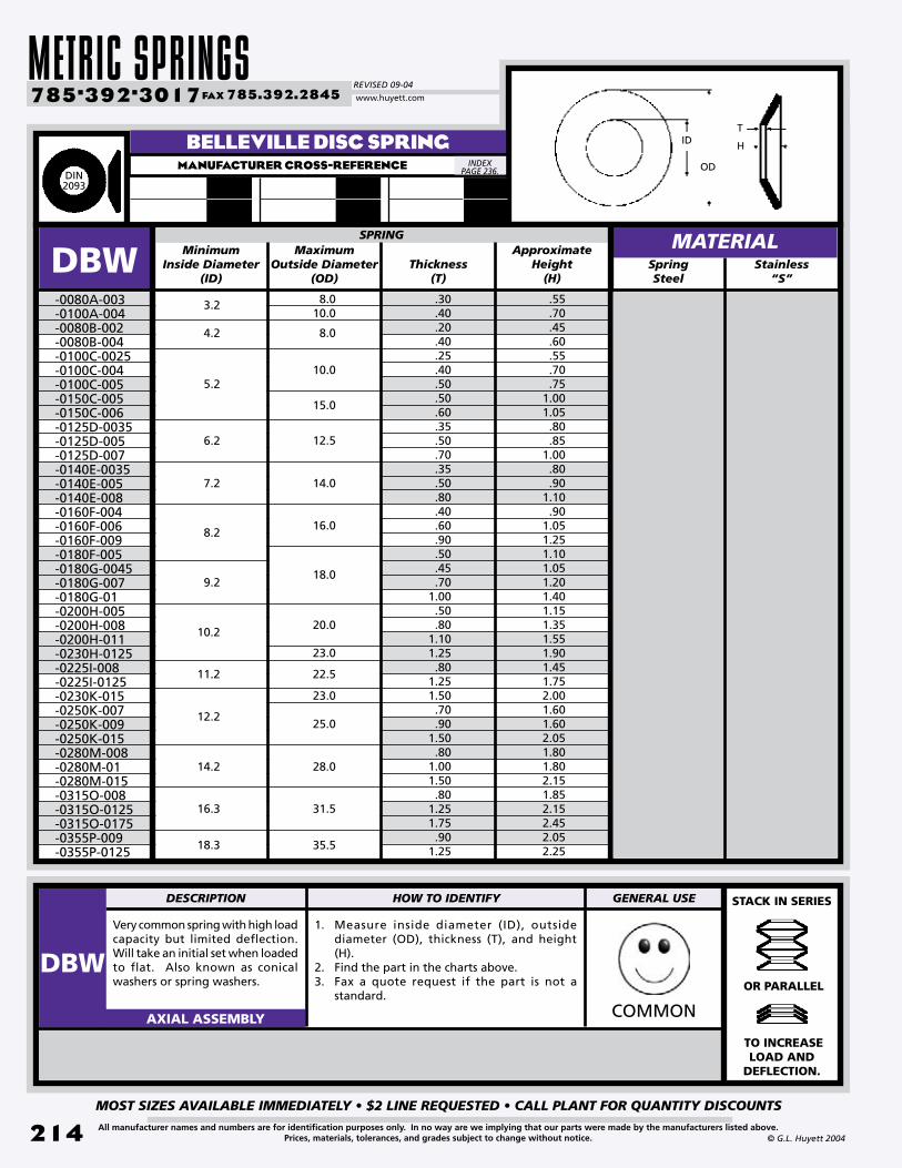
METRIC SPRINGSREVISED 09-04
MOST SIZES AVAILABLE IMMEDIATELY • $2 LINE REQUESTED • CALL PLANT FOR QUANTITY DISCOUNTS
214
785•392•3017 FAX 785.392.2845
All manufacturer names and numbers are for identification purposes only. In no way are we implying that our parts were made by the manufacturers listed above.Prices, materials, tolerances, and grades subject to change without notice. © G.L. Huyett 2004
www.huyett.com
Very common spring with high load capacity but limited deflection. Will take an initial set when loaded to flat. Also known as conical washers or spring washers.
1. Measure inside diameter (ID), outside diameter (OD), thickness (T), and height (H).
2. Find the part in the charts above.3. Fax a quote request if the part is not a
standard.COMMONAXIAL ASSEMBLY
MinimumInside Diameter
(ID)Thickness
(T)
Approximate Height
(H)
SPRINg
DBW-0080A-003-0100A-004-0080B-002-0080B-004-0100C-0025-0100C-004-0100C-005-0150C-005-0150C-006-0125D-0035-0125D-005-0125D-007-0140E-0035-0140E-005-0140E-008-0160F-004-0160F-006-0160F-009-0180F-005-0180G-0045-0180G-007-0180G-01-0200H-005-0200H-008-0200H-011-0230H-0125-0225I-008-0225I-0125-0230K-015-0250K-007-0250K-009-0250K-015-0280M-008-0280M-01-0280M-015-0315O-008-0315O-0125-0315O-0175-0355P-009-0355P-0125
Maximum Outside Diameter
(OD)
.30
.40
.20
.40
.25
.40
.50
.50
.60
.35
.50
.70
.35
.50
.80
.40
.60
.90
.50
.45
.701.00.50.80
1.101.25.80
1.251.50.70.90
1.50.80
1.001.50.80
1.251.75.90
1.25
.55
.70
.45
.60
.55
.70
.751.001.05.80.85
1.00.80.90
1.10.90
1.051.251.101.051.201.401.151.351.551.901.451.752.001.601.602.051.801.802.151.852.152.452.052.25
BELLEVILLE DISC SPRINGMANUFACTURER CROSS-REFERENCE
MATERIALStainless
“S”
3.2
4.2
5.2
6.2
7.2
8.2
9.2
10.2
11.2
12.2
14.2
16.3
18.3
8.010.0
8.0
10.0
15.0
12.5
14.0
16.0
18.0
20.0
23.0
22.5
23.0
25.0
28.0
31.5
35.5
STACK IN SERIES
OR PARALLEL
TO INCREASE LOAD AND
DEFLECTION.
DIN2093
INDEX PAGE 236.
H
T
OD
ID
SpringSteel
DESCRIPTION HOW TO IDENTIFY gENERAL USE
DBW
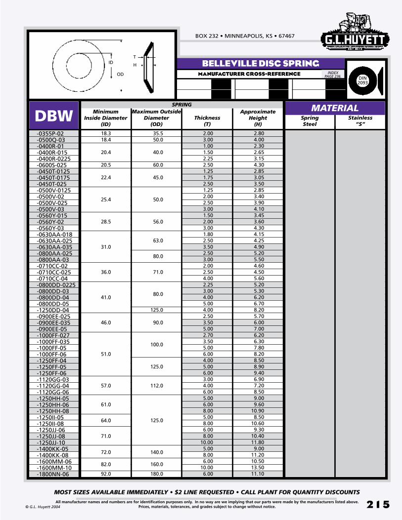
BOX 232 • MINNEAPOLIS, KS • 67467
MOST SIZES AVAILABLE IMMEDIATELY • $2 LINE REQUESTED • CALL PLANT FOR QUANTITY DISCOUNTS
215All manufacturer names and numbers are for identification purposes only. In no way are we implying that our parts were made by the manufacturers listed above.Prices, materials, tolerances, and grades subject to change without notice.© G.L. Huyett 2004
BELLEVILLE DISC SPRINGMANUFACTURER CROSS-REFERENCE
MinimumInside Diameter
(ID)Thickness
(T)
ApproximateHeight
(H)
SPRINg
DBW-0355P-02-0500Q-03-0400R-01-0400R-015-0400R-0225-0600S-025-0450T-0125-0450T-0175-0450T-025-0500V-0125-0500V-02-0500V-025-0500V-03-0560Y-015-0560Y-02-0560Y-03-0630AA-018-0630AA-025-0630AA-035-0800AA-025-0800AA-03-0710CC-02-0710CC-025-0710CC-04-0800DD-0225-0800DD-03-0800DD-04-0800DD-05-1250DD-04-0900EE-025-0900EE-035-0900EE-05-1000FF-027-1000FF-035-1000FF-05-1000FF-06-1250FF-04-1250FF-05-1250FF-06-1120GG-03-1120GG-04-1120GG-06-1250HH-05-1250HH-06-1250HH-08-1250II-05-1250II-08-1250JJ-06-1250JJ-08-1250JJ-10-1400KK-05-1400KK-08-1600MM-06-1600MM-10-1800NN-06
Maximum Outside Diameter
(OD)
2.003.001.001.502.252.501.251.752.501.252.002.503.001.502.003.001.802.503.502.503.002.002.504.002.253.004.005.004.002.503.505.002.703.505.006.004.005.006.003.004.006.005.006.008.005.008.006.008.00
10.005.008.006.00
10.006.00
2.804.002.302.653.154.302.853.053.502.853.403.904.103.453.604.304.154.254.905.205.504.604.505.605.205.306.206.708.205.706.007.006.206.307.808.208.508.909.406.907.208.509.009.60
10.908.50
10.609.30
10.4011.809.00
11.2010.5013.5011.10
MATERIALStainless
“S”
18.318.4
20.4
20.5
22.4
25.4
28.5
36.0
31.0
41.0
46.0
51.0
57.0
61.0
64.0
71.0
72.0
82.0
92.0
35.550.0
40.0
60.0
45.0
50.0
56.0
63.0
80.0
71.0
80.0
125.0
90.0
100.0
125.0
112.0
125.0
140.0
160.0
180.0
DIN2093
INDEX PAGE 236.
H
T
OD
ID
SpringSteel

METRIC SPRINGSREVISED 09-04
MOST SIZES AVAILABLE IMMEDIATELY • $2 LINE REQUESTED • CALL PLANT FOR QUANTITY DISCOUNTS
216
785•392•3017 FAX 785.392.2845
All manufacturer names and numbers are for identification purposes only. In no way are we implying that our parts were made by the manufacturers listed above.Prices, materials, tolerances, and grades subject to change without notice. © G.L. Huyett 2004
www.huyett.com
STANDARD WAVE SPRINGMANUFACTURER CROSS-REFERENCE
Flat wire design yields many benefits vs. compression springs: reduced operating height, precise load deflections, lower cost.
1. Count the waves “peak to peak.”2. Measure the thickness (T) and radial wall
(S).3. Determine free height (Hf).4. Find the part in the chart above.
WEIRDAXIAL ASSEMBLY
Theoretical Spring
Rate N/MMSpringSteel
161922242628303235374042475255626870727580859095100105110115120125130135140145150160165170
44.553.462.366.771.275.684.589.097.9
102.3111.2115.7129.0142.4151.3169.1186.9191.3195.8204.7218.0231.4249.2262.5275.9289.2302.6315.9329.3342.6356.0369.3382.7396.0404.9440.5453.9467.2
2.293.052.793.562.542.793.303.814.573.815.083.053.813.563.814.324.324.324.575.085.595.596.357.374.575.085.336.357.117.628.649.406.867.377.879.40
10.4111.18
BEARINg
DWSDWS-0063
-0075-0087-0095-0102-0110-0118-0126-0138-0146-0158-0165-0185-0205-0217-0244-0268-0276-0284-0295-0315-0335-0354-0374-0394-0413-0433-0453-0472-0492-0512-0532-0551-0571-0591-0630-0650
DWS-0669
Bearing Outside
Dia. (OD)Thickness
(T)Load
Newtons
RadialWall(S)
Numberof Waves
Free Height
(Hf)
Work Height(Hw)
65354835111856652385837996812110085131119108947683685715713411599867667591089787716458
3.18
2.77
2.36
1.98
1.57
6
5
4
3
.76
.46
.41
.30
.25
.61
5.92
3.38
4.52
2.39
1.98
3.63
3.81
4.78
BEARINg PRE-LOAD SPRINg MATERIAL
SSBSmalley
TBSpirolox
OD
Hw
Hf
T
S
Stainless “-SS”
INDEX PAGE 236.
NICECOMPACTDESIGN.
DESCRIPTION HOW TO IDENTIFY gENERAL USE
DWS

BOX 232 • MINNEAPOLIS, KS • 67467
MOST SIZES AVAILABLE IMMEDIATELY • $2 LINE REQUESTED • CALL PLANT FOR QUANTITY DISCOUNTS
217All manufacturer names and numbers are for identification purposes only. In no way are we implying that our parts were made by the manufacturers listed above.Prices, materials, tolerances, and grades subject to change without notice.© G.L. Huyett 2004
Flat wire design yields many benefits vs. compression springs: reduced operating height, precise load deflections, lower cost.
1. Count the waves “peak to peak.”2. Measure the thickness (T) and radial wall
(S).3. Determine free height (Hf).4. Find the part in the chart above.
AXIAL ASSEMBLY
STANDARD WAVE SPRINGMANUFACTURER CROSS-REFERENCE
SSBSmalley
TBSpirolox
OD
Hw
Hf
T
S
Theoretical Spring
Rate N/MMSpring Steel
175180185190200205210215220225230235240250260265270280290300310320340350360370380390400410420430440460480500540580
480.6493.9507.3520.6547.3560.7578.5591.8605.2618.5631.9645.2658.6685.3712.0725.3743.1769.8796.5823.2849.9876.6934.5961.1987.9
1014.61041.31072.41099.11125.81152.51179.21205.91263.71317.11370.51481.81593.0
BEARINg
DWSDWS-0689
-0709-0728-0748-0787-0807-0827-0847-0866-0886-0906-0925-0945-0984-1024-1043-1063-1102-1142-1181-1221-1260-1339-1378-1417-1457-1496-1535-1575-1614-1654-1693-1732-1811-1890-1969-2126
DWS-2284
Bearing Outside
Dia. (OD)Thickness
(T)Load
Newtons
RadialWall(S)
Numberof Waves
Free Height
(Hf)
Work Height(Hw)
8.138.649.149.917.117.377.878.388.647.116.106.356.356.867.377.628.138.649.40
10.417.117.628.649.407.628.138.649.149.658.388.897.628.138.898.138.898.898.89
1161059788174161149138128203303283265232205193182162144129264239198180271249229211196251233317295256318280303327
10
11
9
7
8
6
12
1314
.81
9.53
BEARINg PRE-LOAD SPRINg MATERIAL
3.96
1.07
12.70
Stainless “-SS”
INDEX PAGE 236.
PRECISELOAD
DEFLECTION CHARACTERISTICS
DESCRIPTION HOW TO IDENTIFY gENERAL USE
DWS
IMPERIAL Page 116
WSGWEIRD

METRIC ASSEMBLY COMPONENTSREVISED 09-04
MOST SIZES AVAILABLE IMMEDIATELY • $2 LINE REQUESTED • CALL PLANT FOR QUANTITY DISCOUNTS
218
785•392•3017 FAX 785.392.2845
All manufacturer names and numbers are for identification purposes only. In no way are we implying that our parts were made by the manufacturers listed above.Prices, materials, tolerances, and grades subject to change without notice. © G.L. Huyett 2004
www.huyett.com
METRIC KEYED SHAFTSMANUFACTURER CROSS-REFERENCE
METRIC SHAFT COLLARMANUFACTURER CROSS-REFERENCE
Zinc Plated“-ZC”
SCM Outside Dia.
Black Oxide“-BO”
Inside Dia.
(Bore)
MATERIALStainless
“-SS”
SHAFT COLLAR
SCM-002 -0025
-003 -0035-004
-0045-005
-0055-006-007-008-009-010-011-012-013-014-015-016
SCM-018
22.53
3.54
4.55
5.567891011121314151618
Thickness(Width)
6 2.54
7
8
10
12
1618
20
22
25
2832
5
6
8
10
12
Zinc Plated“-ZC”
SCM Outside Dia.
Black Oxide“-BO”
Inside Dia.
(Bore)
MATERIALStainless
“-SS”
SHAFT COLLAR
SCM-020-022-024-025-026-028-030-032-034-035-036-038-040-042-045-048-050-052
SCM-055
20222425262830323435363840424548505255
Thickness(Width)
3236
40
45
50
63
70
80
14
16
18
14
56
3’“-914”
KFM Width(B)
Depth(C)
Diameter (A)
KEYWAY
KFM Width(B)
Depth(C)
Diameter
(A)
KEYWAY LENgTHLENgTH6’
“-1829”
BAR BAR
3’“-914”
6’“-1829”
KFM-013-014-015-016-017-018-019-020-021-022-023-024
KFM-025
13141516171819202122232425
5 3.0
6 3.5
8 4.0
KFM-026-027-028-030-032-033-035-036-040-045-050-060
KFM-065
26272830323335364045506065
8 4.0
14 5.5
18 7.0
12
105.0
INDEX PAGE 236.
INDEX PAGE 236. A
C
B
SC IMPERIAL
Page 128KF IMPERIAL
Page 140
6885DINBN 868Bossard

BOX 232 • MINNEAPOLIS, KS • 67467
MOST SIZES AVAILABLE IMMEDIATELY • $2 LINE REQUESTED • CALL PLANT FOR QUANTITY DISCOUNTS
219All manufacturer names and numbers are for identification purposes only. In no way are we implying that our parts were made by the manufacturers listed above.Prices, materials, tolerances, and grades subject to change without notice.© G.L. Huyett 2004
CARBON STEEL SHAFT KEYSMANUFACTURER CROSS-REFERENCE
2 x 23 x 34 x 45 x 35 x 56 x 46 x 68 x 58 x 710 x 610 x 812 x 612 x 814 x 614 x 916 x 716 x 10
LENgTHWidth xHeight
(W) x (H)(L)
8mm(L)
10mm(L)
12mm(L)
14mm(L)
16mm(L)
20mm(L)
25mm(L)
30mm(L)
36mm(L)
40mm(L)
45mm(L)
50mm
•••------------------------------------------
•••••••••------------------------
•••••••••------------------------
•••••••••------------------------
•••••••••••------------------
•••••••••••••---•------
---••••••••••••••------
---••••••••••••••••
---••••••••••••••••
---••••••••••••••••
------•••••••••••••••
------•••••••••••••••
H
LW
2 x 23 x 34 x 45 x 35 x 56 x 46 x 68 x 58 x 710 x 610 x 812 x 612 x 814 x 614 x 916 x 716 x 10
LENgTHWidth xHeight
(W) x (H)(L)
56mm(L)
63mm(L)
70mm(L)
80mm(L)
90mm(L)
100mm(L)
110mm(L)
120mm(L)
130mm(L)
140mm(L)
150mm
------•••••••••••••••
------•••••••••••••••
------•---•••••••••••••
------•---•---•••••••••••
------------------•••••••••••
------•---•---•---•••••••••
------------------•---•••••••••
------------------------•---•••••••
------------------------•---•••••••
------------------•---•---•••••••
------------------------•---•---•---•••
DIN 6885
INDEX PAGE 236.
OTHER TYPES OF SHAFT KEYS A V AILABLE
Form C Form D Form E Form F Form g Form H Form J
PleaseCall
PlantFor
Details.DIN 6885
IMPERIALPage 138-139
6885DINBN870Bossard
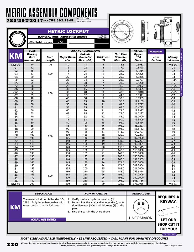
METRIC ASSEMBLY COMPONENTSREVISED 09-04
MOST SIZES AVAILABLE IMMEDIATELY • $2 LINE REQUESTED • CALL PLANT FOR QUANTITY DISCOUNTS
220
785•392•3017 FAX 785.392.2845
All manufacturer names and numbers are for identification purposes only. In no way are we implying that our parts were made by the manufacturers listed above.Prices, materials, tolerances, and grades subject to change without notice. © G.L. Huyett 2004
www.huyett.com
METRIC LOCKNUTMANUFACTURER CROSS-REFERENCE
These metric locknuts fall under ISO-2982. Fully interchangeable with most standard metric locknuts.
1. Verify the bearing bore nominal (N).2. Determine the major diameter (Dm), out-
side diameter (OD), and thickness (T) of the part.
3. Find the part in the chart above.
UNCOMMONAXIAL ASSEMBLY
Major Diam-eter
1012151720222528303235404550556065707580859095100105110115120125130135140145150155160165170180200
KM-00-01-02-03-04-045-05-055-06-065-07-08-09-10-11-12-13-14-15-16-17-18-19-20-21-22-23-24-25-26-27-28-29-30-31-32-33-34-36
KM-40
PitchLength
18222528323438424548525865707580859298105110120125130140145150155160165175180190195200210210220230250
MatingLockwasher
Bearing Bore
Nominal (N)
Outside Diameter
Max. (OD)
Nut FaceDiameter Max. (Dc)
Thickness(T)
1012151720222528303235404550556065707580859095100105110115120125130135140145150155160165170180200
44556677788910111111121213151616171818191920212122222424252526262729
13.517.021.024.026.028.032.036.038.040.044.050.056.061.067.073.079.085.090.095.0
102.0108.0113.0120.0126.0133.0137.0138.0148.0149.0160.0160.0171.0171.0182.0182.0193.0193.0203.0226.0
LOCKNUT DIMENSIONS MATERIAL
KM LowCarbon
BOREKg per
100Pieces
WEIgHT
MB-00-01-02-03-04
-045-05
-055-06
-065-07-08-09-10-11-12-13-14-15-16-17-18-19-20-21-22-23-24-25-26-27-28-29-30-31-32-33-34-36
MB-40
0.56820.85231.13641.42051.98862.27273.12503.69324.54555.68186.53419.0909
12.215914.772716.477317.897721.022725.000015.340919.886446.022756.818264.772772.727387.500097.727390.9091
107.9545119.0000125.0000155.0000159.0909200.0000207.3864221.0000255.6818284.0909280.0000305.1136373.2955
.75
1.00
1.50
2.00
3.00
MA
TIN
G L
OC
KW
ASH
ER D
ESC
RIP
TIO
NS
ON
PA
GE
221.
INDEX PAGE 236.
ODDc N
T
REQUIRES A KEYWAY.
LET OUR SHOP CUT IT FOR YOU!
SEE PAGE 218.
DESCRIPTION HOW TO IDENTIFY gENERAL USE
KM
KMWhittet-Higgins
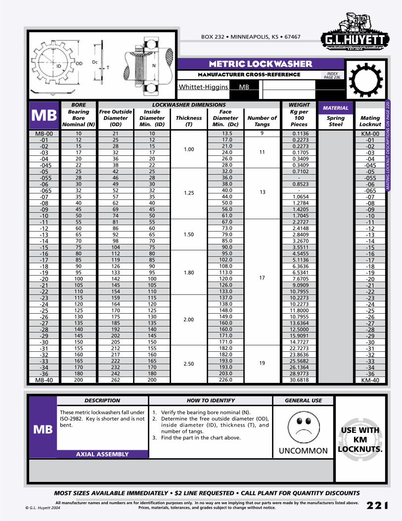
BOX 232 • MINNEAPOLIS, KS • 67467
MOST SIZES AVAILABLE IMMEDIATELY • $2 LINE REQUESTED • CALL PLANT FOR QUANTITY DISCOUNTS
221All manufacturer names and numbers are for identification purposes only. In no way are we implying that our parts were made by the manufacturers listed above.Prices, materials, tolerances, and grades subject to change without notice.© G.L. Huyett 2004
METRIC LOCKWASHERMANUFACTURER CROSS-REFERENCE
These metric lockwashers fall under ISO-2982. Key is shorter and is not bent.
1. Verify the bearing bore nominal (N).2. Determine the free outside diameter (OD),
inside diameter (ID), thickness (T), and number of tangs.
3. Find the part in the chart above.
UNCOMMONAXIAL ASSEMBLY
1012151720222528303235404550556065707580859095100105110115120125130135140145150155160165170180200
MB-00-01-02-03-04
-045-05
-055-06
-065-07-08-09-10-11-12-13-14-15-16-17-18-19-20-21-22-23-24-25-26-27-28-29-30-31-32-33-34-36
MB-40
LOCKWASHER DIMENSIONS
Mating Locknut
Free Outside Diameter
(OD)
Bearing Bore
Nominal (N)
Inside DiameterMin. (ID)
Thickness(T)
Face DiameterMin. (Dc)
13.517.021.024.026.028.032.036.038.040.044.050.056.061.067.073.079.085.090.095.0
102.0108.0113.0120.0126.0133.0137.0138.0148.0149.0160.0160.0171.0171.0182.0182.0193.0193.0203.0226.0
1012151720222528303235404550556065707580859095100105110115120125130135140145150155160165170180200
MBMATERIAL
Number of Tangs
BORE
212528323638424649525762697481869298104112119126133142145154159164170175185192202205212217222232242262
SpringSteel
Kg per 100
Pieces
WEIgHT
1.00
1.25
1.50
1.80
2.00
2.50
11
13
17
9
19
KM-00-01-02-03-04
-045-05
-055-06
-065-07-08-09-10-11-12-13-14-15-16-17-18-19-20-21-22-23-24-25-26-27-28-29-30-31-32-33-34-36
KM-40
OD DcID NT
0.11360.22730.22730.17050.34090.34090.7102
-0.8523
-1.06541.27841.42051.70452.27272.41482.84093.26703.55114.54555.11366.36366.53417.67059.0909
10.795510.227310.227311.800010.795513.636412.500015.909114.772722.727323.863625.568226.136428.977330.6818
MA
TIN
G L
OC
KN
UT
DES
CR
IPTI
ON
S O
N P
AG
E 22
0.
INDEX PAGE 236.
USE WITH KM
LOCKNUTS.
DESCRIPTION HOW TO IDENTIFY gENERAL USE
MB
MBWhittet-Higgins

ASSORTMENTS & TOOLSREVISED 09-04
MOST SIZES AVAILABLE IMMEDIATELY • $2 LINE REQUESTED • CALL PLANT FOR QUANTITY DISCOUNTS
222
785•392•3017 FAX 785.392.2845
All manufacturer names and numbers are for identification purposes only. In no way are we implying that our parts were made by the manufacturers listed above.Prices, materials, tolerances, and grades subject to change without notice. © G.L. Huyett 2004
www.huyett.com
ASSORTMENTS
DISP STANDARD PACKS
Pgs: 224-225Pre-selected boxes of our most popular rings with convenient packaging and labels to help increase your profits.
DISPX COMBINATION PACKS
We make these boxes on a special order basis only. Combos contain part families and tools as a complete retaining solution for your customers.
KIT MAINTENANCE KITS
Available as a special order, these boxes are organized unique to a particular situation or equipment model. These kits are often used to support planned maintenance.
DISPC CUSTOM PACKS
We can assemble packages complete to your requirements, including labels, logos, and special art work.
#2854 External Rings 300 pcs.
....
....
US ARMY....
........
....
....
........
....
....
........
....
....
....
DISPX-241 External Rings 241 pcs.
....
....
....
........
....
....
........
....
....
....
to minimize your inventory.
HOW ASSORTMENTS HELP YOU
Sell “from the box”
to spread your advertising message and yield greater transaction value.
Sell “by the box”
ACME
BOLT
COMPANYBox 111Anywhere, USA(111) 555-1234

BOX 232 • MINNEAPOLIS, KS • 67467
MOST SIZES AVAILABLE IMMEDIATELY • $2 LINE REQUESTED • CALL PLANT FOR QUANTITY DISCOUNTS
223All manufacturer names and numbers are for identification purposes only. In no way are we implying that our parts were made by the manufacturers listed above.Prices, materials, tolerances, and grades subject to change without notice.© G.L. Huyett 2004
TOOLS
PRS STANDARD PLIERS
Pgs: 226-227Permanent tip pliers with separate tools for internal andexternal rings. Available with straight, 45°, or 90° tips.
PRE ERGONOMIC PLIERS
Pgs: 226-227Similar to PRS pliers, with a longer curved grip that
yields more force, which minimizes operator fatigue. Permanent tips come in straight, 45°, and 90° angles.
PRR RATCHET PLIERS
Pg: 228Ratchet pliers feature removable tips so that one pliers may be used on many different rings (providing that you have the tips). Must have separate tools for internal and external applications.
PRC CONVERTIBLE PLIERS
Pg: 229Permanent tip pliers that can be used on both external and
internal rings. As a special order item, we offer quarter turn convertible pliers, which make the conversion process even easier.
PRS STANDARD PLIERS - WIRE RINGS
Pg: 230Eight basic wire ring pliers designs that have knurled tips or
indentions to hold lugless wire rings more securely; however, safety glasses should always be worn when using these pliers.
PRR RATCHET PLIERS - WIRE RINGS
Pg: 231Removable tip wire ring pliers with ratchet action for large-sized rings. Additional “horseshoe” tips can be purchased to expand the pliers capabilities.
RRA APPLICATORS
Pgs: 232-234Applicators come in a variety of sizes and angles that are uniquely dedicated to a very limited number of clip ring sizes.
BEGINS PAGE 226
Purchase rings in a stacked roll pack.
Mount on a rail dispenser.
Remove ring from rail using applicator.
Use the correct tip design for the job, such as this offset
example.
HOW TO USE APPLICATORS

ASSORTMENTSREVISED 09-04
MOST SIZES AVAILABLE IMMEDIATELY • $2 LINE REQUESTED • CALL PLANT FOR QUANTITY DISCOUNTS
224
785•392•3017 FAX 785.392.2845
All manufacturer names and numbers are for identification purposes only. In no way are we implying that our parts were made by the manufacturers listed above.Prices, materials, tolerances, and grades subject to change without notice.
NOTHINg HAS OUR NAME ON IT!
© G.L. Huyett 2004
www.huyett.com
external “snap”
DISP-SH125
INTERNAL HOUSING
DISP-HO125Housing Dia. Qty
INVERTED EXTERNAL
DISP-SHI125Shaft Dia.
INVERTED INTERNAL
DISP-HOI125Housing Dia.
HEAVY DUTY “SNAP”
DISP-SHR125
Shaft Dia.
E-CLIP
DISP-E125
Shaft Dia. Qty
REINFORCED E-CLIP
DISP-RE125
Shaft Dia.
CRESCENT
DISP-C125
Shaft Dia.
EXTERNAL GRIP
DISP-SHF125
Shaft Dia.
external “snap” LARGE SIZE
DISP-SH300
internal housingLARGE SIZE
DISP-HO300
EXTERNAL/INTERNAL MIX
DISP-SHHO220
METRIC E-CLIP
DISP-DE300E-CLIPLARGE SIZE
DISP-E300Shaft Dia. Qty
1/8”5/32”3/16”7/32”1/4”
3020402040
Shaft Dia. Qty3/4”7/8”
105
Carbon Steel
All assortments are packaged in a compartmentalized polypropylene box with an identification card. Identification cards can be printed with your company name and logo. Call today!
SH HO SHI HOI
SHR SHF E RE C
SH HO SH/HO
E
DE
125 Pcs. 125 Pcs. 125 Pcs. 125 Pcs.
125 Pcs.125 Pcs.125 Pcs.125 Pcs.125 Pcs.
220 Pcs.300 Pcs.300 Pcs.
300 Pcs.
300 Pcs.
SEE
DIS
P-H
O30
0 B
ELO
W.
SEE
DIS
P-E3
00 B
ELO
W.
PAGE 10.
PAGE 9. PAGE 14. PAGE 26. PAGE 27. PAGE 32.
PAGE 6. PAGE 16. PAGES 6,16.
PAGE 26.
PAGE 182.
Shaft Dia.SE
E D
ISP-
SH30
0 B
ELO
W.
Qty1/4”5/16”3/8”1/2”3/4”1”
302520202010
1/4”5/16”3/8”1/2”3/4”1”
252525251510
Qty1/2”9/16”5/8”3/4”7/8”1”
302520202010
Qty5/8”3/4”7/8”1”
1-1/4”1-1/2”
252525251510
Qty1/2”5/8”3/4”7/8”
63/64”1-1/16”
302520202010
Carbon Steel
Qty3/16”1/4”5/16”3/8”1/2”3/4”
302520202010
1/8”3/16”1/4”3/8”1/2”5/8”
302520202010
Qty1/8”3/16”1/4”5/16”3/8”1/2”
302520202010
Qty1/4”5/16”3/8”1/2”5/8”3/4”
252525251510
Shaft Dia. Qty1/4”5/16”3/8”7/16”1/2”9/16”5/8”3/4”
13/16”7/8”1”
1-1/4”1-5/16”
2525252530252525101520165
Shaft Dia. Qty1-3/8”1-7/16”1-1/2”1-5/8”1-3/4”1-7/8”
2”2-1/4”2-1/2”2-5/8”2-3/4”2-7/8”
3”
5333322221111
Housing Dia. Qty3/8”7/16”1/2”5/8”
11/16”3/4”
13/16”7/8”1”
1-1/16”1-1/8”1-1/4”1-3/8”
25252525252525252010151510
Housing Dia. Qty1-1/2”1-5/8”1-3/4”1-7/8”
2”2-1/4”2-3/8”2-1/2”2-5/8”2-3/4”2-7/8”
3”
833332221111
External Qty1/4”5/16”3/8”7/16”1/2”5/8”
11/16”3/4”7/8”1”
Internal Qty3/8”7/16”1/2”9/16”5/8”3/4”7/8”1”
1-1/8”1-1/4”
Shaft Dia.5/16”3/8”7/16”1/2”5/8”
Qty3035253015
Shaft Dia. Qty1.2mm1.5mm1.9mm2.3mm3.2mm4.0mm
202020203030
Shaft Dia. Qty5.0mm6.0mm7.0mm8.0mm9.0mm
10.0mm
303030302020
101015151515151055
51015151515101055
DIN
6799
Carbon Steel Carbon Steel Carbon Steel Carbon Steel
Carbon Steel Carbon Steel Carbon Steel Carbon Steel
Carbon Steel Carbon Steel
Carbon Steel
Carbon Steel

BOX 232 • MINNEAPOLIS, KS • 67467
MOST SIZES AVAILABLE IMMEDIATELY • $2 LINE REQUESTED • CALL PLANT FOR QUANTITY DISCOUNTS
225
WE PROTECT YOU FOR RESALE WITH PLAIN PACKAgINg, IDEAL FOR CUSTOMIZATION!
All manufacturer names and numbers are for identification purposes only. In no way are we implying that our parts were made by the manufacturers listed above.Prices, materials, tolerances, and grades subject to change without notice.© G.L. Huyett 2004
DISP-SH100SS DISP-SH50SS DISP-HO100SS DISP-HO50SS DISP-E100SS DISP-E50SS
METRIC external
DISP-DSH150
METRIC internal
DISP-DHO150
SPIRAL SPIRAL MIX
SH HO E
RS,RR,RST,RRT RS/RR,RST/RRT
DSH DHO
STAINLESS STEEL external “snap”
STAINLESS STEEL internal housing
STAINLESS STEELE-CLIPS
100 Pcs. 50 Pcs. 100 Pcs. 50 Pcs. 100 Pcs. 50 Pcs.
150 Pcs.150 Pcs.
PAGE 16. PAGE 26.PAGE 6.
PAGES 38,52,42,56. PAGES 38,52,42,56.
PAGE 152. PAGE 166.
Shaft Dia. Qty1/4”5/16”3/8”7/16”1/2”9/16”5/8”3/4”7/8”1”
10101010101010101010
Shaft Dia. Qty5555555555
1/4”5/16”3/8”7/16”1/2”9/16”5/8”3/4”7/8”1”
Housing Dia. Qty1/4”5/16”3/8”7/16”1/2”9/16”5/8”3/4”7/8”1”
1-1/4”
666620681071510
Housing Dia. Qty433310345375
1/4”5/16”3/8”7/16”1/2”9/16”5/8”3/4”7/8”1”
1-1/4”
Shaft Dia. Qty1/8”5/32”3/16”7/32”*1/4”3/8”7/16”1/2”5/8”
106106122062010
Shaft Dia. Qty53536103105
1/8”5/32”3/16”7/32”*1/4”3/8”7/16”1/2”5/8”
*This size only conforms to SE type ring.
Diameter Qty
1/2”5/8”
11/16”3/4”
13/16”7/8”1”
1-1/16”1-1/8”1-1/4”1-3/8”1-1/2”
303025302525301220251212
Diameter Qty
33332221111
298
External Qty1/2”5/8”3/4”7/8”1”
1-1/8”1-1/4”1-3/8” 1-1/2”
121212121212121212
Internal Qty121212121212121212
1-5/8”1-3/4”1-7/8”
2”2-1/4”2-3/8”2-1/2”2-5/8”2-3/4”2-7/8”
3”Total
1/2”5/8”3/4”7/8”1”
1-1/8”1-1/4”1-3/8”1-1/2”
Total Pieces 216
Shaft Dia. Qty
8mm10mm12mm14mm15mm16mm17mm18mm20mm
15151515101010108
Shaft Dia. Qty
22mm24mm25mm28mm30mm32mm35mm40mm45mm
885544422
Housing Dia. Qty
15mm16mm18mm20mm22mm24mm25mm26mm28mm
20201515101010108
Housing Dia. Qty
30mm32mm34mm35mm38mm40mm45mm50mm60mm
554443322
DIN
472
DIN
471
DISP-RS298 Ext. Medium
DISP-RR298 Int. Medium
DISP-RST298 Ext. Heavy
DISP-RRT298 Int. Heavy
DISP-MDSPI216 Carbon Medium
DISP-MDSPI216SS Stainless Medium
DISP-MHSPI216 Carbon Med Hvy
DISP-MHSPI216SS Stainless Med Hvy
Carbon Steel Carbon Steel
METRIC MIX
DISP-MET300Diameter Qty Diameter Qty
DSH/DHO/DE
300 Pcs.
PAGES 152,166,182.
20mm25mm30mm35mm40mm50mm60mm70mm80mm
20mm25mm30mm
2015151085322
201515
35mm40mm50mm60mm70mm80mm
3.2mm4.0mm5.0mm6.0mm7.0mm8.0mm
1085322
303030302020
E-Clip Rings
External Rings
Internal Rings
DIN
471
472
6799
Carbon Steel

SNAP RING PLIERSREVISED 09-04
MOST SIZES AVAILABLE IMMEDIATELY • $2 LINE REQUESTED • CALL PLANT FOR QUANTITY DISCOUNTS
226
785•392•3017 FAX 785.392.2845
All manufacturer names and numbers are for identification purposes only. In no way are we implying that our parts were made by the manufacturers listed above.Prices, materials, tolerances, and grades subject to change without notice. © G.L. Huyett 2004
www.huyett.com
From To 90° Standard“PRS”
From To 45° 90° Standard“PRS”
Ergonomic“PRE”
From To
SHI SHR USH
SH
BSH VSHFrom To From To From To 45° 90° Standard
“PRS”Ergonomic
“PRE”
SHF
DSHI DSHR
DSH
DAK
DBSH
DAL
DSHF
RINg STYLE AND SIZE TIP ANgLE PLIERS STYLES
-006-012-018-031
-011-015-027-075
From To From To From To Straight 90° Standard“PRS”
-003-010-019-040-085
-010-025-060-100-165
-010-018-028-050-085
-017-026-048-082-100
--012-017-032-085
--016-030-080-100
Part #
-E023-S-E023-M-E023-L-E038-E047-E070-E115
-E034-E040-E047-X-E070-X
From To 90° Standard“PRS”
DSHX
-003-008-010
--015-030
-0015-0035-009-0105-011-016
-E009-E013-E018-E023-E032
--
-012-016
-
-006-008-009-013-017
-ZGG1-ZGG2-ZGG1-ZGG2-ZGG3
-ZGG0-ZGG1-ZGG2-ZGG1-ZGG2-ZGG3
-E023-45S-E023-45M-E023-45L-E038-45-E047-45-E070-45-E115-45
-E023-90S-E023-90M-E023-90L-E038-90-E047-90-E070-90-E115-90
-E034-45-E040-45-E047-45X-E070-45X
-E034-90-E040-90-E047-90X-E070-90X
-E009-90-E013-90-E018-90-E023-90-E032-90
-ZGG1-90-ZGG2-90-ZGG1-90-ZGG2-90-ZGG3-90
-ZGG0-90-ZGG1-90-ZGG2-90-ZGG1-90-ZGG2-90-ZGG3-90
-012-015-018-025-068-093-150
--
-023-066-087-143-350
---
-050-081-106-215
---
-078-100-200-325
---
-039-050-075
-
---
-047-066-098
-
------
-206
------
-312
EXTERNAL RETAINING RINGS
PERMANENT TIPS
Part # METRI
C
FOR AXIAL ASSEMBLY OF SNAP RINGS
ALL RINGS IN A GIVEN ROW USE THE SAME PLIERS.
Straight
Straight
Straight
Straight
METRIC
Standard“PRS”
Part #
Standard“PRS”
Standard“PRS”
Contact plant for price and availability of 45° metric pliers (PRS).
CO
NTA
CT
PLA
NT
FOR
PR
ICE
AN
D A
VA
ILA
BLI
ITY
OF
45°
MET
RIC
PLI
ERS.

BOX 232 • MINNEAPOLIS, KS • 67467
MOST SIZES AVAILABLE IMMEDIATELY • $2 LINE REQUESTED • CALL PLANT FOR QUANTITY DISCOUNTS
227All manufacturer names and numbers are for identification purposes only. In no way are we implying that our parts were made by the manufacturers listed above.Prices, materials, tolerances, and grades subject to change without notice.© G.L. Huyett 2004
From To From To From To 90° Standard“PRS”
DHOI DHOR
DHO
DJK
DBHO
DJLDVHO
-008-010-019-040-085
-010-025-060-100-165
-010-016-040-050-110
-015-040-070-108-140
--
020-034-085
--
-032-080-100
-I009-I011-I018-I023-I032
-I009-90-I011-90-I018-90-I023-90-I032-90
ToFrom
HOI
HO
VVHVHO
BHO
UHO
From To From To 45° 90° Standard“PRS”
Ergonomic“PRE”
RINg STYLE AND SIZE TIP ANgLE
-025-037-062-106-181
-031-056-102-175-300
-062-075-106-143-206
--100-137-200-300
---
-175-237
---
-231-300
Part #
-I025-I038-I047-I070-I090
-I025-45-I038-45-I047-45-I070-45-I090-45
-I025-90-I038-90-I047-90-I070-90-I090-90
PLIERS TYPES
INTERNAL RETAINING RINGS
PERMANENT TIPS
FOR AXIAL ASSEMBLY OF SNAP RINGS
Pliers TYPESSTANDARD ERgONOMIC
Spring-loaded handles, air-cushioned grips, and presets make these the ideal tool for work situations where similar-sized rings are used. The dedicated design requires separate pliers for internal and external rings. These pliers are made of heat-treated, high carbon steel for a long life.
Longer, curved, air-cushioned grip design yields 30% more force. Higher force minimizes fatigue and reduces incidence of carpal tunnel syndrome. Adjustable stops prevent stressful overexpansion of external rings and allow presets that align with the lug holes of internal rings.
TIP ANGLESUse a tip angle that maximizes operator
comfort and production efficiency.
Straight
Straight
ALL RINGS IN A GIVEN ROW USE THE SAME PLIERS.
Part #
METRI
C
PRS PRE
Application using 90° tip angle.
Part #
Standard“PRS”
CO
NTA
CT
PLA
NT
FOR
45°
MET
RIC
PLI
ERS.

SNAP RING PLIERSREVISED 09-04
MOST SIZES AVAILABLE IMMEDIATELY • $2 LINE REQUESTED • CALL PLANT FOR QUANTITY DISCOUNTS
228
785•392•3017 FAX 785.392.2845
All manufacturer names and numbers are for identification purposes only. In no way are we implying that our parts were made by the manufacturers listed above.Prices, materials, tolerances, and grades subject to change without notice. © G.L. Huyett 2004
www.huyett.com
ToFrom
SHI SHR
From To From To Straight
SH
BSH VSH Part #
15° 45° 90°
RINg STYLE AND SIZE TIP ANgLE PLIERS
-T093-T108-X-T120-T120-X-T170
--
-T093-15-T108-15X-T120-15
--T170-15
--
-T093-45-T108-45X-T120-45-T120-45X-T170-45
--
-T093-90-T108-90X-T120-90-T120-90X-T170-90
--
-E093-E108-E120-E120-X-E170-E035-E045
--
-150-354-675-975-1000
--
-215-350
---
--
-325-393
---
-106-150
--193
---
-137-175
--200
---
--
-375-650-950
--
ToFrom
HOI
From To 90°
HO
BHO VHO Part #
45°15°Straight
-181-244-306-306-625
-
-237-300-400-600-1000
-
--306-346-413-525-725
--334-400-500-700-1000
-T093-T108-T120-T120-X-T150 -
-T093-15-T108-15-T120-15
--T150-15
-
-T093-45-T108-45-T120-45-T120-45X-T150-45
-
-T093-90-T108-90-T120-90-T120-90X-T150-90
-
-I093-I108-I120-I120-X-I150-I045
From To
-206-262-315-315
--
-250-300-400-400
--
UHO
From To From To
DSH
DAK
DBSH
DAL
-200--
-105--
-250-400-1000
-122-252-400
From To From To
DHO
DJK
DBHO
DJL
-200--
-105--
-250-400-1000
-122-252-400
Standard Ratchet Pliers come with straight tips.
Part #“PRR”
Standard Ratchet Plierscome with straight tips.
Part #“PRR”
Straight 90°
PRR-E035-90PRR-E045-90PRR-048-90
PRR-E035PRR-E045PRR-048
Straight 90°
PRR-I035-90PRR-I045-90PRR-048-90
PRR-I035PRR-I045PRR-048
Part #
Part #
DSHR
DHOR
REPLACEABLE TIP RATCHET PLIERS
SWITCH FROM INTERNAL TO EXTERNAL
FOR AXIAL ASSEMBLY OF SNAP RINGS
METRIC
RATCHET PLIERS
Work best on really BIG rings.
Ratchet mechanism compressesor expands rings gradually.

BOX 232 • MINNEAPOLIS, KS • 67467
MOST SIZES AVAILABLE IMMEDIATELY • $2 LINE REQUESTED • CALL PLANT FOR QUANTITY DISCOUNTS
229All manufacturer names and numbers are for identification purposes only. In no way are we implying that our parts were made by the manufacturers listed above.Prices, materials, tolerances, and grades subject to change without notice.© G.L. Huyett 2004
CONVERTIBLE PLIERS
From
HOI
HO
VVHOVHO
BHO
To From To From To From To From To
SHI SHR
SH
BSH VSH
Straight 45° 90°
INTERNALEXTERNAL PLIERS
.038
.047
.070
.090
-025-067-088-144
-066-087-143-200
-050-079-101
-
-078-100-200
-
-039-048-067
-
-047-066-098
-
-037-044-103-175
-043-102-175-206
-075-101-138-201
-100-137-200-212
.038
.047
.070
.090
-038-047-070-090
-038-45-047-45-070-45-090-45
-038-90-047-90-070-90-090-90
PART # PRC-
Tip Dia.
Tip Dia.
USE THE SAME PLIERS FOR ALL PARTS IN ONE ROW.
FOR AXIAL ASSEMBLY OF SNAP RINGS
SWITCH FROM INTERNAL TO EXTERNAL
Identify correct tool by tip diameter.
CONVERTIBLE PLIERSConvertible pliers are great for small quantity applications of similar size external and internal retaining rings. Switch the placement of the pliers halves to go from external to internal and vice versa. See the convertible pliers interchange chart above for an easy overview of external/internal convertibility.
QUARTER TURN PLIERSAVAILABLE AS A SPECIAL ORDER: Quarter turn convertible pliers make pliers adjustment fast and easy. Twist the pivot a quarter turn to go from external to internal and vice versa. Contact plant for price and availability.
REPLACEABLE TIP PLIERS
DISP-RRPK1
RATCHET PLIERS
DISP-RRPK2
CONVERTIBLE PLIERS
DISP-RRPK3 12 Pcs.10 Pcs.10 Pcs.
ASSORTMENTS
CONTAINS
(External and Internal)
.038” .047” .070”
#PRS-EXT-NT External
#PRS-INT-NT Internal
Good for snap rings 3/8” to 2”
CONTAINS
.018” (straight, 15°, 45°, 90°)
.120” (straight, 15°, 45°, 90°)
#PRR-E108-NT External
#PRR-I093-NT Internal
For bigger rings!
CONTAINS
Does the work of 24 tools!
.038” (straight, 45°, 90°)
.047” (straight, 45°, 90°)
.070” (straight, 45°, 90°)
.090” (straight, 45°, 90°)

WIRE RING PLIERSREVISED 09-04
MOST SIZES AVAILABLE IMMEDIATELY • $2 LINE REQUESTED • CALL PLANT FOR QUANTITY DISCOUNTS
230
785•392•3017 FAX 785.392.2845
All manufacturer names and numbers are for identification purposes only. In no way are we implying that our parts were made by the manufacturers listed above.Prices, materials, tolerances, and grades subject to change without notice. © G.L. Huyett 2004
www.huyett.com
PRS-E015R PRS-E601R PRS-E602RPRS-E047R
Small fixed tip pliers with a torsion spring and plastic grips. Ideal for small light duty external rings with minimal gaps. Knurled, shaped t ip ensures a positive grip.
PRS-Eg404 PRS-Eg704
Fixed tip pliers with right angled tips to spread, remove, and install rings with a wide range of gap forms. Knurled tips hold rings securely in a variety of positions. Require at least .37” clearance for effective use of these pliers.
PRS-Eg705
Fixed tip pliers with knurled tips to spread, remove and install rings without lug holes. Jaws open 1-1/2”. Similar to the PRS-E601R with its narrow tips, but capable of handling a greater variety of gap forms. Works best where the minimum clearance is .21” to a depth of .43”
Fixed tip pliers with parallel action jaws notched to hold rings securely as they open in a parallel plane. Spring action closes jaws automatically. Notches can accommodate a wide variety of gap forms in rings with a cross section of up to .185”.
Standard fixed tip pliers with a torsion spring and plastic grips. L-shaped knurled tips make this pliers practical for many applications of external rings.
Thin nose fixed tip pliers with a torsion spring and plastic grips. “Needle nose” knurled tips make these pliers useful for installing rings where little clearance around the shaft exists.
Heavier duty “needle nose” pliers with a torsion spring, plastic grips, and an indentation in each tip. Jaws open 1-1/2”. Work well in low clearance areas for installation and removal of spear tipped rings with a wall thickness up to .128” (3.25mm).
Heavy duty fixed tip pliers with a torsion spring and plastic grips. Heavier duty pliers with a .16” high and .18” wide abutment behind the tips. Capable of expanding thicker walled rings from .27” up to 1.4”.
PERMANENT TIP WIRE RING PLIERS FOR AXIAL ASSEMBLY OF WIRE RINGS
PARALLEL ACTION
Pliers at rest.
Pliers withforce applied.
Parallel action jaws open the ring with less chance of the ring buckling or twisting that can occur with regular wire ring pliers.
CLOSED
OPEN
Safety Concerns
Application of wire rings can be dangerous. With no lug holes and the absence of sophisticated ring design, there is a greater risk of operator injury when installing or removing wire rings. Parts can fly off the tips when overstressed or when mismatched. Always wear safety glasses when using retaining ring pliers.
PRS-E048R

BOX 232 • MINNEAPOLIS, KS • 67467
MOST SIZES AVAILABLE IMMEDIATELY • $2 LINE REQUESTED • CALL PLANT FOR QUANTITY DISCOUNTS
231All manufacturer names and numbers are for identification purposes only. In no way are we implying that our parts were made by the manufacturers listed above.Prices, materials, tolerances, and grades subject to change without notice.© G.L. Huyett 2004
PRR-E038R PRR-4936RPRR-2836R
External pliers with a rachet lock and spring return. Pliers do not come with tips. To purchase tips, see PRR-T069, PRR-T089, and PRR-T125 below.
These pliers come with tips similar to those on our PRS-E047R. Tips can also be purchased separately (see PRR-T5036 below). Overall length is 10-1/2”.
These pliers come with tips similar to those on our PRS-E047R. Tips can also be purchased separately (see PRR-T5036 below). Overall length is 14”.
PRR-T069 PRR-TSET PRR-T5036RPRR-T125PRR-T089
0.069” wide groove tips for use with PRR-E038R pliers on 0.46” to 1.40” diameter wire rings.
0.089” wide groove tips for use with PRR-E038R pliers on 1.46” to 4.73” diameter wire rings.
0.125” wide groove tips for use with PRR-E038R pliers on 2.59” to 3.71” diameter wire rings.
Set including PRR-T069, PRR-T089, and PRR-T125 tips for use with PRR-E038R pliers.
L-shaped knurled tips for use with PRR-2836R and PRR-4936R pliers.
REMOVABLE TIP WIRE RING PLIERSFOR AXIAL ASSEMBLY OF WIRE RINGS
1. Fit the notch in the bottom of the tip onto the lower screw.
2. Swing the tip up and fit the second notch onto the upper screw.
3. Tighten the screws slightly to hold the tips in place.
TIP INSTALLATION SLOTTED DESIGN
Ring is stabilized from s lotted des ign which diminishes the chance of the ring ejecting from pliers.
TIPS
COMPLETE SET
.069” .125”
.089”
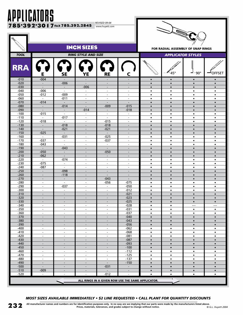
APPLICATORSREVISED 09-04
MOST SIZES AVAILABLE IMMEDIATELY • $2 LINE REQUESTED • CALL PLANT FOR QUANTITY DISCOUNTS
232
785•392•3017 FAX 785.392.2845
All manufacturer names and numbers are for identification purposes only. In no way are we implying that our parts were made by the manufacturers listed above.Prices, materials, tolerances, and grades subject to change without notice. © G.L. Huyett 2004
www.huyett.com
INCH SIZES FOR RADIAL ASSEMBLY OF SNAP RINGS
E
TOOL RINg STYLE AND SIZE APPLICATOR STYLES
SE YE RE C•••••••••••••••••••••••••••••••••---••••••••••••••••••
-004--
-006-012
--014
--
-015-
-018--
-025-
-037-043
--050-062
--075-087
--------------------------
-009-
--006
--
-009-011
--014
--
-017-
-018-021
--031
--
-043--
-074--
-098-118
--
-037-----------------------
--
-006-----
-014-------------------------------------------
-------
-009---
-015-018-021
--025-037
--
-050------
-043-056
---------------------
-031-
-012
-------
-015-018
------------------
-075-050-012-021-023-025-028-031-037-040-043-056-062-068-081-087-093-100-112-125-137-150
---
-010-020-030-040-050-060-070-080-090-100-110-120-130-140-150-160-170-180-190-200-210-220-230-240-250-260-270-280-290-300-310-320-330-340-350-360-370-380-390-400-410-420-430-440-450-460-470-480-490-500-510-520
45° 90°
•••••••••••••••••••••••••••••••••---••••••••••••••••••
••••••••••••••••••••••••••••••••••••••••••••••••••••
RRA
ALL RINGS IN A GIVEN ROW USE THE SAME APPLICATOR.
••••••••••••••••••••••••••••••••••••••••••••••••••••
OFFSET
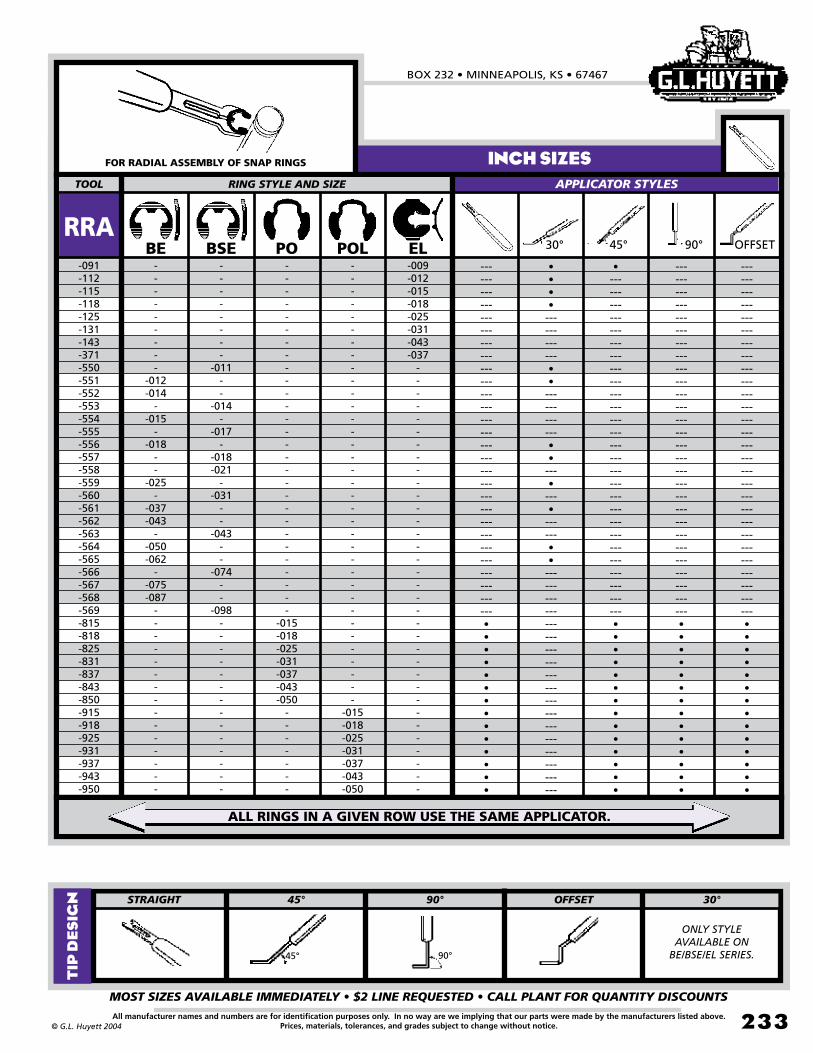
BOX 232 • MINNEAPOLIS, KS • 67467
MOST SIZES AVAILABLE IMMEDIATELY • $2 LINE REQUESTED • CALL PLANT FOR QUANTITY DISCOUNTS
233All manufacturer names and numbers are for identification purposes only. In no way are we implying that our parts were made by the manufacturers listed above.Prices, materials, tolerances, and grades subject to change without notice.© G.L. Huyett 2004
INCH SIZESFOR RADIAL ASSEMBLY OF SNAP RINGS
BE
TOOL RINg STYLE AND SIZE APPLICATOR STYLES
BSE PO POL EL------------------------------------------------------------------------------------••••••••••••••
---------
-012-014
--015
--018
--
-025-
-037-043
--050-062
--075-087
---------------
--------
-011--
-014-
-017-
-018-021
--031
--
-043--
-074--
-098--------------
----------------------------
-015-018-025-031-037-043-050
-------
-----------------------------------
-015-018-025-031-037-043-050
-009-012-015-018-025-031-043-037
----------------------------------
-091-112-115-118-125-131-143-371-550-551-552-553-554-555-556-557-558-559-560-561-562-563-564-565-566-567-568-569-815-818-825-831-837-843-850-915-918-925-931-937-943-950
------------------------------------------------------------------------------------••••••••••••••
•---------------------------------------------------------------------------------••••••••••••••
RRA••••------------••------------••---•---•------••------------------------------------------------------
30°
ALL RINGS IN A GIVEN ROW USE THE SAME APPLICATOR.
STRAIgHT OFFSET 30°45° 90°
ONLY STYLE AVAILABLE ON
BE/BSE/EL SERIES.45° 90°
TIP
DE
SIG
N
--- ---------------------------------------------------------------------------------••••••••••••••
45° 90° OFFSET
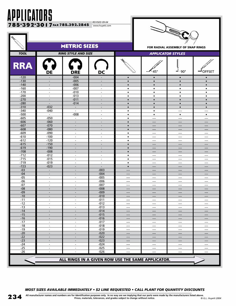
APPLICATORSREVISED 09-04
MOST SIZES AVAILABLE IMMEDIATELY • $2 LINE REQUESTED • CALL PLANT FOR QUANTITY DISCOUNTS
234
785•392•3017 FAX 785.392.2845
All manufacturer names and numbers are for identification purposes only. In no way are we implying that our parts were made by the manufacturers listed above.Prices, materials, tolerances, and grades subject to change without notice. © G.L. Huyett 2004
www.huyett.com
METRIC SIZES FOR RADIAL ASSEMBLY OF SNAP RINGS
DE
TOOL RINg STYLE AND SIZE APPLICATOR STYLES
DRE DC•••••••••---•---------------------------------------------------------------------------------------------------------------
--------
-032-040
--050-060-070-080-090-100-120-150-190-008-012-015-019-023
-----------------------
-004-005-006-007-010-013-011-014
--
-008-------------------------------------
-------------------------
-003-004-005-006-007-008-009-010-011-012-013-014-015-016-017-018-019-020-022-023-024-025-026
-120-130-140-160-170-200-270-280-310-340-500-605-606-607-608-609-610-612-615-619-708-712-715-719-723-03-04-05-06-07-08-09-10-11-12-13-14-15-16-17-18-19-20-22-23-24-25-26
•••••••••---•---------------------------------------------------------------------------------------------------------------
•••••••••••---------------------------------------------------------------------------------------------------------------
RRA
ALL RINGS IN A GIVEN ROW USE THE SAME APPLICATOR.
•••••••••••••••••••••••••---------------------------------------------------------------------
45° 90° OFFSET
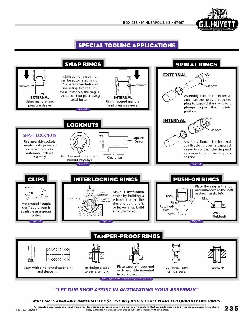
BOX 232 • MINNEAPOLIS, KS • 67467
MOST SIZES AVAILABLE IMMEDIATELY • $2 LINE REQUESTED • CALL PLANT FOR QUANTITY DISCOUNTS
235All manufacturer names and numbers are for identification purposes only. In no way are we implying that our parts were made by the manufacturers listed above.Prices, materials, tolerances, and grades subject to change without notice.© G.L. Huyett 2004
SHAFT LOCKNUTSUse assembly sockets
coupled with powered drive wrenches to automate locknut
assembly.2”
Clearance
SquareDrive
Notches match standard locknut keyways
EXTERNAL
Assembly fixture for external applications uses a tapered plug to expand the ring and a plunger to push the ring into position.
GROOVE
INTERNAL
Assembly fixture for internal applications uses a tapered sleeve to contract the ring and a plunger to push the ring into position.
GROOVE
Installation of snap rings can be automated using 6° tapered mandrels and
mounting fixtures. In these instances, the ring is “snapped” into place using
axial force.EXTERNAL
Using mandrel and pressure sleeve.
INTERNALUsing tapered mandrel
and pressure sleeve.
GROOVEGROOVE
LOCKNUTS
SPIRAL RINGSSNAP RINGS
Make LC installation easier by building a V-block fixture like the one at the left, or let our shop build a fixture for you!
Tapping Block
LC/DLC ring
Shaft Diameter
Groove Diameter
Automated “staple gun” equipment is
available as a special order.
INTERLOCKING RINGSCLIPS
Tool
Ring
Shaft
Retained Part
Finished!
Place the ring in the tool and push down on the shaft as shown at the left.
Ring
PUSH-ON RINGS
Start with a hollowed taper pin and sleeve . . .
Finished!. . . install part using sleeve.
Place taper pin over end with assembly mounted in work piece . . .
. . . or design a taper into the assembly.
TAMPER-PROOF RINGS
See page 15 for sleeve and pin dimensions.
Page 24 Page 32 Page 90
Page 34
Page 4
Page 126
SPECIAL TOOLING APPLICATIONS
“LET OUR SHOP ASSIST IN AUTOMATINg YOUR ASSEMBLY”

PART NUMBER CROSS REFERENCEREVISED 09-04
MOST SIZES AVAILABLE IMMEDIATELY • $2 LINE REQUESTED • CALL PLANT FOR QUANTITY DISCOUNTS
236
785•392•3017 FAX 785.392.2845
All manufacturer names and numbers are for identification purposes only. In no way are we implying that our parts were made by the manufacturers listed above.Prices, materials, tolerances, and grades subject to change without notice. © G.L. Huyett 2004
www.huyett.com
Page #HuyettPart #
471
472
983
984
988
988PS
988SS
1000
1001
1200
2000
3000
3001
3100
3101
3215
3217
4000
4100
5005
5008
5100
5101
5102
5103
5105
5107
5108
5115
5131
5133
5135
5139
5144
5160
5300
5304
5305
5555
5560
5590
5900
6000
6100
6799
7100
7200
7993A
7993B
9000
DSH
DHO
DAK
DJK
SS/PS
PS
SS
E
BE
RE
C
HO
BHO
SH
BSH
RE
SHR
HOI
SHI
TI
HOI
SH
BSH
VSH
C
TY
LC
SHI
TX
BE
E
RG
EL
RE
SHR
NTR
PO
TR
SHF
SHM
PSW
SS
TI
TY
DE
SHF
SHR
DRP
DRB
HO
152
166
162
175
146/147
147
146
26
28
27
32
16
20
6
11
27
9
19
10
93
19
6
11
12
32
92
31
10
92
28
26
27
33
27
9
97
30
97
14
15
112
146
93
92
182
14
9
202
203
16
HOW TO USE THIS CROSS REFERENCE:1. Locate your part number in the part
number column.2. Note the Huyett part number.3. Find the page number, and you’ve found
the part.
Mfg.
DIN
DIN
DIN
DIN
DIN
Ellison
Ellison
IRR
IRR
IRR
IRR
IRR
IRR
IRR
IRR
Military
Military
IRR
IRR
Waldes
Waldes
Waldes
Waldes
Waldes
Waldes
Waldes
Waldes
Waldes
Waldes
Waldes
Waldes
Waldes
Waldes
Waldes
Waldes
Waldes
Waldes
Waldes
Waldes
Waldes
Waldes
Waldes
IRR
IRR
DIN
IRR
IRR
DIN
DIN
Ellison
Page #HuyettPart #
9002
9100
9103
9133
16624
16625
16626
16627
16628
16629
16630
16631
16632
16633
16634
73123/73130
90707
100 SERIES
200 SERIES
23 SERIES
300 SERIES
400 SERIES
A
A0500
A0600
A0700
A0900
A1000
A1100
A1200
A1500
AK
AL
AN
AS (Clip)
AS (Snap)
AS3215
AS3216
AS3217
AS3218
AV
AW
B1500
BE
BHO
BN809-812
BN814
BN815
BN818-820
BN821
VHO
SH
C
DE9
SH
HO
SHI
HOI
BSH
BHO
VSH
VHO
C
E
BE
S
SHF
XRC
XRO
BPX
XSC
XSO
DSH
TRC
XSO
XSC
XRC
A10
BPXZ
A12
A15
DAK
DAL
AN
DBS
DSHR
RRN
RSN
RR
RS
DSHI
DBSH
EBS
BE
BHO
DE
DBS
DU
DSH
DSHR
22
6
32
185
6
16
10
19
11
20
12
22
32
26
28
105
14
86
84
106
82
80
152
88
80
82
86
87
106
104
29
162
163
132
185
158
58
44
52
38
160
161
184
28
20
182
185
185
152
158
Mfg. Page #HuyettPart #
BN822-823
BN824
BN829
BN830
BN831
BN832
BR
BSH
C
C-H
C-L
C-M
CMH
CML
CMM
D
D1300
D1400
D1460
D1500
D2000
D2100
DC
DE
DHO
DNH
DNS
DSH
DTI
DTX
E
EH
EJB
EL
EN
ES
ESB
ESP
ESW
EXT
EXTV
G
GA
GR
H
HO
HOI
HPC
IN
INT
DHO
DHOR
DSHI
DHOI
DC
DSHX
BR
BSH
C
CMH
CML
CMM
CMH
CML
CMM
DTR
DHO
DSH
DSHR
DE
DJK
DAK
DC
DE
DHO
DH
DS
DSH
DTI
DTX
E
DAH
DVHO
EL
USH
DAS
DSB
DSP
DSW
DSHR
DSHI
DSHX
DSHF
DSHX
DC
HO
HOI
BPX
UHO
DHOR
166
171
160
172
186
165
64
11
32
124
120
122
124
120
122
213
166
152
158
182
175
162
186
182
166
194
190
152
212
212
26
196
174
33
71
192
208
205
206
158
160
165
164
165
186
16
19
106
76
171
Mfg.
Bossard
Bossard
Bossard
Bossard
Bossard
Bossard
Spirolox
Rotor Clip
Rotor Clip
Smalley
Smalley
Smalley
Spirolox
Spirolox
Spirolox
Seeger
Anderton
Anderton
Anderton
Anderton
Anderton
Anderton
Rotor Clip
Rotor Clip
Rotor Clip
Smalley
Smalley
Rotor Clip
Rotor Clip
Rotor Clip
Rotor Clip
Smalley
Ellison
Rotor Clip
Eaton
Smalley
Ellison
Ellison
Ellison
Ellison
Ellison
Seeger
Seeger
Ellison
Ellison
Rotor Clip
Rotor Clip
Hubbard
Eaton
Ellison
Ellison
Ellison
Ellison
Ellison
Military
Military
Military
Military
Military
Military
Military
Military
Military
Military
Military
DIN
Military
Eaton
Eaton
ITW
Eaton
Eaton
Seeger
Anderton
Anderton
Anderton
Anderton
Anderton
Anderton
Anderton
Anderton
Seeger
Seeger
Whittet-Higgins
Benzing
Seeger
Aerospace
Aerospace
Aerospace
Aerospace
Seeger
Seeger
Anderton
Rotor Clip
Rotor Clip
Bossard
Bossard
Bossard
Bossard
Bossard
Part # Part # Part #
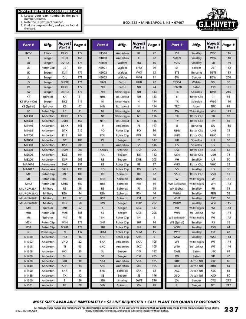
BOX 232 • MINNEAPOLIS, KS • 67467
MOST SIZES AVAILABLE IMMEDIATELY • $2 LINE REQUESTED • CALL PLANT FOR QUANTITY DISCOUNTS
237All manufacturer names and numbers are for identification purposes only. In no way are we implying that our parts were made by the manufacturers listed above.Prices, materials, tolerances, and grades subject to change without notice.© G.L. Huyett 2004
HOW TO USE THIS CROSS REFERENCE:1. Locate your part number in the part
number column.2. Note the Huyett part number.3. Find the page number, and you’ve found
the part.
Page #HuyettPart #
INTV
J
JB
JE
JK
JL
JS
JV
JW
KR
KS (Push-On)
KS (Spiral)
LC
M1308
M1408
M1440
M1465
M1700
M1800
M2300
M2400
M2500
M3200
MA4016
MA4017
MC
ME
MHO
MIL-R-27426A1
MIL-R-27426A2
MIL-R-27426B1
MIL-R-27426B2
MR
MRE
MS
MSH
MSR
N
N1300
N1302
N1305
N1308
N1400
N1408
N1440
N1460
N1465
N1500
N1501
DHOI
DHO
DVHO
JE
DJK
DJL
DHOR
DHOI
DBHO
KR
DKS
KS
LC
DHOI
DSHI
DSHX
DTX
D17
DC
DSB
DSW
D25
DSP
DAS
DAH
MC
ME
MHO
RS
RSN
RR
RRN
MR
MRE
MS
MSH
MSHR
N
HO
VHO
TI
HOI
SH
SHI
SHF
SHR
TX
E
BE
172
166
174
184
175
177
171
172
173
61
213
47
31
172
160
165
212
204
186
208
206
104
205
192
196
189
188
180
38
44
52
58
62
188
48
178
179
132
16
22
93
19
6
10
14
9
92
26
28
Mfg.
Ellison
Seeger
Seeger
Rotor Clip
Seeger
Seeger
Seeger
Seeger
Seeger
Spirolox
Seeger
Spirolox
Rotor Clip
Anderton
Anderton
Anderton
Anderton
Anderton
Anderton
Anderton
Anderton
Anderton
Anderton
Aerospace
Aerospace
Rotor Clip
Rotor Clip
Rotor Clip
Military
Military
Military
Military
Spirolox
Rotor Clip
Spirolox
Rotor Clip
Rotor Clip
Whittet-Higgins
Anderton
Anderton
Anderton
Anderton
Anderton
Anderton
Anderton
Anderton
Anderton
Anderton
Anderton
Page #HuyettPart #
N1540
N1800
N5000
N5001
N5002
N5003
NAN
ND
NH
NHE
NI
NIN
NL
NT
NTH
P
PO
POL
PS
R
R Series
RA
RB
RE
RG
RR
RRN
RRT
RS
RSN
RST
RW
S
SB
SH
SHF
SHI
SHM
SHR
SKA
SKC
SL
SP
SRA
SRC
SRN
SS
SSB
SSN
RE
C
HO
BHO
VHO
VVH
UHB
ND
NH
NH
NI
NI
NL
NT
NT
PS
PO
POL
PS
SS
DSP
DE
DRB
RE
RG
RR
RRN
RRT
RS
RSN
RST
DRP
DLC
DSB
SH
SHF
SHI
SHM
SHR
SKA
SKC
DEL
DSP
SRA
SRC
SRN
SS
DWS
SSN
27
32
16
20
22
21
72
74
133
133
134
134
135
136
136
147
30
30
147
146
205
182
203
27
27
52
58
56
38
44
42
202
187
208
6
14
10
15
9
105
105
187
205
105
105
63
146
216
49
Mfg.
Anderton
Anderton
Waldes
Waldes
Waldes
Waldes
Eaton
Eaton
Whittet-Higgins
Std. Locknut
Whittet-Higgins
Std. Locknut
Whittet-Higgins
Whittet-Higgins
Std. Locknut
Anderton
Rotor Clip
Rotor Clip
Seeger
Anderton
Peterson
Seeger
Seeger
Rotor Clip
Rotor Clip
Spirolox
Spirolox
Spirolox
Spirolox
Spirolox
Spirolox
Seeger
Seeger
Seeger
Rotor Clip
Rotor Clip
Rotor Clip
Rotor Clip
Rotor Clip
Anderton
Anderton
Seeger
Seeger
Anderton
Anderton
Spirolox
Seeger
Smalley
Spirolox
Page #HuyettPart #
SSR
SSR-N
SSRS
ST
STS
SW
T5304
T99220
TB
TI
TR
TRC
TW
TX
TY
U
UHB
UHO
UR
US
USC
USH
VH
VHO
VS
VSH
W
WH (Lockwasher)
WH (Spiral)
WHM
WHT
WHW
WI
WIN
WS (Lockwasher)
WS (Spiral)
WSM
WST
WSW
WT
WTH
XAN
XD
XRC
XRO
XSC
XSO
ZA
ZJ
WSG
WSN
SR
DST
DSTS
DSW
POL
T99
DWS
TI
WSG
TRC
WH
TX
TY
DU
UHB
UHO
UR
US
USC
USH
UR
VHO
US
VSH
W
WH
RR
RRN
RRT
WSI
WI
WI
WS
RS
RSN
RST
WSE
WT
WT
USC
XD
XRC
XRO
XSC
XSO
DTX
DTI
116
118
149
183
185
206
30
101
216
93
116
88
143
92
92
185
72
76
50
36
68
71
50
22
36
12
141
143
52
58
56
115
144
144
142
38
44
42
114
144
144
68
70
86
84
82
80
212
212
Mfg.
Smalley
Smalley
Smalley
Seeger
Benzing
Seeger
Waldes
Eaton
Spirolox
Rotor Clip
Spirolox
Arcon
Whittet-Higgins
Rotor Clip
Rotor Clip
Benzing
Rotor Clip
Rotor Clip
Spirolox
Spirolox
Rotor Clip
Rotor Clip
Smalley
Rotor Clip
Smalley
Rotor Clip
Whittet-Higgins
Whittet-Higgins
Smalley
Smalley
Smalley
Smalley
Whittet-Higgins
Std. Locknut
Whittet-Higgins
Smalley
Smalley
Smalley
Smalley
Whittet-Higgins
Std. Locknut
Eaton
Eaton
Arcon Ntl
Arcon Ntl
Arcon Ntl
Arcon Ntl
Seeger
Seeger
Part # Part # Part #

GENERAL COMODITIES