retail food establishments planning resource
TRANSCRIPT

S.C. Department of Health and Environmental Control
RETAIL FOOD ESTABLISHMENTS PLANNING RESOURCE
Planning, Designing, Constructing and Equipping a Retail Food Establishment
March 2021

Table of Contents
Retail Food Establishments Introduction ..............................................................................................................................1
Planning ....................................................................................................................................2 List of Foods to be Served (Menu) ....................................................................................................... 2
Food Handling Procedures and Processes .......................................................................................... 2
Design and Construction .........................................................................................................6 Location: Living and Sleeping Quarters ................................................................................................ 6
Plumbing .............................................................................................................................................. 6
Finishes (Indoor) ................................................................................................................................ 13
Finishes: Outdoor (Premises) ............................................................................................................. 17
Storage .............................................................................................................................................. 17
Pest Control ....................................................................................................................................... 19
Lighting .............................................................................................................................................. 20
Toilet Rooms, Employee Designated Areas ....................................................................................... 20
Equipment ............................................................................................................................... 22 Design and Construction .................................................................................................................... 22
Installation .......................................................................................................................................... 23
Protection for Foods on Display ......................................................................................................... 28
Warewashing Equipment ................................................................................................................... 30
Sinks .................................................................................................................................................. 32
Refrigeration ...................................................................................................................................... 34
Additional Retail Food Establishment Operations .............................................................. 37 Mobile Food Establishment .................................................................................................................. 37 Commissary ....................................................................................................................................... 37
Mobile Food Unit and Mobile Food Pushcart ...................................................................................... 38
Immediate Outdoor Cooking ................................................................................................................ 45 Design and Construction .................................................................................................................... 46
Barbecue Pit and Pit Cooking Room .................................................................................................... 49 Design and Construction .................................................................................................................... 49
Equipment .......................................................................................................................................... 51
General Guidance................................................................................................................... 52
1
Retail Food Establishments Introduction
This Retail Food Establishment Planning Resource is intended to aid the owner, equipment dealers, architects, engineers, consultants and others in the food industry with good manufacturing practices for planning, constructing and equipping a retail food establishment to meet Regulation 61-25 requirements.
The goal of this guide is to promote uniform design and construction of retail food establishments that are conducive to safe food handling. Properly designed and equipped retail food establishments promote good cleaning and maintenance practices. While all types of equipment and conditions are not covered, the fundamental concepts conveyed may be applied in all installations.
For minimum requirements please refer to South Carolina Department of Health and Environmental Control, Regulation 61-25, Retail Food Establishments. Minimum requirements may not ensure the best possible conditions for your facility.
This planning resource designed is to assist in the development of retail food establishments; it is not an official part of Regulation 61-25.
The submission of plans and specifications may be required by other agencies depending upon the type of facility being constructed, remodeled or renovated. It is recommended that the Fire, Mechanical, Plumbing and Building Code officials are contacted regarding local requirements related to the retail food establishment.

2
Planning
List of Foods to be Served (Menu)
Having an idea of the types of foods that are to be prepared and served will help in determining the types of equipment needed. Identifying the main ingredients used to prepare each food will also help determine the amount of space needed in the retail food establishment for storage and preparation.
Food Handling Procedures and Processes
Once the types of foods to be prepared and served are determined, the next step is to decide how each food item will be handled to include preparation, storage, cooking, refrigerating, displaying, etc.
Descriptions, including specific areas of the food service establishment where foods are handled, will provide a guide to planning the layout of food equipment for an effective workflow. It is also easier to determine the types and quantities of food equipment needed when the processes used to prepare foods are known.
Following are workspaces that may be used in laying out handling procedures and processes needed for foods prepared in the retail food establishment. Description of the process from receiving to ready-to-eat should include:
• How the food will arrive (frozen, fresh, packaged, etc.). • Where the food will be stored (cooler, freezer, dry storage). • Where the food will be handled (prep table, sink, counter, etc.). • How the food will be handled (washed, cut, marinated, breaded, cooked, etc.). • When food will be handled (time of day and frequency/day).
Ready-to-Eat Food Handling Examples: salads, cold sandwiches, raw oysters, raw clams, cut fruit, etc.
Poultry Handling

3
Meat Handling
Seafood Handling
_
Sushi Preparation
Produce Handling
Dry Storage
A retail food establishment whose operation involves a special food process or procedure such as smoking, curing, sushi rice, reduced oxygen packaging (ROP), sous vide, or cook/chill must submit in writing a request for modification or waiver to the Department for review and approval.
Anticipated Volume of Food
Estimating the number of meals to be served/sold will help with determining the types and quantities of cooking and refrigeration equipment needed and, the size of the dry storage area and/or frequency of supply deliveries needed. It will also help in determining the size of the food preparation area(s) needed.

4
Sections below are provided as workspaces for thawing, cooling and reheating procedures.
Reheating for Hot Holding Identify time/temperature control for safety (TCS) foods reheated to at least 165oF (74oC) within 2 hours. Ready-to-eat (RTE) commercially processed foods may be heated to at least 135oF (57oC).
Food Item Method of Reheating RTE?
Yes No
Yes No
Yes No
Yes No
Thawing Process Check appropriate boxes to indicate how food in each category will be thawed.
Cooling Process Check appropriate boxes (TCS) foods are to be cooled to 70oF (21oC) within 2 hours and to 41oF (5oC) within another 4 hours.
Meat Seafood Poultry Other (describe food type)
Shallow Pans in Refrigeration
Ice baths
Rapid Chill
Other Method

5
Possible Food Process Step Needs No Cook Step X X X X X X Cook and Serve X X X X X X X Complex Processes X X X X X X X X X
R
ecei
ve
St
ore
Pr
epar
e
C
ook
C
ool
R
ehea
t
Th
awin
g
H
old
Se
rvic
e Anticipated Equipment, Utensil, Supply Needs
Thermometer ● ● ● ● ● ● ●
Dry Storage ●
Refrigerated Storage (Walk-in) ● ● ● ●
Frozen Storage ** (Walk-in) ● ●
Tables (Prep) ● ●
Cutting Board(s) ● ●
Utensils ● ● ● ●
Sink (Prep) ● ●
Coolers (Prep, Reach-in, etc.) * ● ● ● ● ●
Freezers ** ● ● ● ●
Fryer ● ●
Oven ● ● ●
Charbroiler ● ●
Griddle ● ●
Cook Top/Burner ● ● ●
Ice Bath ●
Blast Chiller ●
Pans (Shallow) ● ● ● ●
Ice Paddle ●
Cold Holding/Service ● ●
Hot Holding/Service ᴓ ●
Food Warmer ᴓ
Microwave ● ● ●
Other:
Other:
* Preparation coolers (including low boys) are not designed for long-term storage. Reach-in coolers (and similar equipment) are not designed for quick chilling of foods.
** Frozen storage units and freezers can promote cooling of foods but are not designed for quick chilling of foods. ᴓ Would not apply to “No Cook Step”.
6
Design and Construction
Location: Living and Sleeping Quarters
When the location of the retail food establishment is being considered, the following areas may not be used to conduct retail food establishment operations:
• A private home kitchen. • A room used or directly opening into a room used as living or sleeping quarters.
On premises living and sleeping quarters provided for lodging registration clerks or resident managers must be separated from rooms and areas used for retail food establishment operations.
Plumbing
Drinking Water Supply
When constructing a retail food establishment or considering an existing structure, it is important to ensure that the drinking water supply at the site is from an approved source that is:
• A public water system of a city, town or other municipality. • A public water system (e.g. well) constructed for use by the retail food establishment. • Of sufficient capacity to meet peak water demands.
The city, town or other municipality, where the retail food establishment will be located should be contacted to determine availability and other information on the public water system.
For information and requirements on a public water system, such as a well, constructed for use by the retail food establishment, contact the local Environmental Affairs (EA) office for the Bureau of Water.
Backflow Prevention (Water)
To protect the drinking water supply from contamination by questionable water, chemicals or other source of pollution, a method of backflow prevention must be provided at each point of use at the retail food establishment. It is important that the backflow prevention method or device chosen meets the protection needs at each point of use.
Air Gap
An air gap is a non-mechanical means of backflow prevention. It is a clear vertical separation between the drinking water supply inlet and the flood level rim of the plumbing fixture.
NOTE: The main backflow prevention device that may be required by the drinking water supplier protects the main water supply only. In other words, it protects others from potential contamination that may occur inside your facility. It does not provide protection from possible contamination within your facility.

7
Backflow Prevention Devices
An air gap between the drinking water supply inlet and the flood level rim of the plumbing fixture, equipment or non-food equipment must be at least twice (2x) the diameter (D) of the water supply inlet and may not be less than 1 inch (25mm).
It is recommended that the water supply inlet is rigidly mounted to ensure the appropriate air gap is maintained. A hose that extends below the flood level rim of the plumbing fixture or reduces the minimum required air gap distance should not be installed on the water supply inlet.
An air gap may not be suitable for all applications.
Backflow prevention devices must meet American Society of Sanitary Engineering (ASSE) standards specified for the application. When installed the device must meet the specific application and type of device, and be easily accessible for inspection and servicing.
Although some backflow prevention devices may look similar on the outside, inside components determine whether the device is designed for continuous or non-continuous pressure applications.
Following are examples of some commonly used backflow prevention devices in retail food establishments. The descriptions are a general summary of how the devices work. For additional information on the performance and installation of any of the devices, a plumber should be consulted.
Atmospheric Vacuum Breaker (AVB)
An atmospheric vacuum breaker (dome shaped) is not designed for constant pressure. If subjected to long periods of continuous pressure, the device may malfunction.
The AVB must be installed downstream of the shutoff valve and at least 6 inches above the highest outlet and/or overflow rim of the potential source of contamination. When an AVB is installed for a disposal or similar equipment, it should extend through the backsplash of the drainboard or soiled dish table.
Because the AVB is not designed for continuous pressure:
• Valves should not be installed downstream of the AVB. • If used, the spray nozzle should be removed from the hose after each use so that the AVB cannot be
left under continuous pressure. • A hose equipped with a spray nozzle that is to remain connected must be turned off at the faucet and
the hose drained (bled) after each use.
NOTE: A simple untested check valve is not very reliable and is not considered an acceptable method of backflow prevention.

8
Examples of equipment where atmospheric vacuum breakers are often installed:
• Mop sink spigots. • Mechanical warewashers. • Disposals. • Chemical dispensers. • Garbage can washers (usually installed in the drain of mop sinks or can wash basins).
Hose Bibb Vacuum Breaker
A hose bibb vacuum breaker is another type of atmospheric vacuum breaker. It is usually installed at the hose bib of a mop sink, can wash or other location where a hose may be attached. Because a hose bib vacuum breaker is not designed for continuous pressure, a pressure spray nozzle should not remain attached at the end of a hose when not in use.
Pressure Vacuum Breaker (PVB)
The pressure vacuum breaker looks almost like the AVB in that it also has a dome shaped top. However, a pressure vacuum breaker is designed for use in a continuous pressure application. It is also equipped with test cocks that allow the device to be performance tested.
The PVB must be installed at least 12 inches above the highest outlet and/or overflow rim of the potential source of contamination.
Pressure vacuum breakers are often installed on hose reel assemblies.

9
Dual-Check Valve Backflow Preventer
The dual-check valve backflow preventer is designed for continuous pressure applications. It operates efficiently when installed vertically or horizontally.
Examples of equipment where dual-check valve backflow preventers are often installed:
• Mop sink spigots (Used where a spray nozzle is attached at the end of a hose). • Water connections to food service equipment (e.g. steamers, combi-therm ovens, rack ovens,
beverage dispensers, coffee brewers, specialty coffee makers, tea brewers, ice machines, rotisserie ovens, water chillers).
• Submerged water inlets on food service equipment (e.g. pasta cookers, rethermalizers, woks, scrapping troughs, steam tables).
• Waste pulpers (drinking water supply line). • Disposals (drinking water supply line). • Chemical dispensers. • Hose reel assemblies.
Dual-Check Valve Backflow Preventer with Intermediate Atmospheric Vent
The dual-check valve backflow preventer with intermediate atmospheric vent is designed for continuous pressure applications. If a backpressure event should occur and if the second check valve is unable to close tightly, leakage will drain through the vent port.
The dual-check valve backflow preventer with intermediate atmospheric vent is often installed at a carbonator. For additional installation information when this device is used at a carbonator, see R.61-25, 5- 203.15.
NOTE: Installing two (2) hose bib vacuum breakers in-line is not equivalent to a dual-check valve backflow preventer and does not create a continuous pressure device.

10
Sewage Disposal
When constructing a retail food establishment or considering an existing structure, it is important to ensure that liquid waste containing animal or vegetable matter (sewage), that may also include chemicals, is disposed through one of the following approved facilities:
• A public sewage treatment plant. • An individual sewage disposal system.
The city, town, other municipality or individual sewer purveyor that provides the public sewage system, where the retail food establishment will be located, should be contacted for availability and other information on the sewage disposal system.
For information and requirements on an individual sewage disposal system, such as a septic tank, constructed for use by the retail food establishment, contact the local Environmental Affairs (EA) office for Onsite Wastewater.
Backflow Prevention (Sewage)
A direct connection may not exist between the sewerage system and any drains connected to equipment in which food, portable equipment or utensils are placed.
Drains
Indirect drainage may be accomplished by using floor sinks, hub drains, floor drains or floor troughs. The drain(s) chosen should be sized and positioned to effectively prevent or minimize liquid waste from splashing or running across the floor. For assistance in determining the type of drain(s) needed, a plumber should be consulted.
Drains for food equipment should be positioned so that they are accessible for maintenance.
Floor drains should be provided when floors are to be water-flushed for cleaning and/or where clean-in-place equipment is to be installed.
NOTES: o Liquid waste drain lines must not pass through an ice machine or ice storage bin. o A warewashing or food preparation (culinary) sink may have a direct connection, unless otherwise
required by law. A mechanical warewasher may have a direct connection between its waste outlet and a floor drain when the warewasher is located within 5 feet of a trapped floor drain and the warewasher outlet is connected to the inlet side of a properly vented floor drain trap.

11
Floor drains, floor sinks and troughs should be installed so that they are even (flush) with the finished floor. A raised drain may result in the pooling of water or the collection of debris around the rim of the drain. When the floor slopes to the drain the transition should be consistent and smooth. An uneven transition may result in water and food collecting in crevices between the floor and the drain.
Examples of equipment where indirect drainage is used:
• Steam tables (hot wells), cold wells (ice). • Steamers, rotisserie ovens, pasta cookers,
rethermalizers. • Rack ovens, combi-therm ovens, wok stoves,
proofers. • Beverage dispensers, ice machines, ice bins,
dipper wells, water chillers. • Mechanical warewashers.
Condensate from walk-in refrigeration units should be drained using one of the following methods:
• Indirectly drained to a floor drain or hub drain that is accessible for cleaning and maintenance. • Drained to an exterior dry well. • Drained using another disposal method that does not create a nuisance.
Grease Trap/Grease Interceptor
The purpose of a grease trap or a grease interceptor is to reduce the amount of fat, oil and grease (FOG) that enters a sewage disposal system. Whether a grease trap or grease interceptor is required is determined by the city, town, other municipality or individual sewer purveyor that provides services to the retail food establishment. The service provider should be contacted for grease trap/grease interceptor sizing information and other requirements.
For information on an individual sewage disposal system and grease traps or grease interceptors, refer to South Carolina Department of Health & Environmental Control, Regulation 61-56, Onsite Wastewater Systems.
Grease Trap
When installed, a grease trap must be located outside so that it is easily accessible for cleaning and maintenance. However, when the building is the property line, a grease trap may be installed inside the retail food establishment provided it meets the following installation requirements.
A grease trap located inside a retail food establishment must not be installed in:
• Food preparation, dispensing or storage areas. • Food equipment storage areas. • Equipment and utensil washing areas. • Single-service articles storage areas.
Location of a grease trap inside must not result in servicing hoses and pumps having to run through the following areas to reach it:
• Food preparation, dispensing or storage areas. • Food equipment storage areas. • Equipment and utensil washing areas. • Single-service articles storage areas.
12
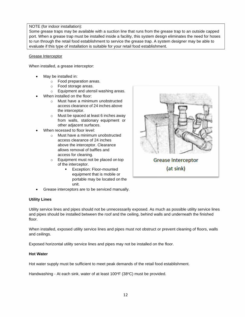
Grease Interceptor
When installed, a grease interceptor:
• May be installed in: o Food preparation areas. o Food storage areas. o Equipment and utensil washing areas.
• When installed on the floor: o Must have a minimum unobstructed
access clearance of 24 inches above the interceptor.
o Must be spaced at least 6 inches away from walls, stationary equipment or other adjacent surfaces.
• When recessed to floor level: o Must have a minimum unobstructed
access clearance of 24 inches above the interceptor. Clearance allows removal of baffles and access for cleaning.
o Equipment must not be placed on top of the interceptor.
Exception: Floor-mounted equipment that is mobile or portable may be located on the unit.
• Grease interceptors are to be serviced manually.
Utility Lines
Utility service lines and pipes should not be unnecessarily exposed. As much as possible utility service lines and pipes should be installed between the roof and the ceiling, behind walls and underneath the finished floor.
When installed, exposed utility service lines and pipes must not obstruct or prevent cleaning of floors, walls and ceilings.
Exposed horizontal utility service lines and pipes may not be installed on the floor.
Hot Water
Hot water supply must be sufficient to meet peak demands of the retail food establishment.
Handwashing - At each sink, water of at least 100oF (38oC) must be provided.
NOTE (for indoor installation): Some grease traps may be available with a suction line that runs from the grease trap to an outside capped port. When a grease trap must be installed inside a facility, this system design eliminates the need for hoses to run through the retail food establishment to service the grease trap. A system designer may be able to evaluate if this type of installation is suitable for your retail food establishment.

13
Manual warewashing - The wash solution in the sink must be maintained at a temperature of at least 110oF (43oC) or the temperature specified on the cleaning agent manufacturer’s label. When hot water sanitization is used at a manual warewashing sink, the sanitizing compartment must be provided with a system that will maintain a temperature of at least 171oF (77oC).
Mechanical warewashing machines (including glass washers) - Hot water provided must meet minimum temperature(s) specified on the warewashing machine’s data plate. Washing and sanitizing temperatures specified on the data plate usually range from 120oF (49oC) to180oF (82oC). The wash temperature for a chemical sanitizing mechanical warewasher may not be less than 120oF (49oC).
Hot water sanitizing temperatures entering the mechanical warewasher’s manifold may not exceed 194oF (90oC). A booster heater may be needed to ensure the minimum hot water temperature specified on the data plate is reached for the final rinse on a hot water sanitizing mechanical warewasher.
Ventilation
When necessary, ventilation of sufficient capacity should be provided to keep the facility free of excessive heat, steam, condensation, vapors, obnoxious odors, smoke and fumes.
When ventilation hood systems are installed in food preparation and warewashing areas, they should be designed to prevent grease or condensation from dripping or draining onto food, equipment or utensils.
Finishes (Indoor)
Indoor material finishes for floors, walls and ceilings must meet all requirements of Regulation 61-25, Retail Food Establishments; however, some construction materials require special considerations.
When deciding on the materials and finishes to install, consideration should be given to the amount of physical effort that may be required to clean and maintain the finish.
Finishes should be installed or applied according to manufacturer’s instructions.
Floors
Exposed concrete floors must be effectively sealed so that the surface is nonabsorbent.
In mechanical warewashing machine areas, floors such as terrazzo, quarry tile, epoxy, and sealed concrete are recommended due to proven durability. Vinyl composition tile (VCT) is not recommended underneath a mechanical warewashing machine because the moisture and heat generated by the equipment may affect the durability of the tile. High heat equipment such as fryers may also affect the durability of VCT.
There are ceramic tiles available that imitate natural stones such as slate and limestone. Like natural stones, some of the ceramic tiles are porous and absorbent. When installed in food preparation areas, warewashing areas, storage areas, other areas that support food service or toilet rooms, the tile should be sealed so that the surface is nonabsorbent and easily cleanable.
Porous and absorbent natural stone floors installed in food service, warewashing or storage areas should be sealed so that the surface is smooth, easily cleanable and nonabsorbent. In toilet rooms, floors must be cleanable and nonabsorbent. Some natural stones are soft and may not be durable when installed underneath heavy food equipment.
Rubber flooring is a durable material for food service operations provided the right flooring is chosen for the application. For example, rubber flooring designed for some sports surfaces tend to be light and spongy to

14
absorb impact. Impact absorbing sports flooring is not designed to support the heavy weight or withstand the heat of some food service equipment.
Vinyl sheet flooring (commercial) installed using weld rods to heat-weld seams, create a durable, unbroken, one-piece finish. Many textured designs provide slip resistance while having the ability to be easily cleaned and maintained.
Sealed wood flooring is acceptable when maintained in good repair. Polyurethane, urethane, epoxy or similar coatings may be applied to wood flooring to meet Chapter 6 criteria.
Anti-slip floor coverings, coatings or treatments may be used on floors. However, the application of abrasive, anti-slip coatings or treatments should be limited to traffic areas.
When provided, to effectively capture liquids and facilitate cleaning, floor drains and floor sinks should be installed so that they are flush (even) with the floor surface.
Cove Base
Junctures between the floor and walls must be coved. The cove base helps to make cleaning of the floor near walls easier and provides protection to walls at junctures. It is recommended that the cove has a minimum height of 4 inches and a radius of at least 1/4 inch.
The cove base should be smooth, durable, non-absorbent and easily cleanable. When water flush cleaning is used in a retail food establishment the transition between the flooring and the cove base should be smooth and cove junctures must be sealed.
Rubber and vinyl cove base, usually supplied in rolls or coils, that are often used in offices, school classrooms and other similar facilities are not recommended when floors are to be water flushed.

15
Walls
The area subject to moisture is considered the highest level that may be reached by splash or spray. The level of splash or spray is generally considered 4 to 5 feet above the finished floor. However, when large pieces of equipment such as mechanical warewashers or floor-mounted mixers are installed, the area of splash or spray may be as high as 8 feet above the finished floor.
Rooms used only for the storage of unopened packages or containers are exempt from wall finish requirements.
Brick and concrete block walls (CMU – Concrete Masonry Unit) in food preparation areas, equipment and utensil washing areas, and garbage storage rooms must have smooth, nonabsorbent and easily cleanable surfaces in areas subject to moisture.
Walls constructed of masonry products should be skim coated or provided with sufficient block filler to provide a smooth surface prior to applying a washable paint. The degree of smoothness desired on the filled masonry product should be thought of as “smooth as sheetrock.”
Block (Concrete Masonry Unit - CMU)
The following is offered as a solution to assist in meeting the minimum cleanability standards of block walls. It is recommended that a high solids block filler (greater than 50%) is applied to the block.
The following factors may affect the number of applications needed to render the block face smooth (like sheetrock) prior to painting:
• Density of the CMU – Less dense CMU tend to have more voids. • Surface of CMU – CMU may have a smooth or textured surface. • Method(s) used to apply block filler – e.g. trowel, paint sprayer, brush or roller.
Brick
When brick is chosen for “atmosphere” in areas where retail food operations occur, a clear coat finish appropriate for brick may be used; provided sufficient coats are applied to render a smooth, easily cleanable, nonabsorbent surface up to the highest level that may be reached by splash or spray.
Ovens with a brick finish should also have smooth, nonabsorbent and cleanable surfaces.
Wall Panels
Fiberglass Reinforced Polyester (FRP) panels, plastic laminated panels and similar wall panel materials should be installed using the appropriate molding or other means that will provide smooth, cleanable junctures.
Ceilings
Suspended ceilings with acoustical tile or other similar lay-in products may be installed in all areas, provided the lay-in products are easily removable for replacement or cleaning.
Rooms used only for the storage of unopened packages or containers are exempt from ceiling finish requirements.

16
SUGGESTIONS: To test a material under consideration in areas where finishes should be smooth, nonabsorbent and easily cleanable, spread mustard or ketchup on a sample and allow it to set for a least 30 minutes. Wipe and review the surface keeping in mind the following:
• Was a stain left on the surface? • Did the ketchup or mustard collect in grooves, crevices or divots? • Were chemicals and heavy scrubbing needed to clean the surface?
To test a material under consideration in areas where finishes should be nonabsorbent, place a few drops of water on a sample. Does the water bead on top of the surface or does the water soak into the surface?
Below is a workspace that may be used to chart the finishes to be used in each area.
Location Floors Walls Ceilings
Food Preparation (Kitchen)
Display Cooking/Preparation
Warewashing
Dry Storage
Walk-in Coolers/Freezers
Employee Toilet Room(s)
Customer Toilet Room(s)
Other:
Other:
Other:
Other:
Other:
Below are some commonly used abbreviations that may be helpful in using the workspace above.
ACT – Acoustical Ceiling Tile GWB or Gyp. – Gypsum Wall Board RF – Resinous Flooring Conc. – Concrete Mfr. or Mfg. – Manufacturer SS – Stainless Steel CMU – Concrete Masonry Unit (Block) PT – Porcelain Tile VCT – Vinyl Composition Tile CT – Ceramic Tile pnt – Paint VLT – Vinyl Lay-in Ceiling Tile Exp. – Exposed QT – Quarry Tile VWC – Vinyl Wallcovering FRP – Fiberglass Reinforced Panels

17
Finishes: Outdoor (Premises)
Outdoor walking and driving surfaces of the premises must be concrete, asphalt, gravel or other similar material. These types of materials minimize dusty and muddy conditions inside and outside the facility, as well as facilitate surface maintenance. The surface must also be graded to drain to prevent standing water.
Outdoor refuse, recyclables and returnables surfaces on the premises must be constructed of smooth, durable and nonabsorbent materials such as concrete or asphalt. The surfaces must also be graded to drain for the sanitary disposal of liquid waste (sewage) generated from cleaning the surfaces and equipment located in these areas. An enclosure, if provided for outdoor refuse, recyclables and returnables must be constructed of durable and cleanable materials.
Servicing area for a mobile food unit or mobile food pushcart must be constructed of smooth materials, such as concrete or asphalt, and must be properly drained. The servicing area must also be provided with overhead protection unless the area is used only for the loading of drinking water or the discharge of sewage and other liquid waste through a closed system of hoses.
Storage
The amount of storage equipment and area(s) needed may depend upon several of the following factors:
• Foods to be served (menu). • Number of meals served between deliveries. • Amount and type of single-service items to be stored. • Amount of TCS foods to be served/stored. • Amount of non-TCS foods and ingredients to be served/stored. • Amount and type of equipment and utensils to be stored. • Frequency of deliveries.
Food, food equipment and utensils may not be stored in the following locations :
• Locker rooms, toilet rooms, garbage rooms or mechanical rooms. • Underneath unshielded sewer lines, waters lines, leaking fire sprinkler
heads, lines on which water has condensed or open stairwells.
Laundered linens and single-service and single-use articles that are packaged or are stored in a cabinet may be stored in a locker room. However, these items may not be stored in the following locations:
• Toilet rooms, garbage rooms or mechanical rooms. • Underneath unshielded sewer lines, waters lines, leaking fire sprinkler heads, lines on which water
has condensed or open stairwells.
Equipment
Shelving, dollies, racks, etc. should be finished so that they are nonabsorbent, corrosion-resistant, durable and smooth. Peg boards are not recommended for use in food preparation and operations areas.
NOTE: Equipment and supplies (e.g. lawn mowers, weed trimmers, blowers, gasoline containers, pesticides and motor oils) used to maintain the exterior of the retail food establishment that are stored on the premises, must be stored to prevent contamination of food, food equipment, utensils and single service and single-use articles. Whenever possible a separate room or area should be provided for these items.

18
The lowest shelf must be at least 6 inches above the floor. This allows access for cleaning the floor underneath as well as provides some protection to food and equipment from splash during cleanup and from spills that may occur. It also discourages pest harborage areas underneath shelving.
When storing bulk foods such as flour, sugar, rice, grits and similar foods, food containers with tight-fitting covers should be used. Bulk food containers installed on casters or mounted on dollies allow the containers to be easily moved for cleaning.
Pallets should not be used for permanent storage and should be removed once they are emptied of the delivered content. Because of their design, pallets do not allow easy cleaning of the floor underneath and can become ideal pest harborage areas.
Milk crates should not be used as shelving. Once the delivered content of the milk crates has been emptied, they should be removed.
Refrigeration storage needs for the retail food establishment may include various reach-in coolers, freezers and walk-in refrigeration units. Reviewing the foods to be served for ingredients that require refrigeration, as well as the frequency of deliveries of TCS foods, should help in determining types and quantities of refrigeration needed. For additional guidance on refrigeration see Retail Food Establishments, Equipment, Refrigeration.
Area(s)
The dry storage area or room should be adjacent to the food preparation area and convenient to receiving.
STORAGE PLANNING EXAMPLE: Restaurant B plans to cook BBQ on a 5-ft. grill for buffet style dining. In addition, a range/oven, convection oven, steamer and a fryer will be installed to prepare vegetables, rice, mashed potatoes, breads, fries, chicken, fish and desserts. A small closet and two wall shelves will provide storage for single-service articles (to-go containers, forks, cups, napkins, etc.) and shelf-stable food ingredients. Because of limited space there is only room for a 2-door under-counter cooler; no walk-in cooler or freezer is installed.
In planning the retail food establishment, answering the following questions may have helped the owner better evaluate the facility’s storage needs:
• What TCS foods and ingredients require refrigeration upon delivery?
o Which of those delivered TCS foods and ingredients will be: Stored in a cooler(s)? Stored in a freezer(s)?
o What are the delivery quantities of each TCS food or ingredient? • How many days are between deliveries of TCS foods and ingredients? • Are there TCS foods that are to be prepared and stored under refrigeration for service at a later
date? In what quantities? • How many meals will be served between deliveries? • Will refrigeration space be needed for leftovers? How much? • How many to-go meals will the facility serve between deliveries? • What types and quantities of single service articles (cups, plates, utensils, etc.) will be stored for to-
go meals? • What non-TCS foods and ingredients require storage space?
CFP Plan Review for Food Establishments manual provides resources for sizing storage areas and refrigeration.

19
Pest Control
A retail food establishment must be designed and constructed to restrict the entrance of insects, rodents and other pests.
• Holes and other gaps along floors, walls and ceilings must be sealed. • Openings around pipes, conduit or wiring must be sealed. • Solid doors opening to the outside must be tight-fitting. Gaps may be closed by installing door
sweeps and/or weather-stripping made of rodent proof materials. • Solid doors opening to the outside should be self-closing or provided with interlocked air curtains (fly
fans). • Windows must be tight-fitting. Gaps may be closed by installing weather-stripping. • Service windows must be self-closing or provided with interlocked air curtains (fly fans). • When installed, screen doors should be tight-fitting and self-closing. • When installed, screening at service windows should be tight-fitting and self-closing. Service
windows, whether screened or solid, that are not self-closing should be provided with interlocked air curtains (fly fans).
• Screening material must not be less than 16 mesh to the inch.
Pest Control Devices
If used, traps, electrocutors and automatic dispensers should be installed per manufacturer’s instructions. When choosing the type and location of devices, the following criteria should be considered.
Light Traps and Low Voltage Fly Traps
Light traps and low voltage fly traps should not be installed on or above food, food contact surfaces, clean equipment, utensils, linens, unwrapped single-service articles and single-use articles.
Insect Electrocutors
Electrocutors should be installed no closer than 5 feet from exposed food, food contact surfaces or clean equipment, utensils, linens, single-service and single-use articles.
Only wall mounted units should be used.
Automatic Dispensers
Automatic metered devices used to dispense pyrethrin sprays should be installed and operated per the pesticide’s EPA (Environmental Protection Agency) registered label. If not specified, the devices should not be installed over or within 8 feet of exposed food, utensils, equipment, or food handling or preparation areas.
NOTE: If the retail food establishment opens into a larger, completely enclosed structure such as a mall, airport, office building or arena, where outer openings of the larger structure are protected against insects and rodents, installation of solid, tight-fitting doors or air curtains (fly fans) may not apply.

20
Lighting
Intensity
At least 50 foot-candles (540 lux) must be provided at surfaces where:
• Employees will be working (chopping, slicing, grinding, mixing, cutting, cooking, etc.) with foods. • Employee safety is a factor.
At least 20 foot-candles (215 lux) must be provided:
• At the surface of customer self-service buffet and salad bars. • Where fresh produce or packaged foods are sold or offered for consumption. • At the entrance to reach-in and under-counter coolers and similar equipment. • At 30 inches above the floor in:
o Areas used for handwashing, warewashing and equipment and utensil storage. o Toilet rooms.
At least 10 foot-candles (108 lux) of light measured at 30 inches above the floor provided in:
• Walk-in refrigeration units. • Dry storage areas. • Other rooms and areas not specified above, during cleaning.
Protection
Light bulbs must be shielded, coated or shatter-resistant in areas where there is exposed food; clean equipment, utensils and linens; or unwrapped single-service and single-use articles.
Protection may be achieved by using plastic shields, plastic sleeves with end caps or shatter-resistant bulbs.
Infrared or other heat lamps should be protected against breakage by a shield surrounding and extending beyond the bulb so that only the face of the bulb is exposed.
Bulbs in areas used only for storing food in unopened packages are not required to be shatter resistant, provided:
• Packages will not be affected by broken glass falling onto them, and • They are capable of being cleaned of all glass debris.
Toilet Rooms, Employee Designated Areas
Toilet Rooms
Toilet rooms must be conveniently located and accessible to employees during all hours of operation. When toilet rooms open directly into food operations areas, they must be completely enclosed and provided with tight-fitting, self-closing doors. Handwashing sinks must be located inside or immediately adjacent to toilet rooms.
The path to toilet rooms provided for customer use must not travel through food preparation, food storage or warewashing areas.
21
Lockers
Lockers or other suitable facilities for the storage of employee personal items (e.g. sweaters, jackets, bags), must be provided and located in a designated area or room where contamination of food, equipment, utensils, linens, single-service articles and single-use articles cannot occur.
Examples of other suitable facilities are shelving, coat racks, hooks or cabinets.
Break and Dressing Areas
If employees are not allowed to take breaks in the dining area, a room or area designated for employee breaks (for eating or drinking) must be provided. The room or area must be in a location that protects food, equipment, utensils, linens, single-service and single use articles from contamination.
If employees will routinely change their clothes in the establishment, dressing rooms or areas must be designated for that purpose.

22
Equipment
Design and Construction
All food service equipment, including any used equipment must meet NSF International (NSF – formerly National Sanitation Foundation), Baking Industry Sanitation Standards Committee (BISSC), or other authorized American National Standards Institute (ANSI) Commercial Food Equipment Standards sanitation certification program recognized by the department, unless otherwise specified in R.61-25.
Food equipment used in the retail food establishment must bear the certification mark of the ANSI authorized organization that tested and certified the equipment (e.g. NSF, UL, ETL, CSA, BISSC) to commercial food equipment or baking industry standards. Used equipment that is certified to ANSI/NSF or ANSI/BISSC standards may be acceptable, provided the equipment has been properly maintained and has not been modified.
Some organizations, such as UL, ETL and CSA, also test and certify electrical and gas components attached to equipment. Therefore, more than one certification mark may be affixed to an item of equipment. Different mark designs are used by these organizations to help identify the type(s) of testing performed on the equipment. Below are some examples of commercial food equipment and baking industry standards marks.
ANSI Accredited Certification Program Sanitation Mark NSF International (NSF)*
Underwriter’s Laboratories (UL)*
Intertek (ETL)*
CSA Group (CSA)*
Baking Industry Sanitation Standards Committee (BISSC)
* Mark may also include one of the following: “Conforms to ANSI/NSF STD #” or “Certified to ANSI/NSF STD #.”

23
Food equipment used in the facility that are exempt from certification must be:
• Made of materials that are corrosion resistant, smooth and nonabsorbent. • Designed and constructed to allow all parts that require cleaning to be easily accessed. The
equipment should also be designed to minimize places that could harbor insects, rodents and other pests.
• Designed to meet all other criteria that apply as outlined in 4-1 and 4-2 of Chapter 4.
It is recommended that shelves and racks are constructed of aluminum, stainless steel, plastic or epoxy/vinyl coated metal. Wooden shelves and racks should be properly sealed.
Installation
This section provides guidance to help ensure effective food equipment installations that will allow adequate and easy cleaning of equipment, and areas around and underneath the equipment.
Location
Equipment including ice machines and ice storage equipment may not be located under exposed or unprotected sewer lines, open stairwells or other sources of contamination.
Ice machines with ice storage equipment should be installed inside the retail food establishment. This does not apply to bagged ice merchandise freezers.
Floor-mounted Equipment
Casters
Whenever possible floor-mounted equipment should be installed on casters. Casters make it easier to move equipment for cleaning of surrounding surfaces and the floor underneath; as well as allow easy access for servicing of equipment. Equipment spacing requirements for cleaning is reduced or eliminated when equipment is installed on casters. Having equipment on casters also allows maximum use of food service space.
Casters should be made of materials that are designed to withstand the conditions in a retail food establishment and should also be sized for the equipment served. For equipment that needs to remain stationary during normal operations, at least two locking casters should be installed.
Skids may be an acceptable alternative to casters when designed for the food service equipment served.

24
Utility service lines (gas, electrical, etc.) for food equipment on casters should be flexible or equipped with easily accessible quick-disconnect couplings. An equipment restraining cable may be used to limit movement of food equipment and protect gas hoses and/or electrical connections from damage or disconnection. The attached restraining cable should be shorter than the flexible line but should be long enough to allow enough space for cleaning. Local fire safety, plumbing and building codes should be checked when considering the use of flexible service lines and quick disconnect couplings.
Legs
Equipment installed directly on the floor, such as proofers, rack ovens and retarders, should be sealed around the entire perimeter of the equipment. The sealant used should provide a water and pest-tight seal. Ramps or kick plates, installed at roll-in proofers and similar equipment, that are easily removable for cleaning should not be sealed to the floor.
Equipment installed on a masonry base reduces the total floor area that must be cleaned. The masonry base should be at least 4 inches in height with a cove of at least 3- inch radius at the juncture of the base and the floor. Equipment should overhang the base at least 2 inches, but not more than the height of the base. Overhang of equipment on the base prevents grease and/or other liquids that may spill or run down the sides from running underneath. The juncture between the base of the equipment and the masonry base should be sealed to prevent pest harborage. When equipment is installed on the floor or on a masonry base, enough spacing from walls and/or other equipment for cleaning access must be considered. See Spacing and Sealing in this section for additional guidance.
NOTE: Furniture skids, movers and slides are designed to facilitate moving of home and office furniture.
Equipment installed on legs must provide at least 6 inches of clearance between the floor and equipment. If no part of the floor under the equipment is more than 6 inches from the cleaning access point, the clearance space may be 4 inches.
NOTE: Floor clearance space of 4 inches does not apply to shelving used to store food, linens, equipment, utensils, single-service articles and single-use articles. Legs of food equipment should be made of materials that are smooth, durable, nonabsorbent and easily cleanable. Legs should also be free of openings or crevices that would allow pest harborage. For leveling of food equipment, legs should be adjustable. When floor-mounted equipment is installed on legs, enough spacing from walls and other equipment for cleaning access must be considered. See Spacing and Sealing in this section for additional guidance. Other Fixed Equipment (not installed on legs)

25
Spacing and Sealing
Fixed equipment that cannot be easily moved should either be spaced to allow cleaning between and behind the equipment or sealed to adjacent walls and other fixed equipment.
Spacing:
Equipment that is sealed to the floor or cannot otherwise be easily moved should be installed to provide enough space for cleaning of the equipment and surrounding areas. The minimum spacing needed for cleaning access may be affected by the depth and height of the equipment.
A fan that protrudes from the back of equipment, such as a convection oven or similar equipment, may affect the minimum amount of spacing needed. Other obstructions to the access opening between and/or behind equipment such as a chase or rigid utility connection may also result in the need for additional spacing.
Following is recommended guidance for minimum spacing of stationary floor mounted equipment:
• Provided access is available from both ends of the equipment:
Total Length of Equipment (A) Minimum Space from Walls
and Other Stationary Equipment (B)
4-feet or less Over 4-feet but less than 8-feet 8-feet and over
6 inches 12 inches 18 inches
• When fixed equipment having a total depth of 4 feet or less are installed side-by-side where there are no wall barriers or other obstructions such as a chase or rigid utility connection, at least six (6) inches of space should be provided between the equipment. This allows cleaning of the sides of the equipment from the front and back access points.
NOTE: The food equipment manufacturer’s installation instructions may also specify minimum spacing (usually 3” to 6”). This minimum spacing is to ensure the best performance of the equipment only. Fixed equipment may need additional spacing beyond the manufacturer’s installation requirements to provide sufficient cleaning access.

26
Equipment that is open underneath, such as a drainboard, dish table or open base table may be spaced away from the wall (about 3” to 4”). This is due to the drainboard, dish table or immobile base table being accessible underneath the countertop.
Sealing:
Equipment attached to walls, such as lavatories, preparation sinks, warewashing sinks, dish tables, counters, cabinets or cooking equipment must be effectively sealed to the wall to prevent splash, debris accumulation and pest harborage.
When the space between the equipment (e.g. walk-in coolers and freezers, retarders, proofers, large ovens) and the wall is too large for use of a silicone sealant, metal or other approved flashing should be used. Some installations may need a combination of flashing and silicone sealant.
Equipment (e.g. under-counter coolers and freezers, under-counter mechanical warewasher, back bar refrigeration, food warmer) not installed on casters or skids, and located underneath a table, counter or drainboard should be sealed to adjoining surfaces. It is recommended that the manufacture’s trim kit for the equipment is used if one is available.
Equipment mounted on legs, such as prep tables and some equipment tables, which are placed against walls but can be easily moved for cleaning do not have to be sealed to adjacent surfaces.
Counter-mounted Equipment
Size, weight, height and the use of rigid utility connections should be considered when installing food equipment on counters or tables. Below are guidelines for installation.
Portable
Counter-mounted equipment is generally considered portable if it is small and light enough to be easily moved by one person.
Easily movable means that the equipment can be lifted or slid across a table or counter to allow cleaning access underneath and behind the equipment. Also, to be considered portable, equipment may not have fixed utility connections.
NOTE: Any combination of bolts, screws, rivets, sealers or flashing that effectively closes the opening between the equipment and the walls in a smooth and sanitary manner is acceptable.

27
Legs
Counter-mounted equipment elevated on legs should provide at least 4 inches of clearance between the table and the equipment.
If the horizontal distance of the tabletop under the equipment is no more than 20 inches from the cleaning access point, the clearance may be 3 inches.
If the horizontal distance of the tabletop under the equipment is no more than 3 inches from the cleaning access point, the clearance may be 2 inches.
Fixed Equipment (not installed on legs)
Counter-mounted equipment not installed on legs and that are not portable should be sealed to the table or counter. The sealant used should provide a water- and pest-tight seal.
Sealed
Equipment installed on shelving underneath a table or counter that is not portable should be sealed to adjoining surfaces. If available, it is recommended that the manufacture’s trim kit for the equipment is used.
Aisle Spacing
This section is provided only as a guide.
Unobstructed and functional aisles and workspaces should be provided. Single-aisle width should be at least 30 inches, but not less than what may be required by local building and fire codes. For a food preparation area designed so that employees work back-to-back, a double-aisle width of at least 60 inches is recommended.
In determining the width of aisles and workspaces the following should be considered:
• Number of employees at the workstations during peak operations. • Type and layout of equipment in the workspace(s). • Clearance needed for effectively opening equipment doors (e.g. coolers, freezers, ovens).
Sufficient aisles and workspaces help facilitate access to handwashing sinks, and cleaning of equipment and surrounding surfaces.
NOTE: If the counter equipment is portable (e.g. toaster, blender, corer, waffle iron), clearance access criteria does not have to be applied.
28
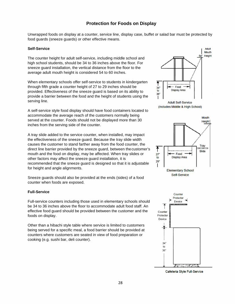
Protection for Foods on Display
Unwrapped foods on display at a counter, service line, display case, buffet or salad bar must be protected by food guards (sneeze guards) or other effective means.
Self-Service
The counter height for adult self-service, including middle school and high school students, should be 34 to 36 inches above the floor. For sneeze guard installation, the vertical distance from the floor to the average adult mouth height is considered 54 to 60 inches.
When elementary schools offer self-service to students in kindergarten through fifth grade a counter height of 27 to 29 inches should be provided. Effectiveness of the sneeze guard is based on its ability to provide a barrier between the food and the height of students using the serving line.
A self-service style food display should have food containers located to accommodate the average reach of the customers normally being served at the counter. Foods should not be displayed more than 30 inches from the serving side of the counter.
A tray slide added to the service counter, when installed, may impact the effectiveness of the sneeze guard. Because the tray slide width causes the customer to stand farther away from the food counter, the direct line barrier provided by the sneeze guard, between the customer’s mouth and the food on display, may be affected. When tray slides or other factors may affect the sneeze guard installation, it is recommended that the sneeze guard is designed so that it is adjustable for height and angle alignments.
Sneeze guards should also be provided at the ends (sides) of a food counter when foods are exposed.
Full-Service
Full-service counters including those used in elementary schools should be 34 to 36 inches above the floor to accommodate adult food staff. An effective food guard should be provided between the customer and the foods on display.
Other than a hibachi style table where service is limited to customers being served for a specific meal, a food barrier should be provided at counters where customers are seated in view of food preparation or cooking (e.g. sushi bar, deli counter).

29
Examples of Sneeze Guard Configurations
Self Service:
Full Service:

30
Warewashing Equipment
A mechanical or manual warewashing operation should be designed and sized to accommodate the cleaning and sanitizing of the equipment and utensils that are to be used.
Warewashing equipment may not be used for cleaning of maintenance tools, preparation or holding of maintenance materials or the disposal of mop water and similar liquid wastes.
Manual Warewashing
A sink consisting of no less than 3 compartments along with drainboards must meet ANSI/NSF Standard 2. Washing, rinsing and sanitizing sink compartments should be large enough to immerse the largest equipment or utensil to be washed (e.g. pot, lug, pan).
Drainboards provided on the manual warewashing sink should be sized to accommodate soiled equipment and utensils prior to being washed and clean equipment and utensils after they have been sanitized to allow air-drying. Each drainboard must be self-draining.
In addition to drainboards, utensil racks or tables large enough to accommodate all soiled and cleaned items that may accumulate during hours of operation may be provided. Drainboards and tables being used for the warewashing operation may not be used at the same time for food preparation.
When hot water sanitization is used, an integral heating device (sink heater) equipped with an integral thermometer must be installed at the sanitizing compartment of the sink. A dish rack or basket for immersion into the sink must be provided.
Warewashing sinks may not be used for handwashing.
Hot and cold water under pressure should be provided through a mixing faucet(s) that can service all compartments of the sink. For hot water criteria, see Retail Food Establishments, Plumbing, Hot Water.
RECOMMENDATION: Other than facilities having limited utensils to be washed, it is recommended that drainboards of at least twenty-four (24) inches in length are provided.

31
Mechanical Warewashing
When installed, the mechanical warewashing machine must meet ANSI/NSF Standard 3 or equivalent commercial warewashing equipment standard. The mechanical warewasher must be operated per the manufacturer’s affixed data plate and other manufacturer’s instructions. The data plate must be positioned so that it is accessible and readable.
Dish tables provided at the mechanical warewasher’s entrance and exit openings should be large enough to accommodate all soiled and cleaned items that may accumulate during hours of operation. Each dish table should be sized to accommodate at least one of the largest dish racks to be used. The lip of dish tables should turn down inside the mechanical warewasher for seamless transfer of filled dish racks.
A pre-rinse sink should be provided in the soiled dish table for removing gross food particles and when necessary to soak equipment and utensils. Some mechanical warewashers have a pre-wash cycle option available.
Door-type mechanical warewasher’s are equipped with handles that extend about 3 inches away from the warewasher. When a door-type mechanical warewasher is installed, the length of each dish table may need to be extended to ensure that the dish rack rests fully on the drainboard. Dish tables must be self-draining.
When a mechanical warewasher is used for cleaning glasses and similar equipment and utensils only, where no gross food particles are present, a pre-rinse sink is not necessary.
A hot water sanitizing, mechanical warewasher flow pressure on the final rinse must be in the range specified by the manufacturer but may not be:
• Less than 5 psi (pounds per square inch), nor • Greater than 30 psi.

32
To achieve the specified flow pressure, a pressure reducing valve designed to regulate water pressure between 5-30 psi and a pressure gauge should be provided. A mechanical warewasher having a pumped final rinse regulated by a pump preset to operate in the required final rinse pressure range does not necessarily need a pressure regulating valve or pressure gauge.
Wash and final rinse temperatures must meet the minimum requirements specified on the data plate. For additional hot water criteria, see Retail Food Establishments, Plumbing, Hot Water.
Clean in Place Warewashing
Fixed equipment (e.g. band saw, slicer, mixer) that is too large to be cleaned using manual or mechanical warewashing equipment must be washed, rinsed and sanitized in place. Removable parts of the equipment such as blades or mixing arms should be cleaned using the appropriate warewashing equipment.
Clean in place (CIP) equipment, such as a frozen dessert machine, that is not designed to be disassembled for cleaning must be designed with inspection access points to ensure that food-contact surfaces throughout the fixed system are being effectively cleaned. Internal food-contact surfaces should be cleaned following the manufacturer’s instructions.
For water connection and drainage criteria see Retail Food Establishments, Plumbing.
Sinks
Besides the manual warewashing sink which is used for cleaning food equipment and utensils, additional sinks are needed for handwashing, maintaining the retail food establishment and possibly food preparation.
A warewashing sink, food preparation sink, or service sink may not be used for handwashing. Handwashing sinks, food preparation sinks and warewashing equipment may not be used for the disposal of mop water and similar liquid waste, the cleaning of maintenance tools, or preparation or holding of maintenance materials.
Handwashing Sink(s)
Handwashing sinks must be conveniently located in food preparation, food dispensing and warewashing areas. Barriers such as doors (any type), curtains, speed rails, trash receptacles or equipment must not obstruct or prevent easy access to employee handwashing stations.
Examples of inaccessible handwashing sink installation:
• Deeply recessed under counters. • Located between pieces of equipment that protrude beyond the handwashing sink so that access is
inhibited.
RECOMMENDATION: Handwashing sink placement will ultimately depend upon the layout, aisle spacing and maximum number of employees that will work within workstations.
When planning a handwashing sink location(s), a walking distance no greater than 25 feet between the farthest point of the workstation and the handwashing sink is suggested. In retail market prep areas, such as meat cutting rooms, produce preparation areas and seafood preparation areas where equipment and preparation is limited, it is recommended that the walking distance is no greater than 30 feet.

33
Handwashing sinks should be installed at a distance to prevent splash from handwashing contamination to food, food contact surfaces or food storage containers. When this is not possible, a barrier such as a splash guard, should be installed to prevent possible contamination.
When a handwashing sink is dropped (recessed) into a food preparation table or counter, a barrier(s) should be installed to prevent potential contamination of the counter workspace.
Soap (hand cleanser) and disposable towels or other hand-drying device should be installed at the handwashing sink. To prevent potential contamination, dispensers and devices should not be installed above or on food preparation surfaces, food storage areas, food equipment, or single-service and single-use articles.
Handwashing sinks are to be used for handwashing only.
Water must be provided through a mixing valve or combination faucet. For water temperature criteria, see Retail Food Establishments, Plumbing, Hot Water.
Food Preparation Sink(s)
A food preparation sink is recommended, to minimize the potential for cross-contamination between ready- to-eat (finished) and raw foods when a sink is routinely used for thawing, washing and/or any other food preparation.
More than one food preparation sink may be a consideration, to prevent potential contamination of ready-to- eat foods (e.g. fruits, vegetables, cooked proteins) by raw proteins (meats, poultry, fish), when the facility routinely uses a sink for preparation of both food categories.
When food preparation is infrequent, or the volume is low, a dedicated preparation sink may not be necessary.
Food preparation sinks may not be used for:
• Handwashing, • Cleaning of maintenance tools, • Preparation or holding of maintenance materials. • Disposal of mop water and similar liquid wastes.
RECOMMENDATIONS: To minimize the potential for cross-contamination due to splash, it is recommended that handwashing sinks are installed at least 12 inches away from food and food contact surfaces.
When a barrier such as a splash guard is used, a height of 12 inches should provide effective splash control for a standard gooseneck faucet. A splash guard height of less than 12 inches may provide effective splash control for handwashing sinks when residential-type lavatory faucets are installed.

34
Service Sink (mop sink, can wash)
At least one conveniently located mop sink, can wash or other curbed cleaning facility must be provided for the disposal of mop water and similar liquid waste. The service sink should be used for the cleaning of mops and similar wet floor cleaning tools as well as the location used to fill mop buckets.
The basin of the service sink should be constructed of materials that provide a smooth, nonabsorbent and easily cleanable surface. Walls at a service sink must be smooth, nonabsorbent and easily cleanable up to the highest level of splash.
A toilet or urinal may not be used as a service sink. A service sink may not be used for handwashing.
Refrigeration
Coolers (refrigerators) used to store TCS foods in areas where retail food establishment operations are conducted must meet ANSI/NSF Standard 7. Standard 7 covers a wide range of refrigeration units (e.g. prep coolers, walk-in coolers, reach-in coolers, beverage coolers, rapid pull-down coolers, etc.) that are designed for specific tasks. Some sections of the standard apply to specific classes or types of coolers.
NOTES & RECOMMENDATIONS: The installation of a floor-mounted service sink minimizes the height of splash and potential damage to the service sink basin from the lifting of a heavy mop bucket to dispose of mop water. To restrict the flow of sewage from traffic areas and workspaces, floor-mounted service sinks constructed on-site should be either curbed or recessed.
A service sink(s) used for cleaning food preparation and warewashing areas should be installed in a location that does not require traveling though customer traffic areas for mops and buckets.
It is recommended that if a service sink is installed on one floor of a food service establishment with multi- level food preparation areas, direct access to the service sink is provided by a service elevator or service ramp without traveling through customer traffic areas. If an elevator or service ramp is not a viable option, it is recommended that a service basin is provided in or adjacent to each floor’s food preparation area.

35
Ambient air temperatures within a food preparation area may affect the optimal performance of some refrigeration units.
Coolers for TCS foods must be capable of maintaining temperatures of 41oF (5oC) or below.
Beverage Cooler
Designed only for the storage/display of bottled, canned or otherwise packaged non-TCS food (e.g. soft drinks, beer, and wine). Because beverage coolers are not designed for the storage of TCS foods, certification is not required.
Prep Cooler
Designed with a refrigerated open top or open condiment rail (e.g. sandwich prep cooler, salad prep cooler, pizza prep cooler, etc.) to allow easy access for assembling foods. Prep coolers are designed to maintain cold foods cold but are not for long-term storage.
Storage Cooler (reach-in cooler)
Designed for the storage of cold, non-frozen foods between the periods of preparation, service, display or sale. Not designed for quick chilling foods.
Walk-in Cooler/Freezers
Walk-in coolers and freezers are designed for long-term storage of TCS and perishable foods. They are enclosed, mechanically refrigerated, storage rooms consisting of floor, walls and ceiling used to maintain specified cold holding temperatures for food.
Floor inside the walk-in cooler or walk-in freezer may meet 6-101.11 and 6-201 in lieu of installing the manufacturer’s flooring. Flooring material should be durable under the specified temperature conditions. See Retail Food Establishments, Finishes (Indoor), Floor, for additional flooring guidance.
Walk-in coolers should not be confused with refrigerated food preparation/processing rooms (e.g. meat cutting rooms, seafood preparation rooms).
Blast Chiller
Designed specifically for cooling foods to a lower temperature within a shortened time, blast chillers are often used when a facility must cool large quantities of foods or when cooling space is limited in other refrigeration. It is an efficient appliance for any amount of food that needs to be quickly chilled.
Service Display Cooler
Designed to display unpackaged or packaged foods to customers with only employee access to the foods (e.g. seafood display, deli display, meat display coolers).
Buffet (cold) Unit
Mechanically refrigerated units intended for customer self-service. The cold buffet unit (e.g. salad bar) is designed to maintain food temperatures. It is not designed for long-term storage or cooling of foods.
NOTE: Walk-in freezers must meet ANSI/NSF Standard 7.

36
Display Cooler (closed)
Designed to display foods that are accessed by opening a hinged or sliding door(s).
Labeling
Labeling identifies the refrigeration unit as a commercial refrigerator, commercial refrigerator and/or freezer, commercial freezer or other identifier specific to the refrigeration unit’s certification.
Some refrigeration units are designed to effectively maintain temperatures when the unit is in a room that does not routinely exceed ambient temperatures specified on its label. As part of the certification, the refrigeration unit may have a label, like the ones shown below, in a location that is clearly visible to the user.
This equipment is intended for the storage and display of non- potentially hazardous, bottled or canned products only.
This equipment is intended for the storage and display of packaged products only.
Ambient temperature typically not to exceed 75oF.”
This equipment is intended for the storage of food in the original sealed package only.
Equipment intended for use in rooms having an ambient temperature of 86oF or less.
Ambient temperature typically not to exceed 80oF.

37
Additional Retail Food Establishment Operations
This section is intended to aid the owner, food industry, equipment dealers, architects, engineers, consultants and others with planning, constructing and equipping additional retail food establishment operations to meet Regulation 61-25, Chapter 9 requirements. The goal is to promote uniform design and construction of additional food operations that are conducive to safe food handling. While all conditions are not covered, the fundamental concepts conveyed may be applied in all installations.
The proposed operation may require more extensive criteria. For minimum requirements please refer to South Carolina Department of Health and Environmental Control, Regulation 61-25, Retail Food Establishments.
This section of the planning resource is to assist in the development of additional retail food establishment operations; it does not constitute an official part of Regulation 61-25.
Mobile Food Establishment
A mobile food establishment consists of a commissary and a mobile food unit(s) or mobile food pushcart(s).
A truck, van, trailer, cart, or watercraft may be used for a mobile food establishment operation if it is designed and equipped following criteria specified in the regulation.
Commissary
The commissary or base of operation is a permitted retail food establishment (e.g. restaurant, market, shared use operation, dedicated commissary) that has been authorized to provide support to a mobile food unit(s) or mobile food pushcart(s). At a minimum the commissary is the location where the mobile food unit(s) or pushcart(s) may:
• Fill the drinking water system tank. • Discharge the sewage retention tank into a sanitary sewage system.
NOTES AND RECOMMENDATIONS: Cars, trucks, vans, trailers, and watercraft not designed for food preparation are not mobile food units (e.g. the trunk of a car).
A mobile food unit with a structure attached or built around it is not a mobile food establishment.
Public property (e.g. parks, schools, business district street corners) considered for operating a mobile food unit or mobile food pushcart may be under the jurisdiction of local planning and zoning (e.g. county, city, or town). It is recommended that the agency having jurisdiction is contacted for requirements. Access to private property (e.g. business parking lot, vacant lot, flee market) should be cleared with the property owner.
Mobile food units, such as carts and trailers that are transported to food operation sites using a vehicle, may be under the jurisdiction of the Department of Motor Vehicles.
Mobile food units with cooking operations may also be under the jurisdiction of the State or local Fire Official.

38
• Dispose of solid waste (e.g. leftover hot held TCS foods, soiled paper towels, single-use food packaging/containers).
• Be cleaned. • Be stored when not in operation.
In support of many of the items above at the commissary, a servicing area must be provided for the mobile food unit(s) or mobile food pushcart(s). The servicing area should be sized to accommodate the mobile unit(s). For servicing area construction criteria, see Retail Food Establishments, Design and Construction, Finishes (Outdoor/Premises) section of this document.
Depending on the scope of the mobile food unit or mobile food pushcart operation, the commissary may also be needed for the:
• Preparation of foods (e.g. chopping, cutting, slicing, peeling, washing, cooking, marinating) including
special processes which require a HACCP or SOP plan (e.g. vacuum (ROP) packaging processes, curing, fermentation).
• Cleaning of equipment and utensils. • Storage of foods (e.g. refrigeration, dry storage). • Storage of equipment, utensils, single-service and single-use articles. • Loading of food, utensils and other supplies.
For assistance with commissary criteria, based on the needs that apply to the mobile food unit(s) or mobile food pushcart(s), see R.61-25 and/or the Retail Food Establishments section of this document. Chapter 9 of R.61-25 provides information on Shared Use Operations (9-5).
A commissary is not considered to be:
• A private home kitchen. • A room used or directly opening into a room used as living or sleeping quarters. • A church, club or other association that does not have a valid permit issued. • Temporary food establishment or community festival operation. • Mobile food unit or mobile food pushcart.
Mobile Food Unit and Mobile Food Pushcart
When planning a mobile food operation, it is important to note that foods must be stored, prepared, displayed and served from the mobile food unit(s) and mobile food pushcart(s) only. Pull behind and other free- standing exterior cookers, grills or smokers may not be used as a part of a mobile food unit or mobile food pushcart operation. Immediate outdoor cooking activities may not be associated with a mobile food unit or mobile food pushcart.
A mobile food unit or mobile food pushcart is considered to:
• Have the ability to be driven, pushed or towed without the removal of structural parts. Exception:
Customer service shelves may be removable. • Have the ability to be movable at all times. Wheels remain on the unit at the operating location
(excluding boats). • Not have permanent connections to water, sewer, electricity or gas.

39
Refrigeration/Insulated Coolers
Sufficient refrigeration must be provided for time/temperature control for safety (TCS) foods that are to be held cold until they are prepared or served. Refrigeration must be capable of maintaining TCS foods at 41oF (5oC) or below. Refrigeration equipment must be designed and operated per its intended use.
Mechanical coolers (e.g. reach-in, prep, under counter) installed inside a mobile food unit must meet ANSI/NSF Standard 7. For refrigeration guidance, see the Retail Food Establishments, Equipment, Refrigeration section of this document.
When an insulated cooler(s) (non-mechanical) is used, the storage method(s) must ensure that:
• Cross-contamination is prevented. • Ice or water, used as a coolant, does not contact packaged food that by the nature of the packaging,
wrapping or container, the food is subject to the entry of water. The insulated cooler must be designed to ensure foods can be positioned so that water does not enter the packaging.
• Ice used as a coolant must come from an approved source. • Insulated cooler(s) is designed to be easily drained of accumulated water. • Materials used in the construction of the insulated cooler must meet R.61-25, 4-1 and 4-2.
A temperature measuring device (thermometer) must be provided for cold holding equipment.
Drinking Water System
Tank Construction and Attached Component(s)
The storage tank must be sized to store at least 5-gallons of drinking water for handwashing in the mobile food unit(s) or on the mobile food pushcart(s). A larger storage tank capacity may be needed on a mobile food unit when water is used in the cooking process or a 3-compartment warewashing sink is also installed.
Materials used to construct the drinking water storage tank for the mobile food unit(s) or mobile food pushcart(s) must meet either ANSI/NSF 59 or 61. All necessary supplemental components for the drinking water supply system must comply with ANSI/ NSF 372 (having a weighted average lead content of 0.25% or less).
The drinking water storage tank must be designed so that it slopes to an outlet that allows the tank to be completely drained. From the filling inlet to the discharge outlet the tank must be fully enclosed.
“V” type threads may only be used on the inlet or outlet of a water tank when a hose is to be permanently attached.
The inner diameter of the drinking water tank inlet must be 3/4 inch (19.1 mm) or less. A hose(s) used to convey drinking water from a storage tank must:
• Be made of materials that are safe, nonabsorbent, durable and corrosion resistant. • Have an interior surface that is smooth. • Be made of materials that are resistant to pitting, chipping, crazing, scratching, scoring, distortion or
decomposition.
NOTES: • Ice being used as a coolant for food storage must not be used for edible ice. • Low ambient air temperature, such as during colder months, is not considered an acceptable
alternate to cold holding equipment.

40
Hose connection(s) for the drinking water supply must be of a size or type that would prevent it being used for any other service that may expose the water supply to contamination (e.g. connecting the drinking water hose to the sewage retention tank). A drinking water hose that is not permanently attached must be identified clearly and durably as to its use.
If a water tank is equipped with a vent it must terminate in a downward direction. The vent must also be covered using one of the following methods:
• When located in a protected area, the vent must be covered with 16 mesh to 1 inch screening or
equivalent. • A vent located in an area not protected from potential contaminants, such as windblown dirt and
debris, must be equipped with a protective filter.
If an access port is provided for inspecting and cleaning of the water tank, the port opening must be on the top of the water tank. The port opening must be designed using the following criteria:
• Flanged upward at least 1/2 inch (13 mm). • Fitted with a port cover assembly that is:
o Equipped with a gasket and a device that secures the cover in place. o Flanged to overlap the opening. o Sloped to drain.
Drinking water system for the mobile food unit or mobile food pushcart must be under pressure.
When compressed air is used to provide water under pressure from the drinking water storage tank, a filter must be installed in the air supply line between the compressor and drinking water system. The filter must not be installed in a manner that would allow oil or oil vapors to pass into the drinking water supply.
A cover or device such as a cap and keeper chain, closed cabinet or closed storage tube must be provided to protect the water inlet, outlet, and hose.
When a portable drinking water storage tank is used, it must be designed so that it can be handled in a manner that protects the drinking water, storage tank and attached components from contamination.
Location
Drinking water supply tank should be installed on the mobile food unit or mobile food pushcart in a location that protects the drinking water supply from sources of contamination such as sewage discharge, oil, grease or dust.
For example, the drinking water tank may be:
• Installed above the sewage storage tank and positioned to avoid potential contamination. • Installed on the opposites side of the mobile food unit or mobile food pushcart, away from the
sewage storage tank.
A mobile food unit or mobile food pushcart may temporarily use a direct connection to an approved drinking water source at the operating location when the following criteria are also met:
NOTE: Hoses manufactured specifically for drinking water supply use (food-grade) may be found in hardware, plumbing, food equipment supply, and retail stores.

41
• The mobile unit is also connected to an approved public sewer system. • The drinking water and sewage storage tanks always remain on the unit.
Sewage Retention System
Tank Construction
The sewage storage tank must be sized so that it is at least 15% larger than the drinking water storage tank. A larger storage tank capacity may be needed when in addition to the handwashing sink a beverage dispenser, steam table or similar equipment requiring drainage is also installed on a mobile food unit.
Materials used to construct the sewage storage tank for the mobile food unit(s) or mobile food pushcart(s) must be durable, corrosion resistant and nonabsorbent. Interior surfaces of the storage tank must be smooth.
From the sewage inlet to the discharge outlet the tank must be fully enclosed. The sewage storage tank must be sloped to an outlet that allows complete drainage. Inner diameter of the drain must be 1 inch (25 mm) or greater and equipped with a shut-off valve to hold and release liquid waste.
On a mobile food pushcart, a removable retention tank may be used. To be considered portable, the storage capacity of the tank cannot exceed 10 gallons (80 lbs.). It is recommended that larger removable tanks are installed on casters or wheels to make it easier to transport the unit for sewage disposal. The removable retention tank must also be permanently labeled “sewage” to eliminate confusion.
If a hose is used to discharge wastewater into sanitary sewer, it must be of a size or type that would prevent it being used for any other service that may expose the water supply to contamination (e.g. connecting the sewage discharge hose to the drinking water storage tank).
If an access port is provided for inspecting and cleaning of the sewage storage tank, the port opening must be on the top of the water tank.
Sewage from the storage tank must be conveyed to an approved sanitary sewage system. At the commissary this could be an accessible service sink or similar disposal receptacle. Sewage from the mobile food unit or mobile food pushcart may not be discharged into storm drains, waterways or onto the ground.
Location
The sewage storage tank should be installed on the mobile food unit or mobile food pushcart in a location that protects the drinking water supply, food and food contact surfaces from potential contamination.
The wastewater connection should be located lower than or away from the water inlet connection to prevent contamination of the drinking water system.
Hot Water
Hot water system and supply must be sufficient to meet the demands of the mobile food unit and mobile food pushcart.
At the handwashing sink, water of at least 100oF (38oC) must be provided.
If installed inside a mobile food unit, the 3-compartment utensil washing sink must be provided with at least 110oF (43oC) water.

42
Backflow Prevention
For backflow prevention criteria when connecting hoses to a drinking water supply or sewage disposal system, see the Retail Food Establishments, Plumbing, Backflow Prevention (Water) and Backflow Prevention (Sewage) sections of this document.
Handwashing Sink
All mobile food units and mobile food pushcarts must be equipped with a handwashing sink.
The handwashing sink must be installed so that it is separated from food and food contact surfaces. This can be accomplished by installing a splashguard or providing a spacing distance of at least 12 inches from food, utensil, single-service and single-use article storage or preparation areas.
Hot and cold water under pressure must be provided at the handwashing sink through a mixing valve or combination faucet.
Handwashing sinks must be accessible during operation of the mobile food unit. Barriers such as equipment and utensils must not obstruct access to the handwashing sink.
For water temperature criteria see Hot Water in this section.
Signage
The following information must be legibly printed on each mobile food unit or mobile food pushcart in a contrasting color from the color of the unit:
• Business name. • Business address.
Signage must be visible to the public while in operation.
Mobile Food Unit (MFU)
A mobile food unit (MFU) is a fully enclosed mobile kitchen that operates as an extension of a commissary. From the mobile food unit, TCS foods may be prepared, cooked or served. Bulk food preparation (e.g. washing, slicing, cutting and peeling) and special processes must occur at the commissary.
Preparation and display areas must be completely enclosed with a solid material, except for a barbecue pit- cooking area. A mobile food unit having a barbecue pit-cooking area must meet applicable criteria specified in Barbecue Pit and Pit-Cooking Room Construction (9-7).
NOTE: Substitution of handwashing facilities with hand sanitizers and/or gloves is not allowed.

43
Finishes
Interior material finishes for floors, walls and ceilings must be smooth, cleanable, durable and nonabsorbent.
Finishes should be installed or applied according to manufacturer’s instructions. For guidance on some construction materials that require special considerations, see Retail Food Establishments, Design and Construction, Finishes (Indoor) section of this document.
When deciding on the finishes to install, consideration should be given to the amount of physical effort that may be needed to maintain the finish in a clean condition and in good repair.
Utility Lines
In mobile food units where utility lines are to be installed, see the Retail Food Establishments, Plumbing, Utility Lines section of this document for guidance.
Ventilation
A mobile food unit must have mechanical exhaust ventilation equipment over cooking equipment that effectively removes cooking odors, smoke, steam, grease, heat, and vapors. Local Fire and Mechanical Officials should be contacted for specific ventilation requirements.
Lighting
Intensity of lighting provided from fixtures must be at least twenty (20) foot-candles.
Light bulbs and fluorescent tubes must be shielded, coated, or shatter resistant. Protection may be achieved by using plastic shields, plastic sleeves with end caps, or shatter-resistant bulbs.
Infrared or other heat lamps should be protected against breakage by a shield surrounding the bulb so that only the face of the bulb is exposed.
Serving Window
Serving window(s) must meet the following criteria:
• Opening area must be no more than 576 square inches and covered with a solid material. • Must be self-closing, a free-falling type, or covered by an air curtain (fly fan) that extends the length
of the opening. An automatic on/off switch or similar device can control the air flow as the window is opened and closed when an air curtain is used.
• When screening is used at a serving window(s) it must be at least 16 mesh per inch.
Doors
Doors must be kept closed during food service operation.
A door or partition that separates the food service area from the driver (cab) section of a vehicle is not necessary unless there are conditions that present potential contamination.
NOTE: Doors and windows to the exterior of the mobile food unit should be as tight-fitting as possible to protect from the entry of insects and rodents.
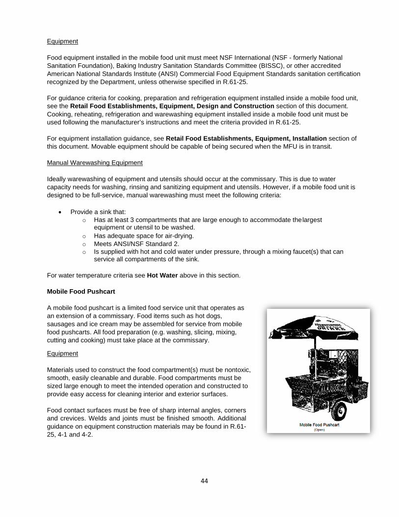
44
Equipment
Food equipment installed in the mobile food unit must meet NSF International (NSF - formerly National Sanitation Foundation), Baking Industry Sanitation Standards Committee (BISSC), or other accredited American National Standards Institute (ANSI) Commercial Food Equipment Standards sanitation certification recognized by the Department, unless otherwise specified in R.61-25.
For guidance criteria for cooking, preparation and refrigeration equipment installed inside a mobile food unit, see the Retail Food Establishments, Equipment, Design and Construction section of this document. Cooking, reheating, refrigeration and warewashing equipment installed inside a mobile food unit must be used following the manufacturer’s instructions and meet the criteria provided in R.61-25.
For equipment installation guidance, see Retail Food Establishments, Equipment, Installation section of this document. Movable equipment should be capable of being secured when the MFU is in transit.
Manual Warewashing Equipment
Ideally warewashing of equipment and utensils should occur at the commissary. This is due to water capacity needs for washing, rinsing and sanitizing equipment and utensils. However, if a mobile food unit is designed to be full-service, manual warewashing must meet the following criteria:
• Provide a sink that:
o Has at least 3 compartments that are large enough to accommodate the largest equipment or utensil to be washed.
o Has adequate space for air-drying. o Meets ANSI/NSF Standard 2. o Is supplied with hot and cold water under pressure, through a mixing faucet(s) that can
service all compartments of the sink.
For water temperature criteria see Hot Water above in this section.
Mobile Food Pushcart
A mobile food pushcart is a limited food service unit that operates as an extension of a commissary. Food items such as hot dogs, sausages and ice cream may be assembled for service from mobile food pushcarts. All food preparation (e.g. washing, slicing, mixing, cutting and cooking) must take place at the commissary.
Equipment
Materials used to construct the food compartment(s) must be nontoxic, smooth, easily cleanable and durable. Food compartments must be sized large enough to meet the intended operation and constructed to provide easy access for cleaning interior and exterior surfaces.
Food contact surfaces must be free of sharp internal angles, corners and crevices. Welds and joints must be finished smooth. Additional guidance on equipment construction materials may be found in R.61- 25, 4-1 and 4-2.

45
Plumbing/Utility Lines
Plumbing of any kind must not be located in food storage compartments.
Enclosure
When assembling foods on a pushcart that is designed for multiple topping options, the preparation and display areas of the mobile food pushcart must be completely enclosed with a solid material. The solid material used may be transparent (e.g. plexiglass), or opaque (e.g. stainless). Lids such as those used over steamer compartments are not considered an enclosure.
Mobile food pushcarts used to serve commercially fully cooked hot dogs with commercially fully cooked chili, or scooped ice cream may have full enclosure criteria waived if in the Department’s opinion no risk of contamination to the food exists, provided those are the only foods served from the unit.
Full enclosure criteria may be waived by the Department when the mobile food pushcart will be operated inside a fully enclosed structure, such as a mall or sports arena, if no risk of food contamination exists.
Doors
Mobile food pushcart doors must be designed so that they can be kept closed when not in use and during transportation.
Immediate Outdoor Cooking
Immediate outdoor cooking (IOC) may only operate in conjunction with and on the premises of a permitted retail food establishment when all applicable criteria for the operation are met. The retail food establishment provides support services to the IOC area.
All food preparation (e.g. breading, slicing, mixing, chopping, thawing, cooling) and warewashing must occur inside the retail food establishment. Only the cooking of foods may occur in the IOC area. The IOC operation is limited to the outdoor cooking, grilling or roasting of foods for immediate service.
IOC activities must not be associated with the following operations:
• Mobile food unit or mobile food pushcart. • Remote service sites to include SC farmer’s markets and seasonal series.

46
An IOC area may not operate as a Shared Use Operation. The permitted retail food establishment is solely responsible for all IOC activities.
Information below provides minimal criteria for this operation. If environmental conditions pose a risk of contamination of foods, additional criteria may be required.
Design and Construction
Retail Food Establishment
Volume of foods that are cooked and served by the IOC operation may not exceed the volume of food production inside the retail food establishment.
Cooking equipment inside the retail food establishment must be of the same or similar size and type as the equipment located in the IOC area.
The retail food establishment must be sufficiently sized and capable of supporting the same operations inside as those performed in the IOC area. Enough dry storage and refrigeration equipment must be provided to accommodate IOC operations.
IOC Area
The IOC site must be located on the premises of the retail food establishment in an area that allows convenient and easy access to support services.
The IOC area must be separated from the public by roping or other effective method.
Floor
The floor of the IOC area must be constructed of concrete, asphalt, tight wood or other similarly cleanable, durable material.
To prevent standing water on the surface of the IOC area it is recommended that the floor is sloped to drain.
Lighting
Sufficient artificial or natural lighting must be available in the IOC area during all hours of operation. When enough natural lighting is not available, at least 20-foot candles of illumination must be provided artificially. Light bulbs and fluorescent tubes located above the IOC food preparation area must be shielded, coated or otherwise shatter resistant.
An IOC area that routinely operates at dusk and/or after dark should consider installing permanent, fixed lighting.
NOTE: The IOC area may also be under the jurisdiction of the local Fire and/or Building Official.
EXAMPLE: A retail food establishment having only a hot dog roller grill inside cannot have a 6-ft chargrill in the IOC area.
EXAMPLE: A retail food establishment having only one under-counter cooler and 2 or 3 wall hung shelves would not be enough to support an IOC operation that prepares racks of ribs.

47
Handwashing Sink
Retail food establishments with IOC areas that are operated more than 4 times a calendar year must have a permanently installed exterior handwashing sink.
The handwashing sink must be located so that it allows convenient use by employees in the IOC area. Equipment and utensils must not block access to the handwashing sink.
Hot and cold water under pressure must be provided at the handwashing sink through a mixing valve or combination faucet.
IOC areas that are operated 4 or less times a calendar year may have a container of water with a spigot. For best results the spigot should be designed to allow a continual flow of water over the hands. A catch bucket must be provided underneath the water container to capture sewage water. Sewage water from the catch bucket must be disposed into an approved sewage system.
At the handwashing sink, water of at least 100oF (38oC) must be provided.
Soap and disposable towels must be provided at the handwashing sink.
When a portable handwashing sink is used, it must have a drinking water storage tank capacity of at least 5 gallons. Drinking water supply must come from an approved source. The sewage water storage tank capacity should be at least 7.5 gallons. Sewage water from the storage tank must be discharged into an approved sewage system.
When a permanently installed handwashing sink is not required in the IOC area, an optional handwashing station with a container of water with a spigot, soap, disposable towels and a catch bucket must be provided.
Plumbing
A hard-plumbed handwashing sink must be connected to an approved drinking water supply and discharged into an approved sewage system.
For guidance see Retail Food Establishments, Design and Construction, Plumbing section of this document.
NOTE: Substitution of handwashing facilities with hand sanitizers and/or gloves is not allowed.

48
Equipment
Cooking:
Cooking equipment used in the IOC area is limited to grills, steam pots, and outdoor pizza ovens. Covers or lids must be provided.
Along with cooking equipment and lids or covers, tables used in this area must be durable, corrosion resistant, nonabsorbent, smooth, easily cleanable and free of seams and difficult to clean areas. Guidance on equipment construction materials may be found in R.61-25, 4-1 and 4-2. Equipment may be fixed or portable.
Warewashing:
All utensils and equipment used in outdoor cooking and serving of food must be returned to the permitted retail food establishment for proper cleaning as specified in Chapter 4. Fixed cooking equipment and tables may be cleaned using in-place cleaning procedures found in R.61-25, 4-6. No other warewashing is permitted in the IOC area.
Insulated Coolers/Cold Storage:
Insulated coolers or similar non-mechanical equipment should be provided for storage of time/temperature control for safety (TCS) foods that are to be held cold until they are prepared or served. Equipment must be capable of maintaining TCS foods at 41oF (5oC) or below. Cold storage equipment must be designed and operated per its intended use.
When an insulated cooler(s) (non-mechanical) is used, the storage method(s) must ensure that:
• Cross-contamination is prevented. • Ice or water, used as a coolant, does not contact packaged food that by the nature of the
packaging, wrapping or container, the food is subject to the entry of water. The insulated cooler must be designed to ensure foods can be positioned so that water does not enter the packaging.
• Ice used as a coolant must come from an approved source. • Insulated cooler should be designed so that it can be easily drained of accumulated water. • Materials used in the construction of the insulated cooler must meet R.61-25, 4-1 and 4-2.
A temperature measuring device (thermometer) must be provided for cold holding equipment.
Displayed Foods:
Foods on display must be provided with covers, lids or other approved method to protect from contamination.
Garbage (refuse):
Used single service and single-use articles, leftover food and similar solid waste generated by the IOC operation must be disposed of as outlined in R.61-25, 5-5.

49
Barbecue Pit and Pit Cooking Room
Barbecue is a single process method of slow cooking meat, poultry or fish in a pit or on a spit using an indirect or direct heat source.
Barbecue cooked outside of a permitted retail food establishment must be performed in a pit-cooking room, located on the premises of the retail food establishment. The pit-cooking room must be: .
• Operated as a part of the permitted retail food establishment. • Located on the physical premises of the retail food establishment.
A pit-cooking room on a mobile food unit must meet barbecue pit and pit cooking room criteria.
Smokehouse rooms must also meet criteria specified in this section.
Design and Construction
Pit-Cooking Room
The pit-cooking room is restricted to barbecue cooking equipment and the single cooking process. All other food preparation (e.g. brining, rubbing, marinating) and processing activities (e.g. shredding, pulling) must be performed inside the retail food establishment, unless the pit room meets all construction criteria in accordance with Chapter 6 of R.61-25.
The pit-cooking room must be completely enclosed.
Floor
Pit-cooking room floor (excluding pit floor) must be constructed of a smooth, nonabsorbent, durable material such as sealed concrete, quarry tile, vinyl flooring or other approved material.
Floors that are to be cleaned using a water-flushing method must be sloped to floor drains and junctures between walls and the floor must be sealed. Sealing the junctures may be accomplished by using a sealant designed for that purpose or by using a coved base.
For guidance on other flooring materials and cove base installation when water flushing, see Retail Food Establishments, Design and Construction, Finishes (Indoor), Floors section of this document.
Walls
Interior walls must have smooth, easily cleanable and washable surfaces up to at least wainscot height (4 feet). Concrete block (CMU) or other similar materials must be finished to provide a smooth, washable surface. For guidance see Retail Food Establishments, Design and Construction, Finishes (Indoor), Walls section of this document.
If screening is used above wainscot, studs and other exposed bracing must be sealed or painted. Screening must be at least 16 mesh per inch. To protect against blowing contamination (e.g. dust, sand, rain), canvas flaps or other effective devices may be required.
Ceiling
Ceiling must have a smooth, nonabsorbent and easily cleanable surface. Joists must be sealed for a smooth, nonabsorbent and easily cleanable surface. Trusses and rafters must not be exposed.

50
Pest Control
Outside openings must be protected against insects and rodents by tight-fitting, self-closing doors, closed windows, screening, effective air curtain(s) or other approved means.
If a garage door is installed, it must be tight-fitting and remain closed during cooking operations.
Lighting
At least twenty (20) foot-candles of light must be provided on all working surfaces, including the handwashing sink.
Light bulbs and fluorescent tubes must be shielded, coated or otherwise shatter resistant.
Handwashing Sink
Hot and cold water under pressure must be provided at the handwashing sink through a mixing valve or combination faucet.
Handwashing sinks must always be accessible. Barriers such as equipment and utensils must not obstruct access to the handwashing sink.
Soap and disposable towels must be provided at the handwashing sink.
Plumbing
Handwashing sink must be connected to an approved drinking water supply and discharged into an approved sewage system.
For guidance see Retail Food Establishments, Design and Construction, Plumbing section of this document.
At the handwashing sink, water of at least 100oF (38oC) must be provided.
Ventilation
Pit-cooking rooms must be ventilated and kept reasonably free of excessive heat, vapors, smoke and fumes. Ventilation can be achieved by:
• A chimney or duct using dampers. • Pit doors. • Other devices that control airflow.
When pits are not directly vented to the outside, the pit-cooking room may be ventilated by a cathedral ceiling using one of the following methods:
• Screened, roof-ridged vents - The mesh size chosen for screening should provide protection from
the entrance of insects and pests (e.g. mice, birds, rats, squirrels). • Mechanical exhaust fans.
NOTE: Substitution of handwashing facilities with hand sanitizers and/or gloves is not allowed.

51
Equipment
Cooking
Barbecue pits or other cooking equipment approved for use must be located inside the pit-cooking room.
Barbecue Pit:
Pit floor may be constructed using one of the following:
• Consist of a solid base of compacted clay with a top layer of clean sand to absorb grease drippings. • Constructed of concrete, fire brick, or other material that can be cleaned and maintained.
Exterior walls of the pit must have a smooth, easily cleanable and washable surface. Concrete blocks (CMU) or other masonry products used for exterior pit wall construction must be troweled, skim coated, or receive sufficient coats of full-strength block filler before a washable paint is applied.
For guidance see Retail Food Establishments, Design and Construction, Finishes (Indoor), Walls section of this document.
Pit grills, grates, and other supports must be:
• Constructed of smooth, easily cleanable, nonabsorbent and non-toxic material.
o Expanded metal and cast-iron grating are recommended materials that can be cleaned and maintained.
o Hog wire, chicken wire, hardware cloth, and similar materials that are not galvanized or have welded joints, are allowed for single-use only and must be discarded after each cooking period.
• In sections that are sized to be easily removable for cleaning.
Pit covers must be single-use or constructed of smooth, easily, cleanable, nonabsorbent, and no-toxic materials.
Other Cooking Equipment in Pit Room:
Using cookers (stationary or mobile) in place of a barbecue pit, requires prior approval by the Department.
Guidance on equipment construction and materials for the proposed cooker must meet criteria specified in R.61-25, 4-1 and 4-2.

52
General Guidance The following sections are provided as general information only. It is not the intent to imply that what is contained in these sections are definitive. For specific guidance, review and approval, the local Building, Mechanical, Plumbing or Fire Official should be contacted. Hot Water
Hot water temperature criteria can be found in Retail Food Establishments, R.61-25, Chapters 4, 5 and 9. The hot water system must be sized to sufficiently meet the demands of the retail food establishment, during operation and cleanup.
Hot water temperature criteria may be found in the following locations of this document:
• Retail Food Establishments, Design and Construction, Plumbing, Hot Water. • Additional Retail Food Operations (for Mobile Food Establishments, Immediate Outdoor Cooking
and Barbecue Pit and Pit-Cooking Room Construction).
Information contained in the following section is for guidance only. When designing the hot water system for your facility a plumber, water heater manufacturer, or local Plumbing Official may be of assistance.
Following is a chart of average hot water fixture demands based on industry recommendations that may be of assistance when planning to use a storage hot water system.
Storage Hot Water System Chart
Equipment/Fixture Type Gallons Per Hour (GPH)
Prep sink (e.g. vegetable, meat, chef’s) 5 (per sink compartment) 3-compartment sink (warewashing) 60 & 3-compartment sink (power wash) & 3-compartment sink (bar) 15 Pre-rinse (hand operated sprayer) 45 Handwashing sink (including toilet room lavatories) 4 Service Sink (e.g. mop sink, can wash) 15 Garbage can washer 30 Dump sink/Blender station sink 5 Hose bib for cleaning 30 Hose reel 30 Mechanical warewasher (e.g. door-type, conveyor, glass washer, under- counter, flight-type)
See manufacturer’s specifications for “Final Rinse
Usage GPH”^ Residential 8 - 12 pound laundry washer (based on 2 cycles/hour) 35* Residential 13 – 16 pound laundry washer (based on 2 cycles/hour) 50* Commercial laundry washer * Steam table (when using hot water automatic fill) 4 (per compartment)
& = See Measuring Sink Compartment Volume in this section for sink compartment calculations based on compartment sizes. * = See manufacturer’s specifications for highest potential hot water/load/hour based on specified model. ^ = Final Rinse Usage (GPH) may also be provided in the NSF International, UL or other ANSI recognized testing laboratory listing.

53
Measuring Sink Compartment Volume
More accurate water usage estimates may be determined by using the chart and calculation options in this section.
Option #1:
The chart below provides gallon capacity for some of the standard sized sink compartments available through manufacturers. To calculate sink sizes not shown in the chart see Option #2.
EXAMPLES:
If sizing is based on 3 compartments of the same size, the gallon capacity chosen should be multiplied by 3. . 3-compartment sink (all compartments the same size)
Sink bowl size – 20” x 28” 10” Water Level – 24 gallons per compartment
3 (compartments) x 24 (gallons per compartment) = 72 gallons total capacity
Following is a calculation example of sink compartments having different sizes.
3-compartment sink (different compartment sizes)
First bowl size – 20” x 28” Second and third bowl sizes – 20” x 20” 10” Water Level – 24 gallons (1st compartment), 16.50 gallons (2nd & 3rd compartments)
1 (compartment) x 24 (gallons 1st compartment) 24 gallons 2 (compartments) x 16.50 (gallons 2nd & 3rd compartments) 33 gallons Total capacity = 57 gallons
NOTE: The fill level gallon capacities in the chart represent only one compartment.

54
Option #2:
The first compartment of a power wash sink is usually larger than the standard 3-compartment warewashing sink. This calculation method may be used for the power wash sink compartment and other warewashing sink compartment sizes not shown in the Option #1 chart.
Formula
Calculate Volume of Each Compartment - Length (in.) x Width (in.) x Depth (in.) = Volume in Cubic Inches (in.3)
Convert Cubic Inches to Cubic Feet - Volume (in.3) ÷ 1728 = Volume in Cubic Feet (ft.3)
Convert Cubic Feet to Gallons - Cubic Feet (ft.3) x 7.48 = Gallons (for one compartment)
EXAMPLES:
Power wash 3-compartment sink – 1st compartment 60” x 28” x 18” = 30240 cubic inches (in.3) 2nd & 3rd compartment 18” x 18” x 12” = 3888 cubic inches (in.3) each
30240 ÷ 1728 = 17.5 cubic feet (ft.3) 3888 ÷ 1728 = 2.25 cubic feet (ft.3) each
17.5 ft.3 x 7.48 = 130.9 gallons (1st compartment) 2.25 ft.3 x 7.48 = 16.8 gallons each (2nd & 3rd compartment)
16.8 x 2 = 33.6
Total capacity 130.9 + 33.6 = 164.5 gallons (rounded 165)
Standard 3-compartment sink – All compartments the same size 20” x 24” x 12” = 5760 cubic inches (in.3) each
5760 ÷ 1728 = 3.33 cubic feet (ft.3) each
3.33 ft.3 x 7.48 = 24.9 gallons (each compartment)
Total capacity 24.9 x 3 = 74.7 gallons (rounded 75)
Following is a chart of average hot water fixture demands based on industry recommendations that may be of assistance when planning to use a tankless hot water system.
Actual GPM flow rates may differ significantly due to factors such as flow rate regulators or big flow faucets. It is recommended that the flow rate listed in the manufacturer’s specifications are reviewed to assist with planning a tankless hot water system.
NOTE: Storage hot water system sizing is based on gallons per hour (GPH), while tankless hot water system sizing is based on gallons per minute (GPM).
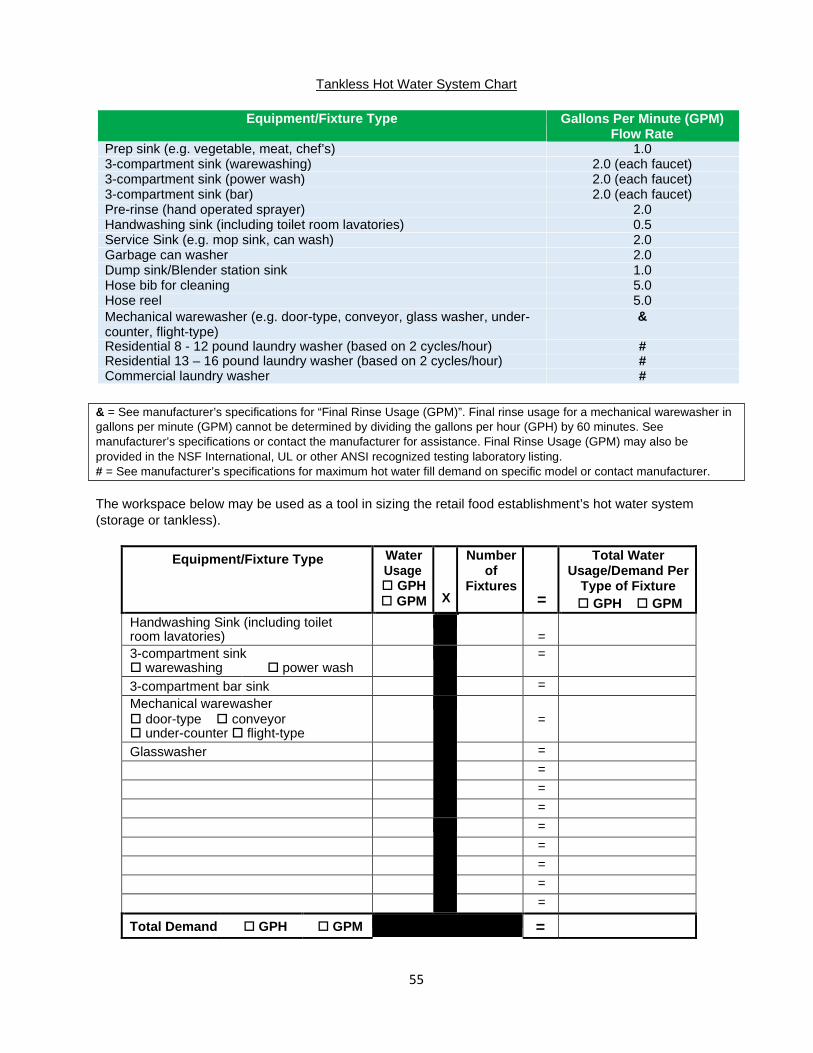
55
Tankless Hot Water System Chart
Equipment/Fixture Type Gallons Per Minute (GPM) Flow Rate
Prep sink (e.g. vegetable, meat, chef’s) 1.0 3-compartment sink (warewashing) 2.0 (each faucet) 3-compartment sink (power wash) 2.0 (each faucet) 3-compartment sink (bar) 2.0 (each faucet) Pre-rinse (hand operated sprayer) 2.0 Handwashing sink (including toilet room lavatories) 0.5 Service Sink (e.g. mop sink, can wash) 2.0 Garbage can washer 2.0 Dump sink/Blender station sink 1.0 Hose bib for cleaning 5.0 Hose reel 5.0 Mechanical warewasher (e.g. door-type, conveyor, glass washer, under- counter, flight-type)
&
Residential 8 - 12 pound laundry washer (based on 2 cycles/hour) # Residential 13 – 16 pound laundry washer (based on 2 cycles/hour) # Commercial laundry washer #
The workspace below may be used as a tool in sizing the retail food establishment’s hot water system (storage or tankless).
Equipment/Fixture Type Water
Usage GPH GPM
X
Number of
Fixtures
=
Total Water Usage/Demand Per
Type of Fixture GPH GPM
Handwashing Sink (including toilet room lavatories)
=
3-compartment sink warewashing power wash
=
3-compartment bar sink =
Mechanical warewasher door-type conveyor under-counter flight-type
=
Glasswasher = = = = = = = = =
Total Demand GPH GPM =
& = See manufacturer’s specifications for “Final Rinse Usage (GPM)”. Final rinse usage for a mechanical warewasher in gallons per minute (GPM) cannot be determined by dividing the gallons per hour (GPH) by 60 minutes. See manufacturer’s specifications or contact the manufacturer for assistance. Final Rinse Usage (GPM) may also be provided in the NSF International, UL or other ANSI recognized testing laboratory listing. # = See manufacturer’s specifications for maximum hot water fill demand on specific model or contact manufacturer.

56
Hot Water Systems
A hot water system should be sized based on the fixtures that are to be supplied with hot water and the potential of those fixtures operating simultaneously during peak demand periods. Peak hot water consumption generally occurs during cleaning periods in most retail food establishments. It is generally accepted that the average clean-up period is two hours.
The following is provided as a guide in planning the hot water system that meets the facility’s needs.
Storage-Tank Type Water Heater:
Storage water heaters provide a reservoir of ready to use hot water. Sizing is based on gallons-per-hour (GPH).
Storage Water Heater
A conventional storage water heater having a 100-gallon storage capacity, for example, can store 100 gallons of hot water at a set temperature. However, as the water is released from the tank to meet fixture demand there is no longer 100 gallons of water at the set temperature. Following is a brief description of how conventional storage water heaters work:
• A storage water heater releases hot water from the top of the tank when a faucet, mechanical
warewasher or other type of fixture or equipment has been turned on or engaged. The hot water is replaced by cold water that enters the bottom of the tank. This ensures that the tank is always full.
• The cold or incoming water mixes with the stored water in the tank which results in a supply of tempered water at the bottom of the tank.
• Once hot water is no longer being released from the storage tank, the tempered water at the bottom of the tank will heat to the set temperature.
The adequacy of the hot water system may be determined by adding the storage capacity of the tank to the recovery rate per hour at 100oF* rise to yield the total gallons of the system.
First hour delivery rating is another method of determining the adequacy of a hot water system. First hour delivery is the amount of hot water a fully heated storage water heater can deliver in the first hour.
Most water heater manufacturer’s list the storage capacity and recovery rate at 100oF rise on commercial water heater data plates. First hour delivery rating may be found on the data plate of some commercial water heaters. Residential water heater data plates usually list the storage capacity only.
*Due to low potable water temperatures recorded across the state (40oF) during cold weather months, it is recommended that sizing is based on the recovery rate of the water heater at a 100oF rise.
Gas and Electric Hot Water Recovery Rates –
When the data plate does not list the recovery rate of the water heater, the following factors may be used to calculate hot water recovery. Calculation using one of these factors is conservative and does not consider tank construction and design that may result in a more efficient water heater.
NOTE: Stagnant water such as that being held in a storage water heater, may promote conditions for bacteria growth. It is recommended that the water heater temperature is maintained at 140oF (60oC). Hot water stored at 140oF (60oC) may be tempered to meet minimum fixture temperature criteria. However, for actual installation criteria a plumber and/or the local Plumbing Official should be contacted.

57
• 1,000 British Thermal Units (BTU) input will heat 0.84 gallons of water at a 100oF rise. • 1,000 Watts (1kW) will heat 4.1 gallons of water at a 100oF rise.
Multiple Water Heaters –
Water heaters that have small storage tanks but possess large recovery capabilities may appear adequate to meet total fixture demand. However, in some cases these water heaters have not been able to deliver enough hot water for immediate use.
• Two or more water heaters used to provide a single source that are plumbed in parallel provides maximum hot water output. Each water heater’s recovery rate should be added to the system’s total storage capacity for sizing purposes.
• When water heaters are plumbed in series, only the first water heater’s recovery rate should be added to the system’s total storage capacity for sizing purposes.
Heat Reclaim System
Heat reclaim systems recover heat energy from refrigeration equipment (e.g. display coolers and cases, prep coolers, freezers) within the establishment and use this energy to generate hot water. While a reclaim unit will increase the hot water system’s recovery capacity, its capability to generate hot water varies with energy input. Because of the refrigeration needed to provide a consistent supply of hot water at a specified temperature, these systems should be designed by an engineer. Retail food markets tend to have the refrigeration capacity to support this type of hot water system.
A heat reclaim system includes a reclaim storage tank(s). The hot water capacity of a heat reclaim system is based on the storage capacity of the storage tank(s) plus the recovery capacity of any heating elements, and the calculation of the total rejected heat (BTU) at a design factor of 50%.
Reclaim system design sometimes include a conventional storage water heater when hot water is needed in a remote area of the establishment to ensure consistent hot water temperatures.

58
EXAMPLE: Below is an example that illustrates how the incoming water temperature may affect the flow rate of water from a tankless water heater system to fixtures. Flow rates in the example are random and do not represent any specific tankless unit. Information on flow rates for specific models may be obtained from the tankless water heater manufacturer’s specifications. The hot water fixtures in a retail food establishment have a total flow rate demand of 6 GPM. The tankless water heater’s temperature is set at 120oF.
Based on the chart above hot water demand for the fixtures would be met on Days 1 & 3. However, on Day 2 the flow rate of hot water available (4 GPM) would be less than the total fixture demand (6 GPM). If a warewashing machine was one of the fixtures attached to the hot water system in the example above, the lower available flow rate output on Day 2 could negatively affect the operation of the warewashing machine.
Solar Water Heater System
Solar water heater systems harness energy from the sun. The system includes a storage tank(s) and solar collectors. Factors that impact a solar water heater system include solar resource and climate. Industry acknowledges that solar water heating systems almost always need a backup system for cloudy days and times of increased demand. As backup a conventional storage water heater is usually installed as a part of this type of system. Sometimes a tankless water heater system is installed for backup to the solar hot water system. A plumber or qualified solar system professional should be contacted for assistance with design and installation.
Clean-up operations in a retail food establishment and weather may affect the ability of this type of system to provide enough hot water. It is recommended that a backup system is provided.
Tankless Water Heater:
Tankless water heaters are known by many names (e.g. instantaneous, continuous flow, on-demand). Industry generally uses the term “tankless” because it literally describes its design, a water heater without a storage tank. Except the small amount of water stored in the heat exchanger coil, water is not retained internally.
Tankless water heater systems are installed for a variety of reasons including energy and space saving. The water heater turns on when water flows through it and activates the flow sensor. When the flow sensor is activated it triggers the heat exchanger coil that “instantaneously” heats the water to the set temperature. Flow through the heat exchanger coil is restricted to allow the water to heat to the set temperature. The flow rate output depends upon the temperature of the incoming (cold) water. Sizing is based on gallons-per- minute (GPM) flow rate.
High-Capacity Tankless Water Heater System
High-capacity tankless water heaters are designed to support multiple fixtures. The GPM flow rate generated by the tankless unit is shared by all fixtures connected to the system.
Set Temperature
120oF
Incoming Water
Temperature
Degree Rise
Total Flow Rate Output (GPM)
Day 1 70oF 50oF 6.2 Day 2 40oF 80oF 4.0 Day 3 90oF 30oF 8.4

59
The adequacy of the tankless hot water system may be determined by comparing the total gallon per minute flow rate at the specified set temperature to the total GPM demand of the fixtures. Due to low water temperatures recorded across the state during cold weather months, it is recommended that when sizing a tankless water heater system, the GPM flow rate is based on an incoming water temperature of 40oF.
When choosing to install a tankless hot water system the following should be considered:
• More than one tankless water heater may be needed if the total GPM fixture demand exceeds the flow rate provided at the specified temperature by one tankless unit.
• A tankless water heater activates when it receives a minimum flow demand from the water fixture(s).
• Specific electrical or gas requirements may be needed for the installation of a tankless water heater.
A plumber, the tankless water heater manufacturer or local Plumbing Official should be contacted for assistance with design and installation.
Point-of-Use Water Heater System
A point-of-use (POU) tankless water heater is sometimes installed at an isolated fixture(s), to avoid a long piping run from the primary hot water system. POU tankless water heaters are small with low GPM flow rates and are usually installed directly underneath the handwashing sink(s).
NOTE: The GPM final rinse usage for a warewashing machine cannot be accurately calculated by dividing the GPH by 60 minutes. Several factors may affect hot water demand of a warewashing machine.
• Dwell time is a factor in determining flow demand. • Hot water usage varies within a class of warewashing machines. Sizing should be based on a
specific model. • Older (used) warewashing machines within a manufacturer’s model class may have a greater hot
water demand than current “water saver” models. Information on the age of an older (used) warewashing machine can be helpful in accurate sizing.
It is important the tankless water system is designed to provide sufficient hot water when demanded at the warewashing machine to ensure effective cleaning of equipment and utensils. For guidance on hot water GPM demand it is recommended that manufacturer’s specification or the manufacturer is consulted.

60
Other Hot Water System Components:
Booster Heater
A booster heater is a special type of water heater. The booster heater is generally designed and intended to instantaneously raise the temperature of hot water to a higher temperature. Its primary function is to provide 180oF water for the final rinse in a hot water sanitizing commercial warewashing machine.
A booster heater that is not built into the mechanical warewasher should be located within 5 feet of the warewashing machine for best results. The warewashing machine’s specifications should be consulted to determine if a built-in booster heater option is available or if a standalone booster heater should be installed.
Other options for providing the minimum hot water sanitizing temperature may be available. A plumber may be able to assist with determining what works best for the facility’s warewashing operation.
Recirculating Pump
When a booster heater (auxiliary or built-in) for a warewashing machine is located more than 25 pipe feet from the primary water heater, it is recommended that the water supply line to the machine’s booster heater is mechanically recirculated. A recirculating pump could also be installed on a water line that supplies hot water for sanitization directly from the water heater to the warewashing machine.
When the length of the hot water piping from the main water heater system to other hot water fixtures is more than 100 feet it is recommended that a recirculating pump is installed. Other methods for minimizing the amount of time it takes for hot water to be delivered to a remote fixture(s) may also be available. For guidance a plumber should be consulted.
Ventilation
All rooms in a permitted retail food establishment must be adequately ventilated and kept reasonably free of grease, excessive heat, steam, condensation, vapors, smoke and fumes. A properly designed ventilation system helps to prevent grease or condensation from collecting on walls, ceilings and floors.
Information contained in the following section is for guidance only. The local Fire, Mechanical and/or Building Official should be contacted for specific ventilation requirements. For design guidance a mechanical engineer, exhaust hood manufacturer, or local Fire, Mechanical and/or Building Official, may be of assistance.
Exhaust Hoods
An exhaust hood system, in food preparation and warewashing areas, helps to prevent contaminants such as grease or condensation from draining or dripping onto exposed food, equipment, utensils or other food contact surfaces. When designed as a part of a total ventilation (HVAC) system an exhaust hood can also help to keep a facility clean, reduce equipment corrosion and add to kitchen staff comfort.
NOTE: To determine if a warewashing machine is designed for hot water or chemical sanitization, the data plate and manufacturer’s specification should be reviewed.

61
Classification of Hoods
Type l Hoods:
Type I hoods are installed over cooking equipment that produce grease or smoke. They are commonly referred to as grease hoods. Food service equipment that only produce heat and moisture may also be installed underneath a Type I hood.
The purpose of a Type I hood is to provide a method of collecting, as nearly as possible, all the grease produced from the cooking process, while furnishing a means of removing heat, smoke, odors and moisture.
The two categories of Type I hoods are listed and unlisted.
• Listed hoods are designed and engineered by a hood manufacturer. They are evaluated, tested, and listed under ANSI/UL Standard 710. Hoods are tested for effective minimum exhaust and supply volumes for various cooking loads, hood installation height and/or clearance needed between the hood and the cooking equipment, and minimum overhang requirements. As part of the certification, the hood would also be evaluated to National Fire Protection Association (NFPA) Standard 96.
• Unlisted hoods are those that have not been tested and listed under ANSI/UL Standard 710.
Cooking equipment installed under a Type I hood falls into 4 categories: light-duty, medium-duty, heavy-duty, and extra-heavy duty.
Light, medium and heavy-duty cooking equipment are often installed together under one hood system. Extra-heavy-duty equipment is usually installed under an exhaust hood system that is independent of other hood systems.
Examples of cooking equipment installed underneath Type I hoods: Fryers, charbroilers, griddles, conveyor and deck-style pizza ovens, ranges, smokers, wok ranges, ovens, braising pans, rotisseries, salamanders, tilting skillets, chain broilers, and tilting kettles.
Type II Hoods:
Type II hoods help to control humidity and, collect and remove heat or steam (condensation) where grease and smoke are not present. They are commonly referred to as condensate hoods.
Light-duty cooking equipment that produce heat and moisture only and mechanical warewashing equipment are installed underneath Type II hoods.
Examples of cooking equipment installed underneath Type II hoods: Ovens (for bakery goods without proteins), steamers, pasta cookers.
Installation of a Type II hood should be considered when a hot water sanitizing, conveyor warewasher is installed due to the amount of moisture and heat that may be generated by the operation. A Type II hood may also be needed when any mechanical warewasher is installed in a small room or alcove where air flow is limited.
NOTE: For design requirements for unlisted hoods, the local mechanical or building official should be contacted. Several ventilation system design calculation methods are available. Some of those methods for design, construction and performance are provided in the Exhaust Hood System Design and Installation (Unlisted Hoods) section of this document and are only provided as guidance.

62
Type I and Type II ventilation hoods are available in various categories for different applications and preferences.
Exhaust Hood System Design and Installation Guidance
(Unlisted Hood)
Guidance information provided below are for unlisted or untested hood systems only. For specific design and installation requirements the local Fire, Mechanical or Building Official should be contacted. A mechanical engineer may also be able to assist with a ventilation system that includes an unlisted hood.
Listed (ANSI/UL Standard 710, UL710B) Type I hoods should be installed based on the manufacturer’s specifications. Type II hoods should also be installed to manufacturer’s specifications.
Canopy Hood:
Canopy hoods overhang cooking equipment to provide a capture area for grease, smoke, condensate, et cetera. Canopy hoods should have a minimum depth of two (2) feet and should be installed so that the bottom of the hood is between 6’6” and 7’0” above the finished floor. Following are configurations for the installation of canopy hoods:
Wall Hung Hood –
Hood is installed against one or more walls. A hood installed against a wall tends to capture and contain more effluent using less air flow than an island hood. Side (end) panels can also help alleviate negative effects of cross- drafts and improve hood performance.
Single and Double Island Hoods –
Hood(s) is installed away from walls with 4 exposed sides. Because an island hood is exposed on all sides, it is more susceptible to cross-drafts and spillage (e.g. grease, condensate, smoke). An island hood having the same equipment underneath as a wall hung canopy hood needs more airflow to provide effective capture.
A single island hood is installed over a single row of cooking equipment. For best capture and containment results a single island hood should be designed with a V-bank of filters. A single filter bank, wall canopy hood installed as an island hood is usually not recommended due to capture limitations.
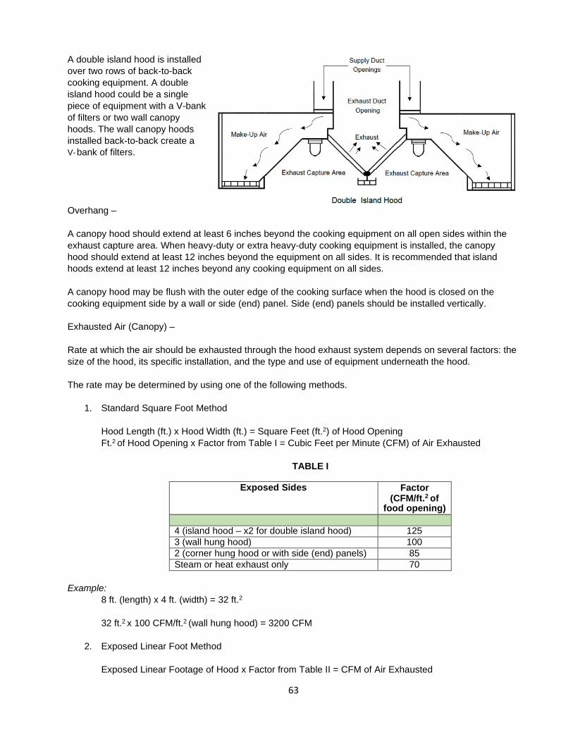
63
A double island hood is installed over two rows of back-to-back cooking equipment. A double island hood could be a single piece of equipment with a V-bank of filters or two wall canopy hoods. The wall canopy hoods installed back-to-back create a V- bank of filters.
Overhang –
A canopy hood should extend at least 6 inches beyond the cooking equipment on all open sides within the exhaust capture area. When heavy-duty or extra heavy-duty cooking equipment is installed, the canopy hood should extend at least 12 inches beyond the equipment on all sides. It is recommended that island hoods extend at least 12 inches beyond any cooking equipment on all sides.
A canopy hood may be flush with the outer edge of the cooking surface when the hood is closed on the cooking equipment side by a wall or side (end) panel. Side (end) panels should be installed vertically.
Exhausted Air (Canopy) –
Rate at which the air should be exhausted through the hood exhaust system depends on several factors: the size of the hood, its specific installation, and the type and use of equipment underneath the hood.
The rate may be determined by using one of the following methods.
1. Standard Square Foot Method
Hood Length (ft.) x Hood Width (ft.) = Square Feet (ft.2) of Hood Opening Ft.2 of Hood Opening x Factor from Table I = Cubic Feet per Minute (CFM) of Air Exhausted
TABLE I
Exposed Sides Factor
(CFM/ft.2 of food opening)
4 (island hood – x2 for double island hood) 125 3 (wall hung hood) 100 2 (corner hung hood or with side (end) panels) 85 Steam or heat exhaust only 70
Example:
8 ft. (length) x 4 ft. (width) = 32 ft.2
32 ft.2 x 100 CFM/ft.2 (wall hung hood) = 3200 CFM
2. Exposed Linear Foot Method
Exposed Linear Footage of Hood x Factor from Table II = CFM of Air Exhausted
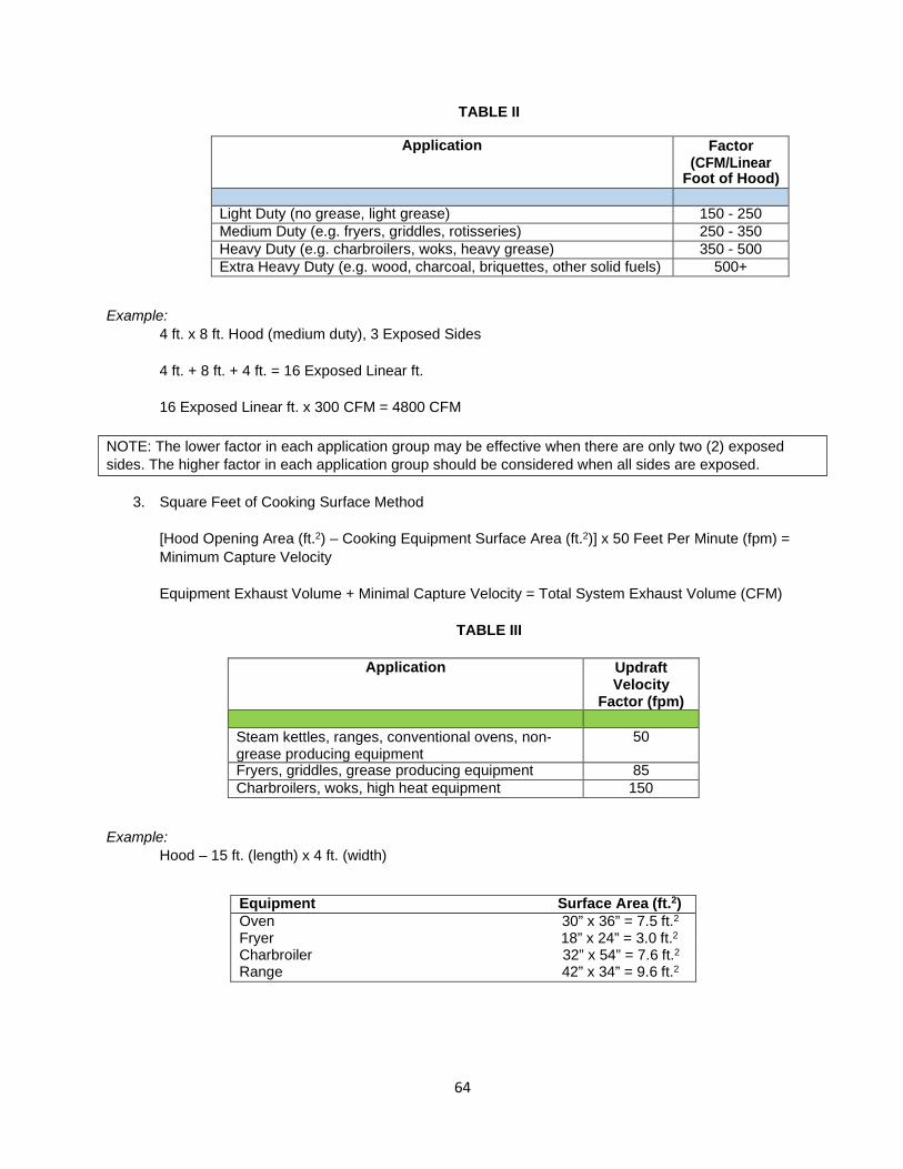
64
TABLE II
Application Factor (CFM/Linear
Foot of Hood) Light Duty (no grease, light grease) 150 - 250 Medium Duty (e.g. fryers, griddles, rotisseries) 250 - 350 Heavy Duty (e.g. charbroilers, woks, heavy grease) 350 - 500 Extra Heavy Duty (e.g. wood, charcoal, briquettes, other solid fuels) 500+
Example:
4 ft. x 8 ft. Hood (medium duty), 3 Exposed Sides
4 ft. + 8 ft. + 4 ft. = 16 Exposed Linear ft.
16 Exposed Linear ft. x 300 CFM = 4800 CFM
3. Square Feet of Cooking Surface Method
[Hood Opening Area (ft.2) – Cooking Equipment Surface Area (ft.2)] x 50 Feet Per Minute (fpm) = Minimum Capture Velocity
Equipment Exhaust Volume + Minimal Capture Velocity = Total System Exhaust Volume (CFM)
TABLE III
Application Updraft
Velocity Factor (fpm)
Steam kettles, ranges, conventional ovens, non- grease producing equipment
50
Fryers, griddles, grease producing equipment 85 Charbroilers, woks, high heat equipment 150
Example:
Hood – 15 ft. (length) x 4 ft. (width)
Equipment Surface Area (ft.2) Oven 30” x 36” = 7.5 ft.2
Fryer 18” x 24” = 3.0 ft.2
Charbroiler 32” x 54” = 7.6 ft.2
Range 42” x 34” = 9.6 ft.2
NOTE: The lower factor in each application group may be effective when there are only two (2) exposed sides. The higher factor in each application group should be considered when all sides are exposed.

65
Ft.2 Factor (fpm) Exhaust (CFM) 7.5 x 50 375 3.0 x 85 255 7.6 x 150 1140 9.9 x 85 816 Total Equipment Exhaust Volume = 2586
15 ft. x 4 ft. = 60 ft.2 Hood Opening
7.5 ft.2 + 3.0 ft.2 + 7.6 ft.2+ 9.9 ft.2 = 28 ft.2 Cooking Equipment Surface Area
[60 ft.2 – 28 ft.2] x 50 fpm = 32 ft.2 x 50 fpm = 1600 CFM Minimal Capture Velocity
2586 CFM + 1600 CFM = 4186 CFM Total System Exhaust Volume
Low Proximity (Backshelf) Hood:
A low proximity or backshelf hood is a Type I hood that is normally installed closer to the cooking surface of equipment than a canopy hood. The depth of a low proximity (backshelf) hood is also shorter than a typical canopy hood, therefore cooking equipment may extend beyond the front of the hood. With the shorter depth, installing the hood closer to the cooking surface of equipment results in better capture of contaminated air.
Because a low proximity hood usually does not extend beyond the cooking surface of equipment, the hood may allow large surges of contaminated air to escape into the cooking/food preparation area. Therefore, it performs best when used for light and medium duty cooking applications.
A low proximity hood should extend from the wall a minimum of 16 inches and installed so that the distance from the top of the cooking equipment to the bottom of the hood is no more than 24 inches. Equipment installed under a low proximity hood should not extend beyond the sides of the hood or more than 36 inches from the back of the hood.
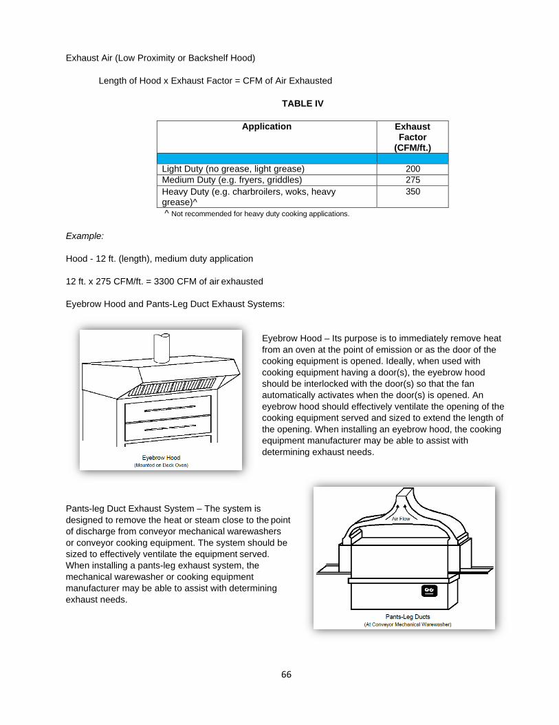
66
Exhaust Air (Low Proximity or Backshelf Hood)
Length of Hood x Exhaust Factor = CFM of Air Exhausted
TABLE IV
Application Exhaust Factor
(CFM/ft.) Light Duty (no grease, light grease) 200 Medium Duty (e.g. fryers, griddles) 275 Heavy Duty (e.g. charbroilers, woks, heavy grease)^
350
^ Not recommended for heavy duty cooking applications.
Example:
Hood - 12 ft. (length), medium duty application
12 ft. x 275 CFM/ft. = 3300 CFM of air exhausted
Eyebrow Hood and Pants-Leg Duct Exhaust Systems:
Eyebrow Hood – Its purpose is to immediately remove heat from an oven at the point of emission or as the door of the cooking equipment is opened. Ideally, when used with cooking equipment having a door(s), the eyebrow hood should be interlocked with the door(s) so that the fan automatically activates when the door(s) is opened. An eyebrow hood should effectively ventilate the opening of the cooking equipment served and sized to extend the length of the opening. When installing an eyebrow hood, the cooking equipment manufacturer may be able to assist with determining exhaust needs.
Pants-leg Duct Exhaust System – The system is designed to remove the heat or steam close to the point of discharge from conveyor mechanical warewashers or conveyor cooking equipment. The system should be sized to effectively ventilate the equipment served. When installing a pants-leg exhaust system, the mechanical warewasher or cooking equipment manufacturer may be able to assist with determining exhaust needs.

67
Duct Size:
Long hoods with multiple ducts should have ducts located no closer than 6 feet apart and no further then 12 feet apart. Duct velocity should be a minimum of 1500 fpm. For best results, exhaust ducts should not be located at the sides of the hood.
An undersized duct(s) may affect the ability of the hood system to effectively remove cooking contaminants from the food preparation area, despite having an appropriately sized exhaust fan(s).
CFM of Air Exhausted ÷ Duct Velocity (fpm) = Duct Area Needed (ft.2)
Example:
3000 CFM ÷ 1500 fpm = 2 ft.2
Filter Area and Filters:
There are two basic types of filters:
• Baffle filters are typically used where grease removal is a primary concern. • Wire mesh filters are generally used where only heat and moisture are of concern.
Space in the hood filter bank not covered by filters should be fitted with sheet metal blanks. The operating velocity of filters should be no less than 200 fpm.
For specific filter requirements the Fire, Mechanical or Building Official should be contacted.
CFM of Air Exhausted ÷ Operating Velocity of the Filter (fpm) = Filter Area Needed (ft.2)
Static Pressure:
The static pressure against the exhaust fan (measured in inches) = the sum of the resistance of the filters, hood entrance loss, wind pressure on the duct opening, accelerating pressure, and the exhaust ducting from the Table V below.
TABLE V
Type of Resistance Average Amount of Resistance (in.) Filter .20 in. Hood Entrance Loss .10 in. Wind Pressure .15 in. Accelerating Pressure .20 in.
Duct Resistance Straight Duct .0025 in. (per linear ft.) Angles - 90o .20 in. (each)
- 45o .10 in. (each) - 30o .05 in. (each)

68
Exhaust Fan Size:
The exhaust fan should be sized to remove the amount of air to be exhausted at the required static pressure. Exhaust fans for equipment installed for the removal of smoke and grease-laden vapors should meet UL 762.
Make-up Air:
Mechanically introduced make-up (outside) air should be introduced to replace air lost through exhaust ventilation when the total amount of air to be exhausted exceeds 1500 CFM.
Not enough or too much outside air could adversely affect the ability of an exhaust system to effectively remove cooking or mechanical warewashing contaminants from food operation areas. Mechanical engineers recommend that a dedicated make-up air system should supply at 80 to 90% to replace the exhausted air in the area where the hood system(s) is located. Having a slight negative pressure helps to contain cooking odors and keep the food preparation area(s) cleaner. Additional make-up air should be brought in through the HVAC system to pressurize the retail food establishment. Some engineered HVAC systems may be designed to provide the needed outside air for a balanced exhaust ventilation system.
The make-up air system should be designed to start and operate with the exhaust ventilation system.
Make-up air can be provided by one or a combination of methods, such as through an integrated hood plenum, transfer air system or diffusers. Please see Food Safety – How to Apply for a Food Permit for additional information.